Netgear orporated WGR826V ACCESS POINT User Manual WGR826Vv1 1
Netgear Incorporated ACCESS POINT WGR826Vv1 1
UserManual.wiki
>
Netgear orporated
>
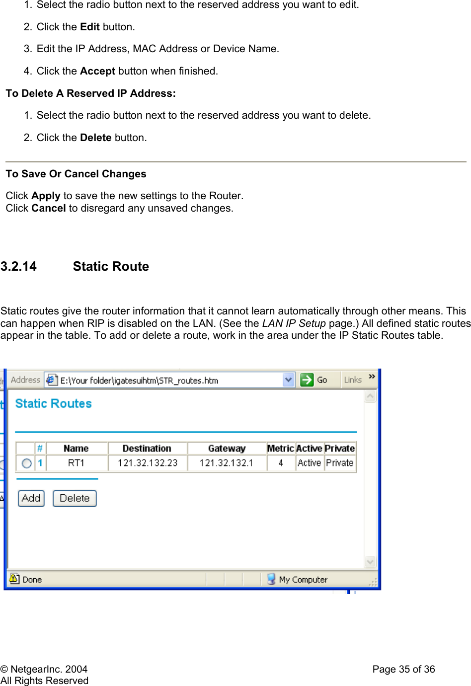
WGR826V User Manual
USERS MANUAL
Navigation menu
Upload a User Manual
Namespaces
Wiki Guide
HTML
PDF
Info
Views
User Manual
Discussion / Help
Navigation