Netgear Xcm8810 Owner S Manual XCM8800_UG
Netgear-Xcm8806-Owner-S-Manual netgear-xcm8806-owner-s-manual
2014-07-06
: Netgear Netgear-Xcm8810-Owner-S-Manual netgear-xcm8810-owner-s-manual netgear pdf
Open the PDF directly: View PDF ![]() .
.
Page Count: 968 [warning: Documents this large are best viewed by clicking the View PDF Link!]
- NETGEAR 8800 User Manual
- Contents
- 1. Overview
- 2. Getting Started
- Overview
- Software Required
- Logging in to the Switch
- Understanding the Command Syntax
- Port Numbering
- Line-Editing Keys
- Command History
- Common Commands
- Accessing the Switch for the First Time
- Configuring Management Access
- Managing Passwords
- Access to Both MSM/MM Console Ports
- Domain Name Service Client Services
- Checking Basic Connectivity
- Displaying Switch Information
- 3. Managing the Switch
- Overview
- Understanding the XCM8800 Shell
- Using the Console Interface
- Using the 10/100 Ethernet Management Port
- Authenticating Users
- Using Telnet
- Using Secure Shell 2
- Using the Trivial File Transfer Protocol
- Understanding System Redundancy
- Understanding Hitless Failover Support
- Understanding Power Supply Management
- Using the Simple Network Management Protocol
- Using the Simple Network Time Protocol
- 4. Managing the XCM8800 Software
- 5. Configuring Slots and Ports on a Switch
- 6. LLDP
- 7. PoE
- 8. Status Monitoring and Statistics
- Overview
- Viewing Port Statistics
- Viewing Port Errors
- Using the Port Monitoring Display Keys
- Viewing VLAN Statistics
- Performing Switch Diagnostics
- Using the System Health Checker
- Setting the System Recovery Level
- Viewing Fan Information
- Viewing the System Temperature
- Using the Event Management System/Logging
- Using sFlow
- Using RMON
- 9. VLANs
- 10. FDB
- 11. Virtual Routers
- 12. Policy Manager
- 13. ACLs
- 14. Routing Policies
- 15. QoS
- Overview
- Configuring QoS
- Platform Configuration Procedures
- Selecting the QoS Scheduling Method
- Configuring 802.1p or DSCP Replacement
- Configuring Egress QoS Profile Rate Shaping
- Configuring Egress Port Rate Limits
- Configuring Traffic Groups
- Creating and Managing Meters
- Adjusting the Byte Count Used to Calculate Traffic Rates
- Controlling Flooding, Multicast, and Broadcast Traffic on Ingress Ports
- Displaying QoS Configuration and Performance
- 16. Network Login
- Overview
- Configuring Network Login
- Authenticating Users
- Local Database Authentication
- 802.1x Authentication
- Web-Based Authentication
- Enabling and Disabling Web-Based Network Login
- Configuring the Base URL
- Configuring the Redirect Page
- Configuring Proxy Ports
- Configuring Session Refresh
- Configuring Logout Privilege
- Configuring the Login Page
- Customizable Authentication Failure Response
- Customizable Graphical Image in Logout Popup Window
- Web-Based Network Login Configuration Example
- Web-Based Authentication User Login
- MAC-Based Authentication
- Additional Network Login Configuration Details
- 17. Security
- Overview
- Safe Defaults Mode
- MAC Security
- DHCP Server
- IP Security
- Denial of Service Protection
- Authenticating Management Sessions Through the Local Database
- Authenticating Management Sessions Through a TACACS+ Server
- Authenticating Management Sessions Through a RADIUS Server
- Authenticating Network Login Users Through a RADIUS Server
- Configuring the RADIUS Client
- RADIUS Server Configuration Guidelines
- Configuring a Windows XP Supplicant for 802.1x Authentication
- Hyptertext Transfer Protocol
- Secure Shell 2
- Secure Socket Layer
- 18. STP
- 19. VRRP
- 20. IPv4 Unicast Routing
- 21. IPv6 Unicast Routing
- 22. RIP
- 23. RIPng
- 24. OSPF
- 25. OSPFv3
- 26. BGP
- Overview
- BGP Features
- Route Reflectors
- Route Confederations
- Route Aggregation
- Inactive Route Advertisement
- Default Route Origination and Advertisement
- Using the Loopback Interface
- Looped AS_Path Attribute
- BGP Peer Groups
- BGP Route Flap Dampening
- BGP Route Selection
- Stripping Out Private AS Numbers from Route Updates
- Route Redistribution
- BGP ECMP
- BGP Static Network
- Graceful BGP Restart
- Cease Subcodes
- Fast External Fallover
- Capability Negotiation
- Route Refresh
- 27. Multicast Routing and Switching
- 28. IPv6 Multicast
- 29. MSDP
- 30. vMAN (PBN)
- A. XCM8800 Software Licenses
- B. Software Upgrade and Boot Options
- C. Troubleshooting
- Troubleshooting Checklists
- LEDs
- Using the Command Line Interface
- Using the Rescue Software Image
- Debug Mode
- Saving Debug Information
- Evaluation Precedence for ACLs
- TOP Command
- TFTP Server Requirements
- System Odometer
- Temperature Operating Range
- Corrupted BootROM on NETGEAR 8800 Series Switches
- Inserting Powered Devices in the PoE Module
- Modifying the Hardware Table Hash Algorithm
- Contacting NETGEAR Technical Support
- D. Supported Protocols, MIBs, and Standards
- E. Glossary
- Index

350 East Plumeria Drive
San Jose, CA 95134
USA
March 2011
202-10804-01
v1.0
NETGEAR 8800 User
Manual
Software Version 12.4

2 |
NETGEAR 8800 User Manual
© 2011 NETGEAR, Inc. All rights reserved.
No part of this publication may be reproduced, transmitted, transcribed, stored in a retrieval system, or translated
into any language in any form or by any means without the written permission of NETGEAR, Inc.
Technical Support
Thank you for choosing NETGEAR. To register your product, get the latest product updates, or get support online,
visit us at http://support.netgear.com.
Phone (US & Canada only): 1-888-NETGEAR
Phone (Other Countries): See Support information card.
Trademarks
NETGEAR, the NETGEAR logo, ReadyNAS, ProSafe, Smart Wizard, Auto Uplink, X-RAID2, and NeoTV are
trademarks or registered trademarks of NETGEAR, Inc. Microsoft, Windows, Windows NT, and Vista are
registered trademarks of Microsoft Corporation. Other brand and product names are registered trademarks or
trademarks of their respective holders.
Statement of Conditions
To improve internal design, operational function, and/or reliability, NETGEAR reserves the right to make changes
to the products described in this document without notice. NETGEAR does not assume any liability that may occur
due to the use, or application of, the product(s) or circuit layout(s) described herein.
Revision History
Publication Part Number Version Publish Date Comments
202-10804-01 v1.0 March 2011 First publication

Contents | 3
Contents
Chapter 1 Overview
Introduction. . . . . . . . . . . . . . . . . . . . . . . . . . . . . . . . . . . . . . . . . . . . . . . . . 22
Terminology . . . . . . . . . . . . . . . . . . . . . . . . . . . . . . . . . . . . . . . . . . . . . .23
Conventions . . . . . . . . . . . . . . . . . . . . . . . . . . . . . . . . . . . . . . . . . . . . . . . . 23
Platform-Naming Conventions . . . . . . . . . . . . . . . . . . . . . . . . . . . . . . . . 23
Text Conventions . . . . . . . . . . . . . . . . . . . . . . . . . . . . . . . . . . . . . . . . . .23
Related Publications. . . . . . . . . . . . . . . . . . . . . . . . . . . . . . . . . . . . . . . . . .24
Part 1: Using the NETGEAR 8800
Chapter 2 Getting Started
Overview . . . . . . . . . . . . . . . . . . . . . . . . . . . . . . . . . . . . . . . . . . . . . . . . . .27
Software Required . . . . . . . . . . . . . . . . . . . . . . . . . . . . . . . . . . . . . . . . . . . 28
Logging in to the Switch . . . . . . . . . . . . . . . . . . . . . . . . . . . . . . . . . . . . . . . 28
Understanding the Command Syntax. . . . . . . . . . . . . . . . . . . . . . . . . . . . .29
Syntax Helper . . . . . . . . . . . . . . . . . . . . . . . . . . . . . . . . . . . . . . . . . . . . .30
Command Shortcuts. . . . . . . . . . . . . . . . . . . . . . . . . . . . . . . . . . . . . . . . 30
Object Names. . . . . . . . . . . . . . . . . . . . . . . . . . . . . . . . . . . . . . . . . . . . .31
Symbols . . . . . . . . . . . . . . . . . . . . . . . . . . . . . . . . . . . . . . . . . . . . . . . . . 32
Limits . . . . . . . . . . . . . . . . . . . . . . . . . . . . . . . . . . . . . . . . . . . . . . . . . . . 33
Port Numbering . . . . . . . . . . . . . . . . . . . . . . . . . . . . . . . . . . . . . . . . . . . . .34
Numerical Ranges . . . . . . . . . . . . . . . . . . . . . . . . . . . . . . . . . . . . . . . . . 34
Line-Editing Keys . . . . . . . . . . . . . . . . . . . . . . . . . . . . . . . . . . . . . . . . . . . .34
Command History. . . . . . . . . . . . . . . . . . . . . . . . . . . . . . . . . . . . . . . . . . . .35
Common Commands . . . . . . . . . . . . . . . . . . . . . . . . . . . . . . . . . . . . . . . . .35
Accessing the Switch for the First Time . . . . . . . . . . . . . . . . . . . . . . . . . . .38
Safe Defaults Setup Method. . . . . . . . . . . . . . . . . . . . . . . . . . . . . . . . . .38
Configuring Management Access. . . . . . . . . . . . . . . . . . . . . . . . . . . . . . . . 39
Account Access Levels. . . . . . . . . . . . . . . . . . . . . . . . . . . . . . . . . . . . . . 40
Configuring the Banner. . . . . . . . . . . . . . . . . . . . . . . . . . . . . . . . . . . . . .40
Startup Screen and Prompt Text . . . . . . . . . . . . . . . . . . . . . . . . . . . . . .41
Default Accounts . . . . . . . . . . . . . . . . . . . . . . . . . . . . . . . . . . . . . . . . . . 43
Creating a Management Account . . . . . . . . . . . . . . . . . . . . . . . . . . . . . .43
Failsafe Accounts . . . . . . . . . . . . . . . . . . . . . . . . . . . . . . . . . . . . . . . . . .44
Managing Passwords . . . . . . . . . . . . . . . . . . . . . . . . . . . . . . . . . . . . . . . . .45
Applying a Password to the Default Account . . . . . . . . . . . . . . . . . . . . .45
Applying Security to Passwords . . . . . . . . . . . . . . . . . . . . . . . . . . . . . . . 46
Displaying Passwords . . . . . . . . . . . . . . . . . . . . . . . . . . . . . . . . . . . . . .47
Access to Both MSM/MM Console Ports . . . . . . . . . . . . . . . . . . . . . . . . . .47

4 | Contents
NETGEAR 8800 User Manual
Domain Name Service Client Services . . . . . . . . . . . . . . . . . . . . . . . . . . . 47
Checking Basic Connectivity . . . . . . . . . . . . . . . . . . . . . . . . . . . . . . . . . . . 48
Ping . . . . . . . . . . . . . . . . . . . . . . . . . . . . . . . . . . . . . . . . . . . . . . . . . . . . 48
Traceroute . . . . . . . . . . . . . . . . . . . . . . . . . . . . . . . . . . . . . . . . . . . . . . . 50
Displaying Switch Information . . . . . . . . . . . . . . . . . . . . . . . . . . . . . . . . . . 50
Chapter 3 Managing the Switch
Overview . . . . . . . . . . . . . . . . . . . . . . . . . . . . . . . . . . . . . . . . . . . . . . . . . . 51
Understanding the XCM8800 Shell . . . . . . . . . . . . . . . . . . . . . . . . . . . . . . 52
Using the Console Interface . . . . . . . . . . . . . . . . . . . . . . . . . . . . . . . . . . . . 52
Using the 10/100 Ethernet Management Port . . . . . . . . . . . . . . . . . . . . . . 53
Authenticating Users . . . . . . . . . . . . . . . . . . . . . . . . . . . . . . . . . . . . . . . . . 53
RADIUS Client . . . . . . . . . . . . . . . . . . . . . . . . . . . . . . . . . . . . . . . . . . . . 54
TACACS+. . . . . . . . . . . . . . . . . . . . . . . . . . . . . . . . . . . . . . . . . . . . . . . . 54
Management Accounts. . . . . . . . . . . . . . . . . . . . . . . . . . . . . . . . . . . . . . 54
Using Telnet . . . . . . . . . . . . . . . . . . . . . . . . . . . . . . . . . . . . . . . . . . . . . . . . 54
About the Telnet Client. . . . . . . . . . . . . . . . . . . . . . . . . . . . . . . . . . . . . . 55
About the Telnet Server . . . . . . . . . . . . . . . . . . . . . . . . . . . . . . . . . . . . . 55
Connecting to Another Host Using Telnet . . . . . . . . . . . . . . . . . . . . . . . 56
Configuring Switch IP Parameters . . . . . . . . . . . . . . . . . . . . . . . . . . . . . 56
Configuring Telnet Access to the Switch . . . . . . . . . . . . . . . . . . . . . . . . 58
Disconnecting a Telnet Session . . . . . . . . . . . . . . . . . . . . . . . . . . . . . . . 62
Using Secure Shell 2 . . . . . . . . . . . . . . . . . . . . . . . . . . . . . . . . . . . . . . . . . 62
Using the Trivial File Transfer Protocol . . . . . . . . . . . . . . . . . . . . . . . . . . . 62
Connecting to Another Host Using TFTP. . . . . . . . . . . . . . . . . . . . . . . . 63
Understanding System Redundancy . . . . . . . . . . . . . . . . . . . . . . . . . . . . . 64
Node Election . . . . . . . . . . . . . . . . . . . . . . . . . . . . . . . . . . . . . . . . . . . . . 65
Replicating Data Between Nodes. . . . . . . . . . . . . . . . . . . . . . . . . . . . . . 66
Viewing Node Status . . . . . . . . . . . . . . . . . . . . . . . . . . . . . . . . . . . . . . . 68
Understanding Hitless Failover Support. . . . . . . . . . . . . . . . . . . . . . . . . . . 69
Protocol Support for Hitless Failover . . . . . . . . . . . . . . . . . . . . . . . . . . . 69
Hitless Failover Caveats. . . . . . . . . . . . . . . . . . . . . . . . . . . . . . . . . . . . . 72
Understanding Power Supply Management. . . . . . . . . . . . . . . . . . . . . . . . 72
Using Power Supplies . . . . . . . . . . . . . . . . . . . . . . . . . . . . . . . . . . . . . . 72
Displaying Power Supply Information. . . . . . . . . . . . . . . . . . . . . . . . . . . 76
Using the Simple Network Management Protocol . . . . . . . . . . . . . . . . . . . 76
Enabling and Disabling SNMPv1/v2c and SNMPv3. . . . . . . . . . . . . . . . 77
Accessing Switch Agents . . . . . . . . . . . . . . . . . . . . . . . . . . . . . . . . . . . . 78
Supported MIBs . . . . . . . . . . . . . . . . . . . . . . . . . . . . . . . . . . . . . . . . . . . 78
Configuring SNMPv1/v2c Settings . . . . . . . . . . . . . . . . . . . . . . . . . . . . . 79
Displaying SNMP Settings . . . . . . . . . . . . . . . . . . . . . . . . . . . . . . . . . . . 80
SNMPv3 . . . . . . . . . . . . . . . . . . . . . . . . . . . . . . . . . . . . . . . . . . . . . . . . . 81
Message Processing . . . . . . . . . . . . . . . . . . . . . . . . . . . . . . . . . . . . . . . 82
SNMPv3 Security . . . . . . . . . . . . . . . . . . . . . . . . . . . . . . . . . . . . . . . . . . 82
SNMPv3 MIB Access Control. . . . . . . . . . . . . . . . . . . . . . . . . . . . . . . . . 86
SNMPv3 Notification. . . . . . . . . . . . . . . . . . . . . . . . . . . . . . . . . . . . . . . . 87

Contents | 5
NETGEAR 8800 User Manual
Using the Simple Network Time Protocol . . . . . . . . . . . . . . . . . . . . . . . . . .89
Configuring and Using SNTP . . . . . . . . . . . . . . . . . . . . . . . . . . . . . . . . .90
SNTP Example . . . . . . . . . . . . . . . . . . . . . . . . . . . . . . . . . . . . . . . . . . . .94
Chapter 4 Managing the XCM8800 Software
Overview. . . . . . . . . . . . . . . . . . . . . . . . . . . . . . . . . . . . . . . . . . . . . . . . . . .95
Using the XCM8800 File System . . . . . . . . . . . . . . . . . . . . . . . . . . . . . . . .96
Moving or Renaming Files on the Switch . . . . . . . . . . . . . . . . . . . . . . . .97
Copying Files on the Switch . . . . . . . . . . . . . . . . . . . . . . . . . . . . . . . . . .98
Displaying Files on the Switch . . . . . . . . . . . . . . . . . . . . . . . . . . . . . . .100
Transferring Files to and from the Switch. . . . . . . . . . . . . . . . . . . . . . .101
Deleting Files from the Switch . . . . . . . . . . . . . . . . . . . . . . . . . . . . . . .103
Managing the Configuration File. . . . . . . . . . . . . . . . . . . . . . . . . . . . . . . .104
Managing XCM8800 Processes. . . . . . . . . . . . . . . . . . . . . . . . . . . . . . . .106
Displaying Process Information . . . . . . . . . . . . . . . . . . . . . . . . . . . . . .106
Stopping a Process. . . . . . . . . . . . . . . . . . . . . . . . . . . . . . . . . . . . . . . .107
Starting a Process . . . . . . . . . . . . . . . . . . . . . . . . . . . . . . . . . . . . . . . .108
Understanding Memory Protection . . . . . . . . . . . . . . . . . . . . . . . . . . . . . .109
Monitoring CPU Utilization . . . . . . . . . . . . . . . . . . . . . . . . . . . . . . . . . . . .110
Disabling CPU Monitoring. . . . . . . . . . . . . . . . . . . . . . . . . . . . . . . . . . .110
Enabling CPU Monitoring . . . . . . . . . . . . . . . . . . . . . . . . . . . . . . . . . . .110
Displaying CPU Utilization History . . . . . . . . . . . . . . . . . . . . . . . . . . . .110
Chapter 5 Configuring Slots and Ports on a Switch
Overview. . . . . . . . . . . . . . . . . . . . . . . . . . . . . . . . . . . . . . . . . . . . . . . . . .113
Configuring Slots on NETGEAR 8800 Switches . . . . . . . . . . . . . . . . . . .114
Details on I/O Ports. . . . . . . . . . . . . . . . . . . . . . . . . . . . . . . . . . . . . . . .115
Configuring Ports on a Switch . . . . . . . . . . . . . . . . . . . . . . . . . . . . . . . . .116
Port Numbering. . . . . . . . . . . . . . . . . . . . . . . . . . . . . . . . . . . . . . . . . . .116
Enabling and Disabling Switch Ports . . . . . . . . . . . . . . . . . . . . . . . . . .117
Configuring Switch Port Speed and Duplex Setting . . . . . . . . . . . . . . .117
Jumbo Frames . . . . . . . . . . . . . . . . . . . . . . . . . . . . . . . . . . . . . . . . . . . . .122
Guidelines for Jumbo Frames. . . . . . . . . . . . . . . . . . . . . . . . . . . . . . . .122
Enabling Jumbo Frames per Port. . . . . . . . . . . . . . . . . . . . . . . . . . . . .122
Enabling Jumbo Frames. . . . . . . . . . . . . . . . . . . . . . . . . . . . . . . . . . . .122
Path MTU Discovery. . . . . . . . . . . . . . . . . . . . . . . . . . . . . . . . . . . . . . .123
IP Fragmentation with Jumbo Frames . . . . . . . . . . . . . . . . . . . . . . . . .123
IP Fragmentation within a VLAN. . . . . . . . . . . . . . . . . . . . . . . . . . . . . .124
Link Aggregation on the Switch . . . . . . . . . . . . . . . . . . . . . . . . . . . . . . . .124
Link Aggregation Overview. . . . . . . . . . . . . . . . . . . . . . . . . . . . . . . . . .125
Dynamic Versus Static Load Sharing . . . . . . . . . . . . . . . . . . . . . . . . . .126
Load-Sharing Algorithms . . . . . . . . . . . . . . . . . . . . . . . . . . . . . . . . . . .126
LACP . . . . . . . . . . . . . . . . . . . . . . . . . . . . . . . . . . . . . . . . . . . . . . . . . .127
Health Check Link Aggregation . . . . . . . . . . . . . . . . . . . . . . . . . . . . . .130
Guidelines for Load Sharing . . . . . . . . . . . . . . . . . . . . . . . . . . . . . . . . .131
Configuring Switch Load Sharing . . . . . . . . . . . . . . . . . . . . . . . . . . . . .132
Load-Sharing Examples . . . . . . . . . . . . . . . . . . . . . . . . . . . . . . . . . . . .135

6 | Contents
NETGEAR 8800 User Manual
Displaying Switch Load Sharing. . . . . . . . . . . . . . . . . . . . . . . . . . . . . . 137
Mirroring . . . . . . . . . . . . . . . . . . . . . . . . . . . . . . . . . . . . . . . . . . . . . . . . . . 138
Guidelines for Mirroring . . . . . . . . . . . . . . . . . . . . . . . . . . . . . . . . . . . . 138
Mirroring Rules and Restrictions . . . . . . . . . . . . . . . . . . . . . . . . . . . . . 140
Mirroring Examples. . . . . . . . . . . . . . . . . . . . . . . . . . . . . . . . . . . . . . . . 140
Verifying the Mirroring Configuration . . . . . . . . . . . . . . . . . . . . . . . . . . 141
Remote Mirroring . . . . . . . . . . . . . . . . . . . . . . . . . . . . . . . . . . . . . . . . . . . 141
Configuration Details . . . . . . . . . . . . . . . . . . . . . . . . . . . . . . . . . . . . . . 142
Guidelines. . . . . . . . . . . . . . . . . . . . . . . . . . . . . . . . . . . . . . . . . . . . . . . 144
Use of Remote Mirroring with Redundancy Protocols . . . . . . . . . . . . . 144
Remote Mirroring with STP . . . . . . . . . . . . . . . . . . . . . . . . . . . . . . . . . 144
Software-Controlled Redundant Port and Smart Redundancy. . . . . . . . . 146
Guidelines for Software-Controlled Redundant Ports and Port Groups147
Configuring Software-Controlled Redundant Ports . . . . . . . . . . . . . . . 147
Verifying Software-Controlled Redundant Port Configurations . . . . . . 148
Displaying Port Information . . . . . . . . . . . . . . . . . . . . . . . . . . . . . . . . . . . 148
Chapter 6 LLDP
Overview . . . . . . . . . . . . . . . . . . . . . . . . . . . . . . . . . . . . . . . . . . . . . . . . . 150
LLDP Packets. . . . . . . . . . . . . . . . . . . . . . . . . . . . . . . . . . . . . . . . . . . . . . 152
Transmitting LLDP Messages . . . . . . . . . . . . . . . . . . . . . . . . . . . . . . . . . 153
Receiving LLDP Messages . . . . . . . . . . . . . . . . . . . . . . . . . . . . . . . . . . . 154
Managing LLDP . . . . . . . . . . . . . . . . . . . . . . . . . . . . . . . . . . . . . . . . . . . . 155
Supported TLVs . . . . . . . . . . . . . . . . . . . . . . . . . . . . . . . . . . . . . . . . . . . . 156
Mandatory TLVs . . . . . . . . . . . . . . . . . . . . . . . . . . . . . . . . . . . . . . . . . . 158
Optional TLVs. . . . . . . . . . . . . . . . . . . . . . . . . . . . . . . . . . . . . . . . . . . . 159
Configuring LLDP. . . . . . . . . . . . . . . . . . . . . . . . . . . . . . . . . . . . . . . . . . . 164
Enabling and Disabling LLDP. . . . . . . . . . . . . . . . . . . . . . . . . . . . . . . . 165
Configuring the System Description TLV Advertisement . . . . . . . . . . . 165
Configuring LLDP Timers . . . . . . . . . . . . . . . . . . . . . . . . . . . . . . . . . . . 165
Configuring SNMP for LLDP. . . . . . . . . . . . . . . . . . . . . . . . . . . . . . . . . 166
Configuring Optional TLV Advertisements . . . . . . . . . . . . . . . . . . . . . . 167
Unconfiguring LLDP . . . . . . . . . . . . . . . . . . . . . . . . . . . . . . . . . . . . . . . 170
Displaying LLDP Settings. . . . . . . . . . . . . . . . . . . . . . . . . . . . . . . . . . . . . 170
Displaying LLDP Port Configuration Information and Statistics . . . . . . 170
Displaying LLDP Information Detected from Neighboring Ports. . . . . .171
Chapter 7 PoE
Overview . . . . . . . . . . . . . . . . . . . . . . . . . . . . . . . . . . . . . . . . . . . . . . . . . 172
NETGEAR Networks PoE Devices . . . . . . . . . . . . . . . . . . . . . . . . . . . . . 172
Summary of PoE Features . . . . . . . . . . . . . . . . . . . . . . . . . . . . . . . . . . . . 173
Power Checking for PoE Module . . . . . . . . . . . . . . . . . . . . . . . . . . . . . . . 173
Power Delivery . . . . . . . . . . . . . . . . . . . . . . . . . . . . . . . . . . . . . . . . . . . . . 174
Enabling PoE to the Switch . . . . . . . . . . . . . . . . . . . . . . . . . . . . . . . . . 174
Power Reserve Budget. . . . . . . . . . . . . . . . . . . . . . . . . . . . . . . . . . . . . 174
PD Disconnect Precedence . . . . . . . . . . . . . . . . . . . . . . . . . . . . . . . . . 175
Port Disconnect or Fault. . . . . . . . . . . . . . . . . . . . . . . . . . . . . . . . . . . . 176

Contents | 7
NETGEAR 8800 User Manual
Port Power Reset . . . . . . . . . . . . . . . . . . . . . . . . . . . . . . . . . . . . . . . . .177
PoE Usage Threshold. . . . . . . . . . . . . . . . . . . . . . . . . . . . . . . . . . . . . .177
Legacy Devices . . . . . . . . . . . . . . . . . . . . . . . . . . . . . . . . . . . . . . . . . .178
PoE Operator Limits . . . . . . . . . . . . . . . . . . . . . . . . . . . . . . . . . . . . . . .178
Configuring PoE . . . . . . . . . . . . . . . . . . . . . . . . . . . . . . . . . . . . . . . . . . . .179
Enabling Inline Power. . . . . . . . . . . . . . . . . . . . . . . . . . . . . . . . . . . . . .179
Reserving Power . . . . . . . . . . . . . . . . . . . . . . . . . . . . . . . . . . . . . . . . .180
Setting the Disconnect Precedence . . . . . . . . . . . . . . . . . . . . . . . . . . .180
Configuring the Usage Threshold. . . . . . . . . . . . . . . . . . . . . . . . . . . . .182
Configuring the Switch to Detect Legacy PDs . . . . . . . . . . . . . . . . . . .182
Configuring the Operator Limit . . . . . . . . . . . . . . . . . . . . . . . . . . . . . . .183
Configuring PoE Port Labels . . . . . . . . . . . . . . . . . . . . . . . . . . . . . . . .183
Power Cycling Connected PDs. . . . . . . . . . . . . . . . . . . . . . . . . . . . . . .183
Adding an XCM88P Daughter Card to an Existing Configuration. . . . .184
Displaying PoE Settings and Statistics. . . . . . . . . . . . . . . . . . . . . . . . . . .186
Clearing Statistics. . . . . . . . . . . . . . . . . . . . . . . . . . . . . . . . . . . . . . . . .186
Displaying System Power Information . . . . . . . . . . . . . . . . . . . . . . . . .186
Displaying Slot PoE Information on NETGEAR 8800 Switches . . . . . .187
Displaying Port PoE Information. . . . . . . . . . . . . . . . . . . . . . . . . . . . . .188
Chapter 8 Status Monitoring and Statistics
Overview. . . . . . . . . . . . . . . . . . . . . . . . . . . . . . . . . . . . . . . . . . . . . . . . . .192
Viewing Port Statistics . . . . . . . . . . . . . . . . . . . . . . . . . . . . . . . . . . . . . . .193
Viewing Port Errors. . . . . . . . . . . . . . . . . . . . . . . . . . . . . . . . . . . . . . . . . .193
Using the Port Monitoring Display Keys . . . . . . . . . . . . . . . . . . . . . . . . . .195
Viewing VLAN Statistics . . . . . . . . . . . . . . . . . . . . . . . . . . . . . . . . . . . . . .196
Performing Switch Diagnostics. . . . . . . . . . . . . . . . . . . . . . . . . . . . . . . . .197
Running Diagnostics. . . . . . . . . . . . . . . . . . . . . . . . . . . . . . . . . . . . . . .197
Observing LED Behavior During a Diagnostic Test . . . . . . . . . . . . . . .199
Displaying Diagnostic Test Results . . . . . . . . . . . . . . . . . . . . . . . . . . .201
Using the System Health Checker . . . . . . . . . . . . . . . . . . . . . . . . . . . . . .202
Understanding the System Health Checker . . . . . . . . . . . . . . . . . . . . .202
Enabling Diagnostic Packets on NETGEAR 8800 Switches . . . . . . . .203
Configuring Diagnostic Packets on the Switch . . . . . . . . . . . . . . . . . . .203
Disabling Diagnostic Packets on the Switch. . . . . . . . . . . . . . . . . . . . .203
Displaying the System Health Check Setting . . . . . . . . . . . . . . . . . . . .203
System Health Check Examples: Diagnostics . . . . . . . . . . . . . . . . . . .204
Setting the System Recovery Level . . . . . . . . . . . . . . . . . . . . . . . . . . . . .205
Configuring Software Recovery . . . . . . . . . . . . . . . . . . . . . . . . . . . . . .205
Configuring Module Recovery . . . . . . . . . . . . . . . . . . . . . . . . . . . . . . .206
Viewing Fan Information. . . . . . . . . . . . . . . . . . . . . . . . . . . . . . . . . . . . . .212
Viewing the System Temperature . . . . . . . . . . . . . . . . . . . . . . . . . . . . . .213
System Temperature Output . . . . . . . . . . . . . . . . . . . . . . . . . . . . . . . .213
Power Supply Temperature . . . . . . . . . . . . . . . . . . . . . . . . . . . . . . . . .214
Using the Event Management System/Logging . . . . . . . . . . . . . . . . . . . .214
Sending Event Messages to Log Targets. . . . . . . . . . . . . . . . . . . . . . .215
Filtering Events Sent to Targets . . . . . . . . . . . . . . . . . . . . . . . . . . . . . .216

8 | Contents
NETGEAR 8800 User Manual
Displaying Real-Time Log Messages. . . . . . . . . . . . . . . . . . . . . . . . . . 225
Displaying Event Logs . . . . . . . . . . . . . . . . . . . . . . . . . . . . . . . . . . . . . 226
Uploading Event Logs . . . . . . . . . . . . . . . . . . . . . . . . . . . . . . . . . . . . . 226
Displaying Counts of Event Occurrences. . . . . . . . . . . . . . . . . . . . . . . 227
Displaying Debug Information . . . . . . . . . . . . . . . . . . . . . . . . . . . . . . . 228
Logging Configuration Changes. . . . . . . . . . . . . . . . . . . . . . . . . . . . . . 228
Using sFlow . . . . . . . . . . . . . . . . . . . . . . . . . . . . . . . . . . . . . . . . . . . . . . . 228
Sampling Mechanisms . . . . . . . . . . . . . . . . . . . . . . . . . . . . . . . . . . . . . 229
Configuring sFlow. . . . . . . . . . . . . . . . . . . . . . . . . . . . . . . . . . . . . . . . . 229
Additional sFlow Configuration Options . . . . . . . . . . . . . . . . . . . . . . . . 231
sFlow Configuration Example. . . . . . . . . . . . . . . . . . . . . . . . . . . . . . . . 232
Displaying sFlow Information . . . . . . . . . . . . . . . . . . . . . . . . . . . . . . . . 233
Using RMON . . . . . . . . . . . . . . . . . . . . . . . . . . . . . . . . . . . . . . . . . . . . . .233
About RMON . . . . . . . . . . . . . . . . . . . . . . . . . . . . . . . . . . . . . . . . . . . . 233
Supported RMON Groups of the Switch. . . . . . . . . . . . . . . . . . . . . . . . 234
Configuring RMON . . . . . . . . . . . . . . . . . . . . . . . . . . . . . . . . . . . . . . . . 236
Event Actions . . . . . . . . . . . . . . . . . . . . . . . . . . . . . . . . . . . . . . . . . . . . 237
Displaying RMON Information . . . . . . . . . . . . . . . . . . . . . . . . . . . . . . . 237
SMON. . . . . . . . . . . . . . . . . . . . . . . . . . . . . . . . . . . . . . . . . . . . . . . . . . 237
Chapter 9 VLANs
Overview . . . . . . . . . . . . . . . . . . . . . . . . . . . . . . . . . . . . . . . . . . . . . . . . . 238
Benefits. . . . . . . . . . . . . . . . . . . . . . . . . . . . . . . . . . . . . . . . . . . . . . . . .238
Virtual Routers and VLANs. . . . . . . . . . . . . . . . . . . . . . . . . . . . . . . . . .239
Types of VLANs . . . . . . . . . . . . . . . . . . . . . . . . . . . . . . . . . . . . . . . . . . . . 239
Port-Based VLANs . . . . . . . . . . . . . . . . . . . . . . . . . . . . . . . . . . . . . . . .240
Tagged VLANs . . . . . . . . . . . . . . . . . . . . . . . . . . . . . . . . . . . . . . . . . . . 242
Protocol-Based VLANs. . . . . . . . . . . . . . . . . . . . . . . . . . . . . . . . . . . . . 244
Precedence of Tagged Packets Over Protocol Filters . . . . . . . . . . . . . 246
Default VLAN . . . . . . . . . . . . . . . . . . . . . . . . . . . . . . . . . . . . . . . . . . . . 246
VLAN Names . . . . . . . . . . . . . . . . . . . . . . . . . . . . . . . . . . . . . . . . . . . . . . 246
Renaming a VLAN . . . . . . . . . . . . . . . . . . . . . . . . . . . . . . . . . . . . . . . . 247
Configuring VLANs on the Switch . . . . . . . . . . . . . . . . . . . . . . . . . . . . . . 247
Creating and Configuring VLANs . . . . . . . . . . . . . . . . . . . . . . . . . . . . . 247
Enabling and Disabling VLANs. . . . . . . . . . . . . . . . . . . . . . . . . . . . . . . 248
VLAN Configuration Examples. . . . . . . . . . . . . . . . . . . . . . . . . . . . . . . 249
Displaying Protocol Information . . . . . . . . . . . . . . . . . . . . . . . . . . . . . . 251
Private VLANs . . . . . . . . . . . . . . . . . . . . . . . . . . . . . . . . . . . . . . . . . . . . . 251
PVLAN Overview . . . . . . . . . . . . . . . . . . . . . . . . . . . . . . . . . . . . . . . . . 252
Configuring PVLANs. . . . . . . . . . . . . . . . . . . . . . . . . . . . . . . . . . . . . . . 260
Displaying PVLAN Information . . . . . . . . . . . . . . . . . . . . . . . . . . . . . . .263
PVLAN Configuration Example 1 . . . . . . . . . . . . . . . . . . . . . . . . . . . . . 264
PVLAN Configuration Example 2 . . . . . . . . . . . . . . . . . . . . . . . . . . . . . 267

Contents | 9
NETGEAR 8800 User Manual
Chapter 10 FDB
Overview. . . . . . . . . . . . . . . . . . . . . . . . . . . . . . . . . . . . . . . . . . . . . . . . . .271
FDB Contents . . . . . . . . . . . . . . . . . . . . . . . . . . . . . . . . . . . . . . . . . . . .272
How FDB Entries Get Added . . . . . . . . . . . . . . . . . . . . . . . . . . . . . . . .272
FDB Entry Types . . . . . . . . . . . . . . . . . . . . . . . . . . . . . . . . . . . . . . . . .272
Managing the FDB . . . . . . . . . . . . . . . . . . . . . . . . . . . . . . . . . . . . . . . . . .274
Adding a Permanent Static Entry . . . . . . . . . . . . . . . . . . . . . . . . . . . . .274
Configuring the FDB Aging Time . . . . . . . . . . . . . . . . . . . . . . . . . . . . .275
Adding Virtual MAC Entries from IP ARP Packets . . . . . . . . . . . . . . . .275
Clearing FDB Entries . . . . . . . . . . . . . . . . . . . . . . . . . . . . . . . . . . . . . .275
Managing Multiple Port FDB Entries. . . . . . . . . . . . . . . . . . . . . . . . . . .276
Supporting Remote Mirroring . . . . . . . . . . . . . . . . . . . . . . . . . . . . . . . .276
Managing FDB MAC Address Tracking . . . . . . . . . . . . . . . . . . . . . . . .277
Displaying FDB Entries and Statistics . . . . . . . . . . . . . . . . . . . . . . . . . . .278
Displaying FDB Entries. . . . . . . . . . . . . . . . . . . . . . . . . . . . . . . . . . . . .278
Displaying FDB Statistics . . . . . . . . . . . . . . . . . . . . . . . . . . . . . . . . . . .279
MAC-Based Security . . . . . . . . . . . . . . . . . . . . . . . . . . . . . . . . . . . . . . . .279
Managing MAC Address Learning . . . . . . . . . . . . . . . . . . . . . . . . . . . .280
Managing Egress Flooding. . . . . . . . . . . . . . . . . . . . . . . . . . . . . . . . . .281
Displaying Learning and Flooding Settings . . . . . . . . . . . . . . . . . . . . .282
Creating Blackhole FDB Entries . . . . . . . . . . . . . . . . . . . . . . . . . . . . . .283
Multicast FDB with Multiport Entry . . . . . . . . . . . . . . . . . . . . . . . . . . . . . .283
Chapter 11 Virtual Routers
Overview. . . . . . . . . . . . . . . . . . . . . . . . . . . . . . . . . . . . . . . . . . . . . . . . . .285
Types of Virtual Routers . . . . . . . . . . . . . . . . . . . . . . . . . . . . . . . . . . . .286
User Virtual Router Configuration Domain . . . . . . . . . . . . . . . . . . . . . .287
Managing Virtual Routers. . . . . . . . . . . . . . . . . . . . . . . . . . . . . . . . . . . . .288
Creating and Deleting User Virtual Routers . . . . . . . . . . . . . . . . . . . . .288
Changing the VR Context. . . . . . . . . . . . . . . . . . . . . . . . . . . . . . . . . . .289
Adding and Deleting Routing Protocols . . . . . . . . . . . . . . . . . . . . . . . .289
Configuring Ports to Use One or More Virtual Routers. . . . . . . . . . . . .290
Displaying Ports and Protocols. . . . . . . . . . . . . . . . . . . . . . . . . . . . . . .291
Configuring the Routing Protocols and VLANs. . . . . . . . . . . . . . . . . . .292
Virtual Router Configuration Example . . . . . . . . . . . . . . . . . . . . . . . . . . .292
Chapter 12 Policy Manager
Overview. . . . . . . . . . . . . . . . . . . . . . . . . . . . . . . . . . . . . . . . . . . . . . . . . .294
Creating and Editing Policies . . . . . . . . . . . . . . . . . . . . . . . . . . . . . . . . . .294
Using the Edit Command . . . . . . . . . . . . . . . . . . . . . . . . . . . . . . . . . . .295
Using a Separate Machine . . . . . . . . . . . . . . . . . . . . . . . . . . . . . . . . . .295
Checking Policies . . . . . . . . . . . . . . . . . . . . . . . . . . . . . . . . . . . . . . . . .296
Refreshing Policies. . . . . . . . . . . . . . . . . . . . . . . . . . . . . . . . . . . . . . . .296
Applying Policies . . . . . . . . . . . . . . . . . . . . . . . . . . . . . . . . . . . . . . . . . . .297
Applying ACL Policies. . . . . . . . . . . . . . . . . . . . . . . . . . . . . . . . . . . . . .297
Applying Routing Policies . . . . . . . . . . . . . . . . . . . . . . . . . . . . . . . . . . .297

10 | Contents
NETGEAR 8800 User Manual
Chapter 13 ACLs
Overview . . . . . . . . . . . . . . . . . . . . . . . . . . . . . . . . . . . . . . . . . . . . . . . . . 299
ACL Rule Syntax . . . . . . . . . . . . . . . . . . . . . . . . . . . . . . . . . . . . . . . . . . . 300
Matching All Egress Packets . . . . . . . . . . . . . . . . . . . . . . . . . . . . . . . . 302
Comments and Descriptions in ACL Policy Files . . . . . . . . . . . . . . . . . 302
Types of Rule Entries . . . . . . . . . . . . . . . . . . . . . . . . . . . . . . . . . . . . . . 303
Match Conditions . . . . . . . . . . . . . . . . . . . . . . . . . . . . . . . . . . . . . . . . . 303
Actions . . . . . . . . . . . . . . . . . . . . . . . . . . . . . . . . . . . . . . . . . . . . . . . . . 304
Action Modifiers . . . . . . . . . . . . . . . . . . . . . . . . . . . . . . . . . . . . . . . . . . 304
ACL Rule Syntax Details . . . . . . . . . . . . . . . . . . . . . . . . . . . . . . . . . . . 306
Layer-2 Protocol Tunneling ACLs . . . . . . . . . . . . . . . . . . . . . . . . . . . . . . 312
Dynamic ACLs . . . . . . . . . . . . . . . . . . . . . . . . . . . . . . . . . . . . . . . . . . . . . 313
Creating the Dynamic ACL Rule. . . . . . . . . . . . . . . . . . . . . . . . . . . . . . 313
Configuring the ACL Rule on the Interface. . . . . . . . . . . . . . . . . . . . . . 314
Configuring ACL Priority. . . . . . . . . . . . . . . . . . . . . . . . . . . . . . . . . . . . 315
ACL Evaluation Precedence . . . . . . . . . . . . . . . . . . . . . . . . . . . . . . . . . . 319
Applying ACL Policy Files . . . . . . . . . . . . . . . . . . . . . . . . . . . . . . . . . . . . 321
Displaying and Clearing ACL Counters . . . . . . . . . . . . . . . . . . . . . . . . 321
Example ACL Rule Entries. . . . . . . . . . . . . . . . . . . . . . . . . . . . . . . . . . 322
ACL Mechanisms . . . . . . . . . . . . . . . . . . . . . . . . . . . . . . . . . . . . . . . . . . . 325
ACL Slices and Rules. . . . . . . . . . . . . . . . . . . . . . . . . . . . . . . . . . . . . . 325
ACL Counters—Shared and Dedicated . . . . . . . . . . . . . . . . . . . . . . . . 337
Policy-Based Routing . . . . . . . . . . . . . . . . . . . . . . . . . . . . . . . . . . . . . . . .337
Layer 3 Policy-Based Redirect . . . . . . . . . . . . . . . . . . . . . . . . . . . . . . . 338
Layer 2 Policy-Based Redirect . . . . . . . . . . . . . . . . . . . . . . . . . . . . . . . 339
Policy-Based Redirection Redundancy . . . . . . . . . . . . . . . . . . . . . . . . 341
ACL Troubleshooting . . . . . . . . . . . . . . . . . . . . . . . . . . . . . . . . . . . . . . . . 344
Chapter 14 Routing Policies
Overview . . . . . . . . . . . . . . . . . . . . . . . . . . . . . . . . . . . . . . . . . . . . . . . . . 346
Routing Policy File Syntax . . . . . . . . . . . . . . . . . . . . . . . . . . . . . . . . . . . . 346
Policy Match Type . . . . . . . . . . . . . . . . . . . . . . . . . . . . . . . . . . . . . . . . 348
Policy Match Conditions . . . . . . . . . . . . . . . . . . . . . . . . . . . . . . . . . . . . 348
Policy Action Statements . . . . . . . . . . . . . . . . . . . . . . . . . . . . . . . . . . . 351
Applying Routing Policies. . . . . . . . . . . . . . . . . . . . . . . . . . . . . . . . . . . . . 352
Policy Examples . . . . . . . . . . . . . . . . . . . . . . . . . . . . . . . . . . . . . . . . . . . . 353
Translating an access profile to a policy. . . . . . . . . . . . . . . . . . . . . . . . 353
Translating a Route Map to a Policy. . . . . . . . . . . . . . . . . . . . . . . . . . . 354
Chapter 15 QoS
Overview . . . . . . . . . . . . . . . . . . . . . . . . . . . . . . . . . . . . . . . . . . . . . . . . . 357
Applications and Types of QoS . . . . . . . . . . . . . . . . . . . . . . . . . . . . . . 359
Traffic Groups. . . . . . . . . . . . . . . . . . . . . . . . . . . . . . . . . . . . . . . . . . . . 361
Introduction to Rate Limiting, Rate Shaping, and Scheduling . . . . . . . 366
Meters. . . . . . . . . . . . . . . . . . . . . . . . . . . . . . . . . . . . . . . . . . . . . . . . . . 369
QoS Profiles . . . . . . . . . . . . . . . . . . . . . . . . . . . . . . . . . . . . . . . . . . . . . 369

Contents | 11
NETGEAR 8800 User Manual
Multicast Traffic Queues. . . . . . . . . . . . . . . . . . . . . . . . . . . . . . . . . . . .371
Egress Port Rate Limiting and Rate Shaping . . . . . . . . . . . . . . . . . . . .371
Configuring QoS. . . . . . . . . . . . . . . . . . . . . . . . . . . . . . . . . . . . . . . . . . . .371
Platform Configuration Procedures. . . . . . . . . . . . . . . . . . . . . . . . . . . .372
Selecting the QoS Scheduling Method. . . . . . . . . . . . . . . . . . . . . . . . .373
Configuring 802.1p or DSCP Replacement . . . . . . . . . . . . . . . . . . . . .374
Configuring Egress QoS Profile Rate Shaping. . . . . . . . . . . . . . . . . . .378
Configuring Egress Port Rate Limits. . . . . . . . . . . . . . . . . . . . . . . . . . .379
Configuring Traffic Groups . . . . . . . . . . . . . . . . . . . . . . . . . . . . . . . . . .380
Creating and Managing Meters . . . . . . . . . . . . . . . . . . . . . . . . . . . . . .383
Adjusting the Byte Count Used to Calculate Traffic Rates . . . . . . . . . .384
Controlling Flooding, Multicast, and Broadcast Traffic on Ingress Ports385
Displaying QoS Configuration and Performance . . . . . . . . . . . . . . . . . . .385
Displaying Traffic Group Configuration Data . . . . . . . . . . . . . . . . . . . .385
Displaying the Rate-Limiting and Rate-Shaping Configuration. . . . . . .386
Displaying Performance Statistics . . . . . . . . . . . . . . . . . . . . . . . . . . . .387
Chapter 16 Network Login
Overview. . . . . . . . . . . . . . . . . . . . . . . . . . . . . . . . . . . . . . . . . . . . . . . . . .389
Web-Based, MAC-Based, and 802.1x Authentication . . . . . . . . . . . . .390
Multiple Supplicant Support . . . . . . . . . . . . . . . . . . . . . . . . . . . . . . . . .392
Campus and ISP Modes. . . . . . . . . . . . . . . . . . . . . . . . . . . . . . . . . . . .392
Network Login and Hitless Failover . . . . . . . . . . . . . . . . . . . . . . . . . . .393
Configuring Network Login . . . . . . . . . . . . . . . . . . . . . . . . . . . . . . . . . . . .394
Enabling or Disabling Network Login on the Switch . . . . . . . . . . . . . . .395
Enabling or Disabling Network Login on a Specific Port. . . . . . . . . . . .395
Configuring the Move Fail Action . . . . . . . . . . . . . . . . . . . . . . . . . . . . .395
Displaying Network Login Settings . . . . . . . . . . . . . . . . . . . . . . . . . . . .396
Exclusions and Limitations . . . . . . . . . . . . . . . . . . . . . . . . . . . . . . . . . .396
Authenticating Users . . . . . . . . . . . . . . . . . . . . . . . . . . . . . . . . . . . . . . . .397
Local Database Authentication. . . . . . . . . . . . . . . . . . . . . . . . . . . . . . . . .397
802.1x Authentication. . . . . . . . . . . . . . . . . . . . . . . . . . . . . . . . . . . . . . . .402
Interoperability Requirements. . . . . . . . . . . . . . . . . . . . . . . . . . . . . . . .402
Enabling and Disabling 802.1x Network Login . . . . . . . . . . . . . . . . . . .403
802.1x Network Login Configuration Example . . . . . . . . . . . . . . . . . . .404
Configuring Guest VLANs. . . . . . . . . . . . . . . . . . . . . . . . . . . . . . . . . . .405
Post-authentication VLAN Movement. . . . . . . . . . . . . . . . . . . . . . . . . .408
802.1x Authentication and Network Access Protection . . . . . . . . . . . .408
Web-Based Authentication . . . . . . . . . . . . . . . . . . . . . . . . . . . . . . . . . . . .412
Enabling and Disabling Web-Based Network Login . . . . . . . . . . . . . . .413
Configuring the Base URL . . . . . . . . . . . . . . . . . . . . . . . . . . . . . . . . . .413
Configuring the Redirect Page . . . . . . . . . . . . . . . . . . . . . . . . . . . . . . .413
Configuring Proxy Ports . . . . . . . . . . . . . . . . . . . . . . . . . . . . . . . . . . . .414
Configuring Session Refresh . . . . . . . . . . . . . . . . . . . . . . . . . . . . . . . .414
Configuring Logout Privilege. . . . . . . . . . . . . . . . . . . . . . . . . . . . . . . . .415
Configuring the Login Page . . . . . . . . . . . . . . . . . . . . . . . . . . . . . . . . .415
Customizable Authentication Failure Response. . . . . . . . . . . . . . . . . .417

12 | Contents
NETGEAR 8800 User Manual
Customizable Graphical Image in Logout Popup Window . . . . . . . . . . 417
Web-Based Network Login Configuration Example . . . . . . . . . . . . . . . 418
Web-Based Authentication User Login. . . . . . . . . . . . . . . . . . . . . . . . . 419
MAC-Based Authentication . . . . . . . . . . . . . . . . . . . . . . . . . . . . . . . . . . . 421
Enabling and Disabling MAC-Based Network Login . . . . . . . . . . . . . . 422
Associating a MAC Address to a Specific Port. . . . . . . . . . . . . . . . . . . 422
Adding and Deleting MAC Addresses . . . . . . . . . . . . . . . . . . . . . . . . . 423
Displaying the MAC Address List . . . . . . . . . . . . . . . . . . . . . . . . . . . . . 423
Configuring Reauthentication Period . . . . . . . . . . . . . . . . . . . . . . . . . . 424
Secure MAC Configuration Example . . . . . . . . . . . . . . . . . . . . . . . . . . 424
MAC-Based Network Login Configuration Example. . . . . . . . . . . . . . . 425
Additional Network Login Configuration Details . . . . . . . . . . . . . . . . . . . . 425
Configuring Network Login MAC-Based VLANs. . . . . . . . . . . . . . . . . . 426
Configuring Dynamic VLANs for Network Login. . . . . . . . . . . . . . . . . . 428
Configuring Network Login Port Restart. . . . . . . . . . . . . . . . . . . . . . . . 431
Authentication Failure and Services Unavailable Handling . . . . . . . . . 432
Chapter 17 Security
Overview . . . . . . . . . . . . . . . . . . . . . . . . . . . . . . . . . . . . . . . . . . . . . . . . . 434
Safe Defaults Mode . . . . . . . . . . . . . . . . . . . . . . . . . . . . . . . . . . . . . . . . . 436
MAC Security . . . . . . . . . . . . . . . . . . . . . . . . . . . . . . . . . . . . . . . . . . . . . . 436
Limiting Dynamic MAC Addresses . . . . . . . . . . . . . . . . . . . . . . . . . . . . 437
MAC Address Lockdown . . . . . . . . . . . . . . . . . . . . . . . . . . . . . . . . . . . 439
MAC Address Lockdown with Timeout. . . . . . . . . . . . . . . . . . . . . . . . . 440
DHCP Server . . . . . . . . . . . . . . . . . . . . . . . . . . . . . . . . . . . . . . . . . . . . . . 445
Enabling and Disabling DHCP . . . . . . . . . . . . . . . . . . . . . . . . . . . . . . . 445
Configuring the DHCP Server . . . . . . . . . . . . . . . . . . . . . . . . . . . . . . . 445
Displaying DHCP Information. . . . . . . . . . . . . . . . . . . . . . . . . . . . . . . . 446
IP Security . . . . . . . . . . . . . . . . . . . . . . . . . . . . . . . . . . . . . . . . . . . . . . . . 446
DHCP Snooping and Trusted DHCP Server . . . . . . . . . . . . . . . . . . . . 447
Source IP Lockdown. . . . . . . . . . . . . . . . . . . . . . . . . . . . . . . . . . . . . . . 454
ARP Learning . . . . . . . . . . . . . . . . . . . . . . . . . . . . . . . . . . . . . . . . . . . . 456
Gratuitous ARP Protection . . . . . . . . . . . . . . . . . . . . . . . . . . . . . . . . . . 458
ARP Validation . . . . . . . . . . . . . . . . . . . . . . . . . . . . . . . . . . . . . . . . . . . 460
Denial of Service Protection . . . . . . . . . . . . . . . . . . . . . . . . . . . . . . . . . . . 461
Configuring Simulated Denial of Service Protection. . . . . . . . . . . . . . . 462
Configuring Denial of Service Protection . . . . . . . . . . . . . . . . . . . . . . . 463
Protocol Anomaly Protection . . . . . . . . . . . . . . . . . . . . . . . . . . . . . . . . 464
Flood Rate Limitation . . . . . . . . . . . . . . . . . . . . . . . . . . . . . . . . . . . . . . 464
Authenticating Management Sessions Through the Local Database. . . .465
Authenticating Management Sessions Through a TACACS+ Server . . . 465
Configuring the TACACS+ Client for Authentication and Authorization466
Configuring the TACACS+ Client for Accounting . . . . . . . . . . . . . . . . . 468
Authenticating Management Sessions Through a RADIUS Server . . . . . 471
How NETGEAR Switches Work with RADIUS Servers . . . . . . . . . . . . 472
Configuration Overview for Authenticating Management Sessions . . . 473
Authenticating Network Login Users Through a RADIUS Server. . . . . . . 474

Contents | 13
NETGEAR 8800 User Manual
How Network Login Authentication Differs from Management Session Authentica-
tion . . . . . . . . . . . . . . . . . . . . . . . . . . . . . . . . . . . . . . . . . . . . . . . . . . . .474
Configuration Overview for Authenticating Network Login Users. . . . .475
Configuring the RADIUS Client . . . . . . . . . . . . . . . . . . . . . . . . . . . . . . . .475
Configuring the RADIUS Client for Authentication and Authorization. .475
Configuring the RADIUS Client for Accounting. . . . . . . . . . . . . . . . . . .477
RADIUS Server Configuration Guidelines . . . . . . . . . . . . . . . . . . . . . . . .479
Configuring User Authentication (Users File) . . . . . . . . . . . . . . . . . . . .479
Configuring the Dictionary File . . . . . . . . . . . . . . . . . . . . . . . . . . . . . . .489
Configuring Command Authorization (RADIUS Profiles) . . . . . . . . . . .489
Additional RADIUS Configuration Examples . . . . . . . . . . . . . . . . . . . .492
Implementation Notes for Specific RADIUS Servers . . . . . . . . . . . . . .496
Setting Up Open LDAP. . . . . . . . . . . . . . . . . . . . . . . . . . . . . . . . . . . . .498
Configuring a Windows XP Supplicant for 802.1x Authentication . . . . . .503
Hyptertext Transfer Protocol. . . . . . . . . . . . . . . . . . . . . . . . . . . . . . . . . . .504
Secure Shell 2 . . . . . . . . . . . . . . . . . . . . . . . . . . . . . . . . . . . . . . . . . . . . .504
Enabling SSH2 for Inbound Switch Access . . . . . . . . . . . . . . . . . . . . .505
Viewing SSH2 Information . . . . . . . . . . . . . . . . . . . . . . . . . . . . . . . . . .507
Using ACLs to Control SSH2 Access . . . . . . . . . . . . . . . . . . . . . . . . . .508
Using SCP2 from an External SSH2 Client . . . . . . . . . . . . . . . . . . . . .510
Understanding the SSH2 Client Functions on the Switch. . . . . . . . . . .511
Using SFTP from an External SSH2 Client . . . . . . . . . . . . . . . . . . . . .512
Secure Socket Layer . . . . . . . . . . . . . . . . . . . . . . . . . . . . . . . . . . . . . . . .513
Enabling and Disabling SSL . . . . . . . . . . . . . . . . . . . . . . . . . . . . . . . . .514
Creating Certificates and Private Keys. . . . . . . . . . . . . . . . . . . . . . . . .515
Displaying SSL Information . . . . . . . . . . . . . . . . . . . . . . . . . . . . . . . . .517
Part 2: Using Switching and Routing Protocols
Chapter 18 STP
Overview. . . . . . . . . . . . . . . . . . . . . . . . . . . . . . . . . . . . . . . . . . . . . . . . . .520
Compatibility Between IEEE 802.1D-1998 and IEEE 802.1D-2004 STP Bridges
520
BPDU Restrict on Edge Safeguard. . . . . . . . . . . . . . . . . . . . . . . . . . . .524
Spanning Tree Domains. . . . . . . . . . . . . . . . . . . . . . . . . . . . . . . . . . . . . .526
Member VLANs . . . . . . . . . . . . . . . . . . . . . . . . . . . . . . . . . . . . . . . . . .527
STPD Modes . . . . . . . . . . . . . . . . . . . . . . . . . . . . . . . . . . . . . . . . . . . .529
Encapsulation Modes . . . . . . . . . . . . . . . . . . . . . . . . . . . . . . . . . . . . . .530
STP States . . . . . . . . . . . . . . . . . . . . . . . . . . . . . . . . . . . . . . . . . . . . . .531
Binding Ports . . . . . . . . . . . . . . . . . . . . . . . . . . . . . . . . . . . . . . . . . . . .532
Rapid Root Failover . . . . . . . . . . . . . . . . . . . . . . . . . . . . . . . . . . . . . . .534
STPD BPDU Tunneling . . . . . . . . . . . . . . . . . . . . . . . . . . . . . . . . . . . .535
STP and Hitless Failover—Modular Switches Only . . . . . . . . . . . . . . .537
STP Configurations . . . . . . . . . . . . . . . . . . . . . . . . . . . . . . . . . . . . . . . . .538
Basic STP Configuration. . . . . . . . . . . . . . . . . . . . . . . . . . . . . . . . . . . .538
Multiple STPDs on a Port . . . . . . . . . . . . . . . . . . . . . . . . . . . . . . . . . . .540
VLANs Spanning Multiple STPDs. . . . . . . . . . . . . . . . . . . . . . . . . . . . .541

14 | Contents
NETGEAR 8800 User Manual
EMISTP Deployment Constraints. . . . . . . . . . . . . . . . . . . . . . . . . . . . . 542
Per VLAN Spanning Tree. . . . . . . . . . . . . . . . . . . . . . . . . . . . . . . . . . . . . 544
STPD VLAN Mapping. . . . . . . . . . . . . . . . . . . . . . . . . . . . . . . . . . . . . . 545
Native VLAN. . . . . . . . . . . . . . . . . . . . . . . . . . . . . . . . . . . . . . . . . . . . . 545
Rapid Spanning Tree Protocol . . . . . . . . . . . . . . . . . . . . . . . . . . . . . . . . . 545
RSTP Concepts . . . . . . . . . . . . . . . . . . . . . . . . . . . . . . . . . . . . . . . . . . 545
RSTP Operation . . . . . . . . . . . . . . . . . . . . . . . . . . . . . . . . . . . . . . . . . . 550
Multiple Spanning Tree Protocol . . . . . . . . . . . . . . . . . . . . . . . . . . . . . . . 557
MSTP Concepts . . . . . . . . . . . . . . . . . . . . . . . . . . . . . . . . . . . . . . . . . . 557
MSTP Operation. . . . . . . . . . . . . . . . . . . . . . . . . . . . . . . . . . . . . . . . . . 567
STP and Network Login . . . . . . . . . . . . . . . . . . . . . . . . . . . . . . . . . . . . . . 569
STP Rules and Restrictions . . . . . . . . . . . . . . . . . . . . . . . . . . . . . . . . . . . 571
Configuring STP on the Switch . . . . . . . . . . . . . . . . . . . . . . . . . . . . . . . . 572
Displaying STP Settings. . . . . . . . . . . . . . . . . . . . . . . . . . . . . . . . . . . . . . 573
STP Configuration Examples . . . . . . . . . . . . . . . . . . . . . . . . . . . . . . . . . . 575
Basic 802.1D Configuration Example. . . . . . . . . . . . . . . . . . . . . . . . . . 575
EMISTP Configuration Example. . . . . . . . . . . . . . . . . . . . . . . . . . . . . . 576
RSTP 802.1w Configuration Example . . . . . . . . . . . . . . . . . . . . . . . . . 577
MSTP Configuration Example . . . . . . . . . . . . . . . . . . . . . . . . . . . . . . . 578
Chapter 19 VRRP
Overview . . . . . . . . . . . . . . . . . . . . . . . . . . . . . . . . . . . . . . . . . . . . . . . . . 582
VRRP and Hitless Failover. . . . . . . . . . . . . . . . . . . . . . . . . . . . . . . . . . 582
VRRP Master Election . . . . . . . . . . . . . . . . . . . . . . . . . . . . . . . . . . . . . 584
VRRP Master Preemption . . . . . . . . . . . . . . . . . . . . . . . . . . . . . . . . . . 585
VRRP Guidelines . . . . . . . . . . . . . . . . . . . . . . . . . . . . . . . . . . . . . . . . . 585
VRRP Configuration Parameters . . . . . . . . . . . . . . . . . . . . . . . . . . . . . . . 586
VRRP Tracking. . . . . . . . . . . . . . . . . . . . . . . . . . . . . . . . . . . . . . . . . . . . . 587
VRRP Tracking Mode. . . . . . . . . . . . . . . . . . . . . . . . . . . . . . . . . . . . . . 588
VRRP VLAN Tracking . . . . . . . . . . . . . . . . . . . . . . . . . . . . . . . . . . . . . 588
VRRP Route Table Tracking . . . . . . . . . . . . . . . . . . . . . . . . . . . . . . . .588
VRRP Ping Tracking. . . . . . . . . . . . . . . . . . . . . . . . . . . . . . . . . . . . . . . 589
Displaying VRRP Tracking Information . . . . . . . . . . . . . . . . . . . . . . . . 589
VRRP Configuration Examples . . . . . . . . . . . . . . . . . . . . . . . . . . . . . . . . 589
Simple VRRP Network Configuration. . . . . . . . . . . . . . . . . . . . . . . . . . 589
Fully Redundant VRRP Network . . . . . . . . . . . . . . . . . . . . . . . . . . . . . 591
VRRP Tracking. . . . . . . . . . . . . . . . . . . . . . . . . . . . . . . . . . . . . . . . . . . 592
Chapter 20 IPv4 Unicast Routing
Overview . . . . . . . . . . . . . . . . . . . . . . . . . . . . . . . . . . . . . . . . . . . . . . . . . 595
Router Interfaces . . . . . . . . . . . . . . . . . . . . . . . . . . . . . . . . . . . . . . . . . 595
Populating the Routing Tables . . . . . . . . . . . . . . . . . . . . . . . . . . . . . . . 596
Hardware Routing Table Management. . . . . . . . . . . . . . . . . . . . . . . . . 604
Configuring Unicast Routing. . . . . . . . . . . . . . . . . . . . . . . . . . . . . . . . . . . 611
Configuring Basic Unicast Routing. . . . . . . . . . . . . . . . . . . . . . . . . . . . 612
Adding a Default Route or Gateway. . . . . . . . . . . . . . . . . . . . . . . . . . . 612
Configuring Static Routes. . . . . . . . . . . . . . . . . . . . . . . . . . . . . . . . . . . 612

Contents | 15
NETGEAR 8800 User Manual
Configuring the Relative Route Priority. . . . . . . . . . . . . . . . . . . . . . . . .613
Configuring Hardware Routing Table Usage . . . . . . . . . . . . . . . . . . . .613
Configuring IP Route Sharing. . . . . . . . . . . . . . . . . . . . . . . . . . . . . . . .613
Configuring Route Compression. . . . . . . . . . . . . . . . . . . . . . . . . . . . . .614
Configuring Static Route Advertisement. . . . . . . . . . . . . . . . . . . . . . . .614
Verifying the Routing Configuration . . . . . . . . . . . . . . . . . . . . . . . . . . . . .615
Viewing IP Routes . . . . . . . . . . . . . . . . . . . . . . . . . . . . . . . . . . . . . . . .615
Viewing the IP ARP Table . . . . . . . . . . . . . . . . . . . . . . . . . . . . . . . . . .615
Viewing IP ARP Statistics. . . . . . . . . . . . . . . . . . . . . . . . . . . . . . . . . . .615
Viewing the IP Configuration for a VLAN . . . . . . . . . . . . . . . . . . . . . . .615
Viewing Compressed Routes . . . . . . . . . . . . . . . . . . . . . . . . . . . . . . . .615
Routing Configuration Example . . . . . . . . . . . . . . . . . . . . . . . . . . . . . . . .617
Proxy ARP . . . . . . . . . . . . . . . . . . . . . . . . . . . . . . . . . . . . . . . . . . . . . . . .619
ARP-Incapable Devices . . . . . . . . . . . . . . . . . . . . . . . . . . . . . . . . . . . .619
Proxy ARP Between Subnets. . . . . . . . . . . . . . . . . . . . . . . . . . . . . . . .620
IPv4 Multinetting. . . . . . . . . . . . . . . . . . . . . . . . . . . . . . . . . . . . . . . . . . . .620
Multinetting Topology . . . . . . . . . . . . . . . . . . . . . . . . . . . . . . . . . . . . . .620
How Multinetting Affects Other Features . . . . . . . . . . . . . . . . . . . . . . .621
Configuring IPv4 Multinetting . . . . . . . . . . . . . . . . . . . . . . . . . . . . . . . .626
IP Multinetting Examples . . . . . . . . . . . . . . . . . . . . . . . . . . . . . . . . . . .626
DHCP/BOOTP Relay . . . . . . . . . . . . . . . . . . . . . . . . . . . . . . . . . . . . . . . .627
Configuring the DHCP Relay Agent Option (Option 82) at Layer 3 . . .627
Verifying the DHCP/BOOTP Relay Configuration . . . . . . . . . . . . . . . .629
Broadcast UDP Packet Forwarding . . . . . . . . . . . . . . . . . . . . . . . . . . . . .629
Configuring UDP Forwarding . . . . . . . . . . . . . . . . . . . . . . . . . . . . . . . .630
UDP Echo Server . . . . . . . . . . . . . . . . . . . . . . . . . . . . . . . . . . . . . . . . .632
IP Broadcast Handling . . . . . . . . . . . . . . . . . . . . . . . . . . . . . . . . . . . . . . .632
IP Broadcast Handling Details . . . . . . . . . . . . . . . . . . . . . . . . . . . . . . .632
Command-line Support for IP Broadcast Handling. . . . . . . . . . . . . . . .633
VLAN Aggregation . . . . . . . . . . . . . . . . . . . . . . . . . . . . . . . . . . . . . . . . . .634
VLAN Aggregation Properties. . . . . . . . . . . . . . . . . . . . . . . . . . . . . . . .635
VLAN Aggregation Limitations . . . . . . . . . . . . . . . . . . . . . . . . . . . . . . .635
SubVLAN Address Range Checking . . . . . . . . . . . . . . . . . . . . . . . . . .635
Isolation Option for Communication Between SubVLANs . . . . . . . . . .636
VLAN Aggregation Example. . . . . . . . . . . . . . . . . . . . . . . . . . . . . . . . .636
Verifying the VLAN Aggregation Configuration. . . . . . . . . . . . . . . . . . .637
Chapter 21 IPv6 Unicast Routing
Overview. . . . . . . . . . . . . . . . . . . . . . . . . . . . . . . . . . . . . . . . . . . . . . . . . .639
Router Interfaces . . . . . . . . . . . . . . . . . . . . . . . . . . . . . . . . . . . . . . . . .639
Tunnels. . . . . . . . . . . . . . . . . . . . . . . . . . . . . . . . . . . . . . . . . . . . . . . . .640
Specifying IPv6 Addresses. . . . . . . . . . . . . . . . . . . . . . . . . . . . . . . . . .640
Neighbor Discovery Protocol . . . . . . . . . . . . . . . . . . . . . . . . . . . . . . . .642
Populating the Routing Table . . . . . . . . . . . . . . . . . . . . . . . . . . . . . . . .643
Configuring IP Unicast Routing . . . . . . . . . . . . . . . . . . . . . . . . . . . . . . . .646
Configuring Basic IP Unicast Routing. . . . . . . . . . . . . . . . . . . . . . . . . .647
Managing Neighbor Discovery . . . . . . . . . . . . . . . . . . . . . . . . . . . . . . .647

16 | Contents
NETGEAR 8800 User Manual
Managing Router Discovery . . . . . . . . . . . . . . . . . . . . . . . . . . . . . . . . . 649
Managing Tunnels . . . . . . . . . . . . . . . . . . . . . . . . . . . . . . . . . . . . . . . . 650
Verifying the IP Unicast Routing Configuration . . . . . . . . . . . . . . . . . . 651
Configuring Route Sharing. . . . . . . . . . . . . . . . . . . . . . . . . . . . . . . . . . . . 651
Configuring Route Compression . . . . . . . . . . . . . . . . . . . . . . . . . . . . . . . 652
Hardware Forwarding Behavior . . . . . . . . . . . . . . . . . . . . . . . . . . . . . . . .652
Hardware Forwarding Limitations. . . . . . . . . . . . . . . . . . . . . . . . . . . . . 653
Hardware Tunnel Support . . . . . . . . . . . . . . . . . . . . . . . . . . . . . . . . . . 653
Routing Configuration Example . . . . . . . . . . . . . . . . . . . . . . . . . . . . . . . . 653
Tunnel Configuration Examples . . . . . . . . . . . . . . . . . . . . . . . . . . . . . . . . 655
6in4 Tunnel Configuration Example . . . . . . . . . . . . . . . . . . . . . . . . . . .655
6to4 Tunnel Configuration Example . . . . . . . . . . . . . . . . . . . . . . . . . . . 657
Chapter 22 RIP
Overview . . . . . . . . . . . . . . . . . . . . . . . . . . . . . . . . . . . . . . . . . . . . . . . . . 661
RIP Versus OSPF. . . . . . . . . . . . . . . . . . . . . . . . . . . . . . . . . . . . . . . . . 662
Advantages of RIP and OSPF . . . . . . . . . . . . . . . . . . . . . . . . . . . . . . . 662
Overview of RIP . . . . . . . . . . . . . . . . . . . . . . . . . . . . . . . . . . . . . . . . . . . . 663
Routing Table . . . . . . . . . . . . . . . . . . . . . . . . . . . . . . . . . . . . . . . . . . . . 663
Split Horizon . . . . . . . . . . . . . . . . . . . . . . . . . . . . . . . . . . . . . . . . . . . . . 663
Poison Reverse . . . . . . . . . . . . . . . . . . . . . . . . . . . . . . . . . . . . . . . . . . 663
Triggered Updates . . . . . . . . . . . . . . . . . . . . . . . . . . . . . . . . . . . . . . . . 663
Route Advertisement of VLANs . . . . . . . . . . . . . . . . . . . . . . . . . . . . . . 664
RIP Version 1 Versus RIP Version 2 . . . . . . . . . . . . . . . . . . . . . . . . . . 664
Route Redistribution. . . . . . . . . . . . . . . . . . . . . . . . . . . . . . . . . . . . . . . . . 664
Configuring Route Redistribution . . . . . . . . . . . . . . . . . . . . . . . . . . . . . 665
RIP Configuration Example . . . . . . . . . . . . . . . . . . . . . . . . . . . . . . . . . . . 666
Chapter 23 RIPng
Overview . . . . . . . . . . . . . . . . . . . . . . . . . . . . . . . . . . . . . . . . . . . . . . . . . 668
RIPng Versus OSPFv3. . . . . . . . . . . . . . . . . . . . . . . . . . . . . . . . . . . . . 669
Advantages of RIPng and OSPFv3 . . . . . . . . . . . . . . . . . . . . . . . . . . . 669
Overview of RIPng . . . . . . . . . . . . . . . . . . . . . . . . . . . . . . . . . . . . . . . . . . 669
Routing Table . . . . . . . . . . . . . . . . . . . . . . . . . . . . . . . . . . . . . . . . . . . . 670
Split Horizon . . . . . . . . . . . . . . . . . . . . . . . . . . . . . . . . . . . . . . . . . . . . . 670
Poison Reverse . . . . . . . . . . . . . . . . . . . . . . . . . . . . . . . . . . . . . . . . . . 670
Triggered Updates . . . . . . . . . . . . . . . . . . . . . . . . . . . . . . . . . . . . . . . . 670
Route Advertisement of VLANs . . . . . . . . . . . . . . . . . . . . . . . . . . . . . . 670
Route Redistribution. . . . . . . . . . . . . . . . . . . . . . . . . . . . . . . . . . . . . . . . . 671
Configuring Route Redistribution . . . . . . . . . . . . . . . . . . . . . . . . . . . . . 671
RIPng Configuration Example . . . . . . . . . . . . . . . . . . . . . . . . . . . . . . . . . 671
Chapter 24 OSPF
Overview . . . . . . . . . . . . . . . . . . . . . . . . . . . . . . . . . . . . . . . . . . . . . . . . . 674
OSPF Edge Mode . . . . . . . . . . . . . . . . . . . . . . . . . . . . . . . . . . . . . . . . 674
Link State Database . . . . . . . . . . . . . . . . . . . . . . . . . . . . . . . . . . . . . . . 674

Contents | 17
NETGEAR 8800 User Manual
Graceful OSPF Restart. . . . . . . . . . . . . . . . . . . . . . . . . . . . . . . . . . . . .676
Areas . . . . . . . . . . . . . . . . . . . . . . . . . . . . . . . . . . . . . . . . . . . . . . . . . .677
Point-to-Point Support . . . . . . . . . . . . . . . . . . . . . . . . . . . . . . . . . . . . .680
Route Redistribution. . . . . . . . . . . . . . . . . . . . . . . . . . . . . . . . . . . . . . . . .681
Configuring Route Redistribution . . . . . . . . . . . . . . . . . . . . . . . . . . . . .681
OSPF Timers and Authentication . . . . . . . . . . . . . . . . . . . . . . . . . . . . .682
Configuring OSPF . . . . . . . . . . . . . . . . . . . . . . . . . . . . . . . . . . . . . . . . . .682
Configuring OSPF Wait Interval . . . . . . . . . . . . . . . . . . . . . . . . . . . . . .683
OSPF Wait Interval Parameters . . . . . . . . . . . . . . . . . . . . . . . . . . . . . .683
OSPF Configuration Example . . . . . . . . . . . . . . . . . . . . . . . . . . . . . . . . .684
Configuration for ABR1. . . . . . . . . . . . . . . . . . . . . . . . . . . . . . . . . . . . .685
Configuration for IR1. . . . . . . . . . . . . . . . . . . . . . . . . . . . . . . . . . . . . . .686
Displaying OSPF Settings . . . . . . . . . . . . . . . . . . . . . . . . . . . . . . . . . . . .686
Chapter 25 OSPFv3
Overview. . . . . . . . . . . . . . . . . . . . . . . . . . . . . . . . . . . . . . . . . . . . . . . . . .688
OSPFv3 Edge Mode. . . . . . . . . . . . . . . . . . . . . . . . . . . . . . . . . . . . . . .689
Link State Database . . . . . . . . . . . . . . . . . . . . . . . . . . . . . . . . . . . . . . .689
Areas . . . . . . . . . . . . . . . . . . . . . . . . . . . . . . . . . . . . . . . . . . . . . . . . . .690
Link-Type Support . . . . . . . . . . . . . . . . . . . . . . . . . . . . . . . . . . . . . . . .692
Route Redistribution. . . . . . . . . . . . . . . . . . . . . . . . . . . . . . . . . . . . . . . . .693
Configuring Route Redistribution . . . . . . . . . . . . . . . . . . . . . . . . . . . . .693
OSPFv3 Timers . . . . . . . . . . . . . . . . . . . . . . . . . . . . . . . . . . . . . . . . . .694
OSPFv3 Configuration Example. . . . . . . . . . . . . . . . . . . . . . . . . . . . . . . .694
Configuration for Router 1 . . . . . . . . . . . . . . . . . . . . . . . . . . . . . . . . . .695
Configuration for Router 2 . . . . . . . . . . . . . . . . . . . . . . . . . . . . . . . . . .696
Configuration for Router 3 . . . . . . . . . . . . . . . . . . . . . . . . . . . . . . . . . .696
Chapter 26 BGP
Overview. . . . . . . . . . . . . . . . . . . . . . . . . . . . . . . . . . . . . . . . . . . . . . . . . .697
BGP Four-Byte AS Numbers . . . . . . . . . . . . . . . . . . . . . . . . . . . . . . . .698
BGP Attributes . . . . . . . . . . . . . . . . . . . . . . . . . . . . . . . . . . . . . . . . . . .698
BGP Community Attributes. . . . . . . . . . . . . . . . . . . . . . . . . . . . . . . . . .699
Extended Community Attributes . . . . . . . . . . . . . . . . . . . . . . . . . . . . . .699
Multiprotocol BGP. . . . . . . . . . . . . . . . . . . . . . . . . . . . . . . . . . . . . . . . .703
BGP Features. . . . . . . . . . . . . . . . . . . . . . . . . . . . . . . . . . . . . . . . . . . . . .703
Route Reflectors. . . . . . . . . . . . . . . . . . . . . . . . . . . . . . . . . . . . . . . . . .704
Route Confederations. . . . . . . . . . . . . . . . . . . . . . . . . . . . . . . . . . . . . .706
Route Aggregation . . . . . . . . . . . . . . . . . . . . . . . . . . . . . . . . . . . . . . . .710
Inactive Route Advertisement. . . . . . . . . . . . . . . . . . . . . . . . . . . . . . . .710
Default Route Origination and Advertisement . . . . . . . . . . . . . . . . . . .711
Using the Loopback Interface. . . . . . . . . . . . . . . . . . . . . . . . . . . . . . . .712
Looped AS_Path Attribute . . . . . . . . . . . . . . . . . . . . . . . . . . . . . . . . . .713
BGP Peer Groups. . . . . . . . . . . . . . . . . . . . . . . . . . . . . . . . . . . . . . . . .713
BGP Route Flap Dampening . . . . . . . . . . . . . . . . . . . . . . . . . . . . . . . .714
BGP Route Selection . . . . . . . . . . . . . . . . . . . . . . . . . . . . . . . . . . . . . .716
Stripping Out Private AS Numbers from Route Updates . . . . . . . . . . .716

18 | Contents
NETGEAR 8800 User Manual
Route Redistribution. . . . . . . . . . . . . . . . . . . . . . . . . . . . . . . . . . . . . . . 717
BGP ECMP. . . . . . . . . . . . . . . . . . . . . . . . . . . . . . . . . . . . . . . . . . . . . . 717
BGP Static Network . . . . . . . . . . . . . . . . . . . . . . . . . . . . . . . . . . . . . . . 718
Graceful BGP Restart. . . . . . . . . . . . . . . . . . . . . . . . . . . . . . . . . . . . . . 719
Cease Subcodes . . . . . . . . . . . . . . . . . . . . . . . . . . . . . . . . . . . . . . . . . 721
Fast External Fallover. . . . . . . . . . . . . . . . . . . . . . . . . . . . . . . . . . . . . . 722
Capability Negotiation. . . . . . . . . . . . . . . . . . . . . . . . . . . . . . . . . . . . . . 722
Route Refresh . . . . . . . . . . . . . . . . . . . . . . . . . . . . . . . . . . . . . . . . . . . 723
Chapter 27 Multicast Routing and Switching
Overview . . . . . . . . . . . . . . . . . . . . . . . . . . . . . . . . . . . . . . . . . . . . . . . . . 724
Multicast Routing Table and RPF Overview. . . . . . . . . . . . . . . . . . . . . . . 725
PIM Overview. . . . . . . . . . . . . . . . . . . . . . . . . . . . . . . . . . . . . . . . . . . . . . 726
PIM Edge Mode . . . . . . . . . . . . . . . . . . . . . . . . . . . . . . . . . . . . . . . . . . 726
PIM Dense Mode . . . . . . . . . . . . . . . . . . . . . . . . . . . . . . . . . . . . . . . . . 726
PIM Sparse Mode. . . . . . . . . . . . . . . . . . . . . . . . . . . . . . . . . . . . . . . . . 728
PIM Mode Interoperation . . . . . . . . . . . . . . . . . . . . . . . . . . . . . . . . . . . 729
PIM Source Specific Multicast . . . . . . . . . . . . . . . . . . . . . . . . . . . . . . . 729
PIM Snooping. . . . . . . . . . . . . . . . . . . . . . . . . . . . . . . . . . . . . . . . . . . . 731
IGMP Overview . . . . . . . . . . . . . . . . . . . . . . . . . . . . . . . . . . . . . . . . . . . . 733
IGMP Snooping . . . . . . . . . . . . . . . . . . . . . . . . . . . . . . . . . . . . . . . . . . 733
Static IGMP . . . . . . . . . . . . . . . . . . . . . . . . . . . . . . . . . . . . . . . . . . . . . 734
IGMP Snooping Filters . . . . . . . . . . . . . . . . . . . . . . . . . . . . . . . . . . . . . 735
Limiting the Number of Multicast Sessions on a Port. . . . . . . . . . . . . . 736
Enabling and Disabling IGMP Snooping Fast Leave . . . . . . . . . . . . . . 736
Using IGMP-SSM Mapping . . . . . . . . . . . . . . . . . . . . . . . . . . . . . . . . . 736
Configuring IP Multicast Routing . . . . . . . . . . . . . . . . . . . . . . . . . . . . . . . 738
Enabling Multicast Forwarding . . . . . . . . . . . . . . . . . . . . . . . . . . . . . . . 738
Configuring PIM . . . . . . . . . . . . . . . . . . . . . . . . . . . . . . . . . . . . . . . . . . 738
Configuring Multicast Static Routes . . . . . . . . . . . . . . . . . . . . . . . . . . . 739
PIM Configuration Examples . . . . . . . . . . . . . . . . . . . . . . . . . . . . . . . . 740
Multicast VLAN Registration. . . . . . . . . . . . . . . . . . . . . . . . . . . . . . . . . . . 748
Basic MVR Deployment . . . . . . . . . . . . . . . . . . . . . . . . . . . . . . . . . . . . 749
Inter-Multicast VLAN Forwarding . . . . . . . . . . . . . . . . . . . . . . . . . . . . . 753
MVR Configurations . . . . . . . . . . . . . . . . . . . . . . . . . . . . . . . . . . . . . . . 754
Displaying Multicast Information. . . . . . . . . . . . . . . . . . . . . . . . . . . . . . . . 756
Displaying the Multicast Routing Table . . . . . . . . . . . . . . . . . . . . . . . . 756
Displaying the Multicast Cache . . . . . . . . . . . . . . . . . . . . . . . . . . . . . . 756
Looking Up a Multicast Route. . . . . . . . . . . . . . . . . . . . . . . . . . . . . . . . 756
Looking Up the RPF for a Multicast Source . . . . . . . . . . . . . . . . . . . . . 756
Displaying the PIM Snooping Configuration. . . . . . . . . . . . . . . . . . . . . 757
Troubleshooting PIM . . . . . . . . . . . . . . . . . . . . . . . . . . . . . . . . . . . . . . . . 757
Multicast Trace Tool . . . . . . . . . . . . . . . . . . . . . . . . . . . . . . . . . . . . . . . 757
Multicast Router Information Tool. . . . . . . . . . . . . . . . . . . . . . . . . . . . . 758

Contents | 19
NETGEAR 8800 User Manual
Chapter 28 IPv6 Multicast
Overview. . . . . . . . . . . . . . . . . . . . . . . . . . . . . . . . . . . . . . . . . . . . . . . . . .759
Managing MLD . . . . . . . . . . . . . . . . . . . . . . . . . . . . . . . . . . . . . . . . . . . . .760
Enabling and Disabling MLD on a VLAN . . . . . . . . . . . . . . . . . . . . . . .760
Configuring MLD. . . . . . . . . . . . . . . . . . . . . . . . . . . . . . . . . . . . . . . . . .760
Clearing MLD Group Registration. . . . . . . . . . . . . . . . . . . . . . . . . . . . .760
Configuring Static MLD Groups and Routers . . . . . . . . . . . . . . . . . . . .760
Displaying MLD Information . . . . . . . . . . . . . . . . . . . . . . . . . . . . . . . . .761
Chapter 29 MSDP
Overview. . . . . . . . . . . . . . . . . . . . . . . . . . . . . . . . . . . . . . . . . . . . . . . . . .762
Supported Platforms. . . . . . . . . . . . . . . . . . . . . . . . . . . . . . . . . . . . . . .763
Limitations. . . . . . . . . . . . . . . . . . . . . . . . . . . . . . . . . . . . . . . . . . . . . . .763
PIM Border Configuration. . . . . . . . . . . . . . . . . . . . . . . . . . . . . . . . . . . . .763
MSDP Peers. . . . . . . . . . . . . . . . . . . . . . . . . . . . . . . . . . . . . . . . . . . . . . .764
MSDP Default Peers. . . . . . . . . . . . . . . . . . . . . . . . . . . . . . . . . . . . . . .764
Peer Authentication . . . . . . . . . . . . . . . . . . . . . . . . . . . . . . . . . . . . . . .765
Policy Filters . . . . . . . . . . . . . . . . . . . . . . . . . . . . . . . . . . . . . . . . . . . . .765
SA Request Processing . . . . . . . . . . . . . . . . . . . . . . . . . . . . . . . . . . . .765
MSDP Mesh-Groups . . . . . . . . . . . . . . . . . . . . . . . . . . . . . . . . . . . . . . . .766
Anycast RP. . . . . . . . . . . . . . . . . . . . . . . . . . . . . . . . . . . . . . . . . . . . . . . .767
SA Cache . . . . . . . . . . . . . . . . . . . . . . . . . . . . . . . . . . . . . . . . . . . . . . . . .768
Maximum SA Cache Entry Limit. . . . . . . . . . . . . . . . . . . . . . . . . . . . . .769
Redundancy . . . . . . . . . . . . . . . . . . . . . . . . . . . . . . . . . . . . . . . . . . . . . . .770
Scaling Limits . . . . . . . . . . . . . . . . . . . . . . . . . . . . . . . . . . . . . . . . . . . . . .770
SNMP MIBs . . . . . . . . . . . . . . . . . . . . . . . . . . . . . . . . . . . . . . . . . . . . . . .770
Configuration Examples . . . . . . . . . . . . . . . . . . . . . . . . . . . . . . . . . . . . . .770
Configuring MSDP . . . . . . . . . . . . . . . . . . . . . . . . . . . . . . . . . . . . . . . .771
Configuring an MSDP Mesh-Group . . . . . . . . . . . . . . . . . . . . . . . . . . .772
Configuring Anycast RP . . . . . . . . . . . . . . . . . . . . . . . . . . . . . . . . . . . .775
Chapter 30 vMAN (PBN)
Overview. . . . . . . . . . . . . . . . . . . . . . . . . . . . . . . . . . . . . . . . . . . . . . . . . .780
vMANs (PBNs) . . . . . . . . . . . . . . . . . . . . . . . . . . . . . . . . . . . . . . . . . . .780
vMAN Configuration Options and Features . . . . . . . . . . . . . . . . . . . . .782
Configuration . . . . . . . . . . . . . . . . . . . . . . . . . . . . . . . . . . . . . . . . . . . . . .784
Configuring vMANs (PBNs) . . . . . . . . . . . . . . . . . . . . . . . . . . . . . . . . .784
Configuring vMAN Options . . . . . . . . . . . . . . . . . . . . . . . . . . . . . . . . . .786
Displaying vMAN Information . . . . . . . . . . . . . . . . . . . . . . . . . . . . . . . . . .788
Configuration Examples . . . . . . . . . . . . . . . . . . . . . . . . . . . . . . . . . . . . . .788
vMAN Example, NETGEAR 8810. . . . . . . . . . . . . . . . . . . . . . . . . . . . .788
Multiple vMAN Ethertype Example . . . . . . . . . . . . . . . . . . . . . . . . . . . .790

20 | Contents
NETGEAR 8800 User Manual
Part 3: Appendixes
Appendix A XCM8800 Software Licenses
Overview . . . . . . . . . . . . . . . . . . . . . . . . . . . . . . . . . . . . . . . . . . . . . . . . . 793
Switch License Features . . . . . . . . . . . . . . . . . . . . . . . . . . . . . . . . . . . . . 794
Aggregation License Features . . . . . . . . . . . . . . . . . . . . . . . . . . . . . . . 794
Advanced Core License Features . . . . . . . . . . . . . . . . . . . . . . . . . . . . 798
Displaying Software Licenses and Feature Packs . . . . . . . . . . . . . . . . . . 798
Obtaining a License Voucher . . . . . . . . . . . . . . . . . . . . . . . . . . . . . . . . . . 799
Enabling and Verifying Licenses . . . . . . . . . . . . . . . . . . . . . . . . . . . . . . . 799
Obtaining Feature Packs . . . . . . . . . . . . . . . . . . . . . . . . . . . . . . . . . . . . . 799
Appendix B Software Upgrade and Boot Options
Downloading a New Image . . . . . . . . . . . . . . . . . . . . . . . . . . . . . . . . . . . 801
Image Filename Prefixes . . . . . . . . . . . . . . . . . . . . . . . . . . . . . . . . . . . 802
Understanding the Image Version String . . . . . . . . . . . . . . . . . . . . . . . 803
Software Signatures . . . . . . . . . . . . . . . . . . . . . . . . . . . . . . . . . . . . . . . 803
Selecting a Primary or a Secondary Image . . . . . . . . . . . . . . . . . . . . . 803
Installing a Core Image. . . . . . . . . . . . . . . . . . . . . . . . . . . . . . . . . . . . .804
Installing a Modular Software Package . . . . . . . . . . . . . . . . . . . . . . . . 806
Rebooting the Switch . . . . . . . . . . . . . . . . . . . . . . . . . . . . . . . . . . . . . . 809
Rebooting the Management Module . . . . . . . . . . . . . . . . . . . . . . . . . . 810
Understanding Hitless Upgrade . . . . . . . . . . . . . . . . . . . . . . . . . . . . . . . . 810
Understanding the I/O Version Number . . . . . . . . . . . . . . . . . . . . . . . . 811
Performing a Hitless Upgrade . . . . . . . . . . . . . . . . . . . . . . . . . . . . . . . 812
Hitless Upgrade Examples . . . . . . . . . . . . . . . . . . . . . . . . . . . . . . . . . . 816
Configuration Changes. . . . . . . . . . . . . . . . . . . . . . . . . . . . . . . . . . . . . . . 817
Viewing a Configuration . . . . . . . . . . . . . . . . . . . . . . . . . . . . . . . . . . . . 819
Returning to Factory Defaults. . . . . . . . . . . . . . . . . . . . . . . . . . . . . . . . 819
ASCII-Formatted Configuration Files . . . . . . . . . . . . . . . . . . . . . . . . . . 819
Using TFTP to Upload the Configuration . . . . . . . . . . . . . . . . . . . . . . . . . 822
Using TFTP to Download the Configuration. . . . . . . . . . . . . . . . . . . . . . . 824
Synchronizing Nodes on Modular Switches. . . . . . . . . . . . . . . . . . . . . . . 825
Additional Behavior on the NETGEAR 8800 Series Switches . . . . . . . 825
Automatic Synchronization of Configuration Files . . . . . . . . . . . . . . . . 825
Accessing the Bootloader. . . . . . . . . . . . . . . . . . . . . . . . . . . . . . . . . . . . . 826
Upgrading the Firmware. . . . . . . . . . . . . . . . . . . . . . . . . . . . . . . . . . . . . . 827
Displaying the BootROM and Firmware Versions . . . . . . . . . . . . . . . . . . 828
Appendix C Troubleshooting
Troubleshooting Checklists . . . . . . . . . . . . . . . . . . . . . . . . . . . . . . . . . . . 830
Layer 1 . . . . . . . . . . . . . . . . . . . . . . . . . . . . . . . . . . . . . . . . . . . . . . . . . 830
Layer 2 . . . . . . . . . . . . . . . . . . . . . . . . . . . . . . . . . . . . . . . . . . . . . . . . . 830
Layer 3 . . . . . . . . . . . . . . . . . . . . . . . . . . . . . . . . . . . . . . . . . . . . . . . . . 831
LEDs. . . . . . . . . . . . . . . . . . . . . . . . . . . . . . . . . . . . . . . . . . . . . . . . . . . . . 833
Using the Command Line Interface . . . . . . . . . . . . . . . . . . . . . . . . . . . . . 834

Contents | 21
NETGEAR 8800 User Manual
General Tips and Recommendations . . . . . . . . . . . . . . . . . . . . . . . . . .835
MSM Prompt. . . . . . . . . . . . . . . . . . . . . . . . . . . . . . . . . . . . . . . . . . . . .837
Command Prompt. . . . . . . . . . . . . . . . . . . . . . . . . . . . . . . . . . . . . . . . .837
Port Configuration. . . . . . . . . . . . . . . . . . . . . . . . . . . . . . . . . . . . . . . . .837
Software License Error Messages . . . . . . . . . . . . . . . . . . . . . . . . . . . .838
VLANs. . . . . . . . . . . . . . . . . . . . . . . . . . . . . . . . . . . . . . . . . . . . . . . . . .839
STP. . . . . . . . . . . . . . . . . . . . . . . . . . . . . . . . . . . . . . . . . . . . . . . . . . . .840
VRRP . . . . . . . . . . . . . . . . . . . . . . . . . . . . . . . . . . . . . . . . . . . . . . . . . .840
Using the Rescue Software Image. . . . . . . . . . . . . . . . . . . . . . . . . . . . . .841
Obtaining the Rescue Image from a TFTP Server . . . . . . . . . . . . . . . .842
Obtaining the Rescue Image from an External Compact Flash Memory Card843
Debug Mode. . . . . . . . . . . . . . . . . . . . . . . . . . . . . . . . . . . . . . . . . . . . . . .844
Saving Debug Information . . . . . . . . . . . . . . . . . . . . . . . . . . . . . . . . . . . .845
Enabling the Switch to Send Debug Information to the Memory Card .845
Copying Debug Information to an External Memory Card . . . . . . . . . .846
Copying Debug Information to a TFTP Server . . . . . . . . . . . . . . . . . . .846
Managing Debug Files . . . . . . . . . . . . . . . . . . . . . . . . . . . . . . . . . . . . .847
Evaluation Precedence for ACLs . . . . . . . . . . . . . . . . . . . . . . . . . . . . . . .851
TOP Command. . . . . . . . . . . . . . . . . . . . . . . . . . . . . . . . . . . . . . . . . . . . .852
TFTP Server Requirements . . . . . . . . . . . . . . . . . . . . . . . . . . . . . . . . . . .852
System Odometer. . . . . . . . . . . . . . . . . . . . . . . . . . . . . . . . . . . . . . . . . . .852
Monitored Components . . . . . . . . . . . . . . . . . . . . . . . . . . . . . . . . . . . .852
Recorded Statistics. . . . . . . . . . . . . . . . . . . . . . . . . . . . . . . . . . . . . . . .852
Temperature Operating Range. . . . . . . . . . . . . . . . . . . . . . . . . . . . . . . . .853
Corrupted BootROM on NETGEAR 8800 Series Switches . . . . . . . . . . .853
Inserting Powered Devices in the PoE Module . . . . . . . . . . . . . . . . . . . .854
Modifying the Hardware Table Hash Algorithm . . . . . . . . . . . . . . . . . . . .854
Configuring the Hash Algorithm . . . . . . . . . . . . . . . . . . . . . . . . . . . . . .854
Viewing the Hash Algorithm Setting . . . . . . . . . . . . . . . . . . . . . . . . . . .855
Contacting NETGEAR Technical Support . . . . . . . . . . . . . . . . . . . . . . . .855
Appendix D Supported Protocols, MIBs, and Standards
MIB Support Details . . . . . . . . . . . . . . . . . . . . . . . . . . . . . . . . . . . . . . . . .861
Standard MIBs . . . . . . . . . . . . . . . . . . . . . . . . . . . . . . . . . . . . . . . . . . .862
NETGEAR Proprietary MIBs. . . . . . . . . . . . . . . . . . . . . . . . . . . . . . . . .896
Appendix E Glossary
Index

Chapter 1. Overview | 22
1
1. Overview
This chapter contains the following sections:
• Introduction on page 22
• Conventions on page 23
• Related Publications on page 24
Introduction
This guide provides the required information to configure the NETGEAR 8800 software in the
currently supported versions running on NETGEAR switches.
This guide is intended for use by network administrators who are responsible for installing and
setting up network equipment. Working knowledge of the following is assumed:
• Local area networks (LANs)
• Ethernet concepts
• Ethernet switching and bridging concepts
• Routing concepts
• Internet Protocol (IP) concepts
• Routing Information Protocol (RIP) and Open Shortest Path First (OSPF)
• Border Gateway Protocol (BGP-4) concepts
• IP multicast concepts
• Protocol Independent Multicast (PIM) concepts
• Simple Network Management Protocol (SNMP)
Note: If any information in the release notes included with your switch
differs from the information in this guide, follow the release notes.
Chapter 1. Overview | 23
NETGEAR 8800 User Manual
Terminology
When features, functionality, or operation is specific to a switch family, the family name is
used. Explanations about features and operations that are the same across all product
families simply refer to the product as the “switch.”
Conventions
This section describes conventions used in the documentation.
Platform-Naming Conventions
The information in this guide applies to the following NETGEAR 8800 series switches: the
NETGEAR 8810 and the NETGEAR 8806.
Text Conventions
Table 1 and Table 2 list the conventions used throughout this guide.
Table 1. Notice Icons
Icon Notice Type Alerts you to...
Caution Risk of personal injury, system damage, or loss of data.
Warning Risk of severe personal injury.
Table 2. Text Conventions
Convention Description
Screen display This typeface indicates command syntax, or represents information as it appears on the
screen.
The words “enter”
and “type” When you see the word “enter” in this guide, you must type something, and then press the
Return or Enter key. Do not press the Return or Enter key when an instruction simply says
“type.”
[Key] names Key names are written with brackets, such as [Return] or [Esc].
If you must press two or more keys simultaneously, the key names are linked with a plus
sign (+). Example:
Press [Ctrl]+[Alt]+[Del].
Words in italicized type Italics emphasize a point or denote new terms at the place where they are defined in the
text. (Italics are also used when referring to publication titles.)

24 | Chapter 1. Overview
NETGEAR 8800 User Manual
Related Publications
The publications related to this one are:
• NETGEAR 8800 Chassis Switch CLI Manual
• NETGEAR 8800 Release Notes
• NETGEAR 8800 Series Switches Hardware Installation Guide
Documentation for NETGEAR products is available on the World Wide Web at the following
location:
http://www.netgear.com/

Chapter 1. Overview | 25
NETGEAR 8800 User Manual

Part 1: Using the NETGEAR 8800
Chapter 2. Getting Started | 27
2
2. Getting Started
This chapter includes the following sections:
• Overview on page 27
• Software Required on page 28
• Logging in to the Switch on page 28
• Understanding the Command Syntax on page 29
• Port Numbering on page 34
• Line-Editing Keys on page 34
• Command History on page 35
• Common Commands on page 35
• Accessing the Switch for the First Time on page 38
• Configuring Management Access on page 39
• Managing Passwords on page 45
• Access to Both MSM/MM Console Ports on page 47
• Domain Name Service Client Services on page 47
• Checking Basic Connectivity on page 48
• Displaying Switch Information on page 50
Overview
Table 3 lists the products that run XCM8800 software.
This chapter describes how to get started using the XCM8800 software on these switches.
Table 3. NETGEAR 8800 Switches
Switch Series Switches
NETGEAR 8800 Series NETGEAR 8810
NETGEAR 8806
28 | Chapter 2. Getting Started
NETGEAR 8800 User Manual
Software Required
The tables in this section describe the software version required for each switch that runs
XCM8800 software.
Note: The features available on each switch are determined by the
installed feature license and optional feature packs. For more
information, see Appendix A, XCM8800 Software Licenses.
Table 4 lists the NETGEAR 8000 series modules and the XCM8800 software version
required to support each module.
Logging in to the Switch
The initial login prompt appears as follows:
(Pending-AAA) login:
At this point, the failsafe account is now available, but the normal AAA login security is not.
(For additional information on using the failsafe account, see Failsafe Accounts on page 44.)
Wait for the following message to appear:
Authentication Service (AAA) on the master node is now available for login.
At this point, the normal AAA login security is available. When you now press the [Enter] key,
the following prompt appears:
login
Whether or not you press the [Enter] key, once you see the above message you can perform
a normal login. (See Default Accounts on page 43.)
Table 4. NETGEAR 8000 Series Switch Modules and Required Software
Module Series Name Modules Minimum Software
Version
MSMs XCM88S1 XCM8800 12.4
8800-series XCM8824F
XCM8848T
XCM8808X
XCM888F
XCM8800 12.4

Chapter 2. Getting Started | 29
NETGEAR 8800 User Manual
Understanding the Command Syntax
This section describes the steps to take when entering a command. See the sections that
follow for detailed information on using the command line interface (CLI).
The NETGEAR 8800 command syntax is described in detail in the NETGEAR 8800 Chassis
Switch CLI Manual. Some commands are also described in this guide in order to describe
how to use the features of the XCM8800 software. However, only a subset of commands are
described here, and in some cases only a subset of the options that a command supports.
The NETGEAR 8800 Chassis Switch CLI Manual should be considered the definitive source
for information on NETGEAR 8800 commands.
You may enter configuration commands at the # prompt. At the > prompt, you may enter only
monitoring commands, not configuration commands. When you log in as administrator
(which has read and write access), you see the # prompt. When you log in as user (which
has only read access), you will see the > prompt. As you are booting up, you may see the >
command prompt. When the bootup process is complete, the # prompt is displayed.
When entering a command at the prompt, ensure that you have the appropriate privilege
level. Most configuration commands require you to have the administrator privilege level. For
more information on setting CLI privilege levels, see the NETGEAR 8800 Chassis Switch CLI
Manual. To use the CLI:
1. Enter the command name.
If the command does not include a parameter or values, skip to step 3. If the command
requires more information, continue to step 2.
2. If the command includes a parameter, enter the parameter name and values.
The value part of the command specifies how you want the parameter to be set. Values
include numerics, strings, or addresses, depending on the parameter.
3. After entering the complete command, press [Return].
Note: If an asterisk (*) appears in front of the command line prompt, it
indicates that you have outstanding configuration changes that have
not been saved. For more information on saving configuration
changes, see Appendix B, Software Upgrade and Boot Options.
This section describes the following topics:
• Syntax Helper on page 30
• Command Shortcuts on page 30
• Object Names on page 31
• Symbols on page 32
• Limits on page 33

30 | Chapter 2. Getting Started
NETGEAR 8800 User Manual
Syntax Helper
The CLI has a built-in syntax helper. If you are unsure of the complete syntax for a particular
command, enter as much of the command as possible and press [Tab] or [?]. The syntax
helper provides a list of options for the remainder of the command and places the cursor at
the end of the command you have entered so far, ready for the next option.
If you enter an invalid command, the syntax helper notifies you of your error and indicates
where the error is located.
If the command is one where the next option is a named component (such as a VLAN,
access profile, or route map), the syntax helper also lists any currently configured names that
might be used as the next option. In situations where this list is very long, the syntax helper
lists only one line of names, followed by an ellipses (...) to indicate that there are more names
that can be displayed.
The syntax helper also provides assistance if you have entered an incorrect command.
Abbreviated Syntax
Abbreviated syntax is the shortest unambiguous allowable abbreviation of a command or
parameter. Typically, this is the first three letters of the command. If you do not enter enough
letters to allow the switch to determine which command you mean, the syntax helper provides
a list of the options based on the portion of the command you have entered.
Note: When using abbreviated syntax, you must enter enough characters
to make the command unambiguous and distinguishable to the
switch.
Command Shortcuts
Components are typically named using the create command. When you enter a command to
configure a named component, you do not need to use the keyword of the component. For
example, to create a VLAN, enter a VLAN name:
create vlan engineering
After you have created the name for the VLAN, you can then eliminate the keyword vlan from
all other commands that require the name to be entered. For example, instead of entering the
modular switch command:
configure vlan engineering delete port 1:3,4:6
you can enter the following shortcut:
configure engineering delete port 1:3,4:6

Chapter 2. Getting Started | 31
NETGEAR 8800 User Manual
Object Names
All named components within a category of the switch configuration, such as VLAN, must be
given a unique object name. Object names must begin with an alphabetical character and
may contain alphanumeric characters and underscores (_), but they cannot contain spaces.
The maximum allowed length for a name is 32 characters.
Object names can be reused across categories (for example, STPD and VLAN names). If the
software encounters any ambiguity in the components within your command, it generates a
message requesting that you clarify the object you specified.
Note: If you use the same name across categories, NETGEAR
recommends that you specify the identifying keyword as well as the
actual name. If you do not use the keyword, the system may return
an error message.
Reserved Keywords
Keywords such as vlan, stp, and other 2nd level keywords, are determined to be reserved
keywords and cannot be used as object names. This restriction applies to the specific word
(vlan) only, while expanded versions (vlan2) can be used.
A complete list of the reserved keywords for XCM8800 12.4.2 and later software is displayed
in Table 5. Any keyword that is not on this list can be used as an object name. Prior to 12.4.2,
all keywords were reserved, that is, none of them could be used for naming user-created
objects such as VLANs.

32 | Chapter 2. Getting Started
NETGEAR 8800 User Manual
Symbols
You may see a variety of symbols shown as part of the command syntax. These symbols
explain how to enter the command, and you do not type them as part of the command itself.
Table 6 summarizes command syntax symbols.
Table 5. Reserved Keywords
Reserved Keywords
aaa
access-list
account
accounts
bandwidth
banner
bfd
bgp
bootp
bootprelay
brm
bvlan
cancel
cfgmgr
cfm
checkpoint-
data
cli
cli-config-
logging
clipaging
configuration
configure
continuous
count
counters
cpu-monitoring
cpu-transmit-
priority
cvlan
debug
debug-mode
devmgr
dhcp
dhcp-client
dhcp-server
diagnostics
diffserv
dns-client
dont-fragment
dos-protect
dot1ag
dot1p
dot1q
ds
edp
egress
elrp
elrp-client
ems
epm
fabric
failover
failsafe-
account
fans
fdb
fdbentry
firmware
flood-group
flooding
flow-control
flow-redirect
forwarding
from
get
hal
hclag
heartbeat
icmp
identity-
management
idletimeout
idmgr
igmp
image
ingress
inline-power
internal-
memory
interval
iob-debug-level
iparp
ipconfig
ipforwarding
ipmc
ipmcforwarding
ipmroute
ip-mtu
ip-option
iproute
ip-security
ipstats
ipv4
IPv4
ipv6
IPv6
ipv6acl
irdp
isid
isis
jumbo-frame
jumbo-frame-size
l2stats
l2vpn
lacp
learning
learning-domain
license
license-info
licenses
lldp
log
loopback-mode
mac
mac-binding
mac-lockdown-
timeout
management
mcast
memory
memorycard
meter
mirroring
mld
mrinfo
msdp
msgsrv
msm
msm-failover
mstp
mtrace
multiple-
response-timeout
mvr
neighbor-
discovery
netlogin
nettools
node
nodemgr
odometers
ospf
ospfv3
pim
policy
ports
power
primary
private-vlan
process
protocol
put
qosprofile
qosscheduler
radius
radius-
accounting
rip
ripng
rmon
router-
discovery
rtmgr
safe-default-
script
script
secondary
session
sflow
sharing
show
slot
slot-poll-
interval
smartredundancy
snmp
snmpv3
sntp-client
source
ssl
stacking
stacking-
support
stack-topology
start-size
stp
stpd
subvlan-proxy-
arp
svlan
switch
switch-mode
sys-health-check
syslog
sys-recovery-
level
tacacs
tacacs-
accounting
tacacs-
authorization
tech
telnet
telnetd
temperature
tftpd
thttpd
time
timeout
timezone
tos
traffic
trusted-ports
trusted-servers
ttl
tunnel
udp
udp-echo-server
udp-profile
update
var
version
virtual-router
vlan
vpls
vr
vrrp
watchdog
web
xmlc
xmld
xml-mode
xml-notification
Chapter 2. Getting Started | 33
NETGEAR 8800 User Manual
Note: XCM8800 software does not support the ampersand (&), left angle
bracket (<), or right angle bracket (>), because they are reserved
characters with special meaning in XML.
Limits
The command line can process up to 4500 characters, including spaces. If you attempt to
enter more than 4500 characters, the switch emits an audible “beep” and will not accept any
further input. The first 4500 characters are processed, however.
Table 6. Command Syntax Symbols
Symbol Description
angle brackets < > Enclose a variable or value. You must specify the variable or value. For example, in the
syntax
configure vlan <vlan_name> ipaddress <ipaddress>
you must supply a VLAN name for <vlan_name> and an address for <ipaddress>
when entering the command. Do not type the angle brackets and do not include spaces
within angle brackets.
square brackets [ ] Enclose a required value or list of required arguments. One or more values or arguments
can be specified. For example, in the syntax
disable port [<port_list> | all]
you must specify either specific ports or all for all ports when entering the command. Do
not type the square brackets.
vertical bar | Separates mutually exclusive items in a list, one of which must be entered. For example,
in the syntax
configure snmp add community [readonly | readwrite]
<alphanumeric_string>
you must specify either the read or write community string in the command. Do not type
the vertical bar.
braces { } Enclose an optional value or a list of optional arguments. One or more values or
arguments can be specified. For example, in the syntax
reboot {time <month> <day> <year> <hour> <min> <sec>} {cancel}
{msm <slot_id>} {slot <slot-number> | node-address <node-address>
| stack-topology {as-standby} }
You can specify either a particular date and time combination, or the keyword cancel to
cancel a previously scheduled reboot. (In this command, if you do not specify an
argument, the command will prompt, asking if you want to reboot the switch now.) Do not
type the braces.
34 | Chapter 2. Getting Started
NETGEAR 8800 User Manual
Port Numbering
The XCM8800 software runs on both stand-alone and modular switches, and the port
numbering scheme is slightly different on each.
Note: The keyword all acts on all possible ports; it continues on all ports
even if one port in the sequence fails.
Numerical Ranges
On the NETGEAR 8800 switch, the port number is a combination of the slot number and the
port number. The nomenclature for the port number is as follows:
slot:port
For example, if an I/O module that has a total of four ports is installed in slot 2 of the chassis,
the following ports are valid:
• 2:1
• 2:2
• 2:3
• 2:4
You can also use wildcard combinations (*) to specify multiple modular slot and port
combinations. The following wildcard combinations are allowed:
• slot:*—Specifies all ports on a particular I/O module.
• slot:x-slot:y—Specifies a contiguous series of ports on a particular I/O module.
• slot:x-y—Specifies a contiguous series of ports on a particular I/O module.
• slota:x-slotb:y—Specifies a contiguous series of ports that begin on one I/O module
and end on another node.
Line-Editing Keys
Table 7 describes the line-editing keys available using the CLI.
Table 7. Line-Editing Keys
Key(s) Description
Left arrow or [Ctrl] + B Moves the cursor one character to the left.
Right arrow or [Ctrl] + F Moves the cursor one character to the right.
[Ctrl] + H or Backspace Deletes character to left of cursor and shifts remainder of line to left.
Chapter 2. Getting Started | 35
NETGEAR 8800 User Manual
Command History
The XCM8800 software stores the commands you enter. You can display a list of these
commands by using the following command:
history
Common Commands
Table 8 describes some of the common commands used to manage the switch. Commands
specific to a particular feature may also be described in other chapters of this guide. For a
detailed description of the commands and their options, see the NETGEAR 8800 Chassis
Switch CLI Manual.
Delete or [Ctrl] + D Deletes character under cursor and shifts remainder of line to left.
[Ctrl] + K Deletes characters from under cursor to end of line.
Insert Toggles on and off. When toggled on, inserts text and shifts previous text to right.
[Ctrl] + A Moves cursor to first character in line.
[Ctrl] + E Moves cursor to last character in line.
[Ctrl] + L Clears screen and movers cursor to beginning of line.
[Ctrl] + P or Up Arrow Displays previous command in command history buffer and places cursor at end
of command.
[Ctrl] + N or Down Arrow Displays next command in command history buffer and places cursor at end of
command.
[Ctrl] + U Clears all characters typed from cursor to beginning of line.
[Ctrl] + W Deletes previous word.
[Ctrl] + C Interrupts the current CLI command execution.
Table 8. Common Commands
Command Description
clear session [history | <sessId> | all] Terminates a Telnet or SSH2 session from the switch.
configure account [all | <name>] Configures a user account password.
Passwords can have a minimum of 0 character and can
have a maximum of 32 characters. Passwords and user
names are case-sensitive.
Table 7. Line-Editing Keys (Continued)
Key(s) Description

36 | Chapter 2. Getting Started
NETGEAR 8800 User Manual
configure banner Configures the banner string. You can enter up to 24
rows of 79-column text that is displayed before the login
prompt of each session. Press [Return] at the beginning
of a line to terminate the command and apply the
banner. To clear the banner, press [Return] at the
beginning of the first line.
configure ports <port_list> {medium
[copper | fiber]} auto off speed <speed>
duplex [half | full]
Manually configures the port speed and duplex setting
of one or more ports on a switch.
configure slot <slot> module
<module_type>
Configures a slot for a particular I/O module card.
Note: This command is available only on
modular switches.
configure ssh2 key {pregenerated} Generates the SSH2 host key. If you cannot find SSH
commands, your XCM8800 image probably does not
have SSH preinstalled. To download and install the
SSH module, go to
http://kbserver.netgear.com/products/8806.asp or
http://kbserver.netgear.com/products/8810.asp.
configure sys-recovery-level [all |
none]
Configures a recovery option for instances where an
exception occurs in XCM8800 software.
configure time <month> <day> <year>
<hour> <min> <sec>
Configures the system date and time. The format is as
follows:
mm dd yyyy hh mm ss
The time uses a 24-hour clock format. You cannot set
the year earlier than 2003 or past 2036.
configure timezone {name <tz_name>}
<GMT_offset> {autodst {name
<dst_timezone_ID>} {<dst_offset>}
{begins [every <floatingday> | on
<absoluteday>] {at <time_of_day>} {ends
[every <floatingday> | on <absoluteday>]
{at <time_of_day>}}} | noautodst}
Configures the time zone information to the configured
offset from GMT time. The format of GMT_offset is +/-
minutes from GMT time. The autodst and
noautodst options enable and disable automatic
Daylight Saving Time change based on the North
American standard.
Additional options are described in the NETGEAR 8800
Chassis Switch CLI Manual.
configure {vlan} <vlan_name> ipaddress
[<ipaddress> {<ipNetmask>} |
ipv6-link-local | {eui64}
<ipv6_address_mask>]
Configures an IP address and subnet mask for a VLAN.
create account [admin | user]
<account-name> {encrypted <password>} Creates a user account. This command is available to
admin-level users and to users with RADIUS command
authorization. The username is between 1 and 32
characters, the password is between 0 and 32
characters.
create vlan <vlan_name> {vr <vr-name>} Creates a VLAN.
Table 8. Common Commands (Continued)
Command Description

Chapter 2. Getting Started | 37
NETGEAR 8800 User Manual
delete account <name> Deletes a user account.
delete vlan <vlan_name> Deletes a VLAN.
disable bootp vlan [<vlan> | all] Disables BOOTP for one or more VLANs.
disable cli-config-logging Disables logging of CLI commands to the Syslog.
disable clipaging Disables pausing of the screen display when a show
command output reaches the end of the page.
disable idletimeout Disables the timer that disconnects all sessions. After
being disabled, console sessions remain open until the
switch is rebooted or until you log off. Telnet sessions
remain open until you close the Telnet client. SSH2
sessions time out after 61 minutes of inactivity.
disable port [<port_list> | all] Disables one or more ports on the switch.
disable ssh2 Disables SSH2 Telnet access to the switch.
disable telnet Disables Telnet access to the switch.
enable bootp vlan [<vlan> | all] Enables BOOTP for one or more VLANs.
enable cli-config-logging Enables the logging of CLI configuration commands to
the Syslog for auditing purposes. The default setting is
enabled.
enable clipaging Enables pausing of the screen display when show
command output reaches the end of the page. The
default setting is enabled.
enable idletimeout Enables a timer that disconnects all sessions (Telnet,
SSH2, and console) after 20 minutes of inactivity. The
default setting is enabled.
enable license {software} <key> Enables a particular software feature license. Specify
<license_key> as an integer.
The command unconfigure switch {all} does
not clear licensing information. This license cannot be
disabled once it is enabled on the switch.
enable ssh2 {access-profile
[<access_profile> | none]} {port
<tcp_port_number>} {vr [<vr_name> | all
| default]}
Enables SSH2 sessions. By default, SSH2 is disabled.
When enabled, SSH2 uses TCP port number 22. If you
cannot find SSH commands, your XCM8800 image
probably does not have SSH preinstalled. To download
and install the SSH module, go to
http://kbserver.netgear.com/products/8806.asp or
http://kbserver.netgear.com/products/8810.asp.
enable telnet Enables Telnet access to the switch. By default, Telnet
uses TCP port number 23.
history Displays the commands entered on the switch.
Table 8. Common Commands (Continued)
Command Description

38 | Chapter 2. Getting Started
NETGEAR 8800 User Manual
Accessing the Switch for the First Time
When you take your switch from the box and set it up for the first time, you must connect to
the console to access the switch. You are prompted with an interactive script that specifically
asks if you want to disable Telnet and SNMP, so these will not be available on your switch at
next reboot. This is called the safe defaults mode.
After you connect to the console and log in to the switch, the screen displays several
interactive questions that lead you through configuring the management access that you
want. You disable SNMP, or Telnet access by using the interactive script (see Safe Defaults
Setup Method on page 38).
All ports are enabled in the factory default setting; you can choose to have all unconfigured
ports disabled on reboot using the interactive questions.
In addition, you can return to the safe defaults mode by issuing the following commands:
• unconfigure switch all
• configure safe-default-script
Safe Defaults Setup Method
After you connect to the console port of the switch, or after you issue the unconfigure switch
all or configure safe-default-script CLI command, the system returns the
following interactive script:
This switch currently has all management methods enabled for convenience reasons.
Please answer these questions about the security settings you would like to use.
Telnet is enabled by default. Telnet is unencrypted and has been the target of
security exploits in the past.
Would you like to disable Telnet? [y/N]:
SNMP access is enabled by default. SNMP uses no encryption, SNMPv3 can be
show banner Displays the user-configured banner.
unconfigure switch {all} Resets all switch parameters (with the exception of
defined user accounts, and date and time information)
to the factory defaults.
If you specify the keyword all, the switch erases the
currently selected configuration image in flash memory
and reboots. As a result, all parameters are reset to
default settings.
Table 8. Common Commands (Continued)
Command Description

Chapter 2. Getting Started | 39
NETGEAR 8800 User Manual
configured to eliminate this problem.
Would you like to disable SNMP? [y/N]:
All ports are enabled by default. In some secure applications, it maybe more
desirable for the ports to be turned off.
Would you like unconfigured ports to be turned off by default? [y/N]:
Changing the default failsafe account username and password is highly
recommended. If you choose to do so, please remember the username and
password as this information cannot be recovered by
NETGEAR
.
Would you like to change the failsafe account username and password
now? [y/N]:
Would you like to permit failsafe account access via the management port?
[y/N]:
Since you have chosen less secure management methods, please remember to
increase the security of your network by taking the following actions:
* change your admin password
* change your failsafe account username and password
* change your SNMP public and private strings
* consider using SNMPv3 to secure network management traffic
You see this interactive script only under the following conditions:
• At initial login (when you use the switch the first time)
• After the command unconfigure switch all
• After the command configure safe-default-script
All the changes you make using this interactive script can be saved through switch reboots, if
you save the setting. If you want to change the management access:
• Use the configure safe-default-script command which maintains your configuration
and reruns the script.
• Use the unconfigure switch all command which resets your switch to the default
factory setting and reruns this script.
Configuring Management Access
This section discusses the following topics:
• Account Access Levels on page 40
• Configuring the Banner on page 40
• Startup Screen and Prompt Text on page 41

40 | Chapter 2. Getting Started
NETGEAR 8800 User Manual
• Default Accounts on page 43
• Creating a Management Account on page 43
• Failsafe Accounts on page 44
Account Access Levels
XCM8800 software supports the following two levels of management:
• User
• Administrator
In addition to the management levels, you can optionally use an external RADIUS server to
provide CLI command authorization checking for each command. For more information on
RADIUS, see Chapter 17, Security.
User Account
A user-level account has viewing access to all manageable parameters, with the exception
of:
• User account database
• SNMP community strings
A person with a user-level account can use the ping command to test device reachability
and change the password assigned to the account name. If you have logged on with user
capabilities, the command line prompt ends with a (>) sign. For example:
XCM8806-1.2 >
Administrator Account
A person with an administrator-level account can view and change all switch parameters.
With this level, you can also add and delete users, as well as change the password
associated with any account name (to erase the password, use the unconfigure switch all
command).
The administrator can disconnect a management session that has been established by way
of a Telnet connection. If this happens, the user logged on by way of the Telnet connection is
notified that the session has been terminated.
If you have logged on with administrator capabilities, the command line prompt ends with a
(#) sign. For example:
XCM8806-1.18 #
Configuring the Banner
You can configure a banner that displays as soon as you power-up the switch, before the
login prompt. To add a banner to your switch, use the following command:
configure banner {acknowledge)

Chapter 2. Getting Started | 41
NETGEAR 8800 User Manual
Using the acknowledge parameter prompts the user with the following message after the
banner appears and before the login prompt:
Hit any key to accept these provisions.
To disable the acknowledgement feature, which forces the user to press a key before the
login screen displays, use the configure banner command omitting the acknowledge
parameter.
Startup Screen and Prompt Text
Once you log into the switch, the system displays the startup screen, as follows:
login: admin
password: blue7
XCM8800
Copyright (C) 2000-2006 NETGEAR, Inc. All rights reserved.
Protected by US Patent Nos: 6,678,248; 6,104,700; 6,766,482; 6,618,388; 6,034,957;
6,859,438; 6,912,592; 6,954,436; 6,977,891; 6,980,550; 6,981,174; 7,003,705; 7,01
2,082.
==============================================================================
Press the <tab> or '?' key at any time for completions.
Remember to save your configuration changes.
* <switchname>.1 #
You must have an administrator-level account to change the text of the prompt. The prompt
text is taken from the SNMP sysname setting.
The number that follows the period after the switch name indicates the sequential line of the
specific command or line for this CLI session.
If an asterisk (*) appears in front of the command line prompt, it indicates that you have
outstanding configuration changes that have not been saved. For example:
* XCM8806-1.19 #
If you have logged on with administrator capabilities, the command line prompt ends with a
(#) sign. For example:
XCM8806-1.18 #
If you have logged on with user capabilities, the command line prompt ends with a (>) sign.
For example:
XCM8806-1.2 >
Using the system recovery commands (see Chapter 8, Status Monitoring and Statistics for
information on system recovery), you can configure either one or more specified slots on a
modular switch or the entire stand-alone switch to shut down in case of an error. If you have
configured this feature and a hardware error is detected, the system displays an explanatory

42 | Chapter 2. Getting Started
NETGEAR 8800 User Manual
message on the startup screen. The message is slightly different, depending on whether you
are working on a modular switch or a stand-alone switch.
The following sample shows the startup screen if any of the slots in a modular switch are shut
down as a result of the system recovery configuration:
login: admin
password:
XCM8800
Copyright (C) 2000-2006 NETGEAR, Inc. All rights reserved.
Protected by US Patent Nos: 6,678,248; 6,104,700; 6,766,482; 6,618,388; 6,034,957;
6,859,438; 6,912,592; 6,954,436; 6,977,891; 6,980,550; 6,981,174; 7,003,705; 7,01
2,082.
==============================================================================
Press the <tab> or '?' key at any time for completions.
Remember to save your configuration changes.
The I/O modules in the following slots are shut down: 1,3
Use the "clear sys-recovery-level" command to restore I/O modules
! XCM8806-8810.1 #
When an exclamation point (!) appears in front of the command line prompt, it indicates that
one or more slots or the entire stand-alone switch are shut down as a result of your system
recovery configuration and a switch error. (See Chapter 8, Status Monitoring and Statistics for
complete information on system recovery and system health check features.)
The following sample shows the startup screen if a stand-alone switch is shut down as a
result of the system recovery configuration:
login: admin
password:
NETGEAR XCM8800
Copyright (C) 2000-2006 NETGEAR, Inc. All rights reserved.
Protected by US Patent Nos: 6,678,248; 6,104,700; 6,766,482; 6,618,388; 6,034,957;
6,859,438; 6,912,592; 6,954,436; 6,977,891; 6,980,550; 6,981,174; 7,003,705; 7,01
2,082.
==============================================================================
Press the <tab> or '?' key at any time for completions.
Remember to save your configuration changes.
All switch ports have been shut down.
Use the "clear sys-recovery-level" command to restore all ports.

Chapter 2. Getting Started | 43
NETGEAR 8800 User Manual
Default Accounts
By default, the switch is configured with two accounts, as shown in Table 9.
To change the password on the default account, see Applying a Password to the Default
Account on page 45.
Creating a Management Account
The switch can have a total of 16 management accounts. You can use the default names
(admin and user), or you can create new names and passwords for the accounts. Passwords
can have a minimum of 0 characters and a maximum of 32 characters.
To create a new account:
1. Log in to the switch as admin.
2. At the password prompt, press [Return], or enter the password that you have configured for
the admin account.
3. Add a new user by using the following command:
create account [admin | user] <account-name> {encrypted
<password>}
If you do not specify a password or the keyword “encrypted”, you are prompted for one.
If you do not want a password associated with the specified account, press [Enter] twice.
Viewing Accounts
To view the accounts that have been created, you must have administrator privileges. To see
the accounts, use the following command:
show accounts
Deleting an Account
To delete an account, you must have administrator privileges. To delete an account, use the
following command:
delete account <name>
Table 9. Default Accounts
Account Name Access Level
admin This user can access and change all manageable parameters. However, the user may
not delete all admin accounts.
user This user can view (but not change) all manageable parameters, with the following
exceptions:
• This user cannot view the user account database.
• This user cannot view the SNMP community strings.

44 | Chapter 2. Getting Started
NETGEAR 8800 User Manual
Failsafe Accounts
The failsafe account is the account of last resort to access your switch. This account is never
displayed by the show accounts command, but it is always present on the switch. To display
whether the user configured a username and password for the failsafe account or to show the
configured connection-type access restrictions use the following command:
show failsafe-account
The failsafe account has admin access level. To configure the account name and password
for the failsafe account, use the following command:
configure failsafe-account {[deny | permit] [all | control | serial | ssh {vr <vr-name>} |
telnet {vr <vr-name>}]}
When you use the command with no parameters, you are prompted for the failsafe account
name and prompted twice to specify the password for the account. For example:
XCM8806-10808.1 # configure failsafe-account
enter failsafe user name: blue5green
enter failsafe password:
enter password again:
XCM8806-10808.2
When you use the command with the permit or deny parameter, the connection-type access
restrictions are altered as specified. For example:
XCM8806-8810.1 # configure failsafe-account deny all
XCM8806-8810.2 # configure failsafe-account permit serial
The failsafe account is immediately saved to NVRAM. On a modular switch, the failsafe
account is saved to both MSM/MMs' NVRAMs if both are present.
You need not provide the existing failsafe account information to change it.
Note: The information that you use to configure the failsafe account
cannot be recovered by NETGEAR. Technical support cannot
retrieve passwords or account names for this account. Protect this
information carefully.
To access your switch using the failsafe account:
1. Connect to the switch using one of the (configured) permitted connection types.
2. At the switch login prompt, carefully enter the failsafe account name. If you enter an
erroneous account name, you cannot re-enter the correct name. In that case, press [Enter]
until you get a login prompt and then try again.
3. When prompted, enter the password.

Chapter 2. Getting Started | 45
NETGEAR 8800 User Manual
Managing Passwords
When you first access the switch, you have a default account. You configure a password for
your default account. As you create other accounts (see Creating a Management Account on
page 43), you configure passwords for those accounts.
The software allows you to apply additional security to the passwords. You can enforce a
specific format and minimum length for the password. Additionally, you can age out the
password, prevent a user from employing a previously used password, and lock users out of
the account after three consecutive failed login attempts.
You can change the password to an encrypted password after you create an account.
This section describes the following topics:
• Applying a Password to the Default Account on page 45
• Applying Security to Passwords on page 46
• Displaying Passwords on page 47
Applying a Password to the Default Account
Default accounts do not have passwords assigned to them. Passwords can have a minimum
of 0 and a maximum of 32 characters. (If you specify the format of passwords using the
configure account password-policy char-validation command, the minimum is 8
characters.)
Note: Passwords and user names are case-sensitive.
To add a password to the default admin account:
1. Log in to the switch using the name admin.
2. At the password prompt, press [Enter].
3. Add a default admin password of green by entering the following command:
configure account admin green
To add a password to the default user account:
1. Log in to the switch using the name user.
2. At the password prompt, press [Enter], or enter the password that you have configured for
the user account.
3. Add a default user password of blue by entering the following command:
configure account user blue

46 | Chapter 2. Getting Started
NETGEAR 8800 User Manual
Note: If you forget your password while logged out of the CLI, you can use
the bootloader to reinstall a default switch configuration, which
allows access to the switch without a password. Note that this
process reconfigures all switch settings back to the initial default
configuration.
Applying Security to Passwords
You can increase the security of your system by enforcing password restrictions, which will
make it more difficult for unauthorized users to access your system.
You can specify that each password must include at least two characters of each of the
following four character types:
• Upper-case A-Z
• Lower-case a-z
• 0-9
• !, @, #, $, %, ^, *, (, )
To set this format for the password, use the following command:
configure account [all | <name>] password-policy char-validation [none | all-char-groups]
You can enforce a minimum length for the password and set a maximum time limit, after
which the password will not be accepted.
To set a minimum length for the password, use the following command:
configure account [all | <name>] password-policy min-length [<num_characters> | none]
To age out the password after a specified time, use the following command:
configure account [all | <name>] password-policy max-age [<num_days> | none]
You can block users from employing previously used passwords by issuing the command:
configure account [all | <name>] password-policy history [<num_passwords> | none]
By default, the system terminates a session after the user has three consecutive failed login
attempts. The user may then launch another session (which again would terminate after
three consecutive failed login attempts). To increase security, you can lock users out of the
system entirely after three failed consecutive login attempts. To use this feature, use the
following command:
configure account [all | <name>] password-policy lockout-on-login-failures [on | off]

Chapter 2. Getting Started | 47
NETGEAR 8800 User Manual
Note: If you are not working on SSH, you can configure the number of
failed logins that trigger lockout, using the configure cli
max-failed-logins <num-of-logins> command. (This
command also sets the number of failed logins that terminate the
particular session.)
After the user’s account is locked out (using the configure account password-policy
lockout-on-login-failures command), it must be specifically re-enabled by an
administrator. To re-enable a locked-out account, use the following command:
clear account [all | <name>] lockout
Selecting the all option affects the setting of all existing and future new accounts.
Note: The default admin account and failsafe accounts are never locked
out, no matter how many consecutive failed login attempts.
Displaying Passwords
To display the accounts and any applied password security, use the following command:
show accounts password-policy
You can also display which accounts may be locked out by issuing the following command:
show accounts
Access to Both MSM/MM Console Ports
You can access either the primary or the backup MSM/MM regardless of which console port
you are connected to.
Use the following command:
telnet msm [a | b]
Domain Name Service Client Services
The Domain Name Service (DNS) client in XCM8800 software augments the following
commands to allow them to accept either IP addresses or host names:
• telnet
• download bootrom
• download image

48 | Chapter 2. Getting Started
NETGEAR 8800 User Manual
• ping
• traceroute
• configure radius server client-ip
• configure tacacs server client-ip
The DNS client can resolve host names to both IPv4 and IPv6 addresses.
In addition, the nslookup utility can be used to return the IP address of a host name.
You can specify up to eight DNS servers for use by the DNS client using the following
command:
configure dns-client add
You can specify a default domain for use when a host name is used without a domain. Use
the following command:
configure dns-client default-domain
For example, if you specify the domain xyz-inc.com as the default domain, then a command
such as ping accounting1 will be taken as if it had been entered
ping accounting1.xyz-inc.com.
Checking Basic Connectivity
The switch offers the following commands for checking basic connectivity:
• ping
• traceroute
Ping
The ping command enables you to send Internet Control Message Protocol (ICMP) echo
messages to a remote IP device. The ping command is available for both the user and
administrator privilege level.
The ping command syntax is:
ping {count <count> {start-size <start-size>} | continuous {start-size <start-size>} |
{start-size <start-size> {end-size <end-size>}}} {udp} {dont-fragment} {ttl <ttl>} {tos
<tos>} {interval <interval>} {vr <vrid>} {ipv4 <host> | ipv6 <host>} {from} {with
record-route}
Options for the ping command are described in Table 10.

Chapter 2. Getting Started | 49
NETGEAR 8800 User Manual
If a ping request fails, the switch stops sending the request after three attempts. Press [Ctrl] +
C to interrupt a ping request earlier. The statistics are tabulated after the ping is interrupted or
stops.
You use the ipv6 variable to ping an IPv6 host by generating an ICMPv6 echo request
message and sending the message to the specified address. If you are contacting an IPv6
link local address, you must specify the VLAN you are sending the message from, as shown
in the following example (you must include the % sign): ping <ipv6> <link-local address>
%<vlan_name> <host>.
Table 10. Ping Command Parameters
Parameter Description
count Specifies the number of ping requests to send.
start-size Specifies the size, in bytes, of the packet to be sent, or the starting size if incremental
packets are to be sent.
continuous Specifies that UDP or ICMP echo messages are to be sent continuously. This option can
be interrupted by pressing [Ctrl] + C.
end-size Specifies an end size for packets to be sent.
udp Specifies that the ping request should use UDP instead of ICMP.
dont-fragment Sets the IP to not fragment the bit.
ttl Sets the TTL value.
tos Sets the TOS value.
interval Sets the time interval between sending out ping requests.
vr Specifies the virtual router name to use for sending out the echo message. If not
specified, VR-Default is used.
Note: User-created VRs are supported only on the platforms listed for this
feature in Appendix A, XCM8800 Software Licenses.
ipv4 Specifies IPv4 transport.
ipv6 Specifies IPv6 transport.
Note: If you are contacting an IPv6 link local address, you must specify the
VLAN you are sending the message from: ping <ipv6> <link-local
address> %<vlan_name> <host>.
host Specifies a host name or IP address (either v4 or v6).
from Uses the specified source address. If not specified, the address of the transmitting
interface is used.
with record-route Sets the traceroute information.

50 | Chapter 2. Getting Started
NETGEAR 8800 User Manual
Traceroute
The traceroute command enables you to trace the routed path between the switch and a
destination endstation. The traceroute command syntax is:
traceroute {vr <vrid>} {ipv4 <host>} {ipv6 <host>} {ttl <number>} {from <from>} {[port <port>]
| icmp}
Where:
• vr is the name of the virtual router.
• ipv4/ipv6 is the transport.
• from uses the specified source address in the ICMP packet. If not specified, the address
of the transmitting interface is used.
• host is the host of the destination endstation. To use the hostname, you must first
configure DNS.
• ttl configures the switch to trace the hops until the time-to-live has been exceeded for
the switch.
• port uses the specified UDP port number.
• icmp uses ICMP echo messages to trace the routed path.
Displaying Switch Information
To display basic information about the switch, use the following command:
show switch

Chapter 3. Managing the Switch | 51
3
3. Managing the Switch
This chapter includes the following sections:
• Overview on page 51
• Understanding the XCM8800 Shell on page 52
• Using the Console Interface on page 52
• Using the 10/100 Ethernet Management Port on page 53
• Authenticating Users on page 53
• Using Telnet on page 54
• Using Secure Shell 2 on page 62
• Using the Trivial File Transfer Protocol on page 62
• Understanding System Redundancy on page 64
• Understanding Hitless Failover Support on page 69
• Understanding Power Supply Management on page 72
• Using the Simple Network Management Protocol on page 76
• Using the Simple Network Time Protocol on page 89
Overview
Using XCM8800, you can manage the switch using the following methods:
• Access the command line interface (CLI) by connecting a terminal (or workstation with
terminal-emulation software) to the console port.
• Access the switch remotely using TCP/IP through one of the switch ports or through the
dedicated 10/100 unshielded twisted pair (UTP) Ethernet management port. Remote
access includes:
• Telnet using the CLI interface.
• Secure Shell (SSH2) using the CLI interface.
• Simple Network Management Protocol (SNMP) access using EPICenter or another
SNMP manager.
• Download software updates and upgrades. For more information, see Appendix B,
Software Upgrade and Boot Options.

52 | Chapter 3. Managing the Switch
NETGEAR 8800 User Manual
The switch supports up to the following number of concurrent user sessions:
• One console session (two console sessions are available if two management modules
are installed)
• Eight shell sessions
• Eight Telnet sessions
• Eight Trivial File Transfer Protocol (TFTP) sessions
• Eight SSH2 sessions
Understanding the XCM8800 Shell
When you log in to XCM8800 from a terminal, you enter the shell with a shell prompt
displayed. At the prompt, you input the commands to be executed on the switch. After the
switch processes and executes a command, the results are relayed to and displayed on your
terminal.
The shell supports ANSI, VT100, and XTERM terminal emulation and adjusts to the correct
terminal type and window size. In addition, the shell supports UNIX-style page view for
page-by-page command output capability.
By default, up to eight active shell sessions can access the switch concurrently; however, you
can change the number of simultaneous, active shell sessions supported by the switch. You
can configure up to 16 active shell sessions. Configurable shell sessions include both Telnet
and SSH connections (not console CLI connections). If only eight active shell sessions can
access the switch, a combination of eight Telnet and SSH connections can access the switch
even though Telnet and SSH each support eight connections. For example, if you have six
Telnet sessions and two SSH sessions, no one else can access the switch until a connection
is terminated or you access the switch via the console.
If you configure a new limit, only new incoming shell sessions are affected. If you decrease
the limit and the current number of sessions already exceeds the new maximum, the switch
refuses only new incoming connections until the number of shell session drops below the
new limit. Already connected shell sessions are not disconnected as a result of decreasing
the limit.
To configure the number of shell sessions accepted by the switch, use the following
command:
configure cli max-sessions
For more information about the line-editing keys that you can use with the XOS shell, see
Line-Editing Keys on page 34.
Using the Console Interface
The CLI built into the switch is accessible by way of the 9-pin, RS-232 port labeled console.
On a modular switch, the console port is located on the front of the management module
(MSM/MM). On a stand-alone switch, the console port is located on the front panel.

Chapter 3. Managing the Switch | 53
NETGEAR 8800 User Manual
Note: For more information on the console port pinouts, see the hardware
installation guide included with your switch.
After the connection has been established, you see the switch prompt and you can log in.
Using the 10/100 Ethernet Management Port
The management module provide a dedicated 10/100 Mbps Ethernet management port. This
port provides dedicated remote access to the switch using TCP/IP. It supports the following
management methods:
• Telnet/SSH2 using the CLI interface
• SNMP access using EPICenter or another SNMP manager
The switch uses the Ethernet management port only for host operation, not for switching or
routing. The TCP/IP configuration for the management port is done using the same syntax as
used for virtual LAN (VLAN) configuration. The VLAN mgmt comes preconfigured with only
the management port as a member. The management port is a member of the virtual router
VR-Mgmt.
When you configure the IP address for the VLAN mgmt, this address gets assigned to the
primary MSM/MM. You can connect to the management port on the primary MSM/MM for any
switch configuration. The management port on the backup MSM/MM is available only when
failover occurs. At that time, the primary MSM/MM relinquishes its role, the backup MSM/MM
takes over, and the VLAN mgmt on the new primary MSM/MM acquires the IP address of the
previous primary MSM/MM.
To configure the IP address and subnet mask for the VLAN mgmt, use the following
command:
configure vlan mgmt ipaddress <ip_address>/<subnet_mask>
To configure the default gateway (you must specify VR-Mgmt for the management port and
VLAN mgmt), use the following command:
configure iproute add default <gateway> {<metric>} {multicast | multicast-only | unicast |
unicast-only} {vr <vrname>}
The following example configuration sets the management port IP address to 192.168.1.50,
mask length of 25, and configures the gateway to use 192.168.1.1:
configure vlan mgmt ipaddress 192.168.1.50/25
configure iproute add default 192.168.1.1 vr vr-mgmt
Authenticating Users
XCM8800 provides three methods to authenticate users who log in to the switch:
• RADIUS client

54 | Chapter 3. Managing the Switch
NETGEAR 8800 User Manual
• TACACS+
• Local database of accounts and passwords
Note: You cannot configure RADIUS and TACACS+ at the same time.
RADIUS Client
Remote Authentication Dial In User Service (RADIUS, RFC 2138) is a mechanism for
authenticating and centrally administrating access to network nodes. The XCM8800 RADIUS
client implementation allows authentication for Telnet or console access to the switch.
For detailed information about RADIUS and configuring a RADIUS client, see Chapter 17,
Security.
TACACS+
Terminal Access Controller Access Control System Plus (TACACS+) is a mechanism for
providing authentication, authorization, and accounting on a central server, similar in function
to the RADIUS client. The XCM8800 version of TACACS+ is used to authenticate prospective
users who are attempting to administer the switch. TACACS+ is used to communicate
between the switch and an authentication database.
For detailed information about TACACS+ and configuring TACACS+, see Chapter 17,
Security.
Management Accounts
XCM8800 supports two levels of management accounts (local database of accounts and
passwords): User and Administrator. A user level account can view but not change all
manageable parameters, with the exception of the user account database and SNMP
community strings. An administrator level account can view and change all manageable
parameters.
For detailed information about configuring management accounts, see Chapter 2, Getting
Started.
Using Telnet
XCM8800 supports the Telnet Protocol based on RFC 854. Telnet allows interactive remote
access to a device and is based on a client/server model. XCM8800 uses Telnet to connect
to other devices from the switch (client) and to allow incoming connections for switch
management using the CLI (server).
This section describes the following topics:

Chapter 3. Managing the Switch | 55
NETGEAR 8800 User Manual
• About the Telnet Client on page 55
• About the Telnet Server on page 55
• Connecting to Another Host Using Telnet on page 56
• Configuring Switch IP Parameters on page 56
• Configuring Telnet Access to the Switch on page 58
• Disconnecting a Telnet Session on page 62
About the Telnet Client
Before you can start an outgoing Telnet session on the switch, you must set up the IP
parameters described in Configuring Switch IP Parameters on page 56. Telnet is enabled
and uses VR-Mgmt by default.
Note: Maximize the Telnet screen so that automatically updating screens
display correctly.
If you use Telnet to establish a connection to the switch, you must specify the IP address or
host name of the device that you want to connect to. Check the user manual supplied with
the Telnet facility if you are unsure of how to do this.
After the connection is established, you see the switch prompt and you can log in.
The same is true if you use the switch to connect to another host. From the CLI, you must
specify the IP address or host name of the device that you want to connect to. If the host is
accessible and you are allowed access, you may log in.
For more information about using the Telnet client on the switch, see Connecting to Another
Host Using Telnet on page 56.
About the Telnet Server
Any workstation with a Telnet facility should be able to communicate with the switch over a
TCP/IP network using VT100 terminal emulation.
Up to eight active Telnet sessions can access the switch concurrently. If you enable the idle
timer using the enable idletimeout command, the Telnet connection times out after 20
minutes of inactivity by default. If a connection to a Telnet session is lost inadvertently, the
switch terminates the session within two hours.
The switch accepts IPv6 connections.
For information about the Telnet server on the switch, see the following sections:
• Configuring Telnet Access to the Switch on page 58
• Disconnecting a Telnet Session on page 62

56 | Chapter 3. Managing the Switch
NETGEAR 8800 User Manual
Connecting to Another Host Using Telnet
You can Telnet from the current CLI session to another host using the following command:
telnet {vr <vr_name>} [<host_name> | <remote_ip>] {<port>}
Note: User-created VRs are supported only on the platforms listed for this
feature in Appendix A, XCM8800 Software Licenses.
If the TCP port number is not specified, the Telnet session defaults to port 23. If the virtual
router name is not specified, the Telnet session defaults to VR-Mgmt. Only VT100 emulation
is supported.
You can use Telnet to access either the primary or the backup MSM/MM regardless of which
console port you are connected to. For more information see Chapter 2, Getting Started.
Configuring Switch IP Parameters
To manage the switch by way of a Telnet connection or by using an SNMP Network Manager,
you must first configure the switch IP parameters.
Using a BOOTP or DHCP Server
If you are using IP and you have a Bootstrap Protocol (BOOTP) server set up correctly on
your network, you must provide the following information to the BOOTP server:
• Switch Media Access Control (MAC) address, found on the rear label of the switch
• IP address
• Subnet address mask (optional)
The switch contains a BOOTP and Dynamic Host Configuration Protocol (DHCP) client, so if
you have a BOOTP or DHCP server in your IP network, you can have it assign IP addresses
to the switch. This is more likely to be desirable on the switch's VLAN mgmt than it is on any
other VLANs.
You can enable the BOOTP or DHCP client per VLAN by using the following commands:
enable bootp vlan [<vlan> | all]
enable dhcp vlan [<vlan_name> | all]
You can disable the BOOTP or DHCP client per VLAN by using the following commands:
disable bootp vlan [<vlan> | all]
disable dhcp vlan [<vlan_name> | all]
To view the current state of the BOOTP or DHCP client, use the following command:
show dhcp-client state

Chapter 3. Managing the Switch | 57
NETGEAR 8800 User Manual
The switch does not retain IP addresses assigned by BOOTP or DHCP through a power
cycle, even if the configuration has been saved. To retain the IP address through a power
cycle, you must configure the IP address of the VLAN using the CLI or Telnet.
If you need the switch's MAC address to configure your BOOTP or DHCP server, you can
find it on the rear label of the switch. Note that all VLANs configured to use BOOTP or DHCP
use the same MAC address to get their IP address, so you cannot configure the BOOTP or
DHCP server to assign multiple specific IP addresses to a switch depending solely on the
MAC address.
Manually Configuring the IP Settings
If you are using IP without a BOOTP server, you must enter the IP parameters for the switch
in order for the SNMP Network Manager or Telnet software to communicate with the device.
To assign IP parameters to the switch, you must perform the following tasks:
• Log in to the switch with administrator privileges using the console interface.
• Assign an IP address and subnet mask to a VLAN.
The switch comes configured with a default VLAN named default. To use Telnet or an
SNMP Network Manager, you must have at least one VLAN on the switch, and that VLAN
must be assigned an IP address and subnet mask. IP addresses are always assigned to
each VLAN. The switch can be assigned multiple IP addresses (one for each VLAN).
Note: For information on creating and configuring VLANs, see Chapter 9,
VLANs.
To manually configure the IP settings:
1. Connect a terminal or workstation running terminal emulation software to the console
port, as detailed in Using the Console Interface on page 52.
2. At your terminal, press [Return] one or more times until you see the login prompt.
3. At the login prompt, enter your user name and password. Note that they are both
case-sensitive. Ensure that you have entered a user name and password with administrator
privileges.
• If you are logging in for the first time, use the default user name admin to log in with
administrator privileges. For example:
login: admin
Administrator capabilities enable you to access all switch functions. The default user
names have no passwords assigned.
• If you have been assigned a user name and password with administrator privileges,
enter them at the login prompt.
4. At the password prompt, enter the password and press [Return].
When you have successfully logged in to the switch, the command line prompt displays
the name of the switch.

58 | Chapter 3. Managing the Switch
NETGEAR 8800 User Manual
5. Assign an IP address and subnetwork mask for the default VLAN by using the following
command:
configure {vlan} <vlan_name> ipaddress [<ipaddress> {<ipNetmask>} | ipv6-link-local |
{eui64} <ipv6_address_mask>]
For example:
configure vlan default ipaddress 123.45.67.8 255.255.255.0
The changes take effect immediately.
Note: As a general rule, when configuring any IP addresses for the switch,
you can express a subnet mask by using dotted decimal notation or
by using classless inter domain routing notation (CIDR). CIDR uses
a forward slash plus the number of bits in the subnet mask. Using
CIDR notation, the command identical to the previous example is:
configure vlan default ipaddress 123.45.67.8/24
6. Configure the default route for the switch using the following command:
configure iproute add default <gateway> {<metric>} {multicast | multicast-only |
unicast | unicast-only} {vr <vrname>}
For example:
configure iproute add default 123.45.67.1
7. Save your configuration changes so that they will be in effect after the next switch reboot.
• If you want to save your changes to the currently booted configuration, use the
following command:
save
• XCM8800 allows you to select or create a configuration file name of your choice to
save the configuration to. If you want to save your changes to an existing or new
configuration file, use the following command:
save configuration [<existing-config> | <new-config>]
8. Log out of the switch by typing:
logout
or
quit
Configuring Telnet Access to the Switch
By default, Telnet services are enabled on the switch and all virtual routers listen for incoming
Telnet requests. The switch accepts IPv6 connections.
Note: User-created VRs are supported only on the platforms listed for this
feature in Appendix A, XCM8800 Software Licenses.

Chapter 3. Managing the Switch | 59
NETGEAR 8800 User Manual
The safe defaults mode runs an interactive script that allows you to enable or disable SNMP,
Telnet, and switch ports. When you set up your switch for the first time, you must connect to
the console port to access the switch. After logging in to the switch, you enter safe defaults
mode. Although SNMP, Telnet, and switch ports are enabled by default, the script prompts
you to confirm those settings.
If you choose to keep the default setting for Telnet—the default setting is enabled—the switch
returns the following interactive script:
Since you have chosen less secure management methods, please remember to
increase the security of your network by taking the following actions:
* change your admin password
* change your SNMP public and private strings
* consider using SNMPv3 to secure network management traffic
For more detailed information about safe defaults mode, see Safe Defaults Setup Method on
page 38.
To configure the virtual router from which you receive a Telnet request, use the following
command:
configure telnet vr [all | default | <vr_name>]
To change the default TCP port number, use the following command:
configure telnet port [<portno> | default]
The range for the port number is 1 through 65535. The following TCP port numbers are
reserved and cannot be used for Telnet connections: 22, 80, and 1023. If you attempt to
configure a reserved port, the switch displays an error message.
Using ACLs to Control Telnet Access
By default, Telnet services are enabled on the switch. You can restrict Telnet access by using
an access control list (ACL) and implementing an ACL policy. You configure an ACL policy to
permit or deny a specific list of IP addresses and subnet masks for the Telnet port.
There are two methods to load ACL policies to the switch:
• Use the edit policy command to launch a VI-like editor on the switch. You can create the
policy directly on the switch.
• Use the tftp command to transfer a policy that you created using a text editor on another
system to the switch.
For more information about creating and implementing ACLs and policies, see Chapter 12,
Policy Manager and Chapter 13, ACLs.
Sample ACL Policies
The following are sample policies that you can apply to restrict Telnet access.
In the following example named MyAccessProfile.pol, the switch permits connections from
the subnet 10.203.133.0/24 and denies connections from all other addresses:

60 | Chapter 3. Managing the Switch
NETGEAR 8800 User Manual
MyAccessProfile.pol
entry AllowTheseSubnets {
if {
source-address 10.203.133.0 /24;
} then {
permit;
}
}
In the following example named MyAccessProfile.pol, the switch permits connections from
the subnets 10.203.133.0/24 or 10.203.135.0/24 and denies connections from all other
addresses:
MyAccessProfile.pol
entry AllowTheseSubnets {
if match any {
source-address 10.203.133.0 /24;
source-address 10.203.135.0 /24;
} then {
permit;
}
}
In the following example named MyAccessProfile_2.pol, the switch does not permit
connections from the subnet 10.203.133.0/24 but accepts connections from all other
addresses:
MyAccessProfile_2.pol
entry dontAllowTheseSubnets {
if {
source-address 10.203.133.0 /24;
} then {
deny;
}
}
entry AllowTheRest {
if {
; #none specified
} then {
permit;
}
}
In the following example named MyAccessProfile_2.pol, the switch does not permit
connections from the subnets 10.203.133.0/24 or 10.203.135.0/24 but accepts connections
from all other addresses:
MyAccessProfile_2.pol
entry dontAllowTheseSubnets {
if match any {

Chapter 3. Managing the Switch | 61
NETGEAR 8800 User Manual
source-address 10.203.133.0 /24;
source-address 10.203.135.0 /24;
} then {
deny;
}
}
entry AllowTheRest {
if {
; #none specified
} then {
permit;
}
}
Configuring Telnet to Use ACL Policies
This section assumes that you have already loaded the policy on the switch. For more
information about creating and implementing ACLs and policies, see Chapter 12, Policy
Manager and Chapter 13, ACLs.
To configure Telnet to use an ACL policy to restrict Telnet access, use the following
command:
configure telnet access-profile [<access_profile> | none]
Use the none option to remove a previously configured ACL.
In the ACL policy file for Telnet, the source-address field is the only supported match
condition. Any other match conditions are ignored.
Note: Do not also apply the policy to the access list. Applying a policy to
both an access profile and an access list is neither necessary nor
recommended.
Viewing Telnet Information
To display the status of Telnet, including the current TCP port, the virtual router used to
establish a Telnet session, and whether ACLs are controlling Telnet access, use the following
command:
show management
Disabling and Enabling Telnet
You can choose to disable Telnet by using the following command:
disable telnet
To re-enable Telnet on the switch, use the following command:

62 | Chapter 3. Managing the Switch
NETGEAR 8800 User Manual
enable telnet
You must be logged in as an administrator to configure the virtual router(s) used by Telnet
and to enable or disable Telnet.
Disconnecting a Telnet Session
A person with an administrator level account can disconnect a Telnet management session. If
this happens, the user logged in by way of the Telnet connection is notified that the session
has been terminated.
To terminate a Telnet session:
1. Log in to the switch with administrator privileges.
2. Determine the session number of the session you want to terminate by using the following
command:
show session {{detail} {<sessID>}} {history}
3. Terminate the session by using the following command:
clear session [history | <sessId> | all]
Using Secure Shell 2
Secure Shell 2 (SSH2) is a feature of the XCM8800 software that allows you to encrypt
session data between a network administrator using SSH2 client software and the switch or
send encrypted data from the switch to an SSH2 client on a remote system. Configuration,
image, public key, and policy files can be transferred to the switch using the Secure Copy
Protocol 2 (SCP2) or the Secure File Transfer Protocol (SFTP).
The XCM8800 SSH2 switch application works with the following clients: Putty, SSH2 (version
2.x or later) from SSH Communication Security, and OpenSSH (version 2.5 or later).
OpenSSH uses the RCP protocol, which has been disabled from the XCM8800 software for
security reasons. Therefore, OpenSSH SCP does not work with the XCM8800 SSH
implementation. You can use OpenSSH SFTP instead.
The switch accepts IPv6 connections.
Up to eight active SSH2 sessions can run on the switch concurrently. If you enable the idle
timer using the enable idletimeout command, the SSH2 connection times out after 20
minutes of inactivity by default. If you disable the idle timer using the disable idletimeout
command, the SSH2 connection times out after 61 minutes of inactivity. If a connection to an
SSH2 session is lost inadvertently, the switch terminates the session within 61 minutes.
For detailed information about SSH2, see Chapter 17, Security.
Using the Trivial File Transfer Protocol
XCM8800 supports the Trivial File Transfer Protocol (TFTP) based on RFC 1350. TFTP is a
method used to transfer files from one network device to another. The XCM8800 TFTP client

Chapter 3. Managing the Switch | 63
NETGEAR 8800 User Manual
is a command line application used to contact an external TFTP server on the network. For
example, XCM8800 uses TFTP to download software image files, switch configuration files,
and ACLs from a server on the network to the switch.
Up to eight active TFTP sessions can run on the switch concurrently.
NETGEAR recommends using a TFTP server that supports blocksize negotiation (as
described in RFC 2348, TFTP Blocksize Option), to enable faster file downloads and larger
file downloads.
For additional information about TFTP, see the following:
• For information about downloading software image files, BootROM files, and switch
configurations, see Appendix B, Software Upgrade and Boot Options.
• For information about downloading ACL (and other) policy files, see Chapter 12, Policy
Manager.
• For information about using TFTP to transfer files to and from the switch, see Chapter 4,
Managing the XCM8800 Software.
• For information about configuring core dump files and managing the core dump files
stored on your switch, see Appendix C, Troubleshooting. If configured, you can transfer
core dump (debug) files from either the internal memory card or the removable external
compact flash card. You can install a removable external compact flash card in only a
modular switch.
Connecting to Another Host Using TFTP
You can TFTP from the current CLI session to another host to transfer files using the
following command:
tftp [<host-name> | <ip-address>] {-v <vr_name>} [-g | -p] [{-l [internal-memory
<local-file-internal> | memorycard <local-file-memcard> | <local-file>} {-r <remote-file>} |
{-r <remote-file>} {-l [internal-memory <local-file-internal> | memorycard
<local-file-memcard> | <local-file>]}]
Note: User-created VRs are supported only on the platforms listed for this
feature in Appendix A, XCM8800 Software Licenses.
The TFTP session defaults to port 69. If you do not specify a virtual router, VR-Mgmt is used.
For example, to connect to a remote TFTP server with an IP address of 10.123.45.67 and
“get” or retrieve an XCM8800 configuration file named XOS1.cfg from that host, use the
following command:
tftp 10.123.45.67 -g -r XOS1.cfg
When you “get” the file via TFTP, the switch saves the file to the primary MSM/MM. If the
switch detects a backup MSM/MM in the running state, the file is replicated to the backup
MSM/MM.

64 | Chapter 3. Managing the Switch
NETGEAR 8800 User Manual
To view the files you retrieved, enter the ls command at the command prompt.
In addition to the tftp command, the following two commands are available for transferring
files to and from the switch:
• tftp get [<host-name> | <ip-address>] {-vr <vr_name>} [{[internal-memory
<local-file-internal> | memorycard <local-file-memcard> | <local_file>} {<remote_file>} |
{<remote_file>} {[internal-memory <local-file-internal> | memorycard
<local-file-memcard> | <local_file>]}] {force-overwrite}
Note: User-created VRs are supported only on the platforms listed for this
feature in Appendix A, XCM8800 Software Licenses.
By default, if you transfer a file with a name that already exists on the system, the switch
prompts you to overwrite the existing file. For more information, see the tftp get
command in the NETGEAR 8800 Chassis Switch CLI Manual.
• tftp put [<host-name> | <ip-address>] {-vr <vr_name>} [{[internal-memory
<local-file-internal> | memorycard <local-file-memcard> | <local_file>} {<remote_file>} |
{<remote_file>} {[internal-memory <local-file-internal> | memorycard
<local-file-memcard> | <local_file>]}]
Note: User-created VRs are supported only on the platforms listed for this
feature in Appendix A, XCM8800 Software Licenses.
Understanding System Redundancy
If you install two MSMs/MMs in the chassis, one assumes the role of primary (also called
“master”) and the other assumes the role of backup. The primary MSM/MM provides all of the
switch management functions including bringing up and programming the I/O modules,
running the bridging and routing protocols, and configuring the switch. The primary MSM/MM
also synchronizes the backup MSM/MM in case it needs to take over the management
functions if the primary MSM/MM fails.
This section describes the following topics:
• Node Election on page 65
• Replicating Data Between Nodes on page 66
• Viewing Node Status on page 68

Chapter 3. Managing the Switch | 65
NETGEAR 8800 User Manual
Node Election
Node election is based on leader election between the MSMs/MMs installed in the chassis.
By default, the MSM/MM installed in slot A has primary status. Each node uses health
information about itself together with a user configured priority value to compute its node role
election priority. Nodes exchange their node role election priorities. During the node election
process, the node with the highest node role election priority becomes the master or primary
node, and the node with the second highest node role election priority becomes the backup
node. All other nodes (if any) remain in STANDBY state.
The primary node runs the switch management functions, and the backup node is fully
prepared to become the primary node if the primary fails. Standby nodes configured to be
master-capable elect a new backup node from among themselves after a failover has
occurred.
Determining the Primary Node
The following parameters determine the primary node:
• Node state—The node state must be STANDBY to participate in leader election and be
selected as primary. If the node is in the INIT, DOWN, or FAIL states, it cannot participate
in leader election. For more information about the node states, see Viewing Node Status
on page 68.
• Configuration priority—This is a user assigned priority. The configured priority is
compared only after the node meets the minimum thresholds in each category for it to be
healthy. Required processes and devices must not fail.
• Software health—This represents the percent of processes available.
• Health of secondary hardware components—This represents the health of the switch
components, such as power supplies, fans, and so forth.
• Slot ID—The MSM/MM slot where the node is installed (MSM-A or MSM-B).
Configuring the Node Priority on a Modular Switch
To configure the priority of an MSM/MM node, use the following command:
configure node slot <slot_id> priority <node_pri>
If you do not configure any priorities, MSM-A has a higher priority than MSM-B. For the
slot_id parameter, enter A for the MSM/MM installed in slot A or B for the MSM/MM installed
in slot B. By default, the priority is 0 and the node priority range is 1 through 100. The higher
the value, the higher the priority.
Relinquishing Primary Status
Before relinquishing primary status and initiating failover, review the section Synchronizing
Nodes on Modular Switches on page 825 to confirm that your platform and both installed
MSMs/MMs or master-capable nodes are running software that supports the synchronize
command.

66 | Chapter 3. Managing the Switch
NETGEAR 8800 User Manual
You can cause the primary to failover to the backup, thereby relinquishing its primary status.
To cause the failover:
1. Use the show switch {detail} command on the primary or the backup node to confirm
that the nodes are synchronized and have identical software and switch configurations
before failover. The output displays the status of the nodes, with the primary node
showing MASTER and the backup node showing BACKUP (InSync).
A node may not be synchronized because checkpointing did not occur, incompatible
software is running on the primary and backup, or the backup is down.
• If the nodes are not synchronized and both nodes are running a version of XCM8800
that supports synchronization, proceed to step 2.
• If the nodes are synchronized, proceed to step 3.
2. If the nodes are not synchronized because of incompatible software, use the synchronize
command to ensure that the backup has the same software in flash as the primary.
The synchronize command:
• Reboots the backup node to prepare it for synchronizing with the primary node
• Copies both the primary and secondary software images
• Copies both the primary and secondary configurations
• Reboots the backup node after replication is complete
After you confirm the nodes are synchronized, proceed to step 3.
3. If the nodes are synchronized, use the run failover {force} command to initiate failover
from the primary node to the backup node. The backup node then becomes the primary
node and the original primary node reboots.
Replicating Data Between Nodes
XCM8800 replicates configuration and run-time information between the primary node and
the backup node so that the system can recover if the primary fails. This method of
replicating data is known as checkpointing. Checkpointing is the process of automatically
copying the active state from the primary to the backup, which allows for state recovery if the
primary fails.
Replicating data consists of the following three steps:
1. Configuration synchronization—Relays current and saved configuration information from
the primary to the backup
2. Bulk checkpoint—Ensures that each individual application running on the system is
synchronized with the backup
3. Dynamic checkpoint—Checkpoints any new state changes from the primary to the backup
To monitor the checkpointing status, use the show checkpoint-data {<process>} command.
Data is not replicated from the primary to the standby nodes.

Chapter 3. Managing the Switch | 67
NETGEAR 8800 User Manual
Relaying Configuration Information
To facilitate a failover from the primary node to the backup node, the primary transfers its
active configuration to the backup. Relaying configuration information is the first level of
checkpointing. During the initial switch boot-up, the primary’s configuration takes effect.
During the initialization of a node, its configuration is read from the local flash. After the
primary and backup nodes have been elected, the primary transfers its current active
configuration to the backup. After the primary and backup nodes are synchronized, any
configuration change you make to the primary is relayed to the backup and incorporated into
the backup’s configuration copy.
Note: To ensure that all of the configuration commands in the backup’s
flash are updated, issue the save command after you make any
changes.
If a failover occurs, the backup node continues to use the primary’s active configuration. If the
backup determines that it does not have the primary’s active configuration because a
run-time synchronization did not happen, the switch reboots. Because the backup always
uses the primary’s active configuration, the active configuration remains in effect regardless
of the number of failovers.
Note: If you issue the reboot command before you save your
configuration changes, the switch prompts you to save your
changes. To keep your configuration changes, save them before you
reboot the switch.
Bulk Checkpointing
Bulk checkpointing causes the primary and backup run-time states to be synchronized. Since
XCM8800 runs a series of applications, an application starts checkpointing only after all of
the applications it depends on have transferred their run-time states to the backup MSM/MM
node.
After one application completes bulk checkpointing, the next application proceeds with its
bulk checkpointing.
To monitor the checkpointing status, use the show checkpoint-data {<process>} command.
To see if bulk checkpointing is complete, that is, to see if the backup node is fully
synchronized (In Sync) with the primary node, use the show switch {detail} command.
If a failover occurs before bulk checkpointing is complete, the switch reboots. However, once
bulk checkpointing is complete, failover is possible without a switch reboot.
68 | Chapter 3. Managing the Switch
NETGEAR 8800 User Manual
Dynamic Checkpointing
After an application transfers its saved state to the backup node, dynamic checkpointing
requires that any new configuration information or state changes that occur on the primary be
immediately relayed to the backup. This ensures that the backup has the most up-to-date
and accurate information.
Viewing Checkpoint Statistics
To view and check the status of one or more processes being copied from the primary to the
backup node, use the following command:
show checkpoint-data {<process>}
This command is also helpful in debugging synchronization problems that occur at run time.
This command displays, in percentages, the amount of copying completed by each process
and the traffic statistics between the process on both the primary and the backup nodes.
Viewing Node Status
XCM8800 allows you to view node statistical information. Each node in a NETGEAR 8800
installed in your system is self-sufficient and runs the management applications. By reviewing
this output, you can see the general health of the system along with other node parameters.
To view node status, use the following command:
show node {detail}
Table 11 lists the node status collected by the switch.
Table 11. Node States
Node State Description
BACKUP In the backup state, this node becomes the primary node if the primary fails or enters the DOWN
state. The backup node also receives the checkpoint state data from the primary.
DOWN In the down state, the node is not available to participate in leader election. The node enters this
state during any user action, other than a failure, that makes the node unavailable for
management. Examples of user actions are:
• Upgrading the software
• Rebooting the system using the reboot command
• Initiating an MSM/MM failover using the run msm-failover command
• Synchronizing the MSM/MM software and configuration in non-volatile storage using the
synchronize command
FAIL In the fail state, the node has failed and needs to be restarted or repaired. The node reaches this
state if the system has a hardware or software failure.
INIT In the initial state, the node is being initialized. A node stays in this state when it is coming up and
remains in this state until it has been fully initialized. Being fully initialized means that all of the
hardware has been initialized correctly and there are no diagnostic faults.

Chapter 3. Managing the Switch | 69
NETGEAR 8800 User Manual
Understanding Hitless Failover Support
The term hitless failover has slightly different meanings on a modular chassis. On a modular
chassis, MSMs/MMs do not directly control customer ports; such ports are directly controlled
by separate processors. When a modular chassis MSM/MM failover occurs, all of the ports in
the chassis are under the control of separate processors which can communicate with the
backup MSM/MM, so all ports continue to function.
As described in the section Understanding System Redundancy on page 64, if you install two
MSMs/MMs (nodes) in a chassis, one assumes the role of primary and the other assumes
the role of backup. The primary node provides all of the switch management functions
including bringing up and programming the I/O modules, running the bridging and routing
protocols, and configuring the switch. The primary node also synchronizes the backup node
in case it needs to take over the management functions if the primary node fails.
The configuration is one of the most important pieces of information checkpointed to the
backup node. Each component of the system needs to checkpoint whatever runtime data is
necessary to allow the backup node to take over as the primary node if a failover occurs,
including the protocols and the hardware dependent layers. For more information about
checkpointing data and relaying configuration information, see Replicating Data Between
Nodes on page 66.
Not all protocols support hitless failover; see Table 12 for a detailed list of protocols and their
support. Layer 3 forwarding tables are maintained for pre-existing flows, but subsequent
behavior depends on the routing protocols used. Static Layer 3 configurations and routes are
hitless. You must configure OSPF graceful restart for OSPF routes to be maintained, and you
must configure BGP graceful restart for BGP routes to be maintained. For more information
about OSPF, see Chapter 24, OSPF, and for more information about BGP, see Chapter 26,
BGP. For routing protocols that do not support hitless failover, the new primary node
removes and re-adds the routes.
Protocol Support for Hitless Failover
Table 12 summarizes the protocol support for hitless failover. Unless otherwise noted, the
behavior is the same for all modular switches.
If a protocol indicates support for hitless failover, additional information is also available in
that particular chapter. For example, for information about network login support of hitless
failover, see Chapter 16, Network Login.
MASTER In the primary (master) state, the node is responsible for all switch management functions.
STANDBY In the standby state, leader election occurs—the primary and backup nodes are elected. The
priority of the node is only significant in the standby state.
Table 11. Node States (Continued)
Node State Description

70 | Chapter 3. Managing the Switch
NETGEAR 8800 User Manual
Table 12. Protocol Support for Hitless Failover
Protocol Behavior Hitless
Border Gateway Protocol
(BGP) If you configure BGP graceful restart, by default the route manager does
not delete BGP routes until 120 seconds after failover occurs. There is no
traffic interruption. However, after BGP comes up after restart, BGP
re-establishes sessions with its neighbors and relearns routes from all of
them. This causes an increase in control traffic onto the network.
If you do not configure graceful restart, the route manager deletes all BGP
routes 1 second after the failover occurs, which results in a traffic
interruption in addition to the increased control traffic.
Yes
Connectivity Fault
Management (IEEE
802.1ag)
An XCM8800 process running on the active MSM/MM should continuously
send the MEP state changes to the backup. Replicating the protocol
packets from an active MSM/MM to a backup may be a huge overhead if
CCMs are to be initiated/received in the CPU and if the CCM interval is in
the order of milliseconds.
RMEP timeout does not occur on a remote node during the hitless failover.
RMEP expiry time on the new master node in case of double failures, when
the REMP expiry timer is already in progress, is as follows:
RMEP Expiry Time = elapsed expiry time on the master node + 3.5 *
ccmIntervaltime + MSM convergence time.
Yes
Link Aggregation Control
Protocol (LACP) If the backup node becomes the primary node, there is no traffic disruption. Yes
Link Layer Discovery
Protocol (LLDP) Since LLDP is more of a tool than a protocol, there is no hitless failover
support. LLDP is also a MIB interface to query the information learned.
After a failover, it takes 30 seconds or greater before the MIB database is
fully populated again.
No
Multicast Source
Discovery Protocol
(MSDP)
If the active MSM/MM fails, the MSDP process loses all state information
and the standby MSM/MM becomes active. However, the failover from the
active MSM/MM to the standby MSM/MM causes MSDP to lose all state
information and dynamic data, so it is not a hitless failover.
No
Network Login 802.1x Authentication
Authenticated clients continue to remain authenticated after failover.
However, 1 second after failover, all authenticated clients are forced to
re-authenticate themselves.
Information about unauthenticated clients is not checkpointed so any such
clients that were in the process of being authenticated at the instant of
failover must go through the authentication process again from the
beginning after failover.
Yes
Network Login Continued MAC-Based Authentication
Authenticated clients continue to remain authenticated after failover so the
failover is transparent to them. Information about unauthenticated clients is
not checkpointed so any such clients that were in the process of being
authenticated at the instant of failover must go through the authentication
process again from the beginning after failover.
In the case of MAC-Based authentication, the authentication process is
very short with only a single packet being sent to the switch so it is
expected to be transparent to the client stations.
Yes

Chapter 3. Managing the Switch | 71
NETGEAR 8800 User Manual
Network Login Continued Web-Based Authentication
Web-based Netlogin users continue to be authenticated after a failover.
Yes
Open Shortest Path First
(OSPF) If you configure OSPF graceful restart, there is no traffic interruption.
However, after OSPF comes up after restart, OSPF re-establishes sessions
with its neighbors and relearns Link State Advertisements (LSAs) from all of
the neighbors. This causes an increase in control traffic onto the network.
If you do not configure graceful restart, the route manager deletes all OSPF
routes 1 second after the failover occurs, which results in a traffic
interruption in addition to the increased control traffic.
Yes
Open Shortest Path First
v3 (OSPFv3) OSPFv3 does not support graceful restart, so the route manager deletes all
OSPFv3 routes 1 second after the failover occurs. This results in a traffic
interruption.
After OSPFv3 comes up on the new primary node, it relearns the routes
from its neighbors. This causes an increase in control traffic onto the
network.
No
Power over Ethernet
(PoE) The PoE configuration is checkpointed to the backup node. This ensures
that if the backup takes over, all ports currently powered stay powered after
the failover and the configured power policies are still in place.
Yes
Protocol Independent
Multicast (PIM) After a failover, all hardware and software caches are cleared and learning
from the hardware is restarted. This causes a traffic interruption since it is
the same as if the switch rebooted for all Layer 3 multicast traffic.
No
Routing Information
Protocol (RIP) RIP does not support graceful restart, so the route manager deletes all RIP
routes 1 second after the failover occurs. This results in a traffic interruption
as well as an increase in control traffic as RIP
re-establishes its database.
No
Routing Information
Protocol next generation
(RIPng)
RIPng does not support graceful restart, so the route manager deletes all
RIPng routes 1 second after the failover occurs. This results in a traffic
interruption.
After RIPng comes up on the new primary node, it relearns the routes from
its neighbors. This causes an increase in control traffic onto the network.
No
Spanning Tree Protocol
(STP) STP supports hitless failover including catastrophic failure of the primary
node without interruption. There should be no discernible network event
external to the switch. The protocol runs in lock step on both master and
backup nodes and the backup node is a hot spare that can take over at any
time with no impact on the network.
Yes
Virtual Router
Redundancy Protocol
(VRRP)
VRRP supports hitless failover. The primary node replicates VRRP PDUs to
the backup, which allows the primary and backup nodes to run VRRP in
parallel. Although both nodes receive VRRP PDUs, only the primary
transmits VRRP PDUs to neighboring switches and participates in VRRP.
Yes
Dynamic Host
Configuration Protocol
server
A DHCP server continues to maintain the IP addresses assigned to various
clients and the lease times even after failover. When a failover happens, all
the clients work as earlier.
Yes
Table 12. Protocol Support for Hitless Failover (Continued)
Protocol Behavior Hitless

72 | Chapter 3. Managing the Switch
NETGEAR 8800 User Manual
Hitless Failover Caveats
This section describes the caveats for hitless failover. Check the latest version of the
XCM8800 release notes for additional information.
Caveat for NETGEAR 8800 Series Switches
The following summary describes the hitless failover caveat for NETGEAR 8800 series
switches:
• I/O modules not yet in the Operational state are powered off and the card state machine
is restarted to bring them to the Operational state. This results in a delay in the I/O
module becoming Operational.
Understanding Power Supply Management
This section describes how XCM8800 manages power consumption on the switch:
• Using Power Supplies on page 72
• Displaying Power Supply Information on page 76
Using Power Supplies
XCM8800 monitors and manages power consumption on the switch by periodically checking
the power supply units (PSUs) and testing them for failures. To determine the health of the
PSU, the XCM8800 checks the voltage, current, and temperature of the PSU.
The power management capability of the XCM8800:
• Protects the system from overload conditions
• Monitors all installed PSUs, even installed PSUs that are disabled
• Enables and disables PSUs as required
• Powers up or down I/O modules based on available power and required power resources
Dynamic Host
Configuration Protocol
client
The IP addresses learned on all DHCP enabled VLANs are retained on the
backup node after failover. Yes
Bootstrap Protocol Relay All bootprelay statistics (including option 82 statistics) are available on the
backup node also Yes
Simple Network Time
Protocol Client SNTP client will keep the backup node updated about the last server from
which a valid update was received, the time at which the last update was
received, whether the SNTP time is currently good or not and all other
statistics.
Yes
Table 12. Protocol Support for Hitless Failover (Continued)
Protocol Behavior Hitless

Chapter 3. Managing the Switch | 73
NETGEAR 8800 User Manual
• Logs power resource changes, including power budget, total available power,
redundancy, and so on
• Detects and isolates faulty PSUs
The switch includes two power supply controllers that collect data from the installed PSUs
and report the results to the MSM/MM modules. When you first power on the switch, the
power supply controllers enable a PSU. As part of the power management function, the
power controller disables the PSU if an unsafe condition arises. For more information about
the power supply controller, see the hardware documentation listed in Chapter 1, Overview.
If you have an XCM88P series Power over Ethernet (PoE) module installed in a NETGEAR
8800 series switch, there are specific power budget requirements and configurations
associated with PoE that are not described in this section. For more detailed information
about PoE, see Chapter 7, PoE.
XCM8800 includes support for the 600/900 W AC PSU for the NETGEAR 8806 switch. You
can mix existing 700/1200 W AC PSUs and 600/900 W AC PSUs in the same chassis. If you
install the 600/900 W AC PSU in a chassis other than the NETGEAR 8806, XCM8800
provides enough power to boot-up the chassis, display a warning message in the log, and
disable the PSU. If this occurs, you see a message similar to the following:
<Warn:HAL.Sys.Warning>MSM-A:Power supply in slot 6 is not supported and is
being disabled.
When a combination of 700/1200 W AC PSUs and 600/900 W AC PSUs are powered on in
the same NETGEAR 8806 chassis, all 700/1200 W AC PSUs are budgeted “down” to match
the lower powered 600/900 W AC output values to avoid PSU shutdown. For more
information about the 600/900 W AC PSU, see the hardware documentation listed in Chapter
1, Overview.
This section describes the following power management topics:
• Initial System Boot-Up on page 73
• Power Redundancy on page 74
• Power Management Guidelines on page 74
• Overriding Automatic Power Supply Management on page 75
Initial System Boot-Up
When XCM8800 boots up, it reads and analyzes the installed I/O modules. XCM8800
considers the I/O modules for power up from the lowest numbered slot to the highest
numbered slot, based on their power requirements and the available system power. If the
system does not have enough power, some I/O modules are not powered up. For example,
XCM8800:
• Collects information about the PSUs installed to determine how many are running and
how much power each can supply.
• Checks for PSU failures.

74 | Chapter 3. Managing the Switch
NETGEAR 8800 User Manual
• Calculates the number of I/O modules to power up based on the available power budget
and the power requirements of each I/O module, including PoE requirements for the
NETGEAR 8800 series PoE I/O module.
• Reserves the amount of power required to power up a second MSM/MM if only one
MSM/MM is installed.
• Reserves the amount of power required to power all fans and chassis components.
• Calculates the current power surplus or shortfall.
• Logs and sends SNMP traps for transitions in the overall system power status, including
whether the available amount of power is:
• Redundant or N+1—Power from a single PSU can be lost and no I/O modules are
powered down.
• Sufficient, but not redundant—Power from a single PSU is lost, and one or more I/O
modules are powered down.
• Insufficient—One or more modules are not powered up due to a shortfall of available
power.
By reading the PSU information, XCM8800 determines the power status and the total amount
of power available to the system. The total power available determines which I/O modules
can be powered up.
Power Redundancy
In simple terms, power redundancy (N+1) protects the system from shutting down. With
redundancy, if the output of one PSU is lost for any reason, the system remains fully
powered. In this scenario, N is the minimum number of power supplies needed to keep the
system fully powered and the system has N+1 PSUs powered.
If the system power status is not redundant, the removal of one PSU, the loss of power to one
PSU, or a degradation of input voltage results in insufficient power to keep all of the I/O
modules powered up. If there is not enough power, XCM8800 powers down the I/O modules
from the highest numbered slot to the lowest numbered slot until the switch has enough
power to continue operation.
If you install or provide power to a new PSU, I/O modules powered down due to earlier
insufficient power are considered for power up from the lowest slot number to the highest slot
number, based on the I/O module’s power requirements.
Whenever the system experiences a change in power redundancy, including a change in the
total available power, degraded input voltage, or a return to redundant power, the switch
sends messages to the syslog.
Power Management Guidelines
The following list describes some key issues to remember when identifying your power needs
and installing PSUs:
• If you disable a slot, the I/O module installed in that slot is always powered down
regardless of the number of PSUs installed.
Chapter 3. Managing the Switch | 75
NETGEAR 8800 User Manual
• If a switch has PSUs with a mix of both 220V AC and 110V AC inputs, XCM8800
maximizes system power by automatically taking one of two possible actions:
• If all PSUs are enabled then all PSUs must be budgeted at 110V AC to prevent
overload of PSUs with 110V AC inputs.
OR
• If the PSUs with 110V AC inputs are disabled, then the PSUs with 220V AC inputs
can be budgeted with a higher output per PSU.
XCM8800 computes the total available power using both methods and automatically uses
the PSU configuration that provides the greatest amount of power to the switch. Table 13
lists combinations where XCM8800 maximizes system power by disabling the PSUs with
110V AC inputs.
For all other combinations of 220V AC and 110V AC PSUs, XCM8800 maximizes system
power by enabling all PSUs and budgeting each PSU at 110V AC.
NETGEAR 8806 switch only—When a combination of 700/1200 W AC PSUs and
600/900 W AC PSUs are powered on in the same BlackDiamond 8806 chassis, all
700/1200 W AC PSUs are budgeted “down” to match the lower powered 600/900 W AC
output values to avoid PSU shutdown.
Overriding Automatic Power Supply Management
You can override automatic power supply management to enable a PSU with 110V AC inputs
that XCM8800 disables if the need arises, such as for a planned maintenance of 220V AC
circuits. If the combination of AC inputs represents one of those listed in Table 13, you can
turn on a disabled PSU using the following command:
configure power supply <ps_num> on
Table 13. PSU Combinations Where 110V PSUs Are Disabled
Number of PSUs with
220V AC Inputs Number of PSUs with
110V AC Inputs
2 1
3 1
3 2
4 1
4 2
5 1

76 | Chapter 3. Managing the Switch
NETGEAR 8800 User Manual
Note: If you override automatic power supply management, you may
reduce the available power and cause one or more I/O modules to
power down.
To resume using automatic power supply management on a PSU, use the configure power
supply <ps_num> auto command. The setting for each PSU is stored as part of the switch
configuration.
To display power supply status and power budget information, use the show power and show
power budget commands.
Displaying Power Supply Information
To display the status of the currently installed power supplies on all switches, use the
following command:
show power {<ps_num>} {detail}
On modular switches, the following commands provide additional power supply information.
To view the system power status and the amount of available and required power, use the
following command:
show power budget
To display the status of the currently installed power supply controllers on modular switches,
use the following command:
show power controller {<num>}
Using the Simple Network Management Protocol
Any network manager program running the Simple Network Management Protocol (SNMP)
can manage the switch, provided the Management Information Base (MIB) is installed
correctly on the management station. Each network manager program provides its own user
interface to the management facilities.
Note: When using a network manager program to create a VLAN,
NETGEAR does not support the SNMP create and wait operation.
To create a VLAN with SNMP, use the create and go operation.
The following sections describe how to get started if you want to use an SNMP manager. It
assumes you are already familiar with SNMP management. If not, see the following
publication:

Chapter 3. Managing the Switch | 77
NETGEAR 8800 User Manual
The Simple Book
by Marshall T. Rose
ISBN 0-13-8121611-9
Published by Prentice Hall.
This section describes the following SNMP topics:
• Enabling and Disabling SNMPv1/v2c and SNMPv3 on page 77
• Accessing Switch Agents on page 78
• Supported MIBs on page 78
• Configuring SNMPv1/v2c Settings on page 79
• Displaying SNMP Settings on page 80
• SNMPv3 on page 81
• Message Processing on page 82
• SNMPv3 Security on page 82
• SNMPv3 MIB Access Control on page 86
• SNMPv3 Notification on page 87
Enabling and Disabling SNMPv1/v2c and SNMPv3
XCM8800 can concurrently support SNMPv1/v2c and SNMPv3. The default is both types of
SNMP enabled. Network managers can access the device with either SNMPv1/v2c methods
or SNMPv3.
To allow support for all SNMP access, or SNMPv1/v2c access only, or SNMPv3 access only,
use the following command:
enable snmp access {snmp-v1v2c | snmpv3}
To prevent support for all SNMP access, or SNMPv1/v2c access only, or SNMPv3 access
only, use the following command:
disable snmp access {snmp-v1v2c | snmpv3}
Most of the commands that support SNMPv1/v2c use the keyword snmp; most of the
commands that support SNMPv3 use the keyword snmpv3.
After a switch reboot, all slots must be in the “Operational” state before SNMP can manage
and access the slots. To verify the current state of the slot, use the show slot command.
Understanding Safe Defaults Mode and SNMP
The safe defaults mode runs an interactive script that allows you to enable or disable SNMP,
Telnet, and switch ports. When you set up your switch for the first time, you must connect to
the console port to access the switch. After logging in to the switch, you enter safe defaults
mode. Although SNMP, Telnet, and switch ports are enabled by default, the script prompts
you to confirm those settings.

78 | Chapter 3. Managing the Switch
NETGEAR 8800 User Manual
If you choose to keep the default setting for SNMP—the default setting is enabled—the
switch returns the following interactive script:
Since you have chosen less secure management methods, please remember to
increase the security of your network by taking the following actions:
* change your admin password
* change your SNMP public and private strings
* consider using SNMPv3 to secure network management traffic
For more detailed information about safe defaults mode, see Safe Defaults Setup Method on
page 38.
Enabling and Disabling SNMP Access on Virtual Routers.
Beginning with 12.4.2 software, you can enable and disable SNMP access on any or all VRs.
By default, SNMP access is enabled on all VRs.
When SNMP access is disabled on a VR, incoming SNMP requests are dropped and the
following message is logged:
SNMP is currently disabled on VR <vr_name> Hence dropping the SNMP requests on
this VR.
To enable SNMP access on a VR, use the following command:
enable snmp access vr [<vr_name> | all]
To disable SNMP access on a VR, use the following command:
disable snmp access vr [<vr_name> | all]
To display the SNMP configuration and statistics on a VR, use the following command:
show snmp {vr} <vr_name>
SNMP access for a VR has global SNMP status that includes all SNMPv1v2c, SNMPv3
default users and default group status. However, trap receiver configuration and trap
enabling/disabling are independent of global SNMP access and are still forwarded on a VR
that is disabled for SNMP access.
Accessing Switch Agents
To access the SNMP agent residing in the switch, at least one VLAN must have an assigned
IP address. XCM8800 supports either IPv4 or IPv6 addresses to manage the switch.
By default, SNMP access and SNMPv1/v2c traps are enabled. SNMP access and SNMP
traps can be disabled and enabled independently—you can disable SNMP access but still
allow SNMP traps to be sent, or vice versa.
Supported MIBs
In addition to private MIBs, the switch supports the standard MIBs listed in Appendix D,
Supported Protocols, MIBs, and Standards.

Chapter 3. Managing the Switch | 79
NETGEAR 8800 User Manual
Configuring SNMPv1/v2c Settings
The following SNMPv1/v2c parameters can be configured on the switch:
• Authorized trap receivers—An authorized trap receiver can be one or more network
management stations on your network. The switch sends SNMPv1/v2c traps to all
configured trap receivers. You can specify a community string and UDP port individually
for each trap receiver. All community strings must also be added to the switch using the
configure snmp add community command.
To configure a trap receiver on a switch, use the following command:
configure snmp add trapreceiver [<ip_address> | <ipv6_address>] community [[hex
<hex_community_name>] | <community_name>] {port <port_number>} {from
[<src_ip_address> | <src_ipv6_address>]} {vr <vr_name>} {mode <trap_mode>}
To delete a trap receiver on a switch, use the following command:
configure snmp delete trapreceiver [[<ip_address> | <ipv6_address>]
{<port_number>} | all]
Entries in the trap receiver list can also be created, modified, and deleted using the
RMON2 trapDestTable MIB table, as described in RFC 2021.
• SNMP access control—This feature allows the administrator to restrict SNMP
access by using the access control list (ACL) and implementing an ACL policy. The
administrator can configure an ACL policy to either permit or deny a specific list of
IP address and subnet masks. There are four subcommands for enacting access
control:
• To configure SNMP to use an ACL policy, use the following command:
configure snmp access-profile <profile_name>
By default, SNMP supports the read/write option.
• To configure SNMP to remove a previously configured ACL policy, use the following
command:
configure snmp access-profile none
• To configure SNMP to use an ACL policy and support the read-only option, use the
following command:
configure snmp access-profile <profile_name> readonly
• To configure SNMP to use an ACL policy and support the read/write option explicitly,
use the following command:
configure snmp access-profile <profile_name> readwrite
In the ACL policy file for SNMP, the source-address field is the only supported match
condition. Any other match conditions are ignored.
• Community strings—The community strings allow a simple method of authentication
between the switch and the remote network manager. There are two types of community
strings on the switch:

80 | Chapter 3. Managing the Switch
NETGEAR 8800 User Manual
• Read community strings provide read-only access to the switch. The default read-only
community string is public.
• Read-write community strings provide read- and-write access to the switch. The
default read-write community string is private.
• System contact (optional)—The system contact is a text field that enables you to enter
the name of the person(s) responsible for managing the switch.
• System name (optional)—The system name enables you to enter a name that you have
assigned to this switch. The default name is the model name of the switch (for example,
XCM8806-1.2).
• System location (optional)—Using the system location field, you can enter the location
of the switch.
Displaying SNMP Settings
To display the SNMP settings configured on the switch, use the following command:
show management
This command displays the following information:
• Enable/disable state for Telnet and SNMP access
• Login statistics
• Enable/disable state for idle timeouts
• Maximum number of CLI sessions
• SNMP community strings
• SNMP trap receiver list
• SNMP trap receiver source IP address
• SNMP statistics counter
• SSH access states of enabled, disabled, and module not loaded
• CLI configuration logging
• SNMP access states of v1, v2c disabled and v3 enabled
• Enable/disable state for Remote Monitoring (RMON)
• Access-profile usage configured via Access Control Lists (ACLs) for additional Telnet and
SSH2 security
• CLI scripting settings
• Enable/disable state
• Error message setting
• Persistence mode
• Dropped SNMP packet counter.

Chapter 3. Managing the Switch | 81
NETGEAR 8800 User Manual
SNMPv3
SNMPv3 is an enhanced standard for SNMP that improves the security and privacy of SNMP
access to managed devices and provides sophisticated control of access to the device MIB.
The prior standard versions of SNMP, SNMPv1, and SNMPv2c, provided no privacy and little
security.
The following RFCs provide the foundation for the NETGEAR implementation of SNMPv3:
• RFC 3410, Introduction to version 3 of the Internet-standard Network Management
Framework, provides an overview of SNMPv3.
• RFC 3411, An Architecture for Describing SNMP Management Frameworks, talks about
SNMP architecture, especially the architecture for security and administration.
• RFC 3412, Message Processing and Dispatching for the Simple Network Management
Protocol (SNMP), talks about the message processing models and dispatching that can
be a part of an SNMP engine.
• RFC 3413, SNMPv3 Applications, talks about the different types of applications that can
be associated with an SNMPv3 engine.
• RFC 3414, The User-Based Security Model for Version 3 of the Simple Network
Management Protocol (SNMPv3), describes the User-Based Security Model (USM).
• RFC 3415, View-based Access Control Model (VACM) for the Simple Network
Management Protocol (SNMP), talks about VACM as a way to access the MIB.
• RFC 3826 - The Advanced Encryption Standard (AES) Cipher Algorithm in the SNMP
User-based Security Model
Note: 3DES, AES 192 and AES 256 bit encryption are proprietary
implementations and may not work with some SNMP Managers.
The SNMPv3 standards for network management were driven primarily by the need for
greater security and access control. The new standards use a modular design and model
management information by cleanly defining a message processing (MP) subsystem, a
security subsystem, and an access control subsystem.
The MP subsystem helps identify the MP model to be used when processing a received
Protocol Data Unit (PDU), which are the packets used by SNMP for communication. The MP
layer helps in implementing a multilingual agent, so that various versions of SNMP can
coexist simultaneously in the same network.
The security subsystem features the use of various authentication and privacy protocols with
various timeliness checking and engine clock synchronization schemes. SNMPv3 is
designed to be secure against:
• Modification of information, where an in-transit message is altered
• Masquerades, where an unauthorized entity assumes the identity of an authorized entity
• Message stream modification, where packets are delayed and/or replayed

82 | Chapter 3. Managing the Switch
NETGEAR 8800 User Manual
• Disclosure, where packet exchanges are sniffed (examined) and information is learned
about the contents
The access control subsystem provides the ability to configure whether access to a managed
object in a local MIB is allowed for a remote principal. The access control scheme allows you
to define access policies based on MIB views, groups, and multiple security levels.
In addition, the SNMPv3 target and notification MIBs provide a more procedural approach for
generating and filtering of notifications.
SNMPv3 objects are stored in non-volatile memory unless specifically assigned to volatile
storage. Objects defined as permanent cannot be deleted.
Note: In SNMPv3, many objects can be identified by a human-readable
string or by a string of hexadecimal octets. In many commands, you
can use either a character string, or a colon-separated string of
hexadecimal octets to specify objects. To indicate hexadecimal
octets, use the keyword hex in the command.
Message Processing
A particular network manager may require messages that conform to a particular version of
SNMP. The choice of the SNMPv1, SNMPv2c, or SNMPv3 MP model can be configured for
each network manager as its target address is configured. The selection of the MP model is
configured with the mp-model keyword in the following command:
configure snmpv3 add target-params [[hex <hex_param_name>] | <param_name>] user
[[hex <hex_user_name>] | <user_name>] mp-model [snmpv1 | snmpv2c | snmpv3]
sec-model [snmpv1 | snmpv2c | usm] {sec-level [noauth | authnopriv | priv]}
{volatile}
SNMPv3 Security
In SNMPv3 the User-Based Security Model (USM) for SNMP was introduced. USM deals
with security related aspects like authentication, encryption of SNMP messages, and defining
users and their various access security levels. This standard also encompasses protection
against message delay and message replay.
USM Timeliness Mechanisms
A NETGEAR switch has one SNMPv3 engine, identified by its snmpEngineID. The first four
octets are fixed to 80:00:11:AE, which represents the NETGEAR vendor ID. By default, the
additional octets for the snmpEngineID are generated from the device MAC address.
Every SNMPv3 engine necessarily maintains two objects: SNMPEngineBoots, which is the
number of reboots the agent has experienced and SNMPEngineTime, which is the local time
since the engine reboot. The engine has a local copy of these objects and the

Chapter 3. Managing the Switch | 83
NETGEAR 8800 User Manual
latestReceivedEngineTime for every authoritative engine it wants to communicate with.
Comparing these objects with the values received in messages and then applying certain
rules to decide upon the message validity accomplish protection against message delay or
message replay.
In a chassis, the snmpEngineID is generated using the MAC address of the MSM/MM with
which the switch boots first.
The snmpEngineID can be configured from the command line, but when the snmpEngineID is
changed, default users revert back to their original passwords/keys, and non-default users
are reset to the security level of no authorization, no privacy. To set the snmpEngineID, use
the following command:
configure snmpv3 engine-id <hex_engine_id>
SNMPEngineBoots can also be configured from the command line. SNMPEngineBoots can
be set to any desired value but will latch on its maximum, 2147483647. To set the
SNMPEngineBoots, use the following command:
configure snmpv3 engine-boots <(1-2147483647)>
Users, Groups, and Security
SNMPv3 controls access and security using the concepts of users, groups, security models,
and security levels.
Users
Users are created by specifying a user name. Depending on whether the user will be using
authentication and/or privacy, you would also specify an authentication protocol (MD5 or
SHA) with password or key, and/or privacy (DES, 3DES, AES) password or key.
Before using the AES, 3DES users, you must install the SSH module and restart the
snmpMaster process. See Installing a Modular Software Package on page 806 for
information on installing the SSH module.
To create a user, use the following command:
configure snmpv3 add user [[hex <hex_user_name>] | <user_name>] {authentication
[md5 | sha] [hex <hex_auth_password> | <auth_password>]} {privacy {des | 3des |
aes {128 | 192 | 256}} [[hex <hex_priv_password>] | <priv_password>]}
}{volatile}
A number of default users are initially available. These user names are: admin, initial,
initialmd5, initialsha, initialmd5Priv, initialshaPriv. The default password for admin is
password. For the other default users, the default password is the user name.
To display information about a user, or all users, use the following command:
show snmpv3 user {[[hex <hex_user_name>] | <user_name>]}
Enabling the SNMPv3 default-user access allows an end user to access the MIBs using
SNMPv3 default-user. To enable default-user, use the following command:
enable snmpv3 default-user

84 | Chapter 3. Managing the Switch
NETGEAR 8800 User Manual
By disabling default-users access, the end-user is not able to access the switch/MIBs using
SNMPv3 default-user. To disable default-user, use the following command:
disable snmpv3 default-user
To delete a user, use the following command:
configure snmpv3 delete user [all-non-defaults | [[hex <hex_user_name>] |
<user_name>]]
Note: The SNMPv3 specifications describe the concept of a security
name. In the XCM8800 implementation, the user name and security
name are identical. In this manual, both terms are used to refer to
the same thing.
Groups
Groups are used to manage access for the MIB. You use groups to define the security model,
the security level, and the portion of the MIB that members of the group can read or write. To
underscore the access function of groups, groups are defined using the following command:
configure snmpv3 add access [[hex <hex_group_name>] | <group_name>] {sec-model
[snmpv1 | snmpv2c | usm]} {sec-level [noauth | authnopriv | priv]} {read-view
[[hex <hex_read_view_name>] | <read_view_name>]} {write-view [[hex
<hex_write_view_name>]] | <write_view_name>]} {notify-view [[hex
<hex_notify_view_name]] | <notify_view_name>]} {volatile}
The security model and security level are discussed in Security Models and Levels on
page 85. The view names associated with a group define a subset of the MIB (subtree) that
can be accessed by members of the group. The read view defines the subtree that can be
read, write view defines the subtree that can be written to, and notify view defines the subtree
that notifications can originate from. MIB views are discussed in SNMPv3 MIB Access
Control on page 86.
A number of default groups are already defined. These groups are: admin, initial, v1v2c_ro,
v1v2c_rw. To display information about the access configuration of a group or all groups, use
the following command:
show snmpv3 access {[[hex <hex_group_name>] | <group_name>]}
Enabling SNMPv3 default-group access activates the access to an SNMPv3 default group
and the user- created SNMPv3-user part of default group. To enable default-group, use the
following command:
enable snmpv3 default-group
Disabling SNMPv3 default-group access removes access to default-users and user-created
users who are part of the default-group. The user-created authenticated SNMPv3 users (who
are part of a user-created group) are able to access the switch. To disable a default-group,
use the following command:

Chapter 3. Managing the Switch | 85
NETGEAR 8800 User Manual
disable snmpv3 default-group
Users are associated with groups using the following command:
configure snmpv3 add group [[hex <hex_group_name>] | <group_name>] user [[hex
<hex_user_name>] | <user_name>] {sec-model [snmpv1| snmpv2c | usm]} {volatile}
To show which users are associated with a group, use the following command:
show snmpv3 group {[[hex <hex_group_name>] | <group_name>] {user [[hex
<hex_user_name>] | <user_name>]}}
To delete a group, use the following command:
configure snmpv3 delete access [all-non-defaults | {[[hex <hex_group_name>] |
<group_name>] {sec-model [snmpv1 | snmpv2c | usm] sec-level [noauth |
authnopriv | priv]}}]
When you delete a group, you do not remove the association between the group and users of
the group. To delete the association between a user and a group, use the following
command:
configure snmpv3 delete group {[[hex <hex_group_name>] | <group_name>]} user
[all-non-defaults | {[[hex <hex_user_name>] | <user_name>] {sec-model
[snmpv1|snmpv2c|usm]}}]
Security Models and Levels
For compatibility, SNMPv3 supports three security models:
• SNMPv1—no security
• SNMPv2c—community strings based security
• SNMPv3—USM security
The default is USM. You can select the security model based on the network manager in your
network.
The three security levels supported by USM are:
• noAuthnoPriv—No authentication, no privacy. This is the case with existing SNMPv1/v2c
agents.
• AuthnoPriv—Authentication, no privacy. Messages are tested only for authentication.
• AuthPriv—Authentication, privacy. This represents the highest level of security and
requires every message exchange to pass the authentication and encryption tests.
When a user is created, an authentication method is selected, and the authentication and
privacy passwords or keys are entered.
When MD5 authentication is specified, HMAC-MD5-96 is used to achieve authentication with
a 16-octet key, which generates a 128-bit authorization code. This authorization code is
inserted in the msgAuthenticationParameters field of SNMPv3 PDUs when the security level
is specified as either AuthnoPriv or AuthPriv. Specifying SHA authentication uses the
HMAC-SHA protocol with a 20-octet key for authentication.

86 | Chapter 3. Managing the Switch
NETGEAR 8800 User Manual
For privacy, the user can select any one of the following supported privacy protocols: DES,
3DES, AES 128/192/256. In the case of DES, a 16-octet key is provided as input to
DES-CBS encryption protocol which generates an encrypted PDU to be transmitted. DES
uses bytes 1-7 to make a 56 bit key. This key (encrypted itself) is placed in
msgPrivacyParameters of SNMPv3 PDUs when the security level is specified as AuthPriv.
SNMPv3 MIB Access Control
SNMPv3 provides a fine-grained mechanism for defining which parts of the MIB can be
accessed. This is referred to as the View-Based Access Control Model (VACM).
MIB views represent the basic building blocks of VACM. They are used to define a subset of
the information in the MIB. Access to read, to write, and to generate notifications is based on
the relationship between a MIB view and an access group. The users of the access group
can then read, write, or receive notifications from the part of the MIB defined in the MIB view
as configured in the access group.
A view name, a MIB subtree/mask, and an inclusion or exclusion define every MIB view. For
example, there is a System group defined under the MIB-2 tree. The Object Identifier (OID)
for MIB-2 is 1.3.6.1.2, and the System group is defined as MIB-2.1.1, or directly as
1.3.6.1.2.1.1.
To define a MIB view which includes only the System group, use the following subtree/mask
combination:
1.3.6.1.2.1.1/1.1.1.1.1.1.1.0
The mask can also be expressed in hex notation (this is used for the XCM8800 CLI):
1.3.6.1.2.1.1/fe
To define a view that includes the entire MIB-2, use the following subtree/mask:
1.3.6.1.2.1.1/1.1.1.1.1.0.0.0
which, in the CLI, is:
1.3.6.1.2.1.1/f8
When you create the MIB view, you can choose to include the MIB subtree/mask or to
exclude the MIB subtree/mask. To create a MIB view, use the following command:
configure snmpv3 add mib-view [[hex <hex_view_name>] | <view_name>] subtree
<object_identifier> {/<subtree_mask>} {type [included | excluded]} {volatile}
After the view has been created, you can repeatedly use the configure snmpv3 add mib-view
command to include and/or exclude MIB subtree/mask combinations to precisely define the
items you want to control access to.
In addition to the user-created MIB views, there are three default views. They are
defaultUserView, defaultAdminView, and defaultNotifyView. To show MIB views, use the
following command:
show snmpv3 mib-view {[[hex <hex_view_name>] | <view_name>] {subtree
<object_identifier>}}

Chapter 3. Managing the Switch | 87
NETGEAR 8800 User Manual
To delete a MIB view, use the following command:
configure snmpv3 delete mib-view [all-non-defaults | {[[hex <hex_view_name>] |
<view_name>] {subtree <object_identifier>}}]
MIB views that are used by security groups cannot be deleted.
SNMPv3 Notification
SNMPv3 can use either SNMPv1 traps or SNMPv2c notifications to send information from an
agent to the network manager. The terms trap and notification are used interchangeably in
this context. Notifications are messages sent from an agent to the network manager, typically
in response to some state change on the agent system. With SNMPv3, you can define
precisely which traps you want sent, to which receiver by defining filter profiles to use for the
notification receivers.
To configure notifications, you configure a target address for the target that receives the
notification, a target parameters name, and a list of notification tags. The target parameters
specify the security and MP models to use for the notifications to the target. The target
parameters name also points to the filter profile used to filter the notifications. Finally, the
notification tags are added to a notification table so that any target addresses using that tag
will receive notifications.
Target Addresses
A target address is similar to the earlier concept of a trap receiver. To configure a target
address, use the following command:
configure snmpv3 add target-addr [[hex <hex_addr_name>] | <addr_name>] param
[[hex <hex_param_name>] | <param_name>] ipaddress [ [ <ip_address> |
<ip_and_tmask> ] | [ <ipv6_address> | <ipv6_and_tmask> ]] {transport-port
<port_number>} {from [<src_ip_address> | <src_ipv6_address>]} {vr <vr_name>}
{tag-list <tag_list>} {volatile}
In configuring the target address you supply an address name that identifies the target
address, a parameters name that indicates the MP model and security for the messages sent
to that target address, and the IP address and port for the receiver. The parameters name
also is used to indicate the filter profile used for notifications. The target parameters is
discussed in Target Parameters, next.
The from option sets the source IP address in the notification packets.
The tag-list option allows you to associate a list of tags with the target address. The tag
defaultNotify is set by default. Tags are discussed in the section Notification Tags on page 89.
To display target addresses, use the following command:
show snmpv3 target-addr {[[hex <hex_addr_name>] | <addr_name>]}
To delete a single target address or all target addresses, use the following command:
configure snmpv3 delete target-addr [{[[hex <hex_addr_name>] | <addr_name>]} |
all]

88 | Chapter 3. Managing the Switch
NETGEAR 8800 User Manual
Target Parameters
Target parameters specify the MP model, security model, security level, and user name
(security name) used for messages sent to the target address. See Message Processing on
page 82 and Users, Groups, and Security on page 83 for more details on these topics. In
addition, the target parameter name used for a target address points to a filter profile used to
filter notifications. When you specify a filter profile, you associate it with a parameter name,
so you must create different target parameter names if you use different filters for different
target addresses.
To create a target parameter name and to set the message processing and security settings
associated with it, use the following command:
configure snmpv3 add target-params [[hex <hex_param_name>] | <param_name>] user
[[hex <hex_user_name>] | <user_name>] mp-model [snmpv1 | snmpv2c | snmpv3]
sec-model [snmpv1 | snmpv2c | usm] {sec-level [noauth | authnopriv | priv]}
{volatile}
To display the options associated with a target parameters name or all target parameters
names, use the following command:
show snmpv3 target-params {[[hex <hex_target_params>] | <target_params>]}
To delete one or all the target parameters, use the following command:
configure snmpv3 delete target-params [{[[hex <hex_param_name>] |
<param_name>]} | all]
Filter Profiles and Filters
A filter profile is a collection of filters that specifies which notifications should be sent to a
target address. A filter is defined by a MIB subtree and mask and by whether that subtree and
mask is included or excluded from notification.
When you create a filter profile, you are associating only a filter profile name with a target
parameter name. The filters that make up the profile are created and associated with the
profile using a different command.
To create a filter profile, use the following command:
configure snmpv3 add filter-profile [[hex <hex_profile_name>] | <profile_name>]
param [[hex <hex_param_name>]] | <param_name>] {volatile}
After the profile name has been created, you associate filters with it using the following
command:
configure snmpv3 add filter [[hex <hex_profile_name>] | <profile_name>] subtree
<object_identifier> {/<subtree_mask>} type [included | excluded] {volatile}
The MIB subtree and mask are discussed in SNMPv3 MIB Access Control on page 86, as
filters are closely related to MIB views. You can add filters together, including and excluding
different subtrees of the MIB until your filter meets your needs.
To display the association between parameter names and filter profiles, use the following
command:

Chapter 3. Managing the Switch | 89
NETGEAR 8800 User Manual
show snmpv3 filter-profile {[[hex <hex_profile_name>] | <profile_name>]} {param
[[hex <hex_param_name>] | <param_name>]}
To display the filters that belong a filter profile, use the following command:
show snmpv3 filter {[[hex <hex_profile_name>] | <profile_name>] {{subtree}
<object_identifier>}
To delete a filter or all filters from a filter profile, use the following command:
configure snmpv3 delete filter [all | [[hex <hex_profile_name>] |
<profile_name>] {subtree <object_identifier>}]]
To remove the association of a filter profile or all filter profiles with a parameter name, use the
following command:
configure snmpv3 delete filter-profile [all |[[hex <hex_profile_name>] |
<profile_name>] {param [[hex <hex_param_name>] | <param_name>}]]
Notification Tags
When you create a target address, either you associate a list of notification tags with the
target or by default, the defaultNotify tag is associated with the target. When the system
generates notifications, only those targets associated with tags currently in the standard MIB
table, called snmpNotifyTable, are notified.
To add an entry to the table, use the following command:
configure snmpv3 add notify [[hex <hex_notify_name>] | <notify_name>] tag [[hex
<hex_tag>] | <tag>] {volatile}
Any targets associated with tags in the snmpNotifyTable are notified, based on the filter
profile associated with the target.
To display the notifications that are set, use the following command:
show snmpv3 notify {[[hex <hex_notify_name>] | <notify_name>]}
To delete an entry from the snmpNotifyTable, use the following command:
configure snmpv3 delete notify [{[[hex <hex_notify_name>] | <notify_name>]} |
all-non-defaults]
Configuring Notifications
Because the target parameters name points to a number of objects used for notifications,
configure the target parameter name entry first. You can then configure the target address,
filter profiles and filters, and any necessary notification tags.
Using the Simple Network Time Protocol
The XCM8800 supports the client portion of the Simple Network Time Protocol (SNTP)
Version 3 based on RFC1769. SNTP can be used by the switch to update and synchronize
its internal clock from a Network Time Protocol (NTP) server. After SNTP has been enabled,
the switch sends out a periodic query to the indicated NTP server, or the switch listens to

90 | Chapter 3. Managing the Switch
NETGEAR 8800 User Manual
broadcast NTP updates. In addition, the switch supports the configured setting for Greenwich
Mean time (GMT) offset and the use of Daylight Saving Time.
Configuring and Using SNTP
To use SNTP:
1. Identify the host(s) that are configured as NTP server(s). Additionally, identify the
preferred method for obtaining NTP updates. The options are for the NTP server to send
out broadcasts or for switches using NTP to query the NTP server(s) directly. A
combination of both methods is possible. You must identify the method that should be
used for the switch being configured.
2. Configure the Greenwich Mean Time (GMT) offset and Daylight Saving Time preference.
The command syntax to configure GMT offset and usage of Daylight Saving Time is as
follows:
configure timezone {name <tz_name>} <GMT_offset>
{autodst {name <dst_timezone_ID>} {<dst_offset>}
{begins [every <floatingday> | on <absoluteday>] {at <time_of_day_hour>
<time_of_day_minutes>}
{ends [every <floatingday> | on <absoluteday>] {at <time_of_day_hour>
<time_of_day_minutes>}}}
By default beginning in 2007, Daylight Saving Time is assumed to begin on the second
Sunday in March at 2:00 AM, and end the first Sunday in November at 2:00 AM and to be
offset from standard time by one hour. If this is the case in your time zone, you can set up
automatic daylight saving adjustment with the command:
configure timezone <GMT_offset> autodst
If your time zone uses starting and ending dates and times that differ from the default, you
can specify the starting and ending date and time in terms of a floating day, as follows:
configure timezone name MET 60 autodst name MDT begins every last sunday march at
1 30 ends every last sunday october at 1 30
You can also specify a specific date and time, as shown in the following command:
configure timezone name NZST 720 autodst name NZDT 60 begins every first sunday
october at 2 00 ends on 3 16 2004 at 2 00
The optional time zone IDs are used to identify the time zone in display commands such
as show switch {detail}.
Table 14 describes the command options in detail.
Table 14. Time Zone Configuration Command Options
tz_name Specifies an optional name for this timezone specification. May be up to six characters
in length. The default is an empty string.
GMT_offset Specifies a Greenwich Mean Time (GMT) offset, in + or - minutes.
autodst Enables automatic Daylight Saving Time.

Chapter 3. Managing the Switch | 91
NETGEAR 8800 User Manual
Automatic Daylight Saving Time changes can be enabled or disabled. The default setting
is enabled. To disable automatic Daylight Saving Time, use the command:
configure timezone {name <tz_name>} <GMT_offset> noautodst
3. Enable the SNTP client using the following command:
enable sntp-client
After SNTP has been enabled, the switch sends out a periodic query to the NTP servers
defined in step 4 (if configured) or listens to broadcast NTP updates from the network.
The network time information is automatically saved into the onboard real-time clock.
4. If you would like this switch to use a directed query to the NTP server, configure the switch
to use the NTP server(s). An NTP server can be an IPv4 address or an IPv6 address or a
hostname. If the switch listens to NTP broadcasts, skip this step. To configure the switch to
use a directed query, use the following command:
configure sntp-client [primary | secondary] <host-name-or-ip> {vr <vr_name>}
The following two examples use an IPv6 address as an NTP server and a hostname as
an NTP server:
dst_timezone_ID Specifies an optional name for this Daylight Saving Time specification. May be up to six
characters in length. The default is an empty string.
dst_offset Specifies an offset from standard time, in minutes. Value is in the range of 1 to 60.
Default is 60 minutes.
floatingday Specifies the day, week, and month of the year to begin or end Daylight Saving Time
each year. Format is:
<week> <day> <month> where:
• <week> is specified as [first | second | third | fourth | last]
• <day> is specified as [sunday | monday | tuesday | wednesday | thursday | friday |
saturday]
• <month> is specified as [january | february | march | april | may | june | july | august
| september | october | november | december]
Default for beginning is second sunday march; default for ending is first sunday
november.
absoluteday Specifies a specific day of a specific year on which to begin or end DST. Format is:
<month> <day> <year> where:
• <month> is specified as 1-12
• <day> is specified as 1-31
• <year> is specified as 1970 - 2035
The year must be the same for the begin and end dates.
time_of_day_hour Specifies the time of day to begin or end Daylight Saving Time. May be specified as an
hour (0-23). Default is 2.
time_of_day_minutes Specify the minute to begin or end Daylight Saving Time. May be specified as a minute
(0-59).
noautodst Disables automatic Daylight Saving Time.
Table 14. Time Zone Configuration Command Options (Continued)
92 | Chapter 3. Managing the Switch
NETGEAR 8800 User Manual
configure sntp-client primary fd98:d3e2:f0fe:0:54ae:34ff:fecc:892
configure sntp-client primary ntpserver.mydomain.com
NTP queries are first sent to the primary server. If the primary server does not respond
within 1 second, or if it is not synchronized, the switch queries the secondary server (if
one is configured). If the switch cannot obtain the time, it restarts the query process.
Otherwise, the switch waits for the sntp-client update interval before querying again.
5. Optionally, the interval for which the SNTP client updates the real-time clock of the switch
can be changed using the following command:
configure sntp-client update-interval <update-interval>
The default sntp-client update-interval value is 64 seconds.
6. You can verify the configuration using the following commands:
• show sntp-client
This command provides configuration and statistics associated with SNTP and its
connectivity to the NTP server.
• show switch {detail}
This command indicates the GMT offset, the Daylight Saving Time configuration and
status, and the current local time.
NTP updates are distributed using GMT time. To properly display the local time in logs and
other time-stamp information, the switch should be configured with the appropriate offset to
GMT based on geographical location. Table 15 lists GMT offsets.
Table 15. Greenwich Mean Time Offsets
GMT
Offset in
Hours
GMT Offset
in Minutes Common Time Zone References Cities
+0:00 +0 GMT - Greenwich Mean
UT or UTC - Universal (Coordinated)
WET - Western European
London, England; Dublin, Ireland;
Edinburgh, Scotland; Lisbon, Portugal;
Reykjavik, Iceland; Casablanca,
Morocco
-1:00 -60 WAT - West Africa Cape Verde Islands
-2:00 -120 AT - Azores Azores
-3:00 -180 Brasilia, Brazil; Buenos Aires,
Argentina; Georgetown, Guyana
-4:00 -240 AST - Atlantic Standard Caracas; La Paz
-5:00 -300 EST - Eastern Standard Bogota, Columbia; Lima, Peru; New
York, NY, Trevor City, MI USA
-6:00 -360 CST - Central Standard Mexico City, Mexico
-7:00 -420 MST - Mountain Standard Saskatchewan, Canada
Chapter 3. Managing the Switch | 93
NETGEAR 8800 User Manual
-8:00 -480 PST - Pacific Standard Los Angeles, CA, Santa Clara, CA,
Seattle, WA USA
-9:00 -540 YST - Yukon Standard
-10:00 -600 AHST - Alaska-Hawaii Standard
CAT - Central Alaska
HST - Hawaii Standard
-11:00 -660 NT - Nome
-12:00 -720 IDLW - International Date Line West
+1:00 +60 CET - Central European
FWT - French Winter
MET - Middle European
MEWT - Middle European Winter
SWT - Swedish Winter
Paris France; Berlin, Germany;
Amsterdam, The Netherlands;
Brussels, Belgium; Vienna, Austria;
Madrid, Spain; Rome, Italy; Bern,
Switzerland; Stockholm, Sweden;
Oslo, Norway
+ 2:00 +120 EET - Eastern European, Russia Zone 1 Athens, Greece; Helsinki, Finland;
Istanbul, Turkey; Jerusalem, Israel;
Harare, Zimbabwe
+3:00 +180 BT - Baghdad, Russia Zone 2 Kuwait; Nairobi, Kenya; Riyadh, Saudi
Arabia; Moscow, Russia; Tehran, Iran
+4:00 +240 ZP4 - Russia Zone 3 Abu Dhabi, UAE; Muscat; Tblisi;
Volgograd; Kabul
+5:00 +300 ZP5 - Russia Zone 4
+5:30 +330 IST - India Standard Time New Delhi, Pune, Allahabad, India
+6:00 +360 ZP6 - Russia Zone 5
+7:00 +420 WAST - West Australian Standard
+8:00 +480 CCT - China Coast, Russia Zone 7
+9:00 +540 JST - Japan Standard, Russia Zone 8
+10:00 +600 EAST - East Australian Standard
GST - Guam Standard
Russia Zone 9
+11:00 +660
+12:00 +720 IDLE - International Date Line East
NZST - New Zealand Standard
NZT - New Zealand
Wellington, New Zealand; Fiji, Marshall
Islands
Table 15. Greenwich Mean Time Offsets (Continued)
GMT
Offset in
Hours
GMT Offset
in Minutes Common Time Zone References Cities

94 | Chapter 3. Managing the Switch
NETGEAR 8800 User Manual
SNTP Example
In this example, the switch queries a specific NTP server and a backup NTP server. The
switch is located in Cupertino, California, and an update occurs every 20 minutes. The
commands to configure the switch are as follows:
configure timezone -480 autodst
configure sntp-client update-interval 1200
enable sntp-client
configure sntp-client primary 10.0.1.1
configure sntp-client secondary 10.0.1.2

Chapter 4. Managing the XCM8800 Software | 95
4
4. Managing the XCM8800 Software
This chapter includes the following sections:
• Overview on page 95
• Using the XCM8800 File System on page 96
• Managing the Configuration File on page 104
• Managing XCM8800 Processes on page 106
• Understanding Memory Protection on page 109
• Monitoring CPU Utilization on page 110
Overview
The XCM8800 software platform is a distributed software architecture. The distributed
architecture consists of separate binary images organized into discrete software modules with
messaging between them. The software and system infrastructure subsystem form the basic
framework of how the XCM8800 applications interact with each other, including the system
startup sequence, memory allocation, and error events handling. Redundancy and data
replication is a built-in mechanism of XCM8800. The system infrastructure provides basic
redundancy support and libraries for all of the XCM8800 applications.
Note: For information about downloading and upgrading a new software
image, saving configuration changes, and upgrading the BootROM,
see Appendix B, Software Upgrade and Boot Options.
Like any advanced operating system, XCM8800 gives you the tools to manage your switch and
create your network configurations. The following enhancements and functionality are included
in the switch operating system:
• File system administration
• Configuration file management
• Process control
• Memory protection

96 | Chapter 4. Managing the XCM8800 Software
NETGEAR 8800 User Manual
• CPU monitoring
File system administration—With the enhanced file system, you can move, copy, and delete
files from the switch. The file system structure allows you to keep, save, rename, and
maintain multiple copies of configuration files on the switch. In addition, you can manage
other entities of the switch such as policies and access control lists (ACLs).
Configuration file management—With the enhanced configuration file management, you can
oversee and manage multiple configuration files on your switch. In addition, you can upload,
download, modify, and name configuration files used by the switch.
Process control—With process control, you can stop and start processes, restart failed
processes, and update the software for a specific process or set of processes.
Memory protection—With memory protection, each function can be bundled into a single
application module running as a memory protected process under real-time scheduling. In
essence, XCM8800 protects each process from every other process in the system. If one
process experiences a memory fault, that process cannot affect the memory space of
another process.
CPU monitoring—With CPU monitoring, you can monitor CPU utilization for Management
Modules (MSMs/MMs) and the individual processes running on the switch. Monitoring the
workload of the CPU allows you to troubleshoot and identify suspect processes.
The following sections describe in more detail how to manage the software.
Using the XCM8800 File System
The file system in XCM8800 is the structure by which files are organized, stored, and named.
The switch can store multiple user-defined configuration and policy files, each with its own
name.
Using a series of commands, you can manage the files on your system. For example, you
can rename or copy a configuration file on the switch, display a comprehensive list of the
configuration and policy files on the switch, or delete a policy file from the switch.
Note: Filenames are case-sensitive. For information on filename
restrictions, see the specific command in the NETGEAR 8800
Chassis Switch CLI Manual.
You can also download configuration and policy files from the switch to a network Trivial File
Transfer Protocol (TFTP) server using TFTP. For detailed information about downloading
switch configurations, see Appendix B, Software Upgrade and Boot Options. For detailed
information about downloading policies and ACLs, see Chapter 12, Policy Manager.
With guidance from NETGEAR Technical Support personnel, you can configure the switch to
capture core dump files, which contain debugging information that is useful in troubleshooting

Chapter 4. Managing the XCM8800 Software | 97
NETGEAR 8800 User Manual
situations. For more information about configuring core dump files and managing the core
dump files stored on your switch, see Appendix C, Troubleshooting.
This section describes the following file management topics:
• Moving or Renaming Files on the Switch on page 97
• Copying Files on the Switch on page 98
• Displaying Files on the Switch on page 100
• Transferring Files to and from the Switch on page 101
• Deleting Files from the Switch on page 103
Moving or Renaming Files on the Switch
To move or rename an existing configuration, policy, or if configured, core dump file in the
system, use the following command:
mv [internal-memory <old-name-internal> internal-memory <new-name-internal> |
internal-memory <old-name-internal> memorycard <new-name-memorycard> |
memorycard <old-name-memorycard> memorycard <new-name-memorycard> | memorycard
<new-name-memorycard> <new-name> | <old-name> memorycard <new-name-memorycard>
| <old-name> <new-name>]
Where the following is true:
• internal-memory—Specifies the internal memory card. Specify internal-memory if you
configured core dumps and are sending debug files to the internal memory.
• old-name-internal—Specifies the current name of the core dump file located on the
internal memory card.
• new-name-internal—Specifies the new name of the core dump file located on the internal
memory card.
• memorycard—Specifies the removable external compact flash memory card. (This
parameter is available only on modular switches.)
• old-name-memorycard—Specifies the current name of the file located on the external
compact flash memory card. Depending on your switch configuration, you can have
configuration, policy, or core dump files stored in this card. (This parameter is available
only on modular switches.)
• new-name-memorycard—Specifies the new name of the file located on the external
compact flash memory card. (This parameter is available only on modular switches.)
• old-name—Specifies the current name of the configuration or policy file.
• new-name—Specifies the new name of the configuration or policy file.
XML-formatted configuration files have a .cfg file extension. The switch runs only .cfg files.
ASCII-formatted configuration files have an .xsf file extension. For more information, see
ASCII-Formatted Configuration Files on page 819. Policy files have a .pol file extension.
When you rename a file, make sure the renamed file uses the same file extension as the
original file. If you change the file extensions, the file may be unrecognized by the system.

98 | Chapter 4. Managing the XCM8800 Software
NETGEAR 8800 User Manual
For example, if you have an existing configuration file named test.cfg, the new filename must
include the .cfg file extension.
When you rename a file on the switch, a message similar to the following appears:
Rename config test.cfg to config megtest.cfg on switch? (y/n)
Enter y to rename the file on your system. Enter n to cancel this process and keep the
existing filename.
If you attempt to rename an active configuration file (the configuration currently selected the
boot the switch), the switch displays an error similar to the following:
Error: Cannot rename current selected active configuration.
For more information about configuring core dump files and managing the core dump files
stored on your switch, see Appendix C, Troubleshooting.
This command also replicates the action from the primary node to the backup node. For
example, if you rename a file on the primary node, the same file on the backup node is
renamed.
For the memorycard option, this command can move files between the external memory card
and the switch. If you use the memorycard option for both the old-name and the new-name, this
command only renames a file on the external memory card.
Examples
The following example renames the configuration file named Test.cfg to Final.cfg:
mv Test.cfg Final.cfg
On a modular switch, the following command moves the configuration file named test1.cfg
from the switch to the external memory card:
mv test1.cfg memorycard test1.cfg
Copying Files on the Switch
The copy function allows you to make a copy of an existing file before you alter or edit the file.
By making a copy, you can easily go back to the original file if needed.
To copy an existing configuration or policy file on your switch, use the following command:
cp [internal-memory <old-name-internal> internal-memory <new-name-internal> |
internal-memory <old-name-internal> memorycard <new-name-memorycard> |
memorycard <old-name-memorycard> memorycard <new-name-memorycard> | memorycard
<old-name-memorycard> <new-name> | <old-name> memorycard <new-name-memorycard>
| <old-name> <new-name>]
Where the following is true:
• internal-memory—Specifies the internal memory card. Specify internal-memory if you
configured core dumps and are sending debug files to the internal memory.

Chapter 4. Managing the XCM8800 Software | 99
NETGEAR 8800 User Manual
• old-name-internal—Specifies the name of the core dump file located on the internal
memory card that you want to copy.
• new-name-internal—Specifies the name of the newly copied core dump file located on
the internal memory card.
• memorycard—Specifies the removable external compact flash memory card. (This
parameter is available only on modular switches.)
• old-name-memorycard—Specifies the name of the file located on the external compact
flash memory card that you want to copy. Depending on your switch configuration, you
can have configuration, policy, or core dump files stored in this card. (This parameter is
available only on modular switches.)
• new-name-memorycard—Specifies the name of the newly copied file located on the external
compact flash memory card. (This parameter is available only on modular switches.)
• old-name—Specifies the name of the configuration or policy file that you want to copy.
• new-name—Specifies the name of the copied configuration or policy file.
XML-formatted configuration files have a .cfg file extension. The switch runs .cfg files only.
ASCII-formatted configuration files have an .xsf file extension. For more information, see
ASCII-Formatted Configuration Files on page 819. Policy files have a .pol file extension.
When you copy a configuration or policy file from the system, make sure you specify the
appropriate file extension. For example, if you want to copy a policy file, specify the filename
and .pol.
When you copy a file on the switch, a message similar to the following appears:
Copy config test.cfg to config test1.cfg on switch? (y/n)
Enter y to copy the file. Enter n to cancel this process and not copy the file.
When you enter y, the switch copies the file with the new name and keeps a backup of the
original file with the original name. After the switch copies the file, use the ls command to
display a complete list of files.
For more information about configuring core dump files and managing the core dump files
stored on your switch, see Appendix C, Troubleshooting.
This command also replicates the action from the primary node to the backup node. For
example, when you copy a file on the primary node, the same file is copied to the backup
node.
For the memorycard option, the source and/or destination is the memorycard. You must mount
the memory card for this operation to succeed. This command copies a file from the switch to
the external memory card or a file already on the card. If you copy a file from the switch to the
external memory card, and the new filename is identical to the source file, you do not need to
re-enter the filename.
Example
The following example copies an existing configuration file named test.cfg and names the
copied configuration file test_rev2.cfg:

100 | Chapter 4. Managing the XCM8800 Software
NETGEAR 8800 User Manual
cp test.cfg test_rev2.cfg
On a modular switch, the following command makes a copy of a configuration file named
primary.cfg from the switch to the external memory card with the same name, primary.cfg:
cp primary.cfg memorycard
Displaying Files on the Switch
To display a list of the configuration, policy, or if configured, core dump files stored on your
switch, use the following command:
ls {[internal-memory | memorycard]} {<file-name>}
Where the following is true:
• internal-memory—Lists the core dump files that are present and saved in the internal
memory card.
If the switch is not configured to save debug files or has not saved any debug files, no
files are displayed.
• memorycard—Lists all files that are stored in the external compact flash memory card.
(This parameter is available only on modular switches.)
• file-name—Lists all the files that match the wildcard.
When you do not specify a parameter, this command lists all of the files stored on your
switch.
Output from this command includes the file size, date and time the file was last modified, and
the file name.
For more information about configuring core dump files and managing the core dump files
stored on your switch, see Appendix C, Troubleshooting.
Example
The following command displays all of the configuration and policy files stored on your
switch:
ls
The following is sample output from this command:
total 424
-rw-r--r-- 1 root root 50 Jul 30 14:19 hugh.pol
-rw-r--r-- 1 root root 94256 Jul 23 14:26 hughtest.cfg
-rw-r--r-- 1 root root 100980 Sep 23 09:16 megtest.cfg
-rw-r--r-- 1 root root 35 Jun 29 06:42 newpolicy.pol
-rw-r--r-- 1 root root 100980 Sep 23 09:17 primary.cfg
-rw-r--r-- 1 root root 94256 Jun 30 17:10 roytest.cfg
On a modular switch, the following command displays all of the configuration and policy files
stored on the external memory card:

Chapter 4. Managing the XCM8800 Software | 101
NETGEAR 8800 User Manual
ls memorycard
The following is sample output from this command:
-rwxr-xr-x 1 root 0 15401865 Mar 30 00:03 bd10K-11.2.0.13.xos
-rwxr-xr-x 1 root 0 10 Mar 31 09:41 test-1.pol
-rwxr-xr-x 1 root 0 10 Apr 4 09:15 test.pol
-rwxr-xr-x 1 root 0 10 Mar 31 09:41 test_1.pol
-rwxr-xr-x 1 root 0 223599 Mar 31 10:02 v11_1_3.cfg
Transferring Files to and from the Switch
TFTP allows you to transfer files to and from the switch, internal memory card, and on a
modular switch, the external memory card. This section describes the commands used to
transfer files to and from the switch.
To transfer a configuration or policy file from a TFTP server, internal memory card, or external
memory card to the switch, use the tftp and tftp get commands:
• tftp [<host-name> | <ip-address>] {-v <vr_name>} [-g | -p] [{-l [internal-memory
<local-file-internal> | memorycard <local-file-memcard> | <local-file>} {-r <remote-file>} |
{-r <remote-file>} {-l [internal-memory <local-file-internal> | memorycard
<local-file-memcard> | <local-file>]}]
• tftp get [<host-name> | <ip-address>] {-vr <vr_name>} [{[internal-memory
<local-file-internal> | memorycard <local-file-memcard> | <local_file>} {<remote_file>} |
{<remote_file>} {[internal-memory <local-file-internal> | memorycard
<local-file-memcard> | <local_file>]}] {force-overwrite}
Where the following is true:
• host-name—Specifies the name of the remote host on the network.
• ip-address—Specifies the IP address of the TFTP server on the network.
• vr_name—Specifies the name of the virtual router.
Note: User-created VRs are supported only on the platforms listed for this
feature in Appendix A, XCM8800 Software Licenses.
• -g—Gets the specified file from the TFTP server and copies it to the local host. (This
parameter is available only on the tftp command.)
• get—Gets the specified file from the TFTP server and copies it to the local host. (This is
part of the tftp get command.)
• internal-memory—Specifies the internal memory card.
• local-file-internal—Specifies the name of the core dump file located on the internal
memory card.
• memorycard—Specifies the removable external compact flash memory card. (This
parameter is available only on modular switches.)

102 | Chapter 4. Managing the XCM8800 Software
NETGEAR 8800 User Manual
• local-file-memcard—Specifies the name of the file on the external compact flash
memory card. (This parameter is available only on modular switches.)
• local-file—Specifies the name of the file (configuration file, policy file) on the local host.
• remote-file—Specifies the name of the file on the remote host.
• force-overwrite—Specifies the switch to automatically overwrite an existing file. (This
parameter is available only on the tftp get command.)
Note: By default, if you transfer a file with a name that already exists on
the system, the switch prompts you to overwrite the existing file. For
more information, see the tftp get command in the NETGEAR
8800 Chassis Switch CLI Manual.
To transfer a configuration or policy file from the switch to a TFTP server, internal memory
card, or external memory card, use the tftp and tftp put commands:
• tftp [<host-name> | <ip-address>] {-v <vr_name>} [-g | -p] [{-l [internal-memory
<local-file-internal> | memorycard <local-file-memcard> | <local-file>} {-r <remote-file>} |
{-r <remote-file>} {-l [internal-memory <local-file-internal> | memorycard
<local-file-memcard> | <local-file>]}]
• tftp put [<host-name> | <ip-address>] {-vr <vr_name>} [{[internal-memory
<local-file-internal> | memorycard <local-file-memcard> | <local_file>} {<remote_file>} |
{<remote_file>} {[internal-memory <local-file-internal> | memorycard
<local-file-memcard> | <local_file>]}]
Where the following is true:
• host-name—Specifies the name of the remote host on the network.
• ip-address—Specifies the IP address of the TFTP server on the network.
• vr_name—Specifies the name of the virtual router.
Note: User-created VRs are supported only on the platforms listed for this
feature in Appendix A, XCM8800 Software Licenses.
• -p—Puts the specified file from the local host and copies it to the TFTP server. (This
parameter is available only on the tftp command.)
• put—Puts the specified file from the local host and copies it to the TFTP server. (This is
part of the tftp put command.)
• internal-memory—Specifies the internal memory card.
• local-file-internal—Specifies the name of the core dump file located on the internal
memory card.

Chapter 4. Managing the XCM8800 Software | 103
NETGEAR 8800 User Manual
• memorycard—Specifies the removable external compact flash memory card. (This
parameter is available only on modular switches.)
• local-file-memcard—Specifies the name of the file on the external compact flash
memory card. (This parameter is available only on modular switches.)
• local-file—Specifies the name of the file (configuration file, policy file) on the local host.
• remote-file—Specifies the name of the file on the remote host.
For more information about TFTP, see Chapter 3, Managing the Switch. For detailed
information about downloading software image files, BootROM files, and switch
configurations, see Appendix B, Software Upgrade and Boot Options. For more information
about configuring core dump files and managing the core dump files stored on your switch,
see Appendix C, Troubleshooting.
For the memorycard option, this command transfers an existing file to or from the external
compact flash memory card.
Example
The following example uses the tftp command to download the configuration file named
XOS1.cfg from the TFTP server:
tftp 10.123.45.67 -g -r XOS1.cfg
The following example uses the tftp get command to download the configuration file from
the TFTP server:
tftp get 10.123.45.67 XOS1.cfg
The following example uses the tftp put command to upload the configuration file from the
switch to the TFTP server:
tftp put 10.123.45.67 XOS1.cfg
Note: On a modular switch, you can transfer files to and from the switch
and an installed external compact flash memory card.
Deleting Files from the Switch
To delete a configuration, policy, or if configured, core dump file from your system, use the
following command:
rm {internal-memory | memorycard} <file-name>
Where the following is true:
• internal-memory—Specifies the internal memory card.
• memorycard—Specifies the removable external compact flash memory card. (This
parameter is available only on modular switches.)
• file-name—Specifies the name of the configuration or policy file to delete.

104 | Chapter 4. Managing the XCM8800 Software
NETGEAR 8800 User Manual
When you delete a configuration or policy file from the system, make sure you specify the
appropriate file extension. For example, when you want to delete a policy file, specify the
filename and .pol. After you delete a file, it is unavailable to the system.
When you delete a file from the switch, a message similar to the following appears:
Remove testpolicy.pol from switch? (y/n)
Enter y to remove the file from your system. Enter n to cancel the process and keep the file
on your system.
If you attempt to delete an active configuration file (the configuration currently selected to
boot the switch), the switch displays an error similar to the following:
Error: Cannot remove current selected active configuration.
For more information about configuring core dump files and managing the core dump files
stored on your switch, see Appendix C, Troubleshooting.
This command also replicates the action from the primary node to the backup node. For
example, when you delete a file on the primary node, the same file on the backup node is
deleted.
For the memorycard option, this command removes/deletes an existing file on the external
memory card.
Example
The following example removes the policy file named newpolicy.pol from the system:
rm newpolicy.pol
On a modular switch with an external memory card installed, the following command
removes the policy file named test.pol from the external memory card:
rm memorycard test.pol
Managing the Configuration File
The configuration is the customized set of parameters that you have selected to run on the
switch. Table 16 describes some of the key areas of configuration file management in
XCM8800.

Chapter 4. Managing the XCM8800 Software | 105
NETGEAR 8800 User Manual
For more information about saving, uploading, and downloading configuration files, see
Saving the Configuration on page 822.
Table 16. Configuration File Management
Task Behavior
Configuration file database XCM8800 supports saving a configuration file into any named file and
supports more than two saved configurations.
For example, you can download a configuration file from a network TFTP
server and save that file as primary, secondary, or with a user-defined name.
You also select where to save the configuration: primary or secondary
partition, or another space.
The file names primary and secondary exist for backward compatibility.
Downloading configuration files XCM8800 uses the tftp and tftp get commands to download
configuration files from the network TFTP server to the switch.
For more information about downloading configuration files, see Using TFTP
to Download the Configuration on page 824.
Uploading configuration files XCM8800 uses the tftp and tftp put commands to upload configuration
files from the switch to the network TFTP server.
For more information about uploading configuration files, see Using TFTP to
Upload the Configuration on page 822.
Managing configuration files,
including listing, copying, deleting,
and renaming
The following commands allow you to manage configuration files:
• ls—Lists all of the configuration files in the system
• cp—Makes a copy of an existing configuration file in the system
• rm—Removes/deletes an existing configuration file from the system
• mv—Renames an existing configuration file
Configuration file type XCM8800 configuration files are saved in Extensible Markup Language
(XML) format. Use the show configuration command to view on the CLI
your currently running switch configuration.
ASCII-formatted configuration file You can upload your current configuration in ASCII format to a network
TFTP server. The uploaded ASCII file retains the CLI format.
To view your configuration in ASCII format, save the configuration with the
.xsf file extension (known as the CLI script file). This saves the XML-based
configuration in an ASCII format readable by a text editor.
XCM8800 uses the upload configuration command to upload the
ASCII-formatted configuration file from the switch to the network TFTP
server.
XCM8800 uses the tftp and tftp get commands to download
configuration files from the network TFTP server to the switch.
For more information about ASCII-formatted configuration files, see
ASCII-Formatted Configuration Files on page 819.
XML configuration mode Indicated by (xml) at the front of the switch prompt. Do not use. Use the
command disable xml-mode to disable this mode.
Displaying configuration files You can also see a complete list of configuration files by entering the ls
command followed by the Tab key.

106 | Chapter 4. Managing the XCM8800 Software
NETGEAR 8800 User Manual
Managing XCM8800 Processes
The XCM8800 consists of a number of cooperating processes running on the switch. With
process control, under certain conditions, you can stop and start processes, restart failed
processes, examine information about the processes, and update the software for a specific
process or set of processes.
This section describes the following topics:
• Displaying Process Information on page 106
• Stopping a Process on page 107
• Starting a Process on page 108
Displaying Process Information
To display information about the processes in the system, use the following command:
show process {<name>} {detail} {description} {slot <slotid>}
Where the following is true:
• name—Specifies the name of the process.
• detail—Specifies more detailed process information, including memory usage statistics,
process ID information, and process statistics.
• description—Describes the name of all of the processes or the specified process
running on the switch.
• slotid—On a modular chassis, specifies the slot number of the MSM/MM. A specifies the
MSM/MM installed in slot A. B specifies the MSM/MM installed in slot B. The number is a
value from 1 to 8. (This parameter is available only on modular switches.)
The show process and show process slot <slotid> commands display the following
information in a tabular format:
• Card—The name of the module where the process is running (modular switches only).
• Process Name—The name of the process.
• Version—The version number of the process. Options are:
• Version number—A series of numbers that identify the version number of the process.
This is helpful to ensure that you have version-compatible processes and if you
experience a problem.
• Not Started—The process has not been started. This can be caused by not having the
appropriate license or for not starting the process.
• Restart—The number of times the process has been restarted. This number increments
by one each time a process stops and restarts.
• State—The current state of the process. Options are:
• No License—The process requires a license level that you do not have. For example,
you have not upgraded to that license, or the license is not available for your platform.

Chapter 4. Managing the XCM8800 Software | 107
NETGEAR 8800 User Manual
• Ready—The process is running.
• Stopped—The process has been stopped.
• Start Time—The current start time of the process. Options are:
• Day/Month/Date/Time/Year—The date and time the process began. If a process
terminates and restarts, the start time is also updated.
• Not Started—The process has not been started. This can be caused by not having the
appropriate license or for not starting the process.
When you specify the detail keyword, more specific and detailed process information is
displayed. The show process detail and show process slot <slotid> detail commands
display the following information in a multi-tabular format:
• Detailed process information
• Memory usage configurations
• Recovery policies
• Process statistics
• Resource usage
Stopping a Process
If recommended by NETGEAR Technical Support personnel, you can stop a running
process. To stop a running process, use the following command:
terminate process <name> [forceful | graceful] {msm <slot>}
Where the following is true:
• name—Specifies the name of the process.
• forceful—Specifies that the software quickly terminate a process. Unlike the graceful
option, the process is immediately shutdown without any of the normal process cleanup.
• graceful—Specifies that the process shutdown gracefully by closing all opened
connections, notifying peers on the network, and other types of process cleanup.
• slot—For a modular chassis, specifies the slot number of the MSM/MM. A specifies the
MSM/MM installed in slot A. B specifies the MSM/MM installed in slot B. The number is a
value from 1 to 8.
Note: Do not terminate a process that was installed since the last reboot
unless you have saved your configuration. If you have installed a
software module and you terminate the newly installed process
without saving your configuration, your module may not be loaded
when you attempt to restart the process with the start process
command.
To preserve a process’s configuration during a terminate and
(re)start cycle, save your switch configuration before terminating the

108 | Chapter 4. Managing the XCM8800 Software
NETGEAR 8800 User Manual
process. Do not save the configuration or change the configuration
during the process terminate and re(start) cycle. If you save the
configuration after terminating a process, and before the process
(re)starts, the configuration for that process is lost.
You can also use a single command to stop and restart a running process during a software
upgrade on the switch. By using the single command, there is less process disruption and it
takes less time to stop and restart the process. To stop and restart a process during a
software upgrade, use the following command:
restart process [class <cname> | <name> {msm <slot>}]
Where the following is true:
• cname—Specifies that the software terminates and restarts all instances of the process
associated with a specific routing protocol on all VRs.
• name—Specifies the name of the process.
Starting a Process
To start a process, use the following command:
start process <name> {msm <slot>}
Where the following is true:
• name—Specifies the name of the process.
• slot—For a modular chassis, specifies the slot number of the MSM/MM. A specifies the
MSM/MM installed in slot A. B specifies the MSM/MM installed in slot B. The number is a
value from 1 to 8.
You are unable to start a process that is already running. If you try to start a currently running
process, for example telnetd, an error message similar to the following appears:
Error: Process telnetd already exists!
Note: After you stop a process, do not change the configuration on the
switch until you start the process again. A new process loads the
configuration that was saved prior to stopping the process. Changes
made between a process termination and a process start are lost.
Else, error messages can result when you start the new process.
As described in the section Stopping a Process on page 107, you can use a single command,
rather than multiple commands, to stop and restart a running process. To stop and restart a
process during a software upgrade, use the following command:
restart process [class <cname> | <name> {msm <slot>}]

Chapter 4. Managing the XCM8800 Software | 109
NETGEAR 8800 User Manual
For more detailed information, see the previous section or the NETGEAR 8800 Chassis
Switch CLI Manual.omm
Understanding Memory Protection
The XCM8800 provides memory management capabilities. Each process runs in a protected
memory space. This infrastructure prevents one process from overwriting or corrupting the
memory space of another process. For example, if one process experiences a loop condition,
is under some type of attack, or is experiencing some type of problem, that process cannot
take over or overwrite another processes’ memory space.
Memory protection increases the robustness of the system. By isolating and having separate
memory space for each individual process, you can more easily identify the process or
processes that experience a problem.
To display the current system memory and that of the specified process, use the following
command:
show memory process <name> {slot <slotid>}
Where the following is true:
• name—Specifies the name of the process.
• slot—On a modular chassis, specifies the slot number of the MSM/MM. A specifies the
MSM/MM installed in slot A. B specifies the MSM/MM installed in slot B. The number is a
value from 1 to 8. (This parameter is available only on modular switches.)
The show memory process command displays the following information in a tabular format:
• System memory information (both total and free)
• Current memory used by the individual processes
The current memory statistics for the individual process also includes the following:
• The module (MSM A or MSM B) and the slot number of the MSM/MM (modular switches
only)
• The name of the process
You can also use the show memory {slot [slotid | a | b]} command to view the system
memory and the memory used by the individual processes, even for all processes on all
MSMs/MMs installed in modular switches. The slot parameter is available only on modular
switches.
In general, the free memory count for an MSM/MM decreases when one or more running
processes experiences an increase in memory usage. If you have not made any system
configuration changes, and you observe a continued decrease in free memory, this might
indicate a memory leak.
The information from these commands may be useful for your technical support
representative if you experience a problem.

110 | Chapter 4. Managing the XCM8800 Software
NETGEAR 8800 User Manual
Monitoring CPU Utilization
You can monitor the CPU utilization and history for all of the processes running on the switch.
By viewing this history on a regular basis, you can see trends emerging and identify
processes with peak utilization. Monitoring the workload of the CPU allows you to
troubleshoot and identify suspect processes before they become a problem. By default, the
switch monitors CPU utilization every 5 seconds. In addition, when CPU utilization of a
process exceeds 90% of the regular operating basis, the switch logs an error message
specifying the process name and the current CPU utilization for the process.
Disabling CPU Monitoring
To disable CPU monitoring, use the following command:
disable cpu-monitoring
This command disables CPU monitoring on the switch; however, it does not clear the
monitoring interval. Therefore, if you altered the monitoring interval, this command does not
return the monitoring interval to 5 seconds. The next time you enable CPU monitoring, the
switch uses the existing configured interval.
Enabling CPU Monitoring
To enable CPU monitoring, use the following command:
enable cpu-monitoring {interval <seconds>} {threshold <percent>}
Where the following is true:
• seconds—Specifies the monitoring interval. The default interval is 5 seconds, and the
range is 5 to 60 seconds. NETGEAR recommends the default setting for most network
environments.
• threshold—Specifies the CPU threshold value. CPU usage is measured in percentages.
The default is 90%, and the range is 0% to 100%.
By default, CPU monitoring is enabled and occurs every 5 seconds. The default CPU
threshold value is 90%.
Displaying CPU Utilization History
To display the CPU utilization history of one or more processes, use the following command:
show cpu-monitoring {process <name>} {slot <slotid>}
Where the following is true:
• name—Specifies the name of the process.

Chapter 4. Managing the XCM8800 Software | 111
NETGEAR 8800 User Manual
• slot—For a modular chassis, specifies the slot number of the MSM/MM. A specifies the
MSM installed in slot A. B specifies the MSM installed in slot B. The number is a value
from 1 to 8.
Output from this command includes the following information:
• Card—The location (MSM A or MSM B) where the process is running on a modular
switch.
• Process—The name of the process.
• Range of time (5 seconds, 10 seconds, and so forth)—The CPU utilization history of the
process or the system. The CPU utilization history goes back only 1 hour.
• Total User/System CPU Usage—The amount of time recorded in seconds that the
process spends occupying CPU resources. The values are cumulative meaning that the
values are displayed as long as the system is running. You can use this information for
debugging purposes to see where the process spends the most amount of time: user
context or system context.
The following is sample truncated output from a modular switch:
show cpu-monitoring
CPU Utilization Statistics - Monitored every 5 seconds
-------------------------------------------------------------------------------
Card Process 5 10 30 1 5 30 1 Max Total
secs secs secs min mins mins hour User/System
util util util util util util util util CPU Usage
(%) (%) (%) (%) (%) (%) (%) (%) (secs)
-------------------------------------------------------------------------------
MSM-A System 0.0 0.0 0.1 0.0 0.0 0.0 0.0 0.9
MSM-B System 0.0 0.0 0.0 0.0 0.0 0.0 0.0 0.0
MSM-A GNSS_cpuif 0.0 0.0 0.0 0.0 0.0 0.0 0.0 0.0 0.0 0.0
MSM-A GNSS_ctrlif 0.0 0.0 0.0 0.0 0.0 0.0 0.0 0.0 0.0 0.0
MSM-A GNSS_esmi 0.0 0.0 0.0 0.0 0.0 0.0 0.0 0.0 0.0 0.0
MSM-A GNSS_fabric 0.0 0.0 0.0 0.0 0.0 0.0 0.0 0.0 0.0 0.0
MSM-A GNSS_mac_10g 0.0 0.0 0.0 0.0 0.0 0.0 0.0 0.0 0.0 0.0
MSM-A GNSS_pbusmux 0.0 0.0 0.0 0.0 0.0 0.0 0.0 0.0 0.0 0.0
MSM-A GNSS_pktengine 0.0 0.0 0.0 0.0 0.0 0.0 0.0 0.0 0.0 0.0
MSM-A GNSS_pktif 0.0 0.0 0.0 0.0 0.0 0.0 0.0 0.0 0.0 0.0
MSM-A GNSS_switch 0.0 0.0 0.0 0.0 0.0 0.0 0.0 0.0 0.0 0.0
MSM-A aaa 0.0 0.0 0.0 0.0 0.0 0.0 0.0 8.4 0.82 0.56
MSM-A acl 0.0 0.0 0.0 0.0 0.0 0.0 0.0 7.5 0.37 0.33
MSM-A bgp 0.0 0.0 0.0 0.0 0.0 0.0 0.0 5.2 0.27 0.42
MSM-A cfgmgr 0.0 0.9 0.3 3.7 1.2 1.2 1.3 27.3 7.70 7.84

112 | Chapter 4. Managing the XCM8800 Software
NETGEAR 8800 User Manual
MSM-A cli 0.0 0.0 0.0 48.3 9.6 2.5 2.1 48.3 0.51 0.37
MSM-A devmgr 0.0 0.0 0.0 0.9 0.3 0.2 0.2 17.1 2.22 2.50
MSM-A dirser 0.0 0.0 0.0 0.0 0.0 0.0 0.0 9.5 0.0 0.0
MSM-A dosprotect 0.0 0.0 0.0 0.0 0.0 0.0 0.0 3.8 0.20 0.26
MSM-A ems 0.0 0.0 0.0 0.0 0.0 0.0 0.0 12.2 1.1 1.16
MSM-A epm 0.0 0.0 0.0 0.9 0.1 0.2 0.2 4.7 2.6 4.18
MSM-A etmon 0.9 0.4 0.6 1.2 1.1 1.0 1.0 23.3 21.84 7.24
...

Chapter 5. Configuring Slots and Ports on a Switch | 113
5
5. Configuring Slots and Ports on a Switch
This chapter describes the following sections:
• Overview on page 113
• Configuring Slots on NETGEAR 8800 Switches on page 114
• Configuring Ports on a Switch on page 116
• Jumbo Frames on page 122
• Link Aggregation on the Switch on page 124
• Mirroring on page 138
• Remote Mirroring on page 141
• Software-Controlled Redundant Port and Smart Redundancy on page 146
• Displaying Port Information on page 148
Overview
This chapter describes the processes for enabling, disabling, and configuring individual and
multiple ports and displaying port statistics.

114 | Chapter 5. Configuring Slots and Ports on a Switch
NETGEAR 8800 User Manual
Configuring Slots on NETGEAR 8800 Switches
This section describes how to configure slots on the NETGEAR 8800’s modular switches.
If a slot has not been configured for a particular type of module, then any type of module is
accepted in that slot, and a default port and VLAN configuration is automatically generated.
After any port on the module has been configured (for example, a VLAN association, a VLAN
tag configuration, or port parameters), all the port information and the module type for that
slot must be saved to non-volatile storage. Otherwise, if the modular switch is rebooted or the
module is removed from the slot, the port, VLAN, and module configuration information is not
saved.
Note: For information on saving the configuration, see Appendix B,
Software Upgrade and Boot Options.
You configure the modular switch with the type of input/output (I/O) module that is installed in
each slot. To do this, use the following command:
configure slot <slot> module <module_type>
You can also preconfigure the slot before inserting the module. This allows you to begin
configuring the module and ports before installing the module in the chassis.
If a slot is configured for one type of module, and a different type of module is inserted, the
inserted module is put into a mismatch state and is not brought online. To use the new
module type in a slot, the slot configuration must be cleared or configured for the new module
type. To clear the slot of a previously assigned module type, use the following command:
clear slot <slot>
All configuration information related to the slot and the ports on the module is erased. If a
module is present when you issue this command, the module is reset to default settings.
To display information about a particular slot, use the following command:
show slot {<slot>} {detail}
Information displayed includes:
• Module type, part number and serial number
• Current state (power down, operational, diagnostic, mismatch)
• Port information
If no slot is specified, information for all slots is displayed.
All slots on the modular switches are enabled by default. To disable a slot, use the following
CLI command:
disable slot

Chapter 5. Configuring Slots and Ports on a Switch | 115
NETGEAR 8800 User Manual
To re-enable slot, use the following CLI command:
enable slot
You can configure the number of times that a slot can be restarted on a failure before it is
shut down. To set the restart-limit, use the following command:
configure slot <slot-number> restart-limit <num_restarts>
Details on I/O Ports
On the NETGEAR 8810 switch, the XCM88S1 with XCM888F installed has eight 1 Gbps fiber
SFP-GBIC data ports. You configure these ports exactly as you do any other ports on the
switch.
Additionally, one slot on the NETGEAR 8810 switch is dedicated to XCM88S1 use—slot A, or
slot 5. Slot B, or slot 6, is a dual-purpose slot; it can be used for a secondary XCM88S1 or for
a module consisting solely of data, or I/O, ports.
The primary XCM88S1 must be in slot A in the NETGEAR 8810 switch, which is referred to
as slot 5 when working with the data ports. If you have a secondary XCM88S1, that one goes
into slot B, which is slot 6 when you work with the data ports. So, when you work with the
data ports on the XCM88S1, you specify slot 5 if you have one XCM88S1, and slot 5 or 6 if
you have two MSMs in the switch.
When you issue any slot commands specifying a slot that contains an XCM88S1 (slot 5 with
one XCM88S1 and slots 5 and 6 with two MSMs) on the NETGEAR 8810 switch, those
commands affect only the data ports on that slot; the MSMs remain unaffected. When you
issue most msm commands on this switch, those commands affect only the XCM88S1 host
CPU subsystem; the I/O ports remain unaffected. The sole exception is that the reboot msm
command reboots both the XCM88S1 and the I/O ports on that module.
On the NETGEAR 8806 switch, the XCM88S1 module also has eight 1 Gbps fiber SFP GBIC
data, or I/O, ports. You configure these ports exactly as you do any other ports on the switch.
Additionally, one slot on the NETGEAR 8806 switch is dedicated to XCM88S1 use—slot A, or
slot 3. Slot B, or slot 4, is a dual-purpose slot; it can be used for a secondary XCM88S1 or for
a module consisting solely of data, or I/O, ports.
The primary XCM88S1 must be in slot A in the NETGEAR 8806 switch, which is referred to
as slot 3 when working with the data ports. If you have a secondary XCM88S1, that one goes
into slot B, which is slot 4 when you work with the data ports. So, when you work with the
data ports on the XCM88S1, you specify slot 3 if you have one XCM88S1, and slot 3 or 4 if
you have two MSMs in the switch.
When you issue any slot commands specifying a slot that contains an XCM88S1 (slot 3 with
one XCM88S1 and slots 3 and 4 with two MSMs) on the 8806 switch, those commands affect
only the data ports on that slot; the MSMs remain unaffected. When you issue most msm
commands on this switch, those commands affect only the XCM88S1 host CPU subsystem;
the I/O ports remain unaffected. The sole exception is that the reboot msm command reboots
both the XCM88S1 and the I/O ports on that module.

116 | Chapter 5. Configuring Slots and Ports on a Switch
NETGEAR 8800 User Manual
On the NETGEAR 8806 switch, the XCM88S1 with XCM888F installed has eight 1 Gbps fiber
SFP-GBIC data ports
Configuring Ports on a Switch
Note: A port can belong to multiple virtual routers (VRs). For more
information on VRs, see Chapter 11, Virtual Routers.
This section describes the following topics of configuring ports on a switch:
• Port Numbering on page 116
• Enabling and Disabling Switch Ports on page 117
• Configuring Switch Port Speed and Duplex Setting on page 117
Port Numbering
XCM8800 runs on both stand-alone and modular switches, and the port numbering scheme
is slightly different on each.
On a NETGEAR 8800 switch, the port number is a combination of the slot number and the
port number. The nomenclature for the port number is as follows:
slot:port
For example, if an I/O module that has a total of four ports is installed in slot 2 of the chassis,
the following ports are valid:
• 2:1
• 2:2
• 2:3
• 2:4
You can also use wildcard combinations (*) to specify multiple modular slot and port
combinations. The following wildcard combinations are allowed:
• slot:*—Specifies all ports on a particular I/O module or stack node
• slot:x-slot:y—Specifies a contiguous series of ports on multiple I/O modules or stack
nodes
• slot:x-y—Specifies a contiguous series of ports on a particular I/O module or stack node
• slota:x-slotb:y—Specifies a contiguous series of ports that begin on one I/O module or
stack node and end on another I/O module or stack node

Chapter 5. Configuring Slots and Ports on a Switch | 117
NETGEAR 8800 User Manual
Enabling and Disabling Switch Ports
By default, all ports are enabled. To enable or disable one or more ports on a switch, use the
following commands:
enable port [<port_list> | all]
disable port [<port_list> | all]
For example, to disable slot 7, ports 3, 5, and 12 through 15 on a modular switch, use the
following command:
disable port 7:3,7:5,7:12-7:15
You have the flexibility to receive or not to receive SNMP trap messages when a port
transitions between up and down. To receive these SNMP trap messages, use the following
command:
enable snmp traps port-up-down ports [<port_list> | all]
To stop receiving these messages, use the following command:
disable snmp traps port-up-down ports [<port_list> | all]
For information on displaying link status, see Displaying Port Information on page 148.
Configuring Switch Port Speed and Duplex Setting
Note: For information on displaying port speed, duplex, autonegotiation,
and flow control settings, see Displaying Port Information on
page 148.
XCM8800 supports the following port types:
• 10 Gbps ports
• 10/100/1000 Mbps copper ports
• 10/100/1000 Mbps copper ports with Power over Ethernet (PoE)—only on the XCM8848T
with XCM88P installed
• 1 Gbps small form factor pluggable (SFP) gigabit Ethernet interface converter (GBIC)
fiber ports
Autonegotiation determines the port speed and duplex setting for each port (except 10 Gbps
ports). You can manually configure the duplex setting and the speed of 10/100/1000 Mbps
ports.
The 10/100/1000 Mbps ports can connect to either 10BASE-T, 100BASE-T, or 1000BASE-T
networks. By default, the ports autonegotiate port speed. You can also configure each port
for a particular speed (either 10 Mbps or 100 Mbps).

118 | Chapter 5. Configuring Slots and Ports on a Switch
NETGEAR 8800 User Manual
Note: With autonegotiation turned off, you cannot set the speed to 1000
Mbps.
In general, SFP gigabit Ethernet ports are statically set to 1 Gbps, and their speed cannot be
modified.
The 10 Gbps ports always run at full duplex and 10 Gbps.
To configure port speed and duplex setting, use the following command:
configure ports <port_list> {medium [copper | fiber]} auto off speed <speed>
duplex [half | full]
To configure the system to autonegotiate, use the following command:
configure ports <port_list> {medium [copper|fiber]} auto on {[{speed <speed>}
{duplex [half | full]}] | [{duplex [half | full]} {speed <speed>}]}
Note: The keyword medium is used to select the configuration medium for
combination ports. If port_list contains any non-combination ports,
the command is rejected.
XCM8800 does not support turning off autonegotiation on the management port.
Table 17 lists the support for autonegotiation, speed, and duplex setting for the various types
of ports.
Flow control on Gigabit Ethernet ports is enabled or disabled as part of autonegotiation (see
IEEE 802.3x). If autonegotiation is set to Off on the ports, flow control is disabled. When
autonegotiation is turned On, flow control is enabled.
With NETGEAR devices, the 1 Gbps ports and the 10 Gbps ports implement flow control as
follows:
• 1 Gbps ports
• Autonegotiation enabled
Table 17. Support for Autonegotiation on Various Ports
Port Autonegotiation Speed Duplex
10 Gbps Off 10000 Mbps Full duplex
1 Gbps fiber SFP GBIC On (default)
Off
1000 Mbps
Full duplex
10/100/1000 Mbps On (default)
Off 10 Mbps
100 Mbps Full/half duplex
Full/half duplex

Chapter 5. Configuring Slots and Ports on a Switch | 119
NETGEAR 8800 User Manual
• Advertise support for pause frames
• Respond to pause frames
• Do not transmit pause frames
• Autonegotiation disabled
• Do not advertise support for pause frames
• Do not respond to pause frames
• Do not transmit pause frames
• 10 Gbps ports for the NETGEAR 8800 series switch modules:
• Autonegotiation always disabled
• Do not advertise support for pause frames
• Respond to pause frames
• Do not transmit pause frames
Flow Control
As shown above, with autonegotiation enabled, NETGEAR 8800 series switches advertise
the ability to support pause frames. This includes receiving, reacting to (stopping
transmission), and transmitting pause frames. However, the switch does not actually transmit
pause frames unless it is configured to do so, as described below.
IEEE 802.3x flow control provides the ability to configure different modes in the default
behaviors. Ports can be configured to transmit pause frames when congestion is detected,
and the behavior of reacting to received pause frames can be disabled.
TX
You can configure ports to transmit link-layer pause frames upon detecting congestion. The
goal of IEEE 802.3x is to backpressure the ultimate traffic source to eliminate or significantly
reduce the amount of traffic loss through the network. This is also called lossless switching
mode.
The following limitations apply to the TX flow control feature:
• Flow control is applied on an ingress port basis which means that a single stream
ingressing a port and destined to a congested port can stop the transmission of other
data streams ingressing the same port which are destined to other ports.
• High volume packets destined to the CPU can cause flow control to trigger. This includes
protocol packets such as VRRP and OSPF.
• When flow control is applied to the fabric ports, there can be a performance limitation. For
example, a single 1G port being congested could backpressure a high-speed fabric port
and reduce its effective throughput significantly.
To configure a port to allow the transmission of IEEE 802.3x pause frames, use the following
command:
enable flow-control tx-pause ports

120 | Chapter 5. Configuring Slots and Ports on a Switch
NETGEAR 8800 User Manual
Note: To enable TX flow-control, RX flow-control must first be enabled. If
you attempt to enable TX flow-control with RX flow-control disabled,
an error message is displayed.
To configure a port to return to the default behavior of not transmitting pause frames, use the
following command:
disable flow-control tx-pause ports
RX
You can configure the switch to disable the default behavior of responding to received pause
frames. Disabling rx-pause processing avoids dropping packets in the switch and allows for
better overall network performance in some scenarios where protocols such as TCP handle
the retransmission of dropped packets by the remote partner.
To configure a port to disable the processing of IEEE 802.3x pause frames, use the following
command:
disable flow-control rx-pause ports
Note: To disable RX flow-control, TX flow-control must first be disabled. If
you attempt to disable RX flow-control with TX flow-control enabled,
an error message is displayed.
To configure a port to return to the default behavior of enabling the processing of pause
frames, use the following command:
enable flow-control rx-pause ports
Turning Off Autonegotiation on a Gigabit Ethernet Port
In certain interoperability situations, you need to turn autonegotiation off on a fiber gigabit
Ethernet port. Although a gigabit Ethernet port runs only at full duplex, you must specify the
duplex setting.
The following example turns autonegotiation off for port 1 (a 1 Gbps Ethernet port) on a
module located in slot 1 of a modular switch:
configure ports 1:1 auto off speed 1000 duplex full
The 10 Gbps ports do not autonegotiate; they always run at full duplex and 10 Gbps speed.
Running Link Fault Signal
The 10 Gbps ports support the Link Fault Signal (LFS) function. This function, which is
always enabled, monitors the 10 Gbps ports and indicates either a remote fault or a local

Chapter 5. Configuring Slots and Ports on a Switch | 121
NETGEAR 8800 User Manual
fault. The system then stops transmitting or receiving traffic from that link. After the fault has
been alleviated, the system puts the link back up and the traffic automatically resumes.
The NETGEAR implementation of LFS conforms to the IEEE standard 802.3ae-2002.
Although the physical link remains up, all Layer 2 and above traffic stops. The system sends
LinkDown and LinkUp traps when these events occur. Additionally, the system writes one or
more information messages to the syslog, as shown in the following example for a
NETGEAR 8800 series switch:
09/09/2004 14:59:08.03 <Info:vlan.dbg.info> MSM-A: Port 4:3 link up at
10 Gbps speed and full-duplex
09/09/2004 14:59:08.02 <Info:hal.sys.info> MSM-A: 4:3 - remote fault
recovered.
09/09/2004 14:59:05.56 <Info:vlan.dbg.info> MSM-A: Port 4:3 link down
due to remote fault
09/09/2004 14:59:05.56 <Info:hal.sys.info> MSM-A: 4:3 - remote fault.
09/09/2004 15:14:12.22 <Info:hal.sys.info> MSM-A: 4:3 - local fault
recovered.
09/09/2004 15:14:11.35 <Info:vlan.dbg.info> MSM-A: Port 4:3 link up at
10 Gbps speed and full-duplex
09/09/2004 15:13:33.56 <Info:vlan.dbg.info> MSM-A: Port 4:3 link down
due to local fault
09/09/2004 15:13:33.56 <Info:hal.sys.info> MSM-A: 4:3 - local fault.
09/09/2004 15:13:33.49 <Info:vlan.dbg.info> MSM-A: Port 4:3 link down
due to local fault
Turning off Autopolarity
The autopolarity feature allows the system to detect and respond to the Ethernet cable type
(straight-through or crossover cable) used to make the connection to the switch port. This
feature applies to only the 10/100/1000 BASE-T ports on the switch.
When the autopolarity feature is enabled, the system causes the Ethernet link to come up
regardless of the cable type connected to the port. When the autopolarity feature is disabled,
you need a crossover cable to connect other networking equipment and a straight-through
cable to connect to endstations. The autopolarity feature is enabled by default.
To disable or enable autopolarity detection, use the following command:
configure ports [<port_list> | all] auto-polarity [off | on]
Where the following is true:
• port_list—Specifies one or more ports on the switch
• all—Specifies all of the ports on the switch
• off—Disables the autopolarity detection feature on the specified ports
• on—Enables the autopolarity detection feature on the specified ports

122 | Chapter 5. Configuring Slots and Ports on a Switch
NETGEAR 8800 User Manual
Under certain conditions, you might opt to turn autopolarity off on one or more ports. The
following example turns autopolarity off for ports 5 to 7 on an XCM8806 series switch:
configure ports 6:5-6:7 auto-polarity off
When autopolarity is disabled on one or more Ethernet ports, you can verify that status using
the command:
show ports information detail
Jumbo Frames
Jumbo frames are Ethernet frames that are larger than 1522 bytes, including four bytes used
for the cyclic redundancy check (CRC). NETGEAR products support switching and routing of
jumbo frames at wire-speed on all ports. The configuration for jumbo frames is saved across
reboots of the switch.
Jumbo frames are used between endstations that support larger frame sizes for more
efficient transfers of bulk data. Both endstations involved in the transfer must be capable of
supporting jumbo frames. The switch only performs IP fragmentation, or participates in
maximum transmission unit (MTU) negotiation on behalf of devices that support jumbo
frames.
Guidelines for Jumbo Frames
For information on displaying jumbo frame status, see Displaying Port Information on
page 148.
Enabling Jumbo Frames per Port
You can enable jumbo frames per port.
When you configure vMANs on NETGEAR 8800 series switches, you can enable or disable
jumbo frames for individual ports before configuring the vMANs.
Enabling Jumbo Frames
Note: Some network interface cards (NICs) have a configured maximum
MTU size that does not include the additional 4 bytes of CRC.
Ensure that the NIC maximum MTU size is at or below the maximum
MTU size configured on the switch. Frames that are larger than the
MTU size configured on the switch are dropped at the ingress port.

Chapter 5. Configuring Slots and Ports on a Switch | 123
NETGEAR 8800 User Manual
To enable jumbo frame support, enable jumbo frames on the desired ports. To set the
maximum jumbo frame size, use the following command:
configure jumbo-frame-size <framesize>
The jumbo frame size range is 1523 to 9216. This value describes the maximum size of the
frame in transit (on the wire), and includes 4 bytes of CRC plus another 4 bytes if 802.1Q
tagging is being used.
Set the MTU size for the VLAN by using the following command:
configure ip-mtu <mtu> vlan <vlan_name>
Next, enable support on the physical ports that will carry jumbo frames using the following
command:
enable jumbo-frame ports [all | <port_list>]
Path MTU Discovery
NETGEAR 8800 switches support path MTU discovery.
Using path MTU discovery, a source host assumes that the path MTU is the MTU of the first
hop (which is known). The host sends all datagrams on that path with the “don’t fragment”
(DF) bit set which restricts fragmentation. If any of the datagrams must be fragmented by a
NETGEAR switch along the path, the NETGEAR switch discards the datagrams and returns
an ICMP Destination Unreachable message to the sending host, with a code meaning
“fragmentation needed and DF set”. When the source host receives the message
(sometimes called a “Datagram Too Big” message), the source host reduces its assumed
path MTU and retransmits the datagrams.
The path MTU discovery process ends when one of the following is true:
• The source host sets the path MTU low enough that its datagrams can be delivered
without fragmentation.
• The source host does not set the DF bit in the datagram headers.
If it is willing to have datagrams fragmented, a source host can choose not to set the DF bit in
datagram headers. Normally, the host continues to set DF in all datagrams, so that if the
route changes and the new path MTU is lower, the host can perform path MTU discovery
again.
IP Fragmentation with Jumbo Frames
The NETGEAR 8800 series switches support fragmentation of IP packets.
The switch supports the fragmenting of IP packets. If an IP packet originates in a local
network that allows large packets and those packets traverse a network that limits packets to
a smaller size, the packets are fragmented instead of discarded.
This feature is designed to be used in conjunction with jumbo frames. Frames that are
fragmented are not processed at wire-speed within the switch fabric.

124 | Chapter 5. Configuring Slots and Ports on a Switch
NETGEAR 8800 User Manual
Note: Only jumbo frame-to-normal frame fragmentation is supported.
Jumbo frame-to-jumbo frame fragmentation is not supported.
To configure VLANs for IP fragmentation:
1. Enable jumbo frames on the incoming port.
2. Add the port to a VLAN.
3. Assign an IP address to the VLAN.
4. Enable ipforwarding on the VLAN.
5. Set the MTU size for the VLAN, using the following command:
configure ip-mtu <mtu> vlan <vlan_name>
The ip-mtu value ranges between 1500 and 9194, with 1500 the default.
Note: To set the MTU size greater than 1500, all ports in the VLAN must
have jumbo frames enabled.
IP Fragmentation within a VLAN
The NETGEAR 8800 supports IP fragmentation within a VLAN. This feature does not require
you to configure the MTU size. To use IP fragmentation within a VLAN:
1. Enable jumbo frames on the incoming port.
2. Add the port to a VLAN.
3. Assign an IP address to the VLAN.
4. Enable ipforwarding on the VLAN.
If you leave the MTU size configured to the default value, when you enable jumbo frame
support on a port on the VLAN you will receive a warning that the ip-mtu size for the VLAN is
not set at maximum jumbo frame size. You can ignore this warning if you want IP
fragmentation within the VLAN, only. However, if you do not use jumbo frames, IP
fragmentation can be used only for traffic that stays within the same VLAN. For traffic that is
sent to other VLANs, to use IP fragmentation, all ports in the VLAN must be configured for
jumbo frame support.
Link Aggregation on the Switch
The link aggregation (also known as load sharing) feature allows you to increase bandwidth
and availability by using a group of ports to carry traffic in parallel between switches. Load
sharing, link aggregation, and trunking are terms that have been used interchangeably in
NETGEAR documentation to refer to the same feature, which allows multiple physical ports

Chapter 5. Configuring Slots and Ports on a Switch | 125
NETGEAR 8800 User Manual
to be aggregated into one logical port, or link aggregation group (LAG). See IEEE 802.3ad for
more information on this feature. The advantages to link aggregation include an increase in
bandwidth and link redundancy.
This section describes the following topics:
• Link Aggregation Overview on page 125
• Dynamic Versus Static Load Sharing on page 126
• Load-Sharing Algorithms on page 126
• LACP on page 127
• Health Check Link Aggregation on page 130
• Guidelines for Load Sharing on page 131
• Configuring Switch Load Sharing on page 132
• Load-Sharing Examples on page 135
• Displaying Switch Load Sharing on page 137
Link Aggregation Overview
Note: All ports in a LAG must be running at the same speed and duplex
setting. Each port can belong to only one LAG.
Load sharing allows the switch to use multiple ports as a single logical port, or LAG. For
example, VLANs see the LAG as a single logical port. And, although you can only reference
the master port of a LAG to a Spanning Tree Domain (STPD), all the ports of the LAG
actually belong to the specified STPD. Most load-sharing algorithms guarantee packet
sequencing between clients.
Link aggregation, or load sharing, is disabled by default.
If a port in a load-sharing group (or LAG) fails, traffic is redistributed to the remaining ports in
the LAG. If the failed port becomes active again, traffic is redistributed to include that port.
Note: Load sharing must be enabled on both ends of the link, or a network
loop may result.
Link aggregation is most useful when:
• The egress bandwidth of traffic exceeds the capacity of a single link.
• Multiple links are used for network resiliency.
In both situations, the aggregation of separate physical links into a single logical link
multiplies total link bandwidth in addition to providing resiliency against individual link failures.

126 | Chapter 5. Configuring Slots and Ports on a Switch
NETGEAR 8800 User Manual
In modular switches, XCM8800 supports LAGs across multiple modules, so resiliency is also
provided against individual module failures.
The software supports control protocols across the LAGs, both static and dynamic. If you add
protocols to the port and then create a LAG on that port, you may experience a slight
interruption in the protocol operation. To seamlessly add or delete bandwidth when running
control protocols, NETGEAR recommends that you create a LAG consisting of only one port.
Then add your protocols to that port and add other ports as needed.
You can run the Link Layer Discovery Protocol (LLDP) on ports in a LAG.
Dynamic Versus Static Load Sharing
XCM8800 software supports two broad categories of load sharing, or link aggregation:
• Dynamic load sharing—Dynamic load sharing includes the Link Aggregation Control
Protocol (LACP) and Health Check Link Aggregation. The Link Aggregation Control
Protocol is used to dynamically determine if link aggregation is possible and then to
automatically configure the aggregation. LACP is part of the IEEE 802.3ad standard and
allows the switch to dynamically reconfigure the link aggregation groups (LAGs). The
LAG is enabled only when LACP detects that the remote device is also using LACP and
is able to join the LAG. Health Check Link Aggregation is used to create a link
aggregation group that monitors a particular TCP/IP address and TCP port.
• Static load sharing—Static load sharing is a grouping of ports specifically configured to
load share. The switch ports at each end must be specifically configured as part of a
load-sharing group.
Note: The platform-related load-sharing algorithms apply to LACP (as well
as static load sharing).
Load-Sharing Algorithms
Load-sharing, or link aggregation, algorithms select an egress link for each packet forwarded
to egress LAG. The XCM8800 software supports the following types of load sharing
algorithms:
• Port based—The egress link is chosen based on the ingress port number.
• Address based—The egress link is chosen based on egress packet contents.
The XCM8800 software provides multiple addressed-based algorithms. For some types of
traffic, the algorithm is fixed and cannot be changed. For other types of traffic, you can
configure an algorithm. Algorithm selection is not intended for use in predictive traffic
engineering.

Chapter 5. Configuring Slots and Ports on a Switch | 127
NETGEAR 8800 User Manual
Note: Always reference the master logical port of the load-sharing group
when configuring or viewing VLANs. VLANs configured to use other
ports in the LAG will have those ports deleted from the VLAN when
link aggregation is enabled.
Link Aggregation Algorithms
The NETGEAR 8800 supports address-based load sharing and distributes packets across all
members of a LAG.
Following are the types of traffic to which addressed-based algorithms apply and the traffic
components used to select egress links:
• IPv4 and IPv6 packets—Load sharing is based on the configured options supported:
• L2 algorithm—Layer 2 source and destination MAC addresses.
• L3 algorithm—Layer 3 source and destination IP addresses.
• L3_L4 algorithm—Layer 3 and Layer 4, the combined source and destination IP
addresses and source and destination TCP and UDP port numbers.
• Non-IP traffic—The source and destination MAC addresses.
You control the field examined by the switch for address-based load sharing when the
load-sharing group is created by using the following command:
enable sharing <port> grouping <port_list> {algorithm [port-based |
address-based {L2 | L3 | L3_L4 | custom}]} {lacp | health-check}
LACP
Note: LACP fails over hitlessly in the event of a failover to a duplicate
MSM/MM in a modular switch.
You can run the Link Aggregation Control Protocol (LACP) on NETGEAR devices. LACP
enables dynamic load sharing and hot standby for link aggregation links, in accordance with
the IEEE 802.3ad standard. All third-party devices supporting LACP run with NETGEAR
devices.
The addition of LACP provides the following enhancements to static load sharing, or link
aggregation:
• Automatic configuration
• Rapid configuration and reconfiguration
• Deterministic behavior
• Low risk of duplication or misordering

128 | Chapter 5. Configuring Slots and Ports on a Switch
NETGEAR 8800 User Manual
After you enable load-sharing, the LACP protocol is enabled by default. You configure
dynamic link aggregation by first assigning a primary, or logical, port to the group, or LAG and
then specifying the other ports you want in the LAG.
LACP, using an automatically generated key, determines which links can aggregate. Each
link can belong to only one LAG. LACP determines which links are available. The
communicating systems negotiate priority for controlling the actions of the entire trunk (LAG),
using LACP, based on the lowest system MAC number. You can override this automatic
prioritization by configuring the system priority for each LAG.
After you enable and configure LACP, the system sends PDUs (LACPDUs) on the LAG ports.
The LACPDUs inform the remote system of the identity of the sending system, the
automatically generated key of the link, and the desired aggregation capabilities of the link. If
a key from a particular system on a given link matches a key from that system on another
link, those links are aggregatable. After the remote system exchanges LACPDUs with the
LAG, the system determines the status of the ports and whether to send traffic on which
ports.
Among those ports deemed aggregatable by LACP, the system uses those ports with the
lowest port number as active ports; the remaining ports aggregatable to that LAG are put into
standby status. Should an active link fail, the standby ports become active, also according to
the lowest port number. (See Configuring LACP on page 133 for the number of active and
standby LACP links supported per platform.)
All ports configured in a LAG begin in an unselected state. Based on the LACPDUs
exchanged with the remote link, those ports that have a matching key are moved into a
selected state. If there is no matching key, the ports in the LAG remain in the unselected
state.
However if more ports in the LAG are selected than the aggregator can handle because of
the system hardware, those ports that fall out of the hardware’s capability are moved into
standby state. The lowest numbered ports are the first to be automatically added to the
aggregator; the rest go to standby. As the name implies, these ports are available to join the
aggregator if one of the selected ports should go offline.
You can configure the port priority to ensure the order that ports join the aggregator. However,
that port must first be added to the LAG before you can configure the LACP settings. Again, if
more than one port is configured with the same priority, the lowest-numbered port joins the
aggregator first.
After the ports in the LAG move into the selected state, LACP uses the mux portion of the
protocol to determine which ports join the aggregator and can collect and distribute traffic. A
few seconds after a port is selected, it moves into the mux state of waiting, and then into the
mux state of attached. The attached ports then send their own LACP sync messages
announcing that they are ready to receive traffic.
The protocol keeps sending and receiving LACPDUs until both sides of the link have echoed
back each other’s information; the ends of the link are then considered synchronized. After
the sync messages match up on each end, that port is moved into the aggregator (into the
mux state of collecting-distributing) and is able to collect and distribute traffic.

Chapter 5. Configuring Slots and Ports on a Switch | 129
NETGEAR 8800 User Manual
The protocol then enables the aggregated link for traffic and monitors the status of the links
for changes that may require reconfiguration. For example, if one of the links in a LAG goes
down and there are standby links in that LAG, LACP automatically moves the standby port
into selected mode and that port begins collecting and distributing traffic.
The marker protocol portion of LACP ensures that all traffic on a link has been received in the
order in which it was sent and is used when links must be dynamically moved between
aggregation groups. The NETGEAR LACP implementation responds to marker frames but
does not initiate these frames.
Note: Always verify the LACP configuration by issuing the show ports
sharing command; look for the ports specified as being in the
aggregator. You can also display the aggregator count by issuing the
show lacp lag command.
You can configure additional parameters for the LACP protocol and the system sends certain
SNMP traps in conjunction with LACP. The system sends a trap when a member port is
added to or deleted from an aggregator.
The system now detects and blocks loopbacks; that is, the system does not allow a pair of
ports that are in the same LAG but are connected to one another by the same link to select
the same aggregator. If a loopback condition exists between two ports, they cannot
aggregate. Ports with the same MAC address and the same admin key cannot aggregate;
ports with the same MAC address and a different admin key can belong to the same LAG.
The system sends an error message if a LAG port is configured and up but still not attached
to the aggregator or in operation within 60 seconds. Use the show lacp member-port <port>
detail command to display the churn on both sides of the link. If the Churn value is shown
as True in the display, check your LACP configuration. The issue may be either on your end
or on the partner link, but you should check your configuration. The display shows as True
until the aggregator forms, when it changes to display as False.
A LAG port moves to expired and then to the defaulted state when it fails to receive an
LACPDU from its partner for a specified time. You can configure this timeout value as long,
which is 90 seconds, or short, which is 3 seconds; the default is long. Use the show lacp lag
<group-id> detail command to display the timeout value for the LAG.
There are two LACP activity modes: active and passive. In LACP active mode, the switch
periodically sends LACPDUs; in passive mode, the switch sends LACPDUs only when it
receives one from the other end of the link. The default is active mode. Use the show lacp
lag <group-id> detail command to display the LACP mode for the LAG.
Note: One side of the link must be in active mode in order to pass traffic. If
you configure your side in the passive mode, ensure that the partner
link is in LACP active mode.

130 | Chapter 5. Configuring Slots and Ports on a Switch
NETGEAR 8800 User Manual
A LAG port moves into a defaulted state after the timeout value expires with no LACPDUs
received for the other side of the link. You can configure whether you want this defaulted LAG
port removed from the aggregator or added back into the aggregator. If you configure the
LAG to remove ports that move into the default state, those ports are removed from the
aggregator and the port state is set to unselected. The default configuration for defaulted
ports is to be removed, or deleted, from the aggregator.
Note: To force the LACP trunk to behave like a static sharing trunk, use the
configure sharing lacp defaulted-state-action command to add
ports to the aggregator.
If you configure the LAG to add the defaulted port into the aggregator, the system takes
inventory of the number of ports currently in the aggregator. If there are fewer ports in the
aggregator than the maximum number allowed, the system adds the defaulted port to the
aggregator (port set to selected and collecting-distributing). If the aggregator has the
maximum ports, the system adds the defaulted port to the standby list (port set to standby).
Use the show lacp lag <group-id> {detail} command to display the defaulted action set for
the LAG.
Note: If the defaulted port is assigned to standby, that port automatically
has a lower priority than any other port in the LAG (including those
already in standby).
Health Check Link Aggregation
The Health Check LAG application allows you to create a link aggregation group where
individual member links can monitor a particular TCP/IP address and TCP port. When
connectivity to the TCP/IP address and TCP port fails, the member link is removed from the
link aggregation group.
Establishing the status of a TCP connectivity is based on standard TCP socket connections.
As long as the switch can establish a TCP connection to the target switch and TCP port, the
connection is considered up. The TCP connection will retry based on the configured
frequency and miss settings.
A typical use case for this application is when a user wishes to connect each member link to
a Security Server to validate traffic. Each member link of the Health Check LAG is connected
to an individual Security Server. The LAG is added to a VLAN on the same subnet as the
Security Server IP addresses they wish to monitor. Each member port is configured to
monitor a particular IP address and TCP port. The Health Check LAG application attempts to
do a TCP connect to each IP/TCP port through each member port. The Health Check LAG,
by virtue of the sharing algorithm, will load balance traffic across the member links. If a TCP
connection cannot be established through the member link, the port is removed from the
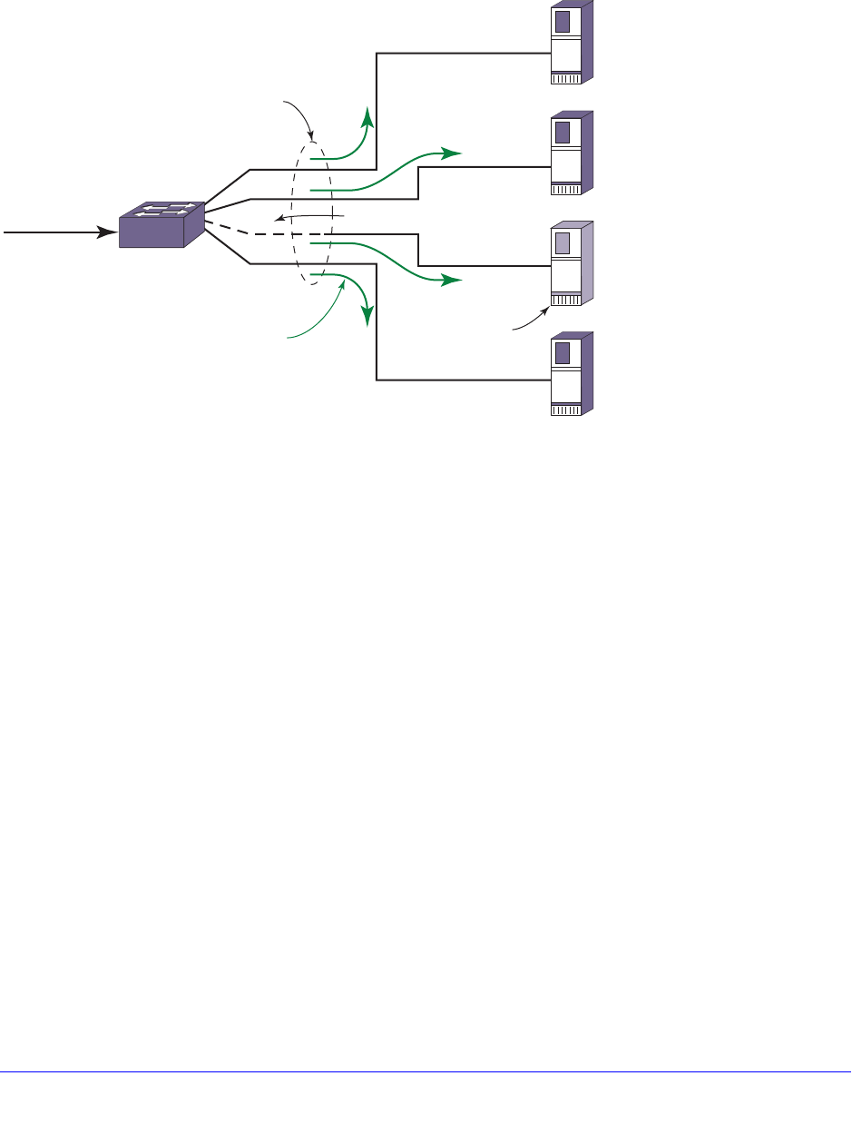
Chapter 5. Configuring Slots and Ports on a Switch | 131
NETGEAR 8800 User Manual
aggregator and traffic through that particular link is redistributed to the other LAG member
links.
Figure 1 displays an example of a Health Check LAG:
Figure 1. Health Check LAG Example
Guidelines for Load Sharing
The following sections provide guidelines for load sharing:
• Load Sharing Guidelines for NETGEAR 8800 Series Switches on page 131
• Load Sharing Rules and Restrictions for All Switches on page 132
Load Sharing Guidelines for NETGEAR 8800 Series Switches
The following rules apply to load sharing on NETGEAR 8800 series switches:
• One static LAG can contain up to 8 ports.
• One LACP LAG can contain up to 16 links per LAG, which includes up to 8 selected links
and 8 standby links.
• One Health Check LAG can contain up to 8 ports.
• The maximum number of LAGs is 128.
EX_Ports_0045
Server1
192.168.1.101
ExtremeXOS
1:3 removed from LAG
HEALTH CHECK LAG Application
controls this LAG or Trunk Group
Connect and monitor
TCP port on each
individual link
Note: The default port to monitor is port 80 (HTTP).
1:10
vlan1
192.168.1.1
Server2
192.168.1.102
Server3
192.168.1.103
No response
from specified
TCP port Server4
192.168.1.104
1:4
1:3
1:2
1:1

132 | Chapter 5. Configuring Slots and Ports on a Switch
NETGEAR 8800 User Manual
Note: See Configuring LACP on page 133 for the maximum number of
links, selected and standby, per LACP.
Load Sharing Rules and Restrictions for All Switches
Additionally, the following rules apply to load sharing on all switches:
• The ports in the LAG do not need to be contiguous.
• A LAG that spans multiple modules must use ports that have the same maximum
bandwidth capability, with one exception—you can mix media type on 1 Gbps ports.
• On both ingress and egress direction on NETGEAR 8800 series switches, when you
configure an ACL to a LAG group, you must configure each of the member ports
exclusively.
Configuring Switch Load Sharing
Note: See Guidelines for Load Sharing on page 131 for specific
information on load sharing for each specific device.
To set up a switch for load sharing, or link aggregation, among ports, you must create a
load-sharing group of ports, also known as a link aggregation group (LAG). The first port in
the load-sharing group is configured to be the master logical port. This is the reference port
used in configuration commands and serves as the LAG group ID. It can be thought of as the
logical port representing the entire port group.
All the ports in a load-sharing group must have the same exact configuration, including
autonegotiation, duplex setting, and so on. All the ports in a load-sharing group must also be
of the same bandwidth class.
The following sections describe common load sharing configuration tasks:
• Creating and Deleting Load Sharing Groups on page 132
• Adding and Deleting Ports in a Load-Sharing Group on page 133
• Configuring the Load Sharing Algorithm on page 133
• Configuring LACP on page 133
• Configuring Health Check Link Aggregation on page 134
Creating and Deleting Load Sharing Groups
To define a load-sharing group, or LAG, you assign a group of ports to a single, logical port
number. To enable or disable a load-sharing group, use the following commands:

Chapter 5. Configuring Slots and Ports on a Switch | 133
NETGEAR 8800 User Manual
enable sharing <port> grouping <port_list> {algorithm [port-based |
address-based {L2 | L3 | L3_L4 | custom}]} {lacp | health-check}
disable sharing <port>
Note: All ports that are designated for the LAG must be removed from all
VLANs prior to configuring the LAG.
Adding and Deleting Ports in a Load-Sharing Group
Ports can be added or deleted dynamically in a load-sharing group, or LAG. To add or delete
ports from a load-sharing group, use the following commands:
configure sharing <port> add ports <port_list>
configure sharing <port> delete ports <port_list>
Note: See Configuring LACP on page 133 for the maximum number of
links, selected and standby, per LACP.
Configuring the Load Sharing Algorithm
For some traffic on selected platforms, you can configure the load sharing algorithm as
described in Load-Sharing Algorithms on page 126. The commands for configuring load
sharing algorithms are:
enable sharing <port> grouping <port_list> {algorithm [port-based |
address-based {L2 | L3 | L3_L4 | custom}]} {lacp | health-check}
Configuring LACP
To configure LACP, you must, again, first create a LAG. The first port in the LAG serves as
the logical port for the LAG. This is the reference port used in configuration commands. It can
be thought of as the logical port representing the entire port group, and it serves as the LAG
Group ID.
To create a LAG for LACP:
1. Create a LAG, using the following command:
enable sharing <port> grouping <port_list> {algorithm [port-based | address-based {L2 |
L3 | L3_L4 | custom}]} {lacp | health-check}
The port you assign using the first parameter becomes the logical port for the link
aggregation group and the LAG Group ID when using LACP. This logical port must also
be included in the port list of the grouping itself.
2. If you want to override the default prioritization in LACP for a specified LAG, use the
following command:

134 | Chapter 5. Configuring Slots and Ports on a Switch
NETGEAR 8800 User Manual
configure sharing <port> lacp system-priority <priority>
This step is optional; LACP handles prioritization using system MAC addresses.
3. Add or delete ports to the LAG as desired, using the following command:
configure sharing <port> add ports <port_list>
4. If you want to override the ports selection for joining the LAG by configuring a priority for a
port within a LAG, issue the following command:
configure lacp member-port <port> priority <port_priority>
5. If you want to change the expiry timer, use the following command:
configure sharing <port> lacp timeout [long | short]
The default value for the timeout is long, or 90 seconds.
6. If you want to change the activity mode, use the following command:
configure sharing <port> lacp activity-mode [active | passive]
The default value for the activity mode is active.
7. If you want to configure the action the switch takes for defaulted LAG ports, use the following
command:
configure sharing <port> lacp defaulted-state-action [add | delete]
The default value for defaulted LAG ports is delete the default ports.
Note: Always verify the LACP configuration by issuing the show ports
sharing command; look for the ports listed as being in the
aggregator.
Configuring Health Check Link Aggregation
To configure Health Check link aggregation you must first create a LAG. One port in the LAG
serves as the logical port for the LAG and is the reference port used in configuration
commands.
When you create the LAG, no monitoring is initially configured. The LAG is created in the
same way that a static LAG is created and if no monitoring is ever created, this LAG behaves
like a static LAG.
1. Create a LAG using the following command:
enable sharing <port> grouping <port_list> {algorithm [port-based |
address-based {L2 | L3 | L3_L4 | custom}]} {lacp | health-check}
The port you assign using the <port> parameter becomes the logical port for the link
aggregation group and the LAG Group ID when using Health Check link aggregation.
This logical port must also be included in the port list of the grouping itself.
2. Configure monitoring for each member port using the following command:

Chapter 5. Configuring Slots and Ports on a Switch | 135
NETGEAR 8800 User Manual
configure sharing health-check member-port <port> add tcp-tracking <IP
Address> {tcp-port <TCP Port> frequency <sec> misses <count>}
If the TCP-port, frequency, or misses are not specified, the defaults described in the
NETGEAR 8800 Chassis Switch CLI Manual are used.
3. Add the LAG to a VLAN whose subnet is the same as the configured tracking IP addresses.
configure vlan <vlan> add port <lag port> [tagged | untagged]
All of the tracking IP addresses must be in the same subnet in which the LAG belongs.
Note: VLANs to which Health Check LAG ports are to be added must be
configured in loopback mode. This is to prevent the VLAN interface
from going down if all ports are removed from the Health Check
LAG. In a normal LAG when all ports are removed from the
aggregator, the trunk is considered DOWN. As a consequence, if
this were the only port in the VLAN, the VLAN interface would be
brought DOWN as well. In the Health Check LAG situation, this
would cause the TCP monitoring to fail because the L3 vlan
interface used by TCP monitoring would no longer send or receive
TCP data.
The following commands are used to modify the configured Health Check LAG.
1. Delete the monitoring configuration for a member port using the following command:
configure sharing health-check member-port <port> delete tcp-tracking <IP
Address> {tcp-port <TCP Port>}
2. Enable or disable monitoring for a member port in the Health Check LAG using the following
command:
configure sharing health-check member-port <port> [disable | enable]
tcp-tracking
Load-Sharing Examples
This section provides examples of how to define load sharing, or link aggregation, on
stand-alone and modular switches, as well has defining dynamic link aggregation.
Load Sharing on a Stand-alone Switch
The following example defines a static load-sharing group that contains ports 9 through 12,
and uses the first port in the group as the master logical port 9:
enable sharing 9 grouping 9-12
In this example, logical port 9 represents physical ports 9 through 12.
When using load sharing, you should always reference the master logical port of the
load-sharing group (port 9 in the previous example) when configuring or viewing VLANs; the

136 | Chapter 5. Configuring Slots and Ports on a Switch
NETGEAR 8800 User Manual
logical port serves as the LAG Group ID. VLANs configured to use other ports in the
load-sharing group will have those ports deleted from the VLAN when load sharing becomes
enabled.
Cross-Module Load Sharing on a NETGEAR 8800 Switch
The following example defines a static load-sharing group on modular switches that contains
ports 9 through 12 on slot 3, ports 7 through 10 on slot 5, and uses port 7 in the slot 5 group
as the primary logical port, or LAG Group ID:
enable sharing 5:7 grouping 3:9-3:12, 5:7-5:10
In this example, logical port 5:7 represents physical ports 3:9 through 3:12 and 5:7 through
5:10.
When using load sharing, you should always reference the LAG Group ID of the load-sharing
group (port 5:7 in the previous example) when configuring or viewing VLANs. VLANs
configured to use other ports in the load-sharing group will have those ports deleted from the
VLAN when load sharing becomes enabled.
Address-based load sharing can also span modules.
Single-Module Load Sharing on a NETGEAR 8800 Switch
The following example defines a static load-sharing, or link aggregation, group that contains
ports 9 through 12 on slot 3 and uses the first port as the master logical port 9, or LAG group
ID:
enable sharing 3:9 grouping 3:9-3:12
In this example, logical port 3:9 represents physical ports 3:9 through 3:12.
LACP Example
The following configuration example:
• Creates a dynamic LAG with the logical port (LAG Group ID) of 10 that contains ports 10
through 12.
• Sets the system priority for that LAG to 3.
• Adds port 5 to the LAG.
enable sharing 10 grouping 10-12 lacp
configure sharing 10 lacp system-priority 3
configure sharing 10 add port 5
Health Check LAG Example
The following example creates a Health Check LAG of 4 ports:
create vlan v1
configure v1 ip 192.168.1.1/24
enable sharing 5 grouping 5-8 health-check

Chapter 5. Configuring Slots and Ports on a Switch | 137
NETGEAR 8800 User Manual
enable loopback-mode v1
configure v1 add port 5
configure sharing health-check member-port 5 add track-tcp 192.168.1.101
tcp-port 8080
configure sharing health-check member-port 6 add track-tcp 192.168.1.102
tcp-port 8080
configure sharing health-check member-port 7 add track-tcp 192.168.1.103
tcp-port 8080
configure sharing health-check member-port 8 add track-tcp 192.168.1.104
tcp-port 8080
Displaying Switch Load Sharing
You can display static and dynamic load sharing. In the link aggregation displays, the types
are shown by the following aggregation controls:
• Static link aggregation—static
• Link Aggregation Control Protocol—LACP
• Health check link aggregation—hlth-chk
To verify your configuration, use the following command:
show ports sharing
To verify LACP configuration, use the following command:
show lacp
To display information for the specified LAG, use the following command:
show lacp lag <group-id> {detail}
To display LACP information for a specific port that is a member of a LAG, use the following
command:
show lacp member-port <port> {detail}
See Displaying Port Information on page 148 for information on displaying summary
load-sharing information.
To clear the counters, use the following command:
clear lacp counters
You can display the LCAP counters for all member ports in the system. To display the LACP
counters, use the following command:
show lacp counters
To display information for a health check LAG, use the following command:
show sharing health-check

138 | Chapter 5. Configuring Slots and Ports on a Switch
NETGEAR 8800 User Manual
Mirroring
Note: You can accomplish port mirroring using ACLs. See Chapter 13,
ACLs for more information.
Mirroring configures the switch to copy all traffic associated with one or more ports, VLANs,
or virtual ports. A virtual port is a combination of a VLAN and a port. The monitor port or ports
can then be connected to a network analyzer or RMON probe for packet analysis. The
system uses a traffic filter that copies a group of traffic to the monitor port(s). You can have
only one monitor port or port list on the switch. This feature allows you to mirror multiple ports
or VLANs to a monitor port, while preserving the ability of a single protocol analyzer to track
and differentiate traffic within a broadcast domain (VLAN) and across broadcast domains (for
example, across VLANs when routing).
Note: The mirroring filter limits discussed in this chapter do not apply when
you are working with Sentriant devices.
Up to 16 mirroring filters and 1 monitor port or 1 monitor port list can be configured. A monitor
port list may contain up to 16 ports.
Note: On NETGEAR 8800 series switches, you can mirror up to 16 VLANs
on a given port.
Mirroring is disabled by default.
Note: Frames that contain errors are not mirrored.
Guidelines for Mirroring
The guidelines for mirroring are hardware dependent. Find your hardware type in this section
for your specific guidelines.
NETGEAR 8800 Series Switches
The traffic filter on NETGEAR 8800 series switches can be defined based on one of the
following criteria:

Chapter 5. Configuring Slots and Ports on a Switch | 139
NETGEAR 8800 User Manual
• Physical port—All data that traverses the port, regardless of VLAN configuration, is
copied to the monitor port(s). You can specify which traffic the port mirrors:
• Ingress—Mirrors traffic received at the port.
• Egress—Mirrors traffic sent from the port.
• Ingress and egress—Mirrors traffic either received at the port or sent from the port.
(If you omit the optional parameters, all traffic is forwarded; the default for port-based
mirroring is ingress and egress).
• VLAN—All data to a particular VLAN, regardless of the physical port configuration, is
copied to the monitor port(s).
• Virtual port—All data specific to a VLAN on a specific port is copied to the monitor
port(s).
• The NETGEAR 8800 supports up to 16 mirror filters where each filter can be a port, a
VLAN, or a port + VLAN.
• The NETGEAR 8800 supports up to 16 monitor ports for one-to-many mirroring.
• Only traffic ingressing a VLAN can be monitored; you cannot specify ingressing or
egressing traffic when mirroring VLAN traffic.
• When routing between VLANs, ingress mirrored traffic is presented to the monitor port(s)
as modified for routing. This is the default behavior and the behavior when you use the
command configure mirroring mode standard. When you use the command configure
mirroring mode enhanced, ingress traffic is mirrored as it is received (on the wire).
• When using standard mode mirroring, a packet which matches both an ingress mirroring
filter and an egress mirroring filter can only be ingress mirrored. The behavior depends
on the location of the ingress port, egress port and monitor port within the switch as well
as the type of module on which the packet ingresses. When using enhanced mode
mirroring, two packets are mirrored when a packet encounters both an ingress and
egress mirroring filter.
• You cannot include the monitor port or ports for NETGEAR 8800 series switches in a
load-sharing group.
• You can run mirroring and sFlow on the same device.
• Tagged and untagged traffic is mirrored slightly differently depending on the module that
the mirrored port and the monitor port or ports are on.
• On NETGEAR 8800 series switches, when traffic is modified by hardware on egress,
egress mirrored packets may not be transmitted out of the monitor port as they egressed
the port containing the egress mirroring filter. In addition, IP multicast packets which are
egress mirrored contain the source MAC address and VLAN ID of the unmodified packet.
• Enhanced mirroring mode must be configured if you are going to configure a remote
mirroring tag. Enhanced mirroring mode is configured using the following command:
configure mirroring mode enhanced
• The configuration of remote-tag does not require the creation of a VLAN with the same
tag; on these platforms the existence of a VLAN with the same tag as a configured
remote-tag is prevented. This combination is allowed so that an intermediate remote
mirroring switch can configure remote mirroring using the same remote mirroring tag as

140 | Chapter 5. Configuring Slots and Ports on a Switch
NETGEAR 8800 User Manual
other source switches in the network. Make sure that VLANs meant to carry normal user
traffic are not configured with a tag used for remote mirroring.
• When a VLAN is created with remote-tag, that tag is locked and a normal VLAN cannot
have that tag. The tag is unique across the switch. Similarly if you try to create a
remote-tag VLAN where remote-tag already exists in a normal VLAN as a VLAN tag, you
cannot use that tag and the VLAN creation fails.
Mirroring Rules and Restrictions
This section summarizes the rules and restrictions for configuring mirroring:
• When you disable mirroring, all the filters are unconfigured.
• To change monitor ports, you must first remove all the filters.
• You cannot mirror the monitor port.
• The mirroring configuration is removed when you:
• Delete a VLAN (for all VLAN-based filters).
• Delete a port from a VLAN (for all VLAN-, port-based filters).
• Unconfigure a slot (for all port-based filters on that slot).
• Any mirrored port can also be enabled for load sharing (or link aggregation); however,
each individual port of the load-sharing group must be explicitly configured for mirroring.
• The monitor port is automatically removed from all VLANs; you cannot add it to a VLAN.
• The mirroring filters are not confined to a single module; they can have ports that span
multiple modules.
• You cannot use the management port at all in mirroring configurations.
• With one-to-many mirroring, you need to enable jumbo frame support in the mirror-to port
and loopback port, if you need to mirror tagged packets of length 1519 to 1522.
• The loopback port is dedicated for mirroring and hence cannot be used for other
configuration and that is indicated through glowing LED.
• Due to certain restrictions, the following packet types will not be egress mirrored using
egress VLAN or virtual port-based mirroring:
• CPU generated packets
• L2 multicast traffic
• As traffic approaches line rate, mirroring rate may decrease. Since mirroring makes
copies of traffic, the bandwidth available will be devoted mostly to regular traffic instead of
mirrored traffic when the load is high.
Mirroring Examples
Mirroring is disabled by default. To enable mirroring on a single port, the following command
can be used:
enable mirroring to port <port-no>

Chapter 5. Configuring Slots and Ports on a Switch | 141
NETGEAR 8800 User Manual
To enable mirroring on multiple ports, use the following command:
enable mirroring to port-list <port-list> loopback-port <port>
The port-list is a list of monitor ports which will transmit identical copies of mirrored packets.
The loopback-port is an otherwise unused port required when mirroring to a port-list. The
loopback-port is not available for switching user data traffic.
To disable mirroring, use the following command:
disable mirroring
Note: When you change the mirroring configuration, the switch stops
sending egress packets from the monitor port until the change is
complete. The ingress mirroring traffic to the monitor port and
regular traffic are not affected.
NETGEAR 8800 Series Switches
The following example selects slot 3, port 4 on a modular switch as the monitor port and
sends all traffic received at slot 6, port 5 to the monitor port:
enable mirroring to port 3:4
configure mirroring add port 6:5 ingress
The following example selects slot 3, port 4 on a modular switch as the monitor port and
sends all traffic sent from slot 6, port 5 to the monitor port:
enable mirroring to port 3:4
configure mirroring add port 6:5 egress
The following example selects ports 5, 6, and 7 on slot 2 on a modular switch as the monitor
ports and sends all traffic received at slot 6, port 5 to the monitor ports. Slot 3, port 1 is an
unused port selected as the loopback port.
enable mirroring to port-list 2:5-2:7 loopback-port 3:1
configure mirroring add port 6:5 ingress
Verifying the Mirroring Configuration
The screen output resulting from the show mirroring command lists the ports that are
involved in mirroring and identifies the monitor port. The display differs slightly depending on
the platform.
Remote Mirroring
Remote mirroring enables the user to mirror traffic to remotely connected switches. Remote
mirroring allows a network administrator to mirror traffic from several different remote
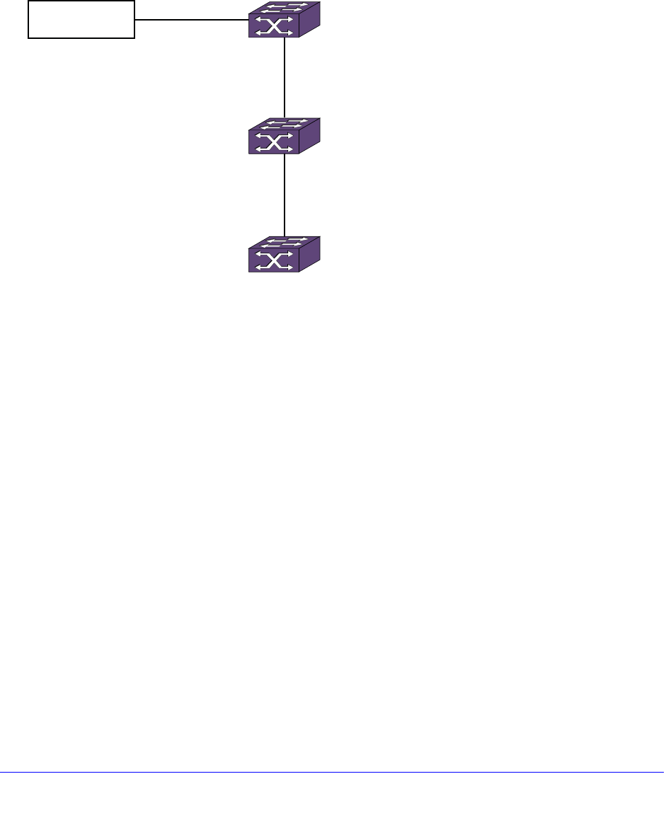
142 | Chapter 5. Configuring Slots and Ports on a Switch
NETGEAR 8800 User Manual
switches to a port at a centralized location. Remote mirroring is accomplished by reserving a
dedicated VLAN throughout the network for carrying the mirrored traffic.
Figure 2 shows a typical remote mirroring topology. Switch A is the source switch that
contains ports, VLANs, and/or virtual ports to be remotely mirrored. Port 25 is the local
monitor port on Switch A. Switch B is the intermediate switch. Switch C is the destination
switch, which is connected to the network analyzer.
Figure 2. Remote Mirroring Topology
All the mirrored packets are tagged with the the remote-tag specified by the source switch,
whether the packet is already tagged or not. The intermediate switches forward the
remote-tagged mirrored packets to the adjacent intermediate/destination switch, as these
ports are added as tagged. The port connected to the network analyzer is added as untagged
in the destination switch. This causes the destination switch to remove the remote-tag, and
the mirrored packet reaches the network analyzer as the source switch sent it.
Unlike basic mirroring, remote mirroring does not remove VLAN membership from the local
monitor ports. This allows remote mirroring to use the existing network topology to transport
remote mirrored packets to a destination switch.
Configuration Details
This section describes in detail the configuration details for the topology shown in Figure 2.
Configuration on Source Switch
The remote-tag keyword followed by the tag is added in the command to enable mirroring.
For example, you can use the following command to establish ports 24 and 25 as monitor
ports, from which any mirrored packets are transmitted with an additional VLAN tag
containing a VLAN ID of 1000:
enable mirroring to port-list 4:24,4:25 loopback-port 1 remote-tag 1000
Network Analyser Port 2
Port 2
Port 25
Switch C
Switch B
Switch A
EX_ports_0044

Chapter 5. Configuring Slots and Ports on a Switch | 143
NETGEAR 8800 User Manual
The show mirroring output displays the remote tag when remote mirroring is configured.
In NETGEAR 8800 series switches, remote mirroring can also be enabled to a single port,
without the port-list and loopback-port keywords. For instance, to enable remote mirroring to
port 25, you can use the following command:
enable mirroring to port 25 remote-tag 1000
Configuration on Intermediate Switch
When you enable mirroring with remote-tag 1000, you need to reserve a VLAN with tag 1000
in all the intermediate switches for remote mirroring. The remote mirroring VLAN in the
intermediate switches is used for carrying the mirroring traffic to the destination switch. The
ports connecting the source and destination switches are added as tagged in the
intermediate switches.
You may add the remote-mirroring keyword when you configure the tag to differentiate a
normal VLAN from the remote mirroring VLAN.
create vlan remote_vlan
configure vlan remote_vlan tag 1000 remote-mirroring
configure vlan remote_vlan add ports 1,2 tagged
Using the remote-mirroring keyword automatically disables learning and IGMP snooping on
the VLAN.
Another way to configure a remote mirroring VLAN is to create a normal VLAN and disable
learning on the VLAN. IGMP snooping must be disabled on that VLAN for you to remotely
mirror multicast packets through the switch.
You may use the following configuration for creating the remote mirroring VLAN:
create vlan remote_vlan
configure vlan remote_vlan tag 1000
disable learning vlan remote_vlan
disable igmp snooping remote_vlan
Configuration on Destination Switch
The configuration on the destination switch is same as that of the intermediate switches,
except that the port connected to the network analyzer is added as untagged whereas all the
other ports connected to the switches are added as tagged.
create vlan remote_vlan
configure vlan remote_vlan tag 1000 remote-mirroring
configure vlan remote_vlan add ports 1 tagged
configure vlan remote_vlan add ports 2 untagged
For a remote mirroring VLAN, the configured tag displayed by the show vlan output is remote
tag instead of the normal tag.
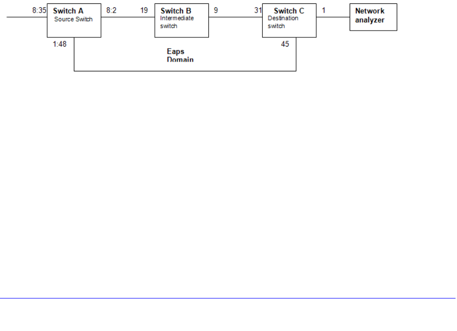
144 | Chapter 5. Configuring Slots and Ports on a Switch
NETGEAR 8800 User Manual
Guidelines
The following are guidelines for remote mirroring:
• Configurations of remote mirroring, which might cause protocol packets to be remotely
mirrored, are not recommended. Since all packet types are mirrored when you configure
remote mirroring, remotely mirrored protocol packets may have undesirable affects on
intermediate and destination switches.
• In the NETGEAR 8800 series switches, remote mirroring can be enabled only when the
enhanced mode is enabled for mirroring.
Use of Remote Mirroring with Redundancy Protocols
You can use remote mirroring with one-to-many mirroring to provide a redundant path from
the source switch to the destination switch. Using Spanning Tree can provide remote
mirroring packets a redundant loop-free path through the network. You should perform the
configuration of Spanning Tree before adding mirroring filters on the source switch to prevent
looping.
Remote Mirroring with STP
In Figure 3, the traffic from switch A is mirrored to the two ports 8:2 and 1:48 to connect to
the destination switch. Using the configuration shown in Figure 3, remote mirrored packets
have a loop-free redundant path through the network using STP.
Figure 3. Remote Mirroring with STP
The configuration for the topology in Figure 3 is given in the following sections.
Switch A Configuration
configure mirroring mode enhanced
enable mirroring to port-list 8:2,1:48 loopback-port 8:1 remote-tag 1000
configure mirroring add port 8:35
create vlan v1
configure vlan v1 tag 1001
configure vlan v1 add ports 8:2,1:48 tag
create stp stp1

Chapter 5. Configuring Slots and Ports on a Switch | 145
NETGEAR 8800 User Manual
configure stp1 mode dot1w
configure stp1 add v1 ports all
configure stp1 tag 1001
configure stp1 add vlan internalMirrorLoopback ports 8:2,1:48
enable stp1
enable stpd
Switch B Configuration
create vlan remote_vlan
configure vlan remote_vlan tag 1000 remote-mirroring
configure vlan remote_vlan add ports 19,9 tag
create vlan v1
configure vlan v1 tag 1001
configure vlan v1 add ports 19,9 tag
create stp stp1
configure stp1 mode dot1w
configure stp1 add v1 ports all
configure stp1 tag 1001
configure stp1 add vlan remote_vlan ports all
enable stp1
enable stpd
Switch C Configuration
create vlan remote_vlan
configure vlan remote_vlan tag 1000 remote-mirroring
configure vlan remote_vlan add ports 31,45 tag
configure vlan remote_vlan add ports 1
create vlan v1
configure vlan v1 tag 1001
configure vlan v1 add ports 31,45 tag
create stp stp1
configure stp1 mode dot1w
configure stp1 add v1 ports all
configure stp1 tag 1001
configure stp1 add vlan remote_vlan ports 31,45
enable stp1
enable stpd
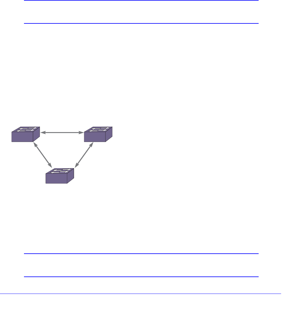
146 | Chapter 5. Configuring Slots and Ports on a Switch
NETGEAR 8800 User Manual
Software-Controlled Redundant Port and
Smart Redundancy
Using the software-controlled redundant port feature you can back up a specified Ethernet
port (primary) with a redundant, dedicated Ethernet port; both ports are on the same switch. If
the primary port fails, the switch will establish a link on the redundant port and the redundant
port becomes active. Only one side of the link must be configured as redundant because the
redundant port link is held in standby state on both sides of the link. This feature provides
very fast path or network redundancy.
Note: You cannot have any Layer 2 protocols configured on any of the
VLANs that are present on the ports.
Smart Redundancy is a feature that allows control over how the failover from a redundant
port to the primary port is managed. If this feature is enabled, which is the default setting, the
switch attempts to revert to the primary port as soon as it can be recovered. If the feature is
disabled, the switch attempts only to recover the primary port to active if the redundant port
fails.
A typical configuration of software-controlled redundant ports is a dual-homed
implementation (Figure 4). This example maintains connectivity only if the link between
switch A and switch B remains open; that link is outside the scope of the software-controlled
port redundancy on switch C.
Figure 4. Dual-Homed Implementation for Switch C
In normal operation, the primary port is active and the software redundant switch (switch C in
Figure 4) blocks the redundant port for all traffic, thereby avoiding a loop in the network. If the
switch detects that the primary port is down, the switch unblocks the redundant port and
allows traffic to flow through that redundant port.
Note: The primary and redundant ports must have identical VLAN
membership.
Switch BSwitch A
Redundant
Link
Primary
Link
Switch C
XOS002

Chapter 5. Configuring Slots and Ports on a Switch | 147
NETGEAR 8800 User Manual
You configure the software-controlled redundant port feature either to have the redundant link
always physically up but logically blocked or to have the link always physically down. The
default value is to have the link physically down, or Off.
By default, Smart Redundancy is always enabled. If you enable Smart Redundancy, the
switch automatically fails over to the redundant port and returns traffic to the primary port
after connectivity is restored on that port. If you do not want the automatic restoration of the
primary link when it becomes active, disable Smart Redundancy.
Guidelines for Software-Controlled Redundant Ports and Port
Groups
Software-controlled redundant ports and port groups have the following limitations:
• You cannot have any Layer 2 protocols configured on any of the VLANs that are present
on the ports. (You will see an error message if you attempt to configure software
redundant ports on ports with VLANs running Layer 2 protocols.)
• The primary and redundant ports must have identical VLAN membership.
• The master port is the only port of a load-sharing group that can be configured as either a
primary or redundant port. Also, all ports on the load-sharing group must fail before the
software-controlled redundancy is triggered.
• You must disable the software redundancy on the master port before enabling or
disabling load sharing.
• You can configure only one redundant port for each primary port.
• Recovery may be limited by FDB aging on the neighboring switch for unidirectional traffic.
For bi-directional traffic, the recovery is immediate.
Configuring Software-Controlled Redundant Ports
When provisioning software-controlled redundant ports, configure only one side of the link as
redundant. In Figure 4 only the ports on switch C would be configured as redundant.
Note: To enable the software-controlled redundant port feature, the
primary and redundant ports must have identical VLAN
membership.
To configure a software-controlled redundant port, use the following command:
configure ports <primaryPort> redundant <secondaryPort> {link [on | off]}
The first port specified is the primary port. The second port specified is the redundant port.
To unconfigure a software-controlled redundant port, use the following command and enter
the primary port(s):
unconfigure ports <port_list> redundant

148 | Chapter 5. Configuring Slots and Ports on a Switch
NETGEAR 8800 User Manual
To configure the switch for the Smart Redundancy feature, use the following command:
enable smartredundancy <port_list>
To disable the Smart Redundancy feature, use the following command:
disable smartredundancy <port_list>
Verifying Software-Controlled Redundant Port Configurations
You can verify the software-controlled redundant port configuration by issuing a variety of CLI
commands.
To display the redundant ports as well as which are active or members of load-sharing
groups, use the following command:
show ports redundant
To display information on which ports are primary and redundant software-controlled
redundancy ports, use the following command:
show ports {mgmt | <port_list>} information {detail}
See Displaying Port Information for more information on the show ports information
command.
Displaying Port Information
You display summary port configuration information using the show ports {mgmt |
<port_list>} configuration {no-refresh} and show ports {mgmt | <port_list>}
information {detail} commands.
The show ports configuration command shows you either summary configuration
information on all the ports, or more detailed configuration information on specific ports. If you
specify the no-refresh parameter, the system displays a snapshot of the data at the time you
issue the command.
The show ports information command shows you either summary information on all the
ports, or more detailed information on specific ports. The output from the command differs
very slightly depending on the platform you are using.
You can display real-time port utilization information, by issuing the following command:
show ports {mgmt | <port_list> | stack-ports <stacking-port-list>} utilization
{bandwidth | bytes | packets}
When you use a parameter (packets, byte, or bandwidth) with the above command, the
display for the specified type shows a snapshot per port when you issued the command.
Digital Diagnostic Monitoring Interface (DDMI) provides critical information about the installed
optic module and is supported on all NETGEAR 8800 blades that use 10G XFP optic
modules. To display basic or detailed system information about XFP optic modules, use the
following commands:

Chapter 5. Configuring Slots and Ports on a Switch | 149
NETGEAR 8800 User Manual
show port <port-list> transceiver information
or
show port <port-list> transceiver information detail

Chapter 6. LLDP | 150
6
6. LLDP
This chapter includes the following sections:
• Overview on page 150
• LLDP Packets on page 152
• Transmitting LLDP Messages on page 153
• Receiving LLDP Messages on page 154
• Managing LLDP on page 155
• Supported TLVs on page 156
• Configuring LLDP on page 164
• Displaying LLDP Settings on page 170
Overview
The software supports the Link Layer Discovery Protocol (LLDP). LLDP is a Layer 2 protocol
(IEEE standard 802.1ab) that is used to determine the capabilities of devices such as repeaters,
bridges, access points, routers, and wireless stations. LLDP support enables devices to
advertise their capabilities and media-specific configuration information and to learn the same
information from the devices connected to it.
The information is represented in Type Length Value (TLV) format for each data item. The
802.1ab specification provides detailed TLV information. The TLV information is contained and
transmitted in an LLDP protocol data unit (LLDPDU). Certain TLVs are mandatory and are
always sent after LLDP is enabled; other TLVs are optionally configured. LLDP defines a set of
common advertisement messages, a protocol for transmitting the advertisements, and a method
for storing the information contained in received advertisements. The switch can receive and
record certain TLVs but not transmit these TLVs; they are TLVs originating from the power over
Ethernet (PoE) powered device (PD) connected to a port and certain inventory management
TLVs.
LLDP provides a standard method of discovering and representing the physical network
connections of a given network management domain. It works independently. The LLDP
neighbor discovery protocol allows you to discover and maintain accurate network topologies in
a multivendor environment.

Chapter 6. LLDP | 151
NETGEAR 8800 User Manual
The information distributed using LLDP is stored by its recipients in a standard Management
Information Base (MIB), making it possible for the information to be accessed by a Network
Management System (NMS) using a management protocol such as the Simple Network
Management Protocol (SNMP).
LLDP transmits periodic advertisements containing device information and media-specific
configuration information to neighbors attached to the same network. LLDP agents cannot
solicit information from other agents by way of this protocol. The switch can transmit and
receive LLDP media endpoint discovery (MED) TLVs. Once enabled, the LLDP MED TLVs
messages are sent only after a neighbor is detected sending out LLDP MED TLVs; the LLDP
MED TLVs are transmitted only after the switch receives an LLDP MED TLV from a neighbor.
For this reason, two connected switches will never exchange LLDP MED TLVs.
Note: Network connectivity devices wait to detect LLDP MED TLVs from
endpoints before they send out LLDP MED TLVs; so 2 network
connectivity devices will not exchange LLDP MED messages.
The TLV format with link layer control frames is used to communicate with other LLDP
agents. LLDP agents also receive link layer control frames, extract the information from
TLVs, and store them in LLDP MIB objects.
If the information values from the device change at any time, the LLDP agent is notified. The
agent then sends an update with the new values, which is referred to as a triggered update. If
the information for multiple elements changes in a short period, the changes are bundled
together and sent as a single update to reduce network load.
You configure LLDP per port, and each port can store received information for a maximum of
four neighbors.
Note: LLDP runs with link aggregation.
The device can also support the following types of LLDP TLVs:
• Avaya-NETGEAR Networks proprietary TLVs
• LLDP media endpoint discovery (MED) TLVs
The software supports several TLVs that are proprietary to Avaya and NETGEAR
(avaya-NETGEAR TLVs). These TLVs primarily advertise and receive information for Avaya
voice over IP (VoIP) telephones. Some of these TLVs primarily concern the PD; the PD
receives these TLVs, but does not transmit them. (See Table 19 for a listing of the proprietary
TLVs that are only received by the switch.) These proprietary LLDPs are transmitted and
received as soon as you enable LLDP and configure the specified TLVs.
LLDP MED TLVs are sent only after the device detects a neighbor transmitting LLDP MED
TLVs; and the LLDP MED TLVs must be configured and enabled prior to the detection. You
must enable the LLDP-MED capabilities TLV before configuring and enabling any other LLDP

152 | Chapter 6. LLDP
NETGEAR 8800 User Manual
MED TLVs. Likewise, when disabling the LLDP MED TLVs, you must disable the LLDP-MED
capabilities TLVs only after you have disabled all other LLDP MED TLVs.
The LLDP MED protocol extension introduces a new feature called MED fast start, which is
automatically enabled when the LLDP MED capabilities TLV is enabled. When a new
MED-capable device is detected, the detecting switch sends out an LLDPDU each 1 second
for the configured number of times (called the repeat count). By default, the switch sends out
the LLDPDU each 1 second 3 times; you can change this repeat count between 1 and 0
seconds 10 times. Once the repeat count is reached, the configured transmit interval value is
used between LLDPDUs. Use the following command to configure the repeat count:
configure lldp med fast-start repeat-count <count>
Note: The fast-start feature is automatically enabled, at the default level of
3, when you enable the LLDP MED capabilities TLV on the port.
You must enable SNMP traps separately for the LLDP MED traps; they are disabled by
default. To enable the LLDP MED SNMP traps, issue the following command:
enable snmp traps lldp-med {ports [all | <port_list>]}
In addition, the switch can receive, but not transmit, the LLDP MED inventory management
TLVs. (See Table 19 for a listing of these inventory management TLVs.)
LLDP Packets
You can configure the device to transmit messages, to receive messages, or both.
LLDP is enabled and configured per port.
Multiple advertisements messages (or TLVs) are transmitted in one LAN packet, the LLDPDU
(Figure 5). The LLDP packet contains the destination multicast address, the source MAC
address, the LLDP EtherType, the LLDPDU data, and a frame check sequence (FCS). The
LLDP multicast address is defined as 01:80:C2:00:00:0E, and the EtherType is defined as
0x88CC.
Figure 5. LLDP Packet Format
The following characteristics apply to LLDP packets:
• They are IEEE 802.3 Ethernet frames.
LLDP_Multicast
Address
Source MAC
Address 88-CC LLDPDU
Data + PadEthertypeSADA
15002 4 Octets66
FCS
XOS005

Chapter 6. LLDP | 153
NETGEAR 8800 User Manual
• The frames are sent as untagged frames.
• The frames are sent with a link-local-assigned multicast address as destination address.
• The Spanning Tree Protocol (STP) state of the port does not affect the transmission of
LLDP frames.
The length of the packet cannot exceed 1500 bytes. As you add TLVs, you increase the
length of the LLDP frame. When you reach 1500 bytes, the remaining TLVs are dropped.
NETGEAR recommends that you advertise information regarding only one or two VLANs on
the LLDP port, to avoid dropped TLVs.
If the system drops TLVs because of exceeded length, the system logs a message to the
EMS and the show lldp statistics commands shows this information under the Tx Length
Exceeded field.
Note: The LLDPDU has a maximum of 1500 bytes, even with jumbo
frames enabled. TLVs that exceed this limit are dropped.
Transmitting LLDP Messages
In transmit mode, the NETGEAR switch periodically sends out an untagged LLDPDU frame
that contains the mandatory LLDP TLVs as well as the configured optional TLVs. The LLDP
agent running on the NETGEAR switch passes serially through the list of ports that are
enabled for LLDP and periodically transmits an LLDP frame containing the mandatory TLVs
and any configured optional TLVs. The mandatory TLVs and the system description TLV are
automatically transmitted after you enable LLDP.
The following information, when configured, can be sent at regular intervals:
• Chassis ID (mandatory)
• Port ID (mandatory)
• Time-to-live (mandatory)
• Port description
• System name
• System description (sent by default)
• System capabilities
• Management address
• 802.1-specific information
• VLAN name
• Port VLAN ID
• Port and protocol VLAN ID
• 802.3-specific information
• MAC/PHY

154 | Chapter 6. LLDP
NETGEAR 8800 User Manual
• Power via MDI
• Link aggregation
• Maximum frame size
• Avaya-NETGEAR Networks proprietary information
• Power conservation request
• Call server
• File server
• 802.1Q framing information
• MED extensions (Once enabled, these are sent only when the switch detects a neighbor
on the port that transmits at least one MED TLV)
• MED capabilities
• Network policy
• Location ID
• Extended information on Power via MDI
This information is obtained from memory objects such as standard MIBs or from system
management information.
Receiving LLDP Messages
The LLDP agent running on an NETGEAR switch receives LLDPDUs, parses the messages,
and stores the information in a remote device database. Unrecognized TLVs are also stored
in the remote device database, in order of TLV type. The information is purged after the
configured timeout interval, unless it is refreshed by the remote LLDP agent.
You access the messages from the neighbors with SNMP or the CLI. To access this
information with the CLI, use the show lldp neighbors detailed command. (You must use
the detailed variable to display this information.)
Each port can store LLDP information from a maximum of four neighbors.
The software receives several TLVs that it does not transmit, as follows:
• Avaya-NETGEAR proprietary information
• PD conservation level support (includes the PD’s current conservation level, typical
power value, and maximum power value, as well as power conservation levels
available to that PD)
• Endpoint IP address (including the mask and gateway addresses)
• Inventory management LLDP MED TLVs:
• Hardware revision
• Firmware revision
• Software revision
• Serial number

Chapter 6. LLDP | 155
NETGEAR 8800 User Manual
• Manufacturer name
• Model name
• Asset ID
Managing LLDP
LLDP is disabled by default. LLDP information is transmitted periodically and stored for a
finite period. You access the information using SNMP. A port configured to receive LLDP
messages can store information for up to four neighbors.
You manage LLDP using the CLI and SNMP. (See NETGEAR 8800 Chassis Switch CLI
Manual for complete information on configuring, managing, and displaying LLDP.)
The LLDP MED TLVs begin transmission only after detecting LLDP MED TLVs transmitted by
a neighbor. After you enable LLDP, you can set a variety of time periods for the transmission
and storage of the LLDP messages (or you can use the default values), as follows:
• Reinitialization period (default is 2 seconds)
• Delay between LLDP transmissions (default is 2 seconds)—applies to triggered updates,
or updates that are initiated by a change in the topology
• Transmit interval (default is 30 seconds)—applies to messages sent periodically as part
of protocol
• Time-to-live (TTL) value (default is 2 minutes)—time that the information remains in the
recipient’s LLDP database
Note: Once the LLDP MED TLVs begin transmitting (after detecting LLDP
MED TLVs from a connected endpoint), those TLVs are also
controlled by these timers.
Each time a device receives an LLDP advertisement packet, the device stores the
information and initializes a timer that is compared to the TTL value of the packet. If the timer
reaches the TTL value, the LLDP agent deletes the stored information. This action ensures
that only valid information is stored in the LLDP agent.
After you enable LLDP, you can enable the LLDP-specific SNMP traps; the traps are disabled
by default. After you enable the LLDP-specific traps, the systems send all LLDP traps to the
configured trap receivers. You configure the period between the system sending SNMP
notifications; the default interval is 5 seconds. LLDP configurations are saved across reboots
when you issue the save configuration command.
The system logs EMS messages regarding LLDP, including when optional TLVs exceeding
the 1500-byte limit are dropped and more than 4 neighbors are detected on a port.
When both IEEE 802.1x and LLDP are enabled on the same port, LLDP packets are not sent
until one or more clients authenticate a port. Also, incoming LLDP packets are only accepted
if one or more clients are authenticated.

156 | Chapter 6. LLDP
NETGEAR 8800 User Manual
You can configure an optional TLV to advertise or not to advertise the device’s management
address information to the port’s neighbors. With XCM8800, when enabled, this TLV sends
out the IPv4 address configured on the management VLAN. If you have not configured an
IPv4 address on the management VLAN, the software advertises the system’s MAC address.
LLDP does not send out IPv6 addresses in this field.
Supported TLVs
The TLVs are contained in the LLDPDU portion of the LLDP packet, and the LLDPDU cannot
exceed 1500 bytes. Some TLVs are mandatory according to the 802.1ab standard, and the
rest are optional. The mandatory and system description TLVs are included by default as
soon as you enable LLDP. The system description TLV is enabled by default on the
XCM8800 LLDP implementation. Additionally some TLVs can be repeated in one LLDP.
Note: To avoid exceeding the 1500-byte limit, NETGEAR recommends
sending information on only one or two VLANs on the LLDP port.
Any TLVs that exceed the limit are dropped.
The following TLVs are enabled by default when LLDP transmit is enabled on a port:
• Chassis ID
• Port ID
• Time to live
• System description
• End-of-LLDP PDU
All of these TLVs that are sent by default are mandatory for the protocol and cannot be
disabled, except the system description. You can configure the system not to advertise the
system description when LLDP is enabled; the other four TLVs cannot be configured not to
advertise. Table 18 lists all the defined TLVs, if they are included by default after you enable
LLDP, if they can be configured, if they are mandatory or optional, and if you can repeat that
TLV in one LLDP packet.
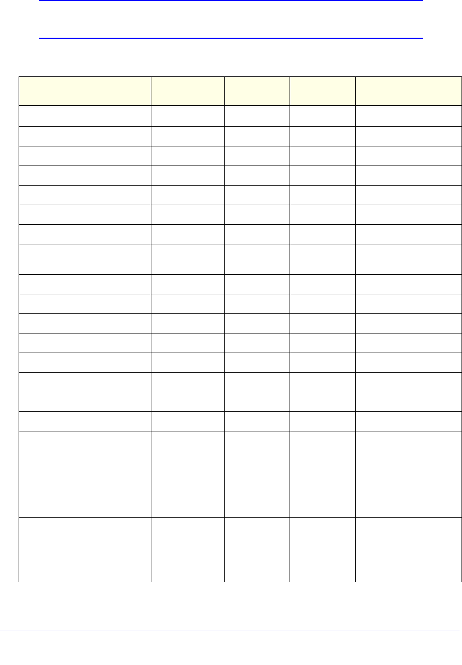
Chapter 6. LLDP | 157
NETGEAR 8800 User Manual
Note: See NETGEAR 8800 Chassis Switch CLI Manual for complete
information on configuring LLDP using the CLI.
Table 18. Available TLVs for Transmission
Name Included by
default User
configurable Repeatable Comments
Chassis ID XMandatory TLV
Port ID XMandatory TLV
Time to live (TTL) XMandatory TLV
Port description X
System name X
System description X X
System capabilities X
Management address XX XCM8800 sends only 1
TLV
VLAN name X X
Port VLAN ID X
Port and protocol VLAN ID X X
Protocol identity XNot supported
MAC/PHY configuration/status X
Power via MDI X
Link aggregation X
Maximum frame size X
LLDP MED capabilities XMust be enabled before
any other MED TLV, and
must be disabled after all
other MED TLVs
MED TLVs transmit only
after detecting a neighbor
transmitting MED TLVs
Network policy X X Content cannot be
configured by SNMP
MED TLVs transmit only
after detecting a neighbor
transmitting MED TLVs
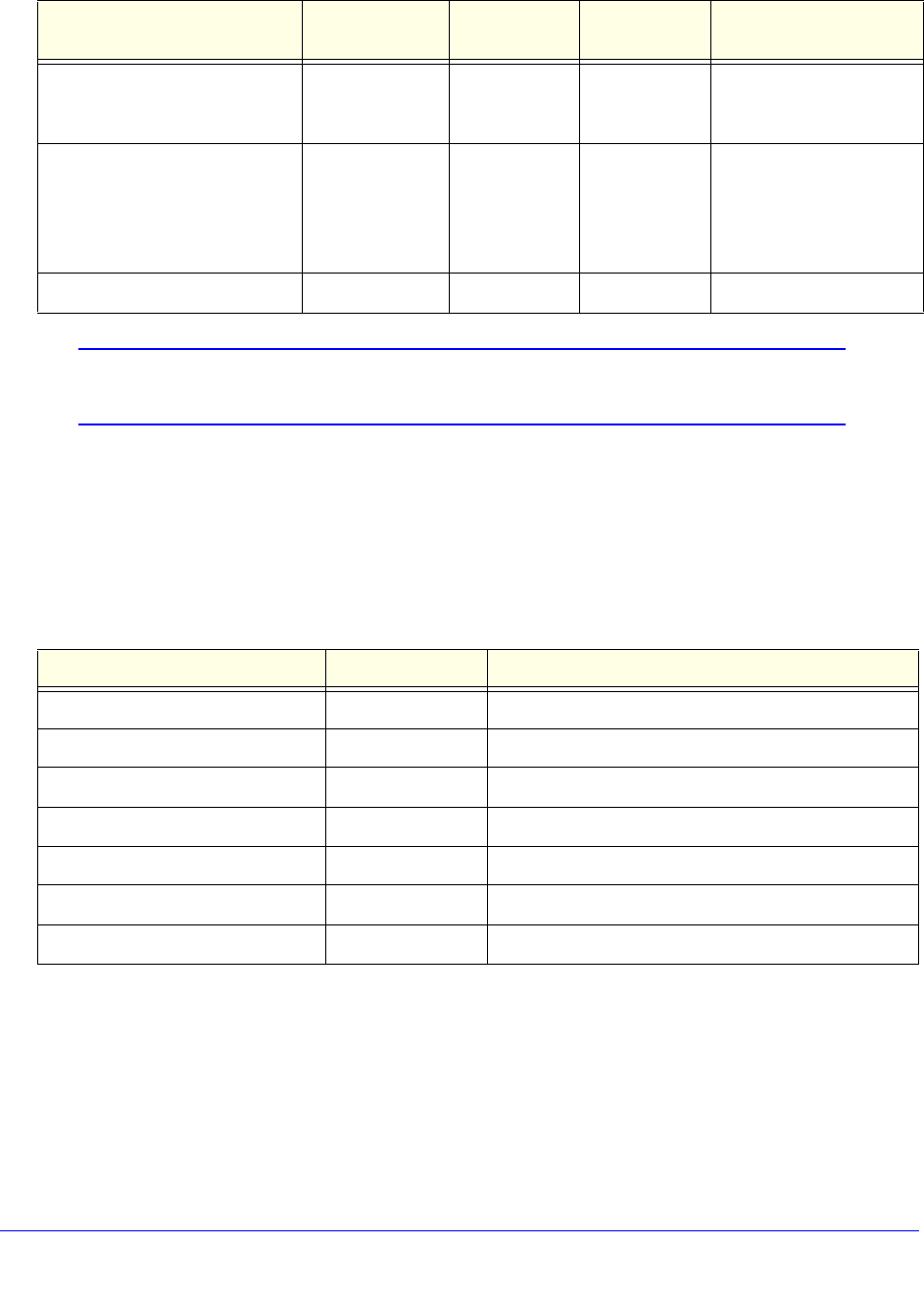
158 | Chapter 6. LLDP
NETGEAR 8800 User Manual
Note: See the NETGEAR 8800 Chassis Switch CLI Manual for complete
information on configuring LLDP using the CLI.
Table 19 lists the TLVs that the switch can receive, but not transmit. To receive any of these
TLVs, the port must be enabled for LLDP. After you enable LLDP receiving on the switch, all
TLVs are received (even if the LLDP MED capabilities TLV is not enabled). To display these
received messages, use the show lldp neighbor detailed CLI command.
Mandatory TLVs
This section describes the following mandatory TLVs, which are automatically enabled after
you enable LLDP on a port:
• Chassis ID TLV on page 159
• Port ID TLV on page 159
Location ID XMED TLVs transmit only
after detecting a neighbor
transmitting MED TLVs
Extended power via MDI XCan be enabled only on a
PoE-capable port
MED TLVs transmit only
after detecting a neighbor
transmitting MED TLVs
End-of-LLDP PDU XMandatory TLV
Table 19. Available TLVs for Reception
Name Type Comments
Hardware revision MED
Firmware revision MED
Software revision MED
Serial number MED
Manufacturer name MED
Model name MED
Asset ID MED
Table 18. Available TLVs for Transmission (Continued)
Name Included by
default User
configurable Repeatable Comments

Chapter 6. LLDP | 159
NETGEAR 8800 User Manual
• TTL TLV on page 159
• End-of-LLDPDU TLV on page 159
Chassis ID TLV
This mandatory TLV is sent by default after you enable LLDP on the port. It is not
configurable.
XCM8800 software uses the system’s MAC address to uniquely identify the device.
Port ID TLV
This mandatory TLV is sent by default after you enable LLDP on the port; you cannot
configure this TLV. The port ID TLV is used to uniquely identify the port within the device.
The software uses the ifName object for this TLV, so it is the port number on stand-alone
switches and the combination of slot and port number on modular switches.
TTL TLV
The TTL TLV is mandatory, sent by default after LLDP is enabled, and nonconfigurable. This
TLV indicates how long the record should be maintained in the LLDP database. The default
value is 120 seconds (or 2 minutes).
A value of 0 in the TTL TLV means the client is shutting down and that record should be
deleted from the database. When you disable an LLDP port, the triggered update LLDPU
from that port contains a TTL TLV of 0.
The TTL TLV is mandatory and is sent by default after LLDP is enabled. Although,
technically, you do not configure the TTL TLV, you can configure the transmit hold value,
which is used to calculate the TTL TLV. (See Configuring LLDP Timers on page 165 for more
information on transmit hold value and TTL.)
End-of-LLDPDU TLV
The end-of-LLDPDU TLV marks the end of the data. The system automatically adds this TLV
to the LLDPDU after you enable LLDP.
Optional TLVs
All the optional TLVs are configurable using the CLI and/or SNMP.
This section describes the optional TLVs, under the following categories:
• Standards-based TLVs on page 160
• LLDP MED TLVs on page 163

160 | Chapter 6. LLDP
NETGEAR 8800 User Manual
Standards-based TLVs
Note: The system description TLV is automatically enabled after you
enable LLDP and is always sent as part of the LLDPDU. Although
this TLV is not mandatory according to the standard, XCM8800
software includes this TLV in all LLDPDUs by default; you can
configure the system not to advertise this TLV.
This section describes the following optional standards-based TLVs:
• Port description TLV on page 160
• System name TLV on page 160
• System description TLV on page 160
• System capabilities TLV on page 161
• Management address TLV on page 161
• VLAN name TLV on page 161
• Port VLAN ID TLV on page 161
• Port and protocol VLAN ID TLV on page 162
• MAC/PHY configuration/status TLV on page 162
• Power via MDI TLV on page 162
• Link aggregation TLV on page 162
• Maximum frame size TLV on page 163
Port description TLV
You configure this TLV to be advertised or not advertised. The port description TLV contains
the ifDescr object, which is the ASCII string you entered using the configure ports
display-string command. If you have not configured this parameter, the TLV carries an
empty string.
System name TLV
You configure this TLV to be advertised or not advertised. The system name TLV contains the
device’s configured system name, if previously configured using SNMP. This is the sysName
as defined in RFC 3418, which you define using the configure snmp sysname command.
System description TLV
This is the only TLV that is enabled by default but not mandatory according to the standard.
The XCM8800 implementation sends this TLV, by default, whenever you enable LLDP on a
port. You can disable sending this TLV after you enable LLDP; but, by default, the system
sends this TLV.

Chapter 6. LLDP | 161
NETGEAR 8800 User Manual
When enabled, the system sends the image information (from the show version command) in
the system description TLV:
XCM8800 version 11.2.0.12 v1120b12 by release-manager
on Fri Mar 18 16:01:08 PST 2005
System capabilities TLV
You configure this TLV to be advertised or not advertised. The system capabilities TLV
indicates the device’s capabilities and which of these are enabled.
The XCM8800 software advertises bridge and router capabilities. When configured to
advertise the system capabilities, NETGEAR devices advertise bridging capabilities. After at
least one VLAN on the device has IP forwarding enabled, the system automatically
advertises router capabilities.
Management address TLV
You configure this TLV to be advertised or not advertised. The management address TLV
supplies the management entity for the device.
XCM8800 advertises only one management TLV. That management TLV is the IP address of
the management VLAN. If the management VLAN does not have an assigned IP address,
the management address TLV advertises the system’s MAC address. LLDP does not
recognize IPv6 addresses in this field.
VLAN name TLV
You configure this TLV to be advertised or not advertised. This TLV can be repeated several
times within one LLDPDU.
The XCM8800 software allows you to advertise VLAN name information to neighboring
devices. This TLV associates a VLAN name to the IEEE 802.1Q tag assigned to that VLAN.
You can enable this TLV for tagged and untagged VLANs. When you enable this TLV for
tagged VLANs, the TLV advertises the IEEE 802.1Q tag for that VLAN. (For untagged
VLANs, the internal tag is advertised.) You can specify exactly which VLANs to advertise.
By default, after you configure this TLV, the system sends all VLAN names on the port.
However, each VLAN name requires 32 bits and the LLDPDU cannot exceed 1500 bytes, so
you should configure the port to advertise only the specified VLANs.
Port VLAN ID TLV
You configure this TLV to be advertised or not advertised. The port VLAN ID advertises the
untagged VLAN on that port. Thus, only one port VLAN ID TLV can exist in the LLDPDU.
If you configure this TLV and there is no untagged VLAN on the particular port, this TLV is not
included in the LLDPDU.
162 | Chapter 6. LLDP
NETGEAR 8800 User Manual
Port and protocol VLAN ID TLV
You configure this TLV to be advertised or not advertised. This TLV can be repeated several
times within one LLDPDU.
When configured, this TLV allows the port to advertise VLANs and whether the port supports
protocol-based VLANs or not. If no protocol-based VLANs are configured on the port, the TLV
still advertises the port’s capability and sets the VLAN ID value to 0.
As NETGEAR devices are always capable of supporting protocol-based VLANs, after you
configure this TLV, the system always advertises support for this type of VLAN.
By default, after you configure this TLV, the system sends information for all VLANs on the
port. However, as VLAN TLV requires space and the LLDPDU cannot exceed 1500 bytes,
you should configure the port to advertise only specified VLANs.
MAC/PHY configuration/status TLV
You configure this TLV to be advertised or not advertised. After configured, this TLV
advertises autonegotiation and physical layer capabilities of the port. The system adds
information about the speed rate, duplex setting, bit rate, physical interface, and
autonegotiation support and status.
Power via MDI TLV
You configure this TLV to be advertised or not advertised. When enabled, this TLV is included
in the LLDPDU only for those ports that support supplying power over Ethernet (PoE).
This TLV allows network management to advertise and discover the power-via-MDI
capabilities of the sending 802.3 LAN station. The device type field contains a binary value
that represents whether an LLDP-MED device transmitting the LLDPDU is a power sourcing
entity (PSE) or power device (PD), as listed in Table 20.
Additional PoE information is advertised as well, including the power status, power class, and
pin pairs used to supply power.
Link aggregation TLV
You configure this TLV to be advertised or not advertised. When enabled, this TLV advertises
information on the port’s load-sharing (link aggregation) capabilities and status.
Table 20. Power Management TLV Device Information
Value Power source
0PSE device
1PD device
2-3 Reserved

Chapter 6. LLDP | 163
NETGEAR 8800 User Manual
Maximum frame size TLV
You configure this TLV to be advertised or not advertised. This TLV allows the port to
advertise its maximum supported frame size to its neighbors.
When jumbo frames are not enabled on the specified port, the TLV reports a value of 1518
after you configure it to advertise. If jumbo frames are enabled, the TLV inserts the configured
value for the jumbo frames.
LLDP MED TLVs
This section describes the optional LLDP media endpoint discovery (MED) TLVs that you can
configure the switch to transmit.
Note: You must configure the LLDP MED capabilities TLV before any of
the other MED TLVs can be enabled. Also, this TLV must be set to
no-advertise after all other MED TLVs are set to no-advertise.
The switch sends all MED TLVs only after it detects a MED-capable device on the port. The
switch does not automatically send any MED TLVs after it is enabled; the switch must first
detect a MED-capable device on the port.
Network connectivity devices wait for LLDP MED TLVs from endpoints before they send out
LLDP MED TLVs; so two network connectivity devices will not exchange LLDP MED
messages.
The following LLEP MED extension TLVs can be transmitted by the switch:
• LLDP MED capabilities TLV on page 163
• Network policy TLV on page 164
• Location identification TLV on page 164
• Extended power-via-MDI TLV on page 164
Note: You display the values for these TLVs using the show lldp
neighbors detailed command.
LLDP MED capabilities TLV
This TLV allows LLDP MED network connectivity devices to determine that specified
endpoints support LLDP MED, and if so, to discover which LLDP MED TLVs the particular
endpoint device supports and what device class it belongs to.
This TLV must be enabled before any of the other LLDP MED TLVs can be enabled.

164 | Chapter 6. LLDP
NETGEAR 8800 User Manual
Network policy TLV
You configure this MED TLV to allow both network connectivity devices and endpoint devices
to advertise VLAN configuration and associated Layer 2 and Layer 3 attributes that apply for
a specific set of applications on that port.
You configure this TLV per port/VLAN. Each application can exist only once on each port. You
can configure a maximum of 8 TLVs, each with its own DSCP value and/or priority tag. This
TLV tells the endpoint the specific VLAN to use for the specific application.
Location identification TLV
You configure this TLV to advertise or not advertise a maximum of three different location
identifiers, each with a different format, as follows:
• Coordinate based, using a 16-byte hexadecimal string
• Civic-based, using a hexadecimal string with a minimum of 6 bytes
• ECS ELIN, using a numerical string with a range of 10 to 25 characters.
Extended power-via-MDI TLV
Use this TLV to advertise fine-grained power requirement details, including the power status
of the PD and the port. You can enable this TLV only on PoE-capable ports; the switch
returns an error message if you attempt to transmit this LLDP TLV over a non-PoE-capable
port.
Configuring LLDP
You configure LLDP per port. To configure LLDP:
1. Enable LLDP on the desired port(s).
2. If desired, configure the system not to advertise the system description TLV.
3. If you want to change any default values, configure the following values:
a. Reinitialize period
b. Transmit interval
c. Transmit delay
d. Transmit hold
4. Enable the SNMP traps and configure the notification interval.
5. Configure any optional TLV advertisements,that you want included in the LLDPDU.
6. If you want to send or receive MED extension TLVs, configure the LLDP MED capabilities
TLV.
7. If you want to change the default value of 3 for the fast-start feature for LLDP MED,
configure the LLDP MED fast-start TLVs.
8. If you want SNMP traps for the LLDP MED extension TLVs, enable these traps.

Chapter 6. LLDP | 165
NETGEAR 8800 User Manual
This section describes how to configure LLDP using the CLI. See the NETGEAR 8800
Chassis Switch CLI Manual for complete information on configuring LLDP. You can also
reference the IEEE 892.1ab standard.
Enabling and Disabling LLDP
LLDP is disabled on all ports by default. When you enable LLDP on the ports, you select
whether the ports will only transmit LLDP messages, only receive the messages, or both
transmit and receive LLDP messages.
To enable LLDP, use the following command:
enable lldp ports [all | <port_list>] {receive-only | transmit-only}
After you enable LLDP, the following TLVs are automatically added to the LLDPDU:
• Chassis ID
• Port ID
• TTL
• System description
• End of LLDPDU
All of these, except the system description, are mandated by the 802.1ab standard. Similarly,
none of these, except the system description, can be configured to advertise or not to
advertise.
To disable LLDP, use the following command:
disable lldp ports [all | <port_list>] {receive-only | transmit-only}
Configuring the System Description TLV Advertisement
If you have not configured the system description using SNMP sysName before enabling
LLDP, the system sends the following information in the system description TLV:
XCM8800 version 11.2.0.12 v1120b12 by release-manager
on Fri Mar 18 16:01:08 PST 2005
To disable the default advertisement of the system description, use the following command:
configure lldp ports [all | <port_list>] no-advertise system-description
Configuring LLDP Timers
After you enable LLDP, the timer values assume the default values. However, if you want to
change any of these default values, use the CLI to configure the relevant timer.

166 | Chapter 6. LLDP
NETGEAR 8800 User Manual
Note: The LLDP timers apply to the entire device and are not configurable
by port.
When LLDP is disabled or if the link goes down, LLDP is reinitialized. The reinitialize delay is
the number of seconds the port waits to restart LLDP state machine; the default is 2 seconds.
To change the default reinitialize delay period, use the following command:
configure lldp reinitialize-delay <seconds>
LLDP messages are transmitted at a set interval; this interval has a default value of every 30
seconds. To change this default value, use the following command:
configure lldp transmit-interval <seconds>
The time between triggered update LLDP messages is referred to as the transmit delay, and
the default value is 2 seconds. You can change the default transmit delay value to a specified
number of seconds or to be automatically calculated by multiplying the transmit interval by
0.25. To change the value for the transmit delay, use the following command:
configure lldp transmit-delay [ auto | <seconds>]
Each LLDP message contains a TTL value. The receiving LLDP agent discards all LLDP
messages that surpass the TTL value; the default value is 120 seconds.
The TTL is calculated by multiplying the transmit interval value and the transmit hold value;
the default transmit hold value is 4. To change the default transmit hold value, use the
following command:
configure lldp transmit-hold <hold>
Configuring SNMP for LLDP
You can send SNMP traps regarding LLDP; the software supports the LLDP MIB. By default,
SNMP LLDP traps are disabled on all ports; to enable LLDP SNMP traps, use the following
command:
enable snmp traps lldp {ports [all | <port_list>]}
The traps are only sent for those ports that are both enabled for LLDP and have LLDP traps
enabled.
To disable the LLDP SNMP traps, use the following command:
disable snmp traps lldp {ports [all | <port_list>]}
The default value for the interval between SNMP LLDP trap notifications is 5 seconds. To
change this interval for the entire switch for LLDP traps, use the following command:
configure lldp snmp-notification-interval <seconds>

Chapter 6. LLDP | 167
NETGEAR 8800 User Manual
Note: If you want to send traps for LLDP MED, you must configure it
separately. Use the enable snmp traps lldp-med {ports
[all | <port_list>]} command to enable these traps.
Configuring Optional TLV Advertisements
By default, all optional TLVs are not added to the LLDPDU, or not advertised.
You can add optional TLVs to the LLDPDU but be aware that the total LLDPDU cannot
exceed 1500 bytes, including the mandatory TLVs. Any optional added TLVs that exceed the
1500-byte limit are dropped. You can see if you have dropped TLVs from your LLDPDU by
referring to the EMS log or by issuing the show lldp statistics command.
Note: NETGEAR recommends that you advertise only one or two VLANS
on specified ports to avoid dropping TLVs from the LLDPDU.
This section describes the following types of optional TLVs:
• Configuring Standards-based Optional TLVs on page 167
• Configuring LLDP MED Optional TLVs on page 169
Configuring Standards-based Optional TLVs
You configure LLDP ports to advertise any of the following optional TLVs:
• Port description TLV
• System name TLV
• System capabilities TLV
• Management address TLV
• VLAN name TLV (repeatable TLVs)
• Port VLAN ID TLV
• Port and protocol VLAN ID TLV (repeatable TLVs)
• MAC/PHY configuration/status TLV
• Power via MDI TLV
• Link aggregation TLV
• Maximum frame size TLV
See Standards-based TLVs on page 160 for complete information on each optional TLV.
To advertise the optional port description information, use the following command:
configure lldp ports [all | <port_list>] [advertise | no-advertise]
port-description

168 | Chapter 6. LLDP
NETGEAR 8800 User Manual
To advertise the system name, use the following command:
configure lldp ports [all | <port_list>] [advertise | no-advertise] system-name
To advertise the system capabilities, use the following command:
configure lldp ports [all | <port_list>] [advertise | no-advertise]
system-capabilities
To advertise the IP address of the management VLAN (or the system MAC address if IP is
not configured), use the following command:
configure lldp ports [all | <port_list>] [advertise | no-advertise]
management-address
You can advertise more than one VLAN name per LLDP-enabled port. To do so, add one
optional VLAN name TLV for each VLAN you want to advertise. If you do not specify VLAN
names, the system sends an advertisement for all VLANs on the port.
To advertise VLAN names, use the following command:
configure lldp ports [all | <port_list>] [advertise | no-advertise]
vendor-specific dot1 vlan-name {vlan [all | <vlan_name>]}
Note: The total LLPDU size is 1500 bytes; any TLVs after that limit are
dropped.
You can advertise the untagged, port-based VLAN for the LLDP-enabled port using the port
VLAN ID TLV. To configure the port VLAN ID TLV, use the following command:
configure lldp ports [all | <port_list>] [advertise | no-advertise]
vendor-specific dot1 port-vlan-ID
You can advertise more than one protocol-based VLAN per LLDP-enabled port. To do so,
add one optional port and protocol VLAN ID TLV for each VLAN you want to advertise. To
advertise these VLANs, use the following command:
configure lldp ports [all | <port_list>] [advertise | no-advertise]
vendor-specific dot1 port-protocol-vlan-ID {vlan [all | <vlan_name>]}
Note: The total LLPDU size is 1500 bytes; any TLVs after that limit are
dropped.
You can advertise the speed capabilities, autonegotiation support and status and physical
interface of the LLDP-enabled port using the MAC/PHY configuration/status TLV. To
advertise this information, use the following command:
configure lldp ports [all | <port_list>] [advertise | no-advertise]
vendor-specific dot3 mac-phy

Chapter 6. LLDP | 169
NETGEAR 8800 User Manual
Configure the power via MDI TLV to advertise the PoE capabilities of the LLDP-enabled port.
To advertise the PoE capabilities and status, use the following command:
configure lldp ports [all | <port_list>] [advertise | no-advertise]
vendor-specific dot3 power-via-mdi
You advertise the load-sharing capabilities and status of the LLDP-enabled port by
configuring the link aggregation TLV. To advertise load-sharing capabilities, use the following
command:
configure lldp ports [all | <port_list>] [advertise | no-advertise]
vendor-specific dot3 link-aggregation
You advertise the maximum frame size available on the LLDP-enabled port using the
maximum frame size TLV. To advertise the maximum frame size, use the following command:
configure lldp ports [all | <port_list>] [advertise | no-advertise]
vendor-specific dot3 max-frame-size
Configuring LLDP MED Optional TLVs
After you enable an LLDP MED TLV, the switch waits until it detects a MED-capable device
before it begins transmitting the configured LLDP MED TLVs. The switch does not transmit
the MED TLVs as soon as they are enabled; it must first detect an MED-capable device.
Because network connectivity devices wait to detect LLDP MED TLVs from endpoints before
they send out LLDP MED TLVs 2 network connectivity devices will not exchange LLDP MED
messages.
To receive SNMP traps on the LLDP MED, you must enable these separately from the other
LLDP traps. For more information, see Configuring SNMP for LLDP on page 166.
You must configure the LLDP MED capabilities TLV before you configure any other LLDP
MED TLVs. Finally, the fast-start feature allows you to increase the learning speed of the
switch for LLDP MED TLVs. The fast-start feature is automatically enabled once you enable
the LLDP MED capabilities TLV; you can change the configuration from the default setting of
3.
See LLDP MED TLVs on page 163 for complete information on each optional TLV.
This section describes configuring the following LLDP MED TLVs:
• LLDP MED capabilities TLV
• LLDP fast-start TLV
• Network policy TLV
• Location identification TLV
• Extended power-via-MDI TLV
To enable configuration and transmission of any other LLDP MED TLV and to determine the
LLDP MED capabilities of endpoint devices, use the following command:
configure lldp ports [all | <port_list>] [advertise | no-advertise]
vendor-specific med capabilities
To configure the LLDP fast-start feature, use the following command:

170 | Chapter 6. LLDP
NETGEAR 8800 User Manual
configure lldp med fast-start repeat-count <count>
To advertise VLAN as associated Layer 2 and Layer 3 attributes for a specified application,
use the network policy TLV with the following command:
configure lldp ports [all | <port_list>] [advertise | no-advertise]
vendor-specific med policy application [voice | voice-signaling |guest-voice |
guest-voice-signaling | softphone-voice | video-conferencing | streaming-video
| video-signaling] vlan <vlan_name> dscp <dscp_value> {priority-tagged}
To advertise location information, use the following command:
configure lldp ports [all | <port_list>] [advertise | no-advertise]
vendor-specific med location-identification [coordinate-based <hex_value> |
civic-based <hex_value> | ecs-elin <elin>]
To advertise power requirement details, use the extended power-via-MDI TLV with the
following command:
configure lldp ports [all | <port_list>] [advertise | no-advertise]
vendor-specific med power-via-mdi
Unconfiguring LLDP
To unconfigure LLDP, use the following command:
unconfigure lldp
This command only returns the LLDP timers to default values; LLDP remains enabled, and all
the configured TLVs are still advertised.
To leave LLDP enabled, but reset the advertised TLVs to the five default TLVs, use the
following command, and specify the affected ports:
unconfigure lldp port [all | <port_list>]
Displaying LLDP Settings
The system displays information on the LLDP status and statistical counters of the ports, as
well as about the LLDP advertisements received and stored by the system. You can display
information on the LLDP port configuration and on the LLDP neighbors detected on the port.
Note: See NETGEAR 8800 Chassis Switch CLI Manual for complete
information on displaying LLDP settings.
Displaying LLDP Port Configuration Information and Statistics
To display LLDP port configuration information, use the show lldp command; to display
detailed LLDP information, add the detailed option.

Chapter 6. LLDP | 171
NETGEAR 8800 User Manual
To display the statistical counters related to the LLDP port, use the show lldp statistics
command.
Displaying LLDP Information Detected from Neighboring Ports
To display information from LLDP neighbors detected on the port, use the show lldp
neighbors command. You must use the detailed option to display information on the LLDP
MED TLVs.

Chapter 7. PoE | 172
7
7. PoE
This chapter includes the following sections:
• Overview on page 172
• NETGEAR Networks PoE Devices on page 172
• Summary of PoE Features on page 173
• Power Checking for PoE Module on page 173
• Power Delivery on page 174
• Configuring PoE on page 179
• Displaying PoE Settings and Statistics on page 186
Overview
Power over Ethernet (PoE) is an effective method of supplying 48 VDC power to certain types of
powered devices (PDs) through Category 5 or Category 3 twisted pair Ethernet cables. PDs
include wireless access points, IP telephones, laptop computers, web cameras, and other
devices. With PoE, a single Ethernet cable supplies power and the data connection, reducing
costs associated with separate power cabling and supply.
The system supports hitless failover for PoE in a system with two Management Switch Fabric
Modules (MSMs). Hitless failover means that if the primary MSM fails over to the backup MSM,
all port currently powered will maintain power after the failover and all the power configurations
remain active.
NETGEAR Networks PoE Devices
The XCM8848T module (with daughter card) for the NETGEAR 8800 series switch supports
PoE.

Chapter 7. PoE | 173
NETGEAR 8800 User Manual
Note: PoE capability for the XCM8848T modules are available only with
the addition of an optional PoE Daughter Module. See Adding an
XCM88P Daughter Card to an Existing Configuration on page 184
for more information.
Summary of PoE Features
The NETGEAR 8800 implementation of PoE supports the following features:
• Configuration and control of the power distribution for PoE at the system, slot, and port
levels
• Real-time discovery and classification of IEEE 802.3af-compliant PDs and many legacy
devices
• Monitor and control of port PoE fault conditions including exceeding configured class
limits and power limits and short-circuit detection
• Support for configuring and monitoring PoE status at the system, slot, and port levels
• Management of an over-subscribed power budget
• Port LED control for indicating the link state
• Support for hitless failover in a chassis with two MSMs
For detailed information on using the PoE commands to configure, manage, and display PoE
settings, see the NETGEAR 8800 Chassis Switch CLI Manual.
Power Checking for PoE Module
PoE modules require more power than other I/O modules. When a chassis containing a PoE
module is booted or a new PoE module is inserted, the power drain is calculated. Before the
PoE module is powered up, the chassis calculates the power budget and powers up the PoE
module only if there is enough power. The chassis powers up as many I/O modules as
possible with lower-numbered slots having priority.
Note: If your chassis has an inline power module and there is not enough
power to supply the configured inline power for the slot, that slot will
not power on; the slot will not function in data-only mode without
enough power for inline power.
If a PoE module is inserted into a chassis, the chassis calculates the power budget and only
powers up the PoE module if there is enough power. Installed modules are not affected.
However, if you reboot the chassis, power checking proceeds as described in the previous

174 | Chapter 7. PoE
NETGEAR 8800 User Manual
paragraph. If there is now enough power, I/O modules that were not powered up previously
are powered up.
If you lose power or the overall available power decreases, the system removes power to the
I/O modules beginning with the highest numbered slots until enough power is available. Inline
power reserved for a slot that is not used cannot be used by other PoE slots (inline power is
not shared among PoE modules).
Before you install your PoE module, consult your sales team to determine the required power
budget.
Power Delivery
This section describes how the system provides power to the PDs.
Enabling PoE to the Switch
You enable or disable inline power to the entire switch, or per slot or per port.
If you are working on a NETGEAR 8800 switch chassis, you must reserve power for each
PoE slot. By default, 50 watts of inline power is provided to each slot. (See Power Reserve
Budget on page 174 for information on reserving power on these devices.)
To enable inline power to the switch, slot, or port, use the following commands:
enable inline-power
To disable inline power to the switch, use the following command:
disable inline-power
Disabling inline power removes power immediately to all connected PDs. The default value is
enabled.
Power Reserve Budget
On modular switches, the power budget is provided on a per slot basis, not switchwide. You
reserve power for each slot, or PoE module. Power reserved for a specific PoE module
cannot be used by any other slot regardless of how much power is actually consumed on the
specified slot. The default power budget reserved for each PoE module is 50 W. The
minimum power you can assign to a slot is 37 W, or 0 W if the slot is disabled. The maximum
possible for each slot is 768 W.
To reduce the chances of ports fluctuating between powered and non-powered states, newly
inserted PDs are not powered when the actual delivered power for the module or switch is
within approximately 19 W of the configured inline power budget for that slot. However, actual
aggregate power can be delivered up to the configured inline power budget for the slot or
switch (for example, when delivered power from ports increases or when the configured inline
power budget for the slot is reduced).

Chapter 7. PoE | 175
NETGEAR 8800 User Manual
Note: NETGEAR recommends that, when using a modular switch, you
fully populate a single PoE module with PDs until the power usage is
just below the usage threshold, instead of spacing PDs evenly
across PoE modules.
If you disable a slot with a PoE module, the reserved power budget remains with that slot
until you unconfigure or reconfigure the power budget. Also, you can reconfigure the
reserved power budget for a PoE module without disabling the device first; you can
reconfigure dynamically. These settings are preserved across reboots and other
power-cycling conditions.
The total of all reserved slot power budgets cannot be larger than the total available power to
the switch. If the base module power requirements plus the reserved PoE power for all
modules exceeds the unallocated power in the system, the lowest numbered slots have
priority in getting power and one or more modules in higher-numbered slots will be powered
down.
Note: On modular switches, PoE modules are not powered-up at all, even
in data-only mode, if the reserved PoE power cannot be allocated to
that slot.
To reset the reserved power budget for a slot to the default value of 50 W, use the following
command:
unconfigure inline-power budget slot <slot>
PD Disconnect Precedence
After a PD is discovered and powered on a modular PoE switch, the actual power drain is
continuously measured. If the usage for power by PDs is within 19 W of the reserved power
budget for the PoE switch or module, the system begins denying power to PDs.
To supply power to all PDs, you can reconfigure the reserved power budget for the switch or
slot, so that enough power is available to power all PDs. You reconfigure the reserved power
budget dynamically; you do not have to disable the device to reconfigure the power budget.
You configure the switch to handle a request for power that exceeds the power budget
situation in one of two ways, called the disconnect precedence:
• Disconnect PDs according to the configured PoE port priority for each PD.
• Deny power to the next PD requesting power, regardless of that port’s PoE priority.
On modular switches, this is a switchwide configuration that applies to each slot; you cannot
configure this disconnect precedence per slot.

176 | Chapter 7. PoE
NETGEAR 8800 User Manual
The default value is deny-port. So, if you do not change the default value and the switch’s or
slot’s power is exceeded, the next PD requesting power is not connected (even if that port
has a higher configured PoE port priority than those ports already receiving power). When
you configure the deny-port value, the switch disregards the configured PoE port priority and
port numbering.
When the switch is configured for lowest-priority mode, PDs are denied power based on the
individual port’s configured PoE priority. If the next PD requesting power is of a higher
configured PoE priority than an already powered port, the lower-priority port is disconnected
and the higher-priority port is powered.
To configure the disconnect precedence for the switch, use the following command:
configure inline-power disconnect-precedence [deny-port | lowest-priority]
To reset the disconnect precedence value to the default value of deny port to the switch, use
the following command:
unconfigure inline-power disconnect-precedence
PoE Port Priority
On the NETGEAR 8800 switches, you can configure the PoE priority for each port as low,
high, or critical; the default value is low. If you configure the disconnect precedence of the
switch as lowest priority, the switch disconnects those PDs with lower PoE port priorities
when the reserved switch or slot power budget is exceeded; the system continues supplying
power to PDs with higher PoE port priorities.
To set the PoE port priority, use the following command:
configure inline-power priority [critical | high | low] ports <port_list>
To reset the PoE priority of the ports to the default value of low, use the following command:
unconfigure inline-power priority ports [all | <port_list>]
If several PDs have the same configured PoE port priority, the priority is determined by the
port number. The highest port number has the lowest PoE priority.
The switch withdraws power (or disconnects) those ports with the highest port number (s).
That is, the highest port number is the lowest PoE priority.
Port Disconnect or Fault
On modular PoE switches, when a port is disconnected, the power is removed from that port
and can be used only by ports on the same slot. The power from the disconnected port is not
redistributed to any other slot.
On all PoE devices, when a port enters a fault state because of a class violation or if you set
the operator limit lower than the amount requested by the PD, the system removes power
from that port. The power removed is, again, available only to other ports on the same slot or
stand-alone switch; it cannot be redistributed to other slots on modular switches. The port

Chapter 7. PoE | 177
NETGEAR 8800 User Manual
stays in the fault state until you disable that port, or disconnect the attached PD, or
reconfigure the operator limit to be high enough to satisfy the PD requirements.
To display the status of PoE ports, including disconnected or faulted ports, use the following
command:
show inline-power info ports
When a port is disconnected or otherwise moves into a fault state, SNMP generates an event
(after you configure SNMP and a log message is created).
Port Power Reset
You can set ports to experience a power-down, discover, power-up cycle.
On the NETGEAR 8800 PoE switches, this power-cycling occurs without returning the power
to the slot’s reserved power budget. This function allows you to reset PDs without losing their
claim to the reserved power budget.
To power cycle specified ports, use the following commands:
reset inline-power ports <port_list>
Ports are immediately depowered and repowered, maintaining current power allocations on
modular switches.
PoE Usage Threshold
The system generates an SNMP event when any slot or stand-alone switch has consumed a
specified percentage of that slot’s reserved power budget or of the entire power for the
stand-alone switch. The default value is 70%; you can configure this threshold to generate
events from 1% to 99% consumption of the reserved power budget. You can also configure
the system to log an Event Management System (EMS) message when the usage threshold
is crossed (see Chapter 8, Status Monitoring and Statistics for more information on EMS). On
modular switches, this threshold percentage is set to be the same for each PoE slot; you
cannot configure it differently for each PoE module.
On modular switches, although the threshold percentage of measured to budgeted power
applies to all PoE modules, the threshold measurement applies only to the percentage per
slot of measured power to budgeted power use; it does not apply to the amount of power
used switchwide.
To configure the threshold percentage of budgeted power used on a slot or the total power on
a stand-alone switch that causes the system to generate an SNMP event and EMS message,
use the following command:
configure inline-power usage-threshold <threshold>
To reset the threshold that causes the system to generate an SNMP event and EMS
message per slot to 70% for measured power compared to budgeted power, use the
following command:
unconfigure inline-power usage-threshold

178 | Chapter 7. PoE
NETGEAR 8800 User Manual
Legacy Devices
XCM8800 software allows the use of non-standard PDs with the switch. These are PDs that
do not comply with the IEEE 802.3af standard.
The system detects non-standard PDs using a capacitance measurement. You must enable
the switch to detect legacy devices; the default value is disabled. You configure the detection
of legacy PoE devices per slot.
Detecting a PD through capacitance is used only if the following two conditions are both met:
• Legacy PD detection is enabled.
• The system unsuccessfully attempted to discover the PD using the standard resistance
measurement method.
To enable the switch to use legacy PDs on a modular switch, use the following command:
enable inline-power legacy slot <slot>
To enable the switch to use legacy PDs on a stand-alone switch, use the following command:
enable inline-power legacy
To disable the non-standard power detection method that allows the switch to use legacy PDs
on a modular switch, use the following command:
disable inline-power legacy slot <slot>
To disable the non-standard power detection method that allows the switch to use legacy PDs
on a stand-alone switch, use the following command:
disable inline-power legacy
PoE Operator Limits
You set the power limit that a PD can draw on the specified ports. The range is 3000 to 16800
mW, and the default value is 15400 mW.
You set the operator limit on specified ports, which limits how much power a PD can draw
from that port by using the following command:
configure inline-power operator-limit <milliwatts> ports [all |<port_list>]
If the measured power for a specified port exceeds the port’s operator limit, the power is
withdrawn from that port and the port moves into a fault state.
To reset the power limit allowed for PDs to the default value of 15.4 W per port, use the
following command:
unconfigure inline-power operator-limit ports [all |<port_list>]
If you attempt to set an operator-limit outside the accepted range, the system returns an error
message.

Chapter 7. PoE | 179
NETGEAR 8800 User Manual
Configuring PoE
PoE supports a full set of configuration and monitoring commands that allow you to
configure, manage, and display PoE settings at the system, slot, and port level. See the
NETGEAR 8800 Chassis Switch CLI Manual for complete information on using the CLI
commands.
To enable inline power, or PoE, you must have a powered switch or chassis and module.
Note: On a module switch, if your chassis has an inline power module and
there is not enough power to supply a slot, that slot will not power
on; the slot will not function in data-only mode without enough power
for inline power.
To configure inline power, or PoE, you must complete the following tasks:
• Enable inline power to the system, slot, and/or port.
• On NETGEAR 8800 switches, reserve power to the switch or slot using a power budget.
• On NETGEAR 8800 switches, configure the disconnect precedence for the PDs in the
case of excessive power demands.
• Configure the threshold for initiating system alarms on power usage.
Additionally, you can configure the switch to use legacy PDs, apply specified PoE limits to
ports, apply labels to PoE ports, and configure the switch to allow you to reset a PD without
losing its power allocation.
Enabling Inline Power
You enable inline power to the switch, slot, or port using the following commands:
enable inline-power
enable inline-power slot <slot>
enable inline-power ports [all | <port_list>]
Note: On modular switches, if your chassis has an inline power module
and there is not enough power to supply a slot, that slot will not
power on; the slot will not function in data-only mode without enough
power for inline power.
To disable inline power to the switch, slot (on modular switches), or port, use the following
commands:
disable inline-power

180 | Chapter 7. PoE
NETGEAR 8800 User Manual
disable inline-power slot <slot>
disable inline-power ports [all | <port_list>]
Disabling the inline power to a PD immediately removes power from the PD.
To display the configuration for inline power, use the following command:
show inline-power
Reserving Power
On modular PoE switches, you reserve power for a given slot. The power reserved for a
given slot cannot be used by any other PoE slots, even if the assigned power is not entirely
used. To reallocate power among the slots, you must reconfigure each slot for the power
budget you want; the power is not dynamically reallocated among PoE modules.
You do not have to disable the PoE devices to reconfigure the power budgets.
On NETGEAR 8800 switches, the default power budget is 50 W per slot, and the maximum is
768 W. The minimum reserved power budget you can configure is 37 W for an enabled slot. If
inline power on the slot is disabled, you can configure a power budget of 0.
Note: NETGEAR recommends that you fully populate a single PoE
module with PDs until the power usage is just below the usage
threshold, instead of spacing PDs evenly across PoE modules.
To reset the power budget for a PoE module to the default value of 50 W, use the following
command:
unconfigure inline-power budget slot <slot>
To display the reserved power budget for the PoE modules, use the following command:
show inline-power slot <slot>
Setting the Disconnect Precedence
Note: The switch generates an SNMP event if a PD goes offline, and the
port’s state moves from Power to Searching. You must configure
SNMP to generate this event.
When the actual power used by the PDs on a switch or slot exceeds the power budgeted for
that switch or slot, the switch refuses power to PDs. There are two methods used by the
switch to refuse power to PDs, and whichever method is in place applies to all PoE slots in

Chapter 7. PoE | 181
NETGEAR 8800 User Manual
the switch. This is called the disconnect precedence method, and you configure one method
for the entire switch.
The available disconnect precedence methods are:
• Deny port
• Lowest priority
The default value is deny port. Using this method, the switch simply denies power to the next
PD requesting power from the slot, regardless of that port’s PoE priority or port number.
Using the lowest priority method of disconnect precedence, the switch disconnects the PDs
connected to ports configured with lower PoE priorities. (See Configuring the PoE Port
Priority for information on port priorities.)
When several ports have the same PoE priority, the lower port numbers have higher PoE
priorities. That is, the switch withdraws power (or disconnects) those ports with the highest
port number(s).
The system keeps dropping ports, using the algorithm you selected with the disconnect ports
command, until the measured inline power for the slot is lower than the reserved inline power.
To configure the disconnect precedence for the switch, use the following command:
configure inline-power disconnect-precedence [deny-port | lowest-priority]
To return the disconnect precedence to the default value of deny port, use the following
command:
unconfigure inline-power disconnect-precedence
To display the currently configured disconnect precedence, use the following command:
show inline-power
To reduce the chances of ports fluctuating between powered and non-powered states, newly
inserted PDs are not powered when the actual delivered power for the switch or module is
within approximately 19 W of the configured inline power budget for that switch or slot.
However, actual aggregate power can be delivered up to the configured inline power budget
for the switch or slot (for example, when delivered power from ports increases or when the
configured inline power budget for the slot is reduced).
Configuring the PoE Port Priority
You can configure the PoE port priority to be low, high, or critical. The default value is low.
If you configure the disconnect precedence as lowest priority and the PDs request power in
excess of the switch’s or slot’s reserved power budget, the system allocates power to those
ports with the highest priorities first.
If several ports have the same PoE priority, the lower port numbers have higher PoE
priorities. That is, the switch withdraws power (or disconnects) those ports with the highest
port number(s).
To configure PoE port priority, use the following command:

182 | Chapter 7. PoE
NETGEAR 8800 User Manual
configure inline-power priority [critical | high | low] ports <port_list>
To reset the port priority to the default value of low, use the following command:
unconfigure inline-power priority ports [all | <port_list>]
To display the PoE port priorities, use the following command:
show inline-power configuration ports <port_list>
Configuring the Usage Threshold
The system generates an SNMP event after a preset percentage of the reserved power for
any slot or total power for a stand-alone switch is actually used by a connected PD. This
preset percentage is called the usage threshold and is the percentage of the measured
power to the budgeted power for each slot or total power for a stand-alone switch.
On modular switches, although the percentage of used to budgeted power is measured by
each PoE module, you set the threshold for sending the event for the entire switch. That is,
after any PoE module passes the configured threshold, the system sends an event.
The default value for this usage threshold is 70%. You can configure the usage threshold to
be any integer between 1% and 99%.
To configure the usage threshold, use the following command:
configure inline-power usage-threshold <threshold>
To reset the usage threshold to 70%, use the following command:
unconfigure inline-power usage-threshold
To display the currently configured usage threshold, use the following command:
show inline-power
Configuring the Switch to Detect Legacy PDs
The PoE device can detect non-standard, legacy PDs, which do not conform to the IEEE
802.3af standard, using a capacitance measurement. However, you must specifically enable
the switch to detect these non-standard PDs; the default value for this detection method is
disabled.
This configuration applies to the entire switch; you cannot configure the detection method per
slot.
The switch detects PDs through capacitance only if both of the following conditions are met:
• The legacy detection method is enabled.
• The switch unsuccessfully attempted to discover the PD using the standard resistance
measurement method.
To enable the switch to detect legacy, non-standard PDs, use the following command:
enable inline-power legacy slot <slot>

Chapter 7. PoE | 183
NETGEAR 8800 User Manual
To reset the switch to the default value, which does not detect legacy PDs, use the following
command:
disable inline-power legacy slot <slot>
To display the status of legacy detection, use the following command:
show inline-power
Configuring the Operator Limit
You configure the maximum amount of power that the specified port can deliver to the
connected PD, in milliwatts (mW). The default value is 15400 mW, and the range is 3000 to
16800 mW.
If the operator limit for a specified port is less than the power drawn by the legacy PD, the
legacy PD is denied power.
To configure the operator limit, use the following command:
configure inline-power operator-limit <milliwatts> ports [all |<port_list>]
To reset the operator limit to the default value of 15.4 W, use the following command:
unconfigure inline-power operator-limit ports [all |<port_list>]
To display the current operator limit on each port, use the following command:
show inline-power configuration ports <port_list>
Configuring PoE Port Labels
You can assign labels to a single or group of PoE ports using a string of up to 15 characters.
To assign a label to PoE ports, use the following command:
configure inline-power label <string> ports <port_list>
To rename a port or to return it to a blank label, reissue the command.
To display the PoE port labels, use the following command:
show inline-power configuration ports <port_list>
Power Cycling Connected PDs
To power cycle a connected PD without losing the power allocated to its port, use the
following command:
reset inline-power ports <port_list>

184 | Chapter 7. PoE
NETGEAR 8800 User Manual
Adding an XCM88P Daughter Card to an Existing
Configuration
XCM8848T I/O Modules for the NETGEAR 8800 Series Switches
This section describes how to add an XCM88P daughter card to a NETGEAR 8800 switch
configuration that has already been saved without PoE capabilities.
The following output displays the results of the show slot command with slot 4 configured:
* XCM8806.2 #
* XCM8806.2 # show slot
Slots Type Configured State Ports Flags
-------------------------------------------------------------------------------
Slot-1 XCM8824F XCM8824F Operational 24 MB
Slot-2 XCM8824F Empty 24
Slot-3 XCM888F XCM888F Operational 8 MB
Slot-4 Empty 0
Slot-5 XCM8808X XCM8808X Operational 8 MB
Slot-6 XCM8848T XCM8848T Operational 48 MB
MSM-A XCM88S1 Operational 0
MSM-B XCM88S1 Operational 0
Flags : M - Backplane link to Master is Active
B - Backplane link to Backup is also Active
D - Slot Disabled
I - Insufficient Power (refer to "show power budget")
To configure a module for the PoE daughter card:
1. Remove the XCM8848T module.
2. Attach the PoE daughter card to the XCM8848T module (as described in installation
document provided with the daughter card).
3. Re-insert the XCM8848T module with the PoE daughter card attached. The following output
displays the results of the show slot command after the card is attached:
* XCM8806.2 #
* XCM8806.2 # show slot
Slots Type Configured State Ports Flags
-------------------------------------------------------------------------------
Slot-1 XCM8824F XCM8824F Operational 24 MB
Slot-2 XCM8824F Empty 24
Slot-3 XCM888F XCM888F Operational 8 MB
Slot-4 Empty 0
Slot-5 XCM8808X XCM8808X Operational 8 MB

Chapter 7. PoE | 185
NETGEAR 8800 User Manual
Slot-6 XCM8848T(P) XCM8848T Operational 48 MB
MSM-A XCM88S1 Operational 0
MSM-B XCM88S1 Operational 0
Flags : M - Backplane link to Master is Active
B - Backplane link to Backup is also Active
D - Slot Disabled
I - Insufficient Power (refer to "show power budget")
You can expect to see the following log messages generated by the system after you
have attached the card:
<Warn:HAL.Card.Warning> MSM-A: Powering on mismatch card - cfg: XCM8848T actual:
XCM8848T(P)
<Warn:HAL.Card.Warning> MSM-B: Powering on mismatch card - cfg: XCM8848T actual:
XCM8848T(P)
4. Change the slot module type to include POE by executing the command
configure slot 4 module XCM8848T (PoE).
Note: You must configure the slot as (PoE) before the power feature is
accessible or enabled.
The following output displays the results of the show slot command after this command
has been executed:
XCM8806.2 # show slot
Slots Type Configured State Ports Flags
-------------------------------------------------------------------------------
Slot-1 XCM8824F XCM8824F Operational 24 MB
Slot-2 XCM8824F Empty 24
Slot-3 XCM888F XCM888F Operational 8 MB
Slot-4 Empty 0
Slot-5 XCM8808X XCM8808X Operational 8 MB
Slot-6 XCM8848T(P) XCM8848T(P) Operational 48 MB
MSM-A XCM88S1 Operational 0
MSM-B XCM88S1 Operational 0
Flags : M - Backplane link to Master is Active
B - Backplane link to Backup is also Active
D - Slot Disabled
I - Insufficient Power (refer to "show power budget")
5. Save the configuration by executing the command save configuration.

186 | Chapter 7. PoE
NETGEAR 8800 User Manual
Displaying PoE Settings and Statistics
You can display the PoE status, configuration, and statistics for the system, slot, and port
levels.
Clearing Statistics
You can clear the PoE statistics for specified ports or for all ports. To clear the statistics and
reset the counters to 0, use the following command:
clear inline-power stats ports [all | <port_list>]
Displaying System Power Information
You can display the status of the inline power for the system and, for additional information,
display the power budget of the switch.
Displaying System PoE Status
To display the PoE status for the switch, use the following command:
show inline-power
The command provides status for the following areas:
• Configured inline power status—The status of the inline power for the switch: enabled or
disabled.
• System power surplus—The surplus amount of power on the system, in watts, available
for budgeting.
• Redundant power surplus—The amount of power on the system, in watts, available for
budgeting if one power supply is lost.
• System power usage threshold—The configured power usage threshold for each slot,
shown as a percentage of budgeted power. After this threshold has been passed on any
slot, the system sends an SNMP event and logs a message.
• Disconnect precedence—The method of denying power to PDs if the budgeted power on
any slot is exceeded.
• Legacy mode—The status of the legacy mode, which allows detection of non-standard
PDs.
The output indicates the following inline power status information for each slot:
• Inline power status—The status of inline power. The status conditions are:
• Enabled
• Disabled
• Firmware status—The operational status of the slot. The status conditions are:
• Operational

Chapter 7. PoE | 187
NETGEAR 8800 User Manual
• Not operational
• Disabled
• Subsystem failure
• Card not present
• Slot disabled
• Budgeted power—The amount of inline power, in watts, that is reserved and available to
the slot.
• Measured power—The amount of power, in watts, that is currently being used by the slot.
Displaying System Power Data
Additionally, you can view the distribution of power, as well as currently required and
allocated power, on the entire modular switch including the power supplies by using the
following command:
show power budget
Displaying Slot PoE Information on NETGEAR 8800 Switches
You can display PoE status and statistics per slot.
Displaying Slot PoE Status
To display PoE status for each slot, use the following command:
show inline-power slot <slot>
The command provides the following information:
• Inline power status—The status of inline power. The status conditions are:
• Enabled
• Disabled
• Firmware status—The operational status of the slot. The status conditions are:
• Operational
• Not operational
• Disabled
• Subsystem failure
• Card not present
• Slot disabled
• Budgeted power—The amount of power, in watts, that is available to the slot.
• Measured power—The amount of power, in watts, that is currently being used by the slot.
Displaying Slot PoE Statistics on NETGEAR Switches
To display the PoE statistics for each slot, use the following command:

188 | Chapter 7. PoE
NETGEAR 8800 User Manual
show inline-power stats slot <slot>
The command provides the following information:
• Firmware status—Displays the firmware state:
• Operational
• Not operational
• Disabled
• Subsystem failure
• Card not present
• Slot disabled
• Firmware revision—Displays the revision number of the PoE firmware
• Total ports powered—Displays the number of ports powered on specified slot
• Total ports awaiting power—Displays the number of remaining ports in the slot that are
not powered
• Total ports faulted—Displays the number of ports in a fault state
• Total ports disabled—Displays the number of ports in a disabled state
Displaying Port PoE Information
You can display the PoE configuration, status, and statistics per port.
Displaying Port PoE Configuration
To display PoE configuration for each port, use the following command:
show inline-power configuration ports <port_list>
This command provides the following information:
• Config—Indicates whether the port is enabled to provide inline power:
• Enabled: The port can provide inline power.
• Disabled: The port cannot provide inline power.
• Operator Limit—Displays the configured limit, in milliwatts, for inline power on the port.
• Label—Displays a text string, if any, associated with the port (15 characters maximum).
Displaying Port PoE Status
To display the PoE status per port, use the following command:
show inline-power info {detail} ports <port_list>
This command provides the following information:
• State—Displays the port power state:
• Disabled
• Searching

Chapter 7. PoE | 189
NETGEAR 8800 User Manual
• Delivering
• Faulted
• Disconnected
• Other
• Denied
• PD’s power class—Displays the class type of the connected PD:
• “-----”: disabled or searching
• “class0”: class 0 device
• “class1”: class 1 device
• “class2”: class 2 device
• “class3”: class 3 device
• “class4”: class 4 device
• Volts—Displays the measured voltage. A value from 0 to 2 is valid for ports that are in a
searching or discovered state.
• Curr—Displays the measured current, in milliamperes, drawn by the PD.
• Power—Displays the measured power, in watts, supplied to the PD.
• Fault—Displays the fault value:
• None
• UV/OV fault
• UV/OV spike
• Over current
• Overload
• Undefined
• Underload
• HW fault
• Discovery resistance fail
• Operator limit violation
• Disconnect
• Discovery resistance, A2D failure
• Classify, A2D failure
• Sample, A2D failure
• Device fault, A2D failure
• Force on error
The detail command lists all inline power information for the selected ports. Detail output
displays the following information:
• Configured Admin State
• Inline Power State

190 | Chapter 7. PoE
NETGEAR 8800 User Manual
• MIB Detect Status
• Label
• Operator Limit
• PD Class
• Max Allowed Power
• Measured Power
• Line Voltage
• Current
• Fault Status
• Detailed Status
• Priority
Displaying Port PoE Statistics
To display the PoE statistics for each port, use the following command:
show inline-power stats ports <port_list>
The command provides the following information:
• State—Displays the port power state:
• Disabled
• Searching
• Delivering
• Faulted
• Disconnected
• Other
• Denied
• PD’s power class—Displays the class type of the connected PD:
• “-----”: disabled or searching
• “class0”: class 0 device
• “class1”: class 1 device
• “class2”: class 2 device
• “class3”: class 3 device
• “class4”: class 4 device
• Absent—Displays the number of times the port was disconnected
• InvSig—Displays the number of times the port had an invalid signature
• Denied—Displays the number of times the port was denied
• Over-current—Displays the number of times the port entered an overcurrent state
• Short—Displays the number of times the port entered undercurrent state

Chapter 7. PoE | 191
NETGEAR 8800 User Manual

Chapter 8. Status Monitoring and Statistics | 192
8
8. Status Monitoring and Statistics
This chapter includes the following sections:
• Overview on page 192
• Viewing Port Statistics on page 193
• Viewing Port Errors on page 193
• Using the Port Monitoring Display Keys on page 195
• Viewing VLAN Statistics on page 196
• Performing Switch Diagnostics on page 197
• Using the System Health Checker on page 202
• Setting the System Recovery Level on page 205
• Viewing Fan Information on page 212
• Viewing the System Temperature on page 213
• Using the Event Management System/Logging on page 214
• Using sFlow on page 228
• Using RMON on page 233
Viewing statistics on a regular basis allows you to see how well your network is performing. If
you keep simple daily records, you can see trends emerging and notice problems arising before
they cause major network faults. In this way, statistics can help you get the best out of your
network.
Overview
The status monitoring facility provides information about the switch. This information may be
useful for your technical support representative if you have a problem. XCM8800 software
includes many command line interface (CLI) show commands that display information about
different switch functions and facilities.
Note: For more information about show commands for a specific XCM8800
feature, see the appropriate chapter in this guide.

Chapter 8. Status Monitoring and Statistics | 193
NETGEAR 8800 User Manual
Viewing Port Statistics
XCM8800 software provides a facility for viewing port statistical information. The summary
information lists values for the current counter for each port on each operational module in
the system. The switch automatically refreshes the display (this is the default behavior).
You can also display a snapshot of the real-time port statistics at the time you issue the
command and view the output in a page-by-page mode. This setting is not saved; therefore,
you must specify the no-refresh parameter each time you want a snapshot of the port
statistics.
Values are displayed to nine digits of accuracy.
To view port statistics, use the following command:
show ports {<port_list> | stack-ports <stacking-port-list>} statistics
{no-refresh}
The switch collects the following port statistical information:
• Link State—The current state of the link. Options are:
• Active (A)—The link is present at this port.
• Ready (R)—The port is ready to accept a link.
• Loopback (L)—The port is configured for WANPHY loopback.
• Not Present (NP)—The port is configured, but the module is not installed in the slot
(modular switches only).
• Transmitted Packet Count (TX Pkt Count)—The number of packets that have been
successfully transmitted by the port.
• Transmitted Byte Count (TX Byte Count)—The total number of data bytes successfully
transmitted by the port.
• Received Packet Count (RX Pkt Count)—The total number of good packets that have
been received by the port.
• Received Byte Count (RX Byte Count)—The total number of bytes that were received by
the port, including bad or lost frames. This number includes bytes contained in the Frame
Check Sequence (FCS), but excludes bytes in the preamble.
• Received Broadcast (RX Bcast)—The total number of frames received by the port that
are addressed to a broadcast address.
• Received Multicast (RX Mcast)—The total number of frames received by the port that are
addressed to a multicast address.
Viewing Port Errors
The switch keeps track of errors for each port and automatically refreshes the display (this is
the default behavior).

194 | Chapter 8. Status Monitoring and Statistics
NETGEAR 8800 User Manual
You can also display a snapshot of the port errors at the time you issue the command and
view the output in a page-by-page mode. This setting is not saved; therefore, you must
specify the no-refresh parameter each time you want a snapshot of the port errors.
To view port transmit errors, use the following command:
show ports {<port_list> | stack-ports <stacking-port-list>} txerrors
{no-refresh}
The switch collects the following port transmit error information:
• Port Number—The number of the port.
• Link State—The current state of the link. Options are:
• Active (A)—The link is present at this port.
• Ready (R)—The port is ready to accept a link.
• Loopback (L)—The port is configured for WANPHY loopback.
• Not Present (NP)—The port is configured, but the module is not installed in the slot
(modular switches only).
• Transmit Collisions (TX Coll)—The total number of collisions seen by the port, regardless
of whether a device connected to the port participated in any of the collisions.
• Transmit Late Collisions (TX Late Coll)—The total number of collisions that have occurred
after the port’s transmit window has expired.
• Transmit Deferred Frames (TX Deferred)—The total number of frames that were
transmitted by the port after the first transmission attempt was deferred by other network
traffic.
• Transmit Errored Frames (TX Errors)—The total number of frames that were not
completely transmitted by the port because of network errors (such as late collisions or
excessive collisions).
• Transmit Lost Frames (TX Lost)—The total number of transmit frames that do not get
completely transmitted because of buffer problems (FIFO underflow).
• Transmit Parity Frames (TX Parity)—The bit summation has a parity mismatch.
To view port receive errors, use the following command:
show ports {<port_list> | stack-ports <stacking-port-list>} rxerrors
{no-refresh}
The switch collects the following port receive error information:
• Port Number
• Link State—The current state of the link. Options are:
• Active (A)—The link is present at this port.
• Ready (R)—The port is ready to accept a link.
• Not Present (NP)—The port is configured, but the module is not installed in the slot
(modular switches only).
• Loopback (L)—The port is in Loopback mode.
Chapter 8. Status Monitoring and Statistics | 195
NETGEAR 8800 User Manual
• Receive Bad CRC Frames (RX CRC)—The total number of frames received by the port
that were of the correct length but contained a bad FCS value.
• Receive Oversize Frames (RX Over)—The total number of good frames received by the
port greater than the supported maximum length of 1,522 bytes.
• Receive Undersize Frames (RX Under)—The total number of frames received by the port
that were less than 64 bytes long.
• Receive Fragmented Frames (RX Frag)—The total number of frames received by the
port that were of incorrect length and contained a bad FCS value.
• Receive Jabber Frames (RX Jabber)—The total number of frames received by the port
that were greater than the support maximum length and had a Cyclic Redundancy Check
(CRC) error.
• Receive Alignment Errors (RX Align)—The total number of frames received by the port
with a CRC error and not containing an integral number of octets.
• Receive Frames Lost (RX Lost)—The total number of frames received by the port that
were lost because of buffer overflow in the switch.
Using the Port Monitoring Display Keys
Table 21 describes the keys used to control the displays that appear if you use any of the
show ports commands without specifying the no-refresh parameter (this is the default
behavior).
Table 22 describes the keys used to control the displays that appear if you use any of the
show ports commands and specify the no-refresh parameter.
Table 21. Port Monitoring Display Keys with Auto-Refresh Enabled
Key(s) Description
UDisplays the previous page of ports.
DDisplays the next page of ports.
[Esc] Exits from the screen.
0Clears all counters.
[Space] Cycles through the following screens:
• Packets per second
• Bytes per second
• Percentage of bandwidth
Note: Available only using the show ports utilization
command.

196 | Chapter 8. Status Monitoring and Statistics
NETGEAR 8800 User Manual
Viewing VLAN Statistics
XCM8800 software provides the facility for viewing VLAN statistics at the port level.
To configure the switch to start counting VLAN statistics, use the following commands:
clear counters
configure ports monitor vlan
Up to four VLANs can be monitored on the same port by issuing the command up to four
times.
To view VLAN statistics at the port level, use the following command:
show ports vlan statistics
The switch collects and displays the following statistics:
• Port—The designated port.
• VLAN—The associated VLANs.
• Rx Frames Count—The total number of frames successfully received by the port.
• Rx Byte Count—The total number of bytes that were received by the port.
• Tx Total Frames—The total number of frames that were transmitted by the port.
• Tx Byte Count—The total number of bytes that were transmitted by the port.
To view VLAN statistics at the VLAN level, use the following command:
show vlan statistics
The switch collects and displays the following statistics:
• VLAN—The designated VLAN.
• Rx Frames Count—The total number of frames successfully received by the port.
• Rx Byte Count—The total number of bytes that were received by the port.
• Tx Total Frames—The total number of frames that were transmitted by the port.
• Tx Byte Count—The total number of bytes that were transmitted by the port.
To stop counting VLAN statistics use the following command:
unconfigure ports monitor vlan
Table 22. Port Monitoring Display Keys with Auto-Refresh Disabled
Key Description
QExits from the screen.
[Space] Displays the next page of ports.

Chapter 8. Status Monitoring and Statistics | 197
NETGEAR 8800 User Manual
Performing Switch Diagnostics
The switch provides a facility for running normal or extended diagnostics. In simple terms, a
normal routine performs a simple ASIC and packet loopback test on all ports, and an
extended routine performs extensive ASIC, ASIC-memory, and packet loopback tests. By
running and viewing the results from diagnostic tests, you can troubleshoot and resolve
network issues.
On NETGEAR 8800 series switches, you can run the diagnostic routine on Input/Output (I/O)
modules or management modules (MSMs/MMs) without affecting the operation of the rest of
the system.
Note: Before running diagnostics, you must power on the External Power
Supply (EPS) when it is connected to the switch.
When you run diagnostics on an I/O module, an MSM/MM, the switch verifies that the:
• Registers can be written to and read from correctly.
• Memory addresses are accessed correctly.
• Application-Specific Integrated Circuit (ASICs) and Central Processing Unit (CPUs)
operate as required.
• Data and control fabric connectivity is active (modular switches only).
• External ports can send and receive packets.
• Sensors, hardware controllers, and LEDs are working correctly.
Note: Before running slot diagnostics on a modular switch, you must have
at least one MSM/MM installed in the chassis.
The remainder of this section describes the following topics:
• Running Diagnostics on page 197
• Observing LED Behavior During a Diagnostic Test on page 199
• Displaying Diagnostic Test Results on page 201
Running Diagnostics
If you run the diagnostic routine on an I/O module, that module is taken offline while the
diagnostic test is performed. Traffic to and from the ports on that I/O module is temporarily
unavailable. When the diagnostic test is complete, the I/O module is reset and becomes
operational again.

198 | Chapter 8. Status Monitoring and Statistics
NETGEAR 8800 User Manual
If you run diagnostics on an MSM/MM, that module is taken offline while the diagnostics test
is performed. When the diagnostic test is complete, the MSM/MM reboots and becomes
operational again.
If you run diagnostics on the primary MSM/MM, the backup MSM/MM assumes the role of the
primary and takes over switch operation. After the MSM/MM completes the diagnostic routine
and reboots, you can initiate failover from the new primary MSM/MM to the original primary
MSM/MM. Before initiating failover, confirm that both MSMs/MMs are synchronized using the
show switch command. If the MSMs/MMs are synchronized, initiate failover using the run
msm-failover command. For more detailed information about system redundancy and
MSM/MM failover, see Understanding System Redundancy on page 64.
Run diagnostics on one MSM/MM at a time. After you run the diagnostic routine on the first
MSM/MM, use the show switch command to confirm that both MSMs/MMs are up, running,
and synchronized before running diagnostics on the second MSM/MM.
After the switch runs the diagnostic routine, test results are saved in the module’s EEPROM
and messages are logged to the syslog.
To run diagnostics on I/O or MSM/MM modules, use the following command:
run diagnostics [extended | normal | stack-port] {slot [<slot> | A | B]}
Where the following is true:
• extended—Takes the switch fabric and ports offline and performs extensive ASIC,
ASIC-memory, and packet loopback tests. Extended diagnostic tests take a maximum of
15 minutes. The CPU is not tested. Console access is available during extended
diagnostics.
If you have a Power over Ethernet (PoE) module installed, the switch also performs an
extended PoE test, which tests the functionality of the inline power adapter.
• normal—Takes the switch fabric and ports offline and performs a simple ASIC and packet
loopback test on all ports.
• <slot>—Specifies the slot number of an I/O module. When the diagnostic test is
complete, the system attempts to bring the I/O module back online.
Note: To run diagnostics on the management portion of the master MSM,
specify slot A or B. If an I/O subsystem is present on the MSM, then
that I/O subsystem will be non-operational until diagnostics are
completed.
• A | B—Specifies the slot letter of the primary MSM. The diagnostic routine is performed
when the system reboots. Both switch fabric and management ports are taken offline
during diagnostics.
Before running diagnostics on a module, you can use the disable slot <slot> {offline}
command to force the module to enter the offline state which takes the switch fabric and ports
offline. If you run diagnostics on a module that is not offline, the switch automatically takes
Chapter 8. Status Monitoring and Statistics | 199
NETGEAR 8800 User Manual
the switch fabric and ports offline when you use the run diagnostics [extended | normal |
stack-port] {slot [<slot> | A | B]} command.
After the diagnostic routine has finished, use the enable slot <slot> command to bring the
module back online and operational.
Observing LED Behavior During a Diagnostic Test
Whether you run a diagnostic test on an I/O module or MSM/MM, LED activity occurs during
and immediately following the test. The LED behavior described in this section relates only to
the behavior associated with a diagnostic test. For more detailed information about all of the
I/O module, MSM/MM, and switch LEDs, see the hardware documentation listed in Related
Publications on page 24.
I/O Module LED Behavior
Table 23 describes the NETGEAR 8800 series switch I/O module LED behavior during a
diagnostic test.
After the I/O module completes the diagnostic test, or the diagnostic test is terminated, the
DIAG and the Status LEDs are reset. During normal operation, the DIAG LED is off and the
Status LED blinks green.
MSM LED Behavior
This section describes the MSM behavior during a diagnostic test.
LED behavior during a diagnostict test on the primary MSM
Table 24 describes the NETGEAR 8800 series switch XCM88S1 LED behavior during a
diagnostic test on the primary MSM.
Table 23. NETGEAR 8800 Series Switch I/O Module LED Behavior
LED Color Indicates
DIAG Amber blinking Diagnostic test in progress.
Amber Diagnostic failure has occurred.
Green Diagnostic test has passed.
Stat Amber blinking Configuration error, code version error, diagnostic failure, or other severe module
error.
Off Diagnostic test in progress, or diagnostic failure has occurred.
200 | Chapter 8. Status Monitoring and Statistics
NETGEAR 8800 User Manual
Table 24. NETGEAR 8800 Series Switch MSM-48 LED Behavior During Diagnostic Test on
Primary MSM
MSM LED Color Indicates
Primary ERR Off Depending on the situation, this state indicates:
• Diagnostic test in progress on the primary MSM.
• Diagnostic test has passed.
• Diagnostic failure has occurred.
ENV Off Depending on the situation, this state indicates:
• Diagnostic test has passed.
• Diagnostic failure has occurred.
Amber blinking Diagnostic test is in progress on the primary MSM.
Mstr/Diag Green/Off Diagnostic failure has occurred.
Off/Green Depending the situation, this state indicates:
• Diagnostic test in progress on the primary MSM.
• Diagnostic test has passed.
Sys/Stat Off/Off Depending on the situation, this state indicates:
• Diagnostic test in progress on the primary MSM.
• Diagnostic test has passed.
Amber/Green
blinking Diagnostic failure has occurred.
Backup ERR Off Depending on the situation, this state indicates:
• Diagnostic test in progress on the primary MSM.
• Diagnostic test has passed.
• Diagnostic failure has occurred.
ENV Off Depending on the situation, this state indicates:
• Diagnostic test in progress on the primary MSM.
• Diagnostic test has passed.
• Diagnostic failure has occurred.
Mstr/Diag Off/Off Diagnostic failure has occurred.
Green/Green Diagnostic test in progress on the primary MSM.
Green/Off Diagnostic test has passed.
Sys/Stat Off/Green blinking Diagnostic test has passed.
Off/Off Diagnostic test in progress on the primary MSM.
Amber/Green
blinking Diagnostic failure has occurred.

Chapter 8. Status Monitoring and Statistics | 201
NETGEAR 8800 User Manual
LED behavior during a diagnostict test on the backup MSM
Table 25 describes the NETGEAR 8800 series switch XCM88S1 LED behavior during a
diagnostic test on the backup MSM.
Displaying Diagnostic Test Results
To display the status of the last diagnostic test run on the switch, use the following command:
show diagnostics {slot [<slot> | A | B]}
Note: The slot, A, and B parameters are available only on modular
switches.
Table 25. NETGEAR 8800 Series Switch XCM88S1 LED Behavior During Diagnostic Test on
Backup MSM
MSM LED Color Indicates
Backup ERR Off Depending on the situation, this state indicates:
• Diagnostic test in progress on the backup MSM.
• Diagnostic test has passed.
ENV Off Depending on the situation, this state indicates:
• Diagnostic test in progress on the backup MSM.
• Diagnostic test has passed.
Mstr/Diag Off/Green Depending on the situation, this state indicates:
• Diagnostic test in progress on the backup MSM.
• Diagnostic test has passed.
Sys/Stat Off/Green Diagnostic test in progress on the backup MSM.
Off/Off Diagnostic test has passed.
Primary ERR Amber Depending on the situation, this state indicates:
• Diagnostic test in progress on the backup MSM.
• Diagnostic test has passed.
ENV Off Depending on the situation, this state indicates:
• Diagnostic test in progress on the backup MSM.
• Diagnostic test has passed.
Mstr/Diag Green/Off Depending on the situation, this state indicates:
• Diagnostic test in progress on the backup MSM.
• Diagnostic test has passed.
Sys/Stat Off/Green blinking Depending on the situation, this state indicates:
• Diagnostic test in progress on the backup MSM.
• Diagnostic test has passed.

202 | Chapter 8. Status Monitoring and Statistics
NETGEAR 8800 User Manual
Using the System Health Checker
The system health checker is a useful tool to monitor the overall health of your system.
Depending on your platform, the software performs a proactive, preventive search for
problems by polling and reporting the health of system components, including I/O and
management module processes, power supplies, power supply controllers, and fans. By
isolating faults to a specific module, backplane connection, control plane, or component, the
system health checker notifies you of a possible hardware fault.
This section describes the system health check functionality of the NETGEAR 8800. This
section also describes the following topics:
• Enabling Diagnostic Packets on NETGEAR 8800 Switches on page 203
• Configuring Diagnostic Packets on the Switch on page 203
• Disabling Diagnostic Packets on the Switch on page 203
• Displaying the System Health Check Setting on page 203
Understanding the System Health Checker
On NETGEAR 8800 series switches, the system health checker tests the backplane, the
CPUs on the MSM modules, the I/O modules, the processes running on the switch, and the
power supply controllers by periodically forwarding packets and checking for the validity of
the forwarded packets.
Two modes of health checking are available: polling (also known as control plane health
checking) and backplane diagnostic packets (also known as data plane health checking).
These methods are briefly described in the following:
• Polling is always enabled on the system and occurs every 5 seconds by default. The
polling value is not a user-configured parameter. The system health checker polls the
control plane health between MSMs and I/O modules, monitors memory levels on the I/O
module, monitors the health of the I/O module, and checks the health of applications and
processes running on the I/O module. If the system health checker detects an error, the
health checker notifies the MSM.
• Backplane diagnostic packets are disabled by default. If you enable this feature, the
system health checker tests the data link for a specific I/O module every 5 seconds by
default. The MSM sends and receives diagnostic packets from the I/O module to
determine the state and connectivity.
If you disable backplane diagnostics, the system health checker stops sending backplane
diagnostic packets.
For more information about enabling and configuring backplane diagnostics, see the
following sections:
• Enabling Diagnostic Packets on NETGEAR 8800 Switches on page 203
• Configuring Diagnostic Packets on the Switch on page 203

Chapter 8. Status Monitoring and Statistics | 203
NETGEAR 8800 User Manual
System health check errors are reported to the syslog. If you see an error, contact NETGEAR
Technical Support.
Enabling Diagnostic Packets on NETGEAR 8800 Switches
To enable diagnostic packets, use the following command:
enable sys-health-check slot <slot>
By default, the system health checker tests the data link or the 10 Gbps links every 5 seconds
for the specified slot.
Note: Enabling backplane diagnostic packets increases CPU utilization
and competes with network traffic for resources.
Configuring Diagnostic Packets on the Switch
To configure the frequency of sending backplane diagnostic packets, use the following
command:
configure sys-health-check interval <interval>
Note: NETGEAR does not recommend configuring an interval of less than
the default interval. Doing so can cause excessive CPU utilization.
Disabling Diagnostic Packets on the Switch
To disable diagnostic packets, use the following command:
disable sys-health-check slot <slot>
By default, the system health checker discontinues sending backplane diagnostic packets to
the specified slot. Only polling is enabled.
Displaying the System Health Check Setting
To display the system health check setting, including polling and how XCM8800 software
handles faults on the switch, use the following command:
show switch
As previously described, polling is always enabled on the switch.
The system health check setting, displayed as SysHealth check, shows the polling setting
and how XCM8800 handles faults. The polling setting appears as Enabled, and the fault

204 | Chapter 8. Status Monitoring and Statistics
NETGEAR 8800 User Manual
handling setting appears in parenthesis next to the polling setting. For more information
about the fault handling setting, see Configuring Module Recovery on page 206.
In the following truncated output from a NETGEAR 8810 switch, the system health check
setting appears as SysHealth check: Enabled (Normal):
SysName: TechPubs Lab
SysName: XCM8810
SysLocation:
SysContact: support@netgear.com
System MAC: 00:04:96:1F:A2:60
SysHealth check: Enabled (Normal)
Recovery Mode: None
System Watchdog: Enabled
System Health Check Examples: Diagnostics
This section provides examples for using the system health checker on the NETGEAR 8800
series switches. For more detailed information about the system health check commands,
see the chapter on commands for status monitoring and statistics in the NETGEAR 8800
Chassis Switch CLI Manual.
Example on the NETGEAR 8800 Series Switch
This section describes a series of two examples for:
• Enabling and configuring backplane diagnostics
• Disabling backplane diagnostics
Enabling and Configuring Backplane Diagnostics
The following example:
• Enables backplane diagnostic packets on slot 3
• Configures backplane diagnostic packets to be sent every 7 seconds
1. Enable backplane diagnostic packets on slot 3 using the following command:
enable sys-health-check slot 3
When you enable backplane diagnostic packets on slot 3, the timer runs at the default
rate of 5 seconds.
2. Configure backplane diagnostic packets to be sent every 7 seconds using the following
command:
configure sys-health-check interval 7

Chapter 8. Status Monitoring and Statistics | 205
NETGEAR 8800 User Manual
Note: NETGEAR does not recommend configuring an interval of less than
5 seconds. Doing this can cause excessive CPU utilization.
Disabling Backplane Diagnostics
Building upon the previous example, the following example disables backplane diagnostics
on slot 3:
disable sys-health-check slot 3
Backplane diagnostic packets are no longer sent, but the configured interval for sending
backplane diagnostic packets remains at 7 seconds. The next time you enable backplane
diagnostic packets, the health checker sends the backplane diagnostics packets every
7 seconds.
To return to the "default" setting of 5 seconds, configure the frequency of sending backplane
diagnostic packets to 5 seconds using the following command:
configure sys-health-check interval 5
Setting the System Recovery Level
Depending on your switch model, you can configure the switch, MSM/MM, or I/O module to
take action if a fault detection exception occurs. The following sections describe how to set
the software and hardware recovery levels on the switch, MSM/MM, and I/O modules.
This section describes the following topics:
• Configuring Software Recovery on page 205
• Configuring Module Recovery on page 206
Configuring Software Recovery
You can configure the system to either take no action or to automatically reboot the switch
after a software task exception, using the following command:
configure sys-recovery-level [all | none]
Where the following is true:
• all—Configures XCM8800 to log an error to the syslog and automatically reboot the
system after any software task exception.
On modular switches, this command sets the recovery level only for the MSMs/MMs. The
MSM/MM should reboot only if there is a software exception that occurs on the MSM/MM.
The MSM/MM should not reboot if a software exception occurs on an I/O module.
• none—Configures the system to take no action if a software task exception occurs. The
system does not reboot, which can cause unexpected switch behavior.

206 | Chapter 8. Status Monitoring and Statistics
NETGEAR 8800 User Manual
Note: Use this parameter only with guidance by NETGEAR’s Technical
Support personnel.
The default setting and behavior is all. NETGEAR strongly recommends using the default
setting.
Displaying the Software Recovery Setting
To display the software recovery setting on the switch, use the following command:
show switch
This command displays general switch information, including the software recovery level.
SysName: XCM8806
SysLocation:
SysContact:
System MAC: 00:04:96:3F:0C:40
System Type: XCM8806
SysHealth check: Enabled (Normal)
Recovery Mode: All
System Watchdog: Enabled
Configuring Module Recovery
You can configure the MSMs/MMs or I/O modules installed in NETGEAR 8800 series
switches to take no action, take ports offline in response to errors, automatically reset,
shutdown, or if dual MSMs/MMs are installed, failover to the other MSM/MM if the switch
detects a hardware fault. This enhanced level of recovery detects faults in the ASICs as well
as packet buses.
To configure module recovery, use the following command:
configure sys-recovery-level slot [all | <slot_number>] [none | reset |
shutdown]
Where the following is true:
• none—Configures the MSM/MM or I/O module to maintain its current state regardless of
the detected fault. The offending MSM/MM or I/O module is not reset. XCM8800 logs fault
and error messages to the syslog and notifies you that the errors are ignored. This does
not guarantee that the module remains operational; however, the switch does not reboot
the module.

Chapter 8. Status Monitoring and Statistics | 207
NETGEAR 8800 User Manual
Note: When the sys-recovery-level is set to none, running msm-failover
does not reboot the current MSM.
• reset—Configures the offending MSM/MM or I/O module to reset upon fault detection.
XCM8800 logs fault, error, system reset, and system reboot messages to the syslog.
• shutdown—Configures the switch to shut down all slots/modules configured for shutdown
upon fault detection. On the modules configured for shutdown, all ports in the slot are
taken offline in response to the reported errors; however, the MSMs/MMs remain
operational for debugging purposes only. You must save the configuration, using the save
configuration command, for it to take effect. XCM8800 logs fault, error, system reset,
system reboot, and system shutdown messages to the syslog.
The default setting is reset.
Depending on your configuration, the switch resets the offending MSM/MM or I/O module if a
hardware fault detection occurs. An offending MSM/MM is reset any number of times and is
not permanently taken offline. On NETGEAR 8800 series switches, an offending I/O module
is reset a maximum of five times. After the maximum number of resets, the I/O module is
permanently taken offline. For more information, see Module Recovery Actions on page 208.
You can configure how XCM8800 handles a detected fault based on the configuration of the
configure sys-recovery-level slot [all | <slot_number>] [none | reset | shutdown] command.
To configure how XCM8800 handles faults, use the configure sys-health-check all level
[normal | strict] command. For detailed information about this command, see the
NETGEAR 8800 Chassis Switch CLI Manual.
To view the system health check settings on the switch, use the show switch command as
described in Displaying the System Health Check Setting on page 203.
Confirmation Messages Displayed
If you configure the hardware recovery setting to either none (ignore) or shutdown, the switch
prompts you to confirm this action. The following is a sample shutdown message:
Are you sure you want to shutdown on errors? (y/n)
Enter y to confirm this action and configure the hardware recovery level. Enter n or press
[Enter] to cancel this action.
Understanding the Shut Down Recovery Mode
You can configure the switch to shut down one or more I/O modules upon fault detection by
specifying the shutdown option. If you configure one or more slots to shut down and the switch
detects a hardware fault, all ports in all of the configured shut down slots are taken offline in
response to the reported errors. (MSMs/MMs are available for debugging purposes only.)
The affected I/O module remains in the shutdown state across additional reboots or power
cycles until you explicitly clear the shutdown state. If a module enters the shutdown state, the
module actually reboots and the show slot command displays the state of the slot as
208 | Chapter 8. Status Monitoring and Statistics
NETGEAR 8800 User Manual
Initialized; however, the ports are shut down and taken offline. For more information about
clearing the shutdown state, see Clearing the Shutdown State on page 211.
Messages Displayed at the Startup Screen
If you configure the shutdown feature and a hardware error is detected, the system displays
an explanatory message on the startup screen. The following truncated sample output shows
the startup screen if any of the slots in a modular switch are shut down as a result of the
system recovery configuration:
The I/O modules in the following slots are shut down: 1,3
Use the "clear sys-recovery-level" command to restore I/O modules
When an exclamation point (!) appears in front of the command line prompt, it indicates that
one or more slots shut down as a result of your system recovery configuration and a switch
error.
Module Recovery Actions
Table 26 describes the actions module recovery takes based on your module recovery
setting. For example, if you configure a module recovery setting of reset for an I/O module,
the module is reset a maximum of five times before it is taken permanently offline.
From left to right, the columns display the following information:
• Module Recovery Setting—This is the parameter used by the configure
sys-recovery-level slot command to distinguish the module recovery behavior.
• Hardware—This indicates the hardware that you may have installed in your switch.
• Action Taken—This describes the action the hardware takes based on the module
recovery setting.
Table 26. Module Recovery Actions for the NETGEAR 8800 Series Switches
Module Recovery Setting Hardware Action Taken
none
Single MSM The MSM remains powered on in its current state.
This does not guarantee that the module remains operational;
however, the switch does not reboot the module.
Dual MSM The MSM remains powered on in its current state.
This does not guarantee that the module remains operational;
however, the switch does not reboot the module.
I/O Module The I/O module remains powered on in its current state. The switch
sends error messages to the log and notifies you that the errors are
ignored.
This does not guarantee that the module remains operational;
however, the switch does not reboot the module.

Chapter 8. Status Monitoring and Statistics | 209
NETGEAR 8800 User Manual
Displaying the Module Recovery Setting
To display the module recovery setting, use the following command:
show slot
The show slot output includes the shutdown configuration. If you configure the module
recovery setting to shut down, the output displays an “E” flag that indicates any errors
detected on the slot disables all ports on the slot. The “E” flag appears only if you configure
the module recovery setting to shut down.
reset
Single MSM Resets the MSM.
Dual MSM Resets the primary MSM and fails over to the backup MSM.
I/O Module Resets the I/O module a maximum of five times. After the fifth time,
the I/O module is permanently taken offline.
shutdown
Single MSM The MSM is available for debugging purposes only (the I/O ports
also go down); however, you must clear the shutdown state using
the clear sys-recovery-level command for the MSM to
become operational.
After you clear the shutdown state, you must reboot the switch.
For more information see, Clearing the Shutdown State on
page 211.
Dual MSM The MSMs are available for debugging purposes only (the I/O ports
also go down); however, you must clear the shutdown state using
the clear sys-recovery-level command for the MSM to
become operational.
After you clear the shutdown state, you must reboot the switch.
For more information see, Clearing the Shutdown State on
page 211.
I/O Module Reboots the I/O module. When the module comes up, the ports
remain inactive because you must clear the shutdown state using
the clear sys-recovery-level command for the I/O module
to become operational.
After you clear the shutdown state, you must reset each affected
I/O module or reboot the switch.
For more information see, Clearing the Shutdown State on
page 211.
Table 26. Module Recovery Actions for the NETGEAR 8800 Series Switches (Continued)
Module Recovery Setting Hardware Action Taken

210 | Chapter 8. Status Monitoring and Statistics
NETGEAR 8800 User Manual
Note: If you configure one or more slots for shut down and the switch
detects a hardware fault on one of those slots, all of the configured
slots enter the shutdown state and remain in that state until explicitly
cleared.
If you configure the module recovery setting to none, the output displays an “e” flag that
indicates no corrective actions will occur for the specified MSM/MM or I/O module. The “e”
flag appears only if you configure the module recovery setting to none.
The following sample output displays the module recovery action. In this example, notice the
flags identified for slot 8:
* XCM8810.2 # show slot
Slots Type Configured State Ports Flags
-------------------------------------------------------------------------------
Slot-1 Empty 0
Slot-2 Empty 0
Slot-3 Empty 0
Slot-4 XCM8824F XCM8824F Operational 24 M
Slot-5 XCM888F XCM888F Operational 8 M
Slot-6 Empty 0
Slot-7 XCM8848T(P) XCM8848T(P) Operational 48 M
Slot-8 XCM8808X XCM8808X Operational 8 M E
Slot-9 Empty 0
Slot-10 Empty 0
MSM-A XCM88S1 Operational 0
MSM-B Empty 0
Flags : M - Backplane link to Master is Active
B - Backplane link to Backup is also Active
D - Slot Disabled
I - Insufficient Power (refer to "show power budget")
Displaying Detailed Module Recovery Information
To display the module recovery setting for a specific port on a module, including the current
recovery mode, use the following command:
show slot <slot>
In addition to the information displayed with show slot, this command displays the module
recovery setting configured on the slot. The following truncated output displays the module
recovery setting (displayed as Recovery Mode) for the specified slot:
Slot-8 information:
State: Operational

Chapter 8. Status Monitoring and Statistics | 211
NETGEAR 8800 User Manual
Download %: 100
Flags: M E
Restart count: 0 (limit 5)
Serial number: 800424-00-02 1104G-02442
Hw Module Type: XCM8808X
SW Version: 12.4.3.5
SW Build: v1243b5-patch1-3
Configured Type: XCM8808X
Ports available: 8
Recovery Mode: Reset
Flags : M - Backplane link to Master is Active
B - Backplane link to Backup is also Active
D - Slot Disabled, S - Slot Secured
I - Insufficient Power (refer to "show power budget")
Clearing the Shutdown State
If you configure one or more modules to shut down upon detecting a hardware fault, and the
switch enters the shutdown state, you must explicitly clear the shutdown state and reset the
affected modules for the switch to become functional. To clear the shutdown state, use the
following command:
clear sys-recovery-level
The switch prompts you to confirm this action. The following is a sample confirmation
message:
Are you sure you want to clear sys-recovery-level? (y/n)
Enter y to confirm this action and clear the shutdown state. Enter n or press [Enter] to cancel
this action.
After using the clear sys-recovery-level command, you must reset each affected module.
If you configured only a few I/O modules to shutdown, reset each affected I/O module as
follows:
1. Disable the slot using the disable slot <slot> command.
2. Re-enable the slot using the enable slot <slot> command.
Note: You must complete this procedure for each module that enters the
shutdown state.
If you configured all I/O modules or one or more MSM/MMs to shutdown, use the reboot
command to reboot the switch and reset all affected I/O modules.

212 | Chapter 8. Status Monitoring and Statistics
NETGEAR 8800 User Manual
After you clear the shutdown state and reset the affected module, each port is brought offline
and then back online before the module and the entire system is operational.
Troubleshooting Module Failures
If you experience an I/O module failure, use the following troubleshooting methods when you
can bring the switch offline to solve or learn more about the problem:
• Restarting the I/O module—Use the disable slot <slot> command followed by the
enable slot <slot> command to restart the offending I/O module. By issuing these
commands, the I/O module and its associated fail counter is reset. If the module does not
restart, or you continue to experience I/O module failure, contact NETGEAR Technical
Support.
• Running diagnostics—Use the run diagnostics normal <slot> command to run
diagnostics on the offending I/O module to ensure that you are not experiencing a
hardware issue. If the module continues to enter the failed state, contact NETGEAR
Technical Support. For more information about switch diagnostics, see Performing Switch
Diagnostics on page 197.
If you experience an MSM/MM failure, contact NETGEAR Technical Support.
Viewing Fan Information
You can view detailed information about the fans installed in your switch. Depending on your
switch model, different information may be displayed.
To view detailed information about the health of the fans, use the following command:
show fans
The switch collects and displays the following fan information:
• State—The current state of the fan. Options are:
• Empty: There is no fan installed.
• Failed: The fan failed.
• Operational: The fan is installed and working normally.
• NumFan—The number of fans in the fan tray.
• Fan Name, displayed as Fan-1, Fan-2, and so on (modular switches also include a
description of the location, for example, Upper or Upper-Right)—Specifies the individual
state for each fan in a fan tray and its current speed in revolutions per minute (rpm).
On modular switches, the output also includes the following information:
• PartInfo—Information about the fan tray, including the:
• Serial number—A collection of numbers and letters, that make up the serial number of
the fan. This is the first series of numbers and letters in the display.
• Part number—A collection of numbers and letters, that make up the part number of
the fan. This is the second series of numbers and letters in the display.

Chapter 8. Status Monitoring and Statistics | 213
NETGEAR 8800 User Manual
• Revision—The revision number of the fan.
• Odometer—Specifies the power-on date and how long the fan tray has been operating
since it was first powered-on.
Viewing the System Temperature
Depending on your switch model, you can view the temperature in Celsius of the I/O
modules, management modules, power controllers, power supplies, and fan trays installed in
your switch. In addition, depending on the software version running on your switch, additional
or different temperature information might be displayed.
This section describes the following topics:
• System Temperature Output on page 213
• Power Supply Temperature on page 214
To view the system temperature, use the following command:
show temperature
System Temperature Output
Modular Switches Only
On a modular switch, the output includes the current temperature and operating status of the
I/O modules, management modules, and power controllers.
The following output shows a sample display of the current temperature and operating status
of the installed modules and power controllers:
XCM8810.4 # show temperature
Field Replaceable Units Temp (C) Status Min Normal Max
--------------------------------------------------------------------------
Slot-1 :
Slot-2 :
Slot-3 :
Slot-4 : XCM8824F 23.00 Normal -10 0-50 60
Slot-5 : XCM888F 25.00 Normal -10 0-50 60
Slot-6 :
Slot-7 : XCM8848T(P) 28.50 Normal -10 0-50 60
Slot-8 : XCM8808X 31.00 Normal -10 0-50 60
Slot-9 :
Slot-10 :
MSM-A : XCM88S1 29.00 Normal -10 0-50 60
MSM-B :
PSUCTRL-1 : 35.71 Normal -10 0-50 60

214 | Chapter 8. Status Monitoring and Statistics
NETGEAR 8800 User Manual
PSUCTRL-2 : 30.50 Normal -10 0-50 60
The switch monitors the temperature of each component and generates a warning if the
temperature exceeds the normal operating range. If the temperature exceeds the
minimum/maximum limits, the switch shuts down the overheated module.
Power Supply Temperature
To view the current temperature of the power supplies installed in the NETGEAR 8800 series
switches, use the following command:
show power {<ps_num>} {detail}
The following is sample output of temperature information:
PowerSupply 1 information:
...
Temperature: 30.1 deg C
...
Using the Event Management System/Logging
We use the general term, event, for any type of occurrence on a switch that could generate a
log message or require an action. For example, a link going down, a user logging in, a
command entered on the command line, or the software executing a debugging statement,
are all events that might generate a log message. The system for saving, displaying, and
filtering events is called the Event Management System (EMS). With EMS, you have many
options about which events generate log messages, where the messages are sent, and how
they are displayed.
Using EMS you can:
• Send event messages to a number of logging targets (for example, syslog host and
NVRAM)
• Filter events per target, by:
• Component, subcomponent, or specific condition (for example, BGP messages,
IGMP.Snooping messages, or the IP.Forwarding.SlowPathDrop condition)
• Match expression (for example, any messages containing the string “user5”)
• Matching parameters (for example, only messages with source IP addresses in the
10.1.2.0/24 subnet)
• Severity level (for example, only messages of severity critical, error, or warning)
• Change the format of event messages (for example, display the date as “12-May-2005” or
“2005-05-12”)
• Display log messages in real time and filter the messages that are displayed, both on the
console and from Telnet sessions
• Display stored log messages from the memory buffer or NVRAM

Chapter 8. Status Monitoring and Statistics | 215
NETGEAR 8800 User Manual
• Upload event logs stored in memory buffer or NVRAM to a TFTP server
• Display counts of event occurrences, even those not included in filter
• Display debug information using a consistent configuration method
EMS supports IPv6 as a parameter for filtering events.
Sending Event Messages to Log Targets
You can specify seven types of targets to receive log messages:
• Console display
• Current session (Telnet or console display)
• Memory buffer (can contain 200 to 20,000 messages)
• NVRAM (messages remain after reboot)
• Primary MSM/MM (for modular systems)
• Backup MSM/MM (for modular systems)
• Syslog host
The first six targets exist by default; but before enabling any syslog host, you must add the
host’s information to the switch using the configure syslog command. NETGEAR EPICenter
can be a syslog target.
By default, the memory buffer and NVRAM targets are already enabled and receive
messages. To start sending messages to the targets, use the following command:
enable log target [console | memory-buffer | nvram | primary-msm |primary-node|
backup-msm | backup-node| session | syslog [all | <ipaddress> | <ipPort>] {vr
<vr_name>} [local0 ... local7]]]
After you enable this feature, the target receives the messages it is configured for. See Target
Configuration on page 216 for information on viewing the current configuration of a target.
The memory buffer can contain only the configured number of messages, so the oldest
message is lost when a new message arrives, when the buffer is full.
To stop sending messages to the target, use the following command:
disable log target [console | memory-buffer | nvram | primary-msm | primary-node
| backup-msm | backup-node | session | syslog [all | <ipaddress> | <ipPort>] {vr
<vr_name>} [local0 ... local7]]]
Note: See your UNIX documentation for more information about the
syslog host facility.
Primary and Backup Systems
A system with dual MSMs/MMs (modular switches) keeps the two systems synchronized by
executing the same commands on both. However, the full data between the EMS servers is

216 | Chapter 8. Status Monitoring and Statistics
NETGEAR 8800 User Manual
not synchronized. The reason for this design decision is to make sure that the control channel
is not overloaded when a high number of log messages are generated.
To capture events generated by the primary node onto the backup node, two additional
targets are shown in the target commands—one called primary-msm (modular switches) and
one called backup-msm (modular switches). The first target is active only on the non-primary
(backup) EMS server and is used to send matching events to the primary EMS server. The
other target is active only on the primary EMS server and is used to send matching events to
all other EMS servers.
If the condition for the backup target is met by a message generated on the primary node, the
event is sent to the backup node. When the backup node receives the event, it detects if any
of the local targets (NVRAM, memory, or console) are matched. If so that event gets
processed. The session and syslog targets are disabled on the backup node, as they are
handled on the primary. If the condition for the primary target is met by a message generated
on the backup, the event is sent to the primary node.
Note that the backup target is active only on the primary node, and the primary target is
active only on the backup node.
Filtering Events Sent to Targets
Not all event messages are sent to every enabled target. Each target receives only the
messages that it is configured for.
Target Configuration
To specify the messages to send to an enabled target, you set a message severity level, a
filter name, and a match expression. These items determine which messages are sent to the
target. You can also configure the format of the messages in the targets. For example, the
console display target is configured to get messages of severity info and greater, the NVRAM
target gets messages of severity warning and greater, and the memory buffer target gets
messages of severity debug-data and greater. All the targets are associated by default with a
filter named DefaultFilter that passes all events at or above the default severity threshold. All
the targets are also associated with a default match expression that matches any messages
(the expression that matches any message is displayed as Match : (none) from the
command line). And finally, each target has a format associated with it.
To display the current log configuration of the targets, use the following command:
show log configuration target {console | memory-buffer | nvram | primary-msm |
primary-node | backup-msm | backup-node | session | syslog {<ipaddress> |
<ipPort> | vr <vr_name>} {[local0 ... local7]}}
To configure a target, you use specific commands for severity, filters, and formats. In addition,
you can configure the source IP address for a syslog target. Configuring the source IP
address allows the management station or syslog server to identify from which switch it
received the log messages. To configure the source IP address for a syslog target, use the
following command:
Chapter 8. Status Monitoring and Statistics | 217
NETGEAR 8800 User Manual
configure log target syslog [all | <ipaddress> | <ipPort>] {vr <vr_name>}
{local0 ... local7} from <source-ip-address>
The following sections describe the commands required for configuring filters, formats, and
severity.
Severity
Messages are issued with one of the following severity levels: Critical, Error, Warning, Notice,
Info, Debug-Summary, Debug-Verbose, or Debug-Data. When a message is sent to a syslog
target, the severity is mapped to a corresponding syslog priority value (see RFC 3164).
The three severity levels for extended debugging—Debug-Summary, Debug-Verbose, and
Debug-Data—require that log debug mode be enabled (which may cause a performance
degradation). See Displaying Debug Information on page 228 for more information about
debugging.
You can use more than one command to configure the severity level of the messages sent to
a target. The most direct way to set the severity level of all the sent messages is to use the
following command:
configure log target [console | memory-buffer | nvram | primary-msm |
primayr-node | backup-msm | backup-node | session | syslog [all | <ipaddress> |
<ipPort> {vr <vr_name>} [local0 ... local7]]] {severity <severity> {only}}
Table 27. Severity Levels Assigned by the Switch
Level Description
Critical A serious problem has been detected that is compromising the operation of the system;
the system cannot function as expected unless the situation is remedied. The switch may
need to be reset.
Error A problem has been detected that is interfering with the normal operation of the system;
the system is not functioning as expected.
Warning An abnormal condition, not interfering with the normal operation of the system, has been
detected that indicate that the system or the network in general may not be functioning as
expected.
Notice A normal but significant condition has been detected, which signals that the system is
functioning as expected.
Info (Informational) A normal but potentially interesting condition has been detected, which signals that the
system is functioning as expected; this level simply provides potentially detailed
information or confirmation.
Debug-Summary A condition has been detected that may interest a developer seeking the reason
underlying some system behavior.
Debug-Verbose A condition has been detected that may interest a developer analyzing some system
behavior at a more verbose level than provided by the debug summary information.
Debug-Data A condition has been detected that may interest a developer inspecting the data
underlying some system behavior.

218 | Chapter 8. Status Monitoring and Statistics
NETGEAR 8800 User Manual
When you specify a severity level, messages of that severity level and greater are sent to the
target. If you want only those messages of the specified severity to be sent to the target, use
the keyword only. For example, specifying severity warning will send warning, error, and
critical messages to the target, but specifying severity warning only sends only warning
messages.
You can also use the following command to configure severity levels, which associate a filter
with a target:
configure log target [console | memory-buffer | primary-msm | primary-node |
backup-msm | backup-node | nvram | session | syslog [all | <ipaddress> |
<ipPort> {vr <vr_name>} [local0 ... local7]]] filter <filter-name> {severity
<severity> {only}}
When you specify a severity level as you associate a filter with a target, you further restrict
the messages reaching that target. The filter may allow only certain categories of messages
to pass. Only the messages that pass the filter and then pass the specified severity level
reach the target.
Finally, you can specify the severity levels of messages that reach the target by associating a
filter with a target. The filter can specify exactly which message it will pass. Constructing a
filter is described in Filtering By Components and Conditions on page 220.
Components and Conditions
The event conditions detected by XCM8800 are organized into components and
subcomponents. To get a listing of the components and subcomponents in your release of
XCM8800, use the following command:
show log components {<event component>} {version}
For example, to get a list of the components and subcomponents in your system, use the
following command:
show log components
The following is partial output from this command:
Severity
Component Title Threshold
------------------- ---------------------------------------------- -------------
...
...
STP Spanning-Tree Protocol (STP) Error
InBPDU STP In BPDU subcomponent Warning
OutBPDU STP Out BPDU subcomponent Warning
System STP System subcomponent Error
...
...
The display above lists the components, subcomponents, and the severity threshold
assigned to each. In EMS, you use a period (.) to separate component, subcomponent, and

Chapter 8. Status Monitoring and Statistics | 219
NETGEAR 8800 User Manual
condition names. For example, you can refer to the InBPDU subcomponent of the STP
component as STP.InBPDU. On the CLI, you can abbreviate or TAB complete any of these.
A component or subcomponent typically has several conditions associated with it. To see the
conditions associated with a component, use the following command:
show log events [<event condition> | [all | <event component>] {severity
<severity> {only}}] {details}
For example, to see the conditions associated with the STP.InBPDU subcomponent, use the
following command:
show log events stp.inbpdu
The following is sample output from this command:
Comp SubComp Condition Severity Parameters
------- ----------- ----------------------- ------------- ----------
STP InBPDU Drop Error 2 total
STP InBPDU Dump Debug-Data 3 total
STP InBPDU Trace Debug-Verbose 2 total
STP InBPDU Ign Debug-Summary 2 total
STP InBPDU Mismatch Warning 2 total
The display above lists the five conditions contained in the STP.InBPDU component, the
severity of the condition, and the number of parameters in the event message. In this
example, the severities of the events in the STP.InBPDU subcomponent range from error to
debug-summary.
When you use the details keyword, you see the message text associated with the
conditions. For example, if you want to see the message text and the parameters for the
event condition STP.InBPDU.Trace, use the following command:
show log events stp.inbpdu.trace details
The following is sample output from this command:
Comp SubComp Condition Severity Parameters
------- ----------- ----------------------- ------------- ----------
STP InBPDU Trace Debug-Verbose 2 total
0 - string
1 - string (printf)
Port=%0%: %1%
The Comp heading shows the component name, the SubComp heading shows the
subcomponent (if any), the Condition heading shows the event condition, the Severity
heading shows the severity assigned to this condition, the Parameters heading shows the
parameters for the condition, and the text string shows the message that the condition will
generate. The parameters in the text string (for example, %0% and %1% above) will be replaced
by the values of these parameters when the condition is encountered and displayed as the
event message.

220 | Chapter 8. Status Monitoring and Statistics
NETGEAR 8800 User Manual
Filtering By Components and Conditions
You may want to send the messages that come from a specific component that makes up
XCM8800 or to send the message generated by a specific condition. For example, you might
want to send only those messages that come from the STP component, or send the message
that occurs when the IP.Forwarding.SlowPathDrop condition occurs. Or you may want to
exclude messages from a particular component or event. To do this, you construct a filter that
passes only the items of interest, and you associate that filter with a target.
The first step is to create the filter using the create log filter command. You can create a
filter from scratch, or copy another filter to use as a starting point. (It may be easiest to copy
an existing filter and modify it.) To create a filter, use the following command:
create log filter <name> {copy <filter name>}
If you create a filter from scratch, that filter initially blocks all events until you add events
(either the events from a component or a specific event condition) to pass. You might create a
filter from scratch if you want to pass a small set of events and to block most events. If you
want to exclude a small set of events, use the default filter that passes events at or above the
default severity threshold (unless the filter has been modified), named DefaultFilter, that you
can copy to use as a starting point for your filter.
After you create your filter, you configure filter items that include or exclude events from the
filter. Included events are passed; excluded events are blocked. To configure your filter, use
the following command:
configure log filter <name> [add | delete] {exclude} events [<event-condition> |
[all | <event-component>] {severity <severity> {only}}]
For example, if you create the filter myFilter from scratch, use the following command to
include events:
configure log filter myFilter add events stp
All STP component events of at least the default threshold severity passes myFilter (for the
STP component, the default severity threshold is error). You can further modify this filter by
specifying additional conditions.
For example, assume that myFilter is configured as before, and assume that you want to
exclude the STP.CreatPortMsgFail event. To add that condition, use the following command:
configure log filter myFilter add exclude events stp.creatportmsgfail
You can also add events and subcomponents to the filter. For example, assume that myFilter
is configured as before, and you want to include the STP.InBPDU subcomponent. To add that
condition, use the following command:
configure log filter myFilter add events stp.inbpdu
You can continue to modify this filter by adding more filter items. The filters process events by
comparing the event with the most recently configured filter item first. If the event matches
this filter item, the incident is either included or excluded, depending on whether the exclude
keyword was used. if necessary, subsequent filter items on the list are compared. If the list of
filter items is exhausted with no match, the event is excluded and is blocked by the filter.

Chapter 8. Status Monitoring and Statistics | 221
NETGEAR 8800 User Manual
To view the configuration of a filter, use the following command:
show log configuration filter {<filter name>}
The following is sample output from this command (for the earlier filter):
Log Filter Name: myFilter
I/ Severity
E Comp. Sub-comp. Condition CEWNISVD
- ------- ----------- ----------------------- --------
I STP InBPDU --------
E STP CreatPortMsgFail -E------
I STP --------
Include/Exclude: I - Include, E - Exclude
Component Unreg: * - Component/Subcomponent is not currently registered
Severity Values: C - Critical, E - Error, W - Warning, N - Notice, I - Info
Debug Severity : S - Debug-Summary, V - Debug-Verbose, D - Debug-Data
+ - Debug Severities, but log debug-mode not enabled
If Match parameters present:
Parameter Flags: S - Source, D - Destination, (as applicable)
I - Ingress, E - Egress, B - BGP
Parameter Types: Port - Physical Port list, Slot - Physical Slot #
MAC - MAC address, IP - IP Address/netmask, Mask - Netmask
VID - Virtual LAN ID (tag), VLAN - Virtual LAN name
L4 - Layer-4 Port #, Num - Number, Str - String
Nbr - Neighbor, Rtr - Routerid, Proc - Process Name
Strict Match : Y - every match parameter entered must be present in the event
N - match parameters need not be present in the event
The show log configuration filter command shows each filter item, in the order that it will
be applied and whether it will be included or excluded. The above output shows the three
filter items, one including events from the STP.InBPDU component, one excluding the event
STP.CreatPortMsgFail, and the next including the remaining events from the STP
component. The severity value is shown as “*”, indicating that the component’s default
severity threshold controls which messages are passed. The Parameter(s) heading is empty
for this filter because no match is configured for this filter. Matches are described in Matching
Expressions next.
Each time a filter item is added to or deleted from a given filter, the specified events are
compared against the current configuration of the filter to try to logically simplify the
configuration. Existing items will be replaced by logically simpler items if the new item
enables rewriting the filter. If the new item is already included or excluded from the currently
configured filter, the new item is not added to the filter.
222 | Chapter 8. Status Monitoring and Statistics
NETGEAR 8800 User Manual
Matching Expressions
You can configure the switch so messages reaching the target match a specified match
expression. The message text is compared with the configured match expression to
determine whether to pass the message on. To require that messages match a match
expression, use the following command:
configure log target [console | memory-buffer | nvram | primary-msm |
primary-node| backup-msm | backp-node | session | syslog [all | <ipaddress> |
<ipPort> {vr <vr_name>} [local0 ... local7]]] match [any |<match-expression>]
The messages reaching the target will match the match-expression, a simple regular
expression. The formatted text string that makes up the message is compared with the match
expression and is passed to the target if it matches. This command does not affect the filter in
place for the target, so the match expression is compared only with the messages that have
already passed the target’s filter. For more information on controlling the format of the
messages, see Formatting Event Messages on page 225.
Simple Regular Expressions
A simple regular expression is a string of single characters including the dot character (.),
which are optionally combined with quantifiers and constraints. A dot matches any single
character, while other characters match only themselves (case is significant). Quantifiers
include the star character (*) that matches zero or more occurrences of the immediately
preceding token. Constraints include the caret character (^) that matches at the beginning of
a message and the currency character ($) that matches at the end of a message. Bracket
expressions are not supported. There are a number of sources available on the Internet and
in various language references describing the operation of regular expressions. Table 28
shows some examples of regular expressions.
Table 28. Simple Regular Expressions
Regular Expression Matches Does Not Match
port port 2:3
import cars
portable structure
poor
por
pot
..ar baar
bazaar
rebar
bar
port.*vlan port 2:3 in vlan test
add ports to vlan
port/vlan
myvlan$ delete myvlan
error in myvlan myvlan port 2:3
ports 2:4,3:4 myvlan link down

Chapter 8. Status Monitoring and Statistics | 223
NETGEAR 8800 User Manual
Matching Parameters
Rather than using a text match, EMS allows you to filter more efficiently based on the
parameter values of the message. In addition to event components and conditions and
severity levels, each filter item can also use parameter values to further limit which messages
are passed or blocked. The process of creating, configuring, and using filters has already
been described in Filtering By Components and Conditions on page 220, so this section
describes matching parameters with a filter item.
To configure a parameter match filter item, use the following command:
configure log filter <name> [add | delete] {exclude} events [<event-condition>
| [all | <event-component>] {severity <severity> {only}}] [match |
strict-match] <type> <value>
Each event in XCM8800 is defined with a message format and zero or more parameter
types. The show log events all command can be used to display event definitions (the
event text and parameter types). Only those parameter types that are applicable given the
events and severity specified are exposed on the CLI. The syntax for the parameter types
(represented by <type> in the command syntax above) is:
[address-family [ipv4-multicast | ipv4-unicast | ipv6-multicast | ipv6-unicast]
| bgp-neighbor <ip address>
| bgp-routerid <ip address>
| {destination | source} [ipaddress <ip address> | L4-port <L4-port>|
mac-address <mac-address>]
| {egress | ingress} [slot <slot number> | ports <portlist>]
| ipaddress <ip address>
| L4-port <L4-port>
| mac-address <mac_address>
| netmask <netmask>
| number <number>
| port <portlist>
| process <process name>
| slot <slotid>
| string <exact string to be matched>
| vlan <vlan name>
| vlan tag <vlan tag>]
You can specify the ipaddress type as IPv4 or IPv6, depending on the IP version. The
following examples show how to configure IPv4 addresses and IPv6 addresses:
• IPv4 address
To configure an IP address, with a mask of 32 assumed, use the following command:
configure log filter myFilter add events all match ipaddress 12.0.0.1
To configure a range of IP addresses with a mask of 8, use the following command:
configure log filter myFilter add events all match ipaddress 12.0.0.0/8
• IPv6 address
To configure an IPv6 address, with a mask of 128 assumed, use the following command:

224 | Chapter 8. Status Monitoring and Statistics
NETGEAR 8800 User Manual
configure log filter myFilter add events all match ipaddress 3ffe::1
To configure a range of IPv6 addresses with a mask of 16, use the following command:
configure log filter myFilter add events all match ipaddress 3ffe::/16
• IPv6 scoped address
IPv6 scoped addresses consist of an IPv6 address and a VLAN. The following examples
identify a link local IPv6 address.
To configure a scoped IPv6 address, with a mask of 128 assumed, use the following
command:
configure log filter myFilter add events all match ipaddress fe80::1%Default
To configure a range of scoped IPv6 addresses with a mask of 16, use the following
command:
configure log filter myFilter add events all match ipaddress
fe80::/16%Default
To configure a scoped IPv6 address with any VLAN, use the following command:
configure log filter myFilter add events all match ipaddress fe80::/16%*
To configure any scoped IPv6 address with a specific VLAN, use the following command:
configure log filter myFilter add events all match ipaddress fe80::/0%Default
Note: In the previous example, if you specify the VLAN name, it must be a
full match; wild cards are not allowed.
The <value> depends on the parameter type specified. As an example, an event may contain
a physical port number, a source MAC address, and a destination MAC address. To allow
only those RADIUS incidents, of severity notice and above, with a specific source MAC
address, use the following command:
configure log filter myFilter add events aaa.radius.requestInit severity notice
match source mac-address 00:01:30:23:C1:00
The string type is used to match a specific string value of an event parameter, such as a user
name. The exact string is matched with the given parameter and no regular expression is
supported.
Match Versus Strict-Match
The match and strict-match keywords control the filter behavior for those incidents with
event definition that does not contain all the parameters specified in a configure log filter
events match command.
This is best explained with an example. Suppose an event in the XYZ component, named
XYZ.event5, contains a physical port number, a source MAC address, but no destination

Chapter 8. Status Monitoring and Statistics | 225
NETGEAR 8800 User Manual
MAC address. If you configure a filter to match a source MAC address and a destination
MAC address, XYZ.event5 will match the filter when the source MAC address matches
regardless of the destination MAC address because the event contains no destination MAC
address. If you specify the strict-match keyword, then the filter will never match event
XYZ.event5 because this event does not contain the destination MAC address.
In other words, if the match keyword is specified, an incident will pass a filter so long as all
parameter values in the incident match those in the match criteria, but all parameter types in
the match criteria need not be present in the event definition.
Formatting Event Messages
Event messages are made up of a number of items. The individual items can be formatted;
however, EMS does not allow you to vary the order of the items. To format the messages for
a particular target, use the following command:
configure log target [console | memory-buffer | nvram | session | syslog [all |
<ipaddress> | <ipPort>] {vr <vr_name>} {local0 ... local7}]] format [timestamp
[seconds | hundredths | none] | date [dd-mm-yyyy | dd-Mmm-yyyy | mm-dd-yyyy |
Mmm-dd | yyyy-mm-dd | none] | severity | event-name [component | condition |
none | subcomponent] | host-name | priority | process-name | process-slot |
source-line
Using the default format for the session target, an example log message might appear as:
06/25/2004 22:49:10.63 <Info:dm.Info> MSM-A: PowerSupply:4 Powered On
If you set the current session format using the following command:
configure log target session format timestamp seconds date mm-dd-yyyy
event-name component
The same example would appear as:
06/25/2004 22:49:10 <dm> PowerSupply:4 Powered On
To provide some detailed information to technical support, set the current session format
using the following command:
configure log target session format timestamp hundredths date mmm-dd event-name
condition process-name source-line
The same example then appears as:
Jun 25 22:49:10.63 <dm.info> devmgr: (dm.c:134) PowerSupply:4 Powered On
Displaying Real-Time Log Messages
You can configure the system to maintain a running real-time display of log messages on the
console display or on a (Telnet) session. To turn on the log display on the console, use the
following command:
enable log target console

226 | Chapter 8. Status Monitoring and Statistics
NETGEAR 8800 User Manual
This setting may be saved to the FLASH configuration and is restored on boot-up (to the
console display session).
To turn on log display for the current session, use the following command:
enable log target session
This setting only affects the current session and is lost when you log off the session.
The messages that are displayed depend on the configuration and format of the target. For
information on message filtering, see Filtering Events Sent to Targets on page 216. For
information on message formatting, see Formatting Event Messages on page 225.
Displaying Event Logs
The log stored in the memory buffer and the NVRAM can be displayed on the current session
(either the console display or Telnet). To display the log, use the following command:
show log {messages [memory-buffer | nvram]} {events {<event-condition> |
<event-component>]} {severity <severity> {only}} {starting [date <date> time
<time> | date <date> | time <time>]} {ending [date <date> time <time> | date
<date> | time <time>]} {match <regex>} {chronological}
You can use many options to select those log entries of interest. You can select to display
only those messages that conform to the specified:
• Severity
• Starting and ending date and time
• Match expression
The displayed messages can be formatted differently from the format configured for the
targets, and you can choose to display the messages in order of newest to oldest or in
chronological order (oldest to newest).
Uploading Event Logs
The log stored in the memory buffer and the NVRAM can be uploaded to a TFTP server. Use
the following command to upload the log:
upload log <ipaddress> {vr <vr_name>} <filename> {messages [memory-buffer |
nvram] {events {<event-condition> | <event_component>}}} {severity <severity>
{only}} {match <regex>} {chronological}
You must specify the TFTP host and the filename to use in uploading the log. There are many
options you can use to select the log entries of interest. You can select to upload only those
messages that conform to the specified:
• Severity
• Match expression

Chapter 8. Status Monitoring and Statistics | 227
NETGEAR 8800 User Manual
The uploaded messages can be formatted differently from the format configured for the
targets, and you can choose to upload the messages in order of newest to oldest or in
chronological order (oldest to newest).
Displaying Counts of Event Occurrences
EMS adds the ability to count the number of occurrences of events. Even when an event is
filtered from all log targets, the event is counted. To display the event counters, use the
following command:
show log counters {<event condition> | [all | <event component>]} {include |
notified | occurred} {severity <severity> {only}}}
The system displays two counters. One counter displays the number of times an event has
occurred, and the other displays the number of times that notification for the event was made
to the system for further processing. Both counters reflect totals accumulated since reboot or
since the counters were cleared using the clear log counters or clear counters command.
The show log counters command also displays an included flag (the column titled In in the
output). The included flag is set to Y(es) if one or more targets are receiving notifications of
this event without regard to matching parameters.
The keywords include, notified, and occurred display events only with non-zero counter
values for the corresponding counter.
The output of the command:
show log counters stp.inbpdu severity debug-summary
is similar to the following:
Comp SubComp Condition Severity Occurred In Notified
------- ----------- ----------------------- ------------- -------- -- --------
STP InBPDU Drop Error 0 Y 0
STP InBPDU Ign Debug-Summary 0 N 0
STP InBPDU Mismatch Warning 0 Y 0
Occurred : # of times this event has occurred since last clear or reboot
Flags : (*) Not all applications responded in time with there count values
In(cluded): Set to Y(es) if one or more targets filter includes this event
Notified : # of times this event has occurred when 'Included' was Y(es)
The output of the command:
show log counters stp.inbpdu.drop
is similar to the following:
Comp SubComp Condition Severity Occurred In Notified
------- ----------- ----------------------- ------------- -------- -- --------
STP InBPDU Drop Error 0 Y 0

228 | Chapter 8. Status Monitoring and Statistics
NETGEAR 8800 User Manual
Occurred : # of times this event has occurred since last clear or reboot
Flags : (*) Not all applications responded in time with there count values
In(cluded): Set to Y(es) if one or more targets filter includes this event
Notified : # of times this event has occurred when 'Included' was Y(es)
Displaying Debug Information
By default, a switch does not generate events of severity Debug-Summary, Debug-Verbose, and
Debug-Data unless the switch is in debug mode. Debug mode causes a performance penalty,
so it should only be enabled for specific cases where it is needed. To place the switch in
debug mode, use the following command:
enable log debug-mode
When the switch is in debug-mode, any filters configured for your targets still affect which
messages are passed on or blocked.
Logging Configuration Changes
XCM8800 allows you to record all configuration changes and their sources that are made
using the CLI by way of telnet or the local console. The changes cause events that are
logged to the target logs. Each log entry includes the user account name that performed the
change and the source IP address of the client (if telnet was used). Configuration logging
applies only to commands that result in a configuration change.
To enable configuration logging, use the following command:
enable cli-config-logging
To disable configuration logging, use the following command:
disable cli-config-logging
CLI configuration logging is disabled by default.
Using sFlow
sFlow® is a technology for monitoring traffic in data networks containing switches and routers.
It relies on statistical sampling of packets from high-speed networks, plus periodic gathering
of the statistics. A User Datagram Protocol (UDP) datagram format is defined to send the
information to an external entity for analysis. sFlow consists of a Management Information
Base (MIB) and a specification of the packet format for forwarding information to a remote
agent. Details of sFlow specifications can be found in RFC 3176, and specifications and more
information can be found at the following website:
http://www.sflow.org
The XCM8800 implementation is based on sFlow version 5, which is an improvement from
the revision specified in RFC 3176. Additionally, the switch hardware allows you to set the
hardware sampling rate independently for each module on the switch, instead of requiring

Chapter 8. Status Monitoring and Statistics | 229
NETGEAR 8800 User Manual
one global value for the entire switch. The switch software also allows you to set the
individual port sampling rates, so you can fine-tune the sFlow statistics gathering. Per the
RFC, sFlow sampling is done on ingress only.
You can enable sFlow and mirroring at the same time on the NETGEAR 8800.
There is no MIB support.
This section describes the following topics:
• Sampling Mechanisms on page 229
• Configuring sFlow on page 229
• Additional sFlow Configuration Options on page 231
• sFlow Configuration Example on page 232
• Displaying sFlow Information on page 233
Note: For information on licensing, see Appendix A, XCM8800 Software
Licenses.
Sampling Mechanisms
The NETGEAR 8800 switches support hardware-based sampling at a programmed interval.
With hardware-based sampling, the data path for a packet that traverses the switch does not
require processing by the CPU. Fast path packets are handled entirely by ASICs and are
forwarded at wire speed rate.
With software-based sampling, the data path for the packets is still fast path; however, the
switch copies all packets to the CPU for sampling (instead of only those that have been
marked for sampling). Software sampling requires intensive CPU processing.
Configuring sFlow
XCM8800 allows you to collect sFlow statistics on a per port basis. An agent, residing locally
on the switch, sends data to a collector that resides on another machine. You configure the
local agent, the address of the remote collector, and the ports of interest for sFlow statistics
gathering. You can also modify default values for how frequently on average a sample is
taken and the maximum number of samples allowed before throttling the sample gathering.
To configure sFlow on a switch, you must do the following tasks:
• Configure the local agent
• Configure the addresses of the remote collectors
• Enable sFlow globally on the switch
• Enable sFlow on the desired ports
Optionally, you may also change the default values of the following items:

230 | Chapter 8. Status Monitoring and Statistics
NETGEAR 8800 User Manual
• How often the statistics are collected
• How frequently a sample is taken, globally or per port
• How many samples per second can be sent to the CPU
Configuring the Local Agent
The local agent is responsible for collecting the data from the samplers and sending that data
to the remote collector as a series of UDP datagrams. The agent address is stored in the
payload of the sFlow data, and is used by the sFlow collector to identify each agent uniquely.
By default, the agent uses the management port IP address as its IP address. To change the
agent IP address, use the following command:
configure sflow agent {ipaddress} <ip-address>
To unconfigure the agent, use the following command:
unconfigure sflow agent
Configuring the Remote Collector Address
You can specify up to four remote collectors to send the sFlow data to. Typically, you would
configure the IP address of each collector. You may also specify a UDP port number different
from the default value of 6343, and/or a virtual router different from the default of VR-Mgmt.
When you configure a collector, the system creates a database entry for that collector that
remains until the collector is unconfigured. All the configured collectors are displayed in the
show sflow {configuration} command. To configure the remote collector, use the following
command:
configure sflow collector {ipaddress} <ip-address> {port <udp-port-number>} {vr
<vrname>}
To unconfigure the remote collector and remove it from the database, use the following
command:
unconfigure sflow collector {ipaddress} <ip-address> {port <udp-port-number>}
{vr <vrname>}
Enabling sFlow Globally on the Switch
Before the switch starts sampling packets for sFlow, you must enable sFlow globally on the
switch. To enable sFlow globally, use the following command:
enable sflow
To disable sFlow globally, use the following command:
disable sflow
When you disable sFlow globally, the individual ports are also put into the disabled state. If
you later enable the global sFlow state, individual ports return to their previous state.
Enabling sFlow on the Desired Ports
To enable sFlow on specific ports, use the following command:

Chapter 8. Status Monitoring and Statistics | 231
NETGEAR 8800 User Manual
enable sflow ports <port_list>
You may enable and disable sFlow on ports irrespective of the global state of sFlow, but
samples are not taken until both the port state and the global state are enabled.
To disable sFlow on ports, use the following command:
disable sflow ports <portlist>
Additional sFlow Configuration Options
You can configure three global options to different values from the defaults. These options
affect how frequently the sFlow data is sent to the remote collector, how frequently packets
are sampled, and the maximum number of sFlow samples that could be processed in the
CPU per second.
You can also configure how frequently packets are sampled per port.
Polling Interval
Each port counter is periodically polled to gather the statistics to send to the collector. If there
is more than one counter to be polled, the polling is distributed in such a way that each
counter is visited once during each polling interval, and the data flows are spaced in time. For
example, assume that the polling interval is 20 seconds and there are 40 counters to poll.
Two ports will be polled each second, until all 40 are polled. To configure the polling interval,
use the following command:
configure sflow poll-interval <seconds>
Global Sampling Rate
The global sampling rate is the rate that newly enabled sFlow ports will have their sample
rate set to. Changing this rate does not affect currently enabled sFlow ports. The default
sample rate is 8192, so by default sFlow samples one packet out of every 8192 received. To
configure the switch to use a different sampling rate, use the following command:
configure sflow sample-rate <number>
For example, if you set the sample rate number to 16384, the switch samples one out of
every 16384 packets received. Higher numbers mean fewer samples and longer times
between samples. If you set the number too low, the number of samples can be very large,
which increases the load on the switch. Do not configure the sample rate to a number lower
than the default unless you are sure that the traffic rate on the source is low.
The minimum rate that these platforms sample is 1 out of every 256 packets. If you configure
a rate to be less than 256, the switch automatically rounds up the sample rate to 256.
Per Port Sampling Rate
The per port sampling rate overrides the system-wide value set in the configure sflow
sample-rate command. The rate is rounded off to the next power of two, so if 400 is
specified, the sample rate is configured as 512. The valid range is 1 to 536870912. To set the
sampling rate on individual ports, use the following command:

232 | Chapter 8. Status Monitoring and Statistics
NETGEAR 8800 User Manual
configure sflow ports <portlist> sample-rate <number>
All ports on the switch or the same I/O module are sampled individually.
Maximum CPU Sample Limit
A high number of samples can cause a heavy load on the switch CPU. To limit the load, there
is a CPU throttling mechanism to protect the switch.
On a modular switch, whenever the limit is reached, the sample rate value is doubled on the
slot from which the maximum number of samples are received. For ports on that slot that are
sampled less frequently, the sampling rate is not changed; the sub-sampling factor is
adjusted downward.
On a stand-alone switch, whenever the limit is reached, the sample rate value is doubled on
the ports from which the maximum number of samples are received. For ports that are
sampled less frequently, the sampling rate is not changed; the sub-sampling factor is
adjusted downward.
To configure the maximum CPU sample limit, use the following command:
configure sflow max-cpu-sample-limit <rate>
Unconfiguring sFlow
To reset the configured values for sFlow to their default values and remove from sFlow any
configured collectors and ports, use the following command:
unconfigure sflow
sFlow Configuration Example
In a service provider environment, you can configure sFlow to sample packets at the edge of
the network to determine the hourly usage for each IP address in the data center. You can
capture Web traffic, FTP traffic, mail traffic, and all bits of data that travel across service
providers’ edge routers to their customers’ (end users’) servers.
The example in this section assumes that you already have an sFlow data collector installed
somewhere in your network. In many environments, the sFlow data collector is on a network
PC.
The following sFlow configuration example for a service provider environment:
• Configures the IP address of the sFlow data collector.
Note: In many environments, the sFlow data collector is not directly
connected to the switch. Make sure to specify the VR used to
forward traffic between the sFlow collector and the switch. In most
cases the VR is VR-Mgmt.

Chapter 8. Status Monitoring and Statistics | 233
NETGEAR 8800 User Manual
• Configures the sampling rate on an edge port.
• Enables sFlow on the edge port.
• Enables sFlow globally on the switch.
configure sflow collector 55.55.55.69 vr vr-mgmt
configure sflow ports 4:12 sample-rate 1024
enable sflow ports 4:12
enable sflow
Displaying sFlow Information
To display the current configuration of sFlow, use the following command:
show sflow {configuration}
To display the sFlow statistics, use the following command:
show sflow statistics
Using RMON
Using the Remote Monitoring (RMON) capabilities of the switch allows network
administrators to improve system efficiency and reduce the load on the network.
This section describes the following topics:
• About RMON on page 233
• Supported RMON Groups of the Switch on page 234
• Configuring RMON on page 236
• Event Actions on page 237
• Displaying RMON Information on page 237
Note: You can use the RMON features of the system only if you have an
RMON management application and have enabled RMON on the
switch.
About RMON
RMON is the common abbreviation for the Remote Monitoring Management Information
Base (MIB) system defined by the Internet Engineering Task Force (IETF) documents RFC
1757 and RFC 2021, which allows you to monitor LANs remotely.
A typical RMON setup consists of the following two components:
• RMON agent

234 | Chapter 8. Status Monitoring and Statistics
NETGEAR 8800 User Manual
• Management workstation
RMON Agent
An RMON agent is an intelligent software agent that continually monitors port statistics and
system variables. The agent transfers the information to a management workstation on
request, or when a predefined threshold is crossed.
Information collected by RMON includes Ethernet port statistics and history and the software
version and hardware revision of the device. RMON generates alarms when threshold levels
are met and then logs those events to the log. RMON can also send traps to the destination
address configured by the management workstation. You can also use RMON to trigger a
system reboot.
Management Workstation
A management workstation communicates with the RMON agent and collects the statistics
from it. The workstation does not have to be on the same network as the RMON agent and
can manage the agent by in-band or out-of-band connections.
If you enable RMON on the switch, you can use a management workstation to review port
statistics and port history, no configuration of the management workstation is necessary.
However, you must use a management workstation to configure the alarm and event entries.
Supported RMON Groups of the Switch
The IETF defines nine groups of Ethernet RMON statistics. The switch supports the following
four of these groups, as defined in RFC 1757:
• Statistics
• History
• Alarms
• Events
The switch also supports the following parameters for configuring the RMON agent and the
trap destination table, as defined in RFC 2021:
• probeCapabilities
• probeSoftwareRev
• probeHardwareRev
• probeDateTime
• probeResetControl
• trapDestTable
The following sections describe the supported groups, the RMON probe configuration
parameters, and the trap destination parameter in greater detail.

Chapter 8. Status Monitoring and Statistics | 235
NETGEAR 8800 User Manual
Statistics
The RMON Ethernet Statistics group provides traffic and error statistics showing packets,
bytes, broadcasts, multicasts, and errors on an Ethernet port.
Information from the Statistics group is used to detect changes in traffic and error patterns in
critical areas of the network.
History
The History group provides historical views of network performance by taking periodic
samples of the counters supplied by the Statistics group. The group features user-defined
sample intervals and bucket counters for complete customization of trend analysis.
The group is useful for analysis of traffic patterns and trends on an Ethernet port, and to
establish baseline information indicating normal operating parameters.
Alarms
The Alarms group provides a versatile, general mechanism for setting threshold and
sampling intervals to generate events on any RMON variable. Both rising and falling
thresholds are supported, and thresholds can be on the absolute value of a variable or its
delta value.
Note that creating an entry in the alarmTable does not validate the alarmVariable and does
not generate a badValue error message.
Alarms inform you of a network performance problem and can trigger automated action
responses through the Events group.
Events
The Events group creates entries in an event log and/or sends SNMP traps to the
management workstation. An event is triggered by an RMON alarm. The action taken can be
configured to ignore it, to log the event, to send an SNMP trap to the receivers listed in the
trap receiver table, or to both log and send a trap. The RMON traps are defined in RFC 1757
for rising and falling thresholds.
Effective use of the Events group saves you time. Rather than having to watch real-time
graphs for important occurrences, you can depend on the Events group for notification.
Through the SNMP traps, events can trigger other actions, which provides a mechanism for
an automated response to certain occurrences.
RMON Probe Configuration Parameters
The RMON probe configuration parameters supported in XCM8800 are a subset of the probe
configuration group as defined in RFC 2021. The probe configuration group controls and
defines the operation of the RMON agent.
You can configure the following objects:
• probeCapabilities—If you configure the probeCapabilities object, you can view the RMON
MIB groups supported on at least one interface by the probe.

236 | Chapter 8. Status Monitoring and Statistics
NETGEAR 8800 User Manual
• probeSoftwareRev—If you configure the probeSoftwareRev object, you can view the
current software version of the monitored device.
• probeHardwareRev—If you configure the probeHardwareRev object, you can view the
current hardware version of the monitored device.
• probeDateTime—If you configure the probeDateTime object, you can view the current
date and time of the probe. For example, Friday December 31, 2004 at 1:30:15 PM EST
is displayed as: 2004-12-31,13:30:15.0
If the probe is aware of time zones, the display also includes the Greenwich Mean Time
(GMT) offset. For example, Friday, December 31, 2004, 1:30:15 PM EST with the offset
known is displayed as: 2004-12-31,13:30:15.0, -4.0
If time information is unavailable or unknown, the time is not displayed.
• probeResetControl—If you configure the probeResetControl object, you can restart a
managed device that is not running normally. Depending on your configuration, you can
do one of the following:
• Warm boot—A warm boot restarts the device using the current configuration saved in
non-volatile memory.
• Cold boot—A cold boot causes the device to reset the configuration parameters
stored in non-volatile memory to the factory defaults and then restarts the device
using the restored factory default configuration.
trapDestTable
The trapDestTable contains information about the configured trap receivers on the switch and
stores this information in non-volatile memory. For information on configuring one or more
trap receivers, see Using the Simple Network Management Protocol on page 76.
Configuring RMON
RMON requires one probe per LAN segment, and stand-alone RMON probes traditionally
have been expensive. Therefore, the approach taken by NETGEAR has been to build an
inexpensive RMON probe into the agent of each system. This allows RMON to be widely
deployed around the network without costing more than traditional network management.
The switch accurately maintains RMON statistics at the maximum line rate of all of its ports.
To enable or disable the collection of RMON statistics on the switch, use one of the following
commands:
enable rmon
disable rmon
By enabling RMON, the switch begins the processes necessary for collecting switch
statistics. By default, RMON is disabled. However, even in the disabled state, the switch
collects etherStats and you can configure alarms and events.
RMON saves the history, alarm, and event configurations to the configuration file. Runtime
data is not stored in the configuration file and is subsequently lost after a system restart.

Chapter 8. Status Monitoring and Statistics | 237
NETGEAR 8800 User Manual
Event Actions
The actions that you can define for each alarm are shown in Table 29.
To be notified of events using SNMP traps, you must configure one or more trap receivers, as
described in the section, Using the Simple Network Management Protocol on page 76.
Displaying RMON Information
To view the status of RMON polling on the switch (the enable/disable state for RMON
polling), use the following command:
show management
To view the RMON memory usage statistics for a specific RMON feature (for example,
statistics, events, logs, history, or alarms) or for all features, use the following command:
show rmon memory {detail | <memoryType>}
SMON
SMON is the common abbreviation for the Switch Network Monitoring Management
Information Base (MIB) system defined by the Internet Engineering Task Force (IETF)
document RFC 2613. SMON is a set of MIB extensions for RMON that allows monitoring of
switching equipment from a SNMP Manager in greater detail. The supported MIB tables are
described in Appendix D, Supported Protocols, MIBs, and Standards;
smonPrioStatsControlTable and smonPrioStatsTable cannot be supported due to hardware
limitations.
Note: When you delete all the mirroring filters through the
portCopyConfigTable, the mirroring is disabled automatically.
Table 29. Event Actions
Action High Threshold
no action
log Sends a log message.
log-and-trap Sends both a log message and a trap to all trap
receivers.
snmp-trap Sends a trap to all trap receivers.

Chapter 9. VLANs | 238
9
9. VLANs
This chapter includes the following sections:
• Overview on page 238
• Types of VLANs on page 239
• VLAN Names on page 246
• Configuring VLANs on the Switch on page 247
• Private VLANs on page 251
Overview
Setting up Virtual Local Area Networks (VLANs) on the switch eases many time-consuming
tasks of network administration while increasing efficiency in network operations.
Note: The software supports using IPv6 addresses, in addition to IPv4
addresses. You can configure the VLAN with an IPv4 address, IPv6
address, or both. See Chapter 21, IPv6 Unicast Routing for
complete information on using IPv6 addresses.
The term VLAN is used to refer to a collection of devices that communicate as if they were on the
same physical LAN. Any set of ports (including all ports on the switch) is considered a VLAN.
LAN segments are not restricted by the hardware that physically connects them. The segments
are defined by flexible user groups that you create with the command line interface (CLI).
Benefits
Note: The system switches traffic within each VLAN using the Ethernet
MAC address. The system routes traffic between two VLANs using
the IP addresses.

Chapter 9. VLANs | 239
NETGEAR 8800 User Manual
Implementing VLANs on your networks has the following advantages:
• VLANs help to control traffic—With traditional networks, broadcast traffic that is
directed to all network devices, regardless of whether they require it, causes congestion.
VLANs increase the efficiency of your network because each VLAN can be set up to
contain only those devices that must communicate with each other.
• VLANs provide extra security—Devices within each VLAN can communicate only with
member devices in the same VLAN. If a device in VLAN Marketing must communicate
with devices in VLAN Sales, the traffic must cross a routing device.
• VLANs ease the change and movement of devices—With traditional networks,
network administrators spend much of their time dealing with moves and changes. If
users move to a different subnetwork, the addresses of each endstation must be updated
manually.
Virtual Routers and VLANs
Note: You can create virtual routers on NETGEAR 8800 switches.
The XCM8800 software supports virtual routers. Each port can belong to multiple virtual
routers. Ports can belong to different VLANs that are in different virtual routers.
If you do not specify a virtual router when you create a VLAN, the system creates that VLAN
in the default virtual router (VR-Default). The management VLAN is always in the
management virtual router (VR-Mgmt).
After you create virtual routers, the XCM8800 software allows you to designate one of these
virtual routers as the domain in which all your subsequent configuration commands, including
VLAN commands, are applied. After you create virtual routers, ensure that you are creating
each VLAN in the desired virtual router domain. Also, ensure that you are in the correct
virtual router domain before you begin modifying each VLAN.
For information on configuring and using virtual routers, see Chapter 11, Virtual Routers.
Types of VLANs
Note: You can have netlogin dynamic VLANs and, on the NETGEAR 8800
series switches only, netlogin MAC-based VLANs. See Chapter 16,
Network Login for complete information on netlogin.
VLANs can be created according to the following criteria:
• Physical port
• IEEE 802.1Q tag
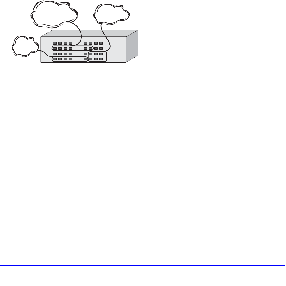
240 | Chapter 9. VLANs
NETGEAR 8800 User Manual
• Ethernet, LLC SAP, or LLC/SNAP Ethernet protocol type
• A combination of these criteria
Port-Based VLANs
In a port-based VLAN, a VLAN name is given to a group of one or more ports on the switch.
At boot-up, all ports are members of the port-based VLAN default. Before you can add any
port to another port-based VLAN, you must remove it from the default VLAN, unless the new
VLAN uses a protocol other than the default protocol any. A port can be a member of only
one port-based VLAN.
On the NETGEAR switch in Figure 6, ports 9 through 14 are part of VLAN Marketing; ports
25 through 29 are part of VLAN Sales; and ports 21 through 24 and 30 through 32 are in
VLAN Finance.
Figure 6. Example of a Port-Based VLAN on an NETGEAR Switch
For the members of different IP VLANs to communicate, the traffic must be routed by the
switch, even if the VLANs are physically part of the same I/O module. This means that each
VLAN must be configured as a router interface with a unique IP address.
Spanning Switches with Port-Based VLANs
To create a port-based VLAN that spans two switches, you must do two things:
1. Assign the port on each switch to the VLAN.
2. Cable the two switches together using one port on each switch per VLAN.
Figure 7 illustrates a single VLAN that spans a BlackDiamond switch and another NETGEAR
switch. All ports on the system 1 switch belong to VLAN Sales. Ports 1 through 29 on the
system 2 switch also belong to VLAN Sales. The two switches are connected using slot 8,
port 4 on system 1 (the BlackDiamond switch), and port 29 on system 2 (the other switch).
EX_060
Sales
Finance
Marketing
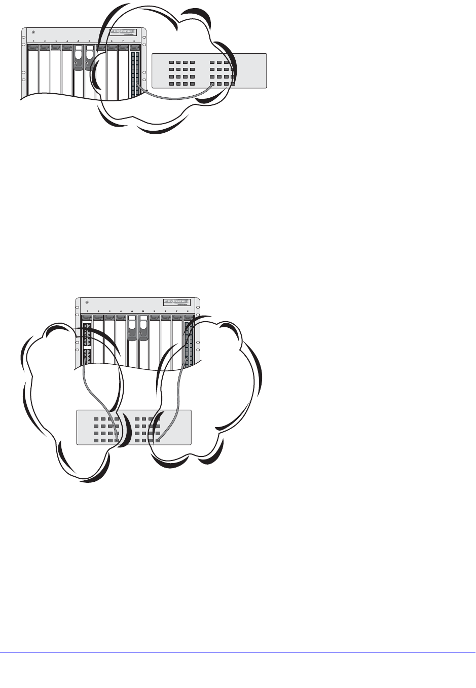
Chapter 9. VLANs | 241
NETGEAR 8800 User Manual
Figure 7. Single Port-based VLAN Spanning Two Switches
To create multiple VLANs that span two switches in a port-based VLAN, a port on system 1
must be cabled to a port on system 2 for each VLAN you want to have span across the
switches. At least one port on each switch must be a member of the corresponding VLANs,
as well.
Figure 8 illustrates two VLANs spanning two switches. On system 2, ports 25 through 29 are
part of VLAN Accounting; ports 21 through 24 and ports 30 through 32 are part of VLAN
Engineering. On system 1, all ports on slot 1 are part of VLAN Accounting; all ports on slot 8
are part of VLAN Engineering.
Figure 8. Two Port-based VLANs Spanning Two Switches
VLAN Accounting spans system 1 and system 2 by way of a connection between system 2,
port 29 and system 1, slot 1, port 6. VLAN Engineering spans system 1 and system 2 by way
of a connection between system 2, port 32, and system 1, slot 8, port 6.
Using this configuration, you can create multiple port-based VLANs that span multiple
switches, in a daisy-chained fashion. Each switch must have a dedicated port for each VLAN.
Each dedicated port must be connected to a port that is a member of its VLAN on the next
switch.
System 1
System 2
EX_061
Sales
EX_063
System 1
System 2
Accounting Engineering

242 | Chapter 9. VLANs
NETGEAR 8800 User Manual
Tagged VLANs
Tagging is a process that inserts a marker (called a tag) into the Ethernet frame. The tag
contains the identification number of a specific VLAN, called the VLANid (valid numbers are 1
to 4094).
Note: The use of 802.1Q tagged packets may lead to the appearance of
packets slightly bigger than the current IEEE 802.3/Ethernet
maximum of 1,518 bytes. This may affect packet error counters in
other devices and may also lead to connectivity problems if
non-802.1Q bridges or routers are placed in the path.
Uses of Tagged VLANs
Tagging is most commonly used to create VLANs that span switches. The switch-to-switch
connections are typically called trunks. Using tags, multiple VLANs can span multiple
switches using one or more trunks. In a port-based VLAN, each VLAN requires its own pair of
trunk ports, as shown in Figure 8. Using tags, multiple VLANs can span two switches with a
single trunk.
Another benefit of tagged VLANs is the ability to have a port be a member of multiple VLANs.
This is particularly useful if you have a device (such as a server) that must belong to multiple
VLANs. The device must have a Network Interface Card (NIC) that supports IEEE 802.1Q
tagging.
A single port can be a member of only one port-based VLAN. All additional VLAN
membership for the port must be accompanied by tags.
Assigning a VLAN Tag
Each VLAN may be assigned an 802.1Q VLAN tag. As ports are added to a VLAN with an
802.1Q tag defined, you decide whether each port uses tagging for that VLAN. The default
mode of the switch is to have all ports assigned to the VLAN named default with an 802.1Q
VLAN tag (VLANid) of 1 assigned.
Not all ports in the VLAN must be tagged. As traffic from a port is forwarded out of the switch,
the switch determines (in real time) if each destination port should use tagged or untagged
packet formats for that VLAN. The switch adds and strips tags, as required, by the port
configuration for that VLAN.
Note: Packets arriving tagged with a VLANid that is not configured on a
port are discarded.
Figure 9 illustrates the physical view of a network that uses tagged and untagged traffic.
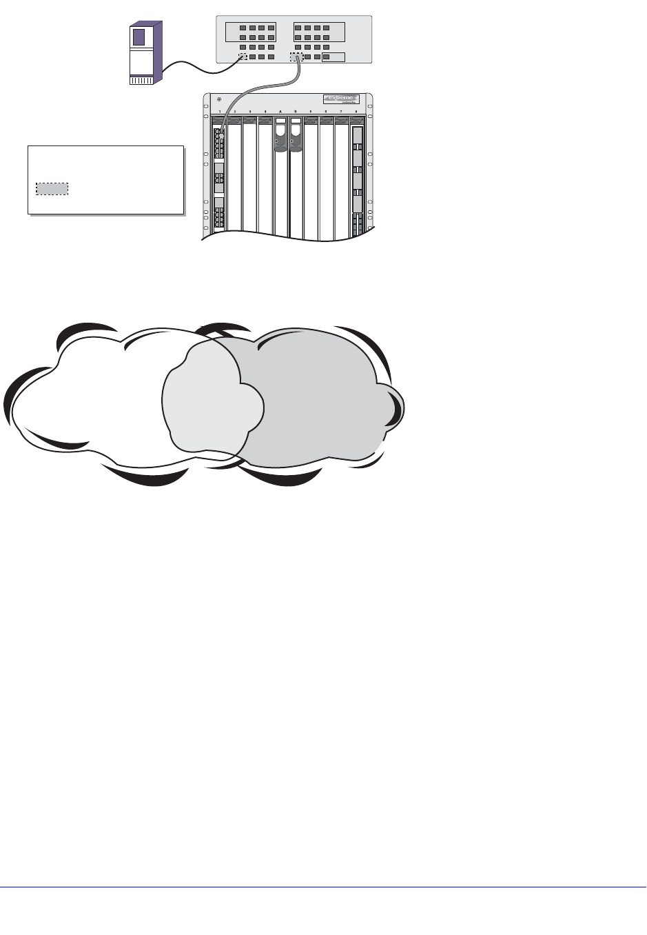
Chapter 9. VLANs | 243
NETGEAR 8800 User Manual
Figure 9. Physical Diagram of Tagged and Untagged Traffic
Figure 10 is a logical diagram of the same network.
Figure 10. Logical Diagram of Tagged and Untagged Traffic
In Figure 9 and Figure 10:
• The trunk port on each switch carries traffic for both VLAN Marketing and VLAN Sales.
• The trunk port on each switch is tagged.
• The server connected to port 25 on system 1 has a NIC that supports 802.1Q tagging.
• The server connected to port 25 on system 1 is a member of both VLAN Marketing and
VLAN Sales.
• All other stations use untagged traffic.
As data passes out of the switch, the switch determines if the destination port requires the
frames to be tagged or untagged. All traffic coming from and going to the server is tagged.
Traffic coming from and going to the trunk ports is tagged. The traffic that comes from and
goes to the other stations on this network is not tagged.
Mixing Port-Based and Tagged VLANs
You can configure the switch using a combination of port-based and tagged VLANs. A given
port can be a member of multiple VLANs, with the stipulation that only one of its VLANs uses
EX_064
System 1
= Marketing
= Sales
M
S
= Tagged port
Marketing & Sales
M SMS
SS
M
M
M
M
S
S
S
S
MM
SS
SS
802.1Q
Tagged server
System 2
EW_025
*Tagged Ports
Sales
System 1
Port 25 *
Port 29 *
System 2
Slot 1, Port 1 *
Marketing
System 1
Ports 1-4 & 9-12
System 2
Slot 1, Port 2
Slot 2, Ports 1-8 & 17-24
System 1
Ports 5-8, 13-16 & 32
System 2
Slot 1, Port 3
Slot 1, Port 4
Slot 2, Ports 9-16 & 25-32
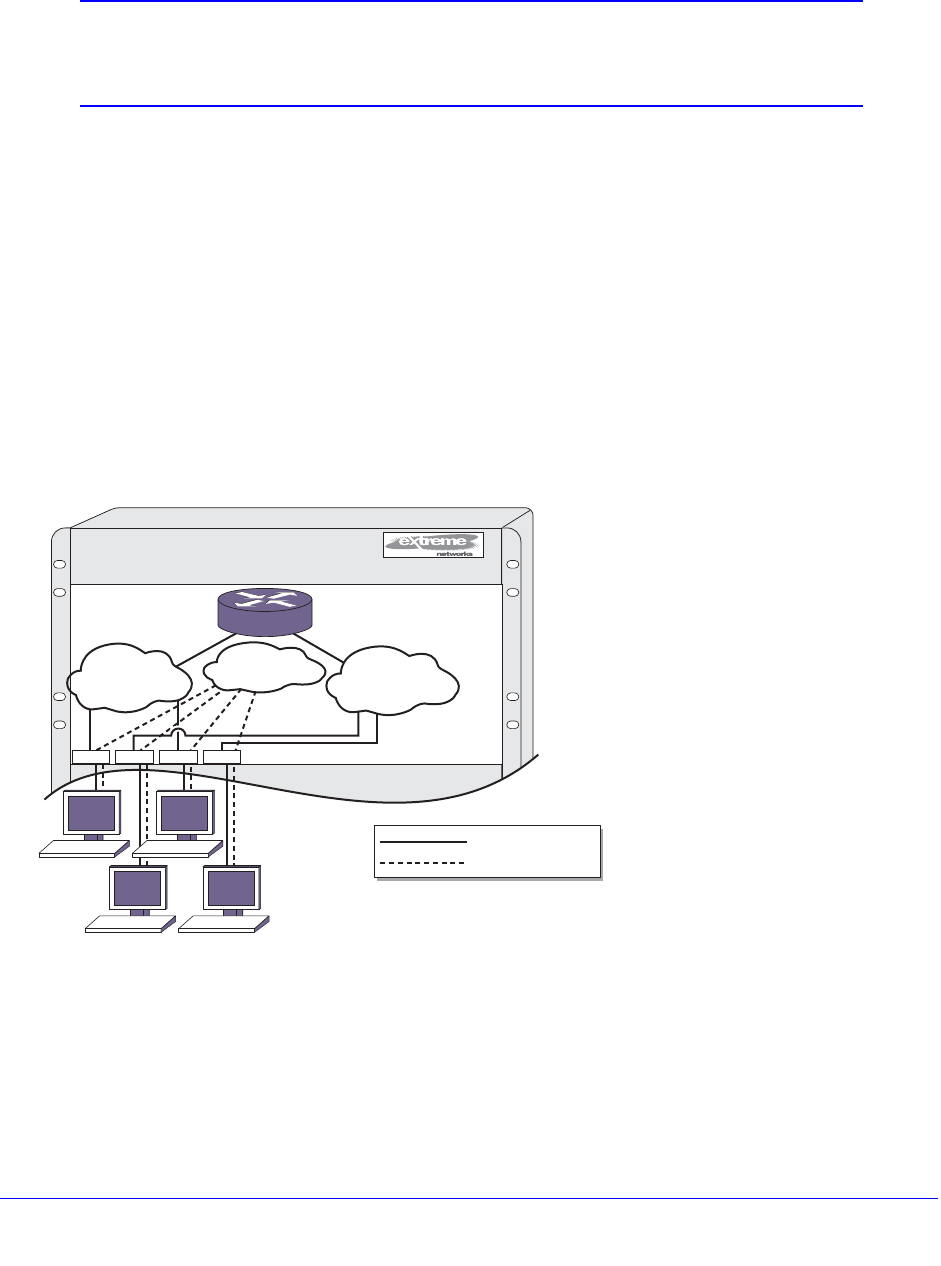
244 | Chapter 9. VLANs
NETGEAR 8800 User Manual
untagged traffic. In other words, a port can simultaneously be a member of one port-based
VLAN and multiple tag-based VLANs.
Note: For the purposes of VLAN classification, packets arriving on a port
with an 802.1Q tag containing a VLANid of 0 are treated as
untagged.
Protocol-Based VLANs
Protocol-based VLANs enable you to define a packet filter that the switch uses as the
matching criteria to determine if a particular packet belongs to a particular VLAN.
Protocol-based VLANs are most often used in situations where network segments contain
hosts running multiple protocols. For example, in Figure 11, the hosts are running both the IP
and NetBIOS protocols.
The IP traffic has been divided into two IP subnets, 192.207.35.0 and 192.207.36.0. The
subnets are internally routed by the switch. The subnets are assigned different VLAN names,
Finance and Personnel, respectively. The remainder of the traffic belongs to the VLAN
named MyCompany. All ports are members of the VLAN MyCompany.
Figure 11. Protocol-Based VLANs
The following sections provide information on using protocol-based VLANs:
• Predefined Protocol Filters on page 245
• Defining Protocol Filters on page 245
• Configuring a VLAN to Use a Protocol Filter on page 246
• Deleting a Protocol Filter on page 246
1234AB5678
EX_065
1
Finance Personnel
My Company
2 3 4
= IP traffic
= All other traffic
192.207.36.0
192.207.35.0
192.207.36.1192.207.35.1

Chapter 9. VLANs | 245
NETGEAR 8800 User Manual
Predefined Protocol Filters
The following protocol filters are predefined on the switch:
• IP (IPv4)
• IPv6 (11.2 IPv6)
• IPX
• NetBIOS
• DECNet
• IPX_8022
• IPX_SNAP
• AppleTalk
Defining Protocol Filters
If necessary, you can define a customized protocol filter by specifying EtherType, Logical
Link Control (LLC), or Subnetwork Access Protocol (SNAP). Up to six protocols can be part
of a protocol filter. To define a protocol filter:
1. Create a protocol using the following command:
create protocol <name>
For example:
create protocol fred
The protocol name can have a maximum of 32 characters.
2. Configure the protocol using the following command:
configure protocol <name> add [etype | llc | snap] <hex> {[etype | llc | snap] <hex>}
Supported protocol types include:
• etype—EtherType
The values for etype are four-digit hexadecimal numbers taken from a list maintained
by the IEEE. This list can be found at the following URL:
http://standards.ieee.org/regauth/ethertype/index.html
• llc—LLC Service Advertising Protocol (SAP)
The values for llc are four-digit hexadecimal numbers that are created by
concatenating a two-digit LLC Destination SAP (DSAP) and a two-digit LLC Source
SAP (SSAP).
• snap—Ethertype inside an IEEE SNAP packet encapsulation
The values for snap are the same as the values for etype, described previously.
For example:
configure protocol fred add llc feff
configure protocol fred add snap 9999

246 | Chapter 9. VLANs
NETGEAR 8800 User Manual
A maximum of 15 protocol filters, each containing a maximum of 6 protocols, can be defined.
No more than 7 protocols can be active and configured for use.
Note: For more information on SNAP for Ethernet protocol types, see TR
11802-5:1997 (ISO/IEC) [ANSI/IEEE std. 802.1H, 1997 Edition].
Configuring a VLAN to Use a Protocol Filter
To configure a VLAN to use a protocol filter, use the following command:
configure {vlan} <vlan_name> protocol <protocol_name>
Deleting a Protocol Filter
If a protocol filter is deleted from a VLAN, the VLAN is assigned a protocol filter of any. You
can continue to configure the VLAN. However, no traffic is forwarded to the VLAN until a
protocol is assigned to it.
Precedence of Tagged Packets Over Protocol Filters
If a VLAN is configured to accept tagged packets on a particular port, incoming packets that
match the tag configuration take precedence over any protocol filters associated with the
VLAN.
Default VLAN
The default switch configuration includes one default VLAN that has the following properties:
• The VLAN name is default.
• It contains all the ports on a new or initialized switch.
• The default VLAN is untagged on all ports. It has an internal VLANid of 1; this value is
user-configurable.
VLAN Names
VLAN names must conform to the guidelines listed in Object Names on page 31.
VLAN names can be specified using the tab key for command completion.
VLAN names are locally significant. That is, VLAN names used on one switch are only
meaningful to that switch. If another switch is connected to it, the VLAN names have no
significance to the other switch.

Chapter 9. VLANs | 247
NETGEAR 8800 User Manual
Note: NETGEAR recommends that you use VLAN names consistently
across your entire network.
You must use mutually exclusive names for the following:
• VLANs
• vMANs
• IPv6 tunnels
• SVLANs
• CVLANs
• BVLANs
Renaming a VLAN
To rename an existing VLAN, use the following command:
configure {vlan} <vlan_name> name <name>
The following rules apply to renaming VLANs:
• You cannot change the name of the default VLAN.
• You cannot create a new VLAN named default.
Configuring VLANs on the Switch
This section describes how to create, name, and enable or disable a VLAN. This part covers
the following areas:
• Creating and Configuring VLANs on page 247
• Enabling and Disabling VLANs on page 248
• VLAN Configuration Examples on page 249
Creating and Configuring VLANs
This section describes the commands associated with setting up VLANs on the switch. To
configure a VLAN:
1. Create and name the VLAN using the following command:
create vlan <vlan_name> {vr <vr-name>}

248 | Chapter 9. VLANs
NETGEAR 8800 User Manual
Note: Each IP address and mask assigned to a VLAN must represent a
unique IP subnet. You cannot configure the same IP subnet on
different VLANs on the same virtual router.
2. If needed, assign an IP address and mask (if applicable) to the VLAN using the following
command:
configure {vlan} <vlan_name> ipaddress [<ipaddress> {<ipNetmask>} |
ipv6-link-local | {eui64} <ipv6_address_mask>]
Note: The software supports using IPv6 addresses, in addition to IPv4
addresses. You can configure the VLAN with an IPv4 address, IPv6 address,
or both. See Chapter 21, IPv6 Unicast Routing for complete information on
using IPv6 addresses.
3. If any ports in this VLAN will use a tag, assign a VLANid using the following command:
configure {vlan} <vlan_name> tag <tag> {remote-mirroring}
4. Assign one or more ports to the VLAN.
configure {vlan} <vlan_name> add ports [<port_list> | all] {tagged | untagged}
{{stpd} <stpd_name>} {dot1d | emistp | pvst-plus}}
As you add each port to the VLAN, decide if the port will use an 802.1Q tag.
5. For the management VLAN on the switch, configure the default IP route for virtual router
VR-Mgmt.
Note: See Chapter 20, IPv4 Unicast Routing for information on configuring
default IP routes or adding secondary IP addresses to VLANs.
Enabling and Disabling VLANs
You can enable or disable individual VLANs. The default setting is that all VLANs are
enabled.
Consider the following guidelines before you disable a VLAN:
• Disabling a VLAN stops all traffic on all ports associated with the specified VLAN.
• You cannot disable any VLAN that is running any Layer 2 protocol traffic.
When you attempt to disable a VLAN running Layer 2 protocol traffic (for example, the
VLAN Accounting), the system returns a message similar to the following:
VLAN accounting cannot be disabled because it is actively use by an L2 Protocol

Chapter 9. VLANs | 249
NETGEAR 8800 User Manual
• You can disable the default VLAN; ensure that this is necessary before disabling the
default VLAN.
• You cannot disable the management VLAN.
• Although you can remove ports from a disabled VLAN, you cannot add ports to a disabled
VLAN or bind Layer 2 protocols to that VLAN.
When you attempt to add ports or bind L2 protocols to a disabled VLAN (for example, the
VLAN Accounting), the system returns a message similar to the following:
VLAN accounting is disabled. Enable VLAN before adding ports.
To disable a VLAN, issue the following CLI command:
disable vlan <vlan_name>
After you have disabled a VLAN and want to re-enable that VLAN, use the following CLI
command:
enable vlan <vlan_name>
VLAN Configuration Examples
Note: To add an untagged port to a VLAN you create, you must first delete
that port from the default vlan. if you attempt to add an untagged
port to a VLAN before deleting it from the default VLAN, you see the
following error message:
Error: Protocol conflict when adding untagged port 1:2. Either add this port as
tagged or assign another protocol to this VLAN.
The following modular switch example creates a port-based VLAN named accounting:
create vlan accounting
configure accounting ipaddress 132.15.121.1
configure default delete port 2:1-2:3,2:6,4:1,4:2
configure accounting add port 2:1-2:3,2:6,4:1,4:2
Note: Because VLAN names are unique, you do not need to enter the
keyword vlan after you have created the unique VLAN name. You
can use the VLAN name alone (unless you are also using this name
for another category such as STPD, in which case NETGEAR
recommends including the keyword vlan).
The following stand-alone switch example creates a port-based VLAN named development
with an IPv6 address:

250 | Chapter 9. VLANs
NETGEAR 8800 User Manual
create vlan development
configure development ipaddress 2001:0DB8::8:800:200C:417A/64
configure default delete port 1-3
configure development add port 1-3
The following modular switch example creates a protocol-based VLAN named ipsales. Slot 5,
ports 6 through 8, and slot 6, ports 1, 3, and 4-6 are assigned to the VLAN. In this example,
you can add untagged ports to a new VLAN without first deleting them from the default VLAN,
because the new VLAN uses a protocol other than the default protocol.
create vlan ipsales
configure ipsales protocol ip
configure ipsales add port 5:6-5:8,6:1,6:3-6:6
The following modular switch example defines a protocol filter, myprotocol and applies it to
the VLAN named myvlan. This is an example only, and has no real-world application.
create protocol myprotocol
configure protocol myprotocol add etype 0xf0f0
configure protocol myprotocol add etype 0xffff
create vlan myvlan
configure myvlan protocol myprotocol
To disable the protocol-based VLAN (or any VLAN) in the above example, use the following
command:
disable vlan myprotocol
To re-enable the VLAN, use the following command:
enable vlan myprotocol
To display VLAN settings, use the following command:
show vlan {detail {ipv4 | ipv6} | <vlan_name> {ipv4 | ipv6} | virtual-router
<vr-router> | <vlan_name> stpd | security}
The show command displays information about each VLAN, which includes:
• Name
• VLANid
• Enabled or disabled
• How the VLAN was created
• Primary IPv4 address
• Secondary IP address (if configured)
• IPv6 addresses (if configured)
• Virtual router that VLAN belongs with
• IPX address (if configured).
• STPD information

Chapter 9. VLANs | 251
NETGEAR 8800 User Manual
• Protocol information
• QoS profile information
• Rate shaping information
• NetLogin information
• Ports assigned
• Tagged/untagged status for each port
• How the ports were added to the VLAN
• Number of VLANs configured on the switch
• IP forwarding information
• Multicasting information
• Routing protocol information
Use the detail option to display the detailed format.
Note: To display IPv6 information, you must use either the show vlan
detail command or show vlan command with the name of the
specified VLAN.
You can display additional useful information on VLANs configured with IPv6 addresses by
issuing the show ipconfig ipv6 vlan <vlan_name> command.
Displaying Protocol Information
To display protocol information, use the following command:
show protocol {<name>}
This show command displays protocol information, which includes:
• Protocol name
• Type
• Value
Private VLANs
The section covers the following Private VLAN (PVLAN) topics:
• PVLAN Overview on page 252
• Configuring PVLANs on page 260
• Displaying PVLAN Information on page 263
• PVLAN Configuration Example 1 on page 264

252 | Chapter 9. VLANs
NETGEAR 8800 User Manual
• PVLAN Configuration Example 2 on page 267
PVLAN Overview
PVLANs offer the following features:
• VLAN isolation
Note: PVLAN features are supported only on the platforms listed for this
feature in the license tables in Appendix A, XCM8800 Software
Licenses.
The following sections introduce PVLAN features and components:
• VLAN Isolation on page 252
• PVLAN Components on page 253
• PVLAN Support over Multiple Switches on page 255
• Extending Network and Subscriber VLANs to Other Switches on page 256
• MAC Address Management in a PVLAN on page 257
• Layer 3 Communications on page 259
• PVLAN Limitations on page 259
VLAN Isolation
VLAN isolation provides Layer 2 isolation between the ports in a VLAN. Figure 12 shows an
application of VLAN isolation.
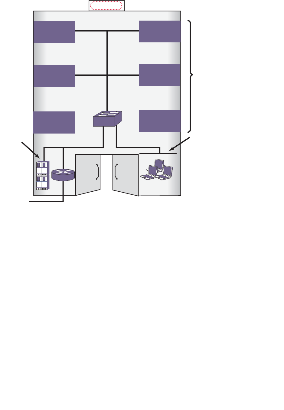
Chapter 9. VLANs | 253
NETGEAR 8800 User Manual
Figure 12. VLAN Isolation Application
In Figure 12, ports in the Guest VLAN have access to services on the network VLAN, but
Guest VLAN ports cannot access other Guest VLAN ports over Layer 2 (or the Marketing or
Engineering VLANs). This provides port-to-port security at Layer 2.
PVLAN Components
Figure 13 shows the logical components that support PVLAN configuration in a switch.
Non-isolated
subscriber VLANs
Network
VLAN
Tag 5 00Tag 1 0
Marketing
VLAN
Tag 1 02
Engineering VLAN
Tag 1 01
APP server
To backbone
Guests
Company A
Isolated
Subscriber VLAN
EX_vlan_0022
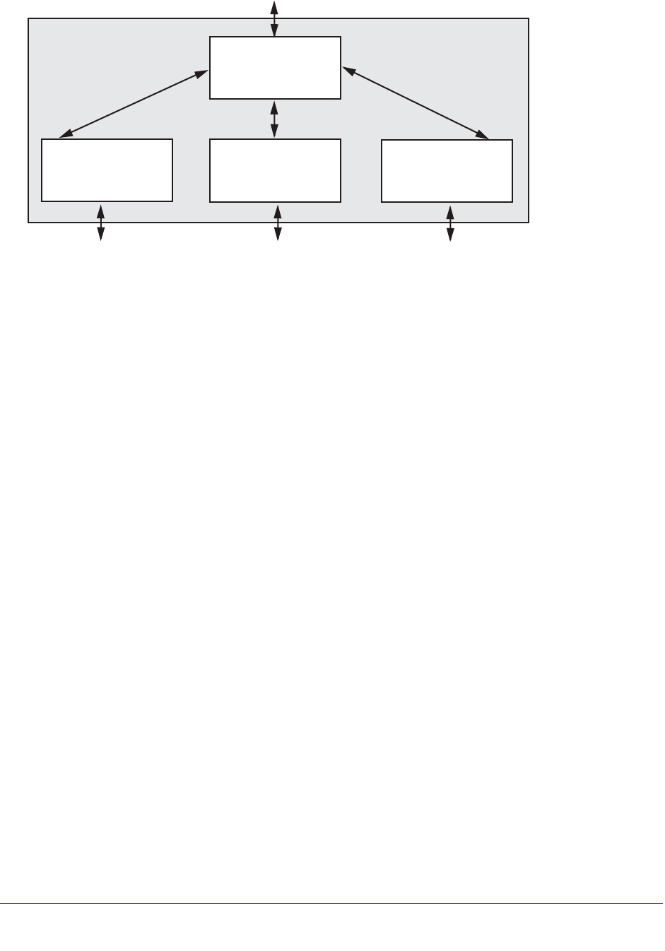
254 | Chapter 9. VLANs
NETGEAR 8800 User Manual
Figure 13. Private VLAN Switch Components
There is one network VLAN in each PVLAN. Ports within a network VLAN, called network
ports, can communicate with all VLAN ports in the PVLAN. Network devices that connect to
the network VLAN ports are considered to be on the network side of the switch.
The network VLAN aggregates the uplink traffic from the other VLANS, called subscriber
VLANs, for egress communications on a network VLAN port. A network port can serve only
one PVLAN, but it can serve one or more subscriber VLANs. Ingress communications on the
network VLAN port are distributed to the appropriate subscriber VLANs for distribution to the
appropriate ports. Devices that connect to subscriber VLAN ports are considered to be on the
subscriber side of the switch.
Tag translation within the PVLAN is managed at the egress ports. To enable tag translation
for uplink traffic from the subscriber VLANs, you must enable tag translation on the
appropriate network VLAN port. Tag translation is automatically enabled on subscriber VLAN
egress ports when the subscriber VLAN is created and the port is added to the VLAN as
tagged. Egress traffic from a subscriber VLAN is always tagged with the subscriber VLAN tag
when the port is configured as tagged.
A non-isolated subscriber VLAN is basically a standard VLAN that can participate in tag
translation through the network VLAN when VLAN translation is enabled on the network
VLAN port. You can choose to not translate tags on a network VLAN port, but this is generally
used only for extending a PVLAN to another switch. A non-isolated subscriber VLAN that
does not use tag translation is functionally equivalent to a regular VLAN, so it is better to
create non-isolated VLANs only when you plan to use tag translation.
Ports in a non-isolated VLAN can communicate with other ports in the same VLAN, ports in
the network VLAN, and destinations on the network side of the switch. As with standard
VLANs, non-isolated ports cannot communicate through Layer 2 with ports in other
subscriber VLANs.
In Figure 12, the Engineering and Marketing VLANs are configured as non-isolated
subscriber VLANs, which means that they act just like traditional VLANs, and they can
participate in tag translation when VLAN translation is enabled on a network VLAN port that
leads to network side location.
Network VLAN
VLAN1
Isolated
subscriber VLAN
Guests
Non-Isolated
subscriber VLAN
Engineering
Non-Isolated
subscriber VLAN
Marketing
Private VLAN
To main core routerTag 1 0
Tag 1 02 Tag 101 Tag 50
EX_vlan_0021
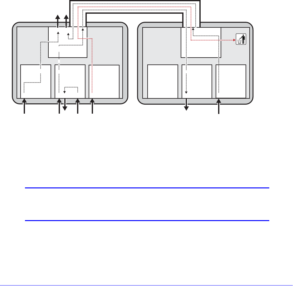
Chapter 9. VLANs | 255
NETGEAR 8800 User Manual
VLAN isolation within the PVLAN is established by configuring a VLAN to be an isolated
subscriber VLAN and adding ports to the isolated VLAN. Unlike normal VLANs, ports in an
isolated VLAN cannot communicate with other ports in the same VLAN over Layer 2 or
Layer 3. The ports in an isolated VLAN can, however, communicate with Layer 2 devices on
the network side of the PVLAN through the network VLAN. When the network VLAN egress
port is configured for tag translation, isolated VLAN ports also participate in uplink tag
translation. When isolated subscriber VLAN ports are configured as tagged, egress packets
are tagged with the isolated VLAN tag. As with standard VLANs and non-isolated VLANs,
isolated ports cannot communicate through Layer 2 with ports in other subscriber VLANs.
PVLAN Support over Multiple Switches
A PVLAN can span multiple switches. Figure 14 shows a PVLAN that is configured to
operate on two switches.
Figure 14. Private VLAN Support on Multiple Switches
A PVLAN can span many switches. For simplicity, Figure 14 shows only two switches, but
you can extend the PVLAN to additional switches by adding connections between the
network VLANs in each switch. The ports that connect two PVLAN switches must be
configured as regular tagged ports. The network and subscriber VLANs on each switch must
be configured with the same tags.
Note: Although using the same VLAN names on all PVLAN switches might
make switch management easier, there is no software requirement
to match the VLAN names. Only the tags must match.
When a PVLAN is configured on multiple switches, the PVLAN switches function as one
PVLAN switch. Subscriber VLAN ports can access the network VLAN ports on any of the
PVLAN switches, and non-isolated VLAN ports can communicate with ports in the same
12 34 56 7830 31 32 33
Private VLAN Private VLAN
Network VLAN
Tagged 1
Subscriber
Isolated VLAN
Tagged 103
Subscriber
Isolated VLAN
Tagged 103
Switch 1 Switch 2
EX_vlan_0030
20 2 1 22
Subscriber
Non-Isolated VLAN
Tagged 102
Preserve tag Tag 102
translate
101 to 1
or
preserve
tag
Subscriber
Non-Isolated VLAN
Tagged 101
12 34 5678 30 31 32 33
Subscriber
Non-Isolated VLAN
Tagged 101
Network VLAN
Tagged 1
Preserve tag 103
Tag 103
Tag 102
21 22 23
Subscriber
Non-Isolated VLAN
Tagged 102
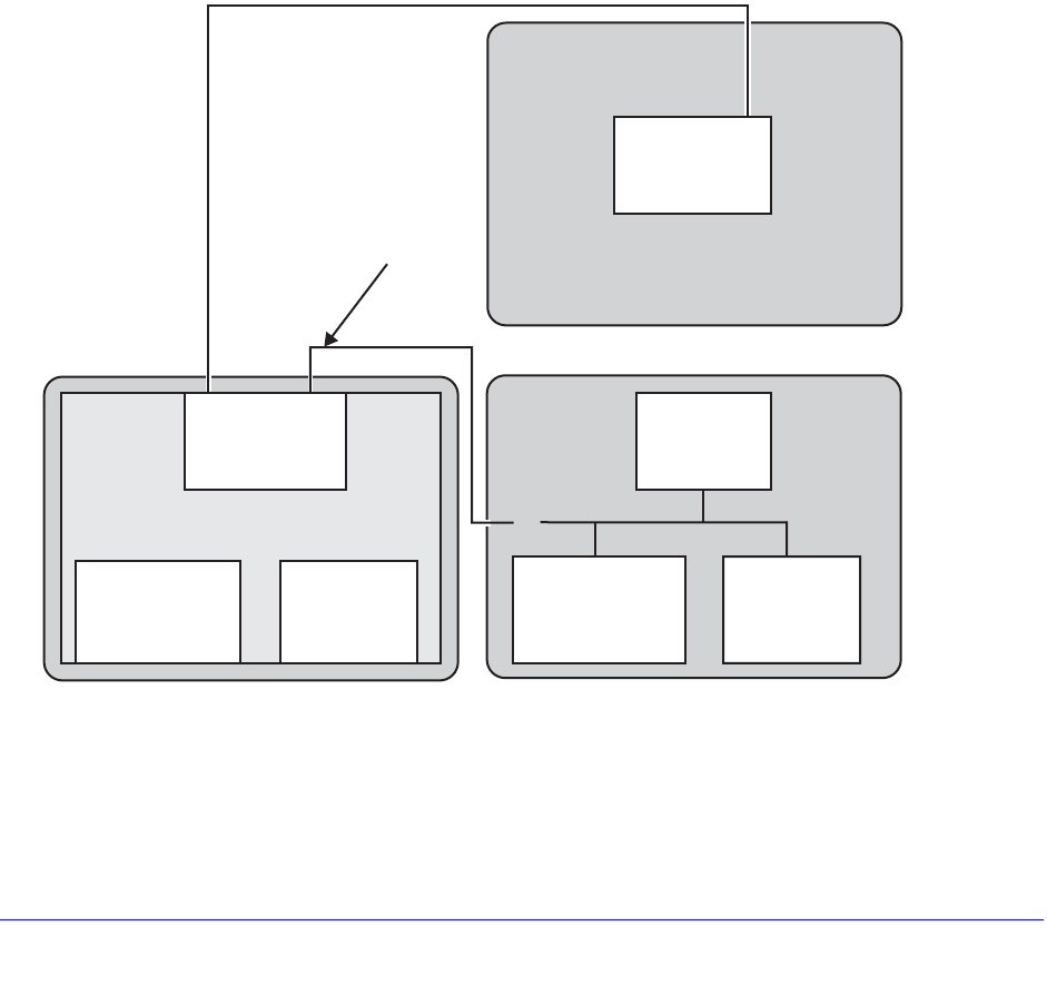
256 | Chapter 9. VLANs
NETGEAR 8800 User Manual
VLAN that are located on a different physical switch. An isolated VLAN can span multiple
switches and maintain isolation between the VLAN ports.
The network and subscriber VLANs can be extended to other switches that are not
configured for the PVLAN (as described in Extending Network and Subscriber VLANs to
Other Switches on page 256). The advantage to extending the PVLAN is that tag translation
and VLAN isolation is supported on the additional switch or switches.
Extending Network and Subscriber VLANs to Other Switches
A network or subscriber VLAN can be extended to additional switches without a PVLAN
configuration on the additional switches. You might want to do this to connect to existing
servers, switches, or other network devices. You probably do not want to use this approach to
support clients, as tag translation and VLAN isolation are not supported unless the PVLAN is
configured on all PVLAN switches as described in PVLAN Support over Multiple Switches on
page 255.
Figure 15 illustrates PVLAN connections to switches outside the PVLAN.
Figure 15. Private VLAN Connections to Switches Outside the PVLAN
In Figure 15, Switch 1, Network VLAN Port 21, connects to a Switch 3 port that only supports
the Network VLAN. In this configuration, the Network VLAN Port 21 on Switch 1 is configured
as “translated,” which translates subscriber VLAN tags to the network VLAN tag for access to
Network VLAN
21 22 23 24
21 22 23 2421 22 23 24
21 22 23 24
Tagged 1
Network VLAN
Tagged 1
Tagged 101 Tagged 101
Private VLAN
Isolated VLANNon-Isolated VLAN
Switch 1
Switch 3
Network VLAN
Tagged 1
Tagged 101 Tagged 101
Isolated VLAN
Non-Isolated VLAN
Switch 2
22
21 22 23 24
PVLAN
endpoint
EX_vlan_0004

Chapter 9. VLANs | 257
NETGEAR 8800 User Manual
the Network VLAN extension on Switch 3. Switch 3, Port 24 is configured as tagged and only
accepts traffic with the Network VLAN Tag. Switch 3 serves as an extension of the Network
VLAN and can be used to connect to network devices such as servers or an internet
gateway.
Switch 2, Port 22 supports the Network, NonIsolated, and Isolated VLANs, but no PVLAN is
configured. Because Port 22 supports multiple VLANs that are part of the PVLAN, and
because these Switch 2 VLANs are not part of the PVLAN, Switch 1, Port 24, must be
configured as a PVLAN endpoint, which establishes the PVLAN boundary. Switch 2, port 22,
is configured as a regular tagged VLAN port.
For most applications, it would be better to extend the PVLAN to Switch 2 so that the PVLAN
features are available to the Switch 2 VLANs. The configuration of Switch 2 behaves as
follows:
• The Switch 2 NonIsolated VLAN ports can communicate with the NonIsolated VLAN ports
on Switch 1, but they cannot participate in VLAN translation.
• The Switch 2 Isolated VLAN ports can communicate with other Switch 2 Isolated VLAN
ports.
• The Switch 2 Isolated VLAN ports cannot participate in VLAN translation.
• The Switch 2 Isolated VLAN ports can receive broadcast and multicast info for the
Isolated VLAN.
• Traffic is allowed from the Switch 1 Isolated VLAN ports to the Switch 2 Isolated VLAN
ports.
MAC Address Management in a PVLAN
Each device that connects to a PVLAN must have a unique MAC address within the PVLAN.
Each MAC address learned in a PVLAN requires multiple FDB entries. For example, each
MAC address learned in a non-isolated subscriber VLAN requires two FDB entries, one for
the subscriber VLAN and one for the network VLAN. The additional FDB entries for a PVLAN
are marked with the P flag in the show fdb command display.
The following sections describe the FDB entries created for the PVLAN components and how
to estimate the impact of a PVLAN on the FDB table:
• Non-Isolated Subscriber VLAN on page 257
• Isolated Subscriber VLAN on page 258
• Network VLAN on page 258
• Calculating the Total FDB Entries for a PVLAN on page 258
Non-Isolated Subscriber VLAN
When a MAC address is learned on a non-isolated subscriber VLAN port, two entries are
added to the FDB table:
• MAC address, non-isolated subscriber VLAN tag, and the port number
• MAC address, network VLAN tag, port number, and a special flag for tag translation

258 | Chapter 9. VLANs
NETGEAR 8800 User Manual
The network VLAN entry is used when traffic comes in from the network ports destined for an
non-isolated port.
Isolated Subscriber VLAN
When a new MAC address is learned on an isolated subscriber VLAN port, two entries are
added to the FDB table:
• MAC address, isolated subscriber VLAN tag, port number, and a flag that indicates that
the packet should be dropped
• MAC address, network VLAN tag, port number, and a special flag for tag translation
Ports in the isolated VLAN do not communicate with one another. If a port in the isolated
VLAN sends a packet to another port in the same VLAN that already has an entry in the FDB,
that packet is dropped. You can verify the drop packet status of an FDB entry by using the
show fdb command. The D flag indicates that packets destined for the listed address are
dropped.
The network VLAN entry is used when traffic comes in from the network ports destined for an
isolated port.
Network VLAN
When a new MAC address is learned on a network VLAN port, the following entry is added to
the FDB table: MAC address, network VLAN tag, and port number.
For every subscriber VLAN belonging to this PVLAN, the following entry is added to the FDB
table: MAC address, subscriber VLAN tag, and port number
Calculating the Total FDB Entries for a PVLAN
The following formula can be used to estimate the maximum number of FDB entries for a
PVLAN:
FDBtotal = [(MACnon-iso + MACiso) * 2 + (MACnetwork * (VLANnon-iso + VLANiso + 1))]
The formula components are as follows:
• MACnon-iso = number of MAC addresses learned on all the non-isolated subscriber
VLANs
• MACiso = number of MAC addresses learned on all the isolated subscriber VLANs
• MACnetwork = number of MAC addresses learned on the network VLAN
• VLANnon-iso = number of non-isolated subscriber VLANs
• VLANiso = number of isolated subscriber VLANs

Chapter 9. VLANs | 259
NETGEAR 8800 User Manual
Note: The formula above estimates the worst-case scenario for the
maximum number of FDB entries for a single PVLAN. If the switch
supports additional PVLANs, apply the formula to each PVLAN and
add the totals for all PVLANs. If the switch also support standard
VLANs, there will also be FDB entries for the standard VLANs.
Layer 3 Communications
For PVLANs, the default switch configuration controls Layer 3 communications exactly as
communications are controlled in Layer 2. For example, Layer 3 communications is enabled
between ports in a non-isolated subscriber VLAN, and disabled between ports in an isolated
subscriber VLAN. Ports in a non-isolated subscriber VLAN cannot communicate with ports in
other non-isolated subscriber VLANs.
You can enable Layer 3 communications between all ports in a PVLAN. For more
information, see Managing Layer 3 Communications in a PVLAN on page 263.
PVLAN Limitations
The Private VLAN feature has the following limitations:
• Requires more FDB entries than a standard VLAN
• Within the same VR, VLAN tag duplication is not allowed
• Within the same VR, VLAN name duplication is not allowed
• Each MAC address learned in a PVLAN must be unique. A MAC address cannot exist in
two or more VLANs that belong to the same PVLAN.
• MVR cannot be configured on PVLANs.
• A PBB network (BVLAN) cannot be added to a PVLAN.
• STP can only be configured on network VLAN ports (and not on subscriber VLAN ports).
To support STP on the network VLAN, you must add all of the VLANs in the PVLAN to
STP.
• There is no NetLogin support to add ports as translate to the network VLAN, but the rest
of NetLogin and the PVLAN feature do not conflict.
• IGMP snooping is performed across the entire PVLAN, spanning all the subscriber
VLANs, following the PVLAN rules. For VLANs that are not part of a PVLAN, IGMP
snooping operates as normal.
• When two switches are part of the same PVLAN, unicast and multicast traffic require a
tagged trunk between them that preserves tags (no tag translation).
• Subscriber VLANs in a PVLAN cannot exchange multicast data with VLANs outside the
PVLAN and with other PVLANs. However, the network VLAN can exchange multicast
data with VLANs outside the PVLAN and with network VLANs in other PVLANs.
An additional limitation applies to the NETGEAR 8800 switches. If two or more member
VLANs have overlapping ports (where the same ports are assigned to both VLANs), each
additional VLAN member with overlapping ports must have a dedicated loopback port. To

260 | Chapter 9. VLANs
NETGEAR 8800 User Manual
state it another way, one of the VLAN members with overlapping ports does not require a
dedicated loopback port, and the rest of the VLAN members do require a single, dedicated
loopback port within each member VLAN.
Note: There is a limit to the number of unique source MAC addresses on
the network VLAN of a PVLAN that the switch can manage. It is
advised not to exceed the value shown in the item “FDB (maximum
L2 entries)” in the Supported Limits table of the NETGEAR 8800
Installation and Release Notes.
Configuring PVLANs
The following sections describe common PVLAN configuration tasks:
• Creating PVLANs on page 260
• Configuring Network VLAN Ports for VLAN Translation on page 261
• Configuring Non-Isolated Subscriber VLAN Ports on page 261
• Configuring Isolated Subscriber VLAN Ports on page 262
• Configuring a PVLAN on Multiple Switches on page 262
• Configuring a Network or Subscriber VLAN Extension to Another Switch on page 263
• Adding a Loopback Port to a Subscriber VLAN on page 263
• Managing Layer 3 Communications in a PVLAN on page 263
• Deleting PVLANs on page 263
• Removing a VLAN from a PVLAN on page 263
Creating PVLANs
To create a VLAN, you need to do the following:
• Create the PVLAN
• Add one VLAN to the PVLAN as a network VLAN
• Add VLANs to the PVLAN as subscriber VLANs
To create a PVLAN, use the following command:
create private-vlan <name> {vr <vr_name>}
To add a network VLAN to the PVLAN, create and configure a tagged VLAN, and then use
the following command to add that network VLAN:
configure private-vlan <name> add network <vlan_name>
To add a subscriber VLAN to the PVLAN, create and configure a tagged VLAN, and then use
the following command to add that subscriber VLAN:

Chapter 9. VLANs | 261
NETGEAR 8800 User Manual
configure private-vlan <name> add subscriber <vlan_name> {non-isolated}
{loopback-port <port>}
By default, this command adds an isolated subscriber VLAN. To create a non-isolated
subscriber VLAN, you must include the non-isolated option.
Configuring Network VLAN Ports for VLAN Translation
When subscriber VLAN traffic exits a network VLAN port, it can be untagged, tagged (with
the subscriber VLAN tag), or translated (to the network VLAN tag).
Note: All traffic that exits a subscriber VLAN port uses the subscriber
VLAN tag, unless the port is configured as untagged. There is no
need to configure VLAN translation (from network to subscriber
VLAN tag) on subscriber VLAN ports.
To configure network VLAN ports for VLAN translation, use the following command and
specify the network VLAN and port numbers:
configure {vlan} <vlan_name> add ports <port_list> private-vlan translated
If you want to later reconfigure a port that is configured for VLAN translation so that it does
not translate tags, use the following command and specify either the tagged or the untagged
option:
configure {vlan} <vlan_name> add ports [<port_list> | all] {tagged | untagged}
{{stpd} <stpd_name>} {dot1d | emistp | pvst-plus}}
Configuring Non-Isolated Subscriber VLAN Ports
The process for configuring non-isolated VLAN ports requires two tasks:
• Add a VLAN to the PVLAN as a non-isolated subscriber VLAN
• Assign ports to the non-isolated subscriber VLAN
These tasks can be completed in any order, but they must both be completed before a port
can participate in a PVLAN. When configuration is complete, all egress traffic from the port is
translated to the VLAN tag for that non-isolated VLAN (unless the port is configured as
untagged).
Note: To configure VLAN translation for network VLAN ports, see
Configuring Network VLAN Ports for VLAN Translation on page 261.
To add a non-isolated subscriber VLAN to the PVLAN, use the following command:
configure private-vlan <name> add subscriber <vlan_name> non-isolated

262 | Chapter 9. VLANs
NETGEAR 8800 User Manual
To add ports to a non-isolated VLAN (before or after it is added to the PVLAN), use the
following command:
configure {vlan} <vlan_name> add ports [<port_list> | all] {tagged | untagged}
{{stpd} <stpd_name>} {dot1d | emistp | pvst-plus}}
If you specify the tagged option, egress traffic uses the non-isolated VLAN tag, regardless of
the network translation configuration on any network port with which these ports
communicate. Egress traffic from a non-isolated VLAN port never carries the network VLAN
tag.
Configuring Isolated Subscriber VLAN Ports
When a port is successfully added to an isolated VLAN, the port is isolated from other ports in
the same VLAN, and all egress traffic from the port is translated to the VLAN tag for that
VLAN (unless the port is configured as untagged).
Note: To configure VLAN translation for network VLAN ports, see
Configuring Network VLAN Ports for VLAN Translation on page 261.
The process for configuring ports for VLAN isolation requires two tasks:
• Add a VLAN to the PVLAN as an isolated subscriber VLAN
• Assign ports to the isolated subscriber VLAN
These tasks can be completed in any order, but they must both be completed before a port
can participate in an isolated VLAN.
To add an isolated subscriber VLAN to the PVLAN, use the following command:
configure private-vlan <name> add subscriber <vlan_name>
To add ports to an isolated VLAN (before or after it is added to the PVLAN), use the following
command:
configure {vlan} <vlan_name> add ports [<port_list> | all] {tagged | untagged}
{{stpd} <stpd_name>} {dot1d | emistp | pvst-plus}}
If you specify the tagged option, egress traffic uses the isolated VLAN tag, regardless of the
network translation configuration on any network port with which these ports communicate.
Egress traffic from an isolated VLAN port never carries the network VLAN tag.
Configuring a PVLAN on Multiple Switches
To create a PVLAN that runs on multiple switches, you must configure the PVLAN on each
switch and set up a connection between the network VLANs on each switch. The ports at
each end of the connection must be configured as tagged ports that do not perform tag
translation. To configure these types of ports, use the following command:
configure {vlan} <vlan_name> add ports <port_list> tagged

Chapter 9. VLANs | 263
NETGEAR 8800 User Manual
Configuring a Network or Subscriber VLAN Extension to Another Switch
You can extend a network or subscriber VLAN to another switch without configuring a PVLAN
on that switch. This configuration is introduced in Extending Network and Subscriber VLANs
to Other Switches on page 256.
To add a network VLAN port as a PVLAN endpoint, use the following command:
configure {vlan} <vlan_name> add ports <port_list> tagged private-vlan
end-point
To configure the port on the switch that is outside of the PVLAN, use the following command:
configure {vlan} <vlan_name> add ports <port_list> tagged
Adding a Loopback Port to a Subscriber VLAN
NETGEAR 8800 series switches require a loopback port for certain configurations. If two or
more subscriber VLANs have overlapping ports (where the same ports are assigned to both
VLANs), each of the subscriber VLANs with overlapping ports must have a dedicated
loopback port.
The loopback port can be added when the subscriber VLAN is added to the PVLAN.
Managing Layer 3 Communications in a PVLAN
The default configuration for Layer 3 PVLAN communications is described in Layer 3
Communications on page 259. To enable Layer 3 communications between all ports in a
PVLAN, use the following command:
configure iparp add proxy [<ipNetmask> | <ip_addr> {<mask>}] {vr <vr_name>}
{<mac> | vrrp} {always}
Specify the IP address or subnet specified for the network VLAN in the PVLAN. Use the
always option to ensure that the switch will reply to ARP requests, regardless of the VLAN
from which it originated.
Deleting PVLANs
To delete an existing PVLAN, use the following command:
delete private-vlan <name>
Removing a VLAN from a PVLAN
When you remove a VLAN from a PVLAN, you remove the association between a VLAN and
the PVLAN. Both the VLAN and PVLAN exist after the removal.
To remove a network or subscriber VLAN from a PVLAN, use the following command:
configure private-vlan <name> delete [network | subscriber] <vlan_name>
Displaying PVLAN Information
The following sections describe how to display PVLAN information:

264 | Chapter 9. VLANs
NETGEAR 8800 User Manual
• Displaying Information for all PVLANs on page 264
• Displaying Information for a Specific PVLAN on page 264
• Displaying Information for a Network or Subscriber VLAN on page 264
Displaying Information for all PVLANs
To display information on all the PVLANs configured on a switch, use the following command:
show private-vlan
Displaying Information for a Specific PVLAN
To display information about a single PVLANs, use the following command:
show {private-vlan} <name>
Displaying Information for a Network or Subscriber VLAN
To display information about a network or subscriber VLAN, use the following command:
show vlan {detail {ipv4 | ipv6} | <vlan_name> {ipv4 | ipv6} | virtual-router
<vr-router> | <vlan_name> stpd | security}
The following flags provide PVLAN specific information:
• s flag—identifies a network VLAN port that the system added to a subscriber VLAN. All
subscriber VLANs contain network VLAN ports that are marked with the s flag.
• L flag—identifies a subscriber VLAN port that is configured as a loopback port.
• t flag—identifies a tagged network VLAN port on which tag translation is enabled. The t
flag only appears in the show vlan display for network VLANs.
• e flag—identifies a network VLAN port that is configured as an endpoint. The e flag only
appears in the show vlan display for network VLANs.
Displaying PVLAN FDB Entries
To view all FDB entries including those created for a PVLAN, enter the following command:
show fdb {blackhole {netlogin [all | mac-based-vlans]} | hardware <mac_addr>
{vlan} <vlan_name> slot [all | <slot>] {number <num_entries>} | netlogin [all |
mac-based-vlans] | permanent {netlogin [all | mac-based-vlans]} | <mac_addr>
{netlogin [all | mac-based-vlans]} | ports <port_list> {netlogin [all |
mac-based-vlans]} | vlan <vlan_name> {netlogin [all | mac-based-vlans]}}
The P flag marks additional FDB entries for PVLANs.
PVLAN Configuration Example 1
Figure 16 shows a PVLAN configuration example for a medical research lab.
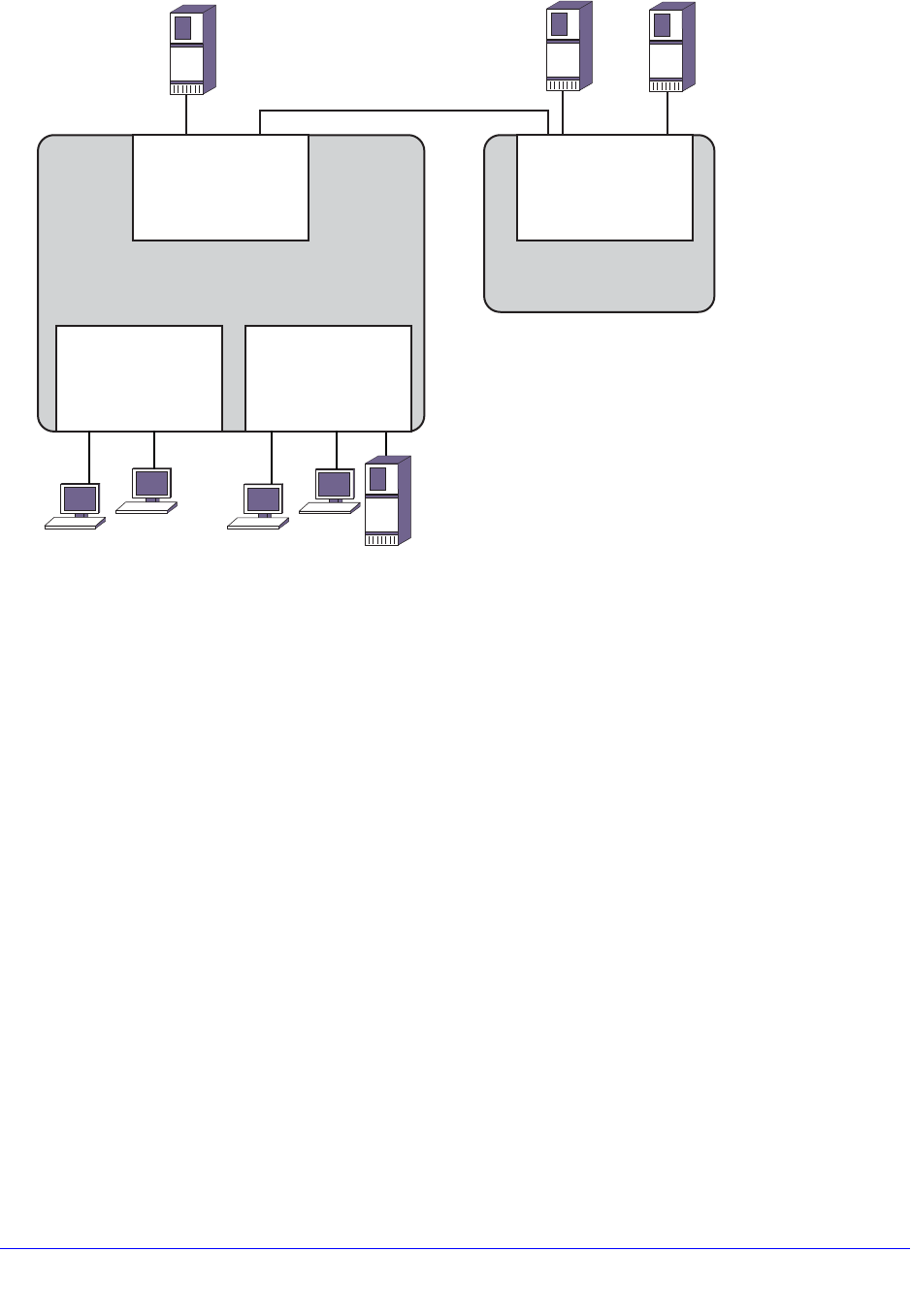
Chapter 9. VLANs | 265
NETGEAR 8800 User Manual
Figure 16. PVLAN Configuration Example 1
The medical research lab hosts lots of visiting clients. Each client has their own room, and
the lab wants to grant them access to the internet through a local web proxy server but
prevent them from accessing other visiting clients. There is a lab in the building where many
research workstations are located. Workstations within the lab require access to other lab
workstations, the internet, and file servers that are connected to a switch in another building.
Visiting clients should not have access to the Research VLAN devices or the file servers on
the remote switch.
The PVLAN in Figure 16 contains the following PVLAN components:
• Network VLAN named Main, which provides internet access through the proxy web
server and access to file servers on the remote switch.
• Isolated subscriber VLAN named ClientConnections, which provides internet access for
visiting clients and isolation from other visiting clients, the Research VLAN devices, and
the remote file servers.
• Non-isolated subscriber VLAN named Research, which provides internet access and
enables communications between Research VLAN devices and the remote file servers.
The first configuration step is to create and configure the VLANs on the local switch:
create vlan Main
configure vlan Main add port 1:*
configure vlan Main tag 100
create vlan ClientConnections
Web
Proxy
Server
ClientConnections
VLAN
Client
Client
(slot 2, tag 200)
Main VLAN
(slot 1, tag100)
Research
VLAN
File
Server
File
Server
File
Server
(slot 3, tag 300)
EX_vlan_0003
Client
Client
Main VLAN
(slot 1, tag100)

266 | Chapter 9. VLANs
NETGEAR 8800 User Manual
configure vlan ClientConnections add port 2:*
configure vlan ClientConnections tag 200
create vlan Research
configure vlan Research add port 3:*
configure vlan Research tag 300
The remote switch VLAN is configured as follows:
create vlan Main
configure vlan Main add port 1:*
configure vlan Main tag 100
The next step is to create the PVLAN on the local switch and configure each of the
component VLANs for the proper role:
create private-vlan MedPrivate
configure private-vlan "MedPrivate" add network "Main"
configure private-vlan "MedPrivate" add subscriber "ClientConnections"
configure private-vlan "MedPrivate" add subscriber "Research" non-isolated
The final step is to configure VLAN translation on the local switch so that Research VLAN
workstations can connect to the file servers on the remote switch:
configure Main add ports 1:1 private-vlan translated
To view the completed configuration, enter the show private-vlan command as follows:
show private-vlan
----------------------------------------------------------------------------------
----
Name VID Protocol Addr Flags Proto Ports Virtual
Active router
/Total
----------------------------------------------------------------------------------
----
MedPrivate VR-Default
Network VLAN:
-main 100 ------------------------------------- ANY 2 /48
VR-Default
Non-Isolated Subscriber VLAN:
-Research 300 ------------------------------------- ANY 2 /96
VR-Default
Isolated Subscriber VLAN:
-ClientConnections 200 --------------------------------- ANY 2 /52
VR-Default
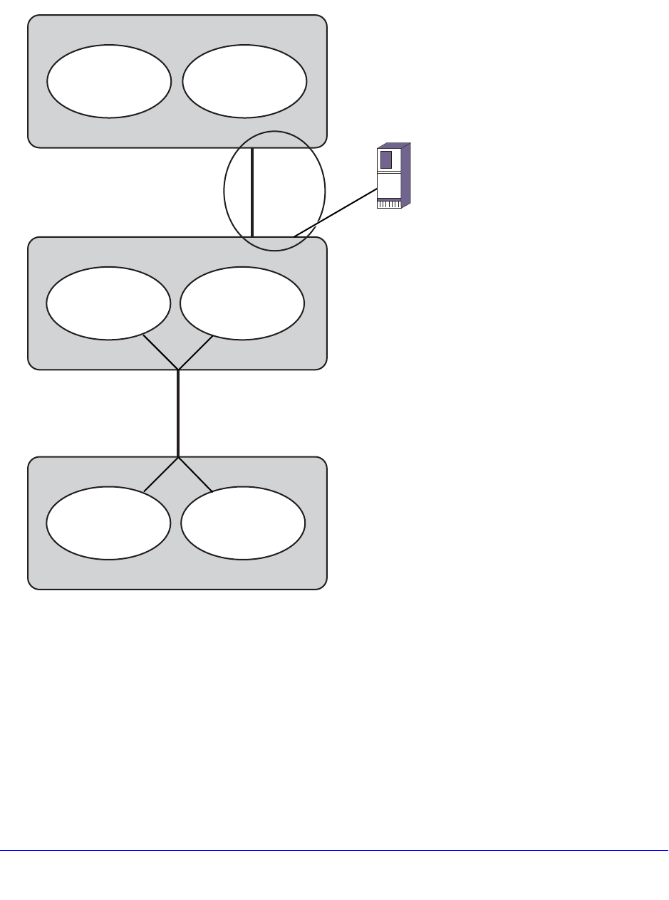
Chapter 9. VLANs | 267
NETGEAR 8800 User Manual
PVLAN Configuration Example 2
Figure 17 shows a PVLAN configuration example for a motel.
Figure 17. PVLAN Configuration Example 2
The motel example in Figure 17 has guest rooms, a conference room, and their web proxy
server on the first floor, and guest rooms on the second floor. The motel has three XCM8806
switches. There is one on the first floor in a closet, one on the first floor in the conference
room, and one on the second floor.
The PVLAN in Figure 17 contains the following PVLAN components:
• A VLAN called Main that contains the web proxy server.
• A VLAN called ConfRoom that contains the ports for the conference room connections.
Second Floor Summ it X450a
FirstFloor Summit X450a
Conference Room Summit X450a
Web Proxy
Server
ClientConnections
(tag 200, ports 5-20)
ConfRoom
(tag 300, no ports)
Port 2,
tagged
Port 2,
tagged Port 1
Main
(tag 100)
ClientConnections
(tag 200, ports 5-19,
20 tagged)
ConfRoom
(tag 300, ports 21-30,
20 tagged)
Port 20
tagged
Port 20
tagged
ClientConnections
(tag 200, ports 1-19,
20 tagged)
ConfRoom
(tag 300, ports 21-30,
20 tagged)
EX_vlan_0060

268 | Chapter 9. VLANs
NETGEAR 8800 User Manual
• A VLAN called ClientConnections that contains client PC connections for the guest
rooms.
The goals for the motel network are as follows:
• Provide internet access for the ConfRoom and ClientConnections VLANs through the
web proxy server.
• Prevent communications between the ConfRoom and ClientConnections VLANs
• Enable communications between clients on the ClientConnections VLAN only within the
conference room.
• Enable communications between devices on the ConfRoom VLAN.
• Prevent communications between the PCs in the ClientConnections VLAN that are not in
the conference room.
Notice the following in Figure 17:
• The XCM8806 switches in the first floor closet and on the second floor contain the Main
VLAN with a tag of 100. This VLAN is connected via a tagged port between the first and
second floor switches.
• The XCM8806 in the conference room does not contain the Main VLAN and cannot be a
PVLAN member.
• All of the switches have the ClientConnections VLAN, and it uses VLAN tag 200.
• All of the switches have the ConfRoom VLAN, and it uses VLAN tag 300.
• The Conference Room XCM8806 connects to the rest of the network through a tagged
connection to the XCM8806 in the first floor closet.
• Because the XCM8806 in the first floor closet is a PVLAN member and uses the same
port to support two subscriber VLANs, a loopback port is required in all subscriber
VLANs, except the first configured subscriber VLAN.
Note: The following examples contain comments that follow the CLI
comment character (#). All text that follows this character is ignored
by the switch and can be omitted from the switch configuration.
The following commands configure the XCM8806 in the first floor closet:
# Create and configure the VLANs.
create vlan Main
configure vlan Main add port 1:1
configure vlan Main tag 100
configure vlan Main add port 1:2 tagged
create vlan ClientConnections
configure vlan ClientConnections tag 200
configure vlan ClientConnections add port 1:5-1:19
configure vlan ClientConnections add port 1:20 tagged

Chapter 9. VLANs | 269
NETGEAR 8800 User Manual
create vlan ConfRoom
configure vlan ConfRoom tag 300
configure vlan ConfRoom add port 1:21-1:30
configure vlan ConfRoom add port 1:20 tagged
# Create and configure the PVLAN named Motel.
create private-vlan Motel
configure private-vlan Motel add network Main
configure private-vlan Motel add subscriber ClientConnections # isolated
subscriber VLAN
configure private-vlan "Motel" add subscriber "ConfRoom" non-isolated
loopback-port 30
configure private-vlan Motel add subscriber ConfRoom non-isolated
# If you omit the loopback-port command, the above command produces the following
error message:
# Cannot add subscriber because another subscriber vlan is already present on the
same port, assign a loopback port when adding the subscriber vlan to the private
vlan
show vlan "ConfRoom"
VLAN Interface with name ConfRoom created by user
Admin State: Enabled Tagging: 802.1Q Tag 300
Virtual router: VR-Default
IPv6: None
STPD: None
Protocol: Match all unfiltered protocols
Loopback: Disabled
NetLogin: Disabled
QosProfile: None configured
Egress Rate Limit Designated Port: None configured
Private-VLAN Name: Motel
VLAN Type in Private-VLAN: Non-Isolated Subscriber
Ports: 1:13. (Number of active ports=1)
Untag: 1:21, 1:22, 1:23, 1:24, 1:25, 1:26, 1:27,
1:28, 1:29
Tag: 1s, 2s, 20, *30L
Flags: (*) Active, (!) Disabled, (g) Load Sharing port
(b) Port blocked on the vlan, (m) Mac-Based port
(a) Egress traffic allowed for NetLogin
(u) Egress traffic unallowed for NetLogin
(t) Translate VLAN tag for Private-VLAN
(s) Private-VLAN System Port, (L) Loopback port
(e) Private-VLAN End Point Port

270 | Chapter 9. VLANs
NETGEAR 8800 User Manual
# Note that the loopback port is flagged with an "L" and listed as a tagged port,
and the network VLAN ports are flagged with an "s" and listed as tagged ports.
The following commands configure the XCM8806 on the second floor:
# create and configure the VLANs
create vlan Main
configure vlan Main tag 100
configure vlan Main add port 1:2 tagged
create vlan ClientConnections
configure vlan ClientConnections tag 200
configure vlan ClientConnections add port 1:5-1:20
create vlan ConfRoom
configure vlan ConfRoom tag 300
# Create and configure the PVLAN named Motel.
create private-vlan Motel
configure private-vlan Motel add network Main
configure private-vlan Motel add subscriber ClientConnections # isolated
subscriber VLAN
configure private-vlan Motel add subscriber ConfRoom non-isolated
The following commands configure the XCM8806 in the conference room:
# create and configure the VLANs
create vlan ClientConnections
configure vlan ClientConnections tag 200
configure vlan ClientConnections add port 1:1-1:19
configure vlan ClientConnections add port 1:20 tag
create vlan ConfRoom
configure vlan ConfRoom tag 300
configure vlan ConfRoom add port 1:21-1:30
configure vlan ConfRoom add port 1:20 tag
# The VLANs operate as extensions of the VLANs on the XCM8806 in the first floor
closet. There is no PVLAN configuration on this switch.

Chapter 10. FDB | 271
10
10. FDB
This chapter includes the following sections:
• Overview on page 271
• Managing the FDB on page 274
• Displaying FDB Entries and Statistics on page 278
• MAC-Based Security on page 279
• Multicast FDB with Multiport Entry on page 283
Overview
Note: See the NETGEAR 8800 Chassis Switch CLI Manual for details of
the commands related to the FDB.
The switch maintains a forwarding database (FDB) of all MAC addresses received on all of its
ports. It uses the information in this database to decide whether a frame should be forwarded or
filtered.
This section describes the following topics:
• FDB Contents on page 272
• How FDB Entries Get Added on page 272
• FDB Entry Types on page 272

272 | Chapter 10. FDB
NETGEAR 8800 User Manual
FDB Contents
Each Forwarding Database (FDB) entry consists of:
• The MAC address of the device
• An identifier for the port and VLAN on which it was received
• The age of the entry
• Flags
Frames destined for MAC addresses that are not in the FDB are flooded to all members of
the VLAN.
How FDB Entries Get Added
The MAC entries that are added to the FDB are learned in the following ways:
• On NETGEAR 8800 series switches, MAC entries can be learned at the hardware level.
• Virtual MAC addresses embedded in the payload of IP ARP packets can be learned when
this feature is enabled.
• Static entries can be entered using the command line interface (CLI).
• Dynamic entries can be modified using the command line interface (CLI).
• Static entries for switch interfaces are added by the system upon switch boot-up.
The ability to learn MAC addresses can be enabled or disabled on a port-by-port basis. You
can also limit the number of addresses that can be learned, or you can lock down the current
entries and prevent additional MAC address learning.
NETGEAR 8000 series modules support different FDB table sizes. On a NETGEAR 8800
switch with a variety of modules, the FDB tables on some modules can be filled before the
tables on other modules. In this situation, when a lower-capacity FDB table cannot accept
FDB entries, a message appears that is similar to the following:
HAL.FDB.Warning> MSM-A: FDB for vlanID1 mac 00:00:03:05:15:04 was not added to
slot 3 - table full.
Note: For information on FDB tables sizes, see the NETGEAR 8800
Release Notes.
FDB Entry Types
The following sections describes the types of entries that can exist in the FDB:
• Dynamic Entries on page 273
• Static Entries on page 273
• Blackhole Entries on page 274

Chapter 10. FDB | 273
NETGEAR 8800 User Manual
• Private VLAN Entries on page 274
Dynamic Entries
A dynamic entry is learned by the switch by examining packets to determine the source MAC
address, VLAN, and port information. The switch then creates or updates an FDB entry for
that MAC address. Initially, all entries in the database are dynamic, except for certain entries
created by the switch at boot-up.
Entries in the database are removed (aged-out) if, after a period of time (aging time), the
device has not transmitted. This prevents the database from becoming full with obsolete
entries by ensuring that when a device is removed from the network, its entry is deleted from
the database. The aging time is configurable, and the aging process operates on the
supported platforms as follows:
• You can configure the aging time to 0, which prevents the automatic removal of all
dynamic entries.
• The aging process takes place in software and the aging time is configurable.
For more information about setting the aging time, see Configuring the FDB Aging Time on
page 275.
Note: If the FDB entry aging time is set to 0, all dynamically learned
entries in the database are considered static, non-aging entries. This
means that the entries do not age, but they are still deleted if the
switch is reset.
Dynamic entries are flushed and relearned (updated) when any of the following take place:
• A VLAN is deleted.
• A VLAN identifier (VLANid) is changed.
• A port mode is changed (tagged/untagged).
• A port is deleted from a VLAN.
• A port is disabled.
• A port enters blocking state.
• A port goes down (link down).
A non-permanent dynamic entry is initially created when the switch identifies a new source
MAC address that does not yet have an entry in the FDB. The entry can then be updated as
the switch continues to encounter the address in the packets it examines. These entries are
identified by the “d” flag in show fdb command output.
Static Entries
A static entry does not age and does not get updated through the learning process. A static
entry is considered permanent because it is retained in the database if the switch is reset or a

274 | Chapter 10. FDB
NETGEAR 8800 User Manual
power off/on cycle occurs. A static entry is maintained exactly as it was created. Conditions
that cause dynamic entries to be updated, such as VLAN or port configuration changes, do
not affect static entries.
To create a permanent static FDB entry, see Adding a Permanent Static Entry on page 274.
A locked static entry is an entry that was originally learned dynamically, but has been made
static (locked) using the MAC address lock-down feature. It is identified by the “s,” “p,” and “l”
flags in show fdb command output and can be deleted using the delete fdbentry [all |
<mac_address> [vlan <vlan name>] command. See MAC Address Lockdown on page 439 for
more information about MAC address lock-down.
Blackhole Entries
A blackhole entry configures the switch to discard packets with a specified MAC destination
address. Blackhole entries are useful as a security measure or in special circumstances
where a specific source or destination address must be discarded. Blackhole entries can be
created through the CLI, or they can be created by the switch when a port’s learning limit has
been exceeded.
Blackhole entries are treated like permanent entries in the event of a switch reset or power
off/on cycle. Blackhole entries are never aged out of the database.
Private VLAN Entries
A Private VLAN (PVLAN) creates special FDB entries that are described in MAC Address
Management in a PVLAN on page 257.
Managing the FDB
This section describes the following topics:
• Adding a Permanent Static Entry on page 274
• Configuring the FDB Aging Time on page 275
• Adding Virtual MAC Entries from IP ARP Packets on page 275
• Clearing FDB Entries on page 275
• Managing Multiple Port FDB Entries on page 276
• Supporting Remote Mirroring on page 276
• Managing FDB MAC Address Tracking on page 277
Adding a Permanent Static Entry
To add a static entry, use the following command:
create fdbentry <mac_addr> vlan <vlan_name> [ports <port_list> | blackhole]
The following example adds a permanent static entry to the FDB:

Chapter 10. FDB | 275
NETGEAR 8800 User Manual
create fdbentry 00:E0:2B:12:34:56 vlan marketing port 3:4
The permanent entry has the following characteristics:
• MAC address is 00:E0:2B:12:34:56.
• VLAN name is marketing.
• Slot number for this device is 3 (only on modular switches).
• Port number for this device is 4.
Configuring the FDB Aging Time
You configure the aging time for dynamic FDB entries using the following command:
configure fdb agingtime <seconds>
If the aging time is set to 0, all aging entries in the database are defined as static, nonaging
entries. This means the entries will not age out, but non-permanent static entries can be
deleted if the switch is reset.
To display the aging time, use the following command:
show fdb
Adding Virtual MAC Entries from IP ARP Packets
Generally, the FDB is programmed with the source MAC address of frames that contain an IP
ARP payload. MAC entries present in the ARP payload as Sender-MAC are not learned.
When IP ARP Sender-MAC learning is enabled, the switch learns both the source MAC
address and the Sender-MAC from the ARP payload, and the switch programs these MAC
addresses in the FDB.
This feature is useful when you want the switch to learn the Sender-MAC address for a
redundant protocol, such as VRRP. For example, if your network has a gateway with a virtual
MAC address, the switch learns the system MAC address for the gateway. If you enable the
IP ARP Sender-MAC learning feature, the switch also learns the virtual MAC address
embedded in IP ARP packets for the gateway IP address.
To enable the IP ARP sender-MAC learning feature, use the following command:
enable learning iparp sender-mac
To view the configuration of this feature, use the following command:
show iparp
To disable this feature, use the following command:
disable learning iparp sender-mac
Clearing FDB Entries
You clear dynamic and permanent entries using different CLI commands.

276 | Chapter 10. FDB
NETGEAR 8800 User Manual
You clear dynamic FDB entries by targeting:
• Specified MAC addresses
• Specified ports
• Specified VLANs,
• All blackhole entries
To clear dynamic entries from the FDB, use the following command:
clear fdb {<mac_addr> | ports <port_list> | vlan <vlan_name> | blackhole}
You clear permanent FDB entries by targeting:
• All permanent entries
• Specified MAC addresses
• Specified VLANs
• All blackhole entries
To clear permanent entries from the FDB, use the following command:
delete fdbentry [all | <mac_address> [vlan <vlan name>]
Managing Multiple Port FDB Entries
The following command begins accepting unicast MAC addresses with multiple ports on all
platforms:
XCM8806 # create fdbentry 00:00:00:00:00:01 "Default" port 1,2
Prior to this release, these platforms would report the following error:
Error: Does not support multiple port FDB entries for uni-cast MAC address!
When the port list contains ports on different slots, the following error is generated:
Error: Multiple ports must be on the same slot for unicast MAC FDB entries.
When an original series port is listed with a multiple port list, the following error is generated:
XCM8806 # create fdbentry 00:00:00:00:00:01 "Default" port 3,4
Error: Slot 3 does not support multiple port FDB entries for uni-cast MAC
address
Supporting Remote Mirroring
The remote mirroring feature copies select traffic from select ports and VLANs and sends the
copied traffic to a remote switch for analysis. The mirrored traffic is sent using a VLAN that is
configured for this purpose. For more information, see Mirroring on page 138.
Transit switches are the switches between the source switch where ports are mirrored and
the destination switch where the mirrored traffic exits the network to an network analyzer or
network storage device. Because the mirrored traffic is an exact copy of the real traffic, a

Chapter 10. FDB | 277
NETGEAR 8800 User Manual
transit switch can learn the MAC addresses and make incorrect forwarding decisions. To
prevent learning on a remote mirroring VLAN, use the following command:
disable learning {vlan} <vlan_name>
To enable learning after it has been disabled, use the following command:
enable learning {vlan} <vlan_name>
Managing FDB MAC Address Tracking
The MAC address tracking feature tracks FDB add, move, and delete events for specified
MAC addresses and for specified ports. When MAC address tracking is enabled for a port,
this feature applies to all MAC addresses on the port.
When an event occurs for a specified address or port, the software generates an EMS
message and can optionally send an SNMP trap. When MAC address tracking is enabled for
a specific MAC address, this feature updates internal event counters for the address.
Note: When a MAC address is configured in the tracking table, but
detected on a MAC tracking enabled port, the per MAC address
statistical counters are not updated.
The MAC address tracking feature is always enabled, however, you must configure MAC
addresses or ports before tracking begins. The default configuration contains no MAC
addresses in the MAC address tracking table and disables this feature on all ports.
The following sections describe how to manage this feature:
• Adding and Deleting MAC Addresses for Tracking on page 277
• Enabling and Disabling MAC Address Tracking on Ports on page 277
• Enabling and Disabling SNMP Traps for MAC Address Changes on page 278
• Displaying the Tracked MAC Addresses and Tracking Statistics on page 278
• Clearing the Tracking Statistics Counters on page 278
Adding and Deleting MAC Addresses for Tracking
Use the following commands to add or delete MAC addresses in the MAC address tracking
table:
create fdb mac-tracking entry <mac_addr>
delete fdb mac-tracking entry [<mac_addr> | all]
Enabling and Disabling MAC Address Tracking on Ports
Use the following command to enable or disable MAC addresses tracking on specific ports:
configure fdb mac-tracking {[add|delete]} ports [<port_list>|all]

278 | Chapter 10. FDB
NETGEAR 8800 User Manual
Enabling and Disabling SNMP Traps for MAC Address Changes
The default switch configuration disables SNMP traps for MAC address changes. Use the
following commands to enable or disable SNMP traps for MAC address tracking events:
enable snmp traps fdb mac-tracking
disable snmp traps fdb mac-tracking
Displaying the Tracked MAC Addresses and Tracking Statistics
Use the following command to display the MAC address tracking feature configuration,
including the list of tracked MAC addresses:
show fdb mac-tracking configuration
Use the following command to display the counters for MAC address add, move, and delete
events:
show fdb mac-tracking statistics {<mac_addr>} {no-refresh}
Clearing the Tracking Statistics Counters
There are several ways to clear the MAC tracking counters:
• Use the clear counters command
• Use the 0 key while displaying the counters with the show fdb mac-tracking statistics
{<mac_addr>} command
• Enter the clear counters fdb mac-tracking [<mac_addr> | all] command
Displaying FDB Entries and Statistics
The following sections describe commands to display FDB entries and statistics:
• Displaying FDB Entries on page 278
• Displaying FDB Statistics on page 279
Displaying FDB Entries
To display FDB entries, use the following command:
show fdb {blackhole {netlogin [all | mac-based-vlans]} | hardware <mac_addr>
{vlan} <vlan_name> slot [all | <slot>] {number <num_entries>} | netlogin [all |
mac-based-vlans] | permanent {netlogin [all | mac-based-vlans]} | <mac_addr>
{netlogin [all | mac-based-vlans]} | ports <port_list> {netlogin [all |
mac-based-vlans]} | vlan <vlan_name> {netlogin [all | mac-based-vlans]} |
{{vpls} {<vpls_name>}}}

Chapter 10. FDB | 279
NETGEAR 8800 User Manual
Note: The MAC-based VLAN netlogin parameter applies only for the
NETGEAR 8800 series switches. See Chapter 16, Network Login
for more information on netlogin.
With no options, the command displays all FDB entries. (The age parameter does not show
on the display for the backup MSM/MM on modular switches; it does show on the display for
the primary MSM/MM.)
Displaying FDB Statistics
To display FDB statistics, use the following command:
show fdb stats {{ports {all | <port_list>} | vlan {all} | {vlan} <vlan_name> }
{no-refresh}}
With no options, the command displays summary FDB statistics.
MAC-Based Security
MAC-based security allows you to control the way the FDB is learned and populated. By
managing entries in the FDB, you can block and control packet flows on a per-address basis.
Note: MAC-based security is not supported on BlackDiamond 20800
series switches in this software release.
MAC-based security allows you to limit the number of dynamically-learned MAC addresses
allowed per virtual port. You can also “lock” the FDB entries for a virtual port, so that the
current entries will not change, and no additional addresses can be learned on the port.
You can also prioritize or stop packet flows based on the source MAC address of the ingress
VLAN or the destination MAC address of the egress VLAN.
Note: For detailed information about MAC-based security, see Chapter 17,
Security.
This section describes the following topics:
• Managing MAC Address Learning on page 280
• Managing Egress Flooding on page 281
• Displaying Learning and Flooding Settings on page 282

280 | Chapter 10. FDB
NETGEAR 8800 User Manual
• Creating Blackhole FDB Entries on page 283
Managing MAC Address Learning
By default, MAC address learning is enabled on all ports. MAC addresses are added to the
FDB as described in How FDB Entries Get Added on page 272.
When MAC address learning is disabled on a port, the switch no longer stores the source
address information in the FDB. However, the switch can still examine the source MAC
address for incoming packets and either forward or drop the packets based on this address.
The source address examination serves as a preprocessor for packets. Forwarded packets
are forwarded to other processes, not to other ports. For example, if the switch forwards a
packet based on the source address, the packet can still be dropped based on the
destination address or the egress flooding configuration.
When MAC address learning is disabled, the two supported behaviors are labeled as follows
in the software:
• forward-packets
• drop-packets
The forward-packets behavior forwards all received packets for further processing. No action
is taken based on the source address.
When the drop-packets option is chosen and all unicast, multicast, and broadcast packets
from a source address not in the FDB are dropped. No further processing occurs for dropped
packets.
The disable learning forward-packets option saves switch resources (FDB space), however, it
can consume network resources when egress flooding is enabled. When egress flooding is
disabled or the drop-packet option is specified, disabling learning adds security by limiting
access to only those devices listed in the FDB.
To disable learning on specified ports, use the following command:
disable learning {drop-packets | forward-packets} port [<port_list> | all]
Note: If neither option is specified, the drop-packets behavior is selected.
To enable learning on specified ports, use the following command:
enable learning {drop-packets | forward-packets} ports [all | <port_list>]
MAC address learning is disabled on a service VLAN (SVLAN) or backbone VLAN (BVLAN)
to create a Provider Backbone Bridge (PBB).
To enable or disable learning on an entire SVLAN or BVLAN, use the following commands
with the appropriate options:
enable learning vlan <vlan-name>
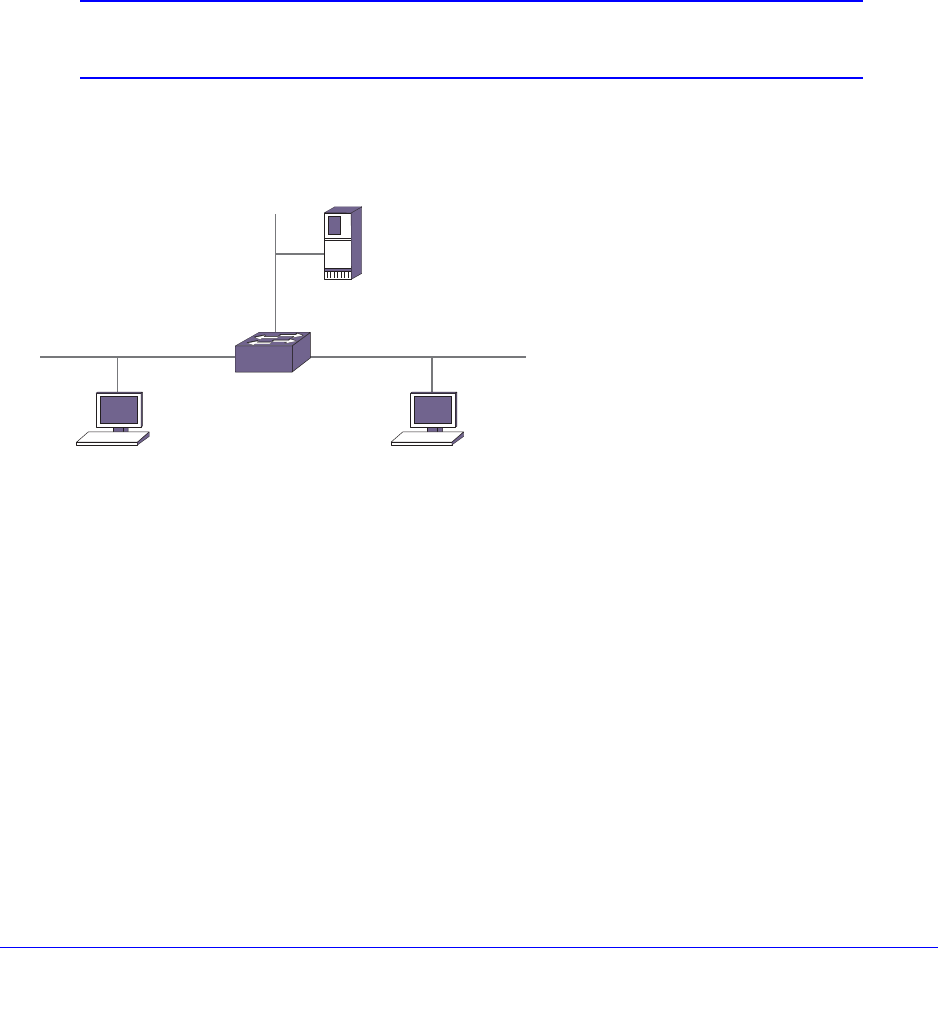
Chapter 10. FDB | 281
NETGEAR 8800 User Manual
disable learning vlan <vlan-name>
Managing Egress Flooding
Egress flooding takes action on a packet based on the packet destination MAC address. By
default, egress flooding is enabled, and any packet for which the destination address is not in
the FDB is flooded to all ports except the ingress port.
You can enhance security and privacy as well as improve network performance by disabling
Layer 2 egress flooding on a port or VLAN. This is particularly useful when you are working
on an edge device in the network. Limiting flooded egress packets to selected interfaces is
also known as upstream forwarding.
Note: Disabling egress flooding can affect many protocols, such as IP and
ARP.
Figure 18 illustrates a case where you want to disable Layer 2 egress flooding on specified
ports to enhance security and network performance.
Figure 18. Upstream Forwarding or Disabling Egress Flooding Example
In this example, the three ports are in an ISP-access VLAN. Ports 1 and 2 are connected to
clients 1 and 2, respectively, and port 3 is an uplink to the ISP network. Because clients 1 and
2 are in the same VLAN, client 1 could possibly learn about the other client’s traffic by sniffing
client 2’s broadcast traffic; client 1 could then possibly launch an attack on client 2.
However, when you disable all egress flooding on ports 1 and 2, this sort of attack is
impossible, for the following reasons:
• Broadcast and multicast traffic from the clients is forwarded only to the uplink port.
• Any packet with unlearned destination MAC addresses is forwarded only to the uplink
port.
• One client cannot learn any information from the other client. Because egress flooding is
disabled on the access ports, the only packets forwarded to each access port are those
packets that are specifically targeted for one of the ports. There is no traffic leakage.
Client 1
Uplink
port 3
Access Link
port 2
Access Link
port 1
ISP FW/
Security Proxy
EXOS Switch
Access VLAN
XOS004A
Client 2

282 | Chapter 10. FDB
NETGEAR 8800 User Manual
In this way, the communication between client 1 and client 2 is controlled. If client 1 needs to
communicate with client 2 and has that IP address, client 1 sends out an ARP request to
resolve the IP address for client 2.
Guidelines for Enabling or Disabling Egress Flooding
The following guidelines apply to enabling and disabling egress flooding:
• Egress flooding can be disabled on ports that are in a load-sharing group. In a
load-sharing group, the ports in the group take on the egress flooding state of the master
port; each member port of the load-sharing group has the same state as the master port.
• FDB learning takes place on ingress ports and is independent of egress flooding; either
can be enabled or disabled independently.
• Disabling unicast (or all) egress flooding to a port also prevents the flooding of packets
with unknown MAC addresses to that port.
• Disabling broadcast (or all) egress flooding to a port also prevents the flooding of
broadcast packets to that port.
• For NETGEAR 8800 switches, the following guidelines apply:
• You can enable or disable egress flooding for unicast, multicast, or broadcast MAC
addresses, as well as for all packets on one or more ports.
• Disabling multicasting egress flooding does not affect those packets within an IGMP
membership group at all; those packets are still forwarded out.
• If IGMP snooping is disabled, multicast packets with static FDB entries are forwarded
according to the FDB entry.
Configuring Egress Flooding
To enable or disable egress flooding on NETGEAR 8800 switches, use the following
commands:
enable flooding [all_cast | broadcast | multicast | unicast] ports [<port_list>
| all]
disable flooding [all_cast | broadcast | multicast | unicast] ports [<port_list>
| all]
Displaying Learning and Flooding Settings
To display the status of MAC learning and egress flooding, use the following commands:
show ports {mgmt | <port_list>} information {detail}
show vlan {detail {ipv4 | ipv6} | <vlan_name> {ipv4 | ipv6} | virtual-router
<vr-router> | <vlan_name> stpd | security}
The flags in the command display indicate the status.

Chapter 10. FDB | 283
NETGEAR 8800 User Manual
Creating Blackhole FDB Entries
A blackhole FDB entry discards all packets addressed to or received from the specified MAC
address. To create a blackhole FDB entry, use the following command:
create fdbentry <mac_addr> vlan <vlan_name> [ports <port_list> | blackhole]
There is no software indication or notification when packets are discarded because they
match blackhole entries.
The blackhole option is also supported through access lists. For example, the following ACL
policy would also blackhole traffic destined to or sourced from a specific MAC address:
entry blackhole_dest {
if {
ethernet-destination-address 00:00:00:00:00:01;
} then {
deny;
}
}
entry blackhole_source {
if {
ethernet-source-address 00:00:00:00:00:01;
} then {
deny;
}
}
A significant difference between the above ACL policy and the create fdbentry command
blackhole option is the hardware used to implement the feature. Platforms with limited
hardware ACL table sizes are able to implement this feature using the FDB table instead of
an ACL table.
Multicast FDB with Multiport Entry
On NETGEAR 8800 series switches you can create FDB entries to multicast MAC addresses
(that is, 01:00:00:00:00:01) and list one or more ports. Use the create fdbentry <mac_addr>
vlan <vlan_name> [ports <port_list> | blackhole] command to enter the multicast FDB
address. After traffic with a multicast MAC destination address enters the switch, that traffic is
multicast to all ports on the list.
However, if the MAC address is in the IP multicast range (for example, 01:00:5e:XX:XX:XX),
IGMP snooping rules take precedence over the multicast static FDB entry. Of course, if you
disable IGMP snooping on all VLANs, the static FDB entry forwards traffic.
On NETGEAR 8800 modules, you can also add a multiport list to the creation of a static FDB
unicast MAC forwarding entry. This is implemented using the create fdbentry vlan ports
command.

284 | Chapter 10. FDB
NETGEAR 8800 User Manual
You can use the create fdbentry vlan ports command to create a static FDB entry with a
unicast MAC address and a list of more than one port. Once the static FDB is created, any
ingress traffic with a destination MAC address matching the FDB entry is multicasted to each
port in the specified list. If the FDB entry is the next hop for an IP adjacency, unicast routing
sends the packet to the first port in the list.
Note: When a multiport list is assigned to a unicast MAC address, load
sharing is not supported on the ports in the multiport list.
However, NETGEAR 8800 modules do not support this feature natively using the FDB table.
Instead, for each FDB entry of this type, a series of system ACLs have been installed which
match the specified MAC address and VLAN ID, and override the egress port forwarding list
with the supplied list of ports. Multiple ACLs per FDB are required to handle Layer 2 echo kill
by installing a unique ACL per individual port in the list to send matching traffic to all other
ports in the list.
User-configured ACLs take precedence over these FDB-generated ACL rules, and the total
number of rules is determined by the platform. The hardware ACL limitations for each
platform are described in Chapter 13, ACLs

Chapter 11. Virtual Routers | 285
11
11. Virtual Routers
This chapter includes the following sections:
• Overview on page 285
• Managing Virtual Routers on page 288
• Virtual Router Configuration Example on page 292
Overview
The XCM8800 software supports virtual routers (VRs). This capability allows a single physical
switch to be split into multiple VRs. This feature separates the traffic forwarded by a VR from the
traffic on a different VR.
Each VR maintains a separate logical forwarding table, which allows the VRs to have
overlapping IP addressing. Because each VR maintains its own separate routing information,
packets arriving on one VR are never switched to another.
Note: VRs should not be connected together through a Layer 2 domain.
Since there is a single MAC address per switch in XCM8800
software, this same MAC address is used for all VRs. If two VRs on
the same switch are connected through a Layer 2 domain, the
intermediate Layer 2 switches learn the same MAC address of the
switch on different ports, and may send traffic into the wrong VR.
Ports on the switch can either be used exclusively by one VR, or can be shared among two or
more VRs. One reason to configure a port for the exclusive use of a single VR is to be sure that
only packets from that VR egress from that port. One reason to configure a port to be shared by
multiple VRs is to pass traffic from multiple VRs across a shared link.
With multiple VRs contained on a single physical switch, some commands in XCM8800 software
now require you to specify to which VR the command applies. For example, when you use the
ping command, you must specify from which VR the ping packets are generated. Many
commands that deal with switch management use the management VR by default. See the

286 | Chapter 11. Virtual Routers
NETGEAR 8800 User Manual
NETGEAR 8800 Chassis Switch CLI Manual for information on the defaults for individual
commands.
Note: The term VR is also used with the Virtual Router Redundancy
Protocol (VRRP). VRRP uses the term to refer to a single VR that
spans more than one physical router, which allows multiple switches
to provide redundant routing services to users.
Types of Virtual Routers
The following sections introduce the two types of VRs in an XCM8800 system:
• System Virtual Routers on page 286
• User Virtual Routers on page 287
System Virtual Routers
The system VRs are the three VRs created at boot-up time. These system VRs cannot be
deleted or renamed. They are named VR-Mgmt, VR-Control, and VR-Default. The following
describes each system VR:
• VR-Mgmt
VR-Mgmt enables remote management stations to access the switch through Telnet,
SSH, and SNMP sessions; and it owns the management port. No other ports can be
added to VR-Mgmt, and the management port cannot be removed from it.
The Mgmt VLAN is created in VR-Mgmt during XCM8800 system boot-up. No other
VLAN can be created in this VR, and the Mgmt VLAN cannot be deleted from it.
No routing protocol is running on or can be added to VR-Mgmt.
• VR-Control
VR-Control is used for internal communications between all the modules and subsystems
in the switch. It has no external visible ports, and you cannot assign any port to it.
VR-Control has no VLAN interface, and no VLAN can be created for it.
No routing protocol is running on or can be added to VR-Control.
• VR-Default
VR-Default is the default VR created by the XCM8800 system. By default, all data ports in
the switch are assigned to VR-Default. Any data port can be added to and deleted from
VR-Default.
Users can create and delete VLANs in VR-Default. The Default VLAN is created in
VR-Default during the XCM8800 system boot-up. The Default VLAN cannot be deleted
from VR-Default.

Chapter 11. Virtual Routers | 287
NETGEAR 8800 User Manual
One instance of each routing protocol is spawned for VR-Default during the XCM8800
system boot-up, and these routing instances cannot be deleted.
User Virtual Routers
Note: User VRs are supported only on the platforms listed for this feature
in Table 75 on page 798. When a modular switch contains modules
or switches that do not support user VRs, the ports on those devices
cannot be added to a user VR.
User VRs are the VRs created by users in addition to the system VRs. When a new user VR
is created, by default, no ports are assigned, no VLAN interface is created, and no support for
any routing protocols is added.
User Virtual Router Configuration Domain
When you create user VRs, you must configure each VR separately, configuring routing
protocols and VLANs for each one. To simplify the configuration process, the XCM8800
software supports a VR configuration domain or context. When you enter a VR command, it
is applied to the currently selected VR context, and you can use VR commands to change
context to a different VR. The VR commands include all the BGP, OSPF, PIM, and RIP
commands, and the commands listed in Table 30.
Table 30. Virtual Router Commands
[enable | disable] ipforwarding
clear iparpa
clear counters iparpa
configure iparpa
configure iparp [add | delete]a
[enable | disable] iparpa
show iparpa
configure iproute [add | delete]a
show iproutea
show ipstatsa
rtlookup
create vlan <vlan-name>
[enable | disable] igmp

288 | Chapter 11. Virtual Routers
NETGEAR 8800 User Manual
The VR context simplifies configuration and management because you do not have to specify
the VR for each individual command. The current context is indicated in the command line
interface (CLI) prompt by the name of the user VR, or no name if in the VR-Default domain.
Managing Virtual Routers
To use the user VR functionality in the XCM8800 software, you need to complete the tasks
described in the following sections:
• Creating and Deleting User Virtual Routers on page 288
• Changing the VR Context on page 289
• Adding and Deleting Routing Protocols on page 289
• Configuring Ports to Use One or More Virtual Routers on page 290
• Displaying Ports and Protocols on page 291
• Configuring the Routing Protocols and VLANs on page 292
Creating and Deleting User Virtual Routers
The NETGEAR 8800 supports up to 64 user VRs. To create a user VR, use the following
command:
create virtual-router <vr-name>
Note: User VRs are supported only on the platforms listed for this feature
in Table 75 on page 798.
A VR name cannot be the same as a VLAN name. You cannot name a user VR with the
names VR-Mgmt, VR-Control, or VR-Default because these are the existing default system
VRs. For backward compatibility, user VRs also cannot be named VR-0, VR-1 or VR-2,
[enable | disable] igmp snoopinga
[enable | disable] ipmcforwarding
show igmp
show igmp snooping
show igmp group
show igmp snooping cache
a. Other commands are available with these
listed.
Table 30. Virtual Router Commands (Continued)

Chapter 11. Virtual Routers | 289
NETGEAR 8800 User Manual
because these three names are the names for the system VRs in XCM8800 releases before
11.0.
If you exceed the maximum number of VRs supported on your platform, a message similar to
the following appears:
Error: Maximum number of User VRs supported by the system is 64
To display the virtual routers, use the following command:
show virtual-router {<vr-name>}
To delete a user VR, use the following command:
delete virtual-router <vr-name>
Before you delete a VR, you must delete all VLANs created in that VR. All of the ports
assigned to this VR are deleted and made available to assign to other VRs. Any routing
protocol that is running on the VR is shut down and deleted gracefully.
Changing the VR Context
To simplify VR configuration, the XCM8800 software supports a VR configuration domain or
context, which allows you to enter commands without specifying a VR in each command. VR
commands are applied to the current VR context. The VR commands consist of all the BGP,
OSPF, PIM, and RIP commands, as well as the create vlan and delete vlan commands.
Other commands apply to the switch as a whole.
To enter a VR context, use the following command:
virtual-router {<vr-name>}
Use the virtual-router command with no VR name, or use the name VR-Default to return to
the default configuration domain.
The following example sets the VR context to the user VR helix:
* XCM8806.13 # virtual-router helix
* (vr helix) XCM8806.14 #
The CLI prompt displays the VR context.
Adding and Deleting Routing Protocols
When a user VR is created, no resources are allocated for routing protocols. You must add
the routing protocols needed for your VR before you attempt to configure them.
The maximum number of protocols supported is 48.
• The basic 7 protocols on VR-Default (RIP, OSPF, BGP, PIM, OSPFv3, and RIPNG)
• 41 additional protocols for user VRs. Any combination of the 5 basic protocols supported
on user VRs (RIP, OSPF, BGP, and PIM) can be assigned to the 64 user VRs, up to a
maximum number of 41.
290 | Chapter 11. Virtual Routers
NETGEAR 8800 User Manual
When you add a protocol to a user VR, the software starts a process to support the protocol,
but it does not enable that protocol. After you add a protocol to a user VR, you must
specifically enable and configure that protocol before it starts.
Note: You must add, configure, and enable a protocol for a VR before you
start unicast or multicast forwarding on the VR and before you
configure any features (such as VLANs) to use the VR.
To add a protocol to a VR, use the following command:
configure vr <vr-name> add protocol <protocol-name>
If you add more than the maximum number of protocols, the following message appears:
Error: Maximum number of Protocols that can be started in the system is 48
To remove a protocol from a VR, use the following command:
configure vr <vr-name> delete protocol <protocol-name>
Configuring Ports to Use One or More Virtual Routers
By default, all the user data ports belong to VR-Default and the default VLAN, Default. All
these ports are used exclusively by VR-Default. To configure a port to use one or more virtual
routers, you need to perform one or more of the tasks described in the following sections:
• Deleting Ports from a Virtual Router on page 290
• Adding Ports to a Single Virtual Router on page 291
• Adding Ports to Multiple Virtual Routers on page 291
Deleting Ports from a Virtual Router
To configure a port for exclusive use by another VR, or for use by multiple VRs, it must first be
deleted from VR-Default. You must delete the port from any VLAN it belongs to before
deleting it from a VR.
To delete a port from a VR, use the following command:
configure vr <vr-name> delete ports <portlist>
CAUTION:
Do not create Layer 2 connections between ports assigned to different
VRs in the same switch. Because each switch supports just one MAC
address, every VR in the switch uses the same MAC address. A Layer 2
connection between two VRs can cause external devices to direct traffic to
the wrong VR.

Chapter 11. Virtual Routers | 291
NETGEAR 8800 User Manual
Adding Ports to a Single Virtual Router
When you add a port to a VR, that port can only be used by that VR.
To add a port to a single VR, use the following command:
configure vr <vr-name> add ports <portlist>
The following example demonstrates how to remove all the ports on slot 3 from the Default
VLAN in VR-Default and add them for the exclusive use of user VR helix:
configure vlan default delete ports 3:*
configure vr vr-default delete ports 3:*
configure vr helix add ports 3:*
Adding Ports to Multiple Virtual Routers
To use a port in multiple VRs, do not add the port to a VR, as described in the previous
section. Add the port to a VLAN in the desired VR.
Note: See Chapter 15, QoS for details about how multiple VRs per port
can affect DiffServ and code replacement.
Note: You should configure any protocols you want to use on a user VR
before you add a VLAN to the user VR. When IP multicast
forwarding will be supported on a user VR, add the PIM protocol
before you enable IP multicast forwarding.
The following example demonstrates how to add port 3:5 to user VRs VR-green and
VR-blue. The tagged VLAN bldg_200 was previously configured in VR-green, and the tagged
VLAN bldg_300 was previously configured in VR-blue.
configure vlan default delete ports 3:5
configure vr vr-default delete ports 3:5
configure vlan bldg_200 add ports 3:5 tagged
configure vlan bldg_300 add ports 3:5 tagged
Displaying Ports and Protocols
You can display the ports, protocols, and names of protocol processes for a VR by using the
following command:
show virtual-router {<vr-name>}

292 | Chapter 11. Virtual Routers
NETGEAR 8800 User Manual
Configuring the Routing Protocols and VLANs
After a user VR is created, the ports are added, and support for any required routing
protocols is added, you can configure the VR.
To create a VLAN in a VR, use the following command:
create vlan <vlan_name> {vr <vr-name>}
If you do not specify a VR in the create vlan command, the VLAN is created in the current
VR context.
VLAN names must conform to the guidelines specified in Object Names on page 31.
Note: All VLAN names and VLAN IDs on a switch must be unique,
regardless of the VR in which they are created. You cannot have two
VLANs with the same name, even if they are in different VRs.
To display the VLANs in a specific VR, use the following command:
show vlan virtual-router <vr-name>
which is a specific form of this command:
show vlan {detail {ipv4 | ipv6} | <vlan_name> {ipv4 | ipv6} | virtual-router
<vr-router> | <vlan_name> stpd | security}
You can also configure routing protocols by using the standard XCM8800 software
commands. The routing configurations of the different VRs are independent of each other.
Virtual Router Configuration Example
The following example demonstrates how to:
• Create a user VR named helix.
• Remove ports from the VLAN Default and VR-Default.
• Add ports to user VR helix.
• Add the OSPF protocol to user VR helix.
• Set the VR context to helix, so that subsequent VR commands affect VR helix.
• Create a VLAN named helix-accounting.
• Add ports that belong to user VR helix to the helix-accounting VLAN.
The CLI prompt is shown in this example to show how the VR context appears. At the end of
the example, the VR is ready to be configured for OSPF, using XCM8800 software
commands.
* XCM8810.1 # create virtual-router helix
* XCM8810.2 # configure vlan default delete ports 3:*

Chapter 11. Virtual Routers | 293
NETGEAR 8800 User Manual
* XCM8810.3 # configure vr vr-default delete ports 3:*
* XCM8810.4 # configure vr helix add ports 3:*
* XCM8810.5 # configure vr helix add protocol ospf
* XCM8810.6 # virtual-router helix
* (vr helix) XCM8810.7 # create vlan helix-accounting
* (vr helix) XCM8810.8 # configure helix-accounting add ports 3:1
* (vr helix) XCM8810.9 #

Chapter 12. Policy Manager | 294
12
12. Policy Manager
This chapter includes the following sections:
• Overview on page 294
• Creating and Editing Policies on page 294
• Applying Policies on page 297
Overview
One of the processes that make up the XCM8800 system is the policy manager. The policy
manager is responsible for maintaining a set of policy statements in a policy database and
communicating these policy statements to the applications that request them.
Policies are used by the routing protocol applications to control the advertisement, reception,
and use of routing information by the switch. Using policies, a set of routes can be selectively
permitted (or denied) based on their attributes, for advertisements in the routing domain. The
routing protocol application can also modify the attributes of the routing information, based on
the policy statements.
Policies are also used by the access control list (ACL) application to perform packet filtering and
forwarding decisions on packets. The ACL application will program these policies into the packet
filtering hardware on the switch. Packets can be dropped, forwarded, moved to a different QoS
profile, or counted, based on the policy statements provided by the policy manager.
Creating and Editing Policies
A policy is created by writing a text file that contains a series of rule entries describing match
conditions and actions to take. Policies are created by writing a text file on a separate machine
and then downloading it to the switch. Once on the switch, the file is then loaded into a policy
database to be used by applications on the switch. Policy text files can also be created and
edited directly on the switch.

Chapter 12. Policy Manager | 295
NETGEAR 8800 User Manual
Note: Although the XCM8800 does not prohibit mixing ACL and routing
type entries in a policy file, it is strongly recommended that you do
not mix the entries, and you use separate policy files for ACL and
routing policies.
When you create a policy file, name the file with the policy name that you will use when
applying the policy, and use “.pol” as the filename extension. For example, the policy name
“boundary” refers to the text file “boundary.pol”.
Using the Edit Command
A VI-like editor is available on the switch to edit policies. To edit a policy file on the switch by
launching the editor, use the following command:
edit policy
There are many commands available with the editor. For information about the editor
commands, use any tutorial or documentation about VI. The following is only a short
introduction to the editor.
Edit operates in one of two modes; command and input. When a file first opens, you are in
the command mode. To write in the file, use the keyboard arrow keys to position your cursor
within the file, then press one of the following keys to enter input mode:
• i - To insert text ahead of the initial cursor position
• a- To append text after the initial cursor position
To escape the input mode and return to the command mode, press the Escape key.
Several commands can be used from the command mode. The following commands are the
most commonly used:
• dd - To delete the current line
• yy - To copy the current line
• p - To paste the line copied
• :w - To write (save) the file
• :q - To quit the file if no changes were made
• :q! - To forcefully quit the file without saving changes
• :wq - To write and quit the file
Using a Separate Machine
You can also edit policies on a separate machine. Any common text editor can be used to
create a policy file. The file is then transferred to the switch using TFTP and then applied.
To transfer policy files to the switch, use the following command:

296 | Chapter 12. Policy Manager
NETGEAR 8800 User Manual
tftp [<host-name> | <ip-address>] {-v <vr_name>} [-g | -p] [{-l [internal-memory
<local-file-internal> | memorycard <local-file-memcard> | <local-file>} {-r
<remote-file>} | {-r <remote-file>} {-l [internal-memory <local-file-internal>
| memorycard <local-file-memcard> | <local-file>]}]
Checking Policies
A policy file can be checked to see if it is syntactically correct. To check the policy syntax, use
the following command:
check policy
This command can only determine if the syntax of the policy file is correct and can be loaded
into the policy manager database. Since a policy can be used by multiple applications, a
particular application may have additional constraints on allowable policies.
Refreshing Policies
When a policy file is changed (such as adding, deleting an entry, adding/deleting/modifying a
statement), the information in the policy database does not change until the policy is
refreshed. The user must refresh the policy so that the latest copy of policy is used.
When the policy is refreshed, the new policy file is read, processed, and stored in the server
database. Any clients that use the policy are updated. To refresh the policy, use the following
command:
refresh policy
For ACL policies only, during the time that an ACL policy is refreshed, packets on the
interface are blackholed, by default. This is to protect the switch during the short time that the
policy is being applied to the hardware. It is conceivable that an unwanted packet could be
forwarded by the switch as the new ACL is being set up in the hardware. You can disable this
behavior. To control the behavior of the switch during an ACL refresh, use the following
commands:
enable access-list refresh blackhole
disable access-list refresh blackhole
The policy manager uses Smart Refresh to update the ACLs. When a change is detected,
only the ACL changes needed to modify the ACLs are sent to the hardware, and the
unchanged entries remain. This behavior avoids having to blackhole packets because the
ACLs have been momentarily cleared. Smart Refresh works well up for up to 200 changes. If
the number of changes exceeds 200, you will see this message: Policy file has more than
200 new rules. Smart refresh can not be carried out. Following this message, you will
see a prompt based on the current blackhole configuration. If blackhole is disabled you will
see the following prompt:
Note, the current setting for Access-list Refresh Blackhole is Disabled.
WARNING: If a full refresh is performed, it is possible packets that should be
denied may be forwarded through the switch during the time the access list is
being installed.

Chapter 12. Policy Manager | 297
NETGEAR 8800 User Manual
Would you like to perform a full refresh?
If blackhole is enabled, you will see the following prompt:
Note, the current setting for Access-list Refresh Blackhole is Enabled.
Would you like to perform a full refresh?
To take advantage of Smart Refresh, disable access-list refresh blackholing.
Applying Policies
ACL policies and routing policies are applied using different commands.
Applying ACL Policies
A policy intended to be used as an ACL is applied to an interface, and the CLI command
option is named <aclname>. Supply the policy name in place of the <aclname> option. To apply
an ACL policy, use the following command:
configure access-list <aclname> [any | ports <portlist> | vlan <vlanname>]
{ingress | egress}
When you use the any keyword, the ACL is applied to all the interfaces and is referred to as
the wildcard ACL. This ACL is evaluated for any ports without specific ACLs, and it is also
applied to any packets that do not match the specific ACLs applied to the interfaces.
When an ACL is already configured on an interface, the command is rejected and an error
message is displayed.
To remove an ACL from an interface, use the following command:
unconfigure access-list <policy-name> {any | ports <portlist> | vlan
<vlanname>} {ingress | egress}
To display the interfaces that have ACLs configured and the ACL that is configured on each,
use the following command:
show access-list {any | ports <portlist> | vlan <vlanname>} {ingress | egress}
Applying Routing Policies
To apply a routing policy, use the command appropriate to the client. Different protocols
support different ways to apply policies, but there are some generalities.
Commands that use the keyword import-policy are used to change the attributes of routes
installed into the switch routing table by the protocol. These commands cannot be used to
determine the routes to be added to the routing table. The following are examples for the
BGP and RIP protocols:
configure bgp import-policy [<policy-name> | none]
configure rip import-policy [<policy-name> | none]

298 | Chapter 12. Policy Manager
NETGEAR 8800 User Manual
Commands that use the keyword route-policy control the routes advertised or received by
the protocol. Following are examples for BGP and RIP:
configure bgp neighbor [<remoteaddr> | all] {address-family [ipv4-unicast |
ipv4-multicast]} route-policy [in | out] [none | <policy>]
configure bgp peer-group <peer-group-name> {address-family [ipv4-unicast |
ipv4-multicast]} route-policy [in |out] [none | <policy>]
configure rip vlan [<vlan-name> | all] route-policy [in | out] [<policy-name> |
none]
Other examples of commands that use route policies include:
configure ospf area <area-identifier> external-filter [<policy-map> |none]
configure ospf area <area-identifier> interarea-filter [<policy-map> | none]
configure rip vlan [<vlan-name> | all] trusted-gateway [<policy-name> | none]
To remove a routing policy, use the none option in the command.

Chapter 13. ACLs | 299
13
13. ACLs
This chapter includes the following sections:
• Overview on page 299
• ACL Rule Syntax on page 300
• Layer-2 Protocol Tunneling ACLs on page 312
• Dynamic ACLs on page 313
• ACL Evaluation Precedence on page 319
• Applying ACL Policy Files on page 321
• ACL Mechanisms on page 325
• Policy-Based Routing on page 337
• ACL Troubleshooting on page 344
Overview
Access Control Lists (ACLs) are used to perform packet filtering and forwarding decisions on
traffic traversing the switch. Each packet arriving on an ingress port and/or VLAN is compared to
the access list applied to that interface and is either permitted or denied. On NETGEAR 8800
series switches, packets egressing an interface can also be filtered. However, only a subset of
the filtering conditions available for ingress filtering are available for egress filtering.
In addition to forwarding or dropping packets that match an ACL, the switch can also perform
additional operations such as incrementing counters, logging packet headers, mirroring traffic to
a monitor port, sending the packet to a QoS profile, and metering the packets matching the ACL
to control bandwidth. Using ACLs has no impact on switch performance (with the minor
exception of the mirror-cpu action modifier).
ACLs are typically applied to traffic that crosses Layer 3 router boundaries, but it is possible to
use access lists within a Layer 2 virtual LAN (VLAN).
ACLs in XCM8800 apply to all traffic. This is somewhat different from the behavior in NETGEAR.
For example, if you deny all the traffic to a port, no traffic, including control packets, such as
OSPF or RIP, will reach the switch and the adjacency will be dropped. You must explicitly allow
those types of packets (if desired). In NETGEAR, an ACL that denied “all” traffic would allow
control packets (those bound for the CPU) to reach the switch.

300 | Chapter 13. ACLs
NETGEAR 8800 User Manual
ACLs are created in two different ways. One method is to create an ACL policy file and apply that
ACL policy file to a list of ports, a VLAN, or to all interfaces.
Note: ACLs applied to a VLAN are actually applied to all ports on the
switch, without regard to VLAN membership.
An ACL policy file is a text file that contains one or more ACL rule entries. This first method
creates ACLs that are persistent across switch reboots, can contain a large number of rule
entries, and are all applied at the same time. See ACL Rule Syntax on page 300 for information
about creating ACL rule entries. For information about creating policy files, see Policy Manager
on page 294.
Policy files are also used to define routing policies. Routing policies are used to control the
advertisement or recognition of routes communicated by routing protocols. ACL policy files and
routing policy files are both handled by the policy manager, and the syntax for both types of files
is checked by the policy manager.
Note: Although the XCM8800 does not prohibit mixing ACL and routing
type entries in a policy file, it is strongly recommended that you do
not mix the entries, and you use separate policy files for ACL and
routing policies.
The second method to create an ACL is to use the CLI to specify a single rule, called a dynamic
ACL. By default, dynamic ACLs persist across reboots; however, you can configure
non-persistent dynamic ACLS that disappear when the switch reboots. Dynamic ACLs consist of
only a single rule. Multiple dynamic ACLs can be applied to an interface. See Layer-2 Protocol
Tunneling ACLs on page 312 for information about creating dynamic ACLs. The precedence of
ACLs can be configured by defining zones and configuring the priority of both the zones and the
ACLs within a zone. See Configuring ACL Priority on page 315 for more information.
ACL Rule Syntax
An ACL rule entry consists of:
• A rule entry name, unique within the same ACL policy file or among Dynamic ACLs.
• Zero or more match conditions.
• Zero or one action (permit or deny). If no action is specified, the packet is permitted by
default.
• Zero or more action modifiers.
Each rule entry uses the following syntax:

Chapter 13. ACLs | 301
NETGEAR 8800 User Manual
entry <ACLrulename>{
if {
<match-conditions>;
} then {
<action>;
<action-modifiers>;
}
}
The following is an example of a rule entry:
entry udpacl {
if {
source-address 10.203.134.0/24;
destination-address 140.158.18.16/32;
protocol udp;
source-port 190;
destination-port 1200 - 1250;
} then {
permit;
}
}
An ACL rule is evaluated as follows:
• If the packet matches all the match conditions, the action and any action modifiers in the
then statement are taken.
• For ingress ACLs, if a rule entry does not contain any match condition, the packet is
considered to match and the action and any action modifiers in the rule entry’s then
statement are taken. For egress ACLs, if a rule entry does not contain any match
condition, no packets will match. See Matching All Egress Packets on page 302 for more
information.
• If the packet matches all the match conditions, and if there is no action specified in the
then statement, the action permit is taken by default.
• If the packet does not match all the match conditions, the action in the then statement is
ignored.
This section describes the following topics:
• Matching All Egress Packets on page 302
• Comments and Descriptions in ACL Policy Files on page 302
• Types of Rule Entries on page 303
• Match Conditions on page 303
• Actions on page 304
• Action Modifiers on page 304
• ACL Rule Syntax Details on page 306

302 | Chapter 13. ACLs
NETGEAR 8800 User Manual
Matching All Egress Packets
Unlike ingress ACLs, for egress ACLs you must specify either a source or destination
address, instead of writing a rule with no match conditions. (Exceptions are the
BlackDiamond 20800 series switches.)
For example, an ingress ACL deny all rule could be:
entry DenyAllIngress{
if {
} then {
deny;
}
}
The previous rule would not work as an egress ACL, except with BlackDiamond 20800 series
switches. The following is an example of an egress ACL deny all rule:
entry DenyAllEgress{
if {
source-address 0.0.0.0/0;
} then {
deny;
}
}
Comments and Descriptions in ACL Policy Files
In ACL policy files, there are two types of textual additions that have no effect on the ACL
actions: comments and descriptions. A comment is ignored by the policy manager and
resides only in the policy file. Comments are not saved in the switch configuration and are not
displayed by the "show policy" command. A description is saved in the policy manager and is
displayed when the ACL is displayed.
You can display the ACL using the following two commands:
show policy {<policy-name> | detail}
show access-list {any | ports <portlist> | vlan <vlanname>} {ingress | egress}
For example, the following policy, saved in the file denyping.pol, contains both a comment
and a description:
# this line is a comment
@description "This line is a description for the denyping.pol"
entry ping_deny_echo-request {
if {
protocol icmp;
icmp-type echo-request;
} then {
deny;
count pingcount_deny;
}
}

Chapter 13. ACLs | 303
NETGEAR 8800 User Manual
Note that the description begins with the tag @description and is a text string enclosed in
quotes.
You can apply the policy to port 1, using the following command:
configure access-list denyping port 1
and display the policy using the following command:
show policy denyping
The output of this command is similar to the following:
Policies at Policy Server:
Policy: denyping
@description This line is a description for the denyping.pol
entry ping_deny_echo-request {
if match all {
protocol icmp ;
icmp-type echo-request ;
}
then {
deny ;
count pingcount_deny ;
}
}
Number of clients bound to policy: 1
Client: acl bound once
Types of Rule Entries
In XCM8800, each rule can be one of following types:
• L2 rule—A rule containing only Layer 2 (L2) matching conditions, such as Ethernet MAC
address and Ethernet type
• L3 rule—A rule containing only Layer 3 (L3) matching conditions, such as source or
destination IP address and protocol
• L4 rule—A rule containing both Layer 3 (L3) and Layer 4 (L4) matching conditions, such
as TCP/UDP port number
Match Conditions
You can specify multiple, single, or zero match conditions. If no match condition is specified,
all packets match the rule entry. Commonly used match conditions are:
• ethernet-source-address <mac-address>—Ethernet source address
• ethernet-destination-address <mac-address> <mask>—Ethernet destination address
and mask

304 | Chapter 13. ACLs
NETGEAR 8800 User Manual
• source-address <prefix>—IP source address and mask
• destination-address <prefix>—IP destination address and mask
• source-port [<port> | <range]—TCP or UDP source port range
• destination-port [<port> | <range>]—TCP or UDP destination port range
Table 31 describes all the possible match conditions.
Actions
The actions are:
• permit—The packet is forwarded.
• deny—The packet is dropped.
The default action is permit, so if no action is specified in a rule entry, the packet is forwarded.
Action Modifiers
Additional actions can also be specified, independent of whether the packet is dropped or
forwarded. These additional actions are called action modifiers. Not all action modifiers are
available on all switches, and not all are available for both ingress and egress ACLs. The
action modifiers are:
• count <countername>—Increments the counter named in the action modifier
• log—Logs the packet header
• log-raw—Logs the packet header in hex format
• meter <metername>—Takes action depending on the traffic rate
• mirror—Sends a copy of the packet to the monitor (mirror) port (ingress only)
• mirror-cpu—Mirrors a copy of the packet to the CPU in order to log it
• qosprofile <qosprofilename>—Forwards the packet to the specified QoS profile
• traffic-queue <traffic-queue>—Places the traffic on the specified traffic-queue
• redirect <ipv4 addr>—Forwards the packet to the specified IPv4 address
• replace-dscp—Replaces the packet’s DSCP field with the value from the associated QoS
profile
• replace-dot1p—Replaces the packet’s 802.1p field with the value from the associated
QoS profile
• replace-dot1p-value <value>—Replaces the packet's 802.1p field with the value
specified without affecting the QoS profile assignment
• replace-ethernet-destination-address <mac-address>—Replaces the packet's
destination MAC address; this is applicable only to layer-2 forwarded traffic
• redirect-port <port>—Overrides the forwarding decision and changes the egress port
used

Chapter 13. ACLs | 305
NETGEAR 8800 User Manual
Counting Packets and Bytes
When the ACL entry match conditions are met, the specified counter is incremented. The
counter value can be displayed by the command:
show access-list counter {<countername>} {any | ports <portlist> | vlan
<vlanname>} {ingress | egress}
Users of NETGEAR 8800 switches can use ACL byte counters as an alternative to ACL
packet counters.
NETGEAR 8800 switches support only ACL packet counters and return an error similar to the
following when the “byte-count” token is used in an ACL rule.
(debug) BD-8806.8 # conf access-list add "aaa" last ports 1:1
Error: Slot 1 does not support ACL byte counters
Note: On NETGEAR 8800 switches, the maximum number of packets that
can be counted with token packet-count or count is 4,294,967,296.
Logging Packets
Packets are logged only when they go to the CPU, so packets in the fastpath are not
automatically logged. You must use both the mirror-cpu action modifier and the log or
log-raw action modifier if you want to log both slowpath and fastpath packets that match the
ACL rule entry. Additionally, Kern.Info messages are not logged by default. You must
configure an EMS filter to log these messages, for example, configure log filter
DefaultFilter add event kern.info. See Chapter 8, Status Monitoring and Statistics for
information about configuring EMS.
Metering Packets
The meter <metername> action modifier associates a rule entry with an ACL meter. See the
section, QoS Profiles on page 369 for more information.
Mirroring Packets
You must enable port-mirroring on your switch. For information, see Mirroring on page 138. If
you attempt to apply a policy that requires port-mirroring, you will receive an error message if
port-mirroring is not enabled.
On the NETGEAR 8800 switches, mirroring can be configured on the same port as egress
ACLs. Mirroring can send packets to port x and you can install your rule at egress port x, and
the rule should match your mirrored traffic.
Redirecting Packets
Packets are forwarded to the IPv4 address specified, without modifying the IP header (except
the TTL is decremented and the IP checksum is updated). The IPv4 address must be in the
306 | Chapter 13. ACLs
NETGEAR 8800 User Manual
IP ARP cache, otherwise the packet is forwarded normally. Only fast path traffic can be
redirected. This capability can be used to implement Policy-Based Routing.
You may want to create a static ARP entry for the redirection IP address, so that there will
always be a cache entry. See Policy-Based Routing on page 337 for more information.
Replacing DSCP or 802.1p Fields
Specify a QoS profile for matching packets. The field values are replaced with the value
associated with that profile. In the following example, DiffServ replacement is configured such
that QP8 is mapped to code point 56. Matching packets are sent to QP8, and the DSCP
value in the packet is set to 56.
entry voice_entry {
if {
source-address 2.2.2.2/32;
} then {
qosprofile qp8;
replace-dscp;
}
}
See Chapter 15, QoS for more details about QoS profiles, and 802.1p and DSCP
replacement.
ACL Rule Syntax Details
Table 31 lists the match conditions that can be used with ACLs, and whether the condition
can be used for ingress ACLs only, or with both ingress and egress. The conditions are
case-insensitive; for example, the match condition listed in the table as TCP-flags can also be
written as tcp-flags. Within Table 31 are five different data types used in matching packets.
Table 32 lists the data types and details on using them.
Table 31. ACL Match Conditions
Match Conditions Description Applicable
IP Protocols/
Direction
ethernet-type <number> Ethernet packet type. In place of the numeric value, you can
specify one of the following text synonyms (the field values are
also listed): ETHER-P-IP (0x0800), ETHER-P-8021Q
(0x8100), ETHER-P-IPV6 (0x86DD).
Ethernet/Ingress
only
ethernet-source-address
<mac-address> Ethernet source MAC address Ethernet/Ingress
only

Chapter 13. ACLs | 307
NETGEAR 8800 User Manual
ethernet-source-address
<mac-address> mask <mask>
or
ethernet-source-address
<mac-address> / <mask>
Ethernet source MAC address and mask. The mask is
optional, and is in the same format as the MAC address, for
example:
ethernet-source-address 00:01:02:03:01:01 mask
ff:ff:ff:ff:00:00
or
ethernet-source-address 00:01:02:03:01:01 /
ff:ff:ff:ff:00:00
Only those bits of the MAC address whose corresponding bit
in the mask is set to 1 will be used as match criteria. So, the
example above will match 00:01:02:03:xx:xx.
If the mask is not supplied then it will be assumed to be
ff:ff:ff:ff:ff:ff. In other words, all bits of the MAC address will be
used for matching.
Ethernet/Ingress
only
ethernet-destination-address
<mac-address> Ethernet destination MAC address Ethernet/Ingress
only
ethernet-destination-address
<mac-address> mask <mask>
or
ethernet-destination-address
<mac-address> / <mask>
Ethernet destination MAC address and mask. The mask is
optional, and is in the same format as the MAC address, for
example:
ethernet-destination-address
00:01:02:03:01:01 mask ff:ff:ff:ff:00:00
or
ethernet-destination-address
00:01:02:03:01:01 / ff:ff:ff:ff:00:00
Only those bits of the MAC address whose corresponding bit
in the mask is set to 1 will be used as match criteria. So, the
example above will match 00:01:02:03:xx:xx.
If the mask is not supplied then it will be assumed to be
ff:ff:ff:ff:ff:ff. In other words, all bits of the MAC address will be
used for matching.
Ethernet/Ingress
only
source-address <prefix> IP source address and mask. Egress ACLs do not support
IPv6 addresses, only IPv4 addresses. Use either all IPv4 or all
IPv6 addresses in an ACL.
All IP/Ingress and
Egress
destination-address <prefix> IP destination address and mask. Egress ACLs do not support
IPv6 addresses, only IPv4 addresses. Use either all IPv4 or all
IPv6 addresses in an ACL.
All IP/Ingress and
Egress
Source-port {<number> |
<range>} TCP or UDP source port. You must also specify the protocol
match condition to determine which protocol is being used on
the port, any time you use the this match condition. In place of
the numeric value, you can specify one of the text synonyms
listed under destination port. If no source-port is specified, the
default source-port is “any.”
TCP, UDP/Ingress
and Egress
Table 31. ACL Match Conditions (Continued)
Match Conditions Description Applicable
IP Protocols/
Direction

308 | Chapter 13. ACLs
NETGEAR 8800 User Manual
Destination-port {<number> |
<range>} TCP or UDP destination port. You must also specify the
protocol match condition to determine which protocol is being
used on the port, any time you use the this match condition. In
place of the numeric value, you can specify one of the
following text synonyms (the field values are also listed):
afs(1483), bgp(179), biff(512), bootpc(68), bootps(67),
cmd(514), cvspserver(2401), DHCP(67), domain(53),
eklogin(2105), ekshell(2106), exec(512), finger(79), ftp(21),
ftp-data(20), http(80), https(443), ident(113), imap(143),
kerberos-sec(88), klogin(543), kpasswd(761), krb-prop(754),
krbupdate(760), kshell(544), idap(389), login(513),
mobileip-agent(434), mobileip-mn(435), msdp(639),
netbios-dgm(138), netbios-ns(137), netbios-ssn(139),
nfsd(2049), nntp(119), ntalk(518), ntp(123), pop3(110),
pptp(1723), printer(515), radacct(1813), radius(1812),
rip(520), rkinit(2108), smtp(25), snmp(161), snmptrap(162),
snpp(444), socks(1080), ssh(22), sunrpc(111), syslog(514),
tacacs-ds(65), talk(517), telnet(23), tftp(69), timed(525),
who(513), xdmcp(177), zephyr-clt(2103), or zephyr-hm(2104).
TCP, UDP/Ingress
and Egress
TCP-flags <bitfield> TCP flags. Normally, you specify this match in conjunction with
the protocol match statement. In place of the numeric value,
you can specify one of the following text synonyms (the field
values are also listed): ACK(0x10), FIN(0x01), PUSH(0x08),
RST(0x04), SYN(0x02), URG(0x20), SYN_ACK(0x12).
TCP/Ingress and
Egress
IGMP-msg-type <number> IGMP message type. Possible values and text synonyms:
v1-report(0x12), v2-report(0x16), v3-report(0x22), V2-leave
(0x17), or query(0x11).
IGMP/Ingress and
Egress
Table 31. ACL Match Conditions (Continued)
Match Conditions Description Applicable
IP Protocols/
Direction

Chapter 13. ACLs | 309
NETGEAR 8800 User Manual
ICMP-code <number> ICMP code field. This value or keyword provides more specific
information than the icmp-type. Because the value's meaning
depends upon the associated icmp-type, you must specify the
icmp-type along with the icmp-code. In place of the numeric
value, you can specify one of the following text synonyms (the
field values also listed); the keywords are grouped by the
ICMP type with which they are associated:
Parameter-problem:
ip-header-bad(0), required-option-missing(1)
Redirect:
redirect-for-host (1), redirect-for-network (2),
redirect-for-tos-and-host (3), redirect-for-tos-and-net (2)
Time-exceeded:
ttl-eq-zero-during-reassembly(1), ttl-eq-zero-during-transit(0)
Unreachable:
communication-prohibited-by-filtering(13),
destination-host-prohibited(10), destination-host-unknown(7),
destination-network-prohibited(9),
destination-network-unknown(6), fragmentation-needed(4),
host-precedence-violation(14), host-unreachable(1),
host-unreachable-for-TOS(12), network-unreachable(0),
network-unreachable-for-TOS(11), port-unreachable(3),
precedence-cutoff-in-effect(15), protocol-unreachable(2),
source-host-isolated(8), source-route-failed(5)
ICMP/Ingress and
Egress
ICMP-type <number> ICMP type field. Normally, you specify this match in
conjunction with the protocol match statement. In place of the
numeric value, you can specify one of the following text
synonyms (the field values are also listed): echo-reply(0),
echo-request(8), info-reply(16), info-request(15),
mask-request(17), mask-reply(18), parameter-problem(12),
redirect(5), router-advertisement(9), router-solicit(10),
source-quench(4), time-exceeded(11), timestamp(13),
timestamp-reply(14), or unreachable(3).
ICMP/Ingress and
Egress
source-sap SSAP is a 1 byte field with possible values 0-255 decimal. The
value can be specified in decimal or hexadecimal. The SSAP
field can be found at byte offset 15 in 802.3 SNAP and LLC
formatted packets.
Ethernet/Ingress
Only
destination-sap DSAP is a 1 byte field with possible values 0-255 decimal. The
value can be specified in decimal or hexadecimal. The DSAP
field can be found at byte offset 14 in 802.3 SNAP and LLC
formatted packets.
Ethernet/Ingress
Only
Table 31. ACL Match Conditions (Continued)
Match Conditions Description Applicable
IP Protocols/
Direction

310 | Chapter 13. ACLs
NETGEAR 8800 User Manual
Note: Directed ARP response packets cannot be blocked with ACLs from
reaching the CPU and being learned.
Along with the data types described in Table 32, you can use the operators <, <=, >, and >= to
specify match conditions. For example, the match condition, source-port > 190, will match
packets with a source port greater than 190. Be sure to use a space before and after an
operator.
snap-type SNAP type is a 2 byte field with possible values 0-65535
decimal. The value can be specified in decimal or
hexadecimal. The SNAP type field can be found a byte offset
20 in 802.3 SNAP formatted packets.
Ethernet/Ingress
Only
IP-TOS <number> IP TOS field. In place of the numeric value, you can specify
one of the following text synonyms (the field values are also
listed): minimize-delay 16 (0x10), maximize-reliability 4(0x04),
minimize-cost2 (0x02), and normal-service 0(0x00).
All IP/Ingress and
Egress
fragments IP fragmented packet. FO > 0 (FO = Fragment Offset in IP
header)aAll IP, no L4
rules/Ingress only
first-fragments Non-IP fragmented packet or first fragmented packet. FO==0. All IP/Ingress only
protocol <number> IP protocol field. For IPv6b, this matches the Next Header field
in the packet. In place of the numeric value, you can specify
one of the following text synonyms (the field values are also
listed): egp(8), esp(5), gre(47), icmp(1), igmp(2), ipip(4),
ipv6(41), ospf(89), pim(102), rsvp(46), tcp(6), or udp(17).
All IP/Ingress and
Egress
vlan-id <number> Matches the VLAN tag number or the VLAN ID which is given
to a VLAN when created. The ACL rule can only be applied to
ports or any, and not VLANs.
All IP/Ingress
a. See the section Fragmented packet handling on page 311 for details.
b. See the section IPv6 Traffic with L4 Match Conditions on page 311 for details about specifying a protocol/port match
with IPv6.
Table 32. ACL Match Condition Data Types
Condition Data Type Description
prefix IP source and destination address prefixes. To specify the address prefix, use the
notation prefix/prefix-length. For a host address, prefix-length should be
set to 32.
number Numeric value, such as TCP or UDP source and destination port number, IP protocol
number.
Table 31. ACL Match Conditions (Continued)
Match Conditions Description Applicable
IP Protocols/
Direction

Chapter 13. ACLs | 311
NETGEAR 8800 User Manual
IPv6 Traffic with L4 Match Conditions
If you apply an ACL policy intended to match IPv6 packets using an ACL that specifies L4
conditions, the traffic will not be matched. For example, the following ACL:
entry destIp {
if {
protocol tcp;
destination-port 120 - 150;
}
then {
permit;
count destIp;
}
}
will not match any IPv6 packets. For IPv6 packets to match, you must add a match condition
that includes all IPv6 L3 addresses. For example, you would change the ACL entry to:
entry destIp {
if {
source-address 0::0/0;
protocol tcp;
destination-port 120 - 150;
}
then {
permit;
count destIp;
}
}
Fragmented packet handling
One keyword is used to support fragmentation in ACLs: first-fragments—FO == 0.
range A range of numeric values. To specify the numeric range, use the notation:
number - number
bit-field Used to match specific bits in an IP packet, such as TCP flags and the fragment flag.
mac-address 6-byte hardware address.
Table 32. ACL Match Condition Data Types
Condition Data Type Description

312 | Chapter 13. ACLs
NETGEAR 8800 User Manual
Policy file syntax checker
The following rules are used to evaluate fragmented packets or rules that use the fragments
or first-fragments keywords.
With no keyword specified, processing proceeds as follows:
• An L3-only rule that does not contain first-fragments keyword matches any IP packets.
• An L4 rule that does not contain first-fragments keyword matches non-fragmented or
initial-fragment packets.
With the first-fragments keyword specified:
• An L3-only rule with the first-fragments keyword matches non-fragmented or initial
fragment packets.
• An L4 rule with the first-fragments keyword matches non-fragmented or initial fragment
packets.
Layer-2 Protocol Tunneling ACLs
Three ACL match conditions and one ACL action interoperate with vendor-proprietary
Layer-2 protocol tunneling.
The following fields within 802.3 Subnetwork Access Protocol (SNAP) and LLC formatted
packets can be matched:
• Destination service access point (SAP)
• Source SAP
The following field can be matched within Subnetwork Access Protocol (SNAP) packets only:
• SNAP type
The following ACL action is added to the specified switches:
• Replacement of the Ethernet MAC destination address
This action replaces the destination MAC address of any matching Layer-2 forwarded
packets on the supported platforms. This action can be used to effectively tunnel protocol
packets, such as STP, across a network by replacing the well-known protocol MAC address
with a different proprietary or otherwise unique MAC address. After tunnel egress, the MAC
destination address can be reverted back to the well-known MAC address.
Note: The “replace-ethernet-destination-address” action applies only to
Layer-2 forwarded packets.

Chapter 13. ACLs | 313
NETGEAR 8800 User Manual
Dynamic ACLs
Dynamic ACLs are created using the CLI. They use a similar syntax and can accomplish the
same actions as single rule entries used in ACL policy files. More than one dynamic ACL can
be applied to an interface, and the precedence among the dynamic ACLs can be configured.
By default, the priority among dynamic ACLs is established by the order in which they are
configured.
Note: Dynamic ACLs have a higher precedence than ACLs applied using
a policy file.
The steps involved in using a dynamic ACL on an interface are:
• Creating the Dynamic ACL Rule on page 313
• Configuring the ACL Rule on the Interface on page 314.
• Configuring ACL Priority on page 315
Creating the Dynamic ACL Rule
Creating a dynamic ACL rule is similar to creating an ACL policy file rule entry. You specify
the name of the dynamic ACL rule, the match conditions, and the actions and
action-modifiers. You can configure a dynamic ACL to be persistent or non-persistent across
system reboots. The match conditions, actions, and action-modifiers are the same as those
that are available for ACL policy files (see ACL Rule Syntax on page 300). In contrast to the
ACL policy file entries, dynamic ACLs are created directly in the CLI. Use the following
command to create a dynamic ACL:
create access-list <dynamic-rule> <conditions> <actions> {non-permanent}
As an example of creating a dynamic ACL rule, compare an ACL policy file entry with the CLI
command that creates the equivalent dynamic ACL rule. The following ACL policy file entry
will drop all ICMP echo-requests:
entry icmp-echo {
if {
protocol icmp;
icmp-type echo-request;
} then {
deny;
}
}
To create the equivalent dynamic ACL rule, use the following command:
create access-list icmp-echo “protocol icmp;icmp-type echo-request” “deny”

314 | Chapter 13. ACLs
NETGEAR 8800 User Manual
Notice that the conditions parameter is a quoted string that corresponds to the match
conditions in the if { ... } portion of the ACL policy file entry. The individual match
conditions are concatenated into a single string. The actions parameter corresponds to the
then { ... } portion of the ACL policy file entry.
From the command line, you can get a list of match conditions and actions by using the
following command:
check policy attribute {<attr>}
The ACL rule shown in the example will be saved when the save command is executed,
because the optional keyword non-permanent was not configured. This allows the rule to
persist across system reboots.
Note also that the sample ACL rule does not specify an application to which the rule belongs.
The default application is CLI.
Limitations
Dynamic ACL rule names must be unique, but can be the same as used in a policy file-based
ACL. Any dynamic rule counter names must be unique.
Configuring the ACL Rule on the Interface
After a dynamic ACL rule has been created, it can be applied to a port, VLAN, or to the
wildcard any interface. When the ACL is applied, you specify the precedence of the rule
among the dynamic ACL rules. To configure the dynamic ACL rule on an interface, use the
following command:
configure access-list add <dynamic_rule> [ [[first | last] {priority
<p_number>} {zone <zone>} ] | [[before | after] <rule>] | [ priority <p_number>
{zone <zone>} ]] [ any | vlan <vlanname> | ports <portlist> ] {ingress | egress}
To remove a dynamic ACL from an interface, use the following command:
configure access-list delete <ruleName> [ any | vlan <vlanname> | ports
<portlist> | all] {ingress | egress}
An ACL can be created to be used when an edge port detects a loop. This ACL acts to block
looped frames while allowing the port to remain in a forwarding state rather than shutting
down. To configure a dynamic ACL for blocking looped STP BPDUs on port 6, for example,
use the following:
create access-list bpdu1 "ethernet-destination-address \
01:80:C2:00:00:00;" "deny; count bpdu1"
conf access-list add "bpdu1" first ports 6 ingress
To configure a dynamic ACL for blocking PVST frames on port 6, use the following:
create access-list bpdu2 "ethernet-destination-address \
01:00:0c:cc:cc:cd;" "deny; count bpdu2"

Chapter 13. ACLs | 315
NETGEAR 8800 User Manual
conf access-list add "bpdu2" first ports 6 ingress
To unconfigure the STP ACL, use the following:
conf access-list del "bpdu1" ports 6
del access-list "bpdu1"
Configuring ACLs on a Management Port
Hardware ACL support is not possible on the management port. Untagged packets that are
received on the management port are processed in software and can be filtered using ACLs.
ACLs applied to the management port/vlan are installed only in software and not in the
hardware.
For example, to block an ICMP echo-request on a management port, use the following:
create access-list echo "protocol icmp; icmp-type echo-request;" "deny; count
echo"
conf access-list add "echo" first vlan "Mgmt" ingress
To unblock ICMP echo-request on a management port, use the following:
conf access-list del "echo" vlan "Mgmt"
del access-list "echo"
To show ACL dropped packet counters, use the following command:
show access-list dynamic counter
Configuring ACL Priority
Management of ACLs is flexible, with configurable priority for dynamic ACLs. This includes
ACLs inserted by internal and external applications, as well as those inserted via the CLI.
The priority is assigned by a system of zones, and within zones by numeric codes.
Zones are of the following type:
• User Space—The User Space zones include the following:
DOS—This is the denial of service zone.
SYSTEM—This is the zone for applications that require a CPU-copy or mirror and for
redirect ACLs.
SECURITY—This is the zone for ACLs installed by security appliances and internal
security processes.
User Space zones consist of default zones and created zones. Default zones group like
functions and cannot be deleted.
The administrator has the ability to create new zones and configure the priority of both
default and created zones. See Configuring User Zones on page 316 for discussion of
created zones and applications. Applications insert ACLs into zones.
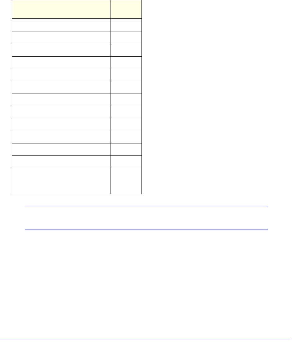
316 | Chapter 13. ACLs
NETGEAR 8800 User Manual
To view both System Space and User Space zones, use the show access-list zone
command.
Table 33 shows the priority of System Space zones and User Space zones together with the
default assignments and priority of applications by zone.
Note: The priority of static ACLs is determined by the order they are
configured, with the first rule configured having the highest priority.
Configuring User Zones
There is a configurable process for applications to insert an ACL into a zone according to the
priority of the application within that zone. Applications can occupy multiple zones. For
example, you can add the Cli application to the DOS zone, and assign it a higher priority than
the Dos application. The DOS zone then has two applications, Cli and Dos application, and
within the DOS zone, an ACL created by the Cli has a higher priority than an ACL inserted by
the Dos application.
Another way to configure ACL priority is by creating new zones. For example, you might
create a zone called MY_HIGH_ZONE, and assign that zone a priority below the DOS zone
Table 33. Default Assignment and Priority of Applications, by Zone
Zone/Default Application Default
Priority
USER SPACE ZONES
DOS 2
hal 1
Dos 2
SYSTEM 3
Cli 1
IpSecurity 2
NetLogin 3
HealthCheckLAG 4
IdentityManager 5
SECURITY 4
Sentriant 1
GenericXml (Allows configuration
of one additional external
application)
2

Chapter 13. ACLs | 317
NETGEAR 8800 User Manual
and above the System zone. You can add applications to that zone and assign their priority.
The example below shows the ACL zone priority that would result from adding the MacInMac
and Cli applications to MY_HIGH_ZONE:
1. DOS Zone
hal
DoS
2. MY_HIGH_ZONE
MacInMac
Cli
3. SYSTEM Zone
Cli
IpSecurity
NetLogin
HealthCheckLAG
IdentityManager
4. SECURITY Zone
Sentriant
Generic Xml
5. SYSTEM_LOW_ZONE
hal
Applications can insert an ACL into any of the zones to which the application belongs. If an
application attempts to insert an ACL into a zone where the application is not configured, an
error message appears, and the ACL is not installed. Therefore, you have full control of ACL
priorities and you can configure the switch to install ACLs from an application at any priority
level. In the example above, the application Cli can insert an ACL into either
MY_HIGH_ZONE or the SYSTEM zone. The location of the ACL within the zone depends on
the priority assigned by the application. An application can assign priority to an ACL using:
• Priority attributes (first or last)
• Relative priority
• Priority numbers
The priority attributes first (highest priority) and last (lowest priority) can be applied to an ACL
to establish its position within a zone.
Relative priority sets the ACL priority relative to another ACL already installed by the
application in the same zone.
Priority numbers allow an application to specify the priority of an ACL within a zone. The
priority numbers are unsigned integers from 0 to 7; a lower number represents a higher
priority. This means that if an application adds an ACL at priority 5 and later adds another
ACL at priority 3, the second ACL has higher priority.

318 | Chapter 13. ACLs
NETGEAR 8800 User Manual
If an application assigns the same priority number to two ACLs, the ACL added most recently
has the higher priority. It is inserted in the priority map immediately ahead of the older ACL
that has the same priority number. This effectively allows the application to create sub-zones
within a zone. The attributes first and last can be used in combination with priority numbers to
prioritize the ACLs within a sub-zone. For example, an ACL could be configured with the first
attribute, along with the same priority number as other ACLs in the same zone, effectively
assigning that ACL the highest priority within a sub-zone.
The show configuration command shows the current configuration of the entire switch in the
form of CLI commands which can later be played back to configure the switch.
The show configuration acl command shows the current configuration of the ACL manager.
The new application keyword allows you to specify the application to which the ACL will be
bound. Typically, applications create and insert ACLs on the switch; however the
administrator can install ACLs "on behalf" of an application by specifying the application
keyword. (This keyword is also used with the show config acl command to enable CLI
playback). If no application is specified, the default application is CLI.
This means you have the ability to create, delete, and configure ACLs for any application.
To create a zone, use the following command:
create access-list zone <name> zone-priority <number>
To configure the priority of zones, use the following command:
configure access-list zone <name> zone-priority <number>
To add an application to a zone at a particular priority, or to change the priority of an
application within a zone, use the following command:
configure access-list zone <name> {add} application <appl-name>
application_priority <number>
An application must occupy at least one zone.
To move an application within a zone or to another zone use the following command:
configure access-list zone <name> move-application <appl-name> to-zone <name>
application-priority <number>
All applications can be configured to go into any and all zones.
A change in the zone list results in a change in the order of dynamic ACLs that have been
applied per interface. The changes in hardware are achieved by uninstalling and then
reinstalling the dynamic ACLs in the new positions. There is a possibility, due to hardware
constraints, that some ACLs will not be reinstalled. These occurrences are logged.
To delete an application from a zone, use the following command:
configure access-list zone <name> delete application <appl-name>
When deleting an application from a zone, any ACLs that have been inserted into that zone
for the deleted application are moved to the next higher zone in which the application
appears.

Chapter 13. ACLs | 319
NETGEAR 8800 User Manual
To delete a zone use the following command:
delete access-list zone <name>
You must remove all applications from a zone before you can delete the zone. You cannot
delete the default zones.
ACL Evaluation Precedence
This section describes the precedence for evaluation among ACL rules for the NETGEAR
8800 series switches. In many cases there will be more than one ACL rule entry for an
interface. This section describes how multiple rule entries are evaluated.
Multiple rule entries do consume hardware resources. If you find that your situation runs up
against those limits, there are steps you can take to conserve resources by modifying the
order of the ACL entries that you create. For details, see ACL Mechanisms on page 325.
The section describes the following topics:
• Rule Evaluation on page 319
• Precedence of Dynamic ACLs on page 320
• Precedence of L2/L3/L4 ACL Entries on page 320
• Precedence Among Interface Types on page 320
• Precedence with Egress ACLs on page 320
• Redundant Rules on page 320
Rule Evaluation
When there are multiple rule entries applied to an interface, evaluation proceeds as follows:
• A packet is compared to all the rule entry match conditions at the same time.
• For each rule where the packet matches all the match conditions, the action and any
action modifiers in the then statement are taken. If there are any actions or action
modifiers that conflict (deny vs. permit, etc), only the one with higher precedence is taken.
• If a packet matches no rule entries in the ACL, it is permitted.
Often there will be a lowest-precedence rule entry that matches all packets. This entry will
match any packets not otherwise processed, so that the user can specify an action to
overwrite the default permit action. This lowest-precedence rule entry is usually the last entry
in the ACL policy file applied to the interface.
Note: When a packet matches more than one rule entry, the highest
precedence conflicting action is taken, so you can use the
precedence to determine if a packet is permitted or denied.
However, incrementing a counter is not a conflicting action, so a
packet that matches more that one rule that increments a common

320 | Chapter 13. ACLs
NETGEAR 8800 User Manual
counter, could count the packet more than once. Do not use
precedence to control counter usage; define different counters for
different cases. For details of this behavior on different platforms,
see, ACL Slices and Rules on page 325.
Precedence of Dynamic ACLs
Dynamic ACLs have a higher precedence than any ACLs applied using policy files. The
precedence among any dynamic ACLs is determined as they are configured. The
precedence of ACLs applied using policy files is determined by the rule’s relative order in the
policy file.
Precedence of L2/L3/L4 ACL Entries
Rule precedence is solely determined by the rule’s relative order. L2, L3, and L4 rules are
evaluated in the order found in the file or by dynamic ACL configuration.
Precedence Among Interface Types
As an example of precedence among interface types, suppose a physical port 1:2 is a
member port of the VLAN yellow. ACLs could be configured on the port, either singly or as
part of a port list, on the VLAN yellow, and on all ports in the switch (the wildcard ACL). For all
packets crossing this port, the port-based ACL has highest precedence, followed by the
VLAN-based ACL and then the wildcard ACL.
Precedence with Egress ACLs
Egress ACL lookup happens at egress, and diffserv, dot1p and other non-ACL feature
examination happen at ingress. Therefore, egress ACL happens at the last moment and has
precedence.
Redundant Rules
For NETGEAR 8800 series switches, eliminate redundant rules (any with the EXACT same
match criteria) in the policy file. If two rules have identical match conditions, but different
actions, the second rule is rejected by the hardware.
For example, the two following ACL entries are not allowed:
entry DenyNMR {
if {
protocol 17;
destination-port 161;
} then {
deny;
count denyNMR;
}
}

Chapter 13. ACLs | 321
NETGEAR 8800 User Manual
entry DenyNIC {
if {
protocol 17;
destination-port 161;
} then {
deny;
count denyNIC;
}
}
Applying ACL Policy Files
A policy file intended to be used as an ACL is applied to a port, VLAN, or to all interfaces (the
any keyword). Use the name of the policy file for the <aclname> parameter in the CLI
command. To apply an ACL policy, use the following command:
configure access-list <aclname> [any | ports <portlist> | vlan <vlanname>]
{ingress | egress}
If you use the any keyword, the ACL is applied to all the interfaces and is referred to as the
wildcard ACL. This ACL is evaluated for any ports without specific ACLs, and it is also
applied to any packets that do not match the specific ACLs applied to the interfaces.
If an ACL is already configured on an interface, the command will be rejected and an error
message displayed.
To remove an ACL from an interface, use the following command:
unconfigure access-list <policy-name> {any | ports <portlist> | vlan
<vlanname>} {ingress | egress}
To display which interfaces have ACLs configured, and which ACL is on which interface, use
the following command:
show access-list {any | ports <portlist> | vlan <vlanname>} {ingress | egress}
This section describes the following topics:
• Displaying and Clearing ACL Counters on page 321
• Example ACL Rule Entries on page 322
Displaying and Clearing ACL Counters
To display the ACL counters, use the following command:
show access-list counter {<countername>} {any | ports <portlist> | vlan
<vlanname>} {ingress | egress}
To clear the access list counters, use the following command:

322 | Chapter 13. ACLs
NETGEAR 8800 User Manual
clear access-list {dynamic} counter {<countername>} {any | ports <portlist> |
vlan <vlanname>} {ingress | egress}
Example ACL Rule Entries
The following entry accepts all the UDP packets from the 10.203.134.0/24 subnet that are
destined for the host 140.158.18.16, with source port 190 and a destination port in the range
of 1200 to 1250:
entry udpacl {
if {
source-address 10.203.134.0/24;
destination-address 140.158.18.16/32;
protocol udp;
source-port 190;
destination-port 1200 - 1250;
} then {
permit;
}
}
The following rule entry accepts TCP packets from the 10.203.134.0/24 subnet with a source
port larger than 190 and ACK & SYN bits set and also increments the counter tcpcnt. The
packets will be forwarded using QoS profile QP3.
entry tcpacl {
if {
source-address 10.203.134.0/24;
protocol TCP;
source-port > 190;
tcp-flags syn_ack;
} then {
permit;
count tcpcnt ;
qosprofile qp3;
}
}
The following example denies ICMP echo request (ping) packets originating from the
10.203.134.0/24 subnet, and increments the counter icmpcnt:
entry icmp {
if {
source-address 10.203.134.0/24;
protocol icmp;
icmp-type echo-request;

Chapter 13. ACLs | 323
NETGEAR 8800 User Manual
} then {
deny;
count icmpcnt;
}
}
The following example prevents TCP connections from being established from the
10.10.20.0/24 subnet, but allows established connections to continue, and allows TCP
connections to be established to that subnet. A TCP connection is established by sending a
TCP packet with the SYN flag set, so this example blocks TCP SYN packets. This example
emulates the behavior of the NETGEAR 8800 permit-established ACL command:
entry permit-established {
if {
source-address 10.10.20.0/24;
protocol TCP;
tcp-flags syn;
} then {
deny;
}
}
The following entry denies every packet and increments the counter default:
entry default {
if {
} then {
deny;
count default;
}
}
The following entry permits only those packets with destination MAC addresses whose first
32 bits match 00:01:02:03:
entry rule1 {
if {
ethernet-destination-address 00:01:02:03:01:01 ff:ff:ff:ff:00:00 ;
} then {
permit ;
}
}
The following entry denies IPv6 packets from source addresses in the 2001:db8:c0a8::/48
subnets and to destination addresses in the 2001:db8:c0a0:1234::/64 subnets:
entry ipv6entry {
if {

324 | Chapter 13. ACLs
NETGEAR 8800 User Manual
source-address 2001:DB8:C0A8:: / 48;
destination-address 2001:DB8:C0A0:1234:: / 64;
} then {
deny;
}
}
Access lists have entries to match an Ethernet type. So the user needs to be careful when
configuring access lists to deny all traffic. For example, the following rule entries permit traffic
only to destination 10.200.250.2 and block any other packet.
entry test_policy_4 {
if {
source-address 0.0.0.0/0;
destination-address 10.200.250.2/32;
} then {
permit;
count test_policy_permit;
}
}
# deny everyone else
entry test_policy_99 {
if {
} then {
deny;
count test_policy_deny;
}
}
Since the deny section does not specify an Ethernet type, all traffic other than IP packets
destined to 10.200.250.2/32 are blocked, including the ARP packets. To allow ARP packets,
add an entry for the Ethernet type, 1x0806, as shown below.
entry test_policy_5 {
if {
ethernet-type 0x0806;
} then {
permit;
count test_policy_permit;
}
}
The following entries use vlan-ids to set up meters based on individual VLANs.
myServices.pol

Chapter 13. ACLs | 325
NETGEAR 8800 User Manual
entry voiceService {
if {
vlan-id 100;
} then {
meter voiceServiceMeter;
}
}
entry videoService {
if {
vlan-id 101;
} then {
meter videoServiceMeter;
}
}
…and so on.
To bind this ACL to a port with vlan-id match criteria use the following command:
config access-list myServices port <N>
ACL Mechanisms
For many applications of ACLs, it is not necessary to know the details of how ACLs work.
However, if you find that your application of ACLs is constrained by hardware limitations, you
can often rearrange the ACLs to use the hardware more efficiently. The following sections go
into some detail about how the ACLs use hardware resources, and some suggestions about
how to reorder or rewrite ACLs to use fewer resources.
• ACL Slices and Rules on page 325
• ACL Counters—Shared and Dedicated on page 337
ACL Slices and Rules
The NETGEAR 8800 uses slices that can apply to any of the supported ports. An ACL
applied to a port may be supported by any of the slices.
The slice support for the cards is as follows:
• XCM888F—
• Its 8 ports have 4 slices with each slice having enough memory for 128 egress rules.
• Its 8 ports have 16 slices with each slice having enough memory for 256 ingress
rules.
• XCM8808X—
• Each group of 2 ports has 4 slices with each slice having enough memory for 128
egress rules.

326 | Chapter 13. ACLs
NETGEAR 8800 User Manual
• Each group of 2 ports has 16 slices with each slice having enough memory for 256
ingress rules.
• XCM8848T/XCM8824F—
• Each group of 24 ports has 4 slices with each slice having enough memory for 128
egress rules.
• Each group of 24 ports has 16 slices with each slice having enough memory for 256
ingress rules.
This architecture also allows a single slice to implement ACLs that are applied to more than
one port. When an ACL entry is applied, if its match conditions do not conflict with an already
existing ACL, the entry is added to the rule memory of an already populated slice. Because
the slices are much more flexible than masks, a much wider variety of rule entries can use
the same slice.
When ACLs are applied, the system programs each slice to select parts of the packet
information to be loaded into it. For example, one possible way a slice can be programmed
allows it to hold the information about a packet’s ingress port, source and destination IP
address, IP protocol, source and destination Layer 4 ports, DSCP value, TCP flag, and if it is
a first fragment. Any rule entry that consists of match conditions drawn from that list is
compatible with that slice. This list of conditions is just one example. A complete description
of possible ways to program a slice is discussed in Compatible and Conflicting Rules on
page 329.
In the following example, the two rule entries are compatible and require only one slice in
hardware even though they are applied to different ports. The following entry is applied to
port 1:
entry ex_A {
if {
source-address 10.10.10.0/24 ;
destination-port 23 ;
protocol tcp ;
} then {
deny ;
}
}
and the following entry is applied to port 2:
entry ex_B {
if {
destination-address 192.168.0.0/16 ;
source-port 1000 ;
protocol tcp ;
} then {
deny ;
}
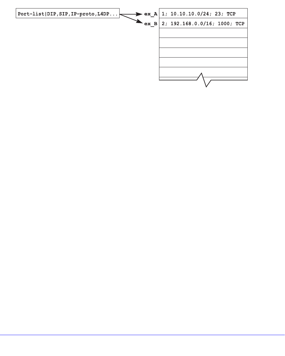
Chapter 13. ACLs | 327
NETGEAR 8800 User Manual
}
Both of these ACLs could be supported on the same slice, since the match conditions are
taken from the example list discussed earlier. This example is shown in Figure 19. In the
example, we refer to slice A, even though the slices are numbered. Slice A just means that
one slice is used, but does not specify a particular slice. Some rules require more than one
slice, so we use letters to show that different slices are used, but not which specific slices.
Figure 19. ACL Entry ex_A and ex_B
There are cases where compatible ACLs require using a different slice. If the memory
associated with a slice is filled with rule entries, then another slice will be used to process any
other compatible entries.
For example, consider the following 129 rule entries applied to ports 3-7:
entry one {
if {
source-address 10.66.10.0/24 ;
destination-port 23 ;
protocol tcp ;
} then {
deny ;
}
}
entry two {
if {
destination-address 192.168.0.0/16 ;
source-port 1000 ;
protocol tcp ;
} then {
deny ;
}
}
entry three {
if {
XM_078
Slice A Rules (128)

328 | Chapter 13. ACLs
NETGEAR 8800 User Manual
source-address 10.5.2.246/32 ;
destination-address 10.0.1.16/32 ;
protocol upd ;
source-port 100 ;
destination-port 200 ;
} then {
deny ;
}
}
....
[The 125 intervening entries are not displayed in this example]
....
entry onehundred_twentynine {
if {
protocol udp ;
destination-port 1714 ;
} then {
deny ;
}
}
Figure 20 shows the result of applying the 129 entries. 128 of the entries are applied to one
slice, and the final entry is applied to a different slice. If another compatible entry is applied
from another port, for example, it will use Slice B.
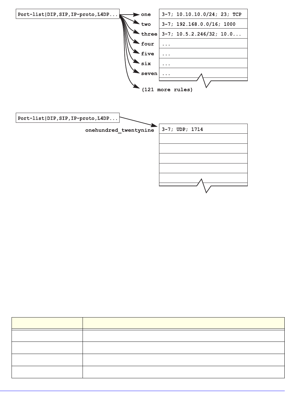
Chapter 13. ACLs | 329
NETGEAR 8800 User Manual
Figure 20. ACL Entry One Through onehundred_twentynine
As entries are configured on the switch, the slices are programmed to implement the rules,
and the rule memory is filled with the matching values for the rules. If a compatible slice is
available, each entry is added to that slice.
Compatible and Conflicting Rules
The slices can support a variety of different ACL match conditions, but there are some
limitations on how you combine the match conditions in a single slice. A slice is divided up
into fields, and each field uses a single selector. A selector is a combination of match
conditions or packet conditions that are used together. To show all the possible combinations,
the conditions in Table 34 are abbreviated.
Table 34. Abbreviations Used in Field Selector Tables
Abbreviation Condition
Ingress
DIP destination address <prefix> (IPv4 addresses only)
SIP source address <prefix> (IPv4 addresses only)
IP-Proto protocol <number>
XM_079
Slice A Rules (128)
Slice B
Rules (128)

330 | Chapter 13. ACLs
NETGEAR 8800 User Manual
L4DP destination-port <number> (a single port)
L4SP source-port <number> (a single port)
DSCP dscp <number>
TCP-Flag TCP-flags <bitfield>
First Fragment first-fragments
L4-Range A Layer 4 port range. For example, if you specify “protocol UDP” and “port 200 -
1200” in an entry, you have used a Layer 4 range. There are a total of sixteen
Layer 4 port ranges. Also, you can have a source port range, or a destination port
range, but not both kinds of ranges together in the same entry.
DIPv6/128 destination address <prefix> (IPv6 address with a prefix length longer than 64)
SIPv6/128 source address <prefix> (IPv6 address with a prefix length longer than 64)
DIPv6/64 destination address <prefix> (IPv6 address with a prefix length up to 64)
SIPv6/64 source address <prefix> (IPv6 address with a prefix length up to 64)
NH IPv6 Next Header field. Use protocol <number> to match.
TC IPv6 Traffic Class field. Use dscp <number>
MACDA ethernet-destination-address <mac-address> <mask>
MACSA ethernet-source-address <mac-address>
Etype ethernet-type <number>
VID This is not a match condition used in ACLs, but is used when an ACL is applied to
VLANs. An ACL applied to a port uses a different field selector than an ACL
applied to a VLAN.
TOS ip-tos <number>
Port-list This is not a match condition used in ACLs, but is used when an ACL is applied to
ports, or to all ports (the wildcard ACL). An ACL applied to a port uses a different
field selector than an ACL applied to a VLAN.
packet-type This selector is used internally and not accessible by users through explicit ACLs.
UDF User-defined field. This selector is used internally and not accessible by users
through explicit ACLs.
Egress
VlanId vlan-id
DaMac ethernet-destination-address
SaMac ethernet-source-address
EtherType ethernet-type
Table 34. Abbreviations Used in Field Selector Tables (Continued)
Abbreviation Condition
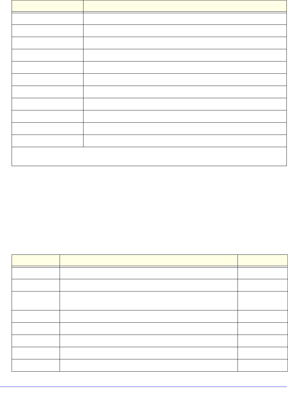
Chapter 13. ACLs | 331
NETGEAR 8800 User Manual
Table 35 lists the same information for NETGEAR 8800 series modules. Any number of
match conditions in a single row for a particular field may be matched. For example if Field 1
has row 1 (Port-list) selected, Field 2 has row 8 (MACDA, MACSA, Etype, VID) selected, and
Field 3 has row 6 (Packet-type) selected, any combination of Port-list, MACDA, MACSA,
Etype, VID, and Packet-type may be used as match conditions.
If an ACL requires the use of field selectors from two different rows, it must be implemented
on two different slices.
TOS ip-tos or diffserv-codepoint
DestIP destination-address
DestIPv6 destination-address <ipv6>
SrcIP source-address
SrcIPv6 source-address <ipv6>
IpProtocol protocol
L4DstPort destination-port. Support only single L4 ports and not port ranges.
L4SrcPort source-port. Support only single L4 ports and not port ranges.
TcpFlags tcp-flags
TrafficClass protocol
Ipv6NextHeader protocol
The following ingress conditions are not supported on egress: Fragments, first-fragments, IGMP-msg-type,
ICMP-type, ICMP-code,
Table 35. Field Selectors, NETGEAR 8800 Series
Field 1 Field 2 Field 3
Port-list DIP, SIP, IP-Proto, L4DP, L4SP, DSCP, TCP-Ctrl, IP-Flag Fragments
L4DP, L4SP DIP, SIP, IP-Proto, L4DP, L4-Range, DSCP, TCP-Ctrl, IP-Flag Port
VID+VID-inner DIP, SIP, IP-proto, L4-range, L4SP+DSCP, TCP-Ctrl, IP-Flag DSCP,
TCP-control
Etype, VID DIPv6/128 VID
Fragments, VID SIPv6/128 IP-Proto, TOS
Port, Dst-Port DIPv6/64, SIPv6/64 L4-Range
Etype, IP-Proto DIPv6/64, NextHdr(IPv6-Proto), TrafficClass(DSCPv6), FL, TCP-Ctrl Dst-Port
VRF, VID MACDA, MACSA, Etype, VID
Table 34. Abbreviations Used in Field Selector Tables (Continued)
Abbreviation Condition

332 | Chapter 13. ACLs
NETGEAR 8800 User Manual
Egress ACLs
Each of the 4 egress slices can be configured to one of the 3 combinations below. The rules
that can be installed into a particular slice should be a subset of the combination to which that
slice is configured.
Following is the table of the available combinations:
• Combination 1:
<vlan-id, ethernet-source-address, ethernet-destination-address, ethernet-type>
• Combination 2:
<vlan-id, diffserv-codepoint/ip-tos, destination-address, source-address,
protocol, destination-port, source-port, tcp-flags>
• Combination 3:
<vlan-id, ip-tos, destination-address<ipv6>, source-address<ipv6>, protocol>
Use Table 35 to determine which ACL entries are compatible. If the entries are compatible,
they can be on the same slice.
For example, the earlier example entries are applied to ports:
entry ex_A {
if {
source-address 10.10.10.0/24 ;
destination-port 23 ;
protocol tcp ;
} then {
deny ;
}
}
entry ex_B {
TOS, VRF,
IP-Proto MACDA, DIP, Etype, VID
MACSA, SIP, Etype, VID
"User Defined Field” 1
"User Defined Field” 2
DIP, SIP, IP-Proto, L4DP, L4SP, DSCP, TCP-Ctrl, Frag-Info
DIP, SIP, IP-Proto, L4DP, L4-range, DSCP, TCP-ctrl, Frag-Info
DIP, SIP, IP-Proto, L4-Range, L4SP, DSCP, TCP-Ctrl, Frag-Info
Table 35. Field Selectors, NETGEAR 8800 Series (Continued)
Field 1 Field 2 Field 3

Chapter 13. ACLs | 333
NETGEAR 8800 User Manual
if {
destination-address 192.168.0.0/16 ;
source-port 1000 ;
} then {
deny ;
}
}
Entry ex_A consists of the following conditions (using the abbreviations from Table 34), SIP,
L4DP, and IP-Proto. Entry ex_B is DIP, L4SP. Since they are applied to ports, the selector for
Field 1 is Port-list (the first item). The selector for Field 2 would be the first item, and Field 3
could be any item.
Our other example entries are also compatible with the entries ex_A and ex_B:
entry one {
if {
source-address 10.66.10.0/24 ;
destination-port 23 ;
protocol tcp ;
} then {
deny ;
}
}
entry two {
if {
destination-address 192.168.0.0/16 ;
source-port 1000 ;
} then {
deny ;
}
}
entry three {
if {
source-address 10.5.2.246/32 ;
destination-address 10.0.1.16/32 ;
protocol upd ;
source-port 100 ;
destination-port 200 ;
} then {
deny ;
}

334 | Chapter 13. ACLs
NETGEAR 8800 User Manual
}
Entry one is SIP, L4DP, and IP-Proto; entry two is DIP, and L4SP; entry three is SIP, DIP,
IP-Proto, L4SP, and L4DP. All of these examples can use the first item in Field 2 in the tables.
However, adding the following entry will not be compatible with the earlier one:
entry alpha {
if {
ethernet-destination-address 00:e0:2b:11:22:33 ;
} then {
deny ;
}
}
Entry alpha is MACDA, and there is no MACDA in the first item for Field 2. Any entry with
MACDA will have to use 6 or 7 from Table 35. If an entry requires choosing a different
selector from the table, it is not compatible and must go into a different slice.
Rule Evaluation and Actions
When a packet ingresses the switch, its header is loaded into all the slices, and the header
value is compared with the rule values. If the values match, the rule action is taken.
Conflicting actions are resolved by the precedence of the entries. However, if rule entries are
on different slices, then ACL counters can be incremented on each slice that contains a
counter-incrementing rule.
Slice and Rule Use by Feature
A number of slices and rules are used by features present on the switch. You consume these
resources when the feature is enabled.
• dot1p examination - enabled by default - 1 slice, 8 rules per chip
• Slice A (F1=Port-list, F2=MACDA, MACSA, Etype, VID, F3=packet-type)
• IGMP snooping - enabled by default - 2 slice, 2 rules
• Slice A (F1=Port-list, F2=MACDA, MACSA, Etype, VID, F3=packet-type)
• Slice B (F1=Port-list, F2=MACDA, MACSA, Etype, VID, F3=IP-Proto, TOS)
• VLAN without IP configured - 2 rules - 2 slices
• Slice A (F1=Port-list, F2=MACDA, MACSA, Etype, VID, F3=packet-type)
• Slice C (F1=Port-list, F2=SIP, DIP, IP-proto, L4SP, L4DP, DSCP, F3=packet-type)
• IP interface - disabled by default - 2 slices, 3 rules (plus IGMP snooping rules above)
• Slice A (F1=Port-list, F2=MACDA, MACSA, Etype, VID, F3=packet-type)
• Slice C (F1=Port-list, F2=SIP, DIP, IP-proto, L4SP, L4DP, DSCP, F3=packet-type)
• VLAN QoS - disabled by default - 1 slice, n rules (n VLANs)
• Slice A or B (F1=Port-list, F2=MACDA, MACSA, Etype, VID, F3=anything)
• port QoS - disabled by default - 1 slice, 1 rule

Chapter 13. ACLs | 335
NETGEAR 8800 User Manual
• Slice D (F1=anything, F2=anything, F3=anything)
• VRRP - 2 slices, 2 rules
• Slice A (F1=Port-list, F2=MACDA, MACSA, Etype, VID, F3=packet-type)
• Slice A or B (F1=Port-list, F2=MACDA, MACSA, Etype, VID, F3=anything)
• IPv6 - 2 slices, 3 rules
• Slice A or B (F1=Port-list, F2=MACDA, MACSA, Etype, VID, F3=anything)
• Slice (F1=Port-list, F2=DIPv6, IPv6 Next Header Field, TC, F3=anything)
• Netlogin - 1 slice, 1 rule
• Slice A or B (F1=Port-list, F2=MACDA, MACSA, Etype, VID, F3=anything)
• VLAN Mirroring - 1 slice, n rules (n VLANs)
• Slice E (F1=Port-list, F2=MACDA, MACSA, Etype, VID, F3=anything)
• Unicast Multiport FDB
• 1 slice, 1+n rules in 24 port and 10G4Xa and 10G4Ca cards
• 1 slice, 2+ n rules in 48 port and G48Ta, G48Xa, G48Te, G48Pe cards
• VLAN Aggregation
• 1 slice, 4 rules for the first subvlan configured and 1 slice, 2 rules for subsequent
subvlan configuration
• Private VLAN
• 2 slices, 3 rules when adding an non-isolated VLAN with loop-back port a to private
VLAN
• 1 slice, 3 rules when adding an isolated subscriber VLAN (without loopback port) to a
private VLAN. 3 additional rules when a loopback port is configured in the above
isolated subscriber VLAN
To display the number of slices used by the ACLs on the slices that support a particular port,
use the following command:
show access-list usage acl-slice port <port>
To display the number of rules used by the ACLs on the slices that support a particular port,
use the following command:
show access-list usage acl-rule port <port>
To display the number of Layer 4 ranges used by the ACLs on the slices that support a
particular port, use the following command:
show access-list usage acl-range port <port>
System Configuration Example
The following example shows incremental configurations and their corresponding ACL
resource consumption.
• Default configuration including: dot1p examination and IGMP snooping:
• 2 slices, 10 rules

336 | Chapter 13. ACLs
NETGEAR 8800 User Manual
• Add an IP interface to the configuration:
• 2 slices, 13 rules
• Add port-based QoS to the configuration:
• 2 slices, 14 rules
• Add VLAN-based QoS to the configuration:
• 2 slices, 15 rules
• Add VRRP to the configuration:
• 2 slices, 17 rules
• Add IPv6 routing (slowpath) to the configuration:
• 4 slices, 24 rules
• Add Netlogin to the configuration:
• 5 slices, 25 rules
Note: The slice and rule usage numbers given in this section may vary
slightly depending on the XCM8800 release.
ACL Error Messages
Errors may happen when installing an ACL policy on a port, VLAN, or all interfaces
(wildcard). Following is a list of the most common error conditions and their resulting CLI
error message:
• Slice resource exceeded: This happens when all slices are allocated for a given chip and
an additional incompatible rule (see Egress ACLs on page 332) is installed which requires
allocation of another slice.
Error: ACL install operation failed - slice hardware full for port 3:1
• Rule resource exceeded: This happens when all slices are allocated for a given chip and
there is an attempt to install a compatible rule to the lowest precedence slice which
already has 128 rules. This condition can be triggered with less than the full capacity
number of rules installed. For example, if 15 of the slices each have less than 128 rules
and there is an attempt to install 129 compatible rules, this error message will be
displayed.
Error: ACL install operation failed - rule hardware full for port 3:1
• Layer-4 port range exceeded: This happens when more than 16 Layer 4 port ranges are
installed on a single chip.
Error: ACL install operation failed - layer-4 port range hardware full for
port 3:1
• Incompatible fields selected: This happens when the selected conditions can not be
satisfied by the available single-slice field selections described in Compatible and
Conflicting Rules on page 329.

Chapter 13. ACLs | 337
NETGEAR 8800 User Manual
Error: ACL install operation failed - conditions specified in rule "r1" cannot be
satisfied by hardware on port 3:1
• UDF exceeded: This happens in the rare case that the two available user-defined fields
are exceeded on a given chip. UDF fields are used to qualify conditions which are not
natively supported by the hardware. Currently, these include: ICMP Type and ICMP
Code.
Error: ACL install operation failed - user-defined-field (UDF) hardware full for port
3:1
ACL Counters—Shared and Dedicated
You can configure rule compression in ACLs to be either shared or dedicated.
In the dedicated mode, ACL rules that have counters are assigned a separate rule space and
the counter accurately shows the count of matching events. If the ACL with counter is applied
to ports 1 and 2, and 10 packets ingress via port 1 and 20 packets ingress via port 2, the ACL
counter value for ports 1 and 2 is 10 and 20 packets respectively. More space is used and the
process is slower than shared. Dedicated is the default setting
In the shared mode, ACL space is reused even with counters. ACL counters count packets
ingressing via all ports in the whole unit. If the ACL with the counter is applied to ports 1 and
2, and 10 packets ingress via port 1, and 20 packets ingress via port 2, the ACL counter
value is 30 each of ports 1 and 2 instead of 10 and 20. The process is faster—as fast as
applying an ACL without the counters—and saves space.
The shared/dedicated setting is global to the switch; that is, the option does not support
setting some ACL rules with shared counters and some with dedicated counters.
Use the following command to configure the shared or dedicated mode:
configure access-list rule-compression port-counters [shared | dedicated]
Use the following command to view the configuration:
show access-list configuration
The shared or dedicated mode does not affect any ACLs that have already been configured.
Only ACLs entered after the command is entered are affected.
To configure all ACLs in the shared mode, the command must be entered before any ACLs
are configured or have been saved in the configuration when a switch is booted.
Policy-Based Routing
This section describes the following topics:
• Layer 3 Policy-Based Redirect on page 338
• Layer 2 Policy-Based Redirect on page 339
• Policy-Based Redirection Redundancy on page 341

338 | Chapter 13. ACLs
NETGEAR 8800 User Manual
Note: See Load Sharing Rules and Restrictions for All Switches on
page 132 for information on applying ACLs to LAG ports.
Layer 3 Policy-Based Redirect
Policy-Based Routing allows you to bypass standard Layer 3 forwarding decisions for certain
flows.
Typically, in a Layer 3 environment, when an IP packet hits an Ethernet switch or router, the
Layer 3 processing determines the next hop and outgoing interface for the packet, based
only on the packet's destination address. The Layer 3 processing does so by looking up the
IP Forwarding Table; this forwarding table itself is populated either by static routes or by
routes learned dynamically from routing protocols such as OSPF and RIP.
With Policy-Based Routing, you can configure policies to use a different nexthop than what
the routing lookup would have chosen. The switch first compares packets to the ACL rule
entries. If there is a match, the packet is forwarded to the destination identified by the redirect
action modifier. If there is no match, the packet is forwarded based on normal routing, in other
words, by looking up a route in the IP Forwarding Table.
When there is a match with a redirect ACL rule, the matched traffic will be redirected to the
nexthop specified in the action. Note that the IP packet itself will not be modified, but only
redirected to the port where the nexthop entry resides. The original IP destination address
and source address are retained in the packet. The TTL is decremented and the IP
checksum is recalculated.
The applications for Policy-Based Routing are quite diverse, since the functionality can be
used to set policies on how flows identified by any Layer 2 to Layer 7 field (bounded by the
switch's ACL syntax) are forwarded. Deployment scenarios include:
• Forwarding flows for certain applications, for example, all HTTP traffic to designated
server(s).
• Redirecting flows from certain source IP addresses for security and other applications.
Policy-Based Routing is implemented using ACLs, so it inherits the capabilities and
limitations of ACL. All the matching conditions used for ACLs can be used for Policy-Based
Routing. The destination IP address must be an IPv4 unicast address.
When a switch finds a matching ACL rule, it forwards the packet to the redirect IP address as
specified in the rule without modifying the packet (except as noted above).
The traffic flow is redirected only after applying the ACL to the port and redirected only when
the redirect IP address’s adjacency is resolved. When the IP ARP table does not have the
information to reach the redirect IP address, the packet is routed based on the Layer 3
routing table. When the switch does not know how to reach the redirect IP address in the rule,
the rule is installed with a warning, but traffic is not redirected until the address is resolved in
the IP ARP table. After the address is resolved, the traffic is redirected.

Chapter 13. ACLs | 339
NETGEAR 8800 User Manual
To configure Policy-Based Routing, you configure an ACL on your switch. You can apply an
ACL policy file, or use a dynamic ACL.
The following is an example ACL rule entry that redirects any TCP traffic with a destination
port of 81 to the device at IP address 3.3.3.2:
entry redirect_port_81 {
if {
protocol tcp;
destination-port 81;
} then {
redirect 3.3.3.2;
}
}
Use the following procedure:
1. Issue the following command to prevent the redirect IP address from clearing from the
IP ARP table due to a timeout:
enable iparp refresh
2. Configure the ACL, either applying an ACL policy file similar to the example, or a Dynamic
ACL.
3. Ping or send traffic so that the redirect IP adjacency is resolved.
You may want to create a static ARP entry for the redirect IP address, so that there will
always be a cache entry.
Layer 2 Policy-Based Redirect
This feature allows matching packets to override the normal forwarding decision and be
Layer 2 switched to the specified physical port. This is accomplished via an additional packet
ACL lookup. While similar to the “Layer 3 Policy-Based Redirect” feature described above, it
differs in that the packet is not modified for Layer 3 routing based on a new IP redirect
nexthop. Instead, the packet uses the packet format based on the forwarding decision. When
the packet was Layer 2-switched, the packet egresses the redirect port unmodified. When
the packet was Layer 3-switched, the packet egresses with the Layer 3 packet modifications
of the nexthop found by the normal Layer 3 forwarding lookups. This feature applies to
unicast, multicast, and broadcast traffic.
redirect-port <port number>
The <port number> argument must be specified in the format <slot>:<port>. For example,
consider the following ACL policies.
The policy shown below redirects any TCP traffic with source Layer 4 port 81 to physical port
3:2.
entry one {
if {
protocol tcp;
340 | Chapter 13. ACLs
NETGEAR 8800 User Manual
source-port 81;
destination-port 200 ;
} then {
count num_pkts_redirected;
redirect-port 3:2;
}
}
The policy shown below redirects any in-profile traffic as defined by the meter configuration to
physical port 14. The out-of-profile traffic would be subject to the action specified in the meter
“out-action” configuration.
entry one {
if {
} then {
meter redirected_traffic;
count num_pkts_redirected;
redirect-port 14;
}
}
If an incorrect port format is used or if the port number specified is out of range, the following
error message will be displayed:
*XCM8810.68 # check policy l2pbr
Error: Policy l2pbr has syntax errors
Line 7 : 12:3 is not a valid port.
XCM8810.70 # check policy l2pbr
Error: Policy l2pbr has syntax errors
Line 7 : 77 is not a valid port.
When this feature is used, the traffic egressing the redirect-port can either be tagged or
untagged depending on the redirect-port VLAN configuration. Table 36 provides the details.
Be aware of the following important implementation notes:
• Using the “redirect-port” action with a disabled port causes traffic to be dropped.
• Using the “redirect-port” action overrides Layer 2 echo kill; the result is that a packet can
be made to egress the ingress port at Layer 2.
Table 36. VLAN Format of Traffic Egressing Redirect-Port
ACL Hardware Type Redirect-Port Not in
Egress VLAN Redirect-Port Tagged in
Egress VLAN Redirect-Port Untagged
in Egress VLAN
XCM8800 Dropped VLAN Tagged Untagged

Chapter 13. ACLs | 341
NETGEAR 8800 User Manual
Policy-Based Redirection Redundancy
This section consists of the following topics:
• Multiple Nexthop Support on page 341
• Health Checking for ARP and Ping on page 342
• Packet Forward/Drop on page 342
• Example—Network Diagram on page 343
Multiple Nexthop Support
As discussed above, Layer 3 and Layer 2 policy-based redirect support only one nexthop for
one policy-based entry. Multiple nexthops with different priorities can be configured. A higher
priority is denoted with a higher number; for example, “priority 5” has a higher precedence
that “priority 1.” When a high priority nexthop becomes unreachable, another preconfigured
nexthop, based on priority, replaces the first. This is done by first creating a flow-redirect
name that is used to hold nexthop information.
Use the following command:
create flow-redirect <flow-redirect-name>
To delete the flow-redirect name, use
delete flow-redirect <flow-redirect-name>
Then information for each nexthop including a defined priority is added one by one to the new
flow-redirect name. Use the following command:
configure flow-redirect <flow-redirect-name> add nexthop <ipaddress> priority
<number>
To delete the nexthop, use the following command:
configure flow-redirect <flow-redirect-name> delete nexthop <ipaddress>
Because an ACL does not recognize the virtual routing concept, one policy-based routing is
used for multiple virtual routing entries when a VLAN-based virtual router is used for one port.
Configuring a virtual router into a flow-redirect allows policy-based routing to work for only
one specific virtual router. Use the following command:
configure flow-redirect <flow-redirect-name> vr <vr-name>
Note: Configuring the virtual router parameter is not supported on
NETGEAR 8800 series switches.
Finally, a new action modifier, redirect-name, is used to specify the flow-redirect name in an
ACL rule entry.
entry redirect_redundancy {
if match all {

342 | Chapter 13. ACLs
NETGEAR 8800 User Manual
source-address 1.1.1.100/24 ;
} then {
permit ;
redirect-name <name>
}
}
Health Checking for ARP and Ping
Policy-based redirection redundancy requires the determination of the reachability or
unreachability of the active next hop and the other configured next hops. This feature uses
Address Resolution Protocol (ARP) and Ping checking to make the determination.
To configure health checking for a specific flow-redirect-name, use the following command:
configure flow-redirect <flow-redirect-name> health-check [ping | arp]
To configure the ping interval and miss for a nexthop, use the following command:
configure flow-redirect <flow-redirect-name> nexthop <ipaddress> ping interval
<interval> miss <miss>
Packet Forward/Drop
The default behavior for policy-based routing when all nexthops are unreachable is to route
packets based on the routing table. Policy-based routing redundancy adds an option to drop
the packets when all nexthops for the policy-based routing become unreachable. For this
option, use the following command:
configure flow-redirect <flow-redirect-name> no-active drop
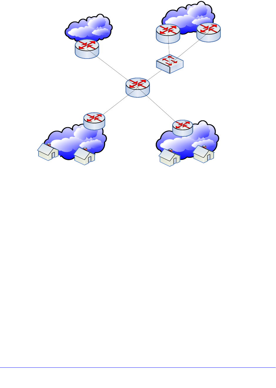
Chapter 13. ACLs | 343
NETGEAR 8800 User Manual
Example—Network Diagram
Any premium customer should use high-speed backbone for IPv4 Unicast traffic. Traffic from
the Source IP = 211.10.15.0/24, 211.10.16.0/24 network blocks should be redirected into two
routers: 192.168.2.2 and 192.168.2.3. The 192.168.2.2 router is preferred to 192.168.2.3. If
router 192.168.2.2 is not reachable, 192.168.2.3 should be used. If both routers are not
reachable, the default route is used.
Use the following procedure:
1. Create a flow-redirect to keep nexthop IP address and health check information.
create flow-redirect premium_subscriber
config flow-redirect premium_subscriber add nexthop 192.168.2.2 priority 200
config flow-redirect premium_subscriber add nexthop 192.168.2.3 priority 100
2. Add an ACL entry with a flow-redirect name action to the existing ACL policy (For example:
premium_user.pol).
entry premium_15 {
if match {
source-address 211.10.15.0/24;
} then {
permit;
redirect-name premium_subscriber;
}
High Speed
Backbone
Low Speed
Backbone
Premium Subscriber
(IP Block: 211.10.15.0/24) Normal Subscriber
(IP Block: 211.9.1.0/24) Premium Subscriber
(IP Block: 211.10.16.0/24)
Normal Subscriber
(IP Block: 211.9.2.0/24)
192.168.1.0/30 192.168.1.4/30
192.168.1.8/30 192.168.2.0/29 L2 S/W
PBR L3 S/W
Low Speed
Backbone Router
High Speed
Backbone Router
High Speed
Backbone Router
192.168.1.5
192.168.1.6
192.168.1.2
192.168.1.1
192.168.1.10
192.168.1.9
192.168.2.1
192.168.2.2 192.168.2.3

344 | Chapter 13. ACLs
NETGEAR 8800 User Manual
}
entry premium_16 {
if match {
source-address 211.10.16.0/24;
} then {
permit;
redirect-name premium_subscriber;
}
}
3. Apply the modified ACL policy file or dynamic ACL into a port, VLAN, or VLAN and Port. (For
example: user1 VLAN: 192.168.1.0/30, user2 VLAN: 192.168.1.4/30)
config access-list premium_user vlan user1 ingress
config access-list premium_user vlan user2 ingress
4. Finally, check the current flow-redirect status.
BD-8810.47 # show flow-redirect "premium_subscriber"
Name : premium_subscriber VR Name : VR-Default
NO-ACTIVE NH : FORWARD HC TYPE : PING
NH COUNT : 2 ACTIVE IP : 192.168.2.3
Index STATE Pri IP ADDRESS STATUS INTERVAL MISS
======================================================================
0 ENABLED 200 192.168.2.2 DOWN 2 2
1 ENABLED 100 192.168.2.3 UP 2 2
BD-8810.48 # show flow-redirect
Flow-Redirect Name NH_CNT ACTIVE IP VR Name D/F HC
=================================================================
premium_subscriber 2 192.168.2.3 VR-Default F PING
ACL Troubleshooting
The following commands are designed to help troubleshoot and resolve ACL configuration
issues.
*switch # show access-list usage [acl-mask | acl-rule | acl-slice | acl-range]
port <port>
show access-list usage <TAB>
acl-mask ACL Mask table resource summary
acl-range ACL Range table resource summary

Chapter 13. ACLs | 345
NETGEAR 8800 User Manual
acl-rule ACL Rule table resource summary
acl-slice ACL slice resource summary
The “acl-mask” keyword is not relevant for XCM8800 models. If you enter this command and
specify an XCM8800 port, the following error message appears:
This command is not applicable to the specified port.
Use the “acl-rule” keyword to display the total number of ACL rules that are available and
consumed for the specified port. If this keyword is specified on a NETGEAR 8800 port, the
first part of the command output details the port list using this resource because the ACL
hardware rules are shared by all ports on a given ASIC (24x1G ports). If you enter the same
command and specify any of the listed ports, the command output is identical.
*switch # show access-list usage acl-rule port 4:1 Ports 4:1-4:12, 4:25-4:36
Total Rules: Used: 46 Available: 2002
The “acl-slice” keyword is used to display ACL resource consumption for each of the
independent TCAMs, or slices, that make up the hardware ACLs. Each slice is a 128-entry
TCAM. The command output displays the number of consumed and available TCAM rules for
each slice as follows.
*switch # show access-list usage acl-slice port 4:1
Ports 4:1-4:12, 4:25-4:36
Slices: Used: 8 Available: 8
Slice 0 Rules: Used: 1 Available: 127
Slice 1 Rules: Used: 1 Available: 127
Slice 2 Rules: Used: 1 Available: 127
Slice 3 Rules: Used: 8 Available: 120
Slice 4 Rules: Used: 8 Available: 120
Slice 5 Rules: Used: 2 Available: 126
Slice 6 Rules: Used: 1 Available: 127
Slice 7 Rules: Used: 24 Available: 104
Use the “acl-range” keyword to view the Layer-4 port range hardware resource on a
NETGEAR 8800 switch. The first part of the command output lists the ports that utilizes this
resource. The second part of the command output lists the number of range checkers that
are consumed and the number available for use.
switch # show access-list usage acl-range port 4:1
Ports 4:1-4:12, 4:25-4:36
L4 Port Ranges: Used: 0 Available: 16

Chapter 14. Routing Policies | 346
14
14. Routing Policies
This chapter includes the following sections:
• Overview on page 346
• Routing Policy File Syntax on page 346
• Applying Routing Policies on page 352
• Policy Examples on page 353
Overview
Routing policies are used to control the advertisement or recognition of routes communicated by
routing protocols, such as Routing Information Protocol (RIP), Open Shortest Path First (OSPF),
and Border Gateway Protocol (BGP). Routing policies can be used to “hide” entire networks or to
trust only specific sources for routes or ranges of routes. The capabilities of routing policies are
specific to the type of routing protocol involved, but these policies are sometimes more efficient
and easier to implement than access lists.
Routing policies can also modify and filter routing information received and advertised by a
switch.
A similar type of policy is an ACL policy, used to control, at the hardware level, the packets
accessing the switch. ACL policy files and routing policy files are both handled by the policy
manager and the syntax for both types of files is checked by the policy manager.
Note: Although XCM8800 does not prohibit mixing ACL and routing type
entries in a policy file, it is strongly recommended that you do not
mix the entries, and you use separate policy files for ACL and
routing policies.
Routing Policy File Syntax
A routing policy file contains one or more policy rule entries. Each routing policy entry
consists of:

Chapter 14. Routing Policies | 347
NETGEAR 8800 User Manual
• A policy entry rule name, unique within the same policy.
• Zero or one match type. If no type is specified, the match type is all, so all match
conditions must be satisfied.
• Zero or more match conditions. If no match condition is specified, then every routing
entity matches.
• Zero or more actions. If no action is specified, the packet is permitted by default.
Each policy entry in the file uses the following syntax:
entry <routingrulename>{
if <match-type> {
<match-conditions>;
} then {
<action>;
}
}
The following is an example of a policy entry:
entry ip_entry {
if match any {
nlri 10.203.134.0/24;
nlri 10.204.134.0/24;
} then {
next-hop 192.168.174.92;
origin egp;
}
}
Policy entries are evaluated in order, from the beginning of the file to the end, as follows:
• If a match occurs, the action in the then statement is taken:
• if the action contains an explicit permit or deny, the evaluation process terminates.
• if the action does not contain an explicit permit or deny, the action is an implicit permit,
and the evaluation process terminates.
• If a match does not occur, the next policy entry is evaluated.
• If no match has occurred after evaluating all policy entries, the default action is deny.
Often a policy has a rule entry at the end of the policy with no match conditions. This entry
matches anything not otherwise processed, so that the user can specify an action to override
the default deny action.
Policy match type, match conditions, and action statements are discussed in the following
sections:
• Policy Match Type on page 348
• Policy Match Conditions on page 348
• Policy Action Statements on page 351

348 | Chapter 14. Routing Policies
NETGEAR 8800 User Manual
Policy Match Type
The two possible choices for the match type are:
• match all—All the match conditions must be true for a match to occur. This is the default.
• match any—If any match condition is true, then a match occurs.
Policy Match Conditions
Table 37 lists the possible policy entry match conditions.
Table 37. Policy Match Conditions
Match Condition Description
as-path [<as-number>
| <as-path-regular-expression>]; Where <as-number> is a valid autonomous system
number in the range [1 - 65535].
Where <as-path-regular-expression> is a multi-character
regular expression (with 2-byte unsigned Integer being an
Atom). Regular expression will consist of the AS-Numbers
and various regular expression symbols. Regular
expressions must be enclosed in double quotes ("").
community [no-advertise | no-export |
no-export-subconfed | number <community_num> |
<community_regular_expression> |
<as_num> : <num>];
Where no-advertise, no-export and no-export-subconfed
are the standard communities defined by RFC.
<community_num> is a four byte unsigned integer,
<as_num> is a two byte AS-Number and <num> is the
2-bytes community number.
Community regular expression is a multi-character regular
expression (with four byte unsigned integer being an
Atom). Regular expression is enclosed in double quotes
("").
med <number>; Where <number> is a 4-byte unsigned integer.
next-hop [<ipaddress> |
<ipaddress-regular-expression>]; Where <ipaddress> is a valid IP address in dotted decimal
format.
nlri [<ipaddress> | any]/<mask-length> {exact};
nlri [<ipaddress> | any] mask <mask> {exact}; Where <ipaddress> and <mask> are IP addresses,
<mask-length> is an integer, and keyword any matches
any IP address with a given (or larger) mask/mask-length.
origin [igp | egp | incomplete]; Where igp, egp and incomplete are the Border Gateway
Protocol (BGP) route origin values.
Chapter 14. Routing Policies | 349
NETGEAR 8800 User Manual
Note: When entering an AS number in a policy file, you must enter a
unique 2-byte or 4-byte AS number. The transition AS number, AS
23456, is not supported in policy files.
Autonomous system expressions
The AS-path keyword uses a regular expression string to match against the autonomous
system (AS) path. Table 38 lists the regular expressions that can be used in the match
conditions for Border Gateway Path (BGP) AS path and community. Table 39 shows
examples of regular expressions and the AS paths they match.
tag <number>; Where <number> is a 4-byte unsigned number.
route-origin [direct | static | icmp | egp | ggp | hello |
rip | isis | esis | cisco-igrp | ospf | bgp | idrp | dvmrp |
mospf | pim-dm | pim-sm | ospf-intra | ospf-inter |
ospf-extern1 | ospf-extern2 | bootp | e-bgp | i-bgp |
mbgp | i-mbgp | e-mbgp]
Matches the origin (different from BGP route origin) of a
route.
A match statement "route-origin bgp" will match routes
whose origin are "I-bgp" or "e-bgp" or "I-mbgp" or
"e-mbgp". Similarly, the match statement "route-origin
ospf" will match routes whose origin is "ospf-inta" or
"ospf-inter" or "ospf-as-external" or "ospf-extern-1" or
"ospf-extern-2"
Table 38. AS Regular Expression Notation
Character Definition
NAs number
N1 - N2Range of AS numbers, where N1 and N2 are AS numbers and N1 < N2
[Nx ... Ny]Group of AS numbers, where Nx and Ny are AS numbers or a range of AS numbers
[^Nx ... Ny]Any AS numbers other than the ones in the group
.Matches any number
^Matches the beginning of the AS path
$Matches the end of the AS path
–Matches the beginning or end, or a space
-Separates the beginning and end of a range of numbers
*Matches 0 or more instances
+Matches 1 or more instances
?Matches 0 or 1 instance
Table 37. Policy Match Conditions (Continued)
Match Condition Description
350 | Chapter 14. Routing Policies
NETGEAR 8800 User Manual
Following are additional examples of using regular expressions in the AS-Path statement.
The following AS-Path statement matches AS paths that contain only (begin and end with)
AS number 65535:
as-path "^65535$"
The following AS-Path statement matches AS paths beginning with AS number 65535,
ending with AS number 14490, and containing no other AS paths:
as-path "^65535 14490$"
The following AS-Path statement matches AS paths beginning with AS number 1, followed by
any AS number from 2 - 8, and ending with either AS number 11, 13, or 15:
as-path "^1 2-8 [11 13 15]$"
The following AS-Path statement matches AS paths beginning with AS number 111 and
ending with any AS number from 2 - 8:
as-path "111 [2-8]$"
{Start of AS SET segment in the AS path
}End of AS SET segment in the AS path
(Start of a confederation segment in the AS path
)End of a confederation segment in the AS path
Table 39. Policy Regular Expression Examples
Attribute Regular Expression Example Matches
AS path is 1234 “1234” 1234
Zero or more occurrences of AS number 1234 “1234*” 1234
1234 1234
Start of AS path set “10 12 { 34” 10 12 34 { 99
33 10 12 { 34 37
End of AS path set “12 } 34” 12 } 34 56
Path that starts with 99 followed by 34 “^99 34 “ 99 34 45
Path that ends with 99 “99 $” 45 66 99
Path of any length that begins with AS numbers 4, 5, 6 “4 5 6 .*” 4 5 6 4 5 6 7 8 9
Path of any length that ends with AS numbers 4, 5, 6 “.* 4 5 6 $” 4 5 6
1 2 3 4 5 6
Table 38. AS Regular Expression Notation (Continued)
Character Definition

Chapter 14. Routing Policies | 351
NETGEAR 8800 User Manual
The following AS-Path statement matches AS paths beginning with AS number 111 and
ending with any additional AS number, or beginning and ending with AS number 111:
as-path "111 .?"
Policy Action Statements
Table 40 lists policy action statements. These are the actions taken when the policy match
conditions are met in a policy entry.
Table 40. Policy Actions
Action Description
as-path "<as_num> {<as_num1> <as_num2>
<as_num3> …. <as_numN>}"; Prepends the entire list of as-numbers to the as-path of
the route.
community set [no-advertise | no-export |
no-export-subconfed | <community_num>
{<community_num1> <community_num2> ….
<community_numN>} | <as_num> :
<community_num> [<as_num1> <community_num1>
<as_num2> <community_num2> ….}];
Replaces the existing community attribute of a route by
the communities specified by the action statement.
Communities must be enclosed in double quotes ("").
community [add | delete] [no-advertise | no-export |
no-export-subconfed | <community_num>
{<community_num1> <community_num2> ….
<community_numN>} | <as_num> :
<community_num> {<as_num1> <community_num1>
<as_num2> <community_num2> ….}];
Adds/deletes communities to/from a route's community
attribute. Communities must be enclosed in double
quotes ("").
community remove; Strips off the entire community attribute from a route.
Communities must be enclosed in double quotes ("").
cost <cost(0-4261412864)>; Sets the cost/metric for a route.
cost-type {ase-type-1 | ase-type-2 | external |
internal}; Sets the cost type for a route.
dampening half-life <minutes (1-45)> reuse-limit
<number (1-20000)> suppress-limit <number
(1-20000)> max-suppress <minutes (1-255)>;
Sets the BGP route flap dampening parameters.
deny; Denies the route.
local-preference <number>; Sets the BGP local preference for a route.
med {add | delete} <number>; Performs MED arithmetic. Add means the value of the
MED in the route will be incremented by <number>, and
delete means the value of the MED in the route will be
decremented by <number>.
med {internal | remove}; Internal means that the Interior Gateway Protocol (IGP)
distance to the next hop will be taken as the MED for a
route. Remove means take out the MED attribute from
the route.

352 | Chapter 14. Routing Policies
NETGEAR 8800 User Manual
Applying Routing Policies
To apply a routing policy, use the command appropriate to the client. Different protocols
support different ways to apply policies, but there are some generalities.
Commands that use the keyword import-policy are used to change the attributes of routes
installed into the switch routing table by the protocol. These commands cannot be used to
determine the routes to be added to the routing table. The following are examples for the
BGP and RIP protocols:
configure bgp import-policy [<policy-name> | none]
configure rip import-policy [<policy-name> | none]
Commands that use the keyword route-policy control the routes advertised or received by
the protocol. For BGP and RIP, here are some examples:
configure bgp neighbor [<remoteaddr> | all] {address-family [ipv4-unicast |
ipv4-multicast]} route-policy [in | out] [none | <policy>]
configure bgp peer-group <peer-group-name> {address-family [ipv4-unicast |
ipv4-multicast]} route-policy [in |out] [none | <policy>]
configure rip vlan [<vlan-name> | all] route-policy [in | out] [<policy-name> |
none]
Other examples of commands that use routing policies include:
configure ospf area <area-identifier> external-filter [<policy-map> |none]
configure ospf area <area-identifier> interarea-filter [<policy-map> | none]
configure rip vlan [<vlan-name> | all] trusted-gateway [<policy-name> | none]
To remove a routing policy, use the none option in the command.
med set <number>; Sets the MED attribute for a route.
next-hop <ipaddress>; Sets the next hop attribute for a route.
nlri [<ipaddress> | any]/<mask-length> {exact};
nlri [<ipaddress> | any] mask <mask> {exact}; These set statements are used for building a list of IP
addresses. This is used by PIM to set up the RP list.
origin {igp | egp | incomplete}; Sets the BGP route origin values.
permit; Permits the route.
tag <number>; Sets the tag number for a route.
weight <number> Sets the weight for a BGP route.
Table 40. Policy Actions (Continued)
Action Description

Chapter 14. Routing Policies | 353
NETGEAR 8800 User Manual
Policy Examples
The following sections contain examples of policies. The examples are:
• Translating an access profile to a policy on page 353
• Translating a Route Map to a Policy on page 354
Translating an access profile to a policy
You may be more familiar with using access profiles on other NETGEAR switches. This
example shows the policy equivalent to an NETGEAR access profile.
NETGEAR 8800 Access-Profile:
Seq_No Action IP Address IP Mask Exact
5 permit 22.16.0.0 255.252.0.0 No
10 permit 192.168.0.0 255.255.192.0 Yes
15 deny any 255.0.0.0 No
20 permit 10.10.0.0 255.255.192.0 No
25 deny 22.44.66.0 255.255.254.0 Yes
Equivalent XCM8800 policy map definition:
entry entry-5 {
If {
nlri 22.16.0.0/14;
}
then {
permit;
}
}
entry entry-10 {
if {
nlri 192.168.0.0/18 exact;
}
then {
permit;
}
}
entry entry-15 {
if {
nlri any/8;
}
then {
deny;
}
}
entry entry-20 {
if {

354 | Chapter 14. Routing Policies
NETGEAR 8800 User Manual
nlri 10.10.0.0/18;
}
then {
permit;
}
}
entry entry-25 {
if {
nlri 22.44.66.0/23 exact;
}
then {
deny;
}
}
The policy above can be optimized by combining some of the if statements into a single
expression. The compact form of the policy looks like this:
entry permit_entry {
If match any {
nlri 22.16.0.0/14;
nlri 192.168.0.0/18 exact ;
nlri 10.10.0.0/18;
}
then {
permit;
}
}
entry deny_entry {
if match any {
nlri any/8;
nlri 22.44.66.0/23 exact;
}
then {
deny;
}
}
Translating a Route Map to a Policy
You may be more familiar with using route maps on other NETGEAR switches. This example
shows the policy equivalent to an NETGEAR route map.
NETGEAR route map:
Route Map : rt
Entry : 10 Action : permit
match origin incomplete
Entry : 20 Action : deny
match community 6553800
Entry : 30 Action : permit
match med 30

Chapter 14. Routing Policies | 355
NETGEAR 8800 User Manual
set next-hop 10.201.23.10
set as-path 20
set as-path 30
set as-path 40
set as-path 40
Entry : 40 Action : permit
set local-preference 120
set weight 2
Entry : 50 Action : permit
match origin incomplete
match community 19661200
set dampening half-life 20 reuse-limit 1000 suppress-limit 3000 max-suppress
40
Entry : 60 Action : permit
match next-hop 192.168.1.5
set community add 949616660
Equivalent policy:
entry entry-10 {
If {
origin incomplete;
}
then {
permit;
}
}
entry entry-20 {
if {
community 6553800;
}
then {
deny;
}
}
entry entry-30 {
if {
med 30;
}
then {
next-hop 10.201.23.10;
as-path 20;
as-path 30;
as-path 40;
as-path 40;
permit;
}
}
entry entry-40 {
if {
}

356 | Chapter 14. Routing Policies
NETGEAR 8800 User Manual
then {
local-preference 120;
weight 2;
permit;
}
}
entry entry-50 match any {
if {
origin incomplete;
community 19661200;
}
then {
dampening half-life 20 reuse-limit 1000 suppress-limit 3000 max-suppress 40
permit;
}
}
entry entry-60 {
if {
next-hop 192.168.1.5;
}
then {
community add 949616660;
permit;
}
}
entry deny_rest {
if {
}
then {
deny;
}
}

Chapter 15. QoS | 357
15
15. QoS
This chapter includes the following sections:
• Overview on page 357
• Configuring QoS on page 371
• Displaying QoS Configuration and Performance on page 385
Overview
Quality of Service (QoS) is a feature that allows you to configure a switch to provide different
levels of service to different groups of traffic. For example, QoS allows you to do the following:
• Give some traffic groups higher priority access to network resources
• Reserve bandwidth for special traffic groups
• Restrict some traffic groups to bandwidth or data rates defined in a Service Level
Agreement (SLA)
• Count frames and packets that exceed specified limits and optionally discard them (rate
limiting)
• Queue or buffer frames and packets that exceed specified limits and forward them later
(rate shaping)
• Modify QoS related fields in forwarded frames and packets (remarking)
Figure 21 shows the QoS components that provide these features on NETGEAR switches.
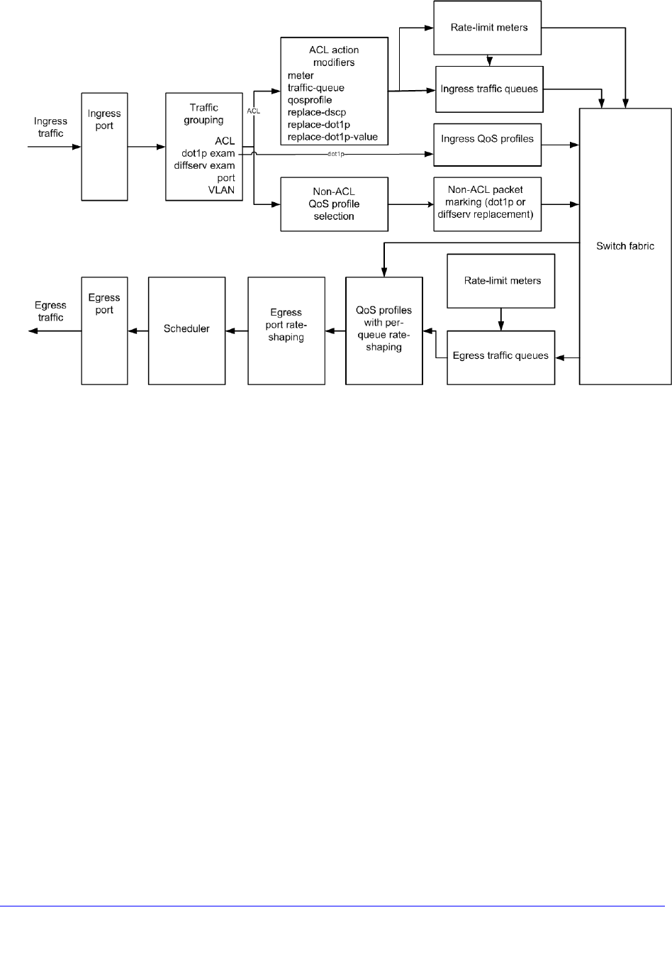
358 | Chapter 15. QoS
NETGEAR 8800 User Manual
Figure 21. QoS on NETGEAR Switches
In Figure 21, data enters the ingress port and is sorted into traffic groups, which can be
classified as either access control list (ACL)-based or nonACL-based. The ACL-based traffic
groups provide the most control of QoS features and can be used to apply ingress and
egress rate limiting and rate shaping as follows:
• Subject ingress traffic to rate limit meters
• Specify ingress hardware queues (QoS profiles) for rate limiting and rate shaping
• Specify ingress software traffic queues for rate limiting and rate shaping (these can be
associated with egress traffic queues for additional QoS control)
• Specify egress software traffic queues for rate limiting and rate shaping
• Specify egress QoS profiles for rate limiting and rate shaping
• Change the dot1p or Differential Services (DiffServ) values in egress frames or packets
NonACL-based traffic groups specify an ingress or egress QoS profile for rate limiting and
rate shaping. These groups cannot use ingress or egress software traffic queues. However,
nonACL-based traffic groups can use the packet marking feature to change the dot1p or
DiffServ values in egress frames or packets.
The ingress rate-limiting and rate-shaping features allow you to apply QoS to incoming traffic
before it reaches the switch fabric. If some out-of-profile traffic needs to be dropped, it is
better to drop it before it consumes resources in the switch fabric.
All ingress traffic is linked to an egress traffic queue or QoS profile before it reaches the
switch fabric. This information is forwarded with the traffic to the egress interface, where it
selects the appropriate egress traffic queue or QoS profile. Egress traffic from all traffic
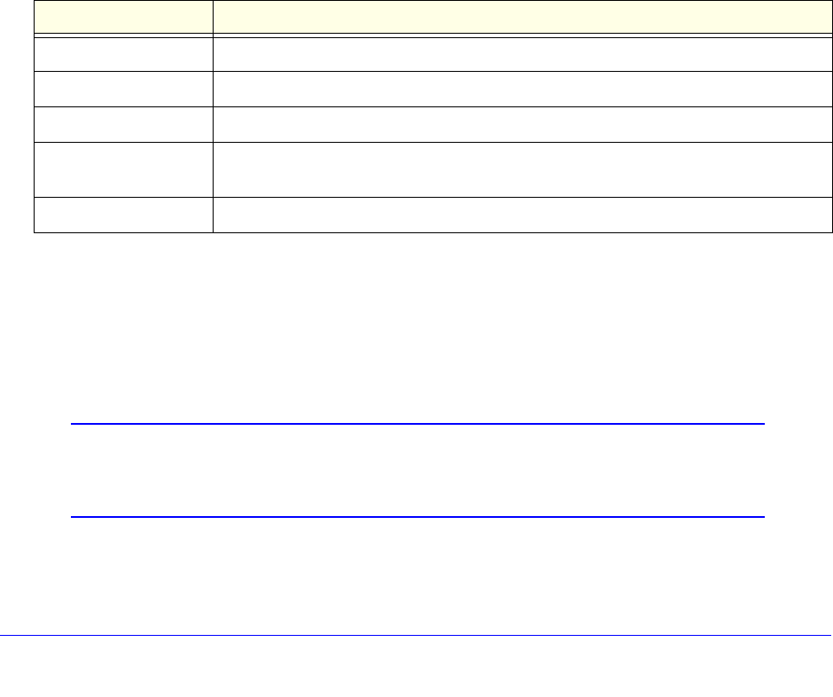
Chapter 15. QoS | 359
NETGEAR 8800 User Manual
queues and QoS profiles is forwarded to the egress port rate-shaping feature, which applies
QoS to the entire port. When multiple QoS profiles are contending for egress bandwidth, the
scheduler determines which queues are serviced.
The following sections provide more information on QoS:
• Applications and Types of QoS on page 359
• Traffic Groups on page 361
• Introduction to Rate Limiting, Rate Shaping, and Scheduling on page 366
• Meters on page 369
• QoS Profiles on page 369
• Multicast Traffic Queues on page 371
• Egress Port Rate Limiting and Rate Shaping on page 371
Applications and Types of QoS
Different applications have different QoS requirements. Table 41 summarizes the QoS
guidelines for different types of network traffic.
Consider the guidelines in Table 41 as general guidelines and not as strict
recommendations. After QoS parameters have been set, you can monitor the performance of
the application to determine if the actual behavior of the applications matches your
expectations. It is very important to understand the needs and behavior of the particular
applications you want to protect or limit. Behavioral aspects to consider include bandwidth
needs, sensitivity to latency and jitter, and sensitivity and impact of packet loss.
Note: Full-duplex links should be used when deploying policy-based QoS.
Half-duplex operation on links can make delivery of guaranteed
minimum bandwidth impossible.
The following sections provide more information on the traffic types listed in Table 41:
Table 41. Traffic Type and QoS Guidelines
Traffic type Key QoS parameters
Voice Minimum bandwidth, priority
Video Minimum bandwidth, priority, buffering (varies)
Database Minimum bandwidth
Web browsing Minimum bandwidth for critical applications, maximum bandwidth for noncritical
applications
File server Minimum bandwidth

360 | Chapter 15. QoS
NETGEAR 8800 User Manual
• Voice Applications on page 360
• Video Applications on page 360
• Critical Database Applications on page 360
• Web Browsing Applications on page 360
• File Server Applications on page 361
Voice Applications
Voice applications, or voice over IP (VoIP), typically demand small amounts of bandwidth.
However, the bandwidth must be constant and predictable because voice applications are
typically sensitive to latency (inter-packet delay) and jitter (variation in inter-packet delay).
The most important QoS parameter to establish for voice applications is minimum bandwidth,
followed by priority.
Video Applications
Video applications are similar in needs to voice applications, with the exception that
bandwidth requirements are somewhat larger, depending on the encoding. It is important to
understand the behavior of the video application being used. For example, in the playback of
stored video streams, some applications can transmit large amounts of data for multiple
streams in one spike, with the expectation that the end stations will buffer significant amounts
of video-stream data. This can present a problem to the network infrastructure, because the
network must be capable of buffering the transmitted spikes where there are speed
differences (for example, going from gigabit Ethernet to Fast Ethernet). Key QoS parameters
for video applications include minimum bandwidth and priority, and possibly buffering
(depending upon the behavior of the application).
Critical Database Applications
Database applications, such as those associated with Enterprise Resource Planning (ERP),
typically do not demand significant bandwidth and are tolerant of delay. You can establish a
minimum bandwidth using a priority less than that of delay-sensitive applications.
Web Browsing Applications
QoS needs for Web browsing applications cannot be generalized into a single category. For
example, ERP applications that use a browser front-end might be more important than
retrieving daily news information. Traffic groupings can typically be distinguished from each
other by their server source and destinations. Most browser-based applications are
distinguished by the dataflow being asymmetric (small dataflows from the browser client,
large dataflows from the server to the browser client).
An exception to this might be created by some Java™-based applications. In addition,
Web-based applications are generally tolerant of latency, jitter, and some packet loss;
however, small packet loss might have a large impact on perceived performance because of
the nature of TCP. The relevant parameter for protecting browser applications is minimum
bandwidth. The relevant parameter for preventing non-critical browser applications from
overwhelming the network is maximum bandwidth.

Chapter 15. QoS | 361
NETGEAR 8800 User Manual
File Server Applications
With some dependencies on the network operating system, file serving typically poses the
greatest demand on bandwidth, although file server applications are very tolerant of latency,
jitter, and some packet loss, depending on the network operating system and the use of TCP
or UDP.
Traffic Groups
A traffic group defines the ingress traffic to which you want to apply some level of QoS. You
can use the XCM8800 software to define traffic groups based on the following:
• Frame or packet header information such as IP address or MAC address
• Class of Service (CoS) 802.1p bits in the frame header
• DiffServ information in a packet header
• Ingress port number
• VLAN ID
Traffic groups that are defined based on frame or packet information are usually defined in
Access Control Lists (ACLs). The exception to this rule is the CoS and DiffServ information,
which you can use to define traffic groups without ACLs.
The function of the CoS and DiffServ traffic groups is sometimes referred to as explicit packet
marking, and it uses information contained within a frame or packet to explicitly determine a
class of service. An advantage of explicit packet marking is that the class of service
information can be carried throughout the network infrastructure, without repeating what can
be complex traffic group policies at each switch location. Another advantage is that end
stations can perform their own packet marking on an application-specific basis. NETGEAR
switch products have the capability of observing and manipulating packet marking
information with no performance penalty.
The CoS and DiffServ capabilities (on supported platforms) are not impacted by the switching
or routing configuration of the switch. For example, 802.1p information can be preserved
across a routed switch boundary and DiffServ code points can be observed or overwritten
across a Layer 2 switch boundary.
During QoS configuration, you configure the QoS level first by configuring QoS profiles, traffic
queues, and meters, and then you define a traffic group and assign the traffic group to the
QoS configuration. The following sections provide additional information on the traffic groups
you can define:
• ACL-Based Traffic Groups on page 362
• CoS 802.1p-Based Traffic Groups on page 362
• DiffServ-Based Traffic Groups on page 363
• Port-Based Traffic Groups on page 365
• VLAN-Based Traffic Groups on page 365
• Precedence of Traffic Groups on page 365

362 | Chapter 15. QoS
NETGEAR 8800 User Manual
ACL-Based Traffic Groups
An ACL-based traffic group allows you to use ACL rules in an ACL policy file to define the
traffic to which you want to apply QoS. An ACL-based traffic group requires more effort to
create, but the ACL rules give you more control over which traffic is selected for the traffic
group. For example, you can use an ACL to add traffic to a traffic group based on the
following frame or packet components:
• IP source or destination address
• IP protocol
• TCP flag
• TCP, UDP, or other Layer 4 protocol
• TCP or UDP port information
• IP fragmentation
• MAC source or destination address
• Ethertype
Depending on the platform you are using, traffic in an ACL traffic group can be processed as
follows:
• Assigned to an ingress meter for rate limiting
• Marked for an egress QoS profile for rate shaping
• Marked for an egress traffic queue for rate shaping
• Marked for DSCP replacement on egress
• Marked for 802.1p priority replacement on egress
When you are deciding whether to use an ACL-based traffic group or another type of traffic
group, consider what QoS features you want to apply to the traffic group. Some QoS features
can only apply to ACL-based traffic groups.
Note: ACLs are discussed in detail in Chapter 13, ACLs .
CoS 802.1p-Based Traffic Groups
CoS 802.1p-based traffic groups forward traffic to QoS features based on the three 802.1p
priority bits in an Ethernet frame. The 802.1p priority bits are located between the 802.1Q
type field and the 802.1Q VLAN ID as shown in Figure 22.
Note: On the BlackDiamond 10808, 12800 series, and 20800 series
switches only: If a port is in more than one virtual router, that port
does not support 802.1p-based traffic groups.
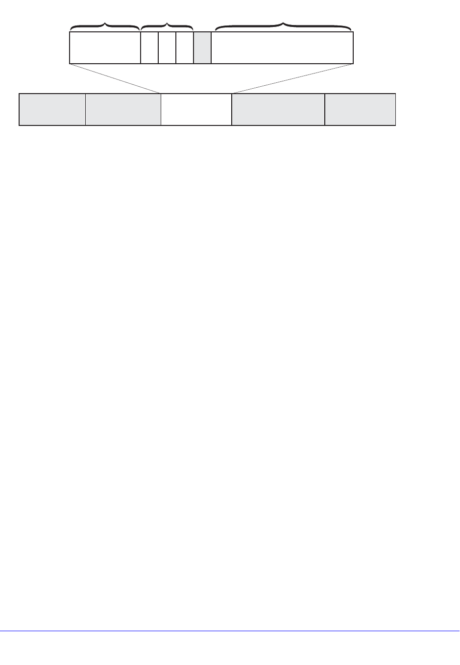
Chapter 15. QoS | 363
NETGEAR 8800 User Manual
Figure 22. 802.1p Priority Bits
The three 802.1p priority bits define up to 8 traffic groups that are predefined in the XCM8800
software.
On NETGEAR 8800 switches, the traffic groups direct traffic to egress QoS profiles for
egress rate shaping (see Table 44).
You do not need to define 802.1p-based traffic groups. You can enable or disable the use of
these traffic groups by enabling or disabling the 802.1p examination feature. You can also
configure which 802.1p values map to which QoS profiles.
A related feature is the 802.1p replacement feature, which allows you to configure the
software to replace the 802.1p bits in an ingress frame with a different value in the egress
frame. For more information on 802.1p replacement, see Configuring 802.1p or DSCP
Replacement on page 374.
DiffServ-Based Traffic Groups
DiffServ-based traffic groups forward traffic to egress QoS profiles based on the
Type-of-Service (TOS) information in an IP packet. In many systems, this type-of-service
information is replaced with a DiffServ field that uses 6 of the 8 bits for a DiffServ code point
(DSCP) as shown in Figure 23. (The other two bits are not used.)
EW_024
Source
address
802.1Q
type
802.1p
priority
802.1Q
VLAN ID
IP packet CRC
Destination
address
8100
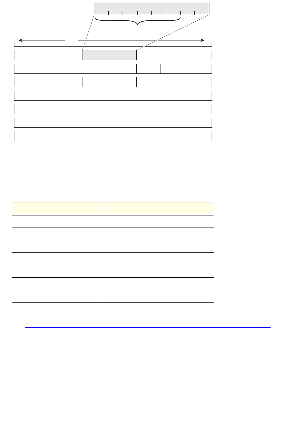
364 | Chapter 15. QoS
NETGEAR 8800 User Manual
Figure 23. DiffServe Code Point
Because the DSCP uses six bits, it has 64 possible values (26 = 64). By default, the values
are grouped and assigned to the default QoS profiles as listed in Table 42.
Note: The default DiffServ examination mappings apply on ports in more
than one VR. If you attempt to configure DiffServe examination or
replacement on a port that is in more than one virtual router, the
system returns the following message:
Table 42. Default DSCP-to-QoS-Profile Mapping
Traffic Group Code Point NETGEAR 8800 Switches QoS Profile
0-7 QP1
8-15 QP1
16-23 QP1
24-31 QP1
32-39 QP1
40-47 QP1
48-55 QP1
56-63 QP8
EW_023
Type-of-service
DiffServ code point
IHL
Data (variable)
0 bits 31
Options (+ padding)
Destination address
Source address
07654321
Total lengthVersion
ProtocolTime-to-live Header checksum
FlagsIdentification Fragment offset

Chapter 15. QoS | 365
NETGEAR 8800 User Manual
Warning: Port belongs to more than one VR. Port properties
related to diff serv and code replacement will not take
effect.
You do not need to define these traffic groups. You can enable or disable the use of these
traffic groups by enabling or disabling the DiffServ examination feature as described in
Configuring a DiffServ-Based Traffic Group on page 381. You can also configure which
DSCP values map to which queues.
Note: When DiffServ examination is enabled on 1 Gigabit Ethernet ports
for NETGEAR 8800 series switches, 802.1p replacement is enabled
and cannot be disabled. The ingress 802.1p value is replaced with
the 802.1p value assigned to the egress QoS profile.
A related feature is the DiffServ replacement feature, which allows you to configure the
software to replace the DSCP in an ingress frame with a different value in the egress frame.
For more information on DiffServ replacement, see Configuring 802.1p or DSCP
Replacement on page 374.
Port-Based Traffic Groups
Port-based traffic groups forward traffic to egress QoS profiles based on the incoming port
number. There are no default port-based traffic groups. You must configure each port-based
traffic group.
Note: Port-based traffic groups apply to all packets.
VLAN-Based Traffic Groups
VLAN-based traffic groups forward traffic to egress QoS profiles based on the VLAN
membership of the ingress port. There are no default VLAN-based traffic groups. You must
configure each VLAN-based traffic group.
Note: VLAN-based traffic groups apply to all packets.
Precedence of Traffic Groups
The XCM8800 software allows you to define multiple traffic groups, and you can configure
traffic groups in such a way that multiple traffic groups apply to an ingress frame or packet.
When an ingress frame or packet matches two or more traffic groups, the software chooses

366 | Chapter 15. QoS
NETGEAR 8800 User Manual
one traffic group based on the precedence defined for the switch platform. In general, the
more specific traffic group definition takes precedence. Table 43 shows the traffic group
precedence for the supported switch platforms (number 1 is the highest precedence).
Introduction to Rate Limiting, Rate Shaping, and Scheduling
The rate limiting and rate shaping terms are used throughout this chapter to describe QoS
features. Some QoS features perform both rate limiting and rate shaping. Rate limiting is the
process of restricting traffic to a peak rate (PR). Rate shaping is the process of reshaping
traffic throughput to give preference to higher priority traffic or to buffer traffic until forwarding
resources become available.
Both rate limiting and rate shaping allow you to take action on traffic that exceeds the
configured limits. These actions include forwarding traffic, dropping traffic, and marking the
excess traffic for possible drops later in the communication path. Software counters allow you
to record traffic statistics such as total packets forwarded and total packets dropped.
The following sections provide general information on rate-limiting and rate-shaping support
in the XCM8800 software:
• Single-Rate QoS on page 366
• Dual-rate QoS on page 367
• Rate Specification Options on page 367
• Disabling Rate Limiting and Rate Shaping on page 368
• Scheduling on page 368
Single-Rate QoS
Single-rate QoS defines a single rate for traffic that is subject to QoS. Single-rate QoS is the
most basic form of rate limiting and is well suited for constant rate traffic flows such as video
or where more complex dual-rate QoS is not needed. The traffic that meets the rate
requirement is considered in-profile. Traffic that does not meet the specified rate is
considered out-of-profile. A two-color system is often used to describe or mark the single-rate
QoS result. In-profile traffic is marked green, and out-of-profile traffic is marked red.
Table 43. Traffic Group Precedence
NETGEAR 8800 Switches
1. ACL-based traffic groups for IP packets (specifies IP address information)
2. ACL-based traffic groups for Ethernet frames (specifies MAC address information)
3. CoS 802.1p-based traffic groups
4. Port-based traffic groups
5. VLAN-based traffic groups
6. DiffServ-based traffic groups

Chapter 15. QoS | 367
NETGEAR 8800 User Manual
Single-rate rate-limiters pass traffic that is in-profile or marked green. Out-of-profile traffic
(marked red) is subject to whatever action is configured for out-of-profile traffic. Out of profile
traffic can be forwarded if bandwidth is available, dropped, or marked for a possible drop later
in the communication path.
For example, you can configure a peak rate (PR) for single-rate rate-limiting. All traffic that
arrives at or below the PR is considered in-profile and marked green. All traffic that arrives
above the PR is considered out-of-profile and marked red. When the traffic exceeds the
capacity of the rate-limiting component, all traffic that is marked red is dropped.
Another type of single-rate QoS is used on NETGEAR 8800 switches. A committed
information rate (CIR) establishes a reserved traffic rate, and a peak burst size (PBS)
establishes a maximum size for a traffic stream. If a traffic stream is at or below the CIR and
the PBS, it is considered to be within profile and marked green. If a traffic stream exceeds
either the CIR or the PBS, it is considered out-of-profile and marked red. On these switches,
you can configure the single-rate rate-limiting components to drop traffic marked red or set a
drop precedence for that traffic. You can also specify a DSCP value to mark the out-of-profile
traffic.
Dual-rate QoS
Dual-rate QoS defines two rates for traffic that is subject to QoS. The lower of the two rates is
the CIR, which establishes a reserved traffic rate. The higher of the two rates is the PR, which
establishes an upper limit for traffic. Dual-rate QoS is well suited to bursty traffic patterns
which are common with typical data traffic. Dual-rate QoS is widely used in legacy Frame
Relay and ATM leased lines.
Note: You must configure the peak rate higher than the committed rate.
A three-color system is used with dual-rate QoS. As with single-rate QoS, traffic at or below
the CIR is considered in-profile, marked green, and forwarded. The traffic that is above the
CIR and below the PIR is out-of-profile and marked yellow. Traffic above the PIR is also
out-of-profile and marked red. When incoming traffic is already marked yellow and is out of
profile, it is marked red. Different switch platforms take different actions on the traffic marked
yellow or red.
Rate Specification Options
The XCM8800 software allows you to specify the CIR and PR in gigabits per second (Gbps),
megabits per second (Mbps), or kilobits per second (Kbps). Most commands also allow you
to specify the CIR and PR as a percentage of the maximum port bandwidth using the minbw
(CIR) and maxbw (PR) options. The default value on all minimum bandwidth parameters is 0%,
and the default value on all maximum bandwidth parameters is 100%.
QoS can be applied at different locations in the traffic path using the following rate-limiting
and rate-shaping components:
• Ingress meters

368 | Chapter 15. QoS
NETGEAR 8800 User Manual
• Ingress QoS profiles (hardware queues)
• Ingress traffic queues (software queues)
• Egress traffic queues
• Egress QoS profiles
• Egress ports
The CIR or minimum bandwidth configuration for a rate-limiting or rate-shaping component is
a bandwidth guarantee for that component at a particular location in the traffic path. The
guarantees for all components at a specified location should add up to less than 100% and
should account for the traffic needs of the other components. For example, if you configure
25% minimum bandwidth for four out of eight queues at a particular location, there will be no
available bandwidth for the remaining four queues when traffic exceeds the port capacity.
Bandwidth unused by a queue can be used by other queues.
The rate-shaping configuration is configured at the location to which it applies on most
platforms. Meters are also used to provide ingress rate shaping on NETGEAR 8800
switches.
Disabling Rate Limiting and Rate Shaping
All switch platforms provide multiple QoS components in the traffic path that provide rate
limiting or rate shaping. These components give you control over where and how the rate
shaping is applied. However, your application might not require rate shaping at every
component. The default configuration for most components provides no rate shaping. When
rate shaping is disabled on a component, the CIR is set to 0 (minbw=0%) and the PR is set to
the maximum bandwidth (maxbw=100%). This setting reserves no bandwidth for the
component and allows the component to use 100% of the port bandwidth. If you need to
remove rate shaping from a QoS component, configure these settings on that component.
Scheduling
Scheduling is the process that determines which traffic is forwarded when multiple QoS
components are competing for egress bandwidth. The XCM8800 software supports the
following scheduling methods:
• Strict priority queuing: All higher priority queues are serviced before lower priority queues.
This ensures that high priority traffic receives access to available network bandwidth
immediately, but can result in lower priority traffic being starved. As long as a queued
packet remains in a higher-priority queue, any lower-priority queues are not serviced.
• Weighted fair queuing: All queues are given access to a relative amount of bandwidth
based on the weight assigned to the queue. When you configure a QoS profile with a
weight of 4, that queue is serviced four times as frequently as a queue with a weight of 1.
The hardware services higher-weighted queues more frequently, but lower-weighted
queues continue to be serviced at all times. Initially, the weight for all queues is set to 1,
which gives them equal weight. If all queues are set to 4, for example, all queues still
have equal weight, but each queue is serviced for a longer period.
• Round-robin priority: All queues are given access based on the configured priority level
and a round-robin algorithm.

Chapter 15. QoS | 369
NETGEAR 8800 User Manual
Scheduling takes place on the egress interface and includes consideration for the
color-marking of egress frames and packets. Green-marked traffic has the highest priority
and is forwarded based on the scheduling method. When multiple queues are competing for
bandwidth, yellow-marked traffic might be dropped or remarked red. Red-marked traffic is
dropped when no bandwidth is available. If yellow-marked traffic is forwarded to the egress
port rate-shaping component, it can be dropped there if the egress port is congested.
Meters
Meters are used to define ingress rate-limiting and rate-shaping on NETGEAR 8800
switches. Some platforms also support meters for egress traffic. The following section
provides information on meters for specific platforms.
Meters on NETGEAR 8800 Switches
The NETGEAR 8800 series switches use a single-rate meter to determine if ingress traffic is
in-profile or out-of-profile. You can also use single-rate meters to determine if egress traffic is
in-profile or out-of-profile.
The out-of-profile actions are drop, set the drop precedence, or mark the DSCP with a
configured value. Additionally, each meter has an associated out-of-profile counter that
counts the number of packets that were above the committed-rate (and subject to the
out-of-profile-action). These meters are a per-port resource; so, for example, assigning a 50
Mbps meter to a VLAN means that each port in the VLAN is assigned 50 Mbps.
QoS Profiles
QoS profiles are queues that provide ingress or egress rate limiting and rate shaping. The
following section provides more information on QoS profiles.
Egress Qos Profiles
Egress QoS profiles are supported on all XCM8800 switches and allow you to provide
dual-rate egress rate-shaping for all traffic groups on all egress ports. Any configuration you
apply to an egress QoS profile is applied to the same egress QoS profile on all other ports.
When you are configuring ACL-based traffic groups, you can use the qosprofile action
modifier to select an egress QoS profile. For DiffServ-, port-, and VLAN-based traffic groups,
the traffic group configuration selects the egress QoS profile. For CoS dot1p traffic groups on
all platforms, the dot1p value selects the egress QoS profile.
Egress QoS profile operation depends on the switch type and is described in the following
section.
Egress QoS Profiles on NETGEAR 8800 Switches
NETGEAR 8800 series switches have two default egress QoS profiles named QP1 and QP8.
You can configure up to six additional QoS profiles (QP2 through QP7) on the switch. The
default settings for egress QoS profiles are summarized in Table 44.
370 | Chapter 15. QoS
NETGEAR 8800 User Manual
For CoS 802.1p traffic groups, the ingress 802.1p priority value selects a specific QoS profile
as shown in Table 44. This mapping can be changed as described in Changing the 802.1p
Priority to QoS Profile Mapping on page 381. For traffic groups other than 802.1p-based
groups, the traffic group configuration selects a specific egress QoS profile by name.
The default dual-rate QoS configuration is 0% for minimum bandwidth and 100% for
maximum bandwidth.
A buffer parameter allows you to define the maximum amount of packet buffer memory to be
used by a QoS profile. By default, all QoS profiles can use 100% of the available packet
buffer memory. However, you can restrict buffer usage for a QoS profile in amounts ranging
from 1 to 100%, in whole integers. Regardless of the maximum buffer setting, the system
does not drop any packets if any packet buffer memory remains to hold the packet and the
current QoS profile buffer use is below the maximum setting.
Note: Using all eight queues on all ports can result in insufficient buffering
to sustain 0 packet loss throughput during full-mesh connectivity with
large packets.
Table 44. Default QoS Profile Parameters on the NETGEAR 8800 Series Switches
Ingress
802.1p
Priority
Value
Egress QoS
Profile
Namea
a. The QoS profile name cannot be changed.
Queue Service
Priority Valueb
b. The queue service priority value cannot be changed.
Buffer Weight Notes
0-6 QP1 1 (Low) 100% 1This QoS profile is part of the default
configuration and cannot be deleted.
QP2 2 (LowHi) 100% 1You must create this QoS profile before
using it.
QP3 3 (Normal) 100% 1You must create this QoS profile before
using it.
QP4 4 (NormalHi) 100% 1You must create this QoS profile before
using it.
QP5 5 (Medium) 100% 1You must create this QoS profile before
using it.
QP6 6 (MediumHi) 100% 1You must create this QoS profile before
using it.
QP7 7 (High) 100% 1You must create this QoS profile before
using it.
7QP8 8 (HighHi) 100% 1This QoS profile is part of the default
configuration and cannot be deleted.

Chapter 15. QoS | 371
NETGEAR 8800 User Manual
When multiple QoS profiles are contending for port bandwidth and the egress traffic in each
profile is within profile, the scheduler determines how the QoS profiles are serviced as
described in Scheduling on page 368. In strict-priority mode, the queues are serviced based
on the queue service priority value. In weighted fair-queuing mode, the queues are serviced
based on the configured weight.
When configured to do so, the priority of a QoS profile can determine the 802.1p bits used in
the priority field of a forwarded frame (see Replacing 802.1p Priority Information on Egress
on page 374). The priority of a QoS profile can determine the DiffServ code point value used
in an IP packet when the packet is forwarded (see Replacing a DSCP on Egress on
page 375).
A QoS profile change does not alter the behavior of the switch until it is assigned to a traffic
group.
Multicast Traffic Queues
BlackDiamond 20800 series switches provide four traffic queues for single-rate rate-limiting
of multicast traffic. The CoS 802.1p value in an ingress multicast packet selects the multicast
traffic queue. CoS 802.1p value 3 selects the guaranteed delivery traffic queue. CoS 802.1p
values 0 to 2 select one of the three best-effort delivery traffic queues.
To apply ingress rate-limiting to a multicast traffic queue, configure a single rate meter and
apply it to either the multicast-guaranteed traffic queue or the best-effort traffic queue. When
you apply a meter to the best-effort traffic queue, it applies to all three best-effort multicast
traffic queues.
Egress Port Rate Limiting and Rate Shaping
Egress port rate limiting and rate shaping allow you to define limits for all egress traffic
coming from the egress QoS profiles and traffic queues. On NETGEAR 8800 switches, you
can apply single-rate rate-limiting. You can also configure ports to pass an unlimited flow as
describe in Disabling Rate Limiting and Rate Shaping on page 368.
Configuring QoS
The following sections provide information on configuring QoS:
• Platform Configuration Procedures on page 372
• Selecting the QoS Scheduling Method on page 373
• Configuring 802.1p or DSCP Replacement on page 374
• Configuring Egress QoS Profile Rate Shaping on page 378
• Configuring Egress Port Rate Limits on page 379
• Configuring Traffic Groups on page 380
• Creating and Managing Meters on page 383
• Adjusting the Byte Count Used to Calculate Traffic Rates on page 384
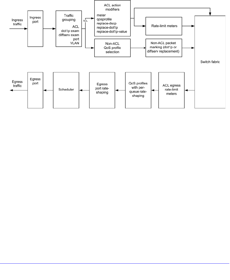
372 | Chapter 15. QoS
NETGEAR 8800 User Manual
• Controlling Flooding, Multicast, and Broadcast Traffic on Ingress Ports on page 385
Platform Configuration Procedures
The following sections provide summary configuration procedures for the NETGEAR 8800.
Figure 24 shows the QoS configuration components for NETGEAR 8800 switches.
Figure 24. QoS on NETGEAR 8800 Switches
The following sections provide information on configuring QoS:
• QoS Configuration Guidelines for NETGEAR 8800 Switches on page 372
• Configuration Summary for NETGEAR 8800 Switches on page 373
QoS Configuration Guidelines for NETGEAR 8800 Switches
The following considerations apply only to QoS on the NETGEAR 8800 switches:
• The following QoS features share resources:
• ACLs
• dot1p
• VLAN-based QoS
• Port-based QoS
• You might receive an error message when configuring a QoS feature in the above list; it is
possible that the shared resource is depleted. In this case, unconfigure one of the other
QoS features and reconfigure the one you are working on.
• This QoS profile is reserved for system control traffic.

Chapter 15. QoS | 373
NETGEAR 8800 User Manual
• These switches allow dynamic creation and deletion of QoS queues, with QP1 and QP8
always available.
• ACL egress rate-limit meters are supported.
Configuration Summary for NETGEAR 8800 Switches
Use the following procedure to configure QoS on NETGEAR 8800 switches:
1. Configure basic Layer 2 connectivity (prerequisite).
2. Configure QoS scheduling, if needed, as described in Selecting the QoS Scheduling Method
on page 373.
3. Configure ingress and egress rate-limiting as needed:
a. Create a meter as described in Creating Meters on page 384.
b. Configure the meter as described in Configuring a Meter on page 384.
c. Apply the meter to ingress traffic as described in Applying a Meter to Ingress or
Egress Traffic on page 384.
4. Configure non-ACL-based egress QoS profile selection as described in the following
sections:
• Configuring a CoS 802.1p-Based Traffic Group on page 380
• Configuring a DiffServ-Based Traffic Group on page 381
• Configuring a Port-Based Traffic Group on page 383
• Configuring a VLAN-Based Traffic Group on page 383
5. Configure 802.1p or DiffServ packet marking as described in Configuring 802.1p or DSCP
Replacement on page 374.
6. Configure egress QoS profile rate shaping as needed:
a. Create egress QoS profiles as described in Creating or Deleting an Egress QoS
Profile on page 378.
b. Configure egress QoS profile rate shaping parameters as described in Configuring
an Egress QoS Profile on page 378.
7. Configure egress port rate shaping as described in Configuring Egress Port Rate Limits on
page 379.
8. Finalize ACL traffic-based group configuration as described in Configuring an ACL-Based
Traffic Group on page 380.
9. Verify the configuration using the commands described in Displaying QoS Configuration and
Performance on page 385.
Selecting the QoS Scheduling Method
QoS scheduling determines the order of QoS profile service and varies between platforms.
The NETGEAR 8800 switches support two QoS scheduling methods: strict-priority and
weighted-round-robin. These scheduling methods are described in Scheduling on page 368.
The scheduling applies globally to all ports on the switch, but you can override the
weighted-round-robin configuration on a QoS profile.

374 | Chapter 15. QoS
NETGEAR 8800 User Manual
To select the QoS scheduling method for a switch, use the following command:
configure qosscheduler [strict-priority | weighted-round-robin]
To override the weighted-round-robin switch configuration on a specific QoS profile, use the
following command:
configure qosprofile <qosprofile> use-strict-priority
Configuring 802.1p or DSCP Replacement
The following sections provide information on 802.1p priority replacement and DSCP
replacement:
• Replacing 802.1p Priority Information on Egress on page 374
• Replacing a DSCP on Egress on page 375
• DiffServ Example on page 377
Replacing 802.1p Priority Information on Egress
By default, 802.1p priority information is not replaced or manipulated, and the information
observed on ingress is preserved when forwarding the frame. This behavior is not affected by
the switching or routing configuration of the switch. However, the switch is capable of
inserting and/or overwriting 802.1p priority information when it transmits an 802.1Q tagged
frame as described in the following sections:
• Replacement in ACL-Based Traffic Groups on page 374
• Replacement in Non-ACL-Based Traffic Groups on page 374
Replacement in ACL-Based Traffic Groups
If you are using ACL-based traffic groups, you can use the replace-dot1p action modifier to
replace the ingress 802.1p priority value with the 802.1p priority value of the egress QoS
profile as listed in Table 45. To specify a specific 802.1p priority value on egress, use the
replace-dot1p-value action modifier.
Note: If you are using ACL-based traffic groups, you must use ACL action
modifiers to replace the 802.1p priority. Traffic that meets any ACL
match conditions is not subject to non-ACL-based 802.1p priority
replacement.
Replacement in Non-ACL-Based Traffic Groups
For non-ACL-based traffic groups, you can enable or disable 802.1p priority replacement on
specific ingress ports. When 802.1p priority replacement is enabled, the default egress
802.1p priority value is set to the priority value of the egress QoS profile as listed in Table 45.

Chapter 15. QoS | 375
NETGEAR 8800 User Manual
To enable 802.1p priority replacement on egress, use the following command:
enable dot1p replacement ports [<port_list> | all]
Note: The port in this command is the ingress port.
To disable this feature, use the following command:
disable dot1p replacement ports [<port_list> | all]
Note: On NETGEAR 8800 switches, only QP1 and QP8 exist by default;
you must create QP2 to QP7. If you have not created these QPs, the
replacement feature will not take effect.
Note: When DiffServ examination is enabled on 1 Gigabit Ethernet ports
for NETGEAR 8800 switches, 802.1p replacement is enabled and
cannot be disabled. The ingress 802.1p value is replaced with the
802.1p value assigned to the egress QoS profile.
Replacing a DSCP on Egress
The switch can be configured to change the DSCP in a packet before forwarding the packet.
This is done with no impact on switch performance and can be configured as described in the
following sections:
Table 45. Default Queue-to-802.1p Priority Replacement Value
Egress QoS
Profile 802.1p Priority
Replacement Value
Q1 0
Q2 1
Q3 2
Q4 3
Q5 4
Q6 5
Q7 6
Q8 7
376 | Chapter 15. QoS
NETGEAR 8800 User Manual
• Replacement in ACL-Based Traffic Groups on page 374
• Replacement in Non-ACL-Based Traffic Groups on page 374
Replacement in ACL-Based Traffic Groups
If you are using ACL-based traffic groups, you can use the replace-dscp action modifier to
replace the ingress DSCP value with the DSCP value of the egress QoS profile as listed in
Table 46.
Note: If you are using ACL-based traffic groups, you must use ACL action
modifiers to replace the DSCP. Traffic that meets any ACL match
conditions is not subject to non-ACL-based DSCP priority
replacement. For all platforms except BlackDiamond 20800 series
switches, NETGEAR recommends that you use ACL-based traffic
groups when configuring DSCP replacement. BlackDiamond 20800
series switches do not support the replace-dscp action modifier.
Replacement in Non-ACL-Based Traffic Groups
For non-ACL-based traffic groups, you can enable or disable DSCP replacement on specific
ingress ports. When DSCP replacement is enabled, the DSCP value used on egress is
determined by either the QoS profile or the 802.1p priority value. Table 46 shows the default
mappings of QoS profiles and 802.1p priority values to DSCPs.
To replace DSCPs, you must enable DiffServ replacement using the following command:
enable diffserv replacement ports [<port_list> | all]
Table 46. Default QoS Profile and 802.1p Priority Value Mapping to DiffServ Code Points
NETGEAR 8800 Switches QoS Profile 802.1p Priority Value DSCP
QP1 0 0
1 8
216
324
432
540
648
QP8 756

Chapter 15. QoS | 377
NETGEAR 8800 User Manual
Note: The port in this command is the ingress port.
To disable this feature, use the following command:
disable diffserv replacement ports [<port_list> | all]
To view the current DiffServ replacement configuration, use the following command:
show diffserv replacement
To change the DSCP mapping, use the following commands:
configure diffserv replacement [{qosprofile} <qosprofile> | priority
<priority>] code-point <code_point>
unconfigure diffserv replacement
DiffServ Example
In this example, we use DiffServ to signal a class of service throughput and assign any traffic
coming from network 10.1.2.x with a specific DSCP. This allows all other network switches to
send and observe the DSCP instead of repeating the same QoS configuration on every
network switch.
To configure the switch:
1. Using ACLs, assign a traffic grouping for traffic from network 10.1.2.x to QP3:
configure access-list qp3sub any
The following is a sample policy file example:
#filename: qp3sub.pol
entry QP3-subnet {
if {
source-address 10.1.2.0/24
} then {
Qosprofile qp3;
replace-dscp;
}
2. Configure the switch so that other switches can signal calls of service that this switch should
observe by entering the following:
enable diffserv examination ports all

378 | Chapter 15. QoS
NETGEAR 8800 User Manual
Note: The switch only observes the DSCPs if the traffic does not match
the configured access list. Otherwise, the ACL QoS setting overrides
the QoS DiffServ configuration.
Configuring Egress QoS Profile Rate Shaping
The following sections describe how to configure egress QoS Profile rate shaping:
• Creating or Deleting an Egress QoS Profile on page 378
• Configuring an Egress QoS Profile on page 378
Creating or Deleting an Egress QoS Profile
The default configuration for most platforms defines eight egress QoS profiles. On NETGEAR
8800 switches, the default configuration defines two egress QoS profiles. On these platforms,
use the following command to create an additional egress QoS profile:
create qosprofile [QP2| QP3 | QP4 | QP5 | QP6 | QP7]
On NETGEAR 8800 switches, use the following command to delete an egress QoS profile:
delete qosprofile [QP2| QP3 | QP4 | QP5 | QP6 | QP7]
Configuring an Egress QoS Profile
Egress QoS profile rate shaping is disabled by default on all ports.
On NETGEAR 8800 switches, use the following command to configure egress QoS profile
rate shaping on one or more ports:
configure qosprofile <qosprofile> {committed_rate <committed_bps> [k | m]}
{maxbuffer <percent>} {maxbw <maxbw_number>} {minbw <minbw_number>} {peak_rate
<peak_rate> [k | m]} {use-strict-priority} {weight <value>}
Note: You must use this command if you want to configure the buffer size
or weight value. Otherwise, you can use the command in the
following description.
Use the following command to configure egress QoS profile rate shaping on one or more
ports:
configure qosprofile {egress} <qosprofile> [{{minbw <minbw_number>} {qos-weight
<weight>} {maxbw <maxbw_number>}} | {{committed_rate <committed_bps> [K | M]}
{qos-weight <weight>} {peak_rate <peak_bps> [K | M]}} ] {priority [<priority> |
<priority_number>]} [ports [<port_list> | all]]

Chapter 15. QoS | 379
NETGEAR 8800 User Manual
Note: You cannot configure the priority for the QoS profile on NETGEAR
8800 switches.
To remove the limit on egress bandwidth per QoS profile per port, re-issue this command
using the default values.
To display the current configuration for the QoS profile, use the following command:
show qosprofile {ingress | egress} ports [ all | <port_list>]
Configuring Egress Port Rate Limits
The following section describes egress port rate limiting on the NETGEAR 8800.
Configuration on NETGEAR 8800 Switches
The default behavior is to have no limit on the egress traffic per port. To configure egress rate
limiting, use the following command:
configure ports <port_list> rate-limit egress [no-limit | <cir-rate> [Kbps |
Mbps | Gbps] {max-burst-size <burst-size> [Kb | Mb]}]
To view the configured egress port rate-limiting behavior, use the following command:
show ports {mgmt | <port_list>} information {detail}
You must use the detail parameter to display the egress port rate configuration and, if
configured, the maximum burst size. See Displaying Port Information on page 148 for more
information on the show ports information command.
You can also display this information using the following command:
show configuration vlan
The following is sample output from the show configuration vlan command for configured
egress rate limiting:
# Module vlan configuration.
#
configure vlan Default tag 1
config port 3:1 rate-limit egress 128 Kbps max-burst-size 200 Kb
config port 3:2 rate-limit egress 128 Kbps
config port 3:10 rate-limit egress 73 Kbps max-burst-size 128 Kb
configure vlan Default add ports 3:1-48 untagged
Note: See Chapter 10, FDB for more information on limiting broadcast,
multicast, or unknown MAC traffic ingressing the port.

380 | Chapter 15. QoS
NETGEAR 8800 User Manual
Configuring Traffic Groups
The following sections describe how to configure traffic groups:
• Configuring an ACL-Based Traffic Group on page 380
• Configuring a CoS 802.1p-Based Traffic Group on page 380
• Configuring a DiffServ-Based Traffic Group on page 381
• Configuring a Port-Based Traffic Group on page 383
• Configuring a VLAN-Based Traffic Group on page 383
Configuring an ACL-Based Traffic Group
ACL-based traffic groups are introduced in ACL-Based Traffic Groups on page 362. An ACL
can implement multiple QoS features, so it is usually best to finalize the ACL after all other
features have been configured.
To configure an ACL-based traffic group, do the following:
1. Create an ACL policy file and add rules to the file using the following guidelines:
a. Use ACL match conditions to identify the traffic for the traffic group.
b. Use ACL action modifiers to apply QoS features such as ingress meter or traffic
queue selection, egress QoS profile or traffic queue selection, and 802.1p priority
replacement to the traffic group.
2. Apply the ACL policy file to the ports where you want to define the traffic groups. You can
apply the file to specific ports, all ports, or all ports in a VLAN.
ACLs are described in detail in Chapter 13, ACLs.
Configuring a CoS 802.1p-Based Traffic Group
As described in CoS 802.1p-Based Traffic Groups on page 362, the default switch
configuration defines CoS 802.1p-based traffic groups. The configuration options for these
groups are described in the following sections:
• Enabling and Disabling 802.1p Examination on page 380
• Changing the 802.1p Priority to QoS Profile Mapping on page 381
Note: If you are using ACL-based traffic groups, use the qosprofile or
traffic-queue action modifier to select a forwarding queue. Traffic
that meets any ACL match conditions is not evaluated by other traffic
groups.
Enabling and Disabling 802.1p Examination
CoS 802.1p examination is supported on all platforms and enabled by default. However, you
can only disable and enable this feature on NETGEAR 8800 switches. To free ACL

Chapter 15. QoS | 381
NETGEAR 8800 User Manual
resources, disable this feature whenever another QoS traffic grouping is configured. (See
Chapter 13, ACLs for information on available ACL resources.)
Note: If you disable this feature when no other QoS traffic grouping is in
effect, 802.1p priority enforcement of 802.1q tagged packets
continues.
To disable the 802.1p examination feature on NETGEAR 8800 switches, use the following
command:
disable dot1p examination ports [<port_list> | all]
To re-enable the 802.1p examination feature on NETGEAR 8800 switches, use the following
command:
enable dot1p examination ports [<port_list> | all]
To display whether the 802.1p examination feature is enabled or disabled, use the following
command:
show ports {mgmt | <port_list>} information {detail}
Changing the 802.1p Priority to QoS Profile Mapping
You can change the 802.1p priority to egress QoS profile mapping on NETGEAR 8800
switches.
To view the current 802.1p priority to QoS profile mapping on a switch, use the following
command:
show dot1p
To change the mapping on NETGEAR 8800 switches, use the following command:
configure dot1p type <dot1p_priority> {qosprofile} <qosprofile>
Configuring a DiffServ-Based Traffic Group
As described in DiffServ-Based Traffic Groups on page 363, the default switch configuration
defines DiffServ-based traffic groups. The configuration options for these groups are
described in the following sections:
• Enabling and Disabling Diffserv Examination on page 382
• Changing the DSCP to QOS Profile Mapping on page 382
Note: If you are using ACL-based traffic groups, use the qosprofile or
traffic-queue action modifier to select a forwarding queue. Traffic
that meets any ACL match conditions is not evaluated by other
traffic groups.

382 | Chapter 15. QoS
NETGEAR 8800 User Manual
Enabling and Disabling Diffserv Examination
When a packet arrives at the switch on an ingress port and Diffserv examination is enabled,
the switch uses the DSCP value to select the egress QoS profile that forwards the packet.
The QoS profile configuration defines the forwarding characteristics for all traffic assigned to
the QoS profile.
Note: On the 1 Gigabit Ethernet ports on the NETGEAR 8800 switches.
802.1p replacement always happens when you configure the
DiffServ traffic grouping.
The DiffServ examination feature is disabled by default. To enable DiffServ examination, use
the following command:
enable diffserv examination ports [<port_list> | all]
Note: When DiffServ examination is enabled on 1 Gigabit Ethernet ports
for NETGEAR 8800 switches, 802.1p replacement is enabled and
cannot be disabled. The ingress 802.1p value is replaced with the
802.1p value assigned to the egress QoS profile.
To disable DiffServ examination, use the following command:
disable diffserv examination ports [<port_list> | all]
Changing the DSCP to QOS Profile Mapping
You can change the egress QoS profile assignment for each of the 64 code points.
To view the current DSCP to QoS profile mapping, use the following command:
show diffserv examination
On NETGEAR 8800 switches, use the following commands to change the DSCP to QoS
profile mapping:
configure diffserv examination code-point <code_point> {qosprofile}
<qosprofile>
unconfigure diffserv examination
After a QoS profile is assigned, the rest of the switches in the network prioritize the packet
using the characteristics specified by the QoS profile.

Chapter 15. QoS | 383
NETGEAR 8800 User Manual
Configuring a Port-Based Traffic Group
A port-based traffic group links a physical ingress port to an egress QoS profile for traffic
forwarding. To configure a port-based traffic group, use the following command:
configure ports <port_list> {qosprofile} <qosprofile>
Note: If you are using ACL-based traffic groups, use the qosprofile or
traffic-queue action modifier to select a forwarding queue. Traffic
that meets any ACL match conditions is not evaluated by other
traffic groups.
Note: On the NETGEAR 8800 switches, port-based traffic groups apply to
all packets.
Configuring a VLAN-Based Traffic Group
A VLAN-based traffic group links all ports in a VLAN to an egress QoS profile for traffic
forwarding. All intra-VLAN switched traffic and all routed traffic sourced from the named
VLAN uses the specified QoS profile. To configure a VLAN-based traffic group, use the
following command:
configure vlan <vlan_name> {qosprofile} <qosprofile>
Note: If you are using ACL-based traffic groups, use the qosprofile or
traffic-queue action modifier to select a forwarding queue. Traffic
that meets any ACL match conditions is not evaluated by other
traffic groups.
Note: On the NETGEAR 8800 series switches, VLAN-based traffic groups
apply to all packets. VLAN-based traffic groups are not supported on
BlackDiamond 20800 series switches.
Creating and Managing Meters
You can configure meters to define bandwidth requirements on NETGEAR 8800 switches.
The following sections describe how to use meters:
• Creating Meters on page 384
• Configuring a Meter on page 384

384 | Chapter 15. QoS
NETGEAR 8800 User Manual
• Applying a Meter to Ingress or Egress Traffic on page 384
• Deleting a Meter on page 384
Creating Meters
To create a meter, use the following command:
create meter <meter-name>
To display the meters already configured on the switch, use the show meter command.
Configuring a Meter
After you create a meter, you configure the meter using the command for the platform you are
using.
To configure a QoS meter on the NETGEAR 8800 series switches, use the following
command:
configure meter <metername> {max-burst-size <burst-size> [Kb | Mb]}
{committed-rate <cir> [Gbps | Mbps | Kbps]} {out-actions [drop |
set-drop-precedence {dscp [none | <dscp-value>]}}
Applying a Meter to Ingress or Egress Traffic
You can apply a meter to ingress traffic using an ACL on NETGEAR 8800 series switches.
You can also apply a meter to egress traffic using an ACL.
Use rules within the ACL to identify the ingress traffic to which you want to apply the meter.
Apply the meter by specifying the meter name with the meter <metername> action modifier.
For information on completing the ACL configuration, see Configuring an ACL-Based Traffic
Group on page 380.
Deleting a Meter
To delete a meter, use the following command:
delete meter <metername>
Note: The associated meters are not deleted when you delete any type of
traffic queue. Those meters remain and can be associated with other
traffic queues. To display the configured meters, use the show
meter command.
Adjusting the Byte Count Used to Calculate Traffic Rates
You can configure a per-packet byte adjustment that the system uses to calculate the ingress
traffic rate, traffic utilization, and traffic statistics. You configure either the number of bytes you

Chapter 15. QoS | 385
NETGEAR 8800 User Manual
want subtracted from each packet ingressing the specified ports or the number of bytes you
want added to the packet ingressing the specified ports.
You add or subtract bytes from packets ingressing specified ports by using the following
command:
configure ports <port_list> rate-limit packet byte-adjustment [increase
<add_bytes> | decrease <sub_bytes>]
By default, all bytes are counted for the ingressing traffic rate. After you issue this command,
the default number of bytes removed is 0; you can add or subtract from 1 to 4 bytes from
each ingressing packet on the specified ports for calculating the ingressing traffic rate.
To display the number of bytes added to or subtracted from the packet to calculate the
ingressing traffic rate, traffic utilization, and traffic statistics, use the following command:
show ports <port_list> information detail
Note: You must use the detail keyword to display this information.
To unconfigure this setting, re-issue the command and enter the value 0.
If you use this command to decrease by 4, the show traffic queue statistics display
shows only bytes; the packets are displayed as 0.
Controlling Flooding, Multicast, and Broadcast Traffic on
Ingress Ports
On NETGEAR 8800 series switches, you can use the following command to control ingress
flooding of broadcast and multicast traffic and traffic for unknown destination MAC
addresses:
configure ports <port_list> rate-limit flood [broadcast | multicast |
unknown-destmac] [no-limit | <pps>]
Displaying QoS Configuration and Performance
The following sections describe ways to display QoS configuration and performance
information:
• Displaying Traffic Group Configuration Data on page 385
• Displaying the Rate-Limiting and Rate-Shaping Configuration on page 386
• Displaying Performance Statistics on page 387
Displaying Traffic Group Configuration Data
The following sections describe how to display traffic group configuration data:

386 | Chapter 15. QoS
NETGEAR 8800 User Manual
• Displaying 802.1p Priority to QoS Profile Mappings on page 386
• Displaying DiffServe DSCP to QoS Profile Mappings on page 386
• Displaying Port and VLAN QoS Settings on page 386
Displaying 802.1p Priority to QoS Profile Mappings
To display the 802.1p priority to egress QoS profile mappings, use the following command:
show dot1p
Displaying DiffServe DSCP to QoS Profile Mappings
To display the DiffServ DSCP to egress QoS profile mappings, use the following commands:
show diffserv examination
Displaying Port and VLAN QoS Settings
You can display QoS settings assigned to ports or VLANs by entering the following
command:
show ports {mgmt | <port_list>} information {detail}
Note: To ensure that you display the QoS information, you must use the
detail keyword.
This command can display which QoS profile, if any, is configured.
Displaying the Rate-Limiting and Rate-Shaping Configuration
The following sections describe how to display rate-limiting and rate-shaping configuration
information:
• Displaying QoS Profile Information on page 386
• Displaying Meters on page 387
• Displaying the Traffic Queue Configuration on page 387
Displaying QoS Profile Information
You can display QoS profile information, using the following commands:
show qosprofile {ingress | egress} ports [ all | <port_list>]
show ports {mgmt | <port_list>} information {detail}
Note: You must specify ingress to view ingress rate shaping information.

Chapter 15. QoS | 387
NETGEAR 8800 User Manual
Displaying Meters
To display the meters that you create, you can use either the show-access list or the show
meter command.
Displaying the Traffic Queue Configuration
To display configuration data for the current ingress and egress traffic queues on your switch,
use the following command:
show traffic queue
To display detailed information on all traffic queues or on a specific queue, use the following
command:
show traffic queue {detail | <queue_name>}
Displaying Performance Statistics
The following sections describe how to display QoS performance statistics:
• Displaying QoS Profile Traffic Statistics on page 387
• Displaying Congestion Statistics on page 387
Displaying QoS Profile Traffic Statistics
After you have created QoS policies that manage the traffic through the switch, you can use
the QoS monitor to determine whether the application performance meets your expectations.
The QoS monitor allows you to display the traffic packet counts in a real-time or a snapshot
display for the specified ports.
To view QoS profile traffic statistics on NETGEAR 8800 switches, use the following
command:
show ports <port_list> qosmonitor {congestion} {no-refresh}
Note: On NETGEAR 8800 modules, only one port per slot or module can
be monitored at any one time.
Displaying Congestion Statistics
To display a count of the packets dropped due to congestion on a port, enter the following
command:
show ports <port_list> congestion {no-refresh}
To display a count of the packets dropped due to congestion in the QoS profiles for a port,
enter the following command:
show ports <port_list> qosmonitor {congestion} {no-refresh}

388 | Chapter 15. QoS
NETGEAR 8800 User Manual
Note: On NETGEAR 8800 modules, only one port per slot or module can
be monitored at any one time.

Chapter 16. Network Login | 389
16
16. Network Login
This chapter includes the following sections:
• Overview on page 389
• Configuring Network Login on page 394
• Authenticating Users on page 397
• Local Database Authentication on page 397
• 802.1x Authentication on page 402
• Web-Based Authentication on page 412
• MAC-Based Authentication on page 421
• Additional Network Login Configuration Details on page 425
Overview
Network login controls the admission of user packets into a network by allowing MAC addresses
from users that are properly authenticated. Network login is controlled on a per port basis. When
network login is enabled on a port, that port does not forward any packets until authentication
takes place.
Network login is capable of three types of authentication: web-based, MAC-based, and 802.1x.
In addition, network login has two different modes of operation: Campus mode and ISP mode.
The authentication types and modes of operation can be used in any combination.
When web-based network login is enabled on a switch port, that port is placed into a
non-forwarding state until authentication takes place. To authenticate, a user must open a web
browser and provide the appropriate credentials. These credentials are either approved, in which
case the port is placed in forwarding mode, or not approved, in which case the port remains
blocked. You can initiate user logout by submitting a logout request or closing the logout window.
The following capabilities are included with network login:
• Web-based login using HTTP available on each port
• Web-based login using HTTPS—if you install the SSH software module that includes
SSL—available on each port
• Multiple supplicants for web-based, MAC-based, and 802.1x authentication on each port

390 | Chapter 16. Network Login
NETGEAR 8800 User Manual
Note: Network login is not supported on BlackDiamond 20800 series
switches.
The remainder of this section describes the following topics:
• Web-Based, MAC-Based, and 802.1x Authentication on page 390
• Multiple Supplicant Support on page 392
• Campus and ISP Modes on page 392
• Network Login and Hitless Failover on page 393
Web-Based, MAC-Based, and 802.1x Authentication
Authentication is handled as a web-based process, MAC-based process, or as described in
the IEEE 802.1x specification. Web-based network login does not require any specific client
software and can work with any HTTP-compliant web browser. By contrast, 802.1x
authentication may require additional software installed on the client workstation, making it
less suitable for a user walk-up situation, such as a cyber-café or coffee shop. A workstation
running Windows 2000 Service Pack 4 or Windows XP supports 802.1x natively and does not
require additional authentication software. NETGEAR supports a smooth transition from
web-based to 802.1x authentication.
MAC-based authentication is used for supplicants that do not support a network login mode,
or supplicants that are not aware of the existence of such security measures, for example an
IP phone.
If a MAC address is detected on a MAC-based enabled network login port, an authentication
request is sent once to the AAA application. AAA tries to authenticate the MAC address
against the configured Remote Authentication Dial In User Server (RADIUS) server and its
configured parameters (timeout, retries, and so on) or the configured local database.
The credentials used for this are the supplicant’s MAC address in ASCII representation and a
locally configured password on the switch. If no password is configured the MAC address is
also used as the password. You can also group MAC addresses together using a mask.
Dynamic Host Control Protocol (DHCP) is required for web-based network login because the
underlying protocol used to carry authentication request-response is HTTP. The client
requires an IP address to send and receive HTTP packets. Before the client is authenticated,
however, the only connection that exists is to the authenticator. As a result, the authenticator
must be furnished with a temporary DHCP server to distribute the IP address.
The switch responds to DHCP requests for unauthenticated clients when DHCP parameters
such as dhcp-address-range and dhcp-options are configured on the network login VLAN.
The switch can also answer DHCP requests following authentication if DHCP is enabled on
the specified VLAN. If network login clients are required to obtain DHCP leases from an
external DHCP server elsewhere on the network, DHCP should not be enabled on the VLAN.

Chapter 16. Network Login | 391
NETGEAR 8800 User Manual
The DHCP allocation for network login has a short time duration of 10 seconds and is
intended to perform web-based network login only. As soon as the client is authenticated, it is
deprived of this address. The client must obtain an operational address from another DHCP
server in the network. DHCP is not required for 802.1x, because 802.1x uses only Layer 2
frames (EAPOL) or MAC-based network login.
URL redirection (applicable to web-based mode only) is a mechanism to redirect any HTTP
request to the base URL of the authenticator when the port is in unauthenticated mode. In
other words, when the user tries to log in to the network using the browser, the user is first
redirected to the network login page. Only after a successful login is the user connected to
the network. URL redirection requires that the switch is configured with a DNS client.
Web-based, MAC-based, and 802.1x authentication each have advantages and
disadvantages, as summarized next.
Advantages of Web-Based Authentication:
• Works with any operating system that is capable of obtaining an IP address using DHCP.
There is no need for special client side software; only a web browser is needed.
Disadvantages of Web-Based Authentication:
• The login process involves manipulation of IP addresses and must be done outside the
scope of a normal computer login process. It is not tied to a Windows login. The client
must bring up a login page and initiate a login.
• Supplicants cannot be re-authenticated transparently. They cannot be re-authenticated
from the authenticator side.
• This method is not as effective in maintaining privacy protection.
Advantages of MAC-Based Authentication:
• Works with any operating system or network enabled device.
• Works silently. The user, client, or device does not know that it gets authenticated.
• Ease of management. A set of devices can easily be grouped by the vendor part of the
MAC address.
Disadvantages of MAC-Based Authentication:
• There is no re-authentication mechanism. The FDB aging timer determines the logout.
• Security is based on the MAC address of the client, so the network is more vulnerable to
spoofing attacks.
Advantages of 802.1x Authentication:
• In cases where the 802.1x is natively supported, login and authentication happens
transparently.
• Authentication happens at Layer 2. It does not involve getting a temporary IP address
and subsequent release of the address to obtain a permanent IP address.
• Allows for periodic, transparent re-authentication of supplicants.

392 | Chapter 16. Network Login
NETGEAR 8800 User Manual
Disadvantages of 802.1x Authentication:
• 802.1x native support is available only on newer operating systems, such as Windows
XP.
• 802.1x requires an EAP-capable RADIUS Server. Most current RADIUS servers support
EAP, so this is not a major disadvantage.
• Transport Layer Security (TLS) and Tunneled TLS (TTLS) authentication methods involve
Public Key Infrastructure (PKI), which adds to the administrative requirements.
Multiple Supplicant Support
An important enhancement over the IEEE 802.1x standard is that NETGEAR 8800 supports
multiple clients (supplicants) to be individually authenticated on the same port. This feature
makes it possible for two or more client stations to be connected to the same port, with some
being authenticated while others are not. A port's authentication state is the logical “OR” of
the individual MAC's authentication states. In other words, a port is authenticated if any of its
connected clients is authenticated. Multiple clients can be connected to a single port of
authentication server through a hub or Layer 2 switch.
Multiple supplicants are supported in ISP mode for web-based, 802.1x, and MAC-based
authentication. In addition, multiple supplicants are supported in Campus mode if you
configure and enable network login MAC-based VLANs. For more information, see
Configuring Network Login MAC-Based VLANs on page 426.
The choice of web-based versus 802.1x authentication is again on a per-MAC basis. Among
multiple clients on the same port, it is possible that some clients use web-based mode to
authenticate, and some others use 802.1x, but the restriction is that they must be in the same
untagged VLAN. This restriction is not applicable if you configure network login MAC-based
VLANs. For more information, see Configuring Network Login MAC-Based VLANs on
page 426.
Note: With multiple supplicant support, after the first MAC is authenticated,
the port is transitioned to the authenticated state and other
unauthenticated MACs can listen to all data destined for the first
MAC. Be aware of this as unauthenticated MACs can listen to all
broadcast and multicast traffic directed to a network
login-authenticated port.
Campus and ISP Modes
Network login supports two modes of operation, Campus and ISP. Campus mode is intended
for mobile users who tend to move from one port to another and connect at various locations
in the network. ISP mode is meant for users who connect through the same port and VLAN
each time (the switch functions as an ISP).

Chapter 16. Network Login | 393
NETGEAR 8800 User Manual
In Campus mode, the clients are placed into a permanent VLAN following authentication with
access to network resources. For wired ports, the port is moved from the temporary to the
permanent VLAN.
In ISP mode, the port and VLAN remain constant. Before the supplicant is authenticated, the
port is in an unauthenticated state. After authentication, the port forwards packets.
You do not explicitly configure the mode of operation; rather, the presence of any NETGEAR
Vendor Specific Attribute (VSA) that has a VLAN name or VLAN ID (any VLAN attribute) in
the RADIUS server determines the mode of operation. If a VLAN attribute is present, it is
assumed to be Campus mode. If a VLAN attribute is not present, it is assumed to be ISP
mode.
Note: When a client is authenticated in multiple VLANs using campus
mode: 1) If any of the authenticated VLANs are deleted manually
from a port or globally, the client is unauthenticated from all VLANs;
and 2) If traffic is not seen on a particular VLAN then the FDB entry
ages out and is deleted; the client itself remains authenticated and
the FDB entry is reinstalled either when traffic is detected on that
VLAN or when the client reauthenticates. For additional information
on Campus and ISP mode operation on ports that support network
login and STP, see Exclusions and Limitations on page 396.
Network Login and Hitless Failover
When you install two management modules (nodes) in a NETGEAR chassis, one node
assumes the role of primary and the another node assumes the role of backup node. The
primary node executes the switch’s management functions, and the backup node acts in a
standby role. Hitless failover transfers switch management control from the primary node to
the backup node.
Note: For more information about protocol, platform, and MSM support for
hitless failover, see Understanding Hitless Failover Support on
page 69.
Network login supports hitless failover by relaying current client authentication information
from the master node to the backup node. For example, if a client moves to the authenticated
state, or moves from an authenticated state to an unauthenticated state, the primary node
conveys this information to the backup node. If failover occurs, your authenticated client
continues to operate as before the failover.

394 | Chapter 16. Network Login
NETGEAR 8800 User Manual
Note: If you use 802.1x network login, authenticated clients remain
authenticated during failover; however, shortly after failover, all
authenticated clients automatically re-authenticate themselves.
Re-authentication occurs without user intervention.
If failover occurs during the authentication or re-authentication of a client, the client must
repeat the authentication process.
Note: Before initiating failover, review the section Synchronizing Nodes on
Modular Switches on page 825 to confirm that your switch and both
(or all) nodes are running software that supports the synchronize
command.
To initiate hitless failover on a network that uses network login:
1. Confirm that the nodes are synchronized and have identical software and switch
configurations using the show switch {detail} command. The output displays the
status of the primary and backup nodes, with the primary node showing MASTER and the
backup node showing BACKUP (InSync).
• If the primary and backup nodes, are not synchronized and both nodes are running a
version of firmware that supports synchronization, proceed to step 2.
• If the primary and backup nodes, are synchronized, proceed to step 3.
2. If the primary and backup nodes, are not synchronized, use the synchronize command to
replicate all saved images and configurations from the primary to the backup.
After you confirm that the nodes are synchronized, proceed to step 3.
3. If the nodes are synchronized, use the run msm-failover command to initiate failover.
For more detailed information about verifying the status of the nodes and system redundancy,
see Understanding System Redundancy on page 64. For more information about hitless
failover, see Understanding Hitless Failover Support on page 69.
Configuring Network Login
This section provides a general overview of the commands used for:
• Enabling or Disabling Network Login on the Switch on page 395
• Enabling or Disabling Network Login on a Specific Port on page 395
• Configuring the Move Fail Action on page 395
• Displaying Network Login Settings on page 396

Chapter 16. Network Login | 395
NETGEAR 8800 User Manual
For more detailed information about a specific mode of network login, including configuration
examples, see the following sections:
• 802.1x Authentication on page 402
• Web-Based Authentication on page 412
• MAC-Based Authentication on page 421
Enabling or Disabling Network Login on the Switch
To enable or disable network login, use one of the following commands and specify the
authentication method:
enable netlogin [{dot1x} {mac} {web-based}]
disable netlogin [{dot1x} {mac} {web-based}]
By default, network login is disabled.
Enabling or Disabling Network Login on a Specific Port
To enable network login on a port, use the following command to specify the ports and the
authentication method:
enable netlogin ports <ports> [{dot1x} {mac} {web-based}]
By default, all methods of network login are disabled on all ports.
Note: When network login and STP are enabled on the same port,
network login operates only when the STP port is in the forwarding
state.
Network login must be disabled on a port before you can delete a VLAN that contains that
port. To disable network login, use the following command:
disable netlogin ports <ports> [{dot1x} {mac} {web-based}]
Configuring the Move Fail Action
If network login fails to perform Campus mode login, you can configure the switch to
authenticate the client in the original VLAN or deny authentication even if the user name and
password are correct. For example, this may occur if a destination VLAN does not exist. To
configure the behavior of network login if a VLAN move fails, use the following command:
configure netlogin move-fail-action [authenticate | deny]
By default, the setting is deny.
The following describes the parameters of this command if two clients want to move to a
different untagged VLAN on the same port:

396 | Chapter 16. Network Login
NETGEAR 8800 User Manual
• authenticate—Network login authenticates the first client that requests a move and
moves that client to the requested VLAN. Network login authenticates the second client
but does not move that client to the requested VLAN. The second client moves to the first
client’s authenticated VLAN.
• deny—Network login authenticates the first client that requests a move and moves that
client. Network login does not authenticate the second client.
The dot1x client is not informed of the VLAN move-fail because it always receives
EAP-Success or EAP-Fail directly based on the authentication result, not based on both
authentication and the VLAN move result.
Displaying Network Login Settings
To display the network login settings and parameters, use the following command:
show netlogin {port <portlist> vlan <vlan_name>} {dot1x {detail}} {mac}
{web-based}
Exclusions and Limitations
The following are limitations and exclusions for network login:
• All unauthenticated MACs will be seeing broadcasts and multicasts sent to the port if
even a single MAC is authenticated on that port.
• Network login must be disabled on a port before that port can be deleted from a VLAN.
• In Campus mode on all switches with untagged VLANs and the network login ports' mode
configured as port-based-VLAN, after the port moves to the destination VLAN, the
original VLAN for that port is not displayed.
• A network login VLAN port should not be a part of Link Aggregation.
• Network login and ELRP are not supported on the same port.
• Network login and STP operate on the same port as follows:
• At least one VLAN on the intended port should be configured both for network login
and STP.
• Network login and STP operate together only in network login ISP mode.
• When STP blocks a port, network login does not process authentication requests and
BPDUs are the only traffic in and out of the port. All user data forwarding stops.
• When STP places a port in forwarding state, network login operates and BPDUs and
user data flow in and out of the port. The forwarding state is the only STP state that
allows network login and user data forwarding.
• If a network login client is authenticated in ISP mode and STP blocks one of the
authenticated VLANS on a given port, the client is unauthenticated only from the port
or VLAN which is blocked.
• All clients that are going through authentication and are learned on a blocked port or
VLAN are cleared.

Chapter 16. Network Login | 397
NETGEAR 8800 User Manual
Authenticating Users
Network login uses two types of databases to authenticate users trying to access the
network:
• RADIUS servers
• Local database
All three network login protocols, web-based, MAC-based, and 802.1x, support RADIUS
authentication. Only web-based and MAC-based network login support local database
authentication.
Note: If you are configuring both a network login RADIUS server and a
Local-User database, you can control which database is used first
for authentication in case authentication fails. For additional details,
see the command reference pages configure netlogin
authentication database-order and unconfigure
netlogin authentication database-order in the
NETGEAR 8800 Chassis Switch CLI Manual.
The network login authenticated entry is cleared when there is an FDB timeout. This applies
to web-based, MAC-Based, and 802.1x authentication.
Local Database Authentication
You can configure the switch to use its local database for web-based and MAC-based
network login authentication. 802.1x network login does not support local database
authentication. Local authentication essentially mimics the functionality of the remote
RADIUS server locally. This method of authentication is useful in the following situations:
• If both the primary and secondary (if configured) RADIUS servers timeout or are unable
to respond to authentication requests
• If no RADIUS servers are configured
• If the RADIUS server used for network login authentication is disabled
If any of the above conditions are met, the switch checks for a local user account and
attempts to authenticate against that local account.
For local authentication to occur, you must configure the switch’s local database with a user
name and password for network login. NETGEAR recommends a maximum of 64 local
accounts. If you need more than 64 local accounts, NETGEAR recommends using RADIUS
for authentication. You can also specify the destination VLAN to enter upon a successful
authentication.

398 | Chapter 16. Network Login
NETGEAR 8800 User Manual
You can also use local database authentication in conjunction with network login MAC-based
VLANs. For more detailed information about network login MAC-based VLANs, see
Configuring Network Login MAC-Based VLANs on page 426.
The following sections describe how to configure your switch for local database
authentication:
• Creating a Local Network Login Account—User Name and Password Only on page 398
• Specifying a Destination VLAN on page 399
• Modifying an Existing Local Network Login Account on page 400
• Displaying Local Network Login Accounts on page 401
• Deleting a Local Network Login Account on page 401
Creating a Local Network Login Account—User Name and Password Only
NETGEAR recommends creating a maximum of 64 local accounts. If you need more than 64
local accounts, NETGEAR recommends using RADIUS for authentication. For information
about RADIUS authentication, see Configuring the RADIUS Client on page 475.
To create a local network login user name and password, use the following command and
specify the <user-name> parameter:
create netlogin local-user <user-name> {encrypted} {<password>} {vlan-vsa
[[{tagged | untagged} [<vlan_name>] | <vlan_tag>]]} {security-profile
<security_profile>}
Both user names and passwords are case-sensitive. User names must have a minimum of 1
character and a maximum of 32 characters. Passwords must have a minimum of 0
characters and a maximum of 32 characters. If you use RADIUS for authentication,
NETGEAR recommends that you use the same user name and password for both local
authentication and RADIUS authentication.
If you attempt to create a user name with more than 32 characters, the switch displays the
following messages:
%% Invalid name detected at '^' marker.
%% Name cannot exceed 32 characters.
If you attempt to create a password with more than 32 characters, the switch displays the
following message after you re-enter the password:
Password cannot exceed 32 characters
The encrypted option is used by the switch to encrypt the password. Do not use this option
through the command line interface (CLI). After you enter a local network login user name,
press [Return]. The switch prompts you twice to enter the password.
The following example:
• Creates a new local network login user name
• Creates a password associated with the local network login user name
create netlogin local-user megtest

Chapter 16. Network Login | 399
NETGEAR 8800 User Manual
password: <Enter the password. The switch does not display the password.>
Reenter password: <Re-enter the password. The switch does not display the
password.>
For information about specifying the destination VLAN, see the next section Specifying a
Destination VLAN on page 399.”
Note: If you do not specify a password or the keyword encrypted, you are
prompted for one.
Specifying a Destination VLAN
If you configure a local network login account with a destination VLAN, upon successful
authentication, the client transitions to the permanent, destination VLAN. You can specify the
destination VLAN when you initially create the local network login account or at a later time.
Adding VLANs when Creating a Local Network Login Account
To specify the destination VLAN when creating the local network login account, use the
following command and specify the vlan-vsa option with the associated parameters:
create netlogin local-user <user-name> {encrypted} {<password>} {vlan-vsa
[[{tagged | untagged} [<vlan_name>] | <vlan_tag>]]} {security-profile
<security_profile>}
Where the following is true:
• tagged—Specifies that the client be added as tagged
• untagged—Specifies that the client be added as untagged
• vlan_name—Specifies the name of the destination VLAN
• vlan_tag—Specifies the VLAN ID, tag, of the destination VLAN
The following example:
• Creates a new local network login user name
• Creates a password associated with the local network login user name
• Adds the VLAN test1 as the destination VLAN
The following is a sample display from this command:
create netlogin local-user megtest vlan-vsa "test1"
password: <Enter the password. The switch does not display the password.>
Reenter password: <Re-enter the password. The switch does not display the
password.>
Adding VLANs at a Later Time
To specify the destination VLAN after you created the local network login account, use the
following command:

400 | Chapter 16. Network Login
NETGEAR 8800 User Manual
configure netlogin local-user <user-name> {vlan-vsa [[{tagged | untagged}
[<vlan_name> | <vlan_tag>]] | none]}
Where the following is true:
• tagged—Specifies that the client be added as tagged
• untagged—Specifies that the client be added as untagged
• vlan_name—Specifies the name of the destination VLAN
• vlan_tag—Specifies the VLAN ID, tag, of the destination VLAN
• none—Specifies that the VSA 211 wildcard (*) is applied, only if you do not specify tagged
or untagged
The following example:
• Modifies a previously created local network login account
• Specifies that clients are added as tagged to the VLAN
• Adds the VLAN blue as the destination VLAN
configure netlogin local-user megtest vlan-vsa tagged "blue"
Modifying an Existing Local Network Login Account
After you create a local network login user name and password, you can update the following
attributes of that account:
• Password of the local network login account
• Destination VLAN attributes including: adding clients tagged or untagged, the name of the
VLAN, and the VLAN ID
If you try modifying a local network login account that is not present on the switch, or you
incorrectly enter the name of the account, output similar to the following appears:
* XCM8810.14 # configure netlogin local-user purplenet
^
%% Invalid input detected at '^' marker.
To confirm the names of the local network login accounts on your switch, use the following
command:
show netlogin local-users
Updating the Local Network Login Password
To update the password of an existing local network login account, use the following
command:
configure netlogin local-user <user_name>
Where user_name specifies the name of the existing local network login account. After you
enter the local network login user name, press [Return]. The switch prompts you to enter a
password. At the prompt enter the new password and press [Return]. The switch then
prompts you to reenter the password.

Chapter 16. Network Login | 401
NETGEAR 8800 User Manual
Passwords are case-sensitive. Passwords must have a minimum of 0 characters and a
maximum of 32 characters. If you attempt to create a password with more than 32
characters, the switch displays the following message after you re-enter the password:
Password cannot exceed 32 characters
The following example modifies the password for the existing local network login account
megtest. The following is a sample display from this command:
configure netlogin local-user megtest
password: <Enter the new password. The switch does not display the password.>
Reenter password: <Re-enter the new password. The switch does not display the
password.>
After you complete these steps, the password has been updated.
Updating VLAN Attributes
You can add a destination VLAN, change the destination VLAN, or remove the destination
VLAN from an existing local network login account. To make any of these VLAN updates, use
the following command:
configure netlogin local-user <user-name> {vlan-vsa [[{tagged | untagged}
[<vlan_name> | <vlan_tag>]] | none]}
With the following:
• user_name—Specifies the name of the existing local network login account
• tagged—Specifies that the client be added as tagged
• untagged—Specifies that the client be added as untagged
• vlan_name—Specifies the name of the destination VLAN
• vlan_name_tag—Specifies the VLAN ID, tag, of the destination VLAN
• none—Specifies that the VSA 211 wildcard (*) is applied, only if you do not specify tagged
or untagged
Displaying Local Network Login Accounts
To display a list of local network login accounts on the switch, including VLAN information,
use the following command:
show netlogin local-users
Deleting a Local Network Login Account
To delete a local network login user name and password, use the following command:
delete netlogin local-user <user-name>

402 | Chapter 16. Network Login
NETGEAR 8800 User Manual
802.1x Authentication
802.1x authentication methods govern interactions between the supplicant (client) and the
authentication server. The most commonly used methods are Transport Layer Security
(TLS); Tunneled TLS (TTLS), which is a Funk/Certicom standards proposal; and PEAP.
TLS is the most secure of the currently available protocols, although TTLS is advertised to be
as strong as TLS. Both TLS and TTLS are certificate-based and require a Public Key
Infrastructure (PKI) that can issue, renew, and revoke certificates. TTLS is easier to deploy,
as it requires only server certificates, by contrast with TLS, which requires client and server
certificates. With TTLS, the client can use the MD5 mode of user name/password
authentication.
If you plan to use 802.1x authentication, see the documentation for your particular RADIUS
server and 802.1x client on how to set up a PKI configuration.
This section describes the following topics:
• Interoperability Requirements on page 402
• Enabling and Disabling 802.1x Network Login on page 403
• 802.1x Network Login Configuration Example on page 404
• Configuring Guest VLANs on page 405
• Post-authentication VLAN Movement on page 408
• 802.1x Authentication and Network Access Protection on page 408
Interoperability Requirements
For network login to operate, the user (supplicant) software and the authentication server
must support common authentication methods. Not all combinations provide the appropriate
functionality.
Supplicant Side
The supported 802.1x clients (supplicants) are Windows 2000 SP4 native client, Windows XP
native clients, and Meetinghouse AEGIS.
A Windows XP 802.1x supplicant can be authenticated as a computer or as a user. Computer
authentication requires a certificate installed in the computer certificate store, and user
authentication requires a certificate installed in the individual user's certificate store.
By default, the Windows XP machine performs computer authentication as soon as the
computer is powered on, or at link-up when no user is logged into the machine. User
authentication is performed at link-up when the user is logged in.
Windows XP also supports guest authentication, but this is disabled by default. See the
relevant Microsoft documentation for further information. The Windows XP machine can be
configured to perform computer authentication at link-up even if user is logged in.

Chapter 16. Network Login | 403
NETGEAR 8800 User Manual
Authentication Server Side
The RADIUS server used for authentication must be EAP-capable. Consider the following
when choosing a RADIUS server:
• Types of authentication methods supported on RADIUS, as mentioned previously.
• Need to support VSAs. Parameters such as Netgear-Netlogin-Vlan-Name (destination
vlan for port movement after authentication) and Netgear-NetLogin-Only (authorization
for network login only) are brought back as VSAs.
• Need to support both EAP and traditional user name-password authentication. These are
used by network login and switch console login respectively.
Note: For information on how to use and configure your RADIUS server,
see Configuring the RADIUS Client on page 475 and the
documentation that came with your RADIUS server.
Enabling and Disabling 802.1x Network Login
To enable 802.1x network login on the switch, use the following command:
enable netlogin dot1x
Any combination of types of authentication can be enabled on the same switch. At least one
of the authentication types must be specified on the CLI.
To disable 802.1x network login on the switch, use the following command:
disable netlogin dot1x
To enable 802.1x network login on one or more ports, use the following command:
enable netlogin ports <portlist> dot1x
Network Login must be disabled on a port before you can delete a VLAN that contains that
port. To disable 802.1x network login on one or more ports, use the following command:
disable netlogin ports <portlist> dot1x
You can set a reauthentication maximum counter value to indicate the number number of
reauthentication trials after which the supplicant is denied access or given limited access. To
configure the reauthentication counter values, use the following command:
configure netlogin dot1x timers
To unconfigure the reauthentication counter values, use the following command:
unconfigure netlogin dot1x guest-vlan

404 | Chapter 16. Network Login
NETGEAR 8800 User Manual
802.1x Network Login Configuration Example
The following configuration example shows the NETGEAR switch configuration needed to
support the 802.1x network login example.
Note: In the following sample configuration, any lines marked (Default)
represent default settings and do not need to be explicitly
configured.
create vlan “temp”
create vlan “corp”
configure vlan “default” delete ports 4:1-4:4
# Configuration Information for VLAN corp
# No VLAN-ID is associated with VLAN corp.
configure vlan “corp” protocol “ANY” (Default)
configure vlan “corp” ipaddress 10.203.0.224 255.255.255.0
# Configuration Information for VLAN Mgmt
configure vlan “Mgmt” ipaddress 10.10.20.30 255.255.255.0
# Network Login Configuration
configure netlogin vlan “temp”
enable netlogin dot1x
enable netlogin ports 1:10-1:14, 4:1-4:4 dot1x
# RADIUS Configuration
configure radius netlogin primary server 10.0.1.2 1812 client-ip 10.10.20.30 vr
“VR-Mgmt”
configure radius netlogin primary shared-secret purple
enable radius
The following example is for the FreeRADIUS server; the configuration might be different for
your RADIUS server:
#RADIUS Server Setting, in this example the user name is eaptest
eaptest Auth-Type := EAP, User-Password == "eaptest"
Session-Timeout = 120,
Termination-Action =1

Chapter 16. Network Login | 405
NETGEAR 8800 User Manual
Note: For information about how to use and configure your RADIUS
server, see Configuring the RADIUS Client on page 475 and the
documentation that came with your RADIUS server.
Configuring Guest VLANs
Ordinarily, a client that does not respond to 802.1x authentication remains disabled and
cannot access the network. 802.1x authentication supports the concept of “guest VLANs”
that allow such a supplicant (client) limited or restricted network access. If a supplicant
connected to a port does not respond to the 802.1x authentication requests from the switch,
the port moves to the configured guest VLAN. A port always moves untagged into the guest
VLAN.
Note: The supplicant does not move to a guest VLAN if it fails
authentication after an 802.1x exchange; the supplicant moves to
the guest VLAN only if it does not respond to an 802.1x
authentication request.
When the authentication server sends an 802.1x request to the supplicant, there is a
specified time interval for the supplicant to respond. By default, the switch uses the
supplicant response timer to authenticate the supplicant every 30 seconds for a maximum of
three tries. If the supplicant does not respond within the specified time, the authentication
server sends another request. After the third 802.1x request without a supplicant response,
the port is placed in the guest VLAN, if the guest VLAN feature has been configured for the
port. The number of authentication attempts is not a user-configured parameter.
If a supplicant on a port in the guest VLAN becomes 802.1x-capable, the switch starts
processing the 802.1x responses from the supplicant. If the supplicant is successfully
authenticated, the port moves from the guest VLAN to the destination VLAN specified by the
RADIUS server. If the RADIUS server does not specify a destination VLAN, the port moves to
the VLAN it belonged to before it was placed in the guest VLAN. After a port has been
authenticated and moved to a destination VLAN, it is periodically re-authenticated. If the port
fails authentication, it moves to the VLAN to which it belonged originally.
Note: A guest VLAN is not a normal network login VLAN. A guest VLAN
performs authentication only if authentication is initiated by the
supplicant.
This section describes the following topics:
• Using Guest VLANs on page 406
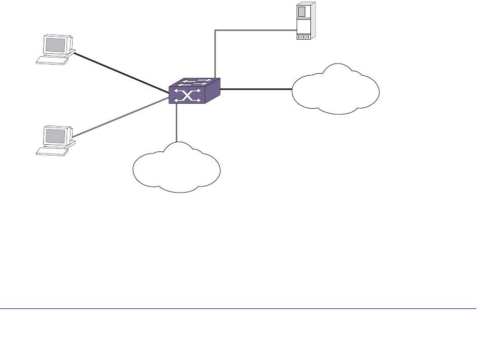
406 | Chapter 16. Network Login
NETGEAR 8800 User Manual
• Guidelines for Configuring Guest VLANs on page 406
• Creating Guest VLANs on page 407
• Enabling Guest VLANs on page 407
• Modifying the Supplicant Response Timer on page 407
• Disabling Guest VLANs on page 407
• Unconfiguring Guest VLANs on page 407
• Displaying Guest VLAN Settings on page 408
Using Guest VLANs
Suppose you have a meeting that includes company employees and visitors from outside the
company. In this scenario, your employees have 802.1x enabled supplicants but your visitors
do not. By configuring a guest VLAN, when your employees log into the network, they are
granted network access (based on their user credentials and 802.1x enabled supplicants).
However, when the visitors attempt to log into the network, they are granted limited network
access because they do not have 802.1x enabled supplicant. The visitors might be able to
reach the Internet, but they are unable to access the corporate network.
For example, in Figure 25 Host A has 802.1x capability and Host B does not. When Host A is
authenticated, it is given full access to the network. Host B does not have 802.1x capability
and therefore does not respond to 802.1x requests from the switch. If port B is configured
with the guest VLAN, port B is moved to the guest VLAN. Then Host B will be able to access
the Internet but not the corporate network. After Host B is equipped with 802.1x capability, it
can be authenticated and allowed to be part of the corporate network.
Figure 25. Guest VLAN for Network Login
Guidelines for Configuring Guest VLANs
Keep in mind the following guidelines when configuring guest VLANs:
EX_173
EW_110
Internet
Authentication
server
Corporate
network
Extreme
switch
Port B
Port A
Host B
No 802.1x
capabilities
Host A
Has 802.1x
capabilities

Chapter 16. Network Login | 407
NETGEAR 8800 User Manual
• You must create a VLAN and configure it as a guest VLAN before enabling the guest
VLAN feature.
• Configure guest VLANs only on network login ports with 802.1x enabled.
• Movement to guest VLANs is not supported on network login ports with MAC-based or
web-based authentication.
• 802.1x must be the only authentication method enabled on the port for movement to
guest VLAN.
• No supplicant on the port has 802.1x capability.
Creating Guest VLANs
If you configure a guest VLAN, and a supplicant has 802.1x disabled and does not respond
to 802.1x authentication requests from the switch, the supplicant moves to the guest VLAN.
Upon entering the guest VLAN, the supplicant gains limited network access.
Note: You can configure guest VLANs on a per port basis, which allows
you to configure more than one guest VLAN per VR.
To create a guest VLAN, use the following command:
configure netlogin dot1x guest-vlan <vlan_name> {ports <port_list>}
Enabling Guest VLANs
To enable the guest VLAN, use the following command:
enable netlogin dot1x guest-vlan ports [all | <ports>]
Modifying the Supplicant Response Timer
To modify the supplicant response timer, use the following command and specify the
supp-resp-timeout parameter:
configure netlogin dot1x timers [{server-timeout <server_timeout>}
{quiet-period <quiet_period>} {reauth-period <reauth_period> {reauth-max
<max_num_reauths>}} {supp-resp-timeout <supp_resp_timeout>}]
The default supplicant response timeout is 30 seconds, and the range is 1 to 120 seconds.
The number of authentication attempts is not a user-configured parameter.
Disabling Guest VLANs
To disable the guest VLAN, use the following command:
disable netlogin dot1x guest-vlan ports [all | <ports>]
Unconfiguring Guest VLANs
To unconfigure the guest VLAN, use the following command:

408 | Chapter 16. Network Login
NETGEAR 8800 User Manual
unconfigure netlogin dot1x guest-vlan {ports <port_list> | <vlan_name>}
Displaying Guest VLAN Settings
To display the guest VLAN settings, use the following command:
show netlogin guest-vlan {vlan_name}
If you specify the vlan_name, the switch displays information for only that guest VLAN.
The output displays the following information in a tabular format:
• Port—Specifies the 802.1x enabled port configured for the guest VLAN.
• Guest-vlan—Displays guest VLAN name and status: enable/disable.
• Vlan—Specifies the name of the guest VLAN.
Post-authentication VLAN Movement
After the supplicant has been successfully authenticated and the port has been moved to a
VLAN, the supplicant can move to a VLAN other than the one it was authenticated on. This
occurs when the switch receives an Access-Accept message from the RADIUS server with a
VSA that defines a new VLAN. The supplicant remains authenticated during this transition.
This occurs on both untagged and tagged VLANs. For example, suppose a supplicant
submits the required credentials for network access; however, it is not running the current,
approved anti-virus software or it does not have the appropriate software updates installed. If
this occurs, the supplicant is authenticated but has limited network access until the problem
is resolved. After you update the supplicant’s anti-virus software, or install the software
updates, the RADIUS server re-authenticates the supplicant by sending ACCESS-ACCEPT
messages with the accompanying VLAN attributes, thereby allowing the supplicant to enter
its permanent VLAN with full network access.
This is normal and expected behavior; no configuration is necessary.
802.1x Authentication and Network Access Protection
802.1x authentication in combination with Microsoft’s Network Access Protection (NAP)
provide additional integrity checks for end users and supplicants that attempt to access the
network. NAP allows network administrators to create system health policies to ensure
supplicants that access or communicate with the network meet administrator-defined system
health requirements. For example, if a supplicant has the appropriate software updates or
anti-virus software installed, the supplicant is deemed healthy and granted network access.
On the other hand, if a supplicant does not have the appropriate software updates or
anti-virus software installed, the supplicant is deemed unhealthy and is placed in a
quarantine VLAN until the appropriate update or anti-virus software is installed. After the
supplicant is healthy, it is granted network access. For more information about NAP, see the
documentation that came with your Microsoft Windows or Microsoft Server software.
To configure your network for NAP, the minimum required components are:
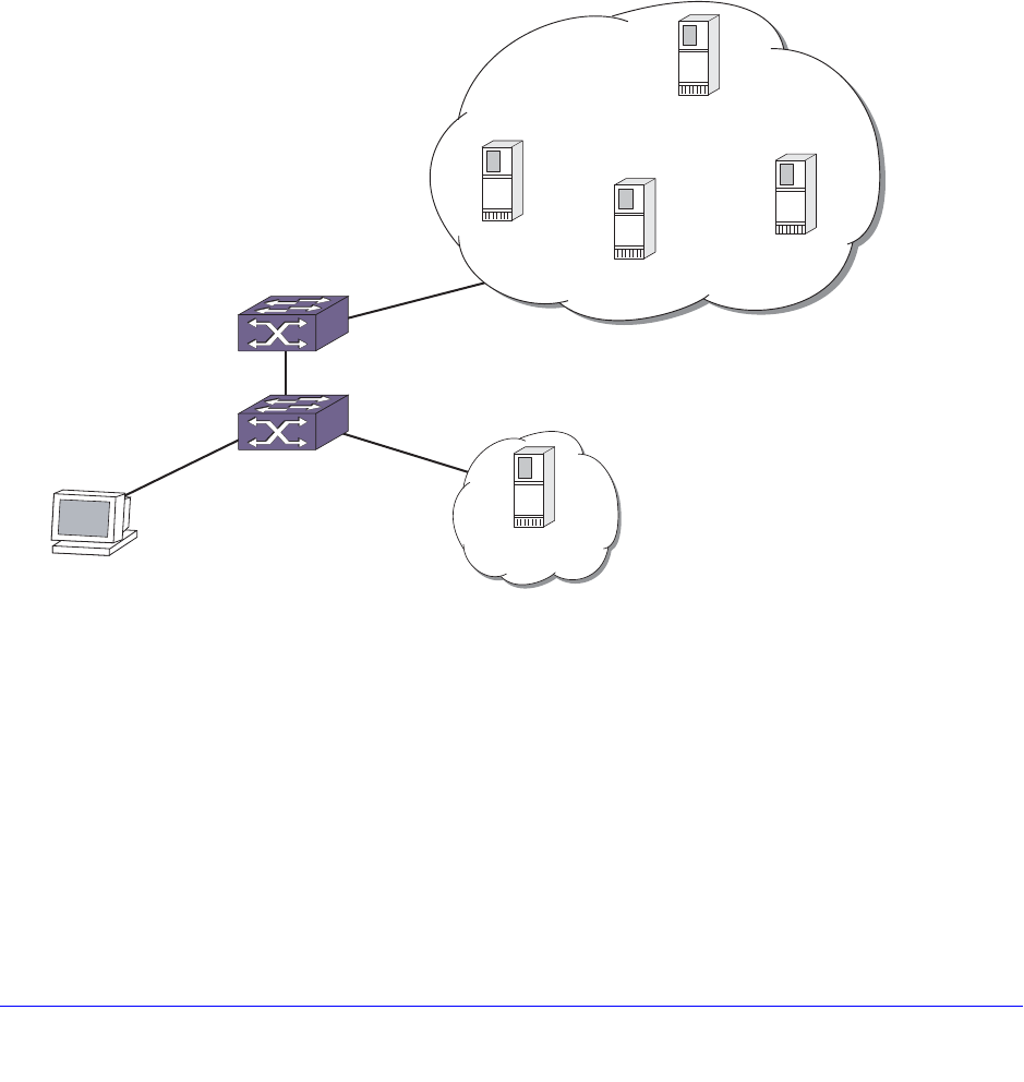
Chapter 16. Network Login | 409
NETGEAR 8800 User Manual
• RADIUS server that supports NAP (Microsoft Windows Vista operating system refers to
this as a network policy server (NPS), formerly known as the internet authentication
server (IAS)).
• Remediation servers that receive unhealthy supplicants. The remediation servers contain
the appropriate software updates, anti-virus software, and so on to make a supplicant
healthy.
In addition to the required hardware and software, you must configure NAP-specific VSAs on
your RADIUS server. By configuring these VSAs, you ensure supplicant authentication and
authorization to the network and the switch creates dynamic Access Control Lists (ACLs) to
move unhealthy supplicants to the quarantine VLAN for remediation. For more information,
see Using NAP-Specific VSAs to Authenticate 802.1x Supplicants on page 411.
Figure 26 displays a sample network that uses NAP to protect the network.
Figure 26. Sample Network Using NAP to Provide Enhanced Security
Example Scenarios Using NAP
Using Figure 26, the following two scenarios describe some sample actions taken when an
802.1x-enabled supplicant initiates a connection to the network. The scenarios assume the
following:
• Scenario 1 has a healthy 802.1x-enabled supplicant.
• Scenario 2 has an unhealthy 802.1x-enabled supplicant.
• 802.1x network login has been configured and enabled on the switch.
EX_174
Workstation
Remediation
server
Remediation
server
EPICenter
IAS/NPS
Domain controller running
Active Directory
Quarantine
VLAN
Production VLAN
(Corporate network)

410 | Chapter 16. Network Login
NETGEAR 8800 User Manual
• The RADIUS server has been configured using the NAP-specific VSAs for authenticating
supplicants.
• The remediation servers have been configured with the appropriate software updates,
anti-virus software, and so on.
• The EPICenter server has been configured to receive traps from the switch. The traps
sent from the switch inform EPICenter of the state of the supplicant. In these scenarios,
you configure EPICenter as the syslog target.
• VLANs Production and Quarantine have already been created and configured.
Note: You can dynamically create the quarantine VLAN if you configure
dynamic VLAN creation on the switch. For more information see, Configuring
Dynamic VLANs for Network Login on page 428.
Scenario 1—Healthy Supplicant
The steps to authenticate a healthy supplicant are:
1. The 802.1x supplicant initiates a connection to the 802.1x network access server (NAS),
which in this scenario is the NETGEAR switch.
2. The supplicant passes its authentication credentials to the switch using PEAP and an inner
authentication method such as MS-CHAPv2.
3. The RADIUS server requests a statement of health (SoH) from the supplicant.
Only NAP-capable supplicants create an SoH, which contains information about whether
or not the supplicant is compliant with the system health requirements defined by the
network administrator.
4. If the SoH indicates that the supplicant is healthy, the RADIUS server sends an
Access-Accept message with a RADIUS VSA indicating which VLAN the healthy supplicant
is moved to (in this example, the Production VLAN).
5. The switch authenticates the supplicant and moves it into the Production VLAN.
6. The switch sends a trap to EPICenter indicating that the supplicant has been successfully
authenticated and the VLAN into which it has been moved.
Scenario 2—Unhealthy Supplicant
The steps to authenticate an unhealthy supplicant are:
1. The 802.1x supplicant initiates a connection to the 802.1x network access server (NAS),
which in this scenario is the NETGEAR switch.
2. The supplicant passes its authentication credentials to the switch using PEAP and an inner
authentication method such as MS-CHAPv2.
3. The RADIUS server requests a statement of health (SoH) from the supplicant.
Only NAP-capable supplicants create an SoH, which contains information about whether
or not the supplicant is compliant with the system health requirements defined by the
network administrator.
Chapter 16. Network Login | 411
NETGEAR 8800 User Manual
4. If the SoH indicates that the supplicant is unhealthy, the RADIUS server sends an
Access-Accept message with RADIUS VSAs indicating which:
• VLAN the unhealthy supplicant is moved to (in this example, the Quarantine VLAN)
• Remediation server(s) the supplicant can get software updates, anti-virus software
and so on to remediate itself
5. When the switch receives the VLAN and remediation server information from the RADIUS
server, the switch:
• Moves the supplicant into the Quarantine VLAN.
• Applies ACLs to ensure the supplicant in the Quarantine VLAN can access only the
remediation servers. All other traffic not originating/destined from/to the remediation
servers is dropped.
• Sends a trap to EPICenter indicating that the supplicant has been authenticated but
has restricted access in the Quarantine VLAN for remediation.
6. The supplicant connects to the remediation server to get software updates, anti-virus
software, and so on to get healthy.
7. After the supplicant is healthy, it re-starts the authentication process and is moved to the
Production VLAN, as a healthy supplicant with full network access.
Using NAP-Specific VSAs to Authenticate 802.1x Supplicants
Table 47 contains the VSA definitions for 802.1x network login in conjunction with devices
and servers that support NAP. The Microsoft Vendor ID is 311.
Note: For more information about NAP and the VSAs supported by NAP,
see the documentation that came with your Microsoft operating
system or server.
Table 47. NAP-Specific VSA Definitions for 802.1x Network Login
VSA Vendor
Type Type Sent-in Description
MS-Quarantine-State 45 Integer Access-Accept Indicates the network access level that the
RADIUS server authorizes the user. The
network access server (the switch) also
enforces the network access level. A value of
“0” gives the user full network access. A value
of “1” gives the user limited network access. A
value of “2” gives the user full network access
within a specified time period.
MS-IPv4-Remediation
-Servers 52 Integer Access-Accept Indicates the IP address(es) of the remediation
server(s) that an unhealthy supplicant moves
to in order to get healthy.

412 | Chapter 16. Network Login
NETGEAR 8800 User Manual
ACLS for Remediation Servers
The NAP VSA, MS-IPv4-Remediation-Servers, contains a list of IP addresses that an
unhealthy and therefore quarantined supplicant should be allowed access to so that it can
remediate itself and become healthy.
The way a quarantine is implemented on the switch is simply by moving the client/port to a
user-designated 'quarantine' VLAN whose VLANID/Name is sent in the Access-Accept
message. It is up to the user to ensure that the quarantine VLAN does indeed have limited
access to the rest of the network. Typically, this can be done by disabling IP forwarding on
that VLAN so no routed traffic can get out of that VLAN. Also, with dynamic VLAN creation,
the quarantine VLAN being supplied by RADIUS could be dynamically created on the switch,
once dynamic VLAN creation is enabled on it. The remediation server(s) would need to be
accessible via the uplink port, regardless of whether the quarantine VLAN is pre-configured
or dynamically created, since IP forwarding is not enabled on it.
To get around this restriction, network login has been enhanced so when a
MS-Quarantine-State attribute is present in the Access-Accept message with
extremeSessionStatus being either 'Quarantined' or 'On Probation,' then a 'deny all traffic'
dynamic ACL will be applied on the VLAN. If such an ACL is already present on that VLAN,
then no new ACL will be applied.
When the last authenticated client has been removed from the quarantine VLAN, then the
above ACL will be removed.
Additionally, if the MS-IPv4-Remediation-Servers VSA is present in the Access-Accept
message, for each IP address present in the VSA a 'permit all traffic to/from this IP address'
ACL will be applied on the quarantine VLAN. This will allow traffic to/from the remediation
servers to pass unhindered in the Quarantine VLAN while all other traffic will be dropped.
Web-Based Authentication
This section describes web-based network login. For web-based authentication, you need to
configure the switch DNS name, default redirect page, session refresh, and logout-privilege.
URL redirection requires the switch to be assigned a DNS name. The default name is
network-access.net. Any DNS query coming to the switch to resolve switch DNS name in
unauthenticated mode is resolved by the DNS server on the switch in terms of the interface
(to which the network login port is connected to)
IP address.
This section describes the following topics:
• Enabling and Disabling Web-Based Network Login on page 413
• Configuring the Base URL on page 413
• Configuring the Redirect Page on page 413
• Configuring Proxy Ports on page 414
• Configuring Session Refresh on page 414
• Configuring Logout Privilege on page 415

Chapter 16. Network Login | 413
NETGEAR 8800 User Manual
• Configuring the Login Page on page 415
• Customizable Authentication Failure Response on page 417
• Web-Based Network Login Configuration Example on page 418
• Web-Based Authentication User Login on page 419
Enabling and Disabling Web-Based Network Login
To enable web-based network login on the switch, use the following command:
enable netlogin web-based
Any combination of types of authentication can be enabled on the same switch. At least one
of the authentication types must be specified on the CLI.
To disable web-based network login on the switch, use the following command:
disable netlogin web-based
To enable web-based network login on one or more ports, use the following command:
enable netlogin ports <portlist> web-based
Network Login must be disabled on a port before you can delete a VLAN that contains that
port. To disable web-based network login on one or more ports, use the following command:
disable netlogin ports <portlist> web
Configuring the Base URL
To configure the network login base URL, use the following command:
configure netlogin base-url <url>
Where <url> is the DNS name of the switch. For example, configure netlogin base-url
network-access.net makes the switch send DNS responses back to the network login clients
when a DNS query is made for network-access.net.
Configuring the Redirect Page
To configure the network login redirect page, use the following command:
configure netlogin redirect-page <url>
Where <url> defines the redirection information for the users after they have logged in. You
must configure a complete URL starting with http:// or https://
By default, the redirect URL value is “http://www.netgear.com”.
You can also configure the redirect value to a specific port number, such as 8080. For
example, you can configure the network login redirect page to the URL value
“http://www.netgear.com:8080”. The default port value is 80.

414 | Chapter 16. Network Login
NETGEAR 8800 User Manual
This redirection information is used only in case the redirection info is missing from RADIUS
server. For example, configure netlogin base-url http://www.netgear.com redirects all
users to this URL after they get logged in.
If you cannot find HTTPS commands, your XCM8800 image probably does not have SSH
preinstalled. To download the SSH module, go to
http://kbserver.netgear.com/products/8806.asp or
http://kbserver.netgear.com/products/8810.asp. For more information about SSH2, see
Chapter 17, Security. For information on installing the SSH module, see Software Upgrade
and Boot Options in Appendix B.
Configuring Proxy Ports
To configure the ports to be hijacked and redirected, use the following commands:
configure netlogin add proxy-port <tcp_port> {http | https}
configure netlogin delete proxy-port
For each hijacked or proxy port, you must specify whether the port is to be used for HTTP or
HTTPS traffic. No more that five hijack or proxy ports are supported for HTTP in addition to
port 80 (for HTTP) and port 443 (for HTTPS), both of which cannot be deleted.
Configuring Session Refresh
To enable or disable the network login session refresh, use one of the following commands:
enable netlogin session-refresh {<refresh_minutes>}
disable netlogin session-refresh
Where <minutes> ranges from 1 - 255. The default setting is 3 minutes. enable netlogin
session-refresh and configure netlogin session-refresh makes the logout window refresh
itself at every configured time interval. Session refresh is enabled by default. When you
configure the network login session refresh for the logout window, ensure that the FDB aging
timer is greater than the network login session refresh timer.
Note: If an attempt is made to authenticate the client in a non-existent
VLAN, and the move fail action setting is authenticate, then the
client is successfully authenticated in the port’s original VLAN, but
subsequent session refreshes fail and cause the client to become
unauthenticated.
When web-based Network login is configured with proxy ports and session-refresh are also
enabled, you must configure the web browser to bypass the web proxy server for the IP
address of the VLAN into which the client moves after authentication.

Chapter 16. Network Login | 415
NETGEAR 8800 User Manual
Configuring Logout Privilege
To enable or disable network login logout privilege, use one of the following commands:
enable netlogin logout-privilege
disable netlogin logout-privilege
These commands turn the privilege for network login users to logout by popping up (or not
popping up) the logout window. Logout-privilege is enabled by default.
You can configure the number of times a refresh failure is ignored before it results in the client
being unauthenticated by using the following commands:
configure netlogin allowed-refresh-failures
unconfigure netlogin allowed-refresh-failures
You can set the number of failures to be from between 0 and 5. The default number of logout
failures is 0.
Configuring the Login Page
You can fully customize the HTML login page and also add custom embedded graphical
images to it. This page and the associated graphics must be uploaded to the switch so that
they can be served up as the initial login page at the base URL. Both HTTP and HTTPS are
supported as a means of authenticating the user via the custom page.
In general, the steps for setting up a custom login page and graphical images (if any) are as
follows:
1. Write the custom web-page.
2. TFTP the page and any embedded JPEG or GIF graphical images that it references onto
the switch.
3. Enable and configure web-based Network Login on the switch. When the custom page is
present on the switch, it will over-ride the configured banner.
Login Page Contents
The customized web-page must have the file name netlogin_login_page.html. While the
contents of the page are left up to the customer, they must contain the following elements:
• An HTML submit form with action="/hello" and method="post" that is used to send the
Network Login username and password to the switch. The form must contain the
following:
• A username input field with name="netgearnetloginuser"
• A password input field with name="netgearnetloginpassword"
• Optionally, one or more graphical images embedded using the tags
<img src="netlogin_<xxx>.jpg"> or
<img src="netlogin_<xxx>.jpeg"> or
<img src="<netlogin_<xxx>.gif">

416 | Chapter 16. Network Login
NETGEAR 8800 User Manual
where <xxx> is user-configurable.
The following is a sample custom page, where the embedded graphical image is named
netlogin_welcome.jpg:
<html lang="en">
<head>
<title>Network Login Page</title>
</head>
<body>
<form action="/hello" method="post">
<img src="netlogin_welcome.jpg">
<br/>
Please log in:
<br/>
User:
<input type="text" name="netgearnetloginuser" />
<br/>
Password:
<input type="password" name="netgearnetloginpassword" />
<br/>
<input type="submit" value="Submit" />
</form>
</body>
</html>
Uploading the Login File to the Switch
To upload the page and the JPEG/GIF files, the switch TFTP command must be used. For
example, assuming the page resides on a TFTP server with IP address 10.255.49.19, the
command used would be
BD-8810.1 # tftp get 10.255.49.19 netlogin_login_page.html
General Guidelines
The following general guidelines are applicable to the login page:
• When the custom web page is not present on the switch, the system falls back to the
using the default banner. The web page may be added (or removed) from the switch at
any time, at which point the switch will stop (or start) using the banner.
• The graphical image file names referenced in the web page must not have any path
information prepended.
• Both uppercase and lowercase names (or a mixture) for the graphical image filenames
are supported, but the user and password tag names should be either all uppercase or all
lowercase, not a mixture of the two.
• More than one form may exist on the page. This can be useful when, for example, in
addition to the main username and password that is typed in by the user, an additional
special username and password needs to be auto-filled and sent. For example, this could
be used when end users without a valid username or password need to be given
restricted access to the network.

Chapter 16. Network Login | 417
NETGEAR 8800 User Manual
Limitations
The following limitations apply to the login page:
• When the client is in the unauthenticated state, any embedded URLs in the custom page
are inaccessible to it.
• Only JPEG and GIF graphical images are supported.
• It is the web page writer's responsibility to write the HTML page correctly and without
errors.
• Only TFTP is supported as a method to upload the web-page and graphical images to the
switch.
Customizable Authentication Failure Response
In the event of web-based network login authentication failure, you can use a custom
authentication failure page to recover. When a customized login page is in effect, 'by default,
any authentication failure results in the following failure response being delivered to the
browser:
Login Incorrect. Click here to try again.
Clicking on the indicated link will bring the user back to the initial custom login page.
You may choose to over ride the above default response with a custom one. This custom
failure response page must be uploaded to the switch using TFTP with the name
netlogin_login_fail_page.html. When authentication fails, the switch responds with this page.
If the page is deleted from the switch, the response reverts back to the default.
The same graphical images that are uploaded to the switch for the custom login page can
also be embedded in the custom authentication failure page.
Note: The custom authentication failure page can be used only when
authentication is being done via the custom login page.
Customizable Graphical Image in Logout Popup Window
You can embed a graphical image in the logout popup window. This image appears in the
window in addition to the text that is displayed. The image must be TFTPed to the switch in
the same manner as the custom login image, and must have the filename
netlogin_logout_image.jpg or netlogin_logout_image.gif (depending on whether the
image is JPEG or GIF). If no such image is present on the switch, then the logout popup
contains only text.

418 | Chapter 16. Network Login
NETGEAR 8800 User Manual
Web-Based Network Login Configuration Example
The following configuration example shows both the NETGEAR switch configuration and the
RADIUS server entries needed to support the example. VLAN corp is assumed to be a
corporate subnet which has connections to DNS, WINS servers, network routers, and so on.
VLAN temp is a temporary VLAN and is created to provide connections to unauthenticated
network login clients. Unauthenticated ports belong to the VLAN temp. This kind of
configuration provides better security as unauthenticated clients do not connect to the
corporate subnet and will not be able to send or receive any data. They have to get
authenticated in order to have access to the network.
• ISP Mode—Network login clients connected to ports 1:10 - 1:14, VLAN corp, will be
logged into the network in ISP mode. This is controlled by the fact that the VLAN in which
they reside in unauthenticated mode and the RADIUS server Vendor Specific Attributes
(VSA), Netgear-Netlogin-Vlan, are the same, corp. So there will be no port movement.
Also if this VSA is missing from RADIUS server, it is assumed to be ISP Mode.
• Campus Mode—On the other hand, clients connected to ports 4:1 - 4:4, VLAN temp, will
be logged into the network in Campus mode since the port will move to the VLAN corp
after getting authenticated. A port moves back and forth from one VLAN to the other as its
authentication state changes.
Both ISP and Campus mode are not tied to ports but to a user profile. In other words, if the
VSA Netgear:Netgear-Netlogin-Vlan represents a VLAN different from the one in which the
user currently resides, then VLAN movement will occur after login and after logout. In
following example, it is assumed that campus users are connected to ports 4:1-4:4, while ISP
users are logged in through ports 1:10-1:14.
Note: In the following sample configuration, any lines marked (Default)
represent default settings and do not need to be explicitly
configured.
create vlan “temp”
create vlan “corp”
configure vlan “default” delete ports 4:1-4:4
enable ipforwarding
# Configuration Information for VLAN temp
# No VLAN-ID is associated with VLAN temp.
configure vlan “temp” ipaddress 198.162.32.10 255.255.255.0
# Configuration Information for VLAN corp
# No VLAN-ID is associated with VLAN corp.
configure vlan “corp” ipaddress 10.203.0.224 255.255.255.0
configure vlan “corp” add port 1:10 untagged

Chapter 16. Network Login | 419
NETGEAR 8800 User Manual
configure vlan “corp” add port 1:11 untagged
configure vlan “corp” add port 1:12 untagged
configure vlan “corp” add port 1:13 untagged
configure vlan “corp” add port 1:14 untagged
# Network Login Configuration
configure vlan “temp” dhcp-address-range 198.162.32.20 - 198.162.32.80
configure vlan “temp” dhcp-options default-gateway 198.162.32.1
configure vlan “temp” dhcp-options dns-server 10.0.1.1
configure vlan “temp” dhcp-options wins-server 10.0.1.85
configure netlogin vlan “temp”
enable netlogin web-based
enable netlogin ports 1:10-1:14,4:1-4:4 web-based
configure netlogin base-url "network-access.net" (Default)
configure netlogin redirect-page http://www.netgear.com (Default)
enable netlogin logout-privilege (Default)
disable netlogin session-refresh 3 (Default)
# DNS Client Configuration
configure dns-client add name-server 10.0.1.1
configure dns-client add name-server 10.0.1.85
#RADIUS Client Configuration
configure radius netlogin primary server 10.0.1.2 1812 client-ip 10.10.20.30 vr
“Vr-Mgmt”
configure radius netlogin primary shared-secret purple
enable radius
For this example, the following lines (for a FreeRADIUS server) should be added to the
RADIUS server users file for each user:
Netgear
:
Netgear
-Netlogin-Only = Enabled (if no CLI authorization)
Netgear
:
Netgear
-Netlogin-Vlan = "corp" (destination vlan for CAMPUS mode network
login)
Note: For information about how to use and configure your RADIUS
server, see Configuring the RADIUS Client on page 475 and the
documentation that came with your RADIUS server.
Web-Based Authentication User Login
To use web-based authentication:

420 | Chapter 16. Network Login
NETGEAR 8800 User Manual
1. Set up the Windows IP configuration for DHCP.
2. Plug into the port that has web-based network login enabled.
3. Log in to Windows.
4. Release any old IP settings and renew the DHCP lease.
This is done differently depending on the version of Windows the user is running:
• Windows 9x—Use the winipcfg tool. Choose the Ethernet adapter that is connected
to the port on which network login is enabled. Use the buttons to release the IP
configuration and renew the DHCP lease.
• Windows NT/2000/XP—Use the ipconfig command line utility. Use the command
ipconfig/release to release the IP configuration and ipconfig/renew to get the
temporary IP address from the switch. If you have more than one Ethernet adapter,
specify the adapter by using a number for the adapter following the ipconfig
command. You can find the adapter number using the command ipconfig/all.
Note: The idea of explicit release/renew is required to bring the network login
client machine in the same subnet as the connected VLAN. When using
we-based authentication, this requirement is mandatory after every logout and
before login again as the port moves back and forth between the temporary and
permanent VLANs.
At this point, the client will have its temporary IP address. In this example, the client
should have obtained the an IP address in the range 198.162.32.20 - 198.162.32.80.
5. Bring up the browser and enter any URL as http://www.123.net or http://1.2.3.4 or
switch IP address as http://<IP address>/login (where IP address could be either temporary
or Permanent VLAN Interface for Campus Mode). URL redirection redirects any URL and IP
address to the network login page. This is significant where security matters most, as no
knowledge of VLAN interfaces is required to be provided to network login users, as they can
login using a URL or IP address.
Note: URL redirection requires that the switch is configured with a DNS client.
A page opens with a link for Network Login.
6. Click the Network Login link.
A dialog box opens requesting a user name and password.
7. Enter the user name and password configured on the RADIUS server.
After the user has successfully logged in, the user will be redirected to the URL
configured on the RADIUS server.
During the user login process, the following takes place:
• Authentication is done through the RADIUS server.
• After successful authentication, the connection information configured on the RADIUS
server is returned to the switch:

Chapter 16. Network Login | 421
NETGEAR 8800 User Manual
• The permanent VLAN
• The URL to be redirected to (optional)
• The URL description (optional)
• The port is moved to the permanent VLAN.
You can verify this using the show vlan command. For more information on the show vlan
command, see VLAN Configuration Examples on page 249.
After a successful login has been achieved, there are several ways that a port can return to a
non-authenticated, non-forwarding state:
• The user successfully logs out using the logout web browser window.
• The link from the user to the switch’s port is lost.
• There is no activity on the port for 20 minutes.
• An administrator changes the port state.
Note: Because network login is sensitive to state changes during the
authentication process, NETGEAR recommends that you do not log
out until the login process is complete. The login process is
complete when you receive a permanent address.
MAC-Based Authentication
MAC-based authentication is used for supplicants that do not support a network login mode,
or supplicants that are not aware of the existence of such security measure, for example an
IP phone.
If a MAC address is detected on a MAC-based enabled network login port, an authentication
request is sent once to the AAA application. AAA tries to authenticate the MAC address
against the configured RADIUS server and its configured parameters (timeout, retries, and so
on) or the local database.
In a MAC-based authentication environment the authentication verification is done only once
at MAC address detection. However, forced reauthentication is allowed through the
Session-Timeout VSA supplied by RADIUS. When this VSA is present the switch
re-authenticates the client based on the value supplied by the VSA. If no VSA is present,
there is no re-authentication.
The credentials used for this are the supplicants MAC address in ASCII representation, and a
locally configured password on the switch. If no password is configured, the MAC address is
used as the password. You can also group MAC addresses together using a mask.
You can configure a MAC list or a table of MAC entries to filter and authenticate clients based
on their MAC addresses. If there a match is found in the table of MAC entries, authentication
occurs. If no match is found in the table of MAC entries, and a default entry exists, the default

422 | Chapter 16. Network Login
NETGEAR 8800 User Manual
will be used to authenticate the client. All entries in the list are automatically sorted in longest
prefix order. All passwords are stored and showed encrypted.
You can associate a MAC address with one or more ports. By learning a MAC address, the
port confirms the supplicant before sending an authorization request to the RADIUS server.
This additional step protects your network against unauthorized supplicants because the port
accepts only authorization requests from the MAC address learned on that port. The port
blocks all other requests that do not have a matching entry.
This section describes the following topics:
• Enabling and Disabling MAC-Based Network Login on page 422
• Associating a MAC Address to a Specific Port on page 422
• Adding and Deleting MAC Addresses on page 423
• Displaying the MAC Address List on page 423
• Configuring Reauthentication Period on page 424
• Secure MAC Configuration Example on page 424
• MAC-Based Network Login Configuration Example on page 425
Enabling and Disabling MAC-Based Network Login
To enable MAC-based network login on the switch, use the following command:
enable netlogin mac
Any combination of types of authentication can be enabled on the same switch. At least one
of the authentication types must be specified on the CLI.
To disable MAC-based network login on the switch, use the following command:
disable netlogin mac
To enable MAC-based network login on one or more ports, use the following command:
enable netlogin ports <portlist> mac
Network Login must be disabled on a port before you can delete a VLAN that contains that
port. To disable MAC-based network login on one or more ports, use the following command:
disable netlogin ports <portlist> mac
Associating a MAC Address to a Specific Port
You can configure the switch to accept and authenticate a client with a specific MAC address.
Only MAC addresses that have a match for the specific ports are sent for authentication. For
example, if you associate a MAC address with one or more ports, only authentication
requests for that MAC address received on the port(s) are sent to the configured RADIUS
server or local database. The port(s) block all other authentication requests that do not have
a matching entry. This is also known as secure MAC.

Chapter 16. Network Login | 423
NETGEAR 8800 User Manual
To associate a MAC address with one or more ports, specify the ports option when using the
following command:
configure netlogin add mac-list [<mac> {<mask>} | default] {encrypted}
{<password>} {ports <port_list>}
You must enable MAC-based network login on the switch and the specified ports. If
MAC-based network login is not enabled on the specified port(s), the switch displays a
warning message similar to the following:
WARNING: Not all specified ports have MAC-Based NetLogin enabled.
For a sample configuration, see Secure MAC Configuration Example on page 424.
Adding and Deleting MAC Addresses
To add a MAC address to the table, use the following command:
configure netlogin add mac-list [<mac> {<mask>} | default] {encrypted}
{<password>} {ports <port_list>}
To remove a MAC address from the table, use the following command:
configure netlogin delete mac-list [<mac> {<mask>} | default]
Displaying the MAC Address List
To display the MAC address table, use the following command:
show netlogin mac-list
When a client needs authentication the best match will be used to authenticate to the server.
MAC-based authentication is VR aware, so there is one MAC list per VR.
Assume we have a supplicant with MAC address 00:04:96:05:40:00, and the switch has the
following table:
MAC Address/Mask Password (encrypted) Port(s)
-------------------- ---------------------- --------------
00:00:00:00:00:10/48 <not configured> 1:1-1:5
00:00:00:00:00:11/48 <not configured> 1:6-1:10
00:00:00:00:00:12/48 <not configured> any
00:01:30:70:0C:00/48 yaqu any
00:01:30:32:7D:00/48 ravdqsr any
00:04:96:00:00:00/24 <not configured> any
The user name used to authenticate against the RADIUS server would be “000496000000”,
as this is the supplicants MAC address with the configured mask applied.
Note that the commands are VR aware, and therefore one MAC list table exists per VR.

424 | Chapter 16. Network Login
NETGEAR 8800 User Manual
Configuring Reauthentication Period
To configure the reauthentication period for network login MAC-based authentication, use the
following commands:
configure netlogin mac timers reauth-period
This timer is applicable only in the case where the client is authenticated in authentication
failure vlan or authentication service unavailable vlan and the RADIUS server provides no
session-timeout attribute during authentication. If the switch does receive the session-timeout
attribute during authentication, the switch uses that value to set the reauthentication period.
For more information on RADIUS server attributes, see Configuring the RADIUS Client on
page 475.
Secure MAC Configuration Example
The following configuration example shows how to configure secure MAC on your NETGEAR
switch. To configure secure MAC:
• Create a VLAN used for network login.
• Configure the VLAN for network login.
• Enable MAC-based network login on the switch.
• Enable MAC-based network login on the ports used for authentication.
• Specify one or more ports to accept authentication requests from a specific MAC address.
In the following example, authentication requests from MAC address:
• 00:00:00:00:00:10 are only accepted on ports 1:1 through 1:5
• 00:00:00:00:00:11 are only accepted on ports 1:6 through 1:10
• 00:00:00:00:00:12 are accepted on all other ports
create vlan nlvlan
configure netlogin vlan nlvlan
enable netlogin mac
enable netlogin ports 1:1-1:10 mac
configure netlogin add mac-list 00:00:00:00:00:10 ports 1:1-1:5
configure netlogin add mac-list 00:00:00:00:00:11 ports 1:6-1:10
configure netlogin add mac-list 00:00:00:00:00:12
To view your network login configuration, use one of the following commands:
• show netlogin {port <portlist> vlan <vlan_name>} {dot1x {detail}} {mac}
{web-based}
• show netlogin mac-list

Chapter 16. Network Login | 425
NETGEAR 8800 User Manual
MAC-Based Network Login Configuration Example
The following configuration example shows the NETGEAR switch configuration needed to
support the MAC-based network login example.
create vlan “temp”
create vlan “corp”
configure vlan “default” delete ports 4:1-4:4
# Configuration Information for VLAN corp
# No VLAN-ID is associated with VLAN corp.
configure vlan “corp” ipaddress 10.203.0.224 255.255.255.0
# Network Login Configuration
configure netlogin vlan “temp”
enable netlogin mac
enable netlogin ports 4:1-4:4 mac
configure netlogin add mac-list default <password>
# RADIUS Client Configuration
configure radius netlogin primary server 10.0.1.2 1812 client-ip 10.10.20.30 vr
“VR-Mgmt”
configure radius netlogin primary shared-secret purple
enable radius
The following example is a users file entry for a specific MAC address on a FreeRADIUS
server:
00E018A8C540 Auth-Type := Local, User-Password == "00E018A8C540"
Note: For information about how to use and configure your RADIUS
server, see Configuring the RADIUS Client on page 475 and the
documentation that came with your RADIUS server.
Additional Network Login Configuration Details
This section describes additional, optional network login configurations. These configurations
are not required to run network login; however, depending on your network settings and
environment, you can use the commands described in this section to enhance your network
login settings.
Review the earlier sections of this chapter for general information about network login and
information about MAC-based, web-based, and 802.1x authentication methods.

426 | Chapter 16. Network Login
NETGEAR 8800 User Manual
This section describes the following topics:
• Configuring Network Login MAC-Based VLANs on page 426
• Configuring Dynamic VLANs for Network Login on page 428
• Configuring Network Login Port Restart on page 431
• Authentication Failure and Services Unavailable Handling on page 432
Configuring Network Login MAC-Based VLANs
Currently, network login allows only a single, untagged VLAN to exist on a port. This limits the
flexibility for untagged supplicants because they must be in the same VLAN.
NETGEAR 8800 switches support network login MAC-based VLANs. Network login
MAC-based VLANs allow a port assigned to a VLAN to operate in a MAC-based fashion. This
means that each individual untagged supplicant, identified by its MAC address, can be in
different VLANs.
Network login MAC-based VLAN utilizes VSA information from both the network login local
database and the RADIUS server. After successfully performing the Campus mode
operation, the supplicant is added untagged to the destination VLAN.
To support this feature, you must configure the network login port’s mode of operation.
Network Login MAC-Based VLANs Rules and Restrictions
This section summarizes the rules and restrictions for configuring network login MAC-based
VLANs:
• You must configure and enable network login on the switch and before you configure
network login MAC-based VLANs.
If you attempt to configure the port’s mode of operation before enabling network login, the
switch displays an error message similar to the following:
ERROR: The following ports do not have NetLogin enabled; 1
Configuring the Port Mode
To support network login MAC-based VLANs on a network login port, you must configure that
port’s mode of operation. To specify MAC-based operation, use the following command and
specify mac-based-vlans:
configure netlogin ports [all | <port_list>] mode [mac-based-vlans |
port-based-vlans]
By default, the network login port’s mode of operation is port-based-vlans. If you modify the
mode of operation to mac-based-vlans and later disable all network login protocols on that
port, the mode of operation automatically returns to port-based-vlans.
When you change the network login port’s mode of operation, the switch deletes all currently
known supplicants from the port and restores all VLANs associated with that port to their

Chapter 16. Network Login | 427
NETGEAR 8800 User Manual
original state. In addition, by selecting mac-based-vlans, you are unable to manually add or
delete untagged VLANs from this port. Network login now controls these VLANs.
With network login MAC-based operation, every authenticated client has an additional FDB
flag that indicates a translation MAC address. If the supplicant’s requested VLAN does not
exist on the port, the switch adds the requested VLAN.
Displaying Network Login MAC-Based VLAN Information
The following commands display important information for network login MAC-based VLANs.
FDB Information
To view FDB entries, use the following command:
show fdb netlogin [all | mac-based-vlans]
By specifying netlogin, you see only FDB entries related to network login or network login
MAC-based VLANs. The flags associated with network login include:
• v—Indicates the FDB entry was added because the port is part of a MAC-Based virtual
port/VLAN combination
• n—Indicates the FDB entry was added by network login
VLAN and Port Information
To view the VLANs that network login adds temporarily in MAC-based mode, use the
following command:
show ports <port_list> information detail
By specifying information and detail, the output displays the temporarily added VLANs in
network login MAC-based mode. To confirm this, review the following output of this
command:
• VLAN cfg—The term MAC-based appears next to the tag number.
• Netlogin port mode—This output was added to display the port mode of operation. Mac
based appears and the network login port mode of operation.
To view information about the ports that are temporarily added in MAC-based mode for
network login, due to discovered MAC addresses, use the following command:
show vlan detail
By specifying detail, the output displays detailed information including the ports associated
with the VLAN. The flags associated with network login include:
• a—Indicates that egress traffic is allowed for network login.
• u—Indicates that egress traffic is not allowed for network login.
• m—Indicates that the network login port operates in MAC-based mode.

428 | Chapter 16. Network Login
NETGEAR 8800 User Manual
Note: If network login is enabled together with STP, the 'a' and 'u' flags are
controlled by network login only when the STP port state is
‘Forwarding.’
Network Login MAC-Based VLAN Example
The following example configures the network login MAC-based VLAN feature:
create vlan users12
create vlan nlvlan
configure netlogin vlan nlvlan
enable netlogin mac
enable netlogin ports 1:1-1:10 mac
configure netlogin ports 1:1-1:10 mode mac-based-vlans
configure netlogin add mac-list default MySecretPassword
Expanding upon the previous example, you can also utilize the local database for
authentication rather than the RADIUS server:
create netlogin local-user 000000000012 vlan-vsa untagged default
create netlogin local-user 000000000010 vlan-vsa untagged users12
For more information about local database authentication, see Local Database
Authentication on page 397.
Configuring Dynamic VLANs for Network Login
During an authentication request, network login receives a destination VLAN (if configured on
the RADIUS server) to put the authenticated user in. The VLAN must exist on the switch for
network login to authenticate the client on that VLAN.
You can configure the switch to dynamically create a VLAN after receiving an authentication
response from a RADIUS server. A dynamically created VLAN is only a Layer 2 bridging
mechanism; this VLAN does not work with routing protocols to forward traffic. If configured for
dynamic VLAN creation, the switch automatically creates a supplicant VLAN that contains
both the supplicant’s physical port and one or more uplink ports. After the switch
unauthenticates all of the supplicants from the dynamically created VLAN, the switch deletes
that VLAN.
Note: Dynamically created VLANs do not support the session refresh
feature of web-based network login because dynamically created
VLANs do not have an IP address.

Chapter 16. Network Login | 429
NETGEAR 8800 User Manual
By dynamically creating and deleting VLANs, you minimize the number of active VLANs
configured on your edge switches. In addition, the dynamic VLAN name can be stored on the
RADIUS server and supplied to the switch during authentication, simplifying switch
management. A key difference between dynamically created VLANs and other VLANs is that
the switch does not save dynamically created VLANs. Even if you use the save command,
the switch does not save a dynamically created VLAN.
After you configure network login on the switch, the two steps to configure dynamic VLANs
are:
• Specifying the tagged uplink port(s) to be added to each dynamically created VLAN
• Enabling the switch to create dynamic VLANs
Specifying the Uplink Ports
The uplink ports send traffic to and from the supplicants from the core of the network. Uplink
ports should not be configured for network login (network login is disabled on uplink ports).
To specify one or more ports as tagged uplink ports that are added to the dynamically created
VLAN, use the following command:
configure netlogin dynamic-vlan uplink-ports [<port_list> | none]
By default, the setting is none.
If you specify an uplink port with network login enabled, the configuration fails and the switch
displays an error message similar to the following:
ERROR: The following ports have NetLogin enabled: 1, 2
If this occurs, select a port with network login disabled.
Enabling Dynamic VLANs for Network Login
To enable the switch to create dynamic VLANs, use the following command:
configure netlogin dynamic-vlan [disable | enable]
By default, the setting is disabled. When enabled, the switch dynamically creates VLANs.
Remember, dynamically created VLANs are not permanent or user-created VLANs. The
switch uses the VLAN ID supplied by the RADIUS attributes (as described below) to create
the VLAN. The switch only creates a dynamic VLAN if the requested VLAN, indicated by the
VLAN ID, does not currently exist on the switch.
The RADIUS server uses VSAs to forward VLAN information. The forwarded information can
include only a VLAN ID (no VLAN name). The following list specifies the supported VSAs for
configuring dynamic VLANs:
• Netgear: Netlogin-VLAN-ID (VSA 209)
• Netgear: Netlogin-Extended-VLAN (VSA 211)
• IETF: Tunnel-Private-Group-ID (VSA 81)

430 | Chapter 16. Network Login
NETGEAR 8800 User Manual
Note: If the ASCII string contains only numbers, it is interpreted as the VLAN
ID. Dynamic VLANS support only numerical VLAN IDs; VLAN names are not
supported.
For more information on NETGEAR VSAs, see NETGEAR VSAs on page 483.
The switch automatically generates the VLAN name in the following format: NLD_<TAG> where
<TAG> specifies the VLAN ID. For example, a dynamic VLAN with an ID of 10 has the name
NLD_0010.
Note: Like all VLAN names, dynamic VLAN names are unique. If you
create a VLAN and use the name of an existing dynamic VLAN, the
switch now sees the dynamic VLAN as a user-created VLAN and will
save this VLAN to the switch configuration. If this occurs, the switch
does not delete the VLAN after the supplicants are authenticated
and moved to the permanent VLAN.
Dynamic VLAN Example with Web-Based Network Login
After you finish the web-based network login configuration as described in Web-Based
Network Login Configuration Example on page 418, complete the dynamic VLAN
configuration by:
• Assigning one or more non-network-login ports as uplink ports
Note: Do not enable network login on uplink ports. If you specify an uplink port
with network login enabled, the configuration fails and the switch displays an
error message.
• Enabling the switch to dynamically create VLANs
Whether you have MAC-based, web-based, or 802.1x authentication, you use the same two
commands to configure dynamic VLANs on the switch.
The following example configures dynamic VLANs on the switch:
configure netlogin dynamic-vlan uplink ports 2:1-2:2
configure netlogin dynamic-vlan enable
Displaying Dynamic VLAN Information
To display summary information about all of the VLANs on the switch, including any
dynamically VLANs currently operating on the switch, use the following command:
show vlan
If the switch has dynamically created VLANs, the VLAN name begins with SYS_NLD_.

Chapter 16. Network Login | 431
NETGEAR 8800 User Manual
To display the status of dynamic VLAN configuration on the switch, use the following
command:
show netlogin
The switch displays the current state of dynamic VLAN creation (enabled or disabled) and the
uplink port(s) associated with the dynamic VLAN.
Configuring Network Login Port Restart
You can configure network login to restart specific network-login-enabled ports when the last
authenticated supplicant unauthenticates, regardless of the configured authentication
methods on the port. This feature, known as network login port restart, is available with all
network login authentication methods although is most practical with web-based network
login. This section describes how this feature behaves with web-based network login;
MAC-based and 802.1x network login do not experience any differences in behavior if you
enable network login port restart.
Currently with web-based network login, if you have an authenticated supplicant and log out
of the network, you must manually release the IP address allocated to you by the Dynamic
Host Control Protocol (DHCP) server. The DHCP server dynamically manages and allocates
IP addresses to supplicants. When a supplicant accesses the network, the DHCP server
provides an IP address to that supplicant. DHCP cannot renegotiate their leases, which is
why you must manually release the IP address.
For example, if the idle timer expires on the switch, the switch disconnects your network
session. If this occurs, it may be unclear why you are unable to access the network. After you
manually renew the IP address, you are redirected to the network login login page and can
log back into the network. To solve this situation in a single supplicant per port environment,
port restart triggers the DHCP client on the PC to restart the DHCP address assignment
process.
Guidelines for Using Network Login Port Restart
Configure network login port restart on ports with directly attached supplicants. If you use a
hub to connect multiple supplicants, only the last unauthenticated supplicant causes the port
to restart. Although the hub does not inflict harm to your network, in this situation, the
previously unauthenticated supplicants do not get the benefit of the port restart configuration.
Enabling Network Login Port Restart
To enable network login port restart, use the following command:
configure netlogin ports [all | <port_list>] restart
Disabling Network Login Port Restart
To disable network login port restart, use the following command:
configure netlogin ports [all | <port_list>] no-restart

432 | Chapter 16. Network Login
NETGEAR 8800 User Manual
Displaying the Port Restart Configuration
To display the network login settings on the port, including the configuration for port restart,
use the following command:
show netlogin port <port_list>
Output from this command includes the enable/disable state for network login port restart.
Authentication Failure and Services Unavailable Handling
The NETGEAR 8800 provides the following features for handling network login
authentication failures, and for handling instances of services unavailable:
• Configuring Authentication Failure VLAN on page 432
• Configuring Authentication Services Unavailable VLAN on page 433
• Configuring Reauthentication Period on page 424
You can use these features to set and control the response to network login authentication
failure and instances of services unavailable.
Configuring Authentication Failure VLAN
When a network login client fails authentication, it is moved to authentication failure VLAN
and given restricted access. To configure the authentication failure VLAN, use the following
commands:
configure netlogin authentication failure vlan
unconfigure netlogin authentication failure vlan
enable netlogin authentication failure vlan ports
disable netlogin authentication failure vlan ports
Use the command netlogin authentication failure vlan to configure authentication failure
VLAN on network-login-enabled ports. When a supplicant fails authentication, it is moved to
the authentication failure VLAN and is given limited access until it passes the authentication.
Through either a RADIUS or local server, the other database is used to authenticate the client
depending on the authentication database order for that particular network login method (mac,
web or dot1x). If the final result is authentication failure and if the authentication failure VLAN
is configured and enabled on that port, then the client is moved there.
For example, if the network login MAC authentication database order is local, radius and
the authentication of a MAC client fails through local database, then the RADIUS server is
used to authenticate. If the RADIUS server also fails authentication, the client is moved to the
authentication failure VLAN. This applies for all authentication database orders
(radius,local; local,radius; radius; local).
In the above example if authentication through local fails but passes through the RADIUS
server, the client is moved to appropriate destination VLAN. If the local server authentication
fails and the RADIUS server is not available, the client is not moved to authentication failure
VLAN.

Chapter 16. Network Login | 433
NETGEAR 8800 User Manual
Dependency on authentication database order
There are four different authentication orders which can be configured per authentication
method. These four orders are the following:
• RADIUS
• Local
• RADIUS, Local
• Local, RADIUS
For each authentication order, the end result is considered in deciding whether to
authenticate the client through the authentication failure VLAN or the authentication service
unavailable VLAN (if configured).
For example, if the authentication order is radius, local, with the RADIUS server
unavailable, and local authentication failed, the client is authenticated in the authentication
failure VLAN (if one is configured on the port).
For local authentication, if the user is not created in the local database, it is considered as
service unavailable. If the user is configured but the password does not match, it is
considered as an authentication failure.
For RADIUS server authentication, if for some reason the user cannot be authenticated due
to problems with the RADIUS configuration, the RADIUS server not running, or some other
problem then it is considered as an authentication service unavailable. If the actual
authentication fails then it is considered as an authentication failure.
Configuring Authentication Services Unavailable VLAN
When the authentication service is not available for authentication, the supplicant is moved to
authentication service unavailable VLAN and given restricted access. To configure the
authentication services unavailable VLAN, use the following commands:
configure netlogin authentication service-unavailable vlan
unconfigure netlogin authentication service-unavailable vlan
enable netlogin authentication service-unavailable vlan ports
disable netlogin authentication service-unavailable vlan ports
If a network login port has web enabled, authentication failure VLAN and authentication
service unavailable VLAN configuration are not applicable to MAC and dot1x clients
connected to that port. For example, if port 1:2 has network login MAC and web
authentication enabled and authentication failure VLAN is configured and enabled on it, and
if a MAC client connected to that port fails authentication, it is not moved to authentication
failure VLAN.

Chapter 17. Security | 434
17
17. Security
This chapter includes the following sections:
• Overview on page 434
• Safe Defaults Mode on page 436
• MAC Security on page 436
• DHCP Server on page 445
• IP Security on page 446
• Denial of Service Protection on page 461
• Authenticating Management Sessions Through the Local Database on page 465
• Authenticating Management Sessions Through a TACACS+ Server on page 465
• Authenticating Management Sessions Through a RADIUS Server on page 471
• Authenticating Network Login Users Through a RADIUS Server on page 474
• Configuring the RADIUS Client on page 475
• RADIUS Server Configuration Guidelines on page 479
• Configuring a Windows XP Supplicant for 802.1x Authentication on page 503
• Hyptertext Transfer Protocol on page 504
• Secure Shell 2 on page 504
• Secure Socket Layer on page 513
Overview
Security is a term that covers several different aspects of network use and operation. One
general type of security is control of the devices or users that can access the network. Ways of
doing this include authenticating the user at the point of logging in. You can also control access
by defining limits on certain types of traffic. Another general type of security operates to protect
the operation of the switch itself. Security measures in this category include routing policies that
can limit the visibility of parts of the network or denial of service protection that prevents the CPU
from being overloaded. Finally, management functions for the switch can be protected from
unauthorized use. This type of protection uses various types of user authentication.

Chapter 17. Security | 435
NETGEAR 8800 User Manual
XCM8800 has enhanced security features designed to protect, rapidly detect, and correct
anomalies in your network. NETGEAR products incorporate a number of features designed
to enhance the security of your network while resolving issues with minimal network
disruption. No one feature can ensure security, but by using a number of features in concert,
you can substantially improve the security of your network.
The following list provides a brief overview of some of the available security features:
• Access Control Lists—Access Control Lists (ACLs) are policy files used by the ACL
application to perform packet filtering and forwarding decisions on incoming traffic and
packets. Each packet arriving on an ingress port is compared to the ACL applied to that
port and is either permitted or denied.
For more information about using ACLs to control and limit network access, see Chapter
13, ACLs.
• Denial of Service Protection—Denial of Service (DoS) protection is a dynamic response
mechanism used by the switch to prevent critical network or computing resources from
being overwhelmed and rendered inoperative. In essence, DoS protection protects the
switch, CPU, and memory from attacks and attempts to characterize the attack (or
problem) and filter out the offending traffic so that other functions can continue. If the
switch determines it is under attack, the switch reviews the packets in the input buffer and
assembles ACLs that automatically stop the offending packets from reaching the CPU.
For more information about DoS attacks and DoS protection, see Denial of Service
Protection on page 461.
• Network Login—Network login controls the admission of user packets and access rights
thereby preventing unauthorized access to the network. Network login is controlled on a
per port basis. When network login is enabled on a port in a VLAN, that port does not
forward any packets until authentication takes place. Network login is capable of three
types of authentication: web-based, MAC-based, and 802.1x.
For more information about network login, see Chapter 16, Network Login.
• Policy Files—Policy files are text files that contain a series of rule entries describing
match conditions and actions to take. Policy files are used by both routing protocol
applications (routing policies) and the ACL application (ACLs).
For more information about policy files, see Chapter 12, Policy Manager.
• Routing Policies—Routing policies are policy files used by routing protocol applications to
control the advertisement, reception, and use of routing information by the switch. By
using policies, a set of routes can be selectively permitted or denied based on their
attributes for advertisements in the routing domain. Routing policies can be used to “hide”
entire networks or to trust only specific sources for routes or ranges of routes.
For more information about using routing policies to control and limit network access, see
Chapter 14, Routing Policies.
• sFlow—sFlow® is a technology designed to monitor network traffic by using a statistical
sampling of packets received on each port. sFlow also uses IP headers to gather
information about the network. By gathering statistics about the network, sFlow becomes
an early warning system notifying you when there is a spike in traffic activity. Upon

436 | Chapter 17. Security
NETGEAR 8800 User Manual
analysis, common response mechanisms include applying an ACL, changing Quality of
Service (QoS) parameters, or modifying VLAN settings.
For more information about sFlow, see the section Using sFlow on page 228.
Safe Defaults Mode
When you set up your switch for the first time, you must connect to the console port to access
the switch. After logging in to the switch, you enter safe defaults mode. Although SNMP,
Telnet, and switch ports are enabled by default, the script prompts you to confirm those
settings. By answering N (No) to each question, you keep the default settings.
Would you like to disable Telnet? [y/N]: No
Would you like to disable SNMP [y/N]: No
Would you like unconfigured ports to be turned off by default [y/N]: No
Would you like to change the failsafe account username and password now? [y/N]:
No
Would you like to permit failsafe account access via the management port? [y/N]:
No
In addition, if you keep the default settings for SNMP and Telnet, the switch returns the
following interactive script:
Since you have chosen less secure management methods, please remember to
increase the security of your network by taking the following actions:
* change your admin password
* change your failsafe account username and password
* change your SNMP public and private strings
* consider using SNMPv3 to secure network management traffic
For more detailed information about safe defaults mode, see Safe Defaults Setup Method on
page 38.
MAC Security
The switch maintains a database of all media access control (MAC) addresses received on
all of its ports. The switch uses the information in this database to decide whether a frame
should be forwarded or filtered. MAC security (formerly known as MAC address security)
allows you to control the way the Forwarding Database (FDB) is learned and populated. For
more information about the FDB, see Chapter 10, FDB.
Note: MAC security is not supported on BlackDiamond 20800 series
switches.
MAC security includes several types of control. You can:

Chapter 17. Security | 437
NETGEAR 8800 User Manual
• Limit the number of dynamically-learned MAC addresses allowed per virtual port. For
more information, see Limiting Dynamic MAC Addresses on page 437.
• “Lock” the FDB entries for a virtual port, so that the current entries will not change, and no
additional addresses can be learned on the port. For information, see MAC Address
Lockdown on page 439.
Note: You can either limit dynamic MAC FDB entries or lockdown the current
MAC FDB entries, but not both.
• Set a timer on the learned addresses that limits the length of time the learned addresses
will be maintained if the devices are disconnected or become inactive. For more
information, see MAC Address Lockdown with Timeout on page 440.
• Use ACLS to prioritize or stop packet flows based on the source MAC address of the
ingress virtual LAN (VLAN) or the destination MAC address of the egress VLAN. For
more information about ACL policies, see ACLs on page 299.
• Enhance security, depending on your network configuration, by disabling Layer 2
flooding. For more information about enabling and disabling Layer 2 flooding, see the
section Managing Egress Flooding on page 281.
Limiting Dynamic MAC Addresses
You can set a predefined limit on the number of dynamic MAC addresses that can participate
in the network. After the FDB reaches the MAC limit, all new source MAC addresses are
blackholed at both the ingress and egress points. These dynamic blackhole entries prevent
the MAC addresses from learning and responding to Internet Control Message Protocol
(ICMP) and address resolution protocol (ARP) packets.
Note: Blackhole FDB entries added due to MAC security violations on
NETGEAR 8800 switches are removed after each FDB aging period
regardless of whether the MAC addresses in question are still
sending traffic. If the MAC addresses are still sending traffic, the
blackhole entries will be re-added after they have been deleted.
Configuring Limit Learning
To limit the number of dynamic MAC addresses that can participate in the network, use the
limit-learning option in following command:
configure ports <portlist> vlan <vlan_name> [limit-learning <number> {action
[blackhole | stop-learning]} | lock-learning | unlimited-learning |
unlock-learning]
This command specifies the number of dynamically-learned MAC entries allowed for these
ports in this VLAN. The range is 0 to 500,000 addresses.

438 | Chapter 17. Security
NETGEAR 8800 User Manual
When the learned limit is reached, all new source MAC addresses are blackholed at the
ingress and egress points. This prevents these MAC addresses from learning and
responding to ICMP and ARP packets.
Dynamically learned entries still get aged and can be cleared. If entries are cleared or aged
out after the learning limit has been reached, new entries will then be able to be learned until
the limit is reached again.
Permanent static and permanent dynamic entries can still be added and deleted using the
create fdbentry and disable flooding ports commands. These override any dynamically
learned entries.
For ports that have a learning limit in place, the following traffic still flows to the port:
• Packets destined for permanent MAC addresses and other non-blackholed MAC
addresses
• Broadcast traffic
Traffic from the permanent MAC and any other non-blackholed MAC addresses still flows
from the virtual port.
To remove the learning limit, use the unlimited-learning option in the following command:
configure ports <portlist> vlan <vlan_name> [limit-learning <number> {action
[blackhole | stop-learning]} | lock-learning | unlimited-learning |
unlock-learning]
The MAC limit-learning feature includes a stop-learning argument that protects the switch
from exhausting FDB resources with blackhole entries. When limit-learning is configured
with stop-learning, the switch is protected from exhausting FDB resources by not creating
blackhole entries. Any additional learning and forwarding is prevented, but packet forwarding
is not impacted for existing FDB entries.
Displaying Limit Learning Information
To verify the configuration, use the following commands:
show vlan <vlan name> security
This command displays the MAC security information for the specified VLAN.
show ports {mgmt | <portlist>} info {detail}
This command displays detailed information, including MAC security information, for the
specified port.
Example of Limit Learning
In Figure 27, three devices are connected through a hub to a single port on the NETGEAR
device. If a learning limit of 3 is set for that port, and you connect a fourth device to the same
port, the switch does not learn the MAC address of the new device; rather, the switch
blackholes the address.
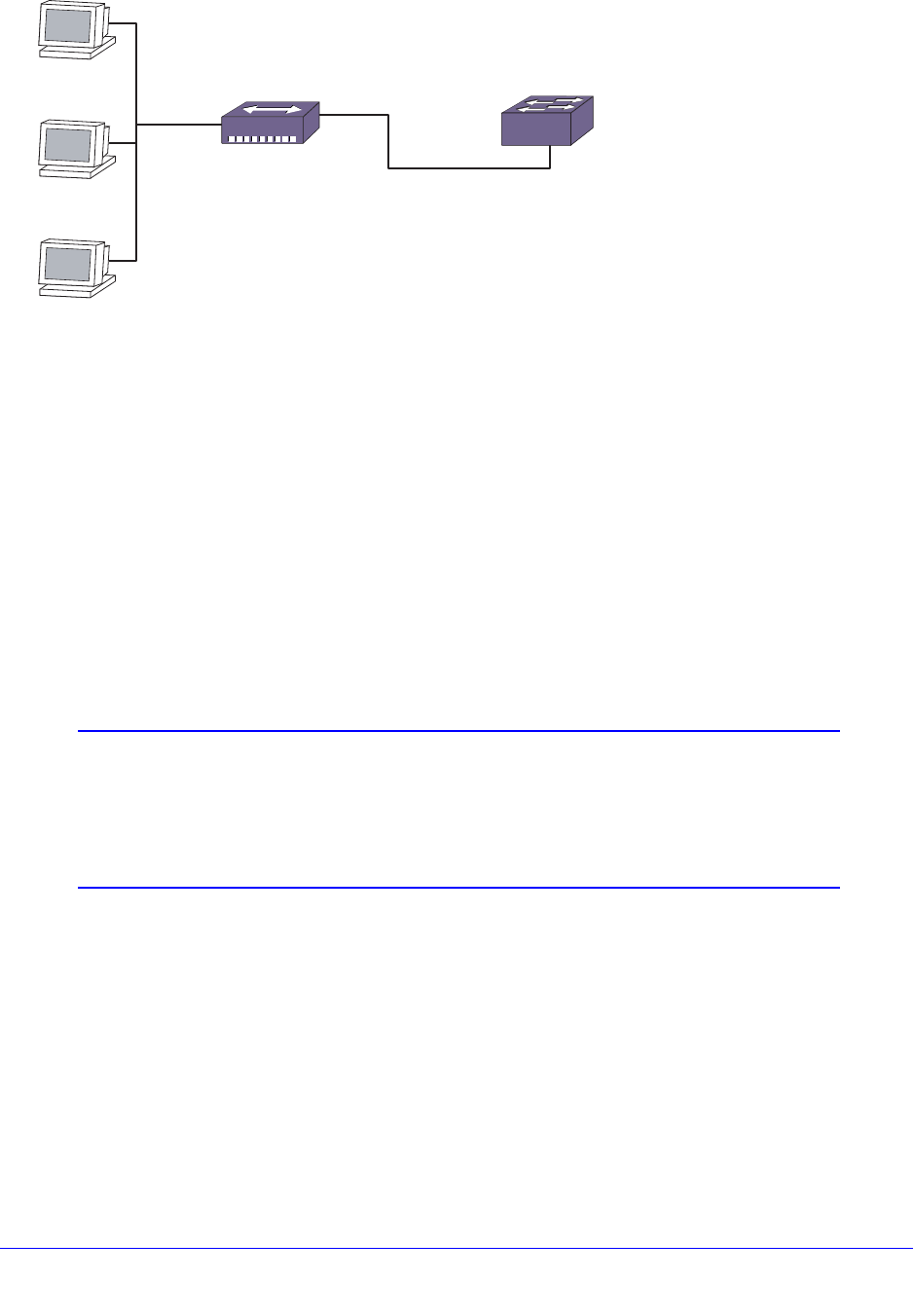
Chapter 17. Security | 439
NETGEAR 8800 User Manual
Figure 27. Switch Configured for Limit Learning
MAC Address Lockdown
In contrast to limiting learning on virtual ports, you can lockdown the existing dynamic FDB
entries and prevent any additional learning using the lock-learning option from the following
command:
configure ports <portlist> vlan <vlan_name> [limit-learning <number> {action
[blackhole | stop-learning]} | lock-learning | unlimited-learning |
unlock-learning]
This command causes all dynamic FDB entries associated with the specified VLAN and ports
to be converted to locked static entries. It also sets the learning limit to 0, so that no new
entries can be learned. All new source MAC addresses are blackholed.
Note: Blackhole FDB entries added due to MAC security violations on
NETGEAR 8800 switches are removed after each FDB aging period
regardless of whether the MAC addresses in question are still
sending traffic. If the MAC addresses are still sending traffic, the
blackhole entries will be re-added after they have been deleted.
Locked entries do not get aged, but can be deleted like a regular permanent entry.
For ports that have lock-down in effect, the following traffic still flows to the port:
• Packets destined for the permanent MAC and other non-blackholed MAC addresses
• Broadcast traffic
Traffic from the permanent MAC still flows from the virtual port.
To remove MAC address lockdown, use the unlock-learning option from the following
command:
EX_175
Device A
Hub
Device B
Device C

440 | Chapter 17. Security
NETGEAR 8800 User Manual
configure ports <portlist> vlan <vlan_name> [limit-learning <number> {action
[blackhole | stop-learning]} | lock-learning | unlimited-learning |
unlock-learning]
When you remove the lockdown using the unlock-learning option, the learning-limit is reset to
unlimited, and all associated entries in the FDB are flushed.
To display the locked entries on the switch, use the following command:
show fdb
Locked MAC address entries have the “l” flag.
MAC Address Lockdown with Timeout
The MAC address lockdown with timeout feature provides a timer for aging out MAC
addresses on a per port basis and overrides the FDB aging time. That is, when this feature is
enabled on a port, MAC addresses learned on that port age out based on the MAC lockdown
timeout corresponding to the port, not based on the FDB aging time. By default, the MAC
address lockdown timer is disabled.
When this feature is enabled on a port, MAC addresses learned on that port remain locked
for the MAC lockdown timeout duration corresponding to the port, even when the port goes
down. As a result, when a device is directly connected to the switch and then disconnected,
the MAC address corresponding to the device will be locked up for the MAC lockdown
timeout duration corresponding to that port. If the same device reconnects to the port before
the MAC lockdown timer expires and sends traffic, the stored MAC address becomes active
and the MAC lockdown timer is restarted. If the device is not reconnected for the MAC
lockdown timeout duration, the MAC entry is removed.
MAC lockdown timeout entries are dynamically learned by the switch, which means these
entries are not saved or restored during a switch reboot. If the switch reboots, the local MAC
entry table is empty, and the switch needs to relearn the MAC addresses.
MAC address lockdown with timeout is configured by individual ports. The lockdown timer
and address learning limits are configured separately for a port.
Note: You cannot enable the lockdown timeout feature on a port that
already has MAC address lockdown enabled. For more information
about MAC address lockdown, see MAC Address Lockdown on
page 439.
MAC address learning limits and the lockdown timer work together in the following ways:
• When the learning limit has been reached on a port, a new device attempting to connect
to the port has its MAC address blackholed.
• As long as the timer is still running for a MAC entry, a new device cannot connect in place
of the device that entry represents. That is, if a device has disconnected from a port, a

Chapter 17. Security | 441
NETGEAR 8800 User Manual
new device cannot replace it until the lockdown timer for the first device has expired. This
condition is true if the limit on the port is set to 1 or if the limit (greater than 1) on the port
has been reached.
• If a learning limit is already configured on a port when you enable the lockdown timeout
feature, the configured limit will continue to apply. Existing blackholed entries are
therefore not affected. If you enable this feature on a port with no configured learning
limit, the default maximum learning limit (unlimited learning) is used.
This section describes the following topics:
• Understanding the Lockdown Timer on page 441
• Examples of Active and Inactive Devices on page 441
• Examples of Disconnecting and Reconnecting Devices on page 442
• Example of Port Movement on page 444
• Configuring MAC Address Lockdown with Timeout on page 444
• Enabling and Disabling MAC Address Lockdown with Timeout on page 444
• Displaying MAC Address Lockdown Information on page 444
Understanding the Lockdown Timer
The lockdown timer works in the following ways:
• When you enable this feature on a port, existing MAC entries for the port begin aging out
based on the configured MAC lockdown timer value.
• If you move a device from one port to another, its MAC address entry is updated with the
new port information, including the lockdown timer value configured for that port.
• If this feature is enabled on a port and you decrease the lockdown timer value for that
port, all of the MAC FDB entries for that port will time out and be removed at the next
polling interval.
• When you disable the lockdown timer on a port, existing MAC address entries for the port
will time out based on the FDB aging period.
Examples of Active and Inactive Devices
Figure 28 shows three devices (A, B, and C) connected through a hub to an NETGEAR
device with MAC lockdown timeout configured on the ports. When each device starts sending
traffic, the source MAC address of the device is learned and FDB entries are created. The
MAC lockdown timer is set at 100 seconds.
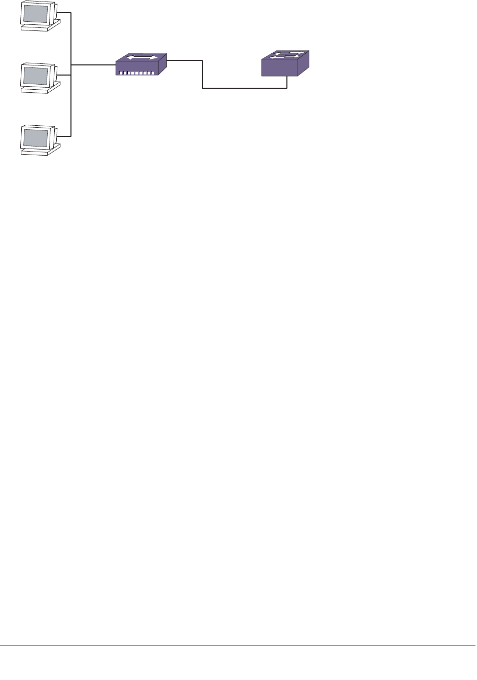
442 | Chapter 17. Security
NETGEAR 8800 User Manual
Figure 28. Devices Using MAC Address Lockdown
Device Inactivity for Less than the MAC Lockdown Timer
As long as a device continues to send traffic, the MAC entry for that device is refreshed, and
the MAC lockdown timer corresponding to the MAC entry is refreshed. Therefore, as long as
the device is active, the timer does not expire. The traffic can be continuous or can occur in
bursts within the MAC lockdown timeout duration for the port.
In this example, Device A starts sending traffic. When the MAC address of Device A is
learned and added to the FDB, the MAC lockdown timer is started for this entry.
Device A stops sending traffic and resumes sending traffic after 50 seconds have elapsed. At
this point the MAC entry for Device A is refreshed and the MAC lockdown timer is restarted.
Device Inactivity for Longer than the MAC Lockdown Timer
When a device stops sending traffic and does not resume within the MAC lockdown timer
interval for the port, the MAC lockdown timer expires, and the MAC entry is removed from the
FDB.
In this example, Devices A, B, and C start sending traffic. As each MAC address is learned,
the MAC lockdown timer is started for each entry.
Device A stops sending traffic; Devices B and C continue sending traffic. After 100 seconds,
the MAC lockdown timer for the Device A entry is removed from the FDB. Because Devices B
and C have continued to send traffic, their MAC entries continue to be refreshed and their
MAC lockdown timers continue to be restarted.
Examples of Disconnecting and Reconnecting Devices
Figure 29 shows Device A connected to an NETGEAR device with MAC lockdown timeout
configured for the ports. When Device A starts sending traffic, the source MAC address is
learned on the port, the FDB entry is created, and the MAC lockdown timer is started for the
entry. The MAC lockdown timer is set at 3,000 seconds.
EX_175
Device A
Hub
Device B
Device C
Chapter 17. Security | 443
NETGEAR 8800 User Manual
Figure 29. Single Device with MAC Lockdown Timeout
Disconnecting a Device
In this example, Device A is disconnected from the port, triggering a port-down action. The
MAC entry for Device A is removed from the hardware FDB; however, the MAC entry for the
device is maintained in the software. The MAC lockdown timer for this entry starts when the
port goes down.
After 3,000 seconds, the MAC entry for Device A is removed from the software.
Disconnecting and Reconnecting a Device
When Device A is disconnected from the port, the resulting port-down action causes the
MAC entry for Device A to be removed from the hardware FDB. The MAC entry in software is
maintained, and the MAC lockdown timer is started for the port.
After only 1,000 seconds have elapsed, Device A is reconnected to the same port and starts
sending traffic. A MAC entry is created in the hardware FDB, and the MAC lockdown timer is
restarted for the MAC entry in the software.
If Device A is reconnected but does not send any traffic for 3,000 seconds, no MAC entry is
created in the hardware FDB, and the MAC lockdown timer will expire after reaching 3,000
seconds.
Disconnecting and Reconnecting Devices with MAC Limit Learning
In this example, a MAC learning limit of 1 has also been configured on the ports in addition to
the MAC lockdown timer of 3000 seconds.
When Device A is disconnected, the resulting port-down action removes the MAC entry for
Device A from the hardware FDB. The MAC entry for Device A is maintained in the software,
and the MAC lockdown timer for this entry is restarted when the port goes down.
After 1000 seconds, a different device is connected to the same port and starts sending
traffic. Because the MAC learning limit is set to 1 and the MAC lockdown timer is still running,
the MAC address of the new device is not learned. Instead, the new MAC address is
blackholed in the hardware.
When the MAC lockdown timer for Device A expires, its MAC entry is removed from the
software. If the new device is still connected to the same port and sends traffic, the MAC
address for the new device is learned and added to the FDB. The MAC lockdown timer for
the new device is started, and the blackhole entry that was created for this device is deleted.
EX_176
Device A
444 | Chapter 17. Security
NETGEAR 8800 User Manual
Example of Port Movement
Figure 30 shows Device A connected to port X. Port X has a MAC lockdown timer setting of
100 seconds, and port Y has a MAC lockdown timer setting of 200 seconds.
Figure 30. Port Movement with MAC Lockdown Timeout
Device A starts sending traffic on port X. The MAC address for Device A is learned and
added to the FDB, and the MAC lockdown timer (100 seconds) is started for this entry.
After 50 seconds, Device A is disconnected from port X and connected to port Y where it
begins sending traffic. When Device A starts sending traffic on port Y, the existing MAC entry
for Device A is refreshed, and port X in the entry is replaced with port Y. At the same time, the
MAC lockdown timer for the entry is restarted for a duration of 200 seconds (the configured
MAC lockdown timer setting for port Y).
Configuring MAC Address Lockdown with Timeout
To configure the MAC lockdown timeout value on one or more specified ports, or on all ports,
use the following command:
configure mac-lockdown-timeout ports [all | <port_list>] aging-time <seconds>
Enabling and Disabling MAC Address Lockdown with Timeout
To enable the MAC lockdown timeout feature on one or more specified ports, or on all ports,
use the following command:
enable mac-lockdown-timeout ports [all | <port_list>]
To disable the MAC lockdown timeout feature on one or more specified ports, or on all ports,
use the following command:
disable mac-lockdown-timeout ports [all | <port_list>]
Displaying MAC Address Lockdown Information
To display configuration information about the MAC lockdown timeout feature, use the
following command:
show mac-lockdown-timeout ports [all | <port_list>]
Output from this command includes the configured timeout value and whether the feature is
enabled or disabled.
To display the MAC entries learned on one or more ports, or on all ports, use the following
command:
show mac-lockdown-timeout fdb ports [all | <port_list>]
EX_177
Device A Device X Device Y

Chapter 17. Security | 445
NETGEAR 8800 User Manual
Output from this command also lists the aging time of the port.
DHCP Server
XCM8800 has Dynamic Host Configuration Protocol (DHCP) support. In simple terms, a
DHCP server dynamically manages and allocates IP addresses to clients. When a client
accesses the network, the DHCP server provides an IP address to that client. The client is
not required to receive the same IP address each time it accesses the network. A DHCP
server with limited configuration capabilities is included in the switch to provide IP addresses
to clients.
This section describes the following topics:
• Enabling and Disabling DHCP on page 445
• Configuring the DHCP Server on page 445
• Displaying DHCP Information on page 446
Enabling and Disabling DHCP
DHCP is enabled on a per port, per VLAN basis. To enable or disable DHCP on a port in a
VLAN, use one of the following commands:
enable dhcp ports <portlist> vlan <vlan_name>
disable dhcp ports <portlist> vlan <vlan_name>
Configuring the DHCP Server
The following commands allow you to configure the DHCP server included in the switch. The
parameters available to configure include the IP address range, IP address lease, and
multiple DHCP options.
To configure the range of IP addresses assigned by the DHCP server, use the following
command:
configure vlan <vlan_name> dhcp-address-range <ipaddress1> - <ipaddress2>
To remove the address range information, use the following command:
unconfigure vlan <vlan_name> dhcp-address-range
To set how long the IP address lease assigned by the server exists, use the following
command:
configure vlan <vlan_name> dhcp-lease-timer <lease-timer>
To set the default gateway, Domain Name Servers (DNS) addresses, or Windows Internet
Naming Service (WINS) server, use the following command:
configure {vlan} <vlan_name> dhcp-options [default-gateway | dns-server
{primary | secondary} | wins-server] <ipaddress>

446 | Chapter 17. Security
NETGEAR 8800 User Manual
To remove the default gateway, DNS server addresses, and WINS server information for a
particular VLAN, use the following command:
unconfigure {vlan} <vlan_name> dhcp-options {[ default-gateway | dns-server
{primary | secondary} | wins-server]}
To remove all the DHCP information for a particular VLAN, use the following command:
unconfigure vlan <vlan_name> dhcp
You can clear the DHCP address allocation table selected entries, or all entries. You would
use this command to troubleshoot IP address allocation on the VLAN. To clear entries, use
the following command:
clear vlan <vlan_name> dhcp-address-allocation [[all {offered | assigned |
declined | expired}] | <ipaddress>]
Displaying DHCP Information
To display the DHCP configuration, including the DHCP range, DHCP lease timer, network
login lease timer, DHCP-enabled ports, IP address, MAC address, and time assigned to each
end device, use the following command:
show dhcp-server {vlan <vlan_name>}
To view only the address allocation of the DHCP server on a VLAN, use the following
command:
show vlan <vlan_name> dhcp-address-allocation
To view only the configuration of the DHCP server on a VLAN, use the following command:
show {vlan} <vlan_name> dhcp-config
IP Security
This section describes a collection of IP security features implemented in XCM8800. If you
configure any of the features described in this section, you can enhance your network
security by controlling which hosts are granted or not granted access to your network.
Note: Currently, BlackDiamond 20800 series switches do not support “IP
Security.”
The IP security features described in this section are:
• DHCP Snooping and Trusted DHCP Server on page 447
• Source IP Lockdown on page 454
• ARP Learning on page 456

Chapter 17. Security | 447
NETGEAR 8800 User Manual
• Gratuitous ARP Protection on page 458
• ARP Validation on page 460
Figure 31 displays the dependencies of IP security. Any feature that appears directly above
another feature depends on it. For example, to configure ARP validation, you must configure
DHCP snooping and trusted DHCP server.
Figure 31. IP Security Dependencies
Note: IP security features are supported on link aggregation ports with the
exception of DHCP snooping with the block-mac option and source
IP lockdown. You can enable IP security on pre-existing trunks, but
you cannot make IP security-enabled ports into trunks without first
disabling IP security.
DHCP Snooping and Trusted DHCP Server
A fundamental requirement for most of the IP security features described in this section is to
configure DHCP snooping and trusted DHCP server. DHCP snooping enhances security by
filtering untrusted DHCP messages and by building and maintaining a DHCP bindings
database. Trusted DHCP server also enhances security by forwarding DHCP packets from
only configured trusted servers within your network.
The DHCP bindings database contains the IP address, MAC Address, VLAN ID, and port
number of the untrusted interface or client. If the switch receives a DHCP ACK message and
the IP address does not exist in the DHCP bindings database, the switch creates an entry in
the DHCP bindings database. If the switch receives a DHCP RELEASE, NAK or DECLINE
message and the IP address exists in the DHCP bindings database, the switch removes the
entry.
You can enable DHCP snooping on a per port, per-VLAN basis and trusted DHCP server on
a per-vlan basis. If configured for DHCP snooping, the switch snoops DHCP packets on the
indicated ports and builds a DHCP bindings database of IP address and MAC address
bindings from the received packets. If configured for trusted DHCP server, the switch
forwards only DHCP packets from the trusted servers. The switch drops DHCP packets from
other DHCP snooping-enabled ports.
In addition, to prevent rogue DHCP servers from farming out IP addresses, you can
optionally configure a specific port or set of ports as trusted ports. Trusted ports do not block
traffic; rather, the switch forwards any DHCP server packets that appear on trusted ports.
EX_178
Disable
ARP
learning
DHCP
secured
ARP
ARP
validation
Source IP
lockdown
Gratuitous ARP
inspection—protect
hosts and switch
Gratuitous ARP
inspection—
protect only
switch
DHCP snooping and trusted DHCP server

448 | Chapter 17. Security
NETGEAR 8800 User Manual
When configured to do so, the switch drops packets from DHCP snooping-enabled ports and
causes one of the following user-configurable actions: disables the port temporarily, disables
the port permanently, blocks the violating MAC address temporarily, blocks the violating MAC
address permanently, and so on.
Configuring DHCP Snooping
By default DHCP snooping is disabled on the switch. To enable DHCP snooping on the
switch, use the following command:
enable ip-security dhcp-snooping {vlan} <vlan_name> ports [all | <ports>]
violation-action [drop-packet {[block-mac | block-port] [duration
<duration_in_seconds> | permanently] | none]}] {snmp-trap}
Note: Snooping IP fragmented DHCP packets is not supported.
The violation action setting determines what action(s) the switch takes when a rogue DHCP
server packet is seen on an untrusted port or the IP address of the originating server is not
among those of the configured trusted DHCP servers. The DHCP server packets are DHCP
OFFER, ACK and NAK. The following list describes the violation actions:
• block-mac—The switch automatically generates an ACL to block the MAC address on
that port. The switch does not blackhole that MAC address in the FDB. The switch can
either temporarily or permanently block the MAC address.
• block-port—The switch blocks all traffic on that port by disabling the port either
temporarily or permanently.
• none—The switch takes no action to drop the rogue DHCP packet or block the port, and
so on. In this case, DHCP snooping continues to build and manage the DHCP bindings
database and DHCP forwarding will continue in hardware as before. This option can be
used when the intent is only to monitor the IP addresses being assigned by the DHCP
server.
Note: You must enable DHCP snooping on both the DHCP server port as
well as on the client port. The latter ensures that DHCP client
packets (DHCP Request, DHCP Release etc.) are processed
appropriately.
Any violation that occurs causes the switch to generate an Event Management System
(EMS) log message. You can configure to suppress the log messages by configuring EMS
log filters. For more information about EMS, see the section Using the Event Management
System/Logging on page 214.
To disable DHCP snooping on the switch, use the following command:
disable ip-security dhcp-snooping {vlan} <vlan_name> ports [all | <ports>]

Chapter 17. Security | 449
NETGEAR 8800 User Manual
Configuring Trusted DHCP Server
To configure a trusted DHCP server on the switch, use the following command:
configure trusted-servers {vlan} <vlan_name> add server <ip_address> trust-for
dhcp-server
You can configure a maximum of eight trusted DHCP servers on the switch.
If you configure one or more trusted ports, the switch assumes that all DHCP server packets
on the trusted port are valid. For more information about configuring trusted ports, see the
next section.
To delete a trusted DHCP server, use the following command:
configure trusted-servers vlan <vlan_name> delete server <ip_address> trust-for
dhcp-server
Configuring Trusted DHCP Ports
To enable DHCP snooping, use the following command:
enable ip-security dhcp-snooping {vlan} <vlan_name> ports [all | <ports>]
violation-action [drop-packet {[block-mac | block-port] [duration
<duration_in_seconds> | permanently] | none]}] {snmp-trap}
For more information about DHCP snooping see, Configuring DHCP Snooping on page 448.
Trusted ports do not block traffic; rather, the switch forwards any DHCP server packets that
appear on trusted ports. Depending on your DHCP snooping configuration, the switch drops
packets and can disable the port temporarily, disable the port permanently, block the MAC
address temporarily, block the MAC address permanently, and so on.
To enable trusted ports on the switch, use the following command:
configure trusted-ports [<ports>|all] trust-for dhcp-server
To disable trusted ports on the switch, use the following command:
unconfigure trusted-ports [<ports>|all] trust-for dhcp-server
Displaying DHCP Snooping and Trusted Server Information
To display the DHCP snooping configuration settings, use the following command:
show ip-security dhcp-snooping {vlan} <vlan_name>
The following is sample output from this command:
DHCP Snooping enabled on ports: 1:2, 1:3, 1:4, 1:7, 1:9
Trusted Ports: 1:7
Trusted DHCP Servers: None
--------------------------------------------
Port Violation-action
--------------------------------------------
1:2 none
450 | Chapter 17. Security
NETGEAR 8800 User Manual
1:3 drop-packet
1:4 drop-packet, block-mac permanently
1:7 none
1:9 drop-packet, snmp-trap
To display the DHCP bindings database, use the following command:
show ip-security dhcp-snooping entries {vlan} <vlan_name>
The following is sample output from this command:
--------------------------------------------
Vlan: dhcpVlan
--------------------------------------------
Server Client
IP Addr MAC Addr Port Port
------- -------- ------ ------
172.16.100.9 00:90:27:c6:b7:65 1:1 1:2
Clearing DHCP Snooping Entries
Existing DHCP snooping entries can be cleared by using the following command. (Note that
this will also clear out any associated Source IP Lockdown and DHCP Secured ARP entries.)
clear ip-security dhcp-snooping entries {vlan} <vlan_name>
Configuring the DHCP Relay Agent Option (Option 82) at Layer 2
This section describes how to configure the DHCP Relay agent option for Layer 2 forwarded
DHCP packets. The DHCP relay agent option feature inserts a piece of information, called
option 82, into any DHCP request packet that is to be relayed by the switch. Similarly, if a
DHCP reply received by the switch contains a valid relay agent option, the option will be
stripped from the packet before it is relayed to the client. This is a Layer 2 option that
functions only when the switch is not configured as a Layer 3 BOOTP relay.
The Agent remote ID sub-option always contains the Ethernet MAC address of the relaying
switch. You can display the Ethernet MAC address of the switch by issuing the show switch
command.
The contents of the inserted option 82 sub-options is as follows:
To enable the DHCP relay agent option at Layer 2, use the following command:
Table 48. Contents of the Inserted Option 82 Sub-options
Code
(1 byte) Length
(1 byte) Sub- Option
(1 byte) Length
(1 byte) Value
(1-32 bytes) Sub-Option
(1 byte) Length
(1 byte) Switch MAC
address
(6 bytes)
82 1
(Circuit ID) 1-32 vlan_info-p
ort_info
2
(Remote ID) 6

Chapter 17. Security | 451
NETGEAR 8800 User Manual
configure ip-security dhcp-snooping information option
Note: When DHCP relay is configured in a DHCP snooping environment,
the relay agent IP address should be configured as the trusted
server.
When DHCP option 82 is enabled, two types of packets need to be handled:
• DHCP Request: When the switch (relay agent) receives a DHCP request, option 82 is
added at the end of the packet. If the option has already been enabled, then the action
taken depends on the configured policy (drop packet, keep existing option 82 value, or
replace the existing option). Unless configured otherwise using the configure
ip-security dhcp-snooping information circuit-id vlan-information, the vlan_info
portion of the circuit ID added will be the VLAN ID of the ingress VLAN.
• DHCP Reply: When the option 82 information check is enabled, the packets received
from the DHCP server are checked for option 82 information. If the remote ID sub-option
is the switch's MAC address, the packet is sent to the client; if not, the packet is dropped.
If the check is not enabled. the packets are forwarded as-is.
To disable the DHCP relay agent option, use the following command:
unconfigure ip-security dhcp-snooping information option
In some instances, a DHCP server may not properly handle a DHCP request packet
containing a relay agent option. To prevent DHCP reply packets with invalid or missing relay
agent options from being forwarded to the client, use the following command:
configure ip-security dhcp-snooping information check
To disable checking of DHCP replies, use this command:
unconfigure ip-security dhcp-snooping information check
A DHCP relay agent may receive a client DHCP packet that has been forwarded from
another relay agent. If this relayed packet already contains a relay agent option, then the
switch will handle this packet according to the configured DHCP relay agent option policy.
The possible actions are to replace the option information, to keep the information, or to drop
packets containing option 82 information. To configure this policy, use the following
command:
configure ip-security dhcp-snooping information policy
The default relay policy is replace. To configure the policy to the default, use this command:
unconfigure ip-security dhcp-snooping information policy
The Layer 2 relay agent option allows you to configure the circuit ID on a VLAN or port basis.,
the Circuit-ID can contain a variable length (up to 32 bytes long) ASCII string with the
following format:
<VLAN Info>-<Port Info>

452 | Chapter 17. Security
NETGEAR 8800 User Manual
If the configuration of either VLAN Info or Port Info causes the total string length of <VLAN
Info>-<Port Info> to exceed 32 bytes, then it is truncated to 32 bytes. The string is not NULL
terminated, since the total circuit ID length is being specified.
For a DHCP client packet ingressing on a VLAN with the VLAN ID equal to 200 and the
ingress port at 3:5, the following are true:
• When neither VLAN Info or Port Info is specified, circuit ID value is = 200-3005
• When VLAN Info is configured to SomeInfo and Port Info is not specified, the circuit ID
value is SomeInfo-3005
• When VLAN Info is not specified and Port Info is configured to User1, the circuit ID value
is 200-User1
• When VLAN Info is configured to SomeInfo and Port Info to User1, the circuit ID value is
SomeInfo-User1
VLAN Info is configurable per VLAN. When not explicitly configured for a VLAN, VLAN Info
defaults to the ASCII string representation of the ingress VLAN ID. To configure the circuit ID
on a VLAN, use the following command:
configure ip-security dhcp-snooping information circuit-id vlan-information
To unconfigure the circuit ID on a VLAN, use the following command:
unconfigure ip-security dhcp-snooping information circuit-id vlan-information
Port Info is configurable. When not explicitly configured for a port, port info defaults to the
ASCII representation of the ingress port’s SNMP ifIndex. To configure the port information
portion of the circuit-ID, use the following command:
configure ip-security dhcp-snooping information circuit-id port-information
port
To unconfigure the port information portion of the circuit-ID, use the following command:
unconfigure ip-security dhcp-snooping information circuit-id port-information
ports
Note: When this feature is enabled, all DHCP traffic must be forwarded in
slowpath only, which means that this feature functions only in the
context of IP Security and only on interfaces where DHCP snooping
is enabled in enforcement (violation-action of ‘drop’) mode, in other
words with DHCP snooping not configured with a violation-action of
‘none’ (which is pure monitoring mode).
For information about configuring option 82 at Layer 3, see Configuring the DHCP Relay
Agent Option (Option 82) at Layer 3 on page 627.

Chapter 17. Security | 453
NETGEAR 8800 User Manual
Example of Option 82 Configuration
The following example describes Option 82 configuration for circuit ID fields.
create vlan v1
conf v1 add ports 21
enable ip-security dhcp-snooping v1 ports all violation-action drop-packet
configure trusted-ports 21 trust-for dhcp-server
conf ip-security dhcp-snooping information option
conf ip-security dhcp-snooping information check
conf ip-security dhcp-snooping information circuit-id vlan-information
ServiceProvider-1 v1
conf ip-security dhcp-snooping information circuit-id port-information cutomer-1 port
1
conf ip-security dhcp-snooping information circuit-id port-information cutomer-2 port
2
CLI display output
==================
* XCM8806.48 # sh ip-security dhcp-snooping v1
DHCP Snooping enabled on ports: 21
Trusted Ports: 21
Trusted DHCP Servers: None
Bindings Restoration : Disabled
Bindings Filename :
Bindings File Location :
Primary Server : None
Secondary Server: None
Bindings Write Interval : 30 minutes
Bindings last uploaded at:
------------------------------------
Port Violation-action
------------------------------------
21 drop-packet
* XCM8806.49 # show ip-security dhcp-snooping information-option
Information option insertion: Enabled
Information option checking : Enabled
Information option policy : Replace
* XCM8806.50 #
* XCM8806.51 # sh ip-security dhcp-snooping information-option circuit-id
vlan-information
Vlan Circuit-ID vlan information string
---- ----------------------------------
Default 1 (Default i.e. vlan-id)
Mgmt 4095 (Default i.e. vlan-id)
v1 ServiceProvider-1
Note: The full Circuit ID string has the form '<Vlan Info>-<Port Info>'
* XCM8806.52
* XCM8806.52 # sh ip-security dhcp-snooping information-option circuit-id
port-information ports all

454 | Chapter 17. Security
NETGEAR 8800 User Manual
Port Circuit-ID Port information string
---- ----------------------------------
1 cutomer-1
2 cutomer-2
3 1003
4 1004
5 1005
6 1006
7 1007
8 1008
9 1009
10 1010
11 1011
12 1012
13 1013
14 1014
15 1015
16 1016
17 1017
18 1018
19 1019
20 1020
21 1021
22 1022
23 1023
24 1024
25 1025
26 1026
Note: The full Circuit ID string has the form '<Vlan Info>-<Port Info>'
* XCM8806.53 #
Source IP Lockdown
Another type of IP security prevents IP address spoofing by automatically placing source IP
address filters on specified ports. This feature, called source IP lockdown, allows only traffic
from a valid DHCP-assigned address obtained by a DHCP snooping-enabled port to enter
the network. In this way, the network is protected from attacks that use random source
addresses for their traffic. With source IP lockdown enabled, end systems that have a DHCP
address assigned by a trusted DHCP server can access the network, but traffic from others,
including those with static IP addresses is dropped at the switch.
Source IP lockdown is linked to the “DHCP snooping” feature. The same DHCP bindings
database created when you enable DHCP snooping is also used by source IP lockdown to
create ACLs that permit traffic from DHCP clients. All other traffic is dropped. In addition, the
DHCP snooping violation action setting determines what action(s) the switch takes when a
rogue DHCP server packet is seen on an untrusted port.
When source IP lockdown is enabled on a port, a default ACL is created to deny all IP traffic
on that port. Then an ACL is created to permit DHCP traffic on specified ports. Each time
Chapter 17. Security | 455
NETGEAR 8800 User Manual
source IP lockdown is enabled on another port, the switch creates ACLs to allow DHCP
packets and to deny all IP traffic for that particular port.
Source IP lockdown is enabled on a per-port basis; it is not available at the VLAN level. If
source IP lockdown is enabled on a port, the feature is active on the port for all VLANs to
which the port belongs.
Note: The source IP lockdown feature works only when hosts are
assigned IP address using DHCP; source IP lockdown does not
function for statically configured IP addresses.
The source IP lockdown ACLs listed in table are applied per port (in order of precedence from
highest to lowest.)
The counter has the same name as that of the rule of the catch-all ACL, so the counter is also
named esSrcIpLockdown_<portIfIndex>_4.
Configuring Source IP Lockdown
To configure source IP lockdown, you must enable DHCP snooping on the ports connected to
the DHCP server and DHCP client before you enable source IP lockdown. You must enable
source IP lockdown on the ports connected to the DHCP client, not on the ports connected to
the DHCP server. To enable DHCP snooping, use the following command:
enable ip-security dhcp-snooping {vlan} <vlan_name> ports [all | <ports>]
violation-action [drop-packet {[block-mac | block-port] [duration
<duration_in_seconds> | permanently] | none]}] {snmp-trap}
Table 49. Source IP Lockdowns Applied Per-port
ACL Name Match
Condition Action When Applied Comments
esSrcIpLockdown_<portIfIndex>_<source IP
in hex> Source IP Permit Runtime Multiple ACLs of
this type can be
applied, one for
each permitted
client.
esSrcIpLockdown_<portIfIndex>_1 Proto UDP,
Dest Port 67 Permit Configuration
time
esSrcIpLockdown_<portIfIndex>_2 Proto UDP,
Dest Port 68 Permit Configuration
time
esSrcIpLockdown_<portIfIndex>_3 Ethertype
ARP Permit Configuration
time
esSrcIpLockdown_<portIfIndex>_4 All Deny +
count Configuration
time

456 | Chapter 17. Security
NETGEAR 8800 User Manual
For more information about DHCP snooping see, Configuring DHCP Snooping on page 448.
By default, source IP lockdown is disabled on the switch. To enable source IP lockdown, use
the following command:
enable ip-security source-ip-lockdown ports [all | <ports>]
To disable source IP lockdown, use the following command:
disable ip-security source-ip-lockdown ports [all | <ports>]
Displaying Source IP Lockdown Information
To display the source IP lockdown configuration on the switch, use the following command:
show ip-security source-ip-lockdown
The following is sample output from this command:
Ports Locked IP Address
23 10.0.0.101
Clearing Source IP Lockdown Information
To remove existing source IP lockdown entries on the switch, use the following command:
clear ip-security source-ip-lockdown entries ports [<ports> | all]
ARP Learning
The address resolution protocol (ARP) is part of the TCP/IP suite used to dynamically
associate a device’s physical address (MAC address) with its logical address (IP address).
The switch broadcasts an ARP request that contains the IP address, and the device with that
IP address sends back its MAC address so that traffic can be transmitted across the network.
The switch maintains an ARP table (also known as an ARP cache) that displays each MAC
address and its corresponding IP address.
By default, the switch builds its ARP table by tracking ARP requests and replies, which is
known as ARP learning. You can disable ARP learning so that the only entries in the ARP
table are either manually added or those created by DHCP secured ARP; the switch does not
add entries by tracking ARP requests and replies. By disabling ARP learning and adding a
permanent entry or configuring DHCP secured ARP, you can centrally manage and allocate
client IP addresses and prevent duplicate IP addresses from interrupting network operation.
This section describes the following topics:
• Configuring ARP Learning on page 457
• Adding a Permanent Entry to the ARP Table on page 457
• Configuring DHCP Secured ARP on page 457
• Displaying ARP Information on page 458

Chapter 17. Security | 457
NETGEAR 8800 User Manual
Configuring ARP Learning
As previously described, ARP learning is enabled by default. The switch builds its ARP table
by tracking ARP requests and replies.
To disable ARP learning on one or more ports in a VLAN, use the following command:
disable ip-security arp learning learn-from-arp {vlan} <vlan_name> ports [all |
<ports>]
To re-enable ARP learning on one or more ports in a VLAN, use the following command:
enable ip-security arp learning learn-from-arp {vlan} <vlan_name> ports [all |
<ports>]
Adding a Permanent Entry to the ARP Table
If you disable ARP learning, you must either manually add a permanent entry to the ARP
table or configure DHCP secured ARP to populate the ARP table.
To manually add a permanent entry to the ARP table, use the following command:
configure iparp add <ip_addr> {vr <vr_name>} <mac>
For more detailed information about this command and IP routing, see Chapter 20, IPv4
Unicast Routing.
Configuring DHCP Secured ARP
Another method available to populate the ARP table is DHCP secured ARP. DHCP secured
ARP requires that ARP entries be added to or deleted from the ARP table only when the
DHCP server assigns or re-assigns an IP address. These entries are known as a secure
ARP entry. If configured, the switch adds the MAC address and its corresponding IP address
to the ARP table as a permanent ARP entry. Regardless of other ARP requests and replies
seen by the switch, the switch does not update secure ARP entries. DHCP secured ARP is
linked to the “DHCP snooping” feature. The same DHCP bindings database created when
you enabled DHCP snooping is also used by DHCP secured ARP to create secure ARP
entries. The switch only removes secure ARP entries when the corresponding DHCP entry is
removed from the trusted DHCP bindings database.
Note: If you enable DHCP secured ARP on the switch without disabling
ARP learning, ARP learning continues which allows insecure entries
to be added to the ARP table.
Before you configure DHCP secured ARP, you must enable DHCP snooping on the switch.
To enable DHCP snooping, use the following command:
enable ip-security dhcp-snooping {vlan} <vlan_name> ports [all | <ports>]
violation-action [drop-packet {[block-mac | block-port] [duration
<duration_in_seconds> | permanently] | none]}] {snmp-trap}
For more information about DHCP snooping see, Configuring DHCP Snooping on page 448.

458 | Chapter 17. Security
NETGEAR 8800 User Manual
By default, DHCP secured ARP learning is disabled. To enable DHCP secured ARP, use the
following command:
enable ip-security arp learning learn-from-dhcp {vlan} <vlan_name> ports [all |
<ports>]
DHCP Secured ARP must be enabled on the DHCP server port as well as the DHCP client
ports. To disable DHCP secured ARP, use the following command:
disable ip-security arp learning learn-from-dhcp {vlan} <vlan_name> ports [all
| <ports>]
Note: You must enable DHCP secured ARP on the DHCP server as well
as on the client ports. DHCP snooping, as always, must also be
enabled on both the server and client ports.
Displaying ARP Information
To display how the switch builds an ARP table and learns MAC addresses for devices on a
specific VLAN and associated member ports, use the following command:
show ip-security arp learning {vlan} <vlan_name>
The following is sample output from this command:
Port Learn-from
----------------------------------
2:1 ARP
2:2 DHCP
2:3 ARP
2:4 None
2:5 ARP
2:6 ARP
2:7 ARP
2:8 ARP
To view the ARP table, including permanent and DHCP secured ARP entries, use the
following command:
show iparp {<ip_addre> | <mac> | vlan <vlan_name> | permanent} {vr <vr_name>}
Note: DHCP secured ARP entries are stored as static entries in the ARP
table.
Gratuitous ARP Protection
When a host sends an ARP request to resolve its own IP address it is called gratuitous ARP.
A gratuitous ARP request is sent with the following parameters:

Chapter 17. Security | 459
NETGEAR 8800 User Manual
• Destination MAC address—FF:FF:FF:FF:FF:FF (broadcast)
• Source MAC address—Host's MAC address
• Source IP address = Destination IP address—IP address to be resolved
In a network, gratuitous ARP is used to:
• Detect duplicate IP address
In a properly configured network, there is no ARP reply for a gratuitous ARP request.
However, if another host in the network is configured with the same IP address as the
source host, then the source host receives an ARP reply.
• Announce that an IP address has moved or bonded to a new network interface card (NIC)
If you change a system NIC, the MAC address to its IP address mapping also changes.
When you reboot the host, it sends an ARP request packet for its own IP address. All of
the hosts in the network receive and process this packet. Each host updates their old
mapping in the ARP table with this new mapping
• Notify a Layer 2 switch that a host has moved from one port to another port
However, hosts can launch man-in-the-middle attacks by sending out gratuitous ARP
requests for the router's IP address. This results in hosts sending their router traffic to the
attacker, and the attacker forwarding that data to the router. This allows passwords, keys,
and other information to be intercepted.
To protect against this type of attack, the router sends out its own gratuitous ARP request to
override the attacker whenever a gratuitous ARP request broadcast packet with the router's
IP address as the source is received on the network.
If you enable both DHCP secured ARP and gratuitous ARP protection, the switch protects its
own IP address and those of the hosts that appear as secure entries in the ARP table.
Configuring Gratuitous ARP
You enable the gratuitous ARP feature on a per VLAN basis, not on a per port basis. The
validation is done for all gratuitous ARP packets received on a VLAN in which this feature is
enabled irrespective of the port in which the packet is received.
When enabled, the switch generates gratuitous ARP packets when it receives a gratuitous
ARP request where either of the following is true:
• The sender IP is the same as the switch VLAN IP address and the sender MAC address
is not the switch MAC address.
• The sender IP is the same as the IP of a static entry in the ARP table and the sender
MAC address is not the static entry's MAC address.
When the switch generates an ARP packet, the switch generates logs and traps.
You can enable gratuitous ARP protection with the following command:
enable ip-security arp gratuitous-protection {vlan} [all | <vlan_name>]
460 | Chapter 17. Security
NETGEAR 8800 User Manual
In addition, to protect the IP addresses of the hosts that appear as secure entries in the ARP
table, use the following commands to enable DHCP snooping, DHCP secured ARP, and
gratuitous ARP on the switch:
• enable ip-security dhcp-snooping {vlan} <vlan_name> ports [all | <ports>] violation-action
[drop-packet {[block-mac | block-port] [duration <duration_in_seconds> | permanently] |
none]}] {snmp-trap}
• enable ip-security arp learning learn-from-dhcp {vlan} <vlan_name> ports [all | <ports>]
• enable ip-security arp gratuitous-protection {vlan} [all | <vlan_name>]
To disable gratuitous ARP protection, use the following command:
disable ip-security arp gratuitous-protection {vlan} [all | <vlan_name>]
Displaying Gratuitous ARP Information
To display information about gratuitous ARP, use the following command:
show ip-security arp gratuitous-protection
The following is sample output from this command:
Gratuitous ARP Protection enabled on following VLANs:
Default, test
ARP Validation
ARP validation is also linked to the “DHCP snooping” feature. The same DHCP bindings
database created when you enabled DHCP snooping is also used to validate ARP entries
arriving on the specified ports.
Validation Option ARP Request Packet Type ARP Response Packet Type
DHCP Source IP is not present in the DHCP
snooping database OR is present but Source
Hardware Address doesn't match the MAC in
the DHCP bindings entry
IP Source IP == Mcast OR
Target IP == Mcast OR
Source IP is not present in the DHCP
snooping database OR
Source IP exists in the DHCP bindings
database but Source Hardware Address
doesn't match the MAC in the DHCP
bindings entry
Source IP == Mcast OR
Target IP == Mcast
Source-MAC Ethernet source MAC does not match
the Source Hardware Address Ethernet source MAC does not match the
Source Hardware Address.
Destination-MAC Ethernet destination MAC does not match the
Target Hardware Address

Chapter 17. Security | 461
NETGEAR 8800 User Manual
Depending on the options specified when enabling ARP validation, the following validations
are done. Note that the 'DHCP' option does not have to be specified explicitly, it is always
implied when ARP validation is enabled.
Configuring ARP Validation
Before you configure ARP validation, you must enable DHCP snooping on the switch. To
enable DHCP snooping, use the following command:
enable ip-security dhcp-snooping {vlan} <vlan_name> ports [all | <ports>]
violation-action [drop-packet {[block-mac | block-port] [duration
<duration_in_seconds> | permanently] | none]}] {snmp-trap}
For more information about DHCP snooping see, Configuring DHCP Snooping on page 448.
By default, ARP validation is disabled. To enable and configure ARP validation, use the
following command:
enable ip-security arp validation {destination-mac} {source-mac} {ip} {vlan}
<vlan_name> [all | <ports>] violation-action [drop-packet {[block-port]
[duration <duration_in_seconds> | permanently]}] {snmp-trap}
The violation action setting determines what action(s) the switch takes when an invalid ARP
is received.
Any violation that occurs causes the switch to generate an Event Management System
(EMS) log message. You can configure to suppress the log messages by configuring EMS
log filters. For more information about EMS, see the section Using the Event Management
System/Logging on page 214.
To disable ARP validation, use the following command:
disable ip-security arp validation {vlan} <vlan_name> [all | <ports>]
Displaying ARP Validation Information
To display information about ARP validation, use the following command:
show ip-security arp validation {vlan} <vlan_name>
The following is sample output from this command:
----------------------------------------------------------------
Port Validation Violation-action
----------------------------------------------------------------
7 DHCP drop-packet, block-port for 120 seconds, snmp-trap
23 DHCP drop-packet, block-port for 120 seconds, snmp-trap
Denial of Service Protection
A Denial-of-Service (DoS) attack occurs when a critical network or computing resource is
overwhelmed and rendered inoperative in a way that legitimate requests for service cannot
succeed. In its simplest form, a Denial of Service attack is indistinguishable from normal
heavy traffic. There are some operations in any switch or router that are more costly than

462 | Chapter 17. Security
NETGEAR 8800 User Manual
others, and although normal traffic is not a problem, exception traffic must be handled by the
switch’s CPU in software.
Some packets that the switch processes in the CPU software include:
• Traffic resulting from new MAC learning
Note: When certain features such as Network Login are enabled, hardware
learning is disabled to let software control new MAC learning.
• Routing and control protocols including ICMP, BGP, OSPF, STP, and so forth
• Switch management traffic (switch access by Telnet, SSH, HTTP, SNMP, and so forth)
• Other packets directed to the switch that must be discarded by the CPU
If any one of these functions is overwhelmed, the CPU may be too busy to service other
functions and switch performance will suffer. Even with very fast CPUs, there will always be
ways to overwhelm the CPU with packets that require costly processing.
DoS Protection is designed to help prevent this degraded performance by attempting to
characterize the problem and filter out the offending traffic so that other functions can
continue. When a flood of CPU bound packets reach the switch, DoS Protection will count
these packets. When the packet count nears the alert threshold, packets headers will be
saved. If the threshold is reached, then these headers are analyzed, and a hardware access
control list (ACL) is created to limit the flow of these packets to the CPU. This ACL will remain
in place to provide relief to the CPU. Periodically, the ACL will expire, and if the attack is still
occurring, it will be re-enabled. With the ACL in place, the CPU will have the cycles to
process legitimate traffic and continue other services.
Note: User-created ACLs take precedence over the automatically applied
DoS protect ACLs.
DoS Protection will send a notification when the notify threshold is reached.
You can also specify some ports as trusted ports, so that DoS protection will not be applied to
those ports.
Configuring Simulated Denial of Service Protection
The conservative way to deploy DoS protection is to use the simulated mode first. In
simulated mode, DoS protection is enabled, but no ACLs are generated. To enable the
simulated mode, use the following command:
enable dos-protect simulated
This mode is useful to gather information about normal traffic levels on the switch. This will
assist in configuring denial of service protection so that legitimate traffic is not blocked.

Chapter 17. Security | 463
NETGEAR 8800 User Manual
The remainder of this section describes how to configure DoS protection, including alert
thresholds, notify thresholds, ACL expiration time, and so on.
Configuring Denial of Service Protection
To enable or disable DoS protection, use the following commands:
enable dos-protect
disable dos-protect
After enabling DoS protection, the switch will count the packets handled by the CPU and
periodically evaluate whether to send a notification and/or create an ACL to block offending
traffic. You can configure a number of the values used by DoS protection if the default values
are not appropriate for your situation.
The values that you can configure are:
• interval—How often, in seconds, the switch evaluates the DoS counter (default: 1
second)
• alert threshold—The number of packets received in an interval that will generate an ACL
(default: 4000 packets)
• notify threshold—The number of packets received in an interval that will generate a notice
(default: 3500 packets)
• ACL expiration time—The amount of time, in seconds, that the ACL will remain in place
(default: 5 seconds)
To configure the interval at which the switch checks for DoS attacks, use the following
command:
configure dos-protect interval <seconds>
To configure the alert threshold, use the following command:
configure dos-protect type l3-protect alert-threshold <packets>
To configure the notification threshold, use the following command:
configure dos-protect type l3-protect notify-threshold <packets>
To configure the ACL expiration time, use the following command:
configure dos-protect acl-expire <seconds>
Configuring Trusted Ports
Traffic from trusted ports will be ignored when DoS protect counts the packets to the CPU. If
we know that a machine connected to a certain port on the switch is a safe "trusted" machine,
and we know that we will not get a DoS attack from that machine, the port where this
machine is connected to can be configured as a trusted port, even though a large amount of
traffic is going through this port.
To configure the trusted ports list, use the following command:

464 | Chapter 17. Security
NETGEAR 8800 User Manual
configure dos-protect trusted-ports [ports [<ports> | all] | add-ports
[<ports-to-add> | all] | delete-ports [<ports-to-delete> | all] ]
Displaying DoS Protection Settings
To display the DoS protection settings, use the following command:
show dos-protect {detail}
Protocol Anomaly Protection
The NETGEAR chipsets contain built-in hardware protocol checkers that support port
security features for security applications, such as stateless DoS protection. The protocol
checkers allow users to drop the packets based on the following conditions, which are
checked for ingress packets prior to the L2/L3 entry table:
• SIP = DIP for IPv4/IPv6 packets.
• TCP_SYN Flag = 0 for Ipv4/Ipv6 packets
• TCP Packets with control flags = 0 and sequence number = 0 for Ipv4/Ipv6 packets
• TCP Packets with FIN, URG & PSH bits set & seq. number = 0 for Ipv4/Ipv6 packets
• TCP Packets with SYN & FIN bits are set for Ipv4/Ipv6 packets
• TCP Source Port number = TCP Destination Port number for Ipv4/Ipv6 packets
• First TCP fragment does not have the full TCP header (less than 20bytes) for Ipv4/Ipv6
packets
• TCP header has fragment offset value as 1 for Ipv4/Ipv6 packets
• UDP Source Port number = UDP Destination Port number for Ipv4/Ipv6 packets
• CMP ping packets payload is larger than programmed value of ICMP max size for
Ipv4/Ipv6 packets
• Fragmented ICMP packets for Ipv4/Ipv6 packets
The protocol anomaly detection security functionality is supported by a set of
anomaly-protection enable, disable, configure, clear, and show CLI commands. For further
details, see the chapter on security commands in the NETGEAR 8800 Chassis Switch CLI
Manual.
Flood Rate Limitation
Flood rate limitation, or storm control, is used to minimize the network impact of ingress
flooding traffic. You can configure ports to accept a specified rate of packets per second.
When that rate is exceeded, the port blocks traffic and drops subsequent packets until the
traffic again drops below the configured rate.
To configure the rate limit, use the following command:
configure ports <port_list> rate-limit flood [broadcast | multicast |
unknown-destmac] [no-limit | <pps>]

Chapter 17. Security | 465
NETGEAR 8800 User Manual
To display rate limiting statistics, use the following command:
show ports {<port_list>} rate-limit flood {no-refresh}
Authenticating Management Sessions Through the Local
Database
You can use a local database on each switch to authenticate management sessions. The
local database stores user names and passwords and helps to ensure that any configuration
changes to the switch can be done only by authorized users. For a detailed description of the
local database of accounts and passwords (the two levels of management accounts), see
Chapter 2, Getting Started.
You can increase authentication security using Secure Shell 2 (SSH2). SSH2 provides
encryption for management sessions. For information about SSH2, see Secure Shell 2 on
page 504.
Note: You can also authenticate Web-based and MAC-based Network
Login users through the local database. For more information, see
Chapter 16, Network Login.
Authenticating Management Sessions Through a
TACACS+ Server
You can use a Terminal Access Controller Access Control System Plus (TACACS+) server to
authenticate management sessions for multiple switches. A TACACS+ server allows you to
centralize the authentication database, so that you do not have to maintain a separate local
database on each switch. TACACS+ servers provide the following services:
• Username and password authentication
• Command authorization (the TACACS+ server validates whether the user is authorized to
execute each command within the subset of commands, based on login privilege level.)
• Accounting service (tracks authentication and authorization events)
Note: You can use a local database on each switch as a backup
authentication service if the TACACS+ service is unavailable. When
the TACACS+ service is operating, privileges defined on the
TACACS+ server take precedence over privileges configured in the
local database.

466 | Chapter 17. Security
NETGEAR 8800 User Manual
To use TACACS+ server features, you need the following components:
• TACACS+ client software, which is included in the XCM8800 software.
• A TACACS+ server, which is a third-party product.
Note: TACACS+ provides many of the same features provided by
RADIUS. You cannot use RADIUS and TACACS+ at the same time.
TACACS+ is a communications protocol that is used between client and server to implement
the TACACS+ service. The TACACS+ client component of the XCM8800 software should be
compatible with any TACACS+ compliant server product. For information on installing,
configuring, and managing a TACACS+ server, see the product documentation for that
server.
The following sections describe how to configure the XCM8800 TACACS+ client component
in the XCM8800 software:
• Configuring the TACACS+ Client for Authentication and Authorization on page 466
• Configuring the TACACS+ Client for Accounting on page 468
Configuring the TACACS+ Client for Authentication and
Authorization
The following sections provide information on configuring the TACACS+ client for TACACS+
authentication and authorization:
• Specifying TACACS+ Server Addresses on page 466
• Configuring the TACACS+ Client Timeout Value on page 467
• Configuring the Shared Secret Password for TACACS+ Communications on page 467
• Enabling and Disabling the TACACS+ Client Service on page 467
• TACACS+ Configuration Example on page 468
Specifying TACACS+ Server Addresses
Before the TACACS+ client software can communicate with a TACACS+ server, you must
specify the server address in the client software. You can specify up to two TACACS+
servers, and you can use either an IP address or a host name to identify each server.
To configure the TACACS+ servers in the client software, use the following command:
configure tacacs [primary | secondary] server [<ipaddress> | <hostname>]
{<tcp_port>} client-ip <ipaddress> {vr <vr_name>}
To configure the primary TACACS+ server, specify primary. To configure the secondary
TACACS+ server, specify secondary.

Chapter 17. Security | 467
NETGEAR 8800 User Manual
Configuring the TACACS+ Client Timeout Value
To configure the timeout if a server fails to respond, use the following command:
configure tacacs timeout <seconds>
To detect and recover from a TACACS+ server failure when the timeout has expired, the
switch makes one authentication attempt before trying the next designated TACACS+ server
or reverting to the local database for authentication. In the event that the switch still has IP
connectivity to the TACACS+ server, but a TCP session cannot be established, (such as a
failed TACACS+ daemon on the server), fail over happens immediately regardless of the
configured timeout value.
For example, if the timeout value is set for 3 seconds (the default value), it will take 3 seconds
to fail over from the primary TACACS+ server to the secondary TACACS+ server. If both the
primary and the secondary servers fail or are unavailable, it takes approximately 6 seconds
to revert to the local database for authentication.
Configuring the Shared Secret Password for TACACS+ Communications
The shared secret is a password that is configured on each network device and TACACS+
server. The shared secret is used to verify communication between network devices and the
server.
To configure the shared secret for client communications with TACACS+ servers, use the
following command:
configure tacacs [primary | secondary] shared-secret {encrypted} <string>
To configure the shared secret for a primary TACACS+ server, specify primary. To configure
the shared secret for a secondary TACACS+ server, specify secondary.
Do not use the encrypted keyword to set the shared secret. The encrypted keyword prevents
the display of the shared secret in the show configuration command output.
Enabling and Disabling the TACACS+ Client Service
The TACACS+ client service can be enabled or disabled without affecting the client
configuration. When the client service is disabled, the client does not communicate with the
TACACS+ server, so authentication must take place through the another service such as the
local database or a RADIUS server.
Note: You cannot use RADIUS and TACACS+ at the same time.
To enable the TACACS+ client service, use the following command:
enable tacacs
To disable the TACACS+ client service, use the following command:
disable tacacs

468 | Chapter 17. Security
NETGEAR 8800 User Manual
TACACS+ Configuration Example
This section provides a sample TACACS+ client configuration.
The following example:
• Specifies the primary TACACS+ server
• Specifies the shared secret for the primary TACACS+ server
• Specifies the secondary TACACS+ server
• Specifies the shared secret for the secondary TACACS+ server
• Enables the TACACS+ client on the switch
All other client configuration parameters use the default settings as described earlier in this
section or in the NETGEAR 8800 Chassis Switch CLI Manual.
configure tacacs primary server 10.201.31.238 client-ip 10.201.31.85 vr "VR-Default"
configure tacacs primary shared-secret purple
configure tacacs secondary server 10.201.31.235 client-ip 10.201.31.85 vr "VR-Default"
configure tacacs secondary shared-secret purple
enable tacacs
To display the TACACS+ client configuration, use the show tacacs command. The following is
sample output from this command:
TACACS+: enabled
TACACS+ Authorization: disabled
TACACS+ Accounting : disabled
TACACS+ Server Connect Timeout sec: 3
Primary TACACS+ Server:
Server name :
IP address : 10.201.31.238
Server IP Port: 49
Client address: 10.201.31.85 (VR-Default)
Shared secret : purple
Secondary TACACS+ Server:
Server name :
IP address : 10.201.31.235
Server IP Port: 49
Client address: 10.201.31.85 (VR-Default)
Shared secret : purple
TACACS+ Acct Server Connect Timeout sec: 3
Primary TACACS+ Accounting Server:Not configured
Secondary TACACS+ Accounting Server:Not configured
Configuring the TACACS+ Client for Accounting
The following sections provide information on configuring the TACACS+ client for TACACS+
accounting:
• Specifying the Accounting Server Addresses on page 469
• Configuring the TACACS+ Client Accounting Timeout Value on page 469
• Configuring the Shared Secret Password for TACACS+ Accounting Servers on page 469

Chapter 17. Security | 469
NETGEAR 8800 User Manual
• Enabling and Disabling TACACS+ Accounting on page 470
• TACACS+ Accounting Configuration Example on page 470
Specifying the Accounting Server Addresses
Before the TACACS+ client software can communicate with an TACACS+ accounting server,
you must specify the server address in the client software. You can specify up to two
accounting servers, and you can use either an IP address or a host name to identify each
server.
To specify TACACS+ accounting servers, use the following command:
configure tacacs-accounting [primary | secondary] server [<ipaddress> |
<hostname>] {<udp_port>} client-ip <ipaddress> {vr <vr_name>}
To configure the primary TACACS+ accounting server, specify primary. To configure the
secondary TACACS+ accounting server, specify secondary.
Configuring the TACACS+ Client Accounting Timeout Value
To configure the timeout if a server fails to respond, use the following command:
configure tacacs-accounting timeout <seconds>
To detect and recover from a TACACS+ accounting server failure when the timeout has
expired, the switch makes one authentication attempt before trying the next designated
TACACS+ accounting server or reverting to the local database for authentication. In the
event that the switch still has IP connectivity to the TACACS+ accounting server, but a TCP
session cannot be established, (such as a failed TACACS+ daemon on the accounting
server), fail over happens immediately regardless of the configured timeout value.
For example, if the timeout value is set for 3 seconds (the default value), it takes 3 seconds to
fail over from the primary TACACS+ accounting server to the secondary TACACS+
accounting server. If both the primary and the secondary servers fail or are unavailable, it
takes approximately 6 seconds to revert to the local database for authentication.
Configuring the Shared Secret Password for TACACS+ Accounting Servers
The shared secret is a password that is configured on each network device and TACACS+
accounting server. The shared secret is used to verify communication between network
devices and the server.
To configure the shared secret for client communications with TACACS+ accounting servers,
use the following command:
configure tacacs-accounting [primary | secondary] shared-secret {encrypted}
<string>
To configure the primary TACACS+ accounting server, specify primary. To configure the
secondary TACACS+ accounting server, specify secondary.
Do not use the encrypted keyword to set the shared secret. The encrypted keyword prevents
the display of the shared secret in the show configuration command output.

470 | Chapter 17. Security
NETGEAR 8800 User Manual
Enabling and Disabling TACACS+ Accounting
After you configure the TACACS+ client with the TACACS+ accounting server information,
you must enable accounting in the TACACS+ client before the switch begins transmitting the
information. You must enable TACACS+ authentication in the client for accounting
information to be generated. You can enable and disable accounting without affecting the
current state of TACACS+ authentication.
To enable TACACS+ accounting, use the following command:
enable tacacs-accounting
To disable TACACS+ accounting, use the following command:
disable tacacs-accounting
TACACS+ Accounting Configuration Example
This section provides a sample TACACS+ client configuration for TACACS+ accounting.
The following example:
• Specifies the primary TACACS+ accounting server
• Specifies the shared secret for the primary TACACS+ accounting server
• Specifies the secondary TACACS+ accounting server
• Specifies the shared secret for the secondary TACACS+ accounting server
• Enables TACACS+ accounting on the switch
All other client configuration features use the default settings as described earlier in this
section or in the NETGEAR 8800 Chassis Switch CLI Manual.
configure tacacs-accounting primary server 10.201.31.238 client-ip 10.201.31.85 vr
"VR-Default"
configure tacacs-accounting primary shared-secret purple
configure tacacs-accounting secondary server 10.201.31.235 client-ip 10.201.31.85 vr
"VR-Default"
config tacacs-accounting secondary shared-secret purple
enable tacacs-accounting
To display the TACACS+ client accounting configuration, use the show tacacs or the show
tacacs-accounting command. The following is sample output from the show tacacs
command:
TACACS+: enabled
TACACS+ Authorization: enabled
TACACS+ Accounting : enabled
TACACS+ Server Connect Timeout sec: 3
Primary TACACS+ Server:
Server name :
IP address : 10.201.31.238
Server IP Port: 49
Client address: 10.201.31.85 (VR-Default)
Shared secret : purple
Secondary TACACS+ Server:

Chapter 17. Security | 471
NETGEAR 8800 User Manual
Server name :
IP address : 10.201.31.235
Server IP Port: 49
Client address: 10.201.31.85 (VR-Default)
Shared secret : purple
TACACS+ Acct Server Connect Timeout sec: 3
Primary TACACS+ Accounting Server:
Server name :
IP address : 10.201.31.238
Server IP Port: 49
Client address: 10.201.31.85 (VR-Default)
Shared secret : purple
Secondary TACACS+ Accounting Server:
Server name :
IP address : 10.201.31.235
Server IP Port: 49
Client address: 10.201.31.85 (VR-Default)
Shared secret : purple
Authenticating Management Sessions Through a RADIUS
Server
You can use a Remote Authentication Dial In User Service (RADIUS) server to authenticate
management sessions for multiple switches. A RADIUS server allows you to centralize the
authentication database, so that you do not have to maintain a separate local database on
each switch. RADIUS servers provide the following services for management sessions:
• Username and password authentication
• Command authorization (the RADIUS server validates whether the user is authorized to
execute each command)
• Accounting service (tracks authentication and authorization events)
Note: You can use a local database on each switch as a backup
authentication service if the RADIUS service is unavailable. When
the RADIUS service is operating, privileges defined on the RADIUS
server take precedence over privileges configured in the local
database.
To use RADIUS server features, you need the following components:
• RADIUS client software, which is included in the XCM8800 software.
• A RADIUS server, which is a third-party product.

472 | Chapter 17. Security
NETGEAR 8800 User Manual
Note: RADIUS provides many of the same features provided by
TACACS+. You cannot use RADIUS and TACACS+ at the same
time.
RADIUS is a communications protocol (RFC 2138) that is used between client and server to
implement the RADIUS service. The RADIUS client component of the XCM8800 software
should be compatible with any RADIUS compliant server product.
The following sections provide more information on management session authentication:
• How NETGEAR Switches Work with RADIUS Servers on page 472
• Configuration Overview for Authenticating Management Sessions on page 473
How NETGEAR Switches Work with RADIUS Servers
When configured for use with a RADIUS server, an XCM8800 switch operates as a RADIUS
client. In RADIUS server configuration, the client component is configured as a client or as a
Network Access Server (NAS). Typically, an XCM8800 NAS provides network access to
supplicants such as PCs or phones.
When a supplicant requests authentication from a switch that is configured for RADIUS
server authentication, the following events occur:
1. The switch sends an authentication request in the form of a RADIUS Access-Request
message.
2. The RADIUS server looks up the user in the users file.
3. The RADIUS server accepts or rejects the authentication and returns a RADIUS
Access-Accept or Access-Reject message.
4. If authentication is accepted, the Access-Accept message can contain standard RADIUS
attributes and Vendor Specific Attributes (VSAs) that can be used to configure the switch.
5. If authentication is accepted, the Access-Accept message can enable command
authorization for that user on the switch. Command authorization uses the RADIUS server to
approve or deny the execution of each command the user enters.
The XCM8800 switch initiates all communications with the RADIUS server. For basic
authentication, the switch sends the Access-Request message, and communications with the
RADIUS server is complete when the switch receives the Access-Accept or Access-Reject
message. For command authorization, communications starts each time a user configured
for command authorization enters a switch command. RADIUS server communications ends
when command use is allowed or denied.
A key component of RADIUS server management is the attributes and VSAs that the
RADIUS server can be configured to send in Access-Accept messages. VSAs are custom
attributes for a specific Vendor, such as NETGEAR. These attributes store information about
a particular user and the configuration options available to the user. The RADIUS client in
XCM8800 accepts these attributes and uses them to configure the switch in response to

Chapter 17. Security | 473
NETGEAR 8800 User Manual
authentication events. The RADIUS server does not process attributes; it simply sends them
when authentication is accepted. It is the switch that processes attributes.
User authentication and attributes are managed on a RADIUS server by editing text files. On
the FreeRADIUS server, the user ID, password, attributes, and VSAs are stored in the users
file, and VSAs are defined in the dictionary file. The dictionary file associates numbers with
each attribute. When you edit the users file, you specify the text version of each attribute you
define. When the RADIUS server sends attributes to the switch, it sends the attribute type
numbers to reduce the network load. Some attribute values are sent as numbers too.
Command authorization is also managed on a RADIUS server by editing text files. On a
FreeRADIUS server, the profiles file is divided into sections called profiles. Each profile lists
command access definitions. In the users file, you can use the Profile-Name attribute to
select the command profile that applies to each user managed by command authorization.
The XCM8800 software supports backup authentication and authorization by a secondary
RADIUS server. If the first RADIUS server, which is configured as the primary RADIUS
server, fails and a secondary RADIUS server is configured, the switch sends the request to
the secondary RADIUS server. If neither RADIUS server is available, the switch looks up the
user in the local database.
RADIUS servers can be optionally configured to work with directory services such as LDAP
or Microsoft Active Directory. Because XCM8800 switches operate with RADIUS servers,
they can benefit from the pairing of the RADIUS server and a directory service. Some
guidelines for configuring FreeRADIUS with LDAP are provided later in this chapter. Since
the use of the directory service requires configuration of the RADIUS server and directory
service, the appropriate documentation to follow is the documentation for those products.
Configuration Overview for Authenticating Management
Sessions
To configure the switch RADIUS client and the RADIUS server to authenticate management
sessions, do the following:
1. Configure the switch RADIUS client for authentication as described in Configuring the
RADIUS Client for Authentication and Authorization on page 475.
2. If you want to use RADIUS accounting, configure the switch RADIUS accounting client as
described in Configuring the RADIUS Client for Accounting on page 477.
3. Configure the RADIUS server for authentication as described in Configuring User
Authentication (Users File) on page 479.
4. If you want to configure command authorization, configure the RADIUS server as described
in Configuring Command Authorization (RADIUS Profiles) on page 489.
5. If you want to use RADIUS accounting, configure a RADIUS accounting server as described
in the documentation for your RADIUS product.

474 | Chapter 17. Security
NETGEAR 8800 User Manual
Authenticating Network Login Users Through a RADIUS
Server
You can use a RADIUS server to authenticate network login users and supply configuration
data that the switch can use to make dynamic configuration changes to accommodate
network login users. A RADIUS server allows you to centralize the authentication database,
so that you do not have to maintain a separate local database on each switch. RADIUS
servers provide the following services for network login sessions:
• Username and password authentication
• Standard RADIUS attributes and NETGEAR VSAs that the switch can use for dynamic
configuration
• Accounting service (tracks authentication and authorization events)
To use RADIUS server features, you need the following components:
• RADIUS client software, which is included in the XCM8800 software.
• A RADIUS server, which is a third-party product.
Note: RADIUS provides many of the same features provided by
TACACS+, but the network login feature does not work with
TACACS+.
The following sections provide more information on network login session authentication:
• How Network Login Authentication Differs from Management Session Authentication on
page 474
• Configuration Overview for Authenticating Network Login Users on page 475
How Network Login Authentication Differs from Management
Session Authentication
Network login authentication is very similar to management session authentication. The
differences are:
• Network login authentication grants network access to devices connected to a switch
port, and management session authentication grants management access to the switch
for configuration and management.
• The user name for network login authentication can be a MAC address.
• Standard RADIUS attributes and NETGEAR VSAs can be used with the network login
and universal port features to configure switch ports and general switch configuration
parameters.

Chapter 17. Security | 475
NETGEAR 8800 User Manual
• Command authorization is not applicable because network login controls network access,
not management session access.
Except for the above differences, network login authentication is the same as described in
How NETGEAR Switches Work with RADIUS Servers on page 472.
Configuration Overview for Authenticating Network Login
Users
To configure the switch RADIUS client and the RADIUS server to authenticate network login
users, do the following:
1. Configure the switch RADIUS client for authentication as described in Configuring the
RADIUS Client for Authentication and Authorization on page 475.
2. If you want to use RADIUS accounting, configure the switch RADIUS accounting client as
described in Configuring the RADIUS Client for Accounting on page 477.
3. Configure network login on the switch as described in Chapter 16, Network Login.
4. Configure the RADIUS server for authentication and NETGEAR VSAs as described in
Configuring User Authentication (Users File) on page 479.
5. If you want to use RADIUS accounting, configure a RADIUS accounting server as described
in the documentation for your RADIUS product.
Configuring the RADIUS Client
The following sections describe how to configure the XCM8800 RADIUS client component in
the XCM8800 software:
• Configuring the RADIUS Client for Authentication and Authorization on page 475
• Configuring the RADIUS Client for Accounting on page 477
For information on installing, configuring, and managing a RADIUS server, see the product
documentation for that server and the guidelines in RADIUS Server Configuration Guidelines
on page 479.
Configuring the RADIUS Client for Authentication and
Authorization
The following sections provide information on configuring the RADIUS client for RADIUS
server authentication and authorization:
• Specifying RADIUS Server Addresses on page 476
• Configuring the RADIUS Client Timeout Value on page 476
• Configuring the Shared Secret Password for RADIUS Communications on page 476
• Enabling and Disabling the RADIUS Client Service on page 477

476 | Chapter 17. Security
NETGEAR 8800 User Manual
Specifying RADIUS Server Addresses
Before the RADIUS client software can communicate with a RADIUS server, you must
specify the server address in the client software. You can specify up to two RADIUS servers,
and you can use either an IP address or a host name to identify each server.
To configure the RADIUS servers in the client software, use the following command:
configure radius {mgmt-access | netlogin} [primary | secondary] server
[<ipaddress> | <hostname>] {<udp_port>} client-ip [<ipaddress>] {vr <vr_name>}
The default port value for authentication is 1812. The client IP address is the IP address used
by the RADIUS server for communicating back to the switch.
To configure the primary RADIUS server, specify primary. To configure the secondary
RADIUS server, specify secondary.
By default, switch management and network login use the same primary and secondary
RADIUS servers for authentication. To specify one pair of RADIUS servers for switch
management and another pair for network login, use the mgmt-access and netlogin
keywords.
Configuring the RADIUS Client Timeout Value
To configure the timeout if a server fails to respond, use the following command:
configure radius {mgmt-access | netlogin} timeout <seconds>
If the timeout expires, another authentication attempt is made. After three failed attempts to
authenticate, the alternate server is used. After six failed attempts, local user authentication
is used.
If you do not specify the mgmt-access or netlogin keyword, the timeout interval applies to
both switch management and netlogin RADIUS servers.
Configuring the Shared Secret Password for RADIUS Communications
The shared secret is a password that is configured on each network device (RADIUS client)
and RADIUS server. The shared secret is used to verify communication between network
devices and the server.
To configure the shared secret for client communications with RADIUS servers, use the
following command:
configure radius {mgmt-access | netlogin} [primary | secondary] shared-secret
{encrypted} <string>
To configure the shared secret for a primary RADIUS server, specify primary. To configure
the shared secret for a secondary RADIUS server, specify secondary.
If you do not specify the mgmt-access or netlogin keyword, the secret applies to both the
primary and secondary switch management and network login RADIUS servers.
Do not use the encrypted keyword to set the shared secret. The encrypted keyword prevents
the display of the shared secret in the show configuration command output.

Chapter 17. Security | 477
NETGEAR 8800 User Manual
Enabling and Disabling the RADIUS Client Service
The RADIUS client service can be enabled or disabled without affecting the client
configuration. When the client service is disabled, the client does not communicate with the
RADIUS server, so authentication must take place through the another service such as the
local database or a TACACS+ server.
Note: You cannot use RADIUS and TACACS+ at the same time.
To enable the RADIUS client service, use the following command:
enable radius {mgmt-access | netlogin}
To disable the RADIUS client service, use the following command:
disable radius {mgmt-access | netlogin}
If you do not specify the mgmt-access or netlogin keywords, RADIUS authentication is
enabled or disabled on the switch for both management and network login.
Configuring the RADIUS Client for Accounting
The following sections provide information on configuring the RADIUS client for RADIUS
accounting:
• Specifying the RADIUS Accounting Server Addresses on page 477
• Configuring the RADIUS Client Accounting Timeout Value on page 478
• Configuring the Shared Secret Password for RADIUS Accounting Servers on page 478
• Enabling and Disabling RADIUS Accounting on page 478
Specifying the RADIUS Accounting Server Addresses
Before the RADIUS client software can communicate with a RADIUS accounting server, you
must specify the server address in the client software. You can specify up to two accounting
servers, and you can use either an IP address or a host name to identify each server.
To specify RADIUS accounting servers, use the following command:
configure radius-accounting {mgmt-access | netlogin} [primary | secondary]
server [<ipaddress> | <hostname>] {<tcp_port>} client-ip [<ipaddress>] {vr
<vr_name>}
The default port value for accounting is 1813. The client IP address is the IP address used by
the RADIUS server for communicating back to the switch.
To configure the primary RADIUS accounting server, specify primary. To configure the
secondary RADIUS accounting server, specify secondary.
By default, switch management and network login use the same primary and secondary
RADIUS servers for accounting. To specify one pair of RADIUS accounting servers for switch

478 | Chapter 17. Security
NETGEAR 8800 User Manual
management and another pair for network login, use the mgmt-access and netlogin
keywords.
Configuring the RADIUS Client Accounting Timeout Value
To configure the timeout if a server fails to respond, use the following command:
configure radius-accounting {mgmt-access | netlogin} timeout <seconds>
If the timeout expires, another authentication attempt is made. After three failed attempts to
authenticate, the alternate server is used.
Configuring the Shared Secret Password for RADIUS Accounting Servers
The shared secret is a password that is configured on each network device (RADIUS client)
and RADIUS accounting server. The shared secret is used to verify communication between
network devices and the server.
To configure the shared secret for client communications with RADIUS accounting servers,
use the following command:
configure radius-accounting {mgmt-access | netlogin} [primary | secondary]
shared-secret {encrypted} <string>
To configure the primary RADIUS accounting server, specify primary. To configure the
secondary RADIUS accounting server, specify secondary.
If you do not specify the mgmt-access or netlogin keywords, the secret applies to both the
primary and secondary switch management and network login RADIUS accounting servers.
Do not use the encrypted keyword to set the shared secret. The encrypted keyword prevents
the display of the shared secret in the show configuration command output.
Enabling and Disabling RADIUS Accounting
After you configure the RADIUS client with the RADIUS accounting server information, you
must enable accounting in the RADIUS client before the switch begins transmitting the
information. You must enable RADIUS authentication in the client for accounting information
to be generated. You can enable and disable accounting without affecting the current state of
RADIUS authentication.
To enable RADIUS accounting, use the following command:
enable radius-accounting {mgmt-access | netlogin}
To disable RADIUS accounting, use the following command:
disable radius-accounting {mgmt-access | netlogin}
If you do not specify a keyword, RADIUS accounting is enabled or disabled on the switch for
both management and network login.

Chapter 17. Security | 479
NETGEAR 8800 User Manual
RADIUS Server Configuration Guidelines
The RADIUS server is introduced in Configuring the RADIUS Client on page 475. This
section describes the following:
• Configuring User Authentication (Users File) on page 479
• Configuring the Dictionary File on page 489
• Configuring Command Authorization (RADIUS Profiles) on page 489
• Additional RADIUS Configuration Examples on page 492
• Implementation Notes for Specific RADIUS Servers on page 496
• Setting Up Open LDAP on page 498
Note: For information on how to use and configure your RADIUS server,
see the documentation that came with your RADIUS server.
Configuring User Authentication (Users File)
User authentication is configured in the users file on a FreeRADIUS server. Other RADIUS
servers might use a different name and a different syntax for configuration, but the basic
components of the users file and user authentication are the same.
For NETGEAR switches, there are three types of users file entries:
• Session management entries
• Network login user entries
• Network login MAC address entries
Note: The “users” file is case-sensitive, and punctuation is very important
for FreeRADIUS.
The following sections describe the users file entries and some of the attributes they contain:
• Session Management Entries on page 479
• Network Login User Entries on page 480
• Network Login MAC Address Entries on page 480
• Standard RADIUS Attributes Used by NETGEAR Switches on page 481
• NETGEAR VSAs on page 483
Session Management Entries
The following is an example of a session management entry:

480 | Chapter 17. Security
NETGEAR 8800 User Manual
eric Password = "", Service-Type = Administrative, Profile-Name = ""
Filter-Id = "unlim"
Netgear:Netgear-CLI-Authorization = Enabled
The key components of the example above are the user name, password, profile name, and
NETGEAR-CLI-Authorization VSA. For simple authentication, you only need to enter the user
name (eric in this example) and a password as described in the RADIUS server
documentation.
Enter the attributes for each user and separate them from the others with commas as
described in the RADIUS server documentation.
The Profile-Name and NETGEAR-CLI-Authorization attributes are required for command
authorization, which is optional. For more information on specifying a profile name, see
Configuring Command Authorization (RADIUS Profiles) on page 489. For more information
on the NETGEAR-CLI-Authorization VSA, see NETGEAR VSAs on page 483.
Network Login User Entries
The following is an example of a network login user entry:
Jim Auth-Type := EAP, User-Password == "12345"
Session-Timeout = 60,
Termination-Action = 1,
Netgear-Security-Profile = "user-auth LOGOFF-PROFILE=avaya-
remove;qos=\"QP1\";",
Netgear-Netlogin-Vlan = voice-avaya
The key components of the example above are the user name, password, attributes, and
NETGEAR VSAs. For simple authentication, you only need to enter the user name (Jim in
this example) and a password as described in the RADIUS server documentation.
Enter the attributes for each user and separate them from the others with commas as
described in the RADIUS server documentation.
In the example above, the Session-Timeout and Termination-Action attributes are examples
of standard RADIUS attributes, and these are described in Standard RADIUS Attributes Used
by NETGEAR Switches on page 481. The NETGEAR-Netlogin-Vlan attributes is an example
of NETGEAR VSAs and are described in NETGEAR VSAs on page 483.
Network Login MAC Address Entries
The following is an example of a network login MAC address entry:
00040D9D12AF Auth-Type := Local, User-Password == "00040D9D12AF"
Session-Timeout = 60,
Termination-Action = 1,
Netgear-Security-Profile = "user-auth LOGOFF-PROFILE=avaya
remove;qos=\"QP1\";",
Netgear-Netlogin-Vlan = voice-avaya
Chapter 17. Security | 481
NETGEAR 8800 User Manual
The key components of the example above are the MAC address, password (which is set to
the MAC address), attributes, and NETGEAR VSAs. For simple authentication, you only
need to enter the MAC address (00040D9D12AF in this example) and a password as
described in the RADIUS server documentation.
Enter the attributes for each user and separate them from the others with commas as
described in the RADIUS server documentation.
In the example above, the Session-Timeout and Termination-Action attributes are examples
of standard RADIUS attributes, and these are described in Standard RADIUS Attributes Used
by NETGEAR Switches on page 481. The NETGEAR-Security-Profile and
NETGEAR-Netlogin-Vlan attributes are examples of NETGEAR VSAs and are described in
NETGEAR VSAs on page 483.
Standard RADIUS Attributes Used by NETGEAR Switches
The XCM8800 software uses standard RADIUS attributes to send information in an
Access-Request message to a RADIUS server. The software also accepts some standard
RADIUS attributes in the Access-Accept message that the RADIUS server sends to the
switch after successful authentication. The switch ignores attributes that it is not programmed
to use.
Table 50 lists the standard RADIUS attributes used by the XCM8800 software.
Table 50. Standard RADIUS Attributes Used by Network Login
Attribute RFC Attribute
Type Format Sent-in Description
User-Name RFC 2138 1String Access-Request Specifies a user name for
authentication.
Calling-Station-ID RFC 2865 31 String Access-Request Identifies the phone number
for the supplicant requesting
authentication.
EAP-Message RFC 3579 79 String Access-Request,
Access-Challenge,
Access-Accept,
and Access Reject
Encapsulates EAP packets.
Login-IP-Host RFC 2138 14 Address Access-Request
and
Access-Accept
Specifies a host to log into
after successful
authentication.
Message-
Authenticator RFC 3579 80 String Access-Request,
Access-Challenge,
Access-Accept,
and Access Reject
Contains a hash of the entire
message that is used to
authenticate the message.
NAS-Port-Type RFC 2865 61 Integer Access-Request Identifies the port type for the
port through which
authentication is requested.

482 | Chapter 17. Security
NETGEAR 8800 User Manual
Attribute 6: Service Type
NETGEAR switches have two levels of user privilege:
• Read-only
• Read-write
Because no command line interface (CLI) commands are available to modify the privilege
level, access rights are determined when you log in. For a RADIUS server to identify the
administrative privileges of a user, NETGEAR switches expect a RADIUS server to transmit
the Service-Type attribute in the Access-Accept packet, after successfully authenticating the
user.
NETGEAR switches grant a RADIUS-authenticated user read-write privilege if a
Service-Type value of 6 is transmitted as part of the Access-Accept message from the
RADIUS server. Other Service-Type values or no value, result in the switch granting
Service-Type RFC 2138 6String Access-Accept Specifies the granted service
type in an Access-Accept
message. See Attribute 6:
Service Type on page 482.
Session-Timeout RFC 2865 27 Integer Access-Accept,
Access-Challenge Specifies how long the user
session can last before
authentication is required.
State RFC 2865 24 String Access-Challenge,
Access-Request Site specific.
Termination-Action RFC 2865 29 Integer Access-Accept Specifies how the switch
should respond to service
termination.
Tunnel-Medium-
Type RFC 2868 65 Integer Access-Accept Specifies the transport
medium used when creating
a tunnel for protocols (for
example, VLANs) that can
operate over multiple
transports.
Tunnel-Private-
Group-ID RFC 2868 81 String Access-Accept Specifies the VLAN ID of the
destination VLAN after
successful authentication;
used to derive the VLAN
name.
Tunnel-Type RFC 2868 64 Integer Access-Accept Specifies the tunneling
protocol that is used.
User-Password RFC 2138 2String Access-Request Specifies a password for
authentication.
Table 50. Standard RADIUS Attributes Used by Network Login (Continued)
Attribute RFC Attribute
Type Format Sent-in Description

Chapter 17. Security | 483
NETGEAR 8800 User Manual
read-only access to the user. Different implementations of RADIUS handle attribute
transmission differently. You should consult the documentation for your specific
implementation of RADIUS when you configure users for read-write access.
NETGEAR VSAs
Table 51 contains the Vendor Specific Attribute (VSA) definitions that a RADIUS server can
send to a NETGEAR switch after successful authentication. These attributes must be
configured on the RADIUS server along with the NETGEAR Vendor ID, which is 1916.
Table 51. VSA Definitions for Web-Based, MAC-Based, and 802.1x Network Login
VSA Attribute
Type Format Sent-in Description
NETGEAR-CLI-
Authorization 201 Integer Access-Accept Specifies whether command authorization is
to be enabled or disabled for the user on the
XCM8800 switch.
NETGEAR-Shell-
Command 202 String
NETGEAR-Netlogin-
VLAN-Name 203 String Access-Accept Name of destination VLAN after successful
authentication (must already exist on
switch).
NETGEAR-Netlogin-URL 204 String Access-Accept Destination web page after successful
authentication.
NETGEAR-Netlogin-
URL-Desc 205 String Access-Accept Text description of network login URL
attribute.
Netgear-Netlogin-Only 206 Integer Access-Accept Indication of whether the user can
authenticate using other means, such as
telnet, console, SSH, or Vista. A value of “1”
(enabled) indicates that the user can only
authenticate via network login. A value of
“0” (disabled) indicates that the user can
also authenticate via other methods.
Netgear-Netlogin-VLAN-
ID 209 Integer Access-Accept ID of destination VLAN after successful
authentication (must already exist on
switch).
Netgear-Netlogin-
Extended-VLAN 211 String Access-Accept Name or ID of the destination VLAN after
successful authentication (must already
exist on switch).
Note: When using this attribute,
specify whether the port should
be moved tagged or untagged to
the VLAN. See the guidelines
listed in the section VSA 211:
NETGEAR-Netlogin-Extended-
Vlan on page 487 for more
information.

484 | Chapter 17. Security
NETGEAR 8800 User Manual
The following sections provide additional information on using the NETGEAR VSAs listed in
Table 51:
• VSA 201: NETGEAR-CLI-Authorization on page 484
• VSA 203: NETGEAR-Netlogin-VLAN-Name on page 484
• VSA 204: NETGEAR-Netlogin-URL on page 485
• VSA 205: NETGEAR-Netlogin-URL-Desc on page 485
• VSA 206: NETGEAR-Netlogin-Only on page 486
• VSA 209: NETGEAR-Netlogin-VLAN-ID on page 486
• VSA 211: NETGEAR-Netlogin-Extended-Vlan on page 487
The examples in the following sections are formatted for use in the FreeRADIUS users file. If
you use another RADIUS server, the format might be different.
Note: For information on how to use and configure your RADIUS server,
see the documentation that came with your RADIUS server.
Note: For untagged VLAN movement with 802.1x netlogin, you can use all
current NETGEAR VLAN VSAs: VSA 203, VSA 209, and VSA 211.
VSA 201: NETGEAR-CLI-Authorization
This attribute specifies whether command authorization is to be enabled or disabled for the
user on the XCM8800 switch. If command authorization is disabled, the user has full access
to all CLI commands. If command authorization is enabled, each command the user enters is
accepted or rejected based on the contents of the profiles file on the RADIUS server. For
more information on RADIUS server configuration for command authorization, see
Configuring Command Authorization (RADIUS Profiles) on page 489.
When added to the RADIUS users file, the following example enables command
authorization for the associated user:
Netgear: Netgear-CLI-Authorization = enabled
When added to the RADIUS users file, the following example disables command
authorization for the associated user:
Netgear: Netgear-CLI-Authorization = disabled
VSA 203: NETGEAR-Netlogin-VLAN-Name
This attribute specifies a destination VLAN name that the RADIUS server sends to the switch
after successful authentication. The VLAN must already exist on the switch. When the switch
receives the VSA, it adds the authenticated user to the VLAN.

Chapter 17. Security | 485
NETGEAR 8800 User Manual
The following describes the guidelines for VSA 203:
• For untagged VLAN movement with 802.1x netlogin, you can use all current NETGEAR
VLAN VSAs: VSA 203, VSA 209, and VSA 211.
• To specify the VLAN name, use an ASCII string.
• When using this VSA, do not specify whether the VLAN is tagged or untagged.
Because the RADIUS server can identify a target VLAN with multiple attributes, the switch
selects the appropriate VLAN or VLANs using the order:
• NETGEAR-Netlogin-Extended-VLAN (VSA 211)
• NETGEAR-Netlogin-VLAN-Name (VSA 203)
• NETGEAR-Netlogin-VLAN-ID (VSA 209)
• Tunnel-Private-Group-ID, but only if Tunnel-Type == VLAN(13) and Tunnel-Medium-Type
== 802 (6). (See Standard RADIUS Attributes Used by NETGEAR Switches on
page 481.)
If none of the previously described attributes are present ISP mode is assumed, and the
client remains in the configured VLAN.
When added to the RADIUS users file, the following example specifies the destination VLAN
name, purple, for the associated user:
Netgear: Netgear-Netlogin-VLAN-Name = purple
VSA 204: NETGEAR-Netlogin-URL
The NETGEARNetLogin-Url attribute specifies a web page URL that the RADIUS server
sends to the switch after successful authentication. When the switch receives the attribute in
response to a Web-based network login, the switch redirects the web client to display the
specified web page. If a login method other than Web-based is used, the switch ignores this
attribute.
The following describes the guidelines for VSA 204:
• To specify the URL to display after authentication, use an ASCII string.
• If you do not specify a URL, the network login infrastructure uses the default redirect page
URL, http://www.netgear.com, or the URL that you configured using the configure
netlogin redirect-page command.
• VSA 204 applies only to the web-based authentication mode of Network Login.
The following example specifies the redirection URL to use after successful authentication.
To configure the redirect URL as http://www.myhomepage.com, add the following line:
Netgear: Netlogin-URL = http://www.myhomepage.com
VSA 205: NETGEAR-Netlogin-URL-Desc
The NETGEAR-NetLogin-Url-Desc attribute provides a redirection description that the
RADIUS server sends to the switch after successful authentication. When the switch receives
this attribute in response to a Web-based network login, the switch temporarily displays the

486 | Chapter 17. Security
NETGEAR 8800 User Manual
redirect message while the web client is redirected to the web page specified by attribute
204. If a login method other than Web-based is used, the switch ignores this attribute.
The following describes the guidelines for VSA 205:
• To let the user know where they will be redirected to after authentication (specified by
VSA 204), use an ASCII string to provide a brief description of the URL.
• VSA 205 applies only to the web-based authentication mode of Network Login.
The following example specifies a redirect description to send to the switch after successful
authentication:
Netgear: Netlogin-URL-Desc = “Authentication successful. Stand by for the home page.”
VSA 206: NETGEAR-Netlogin-Only
The NETGEAR-Netlogin-Only attribute can be used to allow normal authentication or restrict
authentication to only the network login method. When this attribute is assigned to a user and
authentication is successful, the RADIUS server sends the configured value back to the
switch. The configured value is either disabled or enabled.
The NETGEAR switch uses the value received from the RADIUS server to determine if the
authentication is valid. If the configured value is disabled, all normal authentication processes
are supported (Telnet and SSH, for example), so the switch accepts the authentication. If the
configured value is enabled, the switch verifies whether network login was used for
authentication. If network login was used for authentication, the switch accepts the
authentication. If an authentication method other than network login was used, the switch
rejects the authentication.
Add the following line to the RADIUS server users file for users who are not restricted to
network login authentication:
Netgear:Netgear-Netlogin-Only = Disabled
Add the following line to the RADIUS server users file for users who are restricted to network
login authentication:
Netgear:Netgear-Netlogin-Only = Enabled
To reduce the quantity of information sent to the switch, the RADIUS server sends either a 1
for the enabled configuration or a 0 for the disabled configuration. These values must be
configured in the RADIUS dictionary file as shown in Configuring the Dictionary File on
page 489.
VSA 209: NETGEAR-Netlogin-VLAN-ID
This attribute specifies a destination VLAN ID (or VLAN tag) that the RADIUS server sends to
the switch after successful authentication. The VLAN must already exist on the switch. When
the switch receives the VSA, it adds the authenticated user to the VLAN.
The following describes the guidelines for VSA 209:
• For untagged VLAN movement with 802.1x netlogin, you can use all current NETGEAR
VLAN VSAs: VSA 203, VSA 209, and VSA 211.

Chapter 17. Security | 487
NETGEAR 8800 User Manual
• To specify the VLAN ID, use an ASCII string.
• When using this VSA, do not specify whether the VLAN is tagged or untagged.
Because the RADIUS server can identify a target VLAN with multiple attributes, the switch
selects the appropriate VLAN or VLANs using the order:
• NETGEAR-Netlogin-Extended-VLAN (VSA 211)
• NETGEAR-Netlogin-VLAN-Name (VSA 203)
• NETGEAR-Netlogin-VLAN-ID (VSA 209)
• Tunnel-Private-Group-ID, but only if Tunnel-Type == VLAN(13) and Tunnel-Medium-Type
== 802 (6). (See Standard RADIUS Attributes Used by NETGEAR Switches on
page 481.)
If none of the previously described attributes are present ISP mode is assumed, and the
client remains in the configured VLAN.
When added to the RADIUS users file, the following example specifies the destination VLAN
ID, 234, for the associated user:
Netgear:Netgear-Netlogin-VLAN-ID = 234
VSA 211: NETGEAR-Netlogin-Extended-Vlan
This attribute specifies one or more destination VLANs that the RADIUS server sends to the
switch after successful authentication. You can specify VLANS by VLAN name or ID (tag).
The VLANs may either already exist on the switch or, if you have enabled dynamic VLANs
and a non-existent VLAN tag is given, the VLAN is created.
When the switch receives the VSA, it does the following:
• Unauthenticates the user on all VLANs where it is currently authenticated during
reauthentication.
• Authenticates the user on all VLANs in the VSA, or none of them.
In cases where the client is already authenticated, if a single VLAN move fails from a list of
VLANs in the VSA and the move-fail-action is authenticate, then it is left as-is. If the client is
not already authenticated (first time authentication), then it is authenticated on learnedOnVlan
if possible. If move-fail-action is deny then the client is unauthenticated from all the VLANs
where it is currently authenticated. There is no partial success.
Note: if there is one or more invalid VLAN in the VSA, the supplicant is not
authenticated on any one of them.
For example if the VSA is Uvoice;Tdata and the VLAN data does not have a tag or the VLAN
does not exist, then the port movement fails. Even if a single VLAN in the list is invalid the
entire list is discarded and the action taken is based on move-fail-action configuration.
The following describes the guidelines for VSA 211:

488 | Chapter 17. Security
NETGEAR 8800 User Manual
• For tagged VLAN movement with 802.1x netlogin, you must use VSA 211.
• To specify the VLAN name or the VLAN ID, use an ASCII string; however, you cannot
specify both the VLAN name and the VLAN ID at the same time. If the string only contains
numbers, it is interpreted as the VLAN ID.
• A maximum of 10 VLANs are allowed per VSA.
• For tagged VLANs, specify T for tagged before the VLAN name or VLAN ID.
• For untagged VLANs, specify U for untagged before the VLAN name or VLAN ID.
• For movement based on the incoming port’s traffic, specify the wildcard * before the
VLAN name or VLAN ID. The behavior can be either tagged or untagged, based on the
incoming port’s traffic, and mimics the behavior of VSA 203 and VSA 209, respectively.
• Multiple VLAN names or VLAN IDs are separated by semicolons. When multiple vlans
are defined in single VSA 211, the wildcard * is not allowed.
• There cannot be more than one untagged VLAN in a single VSA.
• The same VLAN cannot be both untagged and tagged in a single VSA.
• A client or supplicant can be authenticated in a only one untagged VLAN.
• The ports configured for an untagged VLAN different from the netlogin VLAN can never
be added tagged to the same VLAN.
• A port can be in more than one untagged VLAN when MAC-based VLANs are enabled.
When added to the RADIUS users file, the following examples specify VLANs for the switch
to assign after authentication:
Netgear-Netlogin-Extended-VLAN = Tvoice (Tagged VLAN named voice)
Netgear-Netlogin-Extended-VLAN = Udata (Untagged VLAN named data)
Netgear-Netlogin-Extended-VLAN = *orange (VLAN named orange, tagging dependent
on incoming traffic)
Netgear-Netlogin-Extended-VLAN = T229 (Tagged VLAN with ID 229)
Netgear-Netlogin-Extended-VLAN = U4091 (Untagged VLAN with ID 4091)
Netgear-Netlogin-Extended-VLAN = *145 (VLAN with ID 145, tagging dependent on
incoming traffic)
in FreeRADIUS, a tagged VLAN voice and a tagged VLAN mktg would be configured as
the following:
Netgear-Netlogin-Extended-VLAN = "Tvoice;Tmktg;"
An untagged VLAN data and a tagged VLAN mktg is configured as the following:
Netgear-Netlogin-Extended-VLAN = "Udata;Tmktg;"
A tagged VLAN with VLAN ID 229 and a tagged VLAN with VLAN ID 227 is configured in
FreeRADIUS as the following:
Netgear-Netlogin-Extended-VLAN = "T229;T227;"
An untagged VLAN with VLAN ID 4091 and a tagged VLAN with VLAN ID 2001 is configured
as the following:
Netgear-Netlogin-Extended-VLAN = "U4091;T2001;"

Chapter 17. Security | 489
NETGEAR 8800 User Manual
Configuring the Dictionary File
Before you can use NETGEAR VSAs on a RADIUS server, you must define the VSAs. On
the FreeRADIUS server, you define the VSAs in the dictionary file in the /etc/raddb
directory. You must define the vendor ID for NETGEAR, each of the VSAs you plan to use,
and the values to send for the VSAs. The following example shows the entries to add to a
FreeRADIUS server dictionary file for NETGEAR VSAs:
VENDOR Netgear 1916
ATTRIBUTE Netgear-CLI-Authorization 201 integer Netgear
ATTRIBUTE Netgear-Shell-Command 202 string Netgear
ATTRIBUTE Netgear-Netlogin-Vlan 203 string Netgear
ATTRIBUTE Netgear-Netlogin-Url 204 string Netgear
ATTRIBUTE Netgear-Netlogin-Url-Desc 205 string Netgear
ATTRIBUTE Netgear-Netlogin-Only 206 integer Netgear
ATTRIBUTE Netgear-Netlogin-Vlan-Tag 209 integer Netgear
ATTRIBUTE Netgear-Netlogin-Extended-Vlan 211 string Netgear
ATTRIBUTE Netgear-Security-Profile 212 string Netgear
VALUE Netgear-CLI-Authorization Disabled 0
VALUE Netgear-CLI-Authorization Enabled 1
VALUE Netgear-Netlogin-Only Disabled 0
VALUE Netgear-Netlogin-Only Enabled 1
# End of Dictionary
The lines that begin with VALUE provide the integers that the RADIUS server sends to the
switch when the corresponding text is configured in the RADIUS users file. For example, if
the Netgear-CLI-Authorization attribute is set to Enabled for a particular user, the RADIUS
server sends the value 1 to the switch (which reduces total bytes transferred). The XCM8800
software is designed to interpret the integer values as shown above, so be sure to use these
values.
Configuring Command Authorization (RADIUS Profiles)
Command authorization is enabled in the users file on a FreeRADIUS server, and configured
in the profiles file. Additional configuration is required in the dictionary file and the clients file.
Other RADIUS servers might use different file names or a different syntax for configuration,
but the basic components for configuring command authorization are the same. The following
sections describe the tasks for configuring command authorization:
• Configuring the Users File on page 490
• Configuring the Dictionary File on page 490
• Configuring the Clients File on page 490
• Configuring the Profiles File on page 491

490 | Chapter 17. Security
NETGEAR 8800 User Manual
Configuring the Users File
To enable command authorization for a user, you must modify the users file entry for the user
by configuring the following attributes:
• Profile-Name=<profileName>
• NETGEAR-CLI-Authorization = Enabled
The following users file entries show different ways that these attributes are configured, and
they serve as an example for review later in this section.
user Password = ""
Filter-Id = "unlim"
admin Password = "", Service-Type = Administrative
Filter-Id = "unlim"
eric Password = "", Service-Type = Administrative, Profile-Name = ""
Filter-Id = "unlim"
Netgear:Netgear-CLI-Authorization = Enabled
albert Password = "", Service-Type = Administrative, Profile-Name =
"Profile1"
Filter-Id = "unlim"
Netgear:Netgear-CLI-Authorization = Enabled
lulu Password = "", Service-Type = Administrative, Profile-Name =
"Profile1"
Filter-Id = "unlim"
Netgear:Netgear-CLI-Authorization = Enabled
gerald Password = "", Service-Type = Administrative, Profile-Name "Profile2"
Filter-Id = "unlim"
Netgear:Netgear-CLI-Authorization = Enabled
Note: If authorization is enabled without specifying a valid profile, the user
is unable to execute any commands.
Configuring the Dictionary File
To support the NETGEAR-CLI-Authorization VSA in the users file, you must add this VSA
and the NETGEAR Vendor ID to the dictionary file. For more information, see Configuring the
Dictionary File on page 489.
Configuring the Clients File
The RADIUS clients file lists the RADIUS clients that can access the RADIUS server. For all
clients that use RADIUS per-command authentication, you must add the following type to the
client file:
type:netgear:nas + RAD_RFC + ACCT_RFC

Chapter 17. Security | 491
NETGEAR 8800 User Manual
Configuring the Profiles File
The following example RADIUS profiles file entries show an example configuration for three
profiles:
PROFILE1 deny
{
enable *, disable ipforwarding
show switch
}
PROFILE2
{
enable *, clear counters
show management
}
PROFILE3 deny
{
create vlan *, configure iproute *, disable *, show fdb
delete *, configure rip add
}
The following guidelines apply to the profiles file:
• Changes to the profiles file require the RADIUS server to be shutdown and restarted.
• A profile with the permit on keywords allows use of only the listed commands.
• A profile with the deny keyword allows the use of all commands except the listed
commands.
• Commands are separated by a comma (,) or return.
• When you create command profiles, you can use an asterisk to indicate any possible
ending to any particular command.
• The asterisk cannot be used at the beginning of a command.
• Reserved words for commands are matched exactly to those in the profiles file. Due to
the exact match, it is not enough to simply enter “sh” for “show” in the profiles file, the
complete word must be used. Commands can still be entered in the switch in partial
format.
• When you use per-command authorization, you must ensure that communication
between the each switch and the RADIUS servers is not lost. If the only operating
RADIUS server crashes while users are logged in, users have full administrative access
to the switch until they log out. Using two RADIUS servers and enabling idle timeouts on
all switches greatly reduces the chance of a user gaining elevated access due to RADIUS
server problems.

492 | Chapter 17. Security
NETGEAR 8800 User Manual
Based on the profiles listed in the example above and the users listed in the example in
Configuring the Users File on page 490, command authorization for this example operates as
follows:
• User eric is able to log in, but is unable to perform any commands, because he has no
valid profile assigned.
• Users albert and lulu are assigned to PROFILE1, which uses the deny keyword, so their
use of commands is as follows:
• Cannot use any command starting with enable.
• Cannot use the disable ipforwarding command.
• Cannot use a show switch command.
• Can perform all other commands.
• User gerald is assigned to PROFILE2, so his use of commands is as follows:
• Can use any enable command, the clear counters command, and the show
management command.
• Cannot execute any other commands on the switch.
Additional RADIUS Configuration Examples
RADIUS server. This section provides examples and guidelines for the following tasks:
• Installing and Testing the FreeRADIUS Server on page 492
• Configuring the FreeRADIUS Server on page 493
• Configuring the RADIUS-to-LDAP Attribute Mappings on page 494
• Configuring Additional Attributes Mappings on page 494
• Modifying the RADIUS Schema on page 494
• Configuring the Authentication Method for Supplicants on page 495
• Starting the FreeRADIUS Server on page 495
Installing and Testing the FreeRADIUS Server
RADIUS is a client/server protocol based on UDP. The example presented in this section
describes a RADIUS server that is a daemon process running on a Linux server.
The following example shows how to install and test a FreeRADIUS server:
tar -zxvf freeradius-1.0.2.tar.gz (extract with gunzip and tar)
./configure
make
make install (run this command as root)
radiusd (start RADIUS server, or...)
radiusd -X (start RADIUS server in debug mode)
radtest test test localhost 0 testing123 (test RADIUS server)
If radtest receives a response, the FreeRADIUS server is up and running.

Chapter 17. Security | 493
NETGEAR 8800 User Manual
Note: RADIUS server software can be obtained from several sources.
This solution uses the FreeRADIUS software available on the
following URLs: http://www.freeradius.org and www.redhat.com.
Another free tool, NTRadPing, can be used to test authentication
and authorization requests from Windows clients. NTRadPing
displays detailed responses such as attribute values sent back from
the RADIUS server.
Configuring the FreeRADIUS Server
Configuring the RADIUS server involves configuring the RADIUS server and the RADIUS
client (for authentication and authorization).
FreeRADIUS configuration files are usually stored in the /etc/raddb folder. The following
example demonstrates how to configure the FreeRADIUS server for authentication and
LDAP support:
1. Modify the radiusd.conf file global settings:
log_auth = yes (log authentication requests to the log file)
log_auth_badpass = no (don't log passwords if request rejected)
log_auth_goodpass = no (don't log passwords if request accepted)
2. Modify LDAP Settings:
modules {
ldap {
server = "ldaptest.netgearnetworks.com"
basedn = "o=ldaptestdemo,dc=netgear,dc=com"
filter = "(cn=%{Stripped-User-Name:-%{User-Name}})"
base_filter = "(objectclass=radiusprofile)"
start_tls = no
dictionary_mapping = ${raddbdir}/ldap.attrmap
authtype = ldap
ldap_connections_number = 5
timeout = 4
timelimit = 3
net_timeout = 1
}
}
3. Uncomment LDAP from the authorize section:
authorize {
preprocess
chap
mschap
suffix
ldap
eap
files
}
4. Uncomment LDAP from the authenticate section:
authenticate {

494 | Chapter 17. Security
NETGEAR 8800 User Manual
Auth-Type PAP {
pap
}
Auth-Type CHAP {
chap
}
Auth-Type MS-CHAP {
mschap
}
unix
ldap
eap
A NETGEAR edge switch serves as a network access server (NAS) for workstations and as a
RADIUS client for the RADIUS server. RADIUS clients are configured in
/etc/raddb/clients.conf. There are two ways to configure RADIUS clients. Either group the
NAS by IP subnet or list the NAS by host name or IP address.
To configure the RADIUS client using the second method, use the following commands:
client 192.168.1.1 {
secret = netgear1
shortname = ldap-demo
}
Configuring the RADIUS-to-LDAP Attribute Mappings
Attributes are configured in /etc/freeradius/ladp.attrmap. This file maps RADIUS attributes
to LDAP attributes. Samba has NT/LM password hashes. Hence, the default mapping for
LM-Password and NT-Password must be changed.
To configure attribute mappings, use the following commands:
checkItem User-Password userPassword
checkItem LMPassword sambaLMPassword
checkItem NTPassword sambaNTPassword
replyItem Tunnel-Type radiusTunnelType
replyItem Tunnel-Medium-Type radiusTunnelMediumType
replyItem Tunnel-Private-Group-Id radiusTunnelPrivateGroupId
Configuring Additional Attributes Mappings
Attributes are configured in /etc/freeradius/ladp.attrmap:
## Attributes for NETGEAR Vendor-Specific RADIUS
replyItem Netgear-Security-Profile radiusNetgearSecurityProfile
replyItem Netgear-Netlogin-Vlan-Tag radiusNetgearNetloginVlanTag
replyItem Netgear-Netlogin-Extended-Vlan radiusNetgearNetloginExtendedVlan
Modifying the RADIUS Schema
Additional attributes for RADIUS must be configured to extend the
RADIUS-LDAP-V3.schema under the /etc/openldap directory.
Use the following commands to modify the RADIUS schema:

Chapter 17. Security | 495
NETGEAR 8800 User Manual
attributetype
( 1.3.6.1.4.1.3317.4.3.1.61
NAME 'radiusNetgearSecurityProfile'
DESC ''
EQUALITY caseIgnoreIA5Match
SYNTAX 1.3.6.1.4.1.1466.115.121.1.26
)
attributetype
( 1.3.6.1.4.1.3317.4.3.1.62
NAME 'radiusNetgearNetloginVlanTag'
DESC ''
EQUALITY caseIgnoreIA5Match
SYNTAX 1.3.6.1.4.1.1466.115.121.1.26
)
attributetype
( 1.3.6.1.4.1.3317.4.3.1.63
NAME 'radiusNetgearNetloginExtendedVlan'
DESC ''
EQUALITY caseIgnoreIA5Match
SYNTAX 1.3.6.1.4.1.1466.115.121.1.26
)
Configuring the Authentication Method for Supplicants
The authentication method is configured in /etc/raddb/eap.conf. The authentication method
used by FreeRADIUS is the PEAP (Protected EAP) method. To activate PEAP, a TLS tunnel
is required to encrypt communication between supplicant and RADIUS server. This means
that server certificates are required.
To configure the authentication method, use the following commands:
peap {
default_eap_type = mschapv2
}
tls {
private_key_password = whatever
private_key_file = ${raddbdir}/certs/cert-srv.pem
certificate_file = ${raddbdir}/certs/cert-srv.pem
CA_file = ${raddbdir}/certs/demoCA/cacert.pem
dh_file = ${raddbdir}/certs/dh
random_file = ${raddbdir}/certs/random
fragment_size = 1024
include_length = yes
}
Starting the FreeRADIUS Server
To start RADIUS in the foreground with debugging enabled, use the following command:
radiusd -X -f

496 | Chapter 17. Security
NETGEAR 8800 User Manual
Implementation Notes for Specific RADIUS Servers
The following sections provide some implementation notes on specific RADIUS servers:
• Cistron RADIUS on page 496
• RSA Ace on page 496
• Steel-Belted Radius on page 496
• Microsoft IAS on page 497
Cistron RADIUS
Cistron Radius is a popular server, distributed under GPL. Cistron Radius can be found at:
http://www.radius.cistron.nl/
When you configure the Cistron server for use with NETGEAR switches, you must pay close
attention to the users file setup. The Cistron Radius dictionary associates the word
Administrative-User with Service-Type value 6, and expects the Service-Type entry to appear
alone on one line with a leading tab character.
The following is a user file example for read-write access:
adminuser Auth-Type = System
Service-Type = Administrative-User,
Filter-Id = “unlim”
RSA Ace
For users of their RSA SecureID® product, RSA offers RADIUS capability as part of their
RSA/Ace Server® server software. With some versions of Ace, the RADIUS shared-secret is
incorrectly sent to the switch resulting in an inability to authenticate. As a work around, do not
configure a shared-secret for RADIUS accounting and authentication servers on the switch.
Steel-Belted Radius
For users who have the Steel-Belted Radius (SBR) server from Juniper Networks, it is
possible to limit the number of concurrent login sessions using the same user account. This
feature allows the use of shared user accounts, but limits the number of simultaneous logins
to a defined value. Using this feature requires Steel-Belted Radius for RADIUS authentication
and accounting.
To limit the maximum concurrent login sessions under the same user account:
1. Configure RADIUS and RADIUS-Accounting on the switch.
The RADIUS and RADIUS-Accounting servers used for this feature must reside on the
same physical RADIUS server. Standard RADIUS and RADIUS-Accounting configuration
is required as described earlier in this chapter.
2. Modify the SBR vendor.ini file and user accounts.

Chapter 17. Security | 497
NETGEAR 8800 User Manual
To configure the SBR server, the file vendor.ini must be modified to change the
NETGEAR configuration value of ignore-ports to yes as shown in the example below:
vendor-product = NETGEAR
dictionary = Netgear
ignore-ports = yes
port-number-usage = per-port-type
help-id = 2000
After modifying the vendor.ini file, the desired user accounts must be configured for the
Max-Concurrent connections. Using the SBR Administrator application, enable the check
box for Max-Concurrent connections and fill in the desired number of maximum sessions.
Microsoft IAS
To use NETGEAR VSAs with the Internet Authentication Service (IAS) in Microsoft®
Windows Server™ 2003, you must first create a Remote Access Policy and apply it so that
user authentication occurs using a specific authentication type such as EAP-TLS, PEAP, or
PAP. The following procedure assumes that the Remote Access Policy has already been
created and configured and describes how to define NETGEAR VSAs in Microsoft IAS:
1. Open the IAS administration GUI application. In the left window pane, select the Remote
Access Policies section of the tree. In the right window pane, double-click the desired
Remote-Access policy name so you can edit it.
2. Click the Edit-Profile button in the lower-left corner, and then select the Advanced tab. If any
attributes already appear in the Parameters window, remove them by selecting the attribute
and clicking the Remove button. When the Parameters window is empty, can proceed to the
next step.
3. Click the Add button, which brings up the Add Attributes dialog window.
4. Scroll down the displayed list of RADIUS attributes and select the attribute named
Vendor-Specific. Double-click the Vendor-Specific attribute or click the Add button. The
Multivalued Attribute Information dialog box should appear.
5. Click the Add button, which brings up the Vendor-Specific Attribute Information dialog
window.
a. Select the first radio button for Enter Vendor Code and enter the NETGEAR vendor
code value of 1916 in the text-box.
b. Select the second radio button for Yes, It conforms.
c. Verify both settings, and click the Configure Attribute button to proceed.
6. The Configure VSA (RFC compliant) dialog window should now appear. The settings for this
dialog-window varies, depending on which product and attribute you wish to use in your
network.
a. In the first text-box enter the NETGEAR VSA number for the attribute you want to
configure (see NETGEAR VSAs on page 483).
b. Use the pull-down menu to select the Attribute format, which is the same as the
attribute Type listed in NETGEAR VSAs on page 483.

498 | Chapter 17. Security
NETGEAR 8800 User Manual
Note: For values of format integer you will have to select the type ‘Decimal’
from the pull-down menu.
c. Configure the desired value for the attribute.
d. Once the desired values have been entered, click the OK button.
7. Click the OK button two more times to return to the Add Attributes dialog window.
8. Select Close, and then click OK twice to complete the editing of the Remote Access Policy
profile.
9. To apply the configuration changes, stop and restart the Microsoft IAS service.
After restarting the IAS service, new authentications should correctly return the NETGEAR
VSA after successful authentication. Users who were previously authenticated have to
re-authenticate to before the new VSAs apply to them.
If you experience problems with the newly configured VSAs, use the following
troubleshooting guidelines:
1. If you have multiple IAS Remote Access Policies, verify that the user is being
authenticated with the correct policy. Check the IAS System Log events within Microsoft
Event Viewer to verify the user is authenticated through the policy where VSA settings
are configured.
2. Check whether the VSA configuration performed above is correct. A mismatch in any of the
VSA settings could cause authentication or VSA failure.
3. Verify that attributes such as VLAN tag or VLAN name correctly match the configuration of
your XCM8800 switch and overall network topology. Invalid, or incorrect values returned in
the VSA could prevent authenticated users from accessing network resources.
Setting Up Open LDAP
To integrate an XCM8800 switch in an LDAP environment, a RADIUS server must be
configured to communicate with the LDAP database.
The following components are required to install the access control solution:
• Linux server with Linux Red Hat 4.0
• FREERADIUS 1.1.x
• OpenLDAP 2.3.x
• NETGEAR switches
• Windows XP clients
To configure Universal Port for use in an LDAP environment, use the following procedure:
1. Install and configure a RADIUS server on an existing Linux server as described in
Installing and Testing the FreeRADIUS Server on page 492.
2. Install and configure OpenLDAP as described later in this section.
3. Add vendor specific attributes to the RADIUS and LDAP servers as described in Installing
and Testing the FreeRADIUS Server on page 492 and later in this section.

Chapter 17. Security | 499
NETGEAR 8800 User Manual
4. Configure the edge switches as described in this guide.
5. Configure each supplicant as described in Configuring a Windows XP Supplicant for 802.1x
Authentication on page 503.
For complete instructions on setting up an LDAP server, see the product documentation for
the LDAP server. This section provides examples and guidelines for the following tasks:
• Installing OpenLDAP on page 499
• Configuring OpenLDAP on page 500
• Configuring slapd for Startup on page 500
• Adding New Schemas on page 500
• Populating LDAP Database with Organization and User Entries on page 500
• Restarting the LDAP Server on page 501
• LDAP Configuration Example on page 501
Installing OpenLDAP
OpenLDAP software is an open source implementation of Lightweight Directory Access
Protocol and can be obtained from the site: http://www.openldap.org.
To install OpenLDAP packages:
1. Verify the Red Hat Linux installed releases. The release number is stored in the
/etc/redhat-release file.
2. Verify the version of OpenLDAP currently installed by entering the command rpm -qa |
grep openldap at the Linux prompt.
# rpm -qa |grep openldap
openldap-2.3.xx-x
openldap-clients-2.3.xx-x
openldap-servers-2.3.xx-x
3. If you have a default Red Hat Linux installation, there is at least one OpenLDAP Red Hat
Package Manager (RPM) installed.
The LDAP RPMs can be found on the Red Hat CD or downloaded from one of the
following RPM download sources:
• www.rpmfind.net and search for openldap and select the RPM based on the
distribution
• www.redhat.com and select Download, and then search for openldap
4. After downloading the RPMs to the Linux server, change to the download directory and start
the installation using the rpm command:
# rpm -ivh openldap*
5. Verify that the OpenLDAP RPMs have been installed with the rpm -qa | grep openldap
command at the Linux prompt.
# rpm -qa | grep openldap
openldap-2.3.xx-x
openldap-clients-2.3.xx-x
openldap-servers-2.3.xx-x

500 | Chapter 17. Security
NETGEAR 8800 User Manual
Configuring OpenLDAP
Once the build is complete, the slapd and slurpd daemons are located in
/usr/local/libexec. The config files are in /etc/openldap and ready to start the main server
daemon, slapd.
Configuring slapd for Startup
Before you start slapd, edit /etc/openldap/slapd.conf to include the location to store the
data and details on who is allowed to access the data. The following configuration changes
need to be made:
• Change the suffix
• Change the rootDN
• Use slappasswd to generate rootpw
• Add rootpw entry
Use the following commands to configure slapd for startup:
database (use default)
suffix "dc=xxxxxx,dc=org"
rootdn "cn=xxxx,dc=xxxxxx,dc=org"
rootpw {SSHA}c5PemO1KWqz0254r4rnFVmxKA/evs4Hu
directory /var/lib/ldap
allow bind_v2
pidfile /var/run/slapd.pid
Adding New Schemas
The RADIUS schema and Samba schema for PEAP authentication must be included into the
slapd.conf file. After modifying the file, the LDAP server must be restarted to load the new
schemas.
Use the following commands to add new schemas:
cp /usr/share/doc/freeradius-1.0.1/RADIUS-LDAPv3.schema /etc/openldap/schema/
cp /usr/share/doc/samba-3.0.10/LDAP/samba.schema /etc/openldap/schema
Use the following commands to modify slapd.conf:
include/etc/openldap/schema/RADIUS-LDAPv3.schema
include/etc/openldap/schema/samba.schema
Populating LDAP Database with Organization and User Entries
Use the following commands to make the user entry in the LDAP directory (slapd.conf):
dn: uid=newperson3,o=ldaptestdemo,dc=netgear,dc=com
objectClass: top
objectClass: person
objectClass: radiusprofile << Defined in the RADIUS-LDAPv3 schema

Chapter 17. Security | 501
NETGEAR 8800 User Manual
objectClass: sambaSamAccount
sn: ldaptestdemo
uid: newperson3 <<< This username given in the Odyssey client
cn: newperson3
radiusTunnelMediumType: IEEE-802
radiusTunnelType: VLAN
radiusTunnelPrivateGroupId: 2 <<< Value of the VLAN tag
sambaNTPassword: A3A685F89364D4A5182B028FBE79AC38
sambaLMPassword: C23413A8A1E7665FC2265B23734E0DAC
userPassword:: e1NIQX00MXZzNXNYbTRPaHNwUjBFUU9raWdxbldySW89
sambaSID: S-1-0-0-28976
The Samba-related attributes can be populated in the LDAP server already if there is an
LDAP-enabled Samba infrastructure in place.
Note: If the Samba-related entries are not present, then the values for
sambaNTPassword and sambaNMPPassword can be created by
running the mkntpwd command.
cd /usr/share/doc/samba-3.0.10/LDAP/smbldap-tools/mkntpwd
make
./mkntpwd -L <password> (provides value for sambaLMPassword attribute)
./mkntpwd -N <password> (provides value for sambaNTPassword attribute)
Restarting the LDAP Server
Use the following syntax to stop and start LDAP services:
service ldap restart
For phone authentication (which uses EAP based md5 authentication), the password is
stored in clear text in the UserPassword field for the phone entries in LDAP.
LDAP Configuration Example
Use the following commands to activate the switch for 802.1X port-based authentication:
Create vlan voice
Create vlan data
Crate vlan ldap
Configure voice tag 10
Configure data tag 20
Configure ldap ipaddress 192.168.1.1/24
Enable ipforwarding

502 | Chapter 17. Security
NETGEAR 8800 User Manual
Create vlan nvlan
En netlogin dot1x
En netlogin port 13-24 dot1x
configure radius netlogin primary server 192.168.1.2 1812 client-ip 192.168.1.1
vr VR-Default
configure radius netlogin primary shared-secret netgear1
enable radius netlogin
enable netlogin dot1x
Configure the ports to run a script when a user is authenticated through RADIUS and LDAP:
configure upm event user-authenticate profile a-avaya ports 1-23
LDAP UID entries:
In the LDAP phone UID entry in the users file, use the following attribute to specify a profile to
run on the switch:
Netgear-Security-Profile
To add the port as tagged in the voice VLAN, use the following attribute in the users file:
Netgear-Netlogin-Extended-Vlan = TVoice (use UData for a PC)
Note: It depends on the end-station to determine the fields required for
authentication; XP uses EAP-PEAP and must have encrypted fields
for the UID password. Avaya phones authenticate with MD-5 and
must have an unencrypted field in LDAP.
Scripts
The following a-avaya script tells the phone to configure itself in the voice VLAN, and to send
tagged frames. The script also informs the phone of the file server and call server:
create upm profile a-avaya
create log entry Starting_UPM_Script_AUTH-AVAYA
set var callServer 10.147.12.12
set var fileServer 10.147.10.3
set var voiceVlan voice
set var CleanupProfile CleanPort
set var sendTraps false
#
create log entry Starting_UPM_AUTH-AVAYA_Port_$EVENT.USER_PORT
#*********************************************************
# adds the detected port to the device "unauthenticated" profile port list
#*********************************************************
create log entry Updating_Unauthenticated_Port_List_Port_$EVENT.USER_PORT
#configure upm event user-unauthenticated profile CleanupProfile ports
$EVENT.USER_PORT
#*********************************************************
# Configure the LLDP options that the phone needs

Chapter 17. Security | 503
NETGEAR 8800 User Manual
#*********************************************************
configure lldp port $EVENT.USER_PORT advertise vendor-specific dot1 vlan-name vlan
$voiceVlan
configure lldp port $EVENT.USER_PORT advertise vendor-specific avaya-netgear
call-server $callServer
configure lldp port $EVENT.USER_PORT advertise vendor-specific avaya-netgear
file-server $fileServer
configure lldp port $EVENT.USER_PORT advertise vendor-specific avaya-netgear
dot1q-framing tagged
configure lldp port $EVENT.USER_PORT advertise vendor-specific med capabilities
#configure lldp port $EVENT.USER_PORT advertise vendor-specific med policy application
voice vlan $voiceVlan dscp 46
# If port is PoE capable, uncomment the following lines
#***************************************************************
# Configure the POE limits for the port based on the phone requirement
#***************************************************************
configure lldp port $EVENT.USER_PORT advertise vendor-specific med power-via-mdi
#configure inline-power operator-limit $EVENT.DEVICE_POWER ports $EVENT.USER_PORT
create log entry UPM_Script_A-AVAYA_Finished_Port_$EVENT.USER_PORT
Note: Parts of the scripts make use of the QP8 profile. This is NOT
recommended. For voice, use QP7 for QOS.
Note: This script uses tagging for the phone and the ports for the voice
VLAN. This is NOT necessary; use multiple supplicant and use
untagged for the phones.
Configuring a Windows XP Supplicant for 802.1x
Authentication
For complete instructions on setting up a Windows XP supplicant, see the product
documentation for Microsoft Windows XP. This section provides an overview procedure for
configuring a Windows XP supplicant.
Note: For enhanced security, install the FreeRADIUS server CA certificate
(the CA that signed the certificate installed in eap.conf).
To configure the supplicant:
1. Open the network configuration panel and select the network card and enter the
properties.

504 | Chapter 17. Security
NETGEAR 8800 User Manual
2. Click the Authentication tab, and the Authentication dialog appears.
3. Enable 802.1x and disable authenticate as computer. Choose EAP type of Protected EAP,
then click Properties.
4. Unselect the Validate server certificate and select eap-mschapv2 as the authentication
method. Click Configure.
5. Select or unselect the check box depending on whether you want to use the logon name
and password, then click OK.
Hyptertext Transfer Protocol
The Hyptertext Transfer Protocol (HTTP) is a set of rules for transferring and exchanging
information (data, voice, images, and so on) on the World Wide Web. HTTP is based on a
request-response model. An HTTP client initiates requests by establishing a TCP connection
to a port on a remote host (port 80 by default). An HTTP server listening on that port waits for
and then responds to the request; in many instances, the client is requesting a specific URL
or IP address. Upon receiving a request, the destination server sends back the associated
file or files and then closes the connection.
The web server in XCM8800 allows HTTP clients to access the switch on port 80 (by default)
as well as the network login page without additional encryption or security measures. For
information about secure HTTP transmission, including Secure Socket Layer (SSL), see
Secure Socket Layer on page 513.
By default, HTTP is enabled on the switch. If you disabled HTTP access, you can re-enable
HTTP access on the default port (80) using the following command:
enable web http
To disable HTTP, use the following command:
disable web http
Secure Shell 2
Secure Shell 2 (SSH2) is a feature of the XCM8800 software that allows you to encrypt
session data between a network administrator using SSH2 client software and the switch or
to send encrypted data from the switch to an SSH2 client on a remote system. Configuration,
image, public key, and policy files can be transferred to the switch using the Secure Copy
Protocol 2 (SCP2) or the Secure File Transfer Protocol (SFTP).
The XCM8800 SSH2 switch application works with the following clients: Putty, SSH2 (version
2.x or later) from SSH Communication Security, and OpenSSH (version 2.5 or later).
OpenSSH uses the RCP protocol, which has been disabled in the XCM8800 software for
security reasons. Consequently, OpenSSH SCP does not work with the XCM8800 SSH
implementation. You can use OpenSSH SFTP instead.
The section describes the following topics:
• Enabling SSH2 for Inbound Switch Access on page 505

Chapter 17. Security | 505
NETGEAR 8800 User Manual
• Viewing SSH2 Information on page 507
• Using ACLs to Control SSH2 Access on page 508
• Using SCP2 from an External SSH2 Client on page 510
• Understanding the SSH2 Client Functions on the Switch on page 511
• Using SFTP from an External SSH2 Client on page 512
Enabling SSH2 for Inbound Switch Access
To install the software module, see the instructions in Appendix B, Software Upgrade and
Boot Options.
Note: Do not terminate the SSH process (exsshd) that was installed since
the last reboot unless you have saved your configuration. If you
have installed a software module and you terminate the newly
installed process without saving your configuration, your module
may not be loaded when you attempt to restart the process with the
start process command.
You must enable SSH2 on the switch before you can connect to the switch using an external
SSH2 client. Enabling SSH2 involves two steps:
• Generating or specifying an authentication key for the SSH2 sessions.
• Enabling SSH2 access by specifying a TCP port to be used for communication and
specifying on which virtual router SSH2 is enabled.
After it has enabled, by default, SSH2 uses TCP port 22 and is available on all virtual routers.
Standard Key Authentication
An authentication key must be generated before the switch can accept incoming SSH2
sessions. This can be done automatically by the switch, or you can enter a previously
generated key. To have the key generated by the switch, use the following command:
configure ssh2 key
The key generation process can take up to ten minutes. After the key has been generated,
you should save your configuration to preserve the key.
To use a key that has been previously created, use the following command:
configure ssh2 key {pregenerated}
The switch prompts you to enter the pregenerated key.

506 | Chapter 17. Security
NETGEAR 8800 User Manual
Note: The pregenerated key must be one that was generated by the
switch. To get such key, you can use the command show ssh2
private-key to display the key on the console. Copy the key to a text
editor and remove the carriage return/line feeds from the key. Finally,
copy and paste the key into the command line. The key must be
entered as one line.
The key generation process generates the SSH2 private host key. The SSH2 public host key
is derived from the private host key and is automatically transmitted to the SSH2 client at the
beginning of an SSH2 session.
User Key Based Authentication
Public-Key authentication is an alternative method to password authentication that SSH uses
to verify identity. You can generate a key pair consisting of a private key and a public-key.
The public-key is used by the XCM8800 SSH server to authenticate the user.
In XCM8800, user public keys are stored in the switch’s configuration file; these keys are
then associated (or bound) to a user. The keys are configured on the switch in one of two
ways:
• By copying the key to the switch using scp2/sftp2 with the switch acting as the server
• By configuring the key using the CLI
RSA and DSA encryption keys are both supported.
The public key can be loaded onto the switch using SCP or SFTP, where the switch is the
server. The administrator can do this by using the SCP2 or SFTP2 client software to connect
to and copy the key file to the switch. The public key file must have the extension ssh; for
example id_dsa_2048.ssh. When the .ssh file is copied to the switch, the key is loaded into
the memory. The loaded public keys are saved to the configuration file (*.cfg) when the save
command is issued via the CLI.
The key name is derived from the file name. For example, the key name for the file
id_dsa_2048.ssh will be id_dsa_2048.
The key is associated with a user either implicitly, by pre-pending the user name to the file or
explicitly, using the CLI.
In order for a key to be bound or associated to a user, the user must be known. In other
words, that user must have an entry in the local database on the switch. Once the user is
authenticated the user’s rights (read-only or read/write) are obtained from the database.
The key can be associated with a user by pre-pending the user name to the file name. For
example, admin.id_dsa_2048.ssh.
If the user specified in the filename does not exist on the switch, the key is still accepted, but
will not be associated to any user. Once the user is added, the key can be associated with the
user via the CLI. If the user name is not pre-pended to the filename, the key is accepted by

Chapter 17. Security | 507
NETGEAR 8800 User Manual
the switch but is not associated with any user. The key can be then be associated with the
user via the CLI.
You can also enter or paste the key using the CLI. There cannot be any carriage returns or
new lines in the key. See the appropriate reference page in the NETGEAR 8800 Chassis
Switch CLI Manual for additional details.
The host and user public keys can be written to a file in the config directory using the create
sshd2 key-file command. This enables the administrator to copy the public key to an
outside server.
Enabling SSH2
To enable SSH2, use the following command:
enable ssh2 {access-profile [<access_profile> | none]} {port <tcp_port_number>}
{vr [<vr_name> | all | default]}
You can also specify a TCP port number to be used for SSH2 communication. By default the
TCP port number is 22. The switch accepts IPv6 connections.
Before you initiate a session from an SSH2 client, ensure that the client is configured for any
non-default access list or TCP port information that you have configured on the switch. After
these tasks are accomplished, you may establish an SSH2-encrypted session with the
switch. Clients must have a valid user name and password on the switch in order to log in to
the switch after the SSH2 session has been established.
Up to eight active SSH2 sessions can run on the switch concurrently. If you enable the idle
timer using the enable idletimeout command, the SSH2 connection times out after 20
minutes of inactivity by default. If you disable the idle timer using the disable idletimeout
command, the SSH2 connection times out after 61 minutes of inactivity. If a connection to an
SSH2 session is lost inadvertently, the switch terminates the session within 61 minutes.
For additional information on the SSH protocol, see the Federal Information Processing
Standards Publication (FIPSPUB) 186, Digital Signature Standard, 18 May 1994. This can be
download from: ftp://ftp.cs.hut.fi/pub/ssh. General technical information is also available from:
http://www.ssh.fi
Viewing SSH2 Information
To view the status of SSH2 sessions on the switch, use the following command:
show management
The show management command displays information about the switch including the
enable/disable state for SSH2 sessions and whether a valid key is present.

508 | Chapter 17. Security
NETGEAR 8800 User Manual
Using ACLs to Control SSH2 Access
You can restrict SSH2 access by creating and implementing an ACL policy. You configure an
ACL policy to permit or deny a specific list of IP addresses and subnet masks for the SSH2
port.
The two methods to load ACL policies to the switch are:
• Use the edit policy command to launch a VI-like editor on the switch. You can create the
policy directly on the switch.
• Use the tftp command to transfer a policy that you created using a text editor on another
system to the switch.
For more information about creating and implementing ACLs and policies, see Chapter 12,
Policy Manager and Chapter 13, ACLs.
Sample SSH2 Policies
The following are sample policies that you can apply to restrict SSH2 access.
In the following example named MyAccessProfile.pol, the switch permits connections from
the subnet 10.203.133.0/24 and denies connections from all other addresses:
MyAccessProfile.pol
Entry AllowTheseSubnets {
if {
source-address 10.203.133.0 /24;
}
then
{
permit;
}
}
In the following example named MyAccessProfile.pol, the switch permits connections from
the subnets 10.203.133.0/24 or 10.203.135.0/24 and denies connections from all other
addresses:
MyAccessProfile.pol
Entry AllowTheseSubnets {
if match any {
source-address 10.203.133.0 /24;
source-address 10.203.135.0 /24;
}
then
{
permit;
}
}
In the following example named MyAccessProfile_2.pol, the switch does not permit
connections from the subnet 10.203.133.0/24 but accepts connections from all other
addresses:

Chapter 17. Security | 509
NETGEAR 8800 User Manual
MyAccessProfile_2.pol
Entry dontAllowTheseSubnets {
if {
source-address 10.203.133.0 /24;
}
then
{
deny;
}
}
Entry AllowTheRest {
If {
; #none specified
}
then
{
permit;
}
}
In the following example named MyAccessProfile_2.pol, the switch does not permit
connections from the subnets 10.203.133.0/24 or 10.203.135.0/24 but accepts connections
from all other addresses:
MyAccessProfile_2.pol
Entry dontAllowTheseSubnets {
if match any {
source-address 10.203.133.0 /24;
source-address 10.203.135.0 /24
}
then
{
deny;
}
}
Entry AllowTheRest {
If {
; #none specified
}
then
{
permit;
}
}
Configuring SSH2 to Use ACL Policies
This section assumes that you have already loaded the policy on the switch. For more
information about creating and implementing ACLs and policies, see Chapter 12, Policy
Manager and Chapter 13, ACLs.
To configure SSH2 to use an ACL policy to restrict access, use the following command:

510 | Chapter 17. Security
NETGEAR 8800 User Manual
enable ssh2 {access-profile [<access_profile> | none]} {port <tcp_port_number>}
{vr [<vr_name> | all | default]}
Use the none option to remove a previously configured ACL.
In the ACL policy file for SSH2, the source-address field is the only supported match
condition. Any other match conditions are ignored
Using SCP2 from an External SSH2 Client
In XCM8800, the SCP2 protocol is supported for transferring configuration, image and public
key policy files to the switch from the SCP2 client.
The user must have administrator-level access to the switch. The switch can be specified by
its switch name or IP address.
XCM8800 only allows SCP2 to transfer to the switch files named as follows:
• *.cfg—XCM8800 configuration files
• *.pol—XCM8800 policy files
• *.xos—XCM8800 core image files
• *.xmod—XCM8800 modular package files
• *.ssh—Public key files
In the following examples, you are using a Linux system to move files to and from the switch
at 192.168.0.120, using the switch administrator account admin.You are logged into your
Linux system as user.
To transfer the primary configuration file from the switch to your current Linux directory using
SCP2, use the following command:
[user@linux-server]# scp2 admin@192.168.0.120:primary.cfg primary.cfg
To copy the policy filename test.pol from your Linux system to the switch, use the following
command:
[user@linux-server]# scp2 test.pol admin@192.168.0.120:test.pol
To copy the image file test.xos from your Linux system to the switch, use the following
command:
[user@linux-server]# scp2 test.xos admin@192.168.0.120:test.xos
Now you can use the command install image test.xos to install the image in the switch.
To copy the SSH image file test.xmod from your Linux system to the switch, use the following
command:
[user@linux-server]# scp2 test.xmod admin@192.168.0.120:test.xmod
Now you can use the command install image test.xmod to install the image in the switch.
To load the public key id_rsa.pub from your Linux system to the switch, use the following
command:

Chapter 17. Security | 511
NETGEAR 8800 User Manual
[user@linux-server]# scp2 id_rsa.pub admin@192.168.0.120:test.ssh
This command loads the key into memory, which can be viewed with the command show
sshd2 user-key.
Understanding the SSH2 Client Functions on the Switch
A NETGEAR switch can function as an SSH2 client. This means you can connect from the
switch to a remote device running an SSH2 server and send commands to that device. You
can also use SCP2 to transfer files to and from the remote device.
You do not need to enable SSH2 or generate an authentication key to use the SSH2 and
SCP2 commands from the XCM8800 CLI.
Note: User-created VRs are supported only on the platforms listed for this
feature in Appendix A, XCM8800 Software Licenses.
To send commands to a remote system using SSH2, use the following command:
ssh2 {cipher [3des | blowfish]} {port <portnum>} {compression [on | off]} {user
<username>} {<username>@} [<host> | <ipaddress>] {<remote command>} {vr
<vr_name>}
The remote commands can be any command acceptable by the remote system. You can
specify the login user name as a separate argument or as part of the user@host
specification. If the login user name for the remote system is the same as your user name on
the switch, you can omit the username parameter entirely.
For example, to obtain a directory listing from a remote Linux system with IP address
10.10.0.2 using SSH2, enter the following command:
ssh2 admin@10.10.0.2 ls
To initiate a file copy from a remote system to the switch using SCP2, use the following
command:
scp2 {vr <vr_name>} {cipher [3des | blowfish]} {port <portnum>} <user>@
[<hostname> | <ipaddress>]:<remote_file> <local_file>
For example, to copy the configuration file test.cfg on host system1 to the switch, enter the
following command:
scp2 admin@system1:test.cfg localtest.cfg
To initiate a file copy to a remote system from the switch using SCP2, use the following
command:
scp2 {vr <vr_name>} {cipher [3des | blowfish]} {port <portnum>} <local_file>
<user>@ [<hostname> | <ipaddress>]:<remote_file>
For example, to copy the configuration file engineering.cfg from the switch to host system1,
enter the following command:

512 | Chapter 17. Security
NETGEAR 8800 User Manual
scp2 engineering.cfg admin@system1:engineering.cfg
Using SFTP from an External SSH2 Client
The SFTP protocol is supported for transferring configuration, and policy files to the switch
from the SFTP client. You must have administrator-level access to the switch. The switch can
be specified by its switch name or IP address.
XCM8800 requires that SFTP transfer to the switch files named as follows:
• *.cfg—XCM8800 configuration files
• *.pol—XCM8800 policy files
• *.xos—XCM8800 core image file
• *.xmod—XCM8800 modular package file
• *.ssh—Public key files
In the following examples, you are using a Linux system to move files to and from the switch
at 192.168.0.120, using the switch administrator account admin. You are logged into your
Linux system as account user.
To transfer the primary configuration file from the switch to your current Linux directory using
SCP2, use the following command:
[user@linux-server]# sftp admin@192.168.0.120
password: <Enter password>
sftp> put primary.cfg
To copy the policy filename test.pol from your Linux system to the switch, use the following
command:
[user@linux-server]# sftp admin@192.168.0.120
password: <Enter password>
sftp> put test.pol
To copy the image file test.xos from your Linux system to the switch, use the following
command:
[user@linux-server]# sftp admin@192.168.0.120
password: <Enter password>
sftp> put test.xos
To copy the SSH image file test-ssh.xmod from your Linux system to the switch, use the
following command:
[user@linux-server]# sftp admin@192.168.0.120
password: <Enter password>
sftp> put test-ssh.xmod
To load the public keyed_rsa.pub from your Linux system to the switch, use the following
command:

Chapter 17. Security | 513
NETGEAR 8800 User Manual
[user@linux-server]# sftp admin@192.168.0.120
password: <Enter password>
sftp> put id_rsa.pub id_rsa.ssh
For image file transfers, only one image file at a time can be available for installation. In other
words, if test.xos and test-ssh.xmod both need to be installed, you must follow these steps:
1. Transfer test.xos into the switch using scp/sftp
2. Install the test.xos image using the "install image" command
3. Transfer test-ssh.xmod into the switch using scp/sftp
4. Install the test-ssh.xmod modular package file using "install image" command.
For image file transfers using SFTP or SCP (with the switch acting as the server), once the
image is copied to the switch, validation of image is done by the switch, as indicated by the
following log message:
<Info:AAA.LogSsh> Validating Image file, this could take approximately 30
seconds.. test.xos
You must receive the following log message before you can proceed with the installation of
the image:
<Info:AAA.LogSsh> Image file test-ssh.xmod successfully validated
In stacking switches, you must receive the following log message from all slots before
proceeding with the installation. For example, in a four-switch stack, the installation can be
proceed only after the following log messages are received:
04/19/2007 17:41:09.71 <Info:AAA.LogSsh> Slot-1: Sent file "test.xos" info to
backup
04/19/2007 17:41:09.71 <Info:AAA.LogSsh> Slot-1: Sent file "test.xos" info to
standby slot 3
04/19/2007 17:41:09.71 <Info:AAA.LogSsh> Slot-1: Sent file "test-12.0.0.13.xos"
info to standby slot 4
Secure Socket Layer
Secure Socket Layer (SSLv3) is a feature of XCM8800 that allows you to authenticate and
encrypt data over an SSL connection to provide secure communication. The existing web
server in XCM8800 allows HTTP clients to access the network login page. By using HTTPS
on the web server, clients securely access the network login page using an HTTPS enabled
web browser. Since SSL encrypts the data exchanged between the server and the client, you
protect your data, including network login credentials, from unwanted exposure.
HTTPS access is provided through SSL and the Transport Layer Security (TLS1.0). These
protocols enable clients to verify the authenticity of the server to which they are connecting,
thereby ensuring that users are not compromised by intruders.
Similar to SSH2, if you cannot find SSL commands, your XCM8800 image probably does not
have SSH preinstalled. To download the SSH module, go to
http://kbserver.netgear.com/products/8806.asp or

514 | Chapter 17. Security
NETGEAR 8800 User Manual
http://kbserver.netgear.com/products/8810.asp. To install the module, see the instructions in
Appendix B, Software Upgrade and Boot Options.
You must upload or generate a certificate for SSL server use. Before you can upload a
certificate, you must purchase and obtain an SSL certificate from an Internet security vendor.
The following security algorithms are supported:
• RSA for public key cryptography (generation of certificate and public-private key pair,
certificate signing). RSA key size between 1024 and 4096 bits.
• Symmetric ciphers (for data encryption): RC4, DES, and 3DES.
• Message Authentication Code (MAC) algorithms: MD5 and SHA.
This section describes the following topics:
• Enabling and Disabling SSL on page 514
• Creating Certificates and Private Keys on page 515
• Displaying SSL Information on page 517
Enabling and Disabling SSL
This section describes how to enable and disable SSL on your switch.
Note: To use SSL for secure HTTPS web-based login, you must install the
SSH module that works in concert with that core software image,
and reboot the switch.
Keep in mind the following guidelines when using SSL:
• To use SSL with web-based login (secure HTTP access, HTTPS) you must specify the
HTTPS protocol when configuring the redirect URL.
• If you are downloading the SSH module for the first time and want to immediately use
SSL for secure HTTPS web-based login, restart the thttpd process after installing the
SSH module. For more detailed information about activating the SSH module, see
Guidelines for Activating SSL on page 807.
To enable SSL and allow secure HTTP (HTTPS) access on the default port (443), use the
following command:
enable web https
To disable SSL and HTTPS, use the following command:
disable web https

Chapter 17. Security | 515
NETGEAR 8800 User Manual
Creating Certificates and Private Keys
When you generate a certificate, the certificate is stored in the configuration file, and the
private key is stored in the EEPROM. The certificate generated is in PEM format.
To create a self-signed certificate and private key that can be saved in the EEPROM, use the
following command:
configure ssl certificate privkeylen <length> country <code> organization
<org_name> common-name <name>
Make sure to specify the following:
• Country code (maximum size of 2 characters)
• Organization name (maximum size of 64 characters)
• Common name (maximum size of 64)
Any existing certificate and private key is overwritten.
The size of the certificate depends on the RSA key length (privkeylen) and the length of the
other parameters (country, organization name, and so forth) supplied by the user. If the RSA
key length is 1024, then the certificate is approximately 1 kb. For an RSA key length of 4096,
the certificate length is approximately 2 kb, and the private key length is approximately 3 kb.
Downloading a Certificate Key from a TFTP Server
You can download a certificate key from files stored in a TFTP server. If the operation is
successful, any existing certificate is overwritten. After a successful download, the software
attempts to match the public key in the certificate against the private key stored. If the private
and public keys do not match, the switch displays a warning message similar to the following:
Warning: The Private Key does not match with the Public Key in the certificate. This
warning acts as a reminder to also download the private key.
Downloaded certificates and keys are not saved across switch reboots unless you save your
current switch configuration. After you use the save command, the downloaded certificate is
stored in the configuration file and the private key is stored in the EEPROM.
To download a certificate key from files stored in a TFTP server, use the following command:
download ssl <ip_address> certificate <cert file>
Note: For security measures, you can only download a certificate key in
the VR-Mgmt virtual router.
To see whether the private key matches with the public key stored in the certificate, use the
following command:
show ssl {detail}
This command also displays:

516 | Chapter 17. Security
NETGEAR 8800 User Manual
• HTTPS port configured. This is the port on which the clients will connect.
• Length of the RSA key (the number of bits used to generate the private key).
• Basic information about the stored certificate.
Downloading a Private Key from a TFTP Server
To download a private key from files stored in a TFTP server, use the following command:
download ssl <ip_address> privkey <key file>
If the operation is successful, the existing private key is overwritten. After the download is
successful, a check is performed to find out whether the private key downloaded matches the
public key stored in the certificate. If the private and public keys do not match, the switch
displays a warning message similar to the following: Warning: The Private Key does not
match with the Public Key in the certificate. This warning acts as a reminder to also
download the corresponding certificate.
For security reasons, when downloading private keys, NETGEAR recommends obtaining a
pre-generated key rather than downloading a private key from a TFTP server. See
Configuring Pregenerated Certificates and Keys on page 516 for more information.
Downloaded certificates and keys are not saved across switch reboots unless you save your
current switch configuration. After you use the save command, the downloaded certificate is
stored in the configuration file and the private key is stored in the EEPROM.
Configuring Pregenerated Certificates and Keys
To get the pregenerated certificate from the user, use the following command:
configure ssl certificate pregenerated
You can copy and paste the certificate into the command line followed by a blank line to end
the command.
This command is also used when downloading or uploading the configuration. Do not modify
the certificate stored in the uploaded configuration file because the certificate is signed using
the issuer’s private key.
The certificate and private key file should be in PEM format and generated using RSA as the
cryptography algorithm.
To get the pregenerated private key from the user, use the following command:
configure ssl privkey pregenerated
You can copy and paste the key into the command line followed by a blank line to end the
command.
This command is also used when downloading or uploading the configuration. The private
key is stored in the EEPROM.
The certificate and private key file should be in PEM format and generated using RSA as the
cryptography algorithm.

Chapter 17. Security | 517
NETGEAR 8800 User Manual
Displaying SSL Information
To display whether the switch has a valid private and public key pair and the state of HTTPS
access, use the following command:
show ssl

Part 2: Using Switching and Routing
Protocols

Chapter 18. STP | 519
18
18. STP
This chapter describes the following topics:
• Overview on page 520
• Spanning Tree Domains on page 526
• STP Configurations on page 538
• Per VLAN Spanning Tree on page 544
• Rapid Spanning Tree Protocol on page 545
• Multiple Spanning Tree Protocol on page 557
• STP and Network Login on page 569
• STP Rules and Restrictions on page 571
• Configuring STP on the Switch on page 572
• Displaying STP Settings on page 573
Using the Spanning Tree Protocol (STP) functionality of the switch makes your network more
fault tolerant. The following sections explain more about STP and the STP features supported by
XCM8800.
Note: STP is a part of the 802.1D bridge specification defined by the IEEE
Computer Society. To explain STP in terms used by the IEEE
802.1D specification, the switch will be referred to as a bridge.
XCM8800 supports the new edition of the IEEE 802.1D standard (known as IEEE 802.1D-2004)
for STP, which incorporates enhancements from the IEEE 802.1t-2001, IEEE 802.1W, and IEEE
802.1y standards. The IEEE 802.1D-2004 standard is backward compatible with the IEEE
802.1D-1998 standard. For more information, see Compatibility Between IEEE 802.1D-1998 and
IEEE 802.1D-2004 STP Bridges on page 520.

520 | Chapter 18. STP
NETGEAR 8800 User Manual
Overview
STP is a bridge-based mechanism for providing fault tolerance on networks. STP allows you
to implement parallel paths for network traffic and to ensure that redundant paths are:
• Disabled when the main paths are operational.
• Enabled if the main path fails.
Compatibility Between IEEE 802.1D-1998 and IEEE
802.1D-2004 STP Bridges
The IEEE 802.1D-2004 compliant bridges interoperate with the IEEE 802.1D-1998 compliant
bridges. To ensure seamless operation of your STP network, read this section before you
configure STP.
Differences in behavior between the two standards include the:
• Default port path cost
• Bridge priority
• Port priority
• Edge port behavior
This section describes the bridge behavior differences in more detail.
Default Port Path Cost
The 802.1D-2004 standard modified the default port path cost value to allow for higher link
speeds. A higher link speed can create a situation whereby an 802.1D-1998 compliant bridge
could become the more favorable transit path.
For example, in Figure 32, bridge A is the root bridge running the new 802.1D-2004
standard, bridges B and C are running the old 802.1D-1998 standard, and bridges D, E, and
F are running the new 802.1D-2004 standard. In addition, all ports are 100 Mbps links. The
ports on bridges B and C have a default path cost of 19, and the ports on bridge A, D, E, and
F have a default path cost of 200,000.
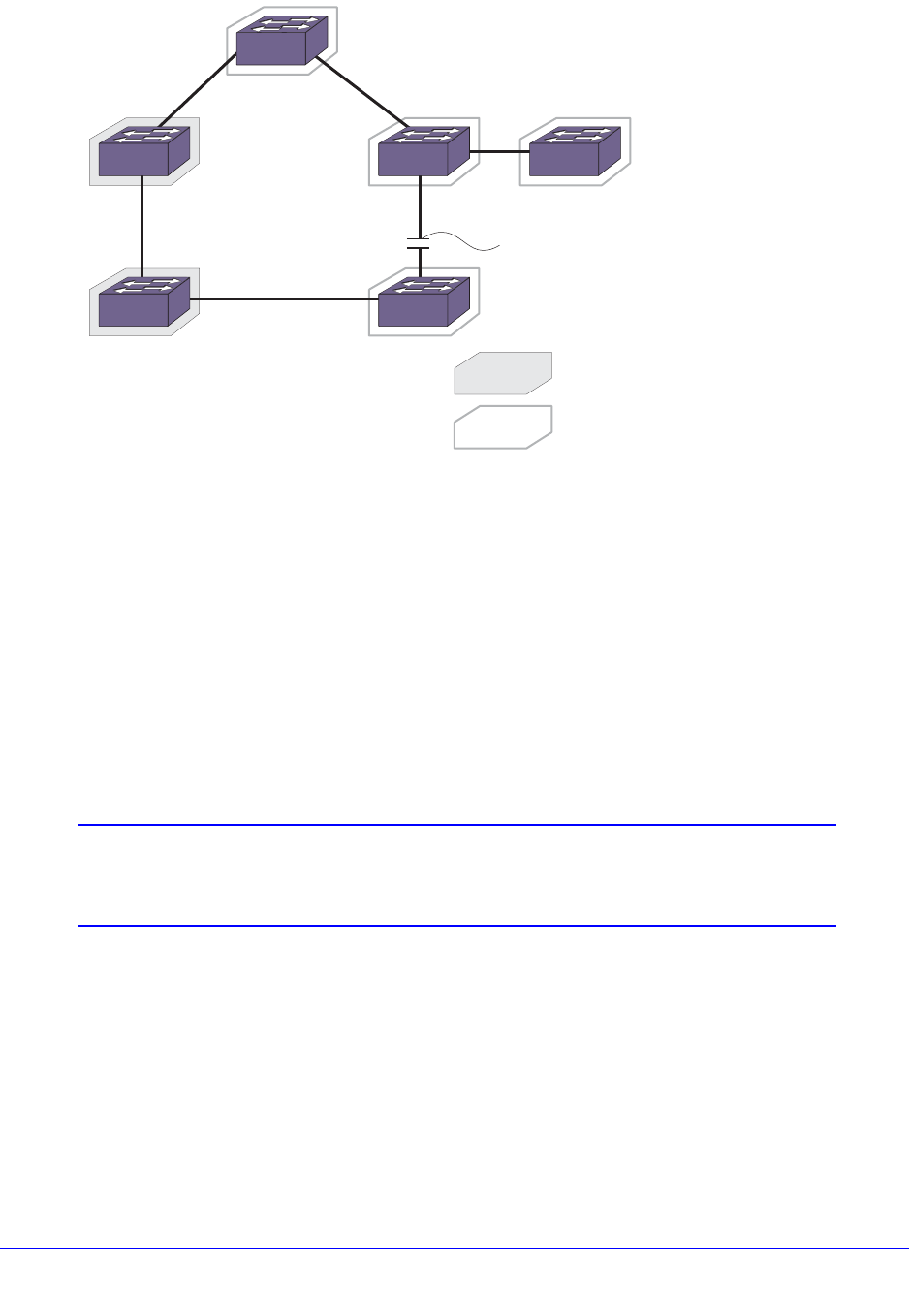
Chapter 18. STP | 521
NETGEAR 8800 User Manual
Figure 32. 802.1D-1998 and 802.1D-2004 Mixed Bridge Topology
If you use the default port path costs, bridge D blocks its port to bridge E, and all traffic
between bridges D and E must traverse all of bridges in the network. Bridge D blocks its port
to bridge E because the path cost to the root bridge is less by going across bridges B and C
(with a combined root cost of 38) compared with going across bridge E (with a root cost of
200,000). In fact, if there were 100 bridges between bridges B, C, and D running the old
802.1D-1998 standard with the default port path costs, bridge D would still use that path
because the path cost is still higher going across bridge E.
As a workaround and to prevent this situation, configure the port path cost to make links with
the same speed use the same path host value. In the example described above, configure
the port path cost for the 802.1D-2004 compliant bridges (bridges A, D, E, and F) to 19.
Note: You cannot configure the port path cost on bridges B and C to
200,000 because the path cost range setting for 802.1D-1998
compliant bridges is 1 to 65,535.
To configure the port path cost, use the following command:
configure stpd <stpd_name> ports cost [auto | <cost>] <port_list>
Bridge Priority
By configuring the STPD bridge priority, you make the bridge more or less likely to become
the root bridge. Unlike the 802.1D-1998 standard, the 802.1D-2004 standard restricts the
bridge priority to a 16-bit number that must be a multiple of 4,096. The new priority range is 0
to 61,440 and is subject to the multiple of 4,096 restriction. The old priority range was 0 to
EX_179
Switch A Root
bridge
Switch B
Switch C Switch D
Blocked
IEEE 802.1D-1998
IEEE 802.1D-2004
Switch E Switch F

522 | Chapter 18. STP
NETGEAR 8800 User Manual
65,535 and was not subject to the multiple of 4,096 restriction (except for MSTP
configurations). The default bridge priority remains the same at 32,768.
If you have a switch that contains an STP or RSTP bridge priority that is not a multiple of
4,096, the switch rejects the entry and the bridge priority returns to the default value while
loading the structure. The MSTP implementation in XCM8800 already uses multiples of 4,096
to determine the bridge priority.
To configure the bridge priority, use the following command:
configure stpd <stpd_name> priority <priority>
For example, to lower the numerical value of the priority (which gives the priority a higher
precedence), you subtract 4,096 from the default priority: 32,768 - 4,096 = 28,672. If you
modify the priority by a value other than 4,096, the switch automatically changes the priority
to the lower priority value. For example, if you configure a priority of 31,000, the switch
automatically changes the priority to 28,672.
Port Priority
The port priority value is always paired with the port number to make up the 16-bit port
identifier, which is used in various STP operations and the STP state machines. Unlike the
802.1D-1998 standard, the 802.1D-2004 standard uses only the four most significant bits for
the port priority and it must be a multiple of 16. The new priority range available is 0 to 240
and is subject to the multiple of 16 restriction. The 802.1D-1998 standard uses the eight most
significant bits for the port priority. The old priority range was 0 to 31 and was not subject to
the multiple of 16 restriction.
To preserve backward compatibility and to use 802.1D-1998 configurations, the existing
configure stpd ports priority command is available.
When you save the port priority value, the switch saves it as the command configure stpd
ports port-priority with the corresponding change in value.
For example, if the switch reads the configure stpd ports priority 16 command, (which is
equivalent to the command configure stpd ports priority 8 entered through CLI), the
switch saves the value as configure stpd ports port-priority 128.
Edge Port Behavior
In XCM8800, NETGEAR had two edge port implementations: edge port and edge port with
safeguard. The 802.1D-2004 standard has a bridge detection state machine, which
introduced a third implementation of edge port behavior. The following list describes the
behaviors of the different edge port implementations:
• Edge port:
• The port does not send BPDUs
• The port does not run a state machine
• If BPDUs are received, the port discards the BPDU and enters the blocking state
• If subsequent BPDUs are not received, the port remains in the forwarding state
• Edge port with safeguard configured:

Chapter 18. STP | 523
NETGEAR 8800 User Manual
• The port sends BPDUs
• When configured for MSTP, the port runs a partial state machine
• If BPDUs are received, the port enters the blocking state
• If subsequent BPDUs are not received, the port attempts to enter the forwarding state
• Edge port running 802.1D-2004 with safeguard enabled:
• The port sends BPDUs
• The port runs a state machine
• If BPDUs are received, the port behaves as a normal RSTP port by entering the
forwarding state and participating in RSTP
• If subsequent BPDUs are not received, the port attempts to become the edge port
again
Edge port with safeguard prevents accidental or deliberate misconfigurations (loops) by
having edge ports enter the blocking state upon receiving a BPDU. The 802.1D-2004
standard implements a bridge detection mechanism that causes an edge port to transition to
a non-edge port upon receiving a BPDU; however, if the former edge port does not receive
any subsequent BPDUs during a pre-determined interval, the port attempts to become an
edge port.
If an 802.1D-2004 compliant safeguard port (edge port) connects to an 802.1D-1998
compliant edge port with safeguard configured, the old safeguard port enters the blocking
state. Although the new safeguard port becomes a designated port, the link is not complete
(and thus no loop is formed) because one side of the link is blocked.
Restricted Role
In a large metro environment, to prevent external bridges from influencing the spanning tree
active topology, the following commands have been introduced for Rapid Spanning Tree
Protocol (RSTP) and Multiple Spanning Tree Protocol (MSTP).
• configure stpd <stpd_name> ports restricted-role enable <port_list>
• This command enables restricted role on a specified port in the core network to
prevent external bridges from influencing the spanning tree active topology.
• Restricted role should not be enabled with edge mode.
• stpd_name—Specifies an STPD name on the switch.
• port_list—Specifies one or more ports or slots and ports.
• Enabling restricted role causes a port to not be selected as a root port, even if it has
the best spanning tree priority vector. Such a port is selected as an alternate port after
the root port is selected. The restricted role is disabled by default. If set, it can cause
a lack of spanning tree connectivity.
• A network administrator enables restricted role to prevent external bridges from
influencing the spanning tree active topology.
• configure stpd <stpd_name> ports restricted-role disable <port_list>
• This command disables restricted role on a specified port in the core network.
• stpd_name—Specifies an STPD name on the switch.
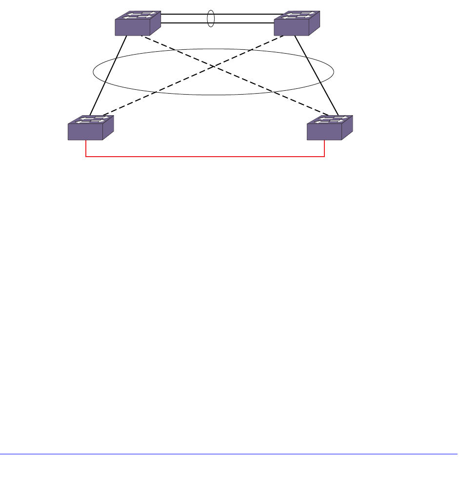
524 | Chapter 18. STP
NETGEAR 8800 User Manual
• port_list—Specifies one or more ports or slots and ports.
• Restricted role is disabled by default. If set, it can cause a lack of spanning tree
connectivity. A network administrator enables restricted role to prevent external
bridges from influencing the spanning tree active topology.
BPDU Restrict on Edge Safeguard
BPDU restrict causes a port on which this feature is configured to be disabled as soon as an
STP BPDU is received on that port thus allowing you to enforce the STP domain borders and
keep the active topology predictable.
Figure 33 shows a BPDU restrict example.
Figure 33. BPDU Restrict
In this figure, loops on the LAN access switches are not prevented since the ports towards
the distribution switches are not running STP but Software Redundant Ports (SRP).
Currently, XCM8800 software cannot run STP on ports that are configured for SRP. STP on
the access switch is unaware of the alternate path and therefore cannot prevent the loop that
exists across the switches. Configuring a port as an edge mode port alone cannot prevent the
loop between the switches because edge ports never send BPDUs. The edge safeguard
feature is not able to prevent the loops because STP does not have the information about the
alternate path.
To prevent the loops across the switches, the edge safeguard feature can be configured with
the BPDU restrict function. When running in BPDU restrict mode, edge safeguard ports send
STP BPDUs at a rate of 1 every 2 seconds. The port is disabled as soon as an STP BPDU is
received on the BPDU restrict port, thereby preventing the loop. Flexibility is provided with an
option to re-enable the port after a user specified time period. If a user enables a port while
STP has disabled it, the port is operationally enabled; STP is notified and then stops any
recovery timeout that has started.
EX_stp_0181
Distribution
Access
BPDU
Restrict Enabled
Edge Port
BPDU
Restrict Enabled
Edge Port
Switch C Switch D
SRP
Loop
SRP
Switch A Switch B

Chapter 18. STP | 525
NETGEAR 8800 User Manual
When an STPD is disabled for a BPDU restrict configured port, an STP port in 802.1D
operation mode begins forwarding immediately, but in the RSTP or MSTP operation modes,
the port remains in the disabled state.
BPDU restrict is available on all of the three operational modes of STP: 802.1D, RSTP, and
MSTP.
Although edge safeguard is not available in 802.1D operation mode, when you configure
BPDU restrict you do so in a similar way, that is, as an extension of edge safeguard; then
only BPDU restrict is available on the port and not edge safeguard.
To configure BPDU restrict, use the following command:
configure {stpd} <stpd_name> ports edge-safeguard enable <port_list>
{bpdu-restrict} {recovery-timeout {<seconds>}}
BPDU restrict can also be configured by using the following commands:
configure {stpd} <stpd_name> ports bpdu-restrict [enable | disable] <port_list>
{recovery-timeout {<seconds>}}
configure stpd <stpd_name> ports link-type [[auto | broadcast | point-to-point]
<port_list> | edge <port_list> {edge-safeguard [enable | disable]
{bpdu-restrict} {recovery-timeout <seconds>}}]
To include BPDU restrict functionality when configuring link types or edge safeguard, see
Configuring Link Types on page 547 and Configuring Edge Safeguard on page 548.
Following shows a BPDU restrict configuration:
* XCM8806.1# configure s1 ports edge-safeguard enable 9 bpdu-restrict
recovery-timeout 400.
Following is sample output from the show s1 ports command resulting from the
configuration:
XCM8806.35 # show s1 ports
Port Mode State Cost Flags Priority Port ID Designated Bridge
9 EMISTP FORWARDING 20000 eDee-w-G-- 128 8009 80:00:00:04:96:26:5f:4e
Total Ports: 1
------------------------- Flags: ----------------------------
1: e=Enable, d=Disable
2: (Port role) R=Root, D=Designated, A=Alternate, B=Backup, M=Master
3: (Config type) b=broadcast, p=point-to-point, e=edge, a=auto
4: (Oper. type) b=broadcast, p=point-to-point, e=edge
5: p=proposing, a=agree
6: (partner mode) d = 802.1d, w = 802.1w, m = mstp
7: i = edgeport inconsistency
8: S = edgeport safe guard active
s = edgeport safe guard configured but inactive
8: G = edgeport safe guard bpdu restrict active in 802.1w and mstp
g = edgeport safe guard bpdu restrict active in 802.1d
9: B = Boundary, I = Internal
10: r = Restricted Role

526 | Chapter 18. STP
NETGEAR 8800 User Manual
XCM8806.5 # show configuration stp
#
# Module stp configuration.
#
configure mstp region 000496265f4e
configure stpd s0 delete vlan default ports all
disable stpd s0 auto-bind vlan default
create stpd s1
configure stpd s1 mode dot1w
enable stpd s0 auto-bind vlan Default
configure stpd s1 add vlan v1 ports 9 emistp
configure stpd s1 ports mode emistp 9
configure stpd s1 ports cost auto 9
configure stpd s1 ports port-priority 128 9
configure stpd s1 ports link-type edge 9
configure stpd s1 ports edge-safeguard enable 9 recovery-timeout 400
configure stpd s1 ports bpdu-restrict enable 9 recovery-timeout 400
enable stpd s1 ports 9
configure stpd s1 tag 10
enable stpd s1
Following is sample output for STP operation mode dot1d from the show configuration
"stp" command:
XCM8806.22 # show configuration stp
#
# Module stp configuration.
#
configure mstp region region2
configure stpd s0 delete vlan default ports all
disable stpd s0 auto-bind vlan default
create stpd s1
enable stpd s0 auto-bind vlan Default
configure stpd s1 add vlan v1 ports 9 emistp
configure stpd s1 ports mode emistp 9
configure stpd s1 ports cost auto 9
configure stpd s1 ports priority 16 9
configure stpd s1 ports link-type edge 9
configure stpd s1 ports edge-safeguard enable 9 recovery-timeout 400
configure stpd s1 ports bpdu-restrict enable 9 recovery-timeout 400
enable stpd s1 ports 9
configure stpd s1 tag 10
enable stpd s1
Spanning Tree Domains
The switch can be partitioned into multiple virtual bridges. Each virtual bridge can run an
independent Spanning Tree instance. Each Spanning Tree instance is called a Spanning Tree

Chapter 18. STP | 527
NETGEAR 8800 User Manual
Domain (STPD). Each STPD has its own root bridge and active path. After an STPD is
created, one or more VLANs can be assigned to it.
A physical port can belong to multiple STPDs. In addition, a VLAN can span multiple STPDs.
The key points to remember when configuring VLANs and STP are:
• Each VLAN forms an independent broadcast domain.
• STP blocks paths to create a loop-free environment.
• Within any given STPD, all VLANs belonging to it use the same spanning tree.
To create an STPD, use the following command:
create stpd <stpd_name>
To delete an STPD, use the following command:
delete stpd <stpd_name>
For detailed information about configuring STP and various STP parameters on the switch,
see Configuring STP on the Switch on page 572.
The remainder of this section describes the following topics:
• Member VLANs on page 527
• STPD Modes on page 529
• Encapsulation Modes on page 530
• STP States on page 531
• Binding Ports on page 532
• Rapid Root Failover on page 534
• STPD BPDU Tunneling on page 535
• STP and Hitless Failover—Modular Switches Only on page 537
Member VLANs
When you add a VLAN to an STPD, that VLAN becomes a member of the STPD. The two
types of member VLANs in an STPD are:
• Carrier
• Protected
Carrier VLAN
A carrier VLAN defines the scope of the STPD, which includes the physical and logical ports
that belong to the STPD and if configured, the 802.1Q tag used to transport Multiple Instance
Spanning Tree Protocol (EMISTP) or Per VLAN Spanning Tree (PVST+) encapsulated bridge
protocol data units (BPDUs) (see Encapsulation Modes on page 530 for more information
about encapsulating STP BPDUs). Only one carrier VLAN can exist in a given STPD,
although some of its ports can be outside the control of any STPD at the same time.

528 | Chapter 18. STP
NETGEAR 8800 User Manual
If you configure EMISTP or PVST+, the STPD ID must be identical to the VLAN ID of the
carrier VLAN in that STPD. See Specifying the Carrier VLAN on page 528 for an example.
If you have an 802.1D configuration, NETGEAR recommends that you configure the StpdID
to be identical to the VLAN ID of the carrier VLAN in that STPD. See Basic 802.1D
Configuration Example on page 575 for an example.
If you configure Multiple Spanning Tree (MSTP—IEEE 802.1Q-2003, formerly IEEE 802.1s)
you do not need carrier VLANs for MSTP operation. With MSTP, you configure a Common
and Internal Spanning Tree (CIST) that controls the connectivity of interconnecting MSTP
regions and sends BPDUs across the regions to communicate the status of MSTP regions.
All VLANs participating in the MSTP region have the same privileges. For more information
about MSTP, see Multiple Spanning Tree Protocol on page 557.
Protected VLAN
Protected VLANs are all other VLANs that are members of the STPD. These VLANs
“piggyback” on the carrier VLAN. Protected VLANs do not transmit or receive STP BPDUs,
but they are affected by STP state changes and inherit the state of the carrier VLAN.
Protected VLANs can participate in multiple STPDs, but any particular port in the VLAN can
belong to only one STPD. Also known as non-carrier VLANs.
If you configure MSTP, all member VLANs in an MSTP region are protected VLANs. These
VLANs do not transmit or receive STP BPDUs, but they are affected by STP state changes
communicated by the CIST to the MSTP regions. Multiple spanning tree instances (MSTIs)
cannot share the same protected VLAN; however, any port in a protected VLAN can belong
to multiple MSTIs. For more information about MSTP, see Multiple Spanning Tree Protocol on
page 557.
Specifying the Carrier VLAN
The following example:
• Creates and enables an STPD named s8.
• Creates a carrier VLAN named v5.
• Assigns VLAN v5 to STPD s8.
• Creates the same tag ID for the VLAN and the STPD (the carrier VLAN’s ID must be
identical to the STPD’s ID).
create vlan v5
configure vlan v5 tag 100
configure vlan v5 add ports 1:1-1:20 tagged
create stpd s8
configure stpd s8 add vlan v5 ports all emistp
configure stpd s8 tag 100
enable stpd s8
Notice how the tag number for the VLAN v5 and the STPD s8 is identical (the tag is 100). By
using identical tags, you have selected the carrier VLAN. The carrier VLAN’s ID is identical to
the STPD’s ID.

Chapter 18. STP | 529
NETGEAR 8800 User Manual
STPD Modes
An STPD has three modes of operation:
• 802.1D mode
Use this mode for backward compatibility with previous STP versions and for
compatibility with third-party switches using IEEE standard 802.1D. When configured in
this mode, all rapid configuration mechanisms are disabled.
• 802.1w mode
Use this mode for compatibility with Rapid Spanning Tree (RSTP). When configured in
this mode, all rapid configuration mechanisms are enabled. The benefit of this mode is
available on point-to-point links only and when the peer is likewise configured in 802.1w
mode. If you do not select point-to-point links and the peer is not configured for 802.1w
mode, the STPD fails back to 802.1D mode.
You enable or disable RSTP on a per STPD basis only. You do not enable RSTP on a per
port basis.
For more information about RSTP and RSTP features, see Rapid Spanning Tree Protocol
on page 545.
• MSTP mode
Use this mode for compatibility with MSTP. MSTP is an extension of RSTP and offers the
benefit of better scaling with fast convergence. When configured in this mode, all rapid
configuration mechanisms are enabled. The benefit of MSTP is available only on
point-to-point links and when you configure the peer in MSTP or 802.1w mode. If you do
not select point-to-point links and the peer is not configured in 802.1w mode, the STPD
fails back to 802.1D mode.
You must first configure a CIST before configuring any MSTIs in the region. You cannot
delete or disable a CIST if any of the MSTIs are active in the system.
You create only one MSTP region on the switch, and all switches that participate in the
region must have the same regional configurations. You enable or disable an MSTP on a
per STPD basis only. You do not enable MSTP on a per port basis.
If configured in MSTP mode, an STPD uses the 802.1D BPDU encapsulation mode by
default. To ensure correct operation of your MSTP STPDs, do not configure EMISTP or
PVST+ encapsulation mode for MSTP STPDs.
For more information about MSTP and MSTP features, see Multiple Spanning Tree
Protocol on page 557.
By default:
• The STPD operates in 802.1D mode.
• The default device configuration contains a single STPD called s0.
• The default VLAN is a member of STPD s0 with autobind enabled.
To configure the mode of operation of an STPD, use the following command:

530 | Chapter 18. STP
NETGEAR 8800 User Manual
configure stpd <stpd_name> mode [dot1d | dot1w | mstp [cist | msti <instance>]]
All STP parameters default to the IEEE 802.1D values, as appropriate.
Encapsulation Modes
You can configure ports within an STPD to accept specific BPDU encapsulations. This STP
port encapsulation is separate from the STP mode of operation. For example, you can
configure a port to accept the PVST+ BPDU encapsulation while running in 802.1D mode.
An STP port has three possible encapsulation modes:
• 802.1D mode
Use this mode for backward compatibility with previous STP versions and for compatibility
with third-party switches using IEEE standard 802.1D. BPDUs are sent untagged in
802.1D mode. Because of this, any given physical interface can have only one STPD
running in 802.1D mode.
This encapsulation mode supports the following STPD modes of operation: 802.1D,
802.1w, and MSTP.
• Multiple Instance Spanning Tree Protocol (EMISTP) mode
EMISTP mode is proprietary to NETGEAR and is an extension of STP that allows a
physical port to belong to multiple STPDs by assigning the port to multiple VLANs.
EMISTP adds significant flexibility to STP network design. BPDUs are sent with an
802.1Q tag having an STPD instance Identifier (STPD ID) in the VLAN ID field.
This encapsulation mode supports the following STPD modes of operation: 802.1D and
802.1w.
• Per VLAN Spanning Tree (PVST+) mode
This mode implements PVST+ in compatibility with third-party switches running this
version of STP. The STPDs running in this mode have a one-to-one relationship with
VLANs and send and process packets in PVST+ format.
This encapsulation mode supports the following STPD modes of operation: 802.1D and
802.1w.
These encapsulation modes are for STP ports, not for physical ports. When a physical port
belongs to multiple STPDs, it is associated with multiple STP ports. It is possible for the
physical port to run in different modes for different domains to which it belongs.
If configured in MSTP mode, an STPD uses the 802.1D BPDU encapsulation mode by
default. To ensure correct operation of your MSTP STPDs, do not configure EMISTP or
PVST+ encapsulation mode for MSTP STPDs.
To configure the BPDU encapsulation mode for one or more STP ports, use the following
command:
configure stpd <stpd_name> ports mode [dot1d | emistp | pvst-plus] <port_list>

Chapter 18. STP | 531
NETGEAR 8800 User Manual
To configure the default BPDU encapsulation mode on a per STPD basis, use the following
command:
configure stpd <stpd_name> default-encapsulation [dot1d | emistp | pvst-plus]
Instead of accepting the default encapsulation modes of dot1d for the default STPD s0 and
emistp for all other STPDs, this command allows you to specify the type of BPDU
encapsulation to use for all ports added to the STPD (if not otherwise specified).
STPD Identifier
An StpdID is used to identify each STP domain. You assign the StpdID when configuring the
domain, and that carrier VLAN of that STPD cannot belong to another STPD. Unless all ports
are running in 802.1D mode, an STPD with ports running in either EMISTP mode or PVST+
mode must be configured with an StpdID.
An StpdID must be identical to the VLAN ID of the carrier VLAN in that STP domain. For an
802.1D STPD, the VLAN ID can be either a user-defined ID or one automatically assigned by
the switch.
Note: If an STPD contains at least one port not in 802.1D mode, you must
configure the STPD with an StpdID.
MSTP uses two different methods to identify the STPDs that are part of the MSTP network.
An instance ID of 0 identifies the CIST. The switch assigns this ID automatically when you
configure the CIST STPD. An MSTI identifier (MSTI ID) identifies each STP domain that is
part of an MSTP region. You assign the MSTI ID when configuring the STPD that participates
in the MSTP region. In an MSTP region, MSTI IDs only have local significance. You can
reuse MSTI IDs across MSTP regions. For more information about MSTP and MSTP
features, see Multiple Spanning Tree Protocol on page 557.
STP States
Each port that belongs to a member VLAN participating in STP exists in one of the following
states:
• Blocking
A port in the blocking state does not accept ingress traffic, perform traffic forwarding, or
learn MAC source addresses. The port receives STP BPDUs. During STP initialization,
the switch always enters the blocking state.
• Listening
A port in the listening state does not accept ingress traffic, perform traffic forwarding, or
learn MAC source addresses. The port receives STP BPDUs. This is the first transitional
state a port enters after being in the blocking state. The bridge listens for BPDUs from
neighboring bridge(s) to determine whether the port should or should not be blocked.

532 | Chapter 18. STP
NETGEAR 8800 User Manual
• Learning
A port in the learning state does not accept ingress traffic or perform traffic forwarding, but
it begins to learn MAC source addresses. The port also receives and processes STP
BPDUs. This is the second transitional state after listening. From learning, the port will
change to either blocking or forwarding.
• Forwarding
A port in the forwarding state accepts ingress traffic, learns new MAC source addresses,
forwards traffic, and receives and processes STP BPDUs.
• Disabled
A port in the disabled state does not participate in STP; however, it will forward traffic and
learn new MAC source addresses.
Binding Ports
The two ways to bind (add) ports to an STPD are: manually and automatically. By default,
ports are manually added to an STPD.
Note: The default VLAN and STPD S0 are already on the switch.
Manually Binding Ports
To manually bind ports, use one of the following commands:
• configure stpd <stpd_name> add vlan <vlan_name> ports [all | <port_list>] {[dot1d
| emistp | pvst-plus]}
• configure vlan <vlan_name> add ports [all | <port_list>] {tagged | untagged} stpd
<stpd_name> {[dot1d | emistp | pvst-plus]}
The first command adds all ports or a list of ports within the specified VLAN to an STPD. For
EMISTP and PVST+, the carrier VLAN must already exist on the same set of ports. The
second command adds all ports or a list of ports to the specified VLAN and STPD at the
same time. If the ports are added to the VLAN but not to the STPD, the ports remain in the
VLAN.
For EMISTP and PVST+, if the specified VLAN is not the carrier VLAN and the specified
ports are not bound to the carrier VLAN, the system displays an error message. If you
configure MSTP on your switch, MSTP does not need carrier VLANs.
Note: The carrier VLAN’s ID must be identical to the ID of the STP domain.

Chapter 18. STP | 533
NETGEAR 8800 User Manual
If you add a protected VLAN or port, that addition inherits the carrier VLAN’s encapsulation
mode unless you specify the encapsulation mode when you execute the configure stpd add
vlan or configure vlan add ports stpd commands. If you specify an encapsulation mode
(dot1d, emistp, or pvst-plus), the STP port mode is changed to match; otherwise, the STP
port inherits either the carrier VLANs encapsulation mode on that port or the STPD’s default
encapsulation mode.
For MSTP, you do not need carrier a VLAN. A CIST controls the connectivity of
interconnecting MSTP regions and sends BPDUs across the regions to communicate region
status. You must use the dot1d encapsulation mode in an MSTP environment. For more
information about MSTP, see the section Multiple Spanning Tree Protocol on page 557.
To remove ports, use the following command:
configure stpd <stpd_name> delete vlan <vlan_name> ports [all | <port_list>]
If you manually delete a protected VLAN or port, only that VLAN or port is removed. If you
manually delete a carrier VLAN or port, all VLANs on that port (both carrier and protected)
are deleted from that STPD.
To learn more about member VLANs, see Member VLANs on page 527. For more detailed
information about these command line interface (CLI) commands, see the NETGEAR 8800
Chassis Switch CLI Manual.
Automatically Binding Ports
To automatically bind ports to an STPD when the ports are added to a VLAN, use the
following command:
enable stpd <stpd_name> auto-bind vlan <vlan_name>
The autobind feature is disabled on user-created STPDs. The autobind feature is enabled on
the default VLAN that participates in the default STPD S0.
For EMISTP or PVST+, when you issue this command, any port or list of ports that you add
to the carrier VLAN are automatically added to the STPD with autobind enabled. In addition,
any port or list of ports that you remove from a carrier VLAN are automatically removed from
the STPD. This feature allows the STPD to increase or decrease its span as ports are added
to or removed from a carrier VLAN.
Note: The carrier VLAN’s ID must be identical to the ID of the STP
domain.
Enabling autobind on a protected VLAN does not expand the boundary of the STPD. If the
same set of ports are members of the protected VLAN and the carrier VLAN, protected
VLANs are aware of STP state changes. For example, assume you have the following
scenario:
• Carrier VLAN named v1
• v1 contains ports 3:1-3:2

534 | Chapter 18. STP
NETGEAR 8800 User Manual
• Protected VLAN named v2
• v2 contains ports 3:1-3:4
Since v1 contains ports 3:1-3:2, v2 is aware only of the STP changes for ports 3:1 and 3:2,
respectively. Ports 3:3 and 3:4 are not part of the STPD, which is why v2 is not aware of any
STP changes for those ports.
In addition, enabling autobind on a protected VLAN causes ports to be automatically added
or removed as the carrier VLAN changes.
For MSTP, when you issue this command, any port or list of ports that gets automatically
added to an MSTI are automatically inherited by the CIST. In addition, any port or list of ports
that you remove from an MSTI protected VLAN are automatically removed from the CIST. For
more information, see Automatically Inheriting Ports—MSTP Only on page 534.
To remove ports, use the following command:
configure stpd <stpd_name> delete vlan <vlan_name> ports [all | <port_list>]
If you manually delete a port from the STPD on a VLAN that has been added by autobind,
XCM8800 records the deletion so that the port does not get automatically added to the STPD
after a system restart.
To learn more about the member VLANs, see Member VLANs on page 527. For more
detailed information about these CLI commands, see the NETGEAR 8800 Chassis Switch
CLI Manual.
Automatically Inheriting Ports—MSTP Only
In an MSTP environment, whether you manually or automatically bind a port to an MSTI in an
MSTP region, the switch automatically binds that port to the CIST. The CIST handles BPDU
processing for itself and all of the MSTIs; therefore, the CIST must inherit ports from the
MSTIs in order to transmit and receive BPDUs. You can only delete ports from the CIST if it is
no longer a member of an MSTI.
For more information about MSTP, see Multiple Spanning Tree Protocol on page 557.
Rapid Root Failover
XCM8800 supports rapid root failover for faster STP failover recovery times in STP 802.1D
mode. If the active root port link goes down, XCM8800 recalculates STP and elects a new
root port. The rapid root failover feature allows the new root port to immediately begin
forwarding, skipping the standard listening and learning phases. Rapid root failover occurs
only when the link goes down and not when there is any other root port failure, such as
missing BPDUs.
The default setting for this feature is disabled. To enable rapid root failover, use the following
command:
enable stpd <stpd_name> rapid-root-failover
To display the configuration, use the following command:
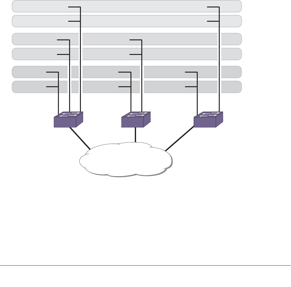
Chapter 18. STP | 535
NETGEAR 8800 User Manual
show stpd {<stpd_name> | detail}
STPD BPDU Tunneling
You can configure XCM8800 to allow a BPDU to traverse a VLAN without being processed
by STP. This is known as BPDU tunneling. There are differences in how to configure this
behavior in XCM8800. The examples in this section show how you might have used this
feature in NETGEAR 8800 and how to configure STPD BPDU tunneling with XCM8800.
You may be more familiar configuring STPD BPDU tunneling on NETGEAR devices. In the
NETGEAR 8800, you specify the VLAN to add to the STPD and then you “ignore” the STP
BPDUs. By ignoring the STP BPDUs, the switch prevents the ports in the VLAN from
becoming part of the STPD. In XCM8800, you specify the VLAN to add to the STPD and then
you disable that STPD. By disabling the STPD, the switch allows the ports associated with
the VLAN to continue passing traffic and the switch forwards the BPDUs without adding any
STP information.
Figure 34. Sample Network Using STPD BPDU Tunneling
The examples described below assume you have already done the following:
• Created the VLANs v1, v2, and v3
• Configured the VLAN tags
• Created the STPDs s1, s2, and s3
• Configured the STPD tags
EX_180
1:1 1:2 1:3 1:1 1:2 1:1 1:3
Service provider L2
2:1 2:1 2:1
VLAN 1
STPD 1
VLAN 2
STPD 2
VLAN 3
STPD 3
Switch A Switch B Switch C

536 | Chapter 18. STP
NETGEAR 8800 User Manual
• Configured the mode of operation for the STPD
• Configured the STP ports
• Enabled STPD
The following example shows how to configure STPD BPDU tunneling on devices running
XCM8800:
Switch A
enable ignore-bpdu vlan v1
enable ignore-bpdu vlan v2
enable ignore-bpdu vlan v3
configure vlan v1 add ports 1:1,2:1 tagged stpd s1
configure vlan v2 add ports 1:2,2:1 tagged stpd s2
configure vlan v3 add ports 1:3,2:1 tagged stpd s3
Switch B
enable ignore-bpdu vlan v1
enable ignore-bpdu vlan v2
configure vlan v1 add ports 1:1,2:1 tagged stpd s1
configure vlan v2 add ports 1:2,2:1 tagged stpd s2
Switch C
enable ignore-bpdu vlan v1
enable ignore-bpdu vlan v3
configure vlan v1 add ports 1:1,2:1 tagged stpd s1
configure vlan v3 add ports 1:3,2:1 tagged stpd s3
The following example shows how to configure STPD BPDU tunneling on devices running
XCM8800:
Switch A
configure vlan v1 add ports 1:1,2:1 tagged
configure vlan v2 add ports 1:2,2:1 tagged
configure vlan v3 add ports 1:3,2:1 tagged
configure stpd s1 add vlan v1 ports 1:1
configure stpd s2 add vlan v2 ports 1:2
configure stpd s3 add vlan v3 ports 1:3
disable s1
disable s2
disable s3
Switch B
configure vlan v1 add ports 1:1,2:1 tagged
configure vlan v2 add ports 1:2,2:1 tagged
configure stpd s1 add vlan v1 ports 1:1

Chapter 18. STP | 537
NETGEAR 8800 User Manual
configure stpd s2 add vlan v2 ports 1:2
disable s1
disable s2
Switch C
configure vlan v1 add ports 1:1,2:1 tagged
configure vlan v3 add ports 1:3,2:1 tagged
configure stpd s1 add vlan v1 ports 1:1
configure stpd s3 add vlan v3 ports 1:3
disable s1
disable s3
STP and Hitless Failover—Modular Switches Only
When you install two management modules (MSM/MM) in a NETGEAR 8800 chassis, one
node assumes the role of primary and the other node assumes the role of backup. The
primary executes the switch’s management functions, and the backup acts in a standby role.
Hitless failover transfers switch management control from the primary to the backup and
maintains the state of STP. STP supports hitless failover. You do not explicitly configure
hitless failover support; rather, if you have two nodes installed, hitless failover is available.
Note: Not all platforms support hitless failover in the same software
release. For more information about protocol, platform, and
MSM/MM support for hitless failover, see Understanding Hitless
Failover Support on page 69.
To support hitless failover, the primary node replicates STP BPDUs to the backup, which
allows the nodes to run STP in parallel. Although both primary and backup node receive STP
BPDUs, only the primary transmits STP BPDUs to neighboring switches and participates in
STP.
Note: Before initiating failover, review the section Synchronizing Nodes on
Modular Switches on page 825 to confirm that both primary and
backup nodes are running software that supports the synchronize
command.
To initiate hitless failover on a network that uses STP:
1. Confirm that the nodes are synchronized and have identical software and switch
configurations using the show switch {detail} command. The output displays the
status of the primary and backup nodes, with the primary node showing MASTER and the
backup node showing BACKUP (InSync).

538 | Chapter 18. STP
NETGEAR 8800 User Manual
• If the primary and backup nodes are not synchronized and both nodes are running a
version of XCM8800 that supports synchronization, proceed to step 2.
• If the primary and backup nodes are synchronized, proceed to step 3.
2. If the primary and backup nodes are not synchronized, use the synchronize command to
replicate all saved images and configurations from the primary to the backup.
After you confirm the nodes are synchronized, proceed to step 3.
3. If the nodes are synchronized, use the run failover (formerly run msm-failover) command
to initiate failover.
For more detailed information about verifying the status of the primary and backup nodes,
and system redundancy, see Understanding System Redundancy on page 64. For more
information about hitless failover, see Understanding Hitless Failover Support on page 69.
STP Configurations
When you assign VLANs to an STPD, pay careful attention to the STP configuration and its
effect on the forwarding of VLAN traffic.
This section describes three types of STP configurations:
• Basic STP
• Multiple STPDs on a single port (which uses EMISTP)
• A VLAN that spans multiple STPDs
Basic STP Configuration
This section describes a basic, 802.1D STP configuration. Figure 35 illustrates a network
that uses VLAN tagging for trunk connections. The following four VLANs have been defined:
• Sales is defined on switch A, switch B, and switch M.
• Personnel is defined on switch A, switch B, and switch M.
• Manufacturing is defined on switch Y, switch Z, and switch M.
• Engineering is defined on switch Y, switch Z, and switch M.
• Marketing is defined on all switches (switch A, switch B, switch Y, switch Z, and switch M).
Two STPDs are defined:
• STPD1 contains VLANs Sales and Personnel.
• STPD2 contains VLANs Manufacturing and Engineering.
The carrier and protected VLANs are also defined:
• Sales is the carrier VLAN on STPD1.
• Personnel is a protected VLAN on STPD1.
• Manufacturing is a protected VLAN on STPD2.
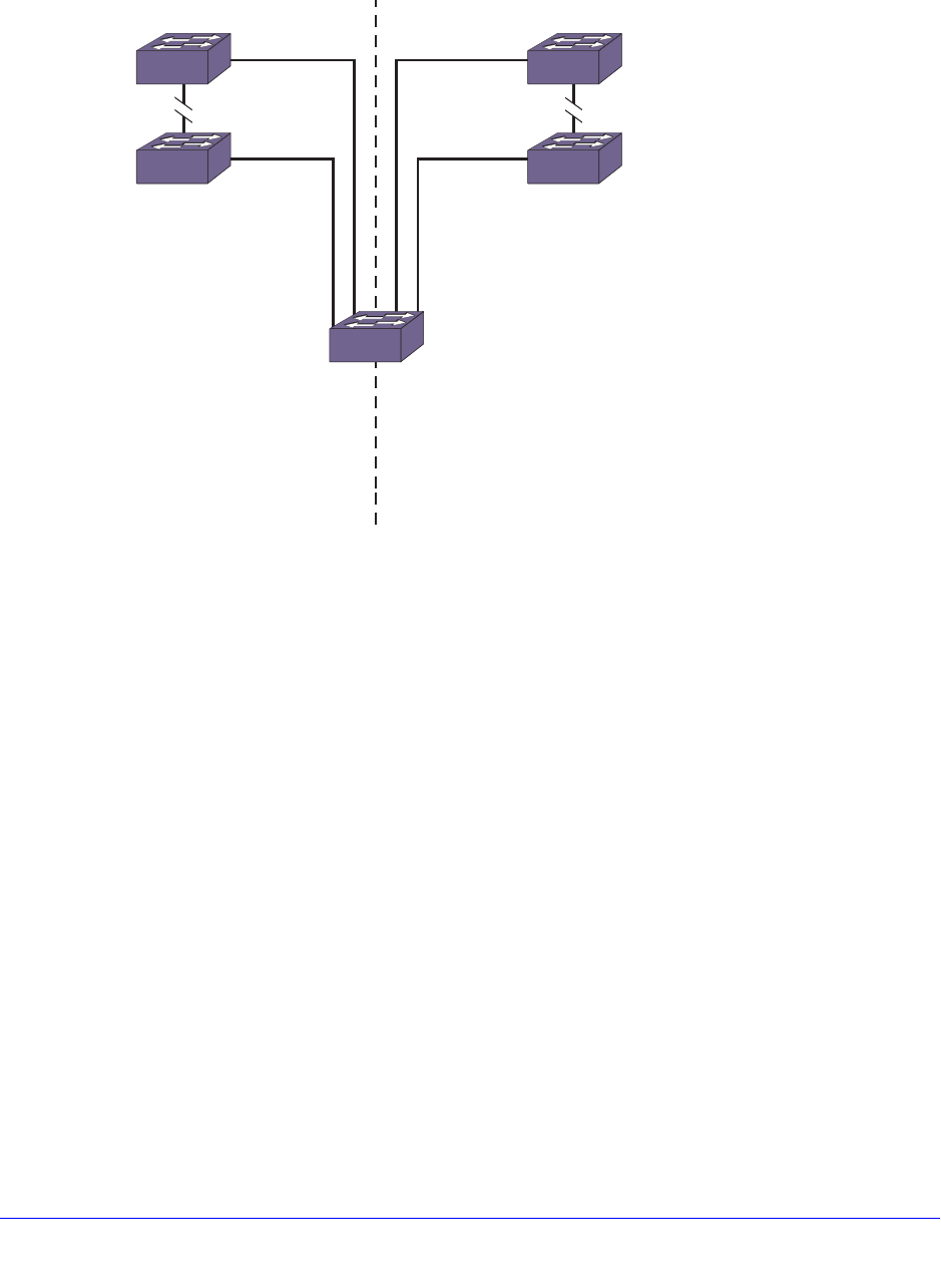
Chapter 18. STP | 539
NETGEAR 8800 User Manual
• Engineering is the carrier VLAN on STPD2.
• Marketing is a member of both STPD1 and STPD2 and is a protected VLAN.
Figure 35. Multiple STPDs
When the switches in this configuration boot-up, STP configures each STPD such that the
topology contains no active loops. STP could configure the topology in a number of ways to
make it loop-free.
In Figure 35, the connection between switch A and switch B is put into blocking state, and
the connection between switch Y and switch Z is put into blocking state. After STP
converges, all the VLANs can communicate, and all bridging loops are prevented.
The protected VLAN Marketing, which has been assigned to both STPD1 and STPD2,
communicates using all five switches. The topology has no loops, because STP has already
blocked the port connection between switch A and switch B and between switch Y and switch
Z.
Within a single STPD, you must be extra careful when configuring your VLANs. Figure 36
illustrates a network that has been incorrectly set up using a single STPD so that the STP
configuration disables the ability of the switches to forward VLAN traffic.
Sales, Personnel, Marketing
STPD 1 STPD 2
Manufacturing, Engineering, Marketing
Sales, Personnel, Manufacturing, Engineering, Marketing
Switch Y
Switch Z
Switch M
Switch B
EX_048
Switch A

540 | Chapter 18. STP
NETGEAR 8800 User Manual
Figure 36. Incorrect Tag-Based STPD Configuration
The tag-based network in Figure 36 has the following configuration:
• Switch 1 contains VLAN Marketing and VLAN Sales.
• Switch 2 contains VLAN Engineering and VLAN Sales.
• Switch 3 contains VLAN Marketing, VLAN Engineering, and VLAN Sales.
• The tagged trunk connections for three switches form a triangular loop that is not
permitted in an STP topology.
• All VLANs in each switch are members of the same STPD.
STP can block traffic between switch 1 and switch 3 by disabling the trunk ports for that
connection on each switch.
Switch 2 has no ports assigned to VLAN Marketing. Therefore, if the trunk for VLAN
Marketing on switches 1 and 3 is blocked, the traffic for VLAN Marketing will not be able to
traverse the switches.
Note: If an STPD contains multiple VLANs, all VLANs should be
configured on all ports in that domain, except for ports that connect
to hosts (edge ports).
Multiple STPDs on a Port
Traditional 802.1D STP has some inherent limitations when addressing networks that have
multiple VLANs and multiple STPDs. For example, consider the sample depicted in
Figure 37.
Marketing & Sales Marketing, Sales & Engineering
Switch 1 Switch 3
Switch 2
EX_049
Sales & Engineering
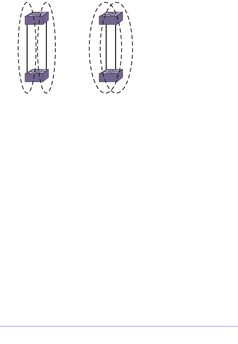
Chapter 18. STP | 541
NETGEAR 8800 User Manual
Figure 37. Limitations of Traditional STPD
The two switches are connected by a pair of parallel links. Both switches run two VLANs, A
and B. To achieve load-balancing between the two links using the traditional approach, you
would have to associate A and B with two different STPDs, called S1 and S2, respectively,
and make the left link carry VLAN A traffic while the right link carries VLAN B traffic (or vice
versa). If the right link fails, S2 is broken and VLAN B traffic is disrupted.
To optimize the solution, you can use the Multiple Instance Spanning (EMISTP) mode, which
allows a port to belong to multiple STPDs. EMISTP adds significant flexibility to STP network
design. Referring to Figure 37, using EMISTP, you can configure all four ports to belong to
both VLANs.
Assuming that S1 and S2 still correspond to VLANs A and B, respectively, you can fine-tune
STP parameters to make the left link active in S1 and blocking in S2, while the right link is
active in S2 and blocking in S1. Again, if the right link fails, the left link is elected active by the
STP algorithm for S2, without affecting normal switching of data traffic.
Using EMISTP, an STPD becomes more of an abstract concept. The STPD does not
necessarily correspond to a physical domain; it is better regarded as a vehicle to carry
VLANs that have STP instances. Because VLANs can overlap, so do STPDs. However, even
if the different STPDs share the entire topology or part of the redundant topology, the STPDs
react to topology change events in an independent fashion.
VLANs Spanning Multiple STPDs
Traditionally, the mapping from VLANs to STP instances have been one-to-one or
many-to-one. In both cases, a VLAN is wholly contained in a single instance. In practical
deployment there are cases in which a one-to-many mapping is desirable. In a typical large
enterprise network, for example, VLANs span multiple sites and/or buildings. Each site
represents a redundant looped area. However, between any two sites the topology is usually
very simple.
Alternatively, the same VLAN may span multiple large geographical areas (because they
belong to the same enterprise) and may traverse a great many nodes. In this case, it is
EX_050
S1 S2
A
A
B
B
S1 S2
A
A
B
B
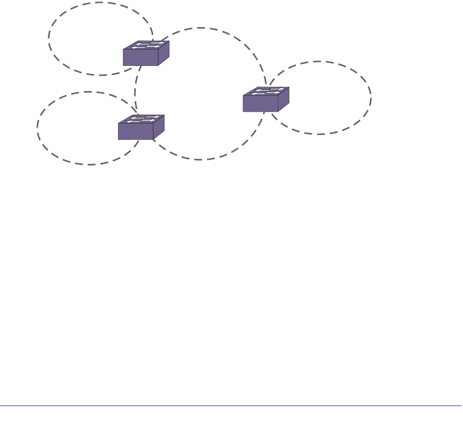
542 | Chapter 18. STP
NETGEAR 8800 User Manual
desirable to have multiple STP domains operating in a single VLAN, one for each looped
area.
The justifications include the following:
• The complexity of the STP algorithm increases, and performance drops, with the size and
complexity of the network. The 802.1D standard specifies a maximum network diameter
of seven hops. By segregating a big VLAN into multiple STPDs, you reduce complexity
and enhance performance.
• Local to each site, there may be other smaller VLANs that share the same redundant
looped area with the large VLAN. Some STPDs must be created to protect those VLANs.
The ability to partition VLANs allows the large VLAN to be “piggybacked” in those STPDs
in a site-specific fashion.
Figure 38 has five domains. VLANs green, blue, brown, and yellow are local to each domain.
VLAN red spans all of the four domains. Using a VLAN that spans multiple STPDS, you do
not have to create a separate domain for VLAN red. Instead, VLAN red is “piggybacked” onto
those domains local to other VLANs.
Figure 38. VLANs Spanning Multiple STPDs
In addition, the configuration in Figure 38 has these features:
• Each site can be administered by a different organization or department within the
enterprise. Having a site-specific STP implementation makes the administration more
flexible and convenient.
• Between the sites the connections usually traverse distribution switches in ways that are
known beforehand to be “safe” with STP. In other words, the looped areas are already
well-defined.
EMISTP Deployment Constraints
Although EMISTP greatly enhances STP capability, these features must deployed with care.
This section describes configuration issues that, if not followed, could lead to an improper
deployment of EMISTP. This section also provides the following restrictive principles to abide
by in network design:
EX_051
S1
S3
VLAN yellow
VLAN red
VLAN red
VLAN brown
S2
S4
VLAN red
VLAN green
VLAN red
VLAN blue
Chapter 18. STP | 543
NETGEAR 8800 User Manual
• Although a physical port can belong to multiple STPDs, any VLAN on that port can be in
only one domain. Put another way, a VLAN cannot belong to two STPDs on the same
physical port.
• Although a VLAN can span multiple domains, any LAN segment in that VLAN must be in
the same STPD. VLANs traverse STPDs only inside switches, not across links. On a
single switch, however, bridge ports for the same VLAN can be assigned to different
STPDs. This scenario is illustrated in Figure 39.
Figure 39. VLANs Traverse Domains Inside Switches
• The VLAN partition feature is deployed under the premise that the overall inter-domain
topology for that VLAN is loop-free. Consider the case in Figure 40, VLAN red (the only
VLAN in the figure) spans STPDs 1, 2, and 3. Inside each domain, STP produces a
loop-free topology. However, VLAN red is still looped, because the three domains form a
ring among themselves.
EX_052
S1
WrongCorrect
S2
S2
S1
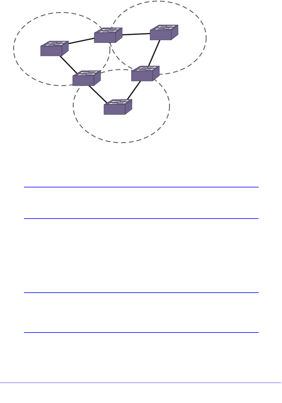
544 | Chapter 18. STP
NETGEAR 8800 User Manual
Figure 40. Looped VLAN Topology
• A necessary (but not sufficient) condition for a loop-free inter-domain topology is that
every two domains only meet at a single crossing point.
Note: You can use MSTP to overcome the EMISTP constraints described
in this section. See Multiple Spanning Tree Protocol on page 557 for
information about MSTP.
Per VLAN Spanning Tree
Switching products that implement Per VLAN Spanning Tree (PVST) have been in existence
for many years and are widely deployed. To support STP configurations that use PVST,
XCM8800 has an operational mode called PVST+.
Note: In this document, PVST and PVST+ are used interchangeably.
PVST+ is an enhanced version of PVST that is interoperable with
802.1Q STP. The following discussions are in regard to PVST+, if
not specifically mentioned.
EX_053
Domain 3
Domain 2
Domain 1

Chapter 18. STP | 545
NETGEAR 8800 User Manual
STPD VLAN Mapping
Each VLAN participating in PVST+ must be in a separate STPD, and the VLAN number
(VLAN ID) must be the same as the STPD identifier (STPD ID). As a result, PVST+ protected
VLANs cannot be partitioned.
This fact does not exclude other non-PVST+ protected VLANs from being grouped into the
same STPD. A protected PVST+ VLAN can be joined by multiple non-PVST+ protected
VLANs to be in the same STPD.
Native VLAN
In PVST+, the native VLAN must be peered with the default VLAN on NETGEAR devices, as
both are the only VLAN allowed to send and receive untagged packets on the physical port.
Third-party PVST+ devices send VLAN 1 packets in a special manner. XCM8800 does not
support PVST+ for VLAN 1. Therefore, when the switch receives a packet for VLAN 1, the
packet is dropped.
When a PVST+ instance is disabled, the fact that PVST+ uses a different packet format
raises an issue. If the STPD also contains ports not in PVST+ mode, the flooded packet has
an incompatible format with those ports. The packet is not recognized by the devices
connected to those ports.
Rapid Spanning Tree Protocol
The Rapid Spanning Tree Protocol (RSTP), originally in the IEEE 802.1w standard and now
part of the IEEE 802.1D-2004 standard, provides an enhanced spanning tree algorithm that
improves the convergence speed of bridged networks. RSTP takes advantage of
point-to-point links in the network and actively confirms that a port can safely transition to the
forwarding state without relying on any timer configurations. If a network topology change or
failure occurs, RSTP rapidly recovers network connectivity by confirming the change locally
before propagating that change to other devices across the network. For broadcast links,
there is no difference in convergence time between STP and RSTP.
RSTP supersedes legacy STP protocols, supports the existing STP parameters and
configurations, and allows for seamless interoperability with legacy STP.
RSTP Concepts
This section describes the following important RSTP concepts:
• Port Roles on page 546
• Link Types on page 546
546 | Chapter 18. STP
NETGEAR 8800 User Manual
Port Roles
RSTP uses information from BPDUs to assign port roles for each LAN segment. Port roles
are not user-configurable. Port role assignments are determined based on the following
criteria:
• A unique bridge identifier (MAC address) associated with each bridge
• The path cost associated with each bridge port
• A port identifier associated with each bridge port
RSTP assigns one of the following port roles to bridge ports in the network, as described in
Table 52.
When RSTP stabilizes, all:
• Root ports and designated ports are in the forwarding state.
• Alternate ports and backup ports are in the blocking state.
RSTP makes the distinction between the alternate and backup port roles to describe the
rapid transition of the alternate port to the forwarding state if the root port fails.
Link Types
With RSTP, you can configure the link type of a port in an STPD. RSTP tries to rapidly move
designated point-to-point links into the forwarding state when a network topology change or
failure occurs. For rapid convergence to occur, the port must be configured as a point-to-point
link.
Table 53 describes the link types.
Table 52. RSTP Port Roles
Port Role Description
Root Provides the shortest (lowest) path cost to the root bridge. Each bridge has only one root port; the
root bridge does not have a root port. If a bridge has two or more ports with the same path cost,
the port with the best port identifier (lowest MAC address) becomes the root port.
Designated Provides the shortest path connection to the root bridge for the attached LAN segment. To prevent
loops in the network, there is only one designated port on each LAN segment. To select the
designated port, all bridges that are connected to a particular segment listen to each other’s
BPDUs and agree on the bridge sending the best BPDU. The corresponding port on that bridge
becomes the designated port. If there are two or more ports connected to the LAN, the port with
the best port identifier becomes the designated port.
Alternate Provides an alternate path to the root bridge and the root port.
Backup Supports the designated port on the same attached LAN segment. Backup ports exist only when
the bridge is connected as a self-loop or to a shared-media segment.
Disabled A port in the disabled state does not participate in RSTP; however, it will forward traffic and learn
new MAC source addresses.
Chapter 18. STP | 547
NETGEAR 8800 User Manual
Configuring Link Types
By default, all ports are broadcast links. To configure the ports in an STPD, use the following
command:
configure stpd <stpd_name> ports link-type [[auto | broadcast | point-to-point]
<port_list> | edge <port_list> {edge-safeguard [enable | disable]
{bpdu-restrict} {recovery-timeout <seconds>}}]
Where the following is true:
• auto—Configures the ports as auto links. If the link is in full-duplex mode or if link
aggregation is enabled on the port, an auto link behaves like a point-to-point link.
• broadcast—Configures the ports as broadcast ports. By default, all ports are broadcast
links.
• point-to-point—Configures the ports for rapid reconfiguration in an RSTP or MSTP
environment.
• edge—Configures the ports as edge ports. For information about edge safeguard, see
Configuring Edge Safeguard , next.
To change the existing configuration of a port in an STPD, and return the port to factory
defaults, use the following command:
unconfigure stpd <stpd_name> ports link-type <port_list>
To display detailed information about the ports in an STPD, use the following command:
show {stpd} <stpd_name> ports {[detail | <port_list> {detail}]}
Table 53. RSTP Link Types
Port Link Type Description
Auto Specifies the switch to automatically determine the port link type. An auto link behaves like a
point-to-point link if the link is in full-duplex mode or if link aggregation is enabled on the port.
Otherwise, the link behaves like a broadcast link used for 802.1w configurations.
Edge Specifies a port that does not have a bridge attached. An edge port is held in the STP
forwarding state unless a BPDU is received by the port. In that case, the port behaves as a
normal RSTP port. The port is no longer considered an edge port. If the port does not receive
subsequent BPDUs during a pre-determined time, the port attempts to become an edge port.
An edge port is placed and held in the STP forwarding state unless a BPDU is received by
the port. In that case, an edge port enters and remains in the blocking state until it stops
receiving BPDUs and the message age timer expires.
Broadcast Specifies a port attached to a LAN segment with more than two bridges. A port with a
broadcast link type cannot participate in rapid reconfiguration using RSTP or MSTP. By
default, all ports are broadcast links.
Point-to-point Specifies a port attached to a LAN segment with only two bridges. A port with point-to-point
link type can participate in rapid reconfiguration. Used for 802.1w and MSTP configurations.

548 | Chapter 18. STP
NETGEAR 8800 User Manual
Configuring Edge Safeguard
Loop prevention and detection on an edge port configured for RSTP is called “edge
safeguard.” You configure edge safeguard on RSTP edge ports to prevent accidental or
deliberate misconfigurations (loops) resulting from connecting two edge ports together or by
connecting a hub or other non-STP switch to an edge port. Edge safeguard also limits the
impact of broadcast storms that might occur on edge ports. This advanced loop prevention
mechanism improves network resiliency but does not interfere with the rapid convergence of
edge ports.
An edge port configured with edge safeguard immediately enters the forwarding state and
transmits BPDUs. If a loop is detected, STP blocks the port. By default, an edge port without
edge safeguard configured immediately enters the forwarding state but does not transmit
BPDUs unless a BPDU is received by that edge port.
You can also configure edge safeguard for loop prevention and detection on an MSTP edge
port.
To configure an edge port and enable edge safeguard on that port, use the following
command:
configure stpd <stpd_name> ports link-type [[auto | broadcast | point-to-point]
<port_list> | edge <port_list> {edge-safeguard [enable | disable]
{bpdu-restrict} {recovery-timeout <seconds>}}]
If you have already configured a port as an edge port and you want to enable edge safeguard
on the port, use the following command:
configure {stpd} <stpd_name> ports edge-safeguard enable <port_list>
{bpdu-restrict} {recovery-timeout {<seconds>}}
To disable edge safeguard on an edge port, use one of the following commands:
• configure {stpd} <stpd_name> ports edge-safeguard disable <port_list>
{bpdu-restrict} {recovery-timeout {<seconds>}}
• configure stpd <stpd_name> ports link-type [[auto | broadcast | point-to-point]
<port_list> | edge <port_list> {edge-safeguard [enable | disable]
{bpdu-restrict} {recovery-timeout <seconds>}}]
In 802.1D-1998, ports that connect to non-STP devices are edge ports. Edge ports do not
participate in RSTP, and their role is not confirmed. Edge ports immediately enter the
forwarding state unless the port receives a BPDU. In that case, edge ports enter the blocking
state. The edge port remains in the blocking state until it stops receiving BPDUs and the
message age timer expires.
XCM8800 supports an enhanced bridge detection method, which is part of the 802.1D-2004
standard. Ports that connect to non-STP devices are still considered edge ports. However, if
you have an 802.1D-2004 compliant edge port, the bridge detection mechanism causes the
edge port to transition to a non-edge port upon receiving a BPDU. If the former edge port
does not receive a subsequent BPDU during a pre-determined interval, the port attempts to
become an edge port.
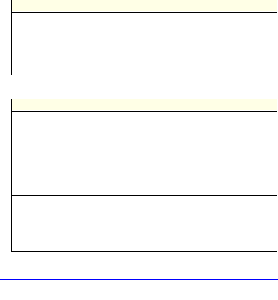
Chapter 18. STP | 549
NETGEAR 8800 User Manual
In XCM8800, STP edge safeguard disables a port when a remote loop is detected. A remote
loop causes BPDUs to be exponentially duplicated which caused high CPU utilization on the
switch even though the port was transitioned to a blocked state.
RSTP Timers
For RSTP to rapidly recover network connectivity, RSTP requires timer expiration. RSTP
derives many of the timer values from the existing configured STP timers to meet its rapid
recovery requirements rather than relying on additional timer configurations. Table 54
describes the user-configurable timers, and Table 55 describes the timers that are derived
from other timers and not user-configurable.
Table 54. User-Configurable Timers
Timer Description
Hello The root bridge uses the hello timer to send out configuration BPDUs through all of
its forwarding ports at a predetermined, regular time interval. The default value is 2
seconds. The range is 1 to 10 seconds.
Forward delay A port moving from the blocking state to the forwarding state uses the forward
delay timer to transition through the listening and learning states. In RSTP, this
timer complements the rapid configuration behavior. If none of the rapid rules are
in effect, the port uses legacy STP rules to move to the forwarding state. The
default is 15 seconds. The range is 4 to 30 seconds.
Table 55. Derived Timers
Timer Description
TCN The root port uses the topology change notification (TCN) timer when it detects a
change in the network topology. The TCN timer stops when the topology change
timer expires or upon receipt of a topology change acknowledgement. The default
value is the same as the value for the bridge hello timer.
Topology change The topology change timer determines the total time it takes the forwarding ports
to send configuration BPDUs. The default value for the topology change timer
depends upon the mode of the port:
• 802.1D mode—The sum of the forward delay timer value (default value is
15 seconds; range of 4 to 30 seconds) and the maximum age timer value
(default value is 20 seconds; range of 6 to 40 seconds).
• 802.1w mode—Double the hello timer value (default value is 4 seconds).
Message age A port uses the message age timer to time out receiving BPDUs. When a port
receives a superior or equal BPDU, the timer restarts. When the timer expires, the
port becomes a designated port and a configuration update occurs. If the bridge
operates in 1w mode and receives an inferior BPDU, the timer expires early. The
default value is the same as the STPD bridge max age parameter.
Hold A port uses the hold timer to restrict the rate that successive BPDUs can be sent.
The default value is the same as the value for the bridge hello timer.

550 | Chapter 18. STP
NETGEAR 8800 User Manual
The protocol migration timer is neither user-configurable nor derived; it has a set value of 3
seconds. The timer starts when a port transitions from STP (802.1D) mode to RSTP (802.1w)
mode and vice-versa. This timer must expire before further mode transitions can occur.
RSTP Operation
In an RSTP environment, a point-to-point link LAN segment has two bridges. A switch that
considers itself the unique, designated bridge for the attached LAN segment sends a
“propose” message to the other bridge to request a confirmation of its role. The other bridge
on that LAN segment replies with an “agree” message if it agrees with the proposal. The
receiving bridge immediately moves its designated port into the forwarding state.
Before a bridge replies with an “agree” message, it reverts all of its designated ports into the
blocking state. This introduces a temporary partition into the network. The bridge then sends
another “propose” message on all of its designated ports for further confirmation. Because all
of the connections are blocked, the bridge immediately sends an “agree” message to unblock
the proposing port without having to wait for further confirmations to come back or without the
worry of temporary loops.
Beginning with the root bridge, each bridge in the network engages in the exchange of
“propose” and “agree” messages until they reach the edge ports. Edge ports connect to
non-STP devices and do not participate in RSTP. Their role does not need to be confirmed. If
you have an 802.1D-2004 compliant edge port, the bridge detection mechanism causes the
edge port to transition to a non-edge port upon receiving a BPDU. If the former edge port
does not receive a subsequent BPDU during a pre-determined interval, the port attempts to
become an edge port.
RSTP attempts to transition root ports and designated ports to the forwarding state and
alternate ports and backup ports to the blocking state as rapidly as possible.
A port transitions to the forwarding state if any of the following is true. The port:
• Has been in either a root or designated port role long enough that the spanning tree
information supporting this role assignment has reached all of the bridges in the network.
Note: RSTP is backward compatible with STP, so if a port does not move to
the forwarding state with any of the RSTP rapid transition rules, a forward delay
timer starts and STP behavior takes over.
Recent backup The timer starts when a port leaves the backup role. When this timer is running,
the port cannot become a root port. The default value is double the hello time
(4 seconds).
Recent root The timer starts when a port leaves the root port role. When this timer is running,
another port cannot become a root port unless the associated port is put into the
blocking state. The default value is the same as the forward delay time.
Table 55. Derived Timers (Continued)
Timer Description
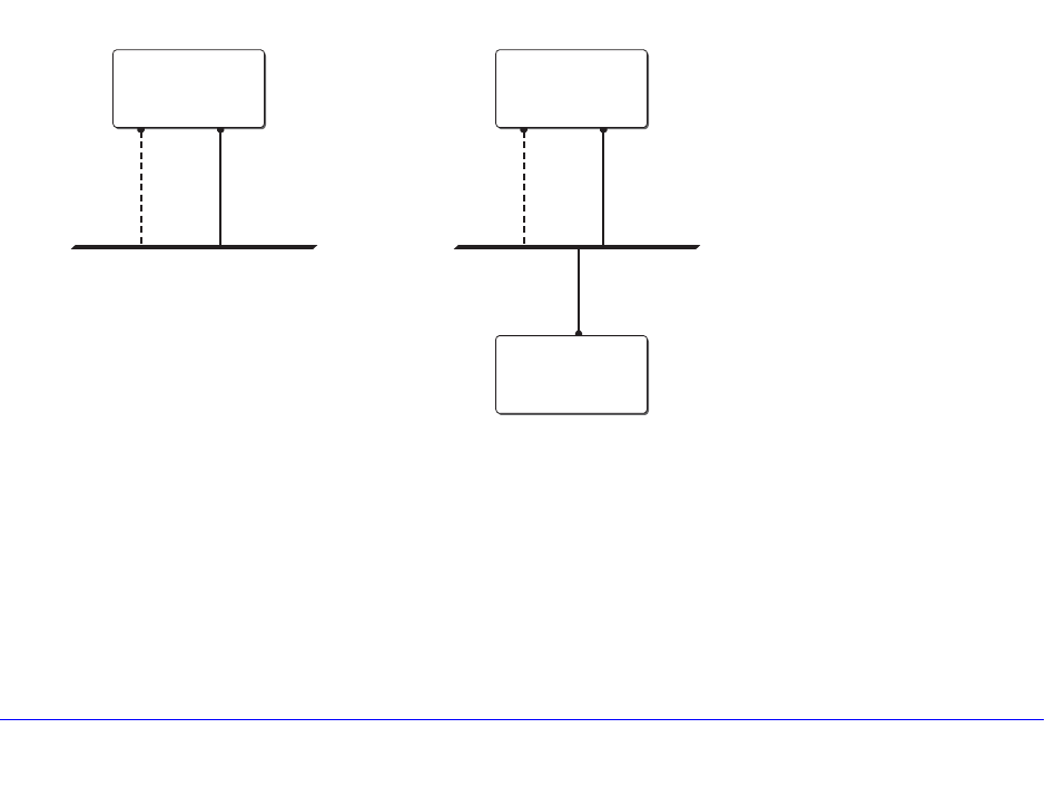
Chapter 18. STP | 551
NETGEAR 8800 User Manual
• Is now a root port and no other ports have a recent role assignment that contradicts with
its root port role.
• Is a designated port and attaches to another bridge by a point-to-point link and receives
an “agree” message from the other bridge port.
• Is an edge port.
An edge port is a port connected to a non-STP device and is in the forwarding state.
The following sections provide more information about RSTP behavior.
Root Port Rapid Behavior
In Figure 41, the diagram on the left displays the initial network topology with a single bridge
having the following:
• Two ports are connected to a shared LAN segment.
• One port is the designated port.
• One port is the backup port.
The diagram on the right displays a new bridge that:
• Is connected to the LAN segment
• Has a superior STP bridge priority
• Becomes the root bridge and sends a BPDU to the LAN that is received by both ports on
the old bridge
Figure 41. Example of Root Port Rapid Behavior
If the backup port receives the BPDU first, STP processes this packet and temporarily elects
this port as the new root port while the designated port’s role remains unchanged. If the new
root port is immediately put into the forwarding state, there is a loop between these two ports.
To prevent this type of loop from occurring, the recent backup timer starts. The root port
transition rule does not allow a new root port to be in the forwarding state until the recent
backup timer expires.
Backup
port
Designated
port
LAN segment
Inital topology
EX_054
Bridge
Backup
port
Designated
port
Superior STP
bridge priority
New topology
Bridge
Root
bridge

552 | Chapter 18. STP
NETGEAR 8800 User Manual
Another situation may arise if you have more than one bridge and you lower the port cost for
the alternate port, which makes it the new root port. The previous root port is now an
alternate port. Depending on your STP implementation, STP may set the new root port to the
forwarding state before setting the alternate port to the blocking state. This may cause a loop.
To prevent this type of loop from occurring, the recent root timer starts when the port leaves
the root port role. The timer stops if the port enters the blocking state. RSTP requires that the
recent root timer stop on the previous root port before the new root port can enter the
forwarding state.
Designated Port Rapid Behavior
When a port becomes a new designated port, or the STP priority changes on an existing
designated port, the port becomes an unsynced designated port. For an unsynced
designated port to rapidly move into the forwarding state, the port must propose a
confirmation of its role on the attached LAN segment (unless the port is an edge port). Upon
receiving an “agree” message, the port immediately enters the forwarding state.
If the receiving bridge does not agree and it has a superior STP priority, the receiving bridge
replies with its own BPDU. Otherwise, the receiving bridge keeps silent, and the proposing
port enters the forwarding state and starts the forward delay timer.
The link between the new designated port and the LAN segment must be a point-to-point link.
If there is a multi-access link, the “propose” message is sent to multiple recipients. If only one
of the recipients agrees with the proposal, the port can erroneously enter the forwarding state
after receiving a single “agree” message.
Receiving Bridge Behavior
The receiving bridge must decide whether or not to accept a proposal from a port. Upon
receiving a proposal for a root port, the receiving bridge:
• Processes the BPDU and computes the new STP topology.
• Synchronizes all of the designated ports if the receiving port is the root port of the new
topology.
• Puts all unsynced, designated ports into the blocking state.
• Sends down further “propose” messages.
• Sends back an “agree” message through the root port.
If the receiving bridge receives a proposal for a designated port, the bridge replies with its
own BPDU. If the proposal is for an alternate or backup port, the bridge keeps silent.
Propagating Topology Change Information
When a change occurs in the topology of the network, such events are communicated
through the network.
In an RSTP environment, only non-edge ports entering the forwarding state cause a topology
change. A loss of network connectivity is not considered a topology change; however, a gain
in network connectivity must be communicated. When an RSTP bridge detects a topology
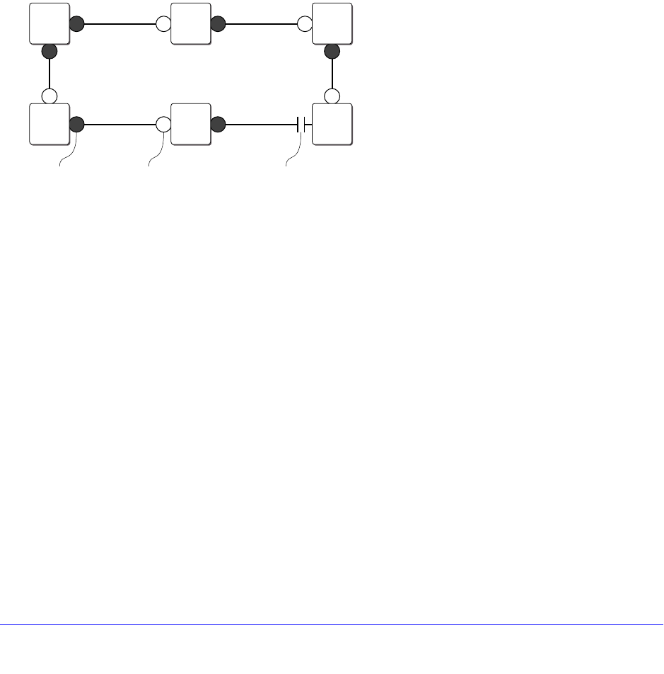
Chapter 18. STP | 553
NETGEAR 8800 User Manual
change, that bridge starts the topology change timer, sets the topology change flag on its
BPDUs, floods all of the forwarding ports in the network (including the root ports), and flushes
the learned MAC address entries.
Rapid Reconvergence
This section describes the RSTP rapid behavior following a topology change. In this
example, the bridge priorities are assigned based on the order of their alphabetical letters;
bridge A has a higher priority than bridge F.
Suppose we have a network, as shown in Figure 42, with six bridges (bridge A through
bridge F) where the following is true:
• Bridge A is the root bridge.
• Bridge D contains an alternate port in the blocking state.
• All other ports in the network are in the forwarding state.
Figure 42. Initial Network Configuration
The network reconverges in the following way:
1. If the link between bridge A and bridge F goes down, bridge F detects the root port is
down. At this point, bridge F:
• Immediately disables that port from the STP.
• Performs a configuration update.
As shown in Figure 43, after the configuration update, bridge F:
• Considers itself the new root bridge.
• Sends a BPDU message on its designated port to bridge E.
Designated
port Root
port EX_055a
A
A , 0B
A , 1C
A , 2
F
A , 1E
A , 2D
A , 3
Blocked
port
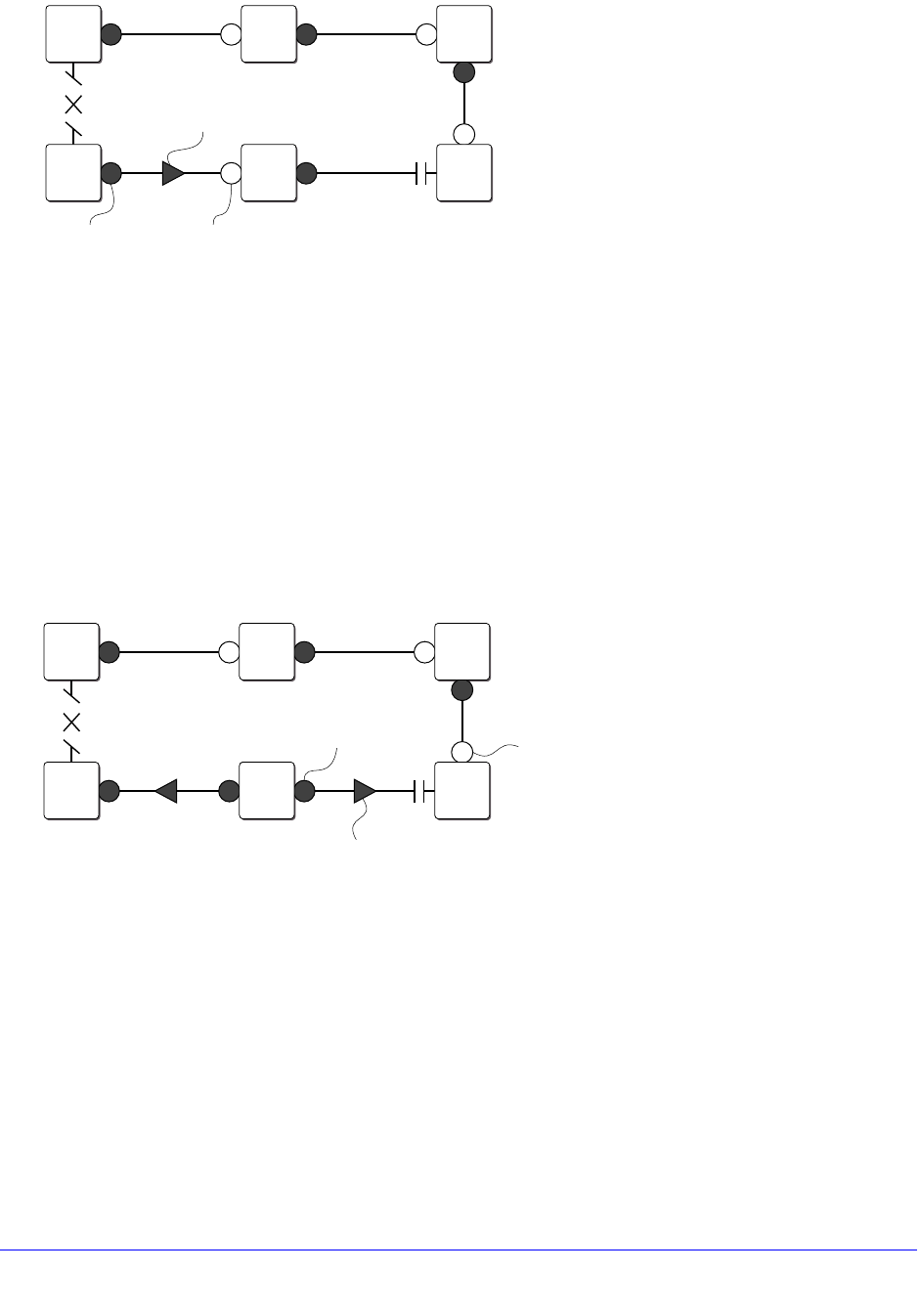
554 | Chapter 18. STP
NETGEAR 8800 User Manual
Figure 43. Down Link Detected
2. Bridge E believes that bridge A is the root bridge. When bridge E receives the BPDU on its
root port from bridge F, bridge E:
• Determines that it received an inferior BPDU.
• Immediately begins the max age timer on its root port.
• Performs a configuration update.
As shown in Figure 44, after the configuration update, bridge E:
• Regards itself as the new root bridge.
• Sends BPDU messages on both of its designated ports to bridges F and D,
respectively.
Figure 44. New Root Bridge Selected
3. As shown in Figure 45, when bridge F receives the superior BPDU and configuration update
from bridge E, bridge F:
• Decides that the receiving port is the root port.
• Determines that bridge E is the root bridge.
EX_055b
B
A , 1C
A , 2
E
A , 2D
A , 3
BPDU
Down
link
A
A , 0
F
F , 0
Designated
port Root
port
EX_055c
B
A , 1C
A , 2
E
E , 0D
A , 3
BPDU
A
A , 0
F
F , 0
Designated
port Root
port
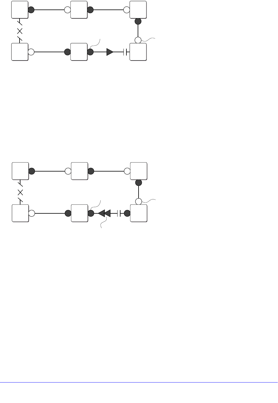
Chapter 18. STP | 555
NETGEAR 8800 User Manual
Figure 45. Communicating New Root Bridge Status to Neighbors
4. Bridge D believes that bridge A is the root bridge. When bridge D receives the BPDU from
bridge E on its alternate port, bridge D:
• Immediately begins the max age timer on its alternate port.
• Performs a configuration update.
As shown in Figure 46, after the configuration update, bridge D:
• Moves the alternate port to a designated port.
• Sends a “propose” message to bridge E to solicit confirmation of its designated role
and to rapidly move the port into the designated state.
Figure 46. Sending a Propose Message to Confirm a Port Role
5. Upon receiving the proposal, bridge E (as shown in Figure 47):
• Performs a configuration update.
• Changes its receiving port to a root port.
The existing designated port enters the blocking state.
Bridge E then sends:
• A “propose” message to bridge F.
• An “agree” message from its root port to bridge D.
EX_055d
B
A
,
1C
A
,
2
E
E
,
0D
A
,
3
A
A
,
0
F
E
,
1
Designated
port Root
port
EX_055e
B
A , 1C
A , 2
E
E , 0
Propose BPDU
A
A , 0
F
E , 1D
A , 3
Designated
port Root
port
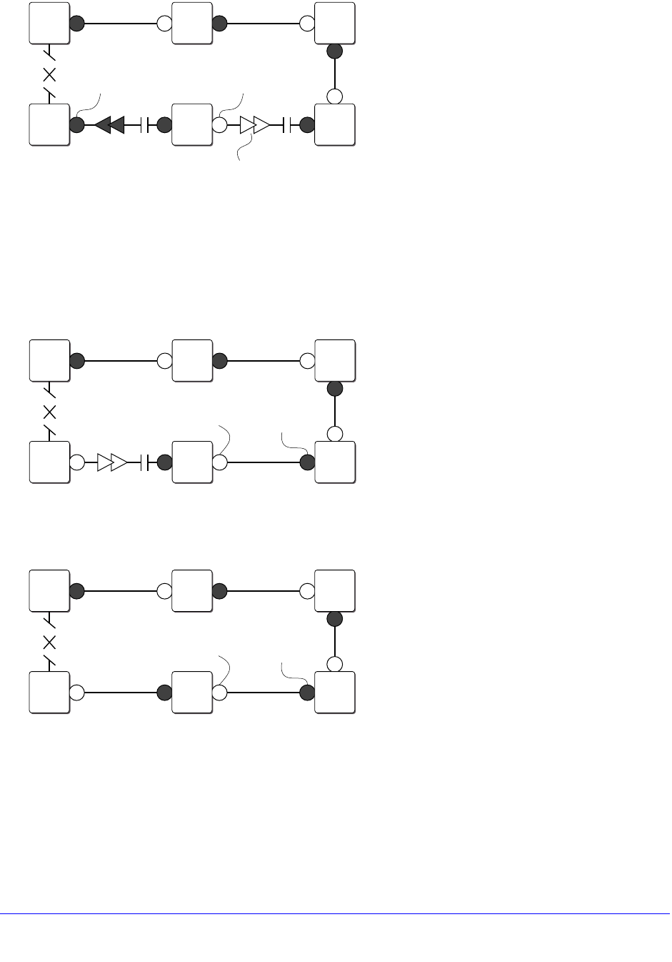
556 | Chapter 18. STP
NETGEAR 8800 User Manual
Figure 47. Communicating Port Status to Neighbors
6. To complete the topology change (as shown in Figure 48):
• Bridge D moves the port that received the “agree” message into the forwarding state.
• Bridge F confirms that its receiving port (the port that received the “propose”
message) is the root port, and immediately replies with an “agree” message to bridge
E to unblock the proposing port.
Figure 48. Completing the Topology Change
Figure 49 displays the new topology.
Figure 49. Final Network Configuration
Compatibility With STP (802.1D)
RSTP interoperates with legacy STP protocols; however, the rapid convergence benefits are
lost when interacting with legacy STP bridges.
Each RSTP bridge contains a port protocol migration state machine to ensure that the ports
in the STPD operate in the correct, configured mode. The state machine is a protocol entity
EX_055f
B
A , 1C
A , 2
E
A , 4
Agree BPDU
A
A , 0
F
E , 1D
A , 3
Designated
port Root
port
EX_055g
B
A , 1C
A , 2
E
A , 4D
A , 3
A
A , 0
F
A , 5
Designated
port
Root
port
EX_055h
B
A , 1C
A , 2
E
A , 4D
A , 3
A
A , 0
F
A , 5
Designated
port
Root
port

Chapter 18. STP | 557
NETGEAR 8800 User Manual
within each bridge configured to run in 802.1w mode. For example, a compatibility issue
occurs if you configure 802.1w mode and the bridge receives an 802.1D BPDU on a port.
The receiving port starts the protocol migration timer and remains in 802.1D mode until the
bridge stops receiving 802.1D BPDUs. Each time the bridge receives an 802.1D BPDU, the
timer restarts. When the port migration timer expires, no more 802.1D BPDUs have been
received, and the bridge returns to its configured setting, which is 802.1w mode.
Multiple Spanning Tree Protocol
The Multiple Spanning Tree Protocol (MSTP), based on IEEE 802.1Q-2003 (formerly known
as IEEE 802.1s), allows the bundling of multiple VLANs into one spanning tree topology. This
concept is not new to NETGEAR. Like MSTP, NETGEAR proprietary EMISTP
implementation can achieve the same capabilities of sharing a virtual network topology
among multiple VLANs; however, MSTP overcomes some of the challenges facing EMISTP,
including enhanced loop protection mechanisms and new capabilities to achieve better
scaling.
MSTP logically divides a Layer 2 network into regions. Each region has a unique identifier
and contains multiple spanning tree instances (MSTIs). An MSTI is a spanning tree domain
that operates within and is bounded by a region. MSTIs control the topology inside the
regions. The Common and Internal Spanning Tree (CIST) is a single spanning tree domain
that interconnects MSTP regions. The CIST is responsible for creating a loop-free topology
by exchanging and propagating BPDUs across regions to form a Common Spanning Tree
(CST).
MSTP uses RSTP as its converging algorithm and is interoperable with the legacy STP
protocols: STP (802.1D) and RSTP (802.1w). MSTP has three major advantages over
802.1D, 802.1w, and other proprietary implementations:
• To save control path bandwidth and provide improved scalability, MSTP uses regions to
localize BPDU traffic. BPDUs containing information about MSTIs contained within an
MSTP region do not cross that region’s boundary.
• A single BPDU transmitted from a port can contain information for up to 64 STPDs. MSTP
BPDU processing utilizes less resources compared to 802.1D or 802.1w where one
BPDU corresponds to one STPD.
• In a typical network, a group of VLANs usually share the same physical topology.
Dedicating a spanning tree per VLAN like PVST+ is CPU intensive and does not scale
very well. MSTP makes it possible for a single STPD to handle multiple VLANs.
MSTP Concepts
This section describes the following MSTP concepts:
• MSTP Regions on page 558
• Common and Internal Spanning Tree on page 560
• Multiple Spanning Tree Instances on page 562
• Boundary Ports on page 564

558 | Chapter 18. STP
NETGEAR 8800 User Manual
• MSTP Port Roles on page 565
• MSTP Port States on page 565
• MSTP Link Types on page 565
• MSTP Edge Safeguard on page 565
• MSTP Timers on page 566
• MSTP Hop Counts on page 566
• Configuring MSTP on the Switch on page 566
MSTP Regions
An MSTP network consists of either individual MSTP regions connected to the rest of the
network with 802.1D and 802.1w bridges or as individual MSTP regions connected to each
other. An MSTP region defines the logical boundary of the network. With MSTP, you can
divide a large network into smaller areas similar to an OSPF area or a BGP Autonomous
System, which contain a group of switches under a single administration. Each MSTP region
has a unique identifier, is bound together by one CIST that spans the entire network. A bridge
participates in only one MSTP region at a time.
An MSTP region can hide its internal STPDs and present itself as a virtual 802.1w bridge to
other interconnected regions or 802.1w bridges because the port roles are encoded in
802.1w and MSTP BPDUs.
By default, the switch uses the MAC address of the switch to generate an MSTP region.
Since each MAC address is unique, every switch is in its own region by default. For multiple
switches to be part of an MSTP region, you must configure each switch in the region with the
same MSTP region identifiers. See Configuring MSTP Region Identifiers on page 559 for
information.
In Figure 50, all bridges inside MSTP regions 1 and 2 are MSTP bridges; bridges outside of
the regions are either 802.1D or 802.1w bridges.
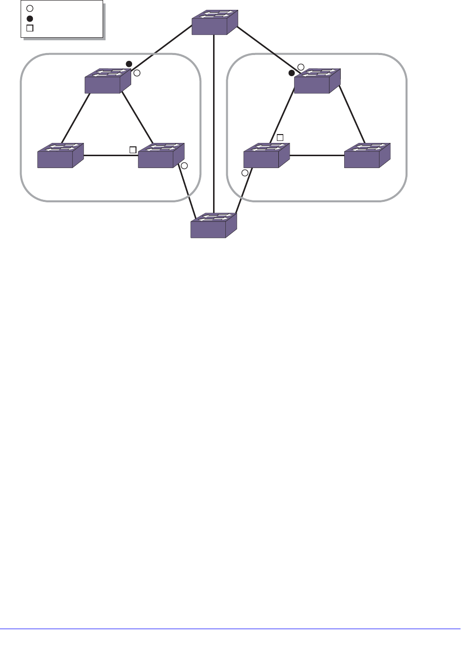
Chapter 18. STP | 559
NETGEAR 8800 User Manual
Figure 50. Sample MSTP Topology with Two MSTP Regions
Configuring MSTP Region Identifiers
For multiple switches to be part of an MSTP region, you must configure each switch in the
region with the same MSTP configuration attributes, also known as MSTP region identifiers.
The following list describes the MSTP region identifiers:
• Region Name—This indicates the name of the MSTP region. In the NETGEAR
implementation, the maximum length of the name is 32 characters and can be a
combination of alphanumeric characters and underscores ( _ ).
• Format Selector—This indicates a number to identify the format of MSTP BPDUs. The
default is 0.
• Revision Level—This identifier is reserved for future use; however, the switch uses and
displays a default of 3.
The switches inside a region exchange BPDUs that contain information for MSTIs. The
switches connected outside of the region exchange CIST information. By having devices look
at the region identifiers, MSTP discovers the logical boundary of a region:
• Configuring the MSTP region name
To configure the MSTP region name, use the following command:
configure mstp region <regionName>
The maximum length of the region name is 32 characters and can be a combination of
alphanumeric characters and underscores ( _ ). You can configure only one MSTP region
on the switch at any given time.
EX_167
B
= boundary port
= master port
= MSTI root port
F
DE
(60)
(20) CIST
regional
root
(50) MSTI
regional
root
MSTP
Region 1
K
GH
IJ
(90)
(40) CIST
regional root,
MSTI
regional root
(80)
(100)
AC
(10) CIST root bridge
MSTP
Region 2

560 | Chapter 18. STP
NETGEAR 8800 User Manual
If you have an active MSTP region, NETGEAR recommends that you disable all active
STPDs in the region before renaming the region on all of the participating switches.
• Configuring the MSTP BPDU format identifier
To configure the number used to identify MSTP BPDUs, use the following command:
configure mstp format <format_identifier>
By default, the value used to identify the MSTP BPDUs is 0. The range is 0 to 255.
If you have an active MSTP region, NETGEAR recommends that you disable all active
STPDs in the region before modifying the value used to identify MSTP BPDUs on all
participating switches.
• Configuring the MSTP revision level
Although the configure mstp revision <revision> command is available on the CLI, this
command is reserved for future use.
Unconfiguring an MSTP Region
Before you unconfigure an MSTP region, NETGEAR recommends that you disable all active
STPDs in the region.
To unconfigure the MSTP region on the switch, use the following command:
unconfigure mstp region
After you issue this command, all of the MSTP settings return to their default values. See
Configuring MSTP Region Identifiers on page 559 for information about the default settings.
Common and Internal Spanning Tree
As previously described, MSTP logically divides a Layer 2 network into regions. The
Common and Internal Spanning Tree (CIST) is a single spanning tree domain that
interconnects MSTP regions. The CIST is responsible for creating a loop-free topology by
exchanging and propagating BPDUs across regions to form a Common Spanning Tree
(CST). In essence, the CIST is similar to having a large spanning tree across the entire
network. The CIST has its own root bridge that is common to all MSTP regions, and each
MSTP region elects a CIST regional root that connects that region to the CIST thereby
forming a CST.
The switch assigns the CIST an instance ID of 0, which allows the CIST to send BPDUs for
itself in addition to all of the MSTIs within an MSTP region. Inside a region, the BPDUs
contain CIST records and piggybacked M-records. The CIST records contain information
about the CIST, and the M-records contain information about the MSTIs. Boundary ports
exchange only CIST record BPDUs.
All MSTP configurations require a CIST domain. You must first configure the CIST domain
before configuring any MSTIs. By default, all MSTI ports in the region are inherited by the
CIST. You cannot delete or disable a CIST if any of the MSTIs are active in the system.

Chapter 18. STP | 561
NETGEAR 8800 User Manual
Configuring the CIST
To configure an STPD as the CIST, use the following command and specify the mstp cist
keywords:
configure stpd <stpd_name> mode [dot1d | dot1w | mstp [cist | msti <instance>]]
You enable MSTP on a per STPD basis only. By specifying the mstp cist keywords, you
configure the mode of operation for the STPD as MSTP, and you identify the STPD to be the
CIST.
CIST Root Bridge
In a Layer 2 network, the bridge with the lowest bridge ID becomes the CIST root bridge. The
parameters (vectors) that define the root bridge include the following:
• User-defined bridge priority (by default, the bridge priority is 32,768)
• MAC address
The CIST root bridge can be either inside or outside an MSTP region. The CIST root bridge is
unique for all regions and non-MSTP bridges, regardless of its location.
For more information about configuring the bridge ID, see the configure stpd priority
command in the NETGEAR 8800 Chassis Switch CLI Manual.
CIST Regional Root Bridge
Within an MSTP region, the bridge with the lowest path cost to the CIST root bridge is the
CIST regional root bridge. The path cost, also known as the CIST external path cost, is a
function of the link speed and number of hops. If there is more than one bridge with the same
path cost, the bridge with the lowest bridge ID becomes the CIST regional root. If the CIST
root is inside an MSTP region, the same bridge is the CIST regional root for that region
because it has the lowest path cost to the CIST root. If the CIST root is outside an MSTP
region, all regions connect to the CIST root via their CIST regional roots.
The total path cost to the CIST root bridge from any bridge in an MSTP region consists of the
CIST internal path cost (the path cost of the bridge to the CIST regional root bridge) and the
CIST external path cost. To build a loop-free topology within a region, the CIST uses the
external and internal path costs, and the MSTI uses only the internal path cost.
Looking at MSTP region 1 in Figure 51, the total path cost for the bridge with ID 60 consists
of an external path cost of A and an internal path cost of E.
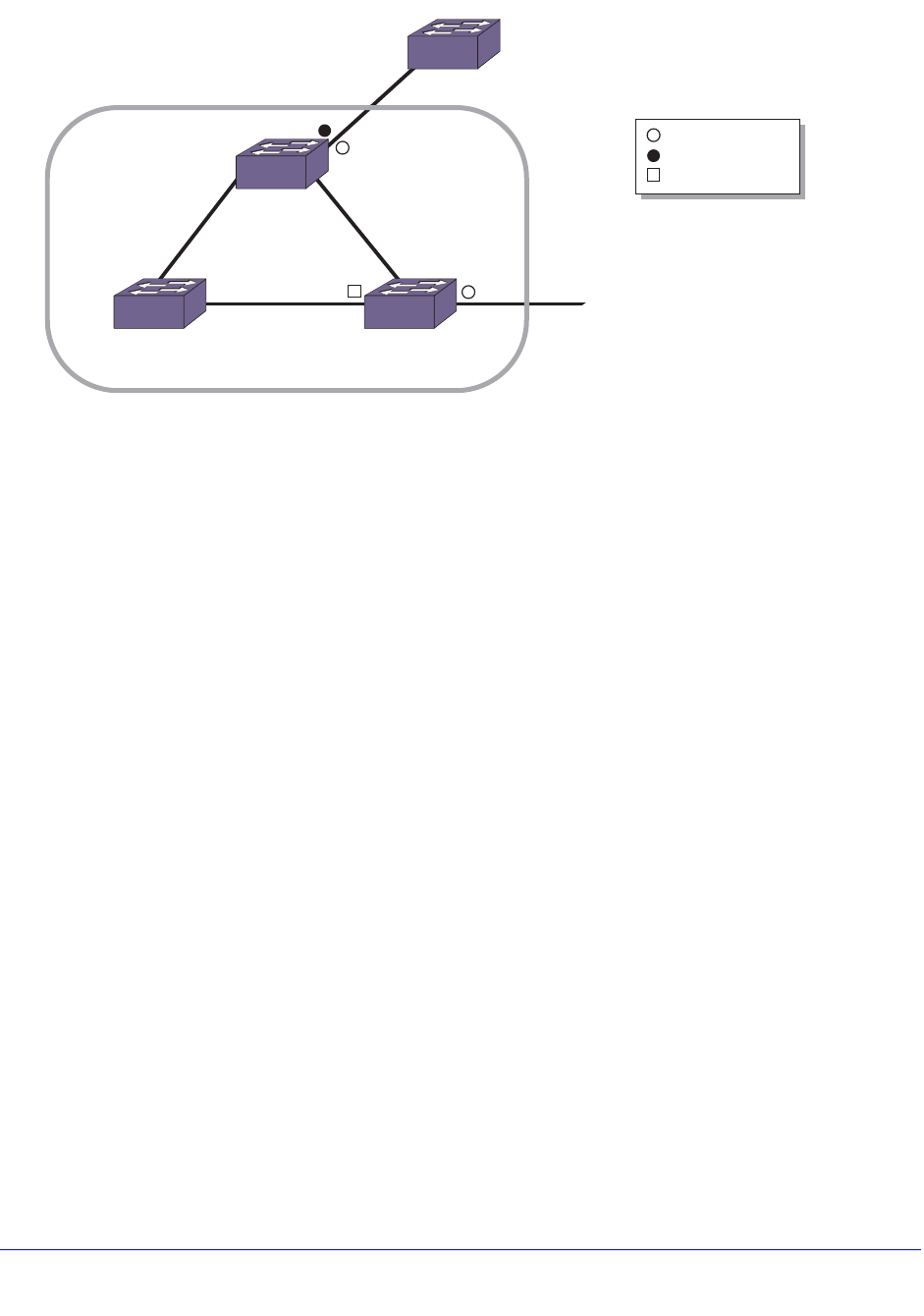
562 | Chapter 18. STP
NETGEAR 8800 User Manual
Figure 51. Close-Up of MSTP Region 1
CIST Root Port
The port on the CIST regional root bridge that connects to the CIST root bridge is the CIST
root port (also known as the master port for MSTIs). The CIST root port is the master port for
all MSTIs in that region, and it is the only port that connects the entire region to the CIST root.
If a bridge is both the CIST root bridge and the CIST regional root bridge, there is no CIST
root port on that bridge.
Enabling the CIST
To enable the CIST, use the following command and specify the CIST domain as the
<stpd_name>:
enable stpd {<stpd_name>}
Multiple Spanning Tree Instances
As previously described, multiple spanning tree instances (MSTIs) control the topology inside
an MSTP region. An MSTI is a spanning tree domain that operates within and is bounded by
a region; an MSTI does not exchange BPDUs with or send notifications to other regions. You
identify an MSTI on a per region basis. The MSTI ID does not have any significance outside
of its region so you can re-use IDs across regions. An MSTI consists of a group of VLANs,
which can share the same network topology. Each MSTI has its own root bridge and a tree
spanning its bridges and LAN segments.
You must first configure a CIST before configuring any MSTIs in the region. You cannot
delete or disable a CIST if any of the MSTIs are active in the system.
You can map multiple VLANs to an MSTI; however, multiple MSTIs cannot share the same
VLAN.
EX_168
F
DE
(60)
(20) CIST
regional root
(50) MSTI
regional root
MSTP
Region 1
G
A
(10) CIST root bridge
= boundary port
= master port
= MSTI root port

Chapter 18. STP | 563
NETGEAR 8800 User Manual
Configuring the MSTI and the MSTI ID
MSTP uses the MSTI ID, not an Stpd ID, to identify the spanning tree contained within the
region. As previously described, the MSTI ID only has significance within its local region, so
you can re-use IDs across regions.
To configure the MSTI that is inside an MSTP region and its associated MSTI ID, use the
following command and specify the mstp [msti <instance>] parameters:
configure stpd <stpd_name> mode [dot1d | dot1w | mstp [cist | msti <instance>]]
The range of the MSTI instance ID is 1 to 4,094.
MSTP STPDs use 802.1D BPDU encapsulation mode by default. To ensure correct operation
of your MSTP STPDs, do not configure EMISTP or PVST+ encapsulation mode for MSTP
STPDs. For more information, see Encapsulation Modes on page 530.
MSTI Regional Root Bridge
Each MSTI independently chooses its own root bridge. For example, if two MSTIs are
bounded to a region, there is a maximum of two MSTI regional roots and one CIST regional
root.
The bridge with the lowest bridge ID becomes the MSTI regional root bridge. The parameters
that define the root bridge include the following:
• User-defined bridge priority (by default, the bridge priority is 32,768)
• MAC address
Within an MSTP region, the cost from a bridge to the MSTI regional root bridge is known as
the MSTI internal path cost. Looking at MSTP region 1 in Figure 51 on page 562, the bridge
with ID 60 has a path cost of F to the MSTI regional root bridge.
The MSTI regional root bridge can be the same as or different from the CIST regional root
bridge of that region. You achieve this by assigning different priorities to the STP instances
configured as the MSTIs and the CIST. For more information about configuring the bridge ID,
see the configure stpd priority command in the NETGEAR 8800 Chassis Switch CLI
Manual.
MSTI Root Port
The port on the bridge that has the lowest path cost to the MSTI regional root bridge is the
MSTI root port. If a bridge has two or more ports with the same path cost, the port with the
best port identifier becomes the root port.
Enabling the MSTI
To enable the MSTI, use the following command and specify the MSTI domain as the
<stpd_name>:
enable stpd {<stpd_name>}
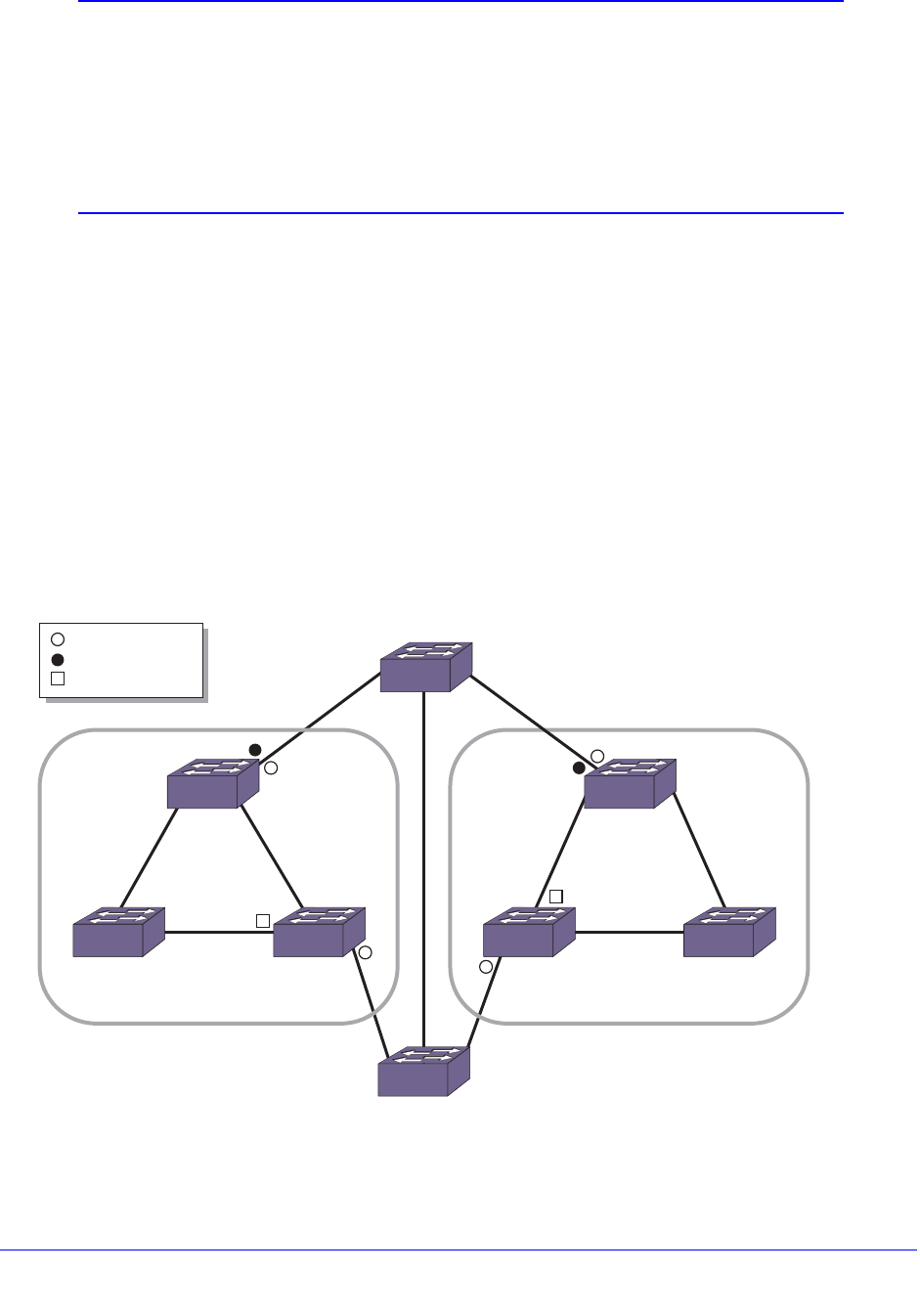
564 | Chapter 18. STP
NETGEAR 8800 User Manual
Note: If two switches are configured for the same CIST and MSTI region,
in order for them to understand that they are in the same region,
both must also belong to the same VLAN which is added to the STP
domain. If they belong to different VLANs, each switch believes that
each belongs to a different region. When an MSTP BPDU is sent, it
carries a VID digest created by VLAN memberships in the CIST
domain and the MSTI domain.
Boundary Ports
Boundary ports are bridge ports that are only connected to other MSTP regions or 802.1D or
802.1w bridges. The ports that are not at a region boundary are called internal ports. The
boundary ports exchange only CIST BPDUs. A CIST BPDU originated from the CIST root
enters a region through the CIST root port and egresses through boundary ports. This
behavior simulates a region similar to an 802.1w bridge, which receives BPDUs on its root
ports and forwards updated BPDUs on designated ports.
Figure 52 shows an MSTP network that consists of two MSTP regions. Each region has its
own CIST regional root and is connected to the CIST root through master ports. The CIST
regional roots in each region are the MSTP bridges having the lowest CIST external root path
cost. The CIST root is the bridge with the lowest bridge ID and is an 802.1w bridge outside of
either MSTP region.
Figure 52. Sample MSTP Topology with Two MSTP Regions
EX_167
B
= boundary port
= master port
= MSTI root port
F
DE
(60)
(20) CIST
regional
root
(50) MSTI
regional
root
MSTP
Region 1
K
GH
IJ
(90)
(40) CIST
regional root,
MSTI
regional root
(80)
(100)
AC
(10) CIST root bridge
MSTP
Region 2

Chapter 18. STP | 565
NETGEAR 8800 User Manual
MSTP Region 1 and MSTP Region 2 are connected to the CIST root through directly
connected ports, identified as master ports. The bridge with ID 100 connects to the CIST root
through Region 1, Region 2, or segment B. For this bridge, either Region 1 or Region 2 can
be the designated region or segment B can be the designated segment. The CIST BPDUs
egressing from the boundary ports carry the CIST regional root as the designated bridge.
This positions the entire MSTP region as one virtual bridge.
The CIST controls the port roles and the state of the boundary ports. A master port is always
forwarding for all CIST and MSTI VLANs. If the CIST sets a boundary port to the discarding
state, the CIST blocks traffic for all VLANs mapped to it and the MSTIs within that region.
Each MSTI blocks traffic for their member VLANs and puts their internal ports into the
forwarding or blocking state depending on the MSTI port roles. For more information about
port states, see MSTP Port States on page 565.
MSTP Port Roles
MSTP uses the same port roles as RSTP (Root, Designated, Alternate, and Backup), as
described in Table 52 on page 546. In addition to those port roles, MSTP introduces a new
port role: Master. A Master port is the port that connects an MSTI to the CIST root.
MSTP Port States
MSTP uses the same port states as RSTP (Listening, Learning, Forwarding, and Blocking).
In the NETGEAR MSTP implementation, the listening state is not truly implemented as FDB
learning cannot be done when the port is not in the forwarding state. Ports in the blocking
state listen but do not accept ingress traffic, perform traffic forwarding, or learn MAC source
address; however, the port receives and processes BPDUs. For more information about all of
the STP port states, see STP States on page 531.
MSTP Link Types
MSTP uses the same link types as STP and RSTP, respectively. In an MSTP environment,
configure the same link types for the CIST and all MSTIs. For more information about the link
types, see Link Types on page 546.
MSTP Edge Safeguard
You can configure edge safeguard for loop prevention and detection on an MSTP edge port.
For more information see Configuring Edge Safeguard on page 548.
Note: In MSTP, configuring edge safeguard at CIST will be inherited in all
MSTI.
In MSTP, an edge port needs to be added to a CIST before adding it
to an MSTI.

566 | Chapter 18. STP
NETGEAR 8800 User Manual
MSTP Timers
MSTP uses the same timers as STP and RSTP, respectively. For more information, see
RSTP Timers on page 549.
MSTP Hop Counts
In an MSTP environment, the hop count has the same purpose as the maxage timer for
802.1D and 802.1w environments. The CIST hop count is used within and outside a region.
The MSTI hop count is used only inside of the region. In addition, if the other end is an
802.1D or 802.1w bridge, the maxage timer is used for interoperability between the protocols.
The BPDUs use hop counts to age out information and to notify neighbors of a topology
change. To configure the hop count, use the following command:
configure stpd <stpd_name> max-hop-count <hopcount>
By default, the hop count of a BPDU is 20 hops. The range is 6 to 40 hops.
Configuring MSTP on the Switch
To configure and enable MSTP:
1. Create the MSTP region using the following command:
configure mstp region <regionName>
2. Create and configure the CIST, which forms the CST, using the following commands:
create stpd <stpd_name>
configure stpd <stpd_name> mode mstp cist
Note: You can configure the default STPD, S0 as the CIST.
No VLAN can be bound to the CIST and no ports can be added to the CIST.
Therefore, the VLAN should be bound to the MSTI and the “show MSTI port”
command will show the VLAN ports. The ports added to the MSTI are bound
automatically to the CIST even though they are not added to it.
3. Enable the CIST using the following command:
enable stpd {<stpd_name>}
4. Create and configure MSTIs using the following commands:
create stpd <stpd_name>
configure stpd <stpd_name> mode mstp msti <instance>
5. Add VLANs to the MSTIs using one of the following commands:
• Manually binding ports
configure stpd <stpd_name> add vlan <vlan_name> ports [all | <port_list>] {[dot1d
| emistp | pvst-plus]}
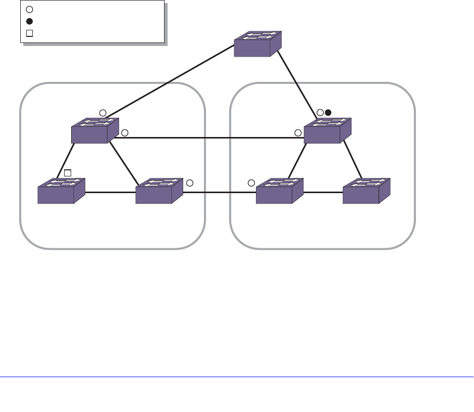
Chapter 18. STP | 567
NETGEAR 8800 User Manual
configure vlan <vlan_name> add ports [all | <port_list>] {tagged | untagged} stpd
<stpd_name> {[dot1d | emistp | pvst-plus]}
• Automatically binding ports to an STPD when ports are added to a member VLAN
enable stpd <stpd_name> auto-bind vlan <vlan_name>
6. Enable the MSTIs.
enable stpd {<stpd_name>}
For a more detailed configuration example, see MSTP Configuration Example on page 578.
MSTP Operation
To further illustrate how MSTP operates and converges, Figure 53 displays a network with
two MSTP regions. Each region contains three MSTP bridges and one MSTI. The overall
network topology also contains one CIST root bridge (Switch A, which has the lowest bridge
ID), one interconnecting 802.1w bridge (Switch D), and 10 full duplex, point-to-point
segments. VLAN Default spans all of the bridges and segments in the network, VLAN
engineering is local to its respective region, and STPD S0 is configured as the CIST on all
bridges.
Figure 53. MSTP Topology with the CIST Root Bridge Contained within a Region
MSTP Region 1 consists of the following:
• Three bridges named Switch A, Switch B, and Switch C
• One MSTI STPD named S1 with an MSTI ID of 1
• VLAN Engineering mapped to the MSTI STPD, S1
EX_165
Switch A
= boundary port
= master port
= MSTI root port
12
3
45 67
1089
CIST root
CIST regional root
MSTI regional root
STPD SI configured on switch A-C
VLAN engineering assigned to SI
STPD SI configured on switch E-G
VLAN finance assigned to SI
CIST
regional root
Switch F
MSTI regional root
Switch D
Switch B Switch C
MSTP
Region 1
MSTP
Region 2
Switch E
Switch G

568 | Chapter 18. STP
NETGEAR 8800 User Manual
• Switch A as the CIST root bridge (this is the CIST root bridge for all regions)
• Switch A as the CIST regional root bridge
• Switch A as the MSTI regional root bridge
• Three boundary ports that connect to MSTP region 2 and other 802.1D or 802.1w bridges
MSTP Region 2 consists of the following:
• Three bridges named Switch E, Switch F, and Switch G
• One MSTI STPD named S1 with an MSTI ID of 1
Note: The MSTI ID does not have any significance outside of its region so you
can re-use IDs across regions.
• VLAN finance mapped to the MSTI STPD, S1
• Switch E as the CIST regional root bridge
• Switch F as the MSTI regional root bridge
• One master port that connects to the CIST
• Three boundary ports that connect to MSTP region 1 and other 802.1D or 802.1w bridges
The following sequence describes how the MSTP topology convergences:
1. Determining the CIST root bridge, MSTP regions, and region boundaries.
Each bridge believes that it is the root bridge, so each bridge initially sends root bridge
BPDUs throughout the network. As bridges receive BPDUs and compare vectors, the
bridge with the lowest Bridge ID is elected the CIST root bridge. In our example, Switch A
has the lowest Bridge ID and is the CIST root bridge.
The bridges in the MSTP regions (Switches A, B, C, E, F, and G) advertise their region
information along with their bridge vectors.
Segments 1, 3, and 9 receive BPDUs from other regions and are identified as boundary
ports for region 1. Similarly, segments 2, 3, and 9 are identified as boundary ports for
region 2.
2. Controlling boundary ports.
The CIST regional root is advertised as the Bridge ID in the BPDUs exiting the region. By
sending CIST BPDUs across regional boundaries, the CIST views the MSTP regions as
virtual 802.1w bridges. The CIST takes control of the boundary ports and only CIST
BPDUs enter or exit a region boundary.
Each MSTP region has a CIST regional root bridge that communicates to the CIST root
bridge. The bridge with the lowest path cost becomes the CIST regional root bridge. The
port on the CIST regional root bridge that connects to the CIST root bridge is the CIST
root port.
For region 1, Switch A has the lowest cost (0 in this example) and becomes the CIST
regional root. Since the bridge is both the CIST root bridge and the CIST regional root
bridge, there is no CIST root port on the bridge.

Chapter 18. STP | 569
NETGEAR 8800 User Manual
For region 2, Switch E is the CIST regional root bridge and so a port on that bridge
becomes the CIST root port.
3. Identifying MSTI regional roots.
Each MSTI in a region has an MSTI regional root bridge. MSTI regional roots are
selected independently of the CIST root and CIST regional root. The MSTP BPDUs have
M-records for each MSTI. Bridges belonging to an MSTI compare vectors in their
M-records to elect the MSTI regional root.
4. Converging the CIST.
The CIST views every region as a virtual bridge and calculates the topology using the
802.1w algorithm. The CIST calculates the topology both inside and outside of a region.
5. Converging MSTIs.
After the CIST identifies the boundary ports, each MSTI in a domain converge their own
trees using 802.1w.
At this point, all CIST and MSTIs have assigned port roles of root, designated, alternate,
and backup to their respective spanning trees. All root and designated ports transition to
the forwarding state while the remaining ports remain in the discarding state.
Propagating topology change information is similar to that described for RSTP. For more
information see, Propagating Topology Change Information on page 552.
For a configuration example, see MSTP Configuration Example on page 578.
STP and Network Login
STP and network login can be enabled on the same port. This feature can be used to prevent
loops while providing redundancy and security on aggregated as well as end switches.
Note: You should be aware that an STP topology change will affect the
network login clients. See STP Rules and Restrictions on page 571
for further information.
Figure 54 shows STP and network login enabled on ports 2 and 3 of Switch 2 and Switch 3
for a typical aggregation scenario.
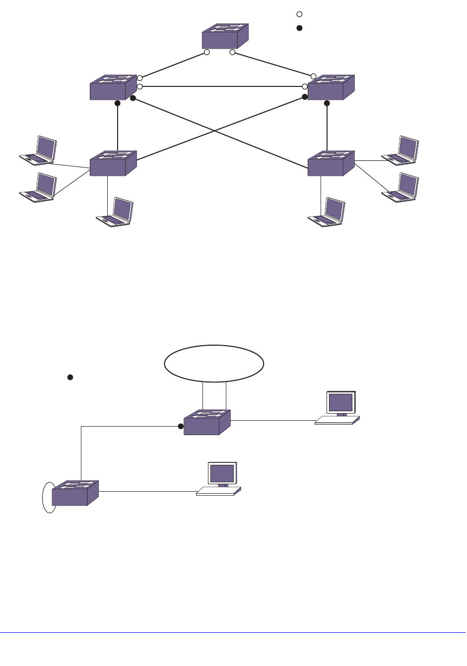
570 | Chapter 18. STP
NETGEAR 8800 User Manual
Figure 54. STP and Network Login Enabled
This relieves the administrator from having to configure network login on all the edge ports.
All the traffic can be monitored and resiliency is provided at the aggregation side.
Figure 55 shows a typical scenario for protecting loops and monitoring traffic on the edge
side.
Figure 55. Traffic Monitoring on the Edge Side
In huge networks, it is not easy to control or prevent end users from connecting devices other
than workstations to the edge ports. This feature helps in preventing the network loops that
occur when end users connect a switch or hub to the existing edge port in order to increase
the number of end user ports.
EX_stp_1082
Switch 1
Root Bridge
Switch 5
Summit
X450-2
Switch 4
Summit
X450-1
Switch 2
1
23 32
2
Indicates only spanning tree.
Indicates both spanning tree
and network login.
Switch 3
Client PCClient PC
EX_stp_1083
Core
Forwarding
Authenticated
Authenticated
Forwarding
Loop
Forwarding
Summit X450a
Extension
Switch
Indicates spanning tree
edge safeguard and
network login.

Chapter 18. STP | 571
NETGEAR 8800 User Manual
STP Rules and Restrictions
This section summarizes the rules and restrictions for configuring STP as follows:
• The carrier VLAN must span all ports of the STPD. (This is not applicable to MSTP.)
• The StpdID must be the VLAN ID of the carrier VLAN; the carrier VLAN cannot be
partitioned. (This is not applicable to MSTP.)
• A default VLAN cannot be partitioned. If a VLAN traverses multiple STPDs, the VLAN
must be tagged.
• An STPD can carry, at most, one VLAN running in PVST+ mode, and its STPD ID must
be identical with that VLAN ID. In addition, the PVST+ VLAN cannot be partitioned.
• The default VLAN of a PVST+ port must be identical to the native VLAN on the PVST+
device connected to that port.
• If an STPD contains both PVST+ and non-PVST+ ports, that STPD must be enabled. If
that STPD is disabled, the BPDUs are flooded in the format of the incoming STP port,
which may be incompatible with those of the connected devices.
• The 802.1D ports must be untagged; and the EMISTP/PVST+ ports must be tagged in
the carrier VLAN.
• An STPD with multiple VLANs must contain only VLANs that belong to the same virtual
router instance.
• STP and network login operate on the same port as follows:
• STP (802.1D), RSTP (802.1W), and MSTP (802.1S) support both network login and
STP on the same port.
• At least one VLAN on the intended port should be configured both for STP and
network login.
• STP and network login operate together only in network login ISP mode.
• When STP blocks a port, network login does not process authentication requests. All
network traffic is blocked except STP BPDUs.
• When STP places a port in forwarding state, all network traffic is allowed and network
login starts processing authentication requests.
• STP cannot be configured on the following ports:
• A mirroring target port.
• A software-controlled redundant port.
• MSTP and 802.1D STPDs cannot share a physical port.
• Only one MSTP region can be configured on a switch.
• In an MSTP environment, A VLAN can belong to one of the MSTIs.
• A VLAN can belong to only one MSTP domain.
• MSTP is not interoperable with PVST+.
• No VLAN can be bound to the CIST.

572 | Chapter 18. STP
NETGEAR 8800 User Manual
Configuring STP on the Switch
To configure basic STP:
1. Create one or more STPDs using the following command:
create stpd <stpd_name>
2. Add one or more VLANs to the STPD using the following command:
configure stpd <stpd_name> add vlan <vlan_name> ports [all | <port_list>] {[dot1d |
emistp | pvst-plus]}
3. Define the carrier VLAN using the following command:
configure stpd <stpd_name> tag <stpd_tag>
Note: The carrier VLAN’s ID must be identical to the ID of the STPD.
4. Enable STP for one or more STPDs using the following command:
enable stpd {<stpd_name>}
After you have created the STPD, you can optionally configure STP parameters for the
STPD.
Note: You should not configure any STP parameters unless you have
considerable knowledge and experience with STP. The default STP
parameters are adequate for most networks.
The following parameters can be configured on each STPD:
• Hello time (In an MSTP environment, configure this only on the CIST.)
• Forward delay
• Max age (In an MSTP environment, configure this only on the CIST.)
• Max hop count (MSTP only)
• Bridge priority
• StpdID (STP, RSTP, EMISTP, and PVST+ only)
• MSTI ID (MSTP only)
The following parameters can be configured on each port:
• Path cost
• Port priority
• Port mode

Chapter 18. STP | 573
NETGEAR 8800 User Manual
Note: The device supports the RFC 1493 Bridge MIB, RSTP-03, and
NETGEAR STP MIB. Parameters of the s0 default STPD support
RFC 1493 and RSTP-03. Parameters of any other STPD support
the NETGEAR STP MIB.
Note: If an STPD contains at least one port not in 802.1D (dot1D) mode,
the STPD must be configured with an StpdID.
The following section provides more detailed STP configuration examples, including 802.1D,
EMISTP, RSTP, and MSTP.
Displaying STP Settings
To display STPD settings, use the following command:
show stpd {<stpd_name> | detail}
To display more detailed information for one or more STPDs, specify the detail option.
This command displays the following information:
• STPD name
• STPD state
• STPD mode of operation
• Rapid Root Failover
• Tag
• Ports
• Active VLANs
• Bridge Priority
• Bridge ID
• Designated root
• STPD configuration information
If you have MSTP configured on the switch, this command displays additional information:
• MSTP Region
• Format Identifier
• Revision Level
• Common and Internal Spanning Tree (CIST)
• Total number of MST Instances (MSTI)

574 | Chapter 18. STP
NETGEAR 8800 User Manual
To display the state of a port that participates in STP, use the following command:
show {stpd} <stpd_name> ports {[detail | <port_list> {detail}]}
To display more detailed information for one or more ports in the specified STPD, including
participating VLANs, specify the detail option.
This command displays the following information:
• STPD port configuration
• STPD port mode of operation
• STPD path cost
• STPD priority
• STPD state (root bridge, and so on)
• Port role (root designated, alternate and so on)
• STPD port state (forwarding, blocking, and so on)
• Configured port link type
• Operational port link type
• Edge port settings (inconsistent behavior, edge safeguard setting)
• MSTP port role (internal or boundary)
If you have MSTP configured and specify the detail option, this command displays
additional information:
• MSTP internal path cost
• MSTP timers
• STPD VLAN Settings
If you have a VLAN that spans multiple STPDs, use the show vlan <vlan_name> stpd
command to display the STP configuration of the ports assigned to that specific VLAN.
The command displays the following:
• STPD port configuration
• STPD port mode of operation
• STPD path cost
• STPD priority
• STPD state (root bridge, and so on)
• Port role (root designated, alternate and so on)
• STPD port state (forwarding, blocking, and so on)
• Configured port link type
• Operational port link type

Chapter 18. STP | 575
NETGEAR 8800 User Manual
STP Configuration Examples
This section provides four configuration examples:
• Basic 802.1D Configuration Example on page 575
• EMISTP Configuration Example on page 576
• RSTP 802.1w Configuration Example on page 577
• MSTP Configuration Example on page 578
Basic 802.1D Configuration Example
The following example:
• Removes ports from the VLAN Default that will be added to VLAN Engineering.
• Creates the VLAN Engineering.
• Assigns a VLAN ID to the VLAN Engineering.
Note: If you do not explicitly configure the VLAN ID in your 802.1D
deployment, use the show vlan command to see the internal VLAN ID
automatically assigned by the switch.
• Adds ports to the VLAN Engineering.
• Creates an STPD named Backbone_st.
• Configures the default encapsulation mode of dot1d for all ports added to STPD
Backbone_st.
• Enables autobind to automatically add or remove ports from the STPD.
• Assigns the Engineering VLAN to the STPD.
• Assigns the carrier VLAN.
Note: To assign the carrier VLAN, the StpdID must be identical to the VLAN
ID of the carrier VLAN.
• Enables STP.
configure vlan default delete ports 2:5-2:10
create vlan engineering
configure vlan engineering tag 150
configure vlan engineering add ports 2:5-2:10 untagged
create stpd backbone_st
configure stpd backbone_st default-encapsulation dot1d
enable stpd backbone_st auto-bind vlan engineering
configure stpd backbone_st tag 150
enable stpd backbone_st
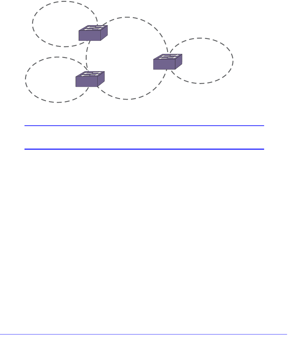
576 | Chapter 18. STP
NETGEAR 8800 User Manual
By default, the port encapsulation mode for user-defined STPDs is emistp. In this example,
you set it to dot1d.
EMISTP Configuration Example
Figure 56 is an example of EMISTP.
Figure 56. EMISTP Configuration Example
Note: By default, all ports added to a user-defined STPD are in emistp
mode, unless otherwise specified.
The following commands configure the switch located between S1 and S2:
create vlan red
configure red tag 100
configure red add ports 1:1-1:4 tagged
create vlan green
configure green tag 200
configure green add ports 1:1-1:2 tagged
create vlan yellow
configure yellow tag 300
configure yellow add ports 1:3-1:4 tagged
create stpd s1
configure stpd s1 add green ports all
configure stpd s1 tag 200
configure stpd s1 add red ports 1:1-1:2 emistp
enable stpd s1
EX_051
S1
S3
VLAN yellow
VLAN red
VLAN red
VLAN brown
S2
S4
VLAN red
VLAN green
VLAN red
VLAN blue
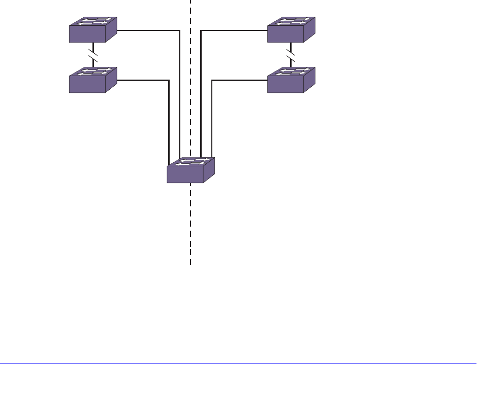
Chapter 18. STP | 577
NETGEAR 8800 User Manual
create stpd s2
configure stpd s2 add yellow ports all
configure stpd s2 tag 300
configure stpd s2 add red ports 1:3-1:4 emistp
enable stpd s2
RSTP 802.1w Configuration Example
Figure 57 is an example of a network with multiple STPDs that can benefit from RSTP. For
RSTP to work:
• Create an STPD.
• Configure the mode of operation for the STPD.
• Create the VLANs and assign the VLAN ID and the VLAN ports.
• Assign the carrier VLAN.
• Add the protected VLANs to the STPD.
• Configure the port link types.
• Enable STP.
Figure 57. RSTP Example
In this example, the commands configure switch A in STPD1 for rapid reconvergence. Use
the same commands to configure each switch and STPD in the network.
Sales, Personnel, Marketing
STPD 1 STPD 2
Manufacturing, Engineering, Marketing
Sales, Personnel, Manufacturing, Engineering, Marketing
Switch Y
Switch Z
Switch M
Switch B
EX_048
Switch A

578 | Chapter 18. STP
NETGEAR 8800 User Manual
create stpd stpd1
configure stpd stpd1 mode dot1w
create vlan sales
create vlan personnel
create vlan marketing
configure vlan sales tag 100
configure vlan personnel tag 200
configure vlan marketing tag 300
configure vlan sales add ports 1:1,2:1 tagged
configure vlan personnel add ports 1:1,2:1 tagged
configure vlan marketing add ports 1:1,2:1 tagged
configure stpd stpd1 add vlan sales ports all
configure stpd stpd1 add vlan personnel ports all
configure stpd stpd1 add vlan marketing ports all
configure stpd stpd1 ports link-type point-to-point 1:1,2:1
configure stpd stpd1 tag 100
enable stpd stpd1
MSTP Configuration Example
You must first configure a CIST before configuring any MSTIs in the region. You cannot
delete or disable a CIST if any of the MSTIs are active in the system.
Figure 58 is an example with multiple STPDs that can benefit from MSTP. In this example,
we have two MSTP regions that connect to each other and one external 802.1w bridge.
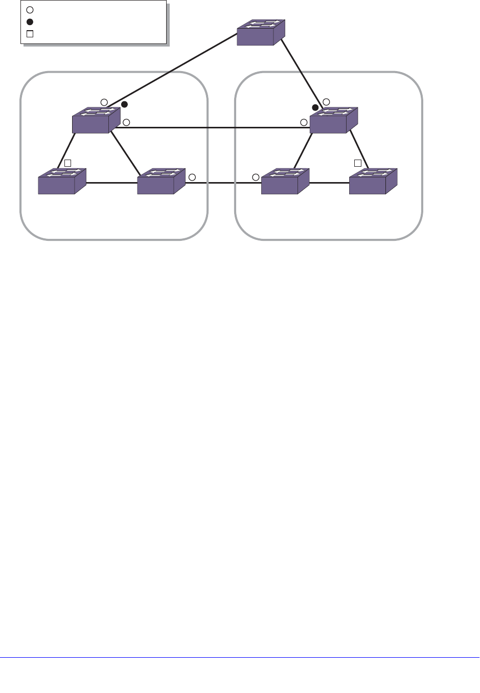
Chapter 18. STP | 579
NETGEAR 8800 User Manual
Figure 58. MSTP Configuration Example
For MSTP to work, complete the following steps on all switches in Region 1 and Region 2:
• Remove ports from the VLAN Default that will be added to VLAN Engineering.
• Create the VLAN Engineering.
• Assign a VLAN ID to the VLAN Engineering.
Note: If you do not explicitly configure the VLAN ID in your MSTP deployment,
use the show vlan command to see the internal VLAN ID automatically
assigned by the switch.
• Add ports to the VLAN Engineering.
• Create the MSTP region.
Note: You can configure only one MSTP region on the switch at any given
time.
• Create the STPD to be used as the CIST, and configure the mode of operation for the
STPD.
• Specify the priority for the CIST.
• Enable the CIST.
• Create the STPD to be used as an MSTI and configure the mode of operation for the
STPD.
• Specify the priority for the MSTI.
• Assign the VLAN Engineering to the MSTI.
EX_166
9
Switch A
= boundary port
= master port
= MSTI root port
12
3
45 67
108
CIST regional root
MSTI regional root
Switch F
MSTI regional root
STPD SI configured on switch A-C
VLAN engineering assigned to SI
STPD SI configured on switch E-G
VLAN finance assigned to SI
CIST regional root
CIST root port
CIST root
Switch D
Switch B Switch C
MSTP
Region 1
MSTP
Region 2
Switch E
Switch G

580 | Chapter 18. STP
NETGEAR 8800 User Manual
• Configure the port link type.
• Enable the MSTI.
On the external switch (the switch that is not in a region):
• Create an STPD that has the same name as the CIST, and configure the mode of
operation for the STPD.
• Specify the priority of the STPD.
• Enable the STPD.
Note: In the following sample configurations, any lines marked (Default)
represent default settings and do not need to be explicitly
configured. STPD s0 already exists on the switch.
In the following example, the commands configure Switch A in Region 1 for MSTP. Use the
same commands to configure each switch in Region 1:
create vlan engineering
configure vlan engineering tag 2
configure vlan engineering add port 2-3 tagged
configure mstp region region1
create stpd s0 (Default)
disable stpd s0 auto-bind vlan Default
configure stpd s0 mode mstp cist
configure stpd s0 priority 32768 (Default)
enable stpd s0
create stpd s1
configure stpd s1 mode mstp msti 1
configure stpd s1 priority 32768 (Default)
enable stpd s1 auto-bind vlan engineering
configure stpd s1 ports link-type point-to-point 2-3
enable stpd s1
In the following example, the commands configure Switch E in Region 2 for MSTP. Use the
same commands to configure each switch in Region 2:
create vlan finance
configure vlan finance tag 2
configure vlan finance add port 2-3 tagged
configure mstp region region2
create stpd s0 (Default)

Chapter 18. STP | 581
NETGEAR 8800 User Manual
configure stpd s0 mode mstp cist
configure stpd s0 priority 32768 (Default)
enable stpd s0 auto-bind vlan Default
enable stpd s0
create stpd s1
configure stpd s1 mode mstp msti 1
configure stpd s1 priority 32768 (Default)
enable stpd s1 auto-bind vlan finance
configure stpd s1 ports link-type point-to-point 2-3
enable stpd s1
In the following example, the commands configure switch D, the external switch. Switch D
becomes the CIST root bridge:
create stpd s0 (Default)
configure stpd s0 mode dot1w
configure stpd s0 priority 28672
enable stpd s0 auto-bind vlan Default
configure stpd s0 ports link-type point-to-point 4-5
enable stpd s0

Chapter 19. VRRP | 582
19
19. VRRP
This chapter includes the following sections:
• Overview on page 582
• VRRP Configuration Parameters on page 586
• VRRP Tracking on page 587
• VRRP Configuration Examples on page 589
This chapter assumes that you are already familiar with the Virtual Router Redundancy Protocol
(VRRP). If not, see the following publications for additional information:
• RFC 2338—Virtual Router Redundancy Protocol (VRRP)
• RFC 2787—Definitions of Managed Objects for the Virtual Router Redundancy Protocol
• Draft IETF VRRP Specification v2.06
Overview
VRRP allows multiple switches to provide redundant routing services to users. VRRP is used to
eliminate the single point of failure associated with manually configuring a default gateway
address on each host in a network. Without using VRRP, if the configured default gateway fails,
you must reconfigure each host on the network to use a different router as the default gateway.
VRRP provides a redundant path for the hosts. Using VRRP, if the default gateway fails, the
backup router assumes forwarding responsibilities.
The following sections provide more information on VRRP:
• VRRP and Hitless Failover on page 582
• VRRP Master Election on page 584
• VRRP Master Preemption on page 585
• VRRP Guidelines on page 585
VRRP and Hitless Failover
When you install two Management Switch Fabric Module (MSM) or Management Modules
(MMs) in a BlackDiamond chassis, one MSM/MM (node) assumes the role of primary and
the other node assumes the role of backup. The primary node executes the switch’s

Chapter 19. VRRP | 583
NETGEAR 8800 User Manual
management functions, and the backup acts in a standby role. Hitless failover transfers
switch management control from the primary to the backup and maintains the state of VRRP.
VRRP supports hitless failover. You do not explicitly configure hitless failover support; rather,
if you have two nodes installed, hitless failover is available.
Note: For more information about protocol, platform, and support for
hitless failover, see Understanding Hitless Failover Support on
page 69.
To support hitless failover, the primary node replicates VRRP protocol data units (PDUs) to
the backup, which allows the nodes to run VRRP in parallel. Although both nodes receive
VRRP PDUs, only the primary transmits VRRP PDUs to neighboring switches and
participates in VRRP.
Note: Before initiating failover, review the section Synchronizing Nodes on
Modular Switches on page 825 to confirm that the primary and
backup nodes are running software that supports the synchronize
command.
To initiate hitless failover on a network that uses VRRP:
1. Confirm that the primary and backup nodes are synchronized and have identical
software and switch configurations using the show switch {detail} command. The
output displays the status of the nodes, with the primary node showing MASTER and the
backup node showing BACKUP (InSync).
• If the primary and backup nodes are not synchronized and both nodes are running a
version of XCM8800 that supports synchronization, proceed to step 2.
• If the primary and backup nodes are synchronized, proceed to step 3.
2. If the primary and backup nodes are not synchronized, use the synchronize command to
replicate all saved images and configurations from the primary to the backup.
After you confirm the primary and backup nodes are synchronized, proceed to step 3.
3. If the primary and backup nodes are synchronized, use the run failover (formerly run
msm-failover) command to initiate failover.
For more detailed information about verifying the status of the nodes and system
redundancy, see Understanding System Redundancy on page 64. For more information
about hitless failover, see Understanding Hitless Failover Support on page 69.

584 | Chapter 19. VRRP
NETGEAR 8800 User Manual
Note: For complete information about software licensing, including how to
obtain and upgrade your license and what licenses are appropriate
for these features, see Appendix A, XCM8800 Software Licenses.
VRRP Master Election
When a VRRP configured network starts, VRRP uses an election algorithm to dynamically
assign master responsibility to one of the VRRP routers on the network. The VRRP master is
determined by the following factors:
• VRRP priority—This is a user-defined field. The range of the priority value is 1 to 254; a
higher number has higher priority. The value of 255 is reserved for a router that is
configured with the virtual router IP address. A value of 0 is reserved for the master
router, to indicate it is releasing responsibility for the virtual router. The default value is
100.
• Higher IP address—If the routers have the same configured priority, the router with the
higher IP address becomes the master.
If the master router becomes unavailable, the election process provides dynamic failover and
the backup router that has the highest priority assumes the role of master.
A new master is elected when one of the following things happen:
• VRRP is disabled on the master router.
• Loss of communication occurs between master and backup routers.
If VRRP is disabled on the master interface, the master router sends an advertisement with
the priority set to 0 to all backup routers. This signals the backup routers that they do not
need to wait for the master down interval to expire, and the master election process for a new
master can begin immediately.
The master down interval is set using the following formula: 3 * advertisement interval + skew
time.
Where:
• The advertisement interval is a user-configurable option.
• The skew time is (256-priority/256).
Note: An extremely busy CPU can create a short dual master situation. To
avoid this, increase the advertisement interval.

Chapter 19. VRRP | 585
NETGEAR 8800 User Manual
VRRP Master Preemption
VRRP master preemption is a feature that allows a VRRP router with a higher VRRP priority
to take control from a lower priority master. VRRP election occurs at network startup or when
the master becomes unavailable. VRRP preemption occurs when a new VRRP router is
added to the network or recovers, and that router has a higher priority than the current VRRP
master.
Note: The router that owns the virtual IP address always preempts,
independent of the VRRP preemption setting.
When a VRRP enabled router preempts the master, it does so in one of the following ways:
• If the preempt delay timer is configured for between 1 and 3600 seconds and the
lower-priority master is still operating, the router preempts the master when the timer
expires.
• If the preempt delay timer is configured for 0, the router preempts the master after 3 times
the hello interval.
• If the higher priority router stops receiving advertisements from the current master for 3
times the hello interval, it takes over mastership immediately.
The preempt delay timer provides time for a recovering router to complete start up before
preempting a lower-priority router. If the preempt delay timer is configured too low, traffic is
lost between the time the preempting router takes control and the time when it has completed
startup.
To enable VRRP master preemption and configure the preempt delay timer, use the following
command:
configure vrrp vlan <vlan_name> vrid <vridval> preempt {delay <seconds>}
To disable VRRP master preemption, use the following command:
configure vrrp vlan <vlan_name> vrid <vridval> dont-preempt
VRRP Guidelines
The following guidelines apply to using VRRP:
• VRRP packets are encapsulated IP packets.
• The VRRP multicast address is 224.0.0.18.
• The virtual router MAC address is 00 00 5E 00 01 <vrid>
• Duplicate VRIDs are allowed on the router but not on the same IP interface or VLAN.
• The maximum number of supported VRIDs per interface is seven.
• An interconnect link between VRRP routers should not be used, except when VRRP
routers have hosts directly attached.
586 | Chapter 19. VRRP
NETGEAR 8800 User Manual
• A maximum of 128 VRID instances are supported on the router.
• Up to seven unique VRIDs can be configured on the router. VRIDs can be re-used, but
not on the same interface.
• VRRP and the Spanning Tree Protocol (STP) can be simultaneously enabled on the
same switch.
• When VRRP and BOOTP/DHCP relay are both enabled on the switch, the relayed
BOOTP agent IP address is the actual switch IP address, not the virtual IP address.
• It is possible to assign multiple virtual IP addresses to the same VRID for a VRRP VR. In
this case, you must meet the following conditions:
• Multiple virtual IP addresses must be on the same subnet.
• The switch cannot own any of the multiple IP addresses.
For example, if you have a VLAN named v1 configured with IP addresses 1.1.1.1/24 and
2.2.2.2/24, the following configurations are allowed:
• VRRP VR on VLAN v1 with VRID 99 with virtual IP addresses 1.1.1.2 and 1.1.1.3
• VRRP VR on VLAN v1 with VRID 99 with virtual IP addresses 1.1.1.98 and 1.1.1.99
Using the VLAN v1 configuration described above, the following configurations are not
allowed:
• VRRP VR on VLAN v1 with VRID 99 with virtual IP addresses 1.1.1.1 and 2.2.2.2 (the IP
addresses are not on the same subnet).
• VRRP VR on VLAN v1 with VRID 99 with virtual IP addresses 1.1.1.1 and 1.1.1.99 (the
switch owns IP address 1.1.1.1).
VRRP Configuration Parameters
Table 56 lists the parameters that you can configure on a VRRP router.
Table 56. VRRP Configuration Parameters
Parameter Description
vrid This is the virtual router identifier and is a configured item in the range of
1 to 255. This parameter has no default value. For more information, see
the create vrrp vlan vrid command.
priority This priority value to be used by this VRRP router in the master election
process. A value of 255 is reserved for a router that is configured with the
virtual router IP address. A value of 0 is reserved for the master router to
indicate it is releasing responsibility for the virtual router. The range is 1 to
254. The default value is 100. For more information, see the configure
vrrp vlan vrid priority command.

Chapter 19. VRRP | 587
NETGEAR 8800 User Manual
VRRP Tracking
Tracking information is used to track various forms of connectivity from the VRRP router to
the outside world. The following sections describe VRRP tracking options and how to display
information on them:
• VRRP Tracking Mode on page 588
• VRRP VLAN Tracking on page 588
• VRRP Route Table Tracking on page 588
• VRRP Ping Tracking on page 589
ip_address This is the IP address associated with this virtual router. You can
associate one or more IP addresses to a virtual router. This parameter
has no default value. For more information, see the configure vrrp vlan
vrid add ipaddress command.
advertisement_interval Specifies the time interval between advertisements in seconds unless
otherwise specified as milliseconds. The default is 1 second.
The range is 1 through 255 seconds or 100 through 999 milliseconds.
Note: If you must configure the range in milliseconds, specify
the milliseconds keyword. If you enter a number from 100
through 255 and do not specify the milliseconds keyword, the
interval defaults to seconds. For more information, see the
configure vrrp vlan vrid advertisement-interval command.
skew_time This is the time to skew master_down_interval, in seconds. This value is
calculated as ((256-priority)/256).
master_down_interval This is the time interval for the backup router to declare master down, in
seconds. This value is calculated as
((3 * advertisement_interval) + skew_time).
preempt_mode This controls whether a higher priority backup router preempts a lower
priority master. A value of true allows preemption, and a value of false
prohibits preemption. The default setting is true.
Note: The router that owns the virtual router IP address
always preempts, independent of the setting of this parameter.
For more information, see the configure vrrp vlan vrid preempt
or the configure vrrp vlan vrid dont-preempt commands.
preempt_timer The preempt timer defines a preempt delay period for a preempting
master. For more information, see the configure vrrp vlan vrid preempt
command.
track mode The track option controls the behavior of the VRRP router when one of
the tracked entities fails or comes back from failure.
For more information, see the configure vrrp vlan <vlan_name>
vrid <vridval> track-mode [all | any] command description.
Table 56. VRRP Configuration Parameters (Continued)
Parameter Description

588 | Chapter 19. VRRP
NETGEAR 8800 User Manual
• Displaying VRRP Tracking Information on page 589
VRRP Tracking Mode
When a VRRP tracked entity fails, the VRRP router behavior is controlled by the tracking
mode. The mode can be all or any. The default mode is all.
When the mode is all, the mastership is relinquished when one of the following events occur:
• All of the tracked VLANs fail
• All of the tracked routes fail
• All of the tracked PINGs fail
When the mode is any, the mastership is relinquished when any of the tracked VLANs,
routes, or PINGs fail.
To configure the tracking mode to all, use the following command:
configure vrrp vlan <vlan_name> vrid <vridval> track-mode all
To configure the tracking mode to any, use the following command:
configure vrrp vlan <vlan_name> vrid <vridval> track-mode any
VRRP VLAN Tracking
You can configure VRRP to track connectivity of up to eight specified VLANs as criteria for
failover. If no active ports remain on the specified VLANs, the router automatically
relinquishes master status based on the tracking mode.
To add a tracked VLAN, use the following command:
configure vrrp vlan <vlan_name> vrid <vridval> add track-vlan
<target_vlan_name>
To delete a tracked VLAN, use the following command:
configure vrrp vlan <vlan_name> vrid <vridval> delete track-vlan
<target_vlan_name>
VRRP Route Table Tracking
You can configure VRRP to track specified routes in the route table as criteria for VRRP
failover. If any of the configured routes are not available within the route table, the router
automatically relinquishes master status based on the tracking mode.
To add a tracked route, use the following command:
configure vrrp vlan <vlan_name> vrid <vridval> add track-iproute
<ipaddress>/<masklength>
To delete a tracked route, use the following command:

Chapter 19. VRRP | 589
NETGEAR 8800 User Manual
configure vrrp vlan <vlan_name> vrid <vridval> delete track-iproute
<ipaddress>/<masklength>
VRRP Ping Tracking
You can configure VRRP to track connectivity using a simple ping to any outside responder.
The responder may represent the default route of the router, or any device meaningful to
network connectivity of the master VRRP router. If pinging the responder fails the specified
number of times, consecutively, the router automatically relinquishes master status based on
the tracking mode.
To add a tracked ping, use the following command:
configure vrrp vlan <vlan_name> vrid <vridval> add track-ping <ipaddress>
frequency <seconds> miss <misses>
The seconds parameter specifies the number of seconds between pings to the target IP
address. The range is 1 to 600 seconds.
The misses parameter specifies the number of misses allowed before this entry is considered
to be failing. The range is 1 to 255 pings.
To delete a tracked ping, use the following command:
configure vrrp vlan <vlan_name> vrid <vridval> delete track-ping <ipaddress>
Displaying VRRP Tracking Information
To view the status of tracked devices, use the following command:
show vrrp {detail}
VRRP Configuration Examples
This section describes the following VRRP network configuration examples:
• Simple VRRP Network Configuration on page 589
• Fully Redundant VRRP Network on page 591
• VRRP Tracking on page 592
Simple VRRP Network Configuration
Figure 59 shows a simple VRRP network.
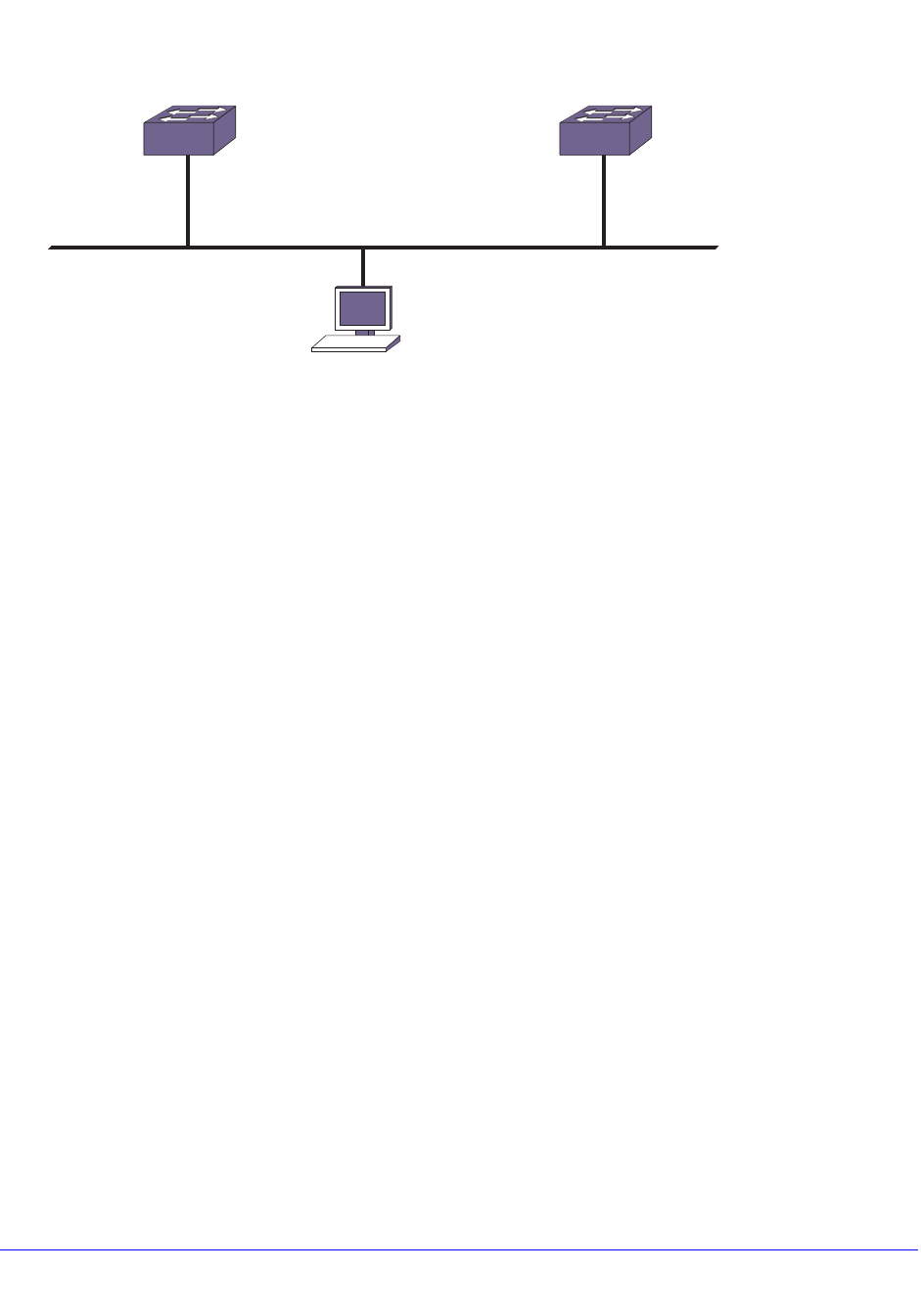
590 | Chapter 19. VRRP
NETGEAR 8800 User Manual
Figure 59. Simple VRRP Network
In Figure 59, a virtual router is configured on Switch A and Switch B using these parameters:
• VRID is 1.
• MAC address is 00-00-5E-00-01-01.
• IP address is 192.168.1.3.
Switch A is configured with a priority of 255. This priority indicates that it is the master router.
Switch B is configured with a priority of 100. This indicates that it is a backup router.
The master router is responsible for forwarding packets sent to the virtual router. When the
VRRP network becomes active, the master router broadcasts an ARP request that contains
the virtual router MAC address (in this case, 00-00-5E-00-01-01) for each IP address
associated with the virtual router. Hosts on the network use the virtual router MAC address
when they send traffic to the default gateway.
The virtual router IP address is configured to be the real interface address of the IP address
owner. The IP address owner is usually the master router. The virtual router IP address is
also configured on each backup router. However, in the case of the backup router, this IP
address is not associated with a physical interface. Each physical interface on each backup
router must have a unique IP address. The virtual router IP address is also used as the
default gateway address for each host on the network.
If the master router fails, the backup router assumes forwarding responsibility for traffic
addressed to the virtual router MAC address. However, because the IP address associated
with the master router is not physically located on the backup router, the backup router
cannot reply to TCP/IP messages (such as pings) sent to the virtual router.
The configuration commands for switch A are as follows:
configure vlan vlan1 ipaddress 192.168.1.3/24
create vrrp vlan vlan1 vrid 1
configure vrrp vlan vlan1 vrid 1 prioirty 255
configure vrrp vlan vlan1 vrid 1 add 192.168.1.3
enable vrrp
EX_068
Switch A
Switch A = Master
VRID = 1
Virtual router IP address = 192.168.1.3
MAC address = 00-00-5E-00-01-01
Priority = 255
Default Gateway = 192.168.1.3
192.168.1.3
Switch B
Switch B = Backup
VRID = 1
Virtual router IP address = 192.168.1.3
MAC address = 00-00-5E-00-01-01
Priority = 100
192.168.1.5
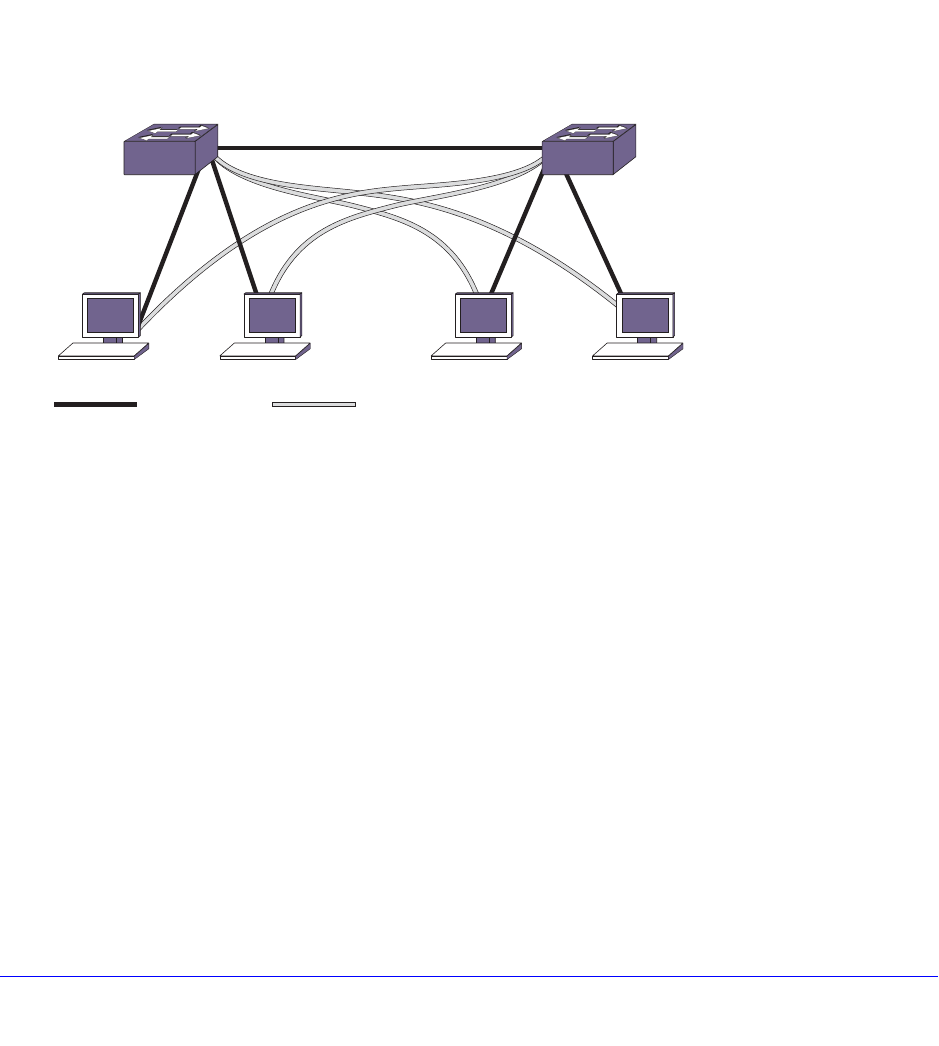
Chapter 19. VRRP | 591
NETGEAR 8800 User Manual
The configuration commands for switch B are as follows:
configure vlan vlan1 ipaddress 192.168.1.5/24
create vrrp vlan vlan1 vrid 1
configure vrrp vlan vlan1 vrid 1 add 192.168.1.3
enable vrrp
Fully Redundant VRRP Network
You can use two or more VRRP-enabled switches to provide a fully redundant VRRP
configuration on your network. Figure 60 shows a fully redundant VRRP configuration.
Figure 60. Fully Redundant VRRP Configuration
In Figure 60, switch A is configured as follows:
• IP address 192.168.1.3
• Master router for VRID 1
• Backup router for VRID 2
• MAC address 00-00-5E-00-01-01
Switch B is configured as follows:
• IP address 192.168.1.5
• Master router for VRID 2
• Backup router for VRID 1
• MAC address 00-00-5E-00-01-02
Both virtual routers are simultaneously operational. The traffic load from the four hosts is split
between them. Host 1 and host 2 are configured to use VRID 1 on switch A as their default
gateway. Host 3 and host 4 are configured to use VRID 2 on switch B as their default
EX_069
Default Route
Switch A
Master for virtual IP 192.168.1.3
Master VRID = 1
Backup for virtual IP 192.168.1.5
Backup VRID = 2
MAC address = 00-00-5E-00-01-01
Switch B
Master for virtual IP 192.168.1.5
Master VRID = 2
Backup for virtual IP 192.168.1.3
Backup VRID = 1
MAC address = 00-00-5E-00-01-02
Backup Route

592 | Chapter 19. VRRP
NETGEAR 8800 User Manual
gateway. In the event that either switch fails, the backup router configured is standing by to
resume normal operation.
The following command lists assume that you have already created the VLAN named vlan1
on the switch.
The configuration commands for switch A are as follows:
configure vlan vlan1 ipaddress 192.168.1.3/24
create vrrp vlan vlan1 vrid 1
configure vrrp vlan vlan1 vrid 1 priority 255
configure vrrp vlan vlan1 vrid 1 add 192.168.1.3
create vrrp vlan vlan1 vrid 2
configure vrrp vlan vlan1 vrid 2 add 192.168.1.5
enable vrrp
The configuration commands for switch B are as follows:
configure vlan vlan1 ipaddress 192.168.1.5/24
create vrrp vlan vlan1 vrid 2
configure vrrp vlan vlan1 vrid 2 priority 255
configure vrrp vlan vlan1 vrid 2 add 192.168.1.5
create vrrp vlan vlan1 vrid 1
configure vrrp vlan vlan1 vrid 1 add 192.168.1.3
enable vrrp
VRRP Tracking
Figure 61 is an example of VRRP tracking.
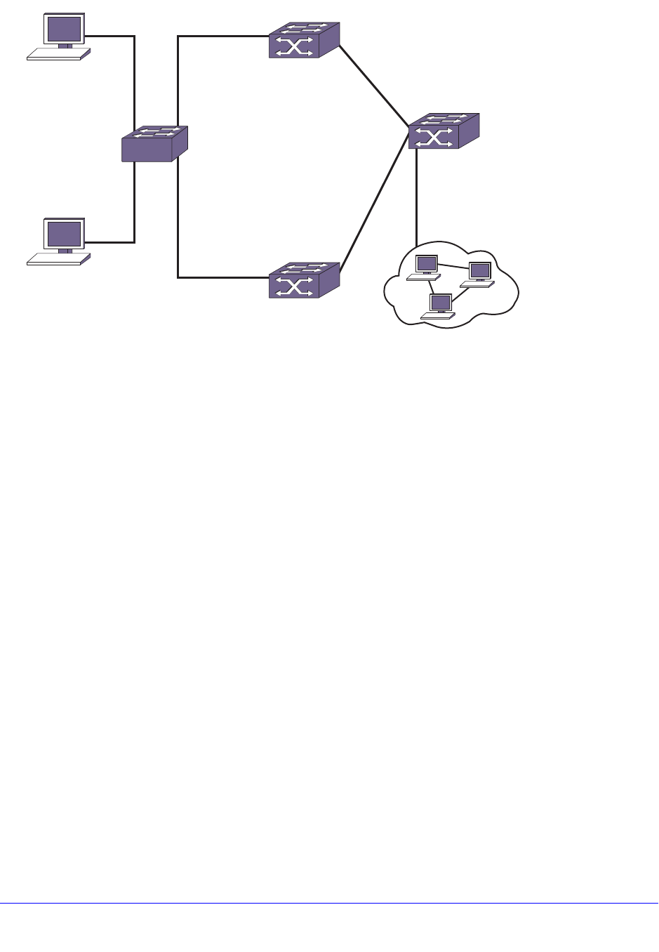
Chapter 19. VRRP | 593
NETGEAR 8800 User Manual
Figure 61. VRRP Tracking
To configure VLAN tracking, as shown in Figure 61, use the following command:
configure vrrp vlan vrrp1 vrid 2 add track-vlan vlan1
Using the tracking mechanism, if VLAN1 fails, the VRRP master realizes that there is no path
to upstream router via the master switch and implements a VRRP failover to the backup.
To configure route table tracking, as shown in Figure 61, use the following command:
configure vrrp vlan vrrp1 vrid 2 add track-iproute 10.10.10.0/24
The route specified in this command must exist in the IP routing table. When the route is no
longer available, the switch implements a VRRP failover to the backup.
To configure ping tracking, as shown in Figure 61, use the following command:
configure vrrp vlan vrrp1 vrid 2 add track-ping 10.10.10.121 frequency 2 miss 2
The specified IP address is tracked. If the fail rate is exceeded, the switch implements a
VRRP failover to the backup. A VRRP node with a priority of 255 may not recover from a
ping-tracking failure if there is a Layer 2 switch between it and another VRRP node. In cases
where a Layer 2 switch is used to connect VRRP nodes, NETGEAR recommends that those
nodes have priorities of less than 255.
EX_067
VRRP master
200.1.1.1/24
(track-vlan)
vlan vlan1
Host 2:
200.1.1.14/24
Gateway:
200.1.1.1
Host 1:
200.1.1.13/24
Gateway:
200.1.1.1
L2 switch
or hub
VRRP backup
200.1.1.2/24
Router
10.10.10.121

Chapter 20. IPv4 Unicast Routing | 594
20
20. IPv4 Unicast Routing
This chapter includes the following sections:
• Overview on page 595
• Configuring Unicast Routing on page 611
• Verifying the Routing Configuration on page 615
• Routing Configuration Example on page 617
• Proxy ARP on page 619
• IPv4 Multinetting on page 620
• DHCP/BOOTP Relay on page 627
• Broadcast UDP Packet Forwarding on page 629
• IP Broadcast Handling on page 632
• VLAN Aggregation on page 634
This chapter assumes that you are already familiar with IP unicast routing. If not, see the
following publications for additional information:
• RFC 1256—ICMP Router Discovery Messages
• RFC 1812—Requirements for IP Version 4 Routers
Note: For more information on interior gateway protocols, see Chapter 22,
RIP and Chapter 24, OSPF. For information on exterior gateway
protocols, see Chapter 26, BGP. For more information on switch
support for IPv6, see Chapter 21, IPv6 Unicast Routing.

Chapter 20. IPv4 Unicast Routing | 595
NETGEAR 8800 User Manual
Overview
The switch provides full Layer 3, IPv4 unicast routing to all switches that run the Advanced
and Core licenses (see Appendix A, XCM8800 Software Licenses). It exchanges routing
information with other routers on the network using one of the following routing protocols:
• Routing Information Protocol (RIP)
• Open Shortest Path First (OSPF)
The switch dynamically builds and maintains a set of routing tables and determines the best
path for each of its routes. Each host using the IP unicast routing functionality of the switch
must have a unique IP address assigned. In addition, the default gateway assigned to the
host must be the IP address of the router interface.
The XCM8800 software can provide both IPv4 and IPv6 routing at the same time. Separate
routing tables are maintained for the two versions. Most commands that require you to
specify an IP address can now accept either an IPv4 or IPv6 address and act accordingly.
Additionally, many of the IP configuration, enabling, and display commands have added
tokens for IPv4 and IPv6 to clarify the version required. For simplicity, existing commands
affect IPv4 by default and require you to specify IPv6, so configurations from an earlier
release still correctly configure an IPv4 network.
The following sections provide additional information on IP unicast routing:
• Router Interfaces on page 595
• Populating the Routing Tables on page 596
• Hardware Routing Table Management on page 604
Router Interfaces
The routing software and hardware routes IP traffic between router interfaces. A router
interface is simply a virtual LAN (VLAN) that has an IP address assigned to it.
As you create VLANs with IP addresses belonging to different IP subnets, you can also
choose to route between the VLANs. Both the VLAN switching and IP routing function occur
within the switch.
Note: Each IP address and mask assigned to a VLAN must represent a
unique IP subnet. You cannot configure the same IP address and
subnet on different VLANs.
Figure 62 shows an example NETGEAR 8800 switch configuration with two VLANs defined;
Finance and Personnel. All ports on slots 1 and 3 are assigned to Finance, and all ports on
slots 2 and 4 are assigned to Personnel. Figure 62 shows the subnet address and interface
address for each VLAN. Traffic within each VLAN is switched using the Ethernet MAC
addresses. Traffic between the two VLANs is routed using the IP addresses.
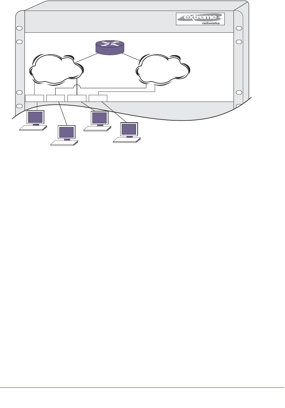
596 | Chapter 20. IPv4 Unicast Routing
NETGEAR 8800 User Manual
Figure 62. Routing Between VLANs
Populating the Routing Tables
The switch maintains a set of IP routing tables for both network routes and host routes. Some
routes are determined dynamically from routing protocols, and some routes are manually
entered. When multiple routes are available to a destination, configurable options such as
route priorities, route sharing, and compressed routes are considered when creating and
updating the routing tables. This section presents the following topics:
• Dynamic Routes on page 596
• Static Routes on page 597
• Multiple Routes on page 597
• Relative Route Priorities on page 597
• IP Route Sharing and ECMP on page 598
• Compressed Routes on page 599
Dynamic Routes
Dynamic routes are typically learned by enabling the RIP, OSPF, or BGP protocols, and are
also learned from Internet Control Message Protocol (ICMP) redirects exchanged with other
routers. These routes are called dynamic routes because they are not a permanent part of
the configuration. The routes are learned when the router starts up and are dynamically
updated as the network changes. Older dynamic routes are aged out of the tables when an
update for the network is not received for a period of time, as determined by the routing
protocol.
1234AB5678
EX_07
0
1
Finance Personnel
2 3 4
192.207.36.0192.207.35.0
192.207.36.14
192.207.35.13
192.207.35.11
192.207.36.12
192.207.36.1192.207.35.1

Chapter 20. IPv4 Unicast Routing | 597
NETGEAR 8800 User Manual
Once a routing protocol is configured, dynamic routes require no configuration and are
automatically updated as the network changes.
Static Routes
Static routes are routes that are manually entered into the routing tables and are not
advertised through the routing protocols. Static routes can be used to reach networks that are
not advertised by routing protocols and do not have dynamic route entries in the routing
tables. Static routes can also be used for security reasons, to create routes that are not
advertised by the router.
Static routes are configured in the XCM8800 software, remain part of the configuration when
the switch is rebooted, and are immediately available when the switch completes startup.
Static routes are never aged out of the routing table.
A default route is a type of static route that identifies the default router interface to which all
packets are routed when the routing table does not contain a route to the packet destination.
A default route is also called a default gateway.
Multiple Routes
When there are multiple, conflicting choices of a route to a particular destination, the router
picks the route with the longest matching network mask. If these are still equal, the router
picks the route using the following default criteria (in the order specified):
• Directly attached network interfaces
• Static routes
• ICMP redirects
• Dynamic routes
• Directly attached network interfaces that are not active.
Note: If you define multiple default routes, the route that has the lowest
metric is used. If multiple default routes have the same lowest
metric, the system picks one of the routes.
You can also configure blackhole routes—traffic to these destinations is silently dropped.
The criteria for choosing from multiple routes with the longest matching network mask is set
by choosing the relative route priorities.
Relative Route Priorities
Table 57 lists the relative priorities assigned to routes depending on the learned source of the
route.
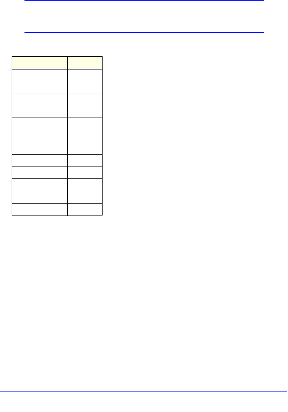
598 | Chapter 20. IPv4 Unicast Routing
NETGEAR 8800 User Manual
Note: Although these priorities can be changed, do not attempt any
manipulation unless you are expertly familiar with the possible
consequences.
IP Route Sharing and ECMP
IP route sharing allows a switch to communicate with a destination through multiple
equal-cost routes. In OSPF and BGP, this capability is referred to as equal cost multipath
(ECMP) routing.
Without IP route sharing, each IP route entry in the routing tables lists a destination subnet
and the next-hop gateway that provides the best path to that subnet. Every time a packet is
forwarded to a particular destination, it uses the same next-hop gateway.
With IP route sharing, an additional ECMP table lists up to 2, 4, or 8 next-hop gateways
(depending on the platform and feature configuration) for each route in the routing tables.
When multiple next-hop gateways lead to the same destination, the switch can use any of
those gateways for packet forwarding. IP route sharing provides route redundancy and can
provide better throughput when routes are overloaded.
The gateways in the ECMP table can be defined with static routes, or they can be learned
through the OSPF or BGP protocols. For more information on the ECMP table, see ECMP
Hardware Table on page 609.
Table 57. Relative Route Priorities
Route Origin Priority
Direct 10
BlackHole 50
Static 1100
ICMP 1200
EBGP 1700
IBGP 1900
OSPFIntra 2200
OSPFInter 2300
RIP 2400
OSPFExtern1 3200
OSPFExtern2 3300
BOOTP 5000

Chapter 20. IPv4 Unicast Routing | 599
NETGEAR 8800 User Manual
Note: Using route sharing makes router troubleshooting more difficult
because of the complexity in predicting the path over which the
traffic travels.
Compressed Routes
Compressed routes allow you to reduce the number of routes that are installed in the
hardware routing tables. The switch uses hardware routing tables to improve packet
forwarding performance. The switch can use both hardware and software to forward packets,
but packet forwarding without software processing is faster. The hardware routing tables
have less storage space than the software, so compressed routes conserve resources and
improve scaling
The compressed route feature allows you to install less specific routes in the table, when
overlapping routes with same nexthop exist. This route pruning technique is implemented as
part of the Route Manager (RtMgr) process.
When a route is added, deleted or updated, the pruning algorithm is applied to see if the new
route and/or its immediate children can be compressed or uncompressed as follows:
• If the parent node (immediate less specific route) of the newly added IP prefix has the
same gateway as the new IP prefix, the newly added prefix is compressed.
• If the gateways of the newly added IP prefix and its immediate children are the same, the
child nodes are compressed.
• If the gateways of the newly added IP prefix and its immediate children are not the same,
and the child nodes had been previously compressed, the child nodes are
uncompressed.
Event Log Messages
Event log messages are given in the following circumstances:
• When compression or uncompression start and end.
[ Severity level: Debug -Summary ]
• During each chunking start and end
[ Severity level: Debug -Verbose ]
• When a route is compressed or uncompressed.
[ Severity level: Debug -Verbose ]
Exceptional Scenarios
This section explains instances of exceptional route compression behavior.
• When a node does not have any best route.
Consider the routing table shown in Table 58. When a node does not have any best
route, children are uncompressed, if they were already compressed. Also this node is
uncompressed, if it had previously been compressed.
600 | Chapter 20. IPv4 Unicast Routing
NETGEAR 8800 User Manual
• When a node contains only a multicast route.
Route compression is applied to unicast routes only. If a node contains only a multicast
route, the compression algorithm is not applied to the node. Therefore multicast nodes
are considered as nodes with no best unicast routes as shown in Table 59.
ECMP Handling When IP Route Sharing Is Enabled
The nodes that have ECMP table entries are compressed only if the following conditions are
met; otherwise, potential sub-optimal forwarding occurs:
• The number of ECMP gateways for a given node must match the number of ECMP
gateways in its parent node.
• A given node’s set of gateways must match its parent’s set of gateways.
Table 60 shows how compression is applied for the nodes with ECMP table entries when IP
route sharing is enabled. Sample routes with ECMP table entries are taken for illustration.
The Reason field in the table provides information about why the compression is applied or
not applied for the node.
Table 58. Route Manager’s Table When There Is No Best Route for a Node
Prefix Gateway Number of best paths Compressed?
192.0.0.0/8 10.203.174.68 1No
192.168.0.0/16 10.203.174.68 0No
192.168.224.0/24 10.203.174.68 1No
192.168.225.0/24 10.203.174.68 1No
Table 59. Route Manager’s Table When a Node Contains Only a Multicast Route
Prefix Gateway Unicast/Multicast Compressed?
192.0.0.0/8 10.203.174.68 Unicast Route No
192.168.0.0/16 10.203.174.68 Multicast Route No
192.168.224.0/24 10.203.174.68 Unicast Route No
192.168.225.0/24 10.203.174.68 Unicast Route No
Chapter 20. IPv4 Unicast Routing | 601
NETGEAR 8800 User Manual
Table 61 shows only uncompressed routes.
Sample output is shown below:
* (debug) BD-12804.9 # enable iproute sharing
* (debug) BD-12804.10 # show iproute
Ori Destination Gateway Mtr Flags VLAN Duration
#s Default Route 12.1.10.10 1 UG---S-um--f v1 0d:20h:1m:3s
#s Default Route 12.1.10.12 1 UG---S-um--f v1 0d:19h:14m:58s
#d 12.1.10.0/24 12.1.10.62 1 U------um--f v1 0d:20h:1m:3s
d 16.1.10.0/24 16.1.10.62 1 -------um--- v16 0d:20h:1m:4s
#d 22.1.10.0/24 22.1.10.62 1 U------um--f v2 0d:20h:1m:4s
Table 60. Route Manager’s Table When IP Route Sharing Is Enabled
Prefix Gateways Compressed? Reason
20.0.0.0/8 Gw1: 30.1.10.1, Gw2:
50.1.10.1 NO This is the top node.
20.1.10.0/24 Gw1: 30.1.10.1 NO Number of gateways did not match. This node has
only one gateway, while the parent node has two.
20.2.10.0/24 Gw1: 30.1.10.1, Gw2:
60.1.10.1 NO Number of gateways match. But one of the ECMP
paths (gateway 60.1.10.1) does not match with its
parent’s ECMP paths.
20.3.10.0/24 Gw1: 30.1.10.1, Gw2:
50.1.10.1 YES Number of gateways matches with its parent. Also
all the gateways match with parent.
20.4.10.0/24 Gw1: 30.1.10.1, Gw2:
50.1.10.1 Gw3:
60.1.10.1
NO Number of gateways does not match with its
parent.
20.1.10.44/32 Gw1: 30.1.10.1 Gw2:
50.1.10.1 NO Number of gateways did not match. [This node has
ECMP table entries, but parent node 20.1.10.0
does not have an ECMP table entry.]
Table 61. HAL(TCAM)/Kernel Routing Table When IP Route Sharing Is Enabled
Prefix Gateway
20.0.0.8/16 Gw1: 30.1.10.1,
Gw2: 50.1.10.1
20.1.10.0/24 Gw1: 30.1.10.1
20.2.10.0/24 Gw1: 30.1.10.1,
Gw2: 60.1.10.1
20.4.10.0/24 Gw1: 30.1.10.1,
Gw2: 50.1.10.1 Gw3:
60.1.10.1
20.1.10.44/32 Gw1: 30.1.10.1 Gw2:
50.1.10.1

602 | Chapter 20. IPv4 Unicast Routing
NETGEAR 8800 User Manual
#s 33.33.33.0/24 12.1.10.25 1 UG---S-um--f v1 0d:20h:1m:3s
#s 55.0.0.0/8 12.1.10.10 1 UG---S-um--f v1 0d:20h:1m:3s
#s 55.0.0.0/8 22.1.10.33 1 UG---S-um--f v2 0d:20h:1m:3s
#s 55.2.1.1/32 12.1.10.22 1 UG---S-um--f v1 0d:20h:1m:3s
#s 55.5.5.1/32 12.1.10.44 1 UG---S-um--f v1 0d:20h:1m:3s
#s 66.0.0.0/8 12.1.10.12 1 UG---S-um--f v1 0d:20h:1m:3s
#s 66.0.0.0/16 12.1.10.12 1 UG---S-um--c v1 0d:20h:1m:3s
#d 70.1.10.0/24 70.1.10.62 1 U------um--f v7 0d:20h:1m:4s
#s 78.0.0.0/8 12.1.10.10 1 UG---S-um--f v1 0d:20h:1m:3s
#s 79.0.0.0/8 12.1.10.10 1 UG---S-um--c v1 0d:20h:1m:3s
#s 79.0.0.0/8 12.1.10.12 1 UG---S-um--c v1 0d:20h:1m:3s
#s 80.0.0.0/8 12.1.10.10 1 UG---S-um--f v1 0d:20h:1m:3s
#d 80.1.10.0/24 80.1.10.62 1 U------um--f v8 0d:20h:1m:4s
#s 81.0.0.0/8 12.1.10.10 1 UG---S-um--f v1 0d:20h:1m:3s
#s 81.0.0.0/8 12.1.10.12 1 UG---S-um--f v1 0d:20h:1m:3s
#s 81.0.0.0/8 12.1.10.13 1 UG---S-um--f v1 0d:20h:1m:3s
#s 82.0.0.0/8 12.1.10.10 1 UG---S-um--f v1 0d:20h:1m:3s
#s 83.0.0.0/8 12.1.10.10 1 UG---S-um--f v1 0d:20h:1m:3s
#d 91.1.10.0/24 91.1.10.62 1 U------um--f v9 0d:20h:1m:4s
#d 92.1.10.0/24 92.1.10.62 1 U------um--f v10 0d:20h:1m:6s
#d 93.1.10.0/24 93.1.10.62 1 U------um--f v11 0d:20h:1m:6s
Origin(Ori): (b) BlackHole, (be) EBGP, (bg) BGP, (bi) IBGP, (bo) BOOTP
(ct) CBT, (d) Direct, (df) DownIF, (dv) DVMRP, (e1) ISISL1Ext
(e2) ISISL2Ext, (h) Hardcoded, (i) ICMP, (i1) ISISL1 (i2) ISISL2
(is) ISIS, (mb) MBGP, (mbe) MBGPExt, (mbi) MBGPInter,
(mo) MOSPF (o) OSPF, (o1) OSPFExt1, (o2) OSPFExt2
(oa) OSPFIntra, (oe) OSPFAsExt, (or) OSPFInter, (pd) PIM-DM, (ps) PIM-SM
(r) RIP, (ra) RtAdvrt, (s) Static, (sv) SLB_VIP, (un) UnKnown
(*) Preferred unicast route (@) Preferred multicast route
(#) Preferred unicast and multicast route
Flags: (B) BlackHole, (D) Dynamic, (G) Gateway, (H) Host Route
(L) Matching LDP LSP, (l) Calculated LDP LSP, (m) Multicast
(P) LPM-routing, (R) Modified, (S) Static, (s) Static LSP
(T) Matching RSVP-TE LSP, (t) Calculated RSVP-TE LSP, (u) Unicast, (U) Up
(f) Provided to FIB (c) Compressed Route
Mask distribution:
2 default routes 12 routes at length 8
1 routes at length 16 9 routes at length 24
2 routes at length 32
Route Origin distribution:
8 routes from Direct 18 routes from Static
Total number of routes = 26
Total number of compressed routes = 3
ECMP Handling When IP Route Sharing Is Disabled
If IP route sharing is disabled, the first best route is installed in the hardware table, if multiple
best routes are available. Hence the compression algorithm considers the first best route for
Chapter 20. IPv4 Unicast Routing | 603
NETGEAR 8800 User Manual
ECMP cases. As shown in the Route Manager Table in Table 62, when IP route sharing is
disabled, all routes are compressed, except the first one in this case.
Sample output is shown below:
* (debug) BD-12804.7 # disable iproute sharing
* (debug) BD-12804.8 # show iproute
Ori Destination Gateway Mtr Flags VLAN Duration
#s Default Route 12.1.10.10 1 UG---S-um--f v1 0d:19h:58m:58s
#s Default Route 12.1.10.12 1 UG---S-um--- v1 0d:19h:12m:53s
#d 12.1.10.0/24 12.1.10.62 1 U------um--f v1 0d:19h:58m:59s
d 16.1.10.0/24 16.1.10.62 1 -------um--- v16 0d:19h:58m:59s
#d 22.1.10.0/24 22.1.10.62 1 U------um--f v2 0d:19h:58m:59s
#s 33.33.33.0/24 12.1.10.25 1 UG---S-um--f v1 0d:19h:58m:58s
#s 55.0.0.0/8 12.1.10.10 1 UG---S-um--c v1 0d:19h:58m:58s
#s 55.0.0.0/8 22.1.10.33 1 UG---S-um--- v2 0d:19h:58m:58s
#s 55.2.1.1/32 12.1.10.22 1 UG---S-um--f v1 0d:19h:58m:58s
#s 55.5.5.1/32 12.1.10.44 1 UG---S-um--f v1 0d:19h:58m:58s
#s 66.0.0.0/8 12.1.10.12 1 UG---S-um--f v1 0d:19h:58m:58s
#s 66.0.0.0/16 12.1.10.12 1 UG---S-um--c v1 0d:19h:58m:58s
#d 70.1.10.0/24 70.1.10.62 1 U------um--f v7 0d:19h:58m:59s
#s 78.0.0.0/8 12.1.10.10 1 UG---S-um--c v1 0d:19h:58m:58s
#s 79.0.0.0/8 12.1.10.10 1 UG---S-um--c v1 0d:19h:58m:58s
#s 79.0.0.0/8 12.1.10.12 1 UG---S-um--- v1 0d:19h:58m:58s
#s 80.0.0.0/8 12.1.10.10 1 UG---S-um--c v1 0d:19h:58m:58s
#d 80.1.10.0/24 80.1.10.62 1 U------um--f v8 0d:19h:58m:59s
#s 81.0.0.0/8 12.1.10.10 1 UG---S-um--c v1 0d:19h:58m:58s
#s 81.0.0.0/8 12.1.10.12 1 UG---S-um--- v1 0d:19h:58m:58s
Table 62. Route Manager’s Table When IP Route Sharing Is Disabled
Prefix Gateways Compressed?
20.0.0.0/8 Gw1: 30.1.10.1, Gw2:
50.1.10.1 NO
20.1.10.0/24 Gw1: 30.1.10.1 YES
20.2.10.0/24 Gw1: 30.1.10.1, Gw2:
60.1.10.1 YES
20.3.10.0/24 Gw1: 30.1.10.1, Gw2:
50.1.10.1 YES
20.4.10.0/24 Gw1: 30.1.10.1, Gw2:
50.1.10.1 Gw3:
60.1.10.1
YES
20.1.10.44/32 Gw1: 30.1.10.1 Gw2:
50.1.10.1 YES
Table 63. HAL(TCAM)/Kernel Routing Table When IP Route Sharing Is Disabled
Prefix Gateway
20.0.0.8/16 Gw1: 30.1.10.1,

604 | Chapter 20. IPv4 Unicast Routing
NETGEAR 8800 User Manual
#s 81.0.0.0/8 12.1.10.13 1 UG---S-um--- v1 0d:19h:58m:58s
#s 82.0.0.0/8 12.1.10.10 1 UG---S-um--c v1 0d:19h:58m:58s
#s 83.0.0.0/8 12.1.10.10 1 UG---S-um--c v1 0d:19h:58m:58s
#d 91.1.10.0/24 91.1.10.62 1 U------um--f v9 0d:19h:58m:59s
#d 92.1.10.0/24 92.1.10.62 1 U------um--f v10 0d:19h:59m:2s
#d 93.1.10.0/24 93.1.10.62 1 U------um--f v11 0d:19h:59m:2s
Origin(Ori): (b) BlackHole, (be) EBGP, (bg) BGP, (bi) IBGP, (bo) BOOTP
(ct) CBT, (d) Direct, (df) DownIF, (dv) DVMRP, (e1) ISISL1Ext
(e2) ISISL2Ext, (h) Hardcoded, (i) ICMP, (i1) ISISL1 (i2) ISISL2
(is) ISIS, (mb) MBGP, (mbe) MBGPExt, (mbi) MBGPInter,
(mo) MOSPF (o) OSPF, (o1) OSPFExt1, (o2) OSPFExt2
(oa) OSPFIntra, (oe) OSPFAsExt, (or) OSPFInter, (pd) PIM-DM, (ps) PIM-SM
(r) RIP, (ra) RtAdvrt, (s) Static, (sv) SLB_VIP, (un) UnKnown
(*) Preferred unicast route (@) Preferred multicast route
(#) Preferred unicast and multicast route
Flags: (B) BlackHole, (D) Dynamic, (G) Gateway, (H) Host Route
(L) Matching LDP LSP, (l) Calculated LDP LSP, (m) Multicast
(P) LPM-routing, (R) Modified, (S) Static, (s) Static LSP
(T) Matching RSVP-TE LSP, (t) Calculated RSVP-TE LSP, (u) Unicast, (U) Up
(f) Provided to FIB (c) Compressed Route
Mask distribution:
2 default routes 12 routes at length 8
1 routes at length 16 9 routes at length 24
2 routes at length 32
Route Origin distribution:
8 routes from Direct 18 routes from Static
Total number of routes = 26
Total number of compressed routes = 8
Hardware Routing Table Management
The switch hardware can route traffic based on information stored in hardware and software
routing tables. Routing tasks are completed much faster when the routes are already stored
in hardware routing tables. When packets are routed using the hardware routing tables, this
is called fast-path routing, because the packets take the fast path through the switch.
The switch hardware provides the fast path, and the XCM8800 software provides the routing
management capabilities, including management of the hardware routing tables. The
software collects all routing information, manages the routes according to the switch
configuration, and stores the appropriate routes in the hardware routing tables. When an IP
unicast packet arrives and the destination IP address is not found in the hardware route
tables, it is routed by software. The software processing takes more time than the fast path,
so routing based on the software tables is called slow-path routing.
NETGEAR 8800 switches allow you to customize the software management of the hardware
routing tables using the following hardware components:

Chapter 20. IPv4 Unicast Routing | 605
NETGEAR 8800 User Manual
• Extended IPv4 Host Cache on page 605
• ECMP Hardware Table on page 609
Extended IPv4 Host Cache
The extended IPv4 host cache feature provides additional, configurable storage space on
select switches to store additional IPv4 hosts in the hardware routing tables. This feature is
supported on NETGEAR 8800 switches. Some switches do not support this feature because
they have more than enough storage space for IPv4 hosts, and some do not have the
hardware required to support this feature.
All switches support slow-path routing (using software routing tables), so adding more entries
in the hardware routing table is a performance feature, which allows more hosts to benefit
from fast-path routing. If your switch log was displaying table-full messages in XCM8800, you
might be able to improve switch performance and avoid the table-full messages by
configuring the extended IPv4 host cache feature.
To use the extended IPv4 host cache feature effectively, it helps to understand how the
hardware tables operate on the switches that support this feature. The hardware forwarding
tables controlled by this feature store entries for the following:
• IPv4 local and remote hosts
• IPv4 routes
• IPv6 local hosts
• IPv6 routes
• IPv4 multicast
The extended IPv4 host cache feature works by customizing the forwarding table space
allotted to these components.
The following sections provide more information about the Extended IPv4 Host Cache
feature:
• Introduction to Hardware Forwarding Tables on page 605
• LPM Table Management on page 606
• Extended IPv4 Host Cache Management Guidelines on page 607
• IPv4 Host Entry Population Sequence on page 608
• Calculating the Number of Routes Needed on page 609
• Lower-Capacity Hardware on page 609
Introduction to Hardware Forwarding Tables
The extended IPv4 host cache feature relates to the four hardware forwarding tables shown
in Figure 63.
606 | Chapter 20. IPv4 Unicast Routing
NETGEAR 8800 User Manual
Figure 63. Hardware Forwarding Tables
The Longest Prefix Match (LPM) and Layer 3 (L3) Hash tables store host and route
information for fast-path forwarding. When the switch locates a route or host in one of these
tables, it follows a table index to the Next Hop table, which contains MAC address and egress
port information that is shared by the hosts and routes in the other tables. The hardware
routing table capacity is partly determined by the capacity of the Next Hop table. The Next
Hop table capacity is smaller than the combined capacity of the other tables because
typically, multiple routes and hosts share each Next Hop table entry. When the other tables
map to many different next hop entries, the Next Hop table can limit the total number of hosts
and routes stored in hardware.
On most platforms, the L3 Hash table is smaller than the LPM tables. Because the L3 Hash
table is the only table that can store IPv4 multicast entries and IPv6 local hosts, and because
of the way the L3 Hash table is populated, forwarding table capacity and forwarding
performance can be improved by allocating space for storing IPv4 local and remote host
entries in the LPM tables.
The extended IPv4 host cache feature specifically allows you to define the number of entries
that are reserved in the LPM tables for IPv4 and IPv6 routes. The unreserved entries are
available for IPv4 local and remote hosts. IPv4 hosts can also occupy unused areas of the L3
Hash table, and when necessary, unused space in the reserved section of the LPM tables.
The maximum number of hosts that can be stored in the hardware routing tables depends on
the configuration and usage of the tables, but the number of local IPv4 hosts and gateways is
ultimately limited to the size of the Next Hop table minus three reserved entries.
LPM Table Management
The internal LPM tables are provided on all platforms.
The XCM8800 software manages the content of the hardware tables based on the
configuration specified by the following commands:
configure iproute reserved-entries [ <num_routes_needed> | maximum | default ]
slot [all | <slot_num>]
Figure 64 lists the hardware capacity for each of the tables shown in Figure 63.
ipuni_0001
Internal LPM Table
Next Hop Table
Reserved
space
L3 Hash Table
Unreserved
space
Reserved
Space
External LPM Tables
Unreserved
space
Chapter 20. IPv4 Unicast Routing | 607
NETGEAR 8800 User Manual
In addition to configuring the number of reserved entries in the LPM tables, the configure
iproute reserved-entries command configures which entries are stored in which tables.
Table 65 shows the hardware routing table contents for several configurations.
Note: On the NETGEAR 8800 switches that do not support the extended
IPv4 host cache feature, the LPM table does not store IPv4 hosts.
Extended IPv4 Host Cache Management Guidelines
When configuring the extended IPv4 host cache feature, consider the following guidelines:
• The default option configures the switch to store entries for local and remote IPv4 hosts
in the LPM tables. On NETGEAR 8800 switches, the default setting creates room for 48
local and remote IPv4 host entries. This option provides more room for IPv4 multicast and
IPv6 hosts in the L3 Hash table.
• The maximum option reserves all space in the LPM tables for IPv4 and IPv6 routes. This
option provides the maximum storage for IPv4 and IPv6 routes when you do not expect to
store many IPv4 multicast and IPv6 hosts in the L3 Hash table.
Table 64. Hardware Routing Table Configuration Capacities
Table NETGEAR 8800
Switches
Internal LPM 12256
External LPM N/A
L3 Hash 8192
Next Hop 8192
Table 65. Hardware Routing Table Contents
Table NETGEAR 8800 Switches
Internal LPM—Reserved space Entries for IPv4 routes and IPv6 routes.a
a. IPv6 routes consume two entries.
Internal LPM—Unreserved space Entries for IPv4 local and remote hosts.
External LPM—Reserved space N/A
External LPM—Unreserved space N/A
L3 Hash Entries for IPv4 local and remote hosts, IPv4
multicast entries, and IPv6 local hosts.a
Next Hop MAC address and egress port information for
the entries in the other tables.

608 | Chapter 20. IPv4 Unicast Routing
NETGEAR 8800 User Manual
Note: If no IPv4 route is found in the LPM table and IPv4 unicast packets
are slow-path forwarded for a given remote host, an IPv4 entry is
created for the remote host in either the L3 hash table or LPM table.
The hardware does not cache entries for remote IPv6 hosts, so IPv6
routes take precedence over IPv4 routes.
IPv4 Host Entry Population Sequence
The XCM8800 software populates the hardware tables with IPv4 host entries by searching
for available space in the following sequence:
1. Unreserved space in the LPM tables as shown in Table 65.
2. Available space in an L3 Hash table bucket.
3. Available space in the reserved section of the LPM table as shown in Table 65.
4. Space used by the oldest host entries in the LPM and L3 Hash tables.
The L3 Hash table is named for the hash function, which stores host and multicast entries
based on an algorithm applied to the host IP address or multicast (Source IP, Group IP, VLAN
ID) tuple. The hash table stores entries in groups of 8, and these groups are called buckets.
When a bucket is full, any additional host or multicast addresses that map or hash to that
bucket cannot be added. Another benefit of the extended IPv4 host cache feature is that you
can reduce these conflicts or hash table collisions, by making room for IPv4 hosts in the LPM
table and reducing demand for the L3 Hash table.
A hardware-based aging mechanism is used to remove any remote IPv4 host entries that
have not had IPv4 unicast packets forwarded to them in the previous hour. (Note that remote
IPv4 hosts only need to be cached when all IPv4 routes do not fit within the number of routes
reserved.) Aging helps to preserve resources for the hosts that are needed most. In a
NETGEAR 8800, aging is performed independently for each I/O module or stack node based
on the ingress traffic for that module or node. Depending on the IPv4 unicast traffic flows,
independent IPv4 host caches for each I/O module can provide increased hardware fast-path
forwarding. Even with aging, it is still possible that the Next Hop table, LPM table, or L3 Hash
bucket do not have space to accept a new host. In those cases, a least-recently used
algorithm is used to remove the oldest host to make space for the new host in hardware.
Local IPv4 host entries are only subject to hardware-based aging if there has been a large
amount of least-recently used replacement, indicating severe contention for HW table
resources. Otherwise, local IPv4 host entries are retained, based on whether IP ARP refresh
is enabled or disabled, and the value for the configure iparp timeout {vr <vr_name>}
<minutes> command.

Chapter 20. IPv4 Unicast Routing | 609
NETGEAR 8800 User Manual
Note: Gateway entries are entries that represent routers or tunnel
endpoints used to reach remote hosts. Gateway entries are not aged
and are not replaced by IPv6 hosts or multicast entries in the L3
Hash table or by any entries requiring space in the Next Hop table.
The software can move gateway entries from the LPM table to the
L3 Hash table to make room for new reserved routes.
Calculating the Number of Routes Needed
Guidelines for calculating the number of routes to reserve are provided in the NETGEAR
8800 Chassis Switch CLI Manual description for the following command:
configure iproute reserved-entries [ <num_routes_needed> | maximum | default ]
slot [all | <slot_num>]
Lower-Capacity Hardware
NETGEAR 8800 modules are considered lower-capacity hardware.
The XCM8800 software supports the coexistence of higher- and lower-capacity hardware in
the same NETGEAR 8800 chassis. To allow for coexistence and increased hardware
forwarding, when the number of IPv4 routes exceeds 25,000, the lower-capacity hardware
automatically transitions from using LPM routing to forwarding of individual remote hosts,
also known as IP Forwarding Database (IP FDB) mode. Lower capacity hardware operating
in IP FDB mode is indicated with a d flag in the output of show iproute reserved-entries
statistics command, indicating that only direct routes are installed.
ECMP Hardware Table
IP route sharing and the ECMP hardware table are introduced in IP Route Sharing and
ECMP on page 598. The following sections provide guidelines for managing the ECMP
hardware table:
• ECMP Table Configuration Guidelines on page 609
• Troubleshooting: ECMP Table-Full Messages on page 611
ECMP Table Configuration Guidelines
The ECMP table contains gateway lists, and each gateway list defines the equal-cost
gateways that lead to a destination subnet. When IP route sharing is enabled, subnet entries
in the LPM table can be mapped to gateway list entries in the ECMP table, instead of to a
single gateway within the LPM table. This mapping is managed in one of two ways,
depending on the platform.
For the NETGEAR 8800, each LPM table entry mapping requires a unique entry in the ECMP
table.
The gateway sets for the platforms listed above might be unique or might be the same as that
used for another LPM table entry. Subnet entries in the LPM table cannot map to the same

610 | Chapter 20. IPv4 Unicast Routing
NETGEAR 8800 User Manual
ECMP table entry, so duplicate gateway sets require additional ECMP table entries, which
reduces the total number of gateway sets the ECMP table can support. This approach also
limits the total number of LPM table entries that can use IP route sharing to the total number
of ECMP table entries. The ECMP table is smaller than the LPM table, so IP route sharing is
not available to all LPM table entries on these platforms.
For improved ECMP scaling, each LPM table entry points to a gateway set entry in the ECMP
table:
Each gateway set entry for the platforms listed above is unique and appears only once in the
ECMP table. Multiple LPM table entries can point to the same gateway set entry. This
efficient use of the ECMP table creates more room in the ECMP table for additional gateway
set entries. It also makes IP route sharing available to every entry in the LPM table.
The following command allows you to configure the maximum number of next-hop gateways
for gateway sets in the ECMP table:
configure iproute sharing max-gateways <max_gateways>
Each gateway entry in a gateway set consumes ECMP table space. As the max_gateways
value decreases, the ECMP table supports more gateway sets. If you configure the
max_gateways value to 8, the switch supports route sharing through up to 8 gateways per
subnet, but supports the smallest number of gateway sets. If you do not need to support up to
8 different gateways for any subnet, you can decrease the max_gateways value to support
more gateway sets.
To determine which gateways might be added to the ECMP table, consider how many local
gateways are connected to the switch and can be used for ECMP, and consider the
max_gateways value. For example, suppose that you have four ECMP gateway candidates
connected to the switch (labeled A, B, C, and D for this example) and the max_gateways
option is set to 4. For platforms that allow a gateway set entry to support multiple subnets,
this configuration could result in up to 11 gateway sets in the ECMP table: ABCD, ABC, ABD,
ACD, BCD, AB, AC, AD, BC, BD, and CD.
If there are 4 gateways and you set max-gateways to 4, you can use the choose function to
calculate the total number of gateway set possibilities as follows:
(4 choose 4) + (4 choose 3) + (4 choose 2) = 11
To calculate the number of gateway set possibilities for a given number of total gateways and
a specific max-gateways value, use the choose function in the following formula:
(TGW choose MGW) + (TGW choose MGW-1) + ... + (TGW choose 2) = TGWsets
In the formula above, TGW represents the total local gateways, MGW represents the
max_gateways value, and TGWsets represents the total gateway sets needed to support all
possible shared paths.
To see if your platform supports the total gateway sets needed, do the following:
• Calculate the total ECMP gateway sets possible as described above.
• Compare your result to the IP route sharing (total combinations of gateway sets)
capacities listed in the XCM8800 Release Notes to verify that the switch can support the
desired number of gateway sets.

Chapter 20. IPv4 Unicast Routing | 611
NETGEAR 8800 User Manual
Troubleshooting: ECMP Table-Full Messages
If the ECMP table is full, no new gateway sets can be added, and IP forwarding is still done in
hardware through one of the following:
• For platforms that allow a gateway set entry to support multiple subnets, forwarding can
be done using an existing gateway set that is a partial subset of the unavailable gateway
set. If the unavailable gateway set consists of N gateways, the subset used could include
a range of gateways from N-1 gateways down to a single gateway. For example, if the
ECMP table does not have room for a new gateway set using gateways E, F, G, and H, a
partial subset such as EFG, EF, or E will be used.
• For platforms that require one gateway set entry per subnet, forwarding is done through a
single gateway.
On NETGEAR 8800 switches, an ECMP table-full condition produces the following message:
<Info:Kern.IPv4FIB.Info> Slot-1: IPv4 route can not use sharing on all its
gateways. Hardware ECMP Table full. Packets are HW forwarded across a subset
of gateways. (Logged at most once per hour.)
If the ECMP table-full message appears, consider the following remedies:
• See the XCM8800 Release Notes for information on the total combinations of gateway
sets supported for IP route sharing on different platforms.
• Reduce the number of gateways adjacent to the switch used for IP route sharing.
• Monitor the switch to see if the condition is transient. For example, if the number of ECMP
table entries temporarily increases due to a network event and then returns to within the
supported range, a permanent change might not be required.
• Determine if IP route sharing to all gateways is required. Since traffic is still being
forwarded in hardware using one or more gateways, the condition may be acceptable.
Configuring Unicast Routing
This section describes the following tasks:
• Configuring Basic Unicast Routing on page 612
• Adding a Default Route or Gateway on page 612
• Configuring Static Routes on page 612
• Configuring the Relative Route Priority on page 613
• Configuring Hardware Routing Table Usage on page 613
• Configuring IP Route Sharing on page 613
• Configuring Route Compression on page 614
• Configuring Static Route Advertisement on page 614

612 | Chapter 20. IPv4 Unicast Routing
NETGEAR 8800 User Manual
Configuring Basic Unicast Routing
To configure IP unicast routing on the switch:
1. Create and configure two or more VLANs.
2. For each VLAN that participates in IP routing, assign an IP address using the following
command:
configure {vlan} <vlan_name> ipaddress [<ipaddress> {<ipNetmask>} | ipv6-link-local |
{eui64} <ipv6_address_mask>]
Ensure that each VLAN has a unique IP address.
3. Configure a default route using the following command:
configure iproute add default <gateway> {<metric>} {multicast | multicast-only | unicast |
unicast-only} {vr <vrname>}
Default routes are used when the router has no other dynamic or static route to the
requested destination.
4. Turn on IP routing for one or all VLANs using the following command:
enable ipforwarding {ipv4 | broadcast | ignore-broadcast | fast-direct-broadcast} {vlan
<vlan_name>}
5. Configure the routing protocol, if required. For a simple network using RIP, the default
configuration may be acceptable.
6. Turn on RIP or OSPF using one of the following commands:
enable rip
enable ospf
Adding a Default Route or Gateway
A default route or gateway defines a default interface to which traffic is directed when no
specific routes are available. To add a default route, use the command:
configure iproute add default <gateway> {<metric>} {multicast | multicast-only
| unicast | unicast-only} {vr <vrname>}
Note: If you define a default route and subsequently delete the VLAN on
the subnet associated with the default route, the invalid default route
entry remains. You must manually delete the configured default
route.
Configuring Static Routes
To configure a static route, use the command:

Chapter 20. IPv4 Unicast Routing | 613
NETGEAR 8800 User Manual
configure iproute add [<ipNetmask> | <ip_addr> <mask>] <gateway> {metric}
{multicast | multicast-only | unicast | unicast-only} {vr <vrname>}
A static route’s nexthop (gateway) must be associated with a valid IP subnet and cannot use
the same IP address as a local VLAN. An IP subnet is associated with a single VLAN by its IP
address and subnet mask. If the VLAN is subsequently deleted, the static route entries using
that subnet must be deleted manually.
Configuring the Relative Route Priority
To change the relative route priority, use the following command:
configure iproute {ipv4} priority [blackhole | bootp | ebgp | ibgp | icmp | isis
| isis-level-1 | isis-level-1-external | isis-level-2 | isis-level-2-external |
ospf-as-external | ospf-extern1 | ospf-extern2 | ospf-inter | ospf-intra | rip
| static] <priority> {vr <vrname>}
Configuring Hardware Routing Table Usage
Allowing individual local and remote IPv4 unicast hosts to occupy the unused portion of the
Longest Prefix Match (LPM) table helps reduce Layer 3 hardware hash table collisions, and
reduces slowpath forwarding of IP unicast and multicast traffic. For more information, see
Hardware Routing Table Management on page 604.
To configure the number of IP routes to reserve in the LPM hardware table, use the
command:
configure iproute reserved-entries [ <num_routes_needed> | maximum | default ]
slot [all | <slot_num>]
To display the current configuration for IP route reserved entries, use the command:
show iproute reserved-entries {slot <slot_num>}
To display the hardware table usage for IP routes, unicast and multicast, use the command:
show iproute reserved-entries statistics { slot <slot_num> }
Configuring IP Route Sharing
IP route sharing is introduced in IP Route Sharing and ECMP on page 598. The following
sections describe how to manage IP route sharing:
• Managing IP Route Sharing on NETGEAR 8800 Switches on page 614
• Viewing the IP Route Sharing Configuration on page 614
Note: Using IP route sharing makes router troubleshooting more difficult
because of the complexity in predicting the path over which the
traffic travels.

614 | Chapter 20. IPv4 Unicast Routing
NETGEAR 8800 User Manual
Managing IP Route Sharing on NETGEAR 8800 Switches
The XCM8800 software supports route sharing across up to 2, 4, or 8 next-hop gateways. To
configure the maximum number of ECMP gateways, use the following command:
configure iproute sharing max-gateways <max_gateways>
For guidelines on managing the number of gateways, see ECMP Hardware Table on
page 609.
To enable route sharing, use the command:
enable iproute {ipv4} sharing
To disable route sharing, use the command:
disable iproute {ipv4} sharing
Viewing the IP Route Sharing Configuration
To view the route sharing configuration, use the following command:
show ipconfig {ipv4} {vlan <vlan_name>}
Configuring Route Compression
Route compression can be enabled for IPv4 routes with the following command:
enable iproute compression {vr <vrname>}
This feature can be disabled for IPv4 routes with the following command:
disable iproute compression {vr <vrname>}
Currently route compression is done in chunking when the user enables or disables route
compression. Because RtMgr processes a limited number of IP prefix nodes per second,
route compression does not cause any performance limitation. Also, incremental route
addition or deletion does not cause any performance change or delay when IP route
compression is enabled.
Configuring Static Route Advertisement
To enable or disable advertisement of all static routes, use one of the following commands:
• enable rip export [bgp | direct | e-bgp | i-bgp | ospf | ospf-extern1 |
ospf-extern2 | ospf-inter | ospf-intra | static | isis | isis-level-1|
isis-level-1-external | isis-level-2 | isis-level-2-external ] [cost <number>
{tag <number>} | policy <policy-name>]
or
disable rip export [bgp | direct | e-bgp | i-bgp | ospf | ospf-extern1 | ospf-extern2 |
ospf-inter | ospf-intra | static | isis | isis-level-1| isis-level-1-external | isis-level-2|
isis-level-2-external ]

Chapter 20. IPv4 Unicast Routing | 615
NETGEAR 8800 User Manual
• enable ospf export [bgp | direct | e-bgp | i-bgp | rip | static | isis |
isis-level-1 | isis-level-1-external | isis-level-2 | isis-level-2-external]
[cost <cost> type [ase-type-1 | ase-type-2] {tag <number>} | <policy-map>]
or
disable ospf export [bgp | direct | e-bgp | i-bgp | rip | static | isis |
isis-level-1| isis-level-1-external | isis-level-2 | isis-level-2-external]
Verifying the Routing Configuration
The following sections describe ways to view the routing configuration:
• Viewing IP Routes on page 615
• Viewing the IP ARP Table on page 615
• Viewing IP ARP Statistics on page 615
• Viewing the IP Configuration for a VLAN on page 615
• Viewing Compressed Routes on page 615
Viewing IP Routes
Use the show iproute command to display the current configuration of IP unicast routing for
the switch and for each VLAN. The show iproute command displays the currently configured
routes and includes how each route was learned.
Viewing the IP ARP Table
To view the IP ARP table entries, use the show iparp command.
Viewing IP ARP Statistics
To view IP ARP table statistics, use the following commands:
show iparp stats [[ <vr_name> | vr {all | <vr_name>} ] {no-refresh} | {vr}
summary]
show iparp stats [vlan {all {vr <vr_name>}} | {vlan} <vlan_name>] {no-refresh}
show iparp stats ports {all | <port_list>} {no-refresh}
Viewing the IP Configuration for a VLAN
To view the IP configuration for one or more VLANs, use the show ipconfig command.
Viewing Compressed Routes
View a compressed route using the following command:

616 | Chapter 20. IPv4 Unicast Routing
NETGEAR 8800 User Manual
show iproute
Sample output:
Ori Destination Gateway Mtr Flags VLAN Duration
#be 3.0.0.0/8 111.222.0.5 7 UG-D---um--- feed 0d:19h:52m:49s
#be 4.0.0.0/8 111.222.0.5 5 UG-D---um--- feed 0d:19h:52m:49s
#be 4.0.0.0/9 111.222.0.5 5 UG-D---um--c feed 0d:19h:52m:49s
#be 4.23.84.0/22 111.222.0.5 7 UG-D---um--c feed 0d:19h:52m:49s
#be 4.23.112.0/22 111.222.0.5 7 UG-D---um--c feed 0d:19h:52m:49s
……………………………………………………
Origin(Ori): (b) BlackHole, (be) EBGP, (bg) BGP, (bi) IBGP, (bo) BOOTP
(ct) CBT, (d) Direct, (df) DownIF, (dv) DVMRP, (e1) ISISL1Ext
(e2) ISISL2Ext, (h) Hardcoded, (i) ICMP, (i1) ISISL1 (i2) ISISL2
(mb) MBGP, (mbe) MBGPExt, (mbi) MBGPInter
(mo) MOSPF (o) OSPF, (o1) OSPFExt1, (o2) OSPFExt2
(oa) OSPFIntra, (oe) OSPFAsExt, (or) OSPFInter, (pd) PIM-DM, (ps) PIM-SM
(r) RIP, (ra) RtAdvrt, (s) Static, (sv) SLB_VIP, (un) UnKnown
(*) Preferred unicast route (@) Preferred multicast route
(#) Preferred unicast and multicast route
Flags: (B) BlackHole, (D) Dynamic, (G) Gateway, (H) Host Route
(m) Multicast, (P) LPM-routing, (R) Modified, (S) Static
(u) Unicast, (U) Up (c) Compressed
Mask distribution:
19 routes at length 8 9 routes at length 9
9 routes at length 10 28 routes at length 11
Route Origin distribution:
7 routes from Direct 184816 routes from EBGP
Total number of routes = 184823
Total number of compressed routes = 93274
Display an iproute summary using the following command:
show iproute summary
Sample output:
=================ROUTE SUMMARY=================
Mask distribution:
1 routes at length 8 7 routes at length 24
1 routes at length 32
Route origin distribution:
6 Static 3 Direct
Total number of routes = 9
Total number of compressed routes = 4
Display a Route Manager configuration using the following command:
show configuration rtmgr

Chapter 20. IPv4 Unicast Routing | 617
NETGEAR 8800 User Manual
Sample output:
#
# Module rtmgr configuration.
#
disable iproute sharing
………
disable icmp timestamp vlan "to62"
enable ip-option loose-source-route
enable iproute compression ipv4 vr "VR-Default"
Routing Configuration Example
Figure 64 illustrates a BlackDiamond switch that has three VLANs defined as follows:
• Finance
• All ports on slots 1 and 3 have been assigned.
• IP address 192.207.35.1.
• Personnel
• Protocol-sensitive VLAN using the IP protocol.
• All ports on slots 2 and 4 have been assigned.
• IP address 192.207.36.1.
• MyCompany
• Port-based VLAN.
• All ports on slots 1 through 4 have been assigned.
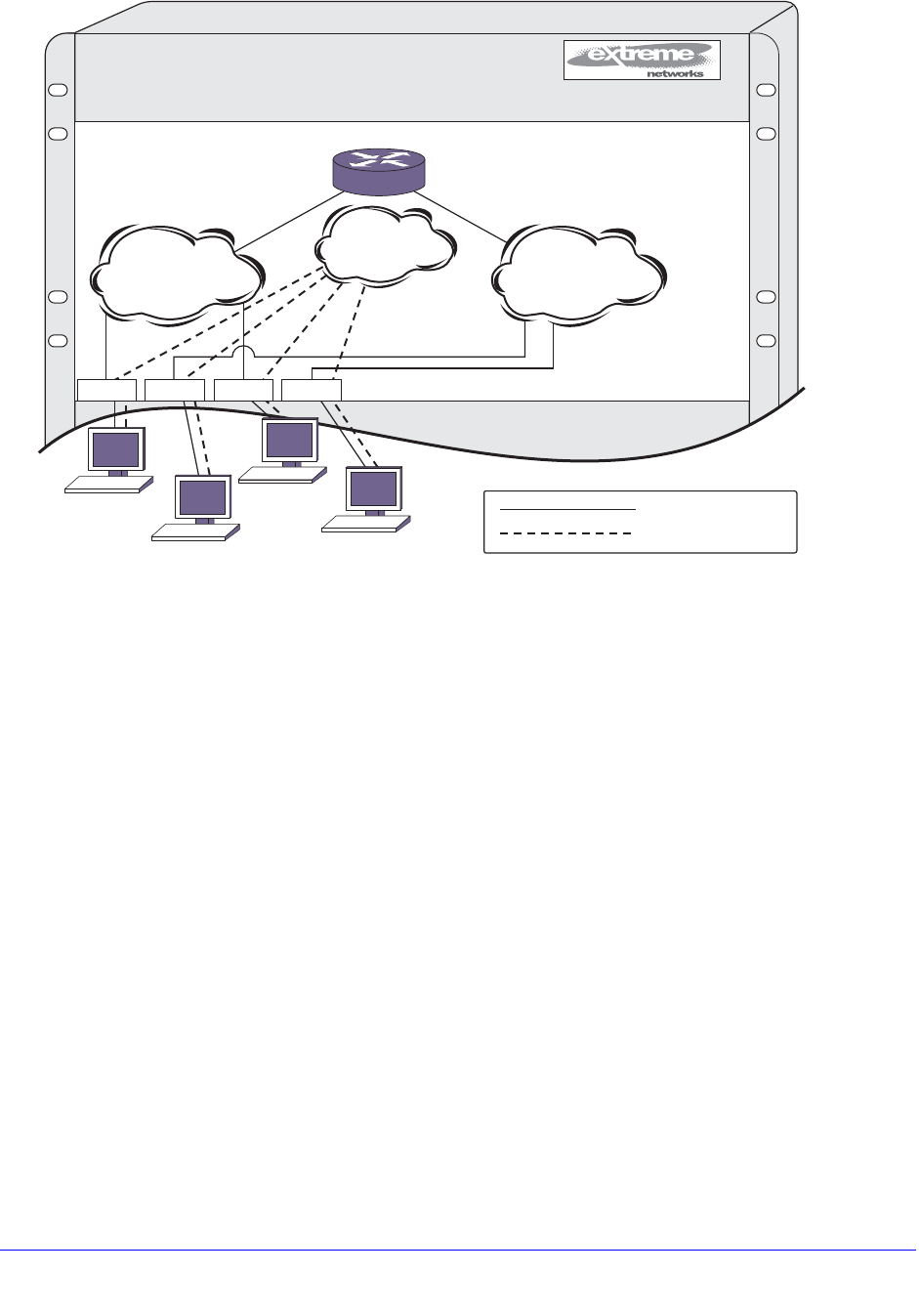
618 | Chapter 20. IPv4 Unicast Routing
NETGEAR 8800 User Manual
Figure 64. Unicast Routing Configuration Example
The stations connected to the system generate a combination of IP traffic and NetBIOS
traffic. The IP traffic is filtered by the protocol-sensitive VLANs. All other traffic is directed to
the VLAN MyCompany.
In this configuration, all IP traffic from stations connected to slots 1 and 3 have access to the
router by way of the VLAN Finance. Ports on slots 2 and 4 reach the router by way of the
VLAN Personnel. All other traffic (NetBIOS) is part of the VLAN MyCompany.
The example in Figure 64 is configured as follows:
create vlan Finance
create vlan Personnel
create vlan MyCompany
configure Finance protocol ip
configure Personnel protocol ip
configure Finance add port 1:*,3:*
configure Personnel add port 2:*,4:*
configure MyCompany add port all
configure Finance ipaddress 192.207.35.1
1234AB5678
EX_047
1
MyCompany
2
IP
NetBIOS
IP
NetBIOS
3 4
= IP traffic
= NetBIOS traffic
192.207.36.1192.207.35.1
Finance
192.207.35.0
Personnel
192.207.36.0
IP
NetBIOS
IP
NetBIOS

Chapter 20. IPv4 Unicast Routing | 619
NETGEAR 8800 User Manual
configure Personnel ipaddress 192.207.36.1
configure rip add vlan Finance
configure rip add vlan Personnel
enable ipforwarding
enable rip
Proxy ARP
Proxy Address Resolution Protocol (ARP) was first invented so that ARP-capable devices
could respond to ARP request packets on behalf of ARP-incapable devices. Proxy ARP can
also be used to achieve router redundancy and to simplify IP client configuration. The switch
supports proxy ARP for this type of network configuration. The section describes some
examples of using proxy ARP with the switch.
ARP-Incapable Devices
To configure the switch to respond to ARP requests on behalf of devices that are incapable of
doing so, you must configure the IP address and MAC address of the ARP-incapable device
using the following command:
configure iparp add proxy [<ipNetmask> | <ip_addr> {<mask>}] {vr <vr_name>}
{<mac> | vrrp} {always}
After it is configured, the system responds to ARP requests on behalf of the device as long as
the following conditions are satisfied:
• The valid IP ARP request is received on a router interface.
• The target IP address matches the IP address configured in the proxy ARP table.
• The proxy ARP table entry indicates that the system should answer this ARP request,
based on the ingress VLAN and whether the always parameter is set. When the always
option is set, the switch always responds to the ARP request even when the ARP
requester is on the same subnet as the requested host. If the always option is not set, the
switch only answers if the ARP request comes in from a VLAN that is not on the same
subnet as the requested host.
When all the proxy ARP conditions are met, the switch formulates an ARP response using
one of the following MAC addresses:
• A specific MAC address specified with the <mac> option
• The VRRP virtual MAC address when the vrrp option is specified and the request is
received on a VLAN that is running VRRP.
• The switch MAC address when neither of the above options applies.

620 | Chapter 20. IPv4 Unicast Routing
NETGEAR 8800 User Manual
Proxy ARP Between Subnets
In some networks, it is desirable to configure the IP host with a wider subnet than the actual
subnet mask of the segment. You can use proxy ARP so that the router answers ARP
requests for devices outside of the subnet. As a result, the host communicates as if all
devices are local. In reality, communication with devices outside of the subnet are proxied by
the router.
For example, an IP host is configured with a class B address of 100.101.102.103 and a mask
of 255.255.0.0. The switch is configured with the IP address 100.101.102.1 and a mask of
255.255.255.0. The switch is also configured with a proxy ARP entry of IP address
100.101.0.0 and mask 255.255.0.0, without the always parameter.
When the IP host tries to communicate with the host at address 100.101.45.67, the IP host
communicates as if the two hosts are on the same subnet, and sends out an IP ARP request.
The switch answers on behalf of the device at address 100.101.45.67, using its own MAC
address. All subsequent data packets from 100.101.102.103 are sent to the switch, and the
switch routes the packets to 100.101.45.67.
IPv4 Multinetting
IP multinetting refers to having multiple IP networks on the same bridging domain (or VLAN).
The hosts connected to the same physical segment can belong to any one of the networks,
so multiple subnets can overlap onto the same physical segment. Any routing between the
hosts in different networks is done through the router interface. Typically, different IP
networks are on different physical segments, but IP multinetting does not require this.
Multinetting can be a critical element in a transition strategy, allowing a legacy assignment of
IP addresses to coexist with newly configured hosts. However, because of the additional
constraints introduced in troubleshooting and bandwidth, NETGEAR recommends that you
use multinetting as a transitional tactic only, and not as a long-term network design strategy.
The implementation introduced in XCM8800 is simpler to configure, does not require that you
create a dummy multinetting protocol, and does not require that you create VLANs for each
IP network. This implementation does not require you to explicitly enable IP multinetting.
Multinetting is automatically enabled when a secondary IP address is assigned to a VLAN.
The following sections discuss these multinetting topics:
• Multinetting Topology on page 620
• How Multinetting Affects Other Features on page 621
• Configuring IPv4 Multinetting on page 626
• IP Multinetting Examples on page 626
Multinetting Topology
For an IP multinetted interface, one of the IP networks on the interface acts as the transit
network for the traffic that is routed by this interface. The transit network is the primary subnet
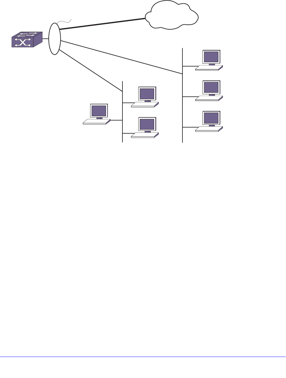
Chapter 20. IPv4 Unicast Routing | 621
NETGEAR 8800 User Manual
for the interface. The remaining multinetted subnets, called the secondary subnets, must be
stub networks. This restriction is required because it is not possible to associate the source of
the incoming routed traffic to a particular network. IP routing happens between the different
subnets of the same VLAN (one arm routing) and also between subnets of different VLANs.
Figure 65. Multinetted Network Topology
Figure 65 shows a multinetted VLAN named multi. VLAN multi has three IP subnets so three
IP addresses have been configured for the VLAN. One of the subnets is the primary subnet
and can be connected to any transit network (for example, the Internet). The remaining two
subnets are stub networks, and multiple hosts such as management stations (such as user
PCs and file servers) can be connected to them. You should not put any additional routing or
switching devices in the secondary subnets to avoid routing loops. In Figure 65 the subnets
are on separate physical segments, however, multinetting can also support hosts from
different IP subnets on the same physical segment.
When multinetting is configured on a VLAN, the switch can be reached using any of the
subnet addresses (primary or secondary) assigned to VLAN. This means that you can
perform operations like ping, Telnet, Trivial File Transfer Protocol (TFTP), Secure Shell 2
(SSH2), and others to the switch from a host residing in either the primary or the secondary
subnet of the VLAN. Other host functions (such as traceroute) are also supported on the
secondary interface of a VLAN.
How Multinetting Affects Other Features
Multinetting affects some other features in XCM8800. The following sections explain how
multinetting affects both Layer 2 and Layer 3 features.
EX_102
VLAN multi
Primary subnet
Secondary
subnet-1
Secondary
subnet-2
Transit
network
Host

622 | Chapter 20. IPv4 Unicast Routing
NETGEAR 8800 User Manual
ARP
ARP operates on the interface and responds to every request coming from either the primary
or secondary subnet. When multiple subnets are configured on a VLAN and an ARP request
is generated by the switch over that VLAN, the source IP address of the ARP request must
be a local IP address of the subnet to which the destination IP address (which is being
ARPed) belongs.
For example, if a switch multinets the subnets 10.0.0.0/24 and 20.0.0.0/24 (with VLAN IP
addresses of 10.0.0.1 and 20.0.0.1), and generates an ARP request for the IP address
10.0.0.2, then the source IP address in the ARP packet is set to 10.0.0.1 and not to 20.0.0.1.
Route Manager
The Route Manager installs a route corresponding to each of the secondary interfaces. The
route origin is direct, is treated as a regular IP route, and can be used for IP data traffic
forwarding.
These routes can also be redistributed into the various routing protocol domains if you
configure route redistribution.
IRDP
Some functional changes are required in Internet Router Discovery Protocol (IRDP) to
support IP multinetting. When IRDP is enabled on a Layer 3 VLAN, XCM8800 periodically
sends ICMP router advertisement messages through each subnet (primary and secondary)
and responds to ICMP router solicitation messages based on the source IP address of the
soliciting host.
Unicast Routing Protocols
Unicast routing protocols treat each IP network as an interface. The interface corresponding
to the primary subnet is the active interface, and the interfaces corresponding to the
secondary subnet are passive subnets.
For example, in the case of Open Shortest Path First (OSPF), the system treats each
network as an interface, and hello messages are not sent out or received over the
non-primary interface. In this way, the router link state advertisement (LSA) includes
information to advertise that the primary network is a transit network and the secondary
networks are stub networks, thereby preventing any traffic from being routed from a source in
the secondary network.
Interface-based routing protocols (for example, OSPF) can be configured on per VLAN basis.
A routing protocol cannot be configured on an individual primary or secondary interface.
Configuring a protocol parameter on a VLAN automatically configures the parameter on all its
associated primary and secondary interfaces. The same logic applies to configuring IP
forwarding, for example, on a VLAN.
Routing protocols in the multinetted environment advertise the secondary subnets to their
peers in their protocol exchange process. For example, for OSPF the secondary subnets are
advertised as stub networks in router LSAs. RIP also advertises secondary subnets to its
peers residing on the primary subnet.

Chapter 20. IPv4 Unicast Routing | 623
NETGEAR 8800 User Manual
OSPF
This section describes the behavior of OSPF in an IPv4 multinetting environment:
• Each network is treated as an interface, and hello messages are not sent out or received
over the non-primary interface. In this way, the router LSA includes information to
advertise that the primary network is a transit network and the secondary networks are
stub networks, thereby preventing any traffic from being routed from a source in the
secondary network.
• Any inbound OSPF control packets from secondary interfaces are dropped.
• Direct routes corresponding to secondary interfaces can be exported into the OSPF
domain (by enabling export of direct routes), if OSPF is not enabled on the container
VLAN.
• When you create an OSPF area address range for aggregation, you must consider the
secondary subnet addresses for any conflicts. That is, any secondary interface with the
exact subnet address as the range cannot be in another area.
• The automatic selection algorithm for the OSPF router ID considers the secondary
interface addresses also. The numerically highest interface address is selected as the
OSPF router-id.
RIP
This section describes the behavior of the Routing Information Protocol (RIP) in an IP
multinetting environment:
• RIP does not send any routing information update on the secondary interfaces. However,
RIP does advertise networks corresponding to secondary interfaces in its routing
information packet to the primary interface.
• Any inbound RIP control packets from secondary interfaces are dropped.
• Direct routes corresponding to secondary interfaces can be exported into the RIP domain
(by enabling export of direct routes), if RIP is not enabled on the container VLAN.
BGP
There are no behavioral changes in the Border Gateway Protocol (BGP) in an IP multinetting
environment. This section describes a set of recommendations for using BGP with IP
multinetting:
• Be careful of creating a BGP neighbor session with a BGP speaker residing in secondary
subnet. This situation can lead to routing loops.
• All secondary subnets are like stub networks, so you must configure BGP in such a way
that the BGP next hop becomes reachable using the primary subnet of a VLAN.
• When setting the BGP next hop using an inbound or outbound policy, ensure that the next
hop is reachable from the primary interface.
• A BGP static network's reachability can also be resolved from the secondary subnet.
• Secondary interface addresses can be used as the source interface for a BGP neighbor.

624 | Chapter 20. IPv4 Unicast Routing
NETGEAR 8800 User Manual
• Direct routes corresponding to secondary interfaces can be exported into the BGP
domain (by enabling export of direct routes).
IGMP Snooping and IGMP
Internet Group Management Protocol (IGMP) snooping and IGMP treat the VLAN as an
interface.
Only control packets with a source address belonging to the IP networks configured on that
interface are accepted. IGMP accepts membership information that originates from hosts in
both the primary and secondary subnets. The following describes the changes in behavior of
IGMP in an IP multinetting environment:
• A Layer 3 VLAN always uses the primary IP address as the source address to send out
an IGMP query, and querier election is based on the primary IP address of interface.
Because the RFC dictates that there is only one querier per physical segment, the querier
may be attached to any of configured IP interfaces, including secondary interfaces,
although this is not a recommended configuration.
• For a static IGMP group, the membership report is also sent out using the primary IP
address.
• For local multicast groups such as 224.0.0.X, the membership report is sent out using the
first IP address configured on the interface, which is the primary IP address in XCM8800.
• The source IP address check is disabled for any IGMP control packets (such as IGMP
query and IGMP membership report). Source IP address checking for IGMP control
packet is disabled for all VLANs, not just the multinetted VLANs.
Multicast Routing Protocols
For Protocol-Independent Multicast (PIM), the following behavior changes should be noted in
a multinetting environment:
• PIM does not peer with any other PIM router on a secondary subnet.
• PIM also processes data packets from the hosts secondary subnets.
• PIM also accepts membership information from hosts on secondary subnets.
STP
Control protocols like the Spanning Tree Protocol (STP) treat the VLAN as an interface. If the
protocol control packets are exchanged as Layer 3 packets, then the source address in the
packet is validated against the IP networks configured on that interface.
DHCP Server
The Dynamic Host Configuration Protocol (DHCP) server implementation in XCM8800 only
supports address allocation on the primary IP interface of the configured VLAN. That is, all
DHCP clients residing on a bridging domain have IP addresses belonging to the primary
subnet. To add a host on secondary subnet, you must manually configure the IP address
information on that host.

Chapter 20. IPv4 Unicast Routing | 625
NETGEAR 8800 User Manual
DHCP Relay
When the switch is configured as a DHCP relay agent, it forwards the DHCP request
received from a client to the DHCP server. When doing so, the system sets the GIADDR field
in the DHCP request packet to the primary IP address of the ingress VLAN. This means that
the DHCP server that resides on a remote subnet allocates an IP address for the client in the
primary subnet range.
VRRP
Virtual Router Redundancy Protocol (VRRP) protection can be provided for the primary as
well as for the secondary IP addresses of a VLAN. For multinetting, the IP address assigned
to an VRRP virtual router identifier (VRID) can be either the primary or the secondary IP
addresses of the corresponding VLAN.
For example, assume a VLAN v1 with two IP addresses: a primary IP address of 10.0.0.1/24,
and a secondary IP address of 20.0.0.1/24.
To provide VRRP protection to such a VLAN, you must configure one of the following:
• Configure VRRP in VLAN v1 with two VRRP VRIDs. One VRID should have the virtual IP
address 10.0.0.1/24, and the other VRID should have the virtual IP address 20.0.0.1/24.
The other VRRP router, the one configured to act as backup, should be configured
similarly.
—OR—
• Configure VRRP in VLAN v1 with two VRRP VRIDs. One VRID should have the virtual IP
address as 10.0.0.1/24, and the other VRID should have the virtual IP address as
20.0.0.1/24.
It is possible for a VRRP VR to have additional virtual IP addresses assigned to it. In this
case, the following conditions must be met:
• Multiple virtual IP addresses for the same VRID must be on the same subnet.
• Multiple virtual IP addresses must all not be owned by the switch.
Assuming a VLAN v1 that has IP addresses 1.1.1.1/24 and 2.2.2.2/24, here are some more
examples of valid configurations:
• VRRP VR on v1 with VRID of 99 with virtual IP addresses of 1.1.1.2 and 1.1.1.3
• VRRP VR on v1 with VRID of 100 with virtual IP addresses of 2.2.2.3 and 2.2.2.4
• VRRP VR on v1 with VRID of 99 with virtual IP addresses of 1.1.1.98 and 1.1.1.99
• VRRP VR on v1 with VRID of 100 with virtual IP addresses of 2.2.2.98 and 2.2.2.99
Given the same VLAN v1 as above, here are some invalid configurations:
• VRRP VR on v1 with VRID of 99 with virtual IP addresses of 1.1.1.1 and 2.2.2.2 (the
virtual IP addresses are not on the same subnet)
• VRRP VR on v1 with VRID of 100 with virtual IP addresses of 2.2.2.2 and 1.1.1.1 (the
virtual IP addresses are not on the same subnet)

626 | Chapter 20. IPv4 Unicast Routing
NETGEAR 8800 User Manual
• VRRP VR on v1 with VRID of 99 with virtual IP addresses of 1.1.1.1 and 1.1.1.99 (one
virtual IP address is owned by the switch and one is not)
• VRRP VR on v1 with VRID of 100 with virtual IP addresses of 2.2.2.2 and 2.2.2.99 (one
virtual IP address is owned by the switch and one is not).
Configuring IPv4 Multinetting
You configure IP multinetting by adding a secondary IP address to a VLAN. Use the following
command to add a secondary IP address:
configure vlan <vlan_name> add secondary-ipaddress [<ipaddress> {<netmask>} |
<ipNetmask>]
After you have added a secondary IP address, you cannot change the primary IP address of
a VLAN until you first delete all the secondary IP addresses. To delete secondary IP
addresses, use the following command:
configure vlan <vlan_name> delete secondary-ipaddress [<ipaddress> | all]
IP Multinetting Examples
The following example configures a switch to have one multinetted segment (port 5:5) that
contains three subnets (192.168.34.0/24, 192.168.35.0/24, and 192.168.37.0/24).
configure default delete port 5:5
create vlan multinet
configure multinet ipaddress 192.168.34.1/24
configure multinet add secondary-ipaddress 192.168.35.1/24
configure multinet add secondary-ipaddress 192.168.37.1/24
configure multinet add port 5:5
enable ipforwarding
The following example configures a switch to have one multinetted segment (port 5:5) that
contains three subnets (192.168.34.0, 192.168.35.0, and 192.168.37.0). It also configures a
second multinetted segment consisting of two subnets (192.168.36.0 and 172.16.45.0). The
second multinetted segment spans three ports (1:8, 2:9, and 3:10). RIP is enabled on both
multinetted segments.
configure default delete port 5:5
create vlan multinet
configure multinet ipaddress 192.168.34.1
configure multinet add secondary-ipaddress 192.168.35.1
configure multinet add secondary-ipaddress 192.168.37.1
configure multinet add port 5:5
configure default delete port 1:8, 2:9, 3:10
create vlan multinet_2
configure multinet_2 ipaddress 192.168.36.1
configure multinet_2 add secondary-ipaddress 172.16.45.1
configure multinet_2 add port 1:8, 2:9, 3:10
configure rip add vlan multinet
configure rip add vlan multinet_2
enable rip

Chapter 20. IPv4 Unicast Routing | 627
NETGEAR 8800 User Manual
enable ipforwarding
DHCP/BOOTP Relay
After IP unicast routing has been configured, you can configure the switch to forward
Dynamic Host Configuration Protocol (DHCP) or BOOTP requests coming from clients on
subnets being serviced by the switch and going to hosts on different subnets. This feature
can be used in various applications, including DHCP services between Windows NT servers
and clients running Windows 95. To configure the relay function:
1. Configure VLANs and IP unicast routing.
2. Enable the DHCP or BOOTP relay function, using the following command:
enable bootprelay {{vlan} [<vlan_name>] | {{vr} <vr_name>} | all [{vr} <vr_name>]}
3. Configure the addresses to which DHCP or BOOTP requests should be directed, using the
following command:
configure bootprelay add <ip_address> {vr <vrid>}
To delete an entry, use the following command:
configure bootprelay delete [<ip_address> | all] {vr <vrid>}
To disable BOOTP relay on one or more VLANs, use the following command:
disable bootprelay {{vlan} [<vlan_name>] | {{vr} <vr_name>} | all [{vr}
<vr_name>]}
To view the BOOTP relay enable/disable configuration, use the following command:
show bootprelay configuration {{vlan} <vlan_name> | {vr} <vr_name>}
Note: When VRRP and BOOTP/DHCP relay are both enabled on the
switch, the relayed BOOTP agent IP address is the actual switch IP
address, not the virtual IP address.
Configuring the DHCP Relay Agent Option (Option 82) at
Layer 3
After configuring and enabling the DHCP/BOOTP relay feature, you can enable the DHCP
relay agent option feature. This feature inserts a piece of information, called option 82, into
any DHCP request packet that is to be relayed by the switch. Similarly, if a DHCP reply
received by the switch contains a valid relay agent option, the option is stripped from the
packet before it is relayed to the client.
When DHCP option 82 is enabled, two types of packets need to be handled:
• DHCP Request: When the switch (relay agent) receives a DHCP request, option 82 is
added at the end of the packet. If the option has already been enabled, then the action

628 | Chapter 20. IPv4 Unicast Routing
NETGEAR 8800 User Manual
taken depends on the configured policy (drop packet, keep existing option 82 value, or
replace the existing option). If the incoming DHCP request is tagged, then that VLAN ID is
added to the circuit ID sub option of option 82; otherwise, the default VLAN ID is added.
• DHCP Reply: When the option 82 information check is enabled, the packets received
from the DHCP server are checked for option 82 information. If the remote ID sub-option
is the switch's MAC address, the packet is sent to the client; if not, the packet is dropped.
If the check is not enabled. the packets are forwarded as-is.
The DHCP relay agent option consists of two pieces of data, called sub-options. The first is
the agent circuit ID sub-option, and the second is the agent remote ID sub-option. When the
DHCP relay agent option is enabled on switches running XCM8800, the value of these
sub-options is set as follows:
• Agent circuit ID sub-option: The full circuit ID string uses the format
<vlan_info>-<port_info>. You can use the default values for vlan_info and port_info, or
you can configure these values as described later in this section.
• Agent remote ID sub-option: Always contains the Ethernet MAC address of the relaying
switch. You can display the Ethernet MAC address of the switch by issuing the show
switch command.
Note: For more general information about the DHCP relay agent
information option, see RFC 3046.
The following sections describe how to manage this feature:
• Enabling and Disabling the DHCP Relay Agent Option on page 628
• Enabling and Disabling DHCP Packet Checking on page 628
• Configuring the DHCP Packet Handling Policy on page 629
• Configuring the DHCP Agent Circuit ID Suboption on page 629
Enabling and Disabling the DHCP Relay Agent Option
To enable the DHCP relay agent option, use the following command after configuring the
DHCP/BOOTP relay function:
configure bootprelay dhcp-agent information option
To disable the DHCP relay agent option, use the following command:
unconfigure bootprelay dhcp-agent information option
Enabling and Disabling DHCP Packet Checking
In some instances, a DHCP server may not properly handle a DHCP request packet
containing a relay agent option. To prevent DHCP reply packets with invalid or missing relay
agent options from being forwarded to the client, use the following command:
configure bootprelay dhcp-agent information check

Chapter 20. IPv4 Unicast Routing | 629
NETGEAR 8800 User Manual
To disable checking of DHCP replies, use this command:
unconfigure bootprelay dhcp-agent information check
Configuring the DHCP Packet Handling Policy
A DHCP relay agent may receive a client DHCP packet that has been forwarded from
another relay agent. If this relayed packet already contains a relay agent option, then the
switch handles this packet according to the configured DHCP relay agent option policy. The
possible actions are to replace the option information, to keep the information, or to drop
packets containing option 82 information. To configure this policy, use the following
command:
configure bootprelay dhcp-agent information policy [drop | keep | replace]
The default relay policy is replace. To configure the policy to the default, use this command:
unconfigure bootprelay dhcp-agent information policy
Configuring the DHCP Agent Circuit ID Suboption
To configure the values used to create the agent circuit ID suboption, use the following
commands:
configure bootprelay dhcp-agent information circuit-id port-information
<port_info> port <port>
configure bootprelay dhcp-agent information circuit-id vlan-information
<vlan_info> {vlan} [<vlan_name>|all]
Verifying the DHCP/BOOTP Relay Configuration
To verify the DHCP/BOOTP relay configuration, use the following command:
show bootprelay
This command displays the configuration of the BOOTP relay service and the addresses that
are currently configured.
Broadcast UDP Packet Forwarding
UDP Forwarding is a flexible and generalized routing utility for handling the directed
forwarding of broadcast UDP packets. UDP Forwarding enables you to configure your switch
so that inbound broadcast UDP packets on a VLAN are forwarded to a particular destination
IP address or VLAN. UDP Forwarding allows applications, such as multiple DHCP relay
services from differing sets of VLANs, to be directed to different DHCP servers.
The following rules apply to UDP broadcast packets handled by this feature:
• If the UDP profile includes BOOTP or DHCP, it is handled according to guidelines
specified in RFC 1542.

630 | Chapter 20. IPv4 Unicast Routing
NETGEAR 8800 User Manual
• If the UDP profile includes other types of traffic, these packets have the IP destination
address modified as configured, and changes are made to the IP and UDP checksums
and TTL field (decrements), as appropriate.
If UDP Forwarding is used for BOOTP or DHCP forwarding purposes, do not configure or use
the existing bootprelay function. However, if the previous bootprelay functions are adequate,
you may continue to use them.
Note: UDP Forwarding only works across a Layer 3 boundary and
currently, UDP Forwarding can be applied to IPv4 packets only, not
to IPv6 packets.
Configuring UDP Forwarding
To configure UDP Forwarding, create a policy file for your UDP profile, and then associate the
profile with a VLAN using the following command:
configure vlan <vlan_name> udp-profile [<profilename> | none]
You can apply a UDP Forwarding policy only to an L3 VLAN (a VLAN having at least one IP
address configured on it). If no IP address is configured on the VLAN, the command is
rejected.
UDP profiles are similar to ACL policy files. UDP profiles use a subset of the match
conditions allowed for ACLs. A UDP Forwarding policy must contain only the following
attributes. Unrecognized attributes are ignored.
• Match attributes
• Destination UDP Port Number (destination-port)
• Source IP address (source-ipaddress)
• Action modified (set) attributes
• Destination IP address (destination-ipaddress)
• VLAN name (vlan)
Policy files used for UDP Forwarding are processed differently from standard policy files.
Instead of terminating when an entry’s match clause becomes true, each entry in the policy
file is processed and the corresponding action is taken for each true match clause.
For example, if the following policy file is used as a UDP Forwarding profile, any packets
destined for UDP port 67 are sent to IP address 20.0.0.5 AND flooded to VLAN to7:
entry one {
if match all {
destination-port 67 ;
} then {
destination-ipaddress 20.0.0.5 ;
}
}

Chapter 20. IPv4 Unicast Routing | 631
NETGEAR 8800 User Manual
entry two {
if match all {
destination-port 67 ;
} then {
vlan "to7" ;
}
}
If you include more than one VLAN set attribute or more than one destination-ipaddress set
attribute in one policy entry, the last one is accepted and the rest are ignored.
Note: Although the Policy manager allows you to set a range for the
destination-port, you should not specify the range for the
destination-port attribute in the match clause of the policy
statement for the UDP profile. If a destination-port range is
configured, the last port in the range is accepted and the rest are
ignored.
You can have two valid set statements in each entry of a UDP Forwarding policy; one a
destination-ipaddress and one a VLAN. XCM8800 currently allows a maximum of eight
entries in a UDP Forwarding policy, so you can define a maximum of 16 destinations for one
inbound broadcast UDP packet: eight IP addresses and eight VLANs.
Note: It is strongly advised to have no more than eight entries in a UDP
Forwarding profile. The UDP Forwarding module processes those
entries even if the entries do not contain any attributes for UDP
Forwarding. Having more than eight entries drastically reduces the
performance of the system. If the inbound UDP traffic rate is very
high, having more than eight entries could cause the system to
freeze or become locked.
Note: If you rename a VLAN referred to in your UDP Forwarding profile,
you must manually edit the policy to reflect the new name, and
refresh the policy.
You can also validate whether the UDP profile has been successfully associated with the
VLAN by using the command show policy {<policy-name> | detail}. UDP Forwarding is
implemented as part of the netTools process, so the command does display netTools as a
user of the policy.
To remove a policy, use the none form of the following command:

632 | Chapter 20. IPv4 Unicast Routing
NETGEAR 8800 User Manual
configure vlan <vlan_name> udp-profile [<profilename> | none]
or use this command:
unconfigure vlan <vlan_name> udp-profile
For more information about creating and editing policy files, see Chapter 12, Policy Manager.
For more information about ACL policy files, see Chapter 13, ACLs.
UDP Echo Server
You can use UDP echo packets to measure the transit time for data between the transmitting
and receiving ends.
To enable UDP echo server support, use the following command:
enable udp-echo-server {vr <vrid>}{udp-port <port>}
To disable UDP echo server support, use the following command:
disable udp-echo-server {vr <vrid>}
IP Broadcast Handling
XCM8800 supports IP subnet directed broadcast forwarding. In XCM8800, IP subnet directed
broadcast forwarding is done in the software by default; if you want to perform forwarding in
the hardware, see the command reference pages on IP forwarding in the NETGEAR 8800
Chassis Switch CLI Manual.
IP Broadcast Handling Details
To understand how IP broadcast handling functions in XCM8800, consider the following two
examples.
For the first example, a system sends an IP packet (for example, via the ping command) to
an IP subnet directed broadcast address which is directly connected to that system. In this
case, the IP packet goes out as an L2 broadcast with the destination media access control
(DMAC) addresses all set to FF, while the source media access control (SMAC) is set to the
system MAC. This packet is sent out of all the ports of the VLAN.
In the second example, a system sends a packet (for example, via the ping command) to an
IP subnet directed broadcast address which is remotely connected via a gateway. In this
case, the IP packet goes out as an L2 unicast packet with the DMAC equal to the gateway's
MAC address, while the SMAC is set to the system MAC. At the gateway router, the existing
IP packet forwarding mechanism is sufficient to send the packet out of the correct interface if
the router is not the final hop router.
When the packet reaches the final hop router, which is directly connected to the target IP
subnet, IP directed broadcast forwarding needs to be turned on. The IP broadcast handling
feature is applicable only at the final hop router directly attached to the target subnet. At the

Chapter 20. IPv4 Unicast Routing | 633
NETGEAR 8800 User Manual
final hop router, when IP subnet directed broadcast forwarding is enabled on an IP VLAN via
the command line, the following happens:
• Some basic validity checks are performed (for example, checking to see if the VLAN has
IP enabled)
• A subnet broadcast route entry for the subnet is installed. For example, consider a
system with the following configuration:
VLAN-A = 10.1.1.0/24, ports 1:1, 1:2, 1:3, 1:4
VLAN-B = 20.1.1.0/24, ports 1:5, 1:6, 1:7, 1:8
VLAN-C = 30.1.1.0/24, ports 1:9, 1:10, 1:11
If you enable IP directed broadcast forwarding on VLAN-A, you should install a route
entry for 10.1.1.1.255 on this system.
• A packet arriving on port 1:5 VLAN-B with destination IP (DIP) set to 10.1.1.255, the
source IP (SIP) set to 20.1.1.3, the DMAC set to the router MAC, and the SMAC set to
the originating system MAC, arrives at the installed route entry and is sent out on all the
ports of VLAN-A, with DMAC set to be all FF and the SMAC set to the router's system
MAC.
• An IP packet arriving on port 1:1 VLAN-A with the DIP set to 10.1.1.255, the SIP set to
10.1.1.3, the DMAC set to all FF, and the SMAC set to the originator’s MAC, causes the
L2 to be flooded out of all the ports of VLAN-A.
When IP subnet directed broadcast is disabled on an IP VLAN, on each port of the VLAN, all
IP subnet directed broadcast entries are deleted.
Note: IP subnet directed broadcast uses fast-path forwarding.
Command-line Support for IP Broadcast Handling
The enable ipforwarding and disable ipforwarding commands are enhanced to support
the enhanced IP broadcast handling functionality on BlackDiamond 10808, 12800, and
20800 platforms. Specifically, the following two keywords were added to the commands:
• fast-direct-broadcast, which specifies to forward IP broadcast packets in the hardware
and send a copy to the CPU
• ignore-broadcast, which specifies to forward IP broadcast packets in the hardware but
not send a copy to the CPU
For further details, see the appropriate command reference pages in the NETGEAR 8800
Chassis Switch CLI Manual.
Note: These two keywords are available on BlackDiamond 10808 and
20800 series switches only.
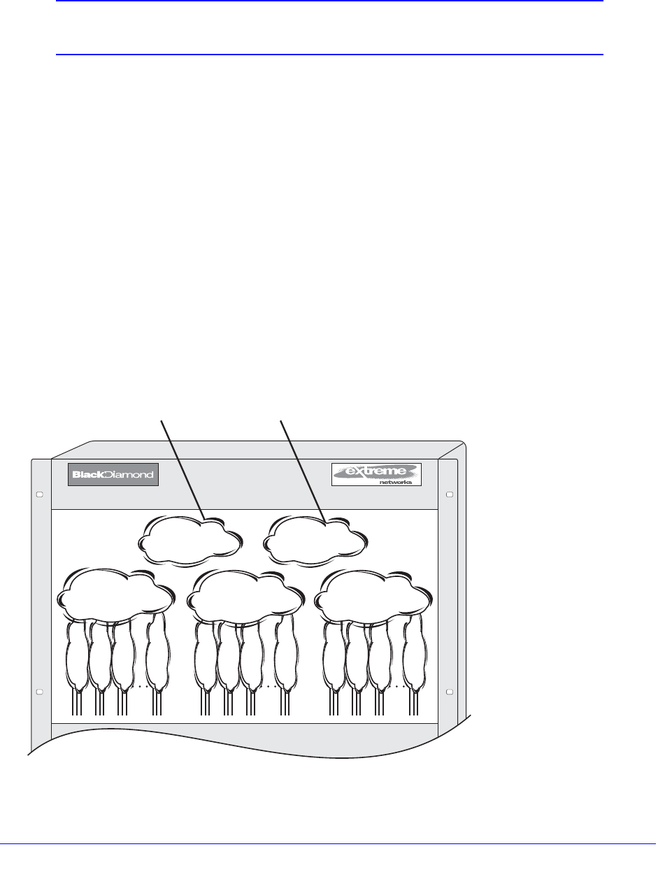
634 | Chapter 20. IPv4 Unicast Routing
NETGEAR 8800 User Manual
VLAN Aggregation
Note: This feature is supported only on the platforms listed for this feature
in the license tables in Appendix A, XCM8800 Software Licenses.
VLAN aggregation is a feature aimed primarily at service providers. The purpose of VLAN
aggregation is to increase the efficiency of IP address space usage. It does this by allowing
clients within the same IP subnet to use different broadcast domains while still using the
same default router.
Using VLAN aggregation, a superVLAN is defined with the desired IP address. The
subVLANs use the IP address of the superVLAN as the default router address. Groups of
clients are then assigned to subVLANs that have no IP address, but are members of the
superVLAN. In addition, clients can be informally allocated any valid IP addresses within the
subnet. Optionally, you can prevent communication between subVLANs for isolation
purposes. As a result, subVLANs can be quite small, but allow for growth without re-defining
subnet boundaries.
Without using VLAN aggregation, each VLAN has a default router address, and you need to
use large subnet masks. The result of this is more unused IP address space.
Multiple secondary IP addresses can be assigned to the superVLAN.
Figure 66 illustrates VLAN aggregation.
Figure 66. VLAN aggregation
1234AB5678
EW_02
6
Sub-VLAN 1
Sub-VLAN 2
Sub-VLAN 3
Sub-VLAN n
Super VLAN_1
IP address: a.b.c.1
mask: /24
Sub-VLAN 1
Sub-VLAN 2
Sub-VLAN 3
Sub-VLAN n
Sub-VLAN 1
Sub-VLAN 2
Sub-VLAN 3
Sub-VLAN n
Super VLAN_2
IP address: a.b.d.1
mask: /24
OSPF Rtr_Link
VLAN_A OSPF Rtr_Link
VLAN_B
Super VLAN_3
IP address: a.b.e.1
mask: /24

Chapter 20. IPv4 Unicast Routing | 635
NETGEAR 8800 User Manual
In Figure 66, all stations are configured to use the address 10.3.2.1 for the default router.
VLAN Aggregation Properties
VLAN aggregation is a very specific application, and the following properties apply to its
operation:
• All broadcast and unknown traffic remains local to the subVLAN and does not cross the
subVLAN boundary. All traffic within the subVLAN is switched by the subVLAN, allowing
traffic separation between subVLANs (while using the same default router address
among the subVLANs).
• Hosts can be located on the superVLAN or on subVLANs. Each host can assume any IP
address within the address range of the superVLAN router interface. Hosts on the
subVLAN are expected to have the same network mask as the superVLAN and have
their default router set to the IP address of the superVLAN.
• All IP unicast traffic between subVLANs is routed through the superVLAN. For example,
no ICMP redirects are generated for traffic between subVLANs, because the superVLAN
is responsible for subVLAN routing. Unicast IP traffic across the subVLANs is facilitated
by the automatic addition of an ARP entry (similar to a proxy ARP entry) when a
subVLAN is added to a superVLAN. This feature can be disabled for security purposes.
VLAN Aggregation Limitations
The following limitations apply to VLAN aggregation:
• No additional routers may be located in a subVLAN. This feature is only applicable for
“leaves” of a network.
• A subVLAN cannot be a superVLAN, and vice-versa.
• SubVLANs are not assigned an IP address.
• A subVLAN should belong to only one superVLAN.
• A subVLAN or superVLAN should not be added to a private VLAN
• Before you can delete a superVLAN, you must delete all subVLANs in that superVLAN.
• When configuring a subVLAN address range, all addresses in the range must belong to
the superVLAN subnet.
SubVLAN Address Range Checking
You can configure subVLAN address ranges on each subVLAN to prohibit the entry of IP
addresses from hosts outside of the configured range.
To configure a subVLAN range, use the following command:
configure vlan <vlan_name> subvlan-address-range <ip address1> - <ip address2>
To remove a subVLAN address range, use the following command:
unconfigure vlan <vlan_name> subvlan-address-range

636 | Chapter 20. IPv4 Unicast Routing
NETGEAR 8800 User Manual
To view the subVLAN address range, use the following command:
show vlan {detail {ipv4 | ipv6} | <vlan_name> {ipv4 | ipv6} | virtual-router
<vr-router> | <vlan_name> stpd | security}
Isolation Option for Communication Between SubVLANs
To facilitate communication between subVLANs, by default, an entry is made in the IP ARP
table of the superVLAN that performs a proxy ARP function. This allows clients on one
subVLAN to communicate with clients on another subVLAN. In certain circumstances,
intra-subVLAN communication may not be desired for isolation reasons.
To prevent normal communication between subVLANs, disable the automatic addition of the
IP ARP entries on the superVLAN using the following command:
disable subvlan-proxy-arp vlan [<vlan-name> | all]
Note: The isolation option works for normal, dynamic, ARP-based client
communication.
VLAN Aggregation Example
The follow example illustrates how to configure VLAN aggregation. The VLAN vsuper is
created as a superVLAN, and subVLANs, vsub1, vsub2, and vsub3 are added to it.
1. Create and assign an IP address to a VLAN designated as the superVLAN. Be sure to
enable IP forwarding and any desired routing protocol on the switch.
create vlan vsuper
configure vsuper ipaddress 192.201.3.1/24
enable ipforwarding
enable ospf
configure ospf add vsuper area 0
2. Create and add ports to the subVLANs.
create vlan vsub1
configure vsub1 add port 10-12
create vlan vsub2
configure vsub2 add port 13-15
create vlan vsub3
configure vsub3 add port 16-18
3. Configure the superVLAN by adding the subVLANs.
configure vsuper add subvlan vsub1
configure vsuper add subvlan vsub2
configure vsuper add subvlan vsub3
4. Optionally, disable communication among subVLANs.
disable subvlan-proxy-arp vlan [<vlan-name> | all]

Chapter 20. IPv4 Unicast Routing | 637
NETGEAR 8800 User Manual
Note: This command has no impact on Layer 3 traffic.
Verifying the VLAN Aggregation Configuration
The following commands can be used to verify proper VLAN aggregation configuration:
• show vlan—Indicates the membership of subVLANs in a superVLAN.
• show iparp—Indicates an ARP entry that contains subVLAN information. Communication
with a client on a subVLAN must have occurred in order for an entry to be made in the
ARP table.

Chapter 21. IPv6 Unicast Routing | 638
21
21. IPv6 Unicast Routing
This chapter includes the following sections:
• Overview on page 639
• Configuring IP Unicast Routing on page 646
• Configuring Route Sharing on page 651
• Configuring Route Compression on page 652
• Hardware Forwarding Behavior on page 652
• Routing Configuration Example on page 653
• Tunnel Configuration Examples on page 655
This chapter assumes that you are already familiar with IPv6 unicast routing. If not, see the
following publications for additional information:
• RFC 2460—Internet Protocol, Version 6 (IPv6) Specification
• RFC 3513—Internet Protocol Version 6 (IPv6) Addressing Architecture
Note: For more information on interior gateway protocols, see Chapter 23,
RIPng or Chapter 25, OSPFv3.

Chapter 21. IPv6 Unicast Routing | 639
NETGEAR 8800 User Manual
Overview
The switch provides full Layer 3, IPv6 unicast routing. It exchanges routing information with
other routers on the network using the IPv6 versions of the following protocols:
• Routing Information Protocol (RIPng)
• Open Shortest Path First (OSPFv3)
The switch dynamically builds and maintains a routing table and determines the best path for
each of its routes.
XCM8800 can provide both IPv4 and IPv6 routing at the same time. Separate routing tables
are maintained for the two protocols. Most commands that require you to specify an IP
address can now accept either an IPv4 or IPv6 address and act accordingly. Additionally,
many of the IP configuration, enabling, and display commands have added tokens for IPv4
and IPv6 to clarify the version required. For simplicity, existing commands affect IPv4 by
default and require you to specify IPv6, so configurations from an earlier release will still
correctly configure an IPv4 network.
ACLs and routing policies also support IPv6. Use of an IPv6 address in a rule entry will
automatically use IPv6.
Note: IPv6 functionality is supported only on the virtual routers (VRs)
VR-Default and VR-Mgmt. VR-Mgmt supports only IPv6 addressing
and static routing; VR-Default also supports dynamic routing.
The following sections provide additional information on IPv6 unicast routing:
• Router Interfaces on page 639
• Tunnels on page 640
• Specifying IPv6 Addresses on page 640
• Neighbor Discovery Protocol on page 642
• Populating the Routing Table on page 643
Router Interfaces
The routing software and hardware routes IPv6 traffic between router interfaces. A router
interface is either a virtual LAN (VLAN) that has an IP address assigned to it, or, new for
IPv6, a Layer 3 tunnel.
As you create VLANs and tunnels with IPv6 addresses, you can also choose to route
(forward traffic) between them. Both the VLAN switching and IP routing function occur within
the switch.

640 | Chapter 21. IPv6 Unicast Routing
NETGEAR 8800 User Manual
An interface can have up to 255 IPv6 addresses, with at least one being a link local address.
IPv4 and IPv6 interfaces can coexist on the same VLAN, allowing both IPv4 and IPv6
networks to coexist on the same Layer 2 broadcast domain.
Note: Each IP address and mask assigned to a VLAN must represent a
unique IP subnet. You cannot configure the same IP address and
subnet on different VLANs within the same virtual router.
Tunnels
The XCM8800 software supports Layer 3 tunnels, which serve as a transition option, as
networks change over from IPv4 to IPv6. The software supports these tunnels on Default-VR.
Note: IPv6 tunnels are supported only on Default-VR and not on user VRs.
The XCM8800 software supports the use of IPv6-in-IPv4 tunnels (known as configured
tunnels or 6in4 tunnels) and IPv6-to-IPv4 tunnels (known as 6to4 tunnels). Both types of
tunnels are used to connect regions of IPv6 routing across a region of IPv4 routing. From the
perspective of the router, the tunnel across the IPv4 region is one hop, even if multiple IPv4
routers are traversed during transport.
A 6in4 tunnel connects one IPv6 region to one other IPv6 region. Multiple 6in4 tunnels can be
configured on a single router to connect with multiple IPv6 regions. Dynamic and static
routing can be configured across a 6in4 tunnel. Hosts in the IPv6 regions need not know
anything about the configured tunnel, since packets destined for remote regions are sent
over the tunnel like any other type of routing interface.
A 6to4 tunnel connects one IPv6 region with multiple IPv6 regions. Only one 6to4 tunnel can
be configured on a single router.
Specifying IPv6 Addresses
IPv6 Addresses are 128 bits (16 bytes) when compared to the 32 bit IPv4 addresses. The
XCM8800 CLI accepts two standard representations for IPv6 addresses, as described in
RFC 3513, section 2.2, items 1, 2, and 3.
For example, the 128 bits of the address are represented by eight, four-digit hexadecimal
numbers separated by colons:
2000:af13:ee10:34c5:800:9192:ba89:2311
3f11:5655:2300:304:0000:0000:7899:acde

Chapter 21. IPv6 Unicast Routing | 641
NETGEAR 8800 User Manual
Leading zeros in a four-digit group can be omitted. There is a special use of a double colon
(::) in an address. The double colon stands for one or more groups of 16 bits of zeros and can
only be used once in an address. For example, the following addresses:
fe80:0:0:0:af34:2345:4afe:0
fe80:0:0:111:0:0:0:fe11
3c12:0:0:0:0:89:ff:3415
can be represented as:
fe80::af34:2345:4afe:0
fe80:0:0:111::fe11
3c12::89:ff:3415
Additionally, you can specify an address in a mixed IPv4/IPv6 mode that uses six, four-digit
hexadecimal numbers for the highest-order part of the address, and uses the IPv4 dotted
decimal representation for the lowest-order remaining portion. For example:
0:0:0:0:0:0:192.168.1.1
0:0:0:0:0:ffff:10.0.14.254
These can be represented as:
::192.168.1.1
::ffff:10.0.14.254
Both Global and Link-local IP addresses can be configured on a VLAN or tunnel interface,
using the following commands:
configure {vlan} <vlan_name> ipaddress [<ipaddress> {<ipNetmask>} | ipv6-link-local
| {eui64} <ipv6_address_mask>]
configure tunnel <tunnel_name> ipaddress [ipv6-link-local | {eui64}
<ipv6_address_mask> ]
where <ipaddress> refers to the address specified in the above format.
The IPv6 address configuration can be verified using the following commands:
show vlan {detail {ipv4 | ipv6} | <vlan_name> {ipv4 | ipv6} | virtual-router
<vr-router> | <vlan_name> stpd | security}show ipconfig ipv6 {vlan <vlan_name> |
tunnel <tunnelname>}
show ipconfig ipv6 {vlan <vlan_name> | tunnel <tunnelname>}
Duplicate Address Detection
When you configure an active interface with an IPv6 address, the interface must send out an
advertisement containing its address. All other interfaces on the subnet have the opportunity
to respond to the newly configured interface, and inform it that the address is a duplicate.
Only after this process occurs, can the interface use the newly configured address. If the
interface receives a message that the newly configured address is a duplicate, it cannot use
the address.
Until the Duplicate Address Detection (DAD) process completes, the new address is
considered tentative, and will be shown as such in any display output. If the address is a

642 | Chapter 21. IPv6 Unicast Routing
NETGEAR 8800 User Manual
duplicate, it will also be labeled as such, and must be reconfigured. On an active interface,
the DAD process should occur so quickly that you would not see the address labeled as
tentative. However, if you are configuring an interface before enabling it, and you display the
configuration, you will see that the address is currently tentative. As soon as you enable the
interface, the address should be ready to use, or labeled as duplicate and must be
reconfigured.
See RFC 2462, IPv6 Stateless Address Autoconfiguration, for more details.
Scoped Addresses
IPv6 uses a category of addresses called link-local addresses that are used solely on a local
subnet. Every IPv6 VLAN must have at least one link-local address. If a global IP address is
configured on a VLAN that has no link-local address, one is assigned automatically by the
switch. The link-local addresses start with the prefix fe80::/64. As a result, a switch can have
the same link local address assigned to different VLANs, or different neighbors on different
links may be using the same link local address. Because of this, there are cases where you
need to specify an address and a VLAN/tunnel to indicate which interface to use. For those
cases, you can indicate the interface by using a scoped address. To scope the address,
append the VLAN/tunnel name to the end of the address, separated by a percent sign (%).
For example, to indicate the link local address fe80::2 on VLAN finance, use the following
form:
fe80::2%finance
Scoped addresses also appear in the outputs of display commands.
IPv6 Addresses Used in Examples
For the purposes of documentation, we follow RFC 3849, which indicates that the prefix
2001:db8::/32 can be used as a global unicast address prefix and will not be assigned to any
end party.
Neighbor Discovery Protocol
The Neighbor Discovery Protocol, as defined in RFC 2461, defines mechanisms for the
following functions:
• Resolving link-layer addresses of the IPv6 nodes residing on the link.
• Locating routers residing on the attached link.
• Locating the address prefixes that are located on the attached link.
• Learning link parameters such as the link MTU, or Internet parameters such as the hop
limit value that has to be used in the outgoing packets.
• Automatic configuration of the IPv6 address for an interface.
• Detecting whether the address that a node wants to use is already in use by another
node, also known as Duplicate Address Detection (DAD).
• Redirecting the traffic to reach a particular destination through a better first-hop.

Chapter 21. IPv6 Unicast Routing | 643
NETGEAR 8800 User Manual
In IPv4, MAC address resolution is done by ARP. For IPv6, this functionality is handled by the
Neighbor Discovery Protocol. The router maintains a cache of IPv6 addresses and their
corresponding MAC addresses and allows the system to respond to requests from other
nodes for the MAC address of the IPv6 addresses configured on the interfaces.
Also supported is router discovery—the ability to send out router advertisements that can be
used by a host to discover the router. The advertisements sent out contain the prefixes and
configuration parameters that allow the end nodes to auto-configure their addresses. The
switch also responds to requests from nodes for router advertisements.
The following settings can be configured on an interface to manage router advertisements:
• Settings to control the sending of router advertisements over the interface periodically
and to control responding to router solicitations
• The maximum time between sending unsolicited router advertisements
• The minimum time between sending unsolicited router advertisements
You can configure the following values, that are advertised by the switch:
• Managed address configuration flag
• Other stateful configuration flag
• Link MTU
• Retransmit timer
• Current hop limit
• Default lifetime
• Reachable time
Additionally, you can configure the following values for each prefix on the prefix list
associated with an interface:
• Valid lifetime of the prefix
• On-link flag
• Preferred lifetime of the prefix
• Autonomous flag
Note: XCM8800 does not support host processing of neighbor router
advertisements.
Populating the Routing Table
The switch maintains an IP routing table for both network routes and host routes. The table is
populated from the following sources:
• Dynamically, by way of routing protocol packets or by Internet Control Message Protocol
(ICMP) redirects exchanged with other routers

644 | Chapter 21. IPv6 Unicast Routing
NETGEAR 8800 User Manual
• Statically, by way of routes entered by the administrator:
• Default routes, configured by the administrator
• Locally, by way of interface addresses assigned to the system
• By other static routes, as configured by the administrator
Once routes are populated using the above method, IPv6 forwarding needs to be enabled on
the VLAN using the following command:
enable ipforwarding ipv6 {vlan <vlan_name> | tunnel <tunnel-name> | vr
<vr_name>}
Note: If you define a default route and subsequently delete the VLAN on
the subnet associated with the default route, the invalid default route
entry remains. You must manually delete the configured default
route.
Dynamic Routes
Dynamic routes are typically learned by way of RIPng or OSPFv3, and routers that use these
protocols use advertisements to exchange information in their routing tables. Using dynamic
routes, the routing table contains only networks that are reachable.
Dynamic routes are aged out of the table when an update for the network is not received for a
period of time, as determined by the routing protocol. For details on the configuration and
behavior of IPv6 dynamic routes, see Chapter 23, RIPng and Chapter 25, OSPFv3.
Static Routes
Static routes are manually entered into the routing table. Static routes are used to reach
networks not advertised by routers. Static IPv6 routes can be created using the following
command:
configure iproute add <ipv6Netmask> [<ipv6Gateway> | <ipv6ScopedGateway>]
{<metric>} {vr <vrname>} {multicast | multicast-only | unicast | unicast-only}
Similar to IPv4 Unicast, IPv6 default and blackhole routes can also be configured. The IPv6
gateway can be a global address or a scoped link-local address of an adjacent router.
Static routes can also be used for security reasons, to control which routes you want
advertised by the router. You configure, if you want all static routes to be advertised, using
one of the following commands:
enable ripng export [direct | ospfv3 | ospfv3-extern1 | ospfv3-extern2 |
ospfv3-inter | ospfv3-intra | static | isis | isis-level-1|
isis-level-1-external | isis-level-2| isis-level-2-external] [cost <number>
{tag <number>} | policy <policy-name>]
or
disable ripng export [direct | ospfv3 | ospfv3-extern1 | ospfv3-extern2 |

Chapter 21. IPv6 Unicast Routing | 645
NETGEAR 8800 User Manual
ospfv3-inter | ospfv3-intra | static | isis | isis-level-1|
isis-level-1-external | isis-level-2| isis-level-2-external]
enable ospfv3 {domain <domainName>} export [direct | ripng | static | isis |
isis-level-1 | isis-level-1-external | isis-level-2 | isis-level-2-external]
[cost <cost> type [ase-type-1 | ase-type-2] | <policy-map>]
or
disable ospfv3 {domain <domainName>} export [direct | ripng | static | isis |
isis-level-1 | isis-level-1-external | isis-level-2 | isis-level-2-external]
The default setting is disabled. Static routes are never aged out of the routing table.
A static route’s nexthop (gateway) must be associated with a valid IP subnet. An IP subnet is
associated with a single VLAN by its IP address and subnet mask. If the VLAN is
subsequently deleted, the static route entries using that subnet must be deleted manually.
The IPv6 routes can be viewed using the following command:
show iproute ipv6 {priority | vlan <vlan_name> | tunnel <tunnel-name> |
<ipv6Netmask> | summary {multicast | unicast}} {vr <vrname>}}
To view the IPv6 routes based on the type of the route, use the command:
show iproute ipv6 origin [direct | static | blackhole | ripng | ospfv3 |
ospfv3-intra | ospv3-inter | ospfv3-extern1 | ospfv3-extern2 | isis |
isis-leve1-1 | isis-level-2 | isis-level-1-external | isis-level-2-external]
{vr <vrname>}
Multiple Routes
When there are multiple, conflicting choices of a route to a particular destination, the router
picks the route with the longest matching network mask. If these are still equal, the router
picks the route using the following default criteria (in the order specified):
• Directly attached network interfaces
• Static routes
• ICMP redirects
• Dynamic routes
• Directly attached network interfaces that are not active.
Note: If you define multiple default routes, the route that has the lowest
metric is used. If multiple default routes have the same lowest
metric, the system picks one of the routes.
You can also configure blackhole routes—traffic to these destinations is silently dropped.
The criteria for choosing from multiple routes with the longest matching network mask is set
by choosing the relative route priorities.
646 | Chapter 21. IPv6 Unicast Routing
NETGEAR 8800 User Manual
Relative Route Priorities
Table 66 lists the relative priorities assigned to routes depending on the learned source of the
route.
Note: Although these priorities can be changed, do not attempt any
manipulation unless you are expertly familiar with the possible
consequences.
To change the relative route priority, use the following command:
configure iproute ipv6 priority [ripng | blackhole | icmp | static |
ospfv3-intra | ospfv3-inter | ospfv3-as-external | ospfv3-extern1 |
ospfv3-extern2 | isis-leve1-1 | isis-level-2 | isis-level-1-external |
isis-level-2-external] <priority> {vr <vrname>}
Configuring IP Unicast Routing
The following sections describe IP unicast routing tasks:
• Configuring Basic IP Unicast Routing on page 647
• Managing Neighbor Discovery on page 647
• Managing Router Discovery on page 649
• Managing Tunnels on page 650
• Verifying the IP Unicast Routing Configuration on page 651
Table 66. Relative Route Priorities
Route Origin Priority
Direct 10
BlackHole 50
Static 1100
ICMP 1200
OSPF3Intra 2200
OSPF3Inter 2300
RIPng 2400
OSPFv3 ASExt 3100
OSPFv3 Extern1 3200
OSPFv3 Extern2 3300

Chapter 21. IPv6 Unicast Routing | 647
NETGEAR 8800 User Manual
Configuring Basic IP Unicast Routing
To configure basic IP unicast routing, do the following:
1. Create and configure two or more VLANs.
2. Assign each VLAN that will be using routing an IP address using the following command:
configure {vlan} <vlan_name> ipaddress [<ipaddress> {<ipNetmask>} | ipv6-link-local |
{eui64} <ipv6_address_mask>]
Ensure that each VLAN has a unique IP address.
3. Configure a static route using the following command:
configure iproute add <ipv6Netmask> [<ipv6Gateway> | <ipv6ScopedGateway>]
{<metric>} {vr <vrname>} {multicast | multicast-only | unicast | unicast-only}
or
Configure a default route using the following command:
configure iproute add default [<ipv6Gateway> | <ipv6ScopedGateway>] {metric} {vr
<vrname>} {multicast-only | unicast-only}
Default routes are used when the router has no other dynamic or static route to the
requested destination.
4. Turn on IP routing for one or all VLANs using the following command:
enable ipforwarding ipv6 {vlan <vlan_name> | tunnel <tunnel-name> | vr
<vr_name>}
5. Configure the routing protocol, if required. For a simple network using RIPng, the default
configuration may be acceptable.
6. Turn on RIPng or OSPFv3 using one of the following commands:
enable ripng
enable ospfv3 {domain <domainName>}
Managing Neighbor Discovery
The following sections describe how to manage neighbor discovery:
• Creating and Deleting Static Entries on page 648
• Configuring the Neighbor-Discovery Cache Size on page 648
• Managing Neighbor-Discovery Cache Updates on page 648
• Clearing the Neighbor-Discovery Cache on page 648
• Returning to the Neighbor-Discovery Cache Default Configuration on page 648
• Displaying Neighbor-Discovery Cache Entries on page 649

648 | Chapter 21. IPv6 Unicast Routing
NETGEAR 8800 User Manual
Creating and Deleting Static Entries
You can statically configure the MAC address of IPv6 destinations on the attached links using
the following commands:
configure neighbor-discovery cache {vr <vr_name>} add [<ipv6address> |
<scoped_link_local>] <mac>
configure neighbor-discovery cache {vr <vr_name>} delete [<ipv6address> |
<scoped_link_local>]
Configuring the Neighbor-Discovery Cache Size
To configure the maximum number of entries for the neighbor-discovery cache, enter the
following command:
configure neighbor-discovery cache {vr <vr_name>} max_entries <max_entries>
To configure the maximum number of pending entries for the neighbor-discovery cache, enter
the following command:
configure neighbor-discovery cache {vr <vr_name>} max_pending_entries
<max_pending_entries>
Managing Neighbor-Discovery Cache Updates
To configure the timeout period for dynamic entries in the neighbor-discovery cache, enter
the following command:
configure neighbor-discovery cache {vr <vr_name>} timeout <timeout>
To enable the refresh of dynamic entries in the neighbor-discovery cache before the timeout
period ends, enter the following command:
enable neighbor-discovery {vr <vr_name>} refresh
To disable the refresh of dynamic entries in the neighbor-discovery cache before the timeout
period ends, enter the following command:
disable router-discovery {ipv6} vlan <vlan_name>
Clearing the Neighbor-Discovery Cache
The neighbor-discovery entries that are learned dynamically can be cleared using the
following command:
clear neighbor-discovery cache ipv6 {<ipv6address> {vr <vr_name>} | vlan
<vlan_name> | vr <vr_name>}
Static neighbor discovery entries are never deleted, and are retained across system reboots.
Returning to the Neighbor-Discovery Cache Default Configuration
To return to the neighbor-discovery cache default configuration, use the following command:
unconfigure neighbor-discovery cache {vr <vr_name>}

Chapter 21. IPv6 Unicast Routing | 649
NETGEAR 8800 User Manual
Displaying Neighbor-Discovery Cache Entries
Both statically configured and dynamic neighbor-discovery entries can be viewed using the
following command:
show neighbor-discovery {cache {ipv6}} {[<ipv6_addr> | <mac> | permanent] {vr
<vr_name>}} | vlan <vlan_name> | vr <vr_name>}
Managing Router Discovery
The following sections describe tasks for managing router discovery:
• Enabling and Disabling Router Discovery on page 649
• Adding and Deleting Prefixes for Router Discovery on page 649
• Configuring Router Discovery Settings on page 649
• Displaying Router Discovery Configuration Settings on page 650
Enabling and Disabling Router Discovery
To enable or disable router discovery on a VLAN, use the following commands:
enable router-discovery {ipv6} vlan <vlan_name>
disable router-discovery {ipv6} vlan <vlan_name>
Adding and Deleting Prefixes for Router Discovery
To add or delete prefixes for advertisement by router discovery, use the following commands:
configure vlan <vlan_name> router-discovery {ipv6} add prefix <prefix>
configure vlan <vlan_name> router-discovery {ipv6} delete prefix [<prefix> |
all]
Configuring Router Discovery Settings
To configure the router discovery settings, use the following commands:
configure vlan <vlan_name> router-discovery {ipv6} default-lifetime
<defaultlifetime>
configure vlan <vlan_name> router-discovery {ipv6} hop-limit <currenthoplimit>
configure vlan <vlan_name> router-discovery {ipv6} link-mtu <linkmtu>
configure vlan <vlan_name> router-discovery {ipv6} managed-config-flag <on_off>
configure vlan <vlan_name> router-discovery {ipv6} max-interval <maxinterval>
configure vlan <vlan_name> router-discovery {ipv6} min-interval <mininterval>
configure vlan <vlan_name> router-discovery {ipv6} other-config-flag <on_off>
configure vlan <vlan_name> router-discovery {ipv6} reachable-time
<reachabletime>
configure vlan <vlan_name> router-discovery {ipv6} retransmit-time
<retransmittime>

650 | Chapter 21. IPv6 Unicast Routing
NETGEAR 8800 User Manual
configure vlan <vlan_name> router-discovery {ipv6} set prefix <prefix>
[autonomous-flag <auto_on_off> | onlink-flag <onlink_on_off> |
preferred-lifetime <preflife> |valid-lifetime <validlife>]
To reset all router discovery settings to their default values, enter the following command:
unconfigure vlan <vlan_name> router-discovery {ipv6}
To reset an individual router discovery setting to its default value, enter one of the following
commands:
unconfigure vlan <vlan_name> router-discovery {ipv6} default-lifetime
unconfigure vlan <vlan_name> router-discovery {ipv6} hop-limit
unconfigure vlan <vlan_name> router-discovery {ipv6} link-mtu
unconfigure vlan <vlan_name> router-discovery {ipv6} managed-config-flag
unconfigure vlan <vlan_name> router-discovery {ipv6} max-interval
unconfigure vlan <vlan_name> router-discovery {ipv6} min-interval
unconfigure vlan <vlan_name> router-discovery {ipv6} other-config-flag
unconfigure vlan <vlan_name> router-discovery {ipv6} reachable-time
unconfigure vlan <vlan_name> router-discovery {ipv6} retransmit-time
Displaying Router Discovery Configuration Settings
To display router discovery settings, use the following command:
show router-discovery {ipv6} {vlan <vlan_name>}
Managing Tunnels
IPv6-in-IPv4 and IPv6-to-IPv4 tunnels are introduced in Tunnels on page 640. The following
sections describe how to manage tunnels:
• Creating an IPv6-in-IPv4 Tunnel on page 650
• Creating an IPv6-to-IPv4 Tunnel on page 651
• Deleting a Tunnel on page 651
• Configuring an IPv6 Address for a Tunnel on page 651
• Displaying Tunnel Information on page 651
Creating an IPv6-in-IPv4 Tunnel
To create an IPv6-in-IPv4 tunnel, use the following command:
create tunnel <tunnel_name> ipv6-in-ipv4 destination <destination-address>
source <source-address>
The source-address refers to an existing address in the switch, and the destination-address
is a remote destination accessible from the switch. A maximum of 255 IPv6-in-IPv4 tunnels
can be configured.

Chapter 21. IPv6 Unicast Routing | 651
NETGEAR 8800 User Manual
Creating an IPv6-to-IPv4 Tunnel
A 6to4 tunnel connects one IPv6 region with multiple IPv6 regions. Only one 6to4 tunnel can
be configured on a single router.
To create an IPv6-to-IPv4 tunnel, use the following command:
create tunnel <tunnel_name> 6to4 source <source-address>
The source-address is an existing address in the switch.
Deleting a Tunnel
To delete a tunnel, use the following command:
delete tunnel <tunnel_name>
Configuring an IPv6 Address for a Tunnel
To configure or unconfigure IPv6 addresses for the tunnels, use the following commands:
configure tunnel <tunnel_name> ipaddress [ipv6-link-local | {eui64}
<ipv6_address_mask> ]
unconfigure tunnel <tunnel_name> ipaddress <ipv6_address_mask>
Displaying Tunnel Information
To display tunnel information, use the following command:
show [{tunnel} {<tunnel_name>}]
Verifying the IP Unicast Routing Configuration
To display the currently configured routes, which includes how each route was learned, use
the following command:
show iproute ipv6
Additional verification commands include:
• show neighbor-discovery cache ipv6—Displays the neighbor discovery cache of the
system.
• show ipconfig ipv6—Displays configuration information for one or more VLANs.
• show ipstats ipv6—Displays the IPv6 statistics for the switch or for the specified VLANs.
Configuring Route Sharing
IP route sharing allows multiple equal-cost routes to be used concurrently. IP route sharing
can be used with static routes and OSPF routes. In OSPF, this capability is referred to as
equal cost multipath (ECMP) routing.

652 | Chapter 21. IPv6 Unicast Routing
NETGEAR 8800 User Manual
Note: IPv6 ECMP functionality is available only on the platforms listed for
this feature in the license tables in Appendix A, XCM8800 Software
Licenses.
The following limitations apply when configuring route sharing:
• The current kernel does not support IPv6 ECMP. As a result this feature is supported only
in hardware (fast path) and not supported in slow path. Due to the kernel limitations, it is
preferred that the neighbor cache is added as a static entry.
Using route sharing makes router troubleshooting more difficult because of the complexity in
predicting the path over which the traffic will travel.
To enable route sharing, use the command:
enable iproute ipv6 sharing
To view the route sharing configuration setting, use the command:
show ipconfig ipv6 {vlan <vlan_name> | tunnel <tunnelname>}
To disable route sharing, use the command:
disable iproute ipv6 sharing
Note: IPV6 ECMP forwarding happens only if next hops are resolved and
updated in the neighbor discovery cache.
Configuring Route Compression
XCM8800 supports route optimization via route compression to reduce the number of routes
to be installed in hardware. This helps with route optimization and scaling. This feature allows
you to install only less specific routes in the table when overlapping routes with the same
nexthop exist. For detailed information about route compression, see Hardware Routing
Table Management on page 604.
To enable this feature, use the command:
enable iproute ipv6 compression {vr <vrname>}
To disable this feature, use the command:
disable iproute ipv6 compression {vr <vrname>}
Hardware Forwarding Behavior
NETGEAR 8800 supports IPv6 unicast forwarding and IPv6 tunneling.

Chapter 21. IPv6 Unicast Routing | 653
NETGEAR 8800 User Manual
Hardware Forwarding Limitations
NETGEAR 8800 switches support hardware forwarding for up to 256 routes with masks
greater than 64 bits. This support was added in XCM8800 using a hardware table designed
for this purpose. When IPv6 forwarding is enabled, the switch behavior is as follows:
• If no space is available in the hardware table, there is no guarantee that traffic for that
route will be properly routed.
• If enabled, route compression can make room for additional routes by reducing the
number of entries in the hardware table.
• When an IPv6 address with a mask greater that 64 bits is configured on a VLAN or
tunnel, that address is automatically added to the hardware table.
Hardware Tunnel Support
Tunnel traffic is forwarded in software and the statistics can be viewed from the show ipstats
ipv6 command.
Note: The MTU for IPv6 Tunnels is set to 1480 bytes, and is not
user-configurable. Configuring jumbo frames has no effect on the
MTU size for IPv6 tunnels.
Routing Configuration Example
Figure 67 illustrates a BlackDiamond switch that has three VLANs defined as follows:
• Finance
• Protocol-sensitive VLAN using IPv6 protocol
• All ports on slots 1 and 3 have been assigned.
• IP address 2001:db8:35::1/48.
• Personnel
• Protocol-sensitive VLAN using the IPv6 protocol.
• All ports on slots 2 and 4 have been assigned.
• IP address 2001:db8:36::1/48.
• MyCompany
• Port-based VLAN.
• All ports on slots 1 through 4 have been assigned.
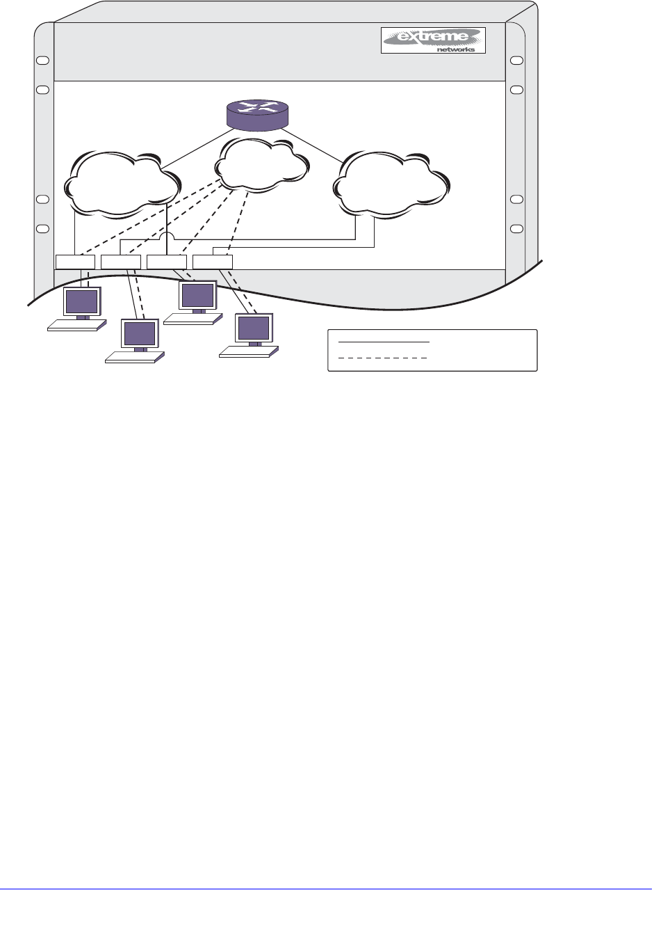
654 | Chapter 21. IPv6 Unicast Routing
NETGEAR 8800 User Manual
Figure 67. IPv6 Unicast Routing Configuration Example
The stations connected to the system generate a combination of IPv6 traffic and NetBIOS
traffic. The IPv6 traffic is filtered by the protocol-sensitive VLANs. All other traffic is directed to
the VLAN MyCompany.
In this configuration, all IPv6 traffic from stations connected to slots 1 and 3 have access to
the router by way of the VLAN Finance. Ports on slots 2 and 4 reach the router by way of the
VLAN Personnel. All other traffic (NetBIOS) is part of the VLAN MyCompany.
The example is configured as follows:
create vlan Finance
create vlan Personnel
create vlan MyCompany
configure Finance protocol ipv6
configure Personnel protocol ipv6
configure Finance add port 1:*,3:*
configure Personnel add port 2:*,4:*
configure MyCompany add port all
configure Finance ipaddress 2001:db8:35::1/48
configure Personnel ipaddress 2001:db8:36::1/48
EX_106
1234AB5678
EX_047
1
MyCompany
2
IPv6
NetBIOS
IPv6
NetBIOS
3 4
= IPv6 traffic
= NetBIOS traffic
2001:db8:36::1/482001:db8:35::1/48
Finance
2001:db8:35::/48
Personnel
2001:db8:36::/48
IPv6
NetBIOS
IPv6
NetBIOS
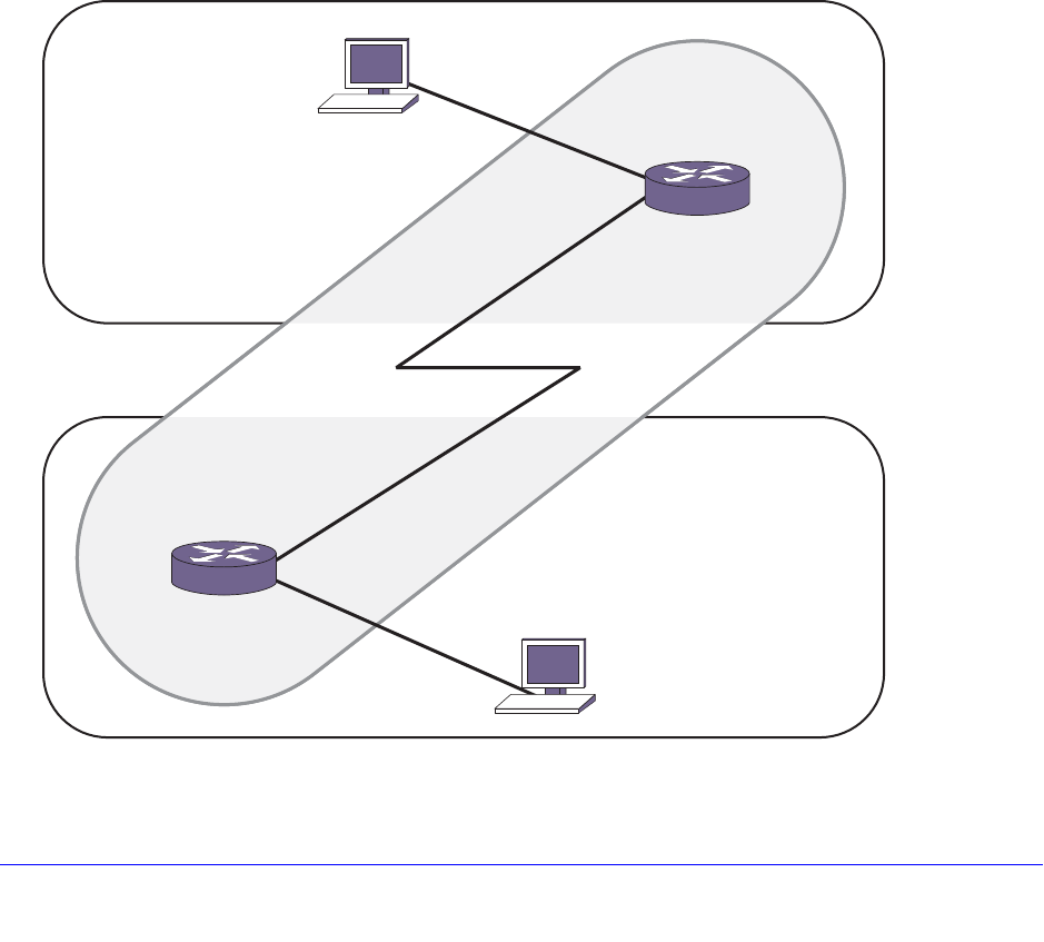
Chapter 21. IPv6 Unicast Routing | 655
NETGEAR 8800 User Manual
configure ripng add vlan Finance
configure ripng add vlan Personnel
enable ipforwarding ipv6
enable ripng
Tunnel Configuration Examples
This section provides the following examples:
• 6in4 Tunnel Configuration Example on page 655
• 6to4 Tunnel Configuration Example on page 657
6in4 Tunnel Configuration Example
Figure 68 illustrates a 6in4 tunnel configured between two IPv6 regions across an IPv4
region.
Figure 68. 6in4 Tunnel Example
IPv6
IPv4
EX_108
Router B
Host B
2001:db8:a::2/64
10.2.0.1/24
2001:db8:2::1/64
Router A
2001:db8:a::1/64
192.168.1.1/24
IPv6
2001:db8:2::101/64
Host A
2001:db8:1::101/64
2
2
1
1
2001:db8:1::1/64

656 | Chapter 21. IPv6 Unicast Routing
NETGEAR 8800 User Manual
In Figure 68, Router A has an interface to an IPv4 region with the address 192.168.1.1 (for
this example we are using private IPv4 addresses, but to tunnel across the Internet, you
would use a public address). Router B has an IPv4 interface of 10.2.0.1. The IPv4 interface
must be created before the tunnel is configured and cannot be deleted until the tunnel is
deleted.
This example has one subnet in each IPv6 region, 2001:db8:1::/64 for Router A and
2001:db8:2::/64 for Router B. Hosts A and B are configured to use IPv6 addresses
2001:db8:1::101 and 2001:db8:2::101 respectively.
For traffic to move from one region to the other, there must be a route. In this example, a
static route is created, but you could enable RIPng or OSPFv3 on the tunnel interface.
In this example, we assume that the IPv4 network can route from Router A to Router B (in
other words, some IPv4 routing protocol is running on the public-ipv4 interfaces). For
platforms on which hardware based tunneling is supported, IPv4 forwarding needs to be
enabled on the tunnel source VLAN. However, in platforms on which IPv6-in-IPv4 tunnels are
supported in software only, you do not need to enable IPv4 forwarding on the public
interfaces in this example unless you are also routing IPv4 traffic on them (in this example, it
is assumed you are running no IPv4 traffic inside your respective IPv6 networks, although
you could).
When Host A needs to send a packet to 2001:db8:2::101 (Host B), it forwards it to Router A.
Router A receives an IPv6 packet from the IPv6 source address 2001:db8:1::101 to the
destination 2001:db8:2::101. Router A has the static route, for the route 2001:db8:2::/64 with
next hop 2001:db8:a::2 (Router B) through the tunnel interface. So Router A encapsulates
the IPv6 packet inside an IPv4 header with the source address 192.168.1.1 and destination
address 10.2.0.1. The encapsulated IPv6 packet passes through the IPv4 network and
reaches the other end of the tunnel - Router B. Router B decapsulates the packet and
removes the IPv4 header. Router B then forwards the IPv6 packet to the destination host -
Host B.
Note: Each IPv6 packet is encapsulated inside an IPv4 header (20 bytes)
before it is forwarded via a IPv6-in-IPv4 tunnel. For example, a
66-byte packet from Host A will be encapsulated and forwarded as a
86-byte packet by the Router A.
Router A
configure vlan default delete port all
create vlan public-ipv4
configure vlan public-ipv4 add port 1 untagged
configure vlan public-ipv4 ipaddress 192.168.1.1/24
create tunnel public6in4 ipv6-in-ipv4 destination 10.2.0.1 source 192.168.1.1
configure tunnel public6in4 ipaddress 2001:db8:a::1/64
enable ipforwarding ipv6 public6in4
create vlan private-ipv6
configure vlan private-ipv6 add port 2 untagged
configure vlan private-ipv6 ipaddress 2001:db8:1::1/64

Chapter 21. IPv6 Unicast Routing | 657
NETGEAR 8800 User Manual
enable ipforwarding ipv6 private-ipv6
configure iproute add 2001:db8:2::/64 2001:db8:a::2
enable ipforwarding public-ipv4
Router B
configure vlan default delete port all
create vlan public-ipv4
configure vlan public-ipv4 add port 1 untagged
configure vlan public-ipv4 ipaddress 10.2.0.1/24
create tunnel public6in4 ipv6-in-ipv4 destination 192.168.1.1 source 10.2.0.1
configure tunnel public6in4 ipaddress 2001:db8:a::2/64
enable ipforwarding ipv6 public6in4
create vlan private-ipv6
configure vlan private-ipv6 add port 2 untagged
configure vlan private-ipv6 ipaddress 2001:db8:2::1/64
enable ipforwarding ipv6 private-ipv6
configure iproute add 2001:db8:1::/64 2001:db8:a::1
enable ipforwarding public-ipv4
6to4 Tunnel Configuration Example
Figure 69 illustrates a 6to4 tunnel configured between two IPv6 regions across an IPv4
region.
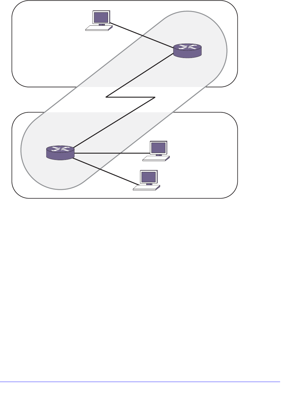
658 | Chapter 21. IPv6 Unicast Routing
NETGEAR 8800 User Manual
Figure 69. 6to4 Tunnel Configuration Example
In Figure 69, Router 1 has an interface to an IPv4 region with the address 192.168.1.1 (for
this example we are using private IPv4 addresses, but to tunnel across the Internet, you
would use a public address). Router 2 has an IPv4 interface of 10.0.0.1. The IPv4 interface
must be created before the tunnel is configured and cannot be deleted until the tunnel is
deleted.
The IPv6 endpoints of 6to4 tunnels must follow the standard 6to4 address requirement. The
address must be of the form 2002:<IPv4_source_endpoint>::/16, where
<IPv4_source_endpoint> is replaced by the IPv4 source address of the endpoint, in
hexadecimal, colon separated form. For example, for a tunnel endpoint located at IPv4
address 10.20.30.40, the tunnel address would be 2002:0a14:1e28::/16. In hex, 10 is 0a, 20
is 14, 30 is 1e and 40 is 28.
This example shows a simple setup on the Router 1 side (one big /48 IPv6 routing domain
with no subnets), and a slightly more complex setup on the Router 2 side (two subnets :0001:
and :0002: that are /64 in length). Hosts 1, 2, and 3 will communicate using their global 2002:
addresses.
The hosts in this example configure themselves using the EUI64 interface identifier derived
from their MAC addresses. See your host OS vendor’s documentation for configuring IPv6
addresses and routes.
EX_109
2002:c0a8:101::204:96ff:fe1f:a52a/48
2002:a00:1:2:201:30ff:fe00:c200/64
2002:a00:1:1:204:96ff:fe1f:a432/64
IPv6
IPv4
Router 2
Host 3
Router 1
IPv6
Host 1
3
2
2
1
1Host 2
2002:c0a8:101::2/48
2002:c0a8:101::1/16
192.168.1.1/24
2002:a00:1:1::1/64
2002:a00:1::1/16
10.0.0.1/24
2002:a00:1:2::1/64

Chapter 21. IPv6 Unicast Routing | 659
NETGEAR 8800 User Manual
In this example, we assume that the IPv4 network can route from Router 1 to Router 2 (in
other words, some IPv4 routing protocol is running on the public-ipv4 interfaces). However,
you do not need to enable IPv4 forwarding on the public interfaces in this example unless
you are also routing IPv4 traffic on them (in this example, it is assumed you are running no
IPv4 traffic inside your respective IPv6 networks, although you could).
Router 1
configure vlan default delete port all
create vlan public-ipv4
configure vlan public-ipv4 add port 1 untagged
configure vlan public-ipv4 ipaddress 192.168.1.1/24
create tunnel public6to4 6to4 source 192.168.1.1
configure tunnel public6to4 ipaddress 2002:c0a8:0101::1/16
enable ipforwarding ipv6 public6to4
create vlan private-ipv6
configure vlan private-ipv6 add port 2 untagged
configure vlan private-ipv6 ipaddress 2002:c0a8:0101::2/48
enable ipforwarding ipv6 private-ipv6
Router 2
configure vlan default delete port all
create vlan public-ipv4
configure vlan public-ipv4 add port 1 untagged
configure vlan public-ipv4 ipaddress 10.0.0.1/24
create tunnel public6to4 6to4 source 10.0.0.1
configure tunnel public6to4 ipaddress 2002:0a00:0001::1/16
enable ipforwarding ipv6 public6to4
create vlan private-ipv6-sub1
configure vlan private-ipv6-sub1 add port 2 untagged
configure vlan private-ipv6-sub1 ipaddress 2002:0a00:0001:0001::1/64
enable ipforwarding ipv6 private-ipv6-sub1
create vlan private-ipv6-sub2
configure vlan private-ipv6-sub2 add port 3 untagged
configure vlan private-ipv6-sub2 ipaddress 2002:0a00:0001:0002::1/64
enable ipforwarding ipv6 private-ipv6-sub2
Host Configurations
The IPv6 addresses of these hosts are based on their MAC address-derived EUI64 interface
identifiers and the address prefixes for their subnets. Each host must also have a static route
configured on it for 6to4 addresses.
Host 1:
• MAC address—00:04:96:1F:A5:2A
• IPv6 address—2002:c0a8:0101::0204:96ff:fe1f:a52a/48
• Static route—destination 2002::/16, gateway 2002:c0a8:0101::2
Host 2:
• MAC address—00:04:96:1F:A4:32

660 | Chapter 21. IPv6 Unicast Routing
NETGEAR 8800 User Manual
• IP address—2002:0a00:0001:0001:0204:96ff:fe1f:a432/64
• Static route—destination 2002::/16, gateway 2002:0a00:0001:0001::1
Host 3:
• MAC address—00:01:30:00:C2:00
• IP address—2002:0a00:0001:0002:0201:30ff:fe00:c200/64
• Static route—destination 2002::/16, gateway 2002:0a00:0001:0002::1

Chapter 22. RIP | 661
22
22. RIP
This chapter includes the following sections:
• Overview on page 661
• Overview of RIP on page 663
• Route Redistribution on page 664
• RIP Configuration Example on page 666
This chapter assumes that you are already familiar with IP unicast routing. If not, see the
following publications for additional information:
• RFC 1058—Routing Information Protocol (RIP)
• RFC 1723—RIP Version 2
• Interconnections: Bridges and Routers
by Radia Perlman
ISBN 0-201-56332-0
Published by Addison-Wesley Publishing Company
Note: RIP is available on platforms with an Aggregation or Advanced Core
license. See Appendix A, XCM8800 Software Licenses for specific
information regarding RIP licensing
Overview
The switch supports the use of the following interior gateway protocols (IGPs):
• Routing Information Protocol (RIP)
• Open Shortest Path First (OSPF)
RIP is a distance-vector protocol, based on the Bellman-Ford (or distance-vector) algorithm. The
distance-vector algorithm has been in use for many years and is widely deployed and
understood.

662 | Chapter 22. RIP
NETGEAR 8800 User Manual
OSPF is a link-state protocol based on the Dijkstra link-state algorithm. OSPF is a newer IGP
and solves a number of problems associated with using RIP on today’s complex networks.
Note: RIP can be enabled on a VLAN with OSPF.
RIP is described in this chapter, and OSPF is described in Chapter 24, OSPF.
RIP Versus OSPF
The distinction between RIP and the OSPF link-state protocols lies in the fundamental
differences between distance-vector protocols and link-state protocols. Using a
distance-vector protocol, each router creates a unique routing table from summarized
information obtained from neighboring routers. Using a link-state protocol, every router
maintains an identical routing table created from information obtained from all routers in the
autonomous system (AS). Each router builds a shortest path tree, using itself as the root. The
link-state protocol ensures that updates sent to neighboring routers are acknowledged by the
neighbors, verifying that all routers have a consistent network map.
Advantages of RIP and OSPF
The biggest advantage of using RIP is that it is relatively simple to understand and to
implement, and it has been the de facto routing standard for many years.
RIP has a number of limitations that can cause problems in large networks, including the
following:
• A limit of 15 hops between the source and destination networks
• A large amount of bandwidth taken up by periodic broadcasts of the entire routing table
• Slow convergence
• Routing decisions based on hop count; no concept of link costs or delay
• Flat networks; no concept of areas or boundaries
OSPF offers many advantages over RIP, including the following:
• No limitation on hop count
• Route updates multicast only when changes occur
• Faster convergence
• Support for load balancing to multiple routers based on the actual cost of the link
• Support for hierarchical topologies where the network is divided into areas
The details of RIP are explained later in this chapter.

Chapter 22. RIP | 663
NETGEAR 8800 User Manual
Overview of RIP
RIP is an IGP first used in computer routing in the Advanced Research Projects Agency
Network (ARPAnet) as early as 1969. It is primarily intended for use in homogeneous
networks of moderate size.
To determine the best path to a distant network, a router using RIP always selects the path
that has the least number of hops. Each router that data must traverse is considered to be
one hop.
Routing Table
The routing table in a router using RIP contains an entry for every known destination network.
Each routing table entry contains the following information:
• IP address of the destination network
• Metric (hop count) to the destination network
• IP address of the next router
• Timer that tracks the amount of time since the entry was last updated
The router exchanges an update message with each neighbor every 30 seconds (default
value), or when there is a change to the overall routed topology (also called triggered
updates). If a router does not receive an update message from its neighbor within the route
timeout period (180 seconds by default), the router assumes the connection between it and
its neighbor is no longer available.
Split Horizon
Split horizon is a scheme for avoiding problems caused by including routes in updates sent to
the router from which the route was learned. Split horizon omits routes learned from a
neighbor in updates sent to that neighbor.
Poison Reverse
Like split horizon, poison reverse is a scheme for eliminating the possibility of loops in the
routed topology. In this case, a router advertises a route over the same interface that
supplied the route, but the route uses a hop count of 16, which defines that router as
unreachable.
Triggered Updates
Triggered updates occur whenever a router changes the metric for a route. The router is
required to send an update message immediately, even if it is not yet time for a regular
update message to be sent. This generally results in faster convergence, but may also result
in more RIP-related traffic.

664 | Chapter 22. RIP
NETGEAR 8800 User Manual
Route Advertisement of VLANs
Virtual LANs (VLANs) that are configured with an IP address but are configured to not route
IP or are not configured to run RIP, do not have their subnets advertised by RIP. RIP
advertises only those VLANs that are configured with an IP address, are configured to route
IP, and run RIP.
RIP Version 1 Versus RIP Version 2
A new version of RIP, called RIP version 2, expands the functionality of RIP version 1 to
include the following:
• Variable-length subnet masks (VLSMs).
• Support for next-hop addresses, which allows for optimization of routes in certain
environments.
• Multicasting.
RIP version 2 packets can be multicast instead of being broadcast, reducing the load on
hosts that do not support routing protocols.
Note: If you are using RIP with supernetting/Classless Inter-Domain
Routing (CIDR), you must use RIPv2 only.
Route Redistribution
More than one routing protocol can be enabled simultaneously on the switch. Route
redistribution allows the switch to exchange routes, including static routes, between the
routing protocols. Figure 70 is an example of route redistribution between an OSPF AS and
a RIP AS.
Chapter 22. RIP | 665
NETGEAR 8800 User Manual
Figure 70. Route Redistribution
Configuring Route Redistribution
Exporting routes from one protocol to another and from that protocol to the first one are
discrete configuration functions. For example, to run OSPF and RIP simultaneously, you
must first configure both protocols and then verify the independent operation of each. Then
you can configure the routes to export from OSPF to RIP and the routes to export from RIP to
OSPF. Likewise, for any other combinations of protocols, you must separately configure each
to export routes to the other.
Redistributing Routes into RIP
Enable or disable the exporting of static, direct, BGP-learned, and OSPF-learned routes into
the RIP domain using the following commands:
enable rip export [bgp | direct | e-bgp | i-bgp | ospf | ospf-extern1 |
ospf-extern2 | ospf-inter | ospf-intra | static] [cost <number> {tag <number>}
| policy <policy-name>]
disable rip export [bgp | direct | e-bgp | i-bgp | ospf | ospf-extern1 |
ospf-extern2 | ospf-inter | ospf-intra | static]
These commands enable or disable the exporting of static, direct, and OSPF-learned routes
into the RIP domain. You can choose which types of OSPF routes are injected, or you can
simply choose ospf, which will inject all learned OSPF routes regardless of type. The default
setting is disabled.
EX_046
OSPF AS
Backbone Area
0.0.0.0
Area
121.2.3.4
ABR
ASBR ASBR
RIP AS
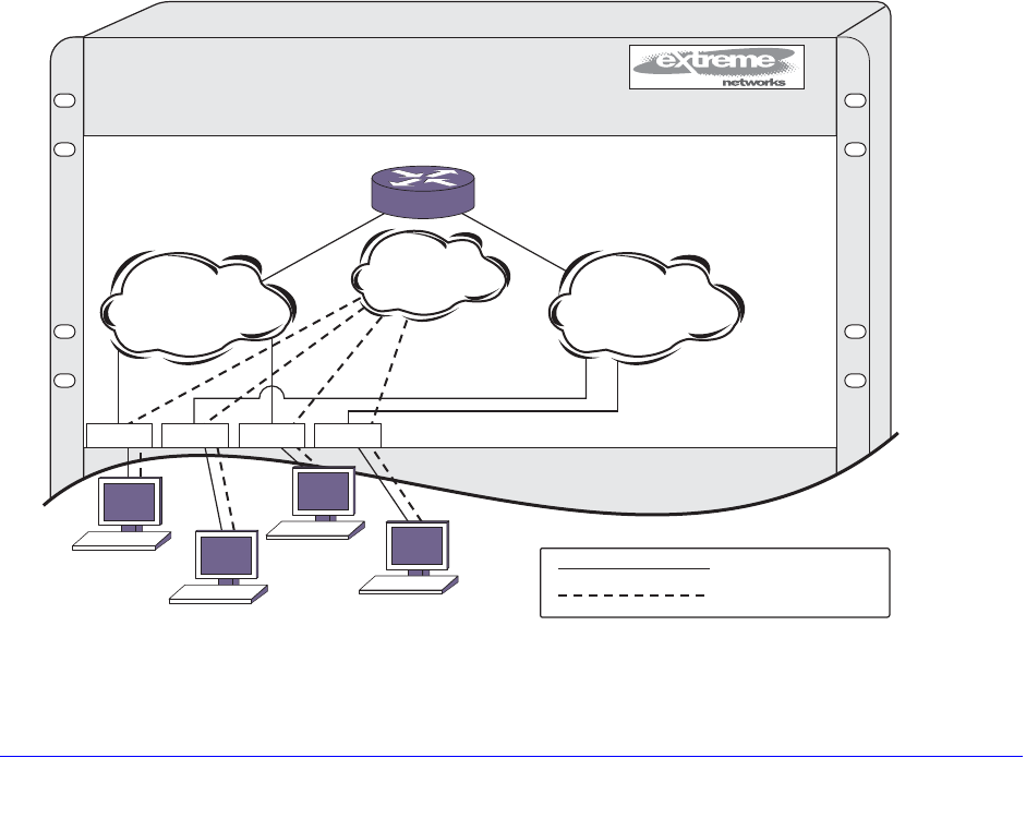
666 | Chapter 22. RIP
NETGEAR 8800 User Manual
RIP Configuration Example
Figure 71 illustrates a NETGEAR 8800 switch that has three VLANs defined as follows:
• Finance
• Protocol-sensitive VLAN using the IP protocol.
• All ports on slots 1 and 3 have been assigned.
• IP address 192.207.35.1.
• Personnel
• Protocol-sensitive VLAN using the IP protocol.
• All ports on slots 2 and 4 have been assigned.
• IP address 192.207.36.1.
• MyCompany
• Port-based VLAN.
• All ports on slots 1 through 4 have been assigned.
This example does use protocol-sensitive VLANs that only admit IP packets. This is not a
common requirement for most networks. In most cases, VLANs will admit different types of
packets to be forwarded to the hosts and servers on the network.
Figure 71. RIP Configuration Example
1234AB5678
EX_047
1
MyCompany
2
IP
NetBIOS
IP
NetBIOS
3 4
= IP traffic
= NetBIOS traffic
192.207.36.1192.207.35.1
Finance
192.207.35.0
Personnel
192.207.36.0
IP
NetBIOS
IP
NetBIOS

Chapter 22. RIP | 667
NETGEAR 8800 User Manual
The stations connected to the system generate a combination of IP traffic and NetBIOS
traffic. The IP traffic is filtered by the protocol-sensitive VLANs. All other traffic is directed to
the VLAN MyCompany.
In this configuration, all IP traffic from stations connected to slots 1 and 3 have access to the
router by way of the VLAN Finance. Ports on slots 2 and 4 reach the router by way of the
VLAN Personnel. All other traffic (NetBIOS) is part of the VLAN MyCompany.
More commonly, NetBIOS traffic would be allowed on the Finance and Personnel VLANs, but
this example shows how to exclude that traffic. To allow the NetBIOS traffic (or other type of
traffic) along with the IP traffic, remove the configure finance protocol ip and configure
Personnel protocol ip commands from the example.
The example in Figure 71 is configured as follows:
create vlan Finance
create vlan Personnel
create vlan MyCompany
configure Finance protocol ip
configure Personnel protocol ip
configure Finance add port 1:*,3:*
configure Personnel add port 2:*,4:*
configure MyCompany add port all
configure Finance ipaddress 192.207.35.1
configure Personnel ipaddress 192.207.36.1
enable ipforwarding
configure rip add vlan all
enable rip

Chapter 23. RIPng | 668
23
23. RIPng
This chapter includes the following sections:
• Overview on page 668
• Overview of RIPng on page 669
• Route Redistribution on page 671
• RIPng Configuration Example on page 671
This chapter assumes you are already familiar with IP unicast routing. If not, see the publication
RFC 2080—RIPng for IPv6.
Note: RIPng is available on platforms with an Edge, Advanced Edge or
Core license. See Appendix A, XCM8800 Software Licenses for
specific information regarding RIPng licensing
Overview
Routing Information Protocol Next Generation (RIPng) is an interior gateway protocol (IGP)
developed for IPv6 networks. The analogous protocol used in IPv4 networks is called Routing
Information Protocol (RIP). Like RIP, RIPng is a relatively simple protocol for the communication
of routing information among routers. Many concepts and features of RIPng are directly parallel
to those same features in RIP.
RIPng is a distance-vector protocol, based on the Bellman-Ford (or distance-vector) algorithm.
The distance-vector algorithm has been in use for many years and is widely deployed and
understood. The other common IGP for IPv6 is Open Shortest Path First Version 3 (OSPFv3),
which is a link-state protocols.
Note: RIPng can be enabled on a VLAN with either OSPFv3 or ISIS.
OSPFv3 and ISIS cannot be enabled on the same VLAN.
RIPng is described in this chapter and OSPFv3 is described in Chapter 25, OSPFv3.

Chapter 23. RIPng | 669
NETGEAR 8800 User Manual
RIPng Versus OSPFv3
The distinction between RIPng and the link-state protocol, OSPFv3, lies in the fundamental
differences between distance-vector protocols (RIPng) and link-state protocols. Using a
distance-vector protocol, each router creates a unique routing table from summarized
information obtained from neighboring routers. Using a link-state protocol, every router
maintains an identical routing table created from information obtained from all routers in the
autonomous system (AS). Each router builds a shortest path tree, using itself as the root. The
link-state protocol ensures that updates sent to neighboring routers are acknowledged by the
neighbors, verifying that all routers have a consistent network map.
Advantages of RIPng and OSPFv3
The biggest advantage of using RIPng is that it is relatively simple to understand and to
implement, and it has been the de facto routing standard for many years.
RIPng has a number of limitations that can cause problems in large networks, including the
following:
• A limit of 15 hops between the source and destination networks
• A large amount of bandwidth taken up by periodic broadcasts of the entire routing table
• Slow convergence
• Routing decisions based on hop count; no concept of link costs or delay
• Flat networks; no concept of areas or boundaries
OSPFv3 offers many advantages over RIPng, including the following:
• No limitation on hop count
• Route updates multicast only when changes occur
• Faster convergence
• Support for load balancing to multiple routers based on the actual cost of the link
• Support for hierarchical topologies where the network is divided into areas
The details of RIPng are explained later in this chapter.
Overview of RIPng
RIPng is primarily intended for use in homogeneous networks of moderate size.
To determine the best path to a distant network, a router using RIPng always selects the path
that has the least number of hops. Each router that data must traverse is considered to be
one hop.

670 | Chapter 23. RIPng
NETGEAR 8800 User Manual
Routing Table
The routing table in a router using RIPng contains an entry for every known destination
network. Each routing table entry contains the following information:
• IP address and prefix length of the destination network
• Metric (hop count) to the destination network
• IP address of the next hop router, if the destination is not directly connected
• Interface for the next hop
• Timer that tracks the amount of time since the entry was last updated
• A flag that indicates if the entry is a new one since the last update
• The source of the route, for example, static, RIPng, OSPFv3, etc.
The router exchanges an update message with each neighbor every 30 seconds (default
value), or when there is a change to the overall routed topology (also called triggered
updates). If a router does not receive an update message from its neighbor within the route
timeout period (180 seconds by default), the router assumes the connection between it and
its neighbor is no longer available.
Split Horizon
Split horizon is a scheme for avoiding problems caused by including routes in updates sent to
the router from which the route was learned. Split horizon omits routes learned from a
neighbor in updates sent to that neighbor.
Poison Reverse
Like split horizon, poison reverse is a scheme for eliminating the possibility of loops in the
routed topology. In this case, a router advertises a route over the same interface that supplied
the route, but the route uses a hop count of 16, which defines that router as unreachable.
Triggered Updates
Triggered updates occur whenever a router changes the metric for a route. The router is
required to send an update message immediately, even if it is not yet time for a regular
update message to be sent. This generally results in faster convergence, but may also result
in more RIPng-related traffic.
Route Advertisement of VLANs
Virtual LANs (VLANs) that are configured with an IP address but are configured to not route
IP or are not configured to run RIP, do not have their subnets advertised by RIP. RIP
advertises only those VLANs that are configured with an IP address, are configured to route
IP, and run RIP.

Chapter 23. RIPng | 671
NETGEAR 8800 User Manual
Route Redistribution
More than one routing protocol can be enabled simultaneously on the switch. Route
redistribution allows the switch to exchange routes, including static routes, between the
routing protocols. Route redistribution is also called route export.
Configuring Route Redistribution
Exporting routes from one protocol to another and from that protocol to the first one are
discrete configuration functions. For example, to run OSPFv3 and RIPng simultaneously, you
must first configure both protocols and then verify the independent operation of each. Then
you can configure the routes to export from OSPFv3 to RIPng and the routes to export from
RIPng to OSPFv3. Likewise, for any other combinations of protocols, you must separately
configure each to export routes to the other.
Redistributing Routes into RIPng
Enable or disable the exporting of static, direct, or other protocol-learned routes into the
RIPng domain using the following commands:
enable ripng export [direct | ospfv3 | ospfv3-extern1 | ospfv3-extern2 |
ospfv3-inter | ospfv3-intra | static] [cost <number> {tag <number>} | policy
<policy-name>]
disable ripng export [direct | ospfv3 | ospfv3-extern1 | ospfv3-extern2 |
ospfv3-inter | ospfv3-intra | static]
These commands enable or disable the exporting of static, direct, and OSPF-learned routes
into the RIPng domain. You can choose which types of OSPF routes are injected, or you can
simply choose ospf, which will inject all learned OSPF routes regardless of type. The default
setting is disabled.
RIPng Configuration Example
The following configuration is similar to the example in the RIP chapter, but uses IPv6
addresses. It illustrates a BlackDiamond switch that has three VLANs defined as follows:
• Finance
• All ports on slots 1 and 3 have been assigned.
• IP address 2001:db8:35::1/48.
• Personnel
• All ports on slots 2 and 4 have been assigned.
• IP address 2001:db8:36::1/48.
• MyCompany
• Port-based VLAN.

672 | Chapter 23. RIPng
NETGEAR 8800 User Manual
• All ports on slots 1 through 4 have been assigned.
The stations connected to the system generate a combination of IPv6 traffic and NetBIOS
traffic.
In this configuration, all traffic from stations connected to slots 1 and 3 have access to the
router by way of the VLAN Finance. Ports on slots 2 and 4 reach the router by way of the
VLAN Personnel. All traffic (NetBIOS and IPv6) is part of the VLAN MyCompany.
The example is configured as follows:
create vlan Finance
create vlan Personnel
create vlan MyCompany
configure Finance add port 1:*,3:*
configure Personnel add port 2:*,4:*
configure MyCompany add port all
configure Finance ipaddress 2001:db8:35::1/48
configure Personnel ipaddress 2001:db8:36::1/48
enable ipforwarding ipv6
configure ripng add vlan Finance
configure ripng add vlan Personnel
enable ripng

Chapter 24. OSPF | 673
24
24. OSPF
This chapter includes the following sections:
• Overview on page 674
• Route Redistribution on page 681
• Configuring OSPF on page 682
• OSPF Configuration Example on page 684
• Displaying OSPF Settings on page 686
This chapter assumes that you are already familiar with IP unicast routing. If not, see the
following publications for additional information:
• RFC 2328—OSPF Version 2
• RFC 1765—OSPF Database Overflow
• RFC 2370—The OSPF Opaque LSA Option
• RFC 3101—The OSPF Not-So-Stubby Area (NSSA) Option
• RFC 3623—Graceful OSPF Restart
• Interconnections: Bridges and Routers
by Radia Perlman
ISBN 0-201-56332-0
Published by Addison-Wesley Publishing Company
Note: OSPF is available on platforms with an Advanced Edge or Core
license. See Appendix A, XCM8800 Software Licenses for specific
information regarding OSPF licensing.

674 | Chapter 24. OSPF
NETGEAR 8800 User Manual
Overview
Open Shortest Path First (OSPF) is a link state protocol that distributes routing information
between routers belonging to a single IP domain; the IP domain is also known as an
autonomous system (AS). In a link-state routing protocol, each router maintains a database
describing the topology of the AS. Each participating router has an identical database
maintained from the perspective of that router.
From the link state database (LSDB), each router constructs a tree of shortest paths, using
itself as the root. The shortest path tree provides the route to each destination in the AS.
When several equal-cost routes to a destination exist, traffic can be distributed among them.
The cost of a route is described by a single metric.
OSPF is an interior gateway protocol (IGP), as is the other common IGP—RIP. OSPF and
RIP are compared in Chapter 22, RIP.
Note: Two types of OSPF functionality are available and each has a
different licensing requirement. One is the complete OSPF
functionality and the other is OSPF Edge Mode, a subset of OSPF
that is described below. See Appendix A, XCM8800 Software
Licenses for specific information regarding OSPF licensing.
OSPF Edge Mode
OSPF Edge Mode is a subset of OSPF available on platforms with an Advanced Edge
license. There are two restrictions on OSPF Edge Mode:
• At most, four Active OSPF VLAN interfaces are permitted. There is no restriction on the
number of Passive interfaces.
• The OSPF Priority on VLANs is 0, and is not configurable. This prevents the system from
acting as a DR or BDR
Link State Database
Upon initialization, each router transmits a link state advertisement (LSA) on each of its
interfaces. LSAs are collected by each router and entered into the LSDB of each router. After
all LSAs are received, the router uses the LSDB to calculate the best routes for use in the IP
routing table. OSPF uses flooding to distribute LSAs between routers. Any change in routing
information is sent to all of the routers in the network. All routers within an area have the
exact same LSDB. Table 67 describes LSA type numbers.
Chapter 24. OSPF | 675
NETGEAR 8800 User Manual
Database Overflow
The OSPF database overflow feature allows you to limit the size of the LSDB and to maintain
a consistent LSDB across all the routers in the domain, which ensures that all routers have a
consistent view of the network.
Consistency is achieved by:
• Limiting the number of external LSAs in the database of each router
• Ensuring that all routers have identical LSAs
To configure OSPF database overflow, use the following command:
configure ospf ase-limit <number> {timeout <seconds>}
Where:
• <number>—Specifies the number of external LSAs that the system supports before it goes
into overflow state. A limit value of 0 disables the functionality.
When the LSDB size limit is reached, OSPF database overflow flushes LSAs from the
LSDB. OSPF database overflow flushes the same LSAs from all the routers, which
maintains consistency.
• timeout—Specifies the timeout, in seconds, after which the system ceases to be in
overflow state. A timeout value of 0 leaves the system in overflow state until OSPF is
disabled and re-enabled.
Opaque LSAs
Opaque LSAs are a generic OSPF mechanism used to carry auxiliary information in the
OSPF database. Opaque LSAs are most commonly used to support OSPF traffic
engineering.
Table 67. LSA Type Numbers
Type Number Description
1Router LSA
2Network LSA
3Summary LSA
4AS summary LSA
5AS external LSA
7NSSA external LSA
9Link local—Opaque
10 Area scoping—Opaque
11 AS scoping—Opaque

676 | Chapter 24. OSPF
NETGEAR 8800 User Manual
Normally, support for opaque LSAs is autonegotiated between OSPF neighbors. In the event
that you experience interoperability problems, you can disable opaque LSAs across the
entire system using the following command:
disable ospf capability opaque-lsa
To re-enable opaque LSAs across the entire system, use the following command:
enable ospf capability opaque-lsa
If your network uses opaque LSAs, NETGEAR recommends that all routers on your OSPF
network support opaque LSAs. Routers that do not support opaque LSAs do not store or
flood them. At minimum a well interconnected subsection of your OSPF network must
support opaque LSAs to maintain reliability of their transmission.
Graceful OSPF Restart
RFC 3623 describes a way for OSPF control functions to restart without disrupting traffic
forwarding. Without graceful restart, adjacent routers will assume that information previously
received from the restarting router is stale and will not be used to forward traffic to that router.
However, in many cases, two conditions exist that allow the router restarting OSPF to
continue to forward traffic correctly. The first condition is that forwarding can continue while
the control function is restarted. Most modern router system designs separate the forwarding
function from the control function so that traffic can still be forwarded independent of the state
of the OSPF function. Routes learned through OSPF remain in the routing table and packets
continue to be forwarded. The second condition required for graceful restart is that the
network remain stable during the restart period. If the network topology is not changing, the
current routing table remains correct. Often, networks can remain stable during the time for
restarting OSPF.
Restarting and Helper Mode
Routers involved with graceful restart fill one of two roles: the restarting router or the helper
router. With graceful restart, the router that is restarting sends out Grace-LSAs informing its
neighbors that it is in graceful restart mode, how long the helper router should assist with the
restart (the grace period), and why the restart occurred. If the neighboring routers are
configured to help with the graceful restart (helper-mode), they will continue to advertise the
restarting router as if it was fully adjacent. Traffic continues to be routed as though the
restarting router is fully functional. If the network topology changes, the helper routers will
stop advertising the restarting router. The helper router will continue in helper mode until the
restarting router indicates successful termination of graceful restart, the Grace-LSAs expire,
or the network topology changes. A router can be configured for graceful restart, and for
helper-mode separately. A router can be a helper when its neighbor restarts, and can in turn
be helped by a neighbor if it restarts.
Planned and Unplanned Restarts
Two types of graceful restarts are defined: planned and unplanned. A planned restart would
occur if the software module for OSPF was upgraded, or if the router operator decided to
restart the OSPF control function for some reason. The router has advance warning, and is

Chapter 24. OSPF | 677
NETGEAR 8800 User Manual
able to inform its neighbors in advance that OSPF is restarting. An unplanned restart would
occur if there was some kind of system failure that caused a remote reboot or a crash of
OSPF, or an MSM/MM failover occurs. As OSPF restarts, it informs its neighbors that it is in
the midst of an unplanned restart. You can decide to configure a router to enter graceful
restart for only planned restarts, for only unplanned restarts, or for both. Also, you can
separately decide to configure a router to be a helper for only planned, only unplanned, or for
both kinds of restarts.
Configuring Graceful OSPF Restart
To configure a router to perform graceful OSPF restart, use the following command:
configure ospf restart [none | planned | unplanned | both]
Since a router can act as a restart helper router to multiple neighbors, you will specify which
neighbors to help. To configure a router to act as a graceful OSPF restart helper, use the
following command:
configure ospf [vlan [all | <vlan-name>] | area <area-identifier> |
virtual-link <router-identifier> <area-identifier>] restart-helper [none |
planned | unplanned | both]
The graceful restart period sent out to helper routers can be configured with the following
command:
configure ospf restart grace-period <seconds>
By default, a helper router will terminate graceful restart if received LSAs would affect the
restarting router. This will occur when the restart-helper receives an LSA that will be flooded
to the restarting router or when there is a changed LSA on the restarting router's
retransmission list when graceful restart is initiated. To disable this behavior, use the
following command:
disable ospf [vlan [all | <vlan-name>] | area <area-identifier> | virtual-link
<router-identifier> <area-identifier>] restart-helper-lsa-check
Areas
OSPF allows parts of a network to be grouped together into areas. The topology within an
area is hidden from the rest of the AS. Hiding this information enables a significant reduction
in LSA traffic and reduces the computations needed to maintain the LSDB. Routing within the
area is determined only by the topology of the area.
The three types of routers defined by OSPF are as follows:
• Internal router (IR)—An internal router has all of its interfaces within the same area.
• Area border router (ABR)—An ABR has interfaces in multiple areas. It is responsible for
exchanging summary advertisements with other ABRs.
• Autonomous system border router (ASBR)—An ASBR acts as a gateway between
OSPF and other routing protocols, or other autonomous systems.

678 | Chapter 24. OSPF
NETGEAR 8800 User Manual
Backbone Area (Area 0.0.0.0)
Any OSPF network that contains more than one area is required to have an area configured
as area 0.0.0.0, also called the backbone. All areas in an AS must be connected to the
backbone. When designing networks, you should start with area 0.0.0.0 and then expand into
other areas.
Note: Area 0.0.0.0 exists by default and cannot be deleted or changed.
The backbone allows summary information to be exchanged between ABRs. Every ABR
hears the area summaries from all other ABRs. The ABR then forms a picture of the distance
to all networks outside of its area by examining the collected advertisements and adding in
the backbone distance to each advertising router.
When a VLAN is configured to run OSPF, you must configure the area for the VLAN. If you
want to configure the VLAN to be part of a different OSPF area, use the following command:
configure ospf vlan <vlan-name> area <area-identifier>
If this is the first instance of the OSPF area being used, you must create the area first using
the following command:
create ospf area <area-identifier>
Stub Areas
OSPF allows certain areas to be configured as stub areas. A stub area is connected to only
one other area. The area that connects to a stub area can be the backbone area. External
route information is not distributed into stub areas. Stub areas are used to reduce memory
consumption and computational requirements on OSPF routers. Use the following command
to configure an OSPF area as a stub area:
configure ospf area <area-identifier> stub [summary | nosummary]
stub-default-cost <cost>
Not-So-Stubby-Areas
Not-so-stubby-areas (NSSAs) are similar to the existing OSPF stub area configuration option
but have the following two additional capabilities:
• External routes originating from an ASBR connected to the NSSA can be advertised
within the NSSA.
• External routes originating from the NSSA can be propagated to other areas, including
the backbone area.
The command line interface (CLI) command to control the NSSA function is similar to the
command used for configuring a stub area, as follows:
configure ospf area <area-identifier> nssa [summary | nosummary]
stub-default-cost <cost> {translate}
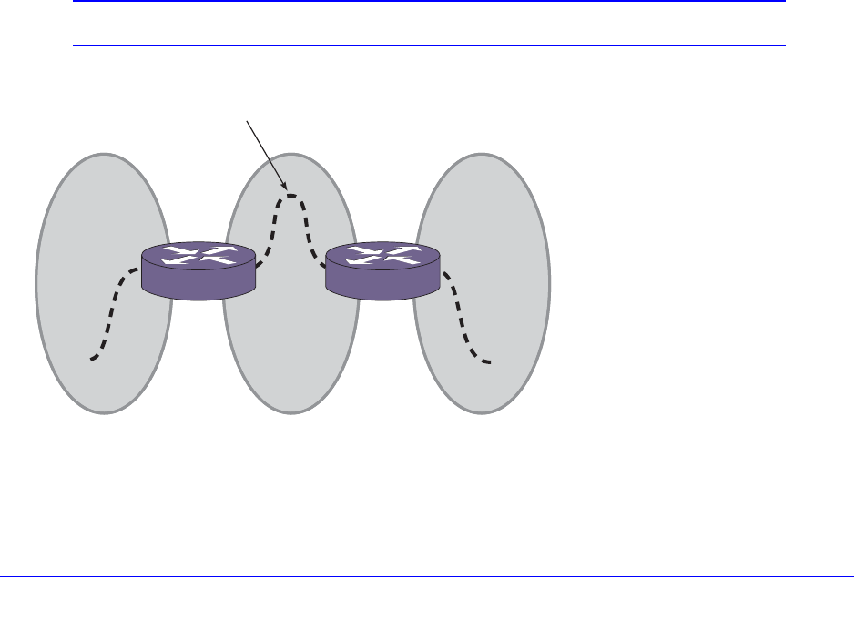
Chapter 24. OSPF | 679
NETGEAR 8800 User Manual
The translate option determines whether type 7 LSAs are translated into type 5 LSAs. When
configuring an OSPF area as an NSSA, translate should only be used on NSSA border
routers, where translation is to be enforced. If translate is not used on any NSSA border
router in a NSSA, one of the ABRs for that NSSA is elected to perform translation (as
indicated in the NSSA specification). The option should not be used on NSSA internal
routers. Doing so inhibits correct operation of the election algorithm.
Normal Area
A normal area is an area that is not:
• Area 0
• Stub area
• NSSA
Virtual links can be configured through normal areas. External routes can be distributed into
normal areas.
Virtual Links
In the situation when a new area is introduced that does not have a direct physical
attachment to the backbone, a virtual link is used. A virtual link provides a logical path
between the ABR of the disconnected area and the ABR of the normal area that connects to
the backbone. A virtual link must be established between two ABRs that have a common
area, with one ABR connected to the backbone. Figure 72 illustrates a virtual link.
Note: Virtual links cannot be configured through a stub or NSSA area.
Figure 72. Virtual Link Using Area1 as a Transit Area
ABR ABR
Area 2 Area 1 Area 0
Virtual link
EX_044
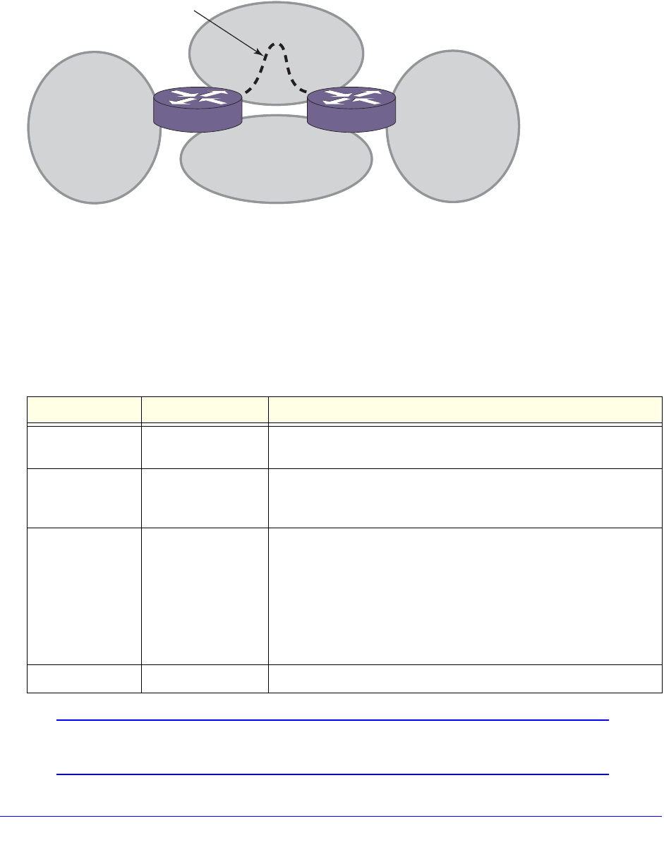
680 | Chapter 24. OSPF
NETGEAR 8800 User Manual
Virtual links are also used to repair a discontiguous backbone area. For example, in
Figure 73, if the connection between ABR1 and the backbone fails, the connection using
ABR2 provides redundancy so that the discontiguous area can continue to communicate with
the backbone using the virtual link.
Figure 73. Virtual Link Providing Redundancy
Point-to-Point Support
You can manually configure the OSPF link type for a VLAN. Table 68 describes the link
types.
Note: The number of routers in an OSPF point-to-point link is determined
per VLAN, not per link.
Table 68. OSPF Link Types
Link Type Number of Routers Description
Auto Varies XCM8800 automatically determines the OSPF link type based on the
interface type. This is the default setting.
Broadcast Any Routers must elect a designated router (DR) and a backup
designated router (BDR) during synchronization. Ethernet is an
example of a broadcast link.
Point-to-point Up to 2 This type synchronizes faster than a broadcast link because routers
do not elect a DR or BDR. It does not operate with more than two
routers on the same VLAN. The Point-to-Point Protocol (PPP) is an
example of a point-to-point link. An OSPF point-to-point link supports
only zero to two OSPF routers and does not elect a designated
router (DR) or backup designated router (BDR). If you have three or
more routers on the VLAN, OSPF fails to synchronize if the neighbor
is not configured.
Passive A passive link does not send or receive OSPF packets.
ABR 1 ABR 2
EX_045
Area 2
Area 0
Area 1 Area 3
Virtual link
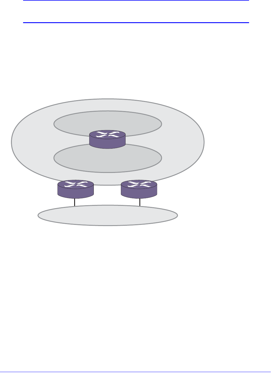
Chapter 24. OSPF | 681
NETGEAR 8800 User Manual
Note: All routers in the VLAN must have the same OSPF link type. If there
is a mismatch, OSPF attempts to operate, but it may not be reliable.
Route Redistribution
More than one routing protocol can be enabled simultaneously on the switch. Route
redistribution allows the switch to exchange routes, including static routes, between the
routing protocols. Figure 74 is an example of route redistribution between an OSPF AS and
a RIP AS.
Figure 74. Route Redistribution
Configuring Route Redistribution
Exporting routes from one protocol to another and from that protocol to the first one are
discrete configuration functions. For example, to run OSPF and RIP simultaneously, you
must first configure both protocols and then verify the independent operation of each. Then
you can configure the routes to export from OSPF to RIP and the routes to export from RIP to
OSPF. Likewise, for any other combinations of protocols, you must separately configure each
to export routes to the other.
Redistributing Routes into OSPF
To enable or disable the exporting of BGP, RIP, static, and direct (interface) routes to OSPF,
use the following commands:
enable ospf export [bgp | direct | e-bgp | i-bgp | rip | static] [cost <cost>
type [ase-type-1 | ase-type-2] {tag <number>} | <policy-map>]
EX_046
OSPF AS
Backbone Area
0.0.0.0
Area
121.2.3.4
ABR
ASBR ASBR
RIP AS

682 | Chapter 24. OSPF
NETGEAR 8800 User Manual
disable ospf export [bgp | direct | e-bgp | i-bgp | rip | static]
These commands enable or disable the exporting of RIP, static, and direct routes by way of
LSA to other OSPF routers as AS-external type 1 or type 2 routes. The default setting is
disabled.
The cost metric is inserted for all Border Gateway Protocol (BGP), RIP, static, and direct
routes injected into OSPF. If the cost metric is set to 0, the cost is inserted from the route. For
example, in the case of BGP export, the cost equals the multiple exit discriminator (MED) or
the path length. The tag value is used only by special routing applications. Use 0 if you do not
have specific requirements for using a tag. (The tag value in this instance has no relationship
with IEEE 802.1Q VLAN tagging.)
The same cost, type, and tag values can be inserted for all the export routes, or policies can
be used for selective insertion. When a policy is associated with the export command, the
policy is applied on every exported route. The exported routes can also be filtered using
policies.
Note: For routes exported to OSPF via a policy file, any refresh applied on
that policy may result in temporary withdrawal and then immediate
readvertising of those routes.
Verify the configuration using the command:
show ospf
OSPF Timers and Authentication
Configuring OSPF timers and authentication on a per area basis is a shortcut to applying the
timers and authentication to each VLAN in the area at the time of configuration. If you add
more VLANs to the area, you must configure the timers and authentication for the new
VLANs explicitly. Use the command:
configure ospf vlan [<vlan-name> | all] timer <retransmit-interval>
<transit-delay> <hello-interval> <dead-interval> {<wait-timer-interval>}
Configuring OSPF
Each switch that is configured to run OSPF must have a unique router ID. NETGEAR
recommends that you manually set the router ID of the switches participating in OSPF,
instead of having the switch automatically choose its router ID based on the highest interface
IP address. Not performing this configuration in larger, dynamic environments could result in
an older LSDB remaining in use.

Chapter 24. OSPF | 683
NETGEAR 8800 User Manual
Configuring OSPF Wait Interval
XCM8800 allows you to configure the OSPF wait interval, rather than using the router dead
interval.
CAUTION:
Do not configure OSPF timers unless you are comfortable exceeding
OSPF specifications. Non-standard settings may not be reliable under all
circumstances.
To specify the timer intervals, use the following commands:
configure ospf area <area-identifier> timer <retransmit-interval>
<transit-delay> <hello-interval> <dead-interval> {<wait-timer-interval>}
configure ospf virtual-link <router-identifier> <area-identifier> timer
<retransmit-interval> <transit-delay> <hello-interval> <dead-interval>
configure ospf vlan [<vlan-name> | all] timer <retransmit-interval>
<transit-delay> <hello-interval> <dead-interval> {<wait-timer-interval>}
OSPF Wait Interval Parameters
You can configure the following parameters:
• Retransmit interval—The length of time that the router waits before retransmitting an
LSA that is not acknowledged. If you set an interval that is too short, unnecessary
retransmissions result. The default value is 5 seconds.
• Transit delay—The length of time it takes to transmit an LSA packet over the interface.
The transit delay must be greater than 0.
• Hello interval—The interval at which routers send hello packets. Shorter times allow
routers to discover each other more quickly but also increase network traffic. The default
value is 10 seconds.
• Dead router wait interval (Dead Interval)—The interval after which a neighboring router
is declared down because hello packets are no longer received from the neighbor. This
interval should be a multiple of the hello interval. The default value is 40 seconds.
• Router wait interval (Wait Timer Interval)—The interval between the interface coming
up and the election of the DR and BDR. This interval should be greater than the hello
interval. If this time is close to the hello interval, the network synchronizes very quickly but
might not elect the correct DR or BDR. The default value is equal to the dead router wait
interval.
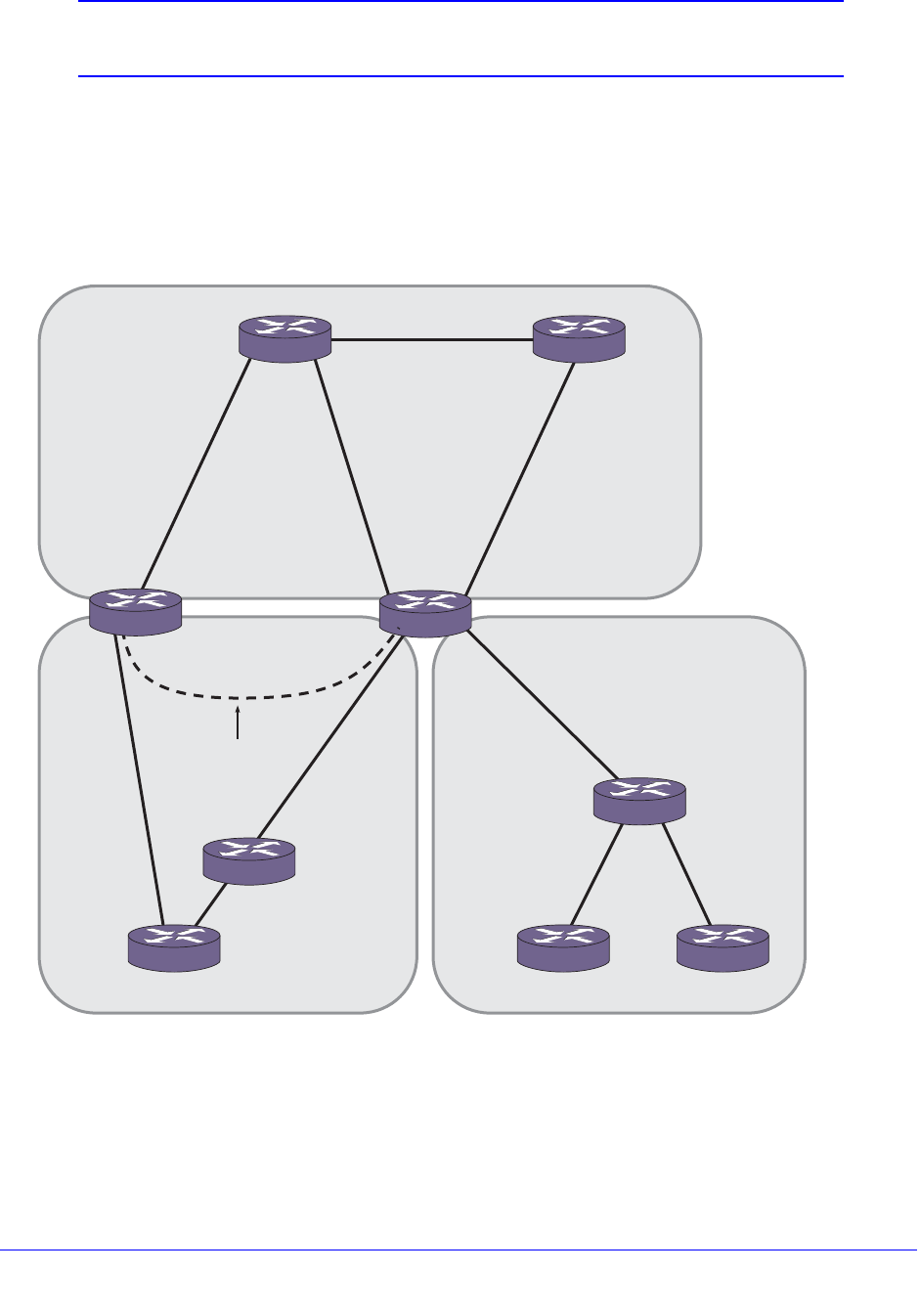
684 | Chapter 24. OSPF
NETGEAR 8800 User Manual
Note: The OSPF standard specifies that wait times are equal to the dead
router wait interval.
OSPF Configuration Example
Figure 75 is an example of an autonomous system using OSPF routers. The details of this
network follow.
Figure 75. OSPF Configuration Example
Area 0 is the backbone area. It is located at the headquarters and has the following
characteristics:
• Two internal routers (IR1 and IR2)
• Two area border routers (ABR1 and ABR2)
Area 0 10.0.1.1
10.0.3.2
10.0.3.1
160.26.25.1
161.48.2.2
161.48.2.1
10.0.2.1
HQ_10_0_2
Chi_160_26_26
HQ_10_0_3
10.0.2.2
10.0.1.2
Area 6 (stub)
Virtual link
IR 2 IR 1
ABR 1
ABR 2
Headquarters
Los Angeles
EX_040
LA_161_48_2
160.26.26.2
Area 5
Chicago
160.26.25.2
160.26.26.1

Chapter 24. OSPF | 685
NETGEAR 8800 User Manual
• Network number 10.0.x.x
• Two identified VLANs (HQ_10_0_2 and HQ_10_0_3)
Area 5 is connected to the backbone area by way of ABR1 and ABR2. It is located in Chicago
and has the following characteristics:
• Network number 160.26.x.x
• One identified VLAN (Chi_160_26_26)
• Two internal routers
Area 6 is a stub area connected to the backbone by way of ABR1. It is located in Los Angeles
and has the following characteristics:
• Network number 161.48.x.x
• One identified VLAN (LA_161_48_2)
• Three internal routers
• Uses default routes for inter-area routing
Two router configurations for the example in Figure 75 are provided in the following section.
Configuration for ABR1
The router labeled ABR1 has the following configuration:
create vlan HQ_10_0_2
create vlan HQ_10_0_3
create vlan LA_161_48_2
create vlan Chi_160_26_26
configure vlan HQ_10_0_2 ipaddress 10.0.2.1 255.255.255.0
configure vlan HQ_10_0_3 ipaddress 10.0.3.1 255.255.255.0
configure vlan LA_161_48_2 ipaddress 161.48.2.2 255.255.255.0
configure vlan Chi_160_26_26 ipaddress 160.26.26.1 255.255.255.0
create ospf area 0.0.0.5
create ospf area 0.0.0.6
enable ipforwarding
configure ospf area 0.0.0.6 stub nosummary stub-default-cost 10
configure ospf add vlan LA_161_48_2 area 0.0.0.6
configure ospf add vlan Chi_160_26_26 area 0.0.0.5
configure ospf add vlan HQ_10_0_2 area 0.0.0.0
configure ospf add vlan HQ_10_0_3 area 0.0.0.0
configure ospf vlan LA_161_48_2 priority 10

686 | Chapter 24. OSPF
NETGEAR 8800 User Manual
configure ospf vlan Chi_160_26_26 priority 10
configure ospf vlan HQ_10_0_2 priority 5
configure ospf vlan HQ_10_0_3 priority 5
enable ospf
Configuration for IR1
The router labeled IR1 has the following configuration:
configure vlan HQ_10_0_1 ipaddress 10.0.1.2 255.255.255.0
configure vlan HQ_10_0_2 ipaddress 10.0.2.2 255.255.255.0
enable ipforwarding
configure ospf add vlan all area 0.0.0.0
configure ospf area 0.0.0.0 priority 10
enable ospf
Note: In OSPF edge mode, the VLAN priority is “0” and cannot be set.
(See OSPF Edge Mode on page 674.) When the license is upgraded
to a Core license, the VLAN priority of “0” needs to be reset in order
to participate in DR/BDR election.
Displaying OSPF Settings
You can use a number of commands to display settings for OSPF. To show global OSPF
information, use the show ospf command with no options.
To display information about one or all OSPF areas, use the following command:
show ospf area {<area-identifier>}
The detail option displays information about all OSPF areas in a detail format.
To display information about OSPF interfaces for an area, a VLAN, or for all interfaces, use
the following command:
show ospf interfaces {vlan <vlan-name> | area <area-identifier> | enabled}
The detail option displays information about all OSPF interfaces in a detail format.
XCM8800 provides several filtering criteria for the show ospf lsdb command. You can
specify multiple search criteria, and only those results matching all of the criteria are
displayed. This allows you to control the displayed entries in large routing tables.
To display the current link-state database, use the following command:

Chapter 24. OSPF | 687
NETGEAR 8800 User Manual
show ospf lsdb {detail | stats} {area [<area-identifier> | all]} {{lstype}
[<lstype> | all]} {lsid <lsid-address>{<lsid-mask>}} {routerid
<routerid-address> {<routerid-mask>}} {interface[[<ip-address>{<ip-mask>} |
<ipNetmask>] | vlan <vlan-name>]}
The detail option displays all fields of matching LSAs in a multiline format. The summary
option displays several important fields of matching LSAs, one line per LSA. The stats option
displays the number of matching LSAs but not any of their contents. If not specified, the
default is to display in the summary format.
A common use of this command is to omit all optional parameters, resulting in the following
shortened form:
show ospf lsdb
The shortened form displays LSAs from all areas and all types in a summary format.

Chapter 25. OSPFv3 | 688
25
25. OSPFv3
This chapter includes the following sections:
• Overview on page 688
• Route Redistribution on page 693
• OSPFv3 Configuration Example on page 694
Note: OSPFv3 is available on platforms with an Advanced Edge or Core
license. See Appendix A, XCM8800 Software Licenses for
information about OSPFv3 licensing.
Overview
Open Shortest Path First (OSPF) is a link state protocol that distributes routing information
between routers belonging to a single IP domain; the IP domain is also known as an
autonomous system (AS). In a link-state routing protocol, each router maintains a database
describing the topology of the AS. Each participating router has an identical database for an area
maintained from the perspective of that router.
From the link state database (LSDB), each router constructs a tree of shortest paths, using itself
as the root. The shortest path tree provides the route to each destination in the AS. When
several equal-cost routes to a destination exist, traffic can be distributed among them. The cost
of a route is described by a single metric.
OSPFv3 supports IPv6, and uses commands only slightly modified from that used to support
IPv4. OSPFv3 has retained the use of the 4-byte, dotted decimal numbers for router IDs, LSA
IDs, and area IDs.
OSPFv3 is an interior gateway protocol (IGP), as is the other common IGP for IPv6, RIPng.
OSPFv3 and RIPng are compared in Chapter 23, RIPng.
Chapter 25. OSPFv3 | 689
NETGEAR 8800 User Manual
Note: Two types of OSPFv3 functionality are available and each has a
different licensing requirement. One is the complete OSPFv3
functionality and the other is OSPFv3 Edge Mode, a subset of
OSPFv3 that is described below. See Appendix A, XCM8800
Software Licenses for specific information regarding OSPFv3
licensing.
OSPFv3 Edge Mode
OSPFv3 Edge Mode is a subset of OSPFv3 available on platforms with an Advanced Edge
license. There are two restrictions on OSPFv3 Edge Mode:
• At most, four Active OSPFv3 VLAN interfaces are permitted. There is no restriction on the
number of Passive interfaces.
• The OSPFv3 Priority on VLANs is 0, and is not configurable. This prevents the system
from acting as a DR or BDR
Link State Database
Upon initialization, each router transmits a link state advertisement (LSA) on each of its
interfaces. LSAs are collected by each router and stored into the LSDB of each router. After
all LSAs are received, the router uses the LSDB to calculate the best routes for use in the IP
routing table. OSPFv3 uses flooding to distribute LSAs between routers. Any change in
routing information is sent to all of the routers in the network. All routers within an area have
the exact same LSDB.
Table 69 describes LSA type numbers.
Table 69. Selected OSPFv3 LSA Types
Type Number Description
0x0008 Link LSA
0x2001 Router LSA
0x2002 Network LSA
0x2003 Inter-Area-Prefix LSA
0x2004 Inter-Area-Router LSA
0x2009 Intra-Area-Prefix LSA
0x4005 AS external LSA

690 | Chapter 25. OSPFv3
NETGEAR 8800 User Manual
Areas
OSPFv3 allows parts of a network to be grouped together into areas. The topology within an
area is hidden from the rest of the AS. Hiding this information enables a significant reduction
in LSA traffic and reduces the computations needed to maintain the LSDB. Routing within the
area is determined only by the topology of the area.
The three types of routers defined by OSPFv3 are as follows:
• Internal router (IR)—An internal router has all of its interfaces within the same area.
• Area border router (ABR)—An ABR has interfaces in multiple areas. It is responsible for
exchanging summary advertisements with other ABRs.
• Autonomous system border router (ASBR)—An ASBR acts as a gateway between
OSPFv3 and other routing protocols, or other autonomous systems.
Backbone Area (Area 0.0.0.0)
Any OSPFv3 network that contains more than one area is required to have an area
configured as area 0.0.0.0, also called the backbone. All areas in an AS must be connected
to the backbone. When designing networks, you should start with area 0.0.0.0 and then
expand into other areas.
Note: Area 0.0.0.0 exists by default and cannot be deleted or changed.
The backbone allows summary information to be exchanged between ABRs. Every ABR
hears the area summaries from all other ABRs. The ABR then forms a picture of the distance
to all networks outside of its area by examining the collected advertisements and adding in
the backbone distance to each advertising router.
When a VLAN is configured to run OSPFv3, you must configure the area for the VLAN. If you
want to configure the VLAN to be part of a different OSPFv3 area, use the following
command:
configure ospfv3 {domain <domainName>} [vlan <vlan-name> | tunnel
<tunnel-name>] area <area-identifier>
If this is the first instance of the OSPFv3 area being used, you must create the area first using
the following command:
create ospfv3 {domain <domainName>} area <area-identifier>
Stub Areas
OSPFv3 allows certain areas to be configured as stub areas. A stub area is connected to only
one other area. The area that connects to a stub area can be the backbone area. External
route information is not distributed into stub areas. Stub areas are used to reduce memory
consumption and computational requirements on OSPFv3 routers. To configure an OSPFv3
area as a stub area, use the following command:
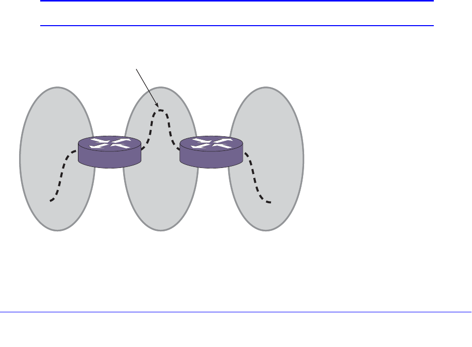
Chapter 25. OSPFv3 | 691
NETGEAR 8800 User Manual
configure ospfv3 {domain <domainName>} area <area-identifier> stub [summary |
nosummary] stub-default-cost <cost>
Not-So-Stubby-Areas
Not-so-stubby-areas (NSSAs) are not supported currently in the XCM8800 implementation of
OSPFv3.
Normal Area
A normal area is an area that is not:
• Area 0
• Stub area
• NSSA
Virtual links can be configured through normal areas. External routes can be distributed into
normal areas.
Virtual Links
In the situation when a new area is introduced that does not have a direct physical
attachment to the backbone, a virtual link is used. A virtual link provides a logical path
between the ABR of the disconnected area and the ABR of the normal area that connects to
the backbone. A virtual link must be established between two ABRs that have a common
area, with one ABR connected to the backbone. Figure 76 illustrates a virtual link.
Note: Virtual links cannot be configured through a stub or NSSA area.
Figure 76. Virtual Link Using Area 1 as a Transit Area
ABR ABR
Area 2 Area 1 Area 0
Virtual link
EX_044
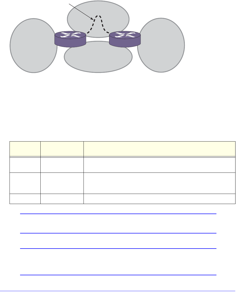
692 | Chapter 25. OSPFv3
NETGEAR 8800 User Manual
Virtual links are also used to repair a discontiguous backbone area. For example, in
Figure 77, if the connection between ABR1 and the backbone fails, the connection using
ABR2 provides redundancy so that the discontiguous area can continue to communicate with
the backbone using the virtual link.
Figure 77. Virtual Link Providing Redundancy
Link-Type Support
You can manually configure the OSPFv3 link type for a VLAN. Table 70 describes the link
types.
Note: The number of routers in an OSPFv3 point-to-point link is
determined per VLAN, not per link.
Note: All routers in the VLAN must have the same OSPFv3 link type. If
there is a mismatch, OSPFv3 attempts to operate, but it may not be
reliable.
Table 70. OSPFv3 Link Types
Link Type Number of
Routers Description
Auto Varies XCM8800 automatically determines the OSPFv3 link type based on the
interface type. This is the default setting.
Broadcast Any Routers must elect a designated router (DR) and a backup designated
router (BDR) during synchronization. Ethernet is an example of a
broadcast link.
Passive A passive link does not send or receive OSPFv3 packets.
ABR 1 ABR 2
EX_045
Area 2
Area 0
Area 1 Area 3
Virtual link
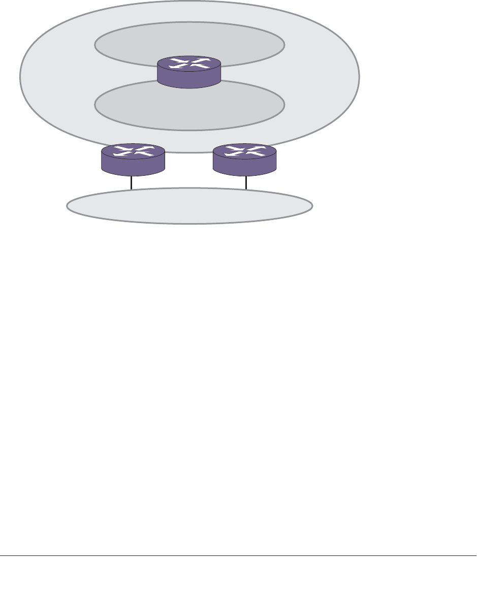
Chapter 25. OSPFv3 | 693
NETGEAR 8800 User Manual
Route Redistribution
More than one routing protocol can be enabled simultaneously on the switch. Route
redistribution allows the switch to exchange routes, including static routes, between the
routing protocols. Figure 78 is an example of route redistribution between an OSPFv3 AS
and a RIPng AS.
Figure 78. Route Redistribution
Configuring Route Redistribution
Exporting routes from one protocol to another and from that protocol to the first one are
discrete configuration functions. For example, to run OSPFv3 and RIPng simultaneously, you
must first configure both protocols and then verify the independent operation of each. Then
you can configure the routes to export from OSPFv3 to RIPng and the routes to export from
RIPng to OSPFv3. Likewise, for any other combinations of protocols, you must separately
configure each to export routes to the other.
Redistributing Routes into OSPFv3
To enable or disable the exporting of RIPng, static, and direct (interface) routes to OSPFv3,
use the following commands:
enable ospfv3 {domain <domainName>} export [direct | ripng | static]
[cost <cost> type [ase-type-1 | ase-type-2] | <policy-map>]
disable ospfv3 {domain <domainName>} export [direct | ripng | static]
EX_046
OSPF AS
Backbone Area
0.0.0.0
Area
121.2.3.4
ABR
ASBR ASBR
RIP AS

694 | Chapter 25. OSPFv3
NETGEAR 8800 User Manual
These commands enable or disable the exporting of RIPng, static, and direct routes by way
of LSA to other OSPFv3 routers as AS-external type 1 or type 2 routes. The default setting is
disabled.
The cost metric is inserted for all RIPng, static, and direct routes injected into OSPFv3. If the
cost metric is set to 0, the cost is inserted from the route. The tag value is used only by
special routing applications. Use 0 if you do not have specific requirements for using a tag.
(The tag value in this instance has no relationship with IEEE 802.1Q VLAN tagging.)
The same cost, type, and tag values can be inserted for all the export routes, or policies can
be used for selective insertion. When a policy is associated with the export command, the
policy is applied on every exported route. The exported routes can also be filtered using
policies.
Note: For routes exported to OSPF via a policy file, any refresh applied on
that policy may result in temporary withdrawal and then immediate
readvertising of those routes.
Verify the configuration using the command:
show ospfv3 {domain <domainName>}
OSPFv3 Timers
Configuring OSPFv3 timers on a per area basis is a shortcut to applying the timers to each
VLAN in the area at the time of configuration. If you add more VLANs to the area, you must
configure the timers for the new VLANs explicitly. Use the command:
configure ospfv3 {domain <domainName>} [vlan <vlan-name> | tunnel <tunnel-name>
| [vlan | tunnel] all] timer {retransmit-interval} <retransmit-interval>
{transit-delay} <transit-delay> {hello-interval} <hello-interval>
{dead-interval} <dead-interval>
OSPFv3 Configuration Example
Figure 79 is an example of an autonomous system using OSPFv3 routers. The details of this
network follow.
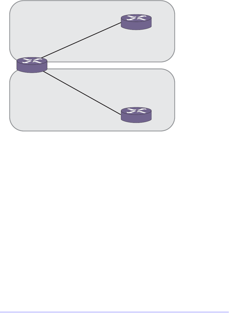
Chapter 25. OSPFv3 | 695
NETGEAR 8800 User Manual
Figure 79. OSPFv3 Configuration Example
In Figure 79 there are three NETGEAR switches running XCM8800 images that have
support for OSPFv3. Router 1 is an area border router and is connected to two other
switches Router 2 and Router 3. Router 1 runs OSPFv3 on both the links connecting it to
Router 2 and Router 3.
The router configurations for the example in Figure 79 are provided in the following section.
After doing all the configurations, Router 1 will establish OSPFv3 adjacency with Router 2
and Router 3. They will also exchange the various link state databases.
Configuration for Router 1
The router labeled Router 1 has the following configuration:
create vlan to-r2
create vlan to-r3
configure vlan to-r2 ipaddress 2001:db8:4444:6666::1/64
configure vlan to-r3 ipaddress 2001:db8:3333:5555::1/64
configure vlan to-r2 add port 1:1
configure vlan to-r3 add port 1:2
enable ipforwarding ipv6
configure ospfv3 routerid 0.0.0.1
configure ospfv3 add vlan to-r2 area 0.0.0.0
Area 0.0.0.0
Area 0.0.0.1
Router 2
Router 1
Router 3
EX_107
2001:db8:4444:6666::2/64
2001:db8:4444:6666::1/64
2001:db8:3333:5555::1/64
2001:db8:3333:5555::2/64
to-r2
to-r3

696 | Chapter 25. OSPFv3
NETGEAR 8800 User Manual
create ospfv3 area 0.0.0.1
configure ospfv3 add vlan to-r3 area 0.0.0.1
enable ospfv3
Configuration for Router 2
The router labeled Router 2 has the following configuration:
create vlan to-r1
configure vlan to-r1 ipaddress 2001:db8:4444:6666::2/64
configure vlan to-r1 add port 1:1
enable ipforwarding ipv6
configure ospfv3 routerid 0.0.0.2
configure ospfv3 add vlan to-r1 area 0.0.0.0
enable ospfv3
Configuration for Router 3
The router labeled Router 3 has the following configuration:
create vlan to-r1
configure vlan to-r1 ipaddress 2001:db8:3333:5555::3/64
configure vlan to-r1 add port 1:1
enable ipforwarding ipv6
configure ospfv3 routerid 0.0.0.3
configure ospfv3 add vlan to-r1 area 0.0.0.1
enable ospfv3

Chapter 26. BGP | 697
26
26. BGP
This chapter includes the following sections:
• Overview on page 697
• BGP Features on page 703
Overview
Border gateway protocol (BGP) is an exterior routing protocol that was developed for use in
TCP/IP networks. The primary function of BGP is to allow different autonomous systems (ASs)
to exchange network reachability information.
An AS is a set of routers that are under a single technical administration. This set of routers uses
a different routing protocol, for example Open Shortest Path First (OSPF), for intra-AS routing.
One or more routers in the AS are configured to be border routers, exchanging information with
other border routers (in different ASs) on behalf of all of the intra-routers.
BGP can be used as an exterior border gateway protocol (referred to as EBGP), or it can be
used within an AS as an interior border gateway protocol (referred to as IBGP).
The following sections provide information on how the XCM8800 software supports BGP:
• BGP Four-Byte AS Numbers on page 698
• BGP Attributes on page 698
• BGP Community Attributes on page 699
• Extended Community Attributes on page 699
• Multiprotocol BGP on page 703
For more information on BGP, see the following documents:
• RFC 1771—Border Gateway Protocol version 4 (BGP-4)
• RFC 1965—Autonomous System Confederations for BGP
• RFC 1966—BGP Route Reflection
• RFC 1997—BGP Communities Attribute
• RFC 1745—BGP/IDRP for IP—OSPF Interaction
• RFC 2385—Protection of BGP Sessions via the TCP MD5 Signature Option

698 | Chapter 26. BGP
NETGEAR 8800 User Manual
• RFC 2439—BGP Route Flap Damping
• RFC 2796—BGP Route Reflection - An Alternative to Full Mesh IBGP
• RFC 2918—Route Refresh Capability for BGP-4
• RFC 3392—Capabilities Advertisement with BGP-4
• RFC 4486—Subcodes for BGP Cease Notification Message
• RFC 4360—BGP Extended Communities Attribute
• RFC 4760—Multiprotocol Extensions for BGP-4
• RFC 4893—BGP Support for Four-octet AS Number Space
• RFC 5396—Textual Representation of Autonomous System (AS) Numbers
• draft_ieft_idr_restart_10.txt—Graceful Restart Mechanism for BGP
Note: XCM8800 supports BGP version 4 only.
Note: For complete information about software licensing, including how to
obtain and upgrade your license and what licenses are appropriate
for these features, see Appendix A, XCM8800 Software Licenses.
BGP Four-Byte AS Numbers
The XCM8800 software supports 4-byte AS numbers, which can be entered and displayed in
the ASPLAIN and ASDOT formats, which are described in RFC 5396, Textual Representation
of Autonomous System (AS) Numbers.
Note: When entering an AS number in a policy file, you must enter a
unique 2-byte or 4-byte AS number. The transition AS number, AS
23456, is not supported in policy files.
BGP Attributes
The following BGP attributes are supported by the switch:
• Origin—Defines the origin of the route. Possible values are Interior Gateway Protocol
(IGP), Exterior Gateway Protocol (EGP), and incomplete.
• AS_Path—The list of ASs that are traversed for this route. The local AS-path is added to
the BGP update packet after the policy is applied.
• AS4_Path—This attribute is used by 4-byte peers when sending updates to 2-byte peers.
This attribute carries AS-number information that can be represented only in 4-bytes.

Chapter 26. BGP | 699
NETGEAR 8800 User Manual
• Next_hop—The IP address of the next hop BGP router to reach the destination listed in
the NLRI field.
• Multi_Exit_Discriminator—Used to select a particular border router in another AS when
multiple border routers exist.
• Local_Preference—Used to advertise this router’s degree of preference to other routers
within the AS.
• Atomic_aggregate—Indicates that the sending border router has used a route aggregate
prefix in the route update.
• Aggregator—Identifies the BGP router AS number and router ID for the router that
performed route aggregation.
• AS4_Aggregator: This attribute is used by 4-byte peers when sending updates to 2-byte
peers. This attribute carries AS-number information that can be represented only in
4-bytes.
• Community—Identifies a group of destinations that share one or more common
attributes.
• Cluster_ID—Specifies a 4-byte field used by a route reflector to recognize updates from
other route reflectors in the same cluster.
• Originator_ID—Specifies the router ID of the originator of the route in the local AS.
• Extended Community—Provides a mechanism for labeling BGP-4 update messages that
carry information
• Multiprotocol reachable NLRI—Used to advertise a feasible BGP route for the non
IPv4-unicast address family
• Multiprotocol unreachable NLRI—This attribute is used to withdraw multiple unfeasible
routes from service
BGP Community Attributes
A BGP community is a group of BGP destinations that require common handling. XCM8800
supports the following well-known BGP community attributes:
• no-export
• no-advertise
• no-export-subconfed
Extended Community Attributes
The extended community attribute provides a mechanism to label BGP routes. It provides
two important enhancements over the standard community attribute:
• An expanded range. Extended communities are 8-bytes wide, whereas regular
communities were only 4-bytes wide. So, this ensures that extended communities can be
assigned for a plethora of uses, without the fear of overlap.
• The addition of 'Type' field provides structure for the extended community

700 | Chapter 26. BGP
NETGEAR 8800 User Manual
The following two types of extended communities are available:
• Route Target (RT)
• Site Of Origin (SOO)
Although these two community types are generally used in L3 VPN network setup, you can
also use them in a non-L3 VPN network to control the distribution of BGP routes.
BGP does not send either the extended or standard community attributes to their neighbors
by default; you must use the configuration command configure bgp neighbor
send-community.
Extended Community Processing
When BGP receives the extended community attribute in a route from its neighbor, it
validates the community syntax. If the community is syntactically valid, the inbound neighbor
route-policy is applied to the route. The inbound route-policy may contain
extended-community statements in match block (in other words, an or/and set) of the policy.
If the route is not rejected by the inbound route-policy, it is added to the LocRIB of the BGP
along with the extended community. The detail option of the show bgp routes command
displays the routes with the extended community attribute if they are present in that route's
path attribute.
Associating the Extended Community Attribute to the BGP Route
The extended community attribute can be added to or removed from a BGP route using an
XCM8800 policy in the same way this action is performed for a regular community attribute.
The extended-community keyword has been added in the Policy Manager, and can be used
in the match as well as in the set block of a policy file.
Syntax in Match block
extended-community "<extended-community-1> <extended-community-2> …"
Where, the syntax of <extended-community-N> is
[rt|soo]:[<2-byte AS num>:<4-byte num> | <4-byte IP Address>:<2-byte num> | <4-byte AS
num>L:<2-byte num | <first two bytes of AS num>.<last two bytes of AS num>:<2-byte num>]
The attributes are defined as follows:
• rt: route target extended community type
• soo: site of origin extended community type
• <2-byte AS number>: This is a 2-byte AS number; the use of private AS-number is not
recommended
• <4-byte num>: a 4-byte unsigned number
• <4-byte IP address>: a valid host IP address; a network address is not accepted; use of
private IP address is not recommended; class-D IP addresses are rejected
• <4-byte AS num>: This is a 4-byte AS number; the use of private AS-number is not
recommended

Chapter 26. BGP | 701
NETGEAR 8800 User Manual
• <first two bytes of AS num>: This is the number represented by the first two bytes of a
four-byte AS number. The use of a private AS-number is not recommended.
• <last two bytes of AS num>: This is the number represented by the last two bytes of a
four-byte AS number. The use of a private AS-number is not recommended
Syntax in Set block
extended-community [set | add | delete] "<extended-community-1>
<extended-community-2> …."
extended-community remove
Where, the syntax of <extended-community-N> is the following:
[rt|soo]:[<2-byte AS num>:<4-byte num> | <4-byte IP Address>:<2-byte num>]
The attributes are defined as follows:
• set: Replaces the existing extended communities by the new ones as supplied in the
policy statement.
• add: Adds new extended communities to the existing extended community attribute. If an
extended community is already present, then policy will not add a duplicate extended
community to the route.
• delete: Deletes some of the extended communities from the extended community
attribute.
• remove: Removes extended community attribute from the route.
• rt: route target extended community type
• soo: site of origin extended community type
• <2-byte AS number>: This is 2-byte AS number. Use of private AS-number is not
recommended
• <4-byte num>: 4-byte unsigned number
• <4-byte IP address>: A valid host IP address. Network address is not accepted. Use of
private IP address is not recommended. Class-D IP address will be rejected.
Examples of Extended Communities
The following are examples of valid extended communities:
• rt:10.203.134.56:400
• soo:800:1600
• rt:14490:2345678
• soo:172.168.45.10:500
• rt:10.10:20000
• soo:1310740L:50000
The following are examples of invalid extended communities:
• rt:10.45.87.0:600: Invalid because the IP address is NOT a valid host IP address
• rt:239.1.1.1:400: Invalid because IP address belongs to class-D

702 | Chapter 26. BGP
NETGEAR 8800 User Manual
• rt:100.200.300.400:200: Invalid because the IP address is invalid
• soo:12345678:500: Invalid because the AS number 12345678 is out of range [1-65535]
Extended Community Syntax
Note the following details with regard to extended community syntax:
• Only rt and soo extended community types are recognized in the policy file.
• The IP address MUST be a valid host address. Network address, Class-D and
experimental IP address are not accepted.
• There should not be any blank spaces inside an extended community. For example, rt
:100:200 is not a valid extended community because there are spaces between rt and :
• All three parameters of an extended community must be present, otherwise the extended
community is rejected.
Extended Community Match Rule in Policy
Regular expressions are not supported for extended communities. In addition, an extended
community match statement matches with a route's extended community if at least one of the
extended communities in the match statement matches with the route's extended community.
There is no need to for all the extended communities in a single match statement to match
with the route's extended community.
For example, suppose the policy file is the following:
entry one {
if {
extended-community "rt:100:20000 rt:10.203.134.5:40 soo:100:50000
soo:192.168.34.1:600";
} then {
permit;
}
}
The above community statement will match with all BGP routes that have at least one of the
following extended communities in their extended community attribute:
• rt:100:20000
• rt:10.203.134.5:40
• soo:100:50000
• soo:192.168.34.1:600
Extended Community Set Rule in Policy
A Policy set block can contain several extended community statements. Each set statement
is applied to the matching route's extended community attribute in the top down order. That
is, the first set is applied to the extended community attribute of the route, the second set is
applied to the result of above, and so forth.
For example, assume that a policy is the following:

Chapter 26. BGP | 703
NETGEAR 8800 User Manual
entry two {
if {
nlri 192.168.34.0/24;
} then {
extended-community set "rt:10.45.92.168:300";
extended-community add "rt:10.203.100.200:40 soo:100:60000";
extended-community delete "rt:65001:10000 soo:72.192.34.10:70";
permit;
}
}
A BGP route 192.168.34.128/25 is received with extended community attribute rt:4567:100
soo:192.168.34.128. When the above policy entry is applied to the route's extended
community attribute, the following is true:
• After applying the 1st set (community set "rt:10.45.92.168:300"), the route's community
becomes rt:10.45.92.168:300.
• After applying the 2nd set (community add "rt:10.203.100.200:40 soo:100:60000"), the
community becomes rt:10.45.92.168:300 rt:10.203.100.200:40 soo:100:60000.
• After applying the 3rd set (community delete "rt:65001:10000 soo:72.192.34.10:70"),
the community becomes rt:10.45.92.168:300 rt:10.203.100.200:40 soo:100:60000.
Note that this delete statement has no effect as none of the communities in the delete
statement are present in the community attribute.
Extended Communities and BGP Route Aggregation
When BGP routes are aggregated with the as-match or as-set CLI option, all the component
route's extended community attributes are aggregated and the resulting aggregated
extended community attributes are attached to the aggregate network.
Aggregation of several extended community attributes is simply the set union of all the
extended communities from all of the aggregated routes.
Multiprotocol BGP
Multiprotocol BGP (MBGP) is an enhanced BGP that carries IP multicast routes. BGP carries
two sets of routes: one set for unicast routing and one set for multicast routing. This allows
BGP to have non-congruent topologies for IPv4 Unicast and IPv4 Multicast networks. The
routes associated with multicast routing are used by the Protocol Independent Multicast
(PIM) to build data distribution trees.
BGP Features
This section describes the following configurable BGP features supported by XCM8800:
• Route Reflectors on page 704
• Route Confederations on page 706
• Route Aggregation on page 710
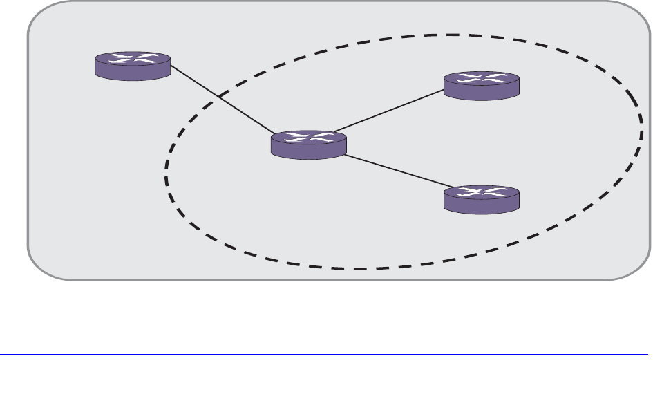
704 | Chapter 26. BGP
NETGEAR 8800 User Manual
• Inactive Route Advertisement on page 710
• Default Route Origination and Advertisement on page 711
• Using the Loopback Interface on page 712
• Looped AS_Path Attribute on page 713
• BGP Peer Groups on page 713
• BGP Route Flap Dampening on page 714
• BGP Route Selection on page 716
• Stripping Out Private AS Numbers from Route Updates on page 716
• Route Redistribution on page 717
• BGP Static Network on page 718
• Graceful BGP Restart on page 719
• Cease Subcodes on page 721
• Fast External Fallover on page 722
• Capability Negotiation on page 722
• Route Refresh on page 723
Route Reflectors
Another way to overcome the difficulties of creating a fully meshed AS is to use route
reflectors. Route reflectors allow a single router to serve as a central routing point for the AS.
A cluster is formed by the route reflector and its client routers. Peer routers that are not part of
the cluster must be fully meshed according to the rules of BGP.
A BGP cluster, including the route reflector and its clients, is shown in Figure 80.
Figure 80. Route Reflectors
EX_042
Client
Route Reflector
Non-client
10.0.0.1
10.0.0.2
30.0.0.1
30.0.0.2
20.0.0.2
20.0.0.1
1.1.1.1
2.2.2.2
3.3.3.3
Cluster
AS 100
Client
4.4.4.4

Chapter 26. BGP | 705
NETGEAR 8800 User Manual
The topology shown in Figure 80 minimizes the number of BGP peering sessions required in
an AS by using route reflectors.
In this example, although the BGP speakers 3.3.3.3 and 4.4.4.4 do not have a direct BGP
peering session between them, these speakers still receive routes from each other indirectly
through 2.2.2.2. The router 2.2.2.2 is called a route reflector and is responsible for reflecting
routes between its clients. Routes received from the client 3.3.3.3 by the router 2.2.2.2 are
reflected to 4.4.4.4 and vice-versa. Routes received from 1.1.1.1 are reflected to all clients.
To configure router 1.1.1.1, use the following commands:
create vlan to_rr
configure vlan to_rr add port 1:1
configure vlan to_rr ipaddress 10.0.0.1/24
enable ipforwarding vlan to_rr
configure bgp router 1.1.1.1
configure bgp as-number 100
create bgp neighbor 10.0.0.2 remote-as 100
enable bgp
enable bgp neighbor all
To configure router 2.2.2.2, the route reflector, use the following commands:
create vlan to_nc
configure vlan to_nc add port 1:1
configure vlan to_nc ipaddress 10.0.0.2/24
enable ipforwarding vlan to_nc
create vlan to_c1
configure vlan to_c1 add port 1:2
configure vlan to_c1 ipaddress 20.0.0.2/24
enable ipforwarding vlan to_c1
create vlan to_c2
configure vlan to_c2 add port 1:2
configure vlan to_c2 ipaddress 30.0.0.2/24
enable ipforwarding vlan to_c2
configure bgp router 2.2.2.2
configure bgp as-number 100
create bgp neighbor 10.0.0.1 remote-as 100
create bgp neighbor 20.0.0.1 remote-as 100
create bgp neighbor 30.0.0.1 remote-as 100
configure bgp neighbor 20.0.0.1 route-reflector-client
configure bgp neighbor 30.0.0.1 route-reflector-client
enable bgp neighbor all
enable bgp
To configure router 3.3.3.3, use the following commands:
create vlan to_rr
configure vlan to_rr add port 1:1
configure vlan to_rr ipaddress 20.0.0.1/24
enable ipforwarding vlan to_rr

706 | Chapter 26. BGP
NETGEAR 8800 User Manual
configure bgp router 3.3.3.3
configure bgp as-number 100
create bgp neighbor 20.0.0.2 remote-as 100
enable bgp neighbor all
enable bgp
To configure router 4.4.4.4, use the following commands:
create vlan to_rr
configure vlan to_rr add port 1:1
configure vlan to_rr ipaddress 30.0.0.1/24
enable ipforwarding vlan to_rr
configure bgp router 4.4.4.4
configure bgp as-number 100
create bgp neighbor 30.0.0.2 remote-as 100
enable bgp neighbor all
enable bgp
Route Confederations
BGP requires networks to use a fully meshed router configuration. This requirement does not
scale well, especially when BGP is used as an IGP. One way to reduce the size of a fully
meshed AS is to divide the AS into multiple sub-ASs and to group these sub-ASs into a
routing confederation. Within the confederation, each sub-AS must be fully meshed. The
confederation is advertised to other networks as a single AS.
Route Confederation Example
Figure 81 shows an example of a confederation.
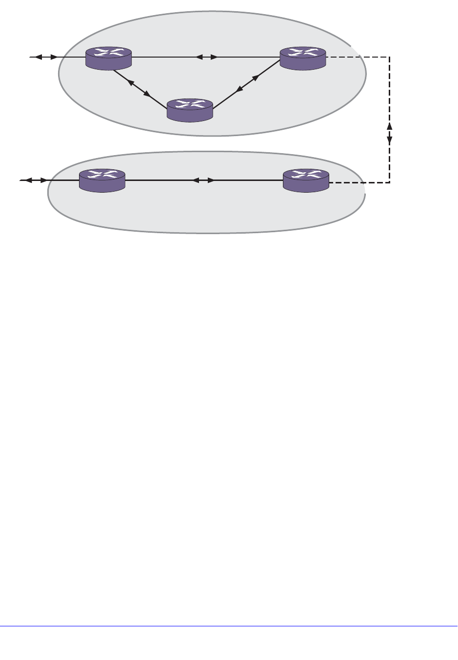
Chapter 26. BGP | 707
NETGEAR 8800 User Manual
Figure 81. Routing Confederation
In this example, AS 200 has five BGP speakers. Without a confederation, BGP would require
that the routes in AS 200 be fully meshed. Using the confederation, AS 200 is split into two
sub-ASs: AS65001 and AS65002. Each sub-AS is fully meshed, and IBGP is running among
its members. EBGP is used between sub-AS 65001 and sub-AS 65002. Router B and router
D are EBGP peers. EBGP is also used between the confederation and outside ASs.
To configure router A, use the following commands:
create vlan ab
configure vlan ab add port 1
configure vlan ab ipaddress 192.1.1.6/30
enable ipforwarding vlan ab
configure ospf add vlan ab area 0.0.0.0
create vlan ac
configure vlan ac add port 2
configure vlan ac ipaddress 192.1.1.17/30
enable ipforwarding vlan ac
configure ospf add vlan ac area 0.0.0.0
enable ospf
configure bgp as-number 65001
configure bgp routerid 192.1.1.17
configure bgp confederation-id 200
enable bgp
EX_043
EBGP
SubAS 65001
SubAS 65002
EBGP
AS 200
IBGP
IBGP
A
192.1.1.6/30 192.1.1.5/30 192.1.1.9/30
192.1.1.17/30
192.1.1.18/30 192.1.1.21/30
192.1.1.22/30
E
192.1.1.13/30
192.1.1.10/30
192.1.1.14/30
EBGP
D
C
B

708 | Chapter 26. BGP
NETGEAR 8800 User Manual
create bgp neighbor 192.1.1.5 remote-AS-number 65001
create bgp neighbor 192.1.1.18 remote-AS-number 65001
enable bgp neighbor all
To configure router B, use the following commands:
create vlan ba
configure vlan ba add port 1
configure vlan ba ipaddress 192.1.1.5/30
enable ipforwarding vlan ba
configure ospf add vlan ba area 0.0.0.0
create vlan bc
configure vlan bc add port 2
configure vlan bc ipaddress 192.1.1.22/30
enable ipforwarding vlan bc
configure ospf add vlan bc area 0.0.0.0
create vlan bd
configure vlan bd add port 3
configure vlan bd ipaddress 192.1.1.9/30
enable ipforwarding vlan bd
configure ospf add vlan bd area 0.0.0.0
enable ospf
configure bgp as-number 65001
configure bgp routerid 192.1.1.22
configure bgp confederation-id 200
enable bgp
create bgp neighbor 192.1.1.6 remote-AS-number 65001
create bgp neighbor 192.1.1.21 remote-AS-number 65001
create bgp neighbor 192.1.1.10 remote-AS-number 65002
configure bgp add confederation-peer sub-AS-number 65002
enable bgp neighbor all
To configure router C, use the following commands:
create vlan ca
configure vlan ca add port 1
configure vlan ca ipaddress 192.1.1.18/30
enable ipforwarding vlan ca
configure ospf add vlan ca area 0.0.0.0
create vlan cb

Chapter 26. BGP | 709
NETGEAR 8800 User Manual
configure vlan cb add port 2
configure vlan cb ipaddress 192.1.1.21/30
enable ipforwarding vlan cb
configure ospf add vlan cb area 0.0.0.0
enable ospf
configure bgp as-number 65001
configure bgp routerid 192.1.1.21
configure bgp confederation-id 200
enable bgp
create bgp neighbor 192.1.1.22 remote-AS-number 65001
create bgp neighbor 192.1.1.17 remote-AS-number 65001
enable bgp neighbor all
To configure router D, use the following commands:
create vlan db
configure vlan db add port 1
configure vlan db ipaddress 192.1.1.10/30
enable ipforwarding vlan db
configure ospf add vlan db area 0.0.0.0
create vlan de
configure vlan de add port 2
configure vlan de ipaddress 192.1.1.14/30
enable ipforwarding vlan de
configure ospf add vlan de area 0.0.0.0
enable ospf
configure bgp as-number 65002
configure bgp routerid 192.1.1.14
configure bgp confederation-id 200
enable bgp
create bgp neighbor 192.1.1.9 remote-AS-number 65001
create bgp neighbor 192.1.1.13 remote-AS-number 65002
configure bgp add confederation-peer sub-AS-number 65001
enable bgp neighbor all
To configure router E, use the following commands:
create vlan ed
configure vlan ed add port 1
configure vlan ed ipaddress 192.1.1.13/30

710 | Chapter 26. BGP
NETGEAR 8800 User Manual
enable ipforwarding vlan ed
configure ospf add vlan ed area 0.0.0.0
enable ospf
configure bgp as-number 65002
configure bgp routerid 192.1.1.13
configure bgp confederation-id 200
enable bgp
create bgp neighbor 192.1.1.14 remote-AS-number 65002
enable bgp neighbor 192.1.1.14
Route Aggregation
Route aggregation is the process of combining the characteristics of several routes so that
they are advertised as a single route. Aggregation reduces the amount of information that a
BGP speaker must store and exchange with other BGP speakers. Reducing the information
that is stored and exchanged also reduces the size of the routing table.
To enable BGP route aggregation, do the following:
1. Enable aggregation using the following command:
enable bgp aggregation
2. Create an aggregate route using the following command:
configure bgp add aggregate-address {address-family [ipv4-unicast
| ipv4-multicast]} <ipaddress> {as-match | as-set} {summary-only}
{advertise-policy <policy>} {attribute-policy <policy>}
Inactive Route Advertisement
BGP inactive routes are defined as those routes that are rated best by BGP and not best in IP
routing table. For example, an IGP route to the same destination may be best because it has
a higher priority in the IP route table than the BGP best route. The default configuration of the
XCM8800 software does not advertise BGP inactive routes to BGP neighbors.
The default configuration (no BGP inactive route advertisement) is more consistent with data
traffic forwarding. However, when advertisement of inactive BGP routes is enabled, BGP
need not depend upon the route manager module to know whether a BGP route is active or
not. This actually improves the performance of BGP processing and advertisement.
To enable or disable BGP inactive route advertising, use the following commands:
enable bgp {address-family [ipv4-unicast | ipv4-multicast]}
advertise-inactive-route
disable bgp {address-family [ipv4-unicast | ipv4-multicast]}
advertise-inactive-route

Chapter 26. BGP | 711
NETGEAR 8800 User Manual
When BGP inactive route advertising is enabled, inactive BGP routes are considered for
BGP route aggregation. When this feature is disabled, inactive BGP routes are ignored while
aggregating routes.
Default Route Origination and Advertisement
The default route origination and advertisement feature allows you to originate and advertise
a default route to a BGP neighbor (or to all neighbors in a peer group) even though no default
route exists in the local IP routing table. It also allows you to associate policy rules to
conditionally advertise a default route to BGP neighbors.
When default route origination becomes active, the default route is advertised to the specified
BGP neighbors, overriding any previously sent default route. If a default route is added to the
local IP routing table while default route origination is active, the default route defined by this
feature takes precedence over the new regular default route. If default route origination
becomes inactive, and a regular default route exists, the regular default route is advertised to
BGP neighbors.
The following sections provide additional information on this feature:
• Managing Policies for Default Route Origination on page 711
• Enabling and Disabling Route Origination on page 712
• Example: Default Route Origination on page 712
Managing Policies for Default Route Origination
When you use a policy with default route origination, the default route is originated only if the
local BGP RIB contains a route that matches the policy match conditions. You can use the
following match conditions:
• NLRI
• AS-path
• Community
• Origin
You can also use the following policy actions in the policy to set the route attributes:
• AS-path
• Community
• Origin
After a policy is configured for default route origination, BGP must periodically scan the local
BGP RIB to make sure that the policy rules evaluate to true for at least one route in local BGP
RIB. If the rules evaluate to true, default origination remains active. If the rules evaluate to
false, then default origination becomes inactive and the default routes must be withdrawn.
For more information on policy match conditions, actions, and configuration, see Chapter 14,
Routing Policies.

712 | Chapter 26. BGP
NETGEAR 8800 User Manual
Enabling and Disabling Route Origination
To enable or disable BGP default route origination and advertisement for BGP neighbors, use
the following commands:
enable bgp [{neighbor} <remoteaddr> | neighbor all] {address-family
[ipv4-unicast | ipv4-multicast]} originate-default {policy <policy-name>}
disable bgp [{neighbor} <remoteaddr> | neighbor all] {address-family
[ipv4-unicast | ipv4-multicast]} originate-default
To enable or disable BGP default route origination and advertisement for a BGP peer group,
use the following commands:
enable bgp {peer-group} <peer-group-name> {address-family [ipv4-unicast |
ipv4-multicast]} originate-default {policy <policy-name>}
disable bgp {peer-group} <peer-group-name> {address-family [ipv4-unicast |
ipv4-multicast]} originate-default
Example: Default Route Origination
The following example configures the originate default route feature for BGP neighbor
10.203.134.5 using policy def_originate.pol.
def_originate.pol
entry prefix_matching {
if match any {
nlri 192.168.3.0/24;
} then {
as-path "65001";
permit;
}
}
enable bgp neighbor 10.203.134.5 originate-default policy def_originate
With this configuration, a default route is originated and sent to neighbor 10.203.134.5 only if
there is a BGP route in the local RIB which matches the statement nlri 192.168.3.0/24. If a
matching route exists, the default route is sent to neighbor 10.203.134.5 with the 65001
as-path prepended. If this is an EBGP neighbor, then the local AS-Number is prepended after
65001.
If the route for the match statement nlri 192.168.3.0/24 goes away and there is no other
matching route in the BGP RIB, the default route origination feature becomes inactive and
BGP withdraws the 0.0.0.0/0 default route from neighbor 10.203.134.5. When a matching
route becomes available again in the local BGP RIB, the default route origination feature
becomes active again and the default route 0.0.0.0/0 is advertised to neighbor 10.203.134.5.
Using the Loopback Interface
If you are using BGP as your IGP, you may decide to advertise the interface as available,
regardless of the status of any particular interface. The loopback interface can also be used

Chapter 26. BGP | 713
NETGEAR 8800 User Manual
for EBGP multihop. Using the loopback interface eliminates multiple, unnecessary route
changes.
Looped AS_Path Attribute
When a BGP speaker receives a route from its neighbor, it must validate the AS_Path
attribute to ensure that there is no loop in the AS_Path. When a BGP speaker finds it's own
AS-number in the received BGP route's AS_Path attribute, it is considered as "Looped AS
Path" and by default, the associated BGP routes are silently discarded.
There are certain cases (such as in a spoke and hub topology) where it becomes necessary
to accept and process BGP routes with looped AS_Path attribute. This feature enables you
to control the processing of BGP routes with looped AS_Path attribute. You can do the
following:
• Allow the route with looped AS_Path to be accepted
• Allow the route with looped AS_Path to be accepted only if the number of occurrences of
its own AS-Number is less than or equal to N, where N is an user-configurable unsigned
integer configured
• Silently discard the route with looped AS_Path
BGP Peer Groups
You can use BGP peer groups to group together up to 512 BGP neighbors. All neighbors
within the peer group inherit the parameters of the BGP peer group. The following mandatory
parameters are shared by all neighbors in a peer group:
• remote AS
• source-interface
• route-policy
• send-community
• next-hop-self
Each BGP peer group is assigned a unique name when it is created. To create or delete peer
groups, use the following commands:
create bgp peer-group <peer-group-name>
delete bgp peer-group <peer-group-name>
Changes made to the parameters of a peer group are applied to all neighbors in the peer
group. Modifying the following parameters will automatically disable and enable the
neighbors before changes take effect:
• remote-as
• timer
• source-interface
• soft-in-reset

714 | Chapter 26. BGP
NETGEAR 8800 User Manual
• password
Adding Neighbors to a BGP Peer Group
To create a new neighbor and add it to a BGP peer group, use the following command:
create bgp neighbor <remoteaddr> peer-group <peer-group-name> {multi-hop}
The new neighbor is created as part of the peer group and inherits all of the existing
parameters of the peer group. The peer group must have remote AS configured.
To add an existing neighbor to a peer group, use the following command:
configure bgp neighbor [all | <remoteaddr>] peer-group [<peer-group-name> |
none] {acquire-all}
If you do not specify the acquire-all option, only the mandatory parameters are inherited
from the peer group. If you specify the acquire-all option, all of the parameters of the peer
group are inherited. This command disables the neighbor before adding it to the peer group.
To remove a neighbor from a peer group, use the peer-group none option.
When you remove a neighbor from a peer group, the neighbor retains the parameter settings
of the group. The parameter values are not reset to those the neighbor had before it inherited
the peer group values.
BGP Route Flap Dampening
Route flap dampening is a BGP feature designed to minimize the propagation of flapping
routes across an internetwork. A route is considered to be flapping when it is repeatedly
available, then unavailable, then available, then unavailable, and so on.
When a route becomes unavailable, a withdrawal message is sent to other connected
routers, which in turn propagate the withdrawal message to other routers. As the route
becomes available again, an advertisement message is sent and propagated throughout the
network.
As a route repeatedly changes from available to unavailable, large numbers of messages
propagate throughout the network. This is a problem in an internetwork connected to the
Internet because a route flap in the Internet backbone usually involves many routes.
Minimizing the Route Flap
The route flap dampening feature minimizes the flapping problem as follows. Suppose that
the route to network 172.25.0.0 flaps. The router (in which route dampening is enabled)
assigns network 172.25.0.0 a penalty of 1000 and moves it to a “history” state in which the
penalty value is monitored. The router continues to advertise the status of the route to
neighbors. The penalties are cumulative. When the route flaps so often that the penalty
exceeds a configurable suppress limit, the router stops advertising the route to network
172.25.0.0, regardless of how many times it flaps. Thus, the route is dampened.

Chapter 26. BGP | 715
NETGEAR 8800 User Manual
The penalty placed on network 172.25.0.0 is decayed until the reuse limit is reached, when
the route is again advertised. At half of the reuse limit, the dampening information for the
route to network 172.25.0.0 is removed.
The penalty is decayed by reducing the penalty value by one-half at the end of a configurable
time period, called the half-life. Routes that flap many times may reach a maximum penalty
level, or ceiling, after which no additional penalty is added. The ceiling value is not directly
configurable, but the configuration parameter used in practice is the maximum route
suppression time. No matter how often a route has flapped, after it stops flapping, it will again
be advertised after the maximum route suppression time.
Configuring Route Flap Dampening
Using a routing policy, you enable BGP route flap dampening per BGP peer session, for a
BGP peer group, or for a set of routes.
To enable route flap dampening over BGP peer sessions, use the following command:
configure bgp neighbor [all | <remoteaddr>] {address-family [ipv4-unicast |
ipv4-multicast]} dampening {{half-life <half-life-minutes> {reuse-limit
<reuse-limit-number> suppress-limit <suppress-limit-number> max-suppress
<max-suppress-minutes>} | policy-filter [<policy-name> | none]}
To enable route flap dampening for a BGP peer group, use the following command:
configure bgp peer-group <peer-group-name> {address-family [ipv4-unicast |
ipv4-multicast]} dampening {{half-life <half-life-minutes> {reuse-limit
<reuse-limit-number> supress-limit <suppress-limit-number> max-suppress
<max-suppress-minutes>}} | policy-filter [<policy-name> | none]}
You can supply the dampening parameters directly through the command line interface (CLI)
command, or use the command to associate a policy that contains the desired parameters.
Disabling Route Flap Dampening
To disable route flap dampening for a BGP neighbor (disabling the dampening also deletes
all the configured dampening parameters), use the following command:
configure bgp neighbor [<remoteaddr> | all] {address-family [ipv4-unicast |
ipv4-multicast]} no-dampening
To disable route flap dampening for a BGP peer group, use the following command:
configure bgp peer-group <peer-group-name> {address-family [ipv4-unicast |
ipv4-multicast]} no-dampening
Viewing the Route Flap Dampening Configuration
To view the configured values of the route flap dampening parameters for a BGP neighbor,
use the following command:
show bgp [neighbor {detail} | {neighbor} <remoteaddr>]
To view the configured values of the route flap dampening parameters for a BGP peer group,
use the following command:

716 | Chapter 26. BGP
NETGEAR 8800 User Manual
show bgp peer-group {detail | <peer-group-name> {detail}}
To display the dampened routes, use the following command:
show bgp neighbor <remoteaddr> {address-family [ipv4-unicast | ipv4-multicast]}
flap-statistics {detail} [all | as-path <path-expression> | community
[no-advertise | no-export | no-export-subconfed | number <community_num> |
<AS_Num>:<Num> ] | network [any / <netMaskLen> | <networkPrefixFilter>] {exact}
]
BGP Route Selection
BGP selects routes based on the following precedence (from highest to lowest):
• higher weight
• higher local preference
• shortest length (shortest AS path)
• lowest origin code
• lowest Multi Exit Discriminator (MED)
• route from external peer
• lowest cost to next hop
• lowest routerID
Stripping Out Private AS Numbers from Route Updates
Private AS numbers are AS numbers in the range 64512 through 65534. You can remove
private AS numbers from the AS path attribute in updates that are sent to external BGP
(EBGP) neighbors. Possible reasons for using private AS numbers include:
• The remote AS does not have officially allocated AS numbers.
• You want to conserve AS numbers if you are multihomed to the local AS.
Private AS numbers should not be advertised on the Internet. Private AS numbers can be
used only locally within an administrative domain. Therefore, when routes are advertised out
to the Internet, the routes can be stripped out from the AS paths of the advertised routes
using this feature.
To configure private AS numbers to be removed from updates, use the following command:
enable bgp neighbor [<remoteaddr> | all] remove-private-AS-numbers
To disable this feature, use the following command:
disable bgp neighbor [<remoteaddr> | all] remove-private-AS-numbers

Chapter 26. BGP | 717
NETGEAR 8800 User Manual
Route Redistribution
BGP, OSPF, and RIP can be enabled simultaneously on the switch. Route redistribution
allows the switch to exchange routes, including static and direct routes, between any two
routing protocols.
Exporting routes from OSPF to BGP and from BGP to OSPF are discrete configuration
functions. To run OSPF and BGP simultaneously, you must first configure both protocols and
then verify the independent operation of each. Then you can configure the routes to export
from OSPF to BGP and the routes to export from BGP to OSPF.
Configuring Route Redistribution
Exporting routes between any two routing protocols are discrete configuration functions. For
example, you must configure the switch to export routes from OSPF to BGP; and, if desired,
you must configure the switch to export routes from BGP to OSPF. You must first configure
both protocols and then verify the independent operation of each. Then you can configure the
routes to export from OSPF to BGP and the routes to export from BGP to OSPF.
You can use route maps to associate BGP attributes including Community, NextHop, MED,
Origin, and Local Preference with the routes. Route maps can also be used to filter out
exported routes.
To enable or disable the exporting of OSPF, RIP, ISIS, static, and direct (interface) routes to
BGP, use the following commands:
enable bgp export [blackhole | direct | ospf | ospf-extern1 | ospf-extern2 |
ospf-inter | ospf-intra | rip | static {address-family [{ipv4-unicast
|ipv4-multicast]} {export-policy <policy-name>}
disable bgp export [blackhole | direct | ospf | ospf-extern1 | ospf-extern2 |
ospf-inter | ospf-intra | rip | static {address-family [{ipv4-unicast
|ipv4-multicast]}
Using the export command to redistribute routes complements the redistribution of routes
using the configure bgp add network command. The configure bgp add network command
adds the route to BGP only if the route is present in the routing table. The enable bgp export
command redistributes the specified routes from the routing table to BGP. If you use both
commands to redistribute routes, the routes redistributed using the network command take
precedence over routes redistributed using the export command.
BGP ECMP
The BGP Equal Cost Multi-path (ECMP) feature supports load sharing by creating a
multipath to a destination. This multipath contains multiple routes that are determined to have
an equal cost because the following parameters are the same for each route:
• Weight
• Local preference (for IBGP multipaths)
• AS path (entire attribute, not just the length)

718 | Chapter 26. BGP
NETGEAR 8800 User Manual
• Origin code
• Multi Exit Discriminator (MED)
• IGP distance to the next hop
• Source session (EBGP or IBGP)
Note: ECMP does not install an additional path if the next hop is the same
as that of the best path. All paths within a multipath must have a
unique next hop value.
BGP ECMP does not affect the best path selection. For example, the router continues to
designate one of the paths as the best path and advertise this best path to its neighbors.
EBGP paths are preferred to IBGP paths.
The BGP ECMP feature allows you to define the maximum number of equal cost paths (up to
eight) in a multipath. A multipath for an IBGP destination is called an IBGP multipath, and the
multipath for an EBGP destination is called an EBGP multipath.
If there are more equal cost paths for a destination than the configured maximum, the BGP
identifier for the advertising BGP speaker is used to establish a path priority. The lower BGP
identifier values have priority over the higher values. For example, if the configuration
supports 4 paths in a multipath, only the four paths with the lowest BGP identifier values
become part of the multipath.
To enable or disable BGP ECMP, enter the following command:
configure bgp maximum-paths <max-paths>
The max-paths setting applies to BGP on the current VR. Specify more than 1 path to enable
BGP ECMP and define the maximum number of paths for IBGP and EBGP multipaths.
Specify 1 path to disable ECMP. To display BGP ECMP configuration information, use the
show bgp command.
BGP Static Network
XCM8800 BGP allows users to add static networks in BGP, which will be redistributed
(advertised) into the BGP domain if there is a corresponding active route in the IP routing
table. Users can associate a policy with the static BGP network to change or to set the route
attributes before the route is advertised to the BGP neighbors.
To create a static BGP network, use the following command:
configure bgp add network {address-family [ipv4-unicast | ipv4-multicast]}
<ipaddr>/<mask_len> {network-policy <policy>}

Chapter 26. BGP | 719
NETGEAR 8800 User Manual
Note: When entering an AS number in a policy file, you must enter a
unique 2-byte or 4-byte AS number. The transition AS number, AS
23456, is not supported in policy files.
To delete a static BGP network, use the following command:
configure bgp delete network {address-family [ipv4-unicast | ipv4-multicast]}
[all | <ipaddress/mask length>]
Graceful BGP Restart
It is possible for BGP control functions to restart without disrupting traffic forwarding. Without
graceful restart, adjacent routers will assume that information previously received from the
restarting router is stale and won’t be used to forward traffic to that router. However, in many
cases, two conditions exist that allow the router restarting BGP to continue to forward traffic
correctly. The first condition is that forwarding can continue while the control function is
restarted. Most modern router system designs separate the forwarding function from the
control function so that traffic can still be forwarded independent of the state of the BGP
function. Routes learned through BGP remain in the routing table and packets continue to be
forwarded. The second condition required for graceful restart is that the network remain
stable during the restart period. If the network topology is not changing, the current routing
table remains correct. Often, networks can remain stable during the time for restarting BGP.
With graceful BGP restart, routes received from a restarting router are marked as stale, but
traffic continues to be forwarded over these routes during the restart process.
Restarting and Receiver Mode
Routers involved with graceful restart fill one of two roles: the restarting router or the
receiving router. When a receiving router detects that the TCP connection with its peer is
reset, it assumes that the peer has entered graceful restart. If the neighboring routers are
configured to help with the graceful restart (receiver-mode), they will continue to advertise the
restarting router as if it was fully functional. Traffic continues to be routed as though the
restarting router is fully functional. The receiver router will continue in receiver mode until the
restarting router re-establishes the TCP session, indicating successful termination of graceful
restart, the restart timers expire. A router can be configured for graceful restart, and for
receiver-mode separately. A router can be a receiver when its neighbor restarts, and can in
turn be helped by a neighbor receiver-mode router if it restarts.
Planned and Unplanned Restarts
Two types of graceful restarts are defined: planned and unplanned. A planned restart occurs
when the software module for BGP is upgraded, or if the router operator decides to restart
the BGP control function for some reason. An unplanned restart occurs when there is some
kind of system failure that causes a remote reboot or a crash of BGP, or when an MSM/MM
failover occurs. You can decide to configure a router to enter graceful restart for only planned

720 | Chapter 26. BGP
NETGEAR 8800 User Manual
restarts, for only unplanned restarts, or for both. Also, you can decide to configure a router to
be a receiver only, and not to do graceful restarts itself.
Configuring Graceful BGP Restart
To configure a router to perform graceful BGP restart, use the following command:
configure bgp restart [none | planned | unplanned | both | aware-only]
The address families participating in graceful restart are configured using the following
command:
configure bgp restart [add | delete] address-family [ipv4-unicast |
ipv4-multicast]
There are three timers that can be configured with the following commands:
configure bgp restart restart-time <seconds>
configure bgp restart stale-route-time <seconds>
configure bgp restart update-delay <seconds>
Graceful BGP Restart Configuration Example
In the following configuration example, Switch-1 is the restarting BGP router, and Switch-2 is
the receiving BGP router.
To configure router Switch-1, use the following commands:
create vlan bgp-restart
configure vlan bgp-restart add port 2:2
configure vlan bgp-restart ipaddress 20.0.0.1/24
enable ipforwarding
configure bgp as-number 100
configure bgp route-id 20.0.0.1
configure bgp restart both
create bgp neighbor 20.0.0.2 remote-as 200
enable bgp neighbor all
enable bgp
To configure router Switch-2, use the following commands:
create vlan bgp-restart
configure vlan bgp-restart add port 2:5
configure vlan bgp-restart ipaddress 20.0.0.2/24
enable ipforwarding
configure bgp as-number 200
configure bgp route-id 20.0.0.2
configure bgp restart aware-only
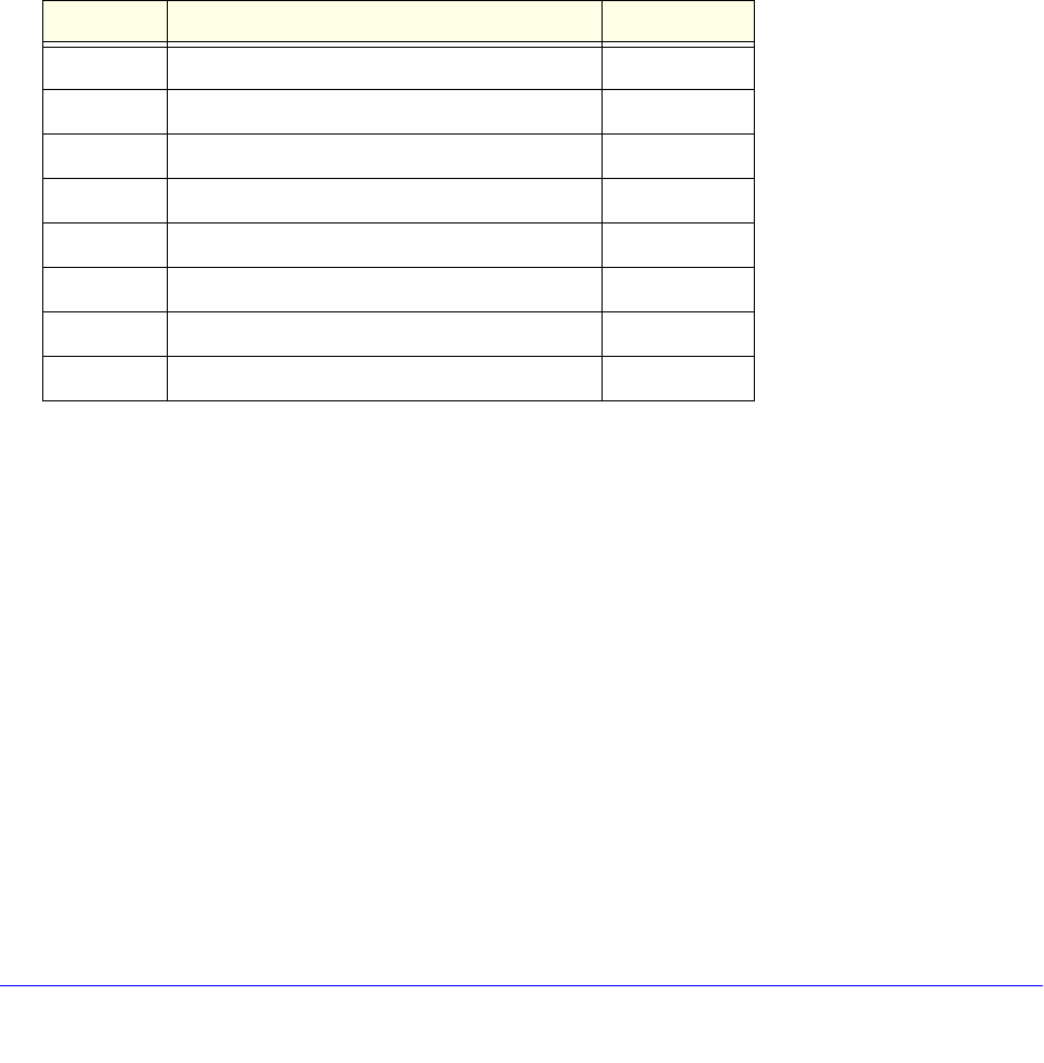
Chapter 26. BGP | 721
NETGEAR 8800 User Manual
create bgp neighbor 20.0.0.1 remote-as 100
enable bgp neighbor all
enable bgp
You can use the following commands to verify that BGP graceful restart is configured:
show bgp
show bgp neighbor
Cease Subcodes
BGP uses the cease subcode in notification message to convey the reason for terminating
the session. The cease subcodes currently supported are given in Table 71.
The following sections provide detailed descriptions of each supported cease subcode.
Maximum Number of Prefixes Reached
This cease subcode is sent when the number of prefixes from a BGP neighbor exceeds the
pre-configured limit. The notification message contains additional data to indicate the
maximum prefix limit configured for the neighbor.
Administrative Shutdown
This cease notification subcode is sent to a BGP neighbor in following two situations
• BGP neighbor is disabled
• BGP protocol is globally disabled. All BGP neighbors that were in the established state
send cease notifications with this subcode
Peer De-configured
This cease notification subcode is sent when BGP neighbor is deleted.
Table 71. Supported Cease Subcodes
Subcode Description Supported?
1Maximum Number of Prefixes Reached Yes
2Administrative Shutdown Yes
3Peer De-configured Yes
4Administrative Reset No
5Connection Rejected No
6Other Configuration Change Yes
7Connection Collision Resolution Yes
8Out of Resources No

722 | Chapter 26. BGP
NETGEAR 8800 User Manual
Other Configuration Change
This cease notification subcode is sent when the following configuration entities change:
• BGP neighbor is added to a peer group
• BGP neighbor is configured as a route-reflector client
• BGP neighbor is part of a peer group and the following configuration elements of the peer
group are changed:
• Password
• Remote-as
• Hold-time, keepalive-time
• Source interface
• Soft-in-reset
Connection Collision Resolution
This cease notification subcode is sent when there is a BGP connection collision.
Fast External Fallover
BGP fast external fallover uses the BGP protocol to converge quickly in the event of a link
failure that connects it to an EBGP neighbor.
The fast external fallover module consists of two commands; one for enabling fallover
(enable bgp fast-external-fallover) and one for disabling fallover (disable bgp
fast-external-fallover). Fast external fallover is disabled by default.
These commands apply to all directly-connected external BGP neighbors.
When BGP fast external fallover is enabled, the directly-connected EBGP neighbor session
is immediately reset when the connecting link goes down.
If BGP fast external fallover is disabled, BGP waits until the default hold timer expires (3
keepalives) to reset the neighboring session. In addition, BGP may tear down the session
somewhat earlier than hold timer expiry if BGP detects that the TCP session and it's directly
connected link is broken (BGP detects this while sending or receiving data from TCP socket).
Capability Negotiation
BGP supports the following capabilities by default:
• IPv4 Unicast address family
• IPv4 Multicast address family
• Route-Refresh (new, code = 64)
• 4-Byte-AS (code = 65)
• Route Refresh Cisco style (code = 128)

Chapter 26. BGP | 723
NETGEAR 8800 User Manual
By default, BGP sends those capabilities in its OPEN message. In addition, BGP supports
graceful restart. All these capabilities (except for the 4-Byte-AS capability) can be enabled
and disabled using the enable bgp neighbor capability and disable bgp peer-group capability
commands.
Execution of these commands does not take effect until the BGP neighbor is reset.
When BGP receives a notification 2/4 (Unsupported optional parameters) in response to an
OPEN, it assumes that the peer does not support capability negotiation and MBGP and
sends an OPEN message without any capability.
BGP brings up peering with minimal common capability for the both sides. For example, in
the case of a local router with both unicast and multicast capabilities and a remote router with
unicast capability. In this case, the local router establishes the connection with unicast-only
capability. When there are no common capabilities, BGP sends an Unsupported Capability
error and resets the connection. A manual intervention and configuration change might be
required in order to establish BGP peering session in this particular case.
The absence of capabilities in an OPEN message from a neighbor is considered the
equivalent of a neighbor supporting IPv4 Unicast capability. For example, in the case of a
local router with unicast and multicast capabilities and a remote router with no capabilities,
the local router establishes the connection with unicast capability.
Note: For faster neighbor session establishment, NETGEAR recommends
that you disable the capability advertisement feature of MBGP while
peering with switches running.
Route Refresh
Route Refresh helps minimize the memory footprint of BGP by not storing the original BGP
route path attributes from a neighbor that advertises route refresh capability in an OPEN
message. Whenever you execute the command configure bgp neighbor [<remoteAddr> |
all] {address-family [ipv4-unicast | ipv4-multicast]} soft-reset in, BGP sends a
route refresh message to its peer if that peer had advertised route refresh capability in its
OPEN message. In response to the route refresh message, the neighbor sends its entire
RIB-OUT database for the requested address family. This helps reapply the inbound
neighbor policy, if there are any changes.

Chapter 27. Multicast Routing and Switching | 724
27
27. Multicast Routing and Switching
This chapter includes the following sections:
• Overview on page 724
• Multicast Routing Table and RPF Overview on page 725
• PIM Overview on page 726
• IGMP Overview on page 733
• Configuring IP Multicast Routing on page 738
• Multicast VLAN Registration on page 748
• Displaying Multicast Information on page 756
• Troubleshooting PIM on page 757
For more information on IP multicasting, see the following publications:
• RFC 1112—Host Extension for IP Multicasting
• RFC 2236—Internet Group Management Protocol, Version 2
• PIM-DM Version 2—draft_ietf_pim_v2_dm_03
• RFC 2362—Protocol-Independent Multicast - Sparse Mode (PIM-SM): Protocol
Specification
The following URL points to the website for the IETF PIM Working Group:
http://www.ietf.org/html.charters/pim-charter.html
Overview
Multicast routing and switching is the functionality of a network that allows a single host (the
multicast server) to send a packet to a group of hosts. With multicast, the server is not forced to
duplicate and send enough packets for all the hosts in a group. Instead, multicast allows the
network to duplicate the packet where needed to supply the group. Multicast greatly reduces the
bandwidth required to send data to a group of hosts. IP multicast routing is a function that allows
multicast traffic to be forwarded from one subnet to another across a routing domain.

Chapter 27. Multicast Routing and Switching | 725
NETGEAR 8800 User Manual
IP multicast routing requires the following functions:
• A router that can forward IP multicast packets
• A router-to-router multicast routing protocol (for example, Protocol Independent Multicast
(PIM)) to discover multicast routes
• A method for the IP host to communicate its multicast group membership to a router (for
example, Internet Group Management Protocol (IGMP))
Note: You should configure IP unicast routing before you configure IP
multicast routing.
Multicast Routing Table and RPF Overview
Beginning with Release 12.1, all IP multicast routes are stored and maintained in the
software multicast route table. Routes are added to the multicast route table from the
following sources:
• Multicast static routes (configured manually by the network administrator)
• Multicast dynamic routes (learned through protocols such as MBGP and MISIS)
The multicast route table is used for reverse path forwarding (RPF) checks, not for packet
routing. The switch uses RPF checks to avoid multicast forwarding loops. When a multicast
packet is received, the switch does an RPF lookup, which checks the routing tables to see if
the packet arrived on the interface on which the router would send a packet to the source.
The switch forwards only those packets that arrive on the interface specified for the source in
the routing tables.
The RPF lookup uses the multicast routing table first, and if no entry is found for the source
IP address, the RPF lookup uses the unicast routing table.
Note: Because the multicast routing table is used only for RPF checks
(and not for routing), IP route compression and ECMP do not apply
to multicast routes in the multicast routing table.
Note: The route metric is no longer used to select between multicast and
unicast routes. If the RPF lookup finds a route in the multicast table,
that route is used. The unicast routing table is used only when no
route is found in the multicast table.
The advantage to having separate routing tables for unicast and multicast traffic is that the
two types of traffic can be separated, using different paths through the network.

726 | Chapter 27. Multicast Routing and Switching
NETGEAR 8800 User Manual
PIM Overview
The switch supports both dense mode and sparse mode operation. You can configure dense
mode or sparse mode on a per-interface basis. After they are enabled, some interfaces can
run dense mode, while others run sparse mode.
The switch also supports PIM snooping. The following sections provide additional information
on PIM:
• PIM Edge Mode on page 726
• PIM Dense Mode on page 726
• PIM Sparse Mode on page 728
• PIM Mode Interoperation on page 729
• PIM Source Specific Multicast on page 729
• PIM Snooping on page 731
PIM Edge Mode
PIM Edge Mode is a subset of PIM that operates with the following restrictions:
• The switch does not act as a candidate rendezvous point (CRP).
• The switch does not act as a candidate bootstrap router (CBSR).
• At most, two active PIM-SM interfaces are permitted. There is no restriction on the
number of passive interfaces (within the limit of the maximum IP interfaces).
• Only PIM Sparse Mode (PIM-SM) is supported.
Note: This feature is supported at and above the license level listed for this
feature in the license tables in Appendix A, XCM8800 Software
Licenses.
Active PIM interfaces can have other PIM enabled routers on them. Passive interfaces
should only have hosts sourcing or receiving multicast traffic.
PIM Dense Mode
Protocol-Independent Multicast - Dense Mode (PIM-DM) is a multicast routing protocol. A
new feature, called PIM-DM state refresh, creates two PIM-DM operating modes, which are
described in the following sections:
• PIM-DM Without State Refresh on page 727
• PIM-DM with State Refresh on page 728
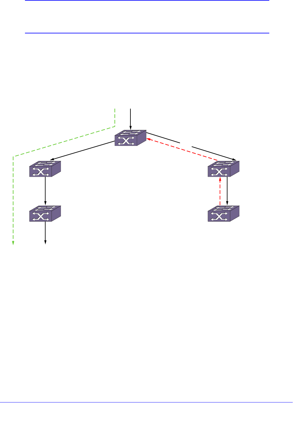
Chapter 27. Multicast Routing and Switching | 727
NETGEAR 8800 User Manual
Note: For additional information on PIM-DM, see RFC 3973, Protocol
Independent Multicast - Dense Mode (PIM-DM): Protocol
Specification.
PIM-DM Without State Refresh
PIM-DM is a broadcast and prune protocol, which means that multicast servers initially
broadcast traffic to all destinations, and then switches later prune paths on which there are
no receivers.
Figure 82 shows a dense mode multicast tree with an active branch and a pruned branch.
Figure 82. PIM-DM Operation
In Figure 82, multicast traffic is flowing from VLAN V1 connected to switch S1. S1 floods
multicast traffic to both neighbors S2 and S3 which in turn flood multicast traffic to S4 and S5.
S4 has IGMP members, so it floods multicast traffic down to VLAN V6. S5, which has no
multicast members, sends a prune upstream towards the source. The green line shows the
flow of traffic on the active branch, and the red line shows the prune sent upstream for the
pruned branch. After outgoing interface V2 is pruned from the multicast tree, subsequent
multicast traffic from S1 flows only through S2 and S4 and is not forwarded to S3.
After S3 sends a prune upstream, S3 starts a prune hold time timer on outgoing interface V5.
When this timer expires, S3 adds V5 back to the multicast egress list and sends a graft
upstream to pull multicast traffic down again. When multicast traffic arrives from S1, it is
forwarded to S5, which repeats the upstream prune message because it still has no
members. This prune, time-out, and flood process repeats as long as the traffic flow exists
and no members are on the pruned branch, and this process consumes bandwidth during
every cycle.
mcast_0019
V1
V3
V2
S3
S5
S2
S1
S4
X
V5V4
V6

728 | Chapter 27. Multicast Routing and Switching
NETGEAR 8800 User Manual
Note: This feature is supported at and above the license level listed for this
feature in the license tables in Appendix A, XCM8800 Software
Licenses.
PIM-DM routers perform reverse path multicasting (RPM). However, instead of exchanging
its own unicast route tables for the RPM algorithm, PIM-DM uses the existing unicast routing
table for the reverse path. As a result, PIM-DM requires less system memory.
PIM-DM with State Refresh
The PIM-DM State Refresh feature keeps the PIM-DM prune state from timing out by
periodically sending a state refresh control message down the source tree. These control
messages reset the prune hold time timer on each pruned interface and prevent the
bandwidth waste that occurs with each prune, time-out, and flood cycle.
When a topology change occurs, the PIM-DM State Refresh feature improves network
convergence. For example, suppose that an S, G entry on S5 in Figure 82 is removed due to
non-availability of a route. Without PIM-DM State Refresh, multicast traffic is blocked for
minutes (due to a time-out on the upstream routers). In the meantime if an IGMP member or
a PIM-DM neighbor joins S5, there is no way to pull traffic down immediately because S5
does not have any S, G information. State refresh control messages solve this problem by
indicating S, G state information periodically to all downstream routers. When S5 receives a
state refresh from S3, it scans the S, G information and all pending requests from PIM-DM
neighbors and IGMP members. If there are pending requests for the group in the state
refresh message, S5 can immediately send a graft message upstream to circumvent the
upstream timers and pull multicast traffic to its members and neighbors.
To enable, configure, and disable the PIM-DM State Refresh feature, use the following
commands:
configure pim state-refresh {vlan} [<vlanname> | all] [on | off]
configure pim state-refresh timer origination-interval <interval>
configure pim state-refresh timer source-active-timer <interval>
configure pim state-refresh ttl <ttlvalue>
PIM Sparse Mode
Unlike PIM-DM, Protocol-Independent Multicast - Sparse Mode (PIM-SM) is an explicit join
and prune protocol, which means that multicast receivers, and the routers that support them,
must join multicast groups before they receive multicast traffic. When all receivers on a
network branch leave a multicast group, that branch is pruned so that the multicast traffic
does not continue to consume bandwidth on that branch. PIM-SM supports shared trees as
well as shortest path trees (SPTs). PIM-SM is beneficial for large networks that have group
members that are sparsely distributed.

Chapter 27. Multicast Routing and Switching | 729
NETGEAR 8800 User Manual
Note: This feature is supported at and above the license level listed for
this feature in the license tables in Appendix A, XCM8800 Software
Licenses.
Using PIM-SM, the router sends a join message to the rendezvous point (RP). The RP is a
central multicast router that is responsible for receiving and distributing the initial multicast
packets. You can configure a dynamic or static RP.
When a router has a multicast packet to distribute, it encapsulates the packet in a unicast
message and sends it to the RP. The RP decapsulates the multicast packet and distributes it
among all member routers.
When a router determines that the multicast rate has exceeded a configured threshold, that
router can send an explicit join to the originating router. When this occurs, the receiving
router gets the multicast directly from the sending router and bypasses the RP.
Note: You can run either PIM-DM or PIM-SM per virtual LAN (VLAN).
PIM Mode Interoperation
A NETGEAR switch can function as a PIM multicast border router (PMBR). A PMBR
integrates PIM-SM and PIM-DM traffic.
When forwarding PIM-DM traffic into a PIM-SM network, the PMBR acts as a virtual first hop
and encapsulates the initial traffic for the RP. The PMBR forwards PIM-DM multicast packets
to the RP, which, in turn, forwards the packets to those routers that have joined the multicast
group.
The PMBR also forwards PIM-SM traffic to a PIM-DM network, based on the (*.*.RP) entry.
The PMBR sends a (*.*.RP) join message to the RP, and the PMBR forwards traffic from the
RP into the PIM-DM network.
No commands are required to enable PIM mode interoperation. PIM mode interoperation is
automatically enabled when a dense mode interface and a sparse mode interface are
enabled on the same switch.
PIM Source Specific Multicast
PIM-SM works well in many-to-many multicasting situations. For example, in video
conferencing, each participating site multicasts a stream that is sent to all the other
participating sites. However, PIM-SM is overly complex for one-to-many multicast situations,
such as multimedia content distribution or streaming stock quotes. In these and similar
applications, the listener is silent and can know the source of the multicast in advance, or can
obtain it. In these situations, there is no need to join an RP, as the join request can be made
directly towards the source.

730 | Chapter 27. Multicast Routing and Switching
NETGEAR 8800 User Manual
Note: This feature is supported at and above the license level listed for this
feature in the license tables in Appendix A, XCM8800 Software
Licenses.
PIM Source Specific Multicast (PIM-SSM) is a special case of PIM-SM, in which a host
explicitly sends a request to receive a stream from a specific source, rather than from any
source.
IGMPv3 hosts can use PIM SSM directly, because the ability to request a stream from a
specific source first became available with IGMPv3. The PIM-SSM capable router interprets
the IGMPv3 message to initiate a PIM-SM join towards the source.
Note: IGMPv1 and IGMPv2 hosts can use PIM SSM if IGMP-SSM
mapping is enabled and configured on the XCM8800 switch. For
more information, see Using IGMP-SSM Mapping on page 736.
PIM-SSM has the following advantages:
• No overhead of switching to the source-specific tree and waiting for the first packet to
arrive
• No need to learn and maintain an RP
• Fewer states to maintain on each router
• No need for the complex register mechanism from the source to the RP
• Better security, as each stream is forwarded from sources known in advance
PIM-SSM has the following requirements:
• Any host that participates directly in PIM-SSM must use IGMPv3.
• To support IGMPv1 and IGMPv2 hosts, IGMP-SSM mapping must be enabled and
configured.
PIM-SSM is designed as a subset of PIM-SM and all messages are compliant with PIM-SM.
PIM-SSM and PIM-SM can coexist in a PIM network; only the last hop router need to be
configured for PIM-SSM if both source and receivers are present all the time. However, to
avoid any JOIN delay, it is recommended that you enable all routers along the (s,g) path for
PIM-SSM.
Configuring the PIM-SSM Address Range
A range of multicast addresses is used for PIM-SSM. Within that address range, non-IGMPv3
messages are ignored, and any IGMPv3 exclude messages are ignored. These messages
are ignored for all router interfaces, even those not configured for PIM-SSM. By default there
is no PIM-SSM range specified on the router. If you choose the default keyword in the CLI
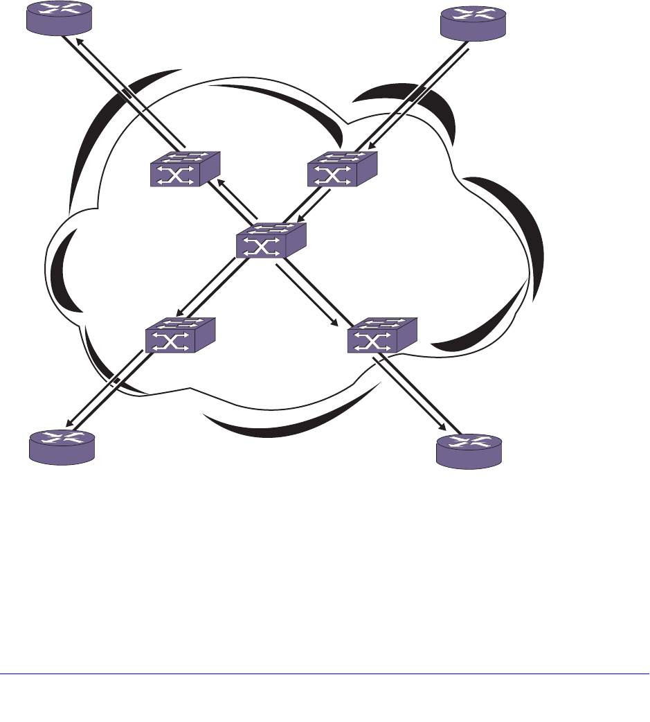
Chapter 27. Multicast Routing and Switching | 731
NETGEAR 8800 User Manual
when specifying the PIM-SSM range, you configure the range 232.0.0.0/8. You can also
choose to specify a different range for PIM-SSM by using a policy file.
To configure the PIM-SSM address range, use the following command:
configure pim ssm range [default | policy <policy-name>]
PIM Snooping
PIM snooping provides a solution for handling multicast traffic on a shared media network
more efficiently. In networks where routers are connected to a L2 switch, multicast traffic is
essentially treated as broadcast traffic (see Figure 83).
Figure 83. Multicast Without PIM Snooping
IGMP snooping does not solve this flooding issue when routers are connected to a L2 switch.
Switch ports are flooded with multicast packets. PIM snooping addresses this flooding
behavior by efficiently replicating multicast traffic only onto ports which routers advertise the
PIM join requests (see Figure 84).
Router 1
Router 4 Router 3
Router 2
RP
(Sender)
with
Receiver
EX_mcast_0018
Multicast
traffic
Multicast
traffic
Multicast
traffic Multicast
traffic
Multicast
traffic
Multicast
traffic
Multicast
traffic
Multicast
traffic
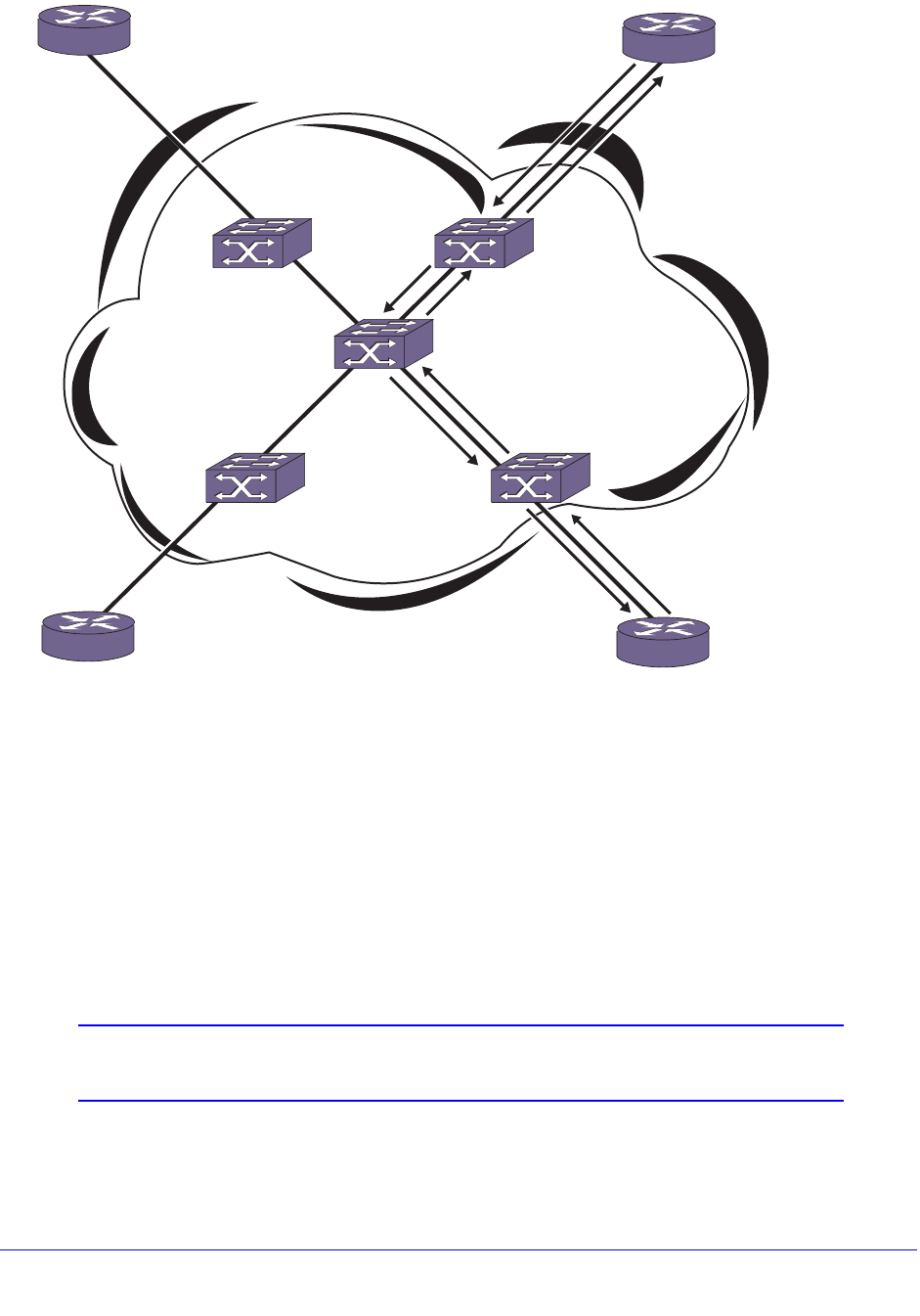
732 | Chapter 27. Multicast Routing and Switching
NETGEAR 8800 User Manual
Figure 84. Multicast With PIM Snooping
PIM snooping does not require PIM to be enabled. However, IGMP snooping must be
disabled on VLANs that use PIM snooping. PIM snooping and MVR cannot be enabled on
the same VLAN.
To enable PIM snooping on one or all VLANs, use the following command:
enable pim snooping {{vlan} <name>}
To disable PIM snooping on one or all VLANs, use the following command:
disable pim snooping {{vlan} <name>}
Note: PIM snooping can be enabled only between PIM SM enabled
switches. It should not enabled between PIM DM enabled switches.
EX_mcast_0015
Router 1
Router 4 Router 3
Router 2
RP
(Sender)
with
Receiver
Multicast
traffic Multicast
traffic
Multicast
traffic
Multicast
traffic
PIM (*.G) join
(*.G) join
(*.G) join
(*.G) join

Chapter 27. Multicast Routing and Switching | 733
NETGEAR 8800 User Manual
IGMP Overview
IGMP is a protocol used by an IP host to register its IP multicast group membership with a
router. A host that intends to receive multicast packets destined for a particular multicast
address registers as a member of that multicast address group. Periodically, the router
queries the multicast group to see if the group is still in use. If the group is still active, a single
IP host responds to the query, and group registration is maintained.
IGMPv2 is enabled by default on the switch, and the XCM8800 software supports IGMPv3.
However, the switch can be configured to disable the generation of periodic IGMP query
packets. IGMP should be enabled when the switch is configured to perform IP multicast
routing.
IGMPv3, specified in RFC 3376, adds support for source filtering. Source filtering is the
ability for a system to report interest in receiving packets only from specific source addresses
(filter mode include) or from all sources except for specific addresses (filter mode exclude).
IGMPv3 is designed to be interoperable with IGMPv1 and IGMPv2.
Note: The XCM8800 software supports IGMPv3 source include mode
filtering, but it does not support IGMPv3 specific source exclude
mode filtering.
The following sections provide information on IGMP features:
• IGMP Snooping on page 733
• Static IGMP on page 734
• IGMP Snooping Filters on page 735
• Limiting the Number of Multicast Sessions on a Port on page 736
• Enabling and Disabling IGMP Snooping Fast Leave on page 736
• Using IGMP-SSM Mapping on page 736
IGMP Snooping
IGMP snooping is a Layer 2 function of the switch; it does not require multicast routing to be
enabled. In IGMP snooping, the Layer 2 switch keeps track of IGMP reports and only
forwards multicast traffic to that part of the local network that requires it. IGMP snooping
optimizes the use of network bandwidth and prevents multicast traffic from being flooded to
parts of the local network that do not need it. The switch does not reduce any IP multicast
traffic in the local multicast domain (224.0.0.x).
IGMP snooping is enabled by default on all VLANs in the switch. If IGMP snooping is
disabled on a VLAN, all IGMP and IP multicast traffic floods within the VLAN. IGMP snooping
expects at least one device on every VLAN to periodically generate IGMP query messages.
To enable or disable IGMP snooping, use the following commands:

734 | Chapter 27. Multicast Routing and Switching
NETGEAR 8800 User Manual
enable igmp snooping {forward-mcrouter-only | {vlan} <name> | with-proxy vr
<vrname>}
disable igmp snooping {forward-mcrouter-only | with-proxy | vlan <name>}
When a port sends an IGMP leave message, the switch removes the IGMP snooping entry
after 1000 milliseconds (the leave time is configurable, ranging from 0 to 10000 ms). The
switch sends a query to determine which ports want to remain in the multicast group. If other
members of the VLAN want to remain in the multicast group, the switch ignores the leave
message, but the port that requests removal is removed from the IGMP snooping table.
If the last port within a VLAN sends an IGMP leave message and the switch does not receive
any responses to the subsequent query, then the switch immediately removes the VLAN from
the multicast group.
IGMP snooping is implemented primarily through ACLs, which are processed on the
interfaces. These special purpose ACLs are called IGMP snooping filters. On NETGEAR
8800 series switches, the software allows you to choose between two types of IGMP
snooping filters: per-port filters (the default) and per-VLAN filters.
The two types of IGMP snooping filters use switch hardware resources in different ways. The
two primary hardware resources to consider when selecting the IGMP snooping filters are the
Layer 3 multicast forwarding table and the interface ACLs. The size of both of these hardware
resources is determined by the switch model. In general, the per-port filters consume more
resources from the multicast table and less resources from the ACL table. The per-VLAN
filters consume less space from the multicast table and more from the ACL table.
In NETGEAR 8800 series switches, the multicast table size is small, so using the per-port
filters can fill up the multicast table and place an extra load on the CPU. To avoid this,
configure the switch to use the per-VLAN filters.
Note: The impact of the per-VLAN filters on the ACL table increases with
the number of VLANs configured on the switch. If you have a large
number of configured VLANs, we suggest that you use the per-port
filters.
Static IGMP
To receive multicast traffic, a host must explicitly join a multicast group by sending an IGMP
report; then, the traffic is forwarded to that host. In some situations, you might like multicast
traffic to be forwarded to a port where a multicast-enabled host is not available (for example,
when you test multicast configurations).
Static IGMP emulates a host or router attached to a switch port, so that multicast traffic is
forwarded to that port, and the switch sends a proxy join for all the statically configured IGMP
groups when an IGMP query is received. You can emulate a host to forward a particular

Chapter 27. Multicast Routing and Switching | 735
NETGEAR 8800 User Manual
multicast group to a port; and you may emulate a router to forward all multicast groups to a
port. Static IGMP is only available with IGMPv2.
To emulate a host on a port, use the following command:
configure igmp snooping {vlan} <vlanname> ports <portlist> add static group <ip
address>
To emulate a multicast router on a port, use the following command:
configure igmp snooping {vlan} <vlanname> ports <portlist> add static router
To remove these entries, use the corresponding command:
configure igmp snooping {vlan} <vlanname> ports <portlist> delete static
group [<ip_address> | all]
configure igmp snooping vlan <vlanname> ports <portlist> delete static router
To display the IGMP snooping static groups, use the following command:
show igmp snooping {vlan} <name> static [group | router]
IGMP Snooping Filters
IGMP snooping filters allow you to configure a policy file on a port to allow or deny IGMP
report and leave packets coming into the port. (For details on creating policy files, see Policy
Manager on page 294.) The IGMP snooping filter feature is supported by IGMPv2 and
IGMPv3.
For the policies used as IGMP snooping filters, all the entries should be IP address type
entries, and the IP address of each entry must be in the class-D multicast address space but
should not be in the multicast control subnet range (224.0.0.x/24).
Use the following template to create a snooping filter policy file that denies IGMP report and
leave packets for the 239.11.0.0/16 and 239.10.10.4/32 multicast groups:
#
# Add your group addresses between "Start" and "end"
# Do not touch the rest of the file!!!!
entry igmpFilter {
if match any {
#------------------ Start of group addresses ------------------
nlri 239.11.0.0/16;
nlri 239.10.10.4/32;
#------------------- end of group addresses -------------------
} then {
deny;
}
}
entry catch_all {
if {

736 | Chapter 27. Multicast Routing and Switching
NETGEAR 8800 User Manual
} then {
permit;
}
}
After you create a policy file, use the following command to associate the policy file and filter
to a set of ports:
configure igmp snooping vlan <vlanname> ports <portlist> filter [<policy> |
none]
To remove the filter, use the none option.
To display the IGMP snooping filters, use the following command:
show igmp snooping {vlan} <name> filter
Limiting the Number of Multicast Sessions on a Port
The default configuration places no limit on the number of multicast sessions on each VLAN
port. To place a limit on the number of sessions, use the following command:
configure igmp snooping {vlan} <vlanname> ports <portlist> set join-limit
{<num>}
To remove a session limit, use the following command:
unconfigure igmp snooping {vlan} <vlanname> ports <portlist> set join-limit
Enabling and Disabling IGMP Snooping Fast Leave
When the fast leave feature is enabled and the last VLAN host leaves a multicast group, the
router immediately removes the VLAN interface from the multicast group. The router does not
query the VLAN for other members of the multicast group before removing group
membership and the multicast interface.
The default setting for IGMP snooping fast leave is disabled. To enable the fast leave feature,
use the following command:
enable igmp snooping {vlan} <name> fast-leave
To disable the fast leave feature, use the following command:
disable igmp snooping {vlan} <name> fast-leave
Using IGMP-SSM Mapping
IGMPv1 and IGMPv2 hosts can use PIM SSM if IGMP-SSM mapping is enabled and
configured on the XCM8800 switch. When the router receives an IGMPv1 or IGMPv2
membership report for a group G, the router uses SSM mapping to determine one or more
source IP addresses for group G. SSM mapping then interprets (not translates) the
membership report as an IGMPv3 report and sends out PIM-SSM joins toward (S1, G) to (Sn,
G).

Chapter 27. Multicast Routing and Switching | 737
NETGEAR 8800 User Manual
When the router receives an IGMP Group leave message from a host, it sends out a group
specific query (unless IGMP fast leave is configured) and continues to support joins for the
corresponding (S1, G) to (Sn, G) channels. When the router does not get a response to the
group specific query after a time-out period, IGMP-SSM mapping informs PIM that the list of
(S1, G) to (Sn, G) pairs should be considered for PIM prunes.
In a multi-access network (where more than one router is receiving IGMP messages from the
hosts), only the designated router sends joins towards the source, so it is desirable to have
same configuration for SSM group range and SSM Mapping range on all routers in a VLAN.
Note: When a group source exists on the same VLAN as a receiver, IGMP
snooping causes the traffic to be L2 switched to the receiver, even if
another source is available through IGMP SSM. This happens
because the group mappings are stored in PIM, which is a L3
protocol.
The following sections provide additional information on IGMP-SSM mapping:
• Limitations on page 737
• Configuring IGMP-SSM Mapping on page 737
• Displaying IGMP-SSM Mappings on page 738
Limitations
• IGMP SSM mapping support is provided for IPv4 only.
• PIM must be disabled on a switch to configure IGMP-SSM mapping.
• A single group address or range can be mapped to a maximum of 50 sources. If more
than 50 sources are configured, the switch uses the 50 longest-matching prefixes.
• NETGEAR recommends a maximum of 500 mappings per switch, but no limit is imposed
by the software.
Configuring IGMP-SSM Mapping
To support PIM-SSM for IGMPv1 and IGMPv2 clients, a PIM-SSM range must be configured,
and that range should include all groups to which the clients want access. If IGMPv1 and
IGMPv2 clients request group addresses outside the PIM-SSM range, those addresses are
ignored by PIM-SSM and forwarded to PIM as (*, G) requests.
To enable IGMP-SSM mapping, first configure a PIM-SSM range, and then enable
IGMP-SSM mapping using the following commands:
configure pim ssm range [default | policy <policy-name>]
enable igmp ssm-map {vr <vr-name>}
To configure an IGMP-SSM mapping, use the following command:

738 | Chapter 27. Multicast Routing and Switching
NETGEAR 8800 User Manual
configure igmp ssm-map add <group_ip> [/<prefix> | <mask>] <source_ip>
{vr <vr-name>}
To remove a single IGMP-SSM mapping, use the following command:
configure igmp ssm-map delete <group_ip> [/<prefix>} | <mask>] [<source_ip> |
all] <vr <vr-name>}
To remove all IGMP-SSM mappings on a virtual router, use the following command:
unconfigure igmp ssm-map {<vr <vr-name>}
To disable IGMP-SSM mapping on a virtual router, use the following command:
disable igmp ssm-map {vr <vr-name>}
Displaying IGMP-SSM Mappings
To see whether or not IGMP-SSM mapping is enabled or disabled and to view the configured
mappings for a multicast IP address, use the command:
show igmp ssm-map {<group_ip>} {vr <vr-name>}
Configuring IP Multicast Routing
This section describes the following tasks:
• Enabling Multicast Forwarding on page 738
• Configuring PIM on page 738
• Configuring Multicast Static Routes on page 739
• PIM Configuration Examples on page 740
Enabling Multicast Forwarding
To enable IP multicast forwarding:
1. Configure the system for IP unicast routing.
2. Enable multicast forwarding on the interface using the following command:
enable ipmcforwarding {vlan <name>}
Configuring PIM
To configure PIM multicast routing, enable multicast forwarding as described in Enabling
Multicast Forwarding on page 738 and do the following:
1. Configure PIM on all IP multicast routing interfaces using the following command:
configure pim add vlan [<vlan-name> | all] {dense | sparse} {passive}

Chapter 27. Multicast Routing and Switching | 739
NETGEAR 8800 User Manual
2. To enable and configure the PIM-DM state refresh feature on one or all VLANs, use the
following commands:
configure pim state-refresh {vlan} [<vlanname> | all] [on | off]
configure pim state-refresh timer origination-interval <interval>
configure pim state-refresh timer source-active-timer <interval>
configure pim state-refresh ttl <ttlvalue>
3. For PIM-SSM, specify the PIM-SSM range, enable IGMPv3, and enable PIM-SSM on the
interfaces using the following commands:
configure pim ssm range [default | policy <policy-name>]
enable igmp {vlan <vlan name>} {IGMPv1 | IGMPv2 | IGMPv3}
enable pim ssm vlan [<vlan_name> | all]
4. Enable PIM on the router using the following command:
enable pim
Configuring Multicast Static Routes
Note: Multicast static routes are supported in the IPv4 address family, but
not the IPv6 address family.
Static routes are used to reach networks not advertised by routers, and are manually entered
into the routing table. You can use either of two commands to create multicast static routes.
The recommended command is the following:
configure iproute add [<ipNetmask> | <ip_addr> <mask>] <gateway> {metric}
{multicast | multicast-only | unicast | unicast-only} {vr <vrname>}
For example:
configure iproute add 55.1.10.0/24 44.1.12.33 multicast
The following command is still supported for backward compatibility with earlier XCM8800
software releases:
configure ipmroute add [<source-net>/<mask-len> | <source-net> <mask>]
{{protocol} <protocol>} <rpf-address> {<metric>} {vr <vr-name>}
In the following example, the configure ipmroute add command is used to specify protocol
information for a route:
configure ipmroute add 58.1.10.0/24 ospf 44.1.12.33
When a static route is configured with protocol information, the route is shown as UP only
when the protocol route is available. Otherwise, the route is Down. In the example above, the

740 | Chapter 27. Multicast Routing and Switching
NETGEAR 8800 User Manual
multicast static route 58.1.10.0/24 is shown as UP only when the OSPF route is available to
reach the network 58.1.10.0/24.
Static routes are stored in the switch configuration and can be viewed with the show
configuration command. Static multicast routes that do not include protocol information are
displayed using the configure iproute command format, even if they were created using the
configure ipmroute command. Static routes that are created with a protocol field are
displayed using the configure ipmroute command format.
PIM Configuration Examples
This section provides the following examples:
• PIM-DM Configuration Example on page 740
• PIM-SM Configuration Example on page 742
• PIM-SSM Configuration Example on page 743
• PIM Snooping Configuration Example on page 744
PIM-DM Configuration Example
In Figure 85, the system labeled IR 1 is configured for IP multicast routing, using PIM-DM.
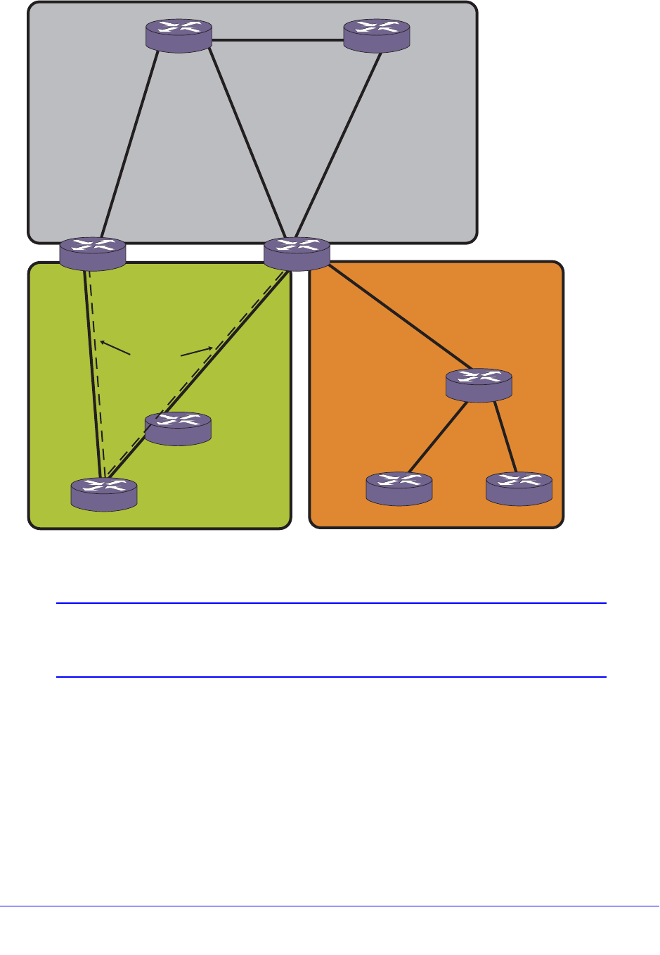
Chapter 27. Multicast Routing and Switching | 741
NETGEAR 8800 User Manual
Figure 85. IP Multicast Routing Using PIM-DM Configuration Example
Note: Figure 85 is used in Chapter 24, OSPF to describe the Open
Shortest Path First (OSPF) configuration on a switch. See that
chapter for more information about configuring OSPF.
The router labeled IR1 has the following configuration:
configure vlan HQ_10_0_1 ipaddress 10.0.1.2 255.255.255.0
configure vlan HQ_10_0_2 ipaddress 10.0.2.2 255.255.255.0
configure ospf add vlan all area 0.0.0.0
enable ipforwarding
enable ospf
enable ipmcforwarding
IR 2 IR 1
Area 0
Area 5 Area 6 (stub)
10.0.1.1
10.0.2.110.0.3.1
10.0.3.2
10.0.1.2
10.0.2.2
Headquarters
ABR 2 ABR 1
HQ_10_0_2
HQ_10_0_3
160.26.25.1
160.26.25.2
160.26.26.2
160.26.26.1
Virtual link
Chi_160_26_26
LA_161_48_2
161.48.2.1
161.48.2.2
Chicago
Los Angeles
EX_mcast_0016
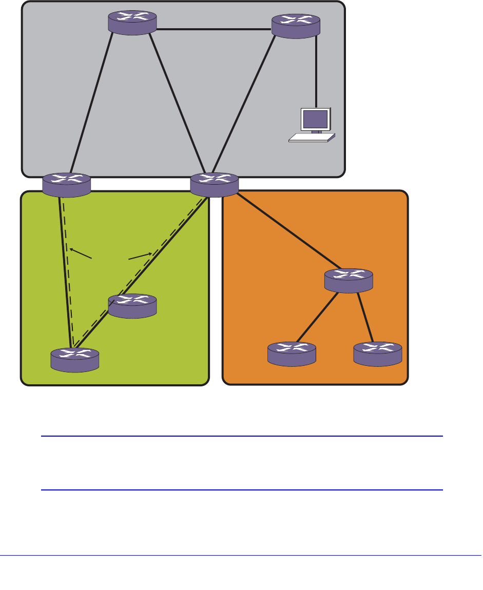
742 | Chapter 27. Multicast Routing and Switching
NETGEAR 8800 User Manual
configure pim add vlan all dense
enable pim
configure pim state-refresh vlan all on
PIM-SM Configuration Example
In Figure 86, the system labeled ABR1 is configured for IP multicast routing using PIM-SM.
Figure 86. IP Multicast Routing Using PIM-SM Configuration Example
Note: Figure 86 is used in Chapter 24, OSPF to describe the Open
Shortest Path First (OSPF) configuration on a switch. See that
chapter for more information about configuring OSPF.
The router labeled ABR1 has the following configuration:
IR 2 IR 1
Area 0
Area 5 Area 6 (stub)
10.0.1.1
10.0.2.1
10.0.3.1
10.0.3.2
10.0.1.2
10.0.2.2
Headquarters
ABR 2 ABR 1
HQ_10_0_2
HQ_10_0_3
160.26.25.1
160.26.25.2
160.26.26.2
160.26.26.1
Virtual link
Chi_160_26_26
LA_161_48_2
161.48.2.1
161.48.2.2
Chicago
Los Angeles
HQ_10_10_4
Rendezvous
point
EX_mcast_0017

Chapter 27. Multicast Routing and Switching | 743
NETGEAR 8800 User Manual
configure vlan HQ_10_0_2 ipaddress 10.0.2.1 255.255.255.0
configure vlan HQ_10_0_3 ipaddress 10.0.3.1 255.255.255.0
configure vlan LA_161_48_2 ipaddress 161.48.2.2 255.255.255.0
configure vlan CHI_160_26_26 ipaddress 160.26.26.1 255.255.255.0
configure ospf add vlan all area 0.0.0.0
enable ipforwarding
enable ipmcforwarding
configure pim add vlan all sparse
tftp TFTP_SERV -g -r rp_list.pol
configure pim crp HQ_10_0_3 rp_list 30
configure pim cbsr HQ_10_0_3 30
The policy file, rp_list.pol, contains the list of multicast group addresses serviced by this
RP. This set of group addresses are advertised as candidate RPs. Each router then elects
the common RP for a group address based on a common algorithm. This group to RP
mapping should be consistent on all routers.
The following is a policy file that configures the CRP for the address ranges 239.0.0.0/24 and
232.144.27.0:
entry netgear1 {
if match any {
}
then {
nlri 239.0.0.0/24 ;
nlri 232.144.27.0/24 ;
}
}
PIM-SSM Configuration Example
In the following example, the default PIM-SSM range of 232.0.0.0/8 is configured. For all
interfaces, non-IGMPv3 messages and IGMPv3 exclude messages are ignored for
addresses in this range. Hosts that use IGMPv3 on VLAN v13 can request and receive
source specific multicast streams for addresses in the PIM-SSM range.
create vlan v12
create vlan v13
configure v12 add port 1
configure v13 add port 2
configure v12 ipaddress 12.1.1.1/24
configure v13 ipaddress 11.1.1.1/24
configure pim add vlan all sparse
enable ipforwarding
enable ipmcforwarding
enable igmp IGMPv3
configure pim ssm range default
enable pim ssm vlan v13
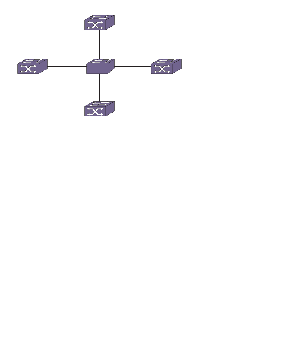
744 | Chapter 27. Multicast Routing and Switching
NETGEAR 8800 User Manual
enable pim
PIM Snooping Configuration Example
Figure 87 shows a network configuration that supports PIM snooping.
Figure 87. PIM Snooping Configuration Example
In Figure 87, Layer 3 switches S2, S3, S4, and S5 are connected using the Layer 2 switch
S1 through the VLAN comm_vlan. Switches S3, S4, and S5 are multicast capable switches,
and switch S2 is a non-multicast capable switch, which has no multicast routing protocol
running.
Without PIM snooping, any ingress multicast data traffic on comm_vlan is flooded to all the
switches, including switch S2, which does not support multicast traffic. IGMP snooping does
not reduce flooding because it floods the multicast traffic to all router ports.
The network design calls for most multicast traffic to egress switch S5. PIM snooping helps
by intercepting the PIM joins received from the downstream routers and forwarding multicast
traffic only to those ports that received PIM joins.
The following sections provide additional information for this example:
• Switch S1 (PIM Snooping Switch) Configuration Commands on page 745
• Switch S3 Configuration Commands on page 745
• Switch S5 Configuration Commands on page 745
• Switch S4 Configuration Commands on page 746
• Switch S2 Configuration Commands on page 746
• PIM Snooping Example Configuration Displays on page 747
S4
(multicast switch)
receiver_vlan
S2
(non-multicast switch)
S3
(RP)
S5
(LHR)
PIM_snooping_0002
sender_vlan
S1
comm_vlan

Chapter 27. Multicast Routing and Switching | 745
NETGEAR 8800 User Manual
Switch S1 (PIM Snooping Switch) Configuration Commands
The following is an example configuration for the PIM snooping switch S1:
create vlan comm_vlan
configure vlan comm_vlan add port 1,2,3,4
disable igmp snooping
disable igmp_snooping comm_vlan
enable pim snooping
enable pim snooping comm_vlan
Switch S3 Configuration Commands
The following is an example configuration for switch S3, which also serves as an RP:
create vlan comm_vlan
configure vlan comm_vlan add port 1
configure comm_vlan ipa 10.172.168.4/24
enable ipforwarding comm_vlan
enable ipmcforwarding comm._vlan
configure pim add vlan comm_vlan sparse
configure ospf add vlan comm._vlan area 0.0.0.0
create vlan sender_vlan
configure vlan sender_vlan add port 2
configure sender_vlan ipa 10.172.169.4/24
enable ipforwarding comm_vlan
enable ipmcforwarding comm._vlan
configure pim add vlan comm._vlan sparse
configure ospf add vlan comm_vlan area 0.0.0.0
enable pim
enable ospf
configure pim crp static 10.172.169.4 pim_policy // RP is configured using the
policy pim_policy for the group 224.0.0.0/4
Switch S5 Configuration Commands
The following is an example configuration for switch S5, which serves as the last hop router
for multicast traffic:
create vlan comm_vlan
configure vlan comm_vlan add port 1
configure comm_vlan ipa 10.172.168.2/24

746 | Chapter 27. Multicast Routing and Switching
NETGEAR 8800 User Manual
enable ipforwarding comm_vlan
enable ipmcforwarding comm._vlan
configure pim add vlan comm_vlan sparse
configure ospf add vlan comm._vlan area 0.0.0.0
create vlan receiver_vlan
configure vlan sender_vlan add port 1
configure sender_vlan ipa 10.172.170.4/24
enable ipforwarding comm_vlan
enable ipmcforwarding comm._vlan
configure pim add vlan comm._vlan sparse
configure ospf add vlan comm_vlan area 0.0.0.0
enable pim
enable ospf
configure pim crp static 10.172.169.4 pim_policy // RP is configured using the
policy pim_policy for the group 224.0.0.0/4
Switch S4 Configuration Commands
The following is an example configuration for switch S4, which is neither an LHR nor a RP:
create vlan comm_vlan
configure vlan comm_vlan add port 1
configure comm_vlan ipa 10.172.168.3/24
enable ipforwarding comm_vlan
enable ipmcforwarding comm._vlan
configure pim add vlan comm_vlan sparse
configure ospf add vlan comm._vlan area 0.0.0.0
enable pim
enable ospf
configure pim crp static 10.172.169.4 pim_policy // RP is configured using the
policy pim_policy for the group 224.0.0.0/4
Switch S2 Configuration Commands
The following is an example configuration for switch S2, which is not enabled for PIM:
create vlan comm_vlan
configure vlan comm_vlan add port 1
configure comm_vlan ipa 10.172.168.6/24
enable ipforwarding comm_vlan

Chapter 27. Multicast Routing and Switching | 747
NETGEAR 8800 User Manual
enable ipmcforwarding comm._vlan
configure ospf add vlan comm._vlan area 0.0.0.0
enable ospf
PIM Snooping Example Configuration Displays
After the example configuration is complete, multicast receivers connect to the network
through switch S5 and multicast sources connect through switch S3.
When switch S5 receives an IGMP request from the receiver_vlan for group 225.1.1.1, it
sends a PIM (*, G) join towards switch S3, which is the RP. The PIM snooping feature on
switch S1 snoops the (*, G) join, and the resulting entry can be viewed by entering the
following command at switch S1:
show pim snooping vlan comm_vlan
PIM Snooping ENABLED
Vlan comm_vlan(3971) Snooping ENABLED
Source Group RP UpPort DownPort Age HoldTime
* 225.1.1.1 10.172.169.4 1 2 15 210
Neighbor IP DR Port Age Hold Time
10.1272.168.4 YES 1 2 105
10.1272.168.2 NO 2 2 105
10.1272.168.3 NO 3 2 105
Once multicast traffic arrives from the sender_vlan, the LHR (switch S2) sends the (S, G) join
message, which is snooped by the PIM snooping switch, switch S1. The resulting entries can
be viewed by entering the following command at switch S1:
show pim snooping vlan comm_vlan
PIM Snooping ENABLED
Vlan comm_vlan(3971) Snooping ENABLED
Source Group RP UpPort DownPort Age HoldTime
* 225.1.1.1 10.172.169.4 1 2 15 210
10.172.169.10 225.1.1.1 10.172.169.4 1 2 15 210
Neighbor IP DR Port Age Hold Time
10.1272.168.4 YES 1 2 105
10.1272.168.2 NO 2 2 105
10.1272.168.3 NO 3 2 105
Multicast traffic is forwarded only to those ports that have received (*, G) or (S, G) joins and
designated router (DR) ports.
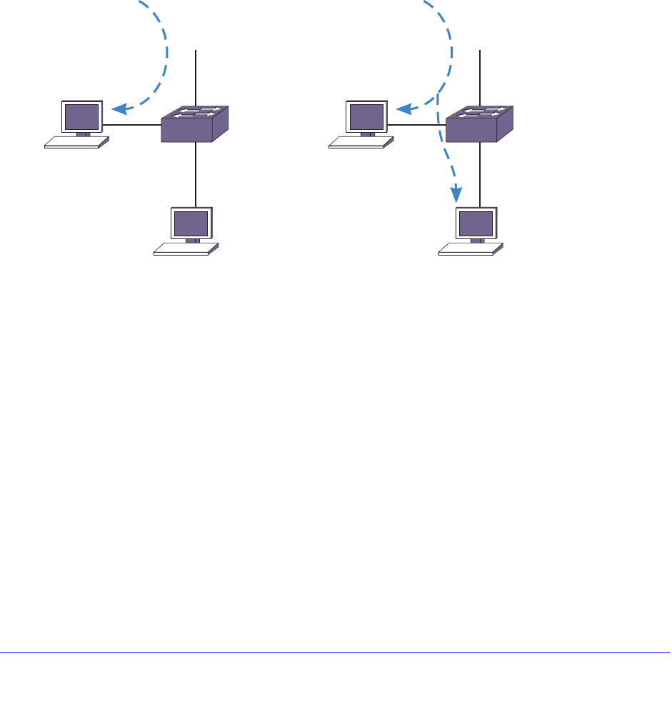
748 | Chapter 27. Multicast Routing and Switching
NETGEAR 8800 User Manual
Multicast VLAN Registration
Multicast VLAN Registration (MVR) is designed to support distributing multicast streams for
IPTV to subscribers over a Layer 2 network. In a standard Layer 2 network, a multicast
stream received on a VLAN is not forwarded to another VLAN. The streams are confined to
the Layer 2 broadcast domain. In an IGMP snooping environment, streams are forwarded
only to interested hosts on a VLAN. For inter-VLAN forwarding (routing) a multicast routing
protocol, such as PIM/DVMRP must be deployed.
MVR breaks this basic rule, so that a stream received over Layer 2 VLANs is forwarded to
another VLAN, eliminating the need for a Layer 3 routing protocol. It simplifies the multicast
stream distribution and is a better solution for IPTV-like services. With MVR, a multicast
stream is forwarded to all VLANs containing interested hosts.
Figure 88. Standard VLAN Compared to an MVR VLAN
In Figure 88, the left side shows a standard VLAN carrying a multicast stream. The host H1
receives the multicast stream because it resides on VLAN Vlan1, but host H2 does not
receive the multicast traffic because no IP multicast routing protocol forwards the stream to
VLAN Vlan2. On the right side of the figure, H2 does receive the multicast stream. Because
Vlan1 was configured as an MVR VLAN, the multicast stream is forwarded to the other
VLANs on the switch. containing hosts that have requested the stream. To configure a VLAN
as an MVR VLAN, use the following command:
configure mvr add vlan <vlan-name>
Typically, IGMP snooping is enabled, so only hosts that have requested a stream can see the
multicast traffic. For example, another host on Vlan2 cannot receive the traffic unless it has
sent an IGMP request to be included in the group.
Notice that only Vlan1 is MVR enabled. Configure MVR only on the ingress VLAN. To enable
MVR on the switch, use the following command:
enable mvr
EX_142
Switch1
H2 subscribed to G
H1 subscribed to G
Vlan1
Vlan1 Vlan1
Vlan2 Vlan2
Stream to Group G
Vlan1
(MVR Enabled)
H2 subscribed to G
H1 subscribed to G
Stream to Group G
Switch1
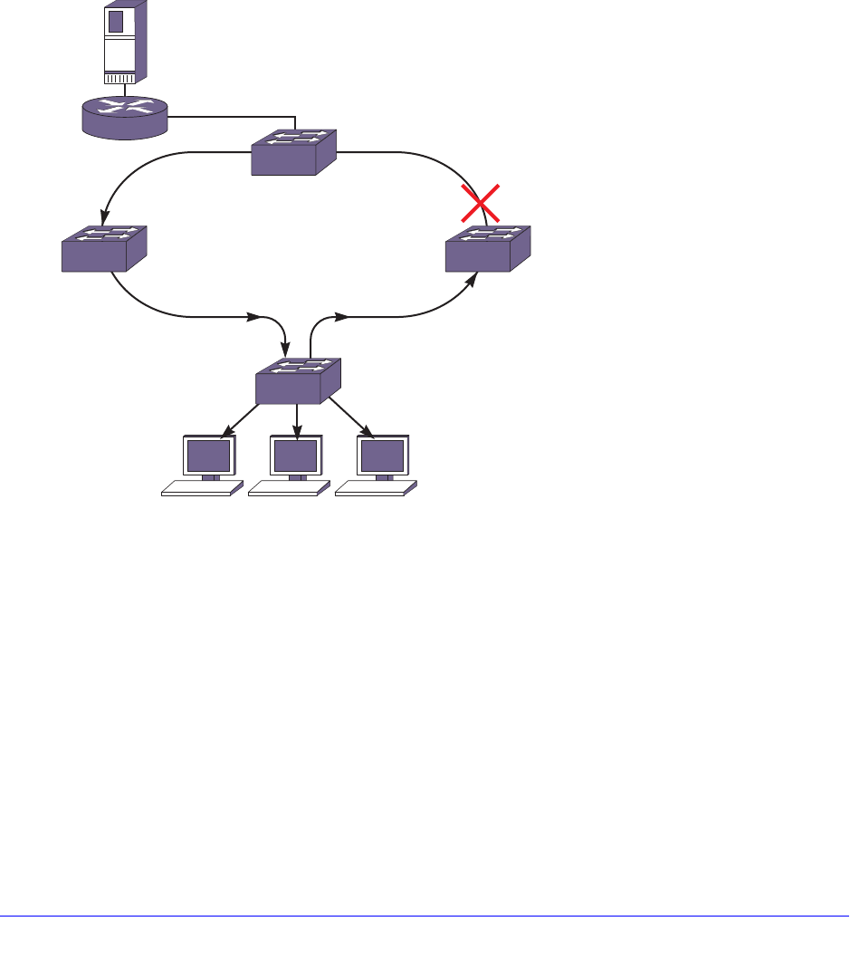
Chapter 27. Multicast Routing and Switching | 749
NETGEAR 8800 User Manual
Basic MVR Deployment
Since MVR is primarily targeted for IPTV and similar applications, a basic deployment for that
application is shown in Figure 89. In the figure, an IPTV server is connected through a router
to a network of switches. Switch 1 has three customer VLANs, Vlan2, Vlan3, and Vlan4. The
multicast streams are delivered through the network core (Metro Ethernets), which often use
a ring topology and some kind of redundant protection to provide high availability. For
example, McastVlan forms a ring through switches Switch1 through Switch4. The link from
Switch2 to Switch4 is shown as blocked, as it would be if some form of protection (such as
STP) is used.
Figure 89. Basic MVR Deployment
Without MVR, there are two ways to distribute multicast streams in this topology:
• Extend subscriber VLANs (Vlan2, Vlan3, and Vlan4) to the network core, by tagging the
ports connecting the switches.
• Configure all VLANS with an IP address and run PIM or DVMRP on each switch.
There are problems with both of these approaches. In the first approach, multiple copies of
the same stream (IPTV channel) would be transmitted in the core, wasting bandwidth. In the
second approach, all switches in the network core would have to be Layer 3 multicast aware,
and would have to run a multicast protocol. Typical network cores are Layer 2 only.
MVR provides a simple solution to this problem. If McastVlan in Switch1 is configured with
MVR, it leaks the traffic into the local subscriber VLANs that contain hosts that request the
traffic. For simple cases, perform these configuration steps:
EX_143
H2 H3 H4
Switch2
Switch1
McastVlan
Vlan2 Vlan4
IPTV server
Switch3
Switch4
McastVlan
McastVlan
McastVlan
Vlan3

750 | Chapter 27. Multicast Routing and Switching
NETGEAR 8800 User Manual
1. Configure MVR on McastVlan.
2. Configure an IP address and enable IGMP and IGMP snooping on the subscriber VLANs
(by default IGMP and IGMP snooping are enabled on NETGEAR switches).
3. For all the multicast streams (IPTV channels), configure static IGMP snooping membership
on the router on McastVlan.
4. Enable MVR on the switches in the network.
Note: MVR works best with IGMPv1 and IGMPv2. NETGEAR
recommends that you do not use MVR with IGMPv3.
The strategy above conserves bandwidth in the core and does not require running PIM on the
subscriber switches.
In this topology, a host (for example, a cable box or desktop PC) joins a channel through an
IGMP join message. Switch1 snoops this message and adds the virtual port to the
corresponding cache's egress list. This is possible because an MVR enabled VLAN can leak
traffic to any other VLAN. When the user switches to another channel, the host sends an
IGMP leave for the old channel and a join for the new channel. The corresponding virtual port
is removed from the cache for the old channel and is added to the cache for the new channel.
As discussed in Static and Dynamic MVR on page 750, McastVlan also proxies IGMP joins
learned on other VLANs to the router. On an MVR network it is not mandatory to have a
router to serve the multicast stream. All that is required is to have a designated IGMP querier
on McastVlan. The IPTV server can also be directly connected to McastVlan.
Static and Dynamic MVR
This section presents the following topics:
• Static MVR on page 750
• Dynamic MVR on page 751
• Configuring Static and Dynamic MVR on page 751
Static MVR
In a typical IPTV network, there are several high demand basic channels. At any instant there
is at least one viewer for each of these channels (streams), and they should always be
available at the core. When a user requests one of these channels, it is quickly pulled locally
from the multicast VLAN. These streams are always available on the core multicast VLAN
through static configuration on the streaming router. For those channels, the Layer 2 switch
does not send any IGMP join messages towards the IGMP querier. These groups must be
statically configured on the streaming router so that these streams are always available on
the ring. For example, on an NETGEAR router, you can use the following command:
configure igmp snooping {vlan} <vlanname> ports <portlist> add static group <ip
address>

Chapter 27. Multicast Routing and Switching | 751
NETGEAR 8800 User Manual
If a multicast packet for a group in the static MVR range is received on an MVR enabled
VLAN, it is always flooded on the MVR VLAN. This allows the neighbor switch in the ring to
receive all the static MVR streams.
Dynamic MVR
In contrast, since a video content provider would like to provide a variety of on-demand and
other premium channels, there are often many lower demand (fewer viewers) premium
channels that cannot all be made available simultaneously at the core network. These should
be streamed from the router only if requested by a host.
IGMP is the standard method used by a host to request a stream. However, IGMP packets
are constrained to a VLAN. Thus, subscribers' IGMP join requests on the VLAN cannot be
forwarded onto other VLANS. With MVR, a VLAN sends proxy IGMP join messages on
behalf of all the subscriber VLANs on the switch. Thus, in Figure 89, McastVlan sends join
and leave messages on behalf of Vlan2, Vlan3, and Vlan4. The router receives the
messages on McastVlan and streams corresponding channels onto the core network. This
provides on-demand service, and an administrator doesn't need to configure static IGMP on
the router for each of these channels.
Configuring Static and Dynamic MVR
By default, all MVR streams are static. You can specify which groups are static by using the
following command:
configure mvr vlan <vlan-name> static group {<policy-name> | none}
Any other groups in the MVR address range are dynamic. You can specify the MVR address
range by using the following command:
configure mvr vlan <vlan-name> mvr-address {<policy-name> | none}
By using these two commands together, you can specify which groups are static and which
are dynamic. If you want all the groups to be dynamic, specify a policy file for the static group
command that denies all multicast addresses.
MVR Forwarding
The goal for MVR is to limit the multicast traffic in the core Layer 2 network to only the
designated multicast VLAN. If the backbone Layer 2 port is tagged with multiple VLANs, as
shown in Figure 90, a set of rules is needed to restrict the multicast streams to only one
VLAN in the core.
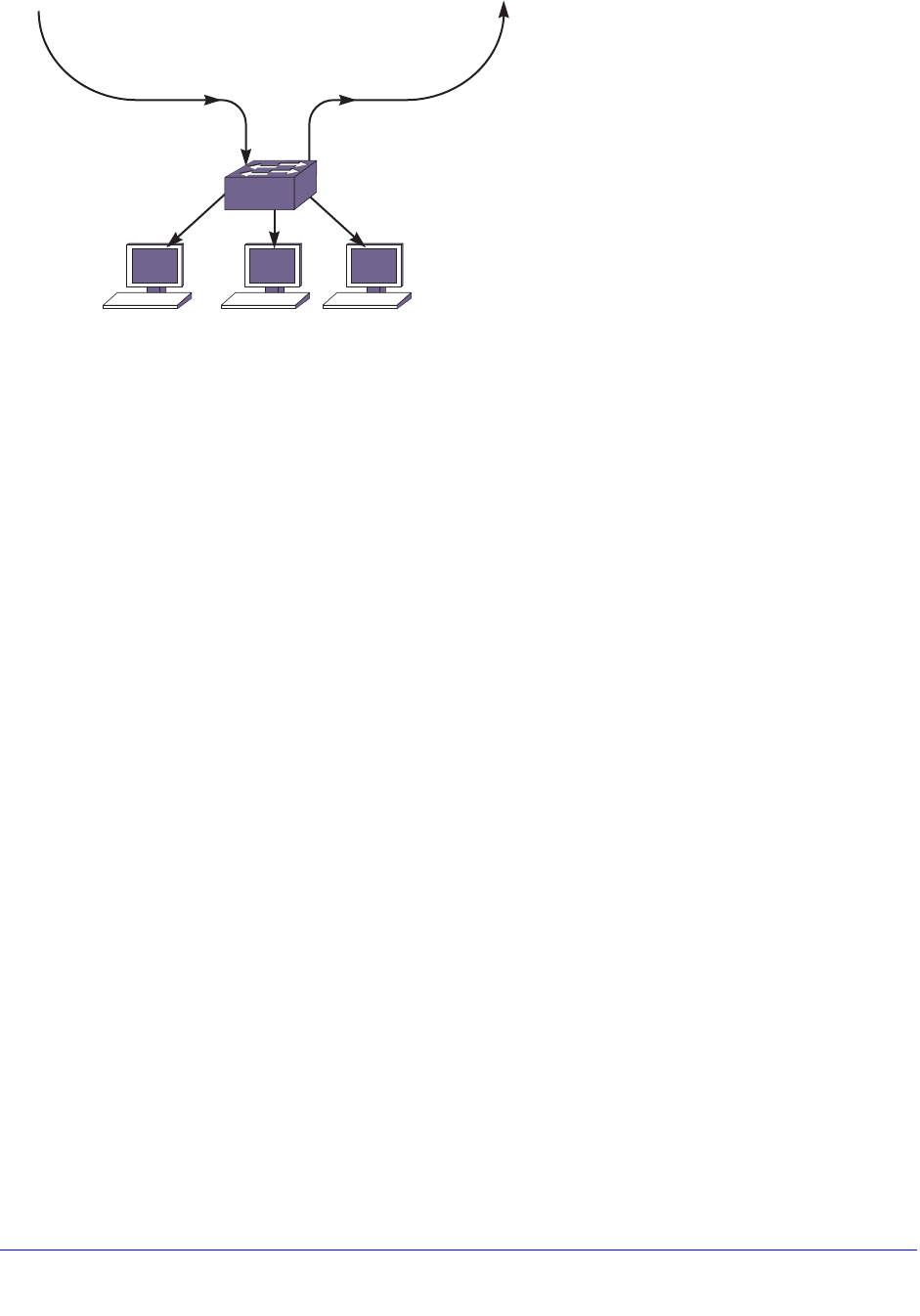
752 | Chapter 27. Multicast Routing and Switching
NETGEAR 8800 User Manual
Figure 90. Multiple VLANs in the Core Network
In Figure 90, the core network has 2 more VLANs, vc1 and vc2, to provide other services.
With MVR, multicast traffic should be confined to McastVlan, and should not be forwarded to
vc1 and vc2. Note that MVR is configured only on the ingress VLAN (McastVlan). MVR is not
configured on any other VLANs.
In the same way as the IGMP snooping forwarding rules, the multicast stream is forwarded
onto member ports and router ports on the VLAN. For a stream received on MVR enabled
ports, this rule is extended to extend membership and router ports to all other VLANs. This
rule works well on the topology in Figure 89. However, in a tagged core topology, this rule
forwards traffic onto VLANs, such as vc1 and vc2, on ports PC1 and PC2. This results in
multiple copies of same stream on the core network, thus reintroducing the problem that
MVR was intended to solve.
To avoid multiple copies of the same stream, MVR forwards traffic with some special
restrictions. MVR traffic is not forwarded to another VLAN unless a host is detected on the
port. On the ingress MVR VLAN, packets are not duplicated to ports belonging to MVR
VLANs. This is to prevent duplicate multicast traffic streams on ingress ports. Streams
belonging to static MVR groups are always forwarded on MVR VLANs so that any host can
join such channels immediately. However, dynamic groups are streamed from the server only
if some host is interested in them. A command is provided to receive traffic on a port which is
excluded by MVR. However, regular IGMP rules still apply to these ports, so the ports must
have a router connected or an IGMP host to receive the stream.
These rules are to prevent multicast packets from leaking into an undesired virtual port, such
as p2 on VLAN pc2 in Figure 90. These rules also allow that, in most topologies, MVR can
be deployed with minimal configuration. However, unlike STP, MVR is not intended to be a
Layer 2 protocol to solve packet looping problems. Since multicast packets leak across
VLANs, one can misconfigure and end up with a multicast storm. MVR does not attempt to
solve such problems.
EX_144
Switch1
Vlan2 vc2
PC2PC1
p1
p2
H2 H4
McastVlan, vc1, vc2
McastVlan, vc1, vc2
H3
H3
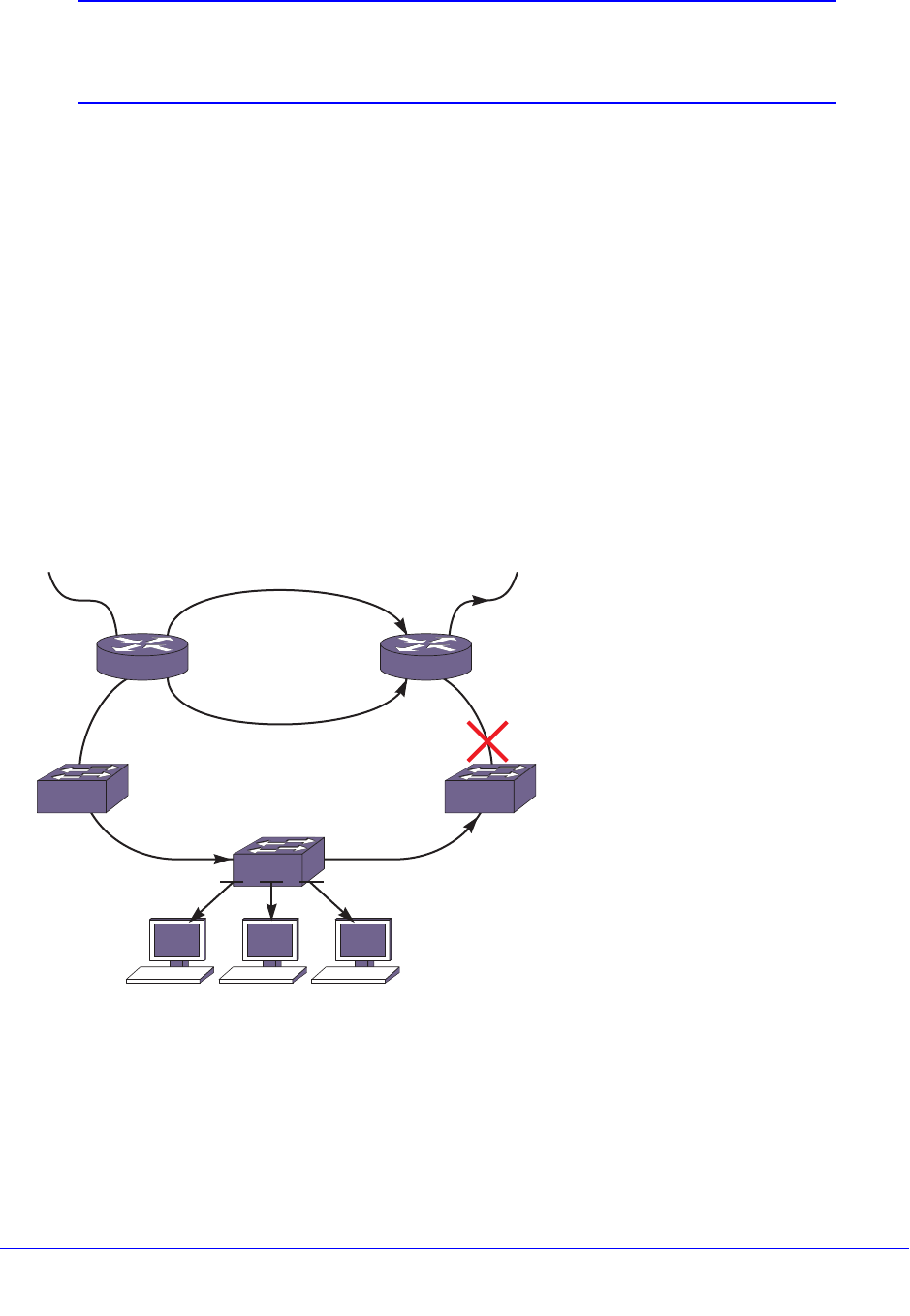
Chapter 27. Multicast Routing and Switching | 753
NETGEAR 8800 User Manual
Note: If a port is blocked by Layer 2 protocols, that port is removed from
the egress list of the cache. This is done dynamically per the port
state.
For most situations, you do not need to manually configure ports to receive the MVR
multicast streams. But if one of the forwarding rules denies forwarding to a port that requires
the streams, you can manually receive the MVR multicast streams by using the following
command:
configure mvr vlan <vlan-name> add receiver port <port-list>
Inter-Multicast VLAN Forwarding
In Basic MVR Deployment on page 749, only simple topologies are considered, in which
subscribers on different VLANs access a multicast VLAN. There are topologies where
streams need to be forwarded onto another multicast VLAN, as shown in Figure 91. In this
figure, a Multicast Service Provider (MSP) multicast VLAN is attached to ports 1:1-2 on both
switches, SW1 and SW2. On the customer side, another multicast VLAN, delivers multicast
streams to other switches around the ring.
Figure 91. Inter-Multicast VLAN Forwarding
In this topology, a multicast stream can be leaked into the customer multicast network
through either switch SW1 or SW2. However, as described in MVR Forwarding on page 751,
packets are not forwarded to router ports (ports 1:4 and 1:5 can be router ports if SW2 is an
IGMP querier). To get around this, MVR needs to be configured on CustVlan either on SW1
or SW2. Since the forwarding rules apply only to non-MVR VLANs, traffic from one MVR
VLAN is leaked into the router ports of another VLAN, if MVR is enabled on that.
EX_145
H2 H3 H4
1:3 1:4
1:4 1:5 1:5
1:21:1 1:21:1
CustVlan
Customer ring
MSP ring
Sw6

754 | Chapter 27. Multicast Routing and Switching
NETGEAR 8800 User Manual
In the topology above, the MSP multicast VLAN is carried on two switches that also carry the
customer multicast VLAN. When multiple switches carry both multicast VLANs, it is
imperative that MVR is configured on only one switch. Only that switch should be used as the
transit point for multicast streams from one multicast ring into another. Otherwise, duplicate
packets are forwarded. Also on the non-MVR switches, the ring ports should be configured as
static router ports, so that ring ports are excluded from forwarding packets onto the customer
ring. There is no mechanism to elect a designated MVR forwarder, so it must be configured
correctly.
MVR Configurations
MVR enables Layer 2 network installations to deliver bandwidth intensive multicast streams.
It is primarily aimed at delivering IPTV over Layer 2 networks, but it is valuable in many
existing STP installations. This section explores a few possible deployment scenarios and
configuration details. Of course, real world networks can be lot different from these examples.
This section is meant to present some ideas on how to deploy MVR over existing networks,
as well as to design new networks that support MVR.
MVR with STP
In a Layer 2 ring topology, MVR works with STP. However, in other Layer 2 topologies,
additional configuration steps may be needed to make sure that multicast feeds reach all
network segments. Extra configuration is required because all ports in the VLAN are part of
an STP domain, so that solely by examining the configuration it is not clear whether a port is
part of bigger ring or is just serving a few hosts. Consider a simplified Layer 2 STP network
as shown in Figure 92.
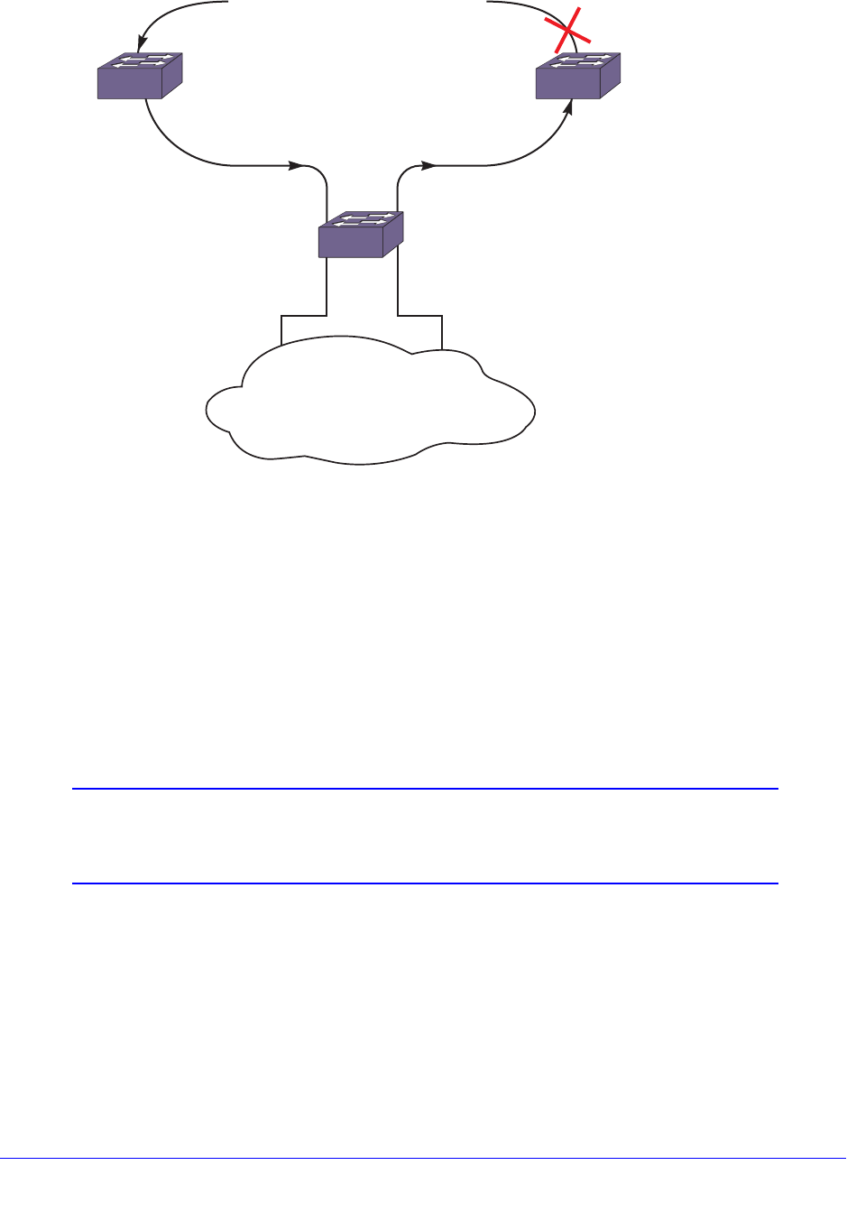
Chapter 27. Multicast Routing and Switching | 755
NETGEAR 8800 User Manual
Figure 92. MVR with STP
In this topology, subscribers are in a Layer 2 cloud on VLAN V1. STP is configured for all
ports of V1. Since V1 spans on the ring as well, multicast cannot be forwarded on V1 blindly.
Forwarding rules (described in MVR Forwarding on page 751), dictate that multicast traffic is
not forwarded on STP enabled ports. This is to make sure that multiple copies of multicast
packets are not forwarded on the ring. However, since other STP enabled ports on V1
(1:3,1:4) are not part of the ring multicast stream, they need to be configured so that they get
the packets. To configure the ports to receive packets, use the following command
(mentioned previously in MVR Forwarding ):
configure mvr vlan <vlan-name> add receiver port <port-list>
Note: If the Layer 2 cloud is connected back to ring ports, traffic may end
up leaking into VLAN V1 in the ring. There is no way to avoid that.
So, such topologies must be avoided.
The following is a typical configuration for Switch 1 in Figure 92:
create vlan v1
configure v1 tag 200
configure v1 add port 1:1, 1:2 tag
configure v1 add port 1:3, 1:4
create vlan mvlan
configure mvlan add port 1:1, 1:2
EX_148
Switch1
MSP ring
V1V1
1:3
1:4
MVlan, vc1MVlan, vc1
Switch2Switch4
Vlan V1 cloud

756 | Chapter 27. Multicast Routing and Switching
NETGEAR 8800 User Manual
configure mvr add vlan mvlan
create stpd stp1
configure stp1 add vlan v1 port all
enable stpd stp1 port all
configure mvr vlan v1 add receiver port 1:3,1:4
enable mvr
Displaying Multicast Information
The following sections describe how to display multicast information:
• Displaying the Multicast Routing Table on page 756
• Displaying the Multicast Cache on page 756
• Looking Up a Multicast Route on page 756
• Looking Up the RPF for a Multicast Source on page 756
• Displaying the PIM Snooping Configuration on page 757
Displaying the Multicast Routing Table
To display part or all of the entries in the multicast routing table, use the following command:
show iproute {ipv4} {{vlan} <name> | [<ipaddress> <netmask> | <ipNetmask>] |
origin [direct | static | mbgp | imbgp | embgp]} multicast {vr <vr_name>}
Displaying the Multicast Cache
The multicast cache stores information about multicast groups. To display part or all of the
entries in the multicast cache, use the following command:
show mcast cache {{vlan} <name>} {{[group <grpaddressMask> | <grpaddressMask>]
{source <sourceIP> | <sourceIP>}} {type [snooping | pim | mvr]} {with-in-port} |
{summary}}
Looking Up a Multicast Route
To look up the multicast route to a specific destination, use the following command with the
multicast option:
rtlookup [<ipaddress> | <ipv6address>] { unicast | multicast | rpf }
{ vr <vr_name> }
Looking Up the RPF for a Multicast Source
To look up the RPF for a multicast source, use the following command with the rpf option:

Chapter 27. Multicast Routing and Switching | 757
NETGEAR 8800 User Manual
rtlookup [<ipaddress> | <ipv6address>] { unicast | multicast | rpf }
{ vr <vr_name> }
Displaying the PIM Snooping Configuration
To display the PIM snooping configuration for a VLAN, use the following command:
show pim snooping {vlan} <name>
Troubleshooting PIM
The following sections introduce two commands that you can use to troubleshoot multicast
communications:
• Multicast Trace Tool on page 757
• Multicast Router Information Tool on page 758
Multicast Trace Tool
The multicast trace tool is the multicast equivalent of unicast trace route mechanism and is
an effective tool for debugging multicast reachability problems. This tool is based on an IETF
draft and uses IGMP. Because it is harder to trace a multicast path from the source to the
destination, a multicast trace is run from the destination to the source. The multicast trace
can be used to do the following:
• Locate where a multicast traffic flow stops
• Identify sub-optimal multicast paths
A multicast trace is used for tracing both potential and actual multicast forwarding tree paths.
When the multicast tree is established and traffic is flowing, this tool traces the actual traffic
flow. If there is no traffic while executing the command, this tool displays the potential path for
the group and source being traced.
You can direct a multicast trace to any network destination, which can be a multicast source
or destination, or a node located between a source and destination. After you initiate the
trace, a multicast trace query packet is sent to the last-hop multicast router for the specified
destination. The query packet contains the source address, group address,
destination/receiver address, response address, maximum number of hops, and TTL to be
used for the multicast trace response.
The previous hop router selection is based on the multicast routing protocol and the state for
the S,G entry in the processing router. For example:
• If there is no S,G state in the router, the parent closest to the RP is chosen as the
previous hop.
• If the S,G state exists in the router, the parent closest to the source is chosen as the
previous hop.

758 | Chapter 27. Multicast Routing and Switching
NETGEAR 8800 User Manual
The last hop router converts the multicast trace query into a unicast traceroute request by
appending response data (for the last hop router) into the received query packet, and the last
hop router forwards the request packet to the router that it believes is the proper previous hop
for the given source and group. Each multicast router adds its response data to the end of the
request packet, and then forwards the modified unicast request to the previous hop.
The first hop router (the router that determines that packets from the source originate on one
of its directly connected networks) changes the packet type to response packet and sends
the completed response to the query generator. If a router along the multicast route is unable
to determine the forwarding state for a multicast group, that router sends a response back to
the originator with NO ROUTE forwarding code.
To initiate a multicast trace, use the following command:
mtrace source <src_address> {destination <dest_address>} {group <grp_address>} {from
<from_address>} {gateway <gw_address>} {timeout <seconds>} {maximum-hops
<number>} {vr <vrname>}
Multicast Router Information Tool
The multicast router information tool is an XCM8800 command that allows you to request
information from a specific multicast router. For more information, see the command
description for the following command:
mrinfo {<router_address>} {from <from_address>} {timeout <seconds>}
{multiple-response-timeout <multi_resp_timeout>} {vr <vrname>}

Chapter 28. IPv6 Multicast | 759
28
28. IPv6 Multicast
This chapter includes the following sections:
• Overview on page 759
• Managing MLD on page 760
Overview
IPv6 multicast is a function that allows a single IPv6 host to send a packet to a group of IPv6
hosts.
Multicast Listener Discovery (MLD) is a protocol used by an IPv6 host to register its IP multicast
group membership with a router. To receive multicast traffic, a host must explicitly join a multicast
group by sending an MLD report; then, the traffic is forwarded to that host. Periodically, the router
queries the multicast group to see if the group is still in use. If the group is still active, a single IP
host responds to the query, and group registration is maintained.
MLD is the IPv6 equivalent to IGMP, and MLDv1 is equivalent to IGMPv2. The XCM8800
software supports the MLDv1 protocol. However, to overcome a hardware limitation, IPv6
multicast packets for a group are flooded.
Note: This release supports host registration through MLD, but it does not
support IPv6 multicast routing. If the switch is connected to an IPv6
multicast router, it can register for IPv6 multicast groups and forward
IPv6 multicast traffic.
Note: This release does not support MLD snooping. If any IPv6 host on a
VLAN registers for an IPv6 multicast group, traffic for the IPv6
multicast group is flooded to all ports on the VLAN.

760 | Chapter 28. IPv6 Multicast
NETGEAR 8800 User Manual
Managing MLD
The following sections describe how to manage MLD on the switch:
• Enabling and Disabling MLD on a VLAN on page 760
• Configuring MLD on page 760
• Clearing MLD Group Registration on page 760
• Configuring Static MLD Groups and Routers on page 760
• Displaying MLD Information on page 761
Enabling and Disabling MLD on a VLAN
MLD is enabled by default on all VLANs. This allows IPv6 hosts to register with IPv6 multicast
groups and receive IPv6 multicast traffic. You can disable MLD using the following command:
disable mld {vlan <name>}
To enable MLD on a VLAN after it has been disabled, use the following command:
enable mld {vlan <vlan name>} {MLDv1 | MLDv2}
Configuring MLD
To configure the timers that control MLD operation, use the following command:
configure mld <query_interval> <query_response_interval>
<last_member_query_interval> {<robustness>}
Clearing MLD Group Registration
To clear a single group or all groups in a VLAN learned through MLD, use the following
command:
clear mld group {<v6grpipaddress>} {{vlan} <name>}
Configuring Static MLD Groups and Routers
In some situations, you might want multicast traffic to be forwarded to a port where a
multicast-enabled host is not available (for example, when you test multicast configurations).
Static MLD emulates a host or router attached to a switch port, so that multicast traffic is
forwarded to that port, and the switch sends a proxy join for all the statically configured MLD
groups when an MLD query is received. You can emulate a host to forward a particular
multicast group to a port; and you may emulate a router to forward all multicast groups to a
port.
To emulate a host on a port, use the following command:

Chapter 28. IPv6 Multicast | 761
NETGEAR 8800 User Manual
configure mld snooping {vlan} <vlanname> ports <portlist> add static
group <v6grpipaddress>
To emulate a multicast router on a port, use the following command:
configure mld snooping {vlan} <vlanname> ports <portlist> add static router
To remove these entries, use the corresponding command:
configure mld snooping {vlan} <vlanname> ports <portlist> delete static
group [all | <v6grpipaddress>]
configure mld snooping {vlan} <vlanname> ports <portlist> delete static router
Displaying MLD Information
To display MLD configuration and operation information, use the following command:
show mld group {{vlan} {<name>} | {<v6grpipaddress>}} {MLDv2}
To display the MLD static group information, use the following command:
show mld snooping vlan <name> static [group | router]

Chapter 29. MSDP | 762
29
29. MSDP
This chapter includes the following sections:
• Overview on page 762
• PIM Border Configuration on page 763
• MSDP Peers on page 764
• MSDP Mesh-Groups on page 766
• Anycast RP on page 767
• SA Cache on page 768
• Redundancy on page 770
• Scaling Limits on page 770
• SNMP MIBs on page 770
• Configuration Examples on page 770
Note: For more information about MSDP, see RFC 3618.
Overview
Multicast Source Discovery Protocol (MSDP) is an interdomain multicast protocol used to
connect multiple multicast routing domains that run Protocol Independent Multicast-Sparse
Mode (PIM-SM). MSDP speakers are configured on each PIM-SM domain. These speakers
establish a peering relationship with other MSDP speakers through secured TCP connections.
When the source sends traffic, the MSDP speaker learns about the source through its
Rendezvous Point (RP). In turn, the RP advertises the source to its peers through Source Active
(SA) messages. The peers receive these advertisements and inform their RPs about the
presence of the active source in the other PIM-SM domain, which triggers the normal PIM
operation in the corresponding domains.

Chapter 29. MSDP | 763
NETGEAR 8800 User Manual
For example, as businesses expand and networks grow in size, it might become necessary
to connect PIM domains to allow multicast applications to reach other offices across the
network. MSDP simplifies this process by providing a mechanism to connect those multicast
routing domains without reconfiguring existing domains. Each PIM domain remains separate
and has its own RP. The RP in each domain establishes an MSDP peering relationship over
a TCP connection either with RPs in other domains or with border routers leading to other
domains. When an RP learns about a new multicast source in its own domain (using the
normal PIM registration process), it then sends a SA message to all of its MSDP peers,
letting them know about the new stream. In this way, the network can receive multicast traffic
from all over the network without having to reconfigure each existing PIM domain.
Supported Platforms
MSDP is supported on NETGEAR 8800 running a firmware with the Core license.
Our implementation of MSDP is compliant with RFC 3618 and RFC 3446, and compatible
with other devices that are compliant with these standards.
Limitations
The limitations of MSDP are as follows:
• There is no support for MSDP operating with SA cache disabled (transit node). MSDP will
always cache/store received SA messages.
• There is no support for logical RP.
• There is no support for MSDP on user-created virtual routers (VRs).
• RIP routes are not used for peer-RPF checking. So, our implementation of MSDP does
not exactly conform to rule (iii) in section 10.1.3 of RFC 3618. However, our
implementation of MSDP uses BGP/OSPF for peer-RPF checking as per rule (iii) in
section 10.1.3.
• Read-write/read-create access is not supported on MSDP MIB objects.
PIM Border Configuration
To create a PIM-SM domain for MSDP, you must restrict the reach of Bootstrap Router (BSR)
advertisements by defining a VLAN border. BSR advertisements are not sent out of a PIM
interface configured as a VLAN border, thereby defining a PIM domain for MSDP.
To configure a PIM VLAN border, use the following command:
configure pim <vlan_name> border

764 | Chapter 29. MSDP
NETGEAR 8800 User Manual
MSDP Peers
MSDP peers exchange messages to advertise active multicast sources. The peer with the
higher IP address passively listens to a well-known port number and waits for the side with
the lower IP address to establish a Transmission Control Protocol (TCP) connection on port
639. When a PIM-SM RP that is running MSDP becomes aware of a new local source, it
sends an SA message over the TCP connection to its MSDP peer. When the SA message is
received, a peer-RPF check is performed to make sure the peer is toward the originating RP.
If so, the RPF peer floods the message further. If not, the SA message is dropped and the
message is rejected.
To configure an MSDP peer, use the following command:
create msdp peer <remoteaddr> {remote-as <remote-AS>} {vr <vrname>}
To delete an MSDP peer, use the following command:
delete msdp peer [all | <remoteaddr>] {vr <vrname>}
To display configuration and run-time parameters about an MSDP peer, use the following
command:
show msdp [peer {detail} | {peer} <remoteaddr>] {vr <vrname>}
MSDP Default Peers
You can configure a default peer to accept all SA messages. Configuring a default peer
simplifies the peer-RPF checking of SA messages. If no policy is specified, the current peer is
the default RPF peer for all SA messages.
When configuring a default peer, you can also specify an optional policy filter. If the peer-RPF
check fails, and a policy filter is configured, the default peer rule is applied to see if the SA
message should be accepted or rejected.
You can configure multiple default peers with different policies. However, all default peers
must either be configured with a default policy or not. A mix of default peers, with a policy and
without a policy, is not allowed.
To configure an MSDP default peer, and optional policy filter, use the following command:
configure msdp peer [<remoteaddr> | all] default-peer {default-peer-policy
<filter-name>} {vr <vrname>}
To remove the default peer, use the following command:
configure msdp peer [<remoteaddr> | all] no-default-peer {vr <vrname>}
To verify that a default peer is configured, use the following command:
show msdp [peer {detail} | {peer} <remoteaddr>] {vr <vrname>}

Chapter 29. MSDP | 765
NETGEAR 8800 User Manual
Peer Authentication
MSDP supports TCP MD5 authentication (RFC 2385) to secure control messages between
MSDP peers. You must configure a secret password for an MSDP peer session to enable
TCP MD5 authentication. When a password is configured, MSDP receives only
authenticated MSDP messages from its peers. All MSDP messages that fail TCP MD5
authentication are dropped.
To configure TCP MD5 authentication on an MSDP peer, use the following command:
configure msdp peer [<remoteaddr> | all] password [none | {encrypted}
<tcpPassword>] {vr <vrname>}
To remove the password, use the following command:
configure msdp peer {all | <remoteaddr>} password none
The password displays in encrypted format and cannot be seen as simple text. Additionally,
the password is saved in encrypted format.
To display the password in encrypted format, use the following command:
show msdp [peer {detail} | {peer} <remoteaddr>] {vr <vrname>}
Policy Filters
You can configure a policy filter to control the flow of SA messages going to or coming from
an MSDP peer. For example, policy filters can help mitigate state explosion during denial of
service (DoS) or other attacks by limiting what is propagated to other domains using MSDP.
To configure an incoming or outgoing policy filter for SA messages, use the following
command:
configure msdp peer [<remoteaddr> | all] sa-filter [in | out] [<filter-name> |
none] {vr <vrname>}
To remove a policy filter for SA messages, use the none keyword:
configure msdp [{peer} <remoteaddr> | peer all] sa-filter [in | out] none
To verify that a policy filter is configured on an MSDP peer, use the following command:
show msdp [peer {detail} | {peer} <remoteaddr>] {vr <vrname>}
SA Request Processing
You can configure the router to accept or reject SA request messages from a specified MSDP
peer or all peers. If an SA request filter is specified, only SA request messages from those
groups permitted are accepted. All others are ignored.
To configure the router to accept SA request messages from a specified MSDP peer or all
peers, use the following command:
enable msdp [{peer} <remoteaddr> | peer all] process-sa-request
{sa-request-filter <filter-name> } {vr <vrname>}

766 | Chapter 29. MSDP
NETGEAR 8800 User Manual
To configure the router to reject SA request messages from a specified MSDP peer or all
peers, use the following command:
disable msdp [{peer} <remoteaddr> | peer all] process-sa-request {vr <vrname>}
To display configuration and run-time parameters about MSDP peers, use the following
command:
show msdp [peer {detail} | {peer} <remoteaddr>] {vr <vrname>}
MSDP Mesh-Groups
MSDP can operate in a mesh-group topology. A mesh-group limits the flooding of SA
messages to neighboring peers. In a mesh-group, every MSDP peer must be connected to
every other peer in the group. In this fully-meshed topology, when an SA message is received
from a member of the mesh-group, the SA message is always accepted, but not flooded to
other members of the same group. Because MSDP peers are connected to every other peer
in the mesh-group, an MSDP peer is not required to forward SA messages to other members
of the same mesh-group. However, SA messages are flooded to members of other
mesh-groups. An MSDP mesh-group is an easy way to implement inter-domain multicast, as
it relaxes the requirement to validate looping of MSDP control traffic (that is, peer-RPF
checking is not required). Consequently, SA messages do not loop in the network.
Note: NETGEAR recommends that you configure anycast RP peers in a
mesh topology.
To configure an MSDP mesh-group, use the following command:
create msdp mesh-group <mesh-group-name> {vr <vrname>}
To remove an MSDP mesh-group, use the following command:
delete msdp mesh-group <mesh-group-name> {vr <vrname>}
To display information about an MSDP mesh-group, use the following command:
show msdp [mesh-group {detail} | {mesh-group} <mesh-group-name>] {vr <vrname>}
To configure a peer to be a member of an MSDP mesh-group, use the following command:
configure msdp peer [<remoteaddr> | all] mesh-group [<mesh-group-name> | none]
{vr <vrname>}
To remove a peer from an MSDP mesh-group, use the following command:
configure msdp [{peer} <remoteaddr> | peer all] mesh-group none {vr <vrname>}

Chapter 29. MSDP | 767
NETGEAR 8800 User Manual
Anycast RP
Anycast RP is an application of MSDP that allows multiple RPs to operate simultaneously in
a PIM-SM domain. Without anycast RP, multiple routers can be configured as candidate RPs,
but at any point in time, only one router can serve as RP. Because anycast RP allows
multiple RPs to be simultaneously active, anycast RP provides both load sharing and
redundancy, as each RP serves the receivers that are closest to it in the network and can
take over for additional receivers if another RP fails.
In an anycast RP topology, all RPs in a PIM-SM domain are configured with the same IP
address on a loopback VLAN. The loopback VLAN IP address should have a 32-bit mask, so
that it specifies a host address. All the routers within the PIM-SM domain select the nearest
RP for each source and receiver. If the senders and receivers within the PIM-SM domain are
distributed evenly, the number of senders that register with each RP is approximately equal.
Another requirement of the anycast RP topology is that MSDP must run on all RPs in the
PIM-SM domain, so all RPs are also MSDP peers. NETGEAR recommends that you
configure an MSDP mesh connection between all MSDP peers in the domain.
Whenever any multicast source becomes active, this information is sent in an MSDP SA
message to the other MSDP peers in the domain, announcing the presence of the source. If
any RP within the domain fails, the IP routing protocol mechanism ensures that next
available RP is chosen. If a sender registers with one RP and a receiver joins another RP, the
information shared through MSDP enables PIM-SM to establish an SPT between the
receiver and the source.
Note: NETGEAR recommends that you configure anycast RP peers in a
mesh topology.
The exchange of information in an anycast RP process works as follows:
• When the first-hop router sends a PIM Register message to the nearest RP, the PIM
router checks to see if the nearest RP is the RP for the group.
• If the nearest RP is the RP for the group, an MSDP SA message is created and
forwarded to the other MSDP peers.
• The MSDP SA message includes the configured originator ID, which is a mandatory
configuration component.
• Each remote peer checks the RPF of the originator ID address and informs the PIM
process on that remote router about active multicast sources.
• Remote receivers get data packets through the remote shared tree, and can then switch
over to the SPT by sending join messages directly towards the source.
To configure anycast RP, do the following at each anycast RP router:
1. Create and configure a loopback VLAN using the following commands:
create vlan <vlan_name> {vr <vr-name>}

768 | Chapter 29. MSDP
NETGEAR 8800 User Manual
enable loopback-mode vlan <vlan_name>
2. Assign the anycast RP address to the loopback VLAN with a 32 bit subnet mask using the
following command:
configure {vlan} <vlan_name> ipaddress [<ipaddress> {<ipNetmask>} |
ipv6-link-local | {eui64} <ipv6_address_mask>]
Note: The anycast RP address must be unique to the loopback VLAN and be
the same on all anycast RP peers. It must not match the router IP address, the
PIM BSR address, or any other IP addresses used by the router or any other
network devices.
3. Enable IP forwarding and IP multicast forwarding on the loopback VLAN using the following
commands:
enable ipforwarding {ipv4 | broadcast | ignore-broadcast |
fast-direct-broadcast} {vlan <vlan_name>}
enable ipmcforwarding {vlan <name>}
4. Add the loopback VLAN into the unicast routing domain using the appropriate command for
your unicast routing protocol:
configure ospf add vlan <vlan-name> area <area-identifier> link-type [auto |
broadcast | point-to-point] {passive}
configure rip add vlan [<vlan-name> | all]
5. Add the loopback VLAN into the PIM-SM domain and configure it as an RP using the
following commands:
configure pim add vlan [<vlan-name> | all] {dense | sparse} {passive}
configure pim crp static <ip_address> [none | <policy>] {<priority> [0-254]}
6. Enable MSDP and establish a peering relationship with similar anycast RP neighbors using
the following commands:
create msdp peer <remoteaddr> {remote-as <remote-AS>} {vr <vrname>}
configure msdp peer [<remoteaddr> | all] password [none | {encrypted}
<tcpPassword>] {vr <vrname>}
configure msdp peer <remoteaddr> description {<peer-description>} {vr
<vrname>}
enable msdp [{peer} <remoteaddr> | peer all] {vr <vrname>}
enable msdp {vr <vrname>}
7. Configure a unique originator ID for each anycast RP peer using the following command:
configure msdp originator-id <ip-address> {vr <vrname>}
SA Cache
As an MSDP router learns of new sources either through a PIM-SM Source-Register (SR)
message or SA message from its RPF peer, it creates an entry in SA cache (or refreshes the
entry if it is already there) and forwards this information to its peers. These entries are
refreshed by periodic SA messages received from the MSDP peers. If these entries are not
refreshed within six minutes, they will time out. When a PIM-SM RP detects that the source is

Chapter 29. MSDP | 769
NETGEAR 8800 User Manual
no longer available it informs MSDP, which in turn removes the SA information from the local
database.
Caching makes it easy for local receivers to know immediately about inter-domain multicast
sources and to initiate building a source tree towards the source. However, maintaining a
cache is heavy both in CPU processing and memory requirements.
Note: Our implementation of MSDP does not support operating with local
cache disabled.
To remove an SA cache server, use the following command:
unconfigure msdp sa-cache-server {vr <vrname>}
As MSDP uses the flood-and-join model to propagate information about sources, there is a
restriction that no more than two advertisements per cache entry will be forwarded per
advertisement interval. This is helpful in reducing an SA message storm and unnecessarily
forwarding them to peers.
By default, the router does not send SA request messages to its MSDP peers when a new
member joins a group and wants to receive multicast traffic. The new member simply waits to
receive SA messages, which eventually arrive.
To configure the MSDP router to send SA request messages immediately to the MSDP peer
when a new member becomes active in a group, use the following command:
configure msdp sa-cache-server <remoteaddr> {vr <vrname>}
To purge all SA cache entries, use the following command:
clear msdp sa-cache {{peer} <remoteaddr> | peer all} {group-address <grp-addr>}
{vr <vrname>}
To display the SA cache database, use the following command:
show msdp [sa-cache | rejected-sa-cache] {group-address <grp-addr>}
{source-address <src-addr>} {as-number <as-num>} {originator-rp
<originator-rp-addr>} {local} {peer <remoteaddr>} {vr <vrname>}
Maximum SA Cache Entry Limit
You can configure a limit on the maximum number of SA cache entries that can be stored in
the cache database. Once the number of SA cache entries exceeds the pre-configured limit,
any newly received cache entries are discarded. You can configure the limit on a per-peer
basis. By default, no SA message limit is set. The router can receive an unlimited number of
SA entries from an MSDP peer.
To configure a limit on the number of SA entries that can be stored in cache, use the following
command:
configure msdp peer [<remoteaddr> | all] sa-limit <max-sa> {vr <vrname>}
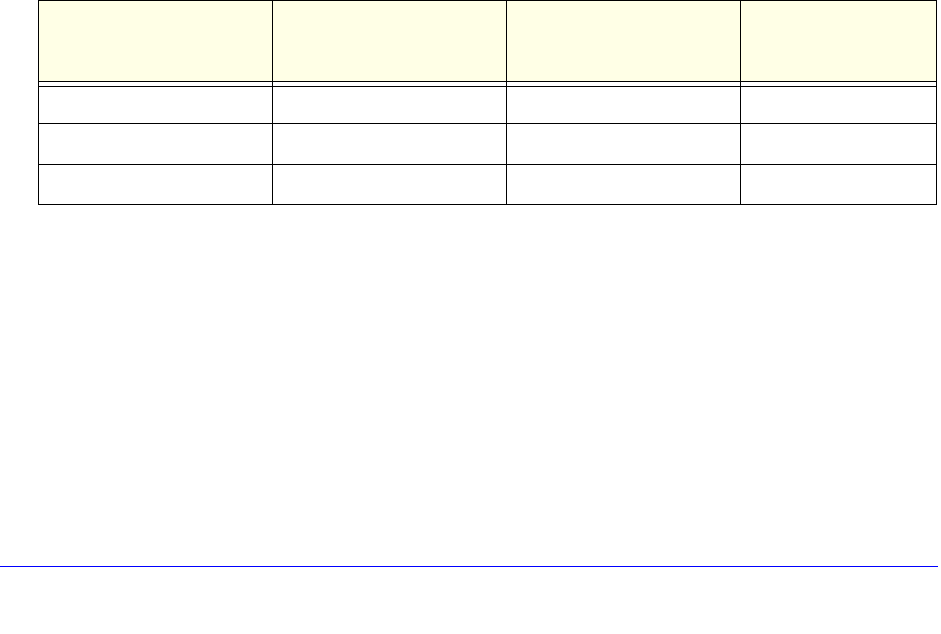
770 | Chapter 29. MSDP
NETGEAR 8800 User Manual
To allow an unlimited number of SA entries, use 0 (zero) as the value for <max-sa>.
To display the SA cache limit, use the following command:
show msdp [peer {detail} | {peer} <remoteaddr>] {vr <vrname>}
Redundancy
Because the peering relationship between MSDP peers is based on TCP connections, after a
failover occurs the TCP connections need to be re-established again. All SA cache entries
learned from the old peering relationships must be flushed and relearned again on new TCP
connections.
On a dual MSM system, MSDP runs simultaneously on both MSMs. During failover, the
MSDP process on the active MSM receives and processes all control messages. MSDP on
the standby MSM is in a down state, and doesn’t receive, transmit, or process any control
messages. If the active MSM fails, the MSDP process loses all state information and the
standby MSM becomes active. However, the failover from the active MSM to the standby
MSM causes MSDP to loses all state information and dynamic data, so it is not a hitless
failover.
On fixed-configuration, stackable switches, an MSDP process failure brings down the switch.
Scaling Limits
SNMP MIBs
SNMP MIB access is not supported for MSDP.
Configuration Examples
This section provides the following configuration examples:
• Configuring MSDP on page 771
Table 72. MSDP Scaling Limits
Platform Type MSDP Peering
Connections (Active TCP
Connections
Entries in SA Cache Mesh-Groups
Chassis 32 16,000 8
Stackable 16 8,000 8
PC 12 8,000 4

Chapter 29. MSDP | 771
NETGEAR 8800 User Manual
• Configuring an MSDP Mesh-Group on page 772
• Configuring Anycast RP on page 775
Configuring MSDP
Figure 93 shows two MSDP-speaking routers, MSDP-1 and MSDP-2. The example in this
section shows how to configure MSDP on each router to:
• Establish a peer session between MSDP-1 and MSDP-2. (To verify the session, enter the
show msdp peer command.)
• Exchange SA messages, if any, between MSDP-1 and MSDP-2. (To view the SA cache
database, enter the show msdp sa-cache command.)
Figure 93. MSDP Configuration Example
The minimum configuration required to establish an MSDP session between MSDP-1 and
MSDP-2 follows.
Configuration for MSDP-1
# VLAN configuration
create vlan test
config vlan test ipaddress 10.172.168.32/24
config default del port 1:1
config vlan test add port 1:1
enable ipforwarding
# MSDP configuration
config msdp originator-id 10.172.168.32
create msdp peer 10.172.168.61
enable msdp peer 10.172.168.61
enable msdp
Configuration for MSDP-2
# VLAN configuration
create vlan test
config vlan test ipaddress 10.172.168.61/24
config default del port 1:1
config vlan test add port 1:1
enable ipforwarding
MSDP-1
10.172.168.32 10.172.168.61
MSDP-2
XOS006A
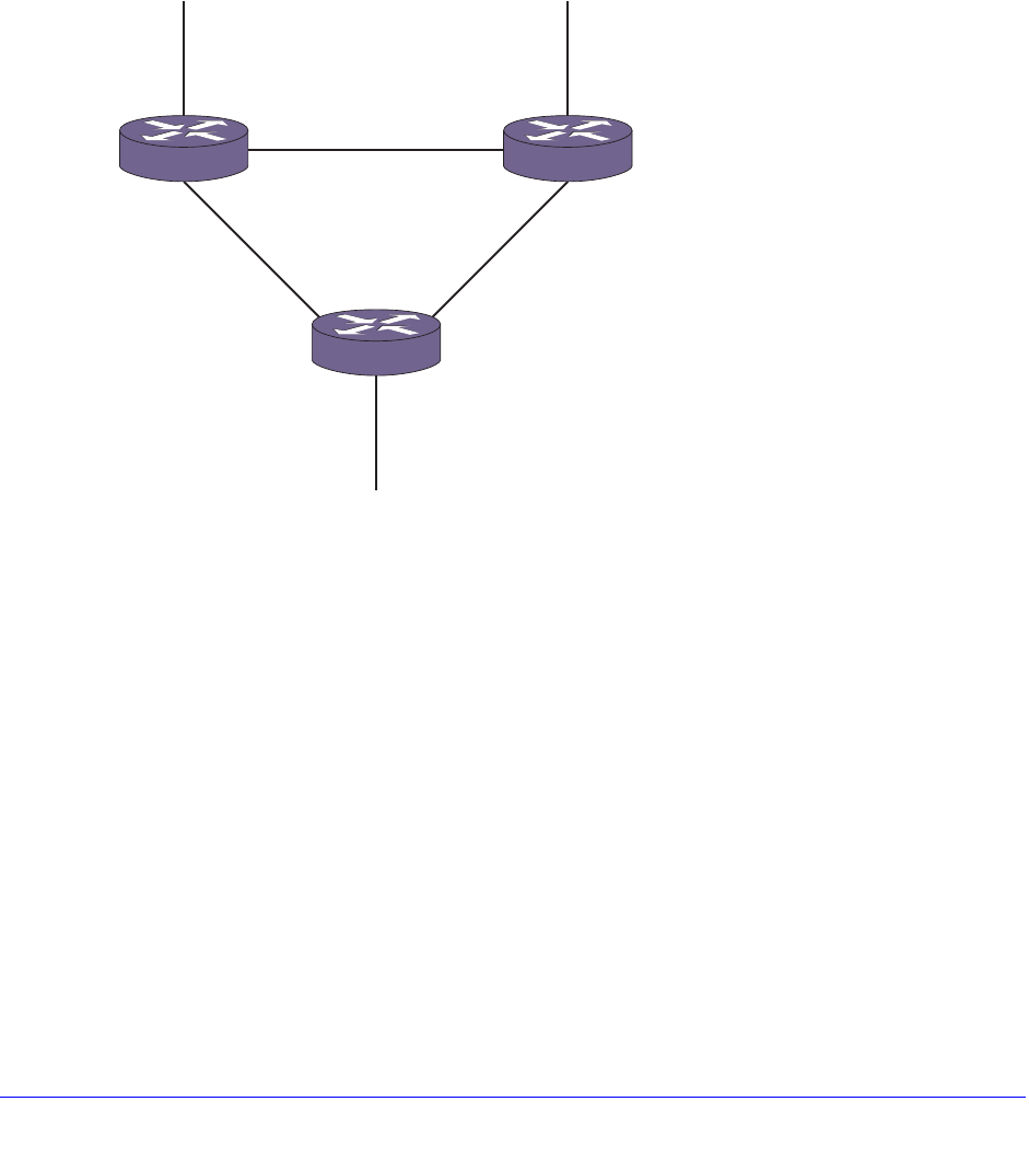
772 | Chapter 29. MSDP
NETGEAR 8800 User Manual
# MSDP configuration
config msdp originator-id 10.172.168.61
create msdp peer 10.172.168.32
enable msdp peer 10.172.168.32
enable msdp
Configuring an MSDP Mesh-Group
Figure 94 shows an example MSDP mesh group configuration.
Figure 94. MSDP Mesh-Group Configuration
In this example:
• MSDP 1, MSDP 2, and MSDP 3 are configured in a mesh-group called M1.
• When the SA message is received at MSDP 1 on interface 10.1.1.1, MSDP 1 floods the
message to MSDP 2 and MSDP 3.
• MSDP 2 inserts the SA message, but the message is not forwarded to MSDP 3 because
it is in the same mesh-group.
• MSDP 3 inserts the SA message, but the message is not forwarded to MSDP 2 because
it is in the same mesh-group.
As this examples shows, a mesh-group limits the flooding of SA messages to neighboring
peers in the mesh-group.
In the configurations, loopback VLANs are used as the MSDP peer addresses. This is the
recommended practice for MSDP. The same can be configured for the originator RP address
also (CBSR and CRP also can be used as the loopback IP addresses).
EX_msdp_0001
10.1.1.1
10.0.3.3
10.0.3.1 10.0.2.2
10.0.2.3
10.0.1.1
10.1.1.1
10.0.1.2
MESH M1
10.1.1.1
MSDP2
MSDP3
MSDP1

Chapter 29. MSDP | 773
NETGEAR 8800 User Manual
In the topology, loopback VLANs are configured on each of the switches and the loopback
addresses for each of the switches are as follows:
• MSDP 1 (10.1.1.1/32)
• MSDP 2 (10.1.1.2/32)
• MSDP 3 (10.1.1.3/32)
Note: The autonomous system (AS) number for the peer is used in
peer-RPF checks. The AS number provided by the user is treated as
the AS number in which the peer resides. If you do not specify an AS
number, BGP is used to determine the AS number for the peer. If the
peer is reachable by other routes, BGP will not be able to determine
the AS number for the peer.
The following sections provide additional information on the MSDP configuration portion of
this example:
• Switch MSDP1 Configuration Commands on page 773
• Switch MSDP2 Configuration Commands on page 774
• Switch MSDP3 Configuration Commands on page 774
Note: For an example of the VLAN and PIM configuration that supports
MSDP in this example, see the next example, Configuring Anycast
RP on page 775, which is similar to this example.
Switch MSDP1 Configuration Commands
The following is an example MSDP configuration for switch MSDP1:
create msdp peer 10.0.1.2
configure msdp peer 10.0.1.2 decription "msdp_22"
configure msdp peer 10.0.1.2 password "test"
create msdp peer 10.0.3.3
configure msdp peer 10.0.3.3 password "test"
configure msdp peer 10.0.3.3 desciption "msdp_13"
create msdp mesh-group m1
configure msdp peer 10.0.1.2 mesh-group m1
configure msdp peer 10.0.3.3 mesh-group m1
configure msdp originator-id 10.0.1.1 /To configure unique originator id

774 | Chapter 29. MSDP
NETGEAR 8800 User Manual
enable msdp peer all
enable msdp
Switch MSDP2 Configuration Commands
The following is an example MSDP configuration for switch MSDP2:
create msdp peer 10.0.1.1
configure msdp peer 10.0.1.1 decription "msdp_21"
configure msdp peer 10.0.1.1 password "test"
create msdp peer 10.0.2.3
configure msdp peer 10.0.2.3 password "test"
configure msdp peer 10.0.2.3 desciption "msdp_23"
create msdp mesh-group m1
configure msdp peer 10.0.1.1 mesh-group m1
configure msdp peer 10.0.2.3 mesh-group m1
configure msdp originator-id 10.0.2.2 /To configure unique originator id
enable msdp peer all
enable msdp
Switch MSDP3 Configuration Commands
The following is an example MSDP configuration for switch MSDP3:
create msdp peer 10.0.3.1
configure msdp peer 10.0.3.1 decription "msdp_31"
configure msdp peer 10.0.3.1 password "test"
create msdp peer 10.0.2.2
configure msdp peer 10.0.2.2 password "test"
configure msdp peer 10.0.2.2 desciption "msdp_13"
create msdp mesh-group m1
configure msdp peer 10.0.3.1 mesh-group m1
configure msdp peer 10.0.2.2 mesh-group m1
configure msdp originator-id 10.0.3.3 /To configure unique originator id
enable msdp peer all
enable msdp
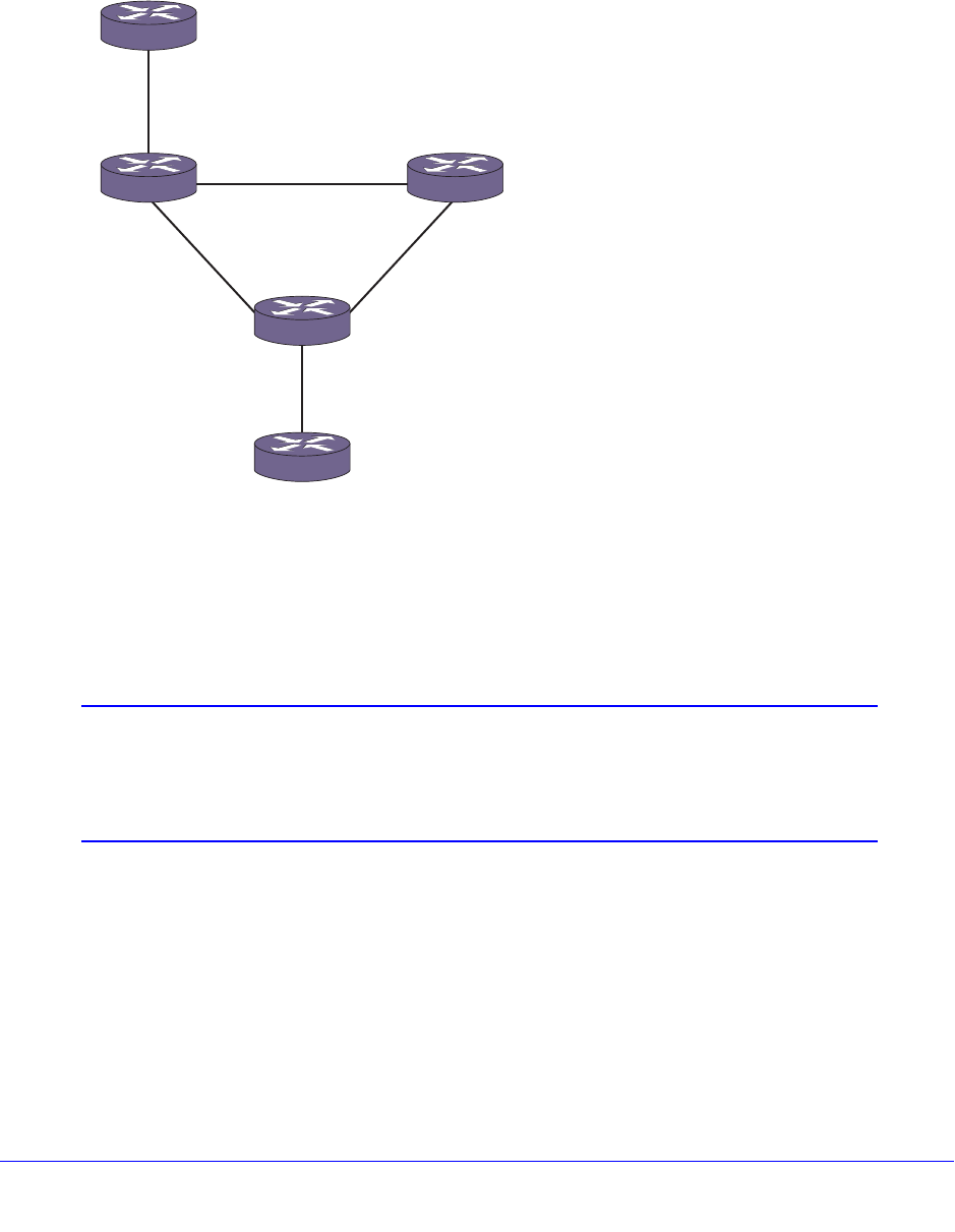
Chapter 29. MSDP | 775
NETGEAR 8800 User Manual
Configuring Anycast RP
Figure 95 shows the mesh-group M1, which is comprised of three MSDP peers: MSDP 1,
MSDP 2, and MSDP 3. MSDP 5 is connected to MSDP 1, and MSDP 4 is connected to
MSDP 3; however, they are not part of the mesh-group.
Figure 95. MSDP Anycast RP Configuration
In Figure 95, all five routers are configured with the same loopback VLAN IP address
(1.1.1.1/32), and this address is configured in each router as an RP in the PIM SM domain.
Three RP routers (MSDP1, MSDP2, and MSDP3) are configured in the MSDP mesh
topology. The unicast routing mechanism ensures that all the non-RP routers in the domain
route join requests to the closest RP router.
Note: The anycast RP address must be unique to the loopback VLAN and
be the same on all anycast RP peers. It must not match the router IP
address, the PIM BSR address, or any other IP address used by the
router or any other network device.
The following sections provide example configurations for the switches shown in Figure 95:
• MSDP 1 Configuration on page 776
• MSDP 2 Configuration on page 776
• MSDP 3 Configuration on page 777
• MSDP 4 Configuration on page 778
• MSDP 5 Configuration on page 778
EX_msdp_0002
10.0.3.1
10.0.3.3 10.0.2.3
10.0.1.1
MSDP1 MSDP2
10.0.1.2
MSDP5
MSDP4
10.0.2.2
10.0.0.2
10.0.0.1
10.0.4.1
10.0.4.2
MSDP3

776 | Chapter 29. MSDP
NETGEAR 8800 User Manual
MSDP 1 Configuration
# VLAN configuration
create vlan v_anycast
configure vlan "v_anycast" ipaddress 1.1.1.1/32
enable loopback-mode vlan "v_anycast"
enable ipforwarding vlan "v_anycast"
enable ipmcforwarding vlan "v_anycast"
# OSPF configuration to inject routes into routing protocols
configure ospf add vlan "v_anycast" area 0.0.0.0
# PIM-SM configuration
configure pim add vlan "v_anycast" sparse
configure pim crp static 1.1.1.1 rp_policy
# MSDP configuration
configure msdp originiator id 10.1.1.4
create msdp peer 10.1.1.5
create msdp peer 10.1.1.2
create msdp peer 10.1.1.3
configure msdp peer all source-interface 10.1.1.1
create msdp mesh-group m1
configure msdp peer 10.1.1.2 mesh-group m1
configure msdp peer 10.1.1.3 mesh-group m1
enable msdp peer all
enable msdp
MSDP 2 Configuration
# VLAN configuration
create vlan v_anycast
configure vlan "v_anycast" ipaddress 1.1.1.1/32
enable loopback-mode vlan "v_anycast"
enable ipforwarding vlan "v_anycast"
enable ipmcforwarding vlan "v_anycast"
# OSPF configuration to inject routes into routing protocols
configure ospf add vlan "v_anycast" area 0.0.0.0
# PIM-SM configuration

Chapter 29. MSDP | 777
NETGEAR 8800 User Manual
configure pim add vlan "v_anycast" sparse
configure pim crp static 1.1.1.1 rp_policy
# MSDP configuration
configure msdp originiator id 10.1.1.2
create msdp peer 10.1.1.1
create msdp peer 10.1.1.3
configure msdp peer all source-interface 10.1.1.2
create msdp mesh-group m1
configure msdp peer 10.1.1.1 mesh-group m1
configure msdp peer 10.1.1.3 mesh-group m1
enable msdp peer all
enable msdp
MSDP 3 Configuration
# VLAN configuration
create vlan v_anycast
configure vlan "v_anycast" ipaddress 1.1.1.1/32
enable loopback-mode vlan "v_anycast"
enable ipforwarding vlan "v_anycast"
enable ipmcforwarding vlan "v_anycast"
# OSPF configuration to inject routes into routing protocols
configure ospf add vlan "v_anycast" area 0.0.0.0
# PIM-SM configuration
configure pim add vlan "v_anycast" sparse
configure pim crp static 1.1.1.1 rp_policy
# MSDP configuration
configure msdp originiator id 10.1.1.3
create msdp peer 10.1.1.1
create msdp peer 10.1.1.2
create msdp peer 10.1.1.4
configure msdp peer all source-interface 10.1.1.3
create msdp mesh-group m1
configure msdp peer 10.1.1.1 mesh-group m1
configure msdp peer 10.1.1.2 mesh-group m1

778 | Chapter 29. MSDP
NETGEAR 8800 User Manual
enable msdp peer all
enable msdp
MSDP 4 Configuration
# VLAN configuration
create vlan v_anycast
configure vlan "v_anycast" ipaddress 1.1.1.1/32
enable loopback-mode vlan "v_anycast"
enable ipforwarding vlan "v_anycast"
enable ipmcforwarding vlan "v_anycast"
# OSPF configuration to inject routes into routing protocols
configure ospf add vlan "v_anycast" area 0.0.0.0
# PIM-SM configuration
configure pim add vlan "v_anycast" sparse
configure pim crp static 1.1.1.1 rp_policy
# MSDP configuration
configure msdp originiator id 10.1.1.4
create msdp peer 10.1.1.3
configure msdp peer all source-interface 10.1.1.4
enable msdp peer all
enable msdp
MSDP 5 Configuration
# VLAN configuration
create vlan v_anycast
configure vlan "v_anycast" ipaddress 1.1.1.1/32
enable loopback-mode vlan "v_anycast"
enable ipforwarding vlan "v_anycast"
enable ipmcforwarding vlan "v_anycast"
# OSPF configuration to inject routes into routing protocols
configure ospf add vlan "v_anycast" area 0.0.0.0
# PIM-SM configuration
configure pim add vlan "v_anycast" sparse
configure pim crp static 1.1.1.1 rp_policy

Chapter 29. MSDP | 779
NETGEAR 8800 User Manual
# MSDP configuration
configure msdp originiator id 10.1.1.5
create msdp peer 10.1.1.1
configure msdp peer all source-interface 10.1.1.5
enable msdp peer all
enable msdp

780
30
30. vMAN (PBN)
This chapter includes the following sections:
• Overview on page 780
• Configuration on page 784
• Displaying vMAN Information on page 788
• Configuration Examples on page 788
Overview
The virtual metropolitan area network (vMAN) features allow you to scale a Layer 2 network and
avoid some of the management and bandwidth overhead required by Layer 3 networks.
The following sections provide more information on these features:
• vMANs (PBNs) on page 780
• vMAN Configuration Options and Features on page 782
Note: If a failover from MSM A to MSM B occurs, vMAN operation is not
interrupted. The system has hitless failover—network traffic is not
interrupted during a failover.
vMANs (PBNs)
The vMAN feature, which is also called the PBN feature, is defined by the IEEE 802.1ad
standard, which is an amendment to the IEEE 802.1Q VLAN standard. Metropolitan area
network (MAN) service providers can use a vMAN to carry VLAN traffic from multiple
customers across a common Ethernet network. The vMAN uses Provider Bridges (PBs) to
create a Layer 2 network that supports vMAN traffic. The vMAN technology is sometimes
referred to as VLAN stacking or Q-in-Q.
Figure 96 shows a vMAN, which spans the switches in a MAN.
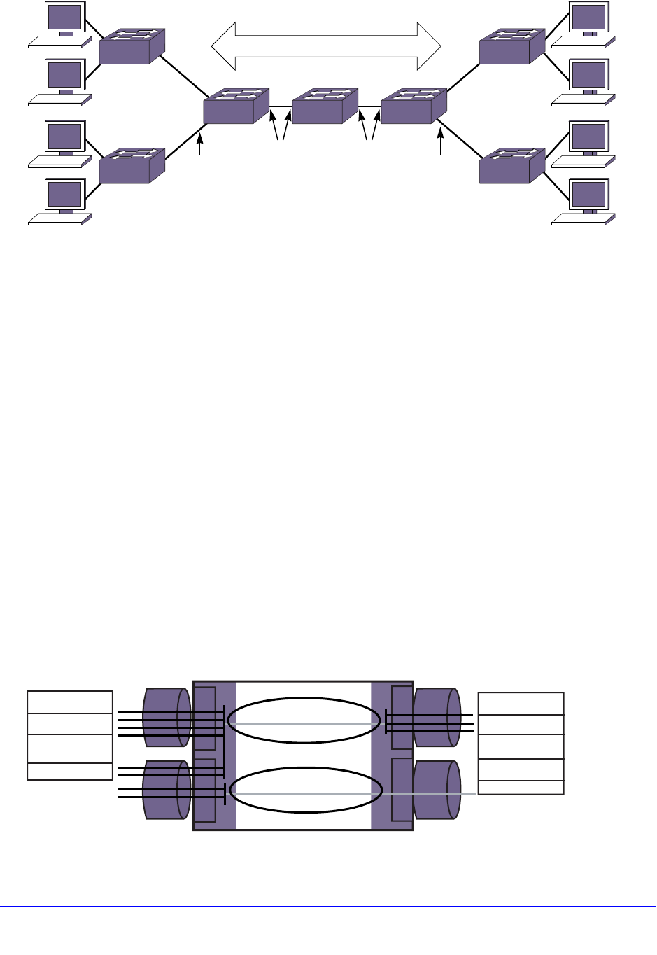
781
Chapter 30. vMAN (PBN) 8800 Chassis Switch
Figure 96. vMAN
The entry points to the vMAN are the access ports on the vMAN edge switches, which
function as PBs. Customer VLAN traffic that is addressed to locations at other vMAN access
ports enters the ingress access port, is switched through the vMAN, and exits the egress
access port. If you do not configure any frame manipulation options, the frames that exit the
vMAN are identical to the frames that entered the vMAN.
All vMAN ports except the access ports are vMAN network ports. The configuration of the
network ports establishes the vMAN.
Figure 96 shows two terms that are used during vMAN configuration: untagged vman port
and tagged vman port. When you configure a vMAN, you create and configure a vman in
software, and then you add ports to it. An untagged vman port represents a vMAN access
port, and despite its name, an untagged vman port supports tagged and untagged VLAN
frames. A tagged vman port represents a vMAN network port, and it only supports tagged
vMAN frames.
A vMAN supports two tags in each Ethernet frame, instead of the single tag supported by a
VLAN Ethernet frame. The inner tag is referred to as the customer tag (C-tag), and this
optional tag is based on the VLAN tag if the source VLAN is a tagged VLAN. The outer tag is
referred to as the service tag (S-tag) or vMAN tag, and it is the tag that is used to switch the
frame through the vMAN. Figure 97 shows the frame manipulation that occurs at the access
switch for a vMAN.
Figure 97. Tag Usage at the vMAN Access Switch
VLAN 1
VLAN 2
vMAN
vMAN
access
ports
(untagged
vman
ports)
vMAN
network
ports
(tagged
vman
ports)
VLAN 1
VLAN 2
vMAN
access
ports
(untagged
vman
ports)
vMAN
network
ports
(tagged
vman
ports)
EX_vman_0001A
VMAN 1
VMAN 2
1.1
1.2
2.1
2.2
MAC DA
MAC SA
S-tag
(32 b, expected)
VLAN tag or
C-tag (optional)
L2 PDU
MAC DA
MAC SA
VLAN tag or
C-tag (optional)
L2 PDU
Tagged port
Tagged port
Untagged port
Untagged port
EX_vman_0037
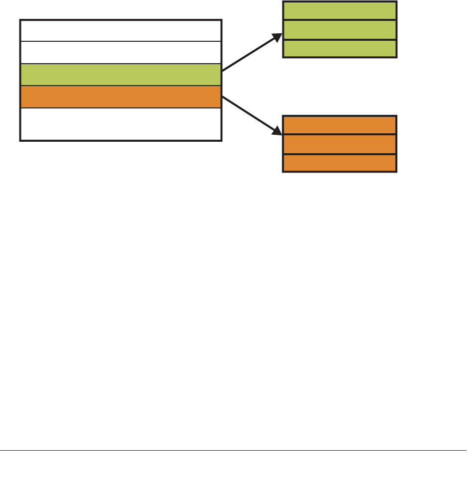
782
Chapter 30. vMAN (PBN) 8800 Chassis Switch
In Figure 97, the switch accepts all tagged (C-tag) and untagged VLAN frames on vMAN
access ports 1.1 and 1.2. The switch then adds the S-tag to the frames and switches the
frames to network ports 2.1 and 2.2. When the 802.1ad frames reach the PB egress port, the
egress switch removes the S-tag, and the VLAN traffic exits the egress access port in its
original form.
When the switch in Figure 97 acts as the egress switch for a vMAN, vMAN frames arrive on
network ports 2.1 and 2.2. The switch accepts only those frames with the correct S-tag,
removes the S-tags, and switches those frames to access ports 1.1 and 1.2. Unless special
configuration options are applied, the egress frames are identical to ingress frames of the
vMAN. (Configuration options are described in vMAN Configuration Options and Features on
page 782.)
Figure 98 shows that the S-tags and C-tags used in vMAN frames contain more than just
customer and service VLAN tags.
Figure 98. S-tag and C-tag Components
Each S-tag and C-tag contains an ethertype, a Class of Service (COS), and a VLAN ID. The
ethertype is described in Secondary Ethertype Support on page 783, and the COS is
described in QoS Support on page 784. The service VLAN ID (SVID) is the VLAN tag you
assign to a vMAN when you create it (configure vman <vman-name> tag <tag>). The
customer VLAN ID (CVID) represents the customer VLAN tag for tagged VLAN traffic.
The service provider configures the vMAN to support the customer traffic. The vMAN service
provider does not need to know anything about the VLAN traffic in the vMAN. The service
provider simply manages the vMAN, and the ingress VLAN traffic is managed by the
customer or another service provider. This separation of VLAN and vMAN management
reduces the dependence of the separate management teams on each other, and allows both
management teams to make changes independent of the other.
vMAN Configuration Options and Features
This section describes the following vMAN (PBN) configuration options and features:
MAC DA (48b)
MAC SA (48b)
vMAN tag or S-tag (32b, optional)
VLAN tag or C-tag (32b, optional)
L2 PDU: if IP packet, it may include
TOS / Diffserv-Codepoint field
S-ethertype (16b)
C-ethertype (16b)
S-COS (4b)
C-COS (4b)
SVID (12b)
CVID (12b)
EX_vman_0036

783
Chapter 30. vMAN (PBN) 8800 Chassis Switch
• ACL Support on page 783
• Secondary Ethertype Support on page 783
• QoS Support on page 784
• Egress Queue Selection on page 784
ACL Support
The NETGEAR 8800 software includes vMAN (PBN) Access Control List (ACL) support for
controlling vMAN frames. vMAN ACLs define a set of match conditions and modifiers that
can be applied to vMAN frames. These conditions allow specific traffic flows to be identified,
and the modifiers allow a translation to be performed on the frames. For example, you can
use vMAN ACLs to modify ingress frame components such as S-COS, S-ethertype, and
SVID before forwarding through an egress port.
Secondary Ethertype Support
Note: This feature is supported only on the platforms listed for this feature
in the license tables in Appendix A, XCM8800 Software Licenses.
The C-tag and S-tag components that are added to all vMAN (PBN) frames (see Figure 98)
include C-ethertype and S-ethertype components that specify an ethertype value for the
customer VLAN and vMAN, respectively. When a VLAN or vMAN frame passes between two
switches, the ethertype is checked for a match. If the ethertype does not match that of the
receiving switch, the frame is discarded.
The default ethertype values are:
• VLAN port (802.1q frames): 0x8100
• Primary vMAN port (802.1ad frames): 0x88A8
• Secondary vMAN port (802.1ad frames): Not configured
The secondary ethertype support feature applies only to vMANs. The ethertype value for
VLAN frames is standard and cannot be changed.
Note: Ensure that the ethertype values are different for vMANs (802.1ad)
on your switch.
If your vMAN transits a third-party device (in other words, a device other than a NETGEAR
8800 device), you must configure the ethertype value on the NETGEAR 8800 device port to
match the ethertype value on the third-party device to which it connects.
The secondary ethertype support feature allows you to define two ethertype values for vMAN
frames and select either of the two values for each port. For example, you can configure

784
Chapter 30. vMAN (PBN) 8800 Chassis Switch
ports that connect to other NETGEAR 8800 devices to use the default primary ethertype
value, and you can configure ports that connect to other equipment to use the secondary
ethertype value, which you can configure to match the requirements of that equipment.
When you create a vMAN, each vMAN port is automatically assigned the primary ethertype
value. After you define a secondary ethertype value, you can configure a port to use the
secondary ethertype value. If two switch ports in the same vMAN use different ethertype
values, the switch substitutes the correct value at each port. For example, for vMAN edge
switches and transit switches, the switch translates an ingress ethertype value to the network
port ethertype value before forwarding. For egress traffic at vMAN edge switches, no
translation is required because the switch removes the S-tag before switching packets to the
egress port.
You can set the primary and secondary ethertypes to any value, provided that the two values
are different.
QoS Support
The vMAN (PBN) feature interoperates with many of the QoS features supported in the
NETGEAR 8800 software. One of those features is egress queue selection, which is
described in the next section. For more information on other QoS features that work with
vMANs, see Chapter 15, QoS.
Egress Queue Selection
This feature examines the 802.1p value or Diffserv code point in a vMAN (PBN) S-tag and
uses that value to direct the packet to the appropriate queue on the egress port. You can
configure this feature to examine the values in the C-tag or the S-tag. For instructions on
configuring this feature, see Selecting the Tag Used for Egress Queue Selection on
page 787.
Configuration
The following sections describe how to configure vMANs and PBBNs:
• Configuring vMANs (PBNs) on page 784
• Configuring vMAN Options on page 786
Configuring vMANs (PBNs)
The following sections provide information on configuring vMANs:
• Guidelines for Configuring vMANs on page 784
• Procedure for Configuring vMANs on page 785
Guidelines for Configuring vMANs
The following are some guidelines for configuring vMANs:
785
Chapter 30. vMAN (PBN) 8800 Chassis Switch
• Each vMAN access port (ingress or egress) can belong to only one vMAN. vMAN network
ports (switch to switch) can support multiple vMANs.
• Duplicate customer MAC addresses that ingress from multiple vMAN access ports on the
same vMAN can disrupt the port learning association process in the switch.
• vMAN names must conform to the guidelines described in Object Names on page 31.
• You must use mutually exclusive names for:
• VLANs
• vMANs
• IPv6 tunnels
• vMAN ports can belong to load-sharing groups.
• The vMAN begins at the ingress customer access port and terminates at the egress
customer access port. Traffic flows from the egress port onto the customer network
without the S-tag. Ensure that all the switch-to-switch ports in the vMAN are configured
as tagged ports. Configure the vMAN ingress and egress ports as a untagged ports
(although the ingress port does accept tagged packets).
Note: You must configure the vMAN egress port as untagged so that the
S-tag is stripped from the frame.
• The following guidelines apply to the NETGEAR 8800 switches:
• You can enable or disable jumbo frames before configuring vMANs. You can enable
or disable jumbo frames on individual ports. See Chapter 5, Configuring Slots and
Ports on a Switch for more information on configuring jumbo frames.
• Platforms support different combinations of tagged and untagged vMANs and VLANs
as shown in Table 73.
Procedure for Configuring vMANs
This section describes the procedure for configuring vMANs. Before configuring vMANs,
review Guidelines for Configuring vMANs on page 784.
To configure a vMAN, complete the following procedure at each switch that needs to support
the vMAN:
Table 73. Port Support for Combined vMANs and VLANs
Platform Combined Untagged
vMAN, Tagged VLAN Combined Tagged
vMAN, Untagged
VLAN
Combined Tagged
vMAN, Tagged VLAN Combined Tagged
vMAN, Untagged
vMAN
NETGEAR 8800 X X Xa
a. The vMAN ethertype must be set to 0x8100, which is different from the default value (0x88a8).
Xb
b. A tagged vMAN cannot be added to a port to which an untagged vMAN has previously been added when the selected
ethertype is 0x8100.

786
Chapter 30. vMAN (PBN) 8800 Chassis Switch
1. If you are configuring a NETGEAR 8800, enable jumbo frames on the switch.
Note: Because the NETGEAR 8800 switch enables jumbo frames
switch-wide, you must enable jumbo frames before configuring vMANs on
NETGEAR systems.
2. Create a vMAN by entering the following command:
create vman <vman-name> {vr <vr_name>}
3. Assign a tag value to the vMAN by entering the following command:
configure vman <vman-name> tag <tag>
4. Add ports to the vMAN by entering the following command:
configure vman <vman-name> add ports [ all | <port_list> ] {untagged | tagged
| svid <svid>}
Specify tagged for network (switch-to-switch) vMAN ports, and specify untagged for
access (ingress and egress) vMAN ports.
Note: You must configure the vMAN egress port as untagged so that the
S-tag is stripped from the frame.
5. Configure additional vMAN options as described in Configuring vMAN Options on page 786..
6. To configure a VLAN to use a vMAN, configure the VLAN on the switch port at the other end
of the line leading to the vMAN access port.
Configuring vMAN Options
• Configuring the Ethertype for vMAN Ports on page 786
• Configuring IGMP Snooping on a vMAN on page 787
• Selecting the Tag Used for Egress Queue Selection on page 787
Note: You can use ACLs to configure some vMAN options. For more
information, see ACL Support on page 783.
Configuring the Ethertype for vMAN Ports
The ethertype is a component of VLAN and vMAN frames and is introduced in Secondary
Ethertype Support on page 783.
To configure the ethertype for vMAN (PBN) ports, do the following:
1. Configure the primary and secondary (if needed) vMAN ethertype values for the switch
using the following command:

787
Chapter 30. vMAN (PBN) 8800 Chassis Switch
configure vman ethertype <value> [primary | secondary]
By default, all vMAN ports use the primary ethertype value.
2. If you plan to use a secondary ethertype, select the secondary ethertype for the appropriate
vMAN ports using the following command:
configure port <port_list> ethertype {primary | secondary}
Configuring IGMP Snooping on a vMAN
Internet Group Management Protocol (IGMP) snooping is introduced in IGMP Snooping on
page 733, and is enabled by default on all VLANs and vMANs. IGMP snooping allows a
switch to forward Layer 2 multicast traffic within a vMAN to only those destinations that
require it.
To use IGMP snooping on a vMAN, you must enable IP multicasting on the vMAN. If your
topology requires a separate VLAN for multicast traffic, some platforms support multicast
traffic on VLAN and vMANs on the same port. The NETGEAR 8800 series switches support
multicast traffic on VLANs and vMANs that share the same port.
To configure multicast support for both a vMAN and a VLAN on the same port of a NETGEAR
8800 series switch, use the following procedure:
1. Enable jumbo frames on the switch.
2. Change the vMAN ethertype to 0x8100 as described in Configuring the Ethertype for vMAN
Ports on page 786.
3. Assign different IP addresses to the VLAN and the vMAN.
4. Enable IP forwarding on both the VLAN and the vMAN.
5. Enable IP multicasting forwarding on both the VLAN and the vMAN.
6. Configure IGMP on both the VLAN and the vMAN.
Note: See Chapter 27, Multicast Routing and Switching for information on
configuring and using multicasting.
After you enable multicast forwarding on the vMAN, you can configure and use IGMP
snooping.
Selecting the Tag Used for Egress Queue Selection
By default, switches that support the enabling and disabling of this feature use the 802.1p
value in the S-tag to direct the packet to the queue on the egress port.
To configure egress queue dot1p examination of the C-tag, use the following command:
enable dot1p examination port [all | <port_list>]
To return to the default selection of using the 802.1p value in the S-tag, use the following
command:

788
Chapter 30. vMAN (PBN) 8800 Chassis Switch
disable dot1p examination ports [all | <port_list>]
Note: See Chapter 15, QoS for information on configuring and displaying
the current 802.1p and DiffServ configuration for the S-tag 802.1p
value.
Displaying vMAN Information
You can display the vMAN (PBN) configuration and any associated EAPS domains by issuing
the following command:
show vman {<vman_name> {ipv6} | etherType | detail {ipv6}}
You can also display vMAN information, as well as all the VLANs, by issuing the show ports
information detail command.
To display information on all vMANs, use the following command:
show vman
To display information on a specific vMAN, use the following command:
show vman <vman_name>
To display the ethertype for a vMAN, use the following command:
show vman ethertype
Configuration Examples
This section provides the following examples:
• vMAN Example, NETGEAR 8810 on page 788
• Multiple vMAN Ethertype Example on page 790
vMAN Example, NETGEAR 8810
The following example shows the steps to configure a vMAN (PBN) on the NETGEAR 8810
switch shown in Figure 99.
789
Chapter 30. vMAN (PBN) 8800 Chassis Switch
Figure 99. Sample vMAN Configuration on NETGEAR 8810 Switch
The vMAN is configured from the building to port 1, slot 3 on the NETGEAR 8810 switch and
from port 2, slot 3 on the NETGEAR switch to the NETGEAR 8806 switch:
enable jumbo frames
create vman vman_tunnel_1
configure vman vman_tunnel_1 tag 100
configure vman vman_tunnel_1 add port 3:1 untagged
configure vman vman_tunnel_1 add port 3:2 tagged
enable dot1p examination port 3:2
The following example configuration demonstrates configuring IP multicast routing between
vMANs and VLANs (when vMAN traffic is not double-tagged) on the NETGEAR 8800
switches. Using this configuration you can use a common uplink to carry both VLAN and
vMAN traffic and to provide multicast services from a vMAN through a separate VLAN (notice
that port 1:1 is in both a VLAN and a vMAN):
enable jumbo-frame ports all
configure vman ethertype 0x8100
create vlan mc_vlan
configure vlan mc_vlan tag 77
create vman vman1
configure vman vman1 tag 88
configure vlan vman1 ipaddress 10.0.0.1/24
configure vlan mc_vlan ipaddress 11.0.0.1/24
enable ipforwarding vman1
enable ipforwarding mc_vlan
enable ipmcforwarding vman1
enable ipmcforwarding mc_vlan
configure vlan mc_vlan add port 1:1 tag
configure vman vman1 add port 1:1 tag
configure vman vman1 add port 2:1, 2:2, 2:3
XOS001
Engineering &
Science Building
BlackDiamond 8810 BlackDiamond 6808
NETGEAR 8806NETGEAR 8810
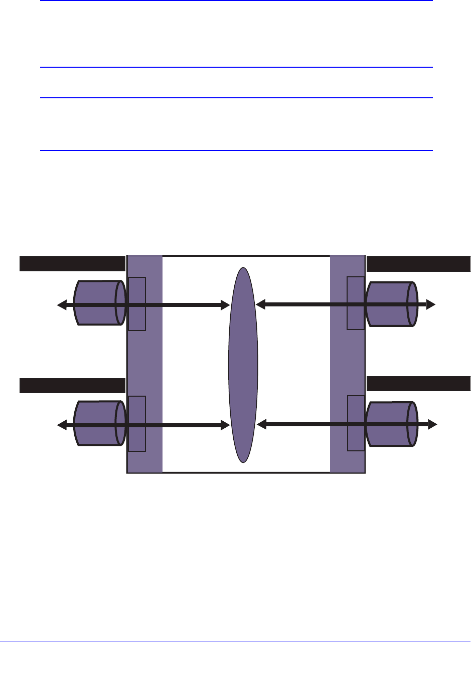
790
Chapter 30. vMAN (PBN) 8800 Chassis Switch
Note: IGMP reports can be received untagged on ports 2:1, 2:2, and 2:3.
Tagged IP multicast data is received on mc_vlan port 1:1 and is
routed using IP multicasting to vman1 ports that subscribe to the
IGMP group.
Note: IGMP snooping (Layer 2 IP multicasting forwarding) does not work
on the vMAN ports because there is no double-tagged IP multicast
cache lookup capability from port 1:1.
Multiple vMAN Ethertype Example
Figure 100 shows a switch that is configured to support the primary ethertype on three ports
and the secondary ethertype on a fourth port. The primary vMAN (PBN) ethertype is changed
from the default value, but that is not required.
Figure 100. Multiple vMAN Ethertype Example
The following configuration commands accomplish what is shown in Figure 100:
# configure vman ethertype 0x9100 primary
# configure vman ethertype 0x8100 secondary
#
# configure port 2:2 ethertype secondary
#
# create vman vman300
1.1
1.2
2.1
2.2
vMAN300
Untag
Tag Ta g
Tag
Ethertype 0x9100
Ethertype 0x9100
EX_vman_003
Ethertype 0x9100
Ethertype 0x8100

791
Chapter 30. vMAN (PBN) 8800 Chassis Switch
# configure vman vman300 tag 300
#
# configure vman vman300 add port 1:1, 2:1, 2:2 tagged
# configure vman vman300 add port 1:2 untagged

Part 3: Appendixes

Appendix A. XCM8800 Software Licenses | 793
A
A. XCM8800 Software Licenses
This appendix includes the following sections:
• Overview on page 793
• Switch License Features on page 794
• Displaying Software Licenses and Feature Packs on page 798
• Obtaining a License Voucher on page 799
• Enabling and Verifying Licenses on page 799
• Obtaining Feature Packs on page 799
Overview
The XCM8800 software supports the following license options:
• NETGEAR Aggregation Code
• NETGEAR Advanced Core Code
• Feature packs
The NETGEAR Aggregation Code provides a basic feature set and the NETGEAR Advanced
Core Code provides the highest level of functionality. The NETGEAR Aggregation Code is the
default license for the NETGEAR 8800.
Software keys are stored in the EEPROM of the chassis and, once enabled, persist through
reboots, software upgrades, power outages, and reconfigurations. Because the license is stored
in the EEPROM of the chassis (and not on the MSM/MM card), the license persists even if you
change MSM/MM cards. The keys are unique to the chassis or switch and are not transferable.
If you attempt to execute a command and you either do not have the required license or have
reached the limits defined by the current license level, the system returns one of the following
messages:
Error: This command cannot be executed at the current license level.
Error: You have reached the maximum limit for this feature at this license
level.
794 | Appendix A. XCM8800 Software Licenses
NETGEAR 8800 User Manual
Switch License Features
The following sections list the features for the switch license levels and feature packs:
• Aggregation License Features on page 794
• Advanced Core License Features on page 798
Aggregation License Features
The Aggregation license provides all Layer-2 and Layer-3 switch applicable capabilities of the
XCM8800 software that are not licensed by the higher license levels (the Advanced Core
licenses) and the Feature Packs. Table 74 lists most of the Aggregation license features.
Table 74. XCM8800 Aggregation License Features
XCM8800 Software Feature
LLDP 802.1ab
LLDP-MED extensions
VLANs—Port based and tagged trunks
VLANs—MAC based
VLANs—Protocol based
VLANs—Private VLANs
L2 Ping / Traceroute 802.1ag
Jumbo frames (including all related items, MTU disc. IP frag.)
QoS—egress port rate shaping/limiting
QoS—egress queue rate shaping/limiting
Port trunking static 802.3ad
Port trunking dynamic (802.3ad LACP) edge, to servers only!
Port trunking dynamic (802.3ad LACP) core, between
switches
Port loopback detection and shutdown (ELRP CLI)
Software redundant port
STP 802.1D
STP EMISTP + PVST+ Compatibility mode (1 domain per
port)
STP EMISTP, PVST+ Full (multi-domain support)

Appendix A. XCM8800 Software Licenses | 795
NETGEAR 8800 User Manual
STP 802.1s
STP 802.1w
Link Fault Signaling (LFS)
ACLs
• IPv4
• Static
ACLs
• IPv6
• Dynamic
MSM/MM hitless failover for STP
MSM/MM hitless failover - Additional capabilities: NetLogin,
PoE. Graceful Restart for OSPF, BGP
CPU DoS protect
CPU Monitoring
SNMPv3
SSH2 server
SSH2 client
SCP/SFTP client
SCP/SFTP server
RADIUS and TACACS+ per command authentication
Network login
• Web based method
• 802.1x method
• MAC based method
• Local database for MAC/Web based methods
• Integration with Microsoft NAP
• Multiple supplicants - same VLAN
• HTTPS/SSL for web-based method
Network login—Multiple supplicants - multiple VLANs
Trusted OUI
MAC security
• Lockdown
• Limit
IP security—DHCP Option 82—L2 mode
Table 74. XCM8800 Aggregation License Features (Continued)
XCM8800 Software Feature

796 | Appendix A. XCM8800 Software Licenses
NETGEAR 8800 User Manual
IP security—DHCP Option 82—L2 mode VLAN ID
IP security—DHCP IP lockdown
IP security—Trusted DHCP server ports
Static IGMP membership, IGMP filters
IPv4 unicast L2 switching
IPv4 multicast L2 switching
IPv4 directed broadcast
IPv4
• Fast-direct broadcast
• Ignore broadcast
IPv6 unicast L2 switching
IPv6 multicast
• MLDv1
• L2 flooding with MLDv1
• L2 switching
IPv6 netTools—Ping, traceroute, BOOTP relay, DHCP, DNS,
and SNTP.
IGMP v1/v2 snooping
IGMP v3 snooping
Multicast VLAN Registration (MVR)
sFlow accounting
CLI scripting
Web-based device management
Web based management—HTTPS/SSL support
XML APIs (for partner integration)
MIBs - Entity, for inventory
Connectivity Fault Management (CFM)
Remote mirroring
Egress mirroring
Y.1731 compliant frame delay and delay variance
measurement
Table 74. XCM8800 Aggregation License Features (Continued)
XCM8800 Software Feature
Appendix A. XCM8800 Software Licenses | 797
NETGEAR 8800 User Manual
System virtual routers
User-created virtual routers
VLAN aggregation
Multinetting for forwarding
UDP Forwarding
UDP BootP relay forwarding
IPv4 unicast routing, including static routes
IPv4 multicast routing, including static routes
IPv6 unicast routing, including static routes
IPv6 multicast routing
IPv6 interworking—IPv6-to-IPv4 and IPv6-in-IPv4 configured
tunnels
IPv6 ECMP
IP security:
• DHCP Option 82—L3 mode
• DHCP Option 82—L3 mode VLAN ID
• Disable ARP learning
• Gratuitous ARP protection
• DHCP secured ARP / ARP validation
IP address security:
• DHCP snooping
• Trusted DHCP server
• Source IP lockdown
• ARP validation
Policy based routing (PBR)
PIM snooping
Protocol-based VLANs
RIPv1/v2
RIPng
IPv6 RIPng
Routing access policies
Route maps
Universal Port—VoIP auto configuration
Table 74. XCM8800 Aggregation License Features (Continued)
XCM8800 Software Feature

798 | Appendix A. XCM8800 Software Licenses
NETGEAR 8800 User Manual
Advanced Core License Features
The Advanced Core License includes all Aggregation License features, and the features in
Table 75.
Displaying Software Licenses and Feature Packs
You can display information on the type of license and feature pack on your NETGEAR
device by using the show licenses command.
Note: For default settings of individual XCM8800 features, see the
individual chapters in this guide.
Universal Port—Dynamic user-based security policies
Universal Port—Time-of-day policies
VRRP
OSPFv2-Edge (limited to max of 4 active interfaces)
OSPFv3-Edge (limited to max of 4 active interfaces)
PIM-SM-Edge (limited to max of 2 active interfaces)
Table 75. XCM8800 Advanced Core License Features
XCM8800 Software Feature
PIM DM “Full”
PIM SM “Full”
PIM SSM “Full”
OSPFv2 “Full” (not limited to 4 active interfaces)
OSPFv3 “Full” (not limited to 4 active interfaces)
BGP4
MBGP
MSDP
Anycast RP
Table 74. XCM8800 Aggregation License Features (Continued)
XCM8800 Software Feature

Appendix A. XCM8800 Software Licenses | 799
NETGEAR 8800 User Manual
Obtaining a License Voucher
You can order the desired functionality from the factory, using the appropriate model of the
desired product. If you order licensing from the factory, the license arrives in a separate
package from the switch. After the license key is installed, it should not be necessary to enter
the information again. However, NETGEAR recommends keeping the certificate for your
records.
You can upgrade the license of an existing product by purchasing a license voucher from
NETGEAR. Contact your supplier to purchase a voucher.
The voucher contains information and instructions on obtaining a license key for the switch
using the NETGEAR Support website at:
http://support.netgear.com
or by phoning NETGEAR Technical Support at:
• 1-888-NETGEAR (US and Canada only)
• For other countries, see the support information card
After you have obtained a license, you cannot downgrade licenses. The license key contains
all the necessary information on the license level.
Enabling and Verifying Licenses
To enable the license, use the following command:
enable license {software} <key>
You can enable the software license key one switch at a time by using the command listed
above, or you can download a license file onto the switch and then enable the licenses
through file upload. (The license file has the extension <.xlic>.) You download the file using
TFTP into the switch. The file can contain licenses for some or all of the NETGEAR switches
that you own. During file processing, only those license keys destined for the specific switch
are used to attempt enabling the licenses. The license file is a text file that has the switch
serial number, software license type, and license key; it is removed from the switch after the
licenses are enabled. To enable licenses using the license file, use the following command:
enable license file <filename>
To verify the licensing on the switch, use the following command:
show licenses
Obtaining Feature Packs
Contact your supplier to purchase a voucher for feature packs. The voucher contains
information and instructions on obtaining a feature pack for the switch using the NETGEAR
Support website at:

800 | Appendix A. XCM8800 Software Licenses
NETGEAR 8800 User Manual
http://support.netgear.com
or by phoning NETGEAR Technical Support at:
• 1-888-NETGEAR (US and Canada only)
• For other countries, see the support information card

Appendix B. Software Upgrade and Boot Options | 801
B
B. Software Upgrade and Boot Options
This appendix includes the following sections:
• Downloading a New Image on page 801
• Understanding Hitless Upgrade on page 810
• Configuration Changes on page 817
• Using TFTP to Upload the Configuration on page 822
• Using TFTP to Download the Configuration on page 824
• Synchronizing Nodes on Modular Switches on page 825
• Accessing the Bootloader on page 826
• Upgrading the Firmware on page 827
• Displaying the BootROM and Firmware Versions on page 828
Downloading a New Image
The core image file contains the executable code that runs on the switch and is preinstalled at
the factory. As new versions of this image are released, you should upgrade the software
running on your system. Modular software packages enhance the functionality of the XCM8800
core image currently running on your switch. Modular software packages are not preinstalled at
the factory.
On NETGEAR 8800 series switches with two MSMs installed, you can upgrade the images
without taking the switch out of service. Known as a hitless upgrade, this method of downloading
and installing a new image minimizes network interruption, reduces the amount of traffic lost,
and maintains switch operation. For more information, see Understanding Hitless Upgrade on
page 810.
802 | Appendix B. Software Upgrade and Boot Options
NETGEAR 8800 User Manual
Note: An XCM8800 core image (.xos file) must be downloaded and
installed on the alternate (non-active) partition. If a user tries to
download to an active partition, the error message “Error: Image
can only be installed to the non-active partition.”
is displayed. An XCM8800 modular software package (.xmod file)
can still be downloaded and installed on either the active or alternate
partition.
This section describes the following topics:
• Image Filename Prefixes on page 802
• Understanding the Image Version String on page 803
• Software Signatures on page 803
• Selecting a Primary or a Secondary Image on page 803
• Installing a Core Image on page 804
• Installing a Modular Software Package on page 806
• Rebooting the Switch on page 809
• Rebooting the Management Module on page 810
Image Filename Prefixes
The software image file can be an .xos file, which contains an XCM8800 core image, or an
.xmod file, which contains an XCM8800 modular software package.
You can identify the appropriate image or module for your platform based on the filename of
the image. Table 76 lists the filename prefixes for each platform.
For example, if you have a NETGEAR 8806 switch, download image filenames with the prefix
NG8800-. For additional installation requirements see the sections, Installing a Core Image
on page 804 and Installing a Modular Software Package on page 806.
Table 76. Filename Prefixes
Platform Filename Prefixes
NETGEAR 8810 NG8800-
NETGEAR 8806 NG8800-
Appendix B. Software Upgrade and Boot Options | 803
NETGEAR 8800 User Manual
Understanding the Image Version String
The image version string contains build information for each version of XCM8800. You can
use either the show version or show switch command to display the XCM8800 version
running on your switch.
Depending on the command line interface (CLI) command, the output is structured as
follows:
• show version
XCM8800 Version <major>.<minor>.<patch>.<build>
For example: XCM8800 version 10.1.2.16
• show switch
<major>.<minor>.<patch>.<build>
For example: 10.1.2.16
Table 77 describes the image version fields.
The show version command also displays information about the firmware (BootROM) images
running on the switch. For more information, see Displaying the BootROM and Firmware
Versions on page 828.
Software Signatures
Each XCM8800 image contains a unique signature. The BootROM checks for signature
compatibility and denies an incompatible software upgrade. In addition, the software checks
both the installed BootROM and software and also denies an incompatible upgrade.
Selecting a Primary or a Secondary Image
A switch can store up to two core images: a primary and a secondary. When downloading a
new image, you select which partition (primary or secondary) to install the new image. You
must install the software image to the alternate partition, and must specify that partition
before downloading the image.
Table 77. Image Version Fields
Field Description
major Specifies the XCM8800 major version number.
minor Specifies the XCM8800 minor version number.
patch Identifies a specific patch release.
build Specifies the XCM8800 build number. This value is reset to 0 for each new major and
minor release.

804 | Appendix B. Software Upgrade and Boot Options
NETGEAR 8800 User Manual
To view your current (active) partition, use the following command:
show switch
Output from this command includes the selected and booted images and if they are in the
primary or secondary partition. The active partition is identified as the “booted image.” The
command shows only two nodes (both MSMs/MMs in a modular chassis).
Use the command
show slot detail
to see the active partition (Image Booted), selected partition for reboot (Image Selected), and
XCM8800 versions installed in the primary and secondary partitions. This command shows
the preceding information for all active nodes.
If two MSMs/MMs are installed in a modular switch, the downloaded image is saved to the
same location on each one.
To select which image the switch loads on the next reboot, use one of the following
commands:
use image {partition} <partition> {msm <slotid>}
Installing a Core Image
Depending on your platform, you can upgrade the core image by using a download
procedure from a Trivial File Transfer Protocol (TFTP) server on the network or an external
compact flash memory card installed in the external compact flash slot of the MSM/MM.
The information in this section describes how to install a new software image.
For information about saving an existing or new switch configuration, see Saving the
Configuration on page 822.
For information about installing a new firmware image on a NETGEAR 8800 series switch,
see Upgrading the Firmware on page 827.
Note: When using a TFTP server to download an XCM8800 image to any
NETGEAR 8800 series switch, the TFTP server must be able to
handle files that are larger than 32MB or the download may fail.
Note: See the most recent version of the XCM8800 Installation and
Release Notes for the most current instructions.
To download a new image:
1. Load the new image onto a TFTP server on your network (if you are using TFTP).

Appendix B. Software Upgrade and Boot Options | 805
NETGEAR 8800 User Manual
2. Load the new image onto an external compact flash memory card (if you are using the
external compact flash slot). This method is available only on modular switches.
Use a PC with appropriate hardware such as a compact flash reader/writer and follow the
manufacturer’s instructions to access the compact flash card and place the image onto
the card.
For more information about installing the external compact flash memory card into the
external compact flash slot of the MSM/MM, see the hardware documentation listed in
Chapter 1, Overview.
3. From a login session on the master, verify which virtual router connects to your TFTP server.
If you loaded the image onto an external compact flash (modular switches only), proceed
to step 4.
If you loaded the image onto a TFTP server, use one of the following ping commands to
confirm which virtual router reaches your TFTP server:
ping vr vr-Mgmt <host>
ping vr vr-Default <host>
At least one of these commands must successfully reach your TFTP server for you to
download the image. After verifying the virtual router that reaches your TFTP server,
specify that virtual router when you download the image.
4. Determine your booted and selected partition using the following command:
show switch
Output from this command indicates the selected and booted images and if they are in
the primary or the secondary partition. The selected image partition indicates which
image will be used at the next reboot. The booted image partition indicates the image
used at the last reboot. It is the active partition.
5. Select the partition to use when downloading an image. For more information, see Selecting
a Primary or a Secondary Image on page 803.
6. Download the new image to the switch using one of the following commands:
download image [[<hostname> | <ipaddress>] <filename> {{vr} <vrname>} |
memorycard <filename>] {<partition>} {msm <slotid>}
• Before the download begins, the switch asks if you want to install the image
immediately after the download is finished.
Enter y to install the image after download. Enter n to install the image at a later time.
When you install the image after download to the alternate partition, you then need to
reboot the switch.
• If you install the image at a later time, the image is still downloaded and saved to the
switch, but you must use the following command to install the software and reboot the
switch:
install image <fname> {<partition>} {msm <slotid>} {reboot}

806 | Appendix B. Software Upgrade and Boot Options
NETGEAR 8800 User Manual
Note: The download image command in the XCM8800 causes the switch to
use the newly downloaded software image during the next switch reboot. To
modify or reset the software image used during a switch reboot, use the use
image command.
Note: A secure method of upgrading the image uses SFTP or SCP2. See
the download image command.
Understanding Core Dump Messages
If you configure the switch to write core dump (debug) files to the internal memory card and
attempt to download a new software image, you might have insufficient space to complete
the image download. If this occurs, move or delete the core dump files from the internal
memory. For example, if you have a modular switch with an external memory card installed
with space available, transfer the files to the external memory card.
The switch displays a message similar to the following and prompts you to take action:
Core dumps are present in internal-memory and must be removed before this
download can continue. (Please refer to documentation for the “configure debug
core-dumps” command for additional information)
Do you want to continue with download and remove existing core dumps? (y/n)
Enter y to remove the core dump files and download the new software image. Enter n to
cancel this action and transfer the files before downloading the image.
Installing a Modular Software Package
In addition to the functionality available in the XCM8800 core image, you can add
functionality to your switch by installing modular software packages. Modular software
packages are contained in files named with the file extension.xmod, while the core images
use the file extension.xos. Modular software packages are built at the same time as core
images and are designed to work in concert with the core image, so the version number of a
modular software package must match the version number of the core image that it will be
running with. For example, the modular software package for Secure Shell (SSH) named as
follows:
ng8800-11.2.0.18-ssh.xmod
Can run only with the core image named:
ng8800-11.2.0.18.xos
You can install a modular software package on the active partition or on the inactive partition.
You would install on the active partition if you want to add the package functionality to the
currently running core image without having to reboot the switch. You would install on the
inactive partition if you want the functionality available after a switch reboot.

Appendix B. Software Upgrade and Boot Options | 807
NETGEAR 8800 User Manual
To install the package, you use the same process that you use to install a new core image.
Follow the process described in the earlier section Installing a Core Image on page 804. On
NETGEAR 8800 series switches, you can use hitless upgrade to install the package. See
Understanding Hitless Upgrade on page 810 for more information.
You activate the installed modular software package either by rebooting the switch or by
issuing the following command:
run update
You can uninstall packages by issuing the following command:
uninstall image <fname> <partition> {msm <slotid>} {reboot}
Note: Do not terminate a process that was installed since the last reboot
unless you have saved your configuration. If you have installed a
software module and you terminate the newly installed process
without saving your configuration, your module may not be loaded
when you attempt to restart the process with the start process
command.
This section describes the following topics:
• Guidelines for Activating SSL on page 807
• Upgrading a Modular Software Package on page 808
Guidelines for Activating SSL
Whether you are currently running SSH or downloading the SSH software module for the first
time, you must complete the following steps to activate the Secure Socket Layer (SSL)
functionality that is packaged with the SSH module. Before you can configure SSL on the
switch, do the following:
• Download and install the SSH software module on the active partition
• Activate the SSH software module
• Gracefully terminate and re-start the thttpd process running on the switch
The following is an example of activating SSL on the switch:
download image 10.10.10.2 NG8800-11.2.0.18-ssh.xmod
run update
restart process thttpd
For more information about SSH and SSL, see Chapter 17, Security.

808 | Appendix B. Software Upgrade and Boot Options
NETGEAR 8800 User Manual
Upgrading a Modular Software Package
When NETGEAR introduces a new core software image, a new modular software package is
also available. If you have a software module installed and upgrade to a new core image, you
need to upgrade to the corresponding modular software package.
Two methods are available to upgrade an existing modular software package on your switch.
Regardless of which method you choose, you must terminate and restart the processes
associated with the software module.
Method One
1. Terminate the processes associated with the software module using one of the following
commands:
terminate process <name> [forceful | graceful] {msm <slot>}
2. Download the software module from your TFTP server or external compact flash memory
card using the following command:
download image [[<hostname> | <ipaddress>] <filename> {{vr} <vrname>} |
memorycard <filename>] {<partition>} {msm <slotid>} {slot <slotid>}
3. Activate the installed modular package, if installed on the active partition, using the following
command:
run update
4. Restart the processes associated with the software module using one of the following
commands:
start process <name> {msm <slot>}
Method Two
1. Download the software module from your TFTP server or external compact flash
memory card using the following command:
download image [[<hostname> | <ipaddress>] <filename> {{vr} <vrname>} |
memorycard <filename>] {<partition>} {msm <slotid>} {slot <slotid>}
2. Activate the installed modular package, if installed on the active partition, using the following
command:
run update
3. Terminate and restart the processes associated with the software module using one of the
following commands:
restart process [class <cname> | <name> {msm <slot>}]
Examples
The following examples upgrade the SSH module on the active partition and assume that you
have:

Appendix B. Software Upgrade and Boot Options | 809
NETGEAR 8800 User Manual
• Upgraded the switch to a new core image (see Installing a Core Image on page 804 for
more information)
• Downloaded the corresponding modular software package to your TFTP server. On a
modular switch, you can download the modular software package to an external compact
flash memory card (see Downloading a New Image on page 801 for more information)
The first example uses the terminate process and start process commands to terminate
and restart the processes associated with the software module that you are updating:
terminate process exsshd graceful
download image 10.10.10.2 ng8800-11.3.0.10-ssh.xmod
run update
start process exsshd
The second example uses the restart process command to terminate and restart the
processes associated with the software module that you are updating:
download image 10.10.10.2 ng8800-11.3.0.10-ssh.xmod
run update
restart process exsshd
Rebooting the Switch
To reboot the switch, use one of the following commands:
reboot {time <month> <day> <year> <hour> <min> <sec>} {cancel} {msm <slot_id>}
{slot <slot-number> | node-address <node-address> | stack-topology {as-standby}
}
Use this command to schedule a time to reboot the switch or to reboot the switch
immediately. To schedule a time to reboot the switch, use the following command:
reboot time <date> <time>
Where date is the date and time is the time (using a 24-hour clock format) when the switch
will be rebooted. The values use the following format:
mm dd yyyy hh mm ss
Note: When you configure a timed reboot of the switch, use the show
switch command to see the scheduled time.
To reboot the switch immediately, use the following command:
reboot
If you do not specify a reboot time, the reboot occurs immediately following the command,
and any previously schedule reboots are cancelled. To cancel a previously scheduled reboot,
use the cancel option.

810 | Appendix B. Software Upgrade and Boot Options
NETGEAR 8800 User Manual
Rebooting the Management Module
To reboot a management module in a specific slot, rather than rebooting the switch, use the
following command:
reboot {time <month> <day> <year> <hour> <min> <sec>} {cancel} {msm <slot_id>}
With the additional options available:
• slot_id— Specifies the slot where the module is installed
• msm-a—Specifies the MSM module installed in slot A
• msm-b—Specifies the MSM module installed in slot B
Note: When you configure a timed reboot of an MSM/MM, use the show
switch command to see the scheduled time.
For more information about all of the options available with the reboot command, see the
NETGEAR 8800 Chassis Switch CLI Manual.
Understanding Hitless Upgrade
Hitless upgrade is a mechanism that allows you to upgrade the XCM8800 software running
on the MSMs without taking the switch out of service. Some additional benefits of using
hitless upgrade include:
• Minimizing network downtime
• Reducing the amount of traffic lost
Although any method of upgrading software can have an impact on network operation,
including interrupting Layer 2 network operation, performing a hitless upgrade can decrease
that impact.
You must have two MSMs installed in your switch to perform a hitless upgrade. With two
MSMs installed in the switch, one assumes the role of primary and the other assumes the
role of backup. The primary MSM provides all of the switch management functions including
bringing up and programming the I/O modules, running the bridging and routing protocols,
and configuring the switch. The primary MSM also synchronizes its configurations with the
backup MSM which allows the backup to take over the management functions of the primary.
Note: The software on the I/O modules is not updated during a hitless
upgrade, only the software on the MSMs. The I/O module software is
updated when the switch reboots or when a disabled slot is enabled.

Appendix B. Software Upgrade and Boot Options | 811
NETGEAR 8800 User Manual
Note: If you download an image to the backup MSM, the image passes
through the primary MSM before the image is downloaded to the
backup MSM.
This section describes the following topics:
• Understanding the I/O Version Number on page 811
• Performing a Hitless Upgrade on page 812
• Hitless Upgrade Examples on page 816
Understanding the I/O Version Number
Each XCM8800 image comes bundled with an I/O module image and contains a unique
upgrade compatibility version number, known as the I/O version number. This number
determines the relationship between the I/O module image and the XCM8800 image and
their support for hitless upgrade. The I/O version number contains build information for each
version of XCM8800, including the major and minor version numbers, and the I/O version
number.
NETGEAR generates the I/O version number, and this number increases over time. Any
modifications to the I/O module image after a major software release changes the I/O version
number. For example, if NETGEAR delivers a patch or service release that modifies the I/O
module image, the I/O version number increases.
When you initiate a hitless upgrade by using the run msm-failover {force} command on the
backup MSM, it checks the I/O version number to determine if a hitless upgrade is possible.
Depending on the currently running software, the switch performs, allows, or denies a hitless
upgrade. The following describes the switch behavior:
• If the new XCM8800 image supports hitless upgrade and is compatible with the current
running I/O module image, you can perform a hitless upgrade.
• If the new XCM8800 image supports hitless upgrade, is compatible with the current
running I/O image but with a degradation of functionality, you can perform a hitless
upgrade with caveats. The switch warns you that the upgrade is hitless; however, the
downloaded software may result in a loss of new functionality. You can either continue the
upgrade with the modified functionality or cancel the action.
To prevent a loss in functionality, schedule time to take the switch offline to perform the
upgrade; do not upgrade the software using hitless upgrade.
• If the new XCM8800 image supports hitless upgrade but is not compatible with the
current running I/O module image (the I/O version numbers do not match), you cannot
perform a hitless upgrade.
The switch warns you that the upgrade may not be hitless. You can either continue the
upgrade or cancel the action. If you continue the upgrade, the primary MSM downloads
the new image to the I/O module and reboots.

812 | Appendix B. Software Upgrade and Boot Options
NETGEAR 8800 User Manual
The following is a sample of the warning message displayed by the switch:
WARNING: The other MSM operates with a different version of I/O module image.
If you continue with the MSM failover, all I/O modules will be reset.
Are you sure you want to failover? (y/n)
Performing a Hitless Upgrade
The steps described in this section assume the following:
• You have received the new software image from NETGEAR, and the image is on either a
TFTP server or an external compact flash memory card. For more information, see
Downloading a New Image on page 801.
• You are running a version of XCM8800 that supports hitless upgrade.
Hitless Upgrade Caveats
The following is a summary of hitless upgrade caveats for NETGEAR 8800 series switches
only:
• If you attempt a hitless upgrade between major releases, the switch warns you that the
upgrade is not hitless. You can either continue the upgrade or cancel the action. If you
continue the upgrade, the primary MSM downloads the new image to the I/O module and
reboots them.
• On a NETGEAR 8800 series switch with XCM8888F modules installed, these versions of
software are incompatible and cannot exist on MSMs installed in the same chassis even
during the hitless upgrade process. If attempted, the backup MSM enters the
non-operational state.
To recover from the non-operational state, do the following:
a. From the primary MSM, use the synchronize command to return the MSMs to the
same version of software.
b. To confirm the MSMs are synchronized, use the show switch command.
The current state indicates which MSM is the primary (displayed as MASTER), which
MSM is the backup (displayed as BACKUP), and if the backup MSM is synchronized
with the primary MSM (displayed as In Sync).
After you recover from the non-operational state and confirm the MSMs are
synchronized, perform the steps in Installing a Core Image on page 804 to install and
upgrade the image on the switch.
Note: If you are upgrading to a newer MSM module on a NETGEAR 8800
series switch, you must insure you are running a version of
XCM8800 that supports the newer MSM module before it is installed
in the switch.

Appendix B. Software Upgrade and Boot Options | 813
NETGEAR 8800 User Manual
Hitless upgrade is not supported between major releases, for
instance XCM8800 11.x and 12.x. Do not attempt to perform a
hitless upgrade. For information about installing an image without
using hitless upgrade, see Installing a Core Image on page 804.
Summary of Tasks
To perform a hitless upgrade to install and upgrade the XCM8800 software on your system:
1. View the current switch information.
• Determine your selected and booted image partitions.
• Verify which MSM is the primary and which is the backup.
• Confirm that the MSMs are synchronized.
2. Select the alternate partition to download the image to (and the partition to boot from after
installing the image). Download and install the new XCM8800 core image on the backup
MSM. Reboot this MSM.
3. Verify that the backup MSM comes up correctly and that the MSMs are synchronized.
4. Initiate failover from the primary MSM to the backup MSM. The backup MSM now becomes
the new primary MSM.
5. Verify that the MSMs come up correctly and that they are synchronized.
6. Download and install the new XCM8800 core image on the original primary MSM (new
backup MSM). Reboot this MSM.
7. Verify that the new backup MSM comes up correctly and that the MSMs are synchronized.
8. Initiate failover from the new primary MSM to the new backup MSM.
This optional step restores the switch to the original primary and backup MSM.
9. Confirm that the failover is successful.
This optional step confirms which MSM is the primary or the backup.
Note: You must install the XCM8800 core image on the alternate partition.
Should you attempt to install the image to the active partition, the
following error message is displayed. “Error: Image can only be
installed to the non-active partition.”
Detailed Steps
To perform a hitless upgrade to install and upgrade the XCM8800 software on your system:
1. View current switch information using the following command:
show switch

814 | Appendix B. Software Upgrade and Boot Options
NETGEAR 8800 User Manual
Determine your selected and booted partition, verify which MSM is the primary and which
is the backup, and confirm that the MSMs are synchronized.
Output from this command indicates, for each MSM, the selected and booted images and
if they are in the primary or the secondary partition. The selected image partition indicates
which image will be used at the next reboot. The booted image partition indicates the
image used at the last reboot. It is the active partition.
The current state indicates which MSM is the primary (displayed as MASTER), which
MSM is the backup (displayed as BACKUP), and if the backup MSM is synchronized with
the primary MSM (displayed as In Sync).
2. Select the alternate partition to download the image to and download and install the new
XCM8800 core image on the backup MSM using the following command:
download image [[<hostname> | <ipaddress>] <filename> {{vr} <vrname>} |
memorycard <filename>] {<partition>} {msm <slotid>}
Note: If the backup MSM is installed in slot B, specify msm B. If the backup
MSM is installed in slot A, specify msm A.
• If you have an expired service contract and attempt to download a new image, you
see the following message:
Service contract expired, please renew it to be able to download the new
software image.
If you see this message, you must renew your service contract to proceed.
• When you have a current service contract, before the download begins the switch
asks if you want to install the image immediately after the download is finished.
• After you download and install the software image on the alternate partition, you must
reboot the MSM manually before you proceed. To reboot the switch, use the following
command:
reboot {time <month> <day> <year> <hour> <min> <sec>} {cancel} {msm
<slot_id>} {slot <slot-number> | node-address <node-address> | stack-topology
{as-standby} }
Reboot only the backup MSM so the switch continues to forward traffic.
• If you install the image at a later time, use the following command to install the
software:
install image <fname> {<partition>} {msm <slotid>} {reboot}
3. Verify that the backup MSM comes up correctly and that the MSMs are synchronized using
the following command:
show switch
The current state indicates which MSM is the primary (displayed as MASTER), which
MSM is the backup (displayed as BACKUP), and if the backup MSM is synchronized with
the primary MSM (displayed as In Sync).

Appendix B. Software Upgrade and Boot Options | 815
NETGEAR 8800 User Manual
4. Initiate failover from the primary MSM to the backup MSM using the following command:
run msm-failover
When you failover from the primary MSM to the backup MSM, the backup becomes the
new primary, runs the software on its active partition, and provides all of the switch
management functions.
If you have a NETGEAR 8800 series switch and the new XCM8800 image supports
hitless upgrade but is not compatible with the current running I/O module image (the I/O
version numbers do not match), you cannot perform a hitless upgrade.
The switch displays a warning message similar to the following:
WARNING: The other MSM operates with a different version of I/O module image.
If you continue with the MSM failover, all I/O modules will be reset.
Are you sure you want to failover? (y/n)
You can either continue the upgrade or cancel the action. If you continue the upgrade, the
primary MSM downloads the new image to the I/O module and reboots.
5. Verify that the backup MSM comes up correctly and that the MSMs are synchronized using
the following command:
show switch
The current state indicates which MSM is the primary (displayed as MASTER), which
MSM is the backup (displayed as BACKUP), and if the backup MSM is synchronized with
the primary MSM (displayed as In Sync).
6. Select the alternate partition to download the image to and download and install the new
XCM8800 core image on the new backup MSM (this was the original primary MSM) using
the following command:
download image [[<hostname> | <ipaddress>] <filename> {{vr} <vrname>} |
memorycard <filename>] {<partition>} {msm <slotid>}
Note: If the new backup MSM is installed in slot A, specify msm A. If the new
backup MSM is installed in slot B, specify msm B.
• Before the download begins, the switch asks if you want to install the image
immediately after the download is finished.
• After you download and install the software image on the alternate partition, you need
to reboot the MSM manually before you proceed. To reboot the switch, use the
following command:
reboot {time <month> <day> <year> <hour> <min> <sec>} {cancel} {msm
<slot_id>} {slot <slot-number> | node-address <node-address> | stack-topology
{as-standby} }
Reboot only the backup MSM so the switch continues to forward traffic.

816 | Appendix B. Software Upgrade and Boot Options
NETGEAR 8800 User Manual
• If you install the image at a later time, use the following command to install the
software:
install image <fname> {<partition>} {msm <slotid>} {reboot}
7. Verify that the new backup MSM comes up correctly and that the MSMs are synchronized
using the following command:
show switch
The current state indicates which MSM is the primary (displayed as MASTER), which
MSM is the backup (displayed as BACKUP), and if the backup MSM is synchronized with
the primary MSM (displayed as In Sync).
8. Optionally, initiate failover from the new primary MSM to the new backup MSM using the
following command:
run msm-failover
When you failover from the new primary MSM to the new backup MSM, this optional step
restores the switch to the original primary and backup MSM.
9. Optionally, confirm that the failover is successful by checking the current state of the MSMs
using the following command:
show switch
You can also perform a hitless upgrade on XCM8800 modular software packages (.xmod
files). To perform a hitless upgrade of a software package, you must install the core software
image first, and the version number of the modular software package must match the version
number of the core image that it will be running with.
For more detailed information about modular software packages, see Installing a Modular
Software Package on page 806. To perform a hitless upgrade, follow the steps described in
the previous section, Performing a Hitless Upgrade on page 812.
Hitless Upgrade Examples
This section provides examples for performing a hitless upgrade on the NETGEAR 8800
series switches.
Note: Before you begin, make sure you are running a version of XCM8800
that supports hitless upgrade. For more information, see the list in
the section Performing a Hitless Upgrade on page 812.
Examples on the NETGEAR 8800 Series Switches
Using the assumptions described below, the following examples perform a hitless upgrade
for a core software image on NETGEAR 8800 series switches:

Appendix B. Software Upgrade and Boot Options | 817
NETGEAR 8800 User Manual
• You have received the new software image from NETGEAR named
NG8800-11.4.0.12.xos.
• You do not know your selected or booted partitions.
• You are currently using the primary partition.
• The image is on a TFTP server named tftphost.
• You are installing the new image immediately after download.
• The MSM installed in slot A is the primary.
• The MSM installed in slot B is the backup.
• You are running XCM8800 11.4 or later on both MSMs.
Performing a Hitless Upgrade on the Alternate Partition
The following example shows the commands necessary to perform a hitless upgrade on the
alternate partition. In this example, the secondary partition is the inactive partition:
show switch
download image tftphost NG8800-11.4.0.12.xos secondary
show switch
reboot msm B
show switch
run msm-failover
show switch
After executing these commands, MSM B will be the master, and the secondary partition will
be the active partition for both MSMs. The previously running software will reside on the
inactive partition (now, the primary partition).
Configuration Changes
The configuration is the customized set of parameters that you have selected to run on the
switch. As you make configuration changes, the new settings are stored in run-time memory.
Settings that are stored in run-time memory are not retained by the switch when the switch is
rebooted. To retain the settings and have them loaded when you reboot the switch, you must
save the configuration to nonvolatile storage.
The switch can store multiple user-defined configuration files, each with its own filename. By
default, the switch has two prenamed configurations: a primary and a secondary
configuration. When you save configuration changes, you can select to which configuration
you want the changes saved or you can save the changes to a new configuration file. If you
do not specify a filename, the changes are saved to the configuration file currently in use. Or
if you have never saved any configurations, you are asked to save your changes to the
primary configuration.

818 | Appendix B. Software Upgrade and Boot Options
NETGEAR 8800 User Manual
Note: Configuration files have a .cfg file extension. When you enter the
name of the file in the CLI, the system automatically adds the .cfg file
extension.
If you have made a mistake or you must revert to the configuration as it was before you
started making changes, you can tell the switch to use the backup configuration on the next
reboot.
Each filename must be unique and can be up to 32 characters long. Filenames are also case
sensitive. For information on filename restrictions, see the specific command in the
NETGEAR 8800 Chassis Switch CLI Manual.
To save the configuration, use the following command:
save configuration {primary | secondary | <existing-config> | <new-config>}
Where the following is true:
• primary—Specifies the primary saved configuration
• secondary—Specifies the secondary saved configuration
• existing-config—Specifies an existing user-defined configuration (displays a list of
available user-defined configuration files)
• new-config—Specifies a new user-defined configuration
You are then prompted to save the changes. Enter y to save the changes or n to cancel the
process.
To use the configuration, use the following command:
use configuration [primary | secondary | <file_name>]
Where the following is true:
• primary—Specifies the primary saved configuration
• secondary—Specifies the secondary saved configuration
• file_name—Specifies an existing user-defined configuration (displays a list of available
user-defined configuration files)
The configuration takes effect on the next reboot.
Note: If the switch is rebooted while in the middle of saving a
configuration, the switch boots to factory default settings if the
previously saved configuration file is overwritten. The configuration
that is not in the process of being saved is unaffected.
This section contains the following topics:

Appendix B. Software Upgrade and Boot Options | 819
NETGEAR 8800 User Manual
• Viewing a Configuration on page 819
• Returning to Factory Defaults on page 819
• ASCII-Formatted Configuration Files on page 819
Viewing a Configuration
You can view the current configuration on the switch by using the following command:
show configuration {<module-name>} {detail}
You can also view just that portion of the configuration that applies to a particular module (for
example, SNMP) by using the module-name parameter.
When you specify show configuration only, the switch displays configuration information for
each of the switch modules excluding the default data.
You can send output from the show configuration {<module-name>} {detail} command to
the NETGEAR Technical Support department for problem-solving purposes. The output
maintains the command line interface (CLI) format of the current configuration on the switch.
Returning to Factory Defaults
To return the switch configuration to factory defaults and reboot the switch, use the following
command:
unconfigure switch
This command resets most of the configuration, with the exception of user-configured user
accounts and passwords, the date, and the time.
To unset the currently selected configuration image, reset all switch parameters, and reboot
the switch, use the following command:
unconfigure switch all
ASCII-Formatted Configuration Files
You can upload your current configuration in ASCII format to a TFTP server. The uploaded
ASCII file retains the CLI format and allows you do the following:
• View and modify the configuration using a text editor, and later download a copy of the file
to the same switch or to one or more different switches.
• Send a copy of the configuration file to NETGEAR Technical Support for problem-solving
purposes.
Summary of Tasks
The following summary describes only the CLI involved to transfer the configuration and load
it on the switch; it is assumed that you know how to modify the configuration file with a text

820 | Appendix B. Software Upgrade and Boot Options
NETGEAR 8800 User Manual
editor. As previously described, to use these commands, use the .xsf file extension. These
steps are not applicable to configurations that use the .cfg file extension.
To work with an ASCII-formatted configuration file, complete the following tasks:
1. Upload the configuration to a network TFTP server using the following command:
upload configuration [<hostname> | <ipaddress>] <filename> {vr <vr-name>}
After the configuration file is on the TFTP server, use a text editor to enter the desired
changes, and rename the file if necessary so it has the .xsf extension.
2. Download the configuration from the TFTP server to the switch using one of the following
commands:
tftp [<host-name> | <ip-address>] -g -r <remote-file>
tftp get [<host-name> | <ip-address>] <remote-file>
3. Verify the configuration file is on the switch using the following command:
ls
4. Load and restore the new configuration file on the switch using the following command:
load script <filename> {arg1} {arg2} ... {arg9}
5. Save the configuration to the configuration database so the switch can reapply the
configuration after switch reboot using the following command:
save configuration {primary | secondary | <existing-config> | <new-config>}
When you save the configuration file, the switch automatically adds the .cfg file extension
to the filename. This saves the ASCII configuration as an XML-based configuration file.
Note: Configuration files are forward compatible only and not backward
compatible. That is, configuration files created in a newer release,
such as XCM8800 12.4, might contain commands that do not work
properly in an older release, such as XCM8800 12.1.
Uploading the ASCII Configuration File To a TFTP Server
To upload the current switch configuration as an ASCII-based file to the TFTP server, use the
upload configuration command and save the configuration with the .xsf file extension.
For example, to transfer the current switch configuration as an ASCII-based file named
meg_upload_config1.xsf to the TFTP server with an IP address of 10.10.10.10, do the
following:
upload configuration 10.10.10.10 meg_upload_config1.xsf
If you successfully upload the configuration to the TFTP server, the switch displays a
message similar to the following:
Uploading meg_upload_config1.xsf to 10.10.10.10 ... done!

Appendix B. Software Upgrade and Boot Options | 821
NETGEAR 8800 User Manual
Downloading the ASCII Configuration File to the Switch
To download the configuration from the TFTP server to the switch, use the tftp or tftp get
command. For example, to retrieve the configuration file named meg-upload_config1.xsf
from a TFTP server with an IP address of 10.10.10.10, you can use one of the following
commands:
tftp 10.10.10.10 -g -r meg_upload_config1.xsf
tftp get 10.10.10.10 meg_upload_config1.xsf
If you successfully download the configuration to the switch, the switch displays a message
similar to the following:
Downloading meg_upload_config1.xsf to switch... done!
Verifying that the ASCII Configuration File is on the Switch
To confirm that the ASCII configuration file is on the switch, use the ls command. The file
with an .xsf extension is the ASCII configuration.
The following sample output contains an ASCII configuration file:
-rw-r--r-- 1 root 0 98362 Nov 2 13:53 Nov022005.cfg
-rw-r--r-- 1 root 0 117136 Dec 12 12:56 epicenter.cfg
-rw-r--r-- 1 root 0 68 Oct 26 11:17 mcastgroup.pol
-rw-r--r-- 1 root 0 21203 Dec 13 15:40 meg_upload_config1.xsf
-rw-r--r-- 1 root 0 119521 Dec 6 14:35 primary.cfg
-rw-r--r-- 1 root 0 96931 Nov 11 11:01 primary_11_11_05.cfg
-rw-r--r-- 1 root 0 92692 Jul 19 16:42 secondary.cfg
Loading the ASCII Configuration File
After downloading the configuration file, you must load the new configuration on the switch.
To load and restore the ASCII configuration file, use the load script <filename> {arg1} {arg2}
... {arg9} command. After issuing this command, the ASCII configuration quickly scrolls
across the screen.
The following is an example of the type of information displayed when loading the ASCII
configuration file:
script.meg_upload_config1.xsf.389 # enable snmp access
script.meg_upload_config1.xsf.390 # enable snmp traps
script.meg_upload_config1.xsf.391 # configure mstp region purple
script.meg_upload_config1.xsf.392 # configure mstp revision 3
script.meg_upload_config1.xsf.393 # configure mstp format 0
script.meg_upload_config1.xsf.394 # create stpd s0
Instead of entering each command individually, the script runs and loads the CLI on the
switch.

822 | Appendix B. Software Upgrade and Boot Options
NETGEAR 8800 User Manual
Saving the Configuration
After you load the configuration, save it to the configuration database for use by the switch.
This allows the switch to reapply the configuration after a switch reboot. To save the
configuration, use the save configuration {primary | secondary | <existing-config> |
<new-config>} command.
When you save the configuration file, the switch automatically adds the .cfg file extension to
the filename. This saves the ASCII configuration as an XML-based configuration file.
You can use any name for the configuration. For example, after loading the file
meg_upload_config1.xsf, you need to save it to the switch. To save the configuration as
configuration1.cfg, use the following command:
save configuration configuration1
Using Autoconfigure and Autoexecute Files
Two features allow you automatically execute scripts that can manage the switch
configuration.
Autoconfigure:
Configuration commands placed in the default.xsf file are executed by the switch as it
comes up and is unable to find its usual configuration file or if the switch is unconfigured or if
the configuration file cannot be determined due to a corrupt NVRAM. This returns the switch
to some basic configuration. When default.xsf is executed, the show switch command
shows default.xsf as the booted configuration file.
The default.xsf file can have any CLI commands as long as they are all executed within
500 seconds. The script is aborted when the commands are not executed within that time.
When the file is loaded, the results can be seen by executing the show script output
default command.
Autoexecute:
Configuration commands placed in the autoexec.xsf file are executed after a switch loads its
configuration. The file is not executed when a default.xsf file has been executed. Use the
file to execute commands after a switch is up and running. The commands must be executed
within 500 seconds or the script execution is aborted.
When an autoexec.xsf file is executed. the results can be seen by executing the show script
output autoexec command.
Using TFTP to Upload the Configuration
You can upload the current configuration to a Trivial File Transfer Protocol (TFTP) server on
your network. Using TFTP, the uploaded configuration file retains your system configuration
and is saved in Extensible Markup Language (XML) format. This allows you to send a copy of

Appendix B. Software Upgrade and Boot Options | 823
NETGEAR 8800 User Manual
the configuration file to the NETGEAR Technical Support department for problem-solving
purposes.
To view your current switch configuration, use the show configuration {<module-name>}
{detail} command available on your switch. Do not use a text editor to view or modify your
XML-based switch configuration files.
To view your current switch configuration in ASCII-format, see ASCII-Formatted
Configuration Files on page 819 for more information about uploading and downloading
ASCII-formatted configuration files.
For more information about TFTP, see Using the Trivial File Transfer Protocol on page 62.
To upload the configuration from the switch to a TFTP server, you can use either the tftp or
the tftp put command:
• tftp [<host-name> | <ip-address>] -p -l <local-file> {-r <remote-file>}
Where the following is true:
• host-name—Specifies the host name of the TFTP server
• ip-address—Specifies the IP address of the TFTP server
• -p—Puts the specified file from the local host and copies it to the TFTP server
• -l <local-file>—Specifies the name of the configuration file that you want to save to
the TFTP server
• -r <remote-file>—Specifies the name of the configuration file on the TFTP server
• tftp put [<host-name> | <ip-address>] <local-file> {<remote-file>}
Where the following is true:
• put—Puts the specified file from the local host and copies it to the TFTP server
• host-name—Specifies the host name of the TFTP server
• ip-address—Specifies the IP address of the TFTP server
• <local-file>—Specifies the name of the configuration file that you want to save to
the TFTP server
• <remote-file>—Specifies the name of the configuration file on the TFTP server
If you upload a configuration file and see the following message:
Error: No such file or directory
Check to make sure that you entered the filename correctly, including the .cfg extension, and
that you entered the correct host name or IP address for the TFTP server.
If your upload is successful, the switch displays a message similar to the following:
Uploading megtest1.cfg to TFTPhost ... done!
You can also upload the current configuration in ASCII format from the switch to a TFTP
server on your network. For more information, see ASCII-Formatted Configuration Files on
page 819.

824 | Appendix B. Software Upgrade and Boot Options
NETGEAR 8800 User Manual
Using TFTP to Download the Configuration
You can download previously saved XML formatted XOS configuration files from a TFTP host
to the switch to modify the switch configuration. Do not use a text editor to view or modify
your switch configuration files; modify your switch configurations directly in the CLI.
To view your current switch configuration in ASCII-format, see ASCII-Formatted
Configuration Files on page 819 for more information about uploading and downloading
ASCII-formatted configuration files.
For more information about TFTP, see Using the Trivial File Transfer Protocol on page 62.
To download the configuration from a TFTP host to the switch, you can use either the tftp or
the tftp get command:
• tftp [<host-name> | <ip-address>] -g -r <remote-file> {-l <local-file>}
Where the following is true:
• host-name—Is the host name of the TFTP server
• ip-address—Is the IP address of the TFTP server
• -g—Gets the specified file from the TFTP server and copies it to the local host
• -r <remote-file>—Specifies the name of the configuration file that you want to
retrieve from the TFTP server
• -l <local-file>—Specifies the name of the configuration file on the switch
• tftp get [host-name> | <ip-address>] <remote-file> {<local-file>}
{force-overwrite}
Where the following is true:
• get—Gets the specified file from the TFTP server and copies it to the local host
• host-name—Is the host name of the TFTP server
• ip-address—Is the IP address of the TFTP server
• <remote_file>—Specifies the name of the configuration file that you want to retrieve
from the TFTP server
• <local-file>—Specifies the name of the configuration file on the switch
• force-overwrite—Specifies the switch to automatically overwrite an existing file
Note: By default, if you transfer a file with a name that already exists on the
system, the switch prompts you to overwrite the existing file. For more
information, see the tftp get command in the NETGEAR 8800 Chassis
Switch CLI Manual.
If you download a configuration file and see the following message:
Error: Transfer timed out

Appendix B. Software Upgrade and Boot Options | 825
NETGEAR 8800 User Manual
Make sure that you entered the filename correctly, including the .cfg extension, and that you
entered the correct host name or IP address for the TFTP server.
If your download is successful, the switch displays a message similar to the following:
Downloading megtest2.cfg to switch... done!
Configurations are downloaded and saved into the switch nonvolatile memory. The
configuration is applied after you reboot the switch.
If the configuration currently running in the switch does not match the configuration that the
switch used when it originally booted, an asterisk (*) appears before the command line
prompt when using the CLI.
You can also download the current configuration in ASCII format from a TFTP server on your
network to the switch. For more information, see ASCII-Formatted Configuration Files on
page 819.
Synchronizing Nodes on Modular Switches
On a dual MSM system with redundancy, you can take the primary node configurations and
images and replicate them on the backup node using the following command:
synchronize
CAUTION:
During a synchronization on a modular chassis, half of the switch fabric is
lost. When the primary node finishes replicating its configurations and
images to the backup node, the full switch fabric is restored.
In addition to replicating the configuration settings and images, this command also replicates
which configuration or image the node should use on subsequent reboots. This command
does not replicate the run-time configuration. You must use the save configuration
command to store the run-time configuration first.
Additional Behavior on the NETGEAR 8800 Series Switches
On the NETGEAR 8800 series switches, the I/O ports on the backup MSM go down when
you synchronize the MSMs. When the primary MSM finishes replicating its configurations
and images to the backup MSM, the I/O ports on the backup MSM come back up.
Automatic Synchronization of Configuration Files
On a dual MSM/MM (node) modular chassis where redundancy is in use, XCM8800
automatically synchronizes all of the configuration files from the primary node to the backup
node if the switch detects that the backup node’s configuration file contents are different from
the primary node. You do not configure this behavior.

826 | Appendix B. Software Upgrade and Boot Options
NETGEAR 8800 User Manual
The switch deletes the old configuration files on the backup node only upon a successful file
synchronization. If an error occurs, the switch does not delete the old configuration files on
the backup node. For example, if you install a backup node that contains different
configuration files from the primary node, the old configuration files are deleted after a
successful bootup of the backup node.
To see a complete listing of the configuration files on your system, use the ls command.
For more detailed information, see Replicating Data Between Nodes on page 66.
Accessing the Bootloader
The Bootloader of the switch initializes certain important switch variables during the boot
process. In the event the switch does not boot properly, some boot option functions can be
accessed through the Bootloader.
Interaction with the Bootloader is required only under special circumstances and should be
done only under the direction of NETGEAR Customer Support. The necessity of using these
functions implies a nonstandard problem which requires the assistance of NETGEAR
Customer Support.
To access the Bootloader menu:
1. Attach a serial cable to the console port of the switch.
2. Attach the other end of the serial cable to a properly configured terminal or terminal
emulator, power cycle the switch, and press the spacebar key on the keyboard of the
terminal during the bootup process.
As soon as you see the BootRom -> prompt, release the spacebar. You can issue a series
of commands to:
• View the installed images.
• Select the image to boot from.
• Select the configuration to use.
• Load a recovery image over the management port.
To see a list of available commands or additional information about a specific command,
enter h or type help.
The following describes some ways that you can use the Bootloader:
• Viewing images—To display a list of installed images, use the show image command.
• Selecting an image—To change the image that the switch boots from in flash memory,
use the boot {image number} command. If you specify image number, the specified image
is booted. If you do not specify an image number, the default image is booted.
• Selecting a configuration—To select a different configuration from the one currently
running, use the config {alt | default | <filename> | none} command. This
command is useful if you experience a problem with the current configuration and there is
an alternate configuration available.

Appendix B. Software Upgrade and Boot Options | 827
NETGEAR 8800 User Manual
• alt—Specifies the alternate configuration file
• default—Specifies the default configuration file
• filename—Specifies a configuration filename
• none—Uses no configuration . This restores the switch to the default configuration. It
may be helpful if a password has been forgotten.
To view the current configuration, use this command without any arguments.
To exit the Bootloader, use the boot command. Specifying boot runs the currently selected
XCM8800 image.
Upgrading the Firmware
Firmware images are bundled with XCM8800 software images. The firmware contains
BootROM images for the MSM and I/O modules and associated firmware images for the
backplane and PSU controllers. XCM8800 automatically compares the existing firmware
image flashed into the hardware with the firmware image bundled with the XCM8800 image
when you:
• Download a new version of XCM8800 to the active partition.
• Install a new module into an active chassis.
After a firmware image upgrade, messages are sent to the log.
You can configure the switch to automatically upgrade the firmware when a different image is
detected, or you can have the switch prompt you to confirm the upgrade process. To
configure the switch’s behavior during a firmware upgrade, use the following command:
configure firmware [auto-install | install-on-demand]
Where the following is true:
• auto-install—Specifies XCM8800 to automatically upgrade the firmware if the software
detects a newer firmware image is available. The switch does not prompt you to confirm
the firmware upgrade.
• on-demand—Specifies the switch to prompt you to upgrade the firmware when XCM8800
determines that a newer firmware image is available. This is the default behavior.
You can use the install firmware {force} command to install the firmware bundled with the
XCM8800 image. To install the new BootROM and firmware, wait until the show slot
command indicates the MSM and I/O modules are operational. When the modules are
operational, use the install firmware command.
If the bundled firmware image is newer than the existing firmware image, the switch prompts
you to confirm the upgrade.
• Enter y to upgrade the firmware.
• Enter n to cancel the firmware upgrade for the specified hardware and continue scanning
for other hardware that needs to be upgraded.
• Enter <cr> to cancel the upgrade.

828 | Appendix B. Software Upgrade and Boot Options
NETGEAR 8800 User Manual
During the firmware upgrade, the switch also prompts you to save your configuration
changes to the current, active configuration. Enter y to save your configuration changes to
the current, active configuration. Enter n if you do not want to save your changes.
The new PSU controller firmware is used immediately after it is installed without rebooting the
switch. The new BootROM and firmware overwrite the older versions flashed into the
hardware. A reboot is required, but not immediately after a firmware upgrade. Use the reboot
command to reboot the switch and activate the new BootROM and firmware.
During the firmware upgrade, do not cycle down or disrupt the power to the switch. If a power
interruption occurs, the firmware may be corrupted and need to be recovered. XCM8800
automatically attempts to recover corrupted firmware; however, in some situations user
intervention is required.
Power over Ethernet (PoE) firmware is always automatically upgraded or downgraded to
match the operational XCM8800 code image. This configuration is not applicable to PoE
firmware.
Displaying the BootROM and Firmware Versions
To display the BootROM (firmware) version on the switch and on all of the modules and PSU
controllers installed in a modular switch, use the show version command.
The following is sample output from a NETGEAR 8800 series switch:
Chassis : 800129-00-02 04344-00039 Rev 2.0
Slot-1 : 800114-00-04 04364-00021 Rev 4.0 BootROM: 1.0.1.7 IMG: 11.4.0.23
Slot-2 : 800115-00-02 04344-00006 Rev 2.0 BootROM: 1.0.1.7 IMG: 11.4.0.23
Slot-3 : 800113-00-04 04354-00031 Rev 4.0 BootROM: 1.0.1.7 IMG: 11.4.0.23
Slot-4 :
Slot-5 : 800112-00-03 04334-00040 Rev 3.0 BootROM: 1.0.1.7 IMG: 11.4.0.23
Slot-6 : 800112-00-03 04334-00004 Rev 3.0 BootROM: 1.0.1.7 IMG: 11.4.0.23
Slot-7 :
Slot-8 :
Slot-9 :
Slot-10 :
MSM-A : 800112-00-03 04334-00040 Rev 3.0 BootROM: 1.0.1.7 IMG: 11.4.0.23
MSM-B : 800112-00-03 04334-00004 Rev 3.0 BootROM: 1.0.1.7 IMG: 11.4.0.23
PSUCTRL-1 : 450117-00-01 04334-00021 Rev 1.0 BootROM: 2.13
PSUCTRL-2 : 450117-00-01 04334-00068 Rev 1.0 BootROM: 2.13
Image : NETGEAR version 11.4.0.23 v1140b23 by release-manager
on Thu Feb 16 12:47:41 PST 2006
BootROM : 1.0.1.7

Appendix C. Troubleshooting | 829
C
C. Troubleshooting
This appendix includes the following sections:
• Troubleshooting Checklists on page 830
• LEDs on page 833
• Using the Command Line Interface on page 834
• Using the Rescue Software Image on page 841
• Debug Mode on page 844
• Saving Debug Information on page 845
• Evaluation Precedence for ACLs on page 851
• TOP Command on page 852
• TFTP Server Requirements on page 852
• System Odometer on page 852
• Temperature Operating Range on page 853
• Corrupted BootROM on NETGEAR 8800 Series Switches on page 853
• Inserting Powered Devices in the PoE Module on page 854
• Modifying the Hardware Table Hash Algorithm on page 854
• Contacting NETGEAR Technical Support on page 855
If you encounter problems when using the switch, this appendix may be helpful. If you have a
problem not listed here or in the release notes, contact NETGEAR Technical Support.

830 | Appendix C. Troubleshooting
NETGEAR 8800 User Manual
Troubleshooting Checklists
This section provides simple troubleshooting checklists for Layer 1, Layer 2, and Layer 3.
The commands and recommendations described are applicable to both IPv4 and IPv6
environments unless otherwise specified. If more detailed information about a topic is
available, you are referred to the applicable section in this appendix.
Layer 1
When troubleshooting Layer 1 issues, verify:
• The installation of cables and connectors.
• The behavior of LED status lights. For additional information about LEDs, see LEDs on
page 833.
• That the port is enabled, the link status is active, and speed and duplex parameters match
the port settings at the other end of the cable.
To display the configuration of one or more ports, use the show ports configuration
command.
• That the packets are being received and transmitted.
To display the number of packets being received and transmitted, use the show ports
{<port_list> | stack-ports <stacking-port-list>} statistics {no-refresh}
command.
• That there are no packet errors.
To display packet error statistics, use the following commands:
• show ports {<port_list> | stack-ports <stacking-port-list>} rxerrors
{no-refresh}—Displays receive error statistics
• show ports {<port_list> | stack-ports <stacking-port-list>} txerrors
{no-refresh}—Displays transmit error statistics
• show ports {mgmt | <port_list>} collisions {no-refresh}—Displays collision
statistics
Layer 2
When troubleshooting Layer 2 issues, verify:
• That the MAC addresses are learned, in the correct Virtual LAN (VLAN), and are not
blackhole entries.
To display FDB entries, use the show fdb command.
• Your VLAN configuration, including the VLAN tag, ports in the VLAN, and whether or not
the ports are tagged.

Appendix C. Troubleshooting | 831
NETGEAR 8800 User Manual
To display detailed information for each VLAN configured on the switch, use the show
vlan detail command.
For additional VLAN troubleshooting tips, see VLANs on page 839.
• Your Spanning Tree Protocol (STP) configuration, including the STP domain (STPD)
number, VLAN assignment, and port state.
To display STP information, use the following commands:
• show stpd detail—Displays the STP settings on the switch
• show stpd ports—Displays the STP state of a port
• show vlan stpd—Displays the STP configuration of the ports assigned to a specific
VLAN
For additional STP troubleshooting tips, see STP on page 840.
Layer 3
When troubleshooting Layer 3 issues, verify:
• The IP address assigned to each VLAN router interface.
To display summary information for all of the VLANs configured on the device, use the
show vlan command.
• That IP forwarding is enabled, the routing protocol is globally enabled, and the routing
protocol is enabled for a VLAN.
To display the configuration information for a specific VLAN, use one of the following
commands:
• show ipconfig {ipv4} {vlan <vlan_name>}—IPv4 environment
• show ipconfig ipv6 {vlan <vlan_name> | tunnel <tunnelname>}—IPv6 environment
• Which destination networks are in the routing table and the source of the routing entry.
To display the contents of the routing table or the route origin priority, use one of the
following commands:
• show iproute—IPv4 environment
• show iproute ipv6—IPv6 environment
To display the contents of the routing table only for routes of a specified origin, use one of
the following commands:
• show iproute origin—IPv4 environment
• show iproute ipv6 origin—IPv6 environment
• That the IP Address Resolution Protocol (ARP) table has the correct entries.
Note: The ARP table is applicable only in IPv4 environments.
To display the contents of the IP ARP table, use the show iparp command.

832 | Appendix C. Troubleshooting
NETGEAR 8800 User Manual
• That the Neighbor Discovery (ND) cache has the correct entries.
Note: The ND cache is applicable only in IPv6 environments.
To display the contents of the ND cache, use the show neighbor-discovery cache ipv6
command.
• IP routing protocol statistics for the CPU of the switch.
Only statistics of the packets handled by the CPU are displayed. To display IP statistics
for the CPU of the switch, use one of the following commands:
• show ipstats—IPv4 environment
• show ipstats ipv6—IPv6 environment
• Your Open Shortest Path First (OSPF) configuration, including the OSPF area ID, router
state, link cost, OSPF timers, interface IP address, and neighbor list.
Note: OSPF is applicable only in IPv4 environments.
To display OSPF information, use the following commands:
• show ospf—Displays global OSPF information for the switch
• show ospf area—Displays information related to OSPF areas
• show ospf area detail—Displays detailed information related to OSPF areas
• show ospf interfaces detail—Displays detailed information about OSPF interfaces
• Your OSPFv3 configuration, including the OSPFv3 area ID, router state, link cost,
OSPFv3 timers, interface IP address, and neighbor list.
Note: OSPFv3 is applicable only in IPv6 environments.
To display OSPFv3 information, use the following commands:
• show ospfv3—Displays global OSPFv3 information for the switch
• show ospfv3 area—Displays information related to OSPFv3 areas
• show ospfv3 interfaces—Displays detailed information about OSPFv3 interfaces
• Your Routing Information Protocol (RIP) configuration, including RIP poison reverse, split
horizon, triggered updates, transmit version, and receive version.
Note: RIP is applicable only in IPv4 environments.
To display detailed information about how you have RIP configured on the switch, use the
show rip command.
• RIP activity and statistics for all VLANs on the switch.
Note: RIP is applicable only in IPv4 environments.

Appendix C. Troubleshooting | 833
NETGEAR 8800 User Manual
To display RIP-specific statistics for all VLANs, use the show rip interface detail
command.
• Your RIP next generation (RIPng) configuration, including RIPng poison reverse, split
horizon, triggered updates, transmit version, and receive version.
Note: RIPng is applicable only in IPv6 environments.
To display detailed information about how you have RIPng configured on the switch, use
the show ripng command.
• RIPng activity and statistics for all VLANs on the switch.
Note: RIPng is applicable only in IPv6 environments.
To display RIPng-specific statistics for all VLANs, use the show ripng interface command.
• End-to-end connectivity.
To test for connectivity to a specific host, use the ping command.
• The routed path between the switch and a destination end station.
To verify and trace the routed path, use the traceroute command.
LEDs
Power LED does not light:
Check that the power cable is firmly connected to the device and to the supply outlet.
On powering-up, the MGMT LED lights yellow:
The device has failed its Power On Self Test (POST) and you should contact your supplier for
advice.
A link is connected, but the Status LED does not light:
Check that:
• All connections are secure.
• Cables are free from damage.
• The devices at both ends of the link are powered-up.
• Both ends of the Gigabit link are set to the same autonegotiation state.
The Gigabit link must be enabled or disabled on both sides. If the two sides are different,
typically the side with autonegotiation disabled will have the link LED lit, and the side with
autonegotiation enabled will not be lit. The default configuration for a Gigabit port is
autonegotiation enabled. Verify by entering the following command:
show ports configuration

834 | Appendix C. Troubleshooting
NETGEAR 8800 User Manual
On power-on, some I/O modules do not boot:
Check the output of the show power budget command to see if all power supplies display the
expected input voltage. Also see the section Power Management Guidelines on page 74 for
more detailed information about power management.
ERR LED on the Management Switch Fabric Module (MSM) turns amber:
Check the syslog message for “critical” software errors. To reset the ERR LED and clear the
log, use the following command and reboot the switch:
clear log static
If you continue to see “critical” software errors or the ERR LED is still amber after issuing the
clear log static command and a switch reboot, contact NETGEAR Technical support for
further assistance.
Status LED on the I/O module turns amber:
Check the syslog message for a related I/O module error. If the error is an inserted I/O
module that conflicts with the software configuration, use one of the following commands to
reset the slot configuration:
clear slot
configure slot <slot> module <module_type>
Otherwise, contact NETGEAR Technical Support for further assistance.
ENV LED on the MSM turns amber:
Check each of the power supplies and all of the fans. Additionally, you display the status in
the show power and show fans displays.
Predictive Failure LED on the AC power supply blinks amber:
Check the current status of the power supply. If the speed of both fans is above 2000 RPM,
the AC power supply unit (PSU) is operating normally and no failure is imminent. To check
and view the health of the installed PSU, use the following command:
show power {<ps_num>} {detail}
Switch does not power up:
All products manufactured by NETGEAR use digital power supplies with surge protection. In
the event of a power surge, the protection circuits shut down the power supply.
To reset the power, unplug the switch for 1 minute, plug it back in, and attempt to power-up
the switch. If this does not work, try using a different power source (different power
strip/outlet) and power cord.
Using the Command Line Interface
This section describes helpful information for using and understanding the command line
interface (CLI). This section describes the following topics:

Appendix C. Troubleshooting | 835
NETGEAR 8800 User Manual
• General Tips and Recommendations on page 835
• MSM Prompt on page 837
• Command Prompt on page 837
• Port Configuration on page 837
• Software License Error Messages on page 838
• VLANs on page 839
• STP on page 840
• VRRP on page 840
General Tips and Recommendations
The initial welcome prompt does not display:
Check that:
• Your terminal or terminal emulator is correctly configured
• Your terminal or terminal emulator has the correct settings:
• 9600 baud
• 8 data bits
• 1 stop bit
• no parity
• XON/OFF flow control enabled
For console port access, you may need to press [Return] several times before the welcome
prompt appears.
The SNMP Network Manager cannot access the device:
Check that:
• The Simple Network Management Protocol (SNMP) access is enabled for the system.
• The device IP address, subnet mask, and default router are correctly configured, and that
the device has been reset.
• The device IP address is correctly recorded by the SNMP Network Manager (see the user
documentation for the Network Manager).
• The community strings configured for the system and Network Manager are the same.
• The SNMPv3 USM, Auth, and VACM configured for the system and Network Manager
are the same.
The Telnet workstation cannot access the device:
Check that:
• The device IP address, subnet mask, and default router are correctly configured, and that
the device has been reset.
• You entered the IP address of the switch correctly when invoking the Telnet facility.

836 | Appendix C. Troubleshooting
NETGEAR 8800 User Manual
• Telnet access is enabled for the switch.
If you attempt to log in and the maximum number of Telnet sessions are being used, you
should receive an error message indicating so.
Traps are not received by the SNMP Network Manager:
Check that the SNMP Network Manager's IP address and community string are correctly
configured, and that the IP address of the Trap Receiver is configured properly on the
system.
The SNMP Network Manager or Telnet workstation can no longer access the device:
Check that:
• Telnet access or SNMP access is enabled for the system.
• The port through which you are trying to access the device has not been disabled. If it is
enabled, check the connections and network cabling at the port.
• The port through which you are trying to access the device is in a correctly configured
Virtual LAN (VLAN).
• The community strings configured for the device and the Network Manager are the same.
Try accessing the device through a different port. If you can now access the device, a
problem with the original port is indicated. Re-examine the connections and cabling.
A network problem may be preventing you from accessing the device over the network. Try
accessing the device through the console port.
Permanent entries remain in the FDB:
If you have made a permanent entry in the FDB that requires you to specify the VLAN to
which the entry belongs and then deleted the VLAN, the FDB entry remains. Although this
does not harm the system, if you want to removed the entry, you must manually delete it from
the FDB.
Default and static routes:
If you have defined static or default routes, those routes remain in the configuration
independent of whether the VLAN and VLAN IP address that used them remains. You should
manually delete the routes if no VLAN IP address is capable of using them.
You forget your password and cannot log in:
If you are not an administrator, another user having administrator access level can log in,
delete your user name, and create a new user name for you, with a new password.
Alternatively, another user having administrator access level can log in and initialize the
device. This will return all configuration information (including passwords) to the initial values.
In the case where no one knows a password for an administrator level user, contact your
supplier.

Appendix C. Troubleshooting | 837
NETGEAR 8800 User Manual
MSM Prompt
You do not know which MSM you are connected to:
If you use a console connection to access and configure the switch, you should connect to
the console port of the primary MSM, not the backup MSM. To determine which console port
you are connected to use the show switch command. The output displays both the primary
and backup MSMs, if installed, and an asterisk (*) appears to the right of the MSM you are
connected to.
The following truncated sample output indicates that you are connected to MSM-A, the
primary MSM:
MSM: MSM-A * MSM-B
You have user privileges, not administrator privileges, on the backup MSM:
If you establish a console connection to access the backup MSM, only user privileges are
available. This is true regardless of the privileges configured on the primary MSM. If you
enter an administrator level command on the backup MSM, the switch displays a message
stating that the command is only supported on the primary MSM.
Command Prompt
You do not know if the switch configuration has been saved:
If an asterisk (*) precedes the command prompt, a new change to the switch configuration
has not been saved. To save the configuration, use the save configuration command. After
you save the configuration, the asterisk (*) no longer precedes the command prompt.
You do not know if you are logged in as an administrator or a user:
Observe the console prompt. If you are logged in as an administrator, the prompt ends with
the hash symbol(#). If you are logged in as a user, the prompt ends with a greater than sign
(>).
The following is sample output from an administrator-level account:
BD-10808.1 #
The following is sample output from a user-level account:
BD-10808.1 >
Port Configuration
No link light on 10/100 Base port:
If patching from a switch to another switch, ensure that you are using a category 5 (CAT5)
crossover cable. This is a CAT5 cable that has pins 1 and 2 on one end connected to pins 3
and 6 on the other end.
Excessive RX CRC errors:

838 | Appendix C. Troubleshooting
NETGEAR 8800 User Manual
When a device that has autonegotiation disabled is connected to an NETGEAR switch with
autonegotiation enabled, the NETGEAR switch links at the correct speed, but in half-duplex
mode. The NETGEAR switch 10/100 physical interface uses a method called parallel
detection to bring up the link. Because the other network device is not participating in
autonegotiation (and does not advertise its capabilities), parallel detection on the NETGEAR
switch is able only to sense 10 Mbps versus 100 Mbps speed and not the duplex mode.
Therefore, the switch establishes the link in half-duplex mode using the correct speed.
The only way to establish a full-duplex link is either to force it at both sides, or run
autonegotiation on both sides (using full-duplex as an advertised capability, which is the
default setting on the NETGEAR switch).
Note: A mismatch of duplex mode between the XCM8800 switch and
another network device causes poor network performance. Viewing
statistics using the show ports rxerrors command on the
XCM8800 switch may display a constant increment of CRC errors.
This is characteristic of a duplex mismatch between devices. This is
NOT a problem with the switch.
Always verify that the switch and the network device match in configuration for speed and
duplex.
No link light on Gigabit fiber port:
Check that:
• The transmit fiber goes to the receive fiber side of the other device and vice-versa. All
Gigabit fiber cables are of the crossover type.
• The Gigabit ports are set to Auto Off (using the command configure ports <port_list>
{medium [copper | fiber]} auto off speed <speed> duplex [half | full]) if you are
connecting the switch to devices that do not support autonegotiation.
By default, the XCM8800 has autonegotiation set to On for Gigabit ports and set to Off for
10 Gigabit ports.
• You are using multimode fiber (MMF) when using a 1000BASE-SX Gigabit Ethernet
Interface Connector (GBIC), and single-mode fiber (SMF) when using a 1000BASE-LX
GBIC. 1000BASE-SX technology does not work with SMF. The 1000BASE-LX
technology works with MMF but requires the use of a mode conditioning patchcord
(MCP).
Software License Error Messages
You do not have the required software license:
If you attempt to execute a command and you do not have the required license, the switch
returns the following message:

Appendix C. Troubleshooting | 839
NETGEAR 8800 User Manual
Error: This command cannot be executed at the current license level.
You have reached the limits defined by the current software license level:
If you attempt to execute a command and you have reached the limits defined by the current
license level the switch returns the following message:
Error: You have reached the maximum limit for this feature at this license
level.
See Appendix A, XCM8800 Software Licenses for information about licensing requirements.
VLANs
You cannot add a port to a VLAN:
If you attempt to add a port to a VLAN and get an error message similar to:
localhost:7 # configure vlan marketing add ports 1:1,1:2
Error: Protocol conflict when adding untagged port 1:1. Either add this port as
tagged or assign another protocol to this VLAN.
You already have a VLAN using untagged traffic on a port. Only one VLAN using untagged
traffic can be configured on a single physical port.
You verify the VLAN configuration using the following command:
show vlan {detail {ipv4 | ipv6} | <vlan_name> {ipv4 | ipv6} | virtual-router
<vr-router> | <vlan_name> stpd | security}
The solution for this error using this example is to remove ports 1 and 2 from the VLAN
currently using untagged traffic on those ports. If this were the “default” VLAN, the command
would be:
localhost:23 # configure vlan default delete ports 1:1,1:2
You can now re-enter the previous command without error:
localhost:26 # configure vlan marketing add ports 1:1,1:2
VLAN names:
There are restrictions on VLAN names. They cannot contain whitespaces and cannot start
with a numeric value.
VLANs, IP addresses, and default routes:
The system can have an IP address for each configured VLAN. You must configure an IP
address associated with a VLAN if you intend to manage (Telnet, SNMP, ping) through that
VLAN or route IP traffic.
You can also configure multiple default routes for the system. The system first tries the
default route with the lowest cost metric.

840 | Appendix C. Troubleshooting
NETGEAR 8800 User Manual
STP
You have connected an endstation directly to the switch and the endstation fails to
boot correctly:
The switch has the Spanning Tree Protocol (STP) enabled, and the endstation is booting
before the STP initialization process is complete. Specify that STP has been disabled for that
VLAN, or turn off STP for the switch ports of the endstation and devices to which it is
attempting to connect; then, reboot the endstation.
Spanning Tree Domain names:
There are restrictions on Spanning Tree Domain (STPD) names. They cannot contain
whitespaces and cannot start with a numeric value.
You cannot add ports within a VLAN to the specified STPD:
Check to ensure that you are adding ports that already exist in the carrier VLAN.
If you see an error similar to the following:
Error: Cannot add VLAN default port 3:5 to STP domain
You might be attempting to add:
• Another 802.1D mode STP port to a physical port that already contains an 802.1D mode
STP port (only one 802.1D encapsulation STP port can be configured on a particular STP
port).
• A carrier VLAN port to a different STP domain than the carrier VLAN belongs.
• A VLAN and/or port for which the carrier VLAN does not yet belong.
Note: This restriction is only enforced in an active STPD and when you enable
STP to make sure you have a legal STP configuration.
Only one carrier VLAN can exist in an STPD:
Only one carrier VLAN can exist in a given STPD although some of the ports on the carrier
VLAN can be outside the control of any STPD at the same time.
The StpdID must be identical to the VLANid of the carrier VLAN in that STPD.
The switch keeps aging out endstation entries in the switch FDB:
If the switch continues to age out endstation entries in the switch FDB:
• Reduce the number of topology changes by disabling STP on those systems that do not
use redundant paths.
• Specify that the endstation entries are static or permanent.
VRRP
You cannot define VRRP virtual router parameters:

Appendix C. Troubleshooting | 841
NETGEAR 8800 User Manual
Before configuring any virtual router parameters for VRRP, you must first create the VRRP
instance on the switch. If you define VRRP parameters before creating the VRRP, you may
see an error similar to the following:
Error: VRRP VR for vlan vrrp1, vrid 1 does not exist.
Please create the VRRP VR before assigning parameters.
Configuration failed on backup MSM, command execution aborted!
If this happens,:
• Create a VRRP instance using the create vrrp vlan vrid command.
• Configure the VRRP instance’s parameters.
Using the Rescue Software Image
WARNING!
The rescue image completely re-initializes the system. All data
residing on the switch is cleared, including configuration files,
policy files, and other system-related files. Use this feature only
with the guidance of NETGEAR Technical Support.
The rescue software image recovers a switch that does not boot up by initializing the internal
compact flash and installing the XCM8800 software on both primary and secondary images
of the compact flash.
NETGEAR 8800 series switches support loading the rescue image to the external compact
flash memory card installed in the MSM. For more information see Obtaining the Rescue
Image from an External Compact Flash Memory Card on page 843.
Before you begin the recovery process, collect the following information:
• IP address, netmask, and gateway for the switch
• IP address of the Trivial File Transfer Protocol (TFTP) server that contains the XCM8800
image
• XCM8800 image filename (the image has a .xos filename extension)
Note: The rescue process initializes the primary and secondary images
with the XCM8800 software image. No additional software packages
or configuration files are preserved or installed. This process takes a
minimum of 7 minutes to complete. To install additional modular
software packages and configuration files, see Software Upgrade
and Boot Options on page 801 for more information.

842 | Appendix C. Troubleshooting
NETGEAR 8800 User Manual
Obtaining the Rescue Image from a TFTP Server
To recover the switch, you must enter the Bootloader and issue a series of commands. To
access the Bootloader:
1. Attach a serial cable to the console port of the MSM.
2. Attach the other end of the serial cable to a properly configured terminal or terminal
emulator. The terminal settings are:
• 9600 baud
• 8 data bits
• 1 stop bit
• no parity
• XON/OFF flow control enabled
3. Reboot the MSM and press the spacebar key on the keyboard of the terminal during the
boot up process.
Note: You must press the spacebar key immediately after a power cycle of the
MSM in order to get into the Bootloader application.
On NETGEAR 8800 series switches, when you see the BootRom banner,
press the spacebar key to get into the Bootloader application.
As soon as you see the BootRom -> prompt, release the spacebar. From here, you can
begin the recovery process.
To obtain the rescue image and recover the switch:
1. Provide the network information (IP address, netmask, and gateway) for the switch
using the following command:
configip ipaddress <ip-address>[/<netmask>] gateway <gateway-address>
Where the following is true:
• ip-address—Specifies the IP address of the switch
• netmask—Specifies the netmask of the switch
• gateway-address—Specifies the gateway of the switch
2. Download the XCM8800 image using the following command:
download image <tftp-address> <filename>
Where the following is true:
• tftp-address—Specifies the IP address of the TFTP server that contains the
XCM8800 image
• filename—Specifies the filename of the XCM8800 image
If you attempt to download a non-rescue image, the switch displays an error message
and returns you to the BootRom -> command prompt.

Appendix C. Troubleshooting | 843
NETGEAR 8800 User Manual
After you download the XCM8800 image file, the switch installs the software and reboots.
After the switch reboots, the switch enters an uninitialized state. At this point, configure the
switch and save your configuration. In addition, if you previously had modular software
packages installed, you must re-install the software packages to each switch partition. For
more information about installing software packages, see Appendix B, Software Upgrade and
Boot Options.
If you are unable to recover the switch with the rescue image, or the switch does not reboot,
contact NETGEAR Technical Support.
Obtaining the Rescue Image from an External Compact Flash
Memory Card
In addition to recovering the switch using the internal compact flash and the management
port, there is also support for loading the rescue image to the external compact flash memory
card installed in the MSM. The compact flash memory card must be file allocation table (FAT)
formatted. Use a PC with appropriate hardware such as a compact flash reader/writer and
follow the manufacturer’s instructions to access the compact flash card and place the image
onto the card.
Before you remove or install any hardware, review the hardware documentation listed in
Related Publications on page 24.
To recover the switch, you must remove power from the switch, install an appropriate
compact flash memory card into the MSM, and enter the Bootloader to issue a series of
commands.
To access the Bootloader:
1. Remove all power cords from the power supplies switch. There should be no power to
the switch.
2. Insert the FAT formatted compact flash memory card into the external compact flash slot of
the MSM installed in slot 5/A.
3. Remove the MSM installed in slot 6/B. Place the MSM in a safe location and do not re-install
it until you finish recovering the switch.
4. Attach a serial cable to the console port of the MSM installed in slot 5/A.
5. Attach the other end of the serial cable to a properly configured terminal or terminal
emulator. The terminal settings are:
• 9600 baud
• 8 data bits
• 1 stop bit
• no parity
• XON/OFF flow control enabled
6. Provide power to the switch by re-inserting the power cords into the power supplies.
7. Immediately press the spacebar until the BootRom -> prompt appears.

844 | Appendix C. Troubleshooting
NETGEAR 8800 User Manual
Note: You must press the spacebar key immediately after a power cycle of the
MSM in order to get into the Bootloader application.
As soon as you see the BootRom -> prompt, release the spacebar. From here, you can
begin the recovery process.
To obtain the rescue image that you placed on the compact flash memory card and recover
the switch:
1. Download the XCM8800 image that is already on the external compact flash memory
card using the following command:
boot file <filename>
Where the filename specifies the image file for the NETGEAR 8800 series switches.
2. At the BootRom -> prompt, press [Return]. The following message appears:
ok to continue
Type YES to begin the recovery process. This takes a minimum of 7 minutes.
3. After the process runs, the BootRom -> prompt displays the following message:
****press enter to reboot*****
Press [Return] to reboot the switch. The switch reboots and displays the login prompt.
You have successfully completed the setup from the external compact flash memory
card.
4. Remove the external compact flash memory card installed in the MSM.
After you download the XCM8800 image file, the switch installs the software and reboots.
After the switch reboots, the switch enters an uninitialized state. At this point, configure the
switch and save your configuration. In addition, if you previously had modular software
packages installed, you must re-install the software packages to each switch partition. For
more information about installing software packages, see Appendix B, Software Upgrade and
Boot Options.
If you are unable to recover the switch with the rescue image, or the switch does not reboot,
contact NETGEAR Technical Support.
Debug Mode
The Event Management System (EMS) provides a standard way to filter and store messages
generated by the switch. With EMS, you must enable debug mode to display debug
information. You must have administrator privileges to use these commands. If you do not
have administrator privileges, the switch rejects the commands.
To enable or disable debug mode for EMS, use the following commands:
enable log debug-mode
disable log debug-mode

Appendix C. Troubleshooting | 845
NETGEAR 8800 User Manual
After debug mode has been enabled, you can configure EMS to capture specific debug
information from the switch. Details of EMS can be found in Chapter 8, Status Monitoring and
Statistics.
Saving Debug Information
You can save switch data and statistics to an external memory card installed in the external
compact flash slot of an MSM (modular switches only), the internal memory card that comes
preinstalled in the switch, or a network TFTP server. With assistance from NETGEAR
Technical Support personnel, you can configure the switch to capture troubleshooting
information, such as a core dump file, to the specified memory card or TFTP server.
The switch only generates core dump files in the following situations:
• If an XCM8800 process fails.
• When forced under the guidance of NETGEAR Technical Support.
The core dump file contains a snapshot of the process when the error occurred.
Note: Use the commands described in this section only under the
guidance of NETGEAR Technical Support personnel to troubleshoot
the switch.
This section describes the following topics:
• Enabling the Switch to Send Debug Information to the Memory Card on page 845
• Copying Debug Information to an External Memory Card on page 846
• Copying Debug Information to a TFTP Server on page 846
• Managing Debug Files on page 847
Modular Switches Only—Before you can enable and save process core dump information to
the external memory card, you must install an external memory card into the external
compact flash slot of the MSM. For more information about installing an external compact
flash memory card, see the hardware documentation listed in Chapter 1, Overview.
Enabling the Switch to Send Debug Information to the Memory
Card
To enable the switch to save process core dump information to the specified memory card,
use the following command:
configure debug core-dumps [internal-memory | memorycard | off]
Where the following is true:

846 | Appendix C. Troubleshooting
NETGEAR 8800 User Manual
• internal-memory—Specifies that saving debug information to the internal memory card is
enabled. This is the default behavior. Use this parameter only under the guidance of
NETGEAR Technical Support personnel.
• memorycard—Specifies that saving debug information to the external memory card is
enabled. Use this parameter only under the guidance of NETGEAR Technical Support
personnel. (This parameter is available only on modular switches.)
• off—Specifies that saving debug information to the external memory card is disabled.
Core dump files have a.gz file extension. The filename format is:
core.<process-name.pid>.gz where process-name indicates the name of the process that
failed and pid is the numerical identifier of that process. If you have a modular switch and
save core dump files to the external memory card, the filename also includes the affected
MSM: MSM-A or MSM-B.
If you configure the switch to write core dump files to the internal memory card and attempt to
download a new software image, you might have insufficient space to complete the image
download. If this occurs, you must decide whether to continue the software download or
move or delete the core dump files from the internal memory. For example, if you have a
modular switch with an external memory card installed with space available, transfer the files
to the external memory card.
Copying Debug Information to an External Memory Card
To save and copy debug information to the specified memory card, use the following
command:
save debug tracefiles memorycard
After the switch writes a core dump file or other debug information to the external memory
card, and before you can view the contents on the card, you must ensure it is safe to remove
the card from the external compact flash slot on the MSM. Use the eject memorycard
command to prepare the card for removal. After you issue the eject memorycard command,
you can manually remove the card from the external compact flash slot on the MSM am read
the data on the card.
To access and read the data on the card, use a PC with appropriate hardware such as a
compact flash reader/writer and follow the manufacturer’s instructions to access the compact
flash card and read the data.
Copying Debug Information to a TFTP Server
To save and copy debug information to the specified TFTP server, use the following
command:
upload debug [<hostname> | <ipaddress>] {{vr} <vrname>}
Progress messages are displayed that indicate the file being copied and when the copying is
finished. Depending on your platform, the switch displays a message similar to the following:
The following files on have been uploaded:

Appendix C. Troubleshooting | 847
NETGEAR 8800 User Manual
Tarball Name: TechPubsLab_C_09271428.tgz
./primary.cfg
You can also use this command in conjunction with the show tech command. Prior to
uploading debug information files, the switch prompts you with the following message to run
the show tech command with the logto file option:
Do you want to run show tech logto file first? (y/n)
Enter y to run the show tech command before uploading debug information. If you enter y, the
show_tech.log.tgz file is included during the upload. Enter n to upload debug information
without running the show tech command.
After you upload the debug information, you should see a compressed TAR file on the TFTP
server, which contains the debug information.
The TAR file naming convention is
<SysName>_<{<slot#>|A|B}I|C>_<Current Time>.tgz
- Current Time = mmddhhmm ( month(01-12), date(01-31), hour(0-24),
minute(00-59) ).
Managing Debug Files
Using a series of commands, you can manage the files stored on the internal or external
memory card. For the purposes of this section, it is assumed that you have configured the
switch to send core dump information under the guidance of NETGEAR Technical Support.
Managing the debug files might include any of the following tasks: renaming or copying a
core dump file, displaying a comprehensive list of files including core dump files, transferring
core dump files, and deleting a core dump file.
The following sections provide a brief overview of the available commands and describe the
following topics:
• Displaying Files on page 848
• Moving or Renaming Files on page 848
• Copying Files on page 849
• Transferring Files on page 849
• Deleting Files on page 851
For information about managing the configuration or policy files stored on your system, see
Chapter 4, Managing the XCM8800 Software.
Note: Filenames are case-sensitive. For information on filename
restrictions, see the specific command in the NETGEAR 8800
Chassis Switch CLI Manual.

848 | Appendix C. Troubleshooting
NETGEAR 8800 User Manual
Displaying Files
To display a list of the files stored on your card, including core dump files, use the following
command:
ls {[internal-memory | memorycard]} {<file-name>}
Where the following is true:
• internal-memory—Lists the core dump files that are present and saved in the internal
memory card.
If the switch has not saved any debug files, no files are displayed.
• memorycard—Lists all files, including the core dump files, that are stored in the external
compact flash memory card. (This parameter is available only on modular switches.)
Output from this command includes the file size, date and time the file was last modified, and
the file name.
For more information about this command, including managing the configuration or policy
files stored on your system, see Chapter 4, Managing the XCM8800 Software.
Moving or Renaming Files
To move or rename an existing core dump file in the system, use the following command:
mv [internal-memory <old-name-internal> internal-memory <new-name-internal> |
internal-memory <old-name-internal> memorycard <new-name-memorycard> |
memorycard <old-name-memorycard> memorycard <new-name-memorycard> | memorycard
<new-name-memorycard> <new-name> | <old-name> memorycard <new-name-memorycard>
| <old-name> <new-name>]
Where the following is true:
• internal-memory—Specifies the internal memory card.
• old-name-internal—Specifies the current name of the core dump file located on the
internal memory card.
• new-name-internal—Specifies the new name of the core dump file located on the internal
memory card.
• memorycard—Specifies the removable external compact flash memory card.
• old-name-memorycard—Specifies the current name of the core dump file located on the
external compact flash memory card. (This parameter is available only on modular
switches.)
• new-name-memorycard—Specifies the new name of the core dump file located on the
external compact flash memory card.
• old-name—Specifies the current name of the configuration or policy file.
• new-name—Specifies the new name of the configuration or policy file.
For more information about this command, including managing the configuration or policy
files stored on your system, see Chapter 4, Managing the XCM8800 Software.

Appendix C. Troubleshooting | 849
NETGEAR 8800 User Manual
Copying Files
The copy function allows you to make a copy of an existing file before you alter or edit the file.
By making a copy, you can easily go back to the original file if needed.
To copy a core dump file, use the following command:
cp [internal-memory <old-name-internal> internal-memory <new-name-internal> |
internal-memory <old-name-internal> memorycard <new-name-memorycard> |
memorycard <old-name-memorycard> memorycard <new-name-memorycard> | memorycard
<old-name-memorycard> <new-name> | <old-name> memorycard <new-name-memorycard>
| <old-name> <new-name>]
Where the following is true:
• internal-memory—Specifies the internal memory card.
• old-name-internal—Specifies the name of the core dump file located on the internal
memory card that you want to copy.
• new-name-internal—Specifies the name of the newly copied core dump file located on
the internal memory card.
• memorycard—Specifies the removable external compact flash memory card.
• old-name-memorycard—Specifies the name of the core dump file located on the external
compact flash memory card. (This parameter is available only on modular switches.)
• new-name-memorycard—Specifies the name of the newly copied core dump file located on
the external compact flash memory card.
• old-name—Specifies the current name of the configuration or policy file.
• new-name—Specifies the new name of the configuration or policy file.
By making a copy of a core dump file, you can easily compare new debug information with
the old file if needed.
If you configure the switch to send core dump (debug) information to the internal memory
card, specify the internal-memory option to copy an existing core dump file. If you have a
modular switch with an external compact clash memory card installed, you can copy the core
dump file to that card.
For more information about this command, including managing the configuration or policy
files stored on your system, see Chapter 4, Managing the XCM8800 Software.
Transferring Files
TFTP allows you to transfer files to and from the switch, internal memory card, and on a
modular switch, the external memory card.
To transfer a core dump file, use the tftp, tftp get, and tftp put commands:
• tftp [<host-name> | <ip-address>] {-v <vr_name>} [-g | -p] [{-l [internal-memory
<local-file-internal> | memorycard <local-file-memcard> | <local-file>} {-r <remote-file>} |
{-r <remote-file>} {-l [internal-memory <local-file-internal> | memorycard
<local-file-memcard> | <local-file>]}]

850 | Appendix C. Troubleshooting
NETGEAR 8800 User Manual
• tftp get [<host-name> | <ip-address>] {-vr <vr_name>} [{[internal-memory
<local-file-internal> | memorycard <local-file-memcard> | <local_file>}
{<remote_file>} | {<remote_file>} {[internal-memory <local-file-internal> |
memorycard <local-file-memcard> | <local_file>]}] {force-overwrite}
• tftp put [<host-name> | <ip-address>] {-vr <vr_name>} [{[internal-memory
<local-file-internal> | memorycard <local-file-memcard> | <local_file>}
{<remote_file>} | {<remote_file>} {[internal-memory <local-file-internal> |
memorycard <local-file-memcard> | <local_file>]}]
Where the following is true:
• host-name—Specifies the name of the remote host.
• ip-address—Specifies the IP address of the TFTP server.
• vr_name—Specifies the name of the virtual router.
Note: User-created VRs are supported only on the platforms listed for this
feature in Appendix A, XCM8800 Software Licenses.
• -g—Gets the specified file from the TFTP server and copies it to the local host. (This
parameter is available only on the tftp command.)
• get—Gets the specified file from the TFTP server and copies it to the local host. (This is
part of the tftp get command.)
• -p—Puts the specified file from the local host and copies it to the TFTP server. (This
parameter is available only on the tftp command.)
• put—Puts the specified file from the local host and copies it to the TFTP server. (This is
part of the tftp put command.)
• internal-memory—Specifies the internal memory card.
• local-file-internal—Specifies the name of the core dump file located on the internal
memory card.
• memorycard—Specifies the removable external compact flash memory card. (This
parameter is available only on modular switches.)
• local-file-memcard—Specifies the name of the file on the external compact flash card.
(This parameter is available only on modular switches.)
• local-file—Specifies the name of the file (configuration file, policy file) on the local host.
• remote-file—Specifies the name of the file on the remote host.
• force-overwrite—Specifies the switch to automatically overwrite an existing file. (This
parameter is available only on the tftp get command.)
Note: By default, if you transfer a file with a name that already exists on the
system, the switch prompts you to overwrite the existing file. For more
information, see the tftp get command in the NETGEAR 8800 Chassis
Switch CLI Manual.

Appendix C. Troubleshooting | 851
NETGEAR 8800 User Manual
If you configure the switch to send core dump information to the internal memory card,
specify the internal-memory option to transfer an existing core dump file from the internal
memory card to the TFTP server. If you have a modular switch with an external compact flash
memory card installed, specify the memorycard option to transfer an existing core dump file
from the external memory card to the TFTP server.
For more information about TFTP, see Chapter 3, Managing the Switch. For more information
about managing the configuration or policy files stored on your system, see Chapter 4,
Managing the XCM8800 Software. For detailed information about downloading software
image files, BootROM files, and switch configurations, see Appendix B, Software Upgrade
and Boot Options.
Deleting Files
To delete a core dump file from your card, use the following command:
rm {internal-memory | memorycard} <file-name>
Where the following is true:
• internal-memory—Specifies the internal memory card.
If you have core dump files stored in the internal memory and you attempt to download a
new software image, you might have insufficient space to complete the image download.
If this happens, delete core dump files from the internal memory.
For example, if you have a modular switch with an external memory card installed with
space available, transfer the files to the external memory card.
• memorycard—Specifies the removable external compact flash memory card. (This
parameter is available only on modular switches.)
• file-name—Specifies the name of the core dump file to delete.
If you delete a core dump file from the system, that file is unavailable.
You can use the * wildcard to delete core dump files from the internal memory card.
For more information about this command, including managing the configuration or policy
files stored on your system, see Chapter 4, Managing the XCM8800 Software.
Evaluation Precedence for ACLs
The ACLs on a port are evaluated in the following order:
• Persistent dynamic ACLs
• Host-integrity permit ACLs
• MAC source address deny ACLs
• Source IP lockdown source IP permit ACLs
• Source IP lockdown deny all ACLs
• ARP validation CPU ACLs

852 | Appendix C. Troubleshooting
NETGEAR 8800 User Manual
• ACLs created using the CLI
• DoS Protect-installed ACLs
• Sentriant-installed ACLs
• MAC-in-MAC installed ACLs
• ACLs applied with a policy file (see Chapter 13, ACLs for precedence among these ACLs)
For information on policy files and ACLs, see Chapter 12, Policy Manager and Chapter 13,
ACLs.
TOP Command
The top command is a UNIX-based command that displays real-time CPU utilization
information by process. The output contains a list of the most CPU-intensive tasks and can
be sorted by CPU usage, memory usage, and run time. For more detailed information about
the top command, see your UNIX documentation.
TFTP Server Requirements
NETGEAR recommends using a TFTP server that supports blocksize negotiation (as
described in RFC 2348, TFTP Blocksize Option), to enable faster file downloads and larger
file downloads.
System Odometer
Each field replaceable component contains a system odometer counter in EEPROM. The
show odometers command displays an approximate days of service duration for an individual
component since the component was manufactured.
Monitored Components
On a modular switch, the odometer monitors the following components:
• Chassis
• MSMs
• I/O modules
• Power controllers
Recorded Statistics
The following odometer statistics are collected by the switch:
• Service Days—The amount of days that the component has been running

Appendix C. Troubleshooting | 853
NETGEAR 8800 User Manual
• First Recorded Start Date—The date that the component was powered-up and began
running
Depending on the software version running on your switch, the modules installed in your
switch, and the type of switch you have, additional or different odometer information may be
displayed.
The following is sample output from a NETGEAR 8800 series switch:
XCM8810.5 # show odometers
Service First Recorded
Field Replaceable Units Days Start Date
---------------------------------------------------------------
Chassis : XCM8810 48 Dec-14-2010
Slot-1 : XCM8848T 47 Dec-16-2010
Slot-2 :
Slot-3 :
Slot-4 :
Slot-5 :
Slot-6 :
Slot-7 :
Slot-8 : XCM8848T 27 Jan-13-2011
Slot-9 :
Slot-10 : XCM8824F 47 Dec-13-2010
MSM-A : XCM88S1 47 Jan-06-2011
MSM-B :
PSUCTRL-1 : 48 Dec-14-2010
PSUCTRL-2 : 48 Dec-14-2010
Temperature Operating Range
XCM8800 has its own temperature operating range of -10° to 50° C.
On a modular switch, any module in the switch that is reported outside this range is
automatically shut down. XCM8800 specifically performs a reboot on any MSM that falls
outside the expected range. This behavior is expected and not indicative of a problem. If you
experience this behavior more than once, contact NETGEAR Technical Support.
Corrupted BootROM on NETGEAR 8800 Series Switches
If your default BootROM image becomes corrupted, you can force the MSM to boot from an
alternate BootROM image, by inserting a pen into the Alternate (A) and Reset (R) holes on
the NETGEAR 8800 series MSM and applying pressure. The alternate BootROM image also
prints boot progress indicators, and you can later use this alternate image to re-install a new
default BootROM image. Finally, a corrupted compact flash can be recovered from either the
Alternate or Default BootROM.

854 | Appendix C. Troubleshooting
NETGEAR 8800 User Manual
For more information, see the hardware documentation listed in Related Publications on
page 24.
Inserting Powered Devices in the PoE Module
To reduce the chances of ports fluctuating between powered and non-powered states, newly
inserted powered devices (PDs) are not powered when the actual delivered power for the
module is within approximately 19 W of the configured inline power budget for that slot.
However, actual aggregate power can be delivered up to the configured inline power budget
for the slot (for example, when delivered power from ports increases or when the configured
inline power budget for the slot is reduced).
Modifying the Hardware Table Hash Algorithm
With hardware forwarding, the switch stores addresses in the hardware table to quickly
forward packets to their destination. The switch uses a hash algorithm to decide where to
store the addresses in the hardware table. The standard, default hash algorithm works well
for most systems; however, for some addresses with certain patterns, the hardware may
attempt to store address information in the same section of the hardware. This can cause an
overflow of the hardware table even though there is enough room to store addresses.
Error Messages Displayed With XCM8800
If you experience a full hardware table that affects Layer 2, IP local host, and IP multicast
forwarding, you see messages similar to the following in the log:
<HAL.IPv4Adj.L3TblFull> MSM-A: IPv4 unicast entry not added. Hardware L3 Table
full.
<Card.IPv4Adj.Warning> Slot 4: IPv4 unicast entry not added. Hardware L3 Table
full.
<HAL.IPv4Mc.GrpTblFullEnt> MSM-A: IPv4 multicast entry (10.0.0.1,224.1.1.1,vlan
1) not added. Hardware Group Table full.
<Card.IPv4Mc.Warning> Slot-4: IPv4 multicast entry not added. Hardware L3 Table
full.
Configuring the Hash Algorithm
If you experience a full hardware table, you can configure a different hash algorithm to
distribute the L2 and L3 addresses differently in the hardware table. You must save your
configuration and reboot the switch to modify the hash algorithm used by the hardware table.
Note: Modify the hardware table hash algorithm only with the guidance of
NETGEAR technical personnel.

Appendix C. Troubleshooting | 855
NETGEAR 8800 User Manual
To modify the hardware table utilization, use the following command:
configure forwarding hash-algorithm [crc16 | crc32] {dual-hash [on | off]}
• The dual-hash [on | off] parameter applies only to NETGEAR 8800 series switches. It
allows you to disable dual-hashing on NETGEAR 8800 modules. The default value for
dual-hash is on.
After you enter the command, the switch displays a message similar to the following:
Warning: This command will take effect only after a save and reboot
Viewing the Hash Algorithm Setting
To view the hardware table settings on the switch, including the configured hash algorithm
and the current hash algorithm, use the following command:
show forwarding configuration
The following is sample output from this command:
XCM8810.6 # show forwarding configuration
L2 and L3 Forwarding table hash algorithm:
Configured hash algorithm: crc32
Current hash algorithm: crc32
L3 Dual-Hash configuration:
Configured setting: on
Current setting: on
Dual-Hash Recursion Level: 1
Hash criteria for IP unicast traffic for L2 load sharing and ECMP route sharing
Sharing criteria: L3_L4
IP multicast:
Group Table Compression: on
Switch Settings:
Switching mode: store-and-forward
XCM8810.7 #
Contacting NETGEAR Technical Support
If you have a network issue that you are unable to resolve, contact NETGEAR technical
support. NETGEAR maintains several Technical Assistance Centers (TACs) around the
world to answer networking questions and resolve network problems.
You can contact technical support by phone at:

856 | Appendix C. Troubleshooting
NETGEAR 8800 User Manual
• 1-888-NETGEAR (US and Canada only)
• In other countries, see the support information card
You can also visit the support website at:
http://support.netgear.com
From the support website, you can download software updates (requires a service contract)
and documentation (including a PDF version of this manual).

Appendix D. Supported Protocols, MIBs, and Standards | 857
D
D. Supported Protocols, MIBs, and
Standards
This appendix includes the following sections:
• General Routing and Switching on page 857
• Virtual LANS (VLANs), Virtual MANs (vMANs) and MAC in MAC on page 858
• Routing Information Protocol (RIP) on page 858
• Quality of Service (QoS) and Policies on page 858
• Open Shortest Path First (OSPF) on page 858
• Border Gateway Protocol 4 (BGP4) on page 858
• Power over Ethernet (PoE) on page 858
• IP Multicast on page 859
• Management - SNMP & MIBs on page 860
• Management - Other on page 861
• Security on page 861
• IPv6 on page 861
• MIB Support Details on page 861
General Routing and Switching
RFC 1812 Requirements for IP Version 4 Routers
RFC 1519 An Architecture for IP Address Allocation
with CIDR
RFC 1256 ICMP Router Discovery Messages
RFC 1122 Requirements for Internet Hosts -
Communication Layers
RFC 768 User Datagram Protocol
RFC 791 Internet Protocol
RFC 792 Internet Control Message Protocol
RFC 793 Transmission Control Protocol
RFC 826 Ethernet Address Resolution Protocol RFC
2338 Virtual Router Redundancy Protocol
IEEE 802.1ab Link Layer Discovery Protocol (LLDP)
IEEE 802.1D-1998 Spanning Tree Protocol
IEEE 802.1W - 2001 Rapid Spanning Tree Protocol
IEEE 802.1Q - 1998 Virtual Bridged Local Area
Networks
858 | Appendix D. Supported Protocols, MIBs, and Standards
NETGEAR 8800 User Manual
Virtual LANS (VLANs), Virtual MANs (vMANs) and MAC in MAC
IEEE 802.1Q VLAN Tagging
IEEE 802.3ad Static load sharing configuration and
LACP-based dynamic configuration
Protocol-sensitive VLANs
Multiple STP domains per VLAN
Virtual MANs
Routing Information Protocol (RIP)
RFC 1058 Routing Information Protocol v1 RFC 2453 RIP Version 2
Quality of Service (QoS) and Policies
IEEE 802.1D -1998 (802.1p) Packet Priority
RFC 2474 Definition of the Differentiated Services
Field (DS Field) in the IPv4 and IPv6 Headers
RFC 2598 DiffServ Expedited Forwarding
RFC 2597 Assured Forwarding
RFC 2475 An Architecture for Differentiated Service
(Core and Edge Router Functions)
Open Shortest Path First (OSPF)
RFC 2328 OSPF Version 2
RFC 1587 The OSPF NSSA Option
RFC 1765 OSPF Database Overflow
RFC 2370 The OSPF Opaque LSA Option
RFC 3623 Graceful OSPF Restart
Border Gateway Protocol 4 (BGP4)
RFC 1771 A Border Gateway Protocol 4 (BGP-4)
RFC 1965 Autonomous System Confederations for
BGP
RFC 2796 BGP Route Reflection - An Alternative to
Full Mesh IBGP
RFC 1997 BGP Communities Attribute
RFC 1745 BGP4/IDRP for IP---OSPF Interaction
RFC 2385 Protection of BGP Sessions via the TCP
MD5 Signature Option
RFC 2439 BGP Route Flap Dampening
Power over Ethernet (PoE)
RFC 3621 Power over Ethernet MIB IEEE 802.3af standard

Appendix D. Supported Protocols, MIBs, and Standards | 859
NETGEAR 8800 User Manual
IP Multicast
RFC 1112 Host extensions for IP multicasting (Internet
Group Management Protocol version 1)
RFC 2236 IGMP Version 2
RFC 3376 IGMP Version 3
IGMP Snooping with Configurable Router Registration
Forwarding
RFC 2362 Protocol Independent Multicast-Sparse
Mode (PIM-SM): Protocol Specification
RFC 2933 Internet Group Management Protocol MIBa
RFC 2934 Protocol Independent Multicast MIB for
IPv4b
RFC 3618 MSDP
RFCS 3446 Anycast RP mechanism using PIM and
MSDP
a. SET operations are not supported on the IGMP Cache Table; however, SET and GET operations are supported on all
other tables.
b. SET operations are not supported on the PIM Candidate RP Table; however, SET and GET operations are supported on
all other tables.

860 | Appendix D. Supported Protocols, MIBs, and Standards
NETGEAR 8800 User Manual
Management - SNMP & MIBs
RFC 1155 Structure and identification of management
information for TCP/IP-based internets
RFC 1157 Simple Network Management Protocol
(SNMP)
RFC 1212 Concise MIB definitions
RFC 1213 Management Information Base for Network
Management of TCP/IP-based internets: MIB-II
RFC 1215 Convention for defining traps for use with
the Simple Network Management Protocol (SNMP)
RFC 2233 Evolution of the Interfaces Group of MIB-II
RFC 1901 Introduction to Community-based SNMPv2
RFC 1902 Structure of Management Information for
Version 2 of the Simple Network Management Protocol
(SNMPv2)
RFC 1903 Textual Conventions for Version 2 of the
Simple Network Management Protocol (SNMPv2)
RFC 1904 Conformance Statements for Version 2 of
the Simple Network Management Protocol (SNMPv2)
RFC 1905 Protocol Operations for Version 2 of the
Simple Network Management Protocol (SNMPv2)
RFC 1906 Transport Mappings for Version 2 of the
Simple Network Management Protocol (SNMPv2)
RFC 1907 Management Information Base for Version 2
of the Simple Network Management Protocol
(SNMPv2)
RFC 1908 Coexistence between Version 1 and Version 2
of the Internet-standard Network Management
Framework
RFC 3410 Introduction and Applicability Statements for
Internet-Standard Management Framework
RFC 3411 An Architecture for Describing Simple Network
Management Protocol (SNMP) Management
Frameworks
RFC 3412 Message Processing and Dispatching for
the Simple Network Management Protocol (SNMP)
RFC 3413 Simple Network Management Protocol
(SNMP) Applications
RFC 3414 User-based Security Model (USM) for version
3 of the Simple Network Management Protocol
(SNMPv3)
RFC 3415 View-based Access Control Model (VACM)
for the Simple Network Management Protocol
RFC 3416 Protocol Operations for version 2 of the
Simple Network Management Protocol.
RFC 3418 Management Information Base (MIB) for the
Simple Network Management Protocol (SNMP).
RFC 2576 Coexistence between Version 1, Version 2,
and Version 3 of the Internet-standard Network
Management Framework
RFC 2578 Structure of Management Information
version 2 (SMIv2).
RFC 2579 Textual Conventions for SMIv2.
RFC 2580 Conformance Statements for SMIv2.
RFC 3826 The Advanced Encryption Standard (AES)
Cipher Algorithm in the SNMP User-based Security
Model
IEEE 802.1 AB LLDP Basic MIB
IEEE 802.1 AB LLDP-EXT-DOT1-MIB
IEEE 802.1 AB LLDP-EXT-DOT3-MIB
RFC 1757 Remote Network Monitoring Management
Information Base
RFC 2021 Remote Network Monitoring Management
Information Base Version 2 using SMIv2
RFC 2613 Switch Network Monitoring
RFC 1724 RIP Version 2 MIB Extension
RFC 1850 OSPF Version 2 Management Information
Base
RFC 1493 Definitions of Managed Objects for Bridges
Definition of Managed Objects for Bridges with Rapid
Spanning Tree Draft-ietf-bridge-rstpmib-03.txt
RFC 2465 Management Information Base for IP
Version 6: Textual Conventions Group
RFC 2466 Management Information Base for IP
Version 6: ICMPv6 Group
RFC 2665 Definitions of Managed Objects for the
Ethernet-like Interface Types
RFC 2668 Definitions of Managed Objects for IEEE
802.3 Medium Attachment Units (MAUs)
RFC 2787 Definitions of Managed Objects for the
Virtual Router Redundancy Protocol
RFC 2737 Entity MIB (Version 2)
RFC 3621 Power over Ethernet MIB
PIM MIB draft-ietf-pim-mib-v2-01.txt
IEEE-8021-PAE-MIB
IEEE8021X-EXTENSIONS-MIB
XCM8800 vendor MIBs include:
statistics, STP, CPU monitoring, ACL, and others
RFC 1657 Definitions of Managed Objects for the
Fourth Version of the Border Gateway Protocol
(BGP-4) using SMIv2
Appendix D. Supported Protocols, MIBs, and Standards | 861
NETGEAR 8800 User Manual
MIB Support Details
The following sections describes the MIB support provided by the XCM8800 SNMP agent
residing on NETGEAR devices running XCM8800. This support includes Standard MIBs
(RFC based and Internet draft based) listed in the table Management - SNMP & MIBs on
page 860 as well as in the section NETGEAR Proprietary MIBs on page 896.
Where applicable, the document notes how the implementation differs from the standards or
from the private MIBs.
Management - Other
RFC 854 Telnet Protocol Specification
Telnet client and server
Secure Shell 2 (SSH2) client and server
Secure Copy 2 (SCP2) client and server
Configuration logging
Multiple Images, Multiple Configs
BSD System Logging Protocol (SYSLOG), with
Multiple Syslog Servers
Local Messages (criticals stored across reboots)
RFC 2030 Simple Network Time Protocol (SNTP)
Version 4 for IPv4 and OSI
Security
Routing protocol authentication
RFC 1492 An Access Control Protocol, Sometimes
Called TACACS
Secure Shell (SSHv2) & Secure Copy (SCPv2) with
encryption/authentication
Secure Socket Layer (SSL)
IEEE 802.1x Port Based Network Access Control
RFC 2138 Remote Authentication Dial In User Service
(RADIUS)
RFC 2139 RADIUS Accounting
Access Control Lists (ACLs)
IPv6
RFC 2460, Internet Protocol, Version 6 (IPv6)
Specification
RFC 2461, Neighbor Discovery for IP Version 6, (IPv6)
RFC 2462, IPv6 Stateless Address Auto configuration
- Router Requirements
RFC 2463, Internet Control Message Protocol
(ICMPv6) for the IPv6 Specification
RFC 2464, Transmission of IPv6 Packets over
Ethernet Networks
RFC 2465, IPv6 MIB, General Group and Textual
Conventions
RFC 2466, MIB for ICMPv6
RFC 1981, Path MTU Discovery for IPv6, August 1996
- Router requirements
RFC 3513, Internet Protocol Version 6 (IPv6)
Addressing Architecture
RFC 3587, Global Unicast Address Format
RFC 2710, IPv6 Multicast Listener Discovery v1
(MLDv1) Protocol
RFC 3810, IPv6 Multicast Listener Discovery v2
(MLDv2) Protocol
RFC 2740, OSPF for IPv6
RFC 2080, RIPng
RFC 2893, Configured Tunnels
RFC 3056, 6to4
Static Unicast routes for IPv6
Telnet server over IPv6 transport
SSH-2 server over IPv6 transport
Ping over IPv6 transport
Traceroute over IPv6 transport
862 | Appendix D. Supported Protocols, MIBs, and Standards
NETGEAR 8800 User Manual
Note: Only entries for the default VR are supported.
Standard MIBs
RFC 1213 (MIB-II)
The following tables, groups, and variables are supported in this MIB.
RFC 2233 (IF-MIB)
The following tables, groups, and variables are supported in this MIB.
Table/Group Supported Variables Comments
System group scalars All objects The object 'sysServices' will always return the value '79'.
Interfaces group Supported as per RFC 2233.
IP Group scalars All objects
ipAddrTable All objects
ipRouteTable All objects Supported as read only. Routes are indexed by prefix
only.
ipNetToMediaTable All objects
ICMP group All objects
TCP group scalars All objects
tcpConnTable All objects
UDP group scalars All objects
udpTable All objects
EGP Group Not supported
SNMP group All objects
At group All objects Supported as read only.
Table/Group Supported Variables Comments
IfNumber
ifTable ifIndex The ifIndex for ports is calculated as ((slot * 1000) +
port). For VLANs, the ifIndex starts from 1000001.

Appendix D. Supported Protocols, MIBs, and Standards | 863
NETGEAR 8800 User Manual
ifDescr
ifType Only the following values are supported:
{other, ethernetCsmacd, softwareLoopback, propVirtual}
ifMtu
ifSpeed
ifPhysAddress
ifAdminStatus The testing state is not supported.
ifOperStatus
ifLastChange
ifInOctets Updated every time SNMP queries this counter.
ifInUcastPkts Updated every time SNMP queries this counter.
IfInNUcastPkts(deprecated) Though deprecated, this object will return a value, if the
system keeps a count. Updated every time SNMP
queries this counter.
ifInDiscards No count is kept of this object, so it will always return 0.
ifInErrors Updated every time SNMP queries this counter.
ifInUnknownProtos No count is kept of this object, so it will always return 0.
ifOutOctets Updated every time SNMP queries this counter.
ifOutUcastPkts Updated every time SNMP queries this counter.
IfOutNUcastPkts(deprecated) Though deprecated, this object will return a value, if the
system keeps a count. Updated every time SNMP
queries this counter.
ifOutDiscards Updated every time SNMP queries this counter.
ifOutErrors Updated every time SNMP queries this counter.
IfOutQLen(deprecated) Though deprecated, this object will return a value, if the
system keeps a count. Updated every time SNMP
queries this counter.
IfSpecific Not implemented. Will always return
“iso.org.dod.internet”.
ifXTable All objects Only port interfaces will return non-zero values for the
counter objects in this table.
The object 'ifPromiscuousMode' is supported read-only.
‘ifCounterDiscontinuityTime’ is not implemented.
All the statistics counters in the ifXTable are updated
every time SNMP queries them.
ifStackTable Not supported
Table/Group Supported Variables Comments
864 | Appendix D. Supported Protocols, MIBs, and Standards
NETGEAR 8800 User Manual
RFC 1215
This MIB defines an SMI for SNMPv1 traps, and some traps themselves. Of these, the
following are supported.
RFC 1493 (BRIDGE-MIB) and draft-ietf-bridge-rstpmib-03.txt
The BRIDGE-MIB has been augmented with draft-ietf-bridge-rstpmib-03.txt for 802.1w
support. Objects below that are defined in the latter are marked as such.
IfTestTable Not supported
ifRcvAddressTable All objects The ‘ifRcvAddressTable’ is supported read-only. Also,
only entries for physical ports will appear in it.
snmpTraps linkDown
linkUp
Traps Comments
coldStart The system cannot distinguish between a cold and warm reboot, so the
warmStart trap is always sent.
warmStart
authenticationFailure
linkDown
linkUp
Table/Group Supported Variables Comments
dot1dBase group scalars dot1dBaseBridgeAddress
dot1dBaseNumPorts This object returns the number of ports in
STP domain ‘s0’, not the total number of
ports on the switch.
dot1dBaseType
dot1dBasePortTable Partial dot1dBasePortIfIndex is supported.
dot1dBasePortCircuit will always have the
value { 0 0 } since there is a one to one
correspondence between a physical port
and its ifIndex.
dot1dBasePortDelayExceededDiscards
and dot1dBasePortMtuExceededDiscards
are not supported and always return 0.
Table/Group Supported Variables Comments

Appendix D. Supported Protocols, MIBs, and Standards | 865
NETGEAR 8800 User Manual
dot1dStp group scalars dot1dStpProtocolSpecification Values for these objects will be returned for
the STP domain 's0' only. For other
domains, see the
NETGEAR-STPEXTENSTIONS-MIB.
dot1dStpPriority
dot1dStpTimeSinceTopologyChange
dot1dStpTopChanges
dot1dStpDesignatedRoot
dot1dStpRootCost
dot1dStpRootPort
dot1dStpMaxAge
dot1dStpHelloTime
dot1dStpHoldTime
dot1dStpForwardDelay
dot1dStpBridgeMaxAge
dot1dStpBridgeHelloTime
dot1dStpBridgeForwardDelay
dot1dStpVersion This object is not present in the original
RFC1493, but is defined in the Internet
draft ‘draft-ietf-bridge-rstp-mib-03.txt’.
dot1dStpTxHoldCount This object is not present in the original
RFC1493, but is defined in the Internet
draft ‘draft-ietf-bridge-rstp-mib-03.txt’.
This object not supported; it always returns
a value of (1). Attempting to set it yields an
error.
dot1dStpPathCostDefault This object is not present in the original
RFC1493, but is defined in the Internet
draft ‘draft-ietf-bridge-rstp-mib-03.txt’.
For this object only 8021d1998(1) is
supported at this time, not
stp802112001(2). Attempting to set (2)
yields an error.
dot1dStpExtPortTable All objects This object is not present in the original
RFC1493, but is defined in the Internet
draft ‘draft-ietf-bridge-rstp-mib-03.txt’.
The object ‘dot1dStpPortProtocolMigration’
is not supported; it always returns a value
of (2). Attempting to set it yields an error.
dot1dStpPortTable All objects
Table/Group Supported Variables Comments
866 | Appendix D. Supported Protocols, MIBs, and Standards
NETGEAR 8800 User Manual
RFC 1724 (RIPv2-MIB)
The following tables, groups, and variables are supported in this MIB.
RFC 1850 (OSPF-MIB)
The following tables, groups, and variables are supported in this MIB.
STP Traps newRoot
topologyChange
dot1dTpFdbTable Supported The object dot1dTpFdbTable displays
ports and FDB mac addresses. They
include both the static and dynamic FDB
entries on the switch. The MIB does not
provide a way to identify the VLAN on
which the entry was learned. The ports
numbers are assumed to be 1 to 128 on
Slot 1, and 128 to 255 on Slot 2, etc. (that
is, with a total of 128 ports on each of the
slots on a Chassis system).
dot1dTpPortTable Supported
dot1dStatic group Supported
Dot1dStaticAllowedToGoTo Not supported
Table/Group Supported Variables Comments
rip2Globals rip2GlobalRouteChanges
rip2GlobalQueries
rip2IfStatTable All objects
rip2IfConfTable All objects
rip2PeerTable Not supported
Table/Group Supported Variables Comments
Appendix D. Supported Protocols, MIBs, and Standards | 867
NETGEAR 8800 User Manual
RFC 2668 (MAU-MIB)
The following tables, groups, and variables are supported in this MIB.
The following new NETGEAR proprietary MAU types have been added to the ifMauType
textual convention:
netgearMauType1000BaseWDMHD OBJECT IDENTIFIER
::= { netgearMauType 7 }
"Gigabit WDM, half duplex"
netgearMauType1000BaseWDMFD OBJECT IDENTIFIER
::= { netgearMauType 8 }
"Gigabit WDM, full duplex"
netgearMauType1000BaseLX70HD OBJECT IDENTIFIER
::= { netgearMauType 9 }
"Gigabit LX70, half duplex"
netgearMauType1000BaseLX70FD OBJECT IDENTIFIER
Table/Group Supported Variables Comments
ospfGeneralGroup All objects
ospfAreaTable All objects
ospfStubAreaTable All objects
ospfLsdbTable All objects
ospfAreaRangeTable All objects
ospfHostTable All objects
ospfIfTable All objects
ospfIfMetricTable All objects
ospfVirtIfTable All objects
ospfNbrTable All objects
ospfVirtNbrTable All objects
ospfExtLsdbTable All objects
ospfAreaAggregateTable All objects
ospfTrap All traps
Table/Group Supported Variables Comments
ifMauTable All objects
ifJackTable All objects
ifMauAutoNegTable All objects Setting auto-negotiation via SNMP is not
supported.

868 | Appendix D. Supported Protocols, MIBs, and Standards
NETGEAR 8800 User Manual
::= { netgearMauType 10 }
"Gigabit LX70, full duplex"
netgearMauType1000BaseZXHD OBJECT IDENTIFIER
::= { netgearMauType 11 }
"Gigabit ZX, half duplex"
netgearMauType1000BaseZXFD OBJECT IDENTIFIER
::= { netgearMauType 12 }
"Gigabit ZX, full duplex"
Corresponding MAU Type List Bits values have been added:
netgear_ifMauTypeListBits_b1000baseWDMHD-- 64
netgear_ifMauTypeListBits_b1000baseWDMFD-- 65
netgear_ifMauTypeListBits_b1000baseLX70HD-- 66
netgear_ifMauTypeListBits_b1000baseLX70FD-- 67
netgear_ifMauTypeListBits_b1000baseZXHD-- 68
netgear_ifMauTypeListBits_b1000baseZXFD-- 69
The following standards-based additions have been made as a 'Work in Progress', as per
draft-ietf-hubmib-mau-mib-v3-02.txt.
1. A new enumeration 'fiberLC(14)' for the JackType textual convention.
2. New MAU types:
dot3MauType10GigBaseX OBJECT-IDENTITY
STATUS current
DESCRIPTION "X PCS/PMA (per 802.3 section 48), unknown PMD."
::= { dot3MauType 31 }
dot3MauType10GigBaseLX4 OBJECT-IDENTITY
STATUS current
DESCRIPTION "X fiber over WWDM optics (per 802.3 section 53)"
::= { dot3MauType 32 }
dot3MauType10GigBaseR OBJECT-IDENTITY
STATUS current
DESCRIPTION "R PCS/PMA (per 802.3 section 49), unknown PMD."
::= { dot3MauType 33 }
dot3MauType10GigBaseER OBJECT-IDENTITY
STATUS current
DESCRIPTION "R fiber over 1550 nm optics (per 802.3 section 52)"
::= { dot3MauType 34 }
dot3MauType10GigBaseLR OBJECT-IDENTITY
STATUS current
DESCRIPTION "R fiber over 1310 nm optics (per 802.3 section 52)"
::= { dot3MauType 35 }
Appendix D. Supported Protocols, MIBs, and Standards | 869
NETGEAR 8800 User Manual
dot3MauType10GigBaseSR OBJECT-IDENTITY
STATUS current
DESCRIPTION "R fiber over 850 nm optics (per 802.3 section 52)"
::= { dot3MauType 36 }
dot3MauType10GigBaseW OBJECT-IDENTITY
STATUS current
DESCRIPTION "W PCS/PMA (per 802.3 section 49 and 50), unknown PMD."
::= { dot3MauType 37 }
dot3MauType10GigBaseEW OBJECT-IDENTITY
STATUS current
DESCRIPTION "W fiber over 1550 nm optics (per 802.3 section 52)"
::= { dot3MauType 38 }
dot3MauType10GigBaseLW OBJECT-IDENTITY
STATUS current
DESCRIPTION "W fiber over 1310 nm optics (per 802.3 section 52)"
::= { dot3MauType 39 }
dot3MauType10GigBaseSW OBJECT-IDENTITY
STATUS current
DESCRIPTION "W fiber over 850 nm optics (per 802.3 section 52)"
::= { dot3MauType 40 }
3. Corresponding new Mau Type List bit values:
b10GbaseX(31) — 10GBASE-X
b10GbaseLX4(32) — 10GBASE-LX4
b10GbaseR(33) — 10GBASE-R
b10GbaseER(34 — 10GBASE-ER
b10GbaseLR(35) — 10GBASE-LR
b10GbaseSR(36) — 10GBASE-SR
b10GbaseW(37) — 10GBASE-W
b10GbaseEW(38) — 10GBASE-EW
b10GbaseLW(39) — 10GBASE-LW
b10GbaseSW(40) — 10GBASE-SW
RFC 2787 (VRRP-MIB)
The following tables, groups, and variables are supported in this MIB.
Table/Group Supported Variables Comments
vrrpOperations vrrpNodeVersion
vrrpNotificationCntl
vrrpStatistics vrrpRouterChecksumErrors
vrrpRouterVersionErrors
870 | Appendix D. Supported Protocols, MIBs, and Standards
NETGEAR 8800 User Manual
PIM-MIB (draft-ietf-pim-mib-v2-01.txt)
This MIB is superset of RFC 2934.
vrrpRouterVrIdErrors
vrrpOperTable All objects Creation of a new row or modifying an existing
row requires vrrpOperAdminState to be set to
'down'; otherwise any kind of set will fail on
this table.
vrrpOperAuthType does not support
'ipAuthenticationHeader'.
vrrpAssoIpAddrTable All objects
vrrpRouterStatsTable All objects
vrrpNotifications vrrpTrapNewMaster
vrrpTrapAuthFailure
Table/Group Supported Variables Comments
pimInterfaceTable pimInterfaceIfIndex
pimInterfaceAddress
pimInterfaceNetMask
pimInterfaceMode
pimInterfaceDR
pimInterfaceHelloInterval
pimInterfaceStatus
pimInterfaceJoinPruneInterval
pimInterfaceCBSRPreference
pimInterfaceTrigHelloInterval Not supported.
Table/Group Supported Variables Comments
Appendix D. Supported Protocols, MIBs, and Standards | 871
NETGEAR 8800 User Manual
pimInterfaceHelloHoldtime These objects are supported as read
only.
pimInterfaceLanPruneDelay
pimInterfacePropagationDelay
pimInterfaceOverrideInterval
pimInterfaceGenerationID
pimInterfaceJoinPruneHoldtime
pimInterfaceGraftRetryInterval
pimInterfaceMaxGraftRetries
pimInterfaceSRTTLThreshold
pimInterfaceLanDelayEnabled
pimInterfaceSRCapable
pimInterfaceDRPriority This object is supported as read only.
pimNeighborTable pimNeighborAddress
pimNeighborIfIndex
pimNeighborUpTime
pimNeighborExpiryTime
pimNeighborMode Feature unsupported, only default value
is returned.
pimNeighborLanPruneDelay Feature unsupported, only default value
is returned.
pimNeighborOverrideInterval
pimNeighborTBit Feature unsupported so only default
value is returned.
pimNeighborSRCapable Feature unsupported so only default
value is returned.
pimNeighborDRPresent Feature unsupported so only default
value is returned.
pimIpMRouteTable pimIpMRouteUpstreamAssertTimer
pimIpMRouteAssertMetric
pimIpMRouteAssertMetricPref
pimIpMRouteAssertRPTBit
pimIpMRouteFlags
Table/Group Supported Variables Comments

872 | Appendix D. Supported Protocols, MIBs, and Standards
NETGEAR 8800 User Manual
pimIpMRouteRPFNeighbor
pimIpMRouteSourceTimer
pimIpMRouteOriginatorSRTTL Feature unsupported so only default
value is returned.
pimIpMRouteNextHopTable pimIpMRouteNextHopPruneReason
pimIpMRouteNextHopAssertWinner
pimIpMRouteNextHopAssertTimer
pimIpMRouteNextHopAssertMetric Not supported.
pimIpMRouteNextHopAssertMetricPref Not supported.
pimIpMRouteNextHopJoinPruneTimer Not supported.
pimRPSetTable pimRPSetGroupAddress
pimRPSetGroupMask
pimRPSetAddress
pimRPSetHoldTime
pimRPSetExpiryTime
pimRPSetComponent
pimCandidateRPTable pimCandidateRPGroupAddress
pimCandidateRPGroupMask
pimCandidateRPAddress
pimCandidateRPRowStatus
pimComponentTable pimComponentIndex
pimComponentBSRAddress
pimComponentBSRExpiryTime
pimComponentCRPHoldTime This object is supported as read only.
pimComponentStatus
Scalars pimJoinPruneInterval
Table/Group Supported Variables Comments
Appendix D. Supported Protocols, MIBs, and Standards | 873
NETGEAR 8800 User Manual
SNMPv3 MIBs
The XCM8800 SNMP stack fully supports the SNMPv3 protocol and therefore implements
the MIBs in the SNMPv3 RFCs. Specifically, the MIBs in the following RFCs are fully
supported.
• RFC 3410 – Introduction and Applicability Statements for Internet-Standard Management
Framework
• RFC 3411 – An Architecture for Describing Simple Network Management Protocol
(SNMP) Management Frameworks
• RFC 3412 – Message Processing and Dispatching for the Simple Network Management
Protocol (SNMP)
• RFC 3413 – Simple Network Management Protocol (SNMP) Applications.
• RFC 3414 – User-based Security Model (USM) for version 3 of the Simple Network
Management Protocol (SNMPv3)
• RFC 3415 – View-based Access Control Model (VACM) for the Simple Network
Management Protocol (SNMP)
• RFC 2576 – Coexistence between Version 1, Version 2, and Version 3 of the
Internet-standard Network Management Framework
• RFC 3826 - The Advanced Encryption Standard (AES) Cipher Algorithm in the SNMP
User-based Security Model
RFC 2737 (ENTITY-MIB)
The following tables, groups, and variables are supported in this MIB.
pimSourceLifetime State Refresh feature is not supported,
so these variables are set to defaults.
pimStateRefreshInterval
pimStateRefreshLimitInterval
pimStateRefreshTimeToLive
PIM Traps pimNeighborLoss Not supported.
Table/Group Supported Variables Comments
entityPhysicalTable entPhysicalndex
entPhysicalDescr
entPhysicalVendorType
entPhysicalContainedIn
entPhysicalClass
Table/Group Supported Variables Comments
874 | Appendix D. Supported Protocols, MIBs, and Standards
NETGEAR 8800 User Manual
RFC 3621 (PoE-MIB)
The following tables, groups, and variables are supported in this MIB.
IEEE-8021-PAE-MIB
This MIB contains objects for the 802.1X protocol draft D10 of the 802.1X standard. The
following tables, groups, and variables are supported in this MIB.
entPhysicalParentRelPos
entPhysicalName
entPhysicalHardwareRev
entPhysicalFirmwareRev
entPhysicalSoftwareRev
entPhysicalSerialNum
entPhysicalMfgName
entPhysicalModelName
entPhysicalAlias
entPhysicalAssetID
entPhysicalIsFRU
Table/Group Supported Variables Comments
pethPsePortTable All objects Objects in this table are read-only.
pethMainPseTable All objects Objects in this table are read-only.
pethNotifications pethPsePortOnOffNotification
pethMainPowerUsageOnNotification
pethMainPowerUsageOffNotification
Table/Group Supported Variables Comments
dot1xPaeSystemAuthControl
dot1xPaePortTable All objects
dot1xAuthConfigTable Not supported In lieu of these tables, NETGEAR supports the
per-station based versions which are present in the
IEEE8021X- EXTENSIONS-MIB.
dot1xAuthStatsTable Not supported
Table/Group Supported Variables Comments
Appendix D. Supported Protocols, MIBs, and Standards | 875
NETGEAR 8800 User Manual
IEEE8021X-EXTENSIONS-MIB
The following tables, groups, and variables are supported in this MIB.
RFC 1757 (RMON-MIB)
The following tables, groups, and variables are supported in this MIB.
RFC 2021 (RMON2-MIB)
The following tables, groups, and variables are supported in this MIB.
dot1xAuthDiagTable Not supported This table has been deprecated in the drafts
subsequent to the 2001 version of the 802.1X
standard.
dot1xAuthSessionStatsTable Not supported
dot1xSuppConfigTable None These tables are not applicable to the switch since
they are for a supplicant.
dot1xSuppStatsTable None
Table/Group Supported Variables Comments
dot1xAuthStationTable All objects
dot1xAuthConfigTable All objects
dot1xAuthStatsTable All objects
Table/Group Supported Variables Comments
etherStatsTable All objects, except
etherStatsDropEvents
historyControlTable All objects
etherHistoryTable All objects, except
etherHistoryDropEvents
alarmTable All objects
eventTable All objects
logTable All objects
Table/Group Supported Variables Comments

876 | Appendix D. Supported Protocols, MIBs, and Standards
NETGEAR 8800 User Manual
RFC 2613 (SMON)
The following tables, groups, and variables are supported in this MIB.
Table/Group Supported Variables Comments
probeCapabilities
probeSoftwareRev
probeHardwareRev
probeDateTime
probeResetControl
trapDestTable All objects
Table/Group Supported Variables Comments
smonVlanStatsControlTable smonVlanStatsControlIndex A unique arbitrary index for this
smonVlanStatsControlEntry.
smonVlanStatsControlDataSource The source of data for this set of VLAN
statistics. This object MAY NOT be
modified if the associated
smonVlanStatsControlStatus object is
equal to active(1).
smonVlanStatsControlCreateTime The value of sysUpTime when this
control entry was last activated. This
object allows to a management station
to detect deletion and recreation cycles
between polls.
smonVlanStatsControlOwner Administratively assigned named of the
owner of this entry. It usually defines the
entity that created this entry and is
therefore using the resources assigned
to it, though there is no enforcement
mechanism, nor assurance that rows
created are ever used.
smonVlanStatsControlStatus The status of this row. An entry MAY
NOT exist in the active state unless all
objects in the entry have an appropriate
value. If this object is not equal to
active(1), all associated entries in the
smonVlanIdStatsTable SHALL be
deleted.

Appendix D. Supported Protocols, MIBs, and Standards | 877
NETGEAR 8800 User Manual
smonVlanIdStatsTable smonVlanIdStatsId The unique identifier of the VLAN
monitored for this specific statistics
collection. Tagged packets match the
VID for the range between 1 and 4094.
An external RMON probe MAY detect
VID=0 on an Inter Switch Link, in which
case the packet belongs to a VLAN
determined by the PVID of the ingress
port. The VLAN to which such a packet
belongs can be determined only by a
RMON probe internal to the switch.
smonVlanIdStatsTotalPkts The total number of packets counted on
this VLAN
smonVlanIdStatsTotalOverflowPkts The number of times the associated
smonVlanIdStatsTotalPkts counter has
overflowed.
smonVlanIdStatsTotalHCPkts The total number of packets counted on
this VLAN.
smonVlanIdStatsTotalOctets The total number of octets counted on
this VLAN.
smonVlanIdStatsTotalOverflowOctets The number of times the associated
smonVlanIdStatsTotalOctets counter
has overflowed.
smonVlanIdStatsTotalHCOctets The total number of octets counted on
this VLAN.
smonVlanIdStatsNUcastPkts The total number of non-unicast packets
counted on this VLAN.
smonVlanIdStatsNUcastOverflowPkts The number of times the associated
smonVlanIdStatsNUcastPkts counter
has overflowed.
smonVlanIdStatsNUcastHCPkts The total number of non-unicast packets
counted on this VLAN.
smonVlanIdStatsNUcastOctets The total number of non-unicast octets
counted on this VLAN.
smonVlanIdStatsNUcastOverflowOctets The number of times the associated
smonVlanIdStatsNUcastOctets counter
has overflowed.
smonVlanIdStatsNUcastHCOctets The total number of Non-unicast octets
counted on this VLAN.
smonVlanIdStatsCreateTime The value of sysUpTime when this entry
was last activated. This object allows to
a management station to detect deletion
and recreation cycles between polls.
Table/Group Supported Variables Comments

878 | Appendix D. Supported Protocols, MIBs, and Standards
NETGEAR 8800 User Manual
dataSourceDapsTable dataSourceCapsObject Defines an object that can be a SMON
data source or a source or a destination
for a port copy operation.
dataSourceRmonCaps General attributes of the specified
dataSource. Note that these are static
attributes, which SHOULD NOT be
adjusted because of current resources
or configuration.
dataSourceCopyCaps PortCopy function capabilities of the
specified dataSource.Note that these
are static capabilities, which SHOULD
NOT be adjusted because of current
resources or configuration.
dataSourceCapsIfIndex This object contains the ifIndex value of
the ifEntry associated with this
smonDataSource. The agent MUST
create 'propVirtual' ifEntries for each
dataSourceCapsEntry of type VLAN or
entPhysicalEntry.
portCopyConfigTable portCopySource The ifIndex of the source which will have
all packets redirected to the destination
as defined by portCopyDest.
portCopyDest Defines the ifIndex destination for the
copy operation.
portCopyDestDropEvents The total number of events in which port
copy packets were dropped by the
switch at the destination port due to lack
of resources. Note that this number is
not necessarily the number of packets
dropped; it is just the number of times
this condition has been detected. A
single dropped event counter is
maintained for each portCopyDest. Thus
all instances associated with a given
portCopyDest will have the same
portCopyDestDropEvents value. The
value for this field will be “0” (zero) due
to hardware limitation.
Table/Group Supported Variables Comments

Appendix D. Supported Protocols, MIBs, and Standards | 879
NETGEAR 8800 User Manual
RFC 2465 (IPV6 MIB)
The following tables, groups, and variables are supported in this MIB.
portCopyDirection This object affects the way traffic is
copied from a switch source port, for the
indicated port copy operation. If this
object has the value copyRxOnly (1)',
then only traffic received on the
indicated source port will be copied to
the indicated destination port. If this
object has the value 'copyTxOnly (2)',
then only traffic transmitted out the
indicated source port will be copied to
the indicated destination port. If this
object has the value 'copyBoth (3)', then
all traffic received or transmitted on the
indicated source port will be copied to
the indicated destination port.
The creation and deletion of instances of
this object is controlled by the
portCopyRowStatus object. Note that
there is no guarantee that changes in
the value of this object performed while
the associated portCopyRowStatus
object is equal to active will not cause
traffic discontinuities in the packet.
portCopyStatus Defines the status of the port copy entry.
In order to configure a source to
destination portCopy relationship, both
source and destination interfaces MUST
be present as an ifEntry in the ifTable
and their respective ifAdminStatus and
ifOperStatus values MUST be equal to
'up(1)'. If the value of any of those two
objects changes after the portCopyEntry
is activated, portCopyStatus will
transition to 'notReady (3)'.
The capability of an interface to be
source or destination of a port copy
operation is described by the
'copySourcePort (0)' and 'copyDestPort
(1)' bits in dataSourceCopyCaps. Those
bits SHOULD be appropriately set by the
agent, in order to allow for a
portCopyEntry to be created.
smonPrioStatsControlTable
Not supported due to hardware
limitations.
smonPrioStatsTable
Table/Group Supported Variables Comments
880 | Appendix D. Supported Protocols, MIBs, and Standards
NETGEAR 8800 User Manual
RFC 2466 (IPV6 ICMP MIB)
The following tables, groups, and variables are supported in this MIB.
IEEE 802.1AB (LLDP-MIB)
All tables and variables of this MIB are supported.
IEEE 802.1AB (LLDP-EXT-DOT1-MIB)
All tables and variables of this MIB are supported.
IEEE 802.1AB (LLDP-EXT-DOT3-MIB)
All tables and variables of this MIB are supported.
Table/Group Supported Variables Comments
ipv6Forwarding All objects
ipv6DefaultHopLimit All objects
ipv6Interfaces All objects
ipv6IfTableLastChange All objects
ipv6IfTable All objects except
ipv6IfEffectiveMtu
ipv6IfStatsTable All objects
ipv6AddrPrefixTable All objects
ipv6AddrTable All objects
ipv6RouteNumber All objects
ipv6DiscardedRoutes All objects
ipv6RouteTable All objects
ipv6NetToMediaTable All objects
Table/Group Supported Variables Comments
ipv6IfIcmpTable All objects

Appendix D. Supported Protocols, MIBs, and Standards | 881
NETGEAR 8800 User Manual
RFC 5601 (PW-STD-MIB)
The following tables, groups, and variables are supported in this MIB. All tables and variables
of this MIB are supported as read only. The comments here are abbreviated versions of the
description in the RFC documentation.
Table/Group Supported Variables Comments
pwTable pwIndex A unique index for the conceptual row identifying a PW
within this table.
pwPeerAddr This object contains the value of the peer node address
of the PW/PE maintenance protocol entity. This object
SHOULD contain a value of all zeroes if not applicable
(pwPeerAddrType is 'unknown').
pwID Pseudowire identifier. If the pwOwner object is
'pwIdFecSignaling' or 'l2tpControlProtocol', then this
object is signaled in the outgoing PW ID field within the
'Virtual Circuit FEC Element'. For other values of
pwOwner, this object is not signaled and it MAY be set
to zero.
pwLocalCapabAdvert If a maintenance protocol is used, it indicates the
capabilities the local node will advertise to the peer.
pwRemoteGroupID This object is obtained from the Group ID field as
received via the maintenance protocol used for PW
setup. Value of zero will be reported if not used. Value
of 0xFFFFFFFF shall be used if the object is yet to be
defined by the PW maintenance protocol.
pwOutboundLabel The PW label used in the outbound direction (i.e.,
toward the PSN). It might be set manually if pwOwner is
'manual'; otherwise, it is set automatically.
pwInboundLabel The PW label used in the inbound direction (i.e.,
packets received from the PSN). It may be set manually
if pwOwner is 'manual'; otherwise, it is set
automatically.
pwCreateTime The value of sysUpTime at the time this PW was
created.
pwUpTime Specifies the time since last change of pwOperStatus to
Up(1).
pwLastChange The value of sysUpTime at the time the PW entered its
current operational state. If the current state was
entered prior to the last re-initialization of the local
network management subsystem, then this object
contains a zero value.
pwAdminStatus The desired operational status of this PW. This object
MAY be set at any time.
882 | Appendix D. Supported Protocols, MIBs, and Standards
NETGEAR 8800 User Manual
RFC 5603 (PW-ENET-STD-MIB)
The following tables, groups, and variables are supported in this MIB. All tables and variables
of this MIB are supported as read only. The comments here are abbreviated versions of the
description in the RFC documentation.
pwOperStatus This object indicates the operational status of the PW; it
does not reflect the status of the Customer Edge (CE)
bound interface.
pwLocalStatus Indicates the status of the PW in the local node.
pwRemoteStatus Indicates the status of the PW as was advertised by the
remote.
pwRowStatus For creating, modifying, and deleting this row. This
object MAY be changed at any time.
pwOamEnable This variable indicates if OAM is enabled for this PW. It
MAY be changed at any time.
pwIndexMappingTable All objects This table enables the reverse mapping of the unique
PWid parameters [peer IP, PW type, and PW ID] and
the pwIndex. The table is not applicable for PWs
created manually or by using the generalized FEC.
Table/Group Supported Variables Comments
pwEnetTable pwIndex This table contains the index to the Ethernet tables
associated with this Ethernet PW, the VLAN
configuration, and the VLAN mode.
pwEnetPwInstance If multiple rows are mapped to the same PW, this index
is used to uniquely identify the individual row.
pwEnetPwVlan This object defines the (service-delimiting) VLAN field
value on the PW.
pwEnetVlanMode This object indicates the mode of VLAN handling
between the port or the virtual port associated with the
PW and the PW encapsulation.
pwEnetPortVlan This object defines if the mapping between the original
port (physical port or VPLS virtual port) to the PW is
VLAN based or not.
pwEnetPortIfIndex This object is used to specify the ifIndex of the Ethernet
port associated with this PW for point-to-point Ethernet
service, or the ifIndex of the virtual interface of the
VPLS instance associated with the PW if the service is
VPLS.
pwEnetRowStatus This object enables creating, deleting, and modifying
this row.
Table/Group Supported Variables Comments
Appendix D. Supported Protocols, MIBs, and Standards | 883
NETGEAR 8800 User Manual
VPLS-MIB (draft-ietf-l2vpn-vpls-mib-02.txt)
The following tables, groups, and variables are supported in this MIB. All tables and variables
of this MIB are supported as read only. The comments here are abbreviated versions of the
description in the RFC documentation.
CFM MIB (IEEE 802.1AG)
This MIB contains objects for the 802.1ag protocol. The following tables, groups, and
variables are supported in this MIB.
Table/Group Supported Variables Comments
vplsConfigTable vplsConfigIndex Unique index for the conceptual row identifying a VPLS
service.
vplsConfigName A textual name of the VPLS. If there is no local name,
or this object is otherwise not applicable, then this
object MUST contain a zero-length octet string.
vplsConfigAdminStatus The desired administrative state of the VPLS service.
vplsConfigRowStatus For creating, modifying, and deleting this row.
vplsConfigMtu The value of this object specifies the MTU of this vpls
instance.
vplsConfigVpnId This objects indicates the IEEE 802-1990 VPN ID of the
associated VPLS service.
vplsStatusTable All objects This table provides information for monitoring Virtual
Private Lan Services (VPLS).
vplsPwBindTable vplsConfigIndex This table provides an association between a VPLS
service and the corresponding Pseudo Wires. A service
can have more than one Pseudo Wire association.
Pseudo Wires are defined in the pwTable.
vplsPwBindIndex
vplsPwBindType The value of this object indicates whether the Pseudo
Wire binding is of type mesh or spoke.
vplsPwBindRowStatus For creating, modifying, and deleting this row.
Table/Group Supported Variables Comments
dot1agCfmMdTable dot1agCfmMdIndex The index to the Maintenance
Domain table.
dot1agCfmMdFormat Supported as read only. The
type (and thereby format) of
the Maintenance Domain
Name.

884 | Appendix D. Supported Protocols, MIBs, and Standards
NETGEAR 8800 User Manual
dot1agCfmMdName Supported as read only. The
Maintenance Domain name.
dot1agCfmMdMdLevel Supported as read only. The
Maintenance Domain Level.
dot1agCfmMdMhfCreation Enumerated value indicating
whether the management
entity can create MHFs (MIP
Half Function) for this
Maintenance Domain.
Supported as read only.
Currently Config in CLI is not
supported. defMHFdefault(2)
value will be returned.
dot1agCfmMdMhfIdPermission Supported as read only.
Currently Config in CLI is not
supported.
sendIdChassisManage(4)
value will be returned.
dot1agCfmMdMaNextIndex Value to be used as the index
of the MA table entries.
dot1agCfmMdRowStatus The status of the row. The
writable columns in a row
cannot be changed if the row
is active. All columns must
have a valid value before a
row can be activated.
dot1agCfmMdTableNextIndex dot1agCfmMdTableNextIndex An unused value for
dot1agCfmMdIndex that will
be used as the MD Index for
the next newly created
domain.
dot1agCfmMaNetTable dot1agCfmMdIndex Maintenance Domain Index.
dot1agCfmMaIndex Index of the MA table
dot1agCfmMdMaNextIndex
needs to be inspected to find
an available index for
row-creation.
dot1agCfmMaNetFormat Supported as read only. The
type of the Maintenance
Association name.
dot1agCfmMaNetName Supported as read only.
Maintenance Association
name.
Table/Group Supported Variables Comments

Appendix D. Supported Protocols, MIBs, and Standards | 885
NETGEAR 8800 User Manual
dot1agCfmMaNetCcmInterval Supported as read only.
Transmission interval between
CCMs to be used by all MEPs
in the MA.
dot1agCfmMaNetRowStatus The status of the row. The
writable columns in a row
cannot be changed if the row
is active. All columns must
have a valid value before a
row can be activated.
dot1agCfmMepTable dot1agCfmMdIndex Maintenance Domain Index.
dot1agCfmMaIndex Maintenance Association
Index.
dot1agCfmMepIdentifier A small integer, unique over a
given Maintenance
Association identifying a
specific Maintenance
Association end point.
dot1agCfmMepIfIndex Supported as read only.
Interface Index of the interface
bridge port.
dot1agCfmMepDirection Supported as read only. The
direction in which the MEP
faces on the bridge port.
dot1agCfmMepPrimaryVid Supported as read only. VID
of the MEP.
dot1agCfmMepActive Supported as read only.
Administrative state of the
MEP.
dot1agCfmMepFngState Current state of the MEP Fault
Notification Generator State
Machine. Can have any one
of the following values:
fngReset (1),
fngDefect (2),
fngReportDefect (3),
fngDefectReported (4),
fngDefectClearing (5)
dot1agCfmMepCciEnabled Supported as read only. If set
to true, the MEP will generate
CCM.
Table/Group Supported Variables Comments

886 | Appendix D. Supported Protocols, MIBs, and Standards
NETGEAR 8800 User Manual
dot1agCfmMepCcmLtmPriority Supported as read only. The
priority value for CCMs and
LTMs transmitted by the MEP.
Currently Config in CLI is not
supported. default value 0 will
be returned.
dot1agCfmMepMacAddress Mac address of the MEP. In
netgear device switch mac will
be returned.
dot1agCfmMepLowPrDef Supported as read only. An
integer value specifying the
lowest priority defect that is
allowed to generate Fault
Alarm. Currently Config in CLI
is not supported: default
VLAN macRemErrXon will be
returned.
dot1agCfmMepFngAlarmTime Supported as read only. The
time that defects must be
present before a Fault Alarm
is issued. Currently Config in
CLI is not supported: default
value 2.5 seconds will be
returned.
dot1agCfmMepFngResetTime Supported as read only. The
time that defects must be
absent before resetting a
Fault Alarm. Currently Config
in CLI is not supported:
default value 10 seconds will
be returned.
dot1agCfmMepHighestPrDefect The highest priority defect that
has been present. Will have
any one of the following
values:
none(0)
defRDICCM(1)
defMACstatus(2)
defRemoteCCM(3)
defErrorCCM(4)
defXconCCM(5)
Table/Group Supported Variables Comments

Appendix D. Supported Protocols, MIBs, and Standards | 887
NETGEAR 8800 User Manual
dot1agCfmMepDefects Error condition to be sent. The
conditions would be any one
of the following:
bDefRDICCM(0),
bDefMACstatus(1),
bDefRemoteCCM(2),
bDefErrorCCM(3),
bDefXconCCM(4)
dot1agCfmMepErrorCcmLastFailure The last-received CCM that
triggered a DefErrorCCM
fault.
dot1agCfmMepXconCcmLastFailure The last-received CCM that
triggered a DefXconCCM
fault.
dot1agCfmMepCcmSequenceErrors The total number of
out-of-sequence CCMs
received from all remote
MEPs.
dot1agCfmMepCciSentCcms The total number of Continuity
Check messages transmitted.
dot1agCfmMepNextLbmTransId Next sequence
number/transaction identifier
to be sent in a Loopback
message.
dot1agCfmMepLbrIn The total number of valid,
in-order Loopback Replies
received.
dot1agCfmMepLbrInOutOfOrder The total number of valid,
out-of-order Loopback Replies
received.
dot1agCfmMepLbrBadMsdu The total number of LBRs
received whose
mac_service_data_unit did
not match (except for the
OpCode) that of the
corresponding LBM.
dot1agCfmMepLtmNextSeqNumber Next transaction
identifier/sequence number to
be sent in a Linktrace
message.
dot1agCfmMepUnexpLtrIn The total number of
unexpected LTRs received.
dot1agCfmMepLbrOut The total number of Loopback
Replies transmitted.
Table/Group Supported Variables Comments

888 | Appendix D. Supported Protocols, MIBs, and Standards
NETGEAR 8800 User Manual
dot1agCfmMepTransmitLbmStatus Supported as read only. A
Boolean flag set to true by the
bridge port to indicate that
another LBM may be
transmitted.
dot1agCfmMepTransmitLbmDestMacAddress Supported as read only. The
Target MAC Address Field to
be transmitted.
dot1agCfmMepTransmitLbmDestMepId Supported as read only. To
transmit the LBM destMEPID
need not be given.
dot1agCfmMepTransmitLbmDestIsMepId Supported as read only. This
will return FALSE always.
dot1agCfmMepTransmitLbmMessages Supported as read only. The
number of Loopback
messages to be transmitted.
dot1agCfmMepTransmitLbmDataTlv Supported as read only. An
arbitrary amount of data to be
included in the Data TLV if the
Data TLV is selected to be
sent. This will return 0.
dot1agCfmMepTransmitLbmVlanPriority Priority. 3 bit value to be used
in the VLAN tag, if present in
the transmitted frame.
Currently Config in CLI is not
supported: default value 0 will
be returned.
dot1agCfmMepTransmitLbmVlanDropEnable Not supported: return FALSE.
dot1agCfmMepTransmitLbmResultOK Indicates the result of the
operation Linked with MEP
active state.
dot1agCfmMepTransmitLbmSeqNumber The Loopback Transaction
Identifier of the first LBM (to
be) sent. The value returned
is undefined if
dot1agCfmMepTransmitLbmR
esultOK is false.
dot1agCfmMepTransmitLtmStatus Supported as read only. A
Boolean flag set to true by the
bridge port to indicate that
another LTM may be
transmitted.
Table/Group Supported Variables Comments

Appendix D. Supported Protocols, MIBs, and Standards | 889
NETGEAR 8800 User Manual
dot1agCfmMepTransmitLtmFlags Supported as read only. The
flags field for LTMs
transmitted by the MEP.
Currently useFDBonly(0) is
supported.
dot1agCfmMepTransmitLtmTargetMacAddress Supported as read only. The
Target MAC Address Field to
be transmitted.
dot1agCfmMepTransmitLtmTargetMepId Not supported. To transmit the
LTM destMEPID need not be
given. Value 0 will be
returned.
dot1agCfmMepTransmitLtmTargetIsMepId Not supported. This will return
FALSE always.
dot1agCfmMepTransmitLtmTtl Supported as read only. The
LTM TTL field.
dot1agCfmMepTransmitLtmResult Supported as read only.
Indicates the result of the
operation. Linked with MEP
active state.
dot1agCfmMepTransmitLtmSeqNumber The LTM Transaction
Identifier.
dot1agCfmMepTransmitLtmEgressIdentifier Supported as read only.
Identifies the MEP Linktrace
Initiator that is originating or
the Linktrace Responder that
is forwarding this LTM.
dot1agCfmMepRowStatus The status of the row. The
writable columns in a row
cannot be changed if the row
is active. All columns must
have a valid value before a
row can be activated.
dot1agCfmMepDbTable dot1agCfmMdIndex Maintenance Domain Index.
dot1agCfmMaIndex MA Index.
dot1agCfmMepIdentifier Maintenance Association End
point Identifier.
dot1agCfmMepDbRMepIdentifier Maintenance association End
Point Identifier of a remote
MEP whose information from
the MEP Database is to be
returned.
Table/Group Supported Variables Comments

890 | Appendix D. Supported Protocols, MIBs, and Standards
NETGEAR 8800 User Manual
dot1agCfmMepDbRMepState The operational state of the
remote MEP IFF State
machines. The state would be
any one of the following:
rMepIdle (1),
rMepStart (2),
rMepFailed (3),
rMepOk (4)
dot1agCfmMepDbRMepFailedOkTime The time (SysUpTime) at
which the IFF Remote MEP
state machine last entered
either the RMEP_FAILED or
RMEP_OK state.
dot1agCfmMepDbMacAddress The MAC address of the
remote MEP.
dot1agCfmMepDbRdi State of the RDI bit in the last
received CCM.
dot1agCfmMepDbPortStatusTlv An enumerated value of the
Port status TLV received in
the last CCM from the remote
MEP or the default value. The
value would be one of the
following:
psNoPortStateTLV (0),
psBlocked (1),
psUp (2)
dot1agCfmMepDbInterfaceStatusTlv An enumerated value of the
Interface status TLV received
in the last CCM from the
remote MEP. The value would
be one of the following:
isNoInterfaceStatusTLV (0),
isUp (1),
isDown (2),
isTesting (3),
isUnknown (4),
isDormant (5),
isNotPresent (6),
isLowerLayerDown (7)
dot1agCfmMepDbChassisIdSubtype networkAddress(5) will be
returned if senderIDTLV is
received.
Table/Group Supported Variables Comments

Appendix D. Supported Protocols, MIBs, and Standards | 891
NETGEAR 8800 User Manual
dot1agCfmMepDbChassisId The first octet contains the
IANA Address Family
Numbers enumeration value
for the specific address type,
and octets 2 through N
contain the network address
value in network byte order.
dot1agCfmMepDbManAddressDomain Not supported: value zero will
be returned.
dot1agCfmMepDbManAddress Not supported: value zero will
be returned.
dot1agCfmLtrTable dot1agCfmMdIndex Maintenance Domain Index.
dot1agCfmMaIndex MA Index.
dot1agCfmMepIdentifier Maintenance Association End
Point Identifier.
dot1agCfmLtrSeqNumber Transaction
identifier/Sequence number
returned by a previous
transmit linktrace message
command.
dot1agCfmLtrReceiveOrder An index to distinguish among
multiple LTRs with the same
LTR Transaction Identifier
field value.
dot1agCfmLtrTtl TTL field value for a returned
LTR.
dot1agCfmLtrForwarded Indicates if a LTM was
forwarded by the responding
MP.
dot1agCfmLtrTerminalMep Not supported: value FALSE
will be returned.
dot1agCfmLtrLastEgressIdentifier An octet field holding the Last
Egress Identifier returned in
the LTR Egress Identifier TLV
of the LTR.
dot1agCfmLtrNextEgressIdentifier An octet field holding the Next
Egress Identifier returned in
the LTR Egress Identifier TLV
of the LTR.
dot1agCfmLtrRelay Value returned in the Relay
Action field.
Table/Group Supported Variables Comments

892 | Appendix D. Supported Protocols, MIBs, and Standards
NETGEAR 8800 User Manual
dot1agCfmLtrChassisIdSubtype networkAddress(5) will be
returned if senderIDTLV is
received.
dot1agCfmLtrChassisId The first octet contains the
IANA Address Family
Numbers enumeration value
for the specific address type,
and octets 2 through N
contain the network address
value in network byte order.
dot1agCfmLtrManAddressDomain Not supported: value zero will
be returned.
dot1agCfmLtrManAddress Not supported: value zero will
be returned.
dot1agCfmLtrIngress The value returned in the
Ingress Action Field of the
LTM.
dot1agCfmLtrIngressMac MAC address returned in the
ingress MAC address field.
dot1agCfmLtrIngressPortIdSubtype interfaceName(5) will be
returned if present.
dot1agCfmLtrIngressPortId 'interfaceName(5)', then the
octet string identifies a
particular instance of the
ifName object. If the particular
ifName object does not
contain any values, another
port identifier type should be
used.
dot1agCfmLtrEgress The value returned in the
Egress Action Field of the
LTM.
dot1agCfmLtrEgressMac MAC address returned in the
egress MAC address field.
dot1agCfmLtrEgressPortIdSubtype interfaceName(5) will be
returned if present.
dot1agCfmLtrEgressPortId 'interfaceName(5)', then the
octet string identifies a
particular instance of the
ifName object. If the particular
ifName object does not
contain any values, another
port identifier type should be
used.
Table/Group Supported Variables Comments

Appendix D. Supported Protocols, MIBs, and Standards | 893
NETGEAR 8800 User Manual
dot1agCfmLtrOrganizationSpecificTlv All Organization specific TLVs
returned in the LTR.
dot1agCfmStackTable dot1agCfmStackifIndex Index object. This object
represents the Bridge Port or
aggregated port on which
MEPs or MHFs might be
configured.
dot1agCfmStackVlanIdOrNone Index object. VLAN ID to
which the MP is attached.
dot1agCfmStackMdLevel Index object. MD Level of the
Maintenance Point.
dot1agCfmStackDirection Index object. Direction in
which the MP faces on the
Bridge Port.
dot1agCfmStackMdIndex The index of the Maintenance
Domain in the
dot1agCfmMdTable to which
the MP is associated.
dot1agCfmStackMaIndex The index of the MA in the
dot1agCfmMaNetTable and
dot1agCfmMaCompTable to
which the MP is associated.
dot1agCfmStackMepId If an MEP is configured, the
MEPID.
dot1agCfmStackMacAddress MAC address of the MP.
dot1agCfmMaMepListTable dot1agCfmMdIndex Maintenance Domain Index.
dot1agCfmMaIndex MA Index.
dot1agCfmMaMepListIdentifier MEPID identifier.
dot1agCfmMaMepListRowStatus
Table/Group Supported Variables Comments

894 | Appendix D. Supported Protocols, MIBs, and Standards
NETGEAR 8800 User Manual
RFC 2665 (EtherLike-MIB)
The following tables, groups, and variables are supported in this MIB.
dot1agCfmFaultAlarm
(NOTIFICATION) dot1agCfmMepHighestPrDefect A MEP has a persistent defect
condition. A notification (fault
alarm) is sent to the
management entity with the
OID of the MEP that has
detected the fault.
The management entity
receiving the notification can
identify the system from the
network source address of the
notification, and can identify
the MEP reporting the defect
by the indices in the OID of
the dot1agCfmMepHighestPr
Defect variable in the
notification:
dot1agCfmMdIndex - Also the
index of the MEPs.
Maintenance Domain table
entry (dot1agCfmMdTable).
dot1agCfmMaIndex - Also an
index (with the MD table
index) of the MEP's
Maintenance Association
network table entry
(dot1agCfmMaNetTable), and
(with the MD table index and
component ID) of the MEP's
MA component table entry.
dot1agCfmMepIdentifier -
MEP Identifier and final index
into the MEP table
(dot1agCfmMepTable).
dot1agCfmMaCompTable Not supported
dot1agCfmConfigErrorList
Table Not supported
dot1agCfmVlanTable Not supported
dot1agCfmDefaultMdTable Not supported
Table/Group Supported Variables Comments
Appendix D. Supported Protocols, MIBs, and Standards | 895
NETGEAR 8800 User Manual
Other unsupported Tables and nodes in EtherLike MIB:
dot3ControlTable, dot3PauseTable, dot3Tests – all nodes under this, dot3Errors,
etherConformance, etherGroups, etherCompliance, dot3Compliance. RFC 1657 (Definitions
of Managed Objects for the Fourth Version of the Border Gateway Protocol (BGP-4) using
SMIv2).
All tables and variables of this MIB are supported with read-only access.
Table/Group Supported Variables Comments
Dot3StatsTable dot3StatsIndex
dot3StatsAlignmentErrors
dot3StatsFCSErrors
dot3StatsSingleCollisionFrames
dot3StatsMultipleCollisionFrames
dot3StatsSQETestErrors Not supported
dot3StatsDeferredTransmissions
dot3StatsLateCollisions
dot3StatsExcessiveCollisions
dot3StatsInternalMacTransmitErrors
dot3StatsCarrierSenseErrors Not supported
dot3StatsFrameTooLongs
dot3StatsInternalMacReceiveErrors
dot3StatsSymbolErrors Not supported
dot3StatsEtherChipSet
dot3StatsDuplexStatus
dot3CollTable dot3CollCount
dot3CollFrequencies
dot3ControlTable Not supported
dot3PauseTable Not supported

896 | Appendix D. Supported Protocols, MIBs, and Standards
NETGEAR 8800 User Manual
NETGEAR Proprietary MIBs
NETGEAR-SYSTEM-MIB
The following tables, groups, and variables are supported in this MIB.
Table/Group Supported Variables Comments
netgearSaveConfiguration When this object is set,
the device copies the
contents of the
configuration database
to a buffer and saves it
to the persistent store
specified by the value
of the object. The save
is performed
asynchronously, and
the SNMP agent
continues to respond to
both gets and sets
while the save is taking
place. A network
management
application may use
the netgearSaveStatus
object to determine
when the
asynchronous save
operation has
completed.
netgearSaveStatus This object returns the
status of a save
operation invoked by
setting the
netgearSaveConfigurat
ion object. A network
management
application can read
this object to determine
that a save operation
has completed."
netgearCurrentConfigInUse Shows which NVRAM
configuration store was
used at last boot.
netgearConfigToUseOnReboot Controls which NVRAM
configuration store will
be used on next reboot.

Appendix D. Supported Protocols, MIBs, and Standards | 897
NETGEAR 8800 User Manual
netgearOverTemperatureAlarm Alarm status of
overtemperature
sensor in device
enclosure.
netgearPrimaryPowerOperational Not supported: always
returns True.
netgearPowerStatus Not supported: always
returns presentOK.
netgearPowerAlarm Not supported: always
returns False.
netgearRedundantPowerStatus
netgearRedundantPowerAlarm Not supported: always
returns presentOK.
netgearInputPowerVoltage Contains the input
voltage of the latest
power-supply to
power-on in a system
with multiple
power-supplies.
netgearPrimarySoftwareRev This value indicates the
revision number of the
software image on the
primary partition.
netgearSecondarySoftwareRev This value indicates the
revision number of the
software image on the
secondary partition.
netgearImageToUseOnReboot This value indicates the
partition where the
software image is
located and to be used
on the next boot.
netgearSystemID This represents the
system ID
netgearSystemBoardID Not supported.
netgearSystemLeftBoardID
netgearSystemRightBoardID
netgearRmonEnable
netgearBootROMVersion Returns information for
the current MSM only.
Table/Group Supported Variables Comments

898 | Appendix D. Supported Protocols, MIBs, and Standards
NETGEAR 8800 User Manual
netgearDot1dTpFdbTableEnable Not supported.
netgearHealthCheckErrorType
netgearHealthCheckAction
netgearHealthCheckMaxRetries
netgearCpuUtilRisingThreshold
netgearCpuTaskUtilPair
netgearCpuAggregateUtilization
netgearCpuUtilRisingThreshold
netgearAuthFailSrcAddr
netgearCpuTransmitPriority
netgearImageBooted
netgearMasterMSMSlot This will return the
internal slot number
assigned to the MSM:
11,12 on the
NETGEAR 8810; 7,8
on the NETGEAR
8806.
netgearChassisPortsPerSlot Returns the max ports
per slot for the system.
Table/Group Supported Variables Comments

Appendix D. Supported Protocols, MIBs, and Standards | 899
NETGEAR 8800 User Manual
netgearMsmFailoverCause The cause of the last
MSM failover: never(1)
means an MSM
Failover has not
occurred since the last
reboot; admin(2)
means the failover was
initiated by the user;
exception(3) means the
former master MSM
encountered a software
exception condition;
removal(4) means the
master MSM was
physically removed
from the chassis;
hwFailure(5) means a
diagnostic failure was
detected in the master
MSM; watchdog(6)
means that the master
MSM hardware
watchdog timer
expired; keepalive(7)
means the master
MSM failed to respond
to slave keepalive
requests. The MSM
failover will have been
hitless only in the
admin(2) and
exception(3) cases.
netgearFanStatusTable netgearFanStatusEntry Operational status of all
internal cooling fans.
netgearFanNumber Identifier of cooling fan,
numbered from the
front and/or left side of
device.
netgearFanOperational Operational status of a
cooling fan.
netgearFanEntPhysicalIndex The entity index for this
fan entity in the
entityPhysicalTable
table of the entity MIB.
netgearFanSpeed The speed (RPM) of a
cooling fan in the
fantray.
netgearCpuTaskTable All objects Not supported.
Table/Group Supported Variables Comments

900 | Appendix D. Supported Protocols, MIBs, and Standards
NETGEAR 8800 User Manual
netgearCpuTask2Table All objects Not supported.
netgearSlotTable All objects Cards are currently not
configurable via SNMP.
netgearPowerSupplyTable netgearPowerSupplyStatus Status of the power
supply.
netgearPowerSupplyInputVoltage Input voltage of the
power supply.
netgearPowerSupplyFan1Speed The speed of Fan-1 in
the power supply unit.
netgearPowerSupplyFan2Speed The speed of Fan-2 in
the power supply unit.
netgearImageTable netgearImageNumber This table contains
image information for
all images installed on
the device.
netgearImageNumber
values are not
compatible with EW
releases: Current
image has value 3
instead of 0.
netgearMajorVersion This is the first number
within the software
image version number
which consists of 4
numbers separated by
a period.
netgearSubMajorVersion This is the second
number within the
software image version
number.
netgearMinorVersion This is the third number
within the software
image version number.
netgearBuildNumber This is the fourth
number within the
software image version
number.
netgearTechnologyReleaseNumber The Technology
Release version. This
value is zero for all but
TR releases."
Table/Group Supported Variables Comments

Appendix D. Supported Protocols, MIBs, and Standards | 901
NETGEAR 8800 User Manual
netgearSustainingReleaseNumber The Sustaining
Release number for the
NETGEAR version.
netgearBranchRevisionNumber This is the branch from
where the software
image was built.
netgearImageType This is the software
image type (e.g. EXOS
core, EXOS module,
EXOS firmware).
netgearImageDescription Description of image
contains image
version, including
major version,
submajor version,
minor version, build
version, build branch,
build-master login,
build date.
netgearPatchVersion The NETGEAR
Release Patch Version.
netgearCpuMonitorInterval This value determines
how frequent CPU
usage will be
monitored.
netgearCpuMonitorTotalUtilization This value indicates the
total CPU Utilization.
netgearCpuMonitorTable This value indicates the
total CPU Utilization.
netgearCpuMonitorSlotId This value indicates the
slot ID where the CPU
is being monitored.
netgearCpuMonitorProcessName This value indicates the
process name for the
process being
monitored.
netgearCpuMonitorProcessId This value indicates the
process ID.
netgearCpuMonitorProcessState This value indicates the
current state of the
process.
netgearCpuMonitorUtilization5secs This value indicates the
CPU utilization in the
past 5 seconds.
Table/Group Supported Variables Comments

902 | Appendix D. Supported Protocols, MIBs, and Standards
NETGEAR 8800 User Manual
netgearCpuMonitorUtilization10secs This value indicates the
CPU utilization in the
past 10 seconds.
netgearCpuMonitorUtilization30secs This value indicates the
CPU utilization in the
past 30 seconds.
netgearCpuMonitorUtilization1min This value indicates the
CPU utilization in the
past 1minute.
netgearCpuMonitorUtilization5mins This value indicates the
CPU utilization in the
past 5 minutes.
netgearCpuMonitorUtilization30mins This value indicates the
CPU utilization in the
past 30 minutes.
netgearCpuMonitorUtilization1hour This value indicates the
CPU utilization in the
past 1 hour.
netgearCpuMonitorUserTime This value indicates the
CPU usage under User
Mode.
netgearCpuMonitorSystemTime This value indicates the
CPU usage under
System Mode.
netgearCpuMonitorSystemTable This table contains
CPU monitoring
information for the all
system processes.
netgearCpuMonitorSystemSlotId This value indicates the
slot ID where the CPU
is being monitored.
netgearCpuMonitorSystemUtilization5secs This value indicates the
CPU utilization in the
past 5 seconds.
netgearCpuMonitorSystemUtilization10secs This value indicates the
CPU utilization in the
past 10 seconds.
netgearCpuMonitorSystemUtilization30secs This value indicates the
CPU utilization in the
past 30 seconds.
netgearCpuMonitorSystemUtilization1min This value indicates the
CPU utilization in the
past 1 minute.
Table/Group Supported Variables Comments

Appendix D. Supported Protocols, MIBs, and Standards | 903
NETGEAR 8800 User Manual
netgearCpuMonitorSystemUtilization5mins This value indicates the
CPU utilization in the
past 5 minutes.
netgearCpuMonitorSystemUtilization30mins This value indicates the
CPU utilization in the
past 30 minutes.
netgearCpuMonitorSystemUtilization1hour This value indicates the
CPU utilization in the
past 1 hour.
netgearCpuMonitorSystemMaxUtilization This value indicates the
maximum CPU
utilization so far.
netgearMemoryMonitorSystemTable This table contains
system-level memory
monitor information.
netgearMemoryMonitorSystemSlotId This value indicates the
slot ID where the
memory is being
monitored.
netgearMemoryMonitorSystemTotal This value indicates the
total memory installed
on the switch.
netgearMemoryMonitorSystemFree This value indicates the
amount of memory that
is free.
netgearMemoryMonitorSystemUsage This value indicates the
amount of memory
consumed for kernel
code.
netgearMemoryMonitorUserUsage This value indicates the
amount of memory
consume by user
processes as well as
the kernel.
netgearMemoryMonitorTable This table contains
memory monitor
information for each
user process.
netgearMemoryMonitorSlotId This value indicates the
slot ID where the
memory is being
monitored.
Table/Group Supported Variables Comments
904 | Appendix D. Supported Protocols, MIBs, and Standards
NETGEAR 8800 User Manual
NETGEAR-VLAN-MIB
The following tables, groups, and variables are supported in this MIB.
netgearMemoryMonitorProcessName This value indicated
the name of the
process being
monitored.
netgearMemoryMonitorUsage This value indicates the
amount of memory
being consumed by
this user process.
netgearMemoryMonitorLimit Not supported
netgearMemoryMonitorZone
netgearMemoryMonitorGreenZoneCount
netgearMemoryMonitorYellowZoneCount
netgearMemoryMonitorOrangeZoneCount
netgearMemoryMonitorRedZoneCount
netgearMemoryMonitorGreenZoneThreshold
netgearMemoryMonitorYellowZoneThreshold
netgearMemoryMonitorOrangeZoneThreshold
netgearMemoryMonitorRedZoneThreshold
Table/Group Supported Variables Comments
netgearVirtualGroup netgearNextAvailableVirtIfIndex
netgearVlanIfTable netgearVlanIfIndex While creating a new row in the
netgearVlanIfTable, the value of the
object netgearVlanIfDescr MUST be
specified.
For all tables in this MIB that contain
objects with RowStatus semantics, the
only values supported are:
{active, createAndGo, destroy}.
netgearVlanIfDescr This is a description of the VLAN
interface.
netgearVlanIfType The VLAN interface type.
netgearVlanIfGlobalIdentifier Not supported.
Table/Group Supported Variables Comments

Appendix D. Supported Protocols, MIBs, and Standards | 905
NETGEAR 8800 User Manual
netgearVlanIfStatus The status column for this VLAN
interface
This object can be set to: active (1);
createAndGo(4); createAndWait(5);
destroy(6). The following values may
be read: active(1); notInService(2);
notReady(3).
netgearVlanIfIgnoreStpFlag Not supported.
netgearVlanIfIgnoreBpduFlag Not supported.
netgearVlanIfLoopbackModeFlag Setting this object to true causes
loopback mode to be enabled on this
VLAN."
netgearVlanIfVlanId The VLAN ID of this VLAN."
netgearGlobalMappingTable Not supported
netgearVlanEncapsTable Not supported
netgearVlanIpTable All objects For all tables in this MIB that contain
objects with RowStatus semantics, the
only values supported are:
{active, createAndGo, destroy}.
netgearVlanProtocolTable Not supported
netgearVlanProtocolBindingTable Partial For all tables in this MIB that contain
objects with RowStatus semantics, the
only values supported are:
{active, createAndGo, destroy}.
New to XCM8800: Association of a
protocol filter and VLAN.
netgearVlanProtocolVlanTable Not supported
netgearVlanProtocolDefTable Partial For all tables in this MIB that contain
objects with RowStatus semantics, the
only values supported are:
{ active, createAndGo, destroy }
New to XCM8800: This is a new table
introduced to add a protocol filter with
etype values during creation of filter
itself.
netgearVlanOpaqueTable All objects This is a read only table. For adding
ports to a VLAN or deleting ports to a
vlan, use
netgearVlanOpaqueControlTable.
Table/Group Supported Variables Comments

906 | Appendix D. Supported Protocols, MIBs, and Standards
NETGEAR 8800 User Manual
NETGEAR-PORT-MIB
The following tables, groups, and variables are supported in this MIB.
netgearVlanOpaqueControlTable All objects For all tables in this MIB that contain
objects with RowStatus semantics, the
only values supported are:
{active, createAndGo, destroy}.
New to XCM8800:
netgearVlanOpaqueControlTable is a
write only table and cannot be used to
read. This is used to add/delete ports
on a VLAN.
netgearVlanStackTable All objects Not supported.
netgearVlanL2StatsTable All objects Not supported.
This table contains per VLAN
information about the number of
packets sent to the CPU, the number
of packets learnt, the number of Igmp
control packets snooped and the
number of Igmp data packets switched.
This is the same information that is
available via the CLI command 'show
l2stats'.
Table/Group Supported Variables Comments
netgearPortLoadshareTable All objects Not supported
netgearPortSummitlinkTable All objects Not supported.
netgearPortLoadshare2Table netgearPortLoadshare2Entry A table of bindings between
a master port and its
load-sharing slaves:
create/delete entries here to
add/delete a port to/from a
load-sharing group. Default
is empty table. There are
restrictions on what row
creates will be accepted by
each device.
netgearPortLoadshare2MasterIfIndex The ifIndex value which
identifies the port controlling
a load-sharing group of ports
which includes
netgearPortLoadshareSlaveI
fIndex.
Table/Group Supported Variables Comments

Appendix D. Supported Protocols, MIBs, and Standards | 907
NETGEAR 8800 User Manual
netgearPortLoadshare2SlaveIfIndex The ifIndex value which
identifies the port which is a
member of a load-sharing
group controlled by
netgearPortLoadshare2
MasterIfInde.
netgearPortLoadshare2Algorithm This value identifies the load
sharing algorithm to be used
for this group of load shared
ports.
netgearPortLoadshare2Status The row status variable,
used according to row
installation and removal
conventions.
netgearPortRateShapeTable All objects Not supported
netgearPortUtilizationTable netgearPortUtilizationEntry Global Qos Profiles are
defined in the
netgearQosProfileTable. This
table contains a list of ports
for which certain QoS parms
are reported.
netgearPortUtilizationAvgTxBw The reported average
bandwidth in the txmit
direction. When displayed it
shows as an Integer value,
i.e., 99.99% is displayed as
9999.
netgearPortUtilizationAvgRxBw The reported average
bandwidth in the receive
direction. When displayed it
shows as an Integer value,
i.e., 99.99% is displayed as
9999.
netgearPortUtilizationPeakTxBw The reported peak
bandwidth in the txmit
direction. When displayed it
shows as an Integer value,
i.e., 99.99% is displayed as
9999.
netgearPortUtilizationPeakRxBw The reported peak
bandwidth in the receive
direction. When displayed it
shows as an Integer value,
i.e., 99.99% is displayed as
9999.
netgearPortInfoTable All objects Not supported
Table/Group Supported Variables Comments

908 | Appendix D. Supported Protocols, MIBs, and Standards
NETGEAR 8800 User Manual
netgearPortXenpakVendorTable All objects Not supported
netgearPortIngressStatsPortTable All objects Not supported
netgearPortIngressStatsQueueTable All objects Not supported
netgearPortEgressRateLimitTable All objects Not supported
netgearWiredClientTable All objects Not supported
netgearPortUtilizationExtnTable netgearPortUtilizationExtnEntry Global Qos Profiles are
defined in the
netgearQosProfileTable. This
table contains a list of ports
for which certain QoS parms
are reported.
netgearPortUtilizationAvgTxPkts The reported number of
average packets in the
transmit direction per
second.
netgearPortUtilizationAvgRxPkts The reported number of
average packets in the
receive direction per second.
netgearPortUtilizationPeakTxPkts The reported number of peak
packets in the transmit
direction per second.
netgearPortUtilizationPeakRxPkts The reported number of peak
packets in the receive
direction per second.
netgearPortUtilizationAvgTxBytes The reported number of
average bytes in the transmit
direction per second.
netgearPortUtilizationAvgRxBytes The reported number of
average bytes in the receive
direction per second.
netgearPortUtilizationPeakTxBytes The reported number of peak
bytes in the transmit
direction per second.
netgearPortUtilizationPeakRxBytes The reported number of peak
bytes in the receive direction
per second.
netgearPortQosStatsTable netgearPortQosStatsEntry This table lists Ports Qos
information for either ingress
or egress.
netgearPortQosIngress Indicates whether the port is
in ingress/egress.
Table/Group Supported Variables Comments

Appendix D. Supported Protocols, MIBs, and Standards | 909
NETGEAR 8800 User Manual
netgearPortQP0TxBytes The number of QOS 0 bytes
that gets transmitted from
this port.
netgearPortQP0TxPkts The number of QOS 0
packets that gets transmitted
from this port.
netgearPortQP1TxBytes The number of QOS 1 bytes
that gets transmitted from
this port.
netgearPortQP1TxPkts The number of QOS 1
packets that gets transmitted
from this port.
netgearPortQP2TxBytes The number of QOS 2 bytes
that gets transmitted from
this port.
netgearPortQP2TxPkts The number of QOS 2
packets that gets transmitted
from this port.
netgearPortQP3TxBytes The number of QOS 3 bytes
that gets transmitted from
this port.
netgearPortQP3TxPkts The number of QOS 3
packets that gets transmitted
from this port.
netgearPortQP4TxBytes The number of QOS 4 bytes
that gets transmitted from
this port.
netgearPortQP4TxPkts The number of QOS 4
packets that gets transmitted
from this port.
netgearPortQP5TxBytes The number of QOS 5 bytes
that gets transmitted from
this port.
netgearPortQP5TxPkts The number of QOS 5
packets that gets transmitted
from this port
netgearPortQP6TxBytes The number of QOS 6 bytes
that gets transmitted from
this port.
netgearPortQP6TxPkts The number of QOS 6
packets that gets transmitted
from this port.
Table/Group Supported Variables Comments

910 | Appendix D. Supported Protocols, MIBs, and Standards
NETGEAR 8800 User Manual
netgearPortQP7TxBytes The number of QOS 7 bytes
that gets transmitted from
this port.
netgearPortQP7TxPkts The number of QOS 7
packets that gets transmitted
from this port.
netgearPortMauTable netgearPortMauEntry Port Optics Status Table
netgearPortMauType This object identifies the
MAU type.
netgearPortMauVendorName This object identifies the
MAU Vendor Name.
netgearPortMauStatus This object identifies the
status of the MAU for this
interface.
netgearPortCongestionStatsTable netgearPortCongestionStatsEntry This table lists ports
congestion information.
netgearPortCongDropPkts The number of packets
dropped due to congestion
on this port.
netgearPortQosCongestionStatsTable netgearPortQosCongestionStatsEntry This table lists ports per
QOS congestion information.
netgearPortQP0CongPkts The number of QOS 0
packets that gets dropped
due to congestion on this
port.
netgearPortQP1CongPkts The number of QOS 1
packets that gets dropped
due to congestion on this
port.
netgearPortQP2CongPkts The number of QOS 2
packets that gets dropped
due to congestion on this
port.
netgearPortQP3CongPkts The number of QOS 3
packets that gets dropped
due to congestion on this
port.
netgearPortQP4CongPkts The number of QOS 4
packets that gets dropped
due to congestion on this
port.
Table/Group Supported Variables Comments
Appendix D. Supported Protocols, MIBs, and Standards | 911
NETGEAR 8800 User Manual
NETGEAR-TRAPPOLL-MIB
The following tables, groups, and variables are supported in this MIB.
netgearPortQP5CongPkts The number of QOS 5
packets that gets dropped
due to congestion on this
port.
netgearPortQP6CongPkts The number of QOS 6
packets that gets dropped
due to congestion on this
port.
netgearPortQP7CongPkts The number of QOS 7
packets that gets dropped
due to congestion on this
port
Trap Comments
netgearPortMauChangeTrap This trap is sent whenever a MAU is inserted or removed. When the
MAU is inserted, the value of netgearPortMauStatus will be 'inserted'
and netgearPortMauType indicates the type of the MAU inserted. If
MAU is removed, the value of netgearPortMauStatus is empty and
the type of the MAU will be NONE
netgearRateLimitExceededAlarm This Notification indicates the first time a poll of a Rate-Limited Port
has a non-zero counter.
Table/Group Supported Variables Comments

912 | Appendix D. Supported Protocols, MIBs, and Standards
NETGEAR 8800 User Manual
NETGEAR-SNMPv3-MIB
The following tables, groups, and variables are supported in this MIB
Table/Group Supported Variables Comments
netgearSmartTrapFlushInstanceTableIndex This object acts as a flush
control for the
netgearSmartTrapInstance
Table. Setting this object can
flush the matching entries from
the netgearSmartTrap
InstanceTable based on certain
rules as defined in the MIB.
netgearSmartTrapRulesTable The entries created in the
netgearSmartTrapRulesTable
define the rules that are used to
generate netgear smart traps.
The object
netgearSmartTrapRulesDesired
OID supports OID values whose
prefix is among the following:
ipAddrTable
ifMauTable
netgearSlotTable
netgearVlanGroup
netgearVirtualGroup
netgearVlanProtocolTable
netgearVlanProtocolVlan
Table
netgearVlanOpaqueTable
netgearStpDomainTable
netgearStpPortTable
netgearStpVlanPortTable
pethPsePortTable
netgearPethSystem
netgearPethPseSlotTable
netgearPethPsePortTable
netgearSmartTrapInstanceTable netgearSmartTrapInstanceTable
is a read-only table that stores
the information about which
variables have changed
according to rules defined in the
netgearSmartTrapRulesTable.

Appendix D. Supported Protocols, MIBs, and Standards | 913
NETGEAR 8800 User Manual
.
Table/Group Supported Variables Comments
netgearTargetAddrExtTable netgearTargetAddrExtIgnoreMP
Model When this object is set to TRUE, the
version of the trap/notification sent to
the corresponding management
target (trap receiver) will be the same
as in releases of NETGEAR prior to
7.1.0. Thus, the value of the
snmpTargetParamsMPModel object
in the snmpTargetParamsTable will
be ignored while determining the
version of the trap/notification to be
sent. When a trap-receives created
via the RMON trapDestTable or from
the CLI command 'configure snmp
add trapreceiver ....', the value of this
object will be set to TRUE for the
corresponding entry in this table.
netgearTargetAddrExtStandardMode When this object is set to TRUE, the
management target will be treated as
a 'standard mode' one, in that any
NETGEAR specific extra
varbindspresent in a
standards-based trap/notification will
not be sent to this management
target. Only the varbinds defined in
the standard will be sent.
netgearTargetAddrExtTrapDestIndex This object contains the value of the
trapDestIndex in the corresponding
entry of the RMON trapDestTable.

914 | Appendix D. Supported Protocols, MIBs, and Standards
NETGEAR 8800 User Manual
NETGEAR-OSPF-MIB
The following tables, groups, and variables are supported in this MIB.
NETGEAR-FDB-MIB
The following tables, groups, and variables are supported in this MIB.
netgearTargetAddrExtUseEvent
Comm This object is used only when
sending RMON alarms as SNMPv3
traps. When it is set to TRUE and an
RMON risingAlarm or fallingAlarm is
being sent for an event, then the
eventCommunity in the RMON event
table is compared to the
snmpTargetAddrName in the
snmpTargetAddrTable. The alarm is
sent to the target only when the two
are the same. This behavior is
exhibited only when the
snmpTargetParamsMPModel
corresponding to the target indicates
an SNMPv3 trap. For SNMPv1/v2c
traps, the community in the RMON
trapDestTable is used for the
comparison, which is the 'regular'
method, as per the standards. When
this object is set to FALSE, then the
RMON alarm (if being sent as an
SNMPv3 trap) is sent without using
the event community for any
comparison.
netgearTargetAddrExtTrapSrcIp This object contains the source IP
address from which traps have to be
sent out. If this object is assigned an
IP address that does not belong to
the switch, an error is thrown.
netgearUsm3DESPrivProtocol Supported from XCM8800 12.3
netgearUsmAesCfb192Protocol Supported from XCM8800 12.3
netgearUsmAesCfb256Protocol Supported from XCM8800 12.3
Table/Group Supported Variables Comments
netgearOspfInterfaceTable All objects This table contains NETGEAR specific
information about OSPF interfaces.
Table/Group Supported Variables Comments
Appendix D. Supported Protocols, MIBs, and Standards | 915
NETGEAR 8800 User Manual
NETGEAR-TRAP-MIB
This MIB defines the following NETGEAR-specific SNMPv1 traps generated by NETGEAR
devices.
Table/Group Supported Variables Comments
netgearFdbMacFdbTable All objects Not supported
netgearFdbIpFdbTable All objects Support SNMP get and get next
operations only.
netgearFdbPermFdbTable All objects
netgearFdbMacExosFdbTable netgearFdbMacExosFdbEntry A table that contains information
about the hardware MAC FDB table.
Supported only on switches running
XCM8800. Support SNMP get and
get next operations only.
netgearFdbMacFdbCounterTable All objects Support SNMP get and get next
operations only.
Trap Comments
netgearMACTrackingAdd The specified MAC address was added to the FDB on the mentioned
port and VLAN.
netgearMACTrackingDel The specified MAC address was deleted from the FDB on the
mentioned port and VLAN.
netgearMACTrackingMove The specified MAC address was moved from the previous port to the
new port on the specified VLAN.
Trap Comments
netgearOverheat The on board temperature sensor has reported a overheat condition.
The system shutdowns until the unit has sufficiently cooled such that
operation may begin again. A cold start trap is issued when the unit
has come back on line.
netgearFanFailed One or more of the cooling fans inside the device has failed. A fanOK
trap will be sent once the fan has attained normal operation.
netgearFanOK A fan has transitioned out of a failure state and is now operating
correctly.
netgearInvalidLoginAttempt A user attempted to log into console or by telnet but was refused
access due to an incorrect username or password.
netgearPowerSupplyGood One or more previously bad sources of power to this agent has come
back to life without causing an agent restart.
916 | Appendix D. Supported Protocols, MIBs, and Standards
NETGEAR 8800 User Manual
NETGEAR-V2TRAP-MIB
This MIB defines the following NETGEAR-specific SNMPv2c traps generated by NETGEAR
devices.
NETGEAR-STPEXTENSIONS-MIB
The following tables, groups, and variables are supported in this MIB.
NETGEAR-STPNOTIFICATIONS-MIB
This MIB defines the following NETGEAR-specific STP Notifications trap generated by
NETGEAR devices.
netgearPowerSupplyFail One or more sources of power to this agent has failed. Presumably a
redundant power-supply has taken over.
netgearModuleStateChanged Signifies that the value of the netgearSlotModuleState for the
specified netgearSlotNumber has changed. Traps are reported only
for significant states.
Trap Comments
netgearHealthCheckFailed CPU HealthCheck has failed.
netgearMsmFailoverTrap MSM failover occurred.
netgearBgpM2PrefixReachedThreshold The netgearBgpPrefixReachedThreshold notification is generated
when the number of prefixes received over this peer session reaches
the threshold limit.
netgearBgpM2PrefixMaxExceeded The netgearBgpPrefixMaxExceeded notification is generated when
the number of prefixes received over this peer session reaches the
maximum configured limit.
netgearNMSInventoryChanged These traps are not generated by the XCM8800 SNMP agent but by
the EPICenter NMS.
netgearNMSTopologyChanged
Table/Group Supported Variables Comments
netgearStpDomainTable All objects This table contains STP information per STP
domain.
netgearStpPortTable All objects This table contains port-specific information per
STP domain.
netgearStpVlanPortTable All objects This table contains information of the ports
belonging to a STP domain on a per VLAN basis.
Trap Comments
Appendix D. Supported Protocols, MIBs, and Standards | 917
NETGEAR 8800 User Manual
NETGEAR-ENTITY-MIB
The following tables, groups, and variables are supported in this MIB.
NETGEAR-PoE-MIB
The following tables, groups, and variables are supported in this MIB.
NETGEAR-RMON-MIB
The following tables, groups, and variables are supported in this MIB
Trap Comments
netgearStpEdgePortLoopDetected A loop has been detected on the netlogin edge safeguard port and
the port will be disabled.
Table/Group Supported Variables Comments
netgearEntityFRUTable entPhysicalIndex A table containing information about each
FRU in the chassis based on Entity MIB.
netgearEntityFRUStartTime First Recorded Start Time.
netgearEntityFRUOdometer Number of time units in service.
netgearEntityFRUOdometerUnit Time unit used to represent value reported by
netgearEntityFRUOdometer. Depending on
the underlying hardware capability.
Table/Group Supported Variables Comments
netgearPethSystemAdminEnable Objects are supported read-only.
netgearPethSystemDisconnectPrecedence
netgearPethSystemUsageThreshold
netgearPethSystemPowerSupplyMode
netgearPethPseSlotTable All objects
netgearPethPsePortTable All objects
918 | Appendix D. Supported Protocols, MIBs, and Standards
NETGEAR 8800 User Manual
.
NETGEAR-QOS-MIB
The following tables, groups, and variables are supported in this MIB.
Table/Group Supported Variables Comments
netgearRtStatsTable netgearRtStatsIndex All objects are supported read-only.
netgearRtStatsIntervalStart
netgearRtStatsCRCAlignErrors
netgearRtStatsUndersizePkts
netgearRtStatsOversizePkts
netgearRtStatsFragments
netgearRtStatsJabbers
netgearRtStatsCollisions All objects are supported read-only.
netgearRtStatsTotalErrors
netgearRtStatsUtilization
Table/Group Supported Variables Comments
netgearQosProfileTable netgearQosProfileIndex An index that uniquely
identifies an entry in the qos
table.
netgearQosProfileName A unique qos profile name.
netgearQosProfileMinBw The minimum percentage of
bandwidth that this queue
requires. The switch is
required to provide the
minimum amount of
bandwidth to the queue. The
lowest possible value is 0%.
netgearQosProfileMaxBw The maximum percentage of
bandwidth that this queue is
permitted to use.
netgearQosProfilePriority The level of priority at which
this queue will be serviced
by the Switch.

Appendix D. Supported Protocols, MIBs, and Standards | 919
NETGEAR 8800 User Manual
netgearQosProfileRowStatus The status of the
netgearQosProfile entry.
This object can be set to:
active(1);
createAndGo(4);
createAndWait(5);
destroy(6).
The following values may be
read: active(1);
notInService(2);
notReady(3).
netgearIQosProfileTable netgearIQosProfileIndex XCM8800 does not support
global QoS profile settings in
CLI; it supports per port
settings only. Walks of this
table display the default
values with which the ports
are initialized.
netgearIQosProfileName A unique ingress Qos profile
name.
netgearIQosProfileMinBwType The type of the current
minimum bandwidth setting.
A value of 1 signifies that the
minimum bandwidth value is
a percentage of the
configurable port bandwidth.
A value of 2 or 3 signifies a
guaranteed minimum
available bandwidth in Kbps
or Mbps respectively.
netgearIQosProfileMinBw The guaranteed minimum
bandwidth for this queue,
expressed as either a
percentage or a specific
bandwidth value, as
specified by the value of
netgearIQosProfileMinBw
Type.
netgearIQosProfileMaxBwType The type of the current
maximum bandwidth setting.
A value of 1 signifies that the
maximum bandwidth value is
a percentage of the
configurable port bandwidth.
A value of 2 or 3 signifies a
maximum allowed bandwidth
in Kbps or Mbps
respectively.
Table/Group Supported Variables Comments

920 | Appendix D. Supported Protocols, MIBs, and Standards
NETGEAR 8800 User Manual
netgearIQosProfileMaxBw The maximum allowed input
bandwidth for this queue,
expressed as either a
percentage or a specific
bandwidth value, as
specified by the value of
netgearIQosProfileMaxBw
Type.
netgearIQosProfileRED The Random Early Drop
threshold. When the input
queue fill ratio exceeds this
percentage, frames start to
drop randomly with a linear
increasing drop probability
as the queue fill count
approaches the max queue
size. A value of 100 indicates
that this feature is currently
disabled.
netgearIQosProfileMaxBuf The percentage of the total
ingress queue size to use.
Lower values can be used to
reduce the max latency
through this queue, but with
potentially greater loss with
bursty traffic.
netgearPerPortQosTable netgearPerPortQosIndex The value of this variable is
the same as the value of
netgearQosProfileIndex of
the Qos Profile which is
overridden (for the port
specified by ifIndex) by the
definition in this table.
netgearPerPortQosMinBw The minimum percentage of
bandwidth that this queue on
the specified port requires.
The switch is required to
provide the minimum amount
of bandwidth to the queue.
The lowest possible value is
0%.
netgearPerPortQosMaxBw The maximum percentage of
bandwidth that this queue on
the specified port is
permitted to use.
netgearPerPortQosPriority The level of priority at which
this queue will be serviced
by the switch.
Table/Group Supported Variables Comments

Appendix D. Supported Protocols, MIBs, and Standards | 921
NETGEAR 8800 User Manual
netgearPerPortQosRowStatus The status of the
netgearPerPortQos entry.
This object can be set to
active(1) and
createAndGo(4). The
following value may be read:
active(1). Note that a
destroy(6) is not supported.
A row will only be deleted
from this table when the Qos
Profile indicated in that row
is changed globally.
netgearQosByVlanMappingTable netgearVlanIfIndex Shows mapping of VLAN to
queues for untagged
packets. For tagged packets,
the vpri field determines
which queue the packet
should be using.
netgearQosByVlanMappingQosProfileIndex Value of
netgearQosProfileIndex that
uniquely identifies a QoS
Profile entry in an
netgearQosProfileTable.
This indicates the QoS to be
given to traffic for this VLAN
in the absence of any other
more specific configuration
information for this traffic.
Table/Group Supported Variables Comments

Appendix E. Glossary | 922
E
E. Glossary
A
AAA Authentication, authorization, and accounting. A system to control which
computer resources specific users can access and to keep track of the activity of
specific users over the network.
ABR Area border router. In OSPF, an ABR has interfaces in multiple areas, and it is
responsible for exchanging summary advertisements with other ABRs.
ACL Access Control List. ACLs are a mechanism for filtering packets at the hardware
level. Packets can be classified by characteristics such as the source or
destination MAC, IP addresses, IP type, or QoS queue. Once classified, the
packets can be forwarded, counted, queued, or dropped. In XCM8800 software,
you configure ACLs by creating a file, called a policy file (with a .pol file
extension). The system parses the policy file and loads the ACL into the
hardware.
alternate port In RSTP, the alternate port supplies an alternate path to the root bridge and the
root port.
AP Access point. In wireless technology, access points are the devices that connect
to the regular wired network and forward and receive the radio signals that
transmit wireless data.
area In OSPF, an area is a logical set of segments connected by routers. The
topology within an area is hidden from the rest of the AS.
ARP Address Resolution Protocol. ARP is part of the TCP/IP suite used to
dynamically associate a device’s physical address (MAC address) with its logical
address (IP address). The system broadcasts an ARP request, containing the IP
address, and the device with that IP address sends back its MAC address so
that traffic can be transmitted.

Appendix E. Glossary | 923
NETGEAR 8800 User Manual
AS Autonomoous system. In OSPF, an AS is a connected segment of a network
topology that consists of a collection of subnetworks (with hosts attached)
interconnected by a set of routes. The subnetworks and the routers are
expected to be under the control of a single administration. Within an AS, routers
may use one or more interior routing protocols and sometimes several sets of
metrics. An AS is expected to present to other ASs an appearance of a coherent
interior routing plan and a consistent picture of the destinations reachable
through the AS. An AS is identified by a unique 16-bit number.
ASBR Autonomous system border router. In OSPF, an ASBR acts as a gateway
between OSPF and other routing protocols or other ASs.
autobind In STP, autobind, when enabled, automatically adds or removes ports from the
STPD. If ports are added to the carrier VLAN, the member ports of the VLAN are
automatically added to the STPD. If ports are removed from the carrier VLAN,
those ports are also removed from the STPD.
autonegotation As set forth in IEEE 802.3u, autonegotation allows each port on the switch—in
partnership with its link partner—to select the highest speed between 10 Mbps
and 100 Mbps and the best duplex mode.
B
backbone area In OSPF, a network that has more than one area must have a backbone area,
configured as 0.0.0.0. All areas in an AS must connect to the backbone area.
backup port In RSTP, the backup port supports the designated port on the same attached
LAN segment. Backup ports exist only when the bridge is connected as a
self-loop or to a shared media segment.
backup router In VRRP, the backup router is any VRRP router in the VRRP virtual router that is
not elected as the master. The backup router is available to assume forwarding
responsibility if the master becomes unavailable.
BDR Backup designated router. In OSPF, the system elects a DR and a BDR. The
BDR smooths the transition to the DR, and each multiaccess network has a
BDR. The BDR is adjacent to all routers on the network and becomes the DR
when the previous DR fails. The period of disruption in transit traffic lasts only as
long as it takes to flood the new LSAs (which announce the new DR). The BDR
is elected by the protocol; each hello packet has a field that specifies the BDR
for the network.
A (Continued)

924 | Appendix E. Glossary
NETGEAR 8800 User Manual
BGP Border Gateway Protocol. BGP is a router protocol in the IP suite designed to
exchange network reachability information with BGP systems in other ASs. You
use a fully meshed configuration with BGP. BGP provides routing updates that
include a network number, a list of ASs that the routing information passed
through, and a list of other path attributes. BGP works with cost metrics to
choose the best available path; it sends updated router information only when
one host has detected a change, and only the affected part of the routing table is
sent. BGP communicates within one AS using Interior BGP (IBGP) because
BGP does not work well with IGP. The routers inside the AS thus maintain two
routing tables: one for the IGP and one for IBGP. BGP uses exterior BGP
(EBGP) between different ASs.
bi-directional rate shaping This is a hardware-based technology that allows you to manage bandwidth on
Layer 2 and Layer 3 traffic flowing to each port on the switch and to the
backplane, per physical port on the I/O module. The parameters differ across
platforms and modules.
blackhole In the NETGEAR implementation, you can configure the switch so that traffic is
silently dropped. Although this traffic appears as received, it does not appear as
transmitted (because it is dropped).
BOOTP Bootstrap Protocol. BOOTP is an Internet protocol used by a diskless
workstation to discover its own IP address, the IP address of a BOOTP server on
the network, and a file that can be loaded into memory to boot the machine.
Using BOOTP, a workstation can boot without a hard or floppy disk drive.
BPDU Bridge protocol data unit. In STP, a BPDU is a packet that initiates
communication between devices. BPDU packets contain information on ports,
addresses, priorities, and costs and ensure that the data ends up where it was
intended to go. BPDU messages are exchanged across bridges to detect loops
in a network topology. The loops are then removed by shutting down selected
bridge interfaces and placing redundant switch ports in a backup, or blocked,
state.
bridge In conventional networking terms, bridging is a Layer 2 function that passes
frames between two network segments; these segments have a common
network layer address. The bridged frames pass only to those segments
connected at a Layer 2 level, which is called a broadcast domain (or VLAN). You
must use Layer 3 routing to pass frames between broadcast domains (VLANs).
In wireless technology, bridging refers to forwarding and receiving data between
radio interfaces on APs or between clients on the same radio. So, bridged traffic
can be forwarded from one AP to another AP without having to pass through the
switch on the wired network.
broadcast A broadcast message is forwarded to all devices within a VLAN, which is also
known as a broadcast domain. The broadcast domain, or VLAN, exists at a
Layer 2 level; you must use Layer 3 routing to communicate between broadcast
domains, or VLANs. Thus, broadcast messages do not leave the VLAN.
Broadcast messages are identified by a broadcast address.
B (Continued)

Appendix E. Glossary | 925
NETGEAR 8800 User Manual
C
carrier VLAN In STP, carrier VLANs define the scope of the STPD, including the physical and
logical ports that belong to the STPD as well as the 802.1Q tags used to
transport EMISTP- or PVST+-encapsulated BPDUs. Only one carrier VLAN can
exist in any given STPD.
CCM In CFM, connectivity check messages are CFM frames transmitted periodically
by a MEP to ensure connectivity across the maintenance entities to which the
transmitting MEP belongs. The CCM messages contain a unique ID for the
specified domain. Because a failure to receive a CCM indicates a connectivity
fault in the network, CCMs proactively check for network connectivity.
CFM Connectivity Fault Management allows an ISP to proactively detect faults in the
network for each customer service instance individually and separately. CFM
comprises capabilities for detecting, verifying, and isolating connectivity failures
in virtual bridged LANs.
checkpointing Checkpointing is the process of copying the active state configurations from the
primary MSM to the backup MSM on modular switches.
CIDR Classless Inter-Domain Routing. CIDR is a way to allocate and specify the
Internet addresses used in interdomain routing more flexibly than with the
original system of IP address classes. This address aggregation scheme uses
supernet addresses to represent multiple IP destinations. Rather than advertise
a separate route for each destination, a router uses a supernet address to
advertise a single route representing all destinations. RIP does not support
CIDR; BGP and OSPF support CIDR.
CIST Common and Internal Spanning Tree. In an MSTP environment, the CIST is a
single spanning tree domain that connects MSTP regions. The CIST is
responsible for creating a loop-free topology by exchanging and propagating
BPDUs across MSTP regions. You can configure only one CIST on each switch.
CIST root port In an MSTP environment, the port on the CIST regional root bridge that connects
to the CIST root bridge is the CIST root port. The CIST root port is the master
port for all MSTIs in that MSTP region, and it is the only port that connects the
entire region to the CIST root bridge.
CIST regional root bridge Within an MSTP region, the bridge with the lowest path cost to the CIST root
bridge is the CIST regional root bridge If the CIST root bridge is inside an MSTP
region, that same bridge is the CIST regional root for that region because it has
the lowest path cost to the CIST root. If the CIST root bridge is outside an MSTP
region, all regions connect to the CIST root through their respective CIST
regional roots.
CIST root bridge In an MSTP environment, the bridge with the lowest bridge ID becomes the
CIST root bridge. The bridge ID includes the bridge priority and the MAC
address. The CIST root bridge can be either inside or outside an MSTP region.
The CIST root bridge is unique for all regions and non-MSTP bridges, regardless
of its location.
CLI Command line interface. You use the CLI to monitor and manage the switch.

926 | Appendix E. Glossary
NETGEAR 8800 User Manual
cluster In BGP, a cluster is formed within an AS by a route reflector and its client routers.
combo port Combination port. On some NETGEAR devices, certain ports can be used as
either copper or fiber ports.
CoS Class of Service. Specifying the service level for the classified traffic type.
CRC Cyclic redundancy check. This simple checksum is designed to detect
transmission errors. A decoder calculates the CRC for the received data and
compares it to the CRC that the encoder calculated, which is appended to the
data. A mismatch indicates that the data was corrupted in transit.
CRC error Cyclic redundancy check error. This is an error condition in which the data failed
a checksum test used to trap transmission errors. These errors can indicate
problems anywhere in the transmission path.
CSPF Constrained shortest path first. An algorithm based on the shortest path first
algorithm used in OSPF, but with the addition of multiple constraints arising from
the network, the LSP, and the links. CSPF is used to minimize network
congestion by intelligently balancing traffic.
D
DA Destination address. The DA is the IP or MAC address of the device that is to
receive the packet.
DAD Duplicate Address Detection. IPv6 automatically uses this process to ensure
that no duplicate IP addresses exist.
default encapsulation mode In STP, default encapsulation allows you to specify the type of BPDU
encapsulation to use for all ports added to a given STPD, not just to one
individual port. The encapsulation modes are:
• 802.1d—This mode is used for backward compatibility with previous STP
versions and for compatibility with third-party switches using IEEE standard
802.1d.
• EMISTP—Multiple Instance Spanning Tree Protocol (EMISTP) mode is an
extension of STP that allows a physical port to belong to multiple STPDs by
assigning the port to multiple VLANs.
• PVST+—This mode implements PVST+ in compatibility with third-party
switches running this version of STP.
designated port In STP, the designated port provides the shortest path connection to the root
bridge for the attached LAN segment. Each LAN segment has only one
designated port.
Device Manager The Device Manager is an NETGEAR-proprietary process that runs on every
node and is responsible for monitoring and controlling all of the devices in the
system. The Device Manager is useful for system redundancy.
C (Continued)

Appendix E. Glossary | 927
NETGEAR 8800 User Manual
DF Don’t fragment bit. This is the don’t fragment bit carried in the flags field of the IP
header that indicates that the packet should not be fragmented. The remote host
will return ICMP notifications if the packet had to be split anyway, and these are
used in MTU discovery.
DHCP Dynamic Host Configuration Protocol. DHCP allows network administrators to
centrally manage and automate the assignment of IP addresses on the
corporate network. DHCP sends a new IP address when a computer is plugged
into a different place in the network. The protocol supports static or dynamic IP
addresses and can dynamically reconfigure networks in which there are more
computers than there are available IP addresses.
DiffServ Differentiated Services. Defined in RFC 2474 and 2475, DiffServ is an
architecture for implementing scalable service differentiation in the Internet.
Each IP header has a DiffServ (DS) field, formerly known as the Type of Service
(TOS) field. The value in this field defines the QoS priority the packet will have
throughout the network by dictating the forwarding treatment given to the packet
at each node. DiffServ is a flexible architecture that allows for either end-to-end
QoS or intradomain QoS by implementing complex classification and mapping
functions at the network boundary or access points. In the NETGEAR
implementation, you can configure the desired QoS by replacing or mapping the
values in the DS field to egress queues that are assigned varying priorities and
bandwidths.
DNS Domain Name Server. This system is used to translate domain names to IP
addresses. Although the Internet is based on IP addresses, names are easier to
remember and work with. All these names must be translated back to the actual
IP address and the DNS servers do so.
domain In CFM, a maintenance domain is the network, or part of the network, that
belongs to a single administration for which connectivity faults are managed.
DoS attack Denial of service attacks occur when a critical network or computing resource is
overwhelmed so that legitimate requests for service cannot succeed. In its
simplest form, a DoS attack is indistinguishable from normal heavy traffic.
XCM8800 software has configurable parameters that allow you to defeat DoS
attacks.
DR Designated router. In OSPF, the DR generates an LSA for the multiaccess
network and has other special responsibilities in the running of the protocol. The
DR is elected by the OSPF protocol.
dropped packets These are packets that the switch received but does not transmit.
E
EBGP Exterior Border Gateway Protocol. EBGP is a protocol in the IP suite designed to
exchange network reachability information with BGP systems in other ASs.
EBGP works between different ASs.
D (Continued)

928 | Appendix E. Glossary
NETGEAR 8800 User Manual
ECMP Equal Cost Multi Paths. This routing algorithm distributes network traffic across
multiple high-bandwidth OSPF, BGP, and static routes to increase performance.
The NETGEAR implementation supports multiple equal cost paths between
points and divides traffic evenly among the available paths.
edge ports In STP, edge ports connect to non-STP devices such as routers, endstations,
and other hosts.
EEPROM Electrically erasable programmable read-only memory. EEPROM is a memory
that can be electronically programmed and erased but does not require a power
source to retain data.
EGP Exterior Gateway Protocol. EGP is an Internet routing protocol for exchanging
reachability information between routers in different ASs. BGP is a more recent
protocol that accomplishes this task.
ELRP Loop Recovery Protocol. ELRP is an NETGEAR-proprietary protocol that allows
you to detect Layer 2 loops.
EMISTP Extreme Multiple Instance Spanning Tree Protocol. This NETGEAR-proprietary
protocol uses a unique encapsulation method for STP messages that allows a
physical port to belong to multiple STPDs.
EMS Event Management System. This NETGEAR-proprietary system saves,
displays, and filters events, which are defined as any occurrences on a switch
that generate a log message or require action.
encapsulation mode Using STP, you can configure ports within an STPD to accept specific BPDU
encapsulations. The three encapsulation modes are:
• 802.1D—This mode is used for backward compatibility with previous STP
versions and for compatibility with third-party switches using IEEE standard
802.1D.
• EMISTP—Multiple Instance Spanning Tree Protocol mode is an extension of
STP that allows a physical port to belong to multiple STPDs by assigning the
port to multiple VLANs.
• PVST+—This mode implements PVST+ in compatibility with third-party
switches running this version of STP.
EPICenter EPICenter is an NETGEAR-proprietary graphical user interface (GUI) network
management system.
Ethernet This is the IEEE 802.3 networking standard that uses carrier sense multiple
access with collision detection (CSMA/CD). An Ethernet device that wants to
transmit first checks the channel for a carrier, and if no carrier is sensed within a
period of time, the device transmits. If two devices transmit simultaneously, a
collision occurs. This collision is detected by all transmitting devices, which
subsequently delay their retransmissions for a random period. Ethernet runs at
speeds from 10 Mbps to 10 Gbps on full duplex.
E (Continued)

Appendix E. Glossary | 929
NETGEAR 8800 User Manual
F
fast path This term refers to the data path for a packet that traverses the switch and does
not require processing by the CPU. Fast path packets are handled entirely by
ASICs and are forwarded at wire speed rate.
FDB Forwarding database. The switch maintains a database of all MAC address
received on all of its ports and uses this information to decide whether a frame
should be forwarded or filtered. Each FDB entry consists of the MAC address of
the sending device, an identifier for the port on which the frame was received,
and an identifier for the VLAN to which the device belongs. Frames destined for
devices that are not currently in the FDB are flooded to all members of the
VLAN. For some types of entries, you configure the time it takes for the specific
entry to age out of the FDB.
FIB Forwarding Information Base. The Layer 3 routing table is referred to as the FIB.
frame This is the unit of transmission at the data link layer. The frame contains the
header and trailer information required by the physical medium of transmission.
full-duplex This is the communication mode in which a device simultaneously sends and
receives over the same link, doubling the bandwidth. Thus, a full-duplex 100
Mbps connection has a bandwidth of 200 Mbps, and so forth. A device either
automatically adjusts its duplex mode to match that of a connecting device or
you can configure the duplex mode; all devices at 1 Gbps or higher run only in
full-duplex mode.
G
GBIC Gigabit Interface Connector. These devices, available in a variety of fiber modes
and physical shapes, provide the physical interface to a gigabit Ethernet
connection.
Gigabit Ethernet This is the networking standard for transmitting data at 1000 Mbps or 1 Gbps.
Devices can transmit at multiples of gigabit Ethernet as well.
H
half-duplex This is the communication mode in which a device can either send or receive
data, but not simultaneously. (Devices at 1 Gbps or higher do not run in
half-duplex mode; they run only in full-duplex mode.)
header This is control information (such as originating and destination stations, priority,
error checking, and so forth) added in front of the data when encapsulating the
data for network transmission.
hitless failover In the NETGEAR implementation on modular switches, hitless failover means
that designated configurations survive a change of primacy between the two
MSMs with all details intact. Thus, those features run seamlessly during and
after control of the system changes from one MSM to another.

930 | Appendix E. Glossary
NETGEAR 8800 User Manual
I
IBGP Interior Border Gateway Protocol. IBGP is the BGP version used within an AS.
ICMP Internet Control Message Protocol. ICMP is the part of the TCP/IP protocol that
allows generation of error messages, test packets, and operating messages. For
example, the ping command allows you to send ICMP echo messages to a
remote IP device to test for connectivity. ICMP also supports traceroute, which
identifies intermediate hops between a given source and destination.
IEEE Institute of Electrical and Electronic Engineers. This technical professional
society fosters the development of standards that often become national and
international standards. The organization publishes a number of journals and
has many local chapters and several large societies in special areas.
IETF Internet Engineering Task Force. The IETF is a large, open, international
community of network designers, operators, vendors, and researchers
concerned with the evolution of the Internet architecture and the smooth
operation of the Internet. The technical work of the IETF is done in working
groups, which are organized by topic.
IGMP Internet Group Management Protocol. Hosts use IGMP to inform local routers of
their membership in multicast groups. Multicasting allows one computer on the
Internet to send content to multiple other computers that have identified
themselves as interested in receiving the originating computer's content. When
all hosts leave a group, the router no longer forwards packets that arrive for the
multicast group.
IGMP snooping This provides a method for intelligently forwarding multicast packets within a
Layer 2 broadcast domain. By “snooping” the IGMP registration information, the
device forms a distribution list that determines which endstations receive
packets with a specific multicast address. Layer 2 switches listen for IGMP
messages and build mapping tables and associated forwarding filters. IGMP
snooping also reduces IGMP protocol traffic.
IGP Interior Gateway Protocol. IGP refers to any protocol used to exchange routing
information within an AS. Examples of Internet IGPs include RIP and OSPF.
inline power According to IEEE 802.3 af, inline power refers to providing an AC or DC power
source through the same cable as the data travels. It allows phones and network
devices to be placed in locations that are not near AC outlets. Most standard
telephones use inline power.
IP Internet Protocol. The communications protocol underlying the Internet, IP
allows large, geographically diverse networks of computers to communicate with
each other quickly and economically over a variety of physical links; it is part of
the TCP/IP suite of protocols. IP is the Layer 3, or network layer, protocol that
contains addressing and control information that allows packets to be routed. IP
is the most widely used networking protocol; it supports the idea of unique
addresses for each computer on the network. IP is a connectionless, best-effort
protocol; TCP reassembles the data after transmission. IP specifies the format
and addressing scheme for each packet.

Appendix E. Glossary | 931
NETGEAR 8800 User Manual
IPv6 Internet Protocol version 6. IPv6 is the next-generation IP protocol. The
specification was completed in 1997 by IETF. IPv6 is backward- compatible with
and is designed to fix the shortcomings of IPv4, such as data security and
maximum number of user addresses. IPv6 increases the address space from 32
to 128 bits, providing for an unlimited (for all intents and purposes) number of
networks and systems; IPv6 is expected to slowly replace IPv4, with the two
existing side by side for many years.
IP address IP address is a 32-bit number that identifies each unique sender or receiver of
information that is sent in packets; it is written as four octets separated by
periods (dotted-decimal format). An IP address has two parts: the identifier of a
particular network and an identifier of the particular device (which can be a
server or a workstation) within that network. You may add an optional
subnetwork identifier. Only the network part of the address is looked at between
the routers that move packets from one point to another along the network.
Although you can have a static IP address, many IP addresses are assigned
dynamically from a pool. Many corporate networks and online services
economize on the number of IP addresses they use by sharing a pool of IP
addresses among a large number of users. (The format of the IP address is
slightly changed in IPv6.)
IPTV Internal Protocol television. IPTV uses a digital signal sent via broadband
through a switched telephone or cable system. An accompanying set top box
(that sits on top of the TV) decodes the video and converts it to standard
television signals.
IR Internal router. In OSPF, IR is an internal router that has all interfaces within the
same area.
IRDP Internet Router Discovery Protocol. Used with IP, IRDP enables a host to
determine the address of a router that it can use as a default gateway. In
NETGEAR implementation, IP multinetting requires a few changes for the IRDP.
ISO This abbreviation is commonly used for the International Organization for
Standardization, although it is not an acronym. ISO was founded in 1946 and
consists of standards bodies from more than 75 nations. ISO had defined a
number of important computer standards, including the OSI reference model
used as a standard architecture for networking.
ISP An Internet Service Provider is an organization that provides access to the
Internet. Small ISPs provide service via modem and ISDN while the larger ones
also offer private line hookups (T1, fractional T1, etc.). Customers are generally
billed a fixed rate per month, but other charges may apply. For a fee, a Web site
can be created and maintained on the ISP's server, allowing the smaller
organization to have a presence on the Web with its own domain name.
ITU-T International Telecommunication Union-Telecommunication. The ITU-T is the
telecommunications division of the ITU international standards body.
I (Continued)

932 | Appendix E. Glossary
NETGEAR 8800 User Manual
J
jumbo frames These are Ethernet frames that are larger that 1522 bytes (including the 4 bytes
in the CRC). The jumbo frame size is configurable on NETGEAR devices; the
range is from 1523 to 9216 bytes.
L
LACP Link Aggregation Control Protocol. LACP is part of the IEEE 802.3ad and
automatically configures multiple aggregated links between switches.
LAG Link aggregation group. A LAG is the logical high-bandwidth link that results
from grouping multiple network links in link aggregation (or load sharing). You
can configure static LAGs or dynamic LAGs (using the LACP).
Layer 2 Layer 2 is the second, or data link, layer of the OSI model, or the MAC layer.
This layer is responsible for transmitting frames across the physical link by
reading the hardware, or MAC, source and destination addresses.
Layer 3 Layer 3 is the third layer of the OSI model. Also known as the network layer,
Layer 3 is responsible for routing packets to different LANs by reading the
network address.
LED Light-emitting diode. LEDs are on the device and provide information on various
states of the device’s operation. See your hardware documentation for a
complete explanation of the LEDs on devices running XCM8800.
license XCM8800 version 11.1 introduces a licensing feature to the XCM8800 software.
You must have a license, which you obtain from NETGEAR, to apply the full
functionality of some features.
link aggregation Link aggregation, also known as trunking or load sharing, conforms to IEEE
802.3ad. This feature is the grouping of multiple network links into one logical
high-bandwidth link.
link type In OSPF, there are four link types that you can configure: auto, broadcast,
point-to-point, and passive.
LLDP Link Layer Discovery Protocol. LLDP conforms to IEEE 802.1ab and is a
neighbor discovery protocol. Each LLDP-enabled device transmits information to
its neighbors, including chassis and port identification, system name and
description, VLAN names, and other selected networking information. The
protocol also specifies timing intervals in order to ensure current information is
being transmitted and received.
load sharing Load sharing, also known as trunking or link aggregation, conforms to IEEE
802.3ad. This feature is the grouping of multiple network links into one logical
high-bandwidth link. For example, by grouping four 100 Mbps of full-duplex
bandwidth into one logical link, you can create up to 800 Mbps of bandwidth.
Thus, you increase bandwidth and availability by using a group of ports to carry
traffic in parallel between switches.

Appendix E. Glossary | 933
NETGEAR 8800 User Manual
LFS Link Fault Signal. LFS, which conforms to IEEE standard 802.3ae-2002,
monitors 10 Gbps ports and indicates either remote faults or local faults.
loop detection In ELRP, loop detection is the process used to detect a loop in the network. The
switch sending the ELRP PDU waits to receive its original PDU back. If the
switch received this original PDU, there is a loop in the network.
LSA Link state advertisement. An LSA is a broadcast packet used by link state
protocols, such as OSPF. The LSA contains information about neighbors and
path costs and is used by the receiving router to maintain a routing table.
LSDB Link state database. In OSPF, LSDB is a database of information about the link
state of the network. Two neighboring routers consider themselves to be
adjacent only if their LSDBs are synchronized. All routing information is
exchanged only between adjacent routers.
M
MAC address Media access control address. The MAC address, sometimes known as the
hardware address, is the unique physical address of each network interface card
on each device.
MAN Metropolitan area network. A MAN is a data network designed for a town or city.
MANs may be operated by one organization such as a corporation with several
offices in one city, or be shared resources used by several organizations with
several locations in the same city. MANs are usually characterized by very
high-speed connections.
master router In VRRP, the master router is the physical device (router) in the VRRP virtual
router that is responsible for forwarding packets sent to the VRRP virtual router
and for responding to ARP requests. The master router sends out periodic
advertisements that let backup routers on the network know that it is alive. If the
VRRP IP address owner is identified, it always becomes the master router.
MED Multiple exit discriminator. BGP uses the MED metric to select a particular
border router in another AS when multiple border routers exist.
MEP In CFM, maintenance end point is and end point for a single domain, or
maintenance association. The MEP may be either an UP MEP or a DOWN MEP.
metering In QoS, metering monitors the traffic pattern of each flow against the traffic
profile. For out-of-profile traffic the metering function interacts with other
components to either re-mark or drop the traffic for that flow. In the NETGEAR
implementation, you use ACLs to enforce metering.
L (Continued)

934 | Appendix E. Glossary
NETGEAR 8800 User Manual
MIB Management Information Base. MIBs make up a database of information (for
example, traffic statistics and port settings) that the switch makes available to
network management systems. MIB names identify objects that can be
managed in a network and contain information about the objects. MIBs provide a
means to configure a network device and obtain network statistics gathered by
the device. Standard, minimal MIBs have been defined, and vendors often have
private enterprise MIBs.
MIP In CFM, the maintenance intermediate point is intermediate between endpoints.
Each MIP is associated with a single domain, and there may be more than one
MIP in a single domain.
mirroring Port mirroring configures the switch to copy all traffic associated with one or
more ports to a designated monitor port. The monitor port can be connected to
an network analyzer or RMON probe for packet analyzer.
MMF Multimode fiber. MMF is a fiber optic cable with a diameter larger than the optical
wavelength, in which more than one bound mode can propagate. Capable of
sending multiple transmissions simultaneously, MMF is commonly used for
communications of 2 kilometers or less.
MSM Master Switch Fabric Module. This NETGEAR-proprietary name refers to the
module that holds both the control plane and the switch fabric for switches that
run the XCM8800 software on modular switches. One MSM is required for
switch operation; adding an additional MSM increases reliability and throughput.
Each MSM has two CPUs. The MSM has LEDs as well as a console port,
management port, modem port, and compact flash; it may have data ports as
well. The MSM is responsible for upper-layer protocol processing and system
management functions. When you save the switch configuration, it is saved to all
MSMs.
MSDP Multicast Source Discovery Protocol. MSDP is used to connect multiple
multicast routing domains. MSDP advertises multicast sources across Protocol
Independent Multicast-Sparse Mode (PIM-SM) multicast domains or
Rendezvous Points (RPs). In turn, these RPs run MSDP over TCP to discover
multicast sources in other domains.
MSTI Multiple Spanning Tree Instances. MSTIs control the topology inside an MSTP
region. An MSTI is a spanning tree domain that operates within a region and is
bounded by that region; and MSTI does not exchange BPDUs or send
notifications to other regions. You can map multiple VLANs to an MSTI; however,
each VLAN can belong to only one MSTI.You can configure up to 64 MSTIs in
an MSTP region.
MSTI regional root bridge In an MSTP environment, each MSTI independently elects its own root bridge.
The bridge with the lowest bridge ID becomes the MSTI regional root bridge.
The bridge ID includes the bridge priority and the MAC address.
MSTI root port In an MSTP environment, the port on the bridge with the lowest path cost to the
MSTI regional root bridge is the MSTI root port.
M (Continued)

Appendix E. Glossary | 935
NETGEAR 8800 User Manual
MSTP Multiple Spanning Tree Protocol. MSTP, based on IEEE 802.1Q-2003 (formerly
known as IEEE 892.1s), allows you to bundle multiple VLANs into one spanning
tree (STP) topology, which also provides enhanced loop protection and better
scaling. MSTP uses RSTP as the converging algorithm and is compatible with
legacy STP protocols.
MSTP region An MSTP region defines the logical boundary of the network. Interconnected
bridges that have the same MSTP configuration are referred to as an MSTP
region. Each MSTP region has a unique identifier, is bound together by one
CIST that spans the entire network, and contains from 0 to 64 MSTIs. A bridge
participates in only one MSTP region at one time. An MSTP topology is
individual MSTP regions connected either to the rest of the network with 802.1D
and 802.1w bridges or to each other.
MTU Maximum transmission unit. This term is a configurable parameter that
determines the largest packet than can be transmitted by an IP interface (without
the packet needing to be broken down into smaller units).
Note: Packets that are larger than the configured MTU size are
dropped at the ingress port. Or, if configured to do so, the system can
fragment the IPv4 packets and reassemble them at the receiving end.
multicast Multicast messages are transmitted to selected devices that specifically join the
multicast group; the addresses are specified in the destination address field. In
other words, multicast (point-to-multipoint) is a communication pattern in which a
source host sends a message to a group of destination hosts.
multinetting IP multinetting assigns multiple logical IP interfaces on the same circuit or
physical interface. This allows one bridge domain (VLAN) to have multiple IP
networks.
MVR Multicast VLAN registration. MVR allows a subscriber on a port to subscribe and
unsubscribe to a multicast stream on the network-wide multicast VLAN; it allows
the single multicast VLAN to be shared in the network while subscribers remain
in separate VLANs. MVR provides the ability to continuously send multicast
streams in the multicast VLAN, but to isolate the The application from the
subscriber VLANs for bandwidth and security reasons. MVR allows a multicast
stream received over a Layer 2 VLAN to be forwarded to another VLAN,
eliminating the need for a Layer 3 routing protocol; this feature is often used for
IPTV applications.
N
NAT Network Address Translation. This is a network capability that enables a group
of computers to dynamically share a single incoming IP address. NAT takes the
single incoming IP address and creates a new IP address for each client
computer on the network.
M (Continued)

936 | Appendix E. Glossary
NETGEAR 8800 User Manual
netlogin Network login provides extra security to the network by assigning addresses
only to those users who are properly authenticated. You can use web-based,
MAC-based, or IEEE 802.1x-based authentication with network login. The two
modes of operation are campus mode and ISP mode.
netmask A netmask is a string of 0s and 1s that mask, or screen out, the network part of
an IP address, so that only the host computer part of the address remains.
NLRI Network layer reachability information. In BGP, the system sends routing update
messages containing NLRI to describe a route and how to get there. A BGP
update message carries one or more NLRI prefixes and the attributes of a route
for each NLRI prefix; the route attributes include a BGP next hop gateway
address, community values, and other information.
node In the NETGEAR implementation, a node is a CPU that runs the management
application on the switch. Each MSM on modular switches installed in the
chassis is a node.
In general networking terms, a node is a device on the network.
Node Manager The Node Manager performs the process of node election, which selects the
master, or primary, MSM when you have two MSMS installed in the modular
chassis. The Node Manager is useful for system redundancy.
NSSA Not-so-stubby area. In OSPF, NSSA is a stub area, which is connected to only
one other area, with additional capabilities:
• External routes originating from an ASBR connected to the NSSA can be
advertised within the NSSA.
• External routes originating from the NSSA can be propagated to other areas.
O
odometer In the NETGEAR implementation, each field replaceable component contains a
system odometer counter in EEPROM.
On modular switches, using the CLI, you can display how long each following
individual component has been in service:
• chassis
• MSMs
• I/O modules
• power controllers
On stand-alone switches, you display the days of service for the switch.
option 82 This is a security feature that you configure as part of BOOTP/DHCP. Option 82
allows a server to bind the client’s port, IP address, and MAC number for
subscriber identification.
OSI Open Systems Interconnection. OSI is the international standard computer
network architecture known for its 7-layer reference model.
N (Continued)

Appendix E. Glossary | 937
NETGEAR 8800 User Manual
OSI reference model The 7-layer standard model for network architecture is the basis for defining
network protocol standards and the way that data passes through the network.
Each layer specifies particular network functions; the highest layer is closest to
the user, and the lowest layer is closest to the media carrying the information.
So, in a given message between users, there will be a flow of data through each
layer at one end down through the layers in that computer and, at the other end,
when the message arrives, another flow of data up through the layers in the
receiving computer and ultimately to the end user or program. This model is
used worldwide for teaching and implementing networking protocols.
OSPF Open Shortest Path First. This is an IGP. OSPF, a routing protocol for TCP/IP
networks, uses a link state routing algorithm that calculates routes for packets
based on a number of factors, including least hops, speed of transmission lines,
and congestion delays. You can also configure certain cost metrics for the
algorithm. This protocol is more efficient and scalable than vector-distance
routing protocols. OSPF features include least-cost routing, ECMP routing, and
load balancing. Although OSPF requires CPU power and memory space, it
results in smaller, less frequent router table updates throughout the network.
This protocol is more efficient and scalable than vector-distance routing
protocols.
OSPFv3 OSPFv3 is one of the routing protocols used with IPV6 and is similar to OSPF.
OUI The Organizational Unique Identifier is the first 24 bits of a MAC address for a
network device that indicate a specific vendor as assigned by IEEE.
P
packet This is the unit of data sent across a network. Packet is a generic term used to
describe units of data at all levels of the protocol stack, but it is most correctly
used to describe application data units. The packet is a group of bits, including
data and control signals, arranged in a specific format. It usually includes a
header, with source and destination data, and user data. The specific structure
of the packet depends on the protocol used.
PD Powered device. In PoE, the PD is the powered device that plugs into the PoE
switch.
PDU Protocol data unit. A PDU is a message of a given protocol comprising payload
and protocol-specific control information, typically contained in a header.
PIM-DM Protocol-Independent Multicast - Dense mode. PIM-DM is a multicast protocol
that uses Reverse Path Forwarding but does not require any particular unicast
protocol. It is used when recipients are in a concentrated area.
PIM-SM Protocol-Independent Multicast - Sparse mode. PIM-SM is a multicast protocol
that defines a rendezvous point common to both sender and receiver. Sender
and receiver initiate communication at the rendezvous point, and the flow begins
over an optimized path. It is used when recipients are in a sparse area.
O (Continued)

938 | Appendix E. Glossary
NETGEAR 8800 User Manual
ping Packet Internet Groper. Ping is the ICMP echo message and its reply that tests
network reachability of a device. Ping sends an echo packet to the specified
host, waits for a response, and reports success or failure and statistics about its
operation.
PMBR PIM multicast border router. A PIMBR integrates PIM-DM and PIM-SM traffic.
PoE Power over Ethernet. The PoE standard (IEEE 802.3af) defines how power can
be provided to network devices over existing Ethernet connections.
policy files You use policy files in XCM8800 to specify ACLs and policies. A policy file is a
text file (with a .pol extension) that specifies a number of conditions to test and
actions to take. For ACLs, this information is applied to incoming traffic at the
hardware level. Policies are more general and can be applied to incoming
routing information; they can be used to rewrite and modify routing
advertisements.
port mirroring Port mirroring configures the switch to copy all traffic associated with one or
more ports to a designated monitor port. A packet bound for or heading away
from the mirrored port is forwarded onto the monitor port as well. The monitor
port can be connected to a network analyzer or RMON probe for packet
analysis. Port mirroring is a method of monitoring network traffic that a network
administrator uses as a diagnostic tool or debugging feature; it can be managed
locally or remotely.
POST Power On Self Test. On NETGEAR switches, the POST runs upon powering-up
the device. If the MGMT LED is yellow after the POST completes, contact your
supplier for advice.
protected VLAN In STP, protected VLANs are the other (other than the carrier VLAN) VLANs that
are members of the STPD but do not define the scope of the STPD. Protected
VLANs do not transmit or receive STP BPDUs, but they are affected by STP
state changes and inherit the state of the carrier VLAN. Also known as
non-carrier VLANs, they carry the data traffic.
proxy ARP This is the technique in which one machine, usually a router, answers ARP
requests intended for another machine. By masquerading its identity (as an
endstation), the router accepts responsibility for routing packets to the real
destination. Proxy ARP allows a site to use a single IP address with two physical
networks. Subnetting is normally a better solution.
PVST+ Per VLAN Spanning Tree +. This implementation of STP has a 1:1 relationship
with VLANs. The NETGEAR implementation of PVST+ allows you to
interoperate with third-party devices running this version of STP. PVST is a
earlier version of this protocol and is compatible with PVST+.
P (Continued)

Appendix E. Glossary | 939
NETGEAR 8800 User Manual
Q
QoS Quality of Service. Policy-enabled QoS is a network service that provides the
ability to prioritize different types of traffic and to manage bandwidth over a
network. QoS uses various methods to prioritize traffic, including IEEE 802.1p
values and IP DiffServ values.
R
RADIUS Remote Authentication Dial In User Service. RADIUS is a client/server protocol
and software that enables remote access servers to communicate with a central
server to authenticate dial-in users and authorize their access to the requested
system or service. RADIUS allows a company to maintain user profiles in a
central database that all remote servers can share. It provides better security,
allowing a company to set up a policy that can be applied at a single
administered network point. With RADIUS, you can track usage for billing and
for keeping network statistics.
RARP Reverse ARP. Using this protocol, a physical device requests to learn its IP
address from a gateway server's ARP table. When a new device is set up, its
RARP client program requests its IP address from the RARP server on the
router. Assuming that an entry has been set up in the router table, the RARP
server will return the IP address to the machine which can store it for future use.
RFC Request for Comment. The IETF RFCs describe the definitions and parameters
for networking.
RIP Routing Information Protocol. This IGP vector-distance routing protocol is part of
the TCP/IP suite and maintains tables of all known destinations and the number
of hops required to reach each. Using RIP, routers periodically exchange entire
routing tables. RIP is suitable for use only as an IGP.
RIPng RIP next generation. RIPng is one of the routing protocols used with IPV6 and is
similar to RIP.
RMON Remote monitoring. RMON is a standardized method to make switch and router
information available to remote monitoring applications. It is an SNMP network
management protocol that allows network information to be gathered remotely.
RMON collects statistics and enables a management station to monitor network
devices from a central location. It provides multivendor interoperability between
monitoring devices and management stations. RMON is described in several
RFCs (among them IETF RFC 1757 and RFC 2201). Network administrators
use RMON to monitor, analyze, and troubleshoot the network. A software agent
can gather the information for presentation to the network administrator with a
graphical user interface (GUI). The administrator can find out how much
bandwidth each user is using and what Web sites are being accessed; you can
also set alarms to be informed of potential network problems.
root bridge In STP, the root bridge is the bridge with the best bridge identifier selected to be
the root bridge. The network has only one root bridge. The root bridge is the only
bridge in the network that does not have a root port.

940 | Appendix E. Glossary
NETGEAR 8800 User Manual
root port In STP, the root port provides the shortest path to the root bridge. All bridges
except the root bridge contain one root port.
route aggregation In BGP, you can combine the characteristics of several routes so they are
advertised as a single route, which reduces the size of the routing tables.
route flapping A route is flapping when it is repeatedly available, then unavailable, then
available, then unavailable. In the XCM8800 BGP implementation, you can
minimize the route flapping using the route flap dampening feature.
route reflector In BGP, you can configure the routers within an AS such that a single router
serves as a central routing point for the entire AS.
routing confederation In BGP, you can configure a fully meshed AS into several sub-ASs and group
these sub-ASs into a routing confederation. Routing confederations help with the
scalability of BGP.
RSTP Rapid Spanning Tree Protocol. RSTP, described in IEEE 802.1w, is an enhanced
version of STP that provides faster convergence. The NETGEAR
implementation of RSTP allows seamless interoperability with legacy STP.
S
SA Source address. The SA is the IP or MAC address of the device issuing the
packet.
SCP Secure Copy Protocol. SCP2, part of SSH2, is used to transfer configuration and
policy files.
sFlow sFlow allows you to monitor network traffic by statistically sampling the network
packets and periodically gathering the statistics. The sFlow monitoring system
consists of an sFlow agent (embedded in a switch, router, or stand-alone probe)
and an external central data collector, or sFlow analyzer.
SFP Small form-factor pluggable. SFP is a specific type of GBIC, designed for use
with small form factor connectors. These transceivers offer high speed and
physical compactness.
6in4 tunnels The 6in4 tunnels, which encapsulate IPv6 packets into IPv4 packets, use
dynamic routing protocols to establish connectivity between several IPv6
networks through over the intervening IPv4 network. The 6in4 tunnel must be
created at each tunnel endpoint. The IPv6 routing protocol considers the 6in4
tunnel as a single IPv6 hop, even if the tunnel comprises many IPv4 hops; the
IPv6 protocol considers the 6in4 tunnel as a normal IPv6 point-to-point link. You
can have many 6in4 tunnels per VR.
R (Continued)

Appendix E. Glossary | 941
NETGEAR 8800 User Manual
6to4 tunnels The 6to4 tunnels are one way to send IPv6 packets over IPv4 networks. This
transition mechanism provides a way to connect IPv6 end-site networks by
automatically tunnelling over the intervening IPv4 Internet. A special IPv6 routing
prefix is used to indicate that the remaining part of the external routing prefix
contains the IPv4 endpoint address of a boundary IPv6 router for that site that
will process IPv6-in-IPv4-encapsulated packets. You can have only one 6to4
tunnel per VR.
slow path This term refers to the data path for packets that must be processed by the
switch CPU, whether these packets are generated by the CPU, removed from
the network by the CPU, or simply forwarded by the CPU.
SMF Single-mode fiber. SMF is a laser-driven optical fiber with a core diameter small
enough to limit transmission to a single bound mode. SMF is commonly used in
long distance transmission of more than 3 miles; it sends one transmission at a
time.
SMON Switch Network Monitoring Management (MIB) system defined by the IETF
document RFC 2613. SMON is a set of MIB extensions for RMON that allows
monitoring of switching equipment from a SNMP Manager in greater detail.
SNMP Simple Network Management Protocol. SNMP is a standard that uses a
common software agent to remotely monitor and set network configuration and
runtime parameters. SNMP operates in a multivendor environment, and the
agent uses MIBs, which define what information is available from any
manageable network device. You can also set traps using SNMP, which send
notifications of network events to the system log.
SNTP Simple Network Time Protocol. SNTP is used to synchronize the system clocks
throughout the network. An extension of the Network Time Protocol, SNTP can
usually operate with a single server and allows for IPv6 addressing.
SSH Secure Shell, sometimes known as Secure Socket Shell, is a UNIX-based
command interface and protocol of securely gaining access to a remote
computer. With SSH commands, both ends of the client/server connection are
authenticated using a digital certificate, and passwords are protected by being
encrypted.
SSL Secure Sockets Layer. SSL is a protocol for transmitting private documents
using the Internet. SSL works by using a public key to encrypt data that is
transferred over the SSL connection. SSL uses the public-and-private key
encryption system, which includes the use of a digital certificate.
S (Continued)

942 | Appendix E. Glossary
NETGEAR 8800 User Manual
STP Spanning Tree Protocol. STP is a protocol, defined in IEEE 802.1d, used to
eliminate redundant data paths and to increase network efficiency. STP allows a
network to have a topology that contains physical loops; it operates in bridges
and switches. STP opens certain paths to create a tree topology, thereby
preventing packets from looping endlessly on the network. To establish path
redundancy, STP creates a tree that spans all of the switches in an extended
network, forcing redundant paths into a standby, or blocked, state. STP allows
only one active path at a time between any two network devices (this prevents
the loops) but establishes the redundant links as a backup if the initial link should
fail. If STP costs change, or if one network segment in the STP becomes
unreachable, the spanning tree algorithm reconfigures the STP topology and
re-establishes the link by activating the standby path.
STPD Spanning Tree Domain. An STPD is an STP instance that contains one or more
VLANs. The switch can run multiple STPDs, and each STPD has its own root
bridge and active path. In the NETGEAR implementation of STPD, each domain
has a carrier VLAN (for carrying STP information) and one or more protected
VLANs (for carrying the data).
STPD mode The mode of operation for the STPD. The two modes of operation are:
• 802.1d—Compatible with legacy STP and other devices using the IEEE
802.1d standard.
• 802.1w—Compatible with Rapid Spanning Tree (RSTP).
stub areas In OSPF, a stub area is connected to only one other area (which can be the
backbone area). External route information is not distributed to stub areas.
system health check The primary responsibility of the system health checker is to monitor and poll
error registers. In addition, the system health checker can be enabled to
periodically send diagnostic packets. System health check errors are reported to
the syslog.
T
TACACS+ Terminal Access Controller Access Control System. Often run on UNIX systems,
the TACAS+ protocol provides access control for routers, network access
servers, and other networked computing devices via one or more centralized
servers. TACACS+ provides separate authentication, authorization, and
accounting services. User passwords are administered in a central database
rather than in individual routers, providing easily scalable network security
solutions.
tagged VLAN You identify packets as belonging to the same tagged VLAN by putting a value
into the 12-bit (4 octet) VLAN ID field that is part of the IEEE 802.1Q field of the
header. Using this 12-bit field, you can configure up to 4096 individual VLAN
addresses (usually some are reserved for system VLANs such as management
and default VLANs); these tagged VLANs can exist across multiple devices. The
tagged VLAN can be associated with both tagged and untagged ports.
TCN Topology change notification. The TCN is a timer used in RSTP that signals a
change in the topology of the network.
S (Continued)

Appendix E. Glossary | 943
NETGEAR 8800 User Manual
TCP Transmission Control Protocol. Together with Internet Protocol (IP), TCP is one
of the core protocols underlying the Internet. The two protocols are usually
referred to as a group, by the term TCP/IP. TCP provides a reliable connection,
which means that each end of the session is guaranteed to receive all of the
data transmitted by the other end of the connection, in the same order that it was
originally transmitted without receiving duplicates.
TFTP Trivial File Transfer Protocol. TFTP is an Internet utility used to transfer files,
which does not provide security or directory listing. It relies on UDP.
U
UDP User Datagram Protocol. This is an efficient but unreliable, connectionless
protocol that is layered over IP (as is TCP). Application programs must
supplement the protocol to provide error processing and retransmitting data.
UDP is an OSI Layer 4 protocol.
unicast A unicast packet is communication between a single sender and a single
receiver over a network.
untagged VLAN A VLAN remains untagged unless you specifically configure the IEEE 802.1Q
value on the packet. A port cannot belong to more than one untagged VLAN
using the same protocol.
USM User-based security model. In SNMPv3, USM uses the traditional SNMP
concept of user names to associate with security levels to support secure
network management.
V
virtual link In OSPF, when a new area is introduced that does not have a direct physical
attachment to the backbone, a virtual link is used. Virtual links are also used to
repair a discontiguous backbone area.
virtual router In the NETGEAR implementations, virtual routers allow a single physical switch
to be split into multiple virtual routers. Each virtual router has its own IP address
and maintains a separate logical forwarding table. Each virtual router also
serves as a configuration domain. The identity of the virtual router you are
working in currently displays in the prompt line of the CLI. The virtual routers
discussed in relation to NETGEAR switches themselves are not the same as the
virtual router in VRRP.
In VRRP, the virtual router is identified by a virtual router (VRID) and an IP
address. A router running VRRP can participate in one or more virtual routers.
The VRRP virtual router spans more than one physical router, which allows
multiple routers to provide redundant services to users.
virtual router MAC address In VRRP, RFC 2338 assigns a static MAC address for the first five octets of the
VRRP virtual router. These octets are set to 00-00-5E-00-01. When you
configure the VRRP VRID, the last octet of the MAC address is dynamically
assigned the VRID number.
T (Continued)

944 | Appendix E. Glossary
NETGEAR 8800 User Manual
VLAN Virtual LAN. The term VLAN is used to refer to a collection of devices that
communicate as if they are on the same physical LAN. Any set of ports
(including all ports on the switch) is considered a VLAN. LAN segments are not
restricted by the hardware that physically connects them. The segments are
defined by flexible user groups you create with the CLI.
VLSM Variable-length subnet masks. In OSPF, VLSMs provide subnets of different
sizes within a single IP block.
VPN Virtual private network. A VPN is a private network that uses the public network
(Internet) to connect remote sites and users. The VPN uses virtual connections
routed through the Internet from a private network to remote sites or users.
There are different kinds of VPNs, which all serve this purpose. VPNs also
enhance security.
VoIP Voice over Internet Protocol is an Internet telephony technique. With VoIP, a
voice transmission is cut into multiple packets, takes the most efficient path
along the Internet, and is reassembled when it reaches the destination.
VR-Control This virtual router is part of the embedded system in NETGEAR BlackDiamond
10K switches. The VR-Control is used for internal communications between all
the modules and subsystems in the switch. It has no ports, and you cannot
assign any ports to it. It also cannot be associated with VLANs or routing
protocols. (Referred to as VR-1 in earlier XCM8800 software versions.)
VR-Default This virtual router is part of the embedded system in NETGEAR BlackDiamond
10K switches. The VR-Default is the default virtual router on the system. All data
ports in the switch are assigned to this virtual router by default; you can add and
delete ports from this virtual router. Likewise, this virtual router contains the
default VLAN. Although you cannot delete the default VLAN from this virtual
router, you can add and delete any user-created VLANs. One instance of each
routing protocol is spawned for this virtual router, and they cannot be deleted.
(Referred to as VR-2 in earlier XCM8800 software versions.)
VRID In VRRP, the VRID identifies the VRRP virtual router. Each VRRP virtual router
is given a unique VRID. All the VRRP routers that participate in the VRRP virtual
router are assigned the same VRID.
VR-Mgmt This virtual router is part of the embedded system in NETGEAR BlackDiamond
10K switches. The VR-Mgmt enables remote management stations to access
the switch through Telnet, SSH, or SNMP sessions; and it owns the
management port. The management port cannot be deleted from this virtual
router, and no other ports can be added. The Mgmt VLAN is created is in this
virtual router, and it cannot be deleted; you cannot add or delete any other
VLANs or any routing protocols to this virtual router. (Referred to as VR-0 in
earlier XCM8800 software versions.)
V (Continued)

Appendix E. Glossary | 945
NETGEAR 8800 User Manual
VRRP Virtual Router Redundancy Protocol. VRRP specifies an election protocol that
dynamically assigns responsibility for a virtual router to one of the VRRP routers
on a LAN. The VRRP router controlling the IP address(es) associated with a
virtual router is called the master router, and forwards packets sent to these IP
addresses. The election process provides dynamic failover in the forwarding
responsibility should the master router become unavailable. In case the master
router fails, the virtual IP address is mapped to a backup router's IP address; this
backup becomes the master router. This allows any of the virtual router IP
addresses on the LAN to be used as the default first-hop router by end-hosts.
The advantage gained from using VRRP is a higher availability default path
without requiring configuration of dynamic routing or router discovery protocols
on every host. VRRP is defined in RFC 2338.
VRRP router Any router that is running VRRP. A VRRP router can participate in one or more
virtual routers with VRRP; a VRRP router can be a backup router for one or
more master routers.
X
XENPAK Pluggable optics that contain a 10 Gigabit Ethernet module. The XENPAKs
conform to the IEEE 802.3ae standard.
V (Continued)

Index | 946
Index
Symbols
! prompt 42, 208
.cfg file 818
.gz file 846
.pol file 295
.xmod file 806
.xos file 806
* prompt 41
# prompt 40, 41
> prompt 40, 41
Numerics
10 gigabit ports 120
802.1ad 780
802.1D 519
802.1D-2004 519
802.1p
default map to egress QoS profiles 370
examination feature 363
priority replacement 374
traffic groups 362
802.1Q
amended for vMANs 780
tagging 242
802.1Q-2003 557
802.1s 557
802.1w 545
802.1x
and NAP 408
802.1x authentication
advantages 391
co-existence with web-based 391
configuration, example 404
disadvantages 392
interoperability requirements 402
methods 402
requirements 390
VLAN movement, post-authentication 408
802.3af 173
A
access levels 40
accessing the switch 38
account types
admin 40
user 40
accounts
creating 43
default 43
deleting 43
failsafe 44
viewing 43
ACL-based traffic groups 362
ACLs
.pol file 295
action modifiers 304
actions 304
counters 321
description 299
dynamic 313
editing 295
egress 304
evaluation precedence 319, 851
examples 322–324
match conditions 306
metering 369
priority 315
refreshing 296
rule entry 300
rule syntax 300
slices 325
smart refresh 296
transferring to the switch 295
troubleshooting 294, 369, 851
action modifiers
ACL 304
action statements, policy 351
actions
ACL 304
active interfaces 726
Address Resolution Protocol. See ARP
admin account 43
agent, local 230
agent, RMON 234
aging entries, FDB 273
alarm actions 237

Index | 947
NETGEAR 8800 User Manual
Alarms, RMON 235
area 0
OSPF 678
OSPFv3 690
areas
OSPF 677
OSPFv3 690
ARPand IP multinetting 622
and VLAN aggregation 635
communicating with devices outside subnet 620
configuring proxy ARP 619
disabling additions on superVLAN 636
gratuitous ARP protection 458
incapable device 619
learning
adding permanent entries 457
configuring 457
DHCP secured ARP 457
displaying information 458
overview 456
proxy ARP between subnets 620
proxy ARP, description of 619
responding to ARP requests 619
validation
configuring 461
displaying information 461
AS BGP private numbers 716
description
BGP 697
OSPF 674
OSPFv3 688
expressions 349
ASCII-formatted configuration file
downloading 821
loading 821
support 105
troubleshooting 820
uploading 820
verifying 821
authentication
local database 397
authentication methods
802.1x 402
MAC-based 421
web-based 412
AuthnoPriv 85
AuthPriv 85
autobind ports 533
autonegotiation
description 117
displaying setting 148
flow control 118
Gigabit ports 120
off 120
on 118
possible settings 120
support 118
autopolarity 121
B
backbone area
OSPF 678
OSPFv3 690
backplane diagnostics
configuring 203
disabling 203
enabling 203
bandwidth restriction 371
banner
string 36
warning 40
base URL, network login 413
BGPand IP multinetting 623
attributes 698
autonomous system
description 697
path 698
cluster 704
community 699
description 697
examples
route confederations 707–710
route reflector 705–706
features 703
loopback interface 712
peer groups
creating 713
deleting 713
description 713
mandatory parameters 713
neighbors 714
private AS numbers 716
redistributing to OSPF 717
route aggregation
description 710
using 710
route confederations 706
route flap dampening
configuring 715
description 714
viewing 715
route reflectors 704
route selection 716
static networks 718

948 | Index
NETGEAR 8800 User Manual
blackhole entries, FDB 274, 437
Bootloader
accessing 826
exiting 827
BOOTP
relay
configuring 627
viewing 629
server 56
using 56
BootROM
displaying 828
prompt 826
Bootstrap Protocol. See BOOTP
Border Gateway Protocol. See BGP
bulk checkpointing 67
C
cabling
10/10/1000BASE-T ports 121
crossover cables 121
campus mode 392
carrier vlan, STP 527
checkpointing
bulk 67
dynamic 68
statistics, displaying 68
CIR 367
CIST
See also MSTP
BPDUs
CIST records 560
M-records 560
configuring 561
definition 560
enabling 562
regional root bridge 561
root bridge 561
root port 562
CLI ! prompt 42, 208
* prompt 41
# prompt 40, 41
> prompt 40, 41
access levels 40
command shortcuts 30
configuration access 40
history 35
limits 33
line-editing keys 34
named components 31
prompt line 41
starting up 45
symbols 32
syntax 29
syntax helper 30
syntax symbols (table) 33
users
adding 43
deleting 43
viewing 43
using 29
cluster 704
collector, remote 230
command
history 35
prompts 40, 41
shortcuts 30
command line interface. See CLI
command syntax, understanding 29
committed information rate 367
Common and Internal Spanning Tree. See CIST
common commands (table) 35–38
communicating with devices outside subnet 620
community strings
private 80
public 80
read 80
read-write 80
compatibility version number 811
components, EMS 218
conditions, EMS 219
configuration
command prompt 40, 41
domain, virtual router 287
logging changes 228
mode, XML 105
primary and secondary 818
returning to factory default 819
viewing current 819
configuration file
.cfg file 818
ASCII-formatted 105
copying 98
deleting 103
description 817
displaying 100
downloading 824
managing 96
overview 104
relaying from primary to backup 67
renaming 97
saving changes 818
selecting 818
uploading 822
using 818
connectivity 48

Index | 949
NETGEAR 8800 User Manual
console
connection 52
maximum sessions 52
controlling Telnet access 58
conventions, guide
notice icons 23
text 23
core dump file
.gz file 846
copying 849
copying to the switch 846
copying to the tftp server 846
deleting 851
description 845
displaying 848
renaming 848
sending to the switch 845
core image. See image
Core license features 798
CoS-based traffic groups 362
CPU monitoring
description 110
disabling 110
enabling 110
overview 96
troubleshooting 110
CPU utilization, history 110
CPU utilization, TOP command 852
customer tag 781
D
database applications, and QoS 360
database overflow, OSPF 675
DDMI See Digital Diagnostic Monitoring Interface
debug information 845
debug mode 228, 844
See also EMS
DECNet protocol filter 245
default
accounts 43
gateway 582, 595
passwords 45
port status 117
returning to factory settings 819
routes 597
users 43
denial of service protection
configuring 463
description 461
disabling 463
displaying settings 464
enabling 463
destination VLAN, network login 399
DHCP
bindings database 447
disabling 445
displaying settings 446
enabling 445
network login and 390
relay
and IP multinetting 625
configuring 627
viewing 629
requirement for web-based network login 390
secured ARP 457
server
and IP multinetting 624
configuring 445
description 445
snooping
configuring 448
disabling 448
displaying information 449
overview 447
trusted ports
configuring 449
overview 449
trusted server
configuring 449
displaying information 449
overview 447
diagnostics
displaying 193, 201
I/O module 197
LEDs 199
MSM 198
running 198
slot 197
system 197
Differential Services. See DiffServ
DiffServ
code point 363
examination feature 365
traffic groups 363
Digital Diagnostic Monitoring Interface 148
disabling route advertising
RIP 664
RIPng 670
distance-vector protocol, description 662, 669
DNSconfiguring 48
description 47
Domain Name Service. See DNS
domains, STP 526
downloading

950 | Index
NETGEAR 8800 User Manual
ASCII-formatted configuration 821
configuration 824
DSCP 363
default map to QoS profiles 364
replacement 375
dual-rate QoS 367
duplex setting, ports 118
duplex, displaying setting 148
dynamic
ACLs 313
checkpointing 68
FDB entries 273, 437
MVR 751
routes
IPv4 596
IPv6 644
VLANs. See netlogin
Dynamic Host Configuration Protocol. See DHCP
E
EAPOL and DHCP 391
EAPS
and IP multinetting 624
names 31
edge safeguard
description 548
disabling 548
enabling 548
egress ACLs 304
egress flooding
displaying 282
guidelines 282
egress port Qos 371
egress QoS profiles 369
EMISTP
description 530
example 540
rules 542
EMS
and dual MSM systems 215
configuring targets
components 218
conditions 219
description 216
severity 217
subcomponents 218
debug mode 228
description 214
displaying messages
console 225
session 226
event message formats 225
expressions
matching 222
regular 222
filtering event messages 216
filters
configuring 220
creating 220
viewing 221
log target
default 215
disabling 215
enabling 215
types 215
logs
displaying 226
displaying counters 227
uploading 226
parameters
behavior 224
matching 223
viewing components and subcomponents 218
viewing conditions 219
encapsulation modes 530
See also STP
ESRP
and IP multinetting 624
ethertype 788
evaluation precedence, ACLs 851
Event Management System. See EMS
Events, RMON 235
explicit packet marking, QoS 361
extended IPv4 host cache feature 605
F
failover 66
failsafe account 44
fan tray information 212
fast path routing 604
FDBconfiguring aging time 275
creating a permanent entry example 274
description 271
displaying 278
dynamic entries
limiting 437
lock down 439
egress flooding 281
entries
adding 272
aging 273
blackhole 274

Index | 951
NETGEAR 8800 User Manual
contents 272
dynamic 273
limiting 279
multicast with multiport entries 283
non-aging 273
non-permanent dynamic entry 273
prioritizing 279
PVLAN 257
static 273
MAC learning 280
managing 274
prioritizing entries 437
feature pack
displaying 798
enabling 799
features, platform-specific 23
file server applications, QoS 361
file syntax, policy 346
file system administration 96
filename requirements 96, 847
filenames, troubleshooting 96, 847
files copying 98, 849
deleting 103, 851
displaying 100, 848
renaming 97, 848
filter profiles and filters, SNMPv3 88
filters, protocol 245
firmware
displaying 828
upgrading 827
flooding 281
flooding, displaying 148
flow control 119
displaying setting 148
Gigabit Ethernet ports 118
forwarding database. See FDB
forwarding rules, MVR 751
G
graceful OSPF restart 676
gratuitous ARP
description 458
Greenwich Mean Time Offsets (table) 92
groups
SNMPv3 84
guest VLAN
creating 407
description 405
disabling 407
enabling 407
guidelines 406
scenarios 406
settings 408
troubleshooting 407
unconfiguring 407
H
hardware table
modifying utilization 855
troubleshooting 854
viewing settings 855
Health Chidk Link Aggregation 130
helper-mode 676
History, RMON 235
hitless failover
description 69
I/O version number 811
network login 393
PoE 172
protocol support 69
STP 537
VRRP 583
hitless upgrade
caveats 812
performing 812
software support 812
tasks
detailed 813
summary 813
understanding 810
HTTP
disabling 504
enabling 504
overview 504
Hypertext Transfer Protocol. See HTTP
I
I/O module
MSM, same module on switch 115
power management 72
I/O ports 115
same module on switch 115
I/O version number 811
IEEE 802.1ad 127
IEEE 802.1D 519
IEEE 802.1D-2004 519
IEEE 802.1Q 242
IEEE 802.1Q-2003 557
IEEE 802.1s 557
IEEE 802.1w 545
IEEE 802.1x 402

952 | Index
NETGEAR 8800 User Manual
IEEE 802.3af 173
IGMP
and IP multinetting 624
description 733
snooping 733
snooping filters 735
static 734
image
.xos file 806
definition 801
downloading 805
primary and secondary 803
selecting a partition 804
upgrading 804
version string 803
inheriting ports, MSTP 534
in-profile traffic 366
Input/Output module. See I/O module
interfaces
active 726
IP multinetting 620
IPv6 router 639
passive 726
router 595
Internet Group Management Protocol. See IGMP
Internet Router Discovery Protocol. See IRDP
interoperability requirements, 802.1x authentication 402
IP fragmentation 123
multicast forwarding, configuring 738
protocol filter 245
security
ARP learning 456
ARP validation 460
dependencies 447
DHCP bindings database 447
DHCP snooping 447
gratuitous ARP 458
source IP lockdown 454
trusted DHCP server 447
switch address entry 57
switch parameters, configuring 56
IP multicast routing
description 724
IGMP
description 733
snooping 733
snooping filters 735
PIM mode interoperation 729
PIM multicast border router (PMBR) 729
PIM-DM 726
PIM-SM 728
IP multinetting
configuring 626
description 620
example 626
interface 620
interoperability with
ARP 622
BGP 623
DHCP relay 625
DHCP server 624
EAPS 624
ESRP 624
IGMP, IGMP snooping 624
IRDP 622
OSPF 623
PIM 624
RIP 623
STP 624
VRRP 625
recommendations 620
topology 620
IP unicast routing
BOOTP relay 627
configuration examples 617
configuring 611
default gateway 595
DHCP relay 627
enabling 612
multinetting
description 620
example 626
proxy ARP 619
relative priorities 597
router interfaces 595
routing table
default routes 597
dynamic routes 596
multiple routes 597
populating 596
static routes 597, 644
verifying the configuration 615
IPv6displaying VLANs 251
ping 49
protocol filter 245
scoped addresses 642
VLANs 238, 249
IPv6 unicast routing
configuration examples 653
configuring 646
enabling 647
relative priorities 646
router interfaces 639
routing table
dynamic routes 644
routing table IPv6

Index | 953
NETGEAR 8800 User Manual
multiple routes 645
populating 643
verifying the configuration 651
IPX protocol filter 245
IPX_8022 protocol filter 245
IPX_SNAP protocol filter 245
IRDP, and IP multinetting 622
isolated subscriber VLAN 255
ISP mode 392
J
jumbo frames
description 122
enabling 123
IP fragmentation 123
path MTU discovery 123
viewing port settings 148
K
keysline-editing 34
port monitoring 195
L
L2 Edge license features 794
LACP.
See link aggregation
LAG.
See link aggregation
latestReceivedEngineTime 83
Layer 1, troubleshooting 830
Layer 2
troubleshooting 830
Layer 3
PVLAN communications 259
troubleshooting 831
LEDs, during diagnostics 199
legacy powered devices.
See PoE
LFS description 120
license voucher 799
licensing
Core license features 798
displaying 798
enabling 799
L2 Edge license features 794
license voucher 799
more than one switch 799
ordering 799
overview 793
standard for each switch 793
verifying 799
limit, sFlow maximum CPU sample limit 232
limiting entries, FDB 279
line-editing keys 34
link aggregation
See also load sharing
adding or deleting ports 133
algorithms 126
and control protocols 126
broadcast, multicast, and unknown packets 131
description 124
displaying 137
dynamic 126
example 136
LACP
active and standby ports 128
and ELSM 133
configuring 133
defaulted port action 130
displaying 137
LAG 132
master port 132
verifying configuration 134
maximum ports and groups 131
restrictions 132
static 126
troubleshooting 125, 126, 133
Link Fault Signal.
See LFS
Link Layer Discovery Protocol. See LLDP
link types
configuring in MSTP 547
configuring in RSTP 547
linkaggregation
health check 130
link-state advertisement. See LSA
link-state database. See LSDB
link-state protocol, description 662, 669
LLDP
and 802.1x 155
Avaya-Extreme information 171
avaya-extreme TLVs 151
configuring 164
default TLVs 156
EMS messages 155
enabling 164
ethertype 152
IP address advertisement 156
length limit 153
LLDPDU 152
LLDP-MED
fast start 152

954 | Index
NETGEAR 8800 User Manual
TLVs 151
traps 152
mandatory TLVs 158
MED information 171
messages received 158
messages sent 156
multicast address 152
neighbor information 171
overview 150
port configuration information 170
receive only TLVs 154
received TLVs 158
repeated TLVs 156
restoring defaults 170
SNMP traps 155
standards-mandated TLVs 156
statistics 171
system description TLV 160
timers 155
transmitted TLVs 156
troubleshooting 153, 163
unconfiguring 164, 170
load sharing 131
See also link aggregation
and VLANs 127, 136
configuring 132
displaying 148
master port 132
maximum ports and groups 131
troubleshooting 136
local agent 230
local database authentication
description 397
password 397
user name 397
local netlogin account
creating 398
deleting 401
destination VLAN
creating 399
modifying 401
displaying 401
modifying 400
lockdown timer, MAC 441
locked entries 439
log target, EMS
disabling 215
enabling 215
logging configuration changes 228
logging in 45
logging messages. See EMS
logout privilege, network login 415
loopback interface 712
LSA type numbers (table)
OSPF 675
OSPFv3 689
LSA, description 674, 689
LSDB, description 674, 689
M
MAC learning, FDB 280
MAC lockdown
configuring 439
displaying entries 440
unconfiguring 439
MAC lockdown timer
configuring 444
disabling 444
displaying entries 444
displaying the configuration 444
enabling 444
examples
active device 441
disconnecting devices 442
inactive device 441
port movement 444
reconnecting devices 442
overview 440
understanding 441
MAC-based
security 279, 436
VLANs, network login 426
MAC-based authentication
advantages 391
configuration, example 425
configuration, secure MAC 424
description 421
disabling 422
disadvantages 391
enabling 422
MAC-in-MAC
troubleshooting 783
management access 40
management accounts, displaying 47
Management Information Base. See MIBs
management port 53
Management Switch Fabric Module. See MSM
manually bind ports 532
master port, load sharing 132
match conditions
ACL 306
policy 348
matching
expressions, EMS 222
parameters, EMS 223
maximum bandwidth, QoS 367

Index | 955
NETGEAR 8800 User Manual
maximum CPU sample limit, sFlow 232
memory protection 96, 109
meters, QoS 369
mgmt VLAN 53
MIBs, supported 78, 860
minimum bandwidth, QoS 367
MLD, static 760
modular switch
jumbo frames 122
load sharing, configuring 132
monitor port 138
port number 116
port-mirroring 138
slot configuration 113
module
enabling and disabling 114
type and number of 114
module recovery
actions 208
clearing the shutdown state 211
configuring 206
description 206
displaying 209
troubleshooting 212
monitor port, port-mirroring 138
monitoring command prompt 40, 41
monitoring the switch 192
MSDP 859
anycast RP 767
configuration example 770
default peers 764
description 762
limitations 763
mesh-groups 766
MIBs 770
peer authentication 765
peers 764
PIM border configuration 763
platforms supported 763
policy filter 765
redundancy 770
SA cache 768
SA cache entry limit 769
SA request processing 765
scaling limits 770
MSM
console sessions 52
reboot 810
MSM module 115
MSM prompt, troubleshooting 837
MSM slots 115
MSTI
See also MSTP
configuring 563
enabling 563
identifier 563
regional root bridge 563
root port 563
MSTI ID 563
MSTP
See also RSTP
advantages of 557
boundary ports 564
common and internal spanning tree 560
configuring 566
edge safeguard 548
enabling 566
hop count 566
identifiers 531
inheriting ports 534
link types
auto 547
broadcast 547
configuring 547
description 546
edge 547
point-to-point 547
multiple spanning tree instances 562
operation 567
overview 557
port roles
alternate 546
backup 546
designated 546
disabled 546
master 565
root 546
region
configuring 559–560
description 558
identifiers 559
unconfiguring 560
multicast
FDB static entry 283
IGMP 733
IGMP snooping 733
IGMP snooping filters 735
PIM 726
PIM edge mode 726
PIM-DM 726
PIM-SM 728
PIM-SSM 730
traffic queues 371
Multicast Source Discovery Protocol (MSDP)
See MSDP
Multicast VLAN Registration.
See MVR
multinetting. See IP multinetting

956 | Index
NETGEAR 8800 User Manual
Multiple Instance Spanning Tree Protocol. See EMISTP
multiple nexthop support 341
multiple routes
IPv4 597
IPv6 645
Multiple Spanning Tree Instances. See MSTI
Multiple Spanning Tree Protocol. See MSTP
multiple supplicants, network login support 392
MVR
and STP 754
dynamic 751
forwarding rules 751
static 750
N
names
character types 31
conventions 31
maximum length of 31
switch 41
VLAN 246
VLAN, STP, EAPS 31
NAPand 802.1x 408
and ACLs 412
overview 408
sample scenarios 409
VSA definitions 411
native VLAN, PVST+ 545
NetBIOS protocol filter 245
netlogin
dynamic VLANs
description 428
displaying 430
enabling 429
example 430
uplink ports 429
port restart
description 431
disabling 431
displaying 432
enabling 431
guidelines 431
netlogin. See network login
Network Access Protection. See NAP
network login
authenticating users 397
authentication methods 390
campus mode 392
configuration examples
802.1x 404
MAC-based 425
web-based 418
description 389
disabling 395
disabling, port 395
enabling 395
exclusions and limitations 396
guest VLAN 405
hitless failover support 393
ISP mode 392
local account
creating 398
deleting 401
displaying 401
modifying 400
local account, destination VLAN
creating 399
modifying 401
local database authentication 397
logout privilege 415
MAC-based VLANs 426
move fail action 395
multiple supplicants 392
port, enabling 395
RADIUS attributes 481
redirect page 413
secure MAC 422
session refresh 414
settings, displaying 396
web-based authentication, user login 419
network VLAN
description 254
extension to non-PVLAN switch 256
noAuthnoPriv 85
node election
configuring priority 65
determining primary 65
overview 65
node states 68
node status, viewing 68
non-aging entries, FDB 273
non-isolated subscriber VLAN 254
non-permanent dynamic entry, FDB 273
normal area
OSPF 679
OSPFv3 691
notification tags, SNMPv3 89
notification, SNMPv3 87
Not-So-Stubby-Area. See NSSA
NSSA 678, 691
See also OSPF
See also OSPFv3
O

Index | 957
NETGEAR 8800 User Manual
opaque LSAs, OSPF 675
Open LDAP 498
Open Shortest Path First IPv6. See OSPFv3
Open Shortest Path First. See OSPF
OSPF
advantages 662
and IP multinetting 623
area 0 678
areas 677
authentication 682
backbone area 678
configuration example 684–686
consistency 675
database overflow 675
description 662, 674
display filtering 686
enabling 612
graceful restart 676
link type 680
LSA 674
LSDB 674
normal area 679
NSSA 678
opaque LSAs 675
point-to-point links 680
redistributing routes
configuring 665, 681
description 664, 681
enabling or disabling 681
redistributing to BGP 717
restart 676
router types 677
settings, displaying 686
stub area 678
timers 682
virtual link 679
wait interval, configuring 683
OSPFv3
advantages 669
area 0 690
areas 690
authentication 694
backbone area 690
configuration example 694–696
description 669, 688
enabling 647
link type 692
LSA 689
LSDB 689
normal area 691
NSSA 691
redistributing routes
configuring 671, 693
description 671, 693
enabling or disabling 693
router types 690
stub area 690
timers 694
virtual link 691
out-of-profile traffic 366
P
partition 803
passive interfaces 726
password security
configuring 46
displaying 47
passwords 45
creating 45
default 45
displaying 47
failsafe account 44
forgetting 46
local database authentication 397
security 45
shared secret, TACACS+ 467, 469, 476, 478
troubleshooting 45
pathMTU discovery 123
PBS 367
peak burst size 367
peak rate 367
peer groups 713
Per VLAN Spanning Tree. See PVST+
permit-established 323
PIM and IP multinetting 624
Dense Mode. See PIM-DM
mode interoperation 729
multicast border router (PMBR) 729
snooping, example 744
Source Specific Multicast. See PIM-SSM
Sparse Mode. See PIM-SM
PIM-DM
description 726
example 741
PIM-SM
and MSDP 762
description 728
example 742
rendezvous point 729
PIM-SSM 730
pingtroubleshooting 49
platform dependence 23
PoEbudgeted power 175, 180

958 | Index
NETGEAR 8800 User Manual
capacitance measurement 182
configuration display 186
configuring 179
default power 180
deny port 180
denying power 175
devices 172
disconnect precedence 175, 180
EMS message 177
enabling and disabling power 179
features 173
hitless failover support 172
legacy powered devices 182
operator limit 183
port fault state 176
port labels 183
port power limits 178
port priority 176, 180
power budget 174, 186
power checking 173
powering PoE modules 173
required power 174
reserving power 180
resetting ports 183
SNMP events 182
statistics 186
troubleshooting 174, 181
upper port power limit 183
usage threshold 182
PoE features 173
poison reverse, RIP 663
poison reverse, RIPng 670
policies
action statements 351
autonomous system expressions 349
examples
translating a route map 354
translating an access profile 353
file syntax 346
rule entry 347
Policy Based Routing 306
policy file
copying 98
deleting 103
displaying 100
renaming 97
policy match conditions 348
policy-based redirection redundancy 341
policy-based routing 338
polling interval, sFlow 231
port autonegotiation 117
configuring 116
duplex setting 118
enabling and disabling 117
flow control 118, 119
health check link aggregation 130
LFS 120
link aggregation 124
lists 34, 116
load sharing 124
management 53
mode, STP 572
monitoring display keys 195
network login 389
numbers and ranges 34, 116
pause frames 119
priority, STP 572
receive errors 194
restart, netlogin 431
SNMP trap 117
software-controlled redundant
configuring 147
description 146
speed
configuring 118
displaying 148
supported types of 117
transmit errors 194
utilization 148
viewing
configuration 148
information 148
receive errors 194
statistics 193
transmit errors 193
wildcard combinations 34, 116
port-based
traffic groups 365
VLANs 240–241
port-mirroring
and load sharing 139
and protocol analyzers 138
description 138
displaying 141
examples 140
guidelines 140
monitor port 138
tagged and untagged frames 139
traffic filter 138
post-authentication VLAN movement, network login 408
power checking, PoE modules 173
power management
consumption 72
displaying information 76
initial system boot-up 73
loss of power 74
overriding 75
re-enabling 76
replacement power supply 74

Index | 959
NETGEAR 8800 User Manual
Power over Ethernet.
See PoE
power supply controller 73
powered devices.
See PoE
primary image 803
prioritizing entries, FDB 279
private AS numbers 716
private community, SNMP 80
private VLAN. See PVLAN
privilege levels
admin 40
user 40
privileges
creating 43
default 43
viewing 43
probe, RMON 234
probeCapabilities 235
probeDateTime 236
probeHardwareRev 236
probeResetControl 236
probeSoftwareRev 236
process
control 96
displaying information 106
error reporting 845
management 106
restarting 108
starting 108
stopping 107
terminating 107
prompt
admin account 40, 41
BootROM 826
shutdown ports 42, 208
unsaved changes 41
user account 40, 41
protected VLAN
STP 528
protocol analyzers, use with port-mirroring 138
protocol filters 245
Protocol Independent Multicast. See PIM
protocol-based VLANs 244
proxy ARP
communicating with devices outside subnet 620
conditions 619
configuring 619
description 619
MAC address in response 619
responding to requests 619
subnets 620
public community, SNMP 80
PVLAN
components 253
configuration 260
configuration example 264
displaying information 263
FDB entries 257
Layer 3 communications 259
limitations 259
MAC address management 257
over mulitple switches 255
PVST+
description 530, 544
native VLAN 545
VLAN mapping 545
Q
Q-in-Q 780
QoS802.1p replacement 374
applications and guidelines 359
committed information rate 367
configuring 371
database applications 360
DSCP replacement 375
dual-rate 367
egress port 371
egress profiles 369
default configuration 370
explicit packet marking 361
file server applications 361
introduction 357
maximum bandwidth 367
metering 369
meters 369
minimum bandwidth 367
multicast traffic queues 371
peak burst size 367
peak rate 367
performance statistics, displaying 387
profiles
default DSCP mapping 364
rate specification 367
rate-limiting configuration, displaying 386
rate-shaping configuration, displaying 386
scheduling 368
single-rate 366
strict priority queuing 368
three-color 367
traffic group configuration, displaying 385
traffic groups
802.1p-based 362
ACL-based 362
CoS-based 362
DiffServ-based 363
introduction 361

960 | Index
NETGEAR 8800 User Manual
port-based 365
precedence 365
VLAN-based 365
troubleshooting 369, 378, 379
two-color 366
use with full-duplex links 359
video applications 360
viewing port settings 148
VLANs
flood control 385
voice applications 360
web browsing applications 360
weighted fair queuing 368
Quality of Service. See QoS
R
RADIUS
and TACACS+ 54, 466, 467, 472, 477
description 54, 475
schema modification 494
TCP port 476
use with Universal Port 498
RADIUS accounting
disabling 478
enabling 478
RADIUS attributes, network login 481
RADIUS client
configuring 476
rapid root failover 534
Rapid Spanning Tree Protocol. See RSTP
rate limiting
egress traffic 371
introduction 366
rate shaping
introduction 366
rate specification
QoS 367
rate-limiting
disabling 368
rate-shaping
disabling 368
read-only switch access 80
read-write switch access 80
reboot
MSM 810
switch 809
receive errors, port 194
receiver-mode 719
redirect page, network login 413
redirection, URL. See URL redirection
redundant ports, software-controlled
configuring 147
description 146
refresh, ACLs 296
regions, MSTP 558
related publications 24
relative route priorities
IPv4 597
IPv6 646
Remote Authentication Dial In User Service. See
RADIUS
remote collector 230
Remote Monitoring. See RMON
renaming a VLAN 247
rendezvous point. See RP
Rendezvous Points (RPs) 934
responding to ARP requests 619
restart process 108
restart, graceful 676
returning to factory defaults 819
RFC 1058 858
RFC 1112 724, 859
RFC 1256 594, 857
RFC 1519 857
RFC 1542 629
RFC 1587 858
RFC 1745 697, 858
RFC 1765 858
RFC 1771 697, 858
RFC 1812 594, 857
RFC 1965 697, 858
RFC 1966 697
RFC 1997 697, 858
RFC 2236 724, 859
RFC 2328 858
RFC 2338 582
RFC 2362 724, 859
RFC 2370 858
RFC 2385 697, 765, 858
RFC 2439 698, 858
RFC 2453 858
RFC 2460 638
RFC 2461 642
RFC 2462 642
RFC 2475 858
RFC 2576 873
RFC 2597 858
RFC 2613 876
RFC 2787 582
RFC 2796 698, 858
RFC 2918 698

Index | 961
NETGEAR 8800 User Manual
RFC 2933 859
RFC 2934 859
RFC 3046 628
RFC 3376 733, 859
RFC 3392 698
RFC 3410 873
RFC 3411 873
RFC 3412 873
RFC 3413 873
RFC 3414 873
RFC 3415 873
RFC 3418 160
RFC 3446 763, 859
RFC 3513 638, 640
RFC 3618 762, 763, 859
RFC 3621 858
RFC 3623 858
RFC 3826 873
RFC 3849 642
RFC 4360 698
RFC 4486 698
RFC 4760 698
RFC 4893 698
RFC 5396 698
RFCs
BGP 697
bridge 573
IPv4 multicast routing 724
IPv4 unicast routing 594
IPv6 unicast routing 638, 642
listing 857
OSPF 673
RIP 661
RIPng 668
VRRP 582
RIP advantages 662
and IP multinetting 623
configuration example 666–667
description 662, 663
disabling route advertising 664
enabling 612
limitations 662
poison reverse 663
redistributing routes
configuring 665, 681
description 664, 681
enabling or disabling 665
redistributing to BGP 717
routing table entries 663
split horizon 663
triggered updates 663
version 2 664
RIPng
advantages 669
configuration example 671–672
description 669
disabling route advertising 670
enabling 647
limitations 669
poison reverse 670
redistributing routes
configuring 671, 693
description 671, 693
enabling or disabling 671
routing table entries 670
split horizon 670
triggered updates 670
RMON
agent 234
alarm actions 237
Alarms group 235
configuring 236
description 233
Events group 235
features supported 234
History group 235
management workstation 234
output 237
probe 234
probeCapabilities 235
probeDateTime 236
probeHardwareRev 236
probeResetControl 236
probeSoftwareRev 236
Statistics group 235
trapDestTable 236
round-robin priority
QoS
round-robin priority 368
route aggregation 710
route confederations 706
route flap dampening 714
route reflectors 704
route selection 716
router interfaces 595, 639
router types
OSPF 677
OSPFv3 690
routing
See IP unicast routing
See IPv6 unicast routing
Routing Information Protocol, IPv6. See RIPng
Routing Information Protocol. See RIP
routing protocols
adding to virtual routers 289

962 | Index
NETGEAR 8800 User Manual
routing table
entries, RIP 663
entries, RIPng 670
IPV4, populating 596
IPv6, populating 643
RP and MSDP 762
definition 729
RSTP
See also STP
and STP 556
configuring 572
designated port rapid behavior 552
edge safeguard 548
link types
auto 547
broadcast 547
configuring 547
description 546
edge 547
point-to-point 547
operation 550
overview 545
port roles
alternate 546
backup 546
designated 546
disabled 546
edge 548
root 546
rapid reconvergence 553
receiving bridge behavior 552
root port rapid behavior 551
timers 549
topology information, propagating 552
rule entry
ACL 300
policy 347
rule syntax, ACL 300
S
safe defaults mode 38
safe defaults script 38
Samba
schema 500
use with LDAP 501
use with RADIUS-to-LDAP mappings 494
sampling rate, sFlow 231
saving configuration changes 818
scheduling, QoS 368
scoped IPv6 addresses 642
SCP2 511, 806
secondary image 803
secure MAC
configuration, example 424
description 422
Secure Shell 2. See SSH2 protocol
Secure Socket Layer. See SSL
security
and safe defaults mode 436
egress flooding 281
security name, SNMPv3 84
service contract
displaying 798
service tag 781
session refresh, network login 414
sessions
console 52
deleting 62
maximum number of 52
shell 52
SSH2 62, 507
Telnet 55
TFTP 63
sFlow
configuration example 232
configuring 229
displaying configuration 233
displaying statistics 233
enabling
on specific ports 230
on the switch 230
local agent 230
maximum CPU sample limit 232
overview 228
polling interval 231
remote collector 230
resetting values 232
sampling rate 231
SFTP 806
shared secret
TACACS+ 467, 469, 476, 478
shellconfiguring 52
maximum number of 52
overview 52
show fans 212
Simple Network Management Protocol. See SNMP
Simple Network Time Protocol. See SNTP
single-rate QoS 366
slapd 500
slot automatic configuration 114
clearing 114
diagnostics 197

Index | 963
NETGEAR 8800 User Manual
displaying information 114
enabling and disabling 114
manual configuration 114
mismatch 114
preconfiguring 114
slow path routing 604
Smart Redundancy
configuring 147
description 146
displaying 148
port recovery 147
smart refresh, ACLs 296
SMON 237, 876
SNAP protocol 246
SNMP
and safe defaults mode 78
community strings 79
configuring 79
settings, displaying 80
supported MIBs 78
system contact 80
system location 80
system name 80
trap receivers 79
using 76
SNMPEngineBoots 82
snmpEngineID 82
SNMPEngineTime 82
SNMPv3
filter profiles and filters 88
groups 84
MIB access control 86
notification 87
overview 81
security 82
security name 84
tags, notification 89
target address 87
target parameters 88
user name 83
SNTP
configuring 90
Daylight Savings Time 90
description 89
example 94
Greenwich Mean Time offset 90
Greenwich Mean Time Offsets (table) 92
NTP servers 90
software image. See image
software module
.xmod file 806
activating 807
description 806
downloading 805
overview 801
uninstalling 807
software requirements for switches 28
software signature 803
software-controlled redundant ports
description 146
displaying 148
displaying configuration 148
troubleshooting 146
typical configurations 146
source active (SA) message 762
source IP lockdown
clearing information 456
configuring 455
displaying information 456
overview 454
spanning tree identifier. See StpdID
Spanning Tree Protocol. See STP
speed, displaying setting 148
speed, ports
configuring 118
displaying 148
split horizon, RIP 663
split horizon, RIPng 670
SSH2 client 511
SSH2 protocol
ACL policy 508
authentication key 505
default port 507
description 62, 504
maximum number of sessions 62, 507
sample ACL policies 508
TCP port number 507
SSLcertificates, downloading 515
certificates, generating 515
certificates, pregenerated 516
description 513
disabling 514
displaying information 517
enabling 514
private key, downloading 516
private key, pregenerated 516
secure web access 513
s-tag ethertype translation 783
stand-alone switch
load sharing example 135
standards 857
start process 108
startup screen
modules shutdown 41
switch 41
static IGMP 734
static MLD 760

964 | Index
NETGEAR 8800 User Manual
static MVR 750
static networks, and BGP 718
static routes 597, 644
statistics
CPU utilization 110
port 193
statistics, RMON 235
status monitoring 192
stop process 107
STPadvanced example 541
and IP multinetting 624
and MVR 754
and RSTP 556
and VLANs 527
and VRRP 586
autobind ports 533
basic configuration example 538
bridge priority 572
carrier vlan 527
compatibility between 802.1D-1998 and
802.1D-2004 520
configurable parameters 572
configuration examples 575
configuring 572
description 520
displaying settings 148, 573
domains
802.1D 529
802.1w 529
creating 527
deleting 527
description 526
displaying 574
mstp 529
EMISTP
example 540
rules 542
encapsulation mode
802.1D 530
description 530
EMISTP 530
PVST+ 530
forward delay 572
guidelines 571
hello time 572
hitless failover support 537
inheriting ports 534
manually bind ports 532
max age 572
max hop count 572
MSTI ID 572
names 31
path cost 572
port and multiple STPDs 527
port mode 572
port priority 572
port states
blocking 531
disabled 532
displaying 574
forwarding 532
learning 532
listening 531
protected VLAN 528
PVST+, description 544
rapid root failover 534
rules and restrictions 571
StpdID 531, 572
troubleshooting 571, 840
StpdID 531
strict priority queuing 368
strings, community 79
stub area, OSPF 678
stub area, OSPFv3 690
subcomponents, EMS 218
Subnetwork Access Protocol. See SNAP protocol
subscriber VLAN
description 254
extension to non-PVLAN switch 256
subVLAN 634
superVLAN 634
supplicant
Windows XP client configuration 503
supplicant side requirements 402
switch
basic information 50
reboot 809
recovery startup screen 41
software requirement 28
startup screen 41
switch management
console 52
overview 51
TFTP 62–64
user sessions 52
switch name 41
switch RMON features 234
switch series, table 27
symbols, command syntax 32
syntax
See also CLI
abbreviated 30
understanding 29
syntax helper 30
system contact, SNMP 80

Index | 965
NETGEAR 8800 User Manual
system diagnostics 197
system health check 202
system health checker 202, 204
configuring backplane diagnostics 203
disabling backplane diagnostics 203
displaying 203
enabling backplane diagnostics 203
modes of operation 202
system health, monitoring 202
system LEDs 833
system location, SNMP 80
system name, SNMP 80
system odometer 852
system recovery
configuring 205
description 205
displaying 206
software 205
system redundancy
bulk checkpointing 67
configuring node priority 65
determining the primary node 65
dynamic checkpointing 68
failover 66
node election 65
relaying configurations 67
viewing
checkpoint statistics 68
status 68
system temperature 213
system virtual routers 286
T
TACACS+
and RADIUS 54, 466, 467, 472, 477
configuration example 468
configuring 466
description 54
disabling 467, 477
enabling 467, 477
password 467, 469, 476, 478
TACACS+ accounting
disabling 470
enabling 470
tagged VLAN (802.1Q) 242
target address, SNMPv3 87
target parameters, SNMPv3 88
TCP MD5 authentication 765
technical support 2
technical support, contacting 855
Telnet
ACL policy 59
and safe defaults mode 59
changing port 59
client 55
configuring virtual router 59
connecting to another host 56
controlling access 58
default port 56
default virtual router 56
description 54
disabling 61
displaying status 61
re-enabling 61
sample ACL policies 59
server 55
session
establishing 55
maximum number of 55
opening 55
terminating 62
viewing 62
TCP port number 56
using 54
temperature range 853
behavior
modular switch 853
temperature, displaying
I/O modules 213
MSM modules 213
power controllers 213
power supplies 214
Terminal Access Controller Access Control System Plus.
See TACACS+
terminate process 107
TFTP
connecting to another host 63
default port 63
description 62
maximum number of sessions 63
server 804
server requirements 63, 852
using 62, 822
TFTP server, troubleshooting 63
three-color Qos 367
timeout, MAC lockdown 440
TOP command 852
TOS 363
traceroute 50
trademarks 2
traffic filter, port-mirroring 138
traffic groups
ACL-based 362
DiffServ-based 363
port-based 365
precedence 365

966 | Index
NETGEAR 8800 User Manual
VLAN-based 365
802.1p-based 362
traffic groups, introduction 361
traffic queues
multicast 371
traffic, in-profile 366
traffic, out-of-profile 366
transmit errors, port 193
trap receivers, SNMP 79
trapDestTable 236
triggered updates, RIP 663
triggered updates, RIPng 670
Trivial File Transfer Protocol. See TFTP
troubleshooting
ACLs 294
ASCII-formatted configuration file 820
campus mode 393
connectivity 48
copying files 99
CPU utilization 110
debug mode, EMS 844
deleting files 103
diagnostics
viewing results 201
downloads and TFTP 63, 852
filenames 96, 847
guest VLAN configuration 407
hardware table 854
IP fragmentation 123
ISP mode 393
Layer 1 830
Layer 2 830
Layer 3 831
LEDs 199, 201
link aggregation 126, 131
LLDP 153
load sharing 126, 131, 132
MAC-in-MAC 783
memory 109
module recovery 212
MSM and I/O ports same module 115
MSM prompt 837
passwords 45
path MTU discovery 123
PoE 173, 174, 175, 180, 181
port configuration 837
port-mirroring 138
power fluctuation on PoE module 854
QoS 378
required software 838
shutdown state
modular switches 211
software limits 839
SSL 43
STP 571, 840
system LEDs 833
TFTP server 63, 852
VLANs 249, 839
VRRP 840
trunks 242
tunneling
IP 640, 655
vMANs 788
two-color Qos 366
Type-of-Service 363
U
UDP echo server 632
Universal Port
use with Open LDAP 498
upgrading the image 804
uplink ports, netlogin 429
uploading
ASCII-formatted configuration 820
XML-formatted configuration 822
upstream forwarding 281
URL redirection 391
user account 40, 43
user name, local database authentication 397
user name, SNMPv3 83
user sessions 52
See also sessions
user virtual routers 287
User-Based Security Model. See USM
users
access levels 40
adding 43
authenticating 53
creating 43
default 43
deleting 43
passwords 45
viewing 43
USM, SNMPv3 security 82
utilization, port 148
V
vendor ID 411, 483
Vendor Specific Attribute. See VSA
version string 803
video applications, and QoS 360
View-Based Access Control Model, SNMPv3 86
virtual link
OSPF 679

Index | 967
NETGEAR 8800 User Manual
OSPFv3 691
Virtual Router Redundancy Protocol. See VRRP
virtual router See VR
virtual routers
default for Telnet 56
VLAN aggregation
description 634
limitations 635
properties 635
proxy ARP 636
secondary IP address 634
subVLAN 634
superVLAN 634
VLAN isolation 252
VLAN stacking 780
VLAN tagging 242
VLAN, guest. See guest VLAN
VLAN-based traffic groups 365
VLANid 242
VLANs
and load sharing 127, 136
and STP 527
and virtual routers 239
assigning a tag 242
benefits 238
configuration examples 249
configuring 247
default tag 242
default VLAN 246
description 238
disabling 248
disabling route advertising 664, 670
displaying IPv6 addresses 250
displaying settings 148
enabling 248
IP fragmentation 124
IPv4 routing 612
IPv6 address 249
IPv6 addresses 238
IPv6 routing 647
mgmt 53
mixing port-based and tagged 243
names 31, 246
port-based 240–241
precedence 246
protocol filters
customizing 245
deleting 246
predefined 245
protocol-based 244
QoS profile 251
renaming 247
tagged 242
troubleshooting 246, 249, 839
trunks 242
types 239
untagged packets 242
VLANid 242
vMANs
and EAPS 788
configuring 785
displaying 788
displaying settings 148
example 788
guidelines 784
names 31
s-tag ethertype translation 783
voice applications, and QoS 360
VR adding routing protocols 289
and VLANs 239
commands 287
configuration domain 287
configuration example 292
configuring routing protocols and VLANs 289
creating 288
deleting 289
description 285
displaying information 291
managing 288
system 286
user 287
VR-Control 286
VR-Default 286
VR-Mgmt 286
VR-Control virtual router 286
VR-Default virtual router 286
VR-Mgmt virtual router 286
VRRP
advertisement interval 584, 587
and IP multinetting 625
and STP 586
configuration parameters (table) 586
default gateway 582
description 582
electing the master 584
examples 589–592
hitless failover support 583
IP address 587
master down interval 584, 587
master router
determining 584
electing 584
preemption 585
multicast address 585
operation 589
ping tracking 589, 593
preempt mode 587
priority 584, 586
redundancy 591

968 | Index
NETGEAR 8800 User Manual
route table tracking 588
skew time 584, 587
tracking
description 587
example 592
troubleshooting 840
virtual IP addresses 586
virtual router MAC address 585, 590
VLAN tracking 588, 593
VRRP virtual router identifier (VRID) 586
VSA203
example 484, 485, 487
204
example 485
205
example 486
206
examples 486
definitions
Extreme 483
NAP 411
definitions (table) 411, 483
order of use 485
W
warranty 798
web browsing applications, and QoS 360
web-based authentication 412
advantages 391
configuration, example 418
disabling 413
disadvantages 391
enabling 413
requirements 390
URL redirection 391
user login setup 419
weighted fair queuing 368
wildcard combinations, port 34, 116
X
XML 105
XML configuration mode 105
