Neuralynx SAT-TX SMALL ANIMAL TELEMETRY TX User Manual sat radio tx
Neuralynx, Inc. SMALL ANIMAL TELEMETRY TX sat radio tx
users manual
Small Animal
Telemetry TX

SMALL ANIMAL TELEMETRY TX
Document Revision 1.0
Last Revised 12/1/05
© Neuralynx, Inc.
2434 N. Pantano Rd. Tucson, AZ
Ph: 520.722.8144 Fax:520.722.8163
www.Neuralynx.com
support@Neuralynx.com

Table of Contents
INTRODUCTION
SAT Overview i
CHAPTER 1
SAT-TX Operation Overview 1
SAT-TX Shorting Plug 2
SAT-TX Headstage Connection 3
SAT-TX Power 4
CHAPTER 2
SAT-TX Battery 5
SAT-TX Battery Charging 5
CHAPTER 3
FCC Compliance 7
i
INTRODUCTION
SAT Overview
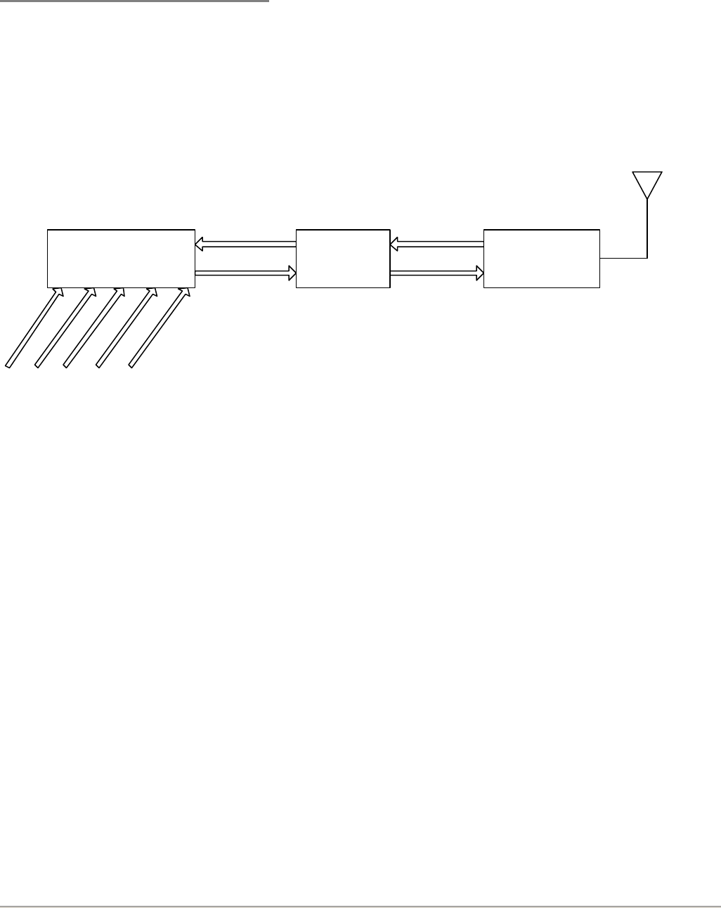
Neuralynx Small Animal Telemetry system consists of 3 components: headstage (SAT-HS4), amplifier (SAT-
AMP), and transmitter (SAT-TX-SS –or- SAT-TX-FLEX). This document is intended to deal primarily with
the transmitter.
Headstage
Ref
Electrode 1
Electrode 2
Electrode 3
Electrode 4
4 Input Signals
1 Reference
POWER Amplifier/
Filter 4 Signals
POWER
Transmitter
The headstage is a buffered preamplifier which buffers signals from 4 input electrodes and 1 reference
electrode. Jumper wires on the headstage board select which electrodes will be used as input signals and
which electrode will be used as a reference. A standard 18-pin Omnetics connector allows this headstage to
interface with the EIB-16 electrode interface board.
The amplifier stage consists of a differential input instrumentation amplifier (INA) for each of the 4 signal
channels and an op-amp to further increase the signal strength. Inputs to each INA are one of the 4 signal
channels and the reference channel. The gain of each amplifier is defined by the user when the product is
ordered. This stage also may include low- and/or high-cut filters for each channel. This is also specified by
the end-user when the product is purchased.
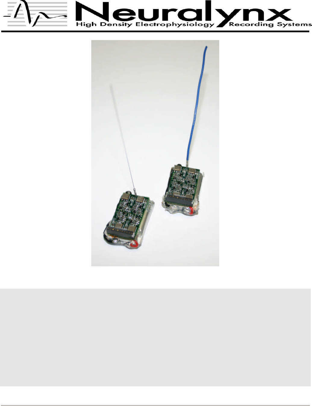
The SAT transmitter is a 4 channel analog FM transmitter operating at approximately 917 MHz, 918 MHz,
919 MHz, and 920 MHz. The four input signals are mixed and transmitted over a small antenna, either rigid
stainless steel (SAT-TX-SS) or flexible 28-gauge wire (SAT-TX-FLEX) depending on which transmitter is
purchased.
1
CHAPTER 1
SAT-TX Operation Overview
This chapter applies to both SAT-TX-SS and SAT-TX-FLEX. User interaction with the SAT-TX occurs
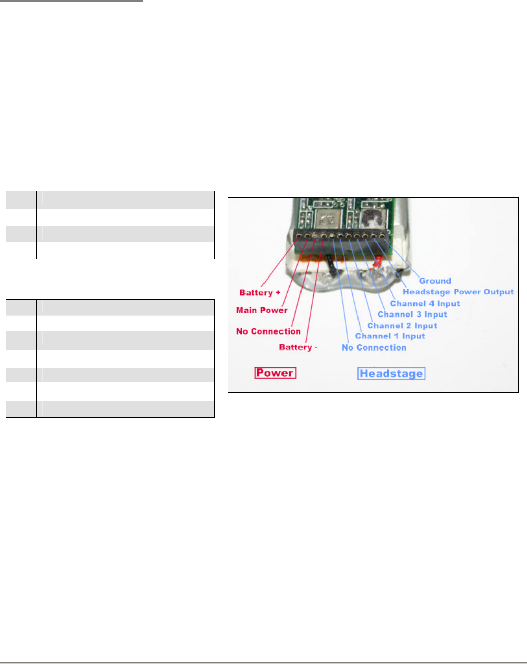
entirely on the 11-pin Mill-max connector. The connector pinout is defined below:
The connector is divided into two sections, Power and Headstage, as illustrated.
Power
1
Battery +
2
Main Power Input
3
NC
4
Battery -
Headstage
1
NC
2
Channel 1 Input
3
Channel 2 Input
4
Channel 3 Input
5
Channel 4 Input
6
Headstage Power Output (+3.3V)
7
GND
NC = No Connection
Figure 1 - SAT-TX connector pinout
Normal setup for recording occurs as follows:
1. Remove the shorting plug from the SAT-TX.
2. Connect the SAT-HS4/SAT-AMP to the SAT-TX (see the section titles SAT-TX Connection)
3. Connect the SAT-HS4 to the EIB-16
4. Turn the SAT-TX power on (see SAT-TX Power)
5. Start acquisition
2
SAT-TX Shorting Plug
A shorting plug is included with the SAT-TX. This should be used to help avoid damage to the transmitter
from electrostatic discharge while handling the device. The shorting plug simply grounds all of the headstage
inputs when the headstage is disconnected. You should always replace the shorting plug when the headstage
is not connected.
Figure 2 - SAT-TX with shorting plug
Note the silver mark on both
shorting plug and SAT connector.
This mark should be aligned.
Also note that the shorting plug is
a 6-pin connector with one pin
removed. The missing pin is the
headstage power output. Do
NOT insert this shorting
connector backwards or you will
short all of the inputs to +3.3V
and ground.
3
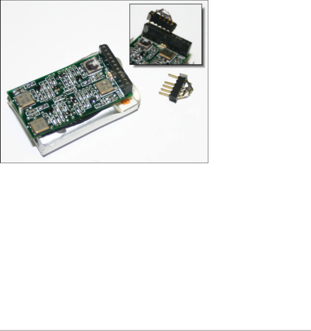
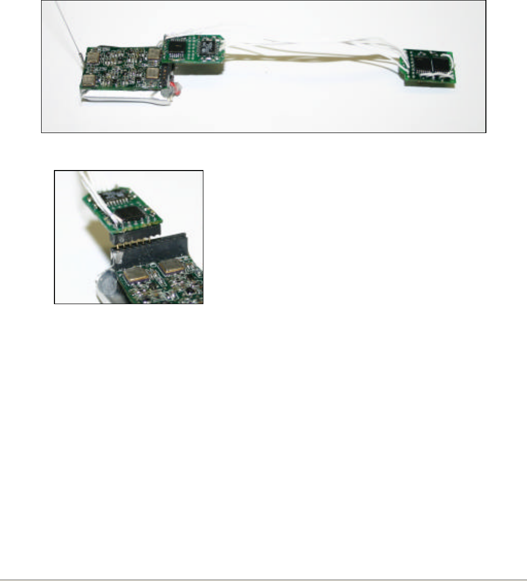
SAT-TX Headstage Connection
A 6-pin connector is used to attach the headstage/amplifier to the main transmitter board. As noted in the
header pinout (figure 1), this connector provides 4 input signals and power/ground outputs to the
headstage/amplifier circuitry. The pins should be inserted into the “Headstage” portion of the SAT-TX
header, aligning on the edge of the connector as shown in figure 4.
Figure 3 - SAT-TX connected to SAT-HS4 and SAT-AMP
Figure 4 - SAT-HS4/AMP connection
Note the missing pin on the amplifier board. This
pin aligns will the “No Connection” pin on the SAT-
TX header.
4
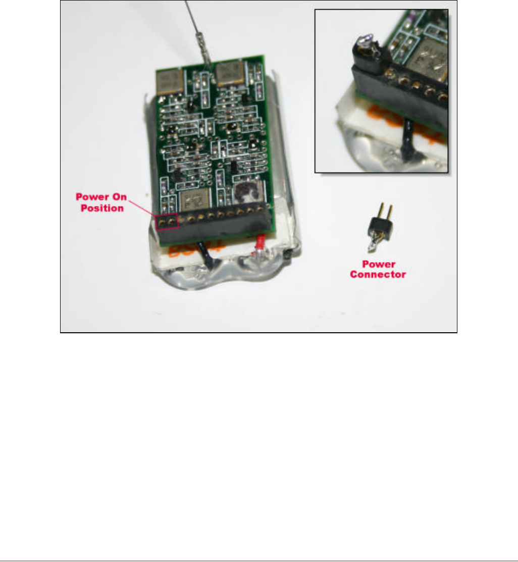
SAT-TX Power
Power is supplied to the SAT-TX by connecting the Battery+ voltage to the Main Power Input. This is done
using a two-pin power connector included with the SAT-TX. Simply place the two pin connector across
positions 1 and 2 of the SAT input header, as illustrated below. Refer to figure 1 for a more detailed pinout.
Figure 5 - SAT-TX and power connector. Inset: power connector in place
5
CHAPTER 2
SAT-TX Battery
The SAT-TX is powered by a lithium polymer (LiPo) battery. The standard battery is rated for 145 mA-
hours. This should allow the SAT-TX to run for 3+ hours, however it is recommended that you do not allow
the battery to discharge fully, therefore the run time between charges should be limited to 3 hours or less.
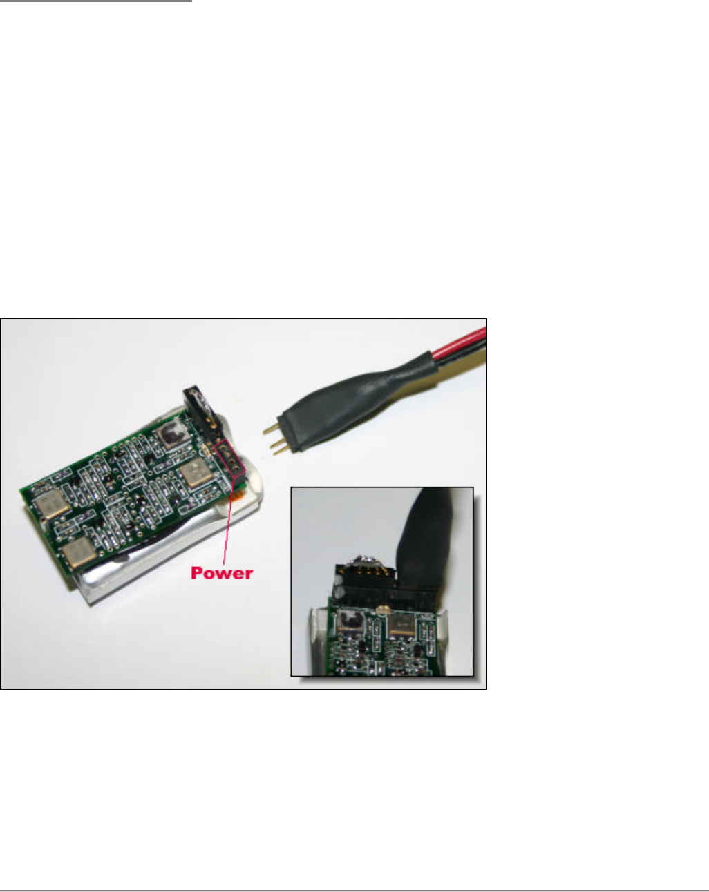
SAT-TX Battery Charging
This battery can be recharged using the included Kokam LIPO-502 charger and adaptor cable. The four pin
connector should be attached to the “Power” section of the SAT-TX header as illustrated.
Figure 6 - Battery charger connection
The missing pin should align
with the “No Connection” pin
on the power section of the
SAT-TX header.
Note the shorting plug is in
place to protect the inputs.
6
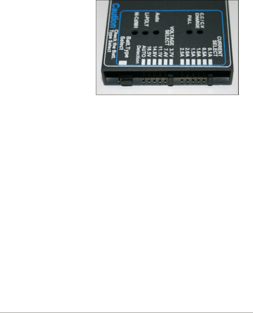
The included Kokam charger should be set up as follows:
Voltage
Current
Battery Type
3.7V
0.1A
Li-POLY
Figure 7 - Battery charger setup
When the charger is connected to a discharged battery the red “Charge” light and yellow “Li-POLY” light
should both illuminate, indicating the battery is being charged. When charging is complete, all of the lights
will blink simultaneously.
If the charger is connected to a fully charged battery all lights will blink simultaneously and continuously. This
“full charge” indication is slightly different than the “incomplete connection” sequence, which consists of all
lights blinking simultaneously 5 times, then the Li-POLY light blinks once, alone.

7
CHAPTER 3
FCC Compliance
This device complies with part 15 of the FCC Rules. Operation is subject to the following two conditions: (1)
This device may not cause harmful interference, and (2) this device must accept any interference received,
include interference that may cause undesired operation.
Changes or modifications to the SAT-TX not expressly approved by Neuralynx could void the user’s
authority to operate this device.