Newtech NT1D Handheld Vital Signs Monitor which transfers data to USB adaptor User Manual
Newtech,INC. Handheld Vital Signs Monitor which transfers data to USB adaptor
Newtech >
User manual

NT1D Vital Signs Monitor
Operating Manual

删除的内容: II

Preface
This operation manual introduces the monitor’s performance, way of operation and others safety
information and so on. This is the best start for new user to use the monitor. This manual is intended
for readers who are family with contacting various measurement and who have experience in
operating monitoring equipment.
Monitor’s features:
Combines a capnograph and pulse oximeter in a small, portable, lightweight monitor.
Measures and displays SpO2 in one graphic and one digital displays.
Measures and displays pulse rate one digital displays.
Measures and displays EtCO2 in one graphic and one digital displays.
Measures and displays respiration rate one digital displays.
Displays CO2 and SpO2 waveforms and trends in one interface
Employs audible and visual alarm warnings for monitored parameters and instrument
malfunctions.
Displays current trend line and trend table.
Displays table of alarm events.
Stores history data.
Provides user selectable language options: English and Chinese.
Uses internal batteries pack to supply power.
Provides external power supply.
Transfers history data wireless.
Equips with wireless USB adapter and PC software.
The monitor is intended for monitoring adult, pediatric, and neonatal patients in clinical environments
where healthcare is provided by healthcare professionals, i.e. doctors, nurse, or technicians.
z This manual includes the maximal configuration. The monitor you use may have not some
functions.
z Federal Law in the United States restricts this device to sale, distribution and use by or on the
order of a physician.
Symbols
The following symbols appear on the monitor:
Symbols Description
Attention! Consult the accompanying
document (This manual))
BF Type Defibrillation
Complies with the European Medical Device
Directive 93/42/EEC
Disposal requirement
Manufacturer date
Manufacturer
Serial number
Static sensitivity mark!
IPX1 Drip proof
RX ONLY Prescriptive device, operated by qualified
personnel only!
删除的内容: II
CONTACT
Address: R1-B1, Hi-Tech Park, NanShan District,
Shenzhen, Guangdong 518057
P.R. China
Postcode: 518057
Tel: 86-755-26525910
Fax: 86-755-26525912
Web cite: Http://www.sznewtech.com
E-mail: sales@sznewtech.com
Authorised Representative
Name: Shanghai International Holding Corp. GmbH(Europe)
Address: Eiffestrasse 80, 20537 Hamburg Germany
Tel: 0049 – 40 – 2513175
FAX: 0049 – 40 – 255726

This page is intentionally left blank.
删除的内容: II

Contents
Table of Contents
1.Safety........................................................................................................................................ 1-1
1.1 Safety Information ............................................................................................................................ 1-1
1.2 Product Label .................................................................................................................................... 1-3
2.Introduction .............................................................................................................................. 2-1
2.1 Product Introduction......................................................................................................................... 2-1
2.2 Monitor Features .............................................................................................................................. 2-1
2.3 Basic Principles of Operation......................................................................................................... 2-1
2.4 Terms’ Explanations ......................................................................................................................... 2-2
3. Unpacking and Installation ................................................................................................... 3-1
3.1 Unpacking.......................................................................................................................................... 3-1
3.2 Installing Pedestal ............................................................................................................................ 3-3
3.3 Installing AC adapter........................................................................................................................ 3-3
3.4 Installing Wireless USB Dongle..................................................................................................... 3-3
3.5 Sensor Connections ........................................................................................................................ 3-4
4. Initial Setup ............................................................................................................................. 4-1
4.1 Main Structure................................................................................................................................... 4-1
4.2 Description Crust.............................................................................................................................. 4-1
4.3 Basic Operation ................................................................................................................................4-2
4.3.1 Keys Operation .......................................................................................................................................4-3
4.3.2 Start Up ....................................................................................................................................................4-3
4.3.3 Running Mode.........................................................................................................................................4-4
4.3.4 Information Column ................................................................................................................................4-5
4.3.5 Status Bar ................................................................................................................................................4-5
4.3.6 Adjust the Volume of Pulse ...................................................................................................................4-6
4.3.7 Indicating Batteries’ Charge and Recharging .....................................................................................4-6
4.3.8 Shut Down ...............................................................................................................................................4-7
4.4 Storage ............................................................................................................................................... 4-8
4.5 Environment of Protection .............................................................................................................. 4-8
4.6 Impact of Performance Consideration.......................................................................................... 4-8
5. Interface and Function .......................................................................................................... 5-1
5.1 Main Monitoring Interface ............................................................................................................... 5-1
5.2 Big Chart Mode................................................................................................................................. 5-2
5.3 Real-time Trend Interface ............................................................................................................... 5-2
5.3.1 Trend Graph Interface............................................................................................................................5-2
删除的内容:
删除的内容: II

Contents
5.3.2 Trend Table Interface .............................................................................................................................5-4
5.3.3 Saving Historical Trend..........................................................................................................................5-5
5.4 Event Table Interface ....................................................................................................................... 5-5
5.5 Setting Menu Interface .................................................................................................................... 5-6
5.5.1 Setting Alarm Limits................................................................................................................................5-6
5.5.2 Setting SpO2............................................................................................................................................5-8
5.5.3 Setting CO2..............................................................................................................................................5-8
5.5.4 Setting Patient’s Information .................................................................................................................5-9
5.5.5 Setting Volume ........................................................................................................................................5-9
5.5.6 Setting Time and Date ......................................................................................................................... 5-10
5.5.7 Setting Trend .........................................................................................................................................5-10
5.5.8 Data Output ...........................................................................................................................................5-10
5.5.9 Set Module............................................................................................................................................. 5-11
5.5.10 Resume Settings ................................................................................................................................5-11
5.5.11 System Information............................................................................................................................. 5-11
5.6 Audible and Visual Indication ....................................................................................................... 5-12
6. Monitoring SpO2..................................................................................................................... 6-1
6.1 Overview ............................................................................................................................................ 6-1
6.2 Principles of Measurement............................................................................................................. 6-1
6.2 Abnormal State of SpO2 Measurement: ....................................................................................... 6-2
6.4 Directions for SpO2 Sensor Use..................................................................................................... 6-2
6.5 Measuring Restriction...................................................................................................................... 6-3
7. Monitoring CO2....................................................................................................................... 7-1
7.1 Overview ............................................................................................................................................ 7-1
7.2 Principles of Measurement............................................................................................................. 7-1
7.3 Medical Use of CO2 Sensor............................................................................................................ 7-1
7.4 CO2 Sensor Adapter Zero............................................................................................................... 7-2
8. Data Output............................................................................................................................. 8-1
8.1 Driver Installations and Copy of Data Analysis Software.......................................................... 8-1
8.1.1 Install USB Drivers ................................................................................................................................. 8-1
8.1.2 Copy the Folder “History Data Viewer”................................................................................................8-3
8.2 Transmit and Delete Data............................................................................................................... 8-4
9. Accessories............................................................................................................................. 9-1
9.1 Standard Configure of NT1D.......................................................................................................... 9-1
9.2 Optional Accessories of NT1D....................................................................................................... 9-1
10. Troubleshooting and Maintenance.................................................................................. 10-1
10.1 Troubleshooting Guide ................................................................................................................ 10-1
删除的内容: v

Contents
10.2 Technical Assistance ................................................................................................................... 10-2
10.3 Factory Default Alarm Range Values ....................................................................................... 10-2
10.4 Returning the Monitor.................................................................................................................. 10-2
10.5 Maintenance and Cleaning ........................................................................................................ 10-2
10.6 Periodic Safety Checks............................................................................................................... 10-4
10.7 Guarantee...................................................................................................................................... 10-4
Appendix A: Specifications........................................................................................................A-1
Appendix B: EMC (Electro-Magnetic Compatibility) .............................................................B-1
删除的内容: II

Contents
This page is intentionally left blank.
删除的内容: v
Safety
1-1
1.Safety
1.1 Safety Information
This chapter lists warnings, attentions, and basic safety information when using NT1D Vital Signs
Monitor. Similar or related and other safety information can be found in appropriate chapters.
Important! To use the monitor correctly and safely, carefully read this operator’s manual. Use of the
monitor requires full understanding and strict observance of these instructions, the precautionary
information in boldface type, and the specifications.
z “Warning”: Indicates a potentially harmful condition that can lead to personal injury.
z “Caution”: Indicates a condition that may lead to equipment damage or malfunction.
z “Note”: A point of particular interest or emphasis intended to provide more effective or convenient.
z To protect against electric shock hazard, the monitor’s cover is to be removed only by qualified
service personnel. There are no user-serviceable parts inside.
z The monitor is a prescription device and is to be operated by qualified healthcare personnel only.
z The exact time and date of the table of events depends on the precision of time and date what you
have set in the monitor, when alarms happened.
z The monitor is not suitable for use in the presence of flammable anesthetic mixture with air,
oxygen or nitrous oxide. Use of SpO2 and CO2 Sensor in such environment may present an
explosion hazard.
z Sucking the chemic matter came from cracked LCD display will cause poisoning. Please take
yourself carefully when the monitor’s display was broken.
z Please check the patient periodically, insure the monitor runs well and place SpO2 sensor and CO2
sensor rightly.
z CO2 readings, respiratory rate, pulse oximetry readings, and pulse signal can be affected by
certain ambient environmental conditions, sensor application errors, and certain patient conditions.
z The use of accessories, transducers, sensors and cables other than those specified may result in
increased emission and/or decreased immunity of the equipment and/or system.
z DO NOT silence the audible alarm if patient safety may be compromised.
z Mark sure that the speaker and speaker’s pore are not covered by any slipcover; otherwise the
alarm maybe can not be heard.
z Always respond immediately to a system alarm since the patient may not be monitored during
certain alarm conditions.
z Before each use, verify that the alarm limits are appropriate for the patient being monitored.
z To ensure accurate performance and prevent device failure, do not expose the monitor to extreme
moisture, such as rain.
z The SpO2 sensor must be moved to a new site at least every 4 hours. Because individual skin
condition affects the ability of the skin to tolerate sensor placement, it may be necessary to change
the sensor site more frequently with some patients. If skin integrity changes, move the sensor to
another site.
z DO NOT use oximetry sensors during magnetic resonance imaging (MRI) scanning. Conducted
current could cause burns. The sensors may affect the MRI image and the MRI unit may affect the
accuracy of oximetry measurements.
z Monitor has no defibrillation synchronization, so it cannot be connected to defibrillation
带格式的: 缩进: 左侧: 0
厘米, 悬挂缩进: 6.32 字
符, 项目符号 + 级别: 1 +
对齐位置: 0 厘米 + 制
表符后于: 0.74 厘米 + 缩
进位置: 0.74 厘米
带格式的: 缩进: 左侧: 0
厘米, 悬挂缩进: 3.6 字符,
项目符号 + 级别: 1 + 对
齐位置: 0 厘米 + 制表符
后于: 0.74 厘米 + 缩进位
置: 0.74 厘米, 制表位:
1.71 字符, 列表制表位 +
不在 2 字符

Safety
1-2
instruments.
z Follow precautions for electrostatic discharge (ESD) and electromagnetic interference (EMI) to
and from other equipment.
z To ensure patient electrical isolation, connect only to other equipment with circuits that are
electrically isolated.
z If uncertain about the accuracy of any measurement, check the patient’s vital signs by alternate
means, and then make sure the monitor is functioning correctly.
z The danger of losing data: this monitor can save current patient’s data only when it is shut down
normally or in low voltage, therefore:
1)when using internal power supply, only allow to shut down the monitor normally or in low
voltage. Do not take batteries down abruptly when the monitor is working or in the progress of
shutting down. To do this can avoid losing data.
2)when using external AC adapter or the pedestal to supply power, if there are four Ni-MH
batteries, you can take batteries down when the monitor is working or in the progress of shutting
down. If there aren’t batteries, you can only pull the adapter out or break the pedestal away only
after monitor shut down normally, you can not pull the adapter out or break the pedestal away
when it is working. To do this can avoid losing data.
z Using SpO2 sensor incorrectly may do harm to patient’s skin. Please check whether the SpO2
sensor is placed following the instructional way and position.
z DO NOT use NIBP or other constructing instruments on same appendage as sensor as blood flow
interrupted by NIBP cuff or circulatory patient condition will result in no pulse found or loss of pulse.
z DO NOT alter or modify SpO2 and CO2 sensor. Alterations or modifications may affect performance
or accuracy.
z Using the SpO2 sensor in the presence of bright lights may result in inaccurate measurements. In
such cases, cover the sensor site with an opaque material.
z DO NOT use SpO2 and CO2 sensor if the sensor or the sensor cable appears damaged.
z DO NOT lift the monitor by the SpO2 sensor or CO2 sensor cable as they could disconnect from the
monitor, causing the monitor to fall on the patient.
z To ensure patient safety, do not place the monitor in any position that might cause it to fall on the
patient.
z Carefully route patient cabling (SpO2 sensor and CO2 sensor) to reduce the possibility of patient
entanglement or strangulation.
z Be sure to follow local governing ordinances and recycling instructions regarding disposal or
recycling of batteries.
z Reuse, disassembly, cleaning, disinfecting or sterilizing the single patient use CO2 airway adapters
may compromise functionality and system performance leading to a user or patient hazard.
Performance is not guaranteed if an item labeled as single patient use is reused.
z If the SpO2 and CO2 Sensor fails to respond as described in this user guide; DO NOT use it until
approved for use by qualified personnel.
z The CO2 Sensor is not patient isolated. Use of the sensor does not require direct patient contact. If
isolation is desired or required, it is the responsibility of the Host system to provide the necessary
isolation.
z This monitor’s electrical isolation part is centralized in the AC adapter. When using external power
supply or charging the batteries, please use only the medical grade AC adapter provided by the
manufacturer. If in doubt about the integrity of the mains supply connection, operate the monitor
from its internal battery pack.
带格式的: 段落间距段前: 0
磅
带格式的: 缩进: 左侧: 0
厘米, 悬挂缩进: 3.6 字符,
项目符号 + 级别: 1 + 对
齐位置: 0 厘米 + 制表符
后于: 0.74 厘米 + 缩进位
置: 0.74 厘米, 制表位:
1.71 字符, 列表制表位 +
不在 2 字符
Safety
1-3
z The monitor is intended only as an adjunct in patient assessment. It must be used in conjunction
with clinical signs and symptoms.
z Please do not repeat to use one-off accessories.
z Do not use SpO2 and CO2 sensor across between epidemical and unepidemical patients before
sterilized.
z Do not connect the host monitor, sensor, AC adapter and pedestal to any other equipment
mutually.
z All equipment connected to the monitor must conform to EN60601-1.
z Use only approved sensors, pulse oximetry and CO2 cables. Other sensors or oximetry cables
may cause improper monitor performance.
z Changes and modifications not expressly approved by the manufacturer responsible for
compliance could void the user’s authority to operate the equipment.
z Ambient light, movement, electromagnetic interference, artifacts, dysfunctional hemoglobin, and
certain dyes, etc may be interfere in the pulse oximeter's function.
z Do not sterilize by irradiation steam, or ethylene oxide.
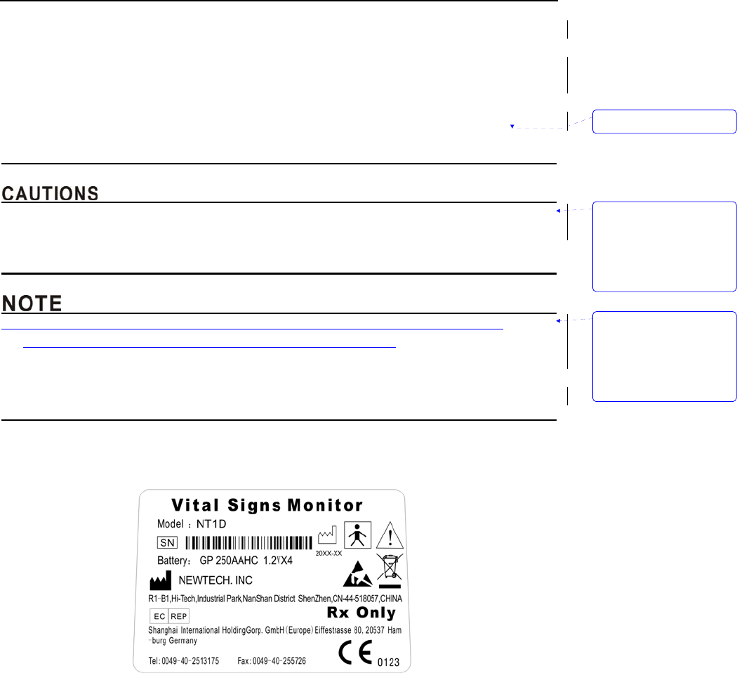
1.2 Product Label
Figure1-1: Product label
带格式的: 缩进: 左侧: 0
厘米, 悬挂缩进: 3.6 字符,
项目符号 + 级别: 1 + 对
齐位置: 0 厘米 + 制表符
后于: 0.74 厘米 + 缩进位
置: 0.74 厘米, 制表位:
1.71 字符, 列表制表位 +
不在 2 字符
带格式的: 缩进: 左侧: 0
厘米, 悬挂缩进: 3.6 字符,
项目符号 + 级别: 1 + 对
齐位置: 0 厘米 + 制表符
后于: 0.74 厘米 + 缩进位
置: 0.74 厘米, 制表位:
1.71 字符, 列表制表位 +
不在 2 字符
删除的内容: s

Safety
1-4
This page is intentionally left blank.

Introduction
2-1
2.Introduction
2.1 Product Introduction
NT1D is a portable handheld vital signs monitor that continuously monitors end tidal carbon
dioxide (EtCO2), respiratory rate (RR), oxygen saturation (SpO2), and pulse rate. The unit is indicated
for monitoring only and must be used in the continuous presence of a qualified healthcare provider,
and transfer history data to PC through USB adapter. It is intended for use in any environment where
continuous, noninvasive monitoring of these parameters is desired, including hospital and hospital
type facilities. The monitor is intended for use on adult, pediatric, and neonatal patients.
Our product is composed of host monitor, SpO2 sensor, mainstream CO2 sensor, pedestal, wireless
USB adapter and PC software.
Our product has input and output ports:
Input: SpO2 sensor port, CO2 sensor port;
Output: Sends data to USB adapter wirelessly.
z Using the monitor in excessive movement will affect the accuracy of saturation measurements
2.2 Monitor Features
z Combines a capnograph and pulse oximeter in a small, portable, lightweight monitor.
z Measures and displays SpO2 in one graphic and one digital display.
z Measures and displays pulse rate one digital displays.
z Measures and displays EtCO2 in one graphic and one digital display.
z Measures and displays respiration rate one digital displays.
z Displays CO2 and SpO2 waveforms and trends in one interface
z Employs audible and visual alarm warnings for monitored parameters and instrument
malfunctions.
z Displays current trend line and trend table.
z Displays table of alarm events.
z Stores history data.
z Provides user selectable language options: English and Chinese.
z Uses internal batteries pack to supply power.
z Provides external power supply.
z Transfers history data wireless.
z Equips with wireless USB adapter and PC software.
2.3 Basic Principles of Operation
z SpO2 principles of operation
Pulse oximetry is based on two principles: 1) oxyhemoglobin and deoxyhemoglobin, which differ in
their absorption of red and infrared light (spectrophotometry), and 2) changes in the volume of arterial
blood in tissue during the pulse cycle (plethysmography), and hence, light absorption by that blood.
A pulse oximeter determines SpO2 by passing red and infrared light into an arteriolar bed and
带格式的: 缩进: 左侧: 0
厘米, 悬挂缩进: 3.57 字
符, 项目符号 + 级别: 1 +
对齐位置: 0.63 厘米 + 制
表符后于: 1.38 厘米 + 缩
进位置: 1.38 厘米, 制
表位: 1.71 字符, 列表制
表位 + 不在 3.71 字符
Introduction
2-2
measures changes in light absorption during the pulsatile cycle. Red and infrared low power
lightemitting diodes (LEDs) in the oximetry sensor serve as light sources; a photodiode serves as the
photodetector.
Because oxyhemoglobin and deoxyhemoglobin differ in light absorption, the amount of red and
infrared light absorbed by blood is related to hemoglobin oxygen saturation. To identify the oxygen
saturation of arterial hemoglobin, the monitor uses the pulsatile nature of arterial flow.
During systole, a new pulse of arterial blood enters the vascular bed and blood volume and light
absorption increase. During diastole, blood volume and light absorption reach their lowest point.
The monitor bases its SpO2 measurements on the difference between maximum and minimum
absorption (measurements at systole and diastole). The focus of light absorption by pulsatile arterial
blood eliminates the effects of nonpulsatile absorbers such as tissue, bone, and venous blood.
z CO2 principles of operation
The CO2 Sensor is used for the continuous measurement of CO2 and respiratory rate. The sensor
measures CO2 by using the infrared absorption technique. The principle is based on the fact that CO2
molecules absorb infrared (IR) light energy of specific wavelengths, with the amount of energy
absorbed being directly related to the CO2 concentration. When an IR beam is passed through a gas
sample containing CO2, the electronic signal from the photo detector (which measures the remaining
light energy) is measured. This signal is then compared to the energy of the IR source and adjusted to
accurately reflect CO2 concentration in the sample. The CO2 Sensor’s response to a known
concentration of CO2 is stored at the factory in the sensor’s memory. A reference channel accounts for
optical changes in the sensor, allowing the system to remain in calibration without user intervention.
z Host monitor’s principles of operation
Patient’s signal is checked and magnified through various sensors and then transported to
parameter module to disposal data by extended cable, and then communicate with host monitor’s
control board to show the measuring result. The results will be shown on the screen in the form of
waveform and figure. It can save every parameter for 99 patients, 72 hours per capita, and can
transfer data to PC wirelessly.
z Pulse oximetry readings and pulse signal can be affected by certain ambient environmental
conditions, probe application errors, and certain patient conditions.
Specific information about ambient environmental conditions, probe application, and patient conditions,
is contained throughout this manual.
2.4 Terms’ Explanations
SpO2 Oxygen saturation value PR Pulse Rate
Pleth Blood dimension EtCO2 End tidal carbon dioxide value
RR Respiration rate
带格式的: 段落间距段前:
0.5 行

Unpacking and Installation
3-1
3. Unpacking and Installation
3.1 Unpacking
Open the package according to the marks on the box. Carefully remove the monitor and its
accessories.
z Count the accessories according to the packing list.
z Check the monitor and accessories for any physical damage.
If there are any problems, contact the distributor immediately.
Friendly reminder: The packaging material should be saved for future transportation and storage.
z Customers should put the wrappers somewhere that child couldn’t touch. When disposaling the
wrappers, you should follow local governing ordinances or hospital instructions.
z The equipment may be polluted by microorganism when deposit and transportation. Please check
the packaging before using. Do not use it if it is damaged.
This monitor is equipped with Ni-MH rechargeable Batteries as well as alkaline batteries. When
using Ni-MH Batteries, we can use external AC adapter or the pedestal to charge to the host monitor.
But when using alkaline batteries, we can not use external AC adapter or the pedestal to charge to the
host monitor.
z Never operate the device without the battery cover in place.
z This monitor only sustain “AA” size Ni-MH Batteries and alkaline batteries,do not use any type of
batteries that have no admission.
z when using alkaline batteries,do not use external AC adapter or the pedestal to charge to the host
monitor.
z DO NOT use Ni-MH Batteries and alkaline batteries together!
z Ni-MH Batteries’ handling
• Do not immerse the battery pack in water; it may malfunction.
• Only recharge the battery pack in the monitor, provided by your local representative, to avoid
possible overheating, burning or rupture of the battery pack.
z Ni-MH Batteries’ storage
• Short-term storage (one month or less): The battery pack has an automatic discharge feature.
You must periodically check the charge level of the battery pack.
• Long-term storage (6 months or more): The battery pack must be stored in a cool, dry area. Its
charge decreases over time. To restore the battery pack to full power, charge and discharge it
three times before use. Long-term storage, without charging the battery, may degrade the battery
capacity.
带格式的: 缩进: 悬挂缩进:
3.38 字符, 多级符号 + 级
别: 1 + 编号样式: 项目符
号 + 对齐位置: 0.85 厘米
+ 制表符后于: 1.59 厘米
+ 缩进位置: 1.59 厘米
带格式的: 缩进: 左侧: 0
厘米, 悬挂缩进: 3.6 字符,
项目符号 + 级别: 1 + 对
齐位置: 0 厘米 + 制表符
后于: 0.74 厘米 + 缩进位
置: 0.74 厘米, 制表位:
1.71 字符, 列表制表位 +
不在 2 字符
带格式的: 缩进: 左侧: 0
厘米, 悬挂缩进: 3.6 字符,
项目符号 + 级别: 1 + 对
齐位置: 0 厘米 + 制表符
后于: 0.74 厘米 + 缩进位
置: 0.74 厘米, 制表位:
1.71 字符, 列表制表位 +
不在 2 字符
Unpacking and Installation
3-2
z Ni-MH Batteries’ disposal
• Do not dispose of the battery pack in fire; it may explode.
• Be sure to follow local governing ordinances and recycling instructions regarding disposal or
recycling of batteries.
z The monitor is not suitable for use in the presence of flammable anesthetic mixture with air,
oxygen or nitrous oxide.
z When using alkaline batteries, do not charge them.
z To ensure patient electrical isolation, connect only to appointed AC adapter with circuits that are
electrically isolated. Do not use unauthorized AC adapter.
z To ensure patient safety, do not place the monitor in any position that might cause it to fall on the
patient.
z If the batteries happen to leak liquid, break the external safeguard or run out of charge, please
stop using these batteries and follow local governing ordinances and recycling instructions
regarding disposal or recycling of batteries.
z Carefully route cables to reduce the possibility of patient entanglement or strangulation
z To ensure accurate performance and prevent device failure, do not expose the monitor to extreme
moisture, such as rain.
z DO NOT use Ni-MH batteries and alkaline batteries together. When exchanging batteries, you
should replace all depleted batteries by fresh ones.
z Please use accompanying batteries only!
z Check the batteries periodically for corrosion. Replace batteries if corrosion is present, otherwise
damage to the monitor may occur.
z Insert the (-) terminal of each battery first, compressing the battery terminal spring until the (+)
terminal clears the positive spring, and pressing the battery downward into place.
z To remove the batteries, reverse the installation process, removing the positive end of each battery
first.
z To avoid corrosion of the contacts, remove batteries from the battery compartment, if you do not
intend to use the monitor for an extended period of time.
带格式的: 缩进: 左侧: 0
厘米, 悬挂缩进: 3.6 字符,
项目符号 + 级别: 1 + 对
齐位置: 0 厘米 + 制表符
后于: 0.74 厘米 + 缩进位
置: 0.74 厘米, 制表位:
1.71 字符, 列表制表位 +
不在 2 字符
带格式的: 缩进: 左侧: 0
厘米, 悬挂缩进: 3.6 字符,
项目符号 + 级别: 1 + 对
齐位置: 0 厘米 + 制表符
后于: 0.74 厘米 + 缩进位
置: 0.74 厘米, 制表位:
1.71 字符, 列表制表位 +
不在 2 字符
删除的内容: when
Unpacking and Installation
3-3
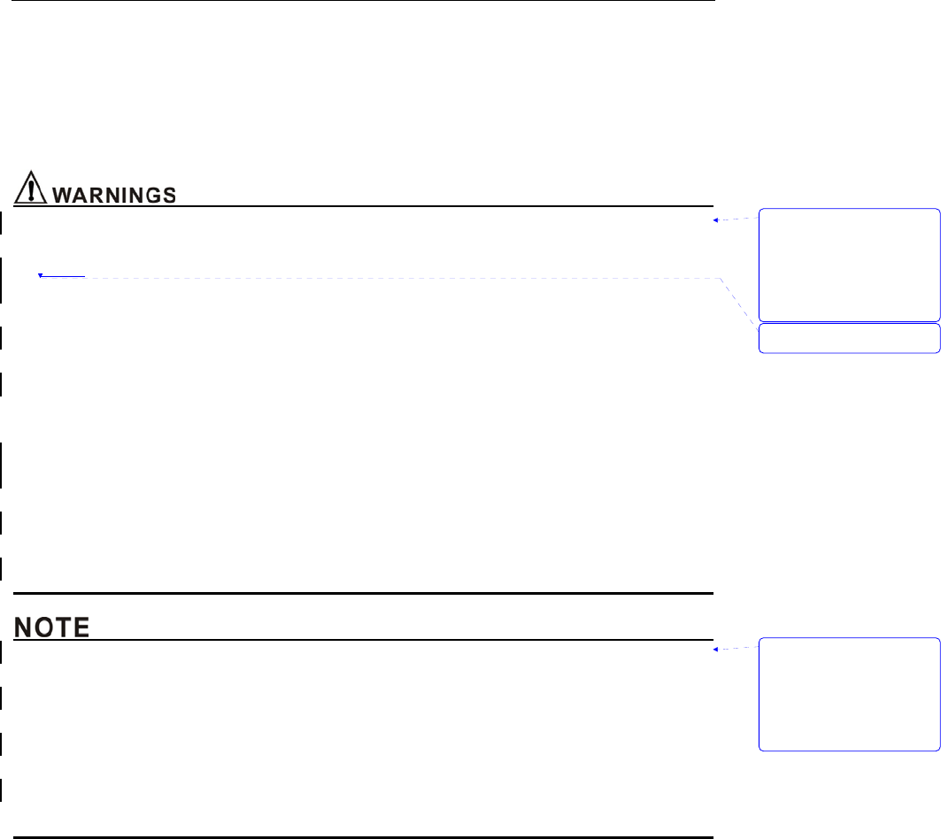
3.2 Installing Pedestal
Figure: 3-1 Install pedestal
1. Plug the AC adapter into the faucet of the pedestal, as shown in Figure 3-1.
2. Put the monitor into the pedestal following the right orientation to insure the contact of metal point
and shrapnel.
3. Connect AC adapter to electrical outlet.
4. If the monitor is shut down, it will set up and display the charging interface, pressing the On/Off key
will enter into normal operating mode.
5. If the monitor is working, it will display the movement of battery icon.
z Do not plug the monitor into the pedestal at wrong orientation.
z Make sure equip the monitor with Ni-MH batteries, do not charge alkaline batteries or any other
type of batteries. Do not mix different kinds of batteries to use!
z When there are no batteries in the monitor and use the pedestal to supply power, you have danger
of losing data. So please make sure shut the monitor down before taking the pedestal away.
3.3 Installing AC adapter
1. Plug the AC adapter into the chargeable faucet which on the bottom of the host monitor.
2. Connect AC adapter to electrical outlet.
3. If the monitor is shut down, it will set up and display the charging interface, pressing the On/Off
key will enter into working interface.
4. If the monitor is working, it will display the movement of battery icon.
3.4 Installing Wireless USB Dongle
This equipment has been tested and found to comply with the limits for a class B digital device,
pursuant to part 15 of the FCC Rules. These limits are designed to provide reasonable protection
against harmful interference in a residential installation. This equipment generates uses and can
radiate radio frequency energy and, if not installed and used in accordance with the instructions, may
cause harmful interference to radio communications. However, there is no guarantee that interference
will not occur in a particular installation. If this equipment dose cause harmful interference to radio or
television reception, which can be determined by turning the equipment off and on, the user is
encouraged to try to correct the interference by one or more of the following measures:
1. Reorient or relocate the main device.
带格式的: 缩进: 左侧: 0
厘米, 悬挂缩进: 3.6 字符,
项目符号 + 级别: 1 + 对
齐位置: 0 厘米 + 制表符
后于: 0.74 厘米 + 缩进位
置: 0.74 厘米, 制表位:
1.71 字符, 列表制表位 +
不在 2 字符
带格式的: 字体: (默认)
Arial
带格式的: 字体: (默认)
Arial
带格式的: 正文, 段落间
距段前: 0 磅, 段后: 0 磅
带格式的: 字体: (默认)
Arial
带格式的: 字体: (默认)
Arial
带格式的: 字体: (默认)
Arial
带格式的: 字体: (默认)
Arial
带格式的: 字体: (默认)
Arial
带格式的: 字体: (默认)
Arial
带格式的: 字体: (默认)
Arial
带格式的: 字体: (默认)
Arial
带格式的: 字体: (默认)
Arial, 字体颜色: 黑色
Unpacking and Installation
3-4
2. Increase the separation between the equipment and receiver.
3. Consult the dealer or an experienced technician for help.
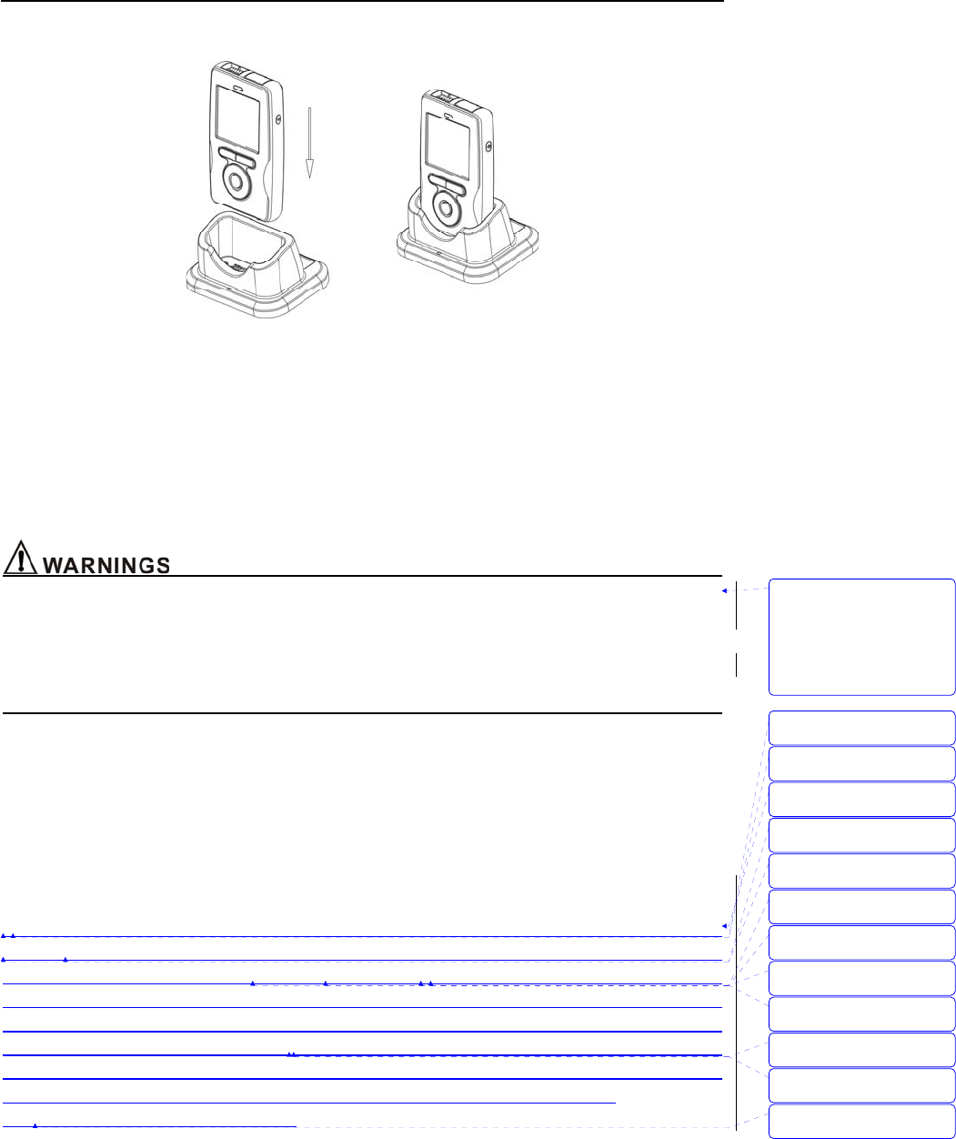
Figure 3-2: Install wireless USB Dongle
Installing steps:
1. Install driver and software at PC.
2. Plug wireless USB Dongle into PC’s USB faucet, The USB Dongle receive data from monitor via
wireless, as shown in Figure 3-2.
3. Open the monitor in 2 meters around the PC, the monitor will send the data to USB Dongle via
wireless.
4. Press MENU key, enter into “sending data” dialog.
5. Choose “connect” button to open the ward software.
6. The software will show historical data of patient’s ID which have stored in the host monitor at the
side column, if it’s connected successfully.
z In order to insure the quality of the transporting signal, please let the monitor close to the USB
wireless adapter plugged in PC as possible and make sure there is no barrier between them.
z This monitor complies with Part 15 of the FCC Rules. Operation is subject to the following two
conditions:
(1) This device may not cause harmful interference.
(2) This device must accept any interference received, including interference that may cause
undesired operation.
z The monitor used for this transmitter must be installed with providing a separation distance of at
least 20cm from all persons.
3.5 Sensor Connections
z Before use, carefully read the sensor directions for use, including all warnings, cautions, and
instructions.
z Do not use a damaged sensor.
z Do not immerse or wet the sensor.
z Do not use a sensor with exposed electronic components.
z Use only sensors and its cable suited to this monitor for SpO2 and CO2 measurements. Other
带格式的: 字体: (默认)
Arial, 字体颜色: 黑色
带格式的: 字体: (默认)
Arial, 字体颜色: 黑色
带格式的: 字体: (默认)
Arial, 字体颜色: 黑色
带格式的: 字体: 非加粗
带格式的: 字体: 五号, 非
加粗
带格式的: 两端对齐
带格式的: 字体: 五号
带格式的: 两端对齐, 定
义网格后自动调整右缩进,
项目符号 + 级别: 1 + 对
齐位置: -0.03 厘米 + 制
表符后于: 0.71 厘米 + 缩
进位置: 0.71 厘米, 调
整中文与西文文字的间距,
调整中文与数字的间距
带格式的: 字体: (默认)
Arial, 字体颜色: 自动设
置, 英语(美国)
带格式的: 字体: (默认)
Arial, 字体颜色: 自动设
置, 英语(美国)
带格式的: 字体: (默认)
Arial, 字体颜色: 自动设
置, 英语(美国)
带格式的: 字体: (默认)
Arial, 字体颜色: 自动设
置, 英语(美国)
带格式的
带格式的: 段落间距段前: 0
磅, 项目符号 + 级别: 1 +
对齐位置: -0.03 厘米 +
制表符后于: 0.71 厘米 +
缩进位置: 0.71 厘米
带格式的: 缩进: 左侧: 0
厘米, 悬挂缩进: 3.6 字符,
项目符号 + 级别: 1 + 对
齐位置: 0 厘米 + 制表符
后于: 0.74 厘米 + 缩进位
置: 0.74 厘米, 制表位:
1.71 字符, 列表制表位 +
不在 2 字符
带格式的: 缩进: 左侧: 0
厘米, 悬挂缩进: 3.6 字符,
项目符号 + 级别: 1 + 对
齐位置: 0 厘米 + 制表符
后于: 0.74 厘米 + 缩进位
置: 0.74 厘米, 制表位:
1.71 字符, 列表制表位 +
不在 2 字符
删除的内容: Send
Unpacking and Installation
3-5
sensors may cause the monitor improper performance.
z Do not lift the monitor by the sensor cable because the cable could disconnect from the monitor,
causing the monitor to drop on the patient.
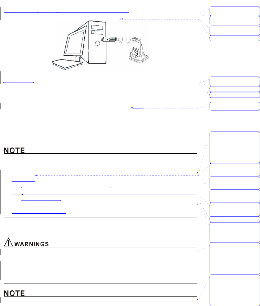
Figure 3-3: Installing sensors
z Installing SpO2 sensor
1. Select the appropriate sensor for the patient.
2. Refer to Figure 3-3, Connect the oximeter plug to pulse oximeter convex interface.
3. The probe is finger of tip oximeter probe. Attach the finger probe with the light to the patient. Be
sure to fully insert the patient's finger into the probe.
4. Apply the sensor following the instructions supplied with the sensor.
z Installing CO2 sensor
1. Insert the CO2 Sensor connector into the receptacle of the host monitor. To remove the connector,
grasp the body portion of the connector back and remove.
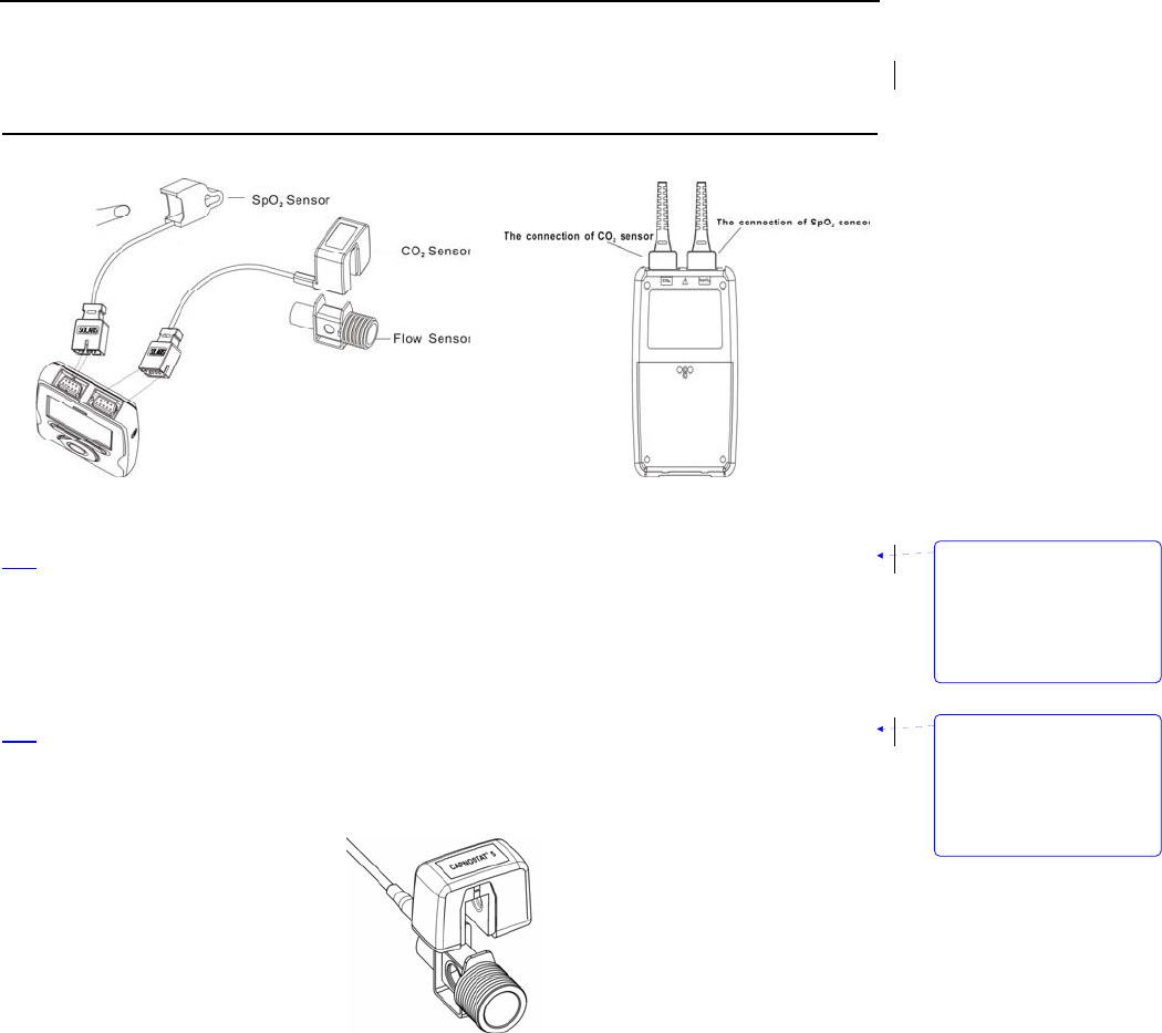
2. Shown below is the CO2 Sensor connection to a CO2 adapter
Figure 3-4: Installing CO2 sensor
3. Open the function of measuring CO2. Please see chapter 5 for more information.
Note: Do not remove by pulling cable.
带格式的: 缩进: 左侧: 0
厘米, 悬挂缩进: 3.6 字符,
项目符号 + 级别: 1 + 对
齐位置: 0.63 厘米 + 制
表符后于: 1.38 厘米 + 缩
进位置: 1.38 厘米, 制
表位: 1.71 字符, 列表制
表位 + 不在 3.71 字符
带格式的: 缩进: 左侧: 0
厘米, 悬挂缩进: 3.6 字符,
项目符号 + 级别: 1 + 对
齐位置: 0.63 厘米 + 制
表符后于: 1.38 厘米 + 缩
进位置: 1.38 厘米, 制
表位: 1.71 字符, 列表制
表位 + 不在 3.71 字符

Unpacking and Installation
3-6
This page is intentionally left blank.
删除的内容:
Initial Setup
4-1
4. Initial Setup
4.1 Main Structure
The monitor is composed by host monitor, SpO2 Sensor, CO2 Sensor and pedestal.
4.2 Description Crust
Figure 4-1 through 4-4 show the crust, display, pedestal and rear/top view of the monitor.
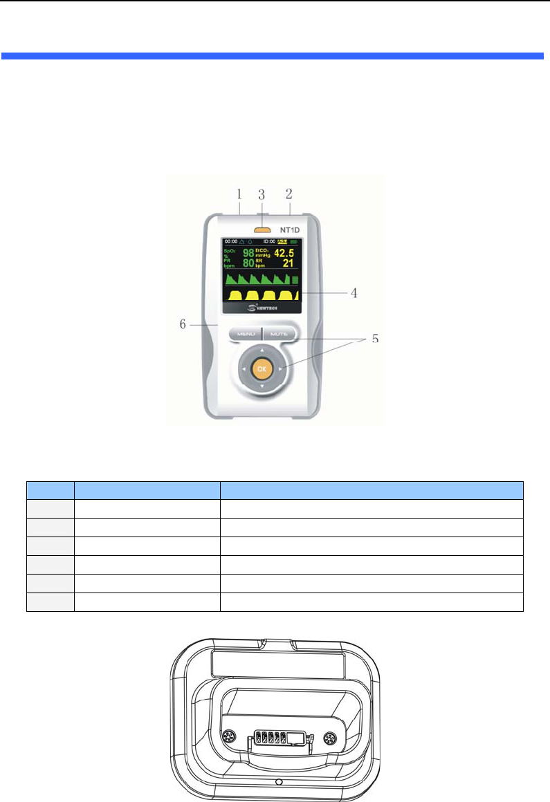
Figure 4-1: Crust
The function of each numbered label in Figure 4-1 is described below:
Label Description Function
1 SpO2 Connector Connect the host monitor and SpO2 Sensor
2 CO2 Connector Connect the host monitor and CO2 Sensor
3 Power indicator light Indicate the state of host monitor
4 Display Window Display the user’s interface
5 Keys Operate the host monitor
6 Crust Protect the internal parts of host monitor
Figure 4-2:Pedestal View
Initial Setup
4-2
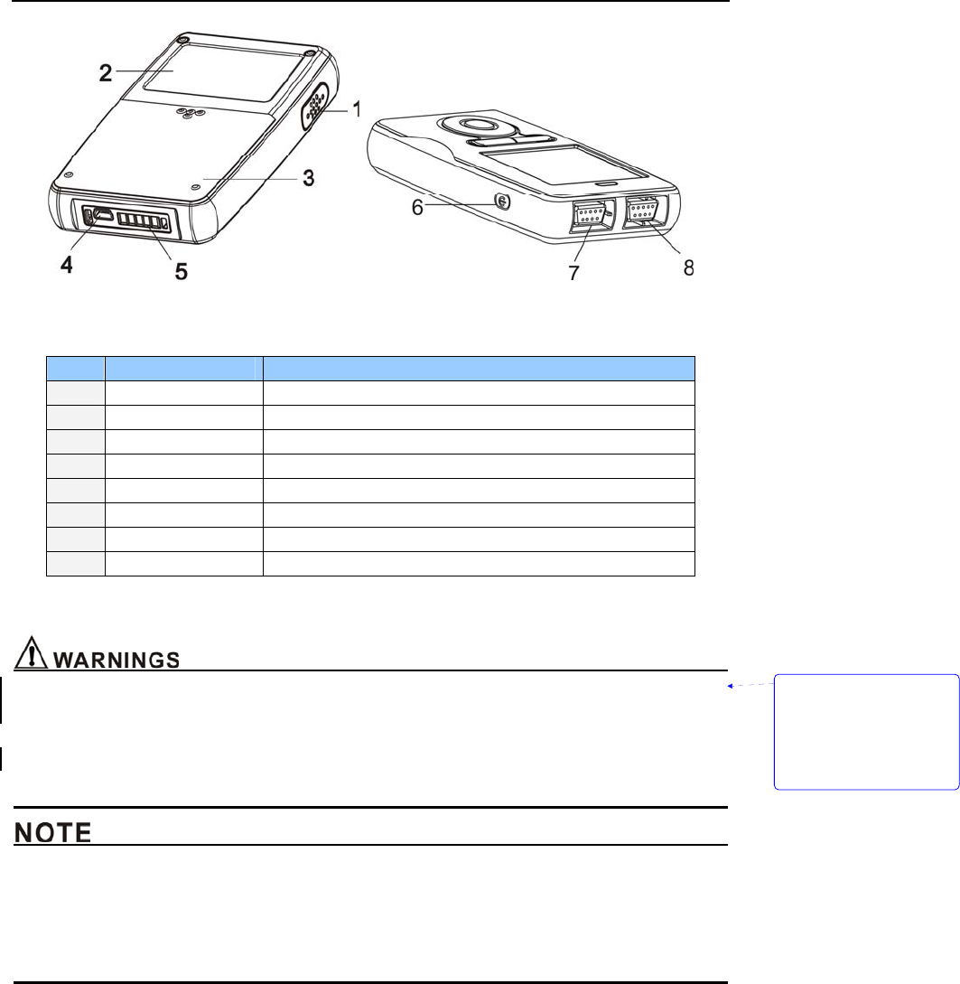
Figure 4-3:Rear/top view
The function of each numbered label in Figure 4-3 is described below:
Label Description Function
1 Speaker Emit sounds of pulse and alarm
2 Rear shuck Protect the internal parts of host monitor
3 Battery door Open it can install or unload batteries
4 Electrical outlet Connect the host monitor and AC adapter
5 Pedestal connector Connect the host monitor and pedestal
6 On/Off key Open and close the host monitor
7 CO2 Connector Connect the host monitor and CO2 Sensor
8 SpO2 Connector Connect the host monitor and SpO2 Sensor
4.3 Basic Operation
z The monitor is a prescription device and is to be operated by qualified personnel only.
z Do not lift the monitor by the probe cable because the cable could disconnect from the monitor,
causing the monitor to drop on the patient.
z Prior to using the monitor, carefully read the manual and accessory directions for use, all
precautionary information in boldface type, and all specifications.
z The monitor is intended only as an adjunct in patient assessment. It must be used in conjunction
with clinical signs and symptoms.
z Before using the monitor, remove the plastic protective sheet that covers the display. This sheet is
only on the display to protect it during shipping. Leaving it on during monitoring could make it
difficult to read displayed measurements.
带格式的: 缩进: 左侧: 0
厘米, 悬挂缩进: 3.6 字符,
项目符号 + 级别: 1 + 对
齐位置: 0 厘米 + 制表符
后于: 0.74 厘米 + 缩进位
置: 0.74 厘米, 制表位:
1.71 字符, 列表制表位 +
不在 2 字符
Initial Setup
4-3
4.3.1 Keys Operation
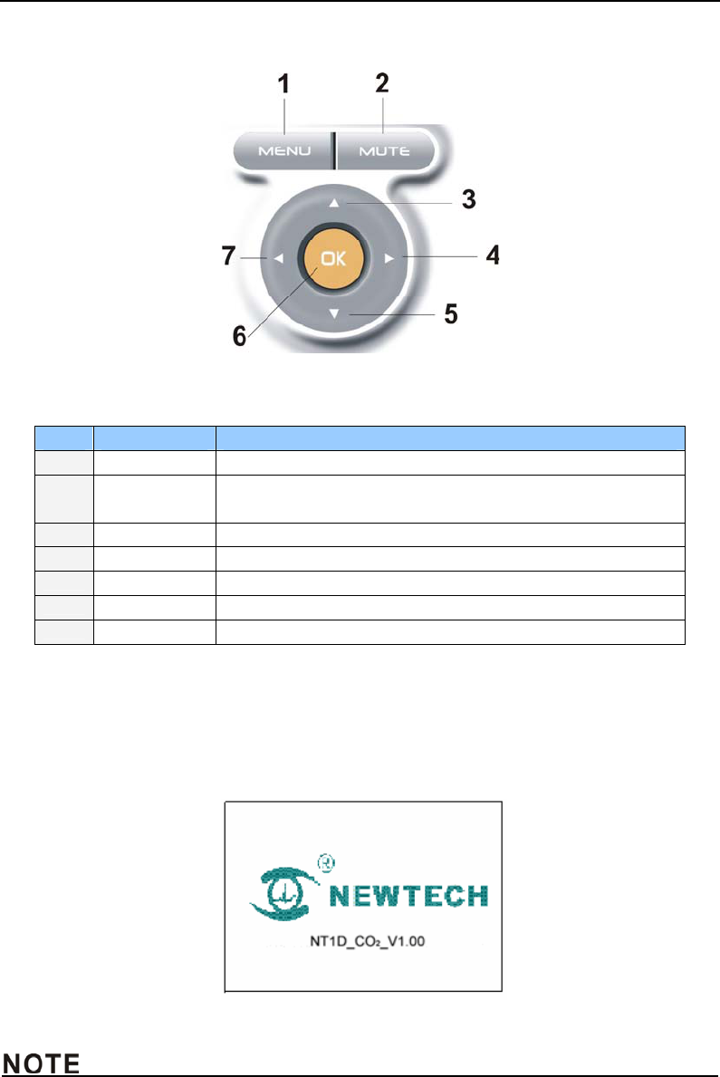
Figure 4-4: keys
The function of each numbered label in Figure 4-4 is described below:
Label Description Function
1 MENU key Press this bottom to enter submenu.
2 MUTE key Press this bottom to shut down the alarm of this parameter or
restart all alarms.
3 Up key Move menu and cursor upwards or increase number.
4 Right key Move menu and cursor rightwards.
5 Down key Move menu and cursor upwards or decrease number.
6 OK key Use to choose menu or number.
7 Left key Move menu and cursor leftwards.
4.3.2 Start Up
z Enclosing butteries
If the monitor is turned off, when you have enclosed batteries, press On/Off key can turn on the
monitor. The start interface is shown in Figure 4-5 below:
Figure4-5: Initialization Screen
z If the battery were insufficient to operated, you maybe can see the opening of the system. And
then, the monitor turns itself off automatically. If the batteries are less or installing the batteries is
Initial Setup
4-4
failure, this monitor may have no response. Then, Please make sure the batteries have enough
energy.
z The monitor is intended only as an adjunct in patient assessment. It must be used in conjunction
with clinical signs and symptoms.
z This monitor is a prescription device and is to be operated by qualified personnel only.
z Do not connect anything other than a SpO2 sensor to the SpO2 sensor port (for example, do not
attempt to connect a PC to the monitor at the sensor port).
z Do not connect anything other than an CO2 sensor to the CO2 sensor port
z Self Test
When turned on, the monitor automatically performs a Self Test. The screen will display the followings
in turn:
1) It will display the software’s version number at all the test times.
2) The self test progress of magnetic disk, power indicator light and speaker is displaying below
the version number.
3) Make sure that you can hear “dee” sound and the power light is on. That means finishing the
self test successfully. If not, do not continue to use this monitor, contact your provider or
manufacturer.
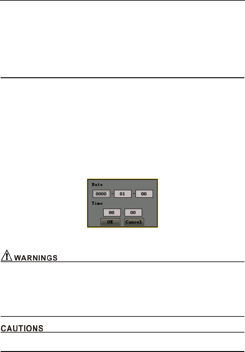
After self testing, if you haven’t set the system time or the right has lost, a dialog box will come out to
hint you set the system time manually.(Refer to Figure 4-6).
Figure 4-6 Setting system time
z Make sure that you can hear “dee” sound and the power light is on. If not, do not continue to use
this monitor.
z Do not lift the monitor by the sensor cable because the cable could disconnect from the monitor,
causing the monitor to drop on the patient.
z Make sure there is no any barrier in the front of the speaker and the speaker’s pores aren’t
covered. Otherwise, you may not hear alarms.
z When adjust any menu’s parameter, the screen will display partially but still record data.
4.3.3 Running Mode
After turning on the monitor, the SpO2 testing is opened automatically. Steps are as follows:
Initial Setup
4-5
1) Install the SpO2 sensor correctly and put patient’s finger in it.
2) The monitor will search for pulse in 10 seconds.
3) If pulse search is successful, in %SpO2 and PR area will display the patient’s %SpO2 and PR. Pulse
indicator will jump together with the pulse jumping. Speaker will generate "dee dee" with the pulse
jumping. Feature as follows:
z %SpO2: Express percent oxygen saturation
z PR: In pulse beats per minute (bpm)
Steps of opening CO2 measuring mode:
1) Attach the CO2 sensor to the monitor and adapter correctly.
2) Press MENU key to enter the setting menu, open CO2 switch. The SpO2 sensor has already been
inserted, but doesn’t input, EtCO2 and RR display area displays “- - -”.
3) If there is CO2 flowing the flow sensor, patient’s end tidal carbon dioxide value and respiration rate
will be shown at the EtCO2 and RR display area.
z EtCO2 means end tidal carbon dioxide value, and has three units:%, KPa, mmHg (default).
z RR means the respiration times of every minute (bpm).
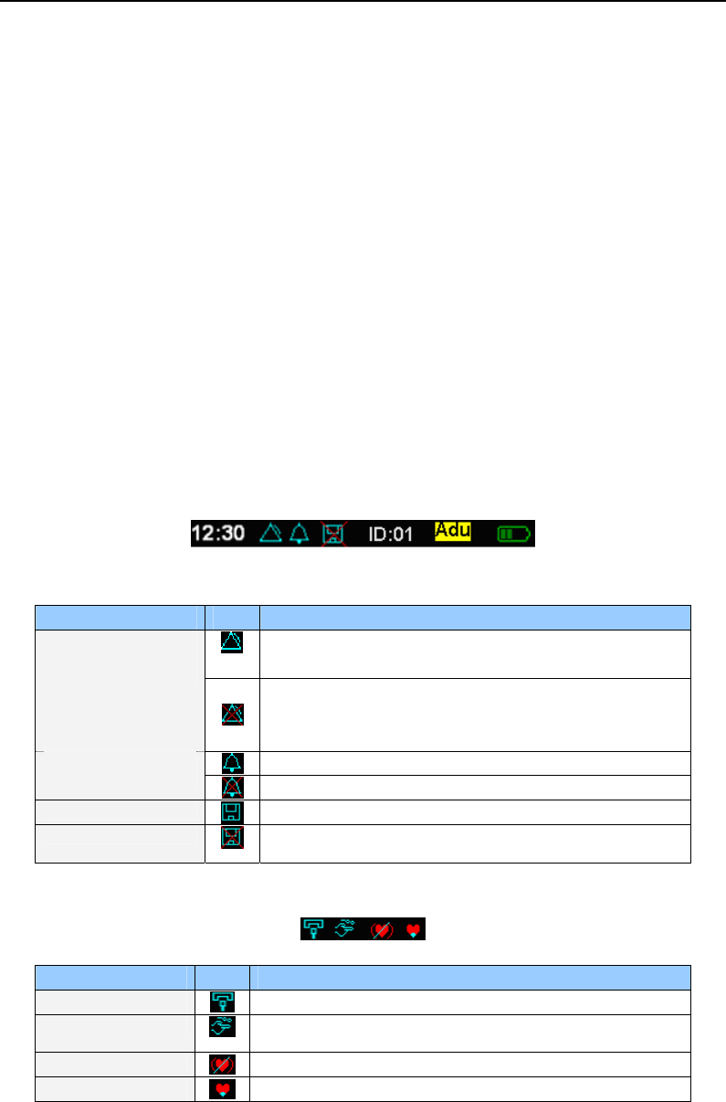
4.3.4 Information Column
From left to right ,the information column displays: time, the state of alarm and mute, remaindering
full of magnetic disk, patient’s ID and type and batteries’ charge level. As shown in figure 4-7.
Figure 4-7: Information column
The function of partial icons in Figure 4-7 is described below:
Name State Description
It means the general alarm switch is turn on, but one or
more sub-switch maybe have already turn off。
State of alarm
It means the general alarm switch is turn off. At this state,
the monitor can generate any alarms except low voltage
alarming.
It means all alarming sound is turn on.
State of silence It means one or more alarming sound is turn off.
Hint of recording data It means recording historical data for present patient.
Hint of full memory It means full memory for present patient and stopping
recording data.
4.3.5 Status Bar
Name State Function
Loss of sensor icon It will be displayed when the sensor is off.
Loss of finger icon The SpO2 sensor has already been inserted, but the sensor
not attached to the finger, the icon will be shown.
Search pulse icon When the monitor is search pulse, the icon will be shown.
Low signal icon It will be displayed if the patient’s signal is low.
Initial Setup
4-6
4.3.6 Adjust the Volume of Pulse
You can adjust the volume of pulse by using the right/left key in all interfaces except trend graph
interfaces.
4.3.7 Indicating Batteries’ Charge and Recharging
z Be sure to follow local governing ordinances and recycling instructions regarding disposal or
recycling of batteries.
z Do not recharge alkaline batteries.
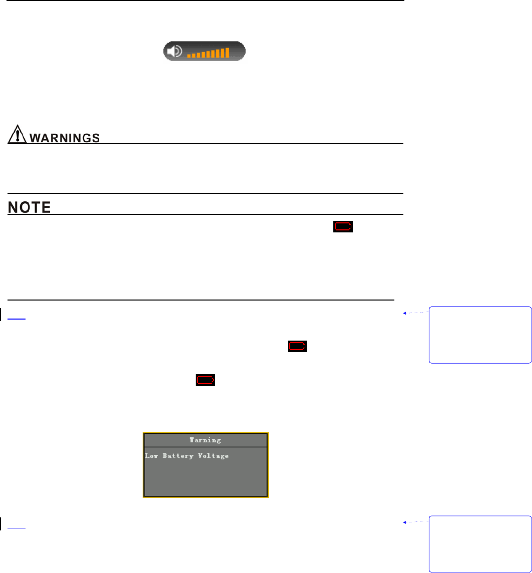
z The system use AA alkaline batteries to estimate remainder time. The icon appears
when there is only approximately 15 minutes of using time remains. The remainder time will
be different if use other kinds of batteries.
z Check the batteries periodically for corrosion. If don’t use the monitor for three months or
more time, please take all batteries away.
z Indicating batteries charge
When the monitor is working, the battery-shaped icon in information column will show remainder
charge. When approximately 15 minutes of charge time remains, will wink and begin low
battery voltage warning, as shown in figure 4-8.
Figure 4-8: low charge icon
If the voltage is excessive low, the monitor will come out a window to reminder user that the monitor
must be shut down and the progress can not be terminable, as shown in figure 4-9.
Figure 4-9: low voltage warning screen
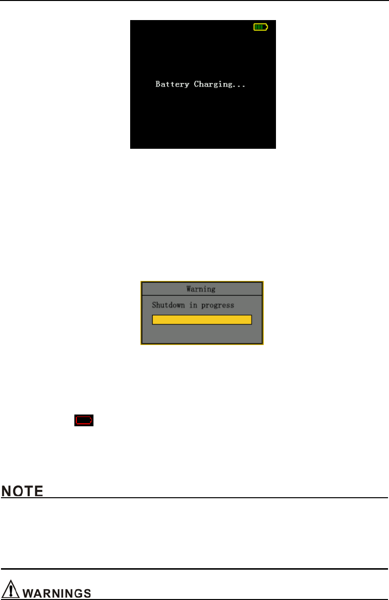
z Internal Recharge Function
When the monitor is connected to an external power source (even if the monitor is turned off), the
battery pack charges automatically. When charging, the battery-shaped icon displays a dynamic
pattern, press On/Off key to enter double waveform interface. After charging, the battery-shaped icon
will show filling pattern, press On/Off key to enter main monitoring interface. If user pulls the charger
out or breaks the pedestal away when the monitor is closed, it will turn off automatically. The charging
screen is shown in figure 4-10.
带格式的: 缩进: 左侧: 0
厘米, 首行缩进: 0 厘米,
项目符号 + 级别: 1 + 对
齐位置: 0.63 厘米 + 制
表符后于: 1.38 厘米 + 缩
进位置: 1.38 厘米, 制
表位: 不在 3.71 字符
带格式的: 缩进: 左侧: 0
厘米, 首行缩进: 0 厘米,
项目符号 + 级别: 1 + 对
齐位置: 0.63 厘米 + 制
表符后于: 1.38 厘米 + 缩
进位置: 1.38 厘米, 制
表位: 不在 3.71 字符
Initial Setup
4-7
Figure 4-10: Charging screen
When the monitor is working, if you connect it to AC adapter or put it on pedestal, the
battery-shaped icon at information column displays a dynamic pattern from 1 to 4 panes. You can
continue using the monitor if user pulls the charger out or breaks the pedestal away in working mode.
4.3.8 Shut Down
1) Shut down normally
Press the On/Off key for full gauge to shut down the monitor when it’s working. The monitor will
come out a window, as shown in figure 4-11.
Figure 4-11: Shut down normally
2) Shut down in low voltage
The monitor turns itself off automatically when batteries are depleted.
The system enters into the state of low voltage, when approximately 15 minutes of charge time
remains. The icon will wink and stored trend data is saved in memory. After that, the historical
data can’t be saved, so please shut it down normally and change batteries.
If the voltage is excessive low, the monitor will come out a window to reminder user that the monitor
must be shut down and the progress can not be terminable, as shown in figure 4-9.
z You can stop shutting the monitor down if it closed automatically because of low voltage.
z The low voltage is distinguished by alkaline battery. That is different for Ni-MH battery, but it
doesn’t matter with using the monitor.
z If you press On/Off key when the AC adapter is inserted, the system will enter the state of
dormancy after full gauge.

Initial Setup
4-8
z In order to keep optimal performance of the equipment, please open the monitor at least 30
seconds after being shut down or cut power.
z The historical data can be saved as the battery-shaped icon winking. After that the data won’t be
saved even if shut down the monitor normally.
4.4 Storage
Remove the batteries from the instrument before long-term storage, or if the device won't be used
for 6 months or more. This protects the device from damage due to batteries leaking acid.
Store the device in its original shipping carton and packing materials to help protect the device
from damage during storage.
4.5 Environment of Protection
For minimizing risks, discard the used-up batteries and this monitor according to your local
government organization rules, ROHS(2002/95/EC)and WEEE(2002/96/EC).
4.6 Impact of Performance Consideration
Inaccurate SpO2 measurements can be caused by:
z Prolonged and/or excessive patient movement;
z Anaemia;
z Venous pulsations;
z Intravascular dyes, such as indocyaninegreen or methylene blue;
z Significant levels of dysfunctional hemoglobins;
z Defibrillation.
The affects of electromagnetic interference on oximetry reading is discussed in the
Troubleshooting and Maintenance section of this manual.
Inaccurate CO2 measurements can be caused by:
z Trachea’s entanglement or strangulation.
z Reuse, disassembly, cleaning, disinfecting or sterilizing the single patient use CO2 airway adapters
z Air flow adapter is damaged.
z CO2 Sensor is damaged.
z CO2 Sensor is wet or has exterior condensation.
z Nitrous oxide, elevated levels of oxygen, helium and halogenated hydrocarbons can influence the
CO2 measurement.
z Air flow adapter windows are dirty.
z CO2 Sensor windows are dirty.
z Patient’s secretion.
z CO2 Sensor is forgotten to reset the air flow adapter.
z CO2 Sensor did not be set and compensated according to the environment.
Ambient environmental conditions and sensor application errors, which can affect pulse oximetry
and CO2 readings, are discussed in the Probe section of this manual and in the probe directions for
use.
带格式的: 缩进: 左侧: 0
厘米, 悬挂缩进: 3.6 字符,
项目符号 + 级别: 1 + 对
齐位置: 0.63 厘米 + 制
表符后于: 1.38 厘米 + 缩
进位置: 1.38 厘米, 制
表位: 1.71 字符, 列表制
表位 + 不在 3.71 字符
带格式的: 缩进: 左侧: 0
厘米, 悬挂缩进: 3.6 字符,
项目符号 + 级别: 1 + 对
齐位置: 0.63 厘米 + 制
表符后于: 1.38 厘米 + 缩
进位置: 1.38 厘米, 制
表位: 1.71 字符, 列表制
表位 + 不在 3.71 字符
Interface and Function
5-1
5. Interface and Function
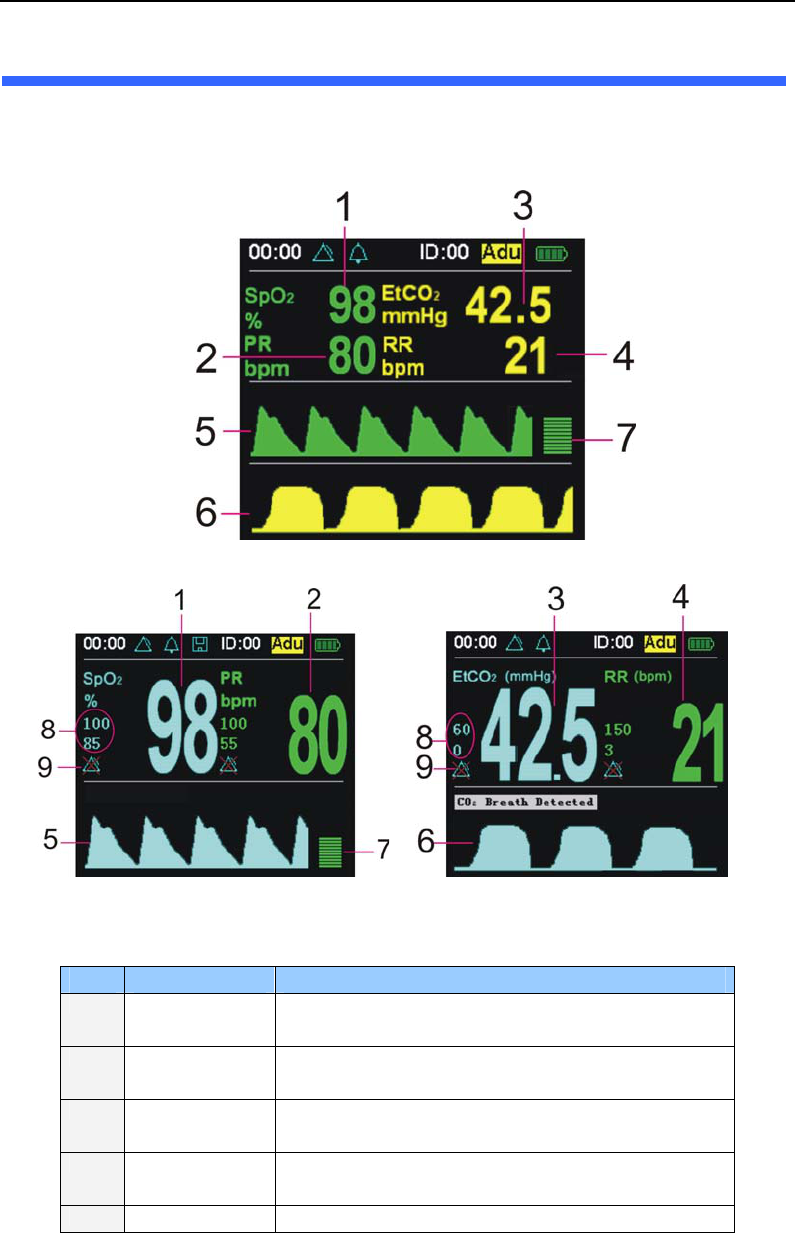
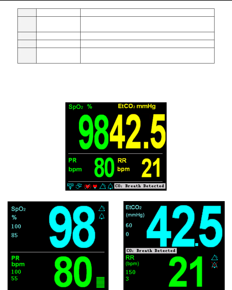
5.1 Main Monitoring Interface
After turning on the monitor, you will enter into the main monitoring interface. Its function is
displaying parameter of patient’s vital signals. Refer to figure 5-1.
(a) Double waveform interface
(b) Single SpO2 module monitoring interface (c) Single CO2 module monitoring interface
Figure 5-1: Main monitoring interface
Label Description Function
1 SpO2 Numeric
Field
Display the current SpO2 value. If it doesn’t measure
SpO2, it will display“- - -”
2 PR Numeric
Field
Display the current value. If it doesn’t measure PR it will
display“- - -”.
3 EtCO2 Numeric
Field
Display the current value. If it doesn’t measure EtCO2 it
will display“- - -”.
4 RR Numeric
Field
Display the current value. If it doesn’t measure RR it will
display“- - -”.
5 SpO2 waveform When it is measuring SpO2, it displays SpO2 waveform. It
Interface and Function
5-2
shows a beeline when it doesn’t.
6 EtCO2 waveform When it is measuring EtCO2, it displays EtCO2 waveform.
It shows a beeline when it doesn’t.
7 Pulse histogram Display the intension of pulse.
8 Alarm Limits It shows the high and low limit of the parameter.
9 Alarm Switch When it is displaying means the alarm of this parameter
is closed.
Note: Press the up and down key to switch the main monitoring interface, big chart mode, trend plot
interface, trend table and event table circularly.
5.2 Big Chart Mode
Press down key to switch real-time monitoring interface to big chart mode, as shown in figure 5-2.
(a) Big chart mode of SpO2 and CO2 module
(b) Big chart mode of single SpO2 module (c) Big chart mode of single CO2 module
Figure 5-2: big chart mode
At monitoring interface, press MUTE key can shut down the sound of alarming or resume all
alarms.
5.3 Real-time Trend Interface
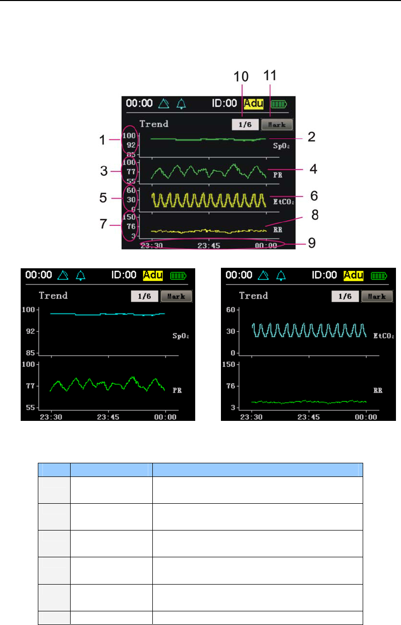
5.3.1 Trend Graph Interface
Press down key to enter into real-time trend interface. It displays trends of the parameters such as
Interface and Function
5-3
SpO2 and PR. It records 1 point every 10 seconds acquiescently in 6 pages. Shut down the monitor,
change date, ID and precision will cause losing the current data and the new real-time trend will be
shown. As shown in figure 5-3. Press right/left key to switch every single parameter’s trend graph
screen.
(a) Trend graph interface of Spo2 and CO2 module
(b) Trend graph interface of single SpO2 module (c) Trend graph interface of single CO2 module
Figure 5-3: Trend graph interface
Label Description Function
1 SpO2 scale ruler Mark SpO2 trend graph’s value range and range of
alarm limits.
2 SpO2 trend graph In order to analyze data, protract SpO2 trend in a
period of time according SpO2 historical data.
3 PR scale ruler Mark PR trend graph’s value range and range of
alarm limits.
4 PR trend graph In order to analyze data, protract PR trend in a
period of time according PR historical data.
5 EtCO2 scale ruler Mark EtCO2 trend graph’s value range and range of
alarm limits.
6 EtCO2 trend graph In order to analyze data, protract EtCO2 trend in a
Interface and Function
5-4
period of time according EtCO2 historical data.
7 RR scale ruler Mark RR trend graph’s value range and range of
alarm limits.
8 RR trend graph In order to analyze data, protract RR trend in a
period of time according RR historical data.
9 Time scale Mark the time scale of this page and time.
10 Selective frame
for turning pages
over
Select the page you want to see trends.
11 Marked button Mark trend of current time.
In the trend graph interface, press OK key to enter operation mode, use right and left key to move
focus and press the MENU key to exit operated mode:
◆selective frame for turning pages over: Move focus to the selective frame, press OK key and
then press the right and left key to select the page you want to see its trend circularly. Press OK
key to drop out operation mode.
Mark◆ button: move focus on mark button, press OK key to set a mark of current time at trend
graph. The mark will move leftwards at the trend graph with time.
z The real-time trend data will be cleared when open the monitor or change patient’s ID every
time. Pictures are protracted step by step from the right side of the screen until it fills in the
whole screen and then the whole waveform will move leftwards. If there no measured patient,
the picture still move leftwards.
z The time to display current trend is different because of different precision. The longest is 18
hours. The historical trends will covered by the new ones if the monitoring time exceeds the
displaying time.
z Shutting down the monitor will cause the losing of real-time trend data.
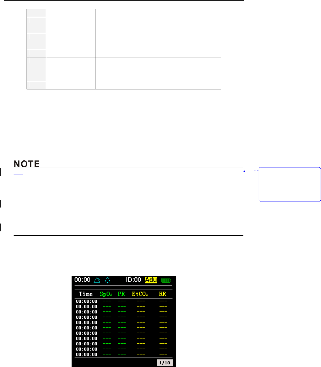
5.3.2 Trend Table Interface
Press down key to enter into trend table interface. Every line of the table will display the data of
every parameter in every time which is recorded in the trend plot interface. As shown in figure 5-4.
(a) Trend table interface of SpO2 and CO2 module
带格式的: 缩进: 左侧:
1.71 字符, 悬挂缩进: 3.6
字符, 项目符号 + 级别: 2
+ 对齐位置: 0.74 厘米 +
制表符后于: 1.48 厘米 +
缩进位置: 1.48 厘米, 制
表位: 不在 4 字符
Interface and Function
5-5
(b) Trend table interface of single SpO2 module (c) Trend table interface of single CO2 module
Figure 5-4: Trend table interface
5.3.3 Saving Historical Trend
Historical trend will be saved in magnetic disk with the following ways:
When patient’s ID number is 00, it does not save historical trend data.
When patient’s ID number is 01~99, it can save historical trend data in recent 72 hours. If
there is no enough room for present user, the icon in the status bar will wink to remind you
that the data won’t be save from now on.
The historical data is saved every 10 seconds acquiescently. The recorded data include the
value of SpO2, PR, CO2, RR.
z Historical trend data will be saved if the monitor shut down normally. But if batteries are taken
away abruptly, the data will lose.
z Historical trend data will be saved at the moment of changing patient’s ID.
z Historical trend data will be saved if there is a low voltage alarm. And then the monitor enters
into the status of low voltage. Please replace batteries in time. At the status of low voltage, it
will no longer save data even if it shut down normally.
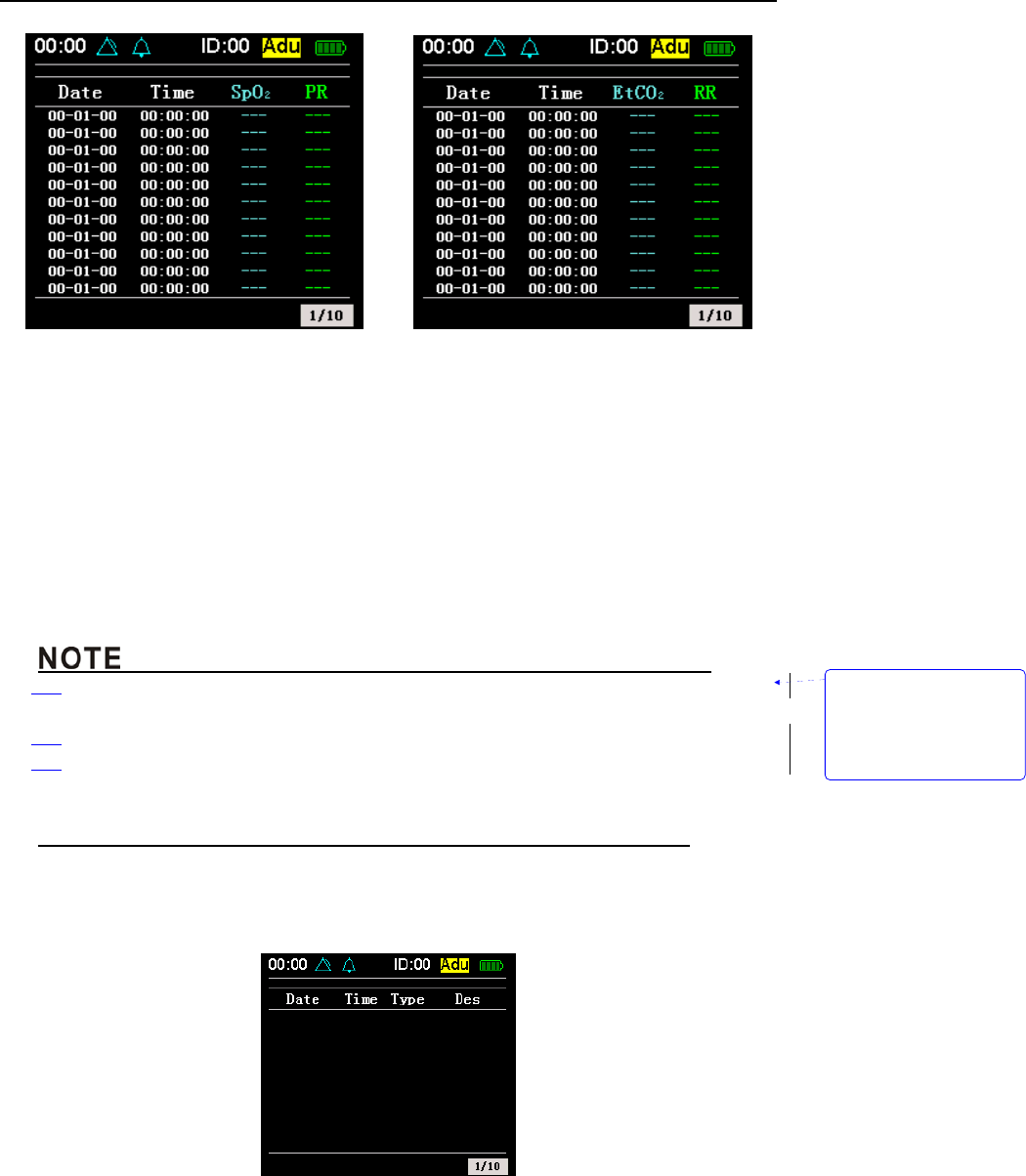
5.4 Event Table Interface
Press down key to enter into event table interface. The event table will show the alarm records of
SpO2, PR or ETCO2, RR or all the four parameters. Refers to figure 5-5.
Figure 5-5: Event table
带格式的: 缩进: 左侧:
1.71 字符, 悬挂缩进: 3.6
字符, 项目符号 + 级别: 2
+ 对齐位置: 0.74 厘米 +
制表符后于: 1.48 厘米 +
缩进位置: 1.48 厘米, 制
表位: 不在 4 字符
Interface and Function
5-6
Operation:
1. You can use the right and left key to turn over pages circularly after pressing OK key when
the focus is on the selective frame. Press OK key again to drop out turning pages.
z The event table will only record alarms happened recently in 10 pages.
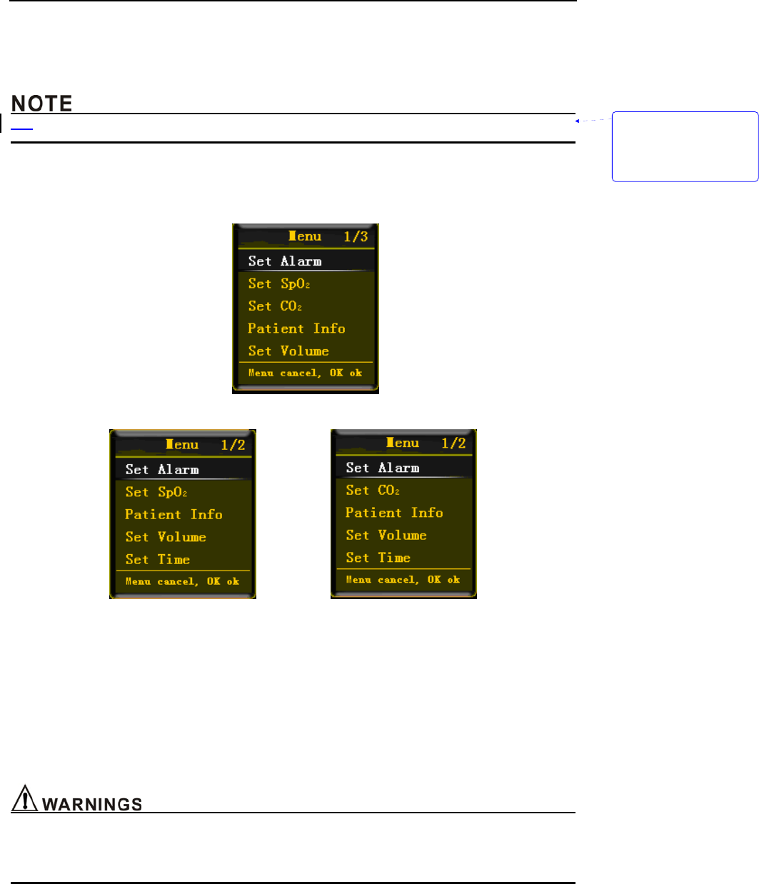
5.5 Setting Menu Interface
At the real-time monitoring interface, big chart mode, trend interface and event table interface,
press MENU key to enter menu interface. As shown in figure 5-6.
(a) Menu of SpO2 and CO2 module
(b) Menu of single SpO2 module (c) Menu of single CO2 module
Figure 5-6: Menu interface
Operation:
1. In the menu, press MENU key can exit.
2. Use up and down key to select different option.
3. Press OK key to affirm your option.
4. After that, a dialog box will come out.
5.5.1 Setting Alarm Limits
z The monitor’s alarm function will be affected by environmental light, EMC and noise and so on.
z The sounds of alarms and the wink of monitoring data on the screen must be audible and visual
by operator.
带格式的: 缩进: 悬挂缩进:
8.4 字符, 项目符号 + 级
别: 2 + 对齐位置: 0.74
厘米 + 制表符后于: 1.48
厘米 + 缩进位置: 1.48 厘
米, 制表位: 不在 4 字符
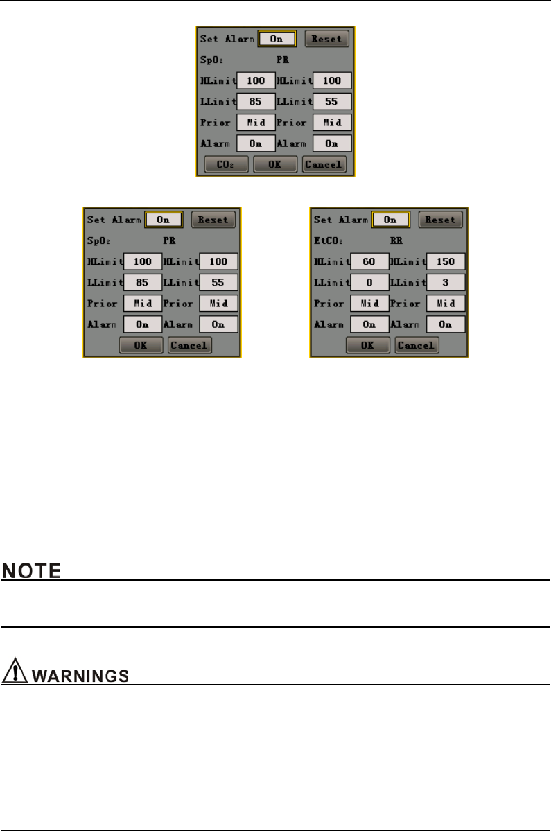
Interface and Function
5-7
(a) Set alarm for SpO2 and CO2 module
(b) Set alarm for single SpO2 module (c) Set alarm limits for single CO2 module
Figure 5-7: Set alarm limits
Operation:
1. Use up, down, right, left key to move focus. When the focus is on OK or Cancel button, press
OK key can save or give up saving settings, then the dialog box will disappear. Pressing
MENU key is equal to choosing Cancel button.
2. Press OK key to enter compiling state, and use right and left key to change limits, then press
OK to exit.
3. When the focus moves to CO2 option, press OK key to switch to set alarm limit of EtCO2 and
RR. (Only for SpO2 and CO2 module).
z If alarm default limit is changed, a decimal point appears behind the displayed value during
monitoring. The decimal point remains on display until the limit is returned to its default value.
z It should be only the professional to adjust the alarm high/low limit. Alarm high limit can not lower
than alarm low limit.
z The alarm system will be invalid if set alarm high/low limit out of the range of alarm limit.
z When patient needs to be looked after specially, inadequacy alarm limit will cause the delay or
invalidation of alarm signal.
z Make sure that the monitor default alarm settings are appropriate for the specific patient being
monitored.
Interface and Function
5-8
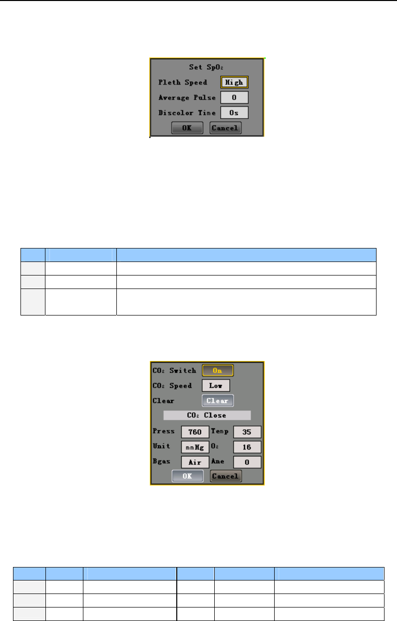
5.5.2 Setting SpO2
In the setting menu, you can choose “Set SpO2” option. As shown in figure 5-8.
Figure 5-8: Set SpO2 (Not suitable for single CO2 module)
Operation:
1. Use up, down, right, left key to move focus. When the focus is on OK or Cancel button, press
OK key can save or give up saving settings, then the dialog box will disappear. Pressing
MENU key is equal to choosing Cancel button.
2. Move the focus to “Pleth Speed” , “Average Pulse” or “ Discolor Time”, press OK key first and
then use up and down key to change the value, press OK to affirm your setting.
NO. Name Option
1 Pleth Speed High, Low
2 Average Pulse 4,8,16
3 Discolor Time 1, 10, 30. It means the interval to change the color of Spo2
waveform according alarming level when alarm occurs.
5.5.3 Setting CO2
In the setting menu, you can choose “Set CO2” option. As shown in figure 5-9.
Figure 5-9: Set CO2 (Not suitable for single SpO2 module)
Operation:
1. Use up, down, right, left key to move focus. When the focus is on OK or Cancel button, press
OK key can save or give up saving settings, then the dialog box will disappear. Pressing
MENU key is equal to choosing Cancel button.
2. User can move focus to switch CO2, set the speed of waveform, zeroing, parameters of CO2.
NO. Name Description NO. Name Description
1 Press barometric pressure 4 O2 O
2 compensation
2 Temp gas temperature 5 Bgas balance gas
3 Unit current CO2 units 6 Ane anesthetic agent
Interface and Function
5-9
5.5.4 Setting Patient’s Information
In the setting menu, you can choose “Patient Info” menu to set patient’s ID, sex and type. As
shown in figure 5-10.
Figure 5-10: Set patient’s information
Operation:
1. Use up, down, right, left key to move focus. When the focus is on OK or Cancel button, press
OK key can save or give up saving settings, then the dialog box will disappear. Pressing
MENU key is equal to choosing Cancel button.
2. You can change patient’s ID from 0 to 99.The types of patient are adult, pediatric and neonate
and the sexes are male and female.
3. When you choose the New button, the system will auto-generate a new ID. You can’t use the
New button, if there no available ID.
4. If you choose an ID that has never been used, press OK key can change ID number and then
the dialog box will exit. If the ID you choose is existing, it will remind you to substitute the
former ID or cancel your operation.
5. If you choose to substitute the ID, the historical data of this ID will be cleared, and the restart
to record new data, then the dialog box will disappear. If you choose to cancel your setting,
then return to setting ID interface with the disappearance of the dialog box.
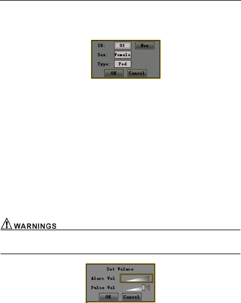
5.5.5 Setting Volume
z Do not turn off the audible alarm or decrease the audible alarm volume if patient safety could be
compromised.
Figure 5-11: Set volume
Operation:
1. Use up, down, right, left key to move focus. When the focus is on OK or Cancel button, press
OK key can save or give up saving settings, then the dialog box will disappear. Pressing
MENU key is equal to choosing Cancel button.
2. Adjust the volume with the right and left and press the up and down key to move the focus,
and then press OK to confirm your setting.
Interface and Function
5-10
5.5.6 Setting Time and Date
Figure 5-12: Set time and date
Operation:
1. Use right and left key to move focus, and press OK to enter compiling state, press OK again
to exit.
2. When the focus is on OK or Cancel button, press OK key can save or give up saving settings,
then exit from the dialog box.
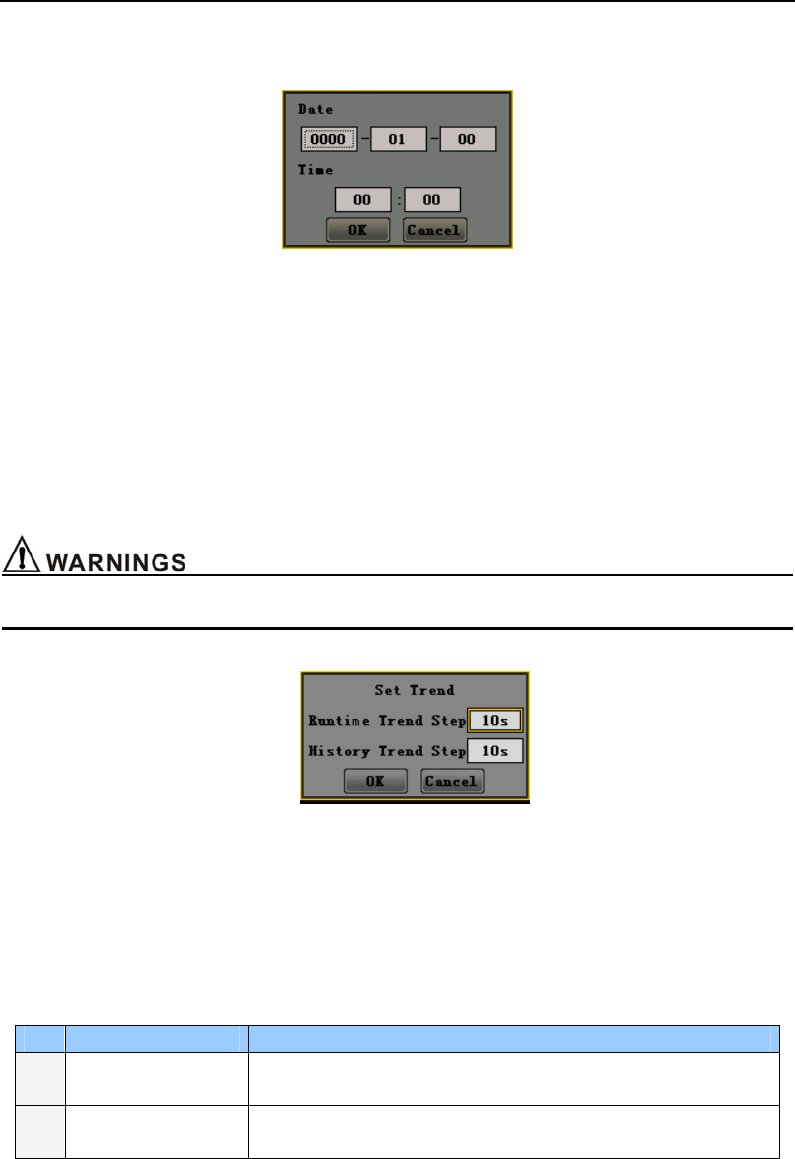
5.5.7 Setting Trend
Select the “Set trend “submenu in the setting menu and you can adjust the trend record step. As
shown in Figure 5-13.
z If you change the steps, the data have saved will be lost.
Figure 5-13: Set trend
Operation:
1. Use up, down, right, left key to move focus. When the focus is on OK or Cancel button, press
OK key can save or give up saving settings, then the dialog box will disappear. Pressing
MENU key is equal to choosing Cancel button.
2. User can move focus to step, press the up/down key to change step. The default value is 10
seconds.
NO. Name Option
1 Runtime Trend Step 1, 5,10,30,60. It means the trend data saving interval in the
monitor.
2 History Trend Step 1, 5,10,30,60. It means the trend data saving interval you can
watch on PC.
5.5.8 Data Output
In the setting menu, you can choose “data output” option to enter data output interface. As shown
Interface and Function
5-11
in figure 5-14.
Figure 5-14: Data output
Operation:
1. Open the “data output “interface in the setting menu.
2. Plug wireless USB Dongle into USB port in PC, and then run the historical data analytical
software. Choose the “Connect instrument” of the software.
3. If it has found instrument, the software will remind you to choose the patient’s ID which you
want to upload to PC. After that, you can upload patient’s data to PC. You can also delete
appointed patient’s data.
4. At the process of sending data, you can press Stop button to stop it. Then the dialog box will
disappear.
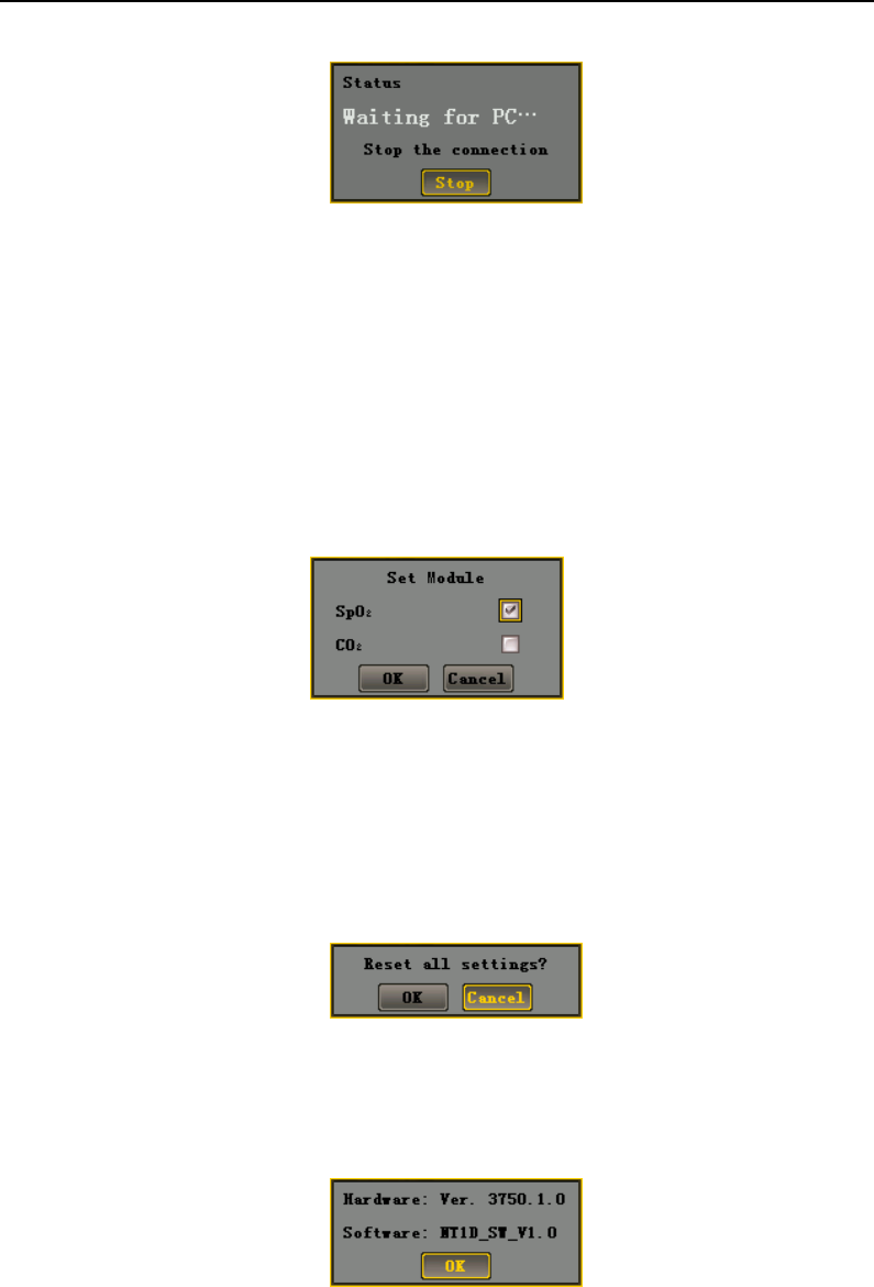
5.5.9 Set Module
Figure 5-15: Set Module
There are three modules of the monitor including the SpO2 and CO2 Module, the Single SpO2
Module and the Single CO2 Module. You can choose one of these to run after entering “Set Module”
submenu.
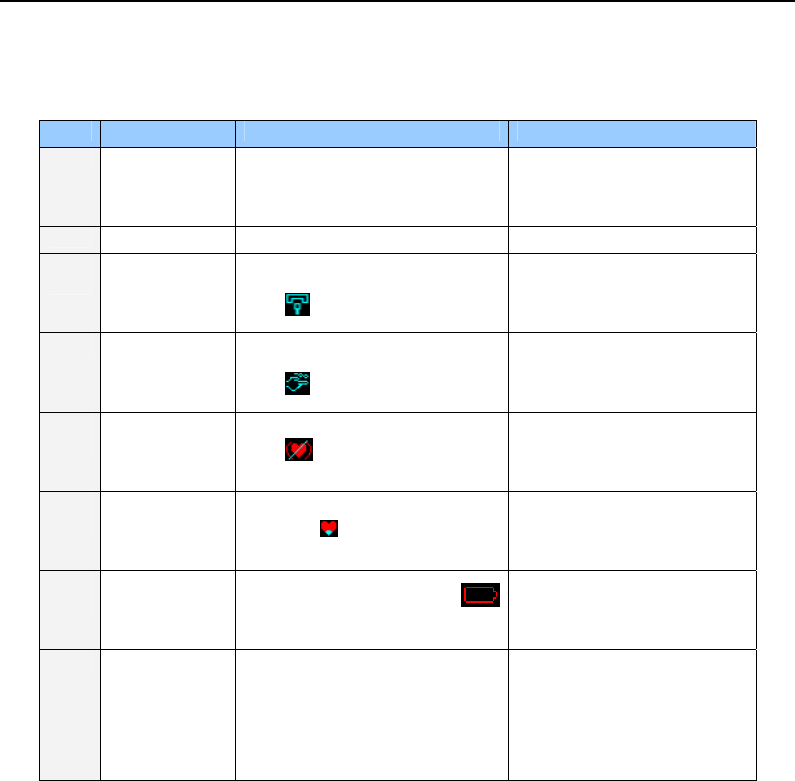
5.5.10 Resume Settings
Entering into the “Reset setting “submenu can resume all settings you have changed. As shown in
figure 5-16.
Figure 5-16: Resume settings
5.5.11 System Information
System information includes the information of hardware, software and product and so on. The
interface is tolerant and can not to be changed. As shown in figure 5-17.
Figure 5-17: System information
Operation:
1. Press OK key to exit the dialog box.
Interface and Function
5-12
5.6 Audible and Visual Indication
The following audible indications do not change with symbols, key board or visual indication:
Label Description Visual indication Audible indication
1
Setup
When self testing, the indicator
will wink red, green and yellow
color once.
One sound ,“dee”
2 Pulse sound / One sound ,“dee”
3
Sensor falls off
The red light will wink and the
icon will be displayed.
Dee,dee,dee-dee,dee
Dee,dee,dee-dee,dee
Period: 10s
4
Loss of finger
The red light will wink and the
icon will be displayed.
Dee,dee,dee-dee,dee
Dee,dee,dee-dee,dee
Period: 10s
5
Loss of pulse
The red light will wink and the
icon will be displayed.
Dee,dee,dee-dee,dee
Dee,dee,dee-dee,dee
Period: 10s
6
Poor signal
The icon will be displayed.
Dee,dee,dee-dee,dee
Dee,dee,dee-dee,dee
Period: 10s
7
Low voltage The red light and the icon
will wink.
Dee,dee,dee-dee,dee
Dee,dee,dee-dee,dee
Period: 10s
8 Alarm sound The red light will wink in high
priority. The yellow light will wink
in medium priority. And the
related parameter values will
wink at the same time.
Dee,dee,dee
Period of high priority:10s
Period of medium priority:25s
Monitoring SpO2
6-1
6. Monitoring SpO2
6.1 Overview
SpO2 measures functional blood oxygen saturation. It measures the percentage of oxyhemoglobin. It
does not measure carboxyhemoglobin or methemoglobin. For example, if 97% of red blood cells in the
artery are oxygenated, then blood has 97% blood oxygen saturation. The monitor SpO2 value reading
would be 97.
SpO2 measurement is a non-invasive, continuous measurement through a SpO2 sensor attached to a
patient’s finger. The sensor is connected directly to the SpO2 module. There are three types of display
for SpO2: percentage (%), pulse rate, and SpO2 waveform.
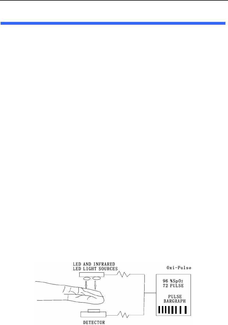
6.2 Principles of Measurement
Pulse oximetry is based on two principles: 1.That oxyhemoglobin and deoxyhemoglobin differ in their
absorption of red and infrared light (i.e., Spectrophotometry), and 2.that the volume of arterial blood in
tissue (and hence, light absorption by that blood) changes during the pulse (i.e., plethysmography). A
pulse oximeter determines SpO2 by passing red and infrared light into an arteriolar bed and measuring
changes in light absorption during the pulsatile cycle. Red and infrared low-voltage light-emitting
diodes (LEDs) in the oximetry probe serve as light sources; a photodiode serves as the photo detector.
Because oxyhemoglobin and deoxyhemoglobin differ in light Absorption, the amount of red and
infrared light absorbed by blood is related to hemoglobin oxygen saturation .To identify the oxygen
saturation of arterial bemoglobin, the monitor uses the pulsatile nature of arterial flow. During systole,
a new pulse of arterial blood volume and light absorption increase.
During diastole, blood volume and light absorption reach their lowest point .The monitor bases its
SpO2 measurements on the difference between maximum and minimum absorption (i.e.,
Measurements at systole and diastole). By doing so, it focuses on light absorption by pulsatile arterial
blood, eliminating the effects of nonpulsatile absorbers such as tissue, bone, and venous blood.
The Pulse oximeter determines SpO2 and pulse rate by passing two wavelengths of light, one red and
one infrared, through body tissue to a photodetector. During measurement, the signal strength
resulting from each light source depends on the color and thickness of the body tissue, the probe
placement, The intensity of the light sources, and the absorption of the arterial and venous blood
(including the time varying effects of the pulse) in the body tissue. (Refer To Figure 6-1)
Figure 6-1: SpO2 theory of operation
The Pulse Oximeter processes these signals, separating the time invariant parameters (tissue
thickness, skin color, light intensity, and venous blood) from the time variant parameters (arterial
volume and SpO2) to identify the pulse rate and calculateoxygen saturation. Oxygen saturation

Monitoring SpO2
6-2
calculations can be performed because oxygen saturated blood predictably absorbs less red light than
oxygen depleted blood.
6.2 Abnormal State of SpO2 Measurement:
After turning on the monitor, if the sensor is installed incorrectly or there are other wrong operations,
the following situation may happen:
1) The SpO2 sensor has already been inserted, but the sensor not attached to the finger, the icon
“” will wink and SpO2 and PR display area has display“- - -”,At the same time, the monitor
will generate lost reminder sound in every 10 seconds.
2) Pulse search mode: If patient is connected with the sensor, the monitor attempts to search pulse.
The icon “ ” will wink. At the same time, display shows display“- - -”in %SpO2 and PR areas.
Normally the search mode process is approximately 10 seconds. If the pulse search is failed, the
monitor generates high alarm.
3) The sensor falling off. The icon “ ” will be displayed.
4) Hinting poor signal. The icon “ ” will displayed.
6.4 Directions for SpO2 Sensor Use
Single patient use SpO2 sensor and SpO2 saturation monitor compose the system to use to examine
the adult, pediatric's blood oxygen degree of saturation (SpO2) and (or) the arteries rate (PR)
physiological parameter and so on. The use situation is not restricted in the specialized medical
establishment the patient guardianship room, the operating room, the first-aid room, the emergency
room and the technique the observation room. Its use cycle generally is 7days to 15 days for a person
in hospitalized.
z The sensor isn’t suitable for continuous and long term SpO2 monitoring. Continuous and long term
monitoring may cause skin to become irritated, reddening, blistering or necrosis.
z The SpO2 sensor has passed biologic compatibility experiments like cell’s toxicity, stimulative test
under skin and scratch test and so on.
Steps:
1) Hold the sensor with its opening towards the patient’s index finger (A). The sensor should be
oriented in such a way that the sensor side with a cable is positioned on the top (B). If an index
finger cannot be positioned correctly, or is not available, other fingers can be used.

Monitoring SpO2
6-3
Figure 6-2: Placement of sensor
2) Insert the patient’s index finger into the sensor until the fingernail tip touches the end of the
sensor. Adjust the finger to be placed evenly on the middle base of the sensor (C).
3) Plug the sensor into the monitor and verify proper operation as described in the monitor
operator’s manual.
4) Inspect the monitoring site every 4 hours for skin integrity.
5) Before each use, surface-clean sensor and cable with a soft gauze pad by saturating it with a
solution such as 70% isopropyl alcohol. If low-level disinfection is required, use a 1:10 bleach
solution.
z Do not sterilize by irradiation steam, or ethylene oxide.
z Do not use a blood pressure cuff or arterial blood pressure measurement device on the same limb
as the sensor.
6.5 Measuring Restriction
6.5.1 The following may affect the accuracy of SpO2 measurement:
High frequency electrical interference from the monitor itself or from ambient electrical
instruments connected to the system.
Patient’s excess movements.
Inductive current generated from MRI can cause burn.
Outside light radiation.
Incorrect sensor placement.
Sensor temperature (suitable temperature range should be 28 ℃- 41 )℃
The same limb used for sensor, NTBP cuff, artery tube or inner tube.
Presence of COHb, MetHb and dyestuff.
Low signal.
Bad perfusion on sensor site.
Coma, anemia, low temperature and insufficient blood flow caused by drugs.

Monitoring SpO2
6-4
z The maximum time duration for one sensor site in use should not be over 4 hours. The sensor
surface temperature should not be higher than 41ºC, or it may cause burn.
z During continuous monitoring, sensor site should be cleaned at least every 12 hours. Otherwise it
may result in inaccurate measurements.
6.5.2 Inaccurate measurements can be caused by:
Incorrect application of the sensor;
Patient’s finger is too big or its blood cycle doesn’t well;
Failure to cover the sensor site with opaque material in high or ambient light conditions;
prolonged and/or excessive patient movement;
Intravascular dyes, such as indocyaninegreen or methylene blue;
Interavascular dyes or externally applied coloring, such as nail polish or pigmented cream;
Venous pulsations;
Significant levels of dysfunctional hemoglobins
Lack of supplying blood.
6.5.3 Loss-of-pulse signal can occur for the following reasons:
The sensor is applied too tightly;
Defibrillation;
A blood pressure cuff is inflated on the same extremity as the one with the sensor attached;
There is arterial occlusion proximal to the sensor;
Poor peripheral profusion;
Losing of pulse or stopping of heart.
Select an appropriate sensor, apply it as directed, and observe all warnings and cautions presented in
the directions for use accompanying the sensor. Clean and remove any substances such as nail polish
from the application site. Periodically check to ensure that the sensor remains properly positioned on
the patient.
High ambient light sources such as surgical lights (especially those with a xenon light source), bilirubin
lamps, fluorescent lights, infrared heating lamps, and direct sunlight can interfere with the performance
of a SpO2 sensor. To prevent interference from ambient light, ensure that the sensor is properly applied,
and cover the sensor site with opaque material.
If patient movement presents a problem, try one or more of the following remedies:
Verify that the sensor is properly and securely applied;
Move the sensor to a less active site;
Use an adhesive sensor that tolerates some patient motion;
Use a new sensor with fresh adhesive backing;
Try to keep patient quiet.
z Failure to cover the sensor site with opaque material in high ambient light conditions may result in
带格式的: 缩进: 左侧: 0
厘米, 悬挂缩进: 3.6 字符,
项目符号 + 级别: 2 + 对
齐位置: 0.74 厘米 + 制
表符后于: 1.48 厘米 + 缩
进位置: 1.48 厘米, 制
表位: 不在 4 字符
带格式的: 缩进: 左侧: 0
厘米, 悬挂缩进: 3.6 字符,
项目符号 + 级别: 1 + 对
齐位置: 0 厘米 + 制表符
后于: 0.74 厘米 + 缩进位
置: 0.74 厘米, 制表位:
1.71 字符, 列表制表位 +
不在 2 字符

Monitoring SpO2
6-5
inaccurate measurements.
z You can select and use sensor to realize how to deal with patient and environment.
z Do not sterilize by irradiation steam, or ethylene oxide. Wipe the monitor with cloth dampened with
soft suds and then wipe surfaces dry. Wipe the sensor with cloth with alcohol if necessary. Note:
Do not spray or pour any liquid directly on the monitor, accessories or consumables.
z Pulse oximetry readings and pulse signal can be affected by certain ambient environmental
conditions, sensor application errors, and patient conditions.
z Tissue damage can be caused by incorrect application or inappropriate duration of use of a SpO2
sensor. Inspect the sensor site as directed in the sensor Directions for Use.
z Inspect the monitoring site every 4 hours for skin integrity.
带格式的: 缩进: 左侧: 0
厘米, 悬挂缩进: 3.6 字符,
项目符号 + 级别: 1 + 对
齐位置: 0 厘米 + 制表符
后于: 0.74 厘米 + 缩进位
置: 0.74 厘米, 制表位:
1.71 字符, 列表制表位 +
不在 2 字符

Monitoring SpO2
6-6
This page is intentionally left blank.

Monitoring CO2
7-1
7. Monitoring CO2
7.1 Overview
The CO2 Sensor is used for the continuous measurement of CO2 and respiratory rate. The sensor
measures CO2 by using the infrared absorption technique. The principle is based on the fact that CO2
molecules absorb infrared (IR) light energy of specific wavelengths, with the amount of energy
absorbed being directly related to the CO2 concentration. When an IR beam is passed through a gas
sample containing CO2, the electronic signal from the photo detector (which measures the remaining
light energy) is measured. This signal is then compared to the energy of the IR source and adjusted to
accurately reflect CO2 concentration in the sample. The CO2 Sensor’s response to a known
concentration of CO2 is stored at the factory in the sensor’s memory. A reference channel accounts for
optical changes in the sensor, allowing the system to remain in calibration without user intervention.
7.2 Principles of Measurement
CO2 monitoring is to monitor the respiration of a patient by detecting the concentration of CO2
generated during respiration. The maximum concentration of CO2 at the end of exhalation is called
End-Tide CO2 (EtCO2). The minimum concentration of CO2 at the end of inspiration is called
Inspiration CO2 (FiCO2). CO2 is generated by cells in the body during metabolizing, and is breathed
out via breathing system. The concentration of CO2 breathed out from the lung reflects directly the
situation of metabolizing and breathing system. If the concentration of CO2 is high, it means that
metabolism is over active, such as blood poisoning or acute fever. If the concentration of CO2 is low, it
is commonly due to a weak output ability of the heart, or the heartbeat stopped, or insufficient blood
flow with less oxygen. Monitoring CO2 is used to warn the doctor of the abnormal breathing and
metabolizing during anaesthesia.
The concentration of CO2 is represented as a pressure level, with ‘mmHg’ or % as its unit. Generally,
the acceptable value is 38mmHg (5%) when air pressure is 760mmHg. The concentration of CO2
varies rapidly from 0% to 5%. To detect the concentration of CO2 accurately, the monitor needs to be
very sensitive.
The monitor is used to measure the EtCO2 and respiration rate of adult, infant and neonatal patient
7.3 Medical Use of CO2 Sensor
z The CO2 Sensor is used to continuously monitor carbon dioxide and report ETCO2, inspired CO2
and respiratory rate of the intubated and non-intubated adult, pediatric, and neonatal patient.
z The CO2 Sensor is indicated for use in care areas such as, but not limited to critical care, intensive
care, anesthesia, medical/surgical units, LTAC units, emergency department, sleep labs and
during intra-hospital transport and inter-hospital transport.
z For use in monitoring patients in respiratory distress, respiratory arrest or that have asthma,
COPD or other disorders where the patient’s ETCO2 and capnogram will benefit the caregiver in
the treatment of the patient.
z For use in monitoring patients pre- and post-intubation.
z To assist in the setup, management and weaning of the patient that is connected to a
“conventional” mechanical ventilator.
Monitoring CO2
7-2
7.4 CO2 Sensor Adapter Zero
The sensor is compatible only with appointed CO2 airway adapters. Each airway adapter has a unique
set of optical characteristics. The adapter zero allows the CAPNOSTAT to adjust to the optical
characteristics of each of the different adapter types. An “Adapter Zero” is a quick process that allows
the Host system to adjust to the special characteristics of a particular CO2 Sensor; it is necessary only
when requested. Such a request may occur the first time a particular CO2 Sensor is connected to a
particular Host, or if a change is detected in the CO2 Sensor.
To perform an Adapter Zero:
1)Connect the CO2 Sensor to the Host.
2)Open the Host’s CO2 switch. If it is the first time you open the CO2 switch , Place the CO2 sensor
onto a clean and dry CO2 adapter that is exposed to room air and away from all sources of CO2,
including the ventilator, the patient’s breath and your own. Do not conduct any operation in 20
minutes.
3)Open the MENU and select ”Set CO2” option.
4)Choose “clear” and the CO2 information column will display “ CO2 Zeroing” and “ CO2 Zero OK”
in turn. At the progress of zeroing, do not conduct any operation including breathing, key-press
and so on. Otherwise, the zeroing operation will fail. The time for a zero is 15-20 seconds. If
failed, the information column will hint “CO2 needs zeroing”, choose “Clear” can zero the
adapter again.
z For optimal results, connect the CO2 Sensor to an adapter and wait 2 minutes before performing
the Adapter Zero procedure.
z CO2 readings and respiration rate can be affected by certain ambient environmental conditions,
sensor application errors, and patient conditions.
z Check whether CO2 adapter is damaged or not. Do not use damaged CO2 adapter.
z If the CO2 waveform (Capnogram) appears abnormal, inspect the CO2 airway adapters and
replace if needed.
z Replace the CO2 airway adapters if excessive secretions are observed.
z Monitor the CO2 waveform (Capnogram) for elevated baseline. Elevated baseline can be caused
by sensor or patient problems.
带格式的: 缩进: 左侧: 0
厘米, 悬挂缩进: 3.6 字符,
项目符号 + 级别: 1 + 对
齐位置: 0 厘米 + 制表符
后于: 0.74 厘米 + 缩进位
置: 0.74 厘米, 制表位:
1.71 字符, 列表制表位 +
不在 2 字符
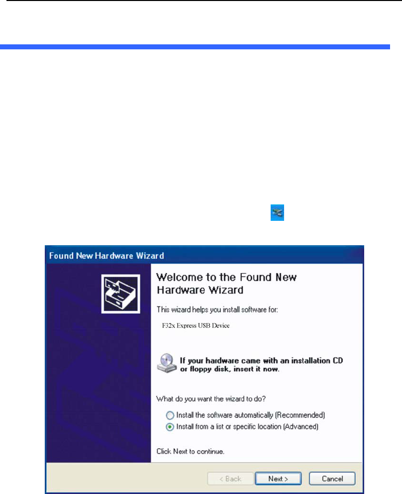
Data output
8-1
8. Data Output
8.1 Driver Installations and Copy of Data Analysis Software
Install the driver “F32x Express USB Driver” and copy the tool folder ” History Data Viewer” from
the enclosed CD to PC before transmitting of data derived from the monitor to PC.
8.1.1 Install USB Drivers
F32x Express USB Drivers is used to drive USB dongle, to install as follows:
1)Insert the enclosed CD into your computer.
2)Plug the USB dongle into the USB faucet in PC, and you will see an automatic popup window
“Welcome to the Found New Hardware Wizard”. Choose “Install from a list or specific location”. Note:
If there is no automatic window, you may double left click the icon on the bottom right corner of
the desktop.
3)Click “Next” and see “Hardware Update Wizard” window as below.
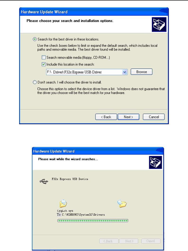
Data Output
8-2
4)Click “Browse” and choose the path G:\Driver\ F32x Express USB Driver. Click “Next” and start
installation.
5)After installation, you will see the window “Completing the Found New Hardware Wizard”.
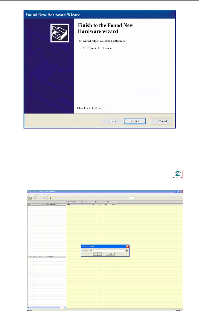
Data output
8-3
Click “Finish” to complete the installation of F32x Express USB Drivers. Once the driver is
installed on PC, there is no need to install for the second time.
8.1.2 Copy the Folder “History Data Viewer”
The software in this folder has the functions of data output, data analysis and printing report.
Copy the folder” History Data Viewer” from CD to PC and enter into it.,dbclick the icon “ ” to start
the main interface of the History Data Viewer software. Click “OK” to start it.
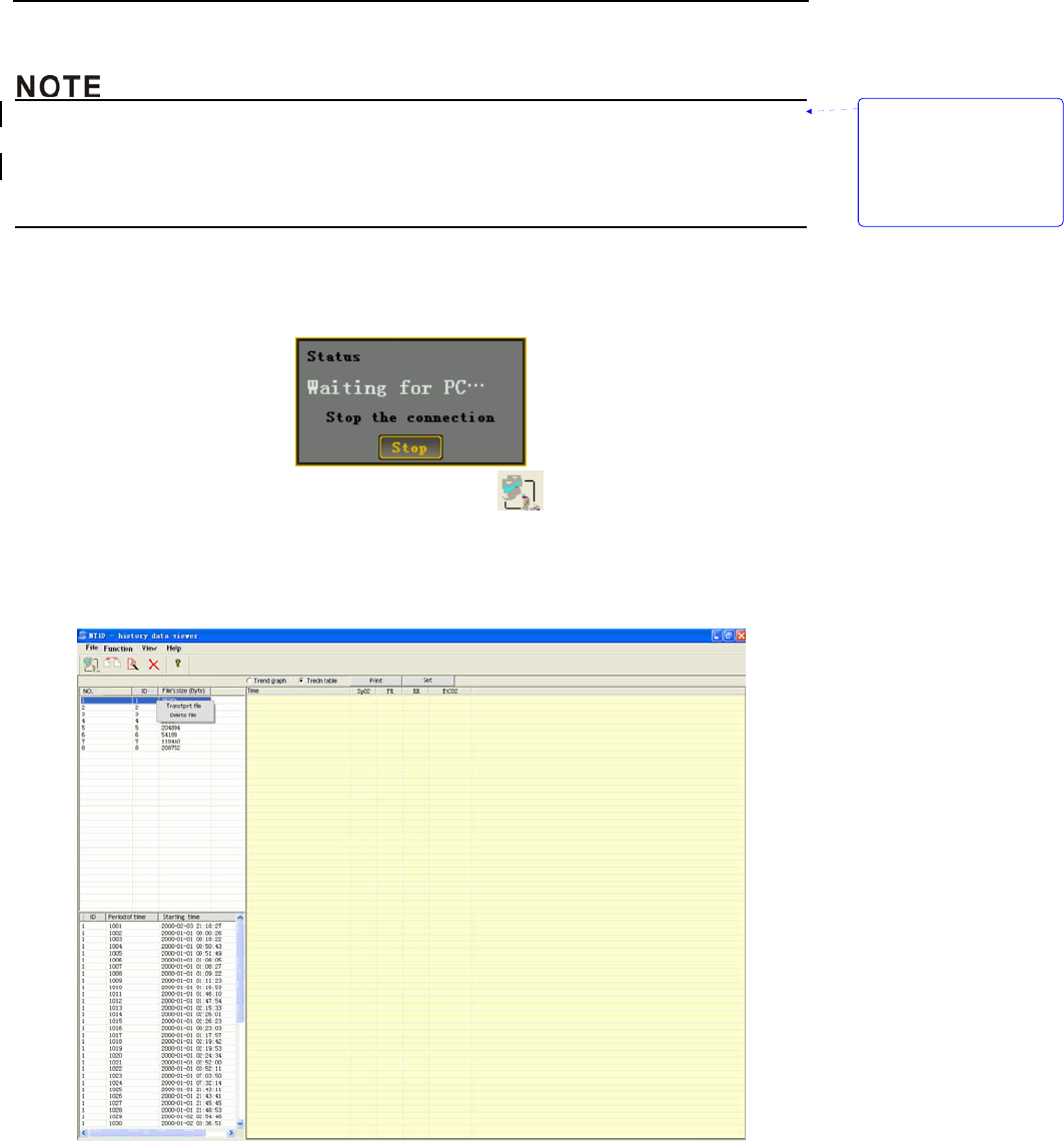
Data Output
8-4
8.2 Transmit and Delete Data
z At the process of data transmitting and deleting, please don’t chose the History Data View
software or pull the USB adapter out, otherwise the process will be failure.
z After data transmitting and deleting, please pull out the USB adapter firstly, and then chose the
History Data View software.
1)Put the monitor into 2 meters around the PC, and open it.
2)Press the MENU key to enter into the dialog box of “Data Output “. The monitor will stick on the
dialog box as shown in the following picture:
3)Open the history data viewer software and click the button ” ” at the top left corner can connect
the monitor and PC wirelessly. If connected successfully, patient’s history data which have stored in
the monitor will be displayed at the left side column of the monitoring software. Select one patient’s
ID, click with the right key and choose “Transmit data” or “Delete data” to send this ID’s data to PC
or delete the stored trend data of the ID in monitor. As shown below:
带格式的: 缩进: 左侧: 0
厘米, 悬挂缩进: 3.6 字符,
项目符号 + 级别: 1 + 对
齐位置: 0 厘米 + 制表符
后于: 0.74 厘米 + 缩进位
置: 0.74 厘米, 制表位:
1.71 字符, 列表制表位 +
不在 2 字符
Accessories
9-1
9. Accessories
9.1 Standard Configure of NT1D
1)Host monitor one
2)SpO2 Sensor one Solaris medical technology company SpO
2 Sensor,
Model: D400AL-160108.
3)CO2 Sensor one Respironics company
Capnostat 5 mainstream CO2 sensor
4)Charging pedestal one
5)Chargeable batteries four 4xAA,2400mAh,Ni-MH chargeable batteries.
6) AC adapter one Input a.c.100-240V,50/60Hz,output d.c. 9V, (operation
power) and 6.0V(Recharging power).(Confirm to EN
60601-1)
7) Safeguard jacket one
8) Wireless USB Dongle one
9) Driving CD one
10)Operation Manual one
11)Maintenance card one
12)Package bill one
9.2 Optional Accessories of NT1D
User can buy accessories from the local agent if necessary. The following are the accessories:
Num Type Description Manufacturer
1 D400A-160108 Digital One Adult SpO2 Sensor Solaris
2 D400P-160108 Digital One Pediatric SpO2 Sensor Solaris
3 Y400N -160108 Digital Y-type Neonatal SpO2 Sensor Solaris
4 DP400A-160108 Digital One Use Only SpO2 Sensor-Adult Solaris
5 DP400N/A-160108 Digital One Use Only SpO2 Sensor-Neonate/Adult Solaris
6 DP400P-160108 Digital One Use Only SpO2 Sensor-Pediatirc Solaris
7 DP400I-160108 Digital One Use Only SpO2 Sensor-Infant Solaris
8 S400A-160108 Digital Adult Finger SpO2 Sensor Solaris
9 S400P-160108 Digital Pediatric Finger SpO2 Sensor Solaris
删除的内容: ~

Accessories
9-2
10 T400A-160108 Adult Soft-Finger SpO2 Sensor Solaris
11 T400P-160108 Pediatric Soft-Finger SpO2 Sensor Solaris
12 W400AN-160108 Digital Wrapped and tied SpO2
Sensor-Neonate/Adult Solaris
13 WP400PI-160108 Digital Wrapped and tied SpO2
Sensor- Pediatirc / Infant Solaris
14 / LoFlo sidestream CO2 sensor Respironics

Troubleshooting and Maintenance
10-1
10. Troubleshooting and Maintenance
z If you are uncertain about the accuracy of any measurement, check the patient’s vital signs by
alternate means; then make sure the monitor is functioning correctly.
z The cover should be removed only by qualified service personnel. There are no user-serviceable
parts inside.
z Do not spray or pour any liquid directly on the monitor, accessories or consumables. Otherwise
may cause damage to the monitor.
If you experience a problem while using the monitor and are unable to correct it, contact qualified
service personnel or representative. The monitor service manual, which is for use by qualified service
personnel, provides additional troubleshooting information.
10.1 Troubleshooting Guide
1. Monitor does not turn on after pressing the power switch.
Check power cable connection.
Replace or recharge the battery pack, or connect to AC power.
Be sure the battery pack is in the monitor and inserted properly.
2. One or more showed elements or indicatory icons do not bright when self testing.
Do not use the monitor and contact technical services department.
3. Indicatory icon of searching pulse is winking more than 10 seconds.
Check whether sensor is suitable or connected correctly following SpO2 using direction. Check
sensor and its cable connection. Chang other patient to use the sensor. Use another sensor or its
prolonged cable.
Lacking of blood supply may cause the failure of tracing pulse, so check the patient or monitor
operator. Replace if necessary, move the sensor to a new site.
Patient’s movement may interfere in the failure of tracing pulse. Keep patient still. Check whether
the sensor is firm. Replace if necessary, move the sensor to a new site.
The probe may be emplaced too tight. Environmental light may also affect monitoring. A blood
pressure cuff is inflated on the same extremity as the one with the sensor attached, Replace
sensors if necessary.
EMI, Remove disturbing equipment.
4. No pulse shown on the bar-graph.
Check sensor connections to the patient cable and to the monitor.
Reposition the sensor.
Try a new sensor or connect your authorized repair center for help.
5. PR, SpO2, EtCO2, RR Pulse rate is erratic, intermittent, or incorrect. (May caused by EMI)
Reposition the SpO2 and CO2 sensor.
Patient must remain still to obtain an accurate measurement.
Close nearby equipment and then open it to find interferential equipment out.
Change the orientation and position of interferential equipment.
带格式的: 缩进: 左侧: 0
厘米, 悬挂缩进: 3.6 字符,
项目符号 + 级别: 1 + 对
齐位置: 0 厘米 + 制表符
后于: 0.74 厘米 + 缩进位
置: 0.74 厘米, 制表位:
1.71 字符, 列表制表位 +
不在 2 字符
带格式的: 缩进: 左侧: 0
厘米, 悬挂缩进: 3.6 字符,
项目符号 + 级别: 1 + 对
齐位置: 0 厘米 + 制表符
后于: 0.74 厘米 + 缩进位
置: 0.74 厘米, 制表位:
1.71 字符, 列表制表位 +
不在 2 字符

Troubleshooting and Maintenance
10-2
Let interferential equipment far away from this monitor.
6. The monitor switches off automatically.
Replace or recharge battery.
Check connections and correct problem.
If previous actions are not effective, contact authorized service representative.
10.2 Technical Assistance
If you need technical information and sustain or ordered parts and operation manual, please
contact your local representative, and tell them is software’s version number of this monitor.
10.3 Factory Default Alarm Range Values
This monitor has default values when it is shipped to leave factory. technician has described how
to change default values in detail at the operation manual.
Factory default alarm range values:
Default value of alarm high
limit
Default value of alarm low
limit
Alarm parameter(unit)
Adult Pediatric Neonate Adult Pediatric Neonate
EtCO2(mmHg) 60 60 60 0 0 0
RR(BPM) 150 150 150 3 12 12
SpO2(%) 100 95 95 85 80 80
PR(BPM) 100 200 200 55 100 100
10.4 Returning the Monitor
If it is necessary to return the monitor for repairs, call the local representative for shipping
instructions.
To repack the monitor, disconnect the accessories from the instrument and wrap each item
separately. Pack them in the original shipping carton. If the original carton is unavailable, use a
suitable box filled with the appropriate amount of packing material.
If the monitor malfunctions, carefully package the monitor with the consumable used at the time of
malfunction and return it with the monitor for inspection.
10.5 Maintenance and Cleaning
z The cover should be removed only by qualified service personnel. There are no user-serviceable
parts inside.
z Turn the monitor off before cleaning.
z Do not spray or pour any liquid directly on placket of the monitor, accessories, connector, switch or
带格式的: 缩进: 左侧: 0
厘米, 悬挂缩进: 3.6 字符,
项目符号 + 级别: 1 + 对
齐位置: 0 厘米 + 制表符
后于: 0.74 厘米 + 缩进位
置: 0.74 厘米, 制表位:
1.71 字符, 列表制表位 +
不在 2 字符

Troubleshooting and Maintenance
10-3
crack. Otherwise it will dose damage to them.
z Do not autoclave, or immerse the monitor in liquid.
z If disinfection is required, wipe the monitor's surfaces with a soft cloth moistened with commercial
nonabrasive cleaner. Do not allow any liquid to enter any of the monitor's opening.
z Do not touch or rub the display window with abrasive, apparatus, brush, shaggy material or any
other stuff that may do damage to the display window.
z If there are any internal parts of the monitor exposed, please contact qualified service personnel to
deal with it. Please follow your local governing ordinances regarding disposal monitor when it
dosen’t run.
z Dispose or recycle of batteries and retired sensors and the monitor’s accessories according to
standard operating procedures or local regulations for the disposal of contaminated medical
waste.
z This monitor can use disabled batteries, please install new ones.
You can clean and disinfect the surface of monitor and sensor. (Sensor is the only part that
contacts to patient, so you should clean it every time after use.)
10.5.1 Cleaning and Disinfecting the Monitor
To clean the monitor’s surface: To clean the monitor’s surfaces, dampen a soft cloth with a
commercial, non-corrosive cleaner or alcohol 70%,and wipe the top, bottom, and front surfaces
lightly.
To disinfect the monitor: Use a cloth dampened with a 10% aqueous solution of hypochlorite
(bleach).
10.5.2 Cleaning and Disinfecting SpO2
You can use a tampon or soft cloth dampened with alcohol 70% to wipe the SpO2 sensor, and then
dry it completely with dry cloth. The same to SpO2 sensor’s LED and receiver. Clean and disinfect
reusable SpO2 sensor. Read SpO2 sensor’s direction carefully before cleaning. Every kind of
SpO2 sensor has its own way to clean.
If low-level disinfection is required, use a 1:10 bleach solution.
10.5.3 Disinfecting Cable
Clean and disinfect cables with 3% hydrogen peroxide, or 70% isopropyl alcohol.
10.5.4 Cleaning and Disinfecting CO2 Sensor
z Cleaning and Disinfecting
Use a cloth dampened with isopropyl alcohol 70%, a 10% aqueous solution of sodium
hypochlorite (bleach), disinfectant spray cleaner such as Steris Coverage® Spray HB, ammonia,
or mild soap.
Wipe down with a clean water-dampened cloth to rinse and dry before use. Make certain that the
sensor windows are clean and dry before reuse.
Cleaning adapter
Reusable adapters (Before reusing the adapter, ensure the windows are dry and residue free and that
the adapter has not been damaged during handling or the cleaning/disinfecting process.):
Clean by rinsing in a warm soapy solution followed by soaking in a liquid disinfectant such as
isopropyl alcohol 70%, a 10% aqueous solution of sodium hypochlorite (bleach), a gluteraldehyde
2.4% solution such as Cidex®, Steris System 1® or ammonia. It should then be rinsed out with
sterile water and dried.
May be disinfected using the methods listed below:
1)Steam Autoclave - adult adapters only;

Troubleshooting and Maintenance
10-4
2)Immerse and soak in Cidex® or equivalent 2.4 glutaraldehyde solution for a 10 hour soak.
3)Immerse and soak in Perasafe® or equivalent peracetic acid. 26% solution for a 10-minutes
soak.
4)Cidex® OPA - follow the manufacturer’s instructions for use.
Disposable adapters:
Treat all single patient use airway adapters in accordance with institutional protocol for single
patient use items.
DO NOT insert any object, such as a brush, into the CO2 airway adapter. Irreparable damage may
occur to the CO2 windows.
z Maintenance Schedule
CO2 Sensor should be compared against calibration gas every 12 months.
NOTE: Accuracy is affected by temperature and barometric pressure.
z CO2 Accuracy Check
The following procedure should be performed to check the CO2 accuracy of the Sensor. It is
recommended that this procedure be included as part of a periodic maintenance schedule.
1)Zeroing. Refers to chapter 7 “7.4 CO2 sensor adapter zero”.
2)Calibration. Open the MENU and select “set CO2” option. You can adjust all parameter’s value
(Pressure, temperature, unit, oxygen compensation and so on) according to the actual environment.
Press OK key can confirm your calibration.
z Do not autoclave, ethylene oxide sterilize, or immerse the monitor and its accessories in liquid.
z Turn off the monitor before cleaning.
z If there are any internal parts of the SpO2 and CO2 sensor exposed, please contact qualified
service personnel to deal with it.
10.6 Periodic Safety Checks
The following safety checks should be performed every 24 months by a qualified person who has
adequate training, knowledge, and practical experience to perform these tests.
● Inspect the equipment for mechanical and functional.
● Inspect the safety relevant labels for legibility.
● Verify that the device functions properly as described in this operator's manual.
If the monitor is not functioning properly or fails any of the above tests, do not attempt to repair the
monitor. Please return the monitor to the manufacturer or to your distributor for any required repairs.
10.7 Guarantee
The company warrants the monitor at the time of its original purchase and for the subsequent time
period of twelve months for the original purchaser. The company warrants SpO2 Sensor free of defects
at the time of its original purchase and for the subsequent time period of three months.
带格式的: 缩进: 悬挂缩进:
8.4 字符, 项目符号 + 级
别: 2 + 对齐位置: 0.74
厘米 + 制表符后于: 1.48
厘米 + 缩进位置: 1.48 厘
米, 制表位: 不在 4 字符

Troubleshooting and Maintenance
10-5
The warranty does not cover the followings:
● The monitor serials number of the label is teared off or can not be recognized.
● Damage to the monitor resulting from misconnection with other devices.
● Damage to the monitor resulting from accidents.
● Changes performed by users without the prior written authorization of the company.
Customer Service Department Tel: 86-755-26520739

Troubleshooting and Maintenance
10-6
This page is intentionally left blank.

Appendix A
A-1
Appendix A: Specifications
A.1 Basic parameter
SpO2, PR, EtCO2, RR.
A.2 Average operation time
≥1000 hours.
A.3 Normal operation time
a) Environment temperature range:(0 ~ 50)℃,
b) Relative Humidity range: ≤ 95 %,
c) Atmospheric pressure range:(700~1060)hPa,
d) Power Voltage: AC 100V-240V,
e) Power frequency: 50/60 Hz,
f) Battery type: 4xAA size Ni-MH rechargeable battery or alkaline battery (Forbidden to charge
alkaline battery).
A.4 Safety requirements and classifications
a) Electric shock type: Type II equipment with internal power supply.
b) Electric shock degree: All application parts are BF type.
c) Harmful liquid material proof degree: Liquid proof.
d) Disinfection: follow manufacturer’s recommended methods.
e) Safety on flammable gas: not suitable to use where flammable gas is present.
f) The monitor has applicable.
g) Power supply:
Internal power supply:4.4~6.0V(4xAA size battery),
II type power adapter: input a.c.100-240V,50/60Hz,output d.c. 9V, (operation power) and 6.0V
(Recharging power).
h) The monitor has signal input and signal output parts, i.e., keypad, LCD, wireless interface.
i) Using external power supply, the monitor is a continuous working system.
A.5 Trend data transfer
1) Wireless, via USB dongle for PC end
2) RF frequency: 2.440GHz
3) Modulate mode: GFSK
4) Effective transfer distance(clear area without interferential source or barrier): ≤10m
5) Transfer speed: ≤ 40kbps
6) Transfer time: ≤ 40secs per ID
7) Power consumption: Rx or Tx Peak ≤13mA
A.6 SpO2
■Measurement range:(0 ~ 100)%.
■Measurement accuracy:(70 ~ 100)%,±2 %,
(0 ~ 69)%, not required.
A.7 PR
■Measurement range: (30 ~ 250)bpm,
删除的内容: ~
删除的内容: ~

Appendix A
A-2
■Measurement accuracy: 1 bpm or ±2%, take the bigger one.
A.8 EtCO2
■Measurement range: 0~150mmHg.
■Resolution: 0.1mmHg (0~69mmHg), 0.25mmHg (70~150mmHg).
■Measurement accuracy:
±2mmHg (0~40mmHg)
±5% (41~70mmHg)
±8% (71~100mmHg)
±10% (101~150mmHg)
A.9 RR
■Measurement range: 0~150 BPM
■Measurement accuracy: ±1 BPM
A.10 Alarm
■Alarm Mode:
Priority
Mode
High Medium
Technical alarm
Low voltage, Pulse lost, Sensor
off, Cable off, CO2 sampling line
off, No breath.
/
Physiological
alarm
Parameter’s value exceed limits(The priority can be
adjusted)
Audible alarm
Dee,Dee,Dee -Dee,Dee
Period: 10secs
Dee,Dee,Dee
Period: 25secs
Digital alarm
Display “- - -’’, related value will
wink, refers to chapter 5.1.
Numeric Blinking
Frequency 0.625Hz
Light alarm
Blinking, Red
Frequency 2Hz
Blinking, Yellow
Frequency 0. 5Hz
Event Record the event, such as the date, time, parameters, etc.
■Alarm Object:
z Physiological alarm: Indicate patient’s physiological parameters exceed limits.
z Technical alarm: Indicate system failure to lead wrong results, i.e., sensor off.
z Normal alarm: In normal range, no harm to patients’ health, .i.e. Battery low voltage.
A.11 Factory default value of alarm parameter
Alarm parameter(unit)
Default value of alarm high
limit
Default value of alarm low
limit

Appendix A
A-3
Adult Pediatric Neonate Adult Pediatric Neonate
EtCO2(mmHg) 60 60 60 0 0 0
RR(BPM) 150 150 150 3 12 12
SpO2(%) 100 95 95 85 80 80
PR(BPM) 100 200 200 55 100 100
A.12 Setting range and allowable tolerance of alarm high/low limits
Alarm parameter Setting range of alarm high
limit
Default value of alarm low
limit
SpO2 21%~100% 20%~99%
PR 35 bpm~250 bpm 30 bpm~245bpm
EtCO2 5~100mmHg 0~99mmHg
RR 1~150bpm 0~149bpm
A.13 Continuous operation time
Power supply: Internal 4xAA alkaline or Ni-MH battery or external wall-power. Capable of charging
when connect to external wall-power or power stack. Be capable of charging Ni-MH batteries only.
(DO NOT to charging alkaline batteries).
Internal power continuous operation time:SpO2 ≥ 10h,SpO2 & CO2 ≥ 3.5h.
A.14 Trend data storage
■ Store time of trend data:
Total 99 patients’ ID,72h trend data per ID
■ Store parameters of trend data:
Include SpO2, Pulse Rate, EtCO2, Respiration Rate, time etc.
A.15 Dimensions and weight
Model Dimensions(mm)L*W*H Net weight(kg)Gross weight(kg)
Host 125x73x23 0.137
0.233(with batteries)
Wireless USB
Dongle 61.8x18.2x9.0 0.0075 -
Charger adapter 95x57x32 0.260 -
A.16 Packing, transportation, storage
■Packing
Place the monitor in a plastic bag, place it in a corrugated carton filled with the foam or other
fillers. Seal the carton.
■Transportation

Appendix A
A-4
The monitor can be transported by airplane, train or automobile. Prevent fierce collision
during transportation. Do not keep it with perishables. The transportation environment
should be:
a)Environment temperature range: -20℃~+70℃;
b) Relative humidity range: ≤95%;
c) Air pressure range: 500hPa~1060hPa.
■Storage
The monitor should be stored indoors with a temperature range: -10 ~+40 , relative ℃℃
humidity≤80%, no corrosive gas, and with good ventilation.
A.17 Explanations of interface
Connector type Description
Wireless(PC end) Connected PC via wireless USB dongle(2.440GHz ISM band)
Wireless(handheld end) Built-in RF IC to communicate with wireless USB Dongle,with data rate up
to 40kbps.(2.440GHz ISM band)
DB9 SpO2 Connector Standard DB9-F Connector
DB9 CO2 Connector Standard DB9-F Connector
A.18 Compliance standards
CE Applied Standard of NT1D
Requirement CE(MDD 93/42/EEC)
EN 60601-1:1990+A1:1993
+A2:1995+A13:1996
Medical electrical equipment-Part1: General requirements for
basic safety and essential performance
General Safety
EN 60601-2-49:2001 Particular requirements for the safety of multifunction Patient
monitoring equipment
EN60601-1-2:2001 Medical equipment-Part1-2: General requirements for
safety-Collateral standard: Electromagnetic
compatibility-Requirements and tests
EMC conformity
CE
R&TTE(99/5/EC)
ETSI EN 301 489-1
V
1.6.1(2008-04)
Electromagnetic compatibility and Radio spectrum Matters
(ERM); ElectroMagnetic Compatibility (EMC) standard for
radio equipment and services; Part 1: Common technical
requirements

Appendix A
A-5
ETSI EN 301 489-17
V1.3.2(2008-04)
Electromagnetic compatibility
and Radio spectrum Matters (ERM);
ElectroMagnetic Compatibility (EMC)
standard for radio equipment;
Part 17: Specific conditions for 2,4 GHz
wideband transmission systems,
5 GHz high performance RLAN equipment and
5,8 GHz Broadband Data Transmitting Systems
ETSI EN 300 328 V1.7.1(2006-10) Electromagnetic compatibility
and Radio spectrum Matters (ERM);
Wideband transmission systems;
Data transmission equipment operating
in the 2,4 GHz ISM band and
using wide band modulation techniques;
Harmonized EN covering essential requirements
under article 3.2 of the R&TTE Directive
Software validation
requirement
IEC 60601-1-4:2000 General requirements for safety -
Collateral Standard:
Programmable electrical medical systems
Usability
requirement
IEC 60601-1-6:2007
Medical electrical equipment Part 1-6: general requirements
for basic safety and essential performance collateral
standard: usability
A
larm conformity IEC60601-1-8:2005 Medical electrical equipment-Part 1-8:General
requirements for safety-Collateral Standard:General
requirements,tests and guidance for alarm systems in
medical electrical equipment and medical systems in medical
electrical equipment and medical electrical systems
Spo2 Particular
standard
EN ISO9919:2005 Medical electrical equipment-Particular requirements for the
basic safety and essential performance of pulse oximeter
equipment for medical use
CO2 Particular
standard
EN ISO 21647:2004/AC:2006 Medical electrical equipment — Particular
requirements for the basic safety and
essential performance of respiratory gas
monitors
ISO 10993-1: 2003 Biological evaluation of medical devices part-1:Evaluation and
testing ISO 10993-1
Biological
compatible
requirement ISO 10993-5:1999 Biological evaluation of medical devices –test for in vitro
cytotoxicity

Appendix A
A-6
ISO 10993-10:2002 Biological evaluation of medical devices – tests for irritation and
delayed-type hypersensitivity
Risk management
requirement
ISO 14971:2007 Medical devices-Application of risk management to medical
devices
Label and symbol EN:980:2003
Graphical symbols for
use in the label of
medical devices
Information
supplied by the
manufacturer
EN 1041:1998 Information supplied by the manufacturer with medical
devices
EN ISO 14155-1:2003 Clinical investigation of medical devices for human subjects
–General requirements
EN ISO 14155-2:2003
Clinical investigation of medical devices for human subjects
–Clinical investigation plans
Clinical
requirement
Guidance of clinical evaluation
Meddev 2.7.1
Evaluation of clinical data: a guide for manufacturers and
notified bodies

Appendix B
B-1
Appendix B: EMC (Electro-Magnetic Compatibility)
Caution: The monitor complys with the limits for medical devices to IEC601-1-2: 1993, EN60601-1-2:
1994, Medical Device Directive 93/42/EEC, and this monitor has been tested for CISPR 11 class A.
Guidance and manufacturer’s declaration-electromagnetic emissions-
for all EQUIPMENT and SYSTEMS
Guidance and manufacturer’s declaration-electromagnetic emission
The NT1D is intended for use in the electromagnetic environment specified below. The
customer of the user of NT1D should assure that it is used in such environment.
Emission test Compliance Electromagnetic
environment-guidance
RF emissions
CISPR 11
Group 1 The NT1D uses RF energy only for
its internal function. Therefore its RF
emissions are very low and are not
likely to cause any interference in
nearby electronic equipment.
RF emission
CISPR 11
Class A
The NT1D is suitable for use in all
establishments other than domestic,
and those directly connected to a low
voltage power supply network which
supplies buildings used for domestic
purposes.
Guidance and manufacture’s declaration-electromagnetic immunity –
for all EQUIPMENT and SYSTEMS
Guidance and manufacturer’s declaration-electromagnetic immunity
The NT1D is intended for use in the electromagnetic environment specified below. The
customer or the user of NT1D should assure that it is used in such an environment.
Immunity test IEC 60601 test
level Compliance level Electromagnetic
environment-guidance
Electrostatic
discharge(ESD)
IEC 61000-4-2
±6 kV contact
±8 kV air
±6 kV contact
±8 kV air
Floors should be wood,
concrete or ceramic tile.
If floor are covered with
synthetic material, the
relative humidity should
be at least 30%.
Power frequency
(50Hz) magnetic
field IEC 61000-4-8
3A/m 3A/m Power frequency
magnetic fields should
be at levels
characteristic of a

Appendix B
B-2
typical location in a
typical commercial or
hospital environment.
Guidance and manufacturer’s declaration-electromagnetic immunity-
for EQUIPMENT and SYSTEMS that are not LIFE-SUPPORTING
Guidance and manufacturer’s declaration-electromagnetic immunity
The NT1D is intended for use in the electromagnetic environment specified below. The
customer or the user of NT1D should assure that it is used in such an environment.
Immunity test IEC 60601 test level Compliance
level
Electromagnetic environment
– guidance
Conducted RF
IEC 61000-4-6
Radiated RF
IEC 61000-4-3
3 Vrms
150 kHz to 80 MHz
3 V/m
80 MHz to 2.5 GHz
3 Vrms
3 V/m
Portable and mobile RF
communications equipment
should be used no closer to any
part of the NT1D. Including
cables than the recommended
separation distance calculated
from the equation applicable to
the frequency of the transmitter.
Recommended separation
distance
d = ⎥
⎦
⎤
⎢
⎣
⎡
1
5.3
VP
d = ⎥
⎦
⎤
⎢
⎣
⎡
1
5.3
EP 80 MHz to 800
MHz
d = ⎥
⎦
⎤
⎢
⎣
⎡
1
7
EP 800 MHz to 2.5
GHz
Where p is the maximum output
power rating of the transmitter in
watts (W) according to the
transmitter manufacturer and d
is the recommended separation
distance in metres (m).
Field strengths from fixed RF
transmitter as determined by an
electromagnetic site survey a
should be less than the
compliance level in each
frequency range b .
Interference may occur in the
vicinity of equipment marked
with the following symbol:
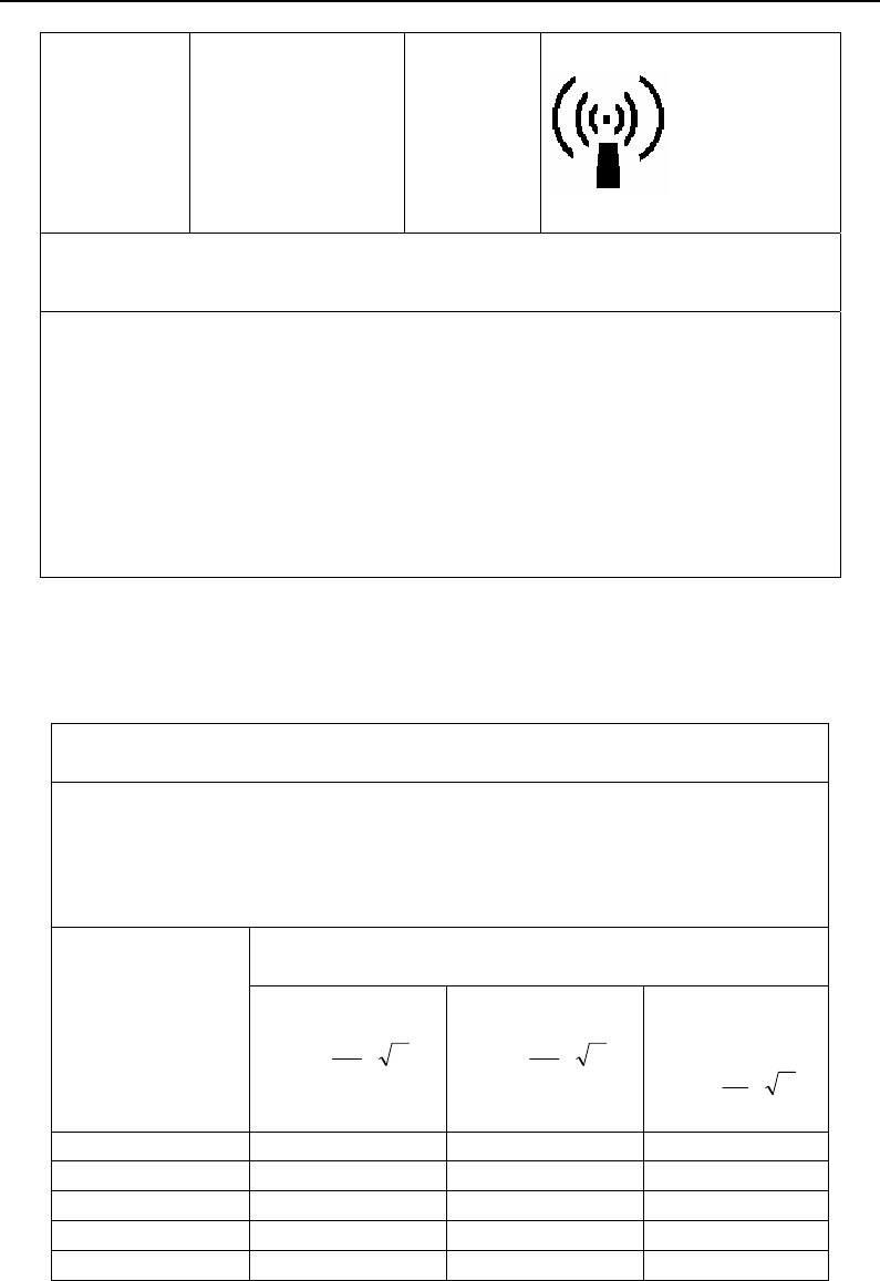
Appendix B
B-3
NOTE 1 At 80 MHz. the higher frequency range applies.
NOTE 2 These guidelines may not apply in all situations. Electromagnetic propagation is
affected by absorption and reflection from structures, objects and people.
a Field strengths from fixed transmitters, such as base stations for radio(cellular/cordless)
telephones and land mobile radios, amateur radio, AM and FM radio broadcast and TV
broadcast cannot be predicted theoretically with accuracy. To assess the electromagnetic
environment due to fixed RF transmitters. An electromagnetic site survey should be
considered. If the measured field strength in the location in which the NT1D is used
exceeds the applicable RF compliance level above, the monitor should be observed to
verify normal operation. If abnormal performance is observed, additional measures may be
necessary, such as reorienting or relocating the NT1D.
b Over the frequency range 150 kHz to 80MHz. Field strengths should be less than 3
V/m.
Recommended separation distances between portable and mobile RF
RF communications equipment and the EQUIPMENT or SYSTEM-
For EQUIPMENT or SYSTEM that are not LIFE-SUPPORTING
Recommended separation distances between
Portable and mobile RF communications equipment and the monitor
The monitor is intended for use in an electromagnetic environment in which radiated RF
disturbances are controlled. The customer or the user of the NT1D can help prevent
electromagnetic interference by maintaining a minimum distance between portable and
mobile RF communications equipment (transmitters) and the NT1D as recommended
below according to the maximum output power of the communications equipment.
Separation distance according to frequency of transmitter
(m)
Rated maximum
output power of
transmitter
(W)
150 kHz to 80 MHz
d = ⎥
⎦
⎤
⎢
⎣
⎡
1
5.3
VP
80 MHz to 800 MHZ
d = ⎥
⎦
⎤
⎢
⎣
⎡
1
5.3
EP
800 MHz to 2.5
GHz
d = ⎥
⎦
⎤
⎢
⎣
⎡
1
7
EP
0.01 0.12 0.12 0.23
0.1 0.37 0.37 0.74
1 1.17 1.17 2.33
10 3.69 3.69 7.38
100 11.67 11.67 23.33

Appendix B
B-4
For transmitters rated at a maximum output power not listed above, the recommended
separation distance d in metres (m) can be estimated using the equation applicable to
the frequency of the transmitter. Where P is the maximum output power rating of the
transmitter in watts (W) according to the transmitter manufacturer.
NOTE1 At 80 MHz and 800 MHz, the separation distance for the higher frequency
range applies.
NOTE2 These guidelines may not apply in all situations. Electromagnetic propagation
is affected by absorption and reflection from structures, objects and people.
These limits are designed to provide reasonable protection against harmful interference in a
typical medical installation. However, because of the proliferation of radio-frequency
transmitting equipment and other sources of electrical noise in the health-care and home
environments (for example, cellular phones, mobile two-way radios, electrical appliances), it is
possible that high levels of such interference due to close proximity or strength of a source,
may result in disruption of performance of this device.
The monitor generates, uses, and can radiate radio frequency energy and, if not installed and used in
accordance with these instructions, may cause harmful interference with other devices in the vicinity.
Disruption may be evidenced by erratic readings, cessation of operation, or other incorrect
functioning .If this occurs, the site of use should be surveyed to determine the source of this disruption,
and actions taken to eliminate the source:
● Turn equipment in the vicinity off and on to isolate the offending equipment
● Reorient or relocate the other receiving device
● Increase the separation between the interfering equipment and this equipment