Contents
- 1. user manual 1
- 2. user manual 2
user manual 1
USB

Copyright
The content of this publication may not be reproduced in any part or as a whole, stored,
transcribed in an information retrieval system, translated into any language, or
transmitted in any form or by any means, mechanical, magnetic, electronic, optical,
photocopying, manual, or otherwise, without prior written permission.
Trademarks
All products, company, brand names are trademarks or registered trademarks of their
respective companies.
FCC Interference Statement FCC ID: YAZ-NEX09
This device complies with part 15 of the FCC Rules. Operation is subject to the following
two conditions: (1) This device may not cause harmful interference, and (2) this device
must accept any interference received, including interference that may cause undesired
operation.
IC: 7839B-NEX09
Complies with Canada RSS-210
CE Declaration of Conformity
This equipment complies with the requirements relating to electromagnetic compatibility,
EN 55022/A1 Class B. Conformity
Warning
They are used for identification purposes only. Specifications are subject to be changed without
prior notice. This equipment has been tested and found to comply with the limits for a class B
digital device, pursuant to part 15 of the FCC rules. These limits are designed to provide to
provide reasonable protection against harmful interference in a residential installation. This
equipment generates, uses and can radiate radio frequency energy and, if not installed and used in
accordance with the installation. , May cause harmful interference to radio communication.
However, there is no guarantee that interference will not occur in a particular installation. If this
equipment does cause harmful interference to radio or television reception, which can be
determined by turning the equipment off and on, the user is encouraged to try to correct the
interference by one or more of the following measures:
-Reorient or relocate the receiving antenna
-Increase the separation between the equipment and receiver
-Connect the equipment into an outlet on a circuit different from that to which the
receiver is connected
-Consult the dealer or an experienced radio / TV technician for help
You are cautioned that changes or modifications not expressly approved by the party responsible
for compliance could void your authority to operate the equipment.
You are cautioned that changes or modifications not expressly approved by the party responsible or compliance could void
your authority to operate the equipment. This transmitter must not be co-located or operating in conjunction with any other
antenna or transmitter. Industry Canada - Class B This digital apparatus does not exceed the Class B limits for radio noise
emission for digital apparatus as set out in the interference-causing equipment standard entitled "Digital
Apparatus," ICES-003 of industry Canada.
FCC RF radiation exposure statement:his transmitter must not be co-located or operating in conjunction with any other antenna or
transmitter.
This Class B digital apparatus complies with Canada RSS-210.Cet appareil num?rique de la classe B est conforme a' la norme
CNR-210 du CanadaThis equipment complies with FCC RF radiation exposure limits set forth for an uncontrolled environment.
This equipment should be installed and operated with a minimum distance of 20 centimeters between the radiator and your body.
t

Table of Contents
Introduction.......................................................................................................................................................1
Features..........................................................................................................................................1
Package Contents..........................................................................................................................2
System Requirements....................................................................................................................2
Wi-Fi Requirements......................................................................................................................2
Hardware Overview..........................................................................................................................................3
Default Router Settings......................................................................................................................................4
Hardware Setup................................................................................................................................................5
Wi-Fi Connection..........................................................................................................................6
Initial /Wireless Setup.............................................................................................................................7
Installation and Conguration Settings.........................................................................................7
NexWare Setup Wizard......................................................................................................................................7
Basic Settings.....................................................................................................................................................9
Admin Password............................................................................................................................9
Wi-Fi..............................................................................................................................................9
Wired Interfaces..........................................................................................................................10
Cellular Datacard.........................................................................................................................11
Realtime Network Trafc.............................................................................................................11
Logout..........................................................................................................................................11
Tool Box............................................................................................................................................................12
System Settings...........................................................................................................................12
Email Notications......................................................................................................................12
System Log..................................................................................................................................13
Flash Firmware............................................................................................................................13
Backup Interface..........................................................................................................................13
Reset to Defaults..........................................................................................................................13
Reboot..........................................................................................................................................13
Advanced Settings...........................................................................................................................................14
DHCP Server...............................................................................................................................14
SNMP (Simple Network Management Protocol)........................................................................14
Dynamic DNS.............................................................................................................................15
QoS (Quality of Service)..............................................................................................................16
Security Settings..............................................................................................................................................17
Remote Admin.............................................................................................................................17
IPsec.............................................................................................................................................17
SSH Server..................................................................................................................................18
SSH Keys....................................................................................................................................18
Routing Settings..............................................................................................................................................18
Routes.........................................................................................................................................18
RIP..............................................................................................................................................19
DMZ Host..................................................................................................................................19
VRRP..........................................................................................................................................20
Internet Failover.........................................................................................................................21
Port Forwarding..........................................................................................................................21
UPnP...........................................................................................................................................22
Table of Contents
Introduction.......................................................................................................................................................1
Features.......................................................................................................................
...................1
Package Contents...............................................................................................................
...........2
System Requirements....................................................................................................................2
Wi-Fi Requirements......................................................................................................................2
Hardware Overview..........................................................................................................................................3
Default Router Settings......................................................................................................................................4
Hardware Setup................................................................................................................................................5
Wi-Fi Connection..........................................................................................................................6
Initial 3G/4G Wireless Setup.............................................................................................................................7
Installation and Conguration Settings.........................
...............................................................
.7
NexWare Setup Wizard......................................................................................................................................7
Basic Settings.................................................................................................................
....................................9
Admin Password............................................................................................................................9
Wi-Fi..............................................................................................................................................9
Wired Interfaces..........................................................................................................................10
Cellular Datacard.........................................................................................................................11
Realtime Network Trafc.............................................................................................................11
Logout.........................................................................................................................
.................11
Tool Box............................................................................................................................................................12
System Settings................................................
...............................................................
............12
Email Notications......................................................................................................................12
System Log.....................................................
...............................................................
..............13
Flash Firmware............................................................................................................................13
Backup Interface..........................................................................................................................13
Reset to Defaults..........................................................................................................................13
Reboot.........................................................
...............................................................
..................13
Advanced Settings..............................................................................................................
.............................14
DHCP Server...............................................................................................................................14
SNMP (Simple Network Management Protocol)........................................................................14
Dynamic DNS....................................................
...............................................................
..........15
QoS (Quality of Service)..............................................................................................................16
Security Settings..............................................................................................................
................................17
Remote Admin.............................................................................................................................17
IPsec..........................................................
...............................................................
....................17
SSH Server..................................................................................................................................18
SSH Keys.......................................................
...............................................................
..............18
Routing Settings...............................................................................................................
...............................18
Routes.........................................................
...............................................................
.................18
RIP..............................................................................................................................................19
DMZ Host.......................................................
...............................................................
............19
VRRP..........................................................................................................................................20
Internet Failover.........................................................................................................................21
Port Forwarding................................................................................................................
..........21
UPnP...........................................................................................................................................22

Troubleshooting....................................................................................................................................................23
Technical Support................................................................................................................................................26
Technical Specications.........
Glossary of Denitions...........
27 dBm
Package Contents
Important: Check the contents of the box rst.
The Business Class II High Availability Router package should contain the items listed below. If any of the
items are missing, please contact your reseller.
(1) Business Class II High Availability Router
(1) CD-ROM
(1) RJ-45 Ethernet Cable
(1) Switching 12V 1.25A Power Adapter
Caution: Using a power supply with a different voltage rating other than the one included with the
Business Class II High Availability Router will cause damage and void the warranty for this prod-
uct.
System Requirements
• Compatible with ExpressCard or USB 3G/4G modem card with activated service.
* NOTE: Subject to terms available from your carrier.
• Computer with Windows XP, Vista, Windows 7, Macintosh, or Linux-based operating system
with an integrated Ethernet adapter or Wireless Wi-Fi 802.11 G interface.
• Internet Explorer, Firefox, Safari, and Google Chrome (for accessing web-based conguration
settings).
Wi-Fi Requirements
• IEEE 802.11 b/g/n adapter.
*ExpressCards, and USB modems need to be activated through your cellular service provider prior
to insertion into the Business Class II High Availability Router.
Package Contents
Important: Check the contents of the box rst.
The Business Class II High Availability Router package should contain the items listed below. If any of the
items are missing, please contact your reseller.
(1) Business Class II High Availability Router
(1) CD-ROM
(1) RJ-45 Ethernet Cable
(1) Switching 12V 1.25A Power Adapter
Caution: Using a power supply with a different voltage rating other than the one included with the
Business Class II High Availability Router will cause damage and void the warranty for this prod
-
uct.
System Requirements
• Compatible with ExpressCard or USB 3G/4G modem card
with activated service.
*
NOTE
: Subject to terms available from your carrier.
• Computer with Windows XP, Vista, Windows 7, Macintosh, or Linux-based operating system
with an integrated Ethernet adapter or Wireless Wi-Fi 802.11 G interface.
• Internet Explorer, Firefox, Safari, and Google Chrome (for accessing web-based conguration
settings).
Wi-Fi Requirements
• IEEE 802.11 b/g/n adapter.
*ExpressCards, and USB modems need to be activated through your cellular service provider prior
to insertion into the Business Class II High Availability Router.
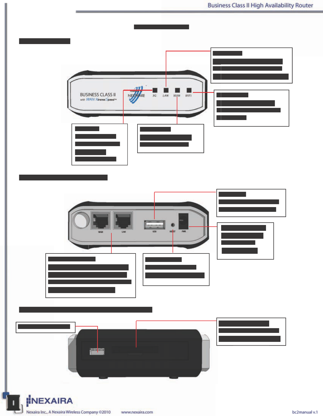
Receptors and Ports (Rear View)
LEDs (Front View)
ExpressCard and Serial Console Port (Side View)
USB Port:
Allows connection with
a 3G/4G USB modem.
ExpressCard Port:
Allows connection with
an ExpressCard modem.
Serial Console Port
Power Receptor:
Compatible with
included 12V
1.25A adapter.
Reset Button:
Resets the Router to
factory default settings.
WAN/LAN Ports:
Automatically senses WAN and
LAN types when connecting to
Ethernet. WAN can be converted
to an additional LAN port.
Hardware Overview
LAN LED:
Lights up blue when a local
Ethernet cable is connected
and blinks to indicate activity.
Wi-Fi LED:
Light blinks blue when
a connection to the Wi-Fi
is available.
WAN LED:
Lights up blue when
WAN is connected.
3G LED:
Solid blue when
connected. Power
indicated by
consistant blink.
Receptors and Ports (Rear View)
LEDs (Front View)
ExpressCard and Serial Console Port (Side View)
USB Port:
Allows connection with
a 3G/4G USB modem.
ExpressCard Port:
Allows connection with
an ExpressCard modem.
Serial Console Port
Serial Console Port
Power Receptor:
Compatible with
included 12V
1.25A adapter.
Reset Button:
Resets the Router to
factory default settings.
WAN/LAN Ports:
Automatically senses WAN and
LAN types when connecting to
Ethernet. WAN can be converted
to an additional LAN port.
Hardware Overview
LAN LED:
Lights up blue when a local
Lights up blue when a local
Ethernet cable is connected
Ethernet cable is connected
and blinks to indicate activity.
and blinks to indicate activity.
Wi-Fi LED:
Wi-Fi LED:
Light blinks blue when
Light blinks blue when
a connection to the Wi-Fi
a connection to the Wi-Fi
is available.
is available.
WAN LED:
Lights up blue when
WAN is connected.
3G LED:
Solid blue when
connected. Power
indicated by
consistant blink.
USB
USB LED:
Default Router Settings
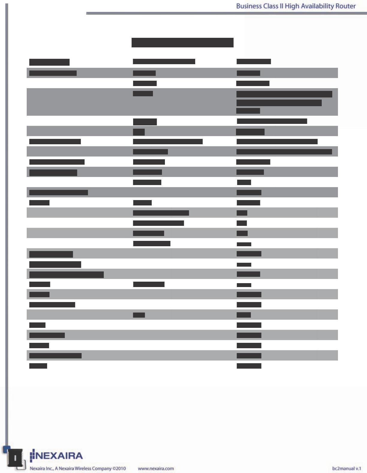
Login Screen Username / Password root /admin
Wi-Fi Interface Devices enabled
Channel Auto select
ESSID NEXWARE### (### are the last
3 digits of the Router’s MAC
Address
Security WPA-PSK / WPA2-PSK
Key password
Wired Interfaces IPv4 Address / Netmask 192.168.1.1 / 255.255.255.0
DNS Server 208.67.222.222 / 208.67.220.220
Cellular Datacard 3G Service Auto detect
System Settings Hostname NexWare
Timezone UTC
Email Notications disabled
DHCP Server enabled
First leased address 100
Number of leased 151
Lease time 12h
Static Leases none
Dynamic DNS disabled
Port Forwarding none
Quality of Service (QoS) enabled
Routes Static IPv4 none
SNMP disabled
Remote Admin disabled
Port 8080
IPsec disabled
SSH Server disabled
VRRP disabled
Internet Failover disabled
UPnP disabled
Default Router Settings
Login Screen
Username / Password
root /admin
Wi-Fi Interface
Devices
enabled
Channel
Auto select
ESSID
NEXWARE### (### are the last
3 digits of the Router’s MAC
Address
Security
WPA-PSK / WPA2-PSK
Key
password
Wired Interfaces
IPv4 Address / Netmask
192.168.1.1 / 255.255.255.0
DNS Server
208.67.222.222 / 208.67.220.220
Cellular Datacard
3G Service
Auto detect
System Settings
Hostname
NexWare
Timezone
UTC
Email Notications
disabled
DHCP
Server
enabled
First leased address
100
Number of leased
151
Lease time
12h
Static Leases
none
Dynamic DNS
disabled
Port Forwarding
none
Quality of Service (QoS)
enabled
Routes
Static IPv4
none
SNMP
disabled
Remote Admin
disabled
Port
8080
IPsec
disabled
SSH Server
disabled
VRRP
disabled
Internet Failover
disabled
UPnP
disabled

Hardware Setup
The Business Class II High Availability Router allows you to access your net-
work using a wireless connection from virtually anywhere within its operating
range. Please note that location placement of the router could affect the wire-
less signal and range limits.
Typical ranges also vary depending on the types of materials and background RF (Radio Frequency) noise
present in your networking environment.
To maximize your wireless range, please follow these guidelines:
1. Choose the right location in your environment for the 3G/4G Wireless Broadband Router. The WLAN
transmitters are radios, and degrade as they go through walls, oors, and obstacles like tubs full of water
(almost impenetrable), stone, or concrete. So for best reception, place your router centrally to the rooms
in which you expect to use WLAN the most. Each wall or ceiling can reduce the Business Class II II High
Availability Router’s range by as much as 90 feet (27 meters).
NOTE: The same considerations apply to your carrier’s 3G/4G broadband carrier’s connection.
2. Keep your product away from electrical devices (such as microwaves, air conditioners, cordless phones,
refrigerators and televisions) that emit large quantities of RFI (Radio Frequency Interference).
NOTE: DO NOT connect the Business Class II High Availability Router to power before following the in-
stallation steps below!
Business Class II High Availability Router Setup
1. ExpressCard or USB connection:
a. Insert an activated ExpressCard into the card slot.
b. Alternatively, insert an activated USB modem into the USB slot.
a. b.
Hardware Setup
The Business Class II High Availability Router allows you to access your net
-
work using a wireless connection from virtually anywhere within its operating
range. Please note that location placement of the router could affect the wire
-
less signal and range limits.
Typical ranges also vary depending on the types of materials and background RF (Radio Frequency) noise
present in your networking environment.
To maximize your wireless range, please follow these guidelines:
1. Choose the right location in your environment for the 3G/4G Wireless Broadband Router. The WLAN
transmitters are radios, and degrade as they go through walls, oors, and obstacles like tubs full of water
(almost impenetrable), stone, or concrete. So for best reception, place your router centrally to the rooms
in which you expect to use WLAN the most. Each wall or ceiling can reduce the Business Class II II High
Availability Router’s range by as much as 90 feet (27 meters).
NOTE:
The same considerations apply to your carrier’s 3G/4G broadband carrier’s connection.
2. Keep your product away from electrical devices (such as microwaves, air conditioners, cordless phones,
refrigerators and televisions) that emit large quantities of RFI (Radio Frequency Interference).
NOTE: DO NOT
connect the Business Class II High Availability Router to power before following the in
NOTE: DO NOT connect the Business Class II High Availability Router to power before following the inNOTE: DO NOT
-
stallation steps below!
Business Class II High Availability Router Setup
1. ExpressCard or USB connection:
a. Insert an activated ExpressCard into the card slot.
b. Alternatively, insert an activated USB modem into the USB slot.
a.
b.
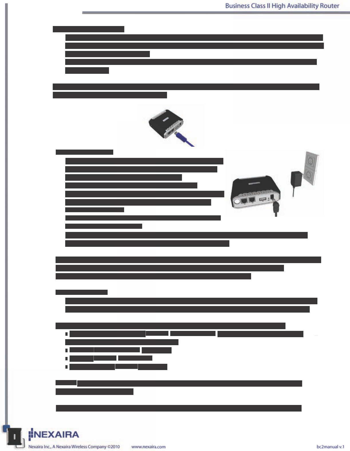
2(ii). Ethernet connection:
a. Insert one end of an Ethernet cable into the LAN Port on the back panel of the router. Insert
the other end into an available Ethernet port of the network adapter in the computer that will
be used to congure the unit.
b. LAN LED should be on when connected. If not, check the connection between the router
and computer.
NOTE: The Business Class II High Availability Router LAN Port is “Auto-MDI/MDIX”, so
any standard Ethernet cable will work.
3. Power connection.
a. Connect the power adapter to the receptor on the back
panel of the router. Plug the other end of the power
adapter into a wall outlet or power strip.
b. The 3G & Wi-Fi LED will turn ON and ash,
indicating that the unit is powered on. Also performing
the boot-up cycle. The LAN and WAN lights will
be on if connected.
c. The 3G/4G LED will ash and stabilize once a 3G/4G
connection is established.
d. Upon completion of the boot-up cycle, the 3G light, LAN and Wi-Fi lights will be on.
Occational ashing may occur indicating normal activity.
NOTES: An uninterruptable power supply (UPS) is recommended for power surges and/or
outages. At a minimum, a surge protector should always be used to protect the
equipment from being damaged by electrical spikes and transients.
Wi-Fi Connection
If you are connecting wirelessly to the Business Class II High Availability Router, you must
ensure that the security settings on the connecting PC are the same as those on the router.
By default, the router broadcasts a secure Wi-Fi signal with WPA-PSK* encryption:
• SSID / Wi-Fi Signal Name is set to NEXWARE### (where ### equal the last three
characters of the router’s MAC address)
• Channel is set to channel 5(2.4GHz)
• Security is set to WPA-PSK*
• Key (password) is set to password
NOTE: It is recommended, for security reasons, that the security settings on the router be
changed during initial setup.
*Please refer to your computer’s Wi-Fi adapter documentation for additional information.
2(ii). Ethernet connection:
a. Insert one end of an Ethernet cable into the LAN Port on the back panel of the router. Insert
the other end into an available Ethernet port of the network adapter in the computer that will
be used to congure the unit.
b. LAN LED should be on when connected. If not, check the connection between the router
and computer.
NOTE: The Business Class II High Availability Router LAN Port is “Auto-MDI/MDIX”, so
any standard Ethernet cable will work.
3. Power connection.
a. Connect the power adapter to the receptor on the back
panel of the router. Plug the other end of the power
adapter into a wall outlet or power strip.
b. The 3G & Wi-Fi LED will turn ON and ash,
indicating that the unit is powered on. Also performing
the boot-up cycle. The LAN and WAN lights will
be on if connected.
c. The 3G/4G LED will ash and stabilize once a 3G/4G
connection is established.
d. Upon completion of the boot-up cycle, the 3G light, LAN and Wi-Fi lights will be on.
Occational ashing may occur indicating normal activity.
NOTES: An uninterruptable power supply (UPS) is recommended for power surges and/or
outages. At a minimum, a surge protector should always be used to protect the
equipment from being damaged by electrical spikes and transients.
Wi-Fi Connection
If you are connecting wirelessly to the Business Class II High Availability Router, you must
ensure that the security settings on the connecting PC are the same as those on the router.
By default, the router broadcasts a secure Wi-Fi signal with WPA-PSK* encryption:
•
SSID / Wi-Fi Signal Name
is set to
NEXWARE###
(where ### equal the last three
characters of the router’s MAC address)
•
Channel
is set to channel
5(2.4GHz)
•
Security
is set to
WPA-PSK*
•
Key (password)
is set to
password
NOTE:
It is recommended, for security reasons, that the security settings on the router be
changed during initial setup.
*Please refer to your computer’s Wi-Fi adapter documentation for additional information.
Initial 3G/4G Wireless Setup
Connecting to the Router Main Page for Installation and Congurations Settings
Follow the steps below to access the Router and perform installation and congure settings:
1) Open a web browser on your computer connected to the router’s LAN port by and Ethernet cable.
2) Enter the IP address of the Router in the URL line of your web browser.
http://192.168.1.1
NOTE: If you have changed the router’s default IP address, enter that address instead of the one above.
3) Type “admin” in the Password eld. If you have changed the password, enter the new one in this
eld. NOTE: Default Username is “root”.
4) Click the “Login” button.
5) You will be greeted by the iconic home page.
Setup Wizard
Select the Setup Wizard Icon. Select the Next button to proceed with the indicated steps of the automated
setup process.
1) Change your administration password. It is recommended that the default password (admin) be replaced
for security reasons. Enter your new password and then re-enter to conrm. Select Next to retain any
changes and move to the next step.
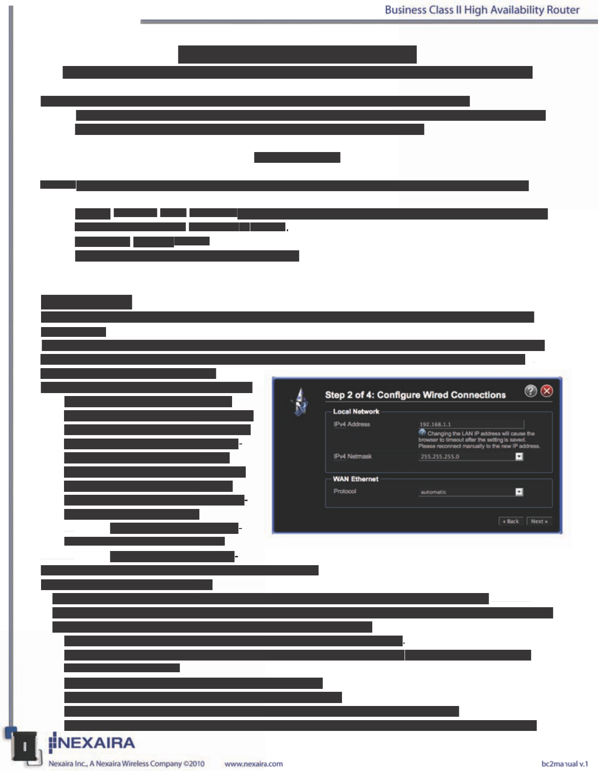
2) Congure your Wired Internet connection.
a. During the boot up process of the
router if your wide area network (WAN)
Ethernet cable is plugged into the WAN
port of the router, the router will auto-
matically be connected to your ISP.
b. If your ISP requires you to setup the
WAN as a PPPoE or PPTP, you will
need to enter your ISP’s required infor-
mation into the proper elds.
i. PPPoE. Typical entries in-
clude the Username and Password
ii. PPTP. Typical entries in-
clude the Username, Password, and the PPTPServer Name.
3a) Congure your wireless settings.
This step allows you to change whether the Wi-Fi is enabled, the channel on which the Wi-Fi
is broadcast on, the wireless mode (b,g,n or mixed), the name that is broadcast, the security and encryption
type, and the key (password) to access the broadcasted Wi-Fi signal.
• Disable only if you do not want anyone accessing the router wirelessly.
• Change channel if other wireless devices are interfering with the router. By default the router will
auto-select the channel.
• Select the wireless mode, choose from b,g,n or a mix.
• The router’s mode is factory set to provide (Access Point)
• Change the Network Name (ESSID) to whatever name you wish to be broadcasted
• Hiding the ESSID does not disable the WiFi signal and should not be thought of as security setting.
Initial 3G/4G Wireless Setup
Connecting to the Router Main Page for Installation and Congurations Settings
Follow the steps below to access the Router and perform installation and congure settings:
1) Open a web browser on your computer connected to the router’s LAN port by and Ethernet cable.
2) Enter the IP address of the Router in the URL line of your web browser.
http://192.168.1.1
NOTE:
If you have changed the router’s default IP address, enter that address instead of the one above.
3) Type
“admin”
in the
Password
eld. If you have changed the password, enter the new one in this
eld. NOTE: Default
Username
is
“root”
.
4) Click the
“Login”
button.
5) You will be greeted by the iconic home page.
Setup Wizard
Select the Setup Wizard Icon. Select the Next button to proceed with the indicated steps of the automated
setup process.
1) Change your administration password. It is recommended that the default password (admin) be replaced
for security reasons. Enter your new password and then re-enter to conrm. Select Next to retain any
changes and move to the next step.
2) Congure your Wired Internet connection.
a. During the boot up process of the
router if your wide area network (WAN)
Ethernet cable is plugged into the WAN
port of the router, the router will auto
-
matically be connected to your ISP.
b. If your ISP requires you to setup the
WAN as a PPPoE or PPTP, you will
need to enter your ISP’s required infor
-
mation into the proper elds.
i. PPPoE. Typical entries in
-
clude the Username and Password
ii. PPTP. Typical entries in
-
clude the Username, Password, and the PPTPServer Name.
3a) Congure your wireless settings.
This step allows you to change whether the Wi-Fi is enabled, the channel on which the Wi-Fi
is broadcast on, the wireless mode (b,g,n or mixed), the name that is broadcast, the security and encryption
type, and the key (password) to access the broadcasted Wi-Fi signal.
• Disable only if you do not want anyone accessing the router wirelessly
.
• Change channel if other wireless devices are interfering with the router
. By default the router will
auto-select the channel.
• Select the wireless mode, choose from b,g,n or a mix.
• The router’s mode is factory set to provide (Access Point)
• Change the Network Name (ESSID) to whatever name you wish to be broadcasted
• Hiding the ESSID does not disable the WiFi signal and should not be thought of as security setting.
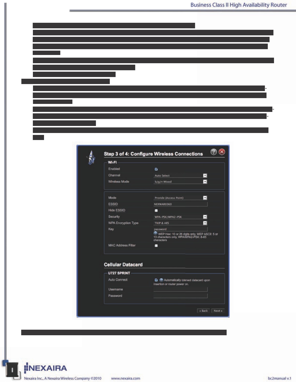
Hiding the ESSID only eliminates the name from being broadcasted.
• Change encryption type as necessary. Some wireless devices cannot connect to all encryption modes.
The default setting is WPA-PSK. Other typical choices include WEP (ASCII or Hex), WPA=PSK, or
WPA2-PSK. Additional available settings require additional software or hardware not included with
this router.
• Change Key (password). We suggest that this setting be changed. This setting controls the require Key
or password to access your wireless signal.
• Choose to lter by MAC Address.
3b) 3G/4G Internet Connection Setup.
a. During the boot up process of the router all compatible data cards are recognized and are setup au-
tomatically. No additional information is typically required to complete the setup of your compatible
3G/4G data card.
b. If your ISP requires additional information to connect to their network, please refer to their documen-
tation for APN, PIN Code, Username, and Password. All data entry elds may not be required to con-
nect to your ISP’s network.
c. Avalible options and selections are dependant on the presence of a datacard and the carrier network
type.
4) Select Next to retain any changes and move to the Completion page and select Finish.
Hiding the ESSID only eliminates the name from being broadcasted.
• Change encryption type as necessary. Some wireless devices cannot connect to all encryption modes.
The default setting is WPA-PSK. Other typical choices include WEP (ASCII or Hex), WPA=PSK, or
WPA2-PSK. Additional available settings require additional software or hardware not included with
this router.
• Change Key (password). We suggest that this setting be changed. This setting controls the require Key
or password to access your wireless signal.
• Choose to lter by MAC Address.
3b) 3G/4G Internet Connection Setup.
a. During the boot up process of the router all compatible data cards are recognized and are setup au
-
tomatically. No additional information is typically required to complete the setup of your compatible
3G/4G data card.
b. If your ISP requires additional information to connect to their network, please refer to their documen
-
tation for APN, PIN Code, Username, and Password. All data entry elds may not be required to con
-
nect to your ISP’s network.
c. Avalible options and selections are dependant on the presence of a datacard and the carrier network
type.
4) Select Next to retain any changes and move to the Completion page and select Finish.
Basics
Admin Password
You can change the router’s administrative password. (default = admin)
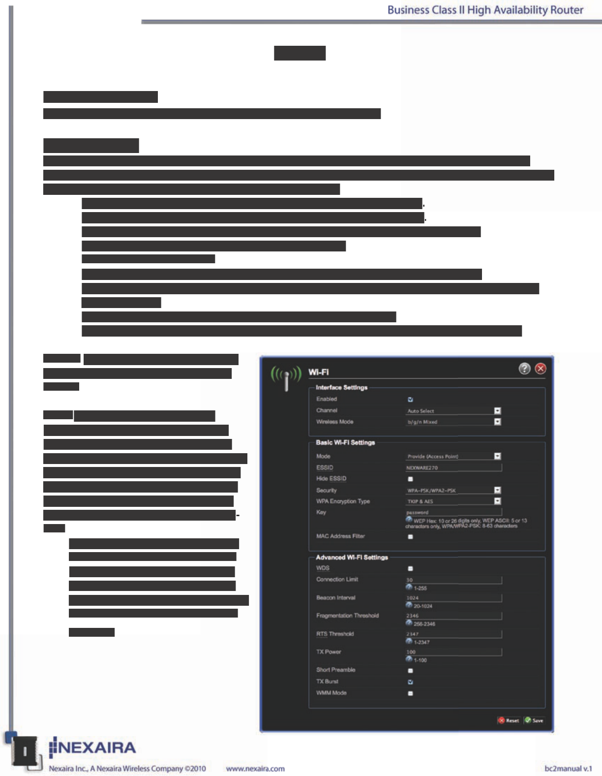
Wi-Fi Settings
Here you can change whether the Wi-Fi is enabled, the channel on which the Wi-Fi is broadcast on, the
name that is broadcast, the wireless mode, the encryption type, the key (password) to access the broadcasted
Wi-Fi signal, and enable Wireless Distribution System (WDS).
• Disable only if you do not want anyone accessing the router wirelessly.
• Change channel if other wireless devices are interfering with the router.
• Change the router’s Wireless Mode. Choose from six settings, b, g, or n and mixes.
• Routing mode is factory set to Provide (Access Point).
• Choose to hide the ESSID.
• Change the Network Name (ESSID) to whatever name you wish to be broadcasted.
• Change security and encryption type as necessary. Some wireless devices cannot connect to all
security modes.
• Change Key (password). We suggest that this setting be changed.
• Choose to enable MAC Address ltering, then select lter policy and create the address list.
NOTE: After any changes, select ”Save”
to retain. System will refresh following,
“Save”.
WDS: Wireless Distribution System
(WDS) is a feature that allows multiple
access points of the same physical radio
type to be bridged together as one common
WiFi network. Because the same physical
radio type must be used, this feature only
operates with other Nexaira routers. The
following conguration options are avail-
able:
• BSSID: Your router supports up to
four WDS clients. Enter the BSSID
(MAC address listed on the bottom
label of the router, also listed under
LAN on the Wired Interfaces page) of
the other devices to be connected to
via WDS.
Basics
Admin Password
You can change the router’s administrative password. (default = admin)
Wi-Fi Settings
Here you can change whether the Wi-Fi is enabled, the channel on which the Wi-Fi is broadcast on, the
name that is broadcast, the wireless mode, the encryption type, the key (password) to access the broadcasted
Wi-Fi signal, and enable Wireless Distribution System (WDS).
• Disable only if you do not want anyone accessing the router wirelessly
.
• Change channel if other wireless devices are interfering with the router
.
• Change the router’s Wireless Mode. Choose from six settings, b, g, or n and mixes.
• Routing mode is factory set to Provide (Access Point).
• Choose to hide the ESSID.
• Change the Network Name (ESSID) to whatever name you wish to be broadcasted.
• Change security and encryption type as necessary. Some wireless devices cannot connect to all
security modes.
• Change Key (password). We suggest that this setting be changed.
• Choose to enable MAC Address ltering, then select lter policy and create the address list.
NOTE:
After any changes, select ”Save”
to retain. System will refresh following,
“Save”.
WDS:
Wireless Distribution System
(WDS) is a feature that allows multiple
access points of the same physical radio
type to be bridged together as one common
WiFi network. Because the same physical
radio type must be used, this feature only
operates with other Nexaira routers. The
following conguration options are avail
-
able:
• BSSID: Your router supports up to
four WDS clients. Enter the BSSID
(MAC address listed on the bottom
label of the router, also listed under
LAN on the Wired Interfaces page) of
the other devices to be connected to
via WDS.
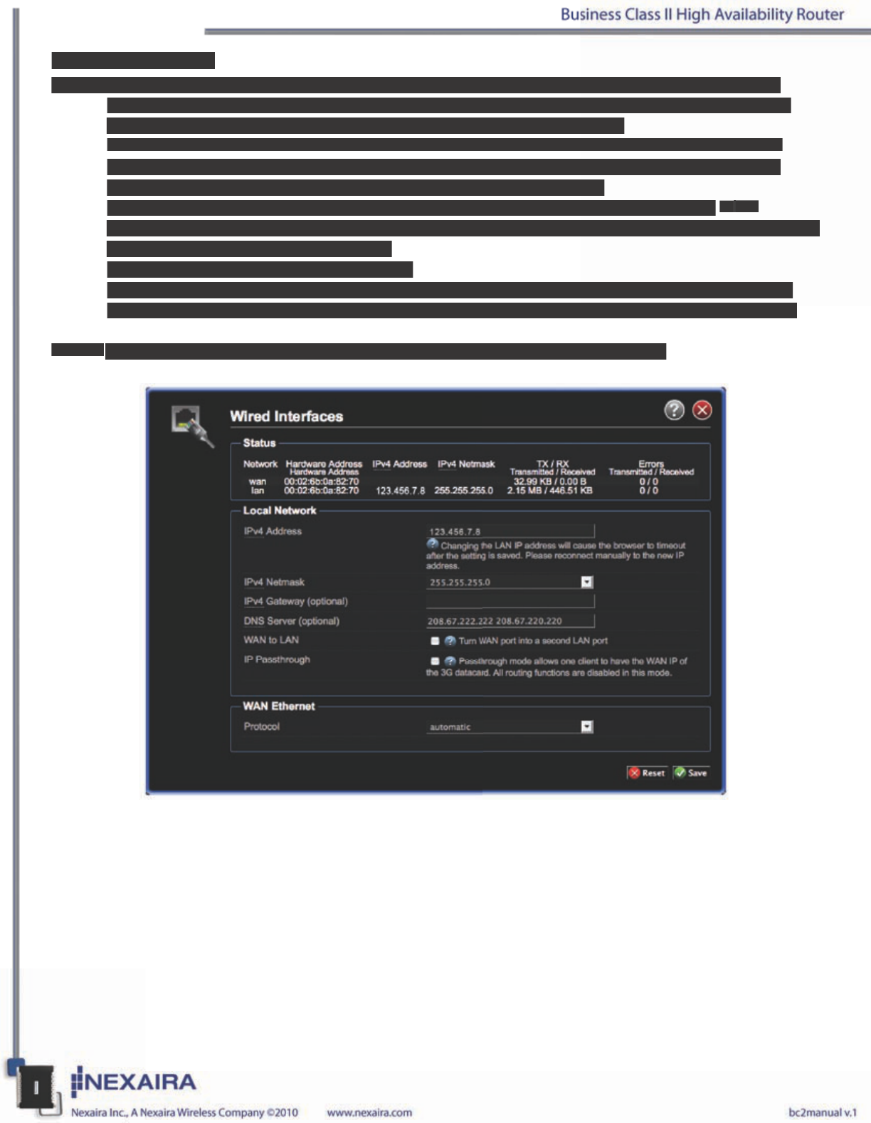
Wired Interfaces
Here you can review WAN, and LAN status as well as change Local Network, and WAN Ethernet settings.
• The IP address is the address of the router. It is also your local network’s gateway address which is
used by all LAN hosts to access the Internet through the WAN connection.
• The Netmask is used to determine the number of subnetworks that can be connected to the router.
• The IP Gateway (optional) eld is and advanced an optional setting that is available if your local
network has a gateway that is different than the router’s LAN IP address.
• DNS Server (optional) allows you to specify a DNS server for LAN hosts to use if your WAN
connection does not supply a valid server address, or if not-peer DNS Server information is required or
chosen under Cellular Datacard settings.
• Change WAN port into a second LAN port.
• Enable IP Passthrough mode to have one client have the WAN IP. All router functions are disabled.
• Enable or disable the router’s ability to connect to the internet through a WAN Ethernet connection.
NOTE: After any changes, select ”Save” to retain. System will refresh following, “Save”.
Wired Interfaces
Here you can review WAN, and LAN status as well as change Local Network, and WAN Ethernet settings.
• The IP address is the address of the router. It is also your local network’s gateway address which is
used by all LAN hosts to access the Internet through the WAN connection.
• The Netmask is used to determine the number of subnetworks that can be connected to the router.
• The IP Gateway (optional) eld is and advanced an optional setting that is available if your local
network has a gateway that is different than the router’s LAN IP address.
• DNS Server (optional) allows you to specify a DNS server for LAN hosts to use if your
W
AN
WAN W
connection does not supply a valid server address, or if not-peer DNS Server information is required or
chosen under Cellular Datacard settings.
• Change WAN port into a second LAN port.
• Enable IP Passthrough mode to have one client have the WAN IP. All router functions are disabled.
• Enable or disable the router’s ability to connect to the internet through a WAN Ethernet connection.
NOTE:
After any changes, select ”Save” to retain. System will refresh following, “Save”.
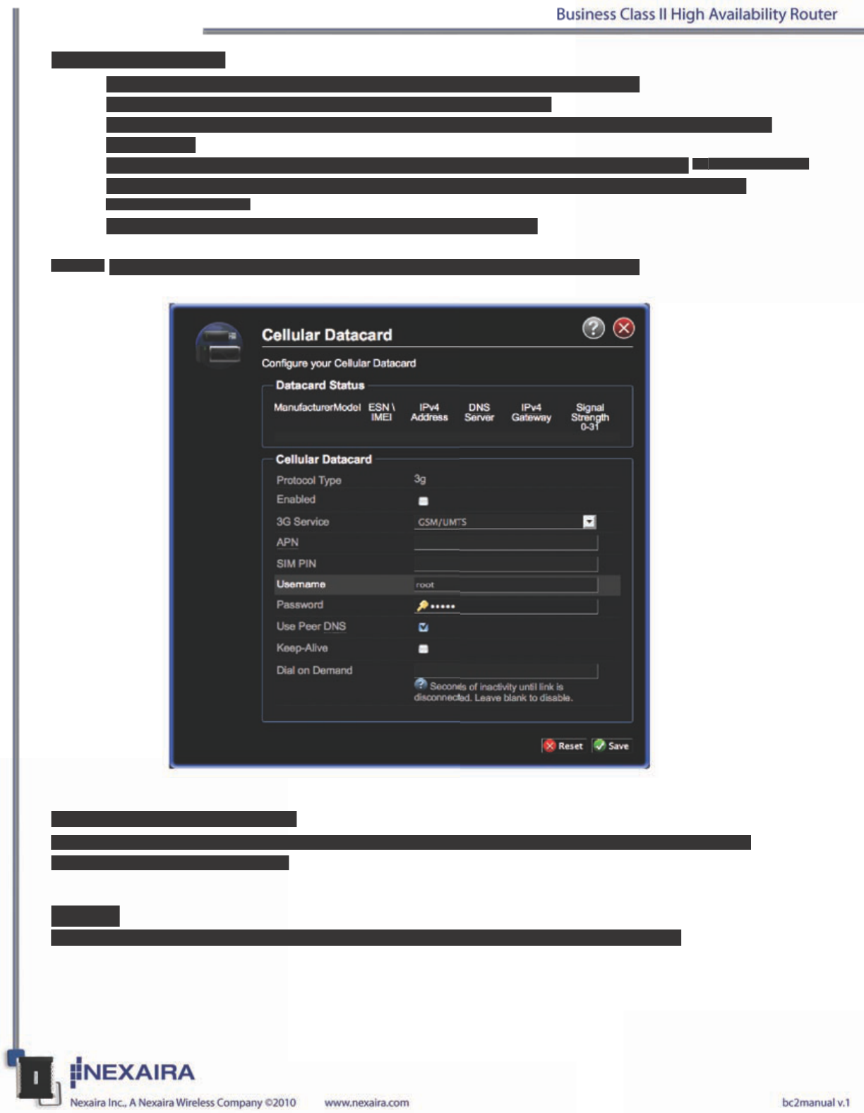
Cellular Datacard
• Enable or disable the router’s ability to access the Internet through a datacard
• Select Service type: UMTS/GPRS, CDMA (default), or EV-DO.
• Insert Access Point (APN), PIN code, Username, and Password as indicated by your 3G/4G wire
less provider.
• Select to use the Peer DNS or an optional location. Input DNS Server information in Wired Interfaces.
• Enable Keep-Alive to determine it the connection is up. Router well re-initilize connection if
connection is down.
• Input time (in seconds) of inactivity until link is disconnected.
NOTE: Settings are auto-populated when an activated compatible datacard is inserted.
Realtime Network Trafc
The Network Trafc status screen shows current trafc status of active interfaces, such as the LAN, the
connected Datacard, and the WAN.
Logout
Here you will be logged out of administrative mode. You will be returned to the login screen.
Cellular Datacard
• Enable or disable the router’s ability to access the Internet through a datacard
• Select Service type: UMTS/GPRS, CDMA (default), or EV-DO.
• Insert Access Point (APN), PIN code, Username, and Password as indicated by your 3G/4G wire
less provider.
• Select to use the Peer DNS or an optional location. Input DNS Server information in
W
ired Interfaces.
Wired Interfaces.
W
• Enable Keep-Alive to determine it the connection is up. Router well re-initilize connection if
connection is down.
• Input time (in seconds) of inactivity until link is disconnected.
NOTE:
Settings are auto-populated when an activated compatible datacard is inserted.
Realtime Network Trafc
The Network Trafc status screen shows current trafc status of active interfaces, such as the LAN, the
connected Datacard, and the WAN.
Logout
Here you will be logged out of administrative mode. You will be returned to the login screen.