User guide
© 2000 NEXAN® Ltd.
This document should be used for the intended use only and any
other distribution, copying, use or disclosure is strictly prohibited.
NEXAN, NEXI, NEXOFT are registered trademarks of Nexan® Ltd.
NEXAN® Ltd
Instructions for Use
NEXAN® SYSTEM Nx-300

300-USM-103 US Issue 1.0
Page 2 of 51 Index
Manual purpose and intended users
These instructions are intended for the Health Care Professional, as a guide to the
use of the Nx-300 System including the Nexan Software -Nexoft (found in the
Telemonitoring Station computer).
It is assumed that the user of the Telemonitoring Station and Nexoft is a
Registered Medical Practitioner who has experience of using Windows Software
on a PC.
The Patient is the user of the Nexi, Nexi-Clip, PDA, Base Station and Auxiliary
Sensors.
A set of instructions, called ‘Patient Guide’ is intended to be left with the patient (to
assist him/her with day-to-day-use)
A set of instructions called ‘READ ME FIRST’ is provided with each Nexi for
patient application of Nexi and Nexi-Clip.
User assistance information
To obtain service contact Nexan Customer Support on 770-360-9090.
Availability of Clinical Study Data
Clinical Study data, obtained using the Nx-300, is available on request from
Nexan Ltd.
Nexan Ltd, cautions the reader of this manual:
•This manual, wholly or partially, is subject to change without notice. Some
features described in this manual may not be available with this Nexan system.
•All rights are reserved: No one is permitted to reproduce or duplicate, in any
form, the whole or part of this manual without the permission of Nexan Ltd.
•Nexan assumes no responsibility for usage not in accordance with this manual
resulting in illegal or improper use of the Nexan system.

300-USM-103 US Issue 1.0
Page 3 of 51
Index
Contents
SECTION 1
Important information
General warnings & precautions .................................................................................. 5
Glossary of symbols & terms ........................................................................................ 7
Environment ................................................................................................................. 7
Symbols on Nx-300 system labelling ........................................................................... 8
Intended use............................................................................................................... 10
Contra-indications: ................................................................................................ 10
SECTION 2
Overview of Nx-300 system
System description ..................................................................................................... 11
Description of parts: ................................................................................................... 12
Parts supplied ............................................................................................................. 13
System setup and operation....................................................................................... 14
SECTION 3
Setting up the PDA and Base Station
Configuring the PDA ................................................................................................... 15
Accessing the HCP menu ..................................................................................... 15
Clearing the memory ............................................................................................ 16
Configuring the PDA for a new Nexi-clip............................................................... 17
Other Configure PDA options ............................................................................... 17
Viewing signals and data to check Nexi operation ............................................... 18
Setting the PDA Clock and Calendar .................................................................... 20
Viewing stored schedule information .................................................................... 20
Configuring the Base Station...................................................................................... 21
Accessing the HCP Menus ................................................................................... 21
Setting the PDA (PDL) ID code............................................................................. 23
Setting the Patient ID code ................................................................................... 24
Setting or editing the measurements schedule..................................................... 25

300-USM-103 US Issue 1.0
Page 4 of 51
SECTION 4
Setting up and using the TeleMonitoring Station
TeleMonitoring Station (TMS) overview...................................................................... 26
Setting up the TMS computer..................................................................................... 27
Connecting the TMS ............................................................................................. 27
Switching on the TMS ........................................................................................... 27
Using Nexoft ............................................................................................................... 28
Logging on ............................................................................................................ 28
Patient Records .................................................................................................... 30
Using the Calendar function to set a download schedule ..................................... 33
Initiating an immediate download ......................................................................... 36
Viewing Downloaded Data.................................................................................... 37
Printing Information............................................................................................... 39
On-line help .......................................................................................................... 41
Shutting down the TMS .............................................................................................. 42
SECTION 5
General Information
Technical Description ................................................................................................. 43
Technical Specifications ............................................................................................. 44
Power requirements ................................................................................................... 45
Transport and Storage conditions .............................................................................. 46
Operating Conditions .................................................................................................. 46
Cleaning, Maintenance, Storage and Calibration ....................................................... 47
Replacing the Base Station fuses .............................................................................. 48
Regulatory Markings .................................................................................................. 49
Federal Communications Commission (FCC) Compliance and Advisory Notice ....... 49
Warranty ..................................................................................................................... 50
Troubleshooting guide ................................................................................................ 51

300-USM-103 US Issue 1.0
Page 5 of 51
Section 1 - Important information
SECTION 1
Important information
General warnings & precautions
All users should read these Safety Instructions carefully and thoroughly before
using the system. To ensure patient safety, all parts of the system must be used in
accordance with the Instructions for Use as indicated by the warning triangle on
the product labels. Particular attention should be made to
WARNINGS
,
CAUTIONS
and
Notes
identified within this document.
•
WARNING
statements identify occurrences that could result in personal injury.
•
CAUTION
statements identify conditions or practices that could result in damage
to the equipment.
•
Note
statements disclose pertinent information.
Warnings
•THE BASE STATION MUST BE CONNECTED TO AN EARTHED (GROUNDED)
POWER SUPPLY.
•THE NEXI® MUST NOT BE APPLIED TO BROKEN, DAMAGED OR IRRITATED
SKIN.
•MONITORING OF PATIENTS WITH PHYSICAL OR MENTAL OR SENSORY
IMPAIRMENT SHOULD ONLY BE UNDERTAKEN IF THE MEDICAL
PRACTITIONER/PHYSICIAN CONSIDERS THEY CAN USE THE Nx-300
SYSTEM CORRECTLY AND THAT IT WILL NOT CAUSE UNDUE STRESS OR
ANXIETY.
•THERE IS A POSSIBILITY OF DEGRADATION OF THE RESPIRATION SIGNAL
IN PATIENTS WITH HIGH BODY MASS INDEX.
•REPLACE FUSES WITH CORRECT TYPE AND RATING; FOR PROTECTION
AGAINST FIRE AND OTHER HAZARDS.
•IF USED IN HOSPITAL, THE BASE STATION UNIT MUST BE CONNECTED TO
A HOSPITAL GRADE OUTLET.
•THE Nx-300 IS NOT FOR USE AS A CRITICAL CARE MONITORING SYSTEM.
•THE Nx-300 IS NOT AN APNOEA MONITOR.

300-USM-103 US Issue 1.0
Page 6 of 51 Section 1 - Important information
Precautions
•Substitution of a component different from that supplied may result in
measurement error.
•Only use the Nexan Supplied Charger or Base Station Unit (BSU) to re-charge
the Personal Data Assistant (PDA).
•Do not use two systems close together since corruption of data may occur. The
Nx-300 system should be used under the supervision of Registered Medical
Practitioner.
•Patients must be advised to contact their Registered Medical Practitioner if they
feel any deterioration in their condition whilst using the Nx-300 system.
•The Base Station, Auxiliary sensors and Telemonitoring Station (TMS) should be
placed in locations where the cables are safely positioned and the units cannot
harm anyone if the units fall.
•No part of the Nx-300 system should be allowed to come into contact with water
or other fluids, substances which could cause combustion, flammable/explosive
gases.
•Do not place any part of the system close to a source of heat (radiator etc.)
•The performance of the Nx-300 system cannot be guaranteed if tampered with
in any way.
•Inspect the Base Station power cord periodically for fraying or other damage. Do
not operate the equipment from mains power with a damaged power cord or
plug.
•Ensure that air can circulate freely around the Base Station and that
contaminates, e.g. talcum powder, are not allowed to ingress.

300-USM-103 US Issue 1.0
Page 7 of 51
Section 1 - Important information
Glossary of symbols & terms
As used in instructions and on product labels:
Auxiliary sensors
An Nx-300 facility to use additional sensors directly
connected to the Base Station.
Download
Data that is transferred from one location to another.
Event
Specific occasion(s) of patient response.
Monitoring schedule
A period of time during which patient monitoring is
carried out.
Trend Data
Data from all the auxiliary sensor sessions which is viewed
over an extended period of time.
Environment
Environmental conditions that affect use:
The Nx-300 system uses a radio frequency signal in the low power, unlicensed
Bands of 869.7- 870MHz in Europe and 916-917MHz in the United States of
America (Part of the 902-928 Band) to transfer system information from the Nexi-
Clip to the PDA. It is possible that interference may occur between the Nx-300 and
other radio equipment operating on the same frequencies. Due to the low power of
the transmissions, the potential for interference is only likely if the two are close to
each other.
Before installing the Nx-300,it is recommended that the installation environment be
checked for other radio devices that may be affected.
Examples of these environments are as follows:
•Domestic
•Social alarms
•Radio-controlled car security devices
•Hearing aids
•CB radios
•Panic alarms
•Television receivers
•Cordless telephones
•FM receivers
It is recommended that if any such equipment is identified, then it should be
checked for correct operation while the Nx-300 is operating as close as possible to
the equipment. Should any problems be observed we recommend the Nx-300 is
switched off and Nexan Customer Support is contacted (see page 2 for contact
details).
300-USM-103 US Issue 1.0
Page 8 of 51 Section 1 - Important information
Symbols on Nx-300 system labelling
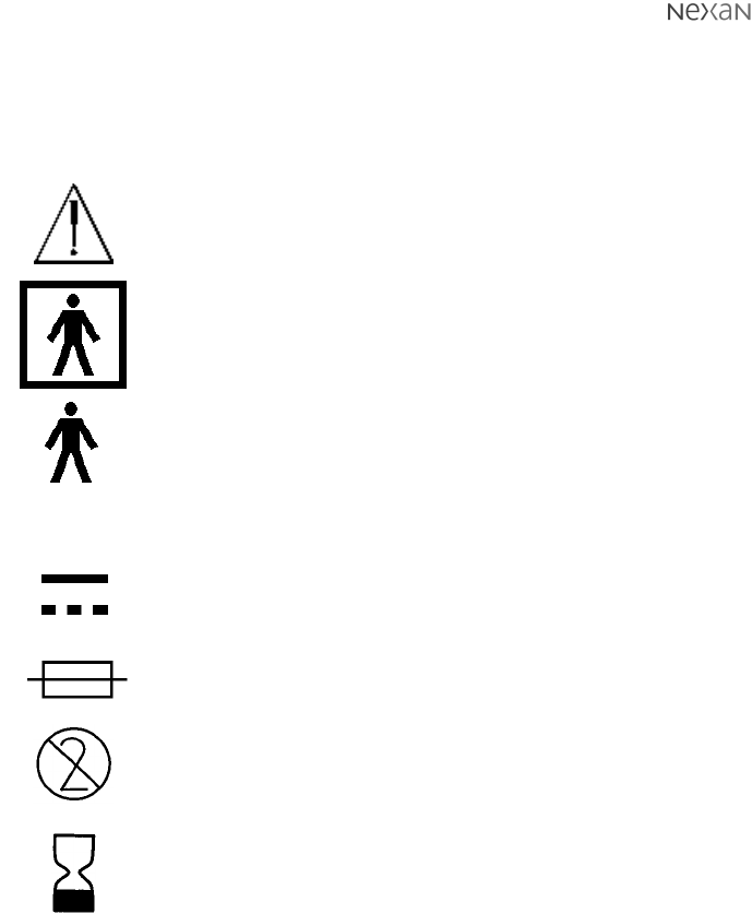
SYMBOL TEXT DESCRIPTION
ATTENTION, Consult Accompanying Documents
Type BF Equipment. Type B equipmment with an F-type
applied part (patient isolation from electric shock)
Used on Nexi.
Type B Equipment. (patient isolation from electric
shock). Used on Base Station
SERIAL NUMBER of device
Direct Current
Fuse 2x T2AH 250V (used on Base Station)
Not for Re-use (Single Use Only) applies to Nexi
(ISO7000/1051, BSEN980:1996)
Use- by (Year-month) applies to Nexi
SN-

300-USM-103 US Issue 1.0
Page 9 of 51
Section 1 - Important information
Symbols on Nx-300 system labelling (continued)
SYMBOL TEXT DESCRIPTION
Input - used on Base Station. Intended only for connection
to patients’ phone.
Output- used on Base Station. Intended only for
connection to patients’ phone line.
Used on Base Station to connect any auxiliary sensor
AECG Type 1 equipments (all)
Base Station Power ON
Base Station Power OFF
PDA Power ON/Confirm action button (green)
R&TTE equipment Class 2 (Member States restrictions)
May apply to Nexi-Clip and Portable Data Assistant (PDA)
A B
AECG 1
I
O

300-USM-103 US Issue 1.0
Page 10 of 51 Section 1 - Important information
Intended use
‘The Nx-300 system is an ambulatory patient monitoring system intended for use in
the home or alternate care settings. The device stores and transmits ECG data,
respiration data, systolic and diastolic blood pressure (non-invasive), and PEF and
FEV1’
Contra-indications:
•THE Nx-300 MUST NOT BE USED ON CHILDREN UNDER 9 YEARS OLD.
•THE Nx-300 IS NOT CONSIDERED SUITABLE FOR USE ON PATIENTS WITH
IMPLANTED DEFIBRILLATORS/PACEMAKERS.
•THE Nx-300 MUST NOT BE USED ON PATIENTS WITH KNOWN SENSITIVITY
TO MEDICAL ADHESIVES.
•THE Nx-300 IS NOT FOR USE AS A CRITICAL CARE MONITORING SYSTEM.
300-USM-103 US Issue 1.0
Page 11 of 51
Section 2 - Overview of Nx-300 system
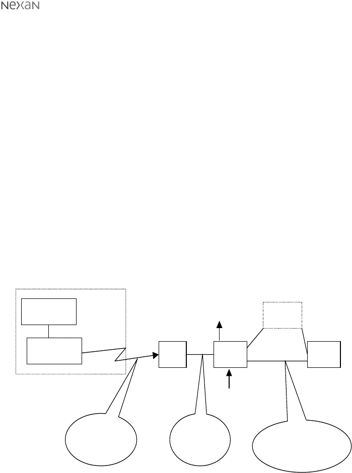
Figure 1. Nexan Nx-300 System
Nexi
Nexi-Clip PDA BSU TMS
Body-worn items
PSTN
Radio
Interface Direct
local
interface
Direct local
interface, or remote
via PSTN
Direct Interfaces to
3
rd
p
art
y
anal
y
ser
SpO2
sensor
SECTION 2
Overview of Nx-300 system
System description
Data from physiological measurements, taken by sensors on the chest and
underarm (Nexi) is converted into radio signals and transmitted via a radio
transmitter (Nexi-Clip attached to the Nexi) to a radio receiver in a Personal Data
Assistant (PDA). The PDA also stores the data for the monitoring period and
normally sits (docked) in a Base Station Unit (BSU) located in the patients’s home.
Whilst docked, the PDA transfers the data to the BSU. A TeleMonitoring Station
(TMS) computer, located within a remote monitoring centre, interrogates and
downloads the data from the Base Station via the patient’s phone line. The TMS
computer software is then used by the Registered Medical Practitioner to display
and interpret the patient data.
The diagram below shows the complete Nx-300 system in operation.
(
Auxiliary
Sensors

300-USM-103 US Issue 1.0
Page 12 of 51 Section 2 - Overview of Nx-300 system
Description of parts:
Nexi: A disposable, multi-parameter adhesive sensor patch
worn on the upper chest and underarm. Contains two
batteries used to power both the Nexi and the Nexi-Clip
when connected.
Nexi-Clip A Radio Transmitter which Clips to the Nexi and contains
a transmitter.
PDA: A Receiver and storage Unit for data storage of data
recieved by radio communications transferring that data to
the Base Station when docked.
Base Station: A Base Unit, located in the patient’s home, for data
storage,analysis and transfer of data to a Telemonitoring
centre on request. Also permits connection of Auxiliary
sensors such as Blood pressure and Spirometry devices
for point-in-time measurements. The Unit also contains a
call discriminator unit, which allows normal use of the
patient’s phone. The discriminator identifies the difference
between incoming voice or data calls and routes the call
appropriately.
TeleMonitoring A dedicated PC, located in the Telemonitoring Centre,
Station (TMS): running a Nexan software package.
Nexan Software: A software package in the TMS for data interpretation and
presentation of the data received from the Patient’s Base
Station. Nexan software is only for use by Healthcare
Professional.
Auxiliary Sensors: Auxiliary sensors connected to the Base Station for the
recording of blood pressure,weight (option) and
spirometry measurements.
300-USM-103 US Issue 1.0
Page 13 of 51
Section 2 - Overview of Nx-300 system
NOTE: Not all parts may be
supplied to all HCPs
12
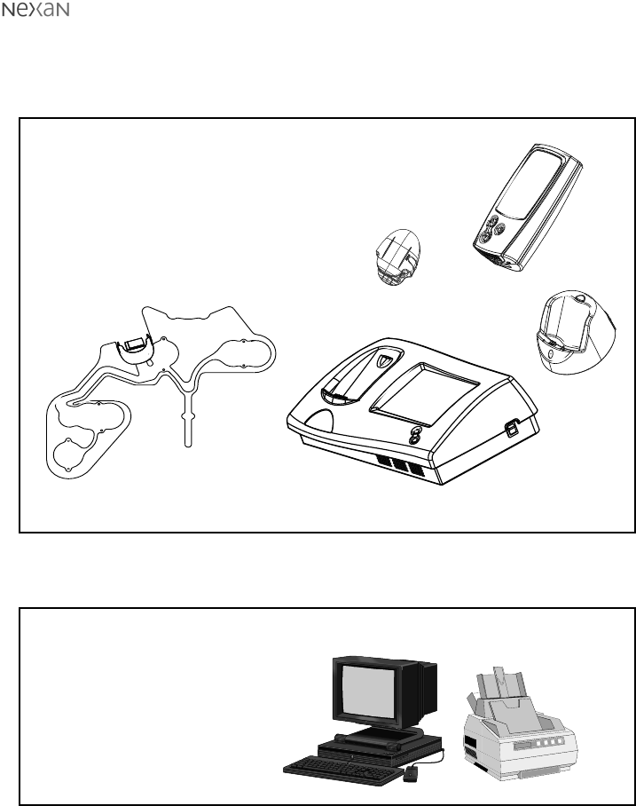
Parts supplied
Parts supplied to patient
1 TMS Personal Computer (containing installed Nexan Software)
2 Printer
CAUTION: Do not store in a damp area. Dampness may affect the device and
cause rust.
Parts supplied to Health Care Professional (HCP)
3
5
1 Nexi (One for each period of 24hrs required use)
2 Nexi-Clip
3 PDA
4 PDA charger unit (as required)
5 Base Station (BSU) + cables
Auxiliary sensors (as required)
1
2
NOTE: Not all parts may be supplied to all patients
4

300-USM-103 US Issue 1.0
Page 14 of 51 Section 2 - Overview of Nx-300 system
System setup and operation
Successful operation of the Nx-300 system depends on thorough patient
instruction. Nexan recommends that you walk through the following steps with
each patient, using the PATIENT GUIDE as a reference:-
•Explain the equipment and procedures to the patient.
•Connecting and powering up the Base Station and PDA.
•Check the patient’s telephone still works (incoming & outgoing calls).
•Applying the Nexi and Nexi-Clip using the READ ME FIRST guide supplied with
each Nexi.
•Verifying operation of the equipment (check out).
•Explain the basic operation of the system and on line help screens.
•Patient tasks (e.g. take blood pressure) and display messages.
•What to do if the telephone line is busy?
•Discuss wearing the Nexi and Nexi-Clip day-to-day.
•Discuss the use of the PDA day-to-day.
•Taking auxiliary sensor measurements - if supplied.
•Explain where and how to call for help/assistance.
•Troubleshooting patient equipment.
300-USM-103 US Issue 1.0
Page 15 of 51
Section 3 - Setting up the PDA and Base Station
SECTION 3
Setting up the PDA and
Base Station
Configuring the PDA
To switch on the PDA, press and hold the
green button. The screen will briefly
display an information view showing the
unique PDA identification number, plus its
software and hardware revisions ð
Personal
Data
Assistant
ID 7800123456
Software 12.34
Hardware 56.78
& Nexan Ltd.
2000
________
____
_________
ABCDEFGH
jkkl
****
HCP Menus
Please enter
HCP PIN:
to select
to confirm
each digit
cdef
ab
_________
Accessing the HCP menu
When preparing the PDA for a new patient, a number of actions should be carried
out, all of which require access to the HCP menus that are hidden from the
patient. A pre-set PIN code is required to
gain access to the HCP menus.
To access the HCP menus:
1 Press and hold the key to show
this display ð
2 Press the key to begin entering
the PIN. The first will be replaced
with ‘ ’.
3 Use the or keys to select the
required PIN digit and press to
confirm when the number is correct.
4 Repeat step 3 until all four digits are
entered.
300-USM-103 US Issue 1.0
Page 16 of 51 Section 3 - Setting up the PDA and Base Station
Accessing the HCP menu (cont.)
When the correct PIN has been entered, the
HCP Main Menu
is displayed ð
Note: If the PIN is not known, then there is
a second, fixed PIN, that will provide
access. If required you can get this PIN by
contacting Nexan.
jkkl
HCP Main Menu
View signals
View summary
View schedule
View status
Configure
Set clock
Reset menu
cdef
ab
to select
to confirm
Exit
___ ____ ____
jkkl
Reset PDA
Erase all data
No
Reset config
No
cdef
ab
to select
to exit
Exit
_____ ___
Clearing the memory
When you are preparing the PDA for a new patient, the first action must always be
to ensure that the memory is completely free of residual data.
To clear the memory:
1 Enter the
HCP Menu
.
2 Press the key until is
highlighted. Press the key to display
the
Reset PDA
screen ð
3 Press the key until
is highlighted and then press the
key. Press the or keys until the
option states and then press .
4 Press the key until is highlighted
and press the key to execute the erase
function and return to the
HCP Main Menu
.
300-USM-103 US Issue 1.0
Page 17 of 51
Section 3 - Setting up the PDA and Base Station
Configuring the PDA for a new Nexi-clip
When setting up a new installation, you must
ensure that the PDA is configured to recieve
data from the specific Nexi-clip being used.
To register a new Nexi-clip with the PDA:
1 Enter the
HCP menu
.
2 Press the key until is
highlighted. Press the key to display the
Configure PDA
screen ð
3 Press the key until is
highlighted and press the key to
highlight the first number of the Nexi-clip
code.
On the rear of the Nexi-clip to be used,
locate the printed label. On the label note
the three figure ID code - this is the code
that must be entered into the PDA.
4 Press or to set the first digit of the Nexi-clip ID code and then press
to store this value and move to the next digit. Repeat this procedure with the
remaining two ID digits.
5 When the last digit has been set, press the key until is highlighted
and then press . The configured options are implemented as the screen is
exited.
Other Configure PDA options
jkkl
Configure PDA
Nexi clip 123
Sig. alarm on
PIN ****
Patient ID
12345678
Calendar on
ECG 3 off
SpO2 on
cdef
ab
to select
to exit
Exit
_________ ___
jkkl
Configure PDA
Nexi clip 123
Sig. alarm on
PIN ****
Patient ID
12345678
Calendar on
ECG 3 off
SpO2 on
cdef
ab
to select
to exit
Exit
_________ ___
When ON, sounds an
alarm when the signal from
the Nexi-clip becomes
weak.
When ON, displays the
date on the standby
screen.
When ON, enables storage
for optional ECG data from
an external ‘flying lead’
attached to the Nexi.
Allows you to set a new
PIN to gain access to the
HCP menus (set to 0000 to
disable the PIN)
An eight figure
representation of the
current Patient ID.
300-USM-103 US Issue 1.0
Page 18 of 51 Section 3 - Setting up the PDA and Base Station
Viewing signals and data to check Nexi operation
The PDA allows you to view the ECG and/or respiratory waveforms being
monitored by the Nexi patch and sent to the PDA by the Nexi-clip. This function is
useful when checking that the patch has been correctly applied and that the Nexi-
clip and PDA are communicating correctly.
To view raw data signals:
1 Apply the Nexi to the patient and attach the
Nexi-clip in the usual manner.
2 Enter the
HCP Menu
.
3 Press the key until is
highlighted. Press the key to display the
Signals Menu
ð
4 Press the or keys until the required
ECG or Resp. signal is highlighted. Press
the key to display the chosen raw data
display ò
jkkl
Signals Menu
ECG lead 1
ECG lead 2
ECG lead 3
Resp. signal
cdef
ab
to select
to confirm
Exit
_______ ____
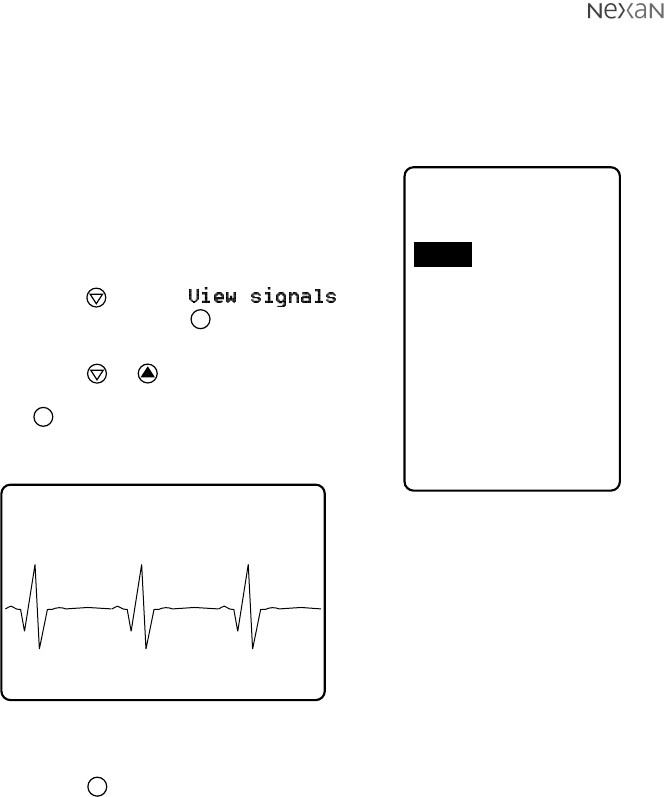
ECG1 HR 75 RR15 SpO2 95
The screen changes to a
‘landscape’ display and shows the
current waveform, plus along the
top: the current Heart Rate and
Respiration Rate.
If no waveform or HR/RR values are
displayed then there may be a
communication problem or fault with
the Nexi/Nexi-clip combination.
Note: If you do not see a good signal, refer to
the Troubleshooting section at the rear of this guide.
5 Press the key to return to the
Signals Menu
.
Additionally you can also view the incoming data simply as numeric values. This
method is discussed next.
300-USM-103 US Issue 1.0
Page 19 of 51
Section 3 - Setting up the PDA and Base Station
75
15
98
jkkl
Summary
HR bpm:
RR /min:
SpO2 %:
to exitab
_______
jkkl
PDA Status
Id: 8700123456
Nexi clip: 123
Nexi clip OK
Mem free %: 85
Signal mV:1234
On at:
10:15 Oct 12
Session: 123
10:25 Oct 12
to exitab
___ ______
Indicates the ID number for
the current Nexi-clip.
Indicates how much data
storage memory is free
within the PDA.
Indicates when the PDA
was last switched on
Indicates the strength of
the signal from the
Nexi-clip. 1000 or less
indicates a weak signal
that could result in data
loss. 2000 or more
indicates a strong signal.
The patient ID number.
Indicates that signals are
being received from the
designated Nexi-clip.
Indicates the current
patient session and when it
commenced.
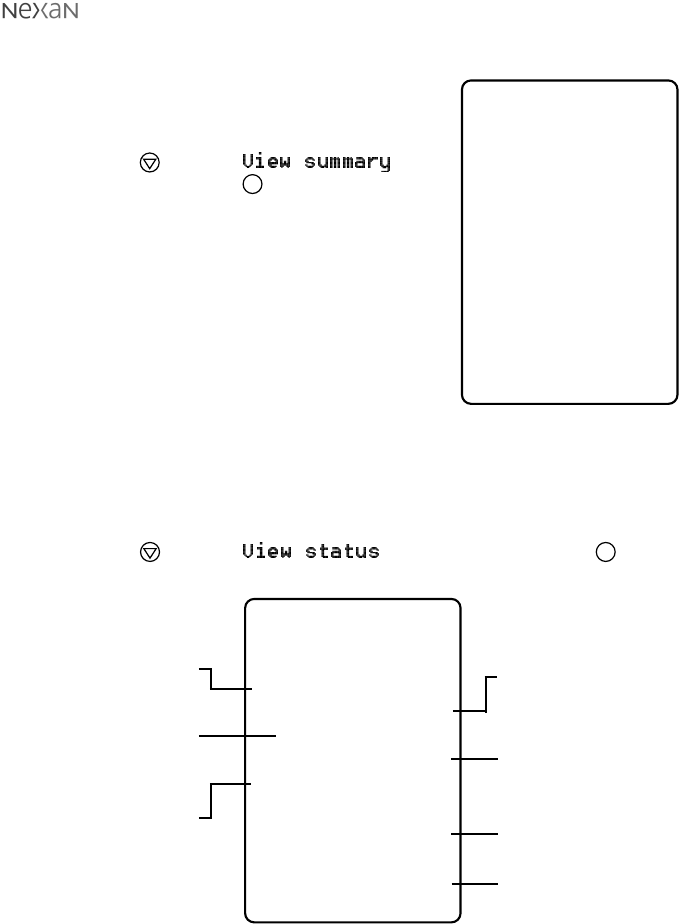
To view numeric signal values:
1 Apply the Nexi to the patient and attach the
Nexi-clip in the usual manner.
2 Enter the
HCP Menu
.
3 Press the key until is
highlighted. Press the key to display the
Summary
screen ð
This screen shows incoming values for the
Heart Rate and Respiration Rate.
If the values remain at
###
then there may
be a communication problem or fault with
the Nexi patch/Nexi-clip combination.
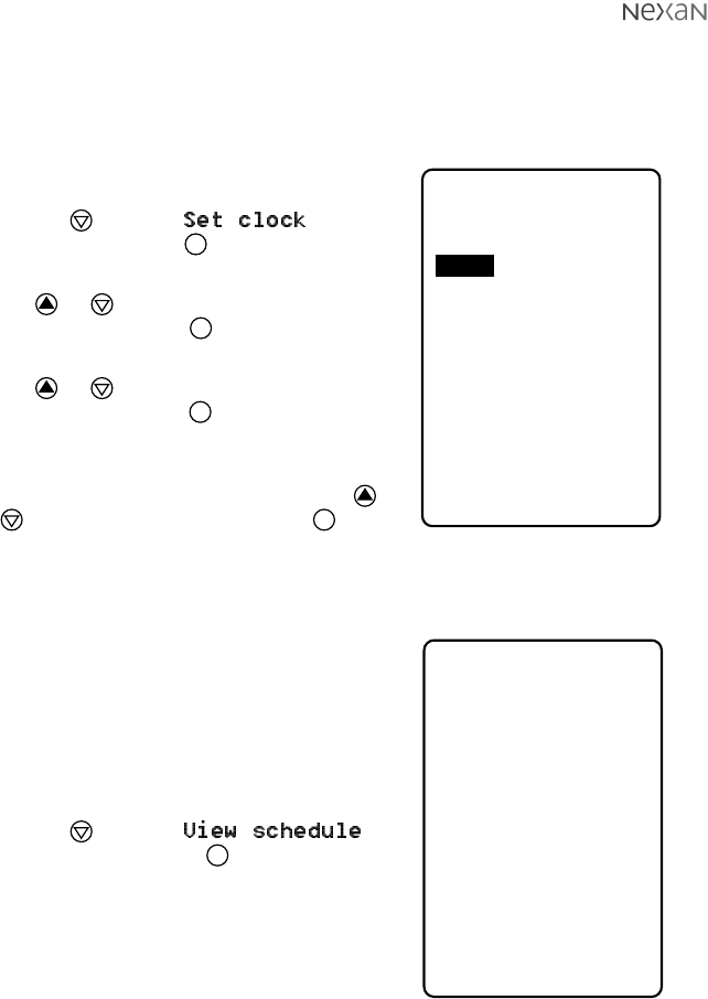
To view the PDA Status screen:
1 Enter the
HCP Menu
.
2 Press the key until is highlighted. Press the key to
display the
PDA Status
screen ò
300-USM-103 US Issue 1.0
Page 20 of 51 Section 3 - Setting up the PDA and Base Station
Setting the PDA Clock and Calendar
The PDA has an internal clock and calendar against which the incoming data is
monitored. It is important that the clock is set correctly when installing the system.
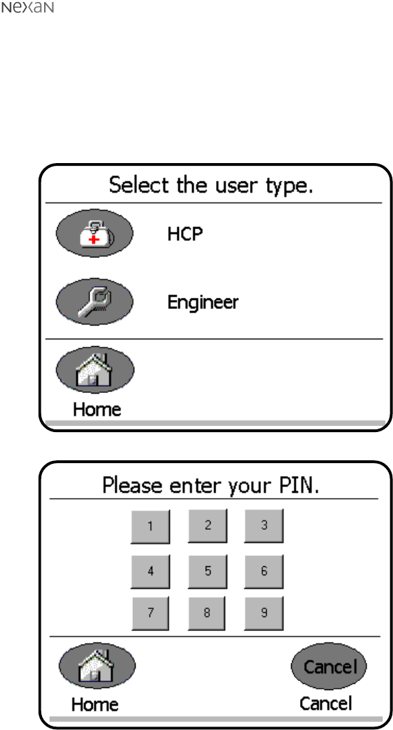
To set the clock and calendar:
1 Enter the
HCP Menu
.
2 Press the key until is
highlighted. Press the key to display the
Set PDA Clock
screen ð
3 Press or to highlight the required
setting and then press begin altering
that setting.
4 Press or to change the current
setting and then press when it is
correct.
5 Repeat steps 3 and 4 until all time and
date settings are correct and then press
or until Exit is highlighted. Press to
quit the screen and apply the changes made.
Viewing stored schedule information
If the Base Station and PDA have any
scheduled extra measurements (blood
pressure, spirometry or weight) programmed,
then it is possible to view a summary of these
on the PDA.
To view scheduled measurements:
1 Enter the
HCP Menu
.
2 Press the key until
is highlighted. Press the key to display
the
Schedule
screen ð
Note: This screen shows only the times
and dates for the scheduled
measurements. It does not differentiate
between the different measurements, nor
does it allow any editing of the entries.
jkkl
Schedule
# Time Date
1 10:15 Oct 12
2 14:00 Oct 12
3 9:15 Oct 13
4 18:00 Oct 13
5
6
7
8
to exitab
________
jkkl
Set PDA Clock
Year 2000
Month 6
Day 23
Hour 15
Minute 47
Second 00
Format 24hr
cdef
ab
to select
to exit
Exit
___ ___ _____
300-USM-103 US Issue 1.0
Page 21 of 51
Section 3 - Setting up the PDA and Base Station
Configuring the Base Station
Accessing the HCP Menus
When the Base Station is switched on, it displays the patient home page. To configure
the Base Station for a new patient it is necessary to access the HCP menus.
To access the HCP menus:
1 Press the ‘smiley face’ logo (in top right corner) until the following is displayed:
2 Press the HCP button to display:
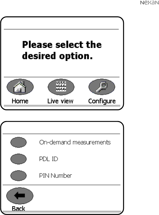
300-USM-103 US Issue 1.0
Page 22 of 51 Section 3 - Setting up the PDA and Base Station
3 Enter your four digit PIN code to display:
4 Press the Configure button to display:
5 Select the required action that you wish to perform.
HCP options
HCP configuration options
300-USM-103 US Issue 1.0
Page 23 of 51
Section 3 - Setting up the PDA and Base Station
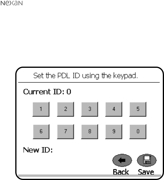
Setting the PDA (PDL) ID code
Each PDA carries a unique identification (PDA ID) code to ensure that recorded
data can be traced back to a specific patient and their PDA. It is important that the
Base Station is programmed with the correct ID number for the PDA in use.
To set the PDA ID code:
1 Enter the HCP/Nurse menu, choose Configure and then select the PDL ID
option. The following screen will be displayed:
The unique 10-digit PDA ID code can be located in three ways:
•It is printed on the label located on the base of the PDA,
•It is displayed during the start-up screen of the PDA, and
•It is displayed in the PDA Status screen that is mentioned earlier in this
section.
2 Locate the 10-digit PDA ID code and enter it into the Base Station using the
on-screen keypad.
3 Press the Save button.
300-USM-103 US Issue 1.0
Page 24 of 51 Section 3 - Setting up the PDA and Base Station
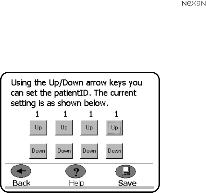
Setting the Patient ID code
In order to maintain a traceable link between recorded data and a particular
patient, it is important that Base Station is programmed with the correct Patient ID
code.
To set the Patient ID code:
1 Enter the HCP/Nurse menu, choose Configure and then select the PatientID
option. The following screen will be displayed:
2 Use the on-screen Up and Down buttons to increment/decrement each of the
four digits until the Patient ID code matches the number that has been
designated for that patient.
3 Press the Save button to store the entered code and exit to the options
screen.
300-USM-103 US Issue 1.0
Page 25 of 51
Section 3 - Setting up the PDA and Base Station
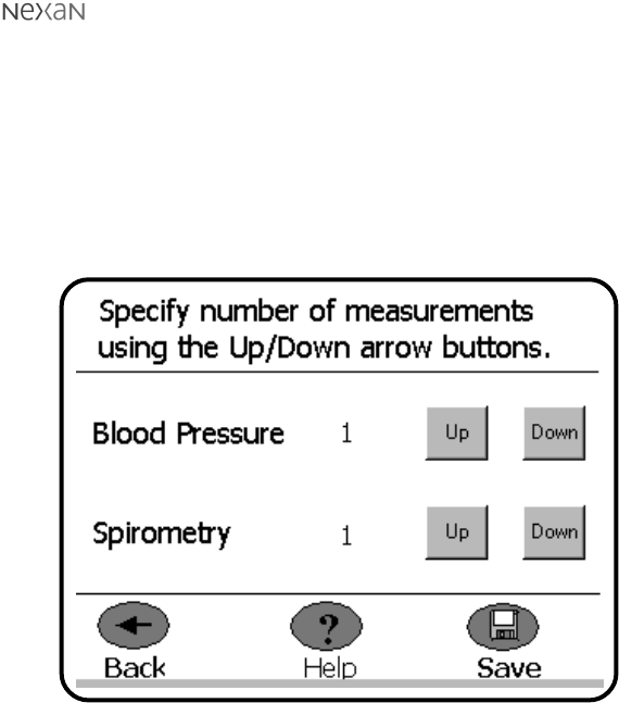
Setting or editing the measurements schedule
Schedules for taking extra measurements (such as blood pressure, spirometry or
weight) are generally set using the Nexoft software from the remote
TeleMonitoring Station (or TMS). However, it is sometimes necessary, or more
convenient, to set or edit these settings whilst on-site with the Base Station.
To increase or reduce the number of measurements:
1 Enter the HCP/Nurse menu, choose Configure and then select the Schedule
option. The following screen will be displayed:
2 Use the on-screen Up and Down buttons to increment/decrement the quantity
of Blood Pressure or Spirometry readings that are required.
3 Press the Save button to store the new scheduled measurements and exit to
the options screen.
Note: The scheduled measurements that are set on the Base Station will take
priority over any similar settings made at the remote TeleMonitoring Station.
The next time that the TMS connects with the Base Station, the new settings
will be uploaded and used to alter the TMS schedules.

300-USM-103 US Issue 1.0
Page 26 of 51 Section 4 - Setting up and using the TMS
SECTION 4
Setting up and using the
TeleMonitoring Station
TeleMonitoring Station (TMS) overview
Data from the Base Station is transferred, via patient’s telephone line, to a
Telemonitoring Centre. Here the Registered Medical Practitioner has access to the
Nexan software, called
Nexoft
, installed on a Nexan TMS computer.
Note: It is recommended that archiving of patient data is carried out both as a pre-
use check between patient use of the Nx-300 system and periodically.
The Registered Medical Practitioner can control the use of the Nx-300 using the
Nexoft program that enables the following features:
•Dial-up to a patient’s home for downloading the monitoring schedule to the
patient’s Base Station.
•Dial-up to a patient’s home to retrieve and view recorded and /or analysed data
from the patient’s Base Station.
•Scheduling the download times.
•Setting up or changing the schedule for blood pressure and/or, spirometry
measurements; collectively known as auxiliary measurements.
•Management of a database of recorded data.

300-USM-103 US Issue 1.0
Page 27 of 51
Section 4 - Setting up and using the TMS
Setting up the TMS computer
Connecting the TMS
1 Unpack your TMS Computer following the instructions on the packaging.
2 Connect the monitor, keyboard and mouse using the colour-coded plugs then
connect the mains power cables to the monitor and computer.
3 Next, using the modem cable provided, connect one end into the modem
socket of the computer and the other end into your telephone line socket.
4 If required connect the computer to the supplied printer by following the printer
manufacturer’s instructions.
Switching on the TMS
PRECAUTIONS
It is recommended that you do not install non-Nexan software onto your TMS
machine. Third-party applications may degrade the performance of the Nexan
software or otherwise interfere with its operation.
In particular:
1 Do not use software that might use the modem(s) (e.g. browsing the Web).
2 Do not run software that may occupy the processor for extended periods (e.g.
long scientific computations).
3 Be aware that the machine has a finite amount of disk space and any space
used will not be available for storing patient data.
4 Be aware that running multiple applications will reduce the availability of main
memory, and degrade performance.
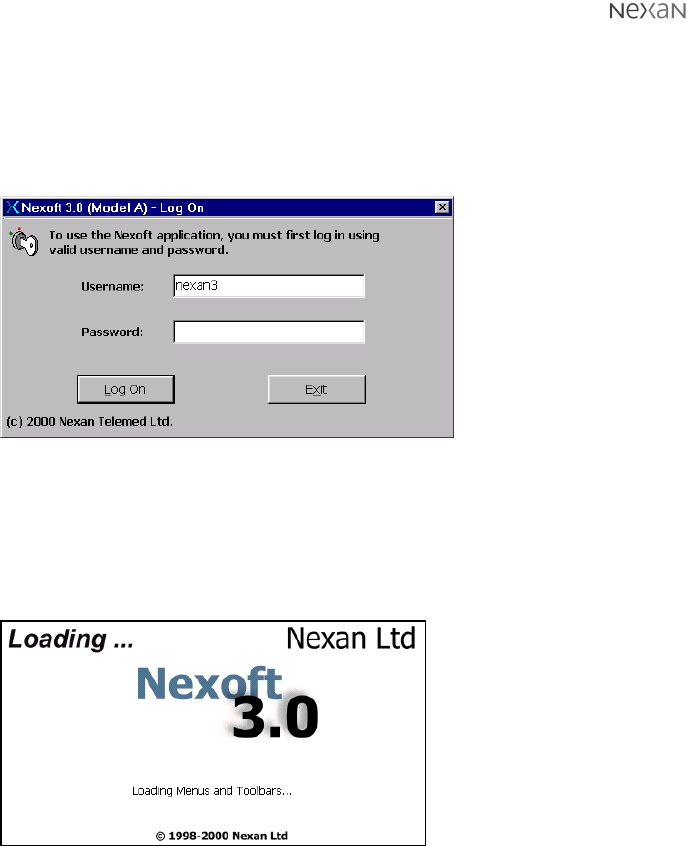
Refer to the manufacturer’s instructions; connect power and switch on your TMS
Computer and monitor. After approximately one minute the Nexan software logon
screen should appear.
300-USM-103 US Issue 1.0
Page 28 of 51 Section 4 - Setting up and using the TMS
Using Nexoft
Logging on
To use the Nexoft Software, you must first log on. Wait a few seconds after the
screen in Figure 2 first appears then enter a username and a password. Click on
the ‘Log On’ button.
Figure 2: Logon Screen
NOTE 1: The screens displayed throughout this section assume that the system
default configuration is being used.
NOTE 2: If your password has expired you will be prompted to enter and confirm a
new one. Do not use ‘common’ passwords.
The splash screen provides
feedback while the
application is loaded (since
there can be 10-15 second
delay loading all the
screens).
Figure 3: Splash Screen
300-USM-103 US Issue 1.0
Page 29 of 51
Section 4 - Setting up and using the TMS
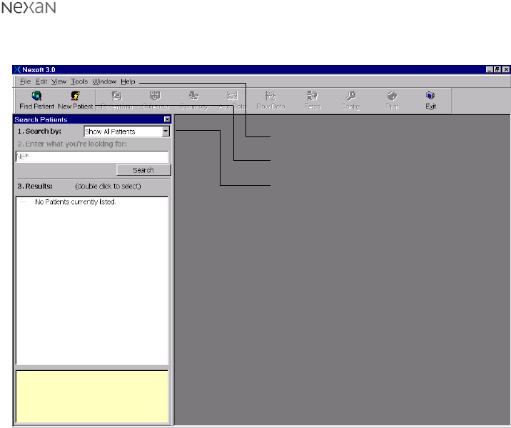
The main application window appears with the
Search Patients
panel (note the tool
bar and menus).
Figure 4: Nexoft main application window
You can ‘undock’ (move around) the Search Patients dialog box, the toolbar and
the menu bar so that you can rearrange the screen to suit. Simply click and hold on
the item to be moved and drag it to a new position.
The items within the toolbar and menu bar can also be customized using the
Configuration option within the Tools menu (or click the Config button on the
toolbar).
Menu bar
Toolbar
Search Patients dialog box
300-USM-103 US Issue 1.0
Page 30 of 51 Section 4 - Setting up and using the TMS
Patient Records
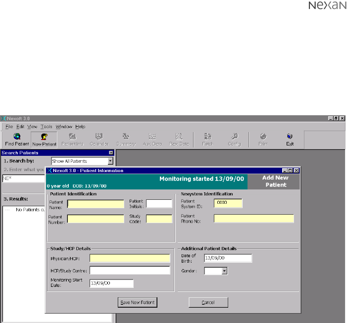
Nexoft allows you to add new patients or view the records of existing patients.
To add a new patient:
•Click the New Patient button on the toolbar, or
•Select the
File
menu and then click the
New Patient
option.
The Patient information dialog will be displayed:
Figure 5: Entering new information using the Patient Information dialog
The Patient Information dialog is divided into four main areas:
•
Patient Identification
- including the patient’s name, number and study code,
•
Nexystem Identification
- including the ID (must be 4 characters) of the patient’s
Nx-300 system and the phone number on which the patient can be contacted,
•
Study/HCP Details
- including the name of the patient’s physician or Health Care
Professional, the hospital/health care center name and the start date,
•
Additional Patient Details
- including the date of birth and the gender of the
patient.
When all necessary information has been entered, click the Save New Patient
button.
The new data is then displayed in the
Patient Information
screen shown overleaf.
300-USM-103 US Issue 1.0
Page 31 of 51
Section 4 - Setting up and using the TMS
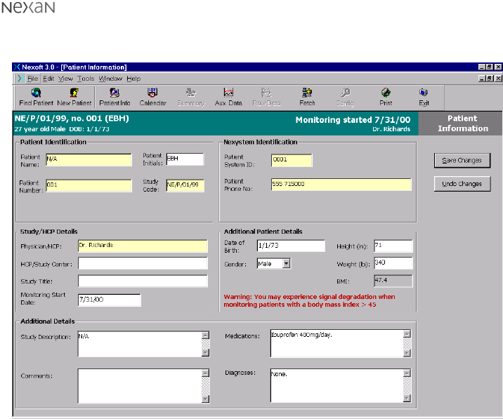
When new patient information has been entered (as discussed on the previous
page) the new data is presented for review in the following screen.
Figure 6: Patient Information screen showing the entered information
This screen allows further data to be added to the patient information in the
following areas:
•
Additional Patient Details
- Patient Height and Weight. From this information a
Body Mass Index (BMI) is automatically calculated (A warning will be displayed
if the calculated BMI figure is greater than 45).
•
Additional Details
- Study Description, Comments, Medications and Diagnoses.
When changes are made to this screen, remember to click the Save Changes
button in order to update the patient record.
300-USM-103 US Issue 1.0
Page 32 of 51 Section 4 - Setting up and using the TMS
To locate existing patient records:
1 If the Search Patients dialog is not already displayed:
•Click the Find Patient button on the toolbar, or
•Select the
File
menu and then click the
Find Patient
option.
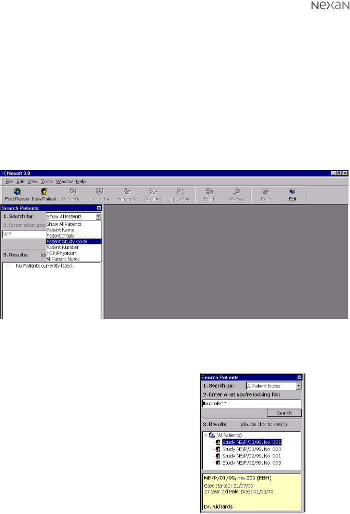
The Search Patients dialog allows you to
Show All Patients
or to search the
database using various criteria:
•Patient Name
•Patient Initials
•Patient Study Code
•Patient Number
•HCP/Physician
•All Patient Notes (search on any patient details)
2 Click on the
Search by:
drop down list to select the required search criteria.
Figure 7: Search Patient dialog showing the database search criteria
3 Now enter additional search information into the text box labelled
2. Enter what
you’re looking for:
4 Click the Search button to interrogate
the database.
The patient details that match your
search criteria will be displayed in the
Results
section.
5To view a summary for a patient: Click
on the patient entry in the list - the
summary is displayed in the yellow box
below.
To view a complete patient record:
Double-click on the patient entry in the
list - the complete patient record is
displayed in a new window. Figure 8: Search results
300-USM-103 US Issue 1.0
Page 33 of 51
Section 4 - Setting up and using the TMS
Using the Calendar function to set a download schedule
Once a new patient has been added, or an existing patient located, the next step
is to organise a download schedule. This defines the dates and times when the
TeleMonitoring Station (TMS) will dial the Base Station (installed at the patient’s
premises) in order to download the recorded data.
To set a download schedule:
1 Display the record page for the required patient (see ‘To locate existing patient
records’).
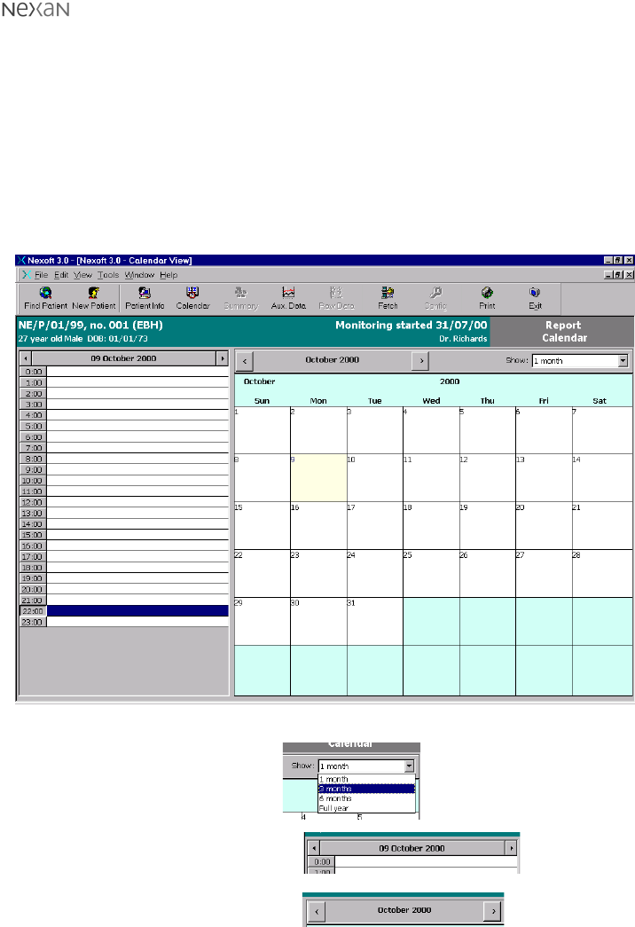
2 Click the Calendar button on the toolbar. A calendar screen will be displayed:
Figure 9: One month calendar view
3 Optionally, use the
Show:
drop down list to select an
alternative calendar view.
To change the current day:
Click the smaller arrow buttons
above the hourly view.
To change the current month:
Click the larger arrow buttons
above the day by day view.
300-USM-103 US Issue 1.0
Page 34 of 51 Section 4 - Setting up and using the TMS
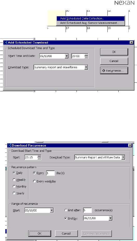
4 Right-click on the first required data
collection day and then left-click on
the
Add Scheduled Data Collection
option to display the
Add Scheduled
Download
dialog.
5 Enter the
required
Start
Time and Date
.
Next, select
the required
Download
Type
from the
following
options:
•Summary Report Only,
•Summary Report and Waveforms, or
•Summary Report and All Raw Data
6 If only a single download is required, click the OK button.
If a series of data downloads are required, click the Recurrence... button to
display the
Download Recurrence
dialog:
7 Set the required
Recurrence
pattern
by
selecting a
Daily
,
Weekly
,
Monthly
or
Yearly
base
interval as
appropriate.
8 In the
Range of
recurrence
section, set either
the
End after:
or
the
End by:
options as
required.
9 When all details
of the download
schedule have
been entered, click the OK button. The
Add Scheduled Download
dialog will
now be visible again, click its OK button to apply the changes.
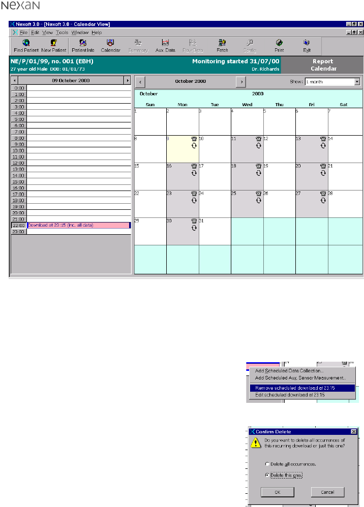
The download schedule will be summarised in the previously selected calendar
view as shown on the next page.
300-USM-103 US Issue 1.0
Page 35 of 51
Section 4 - Setting up and using the TMS
Figure 10: Calendar view showing summary of scheduled downloads
To edit or delete a download schedule:
1 Display the record page for the required patient (see ‘To locate existing patient
records’).
2 Click the Calendar button on the toolbar. A calendar screen will be displayed.
3 Right-click on the appropriate data collection day
and then left-click on either:
•
Edit scheduled download...
option to display
an editable summary of the selected
download settings,
•
Remove scheduled download...
option to
display the
Confirm Delete
dialog:
Select either the
Delete all occurrences
or
the
Delete this one
option as appropriate
and click the OK button.
300-USM-103 US Issue 1.0
Page 36 of 51 Section 4 - Setting up and using the TMS
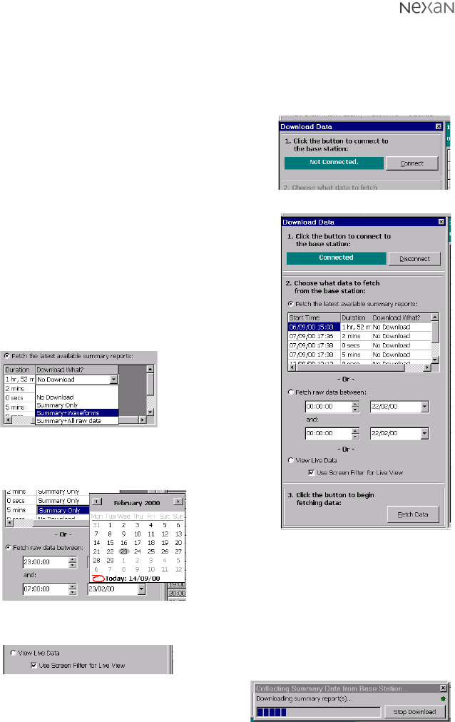
Initiating an immediate download
The system provides an option to make an immediate connection to the Base
Station in order to download data (in addition to, or instead of any programmed
download schedule)
To initiate an immediate download:
1 Display the record page for the required patient
(see ‘To locate existing patient records’).
2 Click the Fetch button on the toolbar. The
Download Data
dialog will be displayed:
3 Click the Connect button to open a connection
between the TMS and the selected Base Station.
Once connected, the
Download Data
dialog
provides a number of options:
•The
Fetch the latest available summary
reports
option allows you to select which of
the reports (that are stored in the Base Unit)
should be downloaded and in what form:
•The
Fetch raw data between
option allows
you to download stored data from monitoring
sessions defined by date and time limits:
•The
View Live Data
option allows you to view real time data as it is
collected by the Base Unit.
4 When all required options have been set,
click the Fetch Data button to begin the
download. A dialog provides an indication
of progress. Once complete, you will be
prompted to refresh the patient - click Yes.
Note: Click Stop Download if
you need to quit the download.
300-USM-103 US Issue 1.0
Page 37 of 51
Section 4 - Setting up and using the TMS
Viewing Downloaded Data
Once data has been downloaded for a particular user you can view various
aspects of the information in a graphical form.
To view raw data on screen:
1 Display the record page for the required patient (see ‘To locate existing patient
records’).
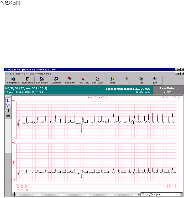
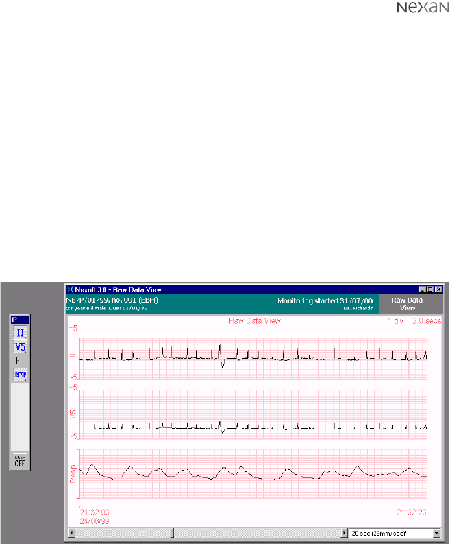
2 Click the Raw Data button on the toolbar. A
Raw Data View
dialog will be
displayed with one or more channels enabled:
Figure 11: Raw data view with two channels enabled
300-USM-103 US Issue 1.0
Page 38 of 51 Section 4 - Setting up and using the TMS
To alter the viewed data:
Channels
The channels to be displayed are controlled by the toolbar buttons shown on the
left hand edge of the screen. The channels are as follows:
•II - ECG waveform from position modified lead 2 (II) of the Nexi.
•V5 - ECG waveform from position modified lead V5 of the Nexi.
•FL - Optional ‘floating’ sensor connected independently to the Nexi-Clip.
•RESP - Respiration signal from the Nexi respiration impedance sensor.
•Filter ON/OFF - When enabled, this baseline filter compensates for changes
in the overall voltage levels measured by the ECG and flying lead sensors.
To switch a channel on or off: Click the button representing that channel.
The raw data view window and the channel toolbar can both be ‘undocked’ and
rearranged to suit:
Figure 12: Raw data view and channel toolbar undocked
300-USM-103 US Issue 1.0
Page 39 of 51
Section 4 - Setting up and using the TMS
Printing Information
The system allows you to print various types of information, such as patient details,
raw data graphs, etc.
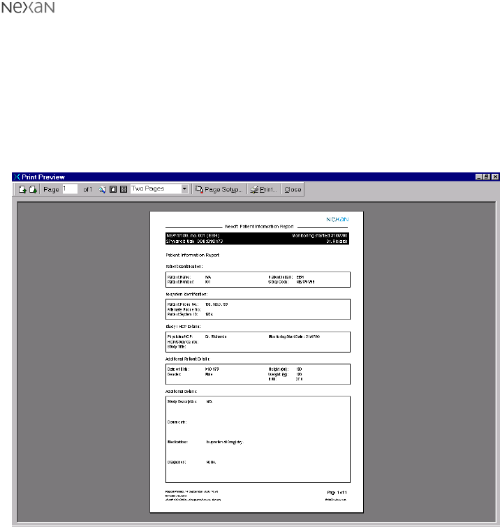
To print patient information:
1 Display the record page for the required patient (see ‘To locate existing patient
records’).
2 Click the Print button on the toolbar. A print preview screen will be displayed:
Figure 13: Print preview showing patient information
3 Ensure that the printer is switched on and ready to receive, then click the Print
button on the preview toolbar.
300-USM-103 US Issue 1.0
Page 40 of 51 Section 4 - Setting up and using the TMS
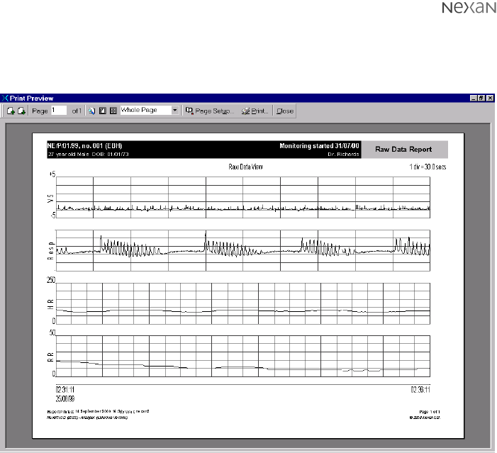
To print raw data channels:
1 Display the required raw data view (see ‘To view raw data on screen’).
2 Click the Print button on the toolbar. A print preview screen will be displayed:
Figure 14: Print preview showing raw data
3 Ensure that the printer is switched on and ready to receive, then click the Print
button on the preview toolbar.
300-USM-103 US Issue 1.0
Page 41 of 51
Section 4 - Setting up and using the TMS
On-line help
The Nexoft system incorporates an extensive on-line help system.
To access on-line help:
1 Select the
Help
menu (or press F1) and then click either:
•
Contents
- to display the help system table of contents,
•
Index
- to view the index listing,or
•
Search
- if you wish to enter a keyword and have the help system locate
related topics.
The help screen will be displayed with either the Contents, Index or Search tab
selected on the left-hand side depending on which option was selected.
2 Choose the required item from the Contents/Index list or enter your keyword to
perform a search.
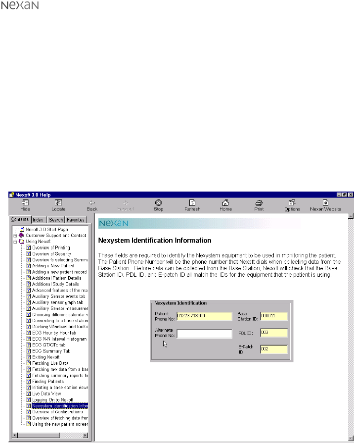
Figure 15: Help screen showing the Contents listing on the left-hand side
Note: The help system is web-enabled so that you can transfer directly to the
Nexan website for futher details. Click the Nexan Website button on the help
toolbar.

300-USM-103 US Issue 1.0
Page 42 of 51 Section 4 - Setting up and using the TMS
Shutting down the TMS
CAUTION: If you exit Nexoft or shut down the computer, scheduled downloads will
not occur.
1 In the main Nexoft window, click the Exit button. The Nexoft window will close,
leaving the standard Windows desktop.
2 Click the Windows Start button.
3 Choose the Shut Down option and, in the dialog that appears, check that the
Shut down the computer?
option is selected.
4 Click the Yes button. After a short while the sceen will display the message
It is
now safe to turn off your computer
.
4 On the front panel of the TMS Computer, press the button marked to set the
computer to standby. If required, switch off the computer at the mains supply.

300-USM-103 US Issue 1.0
Page 43 of 51
Section 5 - General Information
SECTION 5
General Information
Technical Description
System comprising:
a) The on-body equipment, comprising the Nexi and the Nexi-Clip processing
electronics. The Nexi is a disposable element, containing ECG electrodes,
bioelectric impedance electrodes for respiration measurement, and a
connector for an additional ECG electrode. It is a disposable item, designed to
be worn for up to 24 hours. The Nexi-Clip takes measurements via the
electrodes, and transmits them to the Portable Data Assistant (PDA.) The Nexi-
Clip is non-disposable, and is detachable from the Nexi.
b) The PDA which stores up to 24 hours worth of data received from the on-body
equipment.
c) The Base Station Unit (BSU) which stores up to 14 days worth of data received
from the PDA.
d) The Tele-Monitoring Station (TMS) which is used to interrogate the BSU, and
to interpret and display the data.
Nexan Ltd will make available on request circuit diagrams, component parts lists,
descriptions, calibration instructions or other information which will assist the
user’s appropriately qualified technical personnel to repair those parts of
equipment which are designated by the manufacturer as repairable.

300-USM-103 US Issue 1.0
Page 44 of 51 Section 5 - General Information
Technical Specifications
General
Nexi Two lead ECG sensors providing a modified Lead II view and
modified CM5. Respiration impedance waveform. Optional
3rd flying lead with ECG electrode.
Nexi-Clip Contains: PCB
Europe- Radio TX UHF 868 MHz
US- Radio TX UHF 916.5 MHz
PDA: Contains: PCB, Storage device (memory card)
EU- Radio RX operating in unlicensed Band of 869.7-870MHz
US- Radio RX operating in UHF Band 916-917MHz
* Displayed respiration by impedance:Range: 1 - 72
* Breaths Per Minute Accuracy: ±2 Breaths Per Minute
* Displayed two lead ECG sensors
* Heart rate range: 30-250 Beats Per Minute
* Heart rate accuracy: ± 3 Beats Per Minute
* The values displayed are only for ‘Hook-up’ signal checks by the HCP.
BaseStation Computer Mother Board with Pentium Processsor and Hard
Disk storage device, Call discriminator,LCD Touchscreen.
PDA Desktop
charger unit Contains: PCB
TMS Computer 700MHz Pentium III Computer with DVD Drive, backup tape
drive, modem.
Printer HP Deskjet 840C. See manufacturer’s instructions for details.

300-USM-103 US Issue 1.0
Page 45 of 51
Section 5 - General Information
Power requirements
Nexi-Clip and Nexi: Shared 3V requires 2 x 1.5V alkaline AAA cells. (fitted
during manufacture to the Nexi -Not user replaceable)
PDA: 3.6V 1600mAh Re-chargeable Lithium Ion Cell. (No User
Access) Recharge using only the following Nexan
supplied charger units:
a. Nx-300 Base Station Unit (PDA docking slot)
b. Nx-300 PDA Desktop Charger Unit
PDA Desktop charger Requires 7.5VDC 1A . Use only (Model No.JOD-48-09)
supplied by Nexan for use with the with the Nx-300
system.
Base Station Requires 100-240V 50-60Hz~ Power consumption 2A-1A.
Two UL approved fuses rated T2AH (250V).
Omron ® IC Blood
Pressure monitor: 6V requires 4 x AA LR6 1.5V Alkaline batteries.
Micro Plus Spirometer 9V requires 1 x PP3 9V dry cell battery.
TMS Computer UK requires 220-240V 50/60Hz~
US Requires 110-120V 60Hz~
TMS Printer (Option) UK requires 220-240V 50/60Hz~
US Requires 110-120V 60Hz~

300-USM-103 US Issue 1.0
Page 46 of 51 Section 5 - General Information
Transport and Storage conditions
CAUTION: These devices may not meet their performance criteria if stored outside
the ranges stated below.
Nexi and Nexi-Clip
Temperature* -20 to + 65°C
Humidity* 5 to 90% non-condensing
Ambient pressure* 700 to 1060 mbar
Base Station Unit
Temperature* -20 to +65°C
Humidity* 5 to 90% non-condensing
Ambient pressure* 700 to 1060 mbar
*Set by EC38 as per ‘Stationary Equipment’.
PDA and PDA Desktop Charger
Temperature* -20 to +65°C
Humidity* 5 to 90% non-condensing
Ambient pressure* 700 to 1060 mbar
*Set by EC38 as per ‘Stationary Equipment’.
Operating Conditions
CAUTION: These devices may not meet their performance criteria if stored outside
the ranges stated below.
Base Station Unit, PDA and PDA Desktop Charger
Temperature +10 to +40°C
Humidity 30 to 75% non-condensing
Ambient pressure 700 to 1060 mbar
Nexi
Temperature +10 to +40°C
Humidity 30 to 75% non-condensing
Ambient pressure 700 to 1060 mbar
Nexi-Clip
Temperature +10 to +40°C
Humidity 30 to 75% non-condensing
Ambient pressure 700 to 1060 mbar

300-USM-103 US Issue 1.0
Page 47 of 51
Section 5 - General Information
Cleaning, Maintenance, Storage
and Calibration
It is intended that maintenance is carried out between patient use by a suitably
trained person. It is not intended that the patient will carry out any maintenance or
repair (including Base Station fuse replacement) and there are no patient
replaceable parts. If a fault occurs when using the system, first read the Trouble
shooting guide. If the fault is still present then contact Customer Support as
detailed in Page 2. If Customer Support request the return of a part of the system,
it should be returned in its original packaging.
Maintenance of Base Station, PDA and Nexi-Clip
WARNING: REMOVE MAINS POWER FROM THE BASE STATION BEFORE
CLEANING.
WARNING: DO NOT ALLOW THE CLEANING SOLUTION OR WATER TO RUN
INTO CREVICES OR OPENINGS.
The Base Station, PDA and Nexi-Clip can be wiped with a nearly-dry cloth
containing warm water and detergent. Thoroughly wipe off any excess residual
cleaning solution from the Nx-300 system and allow to dry.
While cleaning the Base Station, PDA and Nexi-Clip, they should be checked for
unusual wear or possible damage from an accident.
Re calibration of the Base Station, PDA and Nexi-Clip are not required.
Power Cables
WARNING: DO NOT OPERATE THE EQUIPMENT FROM MAINS POWER WITH A
DAMAGED POWER CORD OR PLUG.
The Base Station mains power supply cable supplied is intended to be used only
with the Nextation and should not be used for any other electrical equipment.
Disconnect the power cable from mains power before inspecting the power cord
periodically for fraying or other damage, and replace as needed.

300-USM-103 US Issue 1.0
Page 48 of 51 Section 5 - General Information
Replacing the Base Station fuses
The Base Station contains two fuses that can easily be replaced by service
personnel if necessary.
CAUTION: Replace each fuse only with the specified type - as indicated on the
Base Station label adjacent to the fuse holder.
Note: Both fuses should be replaced at the same time, even if only one fuse is
found to be unserviceable due to an over current situation. The other fuse may
have become stressed and could become unreliable.
To replace the Base Station fuses:
1 Unplug the power cord from the ac mains supply outlet then unplug the
removable cord from the ac mains inlet of the Base Station.
2 Locate the fuse holder, which protrudes from below the mains inlet socket of
the Base Station.
3 Using a flat bladed screwdriver, depress the centre tab, then carefully withdraw
the fuse holder.
4 Replace both fuses with the specified type.
5 Refit the fuse holder.

Regulatory Markings
Federal Communications Commission
(FCC) Compliance and Advisory Notice
This equipment has been tested and found to comply with the limits for a Class B
digital device, pursuant to Part 15 of the FCC Rules. These limits are designed to
provide reasonable protection against harmful interference in a residential installa-
tion. This equipment generates, uses and can radiate radio frequency energy and,
if not installed and used in accordance with the instructions for use, may cause
harmful interference to radio communications.
However, there is no guarantee that interference will not occur in a particular
installation. If this equipment does cause harmful interference to radio or television
reception which can be determined by turning the equipment off and on, the user is
encouraged to try to correct the interference by one or more of the following
measures:
· Reorient or relocate the receiving antenna.
· Increase the separation between the equipment and the receiver.
· Connect the equipment into an outlet on a circuit different from that to which
the receiver is connected.
· Consult the dealer or an experienced radio/television technician for help.
This device complies with Part 15 of the FCC Rules. Operation is subject to the
following two conditions: (1) this device may not cause harmful
interference, and (2) these devices must accept any interference received,
including interference that may cause undesired operation.
FCC ID: PCPNX-300
Section 5- General Information Page 49 of 51
300-USM-103 US Issue 1.0
CAUTION: Changes or modifications not expressly approved in writing by Nexan Ltd
may void the user’s authority to operate this equipment..

300-USM-103 US Issue 1.0
Page 50 of 51 Section 5 - General Information
Warranty
Nexan Ltd. warrants to the original purchaser that the Nx-300 (Product), provided
in the sales packaging, is free from defects in material and workmanship, under
normal installation and use, according to the following terms and conditions:
1 The warranty for the ‘Product’ extends for ninety (90) days from the date of
purchase by the customer.
2 The warranty for the installed/supplied software extends for ninety (90) days
from the date of purchase by the customer.
3 Nexan Ltd shall be under no liability in respect of any defect arising from fair
wear and tear, wilful damage, negligence, abnormal working conditions, failure
to follow Nexan Ltd’s Instructions (whether conveyed orally or in writing),
misuse, improper installation or alteration or repair of the Products without
Nexan Ltd’s approval.
4 The above warranty does not extend to parts, materials or equipment not
manufactured by Nexan Ltd, in respect of which the Customer shall only be
entitled to the benefit of any such warranty or guarantee as is given by the
manufacturer to Nexan Ltd.
5 Subject as expressly provided here, all warranties, conditions or other items
implied by statute or common law are excluded to the fullest extent permitted
by law.
6 Any claim by the Customer which is based on any defect in material or
workmanship of the products shall be notified to Nexan Ltd immediately after
discovery of the defect. If the Customer does not notify Nexan Ltd accordingly,
the Customer shall not be entitled to reject the products and Nexan Ltd shall
have no liability to the Customer.
7 Where any valid claim in respect of any of the Products which is based on any
defect in the materials or workmanship of the Products is notified to Nexan Ltd,
Nexan Ltd shall be entitiled to replace with new or refurbished replacement
items or repair (at Nexan Ltd’s sole discretion, either at the customers
premises or at Nexan Ltd’s premises in the UK) the Products (or part in
question) but Nexan Ltd shall have no further liability to the Customer.
Repaired, refurbished or replacement ‘Product’ is warranted for the balance of
the warranty period.
8 Nexan Ltd shall not be liable to the Customer by reason of any representation,
or implied warranty, condition or other term, or any duty at common law, or for
any consequential loss or damage (whether for loss of profit or otherwise),
costs, expenses or other claims for consequential compensation whatsoever
arising out of or in connection with any act or omission of Nexan Ltd relating to
the manufacture or supply of the Products or use by the Customer.

300-USM-103 US Issue 1.0
Page 51 of 51
Section 5 - General Information
Troubleshooting guide
Base Station green lamp not lit when Base Station power switch is set to On.
Base Station may not be plugged into wall socket. Ensure that the power lead is
plugged into wall socket and it is switched on.
PDA ECG trace shows poor signals.
If no trace is seen:
•check the Nexi-Clip is transmitting satisfactorily - see Signal mV option on
PDA Status screen. If no radio signal is present, check the Nexi-Clip is
correctly clipped together.
•check the Nexi-Clip Id is correctly configured.
•if no trace is seen on ECG3, check ECG3 is enabled.
•if still no trace, check for Nexi battery failure by trying another clip.
If a noisy trace is seen:
•check Nexi is properly attached to patient. Pay special attention to skin
preparation before application.
If there are gaps in the trace:
•this indicates poor radio reception, possibly due to local radio interference.
Try to identify and remove the source of interference.
•move PDA closer to patient.
If a flat-line is seen:
•if seen on ECG3, the flying lead may not be properly connected to the Nexi;
•may indicate a faulty connection within the Nexi-Clip - try another.