Contents
- 1. User manual
- 2. Install. manual
User manual

Document Name: WAPS Beacon NOC User Manual
Document No: JGR-NN-OP-102.00-Rev1.2
Version No: 1.2
Company Name: NextNav, LLC. Page 1 15-Nov-12
Page 1 of 7
WAPS Beacon NOC User Manual
Version 1.2

Document Name: WAPS Beacon NOC User Manual
Document No: JGR-NN-OP-102.00-Rev1.2
Version No: 1.2
Company Name: NextNav, LLC. Page 2 15-Nov-12
Page 2 of 7
History
Version
Date
Author
Notes
1.0
Nov 01, 2012
Eitan Lazarov
1
1.1
Nov 7, 2012
Subbu Meiyappan
2
1.2
Nov 15, 2012
Eitan Lazarov
3
Notes:
1. Initial Version
2. General cleanup
3. Added antenna installation warning per TCB requirments

Document Name: WAPS Beacon NOC User Manual
Document No: JGR-NN-OP-102.00-Rev1.2
Version No: 1.2
Company Name: NextNav, LLC. Page 3 15-Nov-12
Page 3 of 7
Table of Contents
History ........................................................................................................................................... 2
Notes:............................................................................................................................................. 2
1 Introduction ............................................................................................................................. 4
1.1 Purpose and Scope ...................................................................................................................................... 4
2 Product specification ............................................................................................................. 4
3 Equipment List: ...................................................................................................................... 4
4 Antenna Mounting ................................................................................................................. 5
4.1 TX Antenna .................................................................................................................................................... 5
4.2 Tune-up procedure not to exceed maximum TX Power.......................................................................... 6
4.3 GPS Receive Antenna ................................................................................................................................. 7
4.4 Product information ...................................................................................................................................... 7
Table of Figures
Table 1: WAPS Beacon antenna and cables options ............................................................. 5
Document Name: WAPS Beacon NOC User Manual
Document No: JGR-NN-OP-102.00-Rev1.2
Version No: 1.2
Company Name: NextNav, LLC. Page 4 15-Nov-12
Page 4 of 7
1 Introduction
1.1 Purpose and Scope
This document includes the information of the NextNav WAPS Beacon system A4P-100-0007-01
that is required for the network deployment and Network Operations Center (NOC) operator.
2 Product specification
The WAPS beacon system is intended to be used in restricted access locations (RAL) in indoor
and outdoor environments under all weather conditions. The WAPS beacon is a powered by
power system, and is provided with four 12 volt batteries (providing 48VDC) approved for use in
telecommunications equipment.
WAPS Operating Temperature: -40 Deg C to +50 Deg C operating
Storage temperature: -55 Deg C to +80 Deg C
Humidity: 90% non-condensing.
WAPS weight: 100 lbs.
Power rating: 120VAC, 60Hz, 4 AMP
3 Equipment List:
• NextNav WAPS Beacon
• NextNav Power System
• Antenna
– Transmit Omni
– GPS : L1 GPS (BL1R-A-XTB-1-FKM)
• Cables
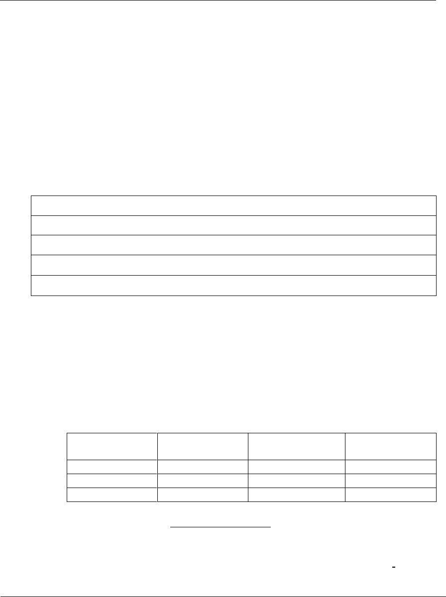
– TX antenna cable: As per chart below:
Main Feed
Length
Cable Type
Jumper Top
Jumper Bottom
<50’
LDF4 (1/2”)
None
None
51’-130’
LDF5 (7/8”)
None
None
131’ -250’
LDF 7 (15/8”)
½” X10’
½” X 6 ft
– GPS antenna Cable: (not to exceed 100 feet)
GPS cables are pre-fabbed and available in three lengths: 25’, 50’ and 100‘. The
cable is an LMR 240 or equivalent (1/4”) and is pre-terminated with mating ends
N male for connection to the beacon and TNC Male for the antenna end.

Document Name: WAPS Beacon NOC User Manual
Document No: JGR-NN-OP-102.00-Rev1.2
Version No: 1.2
Company Name: NextNav, LLC. Page 5 15-Nov-12
Page 5 of 7
4 Antenna Mounting
4.1 TX Antenna
Omni antenna to be installed on tower or roof top construction as defined in site specific
construction drawing. As a general rule on any monopole installations the TX antenna shall be
attached to a 6 foot side arm mount, minimum distance away from the monopole unless the
antenna extends above the monopole in its entirety. Likewise the antenna shall be kept a
minimum distance of 6 feet from any other vertical structures on other types of towers. For
roof tip installations, the TX antenna must extend above all parapet walls and penthouses on
the roof top.
This radio transmitter (FCC ID: A4P-100-0007-01) has been approved by FCC to operate
with the antenna types listed below with the maximum permissible gain and required
antenna impedance for each antenna type indicated. Antenna types not included in this
list, having a gain greater than the maximum gain indicated for that type, are strictly
prohibited for use with this device.
This radio transmitter may only operate using a vertically polarized antenna with maximum gain
of +8 dBi. To reduce potential radio interference to other users, the antenna gain should be so
chosen that the effective radiated power (ERP) does not exceed 30 Watts.
Antenna Type: Monopole
Polarization: Vertical
Maximum Gain: +8 dBi (maximum gain of antenna + cable loss is 0dBd)
Following is a list of the possible antennas and antenna cables combinations.
Table 1: WAPS Beacon antenna and cables options
Antenna
type
Antenna
Gain (dBd)
Cable type
Length
(m)
Cable
Loss
[dB]
PA Gain
*note
ERP
(W)
(PEP)
AMP BCD-8707
6.5
Andrew AVA7-
50
105
8.61
60
30
(worst case:
Antenna
gain = Cable
loss)
Maximum

Document Name: WAPS Beacon NOC User Manual
Document No: JGR-NN-OP-102.00-Rev1.2
Version No: 1.2
Company Name: NextNav, LLC. Page 6 15-Nov-12
Page 6 of 7
PA gain
AMP BCD-8707
6.5
Andrew AVA7-
50
30
0.66
52.01
30
AMP BCD-
87010
10
Andrew AVA5-
50
30
0.66
50.66
30
Laird OD9-11
8.85
LMR-600
30
2.46
53.61
30
Note: PA Gain refers to internal system parameter. This parameter will be used by the NOC to
configure the radio output power.
4.2 Tune-up procedure not to exceed maximum TX Power
A CSV file (configuration file) per transmitter are created by the NOC engineer based
on the installation parameters such as line lengths, antenna type etc.
To comply with FCC RF exposure requirements in Section 1.1307 of FCC Rules, the antenna used for
this transmitter must be fixed-mounted on outdoor permanent structures with a separation distance
of at least 77.5 cm from all persons.

Document Name: WAPS Beacon NOC User Manual
Document No: JGR-NN-OP-102.00-Rev1.2
Version No: 1.2
Company Name: NextNav, LLC. Page 7 15-Nov-12
Page 7 of 7
The TX output power level setting is contained in the CSV file.
The output power is adjusted by the ‘attenuation’ setting This value in the CSV file is
calculated by a formula to set the output power (not to exceed 30W EIRP). The
variables used in the calculation include PA Gain (Gpa), TX Antenna Gain (Gant), TX
filter insertion loss (ILflt), internal cable loss (ILint), external cable loss (ILext), and
transceiver output power (PTCVR).
EIRP (W) = 10^((PTCVR - ILint + Gpa - ILflt - ILext + Gant) / 10) / 1000
4.3 GPS Receive Antenna
GPS antenna should be installed such that it has clear view of sky. Ideally, you would keep the
antenna close to the ground away from obstruction
• Keep any horizontal blockage smaller than 10 degrees
• Obstruction Clearance guideline
– If it is 1 ft wide it should be at least 6 ft away
– If it is 10 ft wide, it should be at least 60 ft. away.
– If it is significantly less than 1 ft wide (like a guy wire, or a post) it should not
cause any measurable effect.
4.4 Product information
Modifications made to the product, unless expressly approved by NextNav, LLC could
void the user’s authority to operate the equipment.
NOTE: This equipment has been tested and found to comply with the limits for a Class A
digital device , pursuant to Part 15 of the FCC Rules. These limits are designed to
provide reasonable protection against harmful interference when the equipment is
operated in a commercial environment. This equipment generates, uses, and can
radiate radio frequency energy and, if not installed and used in accordance with the
instruction manual, may cause harmful interference to radio communications.
Operation of this equipment in a residential area is likely to cause harmful interference
in which case the user will be required to correct the interference at his own expense.