NextNav 100-0007-01 WAPS Beacon LBS System User Manual Install manual
NextNav,LLC WAPS Beacon LBS System Install manual
NextNav >
Contents
- 1. User manual
- 2. Install. manual
Install. manual

Document Name: WAPS BEACON Installation Manual
Version No: 1.4
Company Name: NextNav, LLC.
Confidential Page 1 11-Sep-12
Page 1 of 30
WAPS BEACON Installation Manual
Version 1.4

Document Name: WAPS BEACON Installation Manual
Version No: 1.4
Company Name: NextNav, LLC.
Confidential Page 2 11-Sep-12
Page 2 of 30
NOTE:
This equipment has been tested and found to comply with the limits for a Class B digital device,
pursuant to part 15 of the FCC Rules. These limits are designed to provide reasonable protection
against harmful interference in a residential installation. This equipment generates uses and can
radiate radio frequency energy and, if not installed and used in accordance with the instructions, may
cause harmful interference to radio communications. However, there is no guarantee that
interference will not occur in a particular installation. If this equipment does cause harmful
interference to radio or television reception, which can be determined by turning the equipment off
and on, the user is encouraged to try to correct the interference by one or more of the following
measures:
-Reorient or relocate the antenna.
-Increase the separation between the equipment and receiver.
-Connect the equipment into an outlet on a circuit different from that to which the receiver is
connected.
WARNING:
Changes or modifications to this equipment not expressly approved by the party responsible for
compliance (NextNav LLC) could void the user’s authority to operate the equipment.
This device complies with part 15 of the FCC Rules.
Operation is subject to the condition that the device
does not cause harmful interference.

Document Name: WAPS BEACON Installation Manual
Version No: 1.4
Company Name: NextNav, LLC.
Confidential Page 3 11-Sep-12
Page 3 of 30
History
Version
Date
Author
Notes
1.0
07-May-12
Eitan Lazarov
1
1.1
09-May-12
Eitan Lazarov
2
1.2
17-May-12
Eitan Lazarov
3
1.3
01-Aug-12
Eitan Lazarov
4
1.4
10-Aug-12
Eitan Lazarov
5
Notes:
1. Initial Version
2. Add ground stud drawing
3. Updated installation pictures
4. Updated from June DR
5. Add required FCC certifications information

Document Name: WAPS BEACON Installation Manual
Version No: 1.4
Company Name: NextNav, LLC.
Confidential Page 4 11-Sep-12
Page 4 of 30
Table of Contents
WARNING:..................................................................................................................................... 2
History ........................................................................................................................................... 3
Notes:............................................................................................................................................. 3
1 Introduction ............................................................................................................................. 7
1.1 Purpose and Scope ...................................................................................................................................... 7
2 Architecture ............................................................................................................................ 7
2.1 Hardware Architecture ................................................................................................................................. 7
2.2 Software Architecture ................................................................................................................................... 9
3 Beacon Installation Procedure and Options .................................................................... 10
3.1 Package ....................................................................................................................................................... 10
3.2 Installation Options ..................................................................................................................................... 11
3.2.1 Grounding ................................................................................................................................................ 11
3.2.2 Wall Mounting ......................................................................................................................................... 13
3.2.3 Pole Mounting ......................................................................................................................................... 13
3.2.4 H-Frame Mounting ................................................................................................................................. 14
3.2.5 Power System Mounting ....................................................................................................................... 15
3.3 External Cable Connections ...................................................................................................................... 16
3.4 TX Antenna mounting ................................................................................................................................ 19
3.5 Connecting to the Power System ............................................................................................................. 20
4 Usage Model ........................................................................................................................ 21
4.1 Hardware Connections for the Server ..................................................................................................... 21
4.2 Socket Server Startup ................................................................................................................................ 21
4.3 Socket Client Installation ........................................................................................................................... 22
4.4 Socket Client Startup ................................................................................................................................. 22

Document Name: WAPS BEACON Installation Manual
Version No: 1.4
Company Name: NextNav, LLC.
Confidential Page 5 11-Sep-12
Page 5 of 30
4.4.1 GPS Tab .................................................................................................................................................. 23
4.4.2 Rubidium Tab.......................................................................................................................................... 24
4.4.3 Transmit Tab ........................................................................................................................................... 25
4.4.4 Power Amplifier Tab ............................................................................................................................... 28
5 Known Limitations for the Socket Server ......................................................................... 29
6 References ........................................................................................................................... 30
Table of Figures
Figure 1: WAPS BEACON SYSTEM DIAGRAM ..................................................................... 7
Figure 2: WAPS BEACON CABLES .......................................................................................... 8
Figure 3: SW Architecture ........................................................................................................... 9
Figure 4: Beacon Packaging ..................................................................................................... 10
Figure 5: Grounding Stud .......................................................................................................... 11
Figure 6: Beacon Grounding Scheme ..................................................................................... 12
Figure 7: Wall Mounting ............................................................................................................. 13
Figure 8: Pole Mounting ............................................................................................................. 13
Figure 9: H-Frame Mounting ..................................................................................................... 14
Figure 10: Power System Mounting ......................................................................................... 15
Figure 11: Cable installation between units ............................................................................ 17
Figure 12: External Cable installation ...................................................................................... 18
Figure 13: GUI Summary Tab ................................................................................................... 23
Figure 14: GPS Tab ................................................................................................................... 24
Figure 15: Rubidium Tab ........................................................................................................... 25
Figure 16: Beacon Configuration Setting ................................................................................ 27
Figure 17: Transmitter Tab ........................................................................................................ 28

Document Name: WAPS BEACON Installation Manual
Version No: 1.4
Company Name: NextNav, LLC.
Confidential Page 7 11-Sep-12
Page 7 of 30
1 Introduction
1.1 Purpose and Scope
This document describes the commissioning and normal usage procedure for the WAPS beacon.
This version of the hardware interface through a TCP socket server is derived from an existing
version of the socket server interface that is being used for the Tiger beacon and hence there
may be some references to the Tiger beacon.
2 Architecture
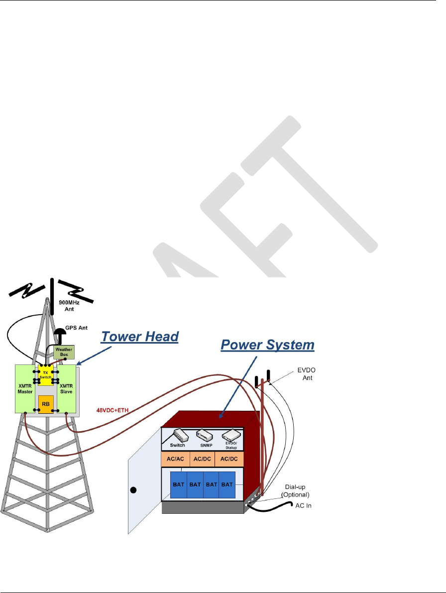
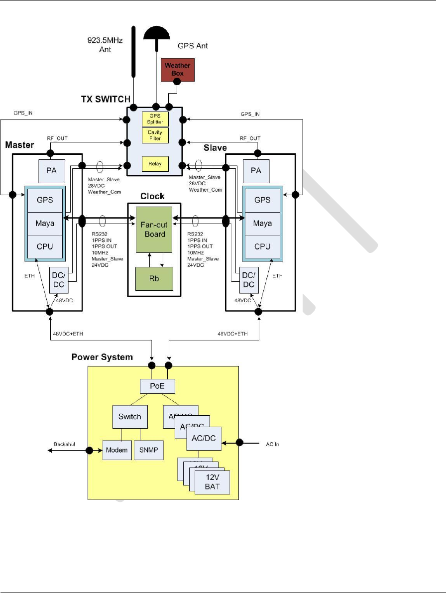
2.1 Hardware Architecture
The hardware architecture of the WAPS Beacon system and the subsystem is described in the
following diagram. It is imperative the user understands that architecture before using the
socket server interface.
The connectivity architecture related to the socket server is illustrated in figure below:
Figure 1: WAPS BEACON SYSTEM DIAGRAM
Document Name: WAPS BEACON Installation Manual
Version No: 1.4
Company Name: NextNav, LLC.
Confidential Page 8 11-Sep-12
Page 8 of 30
Figure 2: WAPS BEACON CABLES
Document Name: WAPS BEACON Installation Manual
Version No: 1.4
Company Name: NextNav, LLC.
Confidential Page 9 11-Sep-12
Page 9 of 30
2.2 Software Architecture
TX FPGA
UART
μB
Main.py
(TCP
Socket Server)
7734
ARM
(192.168.13.1)
Linux
Kernel
Internet/Local
Attach
Socket
Clients
PA
Eth
Figure 3: SW Architecture
Although it is shown that the IP address is static, just so that multiple ZEUS systems can be
connected on the same network, for developmental purposes, we can leave the IP addresses to
be DHCP. One would have to connect a console to the ARM CLI to determine its assigned IP
address.
Document Name: WAPS BEACON Installation Manual
Version No: 1.4
Company Name: NextNav, LLC.
Confidential Page 10 11-Sep-12
Page 10 of 30
3 Beacon Installation Procedure and Options
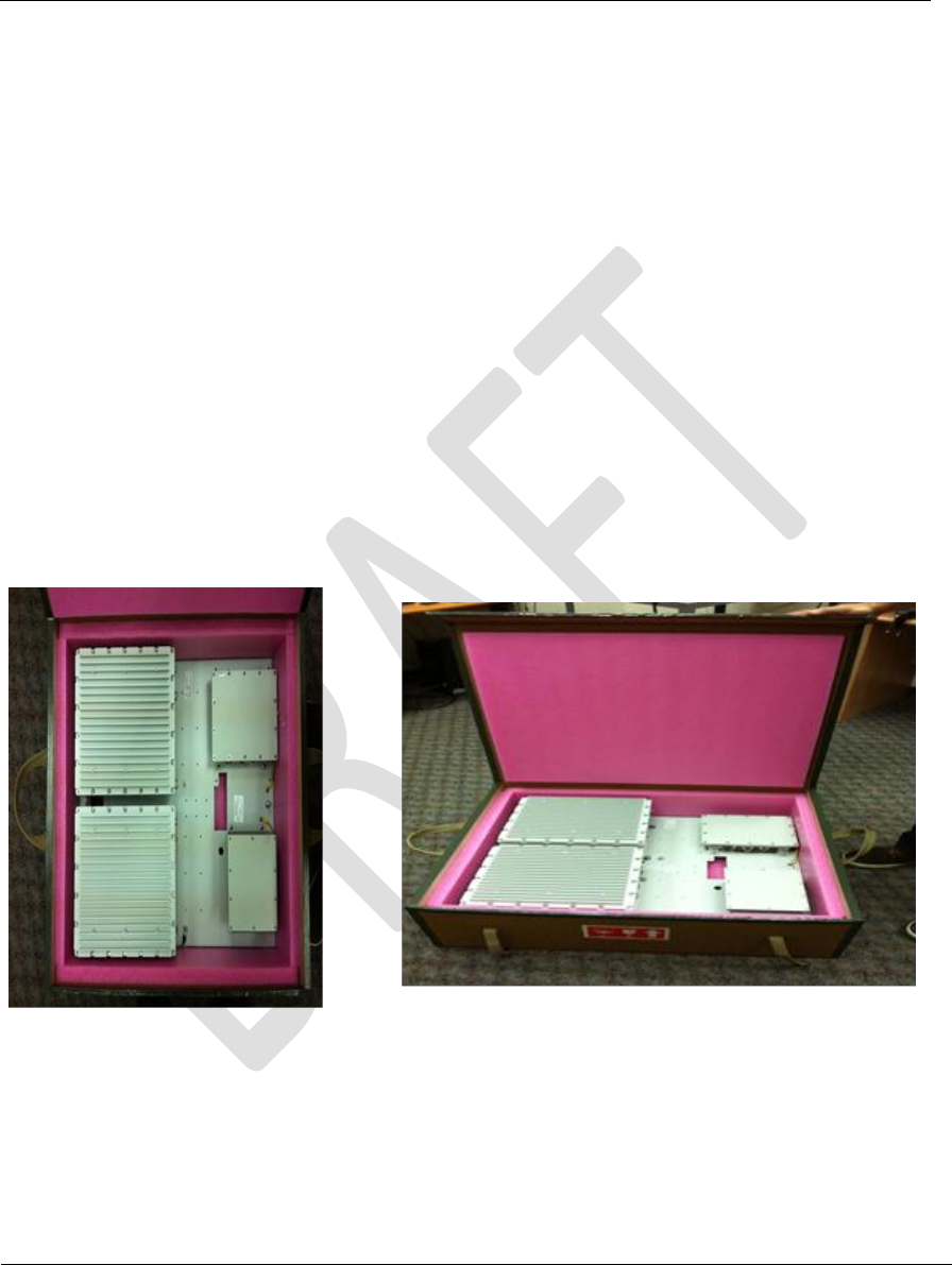
3.1 Package
The WAPS Beacon includes the following items inside the package:
WAPS BEACON mounted on the mounting kit
External Cables:
o HARS00017 x2 (Data: XMTR to RB)
o HARS0018 x2 (Data: XMTR to TXSW)
o HARS0019 x2 (GPS: XMTR to TXSW)
o HARS0020 x2 (RF: XMTR to TXSW)
Figure 4: Beacon Packaging
Document Name: WAPS BEACON Installation Manual
Version No: 1.4
Company Name: NextNav, LLC.
Confidential Page 11 11-Sep-12
Page 11 of 30
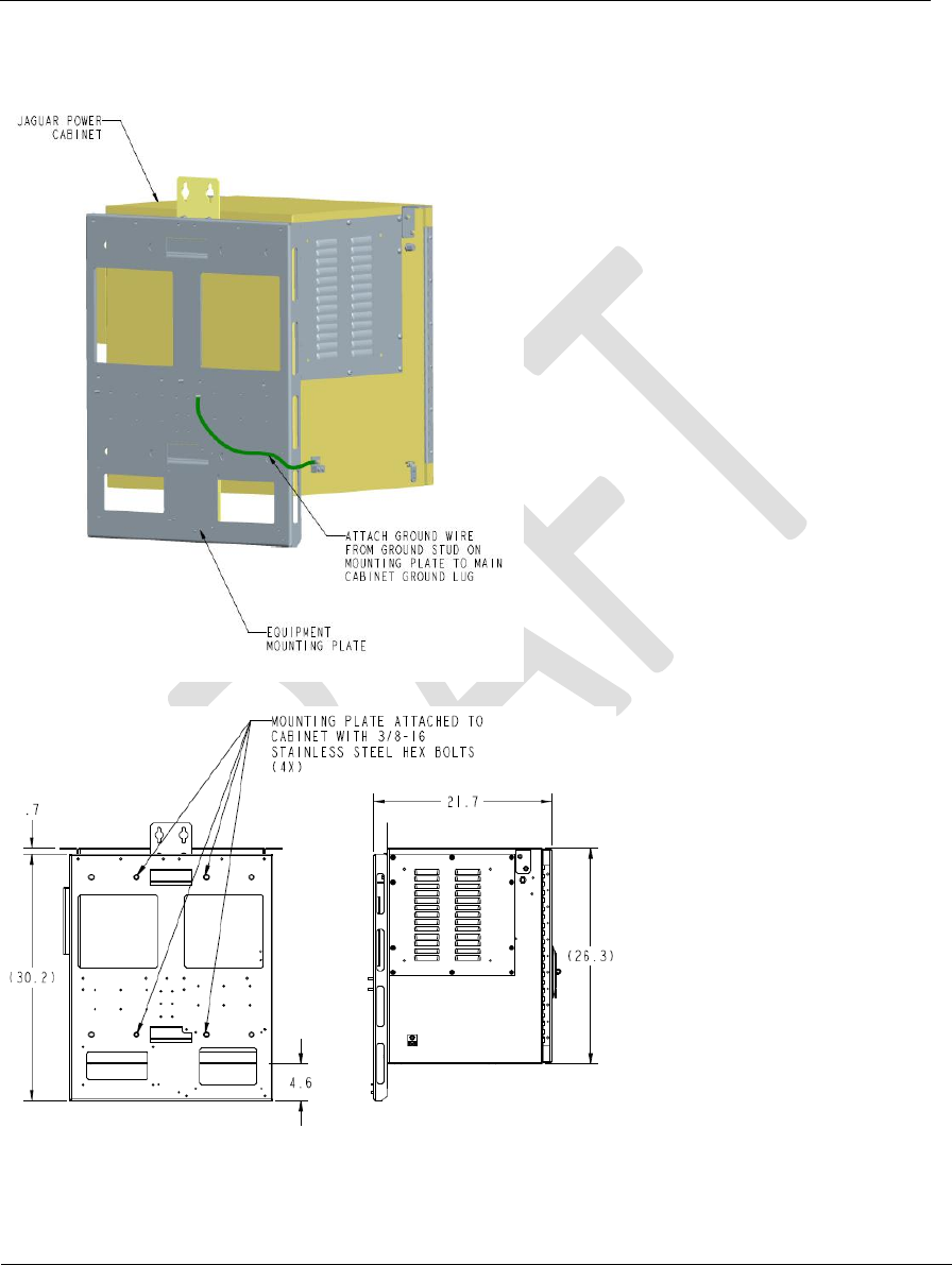
Notes:
1. Before installation, please unbolt all of the XMTR modules from the
mounting plate, mount the mounting plate first and then to mount
the XMTR boxes.
2. NOT TO DRILL HOLES in the MOUNTING KIT in order to install the
Beacon. Please use the provided mounting Kit brackets.
3.2 Installation Options
There are 4 different options to install the WAPS Beacon, as listed and illustrated below:
1. Wall mount
2. Pole mount
3. H-Frame mount
4. Power System back mount
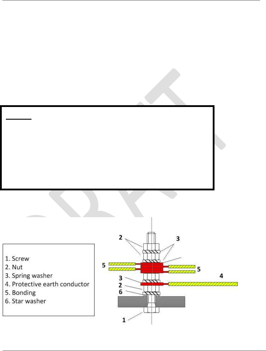
3.2.1 Grounding
Figure 5: Grounding Stud
Document Name: WAPS BEACON Installation Manual
Version No: 1.4
Company Name: NextNav, LLC.
Confidential Page 12 11-Sep-12
Page 12 of 30
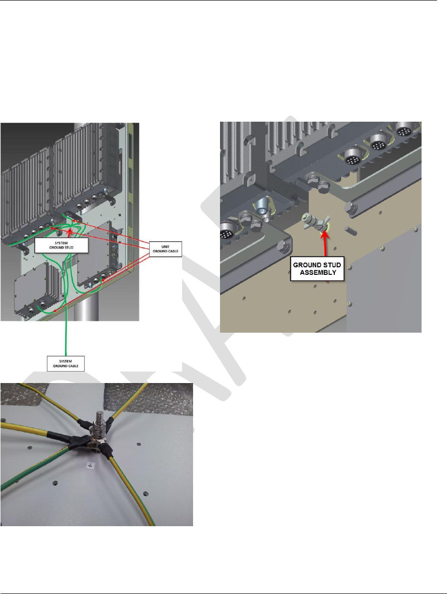
The system is packaged with the 4 separate units (MASTER XMTR, SLAVE XMTR, RB CLK, TX
SWITCH) bonding cables that are connected already to the central Ground Stud as in the
diagram above. Installer will connect the System to the ground using a protective earth cable
from this stud as shown in the diagram above.
Figure 6: Beacon Grounding Scheme
Document Name: WAPS BEACON Installation Manual
Version No: 1.4
Company Name: NextNav, LLC.
Confidential Page 13 11-Sep-12
Page 13 of 30
3.2.2 Wall Mounting
Figure 7: Wall Mounting
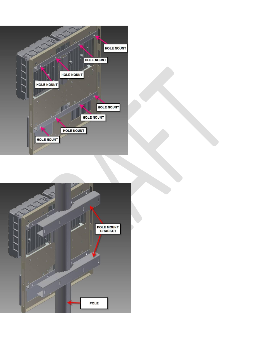
3.2.3 Pole Mounting
Figure 8: Pole Mounting
Document Name: WAPS BEACON Installation Manual
Version No: 1.4
Company Name: NextNav, LLC.
Confidential Page 14 11-Sep-12
Page 14 of 30
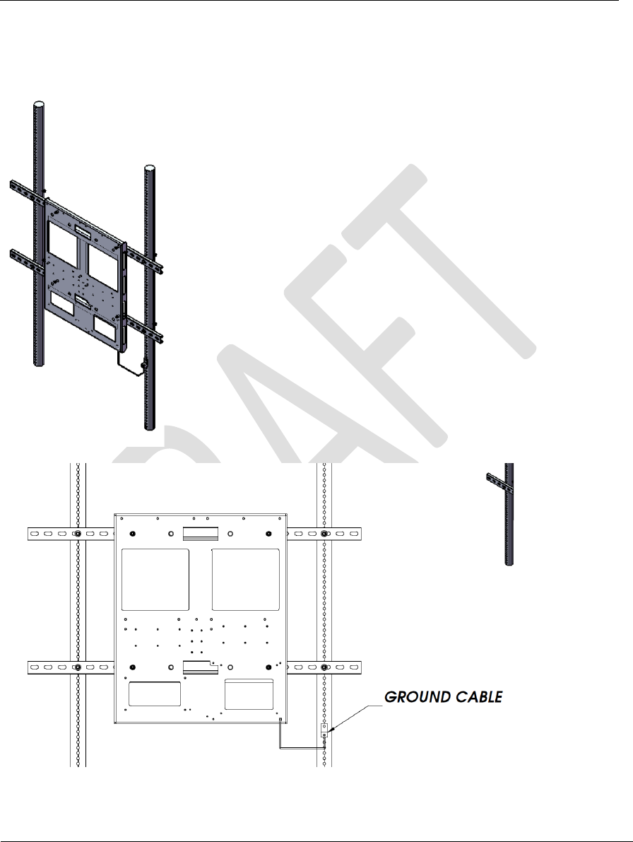
3.2.4 H-Frame Mounting
Figure 9: H-Frame Mounting
Document Name: WAPS BEACON Installation Manual
Version No: 1.4
Company Name: NextNav, LLC.
Confidential Page 15 11-Sep-12
Page 15 of 30
3.2.5 Power System Mounting
Figure 10: Power System Mounting

Document Name: WAPS BEACON Installation Manual
Version No: 1.4
Company Name: NextNav, LLC.
Confidential Page 16 11-Sep-12
Page 16 of 30
3.3 External Cable Connections
3.3.1.1 XMTR
Please follow the diagram below:
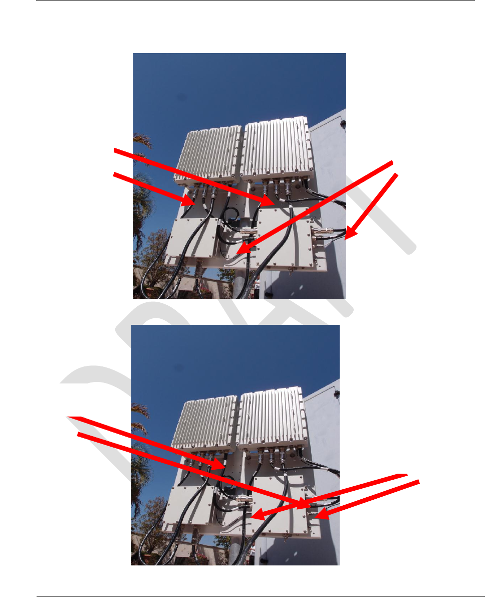
1. Connect data cable - HARS0017 - from MASTER XMTR box to RB box
2. Connect data cable - HARS0017 - from SLAVE XMTR box to RB box
3. Connect data cable - HARS0018 - from MASTER XMTR box to TX SWITCH box
4. Connect data cable - HARS0018 - from SLAVE XMTR box to TX SWITCH box
5. Connect GPS cable - HARS0019 from MASTER XMTR box to TX SWITCH box
6. Connect GPS cable - HARS0019 from SLAVE XMTR box to TX SWITCH box
7. Connect RF cable - HARS0020 - from MASTER XMTR box to TX SWITCH box
8. Connect RF cable - HARS0020 - from SLAVE XMTR box to TX SWITCH box
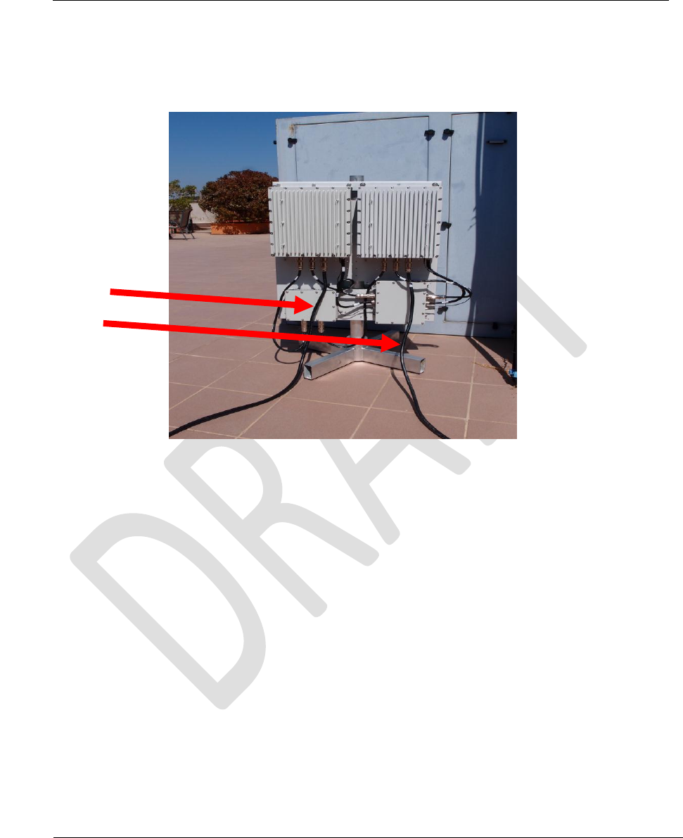
9. Connect the grounding cable to the ground screw on the mounting kit
10. Connect the ETH+DC cable to the MASTER XMTR box
11. Connect the ETH+DC cable to the SLAVE XMTR box
Note: Please allow drip loops for all cable connections (to avoid water running up into the
connectors.
3.3.1.2 Weather box connection
1. Connect data cable HARS0021 – from the TX SWITCH box to the Weather box.
3.3.1.3 GPS Antenna and TX Connections
1. Add Polyphaser (Surge Suppression) on the GPS and TX antenna.
2. Connect the GPS antenna to the GPS antenna port of the TX SWITCH box
3. Connect Tx antenna cable to the “TX” port of the TX SWITCH box
Document Name: WAPS BEACON Installation Manual
Version No: 1.4
Company Name: NextNav, LLC.
Confidential Page 17 11-Sep-12
Page 17 of 30
Figure 11: Cable installation between units
HARS0017 (RB)
HARS0018 (TXSW)
HARS0020 (RF)
HARS0019 (GPS)
Document Name: WAPS BEACON Installation Manual
Version No: 1.4
Company Name: NextNav, LLC.
Confidential Page 18 11-Sep-12
Page 18 of 30
Figure 12: External Cable installation
ETH + DC

Document Name: WAPS BEACON Installation Manual
Version No: 1.4
Company Name: NextNav, LLC.
Confidential Page 19 11-Sep-12
Page 19 of 30
3.4 TX Antenna mounting
Omni antenna to be installed on tower or roof top construction as defined in site specific
construction drawing. As a general rule on any monopole installations the TX antenna shall be
attached to a 6 foot side arm mount, minimum distance away from the monopole unless the
antenna extends above the monopole in its entirety. Likewise the antenna shall be kept a
minimum distance of 6 feet from any other vertical structures on other types of towers. For roof
tip installations, the TX antenna must extend above all parapet walls and penthouses on the
roof top.
This radio transmitter may only operate using a vertically polarized antenna with maximum gain
of +8 dBi. To reduce potential radio interference to other users, the antenna gain should be so
chosen that the equivalent effective radiated power (ERP) does not exceed 30 Watts.
Antenna Type: Monopole
Polarization: Vertical
Maximum Gain: +8 dBi (maximum gain of antenna + cable loss is 3dBd)
A CSV file (configuration file) per transmitter is created by the NOC engineer, based on the
installation parameters such as line lengths, antenna type etc.
The TX output power level setting is contained in the CSV file.
The output power is adjusted by the “attenuation” setting. This value in the CSV file is
calculated by a formula to set the output power (not to exceed 30W EIRP). The variables used in
the calculation include PA Gain (Gpa), TX Antenna Gain (Gant), TX filter insertion loss (ILflt),
internal cable loss (ILint), external cable loss (ILext), and transceiver output power (PTCVR).
EIRP (W) = 10^((PTCVR •] ILint + Gpa •] ILflt •] ILext + Gant) / 10) / 1000
This radio transmitter (FCC ID: A4P-100-0007-01) has been approved by FCC to operate with
the antenna types listed below with the maximum permissible gain and required antenna
impedance for each antenna type indicated. Antenna types not included in this list, having a
gain greater than the maximum gain indicated for that type, are strictly prohibited for use with
this device.

Document Name: WAPS BEACON Installation Manual
Version No: 1.4
Company Name: NextNav, LLC.
Confidential Page 20 11-Sep-12
Page 20 of 30
3.5 Connecting to the Power System
1. Open the Power System door
2. Switch the circuit breaker switches to the “off” position if not already.
3. Connect the HRS0016 cables
4. Plug in the power chord of the WAPS Beacon and switch on the MAIN switch in the
battery compartment
5. Verify that the GND tab is broken off and Battery switch is in the OFF position.
6. Verify that the Rectifier MiniPACK LED’s all go to green.
7. Verify that the MiniPACL controller display is on
8. Flip all three circuit breaker switches from step 3 to the ON position simultaneously.
9. Verify that the following LEDs are lit indicating operation:
a. Ethernet Switch: Phoenix Contact power and ports (all connected ports are lit)
b. EVDO modem (Raven)
10. Test the Battery backup
a. Flip Battery switch to the “ON” position
b. Flip the Main Switch from step 4 to the OFF position.
c. Verify all LEDs from step 7 are lit.
d. Flip the Main switch back to the ON position.
11. Connect the EvDO antenna cables to the EvDO Tx port. In cases of sites which have been
documented as requiring EvDO diversity, connect the diversity antenna to the EvDO DIV
port. In cases of sites which have been documented as needing a POTS line, connect the
phone line to the ‘TELCO’ port.
12. Connect the field service laptop with an Ethernet cable to the ‘Ethernet’ port on in the
Phoenix switch port #5. Wait for a few seconds to get an IP address on the field service
laptop. Try and browse the internet to ensure connectivity. Once connectivity is
ensured, call the operator at the NOC to further commission the beacon box.

Document Name: WAPS BEACON Installation Manual
Version No: 1.4
Company Name: NextNav, LLC.
Confidential Page 21 11-Sep-12
Page 21 of 30
4 Usage Model
4.1 Hardware Connections for the Server
The socket server expects the following modules to be connected to the Zeus board
- PA module
- GPS Module
- Rubidium
- Weatherboard
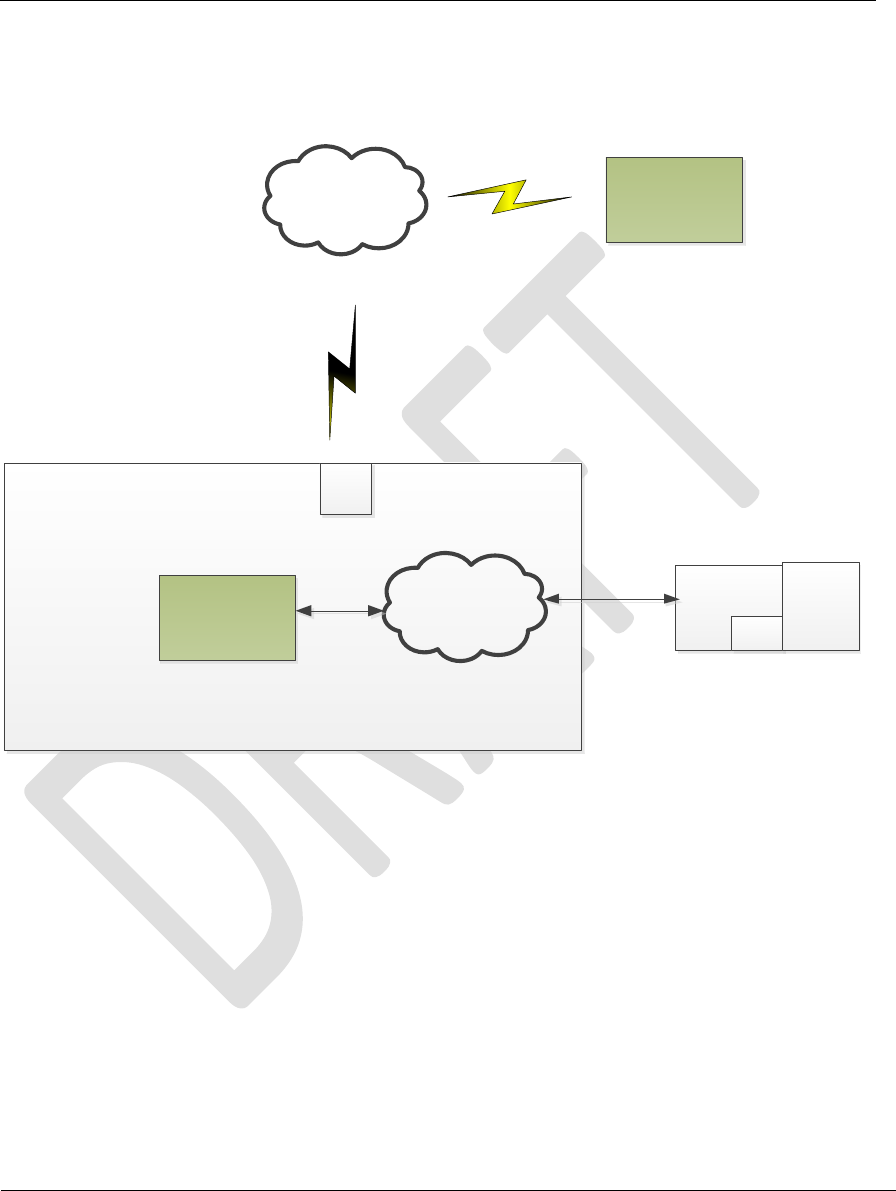
Socket clients communicate with the Socket Server running on zeus over the Ethernet
link as shown in figure below. For developmental purposes, multiple zeus setups can be
connected to the network as long as they have DHCP addresses. One computer on the
same network can be used to communicate with multiple Zeus systems using the
IPAddress:Port configuration.
Ethernet
Switch
Zeus1
DHCP
Zeus2
DHCP
Zeus3
DHCP
GUIClient
Computer
Router
4.2 Socket Server Startup
The socket server runs on the Zeus Board ARM Linux Kernel. To connect to the Zeus Board, use
an ssh client such as ‘putty’ from the GuiClient computer.

Document Name: WAPS BEACON Installation Manual
Version No: 1.4
Company Name: NextNav, LLC.
Confidential Page 22 11-Sep-12
Page 22 of 30
1. Login to the Zeus ARM Linux shell using the ssh client
2. Verify that the socket server is not already running
3. pgrep -fl Main.py # This command will show if the server is already running. If not
continue with the next steps
4. cd ~/apps/server
5. python Main.py –s /dev/ttyO1 > /tmp/Main.log &
4.3 Socket Client Installation
The socket client should be installed on the GuiClient computer. This machine can be a Windows
or a Linux PC (with X Windows) as long as python and svn are installed on the machine.
1. Download pythonxy from http://code.google.com/p/pythonxy/, full version (2.7.2.1).
During installation, make sure that PySerial is selected.
2. Download the Tortoise SVN client http://tortoisesvn.net/downloads.html (optional)
3. Unzip the client.zip zipfile on the GuiClient computer and change directory to the ‘client’
folder.
4.4 Socket Client Startup
1. On the client computer, start the ‘GUIClient.py’ script by double clicking on the
program. (or ‘python GUIClient.py’ in the case of Linux)
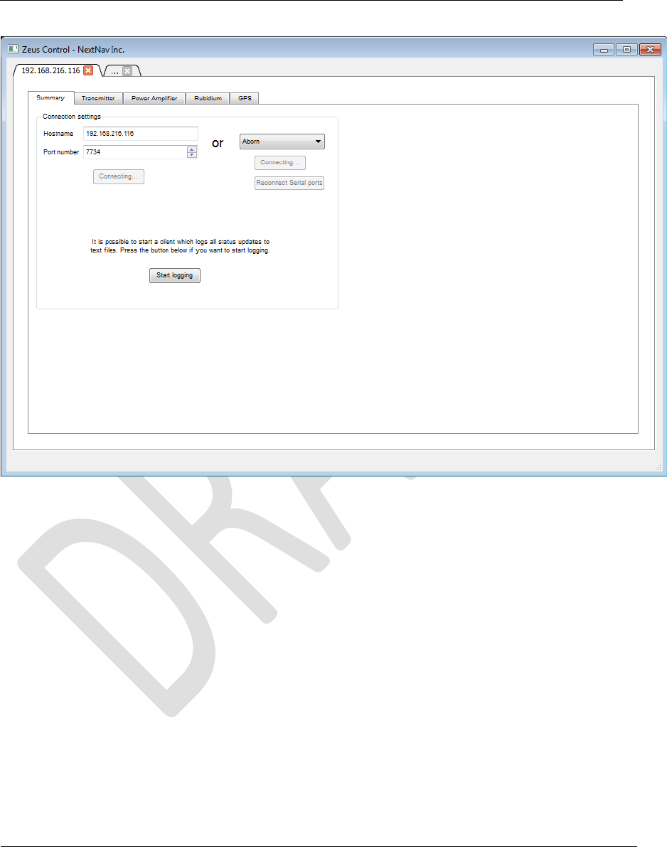
2. The above step will launch a window as shown in Figure 13. In the ‘Summary’ tab,
enter the IP of the beacon provided by the field technician and port number as
‘7734’.
3. Clicking on connect establishes a TCP/IP connection with the beacon and the
connect button changes to ‘Disconnect’ confirming a successful connection.
4. If step 4 fails and an error message ‘Could not connect to server’ is displayed then
debug for one of the following causes:
a) An error in IP/ port entered.
b) Ethernet connection issues.
c) The socket server script not running on the zeus platform.
Document Name: WAPS BEACON Installation Manual
Version No: 1.4
Company Name: NextNav, LLC.
Confidential Page 23 11-Sep-12
Page 23 of 30
Figure 13: GUI Summary Tab
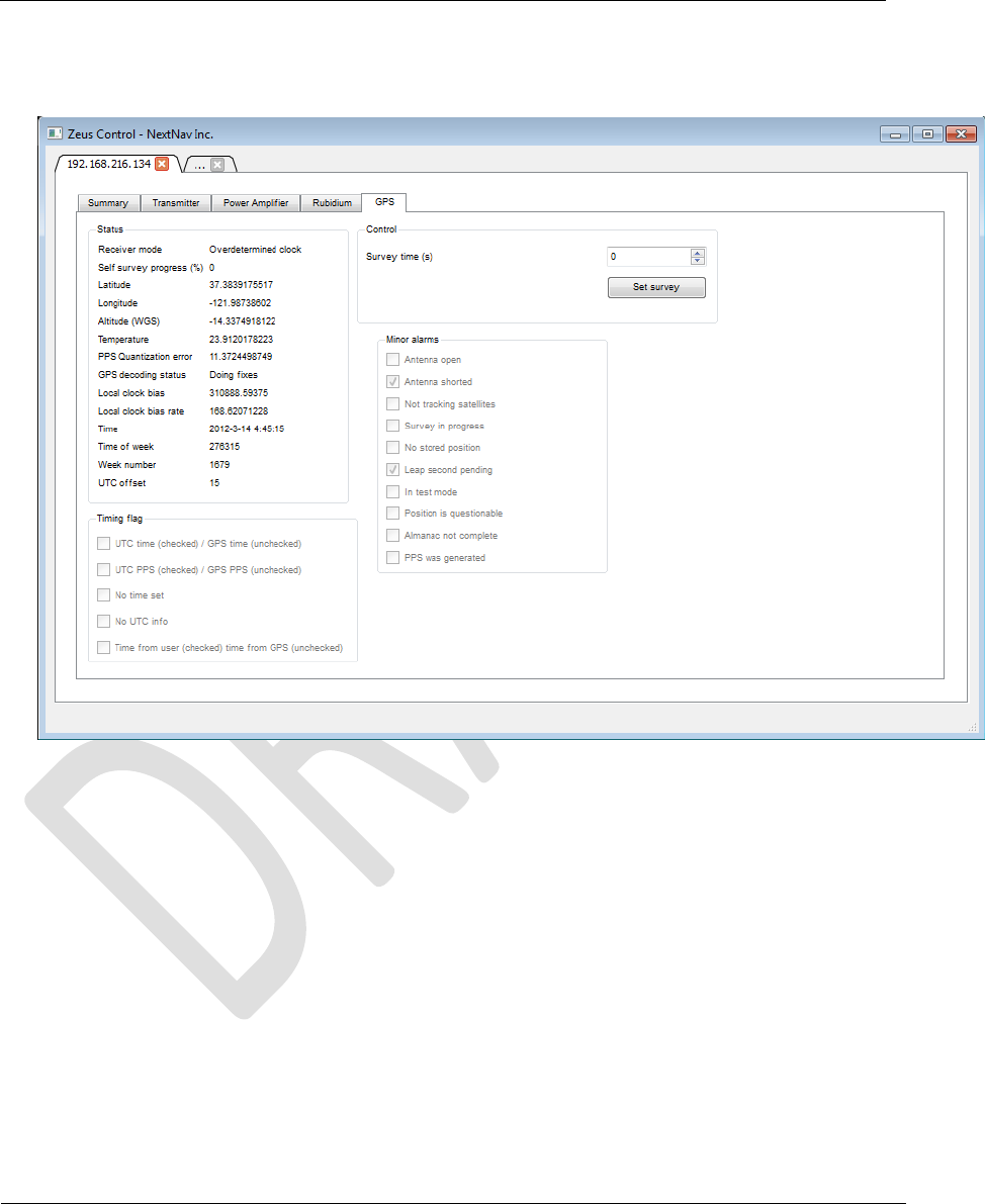
4.4.1 GPS Tab
Click on ‘GPS’ tab to read information from the parsed standard NMEA messages
streamed through the GPS module as shown in Figure 14.
Document Name: WAPS BEACON Installation Manual
Version No: 1.4
Company Name: NextNav, LLC.
Confidential Page 24 11-Sep-12
Page 24 of 30
1. Check for proper GPS antenna connection by verifying antenna status message as not
Open or Short.
Figure 14: GPS Tab
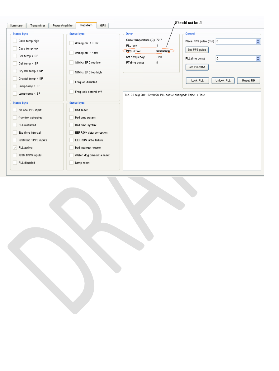
4.4.2 Rubidium Tab
Click on ‘Rubidium’ tab to read the streamed data from the rubidium as shown in Figure
15.
1. Click on ‘Lock PLL’ to synchronize the rubidium PPS to the GPS reference PPS.
2. Note the ‘PPS offset’ which can be a number in the range 0 to 999999999. A
value of -1 indicates that the rubidium is not getting a reference PPS from the
GPS.
Document Name: WAPS BEACON Installation Manual
Version No: 1.4
Company Name: NextNav, LLC.
Confidential Page 25 11-Sep-12
Page 25 of 30
Figure 15: Rubidium Tab
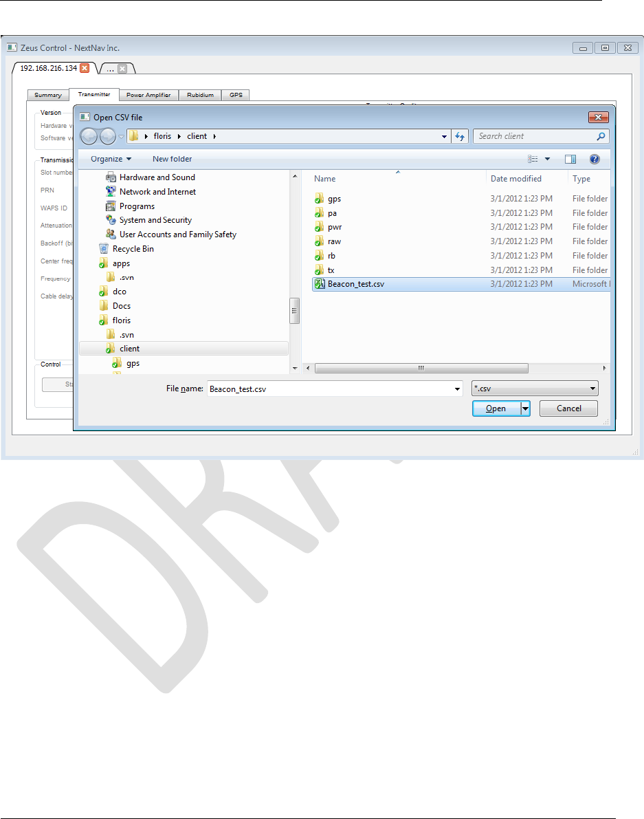
4.4.3 Transmit Tab
Click on ‘Transmitter’ tab and follow the procedure below to program the transmitter
board.
Procedure to confirm PA connections and cabling:
1. Click on ‘Import from CSV’ to launch an explorer window as shown in Figure 16
and choose Beacon_test.csv’ located in the same client folder as the GUI.
Note: The Beacon_test.csv is a test parameters file with random LLA info and a
safe attenuation of 10dB to transmit well below 30W ERP. This is used to test the
PA power levels and confirm cabling between the TX and PA. The final
configuaration CSV files per transmitter are created by the NOC engineer based
on the installation parameters such as line lengths, antenna type.
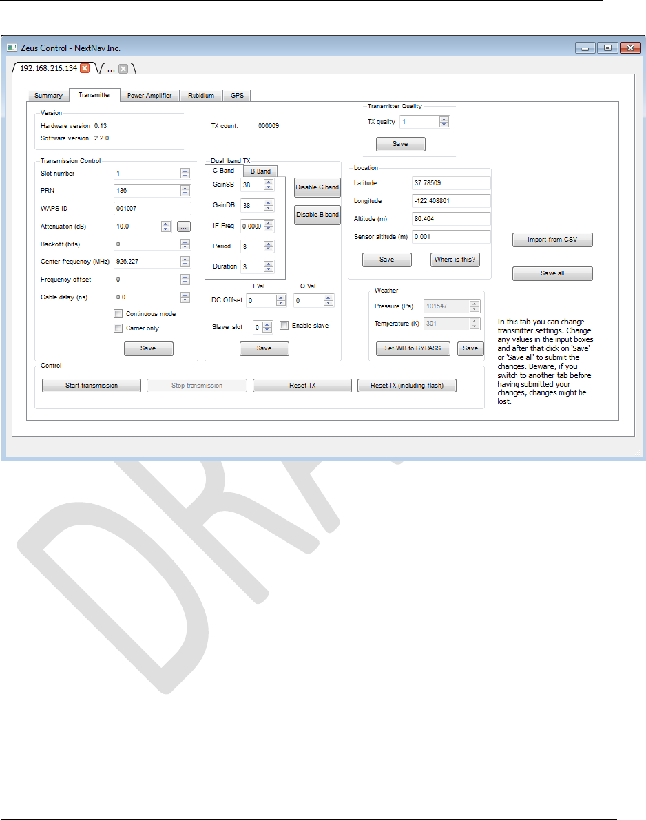
2. Click ok to populate the parameters required for transmission and then click save
in ‘Transmission control’ section which programs the parameters listed in the
transmission control tab. The center frequency of operation comes up as
926.227MHz.

Document Name: WAPS BEACON Installation Manual
Version No: 1.4
Company Name: NextNav, LLC.
Confidential Page 26 11-Sep-12
Page 26 of 30
3. Clicking on ‘Disable C Band’ will change the text of the button to ‘Enable C
Band’. Clicking on it again enables transmission just in the C band with center
frequency as set in the transmission control section.
4. To enable dual band transmission, set ‘IF Freq’ to 2.727 in C band and -2.727 in B
band tabs. Repeat step 3 above for both disable C and B band buttons to enable
transmission in both the bands. Setting these numbers will set the center
frequency of operation for the transmitter in dual band to be 923.5MHz. No other
IF frequency offsets are accepted by the GUI.
5. Click on ‘Set WB to Basic mode’ which will start streaming pressure and
temperature data from the weather sensor connected to the transmitter board.
Make sure the pressure and temperature values change for 0,0 to valid
measurements.
6. Click on ‘Save all’ button to set the rest of the parameters on the transmitter board.
7. Clicking on ‘Start transmission’ will change the text to ‘Starting’ and after 5-10
sec once the board starts to transmit, the entire GUI panel will get disabled except
‘Stop transmission’.
Document Name: WAPS BEACON Installation Manual
Version No: 1.4
Company Name: NextNav, LLC.
Confidential Page 27 11-Sep-12
Page 27 of 30
Figure 16: Beacon Configuration Setting
Document Name: WAPS BEACON Installation Manual
Version No: 1.4
Company Name: NextNav, LLC.
Confidential Page 28 11-Sep-12
Page 28 of 30
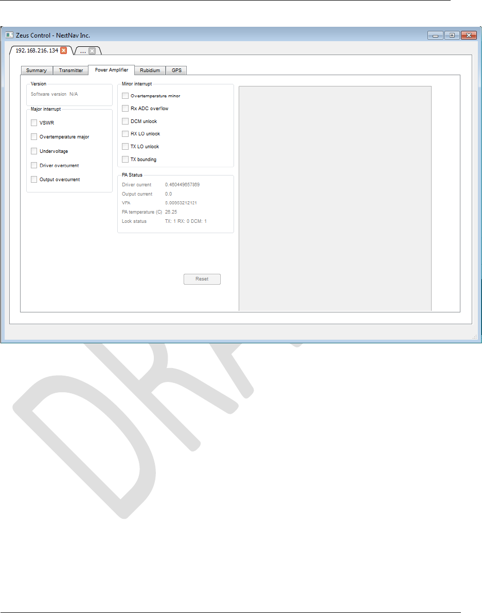
Figure 17: Transmitter Tab
4.4.4 Power Amplifier Tab
1. 3. Ensure that there are no alarms reported by the power amplifier
Document Name: WAPS BEACON Installation Manual
Version No: 1.4
Company Name: NextNav, LLC.
Confidential Page 29 11-Sep-12
Page 29 of 30
Figure 18: Power Amplifier Tab
After these steps, the beacon is commissioned with the correct output power levels (not
exceeding 30W ERP per channel), duty cycle, time slot(s), center frequency and bandwidth. The
GUI is then set to monitoring mode where each of the tabs report the measured parameters
from the beacon.
5 Known Limitations for the Socket Server
1. Image downloads are not supported through Socket Server (TX FPGA, RX FPGA, PA
FPGA)
2. Redundancy control is not supported
3. Communication to Rx FPGA is not supported (either through UART or SPI)

Document Name: WAPS BEACON Installation Manual
Version No: 1.4
Company Name: NextNav, LLC.
Confidential Page 30 11-Sep-12
Page 30 of 30
4. Temperature reading of Zeus temp sensor is not supported
5. One wire ID reading of Tx SWitch is not supported
6. Interrupts/GPMC interfaces are not supported SM95wert
7. Communication to rectifier is not supported
6 References
1) Socket Server ICD https://sharepoint.nextnav.com/proj-
ext/Jaguar/TigerDocs/Socket%20Server%20Protocol%20Definition%20v2.0.docx
2) Jaguar SDD https://sharepoint.nextnav.com/proj-
ext/Jaguar/Beacon%20Docs/Karrya_Beacon_BST_SDD_V4.doc
3) Jaguar Hardware Architecture: https://sharepoint.nextnav.com/proj-
ext/Jaguar/Beacon%20Docs/Karrya%20Beacon%20HW%20Spec%20V4.0.docx