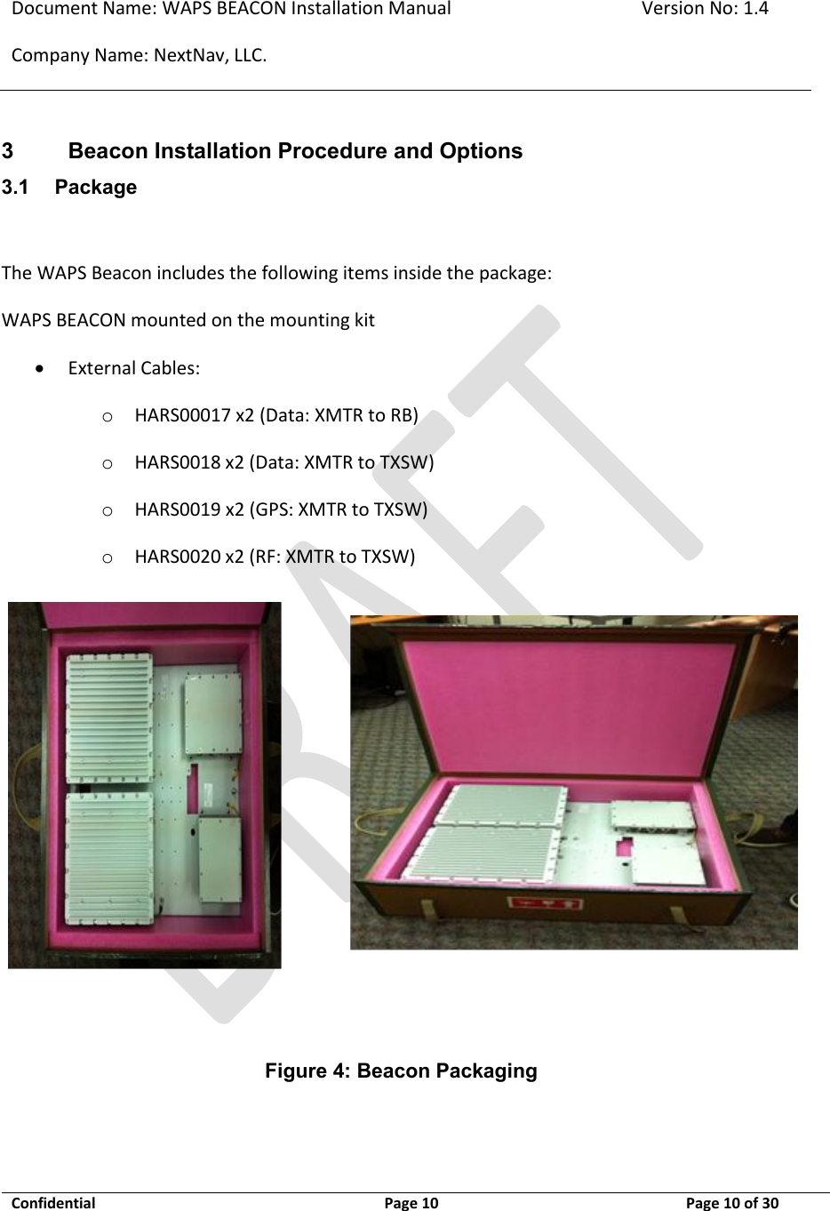
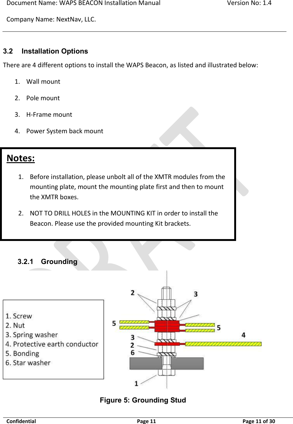
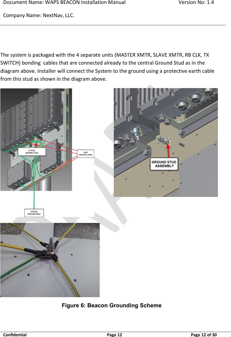
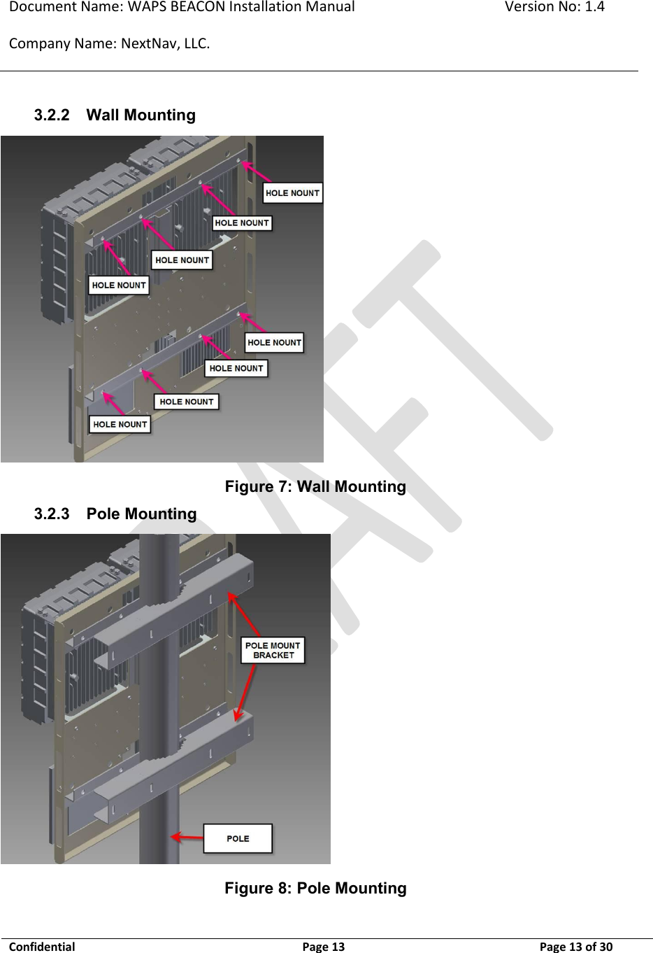
NextNav 100-0007-01 WAPS Beacon LBS System User Manual Install manual
NextNav,LLC WAPS Beacon LBS System Install manual
UserManual.wiki
>
NextNav
>
100-0007-01 User Manual
>
Install. manual
Contents
1.
User manual
2.
Install. manual
Install. manual
Navigation menu
Upload a User Manual
Namespaces
Wiki Guide
HTML
PDF
Info
Views
User Manual
Discussion / Help
Navigation
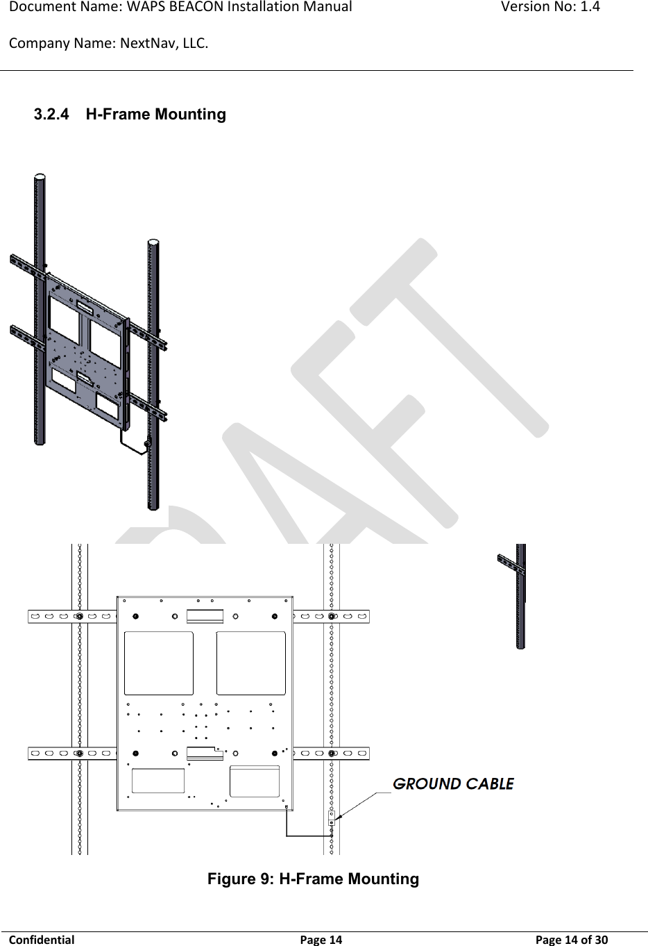
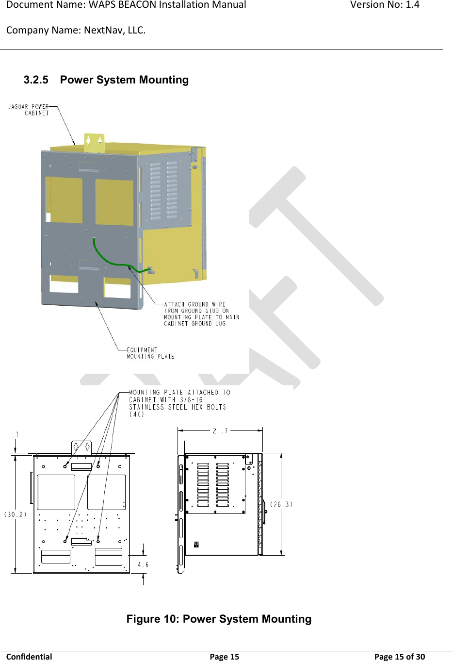
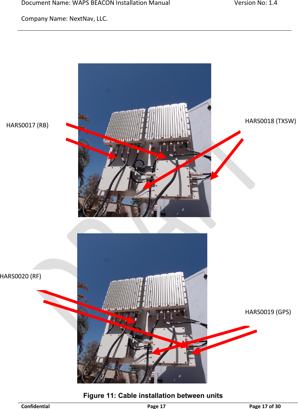
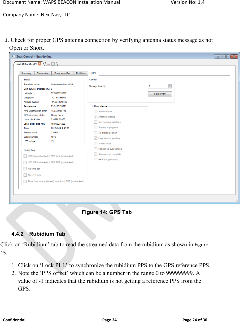
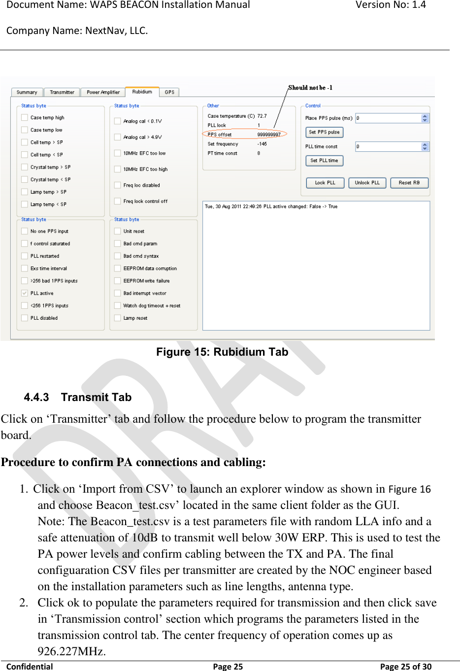
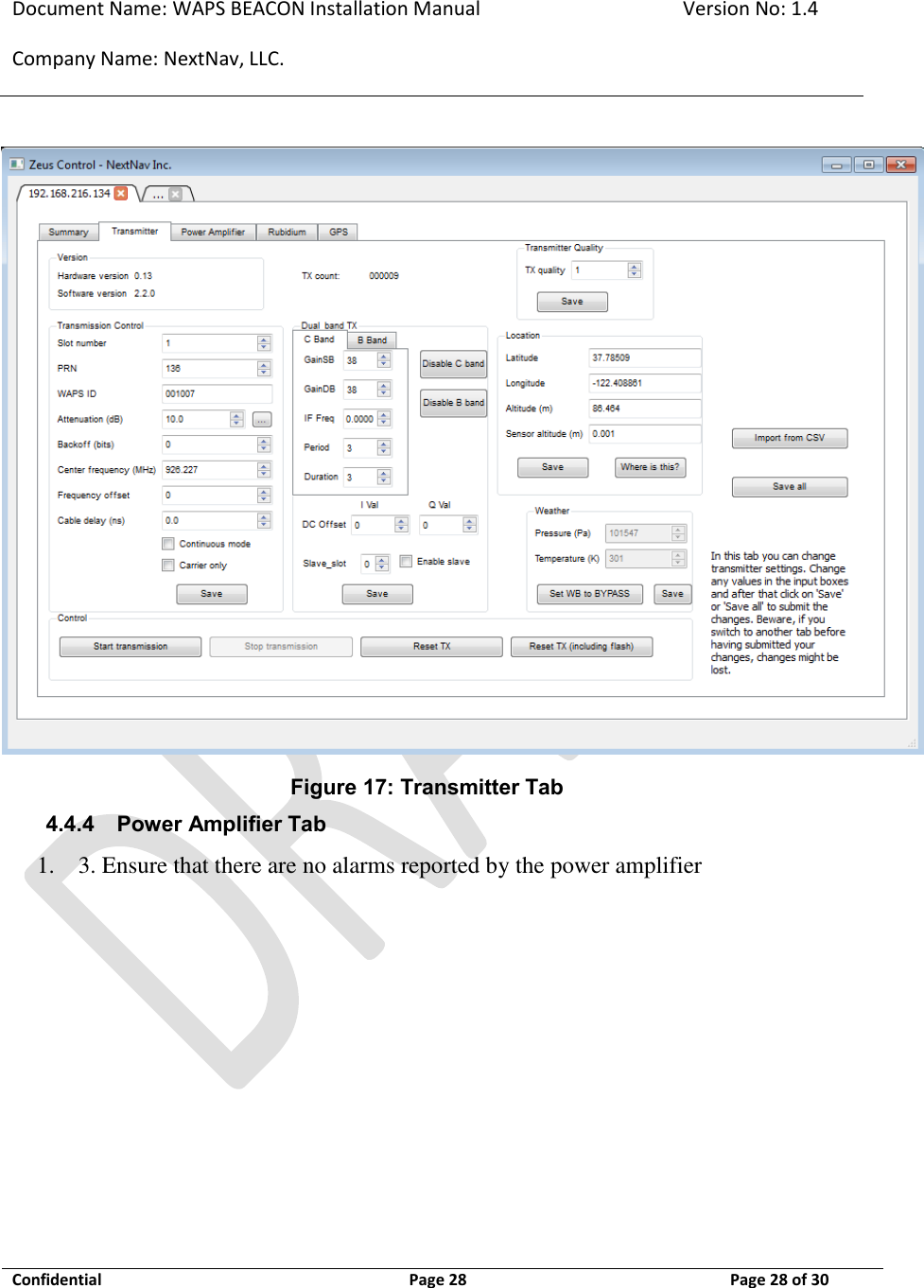
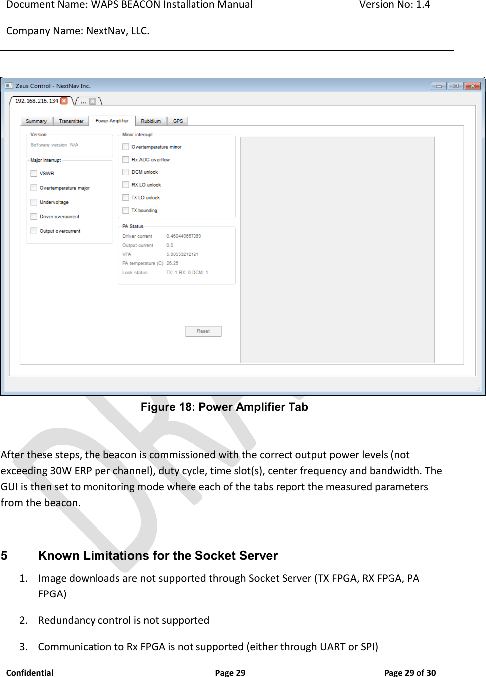
![Document Name: WAPS BEACON Installation Manual Version No: 1.4 Company Name: NextNav, LLC. Confidential Page 19 11-Sep-12 Page 19 of 30 3.4 TX Antenna mounting Omni antenna to be installed on tower or roof top construction as defined in site specific construction drawing. As a general rule on any monopole installations the TX antenna shall be attached to a 6 foot side arm mount, minimum distance away from the monopole unless the antenna extends above the monopole in its entirety. Likewise the antenna shall be kept a minimum distance of 6 feet from any other vertical structures on other types of towers. For roof tip installations, the TX antenna must extend above all parapet walls and penthouses on the roof top. This radio transmitter may only operate using a vertically polarized antenna with maximum gain of +8 dBi. To reduce potential radio interference to other users, the antenna gain should be so chosen that the equivalent effective radiated power (ERP) does not exceed 30 Watts. Antenna Type: Monopole Polarization: Vertical Maximum Gain: +8 dBi (maximum gain of antenna + cable loss is 3dBd) A CSV file (configuration file) per transmitter is created by the NOC engineer, based on the installation parameters such as line lengths, antenna type etc. The TX output power level setting is contained in the CSV file. The output power is adjusted by the “attenuation” setting. This value in the CSV file is calculated by a formula to set the output power (not to exceed 30W EIRP). The variables used in the calculation include PA Gain (Gpa), TX Antenna Gain (Gant), TX filter insertion loss (ILflt), internal cable loss (ILint), external cable loss (ILext), and transceiver output power (PTCVR). EIRP (W) = 10^((PTCVR •] ILint + Gpa •] ILflt •] ILext + Gant) / 10) / 1000 This radio transmitter (FCC ID: A4P-100-0007-01) has been approved by FCC to operate with the antenna types listed below with the maximum permissible gain and required antenna impedance for each antenna type indicated. Antenna types not included in this list, having a gain greater than the maximum gain indicated for that type, are strictly prohibited for use with this device.](https://usermanual.wiki/NextNav/100-0007-01.Install-manual/User-Guide-1841405-Page-19.png)