Nextivity orporated A41-V32-100 Cel-Fi GO Smart Antenna User Manual II
Nextivity Incorporated Cel-Fi GO Smart Antenna II
Contents
- 1. Users Manual I
- 2. User Manual II
User Manual II
Cel-Fi GO SMART ANTENNA Quick Start Guide
Cel‐Fi GO Smart Antenna is a high‐gain, low‐profile, magnetic‐mounted wideband cellular
antenna designed for mobile use on vehicles with the Cel‐Fi GO Smart Signal Booster.
QUICK START GUIDE
GO SMART ANTENNA
CEL-FI A41‐V32‐100
Instructions:
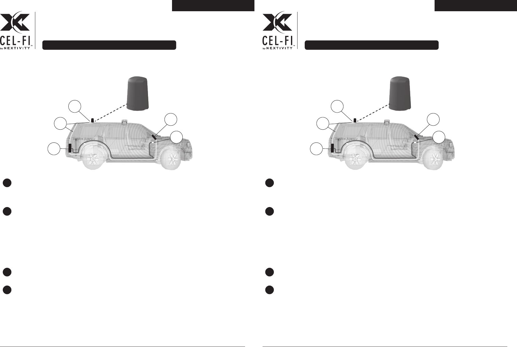
1 Place the Cel-Fi GO Smart Antenna in the desired location on the vehicle.
The Cel-Fi Go Smart Antenna comes with a 3m cable. The cable will connect the Cel-Fi
GO to the Smart Antenna. Make sure the Cel-Fi GO is within cable reach.
2 The magnetic base of the Cel-Fi GO Smart Antenna will stick to any ferrous metal. It
will not stick to aluminum.The antenna needs to be installed on a metallic surface
area (ground plane) of about 30 x 30mm. A vehicle's roof will typically serve this
purpose well.
NOTE: For best results, install the Cel‐Fi GO Smart Antenna and Server Antennas with
as much physical space between them as possible. This will allow the system to
configure to maximum gain without oscillation or feedback.
3 If the Cel-Fi GO needs to be installed, follow the instructions that were included with
the Cel-Fi GO unit.
4 Make sure to connect the Cel‐Fi GO Smart Antenna to the Cel-Fi GO unit’s Donor port.
The Cel-Fi GO is clearly marked with icons for a Donor Antenna Port and a Server
Antenna Port. The product will not function if connected in any other manner.
NOTE: Use the supplied cable for best results, but any cable can be substituted as long
the loss remains <2 dB from the Cel‐Fi GO Smart Antenna to the Cel-Fi GO M unit.
5 Connect the Cel-Fi GO to the power supply.
6 Open the Cel-Fi WAVE app and follow the instructions for pairing a Cel-Fi GO Smart
Antenna with a Cel-Fi GO M.
NOTE: The Smart Antenna’s serial number can be found on the label on the bottom
of the unit.
6 Open the Cel-Fi WAVE app and follow the instructions for pairing a Cel-Fi GO Smart
Antenna with a Cel-Fi GO M.
NOTE: The Smart Antenna’s serial number can be found on the label on the bottom
of the unit.
3
4
Cel-Fi GO M
Cel-Fi Go Smart Antenna
Server Antenna
5Power
1
2
3m Cable
Magnetic Base
Cel-Fi GO SMART ANTENNA Quick Start Guide
Cel‐Fi GO Smart Antenna is a high‐gain, low‐profile, magnetic‐mounted wideband cellular
antenna designed for mobile use on vehicles with the Cel‐Fi GO Smart Signal Booster.
QUICK START GUIDE
GO SMART ANTENNA
CEL-FI A41‐V32‐100
Instructions:
1 Place the Cel-Fi GO Smart Antenna in the desired location on the vehicle.
The Cel-Fi Go Smart Antenna comes with a 3m cable. The cable will connect the Cel-Fi
GO to the Smart Antenna. Make sure the Cel-Fi GO is within cable reach.
2 The magnetic base of the Cel-Fi GO Smart Antenna will stick to any ferrous metal. It
will not stick to aluminum.The antenna needs to be installed on a metallic surface
area (ground plane) of about 30 x 30mm. A vehicle's roof will typically serve this
purpose well.
NOTE: For best results, install the Cel‐Fi GO Smart Antenna and Server Antennas with
as much physical space between them as possible. This will allow the system to
configure to maximum gain without oscillation or feedback.
3 If the Cel-Fi GO needs to be installed, follow the instructions that were included with
the Cel-Fi GO unit.
4 Make sure to connect the Cel‐Fi GO Smart Antenna to the Cel-Fi GO unit’s Donor port.
The Cel-Fi GO is clearly marked with icons for a Donor Antenna Port and a Server
Antenna Port. The product will not function if connected in any other manner.
NOTE: Use the supplied cable for best results, but any cable can be substituted as long
the loss remains <2 dB from the Cel‐Fi GO Smart Antenna to the Cel-Fi GO M unit.
5 Connect the Cel-Fi GO to the power supply.
3
4
Cel-Fi GO M
Cel-Fi Go Smart Antenna
Server Antenna
5Power
1
2
3m Cable
Magnetic Base
Cel-Fi GO SMART ANTENNA Quick Start Guide Cel-Fi GO SMART ANTENNA Quick Start Guide
Copyright © 2018 by Nextivity, Inc. All rights reserved. The Nextivity and Cel-Fi logos are registered
trademarks of Nextivity Inc. All other trademarks or registered trademarks listed belong to their
respective owners. qsg-antenna-go-active-eng_18-0316
Antenna Specifications:
SPECIFICATION
698 – 2700
120 x 180
3:1
698 - 960 MHz // 5 dBi
> 1 GHz // 6 dBi
50
Vertical
Omni‐directional (effective)
SMA‐M
Dependent
Magnetic
ASA UV Stable
Black
‐-20C - 55C
66
ITEM
Frequency (MHz)
Dimensions (mm)
VSWR
Gain:
Gain:
Impedance (Ohm)
Polarization
Radiation pattern
Connector type
Ground plane
Mounting Type
Radome
Color
Operating Temp
IP
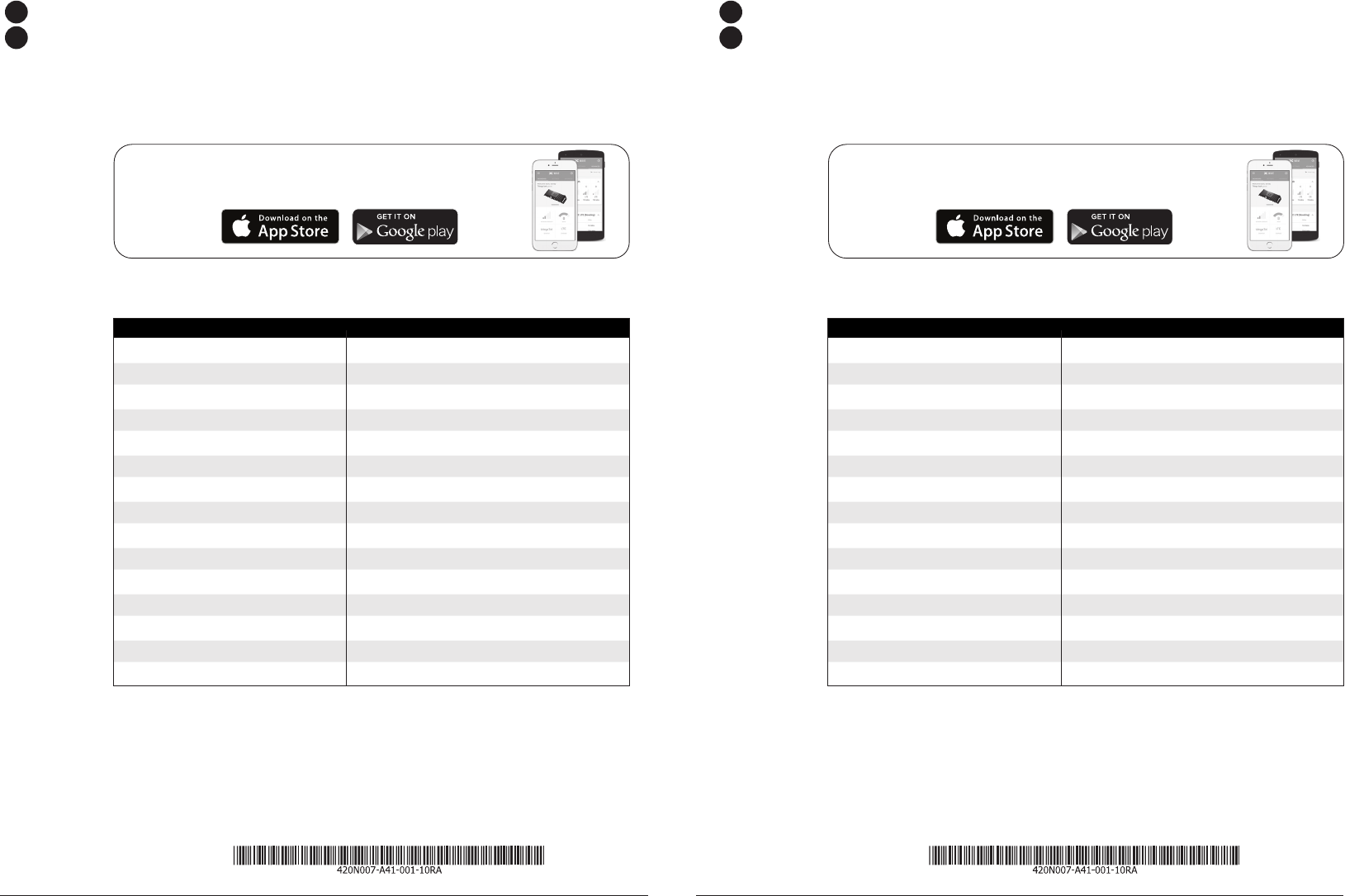
Cel-Fi WAVE is available on both smartphones and
tablets from the following app stores.
Instructions:
1 Place the Cel-Fi GO Smart Antenna in the desired location on the vehicle.
The Cel-Fi Go Smart Antenna comes with a 3m cable. The cable will connect the Cel-Fi
GO to the Smart Antenna. Make sure the Cel-Fi GO is within cable reach.
2 The magnetic base of the Cel-Fi GO Smart Antenna will stick to any ferrous metal. It
will not stick to aluminum.The antenna needs to be installed on a metallic surface
area (ground plane) of about 30 x 30mm. A vehicle's roof will typically serve this
purpose well.
NOTE: For best results, install the Cel‐Fi GO Smart Antenna and Server Antennas with
as much physical space between them as possible. This will allow the system to
configure to maximum gain without oscillation or feedback.
3 If the Cel-Fi GO needs to be installed, follow the instructions that were included with
the Cel-Fi GO unit.
4 Make sure to connect the Cel‐Fi GO Smart Antenna to the Cel-Fi GO unit’s Donor port.
The Cel-Fi GO is clearly marked with icons for a Donor Antenna Port and a Server
Antenna Port. The product will not function if connected in any other manner.
NOTE: Use the supplied cable for best results, but any cable can be substituted as long
the loss remains <2 dB from the Cel‐Fi GO Smart Antenna to the Cel-Fi GO M unit.
5 Connect the Cel-Fi GO to the power supply.
6 Open the Cel-Fi WAVE app and follow the instructions for pairing a Cel-Fi GO Smart
Antenna with a Cel-Fi GO M.
NOTE: The Smart Antenna’s serial number can be found on the label on the bottom
of the unit.
Copyright © 2018 by Nextivity, Inc. All rights reserved. The Nextivity and Cel-Fi logos are registered
trademarks of Nextivity Inc. All other trademarks or registered trademarks listed belong to their
respective owners. qsg-antenna-go-active-eng_18-0316
Antenna Specifications:
SPECIFICATION
698 – 2700
120 x 180
3:1
698 - 960 MHz // 5 dBi
> 1 GHz // 6 dBi
50
Vertical
Omni‐directional (effective)
SMA‐M
Dependent
Magnetic
ASA UV Stable
Black
‐-20C - 55C
66
ITEM
Frequency (MHz)
Dimensions (mm)
VSWR
Gain:
Gain:
Impedance (Ohm)
Polarization
Radiation pattern
Connector type
Ground plane
Mounting Type
Radome
Color
Operating Temp
IP
Cel-Fi WAVE is available on both smartphones and
tablets from the following app stores.
6 Open the Cel-Fi WAVE app and follow the instructions for pairing a Cel-Fi GO Smart
Antenna with a Cel-Fi GO M.
NOTE: The Smart Antenna’s serial number can be found on the label on the bottom
of the unit.
Instructions:
1 Place the Cel-Fi GO Smart Antenna in the desired location on the vehicle.
The Cel-Fi Go Smart Antenna comes with a 3m cable. The cable will connect the Cel-Fi
GO to the Smart Antenna. Make sure the Cel-Fi GO is within cable reach.
2 The magnetic base of the Cel-Fi GO Smart Antenna will stick to any ferrous metal. It
will not stick to aluminum.The antenna needs to be installed on a metallic surface
area (ground plane) of about 30 x 30mm. A vehicle's roof will typically serve this
purpose well.
NOTE: For best results, install the Cel‐Fi GO Smart Antenna and Server Antennas with
as much physical space between them as possible. This will allow the system to
configure to maximum gain without oscillation or feedback.
3 If the Cel-Fi GO needs to be installed, follow the instructions that were included with
the Cel-Fi GO unit.
4 Make sure to connect the Cel‐Fi GO Smart Antenna to the Cel-Fi GO unit’s Donor port.
The Cel-Fi GO is clearly marked with icons for a Donor Antenna Port and a Server
Antenna Port. The product will not function if connected in any other manner.
NOTE: Use the supplied cable for best results, but any cable can be substituted as long
the loss remains <2 dB from the Cel‐Fi GO Smart Antenna to the Cel-Fi GO M unit.
5 Connect the Cel-Fi GO to the power supply.