Nexus 21 Stereo Receiver Multi Control Users Manual 1 Inledning.3
Multi Control to the manual df1a7fbc-510a-426d-bf5f-0d7a96fa76f2
2015-02-05
: Nexus-21 Nexus-21-Stereo-Receiver-Multi-Control-Users-Manual-494970 nexus-21-stereo-receiver-multi-control-users-manual-494970 nexus-21 pdf
Open the PDF directly: View PDF ![]() .
.
Page Count: 68
- 1 Part specification
- 2 Installation
- First start
- 4 Operation
- 5 Function overview
- 6 SPEED functions
- 7 PLUS functions
- 8 NAVIGATION functions
- 9 Wind functions
- 10 Man over board (MOB) function
- 11 Customise your display
- 12 Calibration
- 13 Maintenance and fault finding
- 14 Specifications
- 15 Warranty
Installation and Operation Manual
English
- Instrument -
Multi Control
Installation and Operation Manual
English

MULTI CONTROL
1

MULTI CONTROL
2
Navigation terms
MULTI CONTROL
3
This manual is written for NX2 Multi Control version 3.1 – 5.0
Edition: March 2007

MULTI CONTROL
4
1 Part specification
2 Installation.. .
2.1 Installing the instrument
2.1.1 Installing instru
3 First start ......... ..
3.1 Initialising the inst ..
3.2 Re-initialising the e
4 Operation......... ..
4.1 About this manual
4.2 How to use the push-butto
4.2.1 PAGE...... .
4.2.2 MINUS ....
4.2.3 PLUS .......... .....
4.2.4 SET.............
4.2.5 Clear / cancel / ...
4.2.6 Calibration...... ...
4.2.7 Lighting .......... ...
5 Function overvi
6 SPEED function
6.1 SPEED main-func
6.2 SPEED sub-funct
6.2.1 TRIP LOG (TR ...
6.2.2 TOTAL LOG
6.2.3 MAXIMUM SPEED (
6.2.4 START TIME TA
6.2.5 TIMER......... .....
6.2.6 AVERAGE SPEED (AVS)
6.2.7 DISTANCE (DST) ....................................................................................20
6.2.8 DEPTH (unit/DPT) ...................................................................................21
7 PLUS functions........................................................................ 22
7.1 DEPTH main-function ..................................................................................22
7.2 PLUS sub-functions .....................................................................................22
7.2.1 LIGHT CONTROL....................................................................................22
7.2.2 BATTERY (BAT)......................................................................................23
7.2.3 SHALLOW ALARM (SHA) .......................................................................23
7.2.4 DEPTH ALARM (DEA).............................................................................23
7.2.5 ANCHOR ALARM....................................................................................23
7.2.6 HEADING (HDT/HDM).............................................................................23
7.2.7 TEMPERATURE (TMP)...........................................................................23
7.2.8 UNIVERSAL TIME (UTC) ........................................................................23
7.2.9 BOAT SPEED (BSP/unit).........................................................................23
7.3 Remote Control (REM).................................................................................24
7.4 Set and turn on shallow (SHA) and depth alarm (DEA)................................25
7.5 Set and turn on anchor alarm (ANC)............................................................25
7.6 Clear an alarm value ....................................................................................25
....................................................................... 8
... ......... ................................................................. 12
...............................................................................13
ment to the Server............................................................14
........ ............................................................. 15 ..
rume ............................................................................15 nt
instru nt ........................................................................15 m .......... ............................................................. 16
........................................................................................16
ns........................................................................17
...... ...... ....................................................................................17
...... .....................................................................................17 ......
...... ................................................................................17 ..
........ ...............................................................................18 ......
reset ............................................................................18 .
......... ............................................................................18 ..
......... ............................................................................18 .. ew ................................................................... 19
s ..................................................................... 20
tion ..................................................................................20
ions...................................................................................20
P)....... ............................................................................20
)..(LOG ................................................................................20
MAX) .......................................................................20
R (S )...............................................................................20
........ ................................................................................20
........................................................................20

MULTI CONTROL
7.7 Silencing an alarm
7.8 Turning off /
8 NAVIGATION
8.1 NAVIGATION m
8.2 NAVIGATION s
8.2.1 STEER REFERENCE (
8.2.2 STEER VALUE ..
8.2.3 (SOG) and (CO
8.2.4 (BTW) and (DT
8.2.5 LATITUDE and IT
8.2.6 SET and DRIF
8.2.7 (CMG) and (
8.2.8 WAYPOIN
8.2.9 CROSS TR
8.3 Steer referen
8.3.1 Overview of ef
8.3.2 Steer reference (MEM
8.3.3 Steer referen W
8.3.4 Steer referen S
8.3.5 Steer refer
9 Wind functio
9.1 WIND Main-fun
9.2 WIND Sub-functio
9.2.1 STEER REFER Pil
9.2.2 STEER VALUE .....
9.2.3 APPARENT WIND SPEED
9.2.4 TRUE WIND SPEED
9.2.5 VELOCITY MA
9.2.6 TACTICAL FU (T
9.2.7 GEOGRAPHIC WIND DIRECTION.........................................................35
9.3 Tactical function...........................................................................................36
10 Man over board (MOB) function..............................................37
11 Customise your display...........................................................38
11.1 Move and lock a sub-function ......................................................................38
11.2 Copy and lock a sub-function.......................................................................38
11.3 Select power on function..............................................................................39
11.4 Cancel a moved or locked sub-function....................................................... 39
11.5 Temporary locking of alternating functions ..................................................39
12 Calibration.................................................................................40
12.1 Calibration of speed C10 ............................................................................40
12.1.1 C10 Return (RET) ...............................................................................40
12.1.2 C11 (Unit KTS)....................................................................................40
12.1.3 C12 (1.25 CAL) ...................................................................................40
12.1.4 C13 DAMPING (SEA)..........................................................................41
12.2 C20, calibration of depth..............................................................................41
12.2.1 C20 (RET) ...........................................................................................41
12.2.2 C21 (Unit m)........................................................................................41
.......................................................................................25
on an alarm............................................................................. 25
tiofunc ns............................................................26
ain-function ........................................................................26
ub on-functi s ........................................................................26
Pilot OFF)...........................................................26
(STR) ...........................................................................26
G)....................................................................................26
W)....................................................................................26
LONG UDE (POS) .......................................................26
T....................................................................................... 27
)...DMG ................................................................................27
T CLOSURE VELOCITY (WCV).............................................27
ACK ERROR (XTE) ..............................................................27
ce (P ).................................................................................. 28 ilot
steer erence (Pilot............................................................ 29 r) ............................................................................29
ce (B ) ............................................................................30 T
ce (C ) .............................................................................31 T
ce (AWA) ............................................................................31 en
ns . ....................................................................33 ....
ction.....................................................................................33
ns ....................................................................................33
ENCE ot OFF)...........................................................33 (
(STR .......................................................................33 ) . (AWS)..........................................................34
WS ......................................................................34 T
DE GOOD (VMG)............................................................34
NCTION AC) ................................................................. 34
5

MULTI CONTROL
6
12.2.3 C22 ( - 00.0
12.2.4 C23 (Unit°C)
12.2.5 C24 (0°C TM
12.2.6 C25 (Unit
12.3 C30, calibration of ion
12.3.1 C30 (RET).. .....
12.3.2 C31 (PAGE
12.3.3 C32 (00° OC
12.3.4 C33 (00.0 V
12.3.5 C34 (Auto D
12.3.6 C35 (Auto C
12.3.7 C36 (Auto C
12.3.8 C37 (000°AD
12.3.9 C38 (OFF S
12.3.10 C39 (Pilot ...
12.3.11 C40 (OFF M
12.3.12 C41 DAMPI )..
12.4 Compass calibrati
12.4.1 Automatic co dev
12.4.2 Automatic co dev
12.4.3 Cancel earlie me
12.4.4 Compass misalignment
12.5 C50, calibration o
12.5.1 C50 (RET).. ....
12.5.2 C51 (PAGE
12.5.3 C52 (OFF T
12.5.4 C53 (Unit m
12.5.5 C54 (1.70 ...
12.5.6 C55 (000° A
12.5.7 C56-C63 Wind calibration values.........................................................45
12.5.8 C64 (WIA)............................................................................................46
12.5.9 C65 DAMPING (SEA)..........................................................................46
12.5.10 C67 WIND SPEED ALARM (WSA)......................................................47
12.6 C70, calibration of Network and NMEA........................................................47
12.6.1 C70 (RET)............................................................................................47
12.6.2 C71 (OFF KEY) ...................................................................................47
12.6.3 C72 (d0 SEA).......................................................................................47
12.6.4 C73 (OFF BSP) ...................................................................................47
12.6.5 C74 (OFF DEP) ...................................................................................47
12.6.6 C75 (OFF CMP)...................................................................................48
12.6.7 C76 (OFF WND)..................................................................................48
12.6.8 C77 to C92...........................................................................................48
12.6.9 C93 (d4 NME)......................................................................................48
12.6.10 C94 (OFF COG) ..................................................................................48
12.6.11 C95 (OFF SOG)...................................................................................48
12.6.12 C96 (REF BSP) ...................................................................................48
12.7 NMEA...........................................................................................................49
12.7.1 Transmit NMEA sentences OUT from Server......................................49
ADJ).................................................................................41
........................................................................................41
P) ....................................................................................41
hPA).....................................................................................41
navigat .......................................................................42
............. ........................................................................42
ATO) ................................................................................42
A).....................................................................................42
AR) ...................................................................................42
EV)...................................................................................42
HK)...................................................................................42
LR) ...................................................................................42
J).....................................................................................42
EC) ...................................................................................42
SEA). ................................................................................42
AG) ..................................................................................43
NG (SEA ........................................................................43
on.....................................................................................43
mpass iation compensation (Auto DEV) ....................43
mpass iation check (Auto CHK).................................44
r perfor d compass deviation (Auto CLR) ....................44
correction (Adj) ..............................................44
f wind................................................................................45
............. ........................................................................45 .
ATO) ................................................................................45
WA)...................................................................................45
/s)......................................................................................45
CAL). ................................................................................45
DJ)....................................................................................45

MULTI CONTROL
12.7.2 Change NMEA sentences OUT from Server.......................................50
12.7.3 Receive NMEA sentences IN to Server...............................................51
12.8 Special NMEA sentences ............................................................................53
12.8.1 Baudrate control, .................................................................................53
13 Maintenance and fault finding.................................................54
13.1 Maintenance ................................................................................................54
13.2 Fault finding .................................................................................................54
13.2.1 General................................................................................................54
13.2.2 Fault - action........................................................................................55
13.2.3 Error messages ...................................................................................55
14 Specifications...........................................................................56
14.1 Technical specifications...............................................................................56
14.2 Nexus Network introduction and user policy ................................................56
14.3 Optional Accessories ...................................................................................57
14.4 Abbreviations...............................................................................................59
15 Warranty....................................................................................62
7

MULTI CONTROL
8
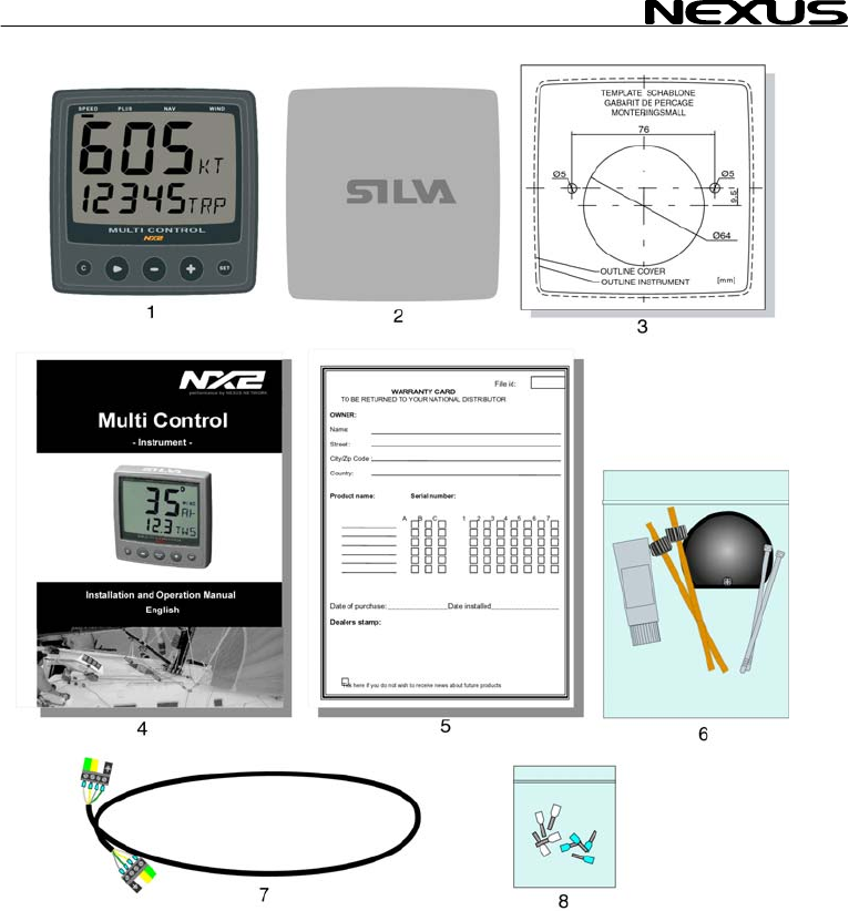
1 Part specification
___________________________________________________________
Items delivered with th instrument
1 NX2 Mult 4
1 Instrument cover 5
5 Cable pro
5 Cable pro
4 Instrument mounting screws 7
4 Rubber c
1 Connectio
1 4-pole jac
1 Silicon pa 7
2 Plastic cable strap 7
1 Adhesive 8
1 Nexus Network cable, 8 m (26 ft) 9
1 Quick guide laminated 10
1 Inter-connection cable, 0,3 m (1 ft )
1 Installation and Operating manual 11
1 Warranty card 12
1 National distributor list 13
Registering this product
Once you have checked that you have all the listed parts, please take time to fill in the
warranty document and return it to your national distributor.
By returning the warranty card, it will assist your distributor to give you prompt and
expert attention. Keep your proof of purchase. Also, your details are added to our
customer database so that you automatically receive new product catalogues when
they are released.
Warranty conditions see chapter 15.
e
i Control instrument
tectors, 0,25 mm (0.1 inch) 6
tectors, 0,75 mm (0.3 inch) 6
aps for screws 7
n back cover 7
k plug 7
ste tube
drill template for instrument
MULTI CONTROL
9

MULTI CONTROL
10
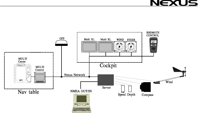
Welcome aboard the N
Thank you for choosing
Through this manual we ould like to help you install, operate and understand your
new Nexus Network.
The Server is the ”hea
depth, heading, wind and navigation (GPS, Loran or Decca) are connected.
From the Server the si
instruments, which rep
transducers.
The Nexus Network is
allows you to connect u
cable, thereby allowing Nexus
Network is capable of c
The connection system, with a single 5 mm (1/5") cable and 4-pole jack plugs with
cable protectors, makes
cable can be cut to exac e colour coded
and marked with a number for easy reference.
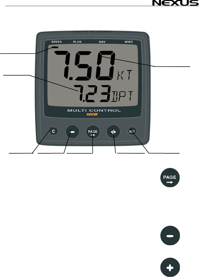
NX2 Multi Control is a multi function instrument that displays a main and a sub-
function together. You can easily ”customise” your favourite combination of
functions, by using the u d lock a sub-function.
The instruments large display gives you very good viewing possibilities from any
angle, even in bright sunlight. The display and the five push-buttons have red back
lighting which you can set to three different lighting levels.
A large selection of optional analogue repeaters and accessories are available. The
analogue steer pilot instrument particularly offers unique functions. When used
together with the steer reference function (AWA), you can actually steer after the
wind and ”expand” the tacking or down wind angle.
These NX2 instruments carry a two year warranty, which gives you as our
customer, confidence to trust NX2 and our commitment to quality.
To get the most out of your new NX2 product, please read through this manual
carefully before you start your installation.
Again, thank you for choosing NX2. If you see us at a show, stop by and say hello.
Good luck and happy boating!
exus Network!
NX2 and welcome to the world of the Nexus Network.
w
rt” of your Nexus Network, to which transducers for speed,
ngle Nexus Network cable transmits power and data to the
eat the information sent from the Server, or other NX2
designed with the industry standard RS 485 databus, which
p to 32 NX2 instrument units on the single Nexus Network
you the flexibility to easily develop your system. The
arrying data 10 times faster than NMEA 0183.
the installation easy. No need to drill big holes and the
t lengths. The connections at the Server ar
nique method to move, copy an
MULTI CONTROL
11
MULTI CONTROL
12
2 Installation
• The installation inc es
1. Read the installation d
2. Plan where to install
3. Run the cables.
4. Install the transducers and instruments.
5. Take a break and admire your install
6. Learn the functions and calibrate you
Before you begin drilling ... think a
and simple as your boat will allow. P Server
and instruments. Think out leaving al instruments in the future.
• A few ”do nots” you s
− Do not cut the cables too short. Allow extra cable length at the Server so it
can be disconnected for inspection without having to disconnect all
attached cables.
− Do not place sealant behind the display. The instrument gasket eliminates
the need for sealant.
− Do not run cables in the bilge, where water can appear.
− Do not run cables close to fluorescent light sources, engine or radio
transmitting equipment to avoid electrical disturbances.
− Do not rush, take your time. A neat installation is easy to do.
• The following material is needed:
Wire cutters and strippers.
Small and large Philips and small flat head screw driver.
Hole saw for the instrument clearance hole 63 mm (2½").
5 mm (1/4") drill for the mounting holes.
Plastic cable ties
If you are doubtful about the installation, obtain the services of an experienced
technician.
lud 6 major steps:
an operation manual.
the transducers and instruments.
ation.
r system.
bout ho you can make the installation as neat w
lan where to position the transducers,
ab space for addition
hould consider:
MULTI CONTROL
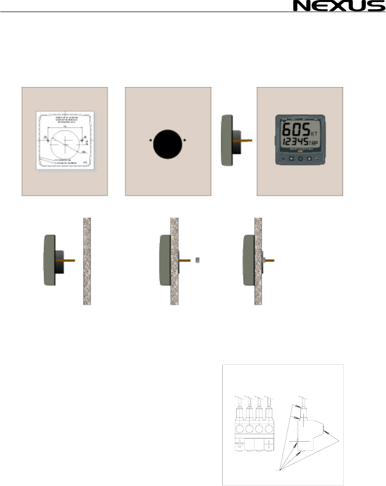
2.1 Installing the instrument
• Place the adhesive drill template on the desired location for the instrument. Drill the
2 holes using a 5 mm (1/4") drill for the two pin bolts. Use a 63 mm (2½") hole saw to
machine the clearance hole for the instrument connection socket. Remove the
template.
• Screw the two pin bolts
• Put the instrument in place
• Screw the two nuts from the back
Note! The two nuts must just be tighten by hand
• Run the Nexus Network cable from the Server
to the instrument.
• If you want to cut the Nexus Network cable to
length, disconnect 4-pole jack plug and cut
the cable. Peel off about 35 mm (1,4") of the
cable insulation. Remove about 6 mm (1/4")
from the 3 isolated wires (the 4th wire is an
earth / screen). Attach the 4 cable protectors
to the wires using a pair of flat pliers.
• Connect the 4 cable protectors to the 4-pole
jack plug as shown. Apply silicon paste on all
locations as
shown.
Note: Must be done to avoid corrosion.
to the instrument
Silicon paste
13
MULTI CONTROL
14
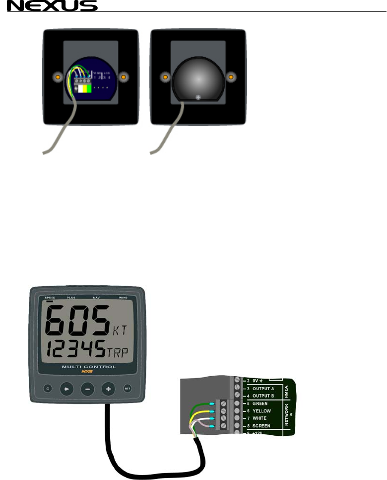
silicon paste to the instrument connection pins at the back of the instrument.
rument pins. Press the cable in to the cable leads.
ith the screw.
g instrument to the Server
directly to the Nexus Network
all use the same colour coded 4-pole jack
• Apply
Press the jack plug onto the inst
• Mount the connection back cover w
2.1.1 Installin
All NX2 instruments are connected
in a daisy chain. They
plugs.
MULTI CONTROL
15
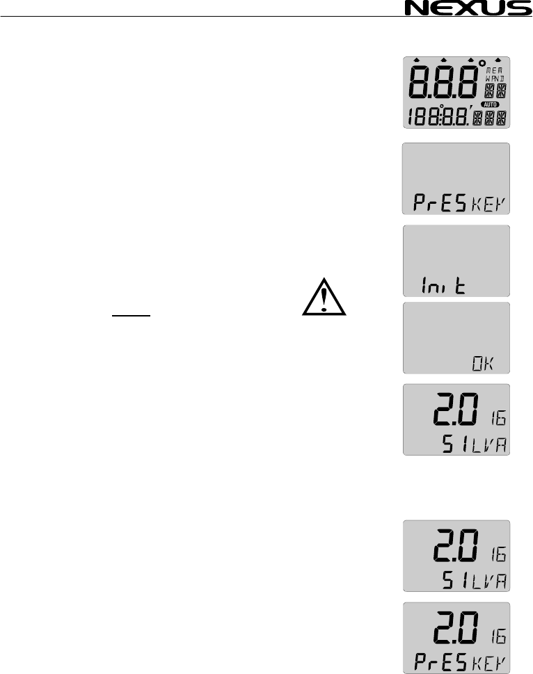
3 First start
3.1 Initialising the instrument
At power on, the instrument will perform a self test. The display
will first show all segme
the Nexus Network ID n
At first power on after in SET
(PrESkey). This will give e instrument a logical ID number on the
Nexus Network.
To initialise the instrume re
instruments, one at the
Note: Always wait for
to be displayed, befor
er in SET
(PrESkey). This will give e instrument a logical ID number on the
Nexus Network.
To initialise the instrume re
instruments, one at the
Note: Always wait for
to be displayed, befor
nts, then the software version number and
umber.
stallation, you will be asked to press stallation, you will be asked to press
th th
nt, p ss SET on all installed digital nt, p ss SET on all installed digital
time. time.
the text ”Init OK”
e
the text ”Init OK”
e you press SET
on the next instrumen
The Server automatical the first unit ID number 16, then
17 and so on. The ord
order as the instrument
Nexus Network.
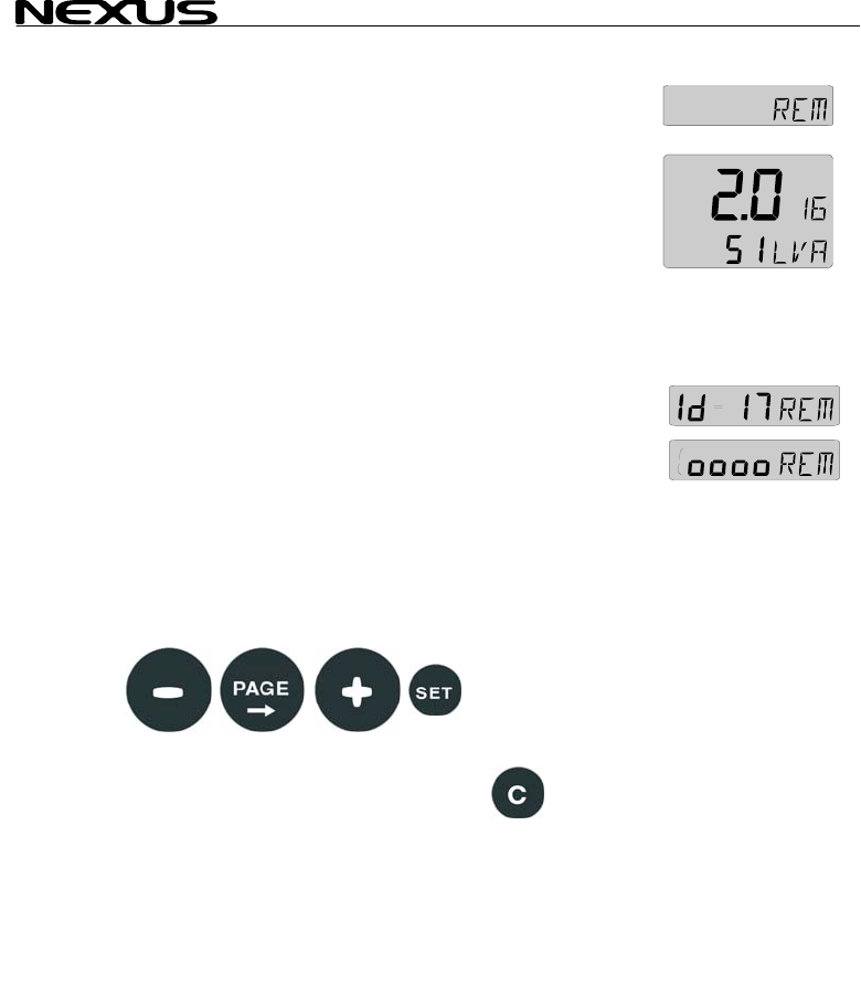
The example shows that the instrument version number is 2.0 and
the given logical ID number is 16.
3.2 Re-initialising the instrument
If two instruments by mistake have the same ID number, this can
cause disturbance and block the information on the Nexus data
bus.
To re-initialise the instrument, press CLEAR during the power up
sequence when version and ID numbers are displayed.
The display self test is then re-started on all instruments and you
will be asked to press KEY on each instrument as explained
above.
Note! If you do not succeed to re-initialise, we suggest you
disconnect all but one instrument with the same ID number, then
repeat the above procedure.
t!
ly gives
er in which you press SET is the same
s will be given a logical ID number on the

MULTI CONTROL
4 Operation
4.1 About this man
• In this manual each ti
push-button name
example PAGE.
• Unless otherwise sta
momentary.
• Each time a function i
brackets and in the same format, w
displayed, ex. (LAt).
• By the word navigator, we mean a GPS, Loran or Decca
instrument.
• Which instrument is navigating? By the term navigating, we
mean the active instrument in which the waypoint memory is
used for navigation to calculate the navigation data, ie BTW,
DTW etc. There can only be one instrument on the Nexus
Network which is keeping the waypoints in memory, but the
waypoints can be reached from all instruments.
• This manual has been written to be:
Compatible with NX2 Server from software version 3.0.
Compatible with NX2 Multi Control instrument from software
version 3.0
The products can be updated to the latest version for a fee.
Please contact your NX2 dealer for further information.
ual
me a push-button is refereed to, the
bold and CAPITAL letters will appear in
ted the push-button presses are
s mentioned in the text, it will be in
here possible, as
16
MULTI CONTROL
17
4.2 How to use the push-buttons
4.2.1 PAGE
A press on PAGE moves the top LCD arrow to the next page. It
scrolls in a circular pattern, one step to the right for every press, in
the order SPEED, DEPTH, NAVIGATE, WIND and then back to
SPEED page again. A press on PAGE and MINUS together, back
steps PAGE to the preceding page.
The PAGE button is also used to move the cursor when in edit
mode.
A press on PAGE moves the cursor in a circular pattern, one step
to the right for every press.
A press on PAGE and MINUS together, back steps cursor to the
preceding step.
4.2.2 MINUS
A press on MINUS moves to the next sub-function.
In edit mode it decreases to the previous digit.
4.2.3 PLUS
A press on PLUS moves to the previous sub-function.
PAGE
SUB
MAIN
CLEAR MINU
SIGN
FUNCTION
FUNCTION
S PLUS SET
PAGE
MULTI CONTROL
18
In edit mode it increases to th
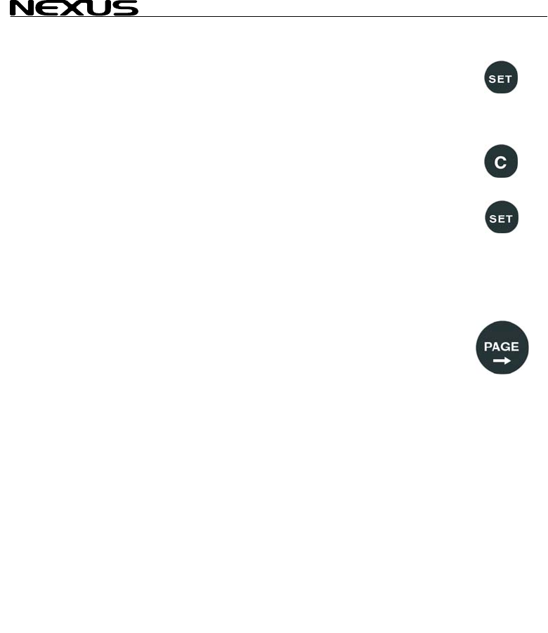
4.2.4 SET
A press on SET unlocks
When unlocked, the digits are ”active” (flashes) and can be edited
by pressing MINUS, PL
When finished editing, l
4.2.5 Clear / cancel / reset
A press on CLEAR, c
counters.
4.2.6 Calibrati
To access calibration m
seconds.
To return to main-function mode, press SET when the text return
(RET) is shown.
4.2.7 Lighting
The instrument uses red back lighting for the display and the 4
push-buttons. The lighting can be set at 4 different levels.
To quick access the light control, press and hold PAGE for more
than 2 seconds. The flashing text (Lit OFF) will be displayed and
the display will be lit momentarily.
To select between the 4 light levels, Press PLUS: LOW, MED,
MAX and OFF. To lock the selected level press SET.
The selected light level will be copied to all NX2 instruments
connected to the system. When the lighting is on, it is not possible
to reduce or turn off the lighting on an individual instrument.
e next digit.
a digit to access edit mode.
US and PAGE as required.
ock the digit by another press on SET.
lear digits, cancel alarms or resets the
on
ode, press and hold SET more than 2 2 sec
2 sec

MULTI CONTROL
5 Function overv
The functions in the M nto 4
pages:
SPEED, DEPTH, NAVIG
WIND.
The selected page is indicated by the LCD arrow at top of the
display.
Each page has 2 types of functions that can be displyed together:
1. Main-function, displayed at the top of the display in 30 high
digits.
2. Sub-function, displayed at the bottom part of the display in 17
mm high digits.
You can easily customise your favourite combination of functions,
(See chapter 11).
The instrument can display metric and imperial units.
For unit selection, (see chapter 12).
For function overview and transducers needed to display each
function, see the inside of the back cover.
In addition, the enclosed laminated quick guide will help you to get
an overview when using the instrument onboard.
iew
ulti Control instrument are divided i
ATE and
19
MULTI CONTROL
20
6 SPEED functio
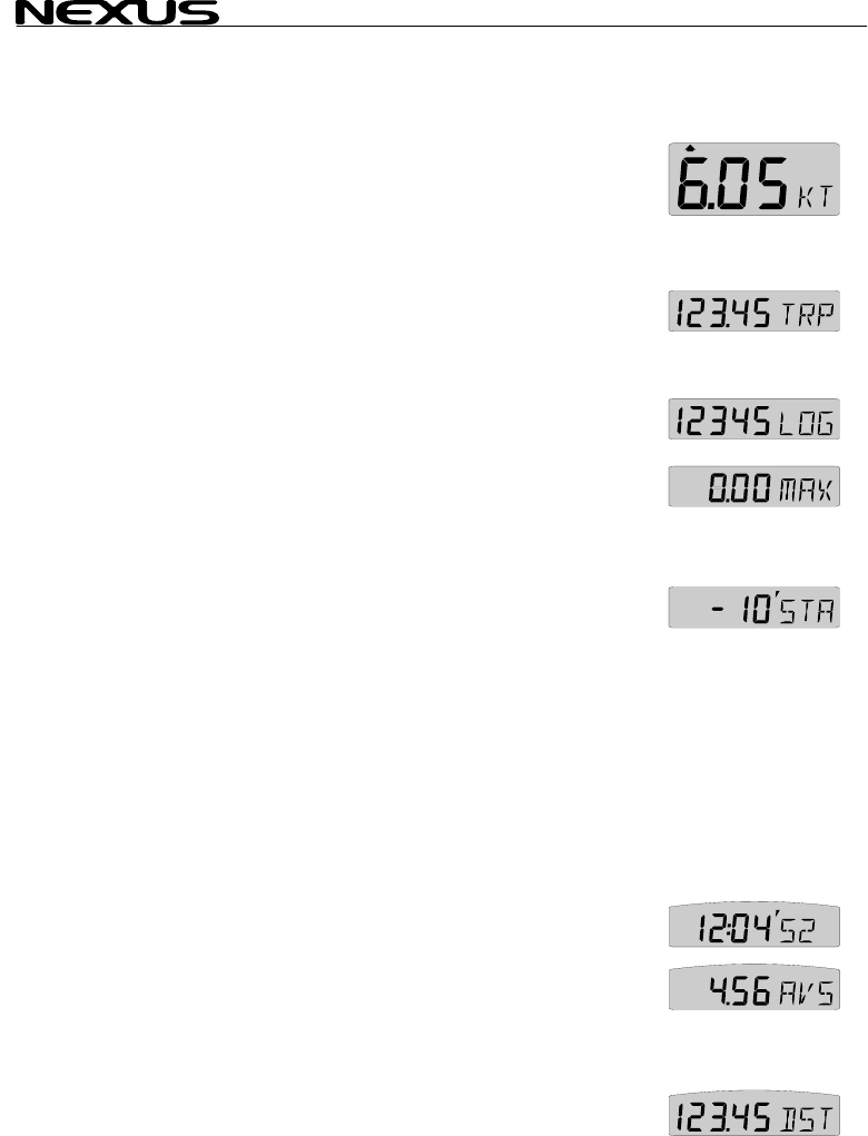
6.1 SPEED main-function
Boat speed through the water
Unit available in knots e
12.1.2, C11). If a nav
(SOG) can be displayed
6.2 SPEED sub
6.2.1 TRIP LOG
0-199,99 NM, only displ
on.
To reset TRIP LOG pre
6.2.2 TOTAL LOG (LOG)
0-19999 NM, only displayed in NM. Can not be reset.
6.2.3 MAXIMU
Maximum speed since
press CLEAR.
6.2.4 START T ER (STA)
Count down timer from 59 to te
To start the timer from m
The figure 1 in 10 is fla t to start count down from
10 minutes, press SET.
If you want to start the timer from any other time (59 to 1 minute)
for example minus 5 minutes (-5’STA), press PAGE, MINUS and
PLUS as required to set 5 minutes and start the timer with SET.
When started, displays the count down time in minutes and
seconds.
During the last 10 seconds the alarm will sound once every
second.
6.2.5 TIMER
Elapsed time in hr/min/sec from power on, or from end of start
timer count down. To reset, press CLEAR.
6.2.6 AVERAGE SPEED (AVS)
Average speed from power on, or from reset of timer. To reset
press CLEAR.
6.2.7 DISTANCE (DST)
Covered distance from power on, or from reset of timer. To reset,
press CLEAR.
ns
.
(KT), km/h (Kh) or miles/h (Mh) (Se
igator is connected, speed over ground
. (See 12.6.11,C95).
-functions
(TRP)
ayed in NM. Distance covered from power
ss CLEAR.
M SPEED (MAX)
power r fr
on, o om reset of timer. To reset,
IM
1 minu s.
inus 10 minutes (-10’STA) press SET.
shing. If you wan

MULTI CONTROL
21
6.2.8 DEPTH (unit/DPT)
Depth from the water surface or the keel depending on calibration
setting (See 12.2.3, C22).
Unit available in meters (m), feet (FT) or fathoms (FA). (See
12.2.2,C21).
The text alternates between the selected (unit) and (DPT).

MULTI CONTROL
7 PLUS function
General information
Alarm on = minute sign
the sub-function.
Alarm off = no minute si
The alarms will be trigge
actual depth becomes le
alarm), or more (depth a
the set depth value.
The alarm is audible (signal) and visual (main and sub-function
flashes).
When a triggered alarm
again if the selected dep
If a different page tha
triggered, the set alar
flashing, until you silence or turn off the alarm. The instrument will
then automatically retur
Loss of signal. If there are no
display indicates 3 dotte
7.1 DEPTH mai
Depth from the water su
setting (See 12.2.3, C22).
Unit available in meters (m), feet (FT) or fathoms (FA).
(See 12.2.2, C21).
7.2 PLUS sub-functions
7.2.1 LIGHT CONTROL
The instrument uses red back lighting for the display and the 5
push-buttons. The lighting can be set at 4 different levels.
To change light level, press SET, The flashing text (Lit OFF) will
be displayed and the display will be lit momentarily.
To select between the 4 light levels, Press PLUS: LOW, MID,
MAX and OFF. To lock the selected level press SET.
The selected light level will be copied to all NX2 instruments
connected to the system. When the lighting is on, it is not possible
to reduce or turn off the lighting on an individual instrument.
s
( ´ ) displayed above the last depth digit in
gn ( ´ ) displayed.
red, if the
ss (shallow
larm), than
has been silenced, it will only be triggered
th value differs by +/-2m (6 ft)
n DEPTH is shown when the alarm is
m function will automatically be shown
n to the previous page.
depth echoes for 3 seconds, the
d lines ( --- ) until a new echo is received.
n-function
rface or the keel depending on calibration
22
MULTI CONTROL
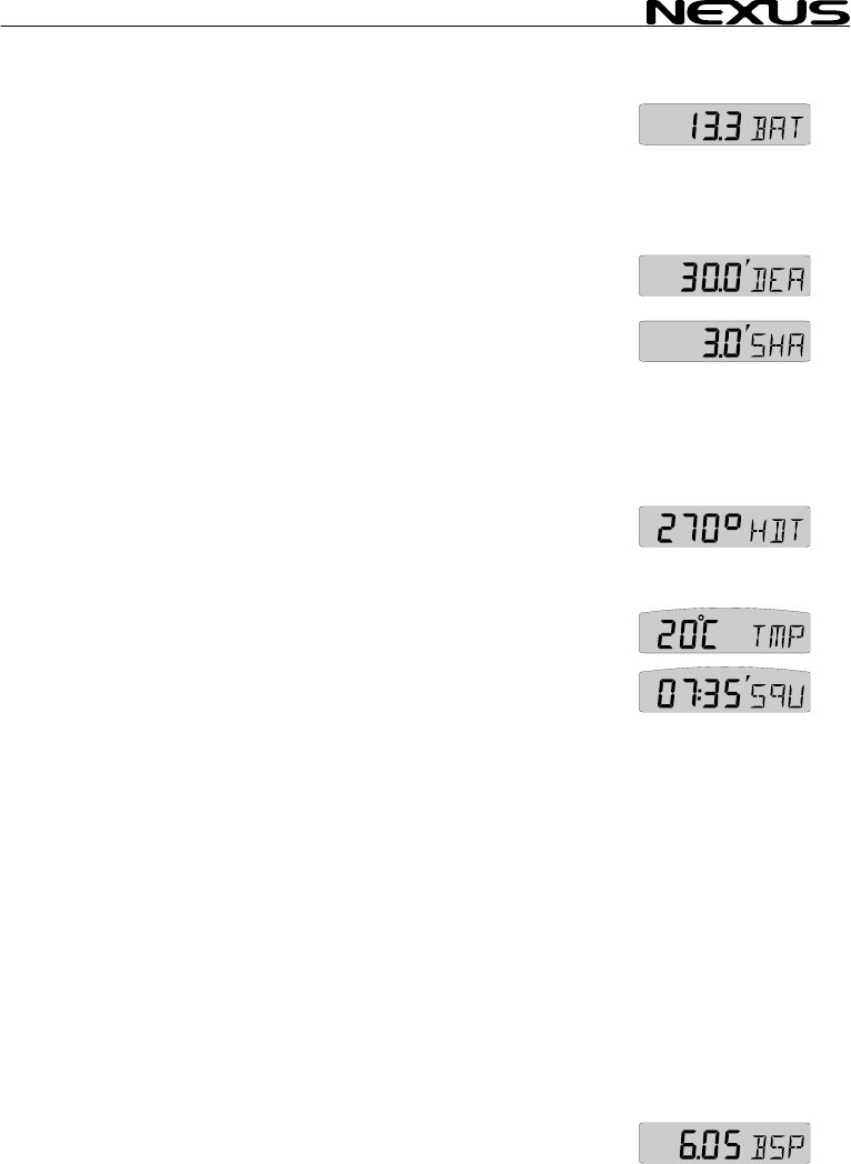
7.2.2 BATTER
Battery voltage at the S
7.2.3 SHALLOW
Depth at which point au
the actual depth becom 4).
7.2.4 DEPTH ALARM (DEA)
Depth at which point a
the actual depth becom
7.2.5 ANCHOR
To set an anchor alarm
minus 1,5 m / 5 FT the
actual value plus 1.5 m
The logic is that when y
the boat is drifting towar
7.2.6 HEADING
Compass heading, head
(See 12.3.11 C40).
7.2.7 TEMPER
Water temperature. Un ( C ) or Fahrenheit
(F). (See 12.2.4, C23 and C24)
7.2.8 UNIVERSA
Time in hr/min/sec. Th
receiver is connected to
after the time.
To set your local time (L) zone from (UTC), press SET and the
first digit flashes.
If you want to add to (UTC), select underlining character ( _ ).
If you want to reduce from (UTC),
select minus sign ( - ) by pressing PLUS.
To set the time zone value press PAGE, MINUS and PLUS as
required.
To store the zone value press SET.
Example: In United Kingdom the local time zone setting should be
( _ 00h ZON) during winter time, and plus one hour ( _01h ZON)
in the summer time.
7.2.9 BOAT SPEED (BSP/unit)
Boat speed through the water. Select the unit from knots (KT), km/h
(Kh) or miles/h (Mh). (See 12.1.2, C11). The text alternates
between (BSP) and the selected (unit).
Y (BAT)
ver.
er
AL
dible and visual alarms will be triggered, if
es less than the set value. (See 7.
ARM (SHA)
udible and visual alarms will be triggered, if
es more than the set value. (See 7.4).
ALARM
, set the shallow (SHA) alarm to actual depth
n set a value for the depth (DEA) alarm to
/ 5 FT.
ou are at anchor, the alarm will warn you if
ds deeper or shallower water.
(HDT/HDM)
ing true (HDT) or heading magnetic (HDM).
ATURE (TMP)
its available in Celsius
L T T
is function will only be displayed if a GPS
the system. The (UTC) is indicated by a (U)
IME (U C)
23
MULTI CONTROL
24
7.3 Remote Co
The NX2 Multi Control
NX2 instruments.
All digital NX2 instrum e
Nexus Network. At pow r up the ID numbers are displayed for a
short time.
The instrument to the right has ID number 16 (version number is
2.0)
Note the ID numbers r the instrument you want to remote
control.
Press SET and the selected ID number is flashing.
Select the ID number for the instrument you want to control with
PLUS and MINUS as required. Press SET to start remote control.
Four push button symbols are displayed to tell you are in remote
mode. The display of the instrument you selected will flash once
and then the PAGE symbol of that instrument will continue to flash
to tell it is remote controlled.
Now you can use the four push buttons:
To exit the remote control page, press CLEAR:
ntrol (REM)
can be used to remote control other digital
ents has their unique ID number on th
e
fo

MULTI CONTROL
7.4 Set and turn on shallow (SHA) and depth
alarm (D
Select shallow (SHA) or
The first digit in the prev
If you want to reset the
To select desired dep as
required.
Press SET to lock the s
By this last press on SE the selected alarm
function, which is indica
depth digit in the sub-fu
7.5 Set and turn o c
Select anchor alarm (AN
The first digit flashes.
The instrument will sug
(actual depth minus 1,5
To store the value press
The minute sign ( ´ ) is s
sub-function.
The instrument will sug
(actual depth plus 1,5 m
To store the value press
The minute sign ( ´ ) is shown above the last depth digit in the
sub-function.
7.6 Clear an alarm value
Select the alarm function to be cleared, press SET.
The first digit flashes.
To clear the alarm, press CLEAR. All digits are set to zero (0).
Press SET to lock the function.
7.7 Silencing an alarm
To silence a triggered alarm that sounds and flashes, press ANY
button.
The sound is silenced and the flashing stops.
The alarm is only triggered again if the selected depth value is
exceeded (shallower or deeper) by 2 m (6 feet).
7.8 Turning off / on an alarm
Select the alarm function to be turned off / on.
To turn the alarm off / on, press CLEAR.
The minute sign ( ´ ) disappears / appears.
EA)
depth (DEA) alarm, pres T. s SE
ious value flashes.
previous value to zero (0), Press CLEAR.
th s
pres MINUS, PLUS and PAGE
elected value.
T, you have turned on
ted by the minute sign ( ´ ) above the last
nction.
n an hor alarm (ANC)
C), press SET.
gest a value for the shallow (SHA) alarm
m / 5 FT).
SET, or select your own depth as in 7.3.
hown above the last depth digit in the
gest a value for the depth (DEA) alarm
/ 5 FT).
SET, or select your own depth as in 7.3.
25
MULTI CONTROL
26
8 NAVIGATION f
8.1 NAVIGATIO
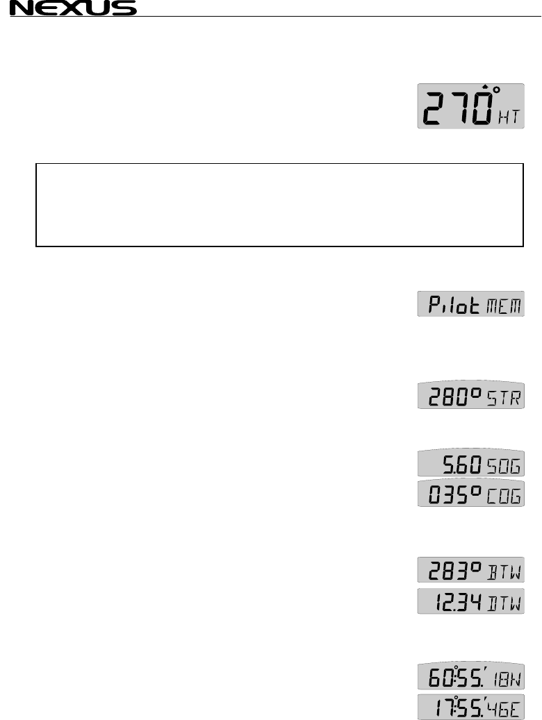
Heading 000° to 359°.
Heading true (HT) or heading e if
the compass transducer is c
If a navigator is conn
selected instead of com (See 12.6.10, C94).
Note! This page can either be on or off. As a factory setting this page
is automatically on
In the set up, you c
See chapter: 12.3.2
8.2 NAVIGATIO
8.2.1 STEER R
Displays the selected s
controls what is show
instrument (Art No 221 e selected
from 5 alternatives. (See 8.3)
8.2.2 STEER VA
Displays steer value for
8.3 and 9.3).
8.2.3 (SOG) an
Speed over ground (SOG) and course over ground (COG).
Alternating function. To stop alternating, press SET. To restart
alternating, press SET again.
8.2.4 (BTW) and (DTW)
Bearing to waypoint (BTW) and distance to waypoint (DTW):For
function explanation, see drawing inside cover page.
To display this function, you must navigate towards a waypoint.
Alternating function. To stop alternating, press SET. To restart
alternating, press SET again.
8.2.5 LATITUDE and LONGITUDE (POS)
Displays position in selected format. Select format from
degrees/minutes and 100:th of a minute (indicated by decimal ( . )
and minute ( ´ ) signs) or from format degrees/minutes/seconds
(indicated by minute ( ´ ) sign only). (See 12.3.9, C38).
Alternating function.
unctions
N main-function
magn tic (HM) can be displayed
nnecte (See 12.3.11 C40)
o d.
ected, course over ground (CG) can be
pass heading.
if a Compass transducer or GPS is connected.
an select this page to be on, off or automatic on.
N sub-functions
EFERENCE (Pilot OFF)
teer reference function. This function also
n on the optional analogue steer pilot
15-02). Steer reference can b
LUE (STR)
the selected steer reference function(See
d (COG)
MULTI CONTROL
27
To stop alternating, pre
again.
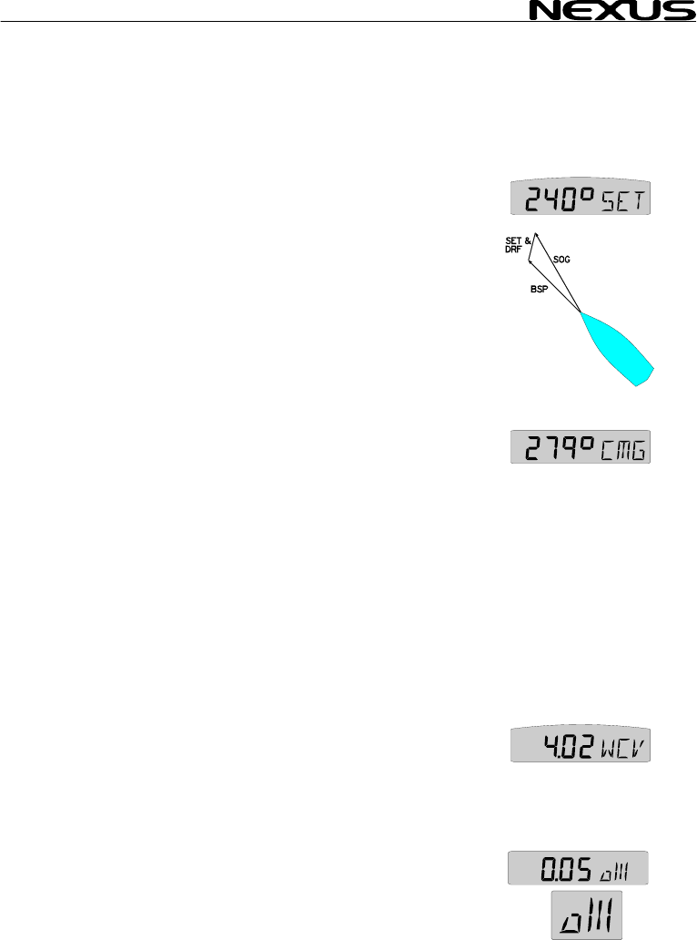
8.2.6 SET and
Direction of current (SE d of current (DRF).
Alternating function. To
To restart alternating, p
8.2.7 (CMG) and (DM
Course made good (CM
The function is based o
The function keeps trac
displays course and distance in a straight line from the start
position.
Locate and mark yo
underway.
To find your new positi
sea chart.
The function starts at pow
To reset (CMG/DMG), press CLEAR.
When the MOB button is pressed it temporarily resets the
CMG/DMG function.
Alternating function. To stop alternating, press SET.
To restart alternating, press SET again.
8.2.8 WAYPOINT CLOSURE VELOCITY (WCV)
Displays the speed over ground towards the waypoint in (KTS),
(Km) or (Mh), (see 12.1.2, C11).
The text alternates between (WCV) and the selected (unit).
8.2.9 CROSS TRACK ERROR (XTE)
Distance in nautical miles (NM) to desired track.
To display this function, you must navigate towards a waypoint.
Your boat is the ”triangle” symbol and the desired track line is
represented by the ”3 vertical lines”. The ”triangle” symbol will tell
you on which side of the desired track you are. You should aim to
ss SET. To restart alternating, press SET
DRIFT
) and spee
T
stop alternating, press SET.
ress SET again.
G)
G) and distance made good (DMG)
n the principle of dead reckoning.
k of the boats way through the water and
ur position and reset CMG/DMG. Get
on, plot the course and distance on your
er on.

MULTI CONTROL
steer your boat so tha , which
means you are on the desired track.
8.3 Steer refere
The sub-function (Pilot) is intended to be used together with the
optional analogue inst 0-2) to
assist the helmsman to
The powerful combin rument
together with the ana 6
functions.
Compass steering: (M
1. Compass steering, using the 1 memory.
2. Headers and lifters, using the 2 memories and trim button. (See
9.3)
Wind steering: (AWA)
3. Close hauled indicato
4. Down wind indicator,
Waypoint steering:
5. Bearing To waypoint
6. Course To Steer (CT
When a steer reference
selected the analogue s
instrument is immediate
It starts to indicate the d
between desired and actual heading
or angle. The logic is to keep the
steer pilot instrument needle straight
up pointing at zero (0) to stay on the
set heading.
From analogue steer pilot instrument version 2.0, (MEM) and
(BTW) is functioning with COG (if navigator connected) even if a
compass is not installed . The analogue read out will start at
speed above 4KTS and stop below 2 KTS.
If you do not have the analogue steer pilot instrument, you can still
use the function, if you display the selected steer reference
heading (STR) in the sub-function and compare it with the actual
compass heading in the main-function.
A NX2 autopilot can not be activated from the steer reference
function. But when the NX2 autopilot has been activated in
compass or wind mode it is possible to alter the autopilots
heading from the (MEM) and (AWA) functions.
t the display readout is 0.00 NM
nce (Pilot)
rument steer pilot (Art. No. 2055
keep the desired heading.
ation of the Multi Control inst
logue steer pilot actually offers you
EM)
r, ex. 35°
ex. 175°
(BTW)
S), including set and drift
has been
teer pilot
ly activated.
ifference
28
MULTI CONTROL
The last used steer ref in mem
and automatically activa lable Server version
2.6)
8.3.1 Overview
Steer reference functio t on
(MEM)=Compass headi
stored in 1 or 2
memories (TAC
(BTW)=Bearing to wayp
(CTS)=Course to steer
waypoint, correc
for drift and curr
(AWA)=Apparent wind a
(OFF)=Steer pilot off
When any steer refere
display will be copied a
in your Nexus Network.
8.3.2 Steer ref
This function requires th
The function is semi
compass heading is copied
value manually.
Select sub-function (Pilot), press SET.
The text (OFF) or the last selected
steer reference function flashes.
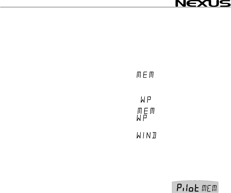
To select steer reference (MEM), press PLUS.
To activate the function, press SET. MEM is shown on the display.
The sub-function (STR) automatically displays the stored (MEM)
value.
The text (MEM) and (STR) is alternating.
If you want to change the steer reference value, press SET.
The first digit flashes.
To set the new value press MINUS, PLUS and PAGE as required.
To store the value, press SET.
Note: Steer reference heading value (MEM) can also be selected
directly from the optional trim button, without first selecting (MEM)
erence function will be stored ory
ted at power on. (Avai
of steer reference (Pilot
n Reference Tex
type display
ng Manual
)
oint Automatic
to Automatic
ted
ent
ngle Manual
nce function is activated, the text on the
nd shown on all Multi Control instruments
erence (MEM)
e NX2 or NMEA compass transducer.
automatic, i.e. when activated, present
to memory. You can later change the
29

MULTI CONTROL
30
in (Pilot OFF) function
1.9.) 8.3.3 Steer reference (BTW)
This function requires the NX2 or NMEA compass transducer and
a NX2 GPS or NMEA navigator.
When selected, the function displays (BTW) and the analogue
steer pilot instrument displays the difference between the
compass heading and the bearing to waypoint (BTW).
The function can only be displayed if the connected navigator is
navigating towards a waypoint.
Since the displayed value it is controlled by the navigator, the
value can not be altered.
Select sub-function (Pilot), press SET.
The text (OFF) or the last selected steer reference function
flashes.
To select steer reference (BTW), press PLUS.
To activate the function, press SET. WP is shown on the display.
The sub-function (STR) automatically displays the stored (BTW)
value.
. (Available from Server software version
MULTI CONTROL
8.3.4 Steer ref
This function requires ass
transducer , NX2 GPS o
When selected the fu
steer pilot instrument displays the difference between the
compass heading and t
and drift.
The function can only be dis if is
navigating towards a wa
Since the displayed va
value can not be altered
The function is comp
parameters compass heading, boat speed through the water,
course and speed ov
waypoint (BTW).
Select sub-function (Pilo
The text (OFF) or th n
flashes.
To select steer referenc
To store the function, pr
The sub-function (STR)
displays the stored (CTS
The text (CTS) and (ST
The function is invalua
distance to a waypoint.
8.3.5 Steer ref
This function requires th ansducer.
The function is semi automatic, i.e. when activated, present wind
angle is copied to memory. You can also change the value
manually.
The function displays the deviation from a set wind angle value
and can be used as a ”close hauled” tack indicator, or show an
enlarged ”picture” of the running angle.
Select sub-function (Pilot), press SET.
The text (OFF) or the last selected steer reference function
flashes.
To select steer reference (AWA), press PLUS.
To store the function, press SET. WIND is shown on the display.
The sub-function (STR) automatically displays the stored (AWA)
value.
The text (AWA) and (STR) is alternating.
If you want to change the steer reference value, press SET.
The first digit flashes.
erence (CTS)
log transducer, NX2 or NMEA comp
r NMEA navigator.
nction displays (CTS) and the analogue
he bearing to waypoint (CTS) including set
played the connected navigator
ypoint.
lue it is controlled by the navigator, the
.
ensated for set and drift, by using the
er ground (COG/SOG) and bearing to
t), press SET.
last selected steer reference functio
e
e (CTS), press PLUS.
ess SET. MEM WP is lit on the display.
automatically
) value.
R) is alternating.
ble when you want to sail the shortest
erence (AWA)
e NX2 or NMEA wind tr
31

MULTI CONTROL
32
The underlining sign ( _
port side.
To select value, press M
To store the value, pres
When the steer referen
the analogue steer pilo
”picture” of the tacking or run angle. Put simply, you ”expand” the
wind angle.
Use the analogue steer pilot as a ”close hauled” instrument.
Example: You have selected 35° starboard side (35° |- STR) as
your tacking angle.
When the needle on t
straight up to zero (0), y ted 35° wind angle.
You can of course als
down wind, to keep a s
warn for a gibe.
Example: You have sele
running angle. When
instrument points to 15° port side you are at 145°. When the
needle is at zero (0) you are at 160°. When the needle points 15°
starboard you are at 175°.
At night, when you can not see the wind shifts, the use of the
(AWA) function together with the analogue steer pilot is a very
helpful.
This is a dynamite function that allows you to ”expand” the
wind angles!!!
When a NX2 Autopilot is activated in wind mode, the (AWA)
function on the Multi Control instrument can be used to perform
an automatic tack.
The minus sign ( - ) in front of the wind angle value = port side.
The underlining sign ( _ ) in front of the wind angle value =
starboard side.
Simply change the value of the digit in front of the wind angle, and
the NX2 Autopilot will gibe to the opposite tack.
) = starboard side. The minus sign ( - ) =
INUS, PLUS and PAGE as required.
s SET.
ce function (AWA) is used together with
t instrument, you can display an enlarged
he analogue steer pilot instrument points
ou steer at the selec
o use the (AWA) function when running
elected value for the run angle and/or to
cted 160° port side (160° -| STR) as your
the needle on the analogue steer pilot
MULTI CONTROL
9 Wind functions
9.1 WIND Main-
Apparent wind angle (AWA), true wind angle (TWA) 000° - 359°,
apparent wind speed (AWS) WS):
Note! This page can either be on or off. As a factory setting this page
is automatically on
In the set up, you c
See chapter: 12.5.2
The main-function WIND
speed, true or apparent
to the right of the wind angle value:
= Wind from port sid
= Wind from starb
The type of wind true or
= Apparent wind .
= True wind.
The selection of apparent (AWA) or true (TWA) wind angle in the
main function also controls what is displayed on the optional
analogue wind instrument (art. no 20550-1).
When the instrument is delivered, the factory setting for the main
function is apparent wind angle (AWA). (See 12.5.3, C51 and
C63).
9.2 WIND Sub-functions
9.2.1 STEER REFERENCE (Pilot OFF)
Displays the selected steer reference function. This function also
controls what is shown on the optional analogue steer pilot
instrument (Art No 22115-02). Steer reference can be selected
from 5 alternatives. (See 8.3)
9.2.2 STEER VALUE (STR)
Displays steer value for the selected steer reference function(See
8.3).
function
or true wind speed (T
if a Compass transducer or GPS is connected.
an select this page to be on, off or automatic on.
, allows you to display wind angle or wind
. The wind angle is indicated by a symbol
e.
oard
apparent, is indicated by a letter:
side.
33
MULTI CONTROL
34
9.2.3 APPARE
Units displayed in m/s (m/s), knots (KTS) or Beaufort (BF), (see
12.5.4, C53). The function
selected (units).
9.2.2 TRUE WIND ANGL
This function requires
function to what is displ
If the main function is set to display apparent wind angle (AWA),
the true wind angle (TWA) will be displayed here.
If the main-function is set to display true wind angle (TWA), the
apparent wind angle (AWA) will be displayed here.
If the main-function is set to display apparent wind speed (AWS),
apparent wind angle (AWA) will be displayed here.
If the main-function is set to display true wind speed (TWS), true
wind angle (TWA) will be displayed here.
9.2.4 TRUE WIND SPEED TWS
This function requires a log transducer. Displayed in m/s (m/s),
knots (KTS) or Beaufort (BF). (See 12.5.4, C53).T
alternates between (TWS) an el
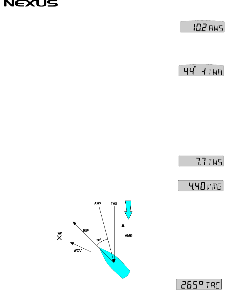
9.2.5 VELOCIT
Displays speed into the
(KTS), (Km) or (Mh), (see 12.1.2, C11). See drawing.
The text alternates between (VMG) and the selected (unit).
function to what is displ
If the main function is set to display apparent wind angle (AWA),
the true wind angle (TWA) will be displayed here.
If the main-function is set to display true wind angle (TWA), the
apparent wind angle (AWA) will be displayed here.
If the main-function is set to display apparent wind speed (AWS),
apparent wind angle (AWA) will be displayed here.
If the main-function is set to display true wind speed (TWS), true
wind angle (TWA) will be displayed here.
9.2.4 TRUE WIND SPEED TWS
This function requires a log transducer. Displayed in m/s (m/s),
knots (KTS) or Beaufort (BF). (See 12.5.4, C53).T
alternates between (TWS) an el
9.2.5 VELOCIT
Displays speed into the
(KTS), (Km) or (Mh), (see 12.1.2, C11). See drawing.
The text alternates between (VMG) and the selected (unit).
NT WIND SPEED (AWS)
alternates between (AWS) and the
E (T
a log transducer. The complimenting
ayed in the main function is displayed.
he complimenting
ayed in the main function is displayed.
WA)
he text
d the s ected (unit) he text
d the s ected (unit)
Y MADE GOOD (VMG)
wind or speed running with the wind in
Y MADE GOOD (VMG)
wind or speed running with the wind in
9.2.6 TACTICAL FUNCTION (TAC)
Displays heading memory, one for starboard and one for port
tack. (For function explanation, see 9.3).
MULTI CONTROL
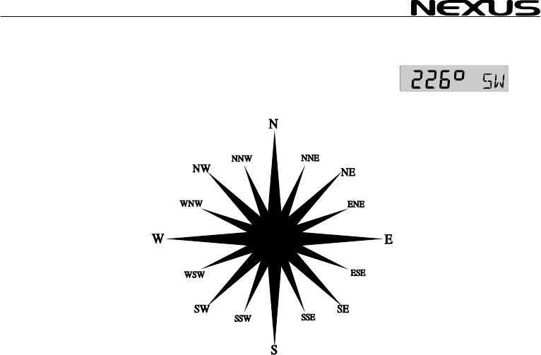
9.2.7 GEOGRA ECTION
This function requires transducer. Displays the
direction in 000° to 359° and the each cardinal point abbreviation
as shown:
000.0° = N
022.5° = NNE
045.0° = NE
067.5° = ENE
090.0° = E
112.5° = ESE
135.0° = SE
157.5° = SSE
180.0° = S
202.5° = SSW
225.0° = SW
247.5° = WSW
270.0° = W
292.5° = WNW
315.0° = NW
337.5° = NNW
If magnetic heading is selected, geographic wind direction will also
be magnetic direction. (See 12.3.4, C33)
PHIC WIND DIR
a compass
35
MULTI CONTROL
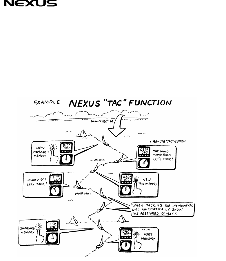
9.3 Tactical function
This function requires a compass transducer and displays course memory. One for
starboard and one for port tack.
To fully use the tactical function it is recommended to install the optional trim button
(Art. No. 19763) and analogue steer pilot instrument (Art. No 22115-02). The trim
button is usually installed close to the steering position. Many prefer to install one trim
button on each side of the boat, that is one for each tack. (For installation of trim
button, see Server manual). Your apparent tack angle is assumed to be constant, in
that your magnetic heading will be changed compared to the wind, that is you will be
changing your heading due to the wind shifts.
The tactical function will give you a fast and exact information about any wind shift
compared to the magnetic heading.
Select sub-function (TAC).
When you have maximum ”lift”, press SET (or the trim button) to
store the value. When the wind ”heads” more than 5-10* it is time
to tack.
Follow the same procedure on the new leg. The reference value
for the selected tack, will be changed every time you press SET
36
MULTI CONTROL
(or the trim button). Wh t
leg will automatically be display
If the optional analogu
sub-function pilot (MEM
The deviation from selected course w
analogue steer pilot inst
If you do not have the o
connected, we suggest
NAVIGATE page. Now
tactical reference (TAC) at the same time.
Remember to turn off
course alarm, set C32 t
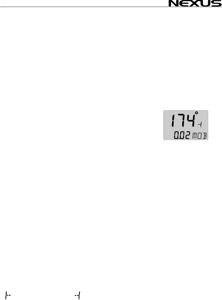
10 Man over boar
This function will guide you back to the position where the man
over board (MOB) butto
This function requires either a navigator (a NX2 GPS or NMEA
navigator can be used
well as a man over boar
If only a compass and
reckoning (MOB) will be displayed on both the Multi Control and
the SPEED Log instrum
useful information, since a person in the water will drift almost as
fast as the boat.
If a navigator, a compass and a log transducer is connected, dead
reckoning (MOB) will be performed and displayed in the SPEED
Log instrument. At the same time the Multi Control instrument will
display (MOB) relative position stored in memory when the (MOB)
button was activated. A position in latitude and longitude is more
important for the sea rescue service.
The (MOB) position is automatically stored in waypoint number
99, and over writes any earlier stored position.
To activate the MOB function, press the (MOB) button.
A fixed alarm signal will sound briefly to alert the crew. The text
(MOB) flashes.
Off course error will be displayed in the main-function.
= steer to starboard. = steer to port.
en you tack, the reference value of the las
ed.
e steer pilot instrument connected, select
as steer reference (See 8.3.2).
), ill be displayed on the
rument.
ptional trim button or analogue steer pilot
you move the sub-function (TAC) to the
you can display both the heading and the
the off course alarm. To turn off the off
o (00 ), (See 12.3.3, C32).
d (MOB) function
n was pressed.
) or a speed and compass transducer as
d (MOB) button. (See Server Manual).
a speed transducer is connected, dead
ents. Dead reckoning (MOB) is also a very
37

MULTI CONTROL
Distance to the MOB po
All you have to do is
indicated direction and d
To reset the (MOB) func
The earlier calculated c r
(DMG) is not affected by th B
If a NX2 GPS and s
connected the analogue instrument will indicate (MOB) course
difference with priority
position.
Note: It is wise to p
Everyone in the crew hould be aware of the (MOB) routine.
When you practice, it ca
a crew member!!!
11 Customise your d
All sub-functions are or
The first location in the . You
can have your favourite sub-function moved in the same sub-
function list, or copied a
11.1 Move and lock a sub-function
Example: In SPEED pa
(DPT) to the top of the s
Select the SPEED pag
Press PAGE and SET together.
All digits flash.
To move and lock the sub-function press SET.
Each time the SPEED page is selected, the sub-function (DPT)
will be displayed at the top of the sub-function list.
11.2 Copy and lock a sub-function
Example: Copy and lock the sub-function true wind speed (TWS)
from WIND page to SPEED page.
Select WIND page and find the sub-function (TWS).
Press PAGE and SET together.
All digits flash.
To move and copy to SPEED page, press PAGE.
To lock the function, press SET.
Each time the SPEED page is selected,
sition will be displayed in the sub-function.
to keep calm and steer the boat in the
istance to pick up your wet crew member.
tion, press CLEAR.
ou se (CMG) and the distance made good
e (MO ) function.
the analogue steer pilot instrument i
to GPS position over dead reckoning
ractice this manoeuvre with the crew.
s
n be thoughtful to use a fender instead of
isplay
ganised in a list under the main-function.
sub-function list is an empty display
nd locked to any other page.
ge, move and lock the sub-functi
b-function list. on depth
u
e and find the sub-function depth (DPT).
38

MULTI CONTROL
the sub-function (TWS)
The copied sub-function remains in its original location. It is only
copied to a second loca
sub-function in the list.
Note: The sub-function should not be moved, to
avoid misunderstanding
11.3 Select powe
The last selected co
according to your selection in 11.
will display at power up.
11.4 Cancel a mo
Example: To cancel the previous moved sub-function true wind
speed (TWS) from SPEED page.
Select the new combination, SPEED page and sub-function
(TWS).
Press PAGE and SET together.
All digits flash.
To cancel the moved sub-function, press CLEAR.
The sub-function is cancelled and the main-function still flashes.
To return the to the original display, press SET.
11.5 Temporary locking of alternating functions
Some functions will alternate automatically between two functions.
Example bearing to waypoint (BTW) and distance to waypoint
(DTW).
To stop alternating, press SET.
To continue alternating, press SET again.
will be displayed.
tion, where it takes the place of the empty
damping (SEA)
.
r on function
mbination of page and sub-functions
1 is the first page the instrument
ved or locked sub-function
39

MULTI CONTROL
12 Calibration
To get the most out of y
carefully calibrate the N
in a non volatile memory
To access calibration mo
seconds.
To select a calibration code, AGE as
required.
To return to normal mode, pr turn (RET)
is displayed.
The different calibratio
C10 - calibration of SPE
C20 - calibration of DEP
C30 - calibration of NAV
C50 - calibration of WIND
C70 - calibration of Netw
To change a calibration
To select calibration va PAG
required.
To lock the selected value, press SET
12.1 Calibration
12.1.1 C10 Retu
To return to normal mod
12.1.2 C11 (Unit KTS)
Unit for speed. Knots (KTS), km/h (K/h) or miles/h (m/h).
12.1.3 C12 (1.25 CAL)
Calibration value for speed and distance (1.00 - 1.99).
Drive the boat a measured distance at normal speed.
Compare the distance with the trip counter.
Calculate the value with the following formula:
True distance from the sea chart : T
Log trip counter distance: L
The current calibration value: C
New calibration value. N
If you suspect a current in the water,
drive the boat in both directions and
divide trip counter distance by 2.
our Nexus Network, it is important to
etwork. The calibration values are stored
.
de, press and hold SET more than 2
press MINUS, PLUS and P
ess SET when the text re
n routines are divided into five groups:
ED
TH
GATE
I
ork and NMEA settings
value, press SET. US and
lue, press MINUS, PL E as
of speed C10
rn (RET)
e, press SET.
40

MULTI CONTROL
12.1.4 C13 DAM
Damping of indicated bo
response time of speed
To change damping, pre
To select damping level
d0 (Min) to d9 (max).
To store the value, pres
Default value is (d0), fo
you may want to ”stabili
(d1) to (d9).
Note! Damping is set se
12.2 C20, calibration of depth
12.2.1 C20 (RET)
To return to normal mod
12.2.2 C21 (Unit m)
Unit for depth. Metre (m
12.2.3 C22 ( - 00
Calibration of the depth
This option is used to s
measured from the water level or the keel.
To measure from the ke
Example: ( - 01.2 ADJ). The distance from the transducer to the
keel is 1.2 m
To measure from the water surface, use the underlining character
( _ ) sign.
Example: ( _ 00.4 ADJ). The distance from the transducer to the
water surface is 0.4 m.
The selected value will be subtracted or added from the measured
depth.
12.2.4 C23 (Unit°C)
Unit for temperature. Celsius (C) or Fahrenheit (F).
12.2.5 C24 (0°C TMP)
Value for compensation of the temperature.
To add, use underlining character ( _ ) ahead of the digit ( _1
TMP).
To subtract, use minus character ( - ) ahead of the digit (-1 TMP).
12.2.6 C25 (Unit hPA)
Future function. Unit for air pressure. Hecto Pascal (hPa) or Inch HG (INH).
PING (SEA)
at speed through the water. Controls the
changes.
ss SET.
press PLUS and select from:
,
s SET.
r use in calm sea. But if the sea is rough,
se” the readout on the display, then select
parately for each instrument.
e, press SET.
), feet (Ft) or fathoms (FA).
.0 ADJ)
transducer position.
elect whether the displayed water depth is
el, use the minus ( - ) sign.
41

MULTI CONTROL
12.3 C30, calibrat
12.3.1 C30 (RET
To return to the normal mode, press SET.
12.3.2 C31 (PAG
This setting allows you to display the Navigate page or not.
PAGE ATO Page automa sducer or
GPS is
PAGE ON Page is alw
PAGE OFF Page is alway
12.3.3 C32 (00°
Off Course Alarm. Can b set
(00°) = Alarm is turned
12.3.4 C33 (00.0 VAR
Magnetic variation. Maxi
Easterly variation = und
Westerly variation = min
The local magnetic varia
12.3.5 C34 (Aut
Automatic compass devi tion
12.3.6 C35 (Aut
Check of automatic com
12.3.7 C36 (Auto CLR)
Clear automatic compass deviation memory, (see 12.4.3).
12.3.8 C37 (000°ADJ)
Compass transducer misalignment correction, (see 12.4.4).
12.3.9 C38 (OFF SEC)
Format of position in latitude and longitude.
(OFF) = Position in degrees, minutes and 100:th of a minute.
Indicated by the sign ( . ) after the minute.
(ON) = Position in degrees, minutes and seconds.
No sign ( . ) after the minute.
12.3.10 C39 (Pilot SEA)
Damping for the optional analogue steer pilot instrument.
LOW = 1.3 sec, MID = 2.8 sec. and MAX = 11 sec.
ion of navigation
)
E ATO)
tically on if Compass tran
connected
ays on
s off
O
e
CA)
between 00°and 99°
off.
)
+/- 99.9°.
mum
erlining ( _ ) sign.
us ( - ) sign.
tion is usually printed in the sea chart.
o
a
DEV)
, (see 12.4.1).
o CHK)
pass deviation, (see 12.4.2).
42

MULTI CONTROL
(Available for analogue
12.3.11 C40 (OFF
(Available from Multi ve
(ON) = All headings and
(OFF) = All headings an be true.
Note a: In the (Goto W ) function, the bearing for every leg will
always be displayed as tru
Note b: The setting is only a
instrument in which is set.
12.3.12 C41 DAM
Damping of compass he
Controls the response ti
To change damping, press SET.
To select damping level
d0 (Min) to d9 (max).
To store the value, pres
Default value is (d0), for use in calm sea. But if the sea is rough,
you may want to ”stabili
(d1) to (d9).
Note! Damping is set se each instrument.
12.4 Compass c
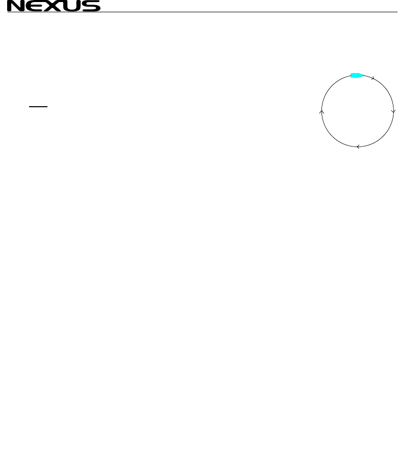
12.4.1 Automatic compass deviation compensation (Auto
DEV)
(Auto DEV) is performed by driving the boat in a circle up to 1¼
turn, so that the magnetic deviation can be measured, and by that
compensated.
Select calibration code C33 (Auto DEV).
Drive the boat in a circle for 1 1/4 turn in calm water. When you
start the circle manoeuvre, press SET.
The un-deviated compass course will be shown in the display as
you turn. Complete the circle up to 1 ¼ turn.
When the manoeuvre is ready, press SET to store the deviation
value.
If the deviation is corrected (Auto DEV) will be displayed.
If the deviation is not corrected, an error message will be
displayed.
To verify the automatic compass deviation, perform an automatic
compass check (Auto CHK), (see 12.4.2).
steer pilot instruments, from version 1.3).
MAG)
rsion 2.0)
bearings will be magnetic.
d bearings will
Pe bearing.
ffects the independent Multi Control
PING (SEA)
ading.
me of heading changes.
, press PLUS and select from:
s SET.
se” the readout on the display, then select
parately for
alibration
43
MULTI CONTROL
44
Note: You will get the b
on the steering whe
performed. When activa
deviation at any time wi
12.4.2 Automati
(Auto CHK) is done by driving the boat in a circ 1 ¼ turn,
after
est result in calm water with a smooth turn
el independently of how the circle is
ted, you can stop the automatic compass
th a press on CLEAR.
c compass deviation check (Auto CHK)
le up to
(Auto DEV) is pe
(Auto DEV). If the devi
from the comparison between
stored.
If the check is OK, (Auto CHK) w
If not an error message
Select automatic comp ET and
repeat the same circle manoeuvre
routine.
Note: As soon as you p
compass, the (Auto D
repeated. So if you have packed your boat for the vacation, think
about where you place ferrous items in relation to the compass
transducer.
12.4.3 Cancel earlier performed compass deviation (Auto
CLR)
To cancel earlier (Auto DEV), press SET.
12.4.4 Compass misalignment correction (Adj)
Compass transducer misalignment correction or the so called ”A-
fault”.
Can be set between 000°and 359°. Allows 180° reversed
mounting if needed. Never mount the transducer in a 90° position
relative to the boats fore-aft line.
To check the transducer position, sail/drive your boat in a straight
line towards two visible objects in a line. If the actual heading
taken from the sea chart is 330° and the compass displays 335°,
then set calibration code C36 value to 360° - 5° = 355°.
rformed. The result will be compared with
tion is less than 1,5*, the average value
a (Auto DEV) and (Auto CHK) will be
ill be displayed.
will be displayed.
ass check (Auto CHK), press S
as described in the (Auto DEV)
lace any kind of ferrous items close to the
EV) / (Auto CHK) routines should be

MULTI CONTROL
12.5 C50, calibra
12.5.1 C50 (RET
To return to the normal mode, press SET.
12.5.2 C51 (PAG
This setting allows you to display the Navigate page or not.
PAGE ATO Page automa nsducer or
GPS is c
PAGE ON Page is
PAGE OFF Page is
12.5.3 C52 (OFF
Select true (TWA)or th
function under WIND. T
display the same selec
have the calibration code C
selected in C51.
C51 (OFF) = Apparent w
C51 (ON) = True wind a
12.5.4 C53 (Uni
Unit for wind speed. Metre/second S) or Beaufort
(BF).
12.5.5 C54 (1.70
Use 1.50 for a single fin wo propeller b
Use 1.70 for a twin fin transducer (with three propeller blades)
12.5.6 C55 (000° ADJ)
Mast top unit misalignment adjust value or the so called ”A-fault”,
makes it possible to choose any horizontal angle.
Example: If the wind angle is +4° when you sail/drive the boat
straight into the wind. Set the calibration channel C54 to 356°.
12.5.7 C56-C63 Wind calibration values
In channels C55 to C62 you set the calibration values for the mast
top unit. Each mast top unit is individually calibrated for best
accuracy.
See the separate wind calibration certificate supplied with each
mast top unit. Each of the inter-cardinal directions are calibrated:
C55 (000° 000)
C56 (045° 045)
C57 (090° 090)
C58 (135° 135) Set the calibration values according
tion of wind
)
E ATO)
tically on if Compass tra
cted
onne
always on
always off
TWA)
e apparent wind angle (AWA) as main-
he optional analogue wind instrument will
tion. All Multi Control instruments which
63 set to (WIA) will display what is
ind angle displayed.
ngle displayed.
t m/s)
(m/s), knots (KT
CAL)
transducer (with t lades)
45

MULTI CONTROL
46
C59 (180° 180)
C60 (225° 225)
C61 (270° 270)
C62 (315° 315)
12.5.8 C64 (WIA
Select from 5 functions.
Select the function to be displayed as main-function under WIND.
The optional analogue
selection.
Select from 5 functions. (WIA) is the factory setting.
If the selected main-fu n will
show the complimenting
function, (TWA) will be s
If the selected main-fun
show the corresponding angle, e.g. if (AWS) is selected, (AWA)
will be shown as the sub-function and vice versa for (TWS) and
(TWA).
(WIA): True (TWA) or a
Depending on what is s
(AWA): Will display app
independent of what is s
(TWA): Will display tr
independent of what is s
(AWS): Will display apparent wind speed (AWS) in this instrument
independent of what is set in C51.
The letters (AW) will be displayed to the right of the wind speed.
(TWS): Will display true wind speed (TWS) in this instrument
independent of what is set in C51.
The letters (TW) will be displayed to the right of the wind speed
value.
12.5.9 C65 DAMPING (SEA)
Damping of True wind Direction. Controls the response time of
wind changes. To change damping, press SET. To select damping
level, press PLUS and select from: d0 (min) to d9 (max). To store
the selected value, press SET.
Factory value is (d0), for use in calm sea. But if the sea is rough,
you may want to ”stabilise” the readout on the display, then select
d0 to d9.
Note! Damping is set separately for each instrument.
to the calibration certificate.
)
(WIA) is the factory setting.
wind instrument will display the same
nction is an angle, the sub-functio
angle, e.g. if (AWA) is selected as main-
hown as sub-function and vice versa.
ction is a wind speed, the sub-function will
pparent wind angle (AWA).
et in C51, (ON = True, OFF = Apparent).
arent wind angle (AWA) in this instrument
et in C51.
ue wind angle (TWA) in this instrument
et in C51.

MULTI CONTROL
12.5.10 C67 WIND SPE
To set a wind speed al
true wind speed is higher than the set level. To switch of the
alarm, set C67 to 00. To silen a .
The alarm level is set from 1 to 50 m/s.
To set the alarm level,
required. To store the s
Note! The Alarm level is
If the set alarm level is ach t ed, the wind speed must drop
below 50% of the set ala
12.6 C70, calibra
When calibration code C70 is selected, the LCD arrow
functions will be display
12.6.1 C70 (RET
To return to the normal mode
12.6.2 C71 (OFF
(On) = Sound when pus
12.6.3 C72 (d0 S
Damping of speed and course over ground (SOG/COG), affecting the complete
Nexus Network and NMEA output.
d0 = no damping. d1 = 2 sec, d2 = 5 sec, d3 = 10 sec, d4 = 20 sec, d5 = 40 sec, d6 =
1.20 min, d7 = 2.40 min, d8 = 5 min and d9 = 10 min.
12.6.4 C73 (OFF BSP)
(OFF) = NX2 log transducer. (On) = NMEA log transducer.
If you want to use a NMEA transducer (connected to the NMEA input, you have to set
C73 to On. The Server will then transmit this information on the Nexus Network to all
connected instruments.
After you have changed this setting, you have to restart the system
12.6.5 C74 (OFF DEP)
(OFF) = NX2 depth transducer. (On) = NMEA depth transducer.
If you want to use a NMEA transducer (connected to the NMEA input, you have to
set C74 to On. The Server will then transmit this information on the Nexus Network
to all connected instruments.
After you have changed this setting, you have to restart the system
ED ALARM (WSA)
arm level. The buzzer will sound when the
ce an al rm, press any key
press SET. To select level, press PAGE, PLUS or MINUS as
elected value, press SET.
always set in m/s regardless of unit used for displaying!
re ed and he alarm Is silenc
vel to be activated again.
rm le
tion of Network and NMEA
s for all
ed
)
, press SET.
KEY)
h buttons are pressed. (OFF) = no sound.
EA)
47

MULTI CONTROL
12.6.6 C75 (OFF
(OFF) = NX2 compass
If you want to use a NM EA input, you have to
set C75 to On. The Server will then transmit this information on the Nexus Network
to all connected instrum
After you have changed
12.6.7 C76 (OFF WND
(OFF) = NX2 wind trans
If you want to use a NM
set C76 to On. The Ser
to all connected instrum
After you have changed
12.6.8 C77 to C92
Contains 16 NMEA slot
12.6.9 C93 (d4 N
Damping for NMEA OU
Only compass heading (HT speed through water
(BSP) can be damped w th th
d0 = 0.5 sec, d2 =1 sec
d6 = 20 sec, d7 = .40 se
12.6.10 C94 (OFF
Select type of heading transducer, compass or navigator (COG),
to be displayed as main-function under NAVIGATE.
When COG is available (NX2 or NMEA), and no compass
transducer is connected, you can set C94 to (ON), COG will also
be used to compute TWD (true wind direction)
12.6.11 C95 (OFF SOG)
Select speed transducer to be displayed as main-function under SPEED.
(OFF) = Boat speed through the water from log transducer.
(ON) = Speed Over Ground (SOG) from navigator. This will not affect wind calculation,
see 12.6.12
12.6.12 C96 (REF BSP)
Select speed transducer (REF BSP) or Speed Over Ground (REF SOG) to be used for
computing true wind speed and angle, VMG, True Wind Direction and trip log, total log
and distance.
(REF BSP) = Boat speed through the water from log transducer.
(REF SOG) = Speed Over Ground (SOG) from navigator.
CMP)
transducer. (On) = NMEA compass transducer.
EA transducer (connected to the NM
ents.
this setting, you have to restart the system
)
ducer. (On) = NMEA wind transducer.
EA transducer (connected to the NMEA input, you have to
ver will then transmit this information on the Nexus Network
ents.
this setting, you have to restart the system
s. (See 12.7.2)
ME)
T from Server.
/HM) and boat
i is code.
, d3 = 2.5 sec, d4 = 5 sec, d5 = 10 sec,
c, d8 = 80 sec and d9 = 160 sec.
COG)
48

MULTI CONTROL
12.7 NMEA
12.7.1 Transmit NMEA ces OUT from Ser
Calibration code C77 to C92 contains 16 NMEA slots
The Server supports 29 different NMEA sentences.
This means you can s o availabl
sentences.
The Nexus Network uses the NM A 01 nces, ve
and 2.0. The number in kets the ca
code for the factory slot number ven to EA sente
0 ( — ) ou
1 (APB) utop
2 (BOD)
3 (BWC)
4 (BWR)
5 (C77) (DBT) th d from th
6 (DPT)
7 (C78) (GLL)
8 (GSA)
9 (C79) (GSV) elli w
10 (C80) (HDM) omp g
11 (C81,89) (HDT) rue h
12 (MTW) Water temperature
13 (C82) (MWD) Wind direction and speed
14 (MWV) Apparent wind speed and angle
15 (RMB) Minimum navigation data
16 (RMC) Minimum specific GPS- and TRANSIT-data
17 (RSA) Rudder Sensor Angle
18 (C83) (RTE) Route Not implemented
19 (C84) (VDR) Set and drift
20 (VHW) Speed and course through the water
21 (C85) (VLW) Distance travelled through the water
22 (C86) (VPW) Speed relative to the wind
23 (C87) (VTG) Course Over Ground and Ground Speed.
24 (C88) (VWT) True wind speed and direction
25 (C90) (WCV) Waypoint closure velocity
26 (WPL) Waypoint location Not implemented
27 (C91) (XTE) Cross track error
28 (C92) (ZDA) Time and date
29 (ZTG) & (UTC) Time to destination or waypoint
30 (VWR) Apparent wind speed and angle
senten ver
elect up to 16 f the 29 e NMEA
E 83 sente rsion 1.5
brac , example (C79), is libration
gi the NM nce.
No t signal
A ilot B
Bearing original destination
Bearing and distance to waypoint
Bearing and distance, dead reckoning
Dep measure e transducer position
Depth
Geographic position
DOP and active satellites
Sat tes in vie
C ass heading, ma netic.
T eading
49

MULTI CONTROL
Example of NMEA sent
$IIAPA,A,A,00.007,L,
$IIAPB,A,A,00.007,L,N,V,V,147.53,T,004,147.52,T,,T*29
$IIBOD,147.53,T,145.
$IIBWC,101515,5912.890,N,01812.580,E,147.52,T,145.02,M,15.649,N,004
$IIBWC,,,,,,147.52,T,145.02,M,15.647,N,004
$IIBWR,101516,5912.890,N,01812.580,E,147.52,T,145.02,M,15.647,N,004
$IIDBT,293.52,f,089.47,M,048.36,F
$IIDPT,089.47,0.40
$IIGLL,5926.110,N,01
$IIHDM,026,M
$IIHDT,029,T
$IIMTW,19,C
$IIMWD,161.77,T,159.
$IIMWV,133,R,07.03,N
$IIRMA,A,5926.110,N,
$IIRMB,A,00.007,L,000,004,5912.890,N,01812.580,E,15.647,147.52,,V*01
$IIRMC,101340,A,5926.115,N,01756.172,E,0.04,063.42,,,*06
$IIVDR,063.42,T,060.92,M,0.04,N
$IIVHW,029,T,026,M,0
$IIVLW,49626.59,N,,
$IIVPW,0.00,N,,
$IIVTG,063.42,T,060.
$IIVWR,133,R,07.03,N
$IIVWT,133,R,07.01,N,03.61,M,,
$IIWCV,0.00,N,004
$IIWPL,5503.000,N,01
$IIXTE,A,A,00.003,L,N
$IIZDA,101341,,,,
$IIZTG,101341,,004
12.7.2 Change N
Before you change any
sentences can be receiv
Select the slot number for the sentence to be changed, then press KEY.
To select the sentence, press DOWN or UP until found.
To lock the selected sentence, press KEY.
One of the advantages with the Nexus Network is the very fast transmission
speed of data compared to the relatively slow NMEA standard (about 10 times
faster). Therefore we recommend that you use Nexus instruments and
transducers for better accuracy.
It takes two seconds to transmit all 16 NMEA sentences.
To double the transmission speed, select a NMEA sentence 2 times with 7 slots
apart, that is the slots should be as far away from each other as possible.
In a similar way, you can select the a sentence 4 times to make it 4 times faster.
Example: If you want to transmit the Nexus compass heading via NMEA, to for
example an autopilot, select (HDM) for every odd slot number, C79, C81, C83 ...
C93, that is 8 times which makes the speed 4 times / second. This leaves the
ences:
N,V,V,145.03,M,004
03,M,004,000
756.171,E,101517,A
27,M,07.01,N,03.61,M
,A
01756.171,E,,,0.23,189.47,,,,*00
0.00,N,00.00,K
93,M,0.04,N,,
,03.62,M,,
013.450,E,027
MEA sentences OUT from Server
of the factory set NMEA sentences, check what NMEA
ed by your NMEA navigator.
50

MULTI CONTROL
other 8 slots with even
NMEA sentences.
For connection of NMEA
12.7.3 Receive
There are 6 different ma
1) Position related da unt of
satellite status if a GPS s
GPS is connected. If a N GPS is co
2) Navigation data: (BT
The Server will automa (DRIFT),
(WCV), (TTG) and (CTS
3) Speed data: is read
4) Depth data: is read o C74 DEP
5) Compass data: is re . Heading
is either (HDT) (priority etwork) is
added to (HDM) but not
6) Wind data: angle an 6 WND)
is set to (ON) See 12.6.7. True wind ed by
Nexus, when the boat speed (the speed
The following NMEA se can be
APA Autopilot sentence ”A”
APB Autopilot sentence ”B”
BOD Bearing
BWC Bearing
BWR Bearing istance to )
DBT Depth measured from the transducer position
DPT Depth
GGA Global positions fix data (GPS)
GLL Geographic position, Latitude/Longitude
GSA DOP and active satellites
GSV Satellites in view
HDM Heading, magnetic
HDT Heading, true
MTW Water temperature
RMB Minimum navigation information
RMC Minimum specific GPS/transit data
WCV Waypoint closure velocity
VDR Set & drift
VHW Water speed and heading
MWV Wind speed and direction
VTG Course Over Ground and Ground Speed
XTE Cross-track-error, measured
ZDA Time & date
numbers, C78, C80, C82 ... C92 free to use for other
instruments OUT from Server, (see Server manual).
NMEA s IN to Server sentence
in types of NMEA sentences:
ta: Position, SOG/COG, time, and a limited amo
is connected. The information is read if no other Nexu
exus nnected, it will take over the navigation.
nd (DRIFT). W), (DTW), (BOD), (XTE), (SET) a
send dattically a to the Nexus Network. E.g.:
). only if (C73 BSP) is set to (ON). See 12.6.4
e 12.6.5
nly if ( ) is set to (ON). Se
ad only if (C75 CMP) is set to (ON) See 12.6.6
xus N) or (HDM). Magnetic variation (from Ne
T).
to (HD
d wind speed is read from (MWV) data, only if (C7
angle and wind speed is calculat
of the water) is known.
ntences received IN to Server:
original destination
istance to
and d waypoint
and d waypoint (old
51

MULTI CONTROL
TBS Target boat speed
CAD Custom angular data
CFD Custom fix data
RSA Rudder Sensor Angle
For connection of NMEA instrument IN to Server, (see Server Manual).
All data (POSITION, BTW, SOG/COG, etc.) is received from one type of NMEA
sentence. If data is placed in different locations, the data will be selected from the
sentence with the highest priority.
Example I: Position is read in priority order: GGA, GLL and. RMC.
Example II: BTW/DTW is priority first with: RMB, BWC and BWR.
The transmission ID (the first two letters after “$”) is ignored by the Server.
Present position is read, after that possible latitude and longitude correction is
added (C39 and C40) before the position is sent over the Nexus Network to all
instruments
52
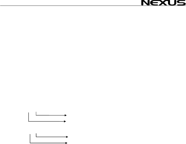
MULTI CONTROL
12.8 Special NM
The Server can read 2 pecial NMEA sentences which can be send from a PC.
One contains TBS (target boat speed), the other CAD (customised angle data )
and CFD (customised retransmitted on the
Nexus Network and ca
instrument.
To get the sub-function TBS, ” sub-
function.Then press PAGE an EAR.
To get the sub-function
sub-function.Then press
To get the sub-function C the ”empty” sub-
function.Then press PAGE
Example of special NME
$PSILTBS,
$PSILCD1,X
CAD
12.8.1 Baudrate
It is possible to change the baudrate from 4800bps to 19200bps.
To do that, a PC is required. Note 19200 is not to be considered
as NMEA since the standard states 4800. See 12.8.1
a. The Requesting unit is allowed to transmit the message:
"$PSILBPS,19200,R,<CR><LF>"
once every 2s at nominal 4800 bps with normal NMEA start bit and stop bit settings.
This message may be received on any of the two Server ports.
b. The receiving unit (NX2 Server) will Confirm message:
"$PSILBPS,19200,C,<CR><LF>"
and send it back on output ports to the requesting unit.
c. When the requesting unit receives the same message but with the flag set to "C"
(Confirmed), both server ports (A and B) are set to 19200bps and transmission may
start at the new baudrate. The sending unit may now stop sending the proprietary
request message since it has entered the higher baudrate. There is no way back
unless there is a power loss.
From power up, baudrate is always set to 4800 and the above procedure must be
repeated.
The receiving unit (Nexus Server) will always check for the proprietary message when
in normal baudrate, not when in high baudrate.
EA sentences
s
fixpoint data ). These 3 data are
n be displayed as a sub-function on the Multi Control
select main function SPEED and the ”empty
d SET together followed by CL
CAD, select main function NAVIGATE and the ”empty”
PAGE and SET together followed by CLEAR.
FD, select main function WIND and
and SET together followed by CLEAR.
A-sentence:
>
X.X,N<CR><LF
Knots
Target boat speed
LF>
(000.0°-360.0°)
.X,X.X,<CR><
CFD (-327.67- +327.67 units)
control,
53

MULTI CONTROL
13 Maintenance a
13.1 Maintenance
• To clean the instrum n rinse
with water.
• Do not use detergen
• At least once a ye , s and apply
additional silicon paste at each connection point.
• Always use the instrume on, when not in
use.
• Storing transducers
longer periods: It is advisable to
transducers, and st
room temperature, if o
13.2 Fault finding
Before you contact your
give you a better servi
make a list of:
• All connected instr e
software version num e
• Server software version number.
• Nexus Network data bus ID numbers for each instrument
(displayed at power up).
13.2.1 General
In most cases, the reason for faults in electronic equipment is the
installation or poor connections. Therefore, always first check that:
• Installation and connection is made per instructions for
instrument and transducers, (see Server manual).
• Screw terminals are carefully tightened.
• No corrosion on any connection points.
• No loose ends in the wires causing short cuts to adjacent
wires.
• Cables for damage, that no cables are squeezed or worn.
• Battery voltage is sufficient, should be at least 10V DC.
• The fuse is not blown and the circuit-breaker has not opened.
• The fuse is of the right type.
• Two instruments do not have the same ID number, (see 3.2).
nd fault finding
e and t, use only mild soap solution
ts or high pressure washing equipment.
check all your connection
ar
nt cover for protecti
and instruments when not in use for
remove the instruments and
ore them inside the boat or at home in
ssible.
p
NX2 dealer, and to assist your dealer to
ce, please check the following points and
um nt and transducers , including their
b rs.
54

MULTI CONTROL
13.2.2 Fault - actio
1. Speed and distance
- C95 (COG) should be cted.
For more information, s
Irregular values: Chec
2. Compass: No readin ( --
− C75 should be OFF, if no .
− Make sure the (Auto DEV) rout
− Make sure the trans
− The transducer cable should face dow
− Make sure transduc corr
For more information, s NX
Irregular values: Chec s d
Make sure there are no
3. Wind: No reading (
− C76 should be OFF ind is connected.
For more information, s
13.2.3 Error messages
The following error messages can appear on the display:
ERROR 2 Nexus Network is missing, check colour coded connections
ERROR 3 No data received within a given time.
ERROR 10 Range error caused by bad format e.g. 17° 70' East.
ERROR 11 Remote command that can not be performed.
ERROR 12 No response from, or missing navigator.
ERROR 13 Waypoint not defined.
ERROR 15 Functions not allowed in autopilot mode.
ERROR 16 Automatic deviation not possible due to NMEA compass selected.
ERROR 17 Automatic deviation check failed. Turn not completed,
error larger than 1,5°.
ERROR 19 The boat probably hit a wave during turn. Error larger than 1,5°.
If other error messages than the above appears on the Multi Control instrument,
contact your NX2 dealer.
n
unctions: No reading ( --- ) f
OFF, if no navigator is conne
ee manual for NX2 Server.
k the speed damping (SEA), (see 12.1.4).
g - )
NMEA compass is connected
ine is done correctly, (see 12.4.1)
ducer is not mounted upside down.
n.
er is aligned ectly, (see 12.4.4).
ee manual for 2 Server.
k the compas amping (SEA), (see 12.3.12).
ferrous items close to the transducer.
--- )
, if no NMEA w
ee manual for NX2 Server.
55

MULTI CONTROL
56
14 Specifications
14.1 Technical s
Dimensions: 3 x23 mm
(4.3x4.3 inch).
Instrument cable:
Power supply:
Power
consumption at 12V:
Temperature range: 80°C (-22°to +176°F)
Weight:
Enclosure:
CE approval
The products conforms
emission according to E
14.2 Nexus Netw
Introduction:
The Nexus data bus is a multi talker multi receiver data bus
specially designed for marine navigation applications. It utilises
the RS485 standard with up to 32 senders and/or receivers to
form a Local Area Network. Data is transmitted synchronously
with 1 start-bit, 8-data-bits, 1 parity-bit, two stop-bits in 9600 baud.
User policy:
The Nexus data bus is open for new users and applications
without a licence or a licence fee. The data bus is, however, the
property of the manufacturer, which means the specification must
be followed in order to protect the manufacturer’s commitments to
the Nexus data bus performance and safety.
For most PC-applications, the full duplex interface (Art. No.
21248), will be a very useful tool for monitoring real time data, to
edit and store waypoints to PC-file or to Server and/or to the NX2
GPS. The interface is supplied with a cable for connection from
PC to the Server or NX2 instruments and/or the NX2 GPS. A 9-
pole D-sub connector is connected to the RS232 port on the PC.
pecifications
Multi Control instrument: 113 x 11
Server: 110 x 165 x 30 mm. (4.3x6.5x1.2 inch)
8 m (26 ft).
12V DC (10-16V). The instruments are polarity protected
Multi Control instrument: 0,08W
with maximum lighting 0,8W.
Server: 0,2W.
Storage:-30°to +
Operation: -10° to +70°C(14°to +158°F)
Multi Control instrument: 260 gram (9.17 oz).
Server: 220 gram. (7.76 oz).
Multi Control Instrument: Water proof
Server: Splash proof
to the EMC requirements for immunity and
N 50 08-1.
ork introduction and user policy

MULTI CONTROL
14.3 Optional Accessories
Below find a selection o al access
dealer for more informa
NX2 C
22118-3 Multi C trument an
22118-2 Multi Control and Server w ransducer, 8m cable
22118-1 Speed g transdu
22118-4 Wind D
22118-5 Compass Data, with transd
22118-6 GPS N
NX2/N
22120-1 Server 3m pow
20707 Log/Temp transducer, 8 m cable (for Nexus and Star)
19915-8 Depth 8m cabl
21731 Compa er 35°, 8
20860 Compa er 45°, 8
20721 Wind t 5m cabl
20721-1 CF-win r, Carbo no mast cable incl.
20594 Nexus mast cable 25m
21721 MTC ( nd Data instr.
69980 MRC (Mast Rotation Sens
21970 GPS A h NMEA
21735 Bracket for GPS Antenna and 35° Compass transducer for bulkhead mount
NX2 D
22117-1 Speed log instrument
22117-3 Multi Control instrument
22117-4 Wind Data instrument
22117-5 Compass Data instrument
22117-6 GPS Navigator instrument
22117-7 Autopilot instrument
NX2 Analog Instruments (all supplied with 0.2m cable)
22115-01 NX2 Analog Wind Angle
22115-02 NX2 Analog Steer Pilot
22115-03 NX2 Analog Speed Trim
22115-05 NX2 Analog Speed 0-16kts
22115-06 NX2 Analog Speed 0-50kts
22115-07 NX2 Analog Depth 0-200m
22115-08 NX2 Analog Depth 0-600ft
22115-09 NX2 Analog Rudder angle
22115-10 NX2 Analog Compass
22115-11 NX2 Analog GPS Speed 0-16kts
22115-12 NX2 Analog GPS Speed 0-50kts
22115-13 NX2 Analog GPS Course
Nexus Remote Control Instrument
21210 Remote Control Instrument (RCI), with Autopilot control, 5m cable, bracket
21218-1 Bracket Remote Control instrument
20966 Connector 4-pole, NEW model (Allows cable - cable connection)
f option ories available. Please contact your local NX2
tion.
o
o d Server, 8m cable
mpletes
ntrol ins ith Speed Log and depth t
log with lo cer, 8m cable
ata, with transducer, 25m cable, mast bracket
ucer 35°, 8 m cable
avigator, with GPS Antenna, 8+10m cable
exus Transducers
compl with er cables
transducer, e (for NX2 only)
ss transduc m cable
ss transduc m cable
ransducer, 2 e, mast bracket g,
d transduce n Fibre, 1260mm long, 380
Mast Twist Compensation) box, 8m cable, for Wi
or Compensation) box
ntenna, wit 0183 output
ig all supplied with 0.2m cable) ital Instruments (
57

MULTI CONTROL
58
Nexus
21680-1 Multi XL instrument, 4m cable (RCI or Multi Center needed to control Multi XL)
21684-1 Multi XL Set, Multi XL instrument and Remote Control instrument
69995 Mast b n alumin 110mm instr.
NX2 G
22118-6 GPS N th GPS
22117-6 GPS N
21970 GPS A
20992-2 Bracket GPS Antenna, plastic with female thread 1" x 14 tpi
21735 Bracket for GPS Antenna and 35° Compass transducer for bulkhead mount
Nexus Autopilot components
22117-7 Autopilot instrument
21210 Remote Control instrument, with Autopilot control, 5m cable, bracket
22115-09 NX2 Analog Rudder angle
21035-2 Servo Unit A-1510, 8m cable
20860 Compass transducer 45°, 8m cable
21731 Compass transducer 35°, 8m cable
21036 Rudder Angle Transmitter RFU-25, 15m cable, ball joint linkage 230mm x 2
69981 Linear Rudder Angle Transmitter
21134 Pumpset PF-0.3 12V
21134-24 Pumpset PF-0.3 24V
21341 Pumpset PF-0.3S 12V, with solenoid
21341-24 Pumpset PF-0.3S 24V, with solenoid
21136 Linear Drive AN-23, stroke 229mm, peak thrust 680kg
69991-12 Integrated Linear Drive HP-40, stroke 254mm, peak thrust 500kg
Multi XL
racket X ium for Multi XL and Nexus / Star 110xL, i
PS
avigator, wi Antenna, 8+10m cable
avigator instrument
ntenna, with NMEA 0183 output

MULTI CONTROL
14.4 Abbreviatio
Abbreviation. Descri
ns
ption
A
ADJ
ANC ANChor
ANC
Arrival Arrival
ARC Arrival Circle
AVS
AWA
AWS
BAT
BF
BOD Bearing Original Des
BSP
BTW
C Celsius
CE
C10 Calibrate 10
CAL
CG
CHK CHecK
CLR
CMG
CMP CoMPass
COG
CTS
CU Central Unit
d differential
D/R Dead Reckoning
DEFAULT Factory setting
DEV DEViation
DMG Distance Made Good
DEA DEpth Alarm
DPT DePTh
DRF DRiFt, Speed of current
DST DiSTance
DTW Distance To Waypoint
E East
EDIT EDIT
EMC Electro Magnetic Compatibility
EN European Norm
F Fahrenheit
F1-F9 Figure of merit
FA Fathoms
FT FeeT
Angle
ADJust
ANChor alarm
AVerage Speed
Apparent Wind Angle
Apparent Wind Speed
BATtery
BeauFort
tination
Boat Speed
Bearing To Waypoint
Communaute Europèenne
Calibrate
Course over Ground
CLeaR
Course Made Good
Course Over Ground
Course To Steer
59

MULTI CONTROL
60
GLL
Geographic Latitude Lo
GoTo
GPS Global Positioning Netw
HDM
HDT HeaDing True
HM
HT
id Identity
Init
Insert
Km
KT
KTS KnoTS
L
LAT LATitude
LCD
LGD
LOG
LON
LOW
MAX
m/s
MEM MEMory
Mh
MID MID
MN
MOB Man Over Board
m metre
N North
NAV NAVigate
NM Nautical Mile
NMEA National Marine Electronic Association
NXT NeXT
OCA Off Course Alarm
RET RETurn
Roll Roll
S South
S/A Selective Availability
SAT SATellite
SEA SEA
SEC SEConds
SET SET, Direction of current
SHA SHallow Alarm
SOG Speed Over Ground
STA STArt
ngitude Go To
ork
HeaDing Magnetic
Heading Magnetic
Heading True
Initiation
Insert
Kilometre per hour
KnoTs
Local
Liquid Crystal Display
Local Geodetic Datum
LOG
LONgitude
LOW
MAX
metres per second
Miles per hour
Magnetic North

MULTI CONTROL
STR STeeR
SW South West
TAC TACtical
TMP TeMPerature
TRP TRiP
TTG Time To Go
TWA True Wind Angle
TWS True Wind Speed
UTC Universal Time Co-ordinate
VAR VARiation
VMG Velocity Made Good
W West
WCV Waypoint Closure Velocity
WP Waypoint
XTE Cross Track Error
- Minus
_ Plus
Wind from port side
Wind from starboard side
The boat is left of the desired track
The boat is right of the desired track
61

MULTI CONTROL
62
15 Warranty
GENERAL
All our products are designed and b
products are correctly installed, ai
operation manual, they will pr
distributors can provide you with the i
in the world.
Please read through and fill in s
product registration.
LIMITED WARRANTY
The warranty covers repair of def
repaired in the country of purch d is stated in the product manual, and
commences from the date of purchase. The above warranty is the Manufacturer’s only warranty
and no other terms, expressed
implied warranty of merchantabili
CONDITIONS
• The supplied warranty card and receipt with proof of purchase date, must be shown to validate
any warranty claim. Claims are to be made in accordance with the claims procedure outlined
below.
• The warranty is non-transfer
• The warranty does not app
faulty installation or incorrect fusing, to conditions resulting from improper use, external
causes, including service or modifications not performed by the Manufacturer or by its national
distributors, or operation outside the environmental parameters specified for the Product.
• The Manufacturer will not compensate for consequential damage caused directly or indirectly
by the malfunction of its equipment. The Manufacturer is not liable for any personal damage
caused as a consequence of using its equipment.
• The Manufacturer, its national distributors or dealers are not liable for charges arising from
sea trials, installation surveys or visits to the boat to attend to the equipment, whether under
warranty or not. The right is reserved to charge for such services at an appropriate rate.
• The Manufacturer reserves the right to replace any products returned for repair, within the
warranty period, with the nearest equivalent, if repair within a reasonable time period should
not be possible.
• The terms and conditions of the warranty as described do not affect your statutory rights.
CLAIMS PROCEDURE
Equipment should be returned to the national distributor, or one of its appointed dealers, in the
country where it was originally purchased. Valid claims will then be serviced and returned to the
sender free of charge.
Alternatively, if the equipment is being used away from the country of purchase, it may be returned
to the national distributor, or one of its appointed dealers, in the country where it is being used. In
this case valid claims will cover parts only. Labour and return postage will be invoiced to the sender
at an appropriate rate.
DISCLAIMER
Common sense must be used at all times when navigating and the Manufacturer’s navigation
equipment should only be considered as aids to navigation.
The Manufacturers policy of continuous improvement may result in changes to product
specification without prior notice.
WARRANTY
uilt to comply to the highest class industry standards. If the
ntained and operated, as described in the installation and
m
ovide long and reliable service. Our international Network of
nformation and assistance you may require virtually anywhere
thi warranty card and send it to your national distributor for
ective parts due to faulty Manufacturing and includes labour when
ase. The warranty perio
or implied, will apply. The Manufacturer specifically excludes the
ty and fitness for a particular purpose.
rable and extends only to the original purchaser.
ly to Products from which serial numbers have been removed,
MULTI CONTROL
63
TO BE RETURNED TO Y
OWNER:
Name:
Street :
City/Zip Code :
Country:
Product name:
Date of purchase: _______________ Date installed ________________
Dealers stamp:
Tick here if you do not wish to receive news about future products
File id:
WARRANTY CARD
OUR NATIONAL DISTRIBUTOR
Serial number:
A B C 1 2 3 4 5 6 7
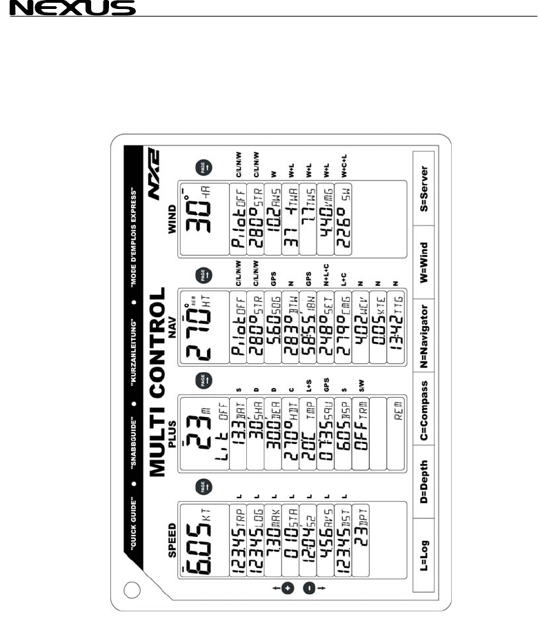
MULTI CONTROL
64

MULTI CONTROL
65

MULTI CONTROL
66

MULTI CONTROL
67
Copyright ©:
Nexus Marine AB
Kuskvägen 4, 191 62 Sollentuna, Sweden
Tel: +46 -(0) 8 – 506 939 00. Fax: +46 -(0) 8 -506 939 01
www.nexusmarine.se
22133-1 Edition 1
