NexusData WMIN01 Water Meter Transmitter User Manual 354312

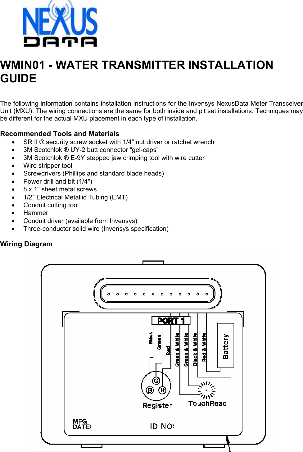
NexusData Ltd. Water Meter Transmitter 354312

Manual

 WMIN01 - WATER TRANSMITTER INSTALLATION GUIDE   The following information contains installation instructions for the Invensys NexusData Meter Transceiver Unit (MXU). The wiring connections are the same for both inside and pit set installations. Techniques may be different for the actual MXU placement in each type of installation.  Recommended Tools and Materials •  SR II ® security screw socket with 1/4" nut driver or ratchet wrench •  3M Scotchlok ® UY-2 butt connector “gel-caps” •  3M Scotchlok ® E-9Y stepped jaw crimping tool with wire cutter •  Wire stripper tool •  Screwdrivers (Phillips and standard blade heads) •  Power drill and bit (1/4") •  8 x 1" sheet metal screws •  1/2" Electrical Metallic Tubing (EMT) •  Conduit cutting tool • Hammer •  Conduit driver (available from Invensys) • Three-conductor solid wire (Invensys specification)  Wiring Diagram
   WIRING INSTRUCTIONS The MXU wiring instructions assume the utility meter with an encoder register has been installed and the proper wire has been run to the MXU installation location. Three-conductor, 22 gauge, solid conductor cable is recommended. (For meter installation, refer to the installation information included in Invensys meter shipping cartons.)  1.  Using the SR II security socket with ratchet wrench or nut driver, open the MXU enclosure by removing SR II type security screw. Bottom part of enclosure will contain the MXU battery and top part the electronics and connection wires. Connect the three wires from the encoder register to the matching color wires on the MXU. If not already done, strip approximately 2" off outer jacket of the encoder wire cable. The wire colors for each unit should be green, red, and black. Insert two matching color wire ends – red to red, green to green, and black to black into a UY-2 gel-cap with the color button of gel-cap facing away. (This provides a better view of wire positions inside the clear plastic gel-cap enabling the installer to see the wires are completely and properly inserted.) Using gel-cap pliers, squeeze the gel-cap. This will splice the two wires and release the waterproof gel to seal the connection. The splice can be checked by pulling gently on the gel-cap while holding the wires to be sure they are tight and secure. Repeat for the remaining two wire connections. If any of the wire connections are not being used they should be capped at the end with a gel-cap. This is to prevent water intrusion via wicking through the exposed wire ends. 2.  Connect the battery to the MXU electronics. Using the gel-cap connecting technique described above, connect the red and white stripe wire from the battery to the red and white stripe wire from the MXU electronics. Repeat the procedure for the black and white stripe wire from the battery to the black and white stripe wire from the MXU. Caution: DO NOT cross connect the black and white and the red and white wires of the MXU and battery pack as this may cause damage to the MXU electronics. 3.  (Optional) TouchRead ® Connection – The MXU includes a built-in TouchRead splitter connection to allow the encoder register to be interrogated by both the MXU and a remote TouchRead System sensor. Wall Mount TouchPad – Using two-conductor or three-conductor wire cable and gel-caps, connect wires to each of the green and white stripe wires from the MXU. Note: If three-conductor wire cable is used, the third wire is not utilized for the TouchRead Connection. At the TouchPad connection, connect the same two wires to the terminal screws on the back of the TouchPad. Caution: Be sure there is no bare wire-to-wire contact. (The TouchRead connection is non-polarity sensitive and will work as long as the same color wires are used at both ends of the connection. If three-conductor wire is used, be sure the third “dead” wire is not mistakenly connected at either end.) Pit-set Mount Sensor – The TouchRead pit-set sensor includes a factory-sealed three-conductor wire cable. Proper wire connections are therefore important. To activate the pit-set TouchRead sensor, use only the red and black wires from the sensor. Approximately 2" of the cable’s outer jacket must be stripped from its end to access these wires. Then, using gel-caps, connect the black wire from the sensor to one of the green and white stripe wires from the MXU. Next, connect the red wire from the sensor to the other green and white stripe wire from the MXU. 4.  Verify MXU operation prior to final assembly - To verify MXU reading, use a NexusData Handheld Terminal (HHT) to interrogate the register and compare to the register odometer reading, register ID number, and MXU ID number. To verify TouchRead reading, use a TouchRead visual reader to display register odometer reading(s) and register ID number(s). If MXU does not function, check all wire connections, redo the connections or change battery pack. (For complete TouchRead installation and troubleshooting, see Invensys installation bulletins: TR-728, TR-997, and TR-998.) 5.  After wiring connections are completed and MXU operation is verified, align guides of top and bottom parts of MXU and close, bringing the connection wires out the front side, using the wire pass-thru guides located on either side of the security screw. Secure the top and bottom parts of the MXU using the security screw. Caution: DO NOT over-tighten security screw.
  MOUNTING INSTRUCTIONS Wall Mounting: (Indoors and Outdoors) 1.  Using MXU mounting bracket, find a convenient location for the MXU mounting. The MXU should be mounted in a vertical position so the top part with the Invensys logo is facing the front. The MXU mounting bracket can be mounted to a wall using screws or fastened to an object using heavy duty wire ties. Grooves have been placed in the back of the bracket for mounting on either horizontal or vertical (existing) pipes. 2.  After mounting the MXU bracket, snap the MXU (which should already be wired as noted in the preceding wiring instructions) into the bracket. Be sure the locating tabs on either side of the MXU have snapped into position in the mounting bracket.The installation is now complete. 3.  TouchPad Mounting (Optional) – If mounting the MXU outdoors and a TouchRead TouchPad connection is to be included, mounting holes can be drilled in the side of the MXU bracket. Using short screws or plastic rivets, mount the TouchPad to the side of the MXU bracket. Caution: When using screws, be sure they do not penetrate the MXU enclosure when mounting the TouchPad. The TouchPad can also be mounted in a location away from the MXU. Be sure to use screws that are designed for and applicable to the mounting surface.  Pit Set Mounting: 1.  Use 1/2” EMT. Select a location for the conduit where the MXU’s installed position will not interfere with the meter and allow the MXU to be located as high as possible inside the meter box. The MXU should be kept approximately 1" from the sides of the meter box and positioned so the meter register odometer remains visible for visual confirmation readings. Conduit mounting method calls for driving a length of conduit into the ground at the bottom of the meter box. (If the bottom of the meter box does not have an opening sufficient for driving the conduit vertically into the ground below, a different mounting method may need to be developed.) Place driver on conduit and strike with hammer, driving conduit downward until it is at the desired height. The correct height should be at the point the driver is level with the top of the meter box in most cases. When completely installed, the top of the MXU should be about 1" below the meter box lid. 2.  After installation of conduit, position the opening located in the bottom of MXU over the conduit and press into place. Place meter box cover (lid) into position. Pit set installation is now complete. 3.  TouchRead Sensor Mounting (Optional) – If installing a TouchRead pit-set module, follow the TR/PL mounting instructions on Invensys bulletin TR-997 for mounting in the meter box lid. Place meter box cover (lid) into position with the TR/PL sensor in place.
  FCC Warning  FCC Warning Modifications not expressly approved by the manufacturer could void the user authority to operate the equipment under FCC Rules.  In order to comply with FCC RF Exposure requirements, the WMIN01 Water Meter Transmitter unit must be installed in such a way that there is a 2 meters separation distance between it and all persons during normal operation.  The installer must maintain 2 meters separation distance from the WMIN01 Water Meter Transmitter when the device is operational.

Navigation menu