Nht Evolution System Users Manual
Evolution System to the manual 1d7edb0f-86c8-4a5f-b69e-156efacfee8d
2015-02-05
: Nht Nht-Evolution-System-Users-Manual-494995 nht-evolution-system-users-manual-494995 nht pdf
Open the PDF directly: View PDF ![]() .
.
Page Count: 1

Evolution
Owner’s
Manual
&
Setup
Guide
1. READ INSTRUCTIONS - All safety and operating instructions should be read before the appliance is operated.
2. RETAIN INSTRUCTIONS - Safety and operating instructions should be retained for future reference.
3. HEED WARNINGS - All warnings on the appliance and in operating instructions should be adhered to.
4. FOLLOW INSTRUCTIONS - All operating and use instructions should be followed.
5. WATER AND MOISTURE- The appliance should not be used near water - near bathtub, washbowl, kitchen sink, laundry tub; in a wet base-
ment near a swimming pool, etc.
6. CARTS AND STANDS - Do not place this product on an unstable cart, stand, tripod, bracket, or table. The appliance
should be used only with a cart or stand that is recommended by the manufacturer.
7. VENTILATION - The appliance should be situated so that its location and position do not interfere with proper ventila-
tion. The appliance should not be situated on a bed, sofa, rug, or any surface that may obstruct cabinet openings.
8. HEAT - The appliance should be situated away from heat sources such as radiators, heat registers, stoves, or other
devices (including amplifiers) that produce heat.
9. POWER SOURCES - This product should be operated only from the type of power source indicated on the marking label.
If you are not sure of the type power supply in your home, consult your product dealer or local power company. For products intended to oper-
ate from battery power or other sources, refer to the operating instructions.
10. POWER CORD PROTECTION - Power supply cords should be routed so that they are not likely to be walked upon or pinched by items
placed upon or against them, paying attention to cords and plugs, convenience receptacles, and the point where they exit from the appliance.
11. POLARIZED PLUG - This appliance is equipped with a polarized line plug (a plug having one blade wider than the other). This plug will fit
into the power outlet only one way. This is a safety feature. If you are unable to insert the plug fully into the outlet, try reversing the plug. If the
plug still fails to fit, contact your electrician to replace your obsolete outlet. Do not attempt to defeat this safety feature.
12. LIGHTNING - For added protection for this product during a lightning storm, or when it is left unattended and unused for long periods of time,
unplug it from the wall outlet and disconnect the antenna or cable system. This will prevent damage to the product due to lightning and power
line surges.
13. OVERLOADING - Do not overload wall outlets, extension cords, or integral convenience receptacles, as this can result in a risk of fire or
electric shock.
14. CLEANING - Unplug this product from the wall outlet before cleaning. Do not use liquid cleaners or aerosol cleaners. Use a damp cloth for
cleaning.
15. NON-USE PERIODS - This amplifier should be unplugged from the outlet when the appliance is left unused for a long period of time.
16. OBJECT AND LIQUID ENTRY - Never push objects of any kind into this product through openings, as they may touch dangerous voltage
points or short-out parts that could result in a fire or electric shock. Never spill liquid of any kind on this product.
17. DAMAGE REQUIRING SERVICE - The appliance should be serviced by qualified personnel when:
a. The power supply cord or plug has been damaged; or
b. Objects have fallen on or liquid has been spilled into the appliance; or
c. The appliance has been exposed to rain; or
d. The appliance does not appear to operate normally or exhibits a marked change in performance; or
e. The appliance has been dropped or the enclosure is damaged.
18. SERVICING - Do not attempt to service this product yourself, as opening or removing covers may expose you to dangerous voltage or other
hazards. Refer all servicing to qualified service personnel. For service warranty information call the NHT Hotline number: 1-800-NHT-9993.
19. REPLACEMENT PARTS - When replacement parts are required, be sure the service technician has used replacement parts specified by
the manufacturer or that have the same characteristics as the original part. Unauthorized substitution may result in fire, electric shock, or other
hazards.
20. SAFETY CHECK - Upon completion of any service or repairs to this product, ask the service technician to perform safety checks to deter-
mine that the product is in proper operating condition.
IMPORTANT SAFETY INSTRUCTIONS
The lightning flash with the arrowhead symbol, within an equilateral triangle, is intended to alert the user to the presence of uninsulated
“dangerous voltage” within the product’s enclosure that may be of sufficient magnitude to constitute a risk of electric shock to persons.
The exclamation point within an equilateral triangle is intended to alert the user to the presence of important operating and maintenance
(servicing) instructions in the literature accompanying the appliance.
WARNING: TO REDUCE THE RISK OF FIRE OR ELECTRIC SHOCK, DO NOT EXPOSE THIS APPLIANCE TO RAIN OR MOISTURE.
THE APPARATUS SHALL NOT BE EXPOSED TO DRIPPING OR SPLASHING AND THAT NO OBJECTS FILLED WITH LIQUIDS, SUCH
AS VASES, SHALL BE PLACED ON THE APPARATUS
CAUTION
RISK OF ELECTRIC SHOCK
DO NOT OPEN
CAUTION: TO REDUCE RISK OF ELECTRICAL SHOCK, DO NOT REMOVE COVER (OR BACK). NO
USER SERVICEABLE PARTS INSIDE. REFER TO QUALIFIED SERVICE PERSONNEL.
CAUTION
TO PREVENT ELECTRIC SHOCK, DO NOT USE THIS (POLARIZED) PLUG WITH AN EXTENSION CORD, RECEP-
TACLE OR OTHER OUTLET UNLESS THE BLADES CAN BE FULLY INSERTED TO PREVENT BLADE EXPOSURE.

Evolution User Guide - Contents
1.0 Intro
1.1 Introduction, About This
Owner's Manual
1.2 Description By Model
1.3 Identifying Your System
2.0 Getting Organized
2.1 Unpacking
2.2 Parts List
3.0 Speaker Placement
3.1 2 Channel Stereo
3.2 5.1 Digital Surround Sound
3.3 Enhanced Digital Surround Formats
3.4 Center Channel
3.5 Subwoofers
3.6 Electronics
4.0 System Assembly
4.1 Supplies and Tools
4.2 Monitor Parts Assembly
4.3 T5 and T6 Tower Assembly
4.4 Assembling Monitors to Pedistals
5.0 Wiring Your Speakers
5.1 General Guides to Wire Layout
5.2 Speaker Phase
5.3 Connecting Speaker Wire
5.4 T5 and T6 Tower Wiring
5.5 Wiring For Monaural Bass
5.6 System Wiring Diagrams
6.0 Connecting Evolution Electronics to Your System
6.1 Signal Connections
6.2 Power Connections
7.0 Basic Settings for the X1 Active Crossover
8.0 X1 Bass Manager/ Active Crossover
8.1 Design
8.2 Placement
8.3 Explanation of Features
8.4 System Status Indicators
8.5 Fine Tuning
9.0 A1 Monaural Amplifier
9.1 Design
9.2 Placement
9.3 Rack Mounting the X1 and or A1
9.4 Power/Standby Mode
9.5 Courtesy Lights
9.6 System Status Indicators
9.7 Replacing the Fuse
9.8 Changing the Line Voltage Setting
10.0 Maintaining Your System
11.0 Evolution Technology
11.1 Monitor Technology
11.2 What is Virtual F.I.G.?
11.3 Boundary Switch
11.4 High Dynamic Range/Low Power
Compression
11.5 Orientation Independent Dispersion
12.0 Glossary of Terms
13.0 Trouble Shooting
14.0 Specifications
1.1 Introduction, About this Owner's Manual
Congratulations on your purchase of an
Evolution System. We believe Evolution to be
the most flexible, high performance loudspeaker
collection available. Along with this manual, we
have included the following tools to assist you
with the setup of your Evolution system:
NHT Combination #2/#3 Phillips Screwdriver
NHT Binding Post Wrench with Bonus Bottle
Opener
Black Cotton Gloves
This Owner’s Manual will provide instructions for
initial assembly and connection of your system
and serve as an ongoing reference tool. The
assembly required is very simple and not time
consuming. The Manual is organized in logical
steps that will quickly take you from unpacking
to sitting back and enjoying the amazing sound
of Evolution.
If you require assistance at any time during the
assembly or installation of your Evolution sys-
tem, contact your authorized NHT dealer or call
our Customer Hotline at 1-800-NHT-9993 (648-
9993).
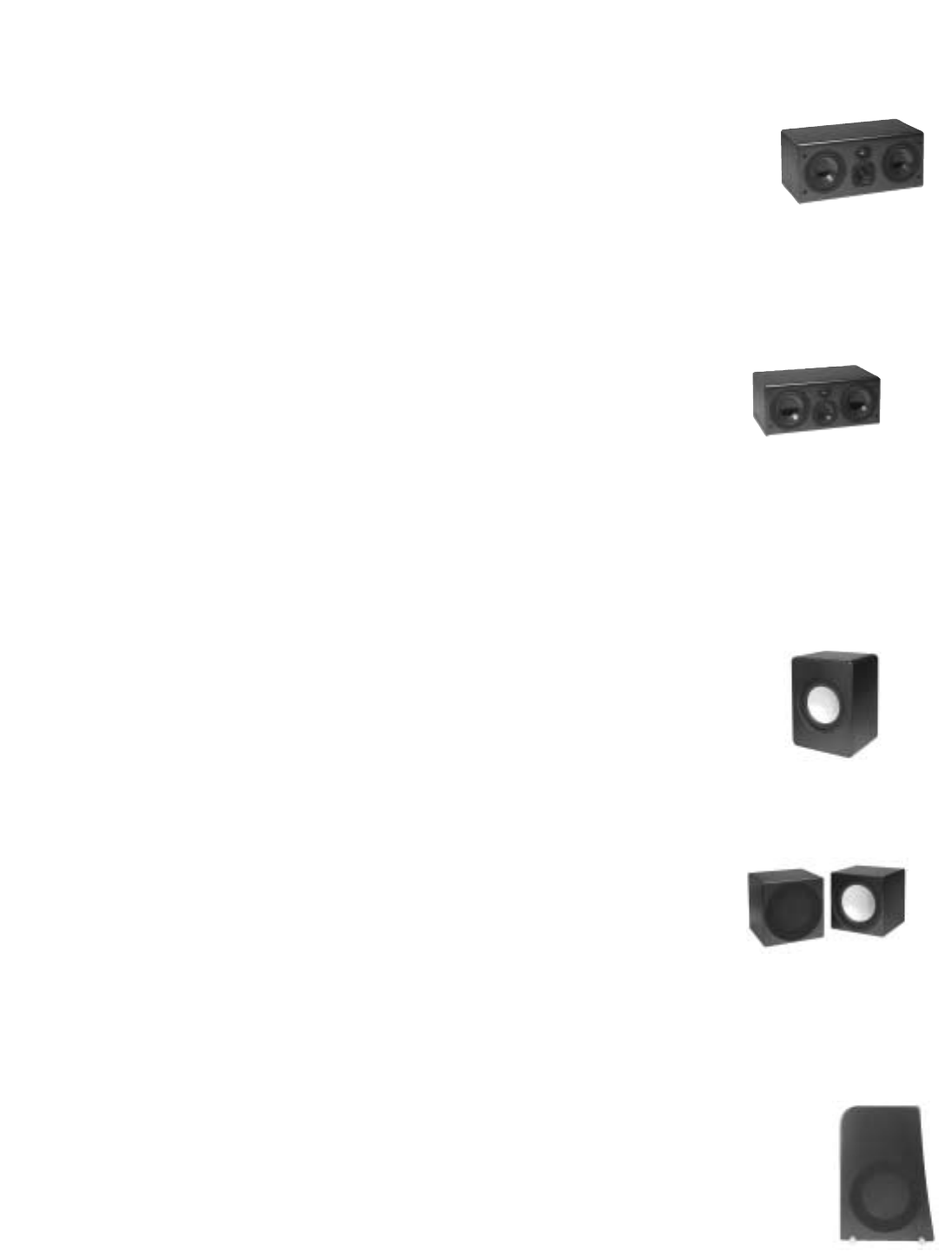
1.2 Description by Model
Monitors
M5 - Designed for small to
medium sized rooms. The
compact M5 is a 3-way,
acoustic suspension, mag-
netically shielded monitor employing (2) 5.25"
woofers, a 3" midrange and a 1" aluminum
dome tweeter.
M6 - Designed for medi-
um to large rooms. The
high output M6 is a 3-way,
acoustic suspension,
magnetically shielded monitor employing (2)
6.5" woofers, a 4" midrange and a 1" aluminum
dome tweeter.
Free Standing Subwoofers
W1 - The cabinet portion of
the U1 Powered Subwoofer
system. The W1 subwoofer
module employs dual, oppos-
ing 12" aluminum cone
woofers in a surprisingly compact enclosure.
W2 - The cabinet portion of
the U2 Powered
Subwoofer system. The
W2 subwoofer is only
available and used in
pairs. Each cabinet contains a 12" front firing,
aluminum cone woofer. This system is ideal for
in-cabinet or built in applications.
Tower Subwoofers
B5 - The B5 subwoofer bass mod-
ule, when mated with M5 Monitor,
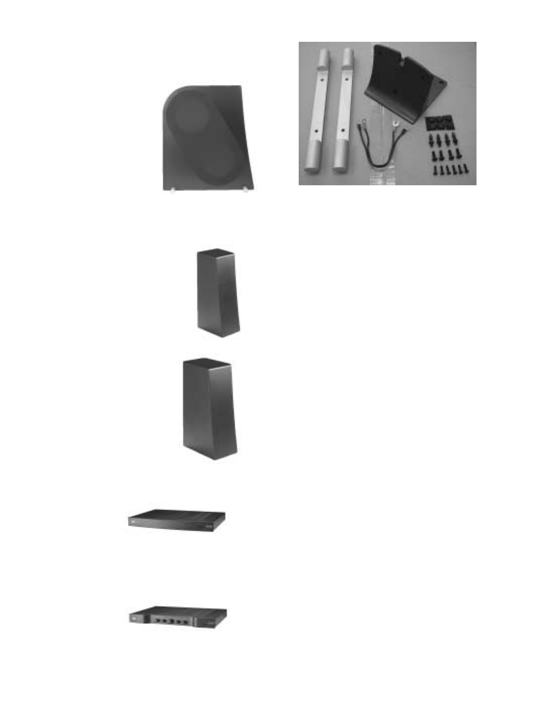
becomes the Evolution T5 tower. It employs the
Evolution 12” aluminum cone woofer. The B5
cabinets are mirror imaged to allow for proper
woofer orientation.
B6 - The B6 subwoofer bass
module mates with the M6 to
form the T6 tower system.
Designed for larger rooms,
the mirror imaged B6 mod-
ules each contain two 12”
aluminum cone woofers.
Pedestals
P5 - The pedestal matched to the
M5. Allows the monitor to be
used free standing with separate
subwoofers or placed as a rear
channel speaker.
P6 - The pedestal matched to
the M6. Allows the monitor to
be used free standing with
separate subwoofers or
placed as a rear channel
speaker.
Electronics
A1 - A full range
(20Hz-20kHz), 250
watt (@ 6ohms), monaural class G amplifier for
use with all Evolution subwoofers and tower
bass modules, or to power an Evolution Monitor.
X1 - A dedicated,
active crossover for
use with all Evolution subwoofer and tower sys-
tems.
K5 / K6 - Parts kit needed to assemble one T5
or T6 tower.
1.3 Identifying Your System
To the right is a chart by model, indicating the
various components and accessory kits includ-
ed with your purchase of either the T5/T6 tower
or U1/U2 subwoofer system. The M5/M6 and
P5/P6 are packaged individually with their
required hardware and accessories.
T5
Towers T6
Towers
M5
M6
B5
Left
B6
Left
B5
Right
B6
Right
K5
Tower
Kit
K6
Tower
Kit
W1
Subwoofer
Cabinet
W2
Subwoofer
Cabinet
X1
Bass
Management/
Active
Crossover
A1
Amplifier
OK
Owners
Kit 1
2
1
1
2
1
1
1
2
1
1
2
1
2
1
1
1
1
1
2
1
1
U1
Subwoofer U2
Subwoofer
T5
Towers
1
2
1
1
2
1
1
T6
Towers
1
2
1
1
2
1
2
1
1
1
1
U1
Subwoofer
1
2
1
1
U2
Subwoofer
2.0 Getting Organized.
CAUTION: Some of the
Evolution product is
heavy. We recommend
you enlist help in
unpacking, assembling
and moving the larger
speaker components.
The cartons for all tower speaker components
and assembly kits are color coded. The print on
the 5 series cartons (M5, B5, K5, P5) is red; the
print on the 6 series cartons (M6, B6, K6, P6) is
blue. All other Evolution product cartons use
black print.
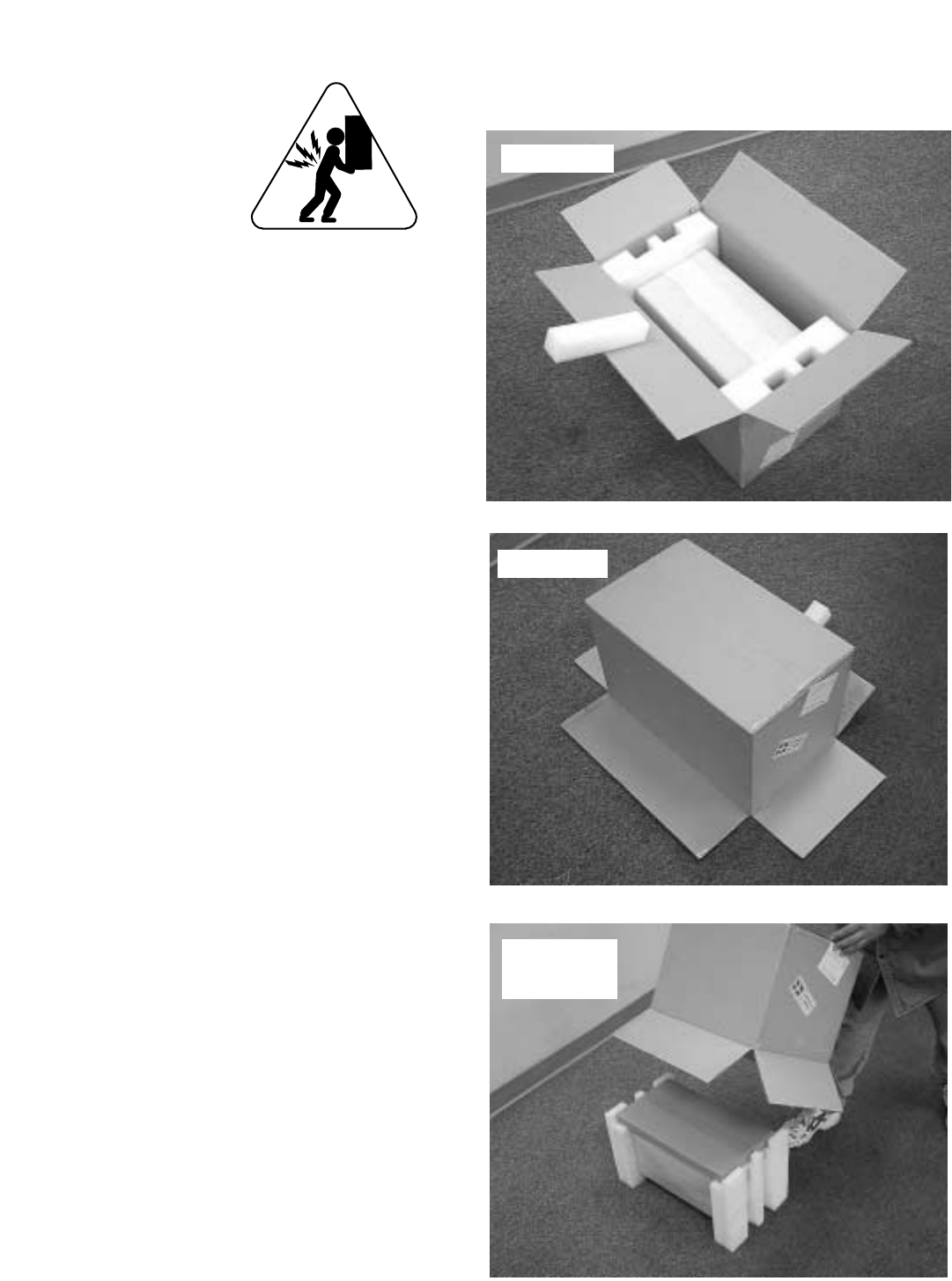
2.1 Unpacking
We suggest you use an open area to unpack
and assemble your system, particularly if you
purchased a tower system. Remember, all
Evolution speaker components are finished in
fine lacquer. To avoid damage, assemble the
speakers on a soft surface, e.g. a carpet or blan-
ket.
Take care in unpacking your NHT products to
avoid marring the cabinets. It's best to use grav-
ity to your advantage. Open each carton as
shown, gently turning it upside down and pulling
the carton up and off of the speaker. Remove
the protective end caps, plastic bag and the
micro-foam. Avoid putting your hands directly
on the speaker drivers as they can be damaged
if handled roughly.
Once you have everything unpacked, inspect
and familiarize yourself with the contents. There
is a complete parts list for each product carton in
the next section.
Note: If possible, we recommend that you store
the shipping cartons and packing material in
case the system needs to be moved in the
future.
open flaps
flip over
slip carton
upwards

2.2 Parts List
M5 or M6 Monitor Carton:
M5 or M6 monitor
Grille carton:
Grille
Logo
Third foot
(2) Thumbscrews
(2) Plastic washers
(4) Rubber feet
Warranty card
W1 Carton:
Subwoofer cabinet for the U1 System
(4) Rubber feet
Warranty card
W2 Carton:
Subwoofer cabinet for the U2 System
(4) Rubber feet
Warranty card
X1 Carton:
X1 Active crossover
Power supply
Warranty card
A1 Carton:
A1 Amplifier
Power cord
Dual Subwoofer Adapter
Warranty card
K5 or K6 (tower assembly kit) Carton:
Mounting buttress
Monitor connection harness
(2) Aluminum stabilizer bars (for B5 or B6)
(4) ¼ - 20 spikes with lock nuts
(4) Metal cups
(4) ¼ - 20 machine screws
(7) 10-24 machine screws
(6) Rubber feet
B5 or B6 (left or right) Bass Module Carton:
Tower Base enclosure
Warranty card
P5 or P6 Carton:
P5 or P6 Pedestal
Metal mounting plate
Stabilizer bar carton:
(4) ¼ - 20 spikes with lock nuts
(4) ¼ - 20 machine screws
(5) 10-24 machine screws
(2) Wire channel brackets
(1) Wire channel
(4) 6 - ¾ flathead screws
(2) Aluminum stabilizer bars (for
P5 or P6)
(4) Metal cups
(8) Rubber feet
Warranty card
3.0 Speaker Placement
Now is a good time to finalize your plans for
speaker placement. This section outlines the
important issues to consider in configuring your
system for optimum performance.
The M5 and M6 monitors are designed to per-
form almost identically whether placed horizon-
tally or vertically. Below are some fundamental
guidelines on Monitor orientation:
1) You do not need to “toe-in” the monitors
toward the listening area; position them facing
straight ahead into the room, perpendicular to
the wall in behind the speaker.
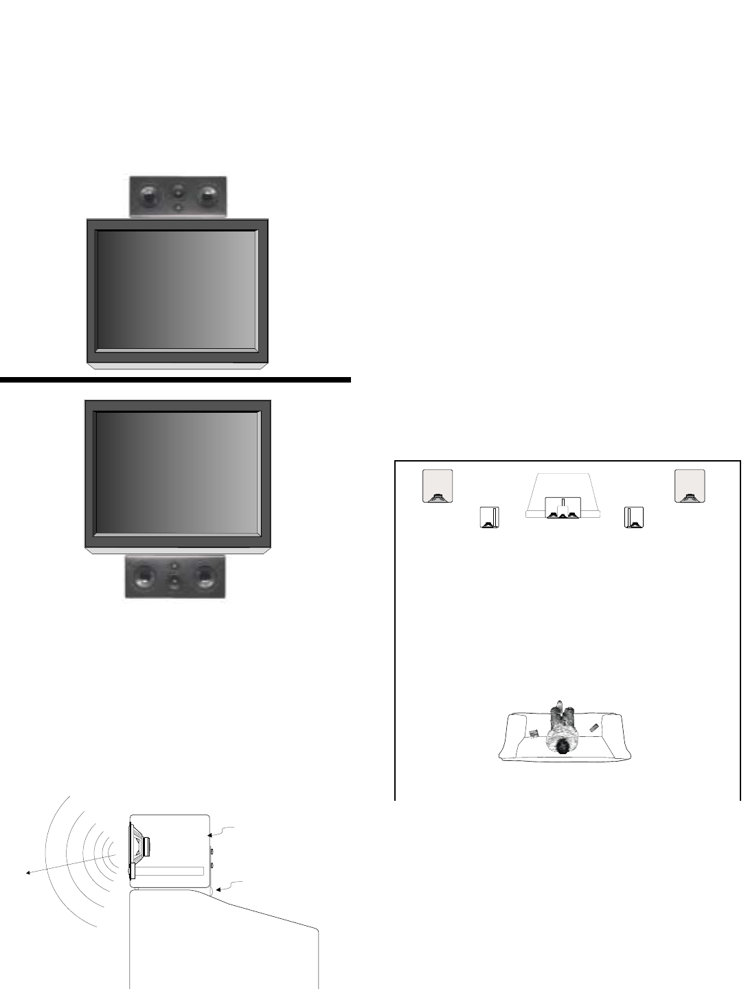
2) When oriented vertically, the tweeters
should be placed inward as shown below.
3) When using the M5 or M6 monitor for a
center channel, it should be placed horizontally.
4) When Evolution monitors are placed hor-
izontally in a cabinet, the tweeter orientation (top
or bottom) depends on the placement height. If
the monitor is placed above the listener’s ear,
the tweeter should be below the midrange driver
as shown in the photo. If the monitor is placed
below the listener’s ear, the tweeter should
above the midrange driver.
Once you have determined how you will orient
your monitors, examine the terminal plate on the
back of your Evolution Monitor. You will find a
Boundary Switch on the plate that is used to
adjust the speaker’s response based on its
placement. If you intend to place the monitor in
a cabinet, on a shelf, on top of a television set or
against a wall, move the boundary switch to the
“1” position. If the monitor is two feet or more
from any surface described above, the switch
should be in the “0” position. If the Monitor is
used as part of a T5 or T6 Tower system, the
Boundary Switch should generally be in the “0”
position. If the Tower system is placed very
close to a corner, set the switch to the “1” posi-
tion.
Note: The terminal plate comes from the facto-
ry oriented for horizontal placement. This allows
speaker wire to hang down neatly from the
speaker. The terminal plate should be rotated
for vertical use. Instructions for rotating the cup
can be found in section 4.2.
An explanation of the technology behind the
guidelines described above can be found in sec-
tion 11 of this manual.
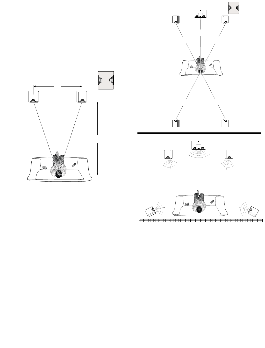
3.1 Two Channel Stereo
The diagram below illustrates the desired moni-
tor and subwoofer placement for two channel
(stereo) listening. If you are not using an
Evolution tower or pedestal and are orienting
the monitors vertically, try to place the M5 or M6
so the tweeters are at or near ear level.
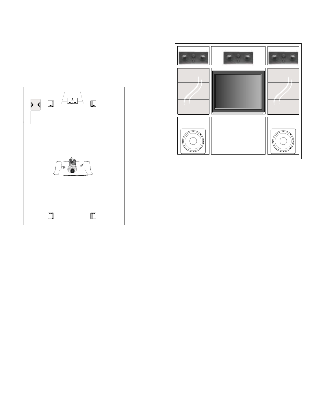
3.2 5.1 Digital Surround
The diagrams below illustrate two options for
positioning your speakers in a 5.1 surround sys-
tem. The first option is ideal, assuming you
have sufficient space to place the front and rear
channel speakers equidistant from the listening
position.
If you are primarily listening from a position near
or against a rear wall as shown in the next illus-
tration, you can place the rear channel monitors
to the sides. Surround processors and
receivers have adjustable delay settings that
allow you to equalize the arrival times for the
rear channels. Refer to your Surround
Processor/AV Receiver manual to find the cor-
rect delay setting.
We realize it may be impossible to arrange your
room to accommodate the ideal surround setup.
Because every home is unique, we suggest you
consult your authorized NHT dealer for alterna-
tive placement advice or call our Customer
Hotline at 1-800-NHT-9993 (648-9993).
1.5 D
D
Front
Left Front
Right
Subwoofer
=
5.1
=
=
=
=
Front
Left
Surround
Left
Front
Right
Surround
Right
Center Channel
Subwoofer
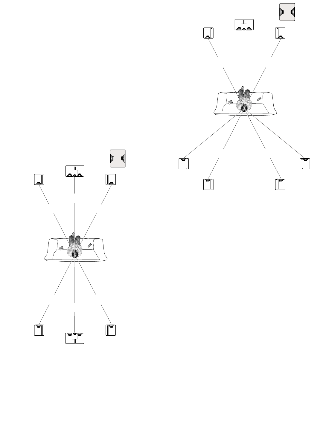
3.3 Enhanced Digital Surround Formats
Different surround formats use different num-
bers of surround speakers. 5.1 systems use two
surround speakers, 6.1 systems use three and
7.1 systems use four. Some AV receivers and
separate Surround Processors are equipped
with 6.1 or 7.1 surround formats. 6.1 refers to
the Dolby Digital Surround EX ™ or DTS
Surround ES ™ standard. The diagrams below
illustrate the suggested positions for 6.1 and 7.1
systems.
Note: Pay attention to the orientation of the
monitors (horizontal or vertical) and tweeters
(top/bottom or inside/outside) in your installation
for correct system performance.
Be aware that there are other surround formats
that are not covered in this setup guide. Consult
your authorized NHT dealer if you are unsure
about your particular system configuration.
=
6.1
=
=
=
=
=
Front
Left
Surround
Left
Front
Right
Surround
Right
Surround
Center
Center Channel
Subwoofer
=
7.1
=
==
=
=
=
Front
Left
Surround
Back
Left
Surround
Left Surround
Right
Front
Right
Surround
Back
Right
Center Channel
Subwoofer
3.4 Center Channel
The M5 and M6 monitors can be placed in a
home entertainment center or directly on top of
a TV as shown below. Remember, for proper
center channel sound dispersion, the Monitor
should be placed horizontally.
If you intend to place your center channel on a
television with a shallow top so that the Monitor
overhangs the television as illustrated below,
you will need to attach the included Third Foot
for proper support (see Section 4.2 for detailed
instructions).
3.5 Subwoofers
Subwoofers produce low frequencies that have
long wavelengths. These wavelengths are sim-
ilar to the dimensions of the room, so the sound
energy strongly interacts with the room bound-
aries. Fortunately, Evolution’s flexible sub-
woofer options, combined with the X1 active
crossover, solve most of the acoustic problems
caused by room interaction with bass frequen-
cies. Experimenting with subwoofer location is
the key to finding the best performance in your
listening environment. Position a subwoofer
cabinet so that its driver(s) are not directly
against a wall or piece of furniture. If you are
using two subwoofers, some improvement in
low frequency response can be achieved by
placing the second subwoofer asymmetrically in
the room.
Note: Because of the massive motor structure
used in the Evolution subwoofer driver, it is not
possible to magnetically shield it. Make sure
you place the subwoofer at least 18” from any
television to avoid discoloration.
Television
Third Foot
Boundary Switch
Set to the '1' position
W2W2
Evolution freestanding subwoofers offer tremen-
dous flexibility in placement. The following sug-
gestions illustrate a few of the possibilities avail-
able to you. If you have a unique placement
requirement or intend to use multiple subwoofer
systems, consult your authorized NHT dealer or
call our Customer Service Hotline at 1-800-
NHT-9993 for advice.
U1 Subwoofer System: The U1 subwoofer
enclosure is a dual, side-firing design. If the U1
is going to be located in a corner or against a
wall, we recommend that you keep the face with
the grille at least 4” from any boundary to obtain
optimum performance.
U2 Subwoofer System: The compact, front-fir-
ing, dual cabinets in the U2 system can be con-
veniently placed near corners , or placed in cab-
inets as illustrated below.
3.6 Electronics
Evolution electronics should be placed with the
rest of your electronic components. Both the A1
amplifier and the X1 Active Crossover can be
rack mounted if desired. Instructions for rack
mounting can be found in section 9.3 of this
manual.
W1
>4"
4.0 System Assembly
This section covers the assembly required for
specific Evolution product configurations. The
operations are simple and easy to accomplish
quickly.
4.1 Supplies and tools
The tools you will need are:
- Combination #2/#3 Phillips screwdriver (pro-
vided in your Owner’s Kit)
- NHT binding post wrench (provided)
- Wire strippers
- Speaker wire (10 to 14 gauge)
- Tape measure or ruler
CAUTION: Some of the Evolution components
are heavy. If possible, have someone available
to assist you during assembly and placement of
the tower and/or subwoofer modules.
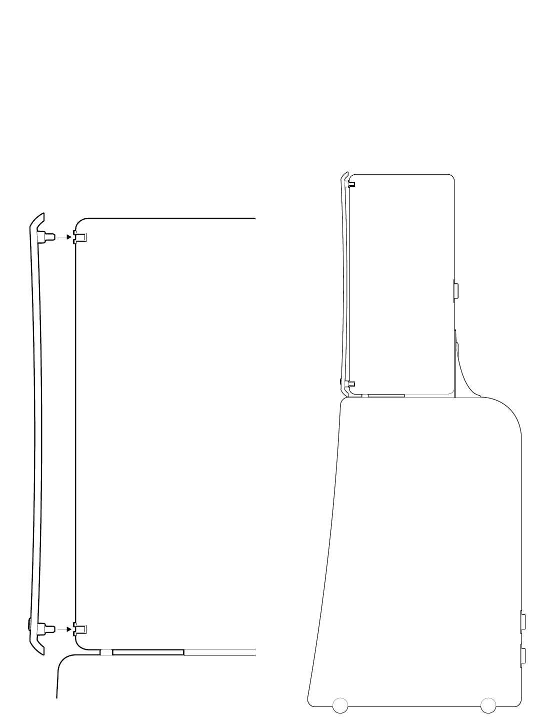
4.2 Monitor Parts Assembly
Step 1: Terminal Plate Orientation
The M5 and M6 are delivered with the Terminal
Plate oriented for horizontal monitor placement.
For vertical monitor placement, the Terminals
should be rotated so that the speaker wire
hangs straight down the rear of the speaker.
Place the monitor on a soft surface in the
desired orientation. See section 3.0 for illustra-
tion of proper tweeter orientation. DO NOT lay
the front baffle of the Monitor down on any sur-
face, as this will damage the drivers.
Remove the four screws from the Terminal Plate
on the back of the Monitor with the supplied #2
screwdriver. Gently pull the Terminal Plate
away from the cabinet and rotate it 90 degrees
so that the Boundary Switch is at the top.
Reinstall the screws in the pilot holes as shown.
Make sure the screws are snug, but be careful
not to over tighten them.
Remove Screws
Rotate Terminal Plate
Reinstall Screws
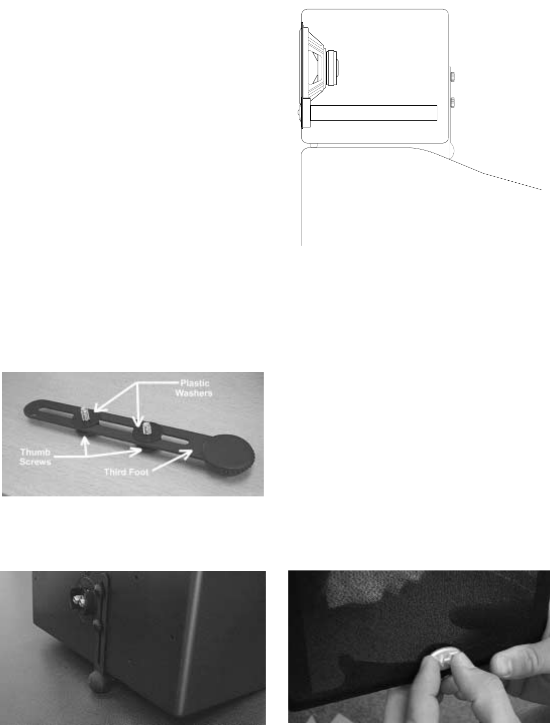
Step 2: NHT Third Foot for Center Channel Use
The M5 and M6 cartons include a “Third Foot”,
a support that stabilizes the monitor when it is
mounted on a television. If the top of the televi-
sion is shallower than the Monitor is deep, the
rear of the Monitor will not be fully supported.
The Third Foot will provide the necessary sup-
port in this case. The Third Foot can also be
used to aim the Monitor down towards the lis-
tening area if the television is significantly above
eye level.
There are two parts supplied with the Third Foot
for assembly: (2) plastic washers and (2) thumb-
screws. The plastic washers go between the
Third Foot and the cabinet to protect the cabi-
net’s lacquer finish. Assemble these parts as
shown and screw the two thumbscrews partially
into the two threaded holes next to the terminal
plate.
Attach the two rubber feet about an inch from
the bottom front edge of the monitor. Set the
monitor on the television and adjust the length of
the third foot so that it rests on the TV set as
shown. Hand tighten the thumbscrews.
Step 3: Logo Placement
The M5 and M6 are supplied with a metal NHT
logo that can be attached to the grilles when the
speakers are placed in the vertical position only.
The logo should be attached at the bottom of the
grille. To attach the logo, hold the grille up to a
light to locate the two holes in the frame through
the cloth. Line up the two posts on the back of
the logo with the holes and press the logo firmly
through the cloth and into the grille frame until it
is fully seated against the grille.
Note: The logo badge is not attachable when
the speaker is placed horizontally.
Television
Step5: Attaching Monitor Grilles
The M5 and M6 are designed to sound the best
when the grilles are used (they may sound
slightly bright if played without the grilles). To
install them, line up the four pins on the back of
the grille with the four rubber cups located in the
corners of the Monitor’s front baffle. Firmly press
all four corners of the grille until the pins seat
against the rubber cups.
Note: The M5 and M6 grilles are intentionally
curved. The grille curve is a design element that
completes a larger curve when a Monitor is
attached to a B5/B6 subwoofer module or either
pedestal stand. The curve is shallow enough
that it may go unnoticed when the monitors are
placed on shelves. The illustration to the right
shows how an Evolution tower looks when the
grille is installed.
4.3 T5 and T6 Tower Assembly
Depending on which model you purchased, you
will now need the parts contained in either the
K5 or K6 assembly kit.
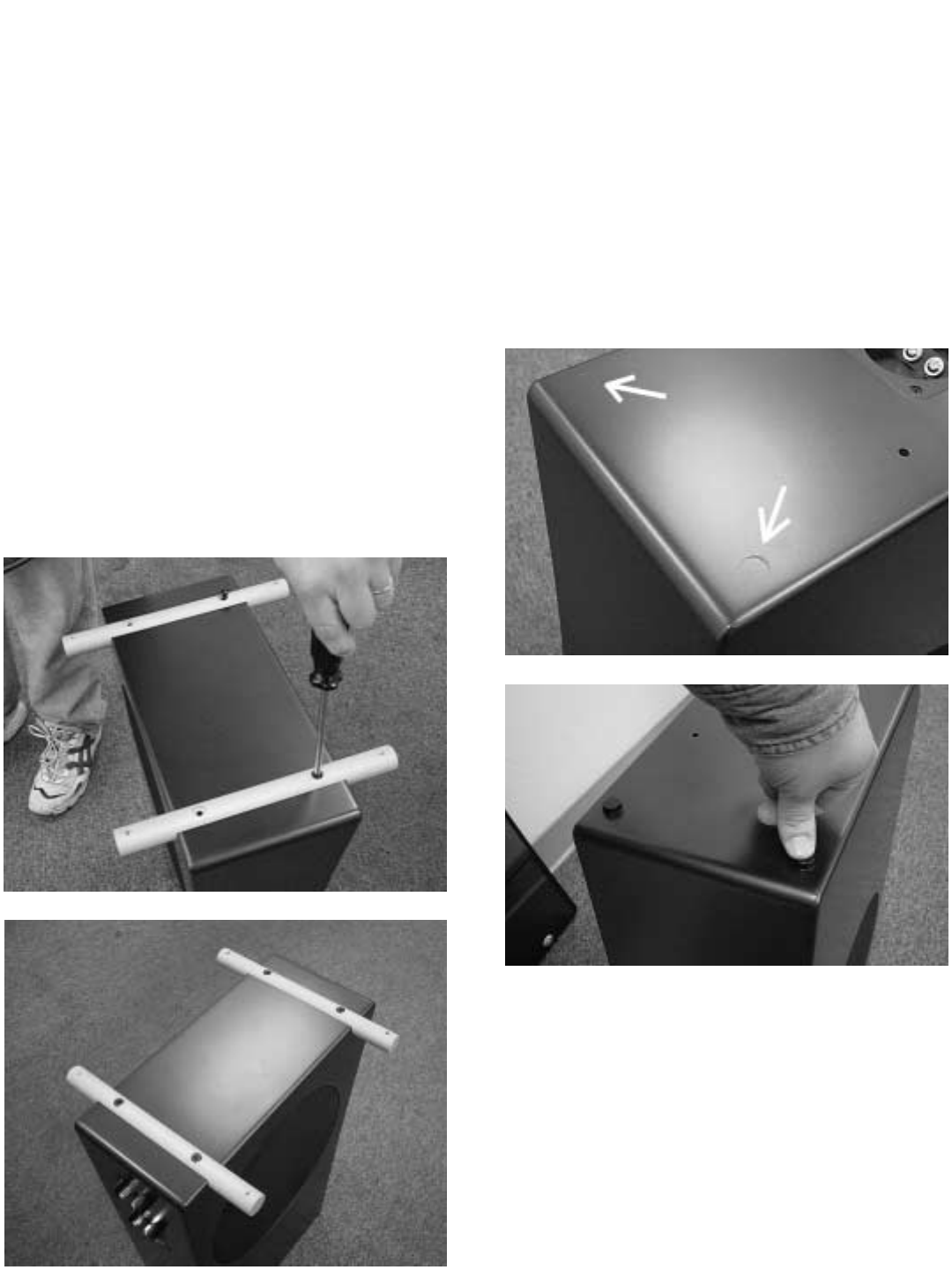
Step 1: Installing the Stabilizer Bars
The aluminum bars attach to the bottom of the
bass module to provide stability for the tower
system. Carefully turn the B5 or B6 bass mod-
ule upside down on a soft surface. There are
four threaded holes on the bottom of the cabi-
net. Gently place the stabilizer bars over the
threaded holes. Start the four large (1/4-20)
screws by hand. Once all the bolts are started,
tighten them with the supplied #3 Phillips screw-
driver.
Note: If you intend to use spikes with the stabi-
lizers, do not install them at this time. The tow-
ers are difficult to move once the spikes are in
place. Spike installation is covered in Step 9.
Step 2: Adhering the Rubber Feet
Once the stabilizers are mounted, carefully turn
the bass module upright. Peel the paper cover
off the back of the two round rubber feet and
attach them to the top front of the B5 or B6.
There are slight indentations on the cabinet to
help you position the rubber feet properly.
.
Step 3: Attaching the Monitor Connection
Harness
The Monitor Connection Harness connects the
Monitor’s speaker terminals to the terminal cup
on top of the subwoofer module. This terminal
cup is internally wired to the uppermost of the
two terminal cups at the bottom rear of the sub-
woofer module. Remove the two gold-plated
screws from the terminal cup on the top of the
B5 or B6 with the #2 screwdriver. Insert the ring
terminal ends of the cable onto the screws and
fasten them into the terminal cup. Check that
the wire is oriented vertically and that you have
connected the red ring terminal to the bass mod-
ule terminal marked in red (and the black ring
terminal to the bass module terminal marked
with black).
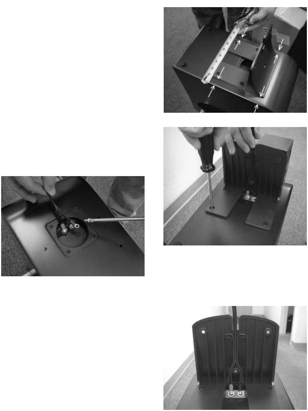
Step 4: Installing the Mounting Buttress
The mounting buttress secures the monitor to
the bass module. Place the buttress over the
four threaded holes on the top of the bass mod-
ule. Start four of the smaller screws (10-24) with
the #2 screwdriver. Center the buttress by mea-
suring the distance between the base of the but-
tress and the speakers’ edge in a few places as
illustrated. Once you have checked alignment
you may tighten the screws, making sure they
are snug, but do not over tighten them.
Step 5: Route Monitor Connection Harness
Route the harness through the channel inside
the buttress as shown below.
Step 6: Bass Module Orientation
At this point you need to decide in which orien-
tation to place the subwoofers. There are two
options, woofers facing inwards or outwards as
shown in the illustration.
If there is going to be a large object located
between the towers (a television or large piece
of furniture), place the subwoofer modules so
that the woofers face to the outside (away from
the television). If there are no large objects
between the towers, orient the subwoofers so
that the woofers face to the inside (towards each
other). Remember that the subwoofer modules
should be at least 18” from the sides of a televi-
sion to prevent discoloration of the screen.
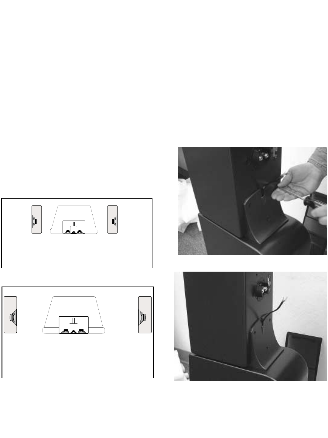
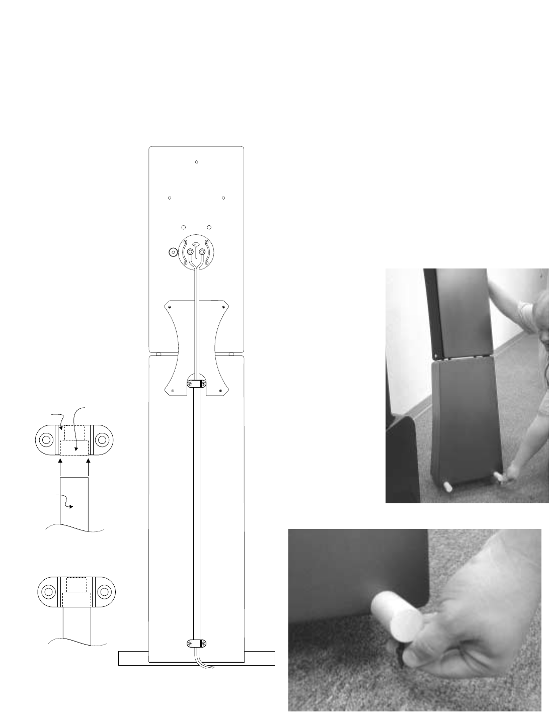
Step 7: Mounting a Monitor to the Bass Module
Place the monitor on the buttress as shown.
The front of the monitor should be resting on the
round rubber feet. Line up the threaded holes in
the back of the monitor with the holes in the but-
tress. Fasten the monitor to the buttress with
three small (10-24) screws using the #2 screw-
driver. Start the center screw first, and then start
the outer screws. Make sure that the Monitor
Connection Harness extends from the top of the
buttress as illustrated below.
Step 8: Connecting the Monitor Connection
Harness to the Monitor
Loosen the nuts on the binding post terminals
enough to allow the spade terminals on the
Harness to fit under them. Make sure you
match wire colors for proper polarity, (red to red,
black to black). The cable should lay flat against
the back of the monitor. Tighten the terminal
nuts using the NHT wrench.
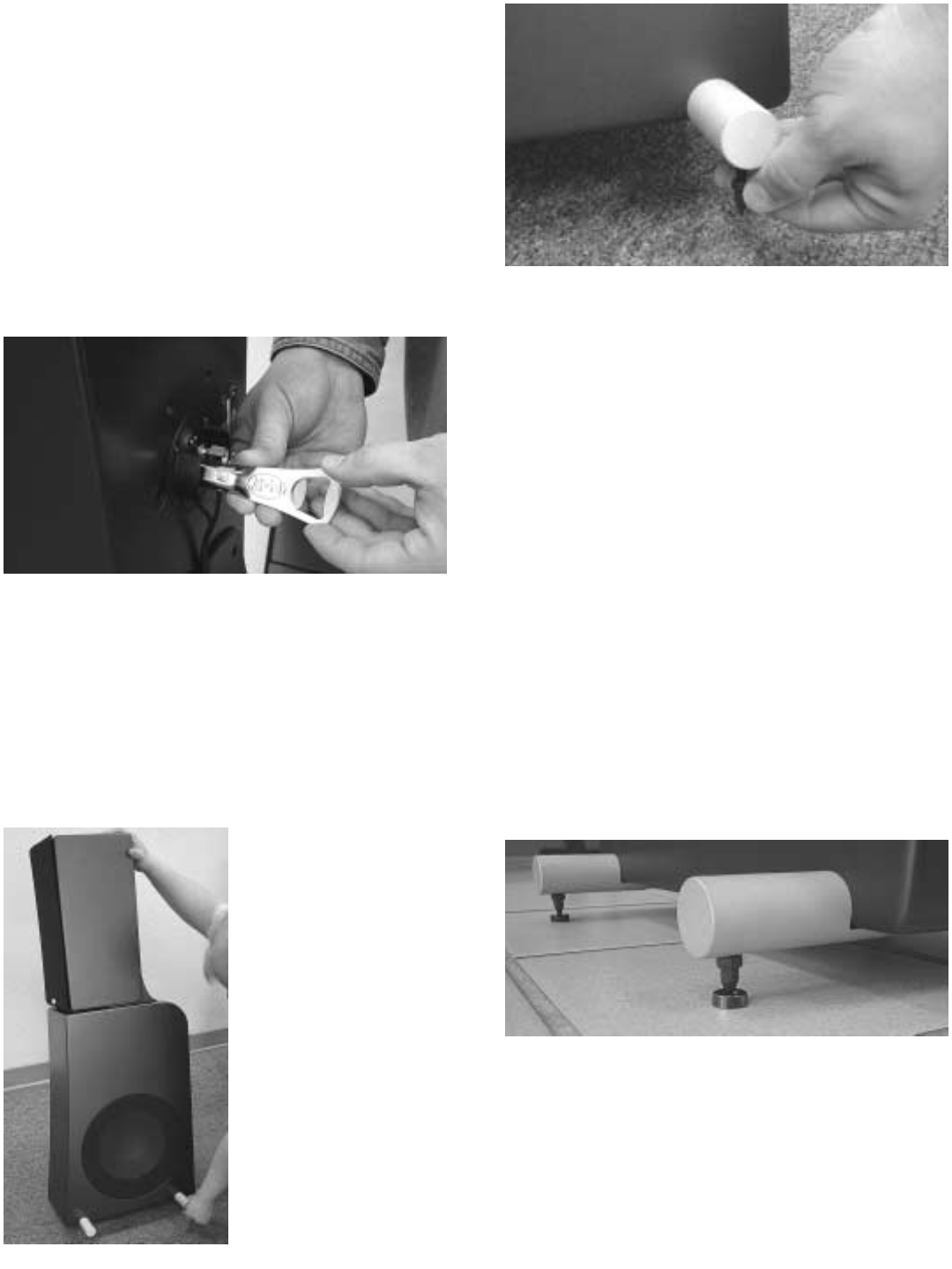
Step 9: Install spikes (optional)
Spikes couple the speaker to the floor, improv-
ing the performance of the system.
Note: Position the speakers in their permanent
location before installing the spikes. It is very dif-
ficult to move the
assembled speakers
once the spikes are in
place. We suggest
two people for this
operation, one to hold
the speaker and the
other to install and
adjust the spikes.
Install the locking nuts
on the threaded
spikes and screw
them all the way down
the shaft until they
stop. Carefully tilt the tower speaker to one side
and screw the metal spikes into the bottom of
the front and rear aluminum stabilizer bars (at
least 3/8”) to the desired height. Hand tighten
the nut to lock it in position. When both sides
are installed, check to ensure that the speaker
does not rock. If necessary, tilt the speaker,
loosen the nut and adjust the height until the
speaker rests firmly on all four spikes. You can
use a small wrench to further tighten the nuts.
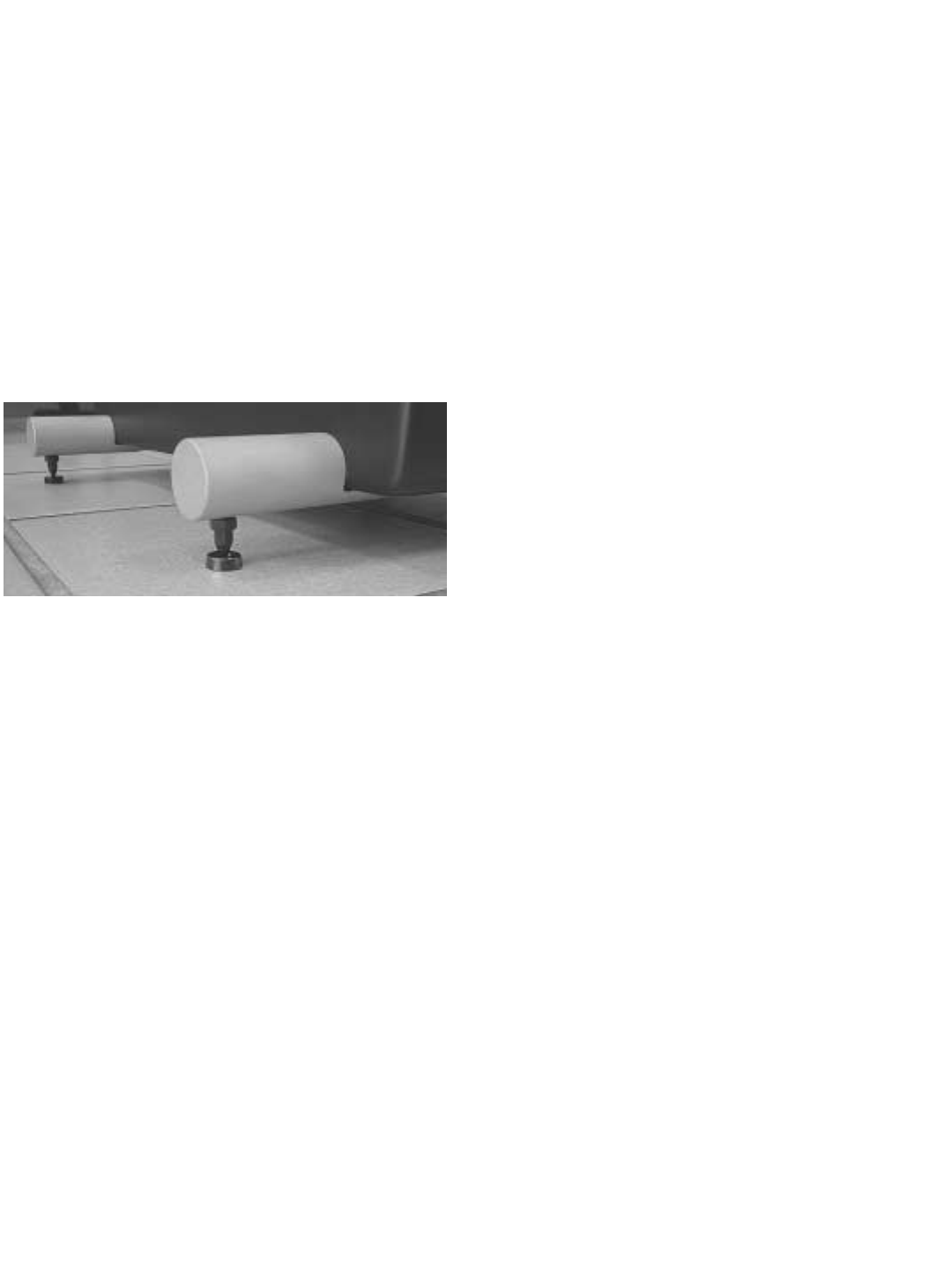
Be aware that wood or tile floors can be dam-
aged by the spike’s sharp tip. Four small metal
cups are included with the tower assembly kit to
fit under each spike and protect your floors.
Once the spikes have been mounted to the sta-
bilizer bar, slip a cup under each spike as you
gently lower the tower to the floor.
4.4 Assembling Monitors On Pedestals
Step 1: Install Aluminum Stabilizer Bars
Carefully turn the P5 or P6 bass module upside
down on a soft surface, being careful not to
scratch the paint. Find the four threaded holes
on the bottom of the pedestal. Gently place the
stabilizer bars over the threaded holes. Start the
four large (1/4-20) screws by hand. Once they
have been started, tighten them with the #3
Phillips screwdriver.
Step 2: Attaching Rubber Feet
Attach the four round rubber feet to the top of
the pedestal. Peel the paper backer from each
foot, and press them into the shallow indenta-
tions on the cabinet surface.
Step 3: Install Metal Mounting Plate
Begin by attaching the metal mounting plate to
the pedestal base with two of the small (10-24)
screws and the #2 Phillips screwdriver. Note
that the notch in the metal plate should be fac-
ing downwards. Do not tighten them all the way
until the monitor is in position.
Gently place the Monitor on the pedestal top
with its back against the mounting plate. Make
sure that you have determined the proper tweet-
er orientation (see Section 3). Start the three
small screws (10-24) through the mounting plate
and into the threaded holes in the back of the
Monitor. Tighten all five screws until snug.
Gently place the monitor on the pedestal top
with back against the mounting plate. Make
sure that you have the proper tweeter orienta-
tion (see Section 3). Start 3 smaller bolts (10-
24) through the mounting plate and into the
threaded holes in the back of the monitor.
Tighten all five bolts until snug.
Step 4: Install Wire Channel Assembly
The wire channel assembly for the P5 and P6
pedestals neatly routes the speaker wire down
the back of the pedestal. It consists of two plas-
tic U shaped brackets, one plastic channel and
four 6-3/4 screws.
To install, first strip ½” -
¾” of insulation from
the ends of your speak-
er wire and connect
them to the monitor’s
binding post by loosen-
ing the binding post
nuts and slipping the
wire into the hole
behind each nut.
Tighten the nuts with
your NHT wrench.
Remember to check for
the correct polarity (see
section 5.3 and 5.3).
Slip the channel over the speaker wire. The
brackets are recessed on one side to accept the
ends of the wire channel. These recesses
should face each other when the channel is
installed. There are small pilot holes in the rear
of the pedestal to accept the 6-3/4 bracket
screws. Fasten the channel to the pedestal with
the brackets and the four screws as shown.
Step 5: Install Spikes (optional)
Spikes provide additional stability when the
pedestal is placed on thick carpet or on an
uneven surface. Position the speakers in or
close to their permanent location before
installing the spikes. It is difficult to move the
speakers once the spikes are in place.
Install the locking
nuts on the
threaded spikes
and screw them
all the way down
the shaft until
they stop. Attach
the spikes on
one side of the
pedestal at a
time. Tilt the
pedestal as
shown in the
photograph and
01
Channel
Bracket Recess
screw the metal spikes into the bottom of the
aluminum stabilizer bars. Tighten the locking
nuts by hand. Move to the other side and repeat
the procedure.
Be aware that wood or tile floors can be dam-
aged by the spike’s sharp tip. Four small metal
cups are included with the pedestal to fit under
each spike and protect the floor. Once the
spikes have been mounted to the stabilizer bar,
slip a cup under each spike as you gently lower
the tower to the floor.
5.0 Wiring Your Speakers
Before beginning to wire
your system, we suggest
you review the following
guidelines and wiring dia-
grams to find the Evolution
system(s) you have pur-
chased.
Tools Required:
NHT Wrench (included)
Wire strippers
Tape measure
Speaker Wire (10 - 14 gauge)
Component Interconnect Cables
5.1 General Guides to Wire Layout
To minimize noise problems, try to segregate
cables by function, and separate them by the
maximum practical distance. Where audio and
video cables intersect, cross them at right
angles. Try not to twist or tie AC power cords
and speaker cables together.
The minimum size speaker cable recommended
for runs of 20 feet or less is 14awg. Heavier spe-
cial purpose cable can be used for longer runs.
For best results, use equal length runs of cable
for the left and right speakers (or for the left,
center and right speakers).
5.2 Speaker Phase
For proper response, the speakers must be
wired in-phase with each other. That is, the Red
(+) terminal on the amplifier speaker output
must be connected to the corresponding Red (+)
terminal on the speaker. The same is true of the
Black (-) terminals. All speaker cable or wire
has a marking along one or both conductors to
help you make the correct connections. Weak
bass and the lack of a well-defined image are
indications that speakers are wired out of
phase. A well-defined image is one in which
you can easily locate the positions of perform-
ers in the sound field.
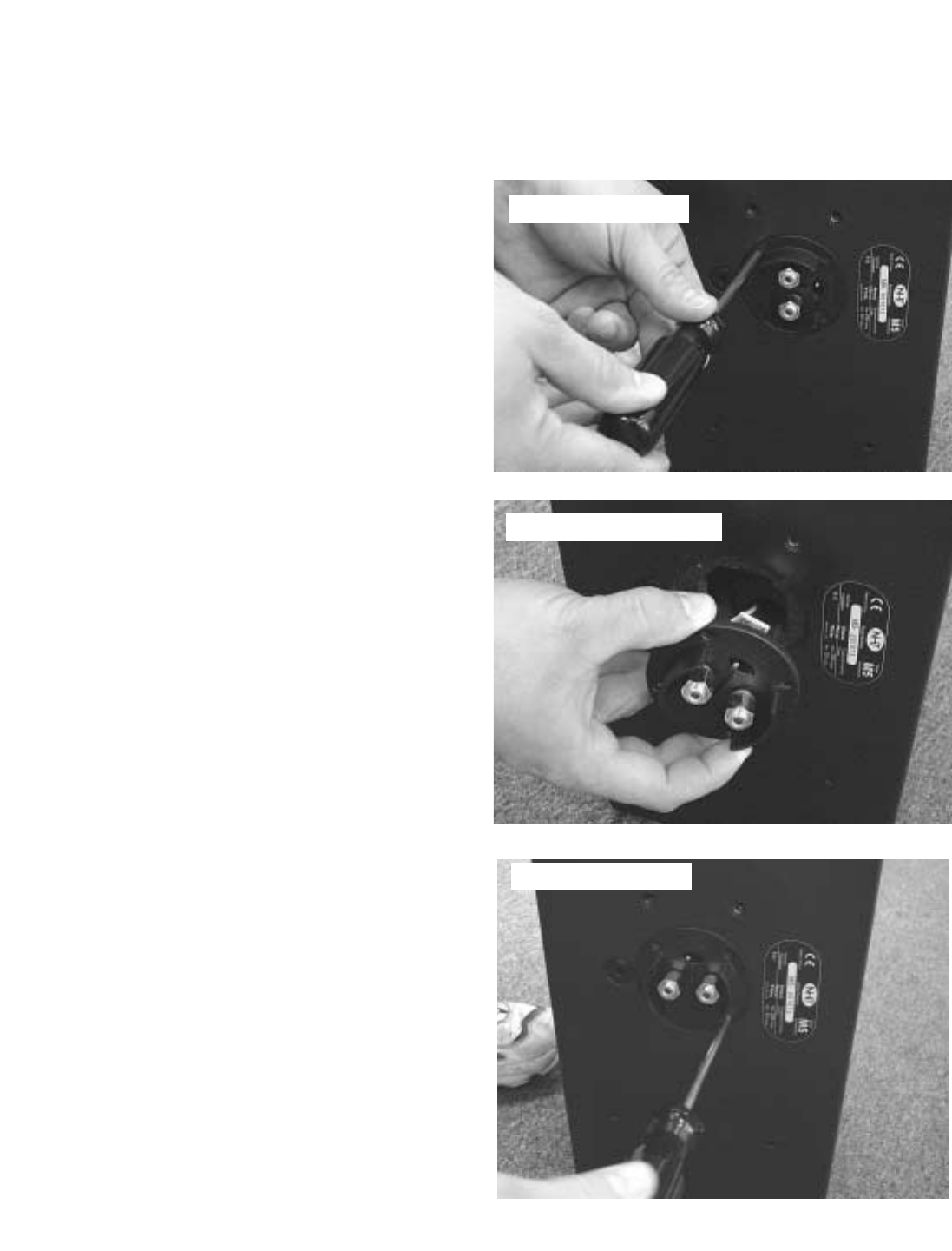
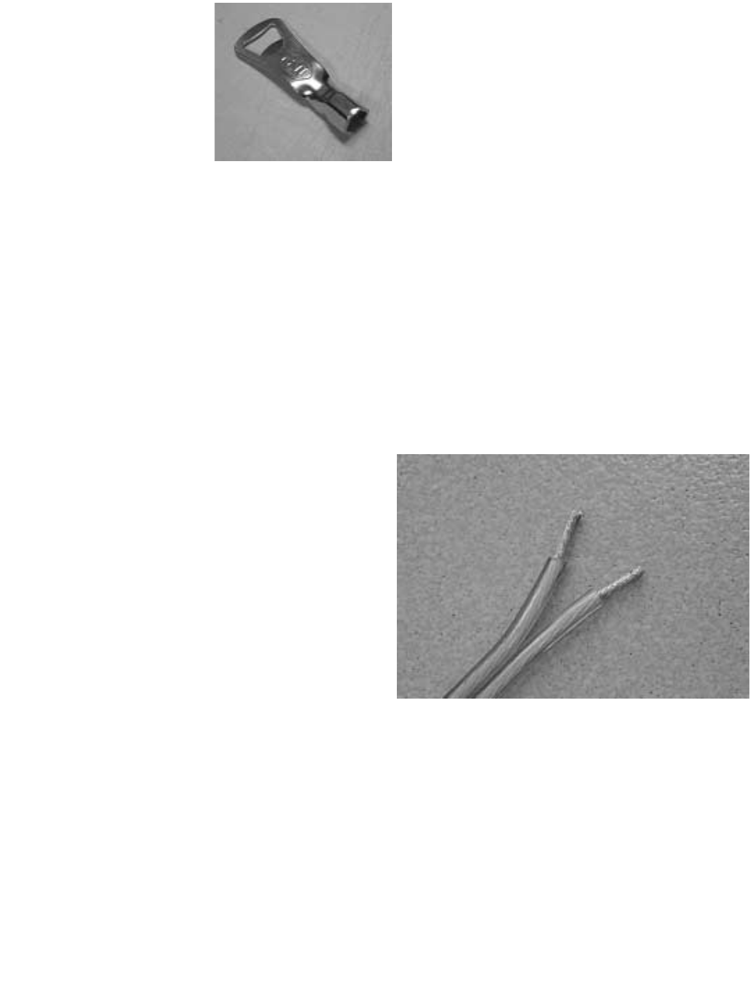
5.3 Connecting Speaker Wire
The gold plated binding posts on all Evolution
speakers will accept raw wire or virtually any
type of special purpose terminal. If you plan to
use raw wire, strip 1/2" to 3/4" of insulation from
the ends, twisting the exposed wire strands
tightly. Remove the binding post nuts on the ter-
minal and slip the wire through the hole in the
binding post. Replace the nuts on the binding
post and tighten until snug with the NHT wrench.
5.4 T5 and T6 Tower Wiring
You will be running 2 pairs of speaker wires to
either Evolution tower model. The M5 and M6
are wired through the B5 or B6 cabinet to keep
the speaker cables near the floor and to reduce
their visibility. There are two Terminal Plates on
the backside of the B5 and B6. The top terminal
plate connects an M5 or M6 to your AV Receiver
or amplifier. The bottom terminal plate connects
a B5 or B6 to an A1 subwoofer amplifier.
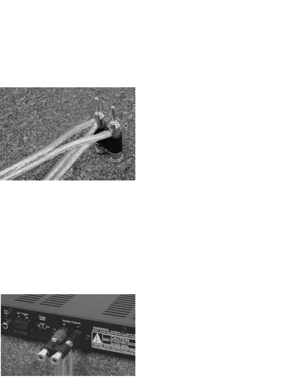
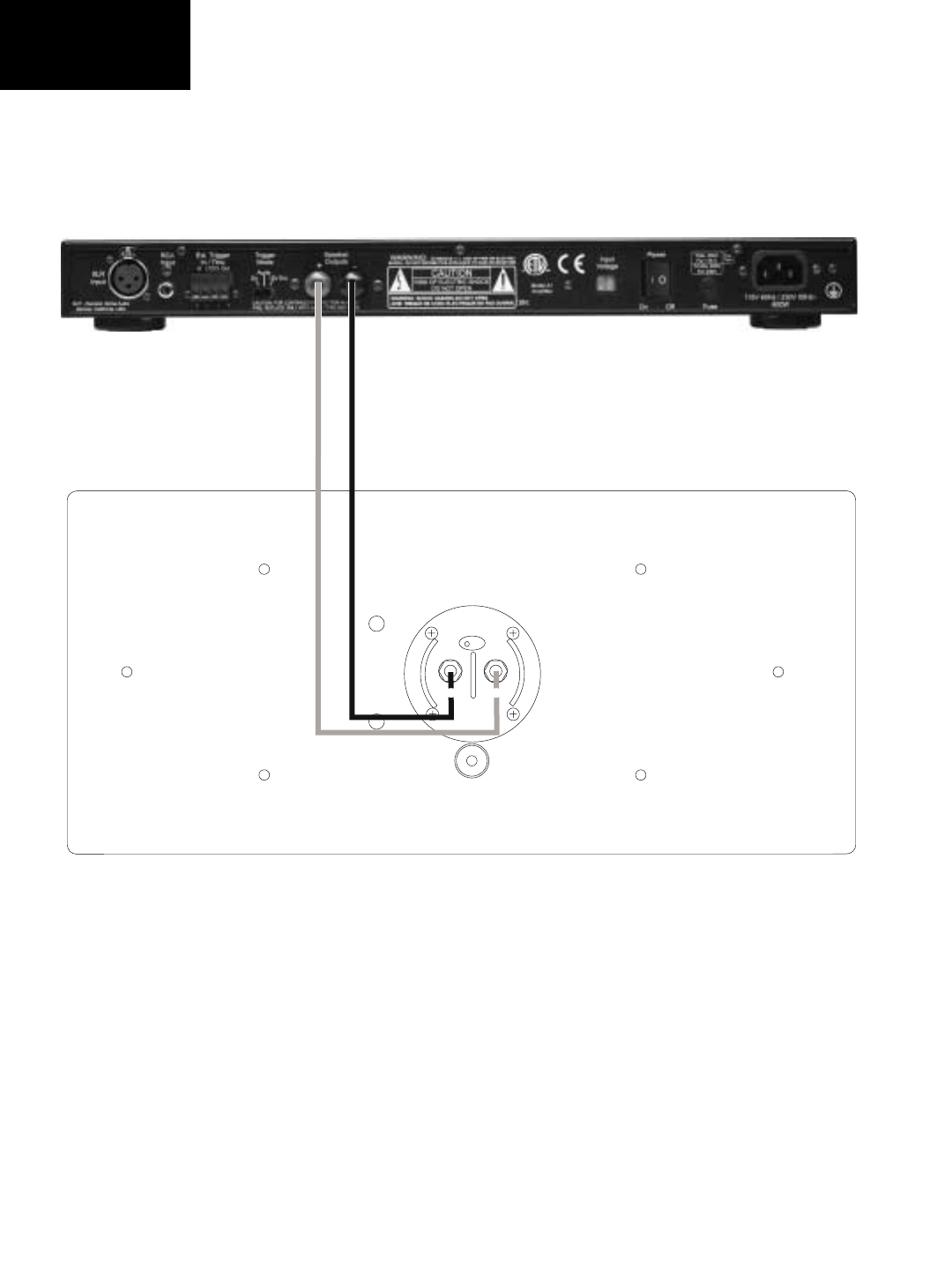
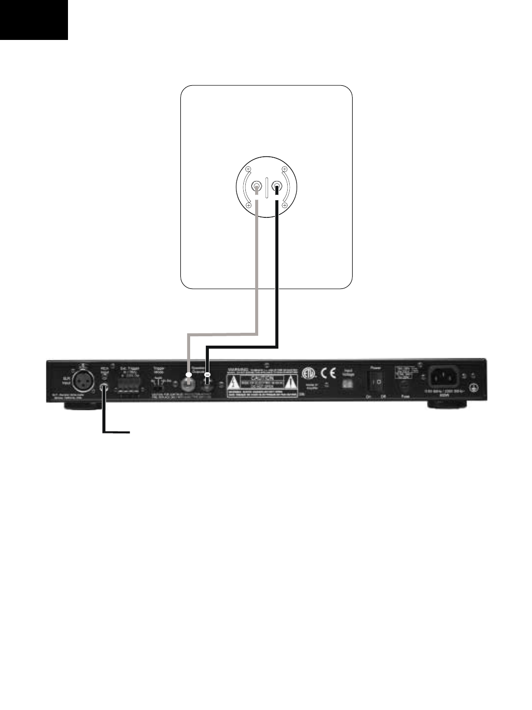
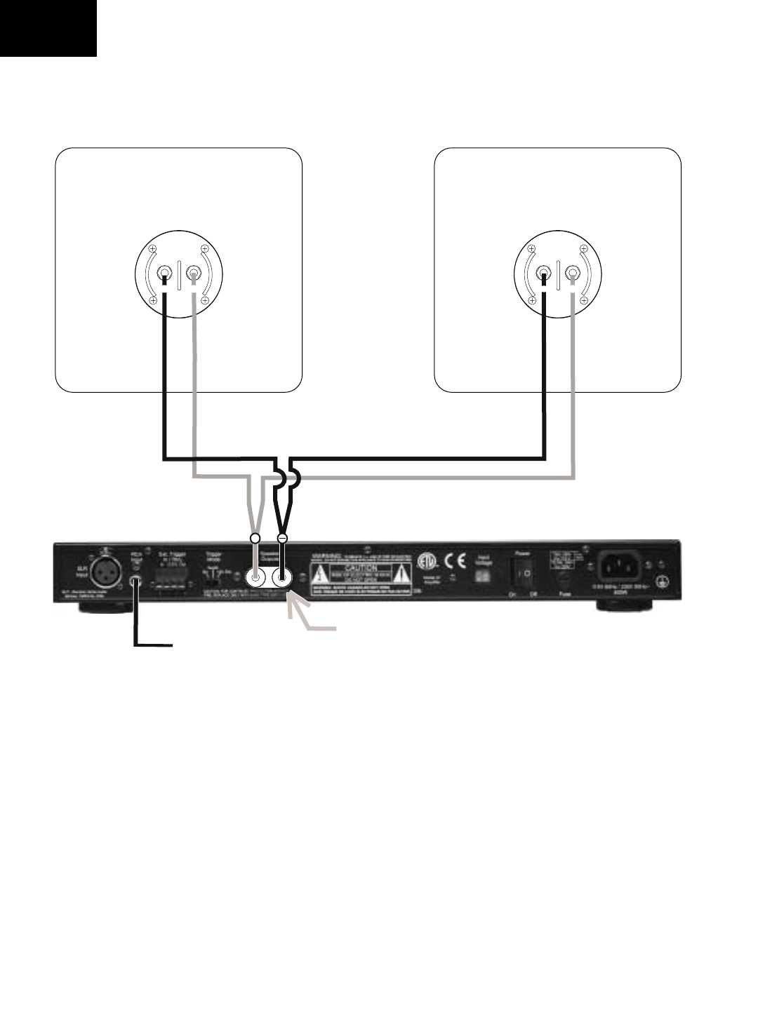
5.5 Wiring for Monaural Bass
The B5 bass modules and the dual W2 sub-
woofer cabinets require one additional wiring
step. The speaker wire coming from the B5 or
W2 cabinets must be connected in parallel at
the A1 subwoofer amplifier. The Dual
Subwoofer Adapter has been supplied with the
A1 amplifier for this purpose (see illustration).
Loosely twist the "+" wires from each subwoofer
(or tower base) together, then repeat for the "-"
wires. Loosen the red and black thumbscrews
on the Adapter until the hole in the shaft is fully
revealed. Insert the twisted pair of "+" speaker
wire to the hole marked with red. Tighten until
the wire is securely clamped. Repeat the proce-
dure for the "-" speaker wire and black thumb-
screw. The Adapter can now be inserted into
the A1 amplifier’s “speaker out” terminal posts.
5.6 System Wiring Diagrams
The following pages contain diagrams illustrat-
ing proper wiring for each Evolution model:
Monitor Wiring Diagram
U1 Wiring Diagram
U2 Wiring Diagram
T5 Wiring Diagram
T6 Wiring Diagram
01
A1
M5/M6
-
-
+
M5 / M6
Wiring Diagram
W1 Cabinet
A1
+
-
+
From X1
U1 Wiring
Diagram
A1
-
W2 Cabinet W2 Cabinet
Use Banana Adapter
-
-
+
++
-
-
-
From X1
U2 Wiring
Diagram
Speaker Output
Left
Speaker Output
Right
++
-
-
-
-
-
-
-
To M6 To M6
Sub Sub
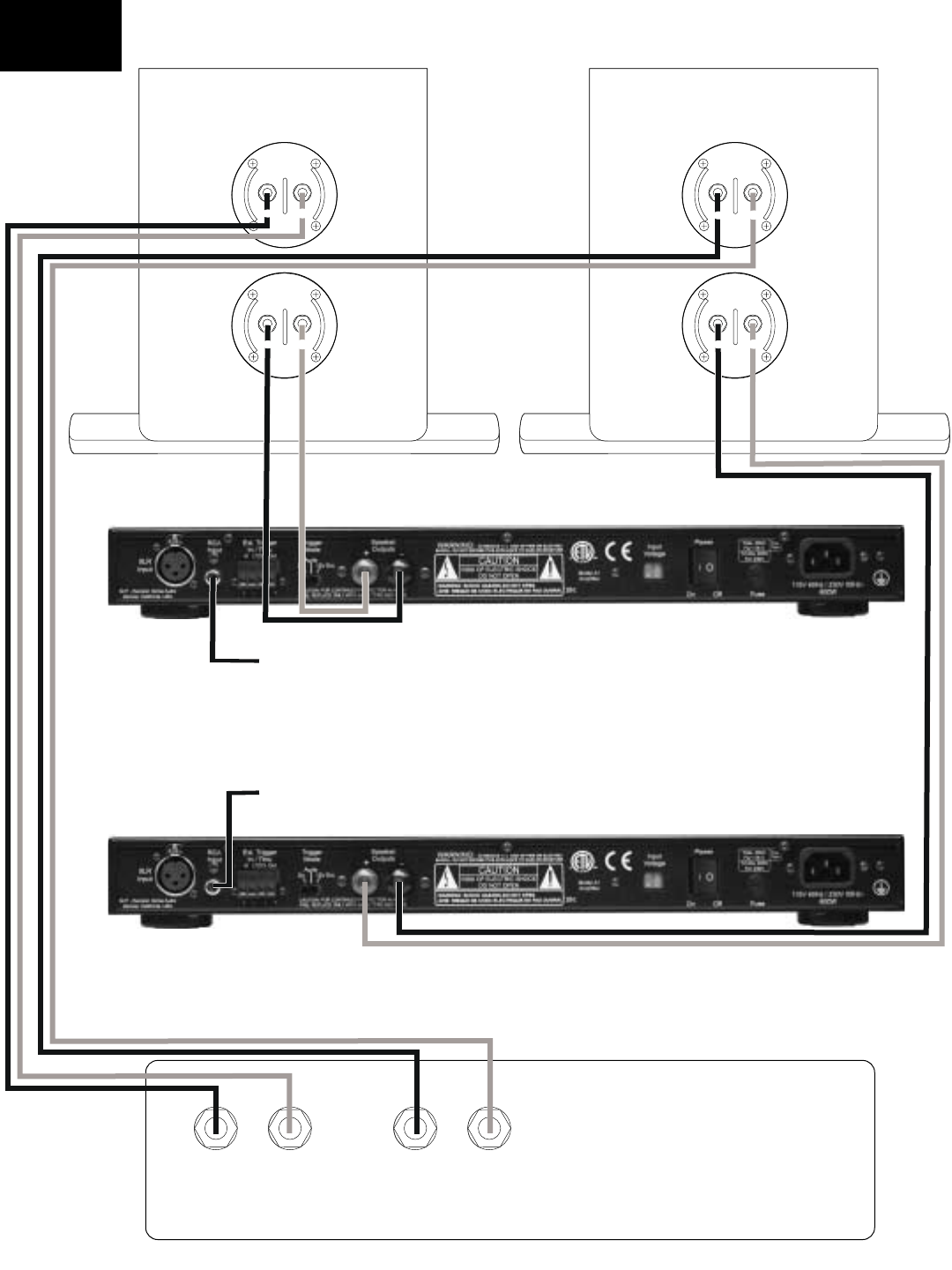
T6 Tower Left T6 Tower Right
A1
A1
+
+
+
+
Right Amp
Left Amp
AV Receiver
or Amplifier
From X1
From X1
T6 Wiring
Diagram
6.0 Connecting Evolution Electronics to Your
System.
There are a number of methods by which you
can connect the X1 Active Crossover and A1
Amplifier to the rest of your system. The method
you choose will be determined largely by the
surround components in your system. This
becomes particularly important in the manage-
ment of bass frequencies. The Evolution elec-
tronics were designed with flexibility and com-
patibility in mind.
The following section will take you through the
steps in making the final connections in your
system. If for some reason the methods
described in this Owner’s Manual don’t work
properly in your system, consult your NHT deal-
er or call us at 1-800-NHT-9993 (648-9993)
6.1 Signal Connections
Review the following connection method
descriptions and use the one that describes
your surround receiver or processor:
Method 1 - Use if there is a Subwoofer Output
(sometimes labeled “LFE”) on your AV Receiver.
Method 2 - Use if there is a pre-amp out/main in
section on your AV Receiver.
Method 3 - Use this method if have a separate
Surround Processor and Amplifier(s).
Method 1
Integrating the X1 into your surround system is
simple and straightforward when using this con-
nection method. Your AV Receiver will control
all crossover functions and the X1 will control
gain, phase and boundary equalization (see 8.3
below).
Connect the Subwoofer/LFE Output on your AV
Receiver to the LFE IN on the X1 active
crossover.
Method 1 - Recommended Surround Settings
We recommend setting the speaker size in your
processor or receiver to “small” when using
either the M5 or M6 monitors. The “small” set-
LFE/
Subwoofer
AV Receiver
X1
To Power amp
Method 1
ting will prevent low bass frequencies from
reaching the Monitors. The removal of the low
bass will make integration of the Monitors with
your Evolution subwoofer easier and has the
additional benefit of increasing the Monitor’s
dynamic range and power handling capability.
Method 2
This is the connection method to use if your AV
Receiver has a pre-amp out/main in section.
This connection method is preferred over
Method 1.
- Remove the jumper connections
between the pre-amp L/R front outputs and the
main L/R inputs.
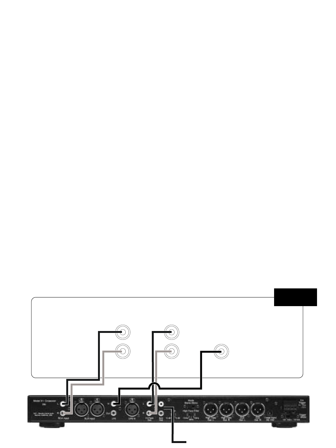
- Connect the Left and Right pre-amp out-
puts from your AV Receiver to the Left and Right
inputs on the X1.
- Connect the Left and Right Hi Pass out-
puts from the X1 to the Left and Right main
inputs on your AV Receiver.
- Connect a single cable from the
Subwoofer/LFE output on the AV Receiver to
the LFE input on the X1.
- Finally, using another single cable, con-
nect one of the Sub outputs on the X1 to the
input on the A-1. Set the mode switch on the X1
to Mono.
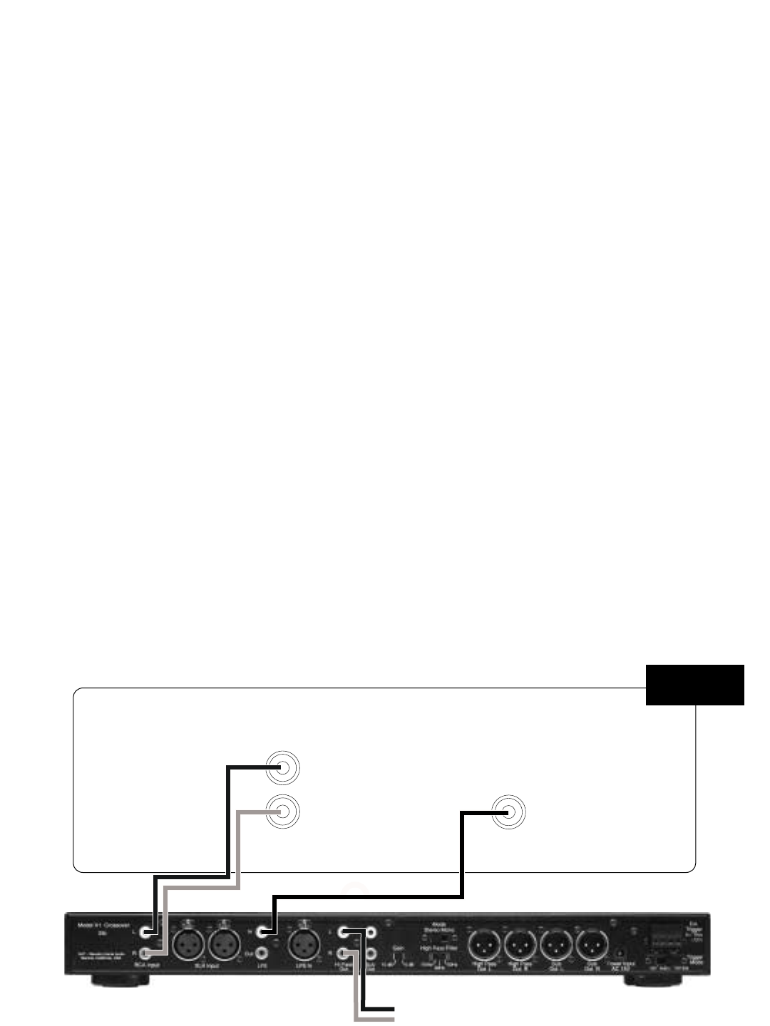
Note: If you are using two A1 amplifiers for
stereo bass, as with the T6 tower system, set
the mode switch on the X1 to Stereo and use the
remaining Sub output on the X1 and connect to
the input on the second A1 . Make sure the left
and right channels are wired correctly.
Method 2 - Recommended Surround Settings
Set your Left and Right front speakers to “large”
in your AV receiver. Set all other speakers that
are not capable of producing low bass frequen-
cies to “small”. The “large” setting will send a full
range signal to the X1. The Hi Pass and Lo
Pass controls on the X1 crossover will then be
used to set the crossover frequencies for the
front L and R monitors and the subwoofer (see
section 7). The Subwoofer(s) receive bass
information from the front Left and Right chan-
nels and the Subwoofer/LFE output (see section
8.3).
Pre Out Main In
RR
LL
X1
LFE/
Subwoofer
AV Receiver
To Power amp
Method 2
Method 3
Use this connection method if you have a sepa-
rate Surround Processor and Amplifier(s).
- Connect the front Left and Right pre-amp
outputs from your Surround Processor to the
Left and Right inputs on the X1.
- Connect the Left and Right Hi Pass out-
puts on the X1 to inputs of the amplifier that is
driving the front Left and front Right speakers.
- Using a single cable, connect the
Subwoofer/LFE output from the Surround
Processor to the LFE input on the X1.
Method 3 - Recommended Surround Settings
Set your Left and Right front speakers to “large”
on your AV receiver. Set all other speakers that
are not capable of producing low bass frequen-
cies to “small”. The “large” setting will send a full
range signal to the X1. You will then use the Hi
Pass and Lo Pass controls on the X1 to set the
crossover points for the front monitors and the
subwoofer (see section 7). The Subwoofer
receives bass information from the front Left and
Right channels and the Subwoofer/LFE output
(see section 8.3).
Note when using methods #2 and #3: Some
Surround Processors and AV Receivers offer an
additional LFE/Subwoofer setting, often referred
to as “Extended Bass” or “Reinforced Bass”. If
your equipment offers this option we strongly
recommend that you do not select it. The X1
processor will automatically sum the LFE chan-
nel with the left and right subwoofer information.
Pre Out
R
L
X1
LFE/
Subwoofer
AV Surround Processor
To Power amp
Method 3
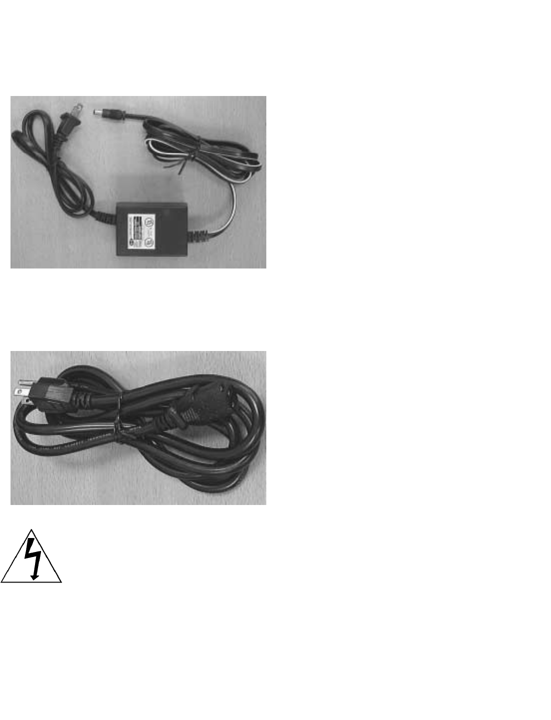
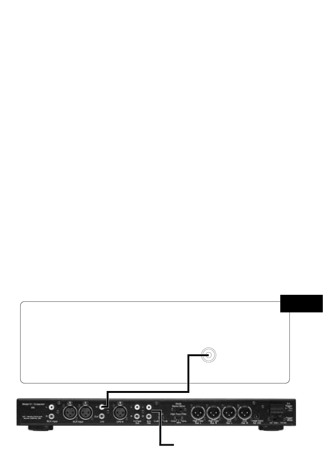
6.2 Power Connections
The X1 crossover receives power via the LL-1
power supply.
The A1 amplifier receives power via the detach-
able IEC style power cord.
Caution: Prior to connecting the A1
amplifier to your audio system, make
sure that all your other electronic
equipment is turned off or unplugged.
7.0 Basic Settings for the X1 Active
Crossover
The following diagrams will provide starting
points for each control feature on the X1. The
diagrams are organized by Evolution model.
Begin with these basic settings and then move
to Section 8 which describes each X1 control
function in detail and provides advice for fine
tuning the X1 to your listening room.
Note: If you are using main speakers other than
Evolution, use the initial settings described for
the U1 or U2 subwoofer.
M5 or M6
Not used in Method #1
One W1 = Mono
Two W1 = Stereo
Boundary EQ LFE Gain
Master Gain
Min
Min
-6
-3 +3
Max
Max
+6
0
090
180
0
Phase
75
55
30
Low Pass
140
80
110
HZ
50
65
Degrees dB
LFE LFE In High Pass
Out L High Pass
Out R
Hi Pass
Out Sub
Out
Gain High Pass Filter
Out
In
R
L
110Hz
Stereo
10 dB 80Hz 50Hz
Mono
0dB
Not used in Method #1
U1
M5 or M6
Not used in Method #1
Boundary EQ LFE Gain
Master Gain
Min
Min
-6
-3 +3
Max
Max
+6
0
090
180
0
Phase
75
55
30
Low Pass
140
80
110
HZ
50
65
Degrees dB
LFE LFE In High Pass
Out L High Pass
Out R
Hi Pass
Out Sub
Out
Gain High Pass Filter
Out
In
R
L
110Hz
Stereo
10 dB 80Hz 50Hz
Mono
0dB
U2
Boundary EQ LFE Gain
Master Gain
Min
Min
-6
-3 +3
Max
Max
+6
0
090
180
0
Phase
75
55
30
Low Pass
140
80
110
HZ
50
65
Degrees dB
Boundary EQ LFE Gain
Master Gain
Min
Min
-6
-3 +3
Max
Max
+6
0
090
180
0
Phase
75
55
30
Low Pass
140
80
110
HZ
50
65
Degrees dB
LFE LFE In High Pass
Out L High Pass
Out R
Hi Pass
Out Sub
Out
Gain High Pass Filter
Out
In
R
L
110Hz
Stereo
10 dB 80Hz 50Hz
Mono
0dB
Not used in Method #1
T6
8.0 X1 Active Crossover
8.1 Design
The NHT X1 active crossover is designed to
provide convenient front-panel adjustment of the
controls necessary to integrate the Evolution
subwoofers with Evolution Monitors or other
satellites. It also provides unbalanced RCA and
differential balanced XLR inputs and outputs for
connection with all types of receivers or sepa-
rate audio components.
NOTE: The X1 contains special equalization
circuitry specifically designed for Evolution sub-
woofers and tower bass modules only. Do not
use with non-Evolution subwoofers.
The X1 Active Crossover can operate as either
a mono (single channel) or stereo unit. In the
stereo mode, you may add an additional sub-
woofer without purchasing an additional
crossover. Two subwoofers can be used for
stereo bass (which is desirable for music repro-
duction) or for additional mono bass reinforce-
ment (for movie soundtracks).
Note: Do not use both the unbalanced (RCA)
and balanced (XLR) inputs at the same time.
The unbalanced (RCA) and balanced (XLR) out-
puts are buffered separately and may be used
simultaneously.
8.2 Placement
The X1 Crossover may be used on a shelf, or in
a standard 19" equipment rack using the option-
al rack ears and hardware. See section 10.3 for
instructions on rack mounting.
Ideally, the X1 should be placed in close prox-
imity to the receiver or surround processor.
Minimizing cable lengths reduces the chance of
noise contamination. If long runs (more than 20
feet) of signal cables are required, we recom-
mend using the balanced (XLR) inputs and out-
puts on the crossover.
If you are using the X1 in combination with the
Evolution A1 amplifier, we recommend that you
place the X1 underneath the A1 amplifier. Or, in
a stereo configuration, place the X1 between
two A1 amplifiers. The A1's are equipped with
lamps under the front edge, which illuminate the
X1 controls. See section 9.2 for more detail.
8.3 X1 Features and Controls
This section describes the various controls and
functions of the X1. Make sure that your X1 con-
trols initially are set as described in Section 7 for
your Evolution model before continuing.
Power/Standby Mode (Rear Panel)
Your X1 crossover does not have a power
switch but has been designed with the ability to
turn on and off under various conditions. There
are three methods for activating the X1.
Once the X1 is
plugged into the
wall outlet it is on -
- there is no main
power switch.
The X1 has a
standby mode
that can be trig-
gered internally or externally. On the rear panel
of the X1 is a 3-position switch that determines
the trigger mode:
1) On; the X1 is always on.
2) Audio; the X1 will automatically turn on
when it detects an audio signal and turn off after
20 minutes with no signal.
3) 12V Ext; the X1 can be remotely turned
on or off when it detects a DC control signal from
another component in your system. The exter-
nal trigger will accept 5 - 24 volt (DC) signals.
For more information regarding external trig-
gers, consult your authorized dealer.
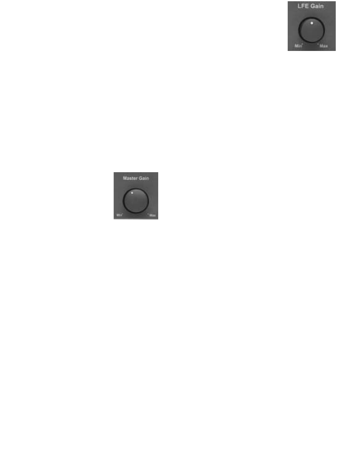
Master Gain (Front Panel)
The Master Gain control allows
you to adjust the volume of the
subwoofer relative to the moni-
tors. Use the Master Gain judi-
ciously. A properly calibrated
subwoofer blends seamlessly
with the Monitors or satellites without calling
attention to itself. Here are some general guide-
lines for setting the Master Gain control:
Begin by playing some stereo music you are
familiar with. Set your AV Receiver or Surround
Processor volume to a comfortable listening
level. Slowly increase or decrease the Master
Gain on the X1 crossover, listening for a natural
frequency balance between the subwoofer (or
tower bass module) and the front left and right
monitors. When properly balanced, you will
hear natural bass extension, without being
aware that it is coming directly from the sub-
woofer.
Once the Master Gain is set, the volume control
on your AV Receiver or Surround Processor will
control the volume of your entire system, includ-
ing the subwoofer.
LFE Gain Control (Front Panel)
LFE is short for ‘Low Frequency
Effects’. Low Frequency Effects
originally were low frequency
sounds added to movie sound-
tracks in order to increase their impact. For con-
sumer electronics, there is no standard con-
cerning what type of signal might be present on
the LFE channel. Therefore, we have added an
LFE input and gain control to the X1 so that you
can integrate whatever is present on the LFE
channel with the signal being reproduced by the
rest of the system.
After you have set the Master Gain level as
described above, play a multi-channel signal
through your system (as from a movie).
Sources with lots of bass output will be the most
useful. Adjust the LFE gain control until the
bass produced by the subwoofer reaches the
desired level. Most users initially set the level of
the LFE gain control at too high a level, so be
prepared to adjust the control over a long period
of time. You have reached an appropriate level
setting when movies soundtracks have impact
and music sources have punchy bass, but the
overall character of the bass produced by the
subwoofer is not thick and ill defined.
The level of the signal on the LFE channel
varies considerably from source to source, so
you may need to use the LFE level trim featured
in most receivers and processors to adjust the
LFE level on a source-by-source basis.
There is an LFE “Thru” output on the back of the
X1. For more information concerning the use of
this output, visit our website,
www.nhthifi.com/technicalhelp/evolution .
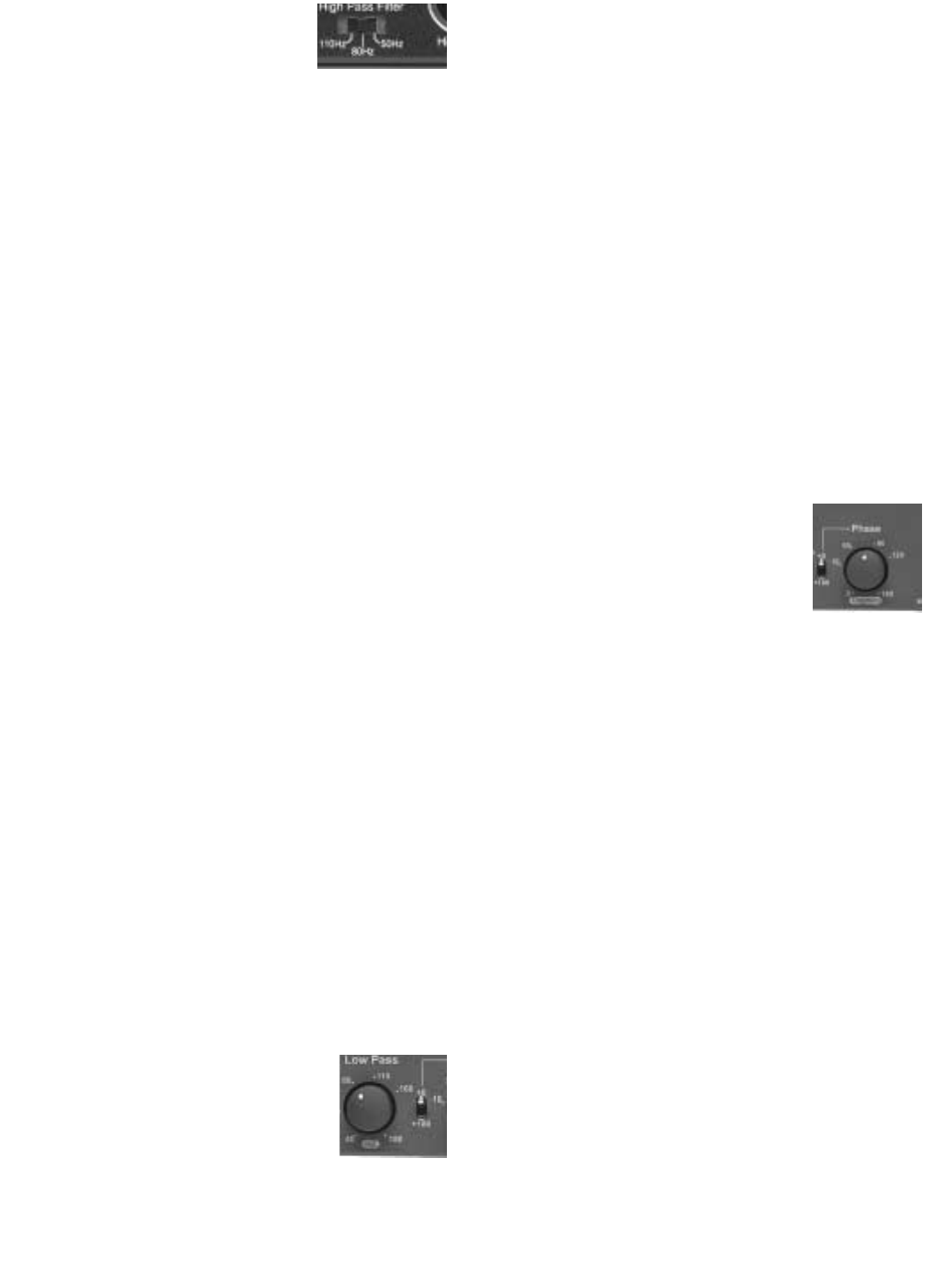
High Pass Filter Switch (Rear
Panel) - Connection Method 2
and 3 Only
Note: If you are using Connection Method #1,
the X1 High Pass Filter is not in the circuit path.
Your monitors will reproduce the frequency
range selected by your AV Receiver.
The High Pass Filter determines the range of
frequencies that the main speakers ("satellites")
will reproduce. For example, a high pass setting
of 80Hz means that the main speakers receive
a signal containing only frequencies above
80Hz. The 3-positon High Pass Filter is selec-
table between 50Hz, 80Hz, and 110Hz to
accommodate a variety of speaker sizes.
If you are using Evolution monitors, the setting
for this control shown is Section 7 should be suf-
ficient. If using speakers other than Evolution
monitors and Connection Methods 2 or 3, use
the guidelines below.
Set the High Pass Filter to a frequency above
the rated low frequency limit of the main speak-
ers. For example, if your speakers have a rated
low frequency response of 40Hz, use the 50Hz
high-pass setting. If your speakers have a rated
low frequency response of 90Hz, use the 110Hz
high-pass setting. Check the owner's manual
for their rated low frequency response.
Low Pass Filter Control (Front Panel) -
Connection Methods 2 and 3 Only
The continuously variable Low
Pass Filter determines the range of
frequencies produced by the sub-
woofer. For example, a low pass
setting of 100Hz means that the
subwoofer reproduces only frequencies below
100Hz. The LFE input is not affected by this
control.
Adjust the Low Pass Filter to approximately the
same setting as the High Pass Filter as a start-
ing point. Adjust the Low Pass Filter in small
increments up or down until the blend between
the Evolution Subwoofer and your main speak-
ers is seamless and the subwoofer does not call
attention to itself. Music featuring male vocals,
cello and acoustic bass, bass guitar and certain
wind instruments (like saxophone and trom-
bone) is useful for setting the low pass frequen-
cy.
Phase Controls (Front Panel)
The Subwoofer Phase switch
and continuously variable knob
set the phase of the subwoofer
output anywhere from 0° to
270° relative to the high pass
output. Proper subwoofer phase is important in
achieving smooth bass response. An improper
phase setting can cause large peaks and dips in
the frequency response of the combined sub-
woofer/satellite system at the listening position.
The result of the peaks and dips is low frequen-
cy production that is very pronounced at certain
frequencies and a lack of seamless integration
between the satellites and subwoofer.
The optimal phase setting will differ according to
room conditions and placement. While fine tun-
ing phase settings, have a familiar stereo CD
available. You should listen to the same song
while alternating phase settings. Find the best
setting while sitting at the primary listening posi-
tion.
The initial settings described in Section 7 should
be an adequate starting place for your Evolution
system. However, if you want to experiment or
are using main speakers other than Evolution
Monitors, use the following procedure: Begin by
setting the phase knob at 0°, alternating the
switch position between 0° and 180°. From the
listening position, choose the switch position
that yields the most bass output and leave the
switch there. Then use the knob to fine-tune the
phase setting. Slowly twist the knob, listening for
the point at which the bass at the listening posi-
tion is the loudest. Small changes in phase gen-
erally produce subtle changes in bass output.
You may have to adjust the knob now and again
over a period of a few weeks to find the best set-
ting for your listening room.
Gain Switch (Rear Panel)
The Subwoofer Gain switch allows you to
increase the gain of the X1 subwoofer output by
10dB. Normally, the factory default "0" position
will give you a wide range of volume adjustment.
However, if the sensitivity of your satellite
speakers is greater than 93dB, your range of
volume adjustment on the X1 may be limited. In
this case, set the Gain Switch to 10dB.
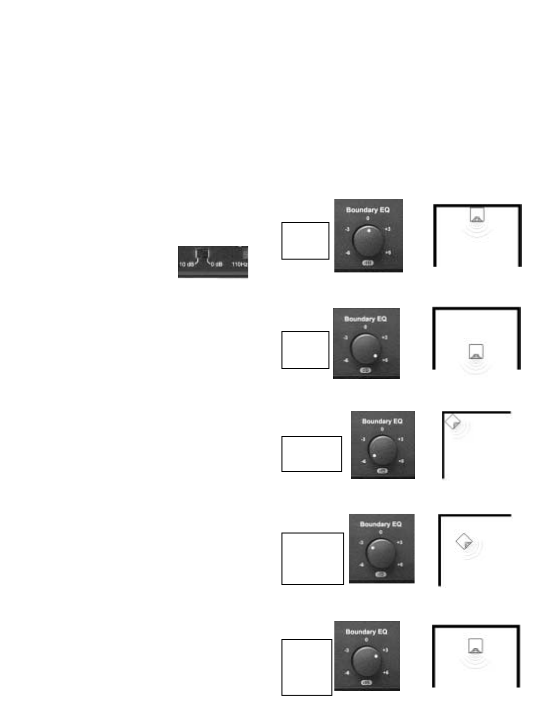
Boundary EQ (Front Panel)
The Boundary EQ is a feature unique to NHT
Evolution products. Reflective boundaries (such
as walls) reinforce a speaker’s bass output (3dB
for two walls, 6dB for a corner) if the subwoofer
is placed near them. Conversely, placing a sub-
woofer out in the room results in a relative
decrease of bass output. Boundary reinforce-
ment may lead to low frequency response that is
uneven. Some frequencies will sound exagger-
ated relative to others, or the subwoofer will
sound thin and lack impact. The Boundary EQ
control allows you to compensate for the effects
of room boundaries on the frequency response
of the subwoofer. Adjusting the control enables
you to achieve smooth low frequency output
from the subwoofer regardless of its location in
your room.
The following diagrams show the correlation
between subwoofer placement and Boundary
EQ. These diagrams are guidelines only. Your
room acoustics and personal tastes will ulti-
mately dictate the final setting.
Quarter
Space
Quarter/
Half
Space
Half/
Whole
Space
Half
Space
Whole
Space
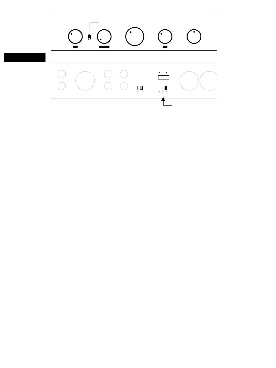
8.4 System Status Indicators
(Front Panel)
Located on the right hand side of the front panel
are two LEDs. They are used to indicate the
functional status of the X1 Crossover.
P - Power LED (green) - indicates the X1 is on
and in a ready condition.
S - Standby LED (amber) - indicates the X1
crossover is in "standby" mode.
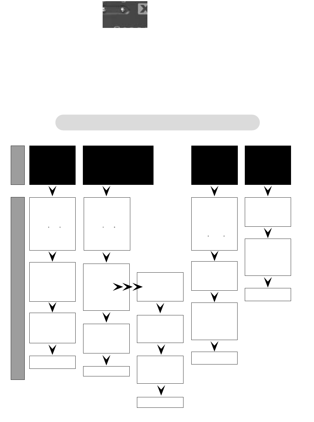
8.5 Fine Tuning Chart
The chart below was developed to assist you in
the further fine tuning of your subwoofer or
tower system. Should you be unable to achieve
satisfactory performance from your Evolution
subwoofer system using the fine-tuning chart,
contact your authorized NHT dealer or call our
Customer Hotline at 1-800-NHT-9993 (648-
9993).
"Boomy"
Too Much
Mid / Upper
Bass
Problem
Solution
Lacks
Low
Bass
Weight
Excessive
Low
Bass
Weight
Lacks
Mid / Upper Bass:
Lean But With
Weight
Fine Tuning Flow Chart
Lower
Low Pass
X-Over
Frequency
Increase
Boundary
EQ
Decrease
Boundary
EQ
Adjust
Subwoofer
Volume
Listen
If this makes
it worse,
try
If the sound
improves
Raise
Low-Pass
Setting
Adjust
Subwoofer
Volume
Adjust
Subwoofer
Phase
Listen
Lower
Subwoofer
Volume
Move
Subwoofer
Closer to
Wall
Move
Subwoofer
Farther
From Wall
Adjust
Subwoofer
Phase
0-90
(Continuously
Add)
Adjust
Subwoofer
Phase
0-90
(Continuously
Add)
Adjust
Subwoofer
Phase
Switch
0-180
Listen Listen
Listen
9.0 A1 Monaural Amplifier
9.1 Design
The A1 is a full range (20Hz - 20kHz) audio
power amplifier. It provides RCA and XLR
inputs for connection with all types of receivers
or separate audio components. The A1 is a sin-
gle channel or monaural amplifier and can be
used with Evolution subwoofer and tower prod-
ucts or to power individual Evolution monitors.
The A1 is a Class G design, which operates at
lower temperatures than other amplifier classes
and is typically more efficient. The A1 offers the
wide dynamic range and low distortion typical of
more conventional class AB designs.
9.2 Placement
The A1 amplifier may be placed on a shelf, or in
a standard 19" equipment rack using the option-
al rack ears and hardware. See instructions on
rack mounting below.
Ideally, the A1 should be placed in close prox-
imity to the receiver or surround processor.
Minimizing cable lengths reduces the chance of
noise contamination. If long runs (more than
20’) of signal cable are required we recommend
using the balanced (XLR) input on the amplifier.
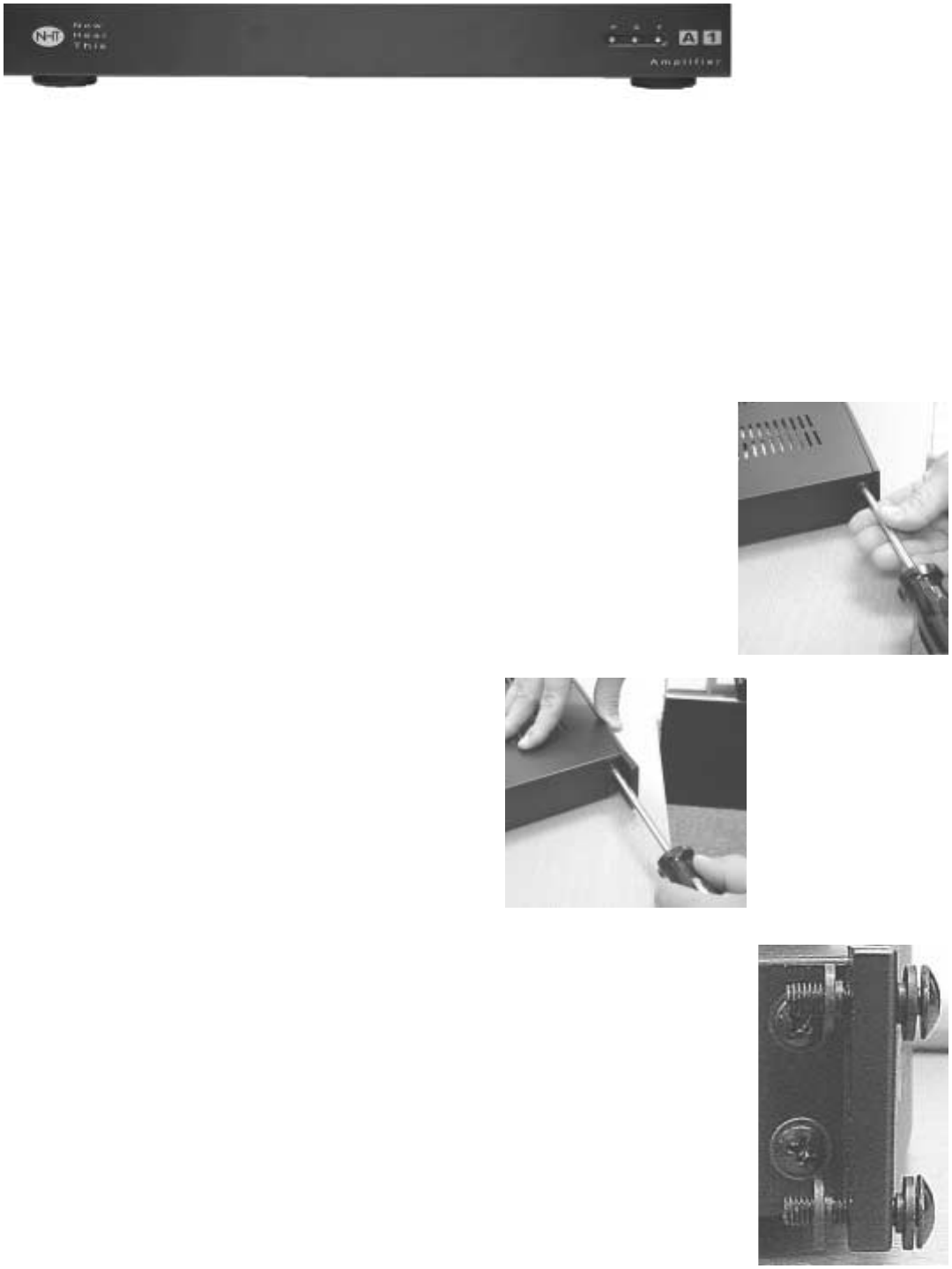
9.3 Rack Mounting the A1 and or X1
You may need assistance to hold the A1 or X1
in place while mounting them to the rack.
Note: When rack mounting, we recommend you
leave at least one rack space between compo-
nents (particularly amplifiers) for proper cooling.
Step One: Remove the
two screws on each
side of the X1 or A1 with
the #2 Phillips screw-
driver.
Step Two: Position
the rack ears over
the threaded holes.
Replace the two
screws and tighten
both securely.
Step Three: Arrange the
mounting screws included
with the rack ears and the
plastic insulating washers
as shown.
Step Four: Start all four
bolts, then tighten secure-
ly.
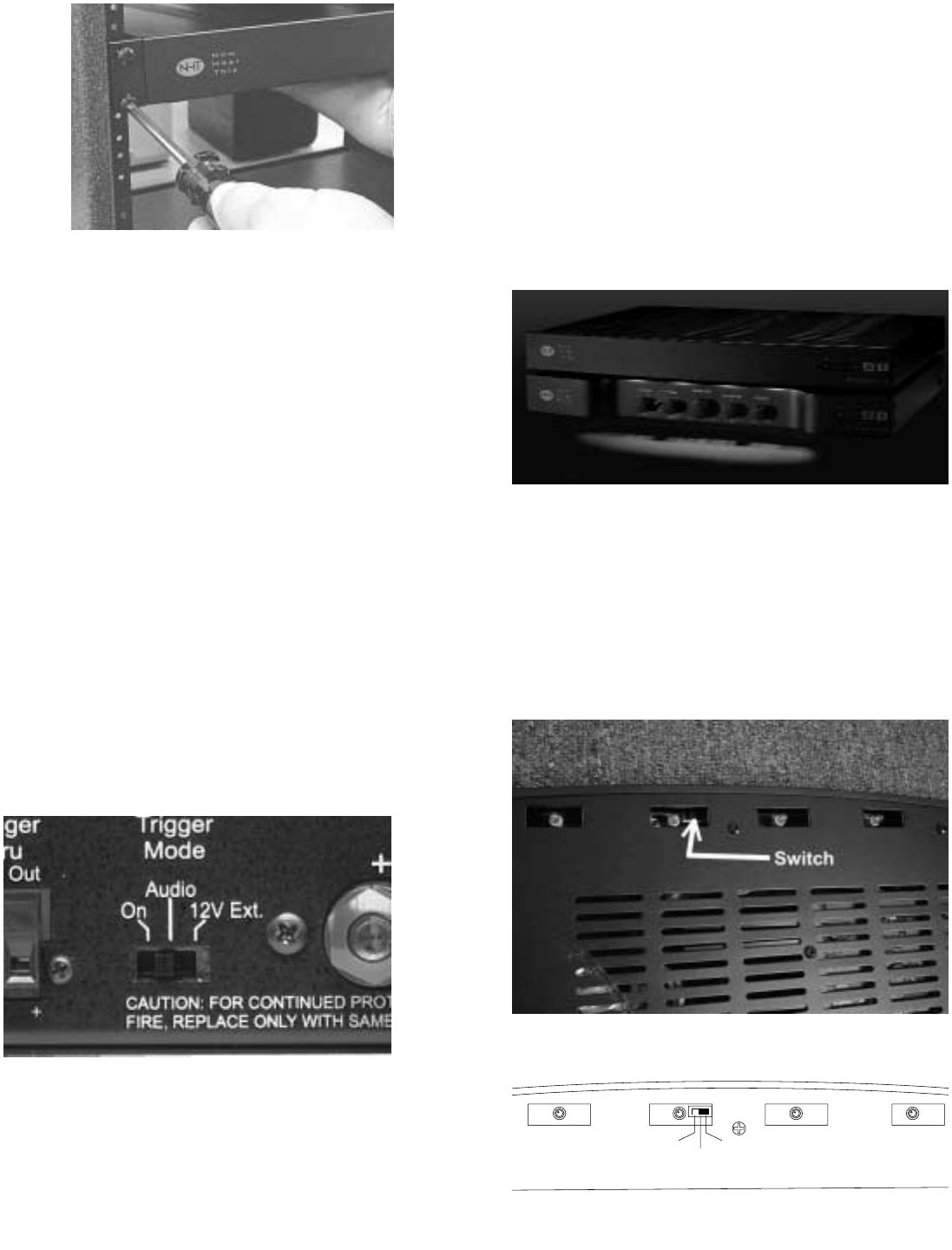
9.4 Power/Standby Mode
The main power switch for the A1 is located on
the rear panel and does not normally need to be
used. The A1 has a standby mode that can be
triggered internally or externally. On the rear
panel of the A1 is a 3-position switch that deter-
mines the trigger mode:
1) On: The A1 is always on.
2) Audio: The A1 will automatically turn on
when it detects an audio signal and turn off after
20 minutes with no signal.
3) 12V Ext: The A1 can be remotely turned
on or off when it detects a DC control signal from
another component in your system. The exter-
nal trigger will accept 5 - 24 volt (DC) signals.
For more information regarding external trig-
gers, consult your authorized dealer.
9.5 A1 Courtesy Lights
The A1 amplifier is equipped with courtesy lights
to illuminate the controls of the X1. This feature
is controlled by a 3-position switch for HI, LO
and OFF that can be accessed from the bottom
of the amplifier just behind the center of the front
panel. The A1 courtesy lights are set in the HI
position at the factory.
To adjust intensity or turn off the lights, unplug
the A1 from the wall. Use a small flat blade
screwdriver and move the switch according to
the desired position using the diagram. The
courtesy lights will shutoff automatically when
the amplifier is in “standby” mode.
High Low Off
9.6 System Status Indicators
Located on the right hand side of the front panel
are three LEDs. They are used to indicate the
status of the A1 amplifier.
P - Power LED (green) - indicates the A1 ampli-
fier is on and in a ready condition.
S - Standby LED (amber) - indicates the A1
amplifier is in "standby" mode.
F - Fault/Protection LED (red) - indicates the A1
amplifier is in a shutdown condition.
Fault/Protection: The A1 can shutdown in
Protection mode for several reasons. A com-
mon reason is that the speaker output wires
have shorted together. Another could be that
the amplifier has overheated. Should either of
these conditions occur, repairing the cause of
the output short or allowing the amplifier to cool
will solve the problem. To reset the A1, turn the
power switch (rear panel) off and then on. If the
problem persists, contact your NHT dealer.
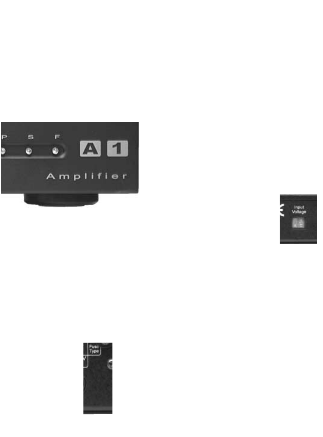
9.7 Replacing the Fuse
The A1 amplifier's fuse
is user-serviceable.
To replace the fuse:
1. Turn the power off.
2. UNPLUG the power cord.
3. Remove the fuse holder cover (next to
power cord) with a flat blade screwdriver.
4. Remove the fuse from holder and replace
it with the appropriate type.
5. Reinstall fuse holder.
Always replace the fuse with one of the exact
same specifications.
For systems operating at 115VAC, use only a
5x20 mm, T5AL, 250V slow-blow fuse.
For systems operating at 230VAC, use only a
5x20mm, T2.5AL, 250V slow-blow fuse.
9.8 Changing the Line Voltage Setting
The A1 was designed to operate
on two line voltage settings,
115VAC and 230VAC. In the
event that it is necessary to
change the line voltage setting,
begin by turning the power
switch to the off position. Remove all the con-
nections from the amplifier, including the detach-
able power cord. Using a flat blade screwdriver,
slide the switch to the correct position. Use the
115VAC position for 110 to 120 VAC, and the
230VAC position for 220 to 240 VAC. Next you
will likely need a power cord that fits the AC
receptacle and you will need to replace the fuse
(see "Changing the Fuse" above)

10.0 Maintaining your system
Your NHT Evolution speakers and electronics
require minimal maintenance under normal use.
The cabinet may be cleaned using a soft cloth.
There is usually no need to use fluids such as
cleaners or wax to clean the surface of the
speakers. The durable lacquer finish is designed
for minimal maintenance. To clean the grille, first
remove it from the speaker, then brush lightly
with a soft brush or use a vacuum on its lowest
setting. Do not attempt to clean the actual dri-
vers. To remove dust, you may use a feather
duster. Do not expose the speakers to direct
sunlight, high temperatures, or moisture.
Electronic components should be wiped with a
dry, soft cloth to remove dust. Do not use any
liquid near or on the electronics as it may cause
electrical shock.
11.0 Evolution Technology
11.1 Monitor Technology
NHT chose the word Evolution to describe our
new products for two reasons. Evolution repre-
sents our belief that loudspeaker design must
evolve to meet the requirements of multi-chan-
nel, digital media both technologically and
ergonomically. Secondly, it represents the evo-
lution of the fundamental technologies unique to
NHT over our 15-year history.
The simple, elegant lines of our Evolution loud-
speakers and subwoofers belie the tremendous
amount of technology built into them. This sec-
tion describes the attention to detail and high
performance contained in this unique collection.
Inside the Evolution Monitors:
Both the M5 and M6, while offering different dri-
ver compliments, offer similar performance. The
distinguishing characteristic between the two
monitors is how loud they will play; the M5 is
designed for small to medium sized rooms, the
M6 for large rooms. The construction methods
and internal technological features that deliver
such high performance are the same.
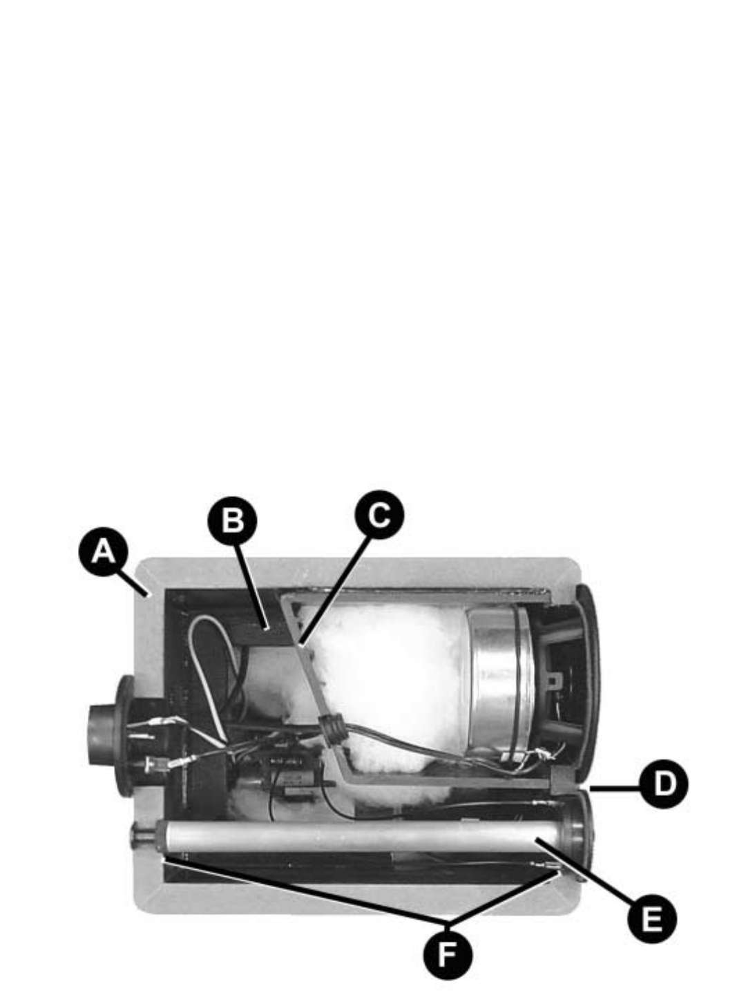
A View Inside an Evolution Monitor
A) The cabinet is constructed of 3/4” MDF.
Lamination on the inside increases structural
rigidity.
B) Where necessary the cabinets are braced to
minimizing unwanted resonances.
C) The internal midrange chamber features non-
parallel internal surfaces that randomize stand-
ing waves, eliminating comb-filtering and
improving clarity and detail. The chamber is also
sized to the midrange driver so that it is acousti-
cally small. This further reduces the possibility of
standing waves.
D) The small footprint of the Neodymium tweet-
er allows closer placement to the midrange dri-
ver, improving mid-range coherence.
E) The tweeter is mounted to a solid aluminum
“Wonder” bar that acts as a massive heatsink,
providing high power handling and less power
compression.
F) The Wonder Bar is mounted to the tweeter
from the rear of the cabinet, further increasing
cabinet rigidity.
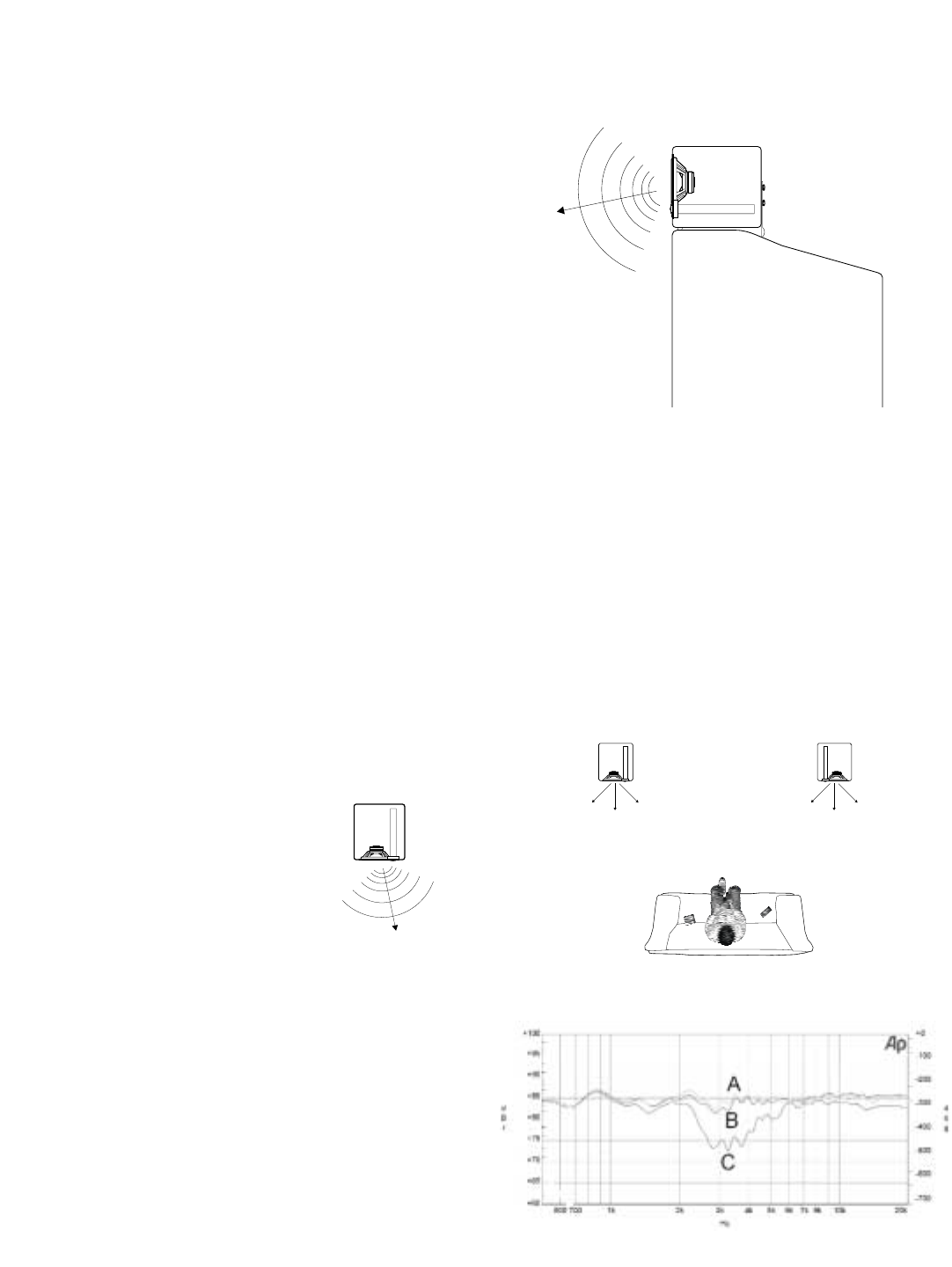
11.2 What is "Virtual" Focused
Image Geometry?
NHT's hallmark for many years was a uniquely
angled which we described as Focused Image
Geometry (F.I.G.). The angled cabinet focused
the mid-range and high frequencies into the lis-
tening room and away from room boundaries
increasing the ratio of direct to reflected sound.
This resulted in loudspeakers systems univer-
sally praised for their imaging and detail to a
wide listening area.
Evolution incorporates a "virtual" adaptation of
F.I.G. Rather than an angled cabinet, we
increase the energy at the listening position
using the crossover.
When Evolution monitors are vertically oriented
and the tweeters on the inside edge of the cabi-
net the null created in the crossover between
the mid and high frequency drivers is directed at
the sidewalls. The graph below shows the
decrease in energy, or reflected sound towards
the wall (C) and the compared to the direct
sound radiating at listening area (A & B). This
improves detail and provides a 3-dimensional
soundstage.
Television
CA
BB
AC
When oriented horizontally, the null is directed at
the ceiling or floor (depending on tweeter posi-
tion) improving mid-range detail.
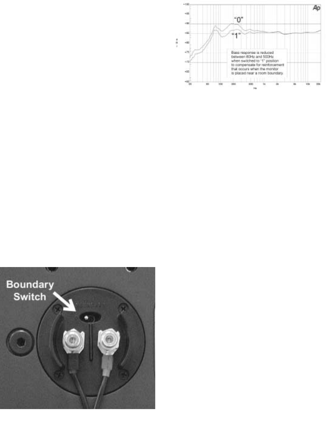
11.3 Boundary Switch
A loudspeaker’s mid-bass response is very
dependant on its room placement. For exam-
ple, if a speaker is tuned for placement away
from walls and is then placed on a bookshelf,
the reinforcement of mid-bass frequencies will
make the speaker sound somewhat “thick”. The
M5 and M6 feature a unique dual mode
crossover that adjusts the monitor’s response in
the mid-bass range for either placement situa-
tion. The graph below illustrates the decrease in
bass energy from 80Hz to 500Hz when the
switch is in the “1” position, making placement
on a shelf or television possible while maintain-
ing proper frequency response. The “0” position
optimizes the monitor for placement away from
room boundaries.
11.4 High Dynamic Range/Low Power
Compression
The increased dynamic range of digital media
can make much greater demands on the output
capabilities of speakers than in the past. As
speakers are pushed towards their limits, the
temperature of the drivers rises. Heat causes
the drivers impedance (resistance to AC current
flow) to increase, reducing the amount of power
the amplifier can deliver to the driver. Dynamic
range is reduced, distortion increases and
sound quality suffers.
Evolution monitors and subwoofers are
designed to minimize this phenomena in a num-
ber of important ways.
1) The 12” woofer contained in all Evolution
subwoofers and tower bass modules employs,
in addition to a massive motor structure, an alu-
minum cone attached to an aluminum former.
The cone acts as a heat sink for the driver, min-
imizing the rise in impedance and resulting dis-
tortion.
2) The Wonder Bar, mounted to the tweet-
ers in the Evolution monitors, dissipates heat
from the most fragile driver in any loudspeaker.
3) Evolution monitors are 3-way systems
with dual woofers. The input power is spread
over multiple drivers, minimizing heat build up
and distortion.

11.5 Orientation Independent Dispersion
The Evolution monitors are optimized for use in
either a horizontal or vertical orientation. This is
achieved by means of the relative placement,
size and crossover frequencies of the drivers.
The very small separation between the
midrange and tweeter drivers allows dispersion
that is very wide and well controlled. When com-
bined with the low crossover frequency between
the woofers and midrange, the resulting sound-
field permits the speaker to be used in a hori-
zontal or vertical orientation without significant
changes in frequency response and imaging
characteristics.
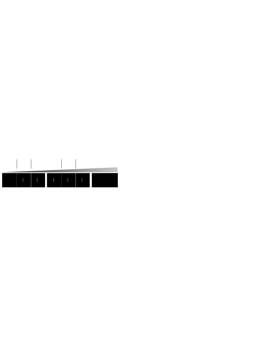
12.0 Glossary of Terms
Active: Uses electrical power.
Amplifier: An electronic device that increases
the current and/or voltage of a signal, providing
power to the loudspeakers (i.e. power amplifier,
integrated amplifier, receiver).
Bass: The range of audio frequencies below
160Hz, characterized by low pitch.
Crossover: An electronic circuit that divides an
audio signal into different frequency ranges.
Distortion: Any deviation from the original sig-
nal.
Driver: The moving part of a loudspeaker, which
radiates sound energy.
Dynamics: Variations in loudness of sound.
Frequency: A rate of vibration, which corre-
sponds to musical pitch, expressed in Hertz
(Hz).
Full Range: A signal encompassing the entire
frequency spectrum.
Hertz (Hz): A unit equal to one cycle per sec-
ond, used to measure the frequency of a signal
or sound.
High-Pass Filter: A filter that passes only high
frequencies above a lower limit.
Impedance: A measure of the total opposition
to current flow in an alternating current circuit,
measured in ohms.
In Phase: The polarity of an audio signal when
connected as follows: (+) to (+) and (-) to (-).
Integrated Amplifier: A preamplifier and ampli-
fier built into one chassis.
Interconnect Cable: A length of shielded wire
with plugs at both ends for feeding signals from
one electronic device to another.
L.F.E.: "Low Frequency Effects"; The .1 channel
of information recorded on most multichannel
digital sound formats.
Line-Level Connection: Low level RCA/phono
or XLR type connection.
Load: A term used to describe the impedance
that a speaker presents to an amplifier.
Low-Pass Filter: A filter that passes only low
frequencies below a higher limit.
Main Speakers: Front L & R channel speakers,
sometimes referred to as satellites.
Main-In: A line-level RCA/XLR power amplifier
input on the back of a receiver, integrated ampli-
fier or power amplifier.
Midrange: The frequency span in the middle of
the audio range, roughly 160Hz - 1300Hz. Also
used to describe the driver that reproduces
these frequencies.
Ohm: A unit of electrical resistance. That which
opposes an electric current in a conductor. In
audio, a measure of the load presented by a
device to an electrical source.
Out-of-Phase: The polarity of an audio signal
when connected as follows: (+) to (-) and (-) to
(+).
Passive: Uses no electrical power.
Phase: An expression of the relative polarities
of two signals.
Power Handling: The ability of a loudspeaker to
operate without large increases in distortion
when given varying amounts of input power.
Preamplifier: An electronic device that selects
sources and passes line-level signals to an
amplifier.
Pre-Out: A preamp line-level RCA output on the
back of a receiver, integrated amplifier or pre-
amplifier.
Receiver: A preamplifier, amplifier and tuner
built into one chassis.
Satellite: Front L & R speakers when used with
a subwoofer. Referred to as "main speakers".
Sensitivity: A ratio of voltage across the speak-
er load to the acoustic power output, measured
Low
Bass
Lower
Mid High
Mid
Bass Mid
Upper
Bass
Upper
Mid
Below
50Hz
50Hz 300Hz180Hz100Hz 700Hz
100Hz 700Hz300Hz
3KHz
and Above
180Hz 3KHz

in decibels.
Sub Out: An line level output for connection to
a subwoofer or subwoofer signal processor.
Subwoofer: A driver designed to operate over
the low bass portion of the audio range. Also
refers to a system consisting of a woofer and its
enclosure, which are physically separate from
the upper range loudspeakers.
Surround Speakers: Speakers located in the
side or rear for surround channel effects.
Treble: The upper part of the frequency spec-
trum, consisting of frequencies above about
1300Hz.
Tweeter: A small driver designed to reproduce
high frequencies.
Watt: A measure of electrical power, combining
the voltage with the electrical current required to
drive the loudspeaker.
Weight: Low frequencies below 50Hz.
Woofer: A driver designed to operate over the
bass portion of the audio range.

13.0 Trouble Shooting
Problem What To Do
Unit fails to illuminate when the power
is connected. 1) Check to see if your AC outlet has power.
2) X1 protection fuse may be blown and
needs to be replaced. Contact your NHT
dealer for assistance.
3) A1 protection fuse may be blown and
needs to be replaced. See section 10.6
changing the fuse.
Unit has no sound output 1) Verify that the ‘P’ (Green) LED is illuminated.
2) If only the ‘S’ (Amber) LED is illuminated verify that the
trigger mode switch is in the ‘Audio’ position.
3) If the trigger mode switch is in the ‘12V Ext’ position
make sure there is 12VDC signal present.
4) Verify system hookup is correct and your unit is reciev-
ing signal.
5) (A1 Only) If the ‘F’ fault (RED) LED is illuminated,
check for shorted speaker wires. Turn unit off/on to
reset.

14.0 Specifications
A1 Amplifier
Frequency response: 10Hz - 65KHz +/-3.0 dB
20Hz - 20KHz +/- 0.5 dB
Distortion: <0.01% 20Hz-1KHz
< 0.075% 10Hz - 20Khz
Power Output:
200W rms into 8 ohms at rated distortion
250W rms into 6 ohms at rated distortion
300W rms into 4 ohms at rated distortion
Signal to noise ratio: 100dB (unwtd)
Input Impedance: >10K ohms
Damping Factor: >100 into 6 ohms
Gain: +27dB (1.7V sensitivity) for full output
Input connectors:
RCA jack for unbalanced line level input
XLR jack for balanced line level input
Detachable terminal block for external trigger in/thru
Output connectors: Pair of 5-way binding post
Standby Mode: Selectable internal and external.
Internal automatic when no signal is present for >20 minutes
Power Consumption: 600W Max
Standby Mode Power Consumption: <3W
Weight: 18 lbs.
Dimensions: 1.5"H x 17"W x 11.5"D
Finish: matte black anodized front panel, black painted chassis
X1 Bass Management /
Active Crossover
Frequency response: 20Hz - 140Hz +/-3dB
through L/R input (continuously variable)
20 - 220Hz +/-3dB through LFE input (fixed)
50,80,110Hz-100KHz +/-3dB
Distortion: < 0.01% subwoofer output @ 100Hz, 1V
< 0.001% hi-pass output @ 1KHz, 1V
Signal to noise ratio: >105dB at Hi-pass output
>100dB at subwoofer output
Crossover: Low-pass continuously variable between 50-140Hz,
12dB/octave
Low-pass fixed at 220Hz,12dB/octave
High-pass selectable between 50, 80, 110Hz, 12dB/octave
Input connectors:
Gold plated L and R RCA jacks for line level input
XLR jacks for line level input
Gold plated RCA jack for LFE input
XLR jack for LFE input
Detachable terminal block for external trigger in/thru
2.1mm x 5.5mm x 9.5mm power connector
Output connectors:
Gold plated L and R RCA jacks for line level high-pass output
Gold plated RCA jack for LFE thru
XLR jacks for line level high-pass output
Gold plated RCA jacks for line level sub woofer output
XLR jacks for line level subwoofer output
Phase Control:
Variable between 0 and 90 degrees
Switchable 0 - 180 degrees
Gain Control: +10dB and 0dB input sensitivity
Stereo / Mono Switch: Stereo or mono operation
Standby Mode: Selectable internal and external.
Internal automatic when no signal is present for >20 minutes
Power Consumption: 3W
Weight: 9 lbs.
Dimensions: 1.5"H x 17"W x 11.5"D
Finish: matte black anodized front panel, black painted chassis

M5 Monitor
System type
Woofer
Midrange
Tweeter
Magnetic Shielding
Impedance (Minimum)
Impedance (Nominal)
Recommended Power
Power Peak
Power RMS
Sensitivity
Crossover Frequency
Crossover Slopes (dB/octave)
Response
-6 dB LF Cutoff
Input Connectors
Dimensions (HxWxD)
Weight
Enclosure Material:
3-way, Acoustic Suspension
5.25” laminated cone
3” paper cone
1” aluminum dome
Yes
3.6Ω
6Ω
100 watts
300 watts
150 watts
85dB (2,83V @ 1 meter)
450Hz, 3kHz
12dB high pass, 12dB low pass
66Hz - 20kHz
51 Hz
5-way binding posts
7.75” x 17.75” x 8.5”
22 lbs.
.75” MDF with backer
B5 Subwoofer Module
System type
Woofer
Midrange
Tweeter
Magnetic Shielding
Impedance (Minimum)
Impedance (Nominal)
Recommended Power
Power Peak
Power RMS
Sensitivity
Crossover Frequency
Crossover Slopes (dB/octave)
Response
-6 dB LF Cutoff
Input Connectors
Dimensions (HxWxD)
Weight
Enclosure Material:
Acoustic Suspension Subwoofer
12” aluminum cone
No
9Ω
12Ω
125 watts
250 watts
125 watts
88dB (2,83V @ 1 meter)
26Hz - 140Hz
24 Hz
5-way binding posts
25” x 7.75” x 17.25”
42 lbs.
.75” MDF with backer
B6 Subwoofer Module
System type
Woofer
Midrange
Tweeter
Magnetic Shielding
Impedance (Minimum)
Impedance (Nominal)
Recommended Power
Power Peak
Power RMS
Sensitivity
Crossover Frequency
Crossover Slopes (dB/octave)
Response
-6 dB LF Cutoff
Input Connectors
Dimensions (HxWxD)
Weight
Enclosure Material:
Acoustic Suspension Dual Subwoofer
(2) 12” aluminum cone
No
4.5Ω
6Ω
250 watts
500 watts
250 watts
94dB (2,83V @ 1 meter)
26Hz - 140Hz
24 Hz
5-way binding posts
27.1” x 8.25” x 23.65”
71 lbs.
.75” MDF with backer
M6 Monitor
System type
Woofer
Midrange
Tweeter
Magnetic Shielding
Impedance (Minimum)
Impedance (Nominal)
Recommended Power
Power Peak
Power RMS
Sensitivity
Crossover Frequency
Crossover Slopes (dB/octave)
Response
-6 dB LF Cutoff
Input Connectors
Dimensions (HxWxD)
Weight
Enclosure Material:
3-way, Acoustic Suspension
6.5” laminated cone
4” paper cone
1” aluminum dome
Yes
3.6Ω
6Ω
200 watts
400 watts
250 watts
87dB (2,83V @ 1 meter)
350Hz, 3kHz
12dB high pass, 12dB low pass
61Hz - 20kHz
45 Hz
5-way binding posts
8.25” x 20” x 10.25”
36 lbs.
.75” MDF with backer

P5 Pedestal
System type
Dimensions (HxWxD)
Weight
Enclosure Material:
Stand For M5 Monitor
25” x 7.75” x 11.75”
16 lbs.
.75” MDF with backer
P6 Pedestal
System type
Dimensions (HxWxD)
Weight
Enclosure Material:
Stand For M6 Monitor
27.1” x 8.25” x 14.25”
18 lbs.
.75” MDF with backer
T5 Tower
System type
Dimensions (HxWxD)
Weight
M5 Monitor integrated with a B5
subwoofer module
43" x 7.75" x 17.25"
40 lbs.
T6 Tower
System type
Dimensions (HxWxD)
Weight
M6 Monitor integrated with a B6
subwoofer module
47.1" x 8.25" x 23.65"
103 lbs.
W1 Subwoofer
System type
Woofer
Midrange
Tweeter
Magnetic Shielding
Impedance (Minimum)
Impedance (Nominal)
Recommended Power
Power Peak
Power RMS
Sensitivity
Crossover Frequency
Crossover Slopes (dB/octave)
Response
-6 dB LF Cutoff
Input Connectors
Dimensions (HxWxD)
Weight
Enclosure Material:
Acoustic Suspension
Dual Opposing Woofer
Subwoofer
(2) 12” aluminum cone
No
4.5Ω
6Ω
250 watts
500 watts
250 watts
94dB (2,83V @ 1 meter)
26Hz - 140Hz
24 Hz
5-way binding posts
22” x 13.5” x 16.65”
71 lbs.
.75” MDF with backer
W2 Subwoofer
System type
Woofer
Midrange
Tweeter
Magnetic Shielding
Impedance (Minimum)
Impedance (Nominal)
Recommended Power
Power Peak
Power RMS
Sensitivity
Crossover Frequency
Crossover Slopes (dB/octave)
Response
-6 dB LF Cutoff
Input Connectors
Dimensions (HxWxD)
Weight
Enclosure Material:
Acoustic Suspension Subwoofer
12” aluminum cone
No
9Ω
12Ω
125 watts
250 watts
125 watts
88dB (2,83V @ 1 meter)
26Hz - 140Hz
24 Hz
5-way binding posts
14” x 14” x 14”
38 lbs.
.75” MDF with backer
