Nice S p A 433A10 Receiver User Manual Neomat A 89 028 NS rev1
Nice S.p.A. Receiver Neomat A 89 028 NS rev1
UserManual.wiki
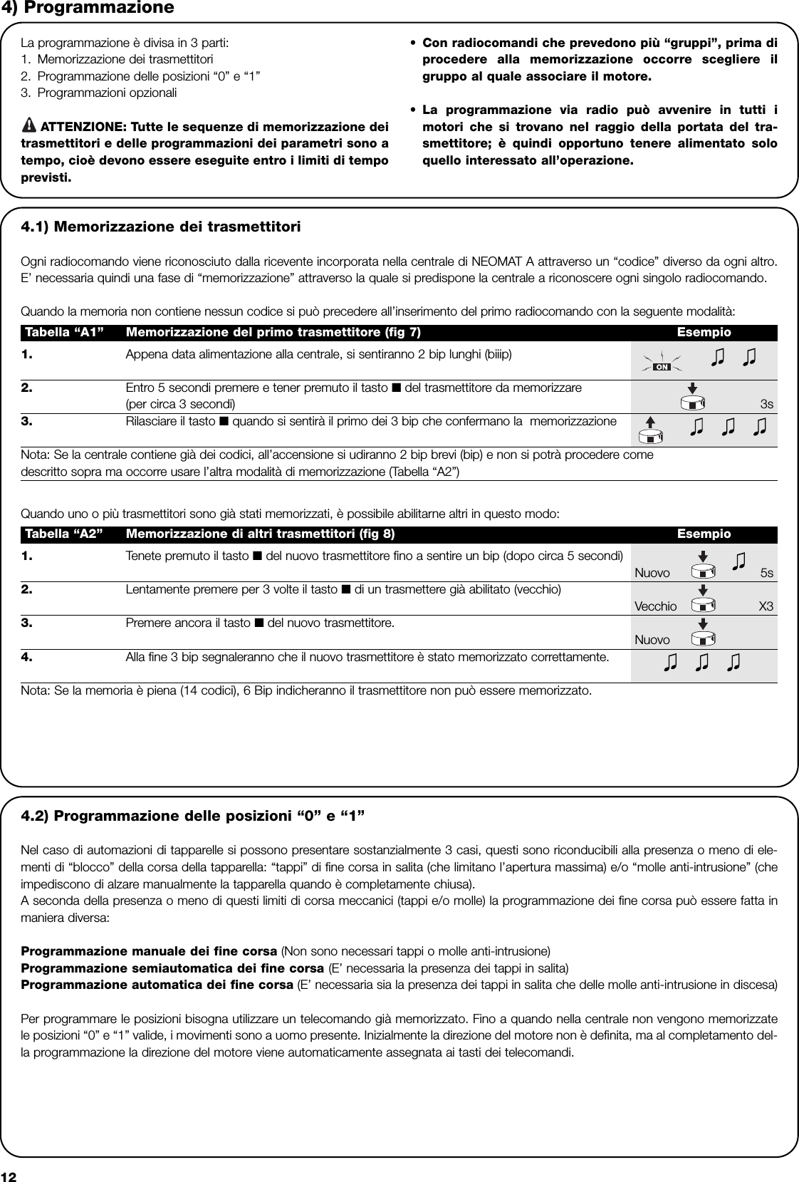
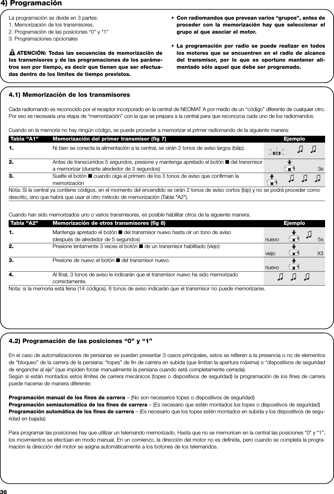
>
Nice S p A
>
433A10 User Manual
>
User Manual
Contents
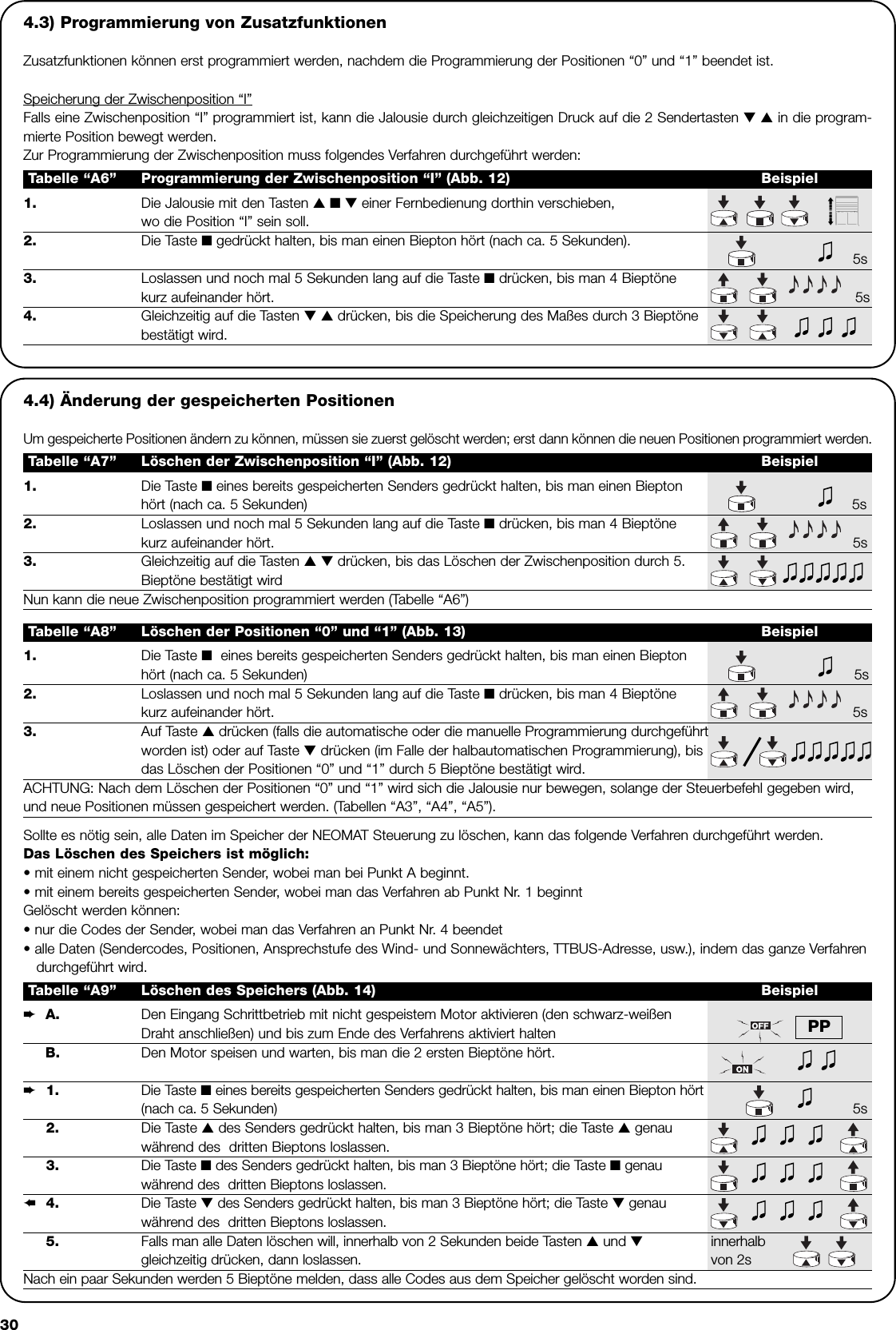
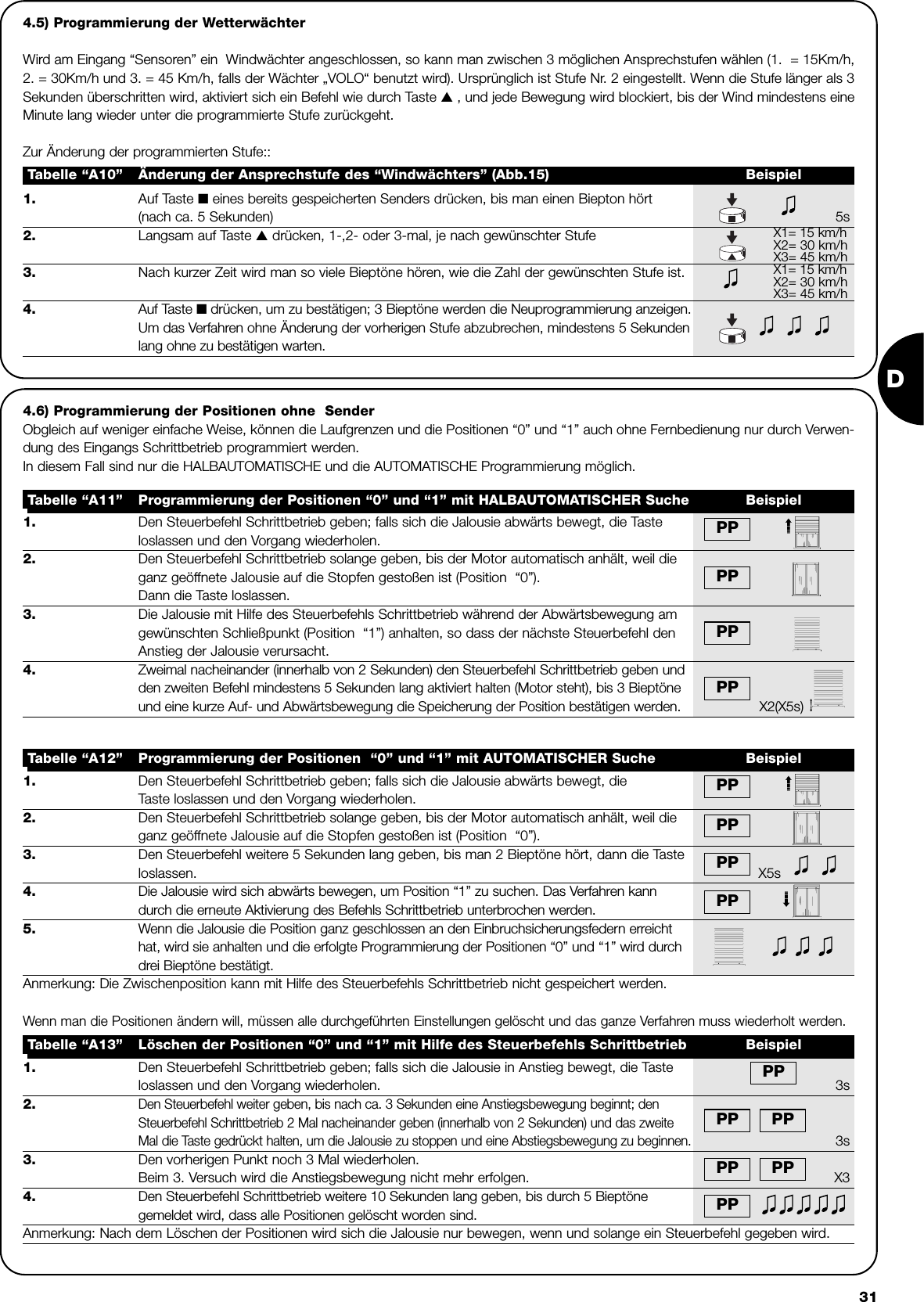
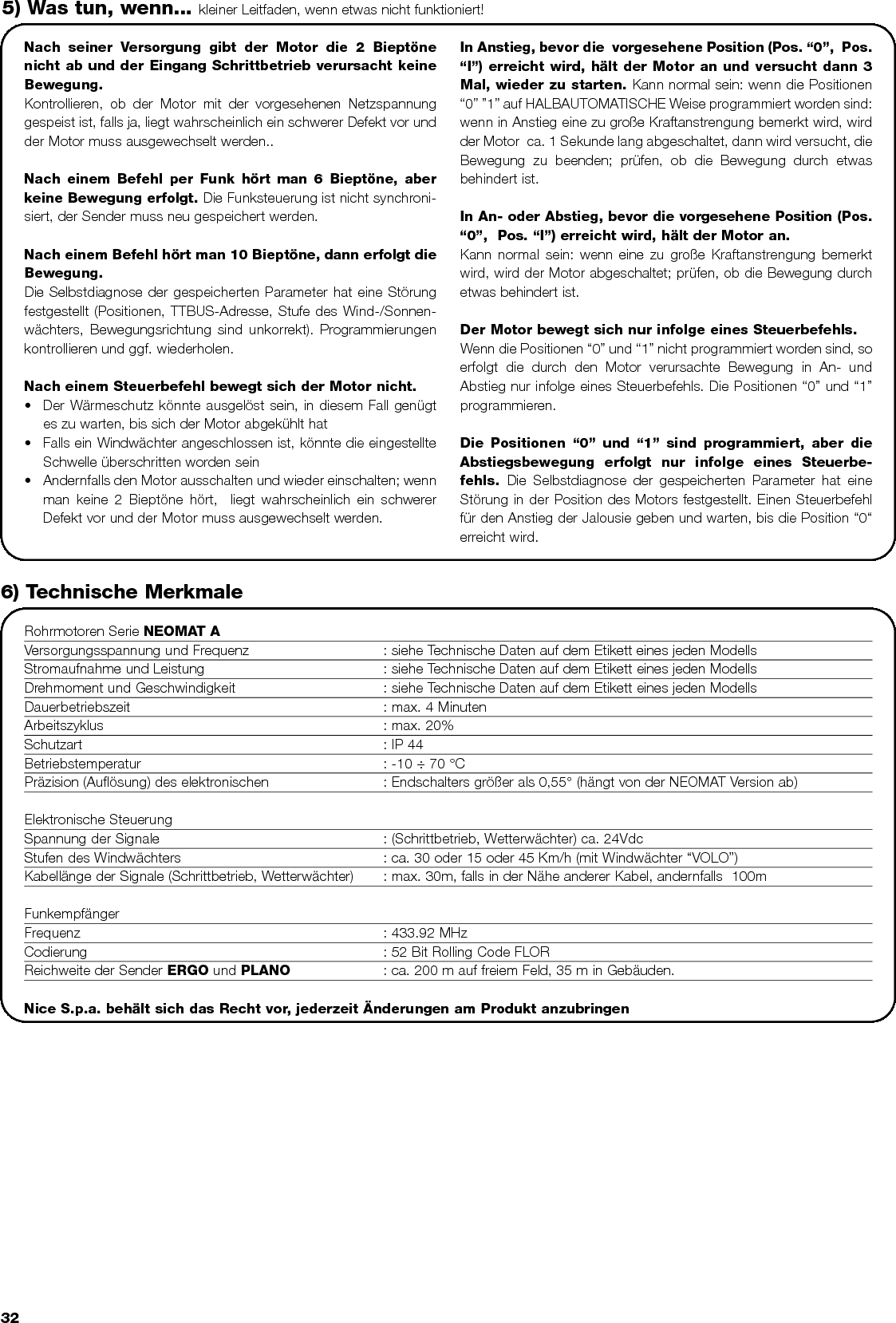
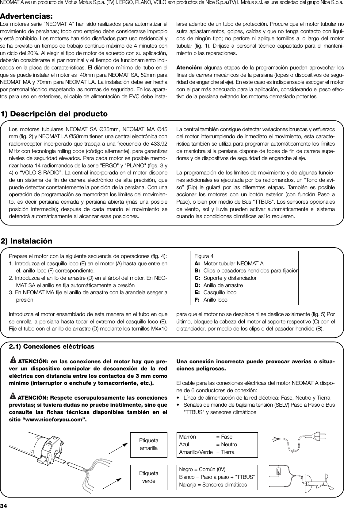
1.
leaflet
2.
User Manual
User Manual
Navigation menu
Upload a User Manual
Namespaces
Wiki Guide
HTML
PDF
Info
Views
User Manual
Discussion / Help
Navigation