Nice S p A 433FR Transmitter User Manual users manual
Nice S.p.A. Transmitter users manual
users manual
INTRODUCTION
When a radio control system is used the transmitter sends a “signal” to the receiver that, if recognised
as valid, activates the output relays.
In view of the fact that a transmitter should activate only its own receiver and not that of your
neighbour, you have to codify the signal sent which means that each receiver will recognise its own
signal and not others that might be similar.
In traditional systems the code can be selected by means of a set of microswitches in the transmitter
(offering only a few thousand combinations) or it can be programmed directly during production (in
this case you have a few million different code numbers available); however, the code number is
fixed which means that each time it is transmitted the same signal is sent.
The fact that the code is sent by radio and that it is always the same does, unfortunately, offer the
possibility to people who are up to no good to receive (even at a distance) and record the signal
which they can then use as the “key” to open your door.
The “FLOR” system uses a principle that makes your radio control extremely safe.
A technique called “Rolling Code” is used that changes a part of the code each time it is transmitted
following a predefined sequence; the code is masked with appropriate mathematical functions so
there is no logical connection between two consecutive codes. The receiver is always synchronised
- 30 -

with the transmitter so it will accept only the programmed code sequence. It is completely
useless to try and copy the signal transmitted with this system because once the code has been
“used” the receiver will only recognise the next one.
From what we have described here it appears essential to keep the code sent by the transmitter and
the receiver perfectly synchronised but this is not completely true because there is a code window
that lets the receiver accept, in sequence, the next code plus a certain number of subsequent codes
without ever accepting a code that has already been used!
Even if you exit from the code window, the receiver is designed to re-synchronise itself automatically:
when it receives the first code there will be no activation but only storage of the code sent; when the
next signal is sent it will be synchronised and activate the outputs. Automatic re-synchronisation is of
course possible only if the codes are received following the established sequence.
DESCRIPTION
The system comprises:
• 1, 2 or 4 channel transmitters (FLO1R, FLO2R, FLO4R), and 2 channel (VR of the VERY series)
• Receivers with a terminal connection, 1 or 2 channels (FLOX1R, FLOX2R, FLOXB2R)
• Receivers with plug in connections, 1 or 2 channels (FLOXIR, FLOXI2R)
• Modular receivers (FLOXM220R, FLOXMR)
• Memory card that contains the codes (BM60, BM250, BM1000 - 15, 63 or 255 codes maximum respectively)
• Aerial (ABF - ABFKIT)
- 31 -
GB
INSTALLATION
Transmitters:
The transmitters are ready to use, each with
their own code number set during
construction. To see if they are working
properly simply press one of the keys and
check that the red LED is flashing, indicating
transmission.
The transmitter has a device built into it that
controls battery state: press one of the keys
and if the battery is fully charged the LED will
give an initial pulse followed immediately by
the transmission signal. If the battery is partly flat the LED will give the first pulse and start
transmitting only after half a second.
In this case we advise you change the battery as soon as possible.
If, on the other hand, the battery is completely flat the LED will flash at half-second intervals without
transmitting and the battery must be changed immediately.
- 32 -
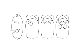
VERY FLO1R FLO2R FLO4R
LED
KEY 1
KEY 2
KEY 3
KEY 4
LED
KEY 1
KEY 2
Fig. 1
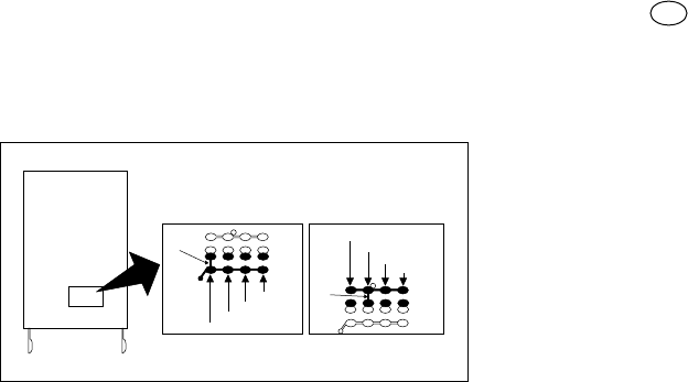
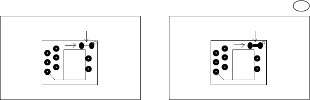
Selecting the channel on the transmitter:
It is possible to modify the key-channel connection on the FLOR1 and FLOR2 versions.
For key 1, simply cut the track that linked it to the 1st channel, as shown in Fig. 1A, and connect one
of the other pads on the right with a drop of solder to link it to the 2nd, 3rd or 4th channel. Do exactly
the same for the 2nd key, as shown in Fig. 1B. On VR the transmitters in the VERY series, the
key/channel association cannot be modified.
- 33 -
GB
WELDING SIDE
Fig. 1A
1
ST
KEY 2
ND
KEY
cut
cut
1
st
channel
1
st
channel
2
nd
channel
2
nd
channel
3
rd
channel
3
rd
channel
4
th
channel
4
th
channel
Fig. 1B
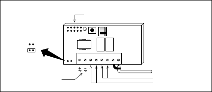
Receivers with terminals:
Receivers with terminals are universal in their use. The container, which can be fixed with screws or
using the adhesive on the bottom, provides the circuit with good protection.
Wire up following this sequence:
1-2: POWER: from 10 to 28 V direct or alternate.
3-4: 1st RELAYOUTPUT: free contact of a normally open relay.
5-6: 2nd RELAY OUTPUT: free contact of a normally open relay (only on 2-channel receivers).
1-2: AERIAL: aerial signal input.
- 34 -
12345612
FLOX1R
FLOX2R
FLOXB2R
AERIAL
2ND RELAY OUTPUT
1ST RELAY OUTPUT
POWER
POWER SUPPLY
SELECTOR
15 - 28 V
10 - 18 V
Fig. 2
CHANNEL SELECTION
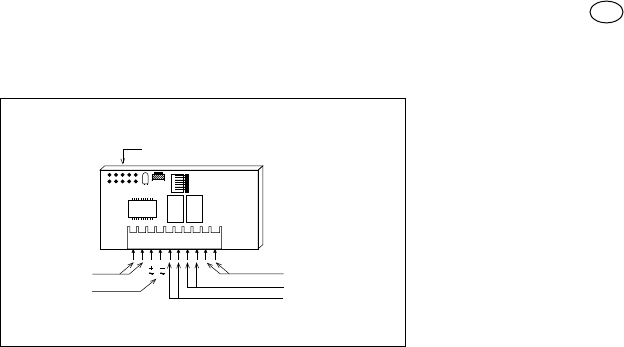
Plug in Receivers:
Plug in receivers are to be plugged directly into NICE units; once plugged in they are ready to work
as all the electrical signals (power, aerial and outputs) have their own place on the unit.
POWER:
from 20 to 28 V direct or alternate,
normally supplied by the unit.
1st RELAYOUTPUT:
free contact of a normally open
relay, used for unit command.
2nd RELAY OUTPUT:
free contact of a normally open
relay available on specific unit
terminals (only on 2-channel
receivers).
AERIAL:
aerial signal input, on specific unit
terminals.
- 35 -
GB
FLOXIR
FLOXI2R
AERIAL
2ND RELAY OUTPUT
1ST RELAY OUTPUT
UNUSED
POWER
Fig. 3
CHANNEL SELECTION
Memory card
Each transmitter has its own code number (selected from more than 250 million) that distinguishes it
from all other remote controls. The receiver can receive all the codes but is activated only if that
particular code is on the list of “authorised” code numbers on the memory card.
The receivers are supplied with a BM250 memory card that can contain a maximum of 63 code
numbers (63 remote controls are the maximum quantity). A BM60 memory card can also be used
with a maximum of 16 code numbers or an BM1000 with a maximum of 255 code numbers, in
substitution of the BM250 card supplied with the unit. When powered, the receiver displays the type
of memory used: if a BM60 memory card is being used the LED will flash briefly; if a BM250 memory
card is being used instead, the LED will flash twice, while if an BM1000 memory card is being used
the LED will flash three times.
All the codes are stored in the memory, so when maximum security is required the code learning
function must be disabled (this can also be done remotely). After the code numbers of the remote
controls being used have been entered, break the track indicated by an arrow (Fig. 4). If, later on,
you wish to enter other code numbers, join the two pads with a dot of solder (Fig. 5)
ATTENTION!!: Turn the receiver off before pulling out or plugging in a memory card.
- 36 -
This is a “hardware” type of disabling function, very simple to do but, consequently, very easy to undo
by an intruder.
There is also another type of disabling function, a “software” type, more difficult to manage but
extremely secure in that only a previously authorised remote control can be used to restore it (see
activating/deactivating the 2nd disabling function).
Still on the subject of safety, there is another even more secure type of disabling function, which is
controlled by a “PASSWORD”. Only a portable accessory BUPC manages this function.
- 37 -
GB
051A LS
051A LS
Fig. 4 Fig. 5
CUT JOIN
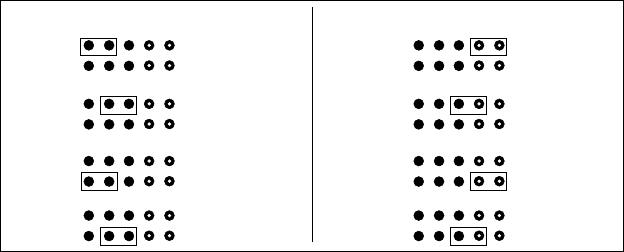
ADJUSTMENTS AND SETTINGS
Selection of the relays on the channels
Each receiver can recognise all 4 transmitter channels (channels = keys). Association of the output
relays to the channel required is done via a jumper that has to be plugged in.
- 38 -
SELECTION OF 1ST RELAY SELECTION OF 2ND RELAY (if present)
Fig. 6
CHANNEL 1
CHANNEL 2
CHANNEL 3
CHANNEL 4
CHANNEL 1
CHANNEL 2
CHANNEL 3
CHANNEL 4
Contact in output
The outputs are controlled by a free, normally open contact (a contact free from other connections).
If a normally closed type of contact is needed:
• Cut the “NO” part of the track (Fig. 7).
• Join the “NC” pads with a spot of solder (Fig. 8).
- 39 -
GB
NA NC
NO NC NO NC
1ST RELAY 2ND RELAY
RECEIVER ON WELDING SIDE
Fig. 7 Fig. 8
CUT JOIN
Fig. 7 Fig. 8
CUT JOIN
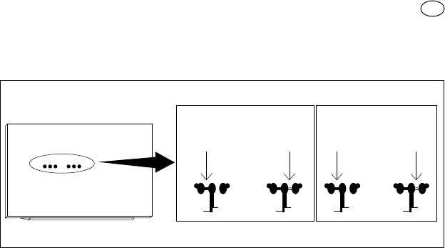
Special functions
Generally speaking the function of a relay in output is temporary, that is, it is energised just a few
seconds after the keys have been pressed on the remote control (delay due to code recognition
time); it de-energises 300 mS after the last valid code number has been received.
The relay in output has some special functions available.
Step-by-step function
The relay is activated when the transmitter key is pressed and remains energised after it has been
released; the relay will be deactivated when the key is pressed again.
Timer function:
The relay is activated when the transmitter key is pressed and remains energised until the
programmed time has elapsed. Time counting starts again each time the transmitter key is pressed
and can be terminated early by keeping the key pressed for at least 3 seconds.
Anti-theft function:
This is a combined function of outputs 1 and 2. By pressing transmitter key 1 you will have the step-
by-step function on channel 1 (suitable for connecting/disconnecting an anti-theft device). On
channel 2, besides normal functioning associated with key 2, there will also be a brief activation of
- 40 -
the transmitter when channel 1 goes from OFF to ON and two brief activations when channel 1
goes from ON to OFF. This means that a visual or acoustic signal can be connected to channel 2 to
signal that the anti-theft device is connected or disconnected.
The special functions must be activated by means of a small spot of solder (Fig. 9) according to the
following table:
No jumper:
all temporary channels
Jumper 1:
1 step-by-step... 2,3,4 temporary
Jumper 2:
1,2 step-by-step... 3,4 temporary
Jumper 3:
1 timer... 2,3,4 temporary
Jumper 4:
1+2 anti-theft... 3,4 temporary
Jumper 5:
all step-by-step channels
- 41 -
GB
No jumper
Jumper 1
Jumper 2
Jumper 3
Jumper 4
Jumper 5
INSTALLING THE AERIAL
The receiver needs an ABF or ABFKIT type aerial to work properly; without an aerial the range is
limited to just a few metres. The aerial must be installed as high as possible; if there are metal or
reinforced concrete structures nearby you can install the aerial on top. If the cable supplied with the
aerial is too short, use a coaxial cable with 52-Ohm impedance (e.g. low dispersion RG58); the cable
must be no longer than 10 m. Connect the centre part (core) to terminal 2 and the shield to terminal
1 (in the relative part). If the aerial is installed where the earth connection is not good (masonry
structures), the shield’s terminal can be connected to earth which will provide a larger range of action.
The earth point must, of course, be in the immediate vicinity and be of good quality. If an ABF or
ABFKIT aerial cannot be installed, you can get quite good results using the length of wire supplied
with the receiver as the aerial, laying it flat and connecting it to terminal 2.
- 42 -

PROGRAMMING
Each transmitter has its own code number (selected from more than 250 million) that distinguishes it
from all other remote controls. The receiver can receive all the codes but is activated only if that
particular code is on the list of “authorised” codes. A code number can be entered or deleted from
this list by means of a “learning” procedure.
The operator has to press a button on the receiver card to activate the procedure: the operations
are timed so first read all the instructions and then carry out the operations one after the other
without stopping.
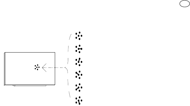
A small red LED visually indicates the different steps of the procedure.
This LED is the only way to check the various operations or receiver states. Because there is a lot of
information to display, there are 2 stable states plus a series of flashes with two speeds:
• LED off: normal functioning mode
• LED on: learning procedure in progress
- 43 -
GB

FAST FLASHING
1/4
second
When it turns on it means there is a
BM60 memory card; it then indicates
that the code number received is a
“copy” while only “original” codes are
valid.
When it turns on it means there are
code numbers memorised that do not
belong to the Flor version; it then
indicates that the code number is not
in the code number window and re-
synchronisation is stopped
.
When it turns on it means that an
error was found in the memory during
reading; it then indicates that the code
is not in the code number window and
re-synchronisation is impossible.
When it turns on it means there is a
BM1000 memory card; it then
indicates that the code is not in the
code number window but that it has
been re-synchronised.
When it turns on it means there is a
BM250 memory card
.
1
2
3
4
5
SLOW FLASHING 1/2 second
No. flashes DESCRIPTION No. flashes DESCRIPTION
The code number received is not
among those authorised
.
End of learning time without any
result
.
Learning successfully finished
(authorised code number)
.
The code number is already on the
authorised code list
.
The list is empty (no codes)
.
The list is full (there is no room for
other code numbers)
.
A request has been made to delete a
code number that does not exist.
Different code numbers were
received during the learning phase
.
Password entered
.
1
2*
3
4
5
6
7
8
9
*
If the 2nd type of disabling function is active, the 2nd flash will be longer than the first
If the 2nd type of disabling function is not active, both flashes will be the same
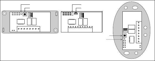
Entering a code number (fast way)
This is the quickest way to enter a code number although it is not very safe because while the code
number is being memorised the receiver could receive a signal from another transmitter that is within
its range and memorise it.
You must take this risk into consideration when deciding how to enter your code number.
- 45 -
LED
PUSH BUTTON
LED
PUSH BUTTON
PUSH BUTTON
LED
Fig. 10
This operation will also let you add the code number of a new transmitter to the receiver’s memory.
1) Press the key on the receiver and hold it down: the LED turns on and you must then.
2) Transmit the code number until the LED turns off pressing any key on the transmitter.
3) Now release the transmitter key: the LED will turn back on ready for a new operation.
4) Repeat the procedure from point 2 for the other transmitters.
Entering a code number (normal way)
This operation too will let you add the code number of a new transmitter to the receiver’s memory.
1) Press the key on the receiver for a moment: the LED will turn on for 5 seconds. Within this time you must:
2) Transmit the code number until the LED turns off pressing any key on the transmitter.
3) Release the transmitter key and wait a second.
4) Transmit the code to confirm by pressing any key on the transmitter.
The LED will now flash 3 times meaning that the operation was done properly; if this does not
happen, repeat the whole procedure from the beginning. Repeat the whole procedure if you want to
enter a new code number.
- 46 -

Entering a code number (remotely)
To enter the code number of a new remote control without using the receiver key you will need an
authorised remote control (note: the first remote control must always be entered using the receiver
key). Now, with the two remote controls, which we shall call NEW (the one whose code number we
want to enter) and OLD (the authorised one), position yourself in their range of action and then:
1) Transmit the NEW code number for at least 5 seconds pressing any key on the NEW transmitter.
And then slowly:
2) Transmit an OLD code number 3 times pressing any key on the OLD transmitter 3 times.
3) Transmit the NEW code number ONCE to confirm pressing any key on the NEW transmitter.
Now the new code number has been entered and you can repeat this procedure immediately with
another remote control.
ATTENTION!! : this operation enters the new code number in all the receivers within the range
of action that recognise the old code number. If there are several receivers nearby with the
old code number, turn the ones off that you do not want to receive the new code number.
- 47 -
GB

DELETING A CODE NUMBER
If you want to delete a code number from the receiver’s memory proceed as follows:
1) Hold the key down on the receiver (about 3 seconds) when the LED turns off let go of the key.
2) Transmit the code until the LEDs turn off again pressing any key on the transmitter.
3) Release the key on the transmitter and wait 1 second.
4) Transmit the code to confirm pressing any key on the transmitter.
The LED will now flash once to indicate that the code has been deleted. If this does not happen
repeat the procedure from the beginning.
DELETING ALL CODE NUMBERS
With this operation all the code numbers stored are deleted (emptying the memory), the 2nd learning
disabling function is also cancelled and TIMER time is set at 3 seconds.
1) Hold the key down on the receiver, the LED will turn off after 3 seconds.
2) Release the key during the 3rd following flash.
3) Wait about 3 seconds.
4) Press the key as soon as the LED turns back on and release it as soon as it turns off.
- 48 -

The operation may take several seconds depending on memory type. During this phase the
LED will flash quickly followed by 5 slow flashes to indicate that it has been reset and the memory is
empty; if this does not happen repeat the procedure from the beginning.
CHECKING THE QUANTITY OF CODE NUMBERS STORED
- Press the receiver key TWICE.
- Count the number of flashes that follow: each flash is a code number.
If there are a lot of code numbers and you want to stop before getting to the end simply press the
key for 1 second.
VERIFYING THE 2ND LEARNING DISABLING FUNCTION
Press the key on the receiver for a moment and wait for the 2 flashes that indicate time end (about
5 seconds).
- If the 2nd flash lasts longer than the first it means the disabling function is active.
- If the duration of both flashes is the same it means the disabling function is not active.
- 49 -
GB

ACTIVATING THE 2ND LEARNING DISABLING FUNCTION
1) Press the key on the receiver for a moment
2) Wait for the 2 flashes that indicate time end (about 5 seconds)
3) Press the key during the 2nd flash and release it as soon as the LED turns off.
2 flashes follow: the 2nd should last longer than the first to indicate that the disabling function is active;
if this does not happen, repeat the procedure from the beginning.
REMOVING THE 2ND LEARNING DISABLING FUNCTION
To remove the learning disabling function you will need an authorised remote control.
1) Press the receiver key for a moment, the LED turns on for 5 seconds within which time you have to:
2) Transmit the code until the LEDs turn off pressing any key on the transmitter.
3) Release the key on the transmitter and wait 1 second.
4) Transmit the code to confirm pressing any key on the transmitter; the LED will now flash 4 times
meaning that the code is already on the list.
5) Press the key during the 4th flash and let it go as soon as the LED turns off.
Two identical flashes will follow meaning that the disabling state is not active; if this does not
happen, repeat the procedure from the beginning.
- 50 -

PROGRAMMING TIMER TIME
The TIMER function has to be active (jumper on 3, see Fig. 9) to programme time. Temporarily
remove the channel selection jumper if you do not want to activate the relays.
1) Press key 1 on the transmitter and hold it down (on an already functioning transmitter) then,
within 3 seconds, you must:
2) Press the receiver key and hold it down.
3) Release the transmitter key.
4) Release the receiver key after a time equivalent to the time you wish to programme (2.5 h max.)
The time is now memorised and will not change unless it is programmed again.
N.B. The receiver’s normal operation is inhibited while you are programming timer time (channels are
not active)
- 51 -
GB
TECHNICAL FEATURES
RECEIVERS:
RECEIVING FREQUENCY: 433.92 MHz controlled with SAW.
INPUT IMPEDANCE: 52 ohm
SENSITIVITY: greater than 0.5 µV for a correctly received signal
(average range 150-200 m with an ABF- ABFKIT aerial)
POWER: from 10 to 18 V with bridge direct or alternate
from 20 to 28 V without bridge on B direct or alternate
ABSORBPTION WHEN NOT WORKING: 15 mA
ABSORPTION OF 1 ACTIVE CHANNEL: 35 mA
DECODING: 52-bit digital (4.500.000.000.000.000 combinations)
No. CHANNELS: 1 or 2 according to the version.
RELAY CONTACT: N.O. max 0.5A-50 V~
ENERGISING TIME: reception of 2 complete code numbers (200 mS)
DE-ENERGISING TIME: 300 mS from the last valid code number
WORKING TEMPERATURE -10 °C + 55 °C
SIZE: 67 x 34 h 17 (FLOXIR-FLOXI2R)
98 x 41 h 25 (FLOX1R FLOX2R)
105 x 68 h 32 (FLOXB2R)
WEIGHT:
24 g FLOXIR-FLOXI2R, 59 g FLOX1R-FLOX2R - 82 g FLOXB2R
- 52 -

TRANSMITTERS SERIES FLOR
CARRIER FREQUENCY: 433.92 MHz controlled by SAW.
RADIATED POWER: 100µW
CODING: 52-bit digital (4.5x10¹⁵ total combinations)
CHANNELS: 1,2 or 4 simultaneously
POWER: 12 Vdc +20% - 40% with a 23A type battery
AVERAGE ABSORPTION: 25mA
WORKING TEMPERATURE: -40 °C +85 °C
SIZE: 72 x 40 h 18
WEIGHT: 40g
APPROVAL: to I-ETS 300 220 specifications
TRANSMITTERS SERIES VERY
CARRIER FREQUENCY: 433.92 MHz controlled by SAW.
RADIATED POWER: 100µW
CODING: 52-bit digital (4.5x10¹⁵ total combinations)
CHANNELS: 2 simultaneously
POWER: 6 Vdc with a type battery litio
AVERAGE ABSORPTION: 10mA
WORKING TEMPERATURE: -40 °C +85 °C
SIZE: 65 x 30 h 10 mm.
APPROVAL: I-ETS 300 220
- 53 -
GB
MEMORY CARD
No. CODES: 15 (BM60), 63 (BM250), 255 (BM1000)
MEMORY TYPE: EEPROM with serial access
MEMORY LIFE: 40 years or 1 million changes
CODE READING TIME: 2 mS per code number
SIZE: 13x11 h9
WEIGHT: 1 g
ACCESSORIES
BUPC: Code control and programming unit
- 54 -