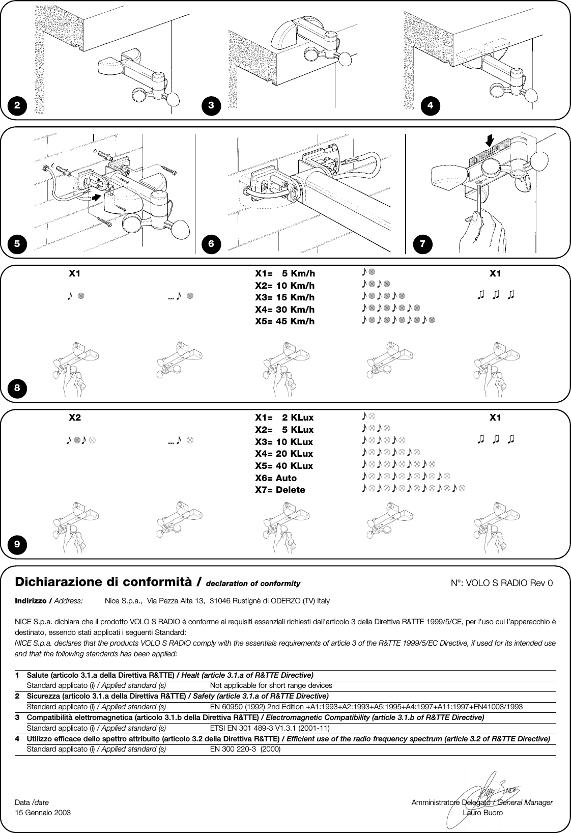
Nice S p A 433VL Climatic sensor User Manual Volo S Radio 140 4862 rev01
Nice S.p.A. Climatic sensor Volo S Radio 140 4862 rev01
UserManual.wiki
>
Nice S p A
>
433VL User Manual
>
User Manual
Contents
1.
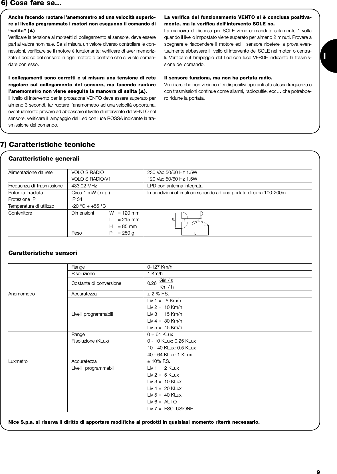
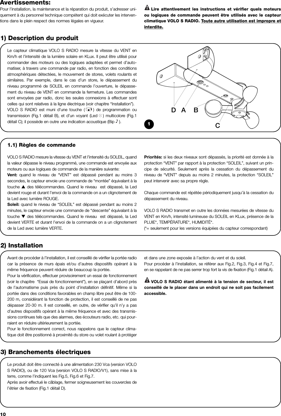
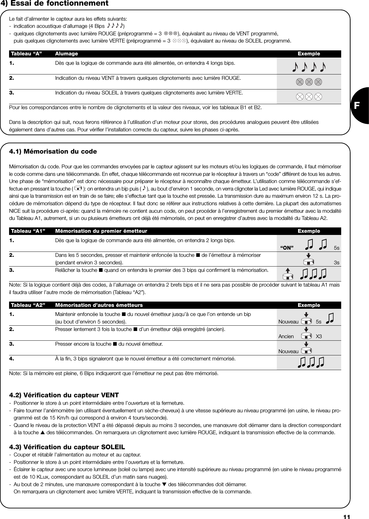
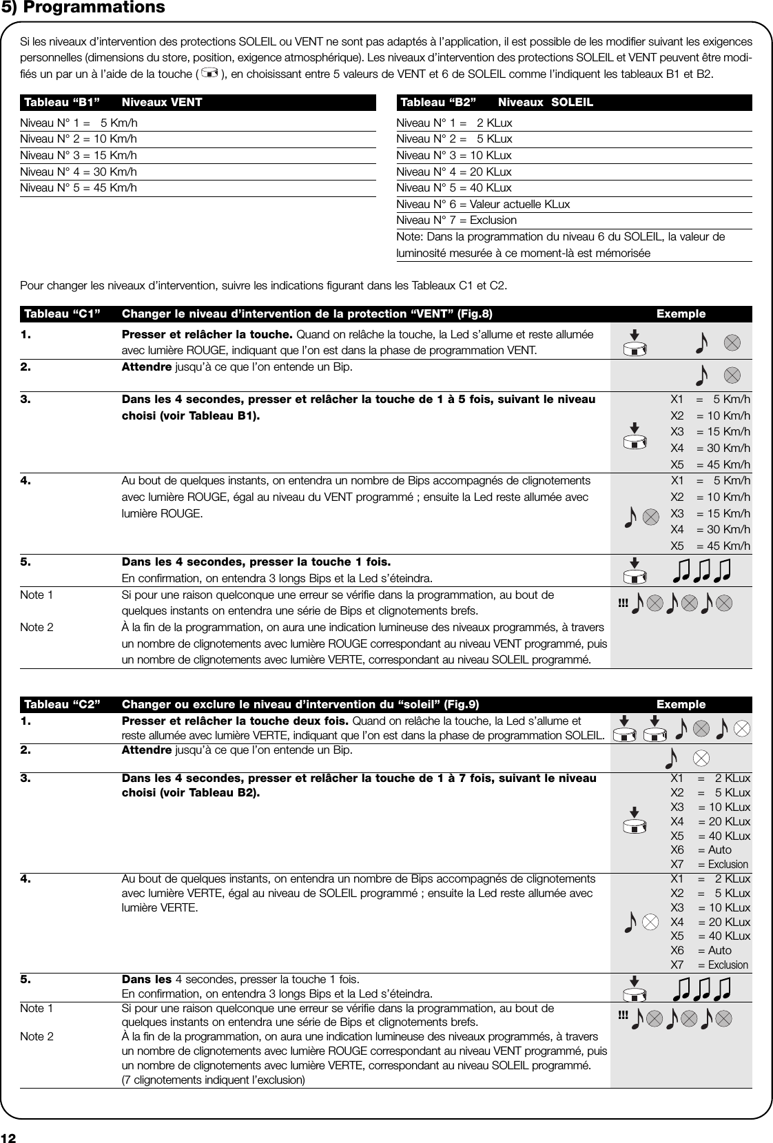
User Manual
2.
User Manual Appendix
User Manual
Navigation menu
Upload a User Manual
Namespaces
Wiki Guide
HTML
PDF
Info
Views
User Manual
Discussion / Help
Navigation