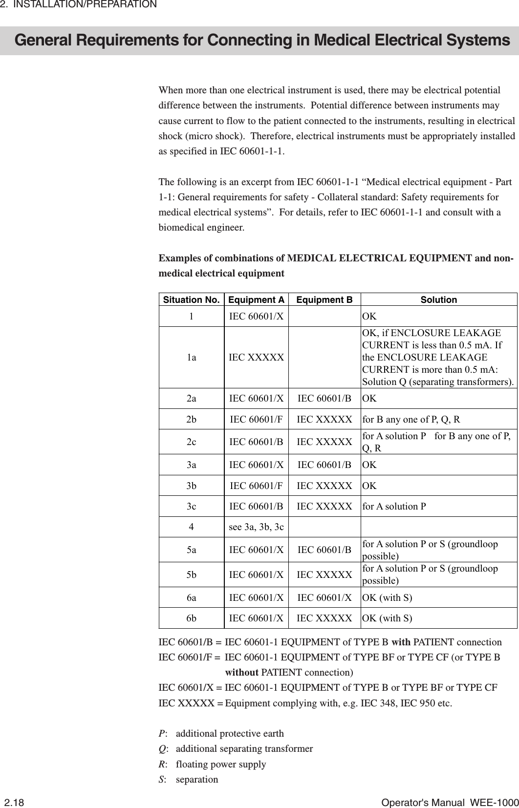
Nihon Kohden ZB-102AA Telemetry Unit User Manual Manual 1
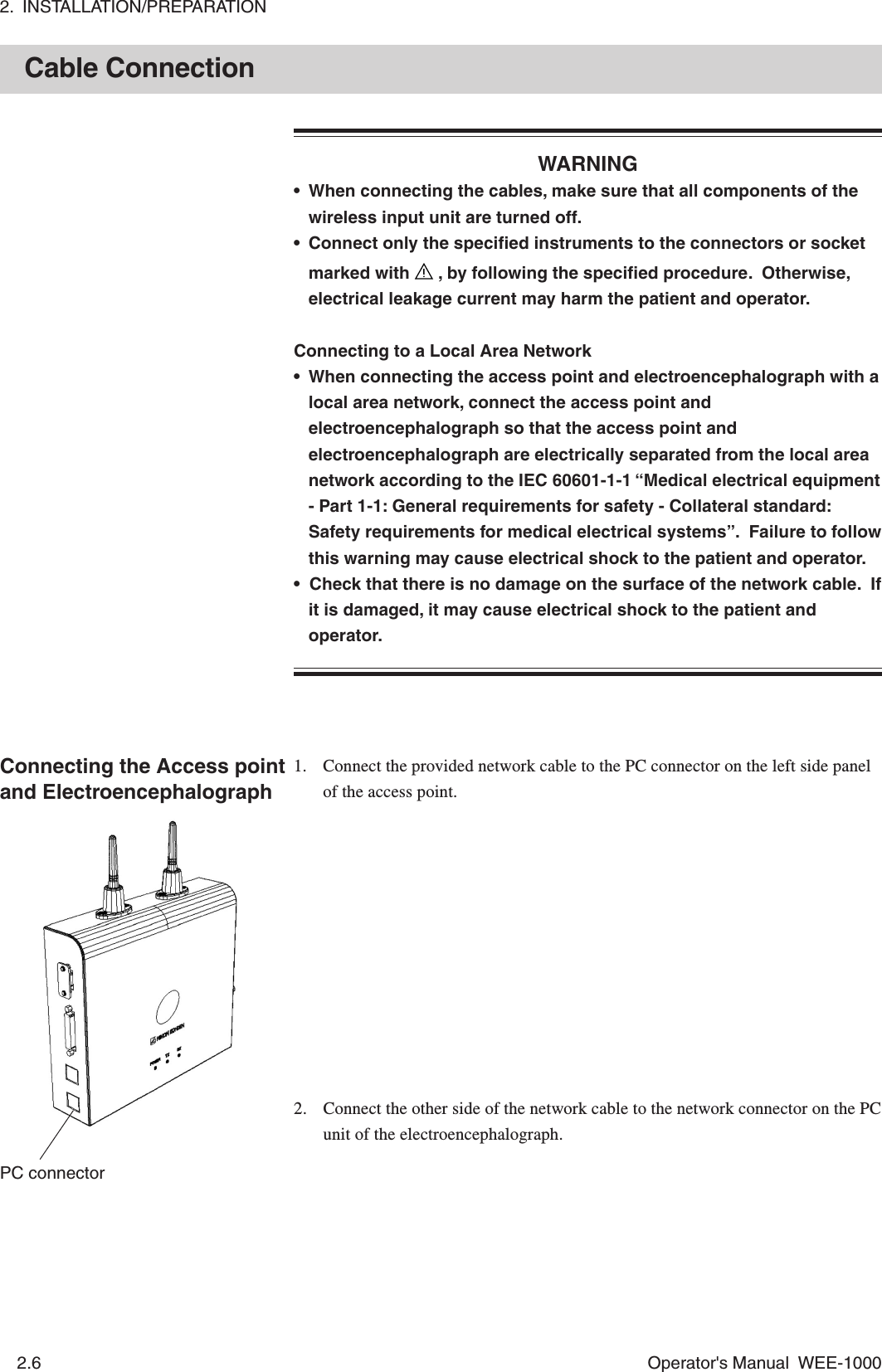
Nihon Kohden Corporation Telemetry Unit Manual 1
UserManual.wiki
>
Nihon Kohden
>
ZB-102AA User Manual
>
Manual 1
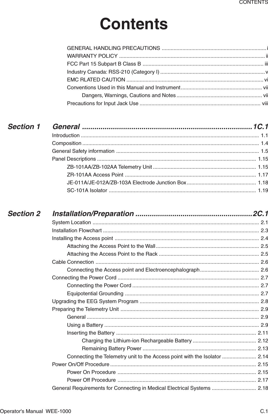
Contents
1.
Manual 1
2.
Manual 2
Manual 1
Navigation menu
Upload a User Manual
Namespaces
Wiki Guide
HTML
PDF
Info
Views
User Manual
Discussion / Help
Navigation