Nihon Kohden ZM-521PAA TRANSMITTER User Manual
Nihon Kohden Corporation TRANSMITTER
(Short-Term Confidential) User Manual
If you have any comments or suggestions on this
manual, please contact us at:
www.nihonkohden.com
Transmitter
ZM-520PA/ZM-521PA
ZM-530PA/ZM-531PA
0614-904743D

In order to use this product safely and fully understand all its functions, read this manual before
using the product.
Keep this manual near the instrument or in the reach of the operator and refer to it whenever the
operation is unclear.
This product stores personal patient information. Manage the information appropriately.
3DWLHQWQDPHVRQWKHVFUHHQVKRWVDQGUHFRUGLQJH[DPSOHVLQWKLVPDQXDODUH¿FWLRQDODQGDQ\
resemblance to any person living or dead is purely coincidental.
The contents of this manual are subject to change without notice.
Copyright Notice
The entire contents of this manual are copyrighted by Nihon Kohden. All rights are reserved. No
part of this document may be reproduced, stored, or transmitted in any form or by any means
(electronic, mechanical, photocopied, recorded, or otherwise) without the prior written permission
of Nihon Kohden.
Operator’s Manual ZM-520PA/521PA/530PA/531PA C.1
Contents
GENERAL HANDLING PRECAUTIONS ...................................................................... i
WARRANTY POLICY ..................................................................................................iii
Equipment Authorization Requirement ........................................................................iv
Compliance with FCC Requirements .....................................................................iv
EMC RELATED CAUTION ........................................................................................... v
Conventions Used in this Manual and Instrument ......................................................vii
Warnings, Cautions and Notes..............................................................................vii
Explanations of the Symbols in this Manual and Instrument ................................viii
Intended Use ..................................................................................................................... 1
General ........................................................................................................................1
Receiving Monitor ........................................................................................................ 3
Panel Description ..............................................................................................................4
Top Panel ..................................................................................................................... 4
Front Panel ................................................................................................................... 5
Rear Panel ................................................................................................................... 7
Important Safety Information ............................................................................................. 8
General ........................................................................................................................8
Output Signal ............................................................................................................. 11
Battery ....................................................................................................................... 12
Transmitter Channel Management ............................................................................. 12
For Patients Using Implantable Pacemaker ............................................................... 13
ECG Monitoring ......................................................................................................... 13
SpO2 Monitoring ......................................................................................................... 15
Maintenance .............................................................................................................. 17
Preparation on Transmitter .............................................................................................. 18
Batteries ..................................................................................................................... 18
Handling Batteries ................................................................................................ 18
Battery Lifetime .................................................................................................... 18
Installing (Replacing) Batteries ............................................................................ 19
Situations Requiring Battery Replacement .......................................................... 20
Battery Level Indication ........................................................................................ 20
Attaching a Strap to the Transmitter ........................................................................... 21
Turning On the Transmitter ......................................................................................... 22
Check Items Before Use ...................................................................................... 22
Check Items After Power On ................................................................................ 23
Check Items After Use ......................................................................................... 23
Turning Off the Transmitter ......................................................................................... 24
Changing the Transmitter Channel ............................................................................. 24
C.2 Operator’s Manual ZM-520PA/521PA/530PA/531PA
Changing Parameter and System Setup Settings ........................................................... 25
Changing PARAMETER SETUP Settings.................................................................. 25
Parameter Setup Setting List ............................................................................... 25
Displaying the PARAMETER SETUP Screen ...................................................... 26
Changing Parameter Setup Settings .................................................................... 27
Changing SYSTEM SETUP Settings ......................................................................... 30
System Setup Setting List .................................................................................... 30
Displaying the SYSTEM SETUP Screen .............................................................. 31
Changing System Setup Settings ........................................................................ 32
Initializing Settings ..................................................................................................... 35
Attaching Electrodes and SpO2 Probe to the Patient....................................................... 36
Attaching Electrodes .................................................................................................. 36
Selecting Electrode Lead ..................................................................................... 36
Connecting the Electrode Lead to the Transmitter ............................................... 36
Electrode Position ................................................................................................ 37
Attaching Electrodes to the Patient and Connecting the Electrode Leads to
Disposable Electrodes ......................................................................................... 41
Checking ECG on the Transmitter Screen ............................................................ 42
Attaching the SpO2 Probe .......................................................................................... 42
Selecting the SpO2 Probe .................................................................................... 42
Connecting the SpO2 Probe to the Transmitter .................................................... 45
Attaching the Probe to the Patient ........................................................................ 46
Locking the Keys on the Transmitter ................................................................................ 48
Monitoring ........................................................................................................................ 49
Screen Descriptions ................................................................................................... 49
Check Electrodes Screen ..................................................................................... 50
Numeric and Waveform Screen ........................................................................... 51
Waveform Review Screen .................................................................................... 52
Numeric Review Screen ....................................................................................... 53
Display Off ............................................................................................................ 53
Basic Monitoring Operation ....................................................................................... 54
Using the Function Key ........................................................................................ 54
Suspending Alarms on the Receiving Monitor ..................................................... 55
Pausing Monitoring............................................................................................... 56
Resuming Monitoring after Pause ........................................................................ 58
Confirming the Patient .......................................................................................... 58
Turning the Display Off ......................................................................................... 59
Turning the Display On after It was Turned Off ..................................................... 60
ECG and Respiration Monitoring ............................................................................... 61
Turning ECG Measurement On/Off ...................................................................... 64
Turning Respiration Measurement On/Off ............................................................ 64
Electrode Detachment .......................................................................................... 64
Operator’s Manual ZM-520PA/521PA/530PA/531PA C.3
SpO2 Monitoring ......................................................................................................... 65
Indications and Messages ............................................................................................... 69
Indication ................................................................................................................... 69
Messages .................................................................................................................. 69
Message Display Priority ...................................................................................... 72
Troubleshooting ............................................................................................................... 73
Transmitter ................................................................................................................. 73
ECG/Respiration ........................................................................................................ 74
SpO2 ......................................................................................................................... 75
Maintenance ....................................................................................................................76
1. External Check ................................................................................................. 76
2. Transmitter Channel ......................................................................................... 76
3. Transmitting/Receiving Signal .......................................................................... 77
4. Display .............................................................................................................. 77
5. Key Operation ................................................................................................... 79
6. ECG Check....................................................................................................... 80
7. Respiration Check ............................................................................................ 81
8. SpO2 Check (with SpO2 Checker) .................................................................... 81
9. SpO2 Check (with Vital Sign Simulator) ............................................................ 82
Maintenance Check Sheet ................................................................................... 84
Lifetime and Disposal ...................................................................................................... 85
Disposing of Used Batteries ...................................................................................... 85
Battery Lifetime .................................................................................................... 85
Disposal ............................................................................................................... 85
Disposing of Electrodes and SpO2 Probes ................................................................ 85
Disposing of Transmitter ............................................................................................. 85
Cleaning, Disinfection and Sterilization ........................................................................... 86
Transmitter and Electrode Leads ............................................................................... 86
Cleaning ............................................................................................................... 86
Disinfection ........................................................................................................... 86
SpO2 Probe ................................................................................................................ 87
Periodic Replacement Schedule ..................................................................................... 87
Repair Parts Availability Policy ........................................................................................ 87
Specifications ..................................................................................................................88
ZM-520PA/ZM-530PA ................................................................................................ 88
Measured Parameters .......................................................................................... 88
Transmitted Data .................................................................................................. 88
Display.................................................................................................................. 88
Displayed Data ..................................................................................................... 88
ECG ..................................................................................................................... 88
Respiration Measurement .................................................................................... 90
SpO2 Measurement (ISO 9919: 2005 compliance) .............................................. 90
C.4 Operator’s Manual ZM-520PA/521PA/530PA/531PA
Transmitter ........................................................................................................... 92
Power Requirements ............................................................................................ 93
Dimension and Weight ......................................................................................... 93
Environment ......................................................................................................... 93
Safety Standards .................................................................................................. 93
Electromagnetic Compatibility .............................................................................. 94
Electromagnetic Emissions .................................................................................. 94
Electromagnetic Immunity .................................................................................... 95
Recommended Separation Distances between Portable and Mobile RF
Communications Equipment ................................................................................ 97
Recovery Time after Defibrillation ........................................................................ 97
System Composition for EMC Test ....................................................................... 97
ZM-521PA/ZM-531PA ................................................................................................ 98
Measured Parameters .......................................................................................... 98
Transmitted Data .................................................................................................. 98
Display.................................................................................................................. 98
Displayed Data ..................................................................................................... 98
ECG ..................................................................................................................... 98
Respiration Measurement .................................................................................. 100
SpO2 Measurement (ISO 9919: 2005 compliance) ............................................ 100
Transmitter ......................................................................................................... 102
Power Requirements .......................................................................................... 103
Dimension and Weight ....................................................................................... 103
Environment ....................................................................................................... 103
Safety Standards ................................................................................................ 103
Electromagnetic Compatibility ............................................................................ 104
Electromagnetic Emissions ................................................................................ 104
Electromagnetic Immunity .................................................................................. 105
Recommended Separation Distances between Portable and Mobile RF
Communications Equipment .............................................................................. 107
Recovery Time after Defibrillation ...................................................................... 107
System Composition for EMC Test ..................................................................... 108
Standard Accessories.................................................................................................... 109
Options .......................................................................................................................... 110
Transmitter ............................................................................................................... 110
ECG/RESP .............................................................................................................. 110
SpO2 ....................................................................................................................... 111
Transmission Frequencies ............................................................................................. 112
Operator’s Manual ZM-520PA/521PA/530PA/531PA i
GENERAL HANDLING PRECAUTIONS
This device is intended for use only by qualified medical personnel.
Use only Nihon Kohden approved products with this device. Use of non-
approved products or in a non-approved manner may affect the performance
specifications of the device. This includes, but is not limited to, batteries,
recording paper, pens, extension cables, electrode leads, input boxes and AC
power.
Please read these precautions thoroughly before attempting to operate the instrument.
1. To safely and effectively use the instrument, its operation must be fully understood.
2. When installing or storing the instrument, take the following precautions.
(1) Avoid moisture or contact with water, extreme atmospheric pressure, excessive humidity
and temperatures, poorly ventilated areas, and dust, saline or sulphuric air.
3ODFHWKHLQVWUXPHQWRQDQHYHQOHYHOÀRRU$YRLGYLEUDWLRQDQGPHFKDQLFDOVKRFNHYHQ
during transport.
(3) Avoid placing in an area where chemicals are stored or where there is danger of gas
OHDNDJH
(4) The power line source to be applied to the instrument must correspond in frequency and
YROWDJHWRSURGXFWVSHFL¿FDWLRQVDQGKDYHVXI¿FLHQWFXUUHQWFDSDFLW\
(5) Choose a room where a proper grounding facility is available.
3. Before Operation
&KHFNWKDWWKHLQVWUXPHQWLVLQSHUIHFWRSHUDWLQJRUGHU
&KHFNWKDWWKHLQVWUXPHQWLVJURXQGHGSURSHUO\
&KHFNWKDWDOOFRUGVDUHFRQQHFWHGSURSHUO\
(4) Pay extra attention when the instrument is in combination with other instruments to avoid
misdiagnosis or other problems.
$OOFLUFXLWU\XVHGIRUGLUHFWSDWLHQWFRQQHFWLRQPXVWEHGRXEO\FKHFNHG
&KHFNWKDWEDWWHU\OHYHOLVDFFHSWDEOHDQGEDWWHU\FRQGLWLRQLVJRRGZKHQXVLQJEDWWHU\
operated models.
4. During Operation
(1) Both the instrument and the patient must receive continual, careful attention.
(2) Turn power off or remove electrodes and/or transducers when necessary to assure the
patient’s safety.
(3) Avoid direct contact between the instrument housing and the patient.
ii Operator’s Manual ZM-520PA/521PA/530PA/531PA
5. To Shutdown After Use
(1) Turn power off with all controls returned to their original positions.
(2) Remove the cords gently; do not use force to remove them.
(3) Clean the instrument together with all accessories for their next use.
6. The instrument must receive expert, professional attention for maintenance and repairs.
When the instrument is not functioning properly, it should be clearly marked to avoid
operation while it is out of order.
7KHLQVWUXPHQWPXVWQRWEHDOWHUHGRUPRGL¿HGLQDQ\ZD\
8. Maintenance and Inspection
(1) The instrument and parts must undergo regular maintenance inspection at least every 6
months.
,IVWRUHGIRUH[WHQGHGSHULRGVZLWKRXWEHLQJXVHGPDNHVXUHSULRUWRRSHUDWLRQWKDWWKH
instrument is in perfect operating condition.
(3) Technical information such as parts list, descriptions, calibration instructions or other
LQIRUPDWLRQLVDYDLODEOHIRUTXDOL¿HGXVHUWHFKQLFDOSHUVRQQHOXSRQUHTXHVWIURP\RXU
Nihon Kohden representative.
9. When the instrument is used with an electrosurgical instrument, pay careful attention to
the application and/or location of electrodes and/or transducers to avoid possible burn to
the patient.
:KHQWKHLQVWUXPHQWLVXVHGZLWKDGH¿EULOODWRUPDNHVXUHWKDWWKHLQVWUXPHQW
LVSURWHFWHGDJDLQVWGH¿EULOODWRUGLVFKDUJH,IQRWUHPRYHSDWLHQWFDEOHVDQGRU
transducers from the instrument to avoid possible damage.

Operator’s Manual ZM-520PA/521PA/530PA/531PA iii
WARRANTY POLICY
Nihon Kohden Corporation (NKC) shall warrant its products against all defects in materials and
ZRUNPDQVKLSIRURQH\HDUIURPWKHGDWHRIGHOLYHU\+RZHYHUFRQVXPDEOHPDWHULDOVVXFKDV
UHFRUGLQJSDSHULQNVW\OXVDQGEDWWHU\DUHH[FOXGHGIURPWKHZDUUDQW\
NKC or its authorized agents will repair or replace any products which prove to be defective
during the warranty period, provided these products are used as prescribed by the operating
instructions given in the operator’s and service manuals.
1RRWKHUSDUW\LVDXWKRUL]HGWRPDNHDQ\ZDUUDQW\RUDVVXPHOLDELOLW\IRU1.&¶VSURGXFWV
NKC will not recognize any other warranty, either implied or in writing. In addition, service,
WHFKQLFDOPRGL¿FDWLRQRUDQ\RWKHUSURGXFWFKDQJHSHUIRUPHGE\VRPHRQHRWKHUWKDQ1.&RULWV
authorized agents without prior consent of NKC may be cause for voiding this warranty.
Defective products or parts must be returned to NKC or its authorized agents, along with an
H[SODQDWLRQRIWKHIDLOXUH6KLSSLQJFRVWVPXVWEHSUHSDLG
7KLVZDUUDQW\GRHVQRWDSSO\WRSURGXFWVWKDWKDYHEHHQPRGL¿HGGLVDVVHPEOHGUHLQVWDOOHGRU
repaired without Nihon Kohden approval or which have been subjected to neglect or accident,
GDPDJHGXHWRDFFLGHQW¿UHOLJKWQLQJYDQGDOLVPZDWHURURWKHUFDVXDOW\LPSURSHULQVWDOODWLRQ
RUDSSOLFDWLRQRURQZKLFKWKHRULJLQDOLGHQWL¿FDWLRQPDUNVKDYHEHHQUHPRYHG
In the USA and Canada other warranty policies may apply.
CAUTION
United States law restricts this product to sale by or on the order of a physician.

iv Operator’s Manual ZM-520PA/521PA/530PA/531PA
Equipment Authorization Requirement
Compliance with FCC Requirements
This device complies with Part 15 of the FCC (Federal Communications Commission) Rules.
Operation is subject to the following two conditions:
(1) this device may not cause harmful interference, and
(2) this device must accept any interference received, including interference that may cause
undesired operation.
7KLVGHYLFHFRPSOLHVZLWK3DUW6XESDUW+RIWKH)&&5XOHVWREHXVHGLQZLUHOHVVPHGLFDO
telemetry service.
Operation of this equipment requires the prior coordination with a frequency coordinator
designated by FCC for the Wireless Medical Telemetry Service.
CAUTION
To comply with the FCC radio frequency (RF) exposure compliance requirements, no
change to the antenna or the device is permitted. Any change to the antenna or the
device could result in the device, exceeding the RF exposure requirements and void
user’s authority to operate this device.
NOTE
• Use this device only indoors.
•
This device has been tested and complies with FCC radiation exposure limits set forth
for an uncontrolled environment. The RF transmission power from the antenna conforms
to the general public FCC RF Exposure Guidelines limit of Specific Absorption Rate
(SAR) 1.6 W/kg. The maximum SAR value measured from this device was extremely
smaller than 1.6 W/kg. This device must not be located together with or operated in
conjunction with any other unspecified antenna or transmitter.
• The devices require registration and deployment by an authorized frequency
coordinator. The ASHE (American Society for Healthcare Engineering) has been
designated by the FCC to manage the WMTS frequencies. This device has frequency
bands which may not be used in some areas. For details, contact your Nihon Kohden
representative. For details on the guidelines, refer to the ASHE home page.

Operator’s Manual ZM-520PA/521PA/530PA/531PA v
EMC RELATED CAUTION
This equipment and/or system complies with the International Standard IEC 60601-
1-2 for electromagnetic compatibility for medical electrical equipment and/or system.
However, an electromagnetic environment that exceeds the limits or levels stipulated
in the IEC 60601-1-2, can cause harmful interference to the equipment and/or
system or cause the equipment and/or system to fail to perform its intended function
or degrade its intended performance. Therefore, during the operation of the
equipment and/or system, if there is any undesired deviation from its intended
operational performance, you must avoid, identify and resolve the adverse
electromagnetic effect before continuing to use the equipment and/or system.
The following describes some common interference sources and remedial actions:
1. Strong electromagnetic interference from a nearby emitter source such as an
authorized radio station or cellular phone:
Install the equipment and/or system at another location if it is interfered with by an
emitter source such as an authorized radio station. Keep the emitter source such
as cellular phone away from the equipment and/or system.
2. Effect of direct or indirect electrostatic discharge:
Make sure all users and patients in contact with the equipment and/or system are
free from direct or indirect electrostatic energy before using it.
3. Electromagnetic interference with any radio wave receiver such as radio or
television:
If the equipment and/or system interferes with any radio wave receiver, locate the
equipment and/or system as far as possible from the radio wave receiver.
4. Electromagnetic interference with any radio wave receiver such as radio or
television:
If the equipment and/or system interferes with any radio wave receiver, locate the
equipment and/or system as far as possible from the radio wave receiver.
5. Interference of lightning:
When lightning occurs near the location where the equipment and/or system is
installed, it may induce an excessive voltage in the equipment and/or system.
In such a case, disconnect the AC power cord from the equipment and/or
system and operate the equipment and/or system by battery power, or use an
uninterruptible power supply.

vi Operator’s Manual ZM-520PA/521PA/530PA/531PA
6. Use with other equipment:
When the equipment and/or system is adjacent to or stacked with other
equipment, the equipment and/or system may affect the other equipment. Before
use, check that the equipment and/or system operates normally with the other
equipment.
7. Use of unspecified accessory, transducer and/or cable:
When an unspecified accessory, transducer and/or cable is connected to this
equipment and/or system, it may cause increased electromagnetic emission
or decreased electromagnetic immunity. The specified configuration of this
equipment and/or system complies with the electromagnetic requirements with
the specified configuration. Only use this equipment and/or system with the
specified configuration.
8. Use of unspecified configuration:
When the equipment and/or system is used with the unspecified system
configuration different than the configuration of EMC testing, it may cause
increased electromagnetic emission or decreased electromagnetic immunity.
Only use this equipment and/or system with the specified configuration.
9. Measurement with excessive sensitivity:
The equipment and/or system is designed to measure bioelectrical signals with
a specified sensitivity. If the equipment and/or system is used with excessive
sensitivity, artifact may appear by electromagnetic interference and this may
cause mis-diagnosis. When unexpected artifact appears, inspect the surrounding
electromagnetic conditions and remove this artifact source.
If the above suggested remedial actions do not solve the problem, consult your
Nihon Kohden representative for additional suggestions.

Operator’s Manual ZM-520PA/521PA/530PA/531PA vii
Conventions Used in this Manual and Instrument
Warnings, Cautions and Notes
:DUQLQJVFDXWLRQVDQGQRWHVDUHXVHGLQWKLVPDQXDOWRDOHUWRUVLJQDOWKHUHDGHUWRVSHFL¿F
information.
WARNING
A warning alerts the user to the possible injury or death associated with the use or
misuse of the instrument.
CAUTION
A caution alerts the user to possible injury or problems with the instrument
associated with its use or misuse such as instrument malfunction, instrument failure,
damage to the instrument, or damage to other property.
NOTE
A note provides specific information, in the form of recommendations, prerequirements,
alternative methods or supplemental information.
viii Operator’s Manual ZM-520PA/521PA/530PA/531PA
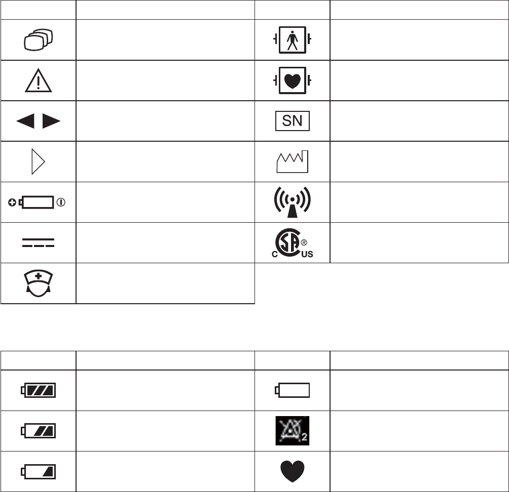
Explanations of the Symbols in this Manual and Instrument
The following symbols found in this manual/instrument bear the respective descriptions as given.
On Panel
Symbol Description Symbol Description
Change screen 'H¿EULOODWLRQSURRIW\SH%)
applied part
Attention, consult operator’s
manual
'H¿EULOODWLRQSURRIW\SH&)
applied part
Moves cursor, scrolls data Serial number
Direction for attaching battery
cover Date of manufacture
Direction for inserting battery RF transmitter
1RQLRQL]LQJUDGLDWLRQ
Direct current F&6$XVPDUN
&DOONH\
On LCD
Symbol Description Symbol Description
Batteries are fully charged Batteries are almost empty
Replace battery
Batteries are getting low Alarm suspended
Batteries are low 456SXOVHV\QFPDUN

Operator’s Manual ZM-520PA/521PA/530PA/531PA 1
Intended Use
General
7KH=03$DQG=03$WUDQVPLWWHUVWUDQVPLW(&*DQGUHVSLUDWLRQIURPDSDWLHQWWRD
1LKRQ.RKGHQPRQLWRUIRUFRQWLQXRXVPRQLWRULQJ7KHIURQW/&'GLVSOD\V(&*QXPHULFYDOXHV
of monitoring parameters, messages and battery condition.* They also display the compressed
ZDYHIRUPDQGQXPHULFGDWDRIWKHODWHVWPLQXWHV
7KH=03$DQG=03$WUDQVPLWWHUVWUDQVPLW(&*UHVSLUDWLRQDQGSXOVHZDYHIRUPV
and SpO2 from a patient to a Nihon Kohden monitor for continuous monitoring. The front LCD
GLVSOD\V(&*RUSXOVHZDYHQXPHULFYDOXHVRIPRQLWRULQJSDUDPHWHUVPHVVDJHVDQGEDWWHU\
condition.7KH\DOVRGLVSOD\WKHFRPSUHVVHGZDYHIRUPDQGQXPHULFGDWDRIWKHODWHVWPLQXWHV
(VVHQWLDOSHUIRUPDQFHRIWKLVWUDQVPLWWHU
7KHGLIIHUHQFHEHWZHHQ=03$3$DQG=03$3$LVWKHWUDQVPLVVLRQIUHTXHQF\
range.
=03$3$
WR0+]FKDQQHOQXPEHUWR
=03$3$
WR0+]FKDQQHOQXPEHU(WR(
WR0+]FKDQQHOQXPEHU(WR(
NOTE
• The transmitter channel can be changed with a QI-901PK channel writer.
• Read the operator’s manual for the receiving monitor together with this manual before
use.
WARNING
Do not diagnose a patient based only on data acquired by the transmitter. Overall
judgement must be performed by a physician who understands the features,
limitations and characteristics of the transmitter and by reading the biomedical signals
acquired by other instruments.
WARNING
Do not use the same transmitter for more than one patient at the same time. Do not
connect different sensors from different patients to the same transmitter.

2 Operator’s Manual ZM-520PA/521PA/530PA/531PA
CAUTION
• Do not use the same channel for different patients. If the same channel is used
for two patients, the two patients’ data will be lost due to mutual modulation
interference, or another patient’s data may appear on the receiving monitor screen.
• Do not use two transmitters with adjacent channels in the same hospital. If
transmitters with adjacent channels are used, their radio waves interfere with each
other.
CAUTION
Signal loss and artifact may occur because of the multipath cancellation* when using
a transmitter.
* Multipath Cancellation (Standing Wave Interference):
:KHQDUDGLRZDYHUHÀHFWVRIIDVXUIDFHWKHUHPD\EHVRPHSRLQWVLQWKHURRPZKHUHWKH
UHÀHFWHGDQGGLUHFWZDYHVDUHH[DFWO\RXWRISKDVH$WWKHVHSRLQWVLQWKHURRPWKHUHÀHFWHG
and direct waves cancel each other out so that the signal strength is decreased. Locations where
signal loss occurs are called “null spots”. If the transmitter is moving or nearby people or objects
are moving, null spots can occur anytime and anywhere.
NOTE
• To prevent interference between channels, assign a channel administrator in the
hospital and only he or she should manage channel assignment.
• Use Nihon Kohden parts and accessories to assure maximum performance from your
instrument.
• For stable signal reception, it is recommended to use a diversity antenna system on the
receiving monitor. Otherwise, spike noise from transient fading of electric field strength
(for example, people moving) may interfere with the transmitter signal and may be
mistaken as an arrhythmia on the receiving monitor.
• For details on antennas and antenna construction, contact your Nihon Kohden
representative. You can also refer to the Telemetry System Installation Guide.
Operator’s Manual ZM-520PA/521PA/530PA/531PA 3
Receiving Monitor
Any Nihon Kohden receiving monitor (central monitor with multiple patient receiver) can receive
signals from this transmitter as long as the protocol version and channel setting are the same on the
receiving monitor and transmitter.
NOTE
• For details on the receiving monitor and upgrade information, contact your Nihon
Kohden representative.
• The transmitter does not give any alarm other than a “low battery” alarm. Alarms must
be managed on the receiving monitor.
• To use protocol 51, an ORG-9100A or ORG-9110A multiple patient receiver software
version 03-03 or later is required. For the protocol setting, refer to the “Changing
SYSTEM SETUP Settings” section.
4 Operator’s Manual ZM-520PA/521PA/530PA/531PA
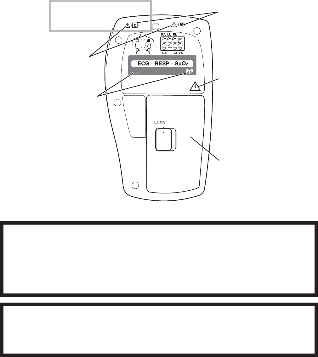
Panel Description
Top Panel
For attaching a strap.
ECG/RESP socket
Connects the electrode lead for
PHDVXULQJ(&*DQGRUUHVSLUDWLRQE\
the impedance method.
ZM-530PA/531PA only
SpO2 socket
Connects the SpO2 probe.
WARNING
Before defibrillation, all persons must
keep clear of the bed and must not
touch the patient or any equipment or
cord connected to the patient. Failure
to follow this warning may cause
electrical shock or injury.
WARNING
When performing defibrillation,
discharge as far as possible from
electrodes, patches and any gel,
cream or medicine on the chest of the
patient. If there is a possibility that the
defibrillator paddle could touch these
materials, remove them from the
patient. If the defibrillator paddle
directly contacts these materials, the
discharged energy may cause skin
burn to the patient.
WARNING
When the transmitter is used with an
electrosurgical unit (ESU), firmly attach
the entire area of the ESU return plate.
Otherwise, the current from the ESU
flows into the electrodes of the
transmitter, causing electrical burn
where the electrodes are attached. For
details, refer to the ESU manual.
CAUTION
Do not shake or swing the transmitter
while holding the leads or cables
connected to the transmitter. The
transmitter may come off and injure
someone or damage surrounding
instruments.
Operator’s Manual ZM-520PA/521PA/530PA/531PA 5
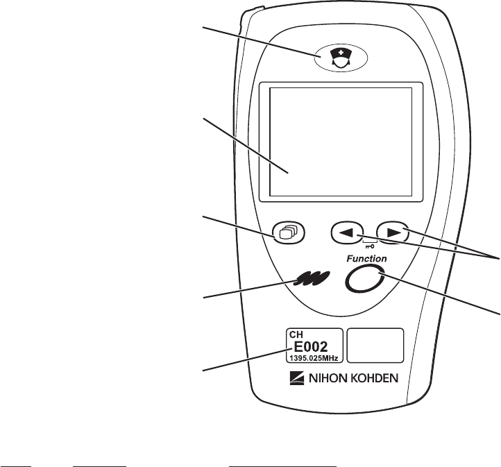
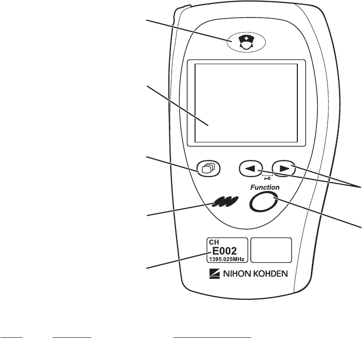
Front Panel
1
3
4
6
7
5
2
No. Name Description
&$//NH\ :KHQWKLVNH\LVSUHVVHGD³SHHS´VRXQGVDWWKHWUDQVPLWWHU
and “CALL” message appears at the monitor. Depending on
WKHVHWWLQJVRQWKHPRQLWRUDQ(&*ZDYHIRUPLVUHFRUGHGZKHQ
WKLVNH\LVSUHVVHG
/&' 'LVSOD\VQXPHULFYDOXHV(&*RUSXOVHZDYHPHVVDJHVDQG
battery status. For details, refer to the “Screen Descriptions”
section.
6FUHHQNH\ 7RJJOHVWKHVFUHHQLQWKHIROORZLQJRUGHU
$IWHUSRZHURQ6WDUWXSĺ&KHFNHOHFWURGHVĺ1XPHULFDQG
ZDYHIRUPĺ:DYHIRUPUHYLHZĺ1XPHULFUHYLHZĺ'LVSOD\
RIIĺ&KHFNHOHFWURGHV«
$IWHUDXWRGLVSOD\RII1XPHULFDQGZDYHIRUPĺ:DYHIRUP
UHYLHZĺ1XPHULFUHYLHZĺ'LVSOD\RIIĺ&KHFNHOHFWURGHV
ĺ1XPHULFDQGZDYHIRUP«
2QD6(783RU&+(&.VFUHHQWKLVNH\FDQFHOVFKDQJLQJ
setting or exits the screen.
6 Operator’s Manual ZM-520PA/521PA/530PA/531PA
1
3
4
6
7
5
2
No. Name Description
4 Infrared receiver Used for upgrading the transmitter software.
5 Channel number label Indicates the channel number of the transmitter.
/HDG6FUROONH\V 2QWKHQXPHULFDQGZDYHIRUPVFUHHQWKHVHNH\VFKDQJHWKH
(&*OHDG
2QWKHZDYHIRUPUHYLHZVFUHHQWKHVHNH\VVFUROOGDWD
2QD6(783VFUHHQWKHVHNH\VPRYHWKHFXUVRU
)XQFWLRQNH\ 'HSHQGLQJRQWKHVHWWLQJRQWKHWUDQVPLWWHUWKLVNH\VXVSHQGV
alarms, pauses monitoring on the receiving monitor or transmits
WKH³3DWLHQWFRQ¿UPHG´PHVVDJH
2QD6(783VFUHHQWKLVNH\UHJLVWHUVWKHVHOHFWHGVHWWLQJDQG
moves the cursor to the next setting item.
2QD&+(&.VFUHHQWKLVNH\VWDUWVRUVWRSVWKHPDLQWHQDQFH
test.
Operator’s Manual ZM-520PA/521PA/530PA/531PA 7
Rear Panel
5HIHUWRWKH³([SODQDWLRQV
of the Symbols in this
Manual and Instrument”
section.
5HIHUWRWKH:$51,1*
below.
5HIHUWRWKH:$51,1*
below.
5HIHUWRWKH³([SODQDWLRQV
of the Symbols in this
Manual and Instrument”
section.
ZM-530PA/531PA only
Battery case
&RQWDLQVWZRDONDOLQHGU\
FHOOEDWWHULHV$$7<3(
WARNING
Close the battery case cover during operation. If the transmitter is used with the
battery case cover open, anyone who touches the opened battery case may receive
an electrical shock when defibrillation is performed. Touching the opened battery case
may cause electrostatic discharge and intermittently interfere with the waveform or
data.
WARNING
This transmitter is not waterproof. If detergent or liquid spills into the transmitter, stop
using it and contact your Nihon Kohden representative. If a wet transmitter is used,
the patient or operator may receive an electrical shock or injury.

8 Operator’s Manual ZM-520PA/521PA/530PA/531PA
Important Safety Information
General
WARNING
Never use the transmitter in the
presence of any flammable anesthetic
gas or high concentration oxygen
atmosphere. Failure to follow this
warning may cause explosion or fire.
WARNING
Never use the transmitter in a
hyperbaric oxygen chamber. Failure to
follow this warning may cause
explosion or fire.
WARNING
Do not take this transmitter into the
MRI test room. This transmitter is not
designed to be used during MRI tests.
WARNING
When performing MRI test, remove all
electrodes and probe from the patient
which are connected to this transmitter.
Failure to follow this warning may
cause skin burn on the patient. For
details, refer to the MRI manual.
WARNING
Before defibrillation, all persons must
keep clear of the bed and must not
touch the patient or any equipment or
cord connected to the patient. Failure
to follow this warning may cause
electrical shock or injury.
WARNING
When the transmitter is used with an
electrosurgical unit (ESU), firmly attach
the entire area of the ESU return plate.
Otherwise, the current from the ESU
flows into the electrodes of the
transmitter, causing electrical burn
where the electrodes are attached. For
details, refer to the ESU manual.
WARNING
When performing defibrillation,
discharge as far as possible from
electrodes, patches and any gel,
cream or medicine on the chest of the
patient. If there is a possibility that the
defibrillator paddle could touch these
materials, remove them from the
patient. If the defibrillator paddle
directly contacts these materials, the
discharged energy may cause skin
burn to the patient.

Operator’s Manual ZM-520PA/521PA/530PA/531PA 9
WARNING
Do not use the same transmitter for
more than one patient at the same
time. Do not connect different sensors
from different patients to the same
transmitter.
WARNING
This transmitter is not waterproof. If
detergent or liquid spills into the
transmitter, stop using it and contact
your Nihon Kohden representative. If a
wet transmitter is used, the patient or
operator may receive an electrical
shock or injury.
WARNING
Close the battery case cover during
operation. If the transmitter is used with
the battery case cover open, anyone
who touches the opened battery case
may receive an electrical shock when
defibrillation is performed. Touching the
opened battery case may cause
electrostatic discharge and
intermittently interfere with the
waveform or data.
WARNING
Do not diagnose a patient based only
on data acquired by the transmitter.
Overall judgement must be performed
by a physician who understands the
features, limitations and characteristics
of the transmitter and by reading the
biomedical signals acquired by other
instruments.
WARNING
When the signal is unstable, keep the
patient under close observation. When
the signal is unstable, the monitoring
and alarm are not reliable and the
receiving monitor cannot detect a
sudden change of the patient’s
condition. This may cause critical
changes in the patient condition to be
overlooked. Install an appropriate
antenna system to ensure stable signal
condition.
WARNING
While the “ALARMS SUSPENDED”
message is displayed on the
transmitter, all alarms on the receiving
monitor are suspended so keep the
patient under close observation.
WARNING
When the patient returns to the bed,
turn on the transmitter and check that
the monitoring is resumed on the
receiving monitor.
WARNING
If the transmitter is not turned off and
monitoring continues for the selected
interval, pause monitoring is canceled
and monitoring continues. Check that
the monitoring is resumed on the
receiving monitor.

10 Operator’s Manual ZM-520PA/521PA/530PA/531PA
CAUTION
Only use Nihon Kohden specified
electrodes, electrode leads and SpO2
probes. Otherwise, the maximum
performance from the transmitter
cannot be guaranteed.
CAUTION
The measurement values and
displayed waveforms on the transmitter
and receiving monitor may be different
due to timing delay of the display or
difference in detection settings.
CAUTION
Turn off the power of mobile phones,
small wireless devices and other
devices which produce strong
electromagnetic interference around a
patient (except for devices allowed by
the hospital administrator). Radio
waves from devices such as mobile
phones or small wireless devices may
be mistaken as pulse waves or
respiration waves and the displayed
data may be incorrect.
CAUTION
• Do not use the same channel
for different patients. If the same
channel is used for two patients, the
two patients’ data will be lost due to
mutual modulation interference, or
another patient’s data may appear
on the receiving monitor screen.
• Do not use two transmitters with
adjacent channels in the same
hospital. If transmitters with adjacent
channels are used, their radio waves
interfere with each other.
CAUTION
Signal loss and artifact may occur
because of the multipath cancellation*
when using a transmitter.
* Multipath Cancellation (Standing Wave
Interference):
:KHQDUDGLRZDYHUHÀHFWVRIIDVXUIDFH
there may be some points in the room where
WKHUHÀHFWHGDQGGLUHFWZDYHVDUHH[DFWO\
out of phase. At these points in the room, the
UHÀHFWHGDQGGLUHFWZDYHVFDQFHOHDFKRWKHU
out so that the signal strength is decreased.
Locations where signal loss occurs are called
“null spots”. If the transmitter is moving or
nearby people or objects are moving, null
spots can occur anytime and anywhere.
CAUTION
Do not shake or swing the transmitter
while holding the leads or cables
connected to the transmitter. The
transmitter may come off and injure
someone or damage surrounding
instruments.
CAUTION
Do not reuse disposable parts and
accessories.

Operator’s Manual ZM-520PA/521PA/530PA/531PA 11
CAUTION
When monitoring respiration is needed,
measure respiration with an
instrument. The transmitter calculates
SpO2 of arterial blood based on the
principle of pulse oximeter and does
not measure respiration.
CAUTION
When monitoring SpO2 only, detection
of arrhythmia and asystole is not
available and arrhythmia alarms such
as ASYSTOLE, VF or VT are not
available. If the patient requires ECG
monitoring, monitor the ECG.
CAUTION
When monitoring SpO2 only (without
ECG monitoring), turn on both the
upper and lower limit alarms for PR
and SpO2 on the receiving monitor. If
the patient’s pulse is not detected
during asystole or other condition, a
“CANNOT DETECT PULSE” or
“CHECK PROBE” alarm occurs instead
of an SpO2 limit alarm. Furthermore, if
the patient has no pulse, noise from
probe movement could be misjudged
as a pulse and cause an incorrect PR
or SpO2 value to be displayed.
Output Signal
WARNING
Do not use the output signal from the receiving monitor as the synchronization signal
for other equipment such as IABP, MRI, echocardiography or defibrillator. There may
be time delay between the monitor and the other equipment caused by waveform
transmission delay and spike noise may interfere on the output signal and be
mistaken as a trigger.

12 Operator’s Manual ZM-520PA/521PA/530PA/531PA
Battery
WARNING
Do not use NiMH batteries for this
transmitter. Some operating
environments may cause NiMH
batteries to produce gas and explode.
CAUTION
Do not handle the batteries with wet
hands.
CAUTION
Refer to the battery manual for details
on handling the batteries.
CAUTION
Battery replacement must be
performed by the operator. When
replacing the batteries of a transmitter
that is currently used for a patient,
disconnect the electrode leads from
the transmitter before replacing
batteries or do not touch the patient
during replacement.
CAUTION
When the transmitter is not in use,
remove the batteries. When the
batteries are installed, battery power is
consumed even when measurement is
not performed.
Transmitter Channel Management
WARNING
The following actions must be taken to properly receive the transmitter signal of the
correct patient on the receiving instrument. Otherwise, there may be signal loss or
signals may mix causing a serious accident, such as monitoring a different patient.
• Assign a channel administrator in the hospital and only he or she should manage
channel assignment.
• The channel administrator must manage the channels in the facility so that there is
no signal interference.
• When the transmitter channel is changed, the channel administrator must check
that the channel on the receiving monitor is also changed and the signal is properly
received.
• The channel administrator must replace the channel number label on the
transmitter with the new one after changing the channel.

Operator’s Manual ZM-520PA/521PA/530PA/531PA 13
For Patients Using Implantable Pacemaker
WARNING
The bioelectric impedance measurement sensor of a minute ventilation rate-adaptive
implantable pacemaker may be affected by transmitter which is connected to the
same patient. If this occurs, the pacemaker may pace at its maximum rate and the
transmitter may give incorrect data to the monitor. If this occurs, disconnect the
electrode leads from the patient or change the setting on the pacemaker by referring
to the pacemaker’s manual. For more details, contact your pacemaker representative
or Nihon Kohden representative.
ECG Monitoring
WARNING
After attaching the electrode to the
patient and connecting the electrode
lead to the transmitter, check that
electrodes are attached to the patient
and check that the electrode lead is
connected to the transmitter properly.
When the electrodes are removed from
the patient, do not touch the metal part
of the electrode with bare hands or let
the metal part of the electrode contact
the metal part of the bed or any other
conductive parts. Failure to follow this
warning may cause electrical shock or
injury to the patient by discharged
energy.
WARNING
The transmitter detects the pacemaker
pulse and rejects the pacemaker pulse
from the heart rate count. However, all
of the pacemaker pulse might not be
rejected. If the pacemaker pulse is not
rejected, the pacemaker pulse is
detected as QRS and false heart rate
may be indicated. Keep pacemaker
patients under close observation.
* )RUWKHSDFHPDNHUSXOVHUHMHFWLRQFDSDELOLW\
of the =03$3$3$3$
WUDQVPLWWHUUHIHUWRWKH³6SHFL¿FDWLRQV
(&*´VHFWLRQ
WARNING
The pacemaker pulse can be
overlooked or detected as QRS. You
cannot confirm the pacemaker
operation only from the detected
pacemaker pulse.

14 Operator’s Manual ZM-520PA/521PA/530PA/531PA
CAUTION
Only use Nihon Kohden specified
electrodes and electrode leads. When
other type of electrodes or electrode
leads are used, the “CHECK
ELECTRODES” message may be
displayed and ECG monitoring may
stop.
CAUTION
When the “CHECK ELECTRODES”
message is displayed on the receiving
monitor, ECG is not monitored properly
and the ECG alarm does not function.
Check the electrode, electrode leads,
and if necessary, replace with new
ones.
CAUTION
Hold the connector of the electrode
lead when connecting/disconnecting
the electrode lead. If you disconnect
the electrode lead by pulling the lead, it
damages the electrode lead.

Operator’s Manual ZM-520PA/521PA/530PA/531PA 15
SpO2 Monitoring
WARNING
SpO2 measurement may be incorrect
in the following cases.
• When the patient’s
carboxyhemoglobin or
methemoglobin increases
abnormally.
• When dye is injected in the blood.
• When using an electrosurgical unit.
• During CPR.
• When measuring at a site with
venous pulse.
• When there is body movement.
• When the pulse wave is small
(insufficient peripheral circulation).
WARNING
When monitoring SpO2 of a patient
who is receiving photodynamic therapy,
the light from the finger probe sensor
may cause a burn. Photodynamic
therapy uses a photosensitizing agent
that has a side effect of
photosensitivity.
The SpO2 probes manufactured by Nihon
.RKGHQKDYHWZRZDYHOHQJWKVZLWKSHDNVLQWKH
UDQJHRIDQGQP7KHPD[LPXPOLJKW
intensity is less than 5.5 mW.
WARNING
• When using the TL-201T finger
probe, do not fasten the probe and
cable to the finger by wrapping
with tape. This may cause burn,
congestion or pressure necrosis from
poor blood circulation.
• When using probes other than the
TL-201T finger probe, to avoid poor
circulation, do not wrap the tape too
tight. Check the blood circulation
condition by observing the skin color
and congestion at the skin peripheral
to the probe attachment site. Even
for short-term monitoring, there may
be burn or pressure necrosis from
poor blood circulation, especially on
neonates or low birth weight infants
whose skin is delicate. Accurate
measurement cannot be performed
on a site with poor peripheral
circulation.
WARNING
Check the circulation condition by
observing the skin color at the
measurement site and pulse waveform.
Change the measurement site every 8
hours for disposable probes and every
4 hours for reusable probes (every 8
hours for TL-631T series probe). The
skin temperature may increase at the
attached site by 2 or 3°C (4 or 5°F)
and cause a burn or pressure necrosis.
When using the probe on the following
patients, take extreme care and
change the measurement site more
frequently according to symptoms and
degree.
• Patient with a fever
• Patient with insufficient peripheral
circulation
• Neonate or low birth weight infant
with delicate skin

16 Operator’s Manual ZM-520PA/521PA/530PA/531PA
WARNING
When not monitoring SpO2, disconnect
the SpO2 cable from the transmitter.
Otherwise, noise from the probe
sensor may interfere and incorrect data
is displayed on the screen.
CAUTION
The disposable probe is not sterilized.
Use the disposable probe only for a
single patient. Never reuse the
disposable probe for another patient
because it causes cross infection.
CAUTION
While a patient is on medication which
causes vasodilation, the pulse
waveform may change and in rare
cases the SpO2 value might not be
displayed.
CAUTION
Do not attach the probe to the same
limb that is used for NIBP
measurement or an IBP catheter. The
SpO2 measurement may be incorrect.
CAUTION
Normal external light does not affect
monitoring but strong light such as a
surgical light or sunlight may affect
monitoring. If affected, cover the
measuring site with a blanket.
CAUTION
When a message indicates a faulty
probe, stop monitoring and replace the
probe with a new one.
CAUTION
Do not use a probe which is
deteriorated by aging. Accurate
measurement cannot be performed.
CAUTION
Do not use a damaged or
disassembled probe. It causes
incorrect measurement and may injure
the patient.
CAUTION
Refer to the probe instruction manual
for details.
CAUTION
When the probe is attached on an
appropriate site with sufficient
circulation and the error message
confirming the probe attachment
repeatedly appears, the probe may be
deteriorated. Replace it with a new
one.

Operator’s Manual ZM-520PA/521PA/530PA/531PA 17
CAUTION
Failure to follow these instructions may
cause cable discontinuity, short circuit,
skin burn on the patient from the probe
temperature increase due to the short
circuit of the probe cable, and incorrect
measurement data. If the probe is
broken, replace it with a new one.
• Do not immerse any part of
the probe cable other than the
disposable probe in chemical
solutions or water.
• Do not pull or bend the probe cable.
• Do not let caster feet run over the
probe cable.
CAUTION
If the attachment site is dirty with blood
or bodily fluids, clean the attachment
site before attaching the probe. If there
is nail polish on the attachment site,
remove the polish. Otherwise, the
amount of transmitted light decreases,
and measured value may be incorrect
or measurement cannot be performed.
CAUTION
If the skin gets irritated or redness
appears on the skin from the probe,
change the attachment site or stop
using the probe. Take extreme care for
the patients with delicate skin.
Maintenance
CAUTION
This transmitter is not waterproof. If
detergent or liquid spills into the
transmitter, stop cleaning or
disinfecting it and contact your Nihon
Kohden representative. The transmitter
needs to be checked for safety and
function before use.
CAUTION
Do not immerse the electrode lead
connector in liquid.
CAUTION
Dispose of Nihon Kohden products
according to your local laws and your
facility’s guidelines for waste disposal.
Otherwise, it may affect the
environment. If there is a possibility
that the product may have been
contaminated with infection, dispose of
it as medical waste according to your
local laws and your facility’s guidelines
for medical waste. Otherwise, it may
cause infection.
CAUTION
Never disassemble or repair the
transmitter. If there is any problem with
the transmitter, contact your Nihon
Kohden representative.

18 Operator’s Manual ZM-520PA/521PA/530PA/531PA
Preparation on Transmitter
Batteries
Handling Batteries
WARNING
Do not use NiMH batteries for this
transmitter. Some operating
environments may cause NiMH
batteries to produce gas and explode.
CAUTION
Refer to the battery manual for details
on handling the batteries.
CAUTION
When the transmitter is not in use,
remove the batteries. When the
batteries are installed, battery power is
consumed even when measurement is
not performed.
CAUTION
Do not handle the batteries with wet
hands.
NOTE
Remove the batteries from the transmitter before disposing of it.
Battery Lifetime
8VHWZR$$/5W\SHDONDOLQHGU\FHOOEDWWHULHV:LWKQHZ1LKRQ.RKGHQUHFRPPHQGHG
DONDOLQHEDWWHULHVWKHWUDQVPLWWHUFDQFRQWLQXRXVO\PHDVXUHIRUWKHIROORZLQJQXPEHURIGD\VDW
URRPWHPSHUDWXUH2SHUDWLRQWLPHGHSHQGVRQWKHWKLFNQHVVRIWKH6S22 probe attachment site.
Transmitter Operating Time (Measuring parameters)
ECG, Resp, SpO2ECG, Resp
=03$=03$ 2.5 days 3.5 days
=03$=03$ GD\V 2.5 days
Recommended Batteries
$ONDOLQHSULPDU\1LKRQ.RKGHQ0HGLSRZHUHTXLYDOHQWWR3DQDVRQLF/5*
Operator’s Manual ZM-520PA/521PA/530PA/531PA 19
NOTE
• Use Nihon Kohden Medipower to ensure specified performance. Outdated, mismatched
or poor-quality batteries can give unacceptable performance (e.g., insufficient
low battery indication). The use of fresh high quality alkaline batteries is strongly
recommended.
• When the display is on, it consumes battery power. Instruct the patient not to turn on
the display during monitoring.
Installing (Replacing) Batteries
CAUTION
Battery replacement must be performed by the operator. When replacing the batteries
of a transmitter that is currently used for a patient, disconnect the electrode leads
from the transmitter before replacing batteries or do not touch the patient during
replacement.
If electrode leads are attached to the patient and the person replacing batteries touches the patient
GXULQJEDWWHU\UHSODFHPHQWH[FHVVSDWLHQWOHDNDJHFXUUHQWPD\ÀRZLQWRWKHSDWLHQW
NOTE
• Replace all batteries at the same time.
• Do not use different types of batteries together.
• Insert the batteries with the correct polarity (+ and –).
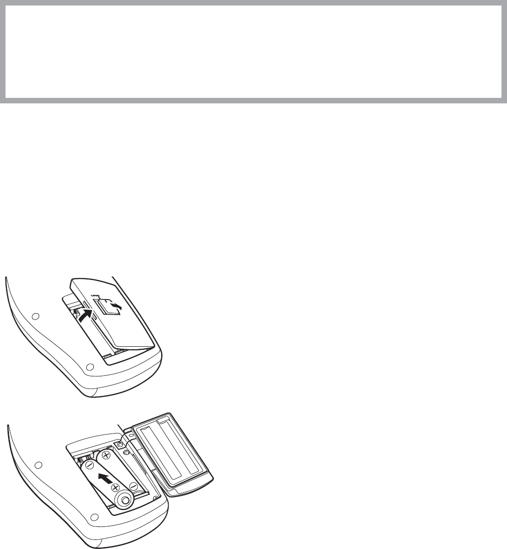
1. Open the battery case cover.
2. Insert two new batteries into the battery case
observing the correct polarity.
The transmitter is automatically turned on
when the batteries are installed.
ii
i
20 Operator’s Manual ZM-520PA/521PA/530PA/531PA
NOTE
Insert the (–) end of the battery first and press it against the spring. If you try to force
the (+) end of the battery in first, it will deform the spring and damage the battery and
transmitter.
3. Close the cover.
Situations Requiring Battery Replacement
Replace the batteries when any of the following occurs.
7KHWUDQVPLWWHUGLVSOD\VWKH³%$77(5<:($.´PHVVDJHRU icon.
• The transmitter generates a constant alarm (continuous “peep” sound).
• The transmitter LCD does not display anything when the power is turned on.
• The receiving monitor displays a battery replacement message.
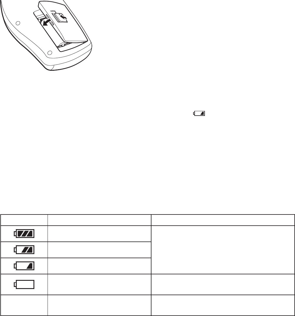
Battery Level Indication
7KHIROORZLQJLFRQVRQWKH/&'LQGLFDWHWKHEDWWHU\OHYHO:KHQ³35272&2/´RQWKH6<67(0
6(783VFUHHQLVVHWWRWKHEDWWHU\OHYHOLQGLFDWLRQLVWUDQVPLWWHGWRWKHUHFHLYLQJPRQLWRU7R
XVHSURWRFROWKH25*$RU25*$PXOWLSOHSDWLHQWUHFHLYHUVRIWZDUHYHUVLRQ
or later is required.
Indication Battery Level Message on the Receiving Monitor
Batteries are fully charged.
There is no message on the monitor.
Batteries are getting low.
Batteries are low.
Batteries are almost empty.
Replace batteries.
Message requiring battery replacement is
displayed.
No indication Dead batteries No signal can be transmitted to the monitor.
There is no indication on the monitor.
i
ii
Operator’s Manual ZM-520PA/521PA/530PA/531PA 21
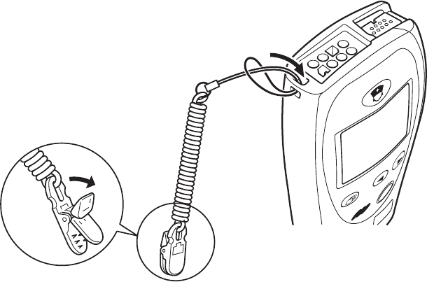
Attaching a Strap to the Transmitter
NOTE
Do not attach the clip to hard objects such as thick cloth or a zipper. It will break the clip.
Attach a strap to the transmitter and fasten the clip to the patient’s clothes or bed sheets.
If the transmitter falls off, the transmitter may be damaged and the batteries may come out. If
WKHSDWLHQWWRXFKHVWKHEDWWHU\WHUPLQDOZKHQSXWWLQJWKHEDWWHULHVEDFNLQWKHWUDQVPLWWHUH[FHVV
SDWLHQWOHDNDJHFXUUHQWPD\ÀRZLQWRWKHSDWLHQW
If the transmitter falls into water or a toilet, stop using the transmitter and contact your Nihon
Kohden representative.
22 Operator’s Manual ZM-520PA/521PA/530PA/531PA
Turning On the Transmitter
When the batteries are installed correctly, the power is turned on. A “peep” sounds for one second,
WKHVWDUWXSVFUHHQDSSHDUVWKHQWKHFKHFNHOHFWURGHVVFUHHQDSSHDUV7KHUHLVQR³SHHS´VRXQG
when there is no battery power.)
$IWHUFKHFNLQJWKDWWKH(&*LVVWDEOHRQWKHFKHFNHOHFWURGHVVFUHHQSUHVVWKH6FUHHQNH\WR
display the numeric and waveform screen.
For details on the screen, refer to the “Screen Descriptions” section.
Check Items Before Use
%HIRUHWXUQLQJRQWKHWUDQVPLWWHUSRZHUFKHFNWKHIROORZLQJWRFRQ¿UPWKDWWKHWUDQVPLWWHUFDQEH
used in normal and safe condition.
Appearance
7KHUHDUHQRGDPDJHGRUGLUW\SDUWVRQWKHRXWVLGHRIWKHWUDQVPLWWHU/&'NH\VVRFNHWV
battery case cover, battery case, etc.).
• The transmitter is completely dry.
• The electrodes, electrode lead and SpO2SUREHDUHQRWEURNHQ
Operator’s Manual ZM-520PA/521PA/530PA/531PA 23
Batteries
• The battery polarity is correct.
7KHEDWWHU\FDVHVSULQJLV¿UPO\DWWDFKHGDQGWKHEDWWHU\LVQRWORRVH
7KHEDWWHU\FDVHFRYHULV¿UPO\FORVHG
Channel Setting
• The transmitter channel matches the receiving monitor channel.
• There is no nearby transmitter with the same channel.
Other
:KHQSHUIRUPLQJGH¿EULOODWLRQVHWWKHKXP¿OWHUWR21RQWKHUHFHLYLQJPRQLWRU7KH
ZDYHIRUPUHFRYHU\PD\EHFRPHVORZGXHWRHOHFWURGHSRODUL]DWLRQZKHQWKHKXP¿OWHULVVHWWR
OFF.
Check Items After Power On
$IWHUWXUQLQJRQWKHSRZHUFKHFNWKHIROORZLQJ
Power On
• The transmitter generates a one second “peep” sound and the startup screen appears.
7KHWUDQVPLWWHUGLVSOD\VWKHFKHFNHOHFWURGHVVFUHHQ
• The transmitter is not too hot.
7KHWUDQVPLWWHUGRHVQRWGLVSOD\WKH³%$77(5<:($.´PHVVDJH
• The transmitter does not interfere with the operation of other medical instruments.
Daily Check
• The “signal loss” message is not displayed on the receiving monitor when the transmitter is
inside the receiving range of the monitor.
• The battery replacement message is not displayed on the monitor.
7KHNH\VRQWKHWUDQVPLWWHUIXQFWLRQSURSHUO\
7KH/&'EULJKWQHVVLVDSSURSULDWH7RDGMXVWEULJKWQHVVUHIHUWRWKH³&KDQJLQJ6<67(0
6(7836HWWLQJV´VHFWLRQ
Check Items After Use
7RXVHWKHWUDQVPLWWHULQVDIHDQGRSWLPXPFRQGLWLRQIRUQH[WWLPHFKHFNWKHIROORZLQJ
Before Turning Power Off
7HPSRUDULO\FKDQJHGVHWWLQJVDUHFKDQJHGEDFNWRWKHSUHYLRXVVHWWLQJV
• There was no malfunction on the transmitter.
Storage
(&*HOHFWURGHOHDGVDQG6S22 probe are cleaned and disinfected.
• If the transmitter got wet, liquid is wiped off and the transmitter is thoroughly dried.
• There are enough consumables, such as disposable electrodes.
• The transmitter power is turned off by removing batteries from the transmitter.
• Dead batteries are disposed of properly.
24 Operator’s Manual ZM-520PA/521PA/530PA/531PA
Turning Off the Transmitter
To turn off the power, remove the batteries. When the power is turned off, the saved waveform and
numeric data are deleted.
Changing the Transmitter Channel
7KHFKDQQHORIWKHWUDQVPLWWHUFDQEHFKDQJHGZLWKWKHRSWLRQDO4,3.FKDQQHOZULWHU
WARNING
The following actions must be taken to properly receive the transmitter signal of the
correct patient on the receiving instrument. Otherwise, there may be signal loss or
signals may mix causing a serious accident, such as monitoring a different patient.
• Assign a channel administrator in the hospital and only he or she should manage
channel assignment.
• The channel administrator must manage the channels in the facility so that there is
no signal interference.
• When the transmitter channel is changed, the channel administrator must check
that the channel on the receiving monitor is also changed and the signal is properly
received.
• The channel administrator must replace the channel number label on the
transmitter with the new one after changing the channel.
NOTE
• The software version of the QI-901PK channel writer must be 02-01 or later to change
the channel on the transmitter.
• The channel writer must be used outside the patient environment.
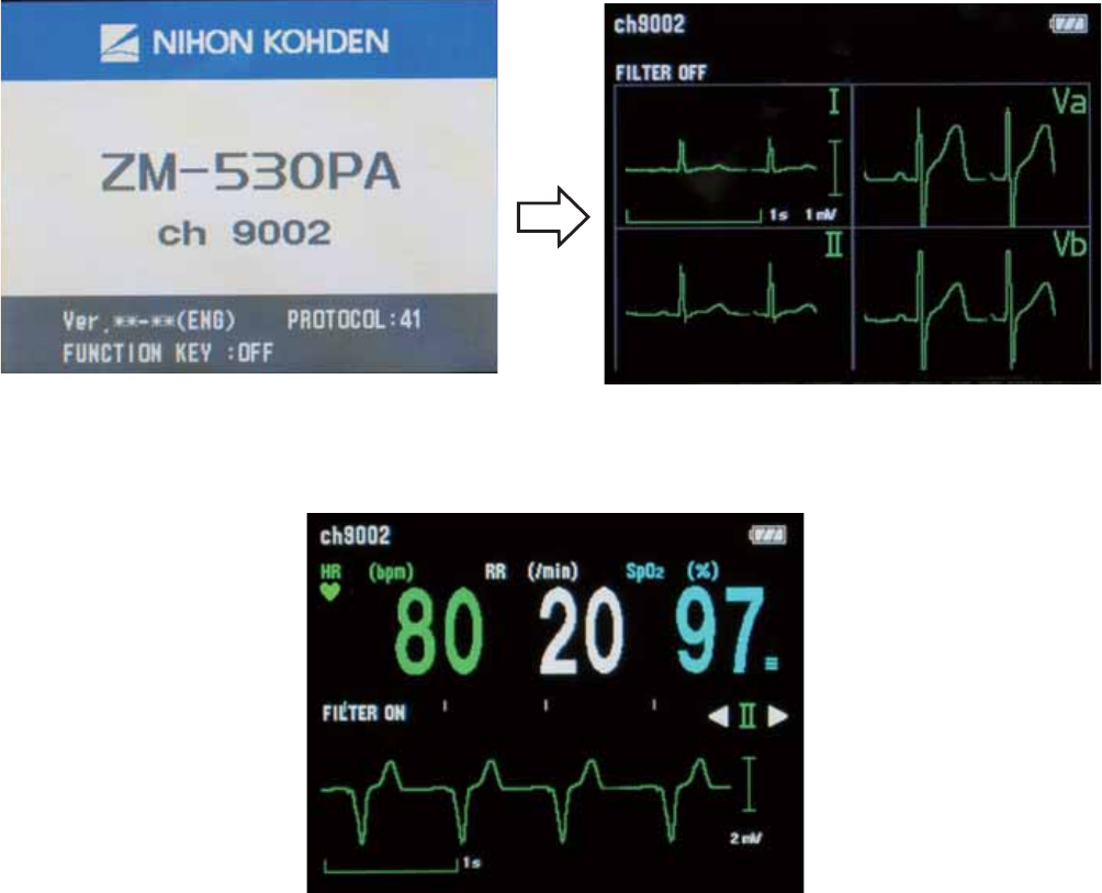
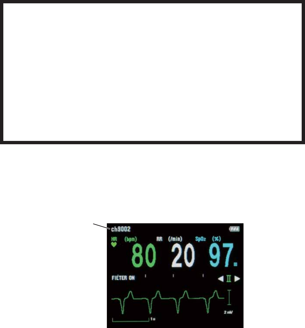
The channel is displayed in the upper left corner of the screen.
Channel

Operator’s Manual ZM-520PA/521PA/530PA/531PA 25
Changing Parameter and System Setup Settings
7KHLQLWLDOVHWWLQJVRQWKH3$5$0(7(56(783DQG6<67(06(783VFUHHQVFDQRQO\EH
changed before monitoring. Changing these settings during monitoring interrupts monitoring.
NOTE
Changing Parameter and System Setup settings must be done by qualified personnel.
Changing PARAMETER SETUP Settings
Parameter Setup Setting List
The factory default settings are underlined.
Setting Item Description Settings
(&*(/(&752'(6 Select the electrode lead type. ,(&$+$
/($'7<3( 6HOHFWWKHW\SHRI(&*OHDGV AUTO/($'6
(&*
0($685(0(17
7XUQ(&*PRQLWRULQJRQRURII:KHQHOHFWURGHVDUH
DWWDFKHGWRWKHSDWLHQWDQG(&*OHDGVDUHFRQQHFWHG
(&*PRQLWRULQJVWDUWVHYHQZKHQWKLVVHWWLQJLVVHW
to OFF. If this setting is set to OFF, the same setting
on the receiving monitor must also be set to OFF.
NOTE
When “PROTOCOL” on the transmitter is set to
51 and the receiving monitor is able to receive
protocol 51, ECG measurement on the receiving
monitor is automatically set to OFF when this
setting is set to OFF on the transmitter.
To use protocol 51, the ORG-9100A or
ORG-9110A multiple patient receiver software
version 03-03 or later is required.
ON, OFF
5(63
0($685(0(17
Turn respiration monitoring on or off.
When this setting is set to OFF, the same setting on
the receiving monitor is automatically set to OFF.
ON, OFF
SpO25(63216( Select the SpO2 response mode. FAST, NORMAL,
SLOW
26 Operator’s Manual ZM-520PA/521PA/530PA/531PA
Displaying the PARAMETER SETUP Screen
1. Turn off the transmitter by removing one
battery.
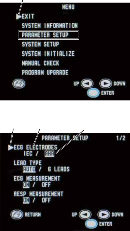
:KLOHSUHVVLQJWKH)XQFWLRQNH\WXUQRQWKH
WUDQVPLWWHULQVHUWWKHEDWWHU\7KH0(18
screen appears.
3UHVVWKHŹNH\WRPRYHWKHFXUVRUWR
³3$5$0(7(56(783´
3UHVVWKH)XQFWLRQNH\WRHQWHU3$5$0(7(5
6(7837KHFXUUHQWVHWWLQJVDUHKLJKOLJKWHG
5. Change the settings:
• To move the cursor and select the setting
LWHPSUHVVWKHŻRUŹNH\WKHQSUHVVWKH
)XQFWLRQNH\
• To select and register the setting, press the
ŻRUŹNH\WKHQSUHVVWKH)XQFWLRQNH\
• To cancel changing the setting of the
VHOHFWHGLWHPSUHVVWKH6FUHHQNH\
:KHQFKDQJLQJVHWWLQJVRQWKH3$5$0(7(5
6(783VFUHHQLVFRPSOHWHSUHVVWKH6FUHHQ
NH\WRUHWXUQWRWKH0(18VFUHHQ
3UHVVWKHŻRUŹNH\WRPRYHWKHFXUVRUWR³(;,7´
3UHVVWKH)XQFWLRQNH\7KHQXPHULFDQGZDYHIRUPVFUHHQDSSHDUV
Cursor
MENU screen
Setting item
PARAMETER SETUP screen - page 1
Setting
Cursor
Operator’s Manual ZM-520PA/521PA/530PA/531PA 27
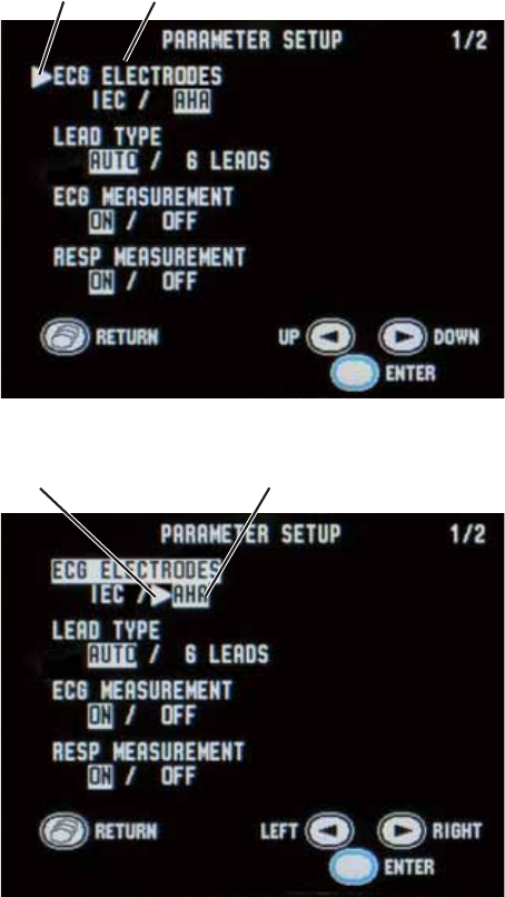
Changing Parameter Setup Settings
ECG ELECTRODES
Select the electrode lead type.
2QWKH3$5$0(7(56(783VFUHHQSUHVV
WKHŹNH\WRPRYHWKHFXUVRUWR³(&*
(/(&752'(6´
3UHVVWKH)XQFWLRQNH\7KHFXUVRUPRYHVWR
the selection item.
3UHVVWKHŹNH\WRVHOHFW³,(&´RU³$+$´
3UHVVWKH)XQFWLRQNH\WRUHJLVWHUWKH
VHOHFWHGVHWWLQJ7KHFXUVRUUHWXUQVWR³(&*
(/(&752'(6´
LEAD TYPE
6HOHFWWKHW\SHRI(&*OHDGV,QQRUPDOXVHVHOHFW³$872´:KHQXVLQJ',1W\SHOHDGZLWK
HOHFWURGHVVHOHFW³/($'6´
2QWKH3$5$0(7(56(783VFUHHQSUHVVWKHŹNH\WRPRYHWKHFXUVRUWR³/($'7<3(´
3UHVVWKH)XQFWLRQNH\
3UHVVWKHŹNH\WRVHOHFW³$872´RU³/($'6´
3UHVVWKH)XQFWLRQNH\WRUHJLVWHUWKHVHOHFWHGVHWWLQJ7KHFXUVRUUHWXUQVWR³/($'7<3(´
Setting item
Cursor
Selected setting
Cursor
28 Operator’s Manual ZM-520PA/521PA/530PA/531PA
ECG MEASUREMENT
7XUQ(&*PRQLWRULQJRQRURII:KHQHOHFWURGHVDUHDWWDFKHGWRWKHSDWLHQWDQG(&*OHDGVDUH
FRQQHFWHG(&*PRQLWRULQJVWDUWVHYHQZKHQWKLVVHWWLQJLVVHWWR2))
If this setting is set to OFF, the same setting on the receiving monitor must also be set to OFF.
NOTE
When “PROTOCOL” on the transmitter is set to 51 and the receiving monitor is able to
receive protocol 51, ECG measurement on the receiving monitor is automatically set
to OFF when this setting is set to OFF on the transmitter. To use protocol 51, the ORG-
9100A/ORG-9110A multiple patient receiver software version 03-03 or later is required.
2QWKH3$5$0(7(56(783VFUHHQSUHVVWKHŹNH\WRPRYHWKHFXUVRUWR³(&*
0($685(0(17´
3UHVVWKH)XQFWLRQNH\
3UHVVWKHŹNH\WRVHOHFW³21´RU³2))´
3UHVVWKH)XQFWLRQNH\WRUHJLVWHUWKHVHOHFWHGVHWWLQJ7KHFXUVRUUHWXUQVWR³(&*
0($685(0(17´
RESP MEASUREMENT
Turn respiration monitoring on or off. When this setting is set to OFF, the same setting on the
receiving monitor is automatically set to OFF.
2QWKH3$5$0(7(56(783VFUHHQSUHVVWKHŹNH\WRPRYHWKHFXUVRUWR³5(63
0($685(0(17´
3UHVVWKH)XQFWLRQNH\
3UHVVWKHŹNH\WRVHOHFW³21´RU³2))´
3UHVVWKH)XQFWLRQNH\WRUHJLVWHUWKHVHOHFWHGVHWWLQJ7KHFXUVRUUHWXUQVWR³5(63
0($685(0(17´
Operator’s Manual ZM-520PA/521PA/530PA/531PA 29
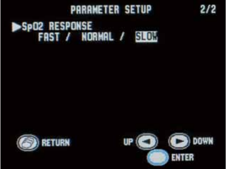
SpO2 RESPONSE
Select the response mode from FAST, NORMAL or SLOW. For details on the response time, refer
WRWKH³6SHFL¿FDWLRQV6S220HDVXUHPHQW,62FRPSOLDQFH´VHFWLRQLQWKLVPDQXDO
NOTE
When measurement condition is unstable due to strenuous movement of the patient, etc.,
response may become slower in all modes.
2QWKH3$5$0(7(56(783VFUHHQSUHVV
WKHŹNH\WRPRYHWKHFXUVRUWR³6S2
5(63216(´³6S25(63216(´LVRQWKH
VHFRQGSDJHRIWKH3$5$0(7(56(783
screen.
3UHVVWKH)XQFWLRQNH\
3UHVVWKHŹNH\WRVHOHFW³)$67´
“NORMAL” or “SLOW”.
3UHVVWKH)XQFWLRQNH\WRUHJLVWHUWKH
selected setting. The cursor returns to “SpO2
5(63216(´
PARAMETER SETUP screen - page 2

30 Operator’s Manual ZM-520PA/521PA/530PA/531PA
Changing SYSTEM SETUP Settings
System Setup Setting List
The factory default settings are underlined.
Setting Item Description Settings
PROTOCOL
Select the transmitting protocol.
51: New protocol. A central monitor with an
25*$RU25*$PXOWLSOHSDWLHQWUHFHLYHU
ZKRVHVRIWZDUHYHUVLRQRUODWHUFDQUHFHLYHWKLV
protocol.
41: Old protocol. A central monitor with an
25*$25*$RU25*$PXOWLSOH
patient receiver can receive this protocol.
NOTE
When 51 is set, the receiving monitor must be able
to receive protocol 51. Otherwise, signals from the
transmitter cannot be received. To use protocol 51,
an ORG-9100A or ORG-9110A multiple patient
receiver software version 03-03 or later is required.
51, 41
%5,*+71(66 Select the screen brightness. DARK,
%5,*+7
)81&7,21.(<
6HOHFWWKHIXQFWLRQRIWKH)XQFWLRQNH\
6863(1'$/$503$86(
Suspends alarm on the receiving monitor for 2
minutes. Pauses monitoring on the transmitter and
receiving monitor.
6863(1'$/$50
Suspends alarm on the receiving monitor for 2
minutes.
CONFIRM:
'LVSOD\VWKH³3$7,(17&21),50('´PHVVDJH
on the transmitter screen and transmits the
message to the receiving monitor.
OFF: No function.
NOTE
“SUSPEND ALARM & PAUSE” and “CONFIRM”
can only be set when PROTOCOL is set to 51. To
use protocol 51, the ORG-9100A or ORG-9110A
multiple patient receiver software version 03-03 or
later is required.
6863(1'
ALARM
3$86(,
6863(1'
ALARM,
CONFIRM,
OFF
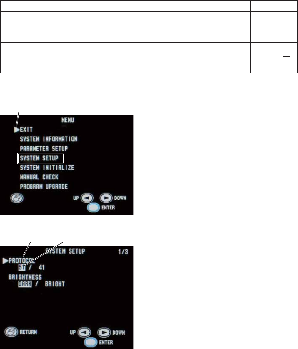
Operator’s Manual ZM-520PA/521PA/530PA/531PA 31
Setting Item Description Settings
$8725(680(
$)7(53$86( 6HOHFWWKHLQWHUYDOWRUHVXPHPRQLWRULQJDIWHU3$86(
VV,
1 min, 2 min,
3 min
6(/(&7$%/(
6&5((17,0(287
3(5,2'PLQ
6HOHFWWKHGLVSOD\WLPHRXWSHULRG ,
Displaying the SYSTEM SETUP Screen
1. Turn off the transmitter by removing one
battery.
:KLOHSUHVVLQJWKH)XQFWLRQNH\WXUQRQ
the transmitter by inserting the battery. The
0(18VFUHHQDSSHDUV
3UHVVWKHŹNH\WRPRYHWKHFXUVRUWR
³6<67(06(783´
3UHVVWKH)XQFWLRQNH\WRHQWHU6<67(0
6(7837KHFXUUHQWVHWWLQJVDUHKLJKOLJKWHG
5. Change the settings.
• To move the cursor and select the setting
LWHPSUHVVWKHŻRUŹNH\WKHQSUHVVWKH
)XQFWLRQNH\
• To select and register the setting, press the
ŻRUŹNH\WKHQSUHVVWKH)XQFWLRQNH\
• To cancel changing the setting of the
VHOHFWHGLWHPSUHVVWKH6FUHHQNH\
7KH6<67(06(783VFUHHQKDVWZRSDJHV
7RGLVSOD\WKHVHFRQGSDJHSUHVVWKHŹNH\
ZKHQWKHFXUVRULVDW³%5,*+71(66´
:KHQFKDQJLQJVHWWLQJVRQWKH6<67(06(783VFUHHQLVFRPSOHWHSUHVVWKH6FUHHQNH\WR
UHWXUQWRWKH0(18VFUHHQ
3UHVVWKHŻRUŹNH\WRPRYHWKHFXUVRUWR³(;,7´
3UHVVWKH)XQFWLRQNH\7KHQXPHULFDQGZDYHIRUPVFUHHQDSSHDUV
Cursor
MENU screen
Setting item
SYSTEM SETUP screen - page 1
Setting
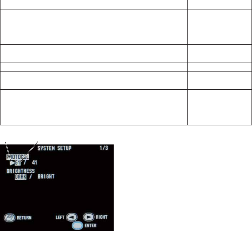
32 Operator’s Manual ZM-520PA/521PA/530PA/531PA
Changing System Setup Settings
PROTOCOL
Select the transmitting protocol. For differences between protocols, refer to the table below.
1HZSURWRFRO$FHQWUDOPRQLWRUZLWKDQ25*$RU25*$PXOWLSOHSDWLHQW
UHFHLYHUZKRVHVRIWZDUHYHUVLRQRUODWHUFDQUHFHLYHWKLVSURWRFRO
2OGSURWRFRO$FHQWUDOPRQLWRUZLWKDQ25*$25*$RU25*$PXOWLSOH
patient receiver can receive this protocol.
NOTE
When 51 is set, the receiving monitor must be able to receive protocol 51. Otherwise,
signals from the transmitter cannot be received.
Differences Between Protocols
Function Protocol 41 Protocol 51
6HWWLQJ(&*0($685(0(17WR2))RQ
the transmitter automatically turns off the
(&*PHDVXUHPHQWVHWWLQJRQWKHUHFHLYLQJ
monitor
1R(&*PHDVXUHPHQW
must be turned off on
the receiving monitor)
Yes
Pause monitoring on the receiving monitor
from the transmitter No Yes
7UDQVPLW³3$7,(17&21),50('´PHVVDJH No Yes
Display battery level of the transmitter on the
receiving monitor No Yes
Transmit SpO2 messages
Some messages (refer
to the “Indication and
Message List” section)
All messages
7UDQVPLW5(63PHVVDJH No Yes
3UHVVWKHŹNH\WRPRYHWKHFXUVRUWR
“PROTOCOL”.
3UHVVWKH)XQFWLRQNH\
3UHVVWKHŹNH\WRVHOHFW³´RU³´
Setting
Cursor
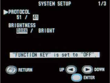
Operator’s Manual ZM-520PA/521PA/530PA/531PA 33
NOTE
FUNCTION KEY (on the second page
of the SYSTEM SETUP screen) can be
set to “SUSPEND ALARM & PAUSE” or
“CONFIRM” only when PROTOCOL is
“51”. If PROTOCOL is changed to “41”,
FUNCTION KEY is automatically changed
to “OFF”.
3UHVVWKH)XQFWLRQNH\WRUHJLVWHUWKHVHOHFWHG
setting. The cursor returns to “PROTOCOL”.
BRIGHTNESS
Select the screen brightness.
3UHVVWKHŹNH\WRPRYHWKHFXUVRUWR³%5,*+71(66´
3UHVVWKH)XQFWLRQNH\
3UHVVWKHŹNH\WRVHOHFW³'$5.´RU³%5,*+7´
3UHVVWKH)XQFWLRQNH\WRUHJLVWHUWKHVHOHFWHGVHWWLQJ7KHFXUVRUUHWXUQVWR³%5,*+71(66´
FUNCTION KEY
6HOHFWWKHIXQFWLRQRIWKH)XQFWLRQNH\)RUGHWDLOVRQXVLQJWKHVHIXQFWLRQVUHIHUWR³%DVLF
Monitoring Operation” in the “Monitoring” section.
6863(1'$/$503$86( 6XVSHQGVDODUPRQWKHUHFHLYLQJPRQLWRUIRUPLQXWHV3DXVHV
monitoring on the transmitter and receiving monitor.
6863(1'$/$50 6XVSHQGVDODUPRQWKHUHFHLYLQJPRQLWRUIRUPLQXWHV
&21),50 'LVSOD\VWKH³3$7,(17&21),50('´PHVVDJHRQWKH
transmitter screen and transmits the message to the receiving
monitor.
OFF: No function.
NOTE
“SUSPEND ALARM & PAUSE” and “CONFIRM” can only be set when PROTOCOL is set
to 51.
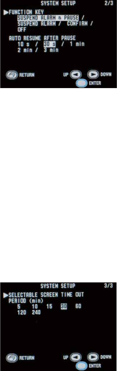
34 Operator’s Manual ZM-520PA/521PA/530PA/531PA
2QWKH6<67(06(783VFUHHQSUHVVWKH
ŹNH\WRPRYHWKHFXUVRUWR³)81&7,21
.(<´,WLVRQWKHVHFRQGSDJHRIWKH
6<67(06(783VFUHHQ
3UHVVWKH)XQFWLRQNH\
3UHVVWKHŹNH\WRVHOHFWWKHIXQFWLRQ
3UHVVWKH)XQFWLRQNH\WRUHJLVWHUWKHVHOHFWHG
setting. The cursor returns to “FUNCTION
.(<´
AUTO RESUME AFTER PAUSE
6HOHFWWKHLQWHUYDOWRUHVXPHPRQLWRULQJDIWHU3$86(:KHQHLWKHURIWKHIROORZLQJFRQGLWLRQVLV
met, monitoring resumes on the receiving monitor.
+HDUWUDWHLVSURSHUO\PRQLWRUHGIRUWKHVHOHFWHGLQWHUYDO
• SpO2 is properly monitored for the selected interval
3UHVVWKHŹNH\WRPRYHWKHFXUVRUWR³$8725(680($)7(53$86(´,WLVRQWKH
VHFRQGSDJHRIWKH6<67(06(783VFUHHQ
3UHVVWKH)XQFWLRQNH\
3UHVVWKHŹNH\WRVHOHFWWKHLQWHUYDO
3UHVVWKH)XQFWLRQNH\WRUHJLVWHUWKHVHOHFWHGVHWWLQJ7KHFXUVRUUHWXUQVWR³$8725(680(
$)7(53$86(´
SELECTABLE SCREEN TIME OUT PERIOD (min)
6HOHFWWKHGLVSOD\WLPHRXWSHULRG,IQRNH\LVSUHVVHGIRUWKHVHOHFWHGWLPHWKHGLVSOD\LV
automatically turned off. The selected time is shown on the Select Screen Time Out Period screen.
Refer to the “Turning the Display Off” section for details.
3UHVVWKHŹNH\WRPRYHWKHFXUVRUWR
³6(/(&7$%/(6&5((17,0(287
3(5,2'PLQ´,WLVRQWKHWKLUGSDJHRIWKH
6<67(06(783VFUHHQ
3UHVVWKH)XQFWLRQNH\
3UHVVWKHŻRUŹNH\WRVHOHFWWLPHRXW
period.
SYSTEM SETUP screen - page 2
SYSTEM SETUP screen - page 3
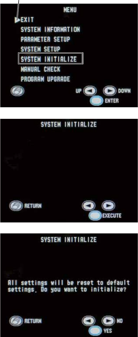
Operator’s Manual ZM-520PA/521PA/530PA/531PA 35
3UHVVWKH)XQFWLRQNH\WRUHJLVWHUWKHVHOHFWHGVHWWLQJ7KHFXUVRUUHWXUQVWR³6(/(&7$%/(
6&5((17,0(2873(5,2'PLQ´
Initializing Settings
Do the following procedure to initialize all settings, except for channel, to the factory default
settings.
1. Turn off the transmitter by removing a battery.
:KLOHSUHVVLQJWKH)XQFWLRQNH\WXUQRQ
the transmitter by inserting the battery. The
0(18VFUHHQDSSHDUV
3UHVVWKHŹNH\WRPRYHWKHFXUVRUWR
³6<67(0,1,7,$/,=(´
3UHVVWKH)XQFWLRQNH\WRHQWHUWKH6<67(0
,1,7,$/,=(VFUHHQ
3UHVVWKH)XQFWLRQNH\$FRQ¿UPDWLRQ
message appears.
7RUHWXUQWRWKH0(18VFUHHQSUHVVWKH
6FUHHQNH\
3UHVVWKH)XQFWLRQNH\WRLQLWLDOL]HVHWWLQJV
7RFDQFHOLQLWLDOL]LQJSUHVVWKHŹNH\7KH
VFUHHQUHWXUQVWRWKH0(18VFUHHQ
Cursor
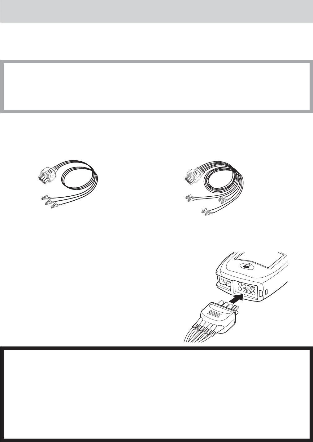
36 Operator’s Manual ZM-520PA/521PA/530PA/531PA
Attaching Electrodes and SpO2 Probe to the Patient
Attaching Electrodes
Selecting Electrode Lead
CAUTION
Only use Nihon Kohden specified electrodes and electrode leads. When other type of
electrodes or electrode leads are used, the “CHECK ELECTRODES” message may
be displayed and ECG monitoring may stop.
The following optional electrode leads can be used with the transmitter.
%53$HOHFWURGHV$+$FOLSW\SH %53$HOHFWURGHV$+$FOLSW\SH
Connecting the Electrode Lead to the Transmitter
&RQQHFWWKHHOHFWURGHOHDGWRWKH(&*5(63VRFNHWRQ
the transmitter.
WARNING
After attaching the electrode to the patient and connecting the electrode lead to the
transmitter, check that electrodes are attached to the patient and check that the
electrode lead is connected to the transmitter properly. When the electrodes are
removed from the patient, do not touch the metal part of the electrode with bare
hands or let the metal part of the electrode contact the metal part of the bed or any
other conductive parts. Failure to follow this warning may cause electrical shock or
injury to the patient by discharged energy.

Operator’s Manual ZM-520PA/521PA/530PA/531PA 37
CAUTION
Do not shake or swing the transmitter while holding the leads or cables connected to
the transmitter. The transmitter may come off and injure someone or damage
surrounding instruments.
CAUTION
Hold the connector of the electrode lead when connecting/disconnecting the
electrode lead. If you disconnect the electrode lead by pulling the lead, it damages
the electrode lead.
Electrode Position
Follow the physician’s instructions for electrode placement when available.
)RU(&*PRQLWRULQJHOHFWURGHVDUHDWWDFKHGRQO\RQWKHFKHVWWRDOORZSDWLHQWPRYHPHQW
DQGREWDLQFRQWLQXRXVVWDEOH(&*7KHIROORZLQJOHDGVDUHH[DPSOHV:KHQDOVRPRQLWRULQJ
UHVSLUDWLRQUHIHUWRWKH³(OHFWURGH3RVLWLRQIRU5HVSLUDWLRQ0RQLWRULQJ´VHFWLRQ
NOTE
The optimum electrode positions for ECG measurement are not always optimum for
respiration measurement. Select positions that are suitable for both ECG and respiration
measurement or positions which give priority to either ECG or respiration measurement.
Electrode Positions for ECG Monitoring
Six Electrodes
7KHHOHFWURGHPHWKRGZLWKOHDG,,DQGOHDG9LVHIIHFWLYHIRUPRQLWRULQJP\RFDUGLDOLVFKHPLD
<RXFDQLPSURYHPRQLWRULQJDFFXUDF\FRQVLGHUDEO\E\DGGLQJOHDG9WRWKLVFRPELQDWLRQ9DDQG
9EFDQEHDWDQ\SRVLWLRQRIWKHVWDQGDUGOHDGV9WR9EXW9DQG9DUHPRVWDSSURSULDWH
for myocardial ischemic monitoring.
RA/R LA/L
RL/RF LL/F
Va/Ca
Vb/Cb
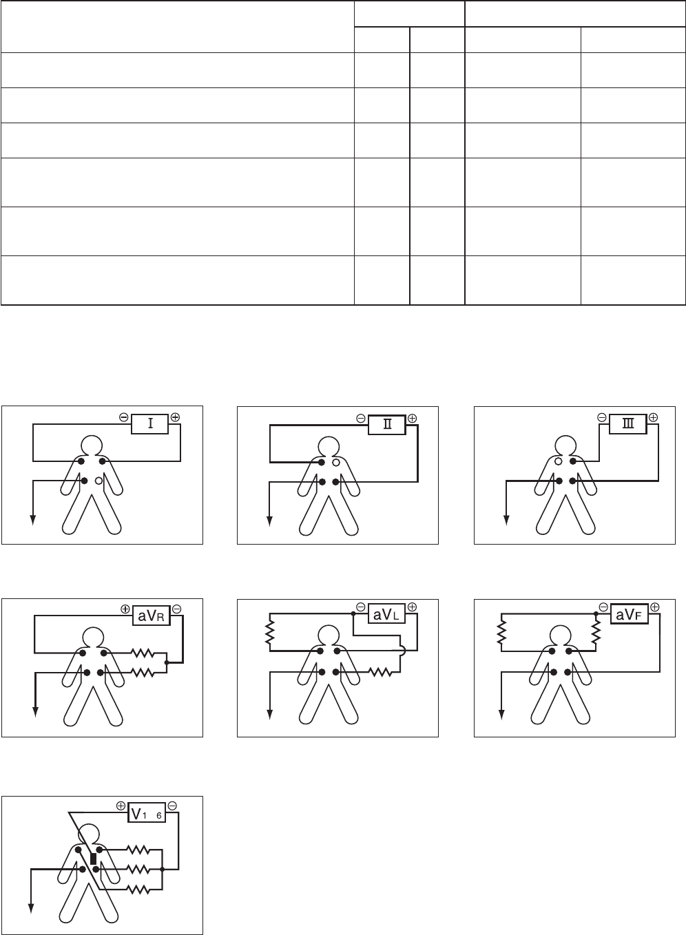
38 Operator’s Manual ZM-520PA/521PA/530PA/531PA
Electrode Position Symbol Lead Color
AHA IEC AHA IEC
Left infraclavicular fossa LA L %ODFN Yellow
Right infraclavicular fossa RA R White Red
Below lowest rib on the left anterior axillary line LL F Red *UHHQ
Right anterior axillary line at the same level as
LL/F RL RF *UHHQ %ODFN
Fifth intercostal space on the left midclavicular
OLQH9SRVLWLRQRIVWDQGDUGOHDGV 9D Ca %URZQEOXH :KLWHEURZQ
/HIWDQWHULRUD[LOODU\OLQHDWWKHVDPHOHYHODV9D
9SRVLWLRQRIVWDQGDUGOHDGV 9E Cb %URZQRUDQJH :KLWHEODFN
Lead Position
Standard limb leads
M
onopolar limb leads
Monopolar chest leads
L
ead
I
Lead I Lead II Lead III
a
VR lead aVL lead aVF lead
to
V1 to V6 leads
RA
RA
RA RA RA
RA
RA
LA
LA
LA
LA
LA
LALA
LL
LL
LL
LL LL
LL
LL
N (RL)
N (RL)
N (RL) N (RL) N (RL)
N (RL)
N (RL)
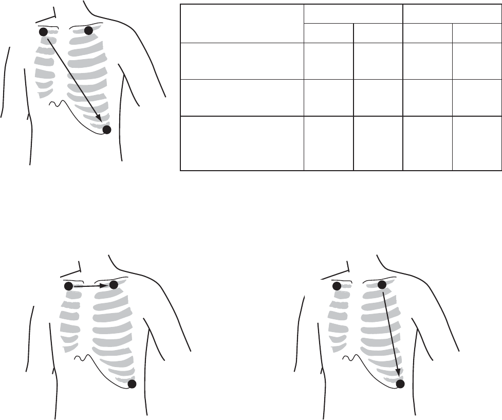
Operator’s Manual ZM-520PA/521PA/530PA/531PA 39
Three Electrodes
/HDG0,,ZKLFKLVVLPLODUWRVWDQGDUGOHDG,,XVHGZKHQ(&*PHDVXUHPHQWKDVSULRULW\
Electrode Position Symbol Lead Color
AHA IEC AHA IEC
Left infraclavicular
fossa LA L %ODFN Yellow
Right infraclavicular
fossa RA R White Red
Below lowest rib
on the left anterior
axillary line
LL F Red *UHHQ
• Lead MI, which is similar to standard
lead I
Change F/LL and L/LA of lead MII.
R/RA
(−)
L/LA
(N)
F/LL
(+)
• Lead MIII, which is similar to standard
lead III
Change R/RA and L/LA of lead MII.
L/LA
(N)
R/RA
(−)
F/LL
(+)
If the electrode positions above are not available due to chest surgery, attach the electrodes to the
URRWRIWKHOLPEVRUEHORZWKHFODYLFOHVIRUVWDEOH(&*PRQLWRULQJ
L/LA
(N)
R/RA
(−)
F/LL
(+)
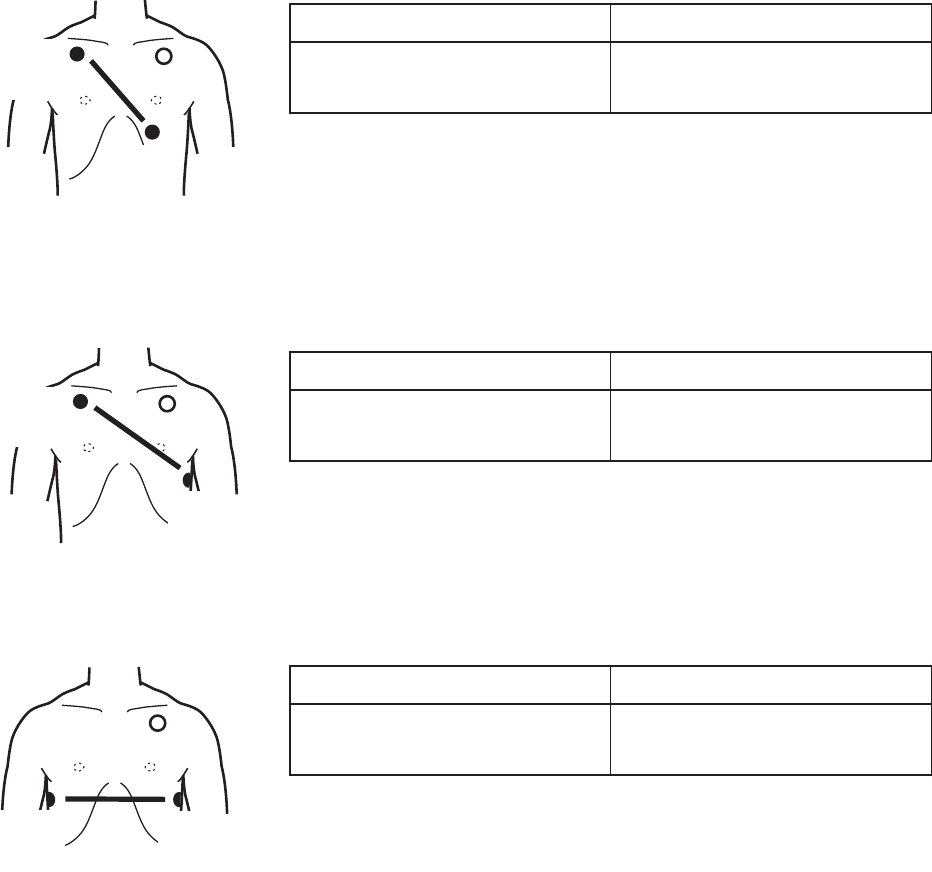
40 Operator’s Manual ZM-520PA/521PA/530PA/531PA
Electrode Positions for Respiration Monitoring
Place the R/RA and F/LL electrodes so that the lungs are between the electrodes.
Position 1
In this position, respiration measurement is available; however, there is a difference in amplitude
between different patients.
R or RA F or LL
Right infraclavicular fossa Fifth intercostal space on the
OHIWPLGFODYLFXODUOLQH9
Position 2
,QWKLVSRVLWLRQWKHZDYHIRUPDPSOLWXGHLVXVXDOO\ODUJHDQGWKH(&*OHDGLVVLPLODUWR/HDG0,,
This position can be generally recommended.
R or RA F or LL
Right infraclavicular fossa Fifth intercostal space on the
OHIWPLGD[LOODU\OLQH9
Position 3
,QWKLVSRVLWLRQWKHUHVSLUDWLRQZDYHIRUPLVRSWLPXPEXWWKH(&*OHDGLVXQXVXDO
R or RA F or LL
Right midaxillary at the
KRUL]RQWDOOHYHORI9
Fifth intercostal space on the
OHIWPLGD[LOODU\OLQH9
R/RA
(−)
F/LL
(+)
N
R/RA
(−)
F/LL
(+)
N
N
R/RA
(−)
F/LL
(+)
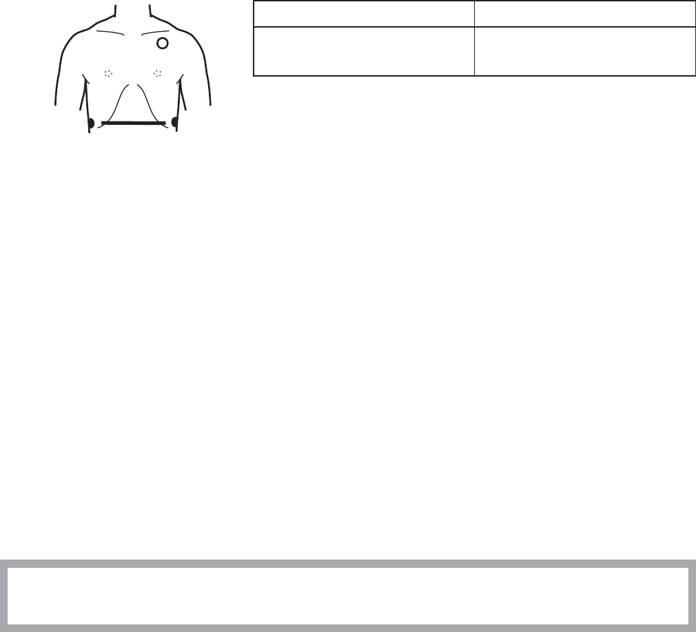
Operator’s Manual ZM-520PA/521PA/530PA/531PA 41
Position 4
,QWKLVSRVLWLRQWKHUHVSLUDWLRQPHDVXUHPHQWLVLQÀXHQFHGE\WKHLPSHGDQFHYDULDWLRQRIWKH
abdomen, so the cardiac pulse wave included in the respiration wave is reduced. Note that the
waveform is inverted in phase compared with the chest movement (the waveform goes down
GXULQJLQVSLUDWLRQ,WLVGLI¿FXOWWRPHDVXUHWKH(&*DWWKHVDPHWLPH
R or RA F or LL
Lowest rib on the right
anterior axillary line
Lowest rib on the left anterior
axillary line
Attaching Electrodes to the Patient and Connecting the Electrode Leads to
Disposable Electrodes
Prepare the Patient Skin
Shave off excessive body hair.
7RUHGXFHVNLQLPSHGDQFHFOHDQWKHHOHFWURGHVLWHZLWKFUHDPRUZLWKDFRWWRQSDGPRLVWHQHGZLWK
DOFRKRO7KRURXJKO\GU\WKHVNLQZLWKDFOHDQFRWWRQSDG
NOTE
• For a patient with frequent body movement, rub the sites with skinPure skin preparation
gel. However, do not use skinPure skin preparation gel on sensitive skin.
• Do not place electrodes on a wound or on an inflamed, wrinkled or uneven skin surface.
Attaching Electrodes to the Patient
CAUTION
Do not reuse disposable parts and accessories.
NOTE
• To maintain good contact between the electrode and skin, check that the paste of the
disposable electrode is not dry.
• When contact between the disposable electrode and skin becomes poor, replace
electrodes with new ones immediately. Otherwise, contact impedance between the skin
and the electrode increases and accurate ECG and respiration waveforms cannot be
obtained.
N
R/RA
(−)
F/LL
(+)
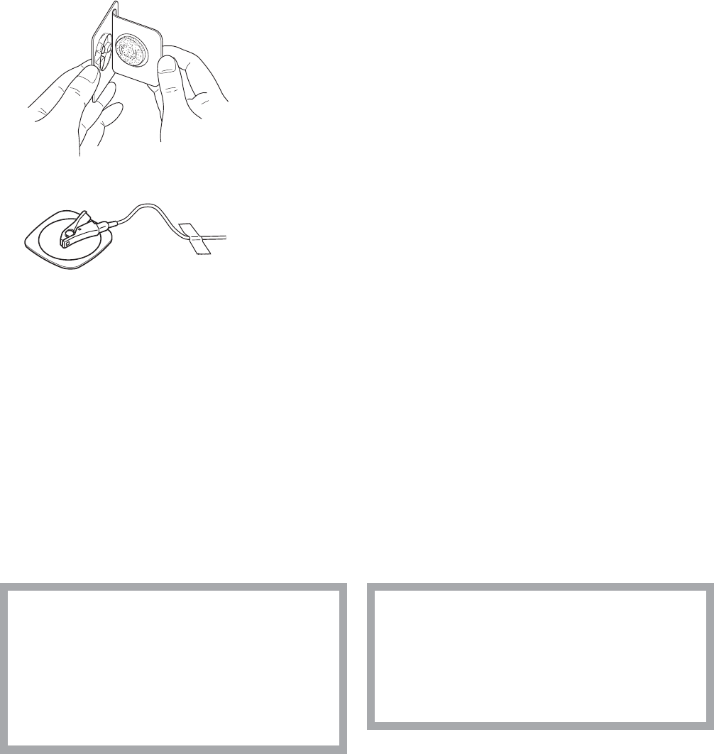
42 Operator’s Manual ZM-520PA/521PA/530PA/531PA
Refer to the electrode operator’s manual for details.
&DUHIXOO\UHPRYHWKHEDFNLQJSDSHUIURPWKHHOHFWURGH
Avoid touching the adhesive surface.
3ODFHWKHHOHFWURGHRQWKHSUHYLRXVO\FOHDQHGVNLQ3D\
attention to the electrode lead color and symbol.
3. Clip the electrode lead to the electrode.
4. Fasten the electrode lead wire with surgical tape
with an extra length of wire between the tape and the
electrode. This lessens the movement of electrode leads
by body movement and helps stable monitoring.
Checking ECG on the Transmitter Screen
$IWHUDWWDFKLQJHOHFWURGHVDQGFRQQHFWLQJ(&*OHDGVFKHFNWKDWWKHHOHFWURGHVDUHSURSHUO\
DWWDFKHGWRWKHSDWLHQWDQGWKH(&*ZDYHIRUPLVDFTXLUHGRQWKHFKHFNHOHFWURGHVVFUHHQ)RU
details on the screen, refer to the “Screen Descriptions” section.
Attaching the SpO2 Probe
Selecting the SpO2 Probe
Select an appropriate probe for the patient.
CAUTION
Only use Nihon Kohden specified
electrodes, electrode leads and SpO2
probes. Otherwise, the maximum
performance from the transmitter
cannot be guaranteed.
CAUTION
Do not use a damaged or
disassembled probe. It causes
incorrect measurement and may injure
the patient.

Operator’s Manual ZM-520PA/521PA/530PA/531PA 43
Reusable Probes
:KHQXVLQJD7/7¿QJHUSUREHFKRRVHWKHDSSURSULDWHFDEOHOHQJWKIRUDWWDFKPHQW
Probe Cable Length Patient Attachment Site
)LQJHUSUREH7/7
P
Adult or child
NJRUPRUH
Finger
1.6 m
0XOWLVLWHSUREH7/7
Attachment tape
Adult or infant
NJRUPRUH
Finger or toe
Neonate
NJRUOHVV
Instep and sole
Finger probe
7/77/7
Attachment tape
7/7
P
Adult or child
NJRUPRUH
Finger or toe
7/7
1.6 m
Disposable Probes
CAUTION
The disposable probe is not sterilized. Use the disposable probe only for a single
patient. Never reuse the disposable probe for another patient because it causes cross
infection.

44 Operator’s Manual ZM-520PA/521PA/530PA/531PA
Probe Patient Attachment Site
7/67/6
40 mm
&DEOHOHQJWK 7/6P
7/6P
Adult
NJRUPRUH
Finger
Neonate
NJRUOHVV
Instep and sole
7/67/6
35 mm
&DEOHOHQJWK 7/6P
7/6P
Adult or child
WRNJ
Finger
Chiled or infant
WRNJ
Toe
7/77/7
&DEOHOHQJWK 7/7 P
7/7P
Adult
NJRUPRUH
Finger or toe
7/77/7
&DEOHOHQJWK 7/7 P
7/7P
Child
WRNJ
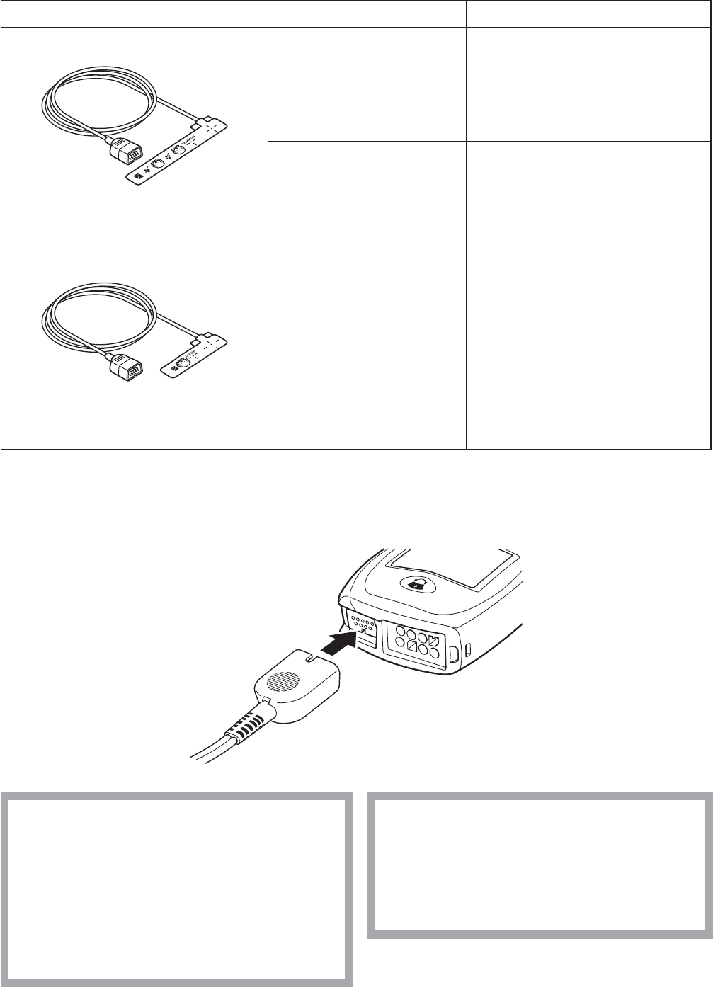
Operator’s Manual ZM-520PA/521PA/530PA/531PA 45
Probe Patient Attachment Site
7/77/7
&DEOHOHQJWK 7/7 P
7/7P
Adult
NJRUPRUH
Finger or toe
Neonate
NJRUOHVV
Instep and sole
7/77/7
&DEOHOHQJWK 7/7 P
7/7P
Infant
WRNJ
Finger or toe
Connecting the SpO2 Probe to the Transmitter
Connect the probe to the SpO2VRFNHWRQWKHWUDQVPLWWHU
CAUTION
Do not shake or swing the transmitter
while holding the leads or cables
connected to the transmitter. The
transmitter may come off and injure
someone or damage surrounding
instruments.
CAUTION
Do not use a damaged or
disassembled probe. It causes
incorrect measurement and may injure
the patient.

46 Operator’s Manual ZM-520PA/521PA/530PA/531PA
Attaching the Probe to the Patient
$WWDFKWKHSUREHWRWKHSDWLHQWE\UHIHUULQJWRWKHSUREH¶VPDQXDO0DNHVXUHWKDWWKHOLJKWHPLWWHU
and photo detector of the probe face each other at the attachment site.
WARNING
• When using the TL-201T finger
probe, do not fasten the probe and
cable to the finger by wrapping
with tape. This may cause burn,
congestion or pressure necrosis from
poor blood circulation.
• When using probes other than the
TL-201T finger probe, to avoid poor
circulation, do not wrap the tape too
tight. Check the blood circulation
condition by observing the skin color
and congestion at the skin peripheral
to the probe attachment site. Even
for short-term monitoring, there may
be burn or pressure necrosis from
poor blood circulation, especially on
neonates or low birth weight infants
whose skin is delicate. Accurate
measurement cannot be performed
on a site with poor peripheral
circulation.
WARNING
Check the circulation condition by
observing the skin color at the
measurement site and pulse waveform.
Change the measurement site every 8
hours for disposable probes and every
4 hours for reusable probes (every 8
hours for TL-631T series probe). The
skin temperature may increase at the
attached site by 2 or 3°C (4 or 5°F)
and cause a burn or pressure necrosis.
When using the probe on the following
patients, take extreme care and
change the measurement site more
frequently according to symptoms and
degree.
• Patient with a fever
• Patient with insufficient peripheral
circulation
• Neonate or low birth weight infant
with delicate skin
WARNING
When monitoring SpO2 of a patient
who is receiving photodynamic therapy,
the light from the finger probe sensor
may cause a burn. Photodynamic
therapy uses a photosensitizing agent
that has a side effect of
photosensitivity.
The SpO2 probes manufactured by Nihon
.RKGHQKDYHWZRZDYHOHQJWKVZLWKSHDNVLQWKH
UDQJHRIDQGQP7KHPD[LPXPOLJKW
intensity is less than 5.5 mW.

Operator’s Manual ZM-520PA/521PA/530PA/531PA 47
CAUTION
If the attachment site is dirty with blood
or bodily fluids, clean the attachment
site before attaching the probe. If there
is nail polish on the attachment site,
remove the polish. Otherwise, the
amount of transmitted light decreases,
and measured value may be incorrect
or measurement cannot be performed.
CAUTION
When the probe is attached on an
appropriate site with sufficient
circulation and the error message
confirming the probe attachment
repeatedly appears, the probe may be
deteriorated. Replace it with a new
one.
CAUTION
If the skin gets irritated or redness
appears on the skin from the probe,
change the attachment site or stop
using the probe. Take extreme care for
the patients with delicate skin.
CAUTION
Do not use a probe which is
deteriorated by aging. Accurate
measurement cannot be performed.
CAUTION
Refer to the probe instruction manual
for details.
CAUTION
The disposable probe is not sterilized.
Use the disposable probe only for a
single patient. Never reuse the
disposable probe for another patient
because it causes cross infection.
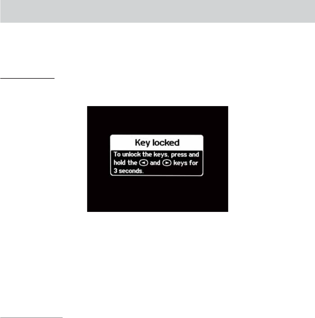
48 Operator’s Manual ZM-520PA/521PA/530PA/531PA
Locking the Keys on the Transmitter
7RSUHYHQWWKHSDWLHQWIURPSUHVVLQJWKHNH\VRQWKHWUDQVPLWWHUGXULQJPRQLWRULQJ\RXFDQORFN
WKHNH\V
7RORFNWKHNH\V
3UHVVWKHŻDQGŹNH\VDWWKHVDPHWLPHDQGKROGIRUPRUHWKDQVHFRQGV7KH³.H\ORFNHG´
screen appears.
:KHQWKHVFUHHQWLPHRXWSHULRGLVVHWWR³PLQ´IDFWRU\GHIDXOWWKH³.H\ORFNHG´VFUHHQLV
GLVSOD\HGIRUVHFRQGVWKHQWKHGLVSOD\WXUQVRIILIWKHUHLVQRNH\RSHUDWLRQ
:KHQWKHVFUHHQWLPHRXWSHULRGLVVHWWRDFHUWDLQQXPEHURIPLQXWHVWKH³.H\ORFNHG´VFUHHQ
LVGLVSOD\HGIRUVHFRQGVWKHQLWFKDQJHVWRWKHQXPHULFDQGZDYHIRUPVFUHHQ,IWKHUHLVQRNH\
operation, the display turns off when the remaining time elapses. Refer to the “Turning the Display
Off” section for details.
7RXQORFNWKHNH\V
3UHVVWKHŻDQGŹNH\VDWWKHVDPHWLPHDQGKROGIRUPRUHWKDQVHFRQGV
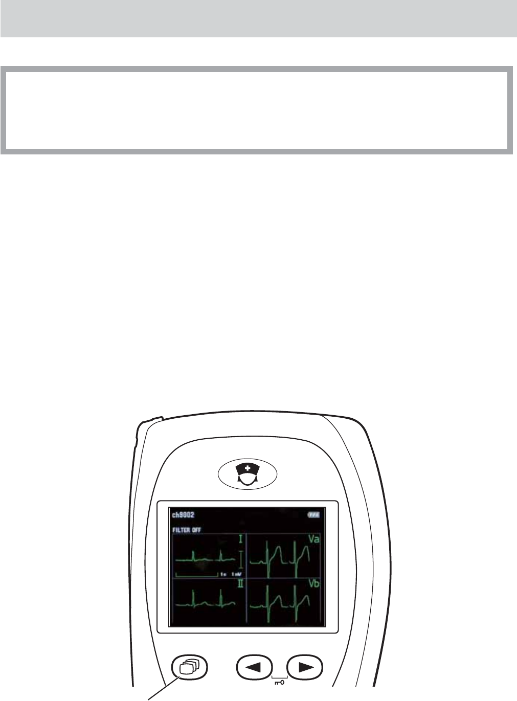
Operator’s Manual ZM-520PA/521PA/530PA/531PA 49
Monitoring
CAUTION
The measurement values and displayed waveforms on the transmitter and receiving
monitor may be different due to timing delay of the display or difference in detection
settings.
NOTE
Do not let the transmitter continuously contact the patient’s skin directly. The transmitter
heats up by 2 or 3°C (4 or 5°F) during operation and it may cause low temperature burn
to the patient.
Screen Descriptions
:KHQWKHWUDQVPLWWHULVWXUQHGRQWKHVWDUWXSVFUHHQDSSHDUVWKHQWKHFKHFNHOHFWURGHVVFUHHQWR
FKHFNWKHHOHFWURGHDWWDFKPHQWDSSHDUV
7KHVFUHHQFKDQJHVLQWKHIROORZLQJRUGHUZKHQWKH6FUHHQNH\LVSUHVVHG
&KHFNHOHFWURGHVĺQXPHULFDQGZDYHIRUPĺZDYHIRUPUHYLHZĺQXPHULFUHYLHZĺGLVSOD\RII
ĺFKHFNHOHFWURGHV
Screen key
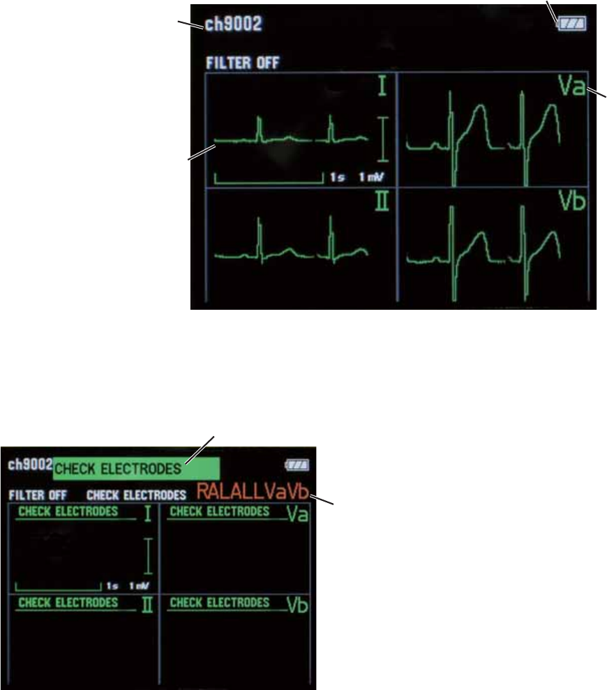
50 Operator’s Manual ZM-520PA/521PA/530PA/531PA
Check Electrodes Screen
<RXFDQFKHFNZKHWKHUWKHHOHFWURGHVDUHSURSHUO\DWWDFKHGWRWKHSDWLHQWDQGWKH(&*ZDYHIRUP
is acquired.
:KHQOHDGVDUHXVHGWKH,,,9DDQG9EOHDGZDYHIRUPVDUHGLVSOD\HG
When 3 leads are used, only the lead II waveform is displayed.
Filter: off
Sweep speed: 12.5 mm/s
Waveform sensitivity: 0.5 cm/1 mV
ECG waveform
Battery level
Lead
Channel number
Detached
electrode position
Message
When electrodes are
GHWDFKHGWKH³&+(&.
(/(&752'(6´
message and detached
electrode position appear
on the screen.
NOTE
When ECG measurement is set to OFF on the PARAMETER SETUP screen, the check
electrodes screen does not appear.
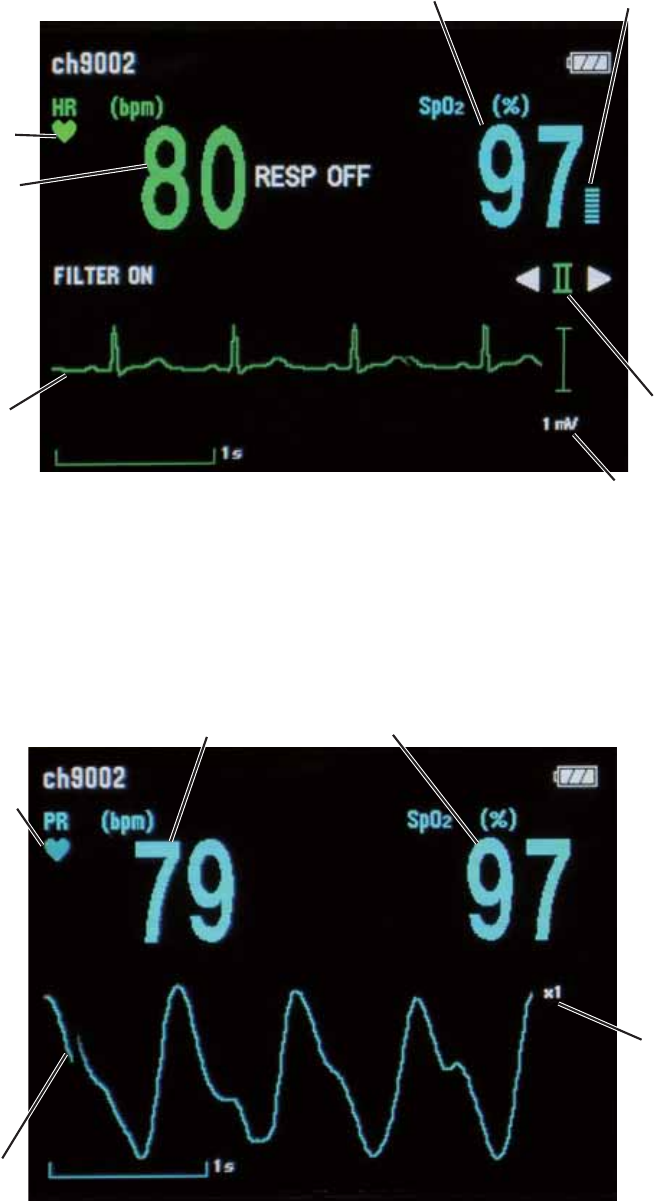
Operator’s Manual ZM-520PA/521PA/530PA/531PA 51
Numeric and Waveform Screen
Numeric values and waveforms of the monitoring parameters are displayed. You can change the
(&*OHDGZLWKWKHŻDQGŹNH\V
Heart rate
QRS sync mark
Pulse bar graph
SpO2
ECG waveform
Filter: on
Sweep speed: 12.5 mm/s
Waveform sensitivity: auto
Waveform
sensitivity
ECG lead
:KHQ(&*DQGUHVSLUDWLRQPHDVXUHPHQWLVWXUQHGRII
Pulse rate
Pulse sync mark
SpO2
Pulse wave
sensitivity
Pulse waveform
Sweep speed: 12.5 mm/s
Waveform sensitivity: auto
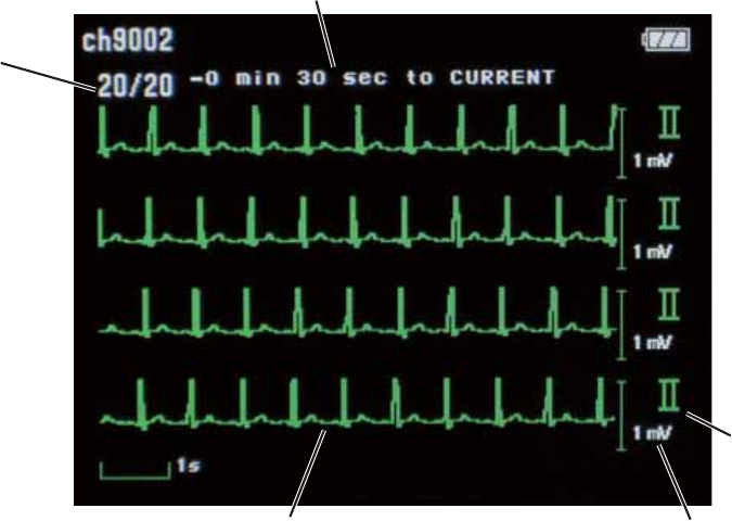
52 Operator’s Manual ZM-520PA/521PA/530PA/531PA
NOTE
The pulse wave amplitude varies according to the ratio of the pulsation component to the
entire transmitted IR signal. When the pulsation component ratio is 1%, the pulse wave
amplitude is about 5 mm at ×1 sensitivity on the screen.
Waveform Review Screen
(&*IXOOGLVFORVXUHIRUXSWRPLQXWHVFDQEHVDYHGDQGUHYLHZHG:KHQ(&*PHDVXUHPHQWLV
turned off and SpO2 is monitored, the pulse waveform is saved.
:KHQ(&*OHDGLVFKDQJHGRQWKHQXPHULFDQGZDYHIRUPVFUHHQWKH(&*IXOOGLVFORVXUHRIWKH
changed lead is saved.
The saved data is deleted when the transmitter is turned off.
ECG lead
Displayed
page
Compressed ECG waveform
7.5 s × 4 traces per page, total 20 pages
Older data
Newer data
Time range of the displayed waveform
(time before the waveform review screen is displayed)
Waveform sensitivity
7RVFUROOWKHZDYHIRUPSUHVVWKHŻRUŹNH\7KHZDYHIRUPLVVFUROOHGE\VHFRQGV
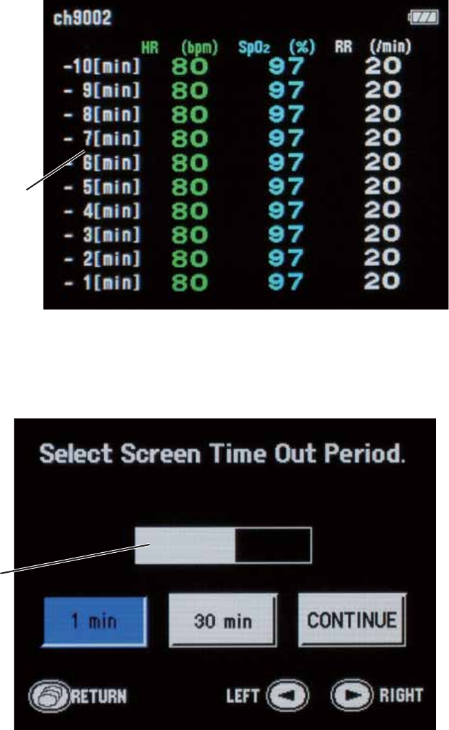
Operator’s Manual ZM-520PA/521PA/530PA/531PA 53
Numeric Review Screen
1XPHULFGDWDRIKHDUWUDWHRUSXOVHUDWHZKHQ(&*LVWXUQHGRII6S22 and respiration rate for up
WRPLQXWHVDUHVDYHGDWPLQXWHLQWHUYDOV
The saved data is deleted when the transmitter is turned off.
Time before the numeric
review screen is displayed.
Older data
Newer data
Display Off
The display can be turned off any time. Refer to the “Turning the Display Off” section for details.
10-second time bar
54 Operator’s Manual ZM-520PA/521PA/530PA/531PA
Basic Monitoring Operation
Using the Function Key
Function key
2QHRIWKHIROORZLQJIXQFWLRQVFDQEHDVVLJQHGWRWKH)XQFWLRQNH\RQWKH6<67(06(783
VFUHHQ5HIHUWRWKH³&KDQJLQJ6<67(06(7836HWWLQJV´VHFWLRQ
6863(1'$/$50 6XVSHQGVDODUPVRQWKHUHFHLYLQJPRQLWRUEHIRUHWKH\RFFXUIRUPLQXWHV
3$86( 3DXVHVPRQLWRULQJRQWKHWUDQVPLWWHUDQGUHFHLYLQJPRQLWRU
&21),50 7UDQVPLWVWKHVLJQDOWKDWWKHSDWLHQWLVFRQ¿UPHGDQGGLVSOD\VWKH
³3$7,(17&21),50('´PHVVDJHRQWKHWUDQVPLWWHU
NOTE
To use the Function key for PAUSE or CONFIRM, you must set “PROTOCOL” on the
SYSTEM SETUP screen of the transmitter to 51 and the receiving monitor must be able
to receive protocol 51. To use protocol 51, an ORG-9100A or ORG-9110A multiple patient
receiver software version 03-03 or later is required.
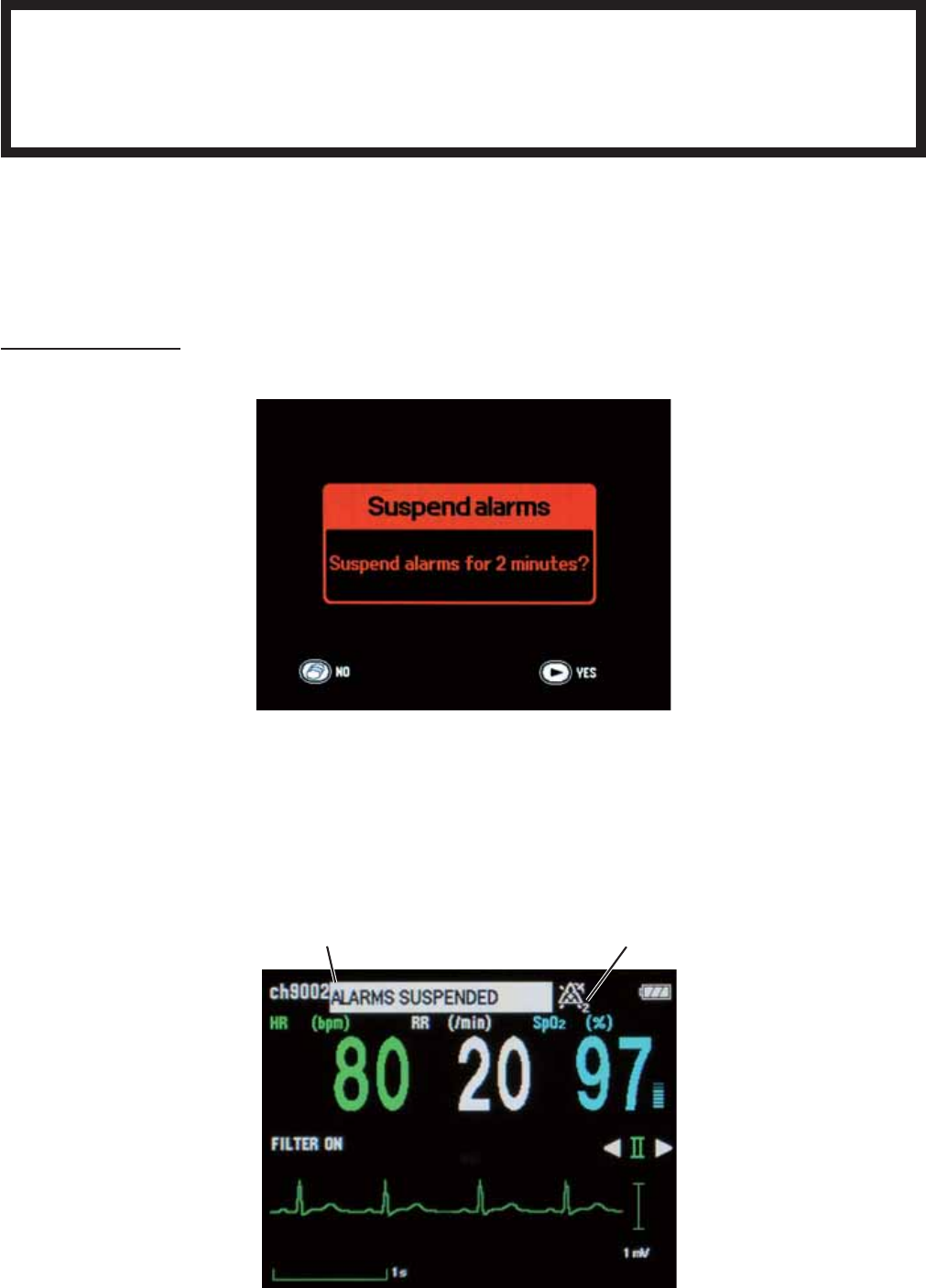
Operator’s Manual ZM-520PA/521PA/530PA/531PA 55
Suspending Alarms on the Receiving Monitor
WARNING
While the “ALARMS SUSPENDED” message is displayed on the transmitter, all
alarms on the receiving monitor are suspended so keep the patient under close
observation.
:KHQWKH)81&7,21.(<LVVHWWR³6863(1'$/$50´RU³6863(1'$/$503$86(´
RQWKH6<67(06(783VFUHHQDODUPVFDQEHVXVSHQGHGIRUPLQXWHVRQWKHUHFHLYLQJPRQLWRU
before they occur.
To suspend alarms:
3UHVVWKH)XQFWLRQNH\7KH³6XVSHQGDODUPV´FRQ¿UPDWLRQVFUHHQDSSHDUV
3UHVVWKHŹNH\WRVXVSHQGDODUPV
7RFDQFHOVXVSHQGLQJDODUPVDQGUHWXUQWRWKHSUHYLRXVVFUHHQSUHVVWKH6FUHHQNH\
:KHQWKHDODUPVDUHVXVSHQGHGWKH³$/$5066863(1'('´PHVVDJHDQGDODUPVXVSHQGHG
icon with the remaining minutes in alarm suspension appear on the transmitter screen.
Message Icon

56 Operator’s Manual ZM-520PA/521PA/530PA/531PA
To cancel suspending alarms during 2 minute alarm suspension:
3UHVVWKH)XQFWLRQNH\ZKLOHWKH³$/$5066863(1'('´PHVVDJHLVGLVSOD\HG7KH
FRQ¿UPDWLRQVFUHHQDSSHDUV
3UHVVWKHŹNH\WRFDQFHODODUPVXVSHQVLRQ
3UHVVWKH6FUHHQNH\WRQRWFDQFHODODUPVXVSHQVLRQ
Pausing Monitoring
:KHQ)81&7,21.(<LVVHWWR³6863(1'$/$503$86(´RQWKH6<67(06(783
screen, you can pause monitoring on the receiving monitor from the transmitter when the patient
FDQQRWEHPRQLWRUHGVXFKDVGXULQJ;UD\H[DPLQDWLRQ
NOTE
To use the Function key for PAUSE, you must set “PROTOCOL” on the SYSTEM SETUP
screen of the transmitter to 51 and the receiving monitor must be able to receive protocol
51. To use protocol 51, an ORG-9100A or ORG-9110A multiple patient receiver software
version 03-03 or later is required.
Monitoring on the receiving monitor resumes when one of the following conditions is met.
:KHQ2))LVVHOHFWHGIRU³$8725(680($)7(53$86(´RQWKH6<67(06(783VFUHHQ
monitoring does not automatically resume.
+HDUWUDWHLVSURSHUO\PRQLWRUHGRQWKHWUDQVPLWWHUIRUWKHLQWHUYDOVHOHFWHGIRU³$872
5(680($)7(53$86(´
• SpO2LVSURSHUO\PRQLWRUHGRQWKHWUDQVPLWWHUIRUWKHLQWHUYDOVHOHFWHGIRU³$8725(680(
$)7(53$86(´
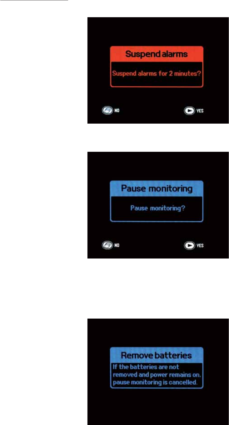
Operator’s Manual ZM-520PA/521PA/530PA/531PA 57
To pause monitoring:
3UHVVWKH)XQFWLRQNH\7KH³6XVSHQGDODUPV´FRQ¿UPDWLRQVFUHHQDSSHDUV
3UHVVWKH)XQFWLRQNH\IRUVHFRQGVWRGLVSOD\WKH³3DXVHPRQLWRULQJ´FRQ¿UPDWLRQVFUHHQ
3UHVVWKHŹNH\WRSDXVHPRQLWRULQJ
7RFDQFHOSDXVHPRQLWRULQJSUHVVWKH6FUHHQNH\
4. Wait about 5 seconds until the “Turn power off” screen appears.
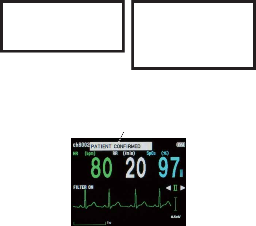
58 Operator’s Manual ZM-520PA/521PA/530PA/531PA
5. Turn off the transmitter.
If the transmitter is not turned off and monitoring continues for the interval set for “AUTO
5(680($)7(53$86(´RQWKH6<67(06(783VFUHHQSDXVHPRQLWRULQJLVFDQFHOOHG
and monitoring continues.
Resuming Monitoring after Pause
7RUHVXPHPRQLWRULQJDIWHUSDXVHFKHFNWKDWWKHHOHFWURGHVHOHFWURGHOHDGVDQGSUREHDUHDWWDFKHG
to the patient then turn on the transmitter.
WARNING
When the patient returns to the bed,
turn on the transmitter and check that
the monitoring is resumed on the
receiving monitor.
WARNING
If the transmitter is not turned off and
monitoring continues for the selected
interval, pause monitoring is canceled
and monitoring continues. Check that
the monitoring is resumed on the
receiving monitor.
Confirming the Patient
:KHQWKH)81&7,21.(<LVVHWWR³&21),50´RQWKH6<67(06(783VFUHHQSUHVVLQJWKH
)XQFWLRQNH\VHQGVDVLJQDOWRWKHUHFHLYLQJPRQLWRUWRLQGLFDWHWKDWWKHSDWLHQWRUSDWLHQWFRQGLWLRQ
LVFRQ¿UPHGE\PHGLFDOVWDII
Message
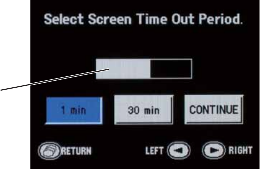
Operator’s Manual ZM-520PA/521PA/530PA/531PA 59
Turning the Display Off
The display can be turned off any time.
To turn off the display:
3UHVVWKH6FUHHQNH\VHYHUDOWLPHVXQWLOWKHIROORZLQJVFUHHQDSSHDUV
10-second time bar
6HOHFWWKHWLPLQJIRUWXUQLQJRIIWKHGLVSOD\ZLWKWKHŻRUŹNH\7KHVHOHFWHGLWHPLV
KLJKOLJKWHGLQEOXH$VHFRQGFRXQWGRZQVWDUWV<RXFDQVHOHFWDGLIIHUHQWWLPHZLWKLQWKH
VHFRQGFRXQWGRZQ
1 min (factory default): Turns the display off 1 minute later.
RUPLQ 7XUQVWKHGLVSOD\RIIZKHQWKHVHOHFWHGWLPHHODSVHV
7RVHWWKHWLPHUHIHUWR³6(/(&7$%/(6&5((17,0(
2873(5,2'PLQ´LQWKH³&KDQJLQJ6\VWHP6HWXS
Settings” section.
&217,18( .HHSWKHGLVSOD\WXUQHGRQ
NOTE
If longer than “1 min” is selected, it reduces the battery lifetime.
:DLWVHFRQGVXQWLOWKHFRXQWGRZQHQGV:KHQWKHFRXQWGRZQHQGVWKHQXPHULFDQG
waveform screen appears.
2USUHVVWKH6FUHHQNH\EHIRUHWKHFRXQWGRZQHQGV7KHFKHFNHOHFWURGHVVFUHHQDSSHDUV
:KHQWKHVHOHFWHGWLPHHODSVHVZLWKRXWDQ\NH\RSHUDWLRQWKHGLVSOD\WXUQVRIIDXWRPDWLFDOO\
,IDNH\LVSUHVVHGWKHFRXQWGRZQUHVHWV
:KHQGLVSOD\LQJWKHFKHFNHOHFWURGHVVFUHHQDIWHUVHOHFWLQJWKHWLPHRXWSHULRGWKHVFUHHQ
DXWRPDWLFDOO\FKDQJHVWRWKHQXPHULFDQGZDYHIRUPVFUHHQPLQXWHVODWHULIWKHUHLVQRNH\
operation, then the display turns off when the remaining time elapses.
:KHQGLVSOD\LQJDQRWKHUVFUHHQDIWHUVHOHFWLQJWKHWLPHRXWSHULRGWKHVFUHHQFKDQJHVWRWKH
QXPHULFDQGZDYHIRUPVFUHHQPLQXWHODWHULIWKHUHLVQRNH\RSHUDWLRQWKHQWKHGLVSOD\WXUQV
off when the remaining time elapses.
• When “1 min” is selected, the display turns off without changing to the numeric and waveform
screen.
60 Operator’s Manual ZM-520PA/521PA/530PA/531PA
When the display is turned off automatically or the power is turned off, the setting returns to
“1 min” (factory default).
Turning the Display On after It was Turned Off
3UHVVWKH6FUHHQNH\2QHRIWKHIROORZLQJVFUHHQDSSHDUV
7KHSUHYLRXVVFUHHQ 7KH6FUHHQNH\LVSUHVVHGZLWKLQPLQXWHVDIWHUWKHGLVSOD\
turned off.
1XPHULFDQGZDYHIRUPVFUHHQ 7KH6FUHHQNH\LVSUHVVHGPRUHWKDQPLQXWHVDIWHUWKH
display turned off.
³.H\ORFNHG´VFUHHQ 7KH6FUHHQNH\LVSUHVVHGDIWHUWKHGLVSOD\WXUQHGRIIDQGWKH
³.H\ORFNHG´VFUHHQZDVWKHODVWVFUHHQEHIRUHWKHGLVSOD\
turned off.
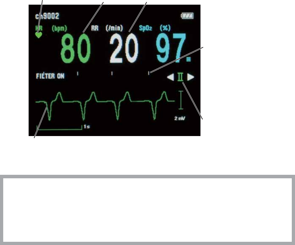
Operator’s Manual ZM-520PA/521PA/530PA/531PA 61
ECG and Respiration Monitoring
:KHQWKHHOHFWURGHVDUHDWWDFKHGDQGWKH(&*OHDGVDUHFRQQHFWHGWKHKHDUWUDWH(&*ZDYHIRUP
respiration rate and respiration waveform appear on the receiving monitor. Refer to the operator’s
manual of the receiving monitor for details.
:KHQOHDGVDUHXVHGRQWKLVWUDQVPLWWHUXSWROHDGV,,,,,,D95D9/D9)9DDQG9ERI
(&*ZDYHIRUPVFDQEHGLVSOD\HGRQWKHUHFHLYLQJPRQLWRU7KHKHDUWUDWHLVDOVRPHDVXUHG
:KHQOHDGVDUHXVHGRQHFKDQQHO(&*ZDYHIRUPRIOHDG,,FDQEHGLVSOD\HGRQWKHUHFHLYLQJ
monitor. Refer to the operator’s manual of the monitor for details.
Pacing marks
:KLWHSDFLQJPDUNV
are displayed at
the points where
DSDFLQJVSLNHLV
detected.
Heart rate
QRS sync mark Respiration rate
ECG lead
You can change the
(&*OHDGZLWKWKH
ŻDQGŹNH\NH\V
ECG waveform Filter: on
Sweep speed: 12.5 mm/s
Waveform sensitivity: auto
CAUTION
Turn off the power of mobile phones, small wireless devices and other devices which
produce strong electromagnetic interference around a patient (except for devices
allowed by the hospital administrator). Radio waves from devices such as mobile
phones or small wireless devices may be mistaken as pulse waves or respiration
waves and the displayed data may be incorrect.
NOTE
• ECG cannot be monitored on a neonate using this transmitter.
• When performing defibrillation, set the hum filter to ON on the receiving monitor. The
waveform recovery may become slow due to electrode polarization when the hum filter
is set to OFF.

62 Operator’s Manual ZM-520PA/521PA/530PA/531PA
Use with a Pacemaker
:KHQPRQLWRULQJDSDFHPDNHUSDWLHQWWKHWUDQVPLWWHUGHWHFWVSDFHPDNHUSXOVHDQGUHMHFWVWKH
SDFHPDNHUSXOVHIURPWKHKHDUWUDWHFRXQW
WARNING
The bioelectric impedance measurement sensor of a minute ventilation rate-adaptive
implantable pacemaker may be affected by transmitter which is connected to the
same patient. If this occurs, the pacemaker may pace at its maximum rate and the
transmitter may give incorrect data to the monitor. If this occurs, disconnect the
electrode leads from the patient or change the setting on the pacemaker by referring
to the pacemaker’s manual. For more details, contact your pacemaker representative
or Nihon Kohden representative.
WARNING
The transmitter detects the pacemaker pulse and rejects the pacemaker pulse from
the heart rate count. However, all of the pacemaker pulse might not be rejected. If the
pacemaker pulse is not rejected, the pacemaker pulse is detected as QRS and false
heart rate may be indicated. Keep pacemaker patients under close observation.
* )RUWKHSDFHPDNHUSXOVHUHMHFWLRQFDSDELOLW\RIWKH=03$3$3$3$WUDQVPLWWHU
UHIHUWRWKH³6SHFL¿FDWLRQV(&*´VHFWLRQ
WARNING
The pacemaker pulse can be overlooked or detected as QRS. You cannot confirm the
pacemaker operation only from the detected pacemaker pulse.
NOTE
• If an electric blanket is used and incorrect heart rate is displayed on the monitor, turn off
the pacing spike detection on the monitor.
• Turn the pacing spike detection to ON on the receiving monitor when monitoring a
pacemaker patient. Pacing pulse is detected by the transmitter and transmitted to the
monitor. If the pacing spike detection is turned OFF, QRS and pacemaker spike might
not be distinguished and pacemaker failure might not be recognized.

Operator’s Manual ZM-520PA/521PA/530PA/531PA 63
Use with an Electrosurgical Unit
)RUXVHZLWKDQHOHFWURVXUJLFDOXQLW(68WKLVWUDQVPLWWHUKDVDFLUFXLWWRSURWHFWWKHSDWLHQWIURP
VNLQEXUQDQGWRUHGXFH(68LQWHUIHUHQFHRQWKH(&*ZDYHIRUP+RZHYHUWKHHIIHFWLYHQHVVRI
WKLVFLUFXLWGHSHQGVRQHOHFWURGHSRVLWLRQDQGWUDQVPLWWHUVHWXS:LWKDQ(68SD\DWWHQWLRQWRWKH
following points.
WARNING
When the transmitter is used with an electrosurgical unit (ESU), firmly attach the
entire area of the ESU return plate. Otherwise, the current from the ESU flows into
the electrodes of the transmitter, causing electrical burn where the electrodes are
attached. For details, refer to the ESU manual.
NOTE
Noise generated from an electrosurgical unit may interfere on an ECG waveform, but will
not damage it.
0HDVXUHZLWKHOHFWURGHOHDG
Use the minimum number of electrodes. Use new electrodes.
• Minimize noise
6HOHFWDQ(&*OHDGZKHUHWKHDFWLYH(&*HOHFWURGHVDUHORFDWHGDVIDUIURPWKHLQFLVLRQDV
possible.
2. Position the + and – electrodes as close as possible.
6HOHFWWKHOHDGVZKHUHWKHDQJOHșEHWZHHQWKHDFWLYHHOHFWURGHVDQGWKHLQFLVLRQLVDVVPDOO
as possible.
4. Set the electrosurgical return plate as close to the incision as possible.
Make small
Incision
Return plate
As far as possible from electrode and
as near as possible to incision

64 Operator’s Manual ZM-520PA/521PA/530PA/531PA
Turning ECG Measurement On/Off
(&*PHDVXUHPHQWFDQEHWXUQHGRQRURIIRQWKH3$5$0(7(56(783VFUHHQ:KHQHOHFWURGHV
DUHDWWDFKHGWRWKHSDWLHQWDQG(&*OHDGVDUHFRQQHFWHG(&*PRQLWRULQJVWDUWVHYHQZKHQ(&*LV
turned off.
When PROTOCOL on the SYSTEM SETUP screen is set to 51:
(&*PHDVXUHPHQWRQWKHUHFHLYLQJPRQLWRULVDXWRPDWLFDOO\VHWWRRII
NOTE
ECG measurement on the transmitter cannot be turned on or off from the receiving
monitor.
When PROTOCOL on the SYSTEM SETUP screen is set to 41:
,I(&*PHDVXUHPHQWLVWXUQHGRIIRQWKHWUDQVPLWWHU(&*PHDVXUHPHQWRQWKHUHFHLYLQJPRQLWRU
must also be turned off.
Turning Respiration Measurement On/Off
5HVSLUDWLRQPHDVXUHPHQWFDQEHWXUQHGRQRURIIRQWKH3$5$0(7(56(783VFUHHQ,I
respiration measurement is turned off, respiration measurement on the receiving monitor is also
turned off.
Electrode Detachment
,QWKHIROORZLQJFRQGLWLRQVWKH³&+(&.(/(&752'(6´PHVVDJHLVGLVSOD\HGRQWKHWUDQVPLWWHU
and receiving monitor.
(OHFWURGHLVGHWDFKHGIURPVNLQ
(OHFWURGHOHDGLVGLVFRQQHFWHGIURPWKHHOHFWURGH
3RODUL]DWLRQYROWDJHEHWZHHQWKHHOHFWURGHDQGVNLQLVH[FHVVLYHO\KLJK
,QWKHVHFDVHVFKHFNWKHFDXVHDQGLIQHFHVVDU\UHSODFHHOHFWURGHVZLWKQHZRQHV
CAUTION
When the “CHECK ELECTRODES” message is displayed on the receiving monitor,
ECG is not monitored properly and the ECG alarm does not function. Check the
electrode, electrode leads, and if necessary, replace with new ones.
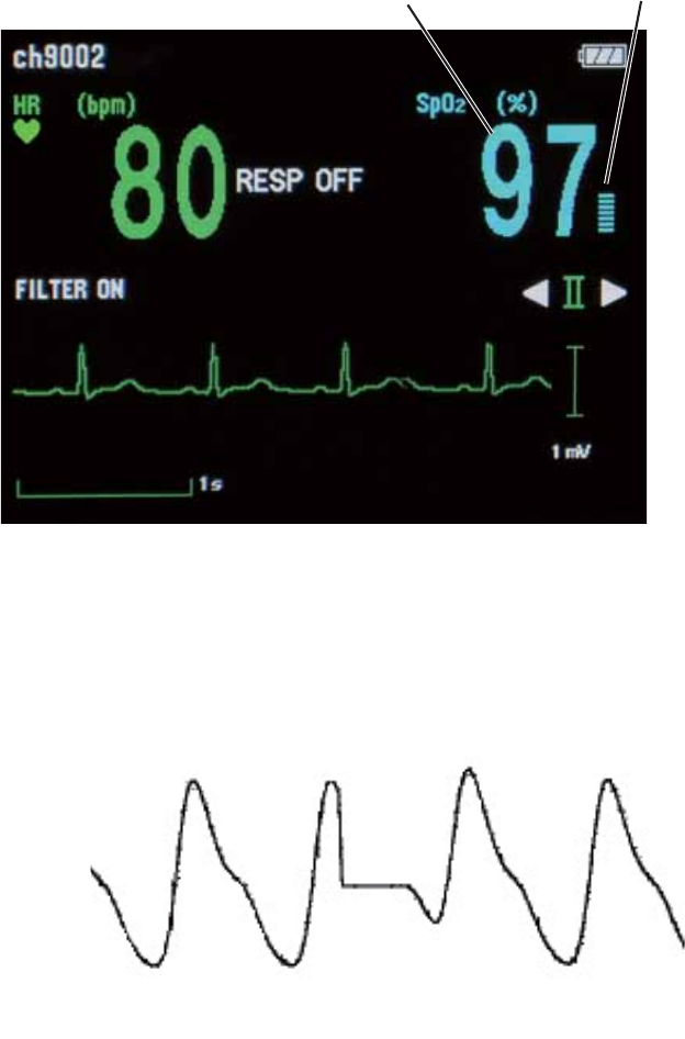
Operator’s Manual ZM-520PA/521PA/530PA/531PA 65
SpO2 Monitoring
The SpO2PRQLWRULQJLVRQO\DYDLODEOHRQWKH=03$DQG=03$WUDQVPLWWHU
When monitoring starts, SpO2 and the pulse waveform are sent to the receiving monitor and SpO2
DQGWKHSXOVHOHYHOEDUJUDSKDUHGLVSOD\HGRQWKHWUDQVPLWWHUVFUHHQ:KHQ(&*LVQRWPHDVXUHG
the pulse waveform and pulse rate are also displayed.
Pulse bar graphSpO2
NOTE
During SpO2 monitoring, the transmitter constantly checks the light intensity of the probe
and adjusts the light intensity to maintain optimum measurement condition. During
adjustment, the pulse wave becomes flat for about 0.5 seconds.

66 Operator’s Manual ZM-520PA/521PA/530PA/531PA
WARNING
SpO2 measurement may be incorrect
in the following cases.
• When the patient’s
carboxyhemoglobin or
methemoglobin increases
abnormally.
• When dye is injected in the blood.
• When using an electrosurgical unit.
• During CPR.
• When measuring at a site with
venous pulse.
• When there is body movement.
• When the pulse wave is small
(insufficient peripheral circulation).
WARNING
Check the circulation condition by
observing the skin color at the
measurement site and pulse waveform.
Change the measurement site every 8
hours for disposable probes and every
4 hours for reusable probes (every 8
hours for TL-631T series probe). The
skin temperature may increase at the
attached site by 2 or 3°C (4 or 5°F)
and cause a burn or pressure necrosis.
When using the probe on the following
patients, take extreme care and
change the measurement site more
frequently according to symptoms and
degree.
• Patient with a fever
• Patient with insufficient peripheral
circulation
• Neonate or low birth weight infant
with delicate skin
WARNING
When monitoring SpO2 of a patient
who is receiving photodynamic therapy,
the light from the finger probe sensor
may cause a burn. Photodynamic
therapy uses a photosensitizing agent
that has a side effect of
photosensitivity.
The SpO2 probes manufactured by Nihon
.RKGHQKDYHWZRZDYHOHQJWKVZLWKSHDNVLQWKH
UDQJHRIDQGQP7KHPD[LPXPOLJKW
intensity is less than 5.5 mW.
WARNING
When not monitoring SpO2, disconnect
the SpO2 cable from the transmitter.
Otherwise, noise from the probe
sensor may interfere and incorrect data
is displayed on the screen.

Operator’s Manual ZM-520PA/521PA/530PA/531PA 67
CAUTION
Turn off the power of mobile phones,
small wireless devices and other
devices which produce strong
electromagnetic interference around a
patient (except for devices allowed by
the hospital administrator). Radio
waves from devices such as mobile
phones or small wireless devices may
be mistaken as pulse waves or
respiration waves and the displayed
data may be incorrect.
CAUTION
Failure to follow these instructions may
cause cable discontinuity, short circuit,
skin burn on the patient from the probe
temperature increase due to the short
circuit of the probe cable, and incorrect
measurement data. If the probe is
broken, replace it with a new one.
• Do not immerse any part of
the probe cable other than the
disposable probe in chemical
solutions or water.
• Do not pull or bend the probe cable.
• Do not let caster feet run over the
probe cable.
CAUTION
Normal external light does not affect
monitoring but strong light such as a
surgical light or sunlight may affect
monitoring. If affected, cover the
measuring site with a blanket.
CAUTION
When the probe is attached on an
appropriate site with sufficient
circulation and the error message
confirming the probe attachment
repeatedly appears, the probe may be
deteriorated. Replace it with a new
one.
CAUTION
When a message indicates a faulty
probe, stop monitoring and replace the
probe with a new one.
CAUTION
While a patient is on medication which
causes vasodilation, the pulse
waveform may change and in rare
cases the SpO2 value might not be
displayed.
CAUTION
Do not attach the probe to the same
limb that is used for NIBP
measurement or an IBP catheter. The
SpO2 measurement may be incorrect.
68 Operator’s Manual ZM-520PA/521PA/530PA/531PA
NOTE
• In order to maintain sufficient blood circulation, keep the measurement site warm by
covering it with a blanket or something similar. Warming the site is effective, especially
for a patient with a small pulse amplitude.
• When monitoring a patient who has an IABP and SpO2 cannot be measured, monitor
the patient on a wired monitor. If the monitor has a sensitivity mode, set the mode to
“MAX”.

Operator’s Manual ZM-520PA/521PA/530PA/531PA 69
Indications and Messages
Indication
Indication Cause Countermeasure
Batteries are fully charged.
—
Batteries are getting low.
Batteries are low.
Batteries are almost empty. Replace the batteries.
Alarms on the receiving monitor
were suspended by pressing the
)XQFWLRQNH\RQWKHWUDQVPLWWHU
Alarms resume when the suspend interval
elapses. To cancel alarm suspension, press
WKH)XQFWLRQNH\DJDLQ
Messages
:KHQ35272&2/RQWKH6<67(06(783VFUHHQLVVHWWRDOOPHVVDJHVDUHWUDQVPLWWHG
:KHQ35272&2/LVVHWWRWKHPHVVDJHVPDUNHGZLWKDUHQRWWUDQVPLWWHG
Message Cause Countermeasure
ALARMS
6863(1'('
Alarms on the receiving monitor are
suspended by pressing the Function
NH\RQWKHWUDQVPLWWHU
$ODUPVUHVXPHZKHQWKHPLQXWH
suspend interval elapses. To cancel
alarm suspension, press the Function
NH\DJDLQ
%$77(5<
:($. Dead batteries Replace the batteries.
CANNOT
'(7(&7
38/6(
Poor blood circulation for measuring
the SpO2 value
&KHFNWKHSDWLHQWFRQGLWLRQSUREH
attachment or change the attachment
site.
The probe is attached too tightly and
is obstructing the blood circulation Reattach the probe.
The probe is not attached to the
patient properly
Attach the probe to the patient
properly.
³/,*+7,17(5)(5(1&(´
³&+(&.352%(6,7(´RU
³'(7(&7,1*38/6(´PHVVDJHLV
GLVSOD\HGIRUPRUHWKDQVHFRQGV
Refer to the cause and
countermeasure for each message in
this Messages table and remove the
cause.

70 Operator’s Manual ZM-520PA/521PA/530PA/531PA
Message Cause Countermeasure
CANNOT
0($685(
Poor contact between the disposable
HOHFWURGHDQGVNLQ
Replace electrodes with new ones
immediately.
&+(&.
(/(&752'(6
(OHFWURGHOHDGLVGLVFRQQHFWHGIURP
the electrode
Firmly connect the electrode lead to
the electrode.
(OHFWURGHOHDGLVGLVFRQQHFWHGIURP
the transmitter
Firmly connect the electrode lead to
the transmitter.
(OHFWURGHOHDGGLVFRQWLQXLW\ Replace the electrode lead with a
new one.
(OHFWURGHLVQRW¿UPO\DWWDFKHGWR
WKHVNLQ Replace the electrode with a new
one.
Polarization voltage is abnormally
high
&+(&.352%(
The probe is not attached to the
patient properly
Attach the probe to the patient
properly.
The probe is not attached at the
appropriate site
Attach the probe to an appropriate
site indicated in the probe manual.
The probe is disconnected from the
transmitter
Connect the probe cable to the
transmitter.
The probe is past its expiration date Replace the probe with a new one.
&+(&.352%(
6,7(
The probe is not attached at the
appropriate site
Attach the probe to an appropriate
site indicated in the probe manual.
The probe is deteriorated Replace the probe with a new one.
The probe is past its expiration date
'(7(&7,1*
38/6(
Searching for the correct pulse wave
for SpO2 monitoring Wait until the pulse wave is detected.
The SpO2 value cannot be obtained
because the waveform is unstable Attach the probe to the patient
properly.
The probe is not attached to the
patient properly
/,*+7
,17(5)(5(1&(
The SpO2 measurement site is under
ÀXRUHVFHQWOLJKWVXUJLFDOOLJKW
sunlight, or other strong light
Cover the measurement site with a
EODQNHWRUFORWK
Considerable body movement
When the message is displayed
IUHTXHQWO\FKHFNWKHSDWLHQWFRQGLWLRQ
and, if necessary, change the
attachment site.
The probe is not attached to the
patient properly

Operator’s Manual ZM-520PA/521PA/530PA/531PA 71
Message Cause Countermeasure
3$7,(17
&21),50('
)XQFWLRQNH\LVSUHVVHGDQGWKH
³3$7,(17&21),50('´VLJQDOLV
transmitted to the receiving monitor
ZKHQ³3$7,(17´LVDVVLJQHGDVWKH
IXQFWLRQIRUWKH)XQFWLRQNH\RQWKH
6<67(06(783VFUHHQ
—
352%(
)$,/85(
The probe is past its expiration date Replace the probe with a new one.
3UREHLVGDPDJHGRUVKRUWFLUFXLWHG
Transmitter failure Contact your Nihon Kohden
representative.
SpO202'8/(
(5525 Transmitter failure Contact your Nihon Kohden
representative.
:($.38/6(
Poor peripheral circulation &KHFNWKHSDWLHQWFRQGLWLRQDQG
change the probe attachment site.
The probe is attached too tightly and
is obstructing the blood circulation
&KHFNWKHSUREHDWWDFKPHQW
condition and if necessary, reattach
the probe.
5(632))
³5(630($685(0(17´RQWKH
3$5$0(7(56(783VFUHHQLVVHW
to OFF
If respiration monitoring is necessary,
VHW³5(630($685(0(17´WR
ON.

72 Operator’s Manual ZM-520PA/521PA/530PA/531PA
Message Display Priority
When more than one message condition occurs on the transmitter, only the message with the
highest priority is displayed.
Priority Message
+LJK 3$7,(17&21),50('
352%()$,/85(
&+(&.(/(&752'(6
SpO202'8/((5525
&+(&.352%(
&+(&.352%(6,7(
&$1127'(7(&738/6(
/,*+7,17(5)(5(1&(
&$11270($685(
'(7(&7,1*38/6(
:($.38/6(
$/$5066863(1'('
Low %$77(5<:($.

Operator’s Manual ZM-520PA/521PA/530PA/531PA 73
Troubleshooting
,IDSUREOHPRFFXUVXVHWKHIROORZLQJWDEOHVWR¿QGDQG¿[LW,IWKHSUREOHPVWLOOUHPDLQVDIWHU
troubleshooting according to these tables, contact your Nihon Kohden representative.
Transmitter
Problem Possible Cause Action
Nothing is displayed
on the LCD after
turning the power on.
Batteries are not installed
correctly. The battery polarity is
wrong.
Install the batteries correctly.
Batteries are completely
discharged.
Replace the batteries with new ones.
/&'LVGLI¿FXOWWR
VHHWRRGDUNRUWRR
light).
LCD brightness is not
appropriate.
Change the LCD brightness on the
6<67(06(783VFUHHQ5HIHUWR
WKH³&KDQJLQJ6<67(06(783
Settings” section.
Nothing is displayed
on the receiving
monitor after turning
the transmitter power
on.
The channel of the transmitter
and monitor does not match.
Set the correct channel on the monitor.
The software version of the
multiple patient receiver or
central monitor is old.
Upgrade the multiple patient receiver
or central monitor software to receive
signal from the transmitter. Contact
your Nihon Kohden representative.
Protocol on the transmitter and
monitor does not match.
Set the same protocol on the
transmitter and monitor.
Protocol on the transmitter is
set to 51 but the monitor cannot
receive protocol 51.
Set the protocol on the transmitter
to 41. Refer to the “System Setup
Setting List” section.

74 Operator’s Manual ZM-520PA/521PA/530PA/531PA
Problem Possible Cause Action
Signal receiving
condition is poor.
Another transmitter with the
same channel is used nearby.
Turn the transmitter power off. If the
monitor still receives a signal, there
is a high probability that another
transmitter of the same channel is
used nearby. Follow the instruction
of your channel administrator and use
another transmitter with a different
channel.
Signals of another patient are
mixing.
Follow the instructions of your
channel administrator and use another
transmitter of a different channel.
The transmitter is damaged. Contact your Nihon Kohden
representative.
ECG/Respiration
Problem Possible Cause Action
The heart rate is
unstable.
Pacing detection setting on the
monitor is not correct.
Turn off the pacing detection setting
on the receiving monitor. When
PRQLWRULQJDSDFHPDNHUSDWLHQWWXUQ
on pacing detection.
7KH³&+(&.
(/(&752'(6´
message appears
on the receiving
monitor.
(OHFWURGHOHDGLVGLVFRQQHFWHG
from the electrode.
Firmly connect the electrode lead to
the electrode.
(OHFWURGHOHDGGLVFRQWLQXLW\ Replace the electrode lead with a new
one.
(OHFWURGHLVQRW¿UPO\DWWDFKHG
WRWKHVNLQ
Replace the electrode with a new one.
Polarization voltage is
abnormally high.
8VH1LKRQ.RKGHQVSHFL¿HG
electrodes.
(&*EDVHOLQHLV
WKLFN$&KXP
The gel on the electrode is dried
out.
Replace the electrode with a new one.
The gel on the electrode is
coming off.
$QHOHFWULFEODQNHWLVXVHG &RYHUWKHEODQNHWZLWKDVKLHOGFRYHU
7KHKXP¿OWHULVVHWWR2))RQ
the monitor.
6HWWKH¿OWHUWR21

Operator’s Manual ZM-520PA/521PA/530PA/531PA 75
Problem Possible Cause Action
The heart rate of a
patient who is using
DQHOHFWULFEODQNHW
is unstable on the
receiving monitor.
Pacing pulse detection is turned
ON on the receiving monitor.
Turn OFF the pacing pulse detection
on the receiving monitor.
1RKHDUWUDWHRU(&*
is displayed.
³(&*0($685(0(17´RQWKH
3$5$0(7(56(783VFUHHQLV
set to OFF.
,I(&*PRQLWRULQJLVQHFHVVDU\VHW
³(&*0($685(0(17´WR21
Respiration
waveform
measurement is
unstable.
The gel on the electrode is dried
out.
Replace the electrode with a new one.
The gel on the electrode is
coming off.
No respiration rate is
displayed.
³5(630($685(0(17´RQ
WKH3$5$0(7(56(783VFUHHQ
is set to OFF.
If respiration monitoring is necessary,
VHW³5(630($685(0(17´WR21
SpO2
Problem Possible Cause Action
SpO2 data is unstable
and not reliable.
The probe size is not appropriate
for the patient.
Use the appropriate probe for the
patient.
Probe attachment condition
is poor. The probe is partly
GHWDFKHGIURPWKHVNLQ([WHUQDO
light is entering the probe.
Firmly attach the probe according to
the procedure in the probe operator’s
manual.
Measurement site is dirty. Patient
is wearing nail polish.
Remove dirt and nail polish.
The probe is attached to the
same limb that is used for NIBP
measurement.
Attach the probe to the opposite limb.
Avoid a site where blood circulation
condition changes greatly.

76 Operator’s Manual ZM-520PA/521PA/530PA/531PA
Maintenance
7RXVHWKHWUDQVPLWWHULQVDIHDQGRSWLPXPFRQGLWLRQSHUIRUPPDLQWHQDQFHFKHFNHYHU\VL[
months.
7KHIROORZLQJXQLWVDUHQHFHVVDU\IRUVRPHFKHFNLQJLWHPV
$;*YLWDOVLJQVLPXODWRU
$;76S22FKHFNHU
• Receiving monitor
CAUTION
Never disassemble or repair the transmitter. If there is any problem with the
transmitter, contact your Nihon Kohden representative.
NOTE
• The measurement accuracy of the above units must be managed to perform accurate
maintenance check.
• For details on the operation of the above units, refer to the manuals provided with these
units.
$PDLQWHQDQFHFKHFNVKHHWLVSURYLGHGDWWKHHQGRIWKLVVHFWLRQ0DNHDFRS\RIWKLVFKHFNVKHHW
EHIRUHSHUIRUPLQJPDLQWHQDQFHFKHFN
1. External Check
• There is no damage or dirt on the outside of the transmitter.
7KHEDWWHU\FDVHFRYHULVQRWGDPDJHGWKHVSULQJLV¿UPO\DWWDFKHGDQGWKHEDWWHU\FDVHFRYHU
FDQEHFORVHG¿UPO\
1RNH\VDUHGDPDJHG
• No electrode leads are damaged.
• There are no blood or chemicals on the transmitter.
• The springs in the battery compartment are not damaged or detached.
• Terminals in the battery case are not corroded.
2. Transmitter Channel
• The channel number label on the transmitter is not torn or removed.
• The channel of the transmitter matches the label.
The transmitter channel is displayed in the upper left corner of the screen. The channel number
also appears on the startup screen.
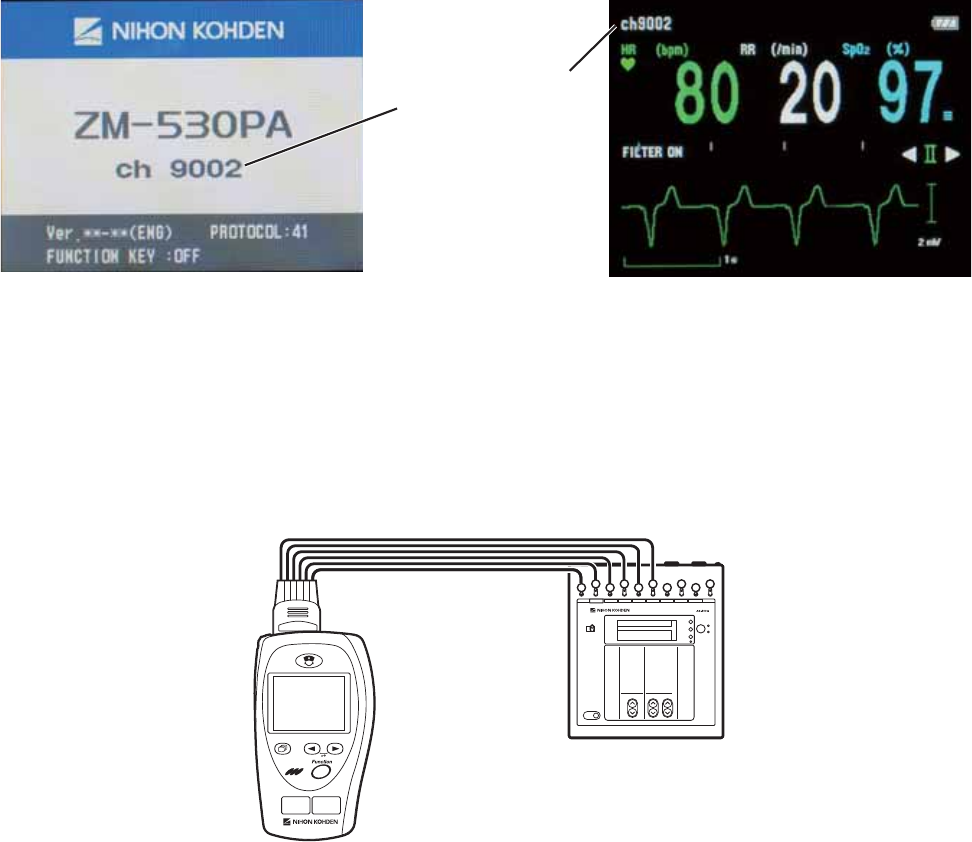
Operator’s Manual ZM-520PA/521PA/530PA/531PA 77
Channel numbers
Startup screen Numeric and waveform screen
3. Transmitting/Receiving Signal
8VHWKH$;*YLWDOVLJQVLPXODWRUDQGUHFHLYLQJPRQLWRU
1. Connect the vital sign simulator to the transmitter only with the electrode leads.
AX-400G
2. Place the transmitter 2 to 3 m from the receiving monitor.
3. Set the channel on the receiving monitor to the channel of the transmitter.
4. Turn on the transmitter and vital sign simulator.
&KHFNWKDWWKH(&*RIWKHWUDQVPLWWHUDSSHDUVRQWKHUHFHLYLQJPRQLWRU
6. Turn off the transmitter.
&KHFNWKDWWKH(&*GLVDSSHDUVIURPWKHUHFHLYLQJPRQLWRU
4. Display
&KHFNWKDWWKHUHDUHQRGRWVPLVVLQJRQWKHVFUHHQ
1. Turn off the transmitter.
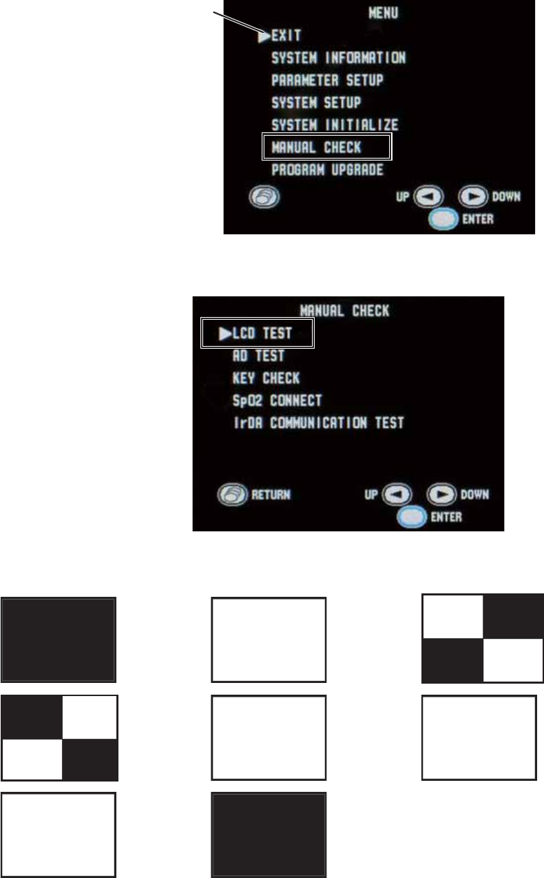
78 Operator’s Manual ZM-520PA/521PA/530PA/531PA
:KLOHSUHVVLQJWKH)XQFWLRQNH\WXUQRQWKHWUDQVPLWWHU7KH0(18VFUHHQDSSHDUV
3UHVVWKHŹNH\WRPRYHWKHFXUVRUWR³0$18$/&+(&.´DQGSUHVVWKH)XQFWLRQNH\
Cursor
3UHVVWKHŻRUŹNH\WRPRYHWKHFXUVRUWR³/&'7(67´DQGSUHVVWKH)XQFWLRQNH\
(DFKWLPHWKHŹNH\LVSUHVVHGWKHVFUHHQFKDQJHVDVEHORZ&KHFNWKDWQRGRWVDUHPLVVLQJ
ĺ ĺ ĺ
ĺ red ĺ green ĺ
blue ĺ ĺ. . .
Operator’s Manual ZM-520PA/521PA/530PA/531PA 79
3UHVVWKH6FUHHQNH\WRUHWXUQWRWKH0$18$/&+(&.VFUHHQ
3UHVVWKH6FUHHQNH\DJDLQWRUHWXUQWRWKH0(18VFUHHQ
5. Key Operation
1. Turn off the transmitter.
:KLOHSUHVVLQJWKH)XQFWLRQNH\WXUQRQWKHWUDQVPLWWHU7KH0(18VFUHHQDSSHDUV
3UHVVWKHŹNH\WRPRYHWKHFXUVRUWR³0$18$/&+(&.´DQGSUHVVWKH)XQFWLRQNH\
Cursor
3UHVVWKHŻRUŹNH\WRPRYHWKHFXUVRUWR³.(<&+(&.´DQGSUHVVWKH)XQFWLRQNH\
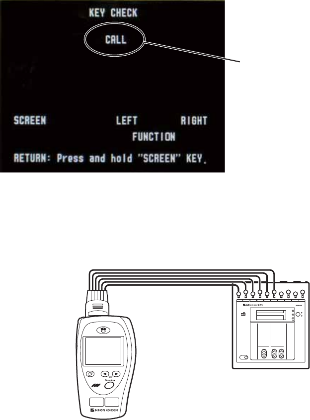
80 Operator’s Manual ZM-520PA/521PA/530PA/531PA
3UHVVHDFKNH\RQHDWDWLPHDQGFKHFNWKDWWKHSUHVVHGNH\LVKLJKOLJKWHGRQWKHVFUHHQ
:KHQWKH&$//NH\LV
SUHVVHGWKHNH\QDPHLV
highlighted.
$IWHUFKHFNLQJSUHVVDQGKROGWKH6FUHHQNH\WRUHWXUQWRWKH0$18$/&+(&.VFUHHQ
6. ECG Check
1. Connect the vital sign simulator to the transmitter only with the electrode leads.
AX-400G
2. Place the transmitter 1 m from the receiving monitor.
3. Turn on the transmitter and vital sign simulator.
&KHFNWKDWWKH(&*RIWKHWUDQVPLWWHUDSSHDUVRQWKHUHFHLYLQJPRQLWRU
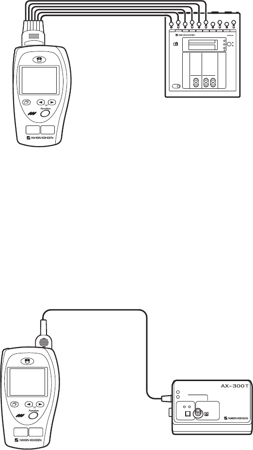
Operator’s Manual ZM-520PA/521PA/530PA/531PA 81
7. Respiration Check
1. Connect the vital sign simulator to the transmitter only with the electrode leads.
AX-400G
2. Place the transmitter 1 m from the receiving monitor.
3. Turn on the transmitter and vital sign simulator.
&KHFNWKDWWKHUHVSLUDWLRQZDYHIRUPRIWKHWUDQVPLWWHUDSSHDUVRQWKHUHFHLYLQJPRQLWRU
8. SpO2 Check (with SpO2 Checker)
1. Connect the SpO2FKHFNHUWRWKHWUDQVPLWWHURQO\ZLWKWKH6S22 connection cable.
AX-300T
2. Place the transmitter 1 m from the receiving monitor.
3. Turn on the transmitter and SpO2 FKHFNHU
&KHFNWKDWWKHSXOVHEDUJUDSKDSSHDUVRQWKHWUDQVPLWWHUVFUHHQ
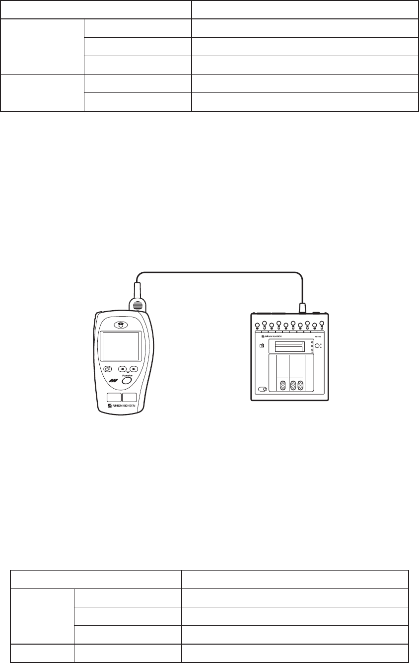
82 Operator’s Manual ZM-520PA/521PA/530PA/531PA
&KHFNWKDW6S22 and pulse rate on the transmitter is within the following range.
SpO2 on the SpO2 Checker Range
SpO2* WR6S22 (±2 digits)
WR6S22 (±2 digits)
WR6S22 (±4 digits)
Pulse rate EHDWVPLQ WREHDWVPLQEHDWPLQ
EHDWVPLQ WREHDWVPLQEHDWPLQ
* The SpO2FKHFNE\WKH6S22FKHFNHULVDIIHFWHGE\WKHFKHFNHU¶VWROHUDQFHWRWKH6S22
measuring accuracy of the transmitter. (The measurement accuracy is described in the
³6SHFL¿FDWLRQV´VHFWLRQ)RUGHWDLOVUHIHUWRWKH6S22FKHFNHUPDQXDO
&KHFNWKDWWKH6S22 and pulse waveform of the transmitter appear on the receiving monitor.
9. SpO2 Check (with Vital Sign Simulator)
1. Connect the vital sign simulator to the transmitter only with the SpO2 connection cable.
AX-400G
2. Place the transmitter 1 m from the receiving monitor.
3. Turn on the transmitter and vital sign simulator.
&KHFNWKDWWKHSXOVHEDUJUDSKDSSHDUVRQWKHWUDQVPLWWHUVFUHHQ
&KHFNWKDW6S22DQG(&*RQWKHWUDQVPLWWHULVZLWKLQWKHIROORZLQJUDQJH
Vital Sign Simulator Range
SpO2* WR6S22 (±2 digits)
WR6S22 (±2 digits)
WR6S22 (±4 digits)
(&* 1250$/ WREHDWVPLQEHDWVPLQ
Operator’s Manual ZM-520PA/521PA/530PA/531PA 83
* The SpO2FKHFNE\WKHYLWDOVLJQVLPXODWRULVDIIHFWHGE\WKHVLPXODWRU¶VWROHUDQFHWRWKH
SpO2 measuring accuracy of the transmitter. (The measurement accuracy is described in
WKH³6SHFL¿FDWLRQV´VHFWLRQ)RUGHWDLOVUHIHUWRWKHYLWDOVLJQVLPXODWRUPDQXDO
&KHFNWKDWWKH6S22DQG(&*RIWKHWUDQVPLWWHUDSSHDURQWKHUHFHLYLQJPRQLWRU

84 Operator’s Manual ZM-520PA/521PA/530PA/531PA
Maintenance Check Sheet
+RVSLWDO2UJDQL]DWLRQ
Service Personnel:
Instrument Name: Transmitter
Instrument Model: =03$=03$=03$=03$
Instrument Serial Number:
+DUGZDUH5HYLVLRQ1XPEHU
Software Revision Number:
([WHUQDO&KHFN 3DVV )DLO
2. Transmitter Channel Pass Fail
3. Transmitting/Receiving Signal Pass Fail
4. Display Pass Fail
5. Key Operation Pass Fail
(&*&KHFN 3DVV )DLO
5HVSLUDWLRQ&KHFN 3DVV )DLO
6S22&KHFN 3DVV )DLO
Overall Judgement
Ƒ2.
Ƒ&DQEHXVHGEXWQHHGVPDLQWHQDQFH
Ƒ0DLQWHQDQFHUHTXLUHG&DQQRWEHXVHG

Operator’s Manual ZM-520PA/521PA/530PA/531PA 85
Lifetime and Disposal
CAUTION
Dispose of Nihon Kohden products according to your local laws and your facility’s
guidelines for waste disposal. Otherwise, it may affect the environment. If there is a
possibility that the product may have been contaminated with infection, dispose of it
as medical waste according to your local laws and your facility’s guidelines for
medical waste. Otherwise, it may cause infection.
Disposing of Used Batteries
Battery Lifetime
Replace the batteries when the battery replacement indication appears on the transmitter.
Disposal
NOTE
Remove the batteries before disposing of the transmitter.
%HIRUHGLVSRVLQJRIWKHEDWWHULHVFKHFNZLWK\RXUORFDOVROLGZDVWHRI¿FLDOVIRUGHWDLOVLQ\RXUDUHD
for proper disposal. It may be illegal to dispose of these batteries in the municipal waste stream.
Disposing of Electrodes and SpO2 Probes
Refer to the manual for each item.
Disposing of Transmitter
Remove the batteries from the transmitter and dispose of the transmitter following your local laws
for disposal.

86 Operator’s Manual ZM-520PA/521PA/530PA/531PA
Cleaning, Disinfection and Sterilization
Transmitter and Electrode Leads
CAUTION
This transmitter is not waterproof. If detergent or liquid spills into the transmitter, stop
cleaning or disinfecting it and contact your Nihon Kohden representative. The
transmitter needs to be checked for safety and function before use.
NOTE
The transmitter cannot be sterilized. Sterilizing the transmitter may damage it.
Before cleaning or disinfecting, remove the batteries from the transmitter. Be careful not to let any
liquid get inside the transmitter.
Cleaning
Wipe the transmitter and electrode leads with a soft cloth moistened with ethanol for disinfection
WRE\YRORUQHXWUDOGHWHUJHQWGLOXWHGZLWKZDWHU$IWHUFOHDQLQJGU\WKHP
completely.
Use cotton swab moistened with neutral detergent diluted with water to clean inside the battery
compartment.
Disinfection
CAUTION
Do not immerse the electrode lead connector in liquid.
:LSHWKHRXWVLGHVXUIDFHRIWKHWUDQVPLWWHUDQGHOHFWURGHOHDGZLWKDQRQDEUDVLYHFORWKPRLVWHQHG
with any of the disinfectants listed below. For details on the disinfectants, refer to the instruction
provided with the disinfectants. Use the recommended concentration.
Disinfectant &RQFHQWUDWLRQ
*OXWDUDOGHK\GHVROXWLRQ
$ON\OGLDPLQRHWK\OJO\FLQHK\GURFKORULGH
%HQ]DONRQLXPFKORULGH
%HQ]HWKRQLXPFKORULGHVROXWLRQ
&KORUKH[LGLQHJOXFRQDWHVROXWLRQ
3KWKDUDO
Phenol 1.56

Operator’s Manual ZM-520PA/521PA/530PA/531PA 87
SpO2 Probe
Refer to the probe manual.
Periodic Replacement Schedule
To maintain the performance of the instrument, the following part must be periodically replaced.
Name Code No. Expected Life Span
Silicon seal (for battery case cover) 1 year
Repair Parts Availability Policy
1LKRQ.RKGHQ&RUSRUDWLRQ1.&VKDOOVWRFNUHSDLUSDUWVSDUWVQHFHVVDU\WRPDLQWDLQWKH
SHUIRUPDQFHRIWKHLQVWUXPHQWIRUDSHULRGRI\HDUVIURPWKHGDWHRIGHOLYHU\,QWKDWSHULRG
1.&RULWVDXWKRUL]HGDJHQWVZLOOUHSDLUWKHLQVWUXPHQW7KLVSHULRGPD\EHVKRUWHUWKDQ\HDUVLI
a board or part necessary for the faulty section is not available.

88 Operator’s Manual ZM-520PA/521PA/530PA/531PA
Specifications
ZM-520PA/ZM-530PA
Measured Parameters
:DYHIRUPV (&*LPSHGDQFHPHWKRGUHVSLUDWLRQSXOVH
1XPHULFGDWD +HDUWUDWHUHVSLUDWLRQUDWH6S22, pulse rate
Transmitted Data
:DYHIRUPV (&*UHVSLUDWLRQSXOVHZDYH
Numeric data: SpO2, pulse rate
Status information: Battery replacement, battery level*, alarm suspended,
SDXVHPRQLWRULQJSDWLHQWFRQ¿UPHG(&*OHDGSDFLQJ
detection, electrode detachment, electrode impedance*,
(&*RIIUHVSLUDWLRQPHWKRGLPSHGDQFH6S22 status,
respiration status*, channel ID, time constant (3.2 s), type
of transmitter, transmitter code number*, transmitter serial
number*
* Transmitted only when the protocol is “51”.
Display
Display size: 2.2 inch TFT color LCD
9LHZLQJDUHD +î9PP
5HVROXWLRQ +î9GRWV
Displayed Data
1XPHULFDQGZDYHIRUPVFUHHQ (&*RQHZDYHIRUPIURPOHDG,,,,,,9DRU9EKHDUW
rate, pulse rate, respiration rate, SpO2, message, battery level,
456SXOVHV\QFPDUNSXOVHEDUJUDSK(&*OHDG
:DYHIRUPUHYLHZVFUHHQ (&*RUSXOVHZDYHRISDVWPLQXWHV
1XPHULFUHYLHZVFUHHQ +HDUWUDWHRUSXOVHUDWHUHVSLUDWLRQUDWHDQG6S22 at 1 minute
LQWHUYDOIRUSDVWPLQXWHV
&KHFNHOHFWURGHVVFUHHQ (&*IRUFKHFNLQJHOHFWURGHDWWDFKPHQW
ECG
ECG Measurement
Channels: 4
,QSXWG\QDPLFUDQJH P9RUPRUH
(OHFWURGHRIIVHWSRWHQWLDOWROHUDQFH P9RUPRUH
,QSXWLPSHGDQFH 0ȍRUPRUH
Operator’s Manual ZM-520PA/521PA/530PA/531PA 89
Common mode rejection ratio: 95 dB or more
,(&FRPSOLHG
3DFLQJSXOVHGHWHFWLRQ DPSOLWXGHWRP9GXUDWLRQWRPV
,(&FRPSOLHG
%DVHGXSRQSDFHPDNHUSXOVHUHMHFWLRQFDSDELOLW\
'H¿EULOODWLRQSURRI (&*LQSXWSURWHFWHGDJDLQVW:V'&N9
,(&FRPSOLHG
(&*UHFRYHU\WLPHDIWHUGH¿EULOODWLRQ ZLWKLQV
(OHFWURGHFRQGLWLRQ 'LVSOD\V&+(&.(/(&752'(6PHVVDJH
7DOO7ZDYHUHMHFWLRQFDSDELOLW\ &RPSOLHVZLWKWKHKHLJKWVRI7ZDYHVIURPWRP9
,(&FRPSOLHG
+HDUWUDWHDYHUDJLQJ &DOFXODWHGE\XVLQJWKHPRVWUHFHQWEHDWV
+HDUWUDWHPHWHUDFFXUDF\DQGUHVSRQVHWRLUUHJXODUUK\WKP
9HQWULFXODUELJHPLQ\7HVWZDYHIRUPQDPHDDPLD
ESP
Slow alternating ventricular bigeminy (Test waveform name:
DDPLEESP
Rapid alternating ventricular bigeminy (Test waveform
QDPHDDPLFESP
Bidirectional systoles (Test waveform name: aami3d*):
ESP
* The test waveforms can be download at http://www.
physionet.org
Response time of heart rate meter to change in heart rate:
+5FKDQJHIURPWRESPWRVHFRQGV
+5FKDQJHIURPWRESPWRVHFRQGV
3DFHPDNHUSXOVHUHMHFWLRQFDSDELOLW\ZLWKRXWRYHUVKRRW
&RPSOLHVZLWKWKHDPSOLWXGHVRISDFHPDNHUSXOVHVWR
P9DQGZLGWKVWRPVVSHFL¿HGLQ,(&
3DFHPDNHUSXOVHUHMHFWLRQFDSDELOLW\ZLWKRYHUVKRRW
2YHUVKRRWDPSOLWXGHVDQGWLPHFRQVWDQWVRIP9
PVWRP9PV$VGH¿QHGE\PHWKRG%RI,(&
WKLVFRUUHVSRQGVWRWKHSDFHPDNHU
SXOVHVDPSOLWXGHVDQGZLGWKVRIP9PVWRDPSOLWXGHV
P9PV
ECG Display and Heart Rate Count
)UHTXHQF\FKDUDFWHULVWLF ¿OWHURQWR+]¿OWHURIIWR+]
+HDUWUDWHGHWHFWLRQPHWKRG $YHUDJH
456GHWHFWLRQ WRPVDPSOLWXGHP9UDWHWREHDWVPLQ
WRPVDPSOLWXGHP9UDWHWREHDWVPLQ
90 Operator’s Manual ZM-520PA/521PA/530PA/531PA
+HDUWUDWHFRXQWLQJUDQJH WREHDWVPLQ
+HDUWUDWHFRXQWLQJDFFXUDF\ EHDWVPLQWREHDWVPLQ
(VVHQWLDOSHUIRUPDQFHRIWKLVWUDQVPLWWHU
Respiration Measurement
Measuring method: Impedance method
Measuring lead: Between R and F
,PSHGDQFHUDQJH WRȍ
([FLWRUFXUUHQW WR$SSN+]
5HVSLUDWLRQUDWHPHDVXULQJDFFXUDF\ FRXQWVPLQDWWRFRXQWVPLQ
5HVSLUDWLRQUDWHFRXQWLQJUDQJH WRFRXQWVPLQ
(VVHQWLDOSHUIRUPDQFHRIWKLVWUDQVPLWWHU
SpO2 Measurement (ISO 9919: 2005 compliance)
0HDVXULQJUDQJH WR6S22
'HFODUHGUDQJH WR6S22
0LQLPXPGLVSOD\UDQJH 6S22
'LVSOD\XSGDWHF\FOH (YHU\VHFRQGV
0HDVXULQJDFFXUDF\UPV $FFXUDF\DVVXUDQFHWHPSHUDWXUHWR&
7RWDODFFXUDF\LQFOXGLQJSUREH 6S226S226S226S22
6S226S226S226S22
XQGHU6S22QRWVSHFL¿HG
$FFXUDF\RIWKHWUDQVPLWWHU 6S226S226S226S22
6S226S226S226S22
XQGHU6S22QRWVSHFL¿HG
3XOVHUDWHGHFODUHGUDQJH WRESP
3XOVHUDWHGLVSOD\UDQJH WRESP
3XOVHUDWHDFFXUDF\UPV ESP
(VVHQWLDOSHUIRUPDQFHRIWKLVWUDQVPLWWHU
NOTE
• The SpO2 measuring accuracy was tested using the TL-201T, TL-260T, TL-271T and
TL-631T SpO2 probes. The testing was performed during induced hypoxia on healthy
volunteers (Ethnicity: 10 Caucasians, 2 Africans, 1 Asian and 3 Indians), (Skin: 8 light,
4 medium, 4 dark), (Age: 21 to 34), (5 women and 11 men) under the condition of no
motion. Arterial blood was sampled and measured by a CO-oximeter. The difference
between SpO2 measured by the SpO2 probe and functional SaO2 measured by a CO-
oximeter was calculated using the root-mean-square (rms) method according to ISO
9919: 2005. This measurement accuracy figure represents 2/3 of all test measurements.
• A pulse oximeter tester that generates simulated signals can be used to check the
difference from the design specification, but it cannot be used as a replacement for
human signals for testing accuracy.
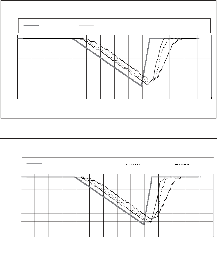
Operator’s Manual ZM-520PA/521PA/530PA/531PA 91
Response time: Selectable from “Slow”, “Normal” and “Fast”.
7KHIROORZLQJJUDSKVVKRZUHVSRQVHWLPHIRUV6S22
change.
Pulse Rate = 70 bpm
60
65
70
75
80
85
90
95
100
0 10 20 30 40 50 60 70 80 90 100 110 120 130 140
Time (seconds)
SpO
2
(%)
SpO
2
Reference SpO
2
Fast SpO
2
Normal SpO
2
Slow
60
65
70
75
80
85
90
95
100
0 10 20 30 40 50 60 70 80 90 100 110 120 130 140
SpO
2
Reference SpO
2
Fast SpO
2
Normal
Pulse Rate = 140 bpm
Time (seconds)
SpO
2
(%)
SpO
2
Slow
92 Operator’s Manual ZM-520PA/521PA/530PA/531PA
7KHIROORZLQJJUDSKVKRZVUHVSRQVHWLPHIRUESPVSXOVHUDWHFKDQJH
SpO
2
= 97
60
70
80
90
100
110
120
130
140
150
0 102030405060708090100110120
Time (seconds)
PR (bpm)
PR Reference PR
Transmitter
)&&UHJXODWLRQ )&&SDUW6XESDUW+
Wireless Medical Telemetry Service (WMTS)
)LHOGVWUHQJWKOLPLWV P9PDWP
Undesired emissions:
FCC part 95 95.1115 (b) (1), (2):
0+] ȝ9PDWP
0+] ȝ9PDWP
Antenna: Internal
Transmission channel: Indicated on the transmitter
7UDQVPLVVLRQIUHTXHQF\UDQJH WR0+]
&KDQQHOVSDFLQJ N+]RUN+]N+]ZKHQLQWHUOHDYHG
0RGXODWLRQ )6.IUHTXHQF\VKLIWNH\LQJ
Type of emission: F1D
2FFXSLHGEDQGZLGWK WRN+]
(IIHFWLYHUDGLDWHGSRZHU P:
Operator’s Manual ZM-520PA/521PA/530PA/531PA 93
Power Requirements
5DWHGYROWDJH 9
6KXWGRZQYROWDJH WR9
2SHUDWLQJYROWDJH 6KXWGRZQYROWDJHWR9
%DWWHU\W\SH 7ZR$$/5W\SHDONDOLQHGU\FHOOSULPDU\EDWWHULHV
%DWWHU\OLIHWLPHZLWKDONDOLQHEDWWHULHVDWURRPWHPSHUDWXUH
=03$ DSSUR[LPDWHO\GD\V
=03$ DSSUR[LPDWHO\GD\VPHDVXULQJ(&*UHVSLUDWLRQDQG
SpO2)
DSSUR[LPDWHO\GD\VPHDVXULQJ(&*DQGUHVSLUDWLRQ
Dimension and Weight
'LPHQVLRQ :î+î'PP
:HLJKW DERXWJH[FOXGLQJEDWWHULHVDQGRWKHUDFFHVVRULHV
DERXWJLQFOXGLQJEDWWHULHVH[FOXGLQJRWKHUDFFHVVRULHV
Environment
Operating environment
7HPSHUDWXUH WR&WR)
+XPLGLW\ WRQRQFRQGHQVLQJ
$WPRVSKHULFSUHVVXUH WRK3D
Storage and transport environment
7HPSHUDWXUH íWR&íWR)
+XPLGLW\ WR
$WPRVSKHULFSUHVVXUH WRK3D
Water resistance
:DWHUGRHVQRWJHWLQVLGHWKHWUDQVPLWWHUZKHQLPPHUVHGLQZDWHUXSWRFPGHHSIRUPLQXWHV
Safety Standards
6DIHW\VWDQGDUG &$1&6$&1R0
&$1&6$&1R6
&$1&6$&1R%
&$1&6$&1R
&$1&6$&1R
,(&
,(&$PHQGPHQW
,(&$PHQGPHQW
,(&
,(&
,62
8/

94 Operator’s Manual ZM-520PA/521PA/530PA/531PA
7\SHRISURWHFWLRQDJDLQVWHOHFWULFDOVKRFN
,17(51$//<32:(5('(48,30(17
'HJUHHRISURWHFWLRQDJDLQVWHOHFWULFDOVKRFN
(&*DQGLPSHGDQFHPHWKRGUHVSLUDWLRQ
'(),%5,//$7,213522)7<3(&)$33/,('3$57
SpO2 '(),%5,//$7,213522)7<3(%)$33/,('
PART
Degree of protection against harmful ingress of water:
,3;QRQSURWHFWHG
'HJUHHRIVDIHW\RIDSSOLFDWLRQLQWKHSUHVHQFHRID)/$00$%/($1$(67+(7,&0,;785(
:,7+$,525:,7+2;<*(1251,752862;,'(
(TXLSPHQWQRWVXLWDEOHIRUXVHLQWKHSUHVHQFHRI
)/$00$%/($1$(67+(7,&0,;785(:,7+
$,525:,7+2;<*(1251,752862;,'(
0RGHRIRSHUDWLRQ &217,1828623(5$7,21
0((48,30(17W\SH +$1'+(/'DQG3257$%/(
Electromagnetic Compatibility
,(&
,(&$PHQGPHQW
Electromagnetic Emissions
7KLVPRGHO=03$=03$LVLQWHQGHGIRUXVHLQWKHHOHFWURPDJQHWLFHQYLURQPHQW
VSHFL¿HGEHORZ7KHFXVWRPHURUWKHXVHURI=03$RU=03$VKRXOGDVVXUHWKDWLWLVXVHG
in such an environment.
Emissions test Compliance Electromagnetic environment - guidance
RF emissions
CISPR 11
*URXS =03$=03$XVHV5)HQHUJ\RQO\IRULWV
internal function. Therefore, its RF emissions are
YHU\ORZDQGDUHQRWOLNHO\WRFDXVHDQ\LQWHUIHUHQFH
in nearby electronic equipment.
RF emissions
CISPR 11
Class B =03$=03$LVVXLWDEOHIRUXVHLQDOO
establishments, including domestic establishments.
+DUPRQLFHPLVVLRQV
,(&
Not applicable
9ROWDJHÀXFWXDWLRQV
ÀLFNHUHPLVVLRQV
,(&
Not applicable

Operator’s Manual ZM-520PA/521PA/530PA/531PA 95
Electromagnetic Immunity
7KLVPRGHO=03$=03$LVLQWHQGHGIRUXVHLQWKHHOHFWURPDJQHWLFHQYLURQPHQW
VSHFL¿HGEHORZ7KHFXVWRPHURUWKHXVHURI=03$RU=03$VKRXOGDVVXUHWKDWLWLVXVHG
in such an environment.
Immunity test IEC 60601 test
level
Compliance
level
Electromagnetic
environment - guidance
(OHFWURVWDWLF
GLVFKDUJH(6'
,(&
rN9FRQWDFW
rN9DLU
rN9FRQWDFW
rN9DLU
Floors should be wood, concrete
RUFHUDPLFWLOH,IÀRRUVDUH
covered with synthetic material,
the relative humidity should be at
OHDVW
(OHFWULFDOIDVW
transient/burst
,(&
rN9IRUSRZHU
supply lines
rN9IRULQSXW
output lines
Not applicable
—
Surge
,(&
rN9GLIIHUHQWLDO
mode
rN9FRPPRQPRGH
Not applicable
—
9ROWDJHGLSVVKRUW
interruptions and
voltage variations
on power supply
input lines
,(&
UT!GLSLQ
UTIRUF\FOHV
UTGLSLQ
UT) for 5 cycles
UTGLSLQ
UT) for 25 cycles
UT!GLSLQ
UT) for 5 s
Not applicable
—
Power frequency
+]
PDJQHWLF¿HOG
,(&
3 A/m 3 A/m 3RZHUIUHTXHQF\PDJQHWLF¿HOGV
should be at levels characteristic
of a typical location in a
typical commercial or hospital
environment.
127(UT is the AC mains voltage prior to application of the test level.
Avoiding Electromagnetic Interference (Impedance Respiration)
Impedance respiration measurement is very sensitive and affected by electromagnetic interference.
7HFKQRORJLFDOOLPLWDWLRQVGRQRWDOORZLPPXQLW\OHYHOVKLJKHUWKDQ9PIRUUDGLDWHG5)
HOHFWURPDJQHWLF¿HOGV(OHFWURPDJQHWLF¿HOGVZLWK¿HOGVWUHQJWKVDERYH9PPD\FDXVH
measurement error. Do not use electrically radiating equipment near the impedance respiration
measurements.

96 Operator’s Manual ZM-520PA/521PA/530PA/531PA
Immunity test IEC 60601 test
level
Compliance
level
Electromagnetic environment -
guidance
Conducted RF
,(&
Radiated RF
,(&
9UPV
N+]WR0+]
9P
0+]WR*+]
9UPV
9P0+]WR
*+]
9P0+]
WR*+]IRU
respiration)
Portable and mobile RF communications
equipment should be used no closer
WRDQ\SDUWRI=03$=03$
including cables, than the recommended
separation distance calculated from the
equation applicable to the frequency of the
transmitter.
Recommended separation distance
d = 1.2 P
d = 1.2 30+]WR0+]
d = 2.3 30+]WR*+]
(d = 3.5 30+]WR0+]IRU
respiration
G 30+]WR*+]IRU
respiration)
where P is the maximum output power
rating of the transmitter in watts (W)
according to the transmitter manufacturer
and d is the recommended separation
distance in meters (m).
)LHOGVWUHQJWKVIURP¿[HG5)WUDQVPLWWHUV
as deter mined by an electromagnetic
site survey*1, should be less than the
compliance level in each frequency range*2.
Interference may occur in the vicinity of
HTXLSPHQWPDUNHGZLWKWKHIROORZLQJ
symbol:
127( $W0+]DQG0+]WKHKLJKHUIUHTXHQF\UDQJHDSSOLHV
127( 7KHVHJXLGHOLQHVPD\QRWDSSO\LQDOOVLWXDWLRQV(OHFWURPDJQHWLFSURSDJDWLRQLVDIIHFWHGE\
DEVRUSWLRQDQGUHÀHFWLRQIURPVWUXFWXUHVREMHFWVDQGSHRSOH
*1 )LHOGVWUHQJWKVIURP¿[HGWUDQVPLWWHUVVXFKDVEDVHVWDWLRQVIRUUDGLRFHOOXODUFRUGOHVVWHOHSKRQHVDQG
ODQGPRELOHUDGLRVDPDWHXUUDGLR$0DQG)0UDGLREURDGFDVWDQG79EURDGFDVWFDQQRWEHSUHGLFWHG
WKHRUHWLFDOO\ZLWKDFFXUDF\7RDVVHVVWKHHOHFWURPDJQHWLFHQYLURQPHQWGXHWR¿[HG5)WUDQVPLWWHUVDQ
HOHFWURPDJQHWLFVLWHVXUYH\VKRXOGEHFRQVLGHUHG,IWKHPHDVXUHG¿HOGVWUHQJWKLQWKHORFDWLRQLQZKLFK
=03$=03$LVXVHGH[FHHGVWKHDSSOLFDEOH5)FRPSOLDQFHOHYHODERYH=03$
=03$VKRXOGEHREVHUYHGWRYHULI\QRUPDORSHUDWLRQ,IDEQRUPDOSHUIRUPDQFHLVREVHUYHG
DGGLWLRQDOPHDVXUHVPD\EHQHFHVVDU\VXFKDVUHRULHQWLQJRUUHORFDWLQJ=03$=03$
*2 2YHUWKHIUHTXHQF\UDQJHN+]WR0+]¿HOGVWUHQJWKVVKRXOGEHOHVVWKDQ9PIRUUHVSLUDWLRQ
DQG9PIRUDOORWKHUIXQFWLRQV

Operator’s Manual ZM-520PA/521PA/530PA/531PA 97
Recommended Separation Distances between Portable and Mobile RF
Communications Equipment
7KH=03$=03$LVLQWHQGHGIRUXVHLQDQHOHFWURPDJQHWLFHQYLURQPHQWLQZKLFK
UDGLDWHG5)GLVWXUEDQFHVDUHFRQWUROOHG7KHFXVWRPHURUWKHXVHURI=03$=03$
can help prevent electromagnetic interference by maintaining a minimum distance between
SRUWDEOHDQGPRELOH5)FRPPXQLFDWLRQVHTXLSPHQWWUDQVPLWWHUVDQG=03$=03$DV
recommended below, according to the maximum output power of the communications equipment.
Rated maximum output
power of transmitter
(W)
Separation distance according to frequency of transmitter (m)
150 kHz to 80 MHz
d = 1.2 P
80 MHz to 800 MHz
d = 1.2 P
(For respiration:
d = 3.5 P)
800 MHz to 2.5 GHz
d = 2.3 P
(For respiration:
d = 7.0 P)
1 1.2 1.2 (3.5*)
12 12 (35*)
For transmitters rated at a maximum output power not listed above, the recommended
separation distance d in meters (m) can be estimated using the equation applicable to the
frequency of the transmitter, where P is the maximum output power rating of the transmitter in
watts (W) according to the transmitter manufacturer.
(* For respiration)
127( $W0+]DQG0+]WKHVHSDUDWLRQGLVWDQFHIRUWKHKLJKHUIUHTXHQF\UDQJH
applies.
127( 7KHVHJXLGHOLQHVPD\QRWDSSO\LQDOOVLWXDWLRQV(OHFWURPDJQHWLFSURSDJDWLRQLV
DIIHFWHGE\DEVRUSWLRQDQGUHÀHFWLRQIURPVWUXFWXUHVREMHFWVDQGSHRSOH
Recovery Time after Defibrillation
7KHWUDQVPLWWHUUHWXUQVWRWKHQRUPDORSHUDWLQJPRGHZLWKLQVHFRQGVDIWHUGH¿EULOODWLRQ7KH
stored settings are not affected.
System Composition for EMC Test
7KH=03$=03$WUDQVPLWWHULVWHVWHGWRFRPSO\ZLWK,(&DQG
$PHQGPHQWZLWKWKHIROORZLQJFRPSRVLWLRQ
Units Cable Length
=03$=03$WUDQVPLWWHU —
%53(&*HOHFWURGHOHDG P
7/7¿QJHUSUREH 1.6 m
98 Operator’s Manual ZM-520PA/521PA/530PA/531PA
ZM-521PA/ZM-531PA
Measured Parameters
:DYHIRUPV (&*LPSHGDQFHPHWKRGUHVSLUDWLRQSXOVH
1XPHULFGDWD +HDUWUDWHUHVSLUDWLRQUDWH6S22, pulse rate
Transmitted Data
:DYHIRUPV (&*UHVSLUDWLRQSXOVHZDYH
Numeric data: SpO2, pulse rate
Status information: Battery replacement, battery level*, alarm suspended,
SDXVHPRQLWRULQJSDWLHQWFRQ¿UPHG(&*OHDGSDFLQJ
detection, electrode detachment, electrode impedance*,
(&*RIIUHVSLUDWLRQPHWKRGLPSHGDQFH6S22 status,
respiration status*, channel ID, time constant (3.2 s), type
of transmitter, transmitter code number*, transmitter serial
number*
* Transmitted only when the protocol is “51”.
Display
Display size: 2.2 inch TFT color LCD
9LHZLQJDUHD +î9PP
5HVROXWLRQ +î9GRWV
Displayed Data
1XPHULFDQGZDYHIRUPVFUHHQ (&*RQHZDYHIRUPIURPOHDG,,,,,,9DRU9EKHDUW
rate, pulse rate, respiration rate, SpO2, message, battery level,
456SXOVHV\QFPDUNSXOVHEDUJUDSK(&*OHDG
:DYHIRUPUHYLHZVFUHHQ (&*RUSXOVHZDYHRISDVWPLQXWHV
1XPHULFUHYLHZVFUHHQ +HDUWUDWHRUSXOVHUDWHUHVSLUDWLRQUDWHDQG6S22 at 1 minute
LQWHUYDOIRUSDVWPLQXWHV
&KHFNHOHFWURGHVVFUHHQ (&*IRUFKHFNLQJHOHFWURGHDWWDFKPHQW
ECG
ECG Measurement
Channels: 4
,QSXWG\QDPLFUDQJH P9RUPRUH
(OHFWURGHRIIVHWSRWHQWLDOWROHUDQFH P9RUPRUH
,QSXWLPSHGDQFH 0ȍRUPRUH
Common mode rejection ratio: 95 dB or more
,(&FRPSOLHG
3DFLQJSXOVHGHWHFWLRQ DPSOLWXGHWRP9GXUDWLRQWRPV
,(&FRPSOLHG
%DVHGXSRQSDFHPDNHUSXOVHUHMHFWLRQFDSDELOLW\
Operator’s Manual ZM-520PA/521PA/530PA/531PA 99
'H¿EULOODWLRQSURRI (&*LQSXWSURWHFWHGDJDLQVW:V'&N9
,(&FRPSOLHG
(&*UHFRYHU\WLPHDIWHUGH¿EULOODWLRQ ZLWKLQV
(OHFWURGHFRQGLWLRQ 'LVSOD\V&+(&.(/(&752'(6PHVVDJH
7DOO7ZDYHUHMHFWLRQFDSDELOLW\ &RPSOLHVZLWKWKHKHLJKWVRI7ZDYHVIURPWRP9
,(&FRPSOLHG
+HDUWUDWHDYHUDJLQJ &DOFXODWHGE\XVLQJWKHPRVWUHFHQWEHDWV
+HDUWUDWHPHWHUDFFXUDF\DQGUHVSRQVHWRLUUHJXODUUK\WKP
9HQWULFXODUELJHPLQ\7HVWZDYHIRUPQDPHDDPLD
ESP
Slow alternating ventricular bigeminy (Test waveform name:
DDPLEESP
Rapid alternating ventricular bigeminy (Test waveform
QDPHDDPLFESP
Bidirectional systoles (Test waveform name: aami3d*):
ESP
* The test waveforms can be download at http://www.
physionet.org
Response time of heart rate meter to change in heart rate:
+5FKDQJHIURPWRESPWRVHFRQGV
+5FKDQJHIURPWRESPWRVHFRQGV
3DFHPDNHUSXOVHUHMHFWLRQFDSDELOLW\ZLWKRXWRYHUVKRRW
&RPSOLHVZLWKWKHDPSOLWXGHVRISDFHPDNHUSXOVHVWR
P9DQGZLGWKVWRPVVSHFL¿HGLQ,(&
3DFHPDNHUSXOVHUHMHFWLRQFDSDELOLW\ZLWKRYHUVKRRW
2YHUVKRRWDPSOLWXGHVDQGWLPHFRQVWDQWVRIP9
PVWRP9PV$VGH¿QHGE\PHWKRG%RI,(&
WKLVFRUUHVSRQGVWRWKHSDFHPDNHU
SXOVHVDPSOLWXGHVDQGZLGWKVRIP9PVWRDPSOLWXGHV
P9PV
ECG Display and Heart Rate Count
)UHTXHQF\FKDUDFWHULVWLF ¿OWHURQWR+]¿OWHURIIWR+]
+HDUWUDWHGHWHFWLRQPHWKRG $YHUDJH
456GHWHFWLRQ WRPVDPSOLWXGHP9UDWHWREHDWVPLQ
WRPVDPSOLWXGHP9UDWHWREHDWVPLQ
+HDUWUDWHFRXQWLQJUDQJH WREHDWVPLQ
+HDUWUDWHFRXQWLQJDFFXUDF\ EHDWVPLQWREHDWVPLQ
(VVHQWLDOSHUIRUPDQFHRIWKLVWUDQVPLWWHU
100 Operator’s Manual ZM-520PA/521PA/530PA/531PA
Respiration Measurement
Measuring method: Impedance method
Measuring lead: Between R and F
,PSHGDQFHUDQJH WRȍ
([FLWRUFXUUHQW WR$SSN+]
5HVSLUDWLRQUDWHPHDVXULQJDFFXUDF\ FRXQWVPLQDWWRFRXQWVPLQ
5HVSLUDWLRQUDWHFRXQWLQJUDQJH WRFRXQWVPLQ
(VVHQWLDOSHUIRUPDQFHRIWKLVWUDQVPLWWHU
SpO2 Measurement (ISO 9919: 2005 compliance)
0HDVXULQJUDQJH WR6S22
'HFODUHGUDQJH WR6S22
0LQLPXPGLVSOD\UDQJH 6S22
'LVSOD\XSGDWHF\FOH (YHU\VHFRQGV
0HDVXULQJDFFXUDF\UPV $FFXUDF\DVVXUDQFHWHPSHUDWXUHWR&
7RWDODFFXUDF\LQFOXGLQJSUREH 6S226S226S226S22
6S226S22 6S226S22
XQGHU6S22QRWVSHFL¿HG
$FFXUDF\RIWKHWUDQVPLWWHU 6S226S226S226S22
6S226S226S226S22
XQGHU6S22QRWVSHFL¿HG
3XOVHUDWHPHDVXULQJUDQJH WRESP
3XOVHUDWHGLVSOD\UDQJH WRESP
3XOVHUDWHDFFXUDF\UPV ESP
(VVHQWLDOSHUIRUPDQFHRIWKLVWUDQVPLWWHU
NOTE
• The SpO2 measuring accuracy was tested using the TL-201T, TL-260T, TL-271T and
TL-631T SpO2 probes. The testing was performed during induced hypoxia on healthy
volunteers (Ethnicity: 10 Caucasians, 2 Africans, 1 Asian and 3 Indians), (Skin: 8 light,
4 medium, 4 dark), (Age: 21 to 34), (5 women and 11 men) under the condition of no
motion. Arterial blood was sampled and measured by a CO-oximeter. The difference
between SpO2 measured by the SpO2 probe and functional SaO2 measured by a CO-
oximeter was calculated using the root-mean-square (rms) method according to ISO
9919: 2005. This measurement accuracy figure represents 2/3 of all test measurements.
• A pulse oximeter tester that generates simulated signals can be used to check the
difference from the design specification, but it cannot be used as a replacement for
human signals for testing accuracy.

Operator’s Manual ZM-520PA/521PA/530PA/531PA 101
Response time: Selectable from “Slow”, “Normal” and “Fast”.
7KHIROORZLQJJUDSKVVKRZUHVSRQVHWLPHIRUV6S22
change.
Pulse Rate = 70 bpm
60
65
70
75
80
85
90
95
100
0 10 20 30 40 50 60 70 80 90 100 110 120 130 140
Time (seconds)
SpO
2
(%)
SpO
2
Reference SpO
2
Fast SpO
2
Normal SpO
2
Slow
60
65
70
75
80
85
90
95
100
0 10 20 30 40 50 60 70 80 90 100 110 120 130 140
SpO
2
Reference SpO
2
Fast SpO
2
Normal
Pulse Rate = 140 bpm
Time (seconds)
SpO
2
(%)
SpO
2
Slow

102 Operator’s Manual ZM-520PA/521PA/530PA/531PA
7KHIROORZLQJJUDSKVKRZVUHVSRQVHWLPHIRUESPVSXOVHUDWHFKDQJH
SpO
2
= 97
60
70
80
90
100
110
120
130
140
150
0 102030405060708090100110120
Time (seconds)
PR (bpm)
PR Reference PR
Transmitter
)&&UHJXODWLRQ )&&SDUW6XESDUW+
Wireless Medical Telemetry Service (WMTS)
)LHOGVWUHQJWKOLPLWV P9PDWP
Undesired emissions:
FCC part 95 95.1115 (b) (1), (2):
0+]ȝ9PDWP
0+]ȝ9PDWP
Antenna: Internal
Transmission channel: Indicated on the transmitter
7UDQVPLVVLRQIUHTXHQF\UDQJH WR0+]
WR0+]
&KDQQHOVSDFLQJ N+]RUN+]N+]ZKHQLQWHUOHDYHG
0RGXODWLRQ )6.IUHTXHQF\VKLIWNH\LQJ
Type of emission: F1D
2FFXSLHGEDQGZLGWK WRN+]
(IIHFWLYHUDGLDWHGSRZHU P:
&DQEHFKDQJHGWRP:LIUHTXLUHG
Operator’s Manual ZM-520PA/521PA/530PA/531PA 103
Power Requirements
5DWHGYROWDJH 9
6KXWGRZQYROWDJH WR9
2SHUDWLQJYROWDJH 6KXWGRZQYROWDJHWR9
%DWWHU\W\SH 7ZR$$/5W\SHDONDOLQHGU\FHOOSULPDU\EDWWHULHV
%DWWHU\OLIHWLPHZLWKDONDOLQHEDWWHULHVDWURRPWHPSHUDWXUH
=03$ DSSUR[LPDWHO\GD\V
=03$ DSSUR[LPDWHO\GD\VPHDVXULQJ(&*UHVSLUDWLRQDQG
SpO2)
DSSUR[LPDWHO\GD\VPHDVXULQJ(&*DQGUHVSLUDWLRQ
Dimension and Weight
'LPHQVLRQ :î+î'PP
:HLJKW DERXWJH[FOXGLQJEDWWHULHVDQGRWKHUDFFHVVRULHV
DERXWJLQFOXGLQJEDWWHULHVH[FOXGLQJRWKHUDFFHVVRULHV
Environment
Operating environment
7HPSHUDWXUH WR&WR)
+XPLGLW\ WRQRQFRQGHQVLQJ
$WPRVSKHULFSUHVVXUH WRK3D
Storage and transport environment
7HPSHUDWXUH íWR&íWR)
+XPLGLW\ WR
$WPRVSKHULFSUHVVXUH WRK3D
Water resistance
:DWHUGRHVQRWJHWLQVLGHWKHWUDQVPLWWHUZKHQLPPHUVHGLQZDWHUXSWRFPGHHSIRUPLQXWHV
Safety Standards
6DIHW\VWDQGDUG &$1&6$&1R0
&$1&6$&1R6
&$1&6$&1R%
&$1&6$&1R
&$1&6$&1R
,(&
,(&$PHQGPHQW
,(&$PHQGPHQW
,(&
,(&
,62
8/

104 Operator’s Manual ZM-520PA/521PA/530PA/531PA
7\SHRISURWHFWLRQDJDLQVWHOHFWULFDOVKRFN
,17(51$//<32:(5('(48,30(17
'HJUHHRISURWHFWLRQDJDLQVWHOHFWULFDOVKRFN
(&*DQGLPSHGDQFHPHWKRGUHVSLUDWLRQ
'(),%5,//$7,213522)7<3(&)$33/,('3$57
SpO2 '(),%5,//$7,213522)7<3(%)$33/,('3$57
Degree of protection against harmful ingress of water:
,3;QRQSURWHFWHG
'HJUHHRIVDIHW\RIDSSOLFDWLRQLQWKHSUHVHQFHRID)/$00$%/($1$(67+(7,&0,;785(
:,7+$,525:,7+2;<*(1251,752862;,'(
(TXLSPHQWQRWVXLWDEOHIRUXVHLQWKHSUHVHQFHRI
)/$00$%/($1$(67+(7,&0,;785(:,7+
$,525:,7+2;<*(1251,752862;,'(
0RGHRIRSHUDWLRQ &217,1828623(5$7,21
0((48,30(17W\SH +$1'+(/'DQG3257$%/(
Electromagnetic Compatibility
,(&
,(&$PHQGPHQW
Electromagnetic Emissions
7KLV0RGHO=03$=03$LVLQWHQGHGIRUXVHLQWKHHOHFWURPDJQHWLFHQYLURQPHQW
VSHFL¿HGEHORZ7KHFXVWRPHURUWKHXVHURI=03$=03$VKRXOGDVVXUHWKDWLWLVXVHGLQ
such an environment.
Emissions test Compliance Electromagnetic environment - guidance
RF emissions
CISPR 11
*URXS =03$=03$XVHV5)HQHUJ\RQO\IRULWV
internal function. Therefore, its RF emissions are very
ORZDQGDUHQRWOLNHO\WRFDXVHDQ\LQWHUIHUHQFHLQ
nearby electronic equipment.
RF emissions
CISPR 11
Class B =03$=03$LVVXLWDEOHIRUXVHLQDOO
establishments, including domestic establishments.
+DUPRQLFHPLVVLRQV
,(&
Not applicable
9ROWDJHÀXFWXDWLRQV
ÀLFNHUHPLVVLRQV
,(&
Not applicable

Operator’s Manual ZM-520PA/521PA/530PA/531PA 105
Electromagnetic Immunity
7KLVPRGHO=03$=03$LVLQWHQGHGIRUXVHLQWKHHOHFWURPDJQHWLFHQYLURQPHQW
VSHFL¿HGEHORZ7KHFXVWRPHURUWKHXVHURI=03$=03$VKRXOGDVVXUHWKDWLWLVXVHGLQ
such an environment.
Immunity test IEC 60601 test
level
Compliance
level
Electromagnetic
environment - guidance
(OHFWURVWDWLF
GLVFKDUJH(6'
,(&
rN9FRQWDFW
rN9DLU
rN9FRQWDFW
rN9DLU
Floors should be wood, concrete
RUFHUDPLFWLOH,IÀRRUVDUH
covered with synthetic material,
the relative humidity should be at
OHDVW
(OHFWULFDOIDVW
transient/burst
,(&
rN9IRUSRZHU
supply lines
rN9IRULQSXW
output lines
Not applicable
—
Surge
,(&
rN9GLIIHUHQWLDO
mode
rN9FRPPRQPRGH
Not applicable
—
9ROWDJHGLSVVKRUW
interruptions and
voltage variations
on power supply
input lines
,(&
UT!GLSLQ
UTIRUF\FOHV
UTGLSLQ
UT) for 5 cycles
UTGLSLQ
UT) for 25 cycles
UT!GLSLQ
UT) for 5 s
Not applicable
—
Power frequency
+]
PDJQHWLF¿HOG
,(&
3 A/m 3 A/m 3RZHUIUHTXHQF\PDJQHWLF¿HOGV
should be at levels characteristic
of a typical location in a
typical commercial or hospital
environment.
127(UT is the AC mains voltage prior to application of the test level.
Avoiding Electromagnetic Interference (Impedance Respiration)
Impedance respiration measurement is very sensitive and affected by electromagnetic interference.
7HFKQRORJLFDOOLPLWDWLRQVGRQRWDOORZLPPXQLW\OHYHOVKLJKHUWKDQ9PIRUUDGLDWHG5)
HOHFWURPDJQHWLF¿HOGV(OHFWURPDJQHWLF¿HOGVZLWK¿HOGVWUHQJWKVDERYH9PPD\FDXVH
measurement error. Do not use electrically radiating equipment near the impedance respiration
measurements.

106 Operator’s Manual ZM-520PA/521PA/530PA/531PA
Immunity test IEC 60601 test
level
Compliance
level
Electromagnetic environment -
guidance
Conducted RF
,(&
Radiated RF
,(&
9UPV
N+]WR0+]
9P
0+]WR*+]
9UPV
9P0+]WR
*+]
9P0+]
WR*+]IRU
respiration)
Portable and mobile RF communications
equipment should be used no closer
WRDQ\SDUWRI=03$=03$
including cables, than the recommended
separation distance calculated from the
equation applicable to the frequency of the
transmitter.
Recommended separation distance
d = 1.2 P
d = 1.2 30+]WR0+]
d = 2.3 30+]WR*+]
(d = 3.5 30+]WR0+]IRU
respiration
G 30+]WR*+]IRU
respiration)
where P is the maximum output power
rating of the transmitter in watts (W)
according to the transmitter manufacturer
and d is the recommended separation
distance in meters (m).
)LHOGVWUHQJWKVIURP¿[HG5)WUDQVPLWWHUV
as deter mined by an electromagnetic
site survey*1, should be less than the
compliance level in each frequency
range*2.
Interference may occur in the vicinity of
HTXLSPHQWPDUNHGZLWKWKHIROORZLQJ
symbol:
127( $W0+]DQG0+]WKHKLJKHUIUHTXHQF\UDQJHDSSOLHV
127( 7KHVHJXLGHOLQHVPD\QRWDSSO\LQDOOVLWXDWLRQV(OHFWURPDJQHWLFSURSDJDWLRQLVDIIHFWHGE\
DEVRUSWLRQDQGUHÀHFWLRQIURPVWUXFWXUHVREMHFWVDQGSHRSOH

Operator’s Manual ZM-520PA/521PA/530PA/531PA 107
*1 )LHOGVWUHQJWKVIURP¿[HGWUDQVPLWWHUVVXFKDVEDVHVWDWLRQVIRUUDGLRFHOOXODUFRUGOHVVWHOHSKRQHVDQG
ODQGPRELOHUDGLRVDPDWHXUUDGLR$0DQG)0UDGLREURDGFDVWDQG79EURDGFDVWFDQQRWEHSUHGLFWHG
WKHRUHWLFDOO\ZLWKDFFXUDF\7RDVVHVVWKHHOHFWURPDJQHWLFHQYLURQPHQWGXHWR¿[HG5)WUDQVPLWWHUVDQ
HOHFWURPDJQHWLFVLWHVXUYH\VKRXOGEHFRQVLGHUHG,IWKHPHDVXUHG¿HOGVWUHQJWKLQWKHORFDWLRQLQZKLFK
=03$=03$LVXVHGH[FHHGVWKHDSSOLFDEOH5)FRPSOLDQFHOHYHODERYH=03$=0
531PA should be observed to verify normal operation. If abnormal performance is observed, additional
PHDVXUHVPD\EHQHFHVVDU\VXFKDVUHRULHQWLQJRUUHORFDWLQJ=03$=03$
*2 2YHUWKHIUHTXHQF\UDQJHN+]WR0+]¿HOGVWUHQJWKVVKRXOGEHOHVVWKDQ9PIRUUHVSLUDWLRQ
DQG9PIRUDOORWKHUIXQFWLRQV
Recommended Separation Distances between Portable and Mobile RF
Communications Equipment
=03$=03$LVLQWHQGHGIRUXVHLQDQHOHFWURPDJQHWLFHQYLURQPHQWLQZKLFKUDGLDWHG5)
GLVWXUEDQFHVDUHFRQWUROOHG7KHFXVWRPHURUWKHXVHURI=03$=03$FDQKHOSSUHYHQW
electromagnetic interference by maintaining a minimum distance between portable and mobile
5)FRPPXQLFDWLRQVHTXLSPHQWWUDQVPLWWHUVDQG=03$=03$DVUHFRPPHQGHGEHORZ
according to the maximum output power of the communications equipment.
Rated maximum output
power of transmitter
(W)
Separation distance according to frequency of transmitter (m)
150 kHz to 80 MHz
d = 1.2 P
80 MHz to 800 MHz
d = 1.2 P
(For respiration:
d = 3.5 P)
800 MHz to 2.5 GHz
d = 2.3 P
(For respiration:
d = 7.0 P)
1 1.2 1.2 (3.5*)
12 12 (35*)
For transmitters rated at a maximum output power not listed above, the recommended
separation distance d in meters (m) can be estimated using the equation applicable to the
frequency of the transmitter, where P is the maximum output power rating of the transmitter in
watts (W) according to the transmitter manufacturer.
(* For respiration)
127( $W0+]DQG0+]WKHVHSDUDWLRQGLVWDQFHIRUWKHKLJKHUIUHTXHQF\UDQJH
applies.
127( 7KHVHJXLGHOLQHVPD\QRWDSSO\LQDOOVLWXDWLRQV(OHFWURPDJQHWLFSURSDJDWLRQLV
DIIHFWHGE\DEVRUSWLRQDQGUHÀHFWLRQIURPVWUXFWXUHVREMHFWVDQGSHRSOH
Recovery Time after Defibrillation
7KHWUDQVPLWWHUUHWXUQVWRWKHQRUPDORSHUDWLQJPRGHZLWKLQVHFRQGVDIWHUGH¿EULOODWLRQ7KH
stored settings are not affected.

108 Operator’s Manual ZM-520PA/521PA/530PA/531PA
System Composition for EMC Test
7KH=03$=03$WUDQVPLWWHULVWHVWHGWRFRPSO\ZLWK,(&DQG
$PHQGPHQWZLWKWKHIROORZLQJFRPSRVLWLRQ
Units Cable Length
=03$=03$WUDQVPLWWHU —
%53(&*HOHFWURGHOHDG P
7/7¿QJHUSUREH 1.6 m

Operator’s Manual ZM-520PA/521PA/530PA/531PA 109
Standard Accessories
Name Model Q’ty Supply Code
Strap — 1 Y233

110 Operator’s Manual ZM-520PA/521PA/530PA/531PA
Options
CAUTION
Only use Nihon Kohden specified electrodes, electrode leads and SpO2 probes.
Otherwise, the maximum performance from the transmitter cannot be guaranteed.
Transmitter
4,3.FKDQQHOZULWHU
ECG/RESP
Name Purpose Length (m) Model Q’ty Supply Code
(OHFWURGH
lead
3 electrodes $+$
clip type %53$ 1 K911A
6 electrodes $+$
clip type %53$ 1 K912A

Operator’s Manual ZM-520PA/521PA/530PA/531PA 111
SpO2
Name Cable
Length Model Q’ty Supply
Code
Finger probe (reusable) P 7/7 13+
1.6 m P225F
0XOWLVLWHSUREHUHXVDEOH 1.6 m 7/7 13*
Finger probe (reusable) P 7/7 1 P311A
1.6 m 7/7 1 P311C
SpO2 probe (for adult, disposable) P 7/7 24 3$
1.6 m 7/7 24 3(
SpO2 probe (for child, disposable) P 7/7 24 3%
1.6 m 7/7 24 3)
SpO2 probe (for neonate/adult,
disposable)
P 7/7 24 3&
1.6 m 7/7 24 3*
SpO2 probe (for child/infant,
disposable)
P 7/7 24 3'
1.6 m 7/7 24 3+
SpO2 probe (for adult/neonate,
disposable)
P 7/6 53$
1.6 m 7/6 53%
SpO2 probe (for child/infant,
disposable)
P 7/6 5 P229A
1.6 m 7/6 5 P229B
COTTONY tape — — P259
)RDPWDSHIRU7/66
66 ——
4 uSDFNDJHV 3
$WWDFKPHQWWDSHIRU7/77 ——
3 uSDFNDJHV P263
Probe fastener — <63 3

112 Operator’s Manual ZM-520PA/521PA/530PA/531PA
Transmission Frequencies
&KDQQHOWR
Transmission
Frequency
(MHz)
Channel
No.
Transmission
Frequency
(MHz)
Channel
No.
Transmission
Frequency
(MHz)
Channel
No.

Operator’s Manual ZM-520PA/521PA/530PA/531PA 113
Transmission
Frequency
(MHz)
Channel
No.
9111
9112
9113
9114
9115
9116
Transmission
Frequency
(MHz)
Channel
No.
9119
9121
9122
9123
9124
9125
9126
9129
9131
9132
9133
9134
9135
9136
9139
9141
9142
9143
9144
9145
9146
9149
9151
Transmission
Frequency
(MHz)
Channel
No.
9152
9153
9154
9155
9156
9159
9161
9162
9163
9164
9165
9166
9169

114 Operator’s Manual ZM-520PA/521PA/530PA/531PA
Transmission
Frequency
(MHz)
Channel
No.
9191
9192
9193
9194
9195
9196
9199
9211
9212
9213
9214
9215
9216
Transmission
Frequency
(MHz)
Channel
No.
9219
9221
9222
9223
9224
9225
9226
9229
9231
9232
9233
9234
9235
9236
9239
9241
9242
9243
9244
9245
9246
611.1125 9249
Transmission
Frequency
(MHz)
Channel
No.
9251
9252
611.1625 9253
9254
9255
9256
611.2125
9259
611.2625 9261
9262
9263
9264
611.3125 9265
9266
611.3625 9269
611.4125
611.4625
611.5125

Operator’s Manual ZM-520PA/521PA/530PA/531PA 115
Transmission
Frequency
(MHz)
Channel
No.
611.5625
611.6125
9291
9292
611.6625 9293
9294
9295
9296
9299
9311
9312
611.9125 9313
9314
9315
9316
Transmission
Frequency
(MHz)
Channel
No.
611.9625
9319
9321
9322
9323
9324
9325
9326
612.1125 9329
9331
9332
612.1625 9333
9334
9335
9336
612.2125
9339
612.2625 9341
9342
9343
9344
612.3125 9345
9346
612.3625 9349
Transmission
Frequency
(MHz)
Channel
No.
9351
9352
612.4125 9353
9354
9355
9356
612.4625
9359
612.5125 9361
9362
9363
9364
612.5625 9365
9366
612.6125 9369
612.6625

116 Operator’s Manual ZM-520PA/521PA/530PA/531PA
Transmission
Frequency
(MHz)
Channel
No.
9391
9392
612.9125 9393
9394
9395
9396
612.9625
9399
613.1125
9411
9412
613.1625 9413
9414
9415
Transmission
Frequency
(MHz)
Channel
No.
9416
613.2125
9419
613.2625 9421
9422
9423
9424
613.3125 9425
9426
613.3625 9429
9431
9432
613.4125 9433
9434
9435
9436
613.4625
9439
613.5125 9441
9442
9443
9444
613.5625 9445
9446
Transmission
Frequency
(MHz)
Channel
No.
613.6125 9449
9451
9452
613.6625 9453
9454
9455
9456
9459
9461
9462
9463
9464
9465
9466
9469
613.9125
613.9625

Operator’s Manual ZM-520PA/521PA/530PA/531PA 117
&KDQQHO(WR(
Transmission
Frequency
(MHz)
Channel
No.
(
(
(
(
(
(
(
1395.1125 (
(
(
(
1395.1625 (
(
(
(
1395.2125 (
(
(
(
1395.2625 (
(
(
(
1395.3125 (
(
(
(
1395.3625 (
(
(
(
1395.4125 (
Transmission
Frequency
(MHz)
Channel
No.
(
(
(
1395.4625 (
(
(
(
1395.5125 (
(
(
(
1395.5625 (
(
(
(
1395.6125 (
(
(
(
1395.6625 (
(
(
(
(
(
(
(
(
(
(
(
(
Transmission
Frequency
(MHz)
Channel
No.
(
(
(
(
(
(
(
1395.9125 (
(
(
(
1395.9625 (
(
(
(
(
(
(
(
(
(
(
(
1396.1125 (
(
(
(
1396.1625 (
(
(
(
1396.2125 (

118 Operator’s Manual ZM-520PA/521PA/530PA/531PA
Transmission
Frequency
(MHz)
Channel
No.
(
(
(
1396.2625 (
(
(
(
1396.3125 (
(
(
(
1396.3625 (
(
(
(
1396.4125 (
(
(
(
1396.4625 (
(
(
(
1396.5125 (
(
(
(
1396.5625 (
(
(
(
1396.6125 (
(
(
Transmission
Frequency
(MHz)
Channel
No.
(
1396.6625 (
(
(
(
(
(
(
(
(
(
(
(
(
(
(
(
(
(
(
(
1396.9125 (
(
(
(
1396.9625 (
(
(
(
(
(
(
(
(
Transmission
Frequency
(MHz)
Channel
No.
(
(
(
(
(
(
(
(
(
(
(
(
(
(
(
(
(
(
(
(
(
(
(
(
(
(
(
(
(
(
(
(
(
(

Operator’s Manual ZM-520PA/521PA/530PA/531PA 119
Transmission
Frequency
(MHz)
Channel
No.
(
(
(
(
(
(
(
(
(
(
(
(
(
(
(
(
(
(
(
(
(
(
(
(
(
(
(
(
(
(
(
(
(
(
Transmission
Frequency
(MHz)
Channel
No.
(
(
(
(
(
(
(
(
(
(
(
(
(
(
(
(
(
(
(
(
(
(
(
(
(
(
(
(
(
(
(
(
(
(
Transmission
Frequency
(MHz)
Channel
No.
(
(
(
(
(
(
(
(
(
(
(
(
(
(
(
(
(
(
(
(
(
(
(
(
(
(
(
(
(
(
(
(
(
(

120 Operator’s Manual ZM-520PA/521PA/530PA/531PA
Transmission
Frequency
(MHz)
Channel
No.
(
(
(
(
(
(
(
(
(
(
(
(
(
(
(
(
(
(
(
(
(
(
(
(
(
(
(
1399.1125 (
(
(
(
1399.1625 (
(
(
Transmission
Frequency
(MHz)
Channel
No.
(
1399.2125 (
(
(
(
1399.2625 (
(
(
(
1399.3125 (
(
(
(
1399.3625 (
(
(
(
1399.4125 (
(
(
(
1399.4625 (
(
(
(
1399.5125 (
(
(
(
1399.5625 (
(
(
(
1399.6125 (
Transmission
Frequency
(MHz)
Channel
No.
(
(
(
1399.6625 (
(
(
(
(
(
(
(
(
(
(
(
(
(
(
(
(
(
(
(
1399.9125 (
(
(
(
1399.9625 (
(

Operator’s Manual ZM-520PA/521PA/530PA/531PA 121
&KDQQHO(WR(
Transmission
Frequency
(MHz)
Channel
No.
(
(
(
(
(
(
(
(
(
(
(
(
(
(
(
(
(
(
(
(
(
(
(
(
(
(
(
(
(
(
(
(
Transmission
Frequency
(MHz)
Channel
No.
(
(
(
(
(
(
(
(
(
(
(
(
(
(
(
(
(
(
(
(
(
(
(
(
(
(
(
(
(
(
(
(
Transmission
Frequency
(MHz)
Channel
No.
(
(
(
(
(
(
(
(
(
(
(
(
(
(
(
(
(
(
(
(
(
(
(
(
(
(
(
(
(
(
(
(

122 Operator’s Manual ZM-520PA/521PA/530PA/531PA
Transmission
Frequency
(MHz)
Channel
No.
(
(
(
(
(
(
(
(
(
(
(
(
(
(
(
(
(
(
(
(
(
(
(
(
(
(
(
(
(
(
(
(
(
(
Transmission
Frequency
(MHz)
Channel
No.
(
(
(
(
(
(
(
(
(
(
(
(
(
(
(
(
(
(
(
(
(
(
(
(
(
(
(
(
(
(
(
(
(
(
Transmission
Frequency
(MHz)
Channel
No.
(
(
(
1429.1125 (
(
(
(
1429.1625 (
(
(
(
1429.2125 (
(
(
(
1429.2625 (
(
(
(
1429.3125 (
(
(
(
1429.3625 (
(
(
(
1429.4125 (
(
(
(
1429.4625 (
(
(

Operator’s Manual ZM-520PA/521PA/530PA/531PA 123
Transmission
Frequency
(MHz)
Channel
No.
(
1429.5125 (
(
(
(
1429.5625 (
(
(
(
1429.6125 (
(
(
(
1429.6625 (
(
(
(
(
(
(
(
(
(
(
(
(
(
(
(
(
(
(
(
1429.9125 (
Transmission
Frequency
(MHz)
Channel
No.
(
(
(
1429.9625 (
(
(
(
(
(
(
(
(
(
(
(
(
(
(
(
(
(
(
(
(
(
(
(
(
(
(
(
(
(
(
Transmission
Frequency
(MHz)
Channel
No.
(
(
(
(
(
(
(
(
(
(
(
(
(
(
(
(
(
(
(
(
(
(
(
(
(
(
(
(
(
(
(
(
(
(

124 Operator’s Manual ZM-520PA/521PA/530PA/531PA
Transmission
Frequency
(MHz)
Channel
No.
(
(
(
(
(
(
(
(
(
(
(
(
(
(
(
(
(
(
(
(
(
(
(
(
(
(
(
1431.1125 (
(
(
(
1431.1625 (
(
(
Transmission
Frequency
(MHz)
Channel
No.
(
1431.2125 (
(
(
(
1431.2625 (
(
(
(
1431.3125 (
(
(
(
1431.3625 (
(
(
(
1431.4125 (
(
(
(
1431.4625 (
(
(
(
1431.5125 (
(
(
(
1431.5625 (
(
(
(
1431.6125 (
Transmission
Frequency
(MHz)
Channel
No.
(
(
(
1431.6625 (
(
(
(
(
(
(
(
(
(
(
(
(
(
(
(
(
(
(
(
1431.9125 (
(
(
(
1431.9625 (
(

Serial Number
Model
Your Representative
Contact information is accurate as of Jan 2015. Visit www.nihonkohden.com for the latest information.
The model and serial number of your instrument are identified on the rear or bottom of the unit.
Write the model and serial number in the spaces provided below. Whenever you call your representative concerning
this instrument, mention these two pieces of information for quick and accurate service.
Manufacturer
NIHON KOHDEN CORPORATION
1-31-4 Nishiochiai, Shinjuku-ku Tokyo 161-8560, Japan
Phone +81 3-5996-8036
Fax +81 3-5996-8100
North and South America
NIHON KOHDEN AMERICA, INC.
15353 Barranca Parkway, Irvine, CA 92618, U.S.A.
Toll-free +1-800-325-0283
Phone +1 949-580-1555
Fax +1 949-580-1550
NIHON KOHDEN LATIN AMERICA S.A.S
Carrera 16 No.93A-36 Of. 802. Bogota D.C., Colombia
Phone +57 1-300-1742
Fax +57 1-300-1825
NIHON KOHDEN DO BRASIL LTDA.
Rua Gomes de Carvalho
1507-Bloco A 9 andar-cjto 91A Vila Olimpia
CEP 04547-005 Sao Paulo-SP. Brasil
Phone +55 11-3841-9943
Fax +55 11-3044-0463
Europe
European Representative
NIHON KOHDEN EUROPE GmbH
Raiffeisenstrasse 10, D-61191 Rosbach, Germany
Phone +49 6003-827-0
Fax +49 6003-827-599
NIHON KOHDEN FRANCE SARL
8, rue Francois Delage, 94 230 Cachan, France
Phone +33 1-49-08-05-50
Fax +33 1-49-08-93-32
NIHON KOHDEN IBERICA S.L.
C/Ulises 75A, E-28043 Madrid, Spain
Phone +34 91-7-161080
Fax +34 91-3-004676
NIHON KOHDEN ITALIA S.r.l.
Via Fratelli Bronzetti 28, 24124 Bergamo, Italy
Phone +39 035-219543
Fax +39 035-232546
NIHON KOHDEN UK LTD
Trident Court 118, 1 Oakcroft Road
Chessington, Surrey KT9 1BD, UK
Phone +44 20-8391-6800
Fax +44 20-8391-6809
Asia
SHANGHAI KOHDEN
MEDICAL ELECTRONIC INSTRUMENT CORP.
567 Huancheng Bei Road
Shanghai Comprehensive Industrial Development Zone
Shanghai 201401, China
Phone +86 21-5743-6998
Fax +86 21-5743-6939
NIHON KOHDEN SINGAPORE PTE LTD
1 Maritime Square, #10-34 HarbourFront Centre
Singapore 099253
Phone +65 6376-2210
Fax +65 6376-2264
NIHON KOHDEN INDIA PVT. LTD.
308, Tower A, Spazedge, Sector 47, Sohna Road
Gurgaon-122 002 Haryana, India
Toll-free +91 1800-103-8182
Phone +9
1 1
24-493-1000
Fax +9
1 1
24-493-1029
NIHON KOHDEN MIDDLE EAST FZE
P.O.Box 261516, JAFZA View 19
Room 308 Jebel Ali Free Zone, Dubai, U.A.E
Phone +9
71 4-
884-0080
Fax +9
71 4-
880-0122
NIHON KOHDEN KOREA, INC.
5F Miso Bldg.
890-47 Daechi-dong, Gangnam-gu, Seoul, 135-280 Korea
Phone +82 2-3273-2310
Fax +82 2-3273-2352