Nihon Kohden ZM-530PAA TRANSMITTER User Manual
Nihon Kohden Corporation TRANSMITTER
UserManual.wiki
>
Nihon Kohden
>
ZM 530PAA User Manual
(Short-Term Confidential) User Manual
Navigation menu
Upload a User Manual
Namespaces
Wiki Guide
HTML
PDF
Info
Views
User Manual
Discussion / Help
Navigation
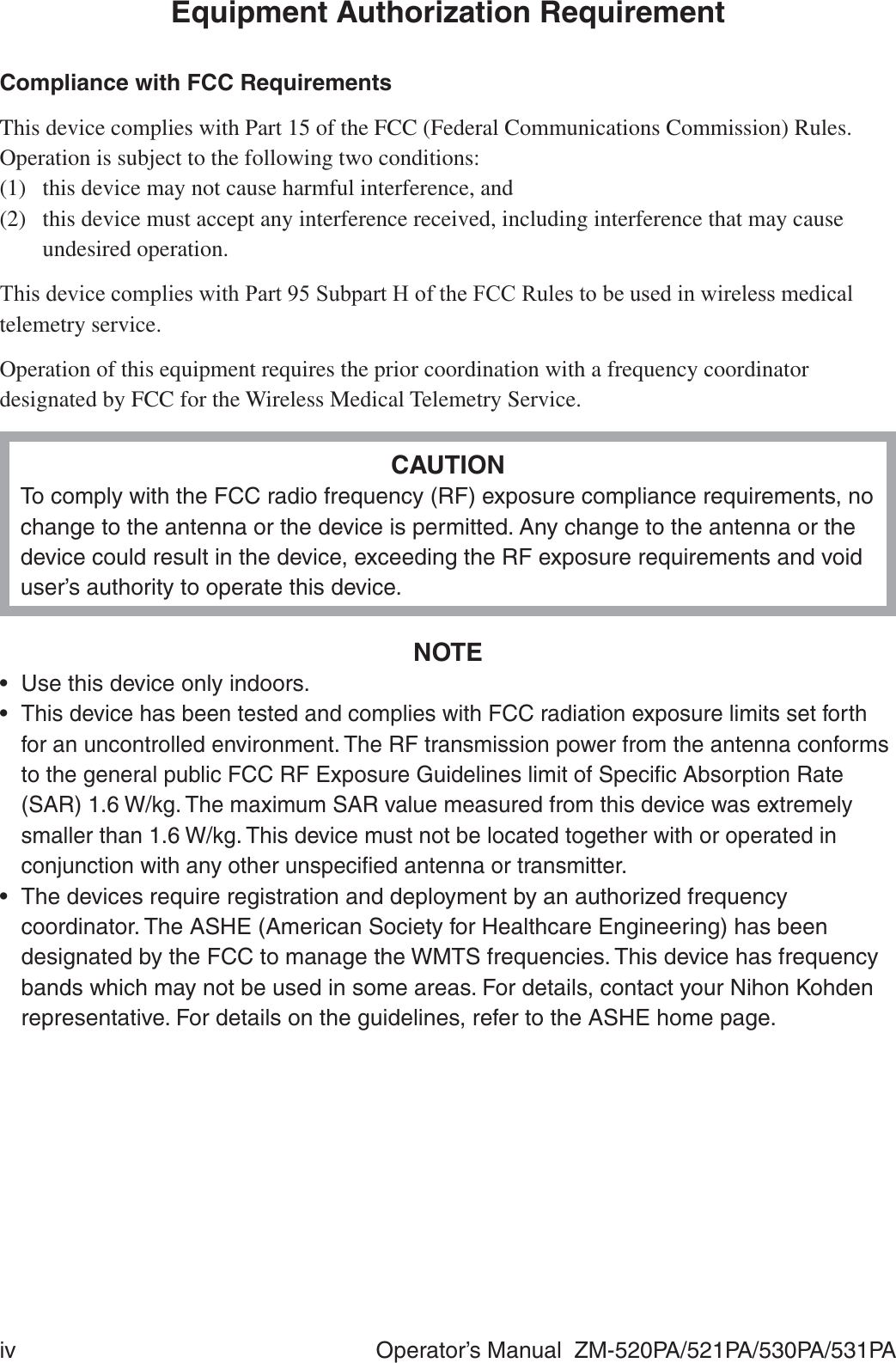
![Operator’s Manual ZM-520PA/521PA/530PA/531PA iiiWARRANTY POLICYNihon Kohden Corporation (NKC) shall warrant its products against all defects in materials and ZRUNPDQVKLSIRURQH\HDUIURPWKHGDWHRIGHOLYHU\+RZHYHUFRQVXPDEOHPDWHULDOVVXFKDVUHFRUGLQJSDSHULQNVW\OXVDQGEDWWHU\DUHH[FOXGHGIURPWKHZDUUDQW\NKC or its authorized agents will repair or replace any products which prove to be defective during the warranty period, provided these products are used as prescribed by the operating instructions given in the operator’s and service manuals.1RRWKHUSDUW\LVDXWKRUL]HGWRPDNHDQ\ZDUUDQW\RUDVVXPHOLDELOLW\IRU1.&¶VSURGXFWVNKC will not recognize any other warranty, either implied or in writing. In addition, service, WHFKQLFDOPRGL¿FDWLRQRUDQ\RWKHUSURGXFWFKDQJHSHUIRUPHGE\VRPHRQHRWKHUWKDQ1.&RULWVauthorized agents without prior consent of NKC may be cause for voiding this warranty.Defective products or parts must be returned to NKC or its authorized agents, along with an H[SODQDWLRQRIWKHIDLOXUH6KLSSLQJFRVWVPXVWEHSUHSDLG7KLVZDUUDQW\GRHVQRWDSSO\WRSURGXFWVWKDWKDYHEHHQPRGL¿HGGLVDVVHPEOHGUHLQVWDOOHGRUrepaired without Nihon Kohden approval or which have been subjected to neglect or accident, GDPDJHGXHWRDFFLGHQW¿UHOLJKWQLQJYDQGDOLVPZDWHURURWKHUFDVXDOW\LPSURSHULQVWDOODWLRQRUDSSOLFDWLRQRURQZKLFKWKHRULJLQDOLGHQWL¿FDWLRQPDUNVKDYHEHHQUHPRYHGIn the USA and Canada other warranty policies may apply.CAUTIONUnited States law restricts this product to sale by or on the order of a physician.](https://usermanual.wiki/Nihon-Kohden/ZM-530PAA/User-Guide-2812665-Page-9.png)
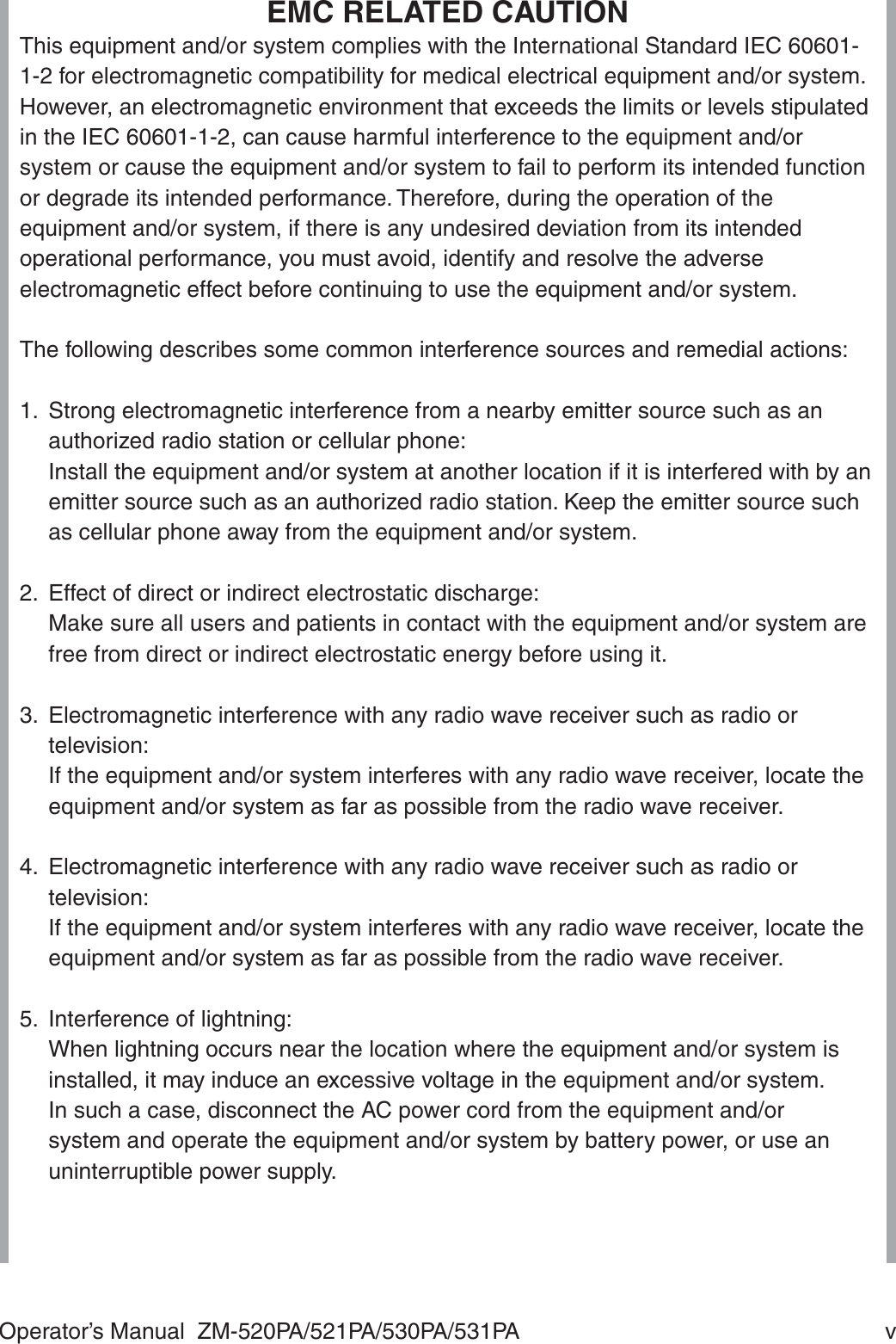
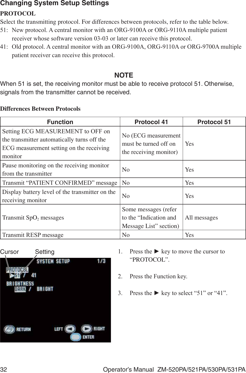
![viii Operator’s Manual ZM-520PA/521PA/530PA/531PAExplanations of the Symbols in this Manual and InstrumentThe following symbols found in this manual/instrument bear the respective descriptions as given.On PanelSymbol Description Symbol DescriptionChange screen 'H¿EULOODWLRQSURRIW\SH%)applied partAttention, consult operator’s manual'H¿EULOODWLRQSURRIW\SH&)applied partMoves cursor, scrolls data Serial numberDirection for attaching battery cover Date of manufactureDirection for inserting battery RF transmitter1RQLRQL]LQJUDGLDWLRQDirect current F&6$XVPDUN&DOONH\On LCDSymbol Description Symbol DescriptionBatteries are fully charged Batteries are almost emptyReplace batteryBatteries are getting low Alarm suspendedBatteries are low 456SXOVHV\QFPDUN](https://usermanual.wiki/Nihon-Kohden/ZM-530PAA/User-Guide-2812665-Page-14.png)
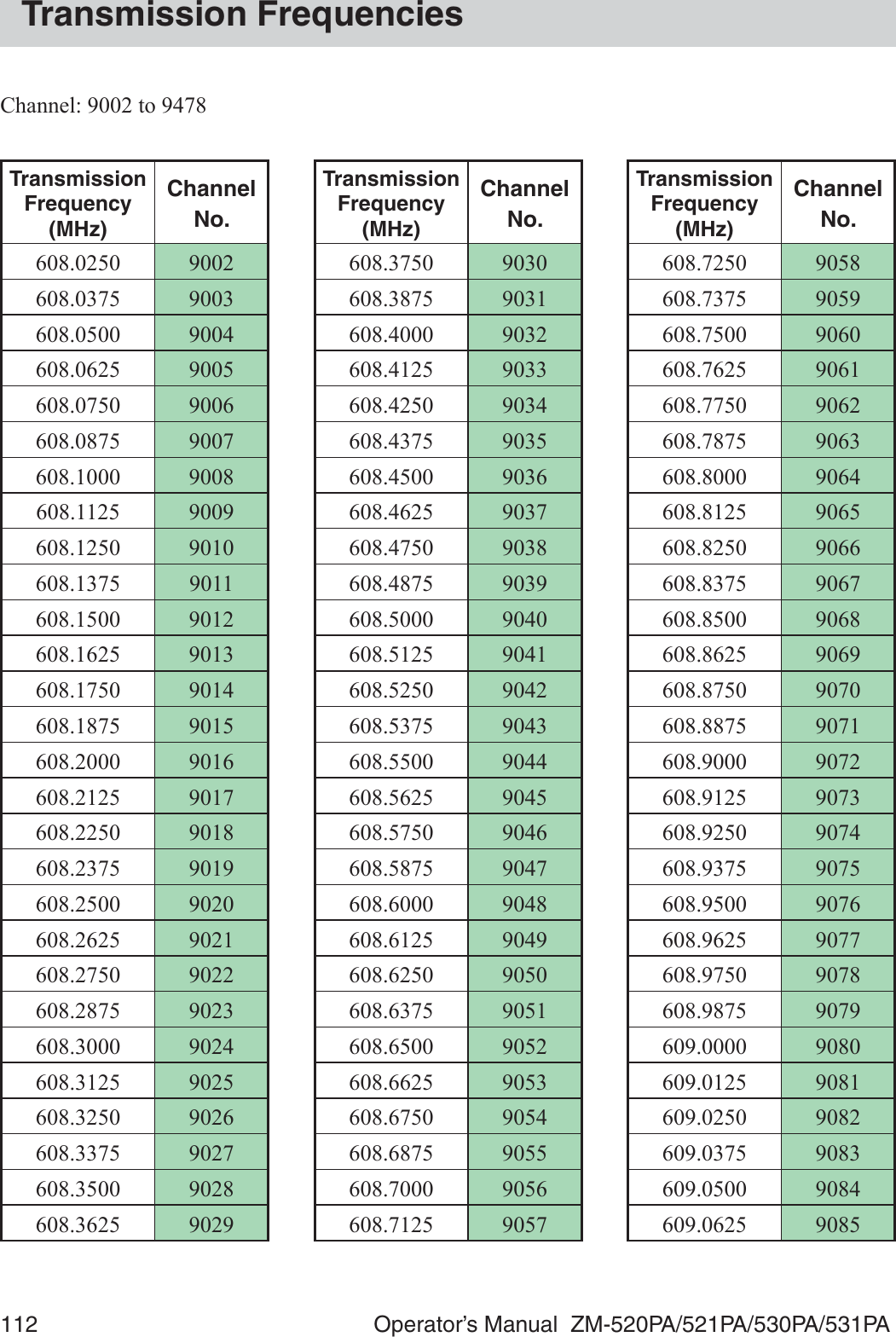
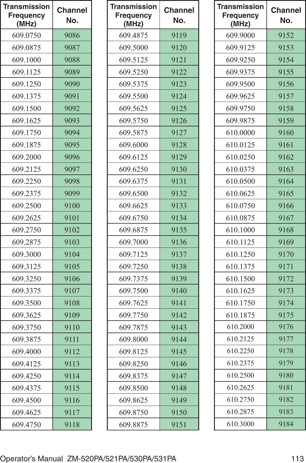
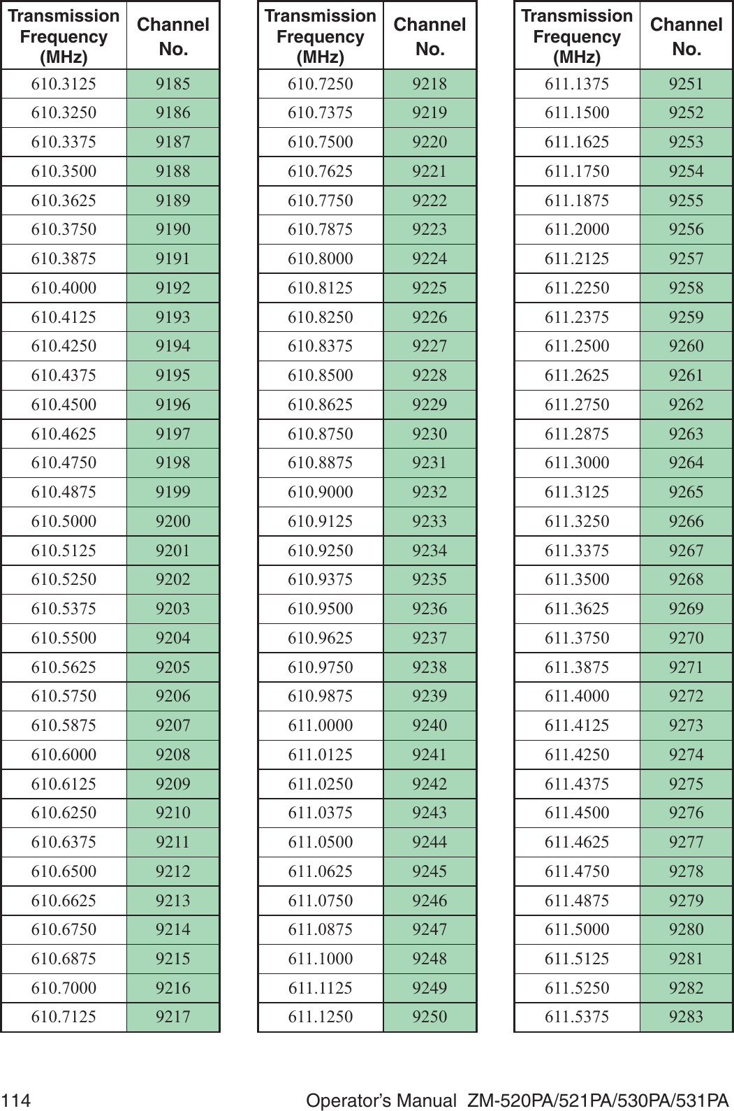
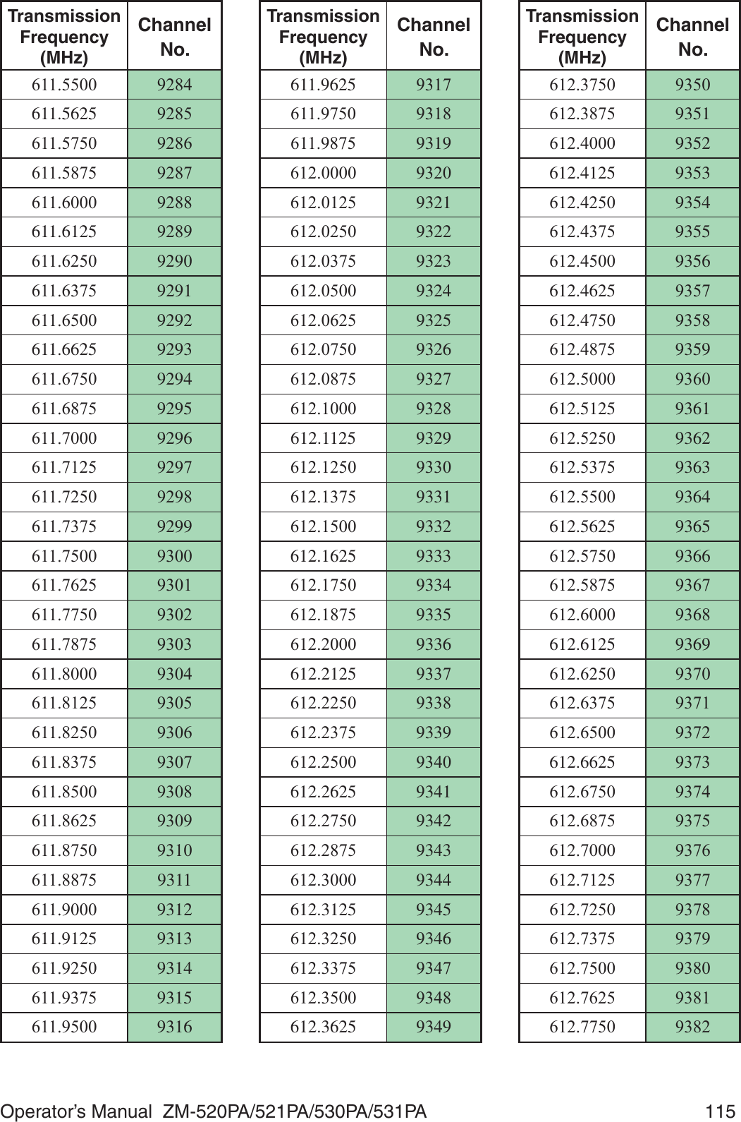
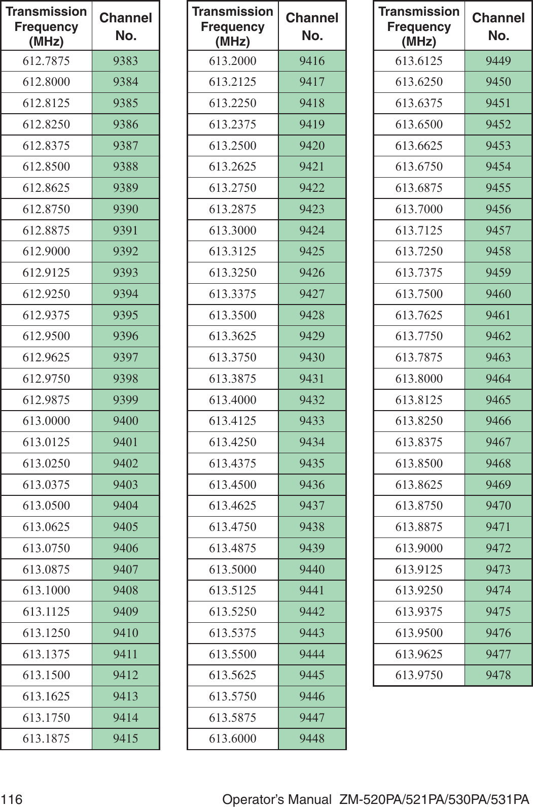
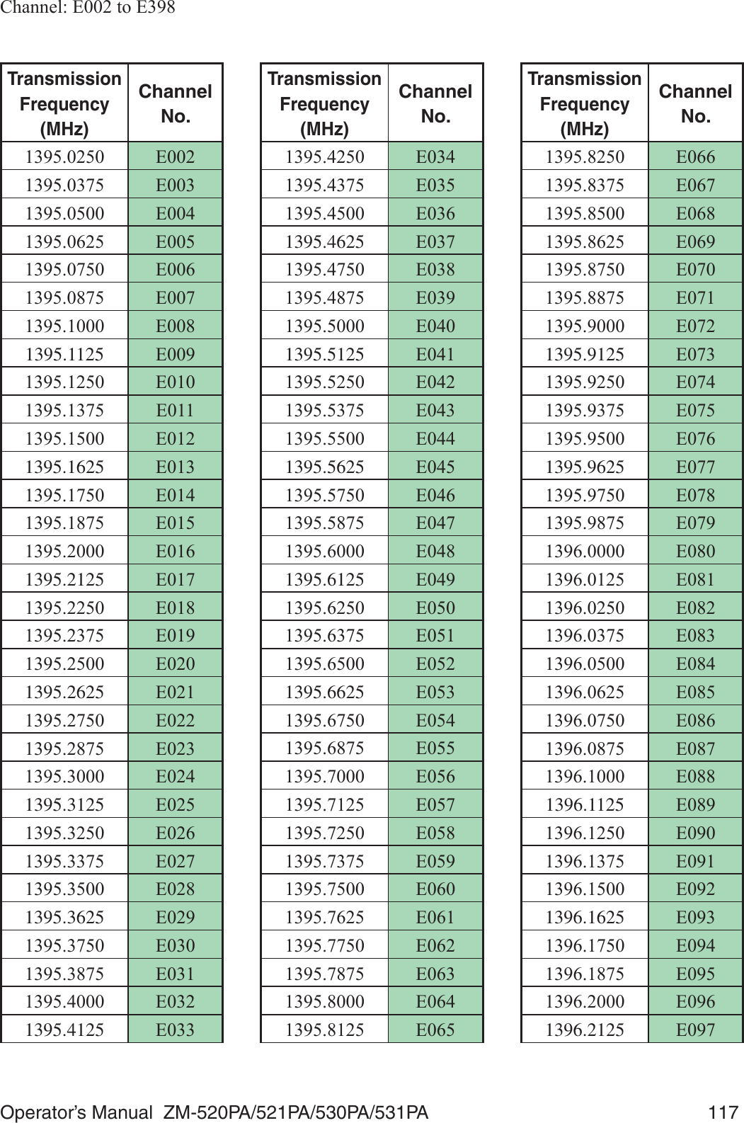
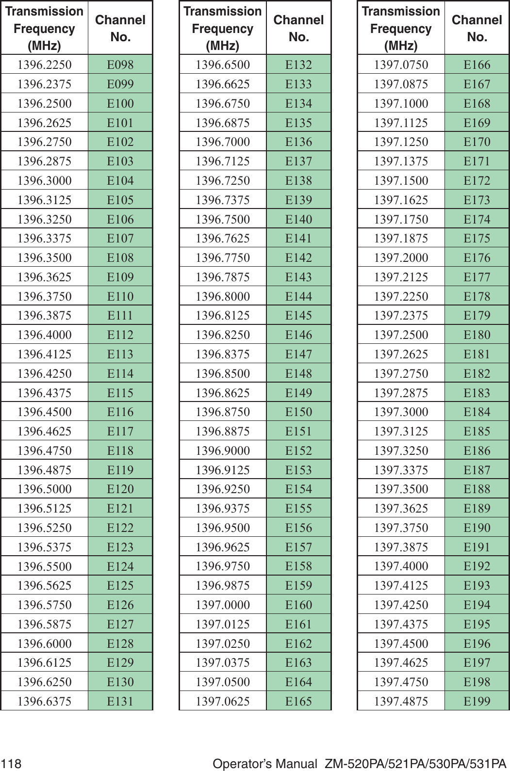
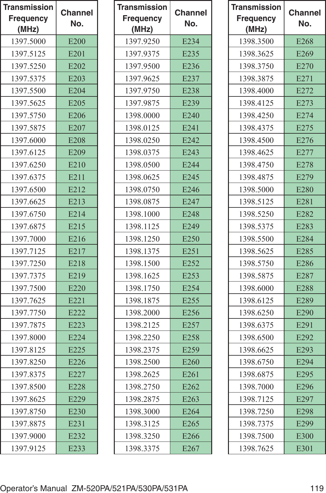
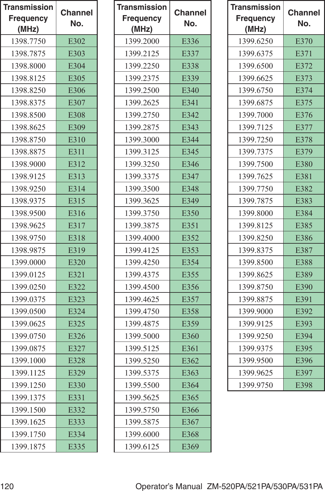
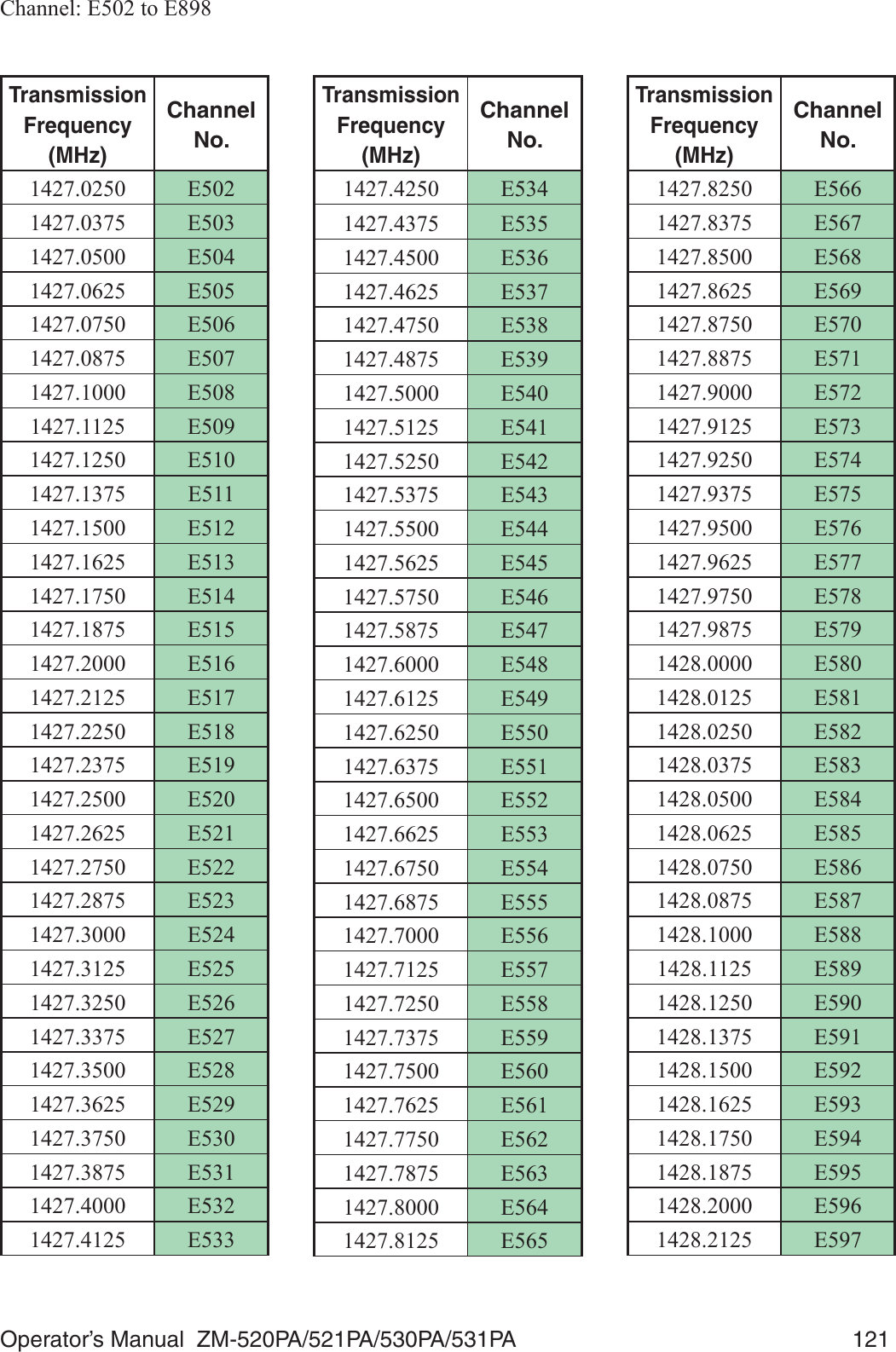
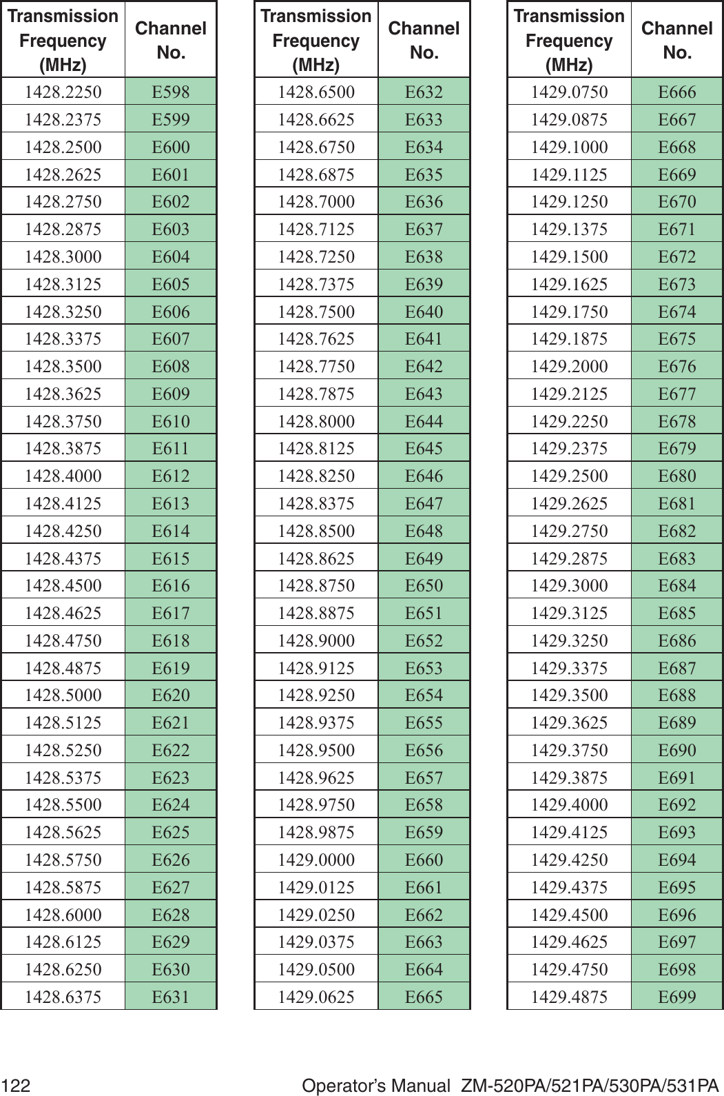
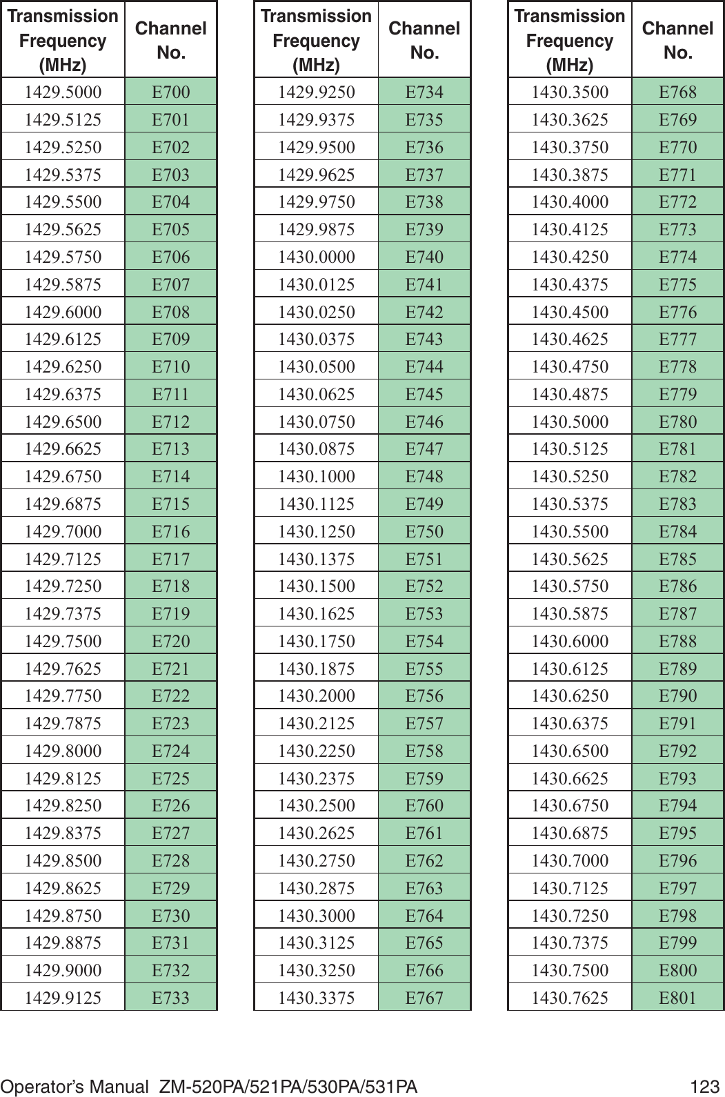
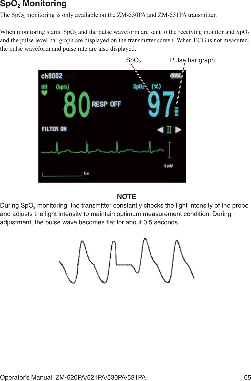
![Operator’s Manual ZM-520PA/521PA/530PA/531PA 1Intended UseGeneral7KH=03$DQG=03$WUDQVPLWWHUVWUDQVPLW(&*DQGUHVSLUDWLRQIURPDSDWLHQWWRD1LKRQ.RKGHQPRQLWRUIRUFRQWLQXRXVPRQLWRULQJ7KHIURQW/&'GLVSOD\V(&*QXPHULFYDOXHVof monitoring parameters, messages and battery condition.* They also display the compressed ZDYHIRUPDQGQXPHULFGDWDRIWKHODWHVWPLQXWHV7KH=03$DQG=03$WUDQVPLWWHUVWUDQVPLW(&*UHVSLUDWLRQDQGSXOVHZDYHIRUPVand SpO2 from a patient to a Nihon Kohden monitor for continuous monitoring. The front LCD GLVSOD\V(&*RUSXOVHZDYHQXPHULFYDOXHVRIPRQLWRULQJSDUDPHWHUVPHVVDJHVDQGEDWWHU\condition.7KH\DOVRGLVSOD\WKHFRPSUHVVHGZDYHIRUPDQGQXPHULFGDWDRIWKHODWHVWPLQXWHV (VVHQWLDOSHUIRUPDQFHRIWKLVWUDQVPLWWHU7KHGLIIHUHQFHEHWZHHQ=03$3$DQG=03$3$LVWKHWUDQVPLVVLRQIUHTXHQF\range.=03$3$ WR0+]FKDQQHOQXPEHUWR=03$3$ WR0+]FKDQQHOQXPEHU(WR( WR0+]FKDQQHOQXPEHU(WR(NOTE• The transmitter channel can be changed with a QI-901PK channel writer.• Read the operator’s manual for the receiving monitor together with this manual before use.WARNINGDo not diagnose a patient based only on data acquired by the transmitter. Overall judgement must be performed by a physician who understands the features, limitations and characteristics of the transmitter and by reading the biomedical signals acquired by other instruments.WARNINGDo not use the same transmitter for more than one patient at the same time. Do not connect different sensors from different patients to the same transmitter.](https://usermanual.wiki/Nihon-Kohden/ZM-530PAA/User-Guide-2812665-Page-15.png)
![Operator’s Manual ZM-520PA/521PA/530PA/531PA 23Batteries• The battery polarity is correct. 7KHEDWWHU\FDVHVSULQJLV¿UPO\DWWDFKHGDQGWKHEDWWHU\LVQRWORRVH 7KHEDWWHU\FDVHFRYHULV¿UPO\FORVHGChannel Setting• The transmitter channel matches the receiving monitor channel.• There is no nearby transmitter with the same channel.Other :KHQSHUIRUPLQJGH¿EULOODWLRQVHWWKHKXP¿OWHUWR21RQWKHUHFHLYLQJPRQLWRU7KHZDYHIRUPUHFRYHU\PD\EHFRPHVORZGXHWRHOHFWURGHSRODUL]DWLRQZKHQWKHKXP¿OWHULVVHWWROFF.Check Items After Power On$IWHUWXUQLQJRQWKHSRZHUFKHFNWKHIROORZLQJPower On• The transmitter generates a one second “peep” sound and the startup screen appears. 7KHWUDQVPLWWHUGLVSOD\VWKHFKHFNHOHFWURGHVVFUHHQ• The transmitter is not too hot. 7KHWUDQVPLWWHUGRHVQRWGLVSOD\WKH³%$77(5<:($.´PHVVDJH• The transmitter does not interfere with the operation of other medical instruments.Daily Check• The “signal loss” message is not displayed on the receiving monitor when the transmitter is inside the receiving range of the monitor.• The battery replacement message is not displayed on the monitor. 7KHNH\VRQWKHWUDQVPLWWHUIXQFWLRQSURSHUO\ 7KH/&'EULJKWQHVVLVDSSURSULDWH7RDGMXVWEULJKWQHVVUHIHUWRWKH³&KDQJLQJ6<67(06(7836HWWLQJV´VHFWLRQCheck Items After Use7RXVHWKHWUDQVPLWWHULQVDIHDQGRSWLPXPFRQGLWLRQIRUQH[WWLPHFKHFNWKHIROORZLQJBefore Turning Power Off 7HPSRUDULO\FKDQJHGVHWWLQJVDUHFKDQJHGEDFNWRWKHSUHYLRXVVHWWLQJV• There was no malfunction on the transmitter.Storage (&*HOHFWURGHOHDGVDQG6S22 probe are cleaned and disinfected.• If the transmitter got wet, liquid is wiped off and the transmitter is thoroughly dried.• There are enough consumables, such as disposable electrodes.• The transmitter power is turned off by removing batteries from the transmitter.• Dead batteries are disposed of properly.](https://usermanual.wiki/Nihon-Kohden/ZM-530PAA/User-Guide-2812665-Page-37.png)
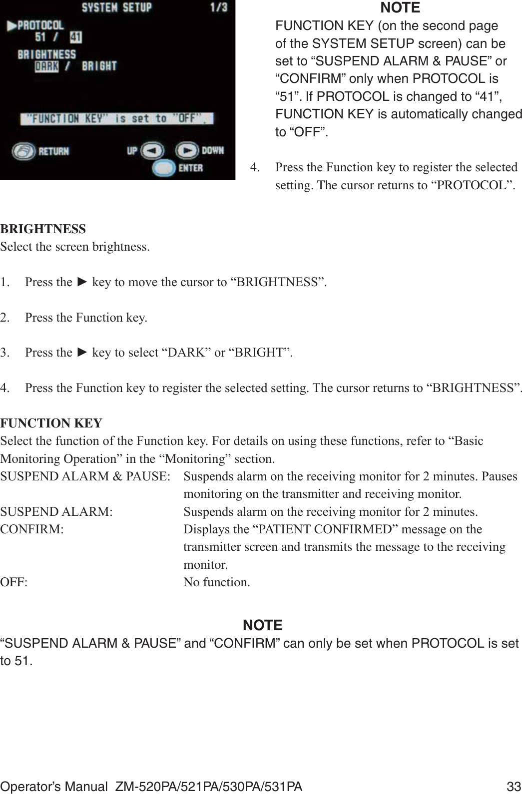
![Operator’s Manual ZM-520PA/521PA/530PA/531PA 35 3UHVVWKH)XQFWLRQNH\WRUHJLVWHUWKHVHOHFWHGVHWWLQJ7KHFXUVRUUHWXUQVWR³6(/(&7$%/(6&5((17,0(2873(5,2'PLQ´Initializing SettingsDo the following procedure to initialize all settings, except for channel, to the factory default settings.1. Turn off the transmitter by removing a battery. :KLOHSUHVVLQJWKH)XQFWLRQNH\WXUQRQthe transmitter by inserting the battery. The 0(18VFUHHQDSSHDUV 3UHVVWKHŹNH\WRPRYHWKHFXUVRUWR³6<67(0,1,7,$/,=(´ 3UHVVWKH)XQFWLRQNH\WRHQWHUWKH6<67(0,1,7,$/,=(VFUHHQ 3UHVVWKH)XQFWLRQNH\$FRQ¿UPDWLRQmessage appears. 7RUHWXUQWRWKH0(18VFUHHQSUHVVWKH6FUHHQNH\ 3UHVVWKH)XQFWLRQNH\WRLQLWLDOL]HVHWWLQJV 7RFDQFHOLQLWLDOL]LQJSUHVVWKHŹNH\7KHVFUHHQUHWXUQVWRWKH0(18VFUHHQCursor](https://usermanual.wiki/Nihon-Kohden/ZM-530PAA/User-Guide-2812665-Page-49.png)
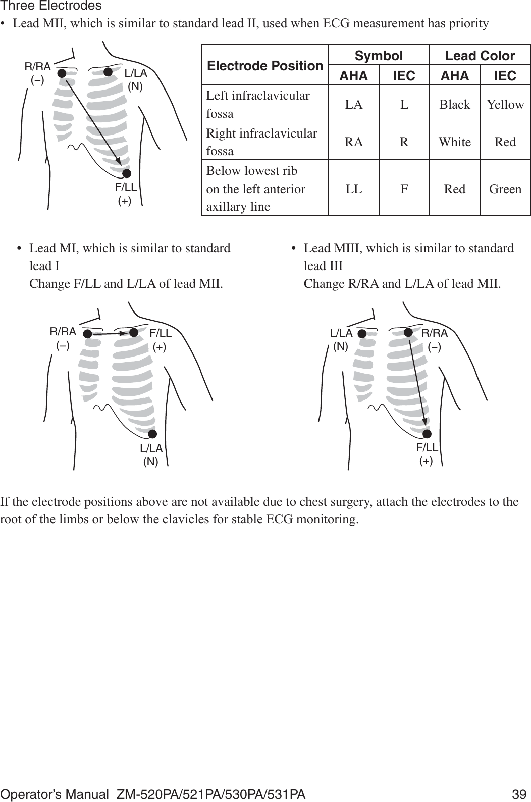
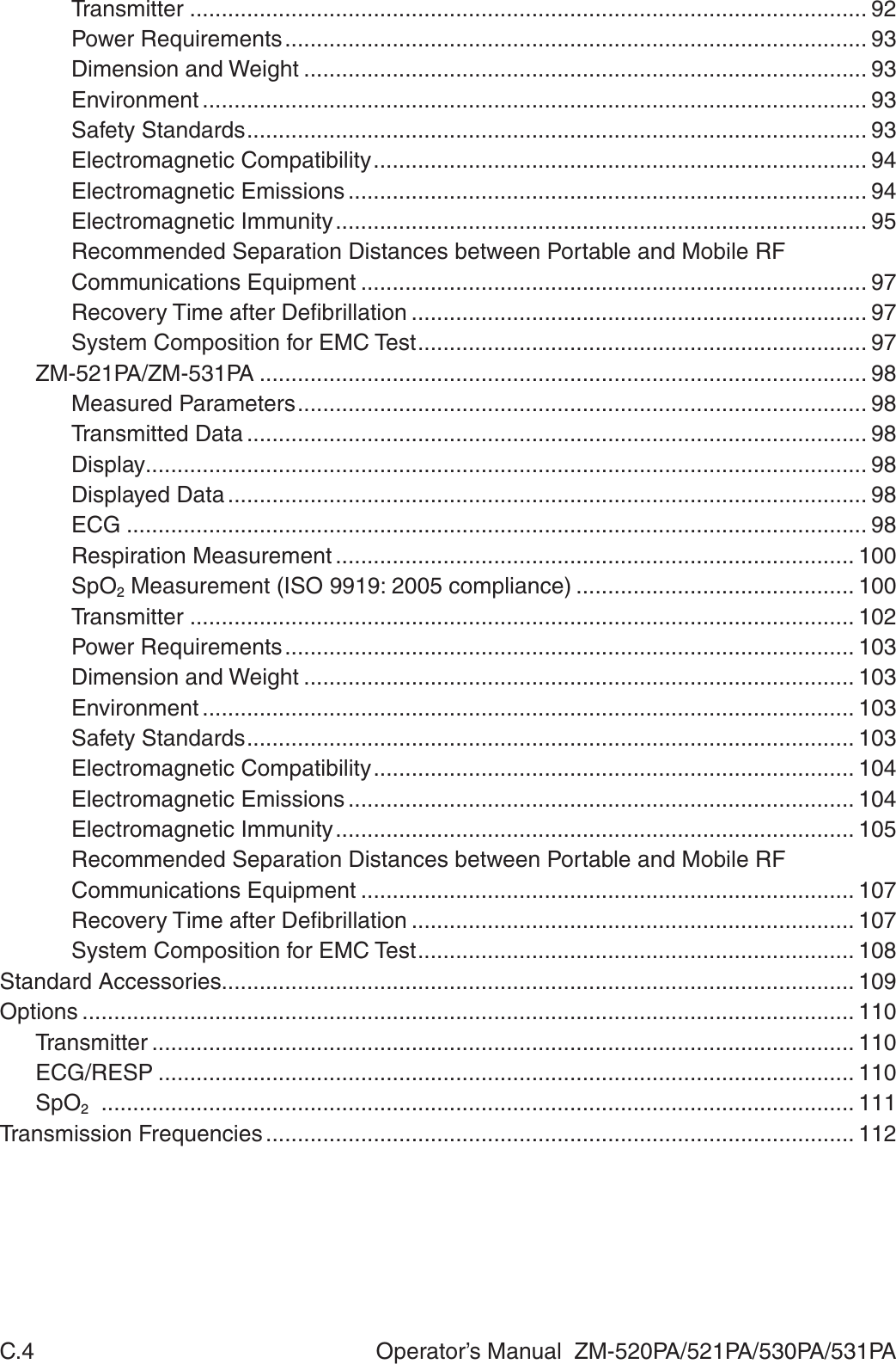
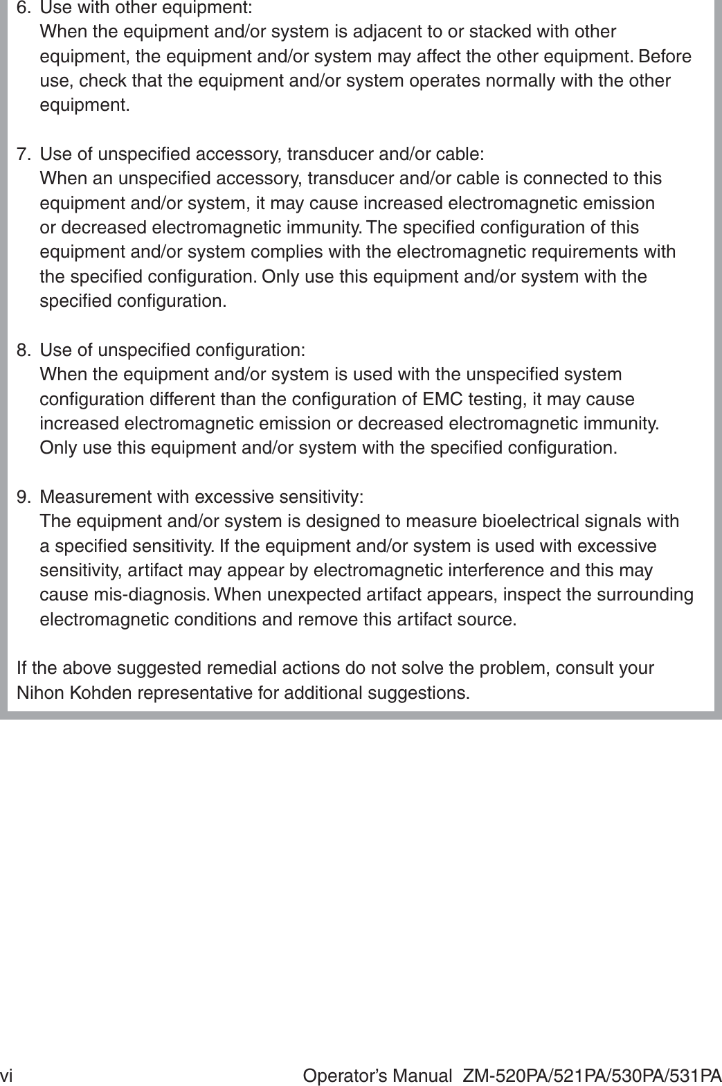
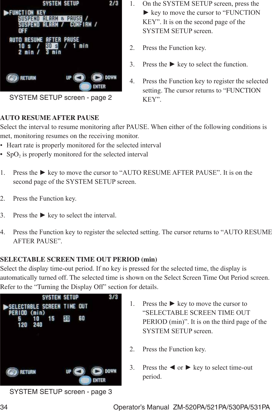
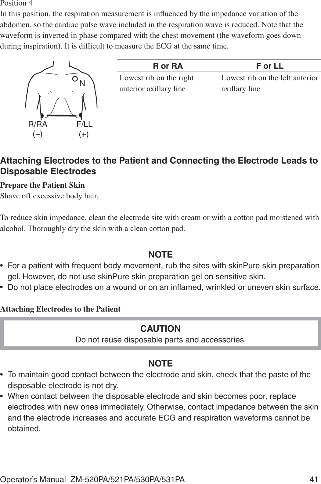
![40 Operator’s Manual ZM-520PA/521PA/530PA/531PAElectrode Positions for Respiration MonitoringPlace the R/RA and F/LL electrodes so that the lungs are between the electrodes.Position 1In this position, respiration measurement is available; however, there is a difference in amplitude between different patients.R or RA F or LLRight infraclavicular fossa Fifth intercostal space on the OHIWPLGFODYLFXODUOLQH9Position 2,QWKLVSRVLWLRQWKHZDYHIRUPDPSOLWXGHLVXVXDOO\ODUJHDQGWKH(&*OHDGLVVLPLODUWR/HDG0,,This position can be generally recommended.R or RA F or LLRight infraclavicular fossa Fifth intercostal space on the OHIWPLGD[LOODU\OLQH9Position 3,QWKLVSRVLWLRQWKHUHVSLUDWLRQZDYHIRUPLVRSWLPXPEXWWKH(&*OHDGLVXQXVXDOR or RA F or LLRight midaxillary at the KRUL]RQWDOOHYHORI9Fifth intercostal space on the OHIWPLGD[LOODU\OLQH9R/RA (−)F/LL (+)NR/RA (−)F/LL (+)NNR/RA (−)F/LL (+)](https://usermanual.wiki/Nihon-Kohden/ZM-530PAA/User-Guide-2812665-Page-54.png)

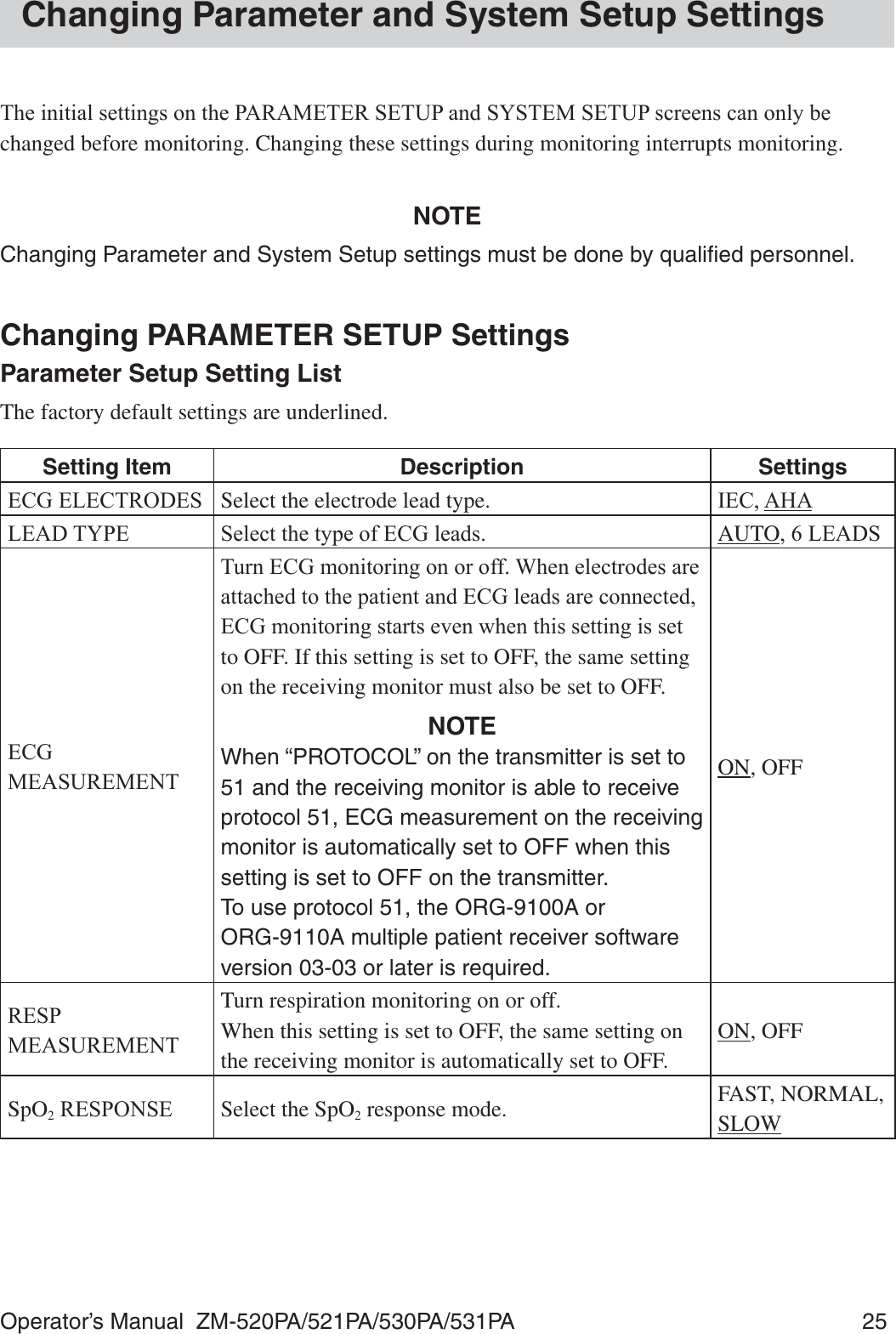
![64 Operator’s Manual ZM-520PA/521PA/530PA/531PATurning ECG Measurement On/Off(&*PHDVXUHPHQWFDQEHWXUQHGRQRURIIRQWKH3$5$0(7(56(783VFUHHQ:KHQHOHFWURGHVDUHDWWDFKHGWRWKHSDWLHQWDQG(&*OHDGVDUHFRQQHFWHG(&*PRQLWRULQJVWDUWVHYHQZKHQ(&*LVturned off.When PROTOCOL on the SYSTEM SETUP screen is set to 51:(&*PHDVXUHPHQWRQWKHUHFHLYLQJPRQLWRULVDXWRPDWLFDOO\VHWWRRIINOTEECG measurement on the transmitter cannot be turned on or off from the receiving monitor.When PROTOCOL on the SYSTEM SETUP screen is set to 41:,I(&*PHDVXUHPHQWLVWXUQHGRIIRQWKHWUDQVPLWWHU(&*PHDVXUHPHQWRQWKHUHFHLYLQJPRQLWRUmust also be turned off.Turning Respiration Measurement On/Off5HVSLUDWLRQPHDVXUHPHQWFDQEHWXUQHGRQRURIIRQWKH3$5$0(7(56(783VFUHHQ,Irespiration measurement is turned off, respiration measurement on the receiving monitor is also turned off.Electrode Detachment,QWKHIROORZLQJFRQGLWLRQVWKH³&+(&.(/(&752'(6´PHVVDJHLVGLVSOD\HGRQWKHWUDQVPLWWHUand receiving monitor. (OHFWURGHLVGHWDFKHGIURPVNLQ (OHFWURGHOHDGLVGLVFRQQHFWHGIURPWKHHOHFWURGH 3RODUL]DWLRQYROWDJHEHWZHHQWKHHOHFWURGHDQGVNLQLVH[FHVVLYHO\KLJK,QWKHVHFDVHVFKHFNWKHFDXVHDQGLIQHFHVVDU\UHSODFHHOHFWURGHVZLWKQHZRQHVCAUTIONWhen the “CHECK ELECTRODES” message is displayed on the receiving monitor, ECG is not monitored properly and the ECG alarm does not function. Check the electrode, electrode leads, and if necessary, replace with new ones.](https://usermanual.wiki/Nihon-Kohden/ZM-530PAA/User-Guide-2812665-Page-78.png)
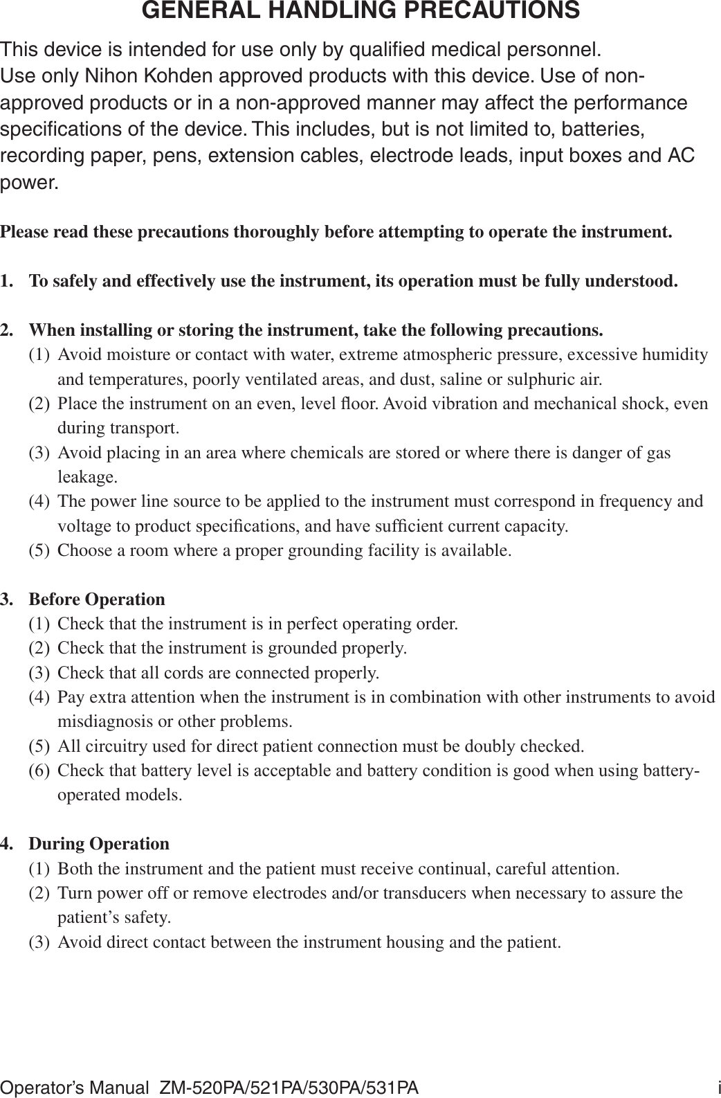
![84 Operator’s Manual ZM-520PA/521PA/530PA/531PAMaintenance Check Sheet+RVSLWDO2UJDQL]DWLRQ Service Personnel: Instrument Name: TransmitterInstrument Model: =03$=03$=03$=03$Instrument Serial Number: +DUGZDUH5HYLVLRQ1XPEHU Software Revision Number: ([WHUQDO&KHFN 3DVV )DLO2. Transmitter Channel Pass Fail3. Transmitting/Receiving Signal Pass Fail4. Display Pass Fail5. Key Operation Pass Fail (&*&KHFN 3DVV )DLO 5HVSLUDWLRQ&KHFN 3DVV )DLO 6S22&KHFN 3DVV )DLOOverall JudgementƑ2.Ƒ&DQEHXVHGEXWQHHGVPDLQWHQDQFHƑ0DLQWHQDQFHUHTXLUHG&DQQRWEHXVHG](https://usermanual.wiki/Nihon-Kohden/ZM-530PAA/User-Guide-2812665-Page-98.png)
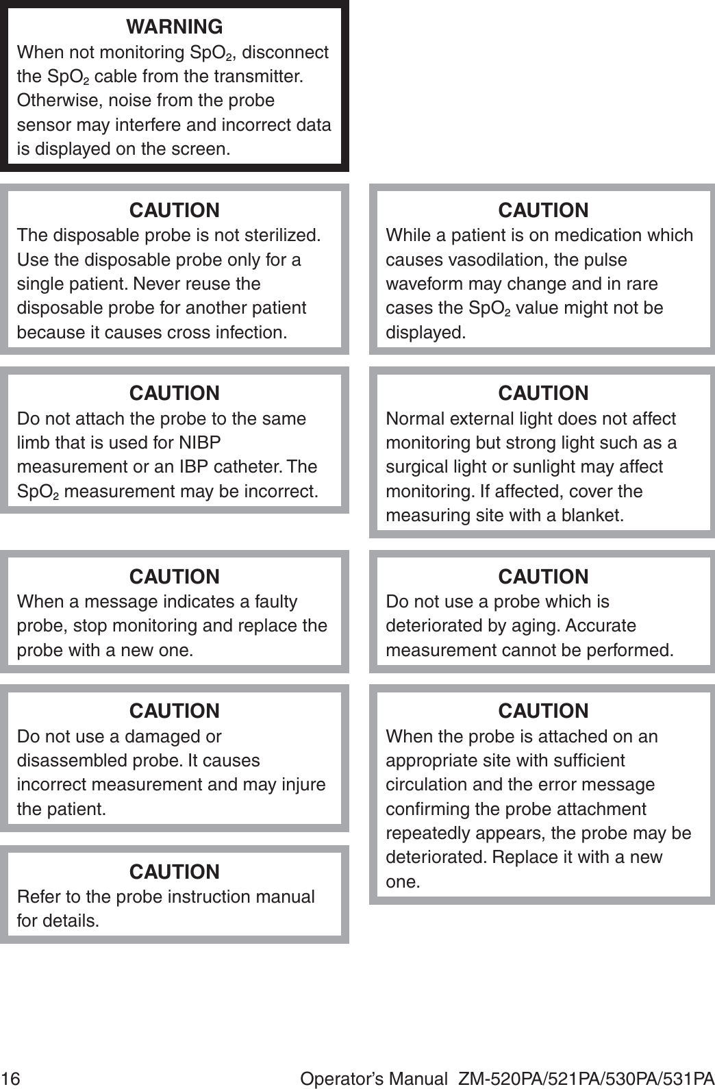
![86 Operator’s Manual ZM-520PA/521PA/530PA/531PACleaning, Disinfection and SterilizationTransmitter and Electrode LeadsCAUTIONThis transmitter is not waterproof. If detergent or liquid spills into the transmitter, stop cleaning or disinfecting it and contact your Nihon Kohden representative. The transmitter needs to be checked for safety and function before use.NOTEThe transmitter cannot be sterilized. Sterilizing the transmitter may damage it.Before cleaning or disinfecting, remove the batteries from the transmitter. Be careful not to let any liquid get inside the transmitter.CleaningWipe the transmitter and electrode leads with a soft cloth moistened with ethanol for disinfection WRE\YRORUQHXWUDOGHWHUJHQWGLOXWHGZLWKZDWHU$IWHUFOHDQLQJGU\WKHPcompletely.Use cotton swab moistened with neutral detergent diluted with water to clean inside the battery compartment. DisinfectionCAUTIONDo not immerse the electrode lead connector in liquid.:LSHWKHRXWVLGHVXUIDFHRIWKHWUDQVPLWWHUDQGHOHFWURGHOHDGZLWKDQRQDEUDVLYHFORWKPRLVWHQHGwith any of the disinfectants listed below. For details on the disinfectants, refer to the instruction provided with the disinfectants. Use the recommended concentration. Disinfectant &RQFHQWUDWLRQ*OXWDUDOGHK\GHVROXWLRQ $ON\OGLDPLQRHWK\OJO\FLQHK\GURFKORULGH %HQ]DONRQLXPFKORULGH %HQ]HWKRQLXPFKORULGHVROXWLRQ &KORUKH[LGLQHJOXFRQDWHVROXWLRQ 3KWKDUDO Phenol 1.56](https://usermanual.wiki/Nihon-Kohden/ZM-530PAA/User-Guide-2812665-Page-100.png)
![Operator’s Manual ZM-520PA/521PA/530PA/531PA 87SpO2 ProbeRefer to the probe manual.Periodic Replacement ScheduleTo maintain the performance of the instrument, the following part must be periodically replaced.Name Code No. Expected Life SpanSilicon seal (for battery case cover) 1 yearRepair Parts Availability Policy1LKRQ.RKGHQ&RUSRUDWLRQ1.&VKDOOVWRFNUHSDLUSDUWVSDUWVQHFHVVDU\WRPDLQWDLQWKHSHUIRUPDQFHRIWKHLQVWUXPHQWIRUDSHULRGRI\HDUVIURPWKHGDWHRIGHOLYHU\,QWKDWSHULRG1.&RULWVDXWKRUL]HGDJHQWVZLOOUHSDLUWKHLQVWUXPHQW7KLVSHULRGPD\EHVKRUWHUWKDQ\HDUVLIa board or part necessary for the faulty section is not available.](https://usermanual.wiki/Nihon-Kohden/ZM-530PAA/User-Guide-2812665-Page-101.png)
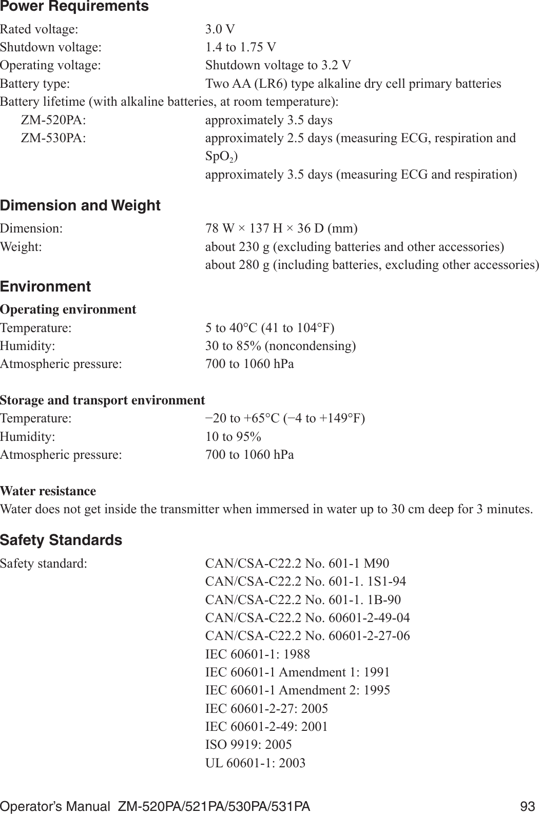
![Operator’s Manual ZM-520PA/521PA/530PA/531PA 89Common mode rejection ratio: 95 dB or more ,(&FRPSOLHG3DFLQJSXOVHGHWHFWLRQ DPSOLWXGHWRP9GXUDWLRQWRPV ,(&FRPSOLHG %DVHGXSRQSDFHPDNHUSXOVHUHMHFWLRQFDSDELOLW\'H¿EULOODWLRQSURRI (&*LQSXWSURWHFWHGDJDLQVW:V'&N9 ,(&FRPSOLHG(&*UHFRYHU\WLPHDIWHUGH¿EULOODWLRQ ZLWKLQV(OHFWURGHFRQGLWLRQ 'LVSOD\V&+(&.(/(&752'(6PHVVDJH7DOO7ZDYHUHMHFWLRQFDSDELOLW\ &RPSOLHVZLWKWKHKHLJKWVRI7ZDYHVIURPWRP9 ,(&FRPSOLHG+HDUWUDWHDYHUDJLQJ &DOFXODWHGE\XVLQJWKHPRVWUHFHQWEHDWV+HDUWUDWHPHWHUDFFXUDF\DQGUHVSRQVHWRLUUHJXODUUK\WKP 9HQWULFXODUELJHPLQ\7HVWZDYHIRUPQDPHDDPLD ESP Slow alternating ventricular bigeminy (Test waveform name: DDPLEESP Rapid alternating ventricular bigeminy (Test waveform QDPHDDPLFESP Bidirectional systoles (Test waveform name: aami3d*): ESP * The test waveforms can be download at http://www. physionet.orgResponse time of heart rate meter to change in heart rate: +5FKDQJHIURPWRESPWRVHFRQGV +5FKDQJHIURPWRESPWRVHFRQGV3DFHPDNHUSXOVHUHMHFWLRQFDSDELOLW\ZLWKRXWRYHUVKRRW &RPSOLHVZLWKWKHDPSOLWXGHVRISDFHPDNHUSXOVHVWRP9DQGZLGWKVWRPVVSHFL¿HGLQ,(&3DFHPDNHUSXOVHUHMHFWLRQFDSDELOLW\ZLWKRYHUVKRRW 2YHUVKRRWDPSOLWXGHVDQGWLPHFRQVWDQWVRIP9PVWRP9PV$VGH¿QHGE\PHWKRG%RI,(&WKLVFRUUHVSRQGVWRWKHSDFHPDNHUSXOVHVDPSOLWXGHVDQGZLGWKVRIP9PVWRDPSOLWXGHVP9PVECG Display and Heart Rate Count)UHTXHQF\FKDUDFWHULVWLF ¿OWHURQWR+]¿OWHURIIWR+]+HDUWUDWHGHWHFWLRQPHWKRG $YHUDJH456GHWHFWLRQ WRPVDPSOLWXGHP9UDWHWREHDWVPLQ WRPVDPSOLWXGHP9UDWHWREHDWVPLQ](https://usermanual.wiki/Nihon-Kohden/ZM-530PAA/User-Guide-2812665-Page-103.png)
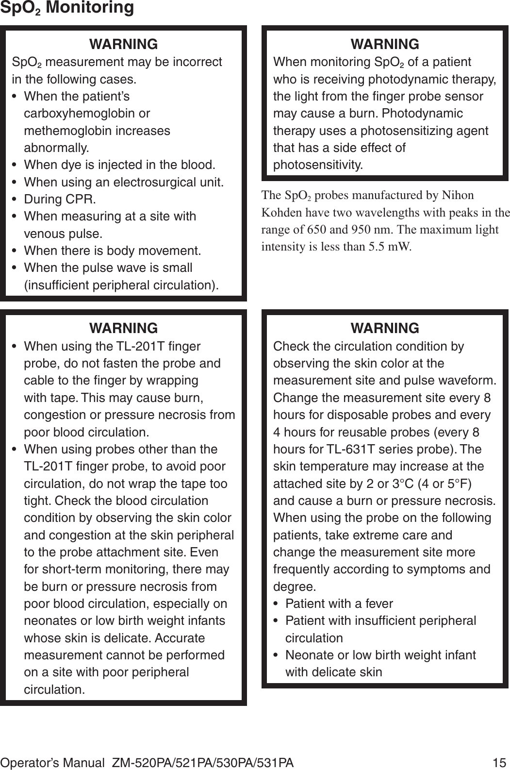
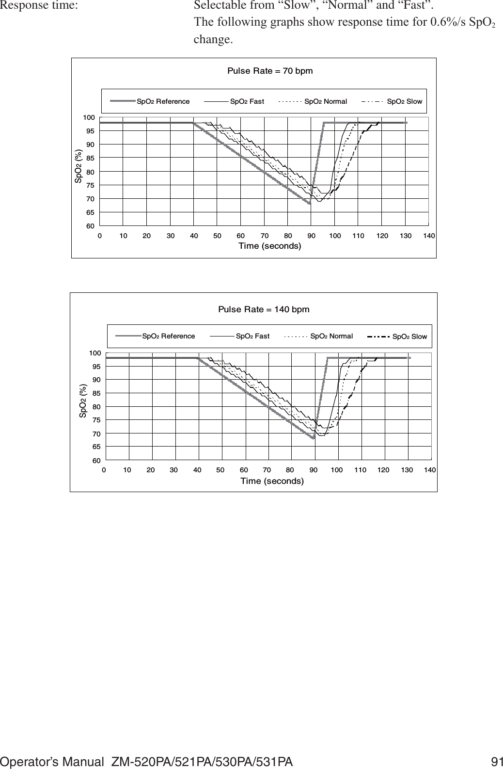
![90 Operator’s Manual ZM-520PA/521PA/530PA/531PA+HDUWUDWHFRXQWLQJUDQJH WREHDWVPLQ+HDUWUDWHFRXQWLQJDFFXUDF\ EHDWVPLQWREHDWVPLQ(VVHQWLDOSHUIRUPDQFHRIWKLVWUDQVPLWWHURespiration MeasurementMeasuring method: Impedance methodMeasuring lead: Between R and F,PSHGDQFHUDQJH WRȍ([FLWRUFXUUHQW WR$SSN+]5HVSLUDWLRQUDWHPHDVXULQJDFFXUDF\ FRXQWVPLQDWWRFRXQWVPLQ5HVSLUDWLRQUDWHFRXQWLQJUDQJH WRFRXQWVPLQ(VVHQWLDOSHUIRUPDQFHRIWKLVWUDQVPLWWHUSpO2 Measurement (ISO 9919: 2005 compliance)0HDVXULQJUDQJH WR6S22 'HFODUHGUDQJH WR6S220LQLPXPGLVSOD\UDQJH 6S22'LVSOD\XSGDWHF\FOH (YHU\VHFRQGV0HDVXULQJDFFXUDF\UPV $FFXUDF\DVVXUDQFHWHPSHUDWXUHWR&7RWDODFFXUDF\LQFOXGLQJSUREH 6S226S226S226S22 6S226S226S226S22 XQGHU6S22QRWVSHFL¿HG$FFXUDF\RIWKHWUDQVPLWWHU 6S226S226S226S22 6S226S226S226S22 XQGHU6S22QRWVSHFL¿HG3XOVHUDWHGHFODUHGUDQJH WRESP3XOVHUDWHGLVSOD\UDQJH WRESP3XOVHUDWHDFFXUDF\UPV ESP(VVHQWLDOSHUIRUPDQFHRIWKLVWUDQVPLWWHUNOTE• The SpO2 measuring accuracy was tested using the TL-201T, TL-260T, TL-271T and TL-631T SpO2 probes. The testing was performed during induced hypoxia on healthy volunteers (Ethnicity: 10 Caucasians, 2 Africans, 1 Asian and 3 Indians), (Skin: 8 light, 4 medium, 4 dark), (Age: 21 to 34), (5 women and 11 men) under the condition of no motion. Arterial blood was sampled and measured by a CO-oximeter. The difference between SpO2 measured by the SpO2 probe and functional SaO2 measured by a CO-oximeter was calculated using the root-mean-square (rms) method according to ISO 9919: 2005. This measurement accuracy figure represents 2/3 of all test measurements.• A pulse oximeter tester that generates simulated signals can be used to check the difference from the design specification, but it cannot be used as a replacement for human signals for testing accuracy.](https://usermanual.wiki/Nihon-Kohden/ZM-530PAA/User-Guide-2812665-Page-104.png)
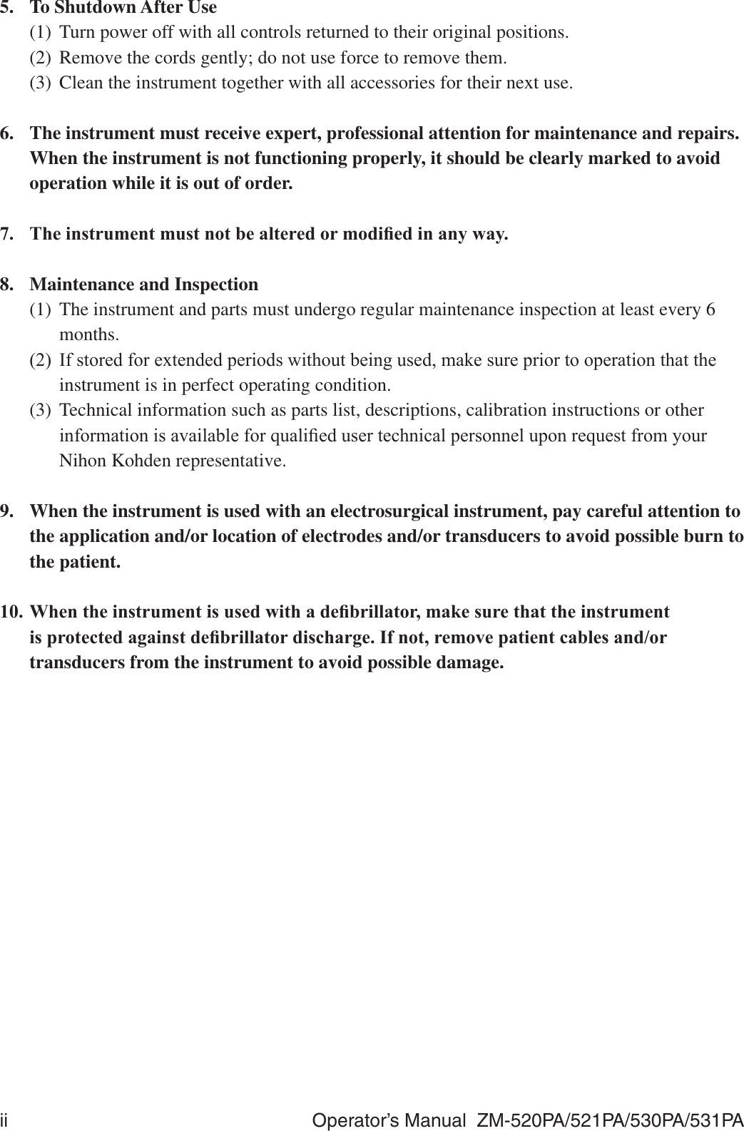
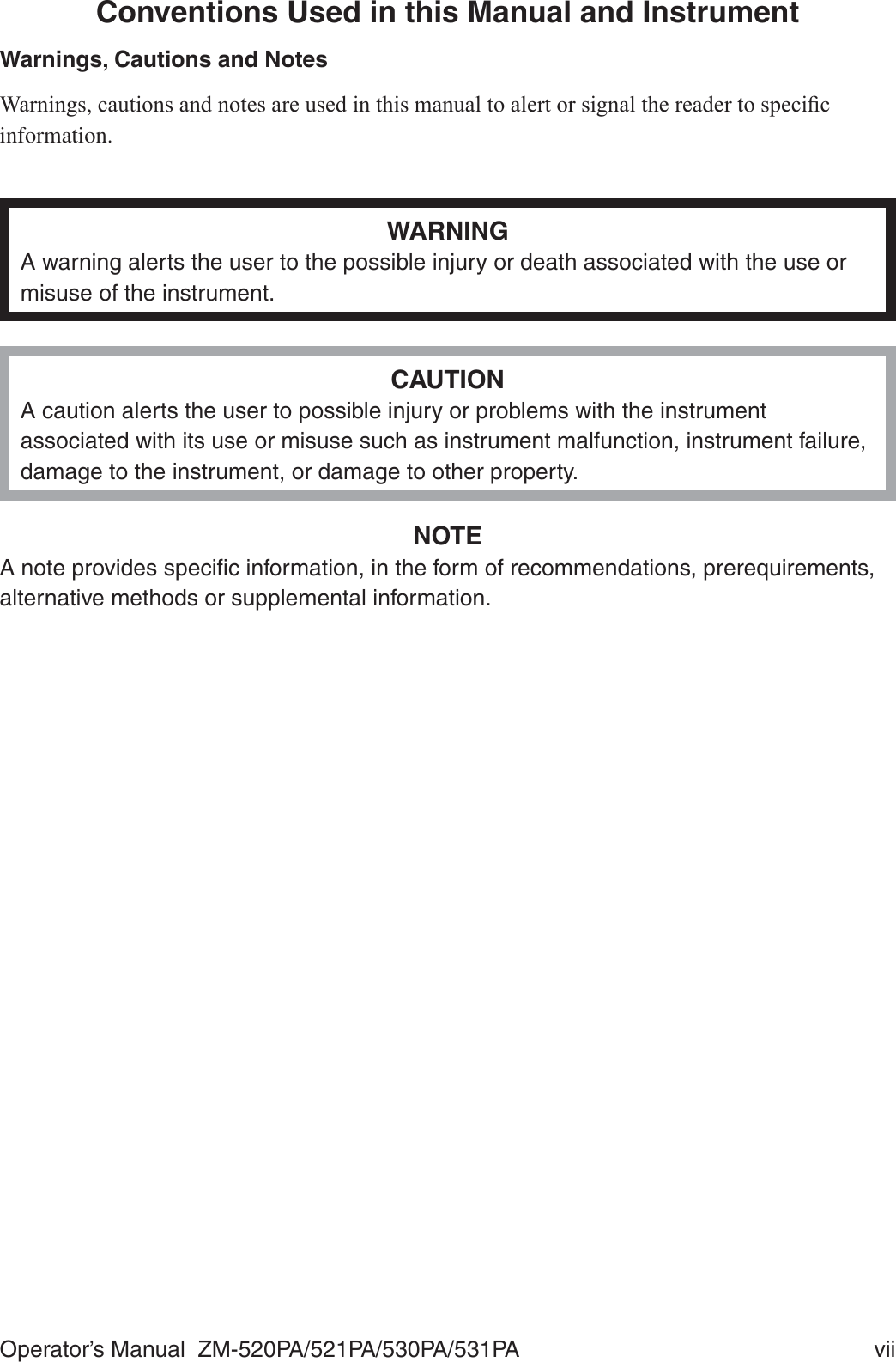
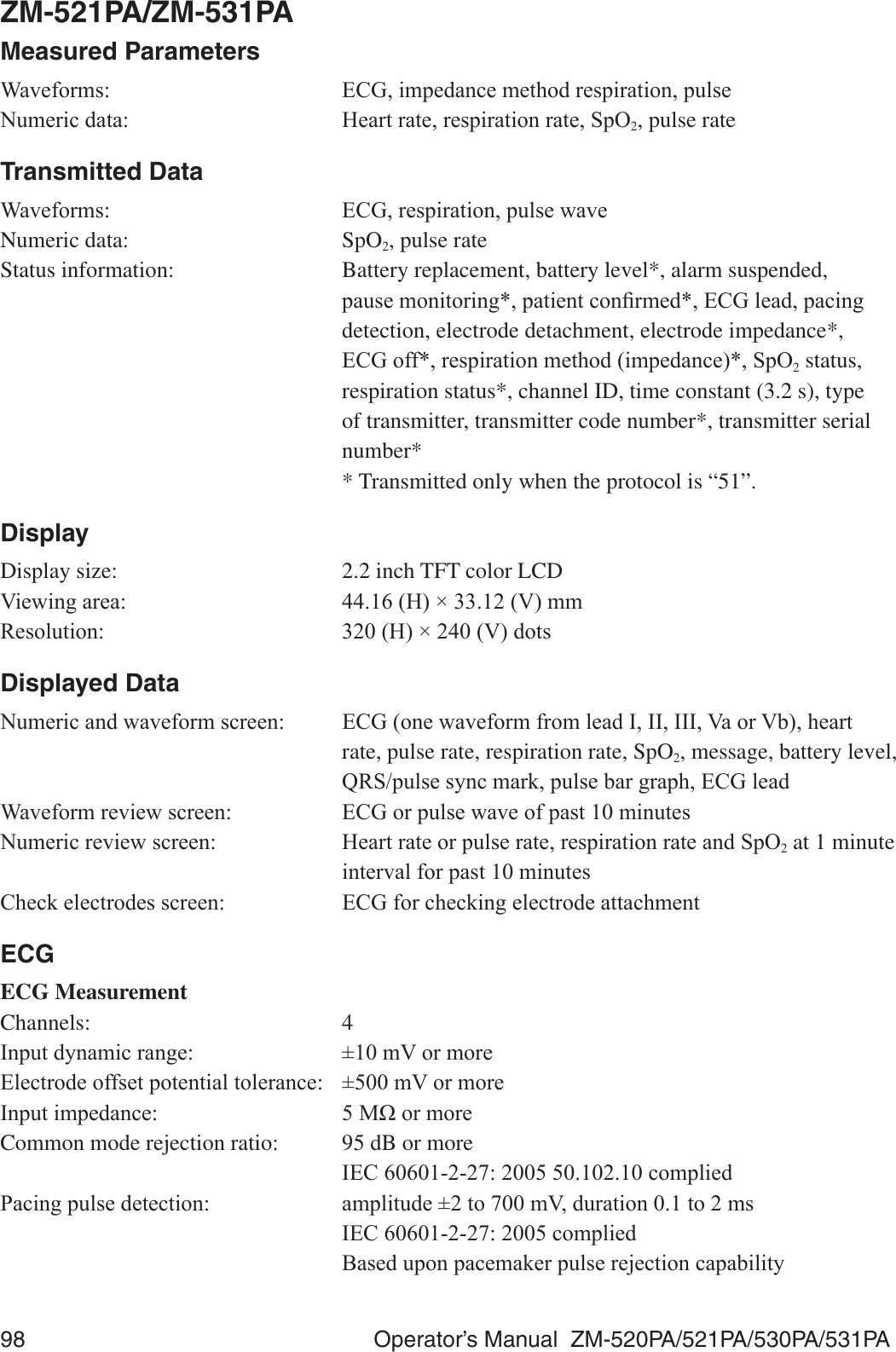
![92 Operator’s Manual ZM-520PA/521PA/530PA/531PA7KHIROORZLQJJUDSKVKRZVUHVSRQVHWLPHIRUESPVSXOVHUDWHFKDQJHSpO2 = 97607080901001101201301401500 102030405060708090100110120Time (seconds)PR (bpm)PR Reference PRTransmitter)&&UHJXODWLRQ )&&SDUW6XESDUW+ Wireless Medical Telemetry Service (WMTS))LHOGVWUHQJWKOLPLWV P9PDWPUndesired emissions: FCC part 95 95.1115 (b) (1), (2): 0+] ȝ9PDWP 0+] ȝ9PDWPAntenna: InternalTransmission channel: Indicated on the transmitter7UDQVPLVVLRQIUHTXHQF\UDQJH WR0+]&KDQQHOVSDFLQJ N+]RUN+]N+]ZKHQLQWHUOHDYHG0RGXODWLRQ )6.IUHTXHQF\VKLIWNH\LQJType of emission: F1D2FFXSLHGEDQGZLGWK WRN+](IIHFWLYHUDGLDWHGSRZHU P:](https://usermanual.wiki/Nihon-Kohden/ZM-530PAA/User-Guide-2812665-Page-106.png)
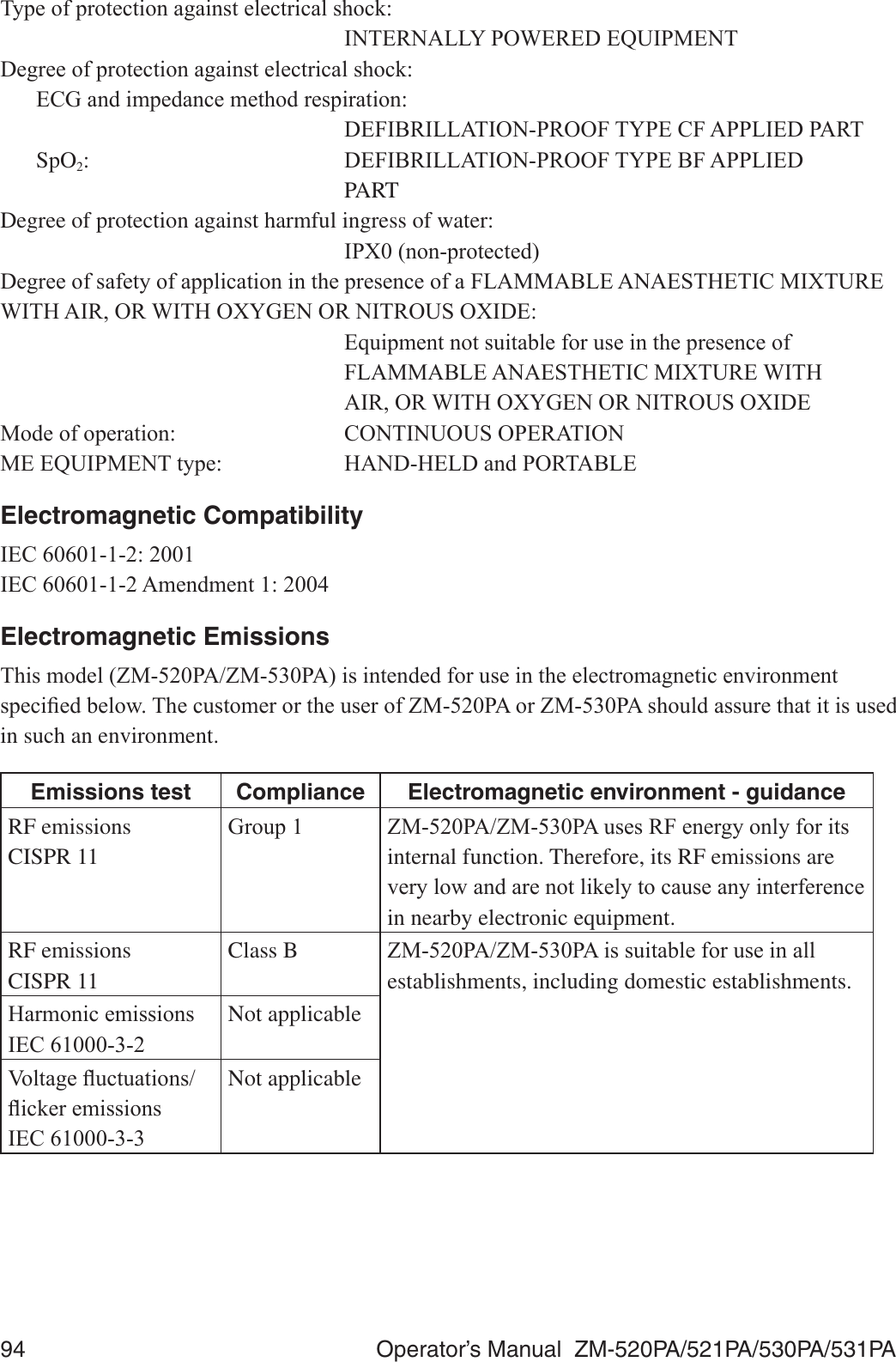
![Operator’s Manual ZM-520PA/521PA/530PA/531PA 95Electromagnetic Immunity7KLVPRGHO=03$=03$LVLQWHQGHGIRUXVHLQWKHHOHFWURPDJQHWLFHQYLURQPHQWVSHFL¿HGEHORZ7KHFXVWRPHURUWKHXVHURI=03$RU=03$VKRXOGDVVXUHWKDWLWLVXVHGin such an environment.Immunity test IEC 60601 test levelCompliance levelElectromagnetic environment - guidance(OHFWURVWDWLFGLVFKDUJH(6',(&rN9FRQWDFWrN9DLUrN9FRQWDFWrN9DLUFloors should be wood, concrete RUFHUDPLFWLOH,IÀRRUVDUHcovered with synthetic material, the relative humidity should be at OHDVW(OHFWULFDOIDVWtransient/burst,(&rN9IRUSRZHUsupply linesrN9IRULQSXWoutput linesNot applicable—Surge,(&rN9GLIIHUHQWLDOmoderN9FRPPRQPRGHNot applicable—9ROWDJHGLSVVKRUWinterruptions and voltage variations on power supply input lines,(&UT!GLSLQUTIRUF\FOHVUTGLSLQUT) for 5 cyclesUTGLSLQUT) for 25 cyclesUT!GLSLQUT) for 5 sNot applicable—Power frequency+]PDJQHWLF¿HOG,(&3 A/m 3 A/m 3RZHUIUHTXHQF\PDJQHWLF¿HOGVshould be at levels characteristic of a typical location in a typical commercial or hospital environment.127(UT is the AC mains voltage prior to application of the test level.Avoiding Electromagnetic Interference (Impedance Respiration)Impedance respiration measurement is very sensitive and affected by electromagnetic interference. 7HFKQRORJLFDOOLPLWDWLRQVGRQRWDOORZLPPXQLW\OHYHOVKLJKHUWKDQ9PIRUUDGLDWHG5)HOHFWURPDJQHWLF¿HOGV(OHFWURPDJQHWLF¿HOGVZLWK¿HOGVWUHQJWKVDERYH9PPD\FDXVHmeasurement error. Do not use electrically radiating equipment near the impedance respiration measurements.](https://usermanual.wiki/Nihon-Kohden/ZM-530PAA/User-Guide-2812665-Page-109.png)
![96 Operator’s Manual ZM-520PA/521PA/530PA/531PAImmunity test IEC 60601 test levelCompliance levelElectromagnetic environment - guidanceConducted RF ,(&Radiated RF,(&9UPVN+]WR0+]9P0+]WR*+]9UPV9P0+]WR*+]9P0+]WR*+]IRUrespiration)Portable and mobile RF communications equipment should be used no closer WRDQ\SDUWRI=03$=03$including cables, than the recommended separation distance calculated from the equation applicable to the frequency of the transmitter. Recommended separation distanced = 1.2 P d = 1.2 30+]WR0+]d = 2.3 30+]WR*+](d = 3.5 30+]WR0+]IRUrespirationG 30+]WR*+]IRUrespiration)where P is the maximum output power rating of the transmitter in watts (W) according to the transmitter manufacturer and d is the recommended separation distance in meters (m).)LHOGVWUHQJWKVIURP¿[HG5)WUDQVPLWWHUVas deter mined by an electromagnetic site survey*1, should be less than the compliance level in each frequency range*2.Interference may occur in the vicinity of HTXLSPHQWPDUNHGZLWKWKHIROORZLQJsymbol:127( $W0+]DQG0+]WKHKLJKHUIUHTXHQF\UDQJHDSSOLHV127( 7KHVHJXLGHOLQHVPD\QRWDSSO\LQDOOVLWXDWLRQV(OHFWURPDJQHWLFSURSDJDWLRQLVDIIHFWHGE\ DEVRUSWLRQDQGUHÀHFWLRQIURPVWUXFWXUHVREMHFWVDQGSHRSOH*1 )LHOGVWUHQJWKVIURP¿[HGWUDQVPLWWHUVVXFKDVEDVHVWDWLRQVIRUUDGLRFHOOXODUFRUGOHVVWHOHSKRQHVDQGODQGPRELOHUDGLRVDPDWHXUUDGLR$0DQG)0UDGLREURDGFDVWDQG79EURDGFDVWFDQQRWEHSUHGLFWHGWKHRUHWLFDOO\ZLWKDFFXUDF\7RDVVHVVWKHHOHFWURPDJQHWLFHQYLURQPHQWGXHWR¿[HG5)WUDQVPLWWHUVDQHOHFWURPDJQHWLFVLWHVXUYH\VKRXOGEHFRQVLGHUHG,IWKHPHDVXUHG¿HOGVWUHQJWKLQWKHORFDWLRQLQZKLFK=03$=03$LVXVHGH[FHHGVWKHDSSOLFDEOH5)FRPSOLDQFHOHYHODERYH=03$ =03$VKRXOGEHREVHUYHGWRYHULI\QRUPDORSHUDWLRQ,IDEQRUPDOSHUIRUPDQFHLVREVHUYHGDGGLWLRQDOPHDVXUHVPD\EHQHFHVVDU\VXFKDVUHRULHQWLQJRUUHORFDWLQJ=03$=03$*2 2YHUWKHIUHTXHQF\UDQJHN+]WR0+]¿HOGVWUHQJWKVVKRXOGEHOHVVWKDQ9PIRUUHVSLUDWLRQDQG9PIRUDOORWKHUIXQFWLRQV](https://usermanual.wiki/Nihon-Kohden/ZM-530PAA/User-Guide-2812665-Page-110.png)
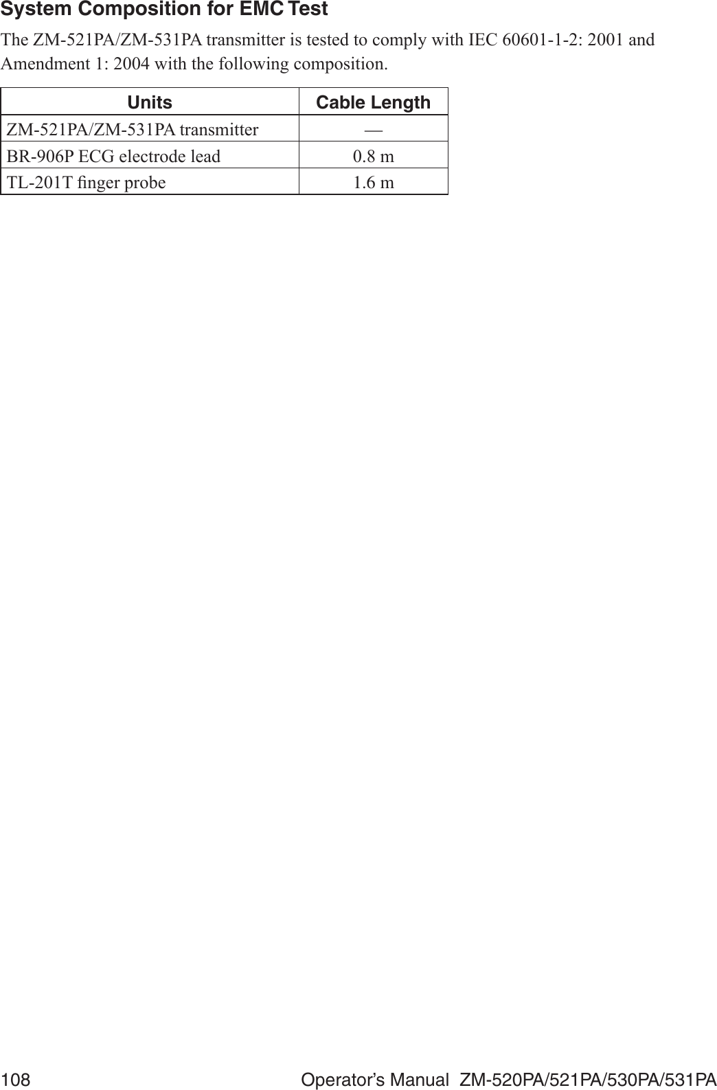
![Operator’s Manual ZM-520PA/521PA/530PA/531PA 97Recommended Separation Distances between Portable and Mobile RF Communications Equipment7KH=03$=03$LVLQWHQGHGIRUXVHLQDQHOHFWURPDJQHWLFHQYLURQPHQWLQZKLFKUDGLDWHG5)GLVWXUEDQFHVDUHFRQWUROOHG7KHFXVWRPHURUWKHXVHURI=03$=03$can help prevent electromagnetic interference by maintaining a minimum distance between SRUWDEOHDQGPRELOH5)FRPPXQLFDWLRQVHTXLSPHQWWUDQVPLWWHUVDQG=03$=03$DVrecommended below, according to the maximum output power of the communications equipment.Rated maximum output power of transmitter(W)Separation distance according to frequency of transmitter (m)150 kHz to 80 MHzd = 1.2 P80 MHz to 800 MHzd = 1.2 P(For respiration:d = 3.5 P)800 MHz to 2.5 GHzd = 2.3 P(For respiration:d = 7.0 P) 1 1.2 1.2 (3.5*) 12 12 (35*) For transmitters rated at a maximum output power not listed above, the recommended separation distance d in meters (m) can be estimated using the equation applicable to the frequency of the transmitter, where P is the maximum output power rating of the transmitter in watts (W) according to the transmitter manufacturer. (* For respiration)127( $W0+]DQG0+]WKHVHSDUDWLRQGLVWDQFHIRUWKHKLJKHUIUHTXHQF\UDQJHapplies. 127( 7KHVHJXLGHOLQHVPD\QRWDSSO\LQDOOVLWXDWLRQV(OHFWURPDJQHWLFSURSDJDWLRQLVDIIHFWHGE\DEVRUSWLRQDQGUHÀHFWLRQIURPVWUXFWXUHVREMHFWVDQGSHRSOHRecovery Time after Defibrillation7KHWUDQVPLWWHUUHWXUQVWRWKHQRUPDORSHUDWLQJPRGHZLWKLQVHFRQGVDIWHUGH¿EULOODWLRQ7KHstored settings are not affected.System Composition for EMC Test7KH=03$=03$WUDQVPLWWHULVWHVWHGWRFRPSO\ZLWK,(&DQG$PHQGPHQWZLWKWKHIROORZLQJFRPSRVLWLRQUnits Cable Length=03$=03$WUDQVPLWWHU —%53(&*HOHFWURGHOHDG P7/7¿QJHUSUREH 1.6 m](https://usermanual.wiki/Nihon-Kohden/ZM-530PAA/User-Guide-2812665-Page-111.png)
![Operator’s Manual ZM-520PA/521PA/530PA/531PA 99'H¿EULOODWLRQSURRI (&*LQSXWSURWHFWHGDJDLQVW:V'&N9 ,(&FRPSOLHG(&*UHFRYHU\WLPHDIWHUGH¿EULOODWLRQ ZLWKLQV(OHFWURGHFRQGLWLRQ 'LVSOD\V&+(&.(/(&752'(6PHVVDJH7DOO7ZDYHUHMHFWLRQFDSDELOLW\ &RPSOLHVZLWKWKHKHLJKWVRI7ZDYHVIURPWRP9 ,(&FRPSOLHG+HDUWUDWHDYHUDJLQJ &DOFXODWHGE\XVLQJWKHPRVWUHFHQWEHDWV+HDUWUDWHPHWHUDFFXUDF\DQGUHVSRQVHWRLUUHJXODUUK\WKP 9HQWULFXODUELJHPLQ\7HVWZDYHIRUPQDPHDDPLD ESP Slow alternating ventricular bigeminy (Test waveform name: DDPLEESP Rapid alternating ventricular bigeminy (Test waveform QDPHDDPLFESP Bidirectional systoles (Test waveform name: aami3d*): ESP * The test waveforms can be download at http://www. physionet.orgResponse time of heart rate meter to change in heart rate: +5FKDQJHIURPWRESPWRVHFRQGV +5FKDQJHIURPWRESPWRVHFRQGV3DFHPDNHUSXOVHUHMHFWLRQFDSDELOLW\ZLWKRXWRYHUVKRRW &RPSOLHVZLWKWKHDPSOLWXGHVRISDFHPDNHUSXOVHVWRP9DQGZLGWKVWRPVVSHFL¿HGLQ,(&3DFHPDNHUSXOVHUHMHFWLRQFDSDELOLW\ZLWKRYHUVKRRW 2YHUVKRRWDPSOLWXGHVDQGWLPHFRQVWDQWVRIP9PVWRP9PV$VGH¿QHGE\PHWKRG%RI,(&WKLVFRUUHVSRQGVWRWKHSDFHPDNHUSXOVHVDPSOLWXGHVDQGZLGWKVRIP9PVWRDPSOLWXGHVP9PVECG Display and Heart Rate Count)UHTXHQF\FKDUDFWHULVWLF ¿OWHURQWR+]¿OWHURIIWR+]+HDUWUDWHGHWHFWLRQPHWKRG $YHUDJH456GHWHFWLRQ WRPVDPSOLWXGHP9UDWHWREHDWVPLQ WRPVDPSOLWXGHP9UDWHWREHDWVPLQ+HDUWUDWHFRXQWLQJUDQJH WREHDWVPLQ+HDUWUDWHFRXQWLQJDFFXUDF\ EHDWVPLQWREHDWVPLQ(VVHQWLDOSHUIRUPDQFHRIWKLVWUDQVPLWWHU](https://usermanual.wiki/Nihon-Kohden/ZM-530PAA/User-Guide-2812665-Page-113.png)
![100 Operator’s Manual ZM-520PA/521PA/530PA/531PARespiration MeasurementMeasuring method: Impedance methodMeasuring lead: Between R and F,PSHGDQFHUDQJH WRȍ([FLWRUFXUUHQW WR$SSN+]5HVSLUDWLRQUDWHPHDVXULQJDFFXUDF\ FRXQWVPLQDWWRFRXQWVPLQ5HVSLUDWLRQUDWHFRXQWLQJUDQJH WRFRXQWVPLQ(VVHQWLDOSHUIRUPDQFHRIWKLVWUDQVPLWWHUSpO2 Measurement (ISO 9919: 2005 compliance)0HDVXULQJUDQJH WR6S22 'HFODUHGUDQJH WR6S220LQLPXPGLVSOD\UDQJH 6S22'LVSOD\XSGDWHF\FOH (YHU\VHFRQGV0HDVXULQJDFFXUDF\UPV $FFXUDF\DVVXUDQFHWHPSHUDWXUHWR&7RWDODFFXUDF\LQFOXGLQJSUREH 6S226S226S226S22 6S226S22 6S226S22 XQGHU6S22QRWVSHFL¿HG$FFXUDF\RIWKHWUDQVPLWWHU 6S226S226S226S22 6S226S226S226S22 XQGHU6S22QRWVSHFL¿HG3XOVHUDWHPHDVXULQJUDQJH WRESP3XOVHUDWHGLVSOD\UDQJH WRESP3XOVHUDWHDFFXUDF\UPV ESP(VVHQWLDOSHUIRUPDQFHRIWKLVWUDQVPLWWHUNOTE• The SpO2 measuring accuracy was tested using the TL-201T, TL-260T, TL-271T and TL-631T SpO2 probes. The testing was performed during induced hypoxia on healthy volunteers (Ethnicity: 10 Caucasians, 2 Africans, 1 Asian and 3 Indians), (Skin: 8 light, 4 medium, 4 dark), (Age: 21 to 34), (5 women and 11 men) under the condition of no motion. Arterial blood was sampled and measured by a CO-oximeter. The difference between SpO2 measured by the SpO2 probe and functional SaO2 measured by a CO-oximeter was calculated using the root-mean-square (rms) method according to ISO 9919: 2005. This measurement accuracy figure represents 2/3 of all test measurements.• A pulse oximeter tester that generates simulated signals can be used to check the difference from the design specification, but it cannot be used as a replacement for human signals for testing accuracy.](https://usermanual.wiki/Nihon-Kohden/ZM-530PAA/User-Guide-2812665-Page-114.png)
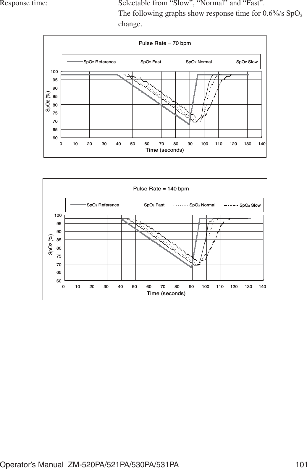
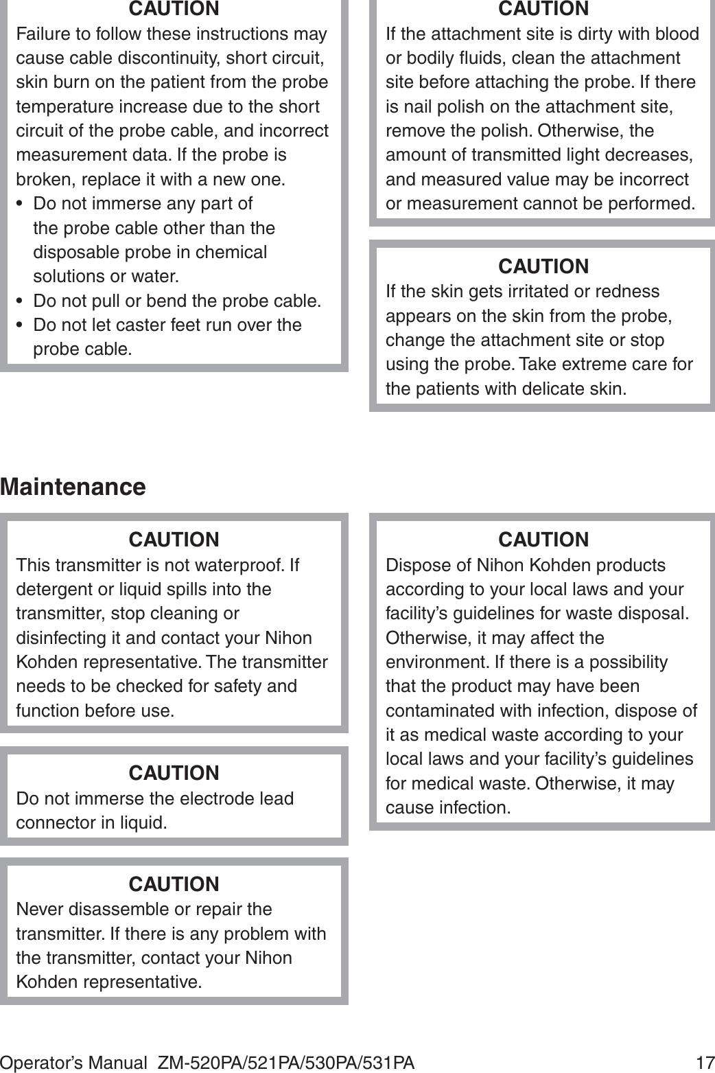
![102 Operator’s Manual ZM-520PA/521PA/530PA/531PA7KHIROORZLQJJUDSKVKRZVUHVSRQVHWLPHIRUESPVSXOVHUDWHFKDQJHSpO2 = 97607080901001101201301401500 102030405060708090100110120Time (seconds)PR (bpm)PR Reference PRTransmitter)&&UHJXODWLRQ )&&SDUW6XESDUW+ Wireless Medical Telemetry Service (WMTS))LHOGVWUHQJWKOLPLWV P9PDWPUndesired emissions: FCC part 95 95.1115 (b) (1), (2): 0+]ȝ9PDWP 0+]ȝ9PDWPAntenna: InternalTransmission channel: Indicated on the transmitter7UDQVPLVVLRQIUHTXHQF\UDQJH WR0+] WR0+]&KDQQHOVSDFLQJ N+]RUN+]N+]ZKHQLQWHUOHDYHG0RGXODWLRQ )6.IUHTXHQF\VKLIWNH\LQJType of emission: F1D2FFXSLHGEDQGZLGWK WRN+](IIHFWLYHUDGLDWHGSRZHU P: &DQEHFKDQJHGWRP:LIUHTXLUHG](https://usermanual.wiki/Nihon-Kohden/ZM-530PAA/User-Guide-2812665-Page-116.png)
![Operator’s Manual ZM-520PA/521PA/530PA/531PA 105Electromagnetic Immunity7KLVPRGHO=03$=03$LVLQWHQGHGIRUXVHLQWKHHOHFWURPDJQHWLFHQYLURQPHQWVSHFL¿HGEHORZ7KHFXVWRPHURUWKHXVHURI=03$=03$VKRXOGDVVXUHWKDWLWLVXVHGLQsuch an environment.Immunity test IEC 60601 test levelCompliance levelElectromagnetic environment - guidance(OHFWURVWDWLFGLVFKDUJH(6',(&rN9FRQWDFWrN9DLUrN9FRQWDFWrN9DLUFloors should be wood, concrete RUFHUDPLFWLOH,IÀRRUVDUHcovered with synthetic material, the relative humidity should be at OHDVW(OHFWULFDOIDVWtransient/burst,(&rN9IRUSRZHUsupply linesrN9IRULQSXWoutput linesNot applicable—Surge,(&rN9GLIIHUHQWLDOmoderN9FRPPRQPRGHNot applicable—9ROWDJHGLSVVKRUWinterruptions and voltage variations on power supply input lines,(&UT!GLSLQUTIRUF\FOHVUTGLSLQUT) for 5 cyclesUTGLSLQUT) for 25 cyclesUT!GLSLQUT) for 5 sNot applicable—Power frequency+]PDJQHWLF¿HOG,(&3 A/m 3 A/m 3RZHUIUHTXHQF\PDJQHWLF¿HOGVshould be at levels characteristic of a typical location in a typical commercial or hospital environment.127(UT is the AC mains voltage prior to application of the test level.Avoiding Electromagnetic Interference (Impedance Respiration)Impedance respiration measurement is very sensitive and affected by electromagnetic interference. 7HFKQRORJLFDOOLPLWDWLRQVGRQRWDOORZLPPXQLW\OHYHOVKLJKHUWKDQ9PIRUUDGLDWHG5)HOHFWURPDJQHWLF¿HOGV(OHFWURPDJQHWLF¿HOGVZLWK¿HOGVWUHQJWKVDERYH9PPD\FDXVHmeasurement error. Do not use electrically radiating equipment near the impedance respiration measurements.](https://usermanual.wiki/Nihon-Kohden/ZM-530PAA/User-Guide-2812665-Page-119.png)
![106 Operator’s Manual ZM-520PA/521PA/530PA/531PAImmunity test IEC 60601 test levelCompliance levelElectromagnetic environment - guidanceConducted RF ,(&Radiated RF,(&9UPVN+]WR0+]9P0+]WR*+]9UPV9P0+]WR*+]9P0+]WR*+]IRUrespiration)Portable and mobile RF communications equipment should be used no closer WRDQ\SDUWRI=03$=03$including cables, than the recommended separation distance calculated from the equation applicable to the frequency of the transmitter. Recommended separation distanced = 1.2 P d = 1.2 30+]WR0+]d = 2.3 30+]WR*+](d = 3.5 30+]WR0+]IRUrespirationG 30+]WR*+]IRUrespiration)where P is the maximum output power rating of the transmitter in watts (W) according to the transmitter manufacturer and d is the recommended separation distance in meters (m).)LHOGVWUHQJWKVIURP¿[HG5)WUDQVPLWWHUVas deter mined by an electromagnetic site survey*1, should be less than the compliance level in each frequency range*2.Interference may occur in the vicinity of HTXLSPHQWPDUNHGZLWKWKHIROORZLQJsymbol:127( $W0+]DQG0+]WKHKLJKHUIUHTXHQF\UDQJHDSSOLHV127( 7KHVHJXLGHOLQHVPD\QRWDSSO\LQDOOVLWXDWLRQV(OHFWURPDJQHWLFSURSDJDWLRQLVDIIHFWHGE\ DEVRUSWLRQDQGUHÀHFWLRQIURPVWUXFWXUHVREMHFWVDQGSHRSOH](https://usermanual.wiki/Nihon-Kohden/ZM-530PAA/User-Guide-2812665-Page-120.png)
![Operator’s Manual ZM-520PA/521PA/530PA/531PA 107*1 )LHOGVWUHQJWKVIURP¿[HGWUDQVPLWWHUVVXFKDVEDVHVWDWLRQVIRUUDGLRFHOOXODUFRUGOHVVWHOHSKRQHVDQGODQGPRELOHUDGLRVDPDWHXUUDGLR$0DQG)0UDGLREURDGFDVWDQG79EURDGFDVWFDQQRWEHSUHGLFWHGWKHRUHWLFDOO\ZLWKDFFXUDF\7RDVVHVVWKHHOHFWURPDJQHWLFHQYLURQPHQWGXHWR¿[HG5)WUDQVPLWWHUVDQHOHFWURPDJQHWLFVLWHVXUYH\VKRXOGEHFRQVLGHUHG,IWKHPHDVXUHG¿HOGVWUHQJWKLQWKHORFDWLRQLQZKLFK=03$=03$LVXVHGH[FHHGVWKHDSSOLFDEOH5)FRPSOLDQFHOHYHODERYH=03$=0531PA should be observed to verify normal operation. If abnormal performance is observed, additional PHDVXUHVPD\EHQHFHVVDU\VXFKDVUHRULHQWLQJRUUHORFDWLQJ=03$=03$*2 2YHUWKHIUHTXHQF\UDQJHN+]WR0+]¿HOGVWUHQJWKVVKRXOGEHOHVVWKDQ9PIRUUHVSLUDWLRQDQG9PIRUDOORWKHUIXQFWLRQVRecommended Separation Distances between Portable and Mobile RF Communications Equipment=03$=03$LVLQWHQGHGIRUXVHLQDQHOHFWURPDJQHWLFHQYLURQPHQWLQZKLFKUDGLDWHG5)GLVWXUEDQFHVDUHFRQWUROOHG7KHFXVWRPHURUWKHXVHURI=03$=03$FDQKHOSSUHYHQWelectromagnetic interference by maintaining a minimum distance between portable and mobile 5)FRPPXQLFDWLRQVHTXLSPHQWWUDQVPLWWHUVDQG=03$=03$DVUHFRPPHQGHGEHORZaccording to the maximum output power of the communications equipment.Rated maximum output power of transmitter(W)Separation distance according to frequency of transmitter (m)150 kHz to 80 MHzd = 1.2 P80 MHz to 800 MHzd = 1.2 P(For respiration:d = 3.5 P)800 MHz to 2.5 GHzd = 2.3 P(For respiration:d = 7.0 P) 1 1.2 1.2 (3.5*) 12 12 (35*) For transmitters rated at a maximum output power not listed above, the recommended separation distance d in meters (m) can be estimated using the equation applicable to the frequency of the transmitter, where P is the maximum output power rating of the transmitter in watts (W) according to the transmitter manufacturer. (* For respiration)127( $W0+]DQG0+]WKHVHSDUDWLRQGLVWDQFHIRUWKHKLJKHUIUHTXHQF\UDQJHapplies. 127( 7KHVHJXLGHOLQHVPD\QRWDSSO\LQDOOVLWXDWLRQV(OHFWURPDJQHWLFSURSDJDWLRQLVDIIHFWHGE\DEVRUSWLRQDQGUHÀHFWLRQIURPVWUXFWXUHVREMHFWVDQGSHRSOHRecovery Time after Defibrillation7KHWUDQVPLWWHUUHWXUQVWRWKHQRUPDORSHUDWLQJPRGHZLWKLQVHFRQGVDIWHUGH¿EULOODWLRQ7KHstored settings are not affected.](https://usermanual.wiki/Nihon-Kohden/ZM-530PAA/User-Guide-2812665-Page-121.png)