Nihon Kohden ZM-920PA WMTS Transmitter User Manual Cover2 ZM920PA 930PA OM pmd
Nihon Kohden Corporation WMTS Transmitter Cover2 ZM920PA 930PA OM pmd
Contents
- 1. Users Manual
- 2. Manual
Users Manual
TRANSMITTER
ZM-920PA/930PA
0614-007205

Model: ZM-920PA/930PA
Manual code no.: 0614-007205
Reader Comment Card
We welcome your comments about this manual. Your comments and suggestions
help us improve our manuals. Please circle the number for each of the following
statements corresponding to your evaluation and add comments in the space
provided.
Fax or send your completed comment card to:
Fax: +81 (3) 5996-8100
International Div., Sales Promotion Section, Nihon Kohden Corp., 1-31-4, Nishiochiai
Shinjuku-ku, Tokyo 161-8560, Japan
Strongly Agree 1 Disagree 4
Agree 2 Strongly Disagree 5
Nuetral 3
This manual is organized. 1 2 3 4 5
I can find the information I want. 1 2 3 4 5
The information is accurate. 1 2 3 4 5
I can understand the instructions. 1 2 3 4 5
The illustrations are appropriate and helpful. 1 2 3 4 5
The manual length is appropriate. 1 2 3 4 5
Comments:
Thank you for your cooperation. We appreciate it very much.
Name:
Occupation/Position:
Hospital/Company:
Address:
Phone:
cutting line
Operator's Manual ZM-920PA/930PA i
Contents
GENERAL HANDLING PRECAUTIONS ......................................... i
WARRANTY POLICY .................................................................... iii
EMC RELATED CAUTION ............................................................. v
Conventions Used in this Manual and Instrument ....................... vii
Warnings, Cautions and Notes ............................................... vii
Explanations of the Symbols in this Manual and Instrument viii
Introduction ......................................................................................... 1
Panel Description ............................................................................... 3
Top Panel ...................................................................................... 3
Front Panel .................................................................................... 4
ZM-920PA ................................................................................ 4
ZM-930PA ................................................................................ 5
Important Safety Information .............................................................. 6
General ......................................................................................... 6
Battery ........................................................................................... 8
Transmitter Channel Management ............................................... 8
For Patients Using Implantable Pacemaker ................................. 9
Output Signal ................................................................................ 9
ECG Monitoring .......................................................................... 10
SpO2 Monitoring .......................................................................... 10
Maintenance ............................................................................... 13
Preparation ....................................................................................... 14
Installing (Replacing) Batteries .................................................. 14
Procedure .............................................................................. 15
WARNING and CAUTION for Battery Handling .......................... 15
Situations Requiring Battery Replacement ................................ 16
Attaching a Strap to the Transmitter ............................................ 16
Turning On/Off the Transmitter .................................................... 17
Check Items Before Turning On the Power ........................... 17
Turning On/Off the Power ...................................................... 17
ii Operator's Manual ZM-920PA/930PA
Check Items After Turning On the Power ............................... 17
Check Items After the Power Off ............................................ 18
ECG Monitoring ................................................................................ 19
ECG Measurement Procedure ................................................... 20
Selecting Electrode Lead and Disposable Electrode ................ 21
Option .................................................................................... 21
Connecting the Electrode Lead to the Transmitter ..................... 22
Selecting the Electrode Position ................................................. 22
Six Electrodes ....................................................................... 23
When Using 4 to 6 DIN Type Leads to Monitor 6 Lead ECG 24
Three Electrodes ................................................................... 25
Connecting the Electrode Lead and Disposable Electrodes ..... 26
Preparing the Patient Skin .................................................... 26
Attaching Electrodes to the Patient ....................................... 26
Detection and Display of Measurement Condition .................... 27
Electrode Detachment .......................................................... 27
Respiration Monitoring ..................................................................... 28
Respiration Measurement Procedure ........................................ 29
Electrode Position for Respiration Monitoring ............................ 29
Electrode Position Examples ................................................ 29
SpO2 Monitoring ............................................................................... 31
Measurement Procedure ............................................................ 33
Selecting SpO2 Probe ................................................................. 33
Reusable Probes .................................................................. 34
Disposable Probes................................................................ 35
Connecting SpO2 Probe to the Transmitter ................................. 36
Attaching the Probe to the Patient .............................................. 37
Starting Measurement ................................................................ 38
Turning SpO2 Data and Pulse Level Bar Graph Display On/Off . 39
Detecting and Displaying Measurement Condition ................... 39
External Light Noise Alarm ................................................... 39
Insufficient Light Alarm .......................................................... 40
Probe Malfunction Alarm....................................................... 40
When Measurement Condition is Unstable .......................... 40
Alarm List .......................................................................................... 41
Troubleshooting ................................................................................ 43
Operator's Manual ZM-920PA/930PA iii
Changing the Transmitter Channel .................................................. 45
Lifetime and Disposal ....................................................................... 46
Disposing of Used Batteries ....................................................... 46
Replacement ......................................................................... 46
Disposal ................................................................................ 46
Disposing of Disposable Electrodes .......................................... 46
Lifetime .................................................................................. 46
Disposal ................................................................................ 46
Disposing of the SpO2 Probe ...................................................... 47
Lifetime .................................................................................. 47
Disposal ................................................................................ 47
Cleaning, Disinfection and Sterilization ........................................... 48
Transmitter and Electrode Lead ................................................. 48
Cleaning ................................................................................ 48
Disinfection............................................................................ 48
SpO2 Probe ................................................................................. 49
Replacing the Battery Case Cover ................................................... 50
Repair Parts Availability Policy......................................................... 50
Specifications ................................................................................... 51
ECG measurement ................................................................ 51
Respiration measurement .................................................... 51
SpO2 measurement ............................................................... 51
Transmitter ............................................................................. 51
Safety standards ................................................................... 52
Water resistance ................................................................... 53
Power requirements .............................................................. 53
Environment .......................................................................... 53
Dimension and Weight .......................................................... 53
Standard Accessories ...................................................................... 54
Options ............................................................................................. 55
ECG/RESP ............................................................................ 55
SpO2...................................................................................... 56
Operator's Manual ZM-920PA/930PA i
GENERAL HANDLING PRECAUTIONS
This device is intended for use only by qualified medical personnel.
Use only Nihon Kohden approved products with this device. Use of
non-approved products or in a non-approved manner may affect the
performance specifications of the device. This includes, but is not
limited to, batteries, recording paper, pens, extension cables,
electrode leads, input boxes and AC power.
Please read these precautions thoroughly before attempting to operate
the instrument.
1. To safely and effectively use the instrument, its operation must be
fully understood.
2. When installing or storing the instrument, take the following
precautions:
(1) Avoid moisture or contact with water, extreme atmospheric
pressure, excessive humidity and temperatures, poorly ventilated
areas, and dust, saline or sulphuric air.
(2) Place the instrument on an even, level floor. Avoid vibration and
mechanical shock, even during transport.
(3) Avoid placing in an area where chemicals are stored or where there
is danger of gas leakage.
(4) The power line source to be applied to the instrument must
correspond in frequency and voltage to product specifications, and
have sufficient current capacity.
(5) Choose a room where a proper grounding facility is available.
3. Before Operation
(1) Check that the instrument is in perfect operating order.
(2) Check that the instrument is grounded properly.
(3) Check that all cords are connected properly.
(4) Pay extra attention when the instrument is in combination with
other instruments to avoid misdiagnosis or other problems.
ii Operator's Manual ZM-920PA/930PA
(5) All circuitry used for direct patient connection must be doubly
checked.
(6) Check that battery level is acceptable and battery condition is good
when using battery-operated models.
4. During Operation
(1) Both the instrument and the patient must receive continual, careful
attention.
(2) Turn power off or remove electrodes and/or transducers when
necessary to assure the patient’s safety.
(3) Avoid direct contact between the instrument housing and the
patient.
5. To Shutdown After Use
(1) Turn power off with all controls returned to their original positions.
(2) Remove the cords gently; do not use force to remove them.
(3) Clean the instrument together with all accessories for their next
use.
6. The instrument must receive expert, professional attention for
maintenance and repairs. When the instrument is not functioning
properly, it should be clearly marked to avoid operation while it is
out of order.
7. The instrument must not be altered or modified in any way.
8. Maintenance and Inspection:
(1) The instrument and parts must undergo regular maintenance
inspection at least every 6 months.
(2) If stored for extended periods without being used, make sure prior
to operation that the instrument is in perfect operating condition.
(3) Technical information such as parts list, descriptions, calibration
instructions or other information is available for qualified user
technical personnel upon request from your Nihon Kohden
distributor.
Operator's Manual ZM-920PA/930PA iii
9. When the instrument is used with an electrosurgical instrument,
pay careful attention to the application and/or location of electrodes
and/or transducers to avoid possible burn to the patient.
10. When the instrument is used with a defibrillator, make sure that the
instrument is protected against defibrillator discharge. If not,
remove patient cables and/or transducers from the instrument to
avoid possible damage.
WARRANTY POLICY
Nihon Kohden Corporation (NKC) shall warrant its products against all
defects in materials and workmanship for one year from the date of delivery.
However, consumable materials such as recording paper, ink, stylus and
battery are excluded from the warranty.
NKC or its authorized agents will repair or replace any products which
prove to be defective during the warranty period, provided these products
are used as prescribed by the operating instructions given in the operator’s
and service manuals.
No other party is authorized to make any warranty or assume liability for
NKC’s products. NKC will not recognize any other warranty, either implied
or in writing. In addition, service, technical modification or any other
product change performed by someone other than NKC or its authorized
agents without prior consent of NKC may be cause for voiding this
warranty.
Defective products or parts must be returned to NKC or its authorized
agents, along with an explanation of the failure. Shipping costs must be pre-
paid.
This warranty does not apply to products that have been modified,
disassembled, reinstalled or repaired without Nihon Kohden approval or
which have been subjected to neglect or accident, damage due to accident,

iv Operator's Manual ZM-920PA/930PA
fire, lightning, vandalism, water or other casualty, improper installation or
application, or on which the original identification marks have been
removed.
In the USA and Canada other warranty policies may apply.
CAUTION
United States law restricts this device to sale by or on the order
of a physician.
Equipment Authorization Requirement
Operation of this equipment requires the prior coordination with a frequency
coordinator designated by the FCC for the Wireless Medical Telemetry
Service.

Operator's Manual ZM-920PA/930PA v
EMC RELATED CAUTION
This equipment and/or system complies with the International
Standard IEC60601-1-2 for electromagnetic compatibility for
medical electrical equipment and/or system. However, an
electromagnetic environment that exceeds the limits or levels
stipulated in the IEC60601-1-2, can cause harmful interference to
the equipment and/or system or cause the equipment and/or
system to fail to perform its intended function or degrade its
intended performance. Therefore, during the operation of the
equipment and/or system, if there is any undesired deviation
from its intended operational performance, you must avoid,
identify and resolve the adverse electromagnetic effect before
continuing to use the equipment and/or system.
The following describes some common interference sources and
remedial actions:
1.Strong electromagnetic interference from a nearby emitter
source such as an authorized radio station or cellular phone:
Install the equipment and/or system at another location if it is
interfered with by an emitter source such as an authorized
radio station. Keep the emitter source such as cellular phone
away from the equipment and/or system.
2.Effect of direct or indirect electrostatic discharge:
Make sure all users and patients in contact with the equipment
and/or system are free from direct or indirect electrostatic
energy before using it. A humid room can help lessen this
problem.
3.Electromagnetic interference with any radio wave receiver
such as radio or television:
If the equipment and/or system interferes with any radio wave
receiver, locate the equipment and/or system as far as
possible from the radio wave receiver.

vi Operator's Manual ZM-920PA/930PA
If the above suggested remedial actions do not solve the
problem, consult your Nihon Kohden Corporation subsidiary or
distributor for additional suggestions.

Operator's Manual ZM-920PA/930PA vii
Conventions Used in this Manual and Instrument
Warnings, Cautions and Notes
Warnings, cautions and notes are used in this manual to alert or signal the
reader to specific information.
WARNING
A warning alerts the user to the possible injury or death
associated with the use or misuse of the instrument.
CAUTION
A caution alerts the user to possible injury or problems with the
instrument associated with its use or misuse such as instrument
malfunction, instrument failure, damage to the instrument, or
damage to other property.
NOTE
A note provides specific information, in the form of
recommendations, prerequirements, alternative methods or
supplemental information.
viii Operator's Manual ZM-920PA/930PA
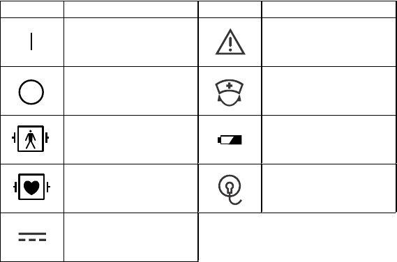
Symbol Description Symbol Description
Power On Attention, consult
operator’s manual
Power Off Nurse call
Defibrillation proof
type BF applied part
Replace battery
Defibrillation proof
type CF applied part
Check electrode
Direct current
Explanations of the Symbols in this Manual and Instrument
The following symbols found in this manual/instrument bear the respective
descriptions as given.

Operator's Manual ZM-920PA/930PA 1
Introduction
The ZM-920PA/930PA transmitter transmits ECG and other data from a patient to
a Nihon Kohden monitor for continuous monitoring. Available parameters and
functions vary between the models. Read the operator’s manual for the monitor
before operation.
Model Parameters Functions
ZM-920PA • ECG
• Impedance respiration
The following information is
indicated by LED.
• Check ECG electrodes
• Replace batteries
ZM-930PA
• ECG
• Impedance respiration
• SpO2
The following information is
indicated on LCD.
• SpO2 value
• Pulse wave amplitude
• Replace batteries
The following information is
indicated by LED.
• Check ECG electrodes
The transmitter channel can be changed by the QI-901PK Channel Writer. To
change the channel number, refer to the channel writer manual.
WARNING
The following actions must be taken to properly receive the
transmitter signal of the correct patient on the receiving instrument,
otherwise, there may be signal loss or signals may mix causing a
serious accident, such as monitoring a different patient.
••
••
•Assign a channel administrator in the hospital and only he or she
should manage channel assignments.
••
••
•The channel administrator must manage the channels in the
facility so that there is no signal interference.
••
••
•When the transmitter channel is changed, the channel
administrator must check that the channel on the receiving
monitor is also changed and the signal is properly received.

2 Operator's Manual ZM-920PA/930PA
••
••
•The channel administrator must replace the channel number label
on the transmitter with the new one after changing the channel.
CAUTION
••
••
•Do not use the same channel for different patients, otherwise, two
patients’ data will be lost due to mutual modulation interference, or
the wrong patient’s data may appear on the receiving monitor
screen.
••
••
•Do not use transmitters of adjacent channels in a hospital,
otherwise, radio waves from one transmitter affect the receiver of
the adjacent channel’s in the transmitter and there may be
interference.
NOTE
••
••
•Use Nihon Kohden parts and accessories to assure maximum
performance from your instrument.
••
••
•It is recommended to use a diversity antenna system on the
receiving monitor for stable signal reception, otherwise, spike
noise from transient fading of electric field strength (for example,
people moving) may interfere with the transmitter signal and may
be mistaken as an arrhythmia on the receiving monitor.
Operator's Manual ZM-920PA/930PA 3
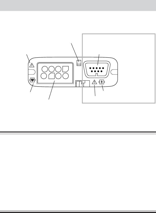
Panel Description
Top Panel
Refer to the warnings below
Refer to the symbol page
ECG/RESP socket
Connects to the electrode lead for measuring ECG
and/or respiration by the impedance method.
Refer to the warnings below
Refer to the symbol page
SpO2 socket
Connects to the SpO2 probe.
For attaching a strap
ZM-930PA only
WARNING
••
••
•Before performing defibrillation, check that the electrode leads
and SpO2 probe attached to the patient are properly connected to
the transmitter. Touching the metal parts of disconnected leads
and probes may cause serious electrical shock or injury by
discharged energy.
••
••
•When performing defibrillation, all persons must keep clear of the
bed and must not touch the patient, any equipment connected to
the patient or the metal parts of leads and probes connected to the
patient. Failure to follow this warning may result in serious
electrical burn, shock or other injury.
4 Operator's Manual ZM-920PA/930PA
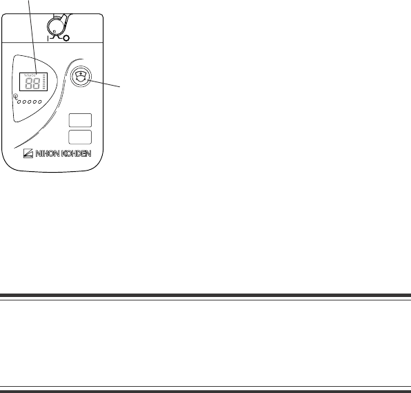
Front Panel
CAUTION
Only use your finger to press the CALL key. Do not press the key
with a sharp object, otherwise the key may be damaged.
Power switch
Turns transmitter power on or off.
CALL key
When this key is pressed,
a "peep" sounds at the
transmitter, and "CALL"
message appears at the
monitor. Depending on the
settings on the monitor, an
ECG waveform is recorded
when this key is pressed.
Channel lable
Replace batteries LED
Lights when the batteries
need replacement.
Check electrodes LED
Lights when the electrode is
detached from the patient.
Battery case
Contains two 1.5 V dry cell batteries (AA).
Refer to the warning below.
RA LA LL Va Vb
USAch
9002
608.025 MHz
WARNING
Close the battery case cover during operation.
If the transmitter is used with the battery case cover open, the
patient may get an electrical shock when defibrillation is performed,
and electrostatic discharge by the patient may intermittently
interfere with the waveform or data.
ZM-920PA
Operator's Manual ZM-920PA/930PA 5
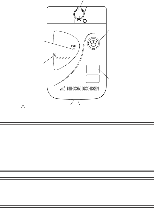
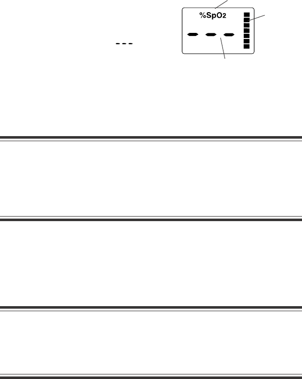
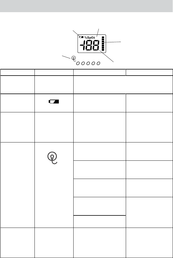
ZM-930PA
Battery replacement mark:
Appears when the batteries
are weak. Immediately
replace the batteries when this
appears.
%SpO2:
Displayed when the power is turned
on. This indication is not displayed
when SpO2 display is turned off.
Pulse level bar graph:
Displays pulse level in 7
steps.
SpO2 data:
Displays SpO2 data.
When SpO2 is 41 to 100%, the value is displayed. (ex. )
When SpO2 is under 40%, “ ” is displayed.
When the detected pulse is too small to measure, “ ” is displayed.
RA LA LL Va Vb
USAch
9002
608.025 MHz
LCD
For the descriptions except for the LCD,
refer to the “ZM-920PA” section on the
previous page.

6 Operator's Manual ZM-920PA/930PA
Important Safety Information
General
WARNING
••
••
•Never use this transmitter in the presence of any flammable
anesthetic gas or high concentration oxygen atmosphere. Failure
to follow this warning may cause explosion or fire.
••
••
•Never use this transmitter in a high-pressure oxygen medical care
tank. Failure to follow this warning may cause explosion or fire.
••
••
•Never take this transmitter into an MRI test room.
••
••
•Before performing defibrillation, check that the electrode leads
and SpO2 probe attached to the patient are properly connected to
the transmitter. Touching the metal parts of disconnected leads
and probes may cause serious electrical shock or injury by
discharged energy.
••
••
•When performing defibrillation, all persons must keep clear of the
bed and must not touch the patient, the equipment connected to
the patient, nor the metal parts of leads and probes connected to
the patient. Failure to follow this warning may result in serious
electrical burn, shock or other injury.
••
••
•When performing defibrillation, discharge as far as possible from
electrodes on the patient. If there is a possibility that the
defibrillator paddle could touch electrodes, remove electrodes
from the patient. If the defibrillator directly contacts the
electrodes, the discharged energy may cause serious electrical
burn to the patient.
••
••
•When using this transmitter with an electrosurgery unit, its return
plate and the electrodes for monitoring must be firmly attached to
the patient. If the return plate is not attached correctly, it may burn
the patient’s skin where the electrodes are attached. Refer to the
instruction manual for the ESU.
••
••
•Close the battery case cover during operation. If the transmitter is
used with the battery case cover open, the patient may get an
electrical shock when defibrillation is performed, and electrostatic

Operator's Manual ZM-920PA/930PA 7
CAUTION
••
••
•Use Nihon Kohden specified electrode leads and SpO2 probes to
assure maximum performance from your instrument.
••
••
•Do not reuse disposable products.
••
••
•Do not shake or swing the transmitter holding the leads/cables
connected to the transmitter. The transmitter may come off and
cause injury to a person or damage surrounding instruments.
••
••
•Attach a strap to the transmitter to prevent the transmitter from
falling.
••
••
•Turn off the power of cellular telephones, small wireless devices
and other devices which produce strong electromagnetic
interference around a patient. Radio waves from devices such as
cellular telephones or small wireless devices may be mistaken as
pulse waves and incorrect data may be displayed.
••
••
•Do not use the same channel for different patients. This could
produce a mutual modulation interference resulting in loss of data
from both patients or the incorrect patient’s data can appear on the
receiving monitor screen.
••
••
•Do not use transmitters of adjacent channels in a hospital,
otherwise, radio waves from one transmitter may affect the
receiver of the adjacent channel’s transmitter and can cause
interference.
discharge by the patient may intermittently interfere with the
waveform or data.

8 Operator's Manual ZM-920PA/930PA
CAUTION
Battery replacement must be performed by medical staff. When
replacing batteries in the transmitter currently used for a patient,
disconnect electrode leads from the transmitter before replacing
batteries. Do not touch the patient during replacement.
WARNING
••
••
•Do not dispose of the battery in fire, or it may explode.
••
••
•Do not disassemble the battery. The contents of the battery are
harmful and flammable.
••
••
•Never short-circuit the + +
+ +
+ and −−
−−
− terminals. This can produce
overheating and with its flammable capabilities can produce a fire.
••
••
•Make sure that the patient does not touch the batteries.
Battery
Transmitter Channel Management
WARNING
The following actions must be taken to properly receive the
transmitter signal of the correct patient on the receiving instrument,
otherwise, there may be signal loss or signals may mix causing a
serious accident, such as monitoring a different patient.
••
••
•Assign a channel administrator in the hospital and only he or she
should manage channel assignments.
••
••
•The channel administrator must manage the channels in the
facility so that there is no signal interference.
••
••
•When the transmitter channel is changed, the channel
administrator must check that the channel on the receiving
monitor is also changed and the signal is properly received.
••
••
•The channel administrator must replace the channel number label
on the transmitter with the new one after changing the channel.

Operator's Manual ZM-920PA/930PA 9
WARNING
Interaction Between Minute Ventilation Rate-Adaptive Pacemakers
and Cardiac Monitoring and Diagnostic Equipment.
The bioelectric impedance measurement sensor of a minute
ventilation rate-adaptive implantable pacemaker, may be affected
by the transmitter which is connected to the same patient. If this
occurs, the pacemaker may pace at its maximum rate and the
transmitter may give incorrect data to the monitor. If this occurs,
disconnect the electrode leads from the patient or change the
setting on the pacemaker by referring to the pacemaker’s manual.
For more details, contact your pacemaker distributor or Nihon
Kohden distributor.
For Patients Using Implantable Pacemaker
Output Signal
CAUTION
Do not use the output signal from the receiving monitor as the
synchronization signal for other equipment such as IABP, MRI,
echocardiography or defibrillator, there may be time delay between
the monitor and the other equipment and spike noise may interfere
with the output signal and be mistaken as a trigger.

10 Operator's Manual ZM-920PA/930PA
ECG Monitoring
CAUTION
••
••
•Use Nihon Kohden specified consumables. With electrodes other
than specified ones, the CHECK ELECTRODE message appears
and monitoring may stop.
••
••
•When the “ELECTRODE OFF” or “CHECK ELECTRODE” message
is displayed on the receiving monitor, check electrodes and
electrode leads. While “ELECTRODE OFF” or “CHECK
ELECTRODE” message is being displayed, there is no ECG
monitoring or alarms.
SpO2 Monitoring
WARNING
••
••
•Measurement may be incorrect in the following cases.
· When the oxyhemoglobin or methemoglobin (HbCO, Met Hb)
increases abnormally.
· When dye is injected in the blood.
· When using an electrosurgical unit.
· During CPR.
· When measuring at a site where there are venous pulses.
· When there is body movement.
· When the pulse wave is small.
••
••
•Check the circulation condition by observing the skin color of the
measuring site and pulse waveform. Change the measuring site
every 8 hours for disposable probes and every 4 hours for
reusable probes. The skin temperature may increase at the
attached site by 2 or 3°C (4 or 5°F) and cause a burn or pressure
necrosis. When using the probe on the following patients, take
extreme care and change the measurement site more frequently
according to symptoms and degree.
· A patient with a fever
· A patient with peripheral circulation insufficiency
· Neonate or low birth weight infant with delicate skin

Operator's Manual ZM-920PA/930PA 11
CAUTION
••
••
•Do not pull or bend the probe cable or put caster feet on the probe
cable. Do not immerse the probe cable in detergents or water.
Failure to follow these cautions may cause cable discontinuity,
short circuit, skin burn on the patient or incorrect measurement
data. Replace any broken probe with a new one.
••
••
•When the attachment site is wet with blood or when the patient has
nail polish on, remove the dirt and nail polish before attaching the
probe. The transmitted light may decrease due to the blood or nail
polish and the measurement data may be incorrect.
••
••
•If the skin gets irritated or redness appears on the skin by the
probe, change the attachment site.
••
••
•When the probe is attached to an appropriate site with sufficient
circulation and an error message confirming the probe attachment
repeatedly appears, the probe may be deteriorated. Replace it
with a new one.
••
••
•Do not use the probe over its stated lifetime. Otherwise the SpO2
measurement accuracy cannot be guaranteed.
••
••
•Use the disposable probe only for one patient. Never reuse the
disposable probe for another patient because it causes cross
infection.
••
••
•Do not use damaged or disassembled probe. Measured data may
be incorrect.
••
••
•To avoid poor circulation, do not wrap the tape too tight. Check the
blood circulation condition by observing the skin color and
congestion at the skin peripheral to the probe attachment site.
Even for short-term monitoring, there may be burn or pressure
necrosis from poor blood circulation, especially on neonates or
low birth weight infants whose skin is delicate. Accurate
measurement cannot be performed on a site with poor peripheral
circulation.
••
••
•When not monitoring SpO2, disconnect the SpO2 probe cord from
the transmitter. Otherwise, noise may interfere from the probe
sensor and cause incorrect data to be displayed on the transmitter
and receiving monitor.

12 Operator's Manual ZM-920PA/930PA
••
••
•When measuring under strong light (surgical light, bilirubin light,
sunlight, etc.), cover the probe with a blanket or cloth. Otherwise,
noise may interfere.
••
••
•When any of the following occurs, the probe may be broken.
Replace it with a new one and check the probe.
••
••
•The transmitter generates “pip” sound every 0.25 seconds.
••
••
•SpO2 data is 85% and blinking.
Disposable SpO2 Probes
CAUTION
••
••
•Replace the probe with a new one as specified in the probe
manual. If the probe is deteriorated, correct SpO2 monitoring
cannot be performed.
••
••
•When using a disposable probe, be careful when removing the
adhesive tape from neonatal skin.
••
••
•When removing a disposable probe taped to the skin, do not pull
from the cable of the probe because this can damage the probe’s
cable connection.
TL-260T Multi-site Y Probe
CAUTION
••
••
•Before use, be sure to attach the probe to the sponge attachment
tape S or L. Do not use the probe without the sponge attachment
tape attached. It causes incorrect measurement and may damage
the attachment site on the skin.
••
••
•When fixing the probe with the sponge attachment tape, confirm
that the adhesive part of the tape is not on the skin. The adhesive
may cause oversensitive symptoms on the skin such as redness
or itch. If the adhesive touches the skin, remove it carefully and
slowly because neonatal skin is very delicate.
••
••
•Do not use a dirty sponge attachment tape. The measurement
value may be incorrect.

Operator's Manual ZM-920PA/930PA 13
CAUTION
Do not disassemble the transmitter when performing maintenance
and inspection. If there is a problem with the transmitter after
maintenance and inspection, contact your Nihon Kohden distributor.
Reusable Probes
CAUTION
••
••
•Do not soak the probe in cleaning solution. It is not waterproof.
••
••
•Do not use creosol soap, glutaraldehyde, sodium hypochlorite, or
benzalkonium chloride, as these substances may damage the
probe.
Disposable Probes
CAUTION
••
••
•Do not soak the probe in cleaning solution. It is not waterproof.
••
••
•Do not use any disinfecting alcohol. It can damage the probe.
Maintenance
WARNING
If detergents or dirty liquid spills into the transmitter, clean it and dry
it completely before use. If the wet transmitter is used, the patient or
anyone in contact with the transmitter may receive an electric
shock.
••
••
•Do not pull from the cable when removing the probe from the
sponge attachment tape because this can damaged the cable.
14 Operator's Manual ZM-920PA/930PA
Type Lifetime
Manganese About 1/2 of alkaline batteries
NiCd About 1/3 of alkaline batteries (when fully charged)
NiMH About 1/2 of alkaline batteries (when fully charged)
Preparation
Installing (Replacing) Batteries
Use two AA type alkaline dry cell batteries, manganese dry cell batteries, NiCd
rechargeable batteries or NiMH batteries.
With new alkaline batteries, the transmitter can continuously measure ECG,
respiration and SpO2 for approximately 3 days or ECG and respiration for
approximately 4 days. Operation time depends on the thickness of SpO2 probe
attachment site.
NOTE
The capacity of manganese, NiCd and NiMH batteries is less than
that of alkaline batteries, therefore the lifetime of the battery is
shorter.
CAUTION
Battery replacement must be performed by medical staff. When
replacing batteries in the transmitter currently used for a patient,
disconnect electrode leads from the transmitter before replacing the
batteries. Do not touch the patient during replacement.
If electrode leads are attached to the patient and the person replacing the batteries
touches the patient, the patient leakage current over the amount allowed may
occur.
CAUTION
••
••
•Replace both batteries at the same time.
••
••
•Do not use different types of batteries together.
Operator's Manual ZM-920PA/930PA 15
WARNING and CAUTION for Battery Handling
WARNING
••
••
•Do not dispose of the battery in fire, or it may explode.
••
••
•Do not disassemble the battery. The contents of the battery are
harmful and flammable.
••
••
•If the contents of the battery contacts the skin or clothes, wash
immediately and thoroughly with running water.
••
••
•Never short-circuit the + +
+ +
+ and −−
−−
− terminals. This can produce
overheating and with its flammable capabilities can produce a fire.
••
••
•Make sure that the patient does not touch the batteries.
CAUTION
When the transmitter is not in use, remove batteries or turn the
power OFF. With the power ON, battery power is consumed even if
measurement is not performed. The batteries may become
unusable from overdischarge, and leakage from the battery may
damage the transmitter.
Procedure
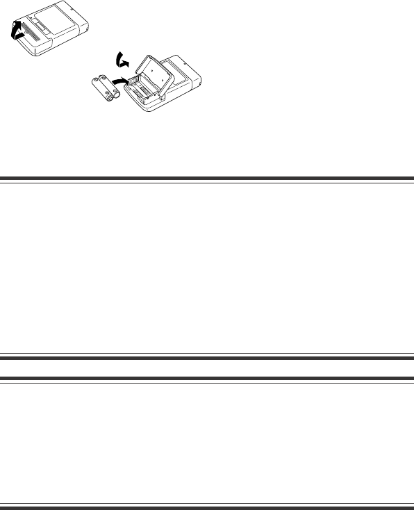
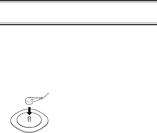
1. Open the battery case cover.
2. Insert two dry cell batteries (LR6)
into the battery case observing the
correct polarity.
3. Close the cover and press it gently
until it clicks.
1
2
3
NOTE
Insert the batteries with the correct polarity (++
++
+ and − −
− −
−).
16 Operator's Manual ZM-920PA/930PA
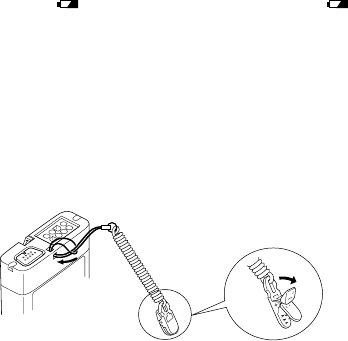
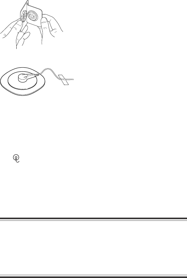
To open the clip, firmly pull out
the tab in direction of the arrow.
NOTE
••
••
•When using rechargeable NiCd batteries or NiMH batteries,
shallow charging/discharging shortens battery capacity. For
details, refer to the battery operator’s manual.
••
••
•Remove the batteries from the transmitter before disposing of the
transmitter.
Situations Requiring Battery Replacement
Replace the batteries when any of the following occurs.
•The “ ” LED lights (ZM-920PA) or the “ ” mark is displayed on the LCD
(ZM-930PA) on the transmitter.
•The transmitter generates a constant alarm (continuous “peep” sound).
•The monitor displays the battery replacement message on the screen.
•When the power of the LCD transmitter is turned on, no message or icon is
displayed. (Only the ZM-930PA).
Attaching a Strap to the Transmitter
NOTE
••
••
•Attach a strap to the transmitter to prevent the transmitter from
falling.
••
••
•Do not attach the clip to hard objects such as thick cloths or
zippers, or the clip may break.
Attach a strap to the transmitter and fasten the clip to the patients’ clothes or bed
sheets.
If the transmitter falls off, the battery cover may be opened. If the patient touches
the terminals of the batteries, patient leakage current over the allowable amount
can occur.

Operator's Manual ZM-920PA/930PA 17
Turning On/Off the Transmitter
Check Items Before Turning On the Power
To use the instrument in a safe and optimum condition, before turning on the
transmitter power switch, check the following.
Appearance
•There is no damage or dirt on the outside of the transmitter. (Power switch,
LED, LCD, CALL key, junction, battery case cover, battery case, etc.)
•The transmitter is completely dry.
•The electrode lead is not broken.
•There is no damage or dirt on the SpO2 probe or on the disposable electrodes.
Battery
•The battery polarity is correct.
•The battery case spring is firmly fixed and the battery is not loose.
•The battery case cover is firmly closed.
Channel Setting
•The transmitter channel corresponds to those of the receiving monitor.
•The same channel is not being used on a different transmitter in the
surrounding area.
Turning On/Off the Power
ON
OFF
To turn on the power, turn the power switch to the right. After
a “peep” sound for about one second, the power is turned on.
(There is no “peep” sound when the “ ” LED light or the
“” are blinking on the LCD).
To turn off the power, turn the power switch to the left.
Check Items After Turning On the Power
After turning on the power, check the following items.
Power On
•The power switch is not damaged.
•The transmitter generates a “peep” sound for about one second.

18 Operator's Manual ZM-920PA/930PA
•All LEDs light and values are displayed on the LCD for about one second.
•The transmitter does not generate a continuous “pip” sound.
•The transmitter does not liberate excessive heat.
•The “ ” LED does not light or the “ ” mark is not displayed on the LCD.
•The transmitter does not interfere with the operation of medical instruments
used near it.
Basic Operation
•The “signal loss” message is not displayed on the monitor when the transmitter
is inside the receiving range of the monitor.
•A “peep” sounds at the transmitter and “CALL” message appears at the
receiving monitor when the CALL key is pressed and the transmitter is inside
the receiving range of the monitor.
•The battery replacement message is not displayed on the monitor.
Check Items After the Power Off
•ECG electrode leads and SpO2 probe are cleaned and disinfected.
•When the transmitter gets wet, liquid is wiped off and the transmitter is
thoroughly dried.
•There are enough consumables, such as disposable electrodes.
•The power is turned off.
•The batteries are removed from the transmitter when it will not be used for a
long time.
•Dead batteries are disposed of properly.

Operator's Manual ZM-920PA/930PA 19
ECG Monitoring
When 6 leads are used on this transmitter, up to 8 lead (I, II, III, aVR, aVL, aVF, Va
and Vb) of ECG waveforms can be displayed on the receiving monitor. The heart
rate is also measured. When 3 leads are used, one channel ECG waveform of lead
II can be displayed on the receiving monitor. Refer to the operator’s manual of the
monitor for details.
WARNING
Interaction Between Minute Ventilation Rate-Adaptive Pacemakers
and Cardiac Monitoring and Diagnostic Equipment*
The bioelectric impedance measurement sensor of a minute
ventilation rate-adaptive implantable pacemaker may be affected by
the transmitter which is connected to the same patient. If this
occurs, the pacemaker may pace at its maximum rate and the
transmitter may give incorrect data to the monitor. If this occurs,
disconnect the electrode leads from the patient or change the
setting on the pacemaker by referring to the pacemaker’s manual.
For more details, contact your pacemaker distributor or Nihon
Kohden distributor.
* Minute ventilation is sensed in rate-adaptive pacemakers by a technology
known as bioelectric impedance measurement (BIM). Many medical devices in
addition to pacemakers use this technology. When one of these devices is used
on a patient with an active, minute ventilation rate-adaptive pacemaker, the
pacemaker may erroneously interpret the mixture of BIM signals created in the
patient, resulting in an elevated pacing rate.
For more information, see the FDA web site.
http://www.fda.gov/cdrh/safety.html

20 Operator's Manual ZM-920PA/930PA
WARNING
When using the transmitter with an ESU, the ESU return plate and
the electrodes for monitoring must be firmly attached to the patient.
If the return plate is not attached correctly, it may burn the patient’s
skin where the electrodes are attached. Refer to the instruction
manual for the ESU.
NOTE
••
••
•This transmitter is not protected against noise generated from an
electrosurgery unit.
••
••
•If an electric blanket is used and incorrect heart rate is displayed
on the monitor, turn off the pacing pulse detection on the monitor.
ECG Measurement Procedure
1. Select the type of electrode lead and disposable electrode according to the
purpose.
2. Connect the electrode lead to the ECG/RESP socket.
3. Connect disposable electrodes to the electrode lead and attach electrodes to
the patient.
After steps 1 to 3 are finished, ECG monitoring automatically starts.
Operator's Manual ZM-920PA/930PA 21
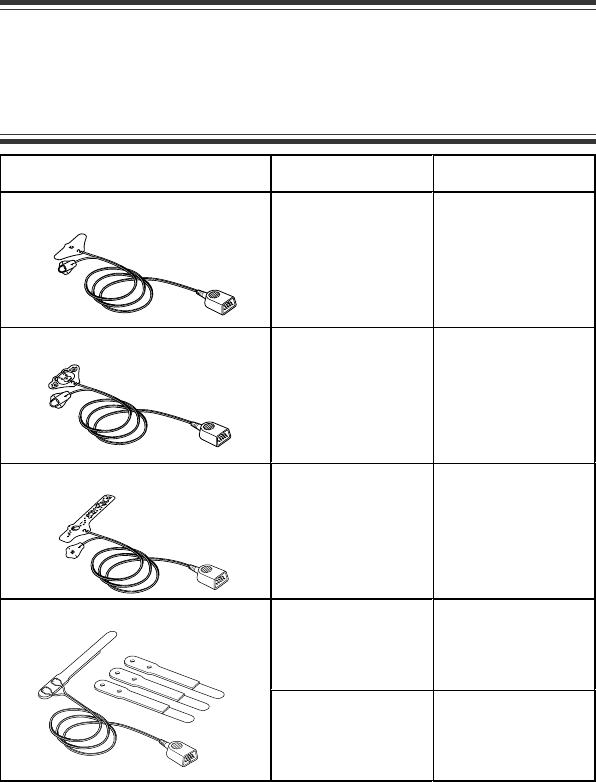
Selecting Electrode Lead and Disposable Electrode
CAUTION
Use Nihon Kohden specified consumables. With electrodes other
than specified ones, the CHECK ELECTRODE message appears and
monitoring may stop.
Option
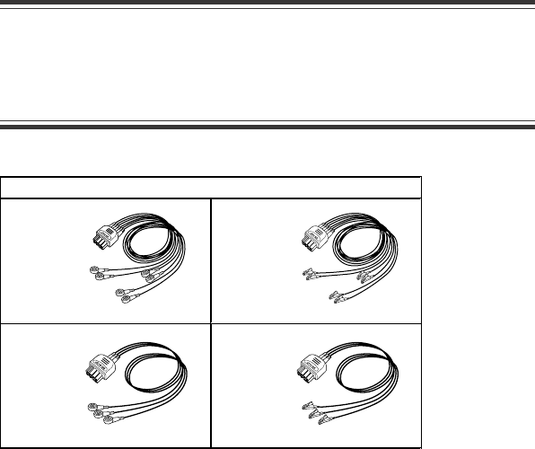
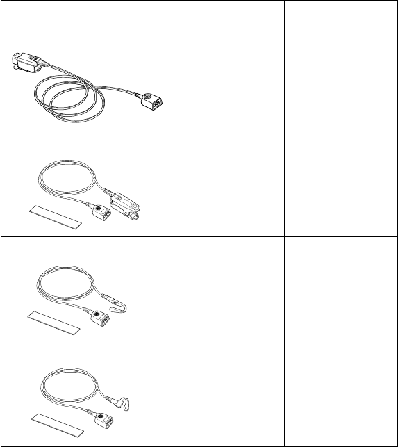
Electrode lead
BR-916PA
6 electrodes, snap type
BR-906PA
6 electrodes, clip type
BR-913PA
3 electrodes, snap type
BR-903PA
3 electrodes, clip type
22 Operator's Manual ZM-920PA/930PA
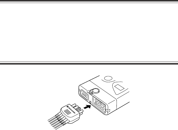
Connecting the Electrode Lead to the Transmitter
Connect the electrode lead to the ECG/RESP socket on the transmitter.
CAUTION
••
••
•Do not shake or swing the transmitter holding the leads/cables
connected to the transmitter. The transmitter may come off and
cause injury to a person or damage surrounding instruments.
••
••
•Hold the connector of the electrode lead when connecting/
disconnecting the electrode lead. If you disconnect the electrode
lead holding the lead, it damages the electrode lead.
Selecting the Electrode Position
Follow the physician’s instructions for electrode placement when available.
For ECG monitoring, electrodes are attached only on the chest to allow patient
movement and obtain continuous stable ECG. Following leads are examples.
When also monitoring respiration, refer to the “Electrode Position for Respiration
Monitoring” section.
NOTE
The optimum electrode positions for ECG measurement of a patient
are not always optimum for respiration measurement of the patient.
Select positions suitable for both ECG and respiration
measurements, or positions which have priority for one
measurement.
Operator's Manual ZM-920PA/930PA 23
RA LA
N (RL) LL
Va Vb
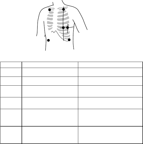
Six Electrodes
Electrode Position
The 6-electrode method with lead II and lead V5 is effective for monitoring
myocardial ischemia. You can improve monitoring accuracy considerably by
adding lead V4 to this combination. Va and Vb can be at any position of the
standard 12 leads V1 to V6, but V4 and V5 are most appropriate for myocardial
ischemic monitoring.
Symbol Lead Color (Clip Color) Electrode Position
RA White (White) Right infraclavicular fossa
LA Black (Black) Left infraclavicular fossa
LL Red (Red) Lowest rib on the left anterior
axillary line
N (RL) Green (Green) Right anterior axillary line at the
same level as LL
Va Brown (Brown) (BR-906PA)
Brown-blue (BR-916PA)
Fifth intercostal space on the left
midclavicular line. (V4 position of
standard 12 leads)
Vb Brown (Brown) (BR-906PA)
Brown-orange (BR-916PA)
Left anterior axillary line at the
same level as Va. (V5 position of
standard 12 leads)
24 Operator's Manual ZM-920PA/930PA
ON
CALL key
RA LA LL Va Vb
USAch
9002
608.025 MHz
When the BR-906PA/916PA electrode
leads are not used, the transmitter is fixed
to 3 lead ECG monitoring. To monitor 6
lead ECG using 4 to 6 DIN type leads, the
transmitter must be fixed to 6 lead
monitoring. To fix transmitter to the 6 lead
ECG monitoring, turn off the transmitter
power, press and hold the CALL key and
turn on the transmitter power.
When the transmitter power is turned off
and on again, the monitoring mode returns
to the original mode.
Standard limb leads
Monopolar limb leads
Monopolar chest leads
Lead I Lead II Lead III
aV
R
lead aV
L
lead aV
F
lead
V1 to V6 leads
to
RA
RA
RA RA RA
RA
RA
LA
LA
LA
LA
LA
LALA
LL
LL
LL
LL LL
LL
LL
N (RL)
N (RL)
N (RL) N (RL) N (RL)
N (RL)
N (RL)
Lead Position
When Using 4 to 6 DIN Type Leads to Monitor 6 Lead ECG
Operator's Manual ZM-920PA/930PA 25
If the electrode position shown above is not available due to chest surgery, attach
the electrodes to the root of the limbs or below the clavicles for stable ECG
monitoring.
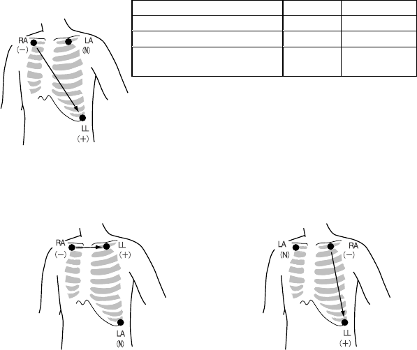
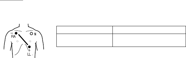
Three Electrodes
By using the optional BR-913PA/903PA electrode lead, 3 lead ECG monitoring is
available.
Electrode Position
•Lead MII, which is similar to standard lead II, used when ECG measurement
has priority
•Lead MI, which is similar to standard
lead I
Change LL and LA of the lead MII.
•Lead MIII, which is similar to
standard lead III
Change RA and LA of the lead MII.
Electrode Position Symbol Lead Color
Left infraclavicular fossa LA (N) Black
Right infraclavicular fossa RA (−)White
Below lowest rib on the
left anterior axillary line LL (+) Red
26 Operator's Manual ZM-920PA/930PA
Connecting the Electrode Lead and Disposable
Electrodes
Preparing the Patient Skin
Shave off excessive body hair.
To reduce skin impedance, clean the electrode site with cream or with a cotton pad
moistened with the electrode site with cream or with a cotton pad moistened with
alcohol. Thoroughly dry the skin with a clean cotton pad.
NOTE
••
••
•For a patient with frequent body movement, rub the sites with
Skinpure skin preparation gel. However, do not use Skinpure skin
preparation gel for sensitive skin.
••
••
•Do not place electrodes on a wound or on an inflamed, wrinkled or
uneven skin surface.
Attaching Electrodes to the Patient
CAUTION
Do not reuse disposable products.
NOTE
••
••
•To maintain good contact between the electrode and skin, check
that the paste of the disposable electrode is not dry.
••
••
•When contact between the disposable electrode and skin becomes
poor, replace electrodes with new ones immediately. Otherwise,
contact impedance between the skin and the electrode increases
and the correct ECG cannot be obtained.
Refer to the electrode operator’s manual for details.
1. Connect the electrode lead to the electrode.
Operator's Manual ZM-920PA/930PA 27
2. Carefully remove the backing paper from
the electrode. Avoid touching the adhesive
surface.
3. Place the electrode on the previously
cleaned skin. Pay attention to the electrode
lead color and symbol.
4. Fasten the electrode lead wire with surgical
tape with an extra length of wire between
the tape and the electrode. This lessens the
movement of electrode leads by body
movement and helps stable monitoring.
Detection and Display of Measurement Condition
Electrode Detachment
The “ ” LED lights on the transmitter or the “CHECK ELECTRODE” message
is displayed on the screen of the monitor in the following cases.
•Electrode is detached from skin.
•Electrode lead is disconnected from the electrode.
•Polarization voltage between the electrode and skin is excessively high.
In these cases, check the cause and if necessary, replace electrodes with new ones.
CAUTION
When the “ELECTRODE OFF” or “CHECK ELECTRODE” message is
displayed on the receiving monitor, check electrodes and electrode
leads and remove the cause. While “ELECTRODE OFF” or “CHECK
ELECTRODE” message is being displayed, there is no ECG
monitoring and no alarms.

28 Operator's Manual ZM-920PA/930PA
Respiration Monitoring
Respiration is monitored by measuring changes in impedance between the RA and
LL ECG electrodes. This transmitter sends the changes in impedance to the
monitor as a respiration waveform. The monitor displays the respiration
waveform and calculates respiration rate. Refer to the operator’s manual of the
monitor for details.
WARNING
Interaction Between Minute Ventilation Rate-Adaptive Pacemakers
and Cardiac monitoring and Diagnostic Equipment*
The bioelectric impedance measurement sensor of a minute
ventilation rate-adaptive implantable pacemaker may be affected by
the transmitter which is connected to the same patient. If this
occurs, the pacemaker may pace at its maximum rate and the
transmitter may give incorrect data to the monitor. If this occurs,
disconnect the electrode leads from the patient or change the
setting on the pacemaker by referring to the pacemaker’s manual.
For more details, contact your pacemaker distributor or Nihon
Kohden distributor.
* Minute ventilation is sensed in rate-adaptive pacemakers by a technology
known as bioelectric impedance measurement (BIM). Many medical devices in
addition to pacemakers use this technology. When one of these devices is used
on a patient with an active, minute ventilation rate-adaptive pacemaker, the
pacemaker may erroneously interpret the mixture of BIM signals created in the
patient, resulting in an elevated pacing rate.
For more information, see the FDA web site.
http://www.fda.gov/cdrh/safety.html
Operator's Manual ZM-920PA/930PA 29
Respiration Measurement Procedure
1. Select the electrode lead and disposable electrodes.
2. Connect the electrode lead to the ECG/RESP socket.
3. Connect disposable electrodes to the electrode lead and attach electrodes to
the patient.
After steps 1 to 3 are finished, respiration monitoring automatically starts.
Electrode Position for Respiration Monitoring
Place the RA and LL electrodes so that the lungs are between the electrodes.
NOTE
The optimum electrode positions for ECG measurement of a patient
are not always optimum for respiration measurement of the patient.
Select positions suitable for both ECG and respiration
measurements, or positions which have priority for one
measurement.
Electrode Position Examples
NOTE
The following examples are when monitoring with 3 electrodes. ECG
cannot be monitored correctly when electrodes are attached as the
following examples when monitoring with 6 electrodes.
Position 1
In this position, respiration measurement is available; however, there is a
difference in amplitude between different patients.
RA LL
Right infraclavicular
fossa
Fifth intercostal space on the
left midclavicular line, V4

30 Operator's Manual ZM-920PA/930PA
RA LL
Right infraclavicular
fossa
Fifth intercostal space on
the left midaxillary line, V6
Position 3
In this position, the respiration waveform is optimum, but the ECG lead is
unusual.
RA LL
Right midaxillary at the
horizontal level of V4
Fifth intercostal space on the
left midaxillary line, V6
Position 4
In this position, the respiration measurement is influenced by the impedance
variation of the abdomen, so the cardiac pulse wave included in the respiration
wave is reduced. Note that the waveform is inverted in phase compared with the
chest movement (the waveform goes down during inspiration). It is difficult to
measure the ECG at the same time.
RA LL
Lowest rib on the right
anterior axillary line
Lowest rib on the left
anterior axillary line
Position 2
In this position, the waveform amplitude is usually large and the ECG lead is
similar to Lead MII. This position can be generally recommended.

Operator's Manual ZM-920PA/930PA 31
SpO2 Monitoring
The SpO2 monitoring is only available on the ZM-930PA transmitter.
This transmitter sends SpO2 and pulse waveform to the monitor and displays
SpO2 data and pulse level bar graph on the LCD.
Refer to the operator’s manual of the monitor for details.
WARNING
••
••
•Measurement may be incorrect in the following cases.
· When the oxyhemoglobin or methemoglobin (HbCO, Met Hb)
increases abnormally.
· When dye is injected in the blood.
· When using an electrosurgical unit.
· During CPR.
· When measuring at a site where there are venous pulses.
· When there is body movement.
· When the pulse wave is small.
••
••
•Check the circulation condition by observing the skin color of the
measuring site and pulse waveform. Change the measuring site
every 8 hours for disposable probes and every 4 hours for
reusable probes. The skin temperature may increase at the
attached site by 2 or 3°C (4 or 5°F) and cause a burn or pressure
necrosis. When using the probe on the following patients, take
extreme care and change the measurement site more frequently
according to symptoms and degree.
· A patient with a fever
· A patient with peripheral circulation insufficiency
· Neonate or low birth weight infant with delicate skin
••
••
•To avoid poor circulation, do not wrap the tape too tight. Check the
blood circulation condition by observing the skin color and
congestion at the skin peripheral to the probe attachment site.
Even for short-term monitoring, there may be burn or pressure
necrosis from poor blood circulation, especially on neonates or

32 Operator's Manual ZM-920PA/930PA
low birth weight infants whose skin is delicate. Accurate
measurement cannot be performed on a site with poor peripheral
circulation.
••
••
•When not monitoring SpO2, disconnect the SpO2 probe cord from
the transmitter. Otherwise, noise may interfere from the probe
sensor and cause incorrect data to be displayed on the transmitter
and receiving monitor.
CAUTION
••
••
•Do not pull or bend the probe cable or put caster feet on the probe
cable. Do not immerse the probe cable in detergents or water.
Failure to follow these cautions may cause cable discontinuity,
short circuit, skin burn on the patient or incorrect measurement
data. Replace any broken probe with a new one.
••
••
•Turn off the power of cellular telephones, small wireless devices
and other devices which produce strong electromagnetic
interference around a patient. Radio waves from devices such as
cellular telephones or small wireless devices may be mistaken as
pulse waves and the displayed data may be incorrect.
NOTE
When monitoring SpO2, monitor ECG at the same time. The ECG
electrode lead works as an antenna for transmitting data from the
transmitter to the receiving monitor. If ECG is not measured, the
telemetry signal may not be received.

Operator's Manual ZM-920PA/930PA 33
Measurement Procedure
1. Select the SpO2 probe.
2. Connect the SpO2 probe to the SpO2 socket.
3. Attach the SpO2 probe to the patient.
After steps 1 to 3 are finished, SpO2 monitoring automatically starts.
Selecting SpO2 Probe
Select an appropriate probe for the patient.
CAUTION
Use Nihon Kohden specified SpO2 probe to assure maximum
performance from your instrument.
34 Operator's Manual ZM-920PA/930PA
Model Subject (Weight) Attachment Site
Finger Probe TL-201T Adults, children
(Weight more than
20 kg)
Finger
Finger Probe TL-101T Adults, children
(Weight more than
20 kg)
Finger or toe
Multi-site Probe TL-120T Adults, children,
infants
(Weight more than
3 kg)
Finger or toe
Foot Probe TL-121T Infants, neonates
(Weight less than 3
kg)
Instep and sole
Reusable Probes
Operator's Manual ZM-920PA/930PA 35
Model Subject (Weight) Attachment Site
TL-251T Adults
(Weight more than
30 kg)
Finger or toe
TL-252T Children
(Weight from 3 to
40 kg)
Finger or toe
TL-253T Neonates
(Weight less than 3
kg)
Instep and sole
Adults, children
(Weight more than
3 kg)
Finger or toeTL-260T
Neonates
(Weight less than 3
kg)
Instep and sole
Disposable Probes
CAUTION
Use the disposable probe only for one patient. Never reuse the
disposable probe for another patient because it causes cross
infection.
36 Operator's Manual ZM-920PA/930PA
Model Subject (Weight) Attachment Site
Adults
(Weight more than
50 kg)
FingerTL-051S/052S
Cable length TL-051S: 80 cm
TL-052S: 160 cm
Neonates
(Weight less than 3
kg)
Instep and sole
Adults, children
(Weight from 15 to
50 kg)
Finger
TL-061S/062S
Cable length TL-061S: 80 cm
TL-062S: 160 cm
Children, infants
(Weight from 3 to
15 kg)
Toe
Connecting SpO2 Probe to the Transmitter
Connect the probe to the SpO2 socket on the transmitter.
CAUTION
••
••
•Do not shake or swing the
transmitter holding the cables
connected to the transmitter.
Otherwise, the transmitter may
come off and cause injury to a
person or damage surrounding
instruments.
••
••
•Hold the connector when
connecting/disconnecting the
probe. If you disconnect the SpO2
probe holding the cable, it damages
the cable.

Operator's Manual ZM-920PA/930PA 37
Attaching the Probe to the Patient
For details, refer to the operator’s manual of each probe.
WARNING
To avoid poor circulation, do not wrap the tape too tight. Check the
blood circulation condition by observing the skin color and
congestion at the skin peripheral to the probe attachment site. Even
for short-term monitoring, there may be burn or pressure necrosis
from poor blood circulation, especially on neonates or low birth
weight infants whose skin is delicate. Accurate measurement
cannot be performed on a site with poor peripheral circulation.
CAUTION
••
••
•When the attachment site is wet with blood or when the patient has
nail polish on, remove the dirt and nail polish before attaching the
probe. The transmitted light may decrease due to the blood or nail
polish and the measurement data may be incorrect.
••
••
•If the skin gets irritated by the tape or redness appears on the skin
by the probe, change the attachment site.
••
••
•When the probe is attached on an appropriate site with sufficient
circulation and the error message confirming the probe
attachment repeatedly appears, the probe may be deteriorated.
Replace it with a new one.
••
••
•Do not use the probe over its stated lifetime. Otherwise the SpO2
measurement accuracy cannot be guaranteed.
••
••
•Do not use damaged or disassembled probe.
••
••
•Replace the probe with a new one as specified in the probe
manual. If the probe is deteriorated, correct SpO2 monitoring
cannot be performed.
••
••
•Do not attach the probe to the same limb that is used for NIBP
measurement or an IBP catheter.
••
••
•When attached, make sure that the photo emitter and the detector
of the probe face each other. Otherwise, SpO2 cannot be
measured properly.

38 Operator's Manual ZM-920PA/930PA
••
••
•When using a disposable probe, be careful when removing the
adhesive tape from neonatal skin.
••
••
•When removing a disposable probe that is taped to the skin, do not
pull the cable part of the probe because this can damage the
probe’s cable connection.
••
••
•Before using the TL-260T multi-site Y probe, be sure to attach the
probe to the sponge attachment tape S or L. Do not use the probe
without the sponge attachment tape attached. It causes incorrect
measurement and may damage the attachment site on the skin.
••
••
•When fixing the TL-260T multi-site Y probe with the sponge
attachment tape, confirm that the adhesive part of the tape is not
on the skin. The adhesive may cause oversensitive symptoms on
the skin such as redness or itch. If the adhesive touches the skin,
remove it carefully and slowly because neonatal skin is very
delicate.
••
••
•Do not use a dirty sponge attachment tape. The measurement
value may be incorrect.
••
••
•Do not pull the cable when removing the TL-260T multi-site Y probe
from the sponge attachment tape. Otherwise the cable may get
damaged.
••
••
•Refer to the probe instruction manual for details.
Starting Measurement
When monitoring starts, SpO2 and pulse waveform are sent to the monitors and
SpO2 data and pulse level bar graph are displayed on the transmitter LCD.
You can turn off the display of SpO2 data and pulse level bar graph on the LCD.
Refer to the “Turning SpO2 Data and Pulse Level Bar Graph Display On/Off”
section.
CAUTION
When the probe is attached on an appropriate site with sufficient
circulation and the error message confirming the probe attachment
repeatedly appears, the probe may be deteriorated. Replace it with
a new one.
Operator's Manual ZM-920PA/930PA 39
Detecting and Displaying Measurement Condition
External Light Noise Alarm
CAUTION
When measuring under strong light (surgical light, bilirubin light,
sunlight, etc.), cover the probe with a blanket or cloth. Otherwise,
noise may interfere.
Strong external light (surgical light or inverter type fluorescent lamp, etc.), may
affect SpO2 monitoring. When external light is too strong to correctly measure
SpO2, the transmitter generates an alarm tone (“pip” sound every 0.5 seconds).
Cover the probe attachment site with blanket or cloth.
Press the CALL key for more than 3
seconds within 10 seconds after turning
transmitter power on (after a “peep” sound).
“%SpO2” is not displayed. When SpO2
monitoring starts, SpO2 data and pulse level
bar graph are not displayed on the LCD.
To turn SpO2 display on, turn the transmitter
power off and turn the power on again.
RA LA LL Va Vb
USAch
9002
608.025 MHz
CALL
key
SpO2 display off
Turning SpO2 Data and Pulse Level Bar Graph
Display On/Off
You can turn off the display of SpO2 data and pulse level bar graph on the LCD.
40 Operator's Manual ZM-920PA/930PA
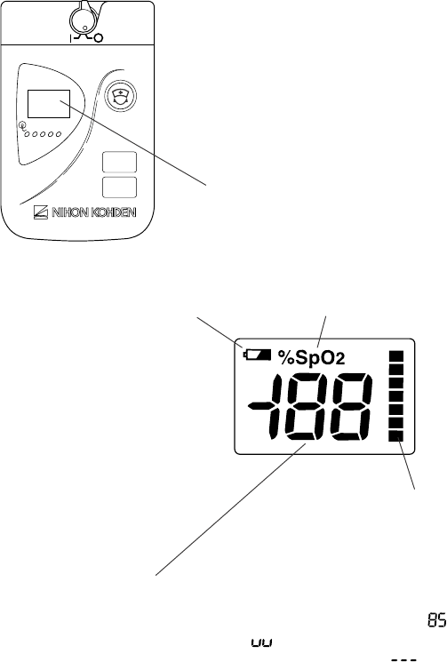
Insufficient Light Alarm
When sufficient light cannot be obtained from the photo emitter of the probe, the
transmitter generates the following sound and indication.
(1) “peep” sound (every 1 second)
(2) pulse level bar graph is maximum
(all bars are lit.)
(3) SpO2 data is displayed as “ ”
(4) %SpO2 is blinking.
In this case, change the attachment site to the appropriate site. Refer to the
operator’s manual of the SpO2 probe.
Probe Malfunction Alarm
CAUTION
When any of the following occurs, the probe may be broken.
Replace it with a new one and check the probe.
••
••
•The transmitter generates “pip” sound every 0.25 seconds.
••
••
•SpO2 data is 85% and blinking.
When Measurement Condition is Unstable
SpO2 data blinks every 1 second when SpO2 signal stability decreases and the
transmitter cannot detect correct pulse waveform because of patient body
movement, poor attachment condition or poor circulation condition at the probe
attachment site.
CAUTION
SpO2 data blinking every second indicates an unstable pulse
waveform and displayed SpO2 value may be inaccurate. The
displayed data may not reflect sudden SpO2 changes.
(3)
(4)
(2)
Operator's Manual ZM-920PA/930PA 41
(1)
Displayed as LED on ZM-920PA
RA LA LL Va Vb
Alarm List
Sound Display Cause Countermeasure
Single
“peep” sound
for 4 s
--- The CALL key is pressed. The sound lasts
while the key is pressed.
--- (1) The battery voltage
decreases and battery
charge is almost zero.
Replace the
batteries with new
ones.
Continuous
“peep” sound
All lights are
off
Battery is completely
discharged.
Replace the
batteries with new
ones. To stop the
sound, turn off the
power.
Electrode lead is
disconnected from the
electrode.
Firmly connect the
electrode lead to
the electrode.
Electrode lead is
disconnected from the
transmitter.
Firmly connect the
electrode lead to
the transmitter.
Electrode lead
discontinuity
Replace the
electrode lead with
a new one.
Electrode is not
firmly attached to the
skin.
--- (2)
Polarization voltage
is abnormally high.
Replace the
electrode with a
new one.
Intermittent
“pip” sound
every 0.5 s
--- SpO2 measurement
site is under
fluorescent light,
surgical light,
sunlight, etc.
Cover the
measurement site
with a blanket or
cloth.
(2)
(5) %SpO2 indication
(4) pulse level bar graph
(3) SpO2 data

42 Operator's Manual ZM-920PA/930PA
Sound Display Cause Countermeasure
Intermittent
“peep” sound
every 1 s
(3)
(4) all lit
(5) blinking
Cannot receive
sufficient light from
the probe photo
emitter.
Attach probe to a
site with 6 to 14
mm thickness
where sufficient
light can be
received.
Intermittent
“pip” sound
every 0.25 s
(3) 85%,
blinking
Broken probe Replace the probe
with a new one.
Patient body
movement
Remove the cause
by checking the
patient condition
and changing the
attachment site.
--- (3) blinking
Probe is not attached
securely.
Securely attach the
probe.

Operator's Manual ZM-920PA/930PA 43
Troubleshooting
If the problem still remains after checking the following, contact your Nihon
Kohden distributor.
Problem Cause Countermeasure
Batteries are not
installed correctly.
The battery
polarity is wrong.
Install the batteries correctly.The power cannot be
turned on.
Batteries are
completely
discharged.
Replace the batteries with new
ones.
Nothing is displayed
on the LCD after
turning the power on.
(ZM-930PA only)
SpO2 display is
turned off.
Turn off the power, and turn on
the power again.
Nothing is displayed
on the monitor after
turning the
transmitter power on.
The channel of the
transmitter and
monitor does not
match.
Set the correct channel on the
monitor.
Electrode lead is
not connected to
the transmitter.
Connect the electrode lead to the
transmitter. ECG electrode lead
works as an antenna for
transmitting data to the receiving
monitor. If ECG is not measured,
the signal may not be received.
Another
transmitter of the
same channel is
used near by.
Turn the transmitter power off. If
the monitor still receives a signal,
there is a high probability that
another transmitter of the same
channel is used nearby.
Follow the instruction of your
channel administrator and use
another transmitter of a different
channel.
Signals are
mixing.
Follow the instruction of your
channel administrator and use
another transmitter of a different
channel.
Signal receiving
condition is poor.
The transmitter is
damaged.
Contact your Nihon Kohden
distributor.

44 Operator's Manual ZM-920PA/930PA
Problem Cause Countermeasure
3 electrode leads
are properly
attached to the
patient but
LEDs light.
The transmitter is fixed to
6 lead monitoring.
Turn off and on the
transmitter power.
Heart rate of the
patient who is
using an electric
blanket cannot be
monitored on the
receiving monitor.
Pacing pulse detection is
set to ON on the monitor.
Turn off the pacing pulse
detection.
The gel on the electrode is
dried out.
The gel on the electrode is
coming off.
Replace the electrode with
a new one.
Electric blanket is used. Cover the blanket with a
shield cover.
ECG baseline is
thick.
(Hum is
overlapping)
Hum filter is set to OFF on
the monitor
Set the filter to ON.
The gel on the electrode is
dried out.
Respiration
waveform
measurement is
unstable.
The gel on the electrode is
coming off.
Replace the electrode with
a new one.
The probe size is not
appropriate for the patient.
Use the appropriate probe
for the patient.
Probe is attached to the
same limb that is used for
NIBP measurement.
Attach the probe to the
opposite limb. Avoid a site
where blood circulation
condition changes greatly.
Probe attachment
condition is poor. Probe is
about to detach from the
skin. External light gets in.
Firmly attach the probe
according to the procedure
in the probe operator’s
manual.
SpO2 data is
unstable and not
reliable.
Measurement site is dirty.
Patient is wearing nail
polish.
Remove dirt and nail
polish.

Operator's Manual ZM-920PA/930PA 45
The transmitter channel can be changed by the QI-901PK Channel Writer. To
change the channel number, refer to the channel writer manual.
WARNING
The following actions must be taken to properly receive the
transmitter signal of the correct patient on the receiving instrument.
Otherwise, there may be signal loss or signals may mix causing a
serious accident, such as monitoring a different patient.
••
••
•Assign a channel administrator in the hospital and only he or she
should manage channel assignments.
••
••
•The channel administrator must manage the channels in the
facility so that there is no signal interference.
••
••
•When the transmitter channel is changed, the channel
administrator must check that the channel on the receiving
monitor is also changed and the signal is properly received.
••
••
•The channel administrator must replace the channel number label
on the transmitter with the new one after changing the channel.
Changing the Transmitter Channel

46 Operator's Manual ZM-920PA/930PA
Lifetime and Disposal
Disposing of Used Batteries
Replacement
When the “ ” LED is lit or the “ ” is displayed on the LCD during operation,
the batteries are running out.
Replace the batteries with new ones. When using rechargeable batteries, recharge
them.
Disposal
Before disposing of the batteries, check with your local solid waste officials for
details in your area for proper disposal. It may be illegal to dispose of these
batteries in the municipal waste stream.
Disposing of Disposable Electrodes
Lifetime
Replace the disposable electrodes with new ones 48 hours after the start of
usage. Otherwise, the gel on the electrode gets dry and adhesive property
decreases. This increases skin electrode contact impedance and causes incorrect
measurement.
Replace the electrodes with new ones even before 48 hours if the contact between
skin and electrode becomes poor.
Disposal
Follow your local laws for disposing of medical waste.

Operator's Manual ZM-920PA/930PA 47
Disposing of the SpO2 Probe
Lifetime
CAUTION
••
••
•Do not use the probe over its stated lifetime. Otherwise the SpO2
measurement accuracy cannot be guaranteed.
••
••
•When the probe is attached on an appropriate site with sufficient
circulation and the error message confirming the probe
attachment repeatedly appears, the probe may be deteriorated.
Replace it with a new one.
Reusable probe
Do not use the probe for more than one year after opening the package. If the
hours are recorded, you can use the probe for up to 6,000 hours.
Warranty for reusable probe
Nihon Kohden Corporation (NKC) shall warrant this probe against all defects in
materials and workmanship for a period of 6 months after the package is opened.
NKC or its authorized agents will repair or replace any probe which proves to be
defective during the warranty period, provided the probe is used in accordance
with the operator’s manual.
Disposable probe
Replace the probe with a new one as specified in the probes operator’s manual. If
the probe is used beyond this time, it deteriorates and correct measurement cannot
be performed.
If the probe is dirty with blood or bodily fluids, replace it with a new one,
regardless of the lifetime.
Disposal
Follow your local laws for disposing of medical waste.

48 Operator's Manual ZM-920PA/930PA
Cleaning, Disinfection and Sterilization
Transmitter and Electrode Lead
WARNING
If detergents or dirty liquid spills into the transmitter, clean it and dry
it completely before use. If the wet transmitter is used, the patient or
anyone in contact with the transmitter may receive an electric
shock.
CAUTION
••
••
•Before cleaning or disinfecting the transmitter, remove the
batteries from the transmitter.
••
••
•The transmitter cannot be sterilized.
Cleaning
Wipe the transmitter and electrode leads with a soft cloth moistened with
disinfecting alcohol or neutral detergent diluted with water. After cleaning, dry
them completely.
Disinfection
CAUTION
••
••
•Do not immerse the electrode lead connector in liquid.
••
••
•Do not disinfect with hypochlorous acid.
••
••
•Use the recommended concentration.
Wipe the outside surface of the transmitter and electrode lead with a non-abrasive
cloth moistened with any of the disinfectants listed on the next page. Use the
recommended concentration.

Operator's Manual ZM-920PA/930PA 49
Disinfectant Concentration (%)
Glutaraldehyde solution 2.0
Hydrochloric alkyl diaminoethylglycine 0.5
Benzalkonium chloride 0.2
Benzethonium chloride solution 0.2
Chlorohexidine gluconate solution 0.5
SpO2 Probe
Refer to the probe manual.

50 Operator's Manual ZM-920PA/930PA
Replacing the Battery Case Cover
When the battery case cover is damaged, replace it with a new one.
Battery case cover, code no. 6113-046365C.
Other than the battery case cover, there are no serviceable parts for the transmitter.
Repair Parts Availability Policy
Nihon Kohden Corporation (NKC) shall stock repair parts (parts necessary to
maintain the performance of the instrument) for a period of 6 years after NKC
announces discontinuation of the instrument. In that period, NKC or its
distributors will repair the instrument. This period may be shorter than 6 years if
the necessary board or part is not available. For discontinuation announcements,
contact your Nihon Kohden distributor or representative.

Operator's Manual ZM-920PA/930PA 51
Specifications
ECG measurement
Channels: 4
Input range: ±5 mV or more
DC offset: ±500 mV or more
Input impedance: 5 MΩ or more (5 Hz)
Pacing pulse detection: ANSI/AAMI EC13
Based upon Pacemaker pulse rejection
Capability
Respiration measurement
Measuring method: Impedance method
Impedance range: 0 to 2 kΩ
SpO2 measurement
Measuring range: 0 to 100%, in 1% steps
Measuring accuracy
When the measuring accuracy of the
SpO2 probe is not considered: ±1 digit (80% ≤ SpO2 ≤ 100%)
±2 digit (50% ≤ SpO2 ≤ 80%)
Less than 50% is not specified.
When the measuring accuracy of the
SpO2 probe is considered: ±2 digit (80% ≤ SpO2 ≤ 100%)
±3 digit (70% ≤ SpO2 ≤ 80%)
Less than 70% is not specified.
Transmitter
FCC regulation: FCC part 95 Subpart-H
Wireless Medical Telemetry Service
(WMTS)
Field strength limits: <200 mV/m (at 3 m)
Undesired emission: below 960 MHz: 200 µV/m (at 3 m)
above 960 MHz: 500 µV/m (at 3 m)
52 Operator's Manual ZM-920PA/930PA
Antenna: ECG electrode lead
Transmission channel: indicated on the transmitter
Transmission frequency range: 608.0250 to 613.9750 MHz
Channel spacing: 50 KHz (25 KHz when interleaved)
Modulation scheme: FSK (Frequency Shift Keying)
Occupied bandwidth: <20 KHz
Effective radiated power: 1.0 mW (conducted)
Safety standards
Safety standard: CSA C22.2 No. 601-1 M90 (1994)
IEC 60601-1 (1988)
IEC 60601-1 Amendment1 (1991)
IEC 60601-1 Amendment2 (1995)
IEC 60601-1-2 (1993)
IEC 60601-2-27 (1994)
According to the type of protection
against electrical shock: INTERNALLY POWERED
EQUIPMENT
According to the degree of protection
against electrical shock:
ECG/impedance method respiration: DEFIBRILLATION-PROOF
TYPE CF APPLIED PART
SpO2: DEFIBRILLATION-PROOF
TYPE BF APPLIED PART
According to the degree of protection
against harmful ingress of water: Ordinary equipment
According to the degree of safety of
application in the presence of a
FLAMMABLE ANAESTHETIC
MIXTURE WITH AIR, OR WITH
OXYGEN OR NITROUS OXIDE: Equipment not suitable for use in the
presence of FLAMMABLE
ANAESTHETIC MIXTURE WITH AIR,
OR WITH OXYGEN OR NITROUS
OXIDE
According to the mode of operation: CONTINUOUS OPERATION
Operator's Manual ZM-920PA/930PA 53
Water resistance
Water does not get inside the transmitter except for the battery case when
immersed in water up to 30 cm deep for 3 minutes.
Power requirements
Battery type: two AA type alkaline dry cell batteries,
manganese dry cell batteries, NiCd
rechargeable batteries, NiMH batteries
Battery lifetime:
ZM-930PA: approximately 3 days
(with alkaline batteries, measuring ECG,
respiration and SpO2 of approximately 60
kg weight adult male patient at the pointing
finger)
approximately 4 days
(with alkaline batteries, measuring ECG
and respiration only)
ZM-920PA: approximately 4 days
Environment
Operating environment
Operating temperature: 5 to 40°C, 41 to 104°F
Operating humidity: 30 to 85% (non-condensing)
Operating atmospheric pressure: 70 to 106 kPa
Operating voltage: 1.6 to 3.2 V
Storage environment
Storage temperature: −20 to 65°C, −4 to 149°F
Storage humidity: 15 to 95% (non-condensing)
Storage atmospheric pressure: 70 to 106 kPa
Dimension and Weight
Dimension: 78 W × 122 H × 26 D (mm)
Weight (without batteries): ZM-930PA: about 180 g
ZM-920PA: about 165 g
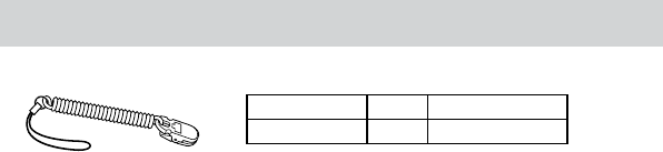
54 Operator's Manual ZM-920PA/930PA
Standard Accessories
Name Q’ty Supply code
Strap 1 Y233

Operator's Manual ZM-920PA/930PA 55
Options
Name Application Model Q’ty Supply
code
3 electrodes, clip type,
lead length 80 cm BR-903PA 1 K911A
3 electrodes, snap type,
lead length 80 cm BR-913PA 1 K910B
6 electrodes, clip type,
lead length 80 cm BR-906PA 1 K912A
Electrode
lead
6 electrodes, snap type,
lead length 80 cm BR-916PA 1 K915A
CAUTION
Use only Nihon Kohden electrodes, electrode leads and SpO2
probes to assure maximum performance from your instrument.
ECG/RESP

56 Operator's Manual ZM-920PA/930PA
SpO2
Name Cable
length
Model/
Code No. Q’ty Supply
code
TL-201T P225F
Finger probe
TL-101T P224A
Multi-site probe TL-120T P225C
Foot probe TL-121T
1
P225D
SpO2 probe (disposable,
for adult, BLUPRO)
TL-251T P201A
SpO2 probe (disposable,
for child, BLUPRO) TL-252T P201B
SpO2 probe (disposable,
for neonate, BLUPRO) TL-253T P201C
Multi-site Y probe
(disposable, for adult,
child, neonate, BLUPO)
1.6
TL-260T
5
P205A
0.8
TL-051S P228A
SpO2 probe (disposable,
for adult, neonate) 1.6 TL-052S P228B
0.8 TL-061S P229A
SpO2 probe (disposable,
for child, infant) 1.6 TL-062S
5
P229B
COTTONY tape 340703 20 P259
Sponge attachment tape
S for TL-260T P260A
Sponge attachment tape
L for TL-260T
24
P260B
Foam tape
--- ---
4
×
25 package P260