Nihon Kohden ZM-940PA Telemetry Medical Transmitter User Manual Cover 2 ZM940PA OM pmd
Nihon Kohden Corporation Telemetry Medical Transmitter Cover 2 ZM940PA OM pmd
User Manual
TRANSMITTER
ZM-940PA
0614-009881

Model: ZM-940PA
Manual code no.: 0614-009881
Reader Comment Card
We welcome your comments about this manual. Your comments and suggestions help us
improve our manuals. Please circle the number for each of the following statements
corresponding to your evaluation and add comments in the space provided.
Fax or send your completed comment card to:
Fax: +81 (3) 5996-8100
International Div., Sales Promotion Section, Nihon Kohden Corp., 1-31-4, Nishiochiai
Shinjuku-ku, Tokyo 161-8560, Japan
Strongly Agree 1 Disagree 4
Agree 2 Strongly Disagree 5
Neutral 3
This manual is organized. 12345
I can find the information I want. 12345
The information is accurate. 12345
I can understand the instructions. 12345
The illustrations are appropriate and helpful. 12345
The manual length is appropriate. 12345
Comments:
Thank you for your cooperation. We appreciate it very much.
Name:
Occupation/Position:
Hospital/Company:
Address:
Phone:
cutting line
Operator's Manual ZM-940PA i
Contents
GENERAL HANDLING PRECAUTIONS .................................................................... i
WARRANTY POLICY ............................................................................................... iii
Equipment Authorization Requirement ................................................................... iii
EMC RELATED CAUTION ....................................................................................... iv
Conventions Used in this Manual and Instrument ................................................. vii
Warnings, Cautions and Notes ......................................................................... vii
Explanations of the Symbols in this Manual and Instrument ........................... viii
Introduction ....................................................................................................................1
Panel Description .......................................................................................................... 2
Front Panel ............................................................................................................... 2
Rear Panel ............................................................................................................... 3
Top Panel ................................................................................................................. 4
Bottom Panel ............................................................................................................ 4
LCD .......................................................................................................................... 6
Note on Parameter Settings .......................................................................................... 8
Important Safety Information ......................................................................................... 9
General .................................................................................................................... 9
Output Signal ........................................................................................................... 9
Preparation .................................................................................................................. 10
Installing (Replacing) Batteries ............................................................................. 10
WARNING and CAUTION for Battery Handling ............................................... 10
Battery Lifetime ................................................................................................. 10
Installing (Replacing) Batteries ........................................................................ 11
Situations Requiring Battery Replacement ..................................................... 12
Battery Condition Indication ............................................................................. 12
Turning the Transmitter On/Off ............................................................................... 13
Turning On the Power ....................................................................................... 13
Turning Off the Power ....................................................................................... 13
Check Items Before Use .................................................................................. 13
Check Items After Power On ............................................................................ 14
Check Items After Use ...................................................................................... 14
Changing the Transmitter Channel ............................................................................. 15
Changing Parameter Setup Settings .......................................................................... 16
Parameter Setup Setting List ................................................................................. 16
Displaying the PARAMETER SETUP Screen ....................................................... 17
Changing Settings ................................................................................................. 18
ii Operator's Manual ZM-940PA
SELECTABLE INTERVALS .............................................................................. 18
INITIAL INTERVAL ............................................................................................ 18
INITIAL CUFF PRESS ...................................................................................... 18
NIBP MODE AFTER STAT ................................................................................ 19
START/FINISH SOUND .................................................................................... 19
OLD NIBP DATA/AFTER .................................................................................. 19
INHIBIT SpO2 DURING NIBP ........................................................................... 20
2ND PARAMETER ........................................................................................... 20
LEADS OFF DISPLAY ...................................................................................... 21
ECG ELECTRODE ........................................................................................... 21
Changing System Setup Settings ............................................................................... 22
System Setup Setting List ...................................................................................... 22
Displaying the SYSTEM SETUP Screen ............................................................... 22
Changing Settings ................................................................................................. 23
CHANNEL/TYPE .............................................................................................. 23
PRESSURE UNIT ............................................................................................ 23
LANGUAGE ...................................................................................................... 24
BRIGHTNESS .................................................................................................. 24
SYSTEM INITIALIZE ......................................................................................... 24
Attaching NIBP Cuff, Electrodes and SpO2 Probe to the Patient ................................ 25
Attachment Examples ............................................................................................ 25
Attaching the NIBP Cuff ......................................................................................... 26
Selecting the NIBP Cuff .................................................................................... 26
Connecting the NIBP Cuff to the Transmitter .................................................... 29
Attaching the NIBP Cuff to the Patient ............................................................. 31
Attaching Electrodes .............................................................................................. 35
Selecting Electrode Lead ................................................................................. 35
Connecting the Electrode Lead to the Transmitter ........................................... 36
Selecting the Electrode Position ...................................................................... 36
Attaching Electrodes to the Patient and Connecting the Electrode Leads to
Disposable Electrodes ..................................................................................... 40
Electrode Position for Respiration Monitoring ................................................. 41
Attaching the SpO2 Probe ...................................................................................... 43
Selecting the SpO2 Probe ................................................................................ 43
Connecting the SpO2 Probe to the Transmitter ................................................ 46
Attaching the Probe to the Patient ................................................................... 46
Locking the Keys on the Transmitter ........................................................................... 48
Monitoring .................................................................................................................... 49
NIBP Monitoring ..................................................................................................... 49
Selecting the Initial Cuff Inflation Pressure ...................................................... 49
Selecting the Measurement Mode and Interval ............................................... 49
Measuring NIBP ............................................................................................... 50
Operator's Manual ZM-940PA iii
Monitoring SpO2 during NIBP Measurement ................................................... 53
ECG and Respiration Monitoring .......................................................................... 53
Electrode Detachment ..................................................................................... 55
SpO2 Monitoring ..................................................................................................... 56
SpO2 and PR Display Order ............................................................................. 57
Monitoring SpO2 during NIBP Measurement ................................................... 57
Display and Message List ........................................................................................... 59
Battery Indication ................................................................................................... 59
ECG/Respiration .................................................................................................... 59
SpO2....................................................................................................................... 60
NIBP ....................................................................................................................... 61
Troubleshooting ........................................................................................................... 62
Transmitter ............................................................................................................. 62
ECG/Respiration .................................................................................................... 63
SpO2....................................................................................................................... 63
NIBP ....................................................................................................................... 64
Maintenance ................................................................................................................ 66
1. External Check ............................................................................................ 66
2. Transmitter Channel ..................................................................................... 66
3. LCD Display ................................................................................................. 68
4. Key Operation .............................................................................................. 69
5. NIBP Cuff for Attaching Transmitter to Patient Arm ...................................... 70
Maintenance Check Sheet .................................................................................... 71
Repair Parts Availability Policy .................................................................................... 72
Lifetime and Disposal .................................................................................................. 73
Disposing of Used Batteries .................................................................................. 73
Battery Lifetime ................................................................................................. 73
Disposal ........................................................................................................... 73
Disposing of Electrodes, SpO2 Probes and NIBP Cuffs ........................................ 73
Cleaning, Disinfection and Sterilization ...................................................................... 74
Transmitter and Electrode Leads ........................................................................... 74
Cleaning ........................................................................................................... 74
Disinfection....................................................................................................... 74
SpO2 Probe ............................................................................................................ 75
YP-943P/944P NIBP Cuffs ..................................................................................... 75
Cleaning ........................................................................................................... 75
Disinfection....................................................................................................... 75
Specifications .............................................................................................................. 76
Measuring Parameters..................................................................................... 76
Transmitting Data ............................................................................................. 76
Displayed Data................................................................................................. 76
ECG Measurement........................................................................................... 76
iv Operator's Manual ZM-940PA
Respiration Measurement ............................................................................... 76
SpO2 Measurement .......................................................................................... 76
NIBP Measurement .......................................................................................... 77
Pulse Rate ........................................................................................................ 77
Transmitter ........................................................................................................ 77
Power Requirements........................................................................................ 77
Dimension and Weight..................................................................................... 77
Environment ..................................................................................................... 78
Safety Standards .............................................................................................. 78
Electromagnetic Compatibility ......................................................................... 79
Electromagnetic Emissions .............................................................................. 79
Electromagnetic Immunity ................................................................................ 80
Recommended Separation Distance between Portable and Mobile RF
Communications Equipment............................................................................ 82
System Composition for EMC Test ................................................................... 82
Standard Accessories ................................................................................................. 83
Options ........................................................................................................................ 84
Transmitter ........................................................................................................ 84
ECG/RESP ....................................................................................................... 84
NIBP ................................................................................................................. 84
SpO2................................................................................................................. 85
Transmission Frequencies .......................................................................................... 86
Operator's Manual ZM-940PA i
GENERAL HANDLING PRECAUTIONS
This device is intended for use only by qualified medical personnel.
Use only Nihon Kohden approved products with this device. Use of non-approved
products or in a non-approved manner may affect the performance specifications of
the device. This includes, but is not limited to, batteries, recording paper, pens,
extension cables, electrode leads, input boxes and AC power.
Please read these precautions thoroughly before attempting to operate the instrument.
1. To safely and effectively use the instrument, its operation must be fully understood.
2. When installing or storing the instrument, take the following precautions:
(1) Avoid moisture or contact with water, extreme atmospheric pressure, excessive
humidity and temperatures, poorly ventilated areas, and dust, saline or sulphuric air.
(2) Place the instrument on an even, level floor. Avoid vibration and mechanical shock,
even during transport.
(3) Avoid placing in an area where chemicals are stored or where there is danger of gas
leakage.
(4) The power line source to be applied to the instrument must correspond in frequency
and voltage to product specifications, and have sufficient current capacity.
(5) Choose a room where a proper grounding facility is available.
3. Before Operation
(1) Check that the instrument is in perfect operating order.
(2) Check that the instrument is grounded properly.
(3) Check that all cords are connected properly.
(4) Pay extra attention when the instrument is in combination with other instruments to
avoid misdiagnosis or other problems.
(5) All circuitry used for direct patient connection must be doubly checked.
(6) Check that battery level is acceptable and battery condition is good when using battery-
operated models.
4. During Operation
(1) Both the instrument and the patient must receive continual, careful attention.
(2) Turn power off or remove electrodes and/or transducers when necessary to assure the
patient’s safety.
(3) Avoid direct contact between the instrument housing and the patient.
5. To Shutdown After Use
(1) Turn power off with all controls returned to their original positions.
(2) Remove the cords gently; do not use force to remove them.
ii Operator's Manual ZM-940PA
(3) Clean the instrument together with all accessories for their next use.
6. The instrument must receive expert, professional attention for maintenance and
repairs. When the instrument is not functioning properly, it should be clearly
marked to avoid operation while it is out of order.
7. The instrument must not be altered or modified in any way.
8. Maintenance and Inspection:
(1) The instrument and parts must undergo regular maintenance inspection at least every 6
months.
(2) If stored for extended periods without being used, make sure prior to operation that the
instrument is in perfect operating condition.
(3) Technical information such as parts list, descriptions, calibration instructions or other
information is available for qualified user technical personnel upon request from your
Nihon Kohden distributor.
9. When the instrument is used with an electrosurgical instrument, pay careful
attention to the application and/or location of electrodes and/or transducers to avoid
possible burn to the patient.
10. When the instrument is used with a defibrillator, make sure that the instrument is
protected against defibrillator discharge. If not, remove patient cables and/or
transducers from the instrument to avoid possible damage.

Operator's Manual ZM-940PA iii
WARRANTY POLICY
Nihon Kohden Corporation (NKC) shall warrant its products against all defects in materials and
workmanship for one year from the date of delivery. However, consumable materials such as
recording paper, ink, stylus and battery are excluded from the warranty.
NKC or its authorized agents will repair or replace any products which prove to be defective
during the warranty period, provided these products are used as prescribed by the operating
instructions given in the operator’s and service manuals.
No other party is authorized to make any warranty or assume liability for NKC’s products.
NKC will not recognize any other warranty, either implied or in writing. In addition, service,
technical modification or any other product change performed by someone other than NKC or
its authorized agents without prior consent of NKC may be cause for voiding this warranty.
Defective products or parts must be returned to NKC or its authorized agents, along with an
explanation of the failure. Shipping costs must be pre-paid.
This warranty does not apply to products that have been modified, disassembled, reinstalled or
repaired without Nihon Kohden approval or which have been subjected to neglect or accident,
damage due to accident, fire, lightning, vandalism, water or other casualty, improper installation
or application, or on which the original identification marks have been removed.
In the USA and Canada other warranty policies may apply.
CAUTION
United States law restricts this device to sale by or on the order of a physician.
Equipment Authorization Requirement
Operation of this equipment requires the prior coordination with a frequency coordinator
designated by FCC for the Wireless Medical Telemetry Service.

iv Operator's Manual ZM-940PA
EMC RELATED CAUTION
This equipment and/or system complies with IEC 60601-2 International Standard
for electromagnetic compatibility for medical electrical equipment and/or
system. However, an electromagnetic environment that exceeds the limits or
levels stipulated in IEC 60601-1-2, can cause harmful interference to the
equipment and/or system or cause the equipment and/or system to fail to
perform its intended function or degrade its intended performance. Therefore,
during the operation of the equipment and/or system, if there is any undesired
deviation from its intended operational performance, you must avoid, identify
and resolve the adverse electromagnetic effect before continuing to use the
equipment and/or system.
The following describes some common interference sources and remedial
actions:
1.Strong electromagnetic interference from a nearby emitter source such as an
authorized radio station or cellular phone:
Install the equipment and/or system at another location. Keep the emitter
source such as cellular phone away from the equipment and/or system, or
turn off the cellular phone.
2.Radio-frequency interference from other equipment through the AC power
supply of the equipment and/or system:
Identify the cause of this interference and if possible remove this interference
source. If this is not possible, use a different power supply.
3.Effect of direct or indirect electrostatic discharge:
Make sure all users and patients in contact with the equipment and/or system
are free from direct or indirect electrostatic energy before using it. A humid
room can help lessen this problem.
4.Electromagnetic interference with any radio wave receiver such as radio or
television:
If the equipment and/or system interferes with any radio wave receiver, locate
the equipment and/or system as far as possible from the radio wave receiver.
5.Interference of lightning
When lightning occurs near the location where the equipment and/or system is
installed, it may induce an excessive voltage in the equipment and/or system.
In such a case, disconnect the AC power cord from the equipment and/or
system and operate the equipment and/or system by battery power, or use an
uninterruptible power supply.

Operator's Manual ZM-940PA v
6.Use with other equipment
When the equipment and/or system is adjacent to or stacked with other
equipment, the equipment and/or system may affect the other equipment.
Before use, check that the equipment and/or system operates normally with
the other equipment.
7.Use of unspecified accessory, transducer and/or cable
When an unspecified accessory, transducer and/or cable is connected to this
equipment and/or system, it may cause increased electromagnetic emission
or decreased electromagnetic immunity. The specified configuration of this
equipment and/or system complies with the electromagnetic requirements
with the specified configuration. Only use this equipment and/or system with
the specified configuration.
8.Use of unspecified configuration
When the equipment and/or system is used with the unspecified system
configuration different than the configuration of EMC testing, it may cause
increased electromagnetic emission or decreased electromagnetic immunity.
Only use this equipment and/or system with the specified configuration.
9.Measurement with excessive sensitivity
The equipment and/or system is designed to measure bioelectrical signals
with a specified sensitivity. If the equipment and/or system is used with
excessive sensitivity, artifact may appear by electromagnetic interference
and this may cause mis-diagnosis. When unexpected artifact appears, inspect
the surrounding electromagnetic conditions and remove this artifact source.
If the above suggested remedial actions do not solve the problem, consult your
Nihon Kohden distributor or representative for additional suggestions.
This equipment complies with International Standard IEC 60601-1-2 (1993) which
requires CISPR11, Group 1, Class B. Class B EQUIPMENT is equipment suitable
for use in domestic establishments and in establishments directly connected to
a low voltage power supply network which supplies buildings used for domestic
purposes.
vi Operator's Manual ZM-940PA
This page is intentionally left blank.

Operator's Manual ZM-940PA vii
Conventions Used in this Manual and Instrument
Warnings, Cautions and Notes
Warnings, cautions and notes are used in this manual to alert or signal the reader to specific
information.
WARNING
A warning alerts the user to the possible injury or death associated with the use
or misuse of the instrument.
CAUTION
A caution alerts the user to possible injury or problems with the instrument
associated with its use or misuse such as instrument malfunction, instrument
failure, damage to the instrument, or damage to other property.
NOTE
A note provides specific information, in the form of recommendations,
prerequirements, alternative methods or supplemental information.
viii Operator's Manual ZM-940PA
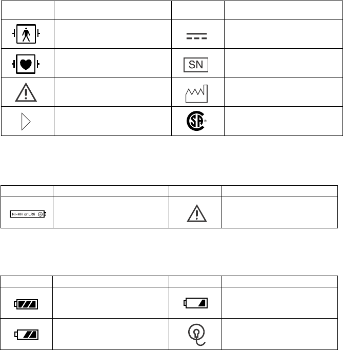
Symbol Description Symbol Description
Full battery Replace battery
NIBP cannot be measured
Replace battery Check electrode
Symbol Description Symbol Description
Defibrillation proof type BF
applied part Direct current
Defibrillation proof type CF
applied part Serial number
Attention, consult operator’s
manual Year of manufacture
Direction for attaching
battery cover CSA mark
On LCD
Explanations of the Symbols in this Manual and Instrument
The following symbols found in this manual/instrument bear the respective descriptions as
given.
On Panel
Symbol Description Symbol Description
Battery position Attention, consult operator’s
manual
Inside Battery Case

Operator's Manual ZM-940PA 1
Introduction
The ZM-940PA transmitter transmits ECG, respiration, SpO2, NIBP and pulse waveform from
a patient to a Nihon Kohden monitor for continuous monitoring. The transmitter can change
channels when connected to the QI-901PK channel writer. The front LCD displays SpO2%,
NIBP, pulse rate, pulse waveform amplitude, electrode condition mark, battery condition and
NIBP measuring mode and interval.
Read the operator’s manual for the receiving monitor together with this manual before operation.
CAUTION
• Do not use the same channel for different patients. Otherwise, two patients’
data will be lost due to mutual modulation interference, or another patient’s
data may appear on the receiving monitor screen.
• Do not use transmitters of adjacent channels in a hospital. Otherwise, radio
waves from one transmitter affect the receiver of the adjacent channel’s
transmitter and there may be interference.
• Do not use the same transmitter on more than one patient at the same time.
Do not connect different sensors on different patients to the same transmitter.
NOTE
• To prevent interference between channels, assign a channel administrator in
the hospital and only he or she should manage channel assignment.
• Use Nihon Kohden parts and accessories to assure maximum performance
from your instrument.
• For stable signal reception, it is recommended to use a diversity antenna
system on the receiving monitor. Otherwise, spike noise from transient fading
of electric field strength (for example, people moving) may interfere with the
transmitter signal and may be mistaken as an arrhythmia on the receiving
monitor.
• NIBP cannot be measured on a neonate. (ECG, respiration and SpO2 can be
monitored on a neonate.)
2 Operator's Manual ZM-940PA
Panel Description
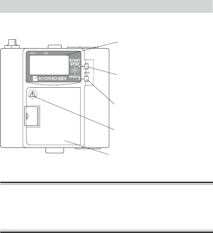
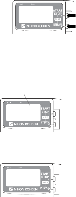
Front Panel
LCD:
Displays measuring data, settings and
other information.
Battery case:
Contains three 1.5 V AA batteries.
NIBP START/STOP key:
Starts/stops NIBP measurement in
selected mode.
NIBP INTERVAL key:
Selects NIBP measurement mode.
WARNING
Close the battery case cover during operation.
If the transmitter is used with the battery case cover open, the patient may get
an electrical shock when defibrillation is performed, and electrostatic discharge
by the patient may intermittently interfere with the waveform or data.
Refer to the WARNING below.
(This symbol is attached to the rear of the
battery case cover.)
Operator's Manual ZM-940PA 3
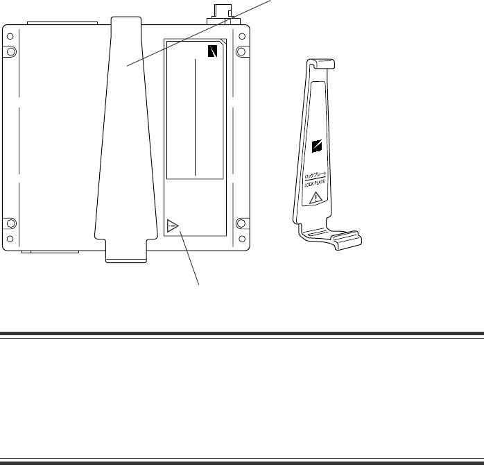
Rear Panel
Lock plate:
Fastens the transmitter to an NIBP cuff.
Refer to the WARNING below.
WARNING
This transmitter is not waterproof. If detergent or liquid spills into the
transmitter, stop using it and contact your Nihon Kohden distributor. If a wet
transmitter is used, the patient or anyone in contact with the transmitter may
receive an electric shock or patient leakage current over the allowed amount
may flow.
4 Operator's Manual ZM-940PA
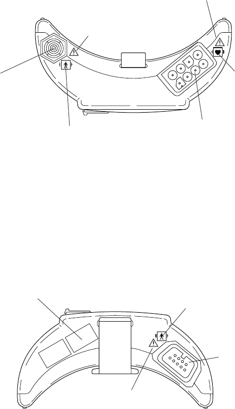
Top Panel
ECG/impedance RESP socket:
Connects the electrode lead for
measuring ECG and/or respiration
by the impedance method.
NIBP socket:
Connects the cuff hose.
Refer to the symbol page.
Refer to the WARNING on the
next page.
Refer to the WARNING on the
next page.
Refer to the symbol
page.
Channel number label:
Indicates the channel number of the
transmitter. Attach the channel number label
to the panel of the monitor.
SpO2 socket:
Connects the SpO2
probe.
Bottom Panel
Refer to the WARNING on the next
page.
Refer to the symbol page.
Operator's Manual ZM-940PA 5
WARNING
• Before performing defibrillation, check that the electrode leads and SpO2
probe attached to the patient are properly connected to the transmitter.
Touching the metal parts of disconnected leads and probes causes serious
electrical shock or injury by discharged energy.
• When performing defibrillation, all persons must keep clear of the bed and
must not touch the patient, any equipment connected to the patient or the
metal parts of leads and probes connected to the patient. Failure to follow this
warning may result in serious electrical burn, shock or other injury.
• When performing defibrillation, discharge as far as possible from electrodes
and medicine on the chest of the patient. If there is a possibility that the
defibrillator paddle could touch electrodes and medicine, remove electrodes
and medicine from the patient. If the defibrillator contacts these materials, the
discharged energy may cause serious electrical burn on the patient.
• When using this transmitter with an ESU, the ESU return plate and the
electrodes for monitoring must be firmly attached to the patient. If the return
plate is not attached correctly, it may burn the patient’s skin where the
electrodes are attached. Refer to the instruction manual for the ESU.
CAUTION
Do not shake or swing the transmitter holding the leads/cables connected to the
transmitter. The transmitter may come off and injure someone or damage
surrounding instruments.
6 Operator's Manual ZM-940PA
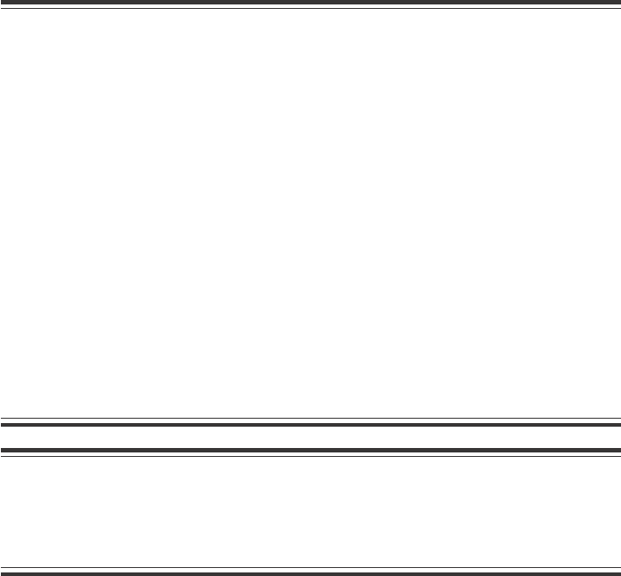
LCD
LOCK
KEYS
1234
56
7
8
9
10
11
No. Name Description
1 NIBP SYS Displays NIBP systolic value.
2 NIBP DIA Displays NIBP diastolic value.
3 NIBP MEAN Displays NIBP mean value.
“CUFF” is displayed with the cuff inflation pressure during
measurement.
4 Check electrode mark Appears when an electrode or electrode lead becomes
detached during ECG measurement.
5 Battery replacement mark Appears when the batteries are weak. For details, refer to
the “Battery Condition Indication” section.
6 Message display area Displays messages.
When ECG is monitored with 6 electrodes and an electrode
or electrode lead is detached, “Check electrode” is indicated
as below, depending on the PARAMETER SETUP setting.
Refer to the “Changing Parameter Setup Settings” and “ECG
and Respiration Monitoring” sections.
LEADS OFF DISPLAY set to CHAR
ECG ELECTRODE set to AHA
LEADS OFF DISPLAY set to CHAR
ECG ELECTRODE set to IEC
LEADS OFF DISPLAY set to IMAGE

Operator's Manual ZM-940PA 7
No. Name Description
7 NIBP measurement mode Displays NIBP measurement mode. When set to auto mode,
the measurement interval is displayed.
8 NIBP interval bar graph In auto NIBP measurement, the remaining time from the last
measurement to the next measurement is displayed as a bar
graph.
9 Pulse level bar graph Displays pulse level in 7 steps.
10 %SpO2Displays SpO2 data.
11 PR Displays pulse rate when NIBP or SpO2 is measured. When
the SpO2 probe is attached to the patient, the real time pulse
rate is displayed. When the SpO2 probe is not attached to the
patient, the pulse rate at the end of NIBP measurement is
displayed.

8 Operator's Manual ZM-940PA
Notes on Parameter Settings
When monitoring NIBP and SpO2, the following setting must be set as indicated in the table to
properly transmit the monitoring data to the receiving monitor. Otherwise, SpO2 cannot be
monitored properly during NIBP measurement.
Some receiving monitors require the software to be upgraded. For details, contact your Nihon
Kohden distributor.
SpO2 probe attachment site INHIBIT SpO2 DURING NIBP setting
Probe attached to the same limb as the cuff ON
Probe attached to the limb without cuff* OFF
* When the SpO2 probe is attached to the same limb as the NIBP cuff and the cuff is
inflated, the SpO2 value becomes unstable and SpO2 or PR alarm may occur.

Operator's Manual ZM-940PA 9
Output Signal
WARNING
Do not use the output signal from the receiving monitor as the synchronization
signal for other equipment such as IABP, MRI, echocardiography or defibrillator
because there may be time delay between the monitor and the other equipment
caused by waveform transmission delay and spike noise may interfere on the
output signal and be mistaken as a trigger.
Important Safety Information
General
WARNING
• Never use this transmitter in the presence of any flammable anesthetic gas or
high concentration oxygen atmosphere. Failure to follow this warning may
cause explosion or fire.
• Never use this transmitter in a high-pressure oxygen medical care tank.
Failure to follow this warning may cause explosion or fire.
• Do not take this transmitter into the MRI test room. This transmitter is not
designed to be used during MRI tests.

10 Operator's Manual ZM-940PA
Installing (Replacing) Batteries
WARNING and CAUTION for Battery Handling
WARNING
• Do not dispose of the battery in fire because it may explode.
• Do not use a disassembled or damaged battery. The contents of the battery
are harmful and the battery may catch fire.
• If the contents of the battery contact the skin or clothes, immediately wash it
thoroughly with water.
• Never short-circuit the + and – terminals. The battery may overheat and catch
fire.
• Take care that the patient does not swallow batteries.
CAUTION
• Refer to the battery and battery charger manuals for details on handling the
batteries.
• Do not handle the batteries with wet hands.
• When the transmitter is not in use, remove batteries. When batteries are
installed, battery power is consumed even if measurement is not performed.
Especially, when NiMH batteries remain in the transmitter when the
transmitter is not in use, the battery may become unusable from
overdischarge and leak liquid which will damage the transmitter.
• The battery charger must be used outside the patient environment.
Battery Lifetime
Use three AA type alkaline dry cell batteries. NiMH rechargeable batteries can also be used.
Preparation
Type Lifetime (Measuring parameters)
ECG, SpO2, NIBP ECG, SpO2ECG only
NiMH secondary 2 days 2 days 2.5 days
Alkaline primary 1 day 2.5 days 3 days
The above data is when new batteries are used at room temperature, NIBP is measured in auto
mode at 60 minute intervals and SpO2 is measured on an index finger of a male patient with
weight 60 kg.
Operation time depends on the thickness of SpO2 probe attachment site.
Operator's Manual ZM-940PA 11
NOTE
When using rechargeable NiMH batteries, shallow charging/discharging
shortens battery capacity. For details, refer to the battery operator’s manual.
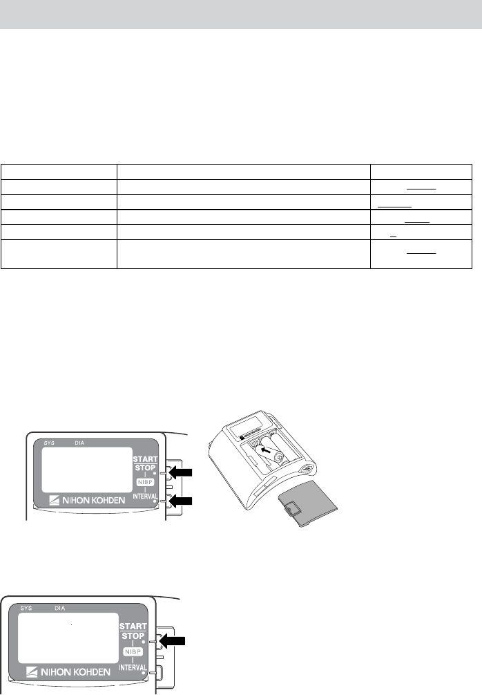
Installing (Replacing) Batteries
CAUTION
Battery replacement must be performed by medical staff. When replacing
batteries of the transmitter currently used for a patient, disconnect electrode
leads from the transmitter before replacing batteries or do not touch the patient
during replacement.
If electrode leads are attached to the patient and a person replacing batteries touches the patient
during battery replacement, patient leakage current over the allowed amount may flow.
CAUTION
• Replace all batteries at the same time.
• Do not use different types of batteries together.
NOTE
Insert the batteries with the correct polarity (+ and –).
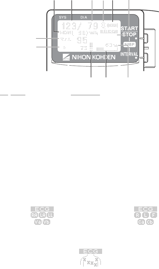
Procedure
1. Remove the battery case cover.
2. Insert three new or fully charged batteries into the
battery case observing the correct polarity.
12 Operator's Manual ZM-940PA
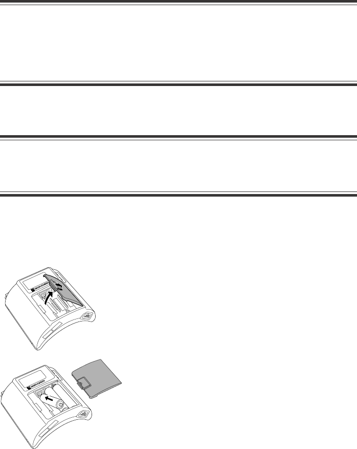
3. Close the cover.
NOTE
Remove the batteries before disposing of the
transmitter.
Situations Requiring Battery Replacement
Replace the batteries when any of the following occurs.
• The transmitter LCD displays the “ ” or “ ”mark.
• The transmitter generates a constant alarm (continuous “peep” sound).
• The transmitter LCD does not display anything when the power is turned on.
• The monitor displays the battery replacement message on the screen.
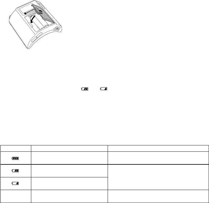
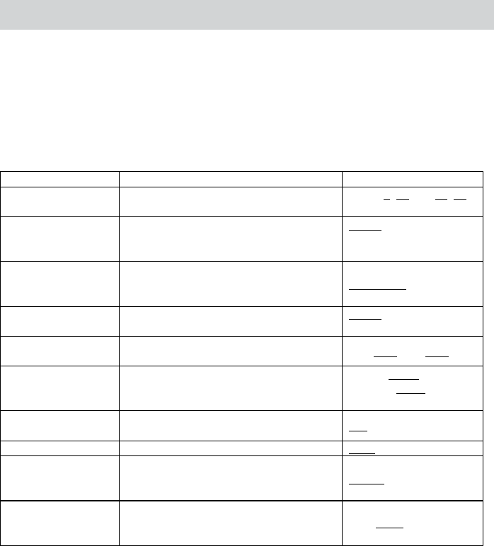
Battery Condition Indication
The battery condition is indicated as follows.
Indication Condition Receiving Monitor
Fully charged battery Batteries are full. There is no indication on
the monitor.
Batteries are low. Replace
batteries.
Batteries are low. NIBP cannot
be measured. Replace batteries.
Message requiring battery replacement is
displayed.
No
indication Dead batteries No signal can be transmitted to the monitor.
There is no indication on the monitor.
Operator's Manual ZM-940PA 13
Turning the Transmitter On/Off
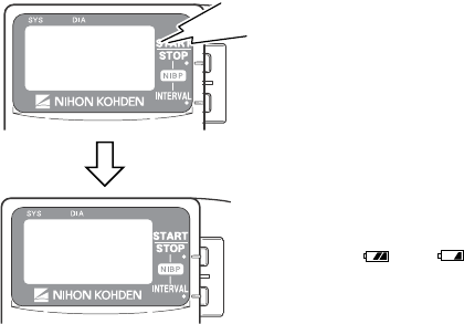
Turning On the Power
When the batteries are installed correctly, the power is
turned on. A one second “peep” sounds and the startup
screen appears. (There is no “peep” sound when there is
no battery power.)
NOTE
Replace the batteries when the LCD displays
the “ ” or “ ”mark.
Turning Off the Power
To turn off the power, remove batteries.
Peep
Check Items Before Use
Before turning on the transmitter power, check the following to confirm that the transmitter can
be used in normal and safe condition.
Appearance
• There are no damaged or dirty parts on the outside of the transmitter (LCD, keys, sockets,
battery case cover, battery case, lock plate, etc.).
• The transmitter is completely dry.
• The electrode lead, SpO2 probe and NIBP cuff are not broken.
• There are no damaged or dirty parts on the disposable SpO2 probe, disposable electrodes or
disposable NIBP cuff.
Batteries
• The battery polarity is correct.
• The battery case spring is firmly fixed and the battery is not loose.
• The battery case cover is firmly closed.
Channel Setting
• The transmitter channel corresponds to those of the receiving monitor.
• There is no transmitter in the surrounding area with the same channel.

14 Operator's Manual ZM-940PA
Check Items After Power On
After turning on the power, check the following.
Power On
• The transmitter generates about a one second “peep” sound and the startup screen appears.
• The transmitter does not generate a continuous “peep” sound.
• The transmitter does not give excessive heat.
• The transmitter LCD displays a “ ” mark.
• The transmitter does not interfere with the operation of other medical instruments in use.
Basic Operation
• The “signal loss” message is not displayed on the receiving monitor when the transmitter is
inside the receiving range of the monitor.
• The battery replacement message is not displayed on the monitor.
• The keys on the transmitter function properly.
• The LCD brightness is appropriate. To adjust brightness, refer to the “Changing System
Setup Settings” section.
Check Items After Use
To use the transmitter in safe and optimum condition for next time, check the following.
Before Turning Power Off
• Temporarily changed settings are changed back to the previous settings.
• There was no malfunction on the transmitter.
Storage
• ECG electrode leads, SpO2 probe and NIBP cuff are cleaned and disinfected.
• When the transmitter gets wet, liquid is wiped off and the transmitter is thoroughly dried.
• There are enough consumables, such as disposable electrodes.
• The transmitter power is turned off by removing batteries from the transmitter.
• Dead batteries are disposed of properly.

Operator's Manual ZM-940PA 15
Changing the Transmitter Channel
The channel of the transmitter can be changed. The optional QI-901PK Channel Writer is
required.
WARNING
The following action must be taken to properly receive the transmitter signal of
the correct patient on the receiving instrument. Otherwise, there may be signal
loss or signals may mix causing a serious accident, such as monitoring a
different patient.
• Assign a channel administrator in the hospital and only he or she should
manage channel assignment on his or her responsibility.
• The channel administrator must manage the channels in the facility so that
there is no signal interference.
• When the transmitter channel is changed, the channel administrator must
check that the channel on the receiving monitor is also changed and the signal
is properly received.
• The channel administrator must replace the channel number label on the
transmitter with the new one after changing the channel.
NOTE
The software version of the QI-901PK channel writer must be 02-01 or later to
change the channel on the ZM-940PA transmitter.
To check the transmitter channel, refer to “CHANNEL” in the “Changing System Setup
Settings” section.
16 Operator's Manual ZM-940PA
Changing Parameter Setup Settings
The initial settings on the PARAMETER SETUP screen must be changed before monitoring.
Changing these settings during monitoring interrupts monitoring.
Parameter Setup Setting List
The factory default settings are underlined.
Setting Item Description Settings
SELECTABLE
INTERVALS
Select the NIBP measurement modes for
the mode selection.
STAT, 5, 10, 15, 30, 60,
120, 240
INITIAL
INTERVAL
Select the initial NIBP measurement
mode at power on.
MAN., 5 min, 10 min,
15 min, 30 min, 60 min,
120 min, 240 min
INITIAL CUFF
PRESS Select the NIBP cuff inflation pressure.
120 mmHg, 150 mmHg,
180 mmHg, 210 mmHg,
240 mmHg
NIBP MODE
AFTER STAT
Select the NIBP measurement mode
after completing STAT measurement.
MAN., 5 min, 10 min,
15 min, 30 min
START/FINISH
SOUND
Turn ON or OFF the sound for NIBP
measurement start/finish. ON, OFF/ON, OFF
OLD NIBP DATA
AFTER
Select whether to hide or dim the NIBP
data after measurement and how long to
wait after measurement to dim or hide it.
DATA: HIDE, DIM
AFTER: 5 min, 10 min,
30 min
INHIBIT SpO2
DURING NIBP
Turn SpO2 monitoring on or off during
NIBP measurement. ON, OFF
2ND PARAMETER Set SpO2 and PR display order. SpO2, PR
LEADS OFF
DISPLAY
Select the mode for displaying electrode
off. This setting is only available when
ECG is monitored with 6 electrodes.
CHAR, IMAGE
ECG ELECTRODE
Select the electrode lead type. This
setting is only available when CHAR is
selected for LEADS OFF DISPLAY.
IEC, AHA
Operator's Manual ZM-940PA 17
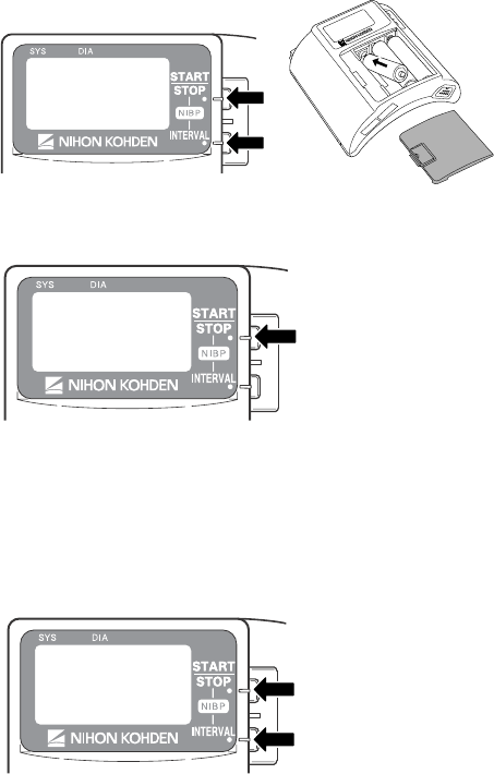
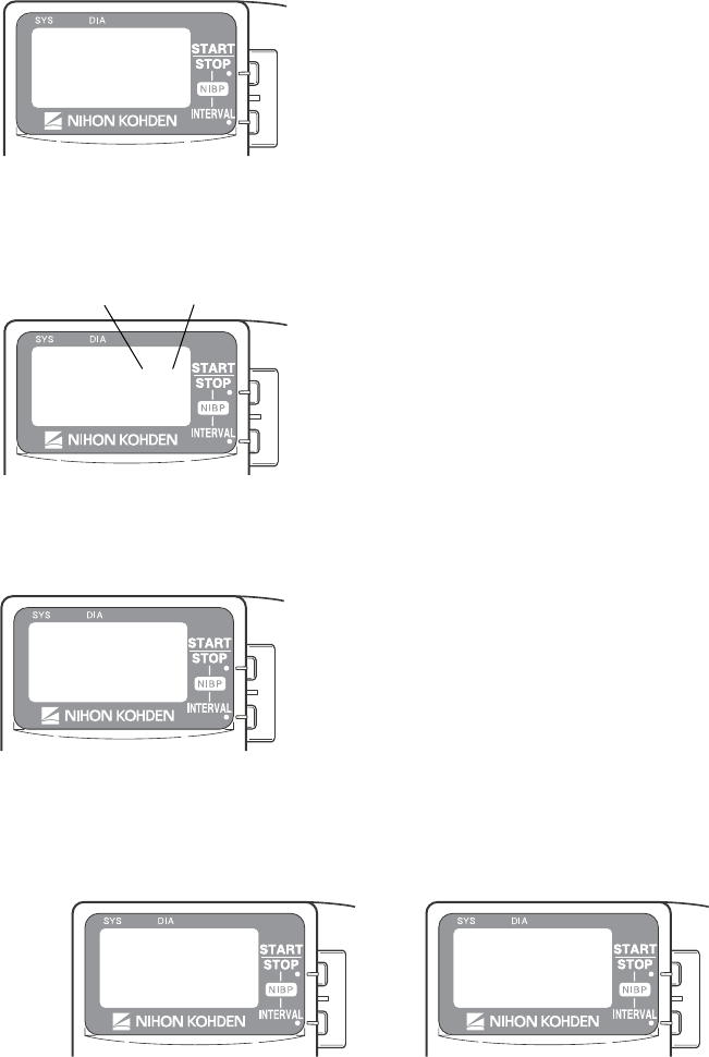
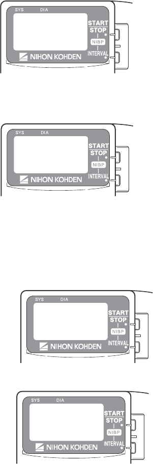
3. Press the NIBP START/STOP key to enter the PARAMETER SETUP screen.
When the cursor is moved to “EXIT” by pressing the NIBP INTERVAL key and the NIBP
START/STOP key is pressed, the startup screen appears, then the monitoring screen
appears.
4. To select or change a setting, press the NIBP START/STOP key.
To move the cursor, press the NIBP INTERVAL key.
Selects or changes setting
Moves cursor
When the cursor is moved to “RETURN” by pressing the NIBP INTERVAL key and the
NIBP START/STOP key is pressed, the SETUP screen appears.
Displaying the PARAMETER SETUP Screen
1. Remove one battery.
2. While pressing the NIBP START/STOP and NIBP INTERVAL keys, install the battery.
The SETUP screen appears.
18 Operator's Manual ZM-940PA
INITIAL INTERVAL
Select the initial NIBP measurement mode at power on.
1. Press the NIBP INTERVAL key to move the
cursor to “INITIAL INTERVAL”.
2. Press the NIBP START/STOP key to select
the mode. Selectable modes are the modes
selected for “SELECTABLE INTERVALS”
and “MAN.” (MANUAL).
INITIAL CUFF PRESS
Select the NIBP cuff inflation pressure.
1. Press the NIBP INTERVAL key to move the
cursor to “INITIAL CUFF PRESS”.
2. Press the NIBP START/STOP key to select
the inflation pressure from 120, 150, 180, 210
and 240 mmHg.
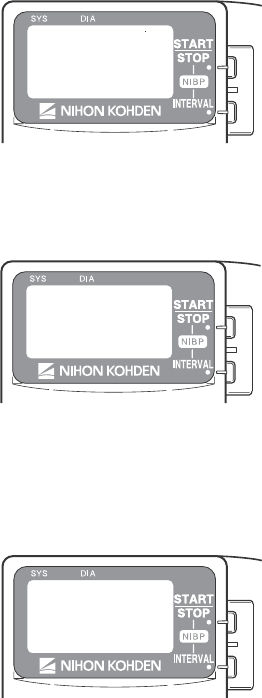
1. Press the NIBP INTERVAL key to move the
cursor to the desired mode.
2. Press the NIBP START/STOP key to select or
unselect the mode. Selectable modes are: STAT,
5, 10, 15, 30, 60, 120 and 240 min.
Changing Settings
SELECTABLE INTERVALS
During monitoring, when the NIBP INTERVAL key is pressed, the measurement mode changes
according to the modes selected in this item. MANUAL mode is already selected for the mode
selection.
Operator's Manual ZM-940PA 19
START/FINISH SOUND
Turn on or off the sound for NIBP measurement start and finish.
Start sound End sound
1. Press the NIBP INTERVAL key to move the
cursor to “START/FINISH SOUND”.
2. Press the NIBP START/STOP key to turn ON
or OFF.
OLD NIBP DATA/AFTER
Select whether to dim or hide the NIBP data after measurement and how long to wait after NIBP
measurement to dim or hide it.
1. Press the NIBP INTERVAL key to move the
cursor to “OLD NIBP DATA/AFTER”.
2. Press the NIBP START/STOP key to select the
setting.
DATA: DIM NIBP data is dimmed after the “AFTER” interval.
HIDE NIBP data is hidden after the “AFTER” interval. “– – –” is displayed on the
screen.
AFTER: Select the interval after NIBP measurement to dim or hide.
Dimmed Hidden
NIBP MODE AFTER STAT
Select the NIBP measurement mode after completing the STAT measurement.
1. Press the NIBP INTERVAL key to move the
cursor to “NIBP MODE AFTER STAT”.
2. Press the NIBP START/STOP key to select
the mode. The selected mode is automatically
selected for “SELECTABLE INTERVALS”
as well.
20 Operator's Manual ZM-940PA
INHIBIT SpO2 DURING NIBP
Set whether or not to monitor SpO2 during NIBP measurement.
When the SpO2 probe is attached to the same limb as the NIBP cuff and this setting is set to
OFF, the pulse may become unstable and SpO2 or PR alarm may occur. It is recommended to
set this setting to ON so that SpO2 is not measured during NIBP measurement.
When the SpO2 probe is attached to the other limb from the NIBP cuff, this setting can be set to
OFF.
NOTE
When this “INHIBIT SpO2 DURING NIBP” is set to OFF, refer to the “Monitoring
SpO2 during NIBP Measurement” section.
1. Press the NIBP INTERVAL key to move the
cursor to “INHIBIT SpO2 DURING NIBP”.
2. Press the NIBP START/STOP key to select
“ON” or “OFF”.
ON: Stops SpO2 monitoring during NIBP measurement.
OFF: SpO2 is monitored during NIBP measurement.
2ND PARAMETER
Set the display order of SpO2 and PR.
When set to SpO2When set to PR
1. Press the NIBP INTERVAL key to move the
cursor to “2ND PARAMETER”.
2. Press the NIBP START/STOP key to select
“SpO2” or “PR”.
Operator's Manual ZM-940PA 21
LEADS OFF DISPLAY
Select the mode for displaying electrode off. This setting is only available when ECG is
monitored with 6 electrodes.
1. Press the NIBP INTERVAL key to move the
cursor to “LEADS OFF DISPLAY”.
2. Press the NIBP START/STOP key to select
“CHAR” or “IMAGE”.
ECG ELECTRODE
Select the electrode lead type. This setting is only available when “CHAR” is selected for
LEADS OFF DISPLAY.
When set to CHAR When set to IMAGE
1. Press the NIBP INTERVAL key to move the cursor
to “ECG ELECTRODE”.
2. Press the NIBP START/STOP key to select “IEC”
or “AHA”.
AHA: RA, LA, LL, Va, Vb
IEC: R, L, F, Ca, Cb
22 Operator's Manual ZM-940PA
Changing System Setup Settings
NOTE
Changing System Setup settings must be done only by a qualified personnel.
System Setup Setting List
The factory default settings are underlined.
Setting Item Description Settings
CHANNEL Displays the transmitter channel.
PRESSURE UNIT Select the units for NIBP. mmHg, kPa
LANGUAGE Select the language for screen display. JPN, ENG
BRIGHTNESS Select the LCD brightness. 1, 2, 3, 4
SYSTEM
INITIALIZE
Initializes all settings to the factory default
settings.
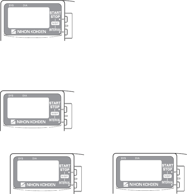
Displaying the SYSTEM SETUP Screen
1. Remove one battery.
2. While pressing the NIBP START/STOP and NIBP INTERVAL keys, install the battery.
The SETUP screen appears.
3. Press the NIBP INTERVAL key to move the cursor to “SYSTEM SETUP”.
4. Press the NIBP START/STOP key to enter the
SYSTEM SETUP screen.
When the cursor is moved to “EXIT” by
pressing the NIBP INTERVAL key and the
NIBP START/STOP key is pressed, the startup
screen appears, then the monitoring screen
appears.
Operator's Manual ZM-940PA 23
5. To select or change a setting, press the NIBP START/STOP key.
To move the cursor, press the NIBP INTERVAL key.
Selects or changes setting
Moves cursor
When the cursor is moved to “RETURN” by pressing the NIBP INTERVAL key and the
NIBP START/STOP key is pressed, the SETUP screen appears.
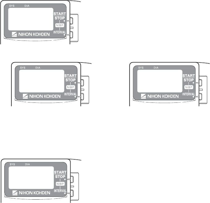
Changing Settings
CHANNEL
The channel of this transmitter is displayed.
Channel of this transmitter
PRESSURE UNIT
Select the unit for NIBP.
1. Press the NIBP INTERVAL key to move the
cursor to “PRESSURE UNIT”.
2. Press the NIBP START/STOP key to select
“mmHg” or “kPa”.
24 Operator's Manual ZM-940PA
LANGUAGE
Select the language for screen display.
1. Press the NIBP INTERVAL key to move the
cursor to “LANGUAGE”.
2. Press the NIBP START/STOP key to select the
language.
SYSTEM INITIALIZE
Do the following procedure to initialize the settings to the factory default settings.
1. Press the NIBP INTERVAL key to move the cursor to “SYSTEM INITIALIZE”.
2. Press the NIBP START/STOP key. The “EXECUTE” message appears.
3. Press the NIBP START/STOP key to initialize the settings to the factory default settings.
BRIGHTNESS
Select the LCD brightness.
1. Press the NIBP INTERVAL key to move the
cursor to “BRIGHTNESS”.
2. Press the NIBP START/STOP key to select the
LCD brightness from 1 to 4.
1234
Light .............................. Dark
Operator's Manual ZM-940PA 25
Attaching NIBP Cuff, Electrodes and SpO2 Probe
to the Patient
The transmitter can be attached to an arm of the patient or placed on the bedside. The required
length of the electrode leads and SpO2 probe cable depends on how the transmitter is to be
attached to the patient.
NOTE
Monitoring SpO2 during NIBP Measurement
When the SpO2 probe is attached to the same limb as the NIBP cuff, the blood
flow decreases during NIBP measurement and pulse wave cannot be detected
and SpO2 cannot be monitored properly. When “INHIBIT SpO2 DURING NIBP” on
the PARAMETER SETUP screen is set to ON (factory default setting), SpO2
monitoring is paused during NIBP measurement to avoid SpO2 alarm
occurrence. However, when monitoring SpO2 on the same limb as NIBP, be
careful when reading SpO2 values.
When monitoring SpO2 is important, attach the probe to the limb to which the
NIBP cuff or catheter is not attached.
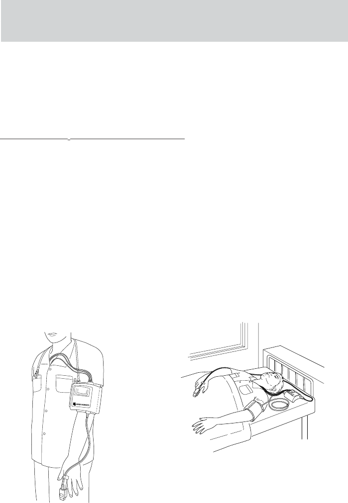
Attachment Examples
When transmitter is attached on an
arm
When transmitter is placed on a bedside
NOTE
When placing the transmitter on a bedside,
place it on a stable and flat place. If the
transmitter falls off, it may be damaged.
26 Operator's Manual ZM-940PA
Attaching the NIBP Cuff
Selecting the NIBP Cuff
Select the NIBP cuff appropriate for the patient.
NOTE
NIBP cannot be measured on neonates using this transmitter.
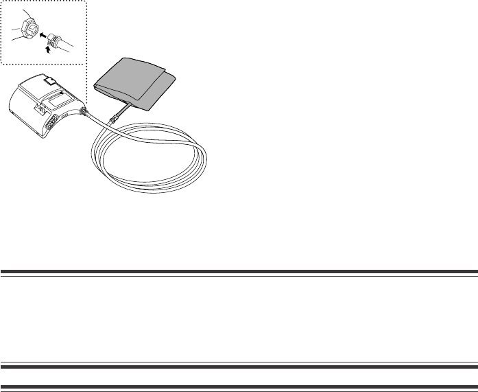
Reusable Cuffs
When attaching the transmitter to the patient arm, a special NIBP cuff is required. An optional
YN-990P extension hose (1.5 m) is available to extend the length between the NIBP socket on
the transmitter and NIBP cuff (e.g. when not attaching the transmitter to the patient arm and
placing the transmitter on a bedside).
Reusable cuff Model Width (cm) Air hose length (cm)
Standard YP-943P 13 15
For adult Large YP-944P 15 15
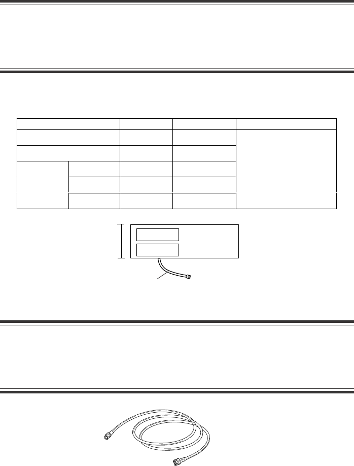
When not attaching the transmitter to the patient arm, the following cuffs can be used. To use
these cuffs, an optional YN-990P extension hose (1.5 m) is required.
Reusable cuff Model Width (cm) Air hose length (cm)
For infants YP-960T 5
Small YP-961T 7
For
children Standard YP-962T 10
Standard YP-963T 13
For adults Large YP-964T 15
15
Width
Width
Air hose
Air hose
Operator's Manual ZM-940PA 27
Disposable Cuffs
CAUTION
The disposable cuffs are not sterilized. If necessary, sterilize the disposable
cuffs using glutaraldehyde solution by following the instructions for the
glutaraldehyde.
When not attaching the transmitter to the patient arm, the following disposable cuffs can be used.
To use these cuffs, an optional YN-990P extension hose (1.5 m) is required.
YN-990P extension hose, 150 cm
Width
Reusable cuff Model Width (cm) Air hose length (cm)
For infants YP-910P 6
For children YP-912P 9
Small YP-913P 12
Standard YP-914P 14
For adults
Large YP-915P 16
20
Extension Hose
CAUTION
When using an extension hose, check that the extension hose is not bent or
squeezed. Otherwise, the cuff may not inflate or deflate. If the cuff cannot
deflate, it may cause congestion on the patient at the cuff attachment site.
Air hose
28 Operator's Manual ZM-940PA
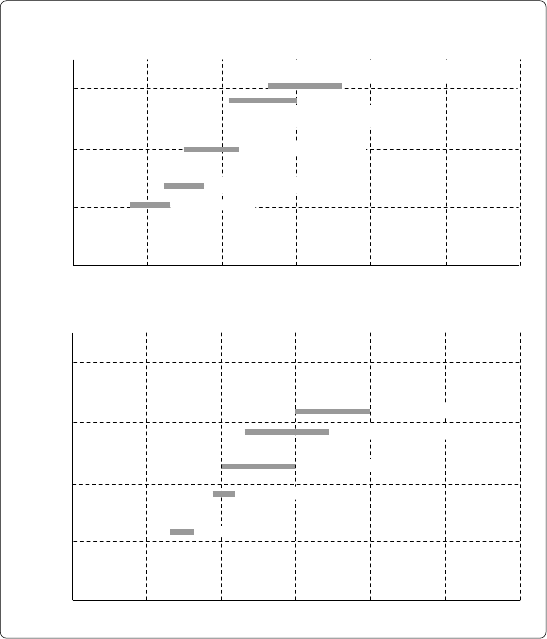
Reference for selecting a cuff
The AHA (American Heart Association) recommends that the cuff width be 40% of the
circumference of the upper arm. Refer to the following graph and select the cuff which suits the
patient’s arm.
NOTE
• If a range of arm circumference appropriate for the cuff is prescribed, use a
cuff within that range.
• To obtain accurate measured values, select a wide cuff which can be attached
to the upper arm. Measuring with a very narrow cuff may result in measured
values higher than the actual values.
• The YP-943P NIBP cuff is for standard size adult. Do not use this cuff when it
does not fit the patient.
15
10
5
10 20 30 40 50
0
20
15
10
5
10 20 30 40 50 60
0
60
Cuff width (cm)
Arm circumference (cm)
Infants YP-960T
Children small YP-961T
Children standard YP-962T
Adults standard YP-943P (cuff for transmitter)
YP-963T
Adults large YP-944P (cuff for transmitter)
YP-964T
Cuff Width and Arm Circumference
Reusable Cuffs
Cuff width (cm)
Arm circumference (cm)
Infants YP-910P
Children standard YP-912P
Adults standard YP-914P
Adults large YP-915P
Disposable Cuffs
Adults small YP-913P
Operator's Manual ZM-940PA 29
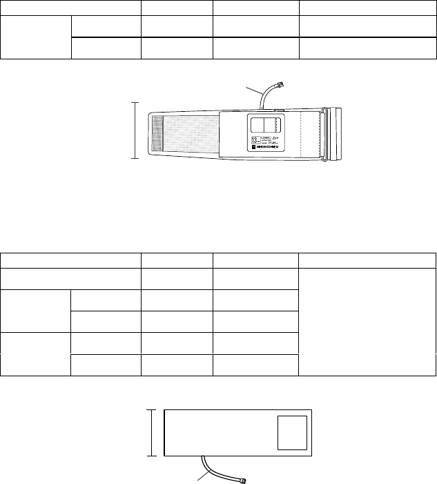
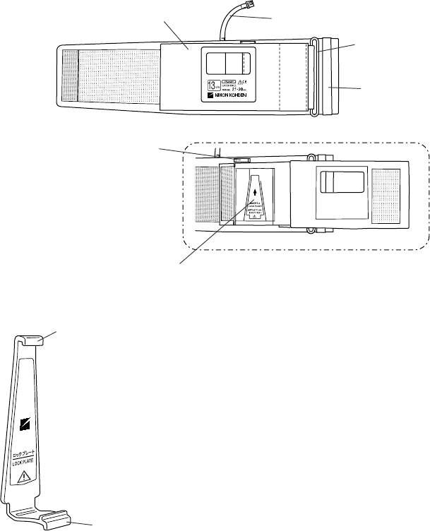
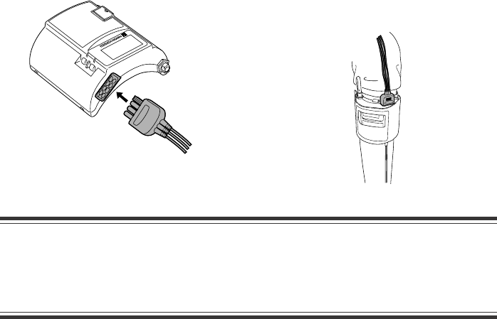
Connecting the NIBP Cuff to the Transmitter
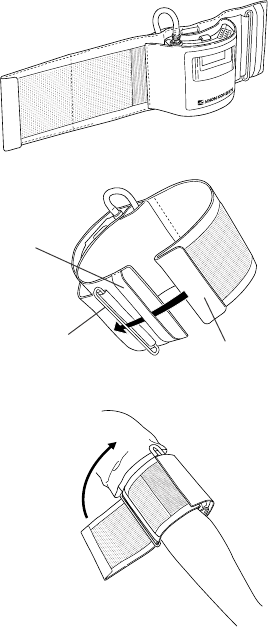
When Using YP-943P/944P NIBP Cuff
To attach the YP-943P/944P NIBP cuff to the transmitter, the lock plate is required.
D ring
Belt
Air hose
Front cover
Front cover open
Belt for the strap
Lock plate pocket
For attaching the NIBP cuff to the transmitter
NOTE
Do not roll up or put weight on the cuff with the lock
plate attached to it. Otherwise, the lock plate may
break.
Lock plate
YP-943P/944P NIBP cuff
Top tab
Bottom tab
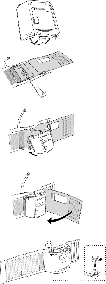
30 Operator's Manual ZM-940PA
1. Remove the lock plate from the
transmitter.
2. Insert the lock plate into the lock plate
pocket on the NIBP cuff.
3. Attach the transmitter to the lock plate
by inserting the tabs on the lock plate
into the slots on the transmitter.
4. Cover the transmitter with the front
cover of the NIBP cuff.
5. Connect the air hose to the NIBP socket
on the transmitter. Turn the cuff
connector joint until it clicks.
1
2
Operator's Manual ZM-940PA 31
When Using YP-960T series or YP-910P series NIBP Cuff
To use these NIBP cuffs, an optional YN-990P extension hose (1.5 m) is required.
NOTE
Connect the joints properly. If there is an air leak, NIBP cannot be measured
properly.
1. Connect the NIBP cuff to the extension hose.
2. Connect the other end of the extension hose to
the NIBP socket on the transmitter. Turn the
joint clockwise until it clicks.
To disconnect the cuff from the transmitter,
turn the hose joint counterclockwise.
Attaching the NIBP Cuff to the Patient
WARNING
Be careful when measuring NIBP on a patient with known bleeding disorders or
coagulation. After NIBP measurement, there may be dot hemorrhage, or
circulatory disorder by thrombus where the cuff was attached.
CAUTION
• Do not wrap the cuff on an arm or thigh which is used for injection. NIBP
measurement on an arm or thigh which is used for injection may cause a
reflux of blood and stop injection.
• Do not wrap the cuff too tight. It may cause poor blood circulation and
congestion. If the cuff is wrapped too loosely, the NIBP value may be
increased.
• If the skin gets irritated or redness appears on the skin from the cuff, change
the attachment site or stop using the cuff.

32 Operator's Manual ZM-940PA
• NIBP and SpO2 can be measured on the same limb, but the SpO2 monitoring
may not be accurate during NIBP measurement. Be careful when reading the
SpO2 values.*
• Do not reuse disposable cuffs.
* Monitoring SpO2 during NIBP Measurement
When the SpO2 probe is attached to the same limb as the NIBP cuff, the blood flow decreases
during NIBP measurement and pulse wave cannot be detected and SpO2 cannot be monitored
properly. When “INHIBIT SpO2 DURING NIBP” on the PARAMETER SETUP screen is
set to ON (factory default setting), SpO2 monitoring is paused during NIBP measurement to
avoid SpO2 alarm occurrence. However, when monitoring SpO2 on the same limb as the
NIBP, be careful when reading SpO2 values.
NOTE
• Measuring NIBP at a site other than the upper arm gives different values from
those measured at the upper arm. When making diagnosis based on the NIBP
values, measure NIBP on an upper arm.
• To accurately detect the pulsatile flow of the artery, the cuff should be
wrapped around a bare upper arm.
• Do not use an abnormal cuff. The cuff deteriorates from use and cleaning.
Before use, check the cuff and confirm that there is no flaw, crack or hole in it.
Be careful not to damage the inflation bag. If the inflation bag has a hole or a
flaw, it may burst during use. Dispose of an abnormal cuff and replace it with
a new one.
• Refer to the NIBP cuff manual for details.
Cuff Position
Place the cuffed upper arm (brachium) at the same height as
the patient’s heart. If the cuff is not at the same level as the
heart, the weight of the blood affects the blood pressure
reading. The pressure difference per unit height is 0.7
mmHg/cm. The blood pressure reading decreases when the
arm is higher than the heart and increases when lower.
The best measuring condition is when the patient is lying on
his/her back with arms and legs relaxed. If the cuff position
cannot be on the same level as the heart, the displayed blood
pressure reading must be mathematically adjusted.
Heart
When placing the
transmitter on a bed, make
sure that the hose is not
bent.
Operator's Manual ZM-940PA 33
Using the YP-943P/944P NIBP Cuff
1. Attach the NIBP cuff to the transmitter. Refer to
the “Connecting the NIBP Cuff to the
Transmitter” section.
2. Insert the end of the cuff into the belt and then
through the D ring as shown at left.
3. Fold back the cuff at the D ring and fasten it
using the velcro tape.
Make sure that the cuff is not attached on a joint.
NOTE
The cuff must not wrap around the elbow.
D ring
Belt
End of cuff
34 Operator's Manual ZM-940PA
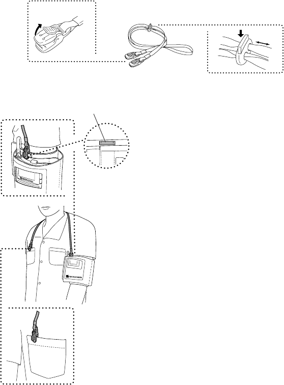
Attaching the Strap to the Transmitter
NOTE
• Use the strap to prevent the transmitter from falling.
• Do not attach the clip to hard objects such as thick cloth or zipper. It will break
the clip.
Attach a strap provided with the transmitter to the NIBP cuff and patient clothes.
To open the clip, firmly
pull out the tab in
direction of the arrow. To adjust the strap length,
push down the tab on the
adjuster and slide.
1. Adjust the length of the strap.
2. Clip one end of the strap to the belt for the strap
on the NIBP cuff.
3. Clip the other end of the strap to the patient’s
clothes as shown left.
Belt for the strap on the NIBP cuff
Operator's Manual ZM-940PA 35
Attaching Electrodes
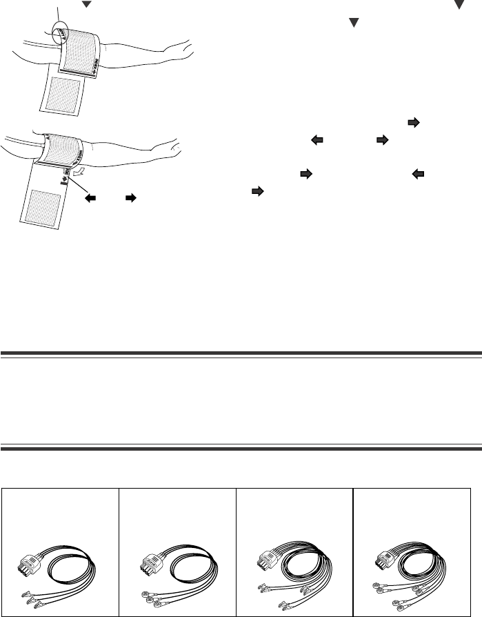
Selecting Electrode Lead
CAUTION
Use only Nihon Kohden specified electrode leads. With electrodes and electrode
leads other than specified ones, the “CHECK ELECTRODE” message appears
and monitoring may stop.
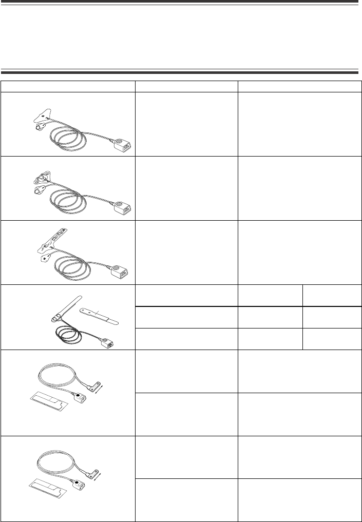
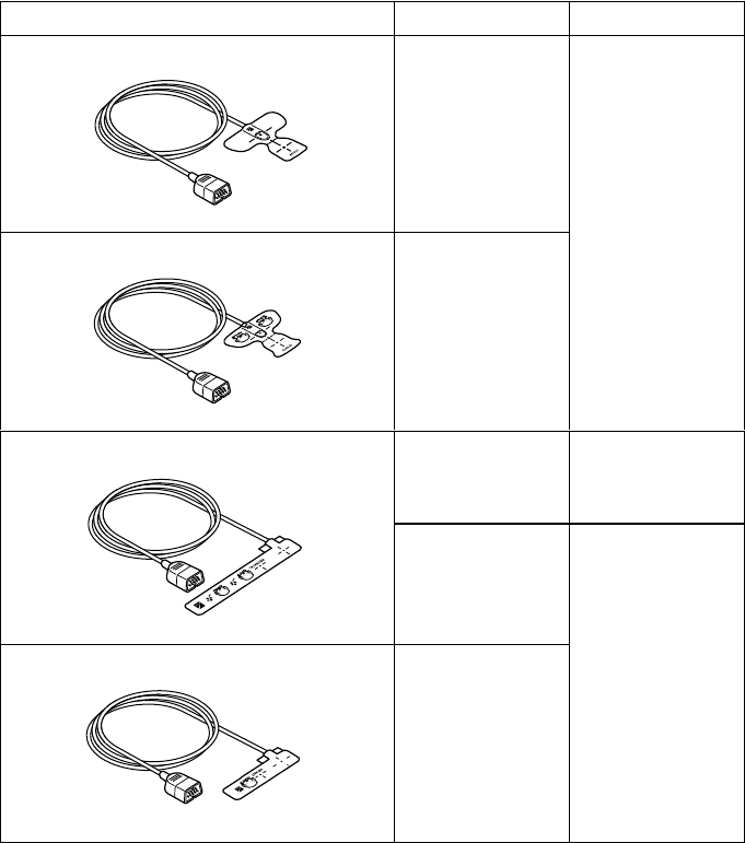
The following electrode leads can be used on the transmitter (option).
ARTERY
RANGE
Using the YP-960T series Reusable Cuffs or YP-910P series Disposable Cuffs
1. Put the cuff on the upper arm so that the
mark of “ARTERY ” aligns with the artery
of the patient.
2. Wrap the cuff so that “INDEX ” comes
within the “ RANGE ”.
If “Index ” is not within the “ RANGE
”, change the cuff size.
BR-903PA,
3 electrodes,
clip type
BR-913PA,
3 electrodes,
snap type
BR-906PA,
6 electrodes,
clip type
BR-916PA,
6 electrodes,
snap type
36 Operator's Manual ZM-940PA
Connecting the Electrode Lead to the Transmitter
Connect the electrode lead to the ECG/RESP socket on the transmitter.
When the transmitter is attached on an arm
CAUTION
Hold the connector of the electrode lead when connecting/disconnecting the
electrode lead. If you disconnect the electrode lead by pulling the lead, it
damages the electrode lead.
Selecting the Electrode Position
Follow the physician’s instructions for electrode placement when available.
For ECG monitoring, electrodes are attached only on the chest to allow patient movement and
obtain continuous stable ECG. Following leads are examples. When also monitoring
respiration, refer to the “Electrode Position for Respiration Monitoring” section.
NOTE
The optimum electrode positions for ECG measurement of a patient are not
always optimum for respiration measurement of the patient. Select positions
suitable for both ECG and respiration measurements, or positions which have
priority for one measurement.
Operator's Manual ZM-940PA 37
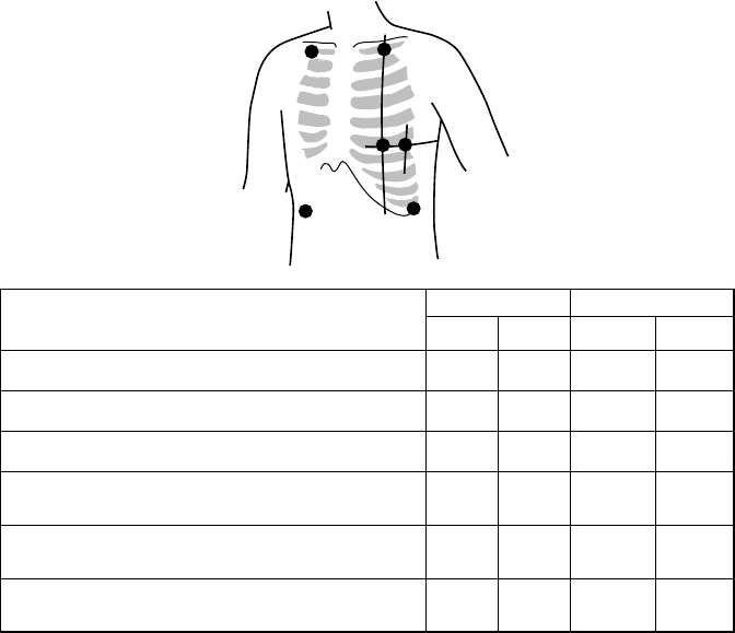
Six Electrodes
The 6-electrode method with lead II and lead V5 is effective for monitoring myocardial ischemia.
You can improve monitoring accuracy considerably by adding lead V4 to this combination. Va
and Vb can be at any position of the standard 12 leads V1 to V6, but V4 and V5 are most
appropriate for myocardial ischemic monitoring.
RA/R LA/L
RL/RF LL/F
Va/Ca
Vb/Cb
Symbol Lead Color
Electrode Position AHA IEC AHA IEC
Left infraclavicular fossa LA L Black Yellow
Right infraclavicular fossa RA R White Red
Below lowest rib on the left anterior axillary line LL F Red Green
Right anterior axillary line at the same level as
LL/F RL RF Green Black
Fifth intercostal space on the left midclavicular
line. (V4 position of standard 12 leads) Va Ca Brown-
blue
White-
brown
Left anterior axillary line at the same level as Va.
(V5 position of standard 12 leads) Vb Cb Brown-
orange
White-
black
38 Operator's Manual ZM-940PA
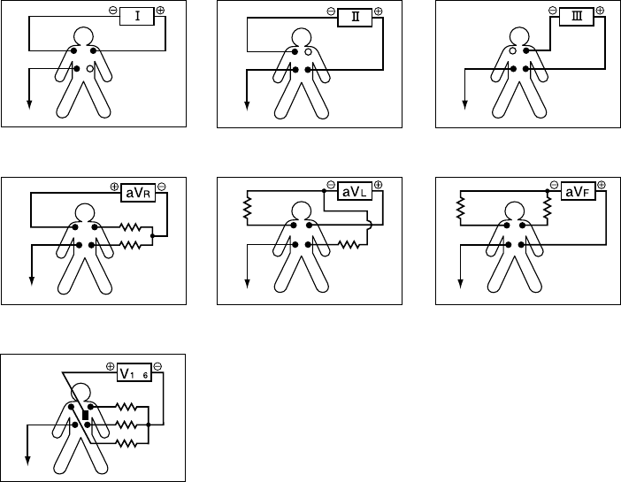
Standard limb leads
Monopolar limb leads
Monopolar chest leads
Lead I Lead II Lead III
aV
R
lead aV
L
lead aV
F
lead
V1 to V6 leads
to
RA
RA
RA RA RA
RA
RA
LA
LA
LA
LA
LA
LALA
LL
LL
LL
LL LL
LL
LL
N (RL)
N (RL)
N (RL) N (RL) N (RL)
N (RL)
N (RL)
Lead Position
Operator's Manual ZM-940PA 39
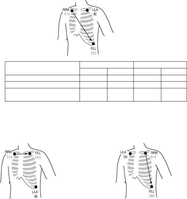
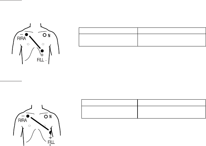
Three Electrodes
• Lead MII, which is similar to standard lead II, used when ECG measurement has priority
Symbol Lead Color
Electrode Position AHA IEC AHA IEC
Left infraclavicular fossa LA L Black Yellow
Right infraclavicular fossa RA R White Red
Below lowest rib on the left
anterior axillary line LL F Red Green
• Lead MI, which is similar to standard
lead I
Change F/LL and L/LA of the lead
MII.
• Lead MIII, which is similar to standard lead
III.
Change R/RA and L/LA of the lead MII.
If the electrode position shown above is not available due to chest surgery, attach the electrodes
to the root of the limbs or below the clavicles for stable ECG monitoring.
40 Operator's Manual ZM-940PA
Attaching Electrodes to the Patient and Connecting the Electrode Leads to
Disposable Electrodes
Prepare the Patient Skin
Shave off excessive body hair.
To reduce skin impedance, clean the electrode site with cream or with a cotton pad moistened
with alcohol. Thoroughly dry the skin with a clean cotton pad.
NOTE
• For a patient with frequent body movement, rub the sites with Skinpure skin
preparation gel. However, do not use Skinpure skin preparation gel on
sensitive skin.
• Do not place electrodes on a wound or on an inflamed, wrinkled or uneven skin
surface.
Attaching Electrodes to the Patient
CAUTION
Do not reuse disposable products.
NOTE
• To maintain good contact between the electrode and skin, check that the paste
of the disposable electrode is not dry.
• When contact between the disposable electrode and skin becomes poor,
replace electrodes with new ones immediately. Otherwise, contact impedance
between the skin and the electrode increases and the correct ECG cannot be
obtained.
Refer to the electrode operator’s manual for details.
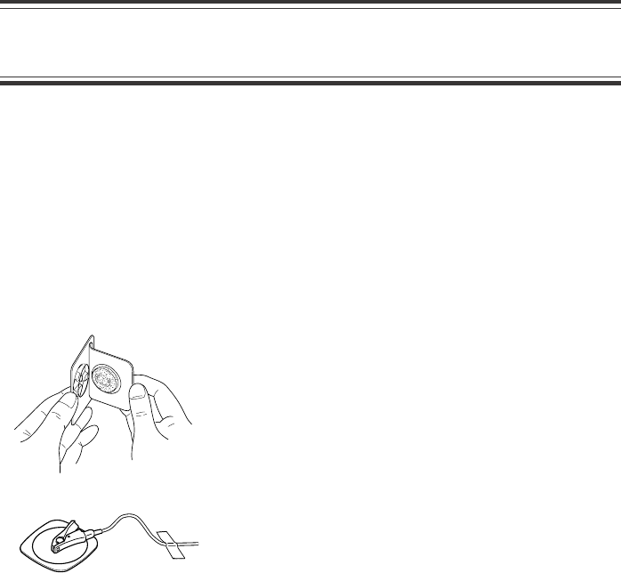
1. Carefully remove the backing paper from the electrode.
Avoid touching the adhesive surface.
2. Place the electrode on the previously cleaned skin.
Pay attention to the electrode lead color and symbol.
3. Clip the electrode lead to the electrode.
4. Fasten the electrode lead wire with surgical tape with
an extra length of wire between the tape and the
electrode. This lessens the movement of electrode
leads by body movement and helps stable monitoring.
Operator's Manual ZM-940PA 41
Electrode Position for Respiration Monitoring
Place the R/RA and F/LL electrodes so that the lungs are between the electrodes.
NOTE
The optimum electrode positions for ECG measurement of a patient are not
always optimum for respiration measurement of the patient. Select positions
suitable for both ECG and respiration measurements, or positions which have
priority for one measurement.
Electrode Position Examples
NOTE
The following examples are when monitoring with 3 electrodes. ECG cannot be
monitored correctly when electrodes are attached as the following examples
when monitoring with 6 electrodes.
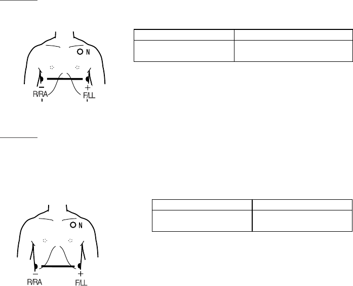
Position 1
In this position, respiration measurement is available; however, there is a difference in amplitude
between different patients.
R or RA F or LL
Right infraclavicular
fossa
Fifth intercostal space on the
left midclavicular line, V4
Position 2
In this position, the waveform amplitude is usually large and the ECG lead is similar to Lead
MII. This position can be generally recommended.
R or RA F or LL
Right infraclavicular
fossa
Fifth intercostal space on the
left midaxillary line, V6
42 Operator's Manual ZM-940PA
Position 3
In this position, the respiration waveform is optimum, but the ECG lead is unusual.
R or RA F or LL
Right midaxillary at the
horizontal level of V4
Fifth intercostal space on the
left midaxillary line, V6
Position 4
In this position, the respiration measurement is influenced by the impedance variation of the
abdomen, so the cardiac pulse wave included in the respiration wave is reduced. Note that the
waveform is inverted in phase compared with the chest movement (the waveform goes down
during inspiration). It is difficult to measure the ECG at the same time.
R or RA F or LL
Lowest rib on the right
anterior axillary line
Lowest rib on the left
anterior axillary line
Operator's Manual ZM-940PA 43
Attaching the SpO2 Probe
Selecting the SpO2 Probe
Select an appropriate probe for the patient.
CAUTION
• Use Nihon Kohden specified SpO2 probe to assure maximum performance
from your instrument.
• Do not use damaged or disassembled probe. It causes incorrect
measurement and may hurt the patient.
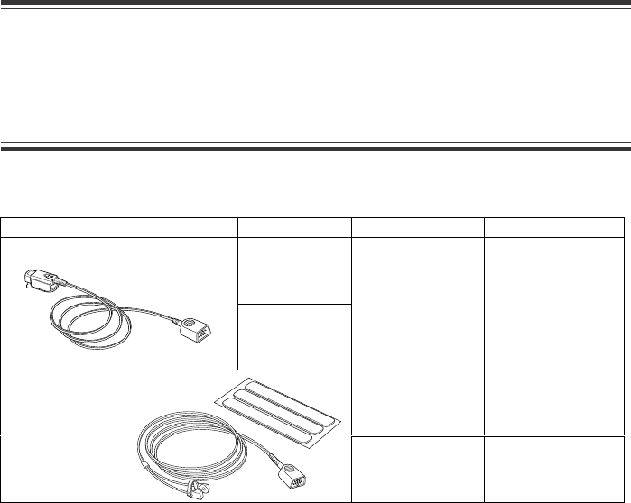
Reusable Probes
When using a TL-201T finger probe, choose the appropriate cable length for attachment.
Probe Cable Length Patient Attachment site
0.6 m
Finger probe TL-201T
1.6 m
Adult or children
20 kg or more
Finger
Adult or Infant
3 kg or more
Finger or toeMulti-site probe TL-220T
Neonate
3 kg or less
Instep and sole
Attachment tape
44 Operator's Manual ZM-940PA
Disposable Probes
CAUTION
• Use the disposable probe only for one patient. Never reuse the disposable
probe for another patient because it causes cross infection.
• Disposable probes are not sterilized.
Probe Patient Attachment site
TL-251T Adult
30 kg or more
Finger or toe
TL-252T Child
3 to 40 kg
Finger or toe
TL-253T Neonate
3 kg or less
Instep and sole
Low birth weight infant
1 kg or less
Instep and
sole
Attachment
tape S
Neonate or Child
3 kg or more
Finger or toe Attachment
tape S
Multi-site Y probe TL-260T
Neonate
3 kg or less
Instep and
sole
Attachment
tape L
Adult
50 kg or more
FingerTL-051S/052S
Cable length TL-051S: 80 cm
TL-052S: 160 cm
Neonate
3 kg or less
Instep and sole
Child or Adult
15 to 50 kg
FingerTL-061S/062S
Cable length TL-061S: 80 cm
TL-062S: 160 cm
Infant
3 to 15 kg
Toe
Attachment tape
40 mm
35 mm
Operator's Manual ZM-940PA 45
Model Patient Attachment site
TL-271T Adult
30 kg or more
TL-272T Child
10 to 50 kg
Finger or toe
Neonate
3 kg or less Instep
TL-273T
Adult
40 kg or more
TL-274T Infant
3 to 20 kg Finger or toe
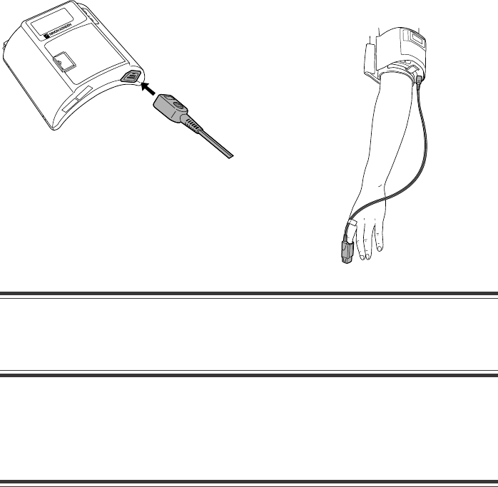
46 Operator's Manual ZM-940PA
CAUTION
Hold the connector when connecting/disconnecting the probe. If you disconnect
the SpO2 probe by pulling the cable, it damages the cable.
Attaching the Probe to the Patient
Attach the probe to the patient by referring to the probe’s manual. Make sure that the light
emitter and photo detector of the probe face each other at the attachment site.
WARNING
• When using a TL-201T finger probe, do not fasten it to a finger by wrapping the
probe to the site with some tape. It may cause poor blood circulation,
congestion, pressure necrosis or burn.
• When using probes other than a TL-201T finger probe, do not wrap the tape too
tight. Check the blood circulation condition by observing the skin color and
congestion at the skin peripheral to the probe attachment site. Even for short-
term monitoring, there may be burn or pressure necrosis from poor blood
circulation, especially on neonates or low birth weight infants whose skin is
delicate. Accurate measurement cannot be performed on a site with poor
peripheral circulation.
Connecting the SpO2 Probe to the Transmitter
Connect the probe to the SpO2 socket on the transmitter.
When the transmitter is attached on an arm

Operator's Manual ZM-940PA 47
• Check the circulation condition by observing the skin color of the measuring
site and the pulse waveform. Change the measuring site every 8 hours for
disposable probes and every 4 hours for reusable probes. The skin
temperature may increase at the attached site by 2 or 3°C (4 or 5°F) and
cause a burn or pressure necrosis. When using the probe on the following
patients, take extreme care and change the measurement site more
frequently according to symptoms and degree.
• A patient with a fever
• A patient with a peripheral circulation insufficiency
• Neonate or low birth weight infant with delicate skin
CAUTION
• If the attachment site is dirty with blood, clean the attachment site before
attaching the probe. If there is nail polish on the attachment site, remove the
polish. Otherwise, the amount of transmitted light decreases and the
measured data may be incorrect or measurement cannot be performed.
• If the skin gets irritated or redness appears on the skin from the probe,
change the attachment site or stop using the probe.
• When the probe is attached on an appropriate site with sufficient circulation,
but the error message confirming the probe attachment repeatedly appears,
the probe may be deteriorated. Replace it with a new one.
• Do not use a probe that is deteriorated by aging. Accurate measurement
cannot be performed.
• When using probes other than a TL-201T finger probe on a neonate, be careful
when removing the adhesive tape from neonatal skin.
• When removing a probe taped to the skin, do not pull the cable. Otherwise the
cable may break.
• When removing the probe from the attachment tape, do not pull the sensor
cable. Otherwise the cable may get damaged.
• Before using the TL-260T multi-site Y probe, be sure to attach the probe to the
sponge attachment tape S or L. Do not use the probe without the sponge
attachment tape attached. It causes incorrect measurement and may damage
the attachment site on the skin.
• When fixing the TL-260T multi-site Y probe with the sponge attachment tape,
confirm that the adhesive part of the tape is not on the skin. The adhesive may
cause oversensitive symptoms on the skin such as redness or itch. If the
adhesive touches the skin, remove it carefully and slowly because neonatal
skin is very delicate.
• Do not use a dirty sponge attachment tape. The measurement value may be
incorrect.
• Refer to the probe instruction manual for details.
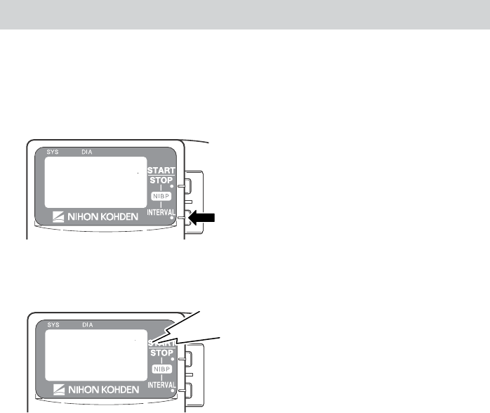
48 Operator's Manual ZM-940PA
Locking the Keys on the Transmitter
To prevent the patient from pressing the keys on the transmitter during monitoring, you can lock
the NIBP START/STOP and NIBP INTERVAL keys.
1. Press the NIBP INTERVAL key for about 3 seconds.
2. A “pip, pip” sounds and the “LOCK KEYS” message is displayed on the LCD.
LOCK
KEYS
Pip, pip
When the NIBP START/STOP key or NIBP INTERVAL key is pressed while the keys are
locked, the “PRESS INT. KEY 3S TO UNLOCK” message appears.
To unlock the keys:
1. Press the NIBP INTERVAL key for about 3 seconds.
2. A “pip, pip” sounds and the keys are unlocked. The “UNLOCK KEYS” message appears
and the keys are unlocked.

Operator's Manual ZM-940PA 49
When preparation is done, monitoring starts.
NIBP Oscillometric Method
NIBP is measured from the change in amplitude pattern of pulsatile oscillation in cuff pressure
as the cuff pressure is reduced from above systolic to below diastolic pressure. The occlusive-
oscillometry method uses this to determine the systolic, diastolic and mean arterial pressure.
NIBP Monitoring
Selecting the Initial Cuff Inflation Pressure
The initial cuff inflation pressure can be changed on the PARAMETER SETUP screen. The
default setting is 180 mmHg. To change the setting, refer to the “Changing Parameter Setup
Settings” section.
Selecting the Measurement Mode and Interval
Measurement Modes
There are three measurement modes: manual, auto and STAT. The selected mode or interval is
displayed at the lower right of the screen.
The measurement mode and interval can be changed by pressing the NIBP INTERVAL key.
When the key is pressed, the measurement mode changes according to the modes selected at
“SELECTABLE INTERVALS” on the PARAMETER SETUP screen. MANUAL mode is
already selected for the mode selection.
To select the modes for the mode selection, refer to the “Changing Parameter Setup Settings”
section.
Manual Measurement
In Manual mode, a single NIBP measurement is performed when the NIBP START/STOP key
is pressed.
STAT (Continuous) Measurement
In STAT mode, measurement is continuously repeated for 15 minutes after the NIBP START/
STOP key is pressed.
When the STAT measurement for 15 minutes is completed, the measurement mode automatically
changes to the Manual mode or Auto mode of selected interval depending on the “NIBP MODE
Monitoring

50 Operator's Manual ZM-940PA
AFTER STAT” setting on the PARAMETER SETUP screen. The default setting is Manual
mode. Refer to the “Changing Parameter Setup Settings” section.
The STAT measurement completes within 15 minutes. When more than 12 minutes elapse from
the start of measurement, there will be no more measurement performed and the measurement
mode changes to the mode selected for “NIBP MODE AFTER STAT” on the PARAMETER
SETUP screen.
Auto Measurement
In Auto mode, measurement is performed automatically at the preset time intervals.
In Auto mode, a single measurement can be performed by pressing the NIBP START/STOP key
between auto measurements.
Measuring NIBP
WARNING
• Be careful when measuring NIBP on a patient with known bleeding disorders
or coagulation. After NIBP measurement, there may be dot hemorrhage, or
circulatory disorder by thrombus where cuff is attached.
• NIBP measurement may be incorrect in the following cases.
• When using an electrical surgery unit.
• When there is body movement.
• When the pulse wave is small (insufficient peripheral circulation).
• Too many arrhythmia.
• When there is vibration.
• When there is a rapid blood pressure change.
• During CPR.
• When performing NIBP measurements in STAT mode or 5 minute intervals,
periodically remove the cuff from the patient for ventilation. Otherwise, the
skin temperature may increase at the cuff attachment site by 2 or 3°C (4 or
5°F). When measuring a patient with a fever or peripheral circulation
insufficiency, it may cause a burn.
CAUTION
When performing NIBP measurement repeatedly, have a rest between
measurements to recover adequate circulation.
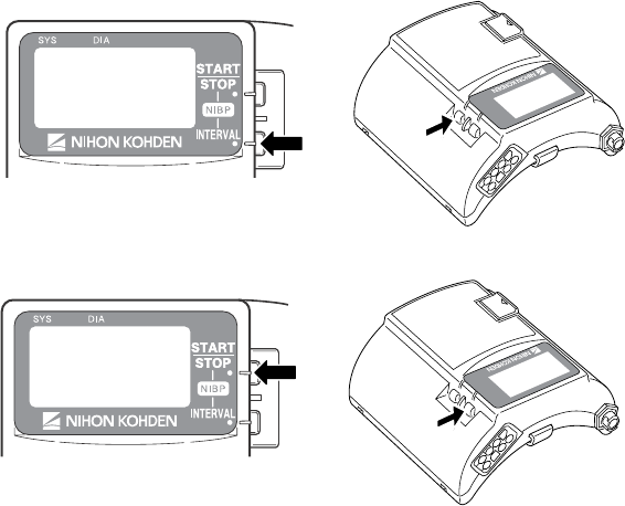
Operator's Manual ZM-940PA 51
NOTE
• When measuring patients who are conscious, help the patient to relax.
Measurement may not be accurate if the patient’s arm is tense or if the patient
talks.
• The data for measurement on a leg tends to be higher than measurement on
the arm. When making diagnosis based on the NIBP values, measure NIBP on
an upper arm.
• Do not apply pressure to the cuff or air hose. NIBP may not be measured
correctly because of noise or NIBP measurement may stop due to the NIBP
safety circuit.
• When the transmitter is attached to the patient arm and the NIBP
measurement is performed when moving, tell the patient to relax and keep
quiet. Otherwise, measurement may be stopped or remeasurement is
repeated due to body movement.
• If there is an abnormal noise generated during measurement, stop using the
transmitter and contact your Nihon Kohden distributor.
• Do not measure NIBP of a patient on whom an IABP is being used.
Measurement may be incorrect due to the mixing of the patient’s own pulse
and IABP pulse.
• NIBP cannot be measured on a neonate using this transmitter.
1. Select the measurement mode by pressing the NIBP INTERVAL key.
2. Press the NIBP START/STOP key to perform measurement.
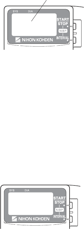
52 Operator's Manual ZM-940PA
The cuff is inflated and the inflation pressure is displayed on the screen.
In manual mode: Measurement is performed once.
In STAT mode: Measurement is performed repeatedly for 15 minutes.
In auto mode: The first measurement is performed when the NIBP START/STOP key
is pressed. The second measurement is performed when the current time
in the transmitter reaches the selected time interval.
To stop measurement during measurement, press the NIBP START/STOP key again.
In STAT mode, after completing the STAT measurement, the measurement mode changes to
the mode set for “NIBP MODE AFTER STAT” on the PARAMETER SETUP screen.
In auto mode, to stop measurement in auto mode, change the mode to manual. To cancel
one measurement, press the NIBP START/STOP key during measurement.
After the measurement is complete, the measured data is displayed on the screen and is
transmitted to the monitor.
Inflation pressure
When SpO2 is not monitored, the pulse rate at the end of NIBP measurement is displayed.
During auto mode measurement, the measurement mode can be changed. During the interval,
press the NIBP INTERVAL key to change the mode. When “MANUAL” is displayed for more
than one second, the measurement in auto mode is stopped.
A buzzer can be set to sound at the start and end of NIBP measurement. Refer to the “Changing
Parameter Setup Settings” section.

Operator's Manual ZM-940PA 53
Data Display After NIBP Measurement
When the time set at “OLD NIBP DATA” on the PARAMETER SETUP screen elapses after
the last measurement, the NIBP data is dimmed or hidden. Whether to dim or hide the old data
can also be selected at “OLD NIBP DATA”. Refer to the “Changing Parameter Setup Settings”
section.
Monitoring SpO2 during NIBP Measurement
When the SpO2 probe is attached to the same limb as the NIBP cuff, the blood flow decreases
during NIBP measurement and pulse wave cannot be detected and SpO2 cannot be monitored
properly. When “INHIBIT SpO2 DURING NIBP” on the PARAMETER SETUP screen is set
to ON (factory default setting), SpO2 monitoring is paused during NIBP measurement to avoid
SpO2 alarm occurrence. However, when monitoring SpO2 on the same limb as the NIBP, be
careful when reading SpO2 values.
ECG and Respiration Monitoring
When the electrodes are attached and the ECG leads are connected to the electrodes, heart rate,
ECG, respiration rate and respiration waveform appear on the monitor.
When 6 leads are used on this transmitter, up to 8 lead (I, II, III, aVR, aVL, aVF, Va and Vb) of
ECG waveforms can be displayed on the receiving monitor. The heart rate is also measured.
When 3 leads are used, one channel ECG waveform of lead II can be displayed on the receiving
monitor. Refer to the operator’s manual of the monitor for details.
Respiration is monitored by measuring changes in impedance between the RA and LL ECG
electrodes. This transmitter sends the changes in impedance to the monitor as a respiration
waveform. The monitor displays the respiration waveform and calculates respiration rate. Refer
to the operator’s manual of the monitor for details.
WARNING
Interaction Between Minute Ventilation Rate-Adaptive Pacemakers and Cardiac
monitoring and Diagnostic Equipment*
The bioelectric impedance measurement sensor of a minute ventilation rate-
adaptive implantable pacemaker may be affected by the transmitter which is
connected to the same patient. If this occurs, the pacemaker may pace at its
maximum rate and the transmitter may give incorrect data to the monitor. If this
occurs, disconnect the electrode leads from the patient or change the setting on

54 Operator's Manual ZM-940PA
the pacemaker by referring to the pacemaker’s manual. For more details,
contact your pacemaker distributor or Nihon Kohden distributor.
* Minute ventilation is sensed in rate-adaptive pacemakers by a technology known as bioelectric
impedance measurement (BIM). Many medical devices in addition to pacemakers use this
technology. When one of these devices is used on a patient with an active, minute ventilation
rate-adaptive pacemaker, the pacemaker may erroneously interpret the mixture of BIM signals
created in the patient, resulting in an elevated pacing rate.
For more information, see the FDA web site.
http://www.fda.gov/cdrh/safety.html
WARNING
When using this transmitter with an ESU, the ESU return plate and the
electrodes for monitoring must be firmly attached to the patient. If the return
plate is not attached correctly, it may burn the patient’s skin where the
electrodes are attached. Refer to the instruction manual for the ESU.
CAUTION
Turn off the power of cell telephones, small wireless devices and other devices
which produce strong electromagnetic interference. Otherwise, the waveforms
and measurements are affected by such interference and the displayed data
may be incorrect.
NOTE
• Noise generated from an electrosurgery unit may interfere on an ECG
waveform, but will not damage it.
• If an electric blanket is used and incorrect heart rate is displayed on the
monitor, turn off the pacing spike detection on the monitor.
• Turn the pacing spike detection to ON on the monitor when monitoring a
pacemaker patient. Pacing pulse is detected by the transmitter and
transmitted to the monitor. If the pacing spike detection is turned OFF, QRS
and pacemaker spike may not be distinguished and pacemaker failure may
not be recognized.
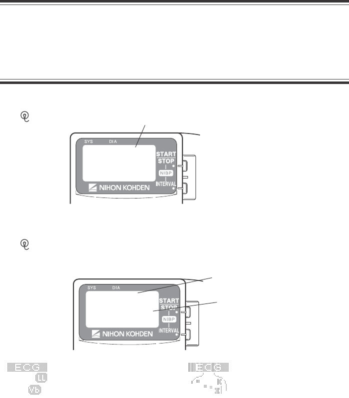
Operator's Manual ZM-940PA 55
Electrode Detachment
In the following conditions, the check electrode indication is displayed on the LCD of the
transmitter and the “CHECK ELECTRODE” message is displayed on the monitor.
• Electrode is detached from skin.
• Electrode lead is disconnected from the electrode.
• Polarization voltage between the electrode and skin is excessively high.
In these cases, check the cause and if necessary, replace electrodes with new ones.
CAUTION
When the “ELECTRODE OFF” or “CHECK ELECTRODE” message is displayed
on the receiving monitor, check electrodes and electrode leads and remove the
cause. While the “ELECTRODE OFF” or “CHECK ELECTRODE” message is
being displayed, there is no ECG monitoring and no alarms.
Check Electrode Indication on the Transmitter when Monitoring with 3 Electrodes
The “ ” mark is displayed. Check electrode symbol
Check Electrode Indication on the Transmitter when Monitoring with 6 Electrodes
The “ ” mark and either the detached lead or detached electrode position is indicated,
depending on the LEADS OFF DISPLAY setting on the PARAMETER SETUP screen.
Check electrode indication
When LEADS OFF
DISPLAY is set to CHAR, the
detached lead is indicated
When LEADS OFF
DISPLAY is set to IMAGE,
the detached electrode
position is indicated with X
Check electrode symbol

56 Operator's Manual ZM-940PA
SpO2 Monitoring
When monitoring starts, SpO2 and pulse waveform are sent to the monitor and SpO2, pulse rate
and pulse level bar graph are displayed on the transmitter LCD.
WARNING
• Measurement may be incorrect in the following cases.
• When the patient’s carboxyhemoglobin or methemoglobin increases
abnormally.
• When dye is injected in the blood.
• When using an electrical surgery unit.
• During CPR.
• When there is body movement.
• When there is vibration.
• When measuring at a site where there are venous pulses.
• When the pulse wave is small (insufficient peripheral circulation).
• When using an IABP (intra-aortic balloon pump).
• Check the circulation condition by observing the skin color of the measuring
site and pulse waveform. Change the measuring site every 8 hours for
disposable probes and every 4 hours for reusable probes. The skin
temperature may increase at the attached site by 2 or 3°C (4 or 5°F) and
cause a burn or pressure necrosis. When using the probe on the following
patients, take extreme care and change the measurement site more
frequently according to symptoms and degree.
• A patient with a fever
• A patient with peripheral circulation insufficiency
• Neonate or low birth weight infant with delicate skin
• When not monitoring SpO2, disconnect the SpO2 cable from the transmitter.
Otherwise, noise may interfere from the probe sensor and incorrect data is
displayed on the screen.
CAUTION
• Turn off the power of cell telephones, small wireless devices and other devices
which produce strong electromagnetic interference. Otherwise, the
waveforms and measurements are affected by such interference and the
displayed data may be incorrect.
• Normally external light does not affect monitoring, however, strong light such
as an operating lamp or sunlight may affect monitoring. If affected, cover the
measuring site with a blanket.

Operator's Manual ZM-940PA 57
• Do not pull or bend the probe cable, and do not run over the probe cable with
caster feet. Do not immerse the probe cable in detergents or water. Failure to
follow these cautions may cause cable discontinuity, short circuit, skin burn
on the patient and incorrect measurement data. Replace any broken probe
with a new one.
• When the probe is attached on an appropriate site with sufficient circulation
and the error message confirming the probe attachment repeatedly appears,
the probe may be deteriorated. Replace it with a new one.
• When the probe failure message appears on the screen, replace it with a new
one. Otherwise SpO2 data may not be accurate.
• While a patient is on medication which causes vasodilation, the pulse
waveform may change and in rare cases the SpO2 value may not be displayed.
NOTE
In order to maintain sufficient blood circulation, keep the measurement site
warm by covering it with a blanket or something similar. Warming the site is
effective, especially for a patient with a small pulse amplitude.
SpO2 and PR Display Order
You can select the display order for SpO2 and PR (pulse rate) on the LCD. Refer to the
“Changing Parameter Setup Settings” section.
Monitoring SpO2 during NIBP Measurement
When the SpO2 probe is attached to the same limb as the NIBP cuff, the blood flow decreases
during NIBP measurement and pulse wave cannot be detected and SpO2 cannot be monitored
properly. When “INHIBIT SpO2 DURING NIBP” on the PARAMETER SETUP screen is set
to ON (factory default setting), SpO2 monitoring is paused during NIBP measurement to avoid
SpO2 alarm occurrence. However, when monitoring SpO2 on the same limb as NIBP, be careful
when reading SpO2 values.
When monitoring SpO2 is important, attach the probe to the limb to which the NIBP cuff or
catheter is not attached.
When SpO2 monitoring is paused during NIBP measurement, the SpO2 value just before the
start of NIBP measurement and an mark are displayed on the transmitter for 30 seconds.
When NIBP measurement is not completed after 30 seconds, “– – –” is displayed for the SpO2
value. The same data also appears on the monitor screen.
58 Operator's Manual ZM-940PA
NOTE
• When continuous SpO2 monitoring is necessary, attach the probe to the limb to
which the NIBP cuff is not attached and set “INHIBIT SpO2 DURING NIBP” on
the PARAMETER SETUP screen to OFF.
• When the probe is attached to the same limb as the NIBP cuff, set the sync
source to a parameter other than SpO2 on the receiving monitor.
• When monitoring SpO2 during STAT NIBP measurement, attach the probe to the
limb to which the NIBP cuff is not attached.
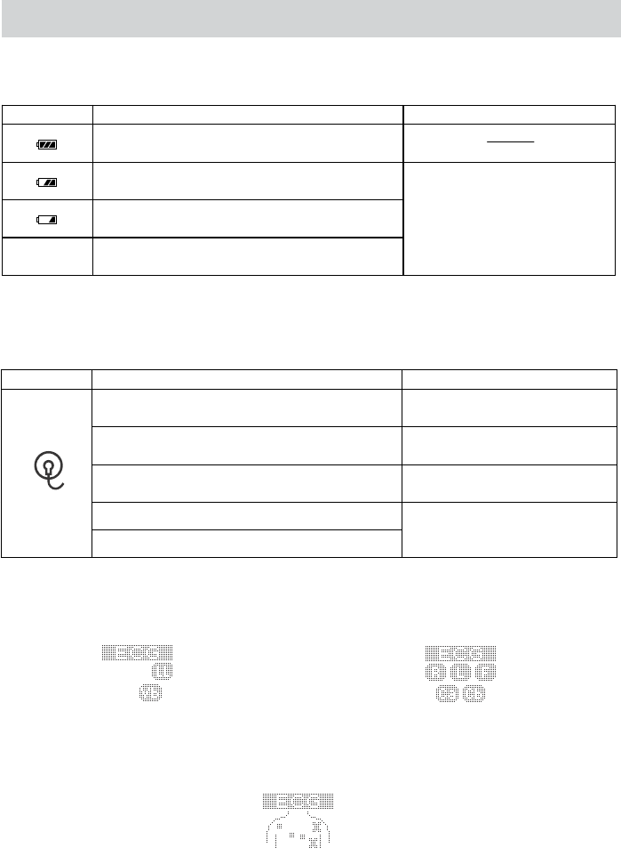
Operator's Manual ZM-940PA 59
Display and Message List
Indication Cause Countermeasure
Fully charged battery
Batteries are low.
Batteries are low. NIBP cannot be measured.
No
indication Dead batteries
Replace batteries.
Battery Indication
ECG/Respiration
Indication Cause Countermeasure
Electrode lead is disconnected from the
electrode.
Firmly connect the electrode
lead to the electrode.
Electrode lead is disconnected from the
transmitter.
Firmly connect the electrode
lead to the transmitter.
Electrode lead discontinuity. Replace the electrode lead
with a new one.
Electrode is not firmly attached to the skin.
Polarization voltage is abnormally high.
Replace the electrode with a
new one.
When monitoring ECG with 6 electrodes, the electrode or lead detached position is indicated by
either lead or electrode position. This is set at LEADS OFF DISPLAY on the PARAMETER
SETUP screen. Refer to the “Changing Parameter Setup Settings” section.
LEADS OFF DISPLAY set to CHAR
ECG ELECTRODE set to AHA
LEADS OFF DISPLAY set to CHAR
ECG ELECTRODE set to IEC
LEADS OFF DISPLAY set to IMAGE

60 Operator's Manual ZM-940PA
Message Cause Countermeasure
During NIBP
measurement
SpO2 monitoring is paused for
NIBP measurement.
Wait for NIBP measurement to
finish.
Considerable body movement.
Detecting
body
movement The probe is not attached to
the patient properly.
When the message is displayed
frequently, check the patient
condition and, if necessary, change
the attachment site.
SpO2 CHECK
PROBE
The probe is not attached to
the patient properly.
Attach the probe to the patient
properly.
The probe is not attached at
the appropriate site.
Attach the probe to a site 6 to 14
mm thick.
SpO2 CHECK
PROBE SITE Probe is expired. Replace the probe with a new one.
Searching for the correct pulse
wave.
Wait until the pulse wave is
detected.
The SpO2 value cannot be
obtained because the
waveform is unstable.
SpO2 DETECTING
PULSE
The probe is not attached to
the patient properly.
Attach the probe to the patient
properly.
SpO2 LIGHT
INTERFERENCE
SpO2 measurement site is
under fluorescent light,
surgical light, sunlight, etc.
Cover the measurement site with a
blanket or cloth.
Probe is expired. Replace the probe with a new one.
SpO2 PROBE
FAILURE Probe is damaged or short-
circuited. Replace the probe with a new one.
Poor peripheral circulation. Check the patient condition and
change the attachment site.
SpO2 WEAK PULSE The probe is attached too
tightly and is obstructing the
blood circulation.
Check the probe attachment
condition and if necessary,
reattach the probe.
SpO2

Operator's Manual ZM-940PA 61
NIBP
Message Cause Countermeasure
The cuff and extension hose are not
properly connected.
The cuff hose (or extension hose) is
not properly connected to the NIBP
socket.
Connect them properly.
NIBP AIR LEAK
The cuff or extension hose is
damaged. Replace with a new one.
The patient’s pulse wave is small. Measure by palpation or auscultation.
NIBP CANNOT
DETECT PULSE The cuff is not wrapped on the
patient properly. Wrap the cuff on the patient properly.
NIBP CUFF
OCCLUSION Transmitter malfunction.
Immediately remove the cuff from the
patient and contact your Nihon Kohden
distributor.
NIBP HIGH CUFF
PRESS
Enormous pressure was applied by
the pressure of the cuff. Remove the cause.
NIBP INFLATION
PRESS LOW Insufficient cuff inflation pressure.
Wait for the remeasurement to be
performed with increased cuff inflation
pressure.
NIBP MEAS TIME-
OUT
The measuring time exceeded the
specified time due to arrhythmia,
body movement, vibration or, cuff
or air hose being squeezed.
Remove the cause if the cause is body
movement, vibration or squeezing of
cuff or hose.
NIBP MODULE
FAILURE Module malfunction. Contact your Nihon Kohden
distributor.
NIBP REMEASURING
NIBP is being remeasured due to
arrhythmia, body movement,
vibration or, cuff or air hose being
squeezed.
If the message still appears after
remeasurement, remove the cause if
the cause is body movement, vibration
or squeezing of cuff or hose.
Check that the hose is not bent or
squeezed.
NIBP SAFETY
CIRCUIT RUNNING
(When this message is
displayed, measurement
cannot be performed for
40 seconds.)
Measurement stopped by the safety
circuit.
Wait 40 seconds, then perform
remeasurement. If the message still
appears, contact your Nihon Kohden
distributor.
NIBP SYS OUT OF
RANGE
The maximum blood pressure
cannot be measured even when the
cuff inflation pressure exceeded 280
mmHg when using adult cuff.
Measure by palpation or auscultation.
The patient’s pulse wave is too
small. Measure by palpation or auscultation.
The cuff is wrapped too loosely. Wrap the cuff properly.
NIBP WEAK PULSE
The cuff size is not appropriate. Use the appropriate cuff.
NIBP ZEROING NIBP zero balance is being
adjusted.
Do not touch the cuff during zeroing.
Wait for the message to disappear.

62 Operator's Manual ZM-940PA
If the problem still remains after checking the following, contact your Nihon Kohden distributor.
Transmitter
Problem Cause Countermeasure
Batteries are not installed
correctly. The battery
polarity is wrong.
Install the batteries correctly.Nothing is
displayed on the
LCD after
turning the
power on.
Batteries are completely
discharged.
Replace the batteries with new ones.
LCD is difficult
to see (too dark
or too light).
LCD brightness is not
appropriate.
Change the LCD brightness on the
SYSTEM SETUP screen. Refer to the
“Changing System Setup Settings”
section.
The channel of the
transmitter and monitor
does not match.
Set the correct channel on the monitor.
Nothing is
displayed on the
monitor after
turning the
transmitter
power on.
The software version of
the multiple patient
receiver is old.
Upgrade the multiple patient receiver
software to receive signal from the
transmitter. The software version must be
01-09 or later.
Another transmitter of the
same channel is used
nearby.
Turn the transmitter power off. If the
monitor still receives a signal, there is a
high probability that another transmitter
of the same channel is used nearby.
Follow the instruction of your channel
administrator and use another transmitter
of a different channel.
Signals are mixing. Follow the instructions of your channel
administrator and use another transmitter
of a different channel.
Signal receiving
condition is
p
oor.
The transmitter is
damaged.
Contact your Nihon Kohden distributor.
Troubleshooting

Operator's Manual ZM-940PA 63
ECG/Respiration
Problem Cause Countermeasure
The heart rate is
unstable.
Pacing detection setting on the
monitor is not correct.
Turn off the pacing detection setting
on the monitor.
When monitoring a pacemaker
patient, turn on pacing detection.
Electrode lead is disconnected
from the electrode.
Firmly connect the electrode lead to
the electrode.
Electrode lead discontinuity Replace the electrode lead with a new
one.
Electrode is not firmly
attached to the skin.
Replace the electrode with a new one.
The “CHECK
ELECTRODE”
message appears
on the receiving
monitor.
Polarization voltage is
abnormally high.
Use Nihon Kohden specified
electrodes.
The gel on the electrode is
dried out.
The gel on the electrode is
coming off.
Replace the electrode with a new one.
Electric blanket is used. Cover the blanket with a shield cover.
ECG baseline is
thick.
(Hum is
overlapping)
Hum filter is set to OFF on the
monitor
Set the filter to ON.
The gel on the electrode is
dried out.
Respiration
waveform
measurement is
unstable.
The gel on the electrode is
coming off.
Replace the electrode with a new one.
SpO2
Problem Cause Countermeasure
The probe size is not
appropriate for the patient.
Use the appropriate probe for the patient.
Probe attachment condition
is poor. Probe is partly
detached from the skin.
External light gets in.
Firmly attach the probe according to the
procedure in the probe operator’s manual.
Measurement site is dirty.
Patient is wearing nail
polish.
Remove dirt and nail polish.
When the probe and cuff are attached to
the same limb, set “INHIBIT SpO2
DURING NIBP” setting on the
PARAMETER SETUP screen to ON.
SpO2 data is
unstable and
not reliable.
Probe is attached to the
same limb that is used for
NIBP measurement.
Attach the probe to the opposite limb.
Avoid a site where blood circulation
condition changes greatly.

64 Operator's Manual ZM-940PA
NIBP
Problem Cause Countermeasure
The cuff hose is not connected
to the NIBP socket properly.
Connect the cuff hose to the socket
properly.
Cuff inflation
pressure is less than
10 mmHg. The cuff is not wrapped
around the arm or is wrapped
too loosely.
Wrap the cuff around the upper
arm.
The cuff hose is not connected
to the NIBP socket.
Connect the cuff hose to the socket
firmly.
The cuff does not
inflate when the
NIBP START/STOP
key is pressed.
The cuff hose or extension
hose may be folded or
squeezed when the cuff
pressure display on the screen
increases quickly but the
actual cuff does not inflate.
Check the cuff hose and air hose.
The cuff size is not correct. Select the cuff which fits the
patient’s limb circumference.
The cuff is not wrapped
around the arm correctly.
Wrap the cuff around the upper
arm, not too tightly or too loosely.
NIBP data is not correct
because of body movement.
Prevent the patient from moving
during measurement.
Check that nothing is touching the
cuff during measurement.
Abnormal
measurement results
are displayed.
Vibration on the cuff.
Change the measuring site.
The cuff is suddenly
deflated during
inflation.
The NIBP START/STOP key
is pressed during inflation.
Auto mode
measurement does
not start even when
the time interval has
passed.
The NIBP INTERVAL key is
pressed and the measurement
mode is changed.
Check the measurement mode and
interval.
The cuff suddenly
inflates.
The measurement mode is set
to auto mode.
Check the time interval. If
necessary, stop measurement.
Cannot connect cuff
to the air hose.
Unspecified cuff is used. Use a cuff specified by Nihon
Kohden.

Operator's Manual ZM-940PA 65
Problem Cause Countermeasure
Vibration on the cuff. Check that nothing is touching the
cuff during measurement.
The cuff hose or extension
hose is bent or squeezed.
Remove the cause.
Cannot measure
NIBP.
The cuff has worn out. Use a new cuff.
Increase the measuring interval.Blood congestion
occurs.
Measuring over a long
period of time at short
intervals.
Do not measure NIBP over a long
time.
Thrombus occurs. Measuring on a patient
with known bleeding
disorders or coagulation.
Do not perform NIBP measurement
on such a patient.
NIBP data on the
screen is --- or dark.
The time set for “OLD
NIBP DATA” on the
PARAMETER SETUP
screen elapsed from the last
measurement.
When NIBP is measured again, the
data is displayed in normal
brightness.
Three loud pip
sounds indicting
NIBP measurement
cannot be started.
The cuff is not deflated
enough to start another
measurement.
Wait 30 seconds and measure again.
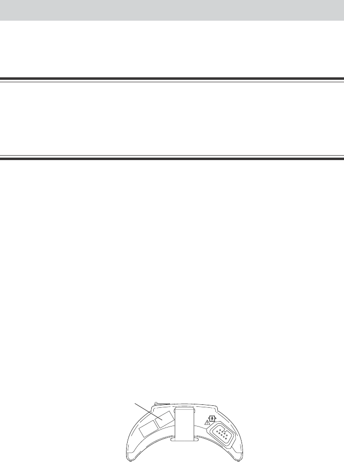
66 Operator's Manual ZM-940PA
To use the instrument in safe and optimum condition, perform maintenance check once every six
months.
CAUTION
Do not disassemble the transmitter when performing maintenance and
inspection. Do not repair the transmitter. When there is any problem with the
transmitter after maintenance and inspection, contact your Nihon Kohden
distributor.
A maintenance check sheet is provided at the end of this section. Make a copy of this check
sheet before performing maintenance check.
1. External Check
• There are no damaged or dirty parts on the outside of the transmitter.
• The battery case cover is not damaged, the spring is firmly fixed and the battery case cover
can be closed firmly.
• NIBP socket is not damaged.
• Keys are not damaged.
• Electrode leads are not damaged.
• There is no blood or chemicals on the transmitter.
2. Transmitter Channel
Check that the channel of the transmitter and the label match.
1. Check that the channel number label attached to the transmitter is not torn or removed.
Maintenance
Channel label
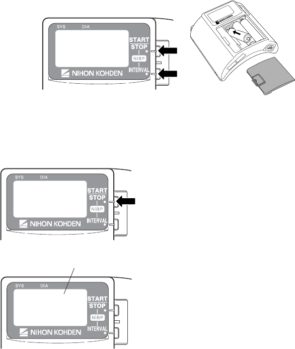
Operator's Manual ZM-940PA 67
2. Remove one battery.
3. While pressing the NIBP START/STOP and NIBP INTERVAL keys, install the battery.
The SETUP screen appears.
4. Press the NIBP INTERVAL key to move the cursor to “SYSTEM SETUP”.
5. Press the NIBP START/STOP key to enter
the SYSTEM SETUP screen. The channel of
this transmitter is displayed.
6. Check that the channel displayed on the LCD
matches the label on the transmitter.
Channel
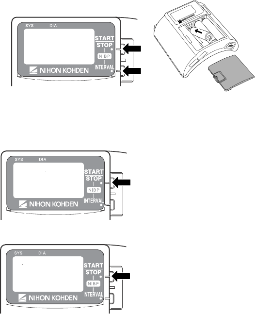
68 Operator's Manual ZM-940PA
3. LCD Display
Check that there are no dots missing on the LCD.
1. Remove one battery.
2. While pressing the NIBP START/STOP and NIBP INTERVAL keys, install the battery.
The SETUP screen appears.
3. Press the NIBP INTERVAL key twice to move the cursor to “MANUAL CHECK”.
4. Press the NIBP START/STOP key to
enter the MANUAL CHECK screen.
5. Check that the cursor is on “LCD
TEST” and press the NIBP START/
STOP key.
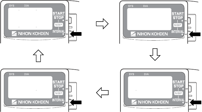
Operator's Manual ZM-940PA 69
6. Every time the NIBP INTERVAL key is pressed, the screen changes as below. Check that
there are no dots missing.
When the NIBP START/STOP key is pressed, the screen returns to the MANUAL
CHECK screen.
4. Key Operation
NIBP START/STOP Key
1. Attach the NIBP cuff to your upper arm.
2. Press the NIBP START/STOP key. Check that the cuff inflates and deflates properly.
3. Press the NIBP START/STOP key again. During inflation, press the NIBP START/STOP
key to check that the cuff deflates properly.
NIBP INTERVAL Key
1. Press the NIBP INTERVAL key and check that the NIBP measuring mode can be changed.
2. Select any interval and press the NIBP START/STOP key to perform auto measurement.
Check that the NIBP is measured at the selected interval.
70 Operator's Manual ZM-940PA
5. NIBP Cuff for Attaching Transmitter to Patient Arm
The NIBP cuff is a consumable. Check the following and when necessary, replace it with a new
one.
Appearance
• There are no dirty parts.
• There are no broken stitches on the cuff.
• The label on the cuff is readable.
• The velcro tape on the cuff is not removed and there are no broken stitches.
• The lock plate is not damaged and functions properly.
Inflation bag
• The inflation bag is not torn or damaged.
• There is no water inside the inflation bag.
• The connector on the inflation bag is not damaged.

Operator's Manual ZM-940PA 71
Maintenance Check Sheet
Hospital/Organization:
Service Personnel:
Instrument Name: Transmitter
Instrument Model: ZM-940PA
Instrument Serial Number:
Hardware Revision Number:
Software Revision Number:
1. External Check OK No
2. Transmitter Channel OK No
3. LCD Display OK No
4. Key Operation OK No
5. NIBP Cuff for Attaching Transmitter to Patient Arm OK No
Overall Judgement
OK
Can be used but needs maintenance
Maintenance required. Cannot be used.

72 Operator's Manual ZM-940PA
Repair Parts Availability Policy
Nihon Kohden Corporation (NKC) shall stock repair parts (parts necessary to maintain the
performance of the instrument) for a period of 8 years from the date of delivery. In that period
NKC or its authorized agents will repair the instrument. This period may be shorter than 8 years
if the board or part necessary for the faulty section is not available.

Operator's Manual ZM-940PA 73
Disposing of Used Batteries
Battery Lifetime
Replace the batteries when the battery replacement indication appears on the transmitter. When
using rechargeable batteries, recharge them.
Lifetime and Disposal
Type Lifetime (Measuring parameters)
ECG, SpO2, NIBP ECG, SpO2ECG only
NiMH secondary 2 days 2 days 2.5 days
Alkaline primary 1 day 2.5 days 3 days
The above data is when new batteries are used at room temperature, NIBP is measured in auto
mode at 60 minute intervals and SpO2 is measured on an index finger of a male patient with
weight 60 kg.
Operation time depends on the thickness of SpO2 probe attachment site.
Disposal
NOTE
Remove the batteries before disposing of the transmitter.
Before disposing of the batteries, check with your local solid waste officials for details in your
area for proper disposal. It may be illegal to dispose of these batteries in the municipal waste
stream.
Disposing of Electrodes, SpO2 Probes and NIBP Cuffs
Refer to the manual of each item.

74 Operator's Manual ZM-940PA
Transmitter and Electrode Leads
CAUTION
• This transmitter is not waterproof. If detergent or liquid spills into the
transmitter, stop cleaning/disinfecting/sterilizing it and contact your Nihon
Kohden distributor. The transmitter needs to be checked for safety and
function before use.
• Before cleaning or disinfecting the transmitter, remove the batteries from the
transmitter.
• The transmitter cannot be sterilized.
Cleaning
Wipe the transmitter and electrode leads with a soft cloth moistened with disinfecting alcohol or
neutral detergent diluted with water. After cleaning, dry them completely.
Disinfection
CAUTION
• Do not immerse the electrode lead connector in liquid.
• Do not disinfect with hypochlorous acid.
• Use the recommended concentration.
Wipe the outside surface of the transmitter and electrode lead with a non-abrasive cloth
moistened with any of the disinfectants listed below. Use the recommended concentration.
Disinfectant Concentration (%)
Glutaraldehyde solution 2.0
Hydrochloric alkyl diaminoethylglycine 0.5
Benzalkonium chloride 0.2
Benzethonium chloride solution 0.2
Chlorohexidine gluconate solution 0.5
Cleaning, Disinfection and Sterilization

Operator's Manual ZM-940PA 75
SpO2 Probe
Refer to the probe manual.
YP-943P/944P NIBP Cuffs
CAUTION
• Do not autoclave.
• Use only glutaraldehyde solution.
• Never allow liquid to get inside the rubber cuff.
• Do not sterilize or disinfect the cuff with ultraviolet light or ozone.
Cleaning
To clean the cuff, remove the lock plate and carefully pull out the inflation bag from the cloth
cover.
Cloth cover: Wash with neutral detergent and water. Thoroughly dry it. When washing in a
washing machine, put it in a net.
Inflation bag: Wipe with a soft cloth or cotton moistened with disinfecting alcohol.
Thoroughly dry it.
Disinfection
To disinfect the cuff, use glutaraldehyde solution. Use the recommended concentration of the
disinfectant. Refer to the disinfectant manual for details. After disinfection, clean the cuff as
described above.

76 Operator's Manual ZM-940PA
Measuring Parameters
Measuring waveforms: ECG, Respiration in impedance method, pulse
Measuring numeric data: SpO2, NIBP, pulse rate
Transmitting Data
Waveform data: ECG, respiration, pulse wave
Numeric data: SpO2 and NIBP
Status information: Battery replacement, channel ID, type of transmitter, check
electrodes, abnormal polarization voltage, pacing data, SpO2
status
Displayed Data
SpO2, NIBP, pulse rate, pulse wave bar graph, check electrode, battery replacement, NIBP
measurement mode and status information
ECG Measurement
Channels: 4
Input range: ±5 mV or more
DC offset: ±500 mV or more
Input impedance: 5 MΩ or more (5 Hz)
Pacing pulse detection: ANSI/AAMI EC13
Based upon Pacemaker pulse rejection Capability
Respiration Measurement
Measuring method: Impedance method
Impedance range: 0 to 2 kΩ or less
SpO2 Measurement
Display range: Depends on the receiving monitor
Measuring range: 0 to 100%, in 1% steps
Minimum display range: 1%
Measuring accuracy (When the measuring accuracy of the SpO2 probe is not considered):
±1 (80% ≤ SpO2 ≤ 100%)
±2 (50% ≤ SpO2 < 80%)
Less than 50% is not specified.
(When considering the measuring accuracy of the SpO2 probe):
±2 (80% ≤ SpO2 ≤ 100%)
±3 (70% ≤ SpO2 < 80%)
Less than 70% is not specified.
Specifications

Operator's Manual ZM-940PA 77
NIBP Measurement
Displayed items: Systolic, diastolic, mean
Cuff pressure display range: 0 to 300 mmHg
Measurement modes: Manual, STAT, auto at 5, 10, 15, 30, 60, 120 or 240 minute
interval
Pulse Rate
Measuring range: 30 to 200 beats/minute ±8 beats/min (NIBP)
30 to 250 beats/min ±3% ±1 beat/min (SpO2)
Transmitter
FCC regulation: FCC part 95 Subpart H
Wireless Medical Telemetry Service (WMTS)
Field strength limits: <200 mV/m (at 3 m)
Undesired emission: below 960 MHz: 200 µV/m (at 3 m)
above 960 MHz: 500 µV/m (at 3 m)
Antenna: Internal
Transmission channel: indicated on the transmitter
Transmission frequency range: 608.0250 to 613.9750 MHz
Channel spacing: 50 kHz (25 kHz when interleave)
Type of emission: F1D
Occupied bandwidth: <20 kHz
Effective radiated power: 1.0 mW (conducted)
Power Requirements
Operating voltage: 3.2 to 4.8 V
Battery type: Three AA type NiMH secondary batteries
Three AA type alkaline dry cell primary batteries
Battery lifetime:
Type Lifetime (Measuring parameters)
ECG, SpO2, NIBP ECG, SpO2ECG only
NiMH secondary 2 days 2 days 2.5 days
Alkaline primary 1 day 2.5 days 3 days
The above data is when new batteries are used at room temperature, NIBP is
measured in auto mode at 60 minute intervals and SpO2 is measured on an index
finger of a male patient with weight 60 kg.
Operation time depends on the thickness of SpO2 probe attachment site.
Dimension and Weight
Dimension: 114 W × 103 H × 58 D (mm)
Weight: 280 g ±30 g (excluding batteries, NIBP cuff and other
accessories)
78 Operator's Manual ZM-940PA
Environment
Operating environment
Operating temperature: 5 to 40°C, 41 to 104°F
When using NIBP cuff, 10 to 40°C, 50 to 104°F
Operating humidity: 30 to 85% (non-condensing)
Operating atmospheric pressure: 70 to 106 kPa
Storage environment
Storage temperature: −20 to 65°C, −4 to 149°F
Storage humidity: 10 to 95%
Storage atmospheric pressure: 70 to 106 kPa
Safety Standards
Safety standard: CAN/CSA-C22.2 No. 601-1 M90:1990
CAN/CSA-C22.2 No. 601-1. 1S1-94:1994
CAN/CSA-C22.2 No. 601-1. 1B-90:R2002
CAN/CSA-C22.2 No. 60601-2-49-04:2004
IEC 60601-1:1988
IEC 60601-1 Amendment1:1991
IEC 60601-1 Amendment2:1995
IEC 60601-1-2:2001
IEC 60601-2-27:1994
IEC 60601-2-30:1999
IEC 60601-2-49:2001
According to the type of protection
against electrical shock: INTERNALLY POWERED EQUIPMENT
According to the degree of protection
against electrical shock:
ECG and impedance method respiration: DEFIBRILLATION-PROOF TYPE CF APPLIED
PART
SpO2 and NIBP: DEFIBRILLATION-PROOF TYPE BF APPLIED
PART
According to the degree of protection
against harmful ingress of water: IPX0 (Ordinary equipment)
According to the degree of safety of
application in the presence of a
FLAMMABLE ANAESTHETIC
MIXTURE WITH AIR, OR WITH
OXYGEN OR NITROUS OXIDE: Equipment not suitable for use in the presence of
FLAMMABLE ANAESTHETIC MIXTURE WITH
AIR, OR WITH OXYGEN OR NITROUS OXIDE
According to the mode of operation: CONTINUOUS OPERATION

Operator's Manual ZM-940PA 79
Electromagnetic Compatibility
IEC 60601-1-2 (2001)
Emissions: CISPR11 Group1,Class B
Electromagnetic Emissions
This Model ZM-940PA is intended for use in the electromagnetic environment specified below.
The customer or the user of the ZM-940PA should assure that it is used in such an environment.
Emissions test Compliance Electromagnetic environment guidance
RF emissions
CISPR 11
Group 1 The ZM-940PA uses RF energy only for its
internal function. Therefore, its RF emissions are
very low and are not likely to cause any
interference in nearby electronic equipment.
RF emissions
CISPR 11
Class B
Harmonic emissions
IEC 61000-3-2
Not applicable
Voltage fluctuations/
flicker emissions
IEC 61000-3-3
Not applicable
The ZM-940PA is suitable for use in all
establishments, including domestic establishments.

80 Operator's Manual ZM-940PA
Electromagnetic Immunity
This Model ZM-940PA is intended for use in the electromagnetic environment specified below.
The customer or the user of the ZM-940PA should assure that it is used in such an environment.
Immunity test IEC 60601 test
level
Compliance
level
Electromagnetic
environment -Guidance
Electrostatic
discharge
(ESD)
IEC 61000-4-2
±6 kV contact
±8 kV air
±6 kV contact
±8 kV air
Floors should be wood,
concrete or ceramic tile. If
floors are covered with
synthetic material, the relative
humidity should be at least
30%.
Electrical fast
transient/ burst
IEC 61000-4-4
±2 kV for power
supply lines
±1 kV for
input/output lines
Not applicable
Surge
IEC 61000-4-5
±1 kV differential
mode
±2 kV common mode
Not applicable
Voltage dips,
short
interruptions
and voltage
variations on
power supply
input lines
IEC 61000-4-11
<5% UT (>95% dip in
UT) for 0.5 cycle
40% UT (60% dip in
UT) for 5 cycles
70% UT (30% dip in
UT) for 25 cycles
<5% UT (>95% dip in
UT) for 5 s
Not applicable
Power
frequency
(50/60 Hz)
magnetic field
IEC 61000-4-8
3 A/m 3 A/m Power frequency magnetic fields
should be at levels characteristic
of a typical location in a typical
commercial or hospital
environment.
NOTE UT is the AC mains voltage prior to application of the test level
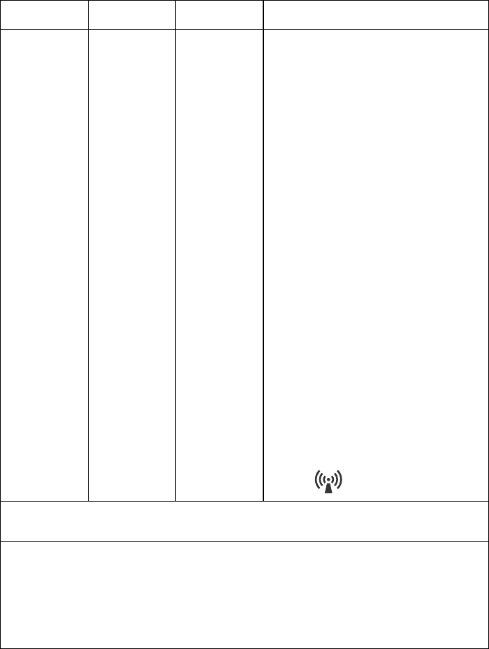
Operator's Manual ZM-940PA 81
Immunity test IEC 60601
test level
Compliance
level
Electromagnetic environment -
guidance
Conducted RF
IEC 61000-4-6
Radiated RF
IEC 61000-4-3
3 Vrms
3 V/m 80 MHz
to 2.5 GHz
3 Vrms
3 V/m 80 MHz
to 2.5 GHz
Portable and mobile RF communications
equipment should be used no closer to any
part of the ZM-940PA, including cables,
than the recommended separation distance
calculated from the equation applicable to
the frequency of the transmitter.
Recommended separation distance
d = 1.2√P
d = 1.2√P 80 MHz to 800 MHz
d = 2.3√P 800 MHz to 2.5 GHz
where P is the maximum output power
rating of the transmitter in watts (W)
according to the transmitter manufacturer
and d is the recommended separation
distance in meters (m).
Field strengths from fixed RF transmitters,
as deter mined by an electromagnetic site
survey*1, should be less than the compliance
level in each frequency range*2.
Interference may occur in the vicinity of
equipment marked with the following
symbol:
NOTE 1: At 80 MHz and 800 MHz, the higher frequency range applies.
NOTE 2: These guidelines may not apply in all situations. Electromagnetic propagation is affected by
absorption and reflection from structures, objects and people.
*1Field strengths from fixed transmitters, such as base stations for radio (cellular/cordless) telephones and
land mobile radios, amateur radio, AM and FM radio broadcast and TV broadcast cannot be predicted
theoretically with accuracy. To assess the electromagnetic environment due to fixed RF transmitters, an
electromagnetic site survey should be considered. If the measured field strength in the location in which
the ZM-940PA is used exceeds the applicable RF compliance level above, the ZM-940PA should be
observed to verify normal operation. If abnormal performance is observed, additional measures may be
necessary, such as re-orienting or relocating the ZM-940PA.
*2Over the frequency range 150 kHz to 80 MHz, field strengths should be less than 3 V/m.
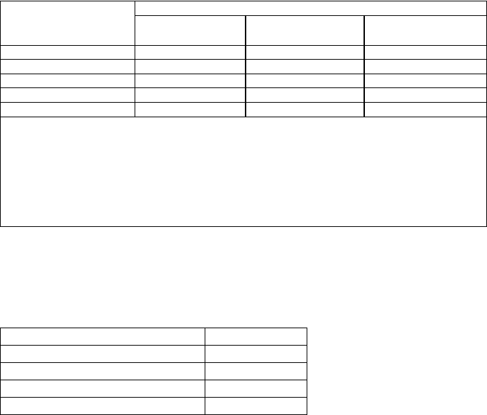
82 Operator's Manual ZM-940PA
Recommended Separation Distances between Portable and Mobile RF
Communications Equipment
The ZM-940PA is intended for use in an electromagnetic environment in which radiated RF
disturbances are controlled. The customer or the user of the ZM-940PA can help prevent
electromagnetic interference by maintaining a minimum distance between portable and mobile
RF communications equipment (transmitters) and the ZM-940PA as recommended below,
according to the maximum output power of the communications.
System Composition for EMC Test
The ZM-940PA bedside monitor is tested to comply with IEC 60601-1-2 (2001) with the
following composition. If any part which is not specified by Nihon Kohden is used, the EMC
specifications may not comply.
Separation distance according to frequency of transmitter (m)
Rated maximum output
power of transmitter
(W)
150 kHz to 80 MHz
d = 1.2√P
80 MHz to 800 MHz
d = 1.2√P
800 MHz to 2.5 GHz
d = 2.3√P
0.01 0.12 0.12 0.23
0.1 0.38 0.38 0.73
1 1.2 1.2 2.3
10 3.8 3.8 7.3
100 12 12 23
For transmitters rated at a maximum output power not listed above, the recommended separation
distance d in meters (m) can be estimated using the equation applicable to the frequency of the
transmitter, where P is the maximum output power rating of the transmitter in watts (W) according
to the transmitter manufacturer.
NOTE 1 At 80 MHz and 800 MHz, the separation distance for the higher frequency range
applies.
NOTE 2 These guidelines may not apply in all situations. Electromagnetic propagation is
affected by absorption and reflection from structures, objects and people.
Units Cable length
ZM-940PA transmitter ---
YP-943P NIBP cuff 0.15 m
BR-906P ECG electrode lead 0.8 m
TL-201T finger probe 1.6 m
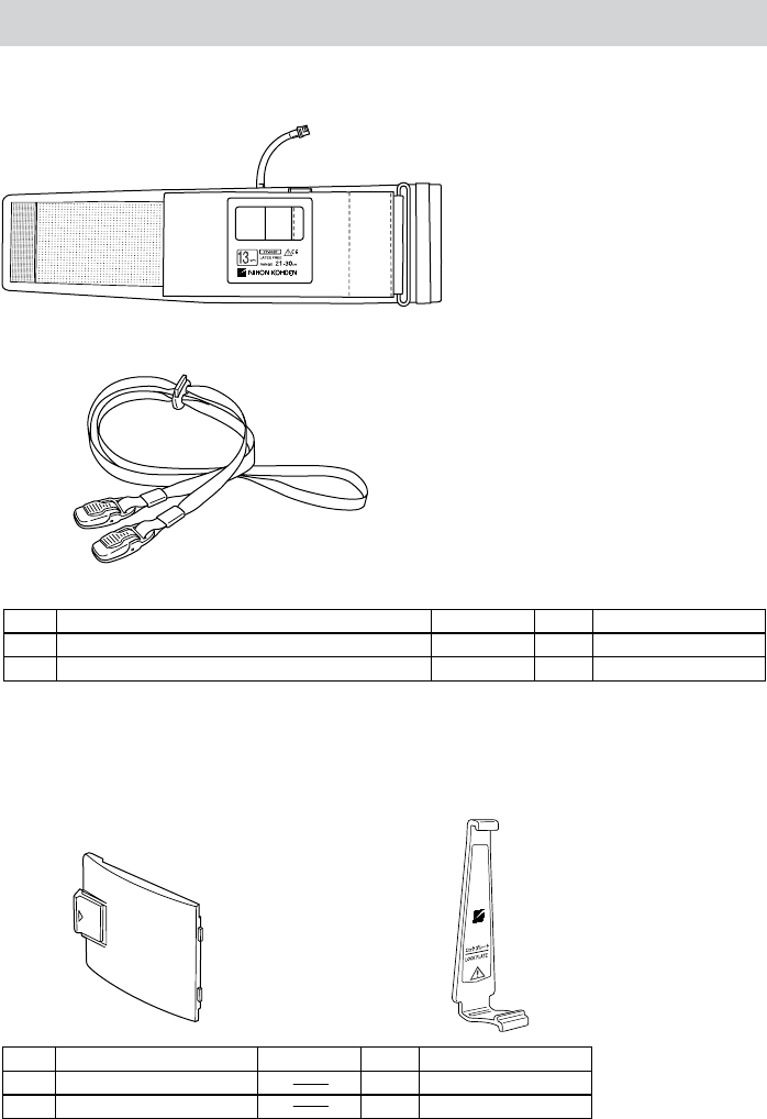
Operator's Manual ZM-940PA 83
1
2
Standard Accessories
No. Name Model Q’ty Supply Code No.
1 NIBP cuff for adult, standard YP-943P 1 S938B
2 Strap --- 1 Y236
34
No. Name Model Q’ty Supply Code No.
3 Battery case cover 1 6144-012004
4 Lock plate 1 6113-049585
The following parts are available for replacement.
Lock plate is a
standard accessory of
the YP-943P/944P
NIBP cuff.

84 Operator's Manual ZM-940PA
Name Width
(cm)
Air Hose
Length
(cm)
Model Q’ty
Supply
Code
No.
Standard 13 YP-943P* S938B
Cuff for adult, for
attaching transmitter to
patient arm Large 15 15 YP-944P* 1S938C
Cuff for infants 5 YP-960T S943A
Small 7 YP-961T S943B
Cuff for children Standard 10 YP-962T S943C
Standard 13 YP-963T S944B
Cuff for adult Large 15
15
YP-964T
1
S944C
Disposable cuff for infants 6 YP-910P ---
Disposable cuff for children 9 YP-912P ---
Small 12 YP-913P ---
Standard 14 YP-914P ---
Disposable cuff for adults
Large 16
20
YP-915P
20
---
Extension hose 150 YN-990P 1 S903
NIBP
* The lock plate is provided with these NIBP cuffs.
CAUTION
Use only Nihon Kohden electrodes, electrode leads, SpO2 probes and NIBP cuffs
to assure maximum performance from your instrument.
Transmitter
Channel writer, QI-901PK
ECG/RESP
Options
Name Application Model Q’ty Supply Code No.
3 electrodes,clip type,
lead length 80 cm BR-903PA 1 K911A
3 electrodes, snap type,
lead length 80 cm BR-913PA 1 K910B
6 electrodes,clip type,
lead length 80 cm BR-906PA 1 K912A
Electrode
lead
6 electrodes,snap type,
lead length 80 cm BR-916PA 1 K915A

Operator's Manual ZM-940PA 85
SpO2
Name Cable
length
Model/
Code No. Q’ty Supply
Code No.
0.6 m P225H
Finger probe (reusable) 1.6 m TL-201T P225F
Multi-site probe (reusable) TL-220T
1
P225G
SpO2 probe (for adult, disposable) TL-251T P201A
SpO2 probe (for child, disposable) TL-252T P201B
SpO2 probe (for neonate,
disposable) TL-253T P201C
Multi-site Y probe
(for low birth weight infant/child/
neonate, disposable)
TL-260T
5
P205A
SpO2 probe (for adult, disposable) TL-271T P203A
SpO2 probe (for child, disposable) TL-272T P203B
SpO2 probe (for neonate/adult,
disposable) TL-273T P203C
SpO2 probe (for child/infant,
disposable)
1.6 m
TL-274T
24
P203D
0.8 m TL-051S P228A
SpO2 probe(for adult/neonate,
disposable) 1.6 m TL-052S P228B
0.8 m TL-061S P229A
SpO2 probe (for child/infant,
disposable) 1.6 m TL-062S
5
P229B
COTTONY tape 340703 20 P259
Foam tape for TL-051S/052S/
061S/062S 4 × 25 package P260
Attachment tape for TL-220T/
251T/252T/253T 3 × 30 package P263
Attachment tape S for TL-260T P260A
Attachment tape L for TL-260T
--- ---
24 P260B

86 Operator's Manual ZM-940PA
Transmission Frequencies
USA
BAND
CHANNEL
SPACING
C
USA
BAND
CHANNEL
SPACING
C
USA
BAND
CHANNEL
SPACING
C
Transmission
frequency
(MHz)
25 kHz step
Channel No.
Transmission
frequency
(MHz)
25 kHz step
Channel No.
Transmission
frequency
(MHz)
25 kHz step
Channel No.
608.0250 9002 608.7750 9062 609.5250 9122
608.0500 9004 608.8000 9064 609.5500 9124
608.0750 9006 608.8250 9066 609.5750 9126
608.1000 9008 608.8500 9068 609.6000 9128
608.1250 9010 608.8750 9070 609.6250 9130
608.1500 9012 608.9000 9072 609.6500 9132
608.1750 9014 608.9250 9074 609.6750 9134
608.2000 9016 608.9500 9076 609.7000 9136
608.2250 9018 608.9750 9078 609.7250 9138
608.2500 9020 609.0000 9080 609.7500 9140
608.2750 9022 609.0250 9082 609.7750 9142
608.3000 9024 609.0500 9084 609.8000 9144
608.3250 9026 609.0750 9086 609.8250 9146
608.3500 9028 609.1000 9088 609.8500 9148
608.3750 9030 609.1250 9090 609.8750 9150
608.4000 9032 609.1500 9092 609.9000 9152
608.4250 9034 609.1750 9094 609.9250 9154
608.4500 9036 609.2000 9096 609.9500 9156
608.4750 9038 609.2250 9098 609.9750 9158
608.5000 9040 609.2500 9100 610.0000 9160
608.5250 9042 609.2750 9102 610.0250 9162
608.5500 9044 609.3000 9104 610.0500 9164
608.5750 9046 609.3250 9106 610.0750 9166
608.6000 9048 609.3500 9108 610.1000 9168
608.6250 9050 609.3750 9110 610.1250 9170
608.6500 9052 609.4000 9112 610.1500 9172
608.6750 9054 609.4250 9114 610.1750 9174
608.7000 9056 609.4500 9116 610.2000 9176
608.7250 9058 609.4750 9118 610.2250 9178
608.7500 9060 609.5000 9120 610.2500 9180

Operator's Manual ZM-940PA 87
USA
BAND
CHANNEL
SPACING
C
USA
BAND
CHANNEL
SPACING
C
USA
BAND
CHANNEL
SPACING
C
Transmission
frequency
(MHz)
25 kHz step
Channel No.
Transmission
frequency
(MHz)
25 kHz step
Channel No.
Transmission
frequency
(MHz)
25 kHz step
Channel No.
610.2750 9182 611.1000 9248 611.9250 9314
610.3000 9184 611.1250 9250 611.9500 9316
610.3250 9186 611.1500 9252 611.9750 9318
610.3500 9188 611.1750 9254 612.0000 9320
610.3750 9190 611.2000 9256 612.0250 9322
610.4000 9192 611.2250 9258 612.0500 9324
610.4250 9194 611.2500 9260 612.0750 9326
610.4500 9196 611.2750 9262 612.1000 9328
610.4750 9198 611.3000 9264 612.1250 9330
610.5000 9200 611.3250 9266 612.1500 9332
610.5250 9202 611.3500 9268 612.1750 9334
610.5500 9204 611.3750 9270 612.2000 9336
610.5750 9206 611.4000 9272 612.2250 9338
610.6000 9208 611.4250 9274 612.2500 9340
610.6250 9210 611.4500 9276 612.2750 9342
610.6500 9212 611.4750 9278 612.3000 9344
610.6750 9214 611.5000 9280 612.3250 9346
610.7000 9216 611.5250 9282 612.3500 9348
610.7250 9218 611.5500 9284 612.3750 9350
610.7500 9220 611.5750 9286 612.4000 9352
610.7750 9222 611.6000 9288 612.4250 9354
610.8000 9224 611.6250 9290 612.4500 9356
610.8250 9226 611.6500 9292 612.4750 9358
610.8500 9228 611.6750 9294 612.5000 9360
610.8750 9230 611.7000 9296 612.5250 9362
610.9000 9232 611.7250 9298 612.5500 9364
610.9250 9234 611.7500 9300 612.5750 9366
610.9500 9236 611.7750 9302 612.6000 9368
610.9750 9238 611.8000 9304 612.6250 9370
611.0000 9240 611.8250 9306 612.6500 9372
611.0250 9242 611.8500 9308 612.6750 9374
611.0500 9244 611.8750 9310 612.7000 9376
611.0750 9246 611.9000 9312 612.7250 9378

88 Operator's Manual ZM-940PA
USA
BAND
CHANNEL
SPACING
C
USA
BAND
CHANNEL
SPACING
C
USA
BAND
CHANNEL
SPACING
C
Transmission
frequency
(MHz)
25 kHz step
Channel No.
Transmission
frequency
(MHz)
25 kHz step
Channel No.
Transmission
frequency
(MHz)
25 kHz step
Channel No.
612.7500 9380 613.1750 9414 613.6000 9448
612.7750 9382 613.2000 9416 613.6250 9450
612.8000 9384 613.2250 9418 613.6500 9452
612.8250 9386 613.2500 9420 613.6750 9454
612.8500 9388 613.2750 9422 613.7000 9456
612.8750 9390 613.3000 9424 613.7250 9458
612.9000 9392 613.3250 9426 613.7500 9460
612.9250 9394 613.3500 9428 613.7750 9462
612.9500 9396 613.3750 9430 613.8000 9464
612.9750 9398 613.4000 9432 613.8250 9466
613.0000 9400 613.4250 9434 613.8500 9468
613.0250 9402 613.4500 9436 613.8750 9470
613.0500 9404 613.4750 9438 613.9000 9472
613.0750 9406 613.5000 9440 613.9250 9474
613.1000 9408 613.5250 9442 613.9500 9476
613.1250 9410 613.5500 9444 613.9750 9478
613.1500 9412 613.5750 9446