Nihon Kohden ZM-941PA Medical Telemetry Transmitter User Manual 1
Nihon Kohden Corporation Medical Telemetry Transmitter Users Manual 1
Contents
- 1. Users Manual 1
- 2. Users Manual 2
Users Manual 1
If you have any comments or suggestions on this
manual, please contact us at:
www.nihonkohden.com
Transmitter
ZM-940PA/ZM-941PA
0614-009881B
Copyright Notice
The entire contents of this manual are copyrighted by Nihon Kohden. All rights are reserved. No part
of this document may be reproduced, stored, or transmitted in any form or by any means (electronic,
mechanical, photocopied, recorded, or otherwise) without the prior written permission of Nihon Ko-
hden.
Operator’s Manual ZM-940PA/941PA i
Contents
GENERAL HANDLING PRECAUTIONS ..........................................................................i
WARRANTY POLICY ..................................................................................................... iii
Equipment Authorization Requirement ........................................................................... iii
EMC RELATED CAUTION ..............................................................................................iv
Conventions Used in this Manual and Instrument ......................................................... vii
Warnings, Cautions and Notes .................................................................................. vii
Explanations of the Symbols in this Manual and Instrument .................................... viii
Introduction ............................................................................................................................1
Panel Description ..................................................................................................................3
Front Panel .......................................................................................................................3
Rear Panel .......................................................................................................................4
Top Panel .........................................................................................................................5
Bottom Panel ...................................................................................................................5
LCD ..................................................................................................................................7
Notes on Parameter Settings.................................................................................................9
Important Safety Information ...............................................................................................10
General ..........................................................................................................................10
Output Signal .................................................................................................................12
Battery ...........................................................................................................................12
Transmitter Channel Management .................................................................................13
For Patients Using Implantable Pacemaker ...................................................................14
NIBP Monitoring .............................................................................................................14
ECG Monitoring .............................................................................................................15
SpO2 Monitoring .............................................................................................................16
Maintenance ..................................................................................................................19
Preparation ..........................................................................................................................20
Installing (Replacing) Batteries ......................................................................................20
WARNING and CAUTION for Battery Handling ........................................................20
Battery Lifetime .........................................................................................................21
Installing (Replacing) Batteries..................................................................................21
Situations Requiring Battery Replacement ...............................................................22
Battery Condition Indication ......................................................................................23
Turning the Transmitter On/Off .......................................................................................23
Turning On the Power ................................................................................................23
Turning Off the Power ................................................................................................23
Check Items Before Use ............................................................................................23
Check Items After Power On .....................................................................................24
Check Items After Use ..............................................................................................24
Changing the Transmitter Channel ......................................................................................25
ii Operator’s Manual ZM-940PA/941PA
Changing Parameter Setup Settings ...................................................................................26
Parameter Setup Setting List .........................................................................................26
Displaying the PARAMETER SETUP Screen ................................................................27
Changing Settings .........................................................................................................28
SELECTABLE INTERVALS .......................................................................................28
INITIAL INTERVAL ....................................................................................................28
INITIAL CUFF PRESS ..............................................................................................28
NIBP MODE AFTER STAT ........................................................................................29
START/FINISH SOUND ............................................................................................29
OLD NIBP DATA/AFTER ...........................................................................................29
INHIBIT SpO2 DURING NIBP ....................................................................................30
2ND PARAMETER ....................................................................................................30
LEADS OFF DISPLAY...............................................................................................31
ECG ELECTRODE ....................................................................................................31
Changing System Setup Settings ........................................................................................32
System Setup Setting List ..............................................................................................32
Displaying the SYSTEM SETUP Screen .......................................................................32
Changing Settings .........................................................................................................33
CHANNEL .................................................................................................................33
PRESSURE UNIT .....................................................................................................33
LANGUAGE ...............................................................................................................34
BRIGHTNESS ...........................................................................................................34
SYSTEM INITIALIZE .................................................................................................34
Attaching NIBP Cuff, Electrodes and SpO2 Probe to the Patient .........................................35
Attachment Examples ....................................................................................................35
Attaching the NIBP Cuff .................................................................................................36
Selecting the NIBP Cuff .............................................................................................36
Connecting the NIBP Cuff to the Transmitter .............................................................39
Attaching the NIBP Cuff to the Patient ......................................................................41
Attaching Electrodes ......................................................................................................45
Selecting Electrode Lead ..........................................................................................45
Connecting the Electrode Lead to the Transmitter ....................................................46
Selecting the Electrode Position ................................................................................46
Attaching Electrodes to the Patient and Connecting the Electrode Leads to
Disposable Electrodes ...............................................................................................50
Electrode Position for Respiration Monitoring ...........................................................51
Attaching the SpO2 Probe ..............................................................................................53
Selecting the SpO2 Probe ..........................................................................................53
Connecting the SpO2 Probe to the Transmitter ..........................................................56
Attaching the Probe to the Patient .............................................................................57
Locking the Keys on the Transmitter ....................................................................................59
Monitoring ............................................................................................................................60
NIBP Monitoring .............................................................................................................60
Selecting the Initial Cuff Inflation Pressure ................................................................60
Selecting the Measurement Mode and Interval .........................................................60
Operator’s Manual ZM-940PA/941PA iii
Measuring NIBP ........................................................................................................61
Monitoring SpO2 during NIBP Measurement .............................................................64
ECG and Respiration Monitoring ...................................................................................64
Electrode Detachment ...............................................................................................66
SpO2 Monitoring .............................................................................................................67
SpO2 and PR Display Order ......................................................................................68
Monitoring SpO2 during NIBP Measurement .............................................................69
Display and Message List ....................................................................................................70
Battery Indication ...........................................................................................................70
ECG/Respiration ............................................................................................................70
SpO2 .............................................................................................................................71
NIBP ..............................................................................................................................72
Troubleshooting ...................................................................................................................73
Transmitter .....................................................................................................................73
ECG/Respiration ............................................................................................................74
SpO2 .............................................................................................................................74
NIBP ..............................................................................................................................75
Maintenance ........................................................................................................................77
1. External Check ......................................................................................................77
2. Transmitter Channel ...............................................................................................77
3. LCD Display ...........................................................................................................79
4. Key Operation ........................................................................................................80
5. NIBP Cuff for Attaching Transmitter to Patient Arm ...............................................81
Maintenance Check Sheet .............................................................................................82
Repair Parts Availability Policy ............................................................................................83
Lifetime and Disposal ..........................................................................................................84
Disposing of Used Batteries ..........................................................................................84
Battery Lifetime .........................................................................................................84
Disposal .....................................................................................................................84
Disposing of Electrodes, SpO2 Probes and NIBP Cuffs .................................................84
Cleaning, Disinfection and Sterilization ...............................................................................85
Transmitter and Electrode Leads ...................................................................................85
Cleaning ....................................................................................................................85
Disinfection ................................................................................................................85
SpO2 Probe ....................................................................................................................86
YP-943P/944P NIBP Cuffs ............................................................................................86
Cleaning ....................................................................................................................86
Disinfection ................................................................................................................86
Specifications ......................................................................................................................87
ZM-940PA ......................................................................................................................87
Measuring Parameters ..............................................................................................87
Transmitting Data ......................................................................................................87
Displayed Data ..........................................................................................................87
ECG Measurement ....................................................................................................87
Respiration Measurement .........................................................................................87
iv Operator’s Manual ZM-940PA/941PA
SpO2 Measurement ...................................................................................................87
NIBP Measurement ...................................................................................................88
Pulse Rate .................................................................................................................88
Transmitter .................................................................................................................88
Power Requirements .................................................................................................88
Dimension and Weight ..............................................................................................89
Environment ..............................................................................................................89
Safety Standards .......................................................................................................89
Electromagnetic Compatibility ...................................................................................90
Electromagnetic Emissions .......................................................................................90
Electromagnetic Immunity .........................................................................................91
Recommended Separation Distances between Portable and Mobile RF
Communications Equipment .....................................................................................93
Recovery Time after Defibrillation .............................................................................93
System Composition for EMC Test ............................................................................93
ZM-941PA ......................................................................................................................94
Measuring Parameters ..............................................................................................94
Transmitting Data ......................................................................................................94
Displayed Data ..........................................................................................................94
ECG Measurement ....................................................................................................94
Respiration Measurement .........................................................................................94
SpO2 Measurement ...................................................................................................94
NIBP Measurement ...................................................................................................95
Pulse Rate .................................................................................................................95
Transmitter .................................................................................................................95
Power Requirements .................................................................................................95
Dimension and Weight ..............................................................................................96
Environment ..............................................................................................................96
Safety Standards .......................................................................................................96
Electromagnetic Compatibility ...................................................................................97
Electromagnetic Emissions .......................................................................................97
Electromagnetic Immunity .........................................................................................98
Recommended Separation Distances between Portable and Mobile RF
Communications Equipment ...................................................................................100
Recovery Time after Defibrillation ...........................................................................100
System Composition for EMC Test ..........................................................................100
Standard Accessories........................................................................................................101
Options ..............................................................................................................................102
Transmitter ...............................................................................................................102
ECG/RESP ..............................................................................................................102
NIBP ........................................................................................................................103
SpO2 .......................................................................................................................104
Transmission Frequencies .................................................................................................105
Operator’s Manual ZM-940PA/941PA i
GENERAL HANDLING PRECAUTIONS
This device is intended for use only by qualified medical personnel.
Use only Nihon Kohden approved products with this device. Use of non-approved
products or in a non-approved manner may affect the performance specifications
of the device. This includes, but is not limited to, batteries, recording paper, pens,
extension cables, electrode leads, input boxes and AC power.
Please read these precautions thoroughly before attempting to operate the instrument.
1. To safely and effectively use the instrument, its operation must be fully understood.
2. When installing or storing the instrument, take the following precautions:
(1) Avoid moisture or contact with water, extreme atmospheric pressure, excessive humidity and
temperatures, poorly ventilated areas, and dust, saline or sulphuric air.
(2) Placetheinstrumentonaneven,leveloor.Avoidvibrationandmechanicalshock,even
during transport.
(3) Avoidplacinginanareawherechemicalsarestoredorwherethereisdangerofgasleakage.
(4) The power line source to be applied to the instrument must correspond in frequency and
voltagetoproductspecications,andhavesufcientcurrentcapacity.
(5) Choose a room where a proper grounding facility is available.
3. Before Operation
(1) Checkthattheinstrumentisinperfectoperatingorder.
(2) Checkthattheinstrumentisgroundedproperly.
(3) Checkthatallcordsareconnectedproperly.
(4) Pay extra attention when the instrument is in combination with other instruments to avoid
misdiagnosis or other problems.
(5) Allcircuitryusedfordirectpatientconnectionmustbedoublychecked.
(6) Checkthatbatterylevelisacceptableandbatteryconditionisgoodwhenusing
batteryoperated models.
4. During Operation
(1) Both the instrument and the patient must receive continual, careful attention.
(2) Turn power off or remove electrodes and/or transducers when necessary to assure the
patient’s safety.
(3) Avoid direct contact between the instrument housing and the patient.
5. To Shutdown After Use
(1) Turn power off with all controls returned to their original positions.
(2) Remove the cords gently; do not use force to remove them.
(3) Clean the instrument together with all accessories for their next use.
ii Operator’s Manual ZM-940PA/941PA
6. The instrument must receive expert, professional attention for maintenance and repairs.
When the instrument is not functioning properly, it should be clearly marked to avoid
operation while it is out of order.
7. Theinstrumentmustnotbealteredormodiedinanyway.
8. Maintenance and Inspection
(1) The instrument and parts must undergo regular maintenance inspection at least every 6
months.
(2) Ifstoredforextendedperiodswithoutbeingused,makesurepriortooperationthatthe
instrument is in perfect operating condition.
(3) Technical information such as parts list, descriptions, calibration instructions or other
informationisavailableforqualiedusertechnicalpersonneluponrequestfromyourNihon
Kohden representative.
9. When the instrument is used with an electrosurgical instrument, pay careful attention to
the application and/or location of electrodes and/or transducers to avoid possible burn to
the patient.
10.Whentheinstrumentisusedwithadebrillator,makesurethattheinstrumentis
protectedagainstdebrillatordischarge.Ifnot,removepatientcablesand/ortransducers
from the instrument to avoid possible damage.

Operator’s Manual ZM-940PA/941PA iii
WARRANTY POLICY
Nihon Kohden Corporation (NKC) shall warrant its products against all defects in materials and
workmanshipforoneyearfromthedateofdelivery.However,consumablematerialssuchas
recordingpaper,ink,stylusandbatteryareexcludedfromthewarranty.
NKC or its authorized agents will repair or replace any products which prove to be defective during
the warranty period, provided these products are used as prescribed by the operating instructions
given in the operator’s and service manuals.
NootherpartyisauthorizedtomakeanywarrantyorassumeliabilityforNKC’sproducts.
NKC will not recognize any other warranty, either implied or in writing. In addition, service,
technicalmodicationoranyotherproductchangeperformedbysomeoneotherthanNKCorits
authorized agents without prior consent of NKC may be cause for voiding this warranty.
Defective products or parts must be returned to NKC or its authorized agents, along with an
explanation of the failure. Shipping costs must be pre-paid.
Thiswarrantydoesnotapplytoproductsthathavebeenmodied,disassembled,reinstalledor
repaired without Nihon Kohden approval or which have been subjected to neglect or accident,
damageduetoaccident,re,lightning,vandalism,waterorothercasualty,improperinstallationor
application,oronwhichtheoriginalidenticationmarkshavebeenremoved.
In the USA and Canada other warranty policies may apply.
CAUTION
United States law restricts this device to sale by or on the order of a physician.
Equipment Authorization Requirement
Operation of this equipment requires the prior coordination with a frequency coordinator designated
by FCC for the Wireless Medical Telemetry Service.

iv Operator’s Manual ZM-940PA/941PA
EMC RELATED CAUTION
This equipment and/or system complies with IEC 60601-2 International Standard for
electromagnetic compatibility for medical electrical equipment and/or system.
However, an electromagnetic environment that exceeds the limits or levels stipulated
in IEC 60601-1-2, can cause harmful interference to the equipment and/or system or
cause the equipment and/or system to fail to perform its intended function or degrade
its intended performance. Therefore, during the operation of the equipment and/or
system, if there is any undesired deviation from its intended operational performance,
you must avoid, identify and resolve the adverse electromagnetic effect before
continuing to use the equipment and/or system.
The following describes some common interference sources and remedial actions:
1. Strong electromagnetic interference from a nearby emitter source such as an
authorized radio station or cellular phone:
Install the equipment and/or system at another location. Keep the emitter source
such as cellular phone away from the equipment and/or system, or turn off the
cellular phone.
2. Radio-frequency interference from other equipment through the AC power supply of
the equipment and/or system:
Identify the cause of this interference and if possible remove this interference
source. If this is not possible, use a different power supply.
3. Effect of direct or indirect electrostatic discharge:
Make sure all users and patients in contact with the equipment and/or system are
free from direct or indirect electrostatic energy before using it. A humid room can
help lessen this problem.
4. Electromagnetic interference with any radio wave receiver such as radio or
television:
If the equipment and/or system interferes with any radio wave receiver, locate the
equipment and/or system as far as possible from the radio wave receiver.
5. Interference of lightning:
When lightning occurs near the location where the equipment and/or system is
installed, it may induce an excessive voltage in the equipment and/or system.
In such a case, disconnect the AC power cord from the equipment and/or
system and operate the equipment and/or system by battery power, or use an
uninterruptible power supply.

Operator’s Manual ZM-940PA/941PA v
6. Use with other equipment:
When the equipment and/or system is adjacent to or stacked with other equipment,
the equipment and/or system may affect the other equipment. Before use, check
that the equipment and/or system operates normally with the other equipment.
7. Use of unspecified accessory, transducer and/or cable:
When an unspecified accessory, transducer and/or cable is connected to this
equipment and/or system, it may cause increased electromagnetic emission
or decreased electromagnetic immunity. The specified configuration of this
equipment and/or system complies with the electromagnetic requirements with the
specified configuration. Only use this equipment and/or system with the specified
configuration.
8. Use of unspecified configuration:
When the equipment and/or system is used with the unspecified system
configuration different than the configuration of EMC testing, it may cause
increased electromagnetic emission or decreased electromagnetic immunity.
Only use this equipment and/or system with the specified configuration.
9. Measurement with excessive sensitivity:
The equipment and/or system is designed to measure bioelectrical signals with
a specified sensitivity. If the equipment and/or system is used with excessive
sensitivity, artifact may appear by electromagnetic interference and this may
cause mis-diagnosis. When unexpected artifact appears, inspect the surrounding
electromagnetic conditions and remove this artifact source.
If the above suggested remedial actions do not solve the problem, consult your Nihon
Kohden representative for additional suggestions.
vi Operator’s Manual ZM-940PA/941PA
This page is intentionally left blank.

Operator’s Manual ZM-940PA/941PA vii
Conventions Used in this Manual and Instrument
Warnings, Cautions and Notes
Warnings,cautionsandnotesareusedinthismanualtoalertorsignalthereadertospecic
information.
WARNING
A warning alerts the user to the possible injury or death associated with the use or
misuse of the instrument.
CAUTION
A caution alerts the user to possible injury or problems with the instrument associated
with its use or misuse such as instrument malfunction, instrument failure, damage to
the instrument, or damage to other property.
NOTE
A note provides specific information, in the form of recommendations, prerequirements,
alternative methods or supplemental information.
viii Operator’s Manual ZM-940PA/941PA
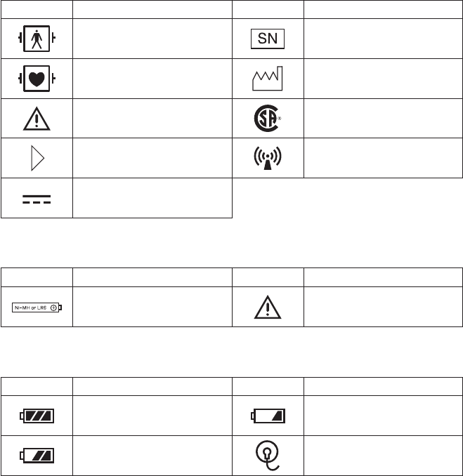
Explanations of the Symbols in this Manual and Instrument
The following symbols found in this manual/instrument bear the respective descriptions as given.
On Panel
Symbol Description Symbol Description
DebrillationprooftypeBF
applied part Serial number
DebrillationprooftypeCF
applied part Year of manufacture
Attention, consult operator’s
manual CSAmark
Direction for attaching
battery cover
RF transmitter
Non-ionizing radiation
Direct current
Inside Battery Case
Symbol Description Symbol Description
Battery position Attention, consult operator’s
manual
On LCD
Symbol Description Symbol Description
Full battery Replace battery
NIBP cannot be measured
Replace battery Checkelectrode

Operator’s Manual ZM-940PA/941PA 1
Introduction
The ZM-940PA/ZM-941PA transmitter transmits ECG, respiration, SpO2, NIBP and pulse waveform
from a patient to a Nihon Kohden monitor for continuous monitoring. The transmitter can change
channels when connected to the QI-901PK channel writer. The front LCD displays SpO2%, NIBP,
pulserate,pulsewaveformamplitude,electrodeconditionmark,batteryconditionandNIBP
measuring mode and interval.
The difference between the ZM-940PA and ZM-941PA is the transmission frequency range.
ZM-940PA:608.0250MHz(channelnumber9002)to613.9750MHz(channelnumber9478)
ZM-941PA:1395.0250MHz(channelnumberE002)to1399.9750MHz(channelnumberE398)
1427.0250MHz(channelnumberE502)to1431.9750MHz(channelnumberE898)
Read the operator’s manual for the receiving monitor together with this manual before operation.
WARNING
Do not use the same transmitter on
more than one patient at the same
time. Do not connect different sensors
on different patients to the same
transmitter.
CAUTION
• Do not use the same channel for
different patients. If the same
channel is used for two patients, the
two patients’ data will be lost due to
mutual modulation interference, or
another patient’s data may appear
on the receiving monitor screen.
• Do not use transmitters of adjacent
channels in a hospital. If a
transmitter of an adjacent channel is
used, radio waves from one
transmitter affect the receiver of the
adjacent channel’s transmitter and
there may be interference.
NOTE
• To prevent interference between channels, assign a channel administrator in the hospital
and only he or she should manage channel assignment.
• Use Nihon Kohden parts and accessories to assure maximum performance from your
instrument.
• For stable signal reception, it is recommended to use a diversity antenna system on the
receiving monitor. Otherwise, spike noise from transient fading of electric field strength
(for example, people moving) may interfere with the transmitter signal and may be
mistaken as an arrhythmia on the receiving monitor.
2 Operator’s Manual ZM-940PA/941PA
• NIBP cannot be measured on a neonate. (ECG, respiration and SpO2 can be monitored
on a neonate.)
• Do not diagnose a patient based on only part of the monitoring data on the transmitter or
only on the data acquired by the transmitter. Overall judgement must be performed by a
physician who understands the features, limitations and characteristics of the transmitter
by reading this operator’s manual thoroughly and by reading the biomedical signals
acquired by other instruments.
• For details on the receiving monitor and upgrade information, contact your Nihon Kohden
representative.
Operator’s Manual ZM-940PA/941PA 3
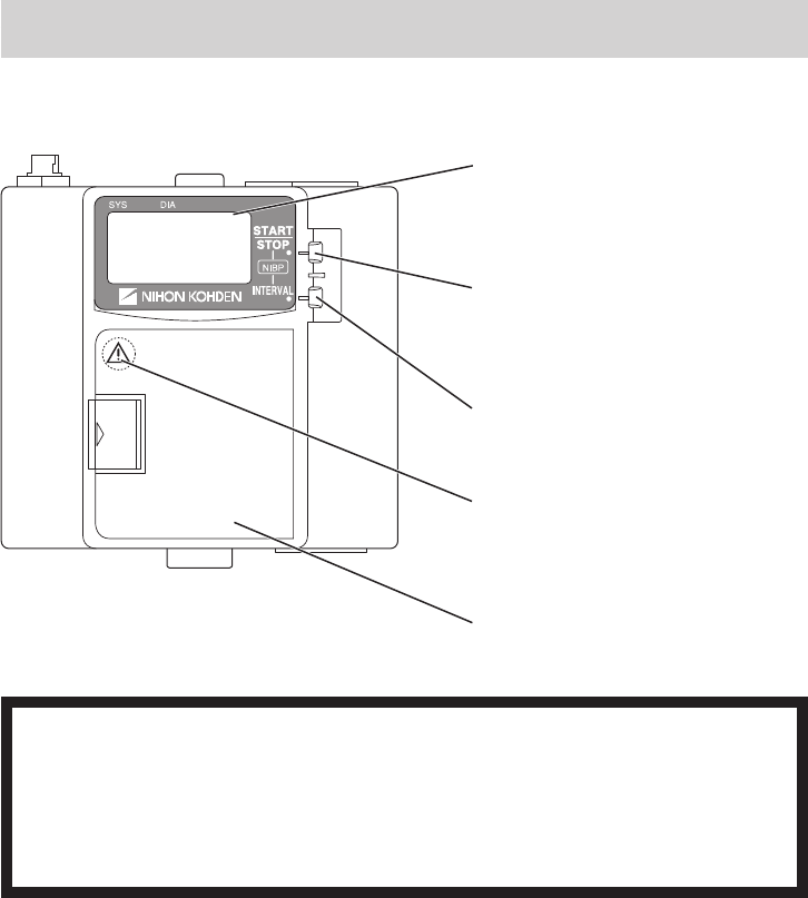
Panel Description
Front Panel
LCD:
Displays measuring data, settings and
other information.
NIBP START/STOP key:
Starts/stops NIBP measurement in
selected mode.
NIBP INTERVAL key:
Selects NIBP measurement mode.
Refer to the WARNING below.
(This symbol is attached to the rear of the
battery case cover.)
Battery case:
Contains three 1.5 V AA (R6) batteries.
WARNING
Close the battery case cover during operation. If the transmitter is used with the
battery case cover open, anyone who touches the opened battery case may receive
an electrical shock when defibrillation is performed. Touching the opened battery case
may cause electrostatic discharge and intermittently interfere with the waveform or
data.
4 Operator’s Manual ZM-940PA/941PA
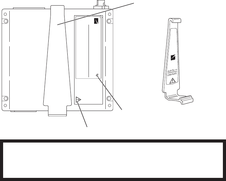
Rear Panel
Lock plate:
Fastens the transmitter to an NIBP cuff.
Refer to the WARNING below.
Refer to the symbol page.
WARNING
This transmitter is not waterproof. If detergent or liquid spills into the transmitter, stop
using it and contact your Nihon Kohden representative. If a wet transmitter is used,
the patient or operator may receive an electrical shock or injury.
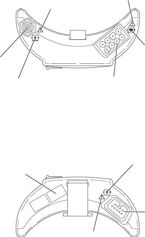
Operator’s Manual ZM-940PA/941PA 5
Top Panel
NIBP socket:
Connects the cuff hose.
Refer to the WARNING on the
next page.
Refer to the symbol page.
Refer to the WARNING on the
next page.
Refer to the symbol
page.
ECG/impedance RESP socket:
Connects the electrode lead for
measuring ECG and/or respiration by
the impedance method.
Bottom Panel
Refer to the WARNING on the next
page.
Refer to the symbol page.
SpO2 socket:
Connects the SpO2
probe.
Channel number label:
Indicates the channel number of the
transmitter. Attach the channel number label
to the panel of the monitor.

6 Operator’s Manual ZM-940PA/941PA
WARNING
Before defibrillation, all persons must
keep clear of the bed and must not
touch the patient or any equipment or
cord connected to the patient. Failure
to follow this warning may cause
electrical shock or injury.
WARNING
The following actions must be taken to
properly receive the transmitter signal
of the correct patient on the receiving
instrument. Otherwise, there may be
signal loss or signals may mix causing
a serious accident, such as monitoring
a different patient.
• Assign a channel administrator in
the hospital and only he or she
should manage channel
assignment.
• The channel administrator must
manage the channels in the facility
so that there is no signal
interference.
• When the transmitter channel is
changed, the channel administrator
must check that the channel on the
receiving monitor is also changed
and the signal is properly received.
• The channel administrator must
replace the channel number label
on the transmitter with the new one
after changing the channel.
WARNING
When performing defibrillation,
discharge as far as possible from
electrodes, patches and any gel,
cream or medicine on the chest of the
patient. If there is a possibility that the
defibrillator paddle could touch these
materials, remove them from the
patient. If the defibrillator paddle
directly contacts these materials, the
discharged energy may cause skin
burn to the patient.
WARNING
When the transmitter is used with an
electrosurgical unit (ESU), firmly
attach the entire area of the ESU
return plate. Otherwise, the current
from the ESU flows into the electrodes
of the transmitter, causing electrical
burn where the electrodes are
attached. For details, refer to the ESU
manual.
CAUTION
Do not shake or swing the transmitter
while holding the leads or cables
connected to the transmitter. The
transmitter may come off and injure
someone or damage surrounding
instruments.
Operator’s Manual ZM-940PA/941PA 7
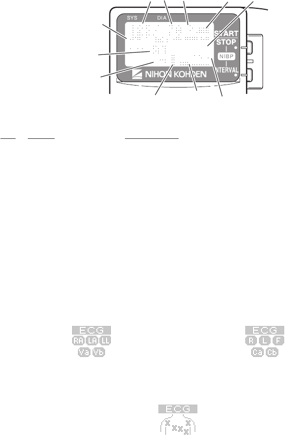
LCD
LOCK
KEYS
12
3
456
7
8
9
10
11
No. Name Description
1 NIBP SYS Displays NIBP systolic value.
2 NIBP DIA Displays NIBP diastolic value.
3 NIBP MAP Displays NIBP mean value.
“CUFF”isdisplayedwiththecuffinationpressureduring
measurement.
4 Checkelectrodemark Appearswhenanelectrodeorelectrodeleadbecomesdetached
during ECG measurement.
5 Batteryreplacementmark Appearswhenthebatteriesareweak.Fordetails,refertothe
“Battery Condition Indication” section.
6 Message display area Displays messages.
When ECG is monitored with 6 electrodes and an electrode or
electrodeleadisdetached,“Checkelectrode”isindicatedas
below, depending on the PARAMETER SETUP setting.
Refer to the “Changing Parameter Setup Settings” and “ECG and
Respiration Monitoring” sections.
LEADS OFF DISPLAY set to CHAR
ECG ELECTRODE set to AHA
LEADS OFF DISPLAY set to CHAR
ECG ELECTRODE set to IEC
LEADS OFF DISPLAY set to IMAGE
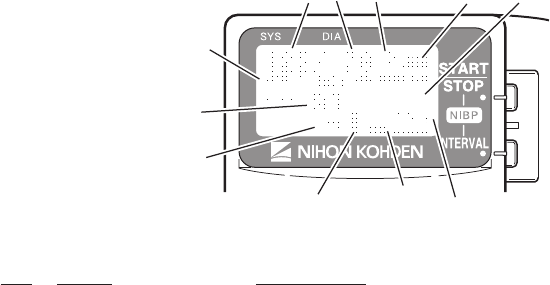
8 Operator’s Manual ZM-940PA/941PA
LOCK
KEYS
12
3
456
7
8
9
10
11
No. Name Description
7 NIBPmeasurementmode DisplaysNIBPmeasurementmode.Whensettoautomode,the
measurement interval is displayed.
8 NIBP interval bar graph In auto NIBP measurement, the remaining time from the last
measurement to the next measurement is displayed as a bar
graph.
9 Pulselevelbargraph Displayspulselevelin7steps.
10 %SpO2 Displays SpO2 data.
11 PR Displays pulse rate when NIBP or SpO2 is measured. When the
SpO2 probe is attached to the patient, the real time pulse rate is
displayed. When the SpO2 probe is not attached to the patient,
the pulse rate at the end of NIBP measurement is displayed.

Operator’s Manual ZM-940PA/941PA 9
Notes on Parameter Settings
When monitoring NIBP and SpO2, the following setting must be set as indicated in the table
to properly transmit the monitoring data to the receiving monitor. Otherwise, SpO2 cannot be
monitored properly during NIBP measurement.
Some receiving monitors require the software to be upgraded. For details, contact your Nihon
Kohden representative.
SpO2 probe attachment site INHIBIT SpO2 DURING NIBP setting
Probe attached to the same limb as the cuff ON
Probe attached to the limb without cuff* OFF
* When the SpO2probeisattachedtothesamelimbastheNIBPcuffandthecuffisinated,
the SpO2 value becomes unstable and SpO2 or PR alarm may occur.

10 Operator’s Manual ZM-940PA/941PA
Important Safety Information
General
WARNING
Never use the transmitter in the
presence of any flammable anesthetic
gas or high concentration oxygen
atmosphere. Failure to follow this
warning may cause explosion or fire.
WARNING
Never use the transmitter in a
hyperbaric oxygen chamber. Failure to
follow this warning may cause
explosion or fire.
WARNING
When performing MRI test, remove all
electrodes from the patient which are
connected to this transmitter. Failure
to follow this warning may cause skin
burn on the patient. For details, refer
to the MRI manual.
WARNING
When performing defibrillation,
discharge as far as possible from
electrodes, patches and any gel,
cream or medicine on the chest of the
patient. If there is a possibility that the
defibrillator paddle could touch these
materials, remove them from the
patient. If the defibrillator paddle
directly contacts these materials, the
discharged energy may cause skin
burn to the patient.
WARNING
Before defibrillation, all persons must
keep clear of the bed and must not
touch the patient or any equipment or
cord connected to the patient. Failure
to follow this warning may cause
electrical shock or injury.
WARNING
When the transmitter is used with an
electrosurgical unit (ESU), firmly
attach the entire area of the ESU
return plate. Otherwise, the current
from the ESU flows into the electrodes
of the transmitter, causing electrical
burn where the electrodes are
attached. For details, refer to the ESU
manual.

Operator’s Manual ZM-940PA/941PA 11
WARNING
Close the battery case cover during
operation. If the transmitter is used
with the battery case cover open,
anyone who touches the opened
battery case may receive an electrical
shock when defibrillation is performed.
Touching the opened battery case
may cause electrostatic discharge and
intermittently interfere with the
waveform or data.
WARNING
This transmitter is not waterproof. If
detergent or liquid spills into the
transmitter, stop using it and contact
your Nihon Kohden representative. If a
wet transmitter is used, the patient or
operator may receive an electrical
shock or injury.
WARNING
Do not use the same transmitter on
more than one patient at the same
time. Do not connect different sensors
on different patients to the same
transmitter.
CAUTION
Only use Nihon Kohden specified
electrodes, electrode leads, SpO2
probes, and NIBP cuffs. Otherwise,
the maximum performance from the
transmitter cannot be guaranteed.
CAUTION
Do not reuse disposable parts and
accessories.
CAUTION
Do not shake or swing the transmitter
while holding the leads or cables
connected to the transmitter. The
transmitter may come off and injure
someone or damage surrounding
instruments.
CAUTION
• Do not use the same channel for
different patients. If the same
channel is used for two patients, the
two patients’ data will be lost due to
mutual modulation interference, or
another patient’s data may appear
on the receiving monitor screen.
• Do not use transmitters of adjacent
channels in a hospital. If a
transmitter of an adjacent channel is
used, radio waves from one
transmitter affect the receiver of the
adjacent channel’s transmitter and
there may be interference.

12 Operator’s Manual ZM-940PA/941PA
CAUTION
Turn off the power of mobile phones,
small wireless devices and other
devices which produce strong
electromagnetic interference around a
patient (except for devices allowed by
the hospital administrator). Radio
waves from devices such as mobile
phones or small wireless devices may
be mistaken as pulse waves and the
displayed data may be incorrect.
Output Signal
WARNING
Do not use the output signal from the receiving monitor as the synchronization signal
for other equipment such as IABP, MRI, echocardiography or defibrillator. There may
be time delay between the monitor and the other equipment caused by waveform
transmission delay and spike noise may interfere on the output signal and be
mistaken as a trigger.
Battery
WARNING
• Keep the batteries away from fire.
They may explode.
• Keep the batteries away from
patients.
• Never short-circuit the + and –
terminals on the battery. It may
cause overheating and fire.
• Do not damage, disassemble, drop
or give impact to the battery.
WARNING
If the battery is damaged and the
substance inside the battery contacts
the eyes or skin, wash immediately
and thoroughly with water and see a
physician. Never rub your eyes,
because you may lose your eyesight.

Operator’s Manual ZM-940PA/941PA 13
CAUTION
Battery replacement must be
performed by the operator. When
replacing batteries of the transmitter
currently used for a patient,
disconnect electrode leads from the
transmitter before replacing batteries
or do not touch the patient during
replacement.
CAUTION
The battery charger must be used
outside the patient environment.
CAUTION
Refer to the battery and battery
charger manuals for details on
handling the batteries.
Transmitter Channel Management
WARNING
The following actions must be taken to properly receive the transmitter signal of the
correct patient on the receiving instrument. Otherwise, there may be signal loss or
signals may mix causing a serious accident, such as monitoring a different patient.
• Assign a channel administrator in the hospital and only he or she should manage
channel assignment.
• The channel administrator must manage the channels in the facility so that there is
no signal interference.
• When the transmitter channel is changed, the channel administrator must check
that the channel on the receiving monitor is also changed and the signal is properly
received.
• The channel administrator must replace the channel number label on the
transmitter with the new one after changing the channel.

14 Operator’s Manual ZM-940PA/941PA
For Patients Using Implantable Pacemaker
WARNING
Interaction Between Minute Ventilation Rate-Adaptive Pacemakers and Cardiac
Monitoring and Diagnostic Equipment*
The bioelectric impedance measurement sensor of a minute ventilation rate-adaptive
implantable pacemaker may be affected by transmitter which is connected to the
same patient. If this occurs, the pacemaker may pace at its maximum rate and the
transmitter may give incorrect data to the monitor. If this occurs, disconnect the
electrode leads from the patient or change the setting on the pacemaker by referring
to the pacemaker’s manual. For more details, contact your pacemaker representative
or Nihon Kohden representative.
* Minuteventilationissensedinrate-adaptivepacemakersbyatechnologyknownasbioelectric
impedancemeasurement(BIM).Manymedicaldevicesinadditiontopacemakersusethis
technology. When one of these devices is used on a patient with an active, minute ventilation rate-
adaptivepacemaker,thepacemakermayerroneouslyinterpretthemixtureofBIMsignalscreated
in the patient, resulting in an elevated pacing rate.
For more information, see the FDA web site.
http://www.fda.gov/cdrh/safety.html
NIBP Monitoring
WARNING
Be careful when measuring NIBP on a
patient with known bleeding disorders
or coagulation. After NIBP
measurement, there may be dot
hemorrhage, or circulatory disorder by
thrombus where the cuff is attached.
WARNING
NIBP measurement may be incorrect
in the following cases.
• When using an electrosurgical unit
• When there is body movement
• When the pulse wave is small
(insufficient peripheral circulation)
• Too many arrhythmias
• When there is vibration
• When there is a rapid blood
pressure change
• During CPR
WARNING
When performing NIBP
measurements in STAT mode or 5
minute intervals, periodically remove
the cuff from the patient for ventilation.
The skin temperature may increase at
the cuff attachment site by 2 or 3°C (4
or 5°F). When measuring a patient
with a fever or peripheral circulation
insufficiency, it may cause a burn.

Operator’s Manual ZM-940PA/941PA 15
CAUTION
Do not wrap the cuff on an arm or
thigh which is used for injection. NIBP
measurement on an arm or thigh
which is used for injection may cause
reflux of blood and stop injection.
CAUTION
Do not wrap the cuff too tight. It may
cause poor blood circulation and
congestion. If the cuff is wrapped too
loosely, the NIBP value may increase.
CAUTION
Do not attach the cuff to the site
where there is injury or inflammation.
If the skin gets irritated or redness
appears on the skin from the cuff,
change the attachment site or stop
using the cuff. Take extreme care on
the patients with delicate skin.
CAUTION
When using an extension hose, check
that the extension hose is not bent or
squeezed. Otherwise, the cuff might
not inflate or deflate. If the cuff cannot
deflate, it may cause congestion on
the patient at the cuff attachment site.
CAUTION
When performing NIBP measurement
repeatedly, have a rest between
measurements to recover adequate
circulation.
ECG Monitoring
CAUTION
Only use Nihon Kohden specified
electrodes and electrode leads. When
other type of electrodes or electrode
leads are used, the “CHECK
ELECTRODES” message may be
displayed and monitoring may stop.
CAUTION
When the “ELECTRODE OFF” or
“CHECK ELECTRODE” message is
displayed on the receiving monitor,
ECG is not monitored properly and
the ECG alarm does not function.
Check the electrode, electrode leads,
and if necessary, replace with new
ones.

16 Operator’s Manual ZM-940PA/941PA
SpO2 Monitoring
WARNING
SpO2 measurement may be incorrect
in the following cases.
• When the patient’s
carboxyhemoglobin or
methemoglobin increases
abnormally.
• When dye is injected in the blood.
• When using an electrosurgical unit.
• During CPR.
• When measuring at a site with
venous pulse.
• When there is body movement.
• When the pulse wave is small
(insufficient peripheral circulation).
WARNING
• When using the TL-201T finger
probe, do not fasten the probe and
cable to the finger by wrapping with
tape. This may cause burn,
congestion or pressure necrosis
from poor blood circulation.
• When using probes other than the
TL-201T finger probe, to avoid poor
circulation, do not wrap the tape too
tight. Check the blood circulation
condition by observing the skin
color and congestion at the skin
peripheral to the probe attachment
site. Even for short-term monitoring,
there may be burn or pressure
necrosis from poor blood circulation,
especially on neonates or low birth
weight infants whose skin is
delicate. Accurate measurement
cannot be performed on a site with
poor peripheral circulation.
WARNING
When not monitoring SpO2,
disconnect the SpO2 cable from the
transmitter. Otherwise, noise from the
probe sensor may interfere and
incorrect data is displayed on the
screen.
WARNING
Check the circulation condition by
observing the skin color at the
measurement site and pulse
waveform. Change the measurement
site every 8 hours for disposable
probes and every 4 hours for reusable
probes (every 8 hours for TL-630T/TL-
631T series probe). The skin
temperature may increase at the
attached site by 2 or 3°C (4 or 5°F)
and cause a burn or pressure
necrosis. When using the probe on the
following patients, take extreme care
and change the measurement site
more frequently according to
symptoms and degree.
• Patient with a fever
• Patient with peripheral circulation
insufficiency
• Neonate or low birth weight infant
with delicate skin
• Patient who is receiving
photodynamic therapy*
* Photodynamic therapy is a treatment to
remove the affected tissue by using a
photosensitizing agent and exposing the tissue
to light. This treatment has a side effect of
photosensitivityandthelightfromthenger
probe sensor may cause a burn. This probe
uses two light wavelengths in the range from
650 to 950 nm. The maximum light intensity
is less than 5.5 mW/sr.

Operator’s Manual ZM-940PA/941PA 17
CAUTION
NIBP and SpO2 can be measured on
the same limb, but the SpO2
monitoring might not be accurate
during NIBP measurement. Be careful
when reading the SpO2 values.*
* Monitoring SpO2 during NIBP Measurement
When the SpO2 probe is attached to the
same limb as the NIBP cuff, the blood
owdecreasesduringNIBPmeasurement
and pulse wave cannot be detected and
SpO2 cannot be monitored properly. When
“INHIBITSpO2 DURING NIBP” on the
PARAMETER SETUP screen is set to ON
(factory default setting), SpO2 monitoring is
paused during NIBP measurement to avoid
SpO2alarmoccurrence.However,when
monitoring SpO2 on the same limb as the
NIBP, be careful when reading SpO2 values.
CAUTION
While a patient is on medication which
causes vasodilation, the pulse
waveform may change and in rare
cases the SpO2 value might not be
displayed.
CAUTION
Normal external light does not affect
monitoring but strong light such as a
surgical light or sunlight may affect
monitoring. If affected, cover the
measuring site with a blanket.
CAUTION
Do not use a probe which is
deteriorated by aging. Accurate
measurement cannot be performed.
CAUTION
Do not use a damaged or
disassembled probe. It causes
incorrect measurement and may
injure the patient.
CAUTION
The disposable probe is not sterilized.
Use the disposable probe only for a
single patient. Never reuse the
disposable probe for another patient
because it causes cross infection.
CAUTION
If the attachment site is dirty with
blood or bodily fluids, clean the
attachment site before attaching the
probe. If there is nail polish on the
attachment site, remove the polish.
Otherwise, the amount of transmitted
light decreases, and measured value
may be incorrect or measurement
cannot be performed.
CAUTION
If the skin gets irritated or redness
appears on the skin from the probe,
change the attachment site or stop
using the probe. Take extreme care for
the patients with delicate skin.

18 Operator’s Manual ZM-940PA/941PA
CAUTION
Do not pull or bend the probe cable,
and do not put caster feet on the
probe cable. Do not immerse the
probe cable in chemical solutions or
water. Failure to follow these
instructions may cause cable
discontinuity, short circuit, skin burn
on the patient and incorrect
measurement data. Replace any
broken probe with a new one.
CAUTION
When the probe is attached on an
appropriate site with sufficient
circulation and the error message
confirming the probe attachment
repeatedly appears, the probe may be
deteriorated. Replace it with a new
one.
CAUTION
When a message indicates a faulty
probe, stop monitoring and replace
the probe with a new one.
CAUTION
When removing a probe that is taped
to the skin, do not pull the probe cable
because this can damage the cable.
CAUTION
Neonatal skin is delicate. Remove the
probe and tape carefully and slowly.
CAUTION
When removing the probe from the
attachment tape, do not pull the
sensor cable because this can
damage the cable.
CAUTION
Do not immerse the disposable probe
in detergents or water. If the probe
adhesive surface gets wet,
adhesiveness becomes weak and the
probe cannot be attached to the skin.
CAUTION
Refer to the probe instruction manual
for details.

Operator’s Manual ZM-940PA/941PA 19
Maintenance
CAUTION
Before cleaning or disinfection,
remove the batteries from the
transmitter. Failure to follow this
instruction may result in electrical
shock or transmitter malfunction.
CAUTION
This transmitter is not waterproof. If
detergent or liquid spills into the
transmitter, stop cleaning or
disinfecting it and contact your Nihon
Kohden representative. The
transmitter needs to be checked for
safety and function before use.
CAUTION
The transmitter cannot be sterilized.
Sterilizing the transmitter may damage
it.
CAUTION
Never disassemble or repair the
transmitter. Disassembly and repair
must be performed by qualified
service personnel.

20 Operator’s Manual ZM-940PA/941PA
Preparation
Installing (Replacing) Batteries
WARNING and CAUTION for Battery Handling
WARNING
• Keep the batteries away from fire.
They may explode.
• Keep the batteries away from
patients.
• Never short-circuit the + and –
terminals on the battery. It may
cause overheating and fire.
• Do not damage, disassemble, drop
or give impact to the battery.
WARNING
If the battery is damaged and the
substance inside the battery contacts
the eyes or skin, wash immediately
and thoroughly with water and see a
physician. Never rub your eyes,
because you may lose your eyesight.
CAUTION
Refer to the battery and battery
charger manuals for details on
handling the batteries.
CAUTION
The battery charger must be used
outside the patient environment.
CAUTION
Do not handle the batteries with wet
hands.
CAUTION
When the transmitter is not in use,
remove batteries. When batteries are
installed, battery power is consumed
even if measurement is not performed.
Especially, when NiMH batteries
remain in the transmitter when the
transmitter is not in use, the battery
may become unusable from
overdischarge and leak liquid which
will damage the transmitter.

Operator’s Manual ZM-940PA/941PA 21
Battery Lifetime
UsethreeAA(R6)typealkalinedrycellbatteries.NiMHrechargeablebatteriescanalsobeused.
ZM-940PA
Type Lifetime (Measuring parameters)
ECG, SpO2, NIBP ECG, SpO2ECG only
NiMHsecondary 2 days 2.5 days 3 days
Alkalineprimary 1 day 2.5 days 3 days
ZM-941PA
Type Lifetime (Measuring parameters)
ECG, SpO2, NIBP ECG, SpO2ECG only
NiMHsecondary 1.5 days 2 days 2.5 days
Alkalineprimary 1 day 2 days 2.5 days
The above data is when the following batteries and battery charger which are recommended by
Nihon Kohden are used. The measurement is performed at room temperature, NIBP is measured in
auto mode at 60 minute intervals and SpO2ismeasuredonanindexngerofamalepatientwith
weight60kg.OperationtimedependsonthethicknessoftheSpO2 probe attachment site.
NiMHsecondary: SANYOHR-3UF(W)
Battery charger: SANYO NC-M55
Alkalineprimary: NihonKohdenMedipower(equivalenttoPanasonicLR6(G))
NOTE
• When the “Low battery ” message is displayed on the receiving monitor, NIBP might
not have been measured according to the NIBP interval setting.
Therefore, the NIBP data displayed on the receiving monitor might not be updated. In this
case, check the measurement time of the NIBP data displayed on the receiving monitor.
• When using rechargeable NiMH batteries, shallow charging/discharging shortens battery
capacity. For details, refer to the battery operator’s manual.
Installing (Replacing) Batteries
CAUTION
Battery replacement must be performed by the operator. When replacing batteries of
the transmitter currently used for a patient, disconnect electrode leads from the
transmitter before replacing batteries or do not touch the patient during replacement.
If electrode leads are attached to the patient and a person replacing batteries touches the patient
duringbatteryreplacement,patientleakagecurrentovertheallowedamountmayow.
22 Operator’s Manual ZM-940PA/941PA
CAUTION
• Replace all batteries at the same time.
• Do not use different types of batteries together.
NOTE
Insert the batteries with the correct polarity (+ and –).
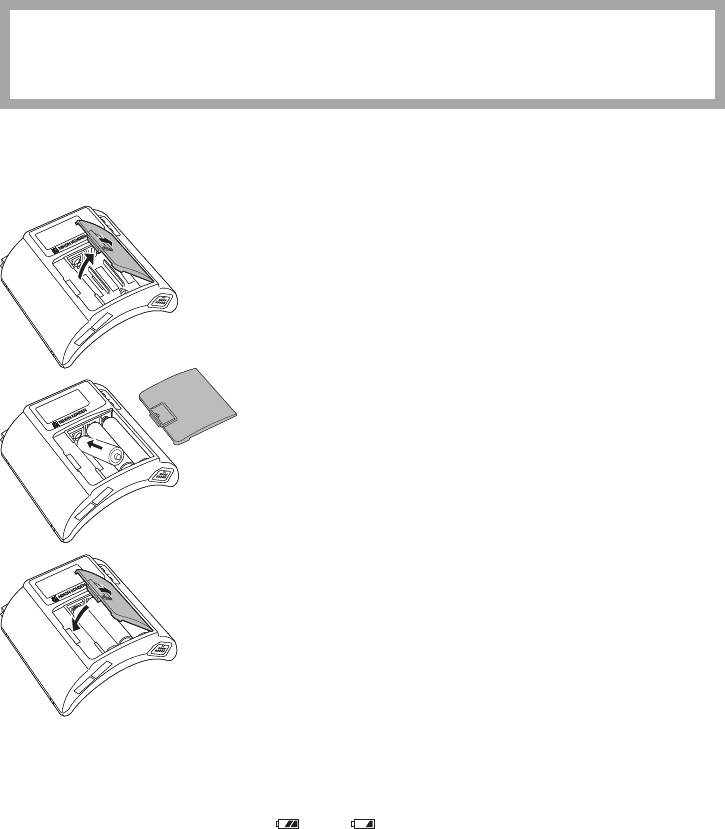
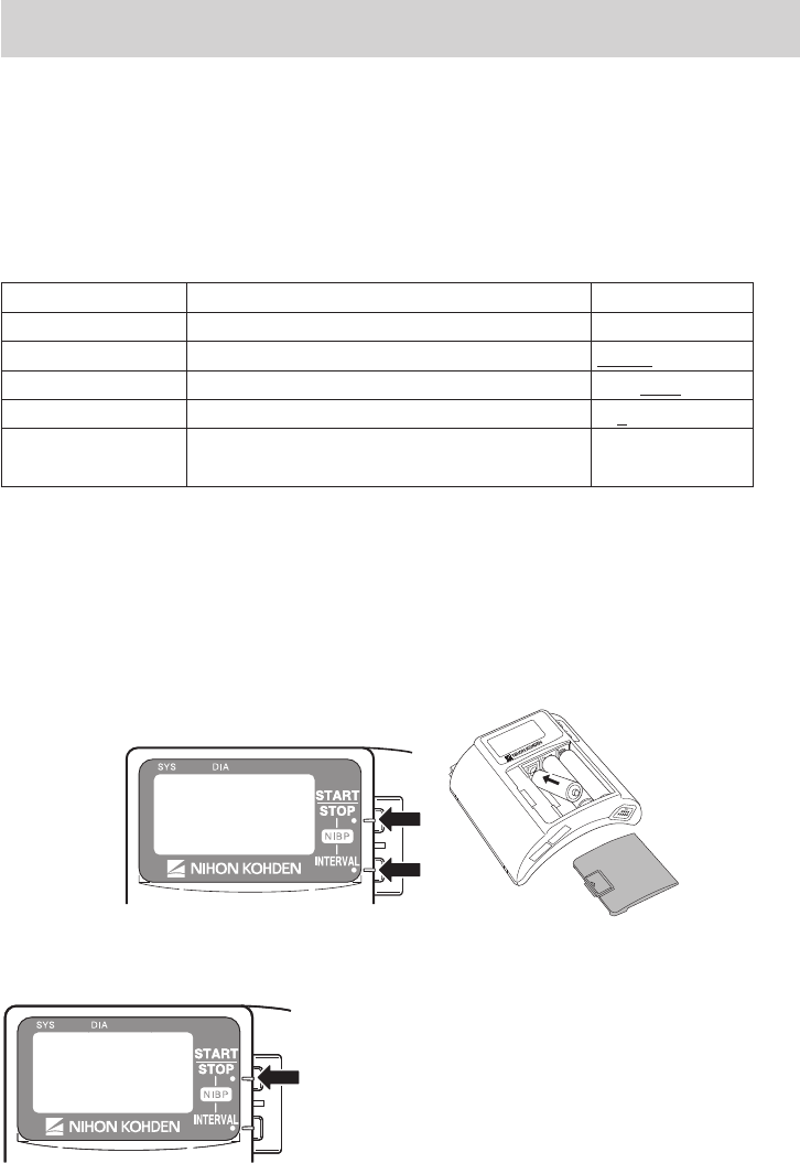
Procedure
1. Remove the battery case cover.
2. Insert three new or fully charged batteries into the battery
case observing the correct polarity.
3. Close the cover.
NOTE
Remove the batteries before disposing of the transmitter.
Situations Requiring Battery Replacement
Replace the batteries when any of the following occurs.
• The transmitter LCD displays the “ ” or “ ”mark.
• The transmitter generates a constant alarm (continuous “peep” sound).
• The transmitter LCD does not display anything when the power is turned on.
• The monitor displays the battery replacement message on the screen.
Operator’s Manual ZM-940PA/941PA 23
Battery Condition Indication
The battery condition is indicated as follows.
Indication Condition Receiving Monitor
Fully charged battery Batteries are full. There is no indication on
the monitor.
Batteries are low. Replace
batteries. Message requiring battery replacement is
displayed.
Batteries are low. NIBP cannot
be measured. Replace batteries.
No indication Dead batteries No signal can be transmitted to the monitor.
There is no indication on the monitor.
Turning the Transmitter On/Off
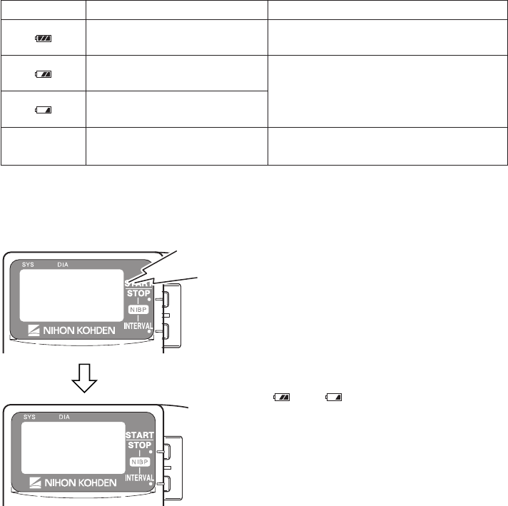
Turning On the Power
When the batteries are installed correctly, the power
is turned on. A one second “peep” sounds and the
startup screen appears. (There is no “peep” sound
when there is no battery power.)
NOTE
Replace the batteries when the LCD displays
the “ ” or “ ”mark.
Turning Off the Power
To turn off the power, remove batteries.
Check Items Before Use
Beforeturningonthetransmitterpower,checkthefollowingtoconrmthatthetransmittercanbe
used in normal and safe condition.
Appearance
• Therearenodamagedordirtypartsontheoutsideofthetransmitter(LCD,keys,sockets,battery
casecover,batterycase,lockplate,etc.).
Peep

24 Operator’s Manual ZM-940PA/941PA
• The transmitter is completely dry.
• The electrode lead, SpO2probeandNIBPcuffarenotbroken.
• There are no damaged or dirty parts on the disposable SpO2 probe, disposable electrodes or
disposable NIBP cuff.
Batteries
• The battery polarity is correct.
• Thebatterycasespringisrmlyxedandthebatteryisnotloose.
• Thebatterycasecoverisrmlyclosed.
Channel Setting
• The transmitter channel corresponds to those of the receiving monitor.
• There is no transmitter in the surrounding area with the same channel.
Check Items After Power On
Afterturningonthepower,checkthefollowing.
Power On
• The transmitter generates about a one second “peep” sound and the startup screen appears.
• The transmitter does not generate a continuous “peep” sound.
• The transmitter does not give excessive heat.
• The transmitter LCD displays a “ ”mark.
• The transmitter does not interfere with the operation of other medical instruments in use.
Basic Operation
• The “signal loss” message is not displayed on the receiving monitor when the transmitter is inside
the receiving range of the monitor.
• The battery replacement message is not displayed on the monitor.
• Thekeysonthetransmitterfunctionproperly.
• The LCD brightness is appropriate. To adjust brightness, refer to the “Changing System Setup
Settings” section.
Check Items After Use
Tousethetransmitterinsafeandoptimumconditionfornexttime,checkthefollowing.
Before Turning Power Off
• Temporarilychangedsettingsarechangedbacktotheprevioussettings.
• There was no malfunction on the transmitter.
Storage
• ECG electrode leads, SpO2 probe and NIBP cuff are cleaned and disinfected.
• When the transmitter gets wet, liquid is wiped off and the transmitter is thoroughly dried.
• There are enough consumables, such as disposable electrodes.
• The transmitter power is turned off by removing batteries from the transmitter.
• Dead batteries are disposed of properly.

Operator’s Manual ZM-940PA/941PA 25
Changing the Transmitter Channel
The channel of the transmitter can be changed. The optional QI-901PK Channel Writer is required.
WARNING
The following actions must be taken to properly receive the transmitter signal of the
correct patient on the receiving instrument. Otherwise, there may be signal loss or
signals may mix causing a serious accident, such as monitoring a different patient.
• Assign a channel administrator in the hospital and only he or she should manage
channel assignment.
• The channel administrator must manage the channels in the facility so that there is
no signal interference.
• When the transmitter channel is changed, the channel administrator must check
that the channel on the receiving monitor is also changed and the signal is properly
received.
• The channel administrator must replace the channel number label on the
transmitter with the new one after changing the channel.
NOTE
The software version of the QI-901PK channel writer must be 02-01 or later to change the
channel on the ZM-940PA/941PA transmitter.
Tocheckthetransmitterchannel,referto“CHANNEL”inthe“ChangingSystemSetupSettings”
section.

26 Operator’s Manual ZM-940PA/941PA
Changing Parameter Setup Settings
The initial settings on the PARAMETER SETUP screen must be changed before monitoring.
Changing these settings during monitoring interrupts monitoring.
Parameter Setup Setting List
The factory default settings are underlined.
Setting Item Description Settings
SELECTABLE
INTERVALS
Select the NIBP measurement modes for
the mode selection.
STAT, 5, 10, 15, 30, 60,
120, 240
INITIAL INTERVAL Select the initial NIBP measurement
mode at power on.
MAN., 5 min, 10 min, 15
min, 30 min, 60 min, 120
min, 240 min
INITIAL CUFF
PRESS SelecttheNIBPcuffinationpressure.
120mmHg,150mmHg,
180mmHg,210mmHg,
240mmHg
NIBP MODE
AFTER STAT
Select the NIBP measurement mode after
completing STAT measurement.
MAN., 5 min, 10 min, 15
min, 30 min
START/FINISH
SOUND
Turn ON or OFF the sound for NIBP
measurementstart/nish. ON, OFF/ON, OFF
OLD NIBP DATA
AFTER
Select whether to hide or dim the NIBP
data after measurement and how long to
wait after measurement to dim or hide it.
DATA: HIDE, DIM
AFTER: 5 min, 10 min,
30 min
INHIBITSpO2
DURING NIBP
Turn SpO2 monitoring on or off during
NIBP measurement. ON, OFF
2ND PARAMETER Set SpO2 and PR display order. SpO2, PR
LEADS OFF
DISPLAY
Select the mode for displaying electrode
off. This setting is only available when
ECG is monitored with 6 electrodes.
CHAR, IMAGE
ECG ELECTRODE
Select the electrode lead type. This setting
isonlyavailablewhenCHARisselected
for LEADS OFF DISPLAY.
IEC, AHA
Operator’s Manual ZM-940PA/941PA 27
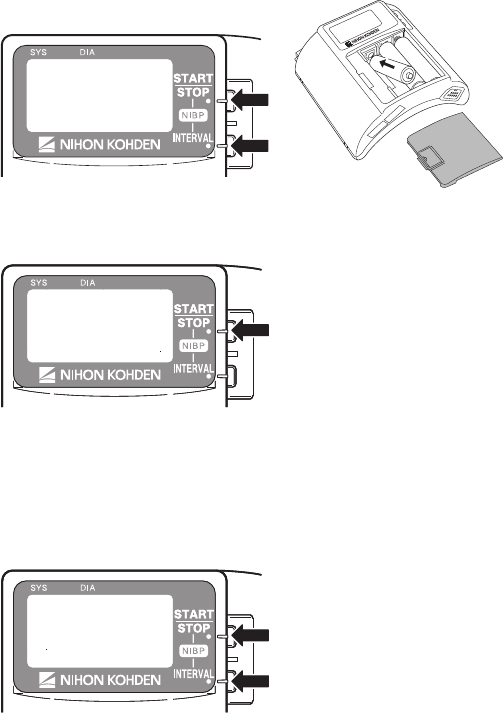
Displaying the PARAMETER SETUP Screen
1. Remove one battery.
2. WhilepressingtheNIBPSTART/STOPandNIBPINTERVALkeys,installthebattery.
The SETUP screen appears.
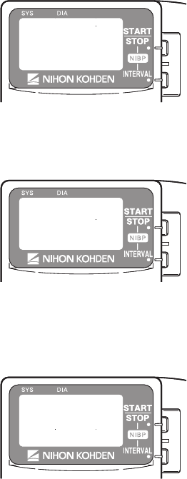
3. PresstheNIBPSTART/STOPkeytoenterthePARAMETERSETUPscreen.
Whenthecursorismovedto“EXIT”bypressingtheNIBPINTERVALkeyandtheNIBP
START/STOPkeyispressed,thestartupscreenappears,thenthemonitoringscreenappears.
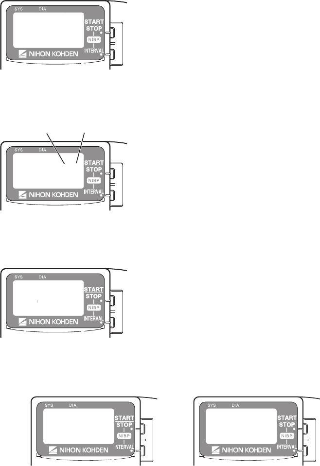
4. Toselectorchangeasetting,presstheNIBPSTART/STOPkey.
Tomovethecursor,presstheNIBPINTERVALkey.
Whenthecursorismovedto“RETURN”bypressingtheNIBPINTERVALkeyandtheNIBP
START/STOPkeyispressed,theSETUPscreenappears.
Selects or changes setting
Moves cursor
Selects or changes setting
Moves cursor
28 Operator’s Manual ZM-940PA/941PA
Changing Settings
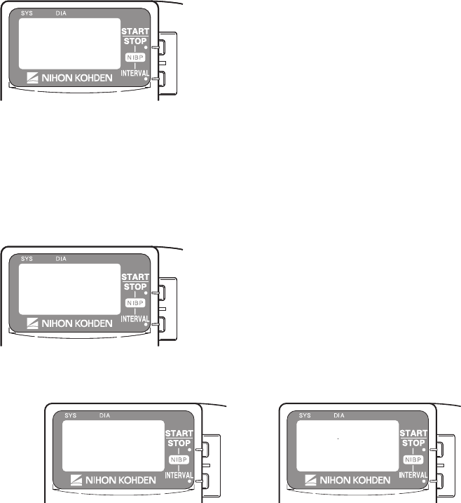
SELECTABLE INTERVALS
Duringmonitoring,whentheNIBPINTERVALkeyispressed,themeasurementmodechanges
according to the modes selected in this item. MANUAL mode is already selected for the mode
selection.
1. PresstheNIBPINTERVALkeytomovethecursor
to the desired mode.
2. PresstheNIBPSTART/STOPkeytoselector
unselect the mode. Selectable modes are: STAT, 5,
10, 15, 30, 60, 120 and 240 min.
INITIAL INTERVAL
Select the initial NIBP measurement mode at power on.
1 PresstheNIBPINTERVALkeytomovethecursor
to “INITIAL INTERVAL”.
2. PresstheNIBPSTART/STOPkeytoselectthe
mode. Selectable modes are the modes selected
for “SELECTABLE INTERVALS” and “MAN.”
(MANUAL).
INITIAL CUFF PRESS
SelecttheNIBPcuffinationpressure.
1 PresstheNIBPINTERVALkeytomovethecursor
to “INITIAL CUFF PRESS”.
2. PresstheNIBPSTART/STOPkeytoselectthe
inationpressurefrom120,150,180,210and240
mmHg.
Operator’s Manual ZM-940PA/941PA 29
NIBP MODE AFTER STAT
Select the NIBP measurement mode after completing the STAT measurement.
1. PresstheNIBPINTERVALkeytomovethecursor
to “NIBP MODE AFTER STAT”.
2. PresstheNIBPSTART/STOPkeytoselectthe
mode. The selected mode is automatically selected
for “SELECTABLE INTERVALS” as well.
START/FINISH SOUND
TurnonoroffthesoundforNIBPmeasurementstartandnish.
1. PresstheNIBPINTERVALkeytomovethecursor
to“START/FINISHSOUND”.
2. PresstheNIBPSTART/STOPkeytoturnONor
OFF
OLD NIBP DATA/AFTER
Select whether to dim or hide the NIBP data after measurement and how long to wait after NIBP
measurement to dim or hide it.
1. PresstheNIBPINTERVALkeytomovethecursor
to “OLD NIBP DATA/AFTER”.
2. PresstheNIBPSTART/STOPkeytoselectthe
setting.
DATA: DIM NIBP data is dimmed after the “AFTER” interval.
HIDE NIBPdataishiddenafterthe“AFTER”interval.“–––”isdisplayedonthescreen.
AFTER: Select the interval after NIBP measurement to dim or hide.
Dimmed Hidden
Start sound End soundStart sound End sound
30 Operator’s Manual ZM-940PA/941PA
INHIBIT SpO2 DURING NIBP
Set whether or not to monitor SpO2 during NIBP measurement.
When the SpO2 probe is attached to the same limb as the NIBP cuff and this setting is set to OFF, the
pulse may become unstable and SpO2 or PR alarm may occur. It is recommended to set this setting
to ON so that SpO2 is not measured during NIBP measurement.
When the SpO2 probe is attached to the other limb from the NIBP cuff, this setting can be set to
OFF.
NOTE
When this “INHIBIT SpO2 DURING NIBP” is set to OFF, refer to the “Monitoring SpO2
during NIBP Measurement” section.
1. PresstheNIBPINTERVALkeytomovethecursor
to“INHIBITSpO2 DURING NIBP”.
2. PresstheNIBPSTART/STOPkeytoselect“ON”or
“OFF”.
ON: Stops SpO2 monitoring during NIBP measurement.
OFF: SpO2 is monitored during NIBP measurement.
2ND PARAMETER
Set the display order of SpO2 and PR.
When set to SpO2 When set to PR
1. PresstheNIBPINTERVALkeytomovethecursor
to “2ND PARAMETER”.
2. PresstheNIBPSTART/STOPkeytoselect“SpO2”
or “PR”.
When set to SpO2When set to PR
Operator’s Manual ZM-940PA/941PA 31
LEADS OFF DISPLAY
Select the mode for displaying electrode off. This setting is only available when ECG is monitored
with 6 electrodes.
1. PresstheNIBPINTERVALkeytomovethecursor
to “LEADS OFF DISPLAY”.
2. PresstheNIBPSTART/STOPkeytoselect“CHAR”
or “IMAGE”.
When set to CHAR When set to IMAGE
ECG ELECTRODE
Selecttheelectrodeleadtype.Thissettingisonlyavailablewhen“CHAR”isselectedforLEADS
OFF DISPLAY.
1. PresstheNIBPINTERVALkeytomovethecursor
to “ECG ELECTRODE”.
2. PresstheNIBPSTART/STOPkeytoselect“IEC”or
“AHA”.
AHA: RA,LA,LL,Va,Vb
IEC: R, L, F, Ca, Cb
32 Operator’s Manual ZM-940PA/941PA
Changing System Setup Settings
NOTE
Changing System Setup settings must be done only by a qualified personnel.
System Setup Setting List
The factory default settings are underlined.
Setting Item Description Settings
CHANNEL Displays the transmitter channel. —
PRESSURE UNIT Select the units for NIBP. mmHg,kPa
LANGUAGE Select the language for screen display. JPN, ENG
BRIGHTNESS Select the LCD brightness. 1, 2, 3, 4
SYSTEM
INITIALIZE
Initializes all settings to the factory default
settings. —
Displaying the SYSTEM SETUP Screen
1. Remove one battery.
2 WhilepressingtheNIBPSTART/STOPandNIBPINTERVALkeys,installthebattery.The
SETUP screen appears.
3. PresstheNIBPINTERVALkeytomovethecursorto“SYSTEMSETUP”.
4. PresstheNIBPSTART/STOPkeytoenterthe
SYSTEM SETUP screen.
When the cursor is moved to “EXIT” by pressing the
NIBPINTERVALkeyandtheNIBPSTART/STOP
keyispressed,thestartupscreenappears,thenthe
monitoring screen appears.
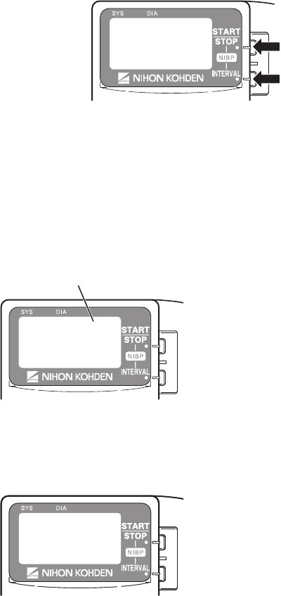
Operator’s Manual ZM-940PA/941PA 33
5. Toselectorchangeasetting,presstheNIBPSTART/STOPkey.
Tomovethecursor,presstheNIBPINTERVALkey.
Selects or changes setting
Moves cursor
Whenthecursorismovedto“RETURN”bypressingtheNIBPINTERVALkeyandtheNIBP
START/STOPkeyispressed,theSETUPscreenappears.
Changing Settings
CHANNEL
The channel of this transmitter is displayed.
Channel of this transmitter
PRESSURE UNIT
Select the unit for NIBP.
1. PresstheNIBPINTERVALkeytomovethecursor
to “PRESSURE UNIT”.
2. PresstheNIBPSTART/STOPkeytoselect“mmHg”
or“kPa”.
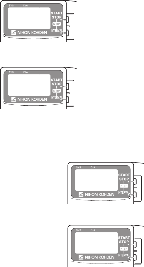
34 Operator’s Manual ZM-940PA/941PA
LANGUAGE
Select the language for screen display.
1. PresstheNIBPINTERVALkeytomovethecursor
to “LANGUAGE”.
2. PresstheNIBPSTART/STOPkeytoselectthe
language.
BRIGHTNESS
Select the LCD brightness.
1. PresstheNIBPINTERVALkeytomovethecursor
to“BRIGHTNESS”.
2. PresstheNIBPSTART/STOPkeytoselecttheLCD
brightness from 1 to 4.
1 2 3 4
Light..............................Dark
SYSTEM INITIALIZE
Do the following procedure to initialize the settings to the factory default settings.
1. PresstheNIBPINTERVALkeytomovethecursorto“SYSTEMINITIALIZE”.
2. PresstheNIBPSTART/STOPkey.The“EXECUTE”messageappears.
3. PresstheNIBPSTART/STOPkeytoinitializethesettingstothefactorydefaultsettings.
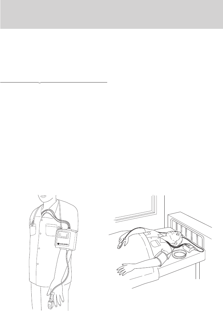
Operator’s Manual ZM-940PA/941PA 35
Attaching NIBP Cuff, Electrodes and SpO2 Probe
to the Patient
The transmitter can be attached to an arm of the patient or placed on the bedside. The required
length of the electrode leads and SpO2 probe cable depends on how the transmitter is to be attached
to the patient.
NOTE
Monitoring SpO2 during NIBP Measurement
When the SpO2 probe is attached to the same limb as the NIBP cuff, the blood flow
decreases during NIBP measurement and pulse wave cannot be detected and SpO2
cannot be monitored properly. When “INHIBIT SpO2 DURING NIBP” on the PARAMETER
SETUP screen is set to ON (factory default setting), SpO2 monitoring is paused during
NIBP measurement to avoid SpO2 alarm occurrence. However, when monitoring SpO2 on
the same limb as NIBP, be careful when reading SpO2 values.
When monitoring SpO2 is important, attach the probe to the limb to which the
NIBP cuff or catheter is not attached.
Attachment Examples
When transmitter is attached on an arm When transmitter is placed on a bedside
NOTE
When placing the transmitter on a bedside,
place it on a stable and flat place. If the
transmitter falls off, it may be damaged.
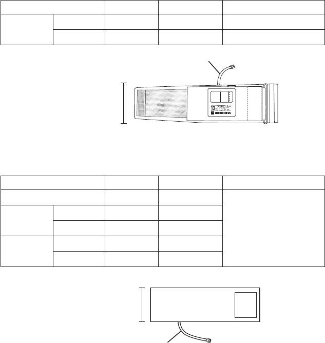
36 Operator’s Manual ZM-940PA/941PA
Attaching the NIBP Cuff
Selecting the NIBP Cuff
Select the NIBP cuff appropriate for the patient.
NOTE
NIBP cannot be measured on neonates using this transmitter.
Reusable Cuffs
When attaching the transmitter to the patient arm, a special NIBP cuff is required. An optional
YN-990Pextensionhose(1.5m)isavailabletoextendthelengthbetweentheNIBPsocketonthe
transmitter and NIBP cuff (e.g. when not attaching the transmitter to the patient arm and placing the
transmitter on a bedside).
Reusable cuff Model Width (cm) Air hose length (cm)
For adult Standard YP-943P 13 15
Large YP-944P 15 15
Width
Air hose
When not attaching the transmitter to the patient arm, the following cuffs can be used. To use these
cuffs, an optional YN-990P extension hose (1.5 m) is required.
Reusable cuff Model Width (cm) Air hose length (cm)
For infant YP-960T 5
15
For child Small YP-961T 7
Standard YP-962T 10
For adult Standard YP-963T 13
Large YP-964T 15
Width
Air hose
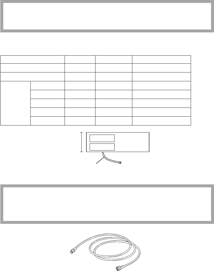
Operator’s Manual ZM-940PA/941PA 37
Disposable Cuffs
CAUTION
Disposable cuffs are not sterilized. If necessary, sterilize the cuff using glutaraldehyde
solution.
When not attaching the transmitter to the patient arm, the following disposable cuffs can be used.
To use these cuffs, an optional YN-990P extension hose (1.5 m) is required.
Reusable cuff Model Width (cm) Air hose length (cm)
For infant YP-810P 6 17
For child YP-811P 8 17
For adult
Small YP-812P 10 17
Standard YP-813P 14 20
Medium large YP-814P 15 20
Large YP-815P 17 20
Extra large YP-816P 18 20
Width
Air hose
Extension Hose
CAUTION
When using an extension hose, check that the extension hose is not bent or
squeezed. Otherwise, the cuff might not inflate or deflate. If the cuff cannot deflate, it
may cause congestion on the patient at the cuff attachment site.
YN-990P extension hose, 150 cm
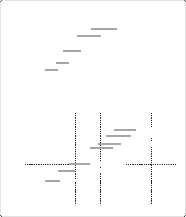
38 Operator’s Manual ZM-940PA/941PA
Reference for selecting a cuff
TheAHA(AmericanHeartAssociation)recommendsthatthecuffwidthbe40%ofthe
circumference of the upper arm. Refer to the following graph and select the cuff which suits the
patient’s arm.
NOTE
• If a range of arm circumference appropriate for the cuff is prescribed, use a cuff within
that range.
• To obtain accurate measured values, select a wide cuff which can be attached to the
upper arm. Measuring with a very narrow cuff may result in measured values higher than
the actual values.
• The YP-943P NIBP cuff is for standard size adult. Do not use this cuff when it does not fit
the patient.
15
10
5
10 20 30 40 50
0
20
15
10
5
10 20 30 40 50 60
0
60
Cuff width (cm)
Arm circumference (cm)
Infants YP-960T
Children small YP-961T
Children standard YP-962T
Adults standard YP-943P (cuff for transmitter)
YP-963T
Adults large YP-944P (cuff for transmitter)
YP-964T
Cuff Width and Arm Circumference
Reusable Cuffs
Cuff width (cm)
Arm circumference (cm)
Children standard YP-811P
Adults large YP-815P
Disposable Cuffs
Infants YP-810P
Adults small YP-812P
Adults standard YP-813P
Adults medium large YP-814P
Adults extra large YP-816P
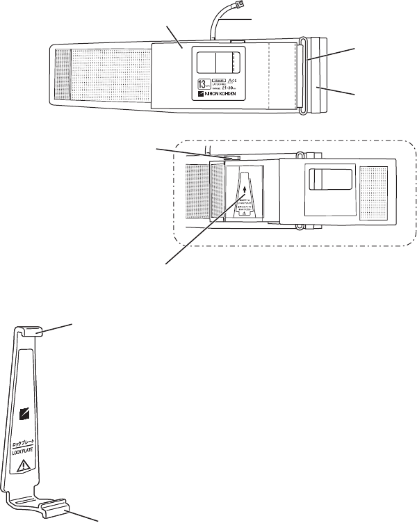
Operator’s Manual ZM-940PA/941PA 39
Connecting the NIBP Cuff to the Transmitter
When Using YP-943P/944P NIBP Cuff
ToattachtheYP-943P/944PNIBPcufftothetransmitter,thelockplateisrequired.
YP-943P/944P NIBP cuff
Front cover Air hose
D ring
Belt
Belt for the strap
Lock plate pocket Front cover open
Lock plate
For attaching the NIBP cuff to the transmitter
NOTE
Do not roll up or put weight on the cuff when the lock plate is
attached to it. The lock plate may break if the cuff is rolled up or
weight is put on it when the lock plate attached.
Top tab
Bottom tab
Top tab
Bottom tab
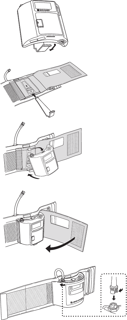
40 Operator’s Manual ZM-940PA/941PA
1. Removethelockplatefromthe
transmitter.
2. Insertthelockplateintothelock
platepocketontheNIBPcuff.
3. Attachthetransmittertothelock
plate by inserting the tabs on the
lockplateintotheslotsonthe
transmitter.
4. Cover the transmitter with the
front cover of the NIBP cuff.
5. Connect the air hose to the NIBP
socketonthetransmitter.Turn
the cuff connector joint until it
clicks.
1
2
1
2