Nihon Kohden ZM-941PA Medical Telemetry Transmitter User Manual 2
Nihon Kohden Corporation Medical Telemetry Transmitter Users Manual 2
Contents
- 1. Users Manual 1
- 2. Users Manual 2
Users Manual 2
Operator’s Manual ZM-940PA/941PA 41
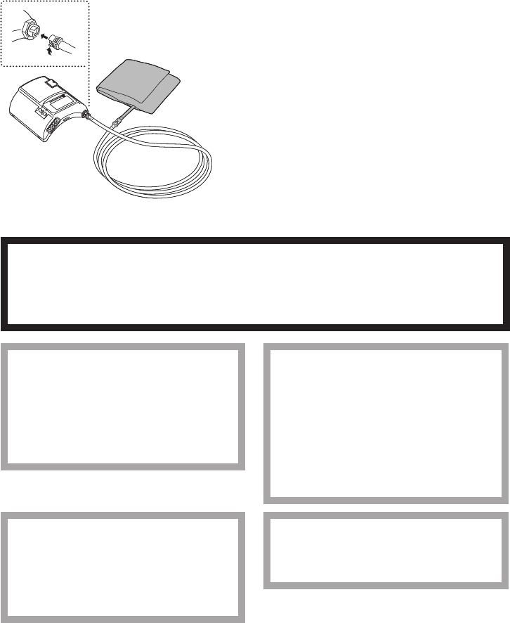
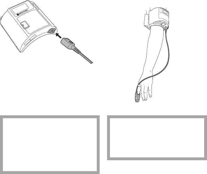
When Using Disposable Cuffs or YP-960T series Reusable Cuffs
To use these NIBP cuffs, an optional YN-990P extension hose (1.5 m) is required.
NOTE
Connect the joints properly. If there is an air leak, NIBP cannot be measured properly.
1. Connect the NIBP cuff to the extension hose.
2. Connect the other end of the extension hose
totheNIBPsocketonthetransmitter.Turn
thejointclockwiseuntilitclicks.
To disconnect the cuff from the transmitter,
turnthehosejointcounterclockwise.
Attaching the NIBP Cuff to the Patient
WARNING
Be careful when measuring NIBP on a patient with known bleeding disorders or
coagulation. After NIBP measurement, there may be dot hemorrhage, or circulatory
disorder by thrombus where the cuff is attached.
CAUTION
Do not wrap the cuff on an arm or
thigh which is used for injection. NIBP
measurement on an arm or thigh
which is used for injection may cause
reflux of blood and stop injection.
CAUTION
Do not attach the cuff to the site
where there is injury or inflammation.
If the skin gets irritated or redness
appears on the skin from the cuff,
change the attachment site or stop
using the cuff. Take extreme care on
the patients with delicate skin.
CAUTION
Do not wrap the cuff too tight. It may
cause poor blood circulation and
congestion. If the cuff is wrapped too
loosely, the NIBP value may increase.
CAUTION
Do not reuse disposable parts and
accessories.

42 Operator’s Manual ZM-940PA/941PA
CAUTION
NIBP and SpO2 can be measured on
the same limb, but the SpO2
monitoring might not be accurate
during NIBP measurement. Be careful
when reading the SpO2 values.*
* Monitoring SpO2 during NIBP Measurement
When the SpO2 probe is attached to the
same limb as the NIBP cuff, the blood
owdecreasesduringNIBPmeasurement
and pulse wave cannot be detected and
SpO2 cannot be monitored properly. When
“INHIBITSpO2 DURING NIBP” on the
PARAMETER SETUP screen is set to ON
(factory default setting), SpO2 monitoring is
paused during NIBP measurement to avoid
SpO2alarmoccurrence.However,when
monitoring SpO2 on the same limb as the
NIBP, be careful when reading SpO2 values.
NOTE
• Measuring NIBP at a site other than the upper arm gives different values from those
measured at the upper arm. When making diagnosis based on the NIBP values, measure
NIBP on an upper arm.
• To accurately detect the pulsatile flow of the artery, the cuff should be wrapped around a
bare upper arm.
• Do not use an abnormal cuff. The cuff deteriorates from use and cleaning. Before use,
check the cuff and confirm that there is no flaw, crack or hole in it. Be careful not to
damage the inflation bag. If the inflation bag has a hole or a flaw, it may burst during use.
Dispose of an abnormal cuff and replace it with a new one.
• Refer to the NIBP cuff manual for details.
Cuff Position
Place the cuffed upper arm (brachium) at the same height
as the patient’s heart. If the cuff is not at the same level as
the heart, the weight of the blood affects the blood pressure
reading.Thepressuredifferenceperunitheightis0.7
mmHg/cm.Thebloodpressurereadingdecreaseswhenthe
arm is higher than the heart and increases when lower.
The best measuring condition is when the patient is lying on
his/herbackwitharmsandlegsrelaxed.Ifthecuffposition
cannot be on the same level as the heart, the displayed blood
pressure reading must be mathematically adjusted.
When placing the transmitter on
a bed, make sure that the hose is
not bent.
Heart
When placing the transmitter on
a bed, make sure that the hose is
not bent.
Heart
Operator’s Manual ZM-940PA/941PA 43
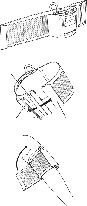
Attaching the Transmitter on an Arm (Using the YP-943P/944P NIBP Cuff)
1. Attach the NIBP cuff to the transmitter. Refer
to the “Connecting the NIBP Cuff to the
Transmitter” section.
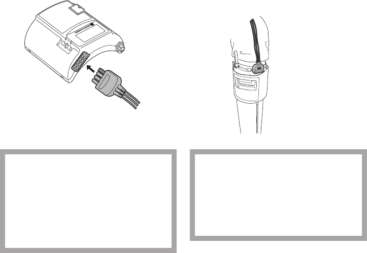
2. Insert the end of the cuff into the belt and then
through the D ring as shown at left.
3. FoldbackthecuffattheDringandfastenit
using the velcro tape.
Makesurethatthecuffisnotattachedonajoint.
NOTE
The cuff must not wrap around the elbow.
Belt
D ring End of cuff
Belt
D ring End of cuff
44 Operator’s Manual ZM-940PA/941PA
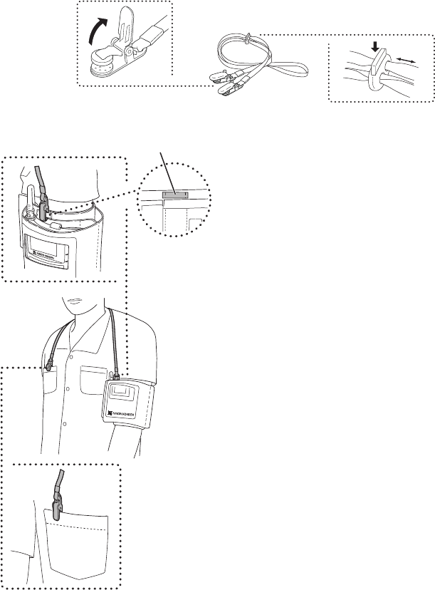
Attaching the Strap to the Transmitter
NOTE
• Use the strap to prevent the transmitter from falling.
• Do not attach the clip to hard objects such as thick cloth or zipper. It will break the clip.
Attach a strap provided with the transmitter to the NIBP cuff and patient clothes.
To open the clip, firmly
pull out the tab in
direction of the arrow. To adjust the strap length,
push down the tab on the
adjuster and slide.
1. Adjust the length of the strap.
2. Clip one end of the strap to the belt for the strap
on the NIBP cuff.
3. Clip the other end of the strap to the patient’s
clothes as shown left.
Belt for the strap on the NIBP cuff
Operator’s Manual ZM-940PA/941PA 45
Placing the Transmitter on the Bed (Using the Disposable Cuffs or YP-960T series Reusable
Cuffs)
1. Put the cuff on the upper arm so that the ▼mark
of “ARTERY ▼” aligns with the artery of the
patient.
ARTERY ▼
2. Wrap the cuff so that “INDEX ” comes
within the “ RANGE ”.
If “Index ” is not within the “ RANGE
”, change the cuff size.
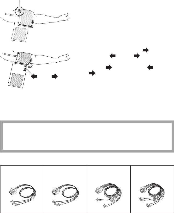
Attaching Electrodes
Selecting Electrode Lead
CAUTION
Only use Nihon Kohden specified electrodes and electrode leads. When other type of
electrodes or electrode leads are used, the “CHECK ELECTRODES” message may
be displayed and monitoring may stop.
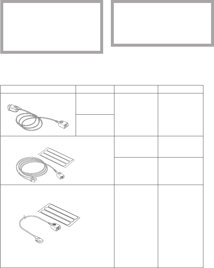
The following electrode leads can be used on the transmitter (option).
BR-903PA,
3 electrodes,
clip type
BR-913PA,
3 electrodes,
snap type
BR-906PA,
6 electrodes,
clip type
BR-916PA,
6 electrodes,
snap type
RANGERANGE
46 Operator’s Manual ZM-940PA/941PA
Connecting the Electrode Lead to the Transmitter
ConnecttheelectrodeleadtotheECG/RESPsocketonthetransmitter.
When the transmitter is attached on an arm
CAUTION
Do not shake or swing the transmitter
while holding the leads or cables
connected to the transmitter. The
transmitter may come off and injure
someone or damage surrounding
instruments.
CAUTION
Hold the connector of the electrode
lead when connecting/disconnecting
the electrode lead. If you disconnect
the electrode lead by pulling the lead,
it damages the electrode lead.
Selecting the Electrode Position
Follow the physician’s instructions for electrode placement when available.
For ECG monitoring, electrodes are attached only on the chest to allow patient movement and
obtain continuous stable ECG. Following leads are examples. When also monitoring respiration,
refer to the “Electrode Position for Respiration Monitoring” section.
NOTE
The optimum electrode positions for ECG measurement of a patient are not always
optimum for respiration measurement of the patient. Select positions suitable for both ECG
and respiration measurements, or positions which have priority for one measurement.
Operator’s Manual ZM-940PA/941PA 47
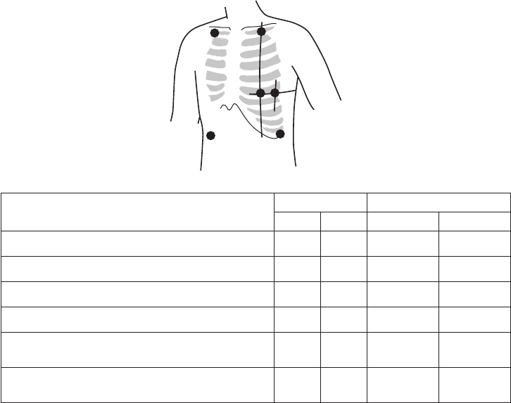
Six Electrodes
The 6-electrode method with lead II and lead V5 is effective for monitoring myocardial ischemia.
You can improve monitoring accuracy considerably by adding lead V4 to this combination. Va and
Vb can be at any position of the standard 12 leads V1 to V6, but V4 and V5 are most appropriate for
myocardial ischemic monitoring.
RA/R LA/L
RL/RF LL/F
Va/Ca
Vb/Cb
Electrode Position Symbol Lead Color
AHA IEC AHA IEC
Left infraclavicular fossa LA L Black Yellow
Right infraclavicular fossa RA R White Red
Below lowest rib on the left anterior axillary line LL F Red Green
Right anterior axillary line at the same level as LL/F RL RF Green Black
Fifth intercostal space on the left midclavicular line.
(V4 position of standard 12 leads) Va Ca Brown-blue White-
brown
Left anterior axillary line at the same level as Va.
(V5 position of standard 12 leads) Vb Cb Brown-
orange White-black
48 Operator’s Manual ZM-940PA/941PA
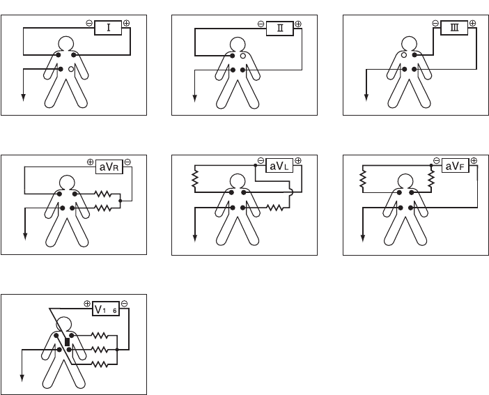
Lead Position
Standard limb leads
Monopolar limb leads
Monopolar chest leads
Lead I
Lead I Lead II Lead III
aVR lead aVL lead aVF lead
V1 to V6 leads
V1 to V6 leads
to
RA
RA
RA RA RA
RA
RA
LA
LA
LA
LA
LA
LA
LA
LL
LL
LL
LL LL
LL
LL
N (RL)
N (RL)
N (RL) N (RL) N (RL)
N (RL)
N (RL)
Operator’s Manual ZM-940PA/941PA 49
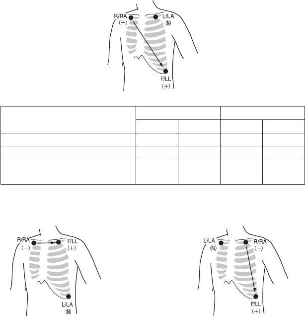
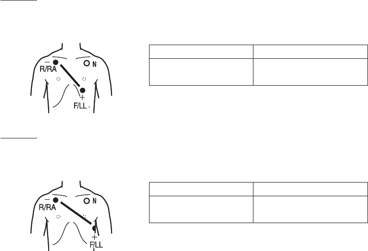
Three Electrodes
• Lead MII, which is similar to standard lead II, used when ECG measurement has priority
Electrode Position Symbol Lead Color
AHA IEC AHA IEC
Left infraclavicular fossa LA L Black Yellow
Right infraclavicular fossa RA R White Red
Below lowest rib on the left anterior
axillary line LL F Red Green
• Lead MI, which is similar to standard lead I
Change F/LL and L/LA of the lead MII.
• Lead MIII, which is similar to standard lead III.
Change R/RA and L/LA of the lead MII.
If the electrode position shown above is not available due to chest surgery, attach the electrodes to
the root of the limbs or below the clavicles for stable ECG monitoring.

50 Operator’s Manual ZM-940PA/941PA
Attaching Electrodes to the Patient and Connecting the Electrode Leads to
Disposable Electrodes
Prepare the Patient Skin
Shave off excessive body hair.
Toreduceskinimpedance,cleantheelectrodesitewithcreamorwithacottonpadmoistenedwith
alcohol.Thoroughlydrytheskinwithacleancottonpad.
NOTE
• For a patient with frequent body movement, rub the sites with Skinpure skin preparation
gel. However, do not use Skinpure skin preparation gel on sensitive skin.
• Do not place electrodes on a wound or on an inflamed, wrinkled or uneven skin surface.
Attaching Electrodes to the Patient
CAUTION
Do not reuse disposable parts and accessories.
NOTE
• To maintain good contact between the electrode and skin, check that the paste of the
disposable electrode is not dry.
• When contact between the disposable electrode and skin becomes poor, replace
electrodes with new ones immediately. Otherwise, contact impedance between the skin
and the electrode increases and the correct ECG cannot be obtained.
Refer to the electrode operator’s manual for details.
1. Carefullyremovethebackingpaperfromtheelectrode.
Avoid touching the adhesive surface.
2. Placetheelectrodeonthepreviouslycleanedskin.Pay
attention to the electrode lead color and symbol.
3. Clip the electrode lead to the electrode.
4. Fasten the electrode lead wire with surgical tape with an
extra length of wire between the tape and the electrode.
This lessens the movement of electrode leads by body
movement and helps stable monitoring.
Operator’s Manual ZM-940PA/941PA 51
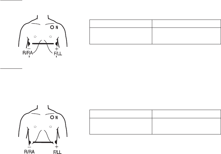
Electrode Position for Respiration Monitoring
Place the R/RA and F/LL electrodes so that the lungs are between the electrodes.
NOTE
The optimum electrode positions for ECG measurement of a patient are not always
optimum for respiration measurement of the patient. Select positions suitable for both ECG
and respiration measurements, or positions which have priority for one measurement.
Electrode Position Examples
NOTE
The following examples are when monitoring with 3 electrodes. ECG cannot be monitored
correctly when electrodes are attached as the following examples when monitoring with 6
electrodes.
Position 1
In this position, respiration measurement is available; however, there is a difference in amplitude
between different patients.
R or RA F or LL
Right infraclavicular fossa Fifth intercostal space on the
left midclavicular line, V4
Position 2
In this position, the waveform amplitude is usually large and the ECG lead is similar to Lead MII.
This position can be generally recommended.
R or RA F or LL
Right infraclavicular fossa Fifth intercostal space on the
left midaxillary line, V6
52 Operator’s Manual ZM-940PA/941PA
Position 3
In this position, the respiration waveform is optimum, but the ECG lead is unusual.
R or RA F or LL
Right midaxillary at the
horizontal level of V4
Fifth intercostal space on the
left midaxillary line, V6
Position 4
Inthisposition,therespirationmeasurementisinuencedbytheimpedancevariationofthe
abdomen, so the cardiac pulse wave included in the respiration wave is reduced. Note that the
waveform is inverted in phase compared with the chest movement (the waveform goes down during
inspiration).ItisdifculttomeasuretheECGatthesametime.
R or RA F or LL
Lowest rib on the right
anterior axillary line
Lowest rib on the left anterior
axillary line
Operator’s Manual ZM-940PA/941PA 53
Attaching the SpO2 Probe
Selecting the SpO2 Probe
Select an appropriate probe for the patient.
CAUTION
Only use Nihon Kohden specified
electrodes, electrode leads, SpO2
probes, and NIBP cuffs. Otherwise,
the maximum performance from the
transmitter cannot be guaranteed.
CAUTION
Do not use a damaged or
disassembled probe. It causes
incorrect measurement and may
injure the patient.
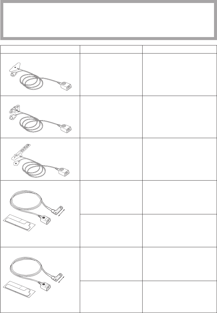
Reusable Probes
WhenusingaTL-201Tngerprobe,choosetheappropriatecablelengthforattachment.
Probe Cable Length Patient Attachment Site
Finger probe TL-201T
0.6 m
Adult or child
20kgormore
Finger
1.6 m
Multi-site probe TL-220T
Attachment tape
Adult or infant
3kgormore
Finger or toe
Neonate
3kgorless
Instep and sole
Finger probe
TL-630T1/TL-630T3/TL-631T1/TL-631T3
Attachment tape
Cable length TL-630T1/TL-631T1: 0.6 m
TL-630T3/TL-631T3: 1.6 m
TL-630T1/630T3:
Adult or child
50kgormore
TL-631T1/631T3:
Adult or child
20kgormore
Finger or toe
54 Operator’s Manual ZM-940PA/941PA
Disposable Probes
CAUTION
The disposable probe is not sterilized. Use the disposable probe only for a single
patient. Never reuse the disposable probe for another patient because it causes cross
infection.
Probe Patient Attachment Site
TL-251T Adult
30kgormore
Finger or toe
TL-252T Child
3to40kg
Finger or toe
TL-253T Neonate
3kgorless
Instep and sole
TL-051S/TL-052S
40 mm
Cable length TL-051S: 0.8 m
TL-052S: 1.6 m
Adult
50kgormore
Finger
Neonate
3kgorless
Instep and sole
TL-061S/TL-062S
35 mm
Cable length TL-061S: 0.8 m
TL-062S: 1.6 m
Adult or child
15to50kg
Finger
Infant
3to15kg
Toe

Operator’s Manual ZM-940PA/941PA 55
Probe Patient Attachment Site
TL-271T/TL-271T3
Cablelength TL-271T: 0.8m
TL-271T3:1.6m
Adult
30kgormore
Finger or toe
TL-272T/TL-272T3
Cablelength TL-272T: 0.8m
TL-272T3:1.6m
Child
10to50kg
TL-273T/TL-273T3
Cablelength TL-273T: 0.8m
TL-273T3:1.6m
Neonate
3kgorless
Instep and sole
Adult
40kgormore
Finger or toe
TL-274T/TL-274T3
Cablelength TL-274T: 0.8m
TL-274T3:1.6m
Infant
3to20kg
56 Operator’s Manual ZM-940PA/941PA
Connecting the SpO2 Probe to the Transmitter
Connect the probe to the SpO2socketonthetransmitter.
When the transmitter is attached on an arm
CAUTION
Do not shake or swing the transmitter
while holding the leads or cables
connected to the transmitter. The
transmitter may come off and injure
someone or damage surrounding
instruments.
CAUTION
Hold the connector when connecting/
disconnecting the SpO2 probe. If you
disconnect the SpO2 probe by pulling
the cable, it damages the cable.

Operator’s Manual ZM-940PA/941PA 57
Attaching the Probe to the Patient
Attachtheprobetothepatientbyreferringtotheprobe’smanual.Makesurethatthelightemitter
and photo detector of the probe face each other at the attachment site.
WARNING
• When using the TL-201T finger
probe, do not fasten the probe and
cable to the finger by wrapping with
tape. This may cause burn,
congestion or pressure necrosis
from poor blood circulation.
• When using probes other than the
TL-201T finger probe, to avoid poor
circulation, do not wrap the tape too
tight. Check the blood circulation
condition by observing the skin
color and congestion at the skin
peripheral to the probe attachment
site. Even for short-term monitoring,
there may be burn or pressure
necrosis from poor blood circulation,
especially on neonates or low birth
weight infants whose skin is
delicate. Accurate measurement
cannot be performed on a site with
poor peripheral circulation.
WARNING
Check the circulation condition by
observing the skin color at the
measurement site and pulse
waveform. Change the measurement
site every 8 hours for disposable
probes and every 4 hours for reusable
probes (every 8 hours for TL-630T/TL-
631T series probe). The skin
temperature may increase at the
attached site by 2 or 3°C (4 or 5°F)
and cause a burn or pressure
necrosis. When using the probe on the
following patients, take extreme care
and change the measurement site
more frequently according to
symptoms and degree.
• Patient with a fever
• Patient with peripheral circulation
insufficiency
• Neonate or low birth weight infant
with delicate skin
• Patient who is receiving
photodynamic therapy*
* Photodynamic therapy is a treatment to
remove the affected tissue by using a
photosensitizing agent and exposing the tissue
to light. This treatment has a side effect of
photosensitivityandthelightfromthenger
probe sensor may cause a burn. This probe
uses two light wavelengths in the range from
650 to 950 nm. The maximum light intensity
is less than 5.5 mW/sr.

58 Operator’s Manual ZM-940PA/941PA
CAUTION
If the attachment site is dirty with
blood or bodily fluids, clean the
attachment site before attaching the
probe. If there is nail polish on the
attachment site, remove the polish.
Otherwise, the amount of transmitted
light decreases, and measured value
may be incorrect or measurement
cannot be performed.
CAUTION
If the skin gets irritated or redness
appears on the skin from the probe,
change the attachment site or stop
using the probe. Take extreme care for
the patients with delicate skin.
CAUTION
When the probe is attached on an
appropriate site with sufficient
circulation and the error message
confirming the probe attachment
repeatedly appears, the probe may be
deteriorated. Replace it with a new
one.
CAUTION
Do not immerse the disposable probe
in detergents or water. If the probe
adhesive surface gets wet,
adhesiveness becomes weak and the
probe cannot be attached to the skin.
CAUTION
Do not use a probe which is
deteriorated by aging. Accurate
measurement cannot be performed.
CAUTION
Neonatal skin is delicate. Remove the
probe and tape carefully and slowly.
CAUTION
When removing a probe that is taped
to the skin, do not pull the probe cable
because this can damage the cable.
CAUTION
When removing the probe from the
attachment tape, do not pull the
sensor cable because this can
damage the cable.
CAUTION
Refer to the probe instruction manual
for details.
Operator’s Manual ZM-940PA/941PA 59
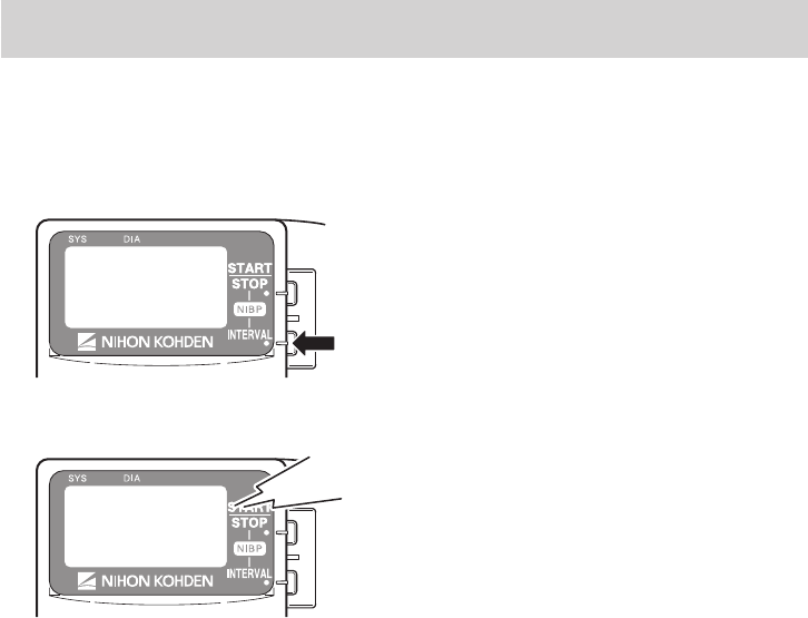
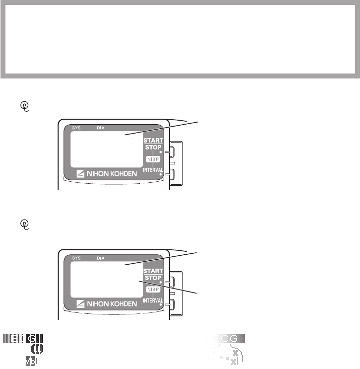
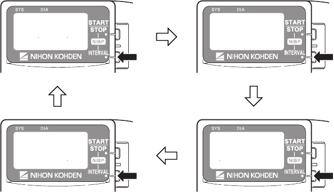
Locking the Keys on the Transmitter
Topreventthepatientfrompressingthekeysonthetransmitterduringmonitoring,youcanlockthe
NIBPSTART/STOPandNIBPINTERVALkeys.
1. PresstheNIBPINTERVALkeyforabout3seconds.
2. A “pip, pip” sounds and the “LOCK KEYS” message is displayed on the LCD.
LOCK
KEYS
Pip, pip
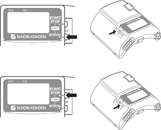
WhentheNIBPSTART/STOPkeyorNIBPINTERVALkeyispressedwhilethekeysarelocked,
the “PRESS INT. KEY 3S TO UNLOCK” message appears.
Tounlockthekeys:
1. PresstheNIBPINTERVALkeyforabout3seconds.
2. A“pip,pip”soundsandthekeysareunlocked.The“UNLOCKKEYS”messageappearsand
thekeysareunlocked.

60 Operator’s Manual ZM-940PA/941PA
Monitoring
When preparation is done, monitoring starts.
NIBP Oscillometric Method
NIBP is measured from the change in amplitude pattern of pulsatile oscillation in cuff pressure
as the cuff pressure is reduced from above systolic to below diastolic pressure. The occlusive-
oscillometry method uses this to determine the systolic, diastolic and mean arterial pressure.
NIBP Monitoring
Selecting the Initial Cuff Inflation Pressure
TheinitialcuffinationpressurecanbechangedonthePARAMETERSETUPscreen.Thedefault
settingis180mmHg.Tochangethesetting,refertothe“ChangingParameterSetupSettings”
section.
Selecting the Measurement Mode and Interval
Measurement Modes
There are three measurement modes: manual, auto and STAT. The selected mode or interval is
displayed at the lower right of the screen.
ThemeasurementmodeandintervalcanbechangedbypressingtheNIBPINTERVALkey.
Whenthekeyispressed,themeasurementmodechangesaccordingtothemodesselectedat
“SELECTABLE INTERVALS” on the PARAMETER SETUP screen. MANUAL mode is already
selected for the mode selection.
To select the modes for the mode selection, refer to the “Changing Parameter Setup Settings”
section.
Manual Measurement
InManualmode,asingleNIBPmeasurementisperformedwhentheNIBPSTART/STOPkeyis
pressed.
STAT (Continuous) Measurement
In STAT mode, measurement is continuously repeated for 15 minutes after the NIBP START/ STOP
keyispressed.
When the STAT measurement for 15 minutes is completed, the measurement mode automatically
changes to the Manual mode or Auto mode of selected interval depending on the “NIBP MODE
AFTER STAT” setting on the PARAMETER SETUP screen. The default setting is Manual mode.

Operator’s Manual ZM-940PA/941PA 61
Refer to the “Changing Parameter Setup Settings” section.
The STAT measurement completes within 15 minutes. When more than 12 minutes elapse from the
start of measurement, there will be no more measurement performed and the measurement mode
changes to the mode selected for “NIBP MODE AFTER STAT” on the PARAMETER SETUP
screen.
Auto Measurement
In Auto mode, measurement is performed automatically at the preset time intervals.
InAutomode,asinglemeasurementcanbeperformedbypressingtheNIBPSTART/STOPkey
between auto measurements.
Measuring NIBP
WARNING
Be careful when measuring NIBP on a
patient with known bleeding disorders
or coagulation. After NIBP
measurement, there may be dot
hemorrhage, or circulatory disorder by
thrombus where the cuff is attached.
WARNING
NIBP measurement may be incorrect
in the following cases.
• When using an electrosurgical unit
• When there is body movement
• When the pulse wave is small
(insufficient peripheral circulation)
• Too many arrhythmias
• When there is vibration
• When there is a rapid blood
pressure change
• During CPR
WARNING
When performing NIBP
measurements in STAT mode or 5
minute intervals, periodically remove
the cuff from the patient for ventilation.
The skin temperature may increase at
the cuff attachment site by 2 or 3°C (4
or 5°F). When measuring a patient
with a fever or peripheral circulation
insufficiency, it may cause a burn.
CAUTION
When performing NIBP measurement
repeatedly, have a rest between
measurements to recover adequate
circulation.
62 Operator’s Manual ZM-940PA/941PA
NOTE
• When measuring patients who are conscious, help the patient to relax. Measurement
may not be accurate if the patient’s arm is tense or if the patient talks.
• The data for measurement on a leg tends to be higher than measurement on the arm.
When making diagnosis based on the NIBP values, measure NIBP on an upper arm.
• Do not apply pressure to the cuff or air hose. NIBP may not be measured correctly
because of noise or NIBP measurement may stop due to the NIBP safety circuit.
• When the transmitter is attached to the patient arm and the NIBP measurement
is performed when moving, tell the patient to relax and keep quiet. Otherwise,
measurement may be stopped or remeasurement is repeated due to body movement.
• If there is an abnormal noise generated during measurement, stop using the transmitter
and contact your Nihon Kohden representative.
• Do not measure NIBP of a patient on whom an IABP is being used. Measurement may
be incorrect due to the mixing of the patient’s own pulse and IABP pulse.
• NIBP cannot be measured on a neonate using this transmitter.
1. SelectthemeasurementmodebypressingtheNIBPINTERVALkey.
2. PresstheNIBPSTART/STOPkeytoperformmeasurement.
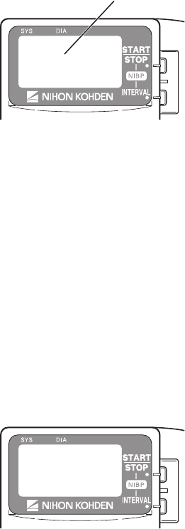
Operator’s Manual ZM-940PA/941PA 63
Thecuffisinatedandtheinationpressureisdisplayedonthescreen.
Inflation pressure
In manual mode: Measurement is performed once.
In STAT mode: Measurement is performed repeatedly for 15 minutes.
Inautomode: TherstmeasurementisperformedwhentheNIBPSTART/STOPkeyis
pressed. The second measurement is performed when the current time in the
transmitter reaches the selected time interval.
Tostopmeasurementduringmeasurement,presstheNIBPSTART/STOPkeyagain.
In STAT mode, after completing the STAT measurement, the measurement mode changes to the
mode set for “NIBP MODE AFTER STAT” on the PARAMETER SETUP screen.
In auto mode, to stop measurement in auto mode, change the mode to manual. To cancel one
measurement,presstheNIBPSTART/STOPkeyduringmeasurement.
After the measurement is complete, the measured data is displayed on the screen and is transmitted
to the monitor.
When SpO2 is not monitored, the pulse rate at the end of NIBP measurement is displayed.
During auto mode measurement, the measurement mode can be changed. During the interval, press
theNIBPINTERVALkeytochangethemode.When“MANUAL”isdisplayedformorethanone
second, the measurement in auto mode is stopped.
A buzzer can be set to sound at the start and end of NIBP measurement. Refer to the “Changing
Parameter Setup Settings” section.

64 Operator’s Manual ZM-940PA/941PA
Data Display After NIBP Measurement
When the time set at “OLD NIBP DATA” on the PARAMETER SETUP screen elapses after the last
measurement, the NIBP data is dimmed or hidden. Whether to dim or hide the old data can also be
selected at “OLD NIBP DATA”. Refer to the “Changing Parameter Setup Settings” section.
Data Display on the Receiving Monitor
When the “Low battery ” message is displayed on the receiving monitor, NIBP might not have
been measured according to the NIBP interval setting. Therefore, the NIBP data displayed on the
receivingmonitormightnotbeupdated.Inthiscase,checkthemeasurementtimeoftheNIBPdata
displayed on the receiving monitor.
Monitoring SpO2 during NIBP Measurement
When the SpO2probeisattachedtothesamelimbastheNIBPcuff,thebloodowdecreases
during NIBP measurement and pulse wave cannot be detected and SpO2 cannot be monitored
properly.When“INHIBITSpO2 DURING NIBP” on the PARAMETER SETUP screen is set to
ON (factory default setting), SpO2 monitoring is paused during NIBP measurement to avoid SpO2
alarmoccurrence.However,whenmonitoringSpO2 on the same limb as the NIBP, be careful when
reading SpO2 values.
ECG and Respiration Monitoring
When the electrodes are attached and the ECG leads are connected to the electrodes, heart rate, ECG
waveform, respiration rate and respiration waveform appear on the monitor.
When 6 leads are used on this transmitter, up to 8 lead (I, II, III, aVR, aVL, aVF, Va and Vb) of
ECG waveforms can be displayed on the receiving monitor. The heart rate is also measured.
When 3 leads are used, one channel ECG waveform of lead II can be displayed on the receiving
monitor. Refer to the operator’s manual of the monitor for details.
Respiration is monitored by measuring changes in impedance between the RA and LL ECG
electrodes. This transmitter sends the changes in impedance to the monitor as a respiration
waveform. The monitor displays the respiration waveform and calculates respiration rate. Refer to
the operator’s manual of the monitor for details.

Operator’s Manual ZM-940PA/941PA 65
WARNING
Interaction Between Minute Ventilation Rate-Adaptive Pacemakers and Cardiac
Monitoring and Diagnostic Equipment*
The bioelectric impedance measurement sensor of a minute ventilation rate-adaptive
implantable pacemaker may be affected by transmitter which is connected to the
same patient. If this occurs, the pacemaker may pace at its maximum rate and the
transmitter may give incorrect data to the monitor. If this occurs, disconnect the
electrode leads from the patient or change the setting on the pacemaker by referring
to the pacemaker’s manual. For more details, contact your pacemaker representative
or Nihon Kohden representative.
* Minuteventilationissensedinrate-adaptivepacemakersbyatechnologyknownasbioelectric
impedancemeasurement(BIM).Manymedicaldevicesinadditiontopacemakersusethis
technology. When one of these devices is used on a patient with an active, minute ventilation rate-
adaptivepacemaker,thepacemakermayerroneouslyinterpretthemixtureofBIMsignalscreated
in the patient, resulting in an elevated pacing rate.
For more information, see the FDA web site.
http://www.fda.gov/cdrh/safety.html
WARNING
When the transmitter is used with an electrosurgical unit (ESU), firmly attach the
entire area of the ESU return plate. Otherwise, the current from the ESU flows into the
electrodes of the transmitter, causing electrical burn where the electrodes are
attached. For details, refer to the ESU manual.
CAUTION
Turn off the power of mobile phones, small wireless devices and other devices which
produce strong electromagnetic interference around a patient (except for devices
allowed by the hospital administrator). Radio waves from devices such as mobile
phones or small wireless devices may be mistaken as pulse waves and the displayed
data may be incorrect.
NOTE
• Noise generated from an electrosurgical unit may interfere on an ECG waveform, but will
not damage it.
• If an electric blanket is used and incorrect heart rate is displayed on the monitor, turn off
the pacing spike detection on the monitor.
• Turn the pacing spike detection to ON on the monitor when monitoring a pacemaker
66 Operator’s Manual ZM-940PA/941PA
patient. Pacing pulse is detected by the transmitter and transmitted to the monitor.
If the pacing spike detection is turned OFF, QRS and pacemaker spike may not be
distinguished and pacemaker failure may not be recognized.
Electrode Detachment
Inthefollowingconditions,thecheckelectrodeindicationisdisplayedontheLCDofthe
transmitterandthe“CHECKELECTRODE”messageisdisplayedonthemonitor.
• Electrodeisdetachedfromskin.
• Electrode lead is disconnected from the electrode.
• Polarizationvoltagebetweentheelectrodeandskinisexcessivelyhigh.
Inthesecases,checkthecauseandifnecessary,replaceelectrodeswithnewones.
CAUTION
When the “ELECTRODE OFF” or “CHECK ELECTRODE” message is displayed on
the receiving monitor, ECG is not monitored properly and the ECG alarm does not
function. Check the electrode, electrode leads, and if necessary, replace with new
ones.
Check Electrode Indication on the Transmitter when Monitoring with 3 Electrodes
The “ ”markisdisplayed.
Check electrode symbol
Check Electrode Indication on the Transmitter when Monitoring with 6 Electrodes
The “ ”markandeitherthedetachedleadordetachedelectrodepositionisindicated,depending
on the LEADS OFF DISPLAY setting on the PARAMETER SETUP screen.
Check electrode symbol
Check electrode indication
When LEADS OFF
DISPLAYissettoCHAR,the
detached lead is indicated
When LEADS OFF
DISPLAY is set to IMAGE,
the detached electrode
position is indicated with X

Operator’s Manual ZM-940PA/941PA 67
SpO2 Monitoring
When monitoring starts, SpO2 and pulse waveform are sent to the monitor and SpO2, pulse rate and
pulse level bar graph are displayed on the transmitter LCD.
WARNING
SpO2 measurement may be incorrect
in the following cases.
• When the patient’s
carboxyhemoglobin or
methemoglobin increases
abnormally.
• When dye is injected in the blood.
• When using an electrosurgical unit.
• During CPR.
• When measuring at a site with
venous pulse.
• When there is body movement.
• When the pulse wave is small
(insufficient peripheral circulation).
WARNING
Check the circulation condition by
observing the skin color at the
measurement site and pulse
waveform. Change the measurement
site every 8 hours for disposable
probes and every 4 hours for reusable
probes (every 8 hours for TL-630T/TL-
631T series probe). The skin
temperature may increase at the
attached site by 2 or 3°C (4 or 5°F)
and cause a burn or pressure
necrosis. When using the probe on the
following patients, take extreme care
and change the measurement site
more frequently according to
symptoms and degree.
• Patient with a fever
• Patient with peripheral circulation
insufficiency
• Neonate or low birth weight infant
with delicate skin
• Patient who is receiving
photodynamic therapy*
* Photodynamic therapy is a treatment to
remove the affected tissue by using a
photosensitizing agent and exposing the tissue
to light. This treatment has a side effect of
photosensitivityandthelightfromthenger
probe sensor may cause a burn. This probe
uses two light wavelengths in the range from
650 to 950 nm. The maximum light intensity
is less than 5.5 mW/sr.
WARNING
When not monitoring SpO2,
disconnect the SpO2 cable from the
transmitter. Otherwise, noise from the
probe sensor may interfere and
incorrect data is displayed on the
screen.

68 Operator’s Manual ZM-940PA/941PA
CAUTION
Turn off the power of mobile phones,
small wireless devices and other
devices which produce strong
electromagnetic interference around a
patient (except for devices allowed by
the hospital administrator). Radio
waves from devices such as mobile
phones or small wireless devices may
be mistaken as pulse waves and the
displayed data may be incorrect.
CAUTION
Do not pull or bend the probe cable,
and do not put caster feet on the
probe cable. Do not immerse the
probe cable in chemical solutions or
water. Failure to follow these
instructions may cause cable
discontinuity, short circuit, skin burn
on the patient and incorrect
measurement data. Replace any
broken probe with a new one.
CAUTION
Normal external light does not affect
monitoring but strong light such as a
surgical light or sunlight may affect
monitoring. If affected, cover the
measuring site with a blanket.
CAUTION
When the probe is attached on an
appropriate site with sufficient
circulation and the error message
confirming the probe attachment
repeatedly appears, the probe may be
deteriorated. Replace it with a new
one.
CAUTION
When a message indicates a faulty
probe, stop monitoring and replace
the probe with a new one.
CAUTION
While a patient is on medication which
causes vasodilation, the pulse
waveform may change and in rare
cases the SpO2 value might not be
displayed.
NOTE
In order to maintain sufficient blood circulation, keep the measurement site warm by
covering it with a blanket or something similar. Warming the site is effective, especially for a
patient with a small pulse amplitude.
SpO2 and PR Display Order
You can select the display order for SpO2 and PR (pulse rate) on the LCD. Refer to the “Changing
Parameter Setup Settings” section.

Operator’s Manual ZM-940PA/941PA 69
Monitoring SpO2 during NIBP Measurement
When the SpO2probeisattachedtothesamelimbastheNIBPcuff,thebloodowdecreases
during NIBP measurement and pulse wave cannot be detected and SpO2 cannot be monitored
properly.When“INHIBITSpO2 DURING NIBP” on the PARAMETER SETUP screen is set to ON
(factory default setting), SpO2 monitoring is paused during NIBP measurement to avoid SpO2 alarm
occurrence.However,whenmonitoringSpO2 on the same limb as NIBP, be careful when reading
SpO2 values.
When monitoring SpO2 is important, attach the probe to the limb to which the NIBP cuff or catheter
is not attached.
When SpO2 monitoring is paused during NIBP measurement, the SpO2 value just before the start of
NIBP measurement and an markaredisplayedonthetransmitterfor30seconds.
WhenNIBPmeasurementisnotcompletedafter30seconds,“–––”isdisplayedfortheSpO2 value.
The same data also appears on the monitor screen.
NOTE
• When continuous SpO2 monitoring is necessary, attach the probe to the limb to which the
NIBP cuff is not attached and set “INHIBIT SpO2 DURING NIBP” on the PARAMETER
SETUP screen to OFF.
• When the probe is attached to the same limb as the NIBP cuff, set the sync source to a
parameter other than SpO2 on the receiving monitor.
• When monitoring SpO2 during STAT NIBP measurement, attach the probe to the limb to
which the NIBP cuff is not attached.
70 Operator’s Manual ZM-940PA/941PA
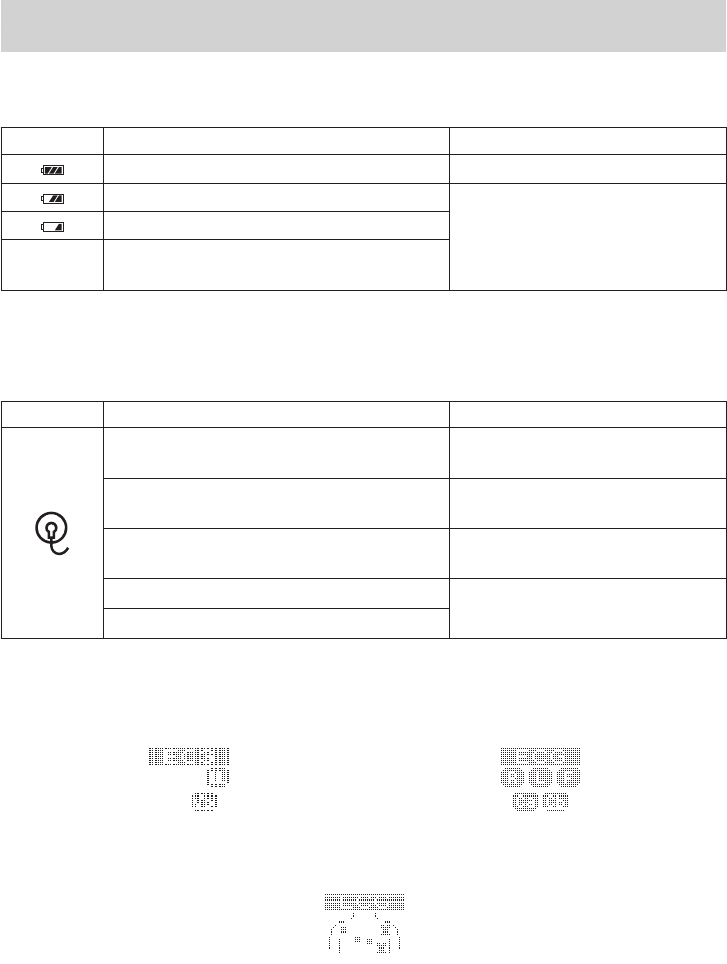
Display and Message List
Battery Indication
Indication Cause Countermeasure
Fully charged battery ——
Batteries are low.
Replace batteries.
Batteries are low. NIBP cannot be measured.
No
indication Dead batteries
ECG/Respiration
Indication Cause Countermeasure
Electrode lead is disconnected from the
electrode.
Firmly connect the electrode lead to
the electrode.
Electrode lead is disconnected from the
transmitter.
Firmly connect the electrode lead to
the transmitter.
Electrode lead discontinuity. Replace the electrode lead with a
new one.
Electrodeisnotrmlyattachedtotheskin. Replace the electrode with a new
one.
Polarization voltage is abnormally high.
When monitoring ECG with 6 electrodes, the electrode or lead detached position is indicated by
either lead or electrode position. This is set at LEADS OFF DISPLAY on the PARAMETER SETUP
screen. Refer to the “Changing Parameter Setup Settings” section.
LEADS OFF DISPLAY set to CHAR
ECG ELECTRODE set to AHA
LEADS OFF DISPLAY set to CHAR
ECG ELECTRODE set to IEC
LEADS OFF DISPLAY set to IMAGE

Operator’s Manual ZM-940PA/941PA 71
SpO2
Message Cause Countermeasure
During NIBP
measurement
SpO2 monitoring is paused for
NIBP measurement. WaitforNIBPmeasurementtonish.
Detecting body
movement
Considerable body movement.
When the message is displayed frequently,
checkthepatientconditionand,if
necessary, change the attachment site.
The probe is not attached to the
patient properly.
SpO2CHECK
PROBE
The probe is not attached to the
patient properly. Attach the probe to the patient properly.
The probe is not attached at the
appropriate site.
Attach the probe to a site 6 to 14 mm
thick.
Probe is expired. Replace the probe with a new one.
SpO2 DETECTING
PULSE
Searching for the correct pulse
wave. Wait until the pulse wave is detected.
The SpO2 value cannot be
obtained because the waveform
is unstable. Attach the probe to the patient properly.
The probe is not attached to the
patient properly.
SpO2LIGHT
INTERFERENCE
SpO2 measurement site is under
uorescentlight,surgicallight,
sunlight, etc.
Cover the measurement site with a
blanketorcloth.
SpO2 PROBE
FAILURE
Probe is expired. Replace the probe with a new one.
Probe is damaged or short-
circuited. Replace the probe with a new one.
SpO2 WEAK PULSE
Poor peripheral circulation. Checkthepatientconditionandchange
the attachment site.
The probe is attached too
tightly and is obstructing the
blood circulation.
Checktheprobeattachmentcondition
and if necessary, reattach the probe.

72 Operator’s Manual ZM-940PA/941PA
NIBP
Message Cause Countermeasure
NIBP AIR LEAK
The cuff and extension hose are not
properly connected. Connect them properly.
The cuff hose (or extension hose) is not
properlyconnectedtotheNIBPsocket.
The cuff or extension hose is damaged. Replace with a new one.
NIBP CANNOT DETECT
PULSE
The patient’s pulse wave is small. Measure by palpation or auscultation.
The cuff is not wrapped on the patient
properly. Wrap the cuff on the patient properly.
NIBPCHANGE
BATTERIES NO NIBP
NIBP cannot be measured due to low
battery. Replace batteries with new ones.
NIBP CUFF OCCLUSION Transmitter malfunction.
Immediately remove the cuff from the
patient and contact your Nihon Kohden
representative.
NIBPHIGHCUFFPRESS Enormous pressure was applied by the
pressure of the cuff. Remove the cause.
NIBP INFLATION PRESS
LOW Insufcientcuffinationpressure.
Wait for the remeasurement to be
performedwithincreasedcuffination
pressure.
NIBP MEAS TIME-OUT
The measuring time exceeded the
speciedtimeduetoarrhythmia,body
movement, vibration or, cuff or air hose
being squeezed.
Remove the cause if the cause is body
movement, vibration or squeezing of
cuff or hose.
NIBP MODULE FAILURE Module malfunction. Contact your Nihon Kohden
representative.
NIBP REMEASURING
NIBP is being remeasured due to
arrhythmia, body movement, vibration
or, cuff or air hose being squeezed.
If the message still appears after
remeasurement, remove the cause if the
cause is body movement, vibration or
squeezing of cuff or hose.
NIBP SAFETY CIRCUIT
RUNNING
(When this message is
displayed, measurement
cannot be performed for 40
seconds.)
Measurement stopped by the safety
circuit.
Checkthatthehoseisnotbentor
squeezed.
Wait 40 seconds, then perform
remeasurement. If the message still
appears, contact your Nihon Kohden
representative.
NIBP SYS OUT OF
RANGE
The maximum blood pressure cannot
be measured even when the cuff
inationpressureexceeded280mmHg
when using adult cuff.
Measure by palpation or auscultation.
NIBP WEAK PULSE
The patient’s pulse wave is too small. Measure by palpation or auscultation.
The cuff is wrapped too loosely. Wrap the cuff properly.
The cuff size is not appropriate. Use the appropriate cuff.
NIBP ZEROING NIBP zero balance is being adjusted. Do not touch the cuff during zeroing.
Wait for the message to disappear.

Operator’s Manual ZM-940PA/941PA 73
Troubleshooting
Iftheproblemstillremainsaftercheckingthefollowing,contactyourNihonKohdenrepresentative.
Transmitter
Problem Cause Countermeasure
Nothing is displayed
on the LCD after
turning the power on.
Batteries are not installed
correctly. The battery polarity
is wrong.
Install the batteries correctly.
Batteries are completely
discharged.
Replace the batteries with new ones.
LCDisdifculttosee
(toodarkortoolight).
LCD brightness is not
appropriate.
Change the LCD brightness on the
SYSTEM SETUP screen. Refer to the
“Changing System Setup Settings”
section.
Nothing is displayed
on the monitor after
turning the transmitter
power on.
The channel of the transmitter
and monitor does not match.
Set the correct channel on the monitor.
The software version of the
multiple patient receiver is old.
Upgrade the multiple patient receiver
software to receive signal from the
transmitter. The software version must
be 01-09 or later.
Signal receiving
condition is poor.
Another transmitter of the same
channel is used nearby.
Turn the transmitter power off. If the
monitor still receives a signal, there is a
high probability that another transmitter
of the same channel is used nearby.
Follow the instruction of your
channel administrator and use another
transmitter of a different channel.
Signals are mixing. Follow the instructions of your
channel administrator and use another
transmitter of a different channel.
The transmitter is damaged. Contact your Nihon Kohden
representative.

74 Operator’s Manual ZM-940PA/941PA
ECG/Respiration
Problem Cause Countermeasure
The heart rate is
unstable.
Pacing detection setting on the
monitor is not correct.
Turn off the pacing detection setting on the
monitor.
Whenmonitoringapacemakerpatient,
turn on pacing detection.
The“CHECK
ELECTRODE”
message appears
on the receiving
monitor.
Electrode lead is disconnected
from the electrode.
Firmly connect the electrode lead to the
electrode.
Electrode lead discontinuity Replace the electrode lead with a new one.
Electrodeisnotrmlyattached
totheskin.
Replace the electrode with a new one.
Polarization voltage is
abnormally high.
UseNihonKohdenspeciedelectrodes.
ECG baseline is
thick.
(Humis
overlapping)
The gel on the electrode is dried
out.
Replace the electrode with a new one.
The gel on the electrode is
coming off.
Electricblanketisused. Covertheblanketwithashieldcover.
HumlterissettoOFFonthe
monitor
SettheltertoON.
Respiration
waveform
measurement is
unstable.
The gel on the electrode is dried
out.
Replace the electrode with a new one.
The gel on the electrode is
coming off.
SpO2
Problem Cause Countermeasure
SpO2 data is unstable
and not reliable.
The probe size is not
appropriate for the patient.
Use the appropriate probe for the
patient.
Probe attachment condition is
poor. Probe is partly detached
fromtheskin.Externallight
gets in.
Firmly attach the probe according to
the procedure in the probe operator’s
manual.
Measurement site is dirty.
Patient is wearing nail polish.
Remove dirt and nail polish.
Probe is attached to the same
limb that is used for NIBP
measurement.
When the probe and cuff are attached
tothesamelimb,set“INHIBIT
SpO2 DURING NIBP” setting on the
PARAMETER SETUP screen to ON.
Attach the probe to the opposite limb.
Avoid a site where blood circulation
condition changes greatly.

Operator’s Manual ZM-940PA/941PA 75
NIBP
Problem Cause Countermeasure
Cuffinationpressure
islessthan10mmHg.
The cuff hose is not connected
totheNIBPsocketproperly.
Connectthecuffhosetothesocket
properly.
The cuff is not wrapped around
the arm or is wrapped too
loosely.
Wrap the cuff around the upper arm.
The cuff does not
inatewhentheNIBP
START/STOPkeyis
pressed.
The cuff hose is not connected
totheNIBPsocket.
Connectthecuffhosetothesocket
rmly.
The cuff hose or extension hose
may be folded or squeezed
when the cuff pressure display
onthescreenincreasesquickly
but the actual cuff does not
inate.
Checkthecuffhoseandairhose.
Abnormal
measurement results
are displayed.
The cuff size is not correct. Selectthecuffwhichtsthepatient’s
limb circumference.
The cuff is not wrapped around
the arm correctly.
Wrap the cuff around the upper arm, not
too tightly or too loosely.
NIBP data is not correct
because of body movement.
Prevent the patient from moving during
measurement.
Vibration on the cuff. Checkthatnothingistouchingthecuff
during measurement.
Change the measuring site.
The cuff is suddenly
deatedduring
ination.
TheNIBPSTART/STOPkeyis
pressedduringination. —
Auto mode
measurement does
not start even when
the time interval has
passed.
TheNIBPINTERVALkeyis
pressed and the measurement
mode is changed.
Checkthemeasurementmodeand
interval.
The cuff suddenly
inates.
The measurement mode is set to
auto mode.
Checkthetimeinterval.Ifnecessary,
stop measurement.
Cannot connect cuff to
the air hose.
Unspeciedcuffisused. UseacuffspeciedbyNihonKohden.

76 Operator’s Manual ZM-940PA/941PA
Problem Cause Countermeasure
Cannot measure NIBP. Vibration on the cuff. Checkthatnothingistouchingthecuff
during measurement.
The cuff hose or extension hose
is bent or squeezed.
Remove the cause.
The cuff has worn out. Use a new cuff.
Blood congestion
occurs.
Measuring over a long period of
time at short intervals.
Increase the measuring interval.
Do not measure NIBP over a long time.
Thrombus occurs. Measuring on a patient with
knownbleedingdisordersor
coagulation.
Do not perform NIBP measurement on
such a patient.
NIBP data on the
screenis---ordark.
The time set for “OLD NIBP
DATA” on the PARAMETER
SETUP screen elapsed from the
last measurement.
When NIBP is measured again, the data
is displayed in normal brightness.
Three loud pip sounds
indicting NIBP
measurement cannot
be started.
Thecuffisnotdeatedenough
to start another measurement.
Wait 30 seconds and measure again.

Operator’s Manual ZM-940PA/941PA 77
Maintenance
Tousetheinstrumentinsafeandoptimumcondition,performmaintenancecheckonceeverysix
months.
CAUTION
Never disassemble or repair the transmitter. Disassembly and repair must be
performed by qualified service personnel.
Amaintenancechecksheetisprovidedattheendofthissection.Makeacopyofthischecksheet
beforeperformingmaintenancecheck.
1. External Check
• There are no damaged or dirty parts on the outside of the transmitter.
• Thebatterycasecoverisnotdamaged,thespringisrmlyxedandthebatterycasecovercanbe
closedrmly.
• NIBPsocketisnotdamaged.
• Keys are not damaged.
• Electrode leads are not damaged.
• There is no blood or chemicals on the transmitter.
2. Transmitter Channel
Checkthatthechannelofthetransmitterandthelabelmatch.
1. Checkthatthechannelnumberlabelattachedtothetransmitterisnottornorremoved.
Channel label
2. Remove one battery.
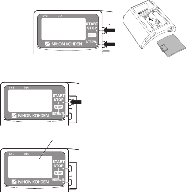
78 Operator’s Manual ZM-940PA/941PA
3. WhilepressingtheNIBPSTART/STOPandNIBPINTERVALkeys,installthebattery.The
SETUP screen appears.
4. PresstheNIBPINTERVALkeytomovethecursorto“SYSTEMSETUP”.
5. PresstheNIBPSTART/STOPkeytoenterthe
SYSTEM SETUP screen. The channel of this
transmitter is displayed.
6. CheckthatthechanneldisplayedontheLCD
matches the label on the transmitter.
ChannelChannel
Operator’s Manual ZM-940PA/941PA 79
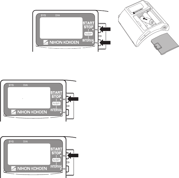
3. LCD Display
CheckthattherearenodotsmissingontheLCD.
1. Remove one battery.
2. WhilepressingtheNIBPSTART/STOPandNIBPINTERVALkeys,installthebattery.The
SETUP screen appears.
3. PresstheNIBPINTERVALkeytwicetomovethecursorto“MANUALCHECK”.
4. PresstheNIBPSTART/STOPkeytoenterthe
MANUALCHECKscreen.
5. Checkthatthecursorison“LCDTEST”andpress
theNIBPSTART/STOPkey.
80 Operator’s Manual ZM-940PA/941PA
6. EverytimetheNIBPINTERVALkeyispressed,thescreenchangesasbelow.Checkthatthere
are no dots missing.
WhentheNIBPSTART/STOPkeyispressed,thescreenreturnstotheMANUALCHECK
screen.
4. Key Operation
NIBP START/STOP Key
1. Attach the NIBP cuff to your upper arm.
2. PresstheNIBPSTART/STOPkey.Checkthatthecuffinatesanddeatesproperly.
3. PresstheNIBPSTART/STOPkeyagain.Duringination,presstheNIBPSTART/STOPkeyto
checkthatthecuffdeatesproperly.
NIBP INTERVAL Key
1. PresstheNIBPINTERVALkeyandcheckthattheNIBPmeasuringmodecanbechanged.
2. SelectanyintervalandpresstheNIBPSTART/STOPkeytoperformautomeasurement.Check
that the NIBP is measured at the selected interval.
Operator’s Manual ZM-940PA/941PA 81
5. NIBP Cuff for Attaching Transmitter to Patient Arm
TheNIBPcuffisaconsumable.Checkthefollowingandwhennecessary,replaceitwithanewone.
Appearance
• There are no dirty parts.
• Therearenobrokenstitchesonthecuff.
• The label on the cuff is readable.
• Thevelcrotapeonthecuffisnotremovedandtherearenobrokenstitches.
• Thelockplateisnotdamagedandfunctionsproperly.
Inationbag
• Theinationbagisnottornordamaged.
• Thereisnowaterinsidetheinationbag.
• Theconnectorontheinationbagisnotdamaged.

82 Operator’s Manual ZM-940PA/941PA
Maintenance Check Sheet
Hospital/Organization:
Service Personnel:
Instrument Name: Transmitter
Instrument Model: ZM-940PA/ZM-941PA
Instrument Serial Number:
HardwareRevisionNumber:
Software Revision Number:
1. ExternalCheck OK No
2. Transmitter Channel OK No
3. LCD Display OK No
4. Key Operation OK No
5. NIBP Cuff for Attaching Transmitter to Patient Arm OK No
Overall Judgement
□ OK
□ Can be used but needs maintenance
□ Maintenance required. Cannot be used.

Operator’s Manual ZM-940PA/941PA 83
Repair Parts Availability Policy
NihonKohdenCorporation(NKC)shallstockrepairparts(partsnecessarytomaintainthe
performance of the instrument) for a period of 8 years from the date of delivery. In that period NKC
or its authorized agents will repair the instrument. This period may be shorter than 8 years if the
board or part necessary for the faulty section is not available.

84 Operator’s Manual ZM-940PA/941PA
Lifetime and Disposal
Disposing of Used Batteries
Battery Lifetime
Replace the batteries when the battery replacement indication appears on the transmitter. When
using rechargeable batteries, recharge them.
ZM-940PA
Type Lifetime (Measuring parameters)
ECG, SpO2, NIBP ECG, SpO2ECG only
NiMHsecondary 2 days 2.5 days 3 days
Alkalineprimary 1 day 2.5 days 3 days
ZM-941PA
Type Lifetime (Measuring parameters)
ECG, SpO2, NIBP ECG, SpO2ECG only
NiMHsecondary 1.5 days 2 days 2.5 days
Alkalineprimary 1 day 2 days 2.5 days
The above data is when the following batteries and battery charger which are recommended by
Nihon Kohden are used. The measurement is performed at room temperature, NIBP is measured in
auto mode at 60 minute intervals and SpO2ismeasuredonanindexngerofamalepatientwith
weight60kg.OperationtimedependsonthethicknessoftheSpO2 probe attachment site.
NiMHsecondary: SANYOHR-3UF(W)
Battery charger: SANYO NC-M55
Alkalineprimary: NihonKohdenMedipower(equivalenttoPanasonicLR6(G))
Disposal
NOTE
Remove the batteries before disposing of the transmitter.
Beforedisposingofthebatteries,checkwithyourlocalsolidwasteofcialsfordetailsinyourarea
for proper disposal. It may be illegal to dispose of these batteries in the municipal waste stream.
Disposing of Electrodes, SpO2 Probes and NIBP Cuffs
Refer to the manual of each item.

Operator’s Manual ZM-940PA/941PA 85
Cleaning, Disinfection and Sterilization
Transmitter and Electrode Leads
CAUTION
This transmitter is not waterproof. If
detergent or liquid spills into the
transmitter, stop cleaning or
disinfecting it and contact your Nihon
Kohden representative. The
transmitter needs to be checked for
safety and function before use.
CAUTION
Before cleaning or disinfection,
remove the batteries from the
transmitter. Failure to follow this
instruction may result in electrical
shock or transmitter malfunction.
CAUTION
Dispose of the transmitter, options
and accessories as specified by Nihon
Kohden. Otherwise, it causes infection
or environmental contamination.
CAUTION
The transmitter cannot be sterilized.
Sterilizing the transmitter may damage
it.
Before cleaning or disinfecting, remove the batteries from the transmitter. Be careful not to let any
liquid get inside the transmitter.
Cleaning
Wipe the transmitter and electrode leads with a soft cloth moistened with disinfecting alcohol or
neutral detergent diluted with water. After cleaning, dry them completely.
Disinfection
CAUTION
• Do not immerse the electrode lead connector in liquid.
• Do not disinfect with hypochlorous acid.
• Use the recommended concentration.
Wipe the outside surface of the transmitter and electrode lead with a non-abrasive cloth moistened
with any of the disinfectants listed below. Use the recommended concentration.

86 Operator’s Manual ZM-940PA/941PA
Disinfectant Concentration (%)
Glutaraldehyde solution 2.0
Alkyldiaminoethylglycinehydrochloride 0.5
Benzalkoniumchloride 0.2
Benzethonium chloride solution 0.2
Chlorhexidine gluconate solution 0.5
SpO2 Probe
Refer to the probe manual.
YP-943P/944P NIBP Cuffs
CAUTION
• Do not autoclave.
• Use only glutaraldehyde solution.
• Never allow liquid to get inside the inflation bag.
• Do not sterilize or disinfect the cuff with ultraviolet light or ozone.
Cleaning
Tocleanthecuff,removethelockplateandcarefullypullouttheinationbagfromtheclothcover.
Cloth cover: Wash with neutral detergent and water. Thoroughly dry it. When washing in a washing
machine, put it in a net.
Inationbag:
Wipe with a soft cloth or cotton moistened with disinfecting alcohol. Thoroughly dry it.
Disinfection
To disinfect the cuff, use glutaraldehyde solution. Use the recommended concentration of the
disinfectant. Refer to the disinfectant manual for details. After disinfection, clean the cuff as
described above.

Operator’s Manual ZM-940PA/941PA 87
Specifications
ZM-940PA
Measuring Parameters
Measuring waveforms: ECG, Respiration in impedance method, pulse
Measuring numeric data: SpO2, NIBP, pulse rate
Transmitting Data
Waveform data: ECG, respiration, pulse wave
Numeric data: SpO2 and NIBP
Statusinformation: Batteryreplacement,channelID,typeoftransmitter,check
electrodes, abnormal polarization voltage, pacing data,
SpO2 status, NIBP status
Displayed Data
SpO2,NIBP,pulserate,pulsewavebargraph,checkelectrode,batteryreplacement,NIBP
measurement mode and status information
ECG Measurement
Channels: 4
Input range: ±5 mV or more
DC offset: ±500 mV or more
Inputimpedance: 5MΩormore(5Hz)
Pacing pulse detection: ANSI/AAMI EC13
BaseduponPacemakerpulserejectionCapability
ECGrecoverytimeafterdebrillation: within10s
Respiration Measurement
Measuring method: Impedance method
Impedancerange: 0to2kΩorless
SpO2 Measurement
Display range: Depends on the receiving monitor
Measuring range: 0 to 100%, in 1% steps
Minimum display range: 1%
Measuring accuracy When the measuring accuracy of the SpO2 probe is not considered:
±1(80%≤SpO2≤100%)
±2(50%≤SpO2 < 80%)
Lessthan50%isnotspecied
88 Operator’s Manual ZM-940PA/941PA
When considering the measuring accuracy of the SpO2 probe:
±2(80%≤SpO2≤100%)
±3(70%≤SpO2 < 80%)
Lessthan70%isnotspecied
NIBP Measurement
Displayed items: Systolic, diastolic, mean
Cuffpressuredisplayrange: 0to300mmHg
Measurement modes: Manual, STAT, auto at 5, 10, 15, 30, 60, 120 or 240
minute interval
Measurementaccuracy: ±3mmHg(0≤NIBP≤200mmHg)
±4mmHg(200<NIBP<300mmHg)
Meets or exceeds AAMI Sp-10. 1992 standard
(Maximummeanerror:±5mmHg
Maximumstandarddeviation:8mmHg)
Pulse Rate
Measuring range: 30 to 200 beats/min ±8 beats/min (NIBP)
30 to 250 beats/min ±3% ±1 beat/min (SpO2)
Transmitter
FCCregulation: FCCpart95SubpartH
Wireless Medical Telemetry Service (WMTS)
Field strength limits: <200 mV/m (at 3 m)
Undesiredemission: below960MHz:200μV/m(at3m)
above960MHz:500μV/m(at3m)
Antenna: Internal
Transmission channel: Indicated on the transmitter
Transmissionfrequencyrange: 608.0250to613.9750MHz
Channelspacing: 50kHzor37.5kHz(12.5kHzwheninterleaved)
Modulation: Frequencyshiftkeying
Type of emission: F1D
Occupiedbandwidth: <20kHz
Effective radiated power: 1.0 mW
Power Requirements
Operating voltage: 3.2 to 4.8 V
Batterytype: ThreeAA(R6)typeNiMHsecondarybatteries
ThreeAA(R6)typealkalinedrycellprimarybatteries

Operator’s Manual ZM-940PA/941PA 89
Battery lifetime:
Type Lifetime (Measuring parameters)
ECG, SpO2, NIBP ECG, SpO2ECG only
NiMHsecondary 2 days 2.5 days 3 days
Alkalineprimary 1 day 2.5 days 3 days
The above data is when the following batteries and battery charger which are recommended
by Nihon Kohden are used. The measurement is performed at room temperature, NIBP is
measured in auto mode at 60 minute intervals and SpO2ismeasuredonanindexngerofa
malepatientwithweight60kg.OperationtimedependsonthethicknessoftheSpO2 probe
attachment site.
NiMHsecondary: SANYOHR-3UF(W)
Battery charger: SANYO NC-M55
Alkalineprimary: NihonKohdenMedipower(equivalenttoPanasonicLR6(G))
Dimension and Weight
Dimension: 114W×103H×58D(mm)
Weight: 280 g ±30 g (excluding batteries, NIBP cuff and other
accessories)
Environment
Operating environment
Operating temperature: 5 to 40°C, 41 to 104°F
When using NIBP cuff, 10 to 40°C, 50 to 104°F
Operating humidity: 30 to 85% (non-condensing)
Operatingatmosphericpressure: 70to106kPa
Storage environment
Storagetemperature: −20to65°C,−4to149°F
Storage humidity: 10 to 95%
Storageatmosphericpressure: 70to106kPa
Safety Standards
Safety standard: CAN/CSA-C22.2 No. 601-1 M90: 1990
CAN/CSA-C22.2 No. 601-1. 1S1-94: 1994
CAN/CSA-C22.2 No. 601-1. 1B-90: R2002
CAN/CSA-C22.2 No. 60601-2-49-04: 2004
CAN/CSA-C22.2 No.60601-2-27:1998
CAN/CSA-C22.2 No. 60601-2-30: 2002
IEC 60601-1:1988
IEC 60601-1 Amendment 1: 1991

90 Operator’s Manual ZM-940PA/941PA
IEC 60601-1 Amendment 2: 1995
IEC 60601-1-2: 2001
IEC60601-2-27:1994
IEC 60601-2-30: 1999
IEC 60601-2-49: 2001
According to the type of protection
againstelectricalshock: INTERNALLYPOWEREDEQUIPMENT
According to the degree of protection
againstelectricalshock:
ECG and impedance method respiration: DEFIBRILLATION-PROOF TYPE CF APPLIED
PART
SpO2 and NIBP: DEFIBRILLATION-PROOF TYPE BF APPLIED
PART
According to the degree of protection
against harmful ingress of water: IPX0 (Ordinary equipment)
According to the degree of safety of
application in the presence of a
FLAMMABLEANAESTHETIC
MIXTUREWITHAIR,ORWITH
OXYGEN OR NITROUS OXIDE: Equipment not suitable for use in the presence of
FLAMMABLEANAESTHETICMIXTUREWITH
AIR,ORWITHOXYGENORNITROUSOXIDE
According to the mode of operation: CONTINUOUS OPERATION
Electromagnetic Compatibility
IEC 60601-1-2: 2001
Electromagnetic Emissions
ThisModelZM-940PAisintendedforuseintheelectromagneticenvironmentspeciedbelow.
The customer or the user of the ZM-940PA should assure that it is used in such an environment.
Emissions test Compliance Electromagnetic environment guidance
RF emissions
CISPR 11
Group 1 The ZM-940PA uses RF energy only for its internal
function. Therefore, its RF emissions are very
lowandarenotlikelytocauseanyinterferencein
nearby electronic equipment.
RF emissions
CISPR 11
Class B The ZM-940PA is suitable for use in all
establishments, including domestic establishments.
Harmonicemissions
IEC 61000-3-2
Not applicable
Voltageuctuations/
ickeremissions
IEC 61000-3-3
Not applicable

Operator’s Manual ZM-940PA/941PA 91
Electromagnetic Immunity
ThisModelZM-940PAisintendedforuseintheelectromagneticenvironmentspeciedbelow.
The customer or the user of the ZM-940PA should assure that it is used in such an environment.
Immunity test IEC 60601 test
level
Compliance
level
Electromagnetic
environment - guidance
Electrostatic
discharge (ESD)
IEC 61000-4-2
±6kVcontact
±8kVair
±6kVcontact
±8kVair
Floors should be wood, concrete
orceramictile.Ifoorsare
covered with synthetic material,
the relative humidity should be at
least 30%.
Electrical fast
transient/ burst
IEC 61000-4-4
±2kVforpower
supply lines
±1kVforinput/output
lines
Not applicable
—
Surge
IEC 61000-4-5
±1kVdifferential
mode
±2kVcommonmode
Not applicable
—
Voltage dips, short
interruptions and
voltage variations
on power supply
input lines
IEC 61000-4-11
<5% UT (>95% dip in
UT) for 0.5 cycle
40% UT (60% dip in
UT) for 5 cycles
70%UT (30% dip in
UT) for 25 cycles
<5% UT (>95% dip in
UT) for 5 s
Not applicable
—
Power frequency
(50/60Hz)
magneticeld
IEC 61000-4-8
3 A/m 3 A/m Powerfrequencymagneticelds
should be at levels characteristic
of a typical location in a
typical commercial or hospital
environment.
NOTE: UT is the AC mains voltage prior to application of the test level
Avoiding Electromagnetic Interference (Impedance Respiration)
Impedance respiration measurement is very sensitive and affected by electromagnetic interference.
Technological limitations do not allow immunity levels higher than 1 V/m for radiated RF
electromagneticelds.Electromagneticeldswitheldstrengthsabove1V/mmaycause
measurement error. Do not use electrically radiating equipment near the impedance respiration
measurements.

92 Operator’s Manual ZM-940PA/941PA
Immunity test IEC 60601 test
level
Compliance
level
Electromagnetic environment
- guidance
Conducted RF IEC
61000-4-6
Radiated RF
IEC 61000-4-3
3 Vrms
3 V/m
80MHzto2.5GHz
3 Vrms
3V/m80MHzto
2.5GHz
(1V/m80MHz
to2.5GHzfor
respiration)
Portable and mobile RF communications
equipment should be used no closer to any
part of the ZM-940PA, including cables,
than the recommended separation distance
calculated from the equation applicable to
the frequency of the transmitter.
Recommended separation distance
d = 1.2√P
d = 1.2√P80MHzto800MHz
d = 2.3√P800MHzto2.5GHz
(d = 3.5√P80MHzto800MHzfor
respiration
d=7.0√P800MHzto2.5GHzfor
respiration)
where P is the maximum output power
rating of the transmitter in watts (W)
according to the transmitter manufacturer
and d is the recommended separation
distance in meters (m).
FieldstrengthsfromxedRFtransmitters,
as deter mined by an electromagnetic
site survey*1, should be less than the
compliance level in each frequency
range*2.
Interference may occur in the vicinity of
equipmentmarkedwiththefollowing
symbol:
NOTE1: At80MHzand800MHz,thehigherfrequencyrangeapplies.
NOTE 2: These guidelines may not apply in all situations. Electromagnetic propagation is affected by
absorptionandreectionfromstructures,objectsandpeople.
*1 Fieldstrengthsfromxedtransmitters,suchasbasestationsforradio(cellular/cordless)telephonesand
land mobile radios, amateur radio, AM and FM radio broadcast and TV broadcast cannot be predicted
theoreticallywithaccuracy.ToassesstheelectromagneticenvironmentduetoxedRFtransmitters,an
electromagneticsitesurveyshouldbeconsidered.Ifthemeasuredeldstrengthinthelocationinwhich
the ZM-940PA is used exceeds the applicable RF compliance level above, the ZM-940PA should be
observed to verify normal operation. If abnormal performance is observed, additional measures may be
necessary, such as re-orienting or relocating the ZM-940PA.
*2 Overthefrequencyrange150kHzto80MHz,eldstrengthsshouldbelessthan1V/mforrespiration
and 3 V/m for all other functions.

Operator’s Manual ZM-940PA/941PA 93
Recommended Separation Distances between Portable and Mobile RF
Communications Equipment
The ZM-940PA is intended for use in an electromagnetic environment in which radiated RF
disturbances are controlled. The customer or the user of the ZM-940PA can help prevent
electromagnetic interference by maintaining a minimum distance between portable and mobile RF
communications equipment (transmitters) and the ZM-940PA as recommended below, according to
the maximum output power of the communications.
Rated maximum output
power of transmitter
(W)
Separation distance according to frequency of transmitter (m)
150 kHz to 80 MHz
d = 1.2√P
80 MHz to 800 MHz
d = 1.2√P
(For respiration:
d = 3.5√P)
800 MHz to 2.5 GHz
d = 2.3√P
(For respiration:
d = 7.0√P)
0.01 0.12 0.12 (0.35*) 0.23(0.7*)
0.1 0.38 0.38 (1.1*) 0.73(2.2*)
1 1.2 1.2 (3.5*) 2.3(7.0*)
10 3.8 3.8 (11*) 7.3(22*)
100 12 12 (35*) 23(70*)
For transmitters rated at a maximum output power not listed above, the recommended separation
distance d in meters (m) can be estimated using the equation applicable to the frequency of the
transmitter, where P is the maximum output power rating of the transmitter in watts (W) according
to the transmitter manufacturer.
(* For respiration)
NOTE1 At80MHzand800MHz,theseparationdistanceforthehigherfrequencyrangeapplies.
NOTE 2 These guidelines may not apply in all situations. Electromagnetic propagation is affected
byabsorptionandreectionfromstructures,objectsandpeople.
Recovery Time after Defibrillation
Thetransmitterreturnstothenormaloperatingmodewithin10secondsafterdebrillation.The
stored settings are not affected.
System Composition for EMC Test
The ZM-940PA bedside monitor is tested to comply with IEC 60601-1-2: 2001 with the following
composition.
Units Cable length
ZM-940PA transmitter —
YP-943P NIBP cuff 0.15 m
BR-906P ECG electrode lead 0.8 m
TL-201Tngerprobe 1.6 m
94 Operator’s Manual ZM-940PA/941PA
ZM-941PA
Measuring Parameters
Measuring waveforms: ECG, Respiration in impedance method, pulse
Measuring numeric data: SpO2, NIBP, pulse rate
Transmitting Data
Waveform data: ECG, respiration, pulse wave
Numeric data: SpO2 and NIBP
Statusinformation: Batteryreplacement,channelID,typeoftransmitter,check
electrodes, abnormal polarization voltage, pacing data,
SpO2 status, NIBP status
Displayed Data
SpO2,NIBP,pulserate,pulsewavebargraph,checkelectrode,batteryreplacement,NIBP
measurement mode and status information
ECG Measurement
Channels: 4
Input range: ±5 mV or more
DC offset: ±500 mV or more
Inputimpedance: 5MΩormore(5Hz)
Pacing pulse detection: ANSI/AAMI EC13
BaseduponPacemakerpulserejectionCapability
ECGrecoverytimeafterdebrillation: within10s
Respiration Measurement
Measuring method: Impedance method
Impedancerange: 0to2kΩorless
SpO2 Measurement
Display range: Depends on the receiving monitor
Measuring range: 0 to 100%, in 1% steps
Minimum display range: 1%
Measuring accuracy When the measuring accuracy of the SpO2 probe is not considered:
±1(80%≤SpO2≤100%)
±2(50%≤SpO2 < 80%)
Lessthan50%isnotspecied
When considering the measuring accuracy of the SpO2 probe:
±2(80%≤SpO2≤100%)
±3(70%≤SpO2 < 80%)
Lessthan70%isnotspecied

Operator’s Manual ZM-940PA/941PA 95
NIBP Measurement
Displayed items: Systolic, diastolic, mean
Cuffpressuredisplayrange: 0to300mmHg
Measurement modes: Manual, STAT, auto at 5, 10, 15, 30, 60, 120 or 240
minute interval
Measurementaccuracy: ±3mmHg(0≤NIBP≤200mmHg)
±4mmHg(200<NIBP<300mmHg)
Meets or exceeds AAMI Sp-10. 1992 standard
(Maximummeanerror:±5mmHg
Maximumstandarddeviation:8mmHg)
Pulse Rate
Measuring range: 30 to 200 beats/min ±8 beats/min (NIBP)
30 to 250 beats/min ±3% ±1 beat/min (SpO2)
Transmitter
FCCregulation: FCCpart95SubpartH
Wireless Medical Telemetry Service (WMTS)
Fieldstrengthlimits: <740mV/m(at3m)
Undesiredemission: below960MHz:200μV/m(at3m)
above960MHz:500μV/m(at3m)
Antenna: Internal
Transmission channel: Indicated on the transmitter
Transmissionfrequencyrange: 1395.0250to1399.9750MHz
1427.0250to1431.9750MHz
Channelspacing: 50kHzor37.5kHz(12.5kHzwheninterleaved)
Modulation: Frequencyshiftkeying
Type of emission: F1D
Occupiedbandwidth: <20kHz
Effective radiated power: 5.0 mW (factory default setting)
Can be changed to 1.0 mW if required
Power Requirements
Operating voltage: 3.2 to 4.8 V
Batterytype: ThreeAA(R6)typeNiMHsecondarybatteries
ThreeAA(R6)typealkalinedrycellprimarybatteries
Battery lifetime:
Type Lifetime (Measuring parameters)
ECG, SpO2, NIBP ECG, SpO2ECG only
NiMHsecondary 1.5 days 2 days 2.5 days
Alkalineprimary 1 day 2 days 2.5 days
96 Operator’s Manual ZM-940PA/941PA
The above data is when the following batteries and battery charger which are recommended by
Nihon Kohden are used. The measurement is performed at room temperature, NIBP is measured in
auto mode at 60 minute intervals and SpO2ismeasuredonanindexngerofamalepatientwith
weight60kg.OperationtimedependsonthethicknessoftheSpO2 probe attachment site.
NiMHsecondary: SANYOHR-3UF(W)
Battery charger: SANYO NC-M55
Alkalineprimary: NihonKohdenMedipower(equivalenttoPanasonicLR6(G))
Dimension and Weight
Dimension: 114W×103H×58D(mm)
Weight: 280 g ±30 g (excluding batteries, NIBP cuff and other
accessories)
Environment
Operating environment
Operating temperature: 5 to 40°C, 41 to 104°F
When using NIBP cuff, 10 to 40°C, 50 to 104°F
Operating humidity: 30 to 85% (non-condensing)
Operatingatmosphericpressure: 70to106kPa
Storage environment
Storagetemperature: −20to65°C,−4to149°F
Storage humidity: 10 to 95%
Storageatmosphericpressure: 70to106kPa
Safety Standards
Safety standard: CAN/CSA-C22.2 No. 601-1 M90: 1990
CAN/CSA-C22.2 No. 601-1. 1S1-94: 1994
CAN/CSA-C22.2 No. 601-1. 1B-90: R2002
CAN/CSA-C22.2 No. 60601-2-49-04: 2004
CAN/CSA-C22.2 No.601.2.27-98:1998
CAN/CSA-C22.2 No. 60601-2-30-02: 2002
IEC 60601-1:1988
IEC 60601-1 Amendment 1: 1991
IEC 60601-1 Amendment 2: 1995
IEC 60601-1-2: 2001
IEC 60601-1-2 Amendment 1: 2004
IEC60601-2-27:2005
IEC 60601-2-30: 1999
IEC 60601-2-49: 2001

Operator’s Manual ZM-940PA/941PA 97
According to the type of protection
againstelectricalshock: INTERNALLYPOWEREDEQUIPMENT
According to the degree of protection
againstelectricalshock:
ECG and impedance method respiration: DEFIBRILLATION-PROOF TYPE CF APPLIED
PART
SpO2 and NIBP: DEFIBRILLATION-PROOF TYPE BF APPLIED
PART
According to the degree of protection
against harmful ingress of water: IPX0 (Ordinary equipment)
According to the degree of safety of
application in the presence of a
FLAMMABLEANAESTHETIC
MIXTUREWITHAIR,ORWITH
OXYGEN OR NITROUS OXIDE: Equipment not suitable for use in the presence of
FLAMMABLEANAESTHETICMIXTUREWITH
AIR,ORWITHOXYGENORNITROUSOXIDE
According to the mode of operation: CONTINUOUS OPERATION
Electromagnetic Compatibility
IEC 60601-1-2: 2001
IEC 60601-1-2 Amendment 1: 2004
Electromagnetic Emissions
ThisModelZM-941PAisintendedforuseintheelectromagneticenvironmentspeciedbelow.
The customer or the user of the ZM-941PA should assure that it is used in such an environment.
Emissions test Compliance Electromagnetic environment guidance
RF emissions
CISPR 11
Group 1 The ZM-941PA uses RF energy only for its internal
function. Therefore, its RF emissions are very
lowandarenotlikelytocauseanyinterferencein
nearby electronic equipment.
RF emissions
CISPR 11
Class B The ZM-941PA is suitable for use in all
establishments, including domestic establishments.
Harmonicemissions
IEC 61000-3-2
Not applicable
Voltageuctuations/
ickeremissions
IEC 61000-3-3
Not applicable

98 Operator’s Manual ZM-940PA/941PA
Electromagnetic Immunity
ThisModelZM-941PAisintendedforuseintheelectromagneticenvironmentspeciedbelow.
The customer or the user of the ZM-941PA should assure that it is used in such an environment.
Immunity test IEC 60601 test
level
Compliance
level
Electromagnetic
environment - guidance
Electrostatic
discharge (ESD)
IEC 61000-4-2
±6kVcontact
±8kVair
±6kVcontact
±8kVair
Floors should be wood, concrete
orceramictile.Ifoorsare
covered with synthetic material,
the relative humidity should be at
least 30%.
Electrical fast
transient/ burst
IEC 61000-4-4
±2kVforpower
supply lines
±1kVforinput/output
lines
Not applicable
—
Surge
IEC 61000-4-5
±1kVdifferential
mode
±2kVcommonmode
Not applicable
—
Voltage dips, short
interruptions and
voltage variations
on power supply
input lines
IEC 61000-4-11
<5% UT (>95% dip in
UT) for 0.5 cycle
40% UT (60% dip in
UT) for 5 cycles
70%UT (30% dip in
UT) for 25 cycles
<5% UT (>95% dip in
UT) for 5 s
Not applicable
—
Power frequency
(50/60Hz)
magneticeld
IEC 61000-4-8
3 A/m 3 A/m Powerfrequencymagneticelds
should be at levels characteristic
of a typical location in a
typical commercial or hospital
environment.
NOTE: UT is the AC mains voltage prior to application of the test level
Avoiding Electromagnetic Interference (Impedance Respiration)
Impedance respiration measurement is very sensitive and affected by electromagnetic interference.
Technological limitations do not allow immunity levels higher than 1 V/m for radiated RF
electromagneticelds.Electromagneticeldswitheldstrengthsabove1V/mmaycause
measurement error. Do not use electrically radiating equipment near the impedance respiration
measurements.

Operator’s Manual ZM-940PA/941PA 99
Immunity test IEC 60601 test
level
Compliance
level
Electromagnetic environment
- guidance
Conducted RF IEC
61000-4-6
Radiated RF
IEC 61000-4-3
3 Vrms
3 V/m
80MHzto2.5GHz
3 Vrms
3V/m80MHzto
2.5GHz
(1V/m80MHz
to2.5GHzfor
respiration)
Portable and mobile RF communications
equipment should be used no closer to any
part of the ZM-941PA, including cables,
than the recommended separation distance
calculated from the equation applicable to
the frequency of the transmitter.
Recommended separation distance
d = 1.2√P
d = 1.2√P80MHzto800MHz
d = 2.3√P800MHzto2.5GHz
(d = 3.5√P80MHzto800MHzfor
respiration
d=7.0√P800MHzto2.5GHzfor
respiration)
where P is the maximum output power
rating of the transmitter in watts (W)
according to the transmitter manufacturer
and d is the recommended separation
distance in meters (m).
FieldstrengthsfromxedRFtransmitters,
as deter mined by an electromagnetic
site survey*1, should be less than the
compliance level in each frequency
range*2.
Interference may occur in the vicinity of
equipmentmarkedwiththefollowing
symbol:
NOTE1: At80MHzand800MHz,thehigherfrequencyrangeapplies.
NOTE 2: These guidelines may not apply in all situations. Electromagnetic propagation is affected by
absorptionandreectionfromstructures,objectsandpeople.
*1 Fieldstrengthsfromxedtransmitters,suchasbasestationsforradio(cellular/cordless)telephonesand
land mobile radios, amateur radio, AM and FM radio broadcast and TV broadcast cannot be predicted
theoreticallywithaccuracy.ToassesstheelectromagneticenvironmentduetoxedRFtransmitters,an
electromagneticsitesurveyshouldbeconsidered.Ifthemeasuredeldstrengthinthelocationinwhich
the ZM-941PA is used exceeds the applicable RF compliance level above, the ZM-941PA should be
observed to verify normal operation. If abnormal performance is observed, additional measures may be
necessary, such as re-orienting or relocating the ZM-941PA.
*2 Overthefrequencyrange150kHzto80MHz,eldstrengthsshouldbelessthan1V/mforrespiration
and 3 V/m for all other functions.

100 Operator’s Manual ZM-940PA/941PA
Recommended Separation Distances between Portable and Mobile RF
Communications Equipment
The ZM-941PA is intended for use in an electromagnetic environment in which radiated RF
disturbances are controlled. The customer or the user of the ZM-941PA can help prevent
electromagnetic interference by maintaining a minimum distance between portable and mobile RF
communications equipment (transmitters) and the ZM-941PA as recommended below, according to
the maximum output power of the communications.
Rated maximum output
power of transmitter
(W)
Separation distance according to frequency of transmitter (m)
150 kHz to 80 MHz
d = 1.2√P
80 MHz to 800 MHz
d = 1.2√P
(For respiration:
d = 3.5√P)
800 MHz to 2.5 GHz
d = 2.3√P
(For respiration:
d = 7.0√P)
0.01 0.12 0.12 (0.35*) 0.23(0.7*)
0.1 0.38 0.38 (1.1*) 0.73(2.2*)
1 1.2 1.2 (3.5*) 2.3(7.0*)
10 3.8 3.8 (11*) 7.3(22*)
100 12 12 (35*) 23(70*)
For transmitters rated at a maximum output power not listed above, the recommended separation
distance d in meters (m) can be estimated using the equation applicable to the frequency of the
transmitter, where P is the maximum output power rating of the transmitter in watts (W) according
to the transmitter manufacturer.
(* For respiration)
NOTE1: At80MHzand800MHz,theseparationdistanceforthehigherfrequencyrange
applies.
NOTE 2: These guidelines may not apply in all situations. Electromagnetic propagation is affected
byabsorptionandreectionfromstructures,objectsandpeople.
Recovery Time after Defibrillation
Thetransmitterreturnstothenormaloperatingmodewithin10secondsafterdebrillation.The
stored settings are not affected.
System Composition for EMC Test
The ZM-941PA bedside monitor is tested to comply with IEC 60601-1-2: 2001 and IEC 60601-1-2
Amendment 1: 2004 with the following composition.
Units Cable length
ZM-941PA transmitter —
YP-943P NIBP cuff 0.15 m
BR-906P ECG electrode lead 0.8 m
TL-201Tngerprobe 1.6 m
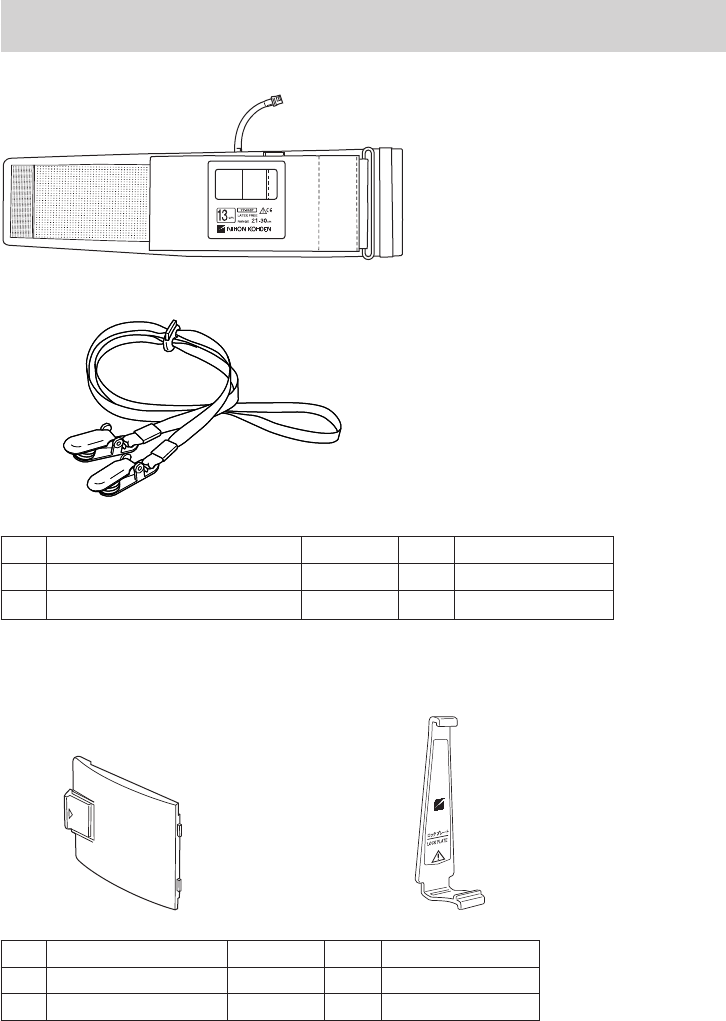
Operator’s Manual ZM-940PA/941PA 101
Standard Accessories
1
2
No. Name Model Q’ty Supply Code No.
1 NIBP cuff for adult, standard YP-943P 1 S938B
2 Strap — 1 Y236
The following parts are available for replacement.
3 4
Lock plate is a standard
accessory of the YP-
943P/944P NIBP cuff.
No. Name Model Q’ty Supply Code No.
3 Battery case cover — 1 6144-012004
4Lockplate — 1 6113-049585

102 Operator’s Manual ZM-940PA/941PA
Options
CAUTION
Only use Nihon Kohden specified electrodes, electrode leads, SpO2 probes, and
NIBP cuffs. Otherwise, the maximum performance from the transmitter cannot be
guaranteed.
Transmitter
Channel writer, QI-901PK
ECG/RESP
Name Application Model Q’ty Supply Code No.
Electrode
lead
3 electrodes, clip type,
lead length 80 cm BR-903PA 1 K911A
3 electrodes, snap type,
lead length 80 cm BR-913PA 1 K910B
6 electrodes, clip type,
lead length 80 cm BR-906PA 1 K912A
6 electrodes, snap type,
lead length 80 cm BR-916PA 1 K915A

Operator’s Manual ZM-940PA/941PA 103
NIBP
Name Width
(cm)
Air Hose
Length
(cm)
Model Q’ty Supply
Code No.
Cuff for adult, for
attaching transmitter to
patient arm
Standard 13
15
YP-943P*
1
S938B
Large 15 YP-944P* S938C
Cuff for infant 5
15
YP-960T
1
S943A
Cuff for child Small 7YP-961T S943B
Standard 10 YP-962T S943C
Cuff for adult Standard 13 YP-963T S944B
Large 15 YP-964T S944C
Disposable cuff for infant 6 17 YP-810P
20
S945C
Disposable cuff for child 8 17 YP-811P S945D
Disposable cuff for adult
Small 10 17 YP-812P S946E
Standard 14 20 YP-813P S946F
Medium
large 15 20 YP-814P S946G
Large 17 20 YP-815P S946H
Extra large 18 20 YP-816P S946I
Extension hose — 150 YN-990P 1 S903
* ThelockplateisprovidedwiththeseNIBPcuffs.

104 Operator’s Manual ZM-940PA/941PA
SpO2
Name Cable
length
Model/
Code No. Q’ty Supply
Code No.
Finger probe (reusable) 0.6 m TL-201T
1
P225H
1.6 m P225F
Multi-site probe (reusable) 1.6 m TL-220T P225G
Finger probe (reusable)
0.6 m TL-630T1 P310A
1.6 m TL-630T3 P310C
0.6 m TL-631T1 P311A
1.6 m TL-631T3 P311C
SpO2 probe (for adult, disposable)
1.6 m
TL-251T
5
P201A
SpO2 probe (for child, disposable) TL-252T P201B
SpO2 probe (for neonate, disposable) TL-253T P201C
SpO2 probe (for adult, disposable) 0.8 m TL-271T
24
P203A
1.6 m TL-271T3 P203E
SpO2 probe (for child, disposable) 0.8 m TL-272T P203B
1.6 m TL-272T3 P203F
SpO2 probe (for neonate/adult,
disposable)
0.8 m TL-273T P203C
1.6 m TL-273T3 P203G
SpO2 probe (for child/infant,
disposable)
0.8 m TL-274T P203D
1.6 m TL-274T3 P203H
SpO2 probe (for adult/neonate,
disposable)
0.8 m TL-051S
5
P228A
1.6 m TL-052S P228B
SpO2 probe (for child/infant,
disposable)
0.8 m TL-061S P229A
1.6 m TL-062S P229B
COTTONY tape
—
340703 20 P259
Foam tape for TL-051S/052S/
061S/062S —
4 ×25packages P260
Attachment tape for TL-220T/
251T/252T/253T/630T/631T 3 ×30packages P263
Probe fastener YS-093P2 30 P267

Operator’s Manual ZM-940PA/941PA 105
Transmission Frequencies
Channel:9002to9478
Transmission
frequency
(MHz)
Channel No.
Transmission
frequency
(MHz)
Channel No.
Transmission
frequency
(MHz)
Channel No.
608.0250 9002 608.4375 9035 608.8500 9068
608.0375 9003 608.4500 9036 608.8625 9069
608.0500 9004 608.4625 9037 608.8750 9070
608.0625 9005 608.4750 9038 608.8875 9071
608.0750 9006 608.4875 9039 608.9000 9072
608.0875 9007 608.5000 9040 608.9125 9073
608.1000 9008 608.5125 9041 608.9250 9074
608.1125 9009 608.5250 9042 608.9375 9075
608.1250 9010 608.5375 9043 608.9500 9076
608.1375 9011 608.5500 9044 608.9625 9077
608.1500 9012 608.5625 9045 608.9750 9078
608.1625 9013 608.5750 9046 608.9875 9079
608.1750 9014 608.5875 9047 609.0000 9080
608.1875 9015 608.6000 9048 609.0125 9081
608.2000 9016 608.6125 9049 609.0250 9082
608.2125 9017 608.6250 9050 609.0375 9083
608.2250 9018 608.6375 9051 609.0500 9084
608.2375 9019 608.6500 9052 609.0625 9085
608.2500 9020 608.6625 9053 609.0750 9086
608.2625 9021 608.6750 9054 609.0875 9087
608.2750 9022 608.6875 9055 609.1000 9088
608.2875 9023 608.7000 9056 609.1125 9089
608.3000 9024 608.7125 9057 609.1250 9090
608.3125 9025 608.7250 9058 609.1375 9091
608.3250 9026 608.7375 9059 609.1500 9092
608.3375 9027 608.7500 9060 609.1625 9093
608.3500 9028 608.7625 9061 609.1750 9094
608.3625 9029 608.7750 9062 609.1875 9095
608.3750 9030 608.7875 9063 609.2000 9096
608.3875 9031 608.8000 9064 609.2125 9097
608.4000 9032 608.8125 9065 609.2250 9098
608.4125 9033 608.8250 9066 609.2375 9099
608.4250 9034 608.8375 9067 609.2500 9100

106 Operator’s Manual ZM-940PA/941PA
Transmission
frequency
(MHz)
Channel No.
Transmission
frequency
(MHz)
Channel No.
Transmission
frequency
(MHz)
Channel No.
609.2625 9101 609.7125 9137 610.1625 9173
609.2750 9102 609.7250 9138 610.1750 9174
609.2875 9103 609.7375 9139 610.1875 9175
609.3000 9104 609.7500 9140 610.2000 9176
609.3125 9105 609.7625 9141 610.2125 9177
609.3250 9106 609.7750 9142 610.2250 9178
609.3375 9107 609.7875 9143 610.2375 9179
609.3500 9108 609.8000 9144 610.2500 9180
609.3625 9109 609.8125 9145 610.2625 9181
609.3750 9110 609.8250 9146 610.2750 9182
609.3875 9111 609.8375 9147 610.2875 9183
609.4000 9112 609.8500 9148 610.3000 9184
609.4125 9113 609.8625 9149 610.3125 9185
609.4250 9114 609.8750 9150 610.3250 9186
609.4375 9115 609.8875 9151 610.3375 9187
609.4500 9116 609.9000 9152 610.3500 9188
609.4625 9117 609.9125 9153 610.3625 9189
609.4750 9118 609.9250 9154 610.3750 9190
609.4875 9119 609.9375 9155 610.3875 9191
609.5000 9120 609.9500 9156 610.4000 9192
609.5125 9121 609.9625 9157 610.4125 9193
609.5250 9122 609.9750 9158 610.4250 9194
609.5375 9123 609.9875 9159 610.4375 9195
609.5500 9124 610.0000 9160 610.4500 9196
609.5625 9125 610.0125 9161 610.4625 9197
609.5750 9126 610.0250 9162 610.4750 9198
609.5875 9127 610.0375 9163 610.4875 9199
609.6000 9128 610.0500 9164 610.5000 9200
609.6125 9129 610.0625 9165 610.5125 9201
609.6250 9130 610.0750 9166 610.5250 9202
609.6375 9131 610.0875 9167 610.5375 9203
609.6500 9132 610.1000 9168 610.5500 9204
609.6625 9133 610.1125 9169 610.5625 9205
609.6750 9134 610.1250 9170 610.5750 9206
609.6875 9135 610.1375 9171 610.5875 9207

Operator’s Manual ZM-940PA/941PA 107
Transmission
frequency
(MHz)
Channel No.
Transmission
frequency
(MHz)
Channel No.
Transmission
frequency
(MHz)
Channel No.
609.7000 9136 610.1500 9172 610.6000 9208
610.6125 9209 611.0625 9245 611.5125 9281
610.6250 9210 611.0750 9246 611.5250 9282
610.6375 9211 611.0875 9247 611.5375 9283
610.6500 9212 611.1000 9248 611.5500 9284
610.6625 9213 611.1125 9249 611.5625 9285
610.6750 9214 611.1250 9250 611.5750 9286
610.6875 9215 611.1375 9251 611.5875 9287
610.7000 9216 611.1500 9252 611.6000 9288
610.7125 9217 611.1625 9253 611.6125 9289
610.7250 9218 611.1750 9254 611.6250 9290
610.7375 9219 611.1875 9255 611.6375 9291
610.7500 9220 611.2000 9256 611.6500 9292
610.7625 9221 611.2125 9257 611.6625 9293
610.7750 9222 611.2250 9258 611.6750 9294
610.7875 9223 611.2375 9259 611.6875 9295
610.8000 9224 611.2500 9260 611.7000 9296
610.8125 9225 611.2625 9261 611.7125 9297
610.8250 9226 611.2750 9262 611.7250 9298
610.8375 9227 611.2875 9263 611.7375 9299
610.8500 9228 611.3000 9264 611.7500 9300
610.8625 9229 611.3125 9265 611.7625 9301
610.8750 9230 611.3250 9266 611.7750 9302
610.8875 9231 611.3375 9267 611.7875 9303
610.9000 9232 611.3500 9268 611.8000 9304
610.9125 9233 611.3625 9269 611.8125 9305
610.9250 9234 611.3750 9270 611.8250 9306
610.9375 9235 611.3875 9271 611.8375 9307
610.9500 9236 611.4000 9272 611.8500 9308
610.9625 9237 611.4125 9273 611.8625 9309
610.9750 9238 611.4250 9274 611.8750 9310
610.9875 9239 611.4375 9275 611.8875 9311
611.0000 9240 611.4500 9276 611.9000 9312
611.0125 9241 611.4625 9277 611.9125 9313
611.0250 9242 611.4750 9278 611.9250 9314
611.0375 9243 611.4875 9279 611.9375 9315

108 Operator’s Manual ZM-940PA/941PA
Transmission
frequency
(MHz)
Channel No.
Transmission
frequency
(MHz)
Channel No.
Transmission
frequency
(MHz)
Channel No.
611.0500 9244 611.5000 9280 611.9500 9316
611.9625 9317 612.4125 9353 612.8625 9389
611.9750 9318 612.4250 9354 612.8750 9390
611.9875 9319 612.4375 9355 612.8875 9391
612.0000 9320 612.4500 9356 612.9000 9392
612.0125 9321 612.4625 9357 612.9125 9393
612.0250 9322 612.4750 9358 612.9250 9394
612.0375 9323 612.4875 9359 612.9375 9395
612.0500 9324 612.5000 9360 612.9500 9396
612.0625 9325 612.5125 9361 612.9625 9397
612.0750 9326 612.5250 9362 612.9750 9398
612.0875 9327 612.5375 9363 612.9875 9399
612.1000 9328 612.5500 9364 613.0000 9400
612.1125 9329 612.5625 9365 613.0125 9401
612.1250 9330 612.5750 9366 613.0250 9402
612.1375 9331 612.5875 9367 613.0375 9403
612.1500 9332 612.6000 9368 613.0500 9404
612.1625 9333 612.6125 9369 613.0625 9405
612.1750 9334 612.6250 9370 613.0750 9406
612.1875 9335 612.6375 9371 613.0875 9407
612.2000 9336 612.6500 9372 613.1000 9408
612.2125 9337 612.6625 9373 613.1125 9409
612.2250 9338 612.6750 9374 613.1250 9410
612.2375 9339 612.6875 9375 613.1375 9411
612.2500 9340 612.7000 9376 613.1500 9412
612.2625 9341 612.7125 9377 613.1625 9413
612.2750 9342 612.7250 9378 613.1750 9414
612.2875 9343 612.7375 9379 613.1875 9415
612.3000 9344 612.7500 9380 613.2000 9416
612.3125 9345 612.7625 9381 613.2125 9417
612.3250 9346 612.7750 9382 613.2250 9418
612.3375 9347 612.7875 9383 613.2375 9419
612.3500 9348 612.8000 9384 613.2500 9420
612.3625 9349 612.8125 9385 613.2625 9421
612.3750 9350 612.8250 9386 613.2750 9422
612.3875 9351 612.8375 9387 613.2875 9423

Operator’s Manual ZM-940PA/941PA 109
Transmission
frequency
(MHz)
Channel No.
Transmission
frequency
(MHz)
Channel No.
Transmission
frequency
(MHz)
Channel No.
612.4000 9352 612.8500 9388 613.3000 9424
613.3125 9425 613.5375 9443 613.7625 9461
613.3250 9426 613.5500 9444 613.7750 9462
613.3375 9427 613.5625 9445 613.7875 9463
613.3500 9428 613.5750 9446 613.8000 9464
613.3625 9429 613.5875 9447 613.8125 9465
613.3750 9430 613.6000 9448 613.8250 9466
613.3875 9431 613.6125 9449 613.8375 9467
613.4000 9432 613.6250 9450 613.8500 9468
613.4125 9433 613.6375 9451 613.8625 9469
613.4250 9434 613.6500 9452 613.8750 9470
613.4375 9435 613.6625 9453 613.8875 9471
613.4500 9436 613.6750 9454 613.9000 9472
613.4625 9437 613.6875 9455 613.9125 9473
613.4750 9438 613.7000 9456 613.9250 9474
613.4875 9439 613.7125 9457 613.9375 9475
613.5000 9440 613.7250 9458 613.9500 9476
613.5125 9441 613.7375 9459 613.9625 9477
613.5250 9442 613.7500 9460 613.9750 9478

110 Operator’s Manual ZM-940PA/941PA
Channel: E002 to E398
Transmission
frequency
(MHz)
Channel
No.
Transmission
frequency
(MHz)
Channel
No.
Transmission
frequency
(MHz)
Channel
No.
1395.0250 E002 1395.4625 E037 1395.9000 E072
1395.0375 E003 1395.4750 E038 1395.9125 E073
1395.0500 E004 1395.4875 E039 1395.9250 E074
1395.0625 E005 1395.5000 E040 1395.9375 E075
1395.0750 E006 1395.5125 E041 1395.9500 E076
1395.0875 E007 1395.5250 E042 1395.9625 E077
1395.1000 E008 1395.5375 E043 1395.9750 E078
1395.1125 E009 1395.5500 E044 1395.9875 E079
1395.1250 E010 1395.5625 E045 1396.0000 E080
1395.1375 E011 1395.5750 E046 1396.0125 E081
1395.1500 E012 1395.5875 E047 1396.0250 E082
1395.1625 E013 1395.6000 E048 1396.0375 E083
1395.1750 E014 1395.6125 E049 1396.0500 E084
1395.1875 E015 1395.6250 E050 1396.0625 E085
1395.2000 E016 1395.6375 E051 1396.0750 E086
1395.2125 E017 1395.6500 E052 1396.0875 E087
1395.2250 E018 1395.6625 E053 1396.1000 E088
1395.2375 E019 1395.6750 E054 1396.1125 E089
1395.2500 E020 1395.6875 E055 1396.1250 E090
1395.2625 E021 1395.7000 E056 1396.1375 E091
1395.2750 E022 1395.7125 E057 1396.1500 E092
1395.2875 E023 1395.7250 E058 1396.1625 E093
1395.3000 E024 1395.7375 E059 1396.1750 E094
1395.3125 E025 1395.7500 E060 1396.1875 E095
1395.3250 E026 1395.7625 E061 1396.2000 E096
1395.3375 E027 1395.7750 E062 1396.2125 E097
1395.3500 E028 1395.7875 E063 1396.2250 E098
1395.3625 E029 1395.8000 E064 1396.2375 E099
1395.3750 E030 1395.8125 E065 1396.2500 E100
1395.3875 E031 1395.8250 E066 1396.2625 E101
1395.4000 E032 1395.8375 E067 1396.2750 E102
1395.4125 E033 1395.8500 E068 1396.2875 E103
1395.4250 E034 1395.8625 E069 1396.3000 E104
1395.4375 E035 1395.8750 E070 1396.3125 E105
1395.4500 E036 1395.8875 E071 1396.3250 E106

Operator’s Manual ZM-940PA/941PA 111
Transmission
frequency
(MHz)
Channel
No.
Transmission
frequency
(MHz)
Channel
No.
Transmission
frequency
(MHz)
Channel
No.
1396.3375 E107 1396.7875 E143 1397.2375 E179
1396.3500 E108 1396.8000 E144 1397.2500 E180
1396.3625 E109 1396.8125 E145 1397.2625 E181
1396.3750 E110 1396.8250 E146 1397.2750 E182
1396.3875 E111 1396.8375 E147 1397.2875 E183
1396.4000 E112 1396.8500 E148 1397.3000 E184
1396.4125 E113 1396.8625 E149 1397.3125 E185
1396.4250 E114 1396.8750 E150 1397.3250 E186
1396.4375 E115 1396.8875 E151 1397.3375 E187
1396.4500 E116 1396.9000 E152 1397.3500 E188
1396.4625 E117 1396.9125 E153 1397.3625 E189
1396.4750 E118 1396.9250 E154 1397.3750 E190
1396.4875 E119 1396.9375 E155 1397.3875 E191
1396.5000 E120 1396.9500 E156 1397.4000 E192
1396.5125 E121 1396.9625 E157 1397.4125 E193
1396.5250 E122 1396.9750 E158 1397.4250 E194
1396.5375 E123 1396.9875 E159 1397.4375 E195
1396.5500 E124 1397.0000 E160 1397.4500 E196
1396.5625 E125 1397.0125 E161 1397.4625 E197
1396.5750 E126 1397.0250 E162 1397.4750 E198
1396.5875 E127 1397.0375 E163 1397.4875 E199
1396.6000 E128 1397.0500 E164 1397.5000 E200
1396.6125 E129 1397.0625 E165 1397.5125 E201
1396.6250 E130 1397.0750 E166 1397.5250 E202
1396.6375 E131 1397.0875 E167 1397.5375 E203
1396.6500 E132 1397.1000 E168 1397.5500 E204
1396.6625 E133 1397.1125 E169 1397.5625 E205
1396.6750 E134 1397.1250 E170 1397.5750 E206
1396.6875 E135 1397.1375 E171 1397.5875 E207
1396.7000 E136 1397.1500 E172 1397.6000 E208
1396.7125 E137 1397.1625 E173 1397.6125 E209
1396.7250 E138 1397.1750 E174 1397.6250 E210
1396.7375 E139 1397.1875 E175 1397.6375 E211
1396.7500 E140 1397.2000 E176 1397.6500 E212
1396.7625 E141 1397.2125 E177 1397.6625 E213
1396.7750 E142 1397.2250 E178 1397.6750 E214

112 Operator’s Manual ZM-940PA/941PA
Transmission
frequency
(MHz)
Channel
No.
Transmission
frequency
(MHz)
Channel
No.
Transmission
frequency
(MHz)
Channel
No.
1397.6875 E215 1398.1375 E251 1398.5875 E287
1397.7000 E216 1398.1500 E252 1398.6000 E288
1397.7125 E217 1398.1625 E253 1398.6125 E289
1397.7250 E218 1398.1750 E254 1398.6250 E290
1397.7375 E219 1398.1875 E255 1398.6375 E291
1397.7500 E220 1398.2000 E256 1398.6500 E292
1397.7625 E221 1398.2125 E257 1398.6625 E293
1397.7750 E222 1398.2250 E258 1398.6750 E294
1397.7875 E223 1398.2375 E259 1398.6875 E295
1397.8000 E224 1398.2500 E260 1398.7000 E296
1397.8125 E225 1398.2625 E261 1398.7125 E297
1397.8250 E226 1398.2750 E262 1398.7250 E298
1397.8375 E227 1398.2875 E263 1398.7375 E299
1397.8500 E228 1398.3000 E264 1398.7500 E300
1397.8625 E229 1398.3125 E265 1398.7625 E301
1397.8750 E230 1398.3250 E266 1398.7750 E302
1397.8875 E231 1398.3375 E267 1398.7875 E303
1397.9000 E232 1398.3500 E268 1398.8000 E304
1397.9125 E233 1398.3625 E269 1398.8125 E305
1397.9250 E234 1398.3750 E270 1398.8250 E306
1397.9375 E235 1398.3875 E271 1398.8375 E307
1397.9500 E236 1398.4000 E272 1398.8500 E308
1397.9625 E237 1398.4125 E273 1398.8625 E309
1397.9750 E238 1398.4250 E274 1398.8750 E310
1397.9875 E239 1398.4375 E275 1398.8875 E311
1398.0000 E240 1398.4500 E276 1398.9000 E312
1398.0125 E241 1398.4625 E277 1398.9125 E313
1398.0250 E242 1398.4750 E278 1398.9250 E314
1398.0375 E243 1398.4875 E279 1398.9375 E315
1398.0500 E244 1398.5000 E280 1398.9500 E316
1398.0625 E245 1398.5125 E281 1398.9625 E317
1398.0750 E246 1398.5250 E282 1398.9750 E318
1398.0875 E247 1398.5375 E283 1398.9875 E319
1398.1000 E248 1398.5500 E284 1399.0000 E320
1398.1125 E249 1398.5625 E285 1399.0125 E321
1398.1250 E250 1398.5750 E286 1399.0250 E322

Operator’s Manual ZM-940PA/941PA 113
Transmission
frequency
(MHz)
Channel
No.
Transmission
frequency
(MHz)
Channel
No.
Transmission
frequency
(MHz)
Channel
No.
1399.0375 E323 1399.4625 E357 1399.8875 E391
1399.0500 E324 1399.4750 E358 1399.9000 E392
1399.0625 E325 1399.4875 E359 1399.9125 E393
1399.0750 E326 1399.5000 E360 1399.9250 E394
1399.0875 E327 1399.5125 E361 1399.9375 E395
1399.1000 E328 1399.5250 E362 1399.9500 E396
1399.1125 E329 1399.5375 E363 1399.9625 E397
1399.1250 E330 1399.5500 E364 1399.9750 E398
1399.1375 E331 1399.5625 E365
1399.1500 E332 1399.5750 E366
1399.1625 E333 1399.5875 E367
1399.1750 E334 1399.6000 E368
1399.1875 E335 1399.6125 E369
1399.2000 E336 1399.6250 E370
1399.2125 E337 1399.6375 E371
1399.2250 E338 1399.6500 E372
1399.2375 E339 1399.6625 E373
1399.2500 E340 1399.6750 E374
1399.2625 E341 1399.6875 E375
1399.2750 E342 1399.7000 E376
1399.2875 E343 1399.7125 E377
1399.3000 E344 1399.7250 E378
1399.3125 E345 1399.7375 E379
1399.3250 E346 1399.7500 E380
1399.3375 E347 1399.7625 E381
1399.3500 E348 1399.7750 E382
1399.3625 E349 1399.7875 E383
1399.3750 E350 1399.8000 E384
1399.3875 E351 1399.8125 E385
1399.4000 E352 1399.8250 E386
1399.4125 E353 1399.8375 E387
1399.4250 E354 1399.8500 E388
1399.4375 E355 1399.8625 E389
1399.4500 E356 1399.8750 E390

114 Operator’s Manual ZM-940PA/941PA
Channel: E502 to E898
Transmission
frequency
(MHz)
Channel
No.
Transmission
frequency
(MHz)
Channel
No.
Transmission
frequency
(MHz)
Channel
No.
1427.0250 E502 1427.4500 E536 1427.8750 E570
1427.0375 E503 1427.4625 E537 1427.8875 E571
1427.0500 E504 1427.4750 E538 1427.9000 E572
1427.0625 E505 1427.4875 E539 1427.9125 E573
1427.0750 E506 1427.5000 E540 1427.9250 E574
1427.0875 E507 1427.5125 E541 1427.9375 E575
1427.1000 E508 1427.5250 E542 1427.9500 E576
1427.1125 E509 1427.5375 E543 1427.9625 E577
1427.1250 E510 1427.5500 E544 1427.9750 E578
1427.1375 E511 1427.5625 E545 1427.9875 E579
1427.1500 E512 1427.5750 E546 1428.0000 E580
1427.1625 E513 1427.5875 E547 1428.0125 E581
1427.1750 E514 1427.6000 E548 1428.0250 E582
1427.1875 E515 1427.6125 E549 1428.0375 E583
1427.2000 E516 1427.6250 E550 1428.0500 E584
1427.2125 E517 1427.6375 E551 1428.0625 E585
1427.2250 E518 1427.6500 E552 1428.0750 E586
1427.2375 E519 1427.6625 E553 1428.0875 E587
1427.2500 E520 1427.6750 E554 1428.1000 E588
1427.2625 E521 1427.6875 E555 1428.1125 E589
1427.2750 E522 1427.7000 E556 1428.1250 E590
1427.2875 E523 1427.7125 E557 1428.1375 E591
1427.3000 E524 1427.7250 E558 1428.1500 E592
1427.3125 E525 1427.7375 E559 1428.1625 E593
1427.3250 E526 1427.7500 E560 1428.1750 E594
1427.3375 E527 1427.7625 E561 1428.1875 E595
1427.3500 E528 1427.7750 E562 1428.2000 E596
1427.3625 E529 1427.7875 E563 1428.2125 E597
1427.3750 E530 1427.8000 E564 1428.2250 E598
1427.3875 E531 1427.8125 E565 1428.2375 E599
1427.4000 E532 1427.8250 E566 1428.2500 E600
1427.4125 E533 1427.8375 E567 1428.2625 E601
1427.4250 E534 1427.8500 E568 1428.2750 E602
1427.4375 E535 1427.8625 E569 1428.2875 E603

Operator’s Manual ZM-940PA/941PA 115
Transmission
frequency
(MHz)
Channel
No.
Transmission
frequency
(MHz)
Channel
No.
Transmission
frequency
(MHz)
Channel
No.
1428.3000 E604 1428.7500 E640 1429.2000 E676
1428.3125 E605 1428.7625 E641 1429.2125 E677
1428.3250 E606 1428.7750 E642 1429.2250 E678
1428.3375 E607 1428.7875 E643 1429.2375 E679
1428.3500 E608 1428.8000 E644 1429.2500 E680
1428.3625 E609 1428.8125 E645 1429.2625 E681
1428.3750 E610 1428.8250 E646 1429.2750 E682
1428.3875 E611 1428.8375 E647 1429.2875 E683
1428.4000 E612 1428.8500 E648 1429.3000 E684
1428.4125 E613 1428.8625 E649 1429.3125 E685
1428.4250 E614 1428.8750 E650 1429.3250 E686
1428.4375 E615 1428.8875 E651 1429.3375 E687
1428.4500 E616 1428.9000 E652 1429.3500 E688
1428.4625 E617 1428.9125 E653 1429.3625 E689
1428.4750 E618 1428.9250 E654 1429.3750 E690
1428.4875 E619 1428.9375 E655 1429.3875 E691
1428.5000 E620 1428.9500 E656 1429.4000 E692
1428.5125 E621 1428.9625 E657 1429.4125 E693
1428.5250 E622 1428.9750 E658 1429.4250 E694
1428.5375 E623 1428.9875 E659 1429.4375 E695
1428.5500 E624 1429.0000 E660 1429.4500 E696
1428.5625 E625 1429.0125 E661 1429.4625 E697
1428.5750 E626 1429.0250 E662 1429.4750 E698
1428.5875 E627 1429.0375 E663 1429.4875 E699
1428.6000 E628 1429.0500 E664 1429.5000 E700
1428.6125 E629 1429.0625 E665 1429.5125 E701
1428.6250 E630 1429.0750 E666 1429.5250 E702
1428.6375 E631 1429.0875 E667 1429.5375 E703
1428.6500 E632 1429.1000 E668 1429.5500 E704
1428.6625 E633 1429.1125 E669 1429.5625 E705
1428.6750 E634 1429.1250 E670 1429.5750 E706
1428.6875 E635 1429.1375 E671 1429.5875 E707
1428.7000 E636 1429.1500 E672 1429.6000 E708
1428.7125 E637 1429.1625 E673 1429.6125 E709
1428.7250 E638 1429.1750 E674 1429.6250 E710
1428.7375 E639 1429.1875 E675 1429.6375 E711

116 Operator’s Manual ZM-940PA/941PA
Transmission
frequency
(MHz)
Channel
No.
Transmission
frequency
(MHz)
Channel
No.
Transmission
frequency
(MHz)
Channel
No.
1429.6500 E712 1430.1000 E748 1430.5500 E784
1429.6625 E713 1430.1125 E749 1430.5625 E785
1429.6750 E714 1430.1250 E750 1430.5750 E786
1429.6875 E715 1430.1375 E751 1430.5875 E787
1429.7000 E716 1430.1500 E752 1430.6000 E788
1429.7125 E717 1430.1625 E753 1430.6125 E789
1429.7250 E718 1430.1750 E754 1430.6250 E790
1429.7375 E719 1430.1875 E755 1430.6375 E791
1429.7500 E720 1430.2000 E756 1430.6500 E792
1429.7625 E721 1430.2125 E757 1430.6625 E793
1429.7750 E722 1430.2250 E758 1430.6750 E794
1429.7875 E723 1430.2375 E759 1430.6875 E795
1429.8000 E724 1430.2500 E760 1430.7000 E796
1429.8125 E725 1430.2625 E761 1430.7125 E797
1429.8250 E726 1430.2750 E762 1430.7250 E798
1429.8375 E727 1430.2875 E763 1430.7375 E799
1429.8500 E728 1430.3000 E764 1430.7500 E800
1429.8625 E729 1430.3125 E765 1430.7625 E801
1429.8750 E730 1430.3250 E766 1430.7750 E802
1429.8875 E731 1430.3375 E767 1430.7875 E803
1429.9000 E732 1430.3500 E768 1430.8000 E804
1429.9125 E733 1430.3625 E769 1430.8125 E805
1429.9250 E734 1430.3750 E770 1430.8250 E806
1429.9375 E735 1430.3875 E771 1430.8375 E807
1429.9500 E736 1430.4000 E772 1430.8500 E808
1429.9625 E737 1430.4125 E773 1430.8625 E809
1429.9750 E738 1430.4250 E774 1430.8750 E810
1429.9875 E739 1430.4375 E775 1430.8875 E811
1430.0000 E740 1430.4500 E776 1430.9000 E812
1430.0125 E741 1430.4625 E777 1430.9125 E813
1430.0250 E742 1430.4750 E778 1430.9250 E814
1430.0375 E743 1430.4875 E779 1430.9375 E815
1430.0500 E744 1430.5000 E780 1430.9500 E816
1430.0625 E745 1430.5125 E781 1430.9625 E817
1430.0750 E746 1430.5250 E782 1430.9750 E818
1430.0875 E747 1430.5375 E783 1430.9875 E819

Operator’s Manual ZM-940PA/941PA 117
Transmission
frequency
(MHz)
Channel
No.
Transmission
frequency
(MHz)
Channel
No.
Transmission
frequency
(MHz)
Channel
No.
1431.0000 E820 1431.4375 E855 1431.8750 E890
1431.0125 E821 1431.4500 E856 1431.8875 E891
1431.0250 E822 1431.4625 E857 1431.9000 E892
1431.0375 E823 1431.4750 E858 1431.9125 E893
1431.0500 E824 1431.4875 E859 1431.9250 E894
1431.0625 E825 1431.5000 E860 1431.9375 E895
1431.0750 E826 1431.5125 E861 1431.9500 E896
1431.0875 E827 1431.5250 E862 1431.9625 E897
1431.1000 E828 1431.5375 E863 1431.9750 E898
1431.1125 E829 1431.5500 E864
1431.1250 E830 1431.5625 E865
1431.1375 E831 1431.5750 E866
1431.1500 E832 1431.5875 E867
1431.1625 E833 1431.6000 E868
1431.1750 E834 1431.6125 E869
1431.1875 E835 1431.6250 E870
1431.2000 E836 1431.6375 E871
1431.2125 E837 1431.6500 E872
1431.2250 E838 1431.6625 E873
1431.2375 E839 1431.6750 E874
1431.2500 E840 1431.6875 E875
1431.2625 E841 1431.7000 E876
1431.2750 E842 1431.7125 E877
1431.2875 E843 1431.7250 E878
1431.3000 E844 1431.7375 E879
1431.3125 E845 1431.7500 E880
1431.3250 E846 1431.7625 E881
1431.3375 E847 1431.7750 E882
1431.3500 E848 1431.7875 E883
1431.3625 E849 1431.8000 E884
1431.3750 E850 1431.8125 E885
1431.3875 E851 1431.8250 E886
1431.4000 E852 1431.8375 E887
1431.4125 E853 1431.8500 E888
1431.4250 E854 1431.8625 E889