Niles Audio Cs525 Users Manual DS00245A/CS
CS650 to the manual 2d8a712e-4b53-4024-aa1d-a90478a24c1a
2015-02-02
: Niles-Audio Niles-Audio-Cs525-Users-Manual-439284 niles-audio-cs525-users-manual-439284 niles-audio pdf
Open the PDF directly: View PDF ![]() .
.
Page Count: 22

MODELS
CS525
CS650
BLENDING HIGH FIDELITY AND ARCHITECTURE®
INSTALLATION & OPERATION GUIDE
MODELS
CS525
CS650
CONTRACTOR SERIES
®
®
DS00245A/CS 3/8/99 4:13 PM Page 22

Congratulations!
Thank you for choosing a Blueprint Series In-Wall Loudspeaker®from Niles. With proper
installation and operation, you'll enjoy years of trouble-free use.
Niles manufactures the industry's most complete line of custom installation components
and accessories for audio/video systems. For a free full line catalog write: Niles, Catalog
Request, P.O. Box 160818, Miami, Florida 33116-0818
TABLE OF CONTENTS
INTRODUCTION 2
FEATURES AND BENEFITS 3
INSTALLATION CONSIDERATIONS 4
SPEAKER PLACEMENT 6
INSTALLATION FUNDAMENTALS 9
INSTALLATION OF SPEAKERS 13
OPERATION 16
SPECIFICATIONS 17
WARRANTY REGISTRATION CARD 19
LIMITED WARRANTY 20
DS00245A/CS 3/8/99 4:13 PM Page 1
Introduction
The CS or
Contractor Series
group of
Blueprint Series In-Wall Loudspeakers®
offers speakers expressly designed for flex-
ibility of use. They function well as prima-
ry speakers in bedrooms, dens or living
rooms; as main or surround speakers in
home theaters; or in large arrays in com-
mercial spaces. The CS525/CS650 offer a
unique combination of adaptability, per-
formance and value which makes them
perfect in a wide variety of applications.
DS00245A/CS 3/8/99 4:13 PM Page 2

Features and Benefits
Hi-Polymer Woofer
The CS525 and CS650 models feature a
unique woofer construction process
called Hi-Polymer Bonding that combines
a waterproof nylon layer with a traditional
pulp-based long throw woofer with a
treated foam rubber surround. Both mod-
els feature custom perforated baskets to
keep construction debris from coming in
contact with the woofer cone.
Polycarbonate Dome Tweeter
The 1” polycarbonate tweeter offers sur-
prisingly wide dispersion characteristics
for great stereo imaging, remarkable clar-
ity, and moisture resistance.
X-Matrix™Reinforced Baffle
The X-Matrix Baffle design uses specially
molded ribs constructed of ABS plastic to
add rigidity to the baffle assembly. The
end result is better clarity and detail.
Absolutely Flush to the Wall Appearance
The unique mounting system of the CS
loudspeakers powerfully clamps the
speaker to the bracket, sandwiching the
wall material between them. Additionally,
the Niles mounting system is carefully
optimized to stiffen the surrounding dry-
wall and prevent it from resonating. You
hear only the music, not the drywall.
Easy Retrofit Installation in your
Existing Home
Designed for ease of installation, the Niles
mounting system makes installations sim-
ple and fast. A supplied template assures
fast and accurate hole cutting. The bracket
slips behind the drywall and the tightening
of the screws sandwich the drywall
between the bracket and speaker. The
grille mounts over the speaker.
Eight Ohm Impedance
The speakers are designed to be placed in
multi-room systems with many pairs of
speakers. The eight ohm impedance is a
very easy electrical load for most ampli-
fiers. This allows many pairs of CS speak-
ers to be wired to a single amplifier using
a Niles speaker selection system.
Low Diffraction, Paintable Aluminum
Grilles
CS speakers utilize rustproof aluminum
grilles. The painted aluminum grille has
hundreds of precisely sized perforations,
creating an acoustically transparent grille.
Infrared Sensor Mount
The speaker baffle has a locator designed
for the Niles MS-1 MicroSensor,™ a
miniature infrared sensor. The MS-1
installs discreetly behind the aluminum
grille and therefore minimizes wall clut-
ter in your home. When you want to
control your equipment, you simply
point your remote control at the speaker
from up to 15 feet away.
Features and Benefits
3
DS00245A/CS 3/8/99 4:13 PM Page 3
Installation Considerations
Recommended Amplifier Power
For satisfactory performance, we recom-
mend an amplifier with a power rating of
five to fifty watts for the CS525 and
CS650. Curiously, most speakers are not
damaged by large amplifiers but by small
amplifiers. If your system is playing loudly,
a small amplifier will run out of power
very quickly. When an amplifier runs out
of power it creates damaging “clipping”
distortion. A large amplifier will play at the
same volume without distorting. See the
section on operating the speakers for more
information about clipping distortion.
Incorporating a Local Volume Control
In a multi-room system there is one indis-
pensible control for true convenience—a
local volume control. It allows you to
adjust the volume of the speakers without
leaving the room.
Plan to wire the system so that each pair
of speakers has its own volume control
built into the wall (think of a volume con-
trol as a dimmer switch for sound).
Niles makes a wide range of high perfor-
mance indoor and outdoor volume con-
trols. They are available in Standard or
Decora®style cover plates (just like your
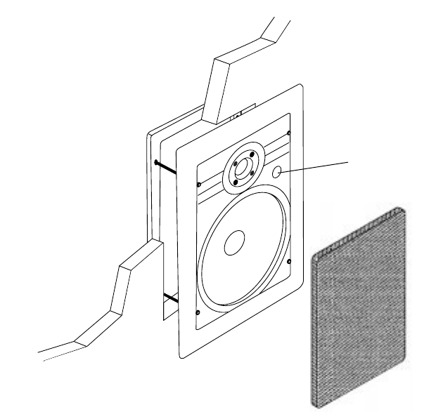
Figure 1
Bracket
Frame/
SpeakerBaffle
IR Knockout
Grille
DS00245A/CS 3/8/99 4:13 PM Page 4
light switches and dimmers). Volume con-
trols are connected in line with the speak-
er, so you must connect the wire from the
amplifier to the volume control and then
from the volume control to the speaker.
Speaker Wire
Use 2-conductor speaker wire when con-
necting CS speakers to your receiver or
amplifier. For most applications, we rec-
ommend you use 16 or 18 gauge wire.
For wiring runs longer than 80 feet we
recommend 14 gauge wire. The spring
loaded terminals of the CS speakers will
accommodate up to 12 gauge wire
directly. Larger sizes can be accommodat-
ed via pin connectors.
When you run wire inside walls, special
jacketing (CL-2 or CL-3) is required to
both protect the wire and for fire preven-
tion. In some areas conduit is required.
For a trouble-free installation, low voltage
wire such as speaker wire must be run in
accordance with the National Electrical
Code and any applicable provisions of the
local building code. If you are unsure of
the correct installation techniques, wire
jacket or type of conduit to use, consult a
professional audio/video installer, your
building contractor, or the local building
and inspection department.
Incorporating a Remote Control
If you are planning to use a stereo system
with a hand held IR remote control, con-
sider the advantages of installing a Niles
IR Repeater system. You are able to con-
trol all of the functions of your system
from the room with the remote pair of
speakers. Niles makes a number of IR sen-
sors which install in the wall, in the ceiling,
in cabinetry, on tabletops, or even behind
the grille of your Niles CS speakers.
An IR sensor requires that a 2-conductor
shielded wire (West Penn D291 or equiva-
lent) be home run from each sensor loca-
tion to the main equipment location. This
wire is normally run beside the speaker
wire at the same time. Typically, the sen-
sor is placed in a location that faces your
listening position. Most remote controls
will have an effective line of sight range of
18 to 30 feet with any Niles sensor placed
in a wall, ceiling, on a cabinet or tabletop
However, when you place a Niles MS-1
MicroSensor behind the perforated alu-
minum grille of a speaker the effective
range is reduced to 9 to 15 feet.
Insulating the Wall Cavity
For best performance from your speakers
fill the wall cavity behind the speaker
with fiberglass insulation (e.g. R-19 unbat-
ted insulation). Try to keep the same
amount of insulation for each speaker,
particularly in the same room, for consis-
tent bass response.
5
Installation Considerations
TECH TIP
Wire size is expressed by its AWG (American Wire
Gauge) number. The lower the number, the larger
the wire, i.e. twelve AWG is physically larger than
fourteen AWG.
DS00245A/CS 3/8/99 4:13 PM Page 5
Speaker Placement
Placement for Critical Listening
If you like to imagine that the band or
orchestra is playing in front of you as you
listen to music, or you are very conscious
of clarity, detail and the textures of the
individual instruments, you are a critical
listener.
In a home theater, the intelligibility of dia-
log and action reproduced by the front
speakers is paramount! The position of the
speakers plays a very important role in
how clear the sound is and how a stereo
image is created. Here are some guide-
lines to make the process of placement
quick and easy.
Make sure the sound will not be blocked
or reflected off of furniture or other objects.
You should have a direct line of sight with
the front of the speaker. To determine the
best position, measure the “listening” dis-
tance between the ideal listening position
(your favorite chair or couch) and the wall
in which you plan to install the speakers.
Try to place the speakers so that they are
equally distant from your listening spot and
at least one half of the listening distance
apart (this maintains a large pleasant stereo
“image”). In home theater applications
where there is a center channel you may
choose to space the left and right main
speakers farther apart for a “bigger than
life” sound with Dolby®encoded movies
and TV shows. However, for combined
music and movie usage stay within the
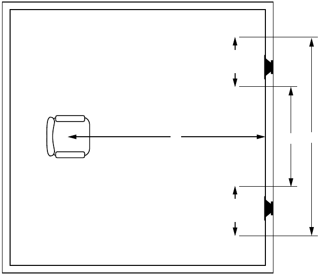
good placement zone
for music. For exam-
ple; if you are ten feet back from the wall,
the speakers should be between five and
ten feet apart (See Figure 2).
Speaker
Placement
Zone
Speaker
Placement
Zone
10’
5’
10’
Figure 2
DS00245A/CS 3/8/99 4:13 PM Page 6

The Boundary Effect
Corners can affect the bass response of
the speaker powerfully! This is called the
boundary effect. You will emphasize par-
ticular bass frequencies and cancel out
other bass frequencies when you place
speakers close to the wall/ceiling bound-
ary or a corner wall boundary. This can
make the speaker sound excessively
boomy and inaccurate to some listeners,
while to others it just seems like more
bass sound. A good rule of thumb is if
you always listen to your current pair of
speakers with the bass turned up, you’ll
enjoy corner placement. If you keep your
tone controls at neutral, try to keep the
speakers at least one or two feet from the
boundaries of the room.
Placement for Varying Listening
Positions
If you want the freedom to sit anywhere
in a room facing any direction, and/or
find that you prefer the “all around you”
sound of some car stereos to a conven-
tional “sound stage” facing you, consider
the speaker placement techniques profes-
sional installers use in restaurants and
bars. They place speakers in an array
around the listening area, so that the
music is always surrounding you, regard-
less of the direction you face.
The rule of thumb is to add one pair of
speakers for every 100 to 200 square feet
of listening area. Curiously, this is not so
that you can play the music louder, but
so that you can play it softer! When you
have only one pair of speakers in a large
room you will notice that when the
sound is perfect in one part of the room,
it is too loud near the speakers. By plac-
ing more than one pair in the room you
will avoid these “hot spots” of loud
sound and you will create still more
sonic ambiance while maintaining clarity
and a rich sound everywhere.
You can make listener position still less
critical by using mono rather than stereo
This can be difficult to achieve with nor-
mal stereo amplifiers. However, Niles
manufactures Systems Integration
Amplifiers which enable one room to be
wired in stereo while other rooms are
wired in mono! Consult your local Niles
dealer for more information.
In smaller rooms or rooms that are infre-
quently used, you typically can’t justify
the expense of more than two speakers
Try to bracket the room with the two
speakers. Diagonal placement is a very
effective way to stretch the coverage pat-
tern of two speakers. You can also com-
promise between direct sound (for detai
and clarity) and reflected sound (the
ambient or “all around you” effect). By
trying to place the speakers so that they
create as much reflected sound as possi-
ble you emphasize the ambient effect
They can be up high in the wall or even
down low at power outlet height , in the
ceiling, near corners, or directed at
reflective objects and walls. The more
reflected sound there is in the room the
stronger the ambient effect at low vol-
umes. You should use moderation, how-
ever, otherwise the compromise becomes
too one sided and at high volumes the
sound will be blurred and less distinct.
Placement for Rear Home Theater
Applications
In a home theater, the goal is to repro-
duce the experience of a great movie the-
ater in our homes. The biggest difference
between the two is the rear or surround
speaker array in a commercial theater
Here, it is not uncommon to see twenty
or thirty speakers around the audience
This huge array of speakers assures that
you will feel completely surrounded by
the ambient soundtrack of the movie
Film makers try to use the “surround”
7
Speaker Placement
DS00245A/CS 3/8/99 4:13 PM Page 7

soundtrack to envelope you in the envi-
ronment on screen. They will place back-
ground music, rain sounds, traffic noise,
etc. on the “surround” soundtrack. In a
home with a single pair of speakers it is
easy for the jungle sounds to sound like
they are “in the middle of your head” just
like headphones!
A single pair of CS Loudspeakers, properly
placed, can create a very convincing sim-
ulation of an array of speakers. If you
place them near a hard reflecting surface
you can make one pair of speakers sound
like several. Create as many reflections as
possible by mounting the speaker up high
in the wall so that the ceiling will act as a
powerful reflector. If you place the speak-
ers near a corner, wash the sound down a
wall from a ceiling location, or mount the
speakers as far away as you can from the
listening area, more reflections will occur.
However, all of these placement tech-
niques require that you work your sur-
round sound amplifier channels harder. If
the surround sound system you are using
has a small five or ten watt amplifier for
the rear speakers, stay within five to eight
feet of the listening location. If you are
using a 25 to 50 watt amplifier you can
mount the speakers 10 to 15 feet away
from the listening location and still
achieve reasonably high volume levels.
Of course, the best way to emulate the
sound of multiple speakers is to use multi-
ple speakers. In large or unusually shaped
rooms this might be the only way to
achieve a good effect. If you like to listen
to music surround modes which emulate
concert hall acoustics, more than two sur-
round speakers will prove extraordinarily
effective. With Niles CS loudspeakers it is
easy to add another pair without affecting
the decor of the room. However, you will
need to use a much more powerful ampli-
fier than that which is built into a typical
surround sound receiver or amplifier.
Niles makes a number of Systems
Integration Amplifiers with proprietary fea-
tures that make them uniquely suited to
enhance a good surround sound system.
Consult your Niles dealer for more infor-
mation.
DS00245A/CS 3/8/99 4:13 PM Page 8
Installation
Fundamentals
Running the Speaker Wire in New
Construction
If you have doubts about whether you are
capable of installing a Niles Blueprint
Series In-Wall Speaker in your walls, con-
sult a Niles dealer or professional installer.
They have special tools, techniques, and
experience to make the impossible possi-
ble. The installer can provide you with an
estimate before any work is done.
Scheduling and Preparation
Plan to schedule the speaker wiring after
the electrical wiring is finished. That way
you can avoid wire routes which could
potentially induce hum over the speaker
wire. The basic rules are:
• Never run speaker wire through the
same hole as an electrical cable.
• Never run speaker wire into the same
J-box as electrical cable.
• Avoid running the speaker wire beside
the electrical cable. Keep it at least three
or four feet distant from any electrical
power cable.
Side-by-side wiring is unavoidable in par-
ticular spots in every house, just move the
speaker wire route away as soon as possi-
ble. If construction forces a side by side
run for more than ten feet, install meta
conduit or shielded speaker wire. Low-
voltage wires such as doorbells, inter-
coms, telephone, security, or television
cannot cause interference or hum on your
speaker wires, so you can safely run all of
them at the same time, through the same
holes, side-by-side.
Before you drill any holes, mount the
speaker brackets in the desired speaker
locations and mount p-rings or open
backed J-boxes where the in-wall volume
controls and stereo equipment will be.
Safety First!
Wear gloves, safety goggles and head pro-
tection when drilling. Avoid nails, they ruin
bits and they can create injury. Pay particu-
lar care when using “hole-hogs” and other
powerful electric drills; the torque of the
drill when suddenly stopped by a nail can
break the wrist of a strong man.
Drilling
Use a bit that is large enough for the wires
you plan to run. An auger bit is the pre-
ferred bit for rough-in wiring. It will actu-
ally pull itself through the wood, so that
the drill motor, not you, does most of the
work. You will be drilling a lot of holes,
so this is important.
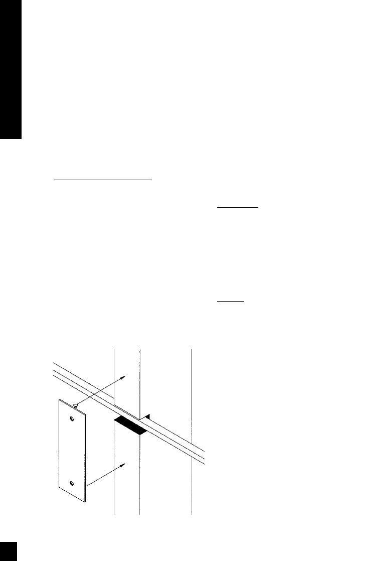
Always drill the holes in the center of the
stud. If you have to notch the stud or dril
the hole closer than one inch from the
edge of the stud, protect the wire with a
nail plate (See Figure 3).
When drilling holes in ceiling joists dril
in the center of the joists and try to locate
the hole near the end of the joist. DO
NOT drill through a “gluelam” or any
load bearing beam without the direction
of your contractor.
9
Installation Fundamentals
Figure 3
DS00245A/CS 3/8/99 4:13 PM Page 9

Try to line the holes up perfectly, because
it makes pulling the wire much easier. A
good technique is to snap a chalk line
across the face of the studs or against the
bottom of the ceiling joists. Then work
backward so that you can always see the
holes you have already drilled. Paying
careful attention to this will save you a lot
of time later on!
Pulling the Cable
Pull the cable in sections (from the stereo
to the volume control, from the volume
control to the speaker). Start with the
longest sections and use left over wire to
complete the short sections. If you plan to
pull many rooms at the same time
through a central route, walk off the dis-
tance to each destination, add a generous
fudge factor for turns and other obstacles,
then cut off each section so that you have
a bundle of wires you can pull at once.
Whenever you run the wire further than
four and one half feet from a hole in a
stud or joist (open attic space, going up
walls, etc.), fasten the wire to the joists or
studs using cable clamps or appropriately
sized wire staples. The wire should not
have large sags in it, nor should it be too
tight. Try to protect the wire from being
stepped on in attics or other unfinished
crawl spaces. There are guard strips, race-
ways and conduits which can be used to
protect the cable. Consult the local build-
ing code for special requirements in your
area.
Concealing Speaker Wire in Existing
Walls
This is actually a fairly simple task if you
restrict your choice of speaker locations
and wire routes to the interior walls or
ceilings of your home. Interior walls in
almost all North American residences are
hollow, so that it is easy to flush mount
speakers into them and route new speaker
cable around the house. What you see
when you look at the painted wall
board, plaster, or paneling is only the
skin of the wall. Behind the skin is the
skeleton; two-by-four wood or metal
“studs” running vertically from the floor
to the ceiling in walls and two-by-six or
larger “joists” running horizontally in the
ceilings and floors. In between the studs
and the joists is the space for the wiring
and plumbing of your home.
Exterior walls are different. They must
insulate the house from the heat and
cold outside, so they are stuffed with
insulation. The national building code
requires that the hollow wall space in
exterior walls be broken by a horizontal
stud placed between the vertical studs.
This “fire blocking” makes it very diffi-
cult to retrofit long lengths of wire. In
some areas of the country the exterior
walls are constructed of solid masonry,
and have no hollow space for speakers
or wires.
Start by examining all the possible routes
you might take to run the speaker wire
from the speaker to the volume control
and back to the stereo. Use a stud sensor
or other device to locate the internal
structure of the wall. You want to avoid
all studs or joists. A typical route would
be: from the speaker location up the
inside of the wall to a new hole drilled
into the top “plate” (horizontal two-by-
four at the top of the inside of the wall),
into the attic crawl space, then down to
the volume control location through
another top plate, back up to the attic,
across the attic, and finally down anoth-
er plate to the wall behind the stereo sys-
tem itself (See Figure 4). The other very
common route is through the bottom
plate of the wall into an unfinished base-
ment or crawl space.
DS00245A/CS 3/8/99 4:13 PM Page 10
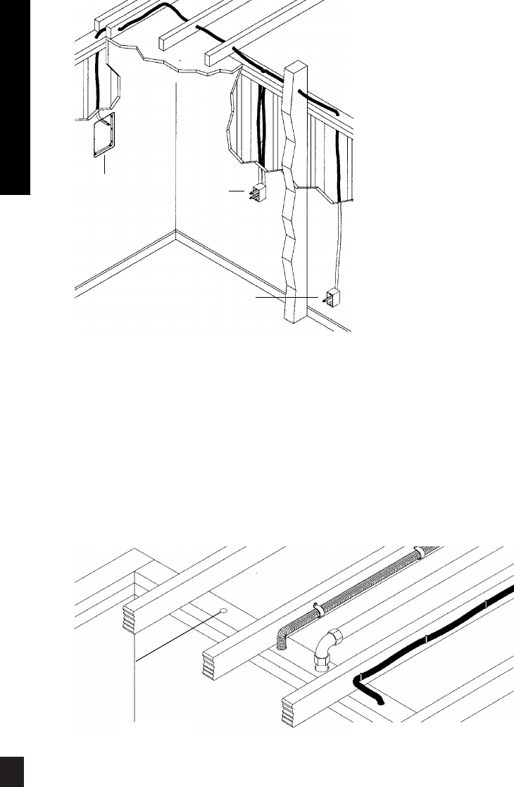
Identify where all of your electrical,
phone, and TV wiring is likely to be and
plan to route around it all. You can acci-
dentally induce 60 Hz hum on your
speakers if you run your speaker wire right
beside electrical wire for more than a few
feet. Try to keep speaker wire running par-
allel to power cables at least 3 feet away.
To find exactly where an electrical cable is
routed, try inspecting the inside of the wall
by turning off the breaker for a particular
power outlet or switch, removing the
cover plate and switch or
receptacle, and shining a
penlight into the wall. If you
have access to an attic or
basement space you can
quickly see which part of the
wall space the wire is free of
obstructions (See Figure 5).
When you don’t have access
above or below the wall, try
to estimate the existing wire
and pipe locations from the
positions of electrical outlets
and plumbed fixtures on both
sides of the wall. Take a look
at the outside of your house
too, sometimes conduit, vents
or drain pipe will be visible
that give useful information
Choose the route with the
fewest potential obstacles.
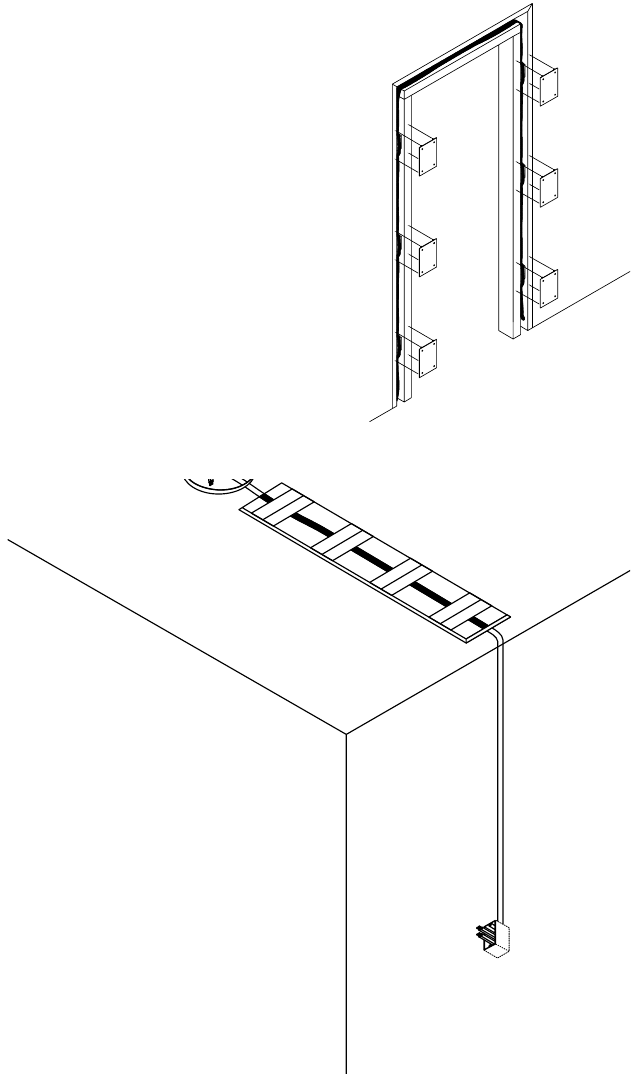
If your house is built on a slab or you are
wiring between two finished floors, look
for baseboards which could be removed
and replaced with the wire behind them
Doorjambs can be removed and often
have enough space for speaker wire al
the way around the door (See Figure 6).
Sometimes, an under-the-carpet run is
possible (there are special flat speaker
wires made for under-the-rug wire runs)
As a last resort, heating and air condition-
ing vents can be used as wire raceways for
11
Installation Fundamentals
Figure 4
Figure 5
Unobstructed space
for speaker wiring
Speaker
Location Volume
Control
Location
Stereo
Location
DS00245A/CS 3/8/99 4:13 PM Page 11
plenum rated wire (check your local
building codes, some municipalities
require conduit).
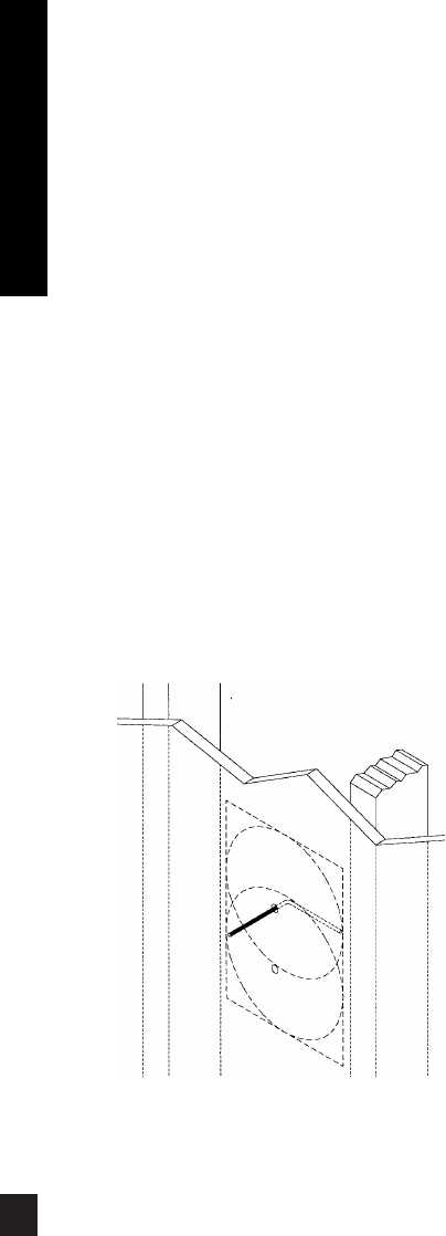
In traditional wood stud/drywall construc-
tion you can cut the hole for the speaker
and utilize the large hole to auger holes
across, up or down the wall for as far as
your drill bit will take you. If you have
matching paint and take reasonable care in
patching you can cut a hatch in the dry-
wall at each stud, run your wire, and patch
and touch-up the wall (See Figure 7).
When you are dealing with the unknown
because of the structure of your home, or
with difficult to patch wall materials like
plaster, lath and plaster, faux finishes,
wallpaper etc., be patient. A careful study
of the potential problems before you start
the job will pay off.
Figure 6
Figure 7
DS00245A/CS 3/8/99 4:13 PM Page 12
Installation
of Speakers
IMPORTANT: Before you cut into any
wall, review the sections on running
wire and speaker placement.
1. Drill a 1/8” pilot hole just barely
through the wallboard or dry wall (1/2” to
5/8” deep in most homes) about an inch
below the center of your proposed speak-
er location (an inch to the side if you are
mounting the speaker horizontally). BE
VERY CAREFUL NOT TO DRILL
THROUGH EXISTING WIRES, PIPES, OR
STRUCTURE. IF YOU FEEL ANY EXTRA
RESISTANCE AS YOU ARE DRILLING,
STOP. Cut a piece of coat hanger equal to
the width of the bracket. Bend the wire in
half creating a right angle. Poke the “L-
shaped” wire into the pilot hole and turn it
in a complete circle. If it turns freely,
repeat the procedure from a hole about an
inch above the center of your proposed
speaker location (See Figure 11).
If the wires movement is obstructed by a
pipe or cable, fill the hole (s) with spackle
or other patching compound and try
another location.
2. When determining the final location of
the cutout keep in mind that the frame
and bracket will extend beyond the
cutout. Make sure that you do not place
the edge of the cutout directly next to a
stud. Locate the studs using a stud sensor
or hand-knocking. Once you have deter-
mined the correct position for the cutout,
hold the supplied template up to the wal
surface. Level the template in either the
horizontal or the vertical position and
mark the wall with a pencil. Drill the four
corners with a 1/4” drill bit.
3. If you are cutting a painted or wal
papered drywall use a sheetrock or keyhole
saw. Cut the hole with the saw at a 45
degree angle. That way, the drywall section
can be replaced cleanly if there is an unseen
obstruction behind the wall. BE VERY
CAREFUL NOT TO SAW THROUGH
EXISTING WIRES, PIPES, OR STRUCTURE
IF YOU FEEL ANY EXTRA RESISTANCE AS
YOU ARE CUTTING, STOP.
4. If you are cutting into lath and plaster
walls, use masking tape to outline your
penciled marks, drill the four corners with
a 1/4” bit and use a razor to score the
plaster down to the lath beneath. Then use
a chisel to remove all of the plaster within
the taped outline. Finally, insert a meta
cutting blade into a sabre saw and very
slowly and carefully saw the lath. Sawing
the lath can easily vibrate plaster off the
wall. If you have the patience, use a pair
of tin snips to slowly nip away at the lath
instead. There is no risk with this method,
it is just time consuming.
13
Installation of Speakers
Figure 11
DS00245A/CS 3/8/99 4:13 PM Page 13
5. Fill the wall cavity with insulation at this
point. Remember to use equal amounts
of insulation for each speaker.
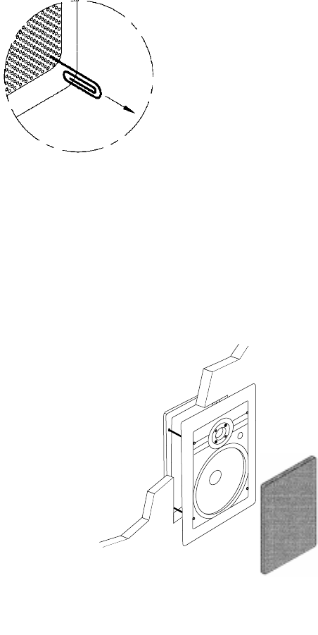
Installing the Speaker
If the grille is already
installed, remove it by
using a bent paper clip or
the tip of a corkscrew and
pulling it away from the
frame (See Figure 12).
1. Separate the speaker wire so
that at least two inches of each conduc-
tor are free.
2. Strip one half inch of insulation from the
end of each conductor of the speaker wire.
3. If you have gold pin connectors which
you wish to use, affix them to the stripped
wire ends now.
4. Connect one stripped wire end (or con-
nector) to the black and one to the red termi-
nal. Pay attention to the markings on the
wire. Each speaker must be connected to the
amplifier in the same way.
5. Slip the bracket through the hole. Orient
the speaker so that the speaker is level.
Secure the speaker and the bracket by tight-
ening the baffle screws. Do not overtighten
the screws, this will distort the frame and the
grilles will not fit (this is not permanent, just
loosen the screws and the grille will pop in).
The screws should pull the speaker and
bracket together (sandwiching the drywall) so
that the frame is absolutely flush with the wall
surface. There should be no gaps between
the wall and the frame (See Figure 13).
6. Carefully fit the grille into its recess so that
it is barely in place. Starting with one corner,
go around the speaker, pushing the grille in a
little bit each time. You should be gentle, the
aluminum grille can be easily bent out of
shape. The speaker will have an absolutely
flush appearance when it is fully in place.
Installing a Niles MS-1 MicroSensor™
There is a 1/2" round molded "IR Sensor
Knockout" on the face of the
speaker baffle. To prevent dam-
age to the crossover network
you must remove the
knockout from the rear of
the speaker. Do not attempt
to remove the knockout
with the speaker face up.
Lay the speaker face down on
a clean carpet or rug. Put the tip
of a screwdriver into the center of
the round "knockout" and sharply tap the
screwdriver handle as necessary. Install
the MS-1 using its mounting hex nut and
washer so that it is tightly secured to the
speaker. Connect all wires and continue
your installation.
Figure 12
Figure 13
DS00245A/CS 3/8/99 4:13 PM Page 14

Speaker Phase
Speaker wire has two conductors. One
conductor is attached to the negative (-)
terminals and one conductor is attached to
the positive (+) terminals of both your
speaker and your amplifier. Usually, the
wire is marked for your convenience.
There are different ways wires are marked:
a stripe on one wire, a ribbed area of one
conductor you can only feel, different col-
ors of metal wire on each conductor, or
there might be a fabric strand or string
wound into one of the conductors. Of
course, there are some wires which appear
completely identical. Be careful, or you
might make a mistake.
If you make a mistake, one speaker will be
playing “out-of-phase” with the other
speaker. An out-of-phase pair of speakers
work against each other and the sound of
the two speakers playing together will be
lacking in bass and be “phasey” sounding.
If you suspect the sound is not right and
you cannot see any markings on the wire,
try this simple test:
1. Stand half way between the two speakers.
2. Play some music with the amplifier or
radio set to Mono.
3. Listen to the richness of the bass and the
loudness of the sound.
4. Turn off the amplifier and reverse the
connections on one amplifier channel
only.
5. Repeat the listening test with the same
setting of the volume control. When the
sound has a richer bass and is slightly
louder the speakers are working together
or “in-phase”.
Painting the Aluminum Grilles
The grille is important to the sound of the
CS loudspeakers. Do not fill the holes of
the grille with paint. The grille is construct-
ed of aluminum with a perfectly even
powder coat overall. This powder coat is
an ideal primer.
Remove the grilles before painting. If you are
using spray paint, use two thin coats without
any primer. If you are using a compressor and
a spray gun, use the finest, most diffuse
setting. Practice first on some paper if you
have no experience painting with spray paint.
If you are using an applicator or brush, and
a can of paint, thin the paint first. You do
not want to have to poke hundreds of holes
in your beautifully painted grilles.
15
Installation of Speakers
DS00245A/CS 3/8/99 4:13 PM Page 15
Operation
Listening at Higher Volumes
It requires more power to achieve a rea-
sonable volume of sound in a large room
than it does in a small room. It is possi-
ble (even if you are not a teenager) to
turn the volume so high that the amplifi-
er
runs out of power
. This creates “clip-
ping” distortion.
Clipping distortion makes treble sound
very harsh and unmusical. When you hear
harsh sounding treble from any good
speaker, turn the volume down immedi-
ately! Those harsh sounds are masking
some much more powerful ultra-high-fre-
quency sound spikes which will quickly
damage any fine loudspeaker. You are
much less likely to damage a speaker with
a large amplifier because it will be very
loud indeed before it produces any clip-
ping distortion.
Cleaning
You can clean the speaker with a damp-
ened soft cloth or paper towel. If the
speaker is mounted high up on a wall or
ceiling, use a broom to gently brush it off.
DS00245A/CS 3/8/99 4:13 PM Page 16

17
Specifications
Specifications
Model CS525
Driver Compliment
5-1/4” Hi-Polymer laminate woofer
1” polycarbonate tweeter
Design Principle
Infinite baffle for large and varying air
volumes
Recommended Amplifier Power
5 to 50 watts
Nominal Impedance
8 Ohms
Frequency Response
65Hz-15kHz, +/-3dB
Sensitivity
89dB for 2.83V pink noise
Overall Exterior Frame Dimensions
7-1/8” x 9-7/8”
Depth Behind Wall
2-1/2” (Assumes 1/2” drywall)
Wall Cut-Out Dimensions
6” x 8-3/4”
Wiring Requirements
0-30 ft.................18 gauge
30-80 ft. ............ 16 gauge
80 ft. and up ...... 14 gauge
Warranty
Five year limited warranty
Model CS650
Driver Compliment
6-1/2” Hi-Polymer laminate woofer
1” polycarbonate tweeter
Design Principle
Infinite baffle for large and varying air
volumes
Recommended Amplifier Power
5 to 50 watts
Nominal Impedance
8 Ohms
Frequency Response
60Hz-15kHz, +/-3dB
Sensitivity
89dB for 2.83V pink noise
Overall Exterior Frame Dimensions
8-3/4” x 11-11/16”
Depth Behind Wall
2-3/4” (Assumes 1/2” drywall)
Wall Cut-Out Dimensions
7-5/16” x 10-1/4”
Wiring Requirements
0-30 ft.................18 gauge
30-80 ft. ............ 16 gauge
80 ft. and up ...... 14 gauge
Warranty
Five year limited warranty
DS00245A/CS 3/8/99 4:13 PM Page 17

PLEASE FILL OUT THE
WARRANTY REGISTRATION
CARD ON THE REVERSE SIDE,
DETACH, AND MAIL TO:
Niles Audio Corporation
Warranty Registration Dept.
P.O. Box 160818
Miami, Florida 33116-0818
DETACH HERE
DS00245A/CS 3/8/99 4:13 PM Page 18

Model Purchased____________________________________________________________________________________
Serial Number____________________________________________________________________________________
Date Purchased (month/day/year)__________________________________________________________________
Dealer Name and Location________________________________________________________________________
__________________________________________________________________________________________________
❑Dr. ❑Miss ❑Mr. ❑Mrs. ❑Ms.
Name____________________________________________________________________________________________
Address_________________________________________________________________________________________
__________________________________________________________________________________________________
City_________________________________________________________State________________Zip______________
Telephone (___________)___________________________________________________________________________
WARRANTY REGISTRATION CARD
Age:
❏Under 25
❏25-34
❏35-44
❏45-54
❏55 & over
Income:
❏Under $24,999
❏$25,000-$34,999
❏$35,000-$44,999
❏$45,000-$59,999
❏$60,000-$74,999
❏$75,000-$99,999
❏Over $99,999
Occupation:
❏Arts/Entertainment
❏Business Owner
❏Engineer
❏Finance/Accounting
❏General Office
❏Management
❏Professional
❏Sales/Marketing
❏Student
❏Tradesperson
Musical tastes:
(Please check all that
apply)
❏Alternative
❏Classical
❏Country
❏Jazz
❏New Age
❏Popular
❏R&B
❏Rock
❏Other______________
How did you hear
about Niles?
❏Architect/Developer
❏Custom Installer
❏Direct Mail
❏Friend/Family
❏In-Store Display
❏Interior Designer
❏Magazine Ad
❏Mail-Order Catalog
❏Newspaper Ad
❏Product Brochure
❏Product Review
❏Retail Salesperson
What magazines do
you read?
1. ______________________
2. ___________________
3. _____________________
Who will install the
product?
❏Custom Installer
❏Electrician
❏Friend
❏Myself
Which factor(s) influ-
enced the purchase
of your Niles product?
(Please check all that
apply)
❏Ease of Use
❏Price/Value
❏Product Features
❏Quality/Durability
❏Reputation
❏Style/Appearance
❏Warranty
Do you. . .?
❏Own a House. If yes,
how many square feet?
__________________
❏Own a Town House/
Condominium/Co-
op
❏Rent an Apartment
❏Rent a House
Are you interested in
receiving literature on
other Niles products?
❏Yes ❏No
Are there products/
capabilities that you
would like to see
introduced?
____________________
____________________
____________________
____________________
____________________
____________________
Please take a moment to fill out our warranty registration card. The information helps us to
get to know you better and develop the products you want
DS00245A/CS 3/8/99 4:13 PM Page 19
Limited Warranty
Niles Audio Corporation ("NILES") warrants its loudspeaker products to the original purchaser
to be free of manufacturing defects in material and workmanship for a period of five years
from date of purchase.
This Warranty is subject to the following additional conditions and limitations. The Warranty
is void and inapplicable if NILES deems that the product has been used or handled other than
in accordance with the instructions provided by the manufacturer, including but not limited to
damage caused by accident, mishandling, improper installation, abuse, negligence, or normal
wear and tear, or any defect caused by repair to the product by anyone other than NILES or an
authorized NILES dealer.
To obtain warranty service, take the unit to the nearest authorized NILES dealer, who will test
the product and if necessary, forward it to NILES for service. If there are no authorized NILES
dealers in your area, you must write to NILES and include your name, address, model and
serial number of your unit, along with a brief description of the problem. A factory Return
Authorization Number will be sent to you. DO NOT RETURN ANY UNIT WITHOUT FIRST
RECEIVING WRITTEN AUTHORIZATION AND SHIPPING INSTRUCTIONS FROM NILES.
If the above conditions are met, the purchaser's sole remedy shall be to return the product to
NILES, in which case NILES will repair or replace, at its sole option, the defective product
without charge for parts or labor. NILES will return a unit repaired or replaced under warranty
by shipping same by its usual shipping method from the factory (only) at its expense within the
United States of America. THERE ARE NO OTHER WARRANTIES, INCLUDING WITHOUT
LIMITATION, EITHER EXPRESS OR IMPLIED WARRANTIES OF MERCHANTABILITY OR FIT-
NESS FOR A PARTICULAR PURPOSE, WITH RESPECT TO THE PRODUCT.
REPAIR OR REPLACEMENT AS PROVIDED UNDER THIS WARRANTY IS THE EXCLUSIVE
REMEDY OF THE CONSUMER/PURCHASER. NILES SHALL NOT BE RESPONSIBLE FOR
ANY INCIDENTAL OR CONSEQUENTIAL DAMAGES EXCEPT TO THE EXTENT PROVIDED
(OR PROHIBITED) BY APPLICABLE LAW.
Some states do not allow the exclusion or limitation of incidental or consequential damages,
so the above limitation may not apply to you. This warranty gives you specific legal rights,
and you may also have other rights which vary from state to state.
For the name of your nearest authorized NILES dealer contact:
NILES AUDIO CORPORATION
P.O. BOX 160818, Miami, Florida 33116-0818.
Please fill in your product information and retain for your records.
Model____________________________________________________________________________________
Serial No._________________________________________________________________________________
Purchase Date_____________________________________________________________________________
DS00245A/CS 3/8/99 4:13 PM Page 20

Niles Audio Corporation
12331 S.W. 130 Street
Miami, Florida 33186
Tel: (305) 238-4373
Fax: (305) 238-0185
Printed in Taiwan
©1999 Niles Audio Corporation. Because Niles strives to continuously improve
products, Niles reserves the right to change product specifications without not
Niles, the Niles logo, Blending High Fidelity and Architecture and Blueprint Se
In-Wall Loudspeakers are registered trademarks of Niles Audio Corporation. Do
is a registered trademark of Dolby Laboratories Licensing Corporation. Decora
registered trademark of Leviton Manufacturing Co., Inc. DS00245A
®
DS00245A/CS 3/8/99 4:13 PM Page 21
