Nissan 1980 200Sx Repair Manual Service Datsun
2015-10-23
: Nissan Nissan-1980-Nissan-200Sx-Repair-Manual-818754 nissan-1980-nissan-200sx-repair-manual-818754 nissan pdf
Open the PDF directly: View PDF ![]() .
.
Page Count: 572 [warning: Documents this large are best viewed by clicking the View PDF Link!]
v
I
DATSUN
I
0
o
1980
DATSUN
200
SX
rl1
SERVICE
MANUAL
A
J
i
I
I
h
t
fi
t
i
t
i
CI
o
IIV
INI55ANI
HlUM
lOco
QUICK
REFERENCE
INDEX
GENERAl
INFORMATION
GI
DATSUN
200SX
MAINTENANCE
M
ENGINE
MECHANICAL
E
Model
S
J
JO
Series
ENGINE
LUBRICATION
COOLING
SYSTEMS
LC
ENGINE
FUEL
iF
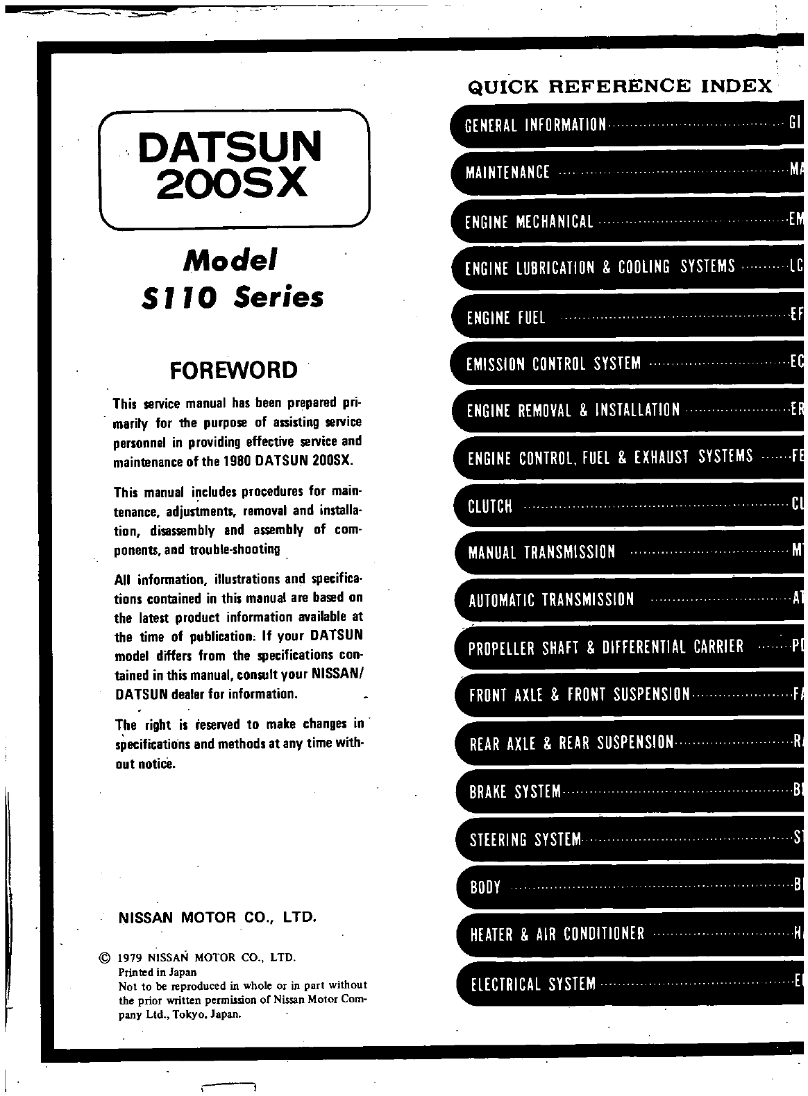
FOREWORD
EMISSION
CONTROL
SYSTEM
E
This
service
manual
has
been
prepared
pri
marily
for
the
purpose
of
assisting
service
personnel
in
providing
effective
service and
maintenance
ofthe
1980
DATSUN
200SX
ENGINE
REMOVAL
INSTALLATION
E
ENGINE
CONTROl
FUEL
EXHAUST
SYSTEMS
F
This
manual
includes
procedures
for
main
tenance
adjustments
removal
and
installa
tion
disassembly
and
assembly
of
com
ponents
and
trouble
shooting
All
information
illustrations
and
specifica
tions
contained
in
this
manual
are
based
on
the
latest
product
information
available
at
the
time
of
publication
If
your
DATSUN
model
differs
from
the
specifications
con
tained
in
this
manual
consult
your
NISSANI
DATSUN
dealer
for
information
CLUTCH
C
MANUAL
TRANSMISSION
M
AUTOMATIC
TRANSMISSION
A
PROPELLER
SHAFT
DIFFERENTIAL
CARRIER
P
FRONT
AXlE
FRONT
SUSPENSION
F
The
right is
reserved
to
make
changes
in
specifications
and
methods
at
any
time
with
out
notice
REAR
AXLE
REAR
SUSPENSION
R
BRAKE
SYSTEM
B
STEERI
NG
SYSTEM
S
NISSAN MOTOR
CO
LTD
BODY
B
HEATER
AIR
CONDITIONER
H
@
t
979
NISSAN
MOTOR
CO
LTD
Printed
in
Japan
Not
to
be
reproduced
in
whole
or
in
part
without
the
prior
written
permission
of
Nissan
Motor
Com
pany
Ltd
Tokyo
Japan
ELECTRICAL SYSTEM
E
v
w
I
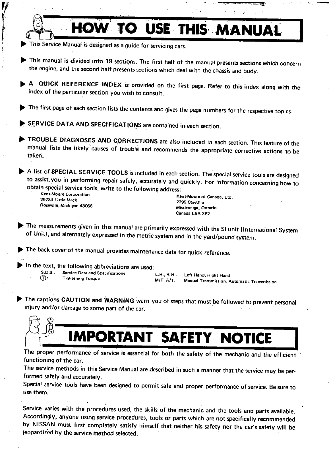
HOW
TO
USE
THIS
MANUAL
This
Service
Manual
is
designed
as
a
guide
for
servicing
cars
This
manual
is
divided
into
19
sections
The
first
half
of
the
manual
presents
sections
which
concern
the
engine
and
the
second
half
presents
sections
which
deal
with
the
chassis
and
body
A
QUICK
REFERENCE
INDEX
is
provided
on
the
first
page
Refer
to
this
index
along
with
the
index of
the
particular
section you
wish
to
consult
The
first
page
of
each
section
lists
the
contents
and
gives
the
page
numbers
for
the
respective
topics
SE
RVICr
DATA
AND
SPECIFICATIONS
are
contained
in
each
section
TROUBLE
DIAGNOSES
AND
CpRRECTIONS
are
also
included
in
each
section
This
feature
of
the
manual
lists
the
likely
causes
of
trouble
and
recommends
the
appropriate
corrective
actions
to
be
taken
A
list
of
SPECIAL
SERVICE
TOOLS
is
included
in
each
section
The
special
service
tools
are
designed
to
assist
you
in
performing
repair safely
accurlltely
and
quickly
For
information
concerning
how
to
obtain
special
service
tools
write
to
the
following
address
Kent
Moore
Corporation
Kent
Moore
of
Canada
Ltd
29784
Little
ack
2395
Cawthra
RO
eville
Michigan
48066
Mississauga
Ontario
Canada
L5A
3P2
The
measurements
given
in this
manual
are
primarily
expressed
with
the
Sl
unit
International
System
of
Unit
and
alternately
expressed
in
the
metric
system
and
in
the
yard
pound
system
The
back
cover
of
the
manual
provides
maintenance
data
for
quick
reference
In
the
text
the
following
abbreviations
are
used
s
o
s Service Data
nd
Specifications
L
HR
H
left
Hand
Right
Hand
f
J
Tightening
TorQue
MOrr
AiT
Manual
Transmission
Automatic
Transmission
The
captions
CAUTION
and
WARNING
warn
you
of
steps
that
must
be
followed
to
prevent
personal
injury
and
or
damage
to
some
part
of
the
car
N
IMPORTANT
SAFETY
NOTICE
I
The
proper
performance
of
service is
essential
for
both
the
safetY
of
the
mechanic
and
the
efficient
functioning
of
the
car
The
service
methods
in
this
Service
Manual
are
described
in
such
a
manner
that
the
service
may
be
per
formed
safely
and
accurately
Special
service
tools
have
been
designed
to
permit
safe
and
proper
performance
of
service
Be
sure
to
use
them
Service
varies
with
the
procedures
used
the
skills
of
the
mechanic
and
the
tools
and
parts
available
Accordingly
anyone
using
service
procedures
tools
or
parts
which
are
not
specifically
recommended
by
NISSAN
must
first
completely
satisfy
himself
that
neither
his
safety
nor
the
car
s
safety
will
be
jeopardized
by
the
service
method
selected
DATSUN
200SX
Model
SIlO
Series
SECTIONGI
GI
GENERAL
INFORMATION
CONTENTS
GENERAL
VIE
WS
MODEL
VARIATION
IDENTIFICATION
NUMBER
LIFTING
POINTS
AND
TOWING
PANTOGRAPH
JACK
GARAGE
JACK
AND
SAFETY
STAND
GI 2
GI 3
GI
4
GI 5
GI 5
GI
5
TIE
DOWN
TOWING
SPECIAL
SERVICE
TOOLS
TIGHTENING
TORQUE
OF
STANDARD
BOLT
GI 5
GI 5
GI 6
GI 6
Genetal
Views
GENERAL
INFORMATION
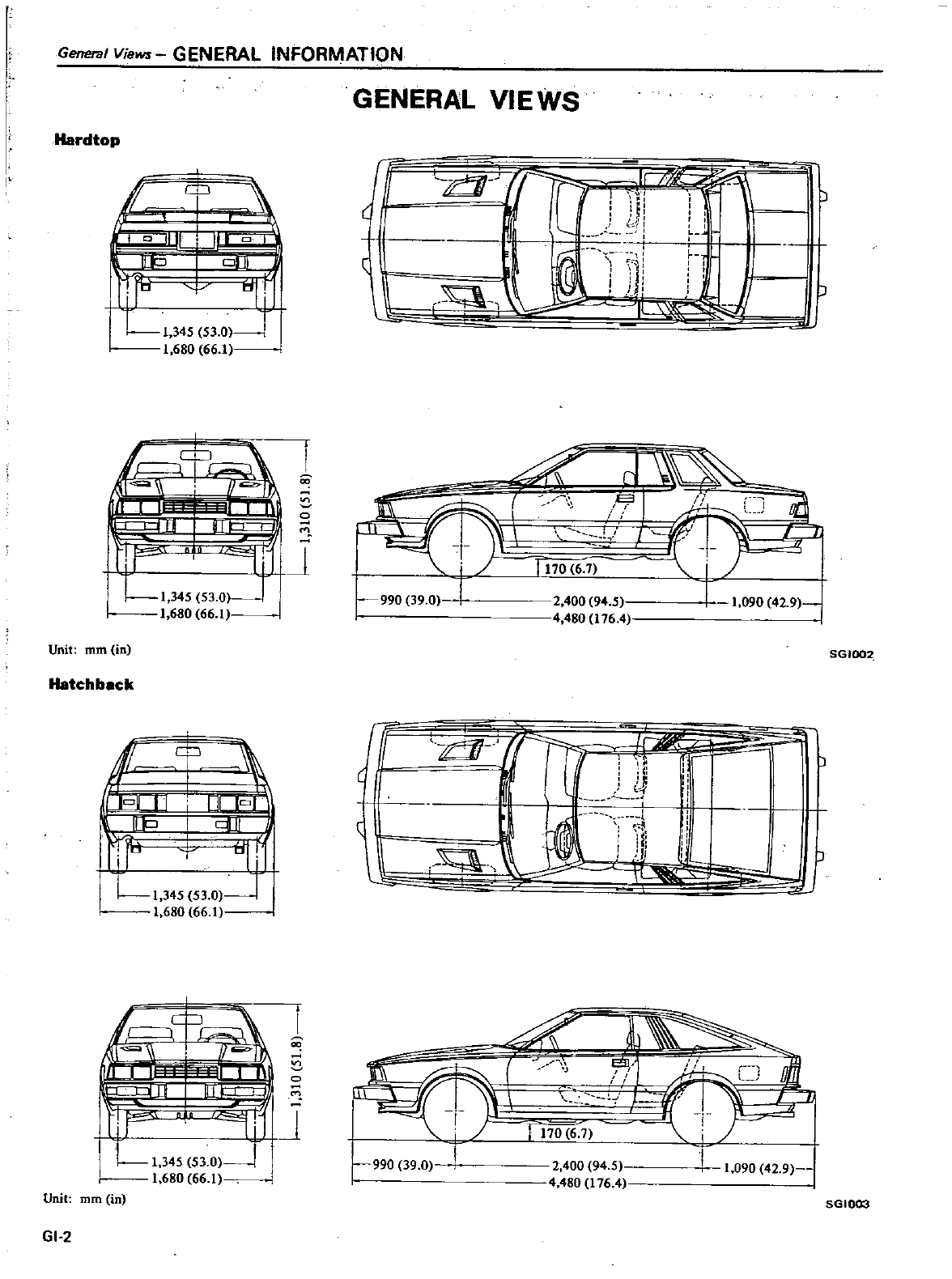
Hardtop
l
I
r
I
O
II
JI1
Po
dI
V
Ll
34S
S3 0
1
680
66
1
ll
r
lU
I11
hF
oi
11
LI
345
53
O
J
1
680
66
1
Unit
mm
in
Hatchback
t
c
iq
L
1
345
53
0
1
680
66
1
Unit
mm
in
GI
2
GENERAL
VIEWS
J
c
f
1
11
I
I
r
L
1
m
41
f
1
1
g
t
I
ll
t
X
990
39
0
2
400
94
5
1
090
42
9
480
176
4
SGIOO2
fT
d
r
Ii
r
b
t
I
I
J
I
t
iL
L
J
J
I
I
J
J
r
1
t
uJJ
Il
IY
1
T
2
400
94
5
t
090
42
9
4
480
t
76
4
990
39
0
5GI003
GENERAL
INFORMATION
Model
Variation
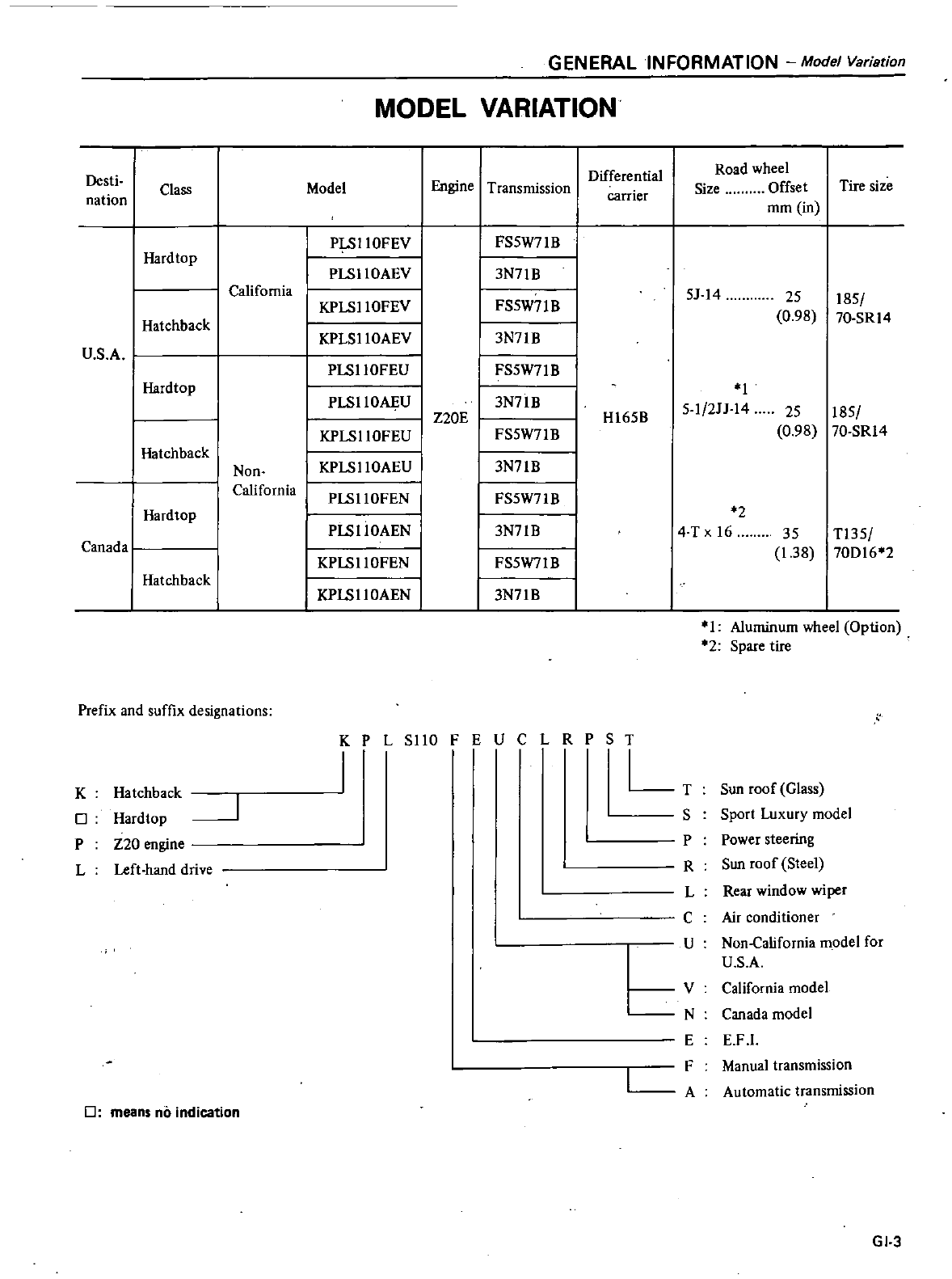
MODEL
VARIATION
Desti
Differential
Road
wheel
nation
Class
Model
Engine
Transmission
carrier
Size
Offset
Tire
size
mm
in
PI
SIIOFEV
FS5W71B
Hardtop
PLSIIOAEV
I
3N71B
California
KPLSIlOFEV
I
5J
14
25
185
FS5W71B
Hatchback
0
98
70
SR
14
KPLSllOAEV
I
3N71B
U
S
A
PLSIl
OFEU
I
FS5W71B
Hardtop
I
I
PLSllOAJ
iU
3N71B
5
1
2JJ
14
25
185
Z20E
HI65B
KPLSllOFEU
I
FS5W71B
0
98
70
SR14
Hatchback
Non
I
KPLSIIOAEU
I
3N71B
California
I
PLSllOFEN
I
FS5W71B
Hard
top
II
2
PLSllOAEN
3N71B
4
T
x
16
35
T135
Canada
I
KPLSllOFEN
I
FS5W7IB
1
38
70D16
2
Hatchback
I
KPLSllOAEN
I
3N71B
Prefix
and
suffix
designations
K
o
P
L
Hatchback
I
Hardtop
J
Z20
engine
Left
hand drive
K
P
L
SIlO
J
I
0
PST
LT
0
means
no
indication
I
Aluminum
wheel
Option
2
Spare
tire
Sun
roof
Glass
Sport
Luxury
model
Power
steering
Sun
roof
Steel
Rear window
wiper
Air
conditioner
Non
California
model
for
U
S
A
V
California
model
N
Canada
model
E E
F
l
F
Manual
transmission
S
P
R
L
C
U
A
Automatic
transmission
GI
3
IdentificationNiJmber
GENERAL
INFORMATION
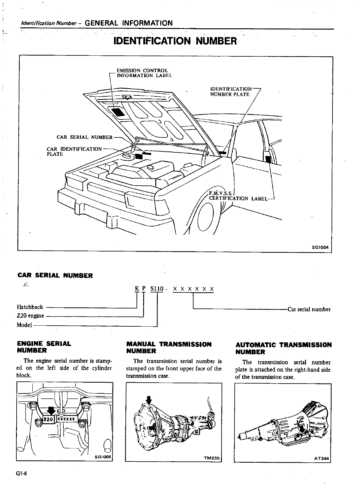
CAR
SERIAL
NUMBER
PLATE
CAR
SERIAL
NUMBER
Hatchback
Z20
engine
Model
ENGINE
SERIAL
NUMBER
The
engine
seria
number
is
stamp
ed
on
the
left
side
of
the
cylinder
block
I
Q
SGIOO6
GI
4
IDENTIFICATION
NUMBER
EMISSION
CONTROL
INFORMATION
LABEL
K
P
SlID
r
x
XXXXX
I
MANUAL
TRANSMISSION
NUMBER
The
transmission
seria
number
is
stamped
on
the
front
upper
face
of
the
transmission
case
TM235
SGI004
Car
serial
number
AUTOMATIC
TRANSMISSION
NUMBER
The
transmission
serial
number
plate
is
attached
on
the
right
hand
side
of
the
transmission
case
A
T344
GENERAL
INFORMATION
UftingPointsand
Towing
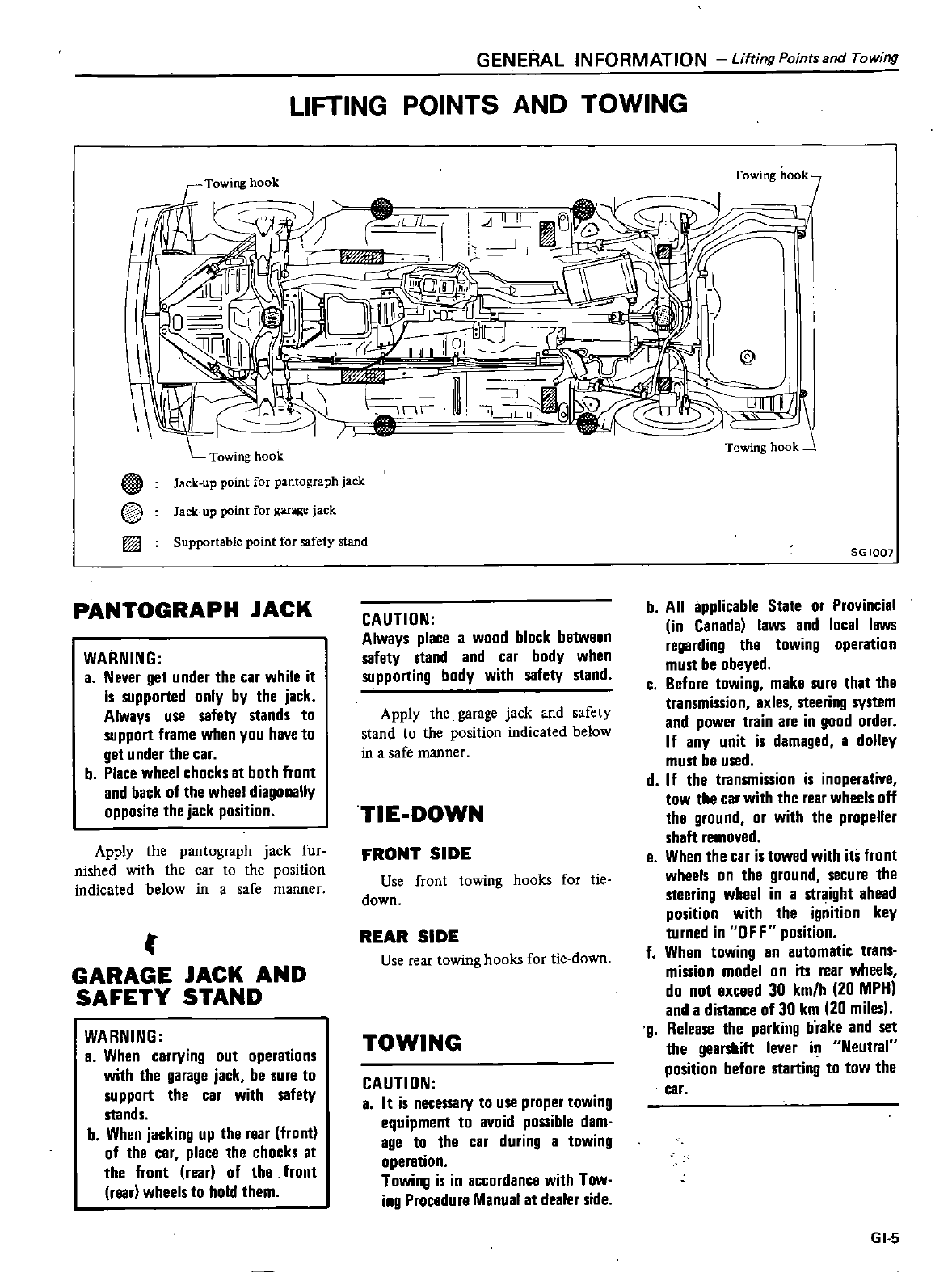
LIFTING
POINTS
AND TOWING
Towing
hook
UL
IW
I
@
A
@
I
il
Towing
hook
Jack
up
point
for
pantograph
jack
Jack
up
point
for
garage
jack
Supportable point
for
safety
stand
PANTOGRAPH
JACK
WARNING
a
Never
get
under
the
car
while
it
is
supported
only
by
the
jack
Always
use
safety
stands
to
support
frame
when
you
have
to
get
under
the
car
b
Place
wheel
chocks
at
both
front
and
back
of
the
wheel
diagonally
opposite
the
jack
position
Apply
the
pantograph
jack
fur
nished
with
the
car
to
the
position
indicated
below
in
a
safe
manner
t
GARAGE
JACK
AND
SAFETY
STAND
WARNING
a
When
carrying
out
operations
with
the
garage
jack
be
sure
to
support
the
car
with
safety
stands
b
When
jacking
up
the
rear
front
of
the
car
place
the
chocks
at
the
front
rear
of
the
front
rear
wheels
to
hold
them
CAUTION
Always
place
a
wood
block
between
safety
stand
and
car
body
when
supporting body
with
safety
stand
Apply
the
garage
jack
and
safety
stand
to
the
position
indicated
below
in
a
safe
manner
TIE
DOWN
FRONT
SIDE
Use
front
towing
hooks
for
tie
down
REAR
SIDE
Use
rear
towing
hooks
for
tie down
TOWING
CAUTION
a
It
is
necessary
to
use
proper
towing
equipment
to
avoid
possible
dam
age
to
the
car
during
a
towing
operation
Towing is
in
accordance
with
Tow
ing
Procedure
Manual
at
dealer
side
Towing hook
7
r
J
@
II
1I
6
Towing
hook
SG
1007
b
All
applicable
State
or
Provincial
in
Canada
laws
and
local
laws
regarding
the
towing operation
must
be
obeyed
c
Before
towing
make
sure
that
the
transmission
axles
steering
system
and
power
train
are
in
good
order
If
any
unit
is
damaged
a
dolley
must
be
used
d
If
the
transmission
is
inoperative
tow
the
car
with
the
rear
wheels
off
the
ground
or
with
the
propeller
shaft
removed
e
When
the
car
is
towed
with
its
front
wheels
on
the
ground
secure
the
steering
wheel
in
a
straight
ahead
position
with
the
ignition
key
turned
in
OFF
position
f
When
towing
an
automatic
trans
mission
model
on
its
rear
wheels
do
not
exceed
30
km
h
20
MPH
and
a
distance
of
30
km
20
miles
g
Release
the
parking
brake
and
set
the
gearshift
lever in
Neutral
position
before
starting
to
tow
the
car
GI 5
Specia
Service
T
oo
s
Tightening
TO
1ueofStandardBolt
GENERAL
INFORMATION
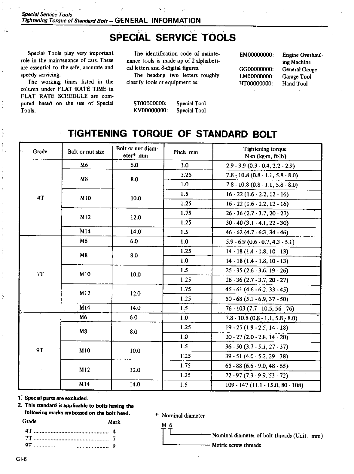
SPECIAL
SERVICE
TOOLS
Special
Tools
play
very
important
role
in
the
maintenance
of
cars
These
are
essential
to
the
safe
accurate
and
speedy
servicing
The
working
times
listed
in
the
column
under
FLAT
RATE
TIME
in
FLAT
RATE
SCHEDULE
are
com
puted
based
on
the
use
of
Special
Tools
The
identification
code
of
mainte
nance
tools
is
made
up
of
2
alphabeli
calletteIS
and
8
digital
figures
The
heading
two
letters
roughly
classify
tools
or
equipment
as
STOOOOOOOO
Special
Tool
KVOOOOOOOO
Special
Tool
EMOOOOOOOO
Engine
Overhaul
ing
Machine
General
Gauge
Garage
Tool
Hand
Tool
GGOOOOOOOO
LMOOOOOOOO
HTOOOOOOOO
TIGHTENING
TORQUE
OF
STANDARD
BOLT
Grade
Bolt
or
nut
size
M6
M8
4T
MIO
MI2
MI4
M6
M8
7T
MIO
MI2
MI4
M6
M8
9T
MIO
MI2
MI4
1
Special
pam
are
excluded
2
This
standard
is
applicable
to
bolu
having
the
following
marks
embossed
on
the
bolt
head
Grade
Mark
4T
7T
9T
GI 6
Bolt
or
nut
diam
eter
mm
Pitch
mm
6 0
1
0
1
25
1
0
1
5
1
25
175
1
25
15
1
0
1
25
1
0
15
1
25
175
1
25
15
1
0
1
25
1
0
1
5
1
25
1
75
1
25
1
5
8 0
10
0
12
0
14
0
60
8
0
10 0
12
0
14
0
6 0
8 0
10
0
12
0
14
0
Nominal
diameter
4
7
9
M6
TT
Tightening
torque
N
m
kg
m
ft
Ib
2939
03
0
4 2 2 2 9
7 8
10
8
0
8
Ll
5
880
7810 8 0 8
Ll
5
8 8 0
16
22
1
6
2
2
12 16
16
22
1
62 2 12 16
26 36
2 7
3
7
20
27
30
40
3
1
41
22
30
46 62
4
7
63
34 46
5
9 6 9
0
607
43
51
I
14
18
1
4
1
8
10 13
I
14
1814
1
8
10 13
I
25
35
26
3
6
19
26
I
26 36
2 7 37
20
27
I
45
61
46
62
33
45
I
50 68
51
6 9
37
50
L
76
103
7 7
10
5
56 76
I
7 8 10 8
O
11
5 8 8
0
I
19
25
1
9
25
14 18
I
20
27
2
0
2814
20
I
36 50
37
51
27
37
I
39
51
4
0
52
29
38
I
65 88
6 6 9
0
48
65
I
72
97
73
99
53 72
I
109
147
11
1
15
0
80
108
Nominal
diameter
of
bolt
threads
Unit
mm
Metric
screw
threads
DATSUN
200SX
Model
S
JJ
0
Series
II
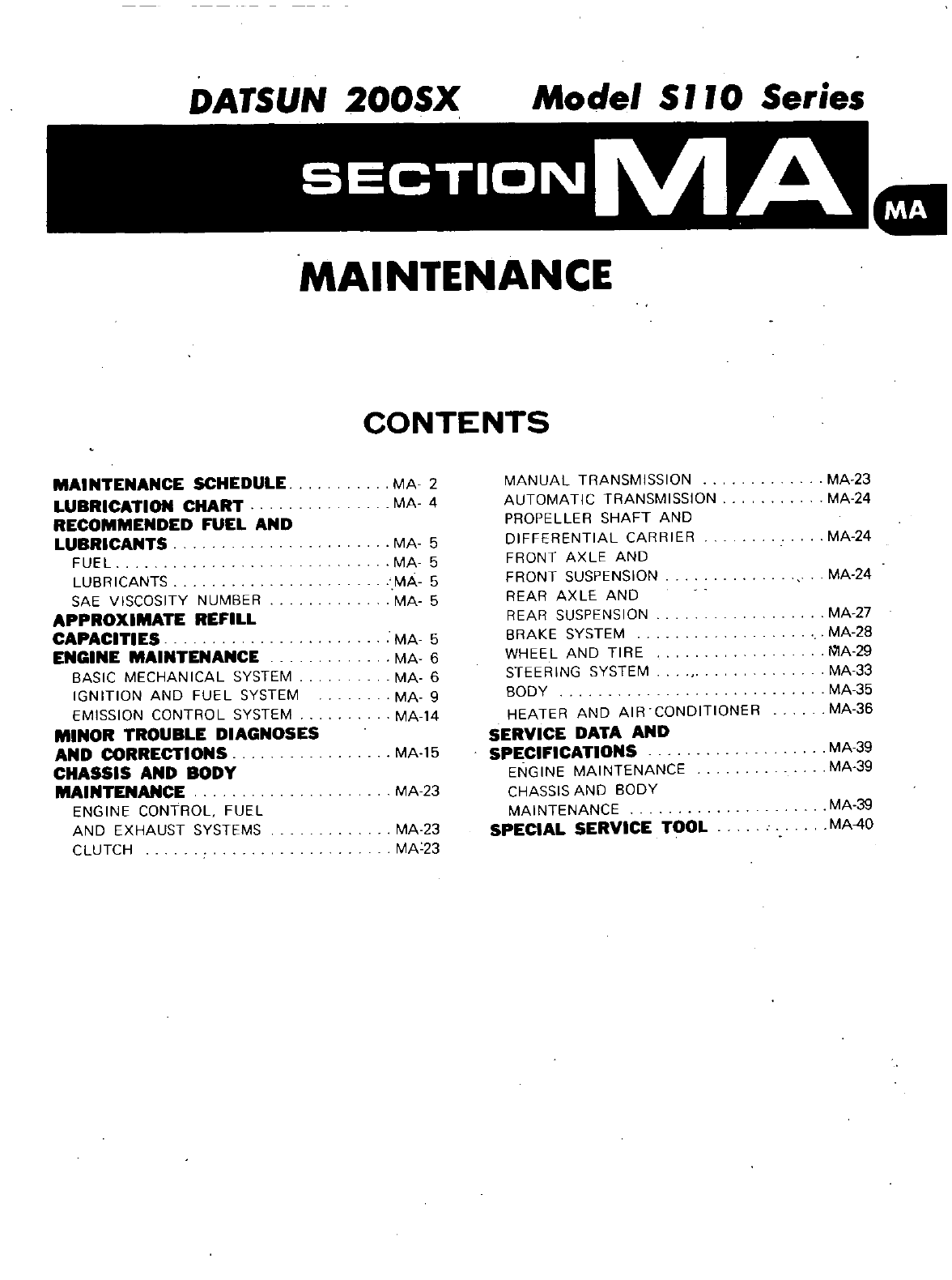
MAINTENANCE
CONTENTS
MAINTENANCE
SCHEDULE
MA
2
MANUAL
TRANSMISSION
MA
23
LUBRICATION
CHART
MA
4
AUTOMATIC
TRANSMISSION
MA
24
RECOMMENDED
FUEL
AND
PROPELLER
SHAFT
AND
LUBRICANTS
MA
5
DIFFERENTIAL
CARRIER
MA
24
FUEL
MA
5
FRONT
AXLE
AND
LUBRICANTS
MA
5
FRONT
SUSPENSION
MA
24
SAE
VISCOSITY
NUMBER
MA
5
REAR
AXLE
AND
APPROXIMATE
REFILL
REAR
SUSPENSION
MA
27
CAPACITIES
MA
5
BRAKE
SYSTEM
MA
28
ENGINE
MAINTENANCE
MA
6
WHEEL
AND
TIRE
fVlA
29
BASIC
MECHANICAL
SYSTEM
MA
6
STEERING
SYSTEM
MA
33
IGNITION
AND
FUEL
SYSTEM
MA
9
BODY
MA
35
EMISSION
CONTROL
SYSTEM
MA
14
HEATER
AND
AIR
CONDITIONER
MA
36
MINOR
TROUBLE
DIAGNOSES
SERVICE
DATA
AND
AND
CORRECTIONS
MA
15
SPECIFICATIONS
MA
39
CHASSIS
AND
BODY
ENGINE
MAINTENANCE
MA
39
MAINTENANCE
MA
23
CHASSIS
AND
BODY
ENGINE
CONTROl
FUEL
MAINTENANCE
MA
39
AND
EXHAUST
SYSTEMS
MA
23
SPECIAL
SERVICE
TOOL
MA
40
CLUTCH
MA
23
Maintenance
Schedule
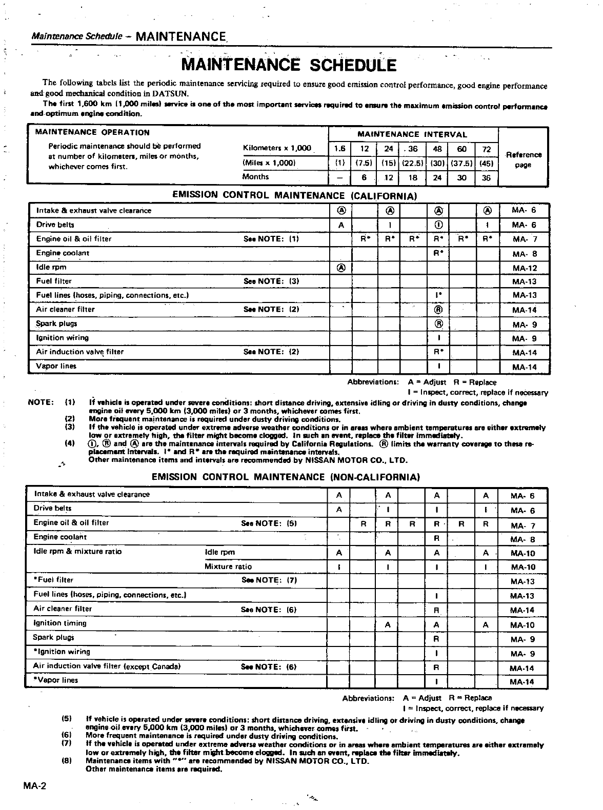
MAINTENANCE
MAINTENANCE
SCHEDULE
The
following tabels
list
the
periodic
maintenance
servicing
required
to
ensure
good
emission
control
performance
good
engine
performance
and
good
mechanical
condition
in
DATSUN
The
fint
1
600
km
11
000
miles
service
is
one
of
the
most
important
services
uired
to
nsurw
the
maximum
mission
control
perfonnlnce
and
optimuin
engine
con
Iition
MAINTENANCE
OPERATION
MAINTENANCE
INTERVAL
Periodic
maintenance
should
be
performed
Kilometers
x
1
000
1
6
t2
24 36 48 60
72
at
number
of
kilometers
miles
or
months
Ref
rence
whichever
comes
first
Miles
x
1
0001
1
7
51
t51
22
5
301
37
5
451
page
Months
6
t2 t8
24
3D
36
Intake
exhaust
valve
clearance
Drive
belts
En
uine
oil oil
filter
Engine
coolant
Idle
rpm
Fuel
filter
Fuel
lines
hoses
piping
connections
etc
Air
cleaner
filter
Spark
plugs
EMISSION
CONTROL
MAINTENANCE
@
CALIFORNIA
@ @
j
A
So
NOTE
111
R
RO
R R
R
RO
@
So
NOTE
131
I
Soo
NOTE
121
@
@
Ignition
wiring
Air
induction
v8lv
filter
Vapor
lines
NOTE
III
121
131
41
So
NOTE
121
R
@
MA
6
MA
6
MA
7
MA
8
MA
12
MA
13
MA
13
MA
14
MA
9
MA
9
MA
t4
MA
t4
RO
Abbreviations
A
Adjust
A
Replace
I I
nspect
correct
replace
if
necessary
If
nhicla
is
under
sever
conditions
short
distance
driving
extensive
idling
or
driving
in
dusty
conditions
change
engine
oil
every
5
000
km
3
000
miles
or
3
months
whichever
comes
first
More
frequent
maintenance
is
required
und
dusty driving
conditions
If
the
vehic
le
is
operated
under
extreme
adverse
weather
conditions
or
in
ar
s
where
ambient
temperaturas
are
either
extremely
low
or
extremely
high
the
filter
might
become
clogged
In
such
an
event
replace
the
filt
immmiatefy
D
@
an
@
are
the
maintenance
intervals
required
by
California
Regulations
@
limits
the
warranty
COYII
to
these
re
placement
InterYals
and
R
the
uired
mainUNInce
intervals
Other
maintenance
items
and
intervals
are
recommended
by
NISSAN MOTOR
CO
L
TO
EMISSION
CONTROL
MAINTENANCE
NON
CALlFORNIA
1
A A
I
R R
R
A
Intake
exhaust
valve
clearance
Drjve
bel
s
Engine
oil oil
filter
Engine
coolant
Idle
rpm mixture
ratio
Fuel
filter
Fuel
lines
hoses
piping
connections
etc
J
Air
cleaner
filter
Ignition
timing
Spark
plugS
So
NOTE
151
R
R R
Idle
rpm
A A
Mixture
ratio
Soo
NOTE
7
So
NOTE
161
R
A
R
I
R
A
Ignition
wiring
Air
induction
valve
filter
except
Canada
Vapor
lines
MA
2
Soo
NOTE
61
A
MA
6
MA
6
MA
7
MA
8
MA
l0
MA
l0
MA
13
MA
13
MA
t4
MA
l0
MA
9
MA
9
MA
14
MA
14
R
A
A
51
161
171
81
Abbreviations
A
Adjust
R
Replace
I
Inspect
correct
replace
if
necessary
If
vehicle
is
operated
under
senre
conditions
short
distance
driving
extensive
idling
or
driving
in
dusty
conditions
chenge
engine
oil
every
5
000
km
3
000
miles
or
3
months
whichner
comes
fitst
Mor
frequent
maintenance
is
required
undar
dusty
driving
conditions
If
the
vehicle
is
opemed
under
extreme
adverse
weather
conditions
or
in
areas
where
ambient
temperatures
are
either
extremely
low
or
extremely
high
the
filter
might
become
dow
l
In such
IIn
event
replace
the
filter
immeduty
Maintenance
items
with
are
recommended
by
NISSAN
MOTOR
CO
L
TO
Other
maintenance
items
Ifll
required
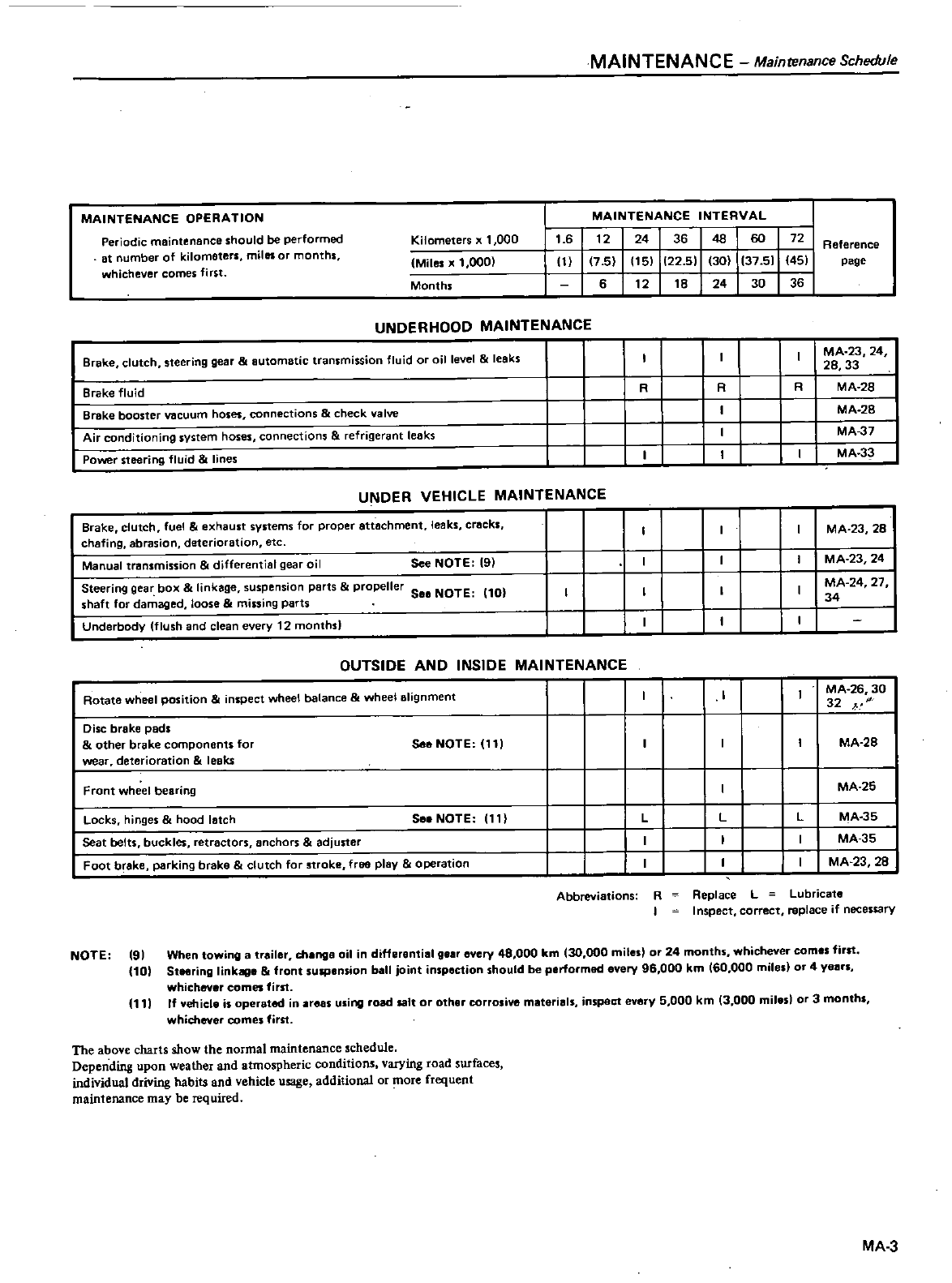
MAINTENANCE
Maintenance
Schedule
Periodic
maintenance
should
be
performed
at
number
of
kilometers
miles
or
months
whichever
comes
first
MAINTENANCE
INTERVAL
Kilometers
x
1
000
1
6
t2
24 36 48 60
72
Reference
Miles
x
1
000
III
17
5
It51
122 51 130 137 51 451
page
Months
6
t2 t8
24 30
36
MAINTENANCE
OPERATION
UNDERHDOD
MAINTENANCE
Brake
fluid
Brake
booster
vacuum
hoses
connections
check
valve
Air
conditioning
system
hoses
connections
refrigerant
leaks
Power
steering
fluid
lines
R
MA
23
24
28 33
R R
MA
28
MA
28
MA
J7
I
I
MA
33
Brake
clutch
steering
gear
automatic
transmission
fluid
or
cillevel
leaks
UNDER
VEHICLE
MAINTENANCE
Brake
clutch
fuel
exhaust
systems
for
proper
attachment
leaks
cracks
chafing
abrasion
deterioration
etc
MA
23 28
Manual transmission
differential
gear
oil
See
NOTE
19
MA
23 24
MA
24
27
34
Steering
gear
box
linkage
suspension
parts
propeller
588
NOTE
10
shaft
for
damaged
loose
missing
parts
Underbody
flush
and
clean
every
12
months
OUTSIDE
AND
INSIDE
MAINTENANCE
Rotate
wheel
position
nspect
wheel
balance
wheel
alignment
MA
26 30
32
yJ
Disc
brake
pads
other
brake
components
for
wear
deterioration
leaks
See
NOTE
111
MA
28
Front
wheel
bearing
MA
25
Locks
hinges
hood
latch
Seat
betts
buckles
retractors
anchors
adjuster
Foot
brake
parking
brake
clutch
for
stroke
free
play
operation
See
NOTE
11
L
L
L
MA
35
MA
35
MA
23
28
Abbreviations
R
I
Replace
L
Lubricate
Inspect
correct
replace
if
necessary
NOTE
91
When
towing
a
trailer
change
oil
in
differential
gear
every
48
000
km
30
000
miles
or
24
months
whichever
comes
first
10
Steering
linkage
front
suspension
ball
joint
inspection
should
be
performed
every
96
000
km
60
000
miles
or
4
years
whichever
comes
first
111
If
vehicle
is
operated
in
areas
using
road
salt
or
other
corrosive materials
inspect
every 5
000
km
3 000
milesl
or
3
months
whichever
comes
first
The
above
charts
show
the
normal
maintenance
schedule
Depending
upon
weather
and
atmospheric
conditions
varying
road
surfaces
individual
driving
habits
and
vehicle
usage
additional
or
ore
frequent
maintenance
may
be
required
MA
3
30
j
f
liSl
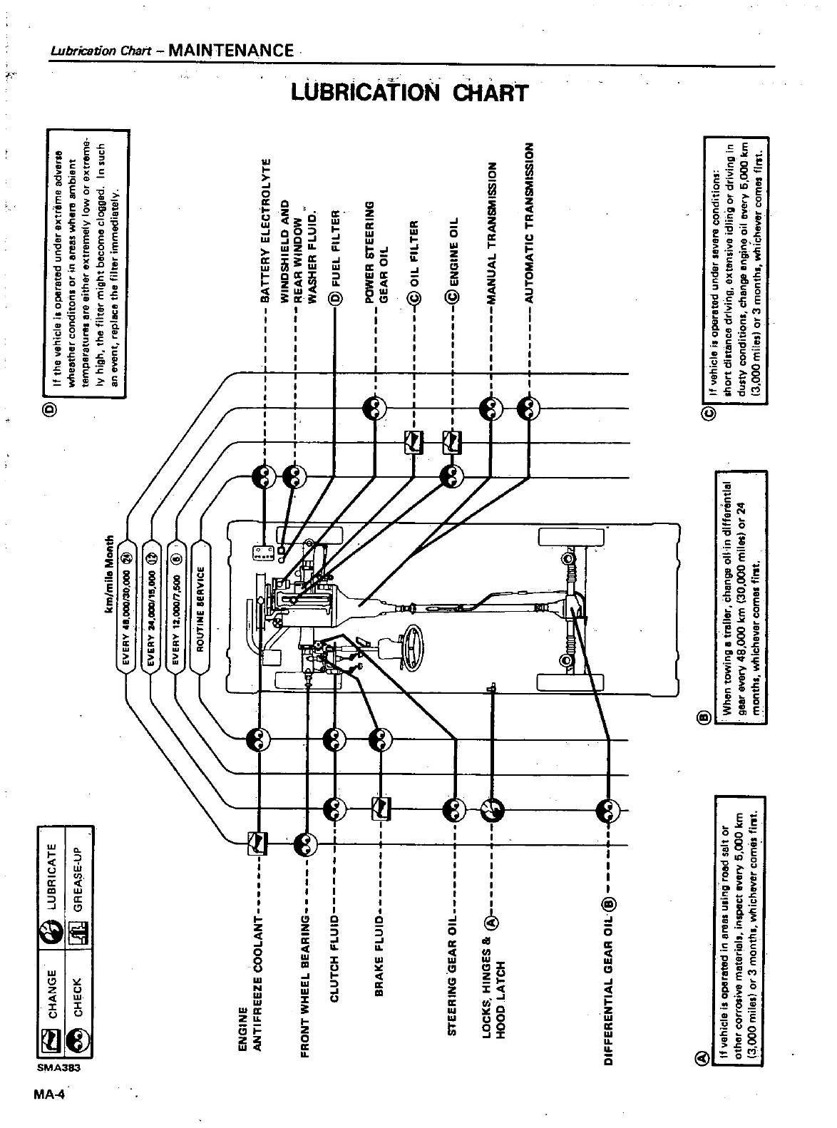
CHANGE
ll
CHECK
LUBRICATE
QIQ
GREASE
UP
ENGINE
ANTIFREEZE
COOLANT
n
FRONT
WHEEL
BEARINGn
CLUTCH
FLUIO
BRAKE
FLUIO
6
STEERING
GEAR
OIL
LOCKS
HINGES
81
@
HOOD
LATCH
DIFFERENTIAL
GEAR
OIL@
@
If
vehicle
is
operated
in
ereai
u
ing
road
salt
or
other
corrosive
material
inspect
every
6
000
km
3
000
mile
or
3
month
whichever
cornel
fil
lt
km
mila
Month
EVERY
411
000130
000
@
EVERY
24
000
115
000
@
1
L
@
When
towing
l
I
trailer
change
011
in
differential
gear
every
48
000
km
30
000
miles
or
24
onth
whichever
cornel
fll
lt
@
If
the
vehicle
i
operated
under
extremeadverse
wheather
conditon
or
in
erel
l
where
ambient
temperature
lIre
either
extremely
low
or
extreme
IV
high
the
filter
might
become
cloggltd
In
such
an
event
replICe
the
filter
Immediatelv
BATTERY
ELECTROLYTE WINDSHIELD
AND
REAR
WINDOW WASHER
FLUID
@
FUEL
FILTER
POWER
STEERING
GEAR
OIL
@OILFILTER @ENGINEOIL
MANUAL
TRANSMISSION AUTOMATICTRANSMISSION
@
If
vehicle
i
operated
under
sevare
conditions
short
dluance
driving
extensive
idling
or
driVing
dusty
conditions
change
engine
oil
every
6
000
km
3
000
miles
or
3
months
whichever
comes
1111t
I
c
m
JJ
o
bo
5
Z
ct
g
I
3
Z
l
m
Z zn
m
2
JJ
Recommended
Fuel
and
Lubricsnts
MAINTENANCE
Approximate
Refill
Capacities
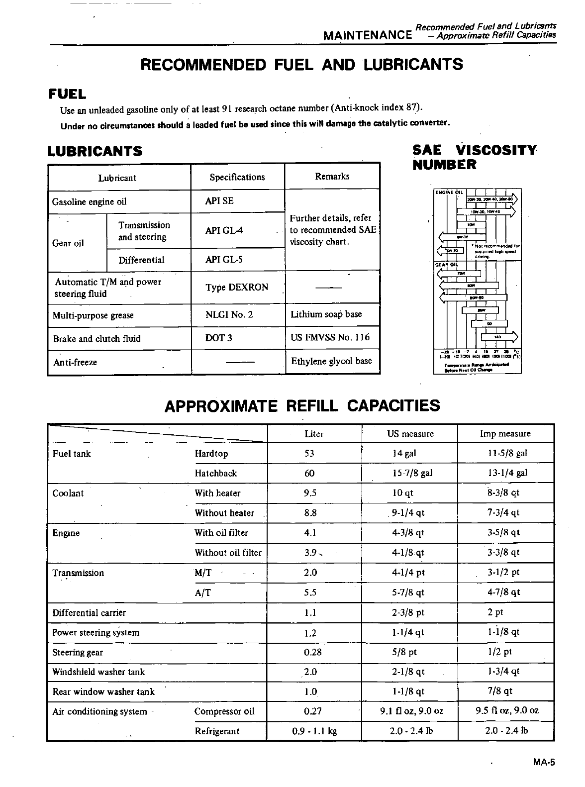
RECOMMENDED
FUEL
AND
LUBRICANTS
FUEL
Use
an
unleaded
gasoline
only
of
at
least
91 research
octane
number
Anti
knock
index
87
Under
no
circumstances
should
a
leaded
fuel
be
used
ince
this
will
damage
the
catalytic
converter
LUBRICANTS
SAE
VISCOSITY
NUMBER
Lubricant
Specifications
Remarks
Gear
oil
Transmission
and
steering
API
GL4
Further
details
refer
to
recommended
SAE
viscosity
chart
ENC
EOIL
I
I
III
0
I
ICM
211
JGIIf4l
I
t
l
1
lo
r
Gasoline
engine
oil
APISE
Anti
freeze
Ethylene
glycol
base
II
I
or
v
rJ
dri
I
I
I
I
l
I
I
r
I
I
I
1
I
1
I
I
I
I
I
I
r
1
I
I
40
I
II
II
1
1
TI
c
nII
OlIl
ll4OlllC11lllllll101
11 F
T
Jl
Nut
O
Ch
Differential
API
GL
5
Automatic
T
M
and
power
steering
fluid
Type
DEXRON
Multi
purpose
grease
NLGI
No
2
lithium
soap
base
Brake
and
clutch
fluid
DOT
3
US
FMVSS
No
116
APPROXIMATE
REFILL
CAPACITIES
liter
us
measure
Imp
measure
Fuel
tank
Hardtop
53
14gal
II
5
8
gal
Hatchback
60
15
78
gal
13
1
4
gal
Coolant
With
heater
9
5
IOqt
8
38
qt
Without
heater
8 8 9
1
4qt
7
3
4
ql
Engine
With
oil
filter
4
1
4
3
8
qt
3
5
8qt
Without
oil
filter
3
9
4
1
8
qt
3
38
ql
Transmission
M
T
2 0
4
1
4
pt
3
1
2
pt
A
T
55
5
7 8
qt
4 7 8
qt
Differential
carrier
11
2
3
8
pi
2
pt
Power
steering
system
1
2
11
4ql
I
1
8
ql
Steering
gear
0
28
5
8
pt
1
2
pt
Windshield
washer
tank
2 0
21
8
ql
13
4qt
Rear
window
washer
tank
1
0
1 1
8
qt
78
qt
Air
conditioning
system
Compressor
oil
0
27
91
f
OZ 9
0
oz 95
f
OZ 9 0
oz
Refrigerant
0
9
11
kg
2 0
2
4lb
2 0 2
41b
MA
5
Engine
Maintenance
MAINTENANC
E
BASIC
MECHANiCAL
SYSTEM
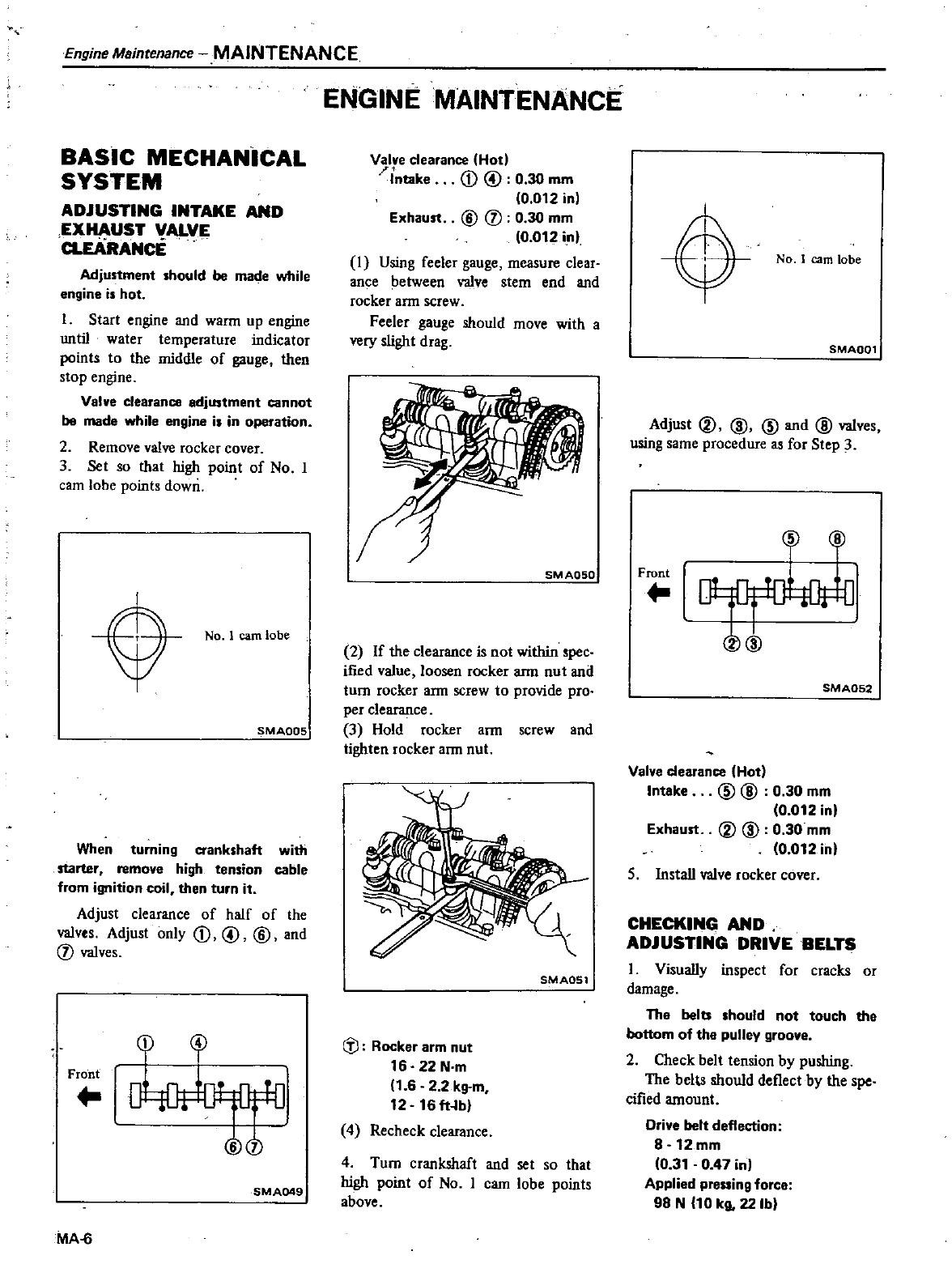
ADJUSTING INTAKE
AND
EXHAUST
VALVE
a
EARANCE
Adjustment
should
be made
while
engine
is
hot
I
Start
engine
and
warm
up
engine
until
water
temperature
indicator
points
to
the
middle
of
gauge
then
stop
engine
Valve
clearance
adjustment
cannot
be made
while
engine
is
in
operation
2
Remove
valve
rocker
cover
3
Set
so
that
high
point
of
No
I
cam
lobe
points
down
No
1
earn
lobe
SMA005
When
turning
crankshaft
with
starter
remove
high
tension
cable
from
ignition
coil
then
turn
it
Adjust
clearance
of
half
of
the
valves
Adjust
only
CD
@ @
and
j
valves
CD
4
Front
o
1lJf
Dt
DFJ
000
SMA049
MAS
ENGINE
MAINTENANCE
Valve
clearance
Hod
Intake
CD
@
0
30
mm
0
012
in
Exhaust
@
j
0
30
mm
10
012
i
n
I
Using
feeler
gauge
measure
clear
ance
between
valve
stem
end
and
rocker
arm
screw
Feeler
gauge
should
move
with
a
very
slight
drag
8M
AQSO
2
If
the
clearance
is
not
within
spec
ified
value loosen
rocker
arm
nut
and
turn
rocker
ann
screw
to
provide
pro
per
clearance
3
Hold
rocker
arm
screw
and
tighten
rocker
arm
nut
SMA051
dl
Rocker
arm
nut
16
22
N
m
1
6
22
kg
m
12
16
ft
b
4
Recheck
clearance
4
Turn
crankshaft
and
set
so
that
high
point
of
No
I
cam
lobe
points
above
0No
1
earn
lobe
SMA001
Adjust
ID ID @
and
@
valves
using
same
procedure
as
for
Step
3
@ @
Front
kG
D
tDf
OO
ID
SMA052
Valve
clearance
Hod
Intake
@ @
0
30
mm
0
012 in
Exhaust
ID ID
0
30
mm
0
012 in
5
Install
valve
rocker
cover
CHECKING
AND
ADJUSTING
DRIVE
BELTS
I
Visually
inspect
for
cracks
or
damage
Th
belts
should
not
touch
the
bottom
of
the
pulley
groove
2
Check
bell
tension
by
pushing
The
belts
should
deflect
by
the
spe
cified
amount
Drive
belt
deflection
8
12
mm
0
31
0
47
in
Applied prening
forc
98
N
10
kg
22lb
A
Loosen
to
adjust
I
t
f
J
r
Checking
point
of
drive
belt
deflection
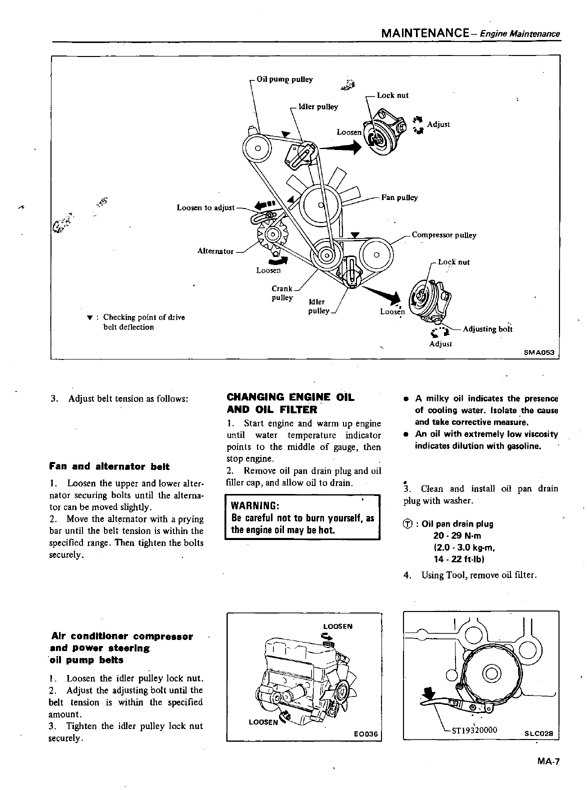
3
Adjust
belt
tension
as
follows
Fan
and
alternator
belt
I
Loosen
the
upper
and
lower
alter
nator
securing
bolts
until
the
alterna
tor
can
be
moved
slightly
2
Move
the
alternator
with
a
prying
bar
until
the
belt
tension
is
within
the
specified
range
Then
tighten
the
bolts
securely
Air
conditioner
compressor
and
power
steering
011
pump
belts
Loosen
the
idler
pulley
lock
nut
2
Adjust
the
adjusting
bolt
until
the
belt tension
is
within
the
specified
amount
3
Tighten
the
idler
puUey
lock
nut
securely
MAINTENANCE
Engine
Maintenance
Alternator
t
ilJ
J
Idler
puUey
LoCk
nut
Adjust
Loosen
Compressor
pulley
Crank
pulley
Idler
pulley
Adjusting
bolt
Adjust
8M
A053
CHANGING
ENGINE
OIL
AND
OIL
FILTER
1
Start
engine
and
warm
up
engine
until
water
temperature
indicator
points
to
the
middle
of
gauge
then
stop
engine
2
Remove
oil
pan
drain
plug
and
oil
fiUer
cap
and
allow
oil
to
drain
A
milky
oil
indicates
the
presence
of
cooling
water
Isolate
the
cause
and
take
corrective
measure
An
oil
with
extremely
low
viscosity
indicates
dilution
with
gasoline
3
Clean
and
install
oil
pan
drain
plug
with
washer
WARNING
Be
careful
not
to
burn
yourself
as
the
engine
oil
may
be
hot
IiJ
Oil
pan
drain
plug
20
29
N
m
2 0 3 0
kg
m
14 22
ft
lb
4
Using
Tool
remove
oil
fIlter
1
1
01
I
1
E0036
SLC028
MA
7
Engine
Maintenance
MAINTENANCE
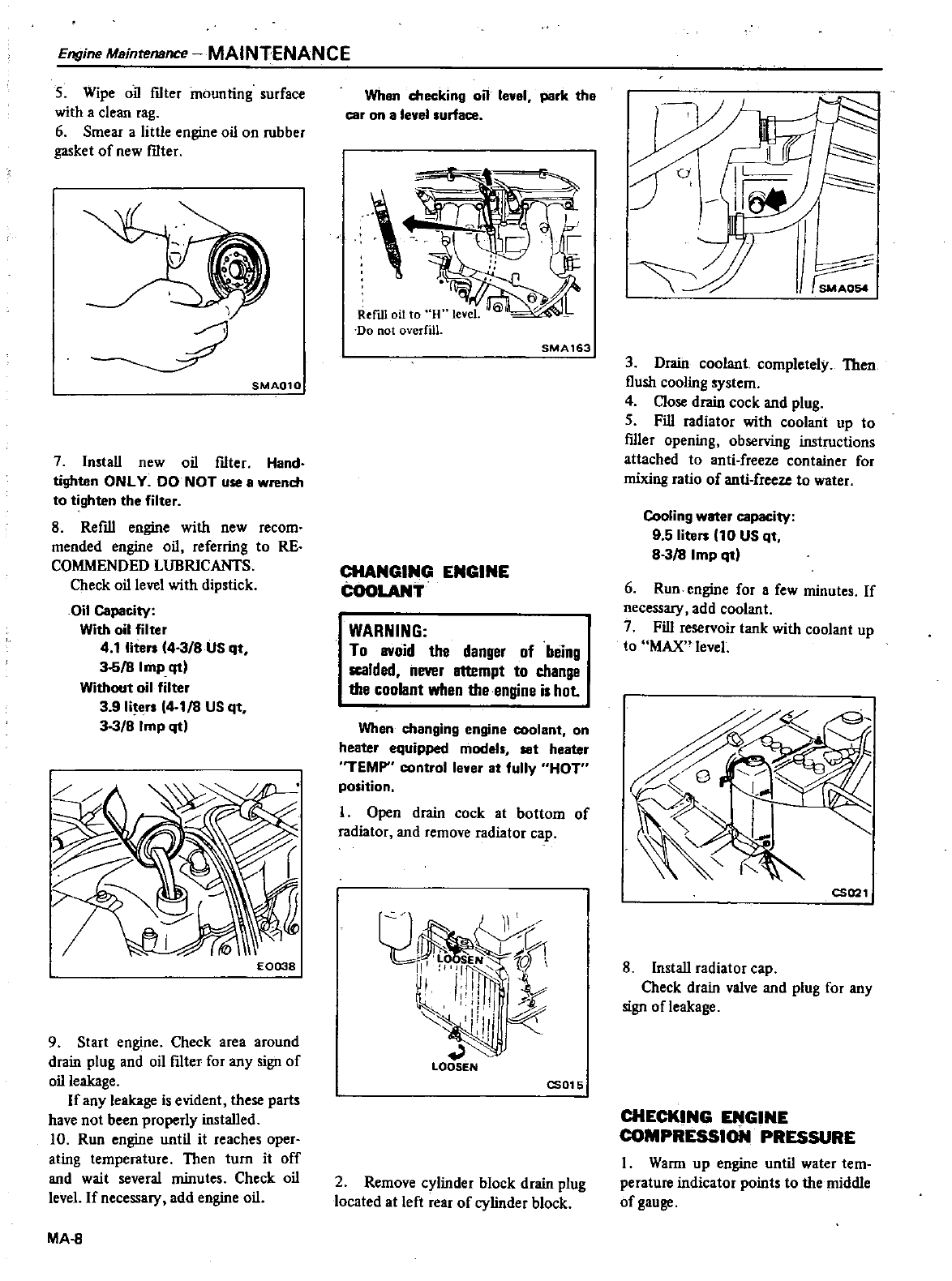
5
Wipe
oil
fIlter
mounting
surface
with
a
clean
rag
6
Smear
a
little
engine
oil
on
rubber
gasket
of
new
fIlter
SMA010
7Install
new
oil
fIlter
Hand
tighten
ONLY
DO
NOT
use a
wrench
to
tighten
the
filter
8
Refill
engine
with
new
recom
mended
engine
oil
referring
to
RE
COMMENDED
LUBRICANTS
Check
oil
level
with
dipstick
Oil
Capacity
With oil
filter
4
1
lite
4
3
8
US
qt
35
8
Imp
qt
Without
oil
filter
3 9
lite
4
18
US
qt
33
8
Imp
qt
E0038
9
Start
engine
Check
area
around
drain
plug
and
oil
fIlter
for
any
sign
of
oil
leakage
If
any
leakage is
evident
these
parts
have
not
been
properly
installed
10 Run
engine
until
it
reaches
oper
ating
temperature
Then
turn
it
off
and
wait
several
minutes
Check
oil
level
If
necessary
add
engine
oil
MA
8
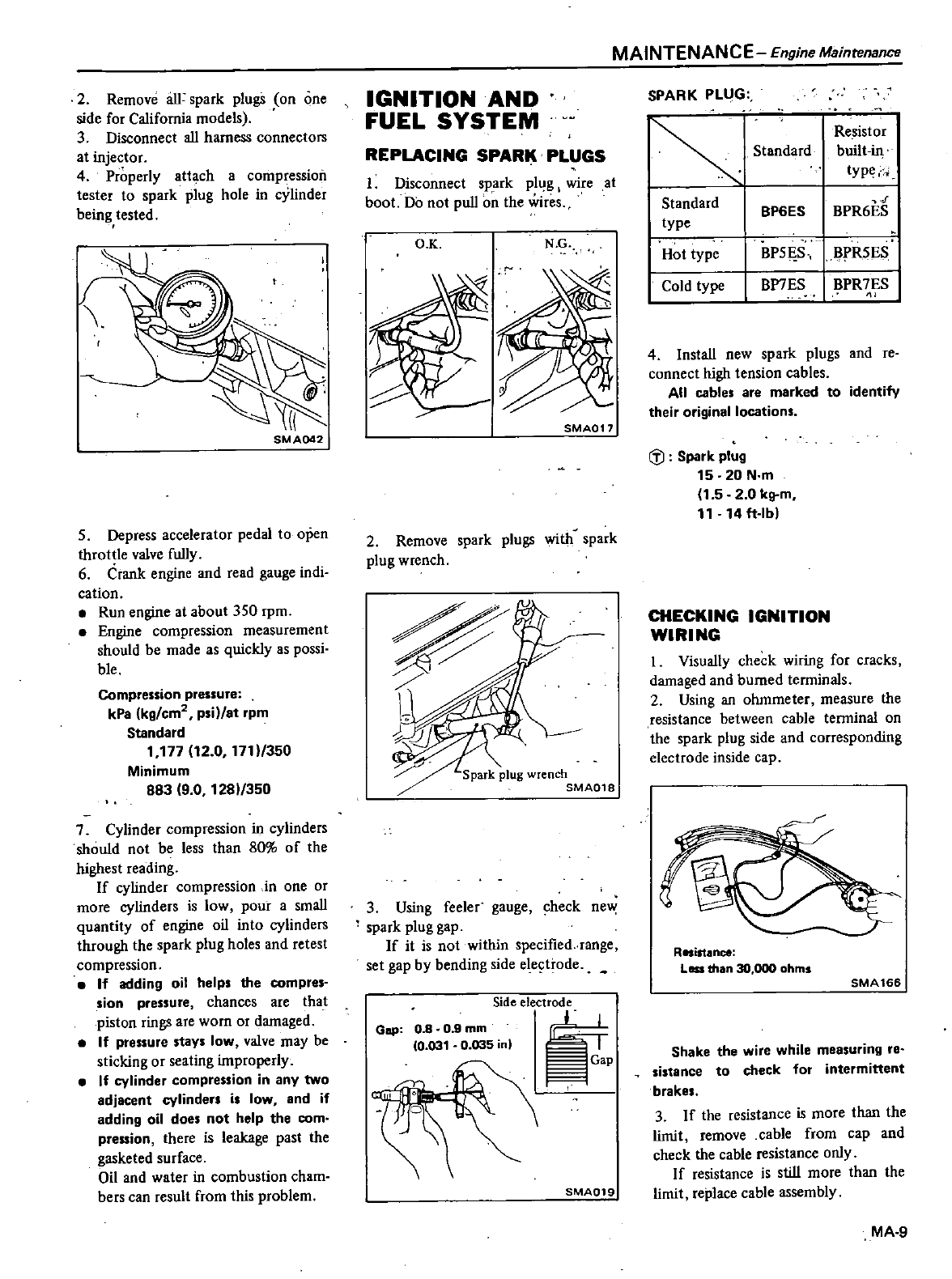
When
checking
on
level
park
the
ear
on
a
level
surface
v
SMA163
CHANGING
ENGINE
COOLANT
WARNING
To BVoid
the
danger
of
being
scalded
never
attempt
to
change
the
coolant when
the
engine
is
hot
When
changing
engine
coolant
on
heater
equipped
model
set
heater
TEMP
control
lever
at
fully
HOT
position
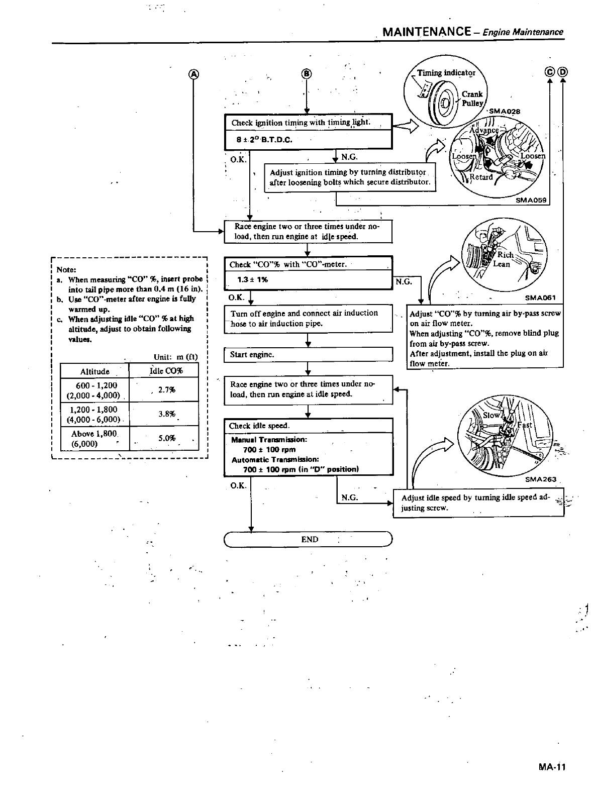
I
Open
drain
cock
at
bottom
of
radiator
and
remove
radiator
cap
r
l
ild
1xrC
rl
1
rli I
v
t
III
1
4
il
I
I
ll
LOOSEN
CS015
2
Remove
cylinder
block
drain
plug
located
at
left
rear
of
cylinder
block
W
F
O
3
Drain
coolant
completely
Then
flush
cooling
system
4
Close
drain
cock
and
plug
5
Fill
radiator
with
coolant
up
to
fIller
opening
observing
instructions
attached
to
anti
freeze
container
for
mixing
ratio
of
anti
freeze
to
water
Cooling
water
capacity
9 5
lite
10
US
qt
83
8
Imp
qtl
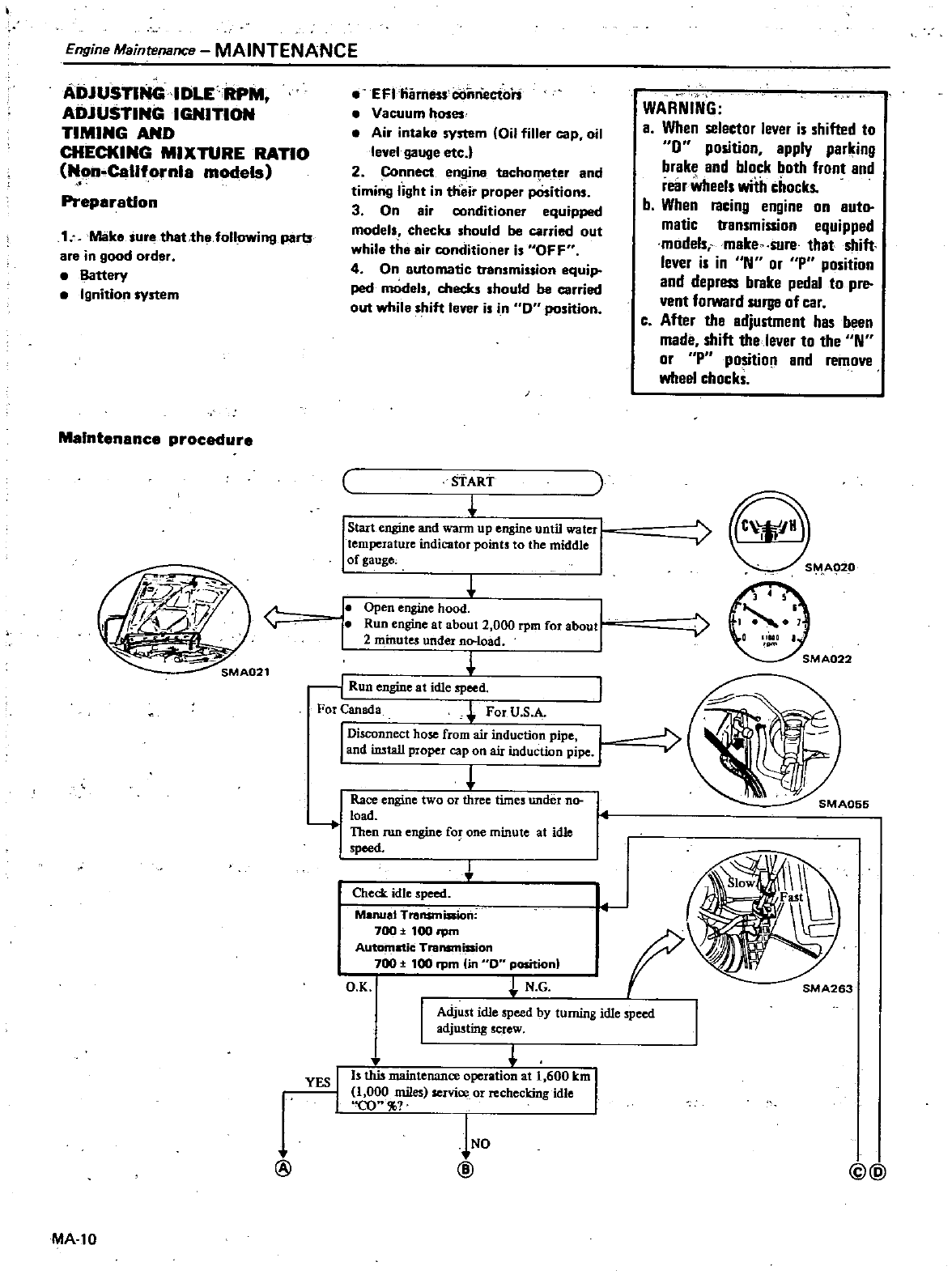
6
Run
engine
for
a
few
minutes
If
necessary
add
coolant
7
Fill
reservoir
tank
with
coolant
up
to
MAX
level
I
t
CS021
8
Install
radiator
cap
Check
drain
valve
and
plug
for
any
sign ofleakage
CHECKING
DiGINE
COMPRESSION
PRESSURE
I
Warm
up
engine
until water
tem
perature
indicator
points
to
the
middle
of
gauge
2
Remove
au
spark
plugs
on
one
side
for
California
models
3
Disconnect
all
harness
connectors
at
injector
4
Properly
attach
a
compression
tester to
spark
plug
hole
in
cylinder
being
tested
8M
A042
S
Depress
accelerator
pedal
to
open
throttle
valve
fully
6
Crank
engine
and
read
gauge
indi
cation
Run
engine
at
about
350
rpm
Engine
compression
measurement
should
be
made
as
quickly
as
possi
ble
Compression
pressure
kPa
kg
em
ps
at
rpm
Standard
1
177
12
0
171
350
Minimum
883
9 0
1281
350
7
Cylinder
compression
in
cylinders
should
not
be
less
than
80
of
the
highest
reading
If
cylinder
compression
in
one
or
more
cylinders
is
low
pour
a
small
quantity
of
engine
oil
into
cylinders
through
the
spark
plug
holes
and
retest
compression
If
adding
oil
helps
the
compres
sion
pressure
chances
are
that
piston
rings
are
worn
or
damaged
If
pressure
stays
low
valve
may
be
sticking
or
seating
improperly
If
cylinder
compression
in
any
two
adjacent
cylinders
i
low
and
if
adding
oil
doe
not
help
the
com
pression
there
is
leakage
past
the
gasketed
surface
Oil
and
water in
combustion
cham
bers
can
result
from
this
problem
IGNITION
AND
FUEL
SYSTEM
REPLACING
SPARK
PLUGS
I
Disconnect
spark
plug
wire
at
boot
Do
not
pull
o
the
wires
O
K
N
G
SMAO
1
7
2
Remove
spark plugs
with
spark
plug
wrench
3
Using
feeler
gauge
check
new
spark
plug
gap
If
it
is
not
within
specified
range
set
gap
by
bending
side
ele
trode
Side
electrode
if
Gap
08 0 9mm
10
03t
0
035
1
SMA019
MAINTENANCE
Engine
Maintenance
SPARK
PLUG
Re
sistor
Standard
built
iJl
type
Standard
BP6ES
BPR6ES
type
Hot
type BPSES
BPRSES
Cold
type
BP7
ES
BPR7ES
4Install
new
spark
plugs
and
re
connect
high
tension
cables
All
cable
are
marked
to
identify
their
original
locations
iYJ
Spark
plug
15 20
N
m
1
52 0
kg
m
11
14
ft
Ibl
CHECKING
IGNITION
WIRING
I
Visually
check
wiring
for
cracks
damaged
and
burned
terminals
2
Using
an
ohmmeter
measure
the
resistance
between
cable
tenninal
on
the
spark
plug
side
and
corresponding
electrode
inside
cap
Resistance
Less
than
30
000
ohms
SMA
166
Shake
the
wire
while
measuring
re
sistanee
to
check
for
intermittent
brake
3
If
the
resistance
is
more
than
the
limit
remove
cable
from
cap
and
check
the
cable
resistance
only
If
resistance
is
still
more
than
the
limit
replace
cable
assembly
MA
9
Engine
Maintenance
MAINTENANCE
ADJUSTlNGIDLERPM
ADJUSTING
IGNITION
TIMING
AND
CHECKING
MIXTURE
RATIO
Non
California
models
Preparation
1
Mako
sure
thauhofollowing
parts
are
in
good
order
Battery
Ignition
system
Maintenance
procaclure
MA
l0
Efl
ilrness
cOi
riecti
ri
Vacuum
hoses
Air
intako
system
Oil
filler
cap
oil
level
gauge
etc
2
Connect
engine
tacho
ter
and
timing
light
in
dieir
proper
pOsitions
3
On
air
conditioner
equipped
mode
s
checks
should
be
carried
out
whilo
tho oi
conditioner
is
OFF
4
On
automatic
transmiuion
equip
peel
modols
checks
should
be
carried
out
while
s
ift
lever
is
in
O
position
START
Start
engine
and
wann
up
engine
until
water
temperature
indicator
points
to
the
middle
I
of
gauge
Open
engine
hood
Run
engine
at
about
2
000
rpm
for
abou
2
undet
no
load
WARNING
a
WIlen
selector
lever
is
shifted
to
0
position
apply
parking
brake
and
block
both
front
and
reanvheels
with
chocks
b
When
racing
engine
on
auto
matic
transmission
equipped
modelsimake
sure
that
shift
lever is in
N
or
P
position
and
depress
brake
pedal
to
pre
vent
forward
SUI
8
of
car
cAfter
tha
adjustment
has
been
made
shift thelever
to
the
N
or
P
position
and
remove
wheel
chocks
E
1
Run
engine
at
idle
speed
For
Canada
For
U
S
A
I
Di
nnect
hose
from air
induction
pipe
and
amtall
proper
cap
on
air
induction
pipe
t
Race
engine
two
or
three
times
under
no
load
Then
run
engine
for
one
minute
at
idle
speed
Check
idle
speed
M
nuai
lransmiRion
7oo
t
100
tpm
Autom
w
ic
Transmission
700
100
rpm
in
D
position
O K
j
N
G
I
Adjust
idle
SPeed
by
turning
idle
opeed
adjusting
screw
j
b
this
maintenance
operation
at
1
600
km
I
1
000
miles
service
or
rechecking
idle
CO
INO
@
YES
I
I
bg
@
r
Note
a
When
measuring
CO
iniert
probe
I
into
tail
pipe
more
than
04m
16
in
J
b
Use
CO
meter
alter
engine
is fully
warmed
up
e
When
adjusting
idle CO
at
high
altitude
adjust
to
obtain
following
valua
Altitude
Unit
m
ft
fdte
00
2
7
600
t
200
2
000
4
000
1
200
1
800
4
000
6
000
Above
1
800
6
000
3 8
5
0
L
J
N
G
I
Adjust
ignition
timin
g
by
turn
g
di
tri ut
r
1
after
loosening
bolts
which
secure
distributor
i
of
Check
ignition
ti
ing
with
ir
ning
t
8
f
20 B
T DC
O
K
I
Race
erigine
two
or
three
times
under
00
I
load
then
run
engine
at
idle
speed
Check
CO
with
CO
meter
1
3
t
1
OK
I
Turn
off
engine
and
connect
air
induction
rhose
to
air
induction
pipe
i
Start
engine
Race
engine
two
or
three
times
under
no
load
then
run
engine
at
idle
speed
I
Check
idle
speed
M
nu
1
Transmission
700
t
100
rpm
Automatic
Tr
nsmission
71100
rpm
in
0
position
O K
I
N G
END
MAINTENANCE
Engine
Maintenance
@@
f
SMA059
If
SMA061
Adjust
CO
by
turning
air
by
pass
screw
on
air
flow
meter
When
adjusting
CO
remove
blind
plug
from air
by
pass
screw
After
adjustment
install
the
plug
on
air
flow
meter
r
r
SMA263
I
Adjust
idle
speed
by turning
idle
speed
ad
justing
screw
L
l
MA
ll
i
ntIine
M
itit
ance
MAINTENANCE
ADJUSTING
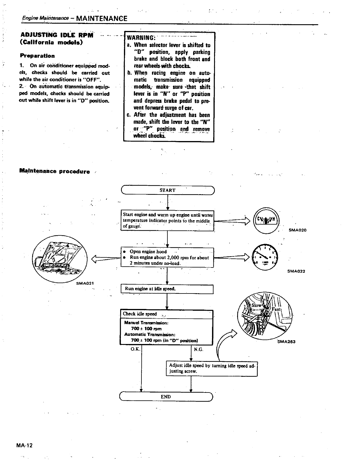
IDLE
RPM
California
models
Preparation
1
On
air
conditioner
equiPPed
mod
els
checks
should
be
carried
out
while
the
air
conditioner
is
OFF
2
On
automatic
transmission
equip
ped
models
checks
should
be
carried
out
while
shift
lever
is
in
Ou
position
Intenailce
procedure
MA
12
WARNING
a
When
selector
lever
is
shifted
to
0
position apply
parking
brake
and
block
both
front
and
fear
wheels
with
chocks
b
Whe
racing
engine
on
auto
matic
transmission
equipped
models
make
sure
that
shift
lever
is
in
N
or
Pposition
and
depress
brake
pedal
to pre
vent
forward
surge
of
car
c
After
the
adjlUtrDent
has
been
made
shift
the
lever
to
the
N
or
Pposition
and
remove
wheel
chockS
START
1
Start
engine
and
warm
up
engine
until
water
temperature
indicatQf
points
to
the
middle
of
gauge
j
Open
engine
hood
Run
engine
about
2
000
rpm
for
about
2
minutes
undeJ
no
load
1
Run
eDsine
at
Idle
speed
1
Check
idle
speed
Ma
al
Tl
Bnsmiaion
700
100
rpm
Automatic
Transmission
700
f
1
rpm
Un
D
position
f
O
K
tG
8
SMA020
SMA022
SMA263
I
dj
st
idle
speed
by
turning
idle
speed
ad
I
JustJ
IJg
screw
1
END
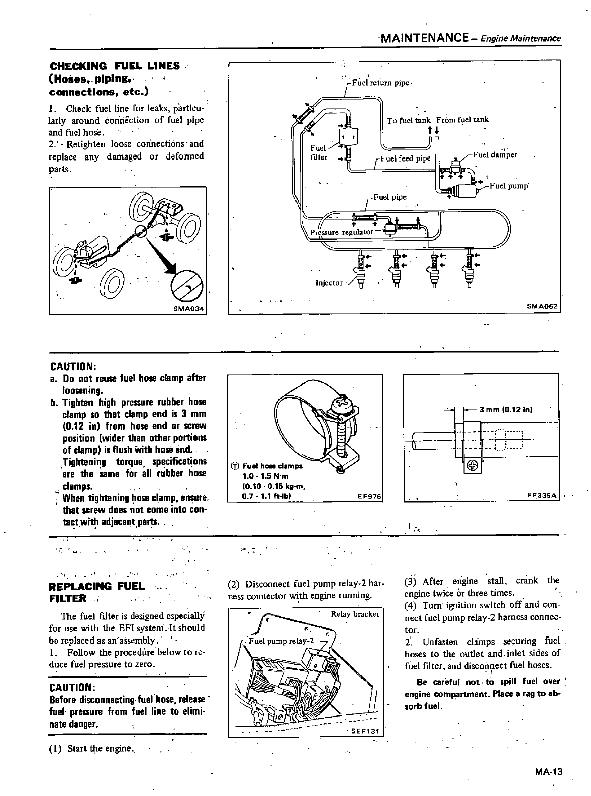
CHECKING
FUEL
LINES
Hoses
piping
connections
etc
I
Check
fuel
line
for
leaks
particu
larly
around
connection
of
fuel
pipe
and
fuel
hose
2
Retighten
loose
connections
and
replace
any
damaged
or
defonned
parts
SMA034
CAUTION
a
00
not
reuse
fuel
hose
clamp
after
loosening
b
Tighten
high
pressure
rubber
hose
clamp
so
that
clamp
end
is
3
mm
0
12
in
from
hose
end
or
screw
position
wider
than
other
portions
of
clamp
is
flush
With
hose
end
Tightening
torque
specifications
are
the
Same
for
all
rubber
hose
clamps
When
tightening
ose
clamp
8n
ure
that
screw
does
not
come
into
con
tact
with
adjacent
parts
REPLACING
FUEL
FILTER
The
fuel
fIlter
is
designed
especially
for
use
with
the
EFI
systerri
It
should
be
replaced
as
an
assembly
I
Follow
the
procedure
below
to
re
duce
fuel
pressure
to
zero
CAUTION
Before
disconnecting
fuel
hose release
fuel
pressure
from
fuel
line
to
elimi
nate
danger
I
Start
the
engine
MAINTENANCE
Engine
Maintenance
Fuel
return
pipe
l
To
fuel
tan
rbm
f
el
tank
rFue
pipe
Fuel
damper
t
Fuel
pump
r
Fuel
pipe
l
tr
btor
J
J
Jf
1j
Injector
W W W
J
Fuel
hose
clamps
1
0
1
5N
m
10
10
0
15
kg
m
07
1 1
ft
Ibl
E
F976
2
Disconnect
fuel
pump
relay
2
har
ness connector
with
engine
runnin
Relay
bracket
SEF131
SMA062
1
3mmlo
12inl
fl
f
I
E
F336A
3
After
engine
stall
crank
the
engine
twice
or
three
times
4
Turn
ignition
switch
off
and
con
nect
fuel
pump
relay
2
hamess
connec
tor
2
Unfasten
clamps
securing
fuel
hoses
to
the
outlet
and
inlet
sides
of
fuel
fIlter
and
disconnect fuel
hoses
Be
careful
not
to
spill
fuel
over
engine
comP
lrtment
Place
a
rag
to
ab
so
b
fuel
MA
13
Engine
Maintenanpe
MAINTENANCE
3
Remove
fuel
mter
I
V
tJl
SMA264
4
To
instaIl fuel
mter
reverse
the
order
of
removal
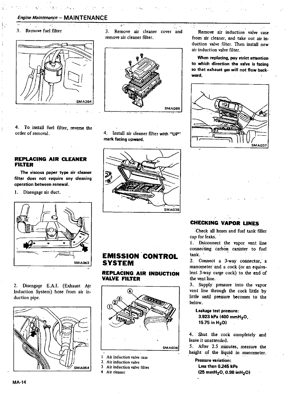
REPLACING
AIR
CLEANER
FILTER
The
viscous
paper
type
air
cleaner
filter
does
not
require
any
deaning
operation
between
renewal
Disengage
air
duct
I
1
SMA063
2
Disengage
EAt
Exhaust
Air
Induction
System
hose
from air
in
duction
pipe
r
J
MA
14
3
Remove
air
cleaner
cover
and
remove
air
cleaner
ftIter
SMA065
4
InstaIl
air
cleaner
mter
with
UP
mark
facing
upward
SMA039
EMISSION
CONTROL
S
YSTEM
REPLACING
AIR
INDUCTION
VALVE
FILTER
SMA036
1
Air
induction
valve
case
2
Air
induction
valve
3
Air
induction
valve
rdter
4
Air
cleaner
Remove
air
induction
valve
case
from
air
cleaner
and
take
out
air
in
duction
valve
fIlter
Then
instaIl
new
air
induction
valve
filter
When
replacing
pay
strict
attention
to
which
direction
the
valve
i
facing
so
that
exhaust
gas
will
not
flow back
ward
J
1
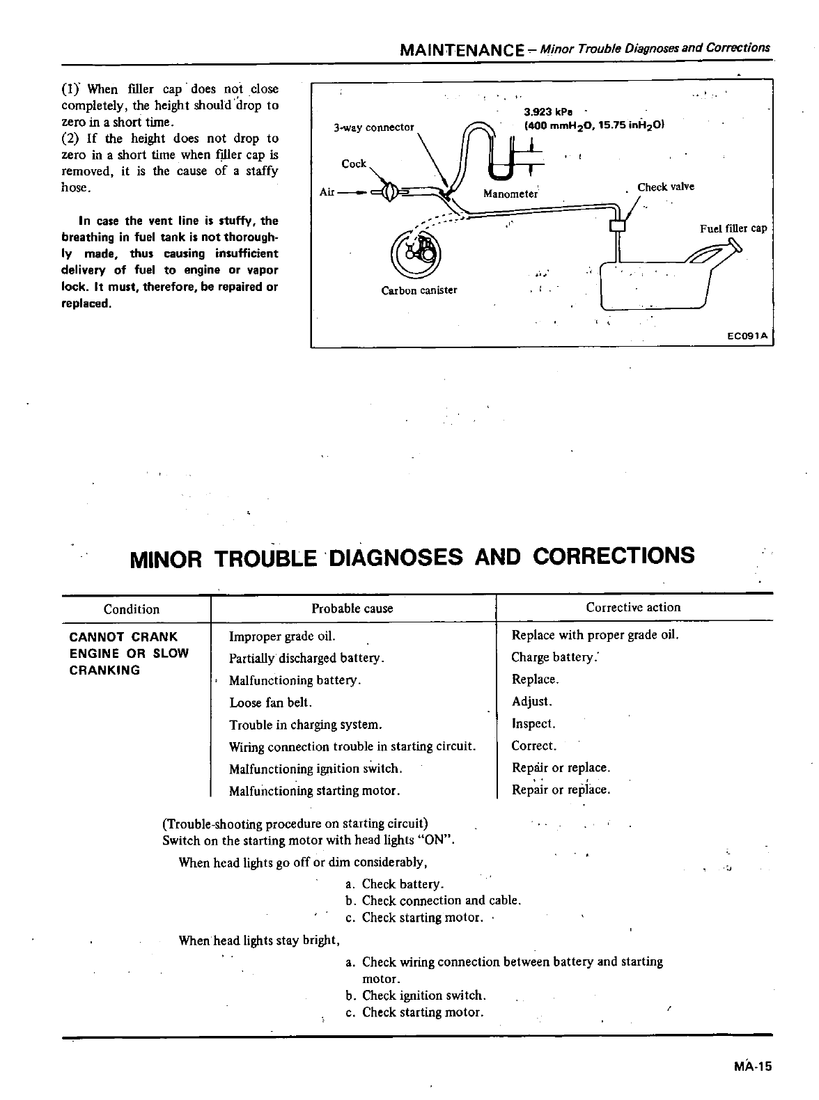
CHECKING
VAPOR
LINES
Check
all
hoses
and fuel
tank
filler
cap
for
leaks
I
Dsiconnect
the
vapor
vent
line
connecting
carbon
canister
to
fuel
tank
2
Connect
a
3
way
connector
a
manometer
and
a
cock
or
an
equiva
lent
3
way
carge
cock
to
the
end
of
the
vent
line
3
Supply
pressure
into
the
vapor
vent
line
tIuough
the
cock
little
by
little until
pressure
becomes
to
the
below
Leakage
test
pressure
3
923
kPa
400
mmll20
15
75
in
H20
4
Shut
the
cock
completely
and
leave
it
unattended
5
After
25
minutes
measure
the
height
of
the
liquid
in
manometer
Pressure
variation
Less
then
0245
kPe
25
mmH20
0 98
inH201
MAINTENANCE
Minor
Trouble
Diagnoses
and Corrections
I
Y
When
filler
cap
does
not
close
completely
the
height
should
drop
to
zero
in
a
short
time
2
If
the
height
does
not
drop
to
zero
in
a
short
time
when iller
cap
is
removed
it
is
the
cause
of
a
staCfy
hose
AII
@
In
case the
vent
line
is
stuffy
the
breathing
in
fuel
tank
is
not
thorough
ly
made
thus
causing
insufficient
delivery
of
fuel
to
engine
or
vapor
lock
It
must
therefore
be
repaired
or
replaced
Carbon
canister
3
923
kPII
400
mmH20
15 75
inH20
Manometer
Check
valve
Fuel
filler
cap
1
EC091A
MINOR
TROUBLE
DIAGNOSES
AND
CORRECTIONS
Condition
Probable
cause
CANNOT
CRANK
ENGINE
OR
SLOW
CRANKING
Improper
grade
oil
Partially
discharged
battery
Malfunctioning
battery
Loose
fan
belt
Trouble
in
charging
system
Wiring
connection
trouble
in
starting
circuit
Malfunctioning
ignition
switch
Malfunctioning
starting
motor
Corrective
action
Replace
with
proper
grade
oil
Charge
battery
Replace
Adjust
Inspect
Correct
Repair
or
replace
Repair
or
replace
Trouble
shooting
procedure
on
starting
circuit
Switch
on
the
starting
motor
with
head
lights
ON
When
head
lights
go
off
or
dim
considerably
a
Check
battery
b
Check
connection
and
cable
c
Check
starting
motor
Whenhead
lights
stay
bright
a
Check
wiring
connection
between
battery
and
starting
motor
b
Check
ignition
switch
c
Check
starting
motor
MA
15
Minor
TrrJUbleDiagnoses
end
Correctiops
MAINTENANCE
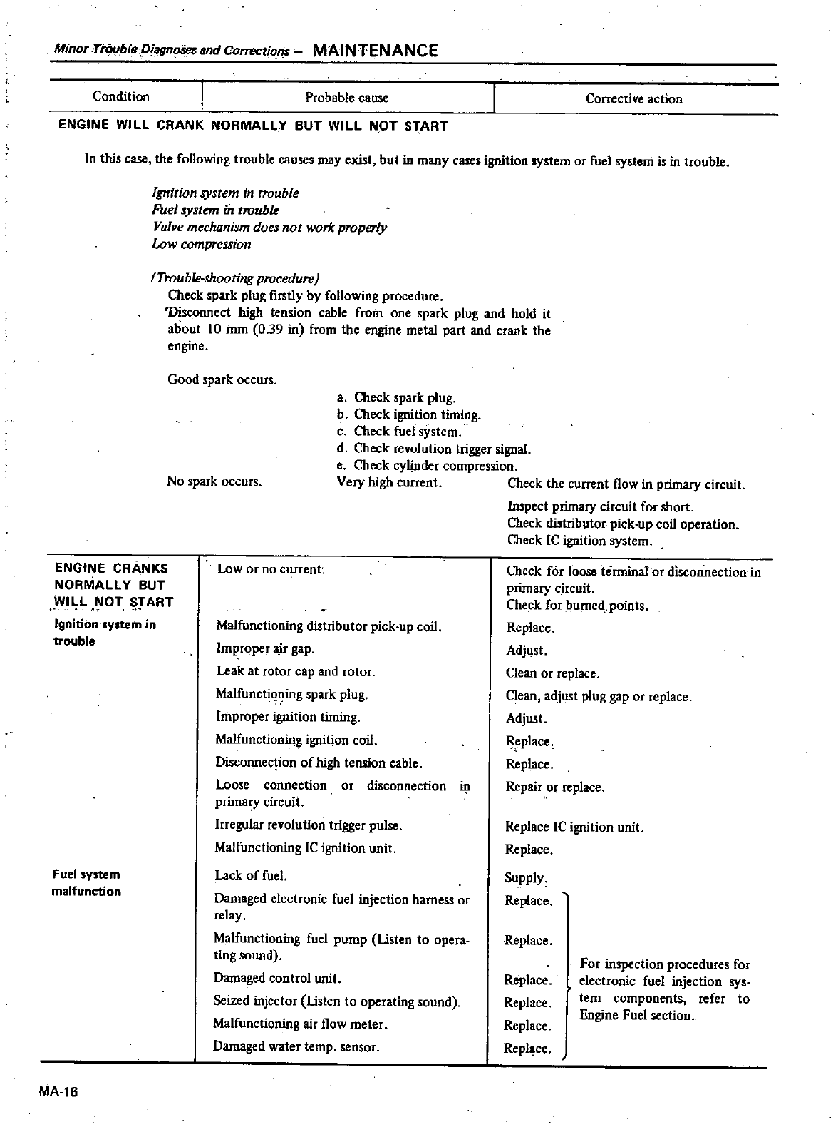
Condition
ENGINE
WILL
CRANK
NORMALLY
BUT
WILL
NOT
START
Probable
cause
Corrective
action
In this
case
the
following
trouble
causes
may
exist
but
in
many
cases
ignition
system
or
fuel
system
i1
in
trouble
Ignition
system
in
trouble
Fuel
system
in
troubk
Valve
mecluznism
does
not
work
properly
Low
compression
Trouble
shooting
procedure
Check
spark
plug
fIrstly
by
following
procedure
Disconnect
high
tension
cable
from
one
spark
plug
and
hold
it
about
10
mm
0
39
in
from
the
engine
metal
part
and
crank
the
engine
ENGINE
CRANKS
NORMALLY
BUT
WI
L
OT
5
ART
Ignition
system
in
trouble
Fuel
system
malfunction
MA
16
Good
spark
occurs
a
Check
spark
plug
b
Check
ignition
timing
c
Check
fuel
system
d
Check
revolution
trigger
signal
e
Check
cylinder
compression
Very
high
current
Check
the
current
flow
in
primary
circuit
Inspect
primary
circuit
for
short
Check
distributor
pick
up
coil
operation
Check
IC
ignition
system
No
spark
occurs
Low
or
no
cunenL
Malfunctioning
distributor
pick
up
coil
Improper
air
gap
Leak
at
rotor
cap and
rotor
Malfunctiflning spark
plug
Improper
ignition
timing
Malfunctioning
ignition
coil
Disconnection
of
high
tension
cable
Loose
connection
or
disconnection
41
primary
circuit
Irregnlar
revolution
trigger
pulse
Malfunctioning
IC
ignition
unit
Lack
of
fuel
Damaged
electronic
fuel
injection
harness
or
relay
Malfunctioning
fuel
pump
Usten
to
opera
ting
sound
Damaged
control
unit
Seized
injector
Usten
to
operating
sound
Malfunctioning
air
flow
meter
Damaged
water
temp
sensor
Check
for
loose
terminal
or
disconnection
in
primary
circuit
Check
for
burned
points
Replace
Adjust
Clean
or
replace
Clean
adjust
plug
gap
or
replace
Adjust
Replace
Replace
Repair
or
replace
Replace
IC
ignition
unit
Replace
Supply
Replace
Replace
Replace
Replace
Replace
Repl
ce
For
inspection
procedures
for
electronic
fuel
injection
sys
tern
components
refer
to
Engine
Fuel
section
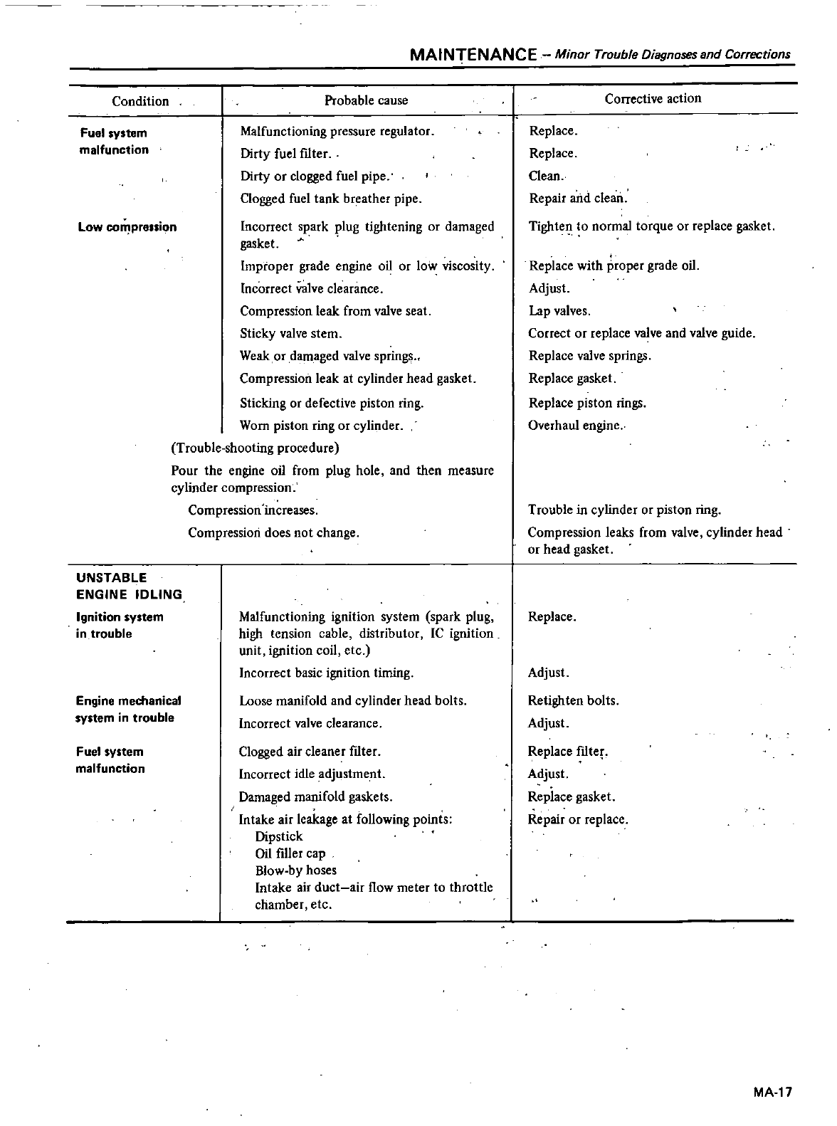
Condition
Fuel
system
malfunction
Low
co
prellion
UNSTABLE
ENGINE
IDLING
Ignition
system
in
trouble
Engine
mechanical
system
in
trouble
Fuel
system
malfunction
MAINTENANCE
Minor
Trouble
Diagnoses
and
Corrections
Probable
cause
Malfunctioning
pressure
regulator
Dirty
fuel
f1lter
Dirty
or
clogged
fuel
pipe
Clogged
fuel
tank
breather
pipe
Incorrect
spark
plug
tightening
or
damaged
gasket
Improper grade
engine
oil
or
low
viscosity
Incorrect
valve
clearance
Compression
leak
from
valve
seat
Sticky
valve
stem
Weak
or
damaged
valve
springs
Compression
leak
at
cylinder
head
gasket
Sticking
or
defective
piston
ring
Worn
piston
ring
or
cylinder
Trouble
shooting
procedure
Pour
the
engine
oil from
plug
hole
and
then
measure
cylinder
compression
Compression
increases
Compression
does
not
change
Malfunctioning
ignition
system
spark
plug
high
tension
cable
distributor
IC
ignition
unit
ignition
coil
etc
Incorrect
basic
ignition
timing
Loose
manifold
and
cylinder
head
bolts
Incorrect
valve
clearance
Clogged
air
cleaner
f1lter
Incorrect
idle
adjustme
nt
Damaged
manifold
gaskets
Intake
air
leakage
at
following
points
Dipstick
Oil
filler
cap
Blow
by
hoses
Intake
air
duct
air
flow
meter
to
throttle
chamber
etc
Corrective
action
Replace
Replace
Clean
Repair
and
clean
Tightefl
to
normal
torque
or
replace
gasket
Replace
with
proper
grade
oil
Adjust
Lap
valves
Correct
or
replace
valve
and
valve
guide
Replace
valve
springs
Replace
gasket
Replace
piston
rings
Overhaul
engine
Trouble
in
cylinder
or
piston
ring
Compression
leaks
from
valve cylinder
head
or
head
gasket
Replace
Adjust
Retighten
bolts
Adjust
Replace
f1lte
Adjust
Replace
gasket
Repair
or
replace
MA
17
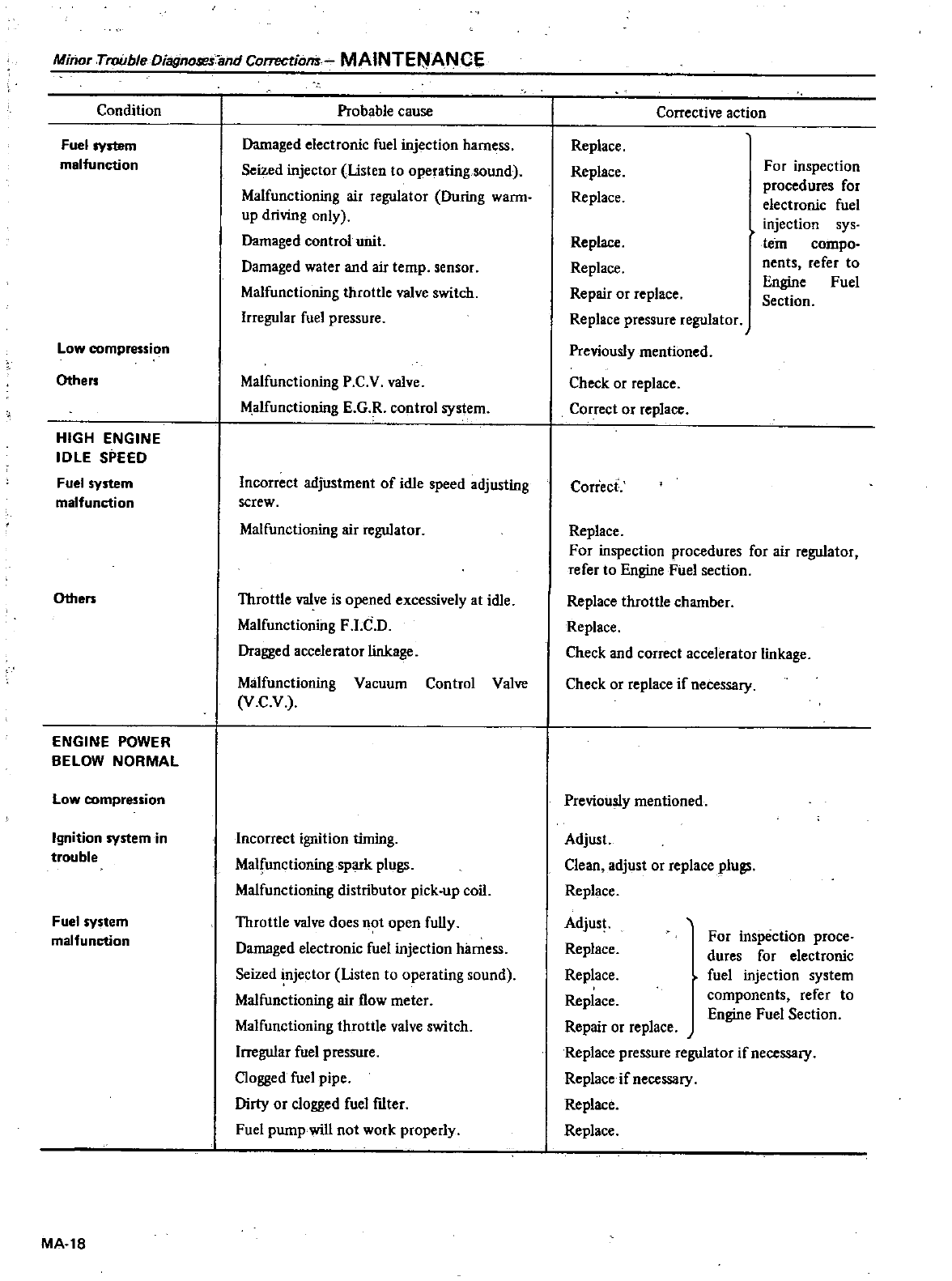
Minor
Trouble
DiagnolJt
s
and
Correctiom
MAINTE
ANCE
Condition
Fuel
system
malfunction
Low
compression
Others
HIGH
ENGINE
IDLE
SPEED
Fuel
system
malfunction
Others
ENGINE
POWER
BELOW
NORMAL
Low
compression
Ignition
system
in
trouble
Fuel
system
malfunction
MA
18
Probable
cause
Damaged
electronic
fuel
injection
harness
Seized
injector
Usten
to
operating
sound
Malfunctioning
air
regulator
During
warm
up
driving
only
Damaged
control
unit
Damaged
water
and
air
temp
sensor
Malfunctioning
throttle
valve
switch
Irregular
fuel
pressure
Malfunctioning
P
C
V
valve
Malfunctioning
E
G R
control
system
Incorrect
adjustment
of
idle
speed
adjusting
screw
Malfunctioning
air
regulator
Throttle
valve
is
opened
excessively
at
idle
Malfunctioning
F
I
C
D
Dragged
accelerator
linkage
Malfunctioning
Vacuum
Control
Valve
V
C
V
Incorrect
ignition
timing
Malfunctioning
spark
plugs
Malfunctioning
distributor
pick
up
coil
Throttle
valve
does
not
open
fully
Damaged
electronic
fuel
injection
harness
Seized
injector
Usten
to
operating
sound
Malfunctioning
air
flow
meter
Malfunctioning
throttle
valve
switch
Irregular
fuel
pressure
Clogged
fuel
pipe
Dirty
or
clogged
fuel
ftIter
Fuel
pwnp
will
not
work
properly
Corrective
action
Replace
Replace
Replace
For
inspection
procedures
for
electronic
fuel
injection
sys
tern
compo
nents
refer
to
Engine
Fuel
Section
Replace
Replace
Repair
or
replace
Replace
pressure
regulator
Previously
mentioned
Check
or
replace
COrrect
or
replace
Correct
Replace
For
inspection
procedures
for
air
regulator
refer
to
Engine
Fuel
section
Replace
throttle
chamber
Replace
Check
and
correct
accelerator
linkage
Check
or
replace
if
necessary
Previously
mentioned
Adjust
Clean
adjust
or
replace
plugs
Replace
Adjust
Replace
Replace
Replace
Repair
or
replace
Replace
pressure
regulator
if
necessary
Replace
if
necessary
Replace
Replace
For
inspection
proce
dures
for
electronic
fuel
injection
system
components
refer
to
Engine
Fuel
Section
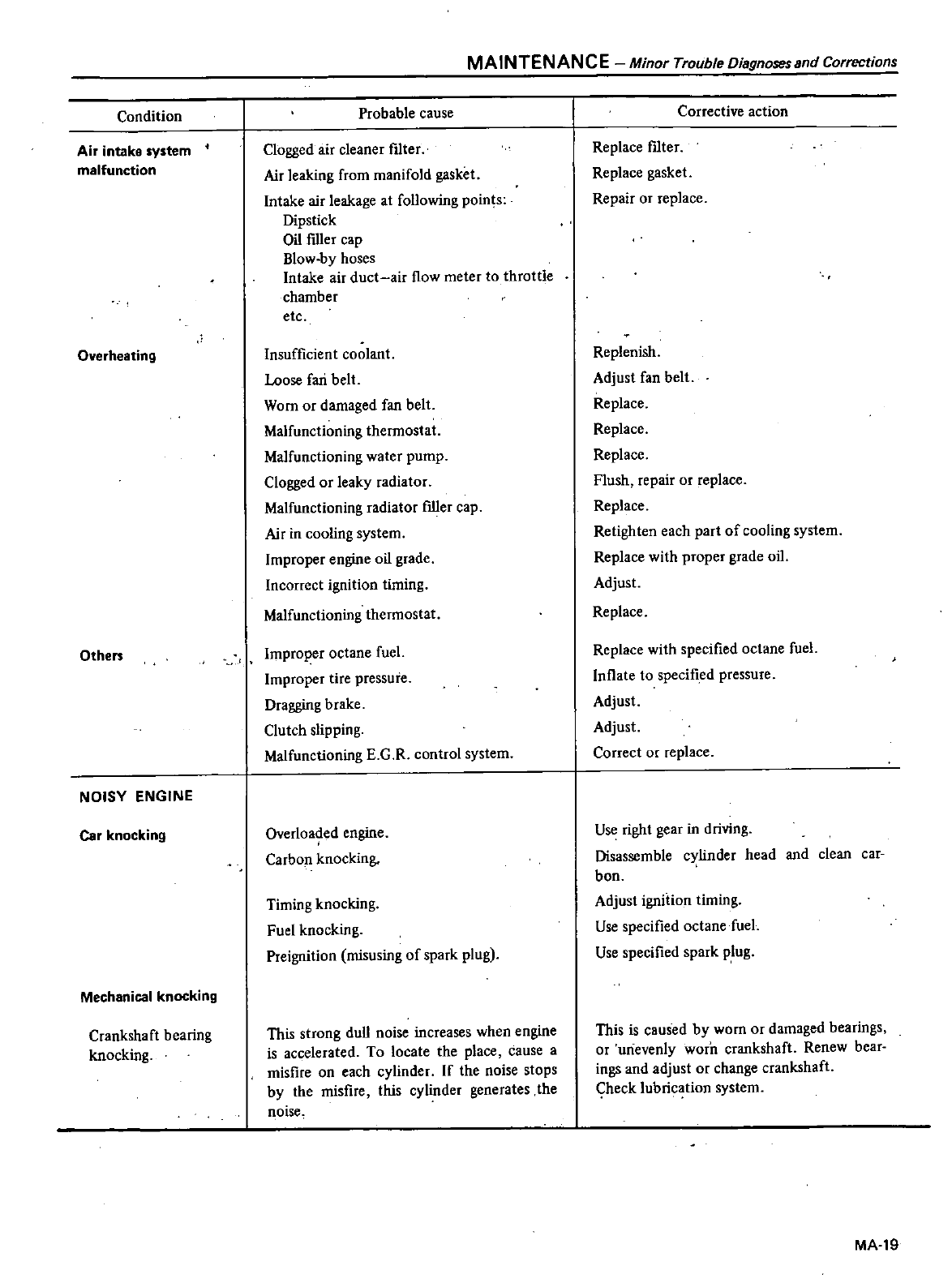
Condition
Air
intake
system
malfunction
Overheating
Othe
NOISY
ENGINE
Car
knocking
Mechanical
knocking
Crankshaft
bearing
knocking
MAINTENANCE
Minor
Trouble
Diagnosessnd
Corrections
Probable
cause
Clogged
air
cleaner
filter
Air
leaking
from
manifold
gasket
Intake
air
leakage
at
following
points
Dipstick
Oil
ftller
cap
Blow
by hoses
Intake air
duct
air
flow
meter
to
throttle
chamber
etc
Insufficient
coolant
Loose
fari
belt
Worn
or
damaged
fan
belt
Malfunctioning
thermostat
Malfunctioning
water
pump
Clogged
or
leaky
radiator
Malfunctioning
radiator
ftller
cap
Air
in
cooling
system
Improper
engine
oil
grade
Incorrect
ignition
timing
Malfunctioning
thermostat
Improper
octane
fuel
Improper
tire
pressure
Dragging
brake
Clutch
slipping
Malfunctioning
E
G
R
control
system
Overloaded
engine
Carbon
knocking
Timing
knocking
Fuel
knocking
Preignition
misusing
of
spark
plug
This
strong
dull
noise
increases
when
engine
is
accelerated
To
locate
the
place
cause
a
misfire
on
each
cylinder
If
the
noise stops
by
the
misfire
this
cylinder
generates
the
noise
Corrective
action
Replace
filter
Replace
gasket
Repair
or
replace
Replenish
Adjust
fan
belt
Replace
Replace
Replace
Flush
repair
or
replace
Replace
Retighten
each
part
of
cooling
system
Replace
with
proper
grade
oil
Adjust
Replace
Replace
with
specified
octane
fuel
Inflate
to
specified
pressure
Adjust
Adjust
Correct
or
replace
Use
right
gear
in
driving
Disassemble
cylinder
head
and
clean
car
bon
Adjust
ignition
timing
Use
specified
octane
fuel
Use
specified
spark
plug
This
is
caused
by
worn
or
damaged
bearings
or
unevenly
worD
crankshaft
Renew
bear
ings
and
adjust
or
change
crankshaft
Check
lubrication
system
MA
19
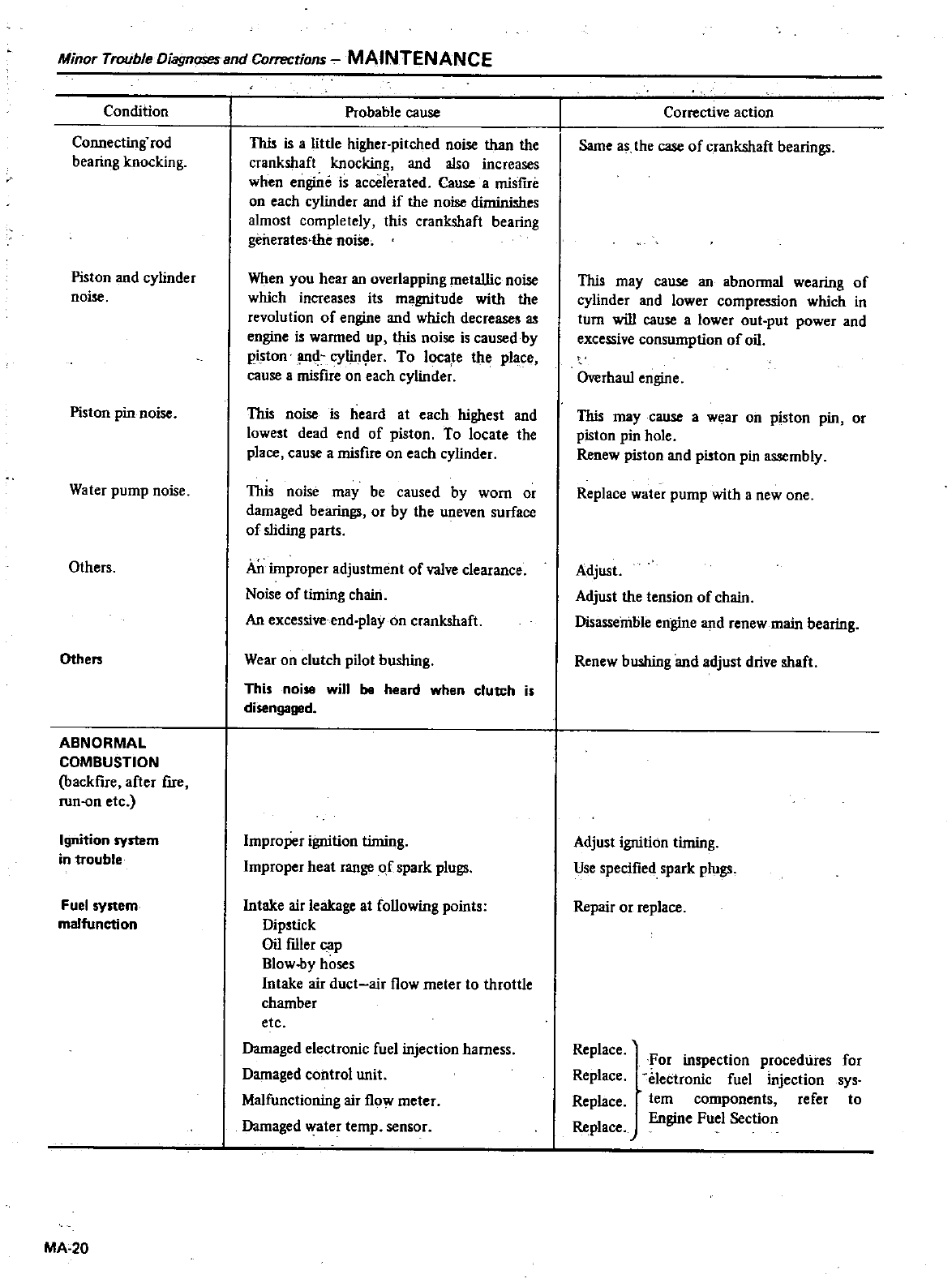
Minor
Trouble
Diagnoseund
Corrections
MAINTENANCE
Condition
Connecting
rod
bearing
knocking
Piston
and
cylinder
noise
Piston
pin
noise
Water
pump
noise
Others
Others
ABNORMAL
COMBUSTION
backfire
after
fire
run
on
etc
Ignition
system
in
trouble
Fuel
system
malfunction
MA
20
Probable
cause
This
is
alittle
higher
pitched
noise
than
the
crankshaft
knocking
and
also
increases
when
engine
is
accelerated
Cause
a
misfue
on
each
cylinder and
if
the
noise
diminishes
almost
completely
this
crankshaft
bearing
generates
the
noise
When
you
hear
an
overlapping
metallic
noise
which
increases
its
magnitude
with
the
revolution
of
engine
and
which
decreases
engine
is wanned
up
this
noise
is
caused
by
piston
lUId
cylinger
To
locate
the
place
cause
a
misfue
on
each
cylinder
This
noise
is
heard
at
each
highest
and
lowest
dead
end
of
piston
To
locate
the
place
cause
a
misfire
on
each
cylinder
This
noise
may
be
caused
by
worn
or
damaged
bearings
or
by
the
uneven
surface
of
sliding
parts
An
improper
adjustment
of
valve
clearance
Noiseoftinringchmn
An
excessive
end
play
on
crankshaft
Wear
on
clutch
pilot
bushing
This
noise
will
be
heard
when
clutch
is
disengaged
Improper
ignition
tinring
Improper
heat
range
of
spark
plugs
Intake
air
leakage
at
following
points
Dipstick
Oil
f1l1er
cap
Blow
by
hoses
Intake
air
duct
air
flow
meter
to
throttle
chamber
etc
Damaged
electronic
fuel
injection
harness
Damaged
control
unit
Malfunctioning
air
flow
meter
Damaged
water
temp
sensor
Corrective
action
Same
as
the
case
of
crankshaft
bearings
This
may
cause
an
abnonnal
wearing
of
cylinder and
lower
compression
which
in
turn
will
cause
a
lower
out
put
power
and
excessive
consumption
of
oil
Overhaul
engine
This
may
cause
a
wear on
piston
pin
or
piston
pin
hole
Renew
piston
and
piston
pin
assembly
Replace
water
pump
with
a
new
one
Adjust
Adjust
the
tension
of
chmn
Disassemble
engine
and
renew
main
bearing
Renew
bushing
and
adjust
drive shaft
Adjust
ignition
timing
Use
specified
spark plugs
Repair
or
replace
Replace
Replace
Replace
Replace
J
For
inspection
procedures
for
electronic
fuel
injection
sys
tern
components
refer
to
Engine
Fuel
Section
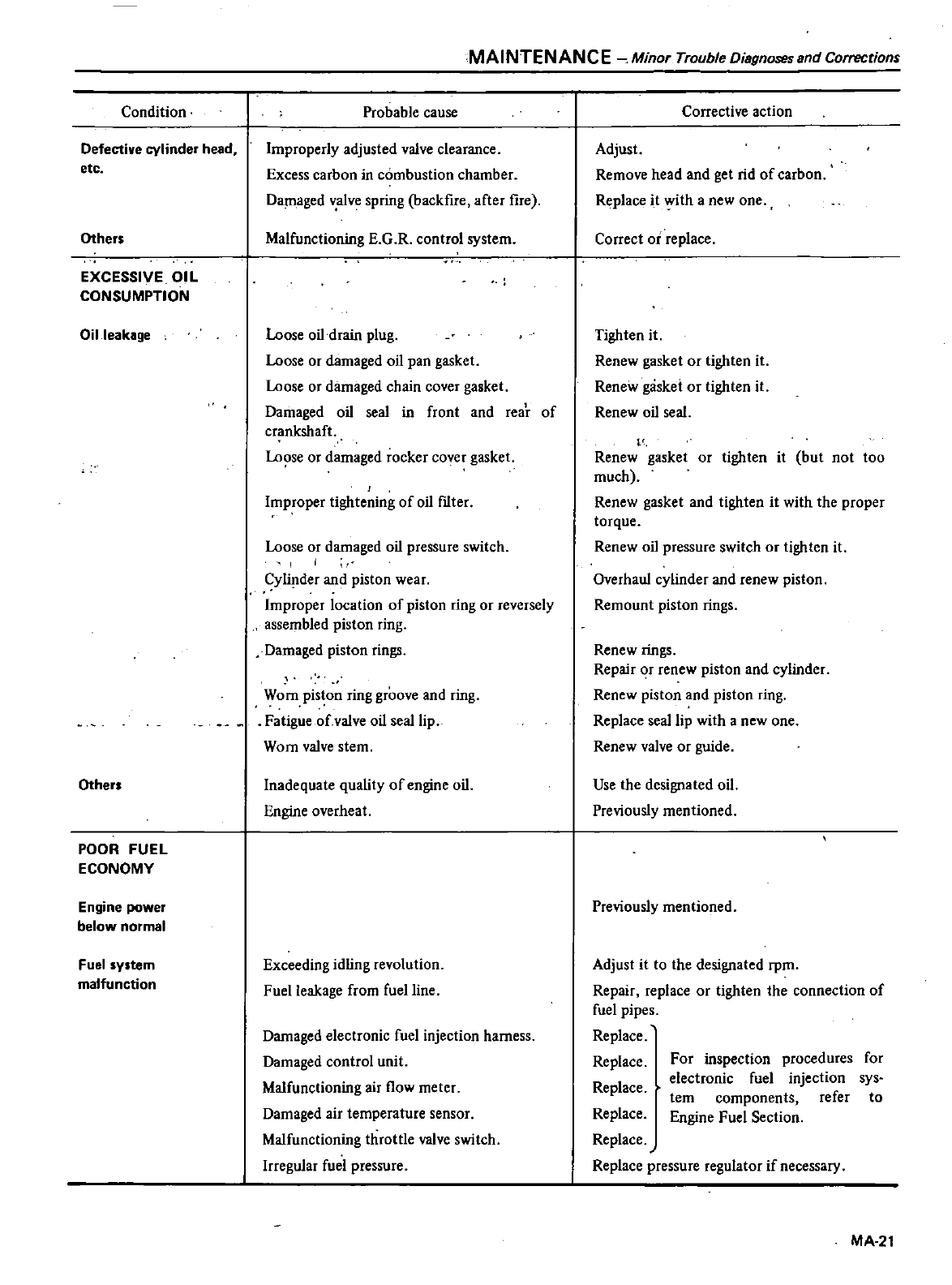
Condition
Defective
cylinder
head
etc
Others
EXCESSIVE
OIL
CONSUMPTION
Oil
leakage
Others
POOR
FUEL
ECONOMY
Engine
power
below
normal
Fuel
system
malfunction
MAINTENANC
E
Minor
Trouble
Diagnoses
and
Corrections
Probable
cause
Improperly
adjusted
valve
clearance
Excess
carbon
in
combustion
chamber
Damaged
v
alve
spring backfire
after
fire
Malfunctioning
E
G
R
control
system
Loose
oil
drain
plug
Loose
or
damaged
oil
pan
gasket
Loose
or
damaged
chain
cover
gasket
Damaged
oil
seal
in
front
and
rear
of
crankshaft
Lo
e
or
damaged
rocker
cover
gasket
Improper
tightening
of
oil
fIlter
Loose
or
damaged
oil
pressure
switch
I
I
Cylinder
and
piston
wear
Improper
location
of
piston
ring
or
reversely
assembled
piston
ring
Damaged
piston
rings
Worn
piston
ring
groove
and
ring
Fatigue
of
valve
oil
seal
lip
Worn
valve
stem
Inadequate
quality
of
engine
oil
Engine
overheat
Exceeding
idling
revolution
Fuel
leakage
from
fuel
line
Damaged
electronic
fuel
injection
harness
Damaged
control
unit
Malfunctioning
air
flow
meter
Damaged
air
temperature
sensor
Malfunctioning
throttle
valve
switch
Irregular
fuel
pressure
Corrective
action
Adjust
Remove
head
and
get
rid
of
carbon
Replace
it
with
a
new
one
Correct
or
replace
Tighten
it
Renew
gasket
or
tighten
it
Renew
gaskei
or
tighten
it
Renew
oil
seal
Renew
gasket
or
tighten
it
but
not too
much
Renew
gasket
and
tighten
it
with
the
proper
torque
Renew
oil
pressure
switch
or
tighten
it
Overhaul
cylinder and
renew
piston
Remount
piston
rings
Renew
rings
Repair
r
renew
piston
and
cylinder
Renew
piston
and
piston
ring
Replace
seal
lip
with
a
new
one
Renew
valve
or
guide
Use
the
designated
oil
Previously
mentioned
Previously
mentioned
Adjust
it
to
the
designated
rpm
Repair
replace
or
tighten
the
connection
of
fuel
pipes
Replace
Replace
Replace
Replace
Replace
Replace
pressure
regulator
if
necessary
For
inspection
procedures
for
electronic
fuel
injection
sys
tern
components
refer
to
Engine
Fuel
Section
MA
21
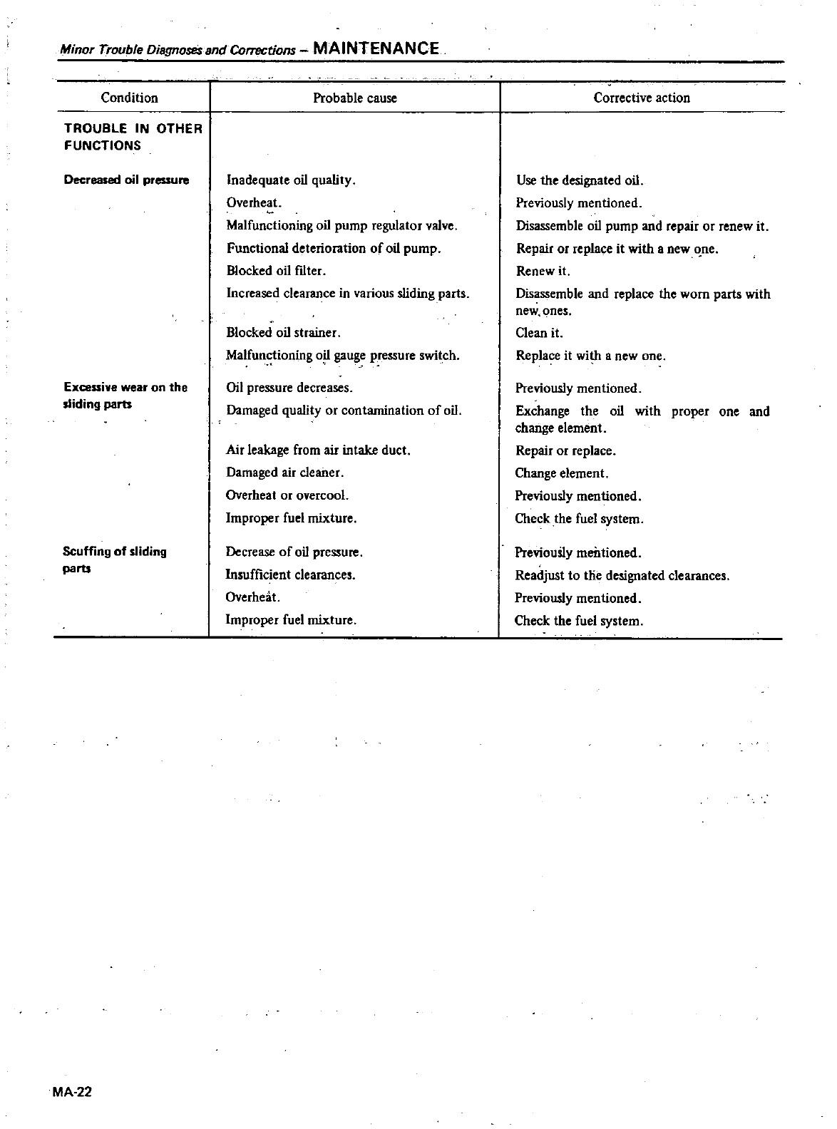
Minor
Trouble
Diagnoses
and
Correctiom
MAINTENANCE
Condition
TROUBLE
IN
OTHER
FUNCTIONS
Decreased
oil
pressure
Excessive
wear on
the
sliding
parts
Scuffing
of
sliding
parts
MA
22
Probable
cause
Inadequate
oil
quality
Overheat
Malfunctioning
oil
pump
regulator
valve
Functional
deterioration
of
oil
pump
Blocked
oil
f1lter
Increased
clearance
in
various
sliding
parts
Blocked
oil
strainer
Malfunctioning
o
gauge
pressure
switch
Oil
pressure
decreases
Damaged
quality
or
contamination
of
oil
Air
leakage
from
air
intake
duct
Damaged
air
cleaner
Overheat
or
overcoat
Improper
fuel
mixture
Decrease
of
oil
pressure
Insufficient
clearances
Overheat
Improper
fuel
mixture
Corrective
action
Use
the
designated
oil
Previously
mentioned
Disassemble
oil
pump
and
repair
or
renew
it
Repair
or
replace
it
with
a
new
ne
Renew
it
Disassemble
and
replace
the
worn
parts
with
new
ones
Clean
it
Replace
it
with
a
new
one
Previously
mentioned
Exchange
the
oil
with
proper
one
and
change
element
Repair
or
replace
Change
element
Previously
mentioned
Check
the
fuel
system
Previously
mentioned
Readjust
to
lIie
designated
clearances
Previously
mentioned
Check
the
fuel
system
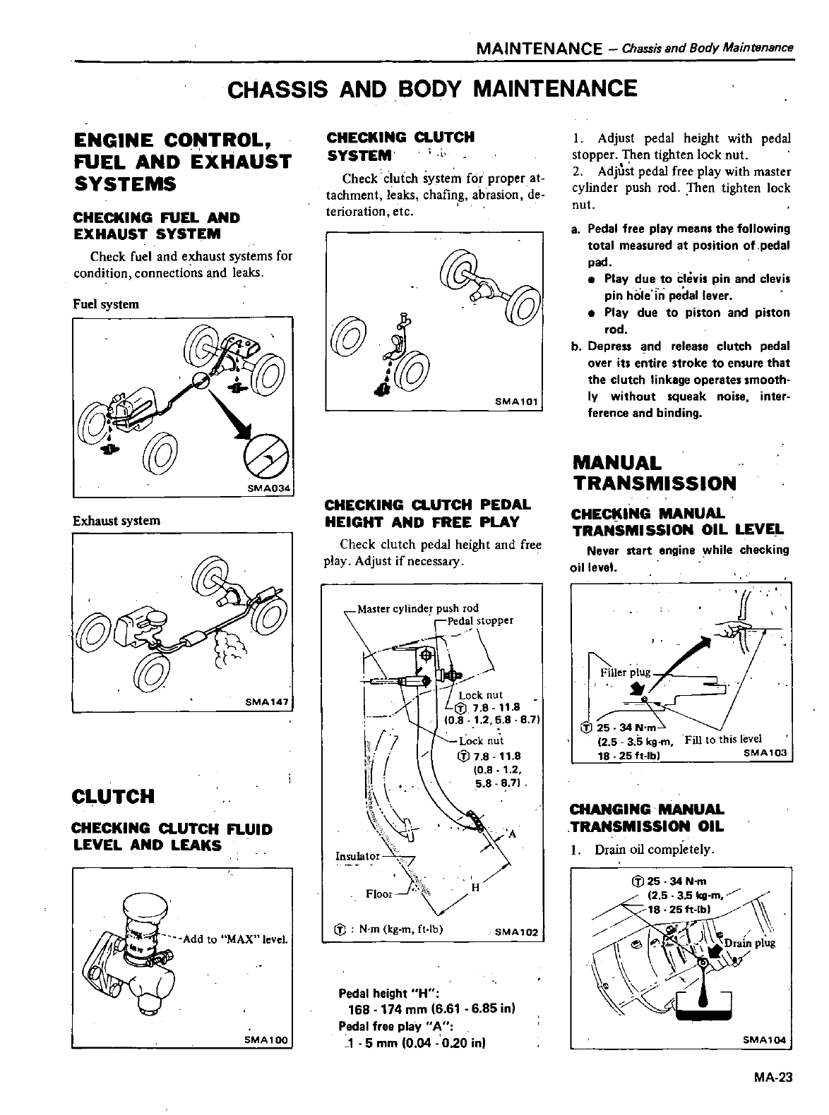
MAINTENANCE
Chassis
and
Body
Mainwnance
CHASSIS
AND
BODY
MAINTENANCE
ENGINE
CONTROL
FUEL
AND
EXHAUST
SYSTEMS
CHECKING FUEL
AND
EXHAUST
SYSTEM
Check
fuel
and
exhaust
systems
for
condition
connections and
leaks
Fuel
system
SMA034
Exhaust
system
@
SMA
147
CLUTCH
CHECKING
CLUTCH
FLUID
LEVEL
AND
LEAKS
Add
to
MAX
level
SMA1QO
CHECKING
CLUTCH
SYSTEM
Check
clutch
system
for
proper
at
tachment
leaks
chafing
abrasion
de
terioration
etc
@j
J
@
SMA101
CHECKING
CLUTCH
PEDAL
HEIGHT
AND
FREE
PLAY
Check
clutch
pedal
height
and
free
play
Adjust
if
necessary
Master
cylinde
push
rod
Pedal
stopper
r1
w
lotf
51
8
8
71
iLl
111
h
InSU1ator
FIOor
j
H
Lock
nut
fl7
8
11
8
10
8
1
2
5 8 8
71
A
fl
N
m
kg
m
ft
lb
SMA102
Pedal
height
H
168 174
mm
6 61 6
85
in
Padal
free
play
A
J
5
mm
0
04
020
in
I
Adjust
pedal
height
with
pedal
stopper
Then
tighten
lock
nut
2
Adjust
pedal
free
play
with
master
cylinder
push
rod
Then
tighten
lock
nut
8
Pedal
free
play
means
the
following
total
measured
at
position
of
pedal
pad
Play
due
to
clevis
pin
and
clevis
pin
hole
in
pedal
lever
Play
due
to
piston
and
piston
rod
b
Depress
nd
release
clutch
pedal
over
its
entire
stroke
to
ensure
that
the
clutch
linkage
operates
smooth
ly
without
squeak
noise
inter
ference and
binding
MANUAL
TRANSMISSION
CHECKING
MANUAL
TRANSMISSION
OIL
LEVE
L
Neyer
start
engine
while
checking
oilleyel
ff
4f
itner
plug
S
2 5
3
5
kg
m
Fill
to
this
level
18
25
ft
Ibl
SMA
1
03
CHANGING
MANUAL
TRANSMISSION
OIL
I
Drain
oil
completely
SMA104
MA
23
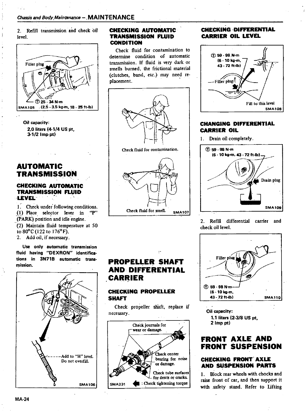
Chassis
and
Body
Maintenance
MAINTENANCE
2Refill
transmission
and
check
oil
level
25ft lb
Oil
capacity
2
0
liten
4
1
4
USJit
3
1
2
Imp
pt
AUTOMATIC
TRANSMISSIQN
CHECKING
AUTOMATIC
TRANSMISSION
FLUID
LEVEL
I
Check
under
following
conditions
i
Place
selector
lever
in
P
pARK
position
and
idle
engine
2
Maintain
fluid
temperature
at
50
to80DC
122
to
176DF
2 Add
oil
if
necessary
Use
only
automatic
transmission
fluid
having
OEXRON
identifica
tions
in
3N71B
automatic
trans
iSlion
Q
J
Add
to
H
level
Do
not
overfill
SMA106
MA
24
CHECKINGAUTOMAnC
TRANSMISSION
FLUID
CONDITION
Check
fluid
for
contamination
to
determine
condition
of
automatic
transmission
If
fluid
is
very
dark
or
smells
burned
the
frictional
material
clutches
band
etc
may
need
reo
placemen
t
Oleck
fluid
for
contamination
I
Check
fluid
for
smell
SMA107
PROPELI
ER SHAFT
AND
DIFFERENTIAL
CAR
IER
CHECKING
PROPELLER
SHAFT
Check
propeller
shaft
replace
if
necessary
Oteek
tube
surfaces
fOJ
denu
or
cracks
SMA231
Oleck
tightening
torque
CHECKING
DIFFEREN11AL
CARRIER
OIL
LEVEL
Fill
to
thislevel
S
MA10B
CHANGING
DIFFERENTIAL
CARRIER
OIL
I
Drain
oil
completely
CV
59 98
N
m
6
10
kg
m72ft
blL
W
SMA109
2
Refill
differential
carrier
and
check
oil
level
cv
59 98
N
m
6
101qj
m
43
72ft
lb
SMA11Q
Oil
capacity
1
1liten
2
38
US
pt
2
Imp
pt
FRONT
AXLE
AND
FRONT
SUSPENSION
CHECKING FRONT
AXLE
AND
SUSPENSION
PARTS
I
Block
rear
wheels
with
chock
and
raise
front
of
car
and
then
support
it
with
safety
stand
Refer
to
lifting
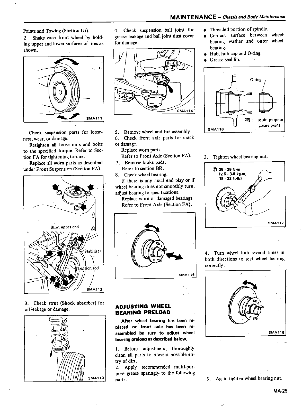
Points
and
Towing
Section
GI
2
Shake
each
front
wheel
by
hold
ing
upper
and
lower
surfaces
of
tires
as
shown
SMA111
Check
suspension
parts
for
loose
ness
wear
or
damage
Retighten
all
loose
nuts
and
bolts
to
the
specified
torque
Refer
to
Sec
tion
FA
for
tightening
torque
Replace
all
worn
parts
as
described
under
Front
Suspension
Section
FA
o
Strut
upper
end
3
Check
strut
Shock
absorber
for
oil
leakage
or
damage
J
MAINTENANCE
Chsssis
and
Body
Maintensnce
4
Check
suspension
ball
joint
for
grease
leakage
and
ball
joint
dust
cover
for
damage
5
Remove
wheel
and
tire
assembly
6
Check
front
axle
parts
for
crack
or
damage
Replace
worn
parts
Refer
to
Front
Axle
Section
FA
7
Remove
brake
pads
Refer
to
section
BR
8
Check
wheel
bearing
If
there
is
any
axial
end
play
or
if
wheel
bearing
does
not
smoothly
turn
adjust
bearing
to
specifications
Replace
worn
or
damaged
bearings
Refer
to
Front
Axle
Section
FA
SMAllS
ADjUSTING
WHEEL
BEARING
PRELOAD
After
wheel
bearing
has
been
reo
placed
or
front
axle
has
been
reo
assembled
be
sure
to
adjust
wheel
bearing
preload
as
described
below
I
Before
adjustment
thoroughly
clean
all
parts
to
prevent
possible
en
try
of
dirt
2
Apply
recommended
multi
pur
pose
grease
sparingly
to
the
following
parts
Threaded
portion
of
spindle
Contact
surface
between
wheel
bearing
washer and
outer
wheel
bearing
Hub
hub
cap
and
O
ring
Grease
seal
lip
dl
nng
SMAl16
Multi
purpose
grease
point
3
Tighten
wheel
bearing
nut
i
J
25
29N
m
12
5
3
0
kg
m
18
22ft
lbl
SMAT17
4
Turn
wheel
hub
several
times
in
both
directions
to
seat
wheel
bearing
correctly
SMAllS
5
Again
tighten
wheel
bearing
nut
MA
25
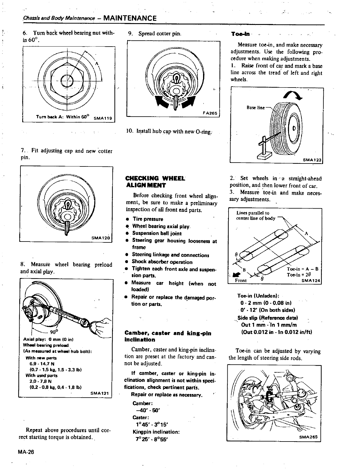
ChassiundBodyMainl11nance
MAINTENANCE
6
Turn
back
wheel
bearing
nut
with
in
600
Tumbac
kA
Within600
SMA119
7
Fit
adjusting
cap
and
new
cotter
pin
8
Measure
wheel
bearing
preload
and
axial
play
900
Axial
play
0
mm
0in
Wh
1
b
ring prelo
As
measured
at
wh
1
hub
bolt
With
new
parts
69
14
7
N
10
7
1
5
kg
1
5 3
31bl
With
US8
t
parts
2
0
7B N
10
208
kg
04
1
8
Ib
SMA121
Repeat
above
procedures
until
cor
rect
starting
torque
is
obtained
MA
26
9
Spread
otterpin
F
A265
10
Install
hub
cap
with
new
O
ring
CHECKING
WHEEL
ALIGN
MENT
Before
checking
front
wheel
align
ment
be
sure
to
make
a
preliminary
inspection
of
all
front
end
parts
Tire
pressure
Wheel
bearing
axial
play
Suspension
ball
joint
Steering
gear
housing
looseness
at
frame
Steering
linkage
and
connections
Shock
absorber
oparation
Tighten
each
front
axle
and
suspen
sion
pam
Measure
car
height
when
not
loaded
Repair
or
replace
the
d
amaged
por
tion
or
parts
Camber
caster
and
kingopln
inclination
Camber
caster
and
king
pin
inclina
tion
are
preset
at
the
factory
and
can
not
be
adjusted
If
camber
caster
or
king
pin
in
clination
alignment
is
not
within
speci
fications
check
pertinent
parts
Repair
or
replace
as
necessary
Camber
40
50
Caster
1045
3
15
Kingpin
inclination
7025
SOSS
Toe
In
Measure
toe
in
and
make
necessary
adjustments
Use
the
following
pro
cedure
when
making
adjustments
I
Raise
front
of
car
and
mark
a
base
line
across
the
tread
of
left
and
right
wheels
Base
line
SMA123
2
Set
wheels
in
a
straight
ahead
position
and
then
lower
front
of
car
3
Measure
toe in
and
make
neces
sary
adjustments
lines
parallel
to
center
line
of
body
Toe
in
Unladen
o
2
mm
O O OS
inl
0
12
On
both
sides
Sid
slip
Reference
datal
Out
1
mm
n
1
mmlm
Out
0
012 in
In
0
012
in
ftl
Toe
in
can
be
adjusted
by
varying
the
length
of
steering
side
rods
SMA265
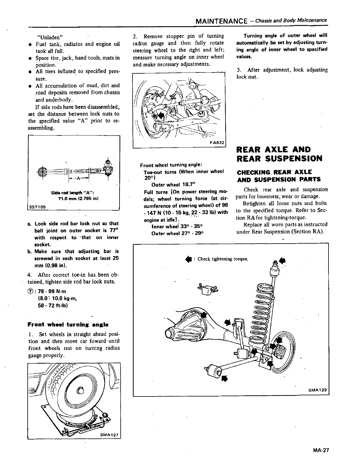
Unladen
Fuel
tank
radiator
and
engine
oil
tank
all
full
Spare
tire
jack
hand
tools
mats
in
position
All
tires
inflated
to
specified
pres
sure
All
accumulation
of
mud
dirt
and
road
deposits
removed
from
chassis
and
underbody
If
side
rods
have
been
disassembled
set
the
distance
between
lock
nuts
to
the
specified
value
A
prior
to
reo
assembling
JJ
Sid
red
length
An
71
0
mm
12
795
in
ssn05
a
Lock
side
rod bar lock
nut
so
that
ball
joint
on
outer
socket
is
770
with
respect
to
that
on
inner
socket
b
Make
sure
that
adjusting
bar
is
screwed
in
eam
socket
at
least
25
mm
0
98 in
4
After
correct toe
in
has
been
ob
tained
tighten
side
rod bar
lock
nuts
Iil
78
98
N
m
8 0
10
0
kg
m
58 72
ft
lb
Front
wheel
turning
engle
I
Set
wheels
in
straight
ahead
posi
tion
and
then
move
car
foward
until
front
wheels
rest
on
turn
ng
radius
gauge
properly
MAINTENANCE
Chassis
and
Body
Maintenance
2
Remove
stopper
pin
of
turning
radius
gauge
and
then
fully
rotate
steering
wheel
to
the
right
and
left
measure
turning
angle
on
inner
wheel
and
make
necessary
adjustments
FA632
Front
wheel
turning
angle
Toe
ut
turns
When
inner wheel
200
Outer
wheel
18
70
Full
turns
On
power
steering
mo
dels
wheel
turning
force
at
cir
cumference
of
steering
wheell
of
98
147
N
10
15
kg
22 33
Ib
with
engine
at
idle
Inner
wheel 330 350
Outer
wheel 270 290
Turning
angle
of
outer
wheel
will
automatically
be
set
by
adjusting
turn
ing
angle
of
inner wheel
to
specified
values
3
After
adjustment
lock
adjusting
lock
nut
REAR
AXLE
AND
REAR
SUSPENSION
CHECKING
REAR
AXLE
AND
SUSPENSION
PARTS
Check
rear
axle
and
suspension
parts
for
looseness
wear
or
damage
Retighten
all
loose
nuts
and
bolts
to
the
specified
torque
Refer
to
Sec
tion
RA
for
tightening
torque
Replace
aU
worn
parts
as
instructed
under
Rear
Suspension
Section
RA
Check
tightening
torque
SMA129
MA
27
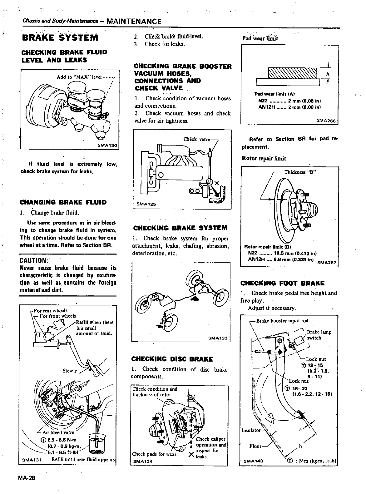
OIl1Sfisand
Body
Maintenance
MAINTENANCE
BRAKE
SYSTEM
CHECKING
BRAKE FLUID
LEVEL
AND
LEAKS
Add
to
MAX
level
SMA
130
If
fluid
level
i
extremely
low
check
brake
system
for
leaks
CHANGING
BRAKE
FLUID
I
Change
brake
fluid
Use
same
procedure
IS
in air
bleed
ing
to
change
brake
fluid
in
ystem
Thi
operation
should
be
done
for
one
wheel
at
a
time
Refer
to
Section
BR
CAUTION
Never
reuse
brake
fluid
because
its
characteristic
is
chang2d
by
oxidiza
tion
as
well
as
contains
the
foreign
material
and
dirt
Air
bleed
valve
3
l6
9
88
N
m
O
7
O
9kg
5
1
65ft
lb
SMA131
Refill
until
new
fluid
appears
MA
28
2
CIieck
brake
fluidleve
3
Check
for
leaks
CHECKING
BRAKE
BOOSTER
VACUUM
HOSES
coNNECTIONS
AND
CHECK
VALVE
1
Check
condition
of
vacuum
hoses
and
connections
2
Check
vacuum
hoses
and
check
valve
for
air
tightness
SMA
125
CHECKING
BRAKE
SYSTEM
I
Check
brake
system
f
r
proper
attachment
leaks
chafmg
abrasion
deterioration
etc
SMA
133
CHECKING
DISC
BRAKE
I
Check
condition
of
disc
brake
components
beck
pads
for
wear
SMA134
Oteck
caliper
operation
and
X
inspect
for
leaks
Pad
wear
liniit
1
ll
A
I
TT
PIId
war
limit
tAt
N22
2
mm
0
08
in
AN12H
2
mm
0
08
in
SMA266
Refer
to
Section
BR
for
pad
re
placement
Rotor
repair
limit
ROtor
repair
limit
B
N22
10
5mm
10
413
in
AN12H
86
mm
0
339
in
SMA267
CHECKING
FOOT
BRAKE
1
Check
brake
pedal
free
height
and
free
play
Adjust
if
necessary
Brake
b
t
0
hl
P
i
1
Ck
nut
j
l12
15
11
2
1
5
9
11
Lock
nut
1
16
22
1
I
16
22
12
16
I
Insulator
Floor
h
SMA140
l
N
m
kg
m
Ct
tb
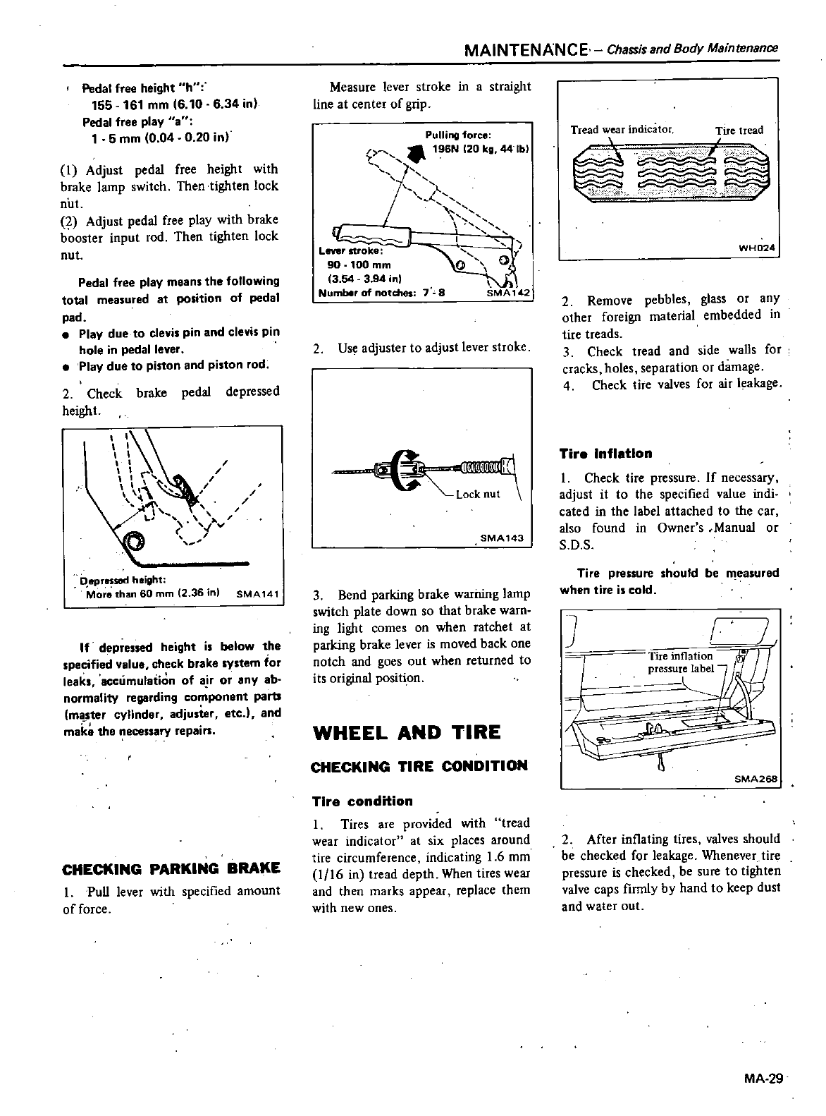
Pedal
free
height
h
155
161
mm
6 10
6 34
in
Pedal
free
play
a
1
5
mm
0
04
0
20
in
1
Adjust
pedal
free
height
with
brake
lamp
switch Then
tighten
lock
nut
Adjust
pedal
free
play
with
brake
booster
input
rod
Then
tighten
lock
nut
Pedal
free
play
mean
the
following
total
measured
at
position
of
pedal
pad
Play
due
to
clevis
pin
and
clevis pin
hole
in
pedal
lever
Play
due
to
piston
and
piston
rod
2
Check
brake
pedal
depressed
height
I
I
d
v
DeprltSSllKl
height
Mor
thi
ln
60
mm
2
36
in
SMA141
If
depressed
height
i
below
the
specified
value
check
brake
system
for
leaks
accumulation
of
a
ror
any
ab
normality
regarding
component
parb
master
cylinder
adju
ier
etc
I
and
make
the
necessary
repain
CHECKING PARKING
BRAKE
I
Pull
lever
with
specified
amount
of
force
MAINTENANCE
Chassis
and
Body
Maintenance
Measure
lever
stroke
in
a
straight
line at
center
of
grip
Pulling
force
196N
120
kg
44
Ib
I
l
n
1
I
L
I
Lever
stroke
90
100
mm
0
0
3
54
3
94
nl
Number
of
notches
7
8
SMA
142
2
Use
adjuster
to
adjust
lever
stroke
I
Lock
fiU
t
SMA143
3
Bend
parking
brake
warning
lamp
switch
plate
down
so
that
brake
warn
ing
light
comes
on
when
ratchet
at
parking
brake
lever
is
moved
back
one
notch
and
goes
out
when
returned
to
its
original
positi
on
WHEEL
AND
TIRE
CHECKING
TIRE
CONDITION
Tire
condition
1
Tires
are
provided
with
tread
wear
indicator
at
six
places
around
tire
circumference
indicating
1
6
mm
1
16
in
tread
depth
When
tires
wear
and
then
marks
appear
replace
them
with
new
ones
Tread
wear
indicator
Tire
tread
t
WH024
2
Remove
pebbles
glass
or
any
other
foreign
material
embedded
in
tire
treads
3
Check tread
and
side
walls
for
cracks
holes
separation
or
damage
4
Check
tire
valves
for
air
leakage
Tire
Inflation
I
Check
tire
pressure
If
necessary
adjust
it
to
the
specified
value
indi
cated
in
the
label
attached
to
the
car
also
found
in
Owner
s
Manual
or
S
D
S
Tire
pressure
should
be
easured
when
tire
is
cold
I
J
rireinflation
pressure
label
l
I
SMA268
2
After
inflating
tires
valves
should
be
checked
for
leakage
Whenever
tire
pressure
is
checked
be
sure
to
tighten
valve
caps
firmly
by
hand
to
keep
dust
and
water
out
MA
29
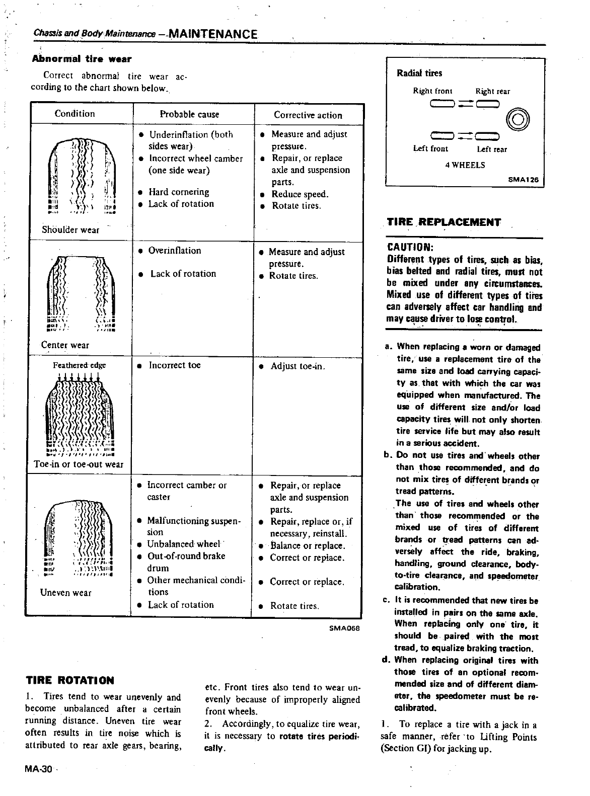
ChaS3is
and
Body
MainrenanaJ
MAINTENANCE
Abnormal
tire
wear
Correct
abnormal
tire
wear
ac
cording
to
the
chart
shown
below
Condition
i
1
1
1
J
1111
allll
j
ll
Shoulder
wear
If
I
ii
ii
I
t
Ii
Center
wear
Feathered
edge
j
l
Ii
I
1
Ii
II
11
t
1i
I
I
I
I
l
I
r
i
II
I
Toe
in
or
toeout
wear
Ij
Iij
j
H
l
m
I
il
I
1
fIll
11
I
I
I
f
1 1
1
ll
ll
o
Ii
Uneven
wear
Probable
cause
Underinflation
both
sides
ar
Incorrect
wheel
camber
one
side
wear
Hard
cornering
Lack
of
rotation
Overinflation
lack
of
rotation
Incorrect
toe
lncorrect
camber
or
caster
Malfunctioning
suspen
sion
Unbalanced
wheel
Out
lf
round
brake
drum
Other
mechanical
condi
dons
Lack
of
rotation
TIRE
ROTATION
1
Tires
tend
to
wear
unevenly
and
become
unbalanced
after
a
certain
running
distance
Uneven
tire
wear
often
results
in
tire
noise which
is
attributed
to
rear
axle
gears
bearing
MA
30
Corrective
action
Measure
and
adjust
plessure
Repair
or
replace
axle
and
suspension
parts
Reduce
speed
Rotate
tires
Measure
and
adjust
pressure
Rotate
tires
Adjust
toe
in
Repair
or
replace
axle
and
suspension
parts
Repair
replace
or if
necessary
reinstall
Balance
or
replace
Correct
or
replace
Correct
or
replace
Rotate
tires
SMA068
etc
Front
tires
also
tend
to
wear
un
evenly
because
of
improperly
aligned
front
wheels
2
Accordingly
to
equaliZe
tire
wear
it
is
necessary
to
rot8te
tires
periodh
cally
Radial
tires
Right
front
Right
rear
c
c
l
@
c
l
c
l
Left
front
Left
rear
4
WHEELS
SMA126
TIRE
REPLACEMENT
CAUTION
Different
types
of
tires
Rich
es
bias
bias
belted
and
radial
tirl
S
murt
not
be
mixed
under
any
cin
umstances
Mind
use
of
different
types
of
tiies
can
adversely
affect
car
handling
and
may
cause
driver
to
lose
control
i
a
When
replacing
worn or
damaged
tire
use a
replacement
tire
of
the
same
size
and
load
carrying
capaci
ty
as
that
with
which
the
car
WIS
aquipped
when
manufactUred
The
use
of
different
size
and
or
load
capacity
ti
will
not
only
horten
tire
service
life
but
may
also
resuh
in a
serious
accident
b
Do
not
use
tires
and
wheels
other
than
those
recommeooed
and
do
not
mix
tire
of
different
brandt
or
tread
patterns
The use
of
tire
and
wheels
other
than
those
recommended
or
the
mixed
use
of
tires
of
diffarent
brands
or
1
ead
patterns
can
ad
versely
affect
the
ride
braking
handling
ground
clearance
body
to
tire
clearance
and
sp
et
tom8ter
calibration
c
It it
recommended
that
new
tires
be
installed
in
pain
on
the
same
axle
When
replacing
only
one
tire
it
should
be
paired
with
the
most
tread
to
equalize
braking
traction
d
When
replacing
original
tires
with
those
tires
of
8n
optional
recom
mended
size
and
of
different diam
ator
tha
speedometer
must
ba ra
calibrated
1
To
replace
atire
with
a
jack
in a
safe
manner
refe
to
lifting
Points
Section
GI
for
jacking
up
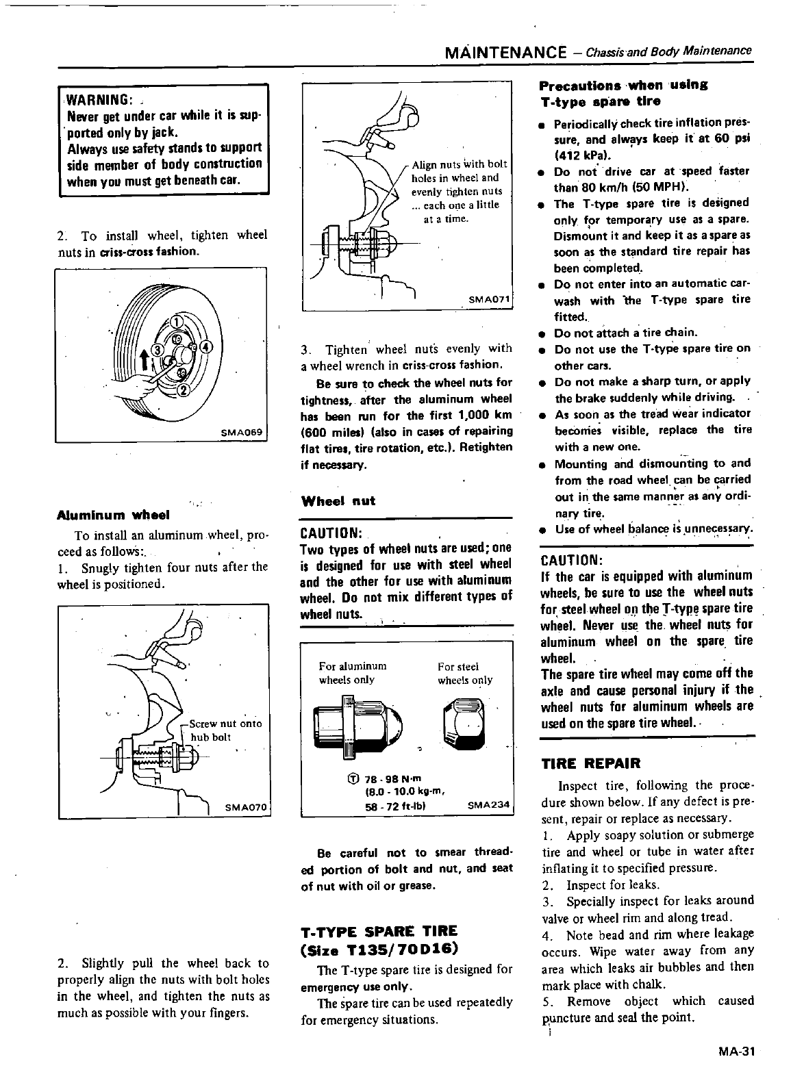
WARNING
Never
get
under
car
while
it
is
sup
ported only by
jack
Always
use
safety
stands
to
support
side
member
of
body
construction
when
you
must
get
beneath
car
2
To
install
wheel
tighten
wheel
nuts
in
criss
cross
fashion
SMA069
Aluminum
whee
To
install
an
aluminum
wheel
pro
ceed
as
followS
I
Snugly
tighten
four
nuts
after
the
wheel
is
positioned
SMA070
2
Slightly
pull
the
wheel
back
to
properly
align
the
nuts
with
bolt
holes
in
the
wheel
and
tighten
the
nuts
as
much
as
possible
with
your
fingers
MAINTENANCE
Chassis
and
Body
Maintenance
Align
nuts
with
bolt
holes
in
wheel
and
evenly
tighten
nuts
each
one
a
little
at
a
time
SMA071
3
Tighten
wheel
nuts
evenly
with
a
wheel
wrench
in
criss
cross
fashion
Be
sure
to
check
the
wheel
nuts
for
tightness
after the aluminum
wheel
has
been
Nn
for
the
first
1
000
km
600
milesl
also
in
cases
of
repairing
flat tire tire
rotation
etc
Retighten
if
necessary
Wheel
nut
CAUTION
Two
types
of
wheel
nuts
are
used
one
is
designed
for
use
with
steel
wheel
and
the other
for
use
with
aluminum
wheel
00
not mix
different
types
of
wheel
nuts
For
aluminum
wheels
only
For
steel
wheels
only
r
C
t
J
78
98
N
m
18
0
10
0
kg
m
58
72
ft
Ibl
SMA234
Be
careful
not
to
smear
thread
ed
portion
of
bolt
and
nut
and
seat
of
nut
with
oil
or
grease
T
TYPE
SPARE
TIRE
Size
T135
70D16
The
T
type
spare
tire
is
designed
for
emergency
use
only
The
spare
tire can
be
used
repeatedly
for
emergency
situations
Precautions
whenuslng
T
type
spa
tire
Pe
iodically
check
tire
inflation
pres
sure
and
always
keep
it
at
60
psi
412 kPa
Do
not
drive
car
at
speed
faster
than
80
km
h
50
MPH
The
T
type
spare
tire
is
designed
only
fpr
tempora
ry
use
as
a
spare
Dismount
it
and
keep
it
as
a
spare
as
soon
as
the
standard
tire
repair
has
been
completed
Do
not
enter
into
an
automatic
car
wash
with
the
T
type
spare
tire
fitted
Do
not
attach
a
tire
chain
Do
not
use
the
T
type
spare
tire
on
other
cars
Do
not
make
a
sharp
turn
or
apply
the
brake
suddenly
while
driving
As
soon
as
the
tread
wear
indicator
becorries
visible
replace
the
tire
with
a
new
one
Mounting
and
dismounting
to
and
from the
road
wheel
can
be
carried
out
in the
same
manner
as
any
ordi
nary
tin
Use
of
wheel
balance
is
unneces
ary
CAUTION
If
the
car
is
equipped
with
aluminum
wheels
be
sure
to
use
the
wheel
nuts
for
steel
wheel
on
the
r
typ
spare
tire
wheel
Never
us
the
wheel
nuts
for
aluminum
wheel
on
the
spare
tire
wheel
The
spare
tire
wheel
may
come
off
the
axle
and
cause
personal
injury
if
the
wheel
nuts
for
aluminum
wheels
are
used
on
the
spare
tire
wheel
TIRE
REPAIR
Inspect
tire
following
the
proce
dure
shown
below
If
any
defect
is
pre
sent
repair
or
replace
as
necessary
1
Apply
soapy
solution
or
submerge
tire
and
wheel
or
tube
in
water
after
inflating
it
to
specified
pressure
2
Inspect
for
leaks
3
Specially
inspect
for
leaks
around
valve
or
wheel
rim
and
along
tread
4
Note
bead
and
rim
where
leakage
occurs
Wipe
water
away
from
any
area
which
leaks
air
bubbles
and
then
mark
place
with
chalk
S
Remove
object
which
caused
p
uncture
and
seal
the
point
MA
31
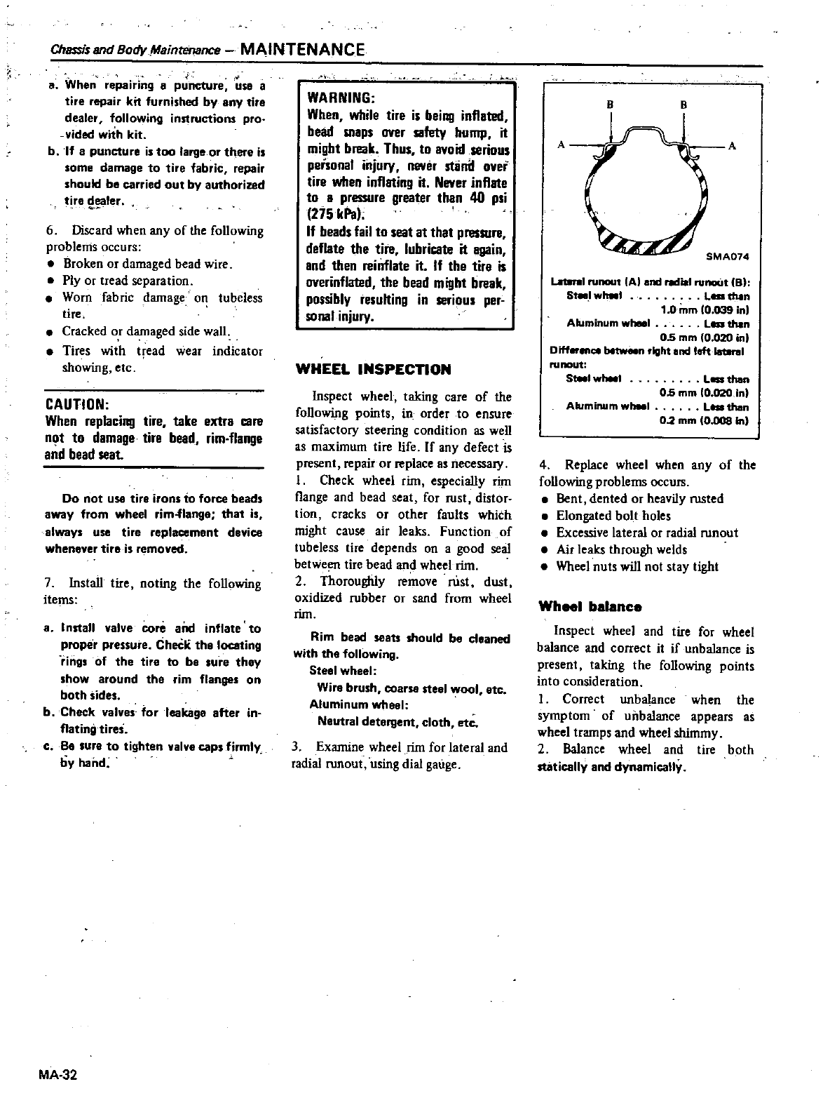
Chassis
and
Body
Maintenance
MAINTENANCE
a
When
repairing
B
puncture
use 8
tire
repair
kit
furnished
by
any
tire
dealer
following
instructions
pro
vided
with
kit
b
If
8
puncture
is
too
large
or
there
is
lome
damage
to
tire
fabric
repair
should
be
carried
out
by
authorized
tire
ller
6
Discard
when
any
of
the
following
problems
occurs
Broken
or
damaged
bead
wire
Ply
or
tread
separation
Worn
fabric
damage
on
tubeless
tire
Cracked
or
damaged
side
wall
Tires
with
tread
wear
indicator
showing
etc
CAUTION
When
replacing
tire
take
extra
care
n
t
to
damage
tire
bead
rim
flange
and
bead
seat
Do
not
U58
tire
irons
to
force
beads
away
from
wheel
rim
flange
that
is
always
use
tire
replacement
device
whenever
tirei r
moved
7
Install
tire
noting
the
following
items
a
Install
valve
core
aOd
inflate
to
proper
pressure
CheC
the
loceting
rings
of
the tire
to
be
sure
they
show
around the rim
flanges
on
both
sides
b
Check
valves
10rleakage
efter
in
flating
tires
c
Be
IUfe
to
tighten
valve
caps
firmly
by
hand
MA
32
WARNING
When
while
tire
is
being
inflated
bead
snipS
over
safety
hump
it
might
break
Thus
to
avoid
serious
personal
injury
never
stlinll
over
tire
when
inflating
it
Never
inflate
to
a
pressure
greater
than
40
psi
275kPa
If
beads
fail
to
seat
It
that
presRlre
deflate
the
tire
lubricate
it
again
and
then
reinflate
it
If
the
tira
is
overinflated
the
bead
might
break
possibly
resulting
in
serious
pl
r
sunal
injury
WHEEL
INSPEcnON
Inspect
wheel
taking
care
of
the
following
points
in
order
to
ensure
satisfactory
steering
condition
as
well
as
maximum
tire
life
If
any
defect
is
present
repair
or
replace
as
necess
uy
I
Check
wheel
rim
especially
rim
flange
and
bead
seat
for
rust
distor
tion
cracks
or
other
faults
which
might
cause
air
leaks
Function
of
tubeless
tire
depends
on
a
good
seal
between
tire
bead
and
wheel
rim
2
Thoroughly
remove
rust
dust
oxidized
rubber
or
sand
from
wheel
rim
Rim
bead
seets
should
be
ct
aned
with
the
following
Steel wheel
Wire
brush
coarse
steel
wool
etc
Aluminum
wheel
Neutral
detergent
cloth
ole
3
Examine wheel
rim
for
lateral
and
radial
runout
using
dial
gauge
B B
A A
SMA074
LaterIII
runout
A
and
ill
rvnout
B
S
I
wheel
Lea
thin
10mm
10
039
in
Lea
than
05mm
10
020
in
Diff
ence
between
right
and left
la
btrel
runout
S
Aluminum
wheel
Aluminum
I
Lea
then
05
mm
O
02O
in
Lea
than
02mm
O
llOB
In
4
Replace
wheel
when
any
of
the
following
problems
occurs
Bent
dented
or
heavily
rusted
Elongated
bolt
holes
Excessive
lateral
or
radial
runout
Air
leaks
through
welds
Wheel
nuts
will
not
stay
tight
Wheel
balance
Inspect
wheel
and
tire
for
wheel
balance
and
correct
it
if
unbalance
is
present
taking
the
following
points
into
consideration
I
Correct
unbalance
when
the
symptom
of
unbalance
appears
as
wheel
tramps
and
wheel
shimmy
2
Balance
wheel
and
tire
both
statically
end
dynamically
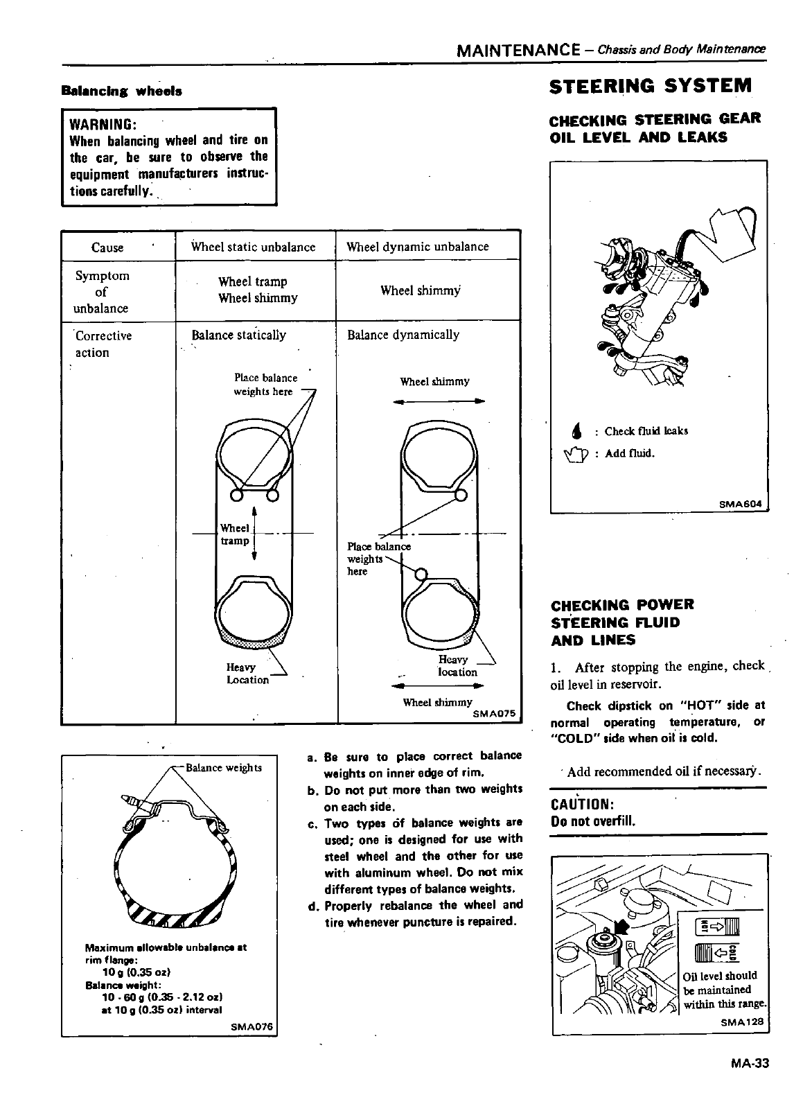
Ianeln
wheels
WARNING
When
balancing
wheel
and
tire
on
the
car
be
SlIre
to
observe
the
equipment
manufacturers
instruc
tions
carefully
Cause
Wheel
static
unbalance
Symptom
of
unbalance
Wheel
tramp
Wheel
shimmy
Corrective
action
Balance
statically
Place
balance
weights
here
Wheel
tramp
o
leavy
Location
Maximum
allowable
unbalanCl
at
rim
flange
10
g
0
35
oz
Bal
n
weight
10
6Og
O
35
2
120z
at
10
D10
35
od
interval
SMA076
MAINTENANCE
Chassis
and
Body
Maintenance
Wheel
dynamic
unbalance
Wheel
shimmy
Balance
dynamically
Wheel
shimmy
o
Place
balance
weights
here
Wheel
shimmy
SMA075
a
Be
sur
to
place
correct
balance
weights
on
inner
edge
of
rim
b
Do
not
put
more
than
two
weights
on
each
side
c
Two
type
6f
balance
weight
are
used
one
is
designed
for
use
with
steel
wheel
and
tha
other
for
u
e
with
aluminum
wheel
Do
not
mix
different
types
of
balance
weights
d
Properly
rebalance
the
wheel
and
ti
e
whenever
puncture
is
repaired
STEERING
SYSTEM
CHECKING
STEERING
GEAR
OIL
LEVEL
AND
LEAKS
Check
fluid
reaks
o
Add
fluid
SMA604
CHECKING
POWER
ST
EERING
FLUID
AND
LINES
I
Mter
stopping
the
engine
check
oi11evel
in
reservoir
Check
dipstick
on
HOT
ide
at
normal
operating
temperature
or
COLD
ide
when
oil
i
cold
Add
recommended
oil
if
necessarY
CAUTION
00
not
overfill
I
c
1
UIllIfII
Oil
level
should
be
maintained
A
within
this
range
SMA12
MA
33
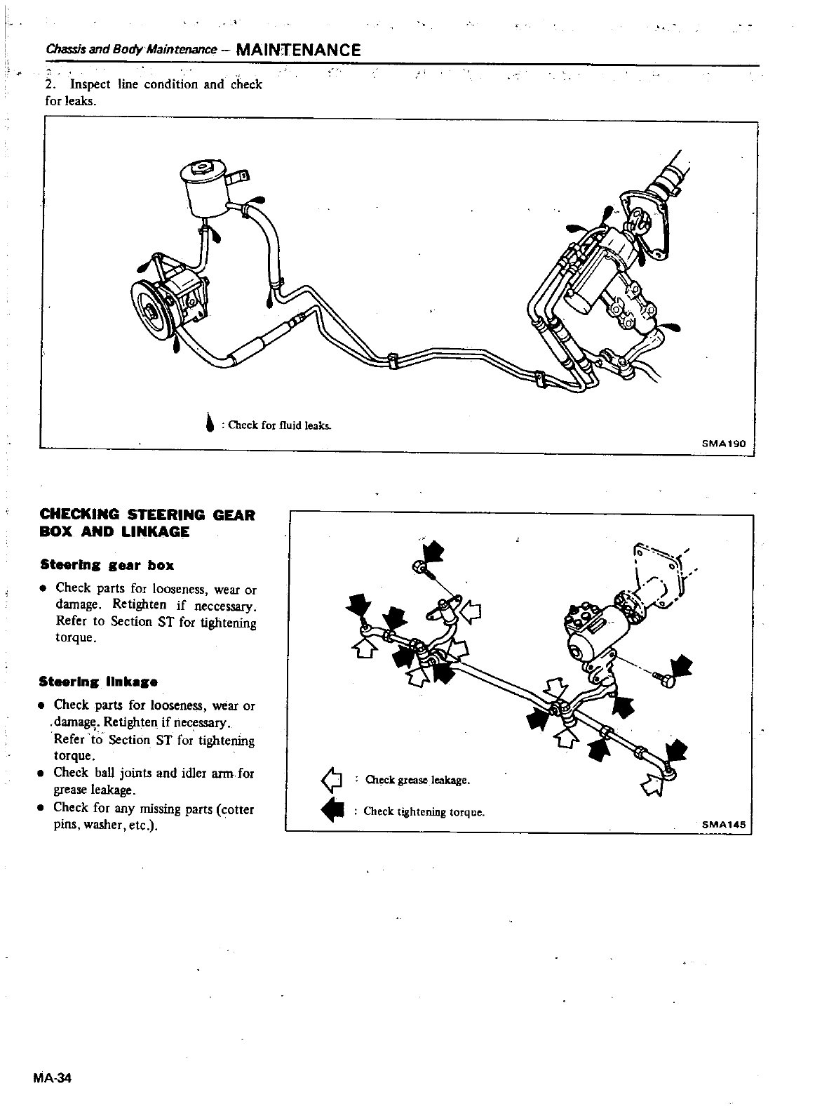
Chassis
and
Body
MainteUJJlce
MAINTENANCE
2
Inspect
line
condition
and
check
for
leaks
Check
for
fluid
leaks
CHECKING
STEERING
GEAR
BOX
AND
LINKAGE
Steerlna
aeer
box
Check parts
for
looseness
wear
or
damage
Retighten
if
neccessary
Refer
to
Section
ST for
tightening
torque
Steerlna
Ilnkeae
Check
parts
for
looseness
wear
or
damag
Retighten
if
necessary
Refer
to
Section
ST for
tightening
torque
Check
ball
joints
and
idler
arm
for
grease
leakage
Check
for
any
missing
parts
cotter
pins
washer
etc
SMA190
Q
Ch
ck
grease
leakage
Check
tightening
torque
MA
34
SMA
145
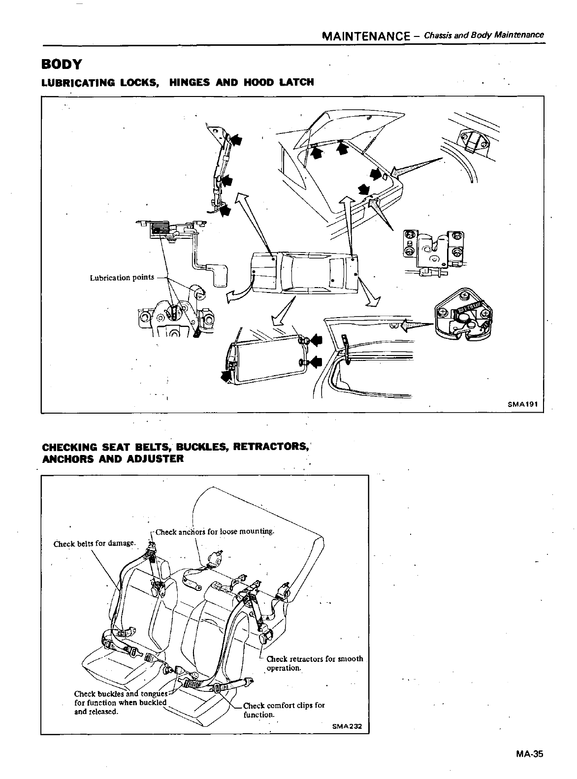
MAINTENANCE
Chassis
and
Body
Maintenance
BODY
LUBRICATING
LOCKS
HINGES
AND
HOOD
LATCH
Lubrication
points
TlI
i
c
SMA191
CHECKING
SEAT
BELTS
BUCKLES
RETRACTORS
ANCHORS
AND
ADJUSTER
O1eck
retractors
for
smooth
operation
SMA232
MA
35
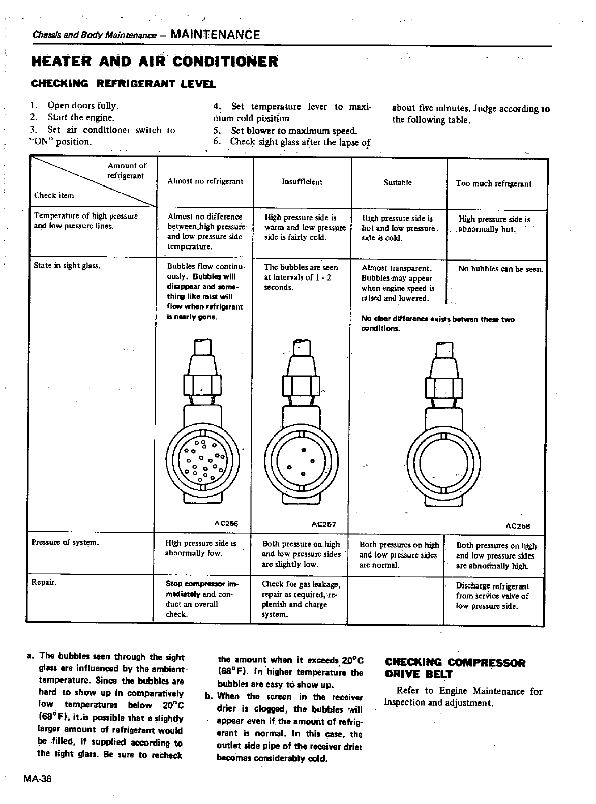
Cha
is
and
Body
Maintenance
MAINTENANCE
HEATER
AND
AlII
CONDITIONER
CHECKING
REFRIGERANT
LEVEL
L
Open
doors
fully
2
Start
the
engine
3
Set
air
conditioner
switch
to
ON
position
Amount
of
refrigerant
Almost
no
refrigerant
Check
item
4
Set
temperature
lever
to
maxi
mum
cold
position
5
Set
blower
to
maximum
speed
6
Checlc
sight
glass
after
the
lapse
of
Temperature
of
high
pressure
and
low
pressure
lines
Almost
no
difference
between
high
pressure
and
low
pressure
side
temperature
Bubbles
flow
continu
ously
Bubbles
will
disappear
am
som
thing
like
mist
will
flow
when
lIf
iglrant
is
nearly
gone
State
in
sight
glass
nl
AC256
Pressure
of
system
High
pressure
side
is
abnormally
low
top
compnssor
im
mediately
and
con
duct
an
overall
ch
k
Repair
a
The
bubbl
seen
through
the
sight
glass
are
influenced
by
tha
ambiant
temperature
Since
the
bubbl
ere
hard
to
how
up
in
comparatively
low
temperature
below
20De
68d
Fh
it
i
possible
that
a
lightly
larger
amount
of
refrigetant
would
be
filled
if
upplied
aCCOrding
to
the
ight
glass
Be
uto
chock
MA
36
Insufficient
High
pressure
side
is
warm
and
low
pressure
side
is
fairly
cold
The
bubbles
are
seen
at
intervals
of
1
2
seconds
n
r
I
AC257
Both press
reon
high
and
tow
pressure
sides
are
slightly
low
Check
fot
gas
leakage
repaiI
a
lequited
re
plenish
and
charge
system
the
amount
when
it
exceeds
2DoC
68DF
In
higher
temperatura
the
bubble
ara
easy
to
show
up
b
When
the
screen
in the
receiver
drier
i
clogged
tha
bubble
will
appear
en
if
the
emount
of
refrig
erant
is
normal
In
this
case the
outlet
side
pipe
of
tha
raceiver
drier
bacome
considerebly
cold
about
five
minutes
Judge
according
to
the
following
table
Suitable
Too
much
refrigenmt
High
pressure
side
is
hot
and
low
pressure
side
is
cold
High
pressure
side
is
abnormally
hot
Almost
transparent
Bubbles
may
appear
when
engine
speed
is
raised
and
lowered
No
bubbles
can
be
seen
No clear
differencr
exists
betwen
thMe
two
conditions
n
AC258
Both
pressures
on
high
and
low
pressure
sides
are
nonnal
Both
pres
ureson
high
and
low
pressure
sides
are
abnormally
high
Discharge
refrigerant
from
serVice
val
e
of
low
pressure
side
CHECKING
COMPRESSOR
DRIVE
BELT
Refer
to
Engine
Maintenance
for
inspection
and
adjustment
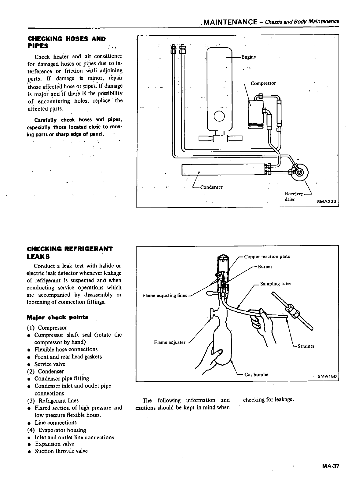
CHECKING
HOSES
AND
PIPES
Check
heater
and
air
conditioner
for
damaged
hoses
or
pipes
due
to
in
terference
or
friction
with
adjoining
parts
If
damage
is
minor
repair
those
affected
hose
or
pipes
If
damage
is
major
and
if
there
is
the
possibility
of
encountering
holes
replace
the
affected
parts
Carefully
check
hoses
and
pipes
especially
thOle
located
CIOM
to
moy
ing
parts
Or
sharp
edge
of
panel
CHECKING
REFRIGERANT
LEAKS
Conduct
a
leak
test
with
halide
or
electric
leak
detector
whenever
leakage
of
refrigerant
is
suspected
and
when
conducting
service
operations
which
are
accompanied
by
disassembly
or
loosening
of
connection
fittings
MoIJor
check
point
I
Compressor
Compressor
shaft
seal
rotate
the
compressor
by
hand
Flexible
hose
connections
Front
and
rear
head
gaskets
Service
valve
2
Condenser
Condenser
pipe
fitting
Condenser
inlet
and
outlet
pipe
connections
3
Refrigerant
lines
Flared
section
of
high
pressure
and
low
pressure
flexible
hoses
line
connections
4
Evaporator
housing
Inlet
and
outlet
line
connections
Expansion
valve
Suction
throttle
valve
111
1
I I
l
I
Flame
adjusting
lines
MAINTENANCE
Chassis
and
Body
Maintenance
Engine
co
ressor
a
o
I
L
Condenser
I
SMA233
Sampling
tube
The
following
information
and
cautions
should
be
kept
in
mind
when
checking
for
leakage
SMA150
MA
37
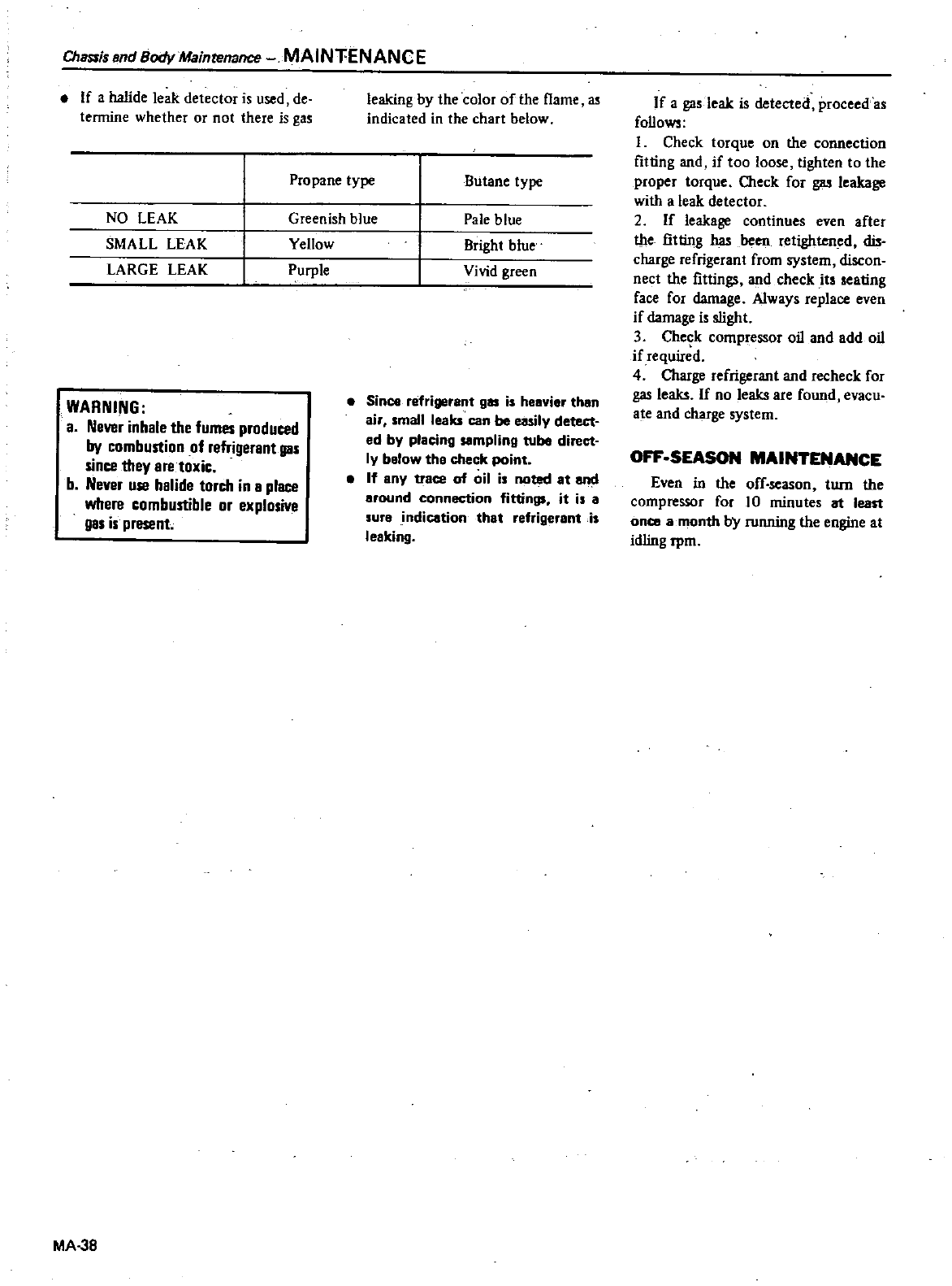
Chassis
end
Body
Maint
mance
MAINTENANCE
If
a
halide
leak
detector
is
used
de
termine
whether
or
not
there
is
gas
leaking by
the
color
of
the
flame
as
indicated
in
the
chart below
Propane
type
Butane
type
NO
LEAK
Greenish
blue
Pale
blue
SMALL
LEAK
Yellow
Bright
blue
LARGE
LEAK
Purple
Vivid
green
WARNING
a
Never
inhale
the
fumes
produced
by
combustion
of
J
nt
gas
since
they
are
toxic
b
Never
use
halide
torch
in
a
place
where
combustible
or
explosive
gas is
present
MA
38
Since
refrigerant
gas
is
heavier
than
ai mall
leaks
can
be
easily
detect
ed
by
placing
sampling
tube
direct
ly
below
the
check
point
If
eny
trace
of
oil
i
noted
at
and
around
connection
fittings
it
is
a
sure
indication
that
refrigerant
is
le
king
If
a
gas
leak
is
detecteil
proceed
as
follows
I
Check
torque
on
the
connection
fitting
and
if
too
loose
tighten
to
the
proper
torque
Oieck
for
gas
leakage
with
a
leak
detector
2
If
leakage
continues
even
after
the
fitting
has
been
retightened
dis
charge
refrigerant
from
system
discon
nect
the
fittings
and
check
it
eating
face
for
damage
Always
replace
even
if
damage
is
slight
3
Che
k
compressor
oil
and add
oil
if
required
4
Oiarge
refrigerant
and
recheck
for
gas
leaks
If
no
leaks
are
found
evacu
ate
and
charge
system
OFF
SEASON
MAl
ANCE
Even
in
the
off
season
turn
the
compressor
for
10
minutes
at
least
once
a
month
by
running
the
engine
at
idling
rpm
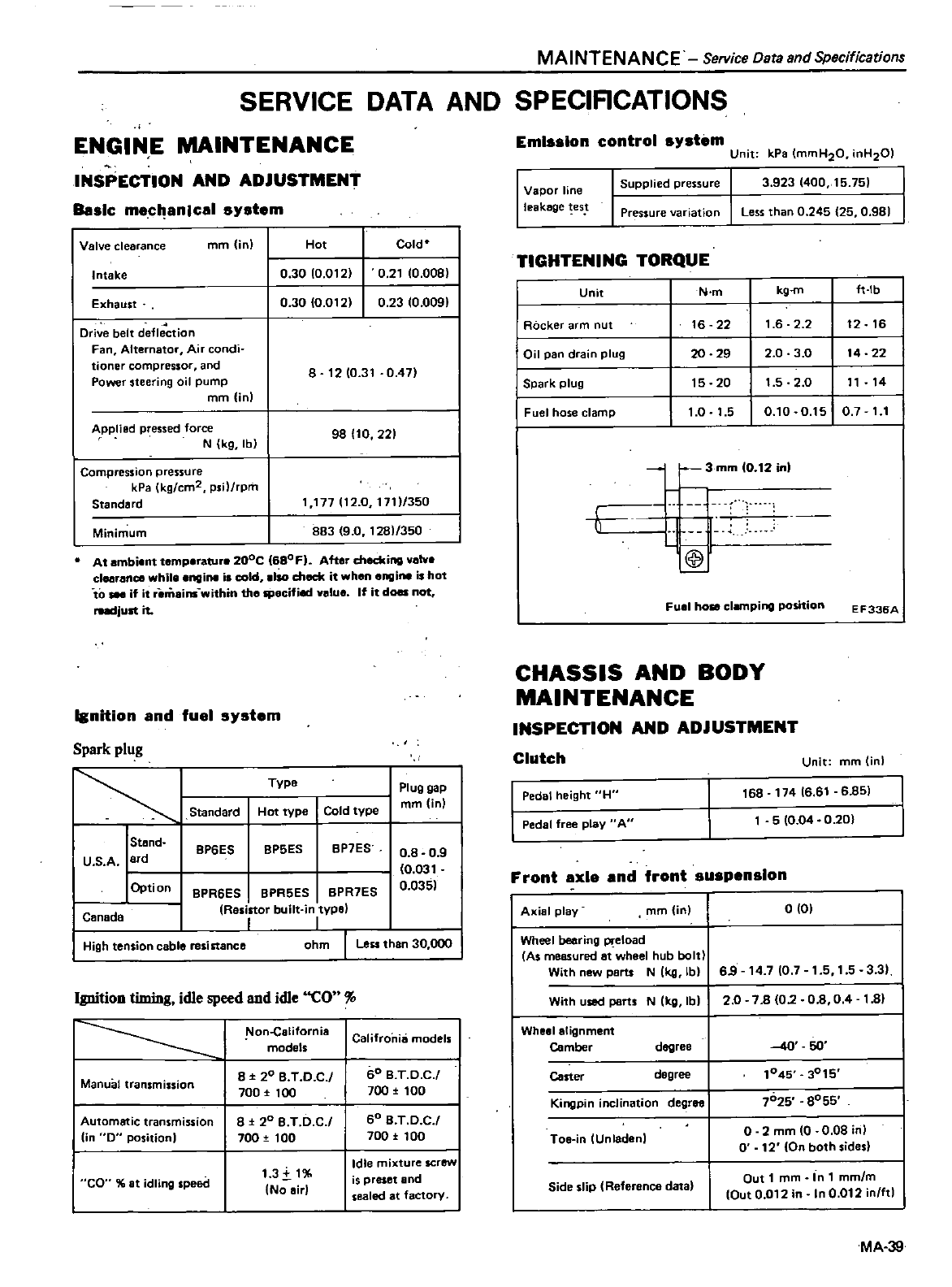
MAINTENANCE
Service
Data
and
Specifications
SERVICE
DATA
AND
SPECIACATIONS
ENGINE
MAINTENANCE
INSPECTION
AND ADJUSTMENT
Basic
mecl
anlcal
system
Valve
clearance
mm
in
Hot
Cold
Intake
0
30
10
Ot
2 0
2t
10
008
0
23
10
0091
Exhaust 0
30
O
Ot
2
Drive
belt
defle
tion
Fan
Alternator Air
condi
tioner
compressor
and
Power
steering
oil
pump
mm
in
8
t210
3t
0
47
Applied
pressed
force
N
kg
lb
98110
221
Compression
pressure
kPa
kg
cm2
psil
rpm
Standard
t
t77lt2
0
17t1
350
883 9
0 t
281
350
Minimum
At
ambient
temperature
200C
680F
After
checking
valve
clearance
while
engine
is
cold
Iso
check
it
when
engine
is
hot
to
if it
remains
within the
Jpecifi
value
If
it
does
not
rudjunit
I
nition
and
fuel
system
Spark
plug
Type
Plug
gap
mm
in
Hot
type
Cold
type
Standard
IStBnd
U
S
A
ard
I
Opti
on
8P7ES
8P5ES8P6ES
0
8 0
9
0
03t
0
035
8PR6ES 8PR5ES 8PR7ES
ResUor
built
in
type
II
ohm
I
Less
than
30
000
Canada
High
tension
cable resistance
Ignition
timing
idle
speed
and
idle
CO
1
on
california
Califronhi
models
1
models
I
ManuOl
tran
mission
8
t
20 B T
D C
60 B
T D
C
I
700
l
100
700
l
100
I
Automatic
tran
mission
8
l
20
B
T
D
C60 B
T O
C
I
lin
0
position
I
700
tOO
700
tOO
1
3i
t
Idle
mixture
screw
CO
at
idling
speed
is
preset
and
No
air
sealed
at
factory
Emission
control
system
Unit
kPa
mmH20
inH201
Vapor
line
leakage
es
Supplied
pressure
3 923 400
15
751
Pressure
variation
Less
than
0
245
25
0
981
TIGHTENING
TORQUE
Unit
N
m
kg
m
ft
Ib
Rocker
arm
nut
16
22
t
6 2 2
12
t6
Oil pan
drain
plug
20 29
2 0 3
0
t4
22
I
Spark
plug
t5
20
1
5 2
0
tt
t4
Fuel
hose
clamp
1
0 t
5
O
tO
0
t5
0
7
11
h
3
mm
0
12
in
l
@
Fuel
hose
clamping
position
EF335A
CHASSIS
AND
BODY
MAINTENANCE
INSPECTION
AND ADJUSTMENT
Clutch
Unit
mm
inl
Pedal
height
H
t68
17416
61
6
851
5
10
04
0
20
Pedal
free
play
AU
Front
axle
and
front
suspension
Axial
play
mm
inl
0
01
Wheel
bearing Pl
eload
As
measured
at
wheel
hub
bolt
With
nBW
pBrts
N
Ikg
lbl
69
t4
710
7
1
5
1
5
3
3
With
used
part
N
Ikg
Ibl
20
78 02
0
8
04
t
81
Wheel
alignment
Camber
degree
40
SO
Carter
degree
1045
3015
Kingpin
inclination
degree
7025
8055
Toe
in
Unladenl
o
2
mm
10
0
08 inl
0
12
On
both sides
Side
slip
Reference
data
Out
1
mm
In
1
mm
m
Out
0
012
in
In
0
012
in
ftl
MA
39
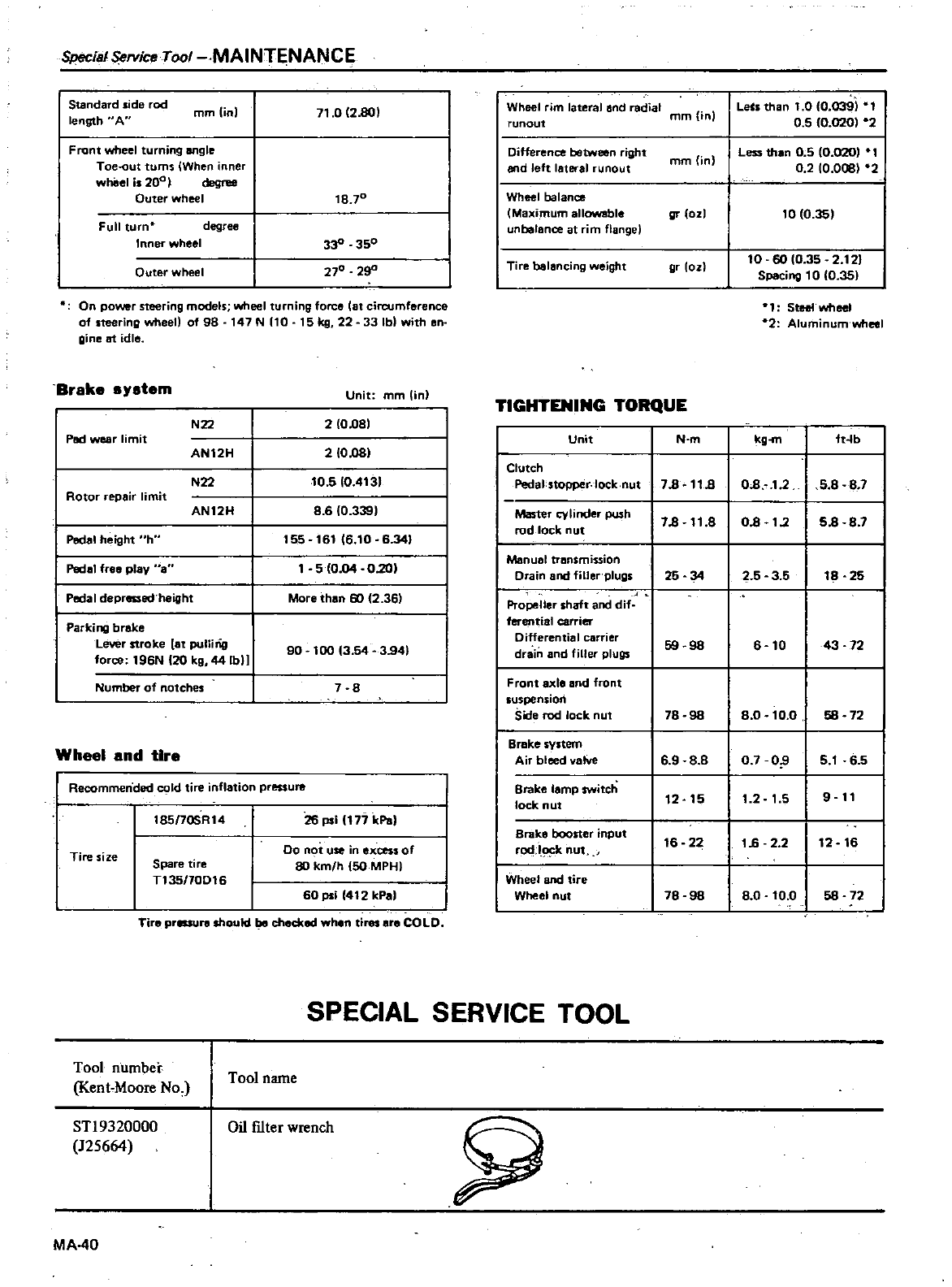
SpecialSi
rvice
Tool
MAINT
NANCE
Standard
ide
rod
length
A
mmlinl
71
0
1280
Front
wheel
turning
angle
Toe
out
turns
IWhen
inner
wheel
i
200
I
degree
Outer
wheel
18
70
Full
turn
degree
Inner
wheel
33
350
270
29
Outer
wheel
On
power
steering
models
wheel
turning
force
lat
circumference
of
steering
wheel
of
98
147
N
110
15
kg
22 33
Ib
with
en
gine
at
idle
Brake
s
stem
Unit
mm
lin
N22
210081
2
10001
10
5
10
4131
86
10
339
155
16116
10
6
341
5
1004
0
201
Pad
wear
limit
AN12H
N22
Rotor
repair
limit
AN12H
Pedal
height
h
Pede
fre8
play
a
Pedal
depressed
height
More
than
60
f2
36
Parking
brake
Lever
stroke
8t
pullirig
0
0
t96N
120
kg
44lbll
90
100
13
54
3
941
Number
of
notches
7
8
Wheel
and
tire
Recommended
Id
tire
inflation
pressure
t85
7OSR14
26
psi
1177
kPaI
Tire
size
00
not
use in
excess of
80
kmlh
150
MPHI
Spare
tire
T135
70DI6
60
psi
1412
kPa
Tire
prlSlure
should
be
checked
when
tires
are
COLD
Wheel
rim
lateral
and
radial
mm
in
runout
LeCs
than
1
0 0
039
0
5
10
020
02
Difference
between
right
end
left
lateral
runout
Less
than
0
5
0
020
1
0
2
10
008
2
mm
in
Wheel
balance
Maximum
allowable
unbelance
at
im
flange
gr
ozl
to
10
35
Tire
balancing
weight
10
60
10
35
2
121
Spac
ng
to
10
351
gr
loz
1
Steet
wheel
2
Aluminum
wheel
TIGHTENING
TORQUE
Unit
N
m
kg
ft
fb
Clutch
Pedal
stopper
lock
nut
78
11
8
08
12
5 8 8
7
Master
cylinder
push
78 11
8
08
t
2
58
8
7
rod
lock
nut
Manual
transmission
Drain
and
filler
plugs
25 34
25 3
5
18 25
Propeller
shaft
and
dif
ferential
carrier
Differential
carrier
59 98
6
10
43 72
drain
and
filler
plugs
Front
axle
and
front
suspension
Side
rod
lock
nut
78
98
80
to
O58
72
Brake
system
Air
bleed
vatve
6 9 8
8 0
7
O
5
1
6
5
Brake
lamp
switch
12
15
1
2
1
5
9
11
lock
nut
Brake
booster
input
16
22
16
2 2
12
16
rod
k
nut
Wheel
and
tire
Wheel
nut
78
98
80
to
O58
72
SPECIAL
SERVICE
TOOL
Tool
number
Kent
Moore
No
Tool
name
ST19320000
125664
Oil
fIlter
wrench
MA
40
SJ
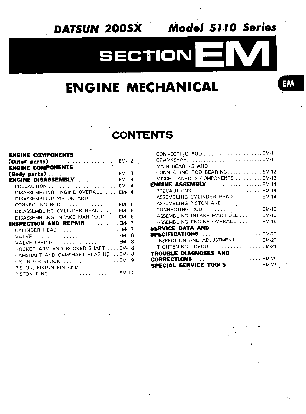
DATSUN
200SX
Model
S
0
Series
ENGINE
MECHANICAL
CONTENTS
ENGINE
COMPONENTS
Outer
parts
ENGINE
COMPONENTS
Body
parts
ENGINE
DISASSEMBLY
PRECAUTION
DISASSEMBLING
ENGINE
OVERALL
DISASSEMBLING
PISTON
AND
CONNECTING
ROD
DISASSEMBLING
CYLINDER HEAD
DISASSEMBLING
INTAKE
MANIFOLD
INSPECTION
AND
REPAIR
CYLINDER
HEAD
VALVE
VALVE
SPRING
ROCKER
ARM
AND
ROCKER
SHAFT
GAMSHAFT
AND
CAMSHAFT
BEARIN
CYLINDER
BLOCK
PISTON PISTON
PIN
AND
PISTON RING
EM
2
EM 3
EM
4
EM
4
EM
4
EM
6
EM 6
EM 6
EM
7
EM 7
EM
8
EM
8
EM 8
EM
8
EM
9
EM lO
CONNECTING
ROD
CRANKSHAFT
MAIN
BEARING
AND
CONNECTING
ROD
BEARING
MISCELLANEOUS
COMPONENTS
ENGINE
ASSEMBLY
PRECAUTIONS
ASSEMBLING
CYLINDER
HEAD
ASSEMBLING
PISTON
AND
CONNECTING
ROD
ASSEMBLING
INTAKE
MANIFOLD
ASSEMBLING
ENGINE
OVERALL
SERVICE
DATA
AND
SPECIFICATIONS
INSPECTION
AND
ADJUSTMENT
TIGHTENING
TORGUE
TROUBLE
DIAGNOSES
AND
CORRECTIONS
SPECIAL
SERVICE
TOOLS
EM
ll
EM
l1
EM
12
EM 12
EM 14
EM 14
EM 14
EM 15
EM 16
EM
16
EM
20
EM
20
EM
24
EM
25
EM
27
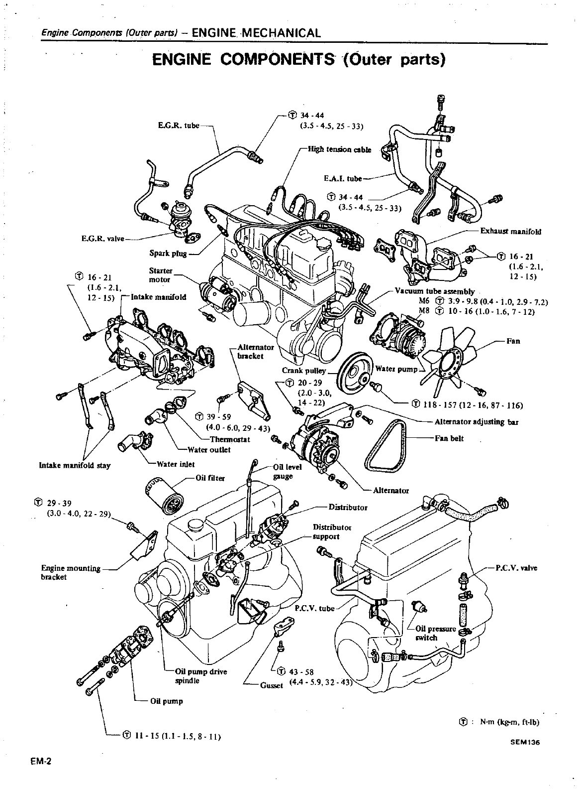
EngineComponenrs
Outer
parts
ENGINE
MECHANICAL
ENGINE
COMPONENTS
Outer
parts
IIigb
temion
coble
1
l
Intake
manifold
st
y
I
l
34
44
35
4
5
25 33
EA
tube
E
G
R
ValVe
Exhaust
manifold
1
l16
21
iti6
2
t
Starter
motor
1
l16
21
1
6 2 1
t2 t5
Intake
manifold
157
12
16 87
116
Alternator
adjusting
bar
Fan
belt
J
29 39
3 0
4
0
22
P
C
V
valve
Oil
pump
J
N
m
tg
m
ft
lb
15
8
11
SEM136
EM
2
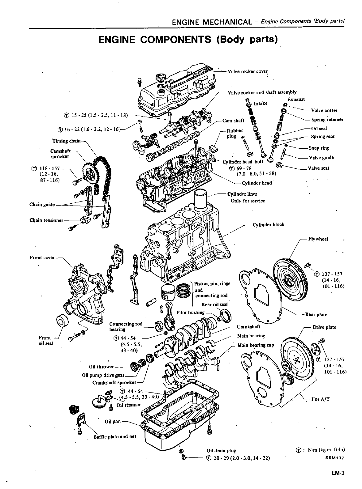
ENGINE
MECHANICAL
Engine
Components
Body
parts
ENGINE
COMPONENTS
Body
parts
Front
cove
l
Valve
rocker
cover
If
16 22
1
6
2 2
2
Valve
rocker
and
shaft
assem
bly
@
Exhaust
tntake
9
Vatve
cotter
eam
shaft
Spring
retainer
Rubber
e
1
Oil
seal
plug
Spring
seat
j
snap
ring
Valve
gUide
Cylinder
head
bolt
If
69
18
Valve
at
1
0
8 0
51
58
Cylinder
head
Camshalt
sprocket
Cylinder
liner
Only
for
service
Cylinder
block
t51
t6
116
Drive
plate
151
16
116
Oil
drain
plug
If
20 29
2
0 3
0
14
22
If
N
m
kg
m
ft
lb
EM137
EM
3
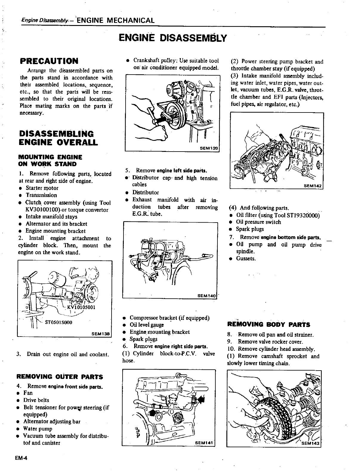
EqgineDisassemb
y
ENGINE
MECHANICAL
PRECAUTION
Arrange
the
disassembled
parts
on
the
parts
stand
in
accordance
with
their
assembled
locations
sequence
etc
so
that
the
parts
will
be
reas
sembled
to
their
original
locations
Place
mating
marks
on
the
parts
if
necessary
DISASSEMBLING
ENGINE
OVERALL
MOUNTING
ENGINE
ON
WOi
tK
STAND
I
Remove
following
parts
located
at
rear
and
right
side
of
engine
Starter
otor
Transmission
Clut
h
cover
assembly
using
Tool
KV30100100
or
torque
convertor
Intake
manifold
stays
Alternator
and
its
bracket
Engine
mounting
bracket
2 Install
engine
attachment
to
cylinder
block
Then
mount
the
engine
on
the
work
stand
SEMl38
3
Drain
out
engine
oil
and
coolant
REMOVING
OUTER
PARTS
4
Remove
engine
front
side
parts
Fan
Drive
belts
Belt
tensioner
for
powI
steering
if
equipped
Alternator
adjusting
bar
Water
pump
Vacuum
tube
assembly
for
distribu
tot
and
canister
EM4
ENGINE
DISASSEMBLY
Crankshaft
pulley
Use
suitable
tool
on
air
conditioner
equipped
model
SEMl39
5
Remove
engine
left
side
parts
Distributor
cap
and
high
tension
cables
Distributor
Exhaust
manifold
with
air
in
duction
tubes
after
removing
E
G
R
tube
SEM140
Compressor
brac
ret
if
equipped
Oil
level
gauge
Engine
mounting
bracket
Spark
plugs
6
Remove
engine
right
side
parts
I
Cylinder
block
to
P
C
V
valve
hose
2
Power
steering
pump
bracket
and
throttle
chamber
stay
if
equipped
3
Intake
manifold
mbly
includ
ing
water
inlet
water
pipes
water out
let
vacuum
tubes
E
G R
valve
throt
tie
chamber
and
EFI
parts
lnjecturs
fuel
pipes
air
regulator
etc
SEM
142
4
And
follpwing
parts
Oil
f1Iter
using
Tool
STl932ciOOO
Oil
pressure
switch
Spark
plugs
7
Remove engine
bottom
side
parts
Oil
pump
and
oil
pump
drive
spindle
Gussets
REMOVING
BODY
PARTS
8
Remove
oil
pan and
oil
strainer
9
Remove
valve
rocker
cover
10
Remove
cylinder
head
assembly
1
Remove
camshaft
sprocket
and
slowly
lower
timing
chain
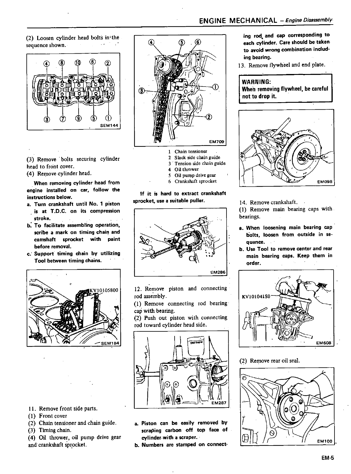
2
Loosen
cylinder
head
bolts
in the
sequence
shown
SEM144
3
Remove
bolts
securing
cylinder
head
to
front
cover
4
Remove
cylinder
head
When
removing
cylinder
head
from
engine
installed
on
car
follow
the
instructions below
8
Turn
crankshaft
until
No
1
piston
is
at
T
D C
on
its
compression
stroke
b
To
facilitate
assembling
operation
scribe
a
mark
on
timing
chai
and
camshaft
sprocket
with
paint
before
removal
c
Support
timing
chain
by
utilizing
Tool
between
timing
chains
II
Remove
front
side
parts
I
Front
cover
2
Chain
tensioner
and
chain
guide
3
Timing
chain
4
Oil
thrower
oil
pump
drive
gear
and
crankshaft
spr
ocket
ENGINE
MECHANICAL
Engine
Disassembly
1
Chain
tensioner
2
Slack
side
chain
guide
3
Tension
side
chain
guide
4
0
il
thrower
5
Oil
PUJl
P
drive
gear
6
Crankshaft
sprocket
If
it
is
hard
to
extract
crankshaft
sprocket
use asuitable
puller
EM286
12
Remove
piston
and
connecting
rod
assembly
I
Remove
connecting
rod
bearing
cap
with
bearing
2
Push
out
piston
with
connecting
rod
toward
cylinder
head
side
J1c
l
J
C
j
I
r
G
0
II
O
EJ
S7
8Piston can
be
easily
removed
by
scraJiing
carbon
off
top
face
of
cylinder
with
a
scraper
b
Numbers
are
stamped
on
connect
ing
rod
and
cap
corresponding
to
each
cylinder
Care
should
betaken
to
avoid
wrong
combination
includ
ing
bearing
13
Remove
flywheel
and end
plate
WARNING
When
removing
flywheel
be
careful
not
to
drop
it
14
Remove
crankshaft
1
Remove
main
bearing
caps
with
bearings
8
When
loosening
main
bearing
cap
bolts
loosen
from
outside
in
se
quence
b
Use
Tool
to
remoye
center
and
rear
main
bearing
caps
Keep
them
in
order
KVIOI041S0
EM608
f
Remove
rear
oil
seal
T
@rb
EM1QO
EM
5
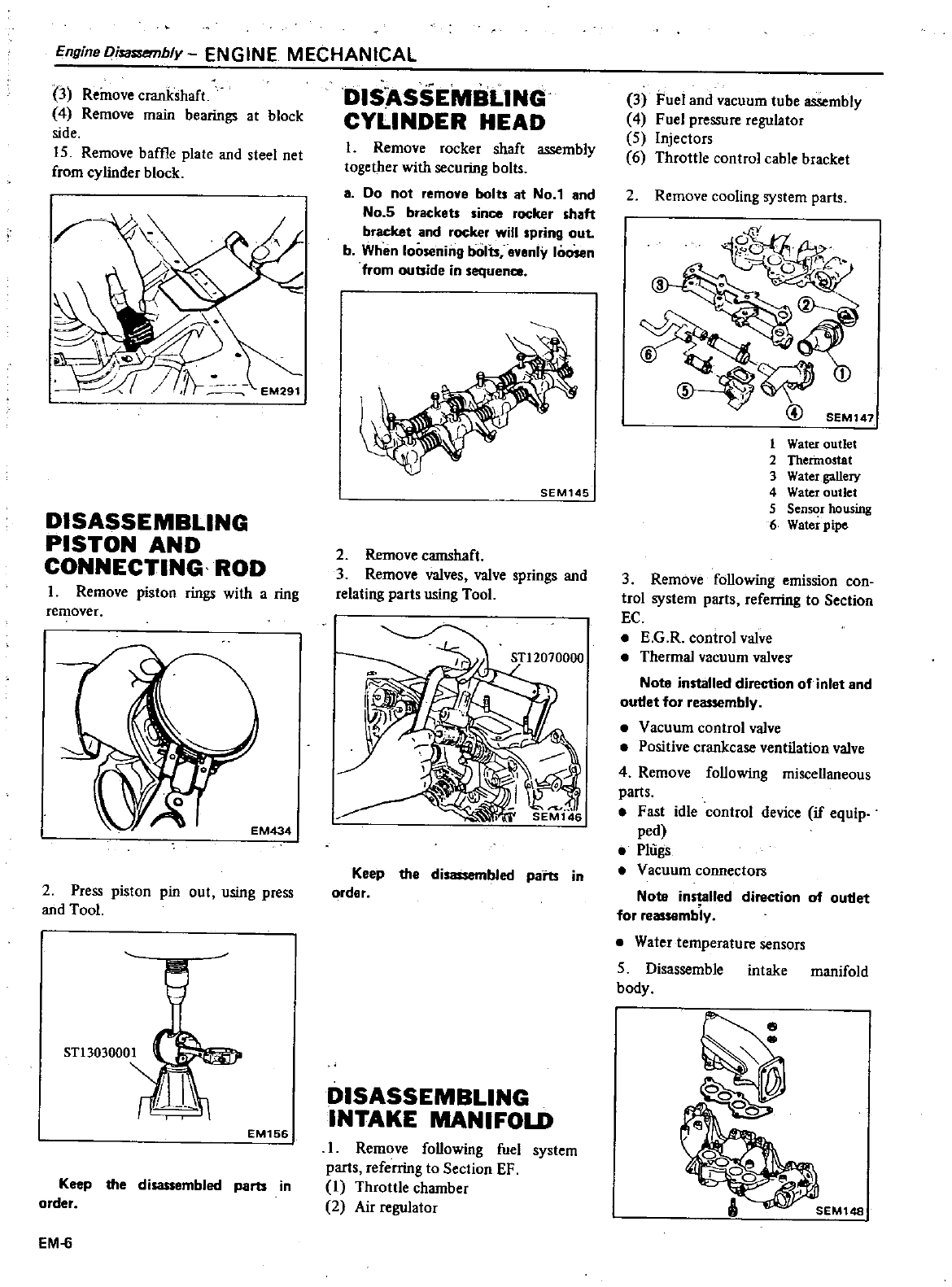
EngineOisa
Sl
fTlbly
ENGINE
MECHANICAL
3
Remove
crankshaft
4
Remove
main
bearings
at
block
side
15
Remove
baffle
plate
and
steel
net
from
cylinder
block
DISASSEMBLING
PISTON
AND
CONNECTING
ROD
1
Remove
piston
rings
with
a
ring
remOver
2
Press
piston
pin
out
using
press
and
Too
ST13030001
EM156
Keep
the
disassembled
parts
in
order
EM
6
DISASSEMBLING
CYLINDER
HEAD
1
Remove
rocker
shaft
assembly
together
with
securing
bolts
a
Do
not
remove
bolu
at
No
1
and
No
5
brackeU
since
rocker shaft
bracket
and
rocker
will
spring
out
b
When
loosening
bolts
evenly
loosen
from
outside
in
sequence
SEM145
2
Remove
camshaft
3
Remove
valves
valve
springs
and
relating parts
using
Too
ST12070000
Keep
the
disassembled
parts
in
order
DISASSEMBLING
INTAKE MANIFOLD
1
Remove
following
fuel
system
parts
referring
to
Section
EF
I
Throttle
chamber
2
Air
regulator
3
Fuel
and
vacuum
tube
assembly
4
Fuel
pressure
regulator
5
Injectors
6
Throttle
control
cable
bracket
2
Remove
cooling
system
parts
1
Water
outlet
2
Thermostat
3
Water
gallery
4
Water
outlet
5
Semol
housing
6
Water
pipe
3
Remove
following
emission
con
trol
system
parts
referring
to
Section
EC
E
G
R
control
valve
Thermal
vacuum
valveS
Nota
installed
direction
of
inlet
and
outletfor
reassembly
Vacuum
control
valve
Positive
crankcase
ventilation
valve
4
Remove
following
miscellaneous
parts
Fast
idle
control
device
if
equip
ped
Plugs
Vacuum
connectors
Note installed
direction
of
outl
t
for
r
mbly
Water
temperature
sensors
5
Disassemble
intake
manifold
body
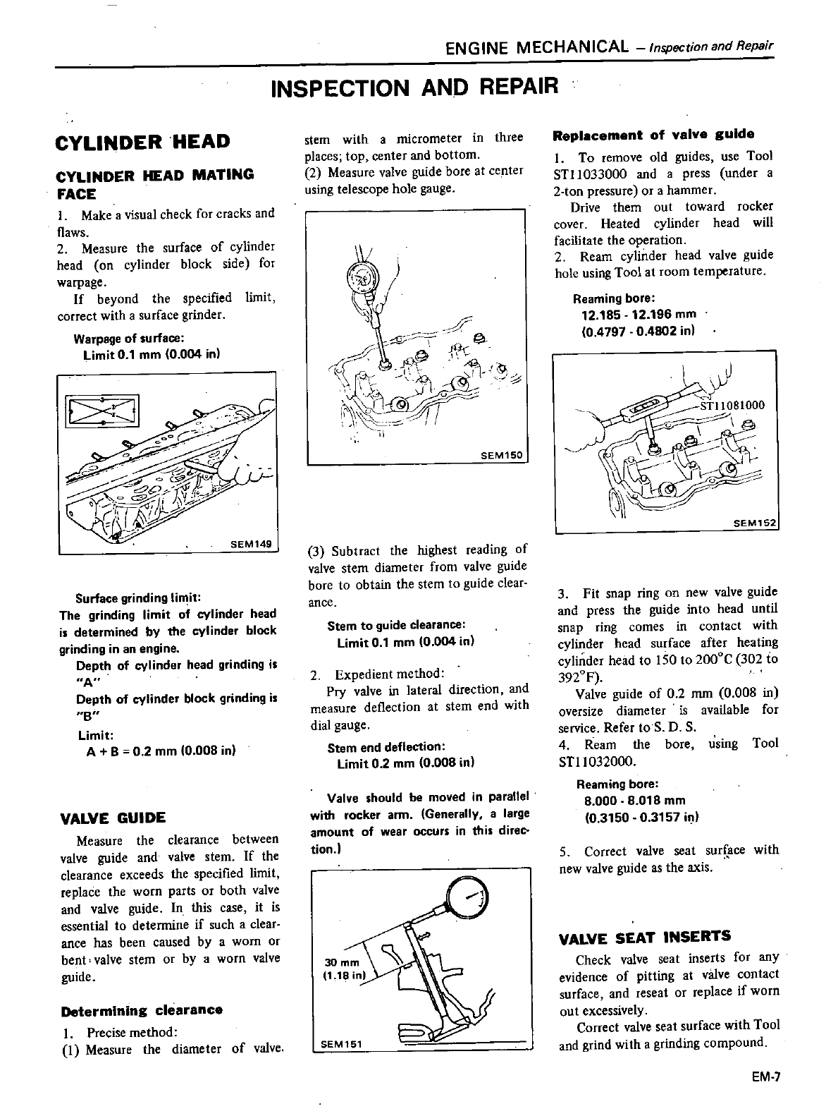
CYLINDER
HEAD
CYLINDER
HEAD
MATING
FACE
I
Make
a
visual
check
for
cracks
and
flaws
2
Measure
the
surface
of
cylinder
head
on
cylinder
block
side
for
warpage
If
beyond
the
specified
limit
correct
with
a
surface
grinder
Warpage
of
surface
limit
0
1
mm
0
004
int
It
Cil
SEM14g
Surface
grinding
li
it
The
grinding
limit
of
cylinder
head
is determined
by
the
cylinder
block
grinding
in
an
engine
Depth
of
cylinder
head
grinding
is
A
Depth
of
cylinder
block
grinding
is
8
limit
A
B
0 2
mm
10
008
in
VALVE GUIDE
Measure
the
clearance
between
valve
guide
and
valve
stem
If
the
clearance
exceeds
the
specified
limit
replace
the
worn
parts
or
both
valve
and valve
guide
In this
case
it
is
essential
to
detennine
if
such
a
clear
ance
has
been caused
by
a
worn
Or
bent
valve
stem
or
by
a
worn
valve
guide
Determining
clearance
Precise
method
I
Measure
the
diameter
of
valve
ENGINE
MECHANICAL
lnspectionandRepair
INSPECTION AND
REPAIR
stem
with a
micrometer
in
three
places
top
center
and
bottom
2
Measure valve
guide
hore
at
center
using
telescope
hole
gauge
F
A
T
Mr
h
oP
10
1
L
j1
@
I
C
d
SEM150
3
Subtract
the
highest
reading
of
valve
stem
diameter
from
valve
guide
bore
to
obtain
the
stem
to
guide
clear
ance
Stem
to
guide
clearance
limit
0
1
mm
10
004 in
2
Expedient
method
Pry
valve
in
lateral
direction
and
measure
deflection
at
stem
end
with
dial
gauge
Stem
end
deflection
limit
02
mm
0
008 in
Valve
should
be
moved
in
parallel
with
rocker
arm
Generally
a
large
amount
of
wear
occurs
in
this
direC
tion
SEM151
Replacement
of
valve
guide
1
To
remove
old
guides
use
Tool
S111033000
and
a
press
under
a
2
ton
pressure
or
a
hammer
Drive
them
out
toward
rocker
cover
Heated cylinder
head
will
facilitate
the
operation
2
Ream
cylinder
head
valve
guide
hole
using
Tool
at
room
temperature
Reaming
bore
12
185
12
196
mm
04797
0
4802
in
SEM152
3
Fit
snap
ring
on
new
valve
guide
and
press
the
guide
into
head
until
snap
ring
comes
in
contact
with
cylinder
head
surface
after
heating
cylinder
head
to
150
to
2000C
302 to
3920F
Valve
guide
of
02
mm
0
008
in
oversize
diameter is
available
for
service
Refer
to
S
D
S
4
Ream
the
bore
using
1001
STl1032000
Reaming
bore
8
000
8
018
mm
0
3150
0
3157
in
5
Correct
valve
seat
sur
ace
with
new
valve
gUide
as
the
axis
VALVE
SEAT
INSERTS
Check
valve
seat
inserts
for
any
evidence
of
pitting
at
valve
contact
surface
and
reseat
or
replace
ifworn
out
excessively
Correct
valve
seat
surface
with
Tool
and
grind
with
a
grinding
compound
EM
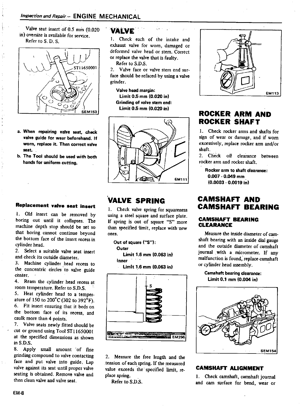
Inspection
and
Repair
ENGINE
MECHANICAL
Valve
seat
insert
of
05
min
0
020
in
oversize
is
available
for
service
Refer
to
S
O
S
J
a
When
repa
nng
valve
seat
check
valve
guide
for
wear
beforehand
If
worn
replace
it
Then
correct
valve
seat
b
The
Tool
should
be
used
with
both
hands
for
uniform
cutting
Replacement
valve
seat
insert
I
Old
insert
can
be
removed
by
boring
out
until
it
collapses
The
machine
deplh
stop
should
be
set
so
that
boring
cannot
continue
beyond
the
bottom
face
of
the
insert
recess
in
cylinder
head
2
Select
a
suitable
valve
seat
insert
and check
its
outside
diameter
3
Machine
cylinder
head
recess
to
the
concentric
circles
to
valve
guide
center
4
Ream the
cylinder
head
recess
at
room
temperature
Refer
to
S
O
S
5
Heat
cylinder
head
10
a
temper
ature
of
150
to
2000C
302
to
3920
F
6
Fit
inserl
ensuring
that
it
beds
on
the
bottom
face
of
its
recess
and
caulk
more
than
4
points
7
Valve
seats
newly
fitted
should
be
cut
or
ground
using
Tool
ST1l65000l
at
the
specified
dimensions
as
shown
in
S
O
S
8
Apply
small
amount
of
fine
grinding compound
to
valve
contacting
face
and
put
valve
into
guide
Lap
valve
against
its
seat
until
proper
valve
seating
is
obtained
Remove
valve
and
then
clean
valve and valve
seat
EM
8
VALVE
I
Check
each
of
the
intake
and
exhaust
valve
for
worn
damaged
or
defonned
valve
head
or
stem
Correct
or
replace
the
valve
that
is
faulty
Refer
to
S
o
s
2
Valve
face
or
valve
stem
end
sur
face
should
betefaced
by
using
a
valve
grinder
Valve
head
margin
Limit
05
mm
10
020
inl
Grinding
of
valve
stem
end
Limit
0 5
mm
10
020 in
EM111
vALVE
SPRING
1
Check
valve
spring
for
squareness
using
a
steel
square
and
surface
plate
If
spring
is
out
of
square
S
more
than
specified
limit
replace
with
new
ones
Out
of
square
S
Outer
Limit
1
6
mm
0
063
in
Inner
Limit
1
6
mm
10
063
inl
J
0
iBEM29s
2
Measure
the
free
length
and
the
tension
of
each
spring
If
the
Illeasured
value
exceeds
the
specified
limi
I
re
place
spring
Refer
to
S
O
s
EM113
ROCKER
ARM
AND
ROCKER
SHAFT
1
Check
rocker
anns
and
shafts
for
sign
of
wear
or
damage
and
if worn
excessively
replace
rocker
arm
and
or
shaft
2
Check
oil
clearance
between
rocker
arm
and
rocker shaft
Rocker
arm
to
shaft
clearance
0
007
0
049
mm
10
0003
0
0019
inl
CAMSHAn
AND
CAMSHAn
BEARING
CAMSHAFT
BEARING
CLEARANCE
Measure
the
inside
diameter
of
cam
shaft
bearing
with
an
inside
dial
gauge
and
the
outside
diameter
of
camshaft
journal
with
a
micrometer
If
any
malfunction
is
found
replace
camshaft
or
cylinder
head
assembly
Camshaft
bearing
clearance
limit
0
1
mm
10
004
inl
SEM154
CAMSHAFT
ALIGNMENT
I
Check
camshaft camshaft
journal
and
cam
surface
for
bend
wear
or
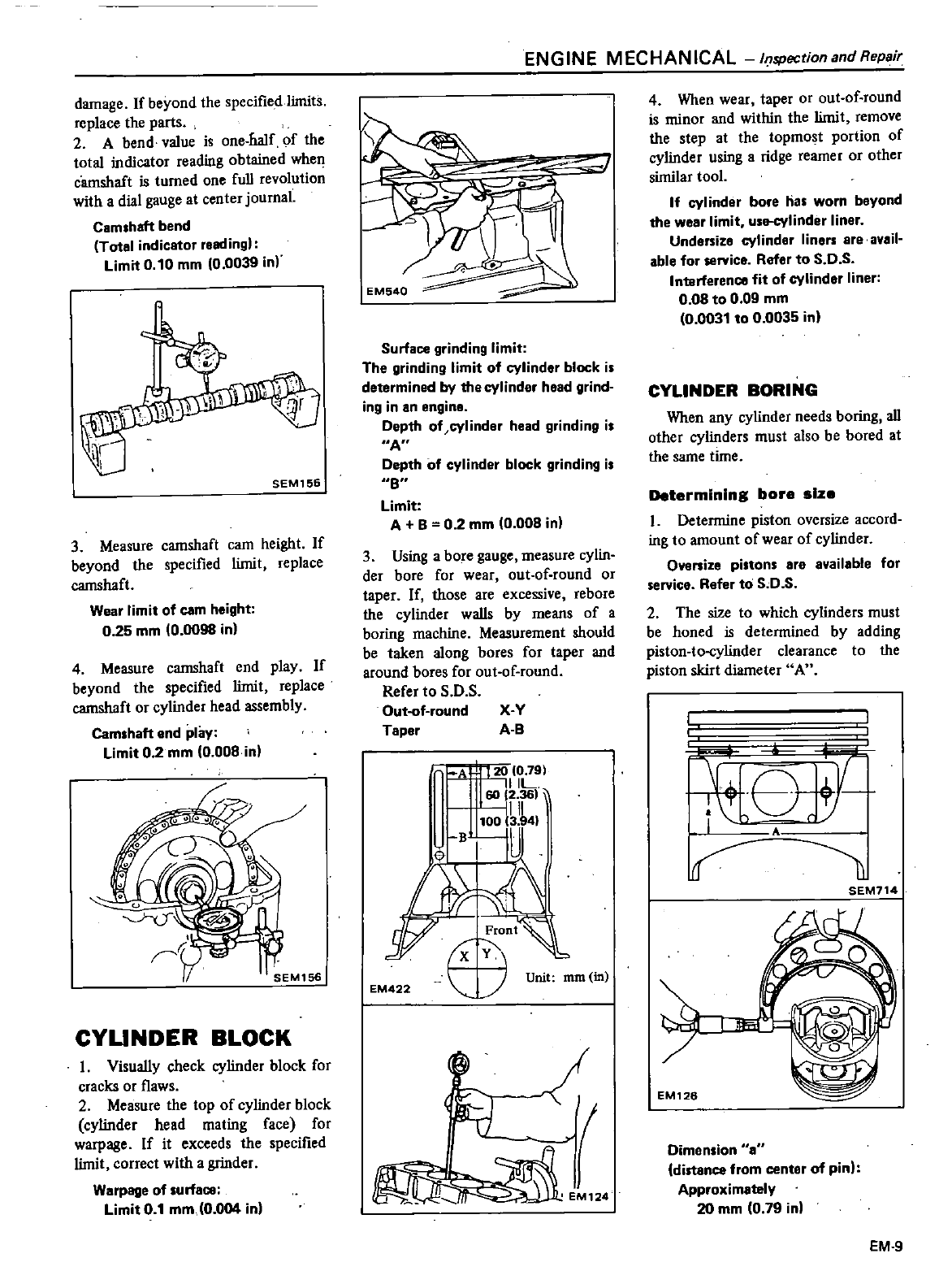
damage
If
beyond
the
specified
limits
replace
the
parts
2
A
bend
value is
one
half
of
the
total
indicator
reading
obtained
when
camshaft is
turned
one full
revolution
with
a
dial
gauge
at
center
journal
Camshaft
bend
Total
indicator
readingl
limit
0
10
mm
10
0039
in
SEM156
3
Measure
camshaft
cam
height
If
beyond
the
specified
limit
replace
camshaft
Wear
limit
of
com
height
025
mm
10
0098
in
4
Measure
camshaft
end
play
If
beyond
the
specified
limit
replace
camshaft
or
cylinder
head
assembly
Camshaft
end
play
limit
0 2
mm
0
008
in
CYUNDER
BLOCK
1
Visually
check
cylinder
block
for
cracks
or
flaws
2
Measure
the
top
of
cylinder
block
cylinder
head
mating
face
for
warpage
If
it
exceeds
the
specified
limit correct
with
a
grinder
Warpage
of
surfaC8
limit
0
1
mm
0
004
in
ENGINE
MECHANICAL
ItJSPectionand
Repair
EM540
Surface
grinding
limit
The
grinding
limit
of
cylinder
block
is
determined
by
the
cylinder
head
grind
ing
in
an
engine
Depth
of
cylinder
head
grinding
is
A
Depth
of
cylinder
block
grinding
is
8
limit
A
B
0 2
mm
0
008
in
3
Using
a
bore
gauge
measure
cylin
der
bore
for
wear
out
of
round
or
taper
If
those
are
excessive
rebore
the
cylinder
walls
by
means of
a
boring
machine Measurement
should
be
taken
along
bores
for
taper
and
around
bores
for
out
of
round
Refer
to
S
O
S
Out
of
round
X
y
Taper
A
B
FA
J1
zU
0
791
I
IiIL
60
12
361
III
I
flit
17
X
I
Unit
mm
in
EM422
L
I
EM124
4
When
wear
taper
or
out
of
round
is
minor
and
within
the
limit
remove
the
step
at
the
topmost
portion
of
cylinder
using
a
ridge
reamer
or
other
similar
tool
If
cyl
inder
bore
has
worn
beyond
the
wear
limit
use
cylinder
liner
Undersize
cylinder
liners
are
avail
able
for
service
Refer
to
S
D
S
IntarferenC8
fit
of
cylinder
liner
0
08
to
0
09
mm
0
0031
to
0
0035
in
CYLINDER
BORING
When
any
cylinder
needs
boring
all
other
cylinders
must
also
be
bored
at
the
same
time
Determining
bore
size
1
Determine
piston
oversize
accord
ing
to
amount
of
wear
of
cylinder
Ovenize
pistons
are
available
for
service
Refer
to
S
D
S
2
The
size
to
which
cylinders
must
be
honed
is
determined
by
adding
piston
to
cylinder
clearance
to
the
piston
skirt
diameter
A
T
tI
A
SEM714
EM126
Dimen
ion
distance
from
center
of
pinl
Approximately
20
mm
0
79
in
EM
9
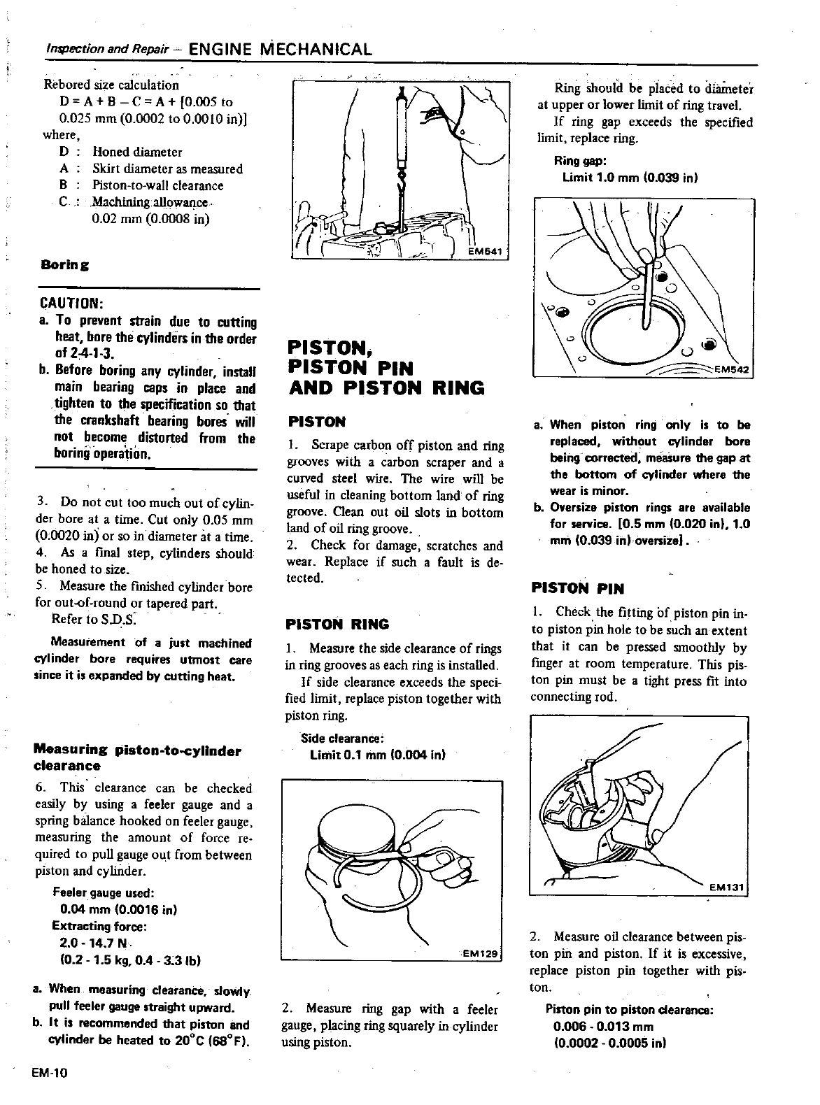
In5PectionandRepair
ENGINE
MECHANICAL
Rebored
size
calculation
D A
B
C
A
0
005
to
0
025
mm
0
0002
to
0
0010
in
where
D
A
B
C
Honed diameter
Skirt
diameter
as
measured
Piston
to
wall
clearance
Machining
allowance
0
02
mm
0
0008
in
Borin
g
CAUTION
a
To
prevenl
strain
due
to
cuning
heat
bore
the
cylinders
in
the
order
of
24
1
3
b
Before
boring
any
cylinder
install
main
bearing
caps
in
place
and
tighten
to
the
specification
so
that
the
crankshaft
bearing
bores
will
not
become
distorted
from
the
boring
operation
3
Do
not
cut too
much
out
of
cylin
der
bore
at
a
time
Cut
only
0
05
rnm
0
0020
in
or
so
in
diameter
at
a
time
4
As
a
final
step
cylinders
should
be
honed
to size
5
Measure
the
fmished
cylinder
bore
for
out
f
round
or
tapered
part
Refer
to
S
D
S
Measurement
of
a
just
machined
cylinder
bore
requires
utmost
care
since
it
is
expanded
by
cutting
heat
Measuring
piston
to
cyllnder
clearance
6
This
clearance
can
be
checked
easily
by
using
a
feeler
gauge
and
a
spring
balance
hooked
on
feeler
gauge
measuring
the
amount
of
force
re
quired
to
pull
gauge
oU
t
from
between
piston
and
cylinder
Feeler
gauge
used
0
04
mm
0
0016
in
Extracting
force
2
0
14
7
N
0
2
1
5
kg
0 4
3
3
Ibl
a
When
measuring
cl
slOWly
pull feeler
gauge straight upward
b
It
is
recommended
that
piston
and
cylinder
be
heated
to
200C 680F
EM
10
I
l
t
J
l
l
EM641
PISTON
PISTON
PIN
AND
PISTON
RING
PISTON
I
Scrape
carbon
off
piston
and
ring
grooves
with
a
carbon
scraper
and
a
curved
steel
wire
The
wire
will
be
useful
in
cleaning
bottom
land
of
ring
groove
Oean
out oil
slots
in
bottom
land
of
oil
ring
groove
2
Check
for
damage
scratches
and
wear
Replace
if
such
a
fault
is
de
tected
PISTON
RING
I
Measure
the
side
clearance
of
rings
in
ring
grooves
as
each
ring
is
installed
If
side clearance
exceeds
the
speci
fied
limit
replace
piston
together
with
piston
ring
Side
clearance
Limit
0
1
mm
0
004
inl
EM129
2
Measure
ring
gap
with
a
feeler
gauge
placing
ring
squarely
in
cylinder
using
piston
Ring
should
be
placed
to
diilmeter
at
upper
or
lower
limit
of
ring
travel
If
ring
gap
exceeds
the
specified
limit
replace
ring
Ring
gap
Limit
1
0
mm
0
039 in
8
When
piston
ring
only
is
to
be
replaced
without
cylinder
bore
being
corrected
measure
the
gap
at
the
bottom
of
cylinder
where
the
wear
is
minor
b
Oversize
piston
rings
are
available
for
service
0
5
mm
0
020
inl
1
0
mm
0
039
in
oversize
PISTON
PIN
1
Check
the
fitting
of
piston
pin
in
to
piston
pin
hole
to
be
such
an
extent
that
it
can
be
pressed smoothly
by
fmger
at
room
temperature
This
pis
ton
pin
must
be
a
tight
press
fit
into
connecting
rod
2
Measure
oil
clearance
between
pis
ton
pin
and
piston
If
it
is
excessive
replace
piston
pin
together
with
pis
ton
Piston
pin
to
piston
dearance
0
006
0
013
mm
0
0002
0
0005
in
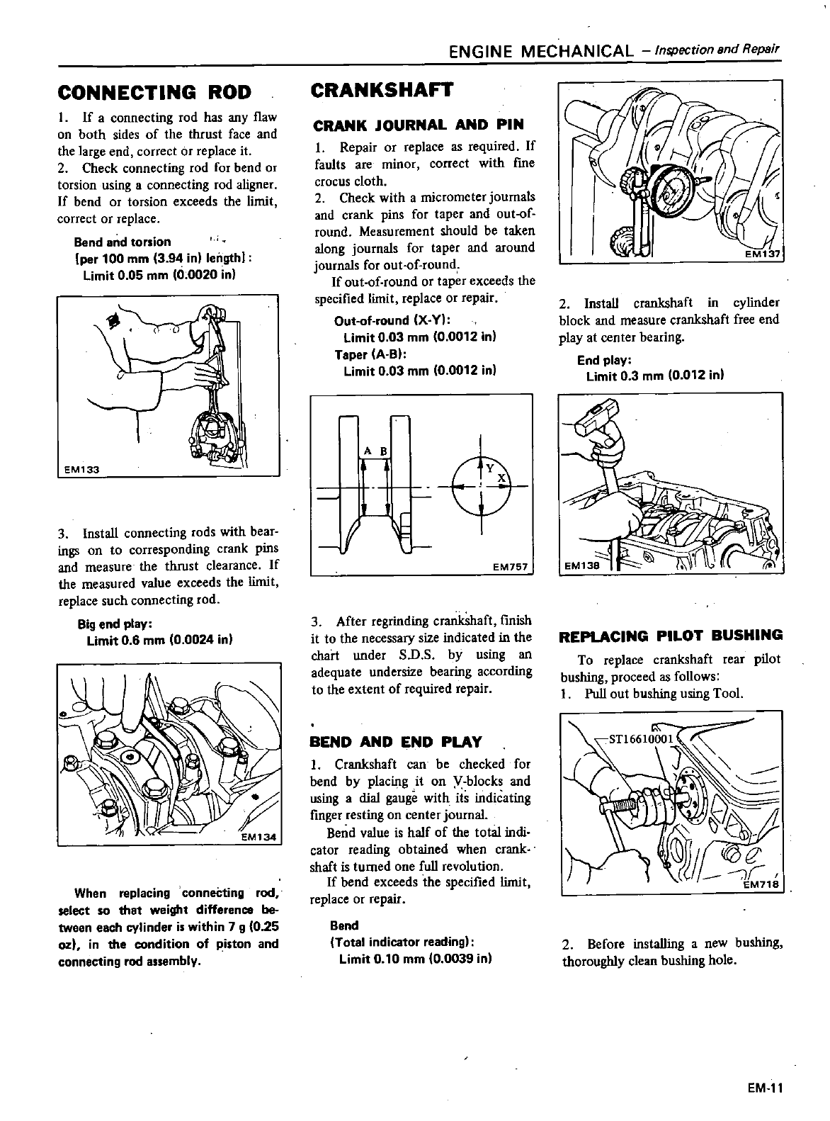
CONNECTING
ROD
I
If
a
connecting
rod
has
any
flaw
on
both
sides
of
the
thrust
face
and
the
large
end
correct
or
replace
it
2
Check
connecting
rod
for
bend
or
torsion
using
a
connecting
rod
aligner
If
bend
or
torsion
exceeds
the
limit
correct
or
replace
Bend
and
torsion
per
100
mm
394
in
length
limit
0
05
mm
10
0020
in
EM133
3
Install
connecting
rods
with
bear
ings
on
to
corresponding
crank
pins
and
measure
the
thrust
clearance
If
the
measured
value
exceeds
the
limit
replace
such
connecting
rod
Big
end
play
Limit
0
6
mm
0
0024
in
When
replacing
conneCting
rod
select
so
that
weight
difference
be
tween
each
cylinder
is
within
7
g
0
25
ozl
in the
condition
of
piston
and
connecting
rod
assembly
ENGINE
MECHANICAL
Inspectionsnd
Repair
CRANKSHA
CRANK
JOURNAL
AND
PIN
I
Repair
or
replace
as
required
If
faults
are
minor
correct
with
fme
crocus
cloth
2
Check
with
a
micrometer
journals
and
crank
pins
for
taper
and
out
of
round
Measurement
should
be
taken
along
journals
for
taper
and
around
journals
for
out
of
round
If
out
of
round
or
taper
exceeds
the
specified
limit
replace
or
repair
Out
of
round
XY
limit
0
03
mm
0
0012
in
Taper
A
BI
Limit
0
03
mm
0
0012
in
I
A
B
EP
EM767
3
After
regrinding
crankshaft
finish
it
to
the
necessary
size
indicated
in
the
chart
under
S
D
S
by
using
an
adequate
undersize
bearing according
to
the
extent
of
required
repair
BEND
AND
END
PLAY
I
Crankshaft
can
be
checked
for
bend
by
placing
it
on
V
blocks
and
using
a
dial
gauge
with
its
indicating
finger
resting
on
center
journal
Bend
value is
half
of
the
total
indi
cator
reading
obtained
when
crank
shaft
is
turned
one
full
revolution
If
bend
exceeds
the
specified
limit
replace
or
repair
Bond
Total
indicator
reading
limit
0
10
mm
0
0039
in
2
Install
crankshaft
in
cylinder
block
and
measure
crankshaft
free
end
play
at
center
bearing
End
play
limit
0 3
mm
10
012
inl
REPLACING
PILOT
BUSHING
To
replace
crankshaft
rear
pilot
bushing
proceed
as
follows
I
Pull
out
bushing
using
Tool
2
Before
installing
a
new
bushing
thoroughly
clean
bushing
hole
EM
11
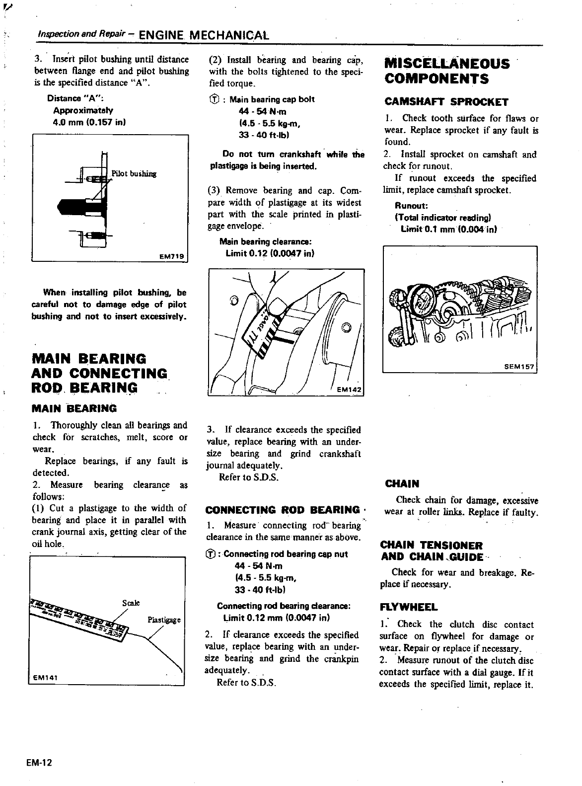
r
Inspection8ndRepair
ENGINE
MECHANICAL
3
Insert
pilot
bushing
until
distance
between
flange
end and
pilot
bushing
is
the
specified
distance
A
Distance
A
Approximately
4
0
mm
0
157
in
EM719
When
installing
pilot
bushing
be
careful
not
to
damage
edge
of
pilot
bushing
and
not
to
insert
exceuiYely
MAIN
BEARING
AND
CONNECTING
ROO
BEARIN
MAIN
BEARING
I
Thoroughly
clean
all
bearings
and
check
for
scratches
melt
score
or
wear
Replace
bearings
if
any
fault
is
detected
2
Measure
bearing
clearan
as
follows
I
Cut
a
plastigage
to
the
width
of
bearing
and
place
it
in
parallel
with
crank
journal
axis
getting
clear
of
the
oil
hole
Sale
Plastigage
EM141
EM 12
2
Install
hearing
and
bearing
cap
with
the
bolts
tightened
to
the
speci
fied
torque
rJJ
Main
bearing
cap
bolt
44
54
N
m
14
5
55
kg
m
33
40
ft
lb
Do
not turn
crankshaft
while
the
plastigage
is
being
inserted
3
Remove
bearing
and
cap
Com
pare
width
of
plastigage
at
its
widest
part
with the
scale
printed
in
plasti
gage
envelope
Main
bearing
clearance
Limit
0
12
0
0047
in
3
If
clearance
exceeds
the
specified
value
replace
bearing
with
an
under
size
bearing
and
grind
crankshaft
journal
adequately
Refer
to
S
D
S
CONNECTING
ROD
BEARING
I
Measure
connecting
rod
bearing
clearance
in
the
same
manner
as
above
rJJ
Connecting
rod
bearing
cap
nut
44 54
N
m
14
5 5 5
kg
m
33
40
ft
lb
Connecting
rod
bearing
dearance
Limit 0
12
mm
0
0047
in
2
If
clearance
exceeds
the
specified
value
repl
ce
bearing
with
an
under
size
bearing
and
grind
the
crankpin
adequately
Refer
to
S
D
S
MISCELLANEOUS
COMPONENTS
CAMSHA
SPROCKET
I
Check
tooth
surface
for
flaws
or
wear
Replace
sprocket
if
any
fault
is
found
2
Install
sprocket
on
camshaft
and
check
for
runout
If
runout
exceeds
the
specified
limit
replace
camshaft
sprocket
Runout
Total
indicator
reading
Limit
0
1
mm
0
004
inl
SEM157
CHAIN
Check
chain
for
damage
excessive
wear
at
roller
links
Replace
if
faulty
CHAIN
TENSIONER
AND
CHAIN
GUIDE
Check
for
wear
and
breakage
Re
place
if
necessary
FLYWHEEL
I
Check
the clutch
disc
contact
surface
on
flywheel
for
damage
or
wear
Repair
or
replace
if
necessary
2
Measure
runout
of
the clutch
disc
contact
surface
with
a
dial
gauge
If
it
exceeds
the
specified
limit
replace
it
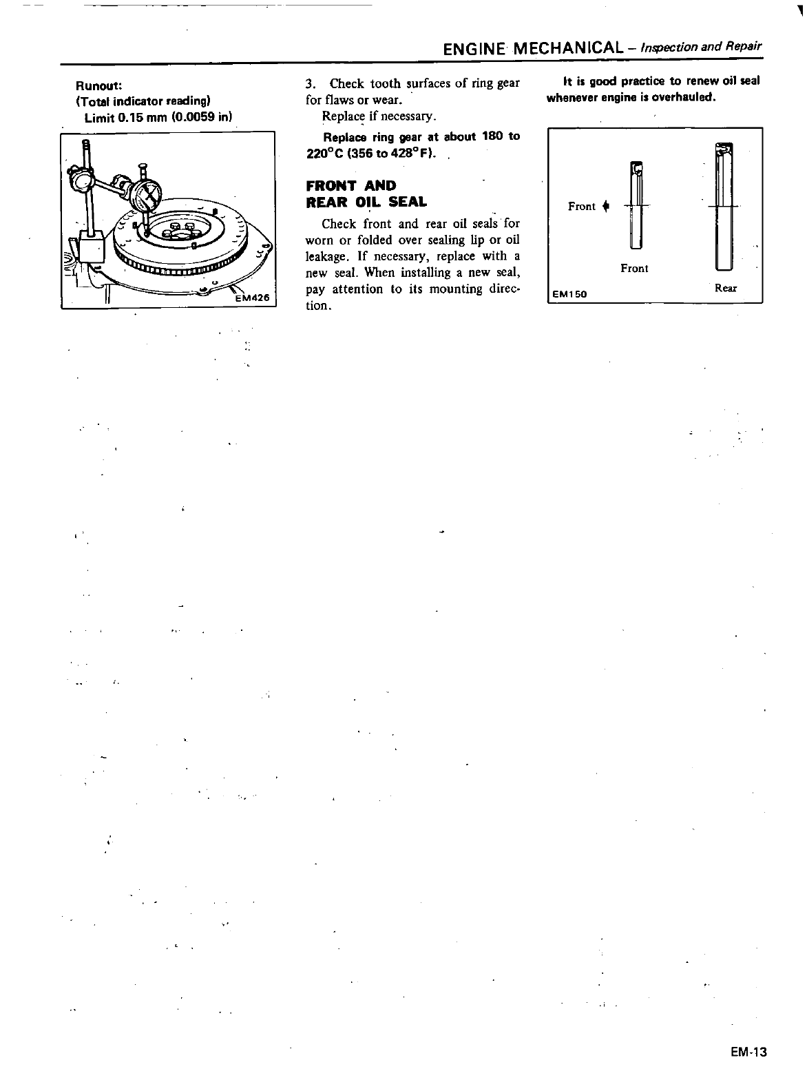
Runout
Total
indicator
reading
Limit
0
15
mm
10
0059
in
ENGINE
MECHANICAL
Inspection
and
Repair
3
Check
tooth
surfaces
of
ring
gear
for
flaws
or
wear
Replace
if
necessary
ReplaC8
ring
gear
at
about
180
to
2200C
356
to
4280F
FRONT
AND
REAR
OIL
SEAL
Check
front
and
rear
oil
seals
for
worn or
folded
over
sealing
lip
or
oil
leakage
If
necessary
replace
with
a
new
seal
When
installing
a
new
seal
pay
attention
to
its
mounting
direc
tion
It
is
good
practice
to
renew
oil
seal
whenever
engine
is
overhauled
Front
lF
1
Front
L
EM150
Rear
EM
13
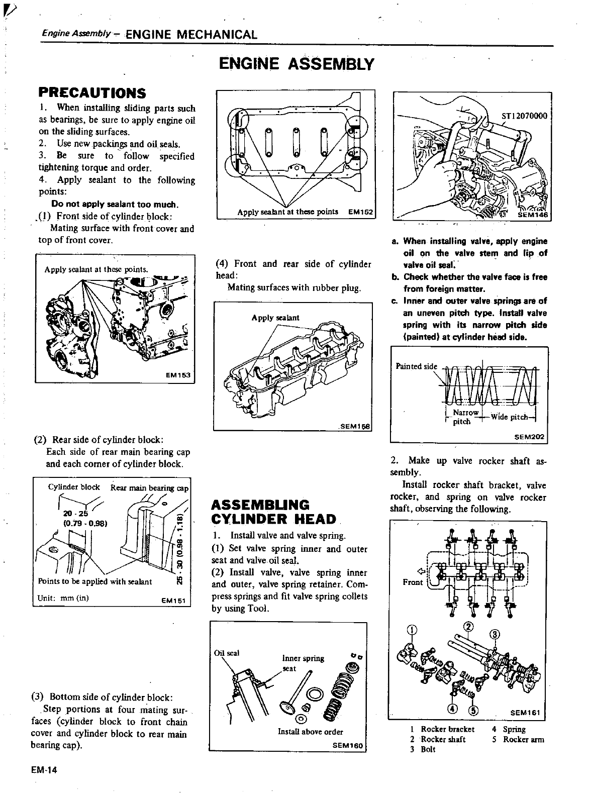
EngineAS3embly
ENGINE
MECHANICAL
PRECAUTIONS
I
When
installing
sliding
part
such
as
bearings
be
sure
to
apply
engine
oil
on
the
sliding
urfaces
2
Use
new
packings
and
oil
seals
3
Be
sure
to
follow
specified
tightening
torque
and
order
4
Apply
sealant
to
the
following
points
Do
not
apply
sealant
too
much
1
Front
side
of
cylinder
lock
Mating
surface
with
front
cover
and
top
of
front
cover
2
Rear
side
of
cylinder
block
Each
side
of
rear
main
bearing
cap
and
each
corner
of
cylinder
block
Cylinder
block
Rear
main
bearing
cap
10
79
O
gSI
4iR
i
Points
to
be
applied
with
sealant
Unit
mm
in
N
EM151
3
Bottom
side
of
cylinder
block
Step
portions
at
four
mating
sur
faces cylinder
block
to
front
chain
cover
and
cylinder
block
to
rear
main
bearing
cap
EM 14
ENGINE
ASSEMBLY
c
d
Apply
sealant
at
these
points
EM152
4
Front
and
rear
side
of
cylinder
head
Mating
surfaces
with
rubber
plug
Apply
sealant
SEMl58
ASSEMBUNG
CYLINDER HEAD
I
Install
valve
and
valve
spring
I
Set
valve
spring
inner
and
outer
seat
and valve
oil
seal
2
Install
valve valve
spring
inner
and
outer
J
valve
spring
retainer
Com
press
springs
and
fit
valve
spring
collets
by
using
Tool
Oil
seal
Inner
spring
tor
0
t
1
@
Install
above
order
SEM160
a
When
in
taIling
valve
apply
engine
oil
on
the
valva
stem
and
lip
of
valve
oil
seal
b
Check
whether
the
valve
face
i
free
from
foreign
matter
c
Inner
and
outer
valve
springs
are
of
an
uneven
pitd1
type
I
nstall
valve
spring
with
its
narrow
pitch
side
painted
at
cylinder
head
id
Painted
sid
111
c
Narrow
pitchw
Wlde
Pltch
SEM202
2
Make
up
valve
rocker
shaft
as
sembly
Install
rocker
shaft
bracket
valve
rocker
and
spring
on
valve
rocker
shaft
observing
the
following
Wf
SEM161
1
Rocker
bracket
2
Rocker
shaft
3
Bolt
4
Spring
5
Rocker
arm
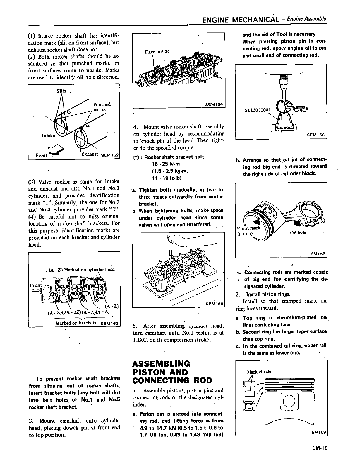
I
Intake
rocker
shaft
has
identifi
cation
mark
slit
on
front
surface
but
exhaust
rocker
shaft
does
not
2
Both
rocker
shafts
should
be
as
sembled
so
that
punched
marks
on
front
surfaces
come
to
upside
Marks
are
used
to
identify
oil
hole
direction
Slits
Intake
Front
0
Exhaust
SEM162
3
Valve
rocker
is
same
for
intake
and
exhaust
and
also
No
1
and
No
3
cylinder
and
provides
identification
mark
I
Similarly
the
one
for
No
2
and
No
4
cylinder
provides
mark 2
4
Be
careful
not
to
miss
original
location
of
rocker
shaft brackets
For
this
purpose
identification
marks
are
provided
on
each
bracket
and cylinder
head
A
Z
Marked
on
cylinder
head
v
Marked
on
brackets
SEM163
To
prevent
rocker
shaft
brackeu
from
slipping
out
of
rocker
shafts
insert
bracket
bolts
any
bolt
will
dol
into bolt
holes
of
No
1
and
No
5
rocker
shaft
bracket
3
Mount
camshaft
onto
cylinder
head
placing
dowellpin
at
front
end
to
top
position
ENGINE
MECHANICAL
Engine
Assembly
Plae
e
upside
SEM164
4
Mount
valve
rocker
shaft
assembly
on
cylinder
head
by accommodating
to
knock
pin
of
the
head
Then
tight
en
to
the
specified
torque
lil
Rocker
shaft
bracket
bolt
15
25
N
m
1
52 5
kg
m
11
18
ft
lb
a
Tighten
bolts
gradually
in
two
to
three
stages
outwardly
from
center
bracket
b
When
tightening
bolts
make
space
under
cylinder
head
since
some
valves
will
open
and
interfered
t
Z
5
After
assembling
Ll1IU r
head
turn
camshaft
until
No
1
piston
is
at
T
D
C
on
its
compression
stroke
ASSEMBLING
PISTON
AND
CONNECTING
ROD
I
Assemble
pistons
piston pins
and
connecting
rods
of
the
designated
cyl
inder
aPiston
pin
is
pressed
into
connect
ing
rod
and
fitting
force
is
from
4
9
to
14
7
kN
0
5
to
1
5
t
0 6
to
1
7
US
ton
0
49
to
1
48
Imp
tonl
and
the
aid
of
Tool
is
necessary
When
pressing
piston
pin
in
con
necting
rod
apply
engine
oil
to
pin
and
small
end
of
connecting
rod
ST13030001
SEM156
b
Arrange
so
that oil
jet
of
connect
ing
rod
big
end
is
directed
toward
the
right
side
of
cylinder
block
EM151
c
Connecting
rods
are
marked
at
side
of
big
end
for
identifying
the
de
signated
cylinder
2
Install
piston
rings
Install
so
that
stamped
mark
on
ring
faces
upward
a
Top
ring
is
chromium
plated
on
liner
contacting
face
b
Second
ring
has
larger
taper
surface
than
top
ring
c
In
the
combined
oil
ring
upper
rail
is
the
same
as
lower
one
Marked
side
1
101
r
EM158
EM
15
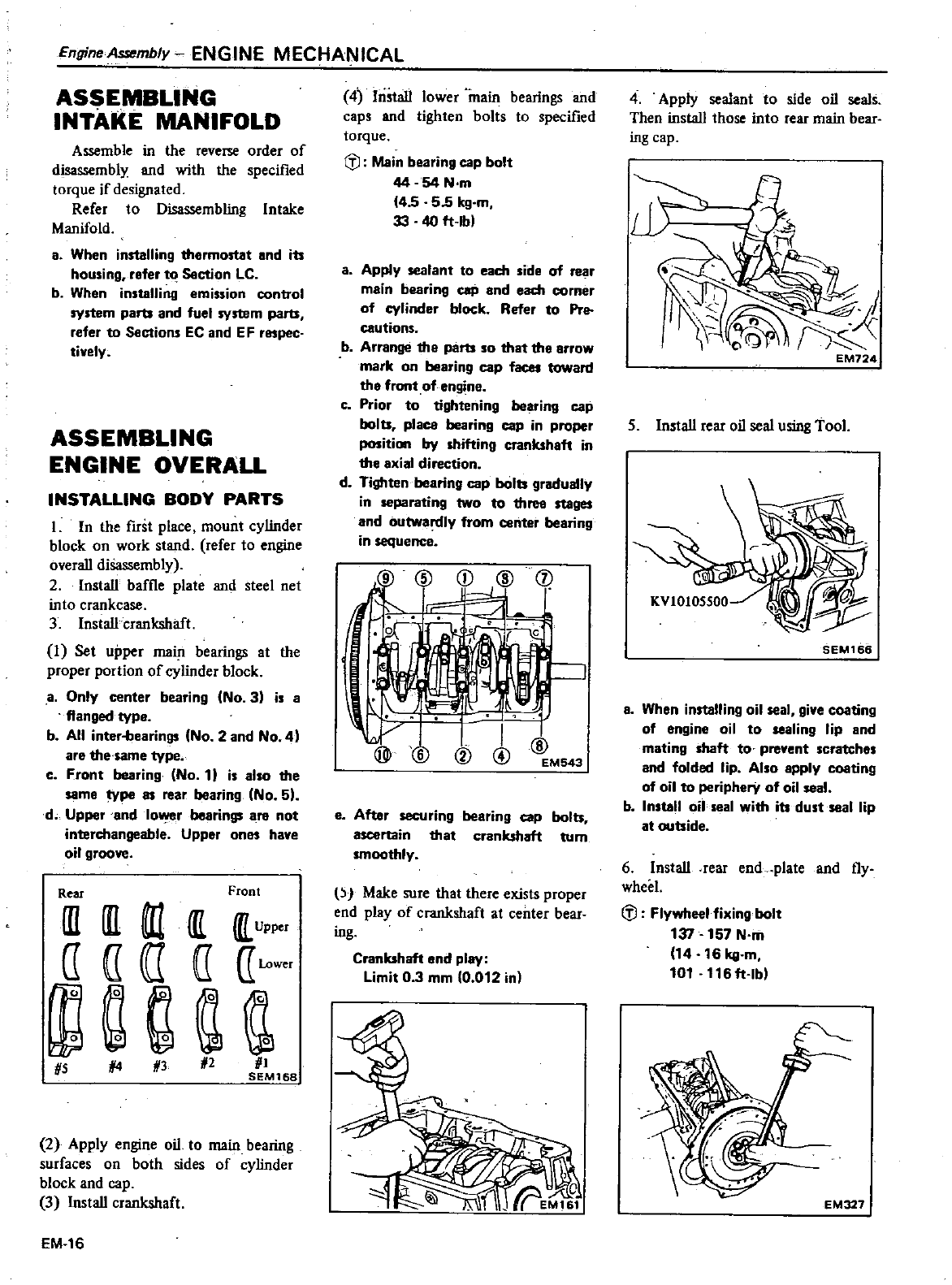
Engine
Assembly
ENGINE
MECHANICAL
ASSEMBLING
INTAKE
MANIFOLD
Assemhle
in
the
reve
order
of
disassembly
and
with
the
specified
torque
if
designated
Refer
to
Disassembling
Intake
Manifold
a
When
installing
thermostat
and
its
housing
refer
t
J
Section
LC
b
When
installing
emission
control
system
parts
and
fuel
system
parts
refer
to
Sections
EC
and
E
Frespec
tively
ASSEMBLING
ENGINE
OVERALL
INSTALLING
BODY
PARTS
1
In
the
first
place
mount
cylinder
block
on
work
stand
refer
to
engine
overall
diSassembly
2 Install
baffle
plate
and
steel
net
into
crankcase
3 Install
crankshaft
1
Set
upper
main
bearings
at
the
proper
portion
of
cylinder
block
a
Only
center
bearing
No
3
is
a
flanged
type
b
All
inter
bearings
No
2
and
No
4
are
the
same
type
c
Front
bearing
No
11
is
also
the
same
type
as
rear
bearing
No
5
d
Upper
and
lOwer
bearings
ara
not
interchangeable
Upper
ones
have
oil
groove
Rear
Front
III III
ill
Upper
IT IT
I
a
wwer
ga
HS
14
H3
N2 HI
SEM168
2
Apply
engine
oil
to
main
bearing
surfaces
on
both
sides
of
cylinder
block
and
cap
3 Install
crankshaft
EM
16
4
Install
lower
main
bearings
and
caps
and
tighten
bolts
to
specified
torque
C
l
Main
bearing
cap
bolt
4454
N
m
4
5
55
kg
m
33 40
ft
lb
a
Apply
sealant
to
each
side
of
rear
main
bearing
caP
and
each
corner
of
cylinder
block Refer
to
Pre
cautions
b
Arrange
the
parts
so
that
tha
arrow
mark
on
bearing
cap
faces
toward
the
front
of
engine
c
Prior
to
tightening
bearing
cap
bolts
placo
bearing
cap
in
proper
position
by
shifting
crankshaft
in
the
axial
direction
d
Tighten
bearing
cap
bolts
gradually
in
separating
two
to
three
stages
and
outwardly
from
center
bearing
in
sequence
@
CD
@
J
I
ill
@
L
I
V
@
eAfter
securing
bearing
cap
bolts
ascertain
that
crankshaft
turn
smoothly
p
Make
sure
that
there
exists
proper
end
play
of
crankshaft
at
center
bear
ing
Crankshaft
end
play
Limit
0 3
mm
0
012 in
4
Apply
sealanl
to
side
oil
seals
Then
install
those
into
rear
main
bear
ing
cap
n
J
I
I
f5
S
EM724
5
Install
rear
oil
seal
using
Tool
SEM166
a
When
installing
oil
seal
give
coating
of
engine
oil
to
sealing
lip
and
mating
shaft
to
prevent
scratches
and
folded
lip
Also
apply
coating
of
oil
to
peripherY
of
oil
seal
b
Install
oil
seal
with
its
dust
seal
lip
at
outside
6 Install
rear
end
plate
and
fly
wheel
C
l
Flywheel
fixing
bolt
137
157
N
m
14 16
kg
m
101
116
ft
lb
EM327
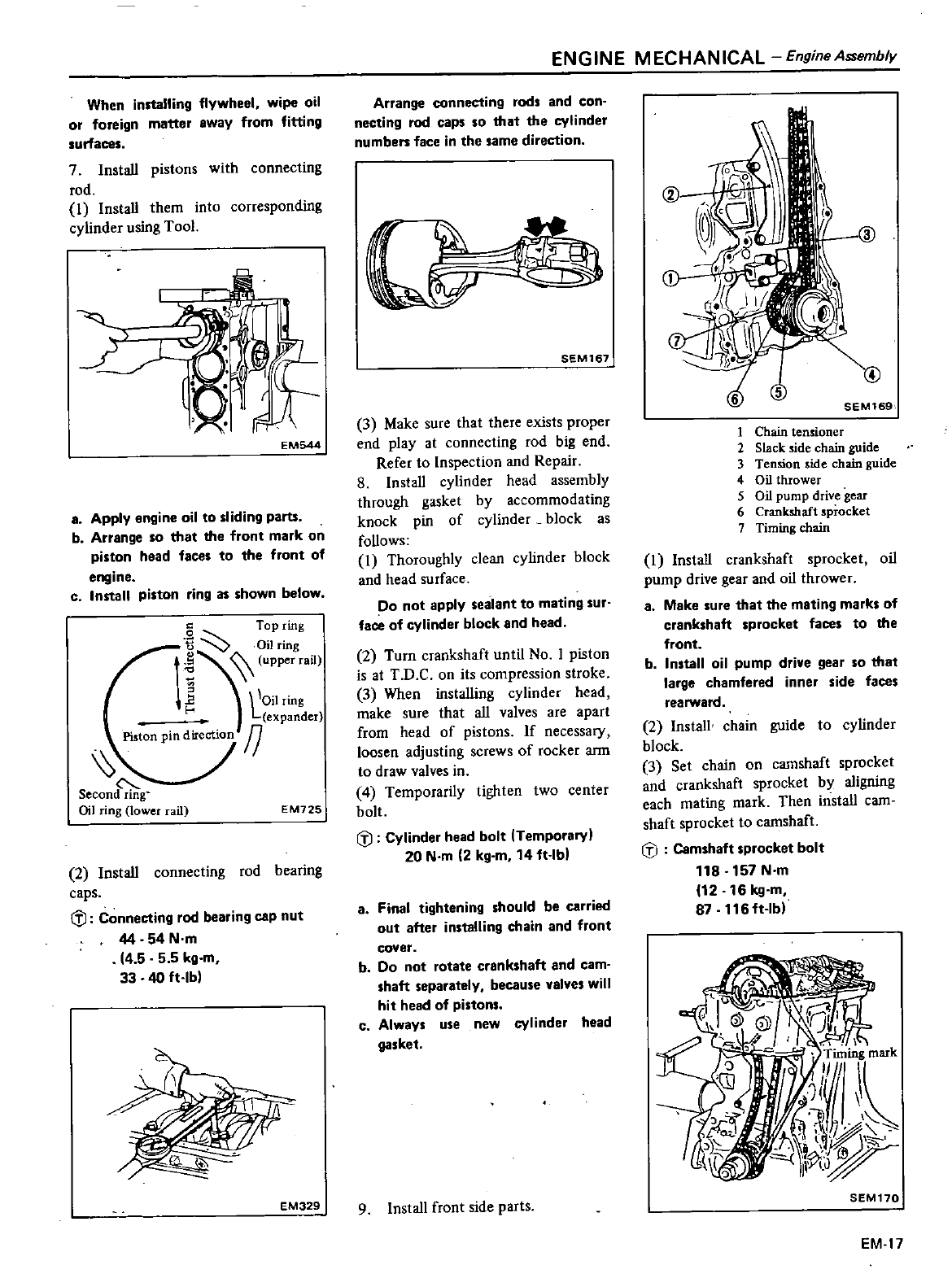
When
installing
flywheel
wipe oil
or
foreign
matter
away
from
fitting
surfaces
7Install
pistons
with
connecting
rod
1
Install them
into
corresponding
cylinder
using
Tool
J
EM544
a
Apply
engine
oil
to
sliding
parts
b
Arrange
so
that
the
front
mark
on
piston
head
faces
to
the
front
of
engine
c
Install
piston
ring
as
shown
below
c
Top
ring
fi
Oil
ring
J
0
upper
rail
ll
Oilring
expander
Piston
pin
direction
fJ
secon
Oil
ring
lower
ail
EM725
2 Install
connecting
rod
bearing
caps
CfJ
Connecting
rod
bearing
ClIp
nut
44
54
N
m
14
555
kg
m
33 40
ft
lb
EM329
ENGINE
MECHANICAL
EngineAssembly
Arrange
connecting
rods
and
con
necting
rod
caps
so that
the cylinder
numbers
face
in the
same
direction
I
SEM167
3
Make
sure
that
there
exists
proper
end
play
at
connecting
rod
big
end
Refer
to
Inspection
and
Repair
8
Install
cylinder
head
assembly
through
gasket
by
accommodating
knock
pin
of
cylinder
block
as
follows
1
Thoroughly
clean cylinder
block
and
head
surface
po
not
apply
sealant
to
mating
sur
face
of
cylinder
block
and
head
2
Turn
crankshaft
until
No
1
piston
is
at
T
D
C
on
its
compression
stroke
3
When
installing
cylinder
head
make
SUre that
all
valves
are
apart
from
head
of
pistons
If
necessary
loosen
adjusting
screws
of
rocker
ann
to
draw
valves
in
4
Temporarily
tighten
two
center
bolt
CfJ
Cylinder
head
bolt
ITemporary
20
N
m
2
kg
m
14
ft
lbl
a
Final
tightening
should
be
carried
out after
installing
chain
and
front
cover
b
Do
not
rotate
crankshaft
and
cam
shaft
separately
because
valyes
will
hit
head
of
pistons
c
Always
use
new
cylinder
head
gasket
9Install
front
side
parts
4
SEM169
1
Chain
tensioner
2
Slack
side
chain
guide
3
Temion
side
chain
guide
4
Oil
thrower
5
Oil
pump
drive
gear
6
Crankshaft
sprocket
7
Timing
chain
1
Install
crankshaft
sprocket
oil
pump
drive
gear
and
oil
thrower
a
Make
sure
that
the
mating
marks
of
crankshaft
sprocket
faces
to
the
front
b
Install
oil
pump drive
gear
so
that
large
chamfered inner
side
faces
rearward
2Install
chain
guide
to
cylinder
block
3
Set
chain
on
camshaft
sprocket
and
crankshaft
sprocket
by
aligning
each
mating
mark Then
install
cam
shaft
sprocket
to
camshaft
CfJ
Camshaft
sprocket
bolt
118
157
N
m
12 16
kg
m
87
116ft
lb
SEM170
EM 17
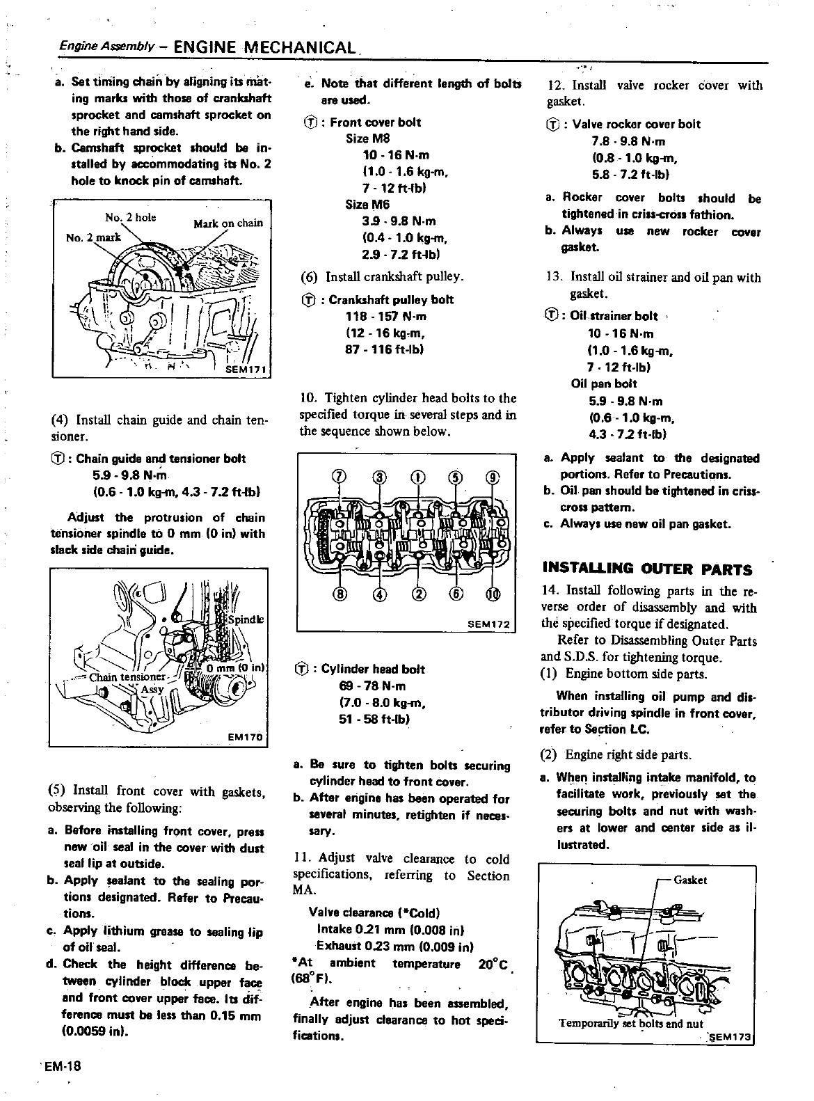
EngineA
mbly
ENGINE
MECHANICAL
a
Set
timing
chain
by
aligning
its
mat
ing
marks
with
those
of
crankshaft
sprocket
and
cemshaft
sprocket
on
the
right
hand
side
b
Camshaft
sProcket
should
be
in
stalled
by
accommodating
its
No
2
hole
to
knock
pin
of
camshaft
No
2
hole
4 Install
chain
guide
and
chain
ten
sioner
fl
Chain
guide
and
tensioner
bolt
5
998
N
0
6
1
0
kg
m
4 3
7
2
ft
b
Adjust
the
protrusion
of
chain
tensioner
spindle
to
0
mm
0
in
with
slack
side
chain
guide
5Install
front
cover
with
gaskets
observing
the
following
a
Before
installing
front
cover
press
new
oil
seal
in
the
cover
with
dust
seal
lip
at
outside
b
Apply
alant
to
the
sealing
por
tions
designated
Refer
to
Precau
tions
c
Apply
lithium
grease
to
sealing
lip
of
oil
seal
d
Check
the
height
difference
be
tween
cylinder
block
upper
face
and
front
cover
upper
face
Its
dif
ference
must
be
less
than
0
15
mm
0
0059
inl
EM
18
e
Note
that
different
length
of
bolts
are
used
CiJ
Front
cover
bolt
Size
M8
10 16 N
m
1
0
1
6
kg
m
7
12
ft
bl
Size
M6
39
9
8
N
m
0 4
1
0
kg
m
2
9
7 2
ft
bl
6Install
crankshaft
pulley
fl
Crankshaft
pulley
bolt
118 157
N
m
112
16
kg
m
87
116
ft
lbl
10
Tighten
cylinder
head
bolts
to
the
specified
torque
in
several
steps
and
in
the
sequence
shown
below
SEM172
fl
Cylinder head
bolt
69
78
N
m
7
0 8 0
kg
m
51
58
ft
lb
a
Be
sure
to
tighten
bolts
securing
cylinder
head
to
front cover
b
After
engine
has
been
operated
for
several
minutes
retighten
if
neces
sary
I
I
Adjust
valve
clearance
to
cold
specifications
referring
to
Section
MA
Valve
clearance
Cold
Intake
0
21
mm
0
008
in
Exhaust
0
23
mm
0
009
inl
At
ambient
temperature
200C
680F
After
engine
has
been
assembled
finally
adjust
clearance
to
hot
speci
fications
12 Install
valve
rocker
cover
with
gasket
fl
Valve
rocker
cover
bolt
7 8 9 8
N
m
08
1
0
kg
m
5 8 7 2
ft
lbl
a
Rocker
cover
bolts
should
be
tightened
in
criss
cross
fathian
b
Always
use
new
rocker
cover
saskat
13
Install
oil
strainer
and
oil
pan
with
gasket
fl
Oil
strainer bolt
10
16
N
m
11
0
1
6
kg
m
7
12
ft
lbl
Oil
pan
bolt
5 9 9 8
N
m
0 6
1
0
kg
m
4
3
72 ft
lbl
a
Apply
sealant
to
the
designated
portions
Refer
to
Precautions
b
Oil
pan
should
be
tightened
in
criss
cross
pattern
c
Always
use
new
oil
pan
gasket
INSTALLING
OUTER
PARTS
14
Install
following
parts
in
the
reo
verse
order
of
disassembly
and
with
the
specified
torque
if
designated
Refer
to
Disassembling
Outer
Parts
and
S
O
S
for
tightening
torque
I
Engine
bottom
side
parts
When
installing
oil
pump
and
dis
tributor
driving
spindle
in
front
cover
refer
to
Section
LC
2
Engine
right
side
parts
a
Whe
installing
intake
manifold
to
facilitate
work
previously
set
the
securing
bolts
and
nut
with
wash
ers
at
lower
and
center
side
as
il
lustrated
Temporarily
set
olts
and
nut
SEM173
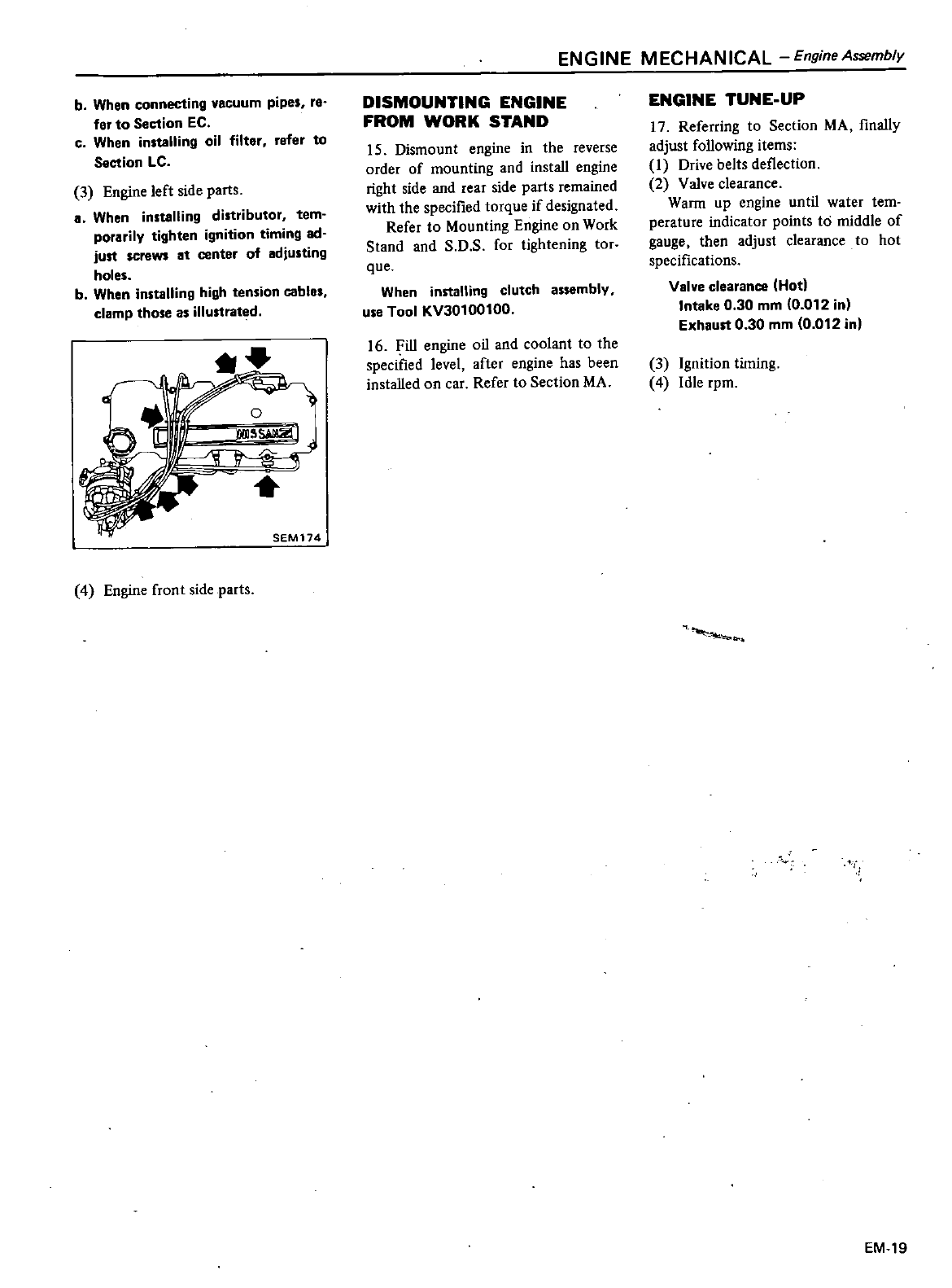
b
When
connecting
vacuum
pipes
re
fer
to
Section
EC
c
When
installing
oil
filter
refer
to
Section
LC
3
Engine
left
side
parts
a
When
installing
distributor
tern
porarilv
tighten
ignition
timing
ad
just
screws
at
center
of
adjusting
holes
b
When
installing
high
tension
cable
clamp
those
as
iIIustrat
d
4
Engine
front
side
parts
ENGINE
MECHANICAL
EngineAssembly
DISMOUNTING
ENGINE
FROM
WORK
STAND
15
Dismount
engine
in
the
reverse
order
of
mounting and
install
engine
right
side
and
rear
side
parts
remained
with
the
specified
torque
if
designated
Refer
to
Mounting
Engine
on
Work
Stand
and
S
D
s
for
tightening
tor
que
When
installing
clutch
assembly
use
Tool
KV30100100
16
Fill
engine
oil
and
coolant
to
the
specified
level
after
engine
has
been
installed
on
car
Refer
to
Section
MA
ENGINE
TUNE
UP
17
Referring
to
Section
MA
finally
adjust
following
items
1
Drive
belts
deflection
2
Valve
clearance
Warm
up
engine
until
water
tem
perature
indicator
points
to
middle
of
gauge
then
adjust
clearance
to
hot
specifications
Valve
clearance
IHotl
Intake
0
30
mm
0
012
in
Exhaust
0
30
mm
0
012
in
3
Ignition
timing
4
Idle
rpm
EM
19
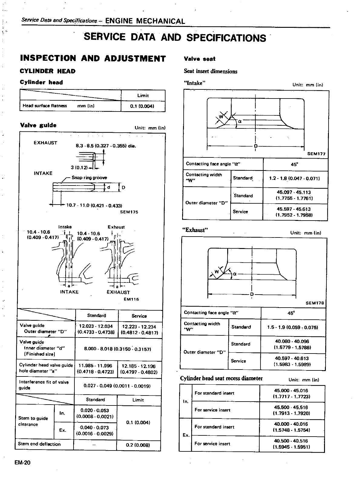
Setvice
Data
and
Spec
fication
ENGINE
MECHANICAL
SERVICE
DATA
AND
SPECIFICATIONS
INSPECTION
AND
ADJUSTMENT
CYLINDER
HEAD
Cylinder
head
Head
surface
flatness
Valve
guIde
EXHAUST
INTAKE
Limit
rnm
lin
0
110
0041
Unit
mm
On
83
8
510
327
0
3551
dia
310
2
r
Snap
ring
groove
10
UtO
7
11
010
421
0
433
SEM175
intake
Exhaust
10
4
10
6
I
l
10
4
10
6
I
h
10
409
04
11
O
409
0
417
Fir
il
V
I
P
f
iJ
J
IJ
11
c
INTAKE
EXHAUST
EM116
Valve
guide
Outer
diameter
0
Valve
guide
Inner
diameter
d
Finished
size
Cyhnder
head
valve
guide
hole
diameter
8
Interference
fit
of
valve
guide
Iln
Stem
to
guide
clearance
I
Ex
Stem
end
deflection
EM
20
St8ndari
i
Service
12
023
12
03412
223
12
234
0
4733
0
47381
10
4812
0
48171
8000
8
01810
3150
0
31571
11
985
11
996
1
2
85
12
196
10
4718
0
4723
10
4797
0
4802
0
027
0
049
0
0011
0
0019
Standard
Limit
0
020
0
053
10
0008
0
OO21
0
1
0
004
0
040
0
073
0
0016
0
0029
02
10 OOSI
Valve
seat
Seal
insert
dimensions
Intake
xL
Q
I
I
I
o
Contacting
face
angle
rt
Contacting
width
W
Stendard
Standard
Outer
diameter
0
Service
Exhaust
C
mtactlng
face
angle
cr
Contacting
width
W
StaruWd
Standard
Outer
diameter
0
Service
Cylinder
head
seat
m
ess
diameter
I
For
standard
nsen
In
For
service
insert
For
standard
insert
EX
I
For
service
insert
Unit
mm
in
l
SEM177
45
1
2
1
80
047
0
0711
45
097
45
113
11
7755
1
776
45
597
45
613
11
1952
1
1958
Unit
mm in
I
SEM118
45
1
5
1
9
0
059
O
07S
40
080
40
096
11
5779
1
57861
40
597
40
613
1
5983
t
59891
Unit
mm in
45
000
45
016
11
7717
1
77231
45
500
45
516
11
1913
1
79201
40
000
40
016
11
5748
1
5754
40
500
40
516
11
5945
1
59511
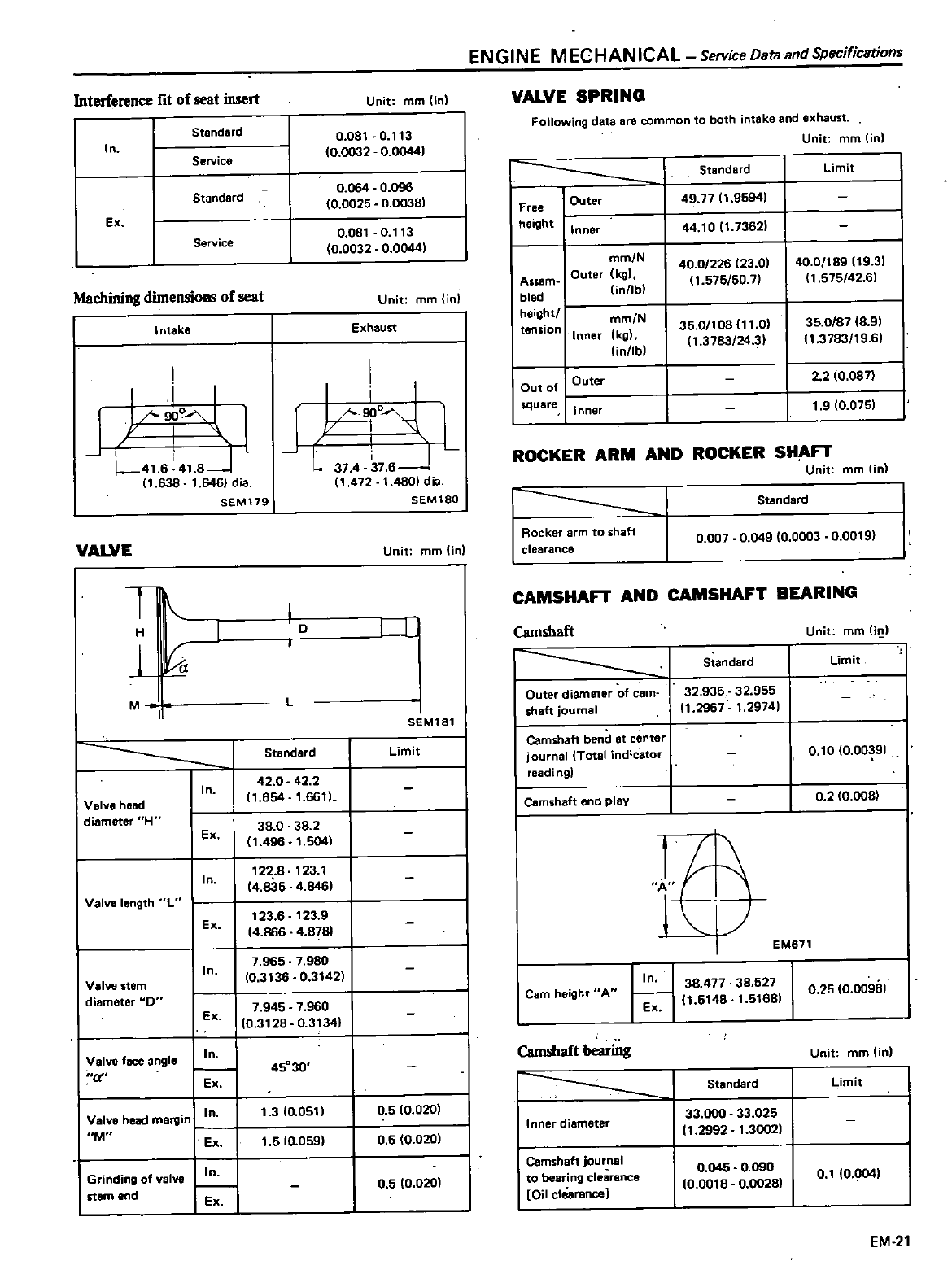
Interference
fit
of
seat
insert
In
Ex
Machining
dimensions
of
seat
Intake
I
I
i
I
Y
90
L41
6
41
8J
11
638
1
646
dia
SEM179
VALVE
T
H
J
M
II
I
In
I
I
Ex
I
iln
Valve
length
L
I
Ex
I
In
I
Valve
head
diameter
H
Valve
stem
diameter
0
Valve
fBee
angle
C
Valve
head
margin
I
In
M
I
Grinding
of
valve
stem
end
Standard
Service
Standard
Service
ENGINE
MECHANICAL
Service
Dara
and
Specificstions
Unit
mm
in
0
081
0
113
10
0032
0
00441
0
064 0
096
0
0025
0
00381
0
081
0
113
0
0032
0
00441
Unit
mm
in
Exhaust
I
r
o
l
L
1
374
37
61
11
472
1
4801
dia
SEM180
Unit
mm
On
j
D
1
L
SEM181
Standard
Limit
42
0
42
2
11
654
1
66tl
38
0
38
2
1
496
1
504
122
8
123
1
4
835
4
846
123
6
123
9
14
866
4
8781
45
30
0
5
10
020
05
0
020
0
5
10
020
VALVE
SPRING
Following
data
ere common
to
both
intake
and
exhaust
Unit
mm
in
I
Standard
Free
I
Outer
49
7711
9594
height
I
Inner
44
1011
7362
mm
N
40
0
226
23
01
Assem
Outer
kg
1
575
50
7
bled
lin
lb
height
mm
N
tension
Inner
Ikg
35
0
108111
0
linllbl
1
3783
24
31
Cut
0
Outer
square
Inner
limit
40
0
189119
31
1
575
42
61
35
0
87
18 91
11
3783
19 61
2
2
0
0871
1
9
10
075
ROCKER
ARM
AND
ROCKER
SHA
Unit
mm in
1
I
II
Rocker
arm
to
shaft
clearance
0
007
0
049
0
0003
0
0019
Standard
Camshaft
CAMSHA
AND
CAMSHAFT
BEARING
Outer
diameter
of
cam
shaft
journal
Camihaft
bend
at
center
journal
Total
indicator
readi
n91
I
Camihaft
nd
pl
Cam
height
A
Camshaft
bearing
Inner
diameter
Cemshaft
journal
to
bearing
clearance
Oil
clearance
Standard
32
935
32
955
11
2967
1
29741
11
l
t
In 38
477
38
527
11
5148
1
51681
Ex
Standard
33
000
33
025
11
2992
1
3002
0
045
0
090
10
0018
0
0028
Unit
mm
Ii
Limit
I
O
to
0
00391
0
2
10
008
EM871
0
25
0
00981
Unit
mm
tin
Limit
0
110
004
EM
21
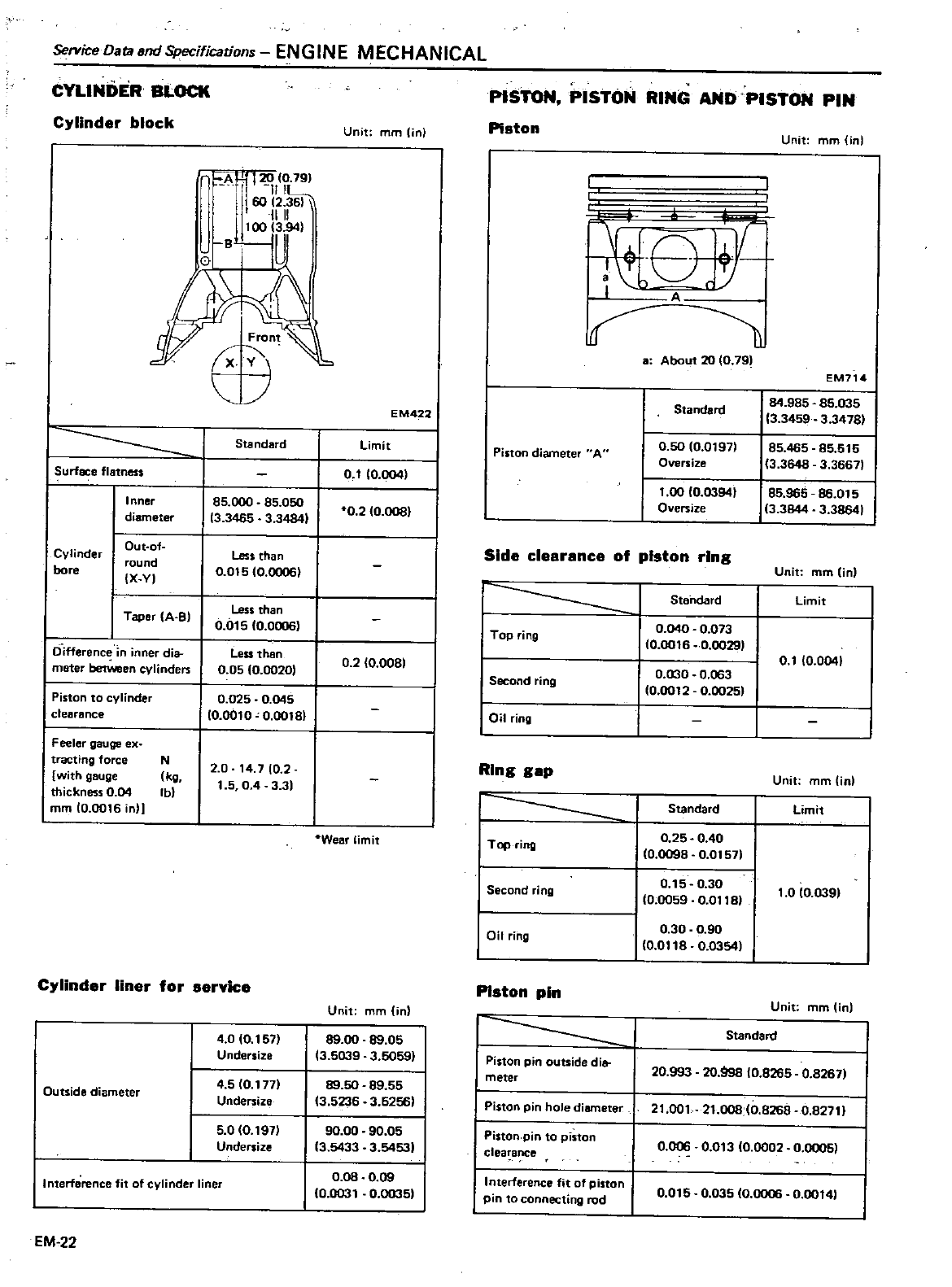
Service
Datasnd
Specifications
ENGINE
MECHANICAL
CYLINDER
BLOCK
Cylinder
block
A
1J
120
10
791
1111
6012
1111
I
0
i
P
Front
XV
Surface
flatness
Inner
diameter
Cylinder
bore
Out
of
round
IX
VI
Taper
A
B
Differene
in
inner
dia
meter
between
cylinders
Piston
to
cylinder
clearance
Feeler
gauge
ex
tracting
force
N
with
gauge
kg
thickness
0
04
Ib
mrn 0
0016
in
Cylinder
liner
for
s
Outside
diameter
Interference
fit
of
cylinder
liner
EM
22
Standard
85
000
85
050
13
3465
3
34841
Less
than
0
01510
00061
Less
than
0
01510
00061
Less
then
0
05
0
00201
0
025
0
045
10
0010
0
00181
2 0
14
710
2
1
5
04
3
31
40
10
1571
Undersize
4
5
0
1711
Undersize
5
010
1971
Undersize
Unit
f11m
io
EM422
limit
0
110
004
0
2
0
0081
0
2
10
0081
Wear
limit
PISTON
PISTON
RING
AND
PISTON
PIN
Piston
Unit
rnm in
f
I
A
cr
a
About
20
10 791
EM714
Standard
84
985
85
035
13
3459
3
34781
Piston
diameter
A
0
50
10
01971
85
465
85
515
Oversize
13
3648
3
36671
1
00
10
03941
85
965
86
015
O
ersize
3
3844
3
38641
Side
clearance
of
piston
ring
Unit
mm
Unl
Standard
Limit
I
Top
ring
I
Second
ring
I
Oil
ring
0
040
0
073
10
0016
0
00291
0
1
0
0041
0
030
0
063
0
0012
0
00251
Ring
gap
1
Standard
I
Top
ring
0
25
0
40
10
0098
0
01571
Second
ring
0
15
0
30
10
0059
0
01181
Oil
ring
0
30
0
90
10
0118
0
03541
Unit
mm
in
Limit
1
0
10
0391
Piston
pin
Unit
mmlin
Unit
mm in
89
00
89
05
Standard
13
5039
3
5059
I
Piston pin
outside
di
meter
20
993
20
998
0
8265
0
82671
89
50
89
55
13
5236
3
6256
Piston
pin
hole
diameter
21
001
21
008
10
8268
0
82711
90
00
90 05
I
Piston
pin
to
piston
13
5433
3
54531
clea
ance
0
006
0
01310
0002
0
00051
0
08
0 09
I
Interference
fit
of
piston
0
0031
0
0035
pin
to
c
onnecting
rod
0
015
0
035
10
0006
0
oot41
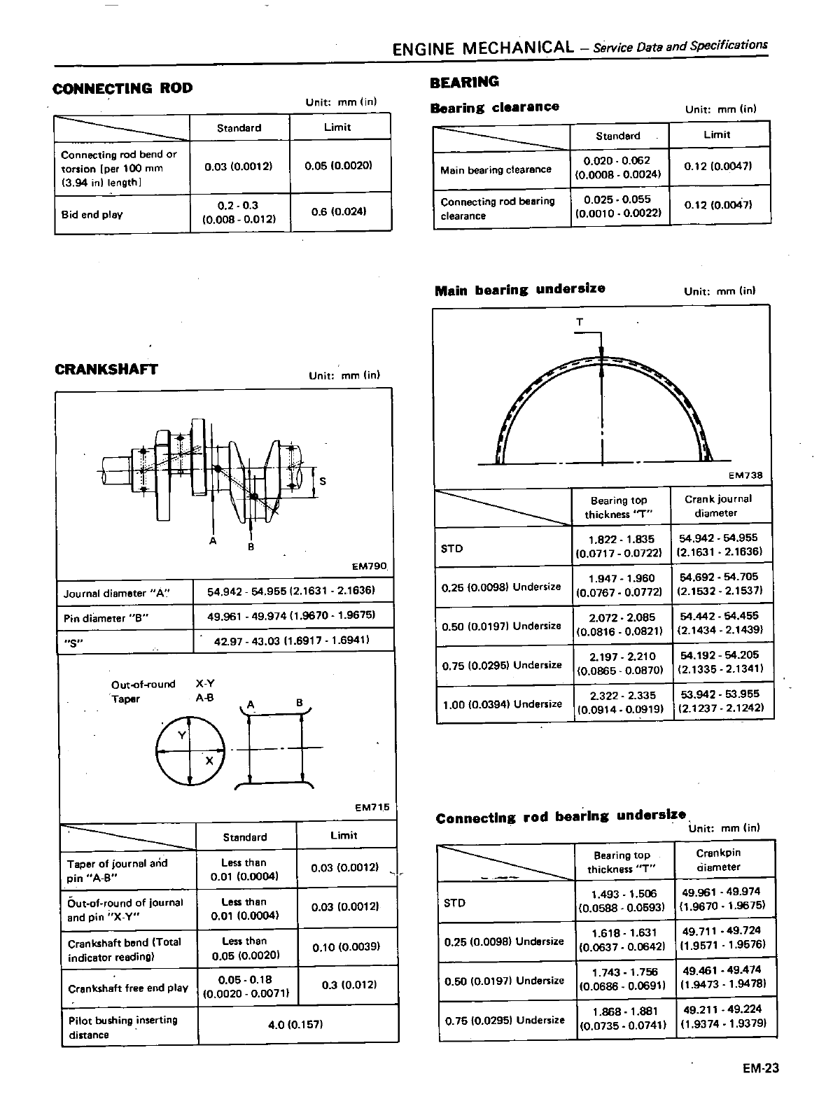
ENGINE
MECHANICAL
ServiceOataandSpecifications
CONNECTING
ROD
BEARING
Unit
mm
in
Bearing
clearence
1
Unit
mm
in
Standard
Limit
I
Standard
Limit
Connecting
rod
bend
or
torsion
per
100
mrn
0
03
0
00121
0
05
10
00201
I
Main
bearing
clearance
0
020
0
062
0
1210
00471
3
94
inllength
0
0008
0
0024
I
Bid
end
plev
0
2
0
3
I
Connecting
rod
beeting
0
025
0
055
0
008
0
0121
06 0
0241
clearance
0
001
0
0
00221
0
12
0
00471
CRANKSHAFT
Unit
mm
lin
a
t1b
S
I
I
Journal
diameter
A
I
Pin
diameter
B
I
S
Out
of
round
X
V
Taper
AB
A
8
54
942
54
955
2
1631
2
16361
EM790
49
961
49
974
1
9670
1
96751
42
97
43
0311
6917
1
69411
A
o
I
Taper
of
journal
and
pin
A
S
IOut
of
round
of
Journal
and
pin
X Y
I
Crankshaft
bend
Total
indicator
reeding
I
Crenksheft
free end
plav
I
Pilot
bushing
inserting
distance
Standard
Less
than
O
Of
0
00041
less
than
0
01
0
00041
Less
than
0
05
0
00201
0
05
O
lB
10
0020
0
00711
8
EM715
Limit
0
03
0
00121
J
I
0
03
10
00121
I
0
10
0
00391
I
0
3
10
0121
40 0
1571
Main
bearing
undersize
Unit
mm in
T
EM738
Bearing
top
Crank
jou
rnal
thickness
T
diameter
I
STD
1
822
1
835
54
942
54
955
10
0717
0
0722
12
1631
2
1636
I
0
25
10
00981
Undersize
1
947
1
960
54
692
54
705
0
0767
0
07721
2
1532
2
15371
I
0
50
0
01971
Undersize
I
2
072
2
085
54
442
54
455
0
0816
0
08211
2
1434
2
14391
I
0
75
0
02951
Undersize
I
2 197 2
210
54
192
54
205
0
0865
0
08701
12
1335
2
13411
1
00
0
0394
Undersize
I
2
322 2
335
53
942
53
955
0
0914
0
09191
2
1237
2
12421
Connecting
rod
bearing
undersize
Unit
rnm
Onl
I
Bearing
top
Crankpin
thickness
T
ciiameter
I
STD
1
493
1
506
49
961
49
974
0
0588
0
05931
0
9670
1
9675
I
0
25
0
00981
Undersize
1
618
1
631
49
711
49
724
10
0637
0
06421
1
9571
1
95761
I
0
50
0
01971
Undersize
1
743
1
756
49
461 49
474
0
0686
0
06911
t
9473
1
94791
I
0
7510
02951
UDdersize
1
868
1
881
49
211
49
224
0
0735
0
07411
1
9374
1
93791
EM
23
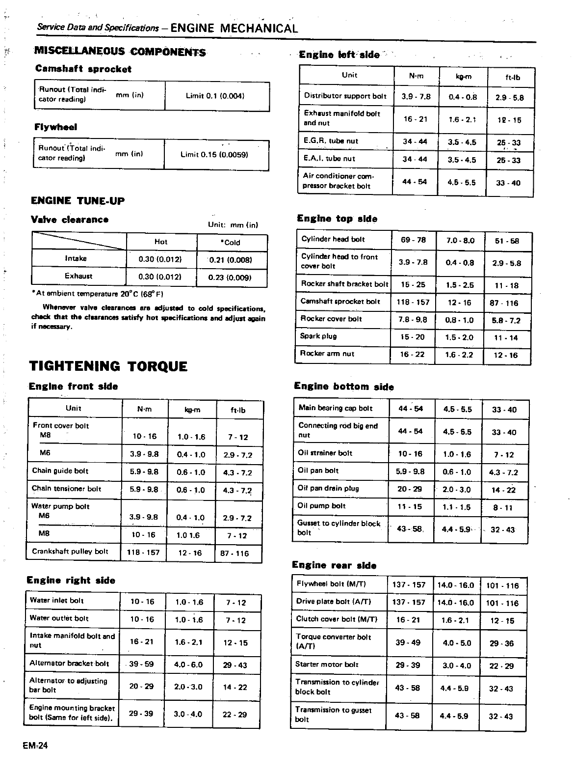
Service
DatallndSpecifications
ENGINE
MECHANICAL
Camshaft
sprocket
MISCELLANEOUSCOMPONENH
I
Runaut
Total
indf
mm
in
cator
readingl
Flywheel
I
Runout
frotsl
iodi
mm
in
cator
reading
ENGINE
TUNE
UP
Valve
clearance
1
I
Intake
I
Exhaust
0
3010
012
0
30
10
012
Limit
Q1
0
004
Limit
0
15
10
0059
Hot
Unit
mm in
Cald
0
21
0
008
0
23
0
009
At
ambient
temperature
200C
168
F
Whenever
valve
clearances
are
adjusted
to
cold
specific
tions
check
thd
the
clearances
satisfy
hot
specifications
and
edjust
again
if
necessary
Engine
front
side
TIGHTENING
TORQUE
Unit
Front
cover
bolt
M8
M6
I
Chain
guide
bolt
I
Chain
tensionetr
bolt
Water
pump
bolt
M6
M8
Crankshaft
pulley
bolt
Engine
right
side
I
Water
inlet
bolt
I
Water
outlet
bolt
I
Intake
manifold
bolt
and
nut
I
Alternator
bracket
bolt
I
Alternator
to
adjusting
bar
bolt
I
Engine
mounting
bracket
bo1t
Same
fot
left
side
EM
24
N
m
10 16
3
9
9
8
5
9 98
5
9
9
8
3 9
98
10
16
118 157
10
16
10 16
16 21
39
59
20 29
29 39
kg
m
1
0
1
6
04
1
0
0
6
1
0
0
6
1
0
04
1
0
1
01
6
12
16
1
0
1
6
1
0
1
6
1
6
2
1
4
0
6
0
20
3
0
3 0
4
0
ft
lb
7
12
2
9
7 2
4
3
7
2
4
3 7
2
9
7 2
7
12
87
116
7
12
7
12
12 15
29 43
14
22
22
29
Engine
left
side
Unit
I
Distributor
support
bolt
I
Exhaust
manifold
bolt
and
nut
I
E
GR tube
nut
I
E
A
I
tube
nut
I
Air
conditioner
cern
pressor
bracket
bolt
N
m
3 9 7
8
16 21
34 44
34 44
44 54
Engine
top
side
I
Cylinder
head
bolt
69 78
I
Cylinder
head
to
front
COYer
bolt
3 9 7 8
I
Rocker
shaft
bracket
bott
15
25
I
Camshaftsprocket
bolt
118 157
I
Rocker
cover
bolt
7
89
8
I
Spark
plug
15
20
I
Rocker
arm
nut
16
22
Engine
bottom side
I
M
in
bearing
cap
bolt
I
Connecting
rod
big
end
nut
t
Oil
strainer
bolt
Oil
pan
bolt
Oil
pan
drain
plug
Oil
pump
bolt
Gusset
to
cylinder
block
bolt
Engine
rear
side
I
Flywheel
bolt
M
TI
I
Drive
plate
bolt
Arr
1
Clutch
cover
bolt
M
T
Torque
converter
bolt
AfT
Starter
motor
bolt
Transmission
to
cylinder
block
bolt
IT
ransmission
to
gU
et
bolt
44 54
4454
10 16
59 9 8
20 29
11
15
43 58
kQ
m
04 0
8
1
6 2
1
3
5
4
5
3 5
4
5
4
5
5
5
7
0
8
0
04
08
1
5 2
5
12
16
0
8
1
0
1
5 2
0
1
6 2 2
45
5 5
45
5
5
1
0
1
6
06
1
0
20
3
0
11
15
44
5
9
ft
lb
2 9
5
8
12 15
25
33
25 33
33
40
51
58
29
5
8
11
18
87
116
5
8
7 2
11
14
12 16
33
40
33
40
7
12
4
3 7
2
14
22
8
11
32 43
137 157
14
0
t6
0
101
116
137 157
14
0
16
0
101
116
16 21
1
6
21
12
15
39
49
40
5
0
29 36
29
39
3
0
4
0
22 29
43
58
44
5
9
32 43
43 58
445
9 32
43
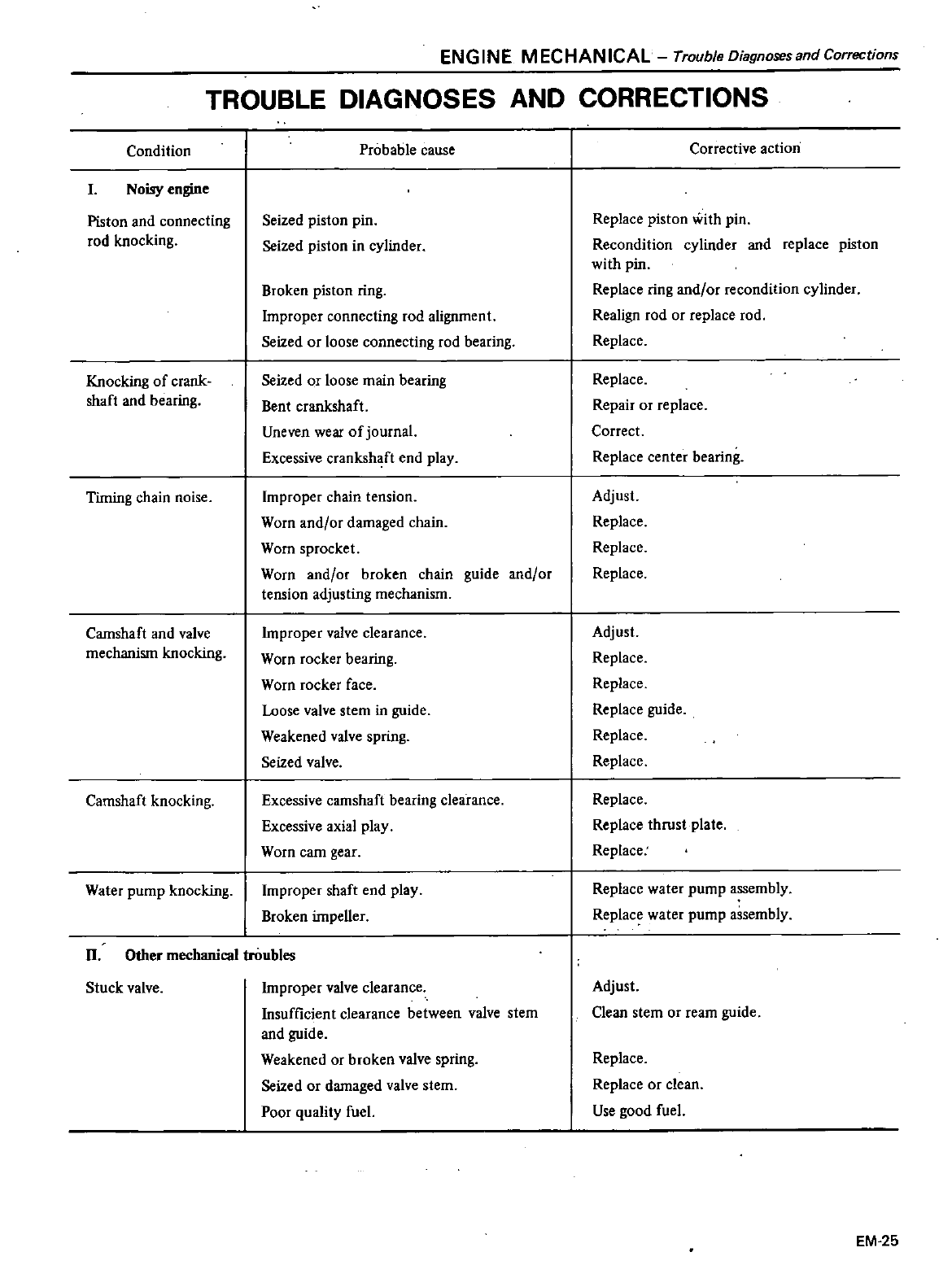
ENGINE
MECHANICAL
Trouble
Diagnoses
and
Corrections
TROUBLE
DIAGNOSES
AND
CORRECTIONS
Condition
I
Noisy
engine
Piston
and
connecting
rod
knocking
Knocking
of
crank
shaft
and
hearing
Timing
chain
noise
Camshaft
and
valve
mechanism
knocking
Camshaft
knocking
Water
pump
knocking
Probable
cause
Seized piston
pin
Seized piston
in
cylinder
Broken
piston
ring
Improper
connecting
rod alignment
Seized
or
loose
connecting
rod
bearing
Seized
or
loose
main
bearing
Bent
crankshaft
Uneven
wear
of
journal
Excessive
crankshaft
end
play
Improper
chain
tension
Worn
and
or
damaged
chain
Worn
sprocket
Worn
and
or
broken
chain
guide
and
or
tension
adjusting
mechanism
Improper
valve
clearance
Worn
rocker
bearing
Worn
rocker
face
Loose
valve
stem
in
guide
Weakened
valve
spring
Seized
valve
Excessive
camshaft
bearing
clea
rance
Excessive
axial
play
Wom
earn
gear
Improper
shaft
end
play
Broken
impeller
Stuck
valve
II
Other
mechanical
troubles
Improper
valve
clearance
Insufficient
clearance
between
valve
stem
and
guide
Weakened
or
broken
valve
spring
Seized
or
damaged
valve
stem
Poor
quality
fuel
Corrective
action
Replace
piston
with
pin
Recondition
cylinder
and
replace
piston
with
pin
Replace
ring
and
or
recondition
cylinder
Realign
rod
or
replace
rod
Replace
Replace
Repair
or
replace
Correct
Replace
center
bearing
Adjust
Replace
Replace
Replace
Adjust
Replace
Replace
Replace
guide
Replace
Replace
Replace
Replace
thrust
plate
Replace
Replace
water
pump
assembly
Replace
water
pump
assembly
Adjust
Clean
stem
or
ream
guide
Replace
Replace
or
clean
Use
good
fuel
EM
25
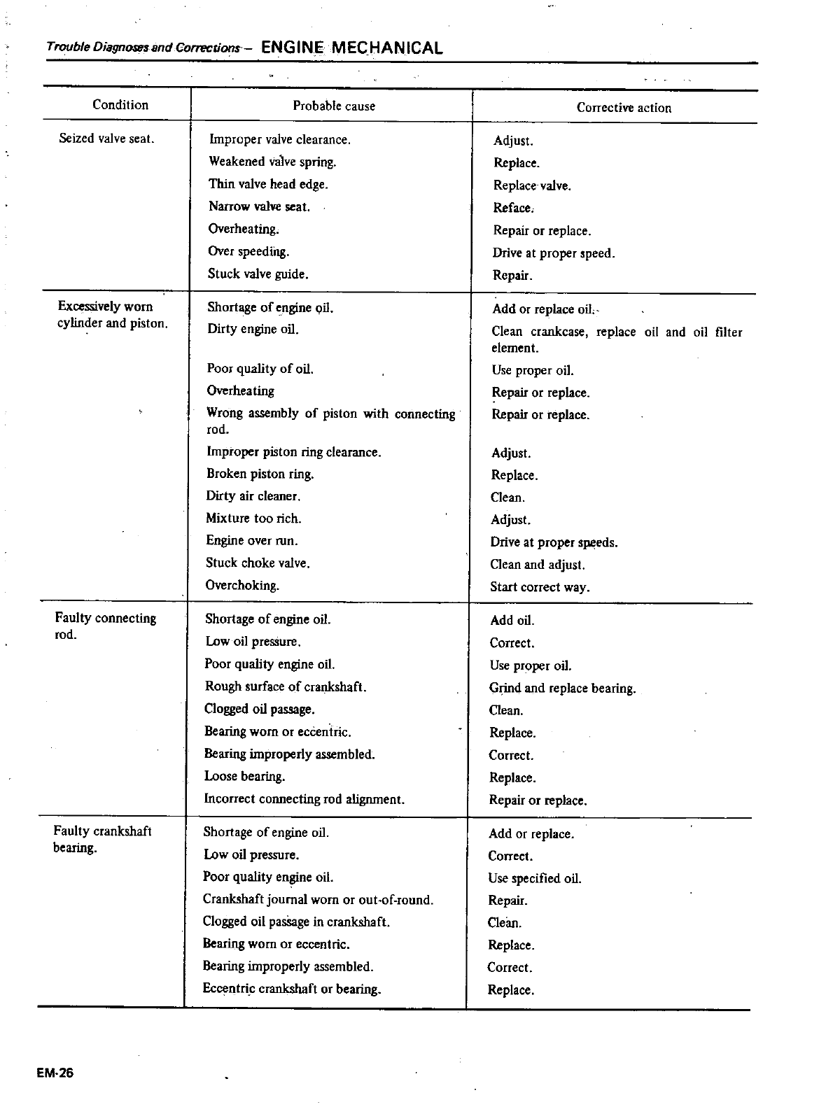
TroubleDiagnosessndCorrections
ENGINE
MECHANICAL
Condition
Seized
valve
seat
Excessively
worn
cylinder
and
piston
Faulty
connecting
rod
Faulty
crankshaft
bearing
EM
26
Probable
cause
Improper
valve
clearance
Weakened
valve
spring
Thin
valve
head
edge
Narrow
valve
seat
Overheating
Over
speeding
Stuck
valve
guide
Shortage
of
engine
oil
Dirty
engine
oil
Poor
quality
of
oil
Overheating
Wrong
assembly
of
piston
with
connecting
rod
Improper
piston
ring
clearance
Broken
piston
ring
Dirty
air
cleaner
Mixture
too
rich
Engine
over
run
Stuck
choke
valve
Overchoking
Shortage
of
engine
oil
low
oil
pressure
Poor
quality
engine
oil
Rough
surface
of
crankshaft
Clogged
oil
passage
Bearing
worn or
eccentric
Bearing
improperly
assembled
loose
bearing
Incorrect
connecting
rod
alignment
Shortage
of
engine
oil
low
oil
pressure
Poor
quality
engine
oil
Crankshaft
journal
worn
or
out
of
round
Clogged
oil
pasSage
in
crankshaft
Bearing
wornor
eccentric
Bearing
improperly
assembled
Eccentri
crankshaft
or
bearing
Corrective
action
Adjust
Replace
Replace
valve
Reface
Repair
or
replace
Drive
at
proper
speed
Repair
Add
or
replace
oil
Clean
crankcase
replace
oil
and
oil
filter
element
Use
proper
oil
Repair
or
replace
Repair
or
replace
Adjust
Replace
Clean
Adjust
Drive
at
proper
speeds
Clean
and
adjust
Start
correct way
Add
oil
Correct
Use
proper
oil
Grind
and
replace
bearing
Clean
Replace
Correct
Replace
Repair
or
replace
Add
or
replace
Correct
Use
specified
oil
Repair
Clean
Replace
Correct
Replace
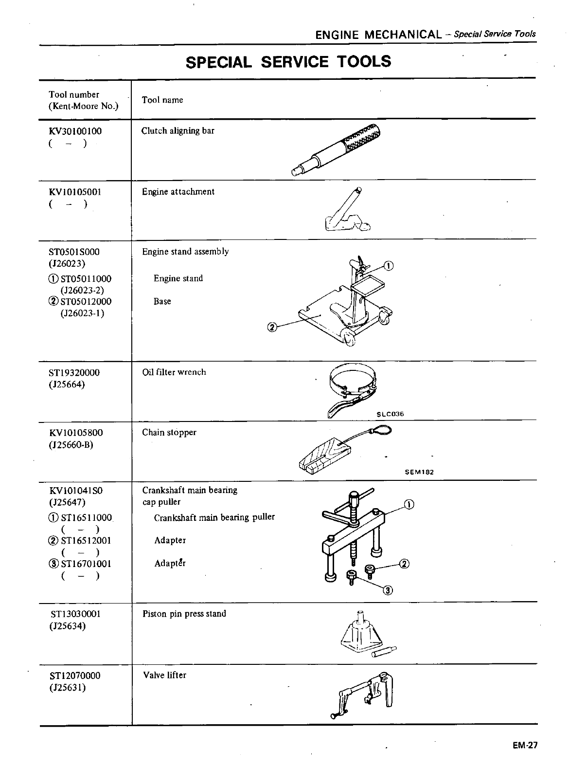
Tool
number
Kent
Moore
No
KV30
100
100
KVlO105001
ST050lS000
126023
CD
ST050l1000
126023
2
CVST05012000
126023
1
ENGINE
MECHANICAL
Special
Service
Tools
SPECIAL
SERVICE
TOOLS
Tool
name
Clutch
aligning
bar
Engine
attachment
Engine
stand
assembly
Engine
stand
Base
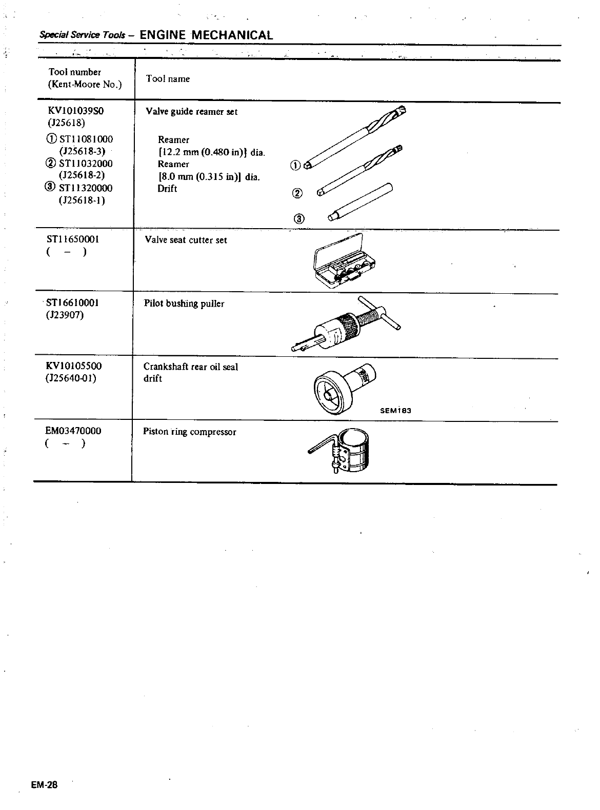
Special
Service
Tools
ENGINE
MECHANICAL
Tool
number
Kent
Moore
No
KVIOlO39SO
125618
D
STlI08l000
125618
3
@
STlI032000
125618
2
@
STl1320000
125618
1
STl165000
I
STl6610001
123907
KVlOI05500
125640
01
EM03470000
EM
28
Tool
name
Valve
guide
reamer
set
Reamer
12
2
mm
0
480
in
dia
Reamer
8
0
mm
0
315
in
dia
Drift
Valve
seat
cutter
set
Pilot
bushing
puller
Crankshaft
rear
oil
seal
drift
Piston
ring
compressor
D
@
@
M
DATSUN
200SX
Model
S
J J
0
Series
SECTION
L
C
ENGINE
LUBRICATION
COOLING
SYSTEMS
CONTENTS
ENGINE
LUBRICATION
SYSTEM
LUBRICATION
CIRCUIT
01 L
PUMP
OIL
PRESSURE
REGULATOR
VALVE
OIL
FILTER
OIL
PRESSURE
RELIEF
VALVE
COOLING
SYSTEM
COOLING
CIRCUIT
RADIATOR
THERMOSTAT
WATER
PUMP
LC
2
LC
2
LC
3
LC
4
LC
4
LC
4
LC
5
LC
5
LC
6
LC
6
LC
7
TEM
COUPLlNG
SERVICE
DATA
AND
SPECIFICATIONS
GENERAL
SPECIFICATIONS
INSPECTION
AND
ADJUSTMENT
TIGHTENING
TORQUE
TROUBLE
DIAGNOSES
AND
CORRECTIONS
LUBRICATION
SYSTEM
COOLING
SYSTEM
SPECIAL
SERVICE
TOOL
LC
7
LC
8
LC
8
LC
8
LC
8
LC
9
LC
9
LC
9
LC
10
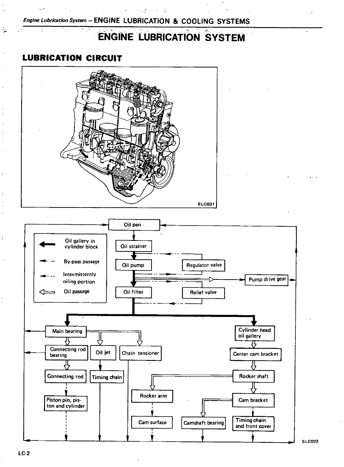
Engine
LubriCstion
System
ENGINE
LUBRICATION
COOLING
SYSTEMS
ENGINE
LUBRICATION
SYSTEM
LUBRICATION
CIRCUIT
SLC021
j
Oil
pan
I
Oil
gallery
in
cylinder
block Oil
strainer
I
I
By pass
passage
I
Regulator
valve
I
Oil
pump
Intermittently
j
Pump
drive
gear
r
oiling
portion
Oil
passage
Oil
filter
I
Relief
valve
I
l
Main
aring
f
I
Con
ecting
rod
II
Oil
J
et
II
Chain
tensioner
I
bearing
I
Connecting
rod
II
Timing
chain
I
I
I
l
Piston
Pin
pis
I
ton
and
cylinder
I
A
Rocker
arm
t
j
I
Camshaft
bearing
I
Cam
surface
LC
2
I
Cylinder
head
I
oil
gallery
I
Center
earn
bracket
I
Rocker
shaft
Cam
bracket
t
I
Timing
chain
I
and
front
cover
S
LC022
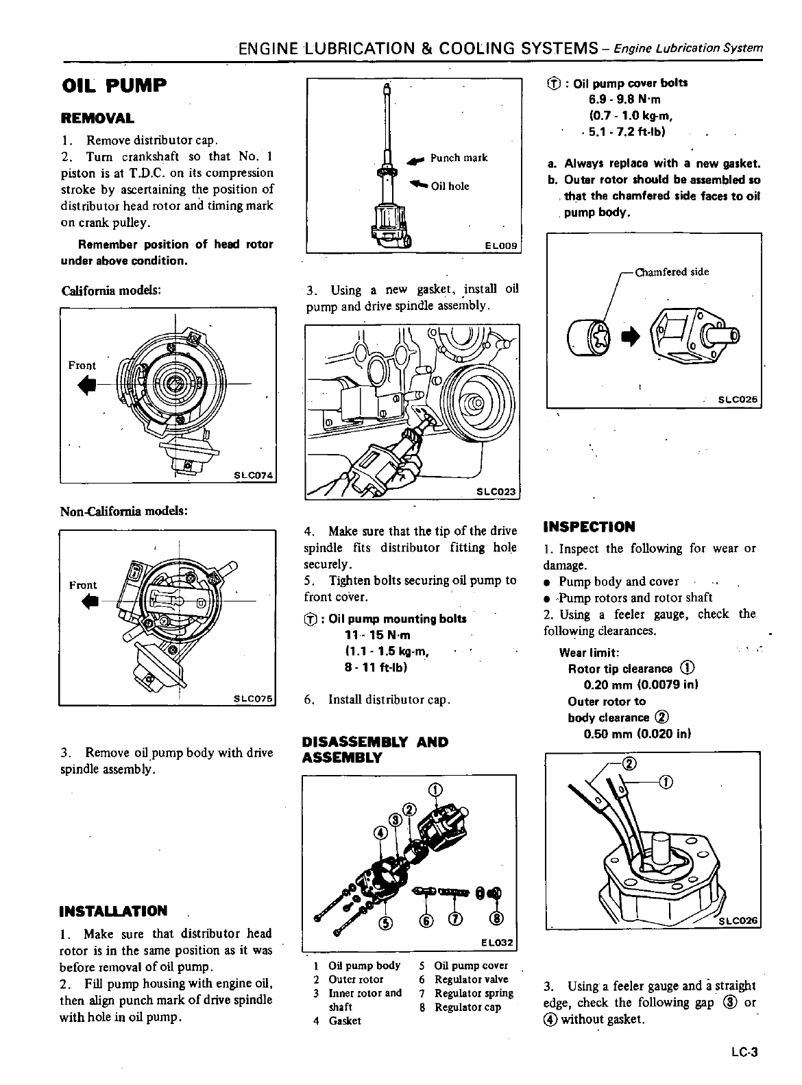
ENGINE
LUBRICATION
COOLING
SYSTEMS
Engine
Lubrication
System
OIL
PUMP
REMOVAL
1
Remove distributor
cap
2
Turn
crankshaft
so
that
No
1
piston
is
at
T
D
C
on
its
compression
stroke
by
ascertaining
the
position
of
distributor
head
rotor
and
timing
mark
on
crank
pulley
Remember
position
of
he
rotor
under
above
condition
California
models
Front
SLC074
Non
Califomia
models
Front
3
Remove
oHpump
body
with
drive
spindle
assembly
INSTALLATION
I
Make
sure
that
distributor
head
rotor
is
in
the
same
position
as
it
was
before
removal
of
oil
pump
2
Fill
pump
housing
with
engine
oil
then
align
punch
mark
of
drive
spindle
with
hole
in
oil
pump
41
Punch
mark
Oil
hole
E
L009
3
Using
a
new
gasket
install
oil
pump
and
drive
spindle
assembly
4
Make
sure
that the
tip
of
the
drive
spindle
fits
distributor
fitting
hole
securely
5
Tighten
bolts
securing
oil
pump
to
front
cover
lfJ
Oil
pump
mounting
bolts
11
15
N
m
111
1
5
kg
m
8 11
ft
lb
6Install
distributor
cap
DISASSEMBLY
AND
ASSEMBLY
@
1
@1
EL032
I
1
Oil
pump
body
2
Outer
rotor
3
Inner
rotor
and
shaft
4
Gasket
5
Oil
pump
cover
6
Regulator
valve
7
Regulator
spring
8
Regulator
cap
lfJ
Oil
pump
cover
bolt
6 9 9 8
N
m
0 7
1
0
kg
m
5
1
7 2
ft
lb
a
Always
replace
with
a
new
gasket
b
Outer
rotor
should
be
assembled
so
th
at
the
chamfered
side
faces
to
oil
pump
body
J
ii9
SLC025
INSPECTION
1
Inspect
the
following
for
wear
or
damage
Pump
body
and
cover
Pump
rotors
and
rotor
shaft
2
Using
a
feeler
gauge
check
the
follo
Ying
Clearances
Wear
limit
Rotor
tip
clearance
CD
0
20
mm
0
0079
in
Outer
rotor
to
body
clearance
V
0
50
mm
0
020 in
o
LC026
3
Using
a
feeler
gauge
and
a
straight
edge
check
the
following
gap
@
or
@
without
gasket
LC
3
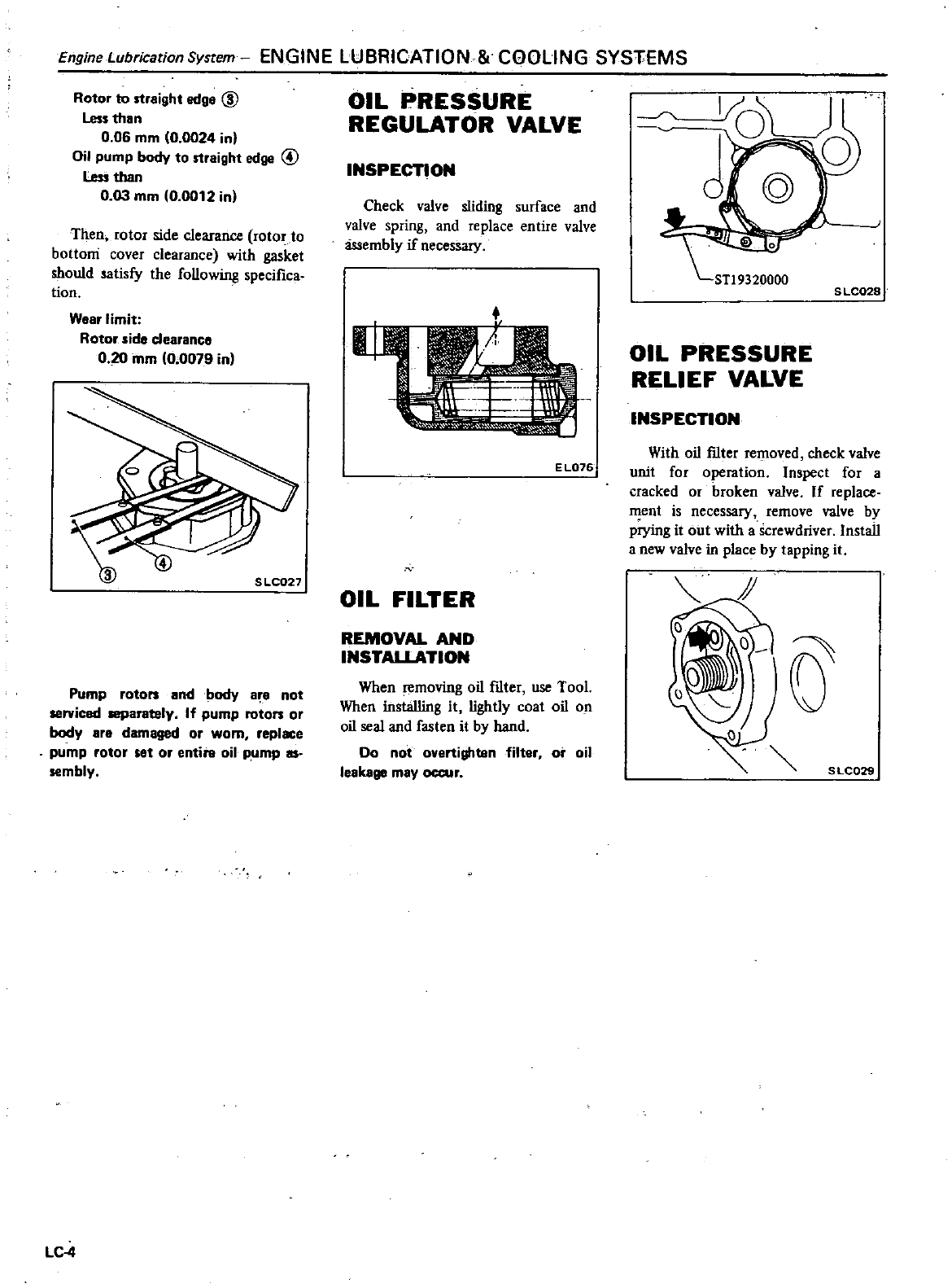
EngineLubricationSystem
ENGINE
LUBRICATION COOLING
SYS1
EMS
Rotor
to
straight
edge @
Less
than
0
06
mm
0
0024
in
Oi
pump
body
to
straight
edge
@
Less
than
0
03
mm
0
0012
in
Then
rotor
side
clearance
rotor
to
bottoni
cover
clearance
with
gasket
should
satisfy
the
following
specifica
tion
Wear
limit
Rotor
side
clearance
0 20
mm
0
0079
in
S
LC027
Pump
rotors
and
body
are
not
serviced
separately
If
pump
rotors
or
body
are
damaged
or
worn
replace
pump
rotor set
or
entire
oil
pump
as
sembly
LC4
OIL
PRESSURE
REGULATOR
VALVE
INSPECTION
Check
valve
sliding
surface
and
valve
spring
and
replace
entire
valve
assembly
if
necessary
E
L076
N
OIL
FILTER
REMOVAL
AND
INSTALLATION
When
removing
oil
f1lter
use
Tool
When
installing
it
lightly
coat
oil
on
oil
seal
and
fasten
it
by
hand
Do
not
overtighten
filter
or
oil
leakage
may
occur
S
lC028
OIL
PRESSURE
RELIEF
VALVE
INSPECTION
With oil
f1lter
rellloved
check
valve
unit
for
operation
Inspect
for
a
cracked
or
broken
valve
If
replace
Il
ent
is
necessary
remove
valve
by
prying
it
out
with
a
screwdriver
InstaII
a
new
valve
in
place
by
tapping
it
a
5
LC029
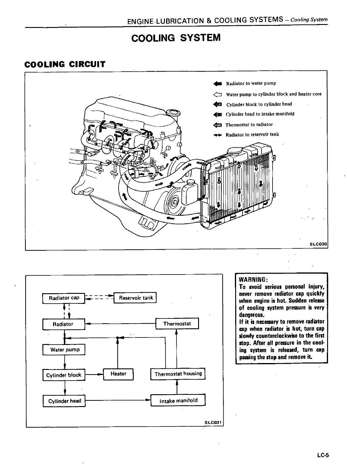
ENGINE
LUBRICATION
COOLING
SYSTEMS
Cooling
System
COOLING
SYSTEM
COOLING
CIRCUIT
Radiator
to
water pump
o
Water
pump
to
cylinder
block
and
heater
core
Cylinder
block
to
cylinder
head
1
Cylinder head
to
intake
manifold
Thermostat
to
radiator
Radiator
to
reservoir
tank
5
LC030
L
Water
pump
A
WARNING
To avoid
serious
peRonal
injury
never
remove
I
Idiator
cap
quickly
when
engine
is
hot
Sudden
release
of
cooling
system
pressure
is
very
dal1llerous
If
it
is
necessary
to
remove
Iadiator
cap
when
Iadiator
is
hot
turn
cap
slowly
counterclockwise
to
the
fillt
stop
After
all
pressure
in
the
coo
ing
system
is released
turn
cap
passing
the
stop
and
remove
it
Radiator
cap
F
Reservoir
tank
t
Radiator
Thermostat
Cylinder
block
H
Heater
I
J
Thermostat
housing
t
f
Cylinder
head
l
Intake
manifold
SLC031
LC
5
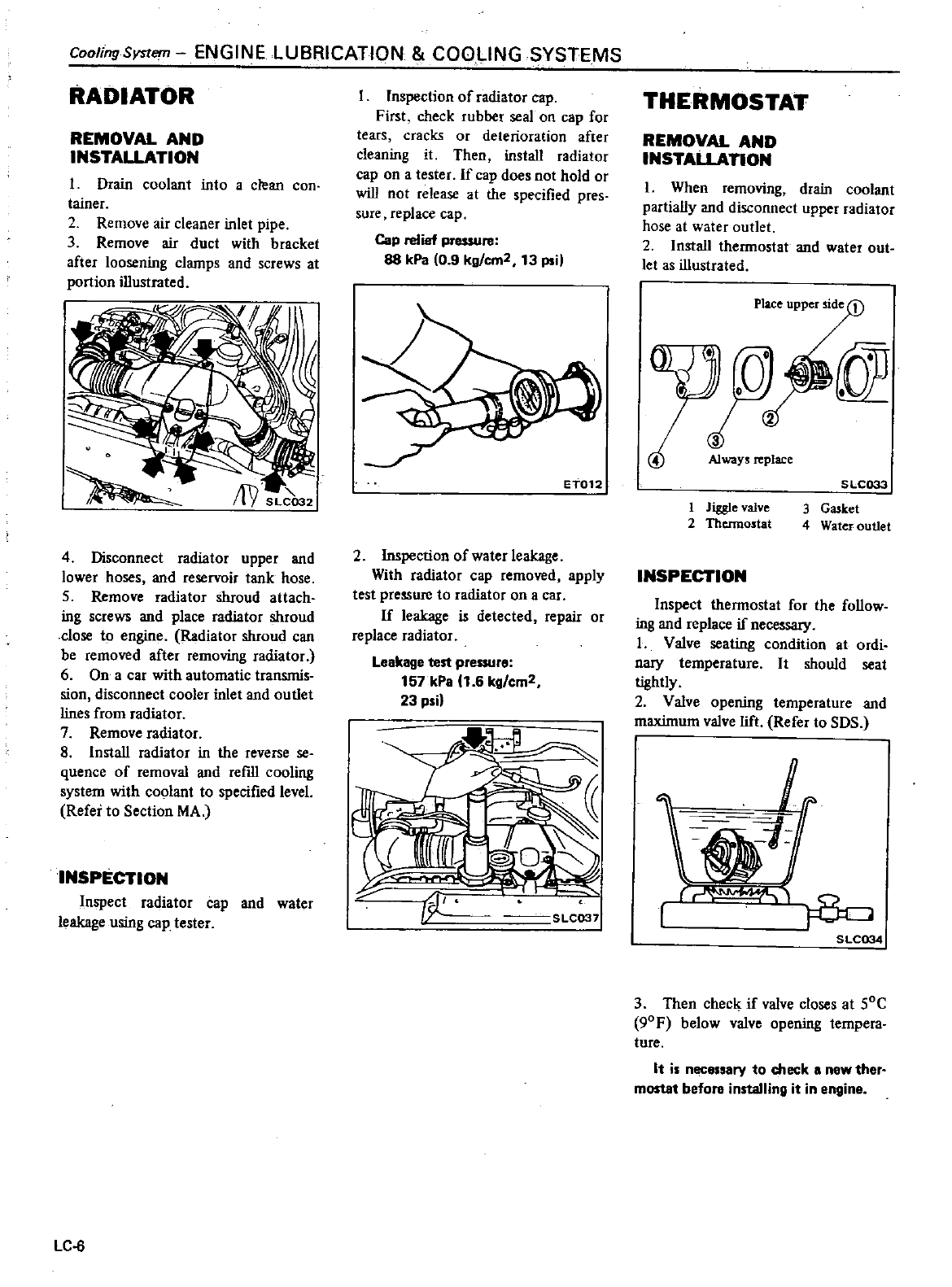
Cooling
System
ENGINE
LUBRICATION
COOLING
SYSTEMS
RADIATOR
REMOVAL
AND
INSTALLATION
I
Drain coolant
into
a
clean
con
tainer
2
Remove
air
cleaner
inlet
pipe
3
Remove
air
duct
with
bracket
after
loosening
clamps
and
screws
at
portion
illustrated
4
Disconnect
radiator
upper
and
lower
hoses
and
reservoir
tank
hose
5
Remove
radiator
shroud
attach
ing
screws
and
place
radiator
shroud
close
to
engine
Radiator
shroud
can
be
removed
after
removing
radiator
6
On
a
car
with
automatic
transmis
sian
disconnect
cooler
inlet
and
outlet
lines
from
radiator
7
Remove
radiator
8 Install
radiator
in
the
reverse
se
quence
of
removal
and
refill
cooling
system
with
coolant
to
specified
level
Refer
to
Section
MA
INSPECTION
Inspect
radiator
cap
and
water
leakage
using
cap
tester
LC
6
Inspection
of
radiator
cap
First
check
rubber
seal
on
cap
for
tears
cracks
or
deterioration
after
cleaning
it
Then
install
radiator
cap
on
a
tester
If
cap
does
not
hold
or
will
not
release
at
the
specified
pres
sure
replace
cap
Cap
relief
pressure
88
kPa
0 9
kg
cm2
13
psi
ET012
2
Inspection
of
water
leakage
With
radiator
cap
removed
apply
test
pressure
to
radiator
on
a
car
If
leakage
is
detected
repair
or
replace
radiator
Leakage
test
pressure
157
kPa
1
6
kg
cm2
23psil
I
y
SLC037
THERMOSTAT
REMOVAL
AND
INSTALLATION
1
When
removing
drain
coolant
partially
and
disconnect
upper
radiator
hose
at
water
outlet
2
Install
thennostat
and
water out
let
as
illustrated
1
Jiggle
valve
2
Thermostat
SLC033
3
Gasket
4
Water
outlet
INSPECTION
Inspect
thennostat
for
the
follow
ing
and
replace
if
necesS3l
I
Valve
seating
condition
at
ordi
nary
temperature
It
should
seat
tightly
2
Valve
opening
temperature
and
maximum
valve
lift
Refer
to
SDS
VJj
i
SLC034
3 Then
check
if
valve
closes
at
SOC
90F
below
valve
opening
tempera
ture
It
is
necessary
to
check
a
new
ther
mostat
before
installing
it
in
engine
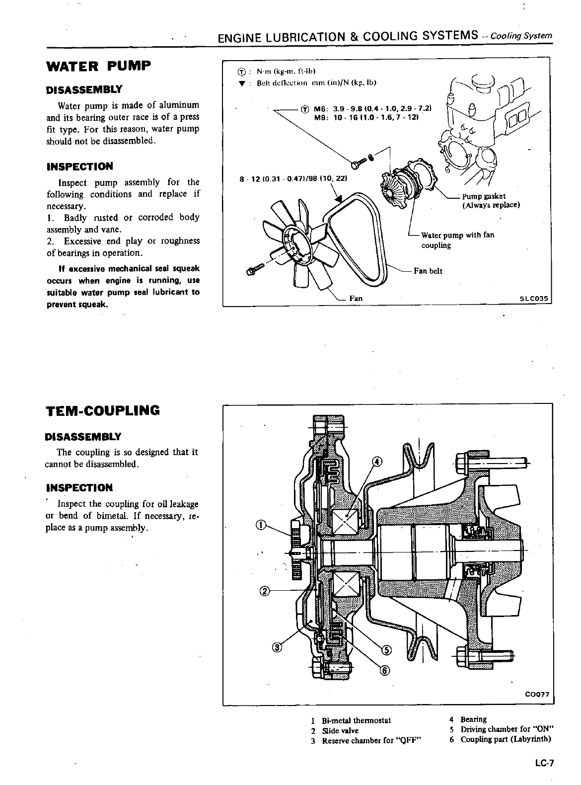
WATER
PUMP
DISASSEMBLY
Water
pump
is
made
of
aluminum
and
its
bearing
outer
race
is
of
a
press
fit
type
For
this
reason
water
pump
should
not
be
disassembled
INSPECTION
Inspect
pump
assembly
for the
following
conditions
and
replace
if
necessary
I
Badly
rusted
or
corroded
body
assembly
and
vane
2
Excessive
end
play
or
roughness
of
bearings
in
operation
If
excessive
mechanical
seal squeak
occurs
when
engine
is
running
use
suitable
water
pump
seal
lubricant
to
prevent
squeak
TEM
COUPLlNG
DISASSEMBLY
The
coupling
is
so
designed
that
it
cannot
be
disassembled
INSPECTION
Inspect
the
coupling
for
oil
leakage
or
bend
of
bimetal
If
necessary
reo
place
as
a
pump
assemhly
ENGINE
LUBRICATION
COOLING
SYSTEMS
Cooling
System
cf
N
m
kg
ln ft
Ib
Belt
dcllcction
mm
in
fN
kg
Ib
@
M6
3 9
9
810
4
1
0
2 9 7
21
M8
10
16
1
0
1
6
7
121
a
1210
31
0
47
98 10
22
Pump
gasket
Always
replace
Water
pump
with
fan
coupling
Fan
belt
SLC035
t
C0077
1
Bi
metal
thermostat
2
Slide
valve
3
ReseIVe
chamber
for
QFF
4
Bearing
5
Driving
chamber
for
ON
6
Coupling
part
Labyrinth
Le
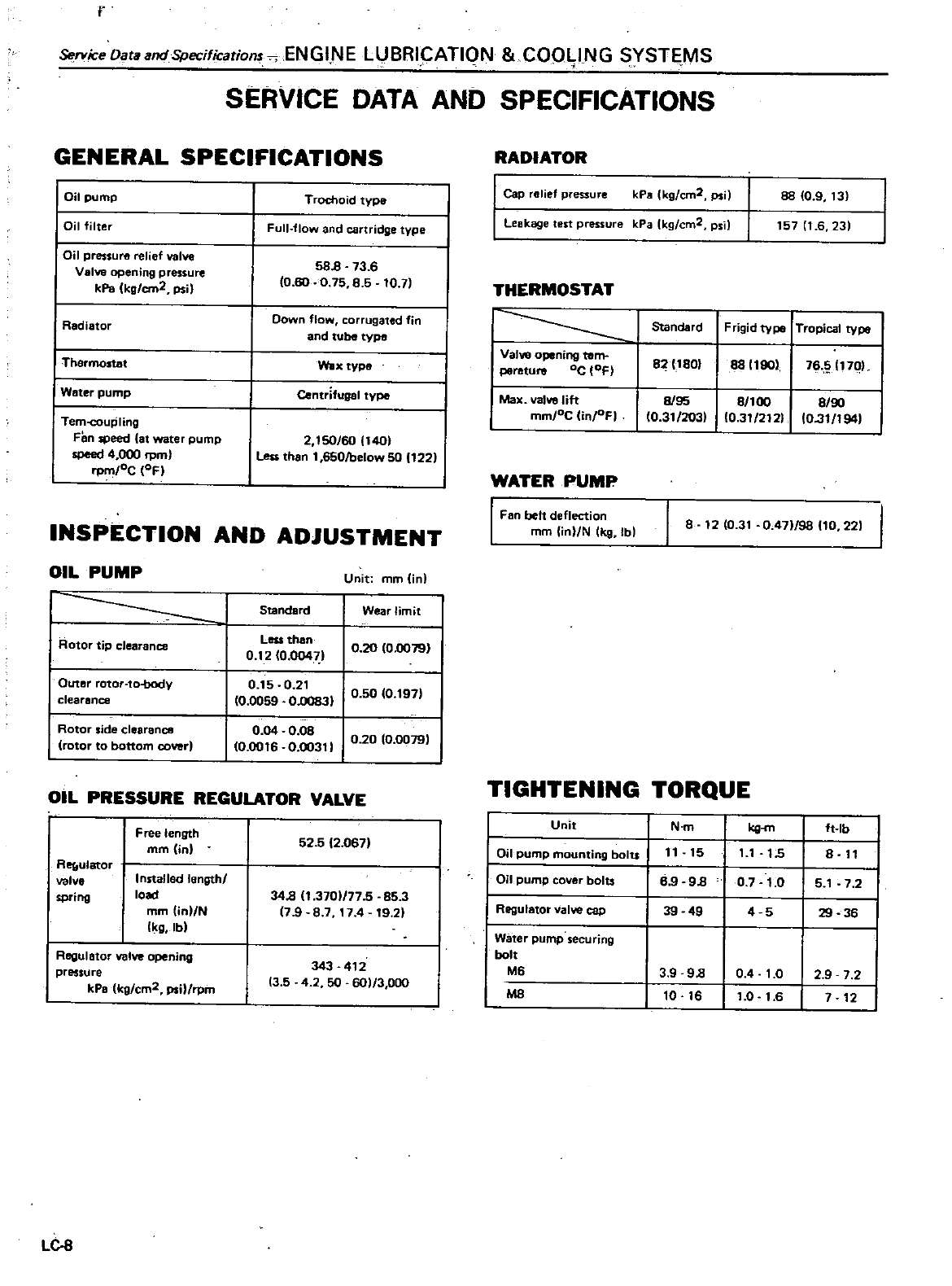
r
ServiceDataandSpecifications
ENGINE
LUBRICATION
COOLING
SYSTEMS
SERVICE
DATA
AND
SPECIFICATIONS
GENERAL
SPECIFICATIONS
I
Oil
pump
I
Oil
filter
Oil
pressure
relief
valve
Valve
opening
pressure
kPa
kg
cm2
psH
I
Redietor
I
Thermostat
I
Water
pump
Tem
coupling
Fen
speed
at
water
pump
speed
4
000 rpm
rp
oC
OF
Trochoid
type
Full
flow
and
cartridge
type
59
8
13
6
0
60
0
75
8
5
10
7
Down
flow
corrugated
fin
and
tube type
Wax
type
Centrifugal
type
2 150
60
1401
Less
than
1
650lbelow
50
122
INSPECTION
AND
ADJUSTMENT
OIL
PUMP
1
Rotor
tip
clearance
Outer
rotor
to
body
clearance
I
Rotor
side
clearance
rotor
to
bottom
cover
Unit
mm
in
Standard
Wear
limit
Less
then
0
12
0
00471
0
20
10
0079
0
15
0
21
I
0 0
0
10
0059
0
llO831
5
197
0
04
0
08
I
0
1
0
0016
0
00311
20
0
0079
OIL
PRESSURE
REGULATOR VALVE
Free
length
mm
jn
Re
ulator
valve
spring
Installed
lengthl
loed
mm in
N
Ikg
lbl
Regulator
valve
opening
pressure
kPa
kg
cm2
psi
rpm
LC
8
52
5 2
0671
34
8 1
3701
77
5
85
3
7
9
8
7
174
19
21
343
412
13
5
4
2
50
601
3000
RADIATOR
CaP
relief
pressure
kPa
kg
cm2
psi
88
09
13
157
11
6
231
Leakage
test
pressure
kPa
Ikg
cm2
psi
THERMOSTAT
1
Standard
Frigid
type
Tropical
type
I
Valve
opening
tom
82
1801
8811901
76
170
perature
oC
OF
I
Max
valve
lift
8
95
8
100
8
90
mm
oC Un oF
I 10
31
203
10
31
212
O
3t
194
WATER
PUMP
I
Fan belt
deflection
mm
lin N
Ikg
Ibl
I
8
12
10
31
0
471
98
10
221
TIGHTENING
TORQUE
Unit
N
m
kg
m
ft
lb
Oil
pump
mounting
bolu
11
15
11
15
8
11
I
Oil
pump
cover
bolts
69
98
07
1
0
5
1
7 2
Regulator
valve
cap
39 49
4 5
29 36
Water
pump
securing
bolt
M6
3 9
98
0 4
1
0
2 9 7 2
Me
10
16
1
0
1
6
7
12
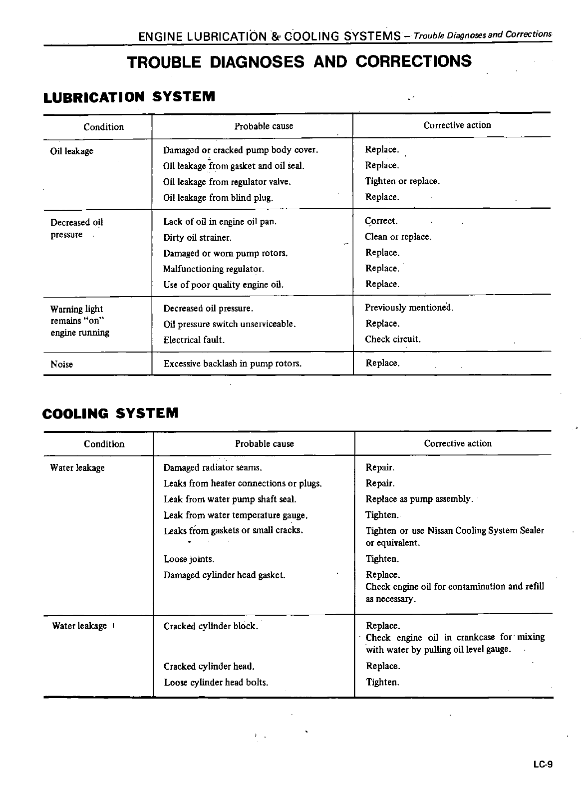
ENGINE
LUBRICATION
COOLING
SYSTEMS
Trouble
Diagnoses
and
Corrections
TROUBLE DIAGNOSES
AND
CORRECTIONS
LUBRICATION
SYSTEM
Condition
Probable
cause
Oil
leakage
Damaged
or
cracked
pump
body
cover
Oil
leakage
from
gasket
and
oil
seal
Oil
leakage
from
regulator valve
Oil
leakage
from
blind
plug
Decreased
oil
pressure
Lack
of
oil
in
engine
oil
pan
Dirty
oil
strainer
Damaged
or
worn
pump
rotors
Malfunctioning
regulator
Use
of
poor
quality
engine
oil
Warning
light
remains
on
engine
running
Decreased
oil
pressure
Oil
pressure
switch
unserviceable
Electrical
fault
Noise
Excessive
backlash
in
pump
rotors
COOLING
SYSTEM
Condition
Probable
cause
Water
leakage
Damaged
radiator
seams
Leaks
from
heater
connections
or
plugs
Leak
from
water
pump
shaft
seal
Leak
from
water
temperature
gauge
Leaks
from
gaskets
or
small
cracks
Loose
joints
Damaged
cylinder
head
gasket
Water
leakage
Cracked
cylinder
block
Cracked
cylinder
head
Loose
cylinder
head
bolts
Corrective
action
Replace
Replace
Tighten
or
replace
Replace
G
orrect
Clean
or
replace
Replace
Replace
Replace
Previously
mentioned
Replace
Check
circuit
Replace
Corrective
action
Repair
Repair
Replace
as
pump
assembly
Tighten
Tighten
or
use
Nissan
Cooling
System
Sealer
or
equivalent
Tighten
Replace
Check
engine
oil
for
contamination
and
refill
as
necessary
Replace
Check
engine
oil
in
crankcase
fonnixing
with
water
by
pulling
oil
level
gauge
Replace
Tighten
LC
9
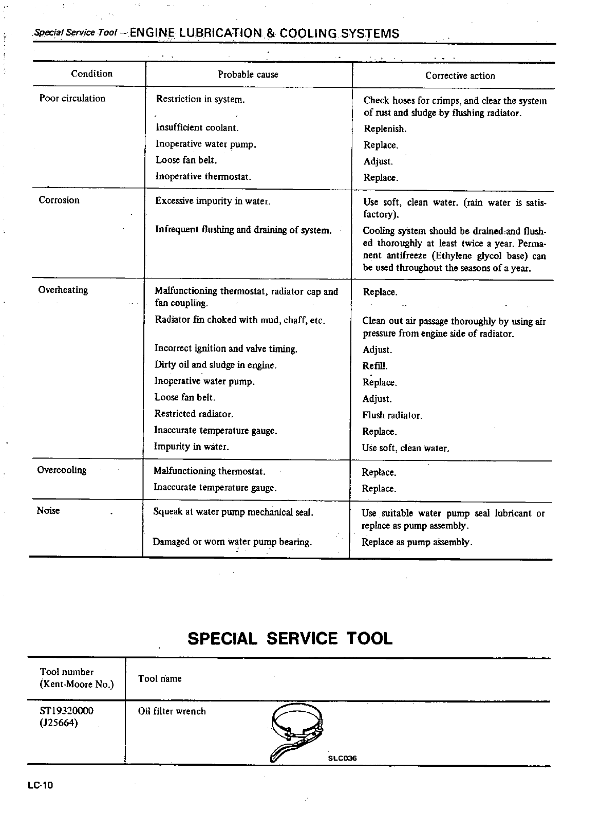
Special
Service
Tool
ENGINE
LUBRICATION
COOLING
SYSTEMS
Condition
Poor
circulation
Corrosion
Overheating
Overcooling
Noise
Tool
number
Kent
Moore
No
STl9320oo0
125664
LC
l0
Probable
cause
Restriction
in
system
Insufficient
coolant
Inoperative
water
pump
Loose
fan
belt
Inoperative
thennostat
Excessive
impurity
in
water
Infrequent
flushing
and
draining
of
system
Malfunctioning
thennostat
radiator
cap and
fan
coupling
Radiator
fm
choked
with
mud
chaff
etc
Incorrect
ignition
and valve
timing
Dirty
oil
and
sludge
in
engine
Inoperative
water
pump
Loose
fan
belt
Restricted
radiator
Inaccurate
temperature
gauge
Impurity
in
water
Malfunctioning
thennostat
Inaccurate
temperature
gauge
Squeak
at
water
pump
mechanical
seal
Damaged
or worn
water
pump
bearing
C
arrective
action
Check
hoses
for
crimps
and
clear
the
system
of
rust
and
sludge
by
flushing
radiator
Replenish
Replace
Adjust
Replace
Use
soft
clean
water rain water
is
satis
factory
Cooling
system
should
be
drained
and
flush
ed
thoroughly
at
least
twice
a
year
Perma
nent
antifreeze
Ethylene
glycol
base
can
be
used
throughout
the
seasons
of
a
year
Replace
Clean
out
air
passage
thoroughly
by
using
air
pressure
from
engine
side
of
radiator
Adjust
Refill
Replace
Adjust
Flush
radiator
Replace
Use
soft
clean
water
Replace
Replace
Use
suitable
water
pump
seal
lubricant
or
replace
as
pump
assembly
Replace
as
pump
aSsembly
SPECIAL
SERVICE
TOOL
Tool
name
Oil
filter
wrench
00
DATSUN
200SX
Model
S
J J
0
Series
SECTIONEF
ENGINE
FUEL
CONTENTS
DESCRIPTION
EFI
SYSTEM
FEATURES
EFI
SYSTEM
OPERATION
FUEL
FLOW
SYSTEM
AIR
FLOW
SYSTEM
ELECTRICAL
FLOW
SYSTEM
FUEL
INJEC
TION
CONTROL
FUEL
INJECTION
TIMING
FUEL
INJECTION
QUANTITY
EFI SYSTEM
COMPONENT
PARTS
CONSTRUCTION
AND
FUNCTION
FUEL
FLOW
SYSTEM
AIR
FLOW
SYSTEM
ELECTRICAL
SIGNAL
SYSTEM
PRECAUTIONS
FOR
AN
EFI
ENGINE
REMOVAL
AND
INSTALLATION
INJECTOR
AND
FUEL
PIPE
PRESSURE
REGULATOR
AIR
REGULATOR
WATER
TEMPERATURE
SENSOR
THROTTLE
VALVE
SWITCH
THROTTLE
CHAMBER
DASH
POT
VACUUM
SWITCH
ALTITUDE
SENSOR
DROPPING
RESISTOR
CONTROL
UNIT
RELAY
AIR
CLEANER
AIR
FLOW
METER
AIR
TEMPERATURE
SENSOR
FUEL FILTER
FUEL
PUMP
AND
FUEL
DAMPER
FUEL
HOSE
ELECTRICAL
SYSTEM
INSPECTION
EF
2
EF
4
EF
4
EF
4
EF
4
EF
5
EF
5
EF
7
EF
7
EF
7
EF
11
EF
11
EF
13
EF
15
EF
18
EF
19
EF
19
EF
20
EF
20
EF
20
EF
20
EF
20
EF
21
EF
21
EF
21
EF
21
EF
21
EF
22
EF
22
EF
22
EF
22
EF
22
EF
23
F
2
3
EF
24
DESCRIPTION
PREPARATIONS
FOR
INSPECTION
INSPECTION
INSPECTION
PROCEDURE
TABLE
EFI
CIRCUIT
DIAGRAM
COMPONENT
PARTS
INSPECTION
FUEL
PRESSURE
CHECK
FUE L
PUMP
FUEL
DAMPER
FUEL
FILTER
INJECTOR
PRESSURE
REGULATOR
AIR
FLOW
METER
AIR
TEMPERATURE
SENSOR
AIR
REGULATOR
THROTTLE
CHAMBER
DASH
POT
WATER
TEMPERATURE
SENSOR
THROTTLE
VALVE
SWITCH
VACUUM
SWITCH
ALTITUDE
SENSOR
DROPPING
RESISTOR
RELAY
CONTROL
UNIT
CHECKING
AIR
LEAKAGE
IN
AIR
INTAKE
SYSTEM
CHECKING
FUEL
HOSES
SERVICE
DATA
AND
SPECIFICATIONS
GENERAL
SPECIFICATIONS
INSPECTION
AND
ADJUSTMENT
TIGHTENING
TORQUE
TROUBLE
DIAGNOSES
AND
CORRECTIONS
TROUBLE
SHOOTING
CHART
CHECKING
AND
ADJUSTING
IDLE
RPM
IGNITION
TIMING
AND MIXTURE
RATIO
EF
24
EF
24
EF
24
EF
25
EF
28
EF
29
EF
29
EF
29
EF
29
EF
29
EF
29
EF
30
EF
30
EF
30
EF
31
EF
31
EF
31
EF
32
EF
32
EF
33
EF
33
EF
33
EF
34
EF
34
EF
35
EF
35
EF
36
EF
36
EF
36
EF 36
EF
37
EF
37
EF
43
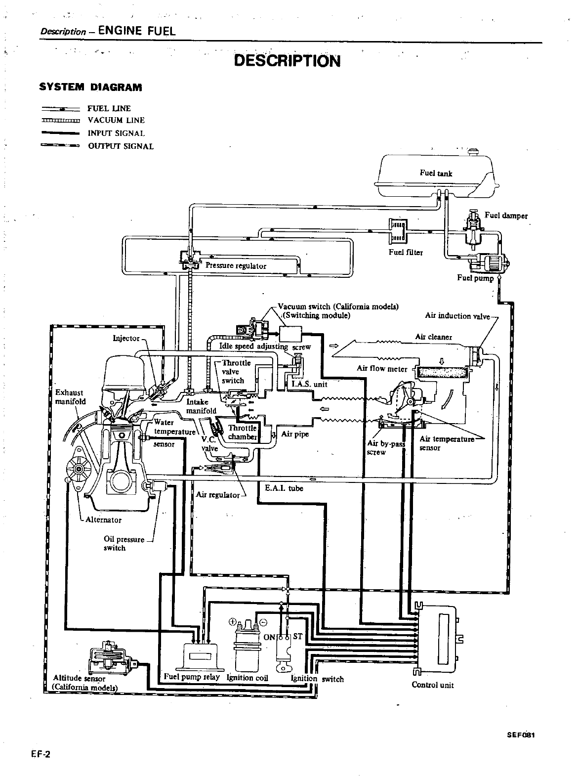
Description
ENGINE
FUEL
DESCRIPTION
SYSTEM
DIAGRAM
fUEL
UNE
VACUUM
LINE
INPUT
SIGNAL
OUTPUT
SIGNAL
r
t
essure
regulatm
h
f
Fueltank
i
I
ili
J
Fuelmter
Fuel
pump
L
cu
witch
California
modelA
Switching
module
Idle
speed
adjus
ing
screw
i
Ji
t
0
r
Air
pipe
EA
tube
Oil
pressure
switch
1
lliru
California
models
I
a
I
C
J
I
8j
8
I
ON
1ST
U
0
Ih
Fuel
pump
relay
Ignition
coil
Ignition
switch
q
EF
2
Air
inducti
ln
valve
Air
cleaner
Ai
r
nwmei
dlJ
fj
1r
L
bI
Air
temperature
y
pall
semOl
ew
II
c
I
J
s
lt1
Control
unit
SEF081
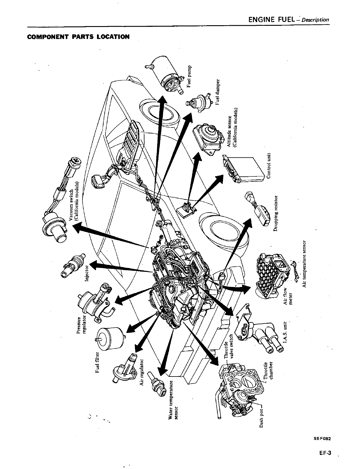
Watet
tem
Perature
sensot
Vacuum
wltch
I
A
ltCl
iforni
l
models
f
A
11
i
0
i
0II
i
yuel
pump
fue
d
aIn
pex
Altitude
5en
oor
California
model
C
i
T
C
I
S
i
contro
unit
Dropping
tes1
tot
MI
ternpetaW
re
n
or
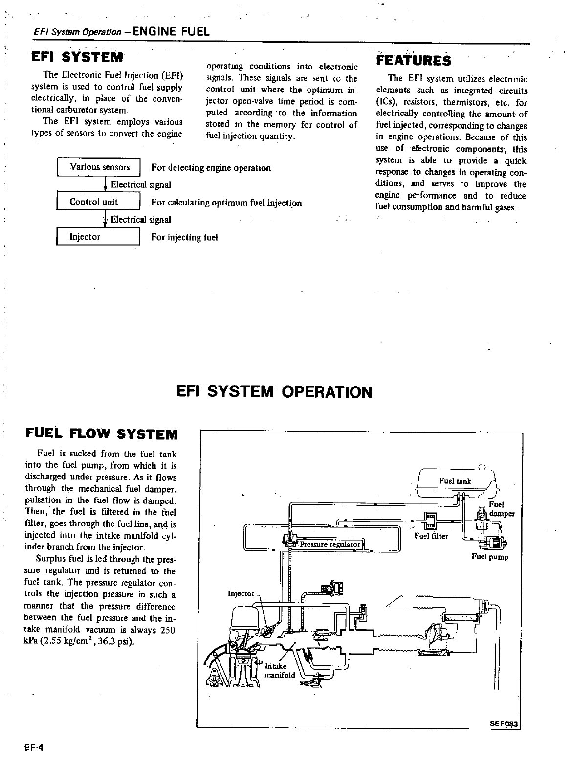
EFI
System
Openltion
ENGINE
FUEL
EFI
SYSTEM
operating
conditions
into
electronic
signals
These
signals
are
sent
to
the
control
unit
where
the
optimum
in
jector
open
valve
time
period
is
com
puted
according
to
the
infonnation
stored
in
the
memorY
for
control
of
fuel
injection quantity
The
Electronic
Fuel
Injection
EFI
system
is
used
to
control
fuel
supply
electrically
in
place
of
the
conven
tional
carburetor
system
The
EFl
system
employs
various
types
of
sensors
to
convert
the
engine
Various
sensors
I
For
detecting
engine
operation
1
Electrical
signal
Control
unit
I
For
calculating
optimum
fuel
injecti
on
Electrical
signal
Injector
I
For
injecting
fuel
EFISYSTEM
OPERATION
FUEL
FLOW
SYSTEM
Fuel
is
sucked
from
the
fuel
tank
into
the
fuel
pump
from
which
it
is
discharged
under
pressure
As
it
flows
through
the
mechanical
fuel
damper
pulsation
in
the
fuel
flow
is
damped
Then the
fuel
is
filtered
in
the
fuel
filter
goes
through
the
fuel
line
and
is
injected
into
the intake
manifold
cyl
inder
branch
from
the
injector
Surplus
fuel
is
led
through
the
pres
sure
regulator
and
is
returned
to
the
fuel
tank
The
pressure
regulator
con
trois
the
injection
pressure
in
such
a
manner
that
the
pressure
difference
between
the
fuel
pressure
and
the
in
take
manifold
vacuum
is
always
250
kPa
2
55
kg
cm
36
3
psi
J
D
EF
4
FEATURES
The
EFl
system
utilizes
electronic
elements such
as
integrated
circuits
ICs
resistors
thennistors
etc for
electrically
controlling
the
amount
of
fuel
injected
corresponding
to
changes
in
engine
operations
Because
of
this
use
of
electronic
components
this
system
is
able
to
provide
a
quick
response
to
changes
in
operating
con
ditions
and
serves
to
improve
the
engine
perfonnance
and
to
reduce
fuel
consumption
and
hannful
gases
un
J
r
n
L
SEFQ83
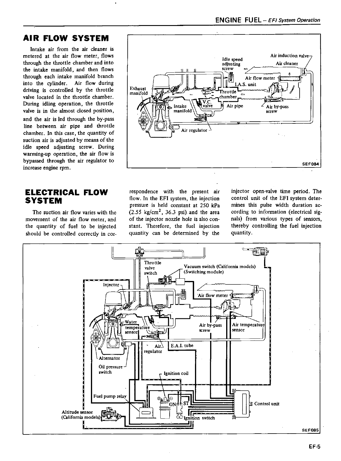
AI
R
FLOW
SYSTEM
Intake
air
from
the
air
cleaner
is
metered
at
the
air
flow
meter
flows
through
the
throttle
chamber
and
in
to
the
intake
manifold
and
then
flows
through
each
intake
manifold
branch
into
the
cylinder
Air
flow
during
driving
is
controlled
by
the
throttle
valve
located
in
the
throttle
chamber
During
idling
operation
the
throttle
valve
is
in
the
almost
closed
position
and
the
air
is
led
through
the
by
pass
line
between
air
pipe
and
throttle
chamber
In
this
case
the
quantity
of
suction
air
is
adjusted
by
means of
the
idle
speed
adjusting
screw
During
warming
up
operation
the
air
flow
is
bypassed
through
the
air
regulator
to
increase
engine
rpm
ELECTRICAL
FLOW
SYSTEM
The
suction
air
flow
varies
with
the
movement
of
the
air
flow
meter
and
the
quantity
of
fuel
to
be injected
should
be
controlled
correctly
in
cor
Injector
11
R
A
respondence
with
the
present
air
flow
In
the
EFI
system
the
injection
pressure
is
held
constant
at
250
kPa
2
55 kg cm2 36
3
psi
and
the
area
of
the
injector
noule
hole
is
also
con
stant
Therefore
the
fuel
injection
quantity
can
be
determined
by
the
l
11
I
ENGINE
FUEL
EFISystemOperation
Idle
speed
adjusting
Air
cleaner
screw
0
AirflOwm
ter
f
LA
S
unit
i
I
Throttle
chamber
L
Air
pipe
LAir
by
pass
screw
SEF084
injector
open
valve
time
period
The
control
unit
of
the
EFI
system
deter
mines
this
pulse
width
duration
ac
cording
to
information
electrical
sig
nals
from
various
types
of
sensors
thereby
controlling
the
fuel
injection
quantity
L
Vacuum
switch
California
models
Switching
module
Air
flOW
o
Air
by
pass
screw
I
Air
temperature
sensor
f
s
Control
unit
SEF085
EF
5
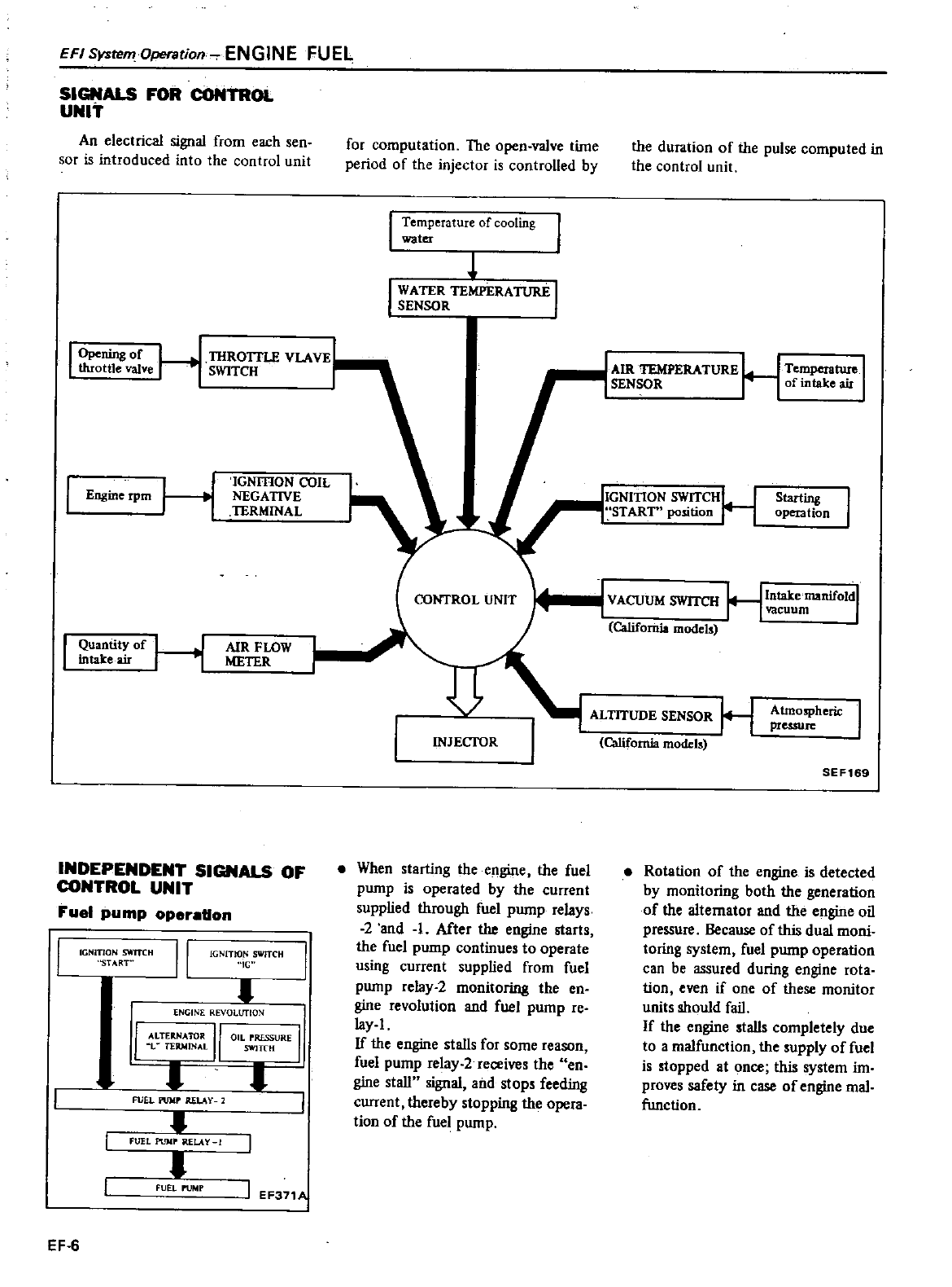
EFI
SystemOperation
ENGINE
FUEL
SIGNALS
FOR
CONTROl
UNIT
An
electrical
signal
from
each
sen
sor
is
introduced
into
the
control
unit
I
Opening
of
L
throttle
valve
I
Engme
rpm
H
Quantity
of
in
take
air
H
TIlROITLE
VLA
VE
SWITCH
IGNmON
COIL
NEGATIVE
TERMINAL
AIR
FLOW
METER
INDEPENDENT
SIGNALS
OF
CONTRDL
UNIT
Fuel
pump
operation
IGNrIlON
SWITCH
START
IGNITION
SWITCH
IG
ENGINE REVOLUTION
I
ALTERNATOR
II
l
TERMINAL
FUEL
pU
lp
ULA
Y
FUEL
PlJlIP
RELAY
fUEL
PUMP
EF
6
I
OIL
rRf5SURE
I
SWITCH
r
I
I
EF37
1
for
computation The
open
vaIve
tiJUe
period
of
the
injector
is
controlled
by
I
Temperature
of
cooling
water
I
WATER
TEMPERA11JRE
I
SENSOR
INJECTOR
When
starting
the
engine
the
fuel
pump
is
operated
by
the
current
supplied
through
fuel
pump
relays
2
and
1
After
the
engine
starts
the
fuel
pump
continues
to
operate
using
current
supplied
from
fuel
pump
relay
2
monitoring
the
en
gine
revolution
and
fuel
pump
reo
lay
1
If
the
engine
stalls
for
some reason
fuel
pump
relay
2
receives
the
en
gine
stall
signal
and
stops
feeding
current
thereby
stopping
the
opera
tion
of
the
fuel
pump
the
duration
of
the
pulse computed
in
the control
unit
AIR
TEMPERATURE
H
TempctalUIel
SENSOR
of
mtake
air
IGNITION
SWITCHH
START
position
Starting
operation
VACUUM
SWITCH
HI
take
manifOldl
vacuum
California
models
ALTITUDE
SENSOR
H
California
modet
Atmospheric
I
preuure
SEF169
Rotation
of
the
engine
is
detected
by
monitoring
both
the
generation
of
the
alternator
and
the
engine
oil
pressure
Because
of
this
dual
moni
toring
system
fuel
pump
operation
can
be
assured
during
engine
rota
tion
even
if
one
of
these
monitor
units
should
fail
If
the
engine
stalls
completely
due
to
a
malfunction
the
supply
offuel
is
stopped
at
once
this
system
iJU
proves
safety
in
case
of
engine
mal
function
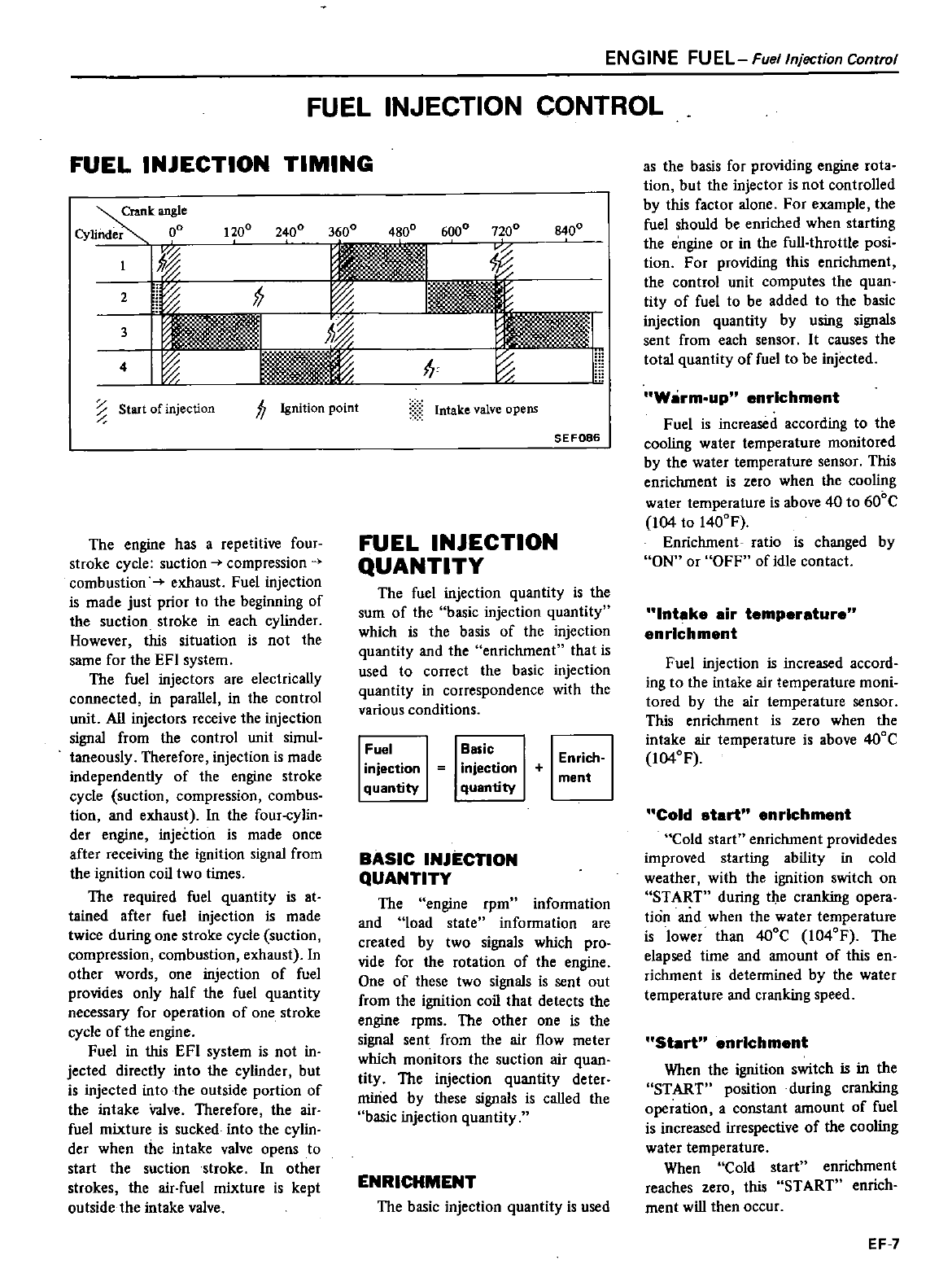
FUEL INJECTION
TIMING
FUEL
INJECTION
CONTROL
Crank
angle
Cylinder
o
1200
2400 3600
4800
6000
7
200
10
I
v
I
f
1k
I
l
1
4
I
I
m
71
ii
c
Start
of
injection
fJ
Ignition
point
The
engine
has
a
repetitive
four
stroke
cycle
suction
compression
4
combustion
exhaust
Fuel
injection
is
made
just
prior
10
the
beginning
of
the
suction
stroke
in
each
cylinder
However
this
situation
is
not
the
same
for
the
EFI
system
The
fuel
injectors
are
electrically
connected
in
parallel
in
the
control
unit
All
injectors
receive
the
injection
signal
from
the
control
unit
simul
taneously
Therefore
injection
is
made
independently
of
the
engine
stroke
cycle
suction
compression
combus
tion
and
exhaust
In
the
four
cylin
der
engine
injeCtion
is
made
once
after
receiving
the
ignition
signal
from
the
ignition
coil
two
times
The
required
fuel
quantity
is
at
tained
after
fuel
injection
is
made
twice
during
one
stroke
cycle
suction
compression
combustion
exhaust
In
other
words
one
injection
of
fuel
provides
only
half
the
fuel
quantity
necessary for
operation
of
one
stroke
cycle
of
the
engine
Fuel
in
this
EFI
system
is
not
in
jected
directly
into
the
cylinder
but
is
injected
into
the
outside
portion
of
the intake
Valve
Therefore
the air
fuel
mixture
is
sucked
into
the
cylin
der
when
the
in
take
valve
opens
to
start
the
suction
stroke
In
other
strokes
the
air
fuel
mixture
is
kept
outside
the
intake
valve
8400
Intake
valve
opens
SEF086
FUEL
INJECTION
QUANTITY
The
fuel
injection
quantity
is
the
sum
of
the
basic
injection quantity
which
is
the
basis
of
the
injection
quantity
and
the
enrichment
Ihat
is
used
to
correct the
basic
injection
quantity
in
correspondence
with
the
various
conditions
Fuel
injection
quantity
Basic
injection
quantity
Enrich
ment
BASIC
INJECTION
QUANTITY
The
engine
rpm
infonnation
and
load
state
information
are
created
by
two
signals
which
pro
vide
for the
rolation
of
the
engine
One
of
these
two
signals
is
sent
out
from
the
ignition
coil
that
detects
the
engine
rpms
The
other
one
is
the
signal
sent
from
the
air
flow
meter
which
monitors
the
suction
air
quan
tity
The
injection quantity
deter
mined
by
these
signals
is
caIled
the
basic
injection quantity
ENRICHMENT
The
basic
injection quantity
is
used
ENGINE
FUEL
Fuel
Injection
Control
as
the
basis
for
providing
engine
rota
tion
but the
injector
is
not
controlled
by
this
factor
alone
For
example
the
fuel
should
be
enriched
when
starting
the
engine
or in
the
full
throttle
posi
tion
For
providing
this
enrichment
the
control
unit
computes
the
quan
tity
of
fuel
to
be
added
to
the
basic
injection quantity
by
using
signals
sent
from
each
sensor
It
causes
the
total
quantity
of
fuel
to
be
injected
Warm
up
enrichment
Fuel
is
increased
according
to
the
cooling
water
temperature
monitored
by
the
water
temperature
sensor
This
enrichment
is
zero
when
the
cooling
water
temperature
is
above
40
to
600C
104
to
l400F
Enrichment
ratio
is
changed
by
ON
or
OFF
of
idle
contact
Intake
air
temperature
enrichment
Fuel
injection
is
increased
accord
ing
to
the
intake
air
temperature
moni
tored
by
the
air
temperature
sensor
This
enrichmen
I
is
zero
when
the
intake air
temperature
is
above
400C
104OF
Cold
start
enrichment
Cold
start
enrichment
providedes
improved
starting
ability
in
cold
weather
with
the
ignition
switch
on
START
during
the
cranking
opera
tion
and
when
the
water
temperature
is
lower
than
400C
1040F
The
elapsed
time
and
amount
of
this
en
richment
is
detennined
by
the
water
temperature
and
cranking
speed
Stsrt
enrichment
When
the
ignition
switch
is
in
the
START
position
during cranking
operation
aconstant amount
of
fuel
is
increased
irrespective
of
the
cooling
water
temperature
When
Cold
start
enrichment
reaches
zero
this
START
enrich
ment
will
then
occur
EF
7
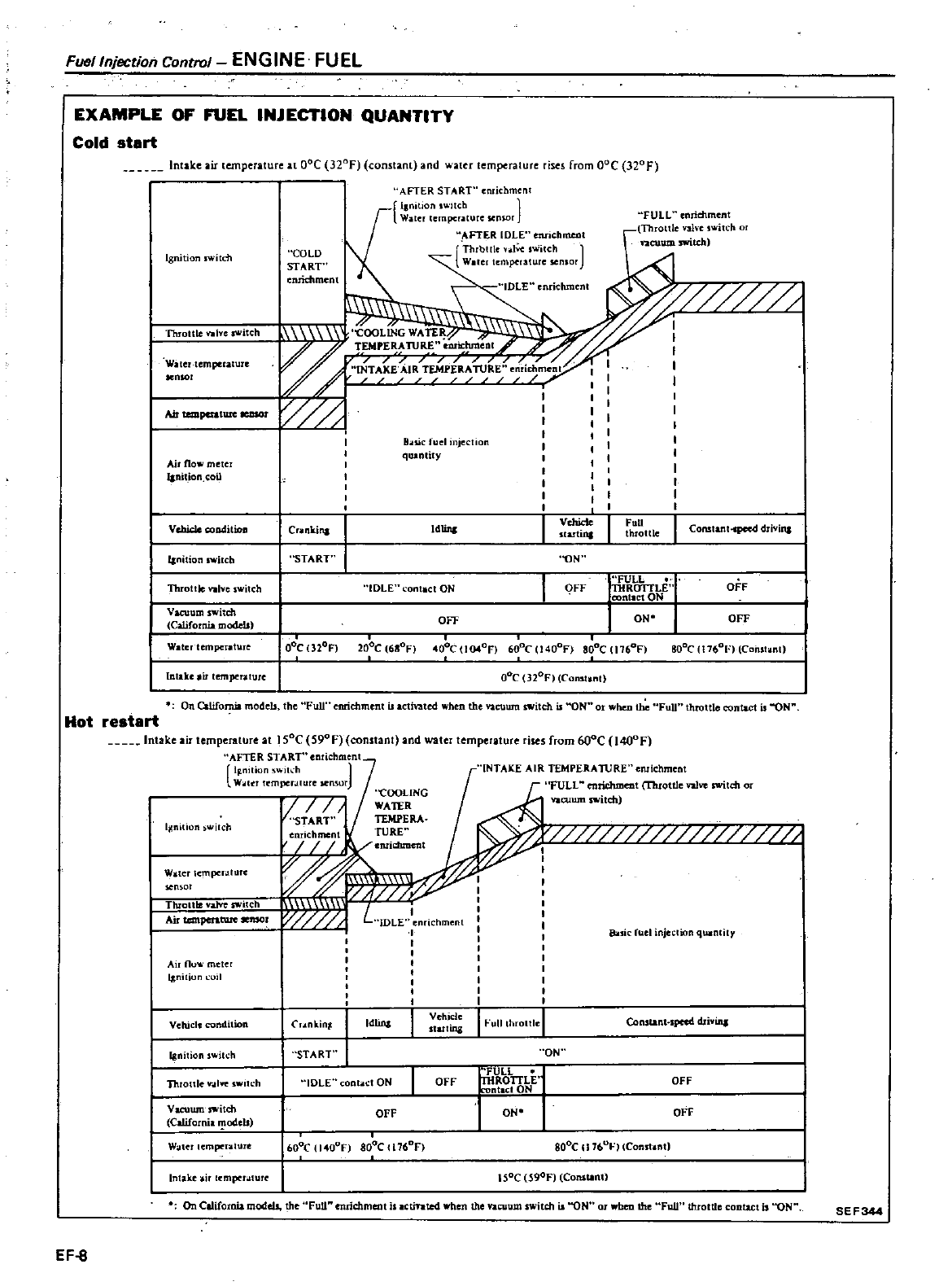
FUtJllnjection
Control
ENGINE
FUEL
EXAMPLE
OF
FUEL
INJECTION
QUANTITY
Cold
start
Intake
air
temperature
It
DoC
320F
constant
and
water
temperature
rises
from
DoC 320 F
Ignition
switch
Throttle
VlIlve
tIIltch
Witertemperalure
sen
Ol
I
AirtempcratureleDSOl
Air
fio
metcr
I
nition
oil
Vcbide
cooditioll
Janition
IWjlcb
Threl
e
VlIlve
switch
Vacuum
switch
California
models
Water
temperature
Intake
lemper
iIturc
COlD
START
nridunent
AFTER
START
ehmenl
llnitlon
ch
1
Waler
empcr
lllurcsensor
FTER
IDLE
enrichrne
at
Thrbllle
i
lw
switch
Iertemperaluresenlor
IDLE
chmenl
FULL
nriehmen
r
Throltle
ahe
switch
I
vacuumswitcb
QOLING
WATER
TEMPERAnJRE
orichm
I
TA
KE
IR
P
R
RE
Bots
ic
luel
njection
quantity
OOe
nor
200C
6110FI
40
C
l04on
600C 140oF 8oC 11760F lIo0e
17601
ConSlant
On
California
models
the
Full
enrichment
ctinted
when
the
vacuum
switch
ON
when
the
Full
throttle
contact
is
ON
oGC
32oF
Const
nt
restart
Intake
air
temperature
at
Isoe
S90F
constant
and
water
temperature
rises
from
600e
I400F
AFTER START
ehment
1F
niliOn
ch
W
t
r
emperalure
Ilensm
Hot
Ijl
nilion
ilch
W
telh
mpcl
lIUll
sensor
TluoltlevlIlYeswilCh
Air
1
lemar
Air no
meter
I
nilion
II
Vehicle
condition
Ignilionswitch
Thronlev
oIhe
s
itch
Vaeuum
ilch
California
1odeb
WOItet
empc
nlure
In
J
ke
emper
llure
On
California
models
the
Fun
enrichment
ctinted
ben
the
vacuum
switch
is
ON
when
the
FuU
throttle
ntut
is
ON
SEF344
EF
8
i
ricbmcnt
w
I
INTAKE
AIR
TEMPERAltlRE
enrichment
FULL
enrichment
Throttle
nlve
switdl
vacuum
switch
sie
fuel
injeclion
qUlrnlity
nkinr
Idlinl
Vehicle
starling
ConstanHpecd drivina
START
ON
IDLE
cION
OFF
FULL
THROTTLE
rontac10N
OFF
OFF
ON
OFF
600
140l
F
800e
176l
F
800C
117b
01
IConst
ntJ
ISoC
S90F
Constant
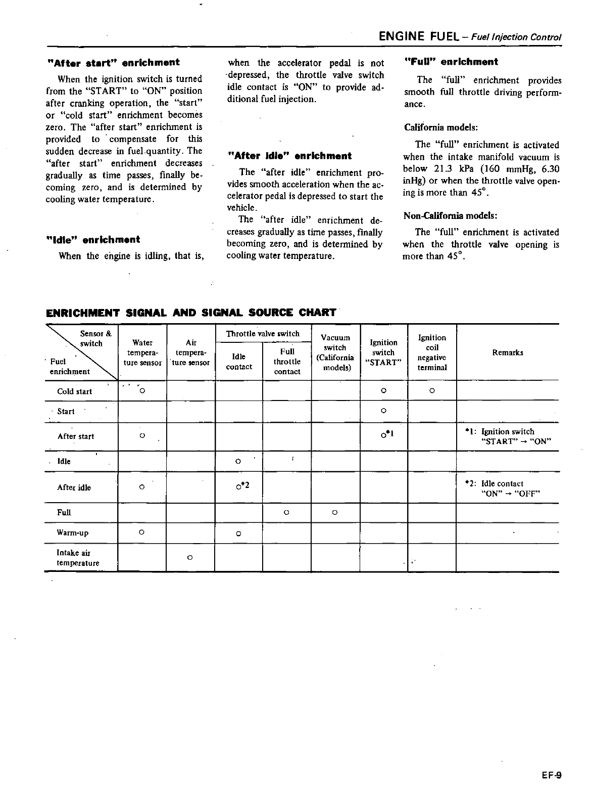
After
start
enrichment
When
the
ignition
switch
is
turned
from
the
START
to
ON
position
after
cranking
operation
the
start
or
cold
start
enrichment
becomes
zero
The
after
start
enrichment
is
provided
to
compensate
for
this
sudden
decrease
in
fuel
quantity
The
after
start
enrichment
decreases
gradually
as
time
passes
finally
be
coming
zero
and
is
detennined
by
cooling
water
temperature
Idle
enrichment
When
the
engine
is
idling
that
is
when
the
accelerator
pedal
is
not
depressed
the
throttle
valve
switch
idle
contact
is
ON
to
provide
ad
ditional
fuel
injection
After
Idle
enrichment
The
after
idle
enrichment
pro
vides
smooth
acceleration
when
the
ac
celerator
pedal
is
depressed
to
start
the
vehicle
The
after
idle
enrichment
de
creases
gradually
as
time
passes
finally
becoming
zero
and
is
detennined
by
cooling
water
temperature
ENGINE
FUEL
Fuellnjection
Control
Full
enrichment
The
smooth
ance
full
enrichment
provides
full
throttle
driving
perfonn
California
models
The
full
enrichment
is
activated
when
the
intake
manifold
vacuum
is
below
21
3
kPa
160
mmHg
6
30
inHg
or
when
the
throttle
valve
open
ing
is
more
than
450
Non
California
models
The
full
enrichment
is
activated
when
the
throttle
valve
opening
is
more
than
450
ENRICHMENT
SIGNAL
AND
SIGNAL
SOURCE
CHART
Throttle valve
switch
I
Vacuum
Ignition
Water
Air
Ignition
Full
witch
switch
coil
Remarks
tempera tempera
Idle
California
negative
Fuel
ture
sensor ture
sensor
throttle
START
enrichment
contact contact
models
terminal
Cold
start
0 0 0
Start
0
After
start
00
11
Ignition
switch
START
ON
Idle
0
After
idle
0
0
22
Idle
contact
ON
OFF
Full
0 0
Warm
up
00
Intake
air
0
temperature
EF
9
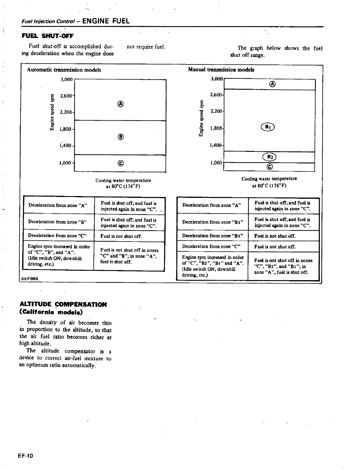
Fuel
Injection
Control
ENGINE
FUEL
FUEL
SHUT
OFf
Fuel
shut
off
is
accomplished
dur
ing
deceleration
when
the
engine
does
Automatic
transmission
models
3
000
I
S
2
600
e
12
200
1
S
I
9
1
800
1
400
1
I
oooi
Deceleration
from
zone
A
Deceleration
from
rone
B
Deceleration from
zone
e
Engine
rpm
increased
in
order
of
e
S
and
A
Idle
switch
ON
downhill
driving
etc
SEF095
not
require
fuel
@
@
@
Cooling
water
temperature
at
80
C
1I6
F
Fuel
is
shut
off
and
fuel
is
injected
again
in
tone
Ci
Fuel
is
shut
off
and
fuel
is
injected
again
in
zone
e
Fuel
is
not
shut
off
Fuel
is
not
shut
ofT
in
zones
C
and
B
inzone
A
fuel
is
shut
off
ALTITUDE
COMPENSATION
California
models
The
density
of
ail
becomes
thin
in
proportion
to
the
altitude
so
that
the
air
fuel
ratio
becomes
riche
t
high
altitude
The
altitude
compensator
is
a
device
to
correct
air
fuel
mixture
to
an
optimum
ratio
automatically
EF
l0
The
graph
below
shows
the
fuel
shut
off
tange
Manual
n
models
3
OC
2
600
s
e
2
200
0
0
Il
0
1
800
1
400
1
000
Deceleration
from
zone
A
Deceleration
from
zone
B
1
D
from
zone
B2
Deceltration
from
zone
e
Engine
rpm
increased
in
order
orue
S2
Bl
and
A
Idle
switch
ON
downhill
driving
etc
@
@
@
@
Cooling
water
temperature
at
80
C
1I6
F
Fuel
is
shut
off
and
fuel
is
injected
again
in
zone
C
Fud
is
shut
off
and
fuel
is
injected
again
in
zone
en
Fuel
is
Dot
shut
off
Fuel
is
not
shut
off
Fuel
is
not
shut
off
in
zones
en
B2
and
Bl
in
z
one A
fuel
is
shut
off
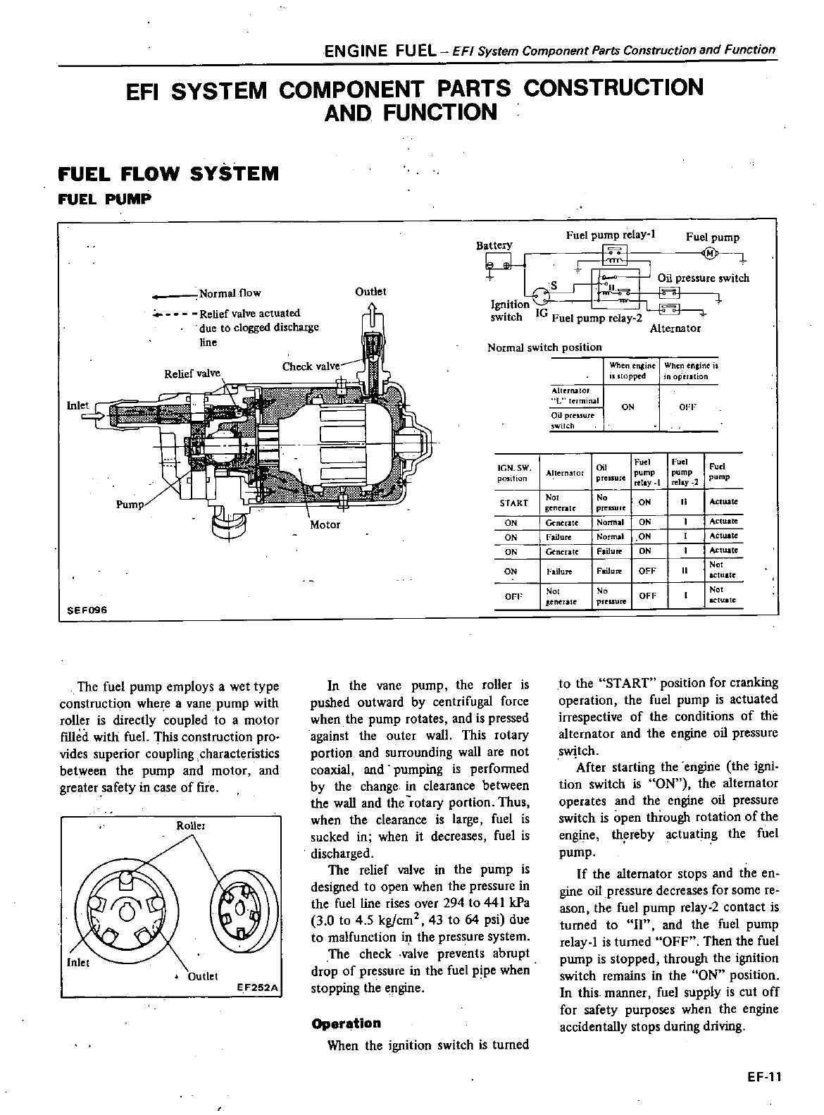
ENG
IN
E
FU
EL
EFI
System
Component
Parts
Construction
and
Function
EFI
SYSTEM
COMPONENT
PARTS
CONSTRUCTION
AND
FUNCTION
FUEL
FLOW
SYSTEM
FUEL
PUMP
Normal
flow
Relief
valve
actuated
due
to
clogged
discharge
line
Inl
The
fuel
pump
employs
a
wet
type
construction
whe
e a
vane
pump
with
roller
is
directly
coupled
to
a
motor
fIlled
with
fuel
This
construction
pro
vides
superior
coupling
characteristics
between
the
pump
and
motor
and
greater
safety
in
case
of
fire
RoUer
Outlet
E
F252A
Outlet
Fuel
pump
relay
Fuel
pump
Battery
El
P
i
1
s
1
I
Oilpres
ureswitch
II
Ignition
I
switch
IG
Fuel
pump
relay
2
Alternator
Normal
switch
position
IGN
SW
position
In
the
vane
pump
the roller
is
pushed
outward
by
centrifugal
force
when
the
pump
rotates
and
is
pressed
against
the
outer
wall
This
rotary
portion
and
surrounding
wall
are
not
coaxial
and
pumping
is
perfonned
by
the
change
in
clearance
between
the
wall
and
the
rotary portion
Thus
when
the
clearance
is
large
fuel
is
sucked
in
when
it
decreases
fuel
is
discharged
The
relief
valve
in
the
pump
is
designed
to
open
when
the
pressure
in
the
fuel
line
rises
over
294
to
44
I
kPa
3
0
to
45
kg
cm2
43
to
64
psi
due
to
malfunction
in
the
pressure
system
The
check
valve
prevents
abrupt
drop
of
pressure
in
the
fuel
pipe
when
stopping
the
engine
Operation
When
the
ignition
switch
is
turned
Nhene
ine
When nline
opped
opEration
Allenulor
L
rmilUll
OLlprclSurt
witch
ON
01
1
START
No
No
ON
generate
pressure
ON
Gentrate
Normal
ON
ON
Failure
NOllTUI1
ON
ON
Gencr
atc
Failure
ON
ON
l
a
ilure
Fwure
OFF
OFF
No No
OFF
SEF096
teneralt
prcuure
Alternator
Oil
Fuel
pump
relay
I
1
pump
Fuel
pump
relay
2
prellure
II
Actuate
Actuak
Actuate
Actuate
No
actuate
No
actuate
to
the
START
position
for
cranking
operation
the
fuel
pump
is
actuated
irrespective
of
the
conditions
of
the
alternator
and
the
engine
oil
pressure
swjtch
After
starting
the
engirie
the
igni
tion
switch
is
ON
the
alternator
operates
and
the
engine
oil
pressure
switch
is
open
through
rotation
of
the
engine
th
reby
actuating
the
fuel
pump
If
the
alternator
stops
and
the
en
gine
oil
pressure
decreases
for
some
re
ason
the
fuel
pump
relay
2
contact
is
turned
to
II
and
the
fuel
pump
relay
l
is
turned
OFF
Then
the
fuel
pump
is
stopped
through
the
ignition
switch
remains
in
the
ON
position
In
this
manner
fuel
supply
is
cut
off
for
safety
purposes
when
the
engine
accidentally
stops
during
driving
EF
l1
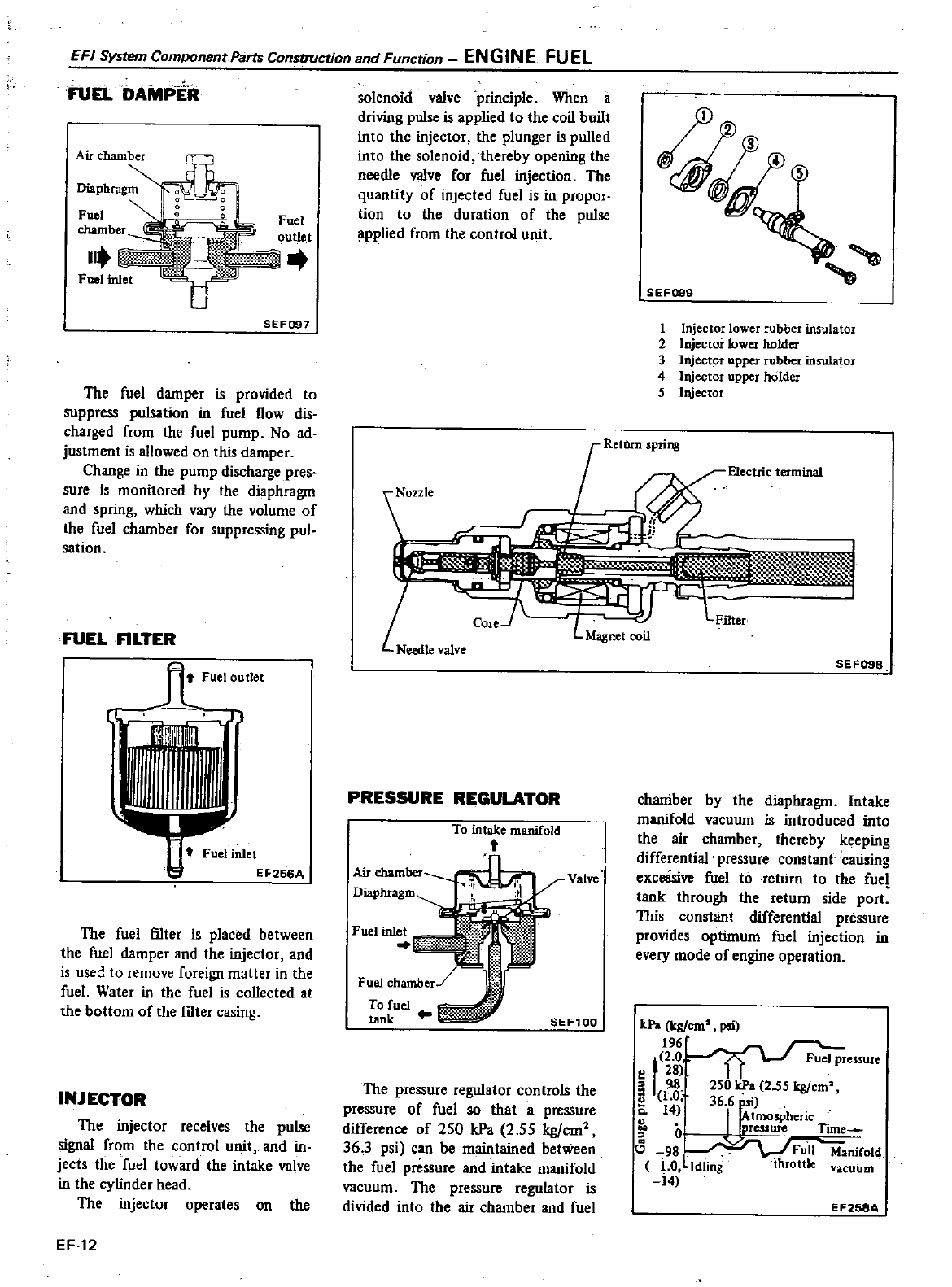
FUEL
DAMPER
EFI
1
Component
Parts
Constroction
and
Function
ENGINE
FUEL
Fuel
outlet
SEF097
The
fuel
damper
is
provided
to
suppress
pulsation
in
fuel
flow
dis
charged
from
the
fuel
pump
No
ad
justment
is
allowed
on
this
damper
Change
in
the
pump
discharge
pres
sure
is
monitored
by
the
diaphragm
and
spring
which
vary
the
volume
of
the
fuel
chamber
for
suppressing
pul
sation
FUEL
FILTER
Il
R
Fuel
outlet
j
Fuel
inlet
EF256A
The
fuel
f1lter
is
placed
between
the
fuel
damper
and
the
injector
and
is
used
to
remove
foreign
matter
in
the
fuel
Water
in
the
fuel
is
collected
at
the
bottom
of
the
f1lter
casing
INJECTOR
The
injector
receives
the
pulse
signal
from
the
control
unit
and
in
jects
the
fuel
toward
the
intake
valve
in
the
cylinder
head
The
injector
operates
on
the
EF
12
solenoid
valve
principle
When
iI
driving
pulse
is
applied
to
the
coil
built
into
the
injector
the
plunger
is
pulled
into
the
solenoid
thereby
opening
the
needle
valve
for
fuel
injection
The
quantity
of
injected
fuel
is
in
propor
tion
to
the
duration
of
the
pulse
pplied
from
the
control
unit
SEF099
1
Injector
lower
rubber
insulator
2
Injector
lower
holder
3
Injector
upper
rubber
insula
or
4
Injector
upper
holder
5
Injector
o
le
FJectric
terminal
li
1
1
I
f
Filter
PRESSURE
REGULATOR
To
intake
manifold
t
Air
chamber
Diaphragm
Fuel inlet
SEF100
The
pressure
regulator
controls the
pressure
of
fuel
so
that
a
pressure
difference
of
250
kPa
2
55
kgjcm
36
3
psi
can
be
maintained
between
the
fuel
pressure
and
intake
manifold
vacuum
The
pressure
regulator
is
divided
into
the
air
chamber
and
fuel
SEF098
chaniber
by
the
diaphragm
Intake
manifold
vacuum
is
introduced
into
the
air
chamber
thereby keeping
differential
pressure
constant
causing
excessive
fuel
to
return
to
the
fuel
tank
through
the
return
side
port
This
constant
differential
pressure
provides
optimum
fuel
injection
in
every
mode
of
engine
operation
kPa
kg
em
psi
196
t
2 0
Fuel
pressure
u
28
98
250 kPa
2
55
kg
em
e
1
0
36
6
si
14
I
tmospheric
0
D
CSSW
e
Ttme
98
Foil
ManiCotd
1
0
Idling
throttle
vacuum
14
E
F258A
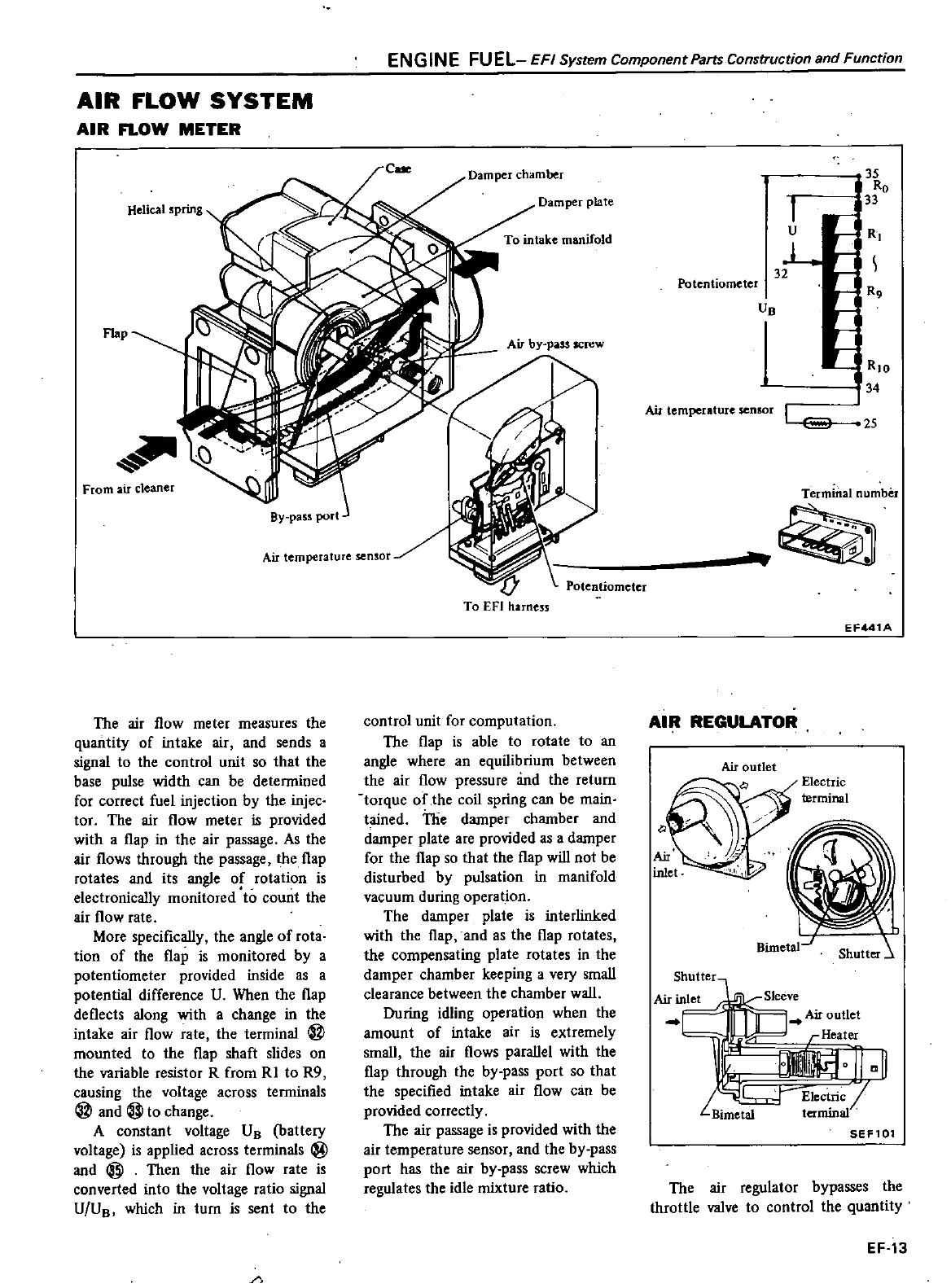
AIR
FLOW
SYSTEM
AIR
FLOW
METER
Helical
spring
From
air
cleaner
EN
GIN
E
FU
E
LE
F
I
System
Component
Parts
Construction
and
Function
Damper
plate
To
intake
manifold
By
pass
port
Air
temperature
sensor
The
air
flow
meter
measures
the
quantity
of
intake air
and
sends
a
signal
to
the
control
unit
so
that the
base
pulse
width
can
be
detennined
for
correct
fuel
injection
by
the
injec
tor
The
air
flow
meter
is
provided
with
a
flap
in
the
air
passage
As
the
air
flows
through
the
passage
the
flap
rotates
and
its
angle
of
rotation
is
electronically
monitored
to
count
the
air
flow
rate
More
specifically
the
angle
of
rota
tion
of
the
flap
is
monitored
by
a
potentiometer
provided
inside
as
a
potential
difference
V
When
the
flap
deflects
along
with
a
change
in
the
intake
air
flow
rate
the terminal
@
mounted
to
the
flap
shaft
slides
on
the
variable
resistor
R
from
RI
to
R9
causing
the
voltage
across
tenninals
@
and@tochange
A constant
voltage
VB
battery
voltage
is
applied
across
terminals
@
and
@
Then
the
air
flow
rate
is
converted
into
the
voltage
ratio
signal
V
VB
which
in
turn
is
sent
to
the
Potentiometer
To
EFI
harness
control
unit
for
computation
The
flap
is
able
to
rotate
to
an
angle
where
an
equilibrium
between
the
air
flow
pressure
and
the
return
torque
of
lhe
coil
spring
can
be
main
tained
The
damper
chamber
and
damper
plate
are
provided
as
a
damper
for
the
flap
so
that
the
flap
will
not
be
disturbed
by
pulsation
in
manifold
vacuum
during
operation
The
damper
plate
is
interlinked
with
the
flap
and as
the
flap
rotates
the
compensating
plate
rotates
in
the
damper
chamber
keeping
a
very
small
clearance
between
the
chamber
wall
During
idling
operation
when
the
amount
of
intake air
is
extremely
small
the
air
flows
parallel
with
the
flap through
the
by
pass
port
so
that
the
specified
intake
air
flow
can
be
provided
correctly
The
air
passage
is
provided
with
the
air
temperature
sensor
and
the
by
pass
port
has
the
air
by
pass
screw
which
regulates
the
idle mixture
ratio
U
35
Ro
33
R
Potentiometer
32
R
IB
RJO
34
Air
temperature
sensor
25
Terminal
number
fi
EF441A
AIR
REGULATOR
Electric
terminal
Shutter
Sleeve
Air outlet
r
Heater
SEF101
The
air
regulator
bypasses
the
throttle
valve
to
control
the
quantity
EF
13
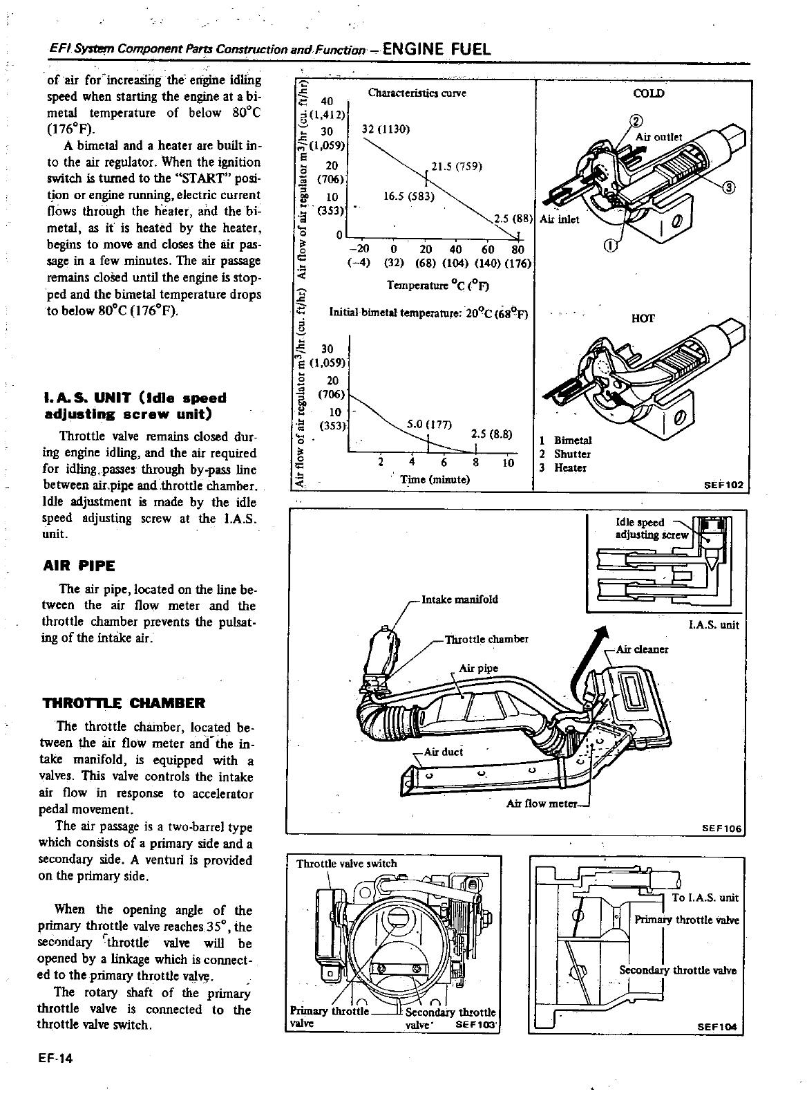
E
FI
ystBrn
Component
Pans
Construction
and
Function
EN
GIN
E
FU
EL
of
air
for
increaSing
the
engine
idling
speed
when
starting
the
engine
at
a
bi
Characteri5tics
curve
COLD
40
metal
temperature
of
below
800C
I
412
176OF
3
30 32
1
30
c
A
bimetal
and
a
heater
are
built
in
1
059
to
the
air
regulator
When
the
ignition
e20
21
5
759
2
switch
is
turned
to
the
START
posi
l
706
on
or
engine
running
electric
current
10 16
5
583
flows
through
the
heater
and
the
bi
a
353
2
5
88
Air
inlet
metal
as
it
is
heated
by
the
heater
0
0
hegins
to
move
and
closes
the
air
pas 20
0
20 40 60 80
sage
in
a
few
minutes
The
air
passage
g
4
32
68
104
140
176
remains
cloSed
until
the
engine
is
stop
Tempetature oe
FJ
ped
and
the
bimetal
temperature
drops
to
below
800C
176OF
0
Initial
bimetal
temperature
200e
68 HOT
I
A
UNIT
Idle
speed
adjusting
screw
unit
Throttle
valve
remains
closed
dur
ing
engine idling
and
the
air
required
for
idling
passes
through
by
pass
line
between
air
pipe
and
throttle
chamber
Idle
adjustment
is
made
by
the
idle
speed
adjusting
screw
at
the
1
A
S
unit
AIR
PIPE
The
air
pipe
located
on
the
line
be
tween
the
air
flow
meter
and
the
throttle
chamber
prevents
the
pulsat
ing
of
the intake
air
THROTTLE CHAMBER
The
throttle
chamber
located
be
tween
the
air
flow
meter
and
the
in
take
manifold
is
equipped
with
a
valves
This
valve
controls the intake
air
flow
in
response
to
accelerator
pedal
movement
The
air
passage
is
a
two
barrel
type
which
consists
of
a
primary
side
and
a
secondary
side
A
venturi
is
provided
on
the
primary
side
When
the
opening
angle
of
the
primary
throttle
valve
reaches
350
the
secondary
throttle
valve
will
be
opened
by
a
linkage
which
is
connect
ed
to
the
primary
throttle
valve
The
rotary
shaft
of
the
primary
throttle
valve
is
connected
to
the
throttle
valve
switch
EF
14
30
e
1
059
s
20
10
ri
o
177
2
5 8 8
I
g
2
4
6 8
10
Thne
mmwU
Intake
manifold
Airduc
dr
ThIottle
valve
witch
1
Bimetal
2
Shutter
3
Heater
SEF102
j
dicr
L
c
JFj
pi
I
A
S
unit
Air
flow
meter
SEF106
Primaty
throttle
valve
I
Secondary
throttle
valve
IH
J
SEF104
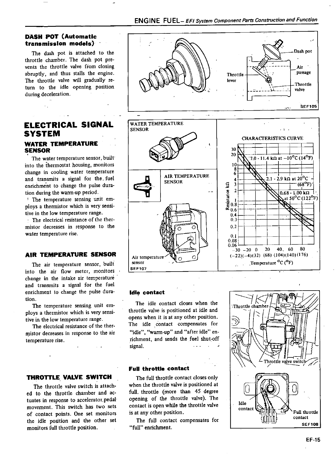
DASH
POT Automatic
transmission
models
The
dash
pot
is
attached
to
the
throttle
chamber
The
dash
pot
pre
vents
the
throttle
valve
from
closing
abruptly
and
thus
stalls
the
engine
The
throttle
valve
will
gradually
reo
turn
to
the
idle
opening
position
during
deceleration
ELECTRICAL
SIGNAL
SYSTEM
WATER
TEMPERATURE
SENSOR
The
water
temperature
sensor
built
into
the
thermostat
housing
monitors
change
in
cooling
water
temperature
and
transmits
a
signal
for
the
fuel
enrichment
to
change
the
pulse
dura
tion
during
the
wann
up
period
I
The
temperature
sensing
unit
em
ploys
a
thermistor
which
is
very
sensi
tive
in
the
low
temperature
range
The
electrical
resistance
of
the
ther
mistor
decreases
in
response
to
the
water
temperature
rise
AIR
TEMPERATURE
SENSOR
The
air
temperature
sensor
buHt
into
the
air
flow
meter
monitors
change
in
the
intake
air
temperature
and
transmits
a
signal
for
the
fuel
enrichment
to
change
the
pulse
dura
tion
The
temperature
sensing
unit
em
ploys
a
thermistor
which
is
very
sensi
tive
in
the
low
temperature
range
The
electrical
resistance
of
the ther
istor
decreases
in
response
to
the air
temperature
rise
THROTTLE
VALVE
SWITCH
The
throttle
valve
switch
is
attach
ed
to
the
throttle
chamber
and
ac
tuates
in
response
to
accelerator
pedal
movement
This
switch
has
two
sets
of
contact
points
One
set
monitors
the
idle
position
and
the
other
set
monitors
full
throttle
position
EN
GIN
E
FU
EL
EFI
System
Component
Parts
Construction
and
Function
WATER TEMPERATURE
SENSOR
q
AIR
TEMPERATURE
SENSOR
Air
temperature
sensor
SEF101
Idl
contact
The
idle
contact
closes
when
the
throttle
valve
is
positioned
at
idle
and
opens
when
it
is
at
any
other
position
The
idle
contact
compensates
for
idle
wann
up
and
after
idle
en
richment
and
sends
the
fuel
shut
off
signal
Full
throttle
contact
The
full
throttle
contact
closes
only
when
the
throttle
valve
is
positioned
at
full
throttle
more
than
45
degree
opening
of
the
throttle
valve
The
contact
is
open
while
the
throttle
valve
is
at
any
other
position
The
full
contact
compensates
for
full
enrichment
Dash
pot
Air
Throttle
passage
lever
Throttle
h
L
valve
J
SEF105
CHARACTERISTICS
CURVE
I
I
114
kn
at
IOoC
l40F
30
I
20
7 0
10
8
6
4
I
2
12 9
Jen
at
200C
c
3
680F
IJ
8
2
0 68
1
00
kn
I
0
I
t
SOOC
1220
1
I
0
6
I
1
0
06
L
30 20
0
20
40 60 80
22
4
32
68
104 140 176
Temperature
Oc
OF
04
0
31
0 2
Full throttle
contact
SEF108
EF
15
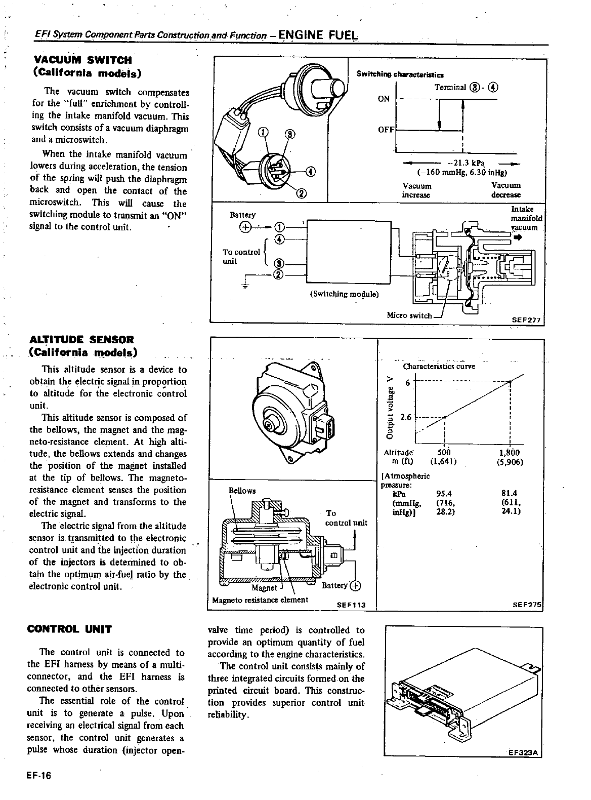
EFI
System
Component
Parts
Construction
and
Function
ENGINE
FUEL
VACUUM
SWITCH
California
models
The
vacuum
switch
compensates
for
the
full
enrichment
by
controll
ing
the
intake
manifold
vacuum
This
switch
consists
of
a
vacuum
diaphragm
and
a
microswitch
When
the intake
manifold
vacuum
lowers
during
acceleration
the
tension
of
the
spring
will
push
the
diaphragm
back
and
open
the
contact
of
the
microswitch
This
will
cause
the
switching
module
to
transmit
an
ON
signal
to
the control
unit
ALTITUDE
SENSOR
california
models
This
altitude
sensor
is
a
device
to
obtain
the
electric
signal
in
proportion
to
altitude
for
the
electronic
control
unit
This
altitude
sensor
is
composed
of
the
bellows
the
magnet
and
the
mag
neto
resistance element
At
high
alti
tude
the
bellows
extends
and
changes
the
position
of
the
magnet
installed
at
the
tip
of
bellows
The
magneto
resistance
element
senses
the
position
of
the
magnet
and
transfonns
to
the
electric
signal
The
electric
signal
from
the
altitude
sensor
is
transmitted
to
the
elec
ronic
control
unit
and
ihe
injection
duration
of
the
injectors
is
detennined
to
ob
tain
the
optimum
air
fue
ratio
by
the
electronic
control
unit
CONTROL
UNIT
The
control
unit
is connected
to
the
EFI
harness
by
means
of
amulti
connector
and
the
EFI
harness is
connected
to
other
sensoIS
The
essential
role
of
the control
unit
is
to
generate
a
pulse
Upon
receiving
an
electrical
signal
from
each
sensor
the control
unit
generates
a
pulse
whose
duration
injector
open
EF
16
Battery
j
@
To
control
unit
@
r
@
Switching
mo
j
ule
Bellows
if
m
J
To
control
unit
Magnet
j
Magneto
resistance
element
SEF113
valve
time
period
is
controlled
to
provide
an
optimum
quantity
of
fuel
according
to
the
engine
characteristics
The
control
unit
consists
mainly
of
three
integrated
circuits fonned
on
the
printed
circuit
board
This
construe
tion
provides
superior
control
unit
reliability
Switching
charact8ristics
Terminal
@ @
ON
hn
j
OFFj
21
3
kPa
160
mmHg
6
30
inHg
Vacuum Vacuum
increase
decrease
Intake
manifold
uum
l
O1aracteristics
curve
6
m
U
nn
u
s
0
2 6
c
o
Altitude
m
ft
500
1
641
Atmospheric
pressure
kPa
mmHg
inHgJl
95
4
716
28
2
SEF217
1
800
5
906
81
4
611
24
1
SEF275
EF323A
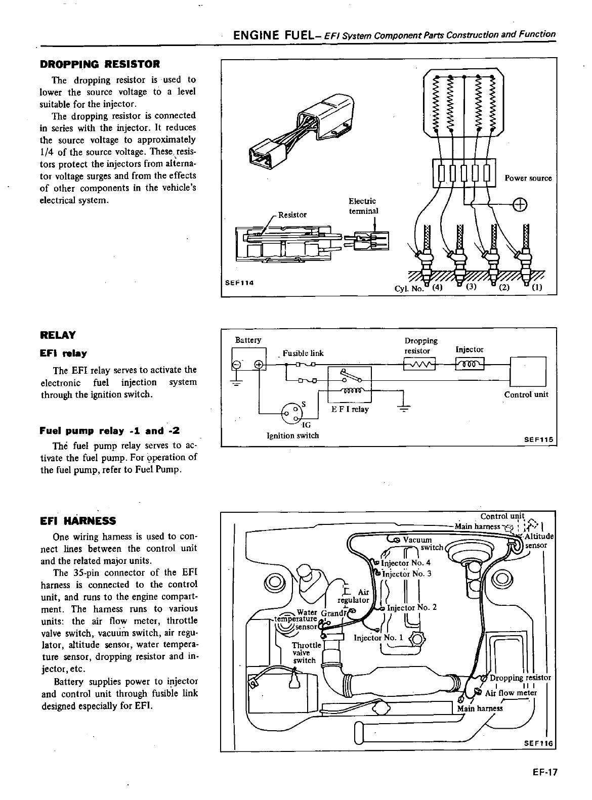
DROPPING RESISTOR
The
dropping
resistor
is
used
to
lower
the
source
voltage
to
a
level
suitable
for the
injector
The
dropping
resistor
is connected
in
series
with
the
injector
It
reduces
the
source
voltage
to
approximately
1
4
of
the
source
voltage
These
resis
tors
protect
the
injectors
from
a1terna
tor
voltage
surges
and
from
the
effects
of
other
components
in
the
vehicle
s
electrical
system
RELAY
EFI
relay
The
EFI
relay
serves
to
activate
the
electronic
fuel
injection
system
through
the
ignition
switch
Fuel
pump
relay
1
and
2
The
fuel
pump
relay
serves
to
ac
tivate
the
fuel
pump
For
9peration
of
the
fuel
pwnp
refer
to
Fuel
Pump
EFI
HARNESS
One
wiring
harness
is
used
to con
nect
lines
between
the
control
unit
and
the
related
major
units
The
35
pin
connector
of
the
EFI
harness
is
connected
to
the control
unit
and
runs
to
the
engine
compart
ment
The harness
runs
to
various
units
the
air
flow
meter
throttle
valve
switch
vacuum
switch
air
regu
lator
altitude
sensor
water
tempera
ture
sensor
dropping
resistor
and
in
jector
etc
Battery
supplies
power
to
injector
and
control
unit
through
fusible
link
designed
especially
for
EFl
EN
G
IN
E
FU
EL
EFI
System
Component
Parts
Construction
and
Function
Electric
Resistor
tenninal
tL
L
1
I
I
I
r
SEF114
Battery
l
I
81
Fusible
link
o
5
I
IG
Ignition
switch
Dropping
resistor
I
I
I
II
Injector
1
Control
unit
SEF115
1
i
Dropping
resistor
I
I
II
I
Air
flow
meter
7
SEF116
EF
17
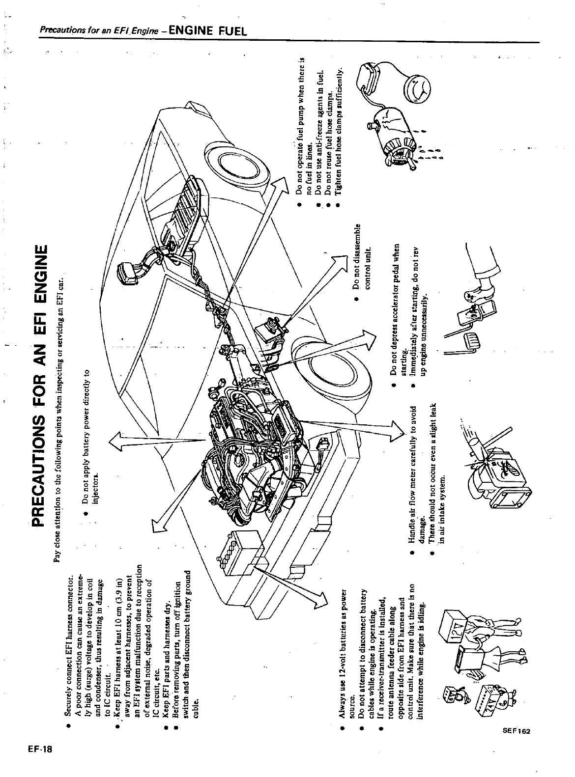
Alwll
1I
UJe
12
olt
battetic
as
power
Qurce
Do
not
attempt
to
disconnect
batter
cable
i
whUe
engine
is
operating
If
a
receiver4ranltnlttet
is
installed
route
antenna
fceder
cable
along
opposite
side
ftom
Efl
hatnes
and
control
unit
Make
iure
that
there
is
no
interferen
e
whUe
engine
is
idling
Do
not
applY
bnttery
pOWe
directly
to
inlectan
i
a
l
j
I
rn
c
p1
PRECAUTIONS
FOR
AN
EFl
ENGINE
PaY
clo
ttentlon
to
the
following
point
when
ill5pecting
or
cvicing
en
EfI
car
Securely
connect
EFI
harne
55
connector
A
poor
connection
can
cause
an
extreme
ly
high
surge
voltll
e
to
develop
in
coil
and
condenser
thus
rerulting
in
damage
tolCcircuit
Keep
EFt
h
rne
t
e
t
10
em
1
91n
away
from
adjacent
hlU
llesses
to
prevent
an
EFl
syltetn
malfunction
due
to
reception
of
external
noise
degraded
operation
of
Ie
circuit
etc
Keep
EFt
parts
end
h
rne
dIY
BefotO
removing
pl1Ita
turn
off
ignition
switch
and
then
duccnnect
batter
ground
cable
00
not
operate
fuel
pump
when
there
is
nO
ruel
in
iMJ
00
not
use
antHrceze
agents
i
n
fuel
Do
not
reule
fuel
hose
cla
mp1l
Tighten
fuel
hose
clamp
sufficientlY
Randle
air
floW
meter
carefullY
to
avoid
dalTlage
There
should
not
occur
even
a
tight
leak
in
air
int
ke
i
tero
v
Do
not
depteSS
aCCClen
tot
pedal
when
ItarUPi
Imrnt
dtatelY
afte1
starting
do
not
rev
up
engine
unneceuarUY
ij
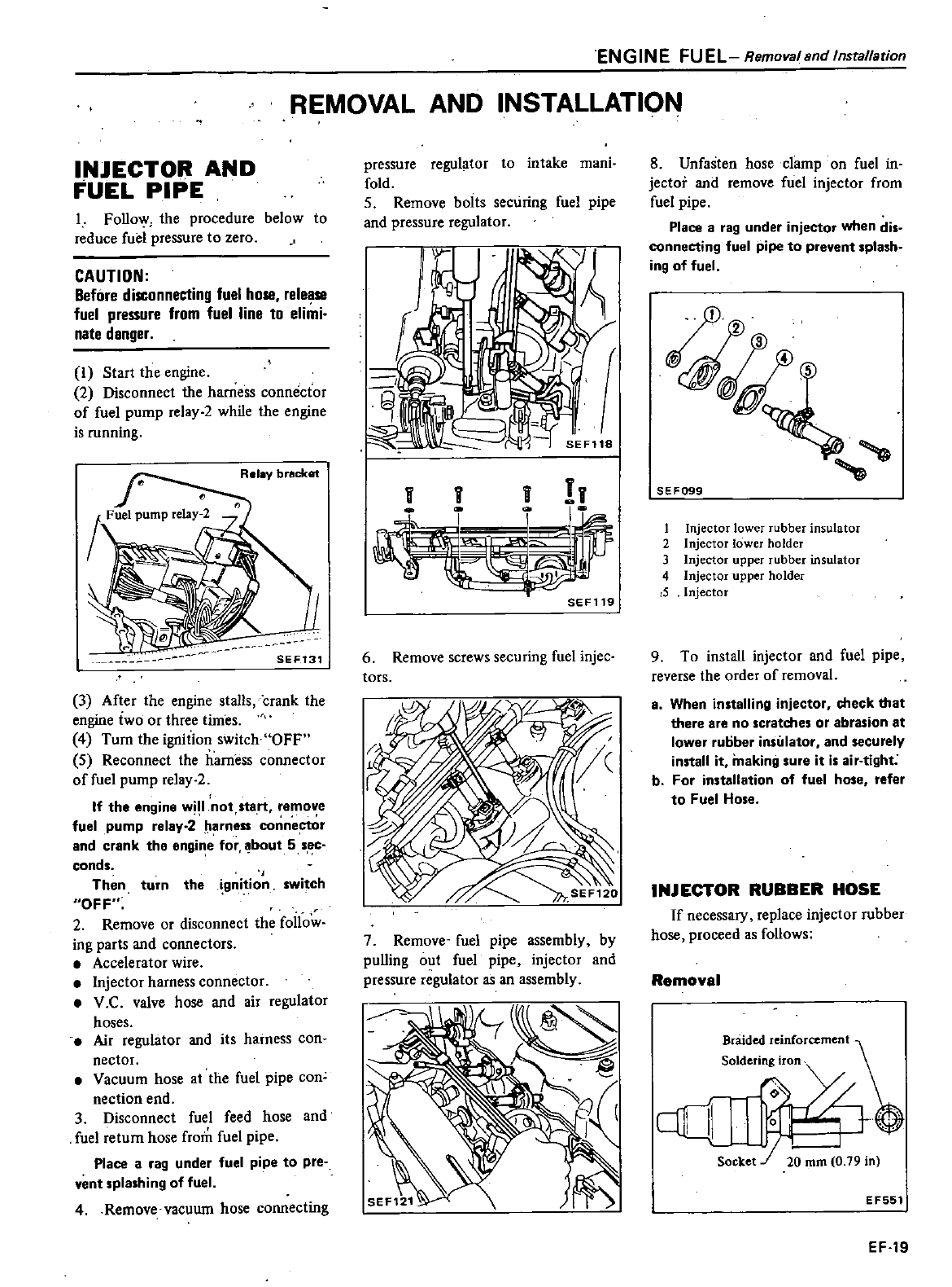
ENGINE
FUEL
Removalsnd
Installstion
REMOVAL
AND
INSTALLATION
INJECTOR AND
FUEL
PIPE
1
Follow
the
procedure
below
to
reduce
fuel
pressure
to
zero
CAUTION
Before
disconnecting
fuel
hose release
fuel
pressure
from
fuel
line to
elimi
nate
danger
I
Start
the
engine
2
Disconnect
the
harness
connector
of
fuel
pump
relay
2while
the
engine
is
running
Rei
bracket
SEF131
3
After
the
engine
stalls
crank
the
engine
two
or
three
times
4
Turn
the
ignition
switch
OFF
5
Reconnect
the
harness
connector
of
fuel
pump
relay
2
If
the
engine
w
1
not
start
remove
fuel
pump
relay
2
I
a
rness
connector
and
crank the
engine
for
bout
5
sec
conds
Then
turn
the
gnition
switch
OFF
2
Remove
or
disconnect
the
follow
ing
parts
and
connectors
Accelerator
wire
Injector
harness
connector
V
C
valve
hose
and
air
regulator
hoses
Air
regulator
and
its
harness
con
nectar
Vacuum
hose
at
the
fuel
pipe
con
nection
end
3
Disconnect
fuel
feed
hose
and
fuel
return
hose
from
fuel
pipe
Place
a
rag
under
fuel
pipe
to
pre
vent
splashing
of
fuel
4
Remove
vacuum
hose connecting
8
Unfasten
hose
clamp
on
fuel
in
jector
and
remove
fuel
injector
from
fuel
pipe
Place
a
rag
under
injector
when dis
J
connecting
fuel
pipe
to
prevent
splash
ing
of
fuel
pressure
regulator
to
intake
mani
fold
5
Remove
boits
securing
fuel
pipe
and
pressure
regulator
SEF119
6
Remove
screws
securing
fuel
injce
tors
7
Remove
fuel
pipe assembly
by
pulling
out
fuel
pipe
injector
and
pressure
regulator
as
an
assembly
SEF099
1
Injector
lower
rubber
insulator
2
Injector
lower
holder
3
Injector
upper
rubber
insulator
4
Injector
upper
holder
i5
Injector
9
To
install
injector
and
fuel
pipe
reverse
the
order
of
removal
a
When
installing
injector
check
that
there
are
no
scratches
or
abrasion
at
lower
rutiber
insulator
and
securely
install
it
making
sure it
is
air
tight
b
For
installation
of
fuel
hose
refer
to
Fuel
Hose
INJECTOR
RUBBER
HOSE
If
necessary
replace
injector
rubber
hose
proceed
as
follows
Removal
Socket
Y
20
mm
0
79
in
EF551
EF
19
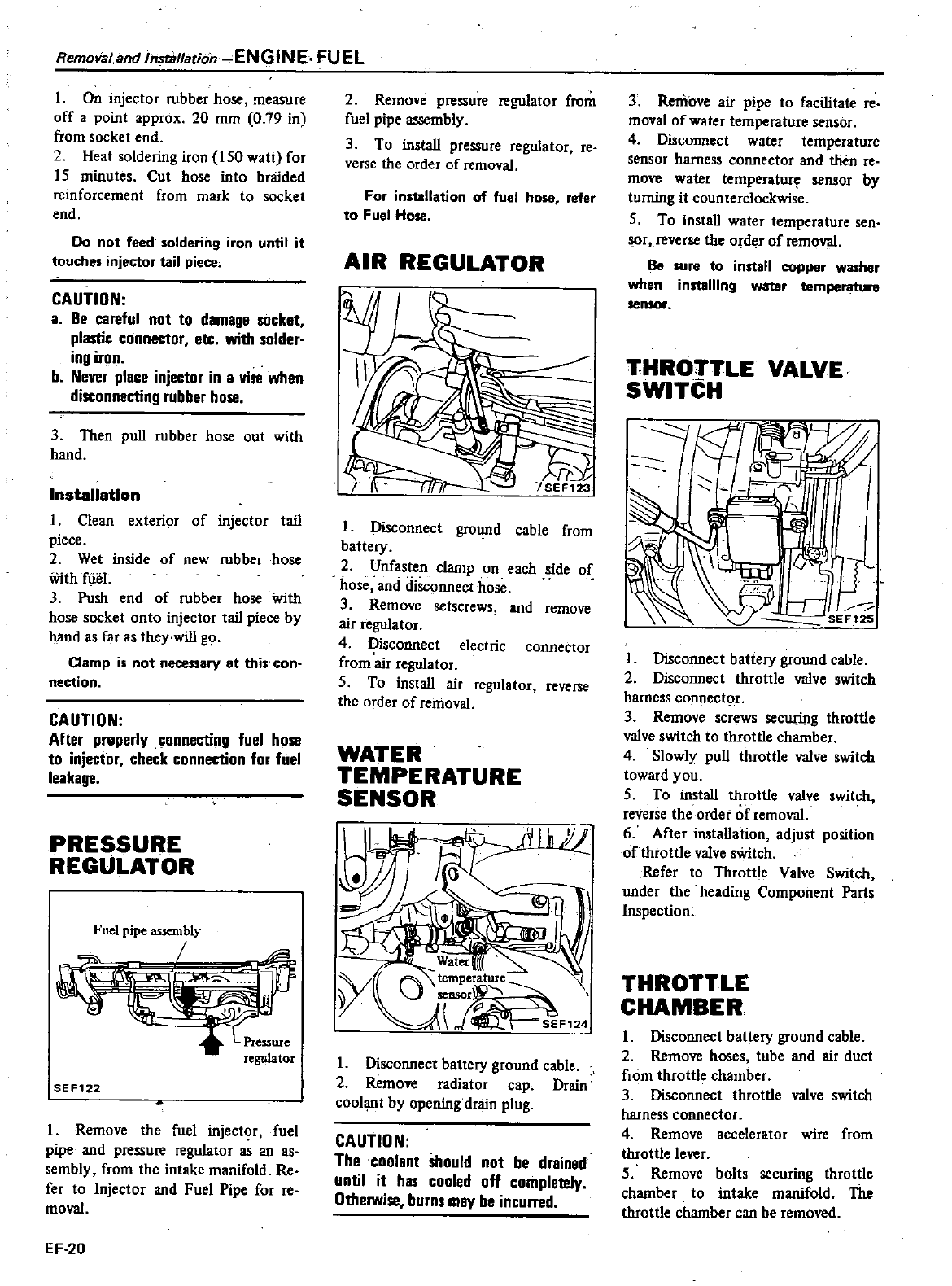
Remolialand
InstBllatioh ENGINE
FUEL
1
On
injector
rubber
hose
measure
off
a
point
approx
20
mm
0
79
in
from
socket
end
2
Heat
soldering
iron
150
watt
for
15
minutes
Cut
hose
into
braided
reinforcement
from
mark
to
socket
end
Do
not
feed
soldering
iron
until
it
touches
injector
tail
piece
CAUTION
a
Be
careful
not
to
damage
socket
plastic
connec1or
etc
with
solder
ing
iron
b
Never
piece
injector
in
a
vise
when
disconnecting
rubber
hose
3
Then
pull
rubber
hose
out
with
hand
Installation
1
Clean
exterior
of
injector
tail
piece
2
Wet
inside
of
new
rubber
hose
With
fUel
3
Push
end
of
rubber
hose
with
hose
socket
onto
injector
tail
piece
by
hand
as
far
as
they
will
go
Clamp is
not
necessary
at
this
con
nection
CAUTION
After
properly
connecting
fuel
hose
to
injector
check connec1ion
for
fuel
leakage
PRESSURE
REGULATOR
Fuel
pipe
assembly
SEF122
I
Remove
the
fuel
injector
fuel
pipe
and
pressure
regulator
as
an
as
sembly
from
the
intake
manifold
Re
fer
to
Injector
and
Fuel
Pipe
for
reo
moval
EF
20
2
Remove
pressure
regulator
from
fuel
pipe assembly
3
To
install
pressure
regulator
reo
verse
the
order
of
removal
For
installation
of
fuel
hose
refer
to
Fuel
Hose
AIR
REGULATOR
I
Disconnect
ground
cable
from
battery
2
Unfasten
clamp
on
each
side
of
hose
and
disconnect
hose
3
Remove
setscrews
and
remove
air
regulator
4
Disconnect
electric
connector
from
air
regulator
S
To
install
air
regulator
reverse
the
order
of
removal
WATER
TEMPERATURE
SENSOR
I
Disconnect
battery
ground
cable
2
Remove
radiator
cap
Drain
coolant
by
opening
drain
plug
CAUTION
The
coolant
should
not
be
drained
until
it
has
cooled
off
completely
Otherwise
burns
may
be incuned
3
Remove
air
pipe
to
facilitate
reo
moval
of
water
temperature
sensor
4
Disconnect
water
temperature
sensor
harness
connector
and
then
re
move
water
temperatur
sensor
by
turning
it
counterclockwise
5
To
install
water
t
Ult
ture
sen
r
reverse
the
Ordi
f
of
removal
Be
sure
to
install
copper
washer
when
installing
watar
temperature
sensor
THROTTLE
VALVE
SWITCH
1
Disconnect
battery ground
cable
2
Disconnect
throttle
valve
switch
harness
co
ector
3
Remove
screws
securing
throttle
valve
switch
to
throttle
chamber
4
Slowly
pull
throttle
valve
witch
toward
you
5
To
install
throttle
valve
witch
reverse
the
order
of
removal
6
After
installation
adjust
position
of
throttle
valve
sWitch
Refer
to
Throttle
Valve
Switch
under
the
heading
Component
Parts
Inspection
THROTTLE
CHAMBER
1
Disconnect
battery
ground
cable
2
Remove
hoses
tube
and
air
duct
from
throttle
chamber
3
Disconnect
throttle
valve
switch
harness
connector
4
Remove
accelerator
wire
from
throttle
lever
5
Remove
bolts
securing
throttle
chamber
to
intake
manifold
The
throttle
chamber
can
be
removed
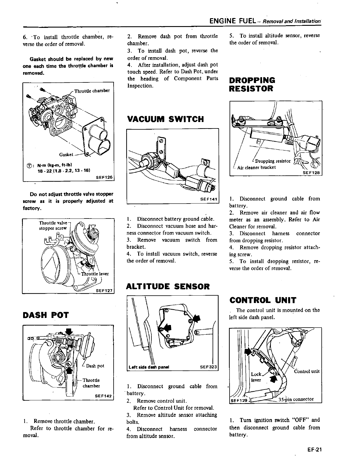
6
To
install
throttle
chamher
reo
verse
the
order
of
removal
Gasket
should
be
replaced
by
new
one
each
time
the
throt
tle
chamber
is
removed
Throttle
chamber
i
J
Nm
lkg
m
ft
lbl
18 22
18
2
2
13
161
SEF126
Do
not
adjust
throttle
valve
stopper
screw
as
it
is
properly
adjusted
at
factory
DASH
POT
Dash
pot
0
11
Throttle
chamber
IJ
SEF142
Remove
throttle
chamber
Refer
to
throttle
chamber
for
reo
moval
ENGINE
FUEL Remova
and
Installation
2
Remove
dash
pot
from
throttle
chamber
3
To
install
dash
pot
reverse
the
order
of
removal
4
After
installation
adjust
dash
pot
touch
speed
Refer
to
Dash
Pot
under
the
heading
of
Component
Parts
Inspection
VACUUM
SWITCH
SEF141
I
Disconnect
battery
ground
cable
2
Disconnect
vacuum
hose
and
har
ness
connector
from
vacuum
switch
3
Remove
vacuum
switch
from
bracket
4
To
install
vacuum
switch
reverse
the
order
of
removal
ALTITUDE
SENSOR
Left
side
dISh
panel
SEF323
1
Disconnect
ground
cable
from
battery
2
Remove
control
unit
Refer
to
Control
Unit
for removal
3
Remove
altitude
sensor
attaching
bolts
4
Disconnect
harness
connector
from
altitude
sensor
5
To
install
altitude
sensor
reverse
the
order
of
removal
DROPPING
RESISTOR
SEF128
1
Disconnect
ground
cable from
battery
2
Remove
air
cleaner
and
air
flow
meter
as
an
assembly
Refer
to
Air
Cleaner
for removal
3
Disconnect
harness
connector
from
dropping
resistor
4
Remove
dropping
resistor
attach
ing
screw
5
To
install
dropping
resistor
re
verse
the
order
of
removal
CONTROL
UNIT
The
control
unit
is
mounted
on
the
left
side
dash
panel
I
Turn
ignition
switch
OFF
and
then
disconnect
ground
cable
from
battery
EF
21
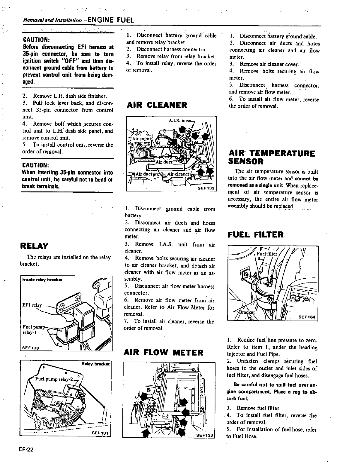
Remoraland
Instal
stion
ENGINE
FUEL
CAUTION
Before
disconnecting
EF
I
harness
at
3511in
connector
be
sure
to turn
ignition
switch
0
FF
and
than
dis
connect
ground
cable
from
battery
to
prevent
control
unit
from
being
dam
aged
2
Remove
L
H
dash
side
finisher
3
Pull
lock
lever
back
and
discon
nect
3S
pin
connector
from
control
unit
4
Remove
bolt
which
secures
con
trol
unit
to
L
R
dash
side
panel
and
remove
control
unit
5
To
install
control
unit
reverse
the
order
of
removal
CAUTION
When
inserting
35
pin
connector
into
control
unit
be
careful
nol
to
bend
at
break
terminals
RELAY
The
relays
are
installed
on
the
relay
bracket
Inside
relay
brKket
Fuel
pump
telay
l
SEF130
Relay
bncket
SEF131
EF 22
I
Oisconnect
battery
ground
cable
and
remove
relay
bracket
2
Disconnect
harness
connector
3
Remove
relay
from
relay
bracket
4
To
install
relay
reverse
the
order
of
removal
AIR
CLEANER
SEF132
I
Disconnect
ground
cable
from
battery
2
Disconnect
air
ducts
and
hoses
connecting
r
cleaner
and
r
flow
meter
3
Remove
I
A
s
unit
from
air
cleaner
4
Remove
bolts
securing
air
cleaner
to
air
cleaner
bracket
and
detach
air
cleaner
with
air
flow
meter
as
an
as
sembly
5
Disconnect
air
flow
meter
harness
connector
6
Remove
air
flow
meter
from
air
cleaner
Refer
to
Air
Flow Meter
for
removal
7
To
install
air
cleaner
reverse
the
order
of
removal
AIR
FLOW
METER
I
I
l
I
DiSConnect battery
ground
cable
2
Disconnect
air
ducts
and
hoses
connecting
air
cleaner
and
air
flow
meter
3
Remove
air
cleaner
cover
4
Remove
bolts
securing
air
fiow
meter
S
Disconnect
ham
cOnnector
and
remove
air
flow
meter
6
To
install
air
flow
meter
reverse
the
order
of
removal
AIR
TEMPERATURE
SENSOR
The
air
temperature
sensor
is
built
into
the
air
flow
meter
and
cannot
be
removed
as
a
single
unit
When
replace
ment
of
air
t
mper
ture
8eDSOI
is
necessary
the
entire
air
flow
meter
assembly
should
be
rep
d
FUEL
FILTER
I
Reduce
fuel
line
pressure
to
zero
Refer
to
item
I
under
the
heading
Injector
and
Fuel
Pipe
2
Unfasten
clamps
securing
fuel
hoses
to
the
outlet
and
inlet
sides
of
fuel
fIlter
and
disengage
fuel
hoses
Be
careful
not
to
spill
fuel
over
en
gine
compartment
Place
a
rag
to
ab
sorb
fuel
3
Remove
fuel
fIlter
4
To
install
fuel
fdter
reverse
the
order
of
removal
S
For
installation
of
fuel
hose
refer
to
Fuel
Hose
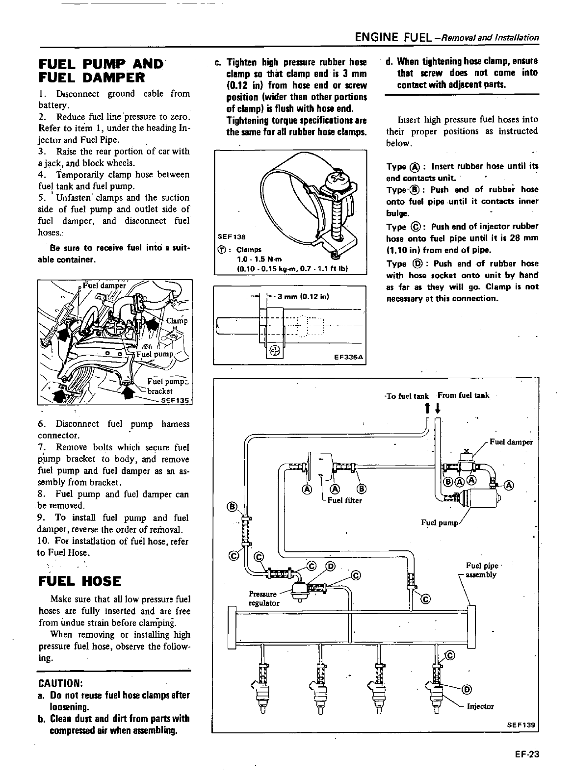
FUEL
PUMP
AND
FUEL
DAMPER
1
Disconnect
ground
cable
from
battery
2
Reduce
fuel
line
pressure
to
zero
Refer
to
item
1
under
the
heading
In
jector
and
Fuel
Pipe
3
Raise
the
rear
portion
of
car
with
a
jack
and
block
wheels
4
Temporarily
clamp
hose
between
fuel
tank
and fuel
pump
S
Unfasten
clamps
and
the
suction
side
of
fuel
pump
and
outlet
side
of
fuel
damper
and
disconnect
fuel
hoses
Be
sure
to
receive
fuel
into
B
suit
able
container
6
Disconnect
fuel
pump
harness
connector
7
Remove
bolts which
secure
fuel
p
lmp
bracket
to
body
and
remove
fuel
pump
and
fuel
damper
as
an
as
sembly
from
bracket
8
Fuel
pump
and fuel
damper
can
be
removed
9
To
install
fuel
pump and
fuel
damper
reverse
the
order
of
removal
10
For
installation
of
fuel
hose
refer
to
Fuel
Hose
FUEL
HOSE
Make
sure
that
all
low
pressure
fuel
hoses
are
fully
inserted
and
are
free
from
undue
strain
before
clamping
When
removing
or
installing
high
pressure
fuel
hose
observe
the
follow
ing
CAUTION
a
Do
not
reuse
fuel
hose
clamps
after
loosening
b
Clean
dull
and
dirt
from
parts
with
compreS
8d air
when
assembling
c
Tighten
high
pressure
rubber
hose
clamp
so
thilt
clamp
end
is
3
mm
0
12
in
from
hose
end
or
screw
position
wider
than
other
portions
of
clamp
is
flush
with
hose
end
Tightening
torque
specifications
are
the
same
for
all
rubber
hose
clamps
SEF138
If
Clamps
1
0
1
5N
m
0
10
0
15 kg
m
0
7
1 1
f
lbl
@
Pre
ure
regulator
l
3
mm
10
12
in
li
II@
EF336A
L
Fuel
ftlter
J
fJ
ENGINE
FUEL
RemovalBnd
Installation
d
When
tightening
hose
clamp
ensure
that
screw
does
not
come
into
contact
with
adjacenl
parts
Insert
high
pressure
fuel
hoses
into
their
proper
positions
as
instructed
helow
Type
@
Insert
rubber
hose
until
its
end
contacts
unit
Type
@
Push
end
of
rubber
hose
onto
fuel
pipe
until
it
contacts
inner
bulge
Type
@
Push
end
of
injector
rubber
hose
onto
fuel
pipe
until
it
is
28
mm
1
10 in
from
end
of
pipe
Type
@
Push end
of
rubber
hose
with
hose
socket
onto
unit
by
hand
as
far
as
they
will
go
Clamp is
not
necessary
at
this
connection
To
fuel
tank
From
fuel
tank
n
n
Fuel
damper
Fuel
pipe
mblY
I
@
SEF139
EF 23
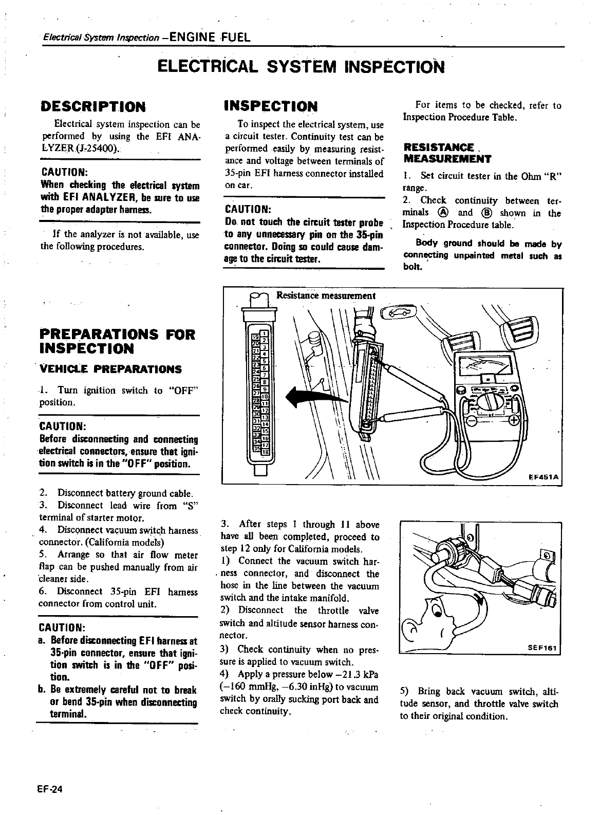
Electrical
System
Inspection
ENGINE
FUEL
ELECTRICAL
SYSTEM
INSPECTION
DESCRIPTION
Electrical
system
inspection
can
be
perfonned
by
using
the
EFI
ANA
L
YZER
J
25400
CAUTION
When
checking
the
electrical
system
with
EFI
ANAL
VZER be
sure
to
use
the
proper
adapter harness
If
the
analyzer
is
not
available
use
the
following
procedures
PREPARATIONS
FOR
INSPECTION
VEHICLE
PREPARATIONS
1
Turn
ignition
switch
to
OFF
position
CAUTION
Before
disconnecting
and
connecting
electrical
connectors
ensure
that
igni
tion
SWilch
is
in
the
0
FF
position
2
Disconnect
battery
ground
cable
3
Disconnect
lead
wire
from
S
tenninal
of
starter
motor
4
DiscQnnect
va
uum
sw
it
h
harness
connector
California
models
5
Arrange
so
that
air
flow
meter
flap
can
be
pushed
manually
from
air
cleaner
side
6
Disconnect
35
pin
EFI
harness
connector
from
control
unit
CAUTION
a
Before
disconnecting
EFI
harness
at
35
pin
connector
ensure
that
igni
tion
swilch
is
in
the
OFF
posi
tion
b
Be
extremely
careful
not
to
break
or
bend
35
pin
when
disconnecting
terminal
EF
24
INSPECTION
To
inspect
the
electrical
system
use
a
circuit
tester
Continuity
test
can
be
perfonnedeasily
by
measuring
resist
ance
and
voltage
between
terminals
of
35
pin
EFI
harness
connector
installed
on
car
CAUTION
Do
not
touch
the
circuit
tester
probe
to
any
unnecessary
pin
on
the
35
pin
connector
Doing
so
could
cause
dam
age
to
the circuit
tester
For
items
to
be
checked
refer
to
Inspection
Procedure
Table
RESISTANCE
MEASUREMENT
I
Set
circuit
tester
in
the
Ohm
R
range
2
Check
continuity
between
ter
minals
@
and
@
shown
in
the
Inspection
Procedure
table
Body
ground
should
be
mad
by
connecting
unpainted
metal
such
81
bolt
Fl
Resistance
measurement
1
r
1
B
I
r
l
L
i
i
l8
II
jj
I
1
U
3
After
steps
I
through
11
above
have
all
been
completed
proceed
to
step
12 only
for
California
models
I
Connect
the
vacuum
switch
har
ness connector
and
disconnect
the
hose
in
the
line
between
the
vacuum
switch
and
the
intake
manifold
2
Disconnect
the
throttle
valve
switch
and
altitude
sensor
harness
con
nectar
3
Check
continuity
when
no
pres
sure
is
applied
to
vacuum
switch
4
Apply
a
pressure
below
21
3
kPa
160
mmHg
6
30
inHg
to
vacuum
switch
by
orally
sucking
port
back
and
check
continuity
5Bring
back
vacuum
switch
a1ti
tude
sensor
and
throttle
valve
switch
to
their
original
condition
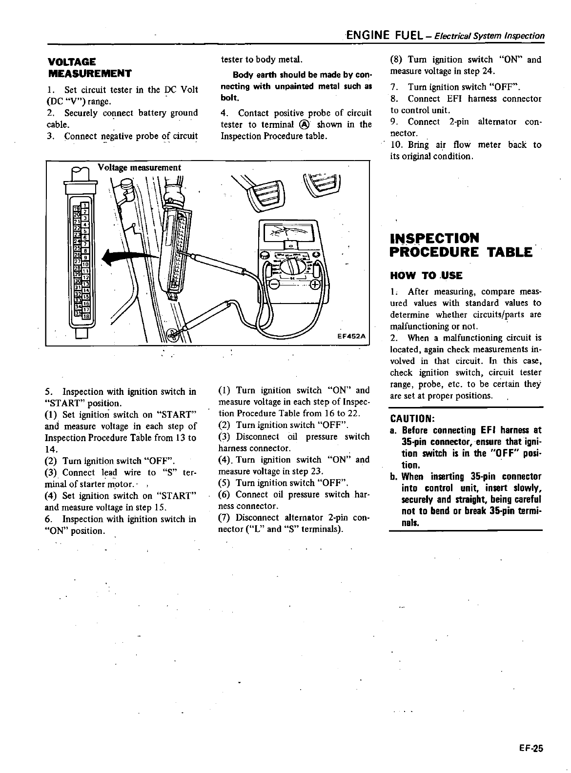
VOLTAGE
MEASUREMENT
1
Set
circuit
tester
in
the
DC
Volt
DC
V
range
2
Securely
connect
battery
ground
cable
3
Connect
negative
probe
of
circuit
Fl
2
I
26
26
9
27
0
1811
1
l1
L13
U
i
4
1
I
IT
ENGINE
FUEL
Electrical
System
Inspection
tester to
body
metal
Body
earth
should
be made
by
con
necting
with
unpainted
metal
such
as
bolt
4
Contact
positive
probe
of circuit
tester to
tenninal
@
shown
in
the
Inspection
Procedure
table
S
Inspection
with
ignition
switch
in
START
position
1
Set
ignition
switch
on
START
and
measure
voltage
in
each
step
of
Inspection
Procedure
Table
from
13
to
14
2
Turn
ignition
switch
OFF
3
Connect
lead
wire
to
S
ter
minal
of
starter
roptor
4
Set ignition
switch
on
START
and
measure
voltage
in
step
1
S
6
Inspection
with
igiIition
switch
in
ON
position
I
101
g
O
L
1
fJU
EF452A
I
Turn
ignition
switch
ON
and
measure
voltage
in
each
step
of
nspec
tion
Procedure
Table
from
16
to
22
2
Turn
ignition
switch
OFF
3
Disconnect
oil
pressure
switch
harness
connector
4
Turn
ignition
switch
ON
and
measure
voltage
in
step
23
S
Turn
ignition
switch
OFF
6
Connect
oil
pressure
switch
har
ness connector
7
Disconnect
alternator
2
pin
con
nector
L
and
S
terminals
8
Turn
ignition
switch
ON
and
measure
voltage
in
step
24
7
Turn
ignition
switch
OFF
8
Connect
EFI
harness
connector
to
control
unit
9
Connect
2
pin
alternator
con
nectar
10
Bring
air
flow
meter
back
to
its
original
condition
INSPECTION
PROCEDURE
TABLE
HOW
TO
USE
1
After
measuring
compare
meas
ured
values
with
standard
values
to
determine
whether
circuits
parts
are
malfunctioning
or
not
2
When
a
malfunctioning
circuit
is
located
again
check
measurements
in
volved
in
that
circuit
In
this
case
check
ignition
switch
circuit
tester
range
probe
etc
to
be
certain
they
are
set
at
proper
positions
CAUTION
a
Before
connecting
EFI
harness
at
35
pin
connector
ensure
that
igni
tion
switch
is
in
the
0
FF
posi
tion
b
When
inserting
35
pin
connector
into
control
unit
insert
slowly
securely
and
straight
being
careful
not
to
bend
or
break
35
pin
termi
nals
EF 25
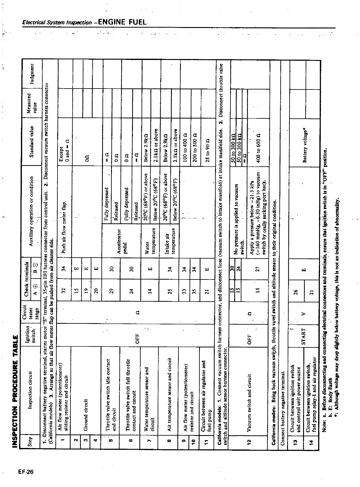
INSPECTIONPROCEDURE
TABLE
m
T1
N
Circuit
tester range
Checkterminala
A
8J
I
Be
Ignition
switch
Step
Inspection
circuit
Auxiliary
op
ration
or
condit
on
J
2
Disconnect
vacuum
switch
harness
connector
Judgment
1
Disconnect
battery
negative
terminal
starter
motor
US
terminal
35
pin
EFI
harness
connector
from
oontrol
unit
California
models
3
Arrange
so
that
air
flow
meter
flap
can
be
pushed
from
air
clenner
side
Air
now
meter
potentiometer
sliding
resistor
and
circuit
32
34
Push
airflow
meter
flap
Fully
deprcs5ed
Releaied
ully
depressed
Released
2p
OC
680P
or
above
B
elow
200C
680F
I
lOae
680P
or
above
I
Below
200C
680F
Standard
value
Measured
value
I
f
o
I
m
Z
Cl
Z
m
C
m
r
I
Except
Qand
n
on
wn
on on
n
Below
2
9kn
2
1kO
or
above
Below
2
9kn
2
1kn
or
above
100
to
400
n
200
to
500
n
2St090n
30
24
Canfornla
model
1
Connect
vacuum
switch
harness
connector
and
dbconnect
hose
vacuum
switch
t6
itttake
manifold
at
intake
manifold
side
2
Disconnect
tnrottle
valve
switch
and
altitude
sensor
harnels
connector
Circuit
betweon
ignition
switch
Bnd
control
unit
power
source
Circuit
between
ignition
switch
fuel
pump
relay
and
air
regulator
Note
a
Before
disconnecting
and
connectiria
electrical
connecton
and
terminab
enlUfO
that
igni
o
n
IWitch
is
in
OFF
podtion
b
E
Body
Earth
Althoush
volllp
may
drop
dfshtiy
below
battery
volllp
this
Is
not
an
indication
of
abnormality
IS
IS
No
preuure
is
applied
to
vacuum
switch
12
Vacuum
switch
and
circuit
OFF
n
Apply
a
pressure
below
21
3
kPa
160
minHg
6
30
inHg
to
vacuum
switch
by
orilly
sucking
port
bac
k
Californi
models
Bring
back
vacuum
swilch
throttle
vavel
switch
and
altitude
sensor
to
their
original
condition
IS
27
Connect
battery
negative
terminal
131
14
I
26
START
v
E
21
Ho
to
300
kn
SO
to
300
kn
Iwn
400
to
600
n
Battery
vottaa
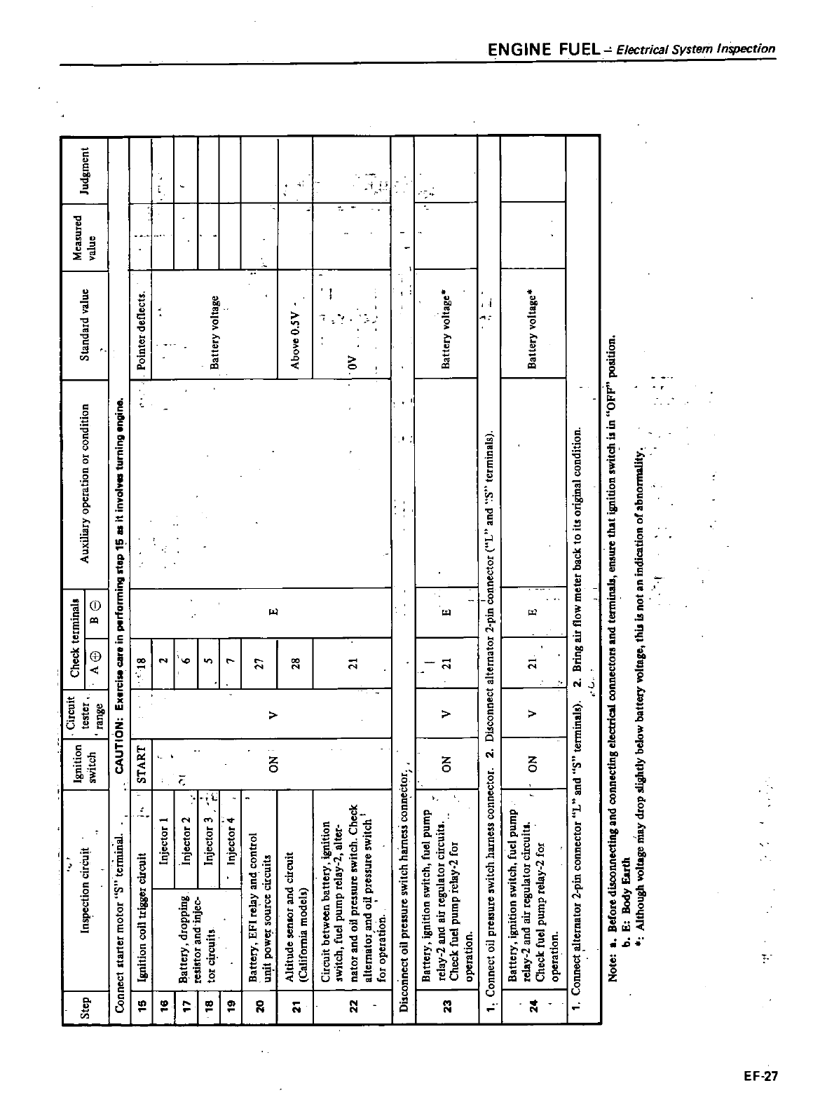
Step
Inspection
cirCu
t
Connect
starter
motor
S
terinin
al
15
Ignition
coil
trigger
circuit
16 17 16 19
Injector
1
attery
dropping
resistor
and
injce
tor
circuits
20
Injector
2
Injector
3
Injector
4
Battery
EFI
relay
and
control
unjt
POWC
f
source
circuits
Altitude
senIOr
and
circuit
California
models
Circuit
between
battery
ignition
switch
fuel
pump
relay
2
a1ter
22
nator
and
oil
pressure
switch
Check
alternator
and
oil
pressure
switch
t
for
operatIon
21
Disconnect
oil
pressure
switch
hames
connector
Battery
ignition
switch
fuel
pump
relay
2
and
air
regulator
circuitl
Check
fuel
pump
relay
2
for
operation
23
24
Ignition
switch
Circuit
tester range
Check
terminals
A
j
I
Be
Auxiliary
operation
or
condition
1
Connect
dtemator
2
pin
connector
uL
and
S
terminals
START
CAUTION
Exerci
care
in
performing
step
1
lIS
it
involve
turning
engine
r
ON ON ON
18
2 6
5 7
27
v
E
Standard
value
Pointer
deflects
Battery
voltage
Above
O
SY
ov
Battery
voltage
Battery
voltage
Note
a
Before
disconnecting
and
connecting
electrical
connectors
and
terminab
ensure
that
ignition
switch
i
in
uOFF
position
b
E
Body
Earth
Although
voltage
may
drop
slightly
below
battery
voltage
this
is
not
an
indication
or
abnormality
I
1
Connect
oil
pressure
switch
harness
connector
2
Disconnect
alternator
2
pin
connector
UL
and
S
terminals
Battery
ignition
switch
fuel
pump
relay
2
and
air
regulator
circuits
Check
fuel
pump
relay
2
for
operation
m
N
28
21
v
I
21
E
v
21
E
2
Bring
air
flow
meter
back
to
its
original
condition
L
Measured
value
Judgment
J
m
Z
G
Z
m
T1
C
m
r
I
l
g
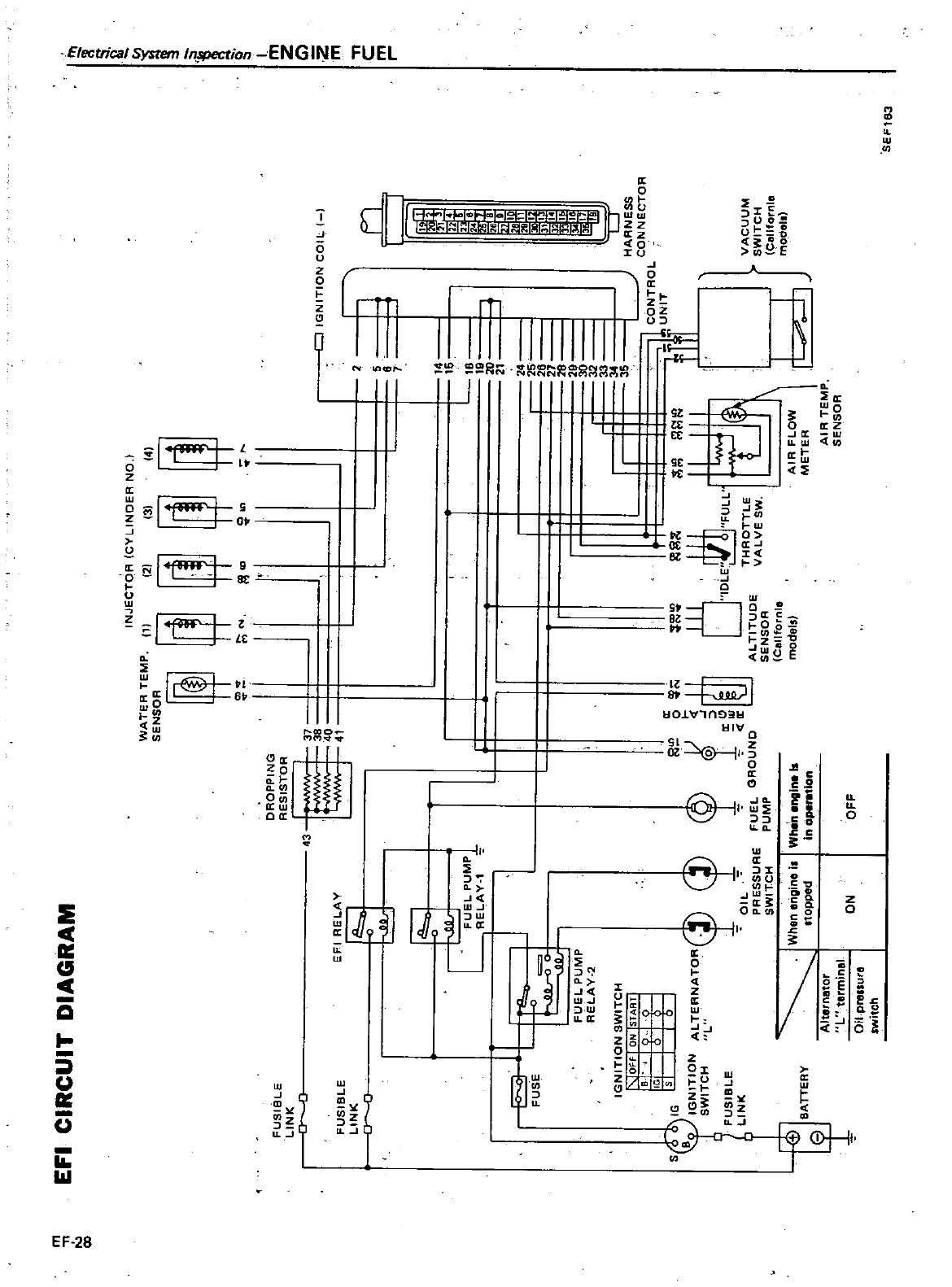
m
n
ex
EFI
CIRCUIT
DIAGRAM
FUSIBLE
LINK
o
c
FUS
BLE
LINK
c
EFI
RELAY
F
t
A
I
Ei
PUMP
REI
AV
1
e
FUSE
I
I
I
FUEL
PUMP
RELAY
2
IGNITION
SW
TCH
OFf
ON
5TA
RT
B
0
0
IG
0
0
S
0J
IG
1
0
cp
B
IGNITION
AL
TEANATOR
SWITCH
L
FUSIBLE
OIL
LINK
PRESSURE
J
SWITCH
When
engine
il
t
nopped
BATTERY
t
Aiternetor Lterminal
ON
Oil
prullure
switch
DROPPING RESISTOR
43
37 3840
4
cp
FUEL
PUMP
Whln
anaina
Is
in
operation
INJECTOACYLINOER
NO
WATER
TEMP
111
121
131
14
oo
j
11
l
N
0
l
J
IGNITION
eQ
L
2
l
7
r
14
15 18
19
l
21
24 252627
8
9
10
3233 34
t
c
f
it
GROUND
Jjln
R
Jre
11l
1O
I
I
DLE
FULL
U
THROTTLE
L
T
ALTITUDE
VALVE
SW
SENSOR
AlA
FLOW
Cellfornle
METER
models
A
R
TEMP
SENSOR
I
I
I
I
VACUUM
SWITCH
Cllllfornlll
modol
OFF
SEF183
s
i
1
0
I
m
Z
Z
m
T1
C
m
r
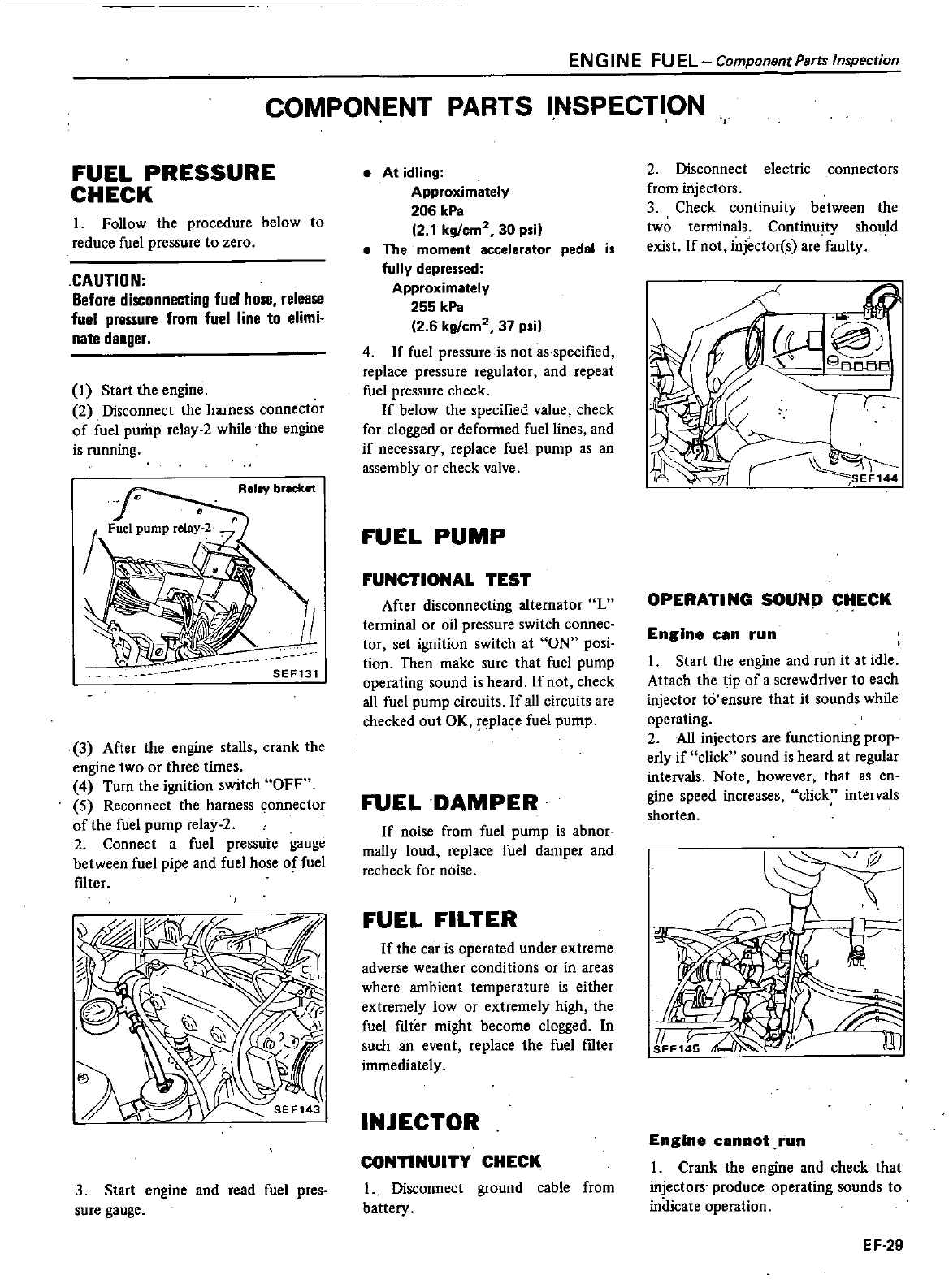
ENGINE
FUEL
Component
Parts
Inspection
COMPONENT
PARTS
INSPECTION
FUEL
PRESSURE
CHECK
1
Follow
the
procedure
below
to
reduce
fuel
pressure
to
zero
CAUTION
Before
disconnecting
fuel
hose
release
fuel
pressure
from
fuel
line
to
elimi
nate
danger
I
Start
the
engine
2
Disconnect
the
harness
connector
of
fuel
pump
relay
2while
the
engine
is
running
Rel
v
br
cket
SEF131
3
After
the
engine
stalls
crank
the
engine
two
or
three
times
4
Turn
the
ignition
switch
OFF
5
Reconnect
the
harness
connector
of
the
fuel
pump
relay
2
2
Connect
a
fuel
pressure
gauge
between
fuel
pipe
and fuel
hose
of
fuel
ftIter
3
Start
engine
and
read
fuel
pres
sure
gauge
At
idling
Approximately
206
kPa
12
1
kg
cm2
30
psi
The
moment
accelerator
pedal
is
fully
depressed
Approximately
255
kPa
26
kg
em2
37
psi
4
If
fuel
pressure
is
not
as
specified
replace
pressure
regulator
and
repeat
fuel
pressure
check
If
below
the
specified
value
check
for
clogged
or
defonned fuel
lines
and
if
necessary
replace
fuel
pump
as
an
assembly
or
check
valve
FUEL
PUMP
FUNCTIONAL
TEST
After
disconnecting
alternator
L
terminal
or
oil
pressure
switch
connec
tor
set
ignition
switch
at
ON
posi
tion
Then
make
sure
that
fuel
pump
operating
sound
is
heard
If
not
check
all
fuel
pump
circuits
If
all
circuits
are
checked
out
OK
eplace
fuel
pump
FUEL
DAMPER
If
noise
from
fuel
pump
is
abnor
mally
loud
replace
fuel
damper
and
recheck
for
noise
FUEL
FILTER
If
the
car
is
operated
under
extreme
adverse
weather
conditions
or
in
areas
where
ambient
temperature
is
either
extremely
low
or
extremely
high
the
fuel
ftIter
might
become
clogged
In
such
an
event
replace
the
fuel
ftIter
immediately
INJECTOR
CONTINUITY
CHECK
1
Disconnect
ground
cable
from
battery
2
Disconnect
electric
connectors
from
injectors
3
Check
continuity
between
the
two
terminals
Continuity
sho
ld
exist
If
not
injectorCs
are
faulty
it
P
LJ
Tf
r
SEF144
OPERATING
SOUND
CHECK
Engine
can
run
1
Start
the
engine
and
run
it
at
idle
Attach
the
tip
of
a
screwdriver
to
each
injector
to
ensure
that
it
sounds
while
operating
2
All
injectors
are
functioning
prop
erly
if
click
sound
is
heard
at
regular
intervals
Note
however
that
as
en
gine
speed
increases
click
intervals
shorten
J
1J
1I
l
Engine
cannot
run
1
Crank
the
engine
and
check
that
injectors
produce
operating
sounds
to
indicate
operation
EF
29
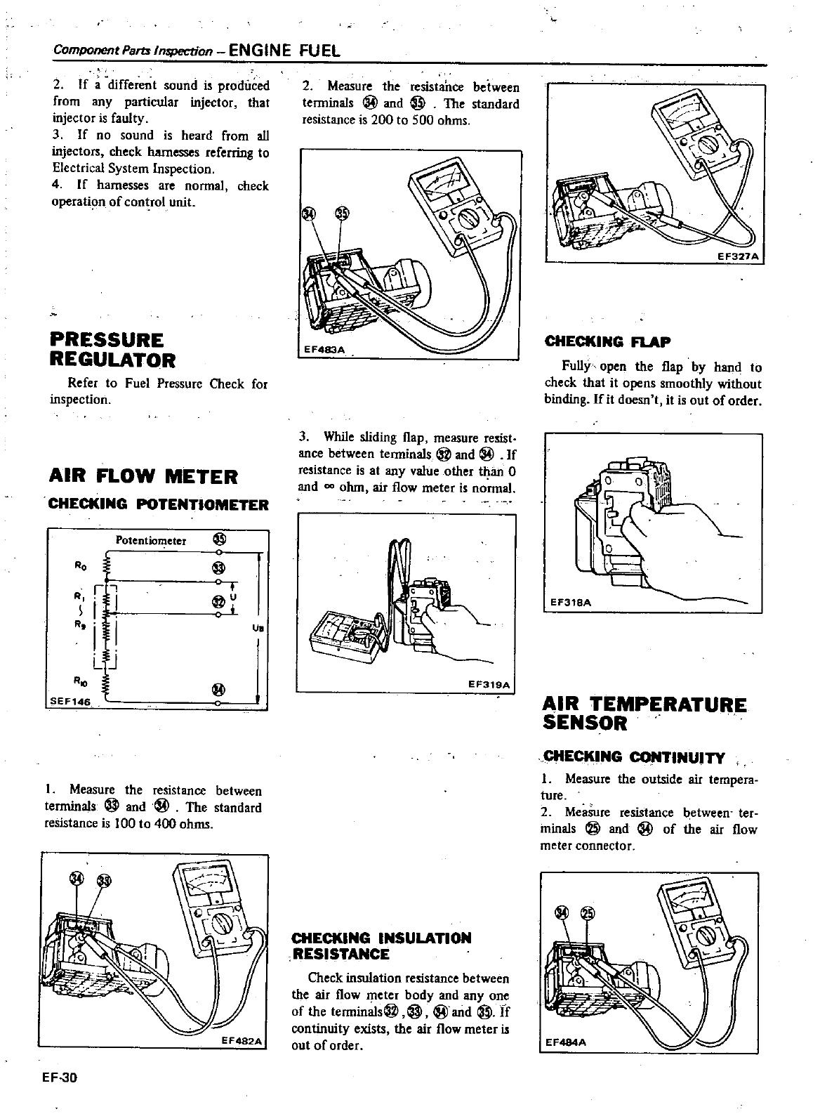
ComponentParttlnspection
ENGINE
FUEL
2
If
a
different
sound
is
produced
from
any
particular
injector
that
injector
is
faulty
3
If
no
sound
is
heard
from
all
injectors
check
harnesses
referring
to
Electrical
System
Inspection
4
I
f
harnesses
are
nonnal
check
operathm
of
control
unit
PRESSURE
REGULATOR
Refer
to
Fuel
Pressure
Check
for
inspection
AIR
FLOW
METER
CHECKING
TlOMETER
Potentiometer
@
@
RO
t
RI
iJJ
R
iI
LJ
R
SEF146
@
@
I
Measure
the
resistance
between
terminals
@
and@
The
standard
resistance
is
100
to
400
ohms
EF482A
EF
30
2
Measure
the
resista
nce
between
tenninals
@
and
@
The
standard
resistance
is
200
to
500
ohms
EF483A
3
While
sliding
flap
measure
resist
ance
between
tenninals
@
and
@
If
resistance
is
at
any
value
other
t
1aJl
0
and
0Cl
ohm
air
flow
meter
is
nonnaJ
UlI
EF319A
CHECKING
INSULATION
RESISTANCE
Check
insulation
resistance
between
the
air
flow
meter
body
and
anyone
of
the
tennin
s@
@
@and
@
If
continuity
exists
the
air
flow
meter
is
out
of
order
EF327A
CHECKING
RAP
Fully
open
the
flap
by
hand
to
check
that
it
opens
smoothly
without
binding
If
it
doesn
t
it
is
out
of
order
EF318A
AIR
TEMPERATURE
SENSOR
CHECKING
INUITY
I
Measure
the
outside
air
tempera
ture
2
Measure
resistance
between
ter
minals
@
and
@
of
the
air
flow
meter
connector
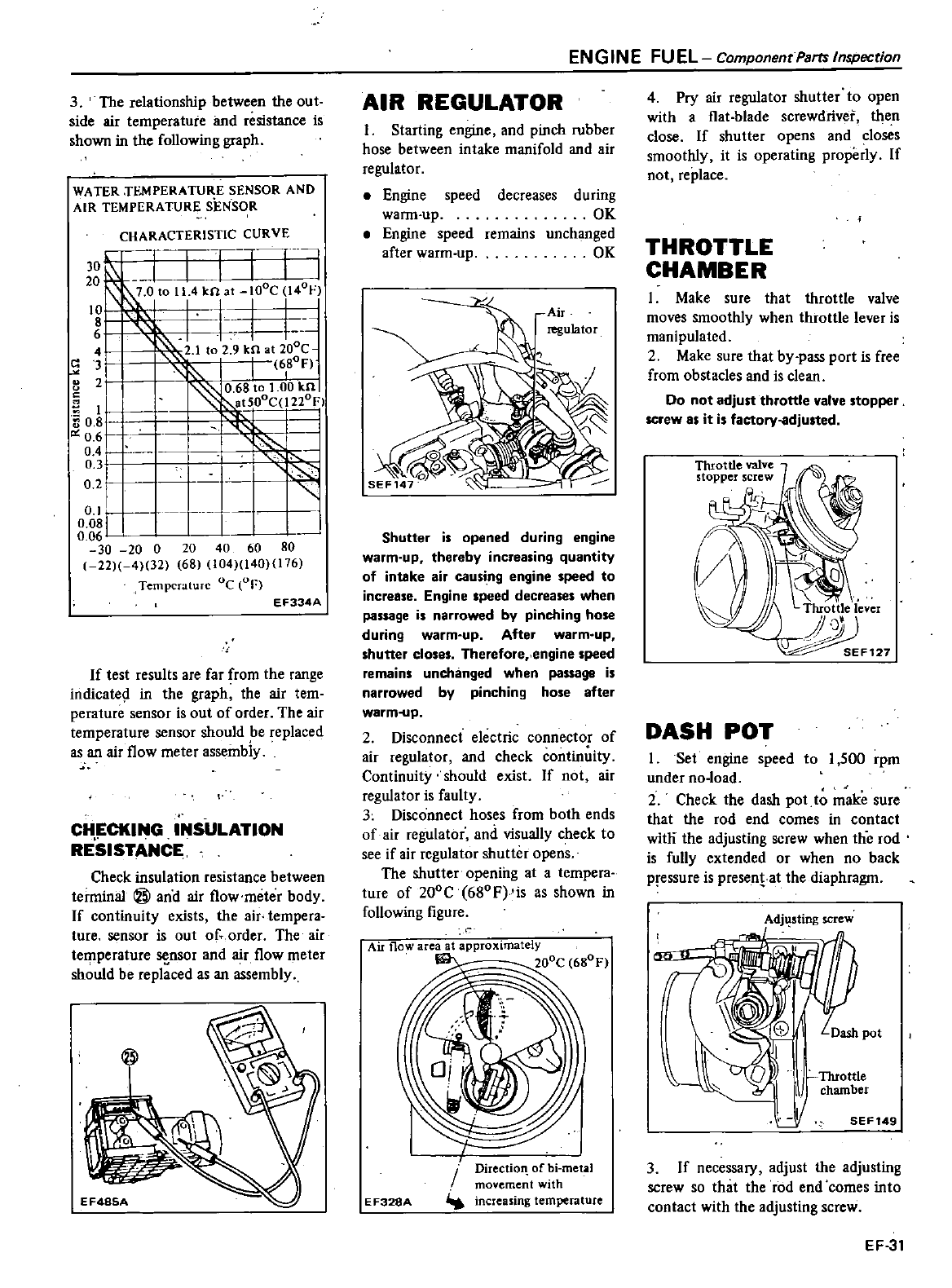
3
The
relationship
between
the
out
side
air
temperature
and
resistance
is
shown
in
the
following
graph
WATER
n
MPERATURE
SENSOR
AND
AIR
TEMPERATURE
SENSOR
CHARACTERISTIC
CURVE
30
r
TC
i
EJ
r
1
r
i
0
42
1
to
2 9
k
at
20oe
3
I
6tF
8
2
O
6SIo
00
knl
at50oC
l220Fl
I
g
J
04
l
0 3
02
I
0
1
O
OS
0
06
30
20
0
20
40
60
SO
22
4
32
6S
104 140 176
Temperature
Oc
OF
EF334A
If
test
results
are
far
from
the
range
indicate
in
the
graph
the
air
tern
perature
sensor
is
out
of
order
The air
temperature
sensor
should
e
replaced
as
an
air
flow
meter
assembly
CHECKING
INSULATION
RESISTANCE
Check
insulation
resistance
between
terminal
@
ana
air
flow
meter
body
If
continuity
exists
the air
tempera
ture
sensor
is
out
of
order
The
air
terpperature
sc
nsor
and
air
flow
meter
should
be
replaced
as
an
assembly
EN
G
IN
E
FU
EL
Component
Parts Inspection
AIR
REGULATOR
I
Starting
engine
and
pinch
rubber
hose
between
intake
manifold
and
air
regulator
Engine
speed
decreases
warm
up
Engine
speed
remains
after
warm
up
during
OK
unchanged
OK
Air
regulator
Shutter
is
opened
during
engine
warm
up
thereby
increasing
quantity
of
intake
air
causi
ng
engine
speed
to
increase
Engine
speed
decreases
when
passage
is
narrowed
by
pinching
hose
during
warm
up After
warm
up
shutter
closes
Therefore
engine
speed
remains
unchanged
when
passage
is
narrowed
by
pinching
hose
after
warm
up
2
Disconnect
electric
connector
of
air
regulator
and
check
continuity
Continuity
should
exist
If
not
air
regulator
is
faulty
3
Disconnect
hoses
from
both
ends
of
air
regulator
and
visually
check
to
see
if
air
regulator
shutter
opens
The
shutter
opening
at
a
tempera
ture
of
200C
680F
is
as
shown
in
following
figure
Air
flow
rea
at
approximately
200C
6SoF
E
F328A
Directioll
of
hi
metal
movement
with
increasing
temperature
4
Pry
air
regulator
shutter
to
open
with
aflat
b1ade
screwdriver
then
close
If
shutter
opens
and
closes
smoothly
it
is
operating
properly
If
not
replace
THROTTLE
CHAMBER
1
Make
sure
that
throttle
valve
moves
smoothly
when
throttle
lever
is
manipulated
2
Make
sure
that
by
pass
port
is
free
from
obstacles
and
is
clean
Do
not
adjust
throttle
valve
stopper
screw
as
it
is
factory
adjusted
Throttle
lever
F127
DASH
POT
1
Set
engine speed
to
1
500
rpm
under
no
load
2
Check
the
dash
pot
to
make
sure
that
the
rod
end
comes
in
contact
witli
the
adjusting
screw
when
the
rod
is
fully
extended
or
when
no
back
pressure
is
presentat
the
diaphragm
Adjusting
screw
I
SEF149
3
If
necessary
adjust
the
adjusting
screw
so
that
the
rod
end
comes
into
contact
with
the
adjusting
screw
EF
31
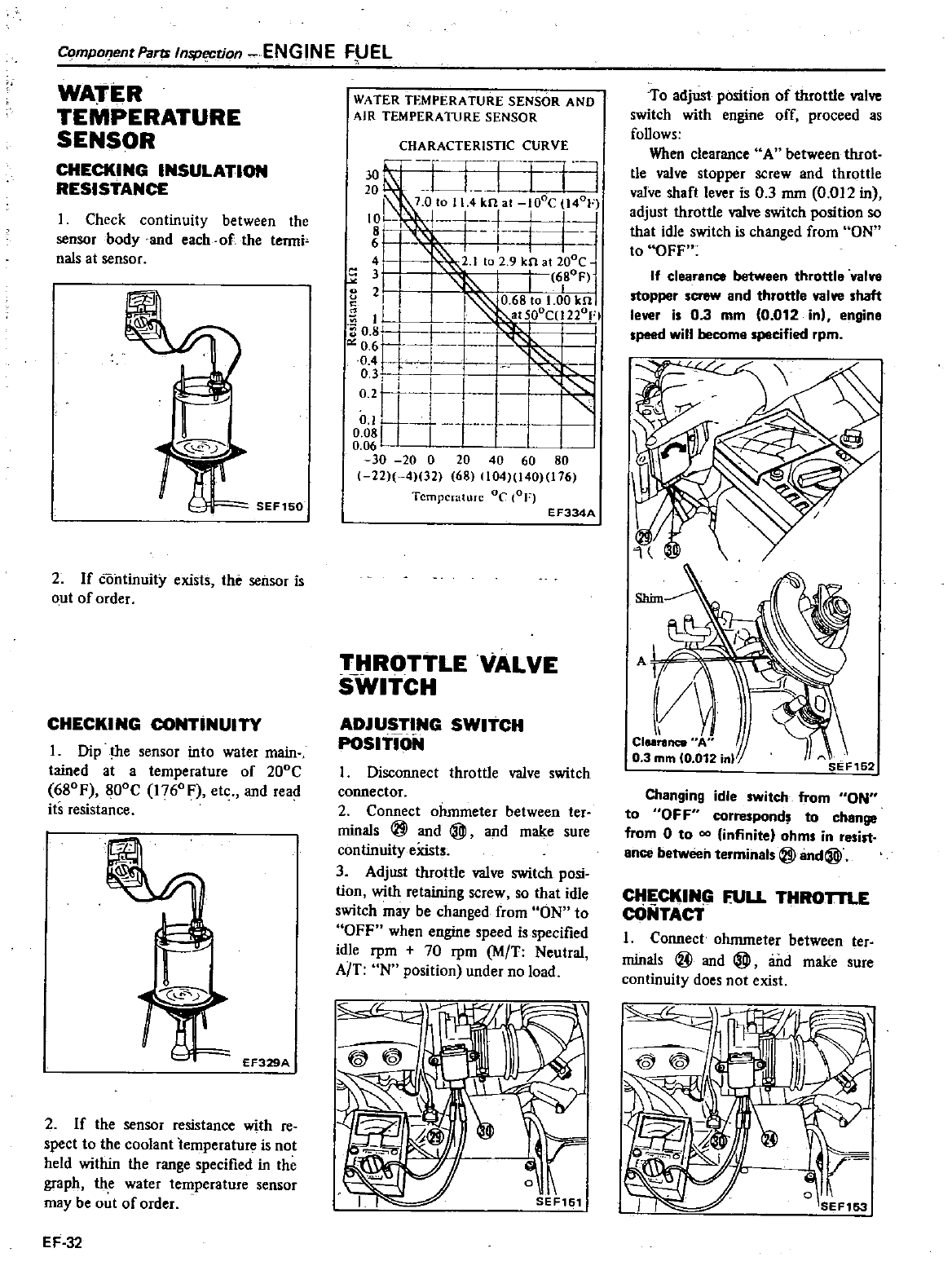
CompOfJentParu
Inspection
ENGINE
F1JEL
WATER
TEMPERATURE
SENSOR
CHECKING
INSULATION
RESISTANCE
1
Check
continuity
between
the
sensor
body
and
each
of
the
tenni
nals
at
sensor
2
If
continuity
exists
the
sensor
is
out
of
order
CHECKING
CONTINUITY
1
Dip
the
sensor
into
water
main
tained
at
a
temperature
of
200C
680F
800C
1760F
etc
and
read
its
resistance
r
rr
EF329A
2
If
the
sensor
resistance
with
re
spect
to
the
coolant
temperature is
not
held
within
the
range
specified
in
the
graph
the
water
temperature
sensor
may
be
ot
of
order
EF
32
WATER TEMPERATURE
SENSOR
AND
AIR
TEMPERA11JRE
SENSOR
CHARACTERISTIC
CURVE
g
T
U
I
j
I
I
7
010114
kn al
lOoC
1401
10L
j
8
j
6
4
i
2
1
to 2 9
kn
at
lOoe
3
I I
6tF
g
21
0
68
to
1
00
kn
I
II
I
aISOoC
1220FI
Ht
i
0
3I
0
2r
0
u
gggL
1
30
20
0
20
40 60
80
1
22
4
32
68
104
140
176
Temperature
DC
COF
EF334A
THROTTLE
VALVE
SWITCH
ADJUSTING
SWITCH
POSITION
Disconnect
throttle
valve
switch
connector
2
Connect
ohmmeter
between
ter
minals
@
and
@
and
make
sure
continuity
eXists
3
Adjust
throttle
valve
switch
posi
tion
with
retaining
screw
so
that
idle
switch
may
be
changed
from
ON
to
OFF
when
engine
speed
is
specified
idle
rpm
70
rpm
M
T
Neutral
A
T
N
position
under
no
load
To
adjust
position
of
throttle
valve
switch
with
engine
off
proceed
as
follows
When clearance
A
between
throt
tle
valve
stopper
screw
and
throttle
valve
shaft
lever
is
03
mm
0
012
in
adjust
throttle
valve
switch
position
so
that
idle
switch is
changed
from
ON
to
OFF
If
clearance
between
throttle
valvo
stopper
screw
and
throttle
valve
shaft
lever
is
03
mm
0
012
in
engine
speed
will
become
specified
rpm
Shim
Changing
idle
switch
from
ON
to
OFF
correspond
to
change
from
0
to
infinite
ohms
in
resist
ance
between
terminals
@and@
CHECKING
fULL
THROTTLE
cONTAcT
1
Connect
ohmmeter
between
ter
minals
@
and
@
and
make
sure
continuity
does
not
exist
o
i
SEF153
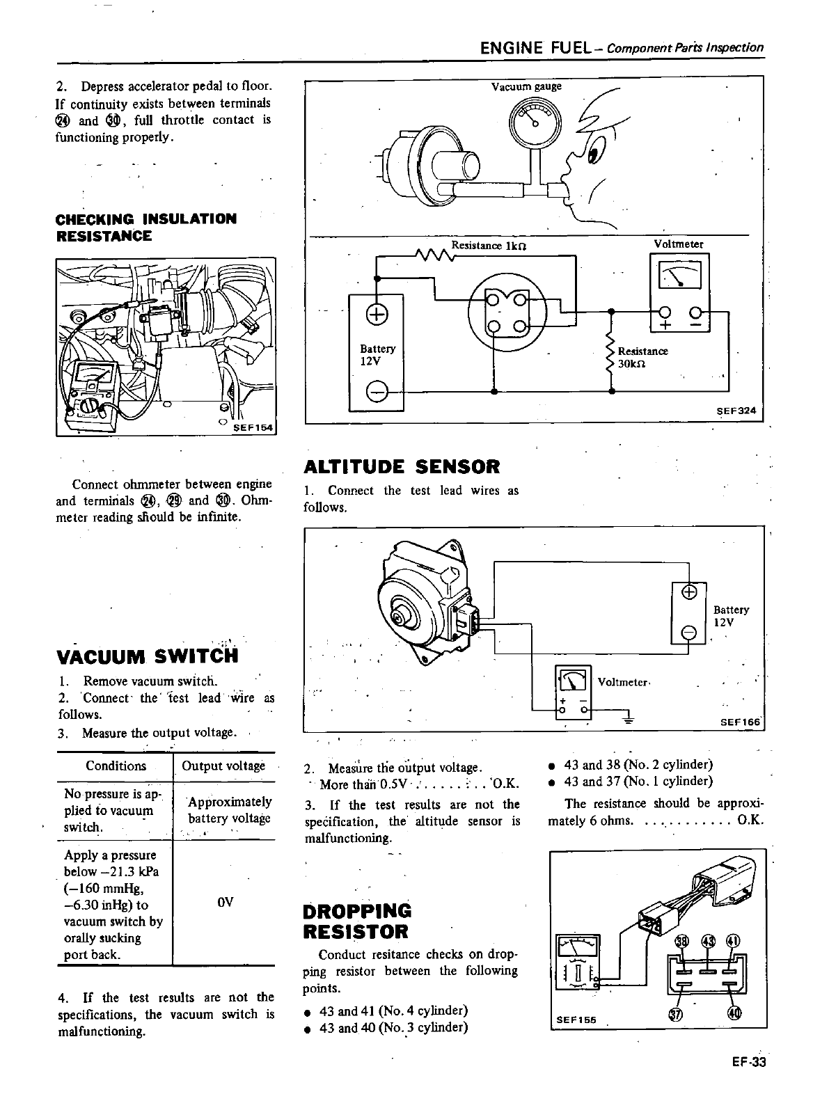
2
Depress
accelerator
pedal
to
floor
If
continuity
exists
between
tenninals
@
and
full
throttle
contact
is
functioning
properly
CHECKING
INSULATION
RESISTANCE
1
o
SEFl54
Connect
ohmmeter
between
engine
and
tenninals
@
@
and
@
Ohm
meter
reading
mould
be
infInite
VACUUM
SWITCH
1
Remove
vacuum
switch
2
Connect
the
test
lead
wire
as
follows
3
Measure
the
output
voltage
Conditions
Output
voltage
No
pressure
is
ap
plied
to
vacuum
switch
Approximately
battery
voltage
Apply
a
pressure
below
21
3
kPa
160
mmHg
6
30
inHg
to
OV
vacuum
switch
by
orally
ucking
port
back
4
If
the
test
results
are
not
the
specifications
the
vacuum
switch
is
malfunctioning
ENG
INE
FU
EL
Component
Parts
Inspection
Vacuum
gauge
11
Resistance
lkn
Voltmeter
I I
EB
ova
o
0
Regstan
30kn
Battery
12V
o
SEF324
ALTITUDE
SENSOR
I
Connect
the
test
lead
wires
as
follows
i
Battery
Jf
12V
III
Voltmeter
0
4
SEF166
2
Measure
the
output
voltage
More
thOriO
5V
O
K
3
If
the
test
results
are
not
the
speCification
the
altitude
sensor
is
malfunctioning
43
and
38
No
2
cylinder
43
and
37
No
1
cylinder
The
resistance
should
be
mately
6
ohms
approxi
O
K
DROPPING
RESISTOR
Conduct
resitance
checks
on
drop
ping
resistor
between
the
following
points
43
and
41
No
4
cylinder
43
and
40
No
3
cylinder
l
SEF155
EF
33
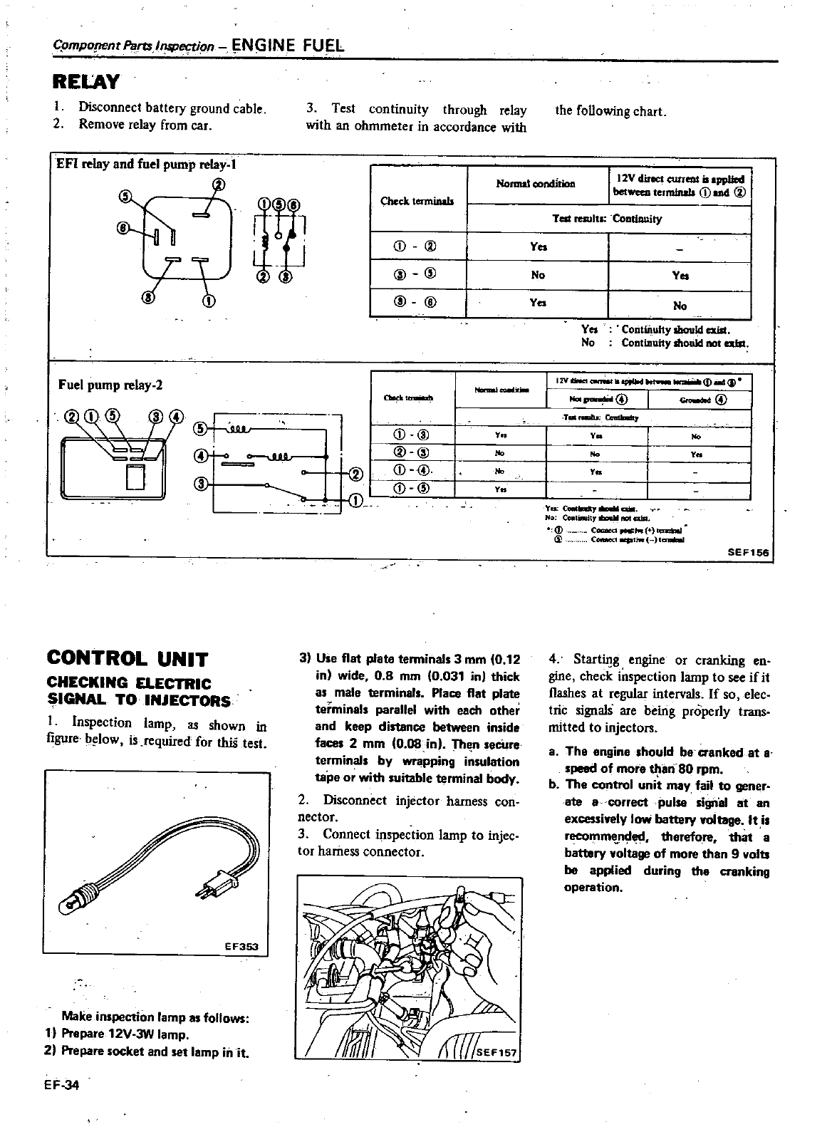
Cpmpopentp
ral
5Per
Von
N
INE
FUEL
RELAY
I
Disconnect
battery
ground
cable
2
Remove
relay
from
car
3
Test
continuity
through
relay
with
an
ohmmeter
in
accordance
with
EFI
relay
and
fuel
pump
relay
I
rp
Chcck
terminals
d
1
nu
j
@
1
@
@
@
@
Fuel
pump
relay
2
the
following
chart
Normal
condition
112V
direct
current
iI
ppUed
I
bet
t
uololls
CDond@
Tell
resultl
CoatiDuity
f
Yea
No
Yes
Ya
No
Yes
Coritiilufty
should
ex
iIt
No
Continuity
IhotiId
not
abt
IZVIliNct
aIIfIW
I
2
J
l
T
D
t
I
NDnIaI
@@
7
nau
0tndIaIIlt
y
y
No
No No
y
No
y
y
CONTROL
UNIT
CHECKING ELECTRIC
IGNAL
TO
INJECTORS
I
Inspection lamp
as
shown
in
figure
b
low
is
required
for
thiS
test
E
F353
Make
inspection lamp
as
follows
1
Prepare
12V 3W
lamp
2
Prepare
socket
and
set
lamp
in
it
EF
34
ac
kll
l
llllilod
l
CD
00
@@
j
@
j
@
3
Use
flat
plate
tenninals
3
mm
0
12
in
wide
0 8
mm
0
031
in
thick
as
male
terminals
Place
flat
plate
terminals
parallel
with
each
other
and
keep
distance between
inside
faces
2
mm
0
08
in
The
n
secUre
terminals
by
wrapping
insulation
tape
or
with
suitable
terminal
body
2
Disconnect
injector
harness
con
nector
3
Connect
inspection
lamp
to
injec
tor
harness
connector
YQ
C
cUII
CO
1inulll
nol
alA
c
ct
ao
c
Ir
I
SEFl56
4
Starting
engine
or
cranking
en
gine
check
iitspection
lamp
to
see
if
it
flashes
at
regular
interval
If
so
elec
ttic
signals
are
being
properly
trans
mitted
to
injectors
aThe
engine
should
be
cranked
at
a
speed
of
more
tJ
IariSO
rpm
b
The
control
unit
may
fail
to
gener
ate
a
correct
pulse signal
at
an
excessiwely
low
battery
voltage
It
is
recomm
nded
therefore
that
a
battery
voltage
of
more
than
9
volts
be
applied
during
the
cranking
operation
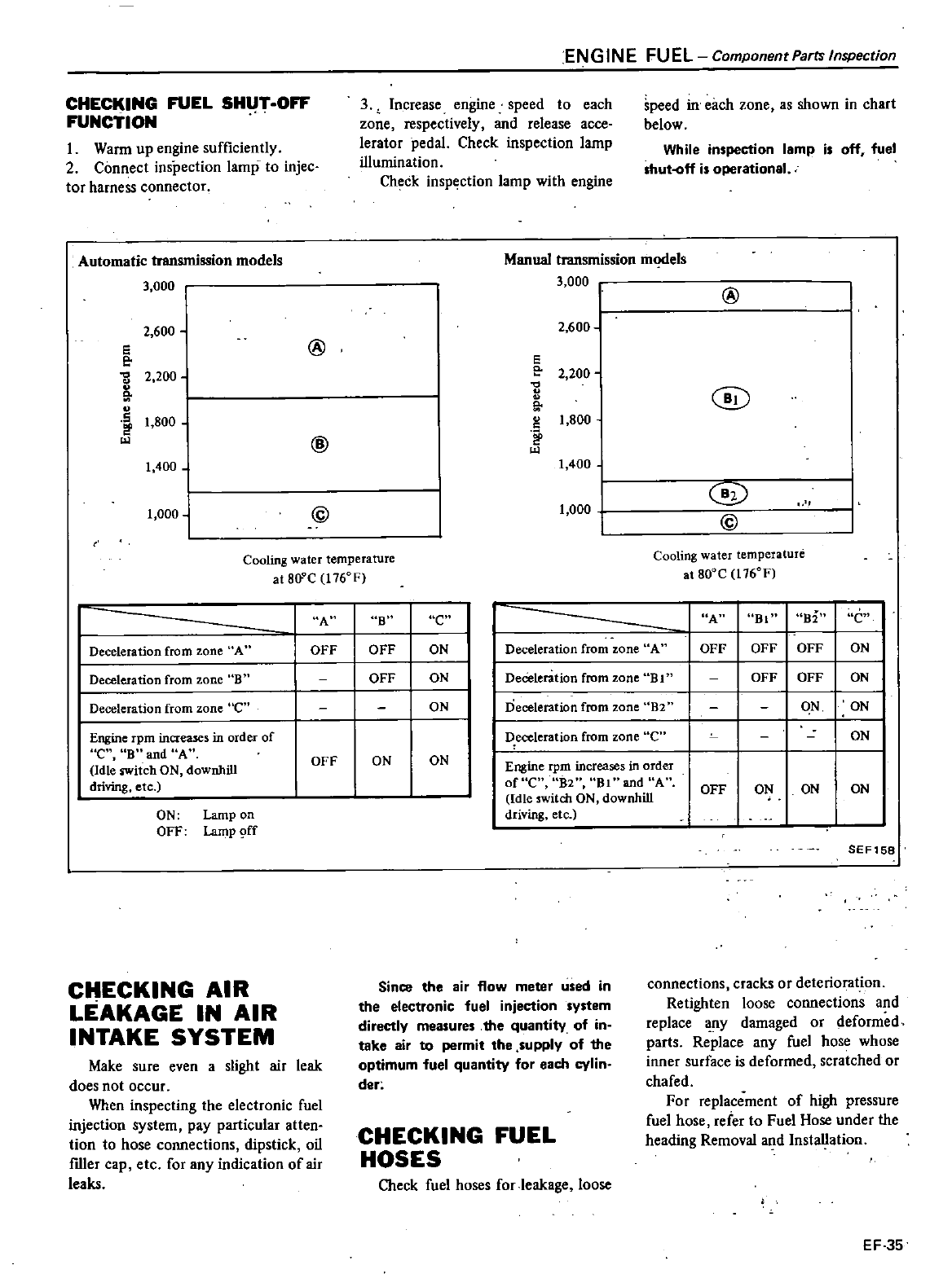
CHECKING
FUEL
SHUT
OFF
FUNCTION
1
Wann
up
engine
sufficiently
2
Connect
inspection
lamp
to
injec
tor
harness
connector
Automatic
transmission
models
3
000
2
600
e
e
0
2
200
51
5
t
800
t
400
1
000
EN
GIN
E
FU
EL
Component
Parts
Inspection
3
Increase
engine
speed
to
each
zone
respectively
and
release
acce
lerator
pedal
Check
inspection lamp
illumination
Check
inspection
lamp
with
engine
speed
ill
each
zone
as
shown
in
chart
below
While
inspection
lamp
is
off
fuel
shut
off
is
operational
Manual
transmission
m
els
3
000
I
2
600
1
@
e
e
2
200
0
51
1
800
c
1
400
1
000
@
@
Cooling
water
temperature
at
80
C
1760F
C
ECKING
AIR
LEAKAGE
IN
AIR
INTAKE
SYSTEM
Make
sure
even
a
slight
air
leak
does
not
occur
When
inspecting
the
electronic
fuel
injection
system
pay
particular
atten
tion
to
hose
connections
dipstick
oil
filler
cap
etc for
any
indication
of
air
leaks
Since
the air
flow
meter
used
in
the
electronic
fuel
injection
system
directly
measures
the
quantity
of
in
take
air
to
permit
the
supply
of
the
optimum
fuel
quantity
for
each
cylin
der
CHECKING
FUEL
HOSES
Check
fuel
hoses
for
leakage
loose
@
@
@
@
Cooling
water
temperature
at
800C
1760F
connections
cracks
or
deterioration
Retighten
loose
connections
and
replace
any
damaged
or
defonned
parts
Replace
any
fuel
hose
whose
inner
surface
is
deformed
scratched
or
chafed
For
replacement
of
high
pressure
fuel
hose
refer
to
Fuel
Hose
under
the
heading
Removal
and
InstaUation
EF
35
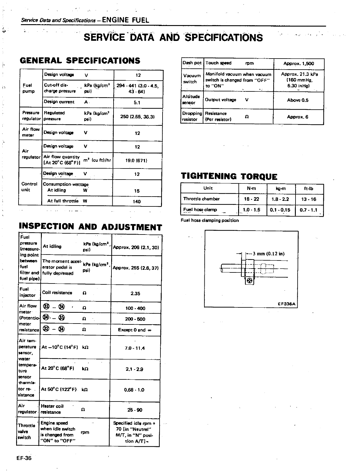
Service
OatasndSpecificatiom
ENGINE
FUEL
SERVICE DATA
AND
SPECIFICATIONS
GENERAL
SPECIFICATIONS
I
Design
voltage
V
12
fuel
I
Cut
off
di
kPa
t
cm2
294
44113
0
4
5
pump
charge
pressure
psi
43
641
Design
current A
5
1
Pressure
Regulated
kpa
kg
em
2SO 12
55 36
31
regulator
pressure
psi
I
Airflow
Design
voltage
V
12
I
meter
Design
voltage
V
12
I
Air
regulator
Air
flow
quantitY
mcuft
hr
19
0
611l
I
IAt
200C
I68
FlJ
i
votteee
V
12
I
Control
Consumption
wattage
I
unit
At
idling
W
15
At
full
throttle
W
140
J
INSPECTION
AND
ADJUSTMENT
fuel
pressul
B
A
dr
measure
t
1n9
iog
point
between
The
moment
acce
kPa
I2
fuel
eretor
pedal
is
kg
em
Approx
255
2
6
37
filter
and
fully
depre1sed
PSI
fuel
pi
kPa
kg
em
Appro
206
12
1
301
PII
Fuel
Coil
resistance
injector
n
2
35
Airflow
@@
n
100
400
metar
Potentia
@ @
fl
200
SOO
meter
@@
resistance
fl
Except
0
and
Air
tem
peratu
re At
tOOC
t4OFI
kfl
1
0
114
sensor
water
tempera
At
200C
168OF
kfl
2
1
29
lUre
sensor
therml
tor
re
At5O
C
t22
F
kfl
0 68
1
0
sistance
Air
Heater
coil
25
90
reQulstor
resistance
n
Engine
speed
Specified
idle
rpm
Throttle
wh
dl
ch
70
in
Neutn
I
enl
l
SWlt
va
is
changed
from
rpm
MfT
in
N
pasi
SWitch
ON
to
OFF
tion
AfT
EF
36
I
Dash
pot
T
ou
h
speed
rpm
Approx
1
500
Vacuum
Manifold
vacuum
when
vacuum
Approx
21
3 kPa
switch switch
is
changed
from
OFF
160
mmHg
to
ON
6
30
i
Hil
I
Altitude
Output
voltage
V
Above
05
leos
or
IDr
ing
Resistance
fl
Approx
6
resistor
Per
resistor
TIGHTENING
TORQUE
I
Unit
N
m
ft
lb
I
Throttle
chamber
I
A
IhOSl
clBn
lp
Futtl
hose
clBr11ping
position
18 22
1
8 2
2
13
16
1
0
1
5
0
1
0 15
0
1
11
3mmIO
l2in
Q
EF336A
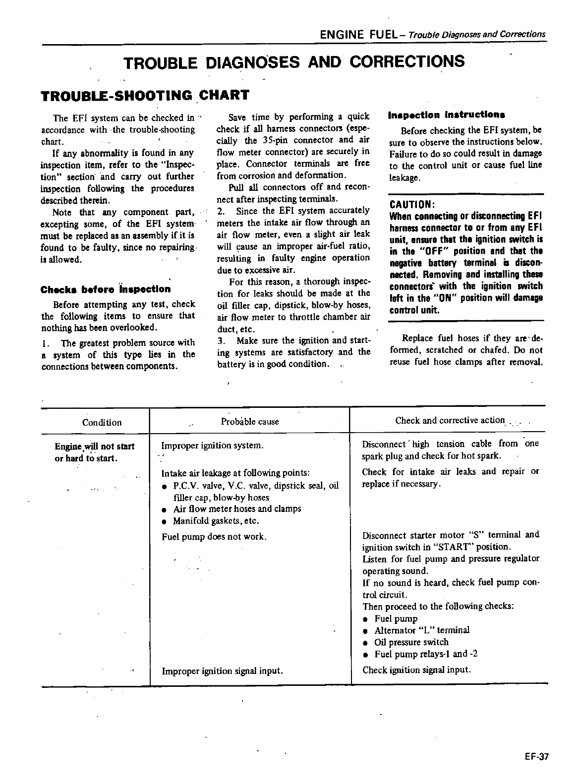
EN
GIN
E
FU
EL
Trouble
Diagnoses
and
Corrections
TROUBLE
DIAGNOSES
AND
CORRECTIONS
TROUBLE
SHOOTING
CHART
The EFl
system
can
be
checked
in
accordance
with
the
trouble
shooting
chart
If
any
abnonnaIity
is
found
in
any
inspection
item
refer
to
the
Inspec
tion
section
and
carry
out
further
inspection
following
the
procedures
described
therein
Note
that
any
component
part
excepting
some
of
the
EFI
system
must
be
replaced
as
an
assembly
if
it
is
found
to
be
faulty
since
no
repairing
is
allowed
Checke
before
inspection
Before
attempting
any
test
check
the
following
items
to ensure
that
nothing
has
been
overlooked
I
The
greatest problem
source
with
a
system
of
this
type
lies
in
the
connections
between
components
Condition
Save
time
by
perfonning
a
quick
check
if
all
harness
connecton
espe
cially
the
35
pin
connector
and
air
flow
meter
connector
are
securely
in
place
Connector
terminals
are
free
from
corrosion
and
deformation
Pull
all
connecton
off
and
recon
nect
after
inspecting
terminals
2Since the
EFI
system
accurately
meters
the
intake
air
flow
through
an
air
flow
meter
even
a
slight
air
leak
will
cause
an
improper
air
fuel
ratio
resulting
in
faulty
engine
operation
due
to
excessive
air
For
this
reason
a
thorough
inspec
tion
for
leaks
should
be
made
at
the
oil
ftller
cap
dipstick
blow
by
hoses
air
flow
meter
to
throttle
chamber
air
duct
etc
3
Make
sure
the
ignition
and
start
ing
systems
are
satisfactory
and
the
battery
is
in
good
condition
Probable
cause
Engine
will
not
start
or
hard
to
start
Improper
ignition
system
Intake
air
leakage
at
following
points
P
C
V
valve
V
C
valve
dipstick
seal
oil
ftller
cap
blow
by
hoses
Air
flow
meter
hoses
and
clamps
Manifold
gaskets
etc
Fuel
pump
does
not
work
Improper
ignition
signal
input
Inspection
Instructlone
Before
checking
the
EFI
system
be
sure
to
observe
the
instructions
below
Failure
to
do
so
could
result
in
damage
to
the control
unit
or
cause
fuel
line
leakage
CAUTION
When
connecting
or
disconnecting
EFI
harness
connector
to
or
tom
any
EFI
unit
enlUre
that
the
ignition
switch
is
in
the
OFF
position
and
that
the
I
battery
terminal
is
discon
nected
Removing
and
ins18l1ing
the
connectors
with
the
ignition
switch
left
in
the
ON
position
will
damage
control
unit
Replace
fuel
hoses
if
they
are
de
fonned
scratched
or
chafed
Do
not
reuse
fuel
hose
clamps
after
removal
Check
and
corrective
action
Disconnect
high
tension
cable
from
one
spark
plug
and
check
for
hot
spark
Check
for
intake
air
leaks
and
repair
or
replace
if
necessary
Disconnect
starter
motor
S
temtinal
and
ignition
switch
in
START
position
listen
for
fuel
pump
and
pressure
regulator
operating
sound
If
no
sound
is
heard
check
fuel
pump
con
trol
circuit
Then
proceed
to
the
following checks
Fuel
pump
Alternator
L
terminal
Oil
pressure
switch
Fuel
pump
relays
I
and
2
Check
ignition
signal
input
EF
37
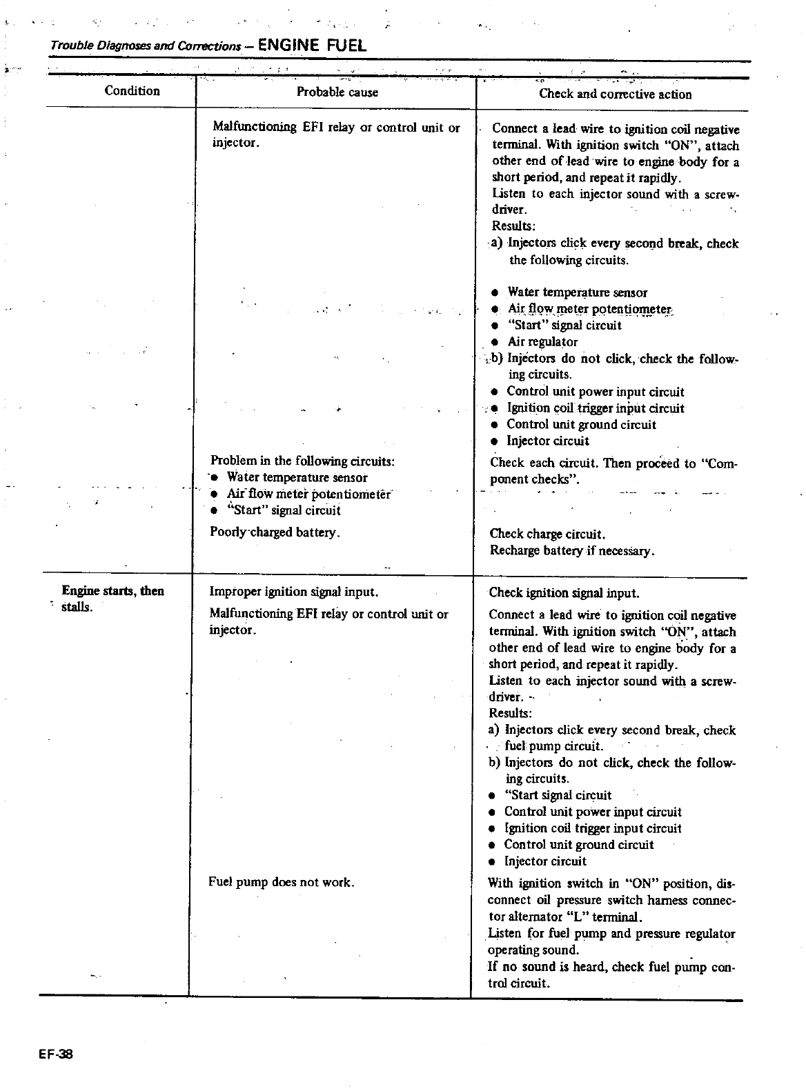
Trouble
Diagnoses
and
ComJCtion
ENGINE
FUEL
Condition
Engine
starts
then
stalls
EF
38
Probable
cause
Malfunctioning
EFI
relay
or
control
unit
or
injector
Problem
in
the
following
circuits
Vater
temperature
sensor
Air
flow
meter
potentionietef
Start
signal
circuit
Poorly
chaIged
battery
Improper
ignition
signal
input
Malfunctioning
EFI
relay
or
control
unit
or
injector
Fuel
pump
does
not
work
Check
and
corrective
action
Connect
a
lead
wire to
ignition
coil
negative
terminal
With
ignition
switch
ON
attach
other
end
of
leadwire
to
engine
body
for a
short
period
and
repeat
it
rapidly
listen
to
each
injector
sound
with
a
screw
driver
Results
a
Injectors
click
every
second
break
check
the
following
circuits
e
Water
temperature
sensor
Air 0
lJleter
po
tent
ete
r
Start
signal
cirelli
t
Air
regulator
b
Injectors
do
not
click
check
the
follow
ing
circuits
Control
unit
power
input
circuit
Ignition
coil
trigger
input
circuit
Control
unit
ground
circuit
e
Injector
circuit
Check
each
circuit
Then
proceed
to
Com
ponent
checks
Check
charge
circuit
Recharge
battery
if
necessary
Check
ignition
signal
input
Connect
a
lead
wire to
ignition
coil
negative
terminal
With
ignition
switch
ON
attach
other
end
of
lead
wire
to
engine
body
for
a
short
period
and
repeat
it
rapidly
listen
to
each
injector
sound
with
a
screw
driver
Results
a
Injectors
click
every
second
break
check
fuel
pump
circuit
b
Injectors
do
not
click
check
the
follow
ing
circuits
Start
signal
circuit
Control
unit
power
input
circuit
Ignition
coil
trigger
input
circuit
Control
unit
ground
circuit
Injector
circuit
With
ignition
switch
in
ON
position
dis
connect
oil
pressure
switch
harness
connec
tor
alternator
L
tenninal
Listen
for
fuel
pump
and
pressure
regulator
operating
sound
If
no
sound
is
heard
check fuel
pump
con
trol
circuit
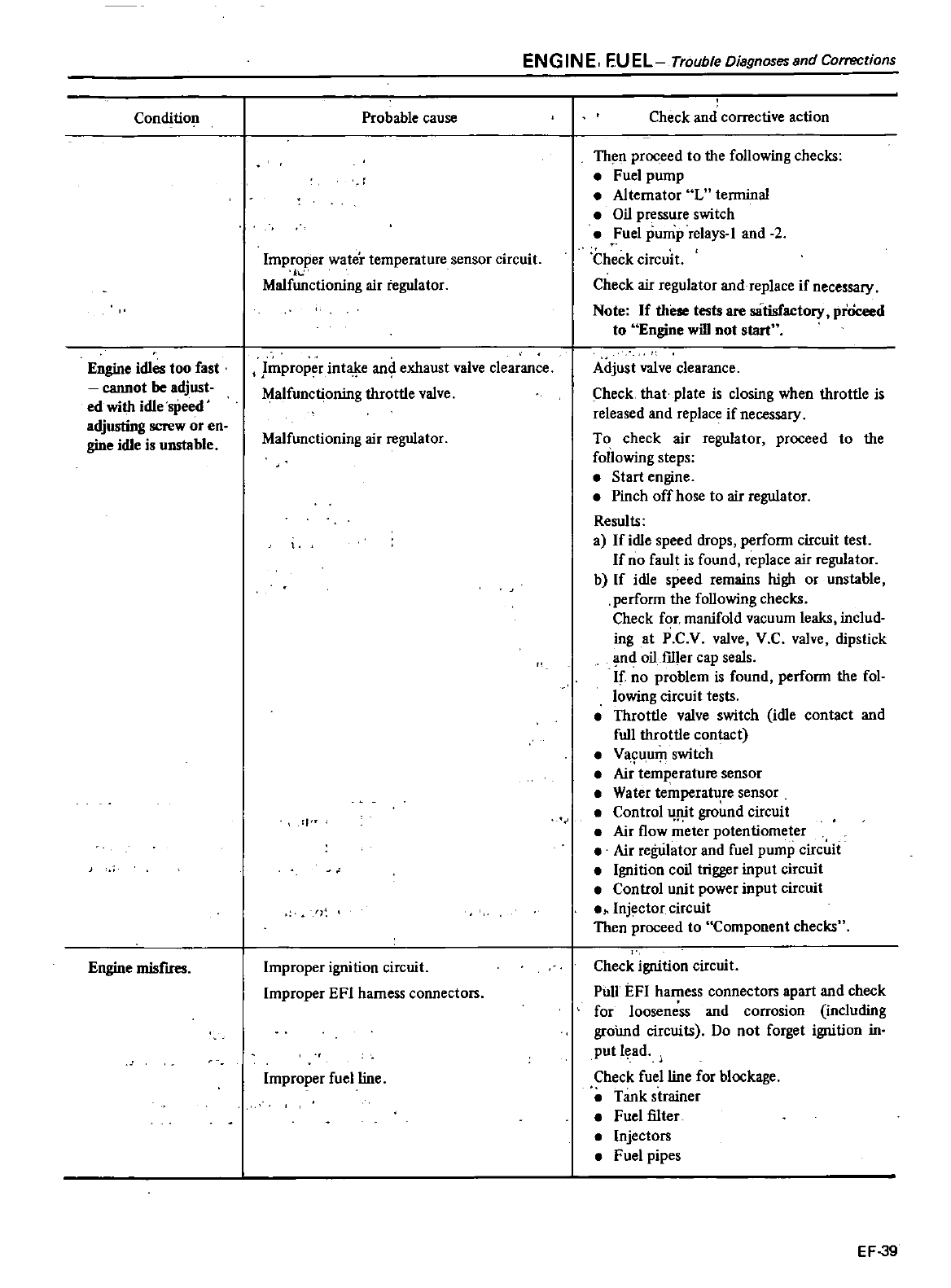
Condition
Engine
idles
too
fast
cannot
be
adjust
ed
with
idle
speed
adjusting
screw
or
en
gine
idle
is
unstable
Engine
misfIres
ENGINE
EUEL
Trouble
Dia9nosessnd
Corrections
Probable
cause
Improper
wate
temperature
sensor
circuit
iI
Malfunctioning
air
regulator
Improper
intaJ
e
an
exhaust
valve
clearance
Malfunctioning
throttle
valve
Malfunctioning
air
regulator
rJ
r
l
Improper
ignition
circuit
Improper
EFI
harness
connectors
Improper
fuel
line
Check
and
corrective
action
Then
proceed
to
the
following
checks
Fuel
pump
Alternator
L
tenninal
Oil
pressure
switch
Fuel
pump
relays
I
and
2
Check
circuit
Check
air
regulator
and
replace
if
necessary
Note
If
these
tests
are
satisfactory
prOceed
to
Engine
will
not
start
Adjust
valve
clearance
Check
that
plate
is
closing
when
throttle
is
released
and
replace
if
necessary
To
check
air
regulator
proceed
to
the
following
steps
Start
engine
Pinch
off
hose
to
air
regulator
Results
al
If
idle
speed
drops
perfonn
circuit
test
If
no
fault
is
found
replace
air
regulator
b
If
idle
speed
remains
high
or
unstable
perfonn
the
following
checks
Check
for
manifold
vacuum
leaks
includ
ing
at
P
CV
valve
V
C
valve
dipstick
nd
oil
f1ller
cap
seals
If
no
problem
is
found
perfonn
the
fol
lowing
circuit
tests
Throttle
valve
switch
idle
contact
and
full
throttle
contact
Va
9u
urp
switch
Air
temperature
sensor
Water
temperature
sensor
Control
Jtit
ground
circuit
Air
flow
meter
potentiometer
Air
regwator
and fuel
pump
circuit
Ignition
coil
trigger
input
circuit
Control
unit
power
input
circuit
1
Inj
ctor
circuit
Then
proceed
to
Component
checks
Check
ignition
circuit
Pull
EFI
harness
connectors
apart
and
check
for
looseness
and
corrosion
including
groimd
circuits
Do
not
forget
ignition
in
put
lead
Check
fuel
line
for
blockage
Tank
strainer
Fuel
filter
Injectors
Fuel
pipes
EF
39
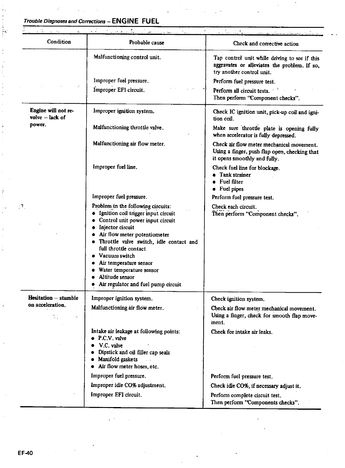
Trouble
Oisgnosesand
Corrections
ENGINE
FUEL
Condition
Engine
will
not
re
volve
lack
of
power
Hesitation stumble
on
acceleration
EF
40
Probable
cause
Malfunctioning
control
unit
Improper
fuel
pressure
improper
EFI
circuit
Lor
t
f
ignition
system
Malfunctioning
throttle
valve
Malfunctioning
air
flow
meter
Improper
fuel
line
Improper
fuel
pressure
Problem
in
the
followiIlg
circuits
Ignition
coil
trigger
input
circuit
Control unit
power
input
circuit
Injector
circuit
Air
flow
meter
potentiometer
Throttle
valve
switch
idle
contact
and
full
throttle
contact
Vacuum
switch
Air
temperature
sensor
Water
temperature
sensor
Altitude
sensor
Air
re
ator
and fuel
pump
circuit
Improper
ignition
system
Malfunctioning
air
flow
meter
Intake
air
leakage
at
following
points
P
C
V
valve
V
C
valve
Dipstick
and
oil
filler
cap
seals
Manifold
gaskets
Air
flow
meter
hoses
etc
Improper
fuel
pressure
Improper
idle
CO
ll
adjustment
Improper
EFI
circuit
Check
and
corrective
action
Tap
control
unit
while
driving
to
see
if
this
aggravates
or
aIleviates
the
problem
If
so
try
another
control
unit
Perfonn
fuel
pressure
test
Perfonn
all
circuit
tests
Then
perfonn Component
checks
Check
IC
ignition
unit
pick
up
coil
and
igni
tion
coil
Make
sure
throttle
plate
is
opening
fully
when
accelerator
is
fuI1ydepressed
Check
air
flow
meter
mechanical
movement
Using
a
finger
push
flap
open
checking
that
it
opens
smoothly
and
fully
Check
fuel
line
for
blockage
Tank
strainer
Fuel
fdter
Fuel
pipes
Perfonn
fuel
pressure
test
Check
each
circuit
Thin
perfonn
Component
checks
Check
ignition
system
Check
air
flow
meter
mechanical
movement
Using
a
finger
check
for
smooth
flap
move
ment
Check
for
intake
air
leaks
Perfonn
fuel
pressure
test
Check
idle
CO
ll if
necessary
adjust
it
Perfonn
complete
circuit
test
Then
perfonn
Components
checks
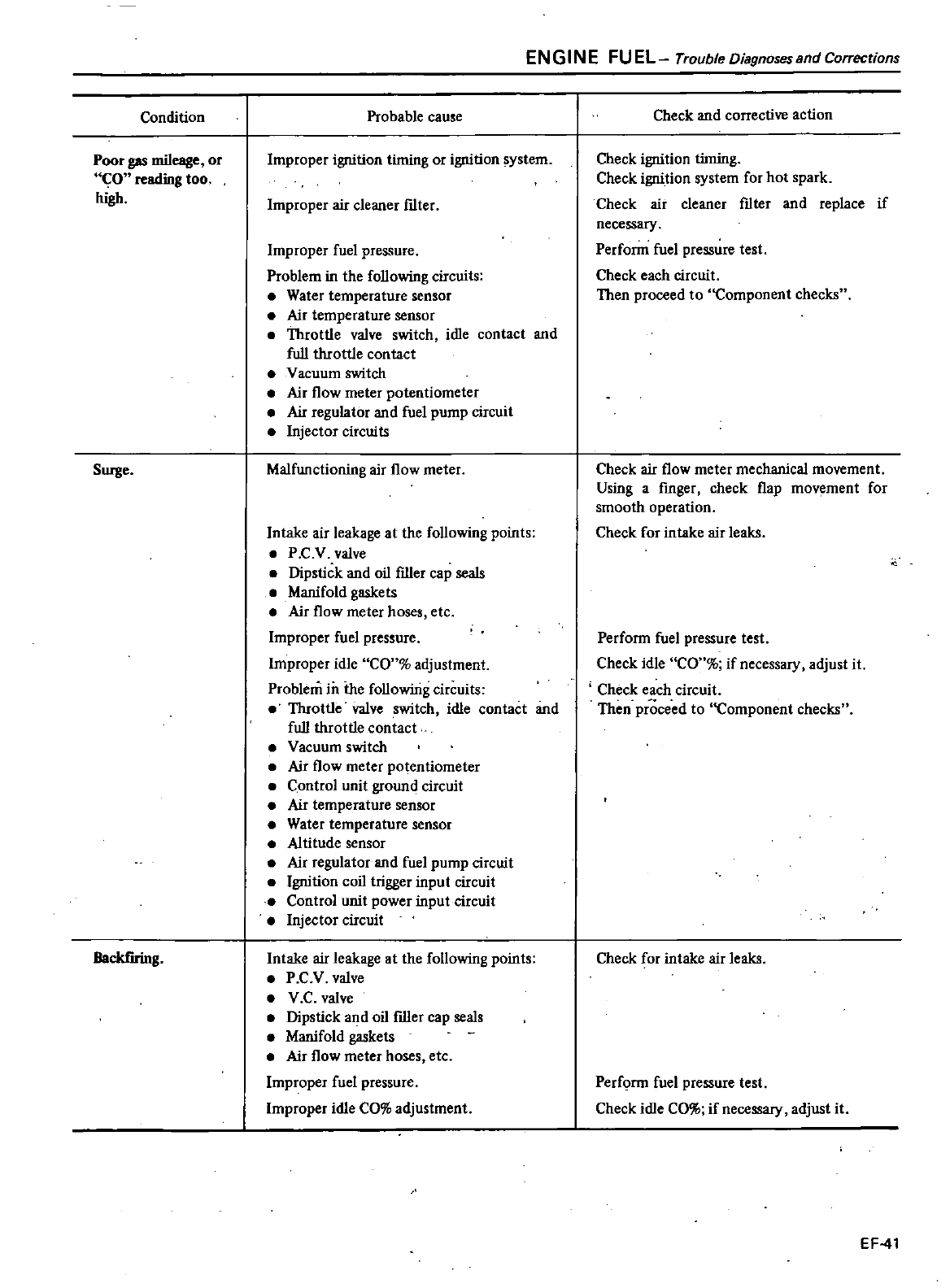
Condition
Poor
gas
mileage
or
CO
reading
too
high
Surge
Backf
uing
ENGINE
FUEL
Trouble
Diagnoses
and
Corrections
Probable
cause
Improper
ignition
timing
or
ignition
system
Improper
air
cleaner
f1lter
Improper
fuel
pressure
Problem
in
the
following
circuits
Water
temperature
sensor
Air
temperature
sensor
Throttle
valve
switch
idle
contact
and
full
throttle
contact
Vacuum
switch
Air
flow
meter
potentiometer
Air
regulator
and fuel
pump
circuit
Injector
cirelli
ts
Malfunctioning
air
flow
meter
Intake
air
leakage
at
the
following
points
P
C
v
valve
Dipstick
and
oil
ftller
cap
seals
Manifold
gaskets
Air
flow
meter
hoses
etc
Improper
fuel
pressure
Improper
idle
CO
adjustment
Problem
in
the
followirig
circuits
Throttle
valve
switch
idle
contact
and
full
throttle
contact
Vacuum
switch
Air
flow
meter
potentiometer
Control
unit
ground
circuit
Air
temperature
sensor
Water
temperature
sensor
Altitude
sensor
Air
regulator
and fuel
pump
circuit
Ignition
coil
trigger
input
circuit
Control
unit
power
input
circuit
Injector
circuit
Intake air
leakage
at
the
following
points
P
C
V
valve
V
C
valve
Dipstick
and
oil
ftller
cap
seals
Manifold
gaskets
Air
flow
meter
hoses
etc
Improper
fuel
pressure
Improper
idle
CO
adjustment
Check
and
corrective
action
Check
ignition
timing
Check
ignition
system
for
hot
spark
Check
air
cleaner
f1lter
and
replace
if
necessary
Perfonn
fuel
pressure
test
Check
each
circuit
Then
proceed
to
Component
checks
Check
air
flow
meter
mechanical
movement
Using
a
fmger
check
flap
movement
for
smooth
operation
Check
for
intake
air
leaks
Perfonn
fuel
pressure
test
Check
idle
CO
if
necessary
adjust
it
Check
each
circuit
Then
proceed
to
Component
checks
Check
for
intake
air
leaks
Perf
nn
fuel
pressure
test
Check
idle
CO
if
necessary
adjust
it
EF
41
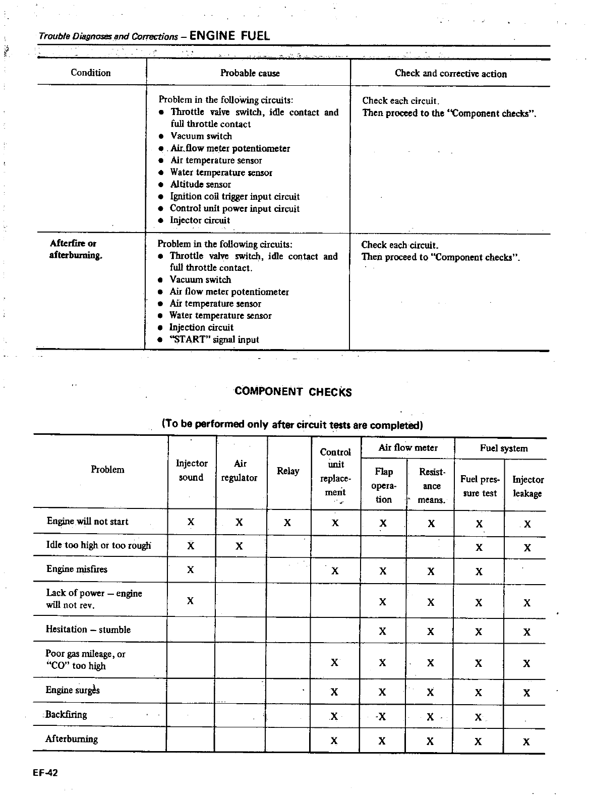
Trouble
Diagnoses
and
Corrections
ENGINE
FUEL
Condition
Probable
cause
Problem
in
the
folloWing
circuits
e
Throttle
valve
switch
idle
contact
and
fulllhrottle
contact
Vacuum
switch
e
Aidlow
meter
potentiometer
Air
temperature
sensor
e
Water
temperature
sensor
Altitude
sensor
e
Ignition
coil
trigger
input
circuit
e
Control
unit
power
input
circuit
e
Injector
circuit
Afterfire
or
a
g
Problem
in
the
following
circuits
Throttle
valve
switch
idle
contact
and
fulllhrottle
contact
Vacuum
switch
e
Air
flow
meter
potentiometer
Air
temperature
sensor
Water
temperature
sensor
Injection
circuit
e
START
signal
input
Check
and
corrective
action
Check
each
circuit
Then
proceed
to
the
Component
checks
Check
each
circuit
Then
proceed
to
Component
checks
COMPONENT
CHECKS
To
be
performed
only
after
circuit
tests
are
completed
Control
Air
flow
meter
Fuel
system
Problem
Injector
Air
unit
Flap
Relay
Resist
sound
regulator
replace
Fuel
pres
Injector
opera
ance
leakage
ment
sure
test
tion
means
Engine
will
not
start
XX
I
X
XX
X X X
Idle
too
high
or
too
rougli
XX
I
XX
Engine
misfires
X
I
XX X X
Lack
of
power
engine
XXX X X
will
not
rev
Hesitation
stumble
XXXX
Poor
gas
mileage
or
X
X X
X
X
CO
too
high
Engine
surgAs
I I
XXXXX
Backfiring
II
XXXX
Afterbuming
II
X
XX
X
X
EF
42
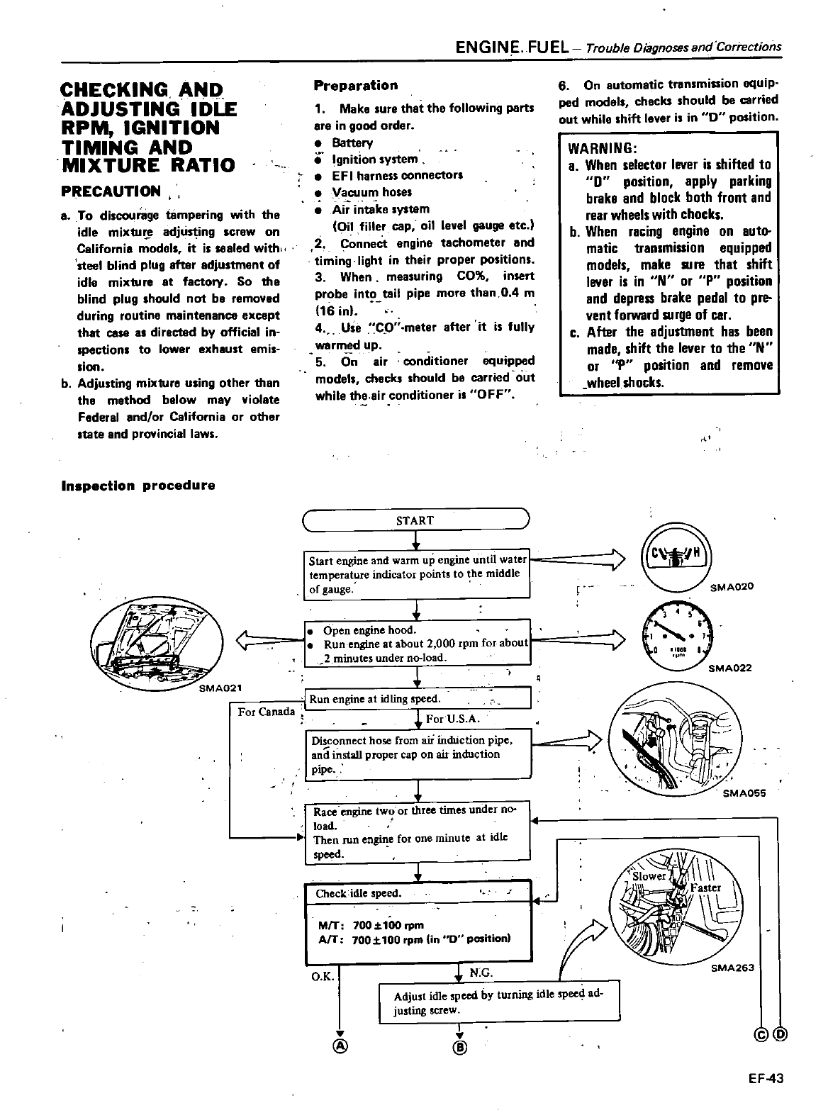
CHECKING
AND
ADJUSTING
IDLE
RPM
IGNITION
TIMING
AND
MIXTURE
RATIO
PRECAUTION
a
To
discourage
tlImpering
with
the
idle
mixtu
adjus1
ing
screw
on
California
model
it
is
sealed
withH
steel
blind
plug
attar
adjustment
of
idle
mixture
at
factory
So
the
blind
plug
should
not
be
removed
during
routine
maintenance
except
that
case
as
directed
by
official
in
spection
to
lower
exhaust
emis
sion
b
Adjusting
mixture
uling
other
than
the
method
below
may
violate
federal
and
or
California
or
other
tate
and
provincial
laws
Inspection
procedure
EN
GIN
E
FU
EL
Trouble
Diagnoses
and Corrections
Preparation
1
Make
sure
that the
following
parts
are
in
good
order
Battery
e
gnition
system
E
F
I
harness
connectors
Vacuum
hoses
Ai
intake
system
Oil
filler
cap
oil
level
gauge
etc
2C
onnect
engine
tachometer
and
timing
light
in
their
proper
positions
3
When
measuring
CO
insert
probe
int
tail
pipe
more
than
0 4
m
16
inl
4
Use
CO
meter
after
it
is
fully
warm
d
up
5
On
air
conditioner
equipped
models
checks
should
be
carried
out
while
the air
conditioner
i
OFF
START
Start
engine
and
warm
up
engine
until
waL
temperature
indicator
points
to
he
middle
of
gauge
Open
engine
hood
Run
engine
at
about
2
000
rpm
for
about
2
minutes under
no
load
SMA021
1
Run
engine
at
idling
speed
For
Canada
I
u
S
A
For
Disconnect
hose
from aii
indUction
pipe
and
install
proper
cap
on
air
induction
pipe
t
Race
engine
two
or
three
times
under
no
load
Then
run
e e
for
one
minute
at
idle
speed
Check
idle
speed
MfT
700
z
tOO
rpm
AfT
700
t
100
rpm
Un
0
position
O K
N G
6
On
automatic
transmission
equip
pad
models
checks
should
be
carried
out
while
shift
lever
is
in
0
position
WARNING
a
When
selector
lever
is
shifted
to
0
position apply parking
brake
and
block
both
front
and
rear
wheels
with
chocks
b
When
racing
engine
on
auto
matic
transmission
equipped
models
make
Rife
that
shift
lever
is
in
N
or
Pposition
and
depress
brake
pedal
to pre
vent
forward
RI
rge
of
car
c
After
the
adjuS1ment
has
been
made
shift
the
lever
to
the
N
or
P
position
and
remove
wheel
shocks
S
M
f
SMA263
Adjust
idle
speed
by turning
idle
spee4
ad
justing
screw
I
@
@
@
EF
43
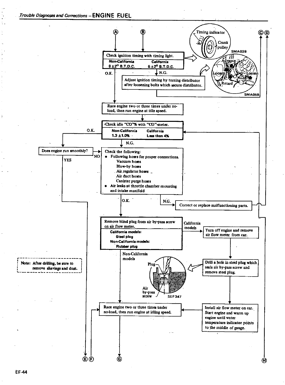
Trouble
Diagno
eund
Cof1l
Ctions
ENGINE
fUEL
I
Does
engine
run
smoothly
YES
r
I
Note
Alter
drilling
be
ure
to
I
remove
dlaviDgs
and
dUll
L
1
EF
44
@U
jiJ
@
@@
OIeck
ignition
timing
with
timing
Ught
Nol1
Cllifomia
Californil
a
zo
a
T
D C
6
ZO
B
T D C
O K
J
N
G
I
Adjust
ignition
timing
by turning
distributor
I
aftedoosening
bolts
which
secure
distributor
I
Race
engine
two
or
three
times
under
n
load
then
run
engine
at
idle
Ipced
r
O K
I
N
G
I
f
0Ieclr
idle
CO
with
CO
meter
O K
Non
C
liforni
C
lifornia
t
31
1
0
less
than
4
I
N
G
OIeck
the
following
Following
hoses
for
proper
connections
VaCWlm
hoses
Blow
by
hoses
Air
regulatOJ
hOle
Air
duct
hoses
Canister
purge
hoses
Air
leaks
at
throttle
chamber
mounting
and
intake
manifold
Remove
blind
plug
from air
by
PUl
SCItW
on
air
flow
meter
Californi
models
Steel
plug
Non
califomia
models
Rubber
plug
Noii
canrornia
models
Race
engine
two
or
tluee
times
under
no
load then
run
engine
at
idling
speed
@
SMA059
Correct
or
replace
malfunctioning
parts
California
models
I
Turn
off
engme
and
remove
air
flow
meter
from
cu
t
Drill
a
hoJi
in steel
plug
wbich
seab
air
by
pass
screw
and
remove
steel
plug
r
Imta11
air
flow
meter
on car
Start
engine
and
warm
up
engine
until
ter
temperature
indicator
pOints
to e
middle
of
gauge
@
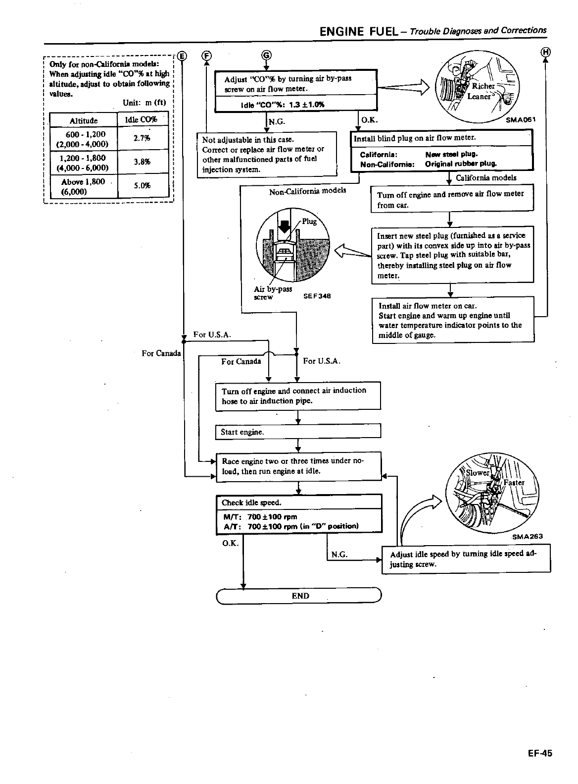
Only
for
non
owrOtnia
models
When
adjUltina
idle
CO
at
high
altitude
adjust
to
obtain
foUowing
val
Unit
m
ft
I
Altitude
Idle
CO
I
600
1
200
2
7
2
000
4
000
I
1
200
1
800
38
4
000
6
000
iI
Above
1
800
5
0
6
000
For
Canada
n
ENGINE
FUEL
Trouble
Disgnosesand
Correcrions
n
cp
Adjust
CO
by turning
air by
pass
screw
on ai
r
flow
meter
Idle
CO
1
3
1
0lI
IN
G
Not
adjustable
in
this
case
Comct
or
replace
air
flow
meter
or
other
malfunctioned
parts
of
fuel
injection
SYstem
Non
alifornia
models
Air
by
pass
screw
SE
F348
For
U
S
A
For
Canada
I
For
U
SA
Turn
off
engine
and
connect
air
induction
hose
to
air
induction
pipe
I
Start
engine
t
Race
engine
two
or
three
times
under
no
J
load
then
run
engine
at
idle
L
Oleck
idle
speed
MfT
7OO
100rpm
AfT
700
1
100
rpm
in
0
position
O
K
I
N G
END
I
O
K
@
SMA061
Install
blind
plug
on
air
flow
meter
I
California
Non
Calitom
e
HIM
steel
plug
Original
rubber
plug
California
models
Turn
off
engine
and
remove
air
flow
meter
from
Cat
I
Insert
new
steel
plug
fumi
hed
as a
service
part
with
its
convex
aide
up
into
air
by
pass
screw
Tap
steel
plug
with
suitable
bar
thereby
inltalling
steel
plug
on
air
flow
meter
I
Install
air
flow
meter
on
Cat
Start
engine
and
warm
up
engine
until
water
temperature
indicator
points
to
the
middle
of
gauge
L
r
Adjust
idle
speed
by turning
idle
speed
ad
justing
screw
EF
45
DATSUN
200SX
Model
S
r r
0
Series
SECTIONEC
EMiSSiON
CONTROL
SYSTEM
CONTENTS
EMISSION
CONTROL
DEVICES
GENERAL
DESCRIPTION
CRANKCASE
EMISSION
CONTROL
SYSTEM
DESCRIPTION
INSPECTION
EXHAUST
EMISSION
CONTROL
SYSTEM
DESCRIPTION
AIR
INDUCTION
SYSTEM
A
I
Sl
EXHAUST
GAS
RECIRCULATION
E
G
R
l
CONTROL
SYSTEM
EC
2
EC
3
EC
5
EC
5
EC
5
EC
6
EC
6
EC
6
EC
9
SPARK
TIMING
CONTROL
SYSTEM
DECELERATION
CONTROL
SYSTEM
I
lntake
manifold
vacuum
control
type
CATALYTIC
CONVERTER
EVAPORATIVE
EMISSION
CONTROL
SYSTEM
DESCRIPTION
OPERATION
INSPECTION
SERVICE
DATA
AND
SPECIFICATIONS
TIGHTENING
TORQUE
EC
15
EC1
EC
17
EC19
EC19
EC
20
EC
21
EC
23
EC
23
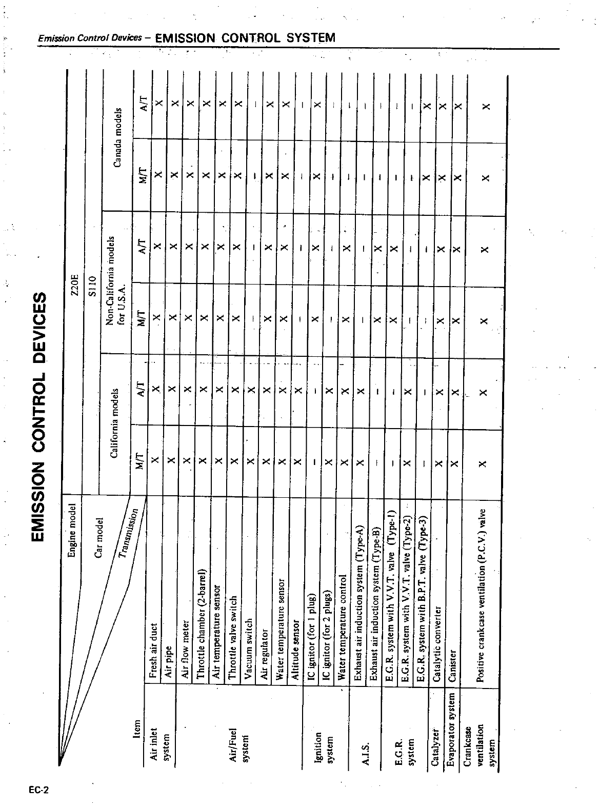
Pl
EMISSION
CONTROL
DEVICES
i
o
Engine
model
Z20E
SIlO
Car
model
a
Non
California
models
California
models
Canada
models
li
for
U
s
A
a
Item
M
T
A
T
M
T
A
T
M
T
A
T
I
Air
inlet
Fresh
air
duct
X
X
X
X
X
X
m
system
Air
pipe
X
X
X
X
X
X
Cii
Air
flow
meter
X
X
X
X
X
X
C
l
Throttle
chamber
2
barrel
X
X
X
X
X
X
5
Z
Air
temperature
sensor
X
X
X
X
X
X
C
Air
Fuel
Throttle
valve
switch
X
X
X
X
X
X
0
Z
system
Vacuum
switch
X
X
I
0
Air
regulator
X
X
X
X
X
X
0
r
Water
temperature
sensor
X
X
X
X
X
X
C
l
Altitude
sensor
X
X
C
l
IC
ignitor
for
I
plug
X
X
X
X
I
Ignition
m
system
IC
ignitor
for
2
plugs
X
X
3
Water
temperature
control
X
X
I
X
X
Exhaust
air
induction
system
Type
A
X
X
A
I
S
Exhaust
air
induction
system
Type
B
X
X
E
G
R
system
with
V
V
T
valve
Type
1
X
X
E
G
R
E
G
R
system
with
V
V
T
valve
Type
2
X
X
system
E
G
R
system
with
B
P
T
valve
Type
3
X
X
Catalyzer
Catalytic
converter
X
X
X
X
X
X
Evaporator
system
Canister
X
X
X
X
X
X
Crankcase ventilation
Positive
crankcase
ventilation
P
C
V
valve
X
X
X
X
X
X
system
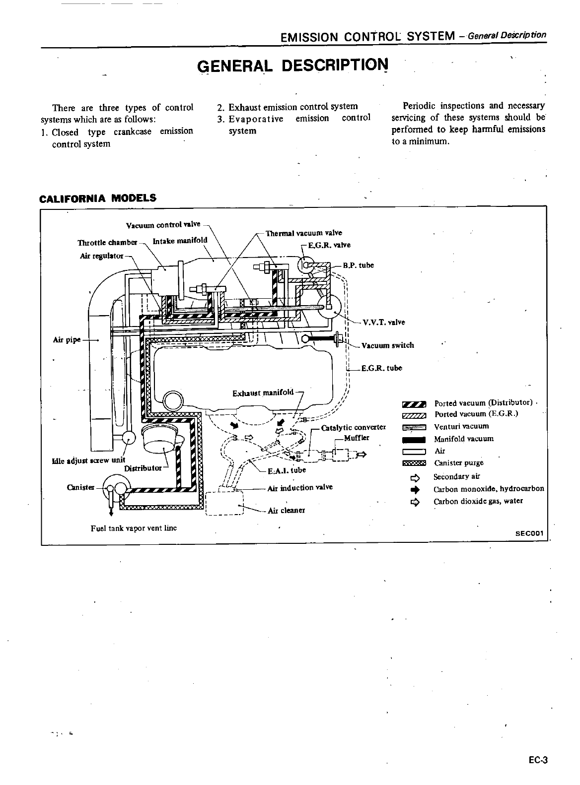
EMISSION CONTROL SYSTEM
General
DeScription
ENERAL
DESCRIPTION
There
are
three
types
of
control
systems
which
are
as
follows
1
Closed
type
crankcase
emission
control
system
2
Exhaust
emission
control
system
3
Evaporative
emission
control
system
Periodic
inspections
and
necessary
servicing
of
these
systems
should
be
perfonned
to
keep
hannful
emissions
to
a
minimum
CALIFORNIA
MODELS
Vacuum
control
valve
Throttle
chamber
lntake
manifold
Airregulator
01IL
IT
11
1
en
I
I
Airpipe
i
I
T
n
f
i
rr
J
u
c
j
tP
Catalytic
convert
r
j
i
f
o
C
r
I
Ii If
1
Idle
adjust
a
ew
umt
lj
r
Distributor
i
f
A
I
tube
Canister
l
L
Air
induction
valve
J
Ail
cleaner
Thermal
vacuum
valve
Ported
vacuum
Distributor
Ported
vacuum
EG
R
Air
Venturi
vacuum
Manifold
vacuum
Q
0
Canister
purge
Secondary
air
Carbon
monoxide
hydrocarbon
Carbon
dioxide
gas
water
Fuel
tank
vapor
vent
line
BEeoo
EC
3
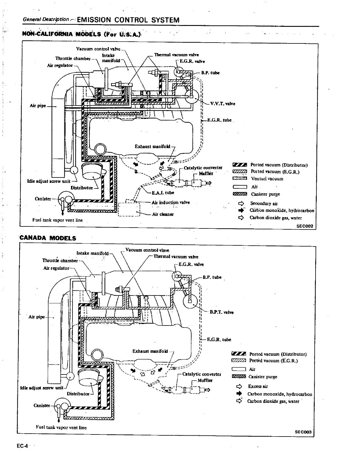
General
De
Cription
EMISSION
CONTROL SYSTEM
NoN
CALIFORNIA
MODELS
For
U
S
A
Vacuum
control
valve
Intau
Thenn2
ftOUum
valve
Throttlechamber
mmifOId
G
R
ntve
Airregulator
r
ta
H
BP
tube
ell
I
n
il
b
i
1
II
VV
T
Valve
Air
pipe
0
f
I
I
raL
I
1
I
no
l
Tv
1J
J
E
G
R
tube
I
JI
J
t
J
l
u
1
b
J
S
II
t
C2Wytic
cooverler
II
C
MalfIOr
t
ldIeadjusls
unit
f
f
J
Distributor
r
t
EA
I
lube
Omister
y
f
dL
Air
mducti
valve
1
J
Air
cleaner
Fuel
tank
vapor
vent
line
CANADA MODELS
Intake
manif
ld
acuum
con
t
vacuum
vaIve
Throttle
chamber
E
GR
val
n
i
ii
M
pipe
1
kL
Ji
1
J
BP
T
val
J
II
I
II
I
E
GR
tube
7
1
gr
21
r
r
ta
yticcon
rter
Y
JA
J
Muffier
Idle
adjust
saew t
II
t
1t
1
J
F
Distributor
Canister
Fuel
tank
vapor
vent
line
EC
4
1
Ported
vacuum
Distributor
Porled
vacuum
E
G
R
Venturi
vacuum
Air
Canister
purge
Q
Q
Secondary
air
Oirbon
monoXide
hydrocarbon
Carbon
dioxide
gas
water
SECOO2
Ported
vacuum
Distributor
Ported
vacuum
E
G
R
Air
Canister
purge
Q
9
Exces
sair
Carbon
monoxide
hydrocarbon
Cubon
dioxide
gas
water
SECOO3
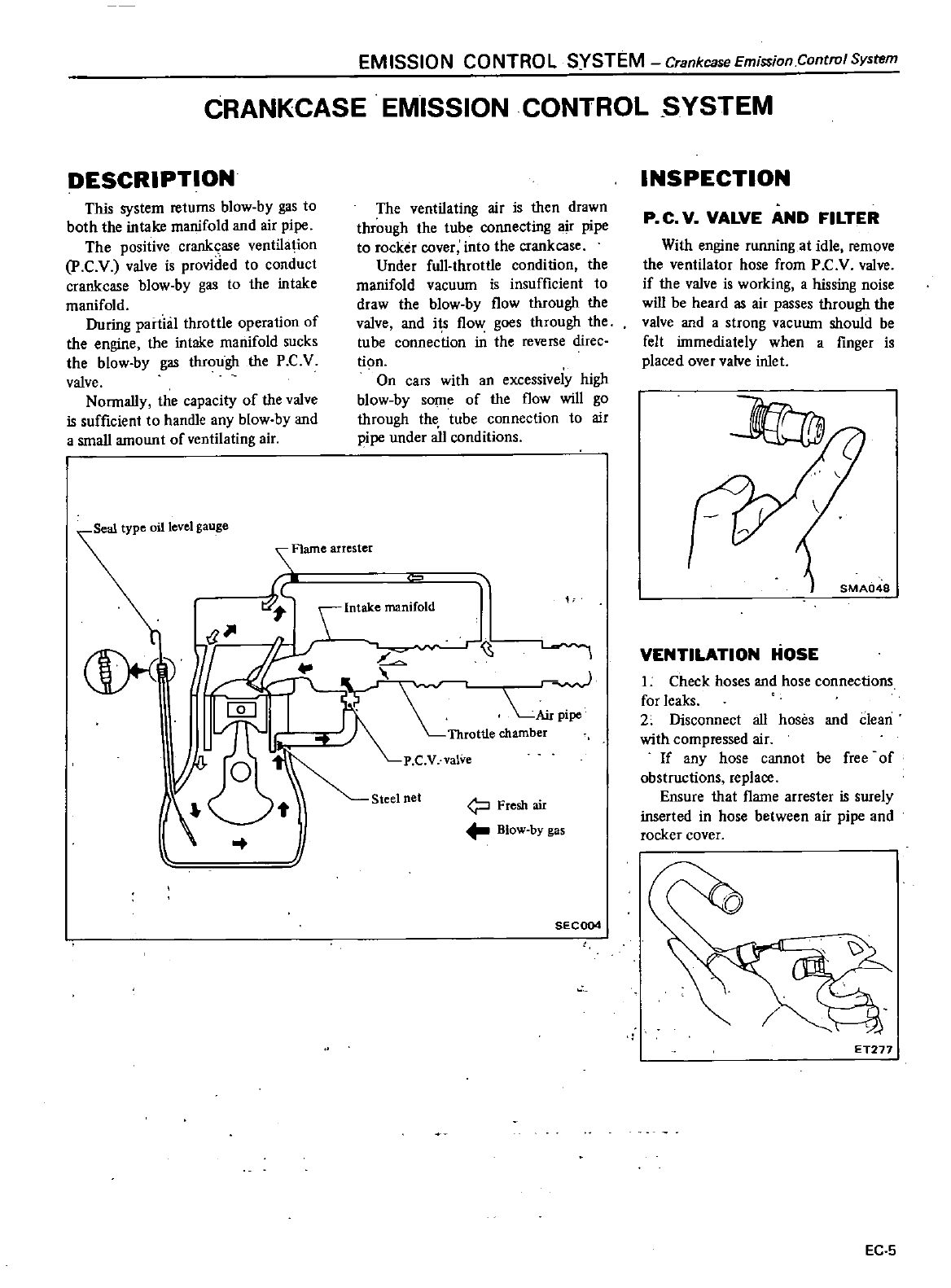
EM
ISSION
CONTRO
L
SYSTEM
Crankcase
Emission
Control
System
CRANKCASE
EMISSION
CONTROL
SYSTEM
DESCRIPTION
Tills
system
returns
blow
by
gas
to
both
the intake
manifold
and
air
pipe
The
positive
crankcase
ventilation
P
C
V
valve
is
provided
to
conduct
crankcase
blow
by
gas
to
the
intake
manifold
During
partial
throttle
operation
of
the
engine
the
intake
manifold
sucks
the
blow
by
gas through
the
P
C
V
valve
Nonnally
the
capacity
of
the
valve
is
sufficient
to
handle
any
blow
by
and
a
small
amount
of
ventilating
air
Seal
type
oil
level
gauge
The
ventilating
air
is
then
drawn
through
the
tube
connecting
air
pipe
to
rocker
cover into
the
crankcase
Under
full
throttle
condition
the
manifold
vacuwn
is
insufficient
to
draw
the blow
by
flow
through
the
valve and
its flow
goes
through
the
tube
connection
in
the
reverse
diIee
lion
On
cars
with
an
excessiveiy
high
blow
by
some
of
the
flow
will
go
through
the
tube
connection
to
air
pipe
under
all
conditions
Flame
arrester
iC
Intake
manifold
J
v
l
T
r
J
Air
L
pipe
R
Throttle
chamber
P
C
V
valve
Steel
net
Fresh
air
Blow
by
gas
SECOO4
INSPECTION
p
C
V
VALVE
AND
FILTER
With
engine
running
at
idle
remove
the
ventilator
hose
from
P
C
V
valve
if
the
valve
is
working
a
hissing
noise
will
be
heard
as
air
passes
through
the
valve
and
a
strong
vacuum
should
be
felt
immediately
when
a
finger
is
placed
over
valve
inlet
VENTILATION
HOSE
1
Check
hoses
and
hose
connections
for
leaks
2
Disconnect
all
hoses
and
dean
with
compressed
air
If
any
hose
cannot
be
free
of
obstructions
replace
Ensure
that
flame
arrester
is
surely
inserted
in
hose
between
air
pipe
and
rocker
cover
ET277
EC
5
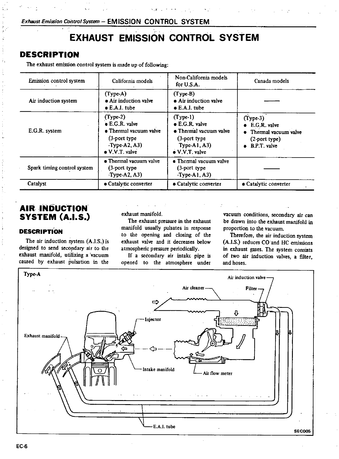
ExhaurtEmission
Control
System
EM
ISSION
CONTROL
SYSTEM
EXHAUST
EMISSION CONTROL
SYSTEM
DESCRIPTION
The
exhaust
emission
control
system
is
made
up
of
following
Emission
control
system
California
models
Air
induction
system
Type
A
Air
induction
valve
EA
tube
Type
2
E
G
R
valve
Thermal
vacuum
valve
3
port
type
TYpe
A2 A3
VV
Tvalve
Thermal
vacuum
valve
3port
type
Type
A2
A3
Catalytic
converter
E
G
R
system
Spark
timing
control
system
Catalyst
AIR
INDUCTION
SYSTEM
A I
S
Non
California
models
for
U
S
A
Type
B
Air
induction
valve
E
A
tube
Type
1
E
G
R
valve
Thennal
vacuum
valve
3
port
type
TYpe
A
I
A3
VV
T
valve
Thennal
vacuum
valve
3
port
type
Type
A
I
A3
Catalytic
converter
exhaust
manifold
The
exhaust
pressure
in
the
exhaust
manifold
usually
pulsates
in
response
to
the
opening
and
closing
of
the
exhaust
valve
and
it
decreases
below
atmospheric
pressure
periodically
If
a
secondary
air
intak
pipe
is
opened
to
the
atmosphere
under
DESCRIPTION
The
air
induction
system
A
I
S
is
designed
to
send
seco
dary
air
to
the
exhaust
manifold
utilizing
a
vacuum
caused
by
exhaust
pulsation
in
the
I
Type
A
Canada
models
Type
3
E
G R
valve
Thennal
vacuum
valve
2
port
type
BP
T
valve
Catalytic
converter
vacuum
conditions
secondary
air
can
be
drawn
into
the
exhaust
manifold
in
proportion
to
the
vacuum
Therefore
the
air
induction
system
A
I
S
reduces CO
and
HC
emissions
in
exhaust
gases
The
system
consists
of
two
air
induction
valves
a
filter
and
hoses
Aircleaner
cy
Injector
Wf
E
A
l
tube
EC
6
n
II
SECOO6
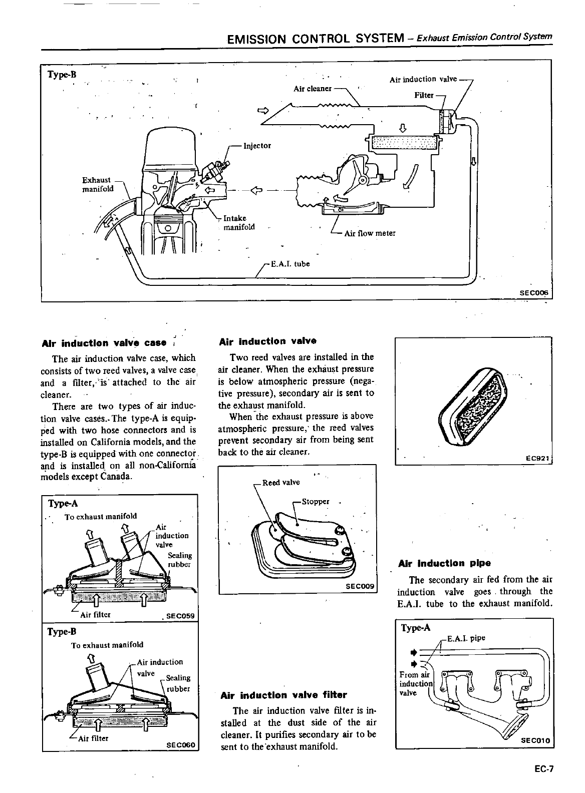
EM
ISSION
CO
NTROL
SYSTEM
Exhaust
Emission
Control
System
Type
B
Air
induction
valve
Air
cleaner
Filter
Exhaust
manifold
E
A
tube
SECOC
Air
induction
valve
Two
reed
valves
are
installed
in
the
air
cleaner
When the
exluiust
pressure
is
below
atmospheric
pressure
nega
tive
pressure
secondary
air
is
sent
to
the
exhaust
manifold
When
the
exhaust
pressure
is
above
atmospheric
pressure
the
reed
valves
prevent
secondary
air
from
being
sent
back
to
the
air
cleaner
Air
induction
valve
case
I
The
air
induction
valve
case
which
consists
of
two
reed
valves
a
valve
case
and
a
fIlter
is
attached
to
the
air
cleaner
There
are
two
types
of
air
induc
tion
valve
cases
The
type
A
is
equip
ped
with
two
hose
connectors
and
is
installed
on
California
models and
the
type
B is
equipped
with
one
connector
and
is
installed
on
all
non
Californla
models
except
Canada
EC921
Type
A
To
exhaust
manifold
1
Air
Induction
pipe
The
secondary
air
fed
from
the
air
induction
valve
goes
through
the
EA
tube
to
the
exhaust
manifold
SEC009
n
MO
Dlkwrtd
iillQl
Air
filter
SEC059
Type
A
rEAl
pipe
Z
From
air
induction
valve
Type
B
To
exhaust
manifold
Airinduction
valve
S
al
e
mg
rubber
1
LAirfi
er
SEC060
Air
induction
valve
filter
The
air
induction
valve
fIlter
is
in
stalled
at
the
dust
side
of
the
air
cleaner
It
purifies
secondary
air
to
be
sent
to
the
exhaust
manifold
EC
7
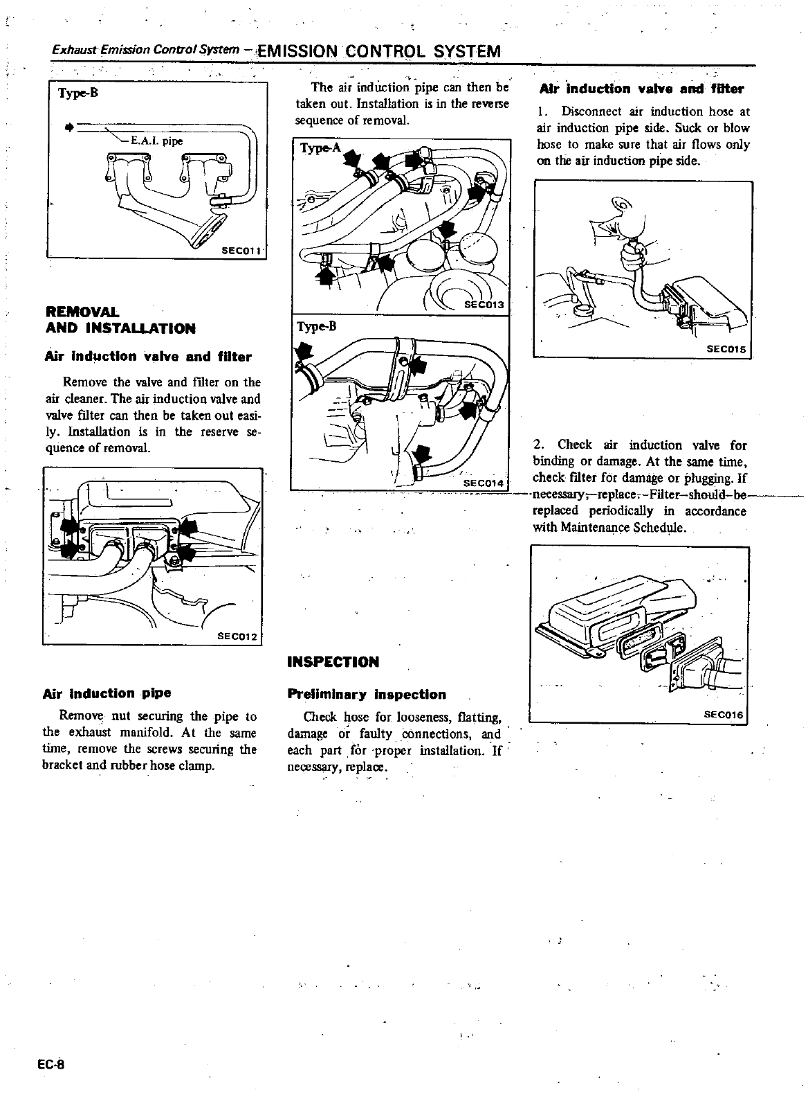
Exhaust
Emission
Control
System
EM
ISSION
CO
NTROL
SYSTEM
Type
B
E
A
I
pipe
REMOVAL
AND
INSTALLATION
Air
Induction
valve
and
filter
Remove
the
valve
and
fIlter
on
the
air
cleaner
The
air
induction
valve
and
valve
fIlter
can
then
be
taken
out
easi
ly
Installation
is
in
the
reserve
se
quence
of
removal
SECQ12
Air
Induction
pipe
Remove
nut
securing
the
pipe
to
the
exhaust
manifold
At
the
same
time
remove
the
screws
securing
the
bracket
and
rubber
hose
clamp
EC
8
The
air
induction
pipe
can
then
be
taken out
Installation
is
in
the
reverse
sequence
of
removal
Type
B
INSPECTION
Preliminary
Inspection
Check
hose
for
looseness
flatting
damage
or
faulty
connections
and
each
part
for
proper
installation
If
nere
ry
replare
AIr
induction
valve
and
fDter
I
Disconnect
air
induction
hose
at
air
induction
pipe
side
Suck
or
blow
hose
to
make
sure
that
air
flows
only
on
the
air
induction
pipe
side
SEC016
2
Check
air
induction
valve
for
binding
or
damage
At
the
same
time
check
fIlter
for
damage
or
plugging
If
necessary
replace
Filter
should
be
replaced
periodically
in
accordance
with
Maintenance
Schedule
SEC016
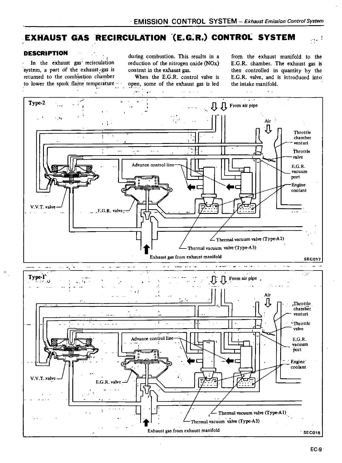
EM
ISSION
CO
NTROL
SYSTEM
Exhaust
Emission
Control
System
EXHAUST
GAS
RECIRCULATION E
G
R
CONTROL
SYSTEM
DESCRIPTION
I
In
the
exhaust
gas
recirculation
system
a
part
fthe
exhaust
gas
is
returned
to
the
combustion
chamber
to
lower
the
spark
flaine
temperature
Type
2
E G R
valve
Type
IL
l
E
G R
valve
during
combustion
This
results
in a
reduction
of
the
nitrogen
oxide
NOx
content
in the
exhaust
gas
When
the
E
G
R
control
valve
is
open
some
of
the
exhaust
gas
is
led
from
the
exhaust
manifold
to
the
E
G
R
chamber
The exhaust
gas
is
then
controlled
in
quantity
by
the
E
G
R
valve
and
is
introduced
into
the
intake
manifold
JJ
From
air
pipe
JT
II
1
All
n
o
Throttle
I
chamber
venturi
II
1
Throttle
valve
E
G
R
vacuum
port
r
Engine
coolant
Advance
oontrollinel
v
L
J
t
Exhaust
gas
from
exhaust
manifold
Thermal
vacuum
valve
Type
A2
L
Thermal
vacuum
valve
Type
A3
SEC017
D
rom
air
pipe
I
Air
0
Throt
e
chamber
venturi
I
I
Throttle
t
valv
e
E
G
R
vacuum
port
II
11
Ad
ance
controlline
Engine
coolant
T
0
r
If
L
J
I
L
Thermal
vacuum
valve
Type
AI
Thermal
vacuum
v
uve
Type
A3
Exhaust
gas
from
exhaust
manifold
SEC018
EC
9
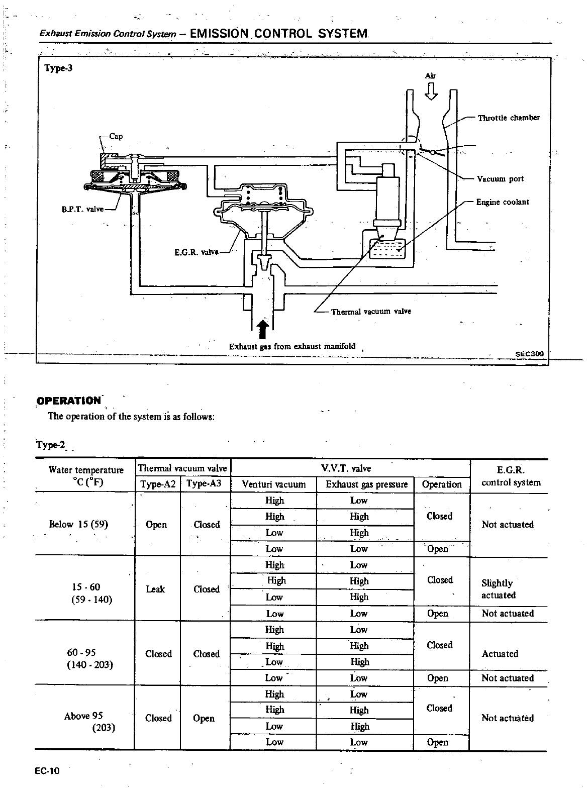
Exhaust
Emission
Control
System
EM
ISSION
CONTROL SYSTEM
Type
3
I
Air
I
I
lL
ro
I
LJ
Vacuum
port
I
r
Engine
coolant
L
Exhaust
gu
from
exhaust
manifold
SEC309
OPERATION
The
operation
of
the
system
is
as
follows
Type
2
Water
temperature
I
Thermal
vacuum
valve
V
V
T
valve
E
G R
Oc
oF
Type
A2
Type
A3
Venturi
vacuum
Exhaust
gas
pressure
Operation
control
system
High
Low
I
High
High
Closed
Below
15
59
Open
Closed
Not
actuated
I
Low
High
Low Low
Open
High
Low
15
60
J
High High
Closed
Slightly
Leak
Closed
59
140
I
Low
High
actua
ted
Low
Low
Open
Not
actuated
High
Low
High
High
Closed
60
95
Closed
Closed
Actuated
140
203
Low
High
Low Low
Open
Not
actuated
High
Low
High
High
Closed
Above
95
Closed
Open
Not
actuated
203
Low
High
Low Low
Open
EC
IO
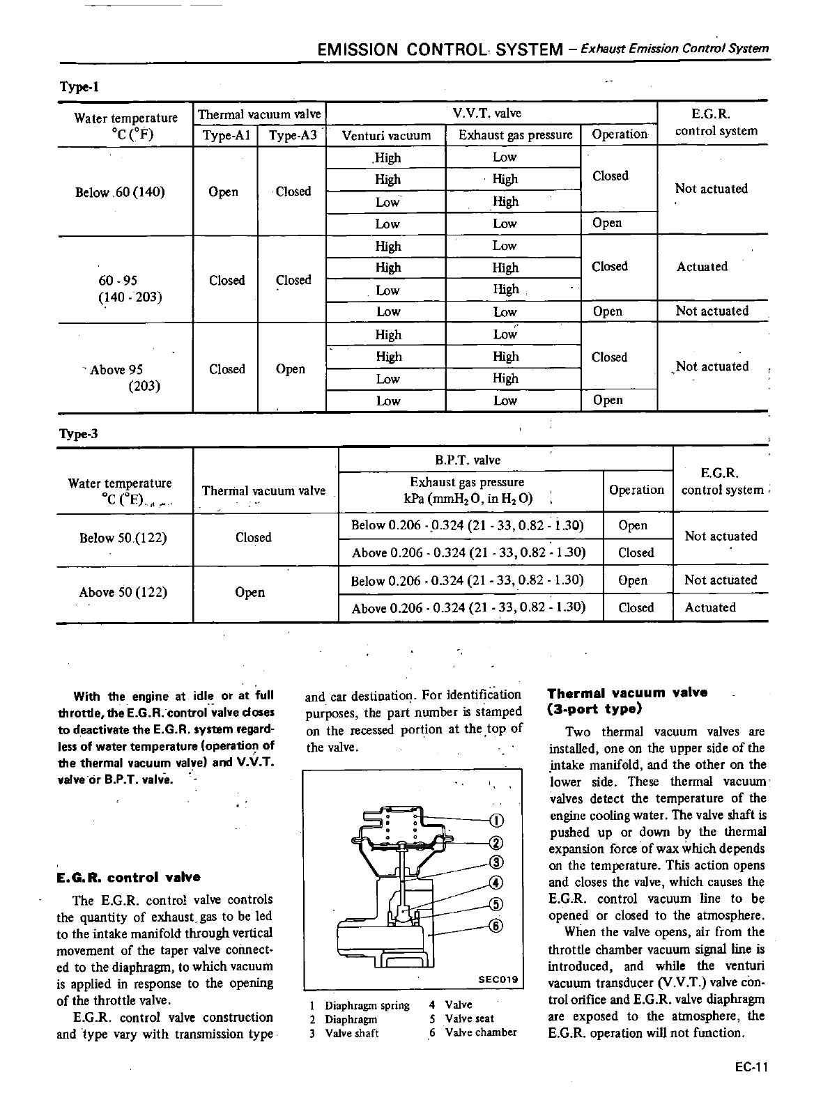
EM
ISSION
CONTROL
SYSTEM
Exhaust
Emission
Control
System
Type
I
Water
temperature
Thermal
vacuum
valve
V V
T
valve
E
G
R
Oc
eF
Type
Al
Type
A3
Venturi
vacuum
Exhaust
gas
pressure
Operation
control
system
High
Low
High
High
Closed
Below
60
140
Open
Closed
Not
actuated
Low
High
Low
Low
Open
High
Low
High
High
I
Closed
Actuated
60 95
Closed Closed
High
140
203
Low
Low
Low
Open
Not
actuated
High
Low
I
High High
Closed
Not
actuated
Above
95
Closed
Open
I
203
Low
High
1
Low
Low
Open
TYpe
3
1
BPT
valve
Water
temperature
Exhaust
gas
pressure
E
G
R
Thermal
vacuum
valve
Operation
control
system
Oc
em
kPa
mmHzO
inHzO
Below
0
206
0
324
21
33
0
82
i
30
Open
Below
50
122
Closed
Not
actuated
Above
0
206
0
324
21
33
0
82
1
30
Closed
Below
0
206
0
324
21
33
0
82
1
30
Open
Not
actuated
Above
50
122
Open
Above
0
206
0
324
21
33
0
82
1
30
Closed
Actuated
With the
engine
at
idle
or at
full
throttle
the
E
G
R
control
valve
doses
to
deactivate
the
E
G R
system
regard
less
of
water
temperature
operation
of
the
thermal
vacuum
valve
and
V
It
T
valve
or
B
P
T
valve
E
G R
control
valve
The E
G R
control
valve
controls
the
quantity
of
exhaust
gas
to
be
led
to
the intake
manifold
through
vertical
movement
of
the
taper
valve
connect
ed
to
the
diaphragm
to
which
vacuum
is
applied
in
response
to
the
opening
of
the
throttle
valve
E
G
R
control
valve
construction
and
type
vary
with
transmission
type
and
car
destinatiol
For
identification
purposes
the
part
number
is
stamped
on
the
recessed
portion
at
the
top
of
the
valve
G
d
I
I
ID
ur
I
SEC019
1
Diaphragm spring
2
Diaphragm
3
Valve
shaft
4
Valve
5
Valve
seat
6
Valve chamber
Thermal
vacuum
valve
3
port
type
Two
thermal
vacuum
valves
are
installed
one
on
the
upper
side
of
the
intake
manifold
and
the
other
on
the
lower
side
These
thennal
vacuum
valves
detect
the
temperature
of
the
engine
cooling
water
The
valve
shaft
is
pushed
up
or
down
by
the
thennal
expansion
force
of
wax
which
depends
on
the
temperature
This
action
opens
and
closes
the
valve
which
causes
the
E
G
R
control
vacuum
line to
be
opened
or
closed
to
the
atmosphere
When
the
valve
opens
air
from
the
throttle
chamber
vacuum
signal
line
is
introduced
and
while the
venturi
vacuum
transducer
V
V
T
valve
con
trolorifice
and
E
G R
valve
diaphragm
are
exposed
to
the
atmosphere
the
E
G R
operation
will
not
function
EC
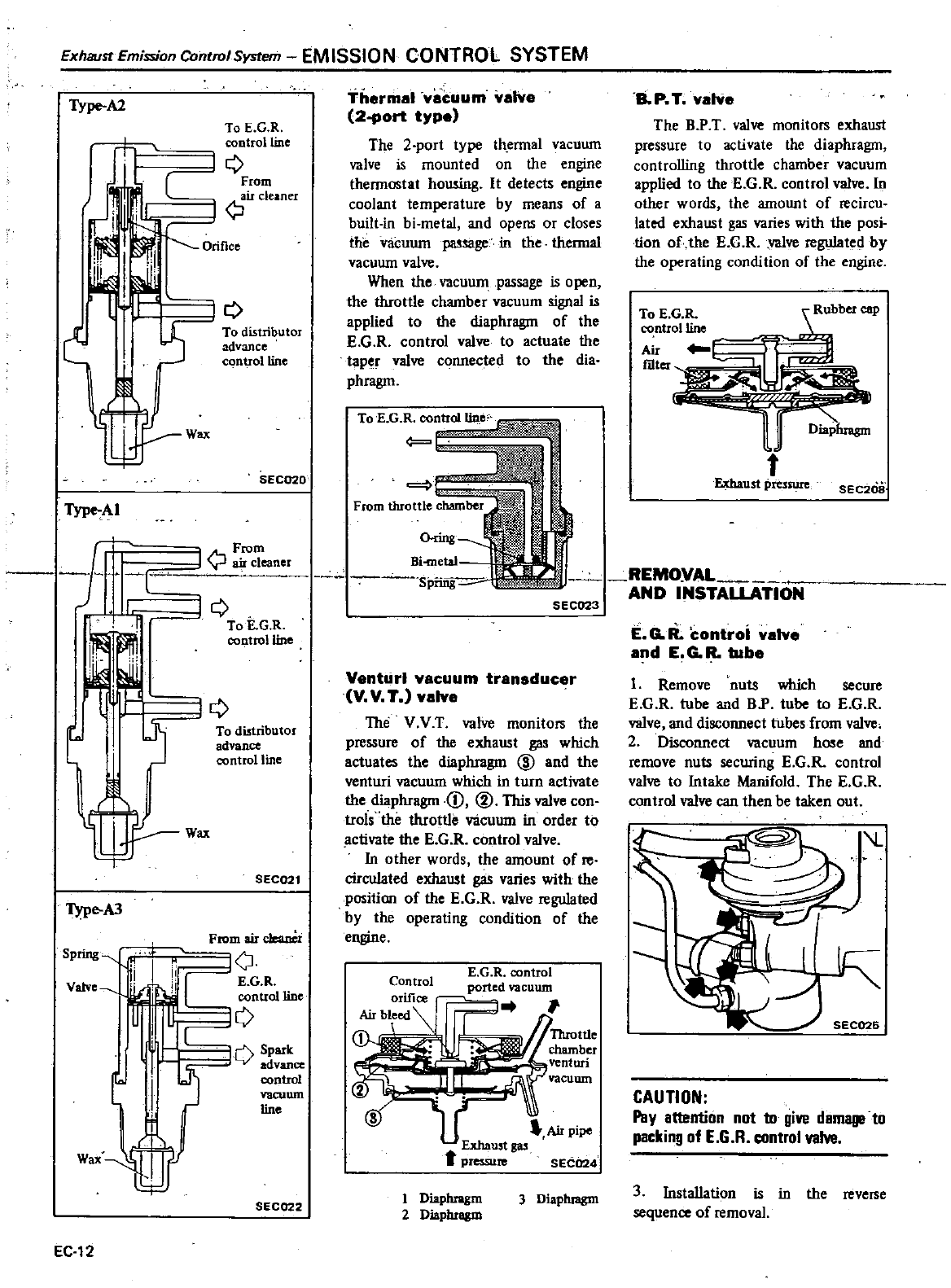
Exhaust
Emission
Control
System
EMISSION
CONTROL
SYSTEM
Type
A2
To
E
G
R
control
line
JQ
r
From
air
cleaner
JQ
Orifice
Q
Type
AI
1
1
n
I
O
j
1
Type
AJ
Spring
1
Ii
Vatve
I
T
Wax
EC
12
To
distributor
advance
control
line
Wax
SEC020
From
I
r
air
cleaner
Q
To
E
G R
control
line
IQ
To
distributor
advance
control
line
Wax
SEC021
From
air
c1eanCi
C
E
G R
control
line
Spark
advance
control
vacuum
line
SEC022
Thermal
vacuum
valve
2
port
type
The
2
port
type
thennal
vacuum
valve
is mounted
on
the
engine
thennostat
housing
It
detects
engine
coolant
temperature
by
means of
a
built
in
bi
metal
and
opens
or
closes
the
vacuum
pa
ge
in
the
thermal
vacuum
valve
When
the
vacuum
passage
is
open
the
throttle
chamber
vacuum
signal
is
applied
to
the
diaphragm
of
the
E
G
R
control
valve
to
actuate
the
per
valve
connected
to
the
dia
phragm
Bi
metal
Spiing
8
P T
valve
The
BP
T
valve
monitors
exhaust
pressure
to
activate
the
diaphragm
controlling
throttle
chamber
vacuum
applied
to
the
E
G
R
control
valve
In
other
words
the
amount
of
recircu
tated exhaust
gas
varies
with
the
posi
tion
of
the
E
G R
valve
regulated
by
the
operating
condition
of
the
engine
To
E
G
R
ubber
ClIp
control1ine
Air
f
Exhaust
pressure
SEC20a
SEC023
REMOVAL
AND
INSTALLATION
Venturi
vacuum
transducer
V V T valve
The
v
V
T
valve
monitors
the
pressure
of
the
exhaust
gas
which
actuates
the
diaphragm
@
and
the
venturi
vacuum
which
in
turn
activate
the
diaphragm
1
@
This
valve
con
trols
the
throttle vacuum
in
order
to
ctivate
the
E
G R
control
valve
In other
words
the
amount
of
reo
circulated
exhaust
gas
varies
with
the
position
of
the
E
G R
valve
regulated
by
the
operating
condition
of
the
engine
Control
orifice
Air
bleed
1
E
G R
control
ported
vacuum
Air
pipe
Exhaust
gas
t
pressu
SEC024
1
Diaphragm
2
Diaphragm
3
Diaphragm
E
GIi
controi
valve
and
E
G R
tube
1
Remove
nuts
which
secure
E
G R
tube
and
BP
tube
to
E
G
R
valve
and disconnect
tubes
from
valve
2
Disconnect
vacuum
hose
and
remove
nuts
securing
E
G
R
control
valve
to
Intake
Manifold
The E
GR
control
valve
can
then
be
taken
out
J
CAUTION
Pay
attention
not
10
give
damage
to
packing
of
E
6
R
control
valve
3Installation
is
in
the
reverse
sequence
of
removal
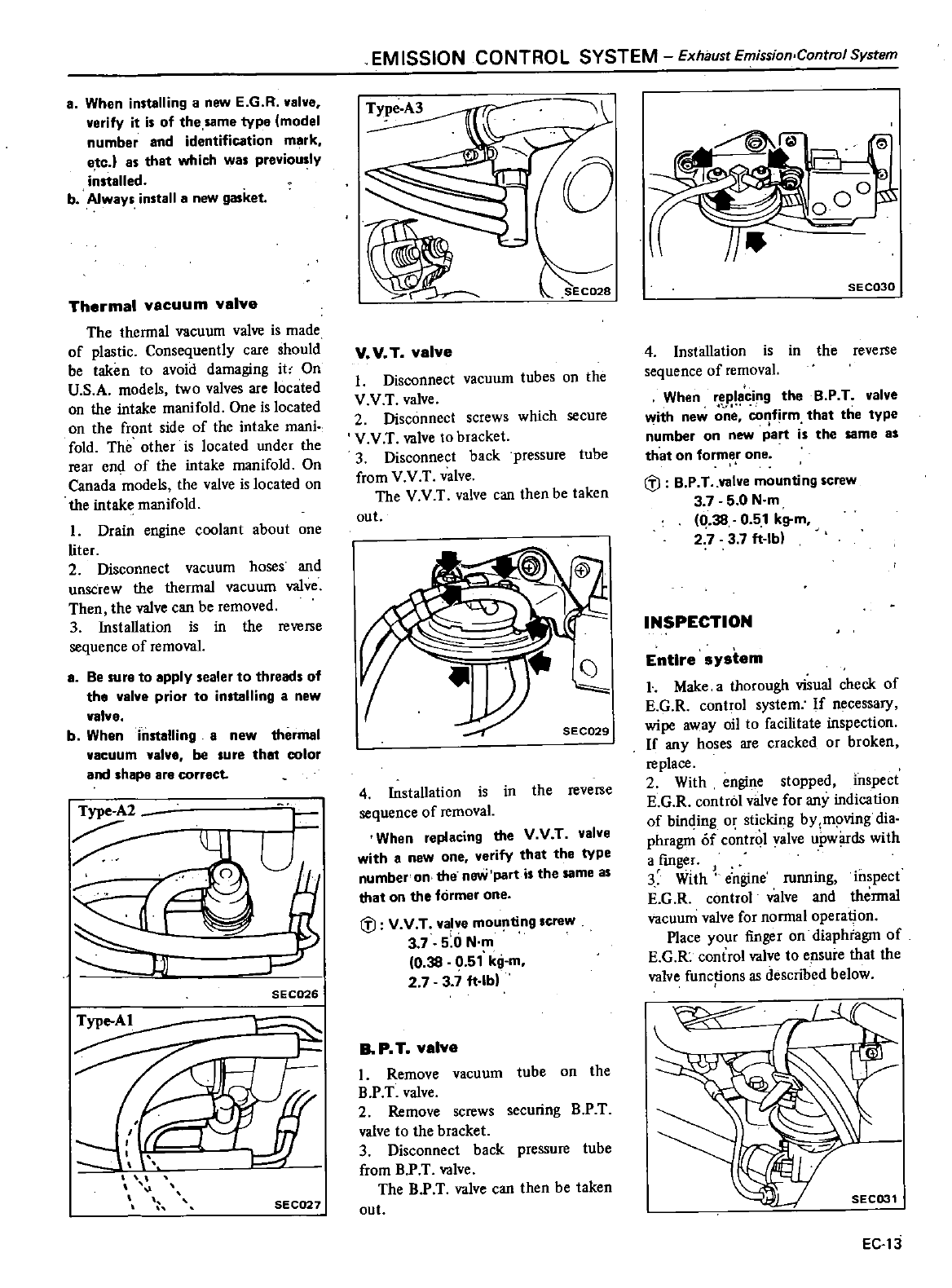
a
When
installing
a
new
E
G R
valve
verify
it
is
of
the
same
type
model
number and
identification
mark
etc l
as
that
which
was
previo
slY
installed
b
Always
install
a
new
gasket
Thermal
vacuum
valve
The
thennal
vacuum
valve
is
made
of
plastic
Consequently
care
should
be
taken
to
avoid damaging
it
On
U
S
A
models
two
valves
are
located
on
the
intake
manifold
One
is
located
on
the
front
side
of
the
intake
mani
fold
The
other
is
located
under
the
rear
end
of
the
intake
manifold
On
Canada
models
the
valve
is
located
on
the
intake
manifold
I
Drain
engine
coolant
about
one
liter
2
Disconnect
vacuum
hoses
and
unscrew
the
thermal
vacuum
valve
Then
the
valve
can
be
removed
3Installation
is
in
the
reverse
sequence
of
removal
a
Be
sura
to
apply
sealer
to
threads
of
the
valve prior
to
installing
a
new
valve
b
When
installing
a
new
thermal
vacuum
valve
be
sure
that
color
and
shape
are
correct
Type
A2
J
SEC026
SEe027
EM
ISSIONCONTROL
SYSTEM
Exhaust
Emission
Control
System
Type
A3
SEC029
V
V
T
valve
1
Disconnect
vacuum
tubes
on
the
V V
T
valve
2
Disconnect
screws
which
secure
V V
T
valve
to
bracket
3
Disconnect
back
pressure
tube
from
V V
T
valve
The V V
T
valve
can
then
be
taken
out
SEC029
4 Installation
is
in
the
reverse
sequence
of
removal
When
replacing
the V V
T
valve
with
a
new
one
verify
that
the
type
number
on
the
noYi
part
is
the same
as
that
on
the
former
one
i
J
V V
T
valve mounting
crew
i
37 5 0
N
m
0
38
0
51
kg
m
2
737
ft
lb
8
P
T
valve
1
Remove
vacuum
tube
on
the
BP
T
valve
2
Remove
screws
securing
B P
T
valve
to
the
bracket
3
Disconnect
back
pressure
tube
from
B
P
T
valve
The B P
T
valve
can
then
be
taken
out
SEC030
4
Installation
is
in
the
reverse
sequence
of
removal
When
replacing
the
B
P
T
valve
with
new
co
f
rm
that
the
type
number
on
new
part
is
the
same
as
that
on
former
one
i
J
B
P
T
valve
mounting
screw
3 7 5 0
N
m
Q
38
0 51
kg
m
2
7 3 7
ft
lb
INSPECTION
Entire
system
l
Make
a
thorough
visual
check
of
E
G R
control
system
If
necessary
wipe
away
oil
to
facilitate
inspection
If
any
hoses
are
cracked
or
broken
replace
2
With
engine
stopped
inspect
E
G R
control
valve
for
any
indication
of
binding
or
sticking
by moving
dia
phragn
Of
c
ntrol
valve
up
ds
with
a
fmger
J
3
With
engine
running
inspect
E
G R
control
valve and
thennal
vacuum
valve
for
nonn
1
operation
Place
your
finger
on
diaphragm
of
E
G
R
control
valve
to
ensure
that
the
valve
functions
as
described
below
r
f
SEC031
EC
13
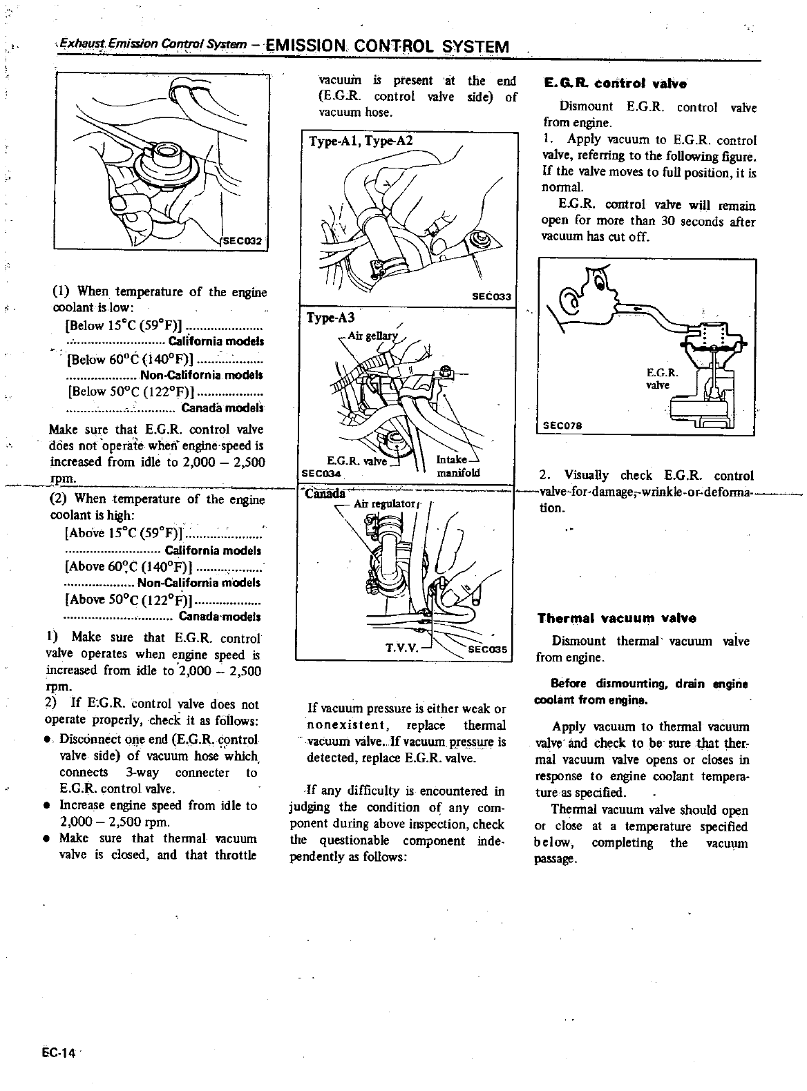
Exhau
Emission Co
1
System
I
M
ISSION
CONTROL
SYSTEM
SECOO2
1
When
temperature
of
the
engine
coolant
is
low
Below
ISoC
S90F
California
models
Below
600
1400F
Non
California
modals
Below
SOOC
1220F
Canada
models
Make
sure
that
E
G
R
control
valve
does
not
operate
when
engine
speed
is
increased
from
idle to
2
000
2
500
rpm
2
When
temperature
of
the
engine
coolant
is
high
Above
ISoC
S90F
California
models
Above
600C
1400F
Non
California
models
Above
SOOC
1220F
Canada
models
1
Make
sure
that
E
G R
control
valve
operates
when
engine
speed
is
increased
from
idle to
2
000
2
SOO
rpm
2
If
E
G
R
control
valve
does
not
operate
properly
check
it
as
follows
Disconnect
one
end
KG R
control
valve
side
of
vacuum
h
which
connects
3
way
connecter
to
E
G R
control
valve
Increase
engine
speed
from
idle
to
2
000
2
SOO
rpm
Make
sure
that
thennal
vacuum
valve
is
closed
and
that
throttle
EC
14
vacuuin is
present
at
the
end
E
GR
control
valve
side
of
vacuum
hose
Type
Al
Type
A2
Canada
Airregulatort
f
T
V
V
J
C035
If
vacuum
pressure
is
either
weak
or
nonexistent
replace
thermal
vacuum
valve
If
vacuum
Pse
ss
lJ
e
is
detected
replace
E
G R
valve
If
any
difficulty
is
encountered
in
judging
the
condition
of
any
com
ponent
during
above
inspection
check
the
questionable
component
inde
pendently
as
follows
E
GR
corit
ol
valve
Dismount
E
G
R
control
valve
from
engine
1
Apply
vacuum
to
E
G
R
control
valve
referring
to
the
following
figure
If
the
valve
moves
to
full
position
it
is
nonnal
E
G
R
control
valve
will
remain
open
for
more
than
30
seconds
after
vacuum
has
cut
off
seC018
I I
ucsl
2
Visually
check
E
G R
control
valve
for
damage
wrinkle
or
deforms
lion
Thermal
vacuum
valve
Dismount
thennal
vacuum
valve
from
engine
Before
dismounting
drain
engine
coolant
from
engine
Apply
vacuum
to
thennal
vacuum
valve
and
check
to
be
sure
that
ther
mal
vacuum
valve
opens
or
closes
in
c
to
engine
coolant
tempera
ture
as
specified
Thennal
vacuum
valve
should
open
or
close
at
a
temperature
specified
below
completing
the
vacuum
pa5Sage
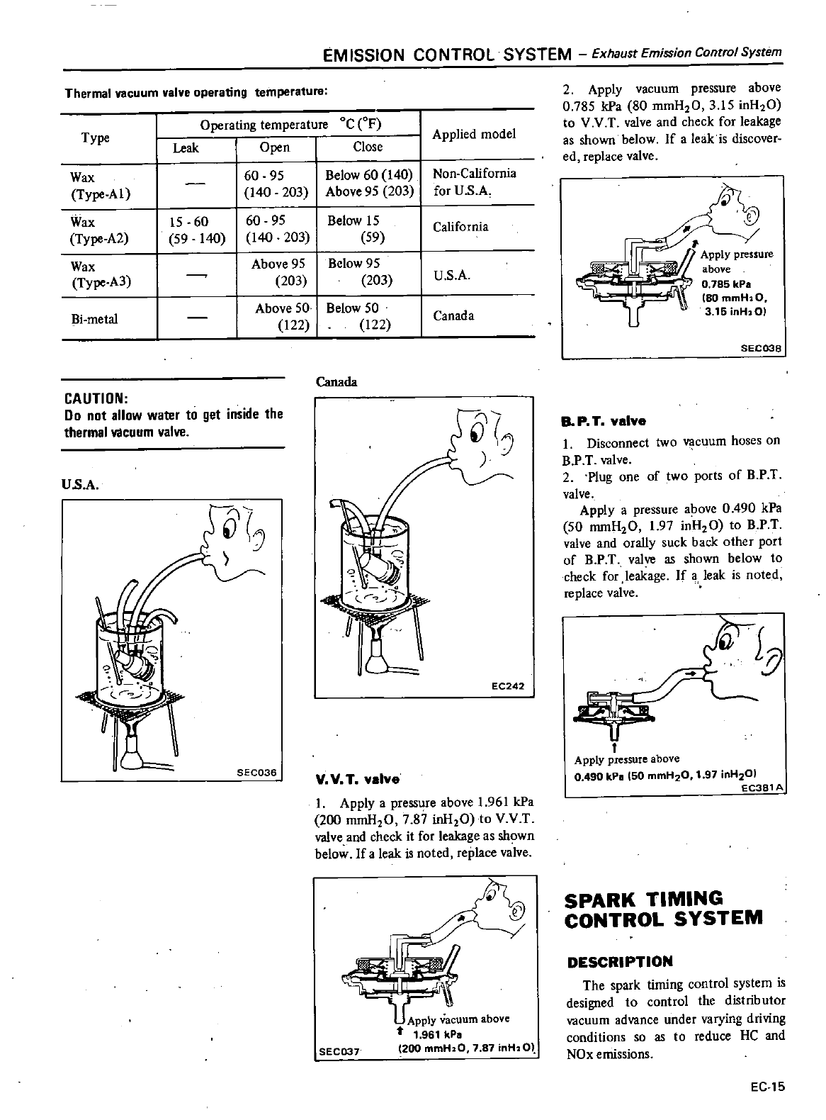
EMISSION CONTROL SYSTEM
Exhaust
Emission
Control
System
Thermal
vacuum
valve
operating
temperature
Oc
OF
Close
Type
Operating
temperature
Leak
Open
60
95
Below
60
140
Non
California
140
203
Above
95
203
for
U
S
A
15
60 60
95
Below
15
California
59
140
140 203
59
I
Above
95
I
Below
95
Apply
pressure
203 203
U
S
A
above
0785 kPa
Above
50
1
Below
50
80
mmH
aO
122 122
Canada
3
15
inH
OI
SEC038
Wax
Type
AI
Wax
Type
A2
Wax
Type
A3
Bi
metal
Applied
model
Canada
CAUTION
Do
not
allow
water
to
gel
inside
the
thermal
Vllcuum
valve
U
s
A
1OC1
EC242
SEC036 VVT valve
1
Apply
a
pressure
above
1
961
kPa
200
mmH20
7
87
inH20
to
V V
T
valve and
check
it
for
leakage
as
shown
below
If
a
leak is
noted
replace
vaive
SEC037
Apply
vacuum
above
t
1
961
kP
200
mmH20
7
87
inH
OJ
2
Apply
vacuum
pressure
above
0
785
kPa
80
mmH20
3
15
inH20
to
VV
T
valve
and
check
for
leakage
as
shown
below
If
a
leak
is
discover
ed
replace
valve
B
P
T
valve
1
Disconnect
two
cuum
hoses
on
BPT
valve
2
Plug
one
of
two
ports
of
BPT
valve
Apply
a
pressure
above
0
490
kPa
50
mmH20
1
97
inH20
to
B P
T
valve
and
orally
suck
back
other
port
of
BP
T
valve
as
shown
below
to
check
for
leakage
If
a
leak is
noted
replace
valve
t
Apply
pressure
above
0
490 kPII
50
mmH20
1
97
inH201
EC381
A
SPARK
TIMING
CONTROL
SYSTEM
DESCRIPTION
The
spark
timing
control
system
is
designed
to
control
the
distributor
vacuum
advance
under
varying
driving
conditions
so as to
reduce
HC
and
NOx
emissions
EC
15
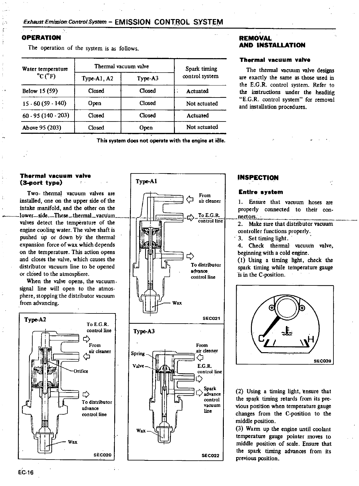
ExhsustEmissionControlSystem
EMISSION
CONTROL
SYSTE
OPERATION
The
operation
of
the
system
is
as
follows
Water temperature
Thennal
vacuum
valve
Spark
timing
Oc
OF
Type
AI
A2
Type
A3
control
system
Below
15
59
Closed Closed
Actuated
15
60
59
140
Open
Closed
Not
actuated
60 95
140
203
Closed Closed
Actuated
Above
95
203
Closed
Open
Not
actuated
This
system
does no1
operate
with
tha
engine
at
iale
Thermal
vacuum
valve
3
port
type
Type
Ai
Two
thennal
vacuum
valves
are
I
installed
one
on
the
upper
side
of
the
intake
manifold
and
the other
on
the
I
I
lower
side
These
thennal
vacuum
1
valves
detect
the
temperature
of
the
engine
coo
ling
wa
ter
Th
e
valve
shaft
is
pushed
up
or
down
by
the
thennal
I
expansion
force
of
wax
which
depends
on
the
temperature
This
action
opens
and
closes
the
valve
which
causes
the
I
distnbutor
vacuum
line to
be
opened
l
or
closed
to
the
atmosphere
When the
valve
opens
the
vacuum
I
signal
line
will
open
to
the
atmos
phere
stopping
the
distributor
vacuum
from
advancing
Type
A2
To
E
G
R
control line
e
C
From
I
air
cleaner
TYpe
A3
Spring
t1
ii
Valve
i
i1i
I
e
To
distributor
advance
control line
Wax
Wax
SEC020
EC
16
I
Ensure
that
vacuum
hoses
are
properly
connected
to
their
con
I
Q
19
controllme
2
Make
sure
that
distributor
vacuum
controller
functions
properly
3
Set
timing
light
4
Check
thennal
vacuum
valve
beginning
with
a
cold
engine
1
Using
a
timing
light
check the
spark
timing
while
temperature
gauge
is
in
the
C
position
A
From
J
r
air
cleaner
iQ
To
distributor
a4vance
coIitrolline
Wax
SEC021
From
airclea
ner
n
lQ
iiCE
G
R
control line
Q
Q
ce
control
vacuum
line
SEC022
REMOVAL
AND
INSTALLATION
Thermal
vacuum
valve
The
thermal
vacuum
valve
designs
are
exactly
the
same
as
those
used
in
the
E
G
R
control
system
Refer
to
the
instructions
under
the
headirig
E
G R
control
system
for removal
and
installation
procedures
INSPECTION
Entire
system
SEC039
2
Using
a
timing
light
ensure
that
the
spark
timing
retards
from
its pre
vious
position
when
temperature
gauge
changes
from
the
C
position
to
the
middle
position
3
Wann
up
the
engine
until
coolant
temperature
gauge
pointer
moves
to
middle
position
of
scale
Ensure
that
the
spark
timing
advances
from
its
previous
position
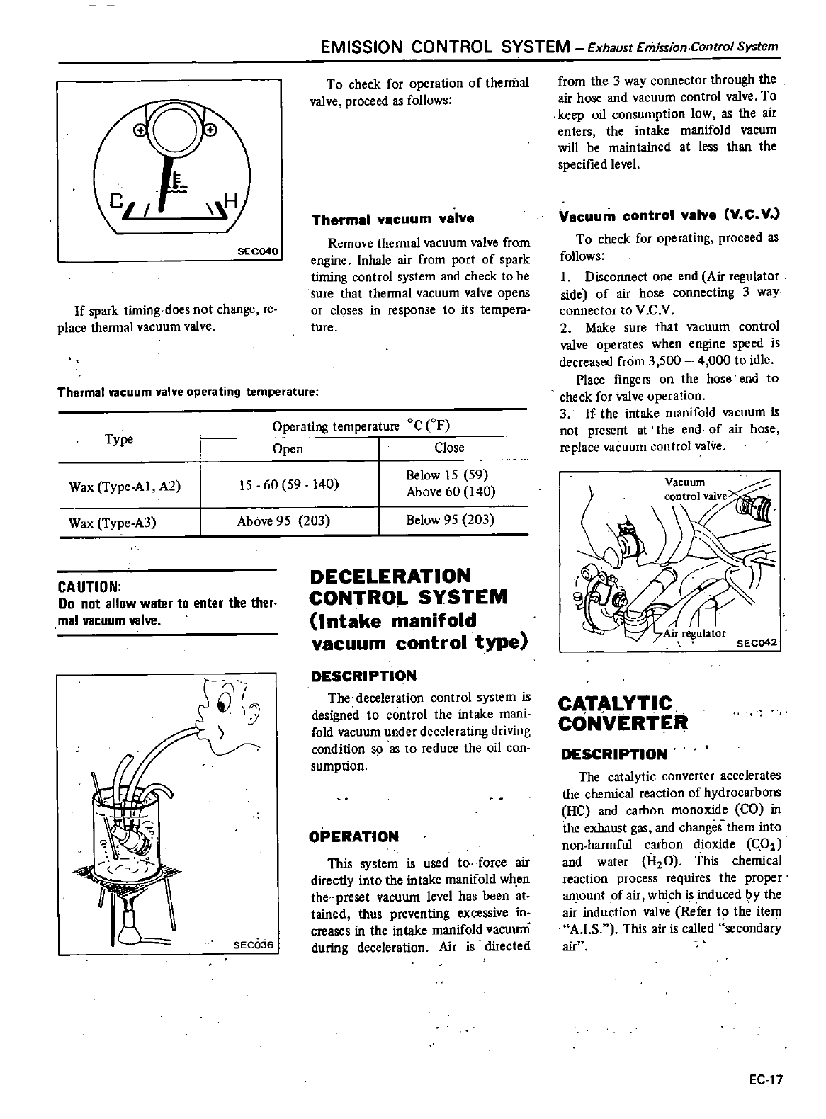
SEC040
If
spark
timing
does
not
change
reo
place
thennal
vacuum
valve
Thermal
vacuum
valve
operating
temperature
Type
EMISSION CONTROL SYSTEM
Exhaust
Emission ControJ
System
To
check
for
operation
of
thermal
valve
proceed
as
follows
Thermal
vacuum
valve
Remove
thermal
vacuum
valve from
engine
Inhale
air
from
port
of
spark
timing
control
system
and
check
to
be
sure
that
thermal
vacuum
valve
opens
or
closes
in
response
to
its
tempera
ture
Operating
temperature
Oc
F
Open
Close
Below
15
59
Above
60
140
Wax
Type
Al
A2
15
60
59
140
Wax
Type
A3
Above
95
203
Below
95
203
CAUTION
00
not
allow
water
10
enter
the
ther
mal
vacuum
valve
SECQ36
DECELERATION
CONTROL
SYSTEM
Intake
manifold
vacuum
control
type
DESCRIPTION
The
deceleration
control
system
is
designed
to
control
the
intake
mani
fold
vacuum
under
decelerating
driving
condition
59
as
to
reduce
the
oil
con
sumption
OPERATION
This
system
is
used
to
force
air
directly
into
the
intake
manifold
w
en
the
preset
vacuum
level
has
been
at
tained
thus
preventing
excessive
in
creases
in
the
intake
manifold
vacuum
during
deceleration
Air
is
directed
from
the 3
way connector
through
the
air
hose
and
vacuum
control
valve
To
keep
oil
consumption
low as
the
air
enters
the intake
manifold
vacum
will
be
maintained
at
less
than
the
specified
level
Vacuum
control
valve
V
C
V
To
check
for
operating
proceed
as
follows
I
Disconnect
one
end
Air
regulator
side
of
air
hose connecting
3
way
connector
to
V
C
V
2
Make
sure
that
vacuum
control
valve
operates
when
engine
speed
is
decreased
from
3
500
4
000
to idle
Place
finger
on
the
hose
end
to
check
for
valve
operation
3
If
the intake
manifold
vacuum
is
not
present
at
the
end
of
air
hose
replace
vacuum
control
valve
CATALYTIC
CONVERTER
DESCRIPTION
The
catalytic
converter
accelerates
the
chemical
reaction
of
hydrocarbons
HC
and
carbon
monoxide
CO
in
the
exhaust
gas
and
changes
them
into
non
hannful
carbon
dioxide
CO
and
water H
O
This
chemical
reaction
process
requires
the
proper
amount
of
air
which
is induced
ythe
air
induction
valve
Refer
t
the
item
A
I
S
This
air
is
called
secondary
air
EC
7
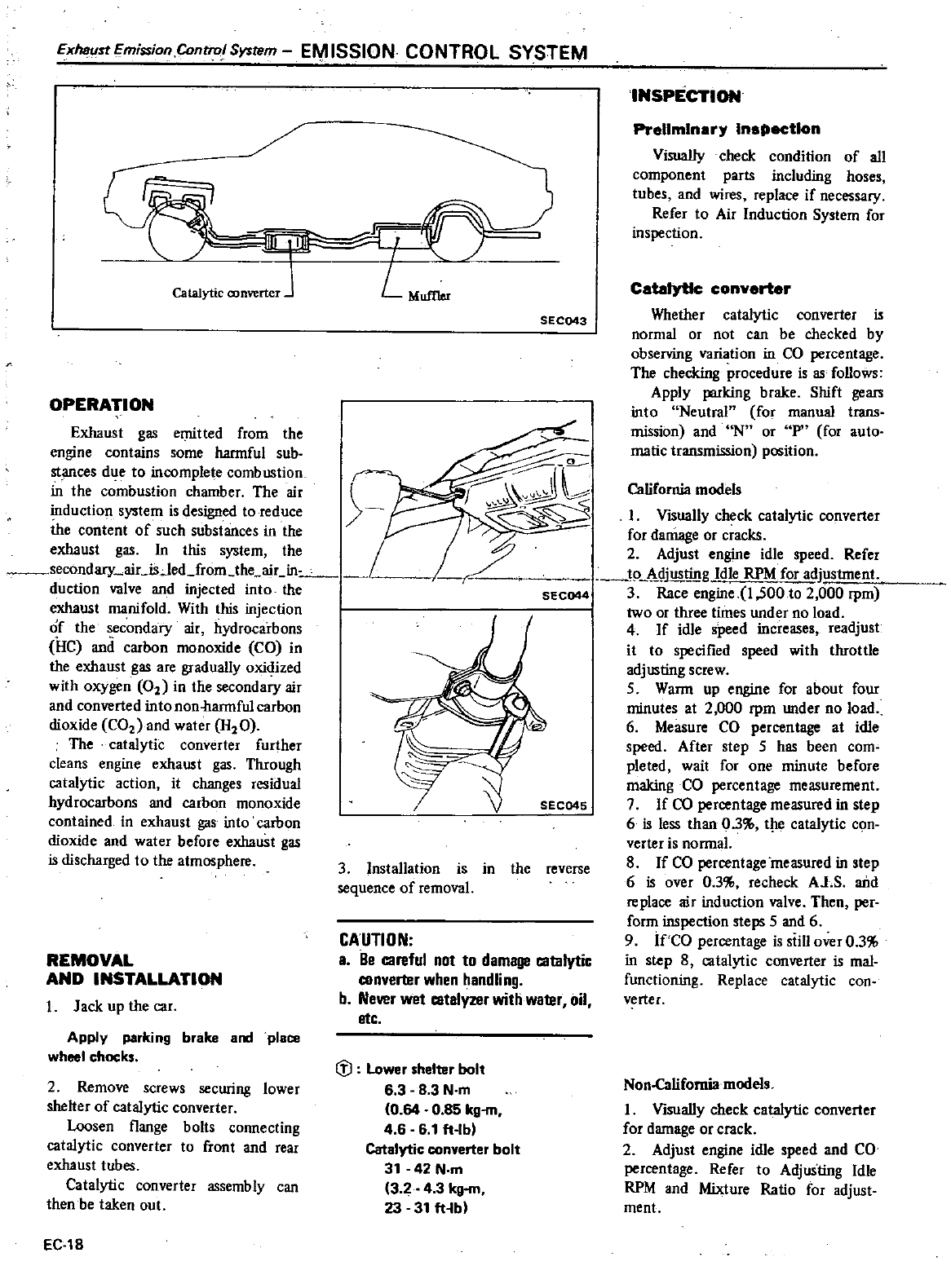
Exhaust
Emission ContrQl
System
EM
ISSION
CONTROL
SYSTEM
Catalytic
converter
OPERATION
Exhaust
gas
emitted
from
the
engine
contains
some
hannful
sub
stances
due
to
incomplete
combustion
in
the
combustion
chamber
The
air
induction
system
is
designed
to
reduce
the
content
of
such
substances
in
the
exhaust
gas
In this
system
the
secondary
aicisJed
from
the
air
in
duction
valve and
injected
into
the
exhaust
manifold
With
this
injection
of the
secondary
air
hydrocarbons
HC
and
carbon
monoxide
CO
in
the
exhaust
gas
are
gradually
oxidized
with
oxygen
0
in
the
secondary
air
and
converted
into
non
hannful
carbon
dioxide
CO
and
water
H
O
The
catalytic
converter
further
cleans
engine
exhaust
gas
Through
catalytic
action
it
changes
residual
hydrocarbons
and
carbon
monoxide
contained
in
exhaust
gas
into
carbon
dioxide
and
water
before
exhaust
gas
is
discharged
to
the
atmosphere
REMOVAL
AND
INSTALLATION
I
Jack
up
the
car
Apply
parking
brake
and
place
wheel
chocks
2
Remove
screws
securing
lower
shelter
of
catalytic
converter
Loosen
flange
bolts
connecting
catalytic
converter
to
front
and
rear
exhaust
tubes
Catalytic
converter
assembly
can
then
be
taken
out
EC
18
I
Visually
check
catalytic
converter
for
damage
or
cracks
2
Adjust
engine
idle
speed
Refer
to
Mjus
g
Idle
RPM
for
adjustment
SEC044
3
Race
engine
1
500
to
2
000
rpm
two
or
three
times
under
no
load
4
If
idle
speed
increases
readjust
it
to
specified
speed
with
throttle
adjusting
screw
SWann
up
engine
for
about
four
minutes
at
2
000 rpm
under
no
load
6
Measure
CO
percentage
at idle
speed
After
step
S
has
been
com
pleted
wait
for
one
minute
before
making
CO
percentage
measurement
7
If
CO
percentage
measured
in
step
6
is
less
than
03
the
catalytic
con
verter
is
nonnal
8
If
CO
percentage
measured
in
step
6
is
over
03
recheck
Al
S
arid
replace
air
induction
valve
Then
per
form
inspection
steps
S
and
6
9
if
CO
percentage
is
still
over
03
in
step
8
catalytic
converter
is
mal
functioning
Replace
catalytic
con
verter
ft
L
MufIIer
SEC043
SEe04S
3 Installation
is
in
the
reverse
sequence
of
removal
CAUTION
a
Be
careful
not
to
damage
catalytic
converter
when
handling
b
Newr
wet
catalyzer
with
wa1er
oil
etc
fJ
Lower
shelter
bolt
6
38
3
N
m
0
64
0
85 kg
m
4 6 6
1
ft
lb
Catalytic
converter
bolt
31
42
N
m
32
43
kg
m
23
31
ft
bl
INSPECTION
Preliminary
Inspection
Visually
check
condition
of
all
component
parts
including
hoses
tubes
and
wires
replace
if
necessary
Refer
to
Air
Induction
System
for
inspection
Ci
converter
Whether
catalytic
converter
is
normal
or
not
can
be
checked
by
observing
variation
in
CO
percentage
The
checking
procedure
is
as
follows
Apply
parking
brake
Shift
gears
into
Neutral
for
manual
trans
mission
and
N
or
P
for
auto
matic
transmission
position
California
models
Non
Califomia
models
I
VisuaIly
check
catalytic
converter
for
damage
or
crack
2
Adjust engine
idle
speed
and
CO
percentage
Refer
to
Adjusting
Idle
RPM
and
Mixture
Ratio
for
adjust
ment
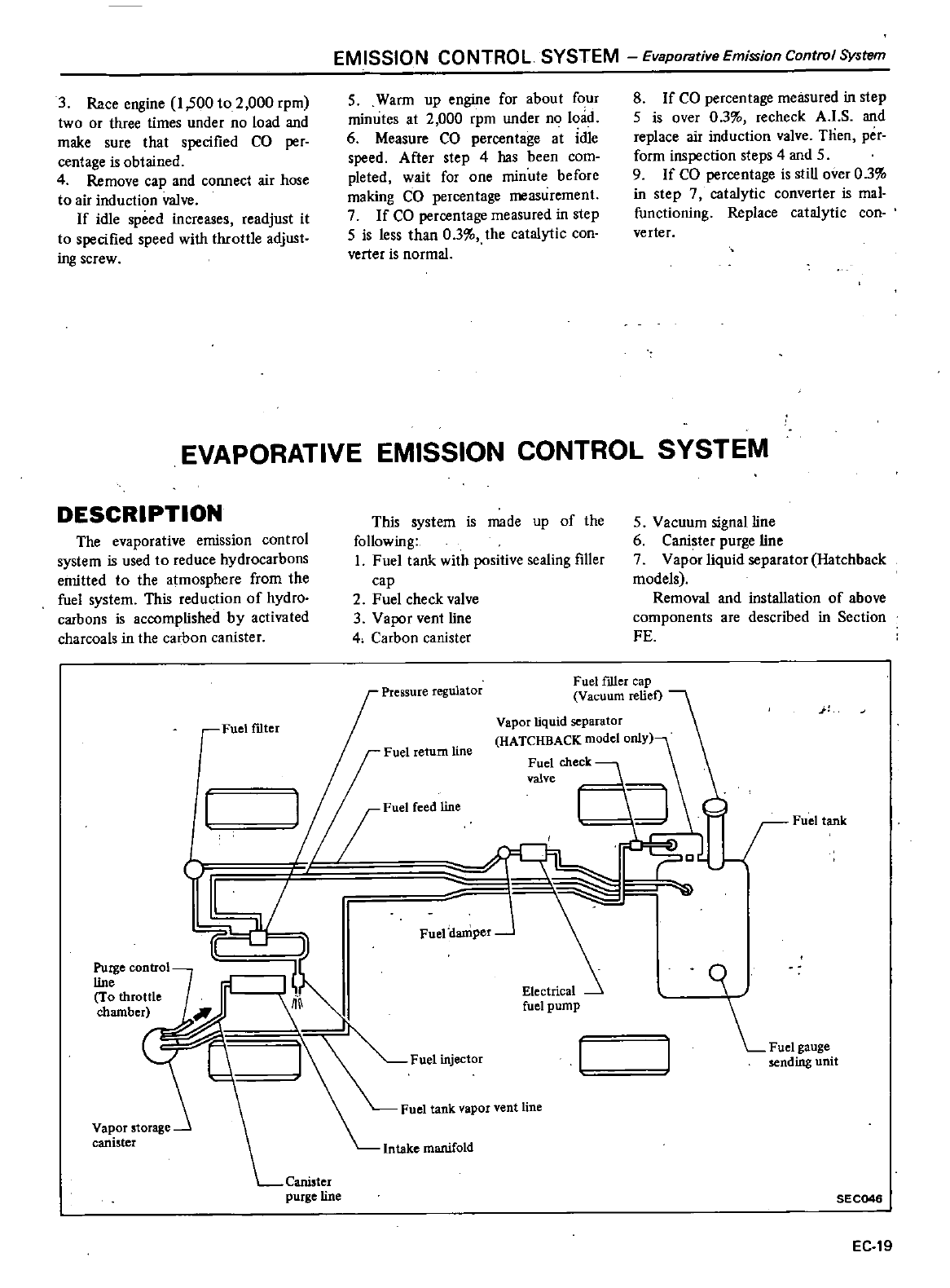
EMISSION
CONTROL
SYSTEM Evaporative
Emission
Control
System
3
Race
engine
1
500
to
2
000
rpm
two
Or
three
times
under
no
load
and
make
sure
that
specified
CO
per
centage
is
obtained
4
Remove
cap
and
connect
air
hose
to
air
induction
v
a1ve
If
idle
speed
increases
readjust
it
to
specified
speed
with
throttle
adjust
ing
screw
5
Wann
up
engine
for
about
four
minutes
at
2
000
rpm
under
no
lmid
6
Measure
CO percentage
at
idle
speed
After
step
4
has
been
com
pleted
wait
for
one
minute
before
making
CO
percentage
measurement
7
If
CO
percentage
measured
in
step
5
is
less
than
03
the
catalytic
con
verter
is
normal
8
If
CO percentage
measured
in
step
S
is
over
03
recheck
AJ
S
and
replace
air
induction
valve
Tlien
per
fonn
inspection
steps
4
and
5
9
If
CO
percentage
is
still
over
03
in
step
7
catalytic
converter
is
mal
functioning
Replace
catalytic
con
verter
EVAPORATIVE
EMISSION CONTROL
SYSTEM
DESCRIPTION
This
system
is
made
up
of
the
following
1
Fuel
tank
with
positive
sealing
filler
cap
2
Fuel
check
valve
3Vapor
vent
line
4
Carbon
canister
S
Vacuum
signal
line
6
Canister purge
line
7Vapor
liquid
separator
Hatchback
models
Removal
and
installation
of
above
components
are
described
in
Section
FE
The
evaporative
emission
control
system
is
used
to
reduce
hydrocarbons
emitted
to
the
atmosphere
from
the
fuel
system
This
reduction
of
hydro
carbons
is
accomplished
by
activated
charcoals
in
the
carbon
canister
Fuel
Hller
cap
Vacuum
reliet
Pressure
regulator
j
Vapor
liquid
separator
HATCHBACK
model
OnlY
Fuel
check
valve
I
Fuel tank
c
I
Fuelf1lter
Fuel
return
line
Z
Fuel
reed
line
1
Fuel
mjector
Fuel tank
vapor
vent
line
81
Fuel
danlper
J
sending
unit
Electrical
fuel
pump
f
Vapor
storage
canister
Intake
manifold
Canister
purge
line
SEC046
EC
19
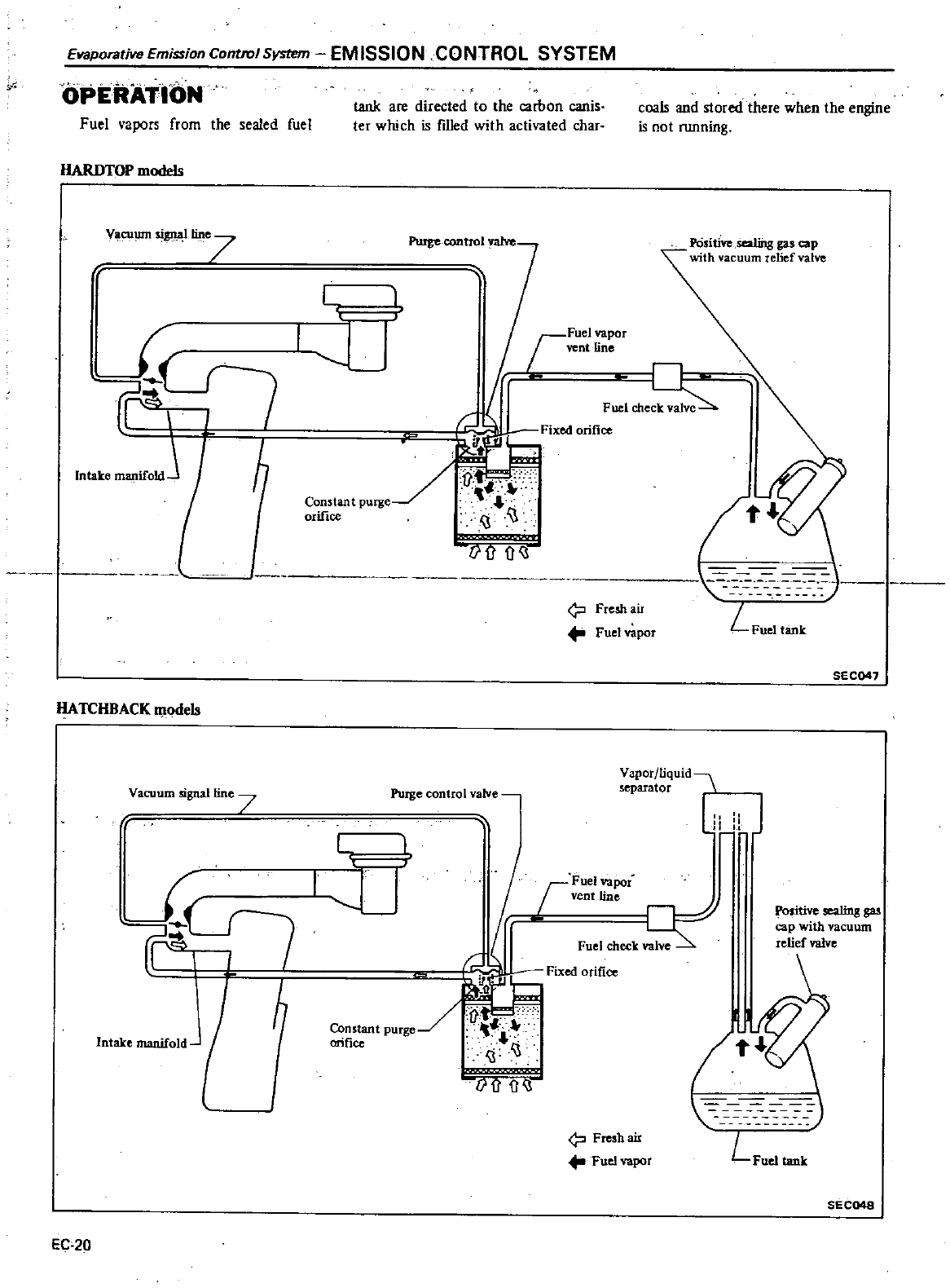
Etlaporative
Emission
ContlOlSystrm
EMISSION
CONTROL
SYSTEM
rr
OPERATION
Fuel
vapors
from
the
sealed
fuel
tank
are
directed
to
the
carbon
canis
ter
which
is
filled
with
activated
char
coals
and
stored there
when
the
engine
is
not
nmning
HARDTOP
models
I
LJ
ri
POsitive
Sealli1g
gas
cap
with
aCllum
relief
valve
Vacu1
J111
lline7
jFUel
vapor
I
vent
line
r
n
Fuel
che
L
Freshair
Fuet
vapor
t
j
L
Fuel
tank
Intake
ffillIlifOldJ
ij
f
fJ
SEC041
HATCHBACK
m
odeb
Yaporjliquid
separator
L
J
Vacuum
signal
line
7
Purge
control
ialve
G
tr
I
I
LJ
r
Fuel
vapor
vent
line
Fuel
check
Fixed
orifice
I
Con
tant
purge
i
lice
Si
S
iji
i
ji
J
sitive
sealing
gas
cap
with
vacuum
relief
valve
1
LFUe
tank
Intake
manifold
J
Fresh
air
Fuel
vapor
SEC048
EC
20
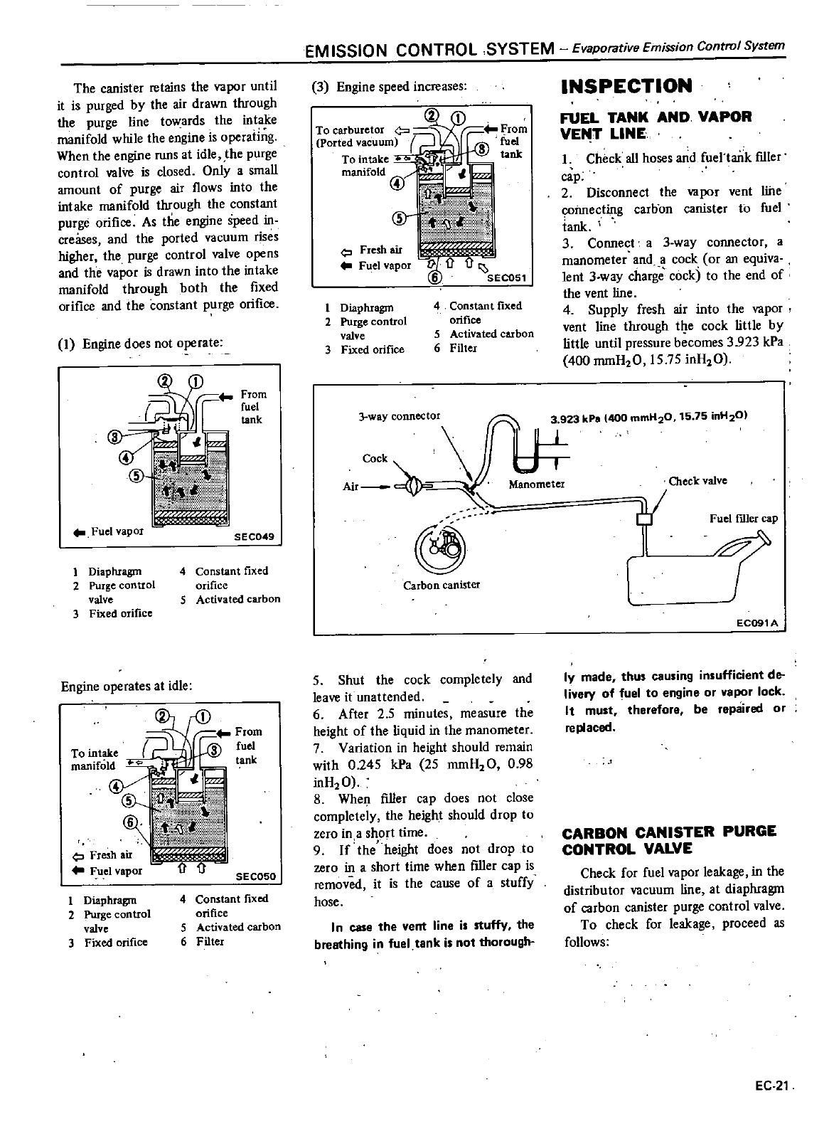
The canister
retains
the
vapor
until
it
is
purged
by
the
air
drawn
through
the
purge line
towards
the
intake
manifold
while
the
engine
is
operaiing
When
the
engine
runs
at
idle
the
purge
control
valVe
is
closed
Only
a
small
amount
of
purge
air
flows
into
the
intake
manifold
through
the
constant
purge
orifice
As
the
engine
speed
in
creases
and
the
ported
vacuum
rises
higher
the
purge
control
valve
opens
and
the
vapor
is
drawn
into
the
intake
manifold
through
both
the
fixed
orifice
and
the constant
purge
orifice
I
Engine
does
not
operate
From
fuel
tank
Fuel
vapor
i
I
umuu
11
l
N
fl
SEC049
1
Diaphragm
2
Purge
control
valve
3
Fixed
orifice
4
Constant
fixed
orifice
5
Activated
carbon
Engine
operates
at
idle
Fresh
air
Fuel
vapor
SEC050
4
Constant
fixed
orifice
5
Activated
carbon
6
Filter
1
Diaphragm
2
Purge
control
valve
3
Fixed
orifice
EM
ISSION
CONTROL SYSTEM
Evaporative
Emission
Control
System
3
Engine
speed
increases
To
carburetor
C
J
Ported
vacuum
To
intake
manifold
@
Fresh
air
F el
vapor
1
Diaphragm
4
Constant
fixed
2
Pltrge
control
orifice
valve
5
Activated
carbon
3
Fixed
orifice
6
Filter
INSPECTION
FUEL
TANK
AND
VAPOR
VEfo
T
LINE
Check
all
hoses
and
fuel
tank
IDler
cap
2
Disconnect
the
vapor
vent
line
C
Onnecting
carbon
canister
to
fuel
iank
3
Connect
a
3
way
connector a
manometer
and
a
cock
or
an
equiva
lent
3
way
charge
cock
to
the
end
of
the
vent
line
4
Supply
fresh
air
into
the
vapor
vent
line
through
t
e
cock
little
by
little
until
pressure
becomes
3
923
kPa
400
mmH20
15
75
inH20
3
way
connector
75
H
0
Cock
3 kPo
400
mmH20
15
in
2
Air
Manometer
Check
valve
@
Carbon
canister
5
Shut
the
cock
completely
and
leave
it
unattended
6
After
25
minutes
measure
the
height
of
the
liquid
in
the
manometer
7
Variation
in
height
should
remain
with
0
245
kPa
25
mmH20
0
98
inH20
8
When
filler
cap
does
not
close
completely
the
height
should
drop
to
zero
in
a
short
time
9
If
the
height
does
not
drop
to
zero
in a
short
time
when
filler
cap
is
removed
it
is
the
cause
of
a
stuffy
hose
In
case the
vent
line
is
stuffy
the
breathing
in
fuel
tank
is
not
thorough
Fuel
filler
cap
EC091A
Iy
made
thus
causing
insufficient
de
livery
of
fuel
to
engine
or
vapor
lock
It
must
therefore be
repaired
or
replaced
CARBON
CANISTER
PURGE
CONTROL
VALVE
Check
for
fuel
vapor
leakage
in
the
distributor
vacuum
line at
diaphragm
of
carbon
canister
purge
control
valve
To
check
for
leakage
proceed
as
follows
EC
21
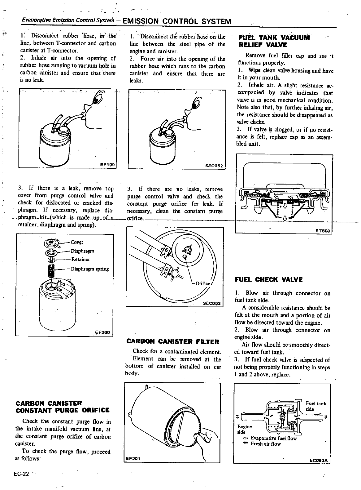
Evaporative
Emi
on
Control
smem
EMISSION
CONTROL SYSTEM
I
Disconnect
rubber
nose
in
he
line
between
T
connector
and
carbon
canister
at
T
onnector
2
Inhale
air
into
the
opening
of
rubber
h
se
running
to
vacuum
hole
in
carbon
canister
and
ensure
that
there
is
no
leak
EF199
I
Disconnect
thb
l
ub
ber
llooe
on
the
line
between
the
steel
pipe
of
the
engine
and
canister
2
Force
air into
the
opening
of
the
rubber
hose
which
runs
to
tiJe
carbon
canIster
and
ensure
that
there
are
leaks
SEC052
3
If
there
is
a
leak
remove
top
3
If
there
are
no
leaks
remove
cover
from
purge
control
valve
and
purge
control
valve
and
check
the
check
for
dislocated
or
cracked
dia
constant
purge
orifice
for leak
If
phragm
If
necessary
replace
dia
necessary
clean
the constant
purge
phragm
kit
which
is
made
up
oLa
orifir
retainer
diaphragm
and
spring
Cover
Diaphragm
Retainer
t
Diaphragm
spring
EF200
CARBON
CANISTER
CONSTANT
PURGE
ORIFICE
Check
the
constant
purge
flow
in
the
intake
manifold
vacuum
line
at
the
constant
purge
orifice
of
carbon
canister
To
check
the
purge
flow
proceed
as
follows
EC
22
SEC053
CARBON
CANISTER
FLTER
Check
for
a
contaminated
element
Element
can
be
removed
at
the
bottom
of
canister
installed
on
car
body
FUn
TANK
VACUUM
RnlEF
VALVE
Remove
fuel
filler
cap
and
see
it
functions
properly
I
Wipe
clean valve
housing
and
have
it
in
your
mouth
2
Inhale
air
A
slight
resistance
ac
cornpaniedby
valve
indicates
that
valve
is
in
good
mechanical
condition
Note
also
that
by
further
inhaling
air
the
resistance
should
be
disappeared
as
valve
clicks
3
If
valve
is
clogged
or if
no
resist
ance
is
felt
replace
cap
as
an
assem
bled
unit
r
ET500
FUEL
CHECK
VALVE
1
Blow
air
through
connector
on
fuel
tank
side
A
considerable
resistance
should
be
felt
at
the
mouth
and
a
portion
of
air
flow
be
directed
toward
the
engine
2
Blow
air
through
connector
on
engine
side
Air
flow
should
be
smoothly
direct
ed
toward
fuel
tank
3
If
fuel
check
valve
is
suspected
of
not
being
properly
functioning
in
steps
I
and
2
above
replace
tm
r
ltank
1
e
l
Q
Evaporative
fuel
flow
Fresh
air
flow
EC090A
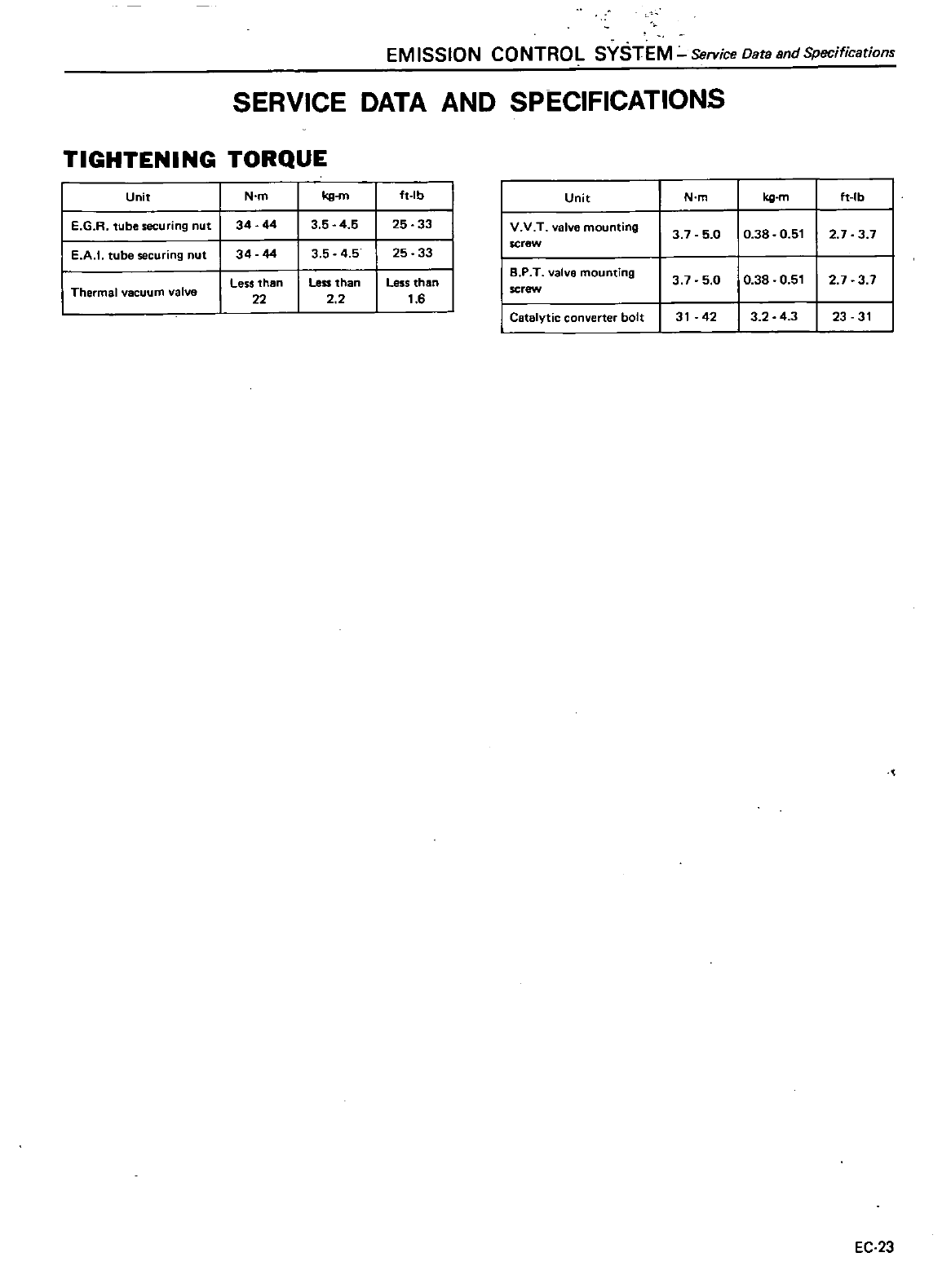
EM
ISSION
CONTROL
SYSTEM
Service
Data
and
Specifications
SERVICE
DATA
AND
SPECIFICATIONS
TIGHTENING
TORQUE
Unit
N
m
kg
m
ft
lb
Unit
N
m
kg
m
ft
Ib
E
G
R
tube
securing
nut
34
44
3 5
45
25
33
I
V V T
valve
mounting
3 7 5
0 0
38
0
51
2
7 3 7
E
A
I
tube
securing
nut
44
4
5
25 33
screw
34
3 5
Less
than
Less
than
Less
than
18
P
T
valvo
mounting
3 7 5
0 0
38
0
51
2
7 3 7
Thermal
vacuum
valve
22
2 2
1
6
screw
I
Catalytic
converter
bolt
31
42
3 2
4
3
23 31
EC
23
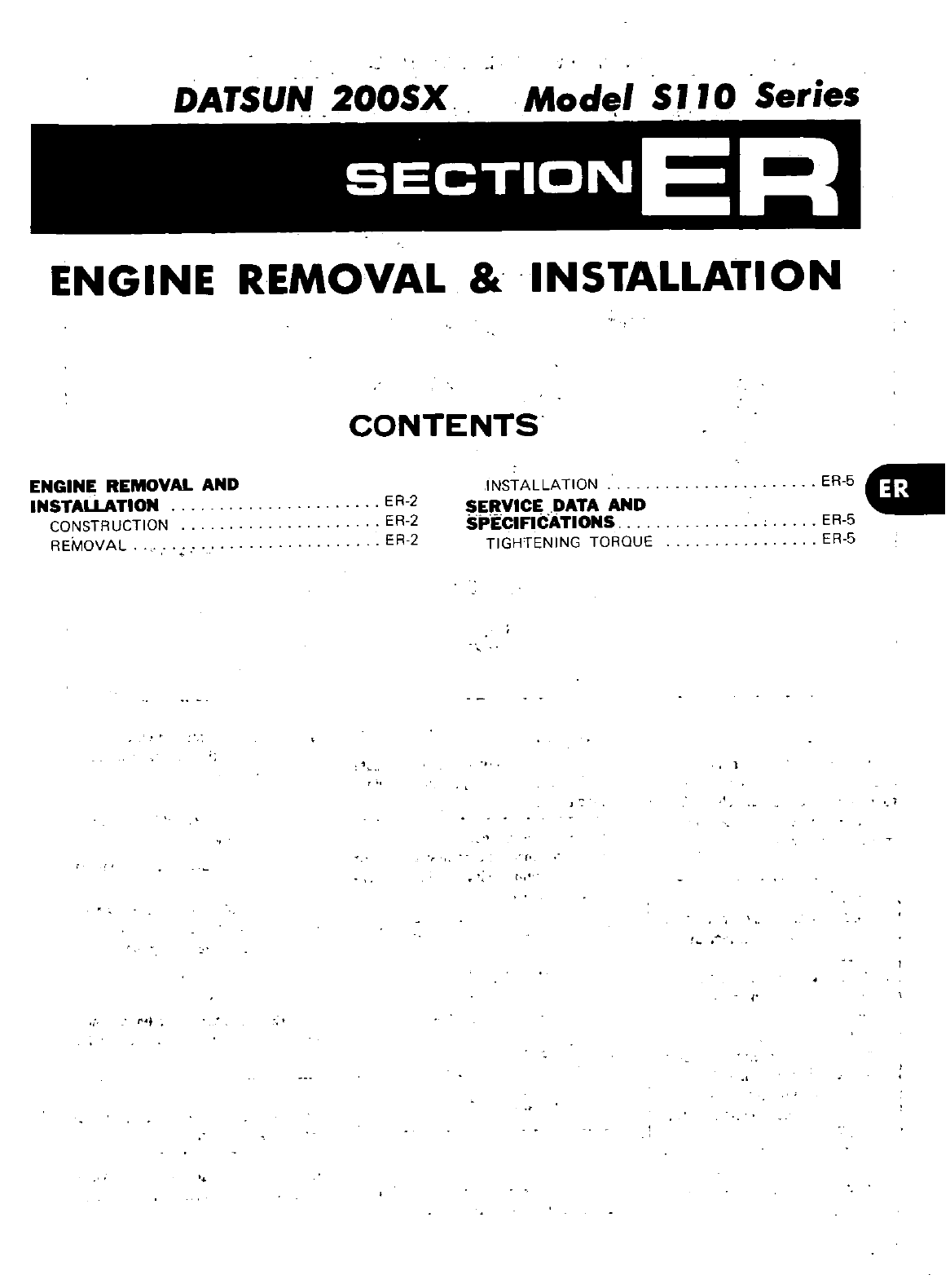
DATSUN
200SX
Mod
1
S
II
0
Series
SECTIONER
ENGINE
REMOVAL
INSTAllATION
CONTENTS
ENGINE
REMOVAL
AND
INSTALLATION
CONSTRUCTION
REMOVAL
ER
2
ER
2
ER
2
INSTALLATION
SERVICE
DATA
AND
SPECIFICATIONS
TIGHTENING
TORQUE
ER
5g
ER
5
ER
5
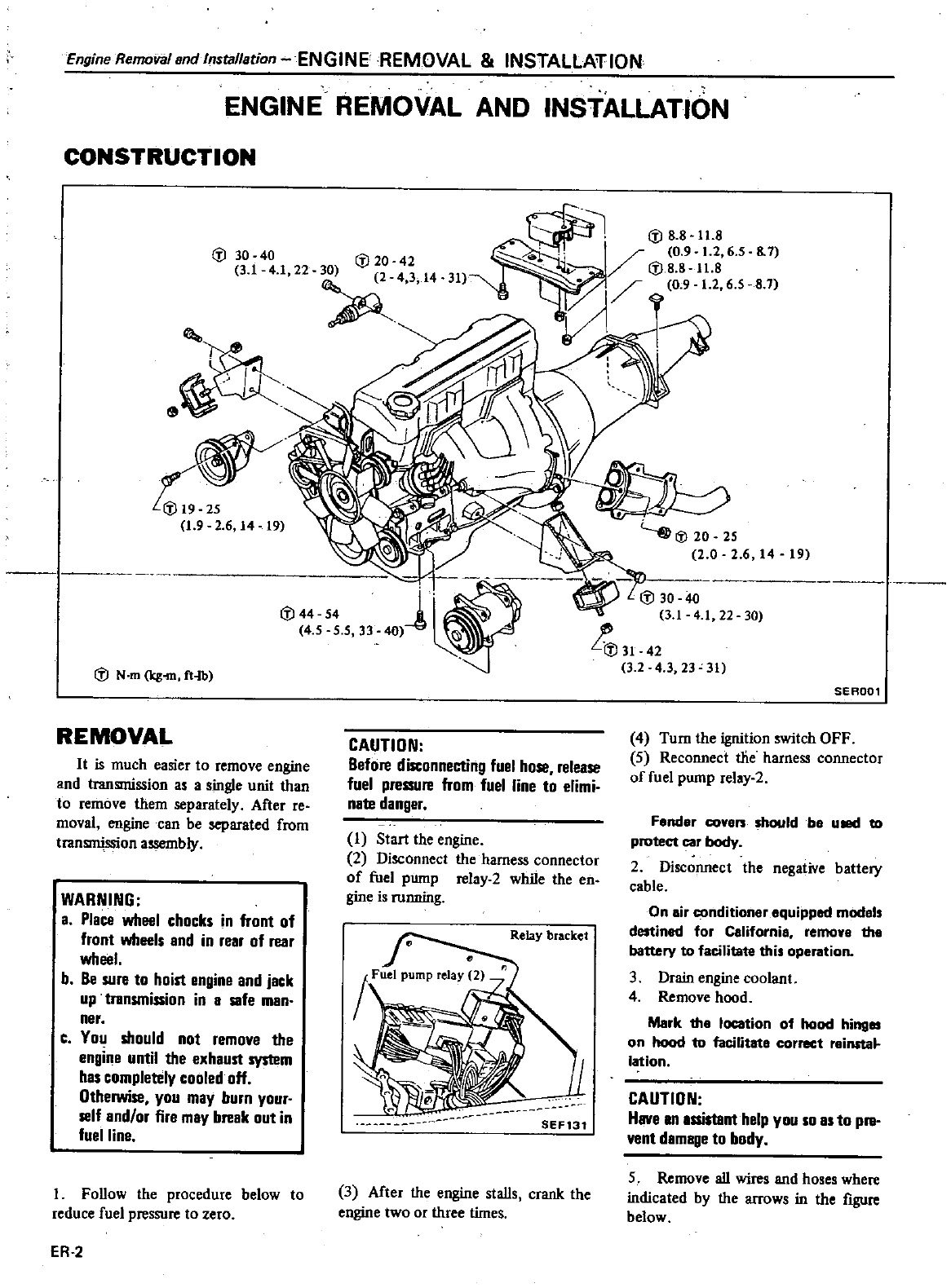
Engine
Removal
and
Installation
ENGINEREMOVAL
INSTALLATION
ENGINE
REMOVAL
AND
INSTALLATION
CONSTRUCTION
Iii
30
40
31
4 1
22
Iii 44 54
4
5
5 5
33
0
1
Iii
N
m
Itg
m
ft
b
REMOVAL
It
is
much
easier
to
remove
engine
and
transmission
as
a
single
unit
than
to
remove
them
separately
After reo
moval
engine
can
be
separated
from
transmission
assembly
WARNING
a
Place
wheel
chocks
in
front
of
front
wheels
and
in
rear
of
rear
wheel
b
Be
sure
to
hoist
engine
and
jack
up
transmission
in
a
safe
man
nero
C
You
should
not
remove
the
engine
until
the
exhaust
system
has
completely
cooled
off
Otherwise
you
may
burn
your
self
and
or
fire
may break
out
in
fuel
line
I
FoUow
the
procedure
below
to
reduce
fuel
pressure
to
zero
ER
2
CAUTION
Before
disconnecting
fuel
hose release
fuel
pressure
from
fuel
line
to
elimi
nate
danger
I
Start
the
engine
2
Disconnect
the
harness
connector
of
fuel
pump
relay
2
while
the
en
gine
is
running
Relay
bracket
SEF131
3
After
the
engine
staUs
crank
the
engine
two
or
three
times
8
7
8 7
19
Iii
30 40
31
4
1
22 30
31
42
3
2
4
3
23
31
SERD01
4
Turn
the
ignition
switch
OFF
5
Reconnect
tJie
harness
connector
of
fuel
pump
rel
y2
F
nd
r
co
shCll
ld
b
uBI
to
protect
car
body
2
Disconnect
the
negative battery
cable
On
air
condition
r
aquipped
mod
ls
destined
for
California
remon
tho
battery
to
facili
this
operation
3
Drain
engine
coolant
4
Remove
hood
Mark
tho
location
of
hood
hinges
on
hood
to
facilitot
correct
reinsta
lotion
CAUTION
Have
an
assistant
help
you
so as
to
PII
vent
damage
to
body
5
Remove
aU
wires
and
hoses
where
indicated
by
the
arrows
in
the
figure
below
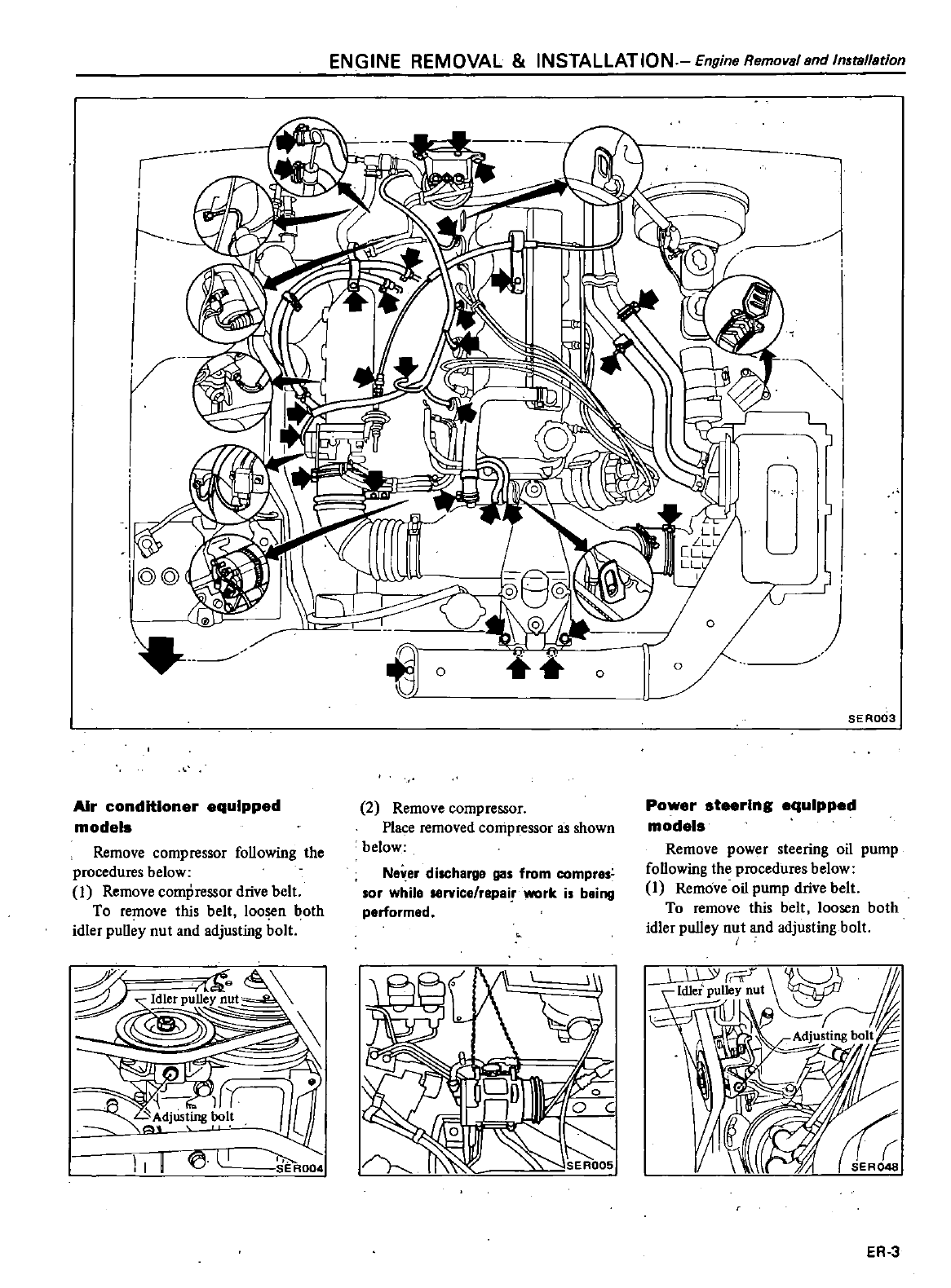
ENGINE
REMOVAL
INSTALLATION
Engine
Removs
and
In
tallation
1
u
Air
conditioner
equipped
models
Remove
compressor
foUowing
the
procedures
below
I
Remove
compressor
drive
belt
To
remove
this
belt
loosen
both
idler
puUey
nut
and
adjusting
bolt
P
fi
qa
9
5
ey
nut
a
1
n
djUS
ing
I
11
l
I
AOO
Yr
p
t
1
J
0
2
Remove
compressor
Place
removed
compressor
as
shown
below
Ne
er
d
ilCherge
gas
from
compres
sor
while
service
repair
work
is
being
performed
III
r
I
o
o
SER003
Power
steering
equipped
models
Remove
power
steering
oil
pump
foUowing
the
procedures
below
I
Remove
oil
pump
drive
belt
To
remove
this
belt
loosen
both
idler
puUey
nut
and
adjusting
bolt
ER
3
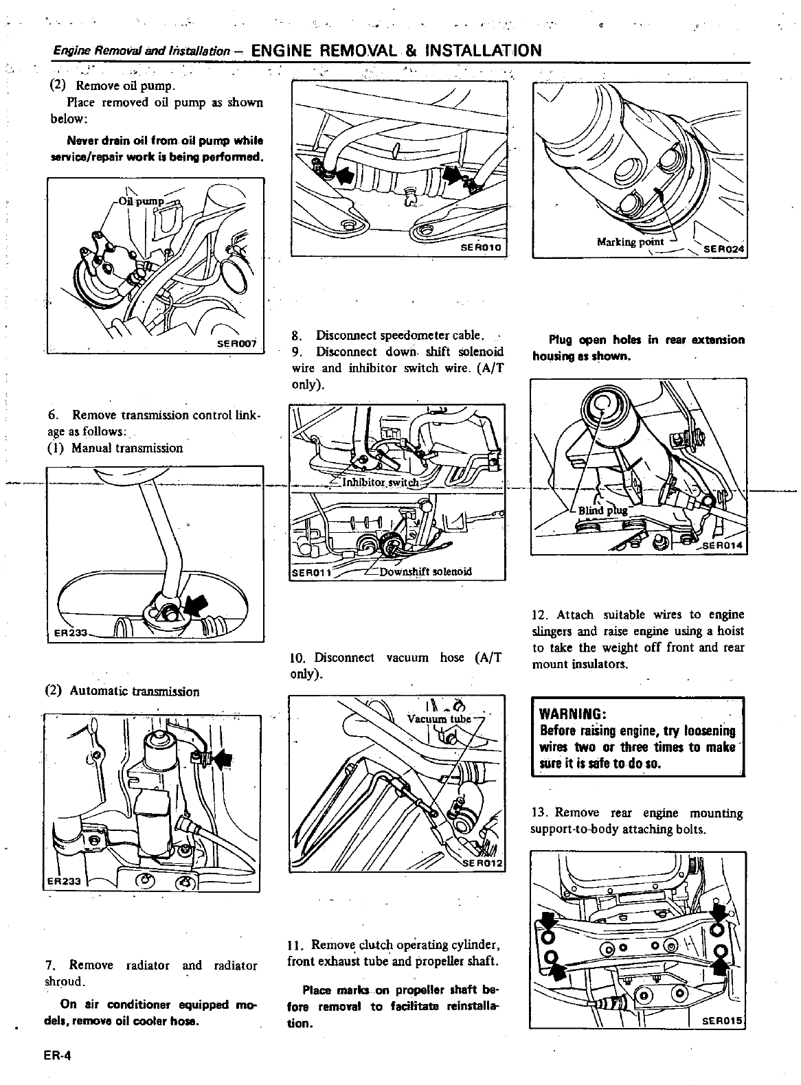
Engine
Removal
and
Installation
ENG
INE
REMOVAL
INSTALLATION
2
Remove
oil
pump
Place
removed
oil
pump
as
shown
below
Never
drain
oil
from
oil
pump
while
sorvice
repair
rk
i
being
perfonnod
6
Remove
transmission
control
link
age
as
foUows
1
Manual
transmission
E
33
iW
2
Automatic
transmission
7
Remove
radiator
and
radiator
shroud
On
air
conditioner
equipped
mo
dels
remove
oil cooler
ho
ER
4
SER010
I
g
Disconnect
speedometer
cable
9
Disconnect
down
shift
solenoid
wire
and
inhibitor
switch
wire
AfT
only
10
Disconnect
vacuum
hose
AfT
only
II
Remove
clutch
operating
cylinder
front
exhaust
tube
and
propeUer
shaft
Place
marks
on
propeller
haft be
fora
remo
al
to
facilitate
reinstall
tion
Mk
1
ar
mgp
SER024
Plug
open
holes
in
rear
extension
housing
as
hown
12
Attach
suitable
wires
to
engine
sIingers
and
raise
engine
using
a
hoist
to
take
the
weight
off
front
and
rear
mount
insulators
WARNING
BeforB
raising
engine
try
loosening
wires
two
or
three
times
to
make
sure it
is
safe
to
do
so
I3
Remove
rear
engine
mounting
support
to
body
aUaching
bolts
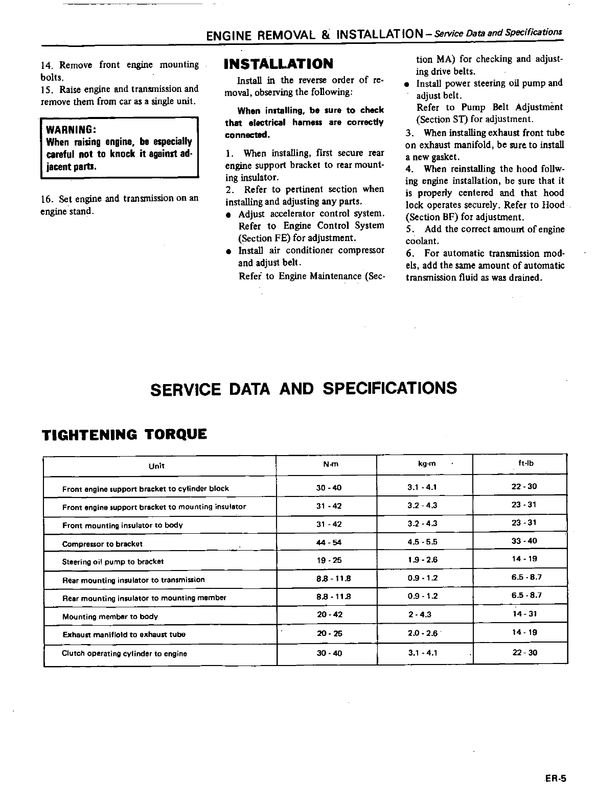
ENGINE
REMOVAL
INSTALLATION ServiceDataandSpecifications
14
Remove
front
engine
mounting
bolts
15
Raise
engine
and
transmission
and
remove
them
from
car
as
a
single
unit
WARNING
When
raising
engine
be
especially
careful
not
to
knock
it
against
ad
jacent
parts
16
Set
engine
and
transmission
on
an
engine
stand
INSTALLATION
InstaU
in
the
reverse
order
of
reo
moval
observing
the
foUowing
When
installing
be
lure to
check
that
electrical
heme
are
correcdy
connected
I
When
installing
first
secure
rear
engine
support
bracket
to
rear
mount
ing
insulator
2
Refer
to
pertinent
section when
installing
and
adjusting
any
parts
Adjust
accelerator
control
system
Refer
to
Engine
Control
System
Section
FE for
adjustment
InstaU
air
conditioner
compressor
and
adjust
belt
Refer
to
Engine
Maintenance
See
tion
MA
for
checking
and
adjust
ing
drive
belts
InstaU
power
steering
oil
pump
and
adjust
belt
Refer
to
Pump
Belt
Adjustment
Section ST
for
adjustment
3
When
installing
exhaust
front
tube
on
exhaust
manifold
be
sure
to
instaU
a
new
gasket
4
When
reinstalling
the hood foUw
ing
engine
instaUation
be
sure
that
it
is
properly
centered
and
that
hood
lock
operates
securely
Refer
to
Hood
Section
BF
for
adjuslment
5
Add the
correct
amount
of
engine
coolant
6
For
automatic
transmission
mod
els
add
the
same
amount
of
automatic
transmission
fluid
as was
drained
SERVICE
DATA
AND
SPECIFICATIONS
TIGHTENING
TORQUE
Unit
N
m
kg
m
ft
Ib
Front
engine
support
bracket
to
cylinder
block
30
40
3
1
4
1
22 30
Front
engine
support
bracket
to
mounting
insulator
31
42
32
4
3
23
31
Front
mounting
insulator
to
body
31
42
3 2
4
3
23
31
Compressor
to
bracket
44 54
4
5 5 5
33 40
Steering
oil
pump
to
bracket
19
25
1
9
2
6
14 19
Rear
mounting
insulator
to
transmission
88
11
8
09
1
2
658
7
Rear
mounting
insulator
to
mounting
member
88
11
8
0
9
1
2
6
5
8
7
Mounting
member
to
body
20 42
2 4 3
14
31
Exhaust
maniflold
to
exhaust
tube
20 25
2
0
2
6
14
19
Clutch
operating
cylinder
to
engine
30 40
3
1
4
1
22 30
ER
S
DATSUN
200SX
Mode
S
110
Series
SECTIONFE
ENGINE
CONTROL
FUEL
EXHAUST
SYSTEMS
CONTENTS
ENGINE
CONTROL
SYSTEM
ADJUSTMENT
REMOVAL
INSPECTION
INST
ALLATION
FUEL
SYSTEM
REMOVAL
FE
2
FE
2
FE
3
FE
3
FE
3
FE
4
FE
5
INSPECTION
INSTALLATION
EXHAUST
SYSTEM
REMOVAL
INSPECTION
INSTALLATION
FE
6
FE
7
FE
S
GII
FE
9
FE
9
FE
9
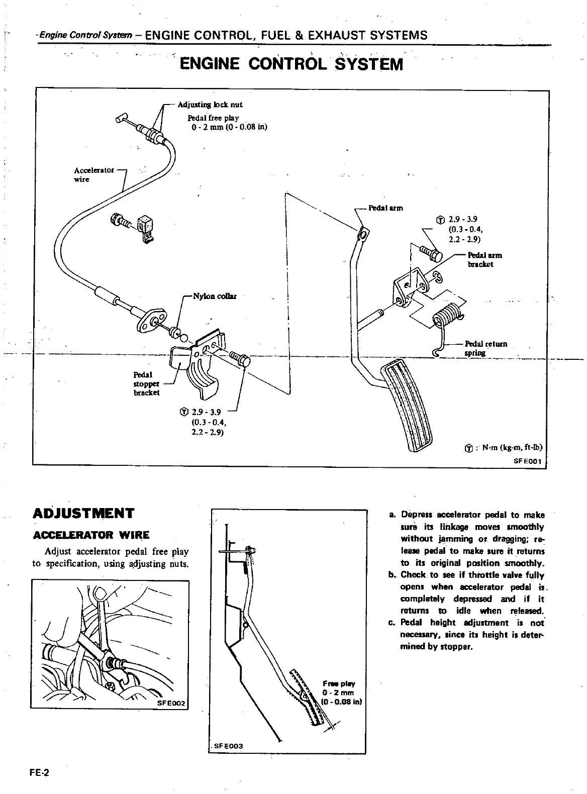
EngjneControISyltem
ENGINE
CONTROL
FUEL
EXHAUST
SYSTEMS
ENGINE
CONTROL
SYSTEM
Adjusting
bet
nut
Ptdal
free
play
o
2
mm
0008
in
frPedaI
arm
Iii
2 9 3 9
0
3 0
4
2
2 2
9
Pedal
arm
brlcket
t
j
aI
t
etum
PlUIll
Iii
N
m
kg
m
ft
lb
SFEQ01
ADJUSTMENT
ACC
RATOR
WIllE
Adjust
accelerator
pedal
free
play
to
specifICation
using
a
djusting
nuts
a
Depress
accelerator
pedal
to
make
Iura
its
linkage
moves
lIDootItly
without
jamming
or
dragging
re
lease
pedal
to
make
lure
it
returns
to
its
original
position
smoothly
b
Check
to
see
if throttle
valve
fully
open
when
accelerator
pedal
i
completely
depressed
and
if it
returns
to
idle
when
releasad
c
Pedal
height
adjustment
i
not
necessary
since
its
height
is
deter
mined
by
stopper
SFEOO3
FE
2
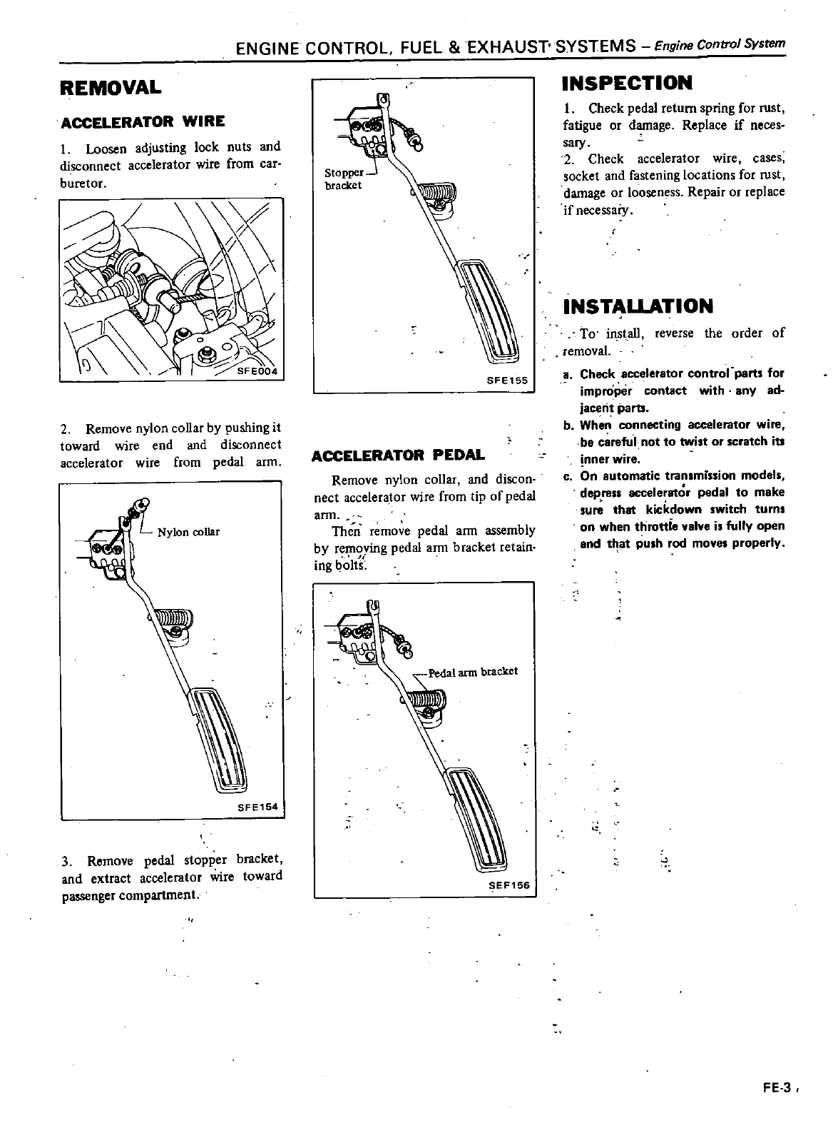
ENGINE
CONTROL
FUEL
EXHAUST
SYSTEMS
Engine
Control
System
REMOVAL
ACCELERATOR
WIRE
I
Loosen
adjusting
lock
nuts
and
disconnect
accelerator
wire
from
car
buretor
2
Remove
nylon
coUar
by
pushing
it
toward
wire
end
and
disconnect
accelerator
wire
from
pedal
ann
SFE154
3
Remove
pedal
stopper
bracket
and
extract
accelerator
wire
toward
passenger compartment
SFE155
ACCELERATOR
PEDAL
Remove
nylon
collar
and
discon
nect
accelerator
wire
from
tip
of
pedal
arm
Then
remove
pedal
arm
assembly
by
removing
pedal
arm
bracket
retain
r
ing
01t
EF156
INSPECTION
I
Check
pedal
return
spring
for
rust
fatigue
or
damage
Replace
if
neces
sary
2
Check accelerator
wire
cases
socket
and
fastening
locations
for
rust
damage
or
looseness
Repair
or
replace
if
necessaiy
INSTALLATION
To
in
staU
reverse
the
order
of
removal
a
Check accelerator
contror
parts
for
improper
contact
with
any
ad
jacent
parts
b
When
connecting
accelerator
wire
be
careful
not to
twilt
or
scratch
its
inner
wire
c
On
automatic
transmission
models
depress
accelerator
pedal
to
make
su
that
kickdown
switch
turn
on
when
throttie
alve
is
fully
open
and
t t
push
rod
mo
properly
FE
3
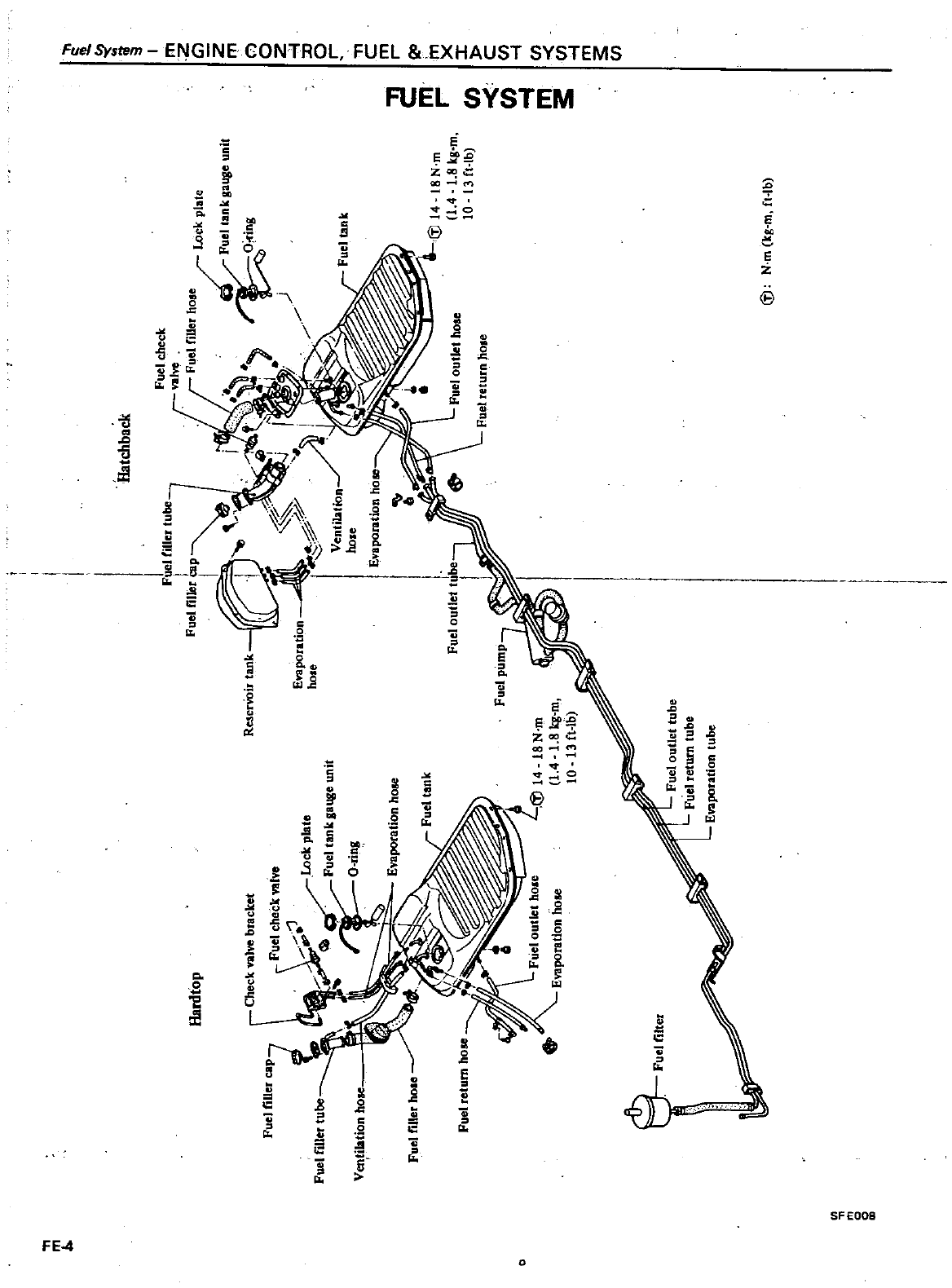
m
J
Hatchback
Fuel
check
vol
Fuel
filler
hose
10
k
I
c
pate
uel
tankaauge
unit
O
ing
Hardtop
Fuel
filler
cap
Fuel
filler
tube
Ventilation
ho
Fuel
filler
hole
Fuel
outlet
hoae
Fuel
fetum
hOle
o
Fuel
outlet
tube
Fuel
return
tube
Enporation
tulx
II
m
Q
Q
om
Fuel
tank
Iii
14
18N
m
1
4
1
8
Itg
m
10
13
fHb
Iii
N
m
kg
m
fHb
m
r
en en
I
m
i
r
l
I
m
Z
G
Z
m
n o
z
l
0
o
r
T1
C
m
r
ll
m
X
J
I
c
C
l
l
C
l
C
l
l
m
s
C
l
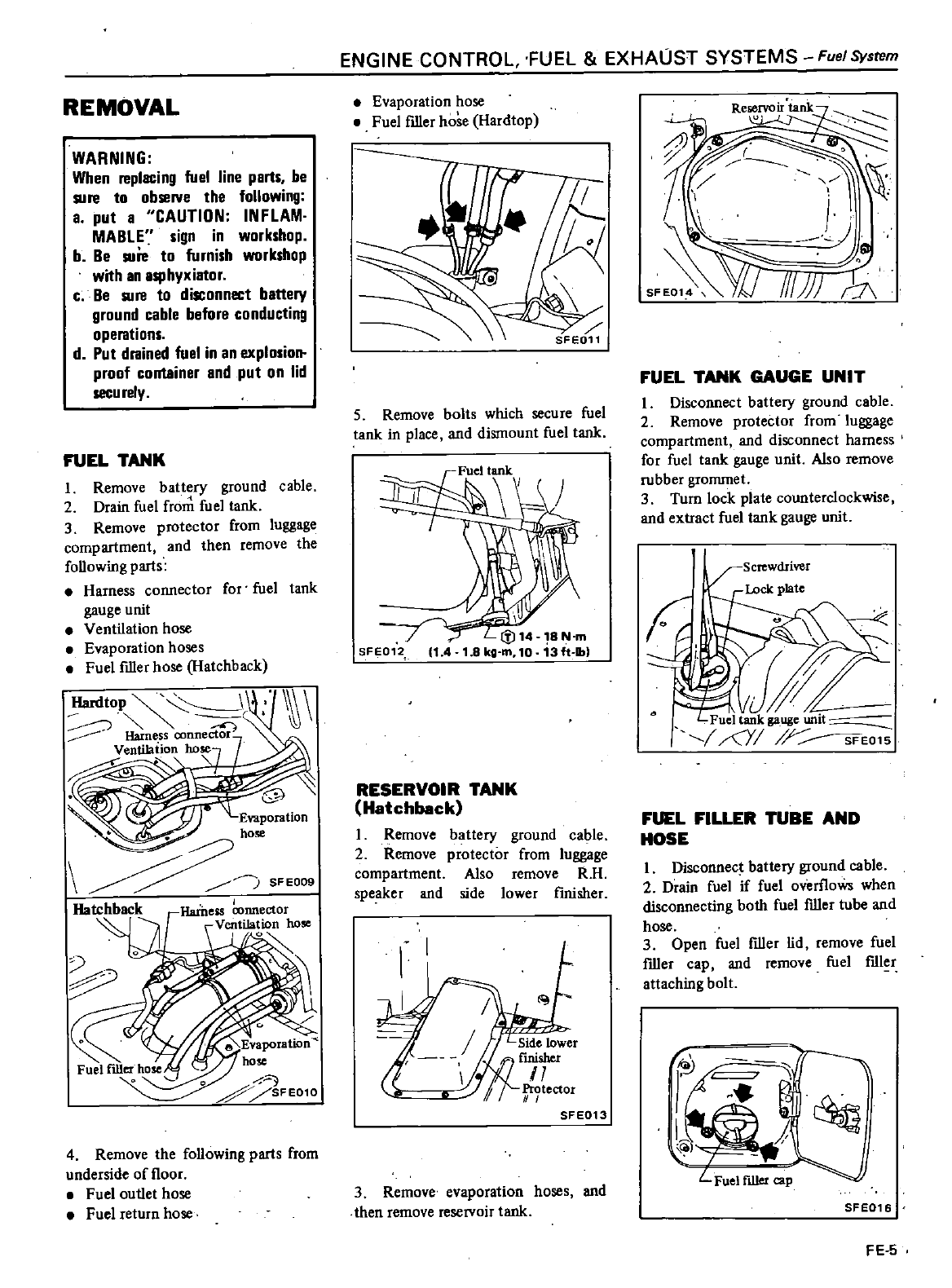
REMOVAL
WARNING
When
replacing
fuel
line
parts
be
sure
to
observe
the
following
a
put
a
CAUTION
INFLAM
MABLE
sign
in
workshop
b
Be
sure
to
furnish
workshop
with
an
asphyxiator
c
Be
sure
to
disconnect
battery
ground
cable
before
conducting
operations
d
Put
drained
fuel
in
an
explosion
proof
container
and
put
on
lid
secu
rely
FUEL
TANK
1
Remove
battery
ground
cable
2
Drain
fuel
fro
fuel
tank
3
Remove protector
from
luggage
compartment
and
then
remove
the
foUowing
parts
Harness
connector
for
fuel
tank
gauge
unit
Ventilation
hose
Evaporation
hoses
Fuel
filler
hose
Hatchback
Hardtop
Harness
connector
Ventilation
hose
HatchbackrHaineiS
nnector
A
Ventilation
hose
b1J
o
o
o
SFE010
4
Remove
the
foUowing
parts
from
underside
of
floor
Fuel
outlet
hose
Fuel
return
hose
ENGINE
CONTROL
FUEL
EXHAUST
SYSTEMS
Fuel
System
Evaporation
hose
Fuel
filler
hose
Hardtop
5
Remove
bolts which
secure
fuel
tank
in
place
and
dismount
fuel
tank
SFE012
1
4
18N
m
3ft
lb
RESERVOIR
TANK
Hatchback
I
Remove
battery
ground
cable
2
Remove
protector
from
luggage
compartment
Also
remove
RH
speaker
and
side
lower
flnisher
l
SFE013
3
Remove
evaporation
hoses
and
then
remove
reservoir
tank
FUEL
TANK
GAUGE
UNIT
I
Disconnect
battery
ground
cable
2
Remove
protector
from
luggage
compartment
and
disconnect
harness
for
fuel
tank
gauge
unit
Also
remove
rubber
grommet
3
Turn
lock
plate
counterclockwise
and
extract
fuel
lank
gauge
unit
FUEL
FILLER
TUBE
AND
HOSE
I
Disconnect
battery
ground
cable
2
Drain
fuel
if
fuel
overfloWs
when
disconnecting
both
fuel
filler
tube
and
hose
3
Open
fuel
filler
lid
remove
fuel
filler
cap and
remove
fuel
fIller
attaching
bolt
G
ii
I
j
1
2
uel
filler
p
SFE016
FE
S
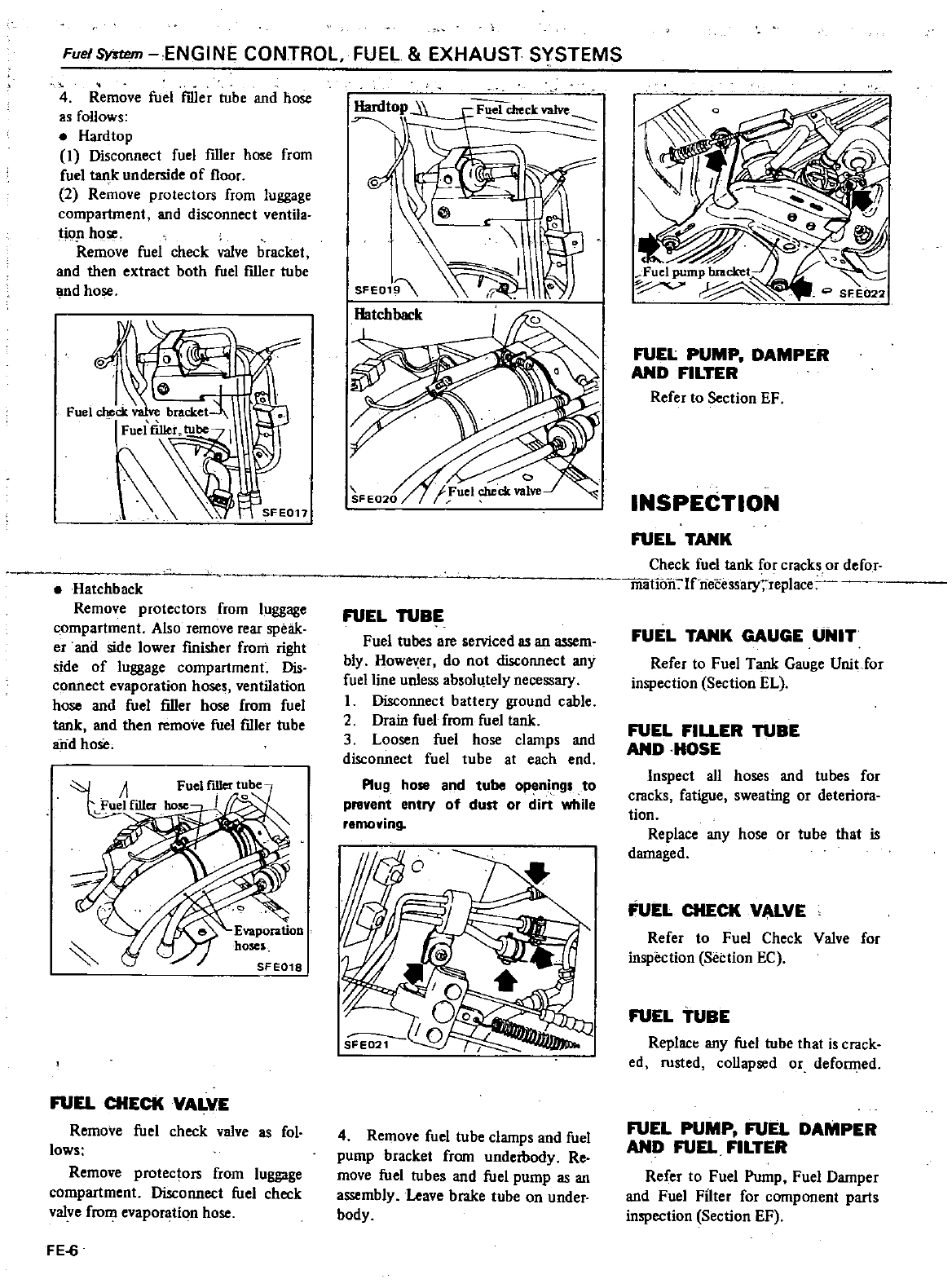
Fuel
System
ENGINE
CONTROL
FUEL
EXHAUST
SYSTEMS
4
Remove
fuel
filler
tube
and
hose
as
follows
Hardtop
1
Disconnect
fuel
filler
hose
from
fuel
al
k
underside
of
floor
2
Remove
protectors
from
luggage
compartment and
disconnect
ventila
tion
hose
Remove
fuel check
valve
bracket
and
then
extract
both
fuel
filler
tube
and
hose
Hatchback
Remove
protectors
from
luggage
compartment
Also
remove rear
speak
er
and
side
lower
fmisher
from
right
side
of
luggage
compartment
Dis
cc
mnect
evaporation
hoses
ventilation
hose
and
fuel
filler
hose
from
fuel
tank
and
then
remove
fuel
filler
tube
arid
hose
1
Fuel
filler
t
be
1
filler
110
I
SFE018
FUEL
CHECK
VALVE
Remove
fuel
check
valve
as
fol
lows
Remove
protectors
from
luggage
compartment
Disconnect
fuel
check
valve
from
evaporation
hose
FE
6
Hardtop
D
9
cl1eckvalve
SFEO
FUEL
TUBE
Fuel
tubes
are
serviced
as
an
assem
bly
How
er
do
not
disconnect any
fuel
line
unless
absolltely
necessary
I
Disconnect
batlery
ground
cable
2
Drain
fuel
from
fuel
tank
3
Loosen fuel
hose
clamps
and
disconnect fuel
tube
at
each
end
Plug
hose
and
tube
openi
ng
to
prevent
entry
of
dust
or
dirt
while
removing
4
Remove
fuel
tube
clamps
and fuel
pump
bracket
from
underbody
Re
move
fuel
tubes
and
fuel
pump
as
an
assembly
Leave
brake
tube
on
under
body
FUEL
PUMP
DAMPER
AND
FILTER
Refer
to
Section
EF
INSPECTION
FUEL
TANK
Check
fuel
tank
for
cracks
or
defor
mauon
If
o
ecessaryreplacl
FUEL
TANK
GAUGE
UNIT
Refer
to
Fuel
Tank
Gauge
Unit
Jor
inspection
Section
EL
FUEL
FILLER
TUBE
AND
HOSE
Inspect
aU
hoses
and
tubes
for
cracks
fatigue
sweating
or
deteriora
tion
Replace
any
hose
or
tube
that
is
damaged
FUEL
CHECK
VALVE
Refer
to
Fuel
Check
Valve
for
inspection
Section
EC
FUEL
TUBE
Replact
any
fuel
tube
1hat
is
crack
ed
rusted
coUapsed
or
deformed
FUEL
PUMP
FUEL
DAMPER
AND
FUEL
FILTER
Refer
to
Fuel
Pump
Fuel
Damper
and
Fuel
Filter
for
component
parts
inspection
Section
EF
ENGINE
CONifROL
FUEt
EXHAUST
SYSTEMS
FueISysll1
INSTALLATION
InstaU
any
parts
of
the
fuel
system
in
the
reverse
order
of
removal
Observe
the
foUowing
notes
and
refer
to
Fuel
Filter
Fuel
Pump
Fuel
Darnper
aod
Fuel
Hose
for
removal
aod
instaUation
Section
EF
GJ
Fuel
tan
k
retaining
bolt
14 18
N
m
1
4
1
8
kg
m
10
13ft
lb
a
Install
ho e
clamp ecurely
Do
not
tighten
excessively
to
avoid
damag
ing
hose
b
Fasten
fuel
tube
clamp
on
und
r
body
ecurely
Failure
to
follow
this
caution
could result in
damage
to
the
urf
e
of
fuel
tube
c
Do
not
kink
or
twist
ole
and
tube
when
they
are
routed
d
Run
the
engine
and
check
for
leak
at
connection
e
Fuel
tank
Install
fuel
filler
hose
etter
fuel
tank
has
been
mounted
in
place
Failure
to
follow
this
rule
could
result in
lea
ge
from
around
hose
connections
Do
not
twist
or
smash
ventilation
and evaporation
hoses
when
they
are
routed
Be
sure
to
retain them
with
clips
securely
f
Fuel
tank
gauge
unit
When
installing
fuel
tank
gauge
unit
align
tlle
projection
of
fuel
tank
gauge
unit
with
the
notch
in
fuel
tank
and
tighten
it
ecurely
Be
sure
to
install
fuel
tank
gauge
unit
with
Q
ring
in
place
FE
7
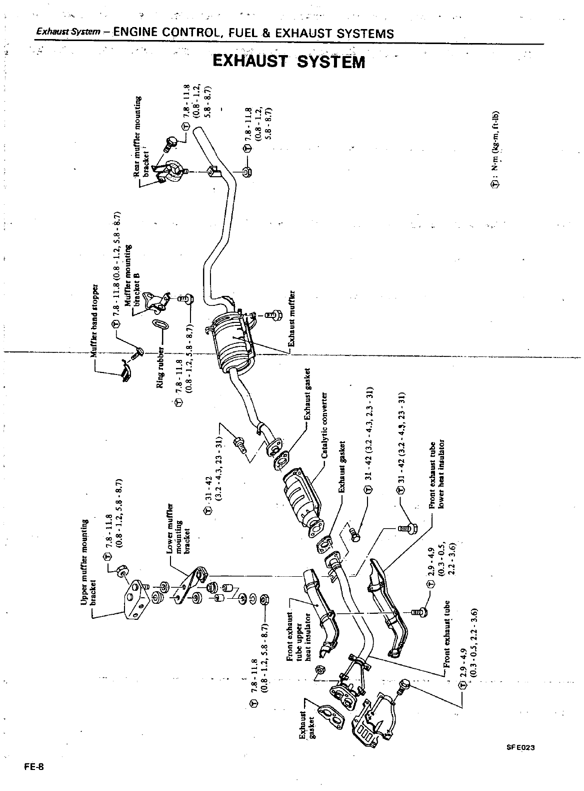
fflermo
tir18
Upper
mu
raCket
8
Iii
7
8
11
58
8
7
0
81
2
gg
I
Lower
mumer
1i
mountlos
1
bncket
@
1
7
@
8
7
m
Co
Iii
7
8
11
8
0
8
1
2
5
8
LIii
2
9
4
9
0
3
0
5
Front
exhaua
tube
2
2
3
6
Iii
2
9
4
9
0
3
0
5
2
2
3
6
Front
ePaust
tube
lower
heat
iniulatOJ
m
0
IIUmer
bond
opper
Iii
7
8
H
8
0
8
12
5
8
j
ounlill8
RiIl8
rUbJer
fj
7
8
H
8l
0
8
12
5
8
8
7
I
Exhaust
murtler
Catalytic
converter
4
23
31l
8
7
Rear
mutner
mounting
l
Iii
7
8
1l
8
0
8
1
2
5
8
8
7
1fJ7
8
H
8
0
8
12
5
8
8
7
Iii
N
m
kg
m
ft
b
m
J
Ii
c
ff f
m
3
l
I
11
m
Zc
Z
m
oZ
l
D
o
r
C
m
r
Ii
m
X
I
C
J
J
l
m
J
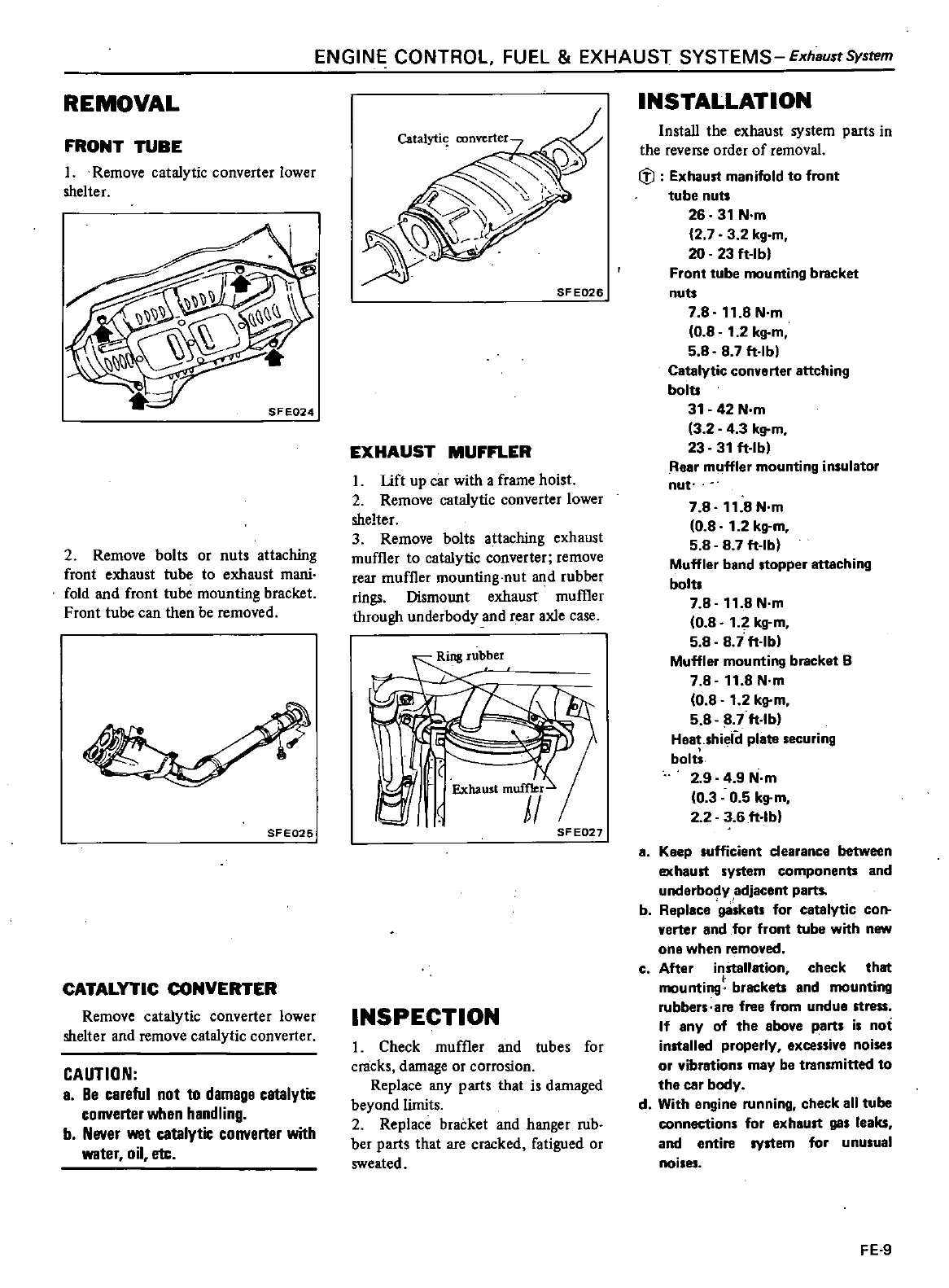
ENGINE
CONTROL
FUEL
EXHAUST
SYSTEMS
ExhBustSystem
REMOVAL
FRONT
TUBE
1
Remove
catalytic
converter
lower
shelter
2
Remove
bolts
or
nuts
attaching
front
exhaust
tube
to
exhaust
mani
fold
and
front
tube
mounting
bracket
Front
tube
can
then
be
removed
SFE025
CATALYTIC
CONVERTER
Remove
catalytic
converter
lower
shelter
and
remove
catalytic
converter
CAUTION
a
Be
careful
not
to
damage
catalytic
converter
when
handling
b
Never
wet
catalytic
converter
with
water
oil
m
SF
E026
EXHAUST
MUFFLER
L
lift
up
car
with
a
frame
hoist
2
Remove
catalytic
converter
lower
shelter
3
Remove
bolts
attaching
exhaust
muffler
to
catalytic
converter
remove
rear
muffler
mounting
nut
and
rubber
rings
Dismount
exhaust
muffler
through
underbody
and
rear
axle
case
I
Exhaust
muffler
1
U
SF
E027
INSPECTION
I
Check
muffler
and
tubes
for
cmcks
damage
or
corrosion
Replace
any
parts
that
is
damaged
beyond
limits
2
Replace
bracket
and
hanger
rub
ber
parts
that
are
cracked
fatigued
or
sweated
INSTALLATION
InstaU
the
exhaust
system
parts
in
the
reverse
order
of
removal
ifl
Exhaust
manifold
to
front
tube
nuts
26
31
N
m
2 7 3 2
kg
m
20 23
ft
lb
Front
tube
mounting
bracket
nuts
7 8
11
8
N
m
08
1
2
kg
m
588 7
ft
lb
Catalytic
converter
attching
bolts
31
42
N
m
3 2 4 3
kg
m
23
31
ft
lb
Rear
muffler
mounting
insulator
nut
7 8 11 8
N
m
0 8
1
2
kg
m
5 8 8 7
ft
lb
Muffler
band
stopper
attaching
bolts
7 8
11
8N
m
0 8
1
2
kg
m
5 8 8
i
ft
lb
Muffler
mounting
bracket
B
7 8 11 8
N
m
0 8
1
2
kg
m
5 8 8 7
ft
lb
Heet
hieiil
plate
ecuring
bolt
2
9 4
9
N
m
03 0 5
kg
m
2 2
3 6
ft
lb
a
Keep
sufficient
clearance
between
exhaust
system
components
and
underbody
adjacent
parts
b
Replace
ga
ket
for
catalytic
con
verter
and
for
front
tube
with
new
one
when
removed
c
After
inStallation
check
that
mounting
brackets
and
mounting
rubbers
are
free
from
undue
stress
If
any
of
the
above
part
i
not
installed
properly
excessive
noise
or
vibrations
may
be
transmitted
to
the
car
body
d
With
engine
running
check
all
tube
connection
for
exhaust
gas
leaks
and
entire
system
for
unusual
noises
FE
9
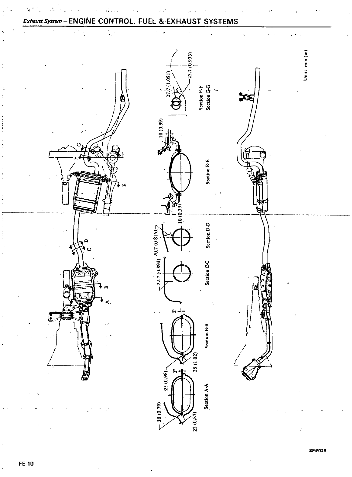
NG
N
CON
ROL
fU
L
E1
AUS
S
S
e
f
j
q
o
E
11
jj
II
II
a
P
A
Q
9
1
a
Q
oJ
a
j
6
j
O
e
SFI
DATSUN
200SX
Mode
S
II
0
Series
SECTIONCL
HYDRAULIC
CLUTCH
CONTROL
CLUTCH
PEDAL
CLUTCH
MASTER
CYLINDER
OPERATING
CYLINDER
CLUTCH
LINE
BLEEDING
CLUTCH
SYSTEM
CLUTCH
UNIT
CLUTCH
DISC
AND
COVER
RELEASE
BEARING
CLUTCH
CONTENTS
CL
2
l
Ci
2
CL
2
CL
4
t
5
CL
5
C
7
CL
7
CL
9
PILOT
BUSHING
SERVICE
DATA
AND
SPECIFICATIONS
GENERAL
SPECIFICATIONS
INSPECTION
AND
ADJUSTMENT
TIGHTENiNG
TORQUE
TROUBLE
DIAGNOSES
AND
CORRECTIONS
SPECIAL
SERVICE
TOOLS
CL
9
CL
11
clli
CL
11
CL11
CL12
CL14
Refer
to
Section
MA
Clutch
for
CHECKING
CLUTCH
PEDAL
HEIGHT
AND
FREE
PLAY
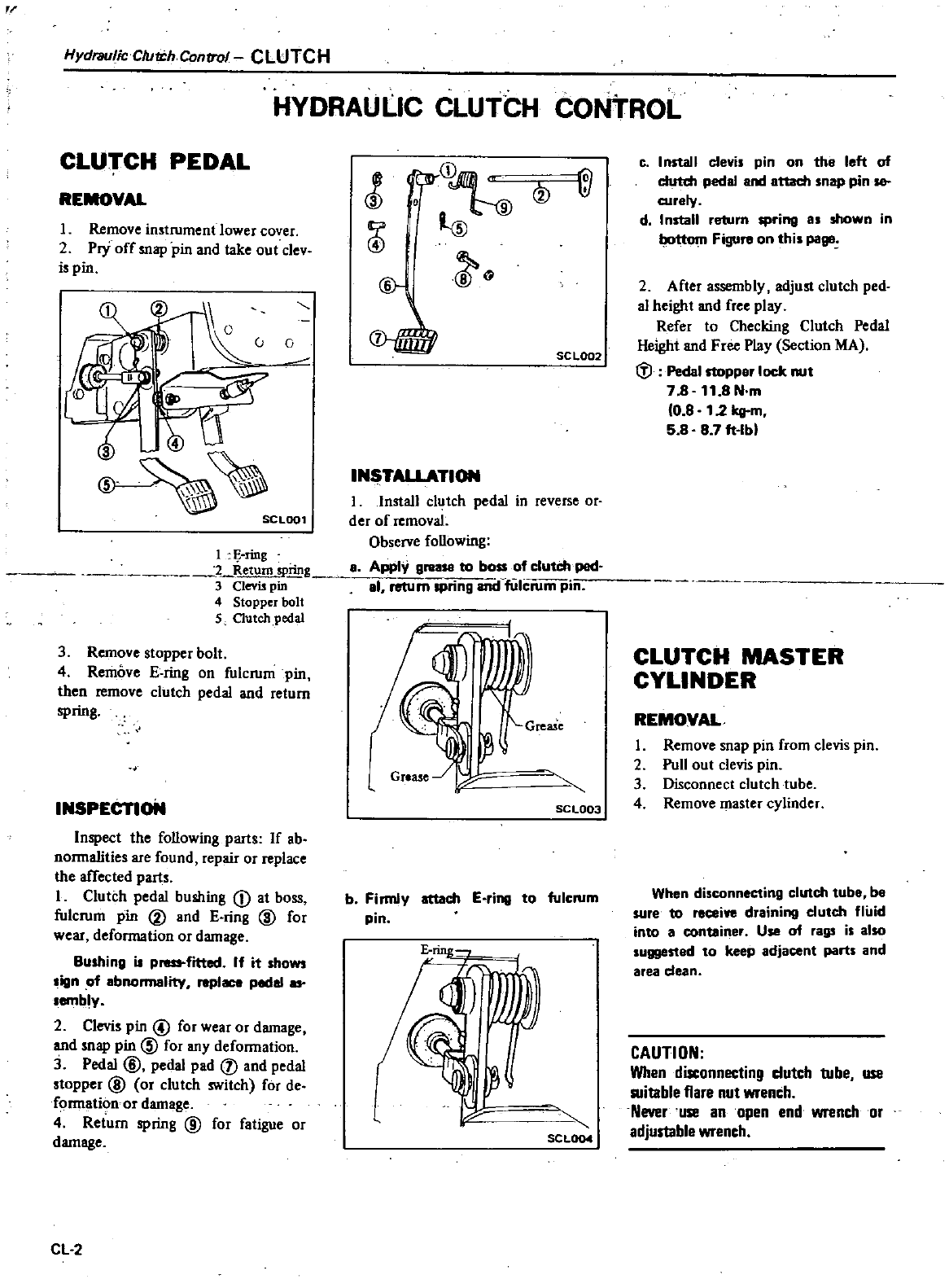
Hydraulic
C
utJ
h
Conrrol
CLUTCH
HYDRAULIC
CLUTCH
CONTROL
CLUTCH
PEDAL
REMOVAL
1
Remove
instrument
lower
cover
2
Pry
off
snap
pin
and
take
out
clev
is
pin
0
o
3
SCLOOl
1
li
ring
1
Return
spring
3
Oevi
pin
4
Stopper
bolt
5
Outchpedal
3
Remove
stopper
bolt
4
Remove
E
ring
on
fulcrum
pin
then
remove
clutch
pedal
and
return
spring
INSPECTIoN
Inspect
the
foUowing
parts
If
ab
nonnalities
are
found
repair
or
replace
the
affected
parts
I
Clutch
pedal
bushing
D
at
boss
fulcrum
pin
V
and
E
ring
@
for
wear
deformation
or
damage
Bushing
iJ
p
fitted
If
it
shows
sign
of
abnonnality
replaca
pedal
as
sembly
2
Clevis
pin
@
for
wear
or
damage
and
snap
pin
@
for
any
deformation
3
Pedal
@
pedal
pad
j
and
pedal
stopper
@
or
clutch
switch
for
de
formation
or
damage
4
Return
spring
@
for
fatigue
or
damage
Cl
2
r
D
G
SC
l002
l
INSTAllATION
I
Install
clutch
pedal
in
reverse
or
der
of
removal
Observe
foUowing
a
Apply
grea
to
boss
ofclutch
ped
al
return
spring
and
fiih
rum
pin
SCL003
b
Firmly
attach
E
ring
to
fulcrum
pin
SCL0Q4
Q
Co
I
nstall
clevis pin
on
tha
left
of
clutch
pedal
and
attach
snap
pin
sa
curaly
d
I
nstall
return
spring
as
shown
in
Figure
on
this
page
2
After
assembly
adjust
clutch
ped
aI
height
and
free
play
Refer
to
Checking
Clutch
Pedal
Height
and
Free
Play
Section
MA
tV
Pedal
rtoppar
lock
nut
7
B
11
8N
m
10
8
12
kg
m
5 8 87
ft
lbl
CLUTCH
MASTER
CYLINDER
REMOVAL
I
Remove
snap
pin
from
clevis
pin
2
Pull
out
clevis
pin
3
Disconnect
clutch
tube
4
Remove
master
cylinder
When
disconnecting
clutch
tube
be
sure
to
recei
draining
clutch
fluid
into
a
container
Use
of
rags
is
also
suggestad
to
keep
adjacent
parts
and
area
dean
CAUTION
When
disconnecting
dutch
tube
use
suitable
flare
nut
wrench
Never
use
an
open
end wrench
or
adjustable
wrench
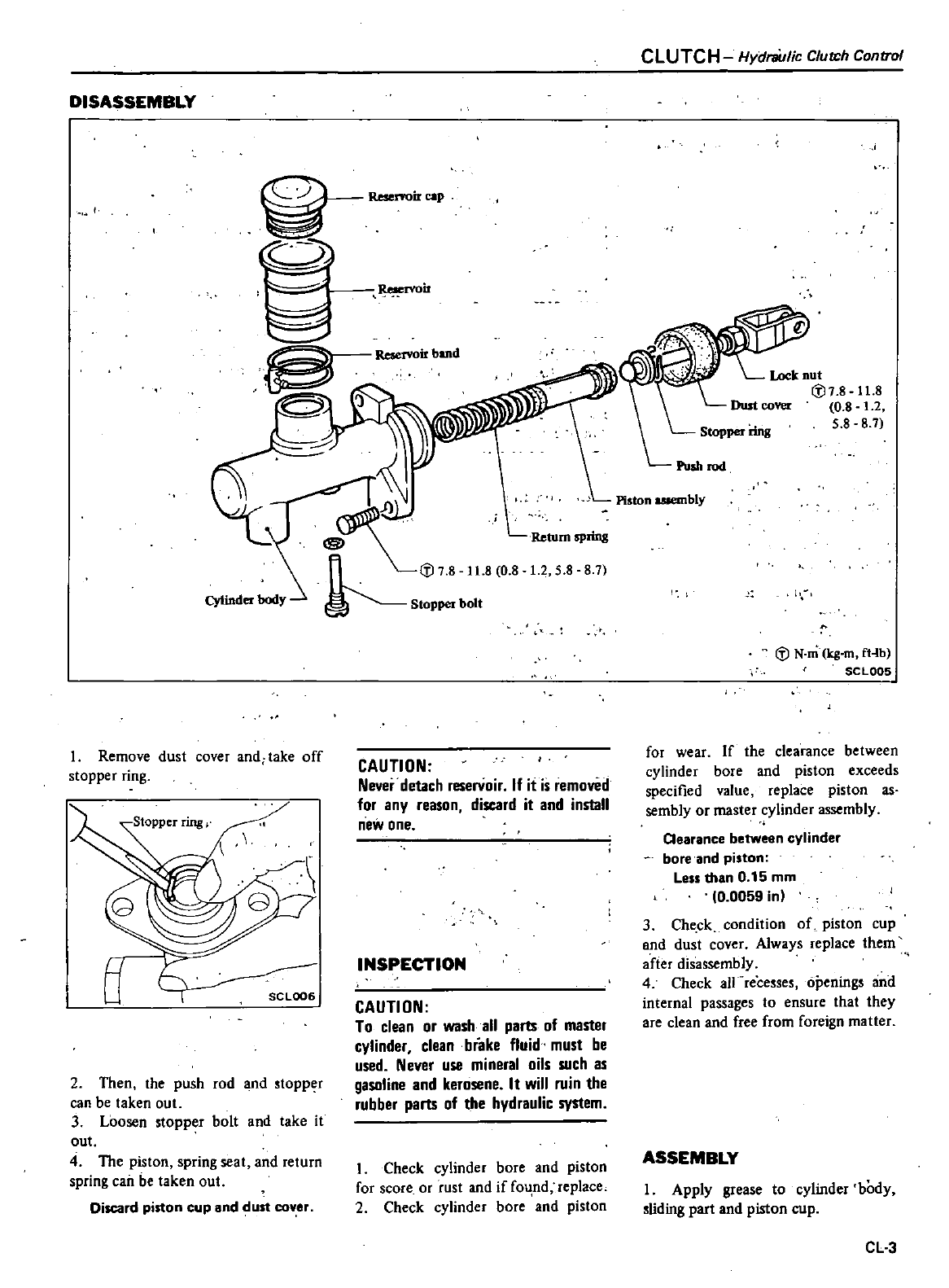
DISASSEMBLY
CLUTCH
Hydniulic
Clutch
Control
I
Remove
dust
cover
and
take
off
stopper
ring
t1
SCLOO6
2
Then
the
push
rod
and
stopper
can
be
taken
out
3
Loosen
stopper
bolt
and
take
it
out
4
The
piston
spring
seat
and
return
spring can
be
taken
out
Discard
piston
cup
and
ust
cover
ir
Reservoir
band
1
Iii
78
11
8 0 8
Stoppetbol
Return
spring
1
2
58 8
7
CAUTION
Never
detach
reservoir
If it
is
removed
for
any
reason
discard
it
and
install
new
one
INSPECTION
CAUTION
To
clean
or
wash
all
parts
of
master
cylinder
clean
brake
fluid
must
be
used
Never
use
mineral
oils
such
as
gasoline
and
kerosene
It
will
ruin
the
rubber
parts
of
the
hydraulic
system
1
Check
cylinder
bore
and
piston
for
score
or
rust
and
if
fo
nd
replace
2
Check
cylinder
bore
and
piston
Lock
nut
lii7
8
11
8
0
8
1
2
58 8
7
Iii
N
m
kg
mfHb
SCL005
for
wear
If
the
clearance
between
cylinder
bore
and
piston
exceeds
specified
value
replace
piston
as
sembly
or
master
cylinder
assembly
Cearance
between
cylinder
bore
and
piston
Le
than
0
15
mm
0
0059
in
3
Check
condition
of
piston
cup
and
dust
cover
Always
replace
them
after
disassembly
4
Check
aU
recesses
openings
and
internal
passages
to
ensure
that
they
are
clean and
free
from
foreign
matter
ASSEMBLY
I
Apply
grease
to
cylinder
body
sliding
part
and
piston
cup
CL3
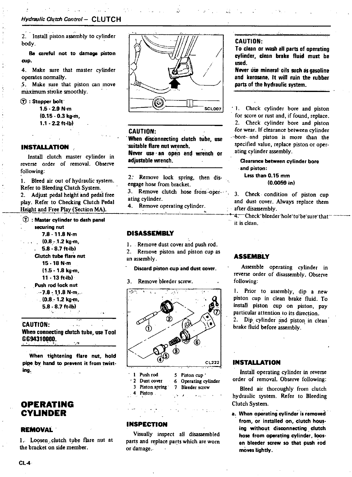
Hydraulic
C1u
t
h
Control
CLUTCH
2Install
piston
assembly
to
cylinder
body
Be
careful
not to
damage
piston
cup
4
Make
sure
that
master
cylinder
operates
normally
5
Make
sure
thai
piston
can
move
maximum
siroke
smoothly
Stopper
bolt
1
529
N
m
0
15
0 3
k9
m
1 1
22
ft
lb
INSTALLATION
InstaU
clutch
master
cylinder
in
reverse
order
of
removal
Observe
foUowing
I
Bleed
air
out
of
hydraulic
system
Refer
to
Bleeding
Clutch
System
2
Adjust
pedal
height
and
pedRl
free
play
Refer
to
Checking
Clutch
Pedal
HeiRht
and
Free
Play
Section
MA
Master
cylinder
to
dash
panel
HCUring
nut
7
8
11 8
N
m
0
8
12
kg
m
58
8
7
ft
bl
Clutch
tube flare
nut
15 18 N
m
1
5
1
8
kg
m
11
13ft
b
Push
rod
lock
nut
7
8
11
8N
m
0
8
1
2
kg
m
58
87
ft
bl
CAUTION
When
connecting
dutch
tube
use
Tool
GG94310000
I
J
When
tightening
flare
nut
hold
pi
by
hand
to
prevent
it
from twist
in9
OPERATING
CYUNDER
REMOVAL
L
lo9sen
clutch
tl
be
flare
nut
at
the
bracket
on
side
member
Cl
4
I
fTI
sc
L001
CAUTION
When
disconnecting
clutch
tube
use
suitable
flare
nut
wrench
Never
use
an
open
end
wrench
or
adjustable
wrench
2
Remove
lock
spring
then
dis
engage
hose
from
bracket
3
Remove
clutch
hose
from
oj
er
ating
cylinder
4
Remove
operating
cylinder
DISASSEMBLY
I
Remove
dust
cover
and
push
rod
2
Remove
piston
and
piston
cup
as
an
assembly
Discard
piston
cup
and
dun
cover
3
Remove
bleeder
screw
CL222
1
Push
rod
2
Dwt
cover
3
Piston
spring
4
Piston
5
Piston
cup
6
Operating
cylinder
7
Bleeder
screw
INSPECTION
Visually
inspect
all
disassembled
parts
and
replace
parts
which
are
worn
or
damage
CAUTION
To
clean
or
wash
all
parts
of
operating
cylinder
clean
brake
fluid
must
be
used
Never
USe
mineral
oils
such
is
gasoline
and
kerosene
It
will
ruin
the
rubber
parts
of
the
hydraulic
system
I
Check
cylinder
bore
and
piston
for
score
or
rust
and
if
found
replace
2
Check
cylinder
bore
and
piston
for
wear
If
clearance
between
cylinder
bore
and
piston
is
more
than
the
specified
value
replace
piston
or
oper
ating
cylinder
assembly
Cearance
between
cylinder
bore
and
piston
less
than
0
15
mm
0
0059
in
3
Check
condition
of
piston
cup
and
dust
cover
Always
replace
them
after
disassembly
heck
bleeder
holno
be
surnhat
it
is
clean
ASSEMBLY
Assemble
operating
cylinder
in
reverse
order
of
disassembly
Observe
following
I
Prior
to
assembly
dip
a
new
pis10n
cup
in
clean
brake
fluid
To
install
piston
cup
on
piston
pay
particular
attention
to
its
direc
ion
2Dip
cylinder
nd
pis10n
in
clean
brake
fluid
before
assembly
INSTALLATION
Install
operating
cylinder
in
reverse
order
of
removal
Observe
foUowing
Bleed
air
thoroughly
from
clutch
hydraulic
system
Refer
to
Bleeding
Clutch
System
8
When
operating
cylinder
is
r
moved
from
or
installed
on
elutch hou
ing
without
disconnecting
clutch
hose
from
operating
cylinder
loos
en
bleeder
scrow
so
that
push
rod
moves
lightly
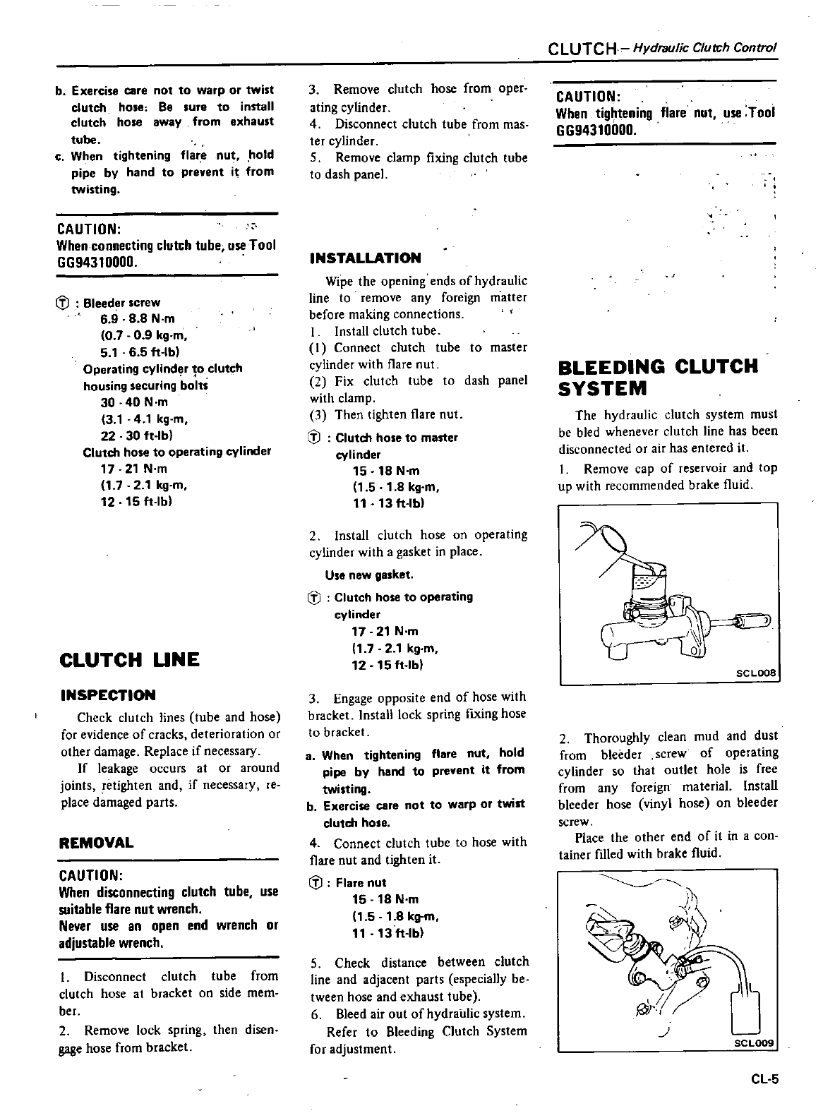
b
Exercise
care
not to
warp
or
twist
clutch
hose
Be
sure
to
install
clutch
hose
away
from
exhaust
tube
c
When
tightening
flare
nut
hold
pipe
by
hand
to
prevent
it
from
twisting
CAUTION
When
connecting
clutch
tube
use
Tool
GG94310000
li
Bleeder
screw
6 9 8 8
N
m
07 0 9
kg
m
5
1
6 5
ft
lb
Operating
cylind
r
10
clutch
housing
securing
bolts
30
40
N
m
3
1
41
kg
m
22 30
ft
lb
Clutch
hose
to
operating
cylinder
17
21
N
m
1
7 2
1kg
m
12 15
ft
lb
CLUTCH
UNE
INSPECTION
Check
clutch
lines
tube
and
hose
for
evidence
of
cracks
deterioration
or
other
damage Replace
if
necessary
If
leakage
occurs
at
or
around
joints
retighten
and
if
necessary
re
place
damaged
parts
REMOVAL
CAUTION
When
disconnecting
clutch
tube
use
suitable
flare
nut
wrench
Never
use
an
open
end
wrench
or
adjustable
wrench
I
Disconnect
clutch
tube
from
clutch
hose
at
bracket
on
side
memo
ber
2
Remove
lock
spring
then
disen
gage
hose
from
bracket
3
Remove
clutch
hose
from
oper
ating
cylinder
4
Disconnect
clutch
tube
from
mas
ter
cylinder
5
Remove
clamp
fixing
clutch
tube
to
dash
panel
INSTALLATION
Wipe
the
opening
ends
of
hydraulic
line
to
remove
any
foreign
matter
before
making
connections
I
Install
clutch
tube
I
Connect
clutch
tube
to
master
cylinder
with
flare
nut
2
Fix
clutch
tube
to
dash
panel
with
clamp
3
Then
tighten
flare
nut
li
Clutch
hose
to
master
cylinder
15 18
N
m
1
5
1
8
kg
m
t
1
13
ft
lb
2
Install
clutch
hose
on
operating
cylinder
with
a
gasket
in
place
Use
new
gasket
li
Clutch
hose
to
operating
cylinder
17
21
N
m
1
72
1kg
m
12 15
ft
lb
3
Engage
opposite
end
of
hose
with
bracket
Install
lock
spring
fixing
hose
to
bracket
a
When
tightening
flare
nut
hold
pipe
by
hand
to
prevent
it
from
twisting
b
Exercise
care
not
to
warp
or
twist
clutch
hose
4
Connect
clutch
tube
to
hose
with
flare
nut
and
tighten
it
li
Flare
nut
15 18
N
m
1
5
1
8
kg
m
11
13
ft
lb
5
Check
distance
between
clutch
line and
adjacent
parts
especially
be
tween
hose
and
exhaust
tube
6
Bleed
air out
of
hydraulic
sys1em
Refer
to
Bleeding
Clutch
System
for
adjustment
CLUTCH
Hydraulic
Clutch
Control
CAUTION
When
tightening
flare
nut use
Tool
GG94310000
BLEEDING
CLUTCH
SYSTEM
The
hydraulic
clutch
system
must
be
bled
whenever
clutch
line
has
been
disconnected
or
air
has
entered
it
I
Remove
cap
of
reservoir
and
top
up
with
recommended
brake
fluid
I
o
SC
LoDe
2
Thoroughly
clean
mud
and
dust
from
bleeder
screw
of
operating
cylinder
so
that
outlet
hole
is
free
from
any
foreign
material
Install
bleeder
hose
vinyl
hose
on
bleeder
screw
Place
the
other
end
of
it
in a
con
tainer
filled
with
brake
fluid
J
SCL009
CL
5
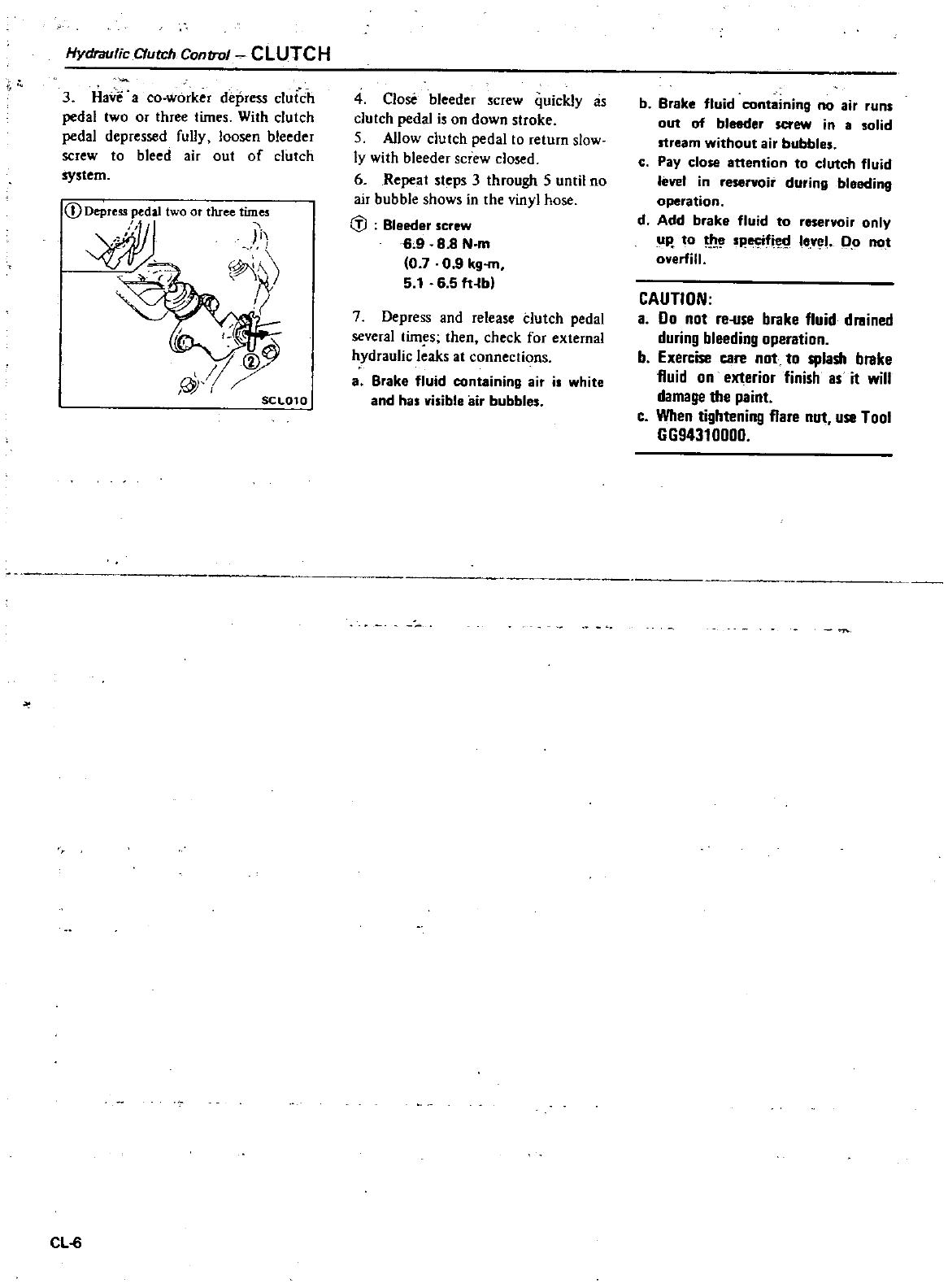
Hydraulic
Clutch
Control
CLUTCH
3
Have
a
co
worker
depress
clutch
pedal
two or
three
times
With
clutch
pedal
depressed
fully
loosen
bleeder
screw
to
bleed
air out
of
clutch
system
CD
Depress
pedal
two
or
three
times
dlll
y
I
I
ilr
j
CJy
@
SCL010
CL
6
4
Close
bleeder
screw
quickly
as
clutch
pedal
is
on
down
stroke
S
Allow
clutch
pedal
10
return
slow
ly
with
bleeder
screw
closed
6
Repeat
steps
3
through
5
until
no
air
bubble
shows
in
the
vinyl
hose
G
l
Bleeder
screw
69
88
N
m
0 7 0 9
kg
m
5
1
6
5
fHbl
7
Depress
and
release
dutch
pedal
several
tim
s
then
check
for
external
hydraulic
leaks
at
connections
a
Brake
fluid
containing
air
i
white
and
has
visible
air
bubbles
b
Brake
fluid
containing
no
air
runs
out
of
bleeder
screw
in
asolid
stream
without
air
bubbles
c
Pay
close
attention
to
clutch
fluid
leve
in
reservoir
during
bleeding
operation
d
Add
brake
fluid
to
reservoir
only
up
to
h
f
tl
le
yel
qo
not
overfill
CAUTION
a
Do
not
re
use
brake
fluid
drained
during
bleeding
operation
b
Exercise
care
not
to
splash
brake
fluid
on
exterior
finish
as
it
will
damage
the
paint
c
When
tightening
flare
nut use
Tool
GGg4310000
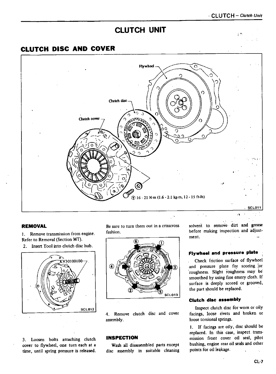
CLUTCH
UNIT
CLUTCH
DISC
AND
COVER
CLUTCH
Clutch
Unit
REMOVAL
Be
sure
to
turn
them
out
in
a
crisscross
fashion
I
Remove
transmission
from
engine
Refer
to
Removal
Section
MT
2
Insert
Tool
into
clutch
disc
hub
@
4
Remove
clutch
disc
and
cover
assembly
3
Loosen
bolts
attaching
clutch
cover
to
Ilywheel
one
turn
each
at
a
time
until
spring
pressure
is
released
INSPECTION
Wash
all
disassembled
parts
except
disc
assembly
in
suitable
cleaning
SCLOll
solvent
to
remove
dirt
and
grease
before
making
inspection
and
adjust
ment
Flywheel
end
pressure
plate
Check
friction
surface
of
Ilywheel
and
pressure
plate
for
scoring
or
roughness
Slight
roughness
may
be
smoothed
by
using
fine
emery
cloth
If
surface
is
deeply
scored
or
grooved
the
part
should
be
replaced
Clutch
disc
assembly
Inspect
clutch
disc
for
worn
or
oily
facings
loose
rivets
and
broken
or
loose
torsional
springs
IIf
facings
are
oily
disc should
be
replaced
In
this
case
inspect
trans
mission
front
cover
oil
seal
pilot
bushing
engine
rear
oil
seals
and
other
points
for
oil
leakage
CL
7
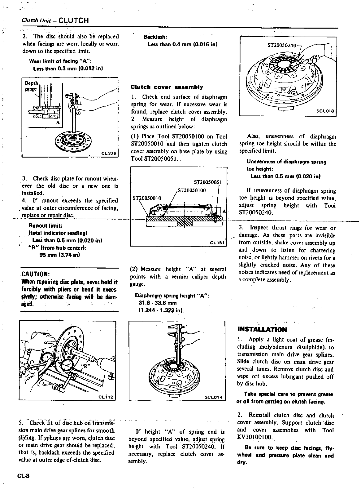
C1Ul1
h
Unit
CLUTCH
2
The
disc
should
also
be
replaced
when
facings
are
worn
locally
or worn
down
to
the
specified
limit
Wear
limit
of
facing
A
Less
than
03
mm
10
012
inl
II
I
ril
Q
l
l
c
F
l
I
I
A
CL336
3
Check
disc
plate
for
runout
when
ever
the
old
disc
or
a
new
one
is
installed
4
If
runout
exceeds
the
specified
value
at
outer
circumference
of
facing
place
or
repair
disc
Runout
limit
total
indicator
reading
Less
than
05
mm
0
020 in
R
from
hub
center
95
mm
3
74
in
Backlash
Less
than
0
4
mm
10
016
inl
Clutch
cover
assembl
1
Check
end
surface
of
diaphragm
spring
for
wear
If
excessive
wear
is
found
replace
clutch
cover
assembly
2
Measure
height
of
diaphragm
springs
as
outlined
below
I
Place
Tool
ST20050100
on
Tool
ST200500
10
and
then
tighten
clutch
cover
assembly
on
base
plate
by
using
Tool
ST20050051
ST20050010
ST20050051
jST20050100
1
@
CAUTION
When
repairing
disc
plate
never
hold
it
forcibly
with
pliers
or
bend
it
exces
siveIy
otherwise
facing
will
be
dam
aged
CL
12
5
Check
fit
of
disc
hub
ontransmis
sion
main drive
gear
splines
for
smooth
sliding
If
splines
are
worn
clutch
disc
or
main
drive
gear
should
be
replaced
that
backlash
exceeds
the
specified
value
at
outer
edge
of
clutch
disc
CL
8
CL
151
2
Measure
height
A
at
several
points
with
a
vernier
caliper
depth
gauge
Oiaphragnt
spring
height
A
31 6
33
6
mm
11
244
1
323inl
l
SCL014
If
height
A
of
spring
end
beyond
specified
value
dju
t
spri
lll
height
with
Tool
ST20050240
1
necessary
replace
clutch
cover
as
sembly
SCL018
Also
unevenness
of
diaphragm
spring
toe
height
should
be
wilhin
the
specified
limit
Unevenness
of
diaphragm
spring
toe
height
Less
than
0 5
mm
0
020
in
A
If
unevenness
of
diaphragm
spring
toe
height
beyond
specified
value
adjust spring
height
with
Tool
ST20050240
3
Inspect
thrust
rings
for
wear
or
damage
As
these
parts
are
invisible
from
outside
shake
cover
assembly
up
and
down
to
listen
for
chattering
noise
or
lightly
hammer
on
rivets
for
a
slighily
cracked noise
Any
of
1hese
noises
indicates
need
of
replacement
as
a
complete
assembly
INSTALLATION
I
Apply
a
light
coat
of
grease
in
c1uding
molybdenum
disulphide
10
transmission
main
drive
gear
splines
Slide
clutch
disc
on
main
drive
gear
several
times
Remove
clutch
disc
and
wipe
off
excess
lubricant
pushed
off
by
disc
hub
Take
special
care
to
prevent
grease
or
oil
from
getting
on
cluteh
faeing
2
Reins1a11
clutch
disc
and
clutch
cover
assembly
Support
clutch
disc
and
cover
assemblies
with
Tool
KV30100100
Be
ure
to
keep
disc
faeings
fly
wheel
and
pressure
plate
clean
and
dry
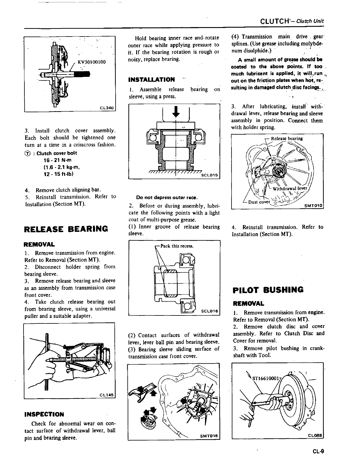
KV30100100
CL340
3
Install
clutch
cover
assembly
Each
bolt
should
be
tightened
one
turn
at
a
time
in a
crisscross
fashion
til
Clutch
cover
bolt
16
21
N
m
1
6 2
1
kg
m
12
15lt
lb
4
Remove
clutch
aligning
bar
5
Reinstall
transmission
Refer
to
Installation
Section
MT
RELEASE
BEARING
REMOVAL
1
Remove
transmission
from
engine
Refer
to
Removal
Section
MT
2
Disconnect
holder
spring
from
bearing
sleeve
3
Remove
release
bearing
and
sleeve
as
an
assembly
from
transmission
case
front
cover
4
Take
clutch
release
bearing
out
from
bearing
sleeve
using
a
universal
puller
and
a
suitable
adapter
CLt45
INSPECTION
Check
for
abnormal
wear on
con
tact
surface
of
withdrawal
lever
ball
pin
and
bearing
sleeve
Hold
bearing
inner
race
and
rotate
outer
race
while
applying
pressure
to
it
If
the
bearing
rotation
is
rough
or
noisy
replace
bearing
INSTALLATION
I
Assemble
release
bearing
on
sleeve
using
a
press
l
j
l
I
u
SCL015
Do
not
depress
outer
race
2
Before
or
during
assembly
lubri
cate
the
following
points
with
a
light
coat
of
multi
purpose
grease
1
Inner
groove
of
release
bearing
sleeve
L
SCL016
2
Contact
surfaces
of
withdrawal
lever
lever
ball
pin
and
bearing
sleeve
3
Bearing
sleeve
sliding
surface
of
transmission
case
front
cover
SMT016
CLUTCH
Clutch
Unit
4
Transmission
main drive
gear
splines
Use
grease
including
molybde
num
disulphide
Amall
mount
of
gre
hould
be
coatad
to
tho
bov
points
If
too
much lu
ricant
is
applied
it
wilt
run
out
on
the
friction
plltes
when hot
re
lulting
in
damaged
clutch
disc
facing
3
After
lubricating
install
with
drawal
lever release
bearing
and
sleeve
assembly
in
position
Connect them
with
holder
spring
SMT010
4
Reinstall
transmission
Refer
to
Installation
Section
MT
PILOT
BUSHING
REMOVAL
I
Remove
transmission
from
engine
Refer
to
Removal
Section
MT
2
Remove
clutch
disc
and
cover
assembly
Refer
to
Clutch
Disc
and
Cover
for removal
3
Remove
pilot
bushing
in crank
shaft
with
TooL
CLOSS
CL
9
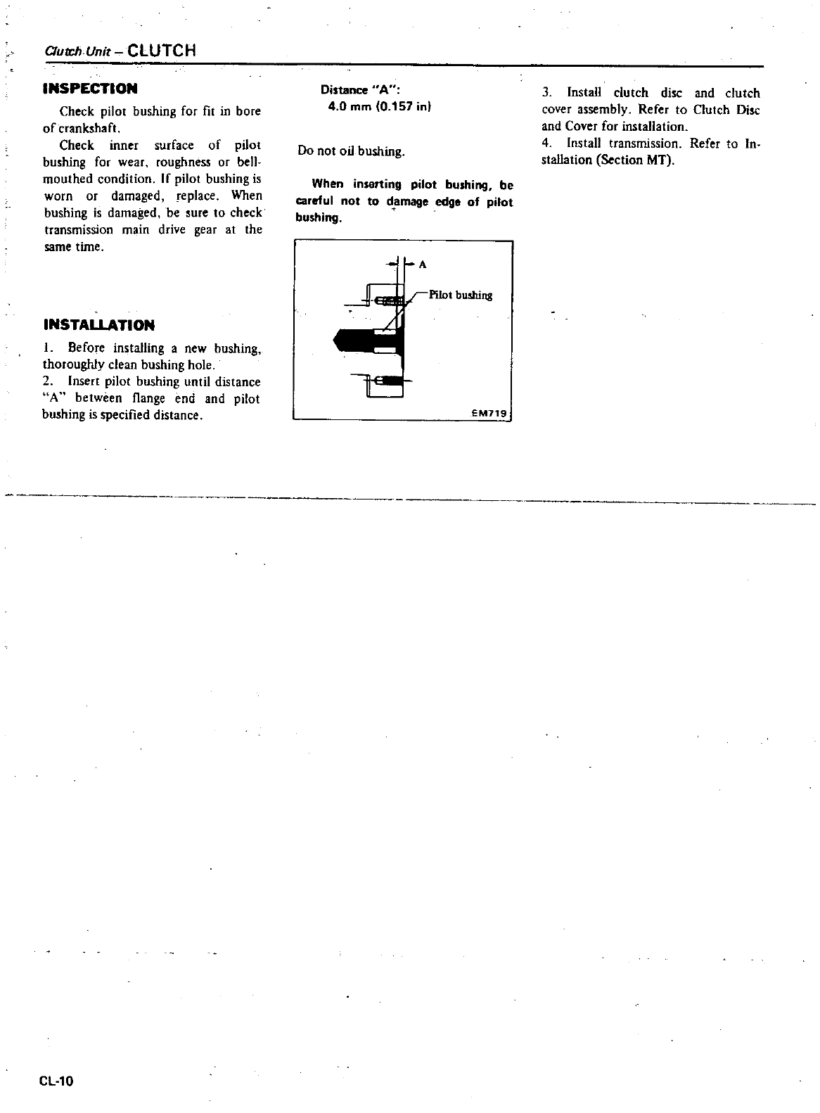
OutdWnit
CLUTCH
INSPECTION
Check
pilot
bushing
for
fit
in
bore
of
crank5haft
Check
inner
surface
of
pilot
bushing
for
wear
roughness
or
bell
mouthed
condition
If
pilot
bushing
is
worn
or
damaged
replace
When
bushing
is
damaged
be
sure
to
check
transmission
main
drive
gear
at
the
same
time
INSTALLATION
1
Before
installing
a
new
bushing
thoroughly
clean
bushing
hole
2
Inser1
pilo1
bushing
until
distance
A
between
flange
end and
pilot
bushing
is
specified
distance
CL10
Distance
A
4 0
mm
0
157
inl
Do
not
oil
bushing
When
inserting
pilot
bushing
be
careful
not
to
damage
edge
of
pilot
bushing
A
Pilot
bushing
EM719
3
InstaU
clutch
disc
and
clutch
cover
assembly
Refer
to
Clutch
Disc
and
Cover
for
installation
4
Install
transmission
Refer
to
In
staUa1ion
Section
MT
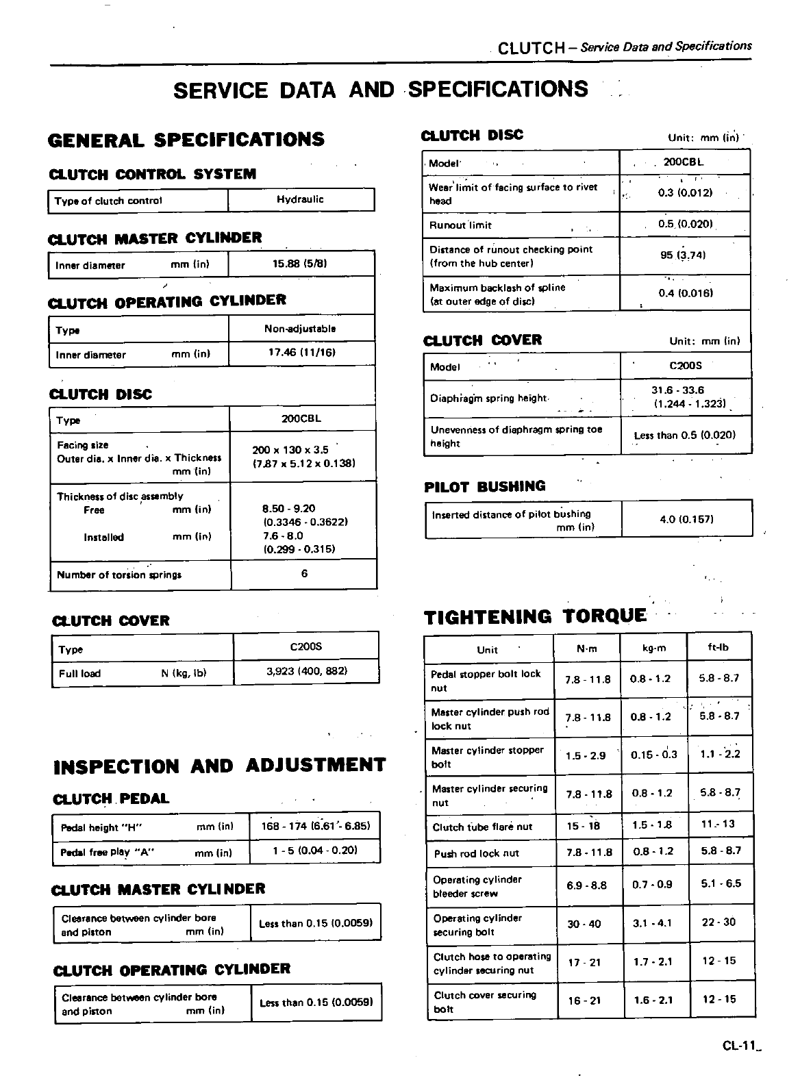
CLUTCH
Service
Data and
Specifications
SERVICE
DATA
AND
SPECIFICATIONS
GENERAL
SPECIFICATIONS
a
UTCH
CONTROL
SYSTEM
I
Type
of
clutch
control
a
UTCH
MASTER
CYLINDER
Ilnnar
diameter
mmOn
Hydraulic
15
88
1581
TV
a
UTCH
OPERATING
CYLINDER
Non
adjustable
Inner
diameter
mm
jn
a
UTCH
DISC
I
Type
Facing
size
Outer
die
x
Inner
die
x
Thickness
mm
inl
Thickness
of
disc
assembly
Free
mm
in
Installed
mmUnl
Number
of
torsion
springs
a
UTCH
COVER
Type
Full
load
N
Ikg
lb
1746
111
161
200CB
L
20
130
x
3 5
1787
x
5
12
x
0
1381
8
50
9
20
10
3346
0
36221
7
6 8
0
10
299
0
315
6
C200S
3
923
1400
882
INSPECTION
AND
ADJUSTMENT
a
UTCH
PEDAL
I
Pedal
height
H
l
Pedal
free
play
AU
mm
in
mm
in
a
UTCH
MASTER
CYLI
NDER
I
Clearance
between
cylinder
bore
and
pilton
mm
Unl
168 174
16
61
6
85
5
10
04
0
201
I
Loss
than
0
15
10
0059
j
a
UTCH
OPERATING
CYLINDER
I
Clearance
between
cylinder
bore
and
piston
mrn in
I
Lessthan
0
15
10
00591
J
a
UTCH DISC
Unit
mm
In
I
Model
200CBL
I
Wear
limit
offacing
surface
to
rivet
0
3
10
0121
I
hood
Runout
limit
0 5
10
0201
I
Distance
of
nout
checking
point
9513
741
from
the
hub
center
I
Maximum
backlash
of
spline
04
10
016
at outer
edge
of
disci
a
UTCH
COVER
Unit
mm
lin
I
Model
C200S
I
Dioph
ag
m
spring
ho
ght
31
6
33
6
11
244
1
3231
I
Unevenness
of
diophragm spring
toe
Less
than
0
5
0
020
height
PILOT
BUSHING
I
Inserted
distance
of
pilot
bushing
4
0
10
1571
mrn in
TIGHTENING
TORQUE
Unit
N
m
kg
m
ft
Ib
I
Pedal
stopper
bolt
lock
7
8
11
8
08
1
2 5
8
8 7
nut
I
Maner
cylinder
push
cd
7
8
11
8 0
8
1
25 8
8
7
lock
nut
Master
cylinder
stopper
1
5 2
9 0
15
0 3
11
2 2
bolt
Master
cylinder
securing
7 8
11
8
0
8
1
25
8
8 7
nut
Clutch
fube flare
nut
15
18
1
5
18
11
13
I
Push
rod
lock
nut
7
8 11
8
08
1
2 5 8
8
7
I
Dporating
cylindor
6 9
88
0 7
09
5
1
6
5
bleeder
screw
Operating
cylinder
30
40
3
1
4
1
22 30
lecuring
bolt
Clutch
hose
to
operating
17 21
17
2
1
12 15
cylinder
securing
nut
I
Clutch
cover
securing
16 21
1
6 2
1
12 15
bolt
CL
11
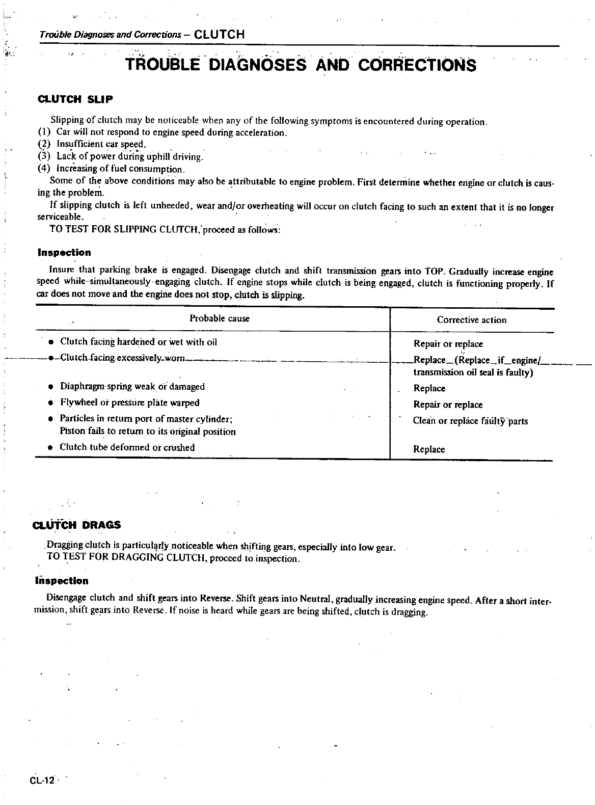
I
TroUble
DiagnosesBnd
Corrections
CLUTCH
TROUBLE
DIAGNOSES
AND
CORRECTIONS
a
UTCH
SLIP
Slipping
of
clutch
may
be
noticeable
when
any
of
the
following
symptoms is
encountered
during
operation
I
Car
will
not
respond
to
engine
speed
during
acceleration
2
Insufficient
car
speed
I
Lack
of
power
during
uphill
driving
4
Increasing
of
fuel
consumption
Some
of
the
above
conditions
may
also
be
attributable
to
engine
problem
First
determine
whether
engine
or
clutch
is
caus
ing
the
problem
If
slipping
clutch
is
left
unheeded
wear
and
or
overheating
will
occur
on
clutch
facing
to
such
an
exten1that
it
is
no
longer
serviceable
TO
TEST
FOR SLIPPING
CLurCH
proceed
as
follows
Inspection
Insure
that
parking
brake
is
engaged Disengage
clutch
and
shift
transmission
gears
into
TOP
Gradually
increase
engine
speed
while
simultaneously
engaging
clutch
If
engine
stops
while clutch
is
being
engaged
clutch
is
functioning
properly
If
car
does
not
move
and
the
engine
does
not
slop
clutch
is
slipping
Probable
cause
Corrective
action
Clutch
facing
hardened
or
wet
with
oil
Clutch
facing
excessively
worn
Diaphragm
spring
weak
or
damaged
Flywheel
or
pressure
plate
warped
Particles
in
return
port
of
master
cylinder
Piston
fails
to
return
to
its
original
posi1ion
Clutch
tube
deformed
or
crushed
Repair
or
replace
Replace Replace
iLengine
transmi
ion
oil
seal
is
faulty
Replace
Repair
or
replace
Clean
or
replace
faulty
paris
Replace
a
UTCH
DRAGS
Dragging
clutcl
is
particul
r1y
noticeable
when
shifting
gears
especially
into
low
gear
TO
TEST
FOR
DRAGGING
CLUTCH
proceed
to
inspection
Inspection
Disengage
clutch
and
shift
gears
into
Reverse
Shift
gears
into
Neutral
gradually
increasing
engine
speed
Aftera
short
inter
mission
shift
gears
into
Reverse
If
noise
is
heard
while
gears
are
being
shifted
clutch
is
dragging
CL
12
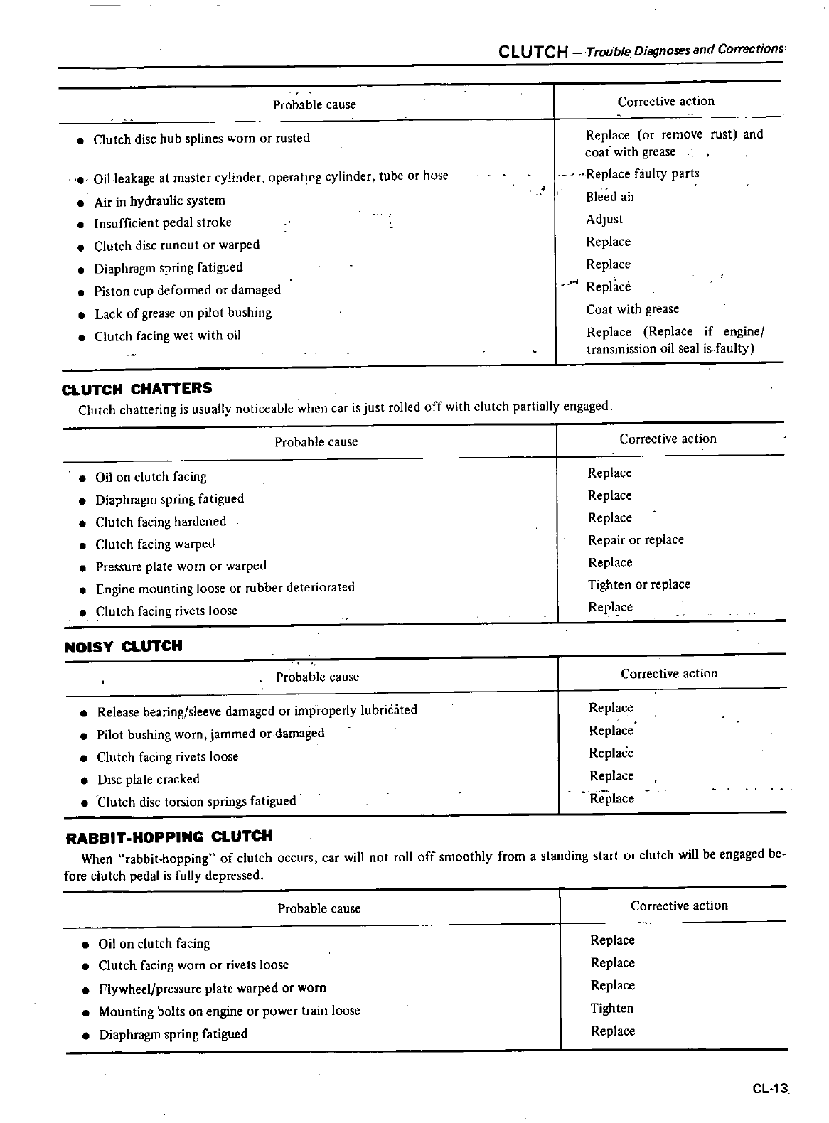
CLUTCH
Trouble
Diagnoses
and
Corrections
Probable
cause
Corrective
action
Clutch
disc
hub
splines
worn
or
rusted
Replace
or remove
rust
and
coat
with
grease
Replace
faulty
parts
Bleed
air
Adjust
Replace
Replace
04
Replace
Coat
with
grease
Replace Replace
if
engine
transmission
oil
seal
is
faulty
Oil
leakage
at
master
cylinder
operating
cylinder
tube
or
hose
Air
in
hydraulic
system
Insufficient
pedal
stroke
Clutch
disc
runout
or
warped
Diaphragm
spring
fatigued
Piston
cup
deformed
or
damaged
Lack
of
grease
on
pilot
bushing
Clutch
facing
wet
with
oil
CLUTCH
CHATTERS
Clutch
chattering
is
usually
noticeable
when
car
is just
rolled
off
with
clutch
partially
engaged
Probable
cause
Corrective
action
Oil
on
clutch
facing
Diaphragm
spring
fatigued
Clutch
facing
hardened
Clutch
facing
warped
Pressure
plate
worn
or
warped
Engine
mounting
loose
or
rubber
deteriorated
Clutch
facing
rivets
loose
Replace
Replace
Replace
Repair
or
replace
Replace
Tighten
or
replace
Replace
NOISY
CLUTCH
Probable
cause
Corrective
action
Release
bearing
sleeve
damaged
or
improperly
lubricated
Pilot
bushing
worn
jammed
or
damaged
Clutch
facing
rivets
loose
Disc
plate
cracked
Clutch
disc
torsion
springs
fatigued
Replace
Replace
Replace
Replace
Replace
RABBIT
HOPPING
CLUTCH
When
rabbit
hopping
of
clutch
occurs
car
will
not
rol1
off
smoothly
from
a
standing
star1
or
clutch
will
be
engaged
be
fore
clutch
pedal
is
fully
depressed
Probable
cause
Corrective
action
Oil
On
clutch
facing
Clutch
facing
worn
or
rivets
loose
Flywheel
pressure
plate
warped
or
worn
Mounting
bolts
on
engine
or
power
train
loose
Diaphragm
spring
fatigued
Replace
Replace
Replace
Tighten
Replace
CL
13
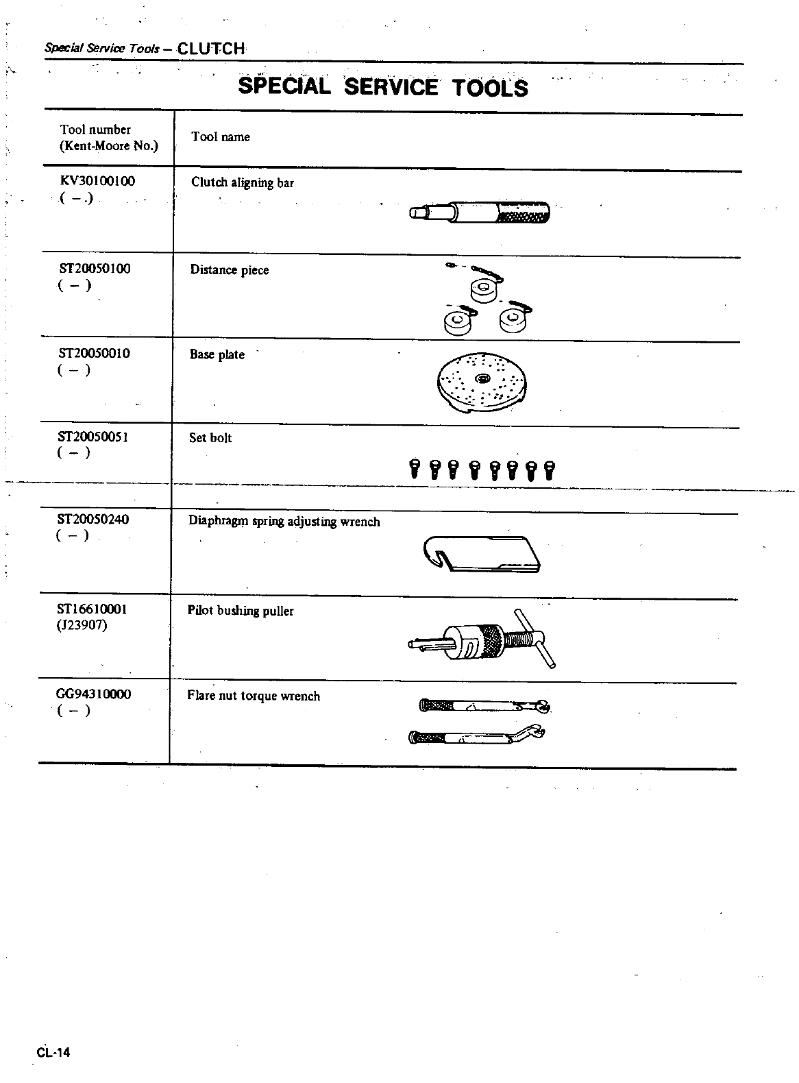
Special
Service
Tools
CLUTCH
SPECIAL
SERVICE
TOOLS
Tool
number
Tool
name
Kent
Moore
No
KV30100100
Clutch
aligning
bar
CLJI
2
1
ST20050100
Distance
piece
@
ST200500
10
Base
plate
@
39
ST20050051
Set
bolt
ST200S0240
Diaphragm
spring
adjusting
wrench
STI
661
000
I
123907
Pilot
bushing
puUer
n
o
GG94310000
Flare
nut
torque
wrench
IIIIlII
lII1A
CL14
DATSUN
200SX Mode
S
II
0
Series
MANUAL
TRANSMISSION
REMOVAL
AND
INSTALLATION
REMOVAL
INSTALLATION
5
SPEED
TRANSMISSION
Model
FSsW71B
REAR EXTENSION
TRANSMISSION
CASE
FORKS
AND
FORK
RODS
GEARS
AND
SHAFTS
REPLACEMENT
OF
OIL
SEALS
CONTENTS
MT
2
MT
2
MT
2
MT
3
MT
6
MT
7
MT
8
MT
9
MT14
REPLACEMENT
OF
BEARINGS
SERVICE
DATA
AND
SPECIFICATIONS
GENERAL
SPECIFICATIONS
INSPECTION
AND
ADJUSTMENT
TIGHTENING
TORQUE
TROUBLE
DIAGNOSES
AND
CORRECTIONS
SPECIAL
SERVICE
TOOLS
MT14
MT16
MT16
MT16
MT17
MT18
MT2
2
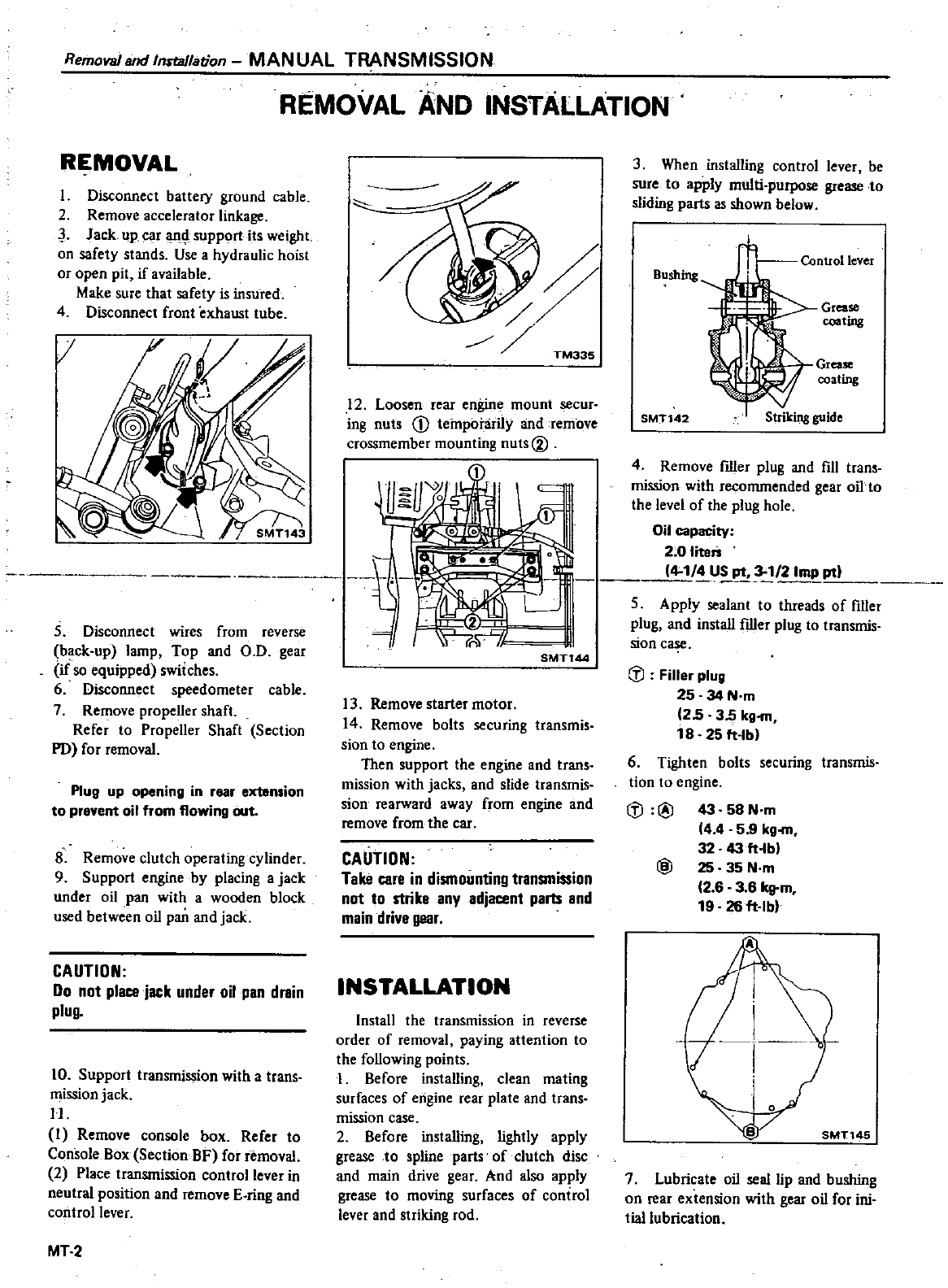
Removal
and
Inrtallation
MANUAL
TRANSMISSION
REMOVAL
AND
INSTALLATION
REMOVAL
I
Disconnect
battery
ground
cable
2
Remove
accelerator
linkage
J
Jack
up
car
anI
support
its
weight
on
safety
stands
Use
a
hydraulic
hoist
or
open
pit
if
available
Make
sure
that
safety
is
insured
4
Disconnect
front
exhaust
tube
5
Disconnect
wires
from
reverse
back
up
lamp
Top
and
O
D
gear
if
so
equipped
switches
6
Disconnect
speedometer
cable
7
Remove
propeUer
shaft
Refer
to
Propeller
Shaft
Section
PO
for
removal
Plug
up
opening
in
rear
extension
to
prevent
oil
from
flowing
out
8
Remove
clutch
operating
cylinder
9
Support
engine
by
placing
a
jack
under
oil
pan
with
a
wooden
block
used
between
oil
pan
and
jack
CAUTION
00
not
place
jack
under
oil
pan
drain
plug
10
Support
transmission
wi1h
a
trans
mission
jack
H
I
Remove
console
box
Refer
to
Console
Box
Section
BF for
removal
2
Place
transmission
control
lever
in
neutral
position
and
remove
E
ring
and
control lever
MT
2
TM335
12
Loosen
rear
engine
mount
secur
ing
nuts
CD
tempobirily
and
remove
crossmember
mounting
nuts
00
I3
Remove
starter
motor
14
Remove
bolts
securing
1ransmis
sian
to
engine
Then support
the
engine
and
trans
mission
with
jacks
and
slide
transmis
sion
rearward
away
ffom
engine
and
remove
from
the
car
CAUTION
Take
care
in
dismounting
transmission
not
to
strike
any
adjacent
parts
and
main
drive
gear
INSTALLATION
Install
the
transmission
in
reverse
order
of
removal
paying
attention
to
the
foUowing
points
I
Before
installing
clean
mating
surfaces
of
engine
rear
plate
and
trans
mission
case
2
Before
instaUing
lightly
apply
grease
to
spline
parts
of
clutch
disc
and
main
drive
gear
And
also
apply
grease
to
moving
surfaces
of
control
lever
and
striking
rod
3
When
installing
control
lever
be
sure
to
apply
multi purpose
grease
to
sliding
parts
as
shown
below
Bushing
Grease
coating
Control
lever
Grease
coating
SMT142
Striking
guide
4
Remove
filler
plug
and
fill
1rans
mission
with
recommended
gear
oiI
o
the
level
of
1he
plug
hole
Oil
capacity
2
0
liten
4
1
lJ
P1
2Imp
I
ll
5
Apply
sealant
to
threads
of
filler
plug
and
instaU
filler
plug
to
transmis
sionc
iJ
Filler
plug
25 34
N
m
25 35
kg
m
18
25
ft
lb
6
Tighten
bolts
securing
transmis
tion
to
engine
iJ
@
43
58
N
m
4
4
59
kg
32
43
ft
bl
@
25
35N
m
2
6 3
81qj
m
19
28ft
lb
A
7
Lubricate
oil
seal
lip
and
bushing
on
rear
extension
with
gear
oil
for
ini
tial
lubrication
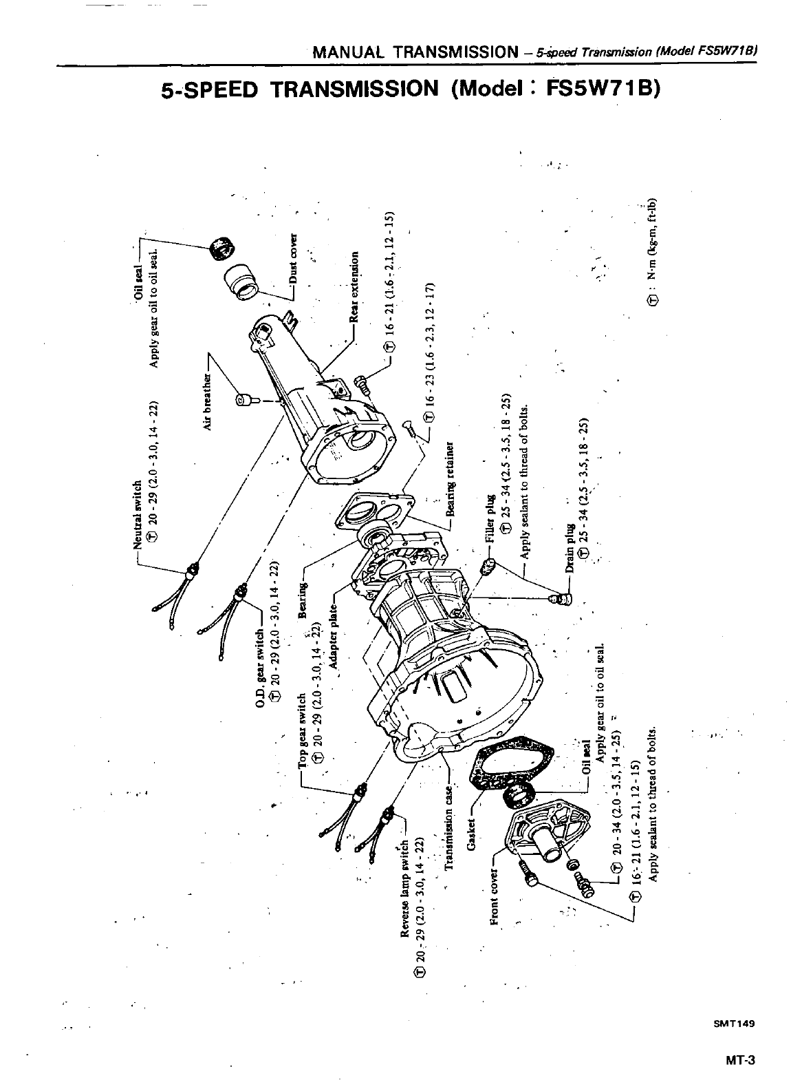
3
Neutral
switch
Iii
20
29
2
0
3
0
14
22
Oil
leal
Apply
gear
oil
to
oil
seal
on
Iii
20
29
2
0
3
0
14
22
Iii
20
rTOP
gear
witch
i
J
20
29
2
0
Revet
lampowS
29
2
0
3
0
14
22
23
1
6
2
3
12
17
f
Bearing
3
0
14
2
Adapter
plate
Front
cover
Filler
plll8
Iii
25
34
2
5
3
5
18
25
Apply
sealant
to
thread
of
bolts
Drain
plug
Iii
25
34
2
5
3
5
18
25
E
21
1
6
21
12
15
Iii
N
m
kg
m
ft
lb
C1I
en
mm
C
f
0 Z
en
3
en
en
5
z
3
Z
C
r
I
Z
CJl
3
en
CJl
o
Z
I
i
a
3
o
Q
1
JJ
C1I
e
OJ
I
iii
g
Cl
It
l
l
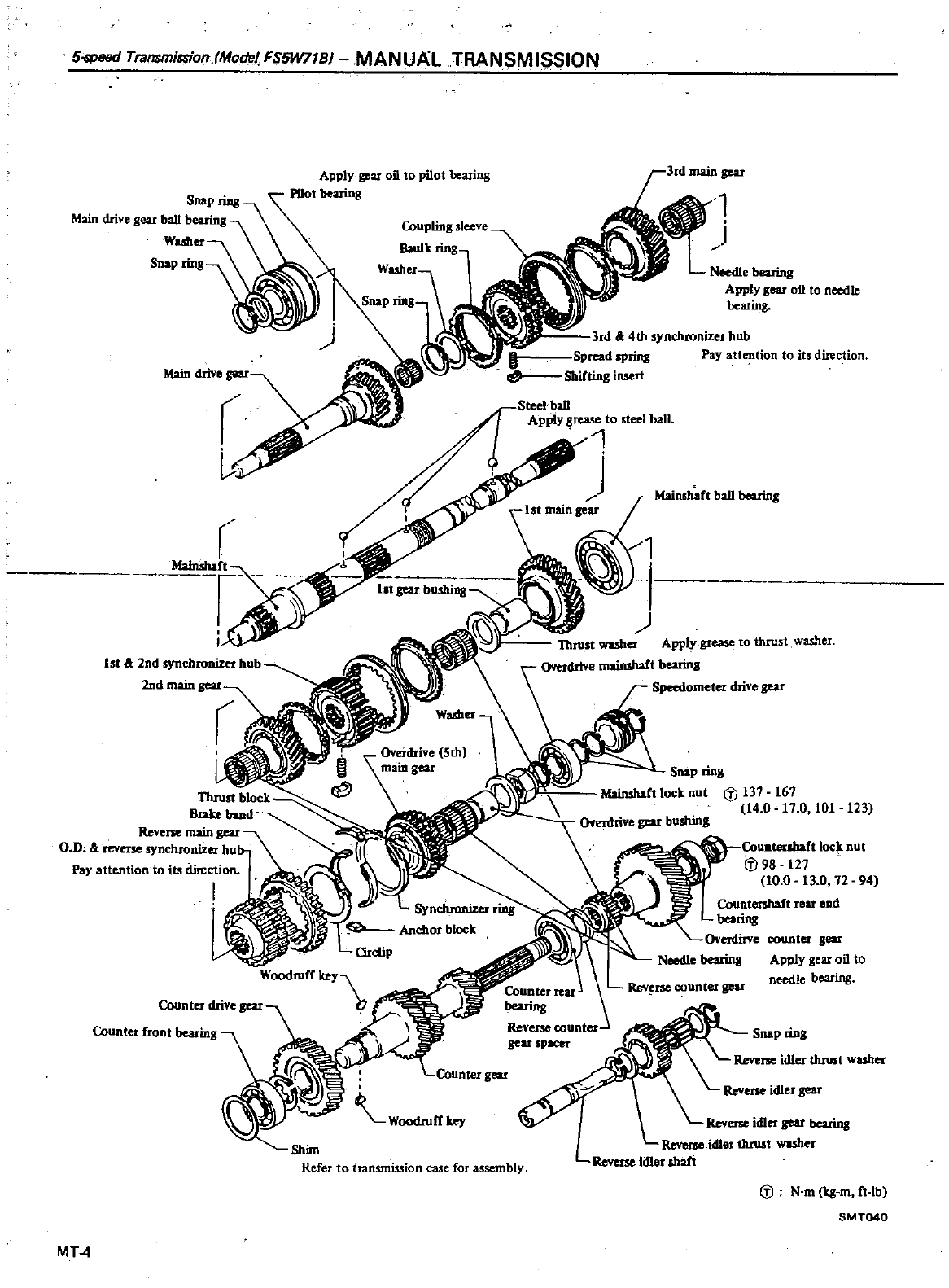
5
speed
Trafl
lTlissiof1
ModeIFS5W71BJ
MANUAL
TRANSMISSION
3rd
main
gear
SnaPrinB
Main
drive
gear
ball
bearing
Washer
Snap
rinB
Apply
gear
oil
to
needle
bearq
3rd
11
4th
synchronizet
hub
pread
spring
Pay
attention
to
its
direction
Shifting
imert
r
G
1st
a
2nd
synchronizer
hub
2nd
main
gear
123
CounterJbaCt
lock
nut
ifJ
98
127
10 0
13
0 12 94
counter
geu
Apply
gear
oil
to
needle
bearing
Counter
front
bearing
Snap
ring
Woodruff
key
Reverse
idlet
sear
bearing
Reverse
idler
thro
t
washer
Reverse
idler
shaft
Shim
Refer
to
transmission
case
for
assembly
Iii
N
m
kg
m
ft
b
SMT040
MT
4
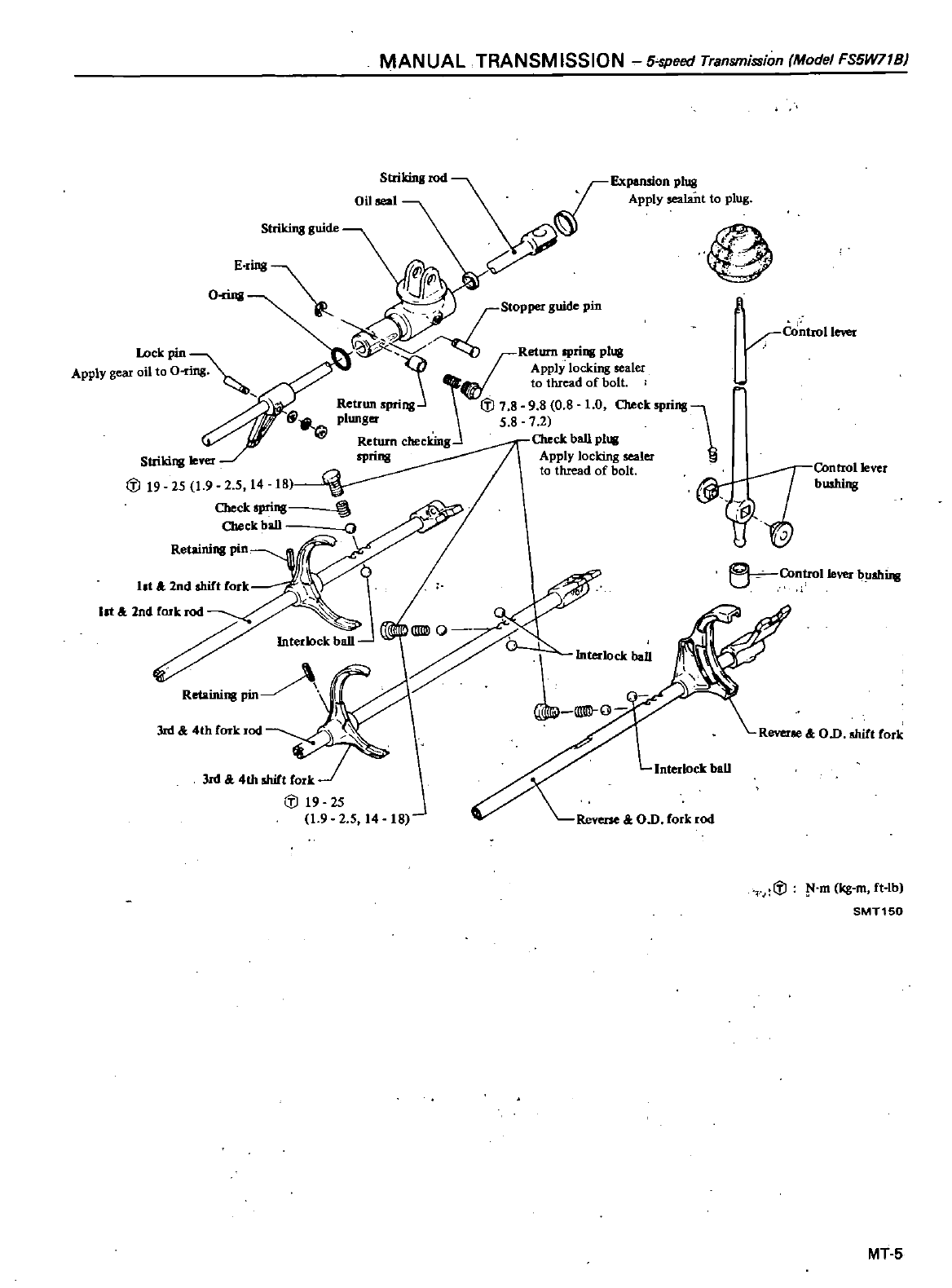
MANUAL
TRANSM
ISSION
5
speed
Transmission
Model
FS5W71BJ
Striking
guide
25
1
9
2 5
14
18
Check
prins
Check
ball
ErinB
r
J
O
r
StoPper
guide
pic
fRetum
spri
plUS
J
Apply
locking
sealer
j
to
thread
of
bolt
t
Retrun
pri
Iii
7
8 9
8
O
g
1
0
Check
prins
1
plunger
5 8 7
2
Return
checking
Check
ball
pl1lll
SPriDl
Apply
locking
sealer
to thread
of
bolt
qeontrollever
@
bushing
0
J
Lock
pin
Apply
gear
oil
to
O
ControlleYer
5
Controlleverb
ahUw
Retainins
Pin
Interlock
baD
3m
4th
Cork
rod
Reverse
OD
shift
Cork
3m
4th
shift
Cork
Iii
19 25
1
9 2
5
14
18
Ioterlock
baD
Iii
l
m
k8
m
Ct
lb
SMT150
MT
5
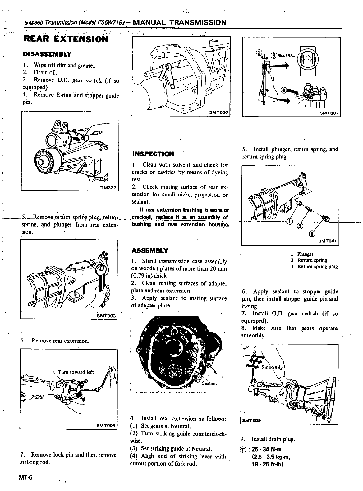
54peed
TT8Il
fTJission
ModeJ
FS5W71B
MANUAL
TRANSM
ISSION
REAR
EXTENSION
DISASSEMBLY
I
Wipe
off
dirt
and
grease
2
Drain
oil
3
Remove
00
gear
switch
if
so
equipped
4
Remove
E
ring
and
stopper
guide
pin
SMT006
INSPECTION
@NEur
4
1
W
@
In
SMT007
5
InstaU
plunger
return
spring
and
return
spring
plug
I
Clean
with
solvent
and
check
for
cracks
or
cavities
by
means of
dyeing
test
TM337
2
Check
mating
surface
of
rear
ex
tension
for
small
nicks
projection
or
sealant
If
fesr
extension
bushing
is
worn
or
5
Remove
return
spring
plug
retum
pla
it
as
an
a
ssembly
of
spring
and
plunger
from
rear
exten
bushing
and
rear
extension
housing
sion
SMT003
6
Remove
rear
extension
SMTOOS
7
Remove
lock
pin
and
then
remove
striking
rod
MT
6
ASSEMBLY
I
Stand
transmission
case
assembly
on
wooden
plates
of
more
than
20
rom
0
79 in
thick
2
Clean
mating
surfaces
of
adapter
plate
and
rear
extension
3
Apply
sealant
to
mating
surface
of
adapter
plate
4
InstaU
rear
extension
as
foUows
I
Se
gears
at
Neutral
2
Turn
striking
guide
counterclock
wise
3
Set
striking
guide
at
Neutral
4
Aligh
end
of
striking
lever
with
cutout
portion
of
fork
rod
SMT041
1
PlUJl8O
2
Return
spring
3
Return
spring
plug
6
Apply
sealant
to
stopper
guide
pin
then
instaU
stopper
guide
pin
and
E
ring
7
InstaU
00
gear
switch
if
so
equipped
8
Make
sure
that
gears
operate
smoothly
9
Install
drain
plug
Iil
25 34 N
m
2
53
5kgfD
18
25
ft
lbl
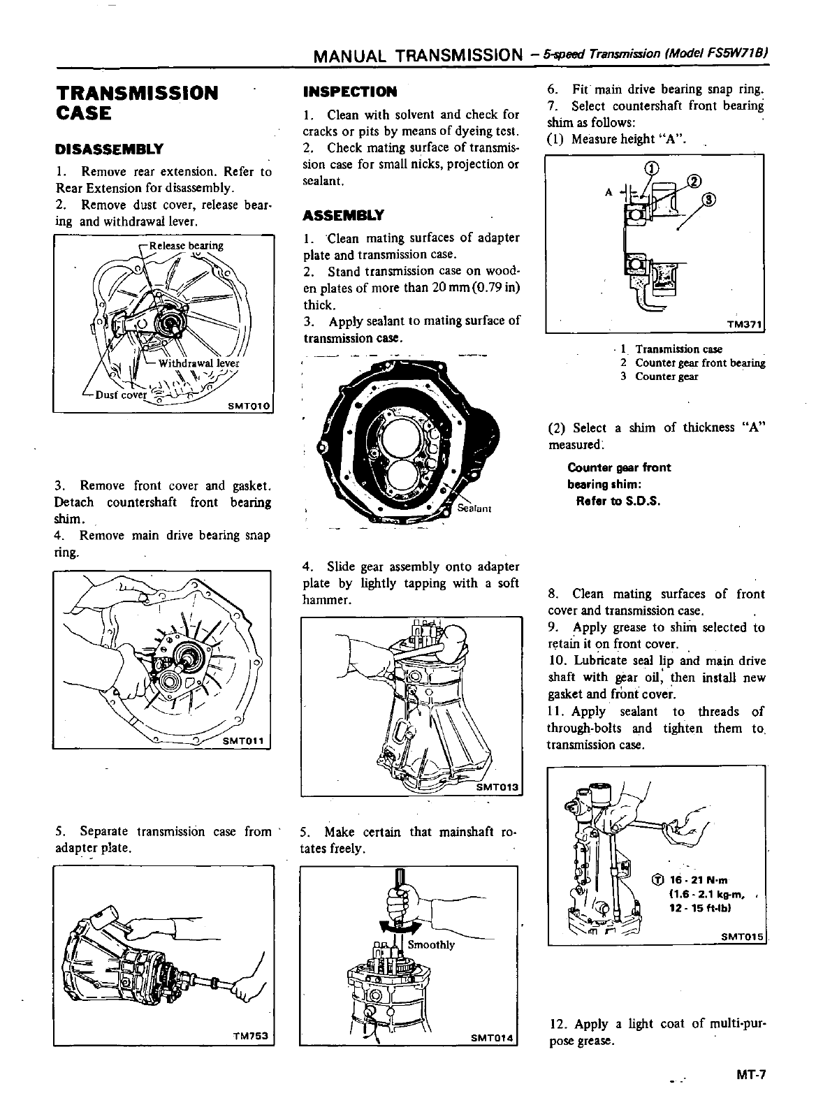
TRANSMISSION
CASE
DISASSEMBLY
1
Remove
rear
extension
Refer
to
Rear
Extension
for
disassembly
2
Remove
dust
cover
release
bear
ing
and
withdrawal
lever
3
Remove
front
cover
and
gasket
Detach
countershaft
front
bearing
shim
4
Remove
main
drive
bearing
snap
ring
5
Separate
transmission
case
from
adapter
plate
TM153
MANUAL
TRANSMISSION
5
speed
Transmission
Model
FS5W71B
INSPECTION
1
Clean
with
solvent
and
check
for
cracks
or
pits
by
means of
dyeing
test
2
Check
mating
surface
of
transmis
sion
case
for
small
nicks
projection
or
sealant
ASSEMBLY
1
clean
mating
surfaces
of
adapter
plate
and
transmission
case
2
Stand
transmission
case
on
wood
en
plates
of
more
than
20
mm
O
79
in
thick
3
Apply
sealant
to
mating
surface
of
transmission
case
4
Slide
gear
assembly
onto
adapter
plate
by
lightly
tapping
with
a
soft
hammer
5
Make
certain
that
mainshaft
roo
tates
freely
SMT014
6
Fit
main drive
bearing
snap
ring
7
Select
countershaft
front
bearing
shim
as
foUows
1
Measure
height
A
I
TM371
1
Tranlmission
case
2
Counter
gear
front
bearing
3
Counter
gear
2
Select
ashim
of
thickness
A
measured
Counter
geer
front
bearing
him
Refer
to
S
O
S
8
Clean
mating
surfaces
of
front
cover
and
transmission
case
9
Apply
grease
to
shim
selected
to
r
tain
it
on
front
cover
10
Lubricate
seal
lip
and
main
drive
shaft
with
gear
oil
then
instaU
new
gasket
and
front
cover
II
Apply
sealant
to
threads
of
through
bolts
and
tighten
them
to
transmission
case
Iii
111
21
N
m
11
6
2
1
kg
m
12
151t
lbl
rmrl
SMT015
12
Apply
a
light
coat
of
multi
pur
pose
grease
MT
7
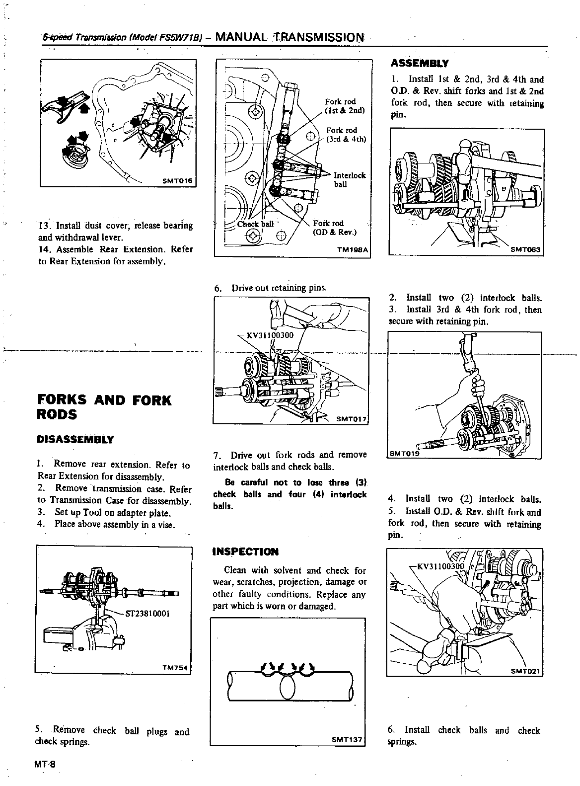
XpeerI
Transmission
Mode
FS5W71BJ
MANUAL
TRANSMISSION
rC
SMT016
13
InstaU
dust
cover
release
bearing
and
withdrawal
lever
14
Assemble
Rear
Extension
Refer
to
Rear
Extension
for
assembly
FORKS
AND
FORK
RODS
DISASSEMBLY
1
Remove
rear
extension
Refer
to
Rear Extension
for
disassembly
2
Remove
transmission
case
Refer
to
Transmission
Case
for
disassembly
3
Set
up
Tool
on
adapter
plate
4
Place
above
assembly
in
a
vise
TM754
5
Remove
check
baU
plugs
and
check
springs
MT
B
Fork
rod
1st
l
2nd
Fl
Chect
baD
@
ED
Interlock
ball
TM198A
6
Drive
out
retaining
pins
7
Drive
out
fork
rods
and
remove
interlock
baUs
and check
baUs
Be
careful
not
to
lose
three
3
check
balls
and
four
4
interlock
balls
INSPECTION
Clean
with
solvent
and
check
for
wear
scratches projection
damage
or
other
faulty
conditions
Replace
any
part
which
is
wornor
darnaged
one
6
SMT137
ASSEMBLY
I
InstaU
1st
2nd
3rd
4th
and
Q
D
Rev
shift
forks
and
1st
2nd
fork
rod
then
secure
with
retaining
pin
2
InstaU
two
2
interlock
baUs
3
InstaU 3rd
4th
fork
rod
then
secure
with
retaining
pin
SMT019
4
InstaU
two
2
interlock
baUs
5
InstaU O
D
Rev
shift
fork
and
fork
rod
then
secure
with
retaining
pin
6
InstaU
check
baIls
and
check
springs
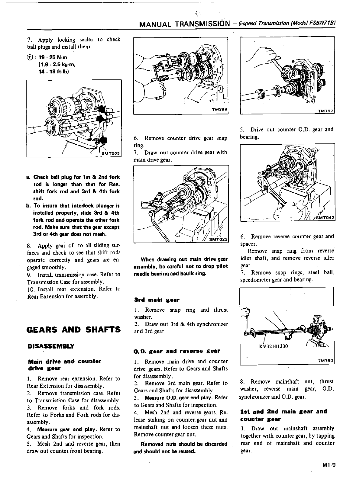
7
Apply
locking
sealer
to
check
ball
plugs
and
install
them
dl
19 25
N
m
1
9
2 5
kg
m
14
18
ft
lb
a
Check
ball
plug
for
1st
2nd
fork
rod
is
longer
than
that
for
Rey
shift
fork
rod
and
3rd
4th
fork
rod
b
To
insure
that
interlock
plunger
is
installed
properly
slide
3rd 4th
fork
rod
and
operata
the
other
fork
rod
Make
lure
that the
gear except
3rd
or
4th
gear
does
not
m
sh
8
Apply
gear
oil
to
all
sliding
sur
faces
and
check
to
see
1hat
shift
rods
operate
correctly
and
gears
are
en
gaged
smoothly
9Install
transmissio
case
Refer
to
Transmission
Case
for
assembly
10
Install
rear
extension
Refer
to
Rear
Extension
for
assembly
GEARS AND
SHAFTS
DISASSEMBLY
Mein
drive
end
counter
drive
geer
1
Remove
rear
xtension
Refer
to
Rear
Extension
for
disassembly
2
Remove
transmission
case
Refer
to
Transmission
Case
for
disassembly
3
Remove
forks
and
fork
rods
Refer
10
Forks
and
Fork
rods
for
dis
assembly
4
Measure
g
r
end
play
Refer
to
Gears
and
Shafts
for
inspection
S
Mesh
2nd
and
reverse
gear
then
draw
out
counter
front
bearing
MANUAL
TRANSMISSION
5
speed
Transmission
Model
FS5W71B
TM398
6
Remove
counter
drive
gear
snap
ring
7
Draw
out
counter
drive
gear
with
main
drive
gear
When
drawing
out
main drive
gear
mbly
b
car
ful
not
to
drop pilot
n
edle
bearing
and
baulk
ring
3rd
meln
geer
I
Remove
snap
ring
and
thrust
washer
2
Draw
out
3rd
4th
synchronizer
and
3rd
gear
o
D
geer
end
reverse
geer
1
Remove
main
drive
and
counter
drive
gears
Refer
to
Gears
and
Shafts
for
disassembly
2
Remove
3rd
main
gear
Refer
to
Gears
and
Shafts
for
disassembly
3
Measure
0
0
ge
r
end
play
Refer
to
Gears
and
Shafts
for
inspection
4
Mesh
2nd
and
reverse
gears
Re
lease
staking
on
counter
gear
nut
and
mainshaft
nut
and
loosen
these
nuts
Remove
counter
gear
nut
Removed
nuts
should
be
discarded
nd
should
not
be
reused
TM757
S
Drive
out
counter
00
gear
and
bearing
6
Remove
revene
counter
gear
and
spacer
Remove
snap
ring
from
reverse
idler
shaft
and
remove
reverse
idler
gear
7
Remove
snap
rings
steel
ball
speedometer
gear
and
bearing
f
I
KV32101330
TM760
8
Remove
mainshaft
nut
thrust
washer
reverse
main
gear
00
synchronizer
and
OD
gear
1st
end
2nd
mein
geer
end
counter
eer
I
Draw
out
mainshaft
assembly
together
with
counter
gear
by
tapping
rear
end
of
mainshaft
and
counter
gear
MT
9
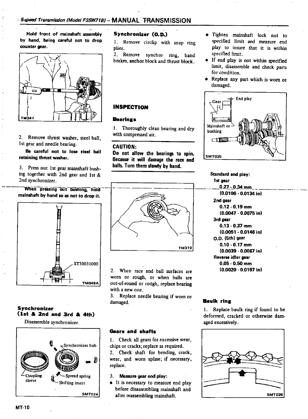
5
siJeed
Trantmiision
Model
FS5W71B MANUAL
l
RANSMISSION
Hold
front
of
mainshaft
assembly
by
hand
being
careful
not to
drop
counter
gear
TMW1
I
J
4
I
rT
2
Remove
thrust
washer
steel
baU
1
st
gear
and
needle
bearing
Be
careful
not
to
lose
teel
ball
retaining
thlUlt
washer
Synchronizer
0
D
I
Remove
circlip
wiih
snap
ring
plier
2
Remove
syncbro
ring
band
brakes
anchor
block
and
thrust
block
INSPECTION
Bearing
I
Thoroughly
clean
bearing
and dry
with
compressed
air
CAUTION
Do
not
allow
the
bearings
to
spin
Because
it
will
damage
the
race
and
balls
Turn
them
slowly by
hand
3
Press
ou1
1st gear
rnainshaft
bush
ing together
with
2nd
gear
and
1st
2nd
synchronizer
Wlliin
priising
oiirliii
liing
holif
mainshaft
by
hand
081
not
to
drop
it
H
r
ST30031000
TM049A
Synchronizer
lat
a
2nd
and
3rd
a
4th
Disassemble
synchronizer
G
Q
sleeve
Shifting
insert
SMT02A
MT10
TM372
2
When
race
and
baU
surfaces
are
worn
or
rough
or
when
balls
are
out
of
round
or
rough
replace
bearing
with
a
new
one
3
Replace
needle
bearing
ifworn or
damaged
Gears
snd
ahafts
I
Check
all
gears
for
excessive
wear
chips
or
cracks
replace
as
required
2
Check shaft
for
bending
crack
wear
d
worn
spline
if
necessary
replace
3
Measure
gear
end
play
It
is
necessary
to
measure
end
play
before
disassembling
mainshaft
and
after
reassembling
mainshaft
Tighten
mainshaft
lock
nut
to
specified
limit
and
tneasure
end
play
to
insure
thai
it
is
within
specified
limit
If
end
play
is
not
within
specified
limit
disassemble
and
check
parts
for
condition
Replace
any
part
which
is
worn
or
damaged
iEndPmY
Mainshaft
o
bushing
CIJE
SMT025
Standard
end
play
1st
lI88r
q2
03
tDlm
0
0106
0
0134
inl
2nd
gear
0
12
0
19
mm
0
0047
0
0075
in
3rd
gar
0
13
037
mm
10
0051
0
0146
in
0
0
5thl
gear
0
10
0
11
mm
00039 0
0061
in
Reverse
idlar
gear
0
05
0
50
mm
00020
0
0197
inl
Baulk
ring
I
Replace
baulk
ring
if
found
to
be
deformed
cracked
or
otherwise
dam
aged
excessively
SMT026
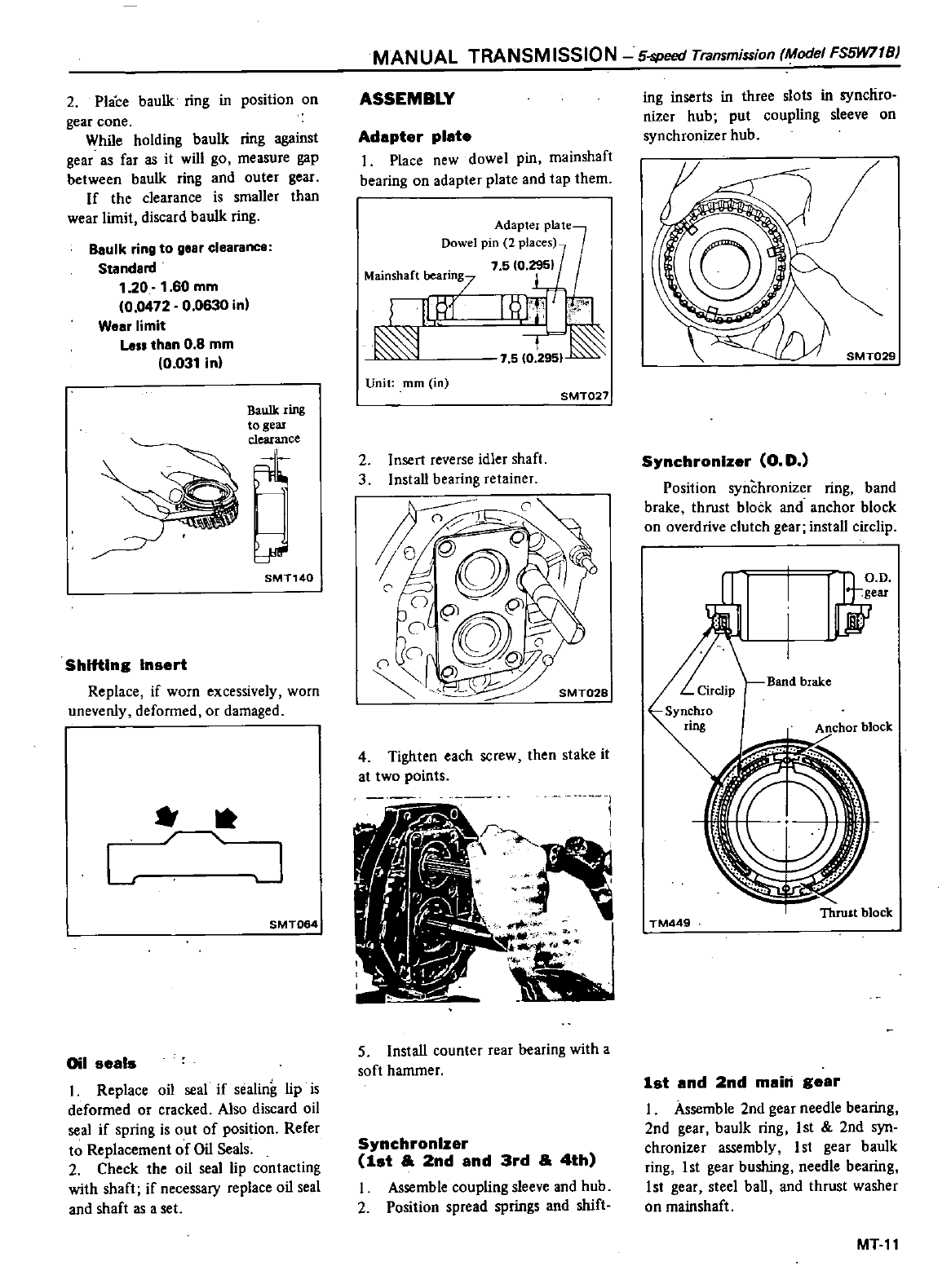
2
Place
baulk
ring
in
position
on
gear
cone
While
holding
baulk
ring
against
gear
as
far
as
it
will
go
measure
gap
between
baulk
ring
and
outer
gear
If
the
clearance
is
smaUer
than
wear
limit
discard
baulk
ring
B8Ulk
ring
to
glar
clearance
Standard
1
20
1
60
mm
0
0472
0
0630
in
Wear
limit
La
than
0 8
mm
0
031
in
SMT140
ShlftlnB
Insert
Replace
if
worn
excessively
worn
unevenly
deformed
or
damaged
L
J
SMT064
Oil seals
1
Replace
oil
seal
if
sealing
lip
is
deformed
or
cracked
Also
discard
oil
seal
if
spring
is
out
of
position
Refer
to
Replacement
of
Oil
Seals
2
Check
the
oil
seal
lip
contacting
with
shaft
if
necessary
replace
oil
seal
and
shaft
as
aset
MANUAL
TRANSMISSION
5
speed
Transmission
Model
FS5W71B
ASSEMBLY
Adapter
plate
I
Place
new
dowel
pin
mainshaft
bearing
on
adapter
plate
and
tap
them
Adapter
plate
Dowel
pin
2
places
Mainshaft
bearing7
1fU11
Unit
mm
in
SMT027
2
Insert
reverse
idler
shaft
3
InstaU
bearing
retainer
4
Tighten
each
screw
then
stake
it
at
two
points
I
I
r
A
5
InstaU
counter
rear
bearing
with
a
soft
hammer
Synchronizer
1st
2nd
and
3rd
4th
I
Assemble
coupling
sleeve
and
hub
2Position
spread
springs
and
shift
ing
inserts
in
three
slots
in
syncliro
nizer
hub
put
coupling
sleeve
on
synchronizer
hub
Synchronizer
G D
Position
synchronizer
ring
band
brake
thrust
block
and
anchor
block
on
overdrive
clutch
gear
install
circlip
JH
D
rjeU
Band
brake
Anchor
block
TM449
Thrust block
1st
and
2nd
main
Bear
I
Assemble
2nd
gear
needle
bearing
2nd
gear
baulk
ring
1st
2nd
syn
chronizer
assembly
I
st
gear
baulk
ring
I
st gear
bushing
needle
bearing
1st
gear
steel
baU
and
thrust
washer
on
mainshaft
MTll
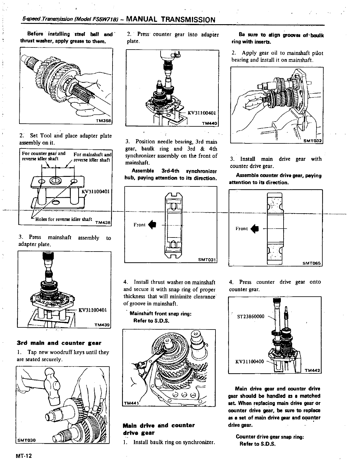
5
PeedTrsn
ission
Model
FS5W71B
MANUAL
TRANSMISSION
Before
installing
Sle8I
boll
and
thru
t
washer
apply
gr
ato
tham
TM358
2
Set
Tool
and
place
adapter
plate
assembly
on
it
For
counter
gear
and
For
mainshaft
and
rever
id
e
shaft
rever
idler
shaft
IoU
J
ID
lJ
f31100401
koles
for
reverie
idler
shaft
2
Press
counter
gear
into
adapter
plate
KV31100401
TM
O
3
Position
needle
bearing
3rd
main
gear
baulk
ring
and
3rd
4th
synchronizer
assembly
on
the
front
of
mainshaft
Assemble
3rd
4th
synchronizer
hub
paying
attention
to
its
direction
TM438
Front
3
Press
mainshaft
assembly
to
adapter
plate
KV3H00401
TM439
3rd
main
and
counter
8ear
I
Tap
new
woodruff
keys
until
they
are
seated
securely
MT12
Vl
SMT031
4
Install
thrust
washer
on
mainshaft
and
secure
it
with
snap
ring
of
proper
1hickness
that
will
minimize
clearance
of
groove
in
mainshafl
Mainshaft
front
snspring
Refer
to
S
O
S
TM441
cHOJ
L
Main
drive
and
counter
drive
8ear
1
Install
baulk
ring
on
synchronizer
Be
RU
to
align
of
baulk
ring
with
inserts
2
Apply
gear
oil
to
mainshaft
pilot
bearing
and
install
it
on
mainshafl
3
InstaU
main
drive
gear
with
counter
drive
gear
Assembfe
counter
driy
gear
paying
attention
to
its
direction
Front
SMT065
4
Press
counter
drive
gear
onto
counter
gear
ST23860000
KV31100400
n
TM442
Main drive
gear
and
counter
drive
gear
should
be
handled
as
a
matched
set
When
replacing
main
driva
gear
or
counter
drive
gear
be
sure
to
replace
8S
8
set
of
main
drive
gear
and
n
ter
driva
gear
Counter
drivege
ar
snap
ring
Rafer
to
S
O
S
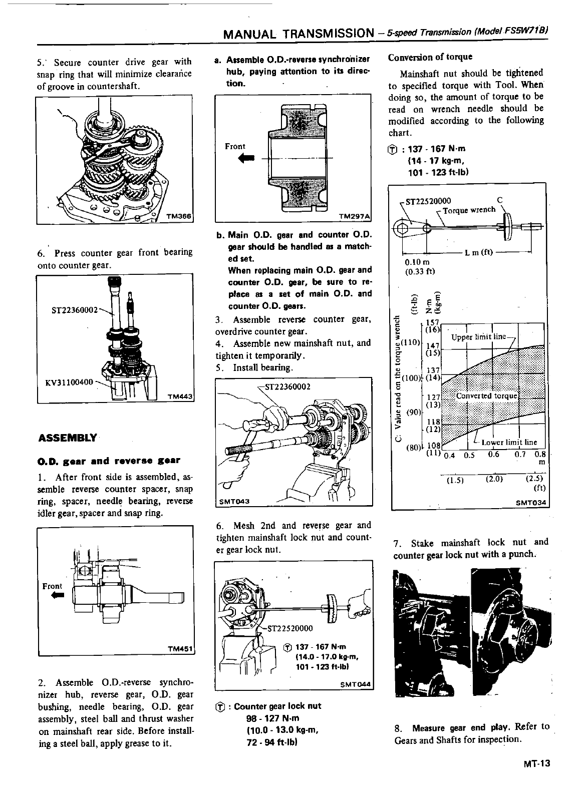
5
Secure
counter
drive
gear with
snap
ring
that
will
minimize
clearance
of
groove
in
countershaft
o
TM366
6Press
counter
gear
front
bearing
onto
counter
gear
ST22360002
KV31100400
n
TM443
ASSEMBLY
O
D
gear
and
reverae
gear
I
After
front
side is
assembled
as
semble
reverse
counter
spacer
snap
ring
spacer
needl
bearing
reverse
idler
gear
spacer
and
snap
ring
Fr
I
LJ
I
TM451
2
Assemble
O
D
reverse
synchro
nizer
hub
reverse
gear
a
D
gear
bushing
needle
bearing
O D
gear
assembly
steel
baU
and
thrust
washer
on
mainshaft
rear
side
Before
instaU
ing
a
steel
baU
apply
grease
to
it
MANUAL
TRANSM
ISSION
5
speed
Transmission
Mode
FS5W71S
a
Assemble
O O
reverse
synchro
nizer
hub
paying
attention
to
its
direc
tion
Front
TM297A
b
Main
0 0
gear
and
countor
0
0
goor
should
be
handled
as
a
motch
ed
set
When
replacing
main
0
0
gear
and
counter
0 0
gear
be
sure
to
re
place
as
a
set
of
main
0
0
and
counter
0 0
gears
3
Assemble
reverse
counter
gear
overdrive
counter
gear
4
Assemble
new
mainshaft
nut
and
tighten
it
temporarily
5
InstaU
bearing
6
Mesh
2nd
and
reverse
gear
and
tighten
mainshaft
lock
nut
and
count
er
gear
lock
nut
w
ST22520000
Iii
137 167
N
m
114
0
17
0
kg
m
101
123ft
lbl
SMT044
iJ
Counter
gear
lock
nut
98
127
N
m
10
0
13
0
kg
m
72
94
ft
lbl
Conversion
of
torque
Mainshaft
nut
should
be
tightened
to
specified
torque
with
Tool
When
doing
so
the
amount
of
torque
to
be
read
on
wrench
needle
should
be
modified
according
to
the
foUowing
chart
If
137 167
N
m
14
17
kg
m
101
123
ft
lb
ST22520000
C
f1
0
Lm
f
rr
O
lOm
0
33
ft
e
S
z
u
c
u
u
1O
C
s
u
00
c
o
0
e
Vi
1
Upp
r
limitll
ne7
J
147
135
1
0
it
uun
o
ii
11
0
4
0 5
6
6
0
70 8
m
90
u
80
15
2
0
2
5
ft
SMT034
7
Stake
mainshaft
lock
nut
and
counter
gear
lock
nut
with
a
punch
8
Measure
gear
end
play
Refer
to
Gears
and
Shafts
for
inspection
MT13
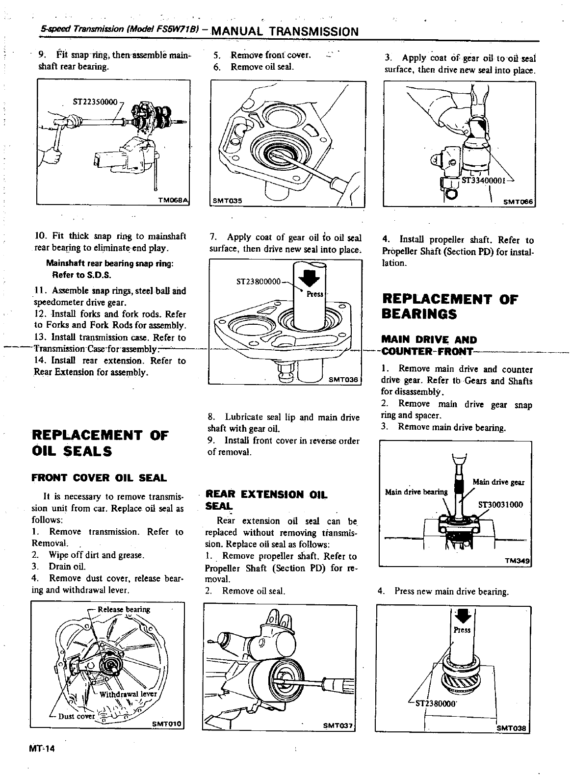
5
speed
Transmission
Model
FS5W77BJ
MANUAL
TRANSMISSION
II
Assemble
soap
rings
steel
baU
and
speedometer
drive
gear
12
InstaU
forks
and
fork
rods Refer
to
Forks
and
Fork
Rods
for
assembly
13
InstaU
transmission
case
Refer
to
Transmission
Case
for
assembly
14
InstaU
rear
extension
Refer
to
Rear
Extension
for
assembly
9
FIt
soap
ring
then
assemble
main
shaft
rear
bearing
ST223500i
TM068A
10
Fit
thick
snap
ring
to
mainshaft
rear
beapng
to
eliminate
end
play
Mainshaft
rear
bearing
snap
ring
Refer
to
S
O
S
REPLACEMENT
OF
OIL
SEALS
FRONT
COVER
OIL
SEAL
It
is
necessary
to
remove
transmis
sion
unit
from
car
Replace
oil
seal
as
follows
Remove
transmission
Refer
to
RemovaL
2
Wipe
off
dirt
and
grease
3
Drain
oil
4
Remove dust
cover
release
bear
ing
and
withdrawal
lever
MT14
MAIN
DRIVE AND
7
COUNTER
FRONT
1
Remove
main
drive
and
counter
drive
gear
Refer
tb
Gears
and
Shafts
for
disassembly
2
Remove
main
drive
gear
snap
ring
and
spacer
3
Remove
main
drive
bearing
5
Remove
front
CO
Ier
6
Remove
oil
seal
7
Apply
coat
of
gear
oil
0
oil
seal
surface
then
drive
new
seal
into
place
ST23800000
PreS
Z
Y
o
J
oV
80
SMT036
8
Lubricate
seal
lip
and
main
drive
shaft
with
gear
oil
9 Install
front
cover
in
reverse
order
of
removal
REAR
EXTENSION
OIL
SEAL
Rear
extension
oil
seal
can
be
replaced
without
removing
transmis
sion
Replace
oil
seal
as
follows
I
Remove
propeller
shaft
Refer
to
PropeUer
Shaft
Section
PD
for
reo
movaL
2
Remove
oil
seal
SMT037
3
Apply
coat
of
gear
oil
to
oil
seal
surface
then
drive
new
seal
into
place
4
InstaU
propeller
shaft
Refer
to
PropeUer
Shaft
Section
PD
for
instal
lation
REPLACEMENT
OF
BEARINGS
TM349
4
Press
new
main
drive
bearing
Press
SMT038
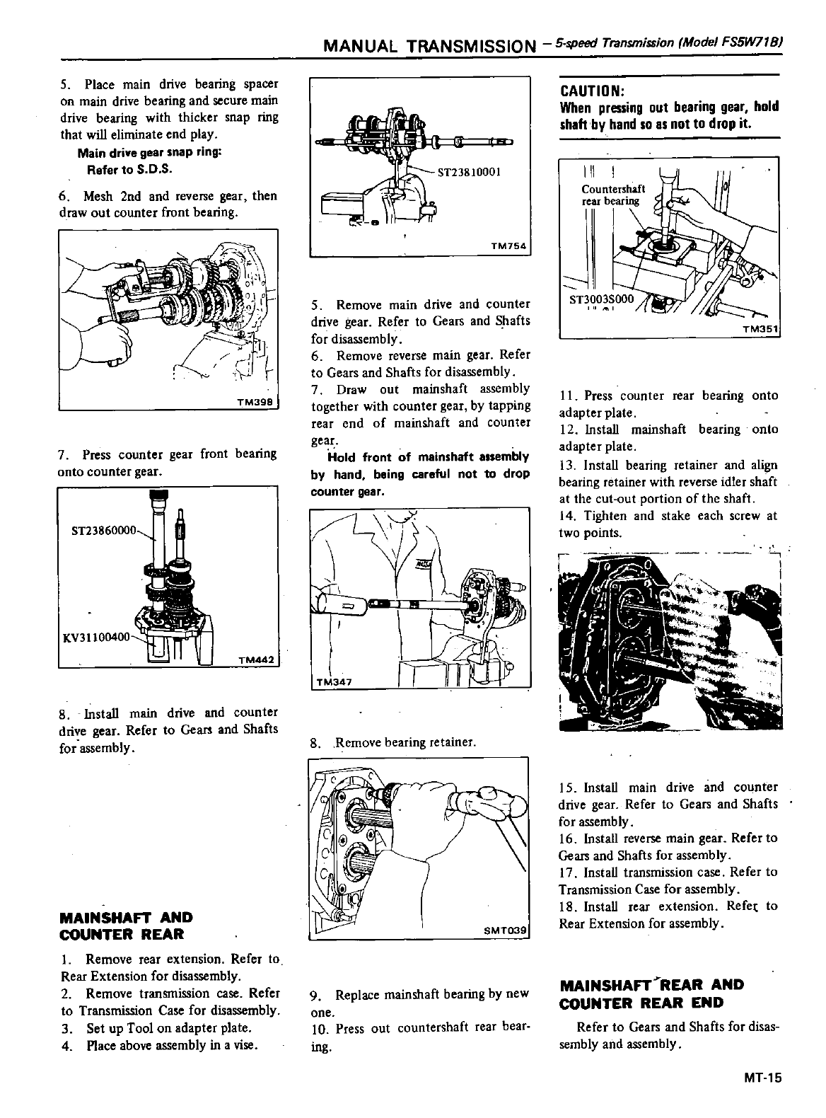
5
Place
main
drive
bearing
spacer
on
main
drive
bearing
and
secure
main
drive
bearing
with
thicker
snap
ring
that
wiD
eliminate
end
play
Main drive
gear
snap
ring
Refer
to
S
O
S
6
Mesh
2nd
and
reverse
gear
then
draw
out
counter
front
bearing
TM398
7
Press
counter
gear
front
bearing
onto
counter
gear
ST23860000
KV31100400
n
TM442
8
InstaU
main
drive
and
counter
drive
gear
Refer
to
Gears
and
Shafts
for
assembly
MAINSHAFT
AND
COUNTER
REAR
1
Remove
rear
extension
Refer
to
Rear
Extension
for
disassembly
2
Remove
transmission
case
Refer
to
Transmission
Case
for
disassembly
3
Set
up
Tool
on
adapter
plate
4
Place
above
assembly
in
a
vise
MANUAL
TRANSMISSION
5
speed
Transmifi1iion
Model
FS5W71B
TM754
5
Remove
main drive
and
counter
drive
gear
Refer
to
Gears
and
Shafts
for
disassembly
6
Remove
reverse
main
gear
Refer
to
Gears
and
Shafts
for
disassembly
7
Draw
out
mainshaft
assembly
together
with
counter
gear
by
tapping
rear
end
of
main
shaft
and
counter
gear
Hold
front
of
meinshaft
essembly
by
hand
being
careful
not
to
drop
counter
gesr
TP
347
8
Remove
bearing
retainer
SMT039
9
Replace
mainshaft
bearing
by
new
one
10
Press
out
countershaft
rear
bear
ing
CAUTION
When
pressing
out
bearing
gear
hold
shaft
by
hand
so
as
not
to
drop
it
III
Countenhaft
rear
bearing
I
I
11
TM351
11
Press
counter
rear
bearing
onto
adapter
plate
12
InstaU
mainshaft
bearing
onto
adapter
plate
13
I
nstaU
bearing
retainer
and
align
bearing
retainer
with
reverse
idler
shaft
at
the
cut
out
portion
of
the
shafl
14
Tigh1en
and
stake
each
screw
at
two
points
15
Install
main drive
and
counter
drive
gear
Refer
to
Gears
and
Shafts
for
assembly
16 InstaU
reverse
main
gear
Refer
to
Gears
and
Shafts
for
assembly
17 InstaU
transmission
case
Refer
to
Transmission
Case
for
assembly
18
InstaU
rear
extension
Refe
to
Rear Extension
for
assembly
MAINSHAFT
REAR
AND
COUNTER
REAR
END
Refer
to
Gears
and
Shafts
for
disas
sembly
and
assembly
MT15
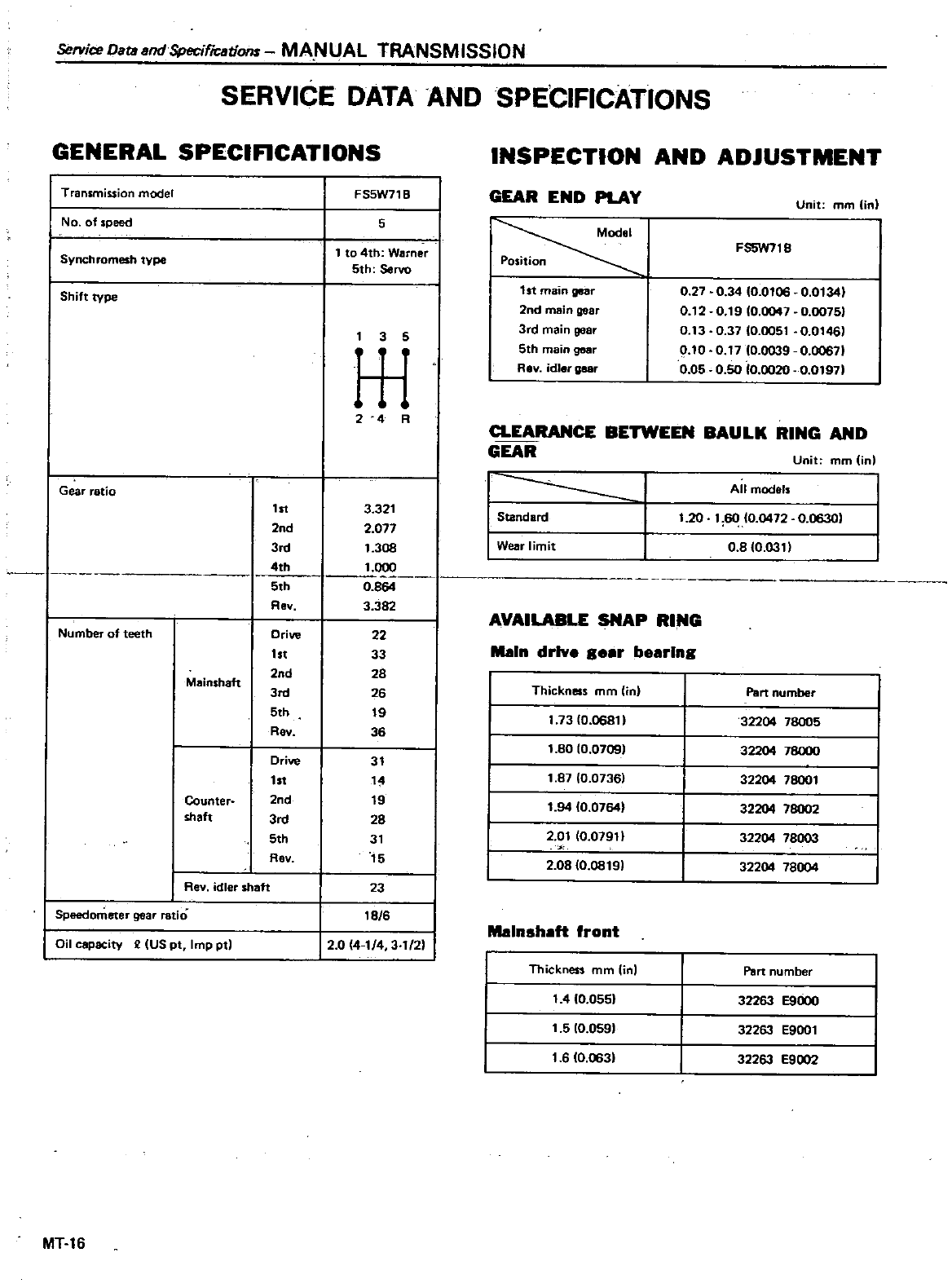
Service
Data
sndSpecificatiom
MA
N
UAL
TRANSM
ISSION
SERVICE
DATA
AND
SPECIFICATIONS
GENERAL
SPECIFICATIONS
Transmission
model
No
of
speed
Synchromesh
type
Shift
type
Gear ratio
Number
of
teeth
Speedometer
gear
ratio
Mainshett
Counter
shaft
Rev
idler
shaft
Oil
capacity
II US
pt
Imp
pt
MT
16
1st
2nd
3rd
4th
5th
Rev
Drive
1st
2nd
3rd
5th
Rev
Drive
1st
2nd
3rd
5th
Rev
FS5W71
B
5
1
to
4th
Warner
5th
Servo
3
5
L
r
24
R
3
321
2
077
1
308
1
000
0
864
3 382
22
33
28
26
19
36
31
1
19
28
31
15
23
lB
6
12
0 414
3
1
21
INSPECTION
AND
ADJUSTMENT
GEAR
END
PLAY
1
st
main
gear
2nd
main
gear
3rd
main
gear
5th
main
gear
Rev
idler
gasr
Unit
mm
in
FS5W718
0
27
0
34
0
0106
0
0134
0
12
0
19
0
0047
0
0075
0
13
0
3710
0051
0
01461
0
10
0
17
0
0039
0
00671
0
05
0
50
0
0020
0
0197
a
EARANCE
BETWEEN
BAULK
RING
AND
GEAR
I
Standard
I
Wear
limit
Unit
rnm
in
All
models
1
20
1
60
10
0472
0
06301
0
810
0311
Main
drlv
s
er
b
erlns
AVAILABLE
SNAP
RING
Thickness
mm
in
1
73
0
06811
1
80
10
0709
1
87
0
0736
1
94
0
07641
2
01
0
07911
2
0810
0819
Malnsheft
front
Thickness
mm
in
1
4 0
055
1
5
10
0591
1
6
0
063
Part
number
32204 78005
32204
78000
32204
78001
32204
78002
32204
78003
32204
78004
Part
number
32263
E9000
32263
E9001
32263
E9002
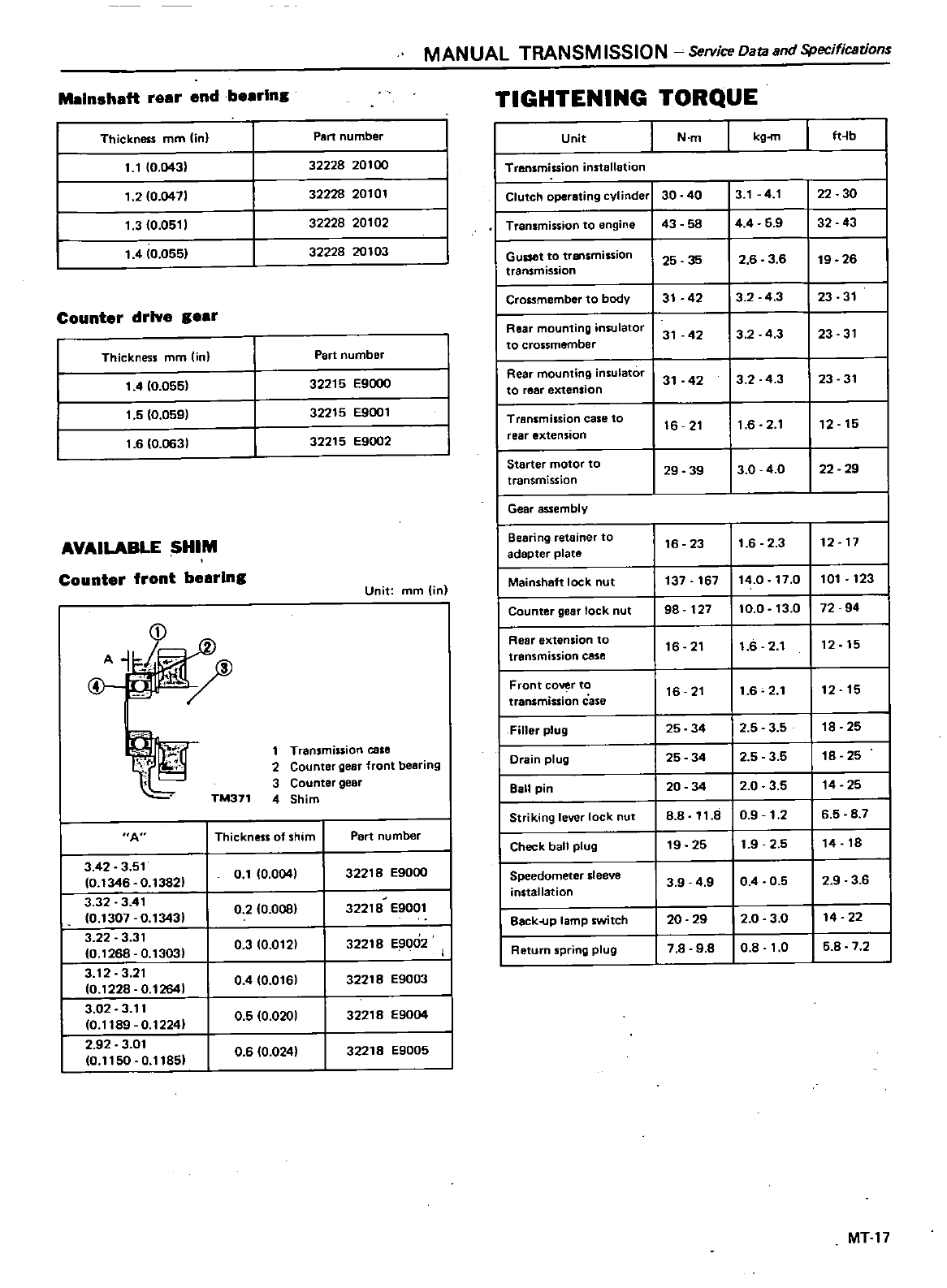
MANUAL
TRANSM
ISSION
Service
Data
and
Specifications
Maln
haft
rear
end
besrlna
Thickness
mm
lin
Part
number
11
0
043
1
20
0471
1
3 0
0511
1
4
0
0551
32228
20100
32228
20101
32228
20102
32228
20103
Counter
drive
aear
Thickness
mm
lin
Part
number
1
4
0
055
1
5
0
059
1
6
0
0631
32215
E9000
32215
E9oo1
32215
E9oo2
AVAILABLE
SHIM
Counter
front
bearlna
Unit
mm
in
D
A
@
I
j
TM371
1
Transmission
case
2
Counter
gear
front
bearing
3
Counter
gear
4
Shim
A
Thickness of shim
Part
number
3
42
3
51
0
1
0
0041
32218
E9000
0
1346
0
13821
3
32
3
41
0
2
10
0081
32218
E9001
0
1307
0
13431
3
22
3
31
0 3
0
012
32218
E9002
0
1268
0
1303
3
12
3
21
0
4 0
016
32218
E9003
0
1228
0
1264
3
02
3
11
0
5 0
0201
32218
E9004
0
1189
0
12241
2
92
3
01
06
0 024
32218
E9005
0
1150
0
11851
TIGHTENING
TORQUE
1
Unit
N
m
kg
m
ft
b
I
Transmission
installation
I
Clutch
operating
cylinder
30 40
3
1
4
1
22 30
I
Transmission
to
engine
43 58
44
5
9
32
43
I
Gusset
to
transmission
25 35
2
6
3
6
19
26
transmission
I
Crossmember
to
body
31
42
3
2 4
3
23
31
I
Rear
mounting
insulator
31
42
3 2
4
3
23
31
to
crossmember
I
Rear
mounting
insulator
31
42
3
2 4
3
23
31
to
reaf
extension
I
Transmission
case
to
16
21
1
6
2
1
12
15
rear
extension
I
Starter
motor
to
29 39
3
0 40
22
29
transmission
I
Gear
assembly
I
Bearing
retainer
to
16
23
1
6
2 3
12
17
adapter
plate
Mainshaft
lock
nut
137
167
14
0
17
0
101
123
Counter
gear
lock
nut
98
127
10
0
13
0
72 94
Rear
extension
to
16 21
1
6
2
1
12 15
transmission
case
Front
cover to
16 21
1
6
2
1
12
15
transmission
case
Filler
plug
25 34
2
5
3 5
18
25
Drain
plug
25 34
2 5
3
5
18 25
Ball
pin
20 34
2
0
3 5
14
25
Striking
lever
lock
nut 88
11
8
0
91
26 5 8 7
Check
ball
plug
19
25
1
9
25
14
18
Speedometer
sleeve
3 9
49 04 0
5 2 9 3 6
installation
Back
up
lamp
switch
20 29
2
0
3
0
14
22
Return
spring
plug
7
8
98 0
8
1
0 5 8 7 2
MT17
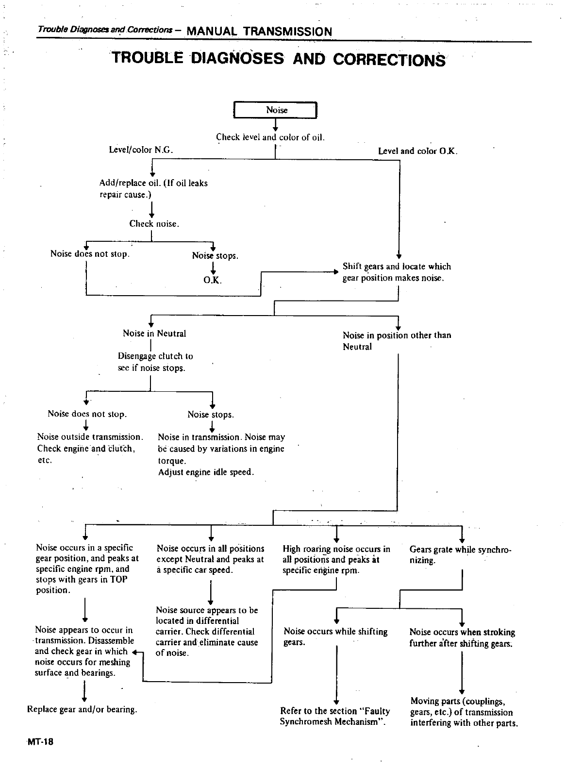
TroubleDiagnosesa
Correctiofl
MANUAL
TRANSMISSION
TROUBLE
DIAGNOSES
AND
CORRECTIONS
Level
color
N
G
Noise
Check
level
and
color
of
oil
I
L
Add
replace
oil
If
oil
leaks
repair
cause
Check
noise
I
NOise
does
not
stop
Noise
stops
OK
Level
and
color
OK
Shift
gears
and
loco
te
which
0
gear
position
makes
noise
I
Noise
in
Neutral
I
Disengage
clutch
to
see
if
noise
stops
I
Noise
does
not
stop
Noise
outside
transmission
Check
engine
and
dutch
etc
Noise
occurs
in a
specific
gear
position
and
peaks
at
specific
engine
rpm
and
stops
with
gears
in
TOP
position
1
Noise
appears
to
occur
in
transmission
Disassemble
and
check
gear
in
which
l
noise
occurs
for
meshing
surface
nd
bearings
1
Replace
gear
and
or
bearing
MIlS
Noise
in
position
other
than
Neutral
Noise
stops
Noise
in
transmission
Noise
may
be
caused
by
variations
in
engine
torque
Adjust
engine
idle
speed
High
roaring
noise
occurs
in
all
positions
and
peaks
8t
specific
engine
rpm
I
Noise
occurs
in
all
positions
except
Neutral
and
peaks
at
a
specific
car
speed
1
Noise
source
appears
to
be
located
in
differential
carrier
Check
differential
carrier
and
eliminate
cause
of
noise
Noise
occurs
while
shifting
gears
Refer
to
1he
section
Faulty
Synchromesh
Mechanism
L
Gears
grate
while
synchro
nizing
L
Noise
occurs
when
stroking
further
after
shifting
gears
Moving
parts
couplings
gears
etc
of
transmission
interfering
with
other
parts
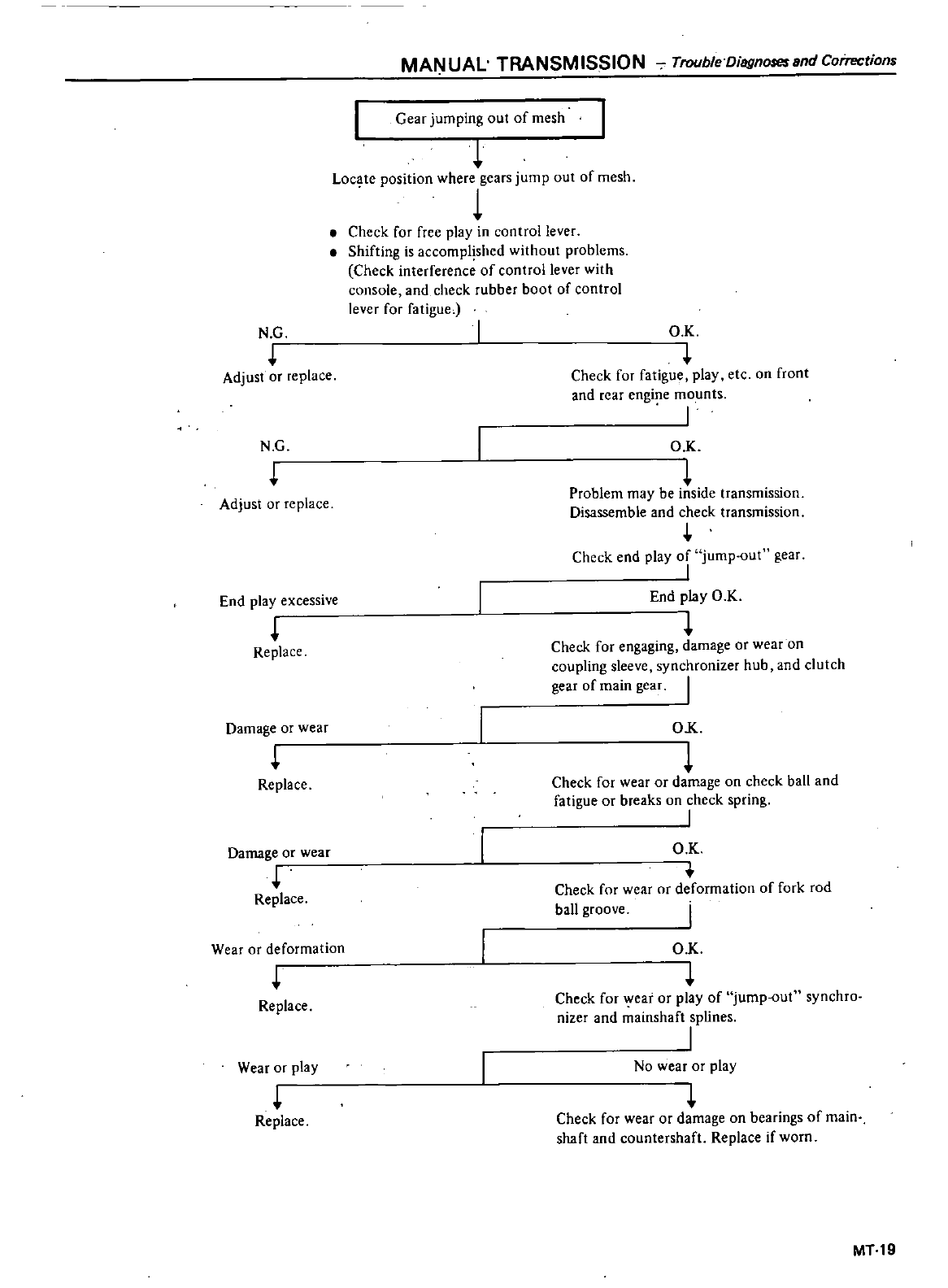
MANUAL
TRANSMISSION
Trouble
DisgnoseundCoirr
ctions
Gear
jumping
out
of
mesh
L
Loc
ilte
position
where
gears
jump
out
of
mesh
Check
for
free
play
in
control
lever
Shifting
is
accomplished
without
problems
Check
interference
of
control
lever
with
console
and
check
rubber
boot
of
control
lever
for
fatigue
N G
Adjust
or
replace
O
K
I
Check
for
fatigue
play
etc
on
front
and
rear
engine
mounts
I
N
G
O K
Problem may
be
inside
transmission
Disassemble
and
check
transmission
Adjust
or
replace
Replace
Check
end
play
of
jump
out
gear
I
End
play
OK
Check
for
engaging damage
or
wear on
coupling
sleeve
synchronizer
hub
and
clutch
gear
of
main
gear
I
End
play
excessive
Damage
or
wear
OK
Check
for
wear
or
damage
on
check
ball
and
fatigue
or
breaks
on
check
spring
I
Replace
Damage
or
wear
Replace
O
K
Check
for
wear
or
deformation
of fork
rod
ball
groove
Wear
or
deformation
O
K
Check
for
wear
or
play
of
jump
out
synchro
nizer
and
mainshaft
splines
I
Replace
Wear
or
play
No
wear
or
play
Replace
Check
for
wear
or
damage
on
bearings
of
main
shaft
and
countershaft
Replace
if
worn
MT19
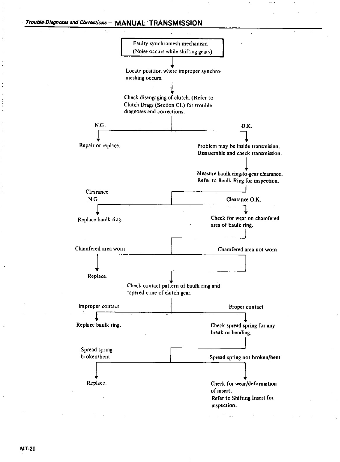
Trouble
Disgnoseund
CDrrections
MANUAL
TRANSMISSION
N
G
Repair
or
replace
Clearance
N
G
Replace
baulk
ring
Chamfered
area
worn
1
Replace
Improper
contact
l
Replace
baulk
ring
Spread
spring
broken
bent
1
Replace
MT
20
Faulty
synchromesh
mechanism
Noise
occurs
while
shifting
gears
Locate
position
where
improper
synchro
meshing
occurs
L
Check
disengaging
of
clutch
Refer
to
Clutch
Drags
Section
CL
for
trouble
diagnoses
and
corrections
I
O
K
Problem
may
be
inside
transmision
Disassemble
and
check
transmission
1
Measure
baulk
ring
to
gear
clearance
Refer
to
Baulk
Ring
for
inspection
Clearance
O
K
l
Check
for
w
ar
on
chamfered
area
of
baulk
ring
I
Chamfered
area
not
worn
1
Check
contact
pattern
of
baulk
ring
and
tapered
cone
of
clutch
gear
Proper
contact
l
Check
spread
spring
for
any
break
or
bending
I
Spread
spring
not
broken
bent
1
Check
for
wear
deformation
of
insert
Refer
to
Shifting
Inset
for
inspection
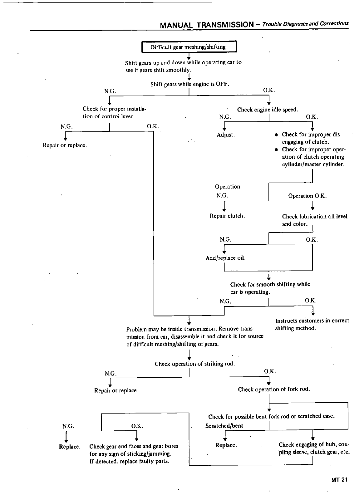
NG
Repair
or
replace
N G
L
Replace
MANUAL
TRANSMISSION
Trouble
Diagnoseund
Correction
Difficult
gear
meshing
shifting
Shift
gears
up
and
down
while
operating
car
to
see
if
gears
shift
smoothly
Shift
gears
while
engine
is
OFF
I
Problem
may
be
inside
transmission
Remove
trans
mission
from
car
disassemble
it
and
check
it
for
source
of
difficult
meshing
shifting
of
gears
L
Check
operation
of
striking
rod
I
N
G
Check
for
proper
installa
tion
of
control
lever
O
c
N G
Repair
or
replace
O
K
Check
gear
end
faces
and
gear
bores
for
any
sign
of
sticking
jamming
If
detected
replace
faulty
parts
O K
N G
Check
engine
idle
speed
I
Adjust
O
K
I
Check
for
improper
dis
engaging
of
clutch
Check
for
improper
oper
ation
of
clutch
operating
cylinder
master
cylinder
I
Operation
N G
Operation
O K
I
Check
lubrication
oil
level
and
color
I
Repair
clutch
N G
Add
replace
oil
I
O K
Check
for
smooth
shifting
while
car
is
operating
N G
O
K
Instructs
customers
in
correct
shifting
method
Ox
Check
operation
of
fork
rod
1
Check
for
possible
bent
fork
rod
or
scratched
case
Scratched
bent
I
Replace
Check
engaging
of
hub
cou
pling
sleeve
clutch
gear
etc
I
MT
21
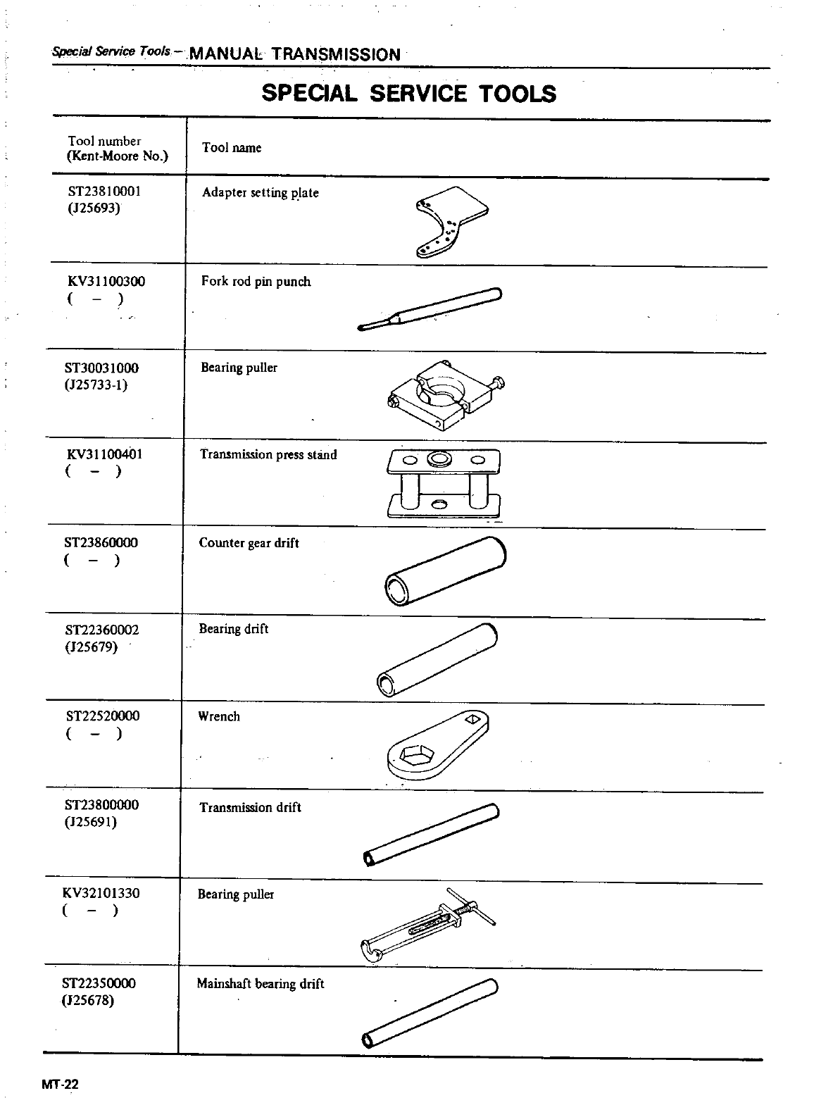
Special
Service
Tools
MANUAL
TRANSMISSION
Tool
number
Kent
Moore
No
ST2381000l
125693
KV311
00300
ST30031000
125733
1
KV311
004
n
ST23860000
ST22360002
125679
ST22520000
ST23800000
125691
KV32
101330
ST22350000
125678
MT
22
SPECIAL
SERVICE
TOOLS
Tool
name
Adapter
setting
plate
Fork
rod pin
punch
Bearing
puUer
Transmission
press
stand
Counter
gear
drift
Bearing
drift
Wrench
Transmission
drift
Bearing
puUer
Mainshaft
bearing
drift
9
Lo
rQ
OJ
rUoLh
ifi
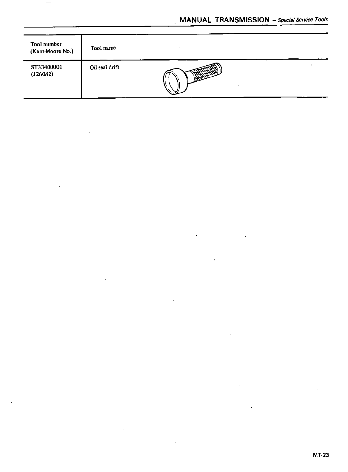
Tool
number
Kent
Moore
No
ST33400001
126082
MANUAL
TRANSMISSION
Special
Service
Tools
Tool
name
OU
seal
drift
MT23
DATSUN
200SX Mode
S
110
Series
SECTION
A
T
AUTOMATIC
TRANSMISSION
CONTENTS
DESCRIPTION
HYDRAULIC
CONTROL
UNIT
AND
VALVES
HYDRAULIC
CONTR
L
CIRCUITS
MINOR
ADJUSTMENTS
REMOVAL
AND
INSTA
LLATION
TRANSMISSION
ASSEMBLY
MAJOR
OVERHAUL
OPERATIONS
SERVICE
NOTES
FOR
DISASSEMBL
Y
DISASSEMBLY
COMPONENT
PARTS
AT
2
AT
3
AT
5
AT
25
AT
28
AT
28
AT30
AT31
AT31
AT
34
FINAL
ASSEMBLY
TROUBLE
SHOOTING
AND
DIAGNOSES
PRELIMINARY
CHECKS
Prior
to
road
testing
DIAGNOSTIC
ROAD
TEST
PRESSURE
TESTING
STALL
TESTING
SERVICE
DATA
AND
SPECIFICATIONS
SPECIAL
SERVICE
TOOLS
AT
44
AT51
AT
51
AT
52
AT
54
AT
55
AT
52
AT
53
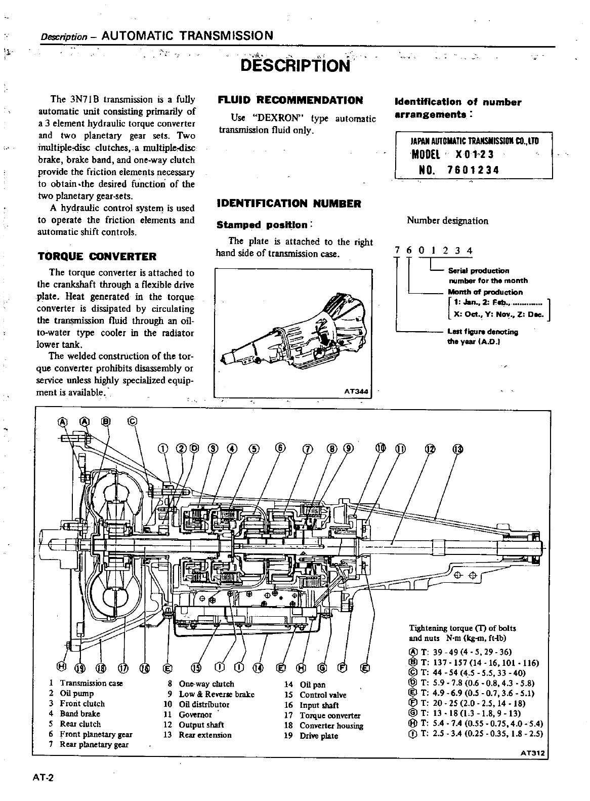
1
Description
AUTOMATIC
TRANSMISSION
The
3N7l
B
transmission
is
a
fully
automatic
unit
consisting
primarily
of
a
3
element
hydraulic
torque
converter
and
two
planetary
gear
sets
Two
inultiple
disc
clutches
a
multiple
disc
brake brake
band
and
one
way
clutch
provide
the
friction
elements
necessary
to
obtain
the
desired
function
of
the
two
planetary
gear
sets
A
hydraulic
control
system
is
used
to
operate
the
friction
elements
and
automatic
shift
controls
TORQUE
CONVERTER
The
torque
converter
is
attached
to
the
crankshaft
through
a
flexible
drive
plate
Heat
generated
in
the
torque
converter
is
dissipated
by
circulating
the
transmission
fluid
through
an
on
to
water
type
cooler
in
the
radiator
lower
tank
The
welded
construction
of
the
tor
que
converter
prohibits
disassembly
or
service
unless
highly
specialized
equip
ment
is
available
@
if
1
Transmission
case
2
Oilpump
3
Frorit
clutch
4
Band
brake
5
Rear
clutch
6
Front
planetary
gear
7
Rear
planetary
gear
DEScRIPTION
FLUID
RECOMMENDATION
Use
DEXRON
type
automatic
transmission
fluid
only
IDENTIFICATION
NUMBER
Stamped
position
The
plate
is
attached
to
the
right
hand
side
of
transmission
case
AT344
8
One
way
clutch
9
Low
Reverse
brake
10
Oil distributor
11
JQvemor
12
Outputshaft
13
Rear
extension
G
14
Oil
pan
IS
Control
valve
16
1npot
shaft
17
Torque
oonverter
18
Converter
housing
19
Dri
plate
AT
2
Identification
of
number
arrangementa
IAPO
AUTOIlATle
TllAIISIIISSlOll
CO
lTO
MODEL
X
01
2
3
NO
7601234
Number
designation
7601234
L
Serial
production
mber
for
the
month
Month
of
production
1
Jan
2
Fob
no
X
Oct
Y
N01
Z
Dec
Lat
figu
denoting
tho
year
A
DJ
Tightening
torque
T
of
bolts
and
nuts
N
m
kg
mfHb
@
T
39 49
4
5
29
36
@
T
137 157
14
16
101
116
@
T
44 54
4 5 5 5
33 40
@
T
5 9 7 8 0 6
0
8 4 3 5 8
@
T
4 9
6 9
0
5
0
73
65
1
T
20
25
20 25
14
18
@T
13
l8
LJ 1
8 9
13
@
T
54
7 4
0 55 0
75
4
05
4
CD
T
2 5 3 4
0
25
0 35
18
2
5
AT312
AUTOMATIC
TRANSM
ISSIO
N
Hydiaulic
Control
Unit
and
Valves
HYDRAULIC
CONTROL
UNIT
AND
VALVES
The
hydraulic
or
automatic
control
system
is
comprised
of
four 4
basic
groups
the
pressure
supply
system
the
pressure
regulating
system
the
flow
control
valves
and
the
friction
elements
PRESSURE
SUPPLY
SYSTEM
The
pressure
supply
system
consists
of
a
gear
type
oil
pump
driven
by
the
engine
through
the
torque
converter
The
pump
provides
pressure
for
aU
hydraulic
and
lubrication
needs
PRESSURE
REGULATOR
VALVES
The
pressure
regulating
valves
con
trol
the
output
pressure
of
the
oil
pump
Pressure
regulator
valve
The
pressure
regulator
valve
con
trols
mainline
pressure
based
on
throttle
opening
for
the
operation
of
the
band
clutches
and
brake
Governor
valve
The
governor
valve
tranSffi
ts
re
gulated
pressure
based
on
car
speed
to
the
shifi
valves
to
control
upshifts
and
downshifts
Vacuum
throttle
valve
The
vacuum
throttle
valve
transmits
regulated
pressure
based
on
engine
load
vacuum
This
pressure
controls
the
pressure
regulator
valve
Also this
pressure
is
applied
to
one
end
of
the
shift
valves
in
opposition
to
governor
pressure
which
acts
on
the
other
end
of
the shift
valves
controlling
upshift
and
downshift
speeds
FLOW CONTROL
VALVES
Manual
valve
The
manual
valve
is
moved
manual
ly
by
the
car
operator
to
select
the
different
drive
ranges
1
2
Shift
valve
The
1
2shift
valve
automaticaUy
shifts
the
transmission
from
first
to
second
or
from
second
to
first
depend
ing
upon
governor
and
throttle
pres
sure
along
with
accelerator
position
solenoid
downshift
valve
See
Hy
draulic
Control
Circuits
Drive
2
23
Shift
valve
The
2
3
shift
valve
automatically
shifts
the
transmission
from
second
to
top
gear
or
from
top
to
second
de
pending
up
governor
and
throttle
pressure
or
accelerator
position
sole
noid
downshift
valve
See
Hydraulic
Control
Circuits
Drive
3
Range
23
Timing
valve
For
23
shifts
a
restrictive
orifice
slows
the
application
fluid
to
the
front
clutch
while
the
slower
reacting
band
is
allowed
to
release
This
prevents
a
hard
2
3
or
3
2
shift
Under
heavy
load
however
the
engine
will
tend
to
run
away
during
the
2
3
or
3
2
shift
pause
therefore
a
2
3
timing
valve
using
throttle
and
governor
pressure
is
used
to
bypass
the
restrictive
orifice
during
such
heavy
load
conditions
Solenoid
downshift
valve
The
solenoid
downshift
valve
is
activated
electrically
when
the
ac
celerator is
floored
causing
a
forced
downshift
from
top
to
second
top
to
fi
st
or
second
to
first
gear
depending
upon
car
speed
governor
pressure
Pressure
modified
valve
The
pressure
modifier
valve
assists
the
mainline
pressure
regulator
valve
in
lowering
mainline
pressure
during
high
speed
light
load
conditions
such
as
steady
speed
cruise
Governor
pres
sure
working
against
a
spring
opens
the
valve
which
aUows
modified
throt
tle
pressure
to
work
against
the
pres
sure
regulator
valve
spring
lowering
mainline
pressure
Lower
operating
pressure
under
light
load
reduces
oil
temperature
and
increases
transmis
siOli
life
Throttle
back
up
valve
The
throttle
back
up
valve
assists
the
vacuum
throttle
valve
to
increase
line
pressure
when
the
manual
valve
is
shifted
either
to
2
or I
range
Second
lock
valve
The
second
lock
valve
is
used
to
bypass
the
1
2
shift
valve
to
maintain
the
band
apply
pressure
in
2
posi
tion
The
valve
is
also
used
as
an
oil
pass
ge
for
the
1
2
shift
valve
band
apply
pressure
in
D D
and
I
Range
CLUTCHES
AND BAND
SERVOS
The
servo
pistons
of
the
clutches
low
reverse
brake
and
band
are
moved
hydraulicaUy
to
engage
the
clutches
brake
and
apply
the
band
The
clutch
and
prake
pistons
are
released
by
spriT
1g
tension
and
band
piston
is
released
by
spring
tension
and
hy
draulic
pressure
AT3
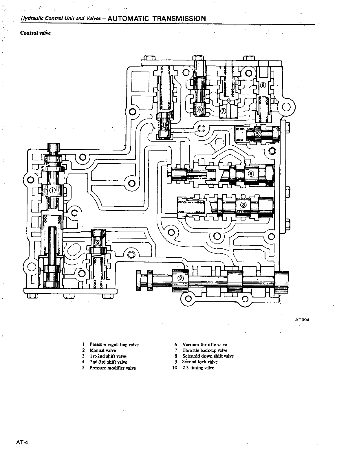
Hydl7lUlic
Control
Unit
and
Valves
AUTOMATIC
TRANSM
ISSIO
N
Control
valVe
rTil
SV
J
AT094
1
Pressure
regulating
valve
2
Manual
valve
3
lst
2nd
shift
valve
4
lnd
3rd
shift
valve
5
Pressure
modifier
valve
6
Vacuum
throttle
valve
7
Throttle
back
up
valve
8
Solenoid
down
shift
valve
9
Second
lock
v8Ive
10
2 3
timing
valve
AT
4
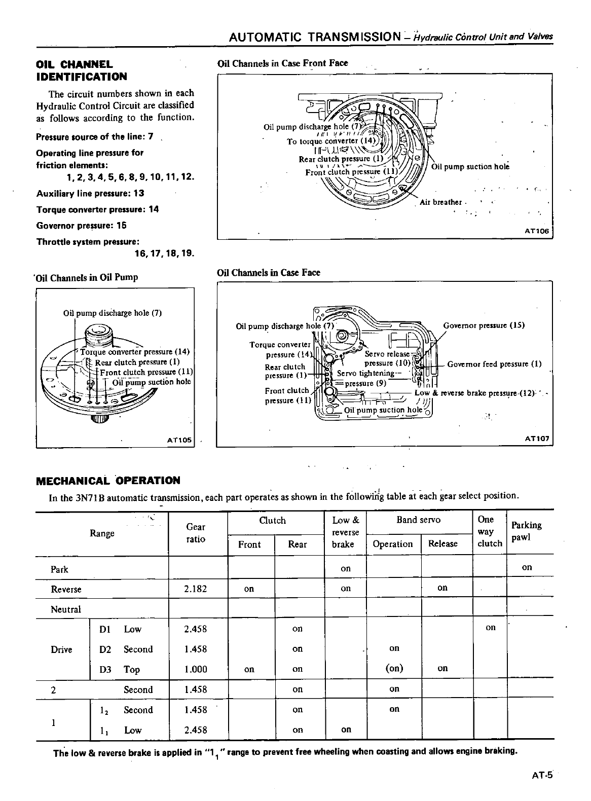
AUTOMATIC
TRANSMISSION
Hydraulic
Control
Unitsnd
Valves
OIL CHANNEL
IDENTIFICATION
Oil
Channels
in
Case
Front
Face
The
circuit
numbers shown
in
each
Hydraulic
Control Circuit
are
classified
as
follows
according
to
the
function
Auxiliary
line
pressure
13
Torque
converter
pressure
14
Governor
pre
ure
15
Throttle
system
pressure
16
17
18
19
Pressure
source
of
the
line
7
Operating
line
pressure
for
friction
elements
12
3
4 5
689
10
1112
AT106
Oil
Channels
in
Oil
Pump
Oil
Channels
in
Case
Face
0
r
o
90
Oil
pump
discharge
hole
7
Governor
pressure
15
i
j
J
Torque
converter
00f
i
pressure
l4
0
Servo
release
Rear
clutch
pressure
10
Governor
feed
pressure
1
pressure
1
Servo
tightening
o0
pressure
9
11
lnl
Front
clutch
rr
I
I
Low
reverse
brake
pressure
12f
pressure
11
U
0
0
Jj
J
o
P
sucti
e
Oil
pump
discharge
hole
7
Torque
converter
pressure
14
q
Rear
clutch
pressure
1
Front
clutch
pressure
11
L
OiiJ
u
nm
P
suction
hole
a
AT10S
AT107
MECHANICAL
OPERATION
In
the
3N71
B
automatic
transmission
each
part
operates
as
shown
in
the
foUowirig
table
at
each
gear
select
position
Gutch
Low
Band
servo
One
Range
Gear
Parking
ratio
reverse
way
pawl
Front
Rear
brake
Operation
Release
clutch
Park
on
on
Reverse
2
182
on on
on
Neutral
Dl
Low
2
458
on
on
Drive
D2
Second
1458
on
on
D3
Top
1
000
on on
on on
2
Second
1458
on on
12
Second
1458
on on
I
Low
2
458
on on
The
low
reverse
brake
is
applied
in
1
range
to
prevent
free
wheeling
when
coasting
and
allows
engine
braking
AT
5
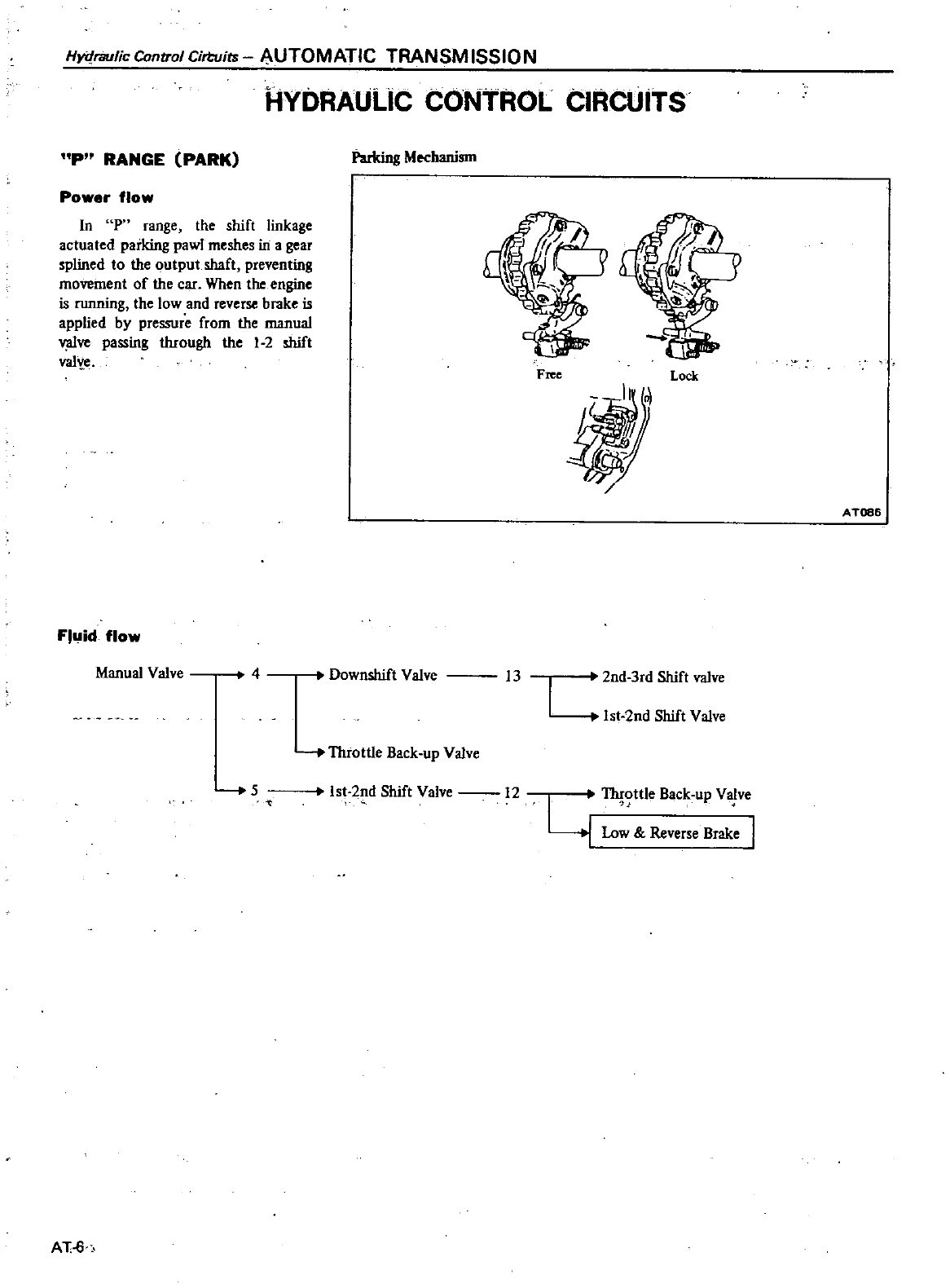
Hydraulic
Control
Cirtuirs
AUTOMATIC
TRANSMISSION
HYDRAULIC
CONTROL
CIRCUITS
P
RANGE
PARK
I
arking
Mechanism
Power
flow
In
P
range
the
shifl
linkage
actuated
parking
pawl
meshes
in a
gear
splined
to
the
output
shaft
preventing
movement
of
the
car
When
the
engine
is
running
the
low
and
reverse
brake
is
applied
by
pressure
from
the
manual
v
Uve
passing
through
the
1
2
shift
valye
F
Locr
11
A
T086
Fluid
flow
Manual
Valve
4
Downshift
Valve
13
2nd
3rd
Shift
valve
1st
2nd
Shift
Valve
Throttle
Back
up
Valve
5
Ist
2nd
Shift
Valve
12
I
1h
ottle
Back
up
Va
ve
y
Low
Reverse
Brake
I
AT
6
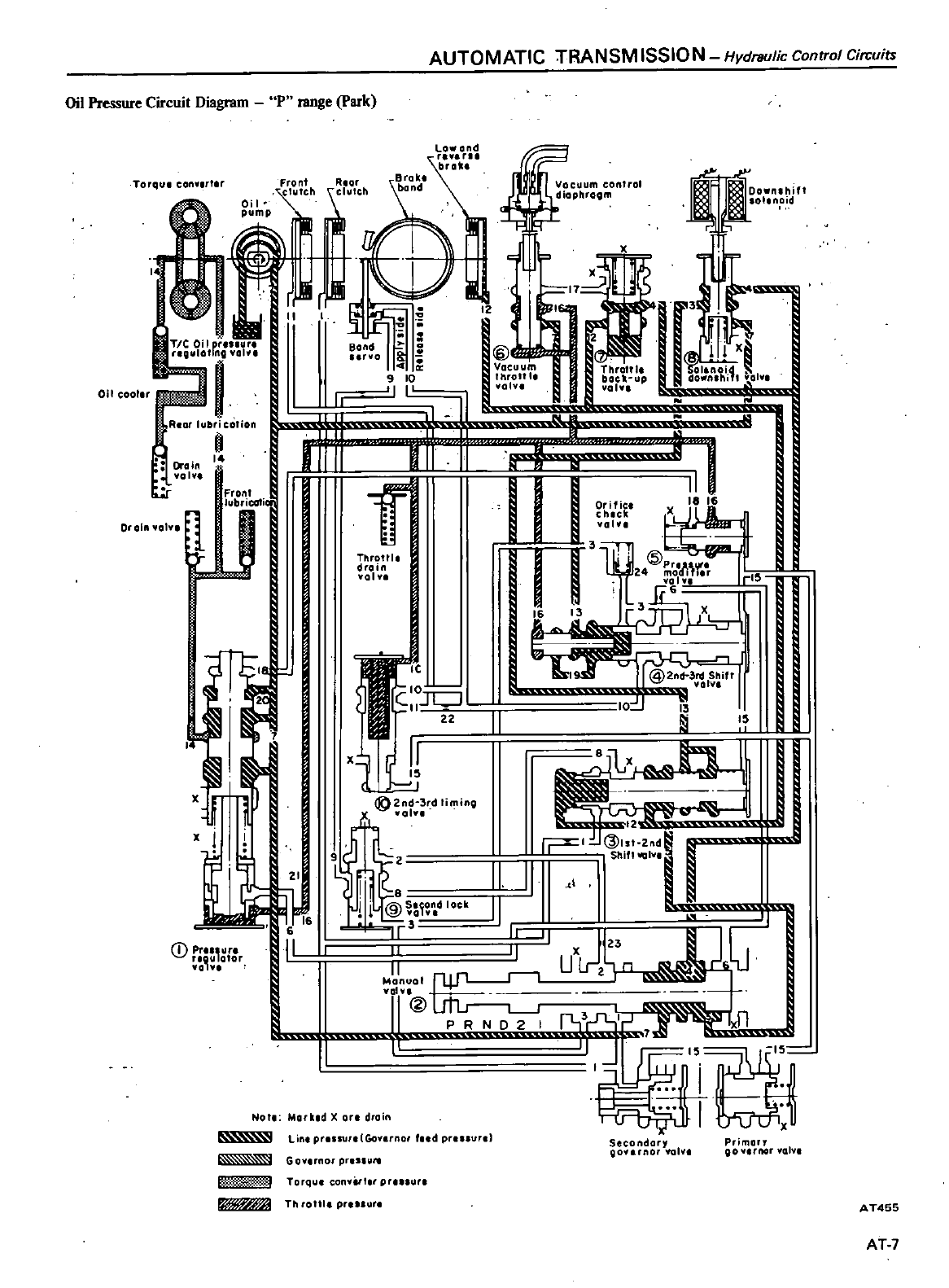
AUTOMATIC
TRANSM
ISSION
Hydraulic
Control
Circuits
Oil
Pressure
Circuit
Diagram
P
range
park
r
nh
r
c
h
11
rIf
0
Ih
gm
j
E
J
I
rl
j
@1
9
10
IY
tr
r
l
lI
olu
l
volv
II
oIll
I
I
I
II
oL
LLl
fir
x
lL
I
r
16
13
TorQu
conv
t
Oi
I
cooler
TIC
Oil
r
Slllt
ro
O
j
01
Rnt
lubrication
o
Drain
14
01
Front
lubricati
0
0
1
1
J
1
x
J
l
I
6
IICD
P
ur
otor
JJI
1
p
1
1
Throttl
drain
1
I
C
1
SII
JL
J
2Z
II
x
1J
IE
2no 3 d Ii
mino
vol
1
I
II
I
@
I
ck
II
r3
II
15
J
ji
t
2
Sh
I
j
I
ru
I
II
Monuol
YOI
I
I
xn
llrr
Itr
Not
Mork
d
X
ort
droin
Secondory
Qovunar
lOlv
Lin
prulUr
lGoy
rnor
fud
pt
r
Primo
OO
l
IOr
olv
Go
rnor
prUI1
l11l
I
Torqu
con
t
t
r
pr
r
Th
ro
lI pr
r
AT455
AT
7
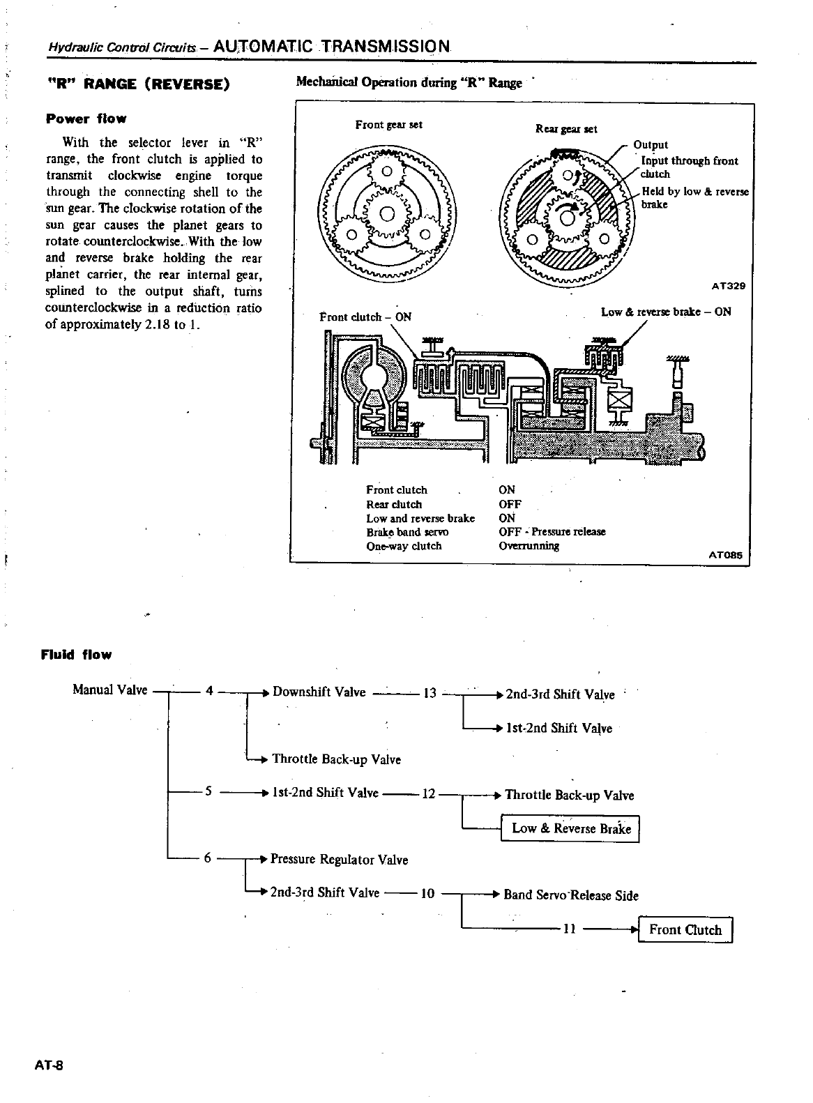
Hydraulic
ContrrJI
Circvits
AUTOMATIC
TRANSMISSION
R
RANGE
REVERSE
Power
flow
With
the
selector
lever
in
R
range
the
front
clutch
is
applied
to
transmit
clockwise
engine
torque
through
the
connecting
shell
to
the
Sun
gear
The
clockwise
rotation
of
the
sun
gear
causes
the
planet
gears
to
rotate
counterclockwise With
the
low
and
reverse
brake
holding
the
rear
planet
carrier
the
rear
internal
gear
splined
to
the
output
shaft
turns
counterclockwise
in
a
reduction
ratio
of
approximately
2
18
to
I
Fluid
flow
Manual
Valve
4
Mechaitical
Operation during
R
Range
Front
gear
set
Front
clutch
ON
Rear
gear
set
Output
Input
through
front
clutch
Held
by
low
reverse
brake
A
T329
Low
reverse
brake
ON
N
Front
clutch
Rear
clutch
Low
and
reverse
brake
Brak
band
servo
Oneway
clutch
Downshift
Valve
I3
5
Throttle
Back
up
Valve
6
Ist
2nd
Shift
Valve
12
L
Pressure
Regulator
Valve
2nd
3rd
Shift
Valve
10
AT
8
ON
OFF
ON
OFF
Pressure
release
Overrunning
AT085
2nd
3rd
Shift
Valve
L
Ist
2nd
Shift
Valve
I
Throttle
Back
up
Valve
y
Low
Reverse
Brake
Band
Servo
Release
Side
II
1
Front
Clutch
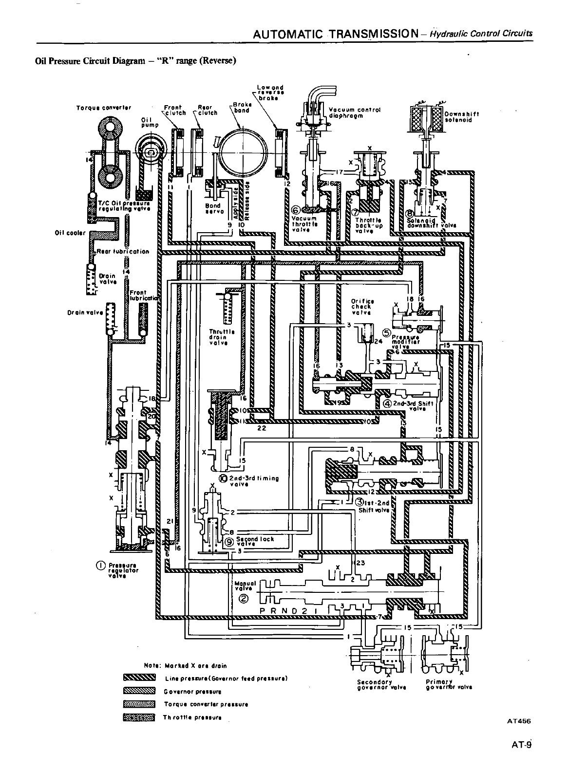
AUTOMATIC
TRANSM
ISSIO N
Hydraulic
Control
Circuits
Front
RlOr
I
h
l
h
0
I
I
trJI
kill
TIC
Oil
cr
l
r
reOlollalnil
volu
1
1
1
l
T
I
JUI
T
U
Oral
01
IL
J
i
I
11
L
L
lh
fi
ThMII
l
drain
val
I
II
xjJ
l
uff
I
n
ui
i
@
M
O
k
II
r
1
L
J
U
lr
1
vci
I
u
r
l
l
1
x
No
Markld
Xdfoin
lrto
Lin
preuur
Go
rnor
ud pr
ur
Oil
Pressure
Circuit
Diagram
R
range
Reverse
Torque
ton
l
rt
r
broil
Brok
band
J
12
Oil cool
x
jJ
G9
2nd
3rd
liming
olv
x
CD
p
Jr
ator
L
r
G
av
rnor prn
ure
f
m
Torqu
COMut
r
prl
ll
Th
ronl
pr
un
ID
24
Ool
l
r
rl
6
I
Secondory
go
rnOI
lGlv
Primor
go
itlr
01
1
AT456
AT
9
Hydraulic
Control
Cirwiu
AUTOMATIC
TRANSM
ISSION
N
RANGE
NEUTRAL
Power
flow
In
ange
no
friction
elements
are
in
use
thus
no
power
is
trans
mitted
to
the
output
shaft
AT10
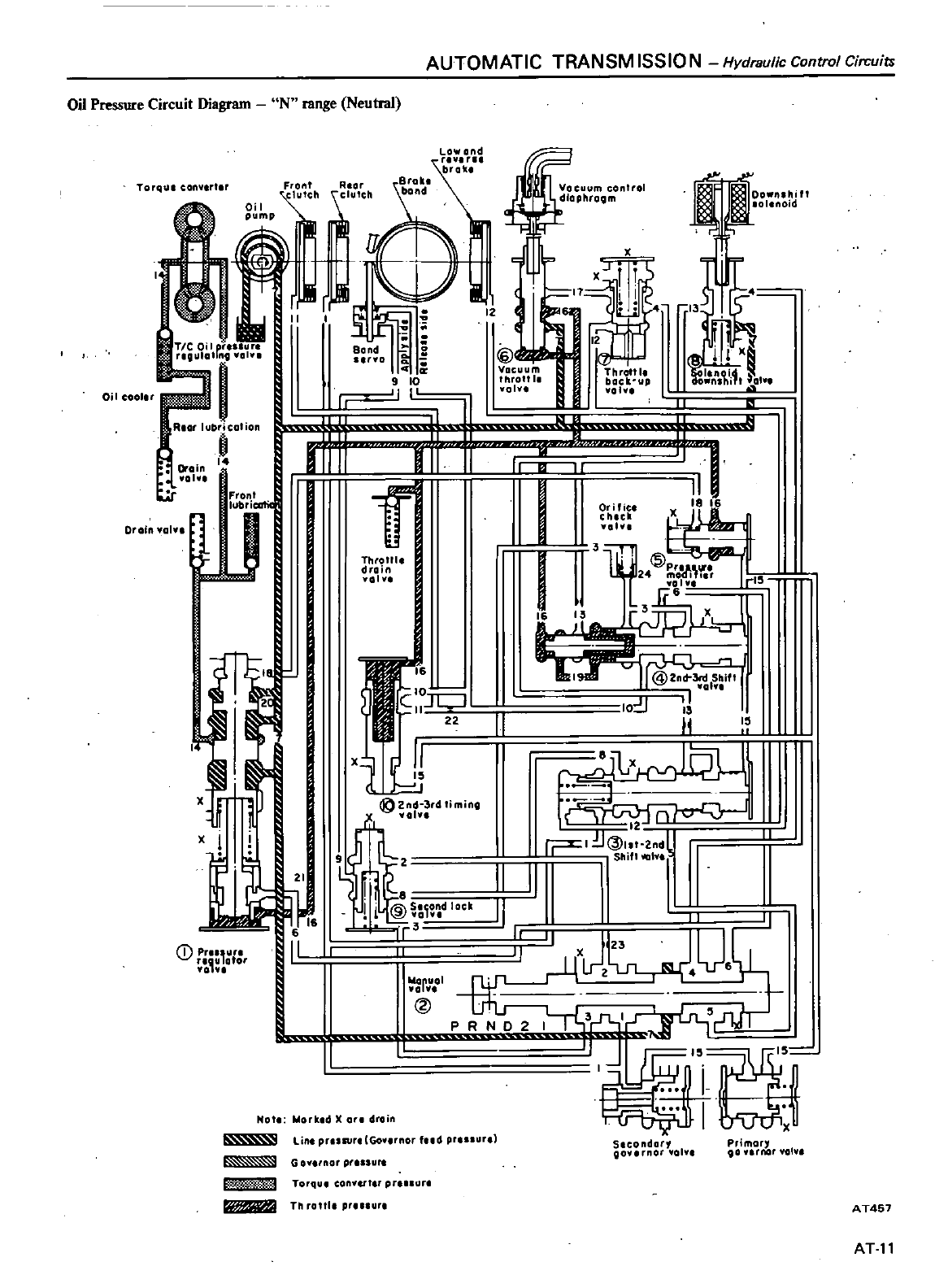
AUTOMATIC
TRANSM
ISSIO N
Hydraulic
Control
Circuits
Oil
Pressure
Circuit
Diagram
N
range
Neutral
flL
4
1t
T11
r1I
11
I
Orifice
18
chlcll
fol
a
L
I
6
Torql
ll
conv
rt
r
Front
lItCh
Oil
1
i
I
Oi
I
cooler
RIO
I
i
ealia
Drain
I
101
Front
lubricaf
t
Drain
01
1
t
x
Xl
II
CD
P
otor
Bond
YO
I
1
Throttle
drain
101
11
10
c
o
Z2
II
t1J
x
21
6
IV
ilL
@
d
lock
frO
6
II
rOI
@
Not
Worked
on
drain
lint
prUSUft
Go
rnor
ud
pr
nur
G
o
no
prlssure
nI
tI
Torqu
conyut
pnn
r
ft
Th rottl
p
ur
I
12
x
@
Vacuum
Ihrottl
oh
Throtllt
bacll
up
wolv
I
JI
F e
X
own
i1t
OIY
rI5
I
jULj
I
I
II
II
fLx
5
l
r
J
t
2
dl
ShiflIllGIY
I
I
I
I
Slcondar
OOv
nor
01
Primory
00
rnor
vol
A
T457
AT11
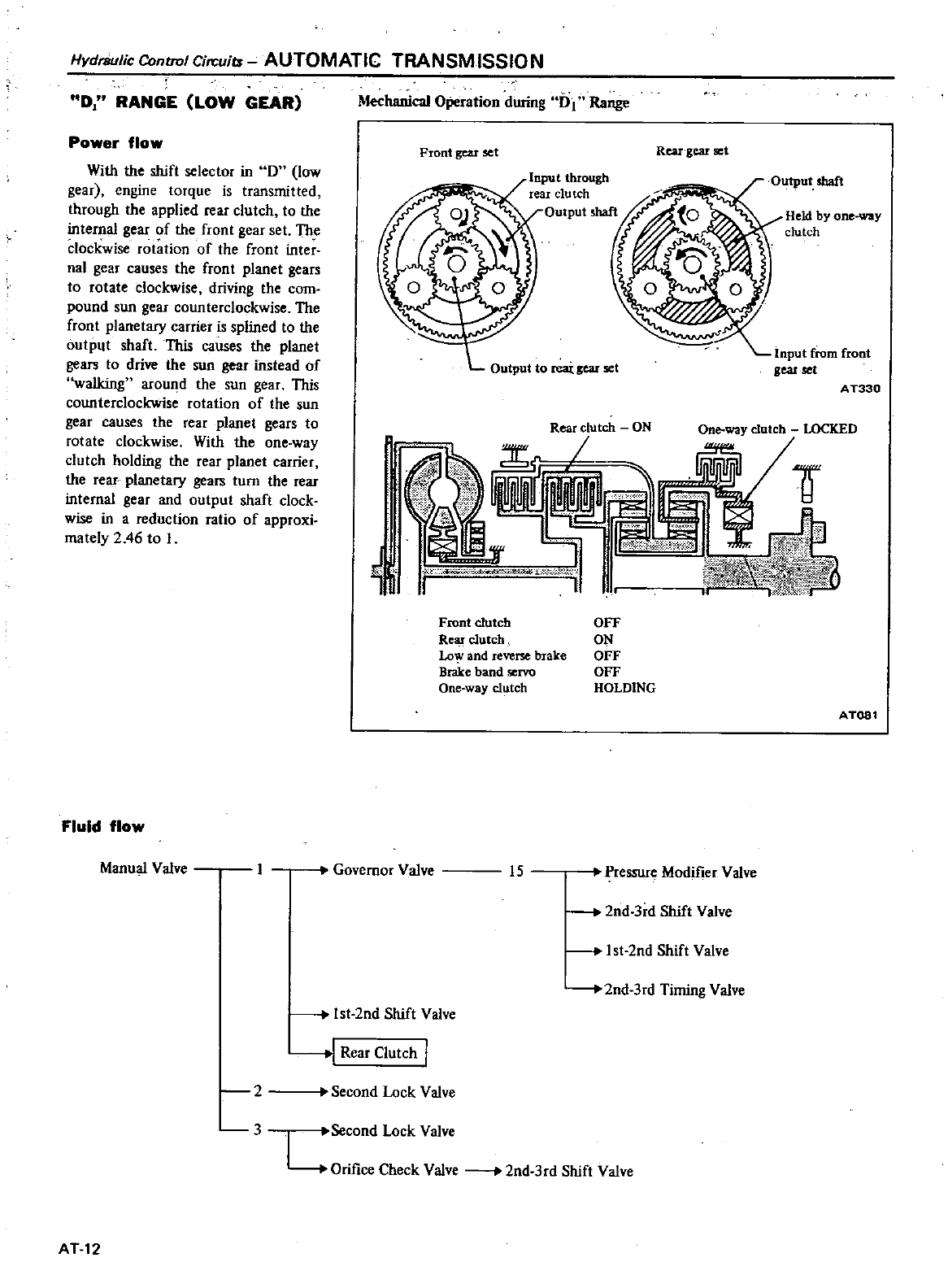
Hydraulic
Centrol
Circuits
AUTOMATIC
TRANSM
ISSIO
N
D
RANGE
LOW
GEAR
Power
flow
With
the
shift
selector
in
D
low
gear
engine
torque
is
transmitted
through
the
applied
rear
clutch
to
the
in1ernal
gear
of
the
fron1
gear
set
The
clockwise
rotation
of
the
front
inter
nal
gear
causes
the
fron
t
planet
gears
to
rotate
clockwise
driving
the
com
pound
sun
gear
counterclockwise
The
front
planetary
carrier
is
splined
10
the
output
shaft
This
causes
the
planet
gears
to
drive
the
sun
gear
instead
of
walking
around
the
sun
gear
This
counterclockwise
rotation
of
the
sun
gear
causes
the
rear
planet
gears
to
rotate
clockwise
With
the
one
way
clutch
holding
the
rear
planet
carrier
the
rear
planetary
gears
turn
the
rear
internal
gear
and
outpu1
shaft
clock
wise
in
a
reduction
ratio
of
approxi
mately
2
46
to
I
Fluid
flow
Manual
Valve
Mechanical
Operation
during
61
Range
Front
gear
set
Rear
gear
set
Output
shaft
Held
by
one
way
clutch
Input
from
front
gear
set
Output
to
reai
gear
set
A
T330
Front
clutch
Rear
clutch
Lo
and
reverse
brake
Brake
band
servo
One
way
clutch
OFF
ON
OFF
OFF
HOLDING
AT081
Governor
Valve
15
Pressure
Modifier
Valve
2nd
3rd
Shift
Valve
Ist
2nd
Shift
Valve
Ist
2nd
Shift
Valve
2nd
3rd
Timing
Valve
J
Rear
Clutch
2
3
Second
Lock
Valve
Second
Lock
Valve
L
Orifice
Check
Valve
2nd
3rd
Shift
Valve
AT12
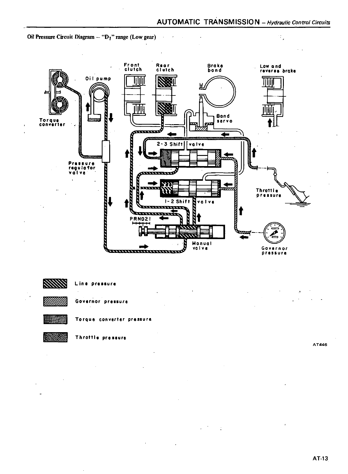
AUTOMATIC
TRANSM
ISSIO
N
Hydraulic
Control
Circuits
Oil
Pressure
Circuit
Diagram
D1
range
Low
gear
1
Torqu
ean
rl
r
Oi
I
pump
t
1
Pres
ur
rlQulo1
or
valv
L
Front
cluleh
t
I
62
J
1
t
Rlar
cl
utch
Brake
bond
Low
Q
nd
r
v1
brake
3
Shill
OI
o
t
Bond
I
b
7
ervo
I
1
Torque
conyerter
pressure
Throttle
prlssure
It
ll
1
Throttle
pr
sur
t
@
I
Governor
pressure
lint
pr
s
ur
Governor
pre
sure
AT446
AT13
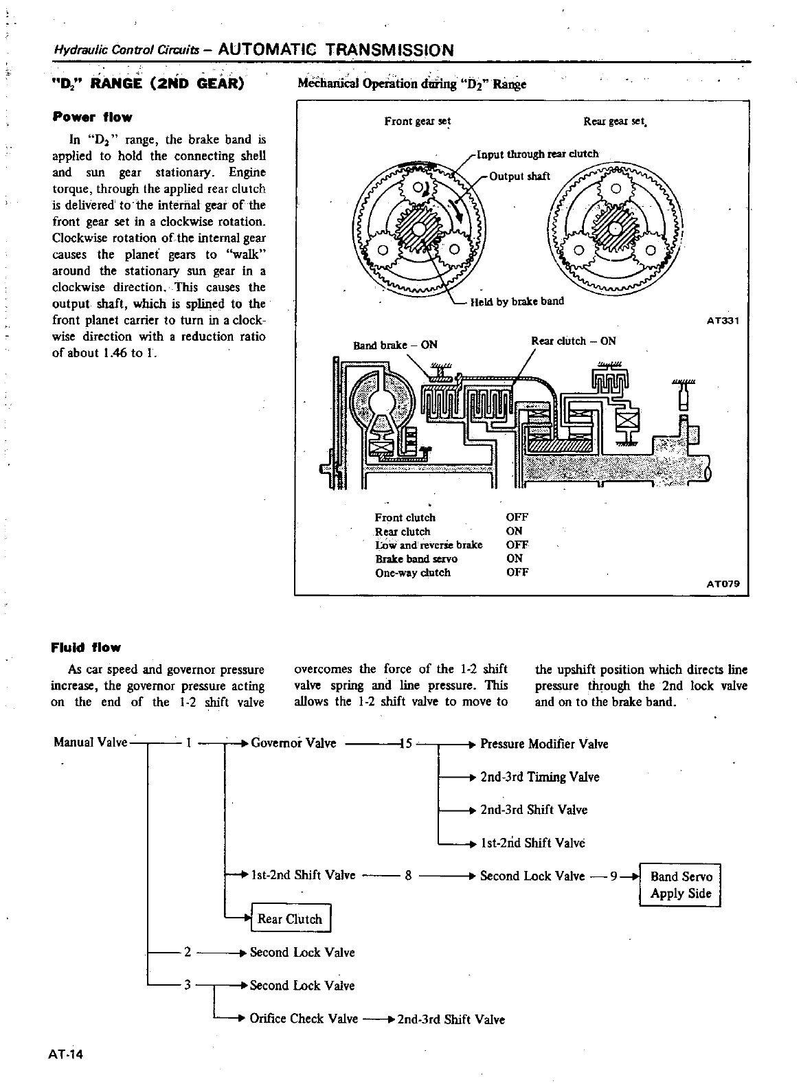
Hydraulic
Control
Circuim
AUTOMATIC
TRANSMISSION
D
RANGE
2ND
GEAR
MechariicaI
Operation
dtiring
D2
Range
Power
flow
Io
D
range
the
brake
band
is
applied
to
hold
the
connecting
sheU
and
sun
gear
stationary
Engine
torque
through
the
applied
rear
clutch
is delivered
to
the
internal
gear
of
the
front
gear
set
in
a
clockwise
rotation
Clockwise
rotation
of
the
internal
gear
causes
the
planet
gears
to
walk
around
the
stationary
sun
gear
in
a
clockwise
direction
This
causes
the
output
shafl
which
is
splined
to
the
front
planet
carrier
to
turn
in
a
clock
wise
direction
with
a
reduction
ratio
of
about
1
46
to
I
Front
gear
set
Rear
gear
set
AT331
Front
clutch
OFF
Rear
clutch
ON
LOw
and
revelSe
biake
OFF
llr
Ike
band
servo
ON
One
way
clutch
OFF
A
T079
Fluid
flow
As
car
speed
and
governor
pressure
increase
the
governor
pressure
acting
on
the
end
of
the
1
2 shift
valve
overcomes
the
force
of
the
1
2
shift
valve
spring
and
line
pressure
This
aUows
the
1
2
shift
valve
to
move
to
the
upshift
position
which
directs
line
pressure
through
the
2nd
lock
valve
and
on
to
the
brake
band
Manual
Valve
Governor
Valve
15
Pressure
Modifier
Valve
2nd
3rd
Timing
Valve
2nd
3rd
Shift
Valve
Ist
2rid
Shift
Valve
Ist
2nd
Shift
Valve
8
Second
Lock
Valve
9
Band
Servo
Apply
Side
4
Rear
Clutch
I
2
Second
Lock
Valve
3
I
Second
Lock
Valve
L
Orifice
Check
Valve
2nd
3rd
Shift
Valve
AT
14
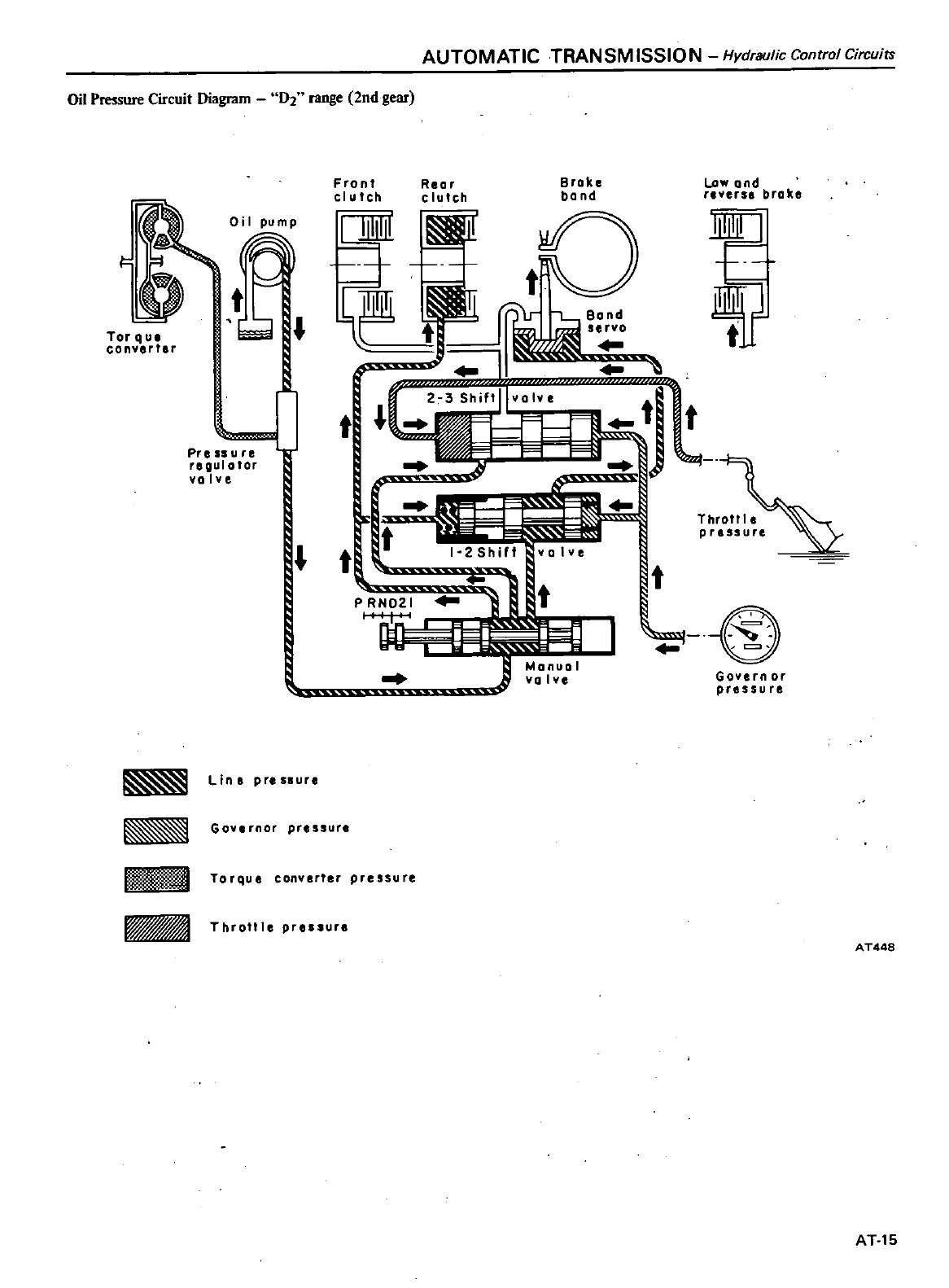
AUTOMATIC
TRANSM
ISSIO
N
Hydraulic
Control
Circuits
Oil
Pressure
Circuit
Diagram
D2
range
2nd
gear
F
Oil
pump
t
f
J
Tor
q
ua
conYerter
Pressure
r
oulator
valve
Line
pressure
Gover
or
pressure
Front
clutch
Brake
ba nd
Low
and
revers
broke
Reor
clutch
I
tl
t
2
hjf
llvOIV
t
r
t
u
l
1Itrrr 1ltrrr 1Itrrr
Throttl
e
It
pressure
j
@
P
RND21
Govern
or
pressure
Torque
converter
pressure
Throlll
prellur
AT448
AT15
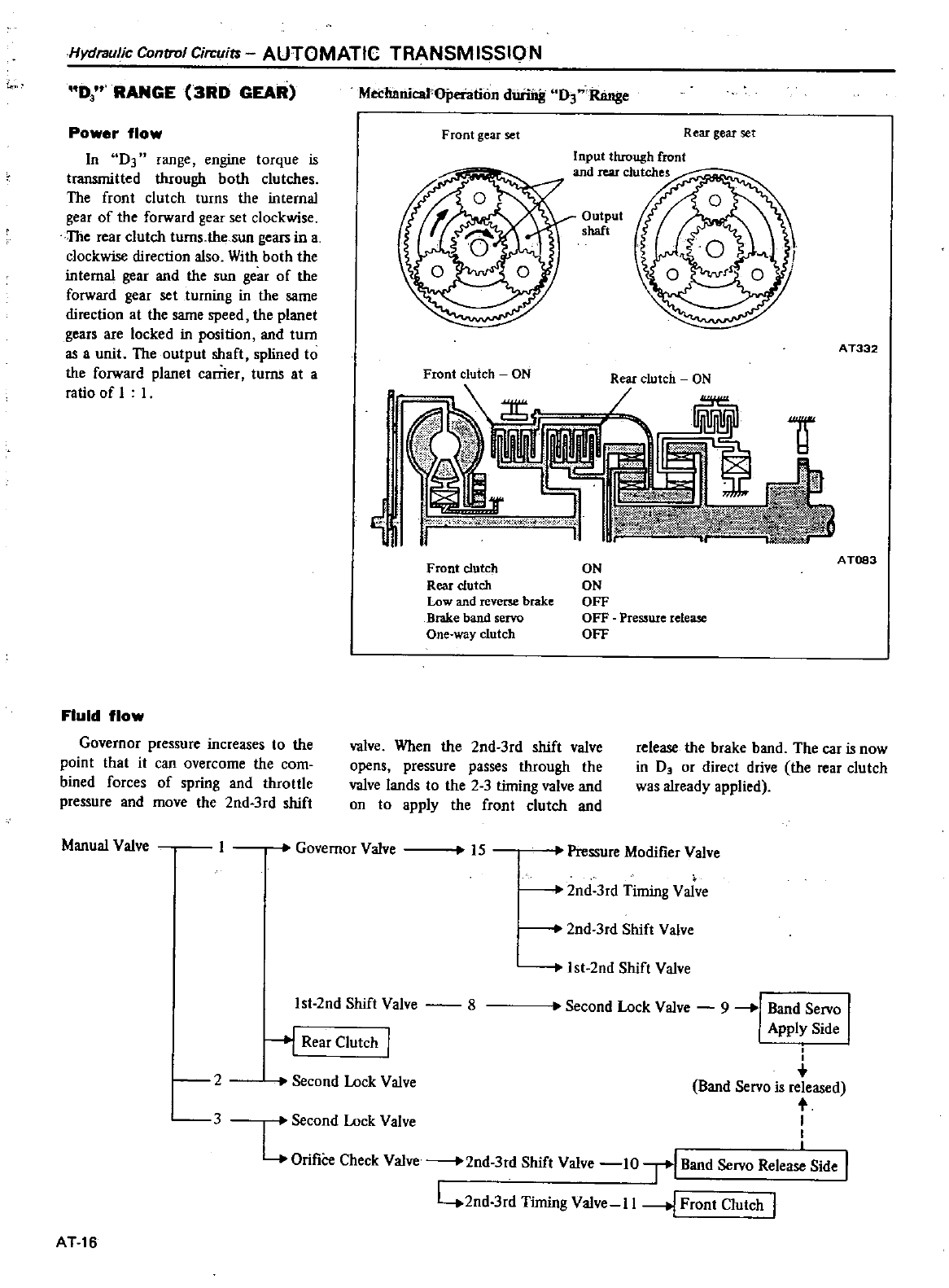
t
Hydraulic
Control
Circuits
AUTOMATIC
TRANSM
ISS10
N
D
RANGE
3RD
GEAR
Power
flow
In
on range
engine
torque
is
transmitted
through
both
clutches
The
front
clutch
turns
the
internal
gear
of
the
forward
gear
set
clockwise
The
rear
clutch
turns
the
sun
gears
in
a
clockwise
direction
also
With
both
the
internal
gear
and
the
sun
gear
of
the
forward
gear set
turning
in
the
same
direction
at
the
same
speed
the
planet
gears
are
locked
in
position
and
turn
as
a
unit
The
output
shaft
splined
to
the
forward
planet
carrier
turns
at
a
ratio
of
I I
Fluid
flow
Governor
pressure
increases
to
the
point
that
it
can
overcome
the
com
bined
forces
of
spring
and
throttle
pressure
and
move
the
2nd
3rd
shift
Manual
Valve
Mechanical
Ojleiation
during
D3
Range
Front
gear
set
Rear
gear
set
Input
through
front
and
rear
clutches
Output
shaft
A
T332
Front
clutch
ON
Rear
clutch
ON
Il
N
Front
clutch
Rear
clutch
Low
and
reverse
brake
Brake
band
servo
One
way
clutch
valve
When
the
2nd
3rd
shift
valve
opens
pressure
passes
through
the
valve
lands
to
the 2 3
timing
valve
and
on
to
apply
the
front
clutch
and
Governor
Valve
15
ON
ON
OFF
OFF
Presswe
release
OFF
AT083
release
the
brake
band
The
car
is
now
in
D
or
direct
drive
the
rear
clu
tch
was
already
applied
Pressure
Modifier
Valve
2nd
3rd
Shift
Valve
2nd
3rd
Timing
Valve
Ist
2nd
Shift
Valve
8
lst
2nd
Shift
Valve
i
I
Band
Servo
is
released
t
Second
Lock
Valve
I
LOrifiCe
Check
Valve
2nd
3rd
Shift
Valve
10
TIBand
Servo Relea
Side
I
42nd
3rd
Timing
Valve
II
I
Front
Clutch
1
J
Rear
Clutch
I
2
Second
Lock
Valve
3
AT16
Second
Lock
Valve
9
Ii
Band
Servo
Apply
Side
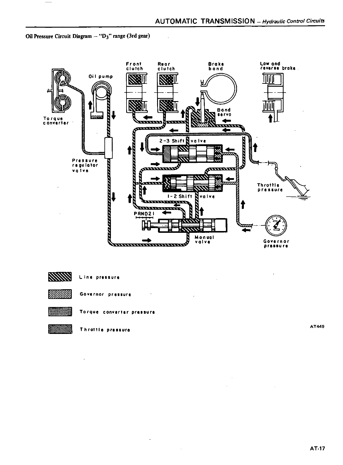
AUTOMATIC
TRANSM
ISSIO
N
Hydraulic
Control
Cirr
uit3
Oil
Pressure
Circuit
Diagram
D3
range
3rd
gear
1
t
Oi
I
pump
To
rq ue
c
anYlrter
r
l
Pressure
re
QU
lator
valve
L
in
pressure
Governor
pressure
Fronf
clutch
Low
and
rever
brake
Rear
clutch
Brake
bond
0
t
Bond
JJ
JI
1
y
W
r
t
It
sY
if
t
tr
Il
PRN021
tt
@
Throttle
pressure
Ya
Iv
Governor
pressure
i
t
lo
IIDJWq
Torque
eonv
rter
pr
ur
Iijp
I
Throlll
preuur
AT449
AT
17
Hydraulic
Control Circuits
AUTOMATIC
TRANSM
ISSION
D
RANGE
KICKDOWN
To
achieve
a
forced
downshift
from
3rd
to
2nd
the
car
speed
must
be
under
approximately
100
km
h
60
MPH
from
2nd
to
1st
it
must
be
under
approximately
50
km
h
30
MPH
FuUy
depressing
the
accelerator
pedal
energizes
the
downshift
sole
noid
which
opens
the
solenoid
down
shift
valve
Oil
pressure
is
then
exerted
against
the
shift
valves
Between
50
and
100
km
h
30
and
60
MPH
this
pressure
wiD
close
the
2nd
3rd
shift
valve
against
governor
pressure
and
the
car
downshifts
When
the
car
speed
is
below
50
km
h
30
MPH
the
I
st
2nd
shift
valve
will
be
closed
and
the
1rans
mission
will
be
in
1
st
gear
As
car
speed
and
governor
pressure
increase
the
shift
valves
automaticaUy
reopen
AT
IS
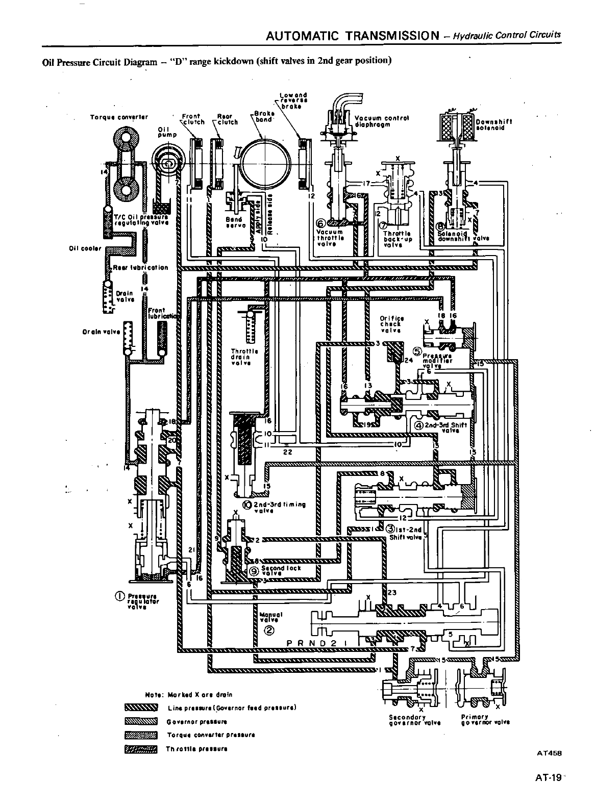
AUTOMATIC
TRANSM
ISSIO
N
Hydraulic
Control Circuits
Oil
Pressure
Circuit
Diagram
D
range
kickdown
shift
valves
in 2nd
gear
position
Torqul
conv
rl
r
Front
Rlor
Iutch
ClutCh
Oil
J1
r
I
TIC
on
p
V
ro
I
O
rog
o
1
0
It
i
i
N
all
COOler
RI
hlbri
cot
ion
8
Oraln
14
vohl
I
Front
lubriCQtif
W
11
X
J
j
D
1
I
t
1
Qto
j
oz
n
l
I
I
m
I
lID
Vacuum
throttl
01
i
d
Yol
23
Ol
yol
l
@
PRND2
I
f
S
D
o
t
y
d
I
3r
J
lu
i
I
own
i1
01
lI
S
U
I
I
8
18 16
@Z
l
3n
I
Shift
Yol
Hmu
u
Jr
5
r
r
1pul
B
2 d
I
ii
lJlu
r
I
N
Tr
Throttle
drain
10
1
I
C
JI
J
Z2
g
2nd
3rd
limine
a
vI
X
J
L
1
I
Hot
Worbd
l
ore
Oroln
IIo
U
Lin
pr
r
Govlrnor
fud
p
uunl
L
GOY
flU
pr u
Tor4
lt
con
I
r
pr
sure
v
Th
r011l
pr
ur
Primor
90
rrror
yo
Y
A
T458
AT19
Hydraulic
Control
CilCuil
AUTOMATIC
TRANSMISSIO
N
2
RANGE
2ND
GEAR
Fluid
flow
opening
the
valve
and
aUowing
pres
sure
to
pass
into
the
line
of
the
throttle
valve
thus
assuring
adequate
throttle
pressure
even
during
decelera
tion
The
downshift
solenoid
valve
is
used
as
a
passage
for
line
pressure
to
lock
the
1
2
and
2
3
shift
valves
Power
flow
Power
flow
in
2range
is
the
same
as
in
D1
range
Line
pressure
from
the
manual
yalve
opens
the
second
lock
valve
against
spring
pressure
As
this
valve
opens
pressure
then
passes
to
apply
the
band
servo
Line
pressure
also
flows
to
the
throttle
back
up
valve
The
range
2
position
is
used
to
lock
he
car
in
2nd
gear
preventing
upshifts
or
downshifts
under
any
con
ditions
Manual
Valve
Governor
Valve
15
Pressure
Modifier
Valve
2nd
3rd
Timing
Valve
L
2nd
3rd
Shift
Valve
Is1
2nd
Shift
Valve
lst
2nd
Shift
Valve
Rear
Clutch
I
2
Band
Servo
Apply
Side
I
Solenoid
Downshift
Valve
13
t2nd
3rd
Shift
Valve
1st
2nd
Shift
Valve
Second
Lock
Valve
9
4
Throttle
Back
up
Valve
17
Vacuum
Throttle
Valve
16
Pressure
Modifier
Valve
2nd
3rd
Shift
Valve
2nd
3rd
Timing
Valve
Throttle
Drain
Valve
Pressure
Regulator
Valve
AT20
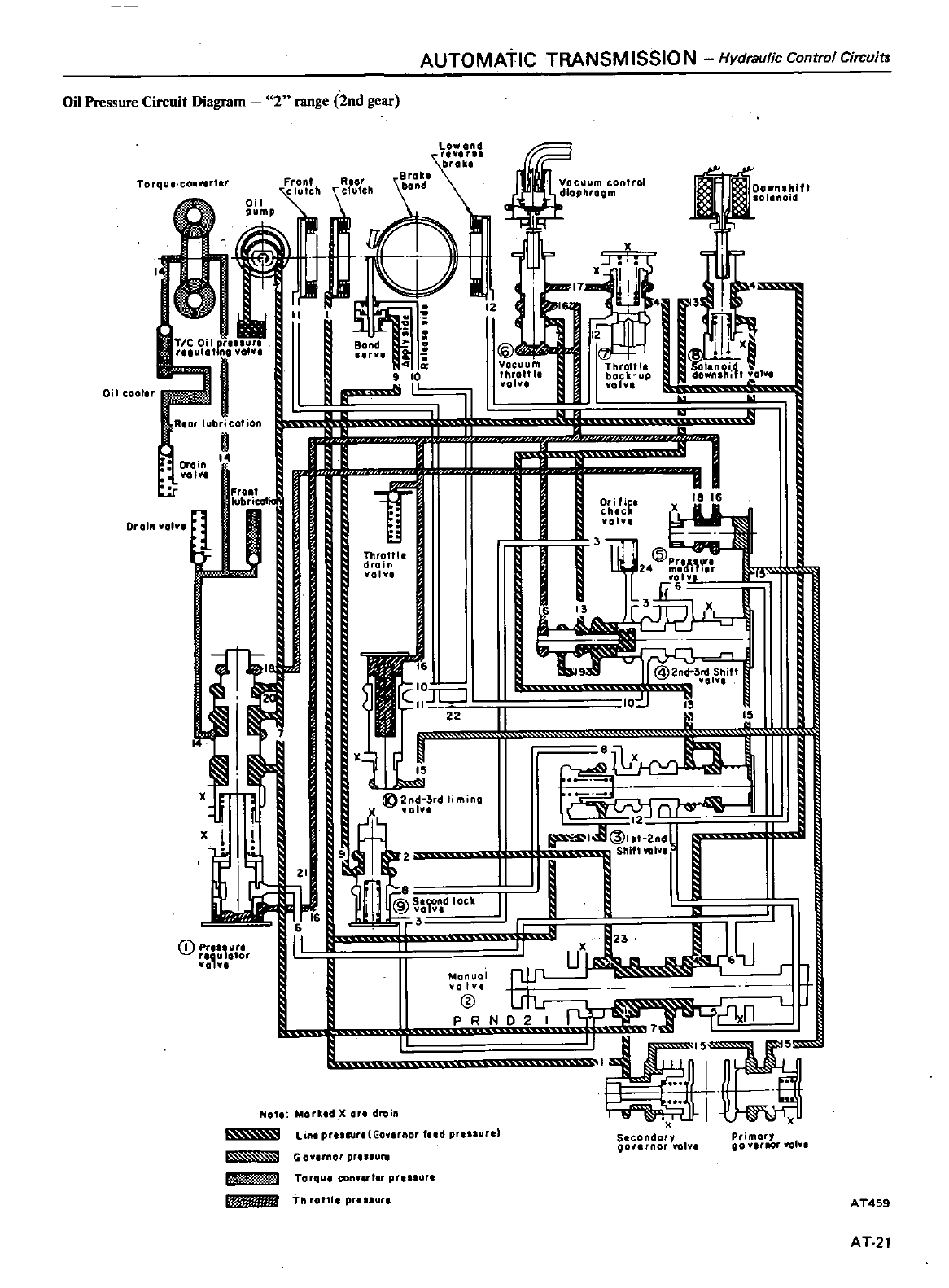
AUTOMATIC
TRANSM
ISSIO
N
Hydraulic
Control
Circuits
Oil
Pressure
Circuit
Diagram
2range
2nd
gear
Torqvt
conv
r1
r
Oil
cooler
Drain
olv
Drain
volv
Front
lubricatit
WI
x
x
1
J
Q
Pr
or
Iau
otor
01
1
Rlor
r
r
r
l
v
it
I
9
10
ll
14
12
boc
k
up
downall
ft
volv
yolv
t
6
ff
I I
I
l
r
13
@
Vacuum
Ihrottlt
01
Throttl
drain
01
11
l
1
1
i
22
@2nr3rd
Shift
01
In
II
21
6
6
II
Manual
I
@
P
R
f
No
worktd
X
or
droln
lint
pr
ur lo
rnor
t
d
pr
urel
Primory
QO
nor
volvl
1
i
l S
Ga
tnor
p
U
Ur
l
JA
Torque
con
pt
r
Th
rottl
pt
fI
AT459
AT
21
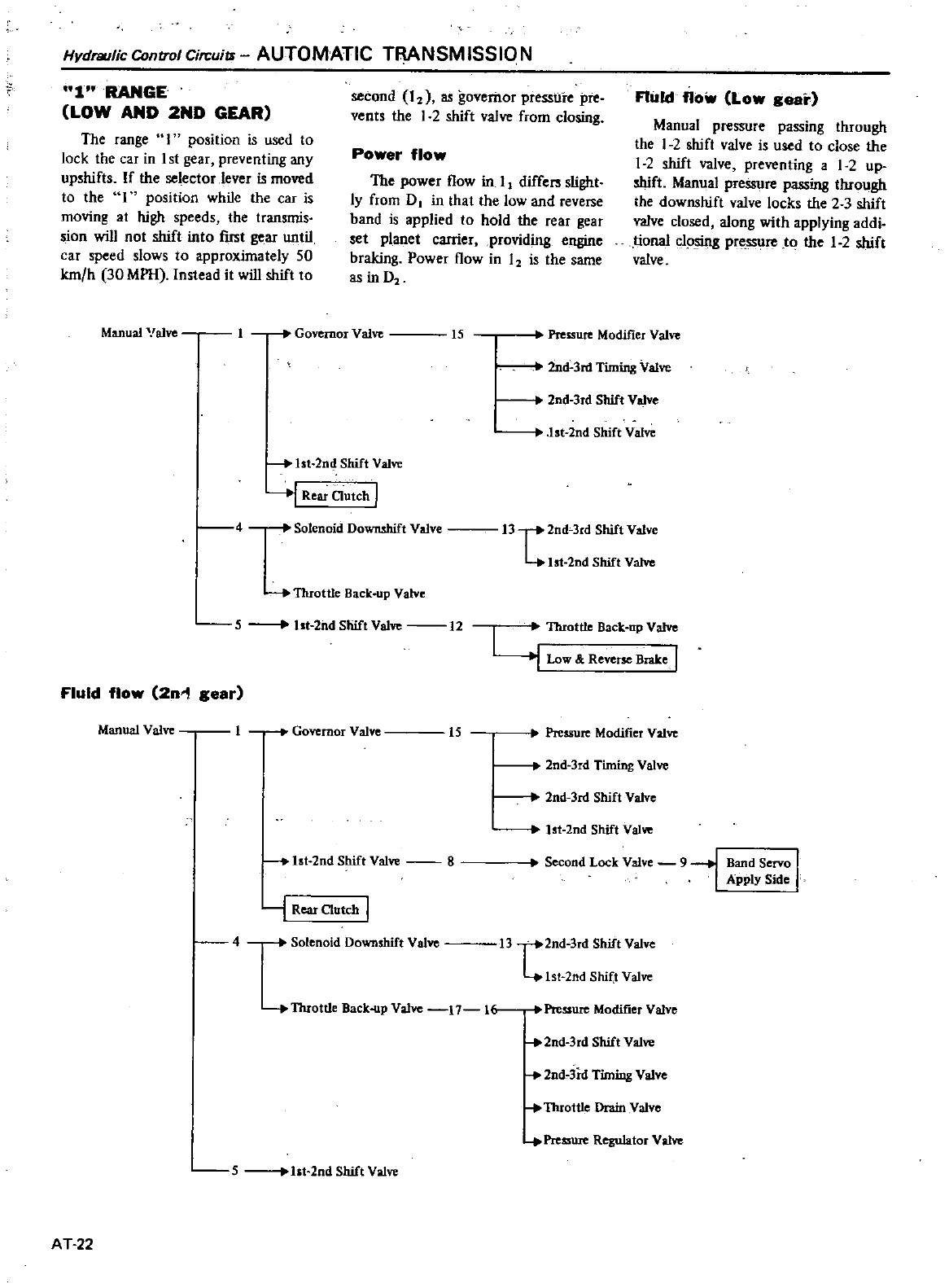
Hydraulic
Control
Circuiu
AUTOMATIC
TRANSMISSION
1
RANGE
LOW
AND
2ND
GEAR
The
range
I
position
is
used
to
lock
the
car
in
1
st
gear
preventing
any
upshifts
If
the
selectorJever
is
moved
to
the
1
position
while
the
car
is
moving
at
high
speeds
the
transmis
sion
will
not
shift
into
fIrst
gear
until
car
speed
slows
to
approximately
50
km h
30
MPH
Instead
i1
will
shift
to
Manual
alYe
second
I
as
governor
pressUre
pre
vents
the
1
2
shift
valve
from
closing
Power
flow
The
power
flow
in
I
differs
slight
Iy
from
D
in
that
the
low
and
reverse
band
is
applied
to
hold
the
rear
gear
set
planet
carrier
providing
engine
braking
Power
flow
in
I
is
1he
same
as
in
D
1
Governor
Valve
15
Pressure
Modifier
Valve
Fluid
flow
Low
gear
Manual
pressure
passing through
the
1
2shift
valve
is
used
to
close
the
1
2
shift
valve
preventing
a
1
2
up
shift
Manual
pressure
passing
through
the
downshift
valve
locks
the
2 3
shift
valve
closed
along
with
applying
addi
tional
c1
sing
pre
ssure
to
the
1
2
shift
valve
2nd
lnl
Tuning
Valve
to
lst
2nd
Shift
Valve
lst
2nd
Shift
Valve
2nd
lrd
Shift
Valve
j
Rear
Clutch
I
4
Solenoid
Downshift
Valve
13
t2nd
lrd
Shift
Valve
Ist
2nd
Shift
Valve
Throttle
Back
up
Valve
5
Ist
2nd
Shift
Valve
12
FluId
flow
2n
l
gear
Manual Valve
lbrottle
Back
up
Valve
I
Low Ii
Reverse
Brake
I
1
Governor
Valve
15
Pressure
Modifier
Valve
2nd
lnl
Shift
Valve
2nd
3rd
Timing
Valve
1st
2nd
Shift
Valve
8
1st
2nd
Shift
Val
Second
Lock
Valve
91
Band
Servo
I
Apply
Side
j
Rear
Clutch
I
4
Solenoid
Downshift
Valve
13
t2nd
lrd
Shift
Valve
1st
2nd
Shit
t
Valve
Throttle
Back
up
Valve
17
1
2nd
lrd
Shift
Valve
Pressure
Modifier
Valve
2nd
3rd
Timing
Valve
Throttle
Drain
Valve
5
bt
2ndShiftValve
Pressure
Regulator
Valve
AT
22
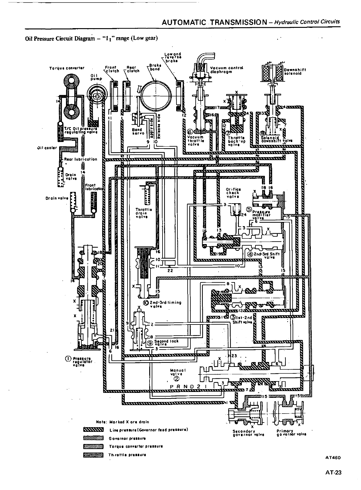
AUTOMATIC
TRANSM
ISSIO N
Hydraulic
Control
Circuits
Oil
Pressure
Circuit
Diagram
II
range
Low
gear
La
and
b
r
Rlor
Srok
C
cllutth
bond
J
p
I
j
IJI
II
Jir
I
u
r
I
o
i
1@
112
1 1
XII
CI
Vacuum
Throttl
OIUOld
t
9
10
throttl
back
up
downlhlft
lol
1
I
01
1
vol
ll
1
I
II
r
1I
i
i
f
c
1
J
I
I
j
l
wr
XIe
16
1
@2nct
3rd
Shift
val
D
ft
m
I
II
1
lr
11
I
f
n
j
J
ij
jl
N
dX
d
ooo
X
Secondory
Qov
rnor
01
Torqul
con
r
I
11
cooler
Rlor
lubricalion
I
Drain
yo
Oroln
Yol
Front
lubriCG
ltc
tu
I
x
rl
u
CD
P
UI
otor
C
m
con
o
Et
oPhrogm
ThroW
drain
vol
II
Lin
prusur
Goy
rnor
tud
pr
un
Primory
90
Ie
r
nor
101
1
G
ov
rnor
pr
ul
t
A
03
Torqul
converler
pre
ure
AT460
Th
oltl
pre
ure
AT
23
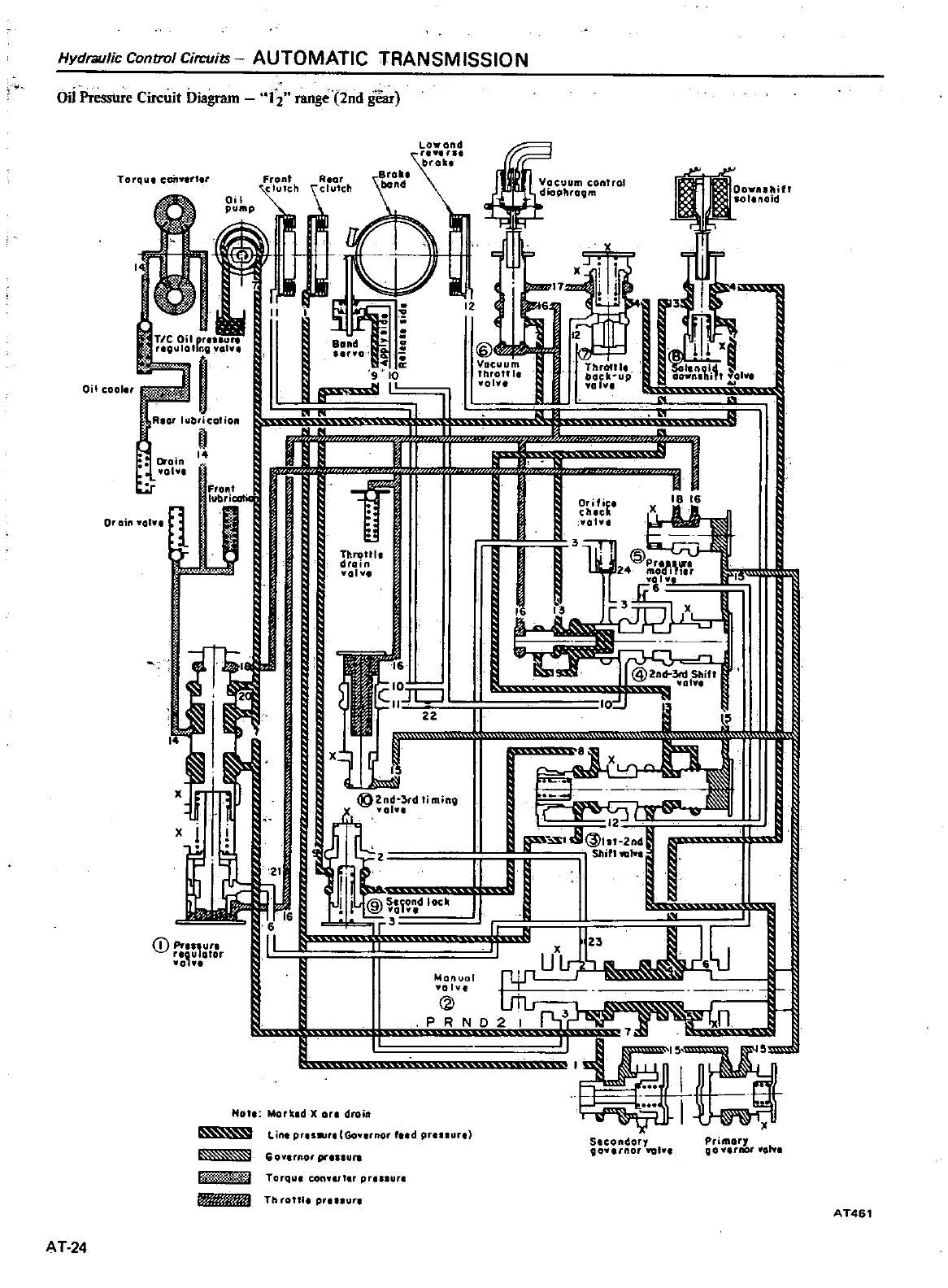
Hydraulic
Control
Circuits
AUTOMATIC
TRANSM
ISSIO
N
1
L
@2n
3tdSllift
10
101
S
I
r
i
@2nd
3rdliminv
vol
It
I
ii
tJJ
r
I
I
I
r
jj
Pressure
Circuit
Diagram
12
range
2nd
gear
La
and
broil
Torqu
c
an
rt
r
Front
clufeh
R
or
tuteh
Oil cool
TIC
Oil
pt
u
re9U
Olloro
J
I
oB
0
l
I
oro
l
JI
Rlor
lubrication
n
4
Iii
II
11
Orain
0
01
FrOnt
lub
icotic
Throttl
drain
101
1
Or
ain
1
01
1
f
I
D
Pr
uro
nou
otor
vol
uum
oot
ol
hro
m
2
I
II
17
1
t
6
b
J
J
III
11i
Th
t1
IItIOl1
g
bocll
up
downahi
tyol
101
I
3
ldI
I
zo
1
r
Sh
l
u
L
6
I
w
Manual
2
PRND2
I
f1
n
Not
Mork
dX
on
drain
Lute
pru
Gov
rnor
dpt
urt
Goy
rnOt
prlS
U
U
T
T
rquI
COn
pr
lur
Th
otll
p
nut
AT
24
S
condor
90
t
ftOI
YQlv
PtimOI
Q
0
Vllnol
olv
AT461
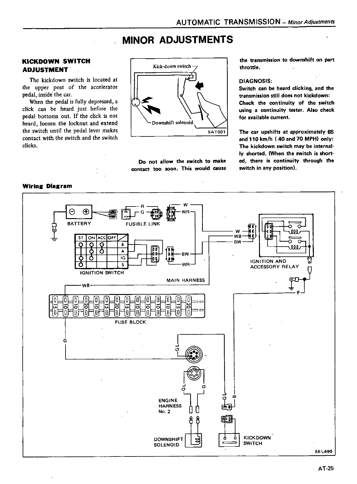
KICKDOWN
SWITCH
ADJUSTMENT
The
kickdown
switch
is
located
at
the
upper
post
of
the
accelerator
pedal
inside
the
car
When
the
pedal
is
fuUy
depressed
a
click
can
be
heard
just
before
the
pedal
bottoms
out
If
the
click
is
not
heard
loosen
the
locknut
and
extend
the
switch
until
the
pedal
lever makes
contact
with
the
switch
and
the
switch
clicks
Wiring
Diagram
AUTOMATIC
TRANSM
ISSION
Minor
Adjustments
MINOR
ADJUSTMENTS
Kick
down
switch
7
SA
TOO
1
Do
not
allow
the
switch
to
make
contact
too
soon
This
would
cause
re
t
1
mO
R
o
BATTERY
FUSIBLE
LINK
ST
ON
t
CC
OFF
J
D
rIl
J
6
r
I
BW
8
r
WR
IGNITION
SWITCH
MAIN
HARNESS
WB
Q
OO O O O O
D
l
Il
0 0 0 0 U
l
0Ul
O
J
0 0
UI
0
o
q
o0
0
0000
l
D
O
Q
O
D
FUSE
BLOCK
G
I
I
J
rOl
E S
G1
No
2
0
DOWNSHIFT
8
SOLENOID
J
iO
II
the
transmission
to
downshift
on
part
throttle
DIAGNOSIS
Switch
can
be
heard
clicking
and
the
transmission
still
does
not
kickdown
Check
the
continuity
of
the
switch
using
a
continuity
tester
Also
check
for
available
current
The
car
upshifts
at
approximately
65
and
110
km
h
40
and
70
MPH
only
The
kickdown
switch
may
be
internal
ly
shorted
When
the
switch
is
short
ed
there
is
continuity
through
the
switch in
any
position
W
iDf
WB
BW
IGNITION
ANO
1J
ACCESSORY
RE
r
J
K1CKDOWN
SWITCH
SEL490
AT25
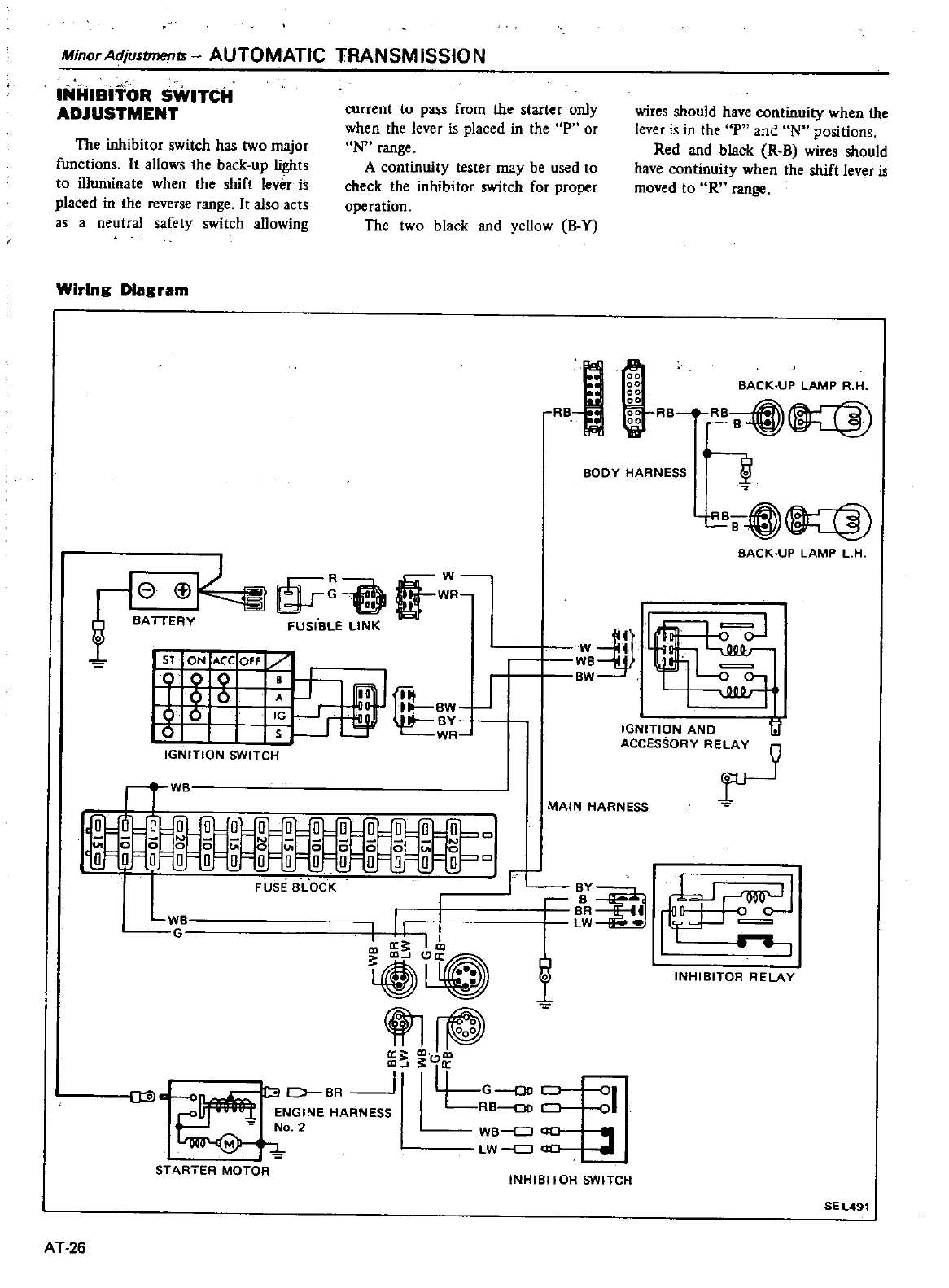
Minor
Adjustmentt
AUTOMATIC
TRANSM
ISSIO
N
INHIBITOR
SWITCH
ADJUSTMENT
current
to
pass
from
the
starter
only
when
the
lever
is
placed
in
the
p
or
N
range
A
continuity
tester
may
be
used
to
check
the
inhibitor
switch
for
proper
operation
The
two
black
and
yeUow
B
Y
wires
should
have
con1inuity
when
the
lever
is
in
the
P
and
Nfl
positions
Red
and
black
R
Bwires should
have
continuity
when
the
shift
lever
is
moved
to
R
range
The
inhibitor
switch
has
two
major
functions
It
allows
the
back up
lights
to
illuminate
when
the shift
lever
is
placed
in
the
reverse
range
It
also
acts
as
a
neutraJ
safety
switch
allowing
Wiring
DIagram
00
00
BACK
UP
LAMP
R
H
gg
iiii
RB RB
00
B
8
o
BODY
HARNESS
BO
BACK
UP
LAMP
L
H
R
O
W
B
TTE
a
E
WR
5T
ON
ACC
Off
1
g g
J
J
I11LBw
J
6
0
rr
w
IGNITION
SWITCH
WW
we
c2
BW
IGNITION
AND
lJ
ACCESSORY
R
ii
W
O U
ii ii ii
o
N
0
000
0
0 0
0
00
r
oo
I
o 0
Q
0
Q
o
o
L
FUSE
BLOCK
w
r
II
ma
III
co
Ii
flfj@
q
Js
l
Dl
C
BR
l
G
Do
on
ENGINE
HARNESS
RB
oo
oU
No
2
we
cJ
CJO
M
LW
J
STARTER
MOTOR
MAIN
HARNESS
r
BY
B
BR
LW
t
INHIBITOR
RELAY
INHIBITOR
SWITCH
SEL491
AT
26
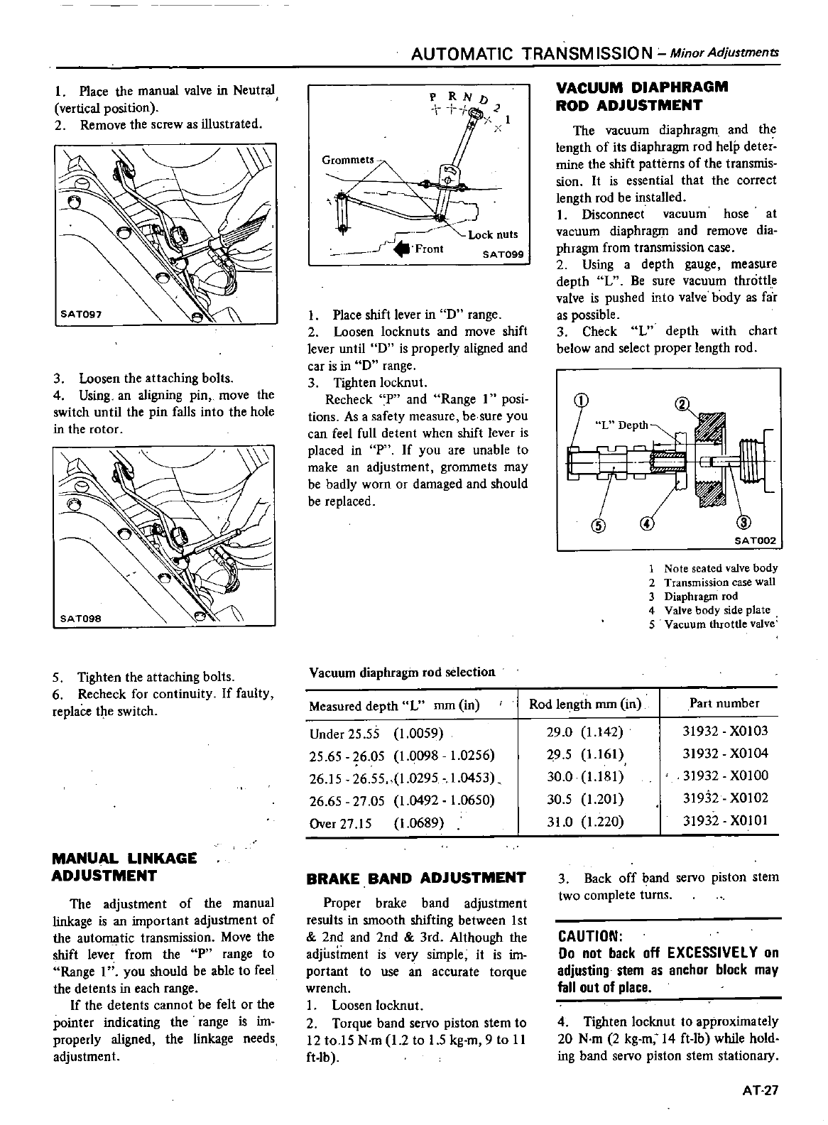
I
Place
the
manual
valve
in
Neutral
vertical
position
2
Remove
the
screw
as
illustrated
3
Loosen
the
attaching
bolts
4
Using
an
aligning
pin
move
the
switch
until
the
pin
falls
into
the
hole
in
the
rotor
5
Tighten
the
attaching
bolts
6
Recheck
for
continuity
If
faulty
replace
the
switch
MANUAL
LINKAGE
ADJUSTMENT
The
adjustment
of
the
manual
linkage
is
an
important
adjustment
of
the
auto
tic
transmission
Move
the
shift
lever
from
the
P
range
to
Range
I
you
should
be
able
to
feel
the
detents
in
each
range
If
the
detents
cannot
be
felt
or
the
pointer
indicating
the range
is
im
properly
aligned
the
linkage
needs
adjustment
AUTOMATIC
TRANSM
ISSIO N
Minor
Adjustments
F
R
ND
I
I
1
Grommets
r
J
c
I
nJ4I
Front
Lock
nuts
SA
T099
Place
shift
lever
in
D
range
2
Loosen
locknuts
and
move
shift
lever
until
D
is
properly
aligned
and
car
is
in
D
range
3
Tighten
locknut
Recheck
P
and
Range
1
posi
tions
As
a
safety
measure
be
sure
you
can
feel
full detent
when
shift
lever
is
placed
in
P
If
you
are
unable
to
make
an
adjustment
grommets
may
be
badly
worn
or
damaged
and
should
be
replaced
Vacuum
diaphragm
rod
selection
Measured
depth
L
mm
in
Under
2555
1
0059
25
65
26
05
1
0098
1
0256
26
15
26
55
1
0295
1
0453
26
65
27
05
1
0492
1
0650
Over
2715
1
0689
BRAKE
BAND
ADJUSTMENT
Proper
brake
band
adjustment
results
in
smooth
shifting
between
1st
2nd
and
2nd
3rd
Although
the
adjustment
is
very
simple
it
is
im
portant
to
use
an
accurate
torque
wrench
I
Loosen
locknut
2
Torque
band
servo
piston
stem
to
12
toI5
N
m
12
to
1
5
kg
m
9
to
II
ft
lb
VACUUM
DIAPHRAGM
ROD
ADJUSTMENT
The
vacuum
diaphragm
and
the
length
of
its
diaphragm
rod
help
deter
mine
the
shift
patterns
of
the
transmis
sion
It
is
essen1ial
that
the correct
length
rod
be
installed
1
Disconnect
vacuum
hose
at
vacuum
diaphragm
and
remove
dia
phragm
from
transmission
case
2
Using
a
dep1h
gauge
measure
depth
L
Be
sure
vacuum
throttle
valve
is
pushed
into
valve
body
as
far
as
possible
3
Check
L
depth
with
chart
below
and
select
proper
length
rod
L
Depth
SAT002
1
Note
seated
valve
body
2
Transmission
case
wall
3
Diaphragm
rod
4
Valve
body
side
plate
5
Vacuum
throttle
valve
Rod
length
mm
in
Part
number
29
0
1
142
29
5
1
161
30
0
1
181
30
5
1
201
31
0
1
220
31932
XOI03
31932
XOlO4
31932
XOIOO
31932
XOlO2
31932
XOIOI
3
Back
off
band
servo
piston
stem
two
complete
turns
CAUTION
00
not
back
off
EXCESSIVElY
on
adjusting
stem
as
anchor
block
may
fall
out
of
place
4
Tigh1en
locknut
to
approximately
20
N
m
2
kg
m
14
ft
lb while
hold
ing
band
servo
piston
stem
stationary
AT
27
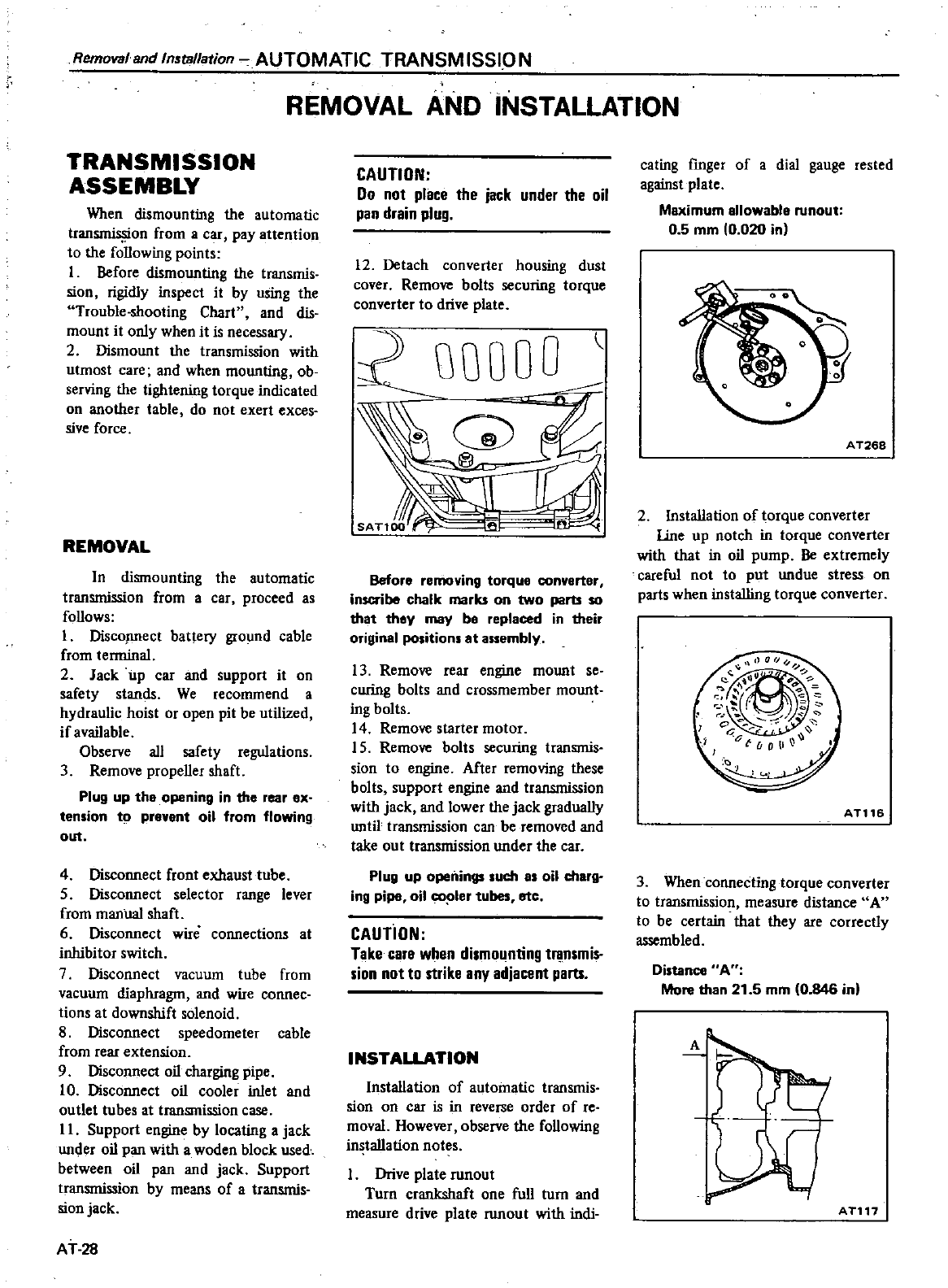
Removal
and
Installation
AUTOMATIC
TRANSMISSION
REMOVAL
AND
INSTALLATION
TRANSMISSION
ASSEMBLY
When
dismounting
the
automatic
tran
on
from
a
car
pay
attention
to
the
foUowing
points
I
Before
dismounting
the
transmis
sion
rigidly
inspect
it
by
using
the
Trouble
shooting
Chart
and
dis
mount
it
only
when
it
is
necessary
2
Dismount
the
transmission
with
utmost
care
and
when
mounting
ob
serving
the
tightening
torque
indicated
on
another
table
do
Dot
exert
exces
sive
force
REMOVAL
In
dismounting
the
automatic
transmission
from
a
car
proceed
as
foUows
I
Disconnect
battery
ground
cable
from
terminal
2
Jack
up
car
and
support
it
on
safety
stands
We
recommend
a
hydraulic
hoist
or
open
pit
be
utilized
if
available
Observe
all
safety
regulations
3
Remove
propeUer
shaft
Plug
up the
opening
in the
rear
ex
tension
to
prevent
oil
from
flowing
out
4
Disconnect
front
exhaust
tube
5
Disconnect
selector
range
lever
from
manual
shaft
6
Disconnect
wire
connections
at
inhibitor
switch
7
Disconnect
vacuum
tube
from
vacuum
diaphragm
and
wire
connee
tions
at
downshift
solenoid
8
Disconnect
speedometer
cable
from
rear
extension
9
Disconnect
oil
charging
pipe
10
Disconnect
oil
cooler
inlet
and
outlet
tubes
at
transmission
case
II
Support
engine
by
locating
a
jack
under
oil
pan
with
a
woden
block
used
between
oil
pan and
jack Support
transmission
by
means of
atransmis
sion
jack
AT
28
CAUTION
Do
not
place
the
jack
under
the
oil
pan
drain
plug
12
Detach
converter
housing
dust
cover
Remove
bolts
securing
torque
converter
to
drive
plate
QOOOO
Before
removing
torque
converter
inscribe chalk
maria
on
two
parts
so
that
they
may
be
replaced
in
their
original
positions
at
assembly
13
Remove
rear
engine
mount
se
curing
bolts
and
crossmember
mount
ingbolts
14
Remove
starter
motor
15
Remove
bolts
securing
transmis
sion
to
engine
After
removing
these
bolts
support
engine
and
transmission
with
jack
and
lower
the
jack
graduaUy
until
transmission
can
be
removed
and
take
out
transmission
under
the
car
Plug
up
openings
such
as
oil
charg
ing
pipe
oil
co
ler
tubes
etc
CAUTiON
Take
care
when
dismounting
transmis
sion
not
to
strike
any
adjacent
parts
INSTALLATION
InstaUation
of
automatic
transmis
sion
on
car
is
in
reverse
order
of
re
moval
However
observe
the
foUowing
installation
notes
Drive
plate
tUnout
Turn
crankshaft
one
fuU
turn
and
measure
drive
plate
runout
with
indi
eating
fInger
of
a
dial
gauge
rested
against
plate
Maximum
allowable
runout
0
5
mm
0
020 in
A
T268
2
InstaUation
of
torque
converter
line
up
notch
in
torque
converter
with
that
in
oil
pump
Be
extremely
careful
not
to
put
undue
stress
on
parts
when
installing
torque
converter
ATl16
3
When
conneCting
torque
converter
to
transmission
measure
distance
A
to
be
certain
that
they
are
correctly
assembled
Distance
A
More
than
21
5
mm
0
846
in
A
ATl17
4Bolt
converter
to
drive
plate
Align
chalk
marks
painted
across
both
parts during
disassembling
pro
cesses
5
After
converter
is
installed
rotate
crankshaft
several
turns
and
check
to
be
sure
that
transmission
rotates
freely
without
binding
6
Pour
recommended
automatic
transmission
fluid
up
to
correct
level
ough
oil
charge
pipe
7
Connect
manual
lever
to
shift
rod
Operation
should
be
carried
out
with
manual and
selector
levers
in
N
8
Connect
inhibitor
switch
wires
aRefer
to
pages
AT
26
and
27
for
Inhibitor
Switch
Adjustment
b
Inspect
and
adjust
switch
as
above
whenever
it
has
to
be
removed
for
service
AUTOMATIC
TRANSM
ISSION
Removal
and
Installation
9
Check
inhibitor
switch
for
oper
ation
Starter
should
be
brought
into
operation
only
when
selector
lever
is
in
P
and
N
positions
it
should
not
be
started
when
lever
is
in
D
2
I
and
R
positions
Back
up
lamp
should also
light
when
selector
lever
is
placed
in
R
position
I
O
Check
fluid
level
in
transmission
For
detailed
procedure
see
page
AT
51
11
Move
selector
lever
through
aU
positions
to
be
sure
that
transmission
operates
correctly
With
hand
brake
applied
rotate
engine
at
idling
Without
disturbing
the
above
setting
move
selector
lever
through
N
to
D
to
2
to
I
and
to
RA
slight
shock
should
be
felt
by
hand
gripping
selector
each
time
transmission
is
shifted
See
page
AT
52 for
Checking
En
gine
Idle
12
Check
to
be
sure
that
line
pressure
is
correct
To
do
this
refer
to
page
AT
54
for
Line
Pressure
Test
13
Perform
staU
test
as
described
in
page
AT
55
AT
29
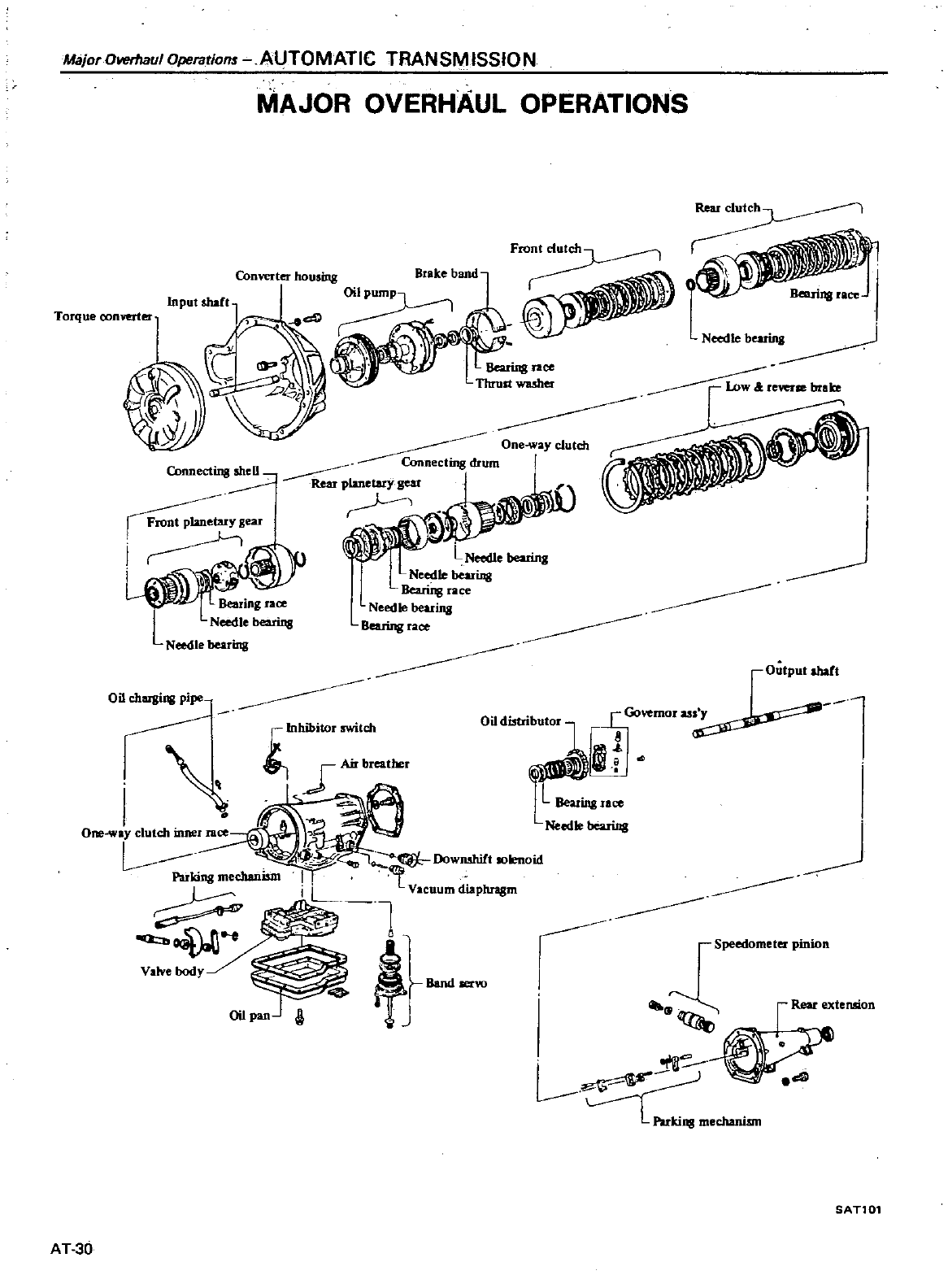
Major
OlllHhaul
Operations
AUTOMATIC
TRANSMISSIO
N
MAJOR
OVERHAUL
OPERATIONS
Torque
converter
Input
shaft
Needleb
reftTsebraJce
Bearing
race
Needle
bearins
L
Needle
bearing
Output
abaft
Oil
chaIJing pipe
c
iI
Speedometer
pinion
Valve
body
otIl
L
et
L
Parking
mechanism
SAn01
AT
30
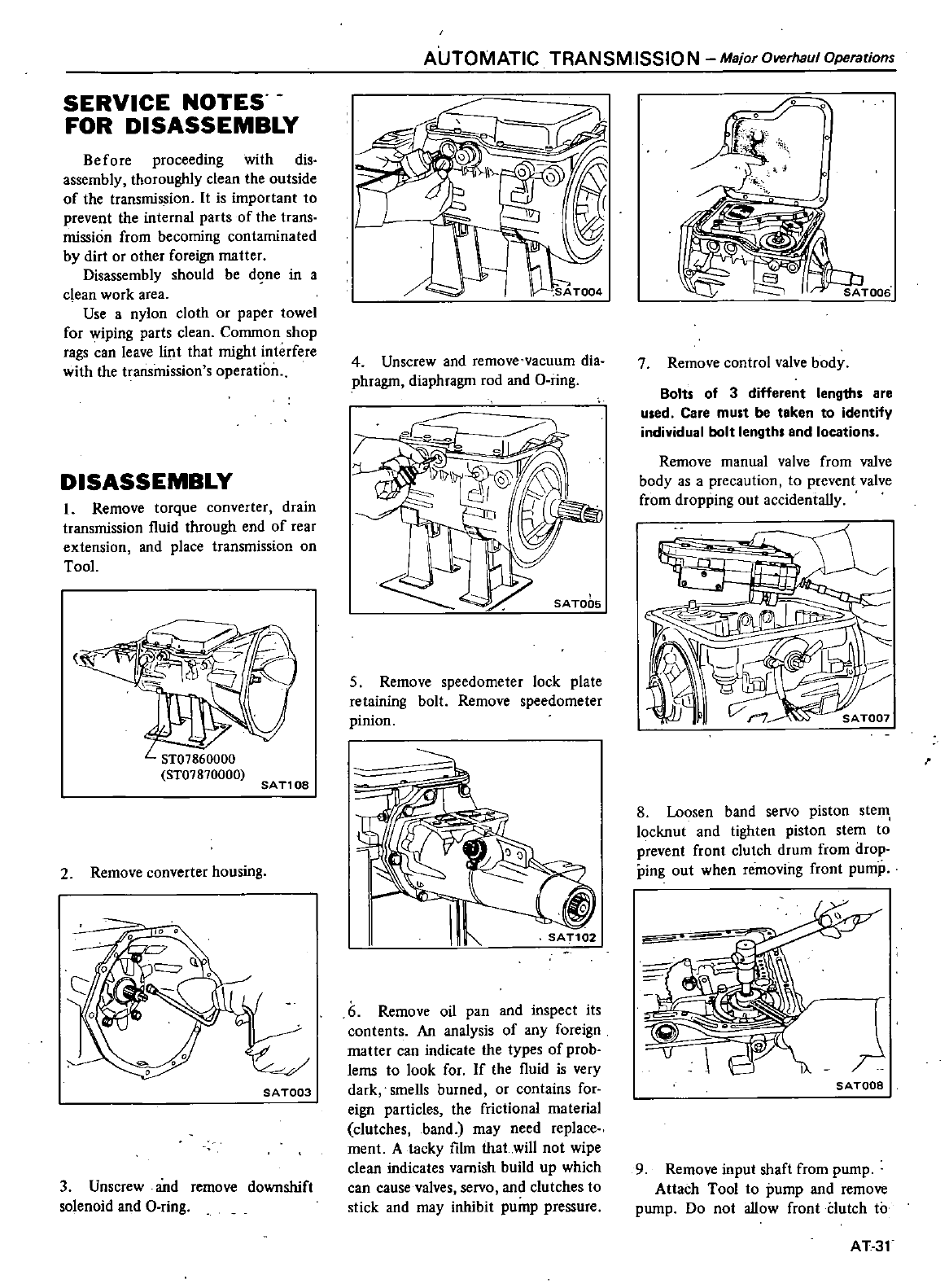
SERVICE
NOTES
FOR
DISASSEMBLY
Before
proceeding
with
dis
assembly
thoroughly
clean
the
outside
of
the
transmission
It
is
important
to
prevent
the
internal
parts
of
the
trans
mission
from
becoming
contaminated
by
dirt or
other
foreign
matter
Disassembly
should
be
d
ne
in
a
clean
work
area
Use
a
nylon
cloth
or
paper
towel
for
wiping
parts
clean
Common
shop
rags
can
leave
lint
that
might
interfere
with
the
transmission
s
operation
DISASSEMBLY
1
Remove
torque
converter
drain
transmission
fluid
through
end
of
rear
extension
and
place
transmission
on
TooL
SAnoa
2
Remove
converter
housing
SAT003
3
Unscrew
and
remove
downshift
solenoid
and
a
ring
AUTOMATIC
TRANSMISSIO
N
Major
Overhaul
Operations
4
Unscrew
and
remove
vacuum
dia
phragm
diaphragm
rod
and
a
ring
SA
T006
5
Remove
speedometer
lock
plate
retaining
bolt
Remove
speedometer
pinion
SAT102
6
Remove
oil
pan
and
inspect
its
contents
An
analysis
of
any
foreign
matter
can
indicate
the
types
of
prob
lems
to
look
for
If
the
fluid
is
very
dark
smells
burned
or
contains
for
eign particles
the
frictional
material
clutches
band
may
need
replace
men
A
tacky
film that
will
not
wipe
clean
indicates
varnish
build
up
which
can
cause
valves
servo
and
clutches
to
stick
and
may
inhibit
pump
pressure
7
Remove
control
valve
body
Bolts
of
3
different
lengths
are
used
Care
must
be
taken
to
identify
individual
bolt
lengths
and
locations
Remove
manual
valve
from
valve
body
as
a
precaution
to
prevent
valve
from
dropping
out
accidentaUy
8
Loosen
band
servo
piston
steIl
locknut
and
tighten
piston
stem
to
prevent
front
clutch
drum
from
drop
ping
out when
removing
front
pump
SATOOB
9
Remove
input
shaft
from
pump
Attach
Tool
to
pump
and
remove
pump
Do
not
aUow
front
Clutch
to
AT31
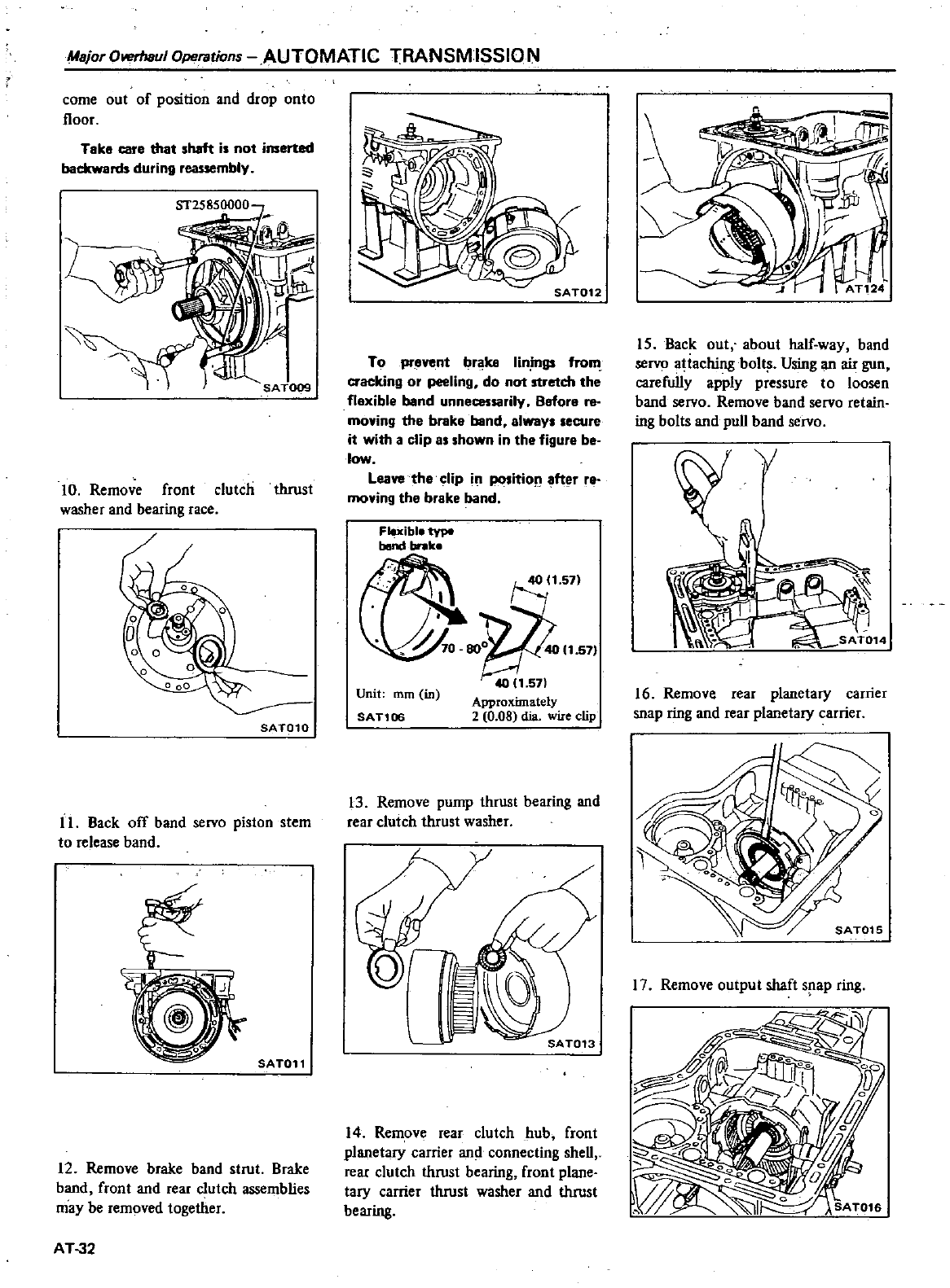
Major
Olll1rhaul
Operations
AUTOMATIC
TRANSMISSIO
N
come
out
of
position
and
drop
onto
floor
Take
care
that
shaft
is
not
inserted
backward
during
reassembly
10
Remove
front
clutch
thrust
washer
and
bearing
race
SAT010
II
Back
off
band
servo
piston
stem
to
release
band
SAT011
12
Remove
brake
band
strut
Brake
band
front
and
rear
clutch
assemblies
may
be
removed
together
AT
32
SAT012
To
prevent
brake
Iin
inus
from
cracking
or
peeling
do
not
stretch
the
flexible
band
unnecessarily
Before
re
moving
the
brake
band
elwaYI
secure
it
with
a
clip as
shown
in the
figure
be
low
Leave
the
clip
i
ition
fter
ra
moving
the
brake
band
Flexible
type
bend
I
nk
Unit
mm in
SAT106
oW
1
57
ApprOXimately
2
0
08
dia
wire
clip
13
Remove
pump
thrust
bearing
and
rear
clutch
thrust
washer
SAT013
14
Remove
rear
clutch
hub
front
planetary
carrier
and
connecting
sheU
rear
clutch
thrust
bearing
front
plane
tary
carrier
thrust
washer
and
thrust
bearing
I
AT124
15
Back
out
about
haIf
way
band
servo
ajtaching
bolt
Using
an
air
gun
carefuUy
apply
pressure
to
loosen
band
servo
Remove
band
servo
retain
ing
bolts
and
puu
band
servo
16
Remove
rear
planetary
carrier
snap
ring
and
rear
planetary
carrier
17
Remove
output
shaft
s
ap
ring
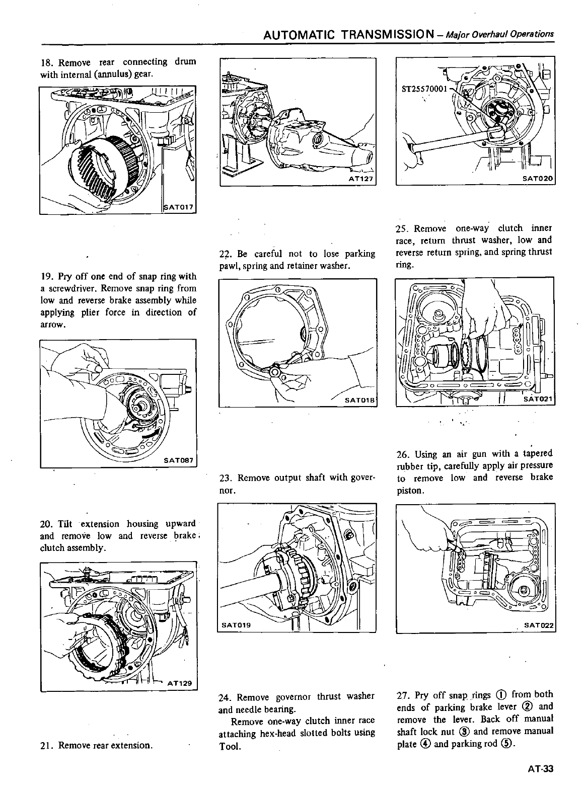
18
Remove
rear
connecting
drum
with
internal
annulus
gear
SATon
19
Pry
off
one
end
of
snap
ring
with
a
screwdriver
Remove
snap
ring
from
low
and
reverse
brake
assembly
while
applying plier
force
in
direction
of
arrow
20
Tilt
extension
housing
upward
and
remove low
and
reverse
brake
clutch
assembly
21
Remove
rear
extension
AUTOMATIC
TRANSM
ISSIO
N
Major
Overhaul
Operations
22 Be
careful
not
to
lose
parking
pawl
spring
and
retainer
washer
01
23
Remove
outpu1
shaft
with
gover
nor
24
Remove
governor
thrust
washer
and
needle
bearing
Remove
one
way
clutch
inner
race
attaching
hex
head
slotted
bolts
using
Tool
SA
T020
25
Remove
one
way
clutch
inner
race
return
thrust
washer
low
and
reverse
return
spring
and
spring
thrust
ring
o
L
I
C
EiL
J
0J
l
O
0
C
J
r
11
AT021
26
Using
an
air
gun
with
a
tapered
rubber
tip
carefuUy
apply
air
pressure
to
remove
low
and
reverse
brake
piston
SAT022
27
Pry
off
snap
rings
CD
from
both
ends
of
parking
brake
lever
@
and
remove
the
lever
Back
off
manual
shaft
lock
nut
@
and
remove
manual
plate
@
and
parking
rod
ID
AT
33
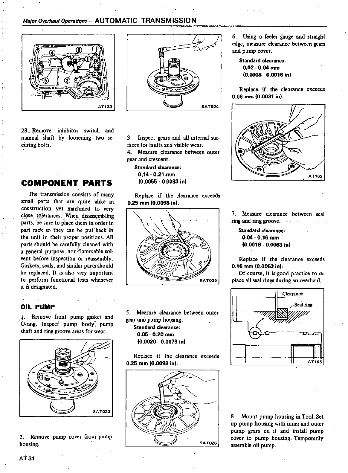
MsjorOverhaulOpsrstions
AUTOMATIC
TRANSMISSION
AT133
28
Remove
inhibitor
switch
and
manual
shaft
by
loosening
two
se
cming
bolts
COMPONENT
PARTS
The
transmission
consists
of
many
small
parts
that
are
quite
alike
in
construction
yet
machined
to
very
c1
e
oIerances
When
disassembling
parts
be
sure
to
place
them
in
order
iD
part
rack
so
they
can
be
put
back
in
the
unit
in
their
proper
positions
AU
parts
should
be
carefuUy
cleaned
with
a
general
purpose
non
flanunable
sol
vent
before
inspection
or
reassembly
Gaskets
seals
and
similar
parts
should
be
replaced
It
is also
very
important
to
perform
functional
tests
whenever
it
is
designated
OIL
PUMP
I
Remove
front
pump
gasket
and
O
ring
Inspect
pump
body
pump
shaft
and
ring
groove
areas
for
wear
w
SAT023
2
Remove
pump
cover
from
pump
housing
AT34
1
u
SA
T024
3
Inspect
gears
and
aU
internal
sur
faces
for
faults
and
visible
wear
4
Measure
clearance
between
outer
gear
and
crescent
Standard
dearanc
e
0
14
0
21
mm
0
0055
0
0083
in
Replace
if
the
clearance
exceeds
0
25
mm
0
0098
in
SA
T025
5
Measure
clearance
between
outer
gear
and
pump
housing
Standard
dearance
0
05
0
20
mm
0
0020
0
0079
in
Replace
if
the
clearance
exceeds
0
25
mm
0
0098
in
SA
T026
6
Using
a
feeler
gauge
and
straighf
edge
measure
clearance
between
gears
and
pump
cover
Standard
clearance
002 0 04
mm
0
0008
0
0016
in
Replace
if
the
clearance
exceeds
0
08
mm
0
0031
in
7
Measure
clearance
between
seal
ring
and
ring
groove
Standard
clearanca
0
04
0
16
mm
0
0016
0
0063
in
Replace
if
the
clearance
exceeds
0
16
mm
0
0063
in
Of
course
it
is
good
practice
to
reo
place aU
seal
rings
during
an
overhaul
l
1earance
J
Sealring
w
yw
11
4
I
AT1
5
8
Mount
pump
housing
in
Tool
Set
up
pump
housing
with
inner
and
outer
pump
gears
on
it
and
instaU
pump
cover
to
pump
housing
Temporarily
assemble
oil
pump
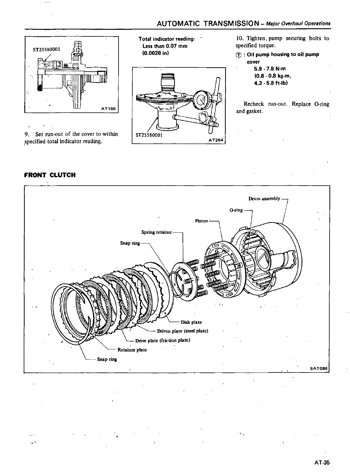
AUTOMATIC
TRANSM
J
SJON
Major
Overhaul
Operations
Totar
indicator
reading
Less
than
0
07
mm
0
0028
in
9Set
run
out
of
the
cover
to
within
specified
total
indicator
reading
0
ST25580001
10
Tighten
pump
securing
bolts
to
specified
torque
b
Oil
pump
housing
to
oil
pump
cover
5 9 7 8
N
m
0 6
08
kg
m
4
3 5 8
ft
lb
1
t
t
AT166
Recheck
run
out
Replace
Q
ring
and
gasket
A
T264
FRONT
CLUTCH
O
ring
Spring
retainer
Dish
plate
Driven
plate
steel
plate
Drive
plate
riction
plate
Snap ring
SAT086
AT
35
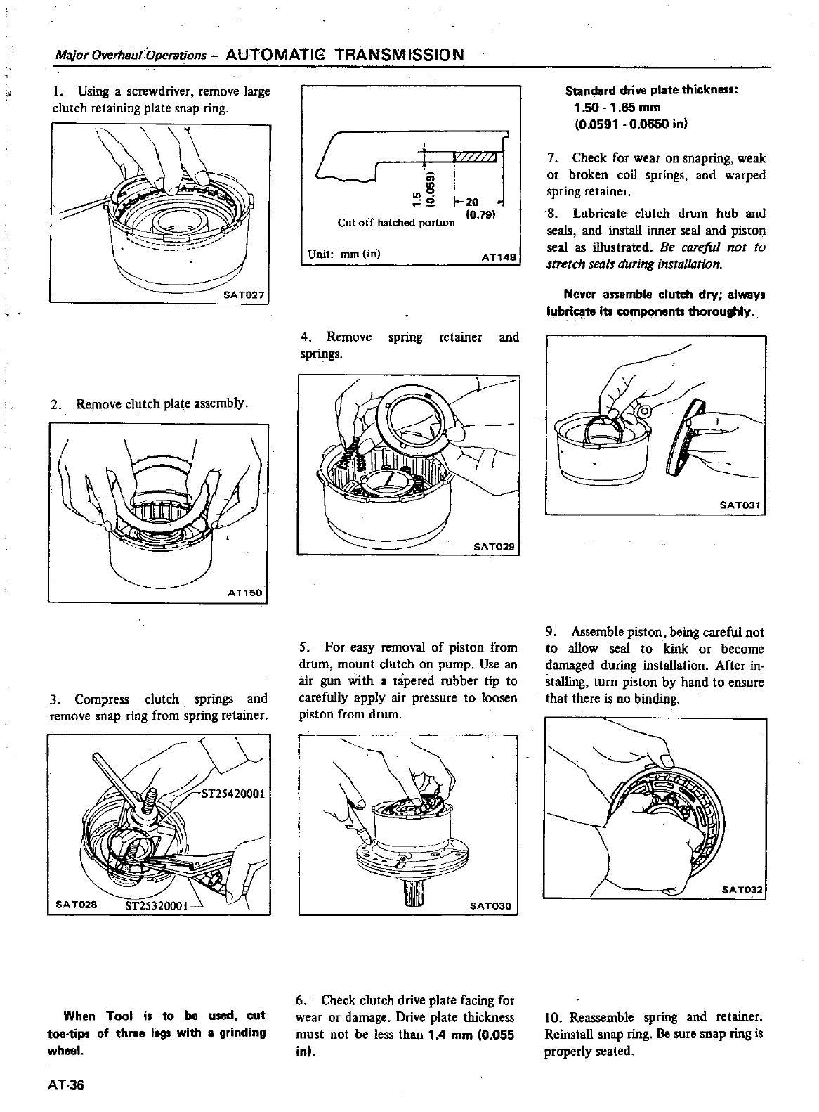
Major
Overhaul
Operstions
AUTOMATlG TRANSMISSIO
N
1
Using
a
screwdriver
remove
large
clutch
retaining
plate
snap
ring
2
Remove
clutch
plate
assembly
AT1S0
3
Compress
clutch
springs
and
remove
snap
ring
from
spring
retainer
When
Tool
is
to
b
used
cut
toe
tips
of th
legs
with
grinding
wheel
AT
36
L
C
1
J
20
0
79
Cut
off
hatched
portion
Unit
mm in
ATl48
4
Remove
spring
retainer
and
springs
SA
T029
5
For
easy
removal
of
piston
from
drum
mount
clutch
on
pump
Use
an
air
gun
with
a
tapered
rubber
tip
to
carefully
apply
air
pressure
to
loosen
piston
from
drum
SA
T030
6
Check
clutch
drive
plate
facing
for
wear
or
darnage
Drive
plate
thickness
must
no1
be
less
than
1
4
mm
0
055
in
Standard
dri
plate
thickness
1
50
1
65
mm
0
0591
00650
in
J
7
Check
for
wear on
snapring
weak
or
broken
coil
springs
and
warped
spring
retainer
S
Lubricate
clutch drum
hub
and
seals
and
instaU
inner
seal
and
piston
seal
as
illustrated
Be
careful
not
to
stretch
seals
during
installation
Neyer
a
mbl
clutch
dry
Iways
lubri
to
its
components
thoroughly
SAT031
9
Assemble
piston
being
careful
not
to
aUow
seal
to
kink
or
become
damaged
during
instaUation
After
in
stalling
turn
piston
by
hand
to
ensure
that
there
is
no
binding
10
Reassemble
spring
and
retainer
ReinstaU
soap
ring
Be
sure
snap
ring
is
properly
seated
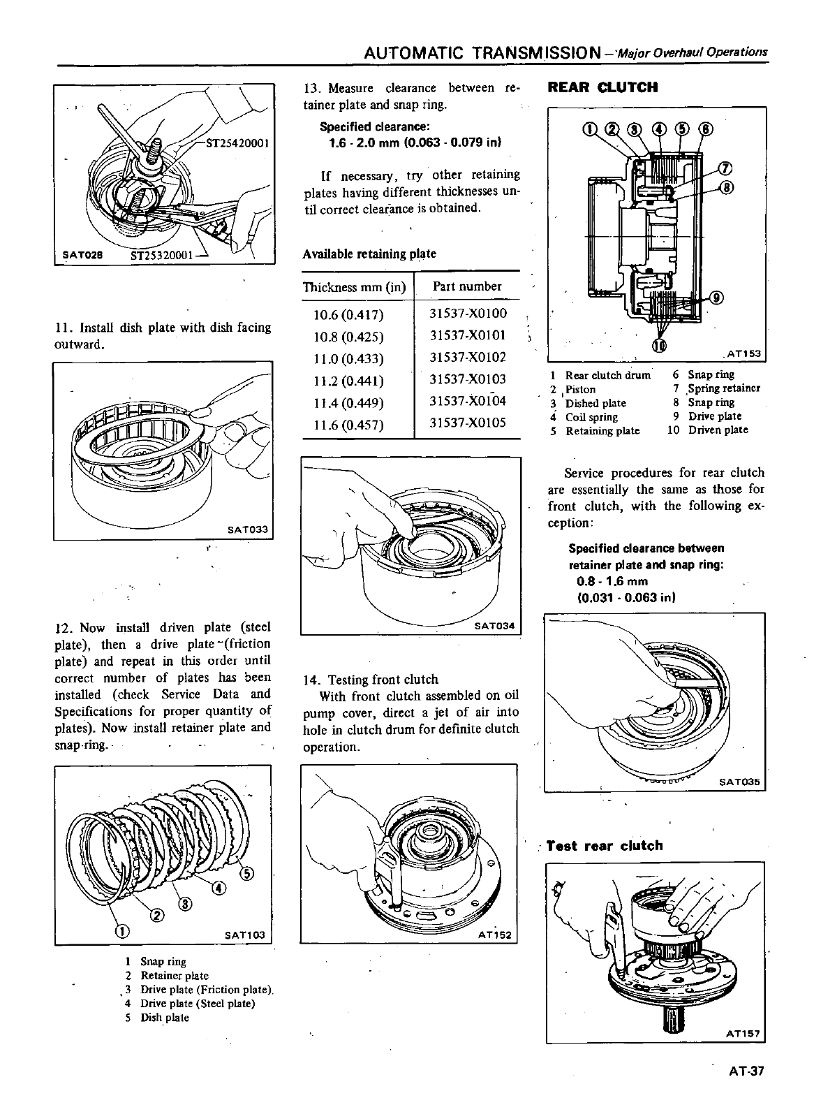
II
Install
dish
plate
with
dish
facing
outward
SA
T033
12
Now
install
driven
plate
steel
plate
then
a
drive
plate
friction
plate
and
repeat
in
this
order
until
correct
number
of
plates
has
been
instaUed
check
Service
Data
and
Specifications
for
proper
quanti1y
of
plates
Now
install
retainer
plate
and
snap
ring
1Snap
ring
2
Retainer
plate
3
Drive
plate
Friction
plate
4
Drive
plate
Steel
plate
5
Dish
plate
AUTOMATIC
TRANSMISSION
Major
Overhaul
Operations
13
Measure
clearance
between
re
tainer
plate
and
snap
ring
Specified
clearance
1
6 2
0
mm
0
063
0
079
in
If
necessary
try
other
retaining
plates
having
different
thicknesses
un
til
correct
clearance
is
obtained
Available
retaining
plate
Thickness
mm
in
Part
number
10 6 0
417
10
8
0
425
11
0
0
433
11
20
441
II
4
0
449
11
60
457
31537
XOIOO
31537
XOIOI
31537
X0102
31537
XOI03
31537
XOI04
31537
X0105
SA
T034
14
Testing
front
clutch
With
front
clutch
assembled
on
oil
pump
cover
direct
a
jet
of
air
into
hole
in
clutch drum
for
definite
clutch
operation
AT152
REAR
CLUTCH
AT153
1
Rear
clutch
drum
6Snap
ring
2
Piston
7
Spring
retainer
3
Dished
plate
8Snap
ring
4
Coil
spring
9
Drive
plate
5
Retaining
plate
10
Driven
plate
Service
procedures
for
rear
clutch
are
essentially
the
same as
those
for
front
clutch
with
the
foUowing
ex
ception
Specified
clearance
betWeen
retainer
plate
and
snap
ring
0 8
1
6
mm
0
031
0
063 in
SA
T035
Test
rear
clutch
III
AT157
AT37
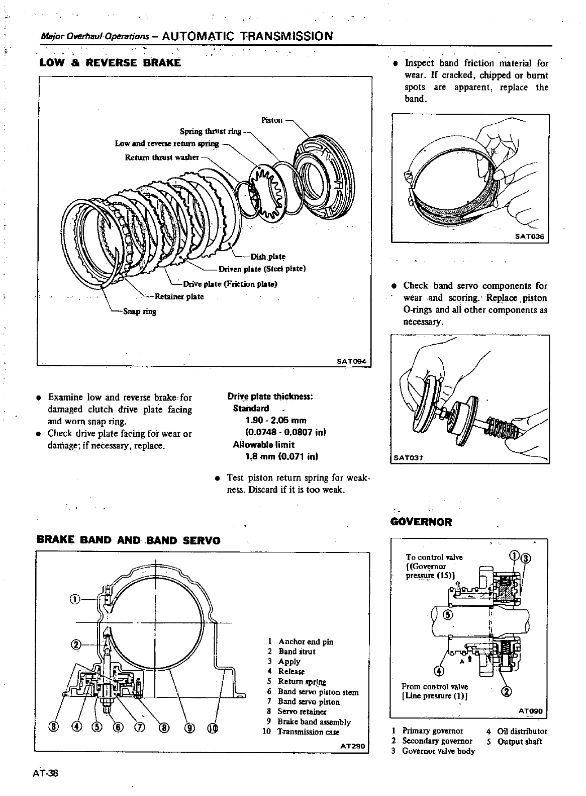
Maior
Overhaul
Operations
AUTOMATIC
T
RANSMISSIO
N
LOW
REVERSE
BRAKE
Spring
thrust
ring
Low
and
reverse
return
spring
Return
tluust
washer
Piston
Dishplatc
Driven
plate
Steel
plate
Drivc
platc
Friction
plate
Retainer
plate
Snap
ring
SA
T094
Examine
low and
reverse
brake
for
damaged
clutch
drive
plate
facing
and
worn
soap
ring
Check
drive
plate
facing
for
wear
or
damage
if
necessary
replace
DriY
4l
plate
thickness
Standard
1
90
2
05
mm
10
0748
0
0807
in
Allowabl
limit
1
8
mm
10
071
in
Test
piston
return
spring
for
weak
ness
Discard
if
it
is
too
weak
BRAKE
BAND
AND
BAND
SERVO
AT
38
Inspect
band
friction
material
for
wear
If
cracked
chipped
or
burnt
spots
are
apparent
replace
the
band
SAT036
Check
band
servo
components
for
wear
and
scoring
Rep
ace
piston
a
rings
and
aU
other
components
as
necessary
GOVERNOR
To
control
valve
11
3
I
Go
rnot
prc 15
z
1
Anchor
end
pin
2
Band
strut
3
Apply
4
Release
4
5
Return
spring
From control
valve
6
Band
servo
piston
stem
Linc
prcssur
I
J
7
Band
servo
piston
8
Servo
retaines
A
TQ90
9
Brake
band
assembly
10
Trammission
case
1
Primary
governor
4
Oil
distributor
2
Secondary
governor
5
Output
shaft
AT290
3
Governor
valve
body
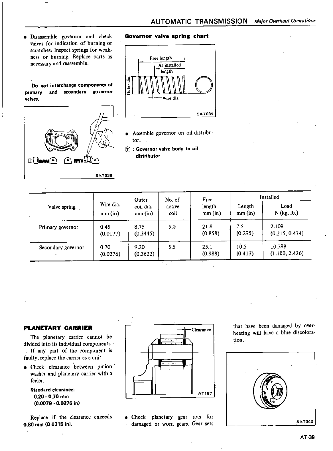
Disassemble
governor
and check
valves
for
indication
of
burning
or
scratches
Inspect
springs
for
weak
ness
or
burning
Replace
parts
as
necessary
and
reassemble
Do
not
interchange
components
of
primary
and
secondary
governor
valves
D
aOlriMI
IIlI1
SA
T038
AUTOMATIC
TRANSM
ISSIO N
Major
Overhaul
Operations
Governor
valve
sprIng
chart
Free
length
I
As
installed
I
Lm
m
0
Wire
dia
SA
T039
Assemble
governor
on
oil
distribu
tor
tl
Governor
valve
body
to
oil
distributor
Outer
No
of
Free
InstaUed
Valve
spring
Wire
dia
coil
dia
active
length
Length
Load
mm
in
mm
in
coil
mm in
mm
in
N
kg
lb
Primary
governor
0
45
8
75
5
0
21
8
7 5
2
109
0
0177
0
3445
0
858
0
295
0
215
0
474
Secondary
governor
0
70
9
20
5 5
25
1
10
5
10
788
0
0276
0
3622
0
988
0
413
11
00
2
426
PLANETARY
CARRIER
The
planetary
carrier
cannot
be
divided
into
its
individual
components
If
any
part
of
the
component
is
faulty
replace
the carrier
as
a
unit
Check
clearance
between
pinion
washer
and
planetary
carrier
with a
feeler
Standard
clearance
0
20
0
70
mm
0
0079
0
0276
in
Replace
if
the
clearance
exceeds
0
80
mm
0
0315
in
Clearance
that
have
been
damaged
by
over
heating
wiD
have
a
blue
discolora
tion
1
r
I
J
In
AT167
1
Check
planetary
gear
sets
for
darnaged
or
worn
gears
Gear
sets
SA
T040
AT
39
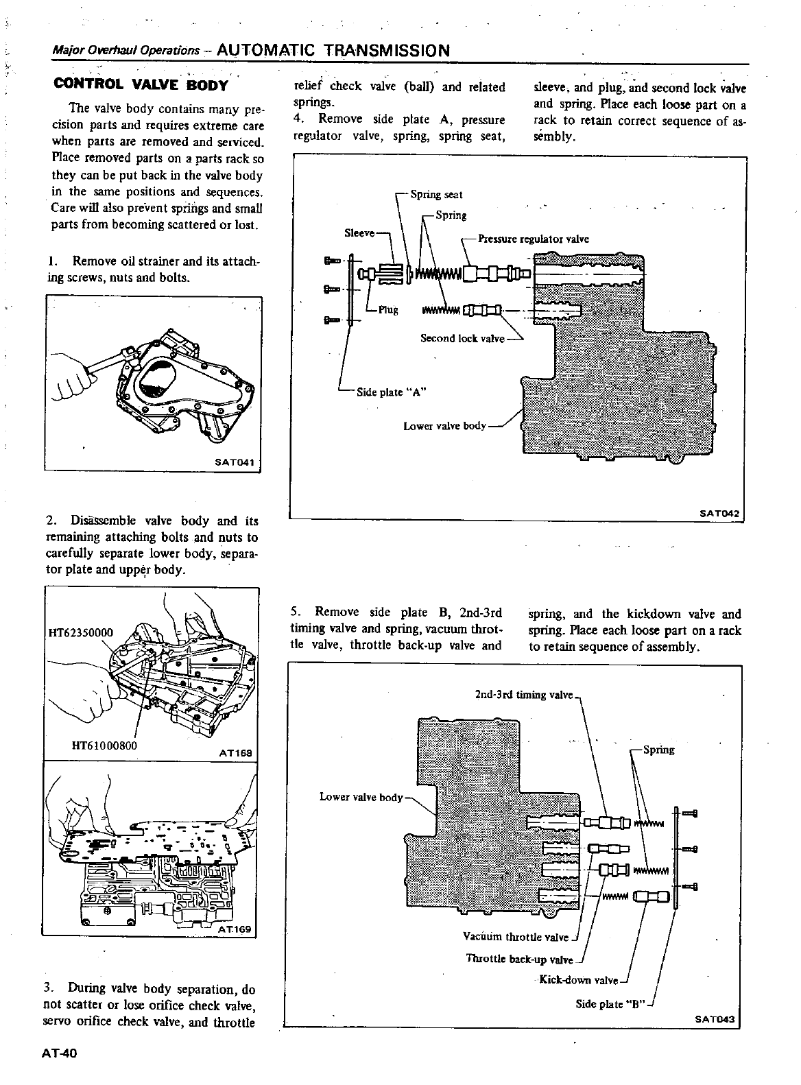
MajorOverlJaulOperations
AUTOMATIC TRANSMISSION
CONTROL
VALVE
BODY
The
valve
body
contains
many
pre
cision
parts
and
requires
extreme
care
when
parts
are
removed
and
serviced
Place
removed
parts
on
a
parts
rack
so
they
can
be put
back
in
the
valve
body
in
the
same
positions
and
sequences
Care
will
also
prevent
springs
and
smaU
parts
from
becoming
scattered
or
lo
t
L
Remove
oil
strainer
aod
its
attach
ing
screws
nuts
and
bolts
SAT041
2
Disassemble
valve
body
and
it
remaining
attaching
bolts
and
nuts
to
carefully
separate
lower
body
separa
tor
plate
and
upp
r
body
HT61000800
AT168
9
9
J
Q
J
IOIi
c
I
9
I
19uDdI
io
J
uii
L
I
1
I
l
l
AT1
9
3
During
valve
body
separation
do
not
scatter
or
lose
orifice
check
valve
servo
orifice
check
valve
and
thro11le
AT
40
relief
check
valve
baU
and
related
springs
4
Remove
side
plate
A
pressure
regulator
valve
spring
spring
seat
sleeve
aod
plug
and
second
lock
valve
aod
spring
Place
each
loose part
on
a
rack
to
retain
correct
sequence
of
as
sembly
Spring
seal
Spring
II
L
Side
plate
A
SA
T042
5
Remove
ide
plate
B
2nd
3rd
timing
valve and
spring
vacuum
throt
tle
valve
thro1tle
back
up
valve
and
spring
aod
the
kickdown
valve and
spring
Place
each
loose
part
on
a
rack
to
retain
sequence
of
assembly
2nd
3rd
timing
valve
Spring
a
a
Throttle
back
up
valve
Kick
down
vaive
Side
plate
B
SAT043
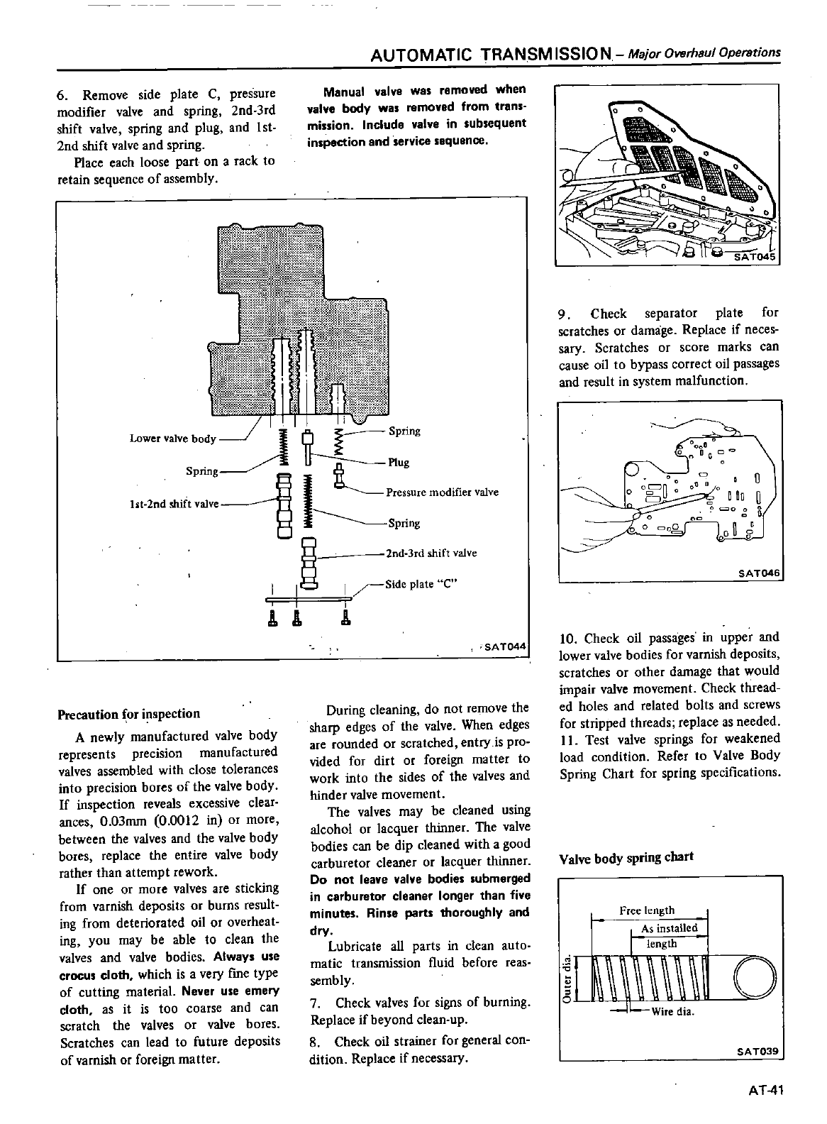
6
Remove
side
plate C
pressure
modifier
valve
and
spring
2nd
3rd
shift
valve
spring
and
plug
and
I
st
2nd
shift
valve
and
spring
Place
each
loose part
on
a
rack
to
retain
sequence
of
assembly
AUTOMATIC
TRANSM
ISSIO
N
Major
Overhaul
Operations
Manual
valve
was
removed
when
valve
body
was
removed
from
trans
mission
Include
valve
in
subsequent
inspection
and
service
sequence
d@4tt
h
1fu
I1
nib
t
fkq
T
AJ
2M
J
L
35t1t
i
w
ml
k
w
Mw
l
I
i1
Wip
j1
11
iiJU
1
jt
PbEH1
ltwmJ
j
111
1
II
Jt
I
@n
vun
Lower
valve
bOdY
Spring
Spring
C
Plug
12
d
shif
11
Pressure
modifier
valve
it
nt
valve
Spnng
nd
3rd
shift
valve
I
g
I
Slde
plate
e
A
A
I
Precaution
for
inspection
A
newly
manufactured
valve
body
represents
precision
manufactured
valves
assembled
with
close
tolerances
into
precision
bores
of
the
valve
body
If
inspection
reveals
excessive
clear
ances
0
03mm
0
0012
in
or
more
between
the
valves
and
the
valve
body
bores
replace
the
en1ire
valve
body
rather
than
attempt
rework
If
one
or
more
valves
are
sticking
from
varnish
deposits
or
burns
resulJ
ing
from
deteriorated
oil
or
overhea1
ing
you
may
be
able
to
clean
the
valves
and
valve
bodies
Always
use
croeus cloth
which
is
a
very
fme
type
of
cutting
material
Never
use
emery
cloth
as
it
is
too
coarse
and
can
scratch the
valves
or
valve
bores
Scratches
can
lead
to
future
deposits
of
varnish
or
foreign
matter
SA
T044
During
cleaning
do
not
remove
the
sharp
edges
of
the
valve
When
edges
are
rounded
or
scratched
entry
is
pro
vided
for
dirt
or
foreign
matter
to
work
into
the
sides
of
the
valves
and
hinder
valve
movement
The
valves
may
be
cleaned
using
alcohol
or
lacquer
thinner
The
valve
bodies
can
be
dip cleaned
with
a
good
carburetor
cleaner
or
lacquer
thinner
Do
not
leave valve
bodies
SUbmerged
in
carburetor
cleaner
longer
than
five
minutes
Rinse
parts
thoroughly
and
dry
Lubricate
all
parts
in
clean
auto
matic
transmission
fluid
before
reas
sembly
7
Check
valves
for
signs
of
burning
Replace
if
beyond
clean
up
8
Check
oil
strainer
for
general
con
dition
Replace
if
necessary
9
Check
separator
plate
for
scratches
or
damage Replace
if
neces
sary
Scratches
or
score
marks
can
cause
oil
to
bypass
correct
oil
passages
and
result
in
system
malfunction
Co
nDllD
o
o
o
o
0
b
nnn
0
0
0
10
0
oo
0
SA
T046
10
Check
oil
passages
in
upper
and
lower
valve
bodies
for
varnish
deposits
scratches
Or
otber
damage
that
would
impair
valve
movement
Check thread
ed
holes
and
related
bolts
and
screws
for
stripped
threads
replace
as
needed
II
Test
valve
springs
for
weakened
load
condition
Refer
to
Valve
Body
Spring
Chart
for
spring
specifications
Valve
body
spring
chart
i5
l
O
Free
length
I
As
installed
I
r
ij
0
Wire
dia
SAT039
AT
41
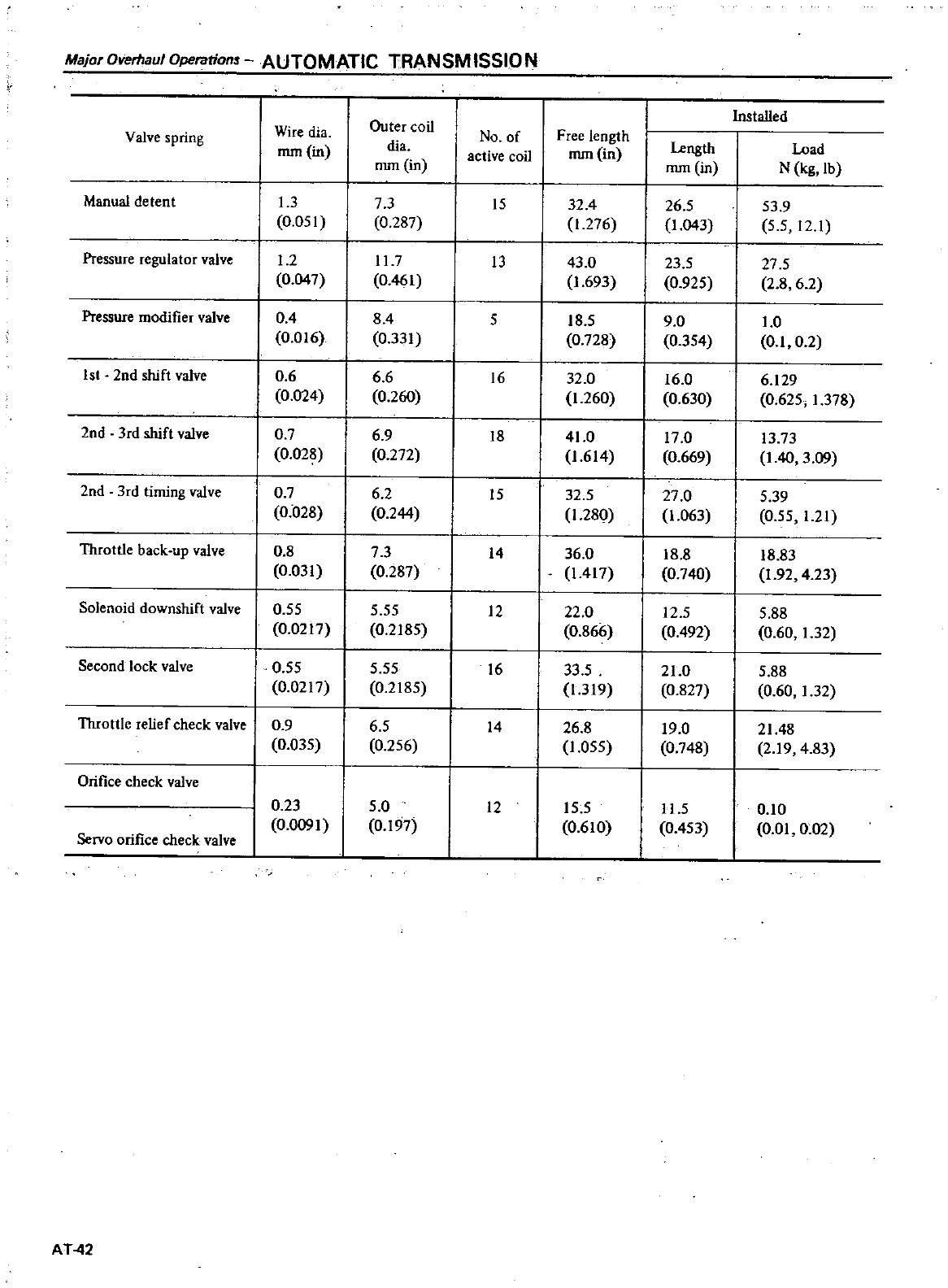
Major
Overflaul
Operations
AUTOMATIC
TRANSM
ISSIO
N
InstaUed
Wire
dia
Outer
coil
No
of
Free length
Valve
spring
mm in
dia
active
coil
mm in
Length
Load
mm
in
mm
in
N
kg
lb
Manual
detent
13
73
15
32
4
26
5
53 9
0
051
0
287
1
276
1
043
55
12
1
Pressure
regulator
valve
1
2
11
7
13
43
0
23
5
27
5
0
047
0
461
1
693
0
925
28 62
Pressure
modifier
valve
04
84
5
18
5
90
1
0
0
016
0
331
0
728
0
354
01 0
2
1st
2nd
shift
valve
0
6 6 6
16
32
0
16 0 6
129
0
024
0
260
1
260
0
630
0
625
1
378
2nd
3rd
shift
valve
0
7
69
18
41
017
0
13
73
0
028
0
272
1
614
0
669
I
40
3
09
2nd
3rd
timing
valve
0
7
62
15
32
5
27
0
5
39
0
028
0
244
1
280
1
063
0
55
1
21
Throttle
back
up
valve
0
8
73
14
36
0
18 8
18
83
0
031
0
287
1
417
0
740
1
92
4
23
Solenoid
downshift
valve
0
55 5
55
12 22
0
12
5
5
88
0
0217
0
2185
0
866
0
492
0
60
1
32
Second
lock
valve
0
55
5
55
16
33
5
21
0
5
88
0
0217
0
2185
1
319
0
827
0
60
1
32
Throttle
relief
check
valve
0
9
65
14
26
8
19
0
2148
0
035
0
256
1
055
0
748
219
4
83
Orifice
check
valve
0
23
5
0
12
15
5
11
5
010
0
0091
0
197
0
610
0
453
0
01
0
02
Servo
orifice
check
valve
AT
42
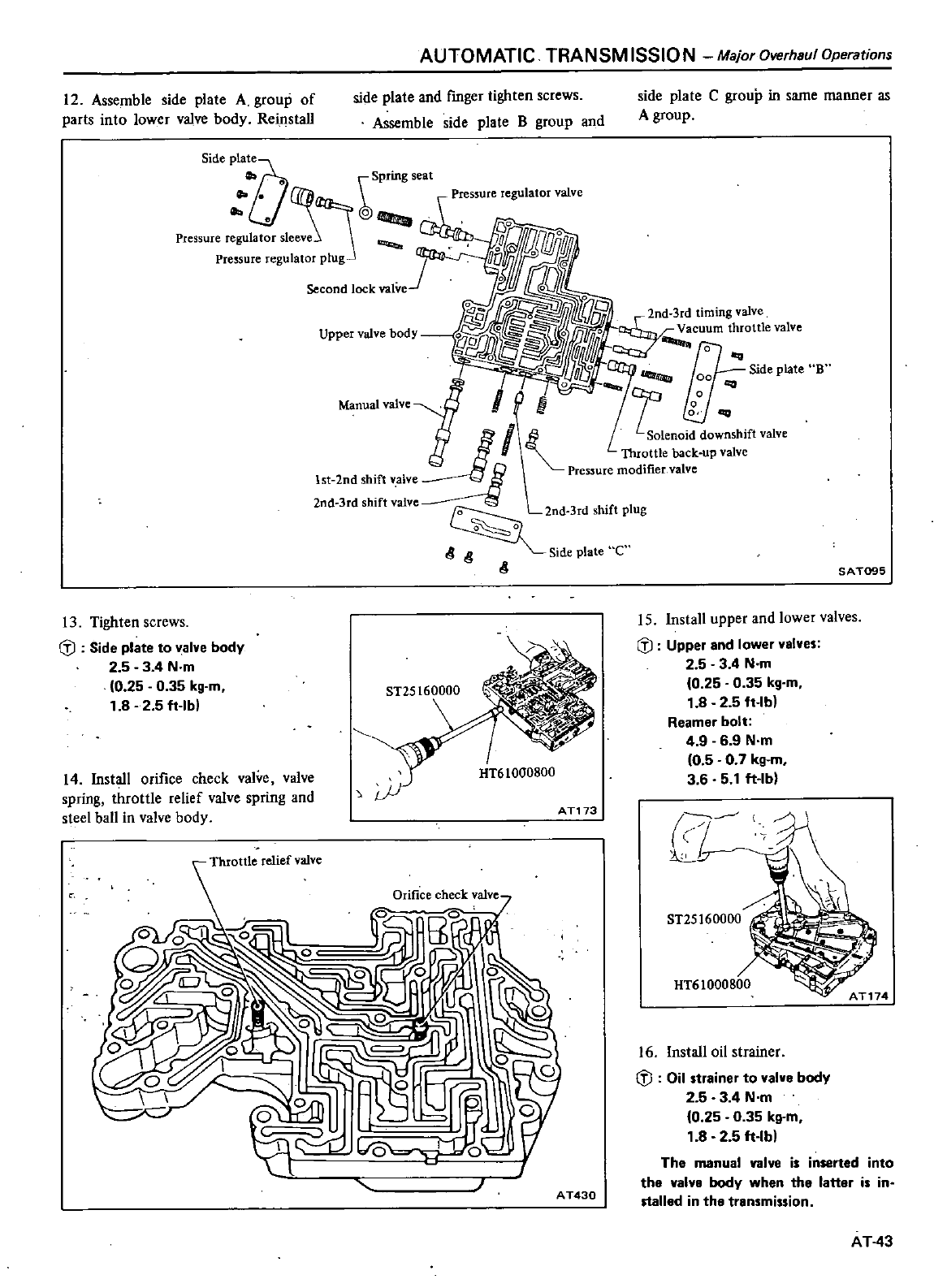
AUTOMATIC
TRANSM
ISSIO
N
Major
Dverhsul
Operations
12
Assemble
side
plate
A
group
of
parts
into
lower
valve
body
Reins1aU
side
plate
and
fmger
tighten
screws
Assemble
side
pla1e
B
group
and
Sid
Pia
talA
Cl
Spring
seat
U
J@
Pressure
regl
llat
r
sleevei
Pressure
regulator
plug
Second
lock
valve
Upper
valve
body
Manual
valve
13
Tighten
screws
cD
Side
plate
to
valve
body
2 5 3
4
N
m
0
25
0
35
kg
m
1
8 2 5
ft
lb
14
Install
orifice
check
valve
valve
spring
1hrottle
relief
valve
spring
and
steel
ball
in
valve
body
AT173
Orifice
check
valve
AT430
side
plate
Cgroup
in
same
manner
as
A
group
SAT095
15
Install
upper
and
lower
valves
cD
Upper
snd
lower
VBlves
2 5 3 4
N
m
0
25
0
35
kg
m
1
8 2 5
ft
lb
Reamer
bolt
4
9 6 9
N
m
0
5
0
7
kg
m
3 6 5
1
fNb
ST25160000
16 Install
oil
strainer
cD
Oil
strsiner
to
valve
body
2 5 3
4
Nm
fO
25 0
35
kg
m
1
82 5
ft
lb
The
manual
valve
is inserted
into
the
valvB
body
when
the latter
is
in
stalled
in
the
transmission
AT
43
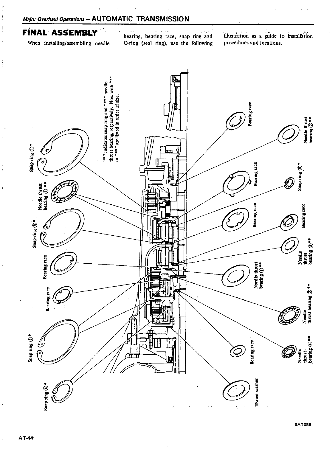
Majo
OverhaulOperations
AUTOMATIC
TRANSMISSION
FINAL
ASSEMBLY
When
installing
assembling
needle
bearing bearing
race
snap
ring
and
iUustration
as
a
guide
to
instaUation
O
ring
seal
ring
use
the
foUowing
procedures
and
locations
@
Co
Q
gE
do
0
a
0
c
2
Q
Q
0
c
u
5
Co
e
QO
CQ
QC
S
oU
e
ll
30
C
e
oS
F
8
i
d
8
Co
cii
a8
Q
a
5
H
Q
u
e
@
r
1
ll
Ji
QQ
UU
ee
C
S
d
a
j
@Q
1
5
zj
Q
U
e
I
8
f
l
il
d
e
C
C
Co
cii
Q
U
e
S
a
5
Q
a
zs 8
S
Co
f
t
e
IS
SA
T099
AT
44
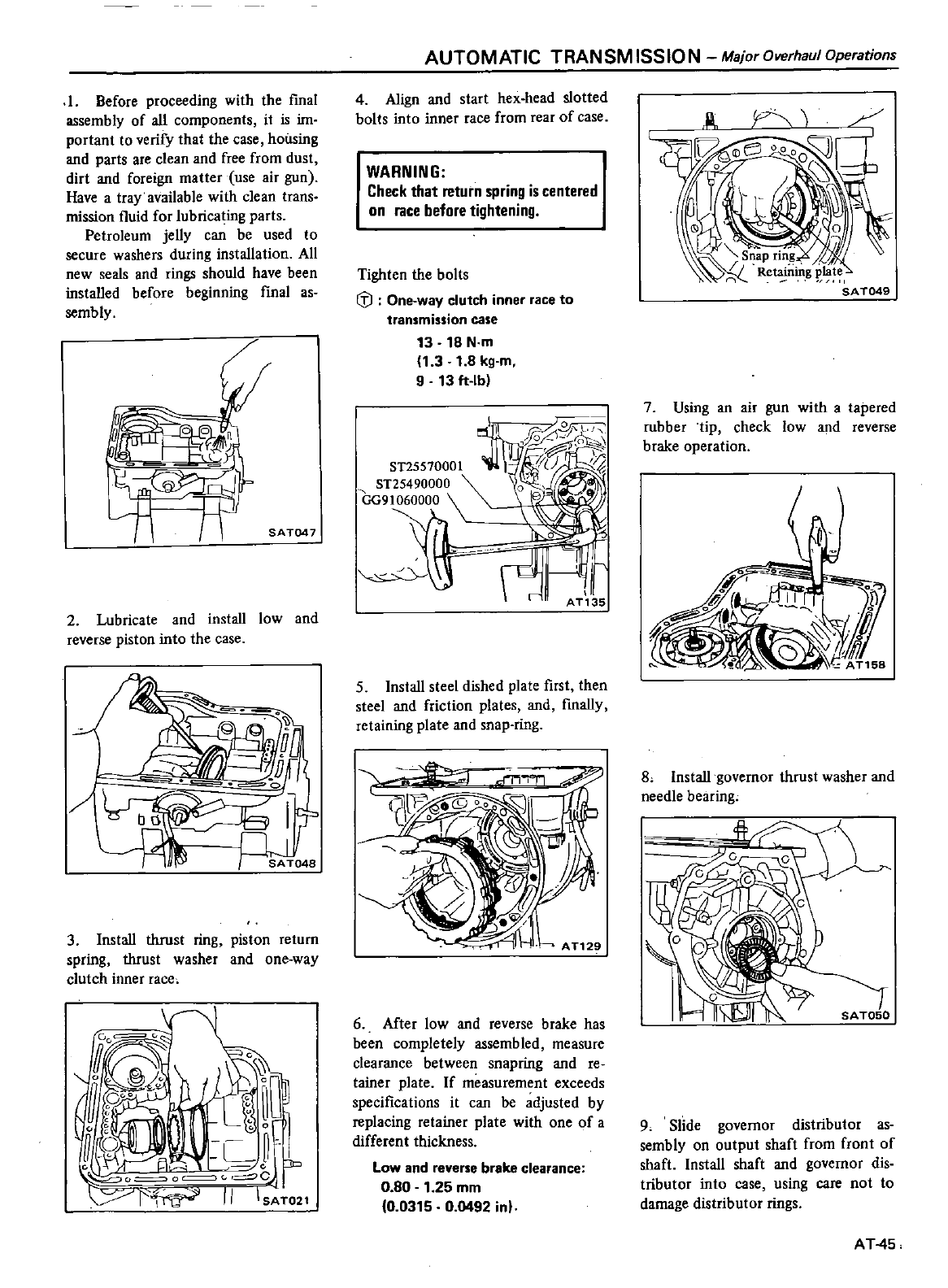
I
Before
proceeding
with
the
fmal
assembly
of
all
components
it
is
im
portant
to
verify
that
the
case
housing
and
parts
are
clean
and
free
from
dust
dirt
and
foreign
matter
use
air
gun
Have
a
tray
available
with
clean
trans
mission
fluid
for
lubricating
parts
Petroleum
jeUy
can
be
used
to
secure
washers
during
installation
All
new
seals
and
rings
should
have
been
installed
before
beginning
final
as
semb
ly
SAT047
2
Lubricate
and
instaU
low
and
reverse
piston
into
the
case
3
InstaU
thrust
ring
piston
return
spring
thrust
washer
and
one
way
clutch
inner
race
JGOC
Oe
c
o
j
cl
GOo
IIU
o
0
o v
1
c
Co
0
l
f
9
r
JP
o o
s
r
II
IS
TOZl
AUTOMATIC
TRANSMISSION
Major
Overhaul
Operations
4
Align
and
start
hex
head slotted
bolts
into
inner
race
from
rear
of
case
WARNING
Check
that
return
spring
is
centered
on
race
before
tightening
Tighten
the
bolts
G
J
One
way
clutch
inner
race
to
transmission
case
13
18
N
m
1
3
1
8
kg
m
9 13
ft
lb
I
I
ii
7
l
i
ST25570001
lfiu
ST25490000
GG91060000
5
Install
steel
dished
pla1e
first
then
steel
and
friction
plates
and
fmaUy
retaining
plate
and snap
ring
6
After
low
and
reverse
brake
has
been
completely
assembled
measure
clearance
between
snapring
and
re
tainer
plate
If
measurement
exceeds
specifications
it
can
be
adjusted
by
replacing
retainer
plate
with
one
of
a
different
thickness
Low
and
reverse
brake
clearance
0
80
1
25
mm
0
0315
0
0492
inl
7
Using
an
air
gun
with
a
tapered
rubber tip
check
low
and
reverse
brake
operation
8
InstaU
governor
thrust
washer
and
needle
bearing
9
Slide
governor
distributor as
sembly
on
output
shaft
from
fron1
of
shaft
Install
shaft
and
governor dis
tributor
into
case
using
care
not
to
damage
distributor
rings
AT
45
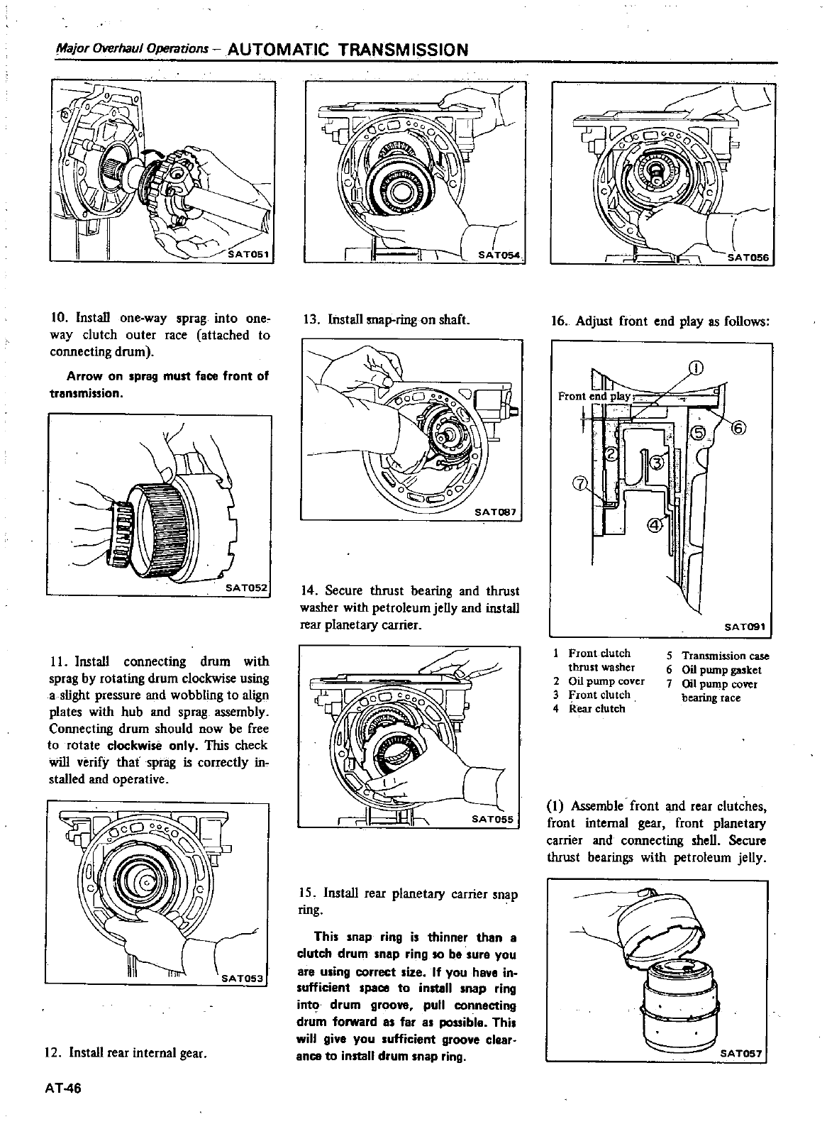
Major
Overhaul
Operations
AUTOMATIC TRANSMISSION
10 InstaU
one
way
sprag
into
one
way
clutch
outer
race
attached
to
connecting
drum
Arrow
on
sprag
must
face
front
of
transmission
II
InstaU
connecting
drum
with
sprag
by
rotating
drum
clockwise
using
a
slight
pressure
and
wobbling
to
aIign
plates
with
hub
and
sprag
assembly
Connecting
drum
should
now
be
free
to
rotate
clockwise
only
This
check
will
verify
that
sprag
is
correctly
in
stalled
and
operative
12
InstaU
rear
in1ernal
gear
AT
46
c
D
CO
V
j
a
13 Install
map
ring
on
shaft
14
Secure
thrust
bearing
and
thrust
washer
with
petroleum
jeUy
and
instaU
rear
planetary
carrier
SA
TOSS
15
Install
rear
planetary
carrier
snap
ring
This
snap
ring
is
thinner
than
8
clutch
drum
snap
ring
so
ba
sure
you
are
using
correct
size
If
you
have
in
sufficient
spaco
to
install
snap
ring
int
drum
groove
pull
connecting
drum
forward
a
far
as
possible
This
will
give
you
sufficient
groove clear
anco
to
install
drum
nap
ring
16
Adjust
front
end
playas
foUows
Front
end
p1aY
1
JL
v
r
l
J
CC
j
SAT091
Front
clutch
thrust
washer
2
Oil
pump
cover
3
Front
clutch
4
Rear
clutch
5
Transmission
case
6
Oil
pump
ga5Ket
7
Oil
pump
cover
bearing
race
I
Assemble
front
and
rear
clutches
front
internal
gear
front
planetary
carrier
and
connecting
sheU
Secure
thrust
bearings
with
petroleum
jeUy
I
4
SATOS7
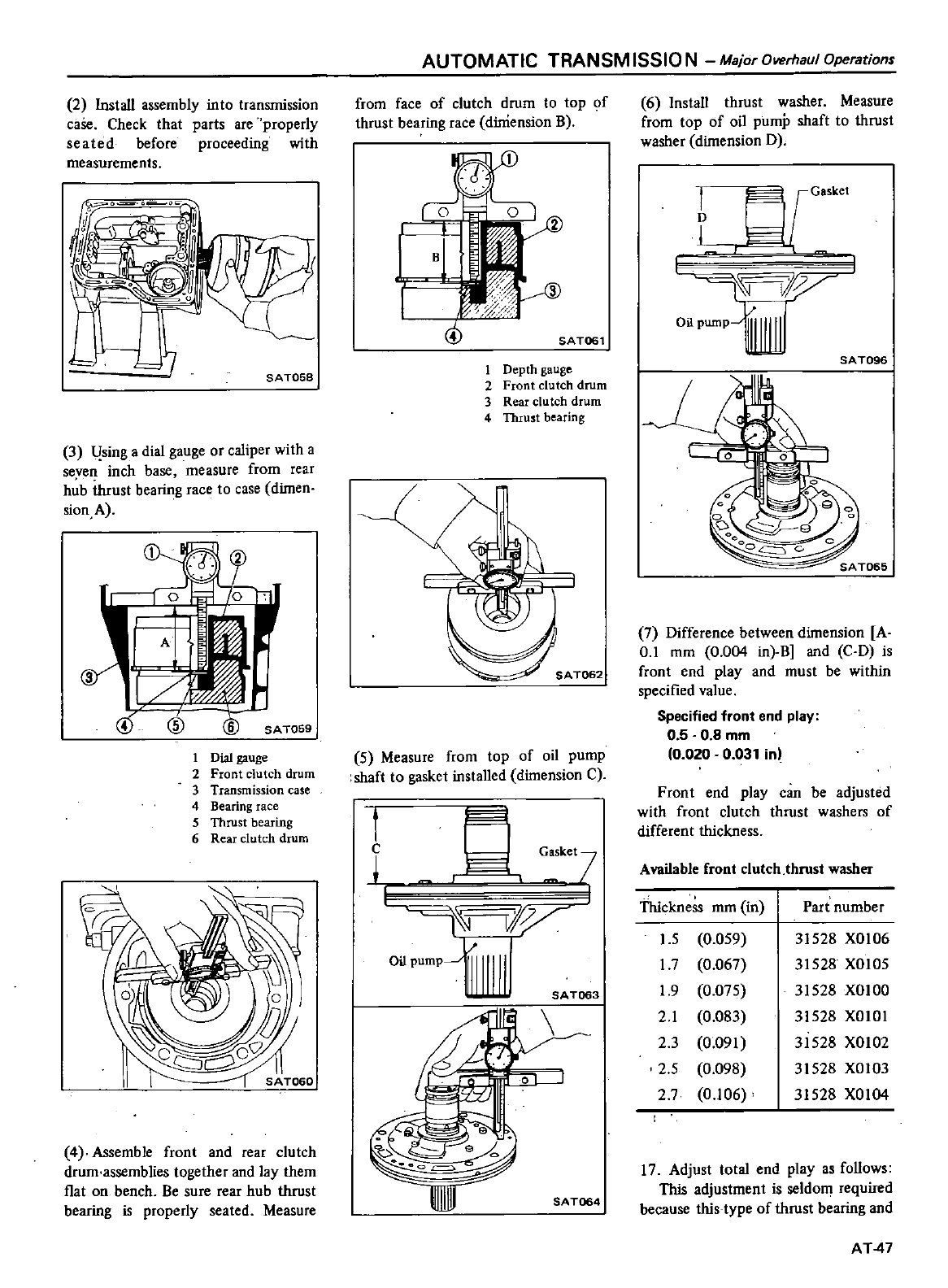
2Install
assembly
into
transmission
caSe
Check
that
parts
are
properly
seated
before
proceeding
with
measurements
SA
T05S
3
l
sing
a
dial
gauge
or
caliper
with
a
seven
inch
base
measure
from
rear
hub
thrust
bearing
race
to
case
dimen
sion
A
3
cID
@
SAT059
1
Dial
gauge
2
Front
clutch
drum
3
Transmission
case
4
Bearing
race
5
Thrust
bearing
6
Rear
clutch
drum
4
Assemble
front
and
rear
clutch
drum
assemblies
together
and
lay
them
l1at
on
bench
Be
sure
rear
hub
thrust
bearing
is
properly
seated Measure
AUTOMATIC
TRANSM
15510
N
Major
Overhaul
Operations
from
face
of
clutch
drum
to
top
of
thrust
bearing
race
dilliension
B
@
SAT061
1
Depth
gauge
2
Front
clutch
drum
3
Rear clu
tch
drum
4
Thrust
bearing
5
Measure
from
top
of
oil
pump
shaft
to
gasket
installed
dimension
C
1
c
I
G
k
I
ty
oilPump
SAT063
fU
0
III
SAT064
6 Install
thrust
washer
Measure
from
top
of
oil
pump
shaft
to
thrust
washer
dimension
D
I
L
fffi
llV
Oil
pumpU
SAT096
7
Difference
between
dimension
A
0
1
mm
0
004
in
B
and
C
D
is
front
end
play
and
must
be
within
specified
value
Specified
front
end
play
0
5
0 8
mm
0
020
0
031
inl
Front
end
play
can
be
adjusted
with
front
clutch
thrust
washers
of
different
thickness
Available
front
clutch
thrust
washer
Thickness
mm
in
Part
number
I
S
0
059
31528
XOlO6
17
0
067
31528
XOl05
1
9
0
075
31528
XOIOO
2
1
0
083
31528
XOIOI
23
0
091
31528
XOI02
25
0
098
31528
XOlO3
2
7
0
106
31528
XOI04
17
Adjust
total
end
playas
follows
This
adjustment
is
seldom
required
because
this
type
of
thrust
bearing
and
AT
47
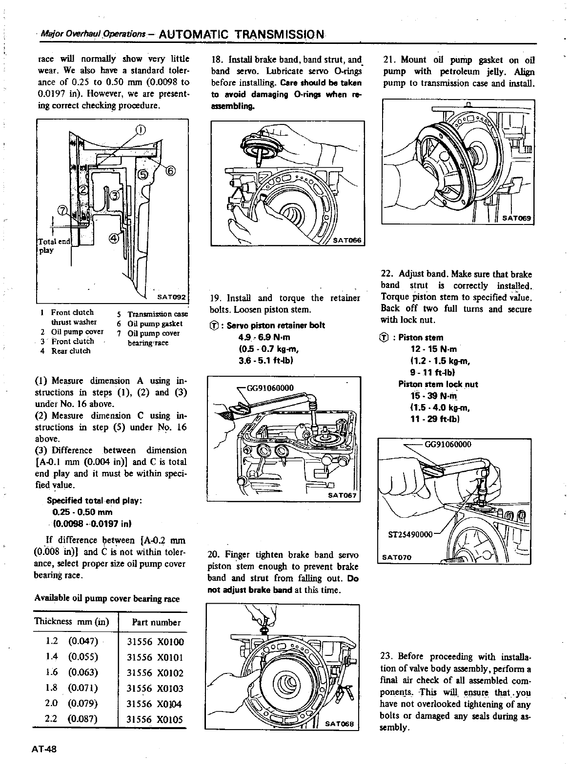
Major
Overhaul
Operations
AUTOMATIC
TRANSM
ISSION
race
will
normally
show
very
little
wear
We
also
have
a
standard
taler
ance
of
0
25
to
0
50
mm
0
0098
to
0
0197
in
However
we
are
present
ing
correct
checking
procedure
j
i
C1l
i
E
r
Tott
Jf
play
SA
T092
Front
clutch
thrust
washer
2
Oil
pump
cover
3
Front
clutch
4 Rear
clutch
5
Transmission
case
6
Oil
pump
ga5ket
7
Oil
pump
cover
be
aring
race
1
Meamre
dimension
A
using
in
structions
in
steps
1
2
and
3
under
No
16
above
2
Measure
dimension
C
using
in
structions
in
step 5
under
N
16
above
3
Difference
between
dimension
A
Q
I
mm
0
004
in
and
C
is
total
end
play
and
it
must
be
within
speci
fied
value
Specified
total
end
play
0
25
0
50
mm
0
00980
0197
inl
If
difference
J
letween
A
Q
2
mm
0
008
in
and
C
is
not
within
taler
ance
select
proper size
oil
pump
cover
bearing
race
Available
oil
pump
cover
bearing
race
Thickness
mm
in
Part
number
1
20
047
31556
XOlOO
14
0
055
31556 XOIOI
1
6 0
063
31556
XOI02
1
8
0
071
31556
XOI03
2
00
079
31556 XOI04
22 0
087
31556
XOl05
AT
48
18
Install
brake
band
band
strut
and
band
servo
Lubricate
servo
O
rings
before
installing
Care
should
be
taken
to
avoid
damaging
O
rings
when
re
mbling
19
Install
and
torque
the
retainer
bolts
Loosen
piston
stem
rfl
Servo
piston
retainer
bolt
49
6
9N
m
05
0
7
kg
m
3 6 5
1
ft
b
20
Finger
tighten
brake
band
servo
piston
stem
enough
to
prevent
brake
band
and
strut
from
falling
out
Do
not
adjust
bnlke
band
at
this
time
21
Mount
oil
pump
gasket
on
oil
pump
with
petroleum
jelly
Align
pump
to
transmission
case
and
install
n
SA
T069
22
Adjust
band
Make
sure
that
brake
band
strut
is
correctly
installed
Torque
piston
tern to
specified
v
Jue
Back
off
two
full
turns
and
secure
with
lock
nut
rfl
Piston
stem
12 15
N
m
1
2
1
5
kg
m
9
11
ft
bl
Piston
stem
lock
nut
15
39N
1 5
4 0
kg
m
11
29
ft
lb
GG91060000
ST25490000
SAT070
23
Before
proceeding
with
installa
tion
of
valve
body
assembly
perform
a
fmal
air
check
of
all
assembled
com
ponenjs
This
will
ensure
that
you
have
not
overlooked
tightening
of
any
bolts
or
damaged
any
seals
during
as
sembly
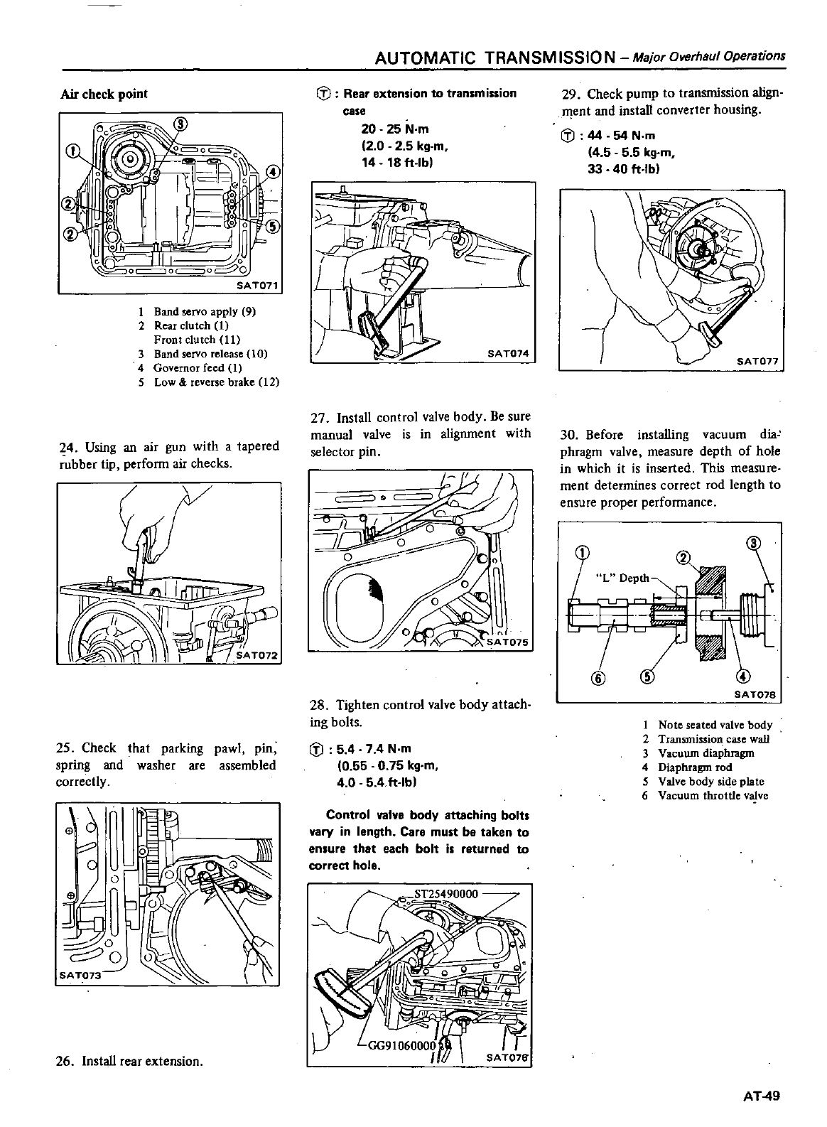
Air
check
point
1
Band
servo
apply
9
2
Rear
clutch
1
Front
clutch
11
3
Band
servo
release
10
4
Governor
feed
1
5
Low
reverse
brake
12
4
Using
an
air
gun
with
a
tapered
rubber
tip
perform
air
checks
25
Check
that
parking
pawl
pin
spring
and
washer
are
assembled
correctly
6
c
l
0
o
0
1
o
2
o
SA
T073
26
Install
rear
extension
AUTOMATIC TRANSMISSIO
N
Major
Overhaul
Operations
Q
Rear
extension
to
transmission
case
20 25
N
m
2 0 2 5
kg
m
14
18
ft
Ib
n
SA
T014
27
Install
control
valve
body
Be
sure
manual
valve
is
in
alignment
with
selector
pin
u
o
tK
oo1
o
28
Tighten
control
valve
body
attach
ing
bolts
dl
5 4
74N
m
0
55
0
75
kg
m
4
0 5
4
ft
Ibl
Control
valve
body
attaching
bolts
vary
in
length
Care
must
be
taken
to
ensure
that
each
bolt
is
returned
to
correct
hole
29
Check
pump
to
transmission
align
I11ent
and
install
converter
housing
dl
44
54
N
m
4
5 5 5
kg
m
33
40
ft
Ibl
30
Before
installing
vacuum
dia
phragm
valve
measure
depth
of
hole
in
which
it
is inserted
This
measure
ment
determines
correct rod
length
to
ensure
proper
performance
SA
T078
1
Note
seated
valve
body
2
Transmission
case wall
3
Vacuwn
diaphrngm
4
Diaphragm
rod
5
Valve
body
side
plate
6
Vacuum
throttle
valve
AT
49
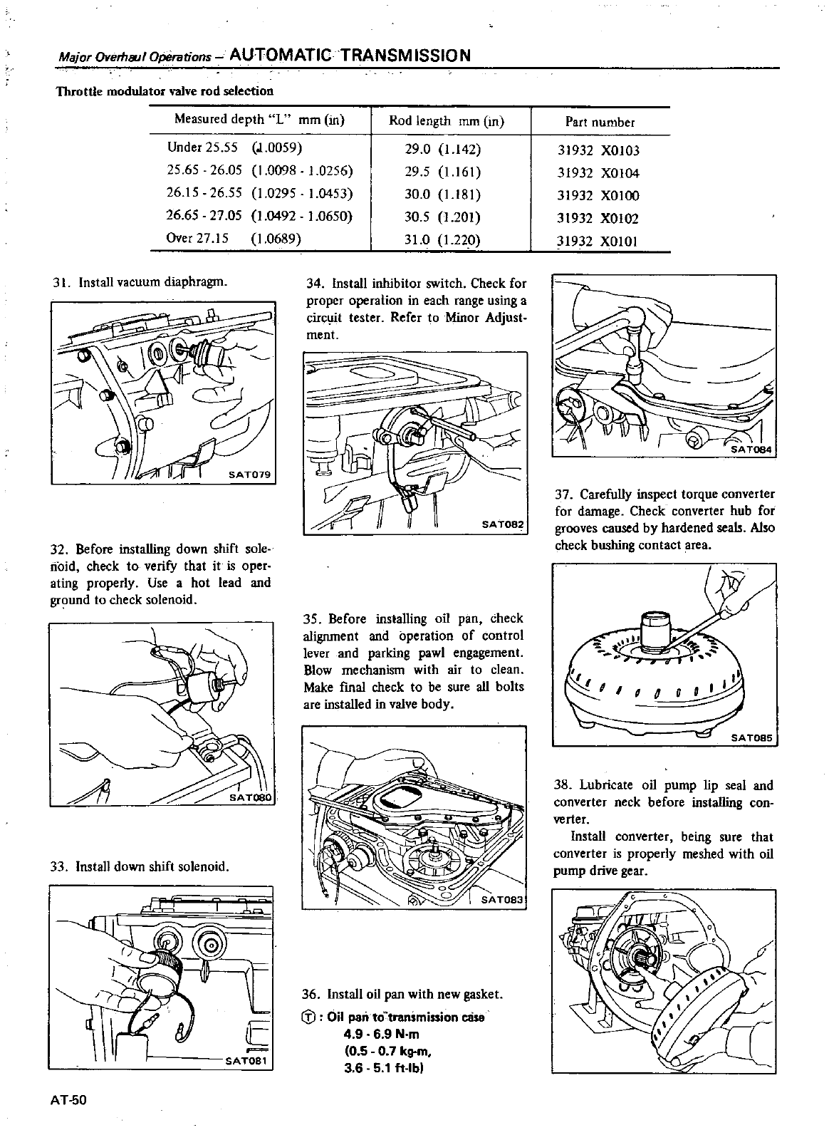
Major
Overhsul
Operations
AUTOMATIC
TRANSM
15510
N
Throttle
modulator
valve
rod
selectioo
Measured
depth
L
mm
in
Rod
length
mm
in
Under
2555
25 65
26
05
2615
2655
26
65
27 05
Over
27
15
J
0059
1
0098
1
0256
1
0295
1
0453
1
0492
1
0650
1
0689
29
0
1
142
29
5
1
161
30
0
l
l81
30
5
1
201
31
0
1
22
0
31
Install
vacuum
diaphragm
32
Before
installing
down
shift
sole
noid
check
to
verify
that
it
is
oper
ating
properly
Use
a
hot
lead
and
ground
to
check
solenoid
A
33
Install
down
shift
solenoid
L
@J
E
F
SATOS1
AT
50
34
Install
inhibitor
switch
Check
for
proper
operation
in
each
range
using
a
circuit
tester
Refer
to
Minor
Adjust
ment
SA
T082
35
Before
installing
oil
pan
check
alignment
and
operation
of
control
lever
and
parking
pawl
engagement
Blow
mechanism
with
air
to
clean
Make
fmal
check
to
be
sure
all
bolts
are
installed
in
valve
body
36
Install
oil
pan
with
new
gasket
tfl
Oil
pan
to
transmission
ease
4 9
6 9
N
m
0
5 0 7
kg
m
36
5
1
ft
Ibl
Part
number
31932
XOI03
31932
XOI04
31932
XOlOO
31932
XOI02
31932
XOIOI
37
Carefully
inspect
torque
converter
for
damage
Check
converter
hub
for
grooves
caused
by
hardened
seals
Also
check
bushing
contact
area
38
Lubricate
oil
pump
lip
seal
and
converter
neck
before
installing
con
verter
Install
converter
being
sure
that
converter
is
properly
meshed
with
oil
pump
drive
gear
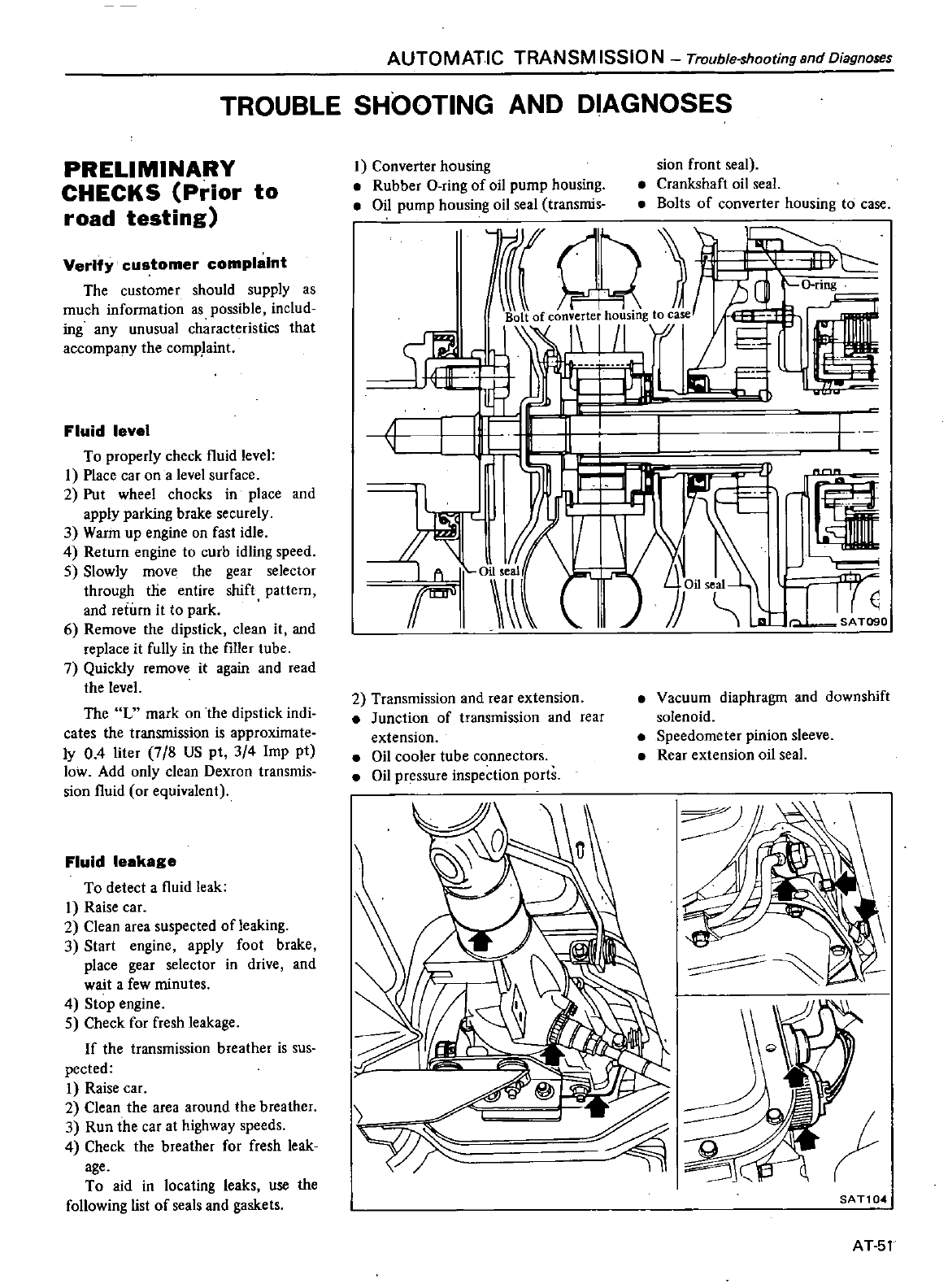
AUTOMATIC TRANSMISSION
Trouble
shootingsndDiagnoses
TROUBLE
SHOOTING
AND
DIAGNOSES
PRELIMINARY
CHECKS
Prior
to
road testing
Verify
customer
complaint
The
customer
should
supply
as
much
information
as
possible
includ
ing
any
unusual characteristics
that
accompany
the
comp
laint
Fluid
level
To
properly
check
l1uid level
1
Place
car
on
a
level
surface
2
Put
wheel
chocks
in
place
and
apply
parking
brake
securely
3
Warm
up
engine
on
fast
idle
4
Return
engine
to
curb
idling
speed
5
Slowly
move
the
gear
selector
through
tlie
entire
shift
pattern
and
return
it
to
park
6
Remove
the
dipstick
clean
it
and
replace
it
fully
in
the
filler
tube
7
Quickly
remove
it
again
and
read
the
level
The
L
mark
on
the
dipstick
indi
cates
the
transmission
is
approximate
ly
0
4
liter
78
US
pt
3
4
Imp
pt
low
Add
only
clean
Dexron
transmis
sion
l1uid
or
equivalent
Fluid
leakage
To
detect
a
l1uid
leak
I
Raise
car
2
Clean
area
suspected
of
leaking
3
Start
engine apply
foot
brake
place
gear
selector
in
drive
and
wait
a
few
minutes
4
Stop
engine
5
Check
for
fresh
leakage
If
the
transmission
breather
is
8US
pected
I
Raise
car
2
Clean
the area
around
the
breather
3
Run
the
car
at
highway
speeds
4
Check
the
breather
for
fresh
leak
age
To
aid
in
locating
leaks
use the
following
list
of
seals
and
gaskets
1
Converter
housing
Rubber
O
ring
of
oil
pump
housing
Oil
pump
housing
oil
seal
transmis
sian
front
seal
Crankshaft
oil
seal
Bolts
of
converter
housing
to
case
f
CD
I I
1
II
8
1
IL
I
II
I
II
If
O
filse
if
o
2
Transmission
and
rear
extension
Junction
of
transmission
and
rear
extension
Oil
cooler
tube
connectors
Oil
pr
ssure
inspection
ports
Vacuum
diaphragm
and
downshift
solenoid
Speedometer
pinion
sleeve
Rear
extension
oil
seal
I
SAT104
AT
51
TroublfHhootingand
DilJgnoses
AUTOMATIC
TRANSM
15510
N
Fluid
condition
Transmission
fluid
color
and
tex
ture can
aid
greatly
in
transmission
trouble
shooting
When
checking
l1uid
level
examine
the
transmission
l1uid
and
note
its
color
texture
and
odor
Some
common
fonns
of
contami
nation
are
listed
below
I
Dark
or
Black
Fluid
With
a
burned odor
Worn
friction
material
Without
an
odor
Slight
engine
coolant
leak
in
radiator
2
Milky
Pink
Fluid
Water
Contami
nation
Coolant
leak
Road
water
entering
through
filler
tube
or
breath
er
3
Varnished
Fluid
light
to
dark
brown
and
tacky
Oxidation
Over
or
Underfilling
Overheating
Engine
Idle
Check
and
adjust
idle to
specifica
tions
Idling
speed
700
i
100
rpm
at
0
range
Engine
011
and
coolant
levels
Prior
to
road
testing
check
engine
oil
and
coolant
levels
and
fill
as
neces
sary
Shift
linkage
Start
in
park
position
depress
detent
button
and
slowly
move
the
gear selector
through all ranges
The
detent
clicks
should
correspond
with
the
range
indicator
AT
52
pIAGN
STIC
ROAD
TEST
Prior
to
road
testing
perform
the
preliminary
inspections
outlined
earlier
If
the
car
is
not
equipped
with
a
tachometer
install
a
portable
tacho
tneter
in
the
car
And
also
install
a
suitable
vacuum
gauge
and
pressure
gauge
If
the
customer
has
a
specific
complaint
select
road
conditions
similar
to
those
described
eg
steep
hills
freeways
etc
Follow
the
test
sequence
as
out
lined
in
this
section
and
mark
the
results
on
the
Symptom
Chart
on
page
AT
59
It
may
be
necessary
to
repeat
sections
of
the
test
under
different
throttle
conditions
e
g
light
medium
or
full
throttle After
completing
the
road
test
compare
the
test
results
to
lIIe
Trouble
shooting
Chart
on
page
AT
56
ROAD
TESTING
L
Park
Range
Place
the gear
selector
in
P
range
and
start
the
engine
Stop
the
engine
and
repeat
the
procedure
in
all
other
ranges
and
neutral
In
park
the
car
should
be
locked
in
position
unable
to
roll
or
move
Mark
all
results
on
the
Symptom
Chart
2
Reverse
Manually
shift
the
gear selector
from
P
to
R
and
note
shift
quali
ty
Drive
the
car
in
reverse
long
enough
to
detect
slippage
or
other
abnormalities
Note
results
3
Neutral
Manually
shift
the
gear
selector
from
P
to
N
and
note
quality
In
neutral
no
clutches
or
bands
are
ap
plied
and
there
should
be
no
move
ment
Note
results
4
Drive
Range
Manually
shift
the
gear
selector
to
ran
e
0
and
note
shift
quality
Drive
the
car
through
all
automatic
shifts
and
in
all
gear
ranges
Note
shift
quality
and
timing
km
h
MPH
check
for
slippage
noise
or
other
abnormal
conditionS
If
necessary
drive
the
test
sequence
under
different
throttle
openings
e
g
light
medium
or
full
throttle
5
Range
2
Manually
shift
the
gear
selector
to
range
2
Check
for
slippage
hesita
tion
or
abnormal
condition
The
trans
mission
should
remain
in
2nd
gear
regardless
of
car
speed
or
engine
re
volutions
Note
re
lts
6
Range
I
Manually
shift
the
gear
selector
to
range
I
Note
shift
quality
It
should
however
downshift
im
mediately
to
2nd
gear
and
downshift
again
to
1st
gear
as
road
speed
de
creases
Accelerate
and
decelerate
in
1st
gear
to
determine
engine
braking
Note
results
The
transmission
should
not
shift
into
1st
gear
from
0
range
if
tha
car
road
speed
is
above
approximately
50
km
h
30
MPHI
7
Record
line
pressure
and
governor
pressure
at
each
range
and
at
each
throttle
vacuum
in
accordance
with
the
pressure
testing
described
below
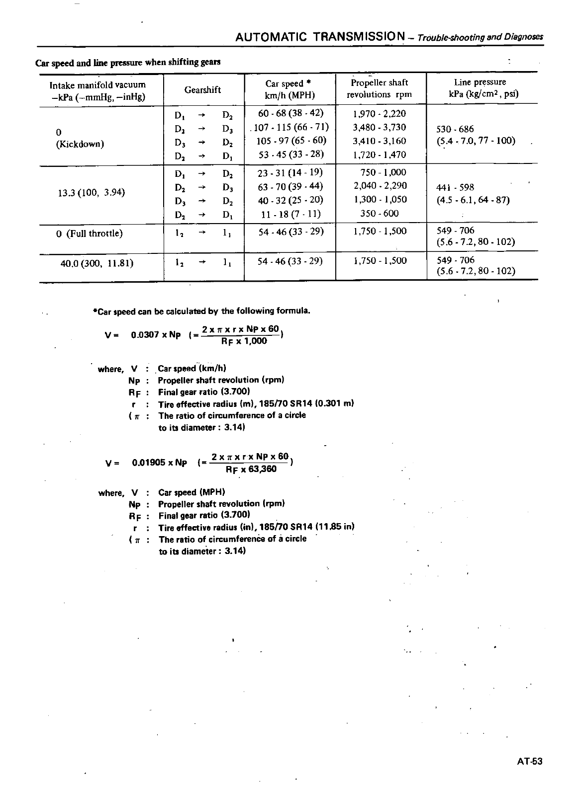
AUTOMATIC
TRANSM
15510
N
Trouble
shooting
and
Diagnoses
Car
speed
and
line
pressure
when
shifting
gears
Intake
manifold
vacuum
Gearshift
Car
speed
Propeller
shaft
Line
pressure
kPa
mmHg
inHg
km
h
MPH
revolutions
rpm
kPa
kg
em
2
psi
0
O2
60 68
38
42
1
970
2
220
0
00
107 115
66
71
3
480
3730
530
686
Kiekdown
00
105
97
65
60
3
410
3
160
5
4
70
77
100
0 0
53
45
33
28
1720
1470
0
O2
23
31
14
19
750
1
000
13
3
100
3
94
O2
0
63
70
39
44
2
040
2
290
441
598
00
40 32
25
20
1
300
1
050
4
5
6
1
64
87
O2
0
II
18 7
II
350 600
o
Full
throttle
I I
54 46 33
29
1750
1
500
549 706
5
6 7 2
80
102
40
0
300
11
81
I I
54
46
33 29
1
750
1
500
549 706
5672
80
102
Car
speed
can
be
calculated
by
the
following
formula
v
where
V
Np
RF
r
v
where
V
Np
RF
r
00307
x
Np
1
2
x
x
r
x
Np
x
60
RF
x
1
000
Car
speed
km
h
Propeller
shaft
revolution
rpml
Final
gear
ratio
13
700
Tire
effective
radius
m
185nO
SR14
0
301
m
The
ratio
of
circumference
of
a
circle
to
its
diameter
3
141
0
01905xNp
2xll
xrxNPx60
RF
x
63
360
Car
speed
MPH
Propeller
shaft
revolution
rpm
Final
gear
ratio
3
700
Tire effective
radius
in
18SnO
SR14
1185
in
The
ratio
of
circum
of
a
circle
to
its
diameter
3
14
AT
53
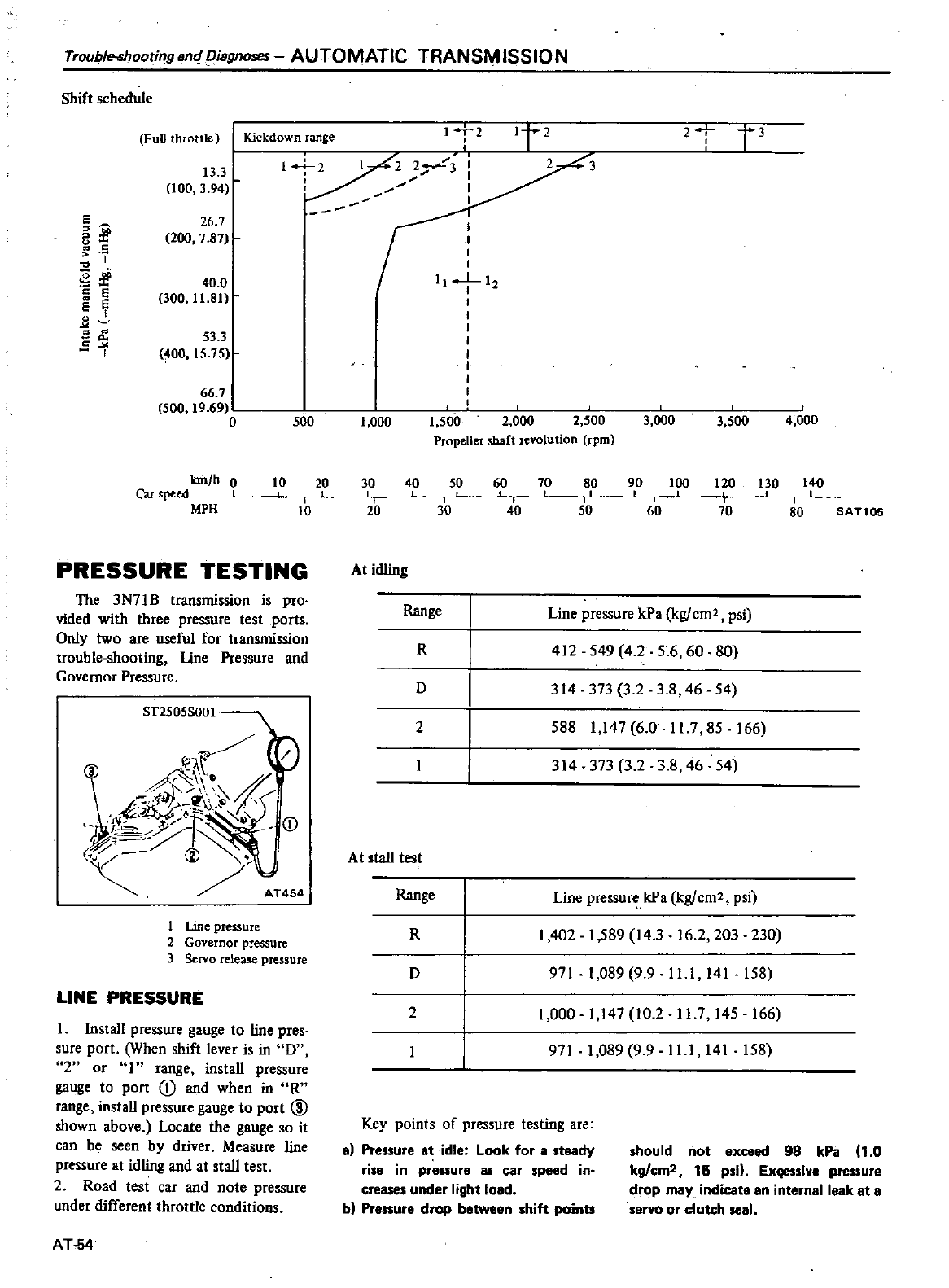
Trouble
shooting
8m
iagnoses
AUTOMATIC
TRANSM
ISSION
Shift
schedule
Full
throttle
Kickdown
range
1
2
1t2
2
t
t3
13
3
1
2
2Y3
3
000
3
94
I
E
26
7
I
f
200
7
87
I
l
c
I
0
I
I
3
r
400
1
1
12
S
e
I
E
300
11
81
I
EII
d
I
53
3
5
0
I
I
OO
15 75
I
I
I
66
7
I
500
19
69
c
0
500
1
000
1
500
2
000
2
500
3
000
3
500
4
000
Propeller
shaft
revolution
rpm
kmfh
0
Car
speed
I
MPH
10
PRESSURE
TESTING
The
3N71B
transmission
is
pro
vided
with
three
pressure
test
ports
Only
two
are
useful
for
transmission
trouble
shooting
line
Pressure
and
Governor
Pressure
ST2505S001
AT454
1
Line
pressure
2
Governor
pressure
3
Servo
release
pressure
LINE
PRESSURE
I
Install
pressure
gauge
to line
pres
sure
port
When
shift
lever
is
in
0
2
or
1
range
install
pressure
gauge
to
port
CD
and
when
in
R
range
install
pressure
gauge
to
port
@
shown
above
Locate
the
gauge
so
it
can
be
seen
by
driver
Measure
line
pressure
at
idling
and
at
stall
test
2
Road
test
car
and
note
pressure
under
different
throttle
conditions
AT
54
20
90
100 130 140
30
40
50
30
60
70
120
70
80
10
20
80
40
50 60
SAT105
At
idling
Range
Line
pressure
kPa
kg
cm2
psi
412
549
4
2
5
6
60
80
314
373
3
2
3
8
46
54
588
1
147
60
11
7
85
166
314
373
32
3
8
46
54
R
D
2
At
tall
test
Range
Line
pressur
kPa
kg
cm2
psi
R
1402
1
589
14
3
16 2
203
230
D
971
1
089
9 9
11
1
141
158
2
1
000
1
147
10
2
117
145 166
971
1
089
9 9
11
1
141
158
Key
points
of
pressure
testing
are
al
Pressure
at
idle
Look
for
a
teady
rise
in
pressure
as
car
speed
in
cre
under
light
load
bl
Pr
ur
drop
b
tween
hift
point
hould
not
exceed
98
kPa
1
0
kg
cm2
15
p
n
Ex
i
pressure
drop
may
indicate
an
internal
leak
at
a
servo
or
clutch
seal
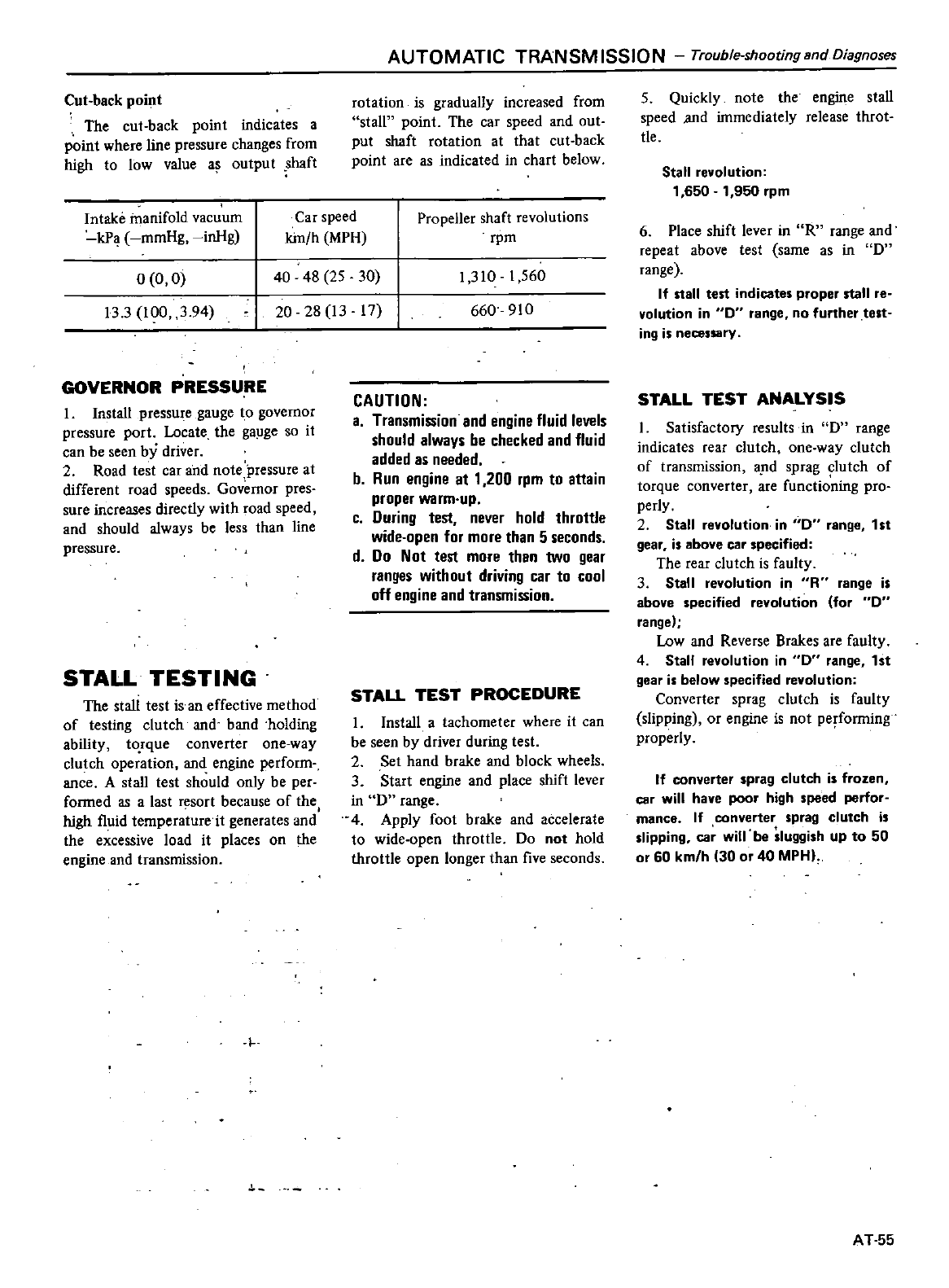
Cut
back
point
The
cut
back
point
indicates
a
point
where
line
pressure
changes
from
high
to low
value
a
output
shaft
AUTOMATIC TRANSMISSION
Trouble
shootingandOiagnoses
rotation
is
gradually
increased
from
stall
point
The
car
speed
and
out
put
shaft
rotation
at
that
cut
back
point
are
as
indicated
in
chart
below
Intake
manifold
vacuum
Car
speed
Propeller
shaft
revolutions
kPa
mmHg
inHg
km
h
MPH
rpm
o
00
40 48
25
30
1
310
1
560
13
3
100
3
94
20
28
13
17
660 910
GOVERNOR
PRESSURE
I
Install
pressure
gauge
to
governor
pressure
port
Locate
the
ga
ge
so
it
can
be
seen
by
driver
2
Road
test
car
and
note
pressure
at
different
road
speeds
Gov
mor
pres
sure
increases
directly
with
road
speed
and
should
always
be
less
than
line
pressure
STALL
TESTING
The
stall
test
is
an
effective
method
of
testing
clutch
and
band
holding
ability
to
rque
converter
one
way
clutch
operation
and
engine
perform
ance
A stall
test
should
only be
per
formed
as a
last
resort
because
of
the
high
l1uid
temperature
it
generates
and
the
excessive
load
it
places
on
the
engine
and
transmission
1
CAUTION
a
Transmission
and
engine
fluid
levels
should
alwavs
be
checked
and
fluid
added
as
needed
b
Run
engine
at
1
200
rpm
to
attain
proper
warm
up
c
During
test
never
hold
throttle
wide
open
for
more
than
5
seconds
d
Do
Not
test
more
than
two
gear
ranges
without
driving
car
to
cool
off
engine
and
transmission
STALL
TEST
PROCEDURE
1
Install
a
tachometer
where
it
can
be
seen
by
driver
during
test
2
Set
hand
brake
and
block
wheels
3
Start
engine
and
place
shift
lever
in
D
range
4
Apply
foot
brake
and
accelerate
to
wide
open
throttle
Do
not
hold
throttle
open
longer
than five
seconds
5
Quickly
note
the
engine
stall
speed
and
immediately
release
throt
tle
Stall
revolution
1
650
1
950 rpm
6
Place
shift
lever
in
R
range
and
repeat
above
test
same
as
in
D
range
If
stall
test
indicates proper
stall
re
volution
in
D
range
no
further
tost
ing
is
necessary
STALL
TEST
ANALYSIS
I
Satisfactory
results
in
0
range
indicates
rear
clutch
one
way
clutch
of
transmission
apd
sprag
flutch
of
torque
converter
are
functioning
pro
perly
2
Stall
revolution
in
0
range
1st
gear is
above
car
specified
The
rear
clutch
is
faulty
3
Stall
revolution in
R
range
is
above
specified
revolution
for
0
range
Low
and
Reverse
Brakes
are
faulty
4
Stall
revolution in
0
range
1St
gear is
below
specified
revolution
Converter
sprag clutch
is
faulty
slipping
or
engine
is
not
performing
properly
If
converter
sprag
clutch
is
frozen
car
will
have
poor
high
speed
perfor
mance
If
converter
sprag
clutch
is
slipping
car
will
be
sluggish
up
to
50
or
60
km
h
30
or
40
MPHl
AT 55
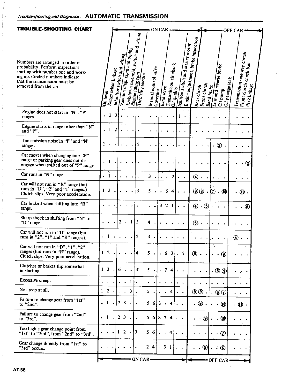
Trouble
shooting
Bnd
Diagnoses
AUTOMATIC
TRANSM
IS
ION
TROUBLE
SHOOTING
CHART
Numbers
are
arranged
in
order
of
probability
Perform
inspections
starting
with
number
one
and
work
ing
up
Circled
numbers
indicate
that
the
transmission
must
be
removed
from
the
car
Engine
does
not
start
in
Nn
P
ranges
Engine
starts
in
range
other
than
N
and
p
Transmi
sion
noise
in
P
and
N
ranges
Car
moves
when
changing
into
P
range
or
parking
gear
does
not
dis
engage
when
shifted
out
of
P
range
Car
runs
in
N
range
Car
will
not
run
in
R
range
but
runs
in
0
2
and
I
ranges
Clutch
slips
Very
poor
acceleration
Car
braked
when
shifting
into
R
range
Sharp
shock
in
shifting
from
N
to
D
range
Car
will
not
run
in
0
range
but
runs
in
2
and
R
ranges
Car
will
not
run
in
D
I
2
ranges
but
rims
in
R
range
Clutch
slips
Very
poor
acceleration
Clutches
or
brakes
slip
somewhat
in
tarting
Excessive
creep
No
creep
at
all
Failure
to
change
gear
from
I
st
to
2nd
Failure
to
change
gear
from
2nd
to
3rd
Too
high
a
gear
change
point
from
1st
to
2nd
from
lnd
to
3rdu
Gear
change
directly
from
1st
to
3rd
occurs
AT56
J
S
s
0
2
s
Cf7
CO
E
13
Eib
oe
4
ti
e
fe
aOClO
co
Sf
a
f
e
0
ii
EEo
t
ag
o
r
i
Ur
J
Q
d
oS
J5
2 3
2
I
I
2
2
I
2
I
26
2
I
3
I
23
23
I
2
ON
CAR
c
E
it
c
fi
e
L
a
u
c
M
O
t
I
f
C
0
S
c
c0J
R
f
t
S
0
t
CI
Cir
E
Jsou
It
0
OIl
c
i8
cSg
jl
t
2
3 2
3
6 4
5
321
3
4
23
4
63
5
374
5
5
4
56874
56874
35
64
2
4
3
I
IN
CAR
l
0
tl
fj
t
fi
f
GJ
l
0
111
Jfe
CI
I
o
cfJB
i
CO
g
Ct
0 c
cE
3C5C5
@
@
@@
J
@
@
CID
@
7
@
@@
@
@@
@
D
@
@
CID
OFF
CAR
OFF
CAR
s
J
0
5fJ
s
E
00
ra
11
E
0
S
MC
It
I
V
@
@
@
@
@
@
D
@
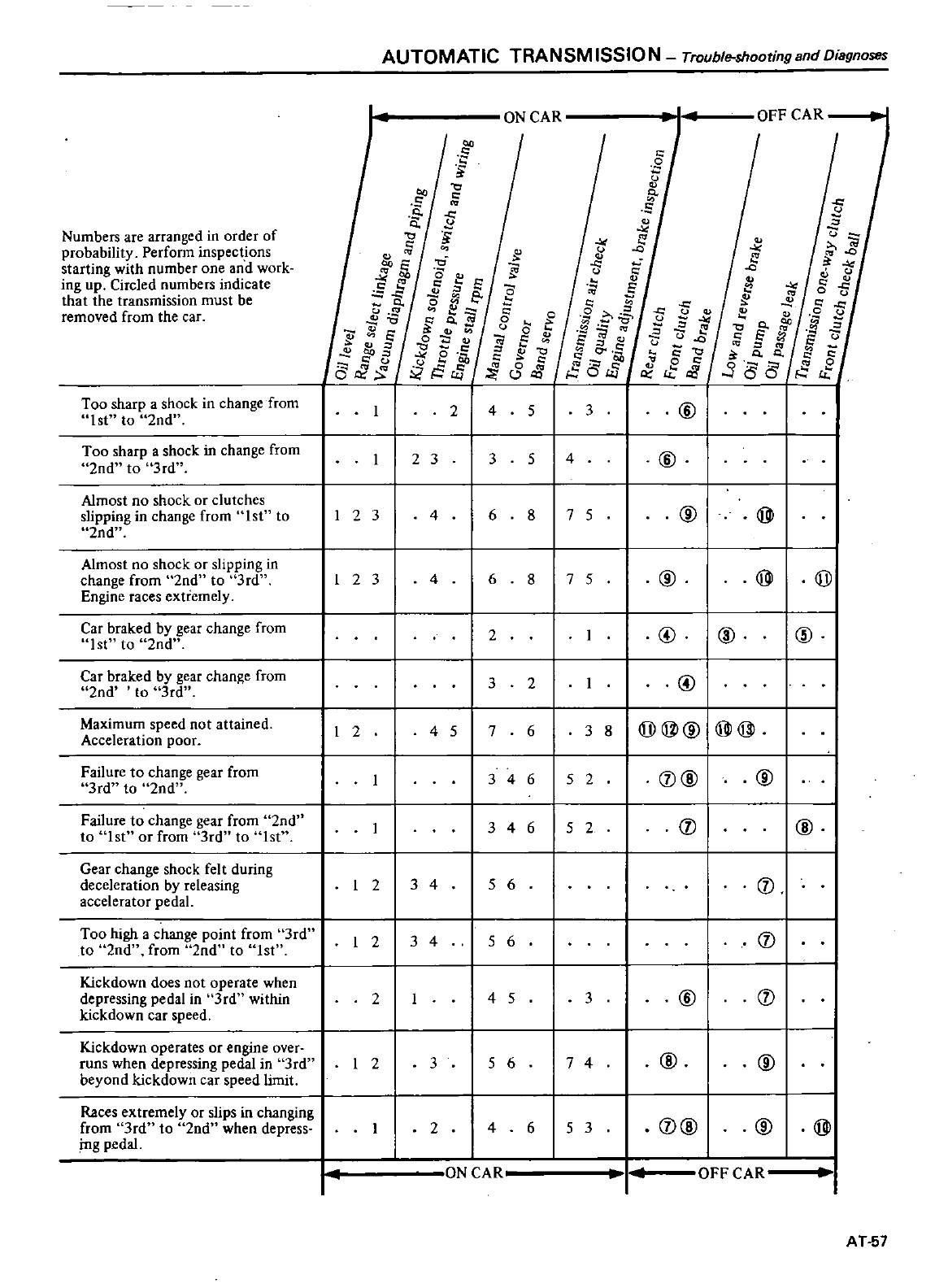
Numbers
are
arranged
in
order
of
probability
Perform
inspect
ons
starting
with
number
one
and
work
ing
up
Circled
numbers
indicate
that
the
transmission
must
be
removed
from
the
car
Too
sharp
a
shock
in
change
from
1st
to
2nd
Too
sharp
a
shock
in
change
from
2nd
to
3rd
Almost
no
shock
or
clutches
slipping
in
change
from
1st
to
2nd
Almost
no
shock
or
slipping
in
change
from
2nd
to
3rd
Engine
races
extremely
Car
braked
by
gear
change
from
lst
to
2nd
Car
braked
by
gear
change
from
2nd
to
3rd
Maximum
speed
not
attained
Acceleration
poor
Failure
to
change
gear
from
3rd
to
2nd
Failure
to
change
gear
from
2nd
to
1st
or
from
3rd
to
lst
Gear
change
shock
felt
during
deceleration
by
releasing
accelerator
pedal
Too
high
a
change
point
from
3rd
I
to
2nd
from
2nd
to
1st
Kickdown
does
not
operate
when
depressing
pedal
in
3rd
within
kick
down
car
speed
Kickdown
operates
or
engine
over
runs
when
depressing
pedal
in
3rd
beyond
kick
down
car
speed
limit
Races
extremely
or
slips
in
changing
from
3rd
to
2nd
when
depress
ing
pedal
AUTOMATIC
TRANSM
15510
N
Trouble
shooting
and
Diagnoses
s
Je
or
U
Jg
0
E
f1
6
I
2
3
123
I
2
I
2
I
2
I
2
r
I
I
2
f
i
ff
i
0
Ei
0
e
t
tJ
o
os
Jt
rJJ
2 3
4
4
4
5
34
34
3
2
ON
CAR
l
a
c
o
u
0
t
a
E
g
g
C5tE
2 4
3
6
6
2
3
2
76
346
346152
5
6
5
6
4
5
5
6
4
ON
CAR
If
ii
N
E
g
3
1
0
i5
Ei
o
c
0
v
c
o
5 3
5
4
8
7 5
8
7 5
3
8
5 2
3
7
4
6
5
3
o
tf
S
e
0
or
fj
E
3
0
0
d
ct
iJ
@
@
OFF
CAR
fi
5
rJ
o
it
0
5fj
c
or
e
B
fJ
E
u
S
0 0
S
r
388
s
@
@@
@
j
@
I@
CID
@I
@@@I@
j
CD@
@
@
CD@
I
CD
@
CD
CD
@
CD
@
@ @
OFF
CAR
AT
57
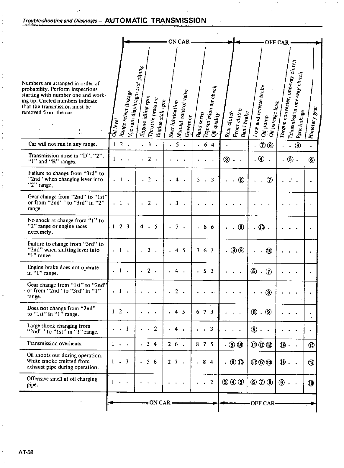
Trl
ble
shooting
and
OiagnOSJ
S
AUTOMATIC
TRANSM
IS
IO
N
Numbers
are
arranged
in
order
of
probability
Perform
inspections
starting
with
number
one
and
work
ing
up
Circled
numbers
indicate
that
the
transmission
must
be
removed
from
the
car
Car
will
not
run
in
any
range
Transmission
noise
in D
2
I
and
R
ranges
Failure
to
change
from
3rd
to
2nd
when
changing
lever
into
2range
Gear
change
from
2nd to
1st
or
from
2nd
to
3rd
in
2
range
No
shock
at
change
from
I
to
2range
or
engine
races
extremely
Failure
to
change
from
3rd
to
2nd
when
shifting
lever
into
I
range
Engine
brake
does
not
operate
in
1
range
Gear
change
from
1st
to
2nd
or
from
2nd
to
3rd
in
I
range
Does
not
change
from
2nd
to
1st
in
1
range
large
shock
changing
from
2nd
to
st in
range
Transmission
overheats
n
n
0
f
a
0
g
0
ii
S
oo
f
l
601
2 3
123
I
2
Oil shoots
out
during
operation
White
smoke
emitted
from
3
exhaust
pipe
during
operation
Offensive
smell
at
oil
charging
pipe
AT
58
ON
CAR
E
e
J
E
I
lO
fi
e
52
a
Q
tl
IV
G
1iO
e
tiC
JitSJi
ge
c
g
0
0
0
C
E
c
c
5
2
24
2 3
4
5
7
OFF
CAR
fi
o
9
t
G
E
00
r
S
rl 6
1
2
r
e
0
fi
Q
v
IV
IV c
C
J
t
0
c
IV
eo
8
gag
u
tl
io
o
J
6 5
E2
cEo
CV
ID
I
I
8E
2
f
0
0
c
0
C
l
I
0
t
rt
gj
e
II
@I
@
641
I@
@@
5@
3
8 6
@ @
2 4
5
763
@@
@
2
4
531
I@
I
2
@
4
5
67 3
I
I
@
@I
I
24
3
I
I
@
I
3
4
I
26 8 7
5
I
@@I@@@I@
I
@
5
6
2
78 4
@@
@@@
@@
2
I@@@
@
@I
@
I@
ON
CAR
OFF CAY
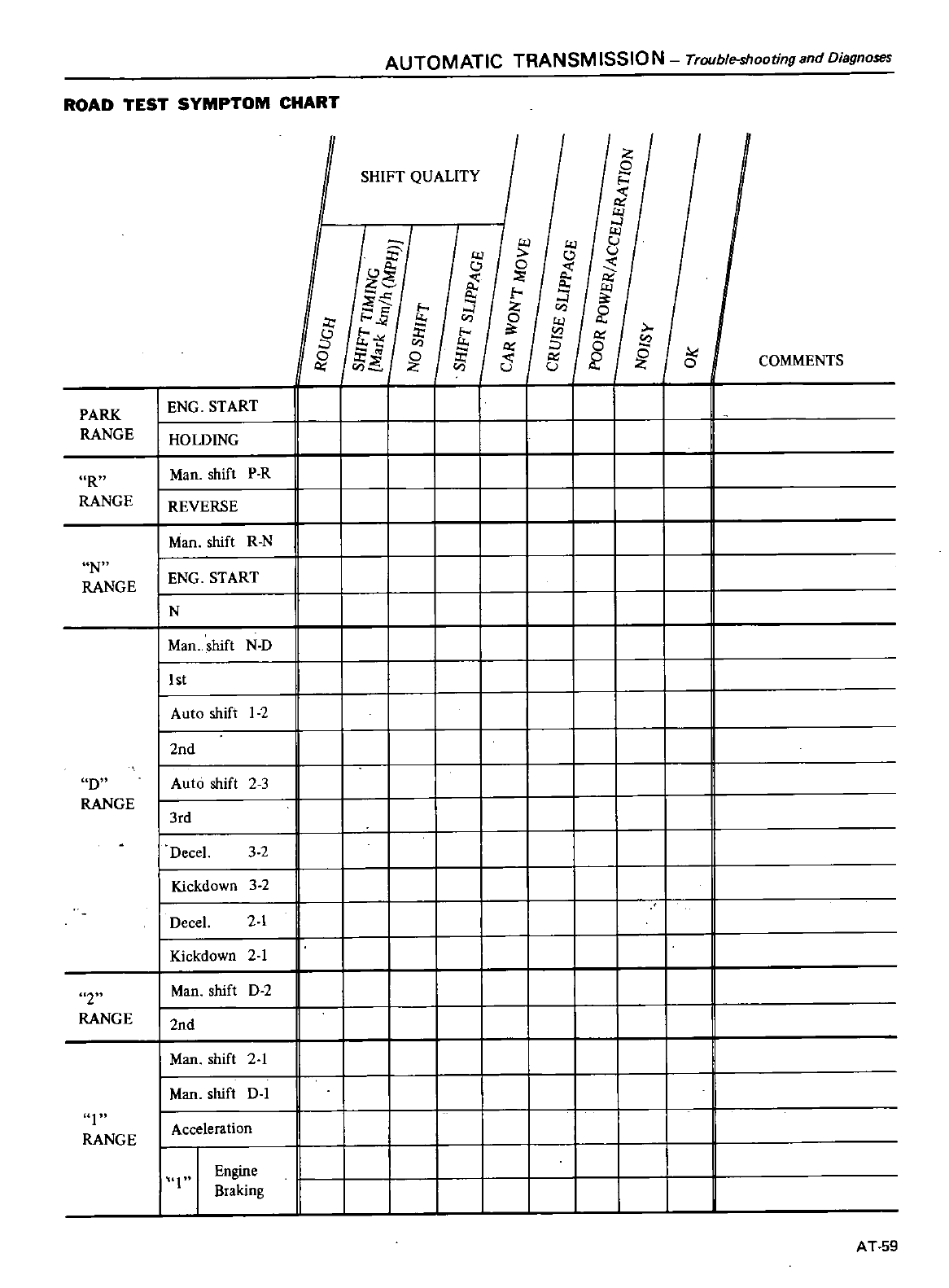
AUTOMATIC TRANSM
15510
N
Trouble
shooting
and
Diagnoses
ROAD
TEST
SYMPTOM
CHART
I
Z
SHIFT
QUALITY
S2
I
t
l
g
l
8
0
t
z
e
e
I
1
Il
if
x
I
I
is
g
x
ft
t
0
o
r
0
5
t
t
Z
u
COMMENTS
PARK
I
ENG
START
II
IIIIII I
L
RANGE
HOWING
IIIIII I
R
Man
shift
P
R
II
I III I I II
RANGE
REVERSE
IIII I
I
Man
shift
R
N
IIIII I I I
II
N
I
ENG
START
II I I III I II
RANGE
IN
II
IIIII I I I
I
Man
shift
N D
II
IIIIIII I
lIst
I
I I
I
IIII
I
Auto
shift
2
I I I I II
I
2nd
IIIIIII
D
I
Auto
shift 2
3
II I I III II
RANGE
I
3rd
III I
I
I
I
Decel
3
2
I
I I I
II
I
Kickdown
3
2
j
II I I I
I
Decel
2
1
IIIII
I
Kickdown
2
1
I I IIII
2
I
Man
shift
0
2
I
I
I
I
RANGE
I
2nd
II
I
II I
II
I
Man
shift 2
1
III
I
Man
shift
0
1
II
I
I
Acceleration
II I
RANGE
I
Engine
II
III
Braking
II
III
i
AT
59
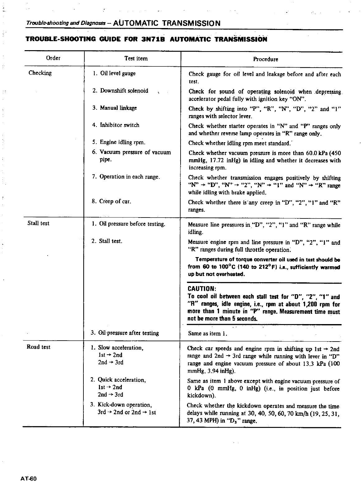
TroublNhoovng
and
Diagnoses
AUTOMATIC
TRANSM
15510
N
TROUBLE
SHOOnNG
GUIDE
FOR
3N71B
AUTOMATIC
TRANSMISSION
Order
Test
item
Checking
Oil
level
gauge
2
Downshift
solenoid
3
Manual
linkage
4
Inhibitor
switch
5
Engine
idling
rpm
6
Vacuum
pressure
of
vacuum
pipe
7
Operation
in
each
range
8
Creep
of
car
Stall
test
I
Oil
pressure
before
testing
2
Stall
test
3
Oilpressure
after
testing
Road
test
1
Slow
acceleration
Ist
2nd
2nd
3rd
2
Quick
acceleration
1st
2nd
2nd
3rd
3
Kick
down
operation
3rd
2nd
or
2nd
1st
AT
60
Procedure
Check
gauge
for
oil
level
and
leakage
before
and
after
each
test
Check
for
sound
of
operating
solenoid
when
dep
ressing
accelerator
pedal
fully
with
ignition
key
ON
Check
by
shifting
into
P
R D
2
and
I
ranges
with
selector
lever
Check
whether
starter
operates
in
N
and
P
ranges
only
and
whether
reverre
lamp
operates
in
R
range
only
Check
whether
idling
rpm
meet
standard
Check
whether
vacuum
pressure
is
more
than
60
0
kPa
450
mmHg
17 72
inHg
in
idling
and
whether
it
decreases
with
increasing
rpm
Check
whether
transmission
engages
positively
by
shifting
N D
2
N
and
N R
range
while
idling
with
brake
applied
Check
whether there
is
any
creep
in
D
I
and
R
ranges
Measure
line
pressures
in
D
2
I
and
OR
range
while
idling
Measure
engine
rpm
and
line
pressure
in
D
2
and
R
ranges
during
full
throttle
operation
Temperature
of
torque
converter
oil
used
in
test
should
be
from
60
to
l000C
140
to
2120Fl
i
e
sufficiently
warmed
up
but not
overheated
CAUTION
To
cool
oil
between
each
stall
test
for
0
2
T
and
R
ranges
idle
engine
i
e
rpm
at
about
1
200
rpm
for
more
than
1
minute
in
P
range
Measuremenl
time
must
not
be
more
than
5
seconds
Same
as
item
I
Check
car
speeds
and
engine
rpm
in
shifting
up
1st
2nd
range
and 2nd
3rd
range
while
running
with
lever
in
0
range
and
engine
vacuum
pressure
of
about
13
3
kPa
100
mmHg
3
94
inHg
Same
as
item
I
above
except
with
engine
vacuum
pressure
of
o
kPa
0
mmHg
0
inHg
i
ein
position
just
before
kickdown
Check
whether
th
kickdown
operates
and
measure
the
time
delays
while
running
at
30 40 50
60 70
km
h
19
25
31
37
43
MPH
in
Os
range
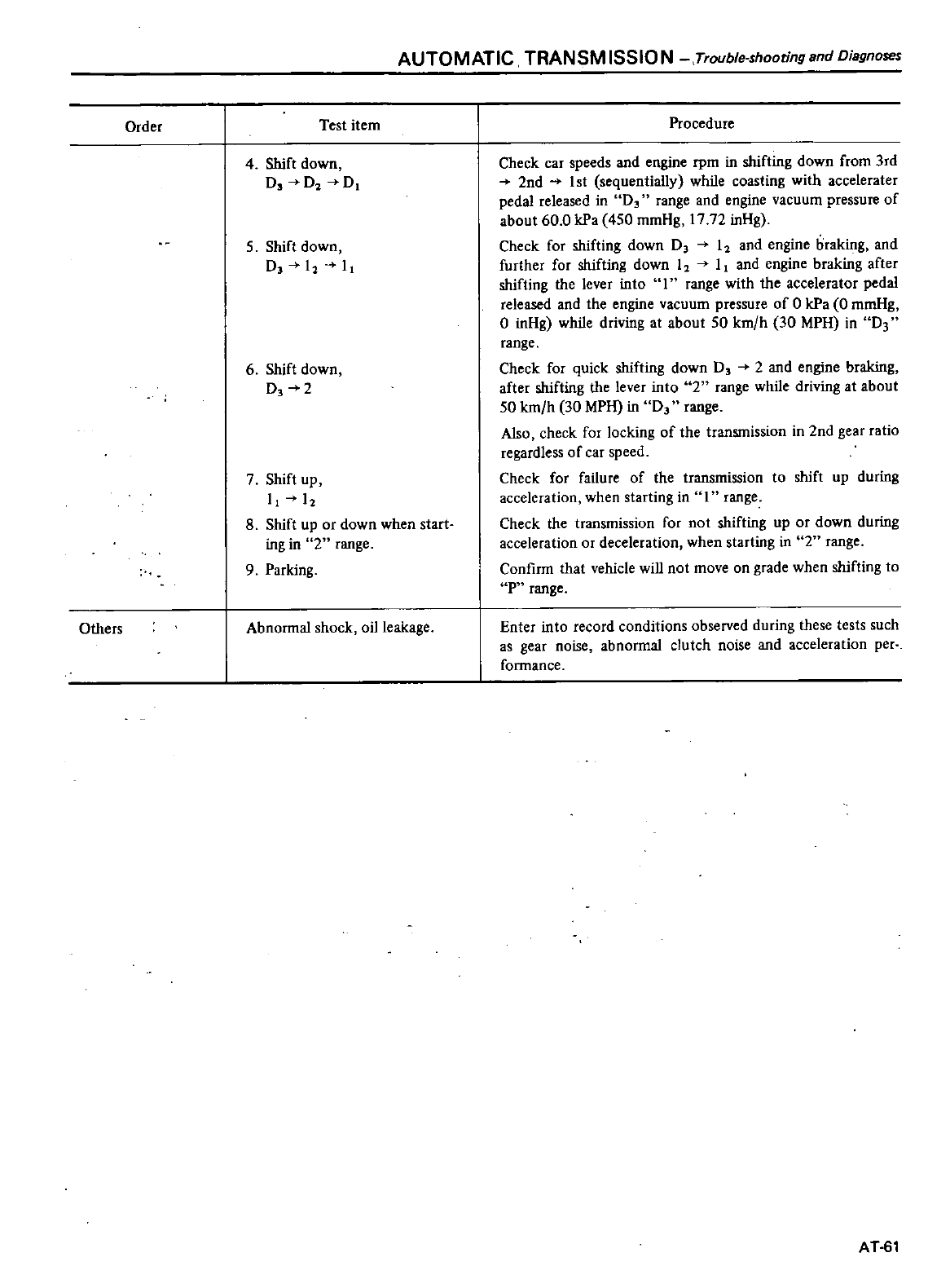
AUTOMATIC
TRANSMISSION
Trouble shooting
and
Diagnoses
Order
Test
item
4
Shift
down
Ds
02
D1
5
Shift
down
D
12
11
6
Shift
down
0
2
7
Shift
up
11
l
12
8
Shift
up
or
down
when
start
ing
in
2range
9
Parking
Others
Abnormal
shock
oil
leakage
Procedure
Check
car
speeds
and
engine
rpm in
shifting
down
from
3rd
2nd
1st
sequentially
while
coasting
with
accelerater
pedal
released
in
D3
range
and
engine
vacuum
pressure
of
about
60
0
kPa 450
mmHg
1772
inHg
Check
for
shifting
down D
I
and
engine
braking
and
further
for
shifting
down
I I
and
engine
braking
after
shifting
the
lever
into
I
range
with
the
accelerator
pedal
released
and
the
engine
vacuum
pressure
of
0
kPa
0
mmHg
o
inHg
while
driving
at
about
50
km
h
30
MPH
in
D3
range
Check
for
quick
shifting
down
0
2
and
engine
braking
after
shifting
the
lever
into
2range while
driving
at
about
50
km
h
30
MPH
in
0
range
Also
check
for
locking
of
the
transmission
in
2nd
gear
ratio
regardless
of
car
speed
Check
for
failure
of
the
transmission
to
shift
up
during
acceleration
when
starting
in
range
Check
the
transmission
for
not
shifting
up
or
down
during
acceleration
or
deceleration
when
starting
in
2range
Confirm
that
vehicle
will
not
move
on
grade
when
shifting
to
P
range
Enter
into
record
conditions
observed
during
these
tests such
as
gear
noise
abnormal
clutch
noise
and
acceleration
per
formance
AT
51
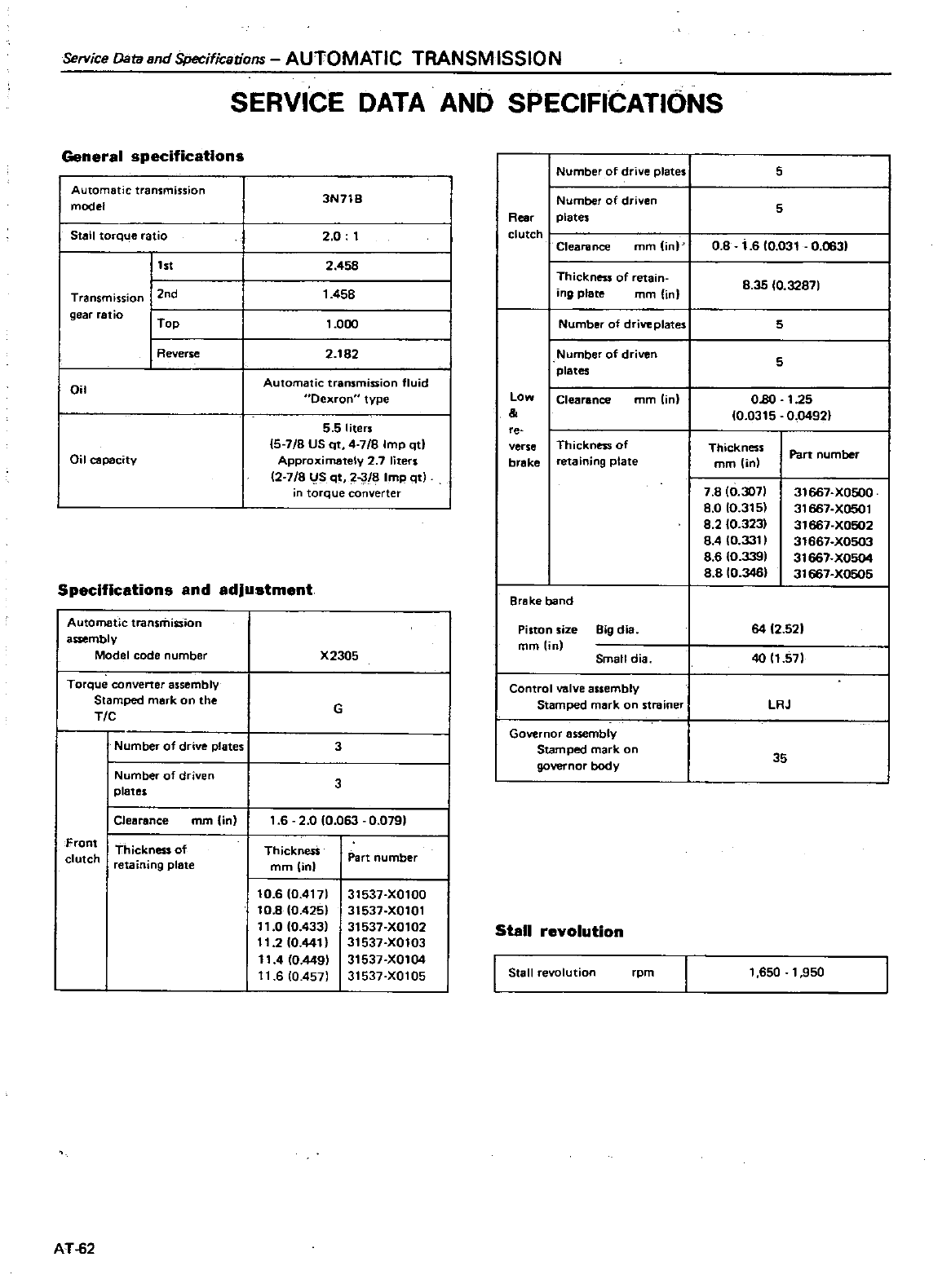
Service
Datund
Specifications
AUTOMATIC
TRANSMISSION
General
specifications
Automatic
transmission
model
Stall
torque
ratio
l
st
Transmission
I
2nd
gear
fatio
I
Top
I
Reverse
Oil
Oil
capacity
SERVICE
DATA
AND
SPECIFICATIONS
3N718
I
Number
of
drive
plates
Number
of
driven
plates
2
0 t
Reo
cl
Clearance
mm
in
2 458
1458
Thickness
of
retain
ing
plate
mm
Un
1
000
Number
of
drive
plates
I
Number
of
driven
plates
I
Clearance
mm
lin
2
182
Automatic transmiuion
fluid
Oexron
type
Low
5 5
liters
15
78
US
qt
478
Imp
qtl
Approximately
2 7
liters
12
7
8
US
qt
2
8
Imp
qt
torque
converter
e
verse
brake
Thickness
of
retaining
plate
Specifications
and
adjustment
Automatic
transmission
assembly
Model
code
number
Torque
converter
assembly
Stamped
mark
on
the
TIC
Number
of
drive
plates
I
Number
of
driven
plates
Clearance
mm
in
Front
clutch
Thickness
of
retaining
plate
AT
62
Brake
band
X2305
Piston
size
Big
dia
mmlin
Small
dia
G
Control
valve
assembly
Stamped
mark
on
strainer
3
Governor
assembly
Stamped
mark
on
governor
body
3
1
6
2
0 0
063
0
0791
Thicknesi
mmOnl
Part
number
10
610
4171
10
8
10
4251
110
10
433
t1
210
44t
11
4
10
449
11
6
10
457
31537
X0100
31537
X0101
3t537
X0102
31537
X0103
31537
X0104
31537
X0105
Stall
revolution
I
Stall
revolution
rpm
5
08
1
6 0
031
0
063
5
8
35
10
32871
5
5
0
80
1
25
10
0315
0
04921
Thickness
mm
in
7
810
3071
8
0
10
315
8
2
10
323
8AI0 33tl
8 6
10
3391
88
10
346
1
650
1
950
Part
number
31667
X0500
31667
X0501
31667
X0502
31667
X0503
31667
X0504
31667
X0505
64
2
52
40 11
57
LRJ
35
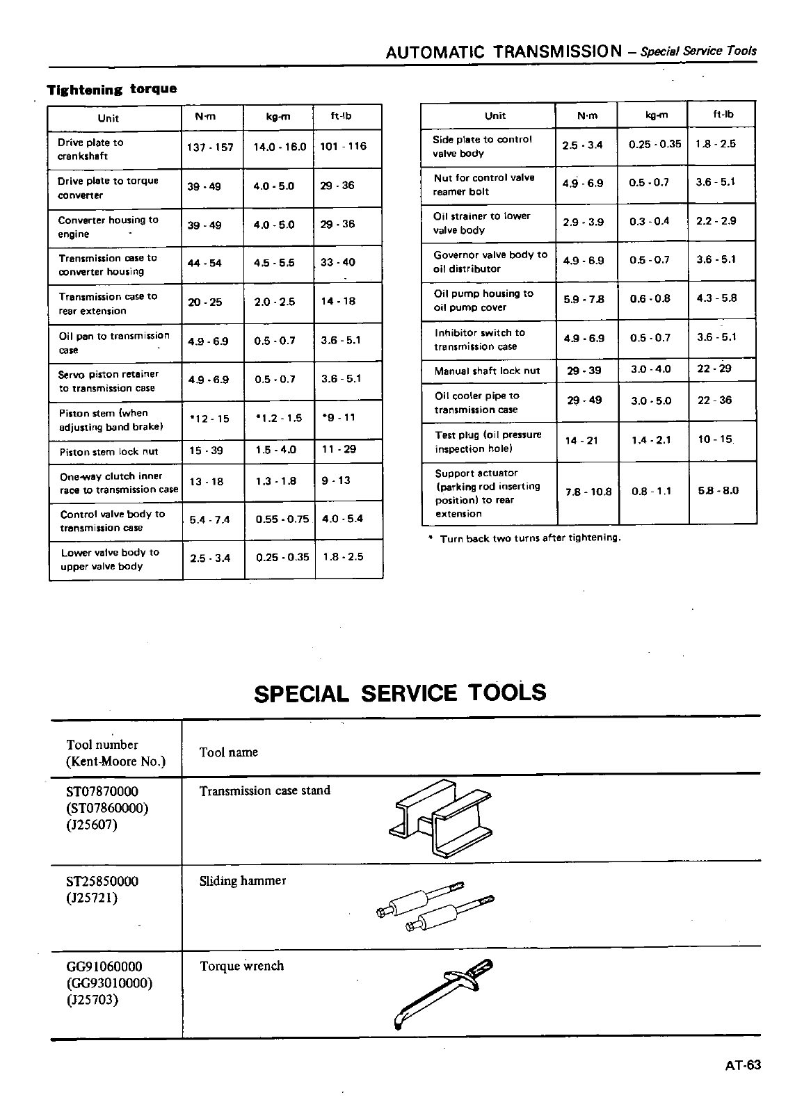
AUTOMATIC
TRANSM
15510
N
Specisl
Service
Tools
Tightening
torque
Unit
N
m
kg
m
ft
Ib
Unit
N
m
kg
m
ft
Ib
Drive
plate
to
137 157
14
0
16
0
101
116
Side
plate
to
control
2 5 3 4
0
25
0
35
1
8
2 5
crankshaft
valve
body
Drive
plate
to
torque
39 49
4
0
5 0
29 36
Nut
for
control
valve
4
9
69 0
50 7 3 6 5
t
converter
reamer
bolt
Converter
housing
to
39
49
40
5
0
29 36
Oil
strainer
to
lower
2
9
3
9
0 3 0 4 2 2 2
9
engine
valve
body
Transmission
case
to
44 54
455 5
33 40 Governor
valve
body
to
49
69
0
5
0
7 3
6
5
1
converter
housing
oil
distributor
Transmission
case
to
20 25
2
0
2 5
14
18
Oil
pump
housing
to
5
9
713
0
6 0 8
4
3 5 8
rear
extension
oil
pump
cover
Oil
pen
to
transmission
49
6
90
5
0
7 3
6
5
1
Inhibitor
switch
to 49
6 9
0
5
0
7 3 6 5
t
ca
transmission
case
Servo
piston
retainer
49
6
9
0 5 0 7 3 6 5
1
Manual
shaft
lock
nut
29 39
3
0 4
0
22 29
to
transmission
case
Oil
cooler
pipe
to
29
49
3
0
5
0
22
36
Piston
stem
when
12 15
1
2
1
5
9
11
transmission
case
adjusting
band
brake
Test
plug
oil
pressure
14 21
14
2
1
10 15
Piston
stem
lock
nut
15 39
1
5 4
0
11
29
nspecticn
hole
Oneway
clutch
inner
t3
18
1
3
1
8
9
13
Support
actuator
race
to
transmission
case
parking
rod
nserting
7
8
10
8
0
8
11
513
8
0
positionl
to
rear
Control
valve
body
to
5 4
74
0
55
0
75
40
5
4
extension
transmission
case
I
Lo
v
lv
body
to
Turn back
two
turns
aftar
tightening
2 5 3
4
0
25
0
35
1
8
2 5
upper
valve
body
SPECIAL
SERVICE TOoLs
Tool number
Kent
Moore
No
Tool
name
ST07870000
ST07860000
125607
Transmission
case
stand
ST25850000
125721
Sliding
hammer
GG91060000
GG930
10000
J25703
Torque
wrench
AT
53
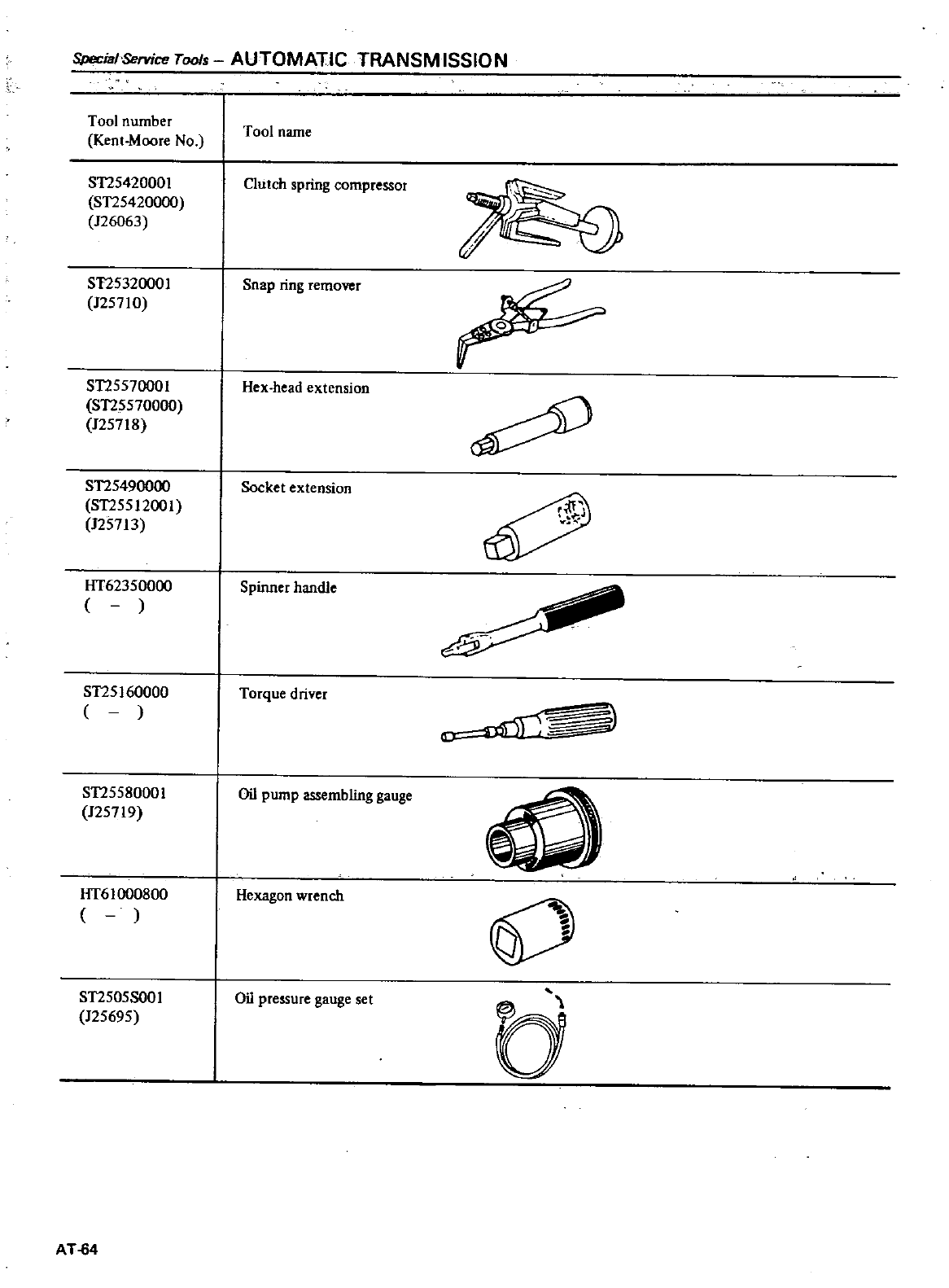
Special
Service
Toofs
AUTOMATIC
TRANSM
15510
N
Tool
number
Kent
Moore
No
Tool
name
ST25420001
ST2542000Q
126063
Clutch
spring
compressor
ST25320001
125710
Snap
ring
remover
o
ST2557000
I
Hex
head
extension
ST2557000Q
J25718
ST25490000
Socket
extension
ST255
1200
I
125713
HT62350000
Spinner
handle
ST25160000
Torque
driver
ST25580001
Oil
pump
assembling
gauge
Q
125719
HT6
I
000800
Hexagon
wrench
j
ST2505S001
Oil
pressure
gauge
set
125695
c
AT
64
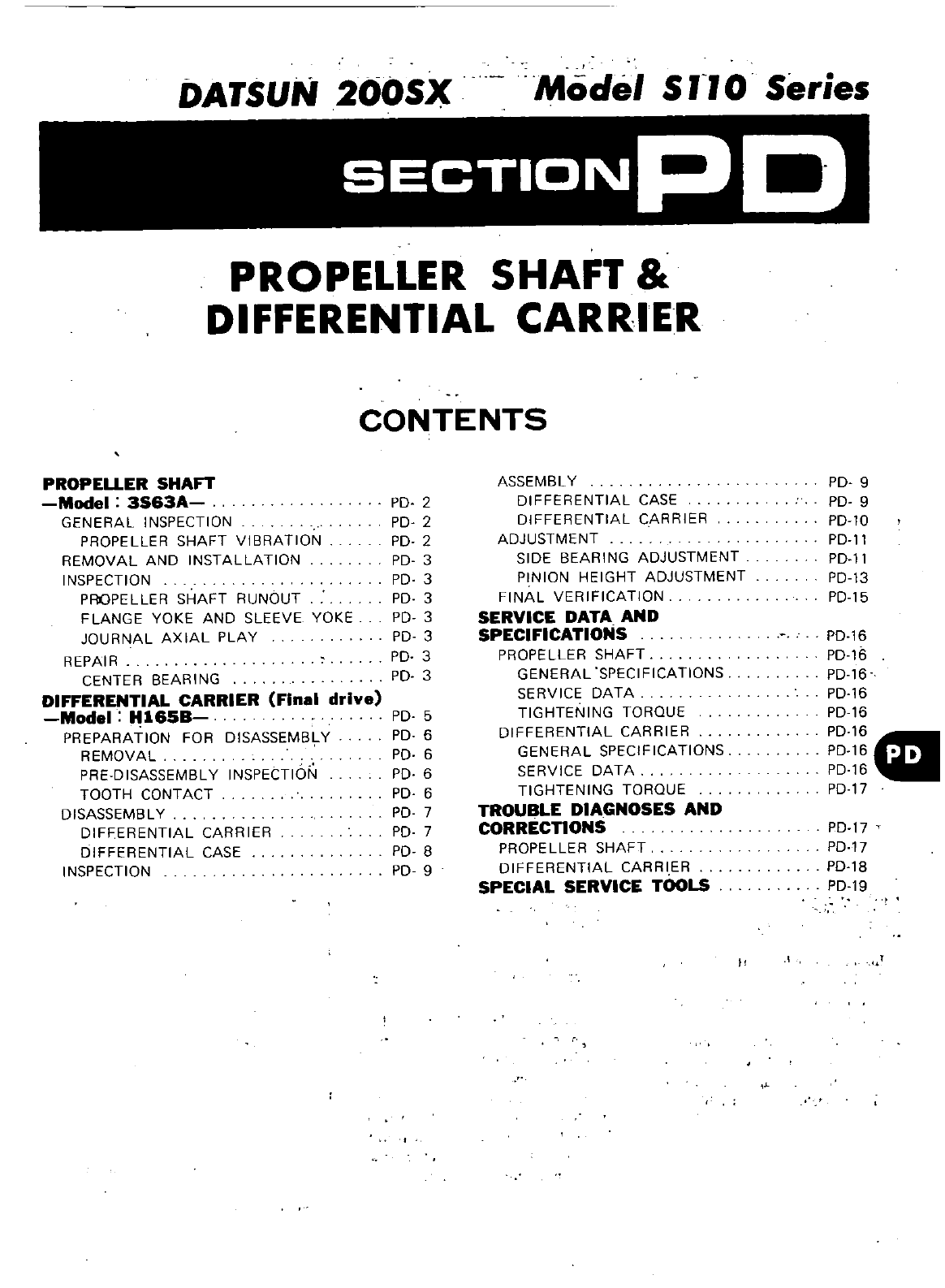
DATSUN
200SX
Model
S
rJ
0
Series
SECTIONP
D
PROPELLER
SHAFT
DIFFERENTIAL
CARRIER
CONTENTS
PROPEUER
SHAFT
Model
3S63A
GENERAL
INSPECTION
PROPELLER
SHAFT
VIBRATION
REMOVAL
AND
INSTALLATION
INSPECTION
PROPELLER
SHAFT RUNOUT
FLANGE
YOKE
AND
SLEEVE
YOKE
JOURNAL
AXIAL
PLAY
REPAIR
CENTER
BEARING
DIFFERENTIAL
CARRIER
Final
drive
Model
H165B
PREPARATION
FOR
DISASSEMBLY
REMOVAL
PRE
DISASSEMBLY
INSPECTION
TOOTH
CONTACT
DISASSEMBLY
DIFFERENTIAL
CARRIER
DIFFERENTIAL
CASE
INSPECTION
PD
2
PD
2
PD
2
PD
3
PD
3
PD
3
PD
3
PD
3
PD
3
PD
3
PD
5
PD
6
PD
6
PD
6
PD
6
PD
7
PD
7
PD
B
PD
9
ASSEMBL
Y
DIFFERENTIAL
CASE
DIFFERENTIAL
CARRIER
ADJUSTMENT
SIDE
BEARING
ADJUSTMENT
PINION
HEIGHT
ADJUSTMENT
FINAL
VERIFICATION
SERVICE
DATA
AND
SPECIFICATIONS
PROPELLER
SHAFT
GENERAL
SPECIFICATIONS
SERVICE
DATA
TIGHTENING
TORQUE
DIFFERENTIAL
CARRIER
GENERAL
SPECIFICATIONS
SERVICE
DATA
TIGHTENING
TORQUE
TROUBLE
DIA
GNOSES
AND
CORRECTIONS
PROPELLER
SHAFT
DIFFERENTIAL
CARRIER
SPECIAL
SERVICE
TOOLS
PD
9
PD
9
PD
l0
PD
11
PD
l1
PD
13
PD
15
PD
16
PD
16
PD
16
PD
16
PD
16
PD
16
PD
16
1ft
PD
16
PD
17
PD
17
PD
17
PD
1B
PD
19
1
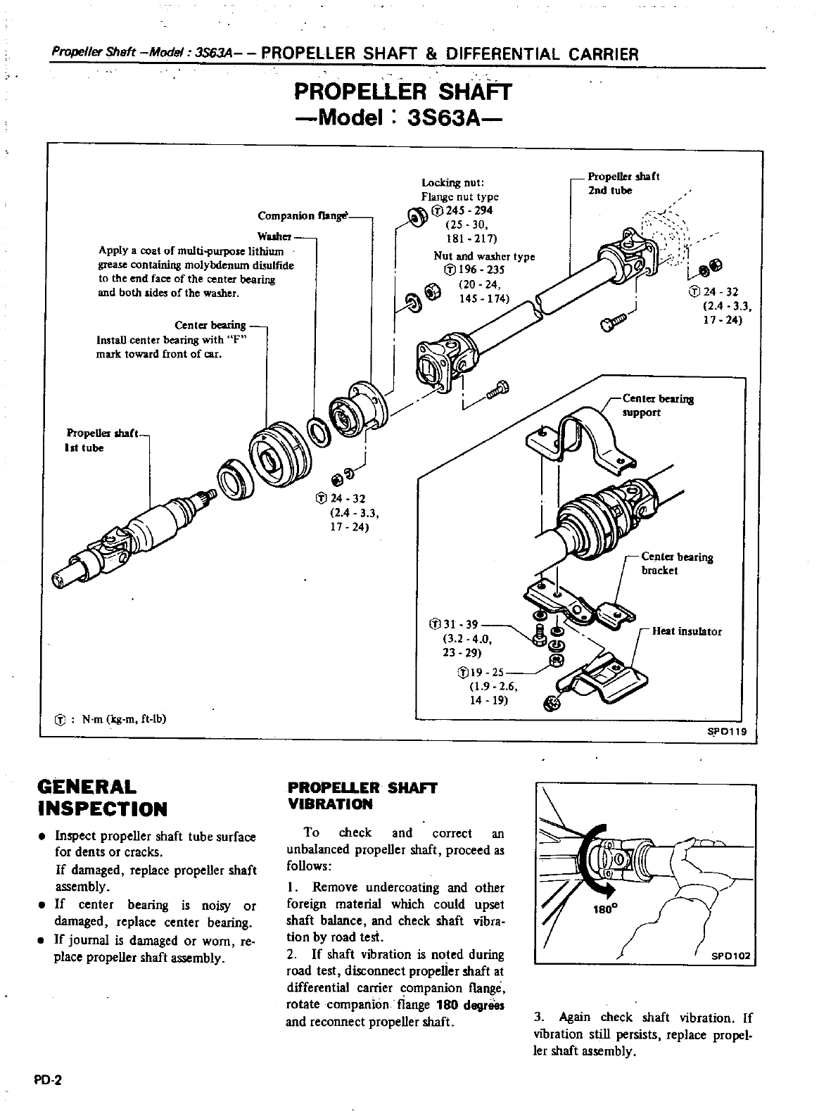
PropellerSheft
Model
3S63A
PROPELLER
SHAFT
8
DIFFERENTIAL
CARRIER
PROPELLER
SHAFT
Model
3S63A
Companion
flange
Washer
Apply
a
coat
of
muIti
PUIJlOse
lithium
grease
containing molybdenum
disulfide
to
the
end
face
of
the
center
bearing
and
both
sides
of
the
washer
Locking
nut
Flange
nut
type
b245
294
U
25 30
181
217
Nut
and
washer
type
if
196
235
20
24
VI
145 174
Center
bearing
Install
center
bearing
with
F
ffiuk
toward
front
of
car
V
if
32
2
4
3 3
17
24
Propeller
lhaft
1st
tube
fJ
N
m
kg
m
ft
tb
GENERAL
INSPECTION
Inspect propeller
shaft
tube
surface
for
dents
or
cracks
If
damaged
replace
propeller
shaft
assembly
If
center
bearing
is
noisy
or
damaged
replace
center
bearing
If
journal
is
damaged
or
worn
re
place
propeller
shaft
assembly
PD
2
PROPELLER
SHAFT
VIBRATION
To
check and
correct
an
unbalanced
propeller
shaft
proceed
as
follows
I
Remove
undercoating
and
other
foreign
material
which
could
upset
shaft
balance
and
check
shaft vibra
tion
by
road
tesi
2
If
shaft
vibration
is
noted
during
road
test
disconnect
propeUer
shaft
at
differential
carrier
companion
flange
rotate
companion
flange
180
degrlies
and
reconnect
propeller
shaft
Propeller
shaft
2nd
tube
ill
fJ
24
32
24
33
17
24
Center
bearing
support
S
PD11
3
Again
check
shaft
vibration
If
VIbration
still
persists
replace
propel
ler
shaft
assembly
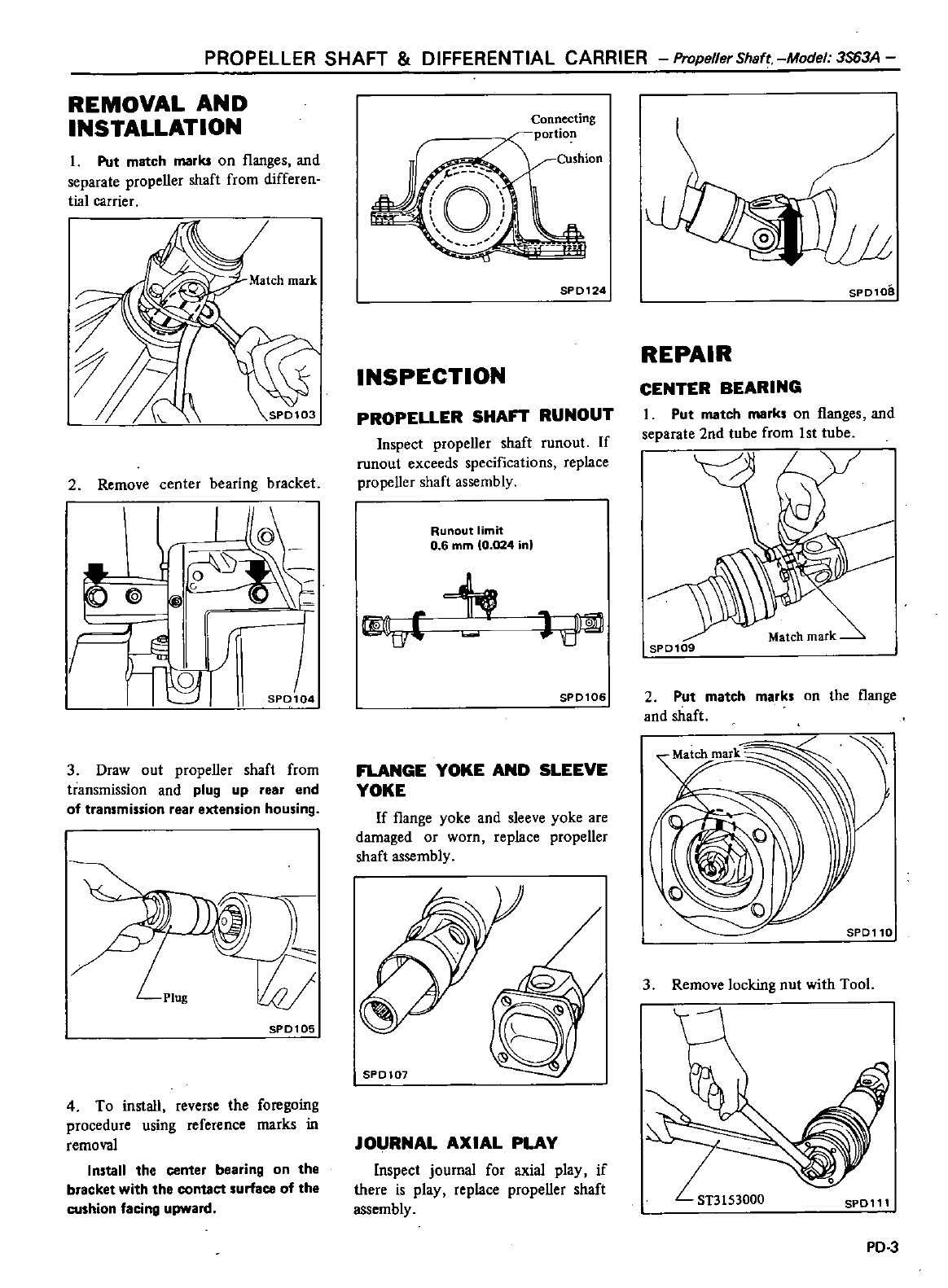
PROPELLER
SHAFT
DIFFERENTIAL
CARRIER
PropellerShaft
Mode
3S63A
REMOVAL
AND
INSTALLATION
I
Put
match
marks
on
l1anges
and
separate propeller
shaft
from
differen
tial
carrier
2
Remove
center
bearing
bracket
I
I
@
1
ro
S
KO
c
I
J
3
Draw
out
propeller
shaft
from
transmission
and
plug
up
rear
end
of
transmission
rear
extension
housing
o
t
Plug
SPD105
4
To
install
reverse
the
foregoing
procedure
using
reference
marks
in
removal
Install
the center
bearing
on
the
bracket
with
the
contact
surface
of
the
cushion
facing
upward
Connecting
portion
Cushion
c c
r
SPD124
INSPECTION
PROPELLER
SHAn
RUNOUT
Inspect
propeller
shaft
runout
If
ronout
exceeds
specifications
replace
propeller
shaft
assembly
Runout
limit
0 6
mm
0 024
in
itM
SPD106
FLANGE
YOKE
AND
SLEEVE
YOKE
If
l1ange
yoke
and
sleeve
yoke
are
damaged
or
worn
replace
propeller
shaft
assembly
SP0107
JOURNAL
AXIAL
PLAY
Inspect
journal
for
axial
play
if
there
is play
replace
propeller
shaft
assembly
SPD10B
REPAIR
CENTER
BEARING
I
Put
match
marks
on
l1anges
and
separate
2nd
tube
from
1st
tube
SPD109
2Put
match
marks
on
the
l1ange
and
shaft
m
Q
aU
SPD110
3
Remove
locking
nut
with
Tool
PD
3
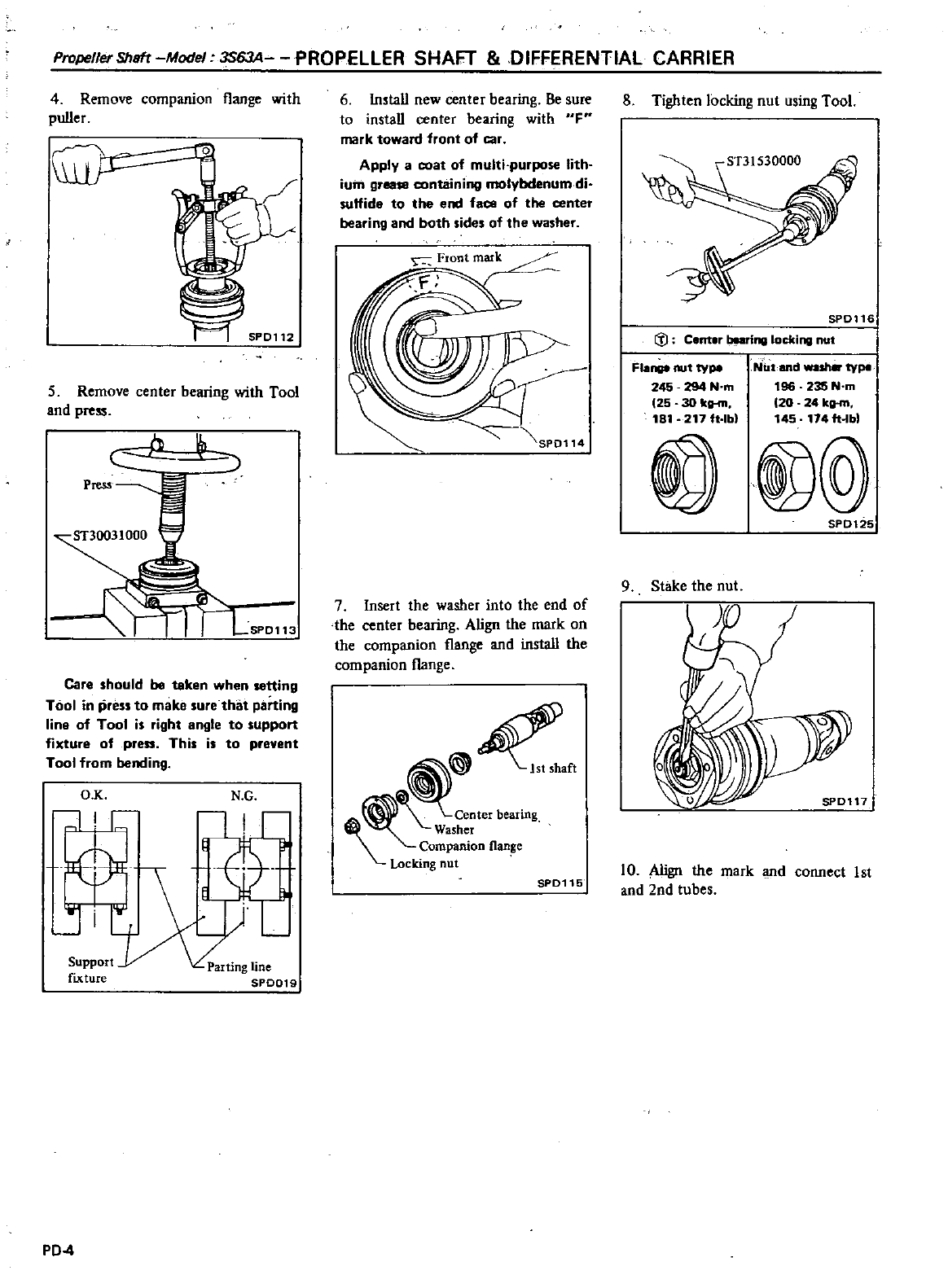
PropellerShsft
Model
3S63A
PROPELLER
SHAFT
DIFFERENTIAL
CARRIER
4
Remove
companion
l1ange
with
puller
L
5
Remove
center
bearing
with
Tool
and
press
1
iLsP0113
Care
should
be
token when
setting
Tool
in
press
to
make
sure
that
parting
line
of
Tool
is
right
angle
to
support
fixture
of
press
This
is
to
prevent
Tool
from
bending
O K
liC
Ji
N
G
f
Support
fIxture
PD
4
6
Install
new
center
bearing
Be
sure
to
install
center
bearing
with
OF
mark
toward
front
of
car
Apply
a
coat
of
multi
purpose
lith
iuin
grease
containing
molybdenum
di
sulfide
to
the
end
faoe
of
the
cente
bearing
and
both
sides
of
the
washer
7
Insert
the
washer
into
the
end
of
the
center
bearing
Align
the mark
on
the
companion
flange
and
install
the
companion
flange
9
center
bearing
Washer
Companion
flange
Locking
nut
I
SPD115
8
Tighten locking
nut
using
Tool
SP0116
C
l
Cent
r
baring
locking
nut
Flange
nut
type
245
294
N
m
25 30
ka
m
181
217
It
lb
Ntit
and
wash
type
196 235
N
m
20 24
ka
m
145
1741t
bl
@
SPD125
9
Stake
the
nut
10
Align
the
mark
and
connect
1st
and
2nd
tubes
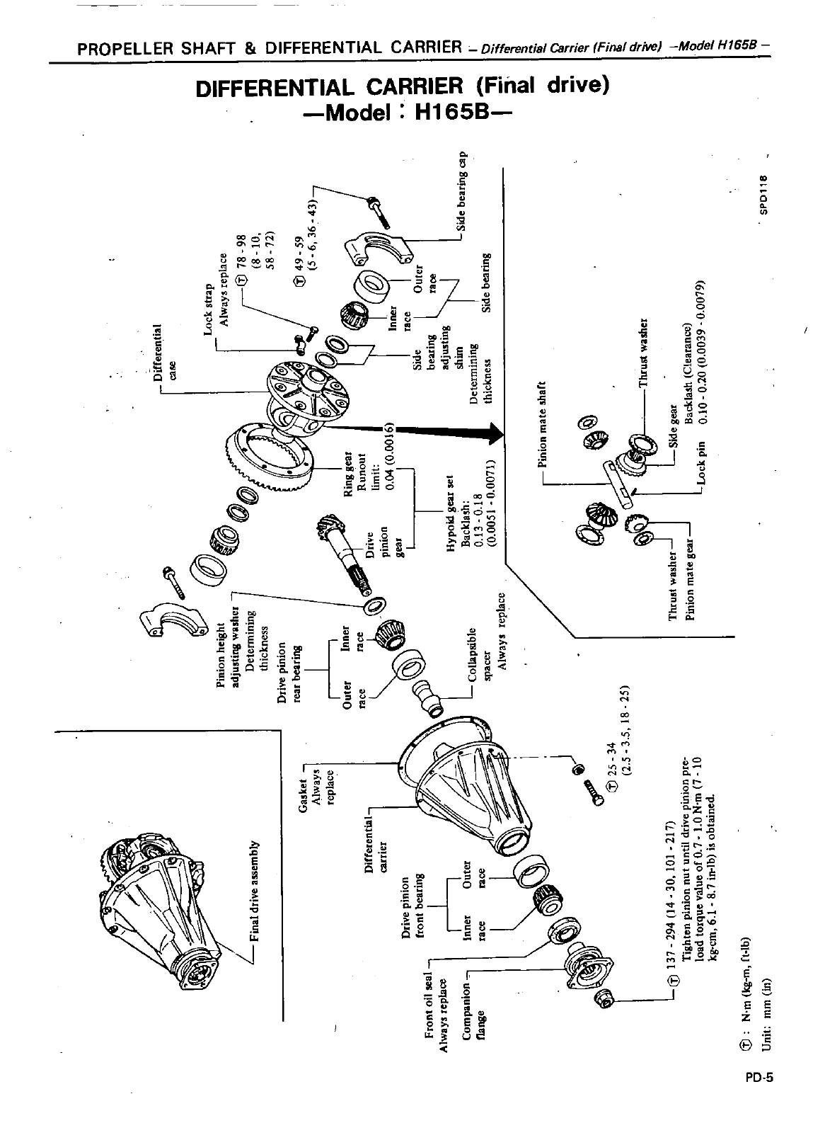
Olftere1
tial
case
CD
Villion
ne
llht
e
Iff
ad
UStinS
s
t
et
W
Detetn
inln
b
thick
nesS
Drive
p
wot
ca
inII
I
nllS
er
Rlfl
Ollt
outer
race
Dti
e
inl
t
n
n
6
ft
J
ir
ill
II
set
l
YI
Bac
K
tn
13
0
18
col1
p
ble
o
005
I
0
00111
S
Jacet
p
waYt
te1
ace
S
de
inll
diP
Lock
tu
MY
a
te
p
ace
J@111911
8
10
511
11
@
49
59
5
6
36
43
L
ftna1
dl
Ie
assern
ty
DJ
taCe
Outct
Side
a
i1
l
adiustifl
sbin
l
oetetrninitW
side
oeatIDS
tnict
t
es
Gas
et
tt
l
HaYt
replace
Ditfelent
cattiet
front
oil
a
A
aY
replace
Corovaniot
ll1
l
y
nWP
mate
hatt
34
15
@
15
35
18
1
5
u
to
1
11
in
on
P
10
O
10
vep
1
43
iI
ON
HI
u
un
I
13
19
1
00
l
of
0
btained
@
1
plte
P
ue
valuen
11
0
ad
to
1
81
10
6
g
Ct
l1
t
M
J
o
I
l
o
J
n
1
l
0
t1
0
0
Jl
l
t
m
i
J
tJ
n
S
S
0
a
i
Q
c0
n
oJ
i
0
t
u
st
O
S
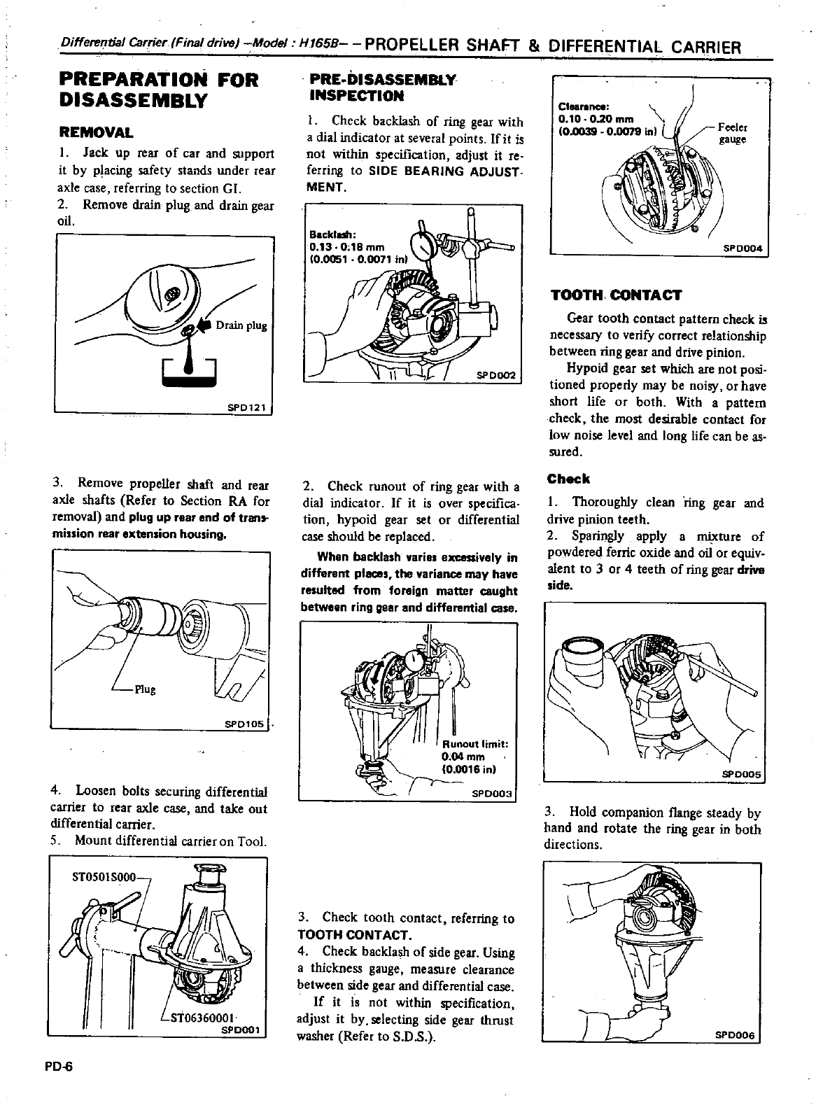
Differential
Carrier
Final drive
Model
H165B
PROPELLER
SHAFT
DIFFERENTIAL
CARRIER
PREPARATION
FOR
DISASSEMBLY
REMOVAL
I
Jack
up
rear
of
car
and
support
it
by
placing
safety
stands
under
rear
axle
case
referring
to
section
GI
2
Remove
drain
plug
and
drain
gear
oil
SPD121
3
Remove
propeller
shaft
and
rear
axle
shafts
Refer
to
Section
RA
for
removal
and
plug
up
rear
end
of
tran
mission
rear
extension
housing
SP0105
4
Loosen
bolts
securing
differential
carrier
to
rear
axle
case
and
take
out
differential
carrier
5
Mount
differential
C3rrieron
Tool
PD
6
PRE
DISASSEMBLY
INSPECTION
I
Check
backlash
of
ring
gear
with
a
dial
indicator
at
several
points
If
it
is
not
within
specification
adjust
it
re
ferring
to
SIDE
BEARING
ADJUST
MENT
Backlash
0
13
0
18
mm
10
0051
0
0071
inl
SP
0002
2
Check
runout
of
ring
gear
with
a
dial
indicator
If
it
is
over
specifica
tion
hypoid
gear
set
or
differential
case
should
be
replaced
When
backlash
varies
excessively
in
different
places
the
variance may
have
resulted
from
foreign
matter
caught
between
ring
gear
and
differential
case
I
Runout
limit
0
04
mm
10
0016
in
SPD003
3
Check
tooth
contact
referring
to
TOOTH
CONTACT
4
Check
backlash
of
side
gear
Using
a
thickness
gauge
measure
clearance
between
side
gear
and
differential
case
If
it
is
not
within
specification
adjust
it
by
selecting
side
gear
thrust
washer
Refer
to
S
O
s
Cleal
llnce
0
10
0
20
mm
10
llO39
0
0078
inl
SPD004
TOOTH
CONTACT
Gear
tooth
contact
pattern
check
is
necessary
to
verify
correct
relationship
between
ring
gear
and
drive
pinion
Hypoid
gear
set
which
are
not
posi
tioned
properly
may
be
noisy
or
have
short
life
or
both
With
a
pattern
check
the
most
desirable
contact
for
low
noise
level
and
long
life
can
be
as
sured
Check
I
Thoroughly
clean
ring
gear
and
drive
pinion
teeth
2
Sparingly
apply
a
mixture
of
powdered
ferric
oxide
and
oil
or
equiv
alent
to
3
or
4
teeth
of
ring
gear
drive
side
SPOOD5
3
Hold
companion
flange
steady
by
hand
and
rotate
the
ring
gear
in
both
directions
SPoooa
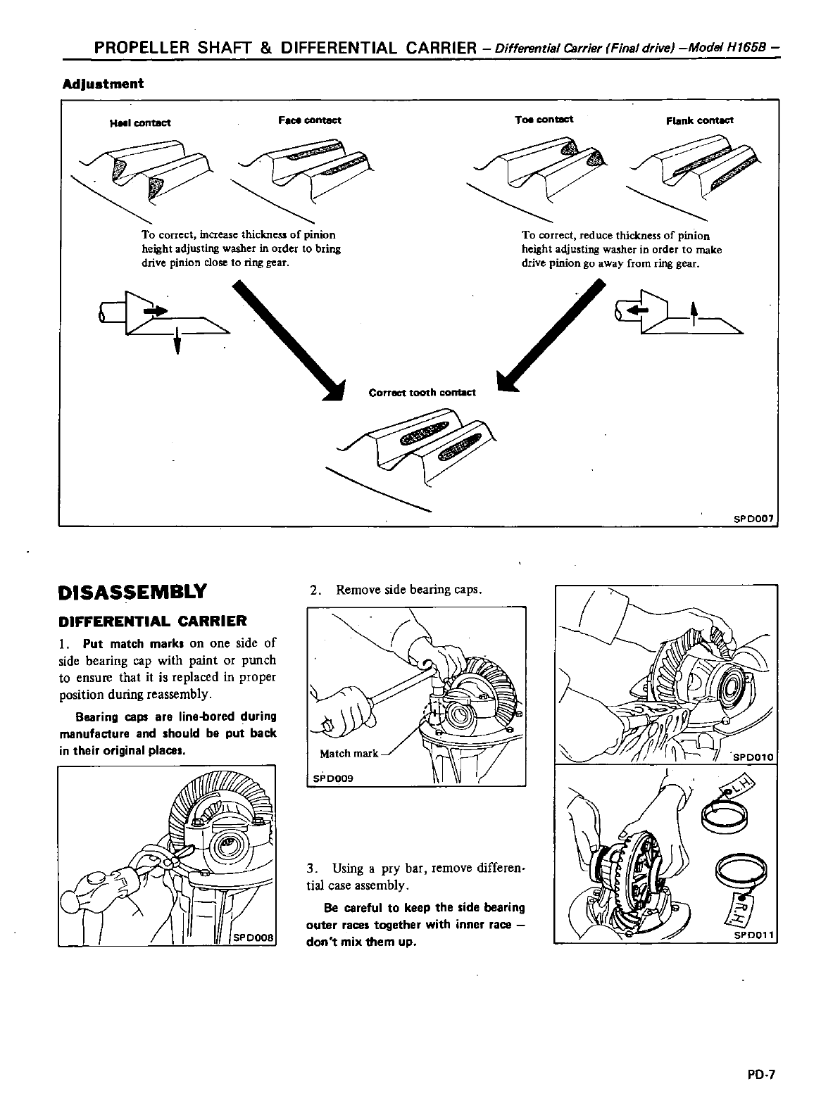
PROPELLER
SHAFT
DIFFERENTIAL
CARRIER
Oifferent
sl
Carrier
Finsl
drivel
Model
H1658
Adjustment
H
I
contact
F
ce
contact
Toe
contaCt
Flank
cont8ct
To
correct
increase
thickness
of
pinion
height
adjusting
washer
in
order
to
bring
drive
pinion
close
to
ring
gear
To
correct
reduce
thickness
of
pinion
height
adjusting
washer
in
order
to
make
drive
pinion
go
away
from
ring
gear
c
DISASSEMBLY
DIFFERENTIAL
CARRIER
1
Put
match
mark
on
one
side
of
side
bearing
cap
with
paint
or
punch
to
ensure
that
it
is
replaced
in
proper
position
during
reassembly
Bearing
caps
are
line
bored
during
manufacture
and
should
be
put back
in
their
original
place
1
08
Correct
tooth
conae1
2
Remove
side
bearing
caps
SP
0009
1
W
3
Using
apry
bar
remove
differen
tialcase
assembly
Be
careful
to
keep
the
side
bearing
outer
races
together
with
inner
race
don
mix
them
up
V
SPD007
SP0011
PD
7
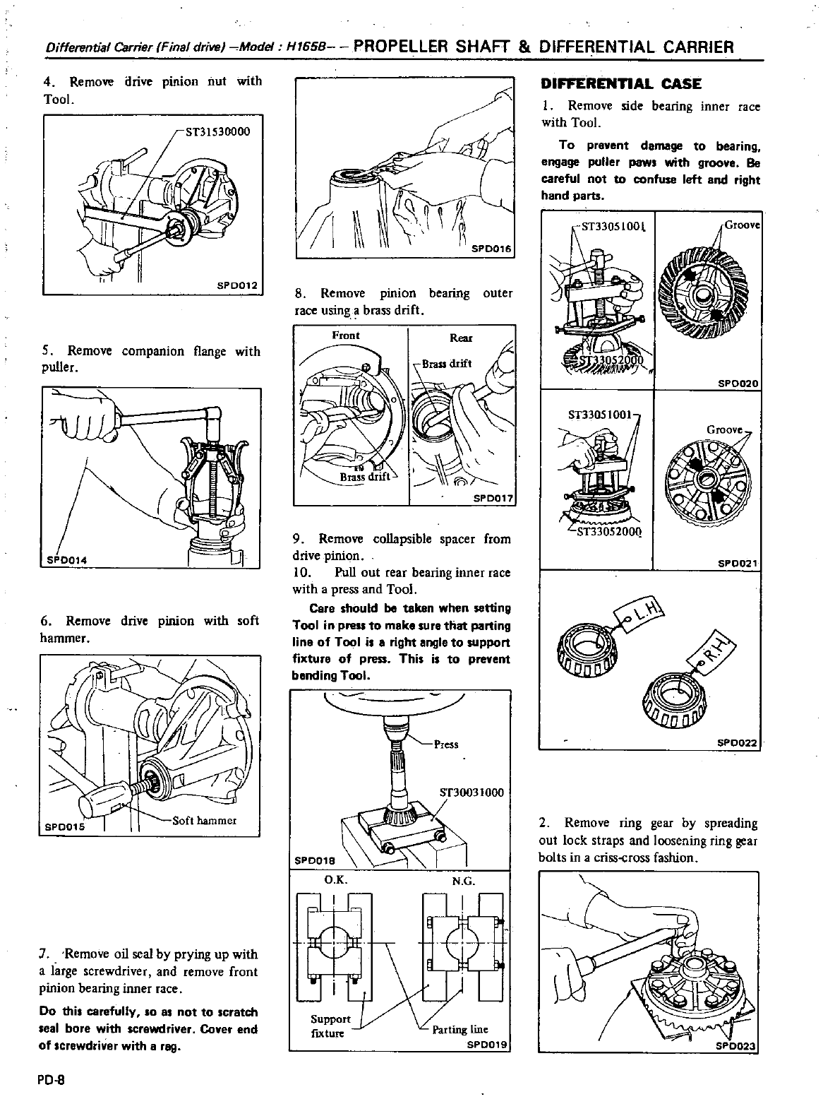
Differential
Carrier
Final
drive
Model
H165B
PROPELLER
SHAFT
DIFFERENTIAL
CARRIER
4
Remove
drive
pinion
nut
with
TooL
SPD012
5
Remove
companion
l1ange
with
puller
SPD014
1
ij
6
Remove
drive
pinion
with
soft
hammer
Soft
hammer
Remove
oil
seal
by
prying
up
with
a
large
screwdriver
and
remove
front
pinion
bearing
inner
race
Do
this
carefully
so
as
not
to
scratch
seal
bore
with
screwdriver
Cover
end
of
screwdriver
with
a
rag
PD
8
1
S
SPOOl
8
Remove
pmlOn
bearing
outer
race
using
a
brass
drift
SPD017
9
Remove
collapsible
spacer
from
drive
pinion
10
Pull
out
rear
bearing
inner
race
with
a
press
and
Tool
Care
should
be
taken
when
setting
Tool
in
press
to
maka
sura
that
parting
line
of
Tool
is
a
right
angle
to
support
fixture
of
press
This
is
to
prevent
bonding
Tool
SP0018
O K N
G
lie
Support
fIXture
DIFFERENnAL
CASE
I
Remove
side
bearing
inner
race
with
TooL
To
prevent
damage
to
bearing
engage
puller
paws
with
groa
Be
careful
not to
confuse
left
and right
hand parts
ST3305100l
SP0020
ST3305200Q
SPD021
SPD022
2
Remove
ring
gear
by
spreading
out
lock
straps
and
loosening
ring
gear
bolts
in
a
criss
cross
fashion
SPD023
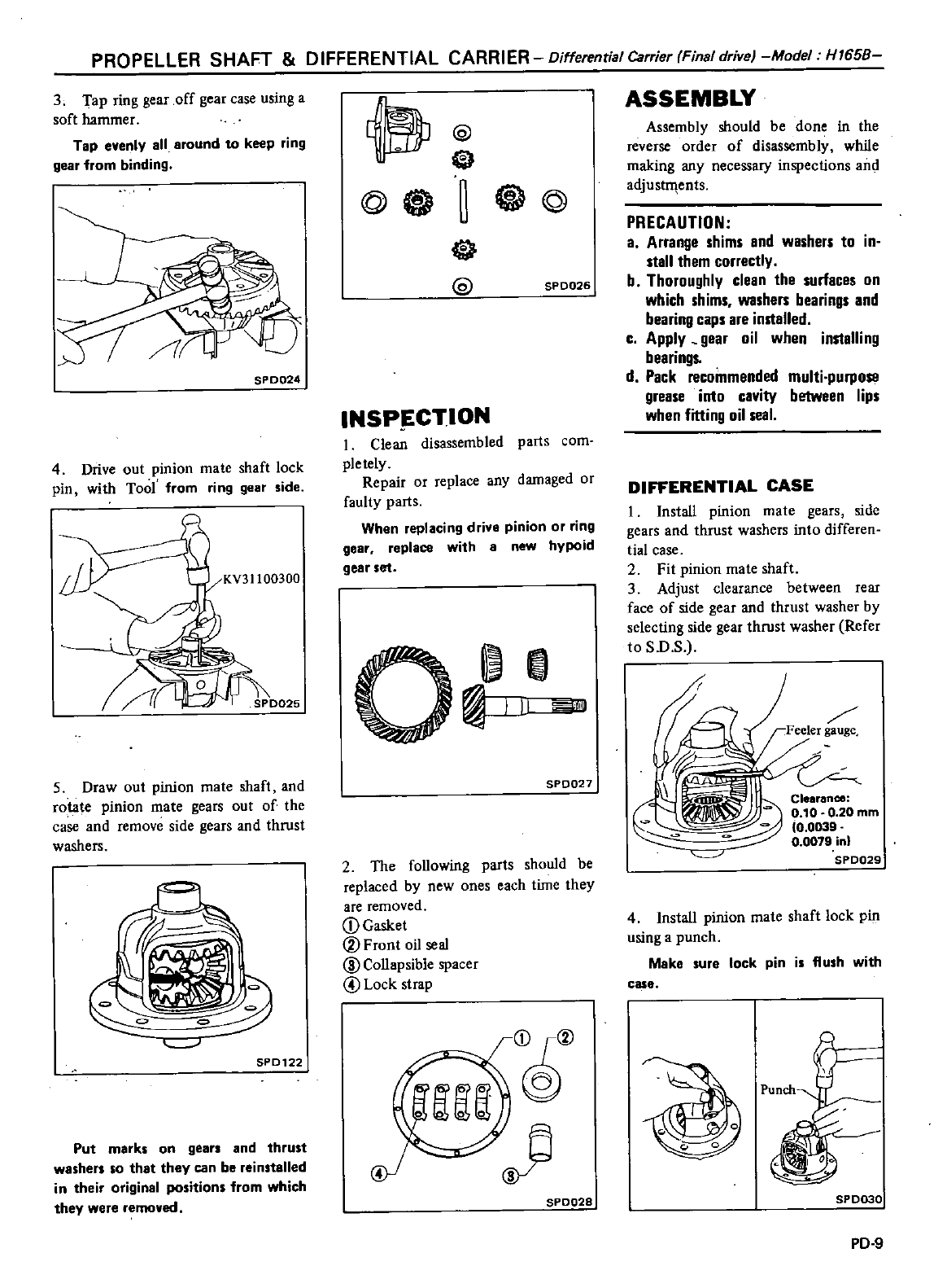
PROPELLER
SHAFT DIFFERENTIAL
CARRIER
Differential
Carrier
Final
drive
Model
H1658
3
Tap ring
gear
off
gear
case
using
a
soft
hammer
Tap
evenly
all
around
to
keep
ring
gear
from
binding
SPD024
4
Drive
out
pinion
mate
shaft
lock
pin
with
Tool
from
ring
gear
side
5
Draw
out
pinion
mate
shaft
and
rota e
pinion
mate
gears
out
of
the
case
and
remove
side
gears
and
thrust
washers
SPD122
Put
marks
on
gears
and
thrust
washer
so
that
they
can
be
reinstalled
in
their
original
positions
from
which
they
were
removed
@
e
e
@@
@4S
@
SPD026
INSP
CTION
I
Clean
disassembled
parts
com
pletely
Repair
or
replace
any
damaged
or
faulty
parts
When
replacing
drive
pinion
or
ring
gear
replace
with
8
new
hypoid
gear
set
O
II
SP0027
2
The
following
parts
should
be
replaced
by
new
ones
each
time
they
are
removed
CD
Gasket
@Frontoilseal
ID
Collapsible
spacer
@
Lock
strap
@
SP0028
ASSEMBLY
Assembly
should
be
done
in
the
reverse
order
of
disassembly
while
making
any
necessary
inspections
and
adjust
1ents
PRECAUTION
a
Arrange
shims
and
washers
to
in
stall
them
correctly
b
Thoroughly
clean
the
surfaces
on
which
shims
washers
bearings
and
bearing
caps
are
installed
c
Apply
gear
oil
when
installing
bearings
d
Pack
recommended
multi
purpose
grease
inlo
cavity
between
lips
when
fitting
oil
seal
DIFFERENTIAL
CASE
I
Install
pinion
mate
gears
side
gears
and
thrust
washers
into
differen
tia
case
2
Fit
pinion
mate
shaft
3Adjust
clearance
between
rear
face
of
side
gear
and
thrust
washer
by
selecting
side
gear
thrust
washer
Refer
to
S
D
S
Feeler
t
t
5
B
c
Clurance
0
10
O
20mm
0
0039
0
0079
in
5P0029
4
Insta
l
pinion
mate
shaft
lock
pin
using
a
punch
Make
sure
lock
pin
is
flush
with
case
5P0030
PD
9
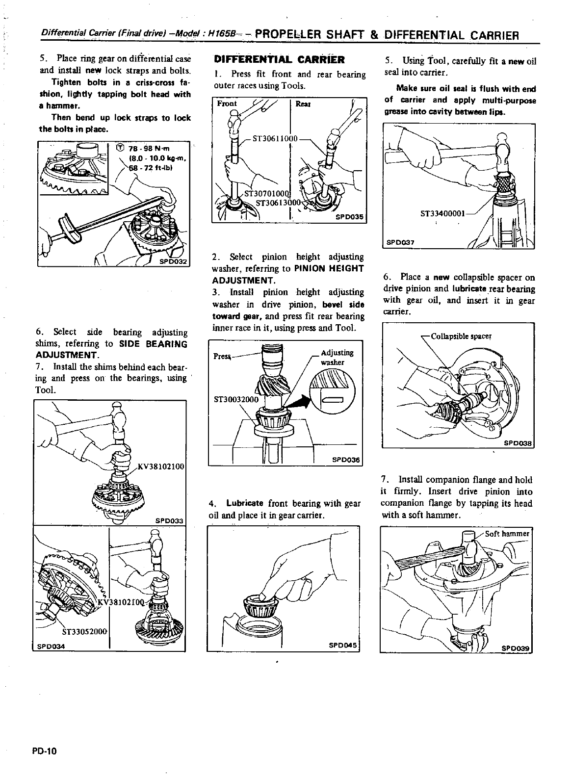
Differential
Carrier
fFinaldrive
Model H
65B
PROPEbLER
SHAFT
DIFFERENTIAL
CARRIER
5
Place
ring
gear
on
differential
case
and
install
new
lock
straps
and
bolts
Tighten
bolu
in a
crisl
cross
fa
shion
lightly
tapping
bolt
head
with
a
hammer
Then
bend
up
lock
straps
to
lock
the bolts
in
place
Iii
7S
gSN
m
L
IS
O
10
0
kG
58 72
ft
bl
A
6
Select
side
bearing
adjusting
shims
referring
to
SIDE
BEARING
ADJUSTMENT
7
Install
the
shims
behind
each
bear
ing
and
press
on
the
bearings
using
Tool
SPD033
ST33052000
SPD034
PD
IO
DIFFERENTIAL
CARRiER
I
Press
fit
front
and
rear
bearing
outer
races
using
Tools
SP
0035
1
2
Select
pmlOn
height adjusting
washer
referring
to
PINION
HEIGHT
ADJUSTMENT
3
Install
pinion
height
adjusting
washer
in
drive
pinion
bevel
side
toward
gear
and
press
fit
rear
bearing
inner
race
in
it
using
press
and
Tool
4
Lubricate
front
bearing
with
gear
oil
and
place
it
in
gear
carrier
SPD045
5
Using Tool
carefully
fit
a
new
oil
seal
into
carrier
Make
lure
oil
seal
is
flush
with
end
of
carrier
and
apply
multi
purpose
grease
into
cavity
d
lips
l
SPDQ37
ST33400001
i
I
6
Place
a
new
collapsible
spacer
on
drive
pinion
and
lubricate
rear
bearing
with
gear
oil
and
insert
it
in
gear
carrier
SP003S
7
Install
companion
l1ange
and
hold
it
firmly
Insert
drive
pinion
into
companion
flange
by
tapping
its
head
with
a
soft
hammer
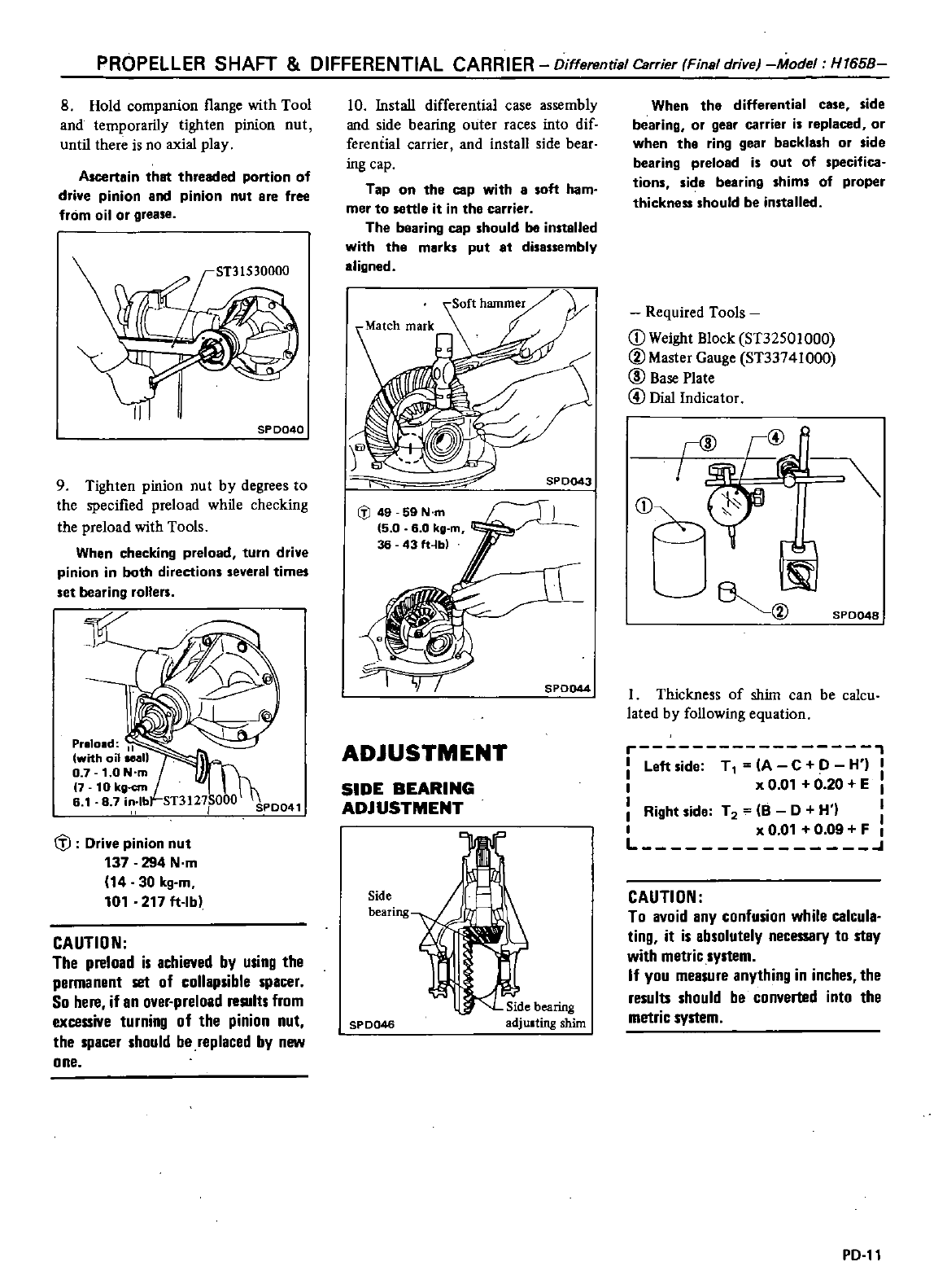
PROPELLER
SHAFT
DIFFERENTIAL
CARRIER
Differential
Carrier
Final
drive
Model
H165B
8
Hold
companion
l1ange
with
Tool
and
temporarily
tighten
pinion
nut
until
there
is
no
axial
play
Ascertain
that
threaded
portion
of
drive
pinion
and
pinion
nut
are
free
from
oil
or
grease
SP
0040
9
Tighten
pinion
nut
by
degrees
to
the
specified
preload
while
checking
the
preload
with
Tools
When
checking
preload
turn
drive
pinion
in
both
directions
several
times
set
bearing
rollers
l
Preload
II
with
oilMan
0
7
1
0
Nom
7
10
kliJ
cm
6
1
8
7in
lb
J
Drive
pinion
nut
137 294
N
m
14 30
kg
m
101
217
ft
Ib
CAUTION
The
preload
is
achieved
by
using
the
permanent
set
of
collapsible
spacer
So
here
if
an
over
preload
results
from
excessive
turning
of the
pinion
nut
the
spacer
should
be
replaced
by
new
one
10 Install
differential
case
assembly
and
side
bearing
miter
races
into
dif
ferential
carrier
and
install
side
bear
ing
cap
Tap
on
the
cap
with
8
soft
ham
mer
to
settle
it
in the
carrier
The
bearing
cap
should
be
installed
with
the
marks
put
8t
disassembly
aligned
IiJ
49 59
N
m
5
0
6 0
kg
m
36
431t
IOI
If
SPD044
ADJUSTMENT
SIDE
BEARING
ADJUSTMENT
Side
bearing
SPD046
Side
bearing
adjulting
shim
When
the
differential
case
side
bearing
or
gear
carrier
is
replaced
or
when
the
ring
gear
backlash
or
side
bearing
preload
is
out
of
specifica
tions
side
bearing
shims
of
proper
thickness
should
be
installed
Required
Tools
D
Weight
Block
ST32501
000
@Master
Gauge
ST33741000
@
Base
Plate
@
Dial
Indicator
@
j@R
tl
I
D
0f
@
SPD048
I
Thickness
of
shim
can
be
calcu
lated
by
following
equation
Left
side
T
A
C
O
H
I
x
0 01 0
20
EI
Right
side
T
2
8 0
H
I
x
0
01 0
09
F
I
L
CAUTION
To avoid
any
confusion
while
calcula
ting
it
is absolutely
necessary
to
stay
with
metric
system
If
you
measure
anything
in inches
the
results should
be
converted
into
the
metric
system
PO
tt
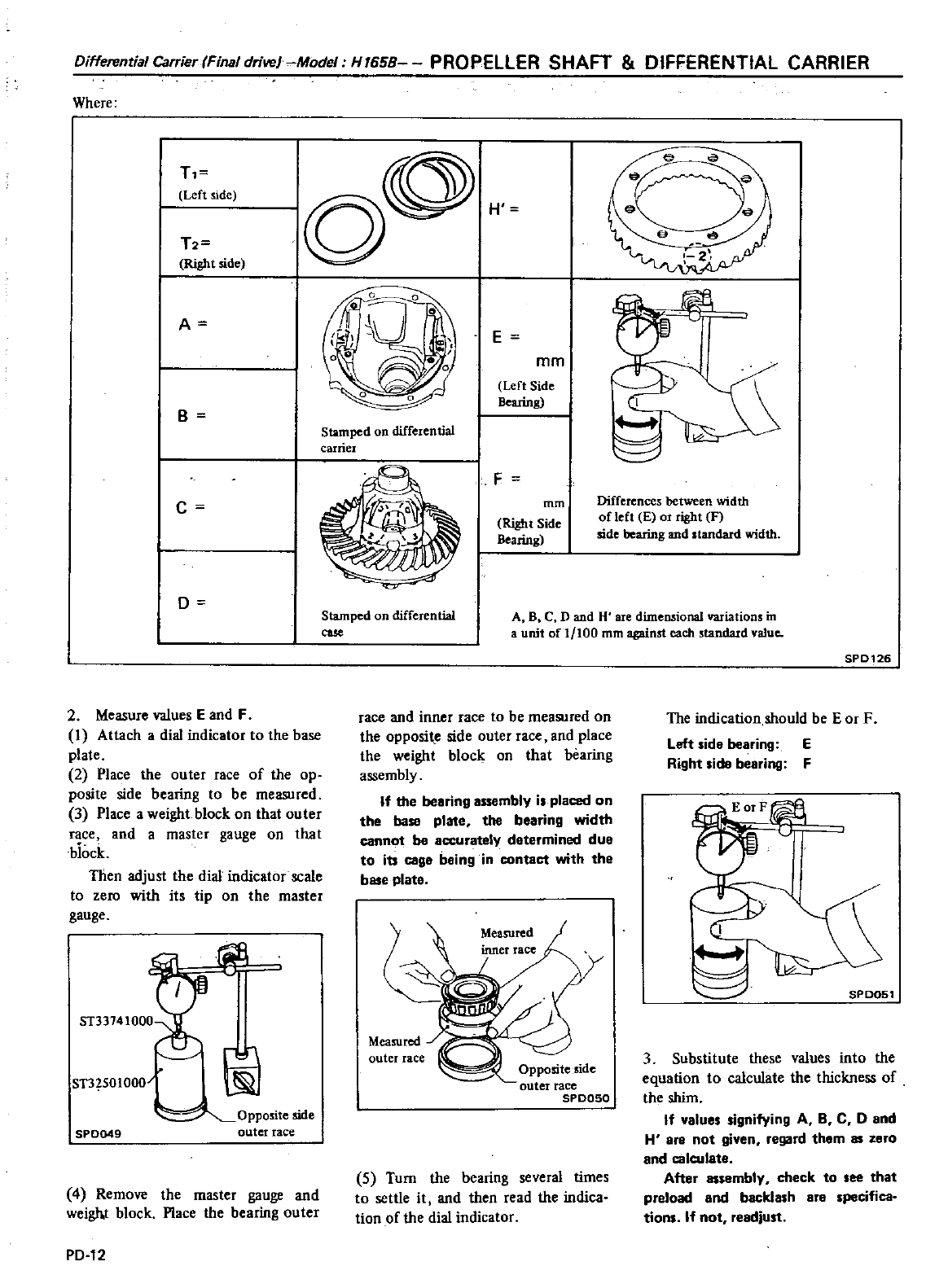
Differential
CarrierfFinal
drivel
Model
H7658
PROPEllER
SHAFT
DIFFERENTIAL
CARRIER
Where
T
Left
side
T2
Right
side
A
B
c
D
2
Measure
values
E
and
F
I
Attach
a
dial
indicator
to
the
base
plate
2
Place
the
outer
race
of
the op
posite
side
bearing
to
be
measured
3
Place
a
weight
block
on
that
outer
race
and
a
master
gauge
on
that
biock
Then
adjust
the
dial
indicator
scale
to
zero
with
its
tip
on
the
master
gauge
ST3
501000
SP0Q49
Oppo
ite
side
outer
race
4
Remove
the
master
gauge
and
weigh
t
block
Place
the
bearing
outer
PD
12
o
H
oo
0
U
o
G
o
l
E
mm
Left
Side
Bearing
Stamped
on
differential
carrier
F
mm
Right
Side
Bearing
Stamped
on
differential
cue
Differences
between
width
of
left
E
or
right
F
side
bearing
and
standard
width
A
B
C
D
and
H
are
dimensional
variations
in
a
unit
ofl
100
mm
against
each
standard
value
race
and
inner
race
to
be
measured
on
the
opposi
e
side
outer
race
and
place
the
weight
block
on
that
bearing
assembly
If
the
bearing
embly
i
placed
on
the
base
plate
the
bearing
width
cannot
be
accurately
determined
due
to
its
cage
being
in
contact
with
the
base
plate
Measured
outer
race
5
Turn
the
bearing
several
limes
to
settle
it
and
then
read
the
indica
tion
of
the
dial
indicator
SPD126
The
indication
should
be
Ear
F
Left
ide
bearing
E
Right
ide
bearing
F
speOS1
3
Substitute
these
values
into
the
equation
to
calculate
the
thickness
of
the
shim
If
value
ignifying
A
BC
0
and
H
are
not
given
regard
them
as
zero
and
calculate
After
as
embly
check
to
ee that
preload
end
backla
h
ere
pecifica
tion
If
not
readjust
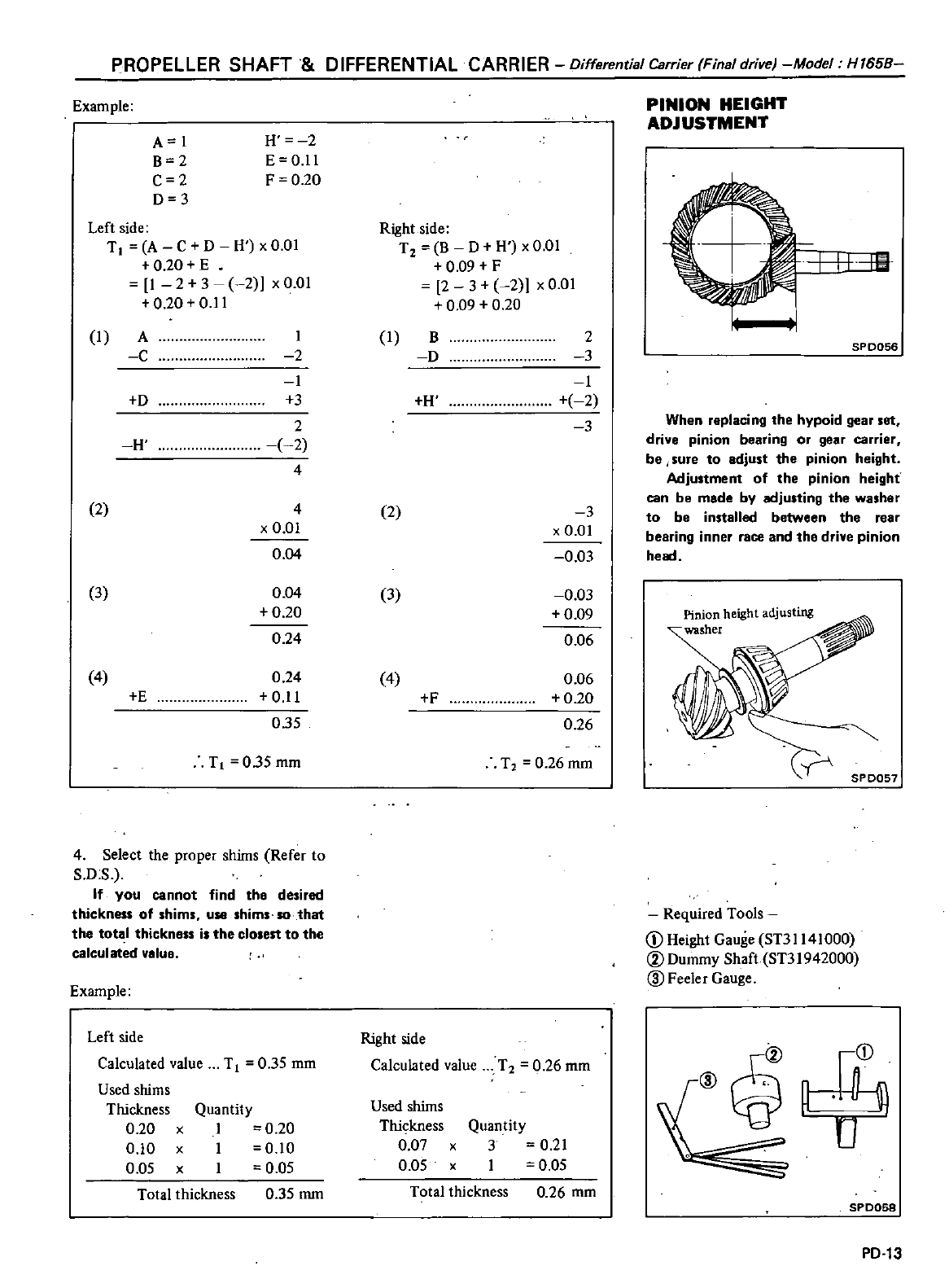
PROPELLER
SHAFT
DIFFERENTIAL
CARRIER
Differential
Carrier
Final
drive
Model
H165B
Example
A
I
B
2
C
2
D
3
H
2
E Ol1
F
0
20
Left
side
T
A
C
0
H
xO
OI
0
20
E
1
2 3 2
xO
OI
0
20 0
11
I
A
C
I
2
I
3
2
2
4
0
H
2 4
x
0 01
0
04
3
0
04
0
20
0
24
4
0
24
0
11
035
E
T
035mm
4
Select
the
proper
shims
Refer
to
S
O
S
If you
cannot
find
the
desired
thickness
of
shims
use
shims
so
that
the
total
thickness
is
the
closest
to
the
calculated
value
Example
Left
side
Calculated
value
T
0
35
mm
Used
shims
Thickness
Quantity
0
20
x
I
0
20
0
10
x
I
0
10
0
05
xI
0
05
Total
thickness
0
35
mm
Right side
T2
B
D H
xO
01
0
09
F
2
3
2
xO
OI
0
09
0
20
I
B
2
D
3
I
H
2
3
2
3
x
001
0
03
3 0
03
0
09
0
06
4
0
06
0
20
0
26
F
T
0
26mm
Right side
Calculated
value
T
2
0
26
mm
Used
shims
Thickness
0
07
x
0
05 x
Quantity
3 0
21
I
0
05
Total
thickness
0
26
mm
PINION
HEIGHT
ADJUSTMENT
I
I
l
Hiit
SP0056
When
replacing
the
hypoid
gear
set
drive
pinion
bearing
or
gear
carrier
be
sure
to
adjust
the
pinion
height
Adjustment
of
the
pinion
height
can
be made
by
adjusting
the
washer
to
be
installed
between the
rear
bearing
inner
rice
and
the
drive
pinion
head
Pinion
height adjusting
washer
SPD051
Required
Tools
j
Height
Gauge
ST31141
000
CV
Dummy
Shaft
ST31942000
ID
Feeler
Gauge
CV
j
L
r
SPD058
PD
13
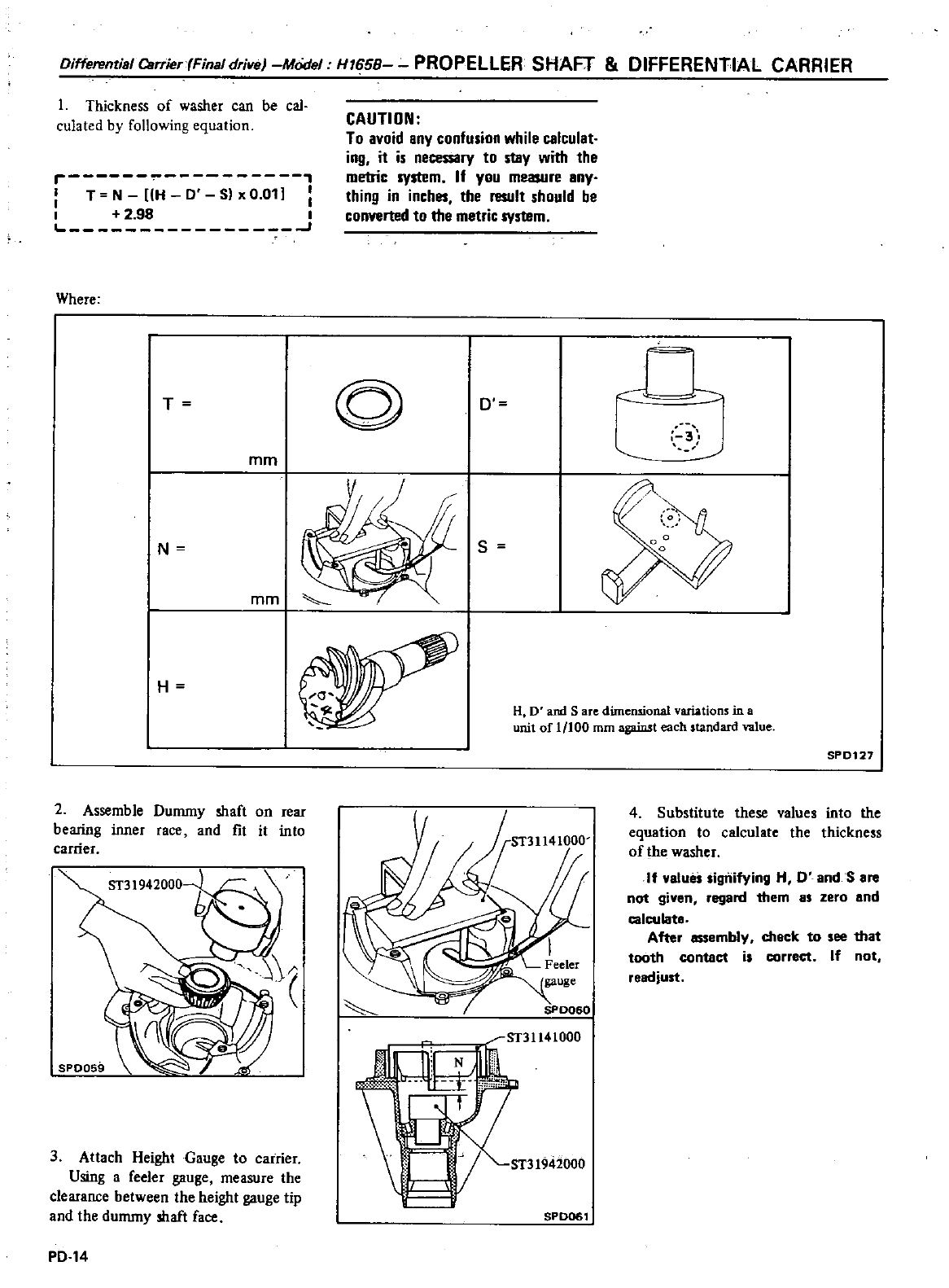
Oifferential
Csrrier
Final
drive
Model H165B
PROPELLER
SHAFT
DIFFERENTIAL
CARRIER
I
Thickness
of
washer
can
be
cal
culated
by
following
equation
r
T
N H
0
Sl
x
0
011
I
2
98
I
Where
T
mm
N
mm
H
2
Assemble
Dummy
shaft
on
rear
bearing
inner
race
and
fit
it into
carrier
3
Attach
Height
Gauge
to
carrier
Using
a
feeler
gauge
measure
the
clearance
between
the
height
gauge
tip
and
the
dummy
shaft
face
PO
14
CAUTION
To avoid
any
confusion
while
calculat
ing
it
is
necessary
to
stay
with
the
metric
system
If
you
measure
any
thing
in
inches
the
result
should
be
converted
to
the
metric
system
@
D
s
n
3
H
D
and
S
are
dimensional
variations
in
a
unit
of
1
100
mm
against
each
standard
value
ST31141000
SPD061
SP
0127
4
Substitute
these
values
into
the
equation
to
calculate
the
thickness
of
the
washer
If
value
Sigilifying
H
0
andS
are
not
given
regard
them
8S
zero
and
calculate
After
essembly
check
to
see
that
tooth
contact
is
correct
If
not
readjust
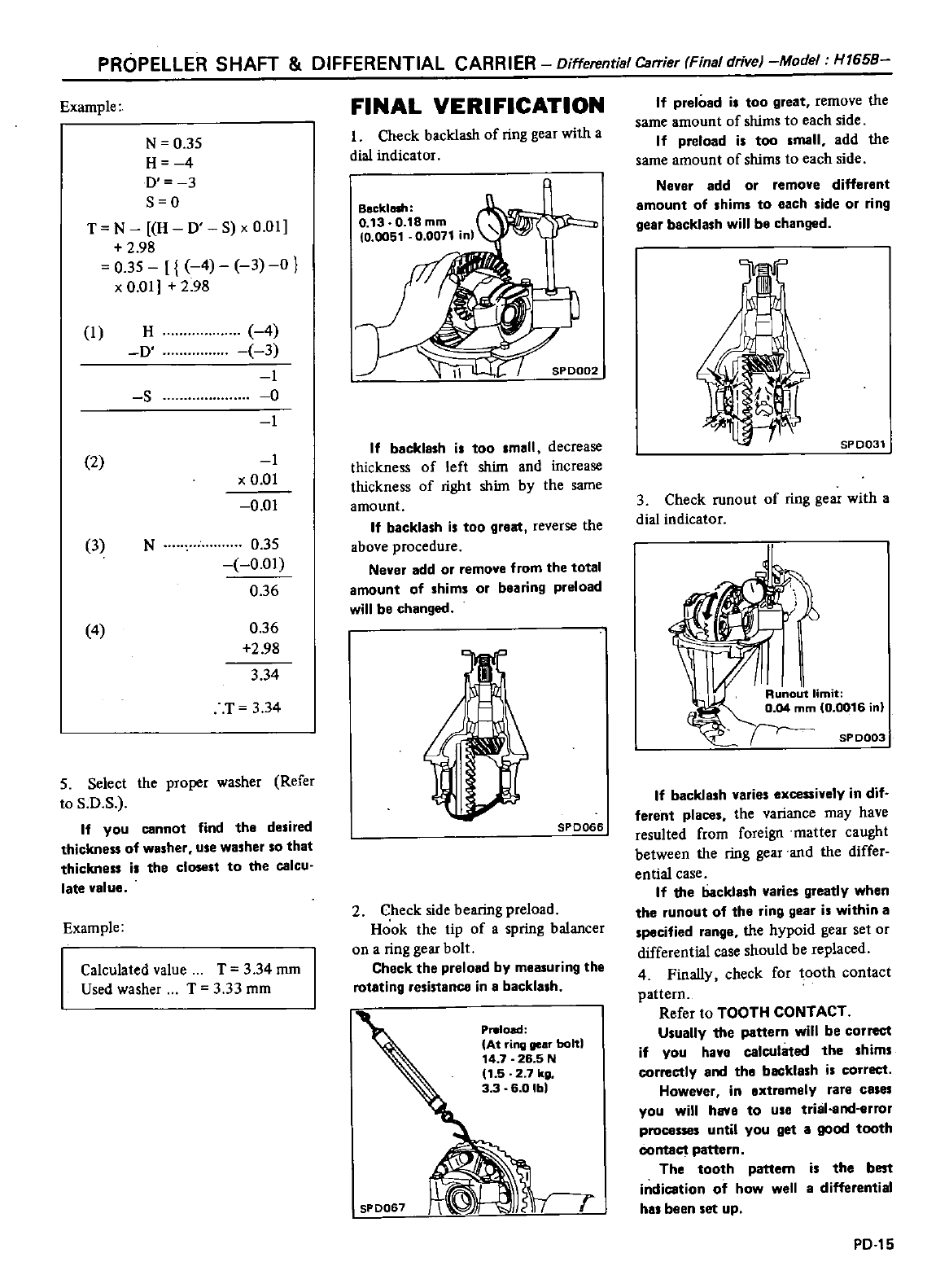
PROPELLER
SHAFT
DIFFERENTIAL
CARRIER
Differential
Carrier
Final
drive
Model
H1658
Example
N
0
35
H
4
D
3
S O
T
N H
0
S
x
0
01
2
98
0
35
4
3
0
x
0
01
2
98
I
H
0
4
3
I
0
I
S
2
I
x
0
01
00
3
N
0
35
0
01
0
36
4
0
36
2
98
3
34
T
3
34
5
Select
the
proper
washer
Refer
to
S
O
S
If
you
cannot
find
the
desired
thickness
of
washer
use
washer
SO
that
thickness
is
the
closest
to
the
calcu
late
value
Example
Calculated
value
T
3
34
mm
Used
washer
T 3
33
mm
FINAL
VERIFICATION
Check
backlash
of
ring
gear
with
a
dial
indicator
If
backlash
is
too
small
decrease
thickness
of
left
shim
and
increase
thickness
of
right
shim
by
the
same
amount
If
backlash
is
too
great
reverse
the
above
procedure
Never
add
or
remove
from
the
total
amount
of
shims
or
bearing preload
will
be
changed
SPD066
2
Check
side
bearing preload
Hook
the
tip
of
a
spring
balancer
on
a
ring
gear
bolt
Check
the
preload
by
mea
uring
the
rotating
resistance
in
a
backlash
Preload
At
ring
gear
bold
14
7
26
5
N
11
5 2
7
kg
33 6
01bl
SPD067
If
prelOad
i
too
great
remove
the
same
amount
of
shims to
each
side
If
preload
i
too
mall
add
the
same
amount
of
shims
to
each
side
Never
add
or
remove
different
amount
of
shims
to
each
side
or
ring
gear
beckla
h
will
be
changed
5P0031
3
Check
runout
of
ring
gear
with
a
dial
indicator
SP
0003
If
backlash
varies
excessively
in
dif
ferent
places
the
variance may
have
resulted
from
foreign
matter
caught
between
the
ring
gear
and
the
differ
entia
case
If
the
backla
h
varies
greatly
when
the
runout
of
the
ring
gear
is
within
a
pecified
range
the
hypoid
gear set
or
differential
case
should
be
replaced
4
Finally
check
for
tooth
contact
pattern
Refer
to
TOOTH
CONTACT
U
ually
the
pettern will
be
correct
if
you
have
calculated
the hims
correctly
and
the
backla
h
i
correct
However
in
extremely
rare
cales
you
will
have
to
use
trial
nd
error
proce
until
you
get
a
good
tooth
contact
pattern
The
tooth
pattem
i
the
best
indieation
of
how
well a
differential
ha
been
et
up
PO
15
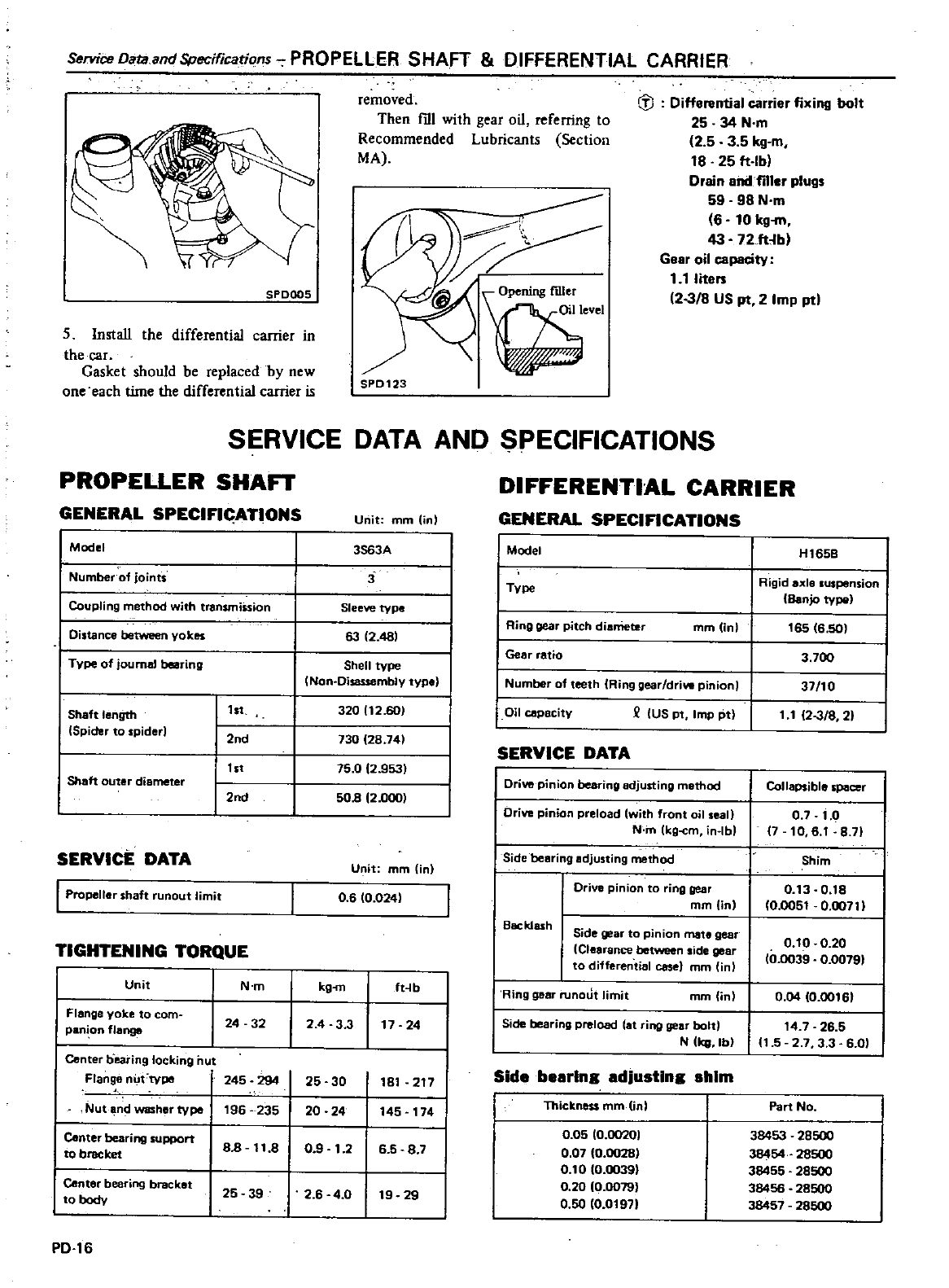
ServiceDataandSpecifications
PROPELLER
SHAFT
DIFFERENTIAL
CARRIER
SPDOOS
5
Install
the
differential
carrier
in
the
car
Gasket
should
be
replaced
by
new
one
each
time
the
differential
carrier
is
removed
Then
fill
with
gear
oil
referring
to
Recommended
Lubricants
Section
MA
fl
Differential
carrier
fixing
bolt
25
34
N
m
2 5 3 5
kg
m
18
25
ft
Ibl
Drain
and
filler
plugs
59 98
N
m
6 10
kg
m
43 72
ft
b
Gear
oil
capacity
1 1 I
ita
rs
2
318
US
pt
2
Imp
ptl
SPD123
ngrdler
Oil
level
SERVICE
DATA
AND
SPECIFICATIONS
PROPELLER
SHAn
GENERAL
SPECIFlc
ATIONS
Model
Number
of
joints
Coupling
method
with
transmiSsion
Distance
yokes
Type
of
journal
bearing
Shaft
lenQth
Spider
to
spider
1st
2nd
tst
Shaft
outer
diameter
2nd
SERVICE
DATA
I
Propeller
shaft
runout
limit
TIGHTENING
TORQUE
Unit
I
Flange
yoke
to
com
pani
on
flange
N
m
24 32
Center
b
earing
locking
nut
Flange
nut
tvpct
245
294
Nut
ridwashertvpe
196
235
20 24
I
Center
bearing
support
to
bracket
88
80 9
1
2
I
Center
bearing
bracket
I
to
body
25 39
2
6
4
0
PD
16
Unit
mm
in
3S63A
3
Sleeve
type
63
2
481
Shell
type
Non
Disassemblv
type
3201
2
601
730
28
741
75
0
2
9531
50B
2
0001
Unit
mm
in
06 0
0241
kg
m
fHb
24
3 3
17
24
25 30
8
217
45
74
6
5
8
7
9
29
DIFFERENTIAL
CARRIER
GENERAL
SPECIFICATIONS
I
Model
I
TVpe
I
Ring
gear
pitch
dianleter
mm
Unl
I
Gear
ratio
I
Number
of
teeth
Ring
gear
drive
pinion
I
Oil
cepacity
2
US pt
Imp
pt
SERVICE
DATA
Drive
pinion
bearing
adjusting
mathod
Drive
pinion
preload
with
front
oil
seal
N
m
kg
cm
in
lb
I
Side
bearing
adjusting
method
Drive
pinion
to
ring
gear
mm
jn
Backlash
Side gear
to
pinion
mate
gear
Clearance
side
gear
to
differential
case
mm
in
Ring
gear
nmout
limit
mm
in
H1658
Rigid
axle
suspension
Banjo
typo
t65
6
50
3
700
3710
11
23
8
21
Collapsible
spacer
0
7
0
7
10
6
t
8
71
Shim
0
3 0
8
0
005
0
00711
000
20
10
0039
0
00791
0
04
0
00
61
Side
bearing preload
at
ring
gear
bolt
14
7
26
5
N
kG
lbl
1
5
2
7 3 3 6
01
Side
bearln
adjustin
shim
Thickness
mm
inl
0
05
0
00201
0 07 0
00281
0 0
10
00391
0
20
0
00791
0
50
10
0
971
Part
No
38453 28500
38454
28500
38455
28500
38456 28500
38457 28500
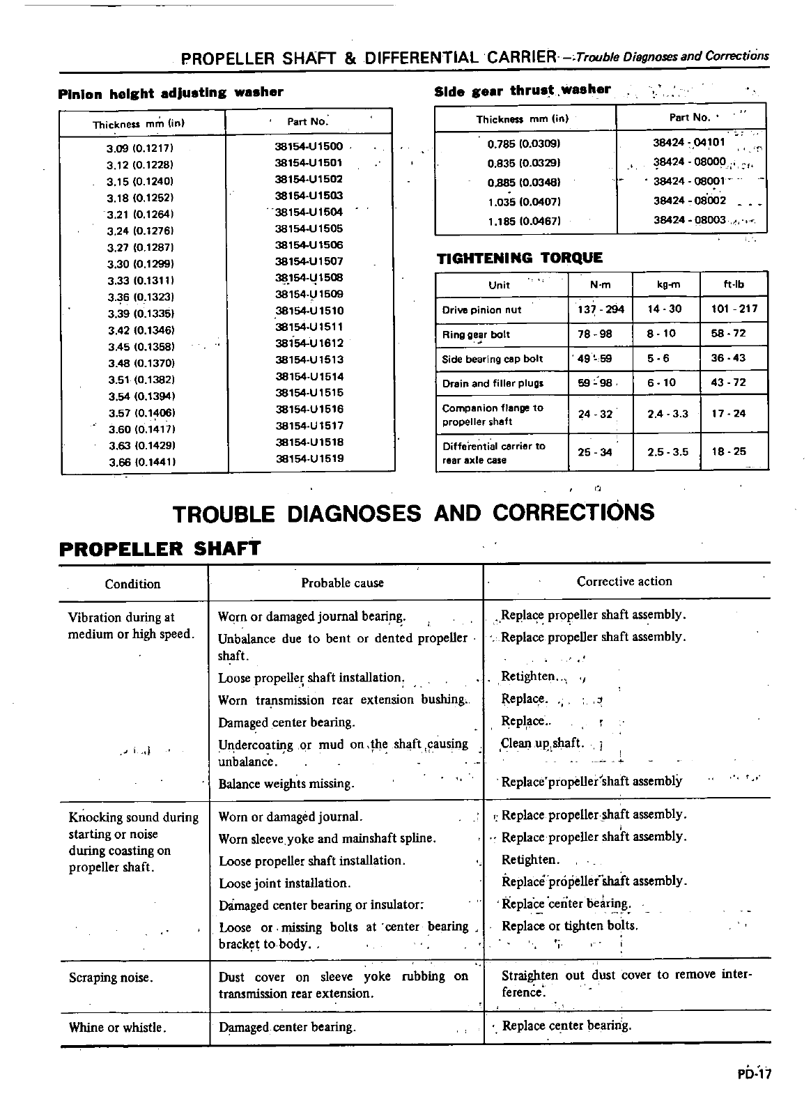
PROPELLER
SHAFT
DIFFERENTIAL
CARRIER
Trouble
Diagnosesand
Corrections
Pinion
height
adjusting
washer
Side
gear
thrust
washer
Thickness
mm
in
Part
No Thickness
mm in
Part
No
3
09
10
12171
38154
U
1500
0
785
10
0309
38424
04101
3
12
10
12281
38154
UI501
0
835
10
03291
8424
08000
3
15
0
12401
38154
Ut502
0
885 10
0348
38424
08001
3
181O
t252
38154
U
1503
1
035
10
04071
38424
08002
3
21
10
12641
38154
U
1504
3
2410
12761
38154
U
1505
1
185
10
04671
38424
08003
3
27
0
12871
38154
U
1506
3
30
0
1299
38154
U1507
TIGHTENING
TORQUE
3
33
10
13111
38
154
l
1508
Unit
N
m
kg
m
ft
Ib
3
36
10
13231
38154
U1509
3
39
0
1335
38154UI510
I
Drive
pinion
nut
137
294
14
30
101
217
3
42
10
1346
38154
U1511
I
Ring
ge
r
bolt
78
98
8
10 58 72
3
4510
13581
38154
Ut612
3
48
10
1370
38154
U1513
I
Side
beari
ng
cap
bolt
49
59
5
6
36 43
3
51
0
13821
38154
U1514
I
Drain
and
filler
plugs
59 1098
6
43 72
3
54
10
t394
38154
U1515
3
57
10
14061
38154
UI516
I
Companion
flange
to
24 32
2
4
33
17
24
3
6010
14171
38154
UI517
propeller
5h8ft
3
63
10
14291
38154
UI518
I
Difforential
co
io
to
3
66
10
14411
38154
U1519
rear
axle
case
25 34
2
5
3 5
18 25
TROUBLE
DIAGNOSES
AND
CORRECTIONS
PROPELLER SHAFT
Condition
Vibration
during
at
medium
or
high
speed
Knocking
sound
during
starting
or
noise
during
coasting
on
propeller
shaft
Scraping
noise
Whine
or
whistle
Probable
cause
Worn
or
damaged journal
beari
n
Unbalance
due
to
bent
or
dented
propeller
shaft
Loose
propeller
shaft
installation
Worn
transmission
rear
extension
bushing
Damaged
center
bearing
U
dercoatiI
g
or
mud
on
he
shaft
ausing
unbalance
Balance
weights ntissing
Worn
or
damaged
journal
Worn
sleeve
yoke
and
mainshaft
spline
Loose
propeller
shaft
installation
Loose
joint
installation
Damaged
center
bearing
or
insulator
Loose
or
ntissing
bolts
at
center
bearing
brac
t
10
body
Dust
cover
on
sleeve
yoke
rubbing
on
transmission
rear
extension
Damaged
center
bearing
Corrective
action
Repla
prol
eller
shaft
assembly
Replace
propeller
shaft
assembly
Retighten
Replac
e
Repl
ace
Clean
up
shaft
j
Replace
propeller
shaft
assembly
Replace
propeller
shaft
assembly
Replace
propeller
shaft
assembly
Retighten
Replace
propellei
shaft
assembly
Repla
center
bear
g
Replace
or
tighten
bolts
Straighten
out
dust
cover
to
remove
inter
ference
Replace
center
bearing
1
0
17
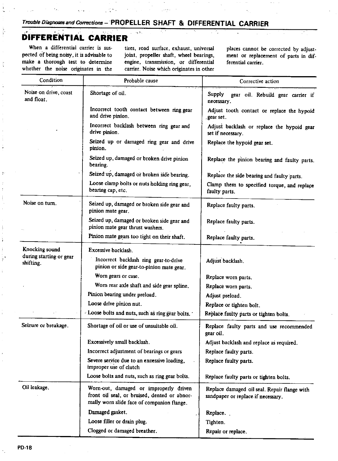
Trouble
Diagnoses
and
Corrections
PROPELLER
SHAFT
DIFFERENTIAL
CARRIER
DIFFERENTIAL
CARRIER
When
a
differential
carrier
is
sus
pected
of
being
noisy
it
is
advisable
to
make
a
thorough
test
to
detennine
whether
the
noise
originates
in
the
Condition
tites
road
surface
exhaust
universal
joint
propeller
shaft
wheel
bearings
engine
transmission
or
differential
carrier
Noise
which
originates
in
other
Noise
on
drive
coast
and
l1oat
Noise
on
turn
Knocking
sound
during
starting
or
gear
shifting
Seizure
or
breakage
Oil
leakage
PD
18
Probable
cause
Shortage
of
oil
Incorrect
tooth
contact
between
ring
gear
and
drive
pinion
Incorrect
backlash
between
ring gear
and
drive
pinion
Seized
up
or
damaged
ring
gear
and
drive
pinion
Seized
up
damaged
or
broken
drive
pinion
bearing
Seized
up
damaged
or
broken
side
bearing
Loose
clamp
bolts
or
nuts
holding
ring
gear
bearing
cap
etc
Seized
up
damaged
or
broken
side
gear
and
pinion
mate
gear
Seized
up
damaged
or
broken
side
gear
and
pinion
mate
gear
thrust
washers
Pinion
mate
gears
too
tight
on
their
shaft
Excessive
backlash
Incorrect
backlash
ring
gear
to
drive
pinion
or
side
gear
to
pinion
mate
gear
Worn
gears
or
case
Worn
rear
axle
shaft
and
side
gear
spline
Pinion
bearing
under
preload
Loose
drive
pinion
miL
Loose
boltS
and
nuts
such
as
ring
gear
bolts
Shortage
of
oil
or
use
of
unsuitable
oil
Excessively
small
backlash
Incorrect
adjustment
of
bearings
or
geats
Severe
ser
vice
due
to
an
excessive
loading
improper
use
of
clutch
Loose
bolts
and
nuts
such
as
ring gear
bolts
Worn
out
damaged
or
improperly
driven
front
oil
seal
or
bruised
dented
or
abnor
mally
worn
slide
face
of
companion
l1ange
Damaged
gasket
Loose
filler
or
drain
plug
Clogged
or
damaged
breather
places
cannot
be
corrected
by
adjust
ment
or
replacement
of
parts
in
dif
ferential
carrier
Corrective
action
Supply
gear
oil
Rebuild
gear
carrier
if
necessary
Adjust
tooth
contact
or
replace
the
hypoid
gear
set
Adjust
backlash
or
replace
the
hypoid
gear
set
if
necessary
Replace
the
hypoid
gear
set
Replace
the
pinion
bearing
and
faulty
parts
Replace
the
side
bearing
and
faulty
parts
Clamp
them
to
specified
torque
and
replal
faulty
parts
Replace
faulty
parts
Replace
faulty
parts
Replace
faulty
parts
Adjust
backlash
Replace
worn
parts
Replace
worn
parts
Adjust
preload
Replace
or
tighten
bolt
ReplaCe
faulty
parts
or
lighten
bolts
Replace
faulty
parts
and
use
recommended
gear
oil
Adjust
backlash
and
replace
as
required
Replace
faulty
parts
Replace
faulty
parts
Replace
faulty
parts
or
tighten
bolts
Replace
damaged
oil
seal
Repair
l1ange
with
sandpaper
or
replace
if
necessary
Replace
Tighten
Repair
or
replace
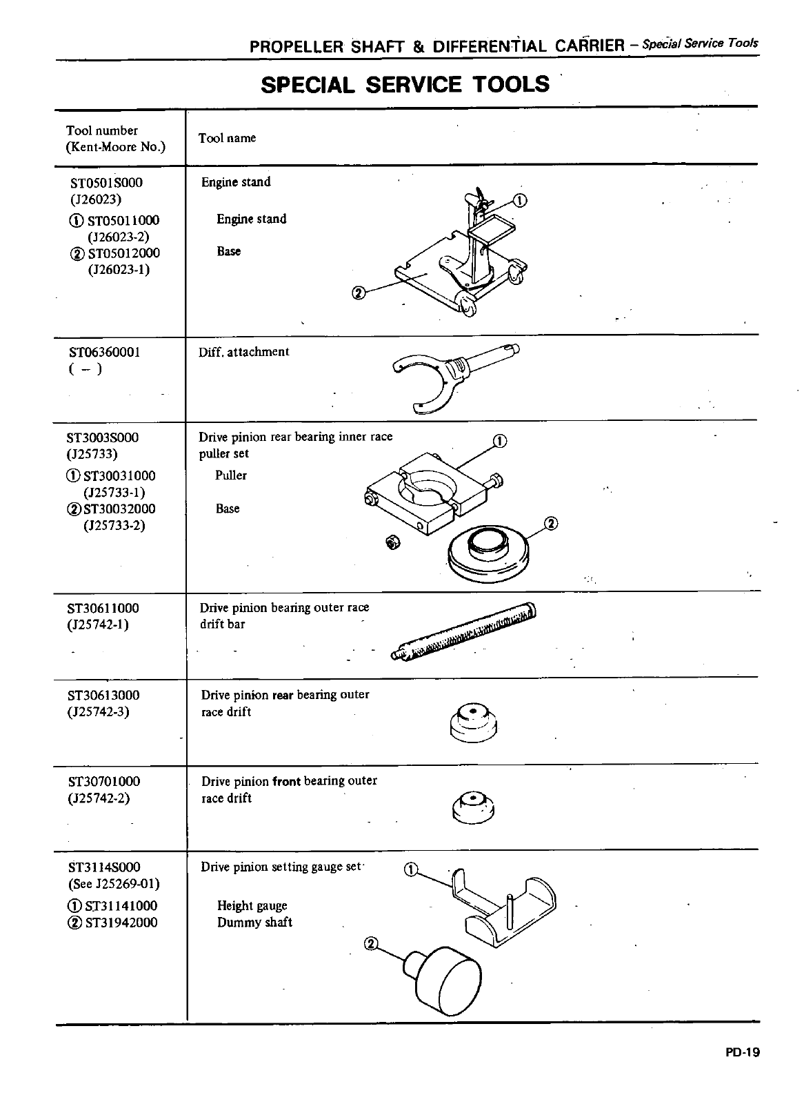
Tool
number
Kent
Moore
No
ST050
I
SOOO
126023
CD
ST05011
000
126023
2
@ST05012000
126023
1
ST0636000l
ST3003S000
125733
CD
ST30031
000
125733
1
@ST30032000
125733
2
ST30611000
125742
1
ST30613000
1257423
ST30701000
125742
2
ST3114S000
See
125269
01
CD
ST31141000
@ST31942000
PROPELLER
SHAFT
DIFFERENTIAL
CARRIER
Special
Service
Tools
SPECIAL
SERVICE
TOOLS
Tool
name
Engine
stand
Engine
stand
Base
Diff
attachment
Drive
pinion
feaf
bearing
inner
race
puller
set
Puller
Base
Drive
pinion
bearing
outer
race
drift
bar
Drive
pinion
rear
bearing
outer
race
drift
Drive
pinion
front
bearing
Quter
race
drift
6
Drive
pinion
setting
gauge
set
Height
gauge
Dummy
shaft
PD
19
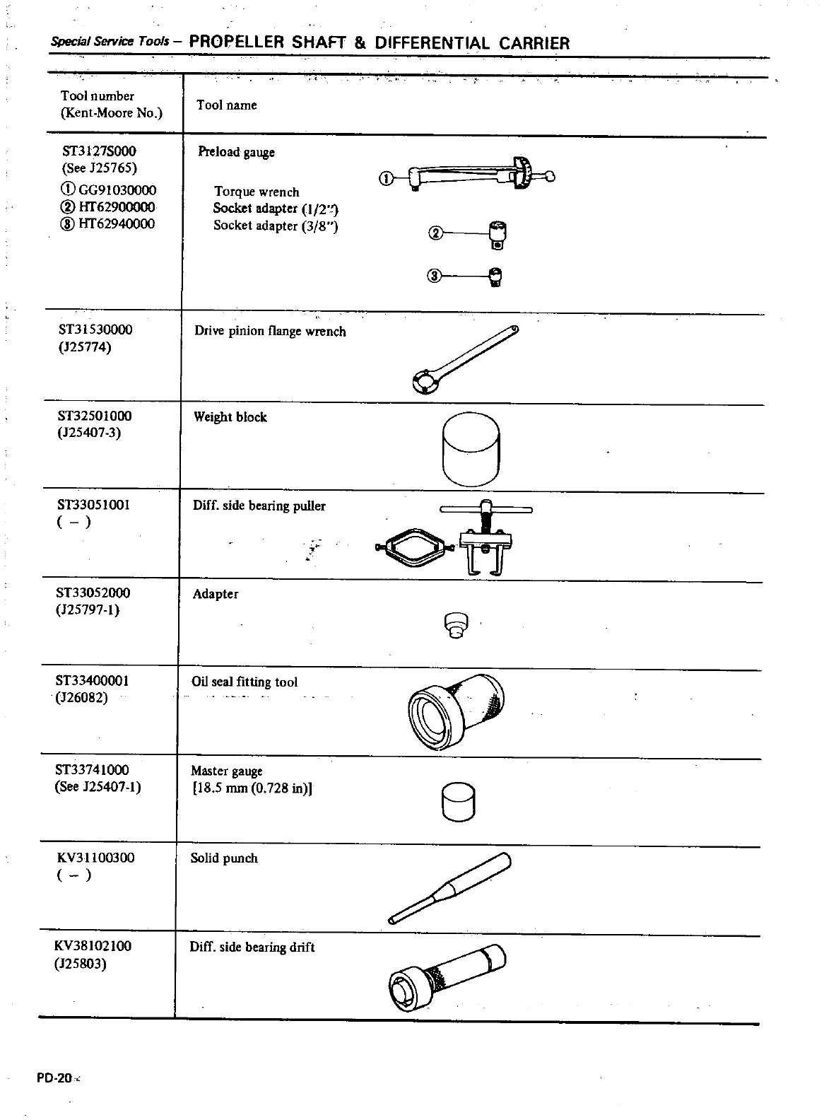
Special
Service
Tools
PROPELLER
SHAFT
DIFFERENTIAL
CARRIER
Tool
number
Kent
Moore
No
Tool
name
ST3127S000
See
125765
CD
GG91030000
CV
lIT62900000
@
lIT62940000
Preload
gauge
Torque
wrench
Socket
adapter
1
2
1
Socket
adapter
3
8
t
o
e
ST31530000
Drive
pinion
l1ange
wrench
125774
ST32501000
Weight
block
125407
3
ST33051001
Diff
side
bearing
puller
ST33052000
Adapter
125797
1
5J
ST33400001
Oil
seal
fitting
tool
126082
ST33741000
Master
gauge
See
125407
1
18
5
mm
0
728
in
8
KY311
00300
Solid
punch
KY38102100
125803
Diff
side
bearing
drift
PD
20
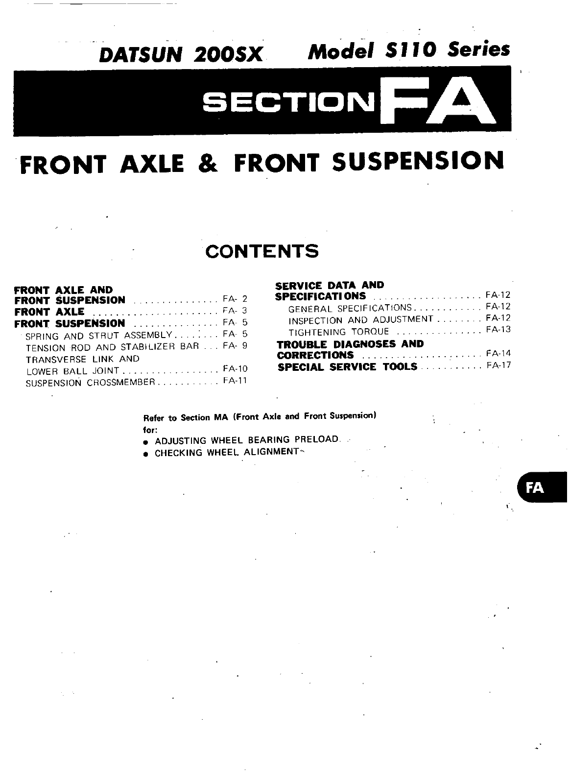
DATSUN
200SX
Model
S
110 Series
SECTION
FA
FRONT
AXLE
FRONT
SUSPENSION
CONTENTS
FRONT
AXLE
AND
FRONT
USPENSION
FRONT
AXLE
FRONT
SUSPENSION
SPRING
AND
STRUT
ASSEMBLY
TENSION
ROD
AND
STABILIZER
BAR
TRANSVERSE
LINK
AND
LOWER
BALL
JOINT
SUSPENSION
CROSSMEMBER
FA
2
FA
3
FA
5
FA
5
FA
9
SERVICE
DATA
AND
SPECIFICATIONS
GENERAL
SPECIFICATIONS
INSPECTION
AND
ADJUSTMENT
TIGHTENING
TORQUE
TROUBLE
DIAGNOSES
AND
CORRECTIONS
SPECIAL
SERVICE
TOOLS
FA
12
FA
12
FA12
FA13
FA10
FA
ll
FA
14
FA
17
Refer
to
Section
MA
Front
Axle
and
Front
Su
pen
ionl
for
ADJUSTING
WHEEL
BEARING
PRELOAD
CHECKING
WHEEL
ALlGNMENT
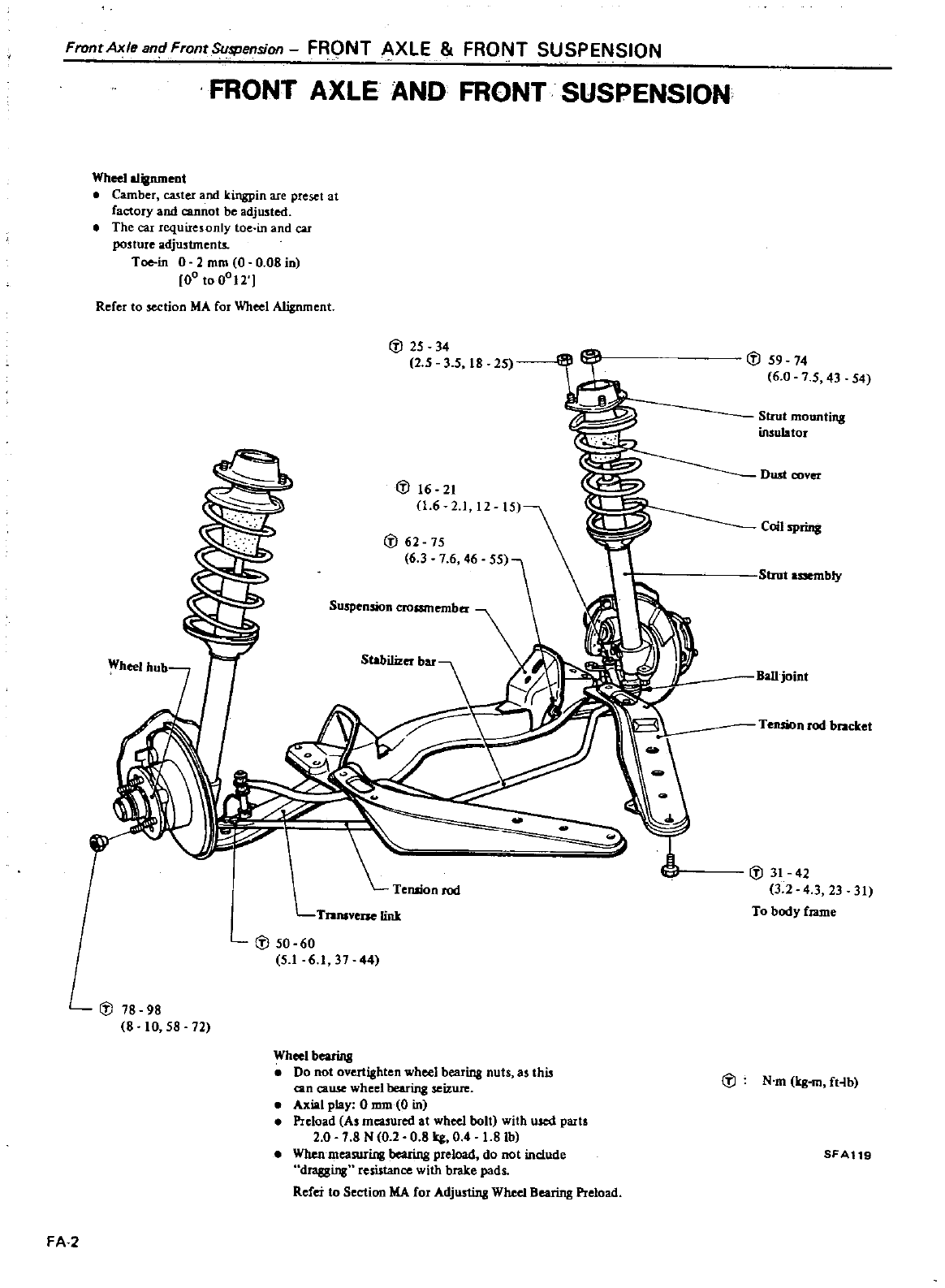
FrontAxleandFronrSu
lPension
FRONT
XLE
FRONT
SUSPENSION
FRONT
AXLE
AND
FRONT
SUSPENSION
Wheel
alignment
Camber
caster
and
kingpin
are
preset
at
factory
and
cannot
be
adjusted
The
car
requiresonly
toe in
and
car
pouure
adjustment
Toe
in 0
2
mm
0
0
08
in
00
to
0012
RefeI
to
section
MA
fot
Wheel
Alignment
J
25 34
2 5
3
5
18
25
J
16
21
1
6
21
12
J
62
7S
6 3
7 6
46
Suspension
croumember
Stabilizer
bar
l
Te
llion
rod
TranlVcue
link
J
50 60
5
161
37 44
J
78 98
8
10
58
72
Wheel
bearing
Do
not
overtighten
wheel
bearing
nuts
as
this
can
cawe
wheel
bearing
seizure
Axial
play
0
mm
0
in
Preload
As
measured
at
wheel
bolt
with
used
parts
2
0
7 8
N
0
2
081rg 0
4
1
8
lb
When
measuring
bearing preload
do
not
include
dragging
resistance
with
brake
pads
Refer
to
Section
MA
for
Adju
linB
Wheelllearing
Preload
FA
2
J
59
74
6
0
7
5
43
54
Strut
mounting
insulator
Dust
covet
Coil
SPrinll
Strut
bly
BaUjoint
Tension
rod
bracket
J
31
42
3
2
4 3
23 31
To
body
rame
J
N
m
Irg
m
ft
lb
SFA
9
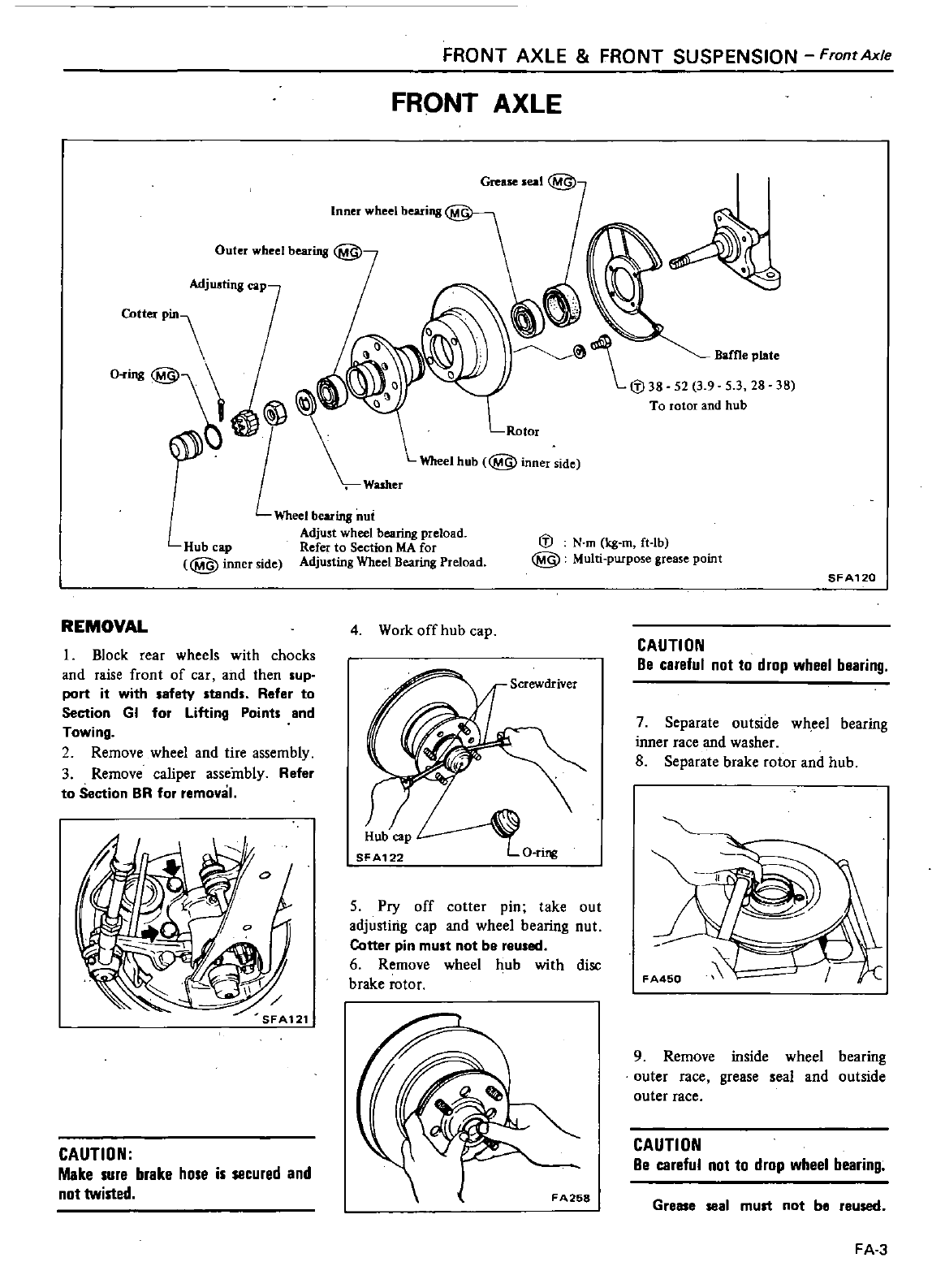
FRONT
AXLE
FRONT
SUSPENSION
Front
Axle
FRONT
AXLE
We seal
@
Inner
wheel
bearing
Cotter
Pin
@
@j
L
LWheelhub
@innerside
Washer
Wheel
bearing
nut
Adjust
wheel
bearing
preload
Hub
cap
Refer
to
Section
MA
for
@g
inner
side
Adjusting
Wheel
Bearing
Preload
Baffle
plate
38
lD
@
N
m
kg
m
ft
lb
Multi
purpose
grease
point
SFA120
REMOVAL
4
Work
off
hub
cap
CAUTION
Be
careful
not
to
drop
wheel
bearing
I
Block
rear
wheels
with
chocks
and
raise
front
of
car
and
then
sup
port
it
with
safety
stands
Refer
to
Section
GI
for
Lifting
Points
and
Towing
2
Remove
wheel
and
tire
assembly
3
Remove
caliper
assembly
Refer
to
Section
BR
for
removal
Screwdriver
7
Separate
outside wheel
bearing
inner
race
and washer
8
Separate
brake
rotor
and hub
O
riJ11
5
Pry
off
cotter
pin
take
out
adjusting
cap
and
wheel
bearing
nut
Cotter
pin
must
not
be
reused
6
Remove
wheel
hub
with
disc
brake
rotor
9
Remove
inside
wheel
bearing
outer
race
grease
seal
and outside
outer
race
CAUTION
Be
careful
not
to
drop
wheel
bearing
CAUTION
Make
sure
brake
hose
is
secured
and
not
twisted
FA258
Grease
seal
mud
not
be
reused
FA
3
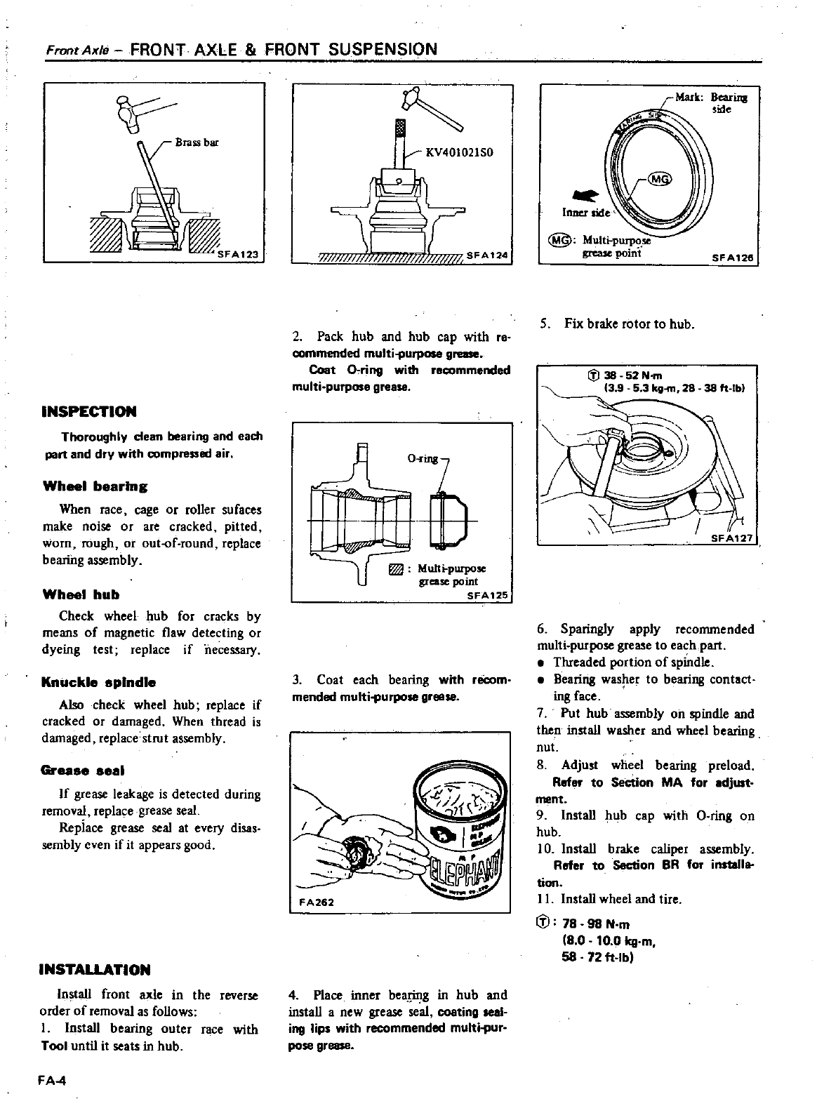
FronrAxle
FRONT
AXLE
FRONT
SUSPENSION
INSPECTION
Thoroughly
dean
bearing
and each
part
and
dry
with
compressed
air
Wh
1
bearing
When
race
cage
or
roller
sufaces
make
noise
or
are
cracked
pitted
worn
rough
or
out
f
round
replace
bearing
assembly
Wheel
hub
Check
wheel
hub
for
cracks
by
means
of
magnetic
flaw
detecting
or
dyeing
test
replace
if
necessary
Knuckle
aplndle
Also
check wheel
hub
replace
if
cracked
or
damaged
When
thread
is
damaged replace
strut
assembly
Greaae
aeal
If
grease
leakage
is
detected
during
removal
replace
grease
seal
Replace
grease
seal
at
every
disas
sembly
even
if
it
appears
good
INSTALLATION
Install
front
axle
in
the
reverse
order
of
removal
as
follows
I
Install
bearing
outer
race
with
Tool
until
it
seats
in
hub
FA
4
I I
1
11
1
Y
III
SFA
124
2
Pack
hub
and hub
cap
with
re
commended
multi
purpose
grease
Coat
o
ring
with
recommended
multi
purpose
grease
O
l
q
MuIt
purpo
grease
point
SFA125
3
Coat
each
bearing
with
reCom
mended
multi
purpo
gr
4
Place
inner
bea
J
in
in
hub
and
install
a
new
grease
seal
coating
seal
ing
lips
with
recommended
multi
pur
PO
gr
@
Multi
purpo
grease
point
SFA126
5
Fix
brake
rotor
to
hub
38
ft
Ib
6
Sparingly
apply
recommended
multi purpose
grease
to
each
part
Threaded
portion
of
spindle
Bearing
washer
to
bearing
contact
ing
face
7
Put
hub
assembly
on
spindle
and
then
install
washer
and
wheel
bearing
nut
8
Adjust
wheel
bearing
preload
Roter
to
Section
MA
for
adjUlt
ment
9 Install
hub
cap
with
a
ring
on
hub
10
Install
brake
caliper
assembly
Roter
to
Section
BR
for
installa
tion
II
Install
wheel
and
tire
cD
78
98
N
m
8
0
10
0
kg
m
58
72
ft
Ibl
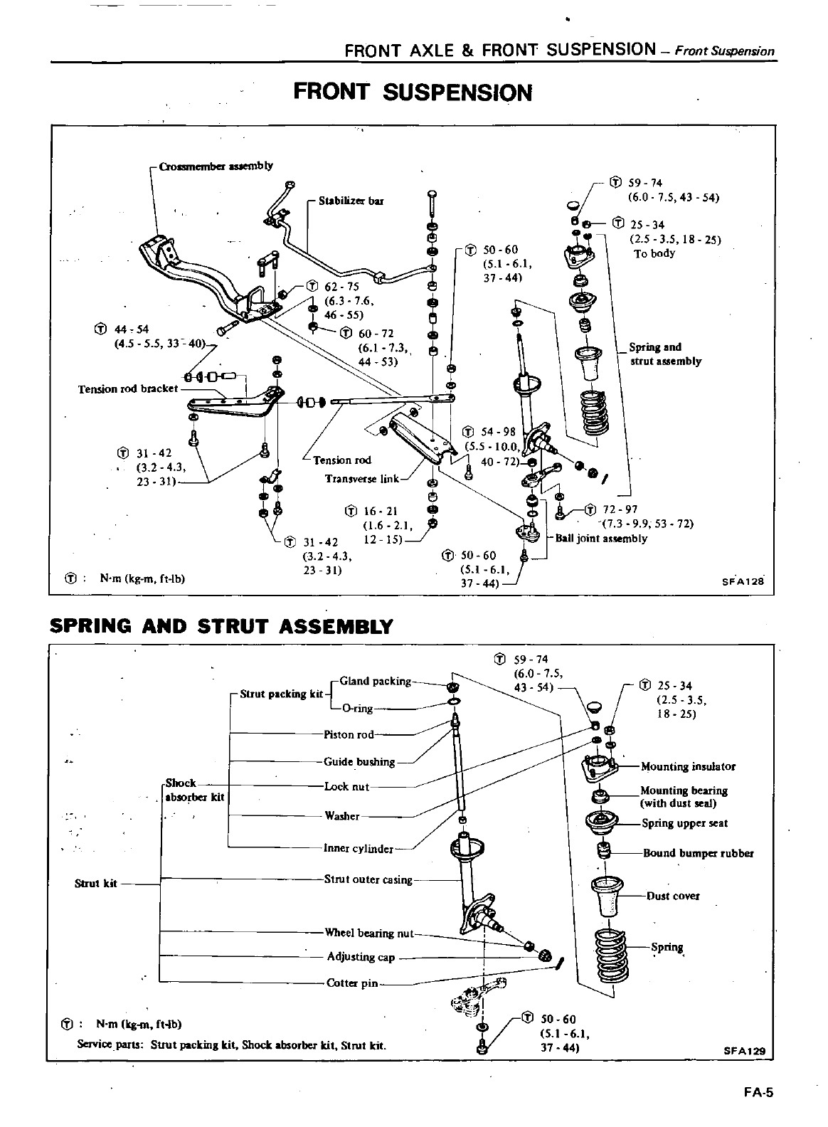
FRONT
AXLE
FRONT
SUSPENSION
Front
Suspension
FRONT
SUSPENSION
Croamember
auembly
I
J
59
74
i
or
6 0
7 5
43
54
t
I
J
25 34
f8
2 5
3
5
18
25
I
J
50
60
To
body
J
5
161
3744
I
J
62
75
e
6 3
7
6
t
1
46
55
I
J
60
72
b
t
I
U
t
bIY
tf
J
I
L
5 5
10
0
Ten
n
I
J
t
Transverse
link
1
I
i
oS
I
I
J
6
2
1
j
br
I
J
g3
9
9
53
72
XI
J
31
42
12 15
Balljo
nta
sembly
3 2 4
3
I
J
50
60
23 31
51
6
1
37
44
8
e
Stabilizer
bar
1
J4454
4 5
55
33
Z
Tension
rod
bracket
I
J
31
42
3 2
4
3
23
31
I
J
N
m
kg
m
ft
Ib
SFA128
SPRING AND
STRUT
ASSEMBLY
Strut
kit
I
J
59
74
6 0
7 5
Gland
packing
43 54
I
J
25
34
rstruI
packing
kit
C
2 5
3
5
O
nng
3
18 25
I
ton
rud
I
uldebusllIng
Mountingin
u1alor
ShoCk
Lock
nut
Mounting
bearing
b
O
ber
kit
with
dust
seal
I
Washer
sPring
upper
seal
Inner
cylinder
G
Bound
bumper
rubber
DUSI
cover
I
SPring
J
Strut
outer
casing
1
bearing
nut
9
fr
f
r
J
I
J
50
60
V
5
16
1
37
44
SFAl29
Adjusting
cap
Atterpin
I
J
N
m
kg
m
ft
b
Service
parts
SUUt
packing
kit
Shock
absorber
kit
Strut
kit
FA
5
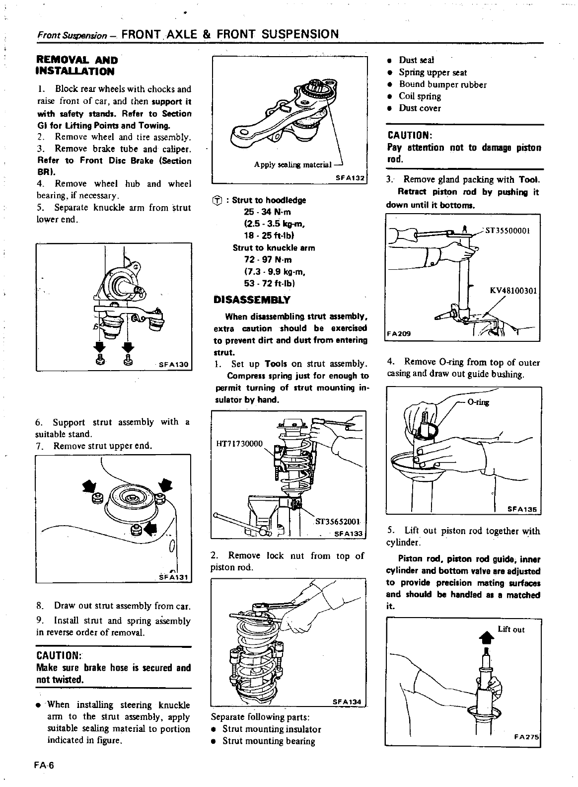
FrontSuspension
FRONT
AXLE
FRONT
SUSPENSION
REMOVAL
AND
INSTAllAnON
Block
rear
wheels
with
chocks
and
raise
front
of
car
and
then
support
it
with
safety
stands
Refer
to
Section
GI
for
Ufting
Points
and
Towing
Remove
wheel
and
tire
assembly
3
Remove
brake
tube
and
caliper
Refer
to
Front
Disc
Brake
Section
BRl
4
Remove
wheel
hub
and
wheel
bearing
if
necessary
5
Separate
knuckle
arm
from
strut
lower
end
r
SFA130
6
Support
strut
assembly
with
a
suitable
stand
7
Remove
strut
upper
end
SFA
31
8
Draw
out
strut
assembly
from
car
9Install
strut
and
spring
assembly
in
reverse
order
of
removal
CAUTION
Make
sure
brake
hose
is
secured
and
not
twisted
When
installing
steering
knuckle
arm
to
the
strut
assembly
apply
suitable
sealing
material
to
portion
indicated
in
figure
FA
6
A
pply
sealing
material
SFA132
GJ
Strut
to
hoodledge
25
34
N
m
2 5 3
5
kg
m
18
25
ft
Ibl
Strut
to
knuckle
arm
72
97
N
m
7 3 9 9
kg
m
53 72
ft
Ibl
DISASSEMBLY
When
disassembling
strut
assambly
extra
caution should
be
exercised
to
prevent
dirt
and
dust
from
entering
strut
Set
up Tools
on
strut
assembly
Compress
spring
just
for
enough
to
permit
turning
of
strut
mounting
in
sulator
by
hand
HT7t730000
ST35652001
SFA133
2
Remove
lock
nut
from
top
of
piston
rod
J
LX
SFA134
Separate
following
parts
Strut
mounting
insulator
Strut
mounting
bearing
Dust
seal
Spring
upper
seat
Bound
bumper
rubber
Coil
spring
Dust
cover
CAUTION
Pay
attention
not
to
damaga
piston
rod
3
Remove
gland
packing
with
Tool
Retract
piston
rod
by
pushing
it
down
until
it
bottoms
J
A
ST35500001
J
FA209
KV48100301
4
Remove
O
ring
from
top
of
outer
casing
and
draw
out
guide
bushing
SFA135
5
Lift
out
piston
rod
together
with
cylinder
Piston
rod
piston
rod
guide
innlr
cylinder
and
bottom
valvl
are
adjusted
to
provide
precilion
mating
surfaces
Ind
should
be
hlndled
IS
I
matched
it
Lift
out
FA275
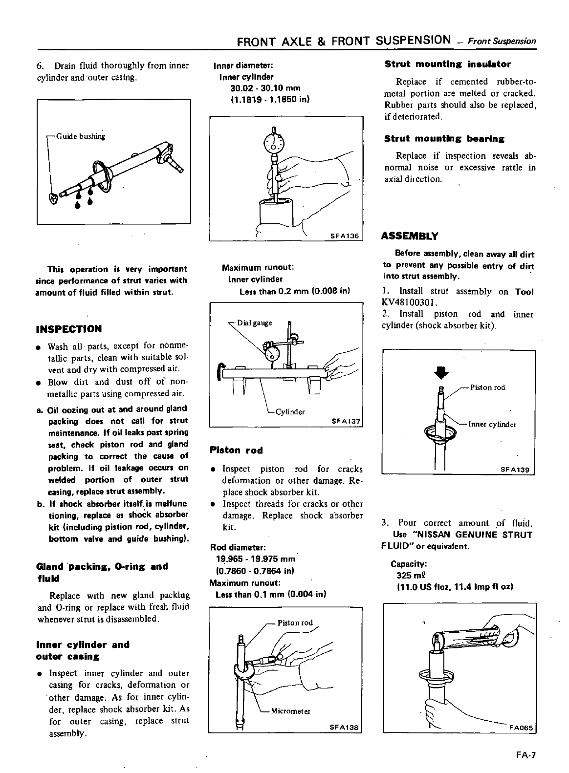
6
Drain
l1uid
thoroughly
from
inner
cylinder
and
outer
casing
r
Guide
bushing
iJ
Thi
operation
i
very
important
since
performance
of
strut
varies
with
amount
of
fluid
filled
within
strut
INSPECTION
Wash
all
parts
except
for
noome
tallic
parts
clean
with
suitable sol
vent
and
dry
with
compressed
air
Blow
dirt
and
dust
off
of
non
metallic
parts
using
compressed
air
8
Oil
oozing
out
at
and
around
gland
packing
does
not
call
for
strut
maintenance
If
oil
leaks
part
pring
at
check
piston
rod
and
gland
packing
to
correct
the
cause
of
problem
If
oil
leakage
occurs
on
welded
portion
of
outer
strut
casing
replace
strut
assembly
b
If
hock
absorber
itself
is
malfunc
tioning
replace
as
shock
absorber
kit
including
pillion
rod
cylinder
bottom
valve
and
guide
bushing
Gland
packing
O
ring
and
fluid
Replace
with
new
gland
packing
and
O
ring
or
replace
with
fresh
l1uid
whenever
strut
is
disassembled
Inner
cylinder
and
outer
casing
Inspect
inner
cylinder
and
outer
casing
for
cracks
deformation
or
other
damage
As
for
inner
cylin
der
replace
shock
absorber
kit
As
for
outer
casing
replace
strut
assembly
FRONT
AXLE
FRONT
SUSPENSION
FrontSuspension
Inner
diameter
Inner
cylinder
30
02
30 10
mm
1
1819
1
1850
in
SFA136
Maximum
runout
Inner
cylinder
Less
than
0 2
mm
0
008
in
t
r
O
cYlinder
SFA137
Piston
rod
Inspect
piston
rod
for
cracks
defoffilation
or
other
damage
Re
place
shock absorber
kit
Inspect
threads
for
cracks
or
ot
her
damage
Replace
shock absorber
kit
Rod
diameter
19
965
19
975
mm
0
7860
0
7864
in
Maximum
runout
Less
than
0
1
mm
0
004
inl
SFA138
Strut
mounting
insulator
Replace
if
cemented
rubber
to
metal
portion
are
melted
or
cracked
Rubber
parts
should
also
be
replaced
if
deteriorated
Strut
mounting bearing
Replace
if
inspection
reveals
ab
normal
noise
or
excessive
rattle
in
axial
direction
ASSEMBLY
Before
assembly
clean
away
all
dirt
to
prevent
any
possible
entry
of
dirt
into
strut
assembly
I
Install
strut
assembly
on
Tool
KV
4810030
I
2
Install
piston
rod
and
inner
cylinder
shock
absorber
kit
Y
Piston
rod
f
M
SFA139
3
Pour
correct
amount
of
fluid
U
e
NISSAN
GENUINE
STRUT
F
LUI
0
or
equivalent
Capacity
325
m2
11
0
US
110z
11
4
Imp
11
ozl
FA
7
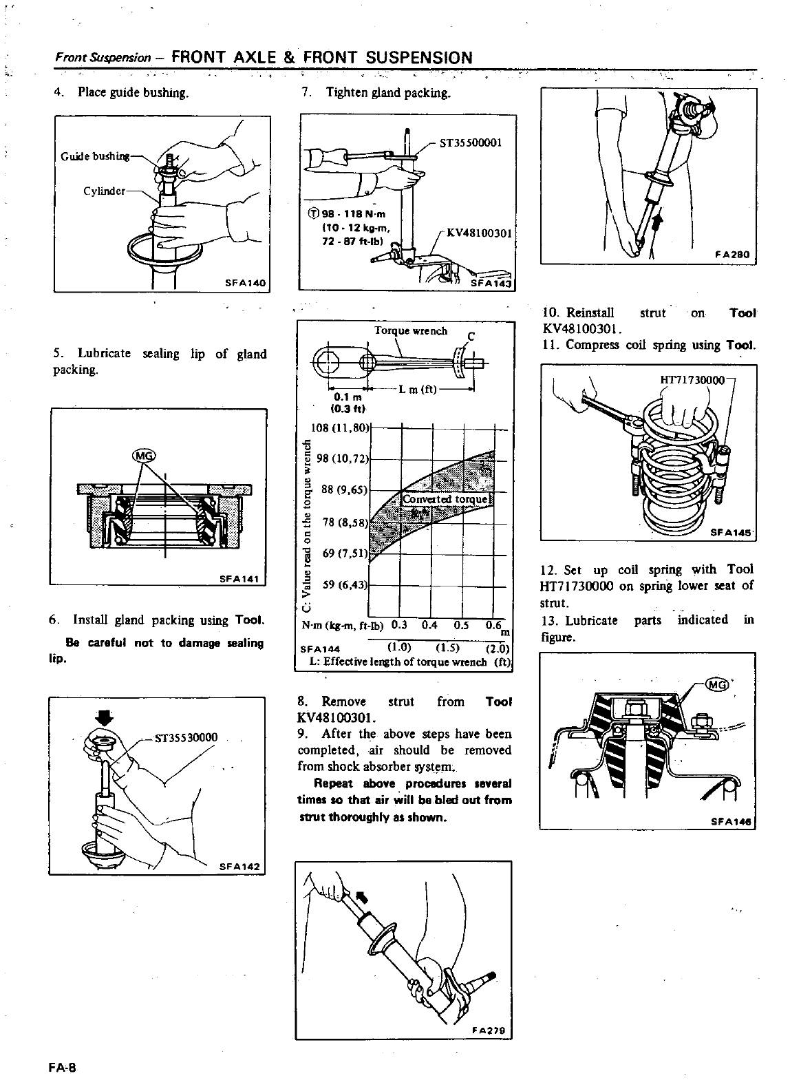
Front
Suspension
FRONT
AXLE
FRONT
SUSPENSION
4Place
guide
bushing
Cylinder
Guide
bu
shing
SFA140
5
Lubricate
sealing
lip
of
gland
packing
SFA141
6Install
gland
packing
using
Tool
Be
careful
not
to
damage
sealing
lip
SFA142
FA
8
7
Tighten
gland
packing
ST3SS00001
LJ
fl98
118
N
m
10
12kg
m
4
72
87ft
SFA143
LorIw
1tch
c
f
Lm
ft
O
1m
0
3ftl
108
11
80
o
E
98
10
12
o
88
9
65
B
o
78
8
58
o
0
3
o
u
Converted
torquel
p
59
6
43
N
m
q
ft
lb
0
3
0
4
0
5
06
m
SFA144
1
0
15
2
0
L
Effective
length
of
torque
wrench
ft
8
Remove
trut
from
Tool
KV48100301
9
After
the
above
steps
have
been
completed
air
should
be
removed
from
shock
absorber
syst
m
Repeat
above
procedure
everal
timal
10 that
air
will
ba
bled
out
from
strut
thoroughly
al
hown
FA
279
1
FA280
10
Reinstall
strut
on
Toot
KV48
10030
I
1
L
Compress
coil
spring
u
ing
Tool
HT71730000
SFA14S
12
Set
up
coil
pring
with
Tool
HT71730000
on
spring
lower
seat
of
strut
13
Lubricate
parts
indicated
in
figure
At
SFA1
48
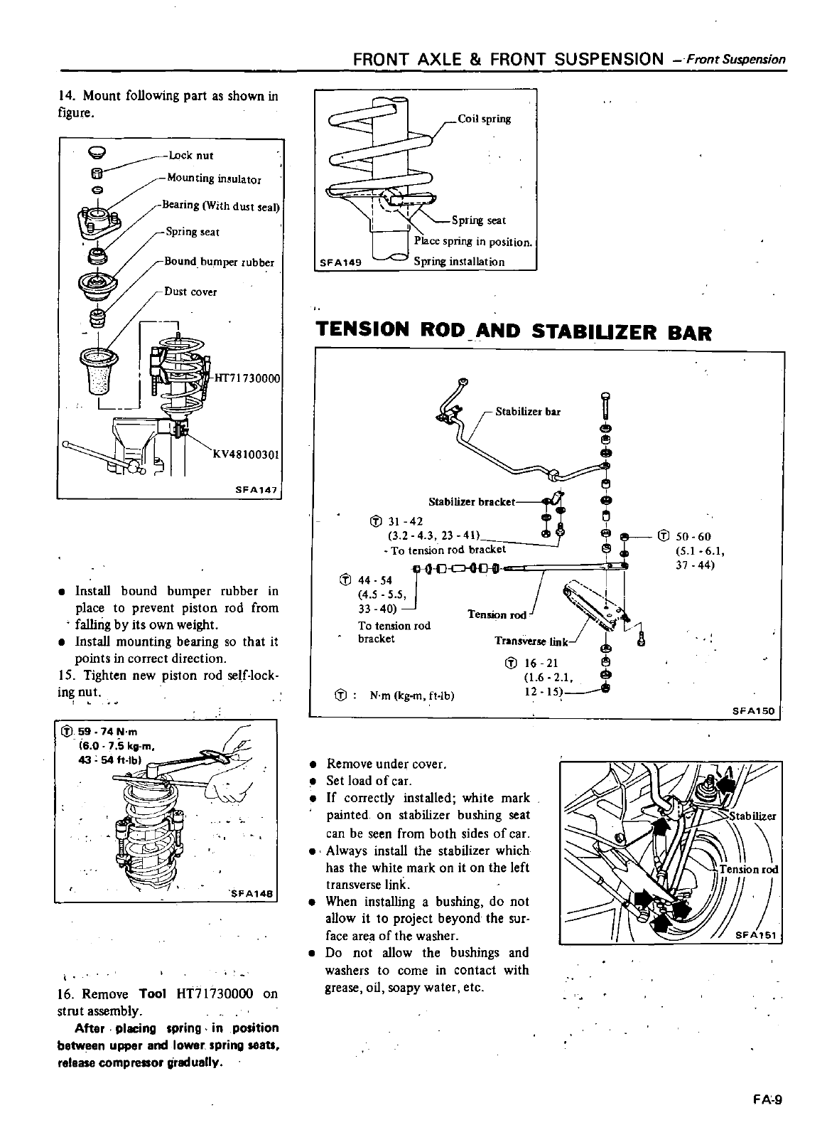
14
Mount
following
part
as
shown
in
figure
G
Lock
nut
Mounting
insulator
c
Bear
ing
With
dust
Seal
spnng
eat
Bound
bumper
rubber
Dust
cover
Hf71730000
LJ
KV48100301
SFA147
Install
bound
bumper
rubber
in
place
to
prevent
piston
rod
from
falling
by
its
own
weight
Install
mounting
bearing
so
that
it
points
in
correct
direction
15
Tighten
new
piston
rod
self
lock
in
nut
IV
59
74N
m
i6
0
1
5k
43 54
ft
Ibl
Uvd
FA148
16
Remove
Tool
HT71730000
on
strut
assembly
After
placing
spring
in
position
between
upper
and
lower
spring
seatl
release
eompreaor
greduelly
FRONT
AXLE
FRONT
SUSPENSION
Front
Suspension
Coil
spring
mi
I
I
I
Sprmg
seat
d
Place
pnng
In
po
ilton
SFA149
Spnng
InstallatIon
TENSION
ROD
AND STABIUZER
BAR
e
Stabilizer
braCketlj
rl1
IV
31
42
3 2 4 3
23
411
IV
50 60
To
tension
rod
bracket
5
1
6
1
IV
44
54
In
cJO
JI
37
44
4 5 5 5
l
33
40
Tension
rod
J
To
tension
rod
t
1
bracket
Transverse
link
A
IV
16
21
1
6 2
1
1215
IV
Nm
kg
m
ft
Ib
SFA150
Remove
under
cover
Set
load
of
car
If
correctly
installed
white
mark
painted
on
stabilizer
bushing
seat
can
be
seen
from
both
sides
of
car
Always
install
the
stabilizer
which
has
the
while
mark
on
it
on
the left
transverse
link
When
installing
a
bushing
do
not
allow
it
to
project
beyond
the
sur
face
area
of
lhe
washer
Do
not
allow the
bushings
and
washers
to
come
in
contact
with
grease
oil
soapy
water
etc
FA
9
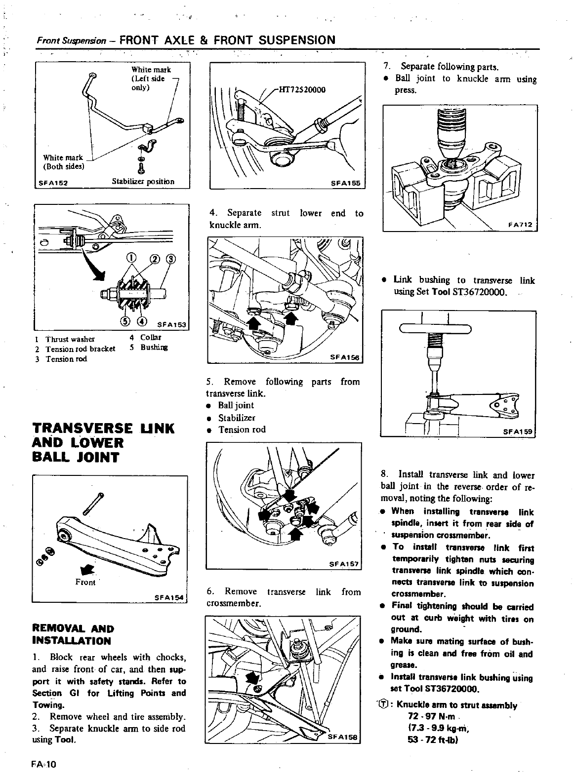
Front
Suspension
FRONT AXLE FRONT
SUSPENSION
White
mark
Left
side
only
White
mark
Both
sides
r
SFA152
Stabilizer
position
CD
1
Tluust
washer
2
Tension
lod
bracket
3
Tension
rod
SFAl53
4
Collar
5 Bu
hins
TRANSVERSE
UNK
AND
LOWER
BALL
JOINT
vtJ
9
Front
SFAl54
REMOVAL
AND
INSTAllATION
I
Block
ear
wheels
with
chocks
and
raise
front
of
car
and
then
up
port
it
with
safety
tand
Refer
to
Section
GI
for
Lifting
Points
and
Towing
2
Remove
wheel and
tire
assembly
3
Separate
knuckle
arm
to
side
rod
using
Tool
FA
10
1IT72520000
SFA155
4
Separate
strut
lower
end
to
knuckle
arm
5
Remove
following
parts
from
transverse
link
I
Balljoint
I
Stabilizer
Tension
rod
SFA1511
6
Remove
transverse
link
from
crossmember
SFAl58
7
Separate
following
parts
I
Ball
joint
to
knuckle
arm
using
press
FA712
I
Unk
bushing
to
transverse
link
using
Set
Tool
ST36720000
f
rG
SFA159
8 Install
transverse
link
and
lower
ball
joint
in
the
reverse
order
of
re
moval
noting
the
following
I
Wh
n
instelling
tremver
link
spindle
insert
it
from
rear
lide
of
suspension
crOS3
I
To
instell
transye
link
first
temporerily
tighten
nuts
securing
tren
ve
link
spindl
which
con
neeu
transven
link
to
suspension
cross
member
I
Finel
tightening
hould
be
carried
out lit
curb
weight
with
tire
on
ground
I
Make
ure
mating
urfe
of
bu
h
ing
is
clean
end
free
from
oil
end
gre
I
Install
tren e
link
bushing
u
ing
set
Tool
ST36720000
tfl
Knuckl
erm
to
strut
IISIllmbly
72
97
N
m
17
39
9
kg
ni
53
72
ft
lb
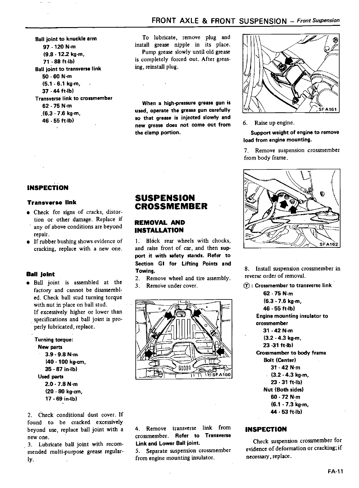
Ball
joint
to
knuckle
arm
97
120
N
m
9 8
122
kg
m
71
88
ft
Ibl
Ball
joint
to
transvene
link
50 60
N
m
5
1
6
1
kg
m
37 44
ft
Ibl
Transverse
link
to
crossmember
62
75
N
m
16
3 7 6
kg
m
46
55
ft
lb
INSPECTION
Transv
rs
link
Check
for
signs
of
cracks
distor
tion
or
other
damage
Replace
if
any
of
above
conditions
are
beyond
repair
If
rubber
bushing
shows
evidence
of
cracking
replace
with
a
new
one
Ball
Joint
BaIl
joint
is
assembled
at
the
factory
and
cannot
be
disassembl
ed
Check
ball
stud
turning
torque
with
nut
in
place
on
ball
stud
If
excessively
higher
or
lower
than
specifications
and
ball
joint
is
pro
perly
lubricated
replace
Turning
torque
New
parts
3
9
9
8
N
m
40
100
kltcm
35
87 in
Ibl
Used
parts
2
0
7
8N
m
20
80
kg
em
17
69 in
Ibl
2
Check
conditional
dust
cover
If
found
to
be
cracked
excessively
beyond
use
replace
ball
joint
with
a
new
one
3
Lubricate
ball
joint
with
recom
mended
multi
purpose
grease
regular
ly
FRONT
AXLE
FRONT
SUSPENSION
FrontSuspension
To
lubricate
remove
plug
and
install
grease
nipple
in
its
place
Pump
grease
slowly
until
old
grease
is
completely
forced
out
After
greas
ing
reinstall
plug
When
a
high
pressure
grease
gun
is
used
operate
the
grease
gun
carefully
so
that
grease
is
injected
slowly
and
new
grease
does
not
come
out
from
the
clamp
ponion
SUSPENSION
CROSSMEMBER
REMOVAL
AND
INSTALLATION
I
Bl6ck
rear
wheels
with
chocks
and
raise
front
of
car
and
then
sup
port
it
with
safety
stands
Refer
to
Section
GI
for
Lifting
Points
and
Towing
2
Remove
wheel
and
tire
assembly
3
Remove
under
cover
4
Remove
transverse
link
from
crossmember
Refer
to
Tran
vene
Link
and
Lower
Ball
joint
S
Separate suspension
crossmember
from
engine
mounting
insulator
6
Raise
up
engine
Support
weight
of
engine
to
remove
load
from
engine
mounting
7
Remove
suspension
crossmember
from
body
frame
8
Install
suspension
crossmember
in
reverse
order
of
removal
f
Crossmember
to
transverse
link
62 75
N
m
6 3 7 6 kg
m
46 55
ft
Ibl
Engine
mounting
insulator
to
crossmember
31
42
N
m
32
43
kg
m
23
31
ft
Ibl
Crossmember
to
body
frame
Bolt
Center
31
42
N
m
3 2
4
3
kg
m
23
31
ft
Ibl
Nut
Both
sidesl
60
72
N
m
6
1
7 3
kg
m
44
53
ft
Ib
INSPECTION
Check
suspension
crossmember
for
evidence
of
deformation
or
cracking
if
necessary
replace
FA
l1
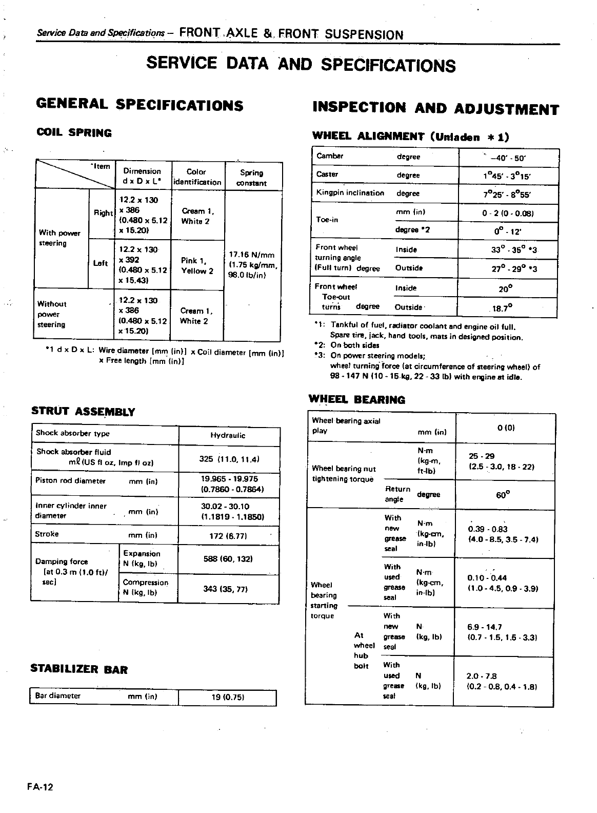
Service
Os
tBsndSpecifications
FRONT
AXLE
FRONT
SUSPENSION
SERVICE
DATA
AND
SPECIFICATIONS
GENERAL
SPECIFICATIONS
COIL
SPRING
Color
identification
Spring
constant
Dimension
d
DxL
12
2
30
Right
386
ere
m
1
0
480
5
12
White
2
With
power
5
201
steering
12
2
130
1716
N
mm
Lah
392
Pink
1
1
75
kg
mm
10
480
5
12
Yellow
2
98
0Iblin
5
43
Without
power
steering
2
2
30
x
3S6
Cream
1
0
480
x
5
12
White
2
5
20
d
x
0
xL
Wire
diameter
mm
lin
x
Coil
diameter
mm in
x
Free
length
mm
in
STRUT
ASSE
MBLY
I
Shock
absorber
type
I
Shock
absorber
fluid
mQ
US
fl
OZ
Imp
fl
ozl
l
Piston
rod diameter
mm
in
linneI
cylinder
inner
diameter
mm
i
n
I
Stroke
mm
in
I
Expansion
Damping
force
N
kg
Ibl
t
0 3
m
11
0
hI
see
I
Compression
N
k9
lb
HYdraulic
325
11
0
114
19
965
19
975
10
7860
0
7864
30
02
30
10
11
1819
1
1850
172
16
77
588
tOO
132
J43
135
77
STABILIZER
BAR
I
Bar
diameter
mm in
t9
10
75
FA
12
INSPECTION
AND
ADJUSTMENT
WHEEL
ALIGNMENT
Unladen
1
1
Camber
degree
40
50
I
Caster
degree
045
3015
Kingpin
inclination
degree
1025
S055
mm
in 0
2
00
081
Toe
in
degree
2
0
12
Front
wheel Inside
330
350
3
turning
ngle
290
3
Full
turn
degree
Outside
270
Front
wheel Inside
200
Toe
out
turns
degree
Outside
18
70
1
Tankful
of
fuel
radiator
coolant
and
engine
oil
full
Spare
tire
jack
hand
tools
mats
in
designed
position
2
Onboth
sides
3
On
power
steering
models
wheel
turning
force
tat
circumference
of
steering
wheel of
98
147N
10
15 kg
22
33
Ibl
with
engine
at
idle
WHEEL BEARING
Wheel
bearing
axial
play
mm in
N
m
kg
m
Wheel
bearing
nut
ft
lbl
tightening
torque
Return
degree
angle
With
N
m
new
kgan
gre
in
lbl
se
1
With
N
m
used
kg
cm
Wheel gro
bearing
se
l
in
lbl
starting
torque With
new
N
At
grease
Ik9
lbl
wheel
seal
hub
bolt
With
usad
N
grease
Ik9
lb
se
t
0
01
25
29
2 5 3
0
18
22
600
0
39
0
83
14
0
S
5
3
5
741
0
10
0
44
1
0 45 0
9
3
91
6
9
14
7
fO
7
1
5
1
5
33
2
0
7B
10
2 0
8
04
1
8
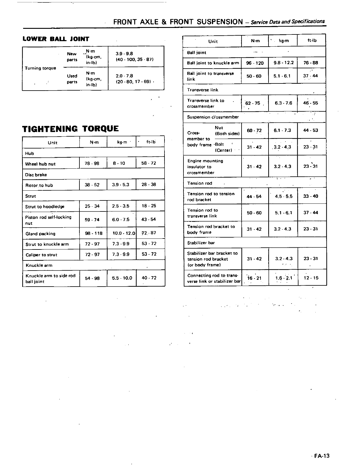
FRONT
AXLE
FRONT
SUSPENSION
ServiceOataandSpecifications
LOWER
BAlL
JOINT
New
N
m
3 9
98
parts
kg
em
140
100
35
871
in
Ibl
Turning
torque
Used
N
m
2 0 7
8
parts
kg
em
120
80
17
691
Ibl
TIGHTENING
TORQUE
I
Unit
I
N
m
I
kg
mft
Ib
I
Hub
I
Wheel
hub
nut
I
78 98
8
10
I
58 72
I
Disc
brake
I
Rotor
to
hub
I
38 52
I
3953
I
28 38
I
Strut
I
Strut
to
hoodledge
25 34
25 3 5
18
25
I
Piston
rod
sei
Iocklng
59
74
60
7 5
43 54
nut
Gland
packing
9B
118
10
0
12
0
U2
87
Strut
to
knuckle
arm
72
97
7 3 9
9
53 72
Caliper
to
strut
72 97
7 3 9
9
53 72
Knuckle
arm
I
Knuckle
arm
to
side
rod
54
98
5 5
10
0
I
40 72
ball
joint
FA
13
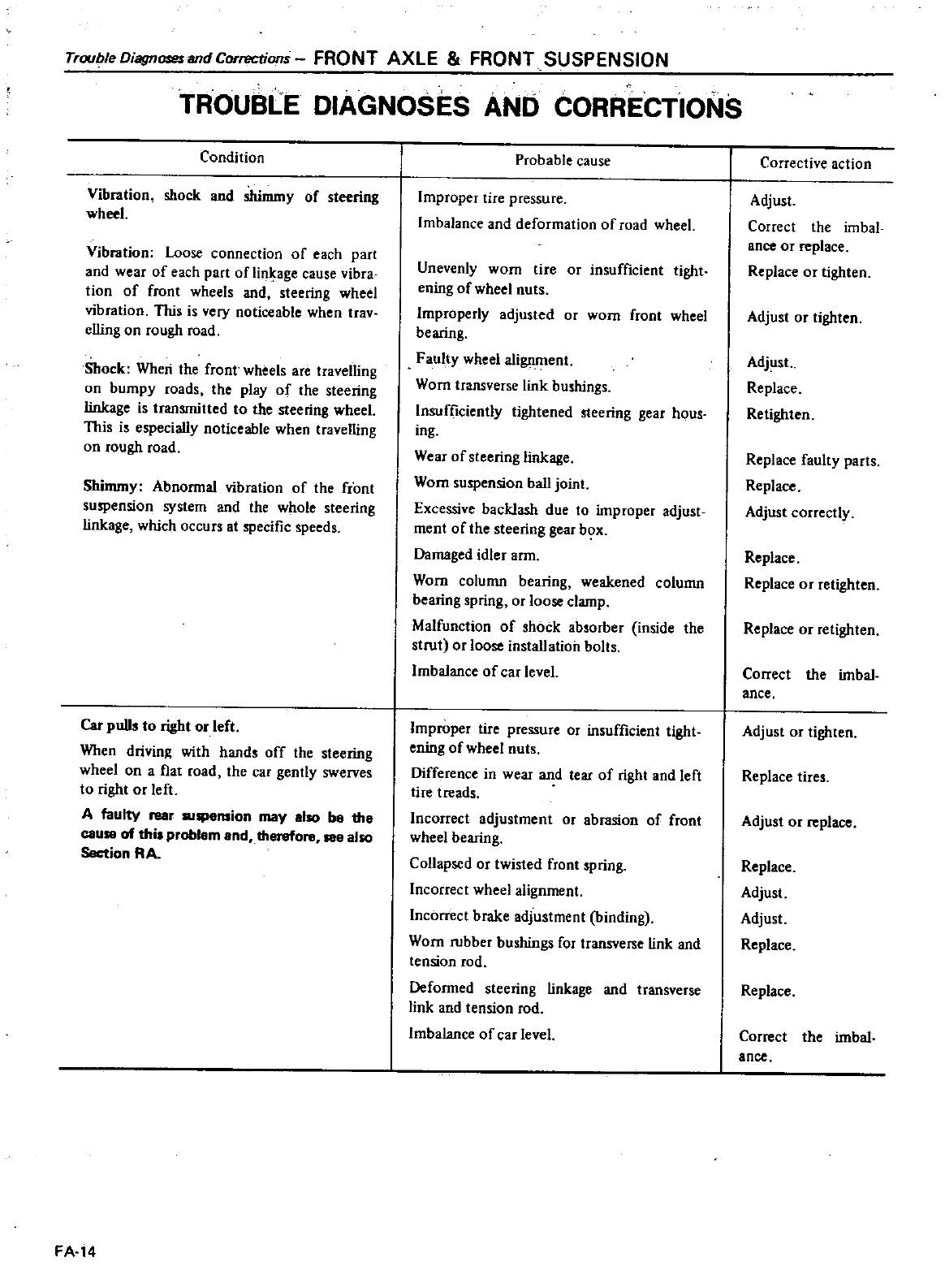
Trou
Jle
Diagnoses
and
Corrections
FRONT
AXLE
FRONT
SUSPENSION
TROUBLE
DIAGNOSES
AND
CORRECTIONS
Condition
Vibration
shock
and
shimmy
of
steering
wheel
Vibration
Loose
connection
of
each
part
and
wear
of
each
part
of
Iini
age
cause
vibra
tion
of
front
wheels
and
steering
wheel
vibration
This
is
very
noticeable
when
trav
elling
on
rough
road
Shock
When
the
front
wheels
are
travelling
on
bumpy
roads
the
play
of
the
steering
linkage
is
transmitted
to
the
steering
wheel
This
is
especially
noticeable
when
travelling
on
rough
road
Shimmy
Abnormal vibration
of
the
front
suspension
system
and
the
whole
steering
linkage
which
occurs
at
specific
speeds
Car pulls
to
right
or
left
When
drivin
with
hands
off
the
steering
wheelan
aflat
road
the
car
gently
swerves
to
right
or
left
A
faulty
rear
lII
ellSion
may
also
b8 the
caUI8
of
this
problem
and
therefore
188
also
Sectinn
RA
FA
14
Probable
cause
Improper
tire
pressure
Imbalance
and
deformation
of
road wheel
Unevenly
wom
tire
or
insufficient
tight
ening
of
wheel
nuts
Improperly
adjusted
or
wom
front
wheel
bearing
Faulty
wheel
alignment
Wom
transverse
link
bushings
Insufficiently
tightened
steering gear
hous
ing
Wear
of
steering
linkage
Wom
suspension
ball
joint
Excessive
backlash
due
to
improper
adjust
ment
of
the
steering
gear
box
Damaged
idler
arm
Worn column
bearing
weakened
column
bearing
spring
or
loose
clamp
Malfunction
of
shock absorber inside
the
strut
or
loose
installation
bolts
Imbalance
of
car
level
Improper
tire
pressure
or
insufficient
tight
ening
of
wheel
nuts
Difference
in
wear
and tear
of
right
and
left
tire
treads
Incorrect
adjustment
or
abrasion
of
front
wheel
bearing
Collapsed
or
twisted
front
spring
Incorrect
wheel
alignment
Incorrect brake
adjustment
binding
Worn
rubber
bushings
for
transverse
link
and
tension
rod
Deformed
steering
linkage
and
transverse
link
and
tension
rod
Imbalance
of
car
level
Corrective
action
Adjust
Correct
the
imbal
ance
or
replace
Replace
or
tighten
Adjust
or
tighten
Adjust
Replace
Retighten
Replace
faulty
parts
Replace
Adjust
correctly
Replace
Replace
or
retighten
Replace
or
retighten
Correct
the
imbal
ance
Adjust
or
tighten
Replace
tires
Adjust
or
replace
Replace
Adjust
Adjust
Replace
Replace
Correct
the
imbal
ance
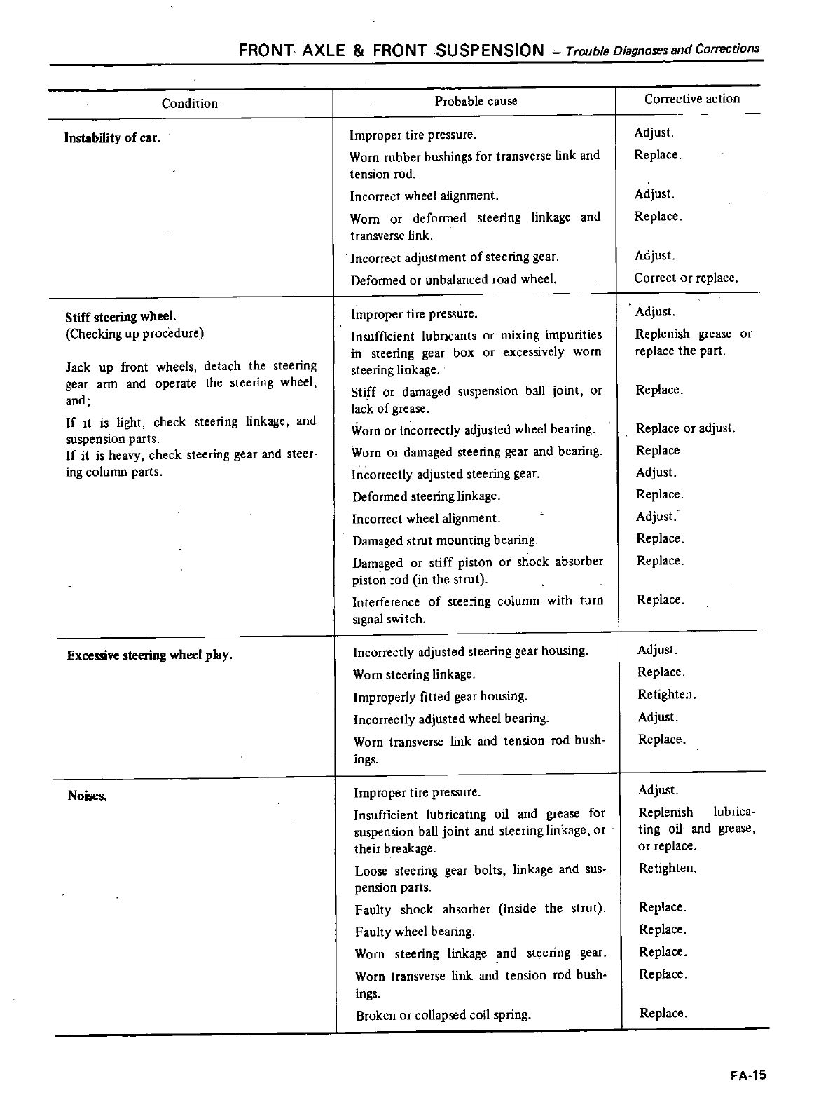
FRONT
AXLE
FRONT
SUSPENSION Trouble
Diagnoses
and
Corrections
Condition
Instability
of
car
Stiff
steering
wheel
Checking
up
procedure
Jack
up
front
wheels
detach
the
steering
gear
arm
and
operate
the
steering
wheel
and
If
it
is
light
check
steering
linkage
and
suspension
parts
If
it
is
heavy
check
steering
gear
and
steer
ing
column
parts
Excessive
steering
wheel
play
Noises
Probable
cause
Improper
tire
pressure
Worn
rubber
bushings
for
transverse
link
and
tension
rod
Incorrect
wheel
alignment
Worn
or
deformed
steering
linkage
and
transverse
link
Incorrect
adjustment
of
steering
gear
Deformed
or
unbalanced
road
wheel
Improper
tire
pressure
Insufficient
lubricants
or
mixing impurities
in
steering
gear
box
or
excessively
worn
steering
linkage
Stiff
or
damaged
suspension
ball
joint
or
lack
of
grease
Worn
or
incorrectly
adjusted
wheel
bearing
Worn
or
damaged
steering
gear
and
bearing
Incorrectly
adjusted
steering
gear
Deformed
steering
linkage
Incorrect
wheel
alignment
Damaged
strut
mounting
bearing
Damaged
or
stiff
piston
or
shock absorber
piston
rod
in
the
strut
Interference
of
steering
column
with
turn
signal
swi
tch
Incorrectly
adjusted
steering
gear
housing
Worn
steering
linkage
Improperly
fitted
gear
housing
Incorrectly
adjusted
wheel
bearing
Worn
transverse
link
and
tension
rod bush
ings
Improper
tire
pressure
Insufficient
lubricating
oil
and
grease
for
suspension
baU
joint
and
steering
linkage
or
their
breakage
Loose
steering
gear
bolts
linkage
and
sus
pension
parts
Faulty
shock absorber
inside
the
strut
Faulty
wheel
bearing
Worn
steering
linkage
and
steering
gear
Worn
transverse
link
and
tension
rod bush
ings
Broken
or
coUapsed
coil
spring
Corrective
action
Adjust
Replace
Adjust
Replace
Adjust
Correct
or
replace
Adjust
Replenish
grease
or
replace
the
part
Replace
Replace
or
adjust
Replace
Adjust
Replace
Adjust
Replace
Replace
Replace
Adjust
Replace
Retighten
Adjust
Replace
Adjust
Replenish
lubrica
ting
oil
and
grease
or
replace
Retighten
Replace
Replace
Replace
Replace
Replace
FA
15
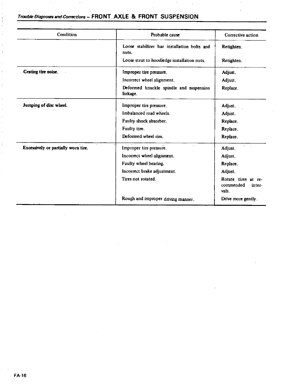
Trouble
DiagnmsundCorTfICtions
FRONT
AXLE
FRONT
SUSPENSION
Condition
Probable
cause
Loose
stabilizer
bar
installation
bolts
and
nuts
Loose
strut
to
hoodledge
installation
nuts
Grating
tire
noise
Improper
tire
pressure
Incorrect
wheel
alignment
Deformed knuckle
spindle
and
suspension
linkage
Jumping
of
disc
wheel
Improper
tire
pressure
Imbalanced
road
wheels
Faulty
shock
absorber
Faulty
tire
Deformed
wheel
rim
Excessively
or
partially
worn
tire
Improper
tire
pressure
Incorrect
wheel
alignment
Faulty
wheel
bearing
Incorrect
brake
adjustment
Tires
not
rotated
Rough
and
improper
driving
manner
FA
16
Corrective
action
Retighten
Retighten
Adjust
Adjust
Replace
Adjust
Adjust
Replace
Replace
Replace
Adjust
Adjust
Replace
Adjust
Rotate
tires
commended
val
Drive
more
gently
at
re
inter
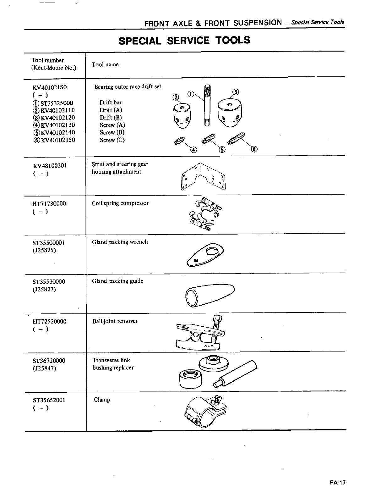
Tool
number
Kent
Moore
No
KV401021S0
CD
ST35325000
@KV40102110
@KV40102120
@KV40102130
CID
KV
40
102140
@KV40102150
KV48100301
HT71730000
ST35500001
125825
ST35530000
125827
HT72520000
ST36720000
125847
ST35652001
FRONT
AXLE
FRONT
SUSPENSION
Special
Service
Tool
SPECIAL
SERVICE
TOOLS
Tool
name
Bearing
outer
race
drift
set
Drift
bar
Drift
A
Drift
B
Screw
A
Screw
B
Screw
C
Strut
and
steering
gear
housing
attachment
Coil
spring
compressor
G
land
packing
wrench
Gland
packing
guide
Ball
joint
remover
Transverse
link
bushing
replacer
Clamp
V
V
I
J
tL
t
3
o
FA
17
DATSUN
200SX
Model
SIlO
Series
SECTIONRA
REAR
AXLE
REAR
SUSPENSION
REAR
AXLE
REAR
AXLE
REAR
AXLE
ASSEMBLY
REAR
AXLE
SHAFT
AND
WHEEL
BEARING
REAR
SUSPENSION
REAR
SUSPENSION
STABILIZER
BAR
SHOCK
ABSORBER
COIL
SPRING
UPPER
LINK
AND
LOWER
LINK
CONTENTS
RA
2
RA
2
RA
2
RA
3
RA
5
RA
5
RA
6
RA
6
RA
7
RA
7
SERVICE
DATA
AND
SPECIFICATIONS
GENERAL
SPECIF
ICA
TIONS
INSPECTION
AND
ADJUSTMENT
TIGHTENING
TORGUE
TROUBLE
DIAGNOSES
AND
CORRECTIONS
SPECIAL
SERVICE
TOOLS
RA
8
RA
8
RA
8
RA
8
RA
9
RA
lO
GII
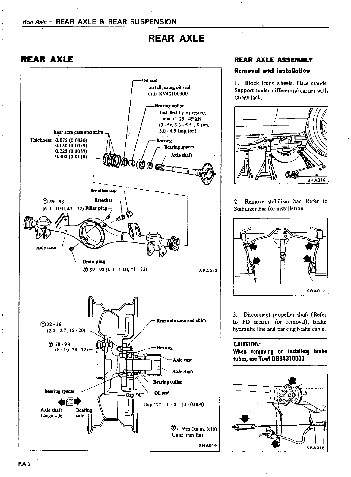
RearAxle
REAR
AXLE
REAR
SUSPENSION
REAR
AXLE
REAR
AXLE
Oil
w
Install
using
oil
seal
drift
KV40100300
Rear
axle
cue
end
shim
BeuiDg
coner
Installed
by
a
p
ing
force
of
29
49
kN
3
5t
3 3 5 5
US
ton
3
0
4
9
Imp
ton
Thickne
0
075
0
0030
0
150
0
0059
0
225
0
0089
0
300
0
0118
I
L
llteatherCOP
l
Breather
72
Filler
PI 1
72
SAA013
C
J22
26
2
2
2 7
16 20
Rear
axle
cue
end
shim
C
J
78 98
8
10 58
72
BeuiDg
Ax1
I
II
ease
Axle
shafl
Bearingcol1ar
Bearing
spacer
fiJ
Aal
shaft
Beerin8
fIanse
side
ide
1
r
f
Gap
C
0iI
w
W
Gap
C
0
0
1
0
0
004
J
C
J
N
m
kg
m
ft
Ib
Unit
rom in
SAA014
RA
2
REAR
AXLE
ASSEMBLY
Removal
and
Inatallatlon
Block
front
wheels
Place
stands
Support
under
differential
carrier
with
garage
jack
I
I
A
2
Remove
stabilizer
bar
Refer
to
Stabilizer
Bar
for
installation
4
1
I
It
SAA017
3
Disconnect
propeller
shaft
Refer
to
PO
section
for
removal
brake
hydraulic
line
and
parking
brake
cable
CAUTION
When
removing
or
installing
brake
tubes
use
Tool
GG94310000
t
e
c
C
SRA018
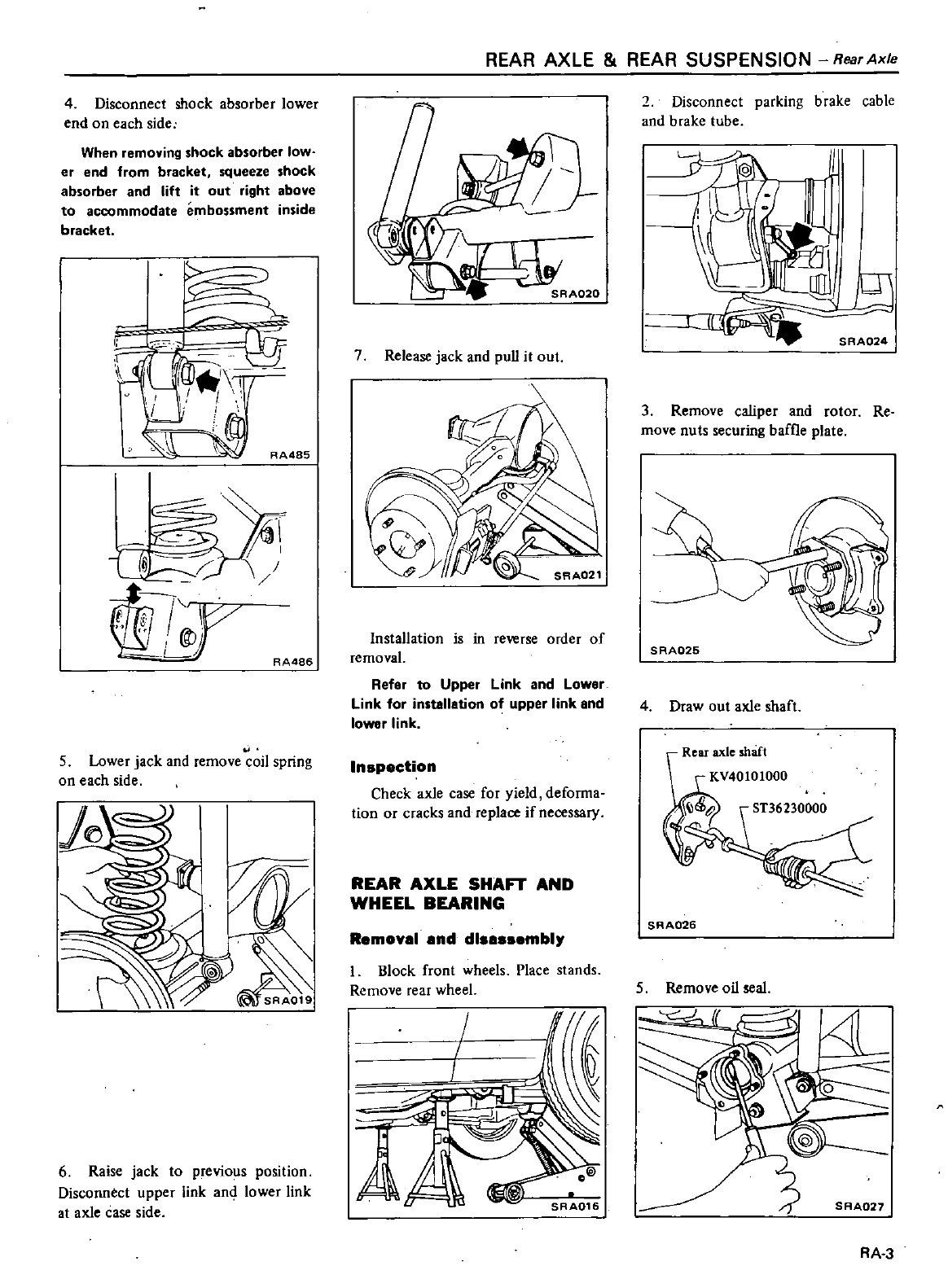
4
Disconnect
shock absorber
lower
end
on
each
side
When
removing
shock
absorber
low
er
end
from
bracket
squeeze
shock
absorber
and
lift
it
out
right
above
to
accommodate
embossment
inside
bracket
F
p
c
iI
y
II
I
I
I
l
RA485
It
R
A486
5
Lower
jack
and
remove
coil
spring
on
each
side
jf
6Raise
jack
to
previous
position
Disconnect
upper
link
and
lower
link
at
axle
case
side
REAR
AXLE
REAR
SUSPENSION
Rear
Axle
7
Release
jack
and
pull
it
out
Installation
is
in
reverse
order
of
removal
Refer
to
Upper
Link
and
Lower
Link
for
installation
of
upper
link
and
lower
link
In
p
ction
Check
axle
case
for
yield
deforma
tion
or
cracks
and
replace
if
necessary
REAR
AXLE
SHAFT
AND
WHEEL
BEARING
R
mov
1
nd
dl
mbl
I
Block
front
wheels
Place
stands
Remove
rear
wheel
A
2
Disconnect
parking
brake
cable
and
brake tube
3
Remove
caliper
and
rotor
Re
move
nuts
securing
baffle
plate
4
Draw
out
axle
shaft
Rear
axle
shaft
SAA026
5
Remove
oil
seal
4
SAA027
RA 3
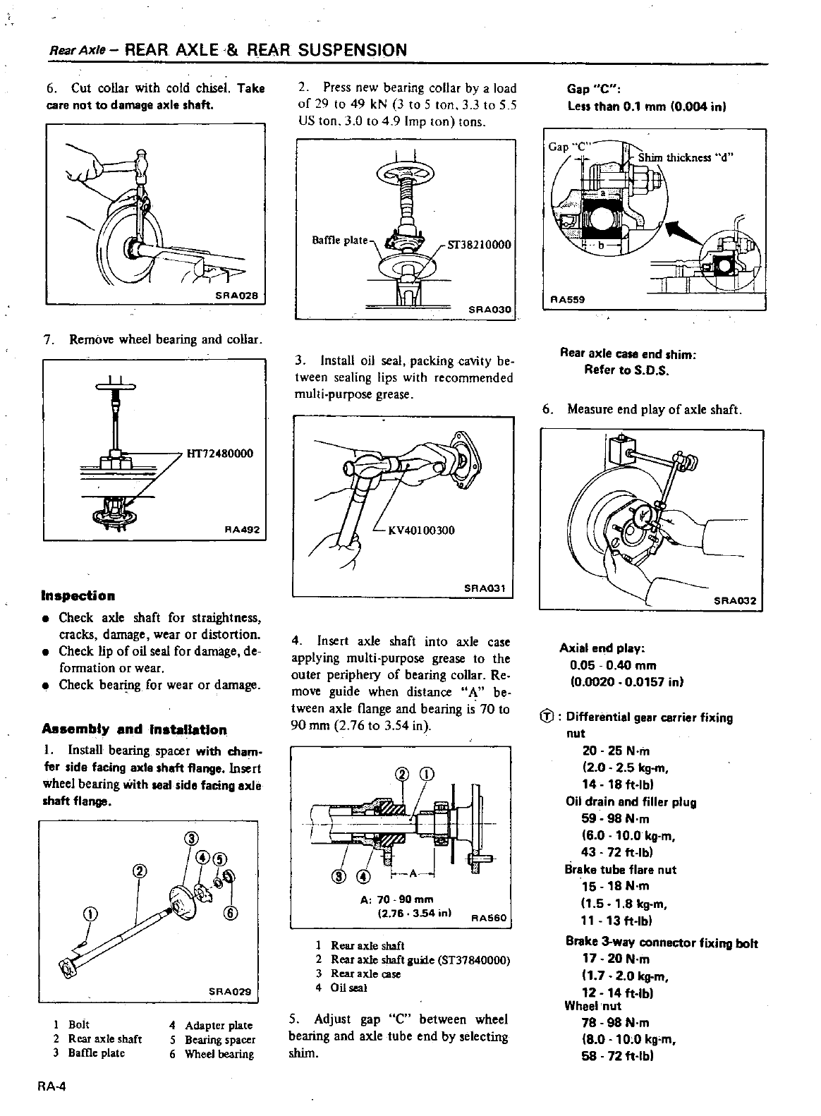
Rear
Axle
REAR
AXLE
REAR
SUSPENSION
6
Cut
collar
with
cold
chisel
Take
care
not to
damage
axle
sheft
SRA028
7
Remove
wheel
bearing
and
collar
L
l
AA492
Inspection
Check
axle
shaft
for
straightness
cracks
damage
wear
or
distortion
Check
lip
of
oil
seal
for
damage
de
formation
or
wear
Check
bearing
for
wear
or
damage
Assembly
and
Installation
I
Install
bearing
spacer
with
cham
fer
ide
facing
axle
haft
flange
Insert
wheel
bearing
with
seal
ido
facing
ollie
haft
flange
CD
SRAQ29
1
Bait
2
Rear
axle
shaft
3
Bame
plate
4
Adapter
plate
5
Bearing
spacer
6
Wheel
bearing
RA
4
2
Press
new
bearing
collar
by
a
load
of
29
to
49
kN
3
to
5
ton
3 3
to
5 5
US
ton
3
0
to
4
9
Imp
Ion
Ions
Baffle
plate
SRA030
3
Install
oil
seal
packing
cavity
be
tween
sealing
lips
with
recommended
multi purpose
grease
KV40100300
SAA031
4
Insert
axle
shaft
into
axle
case
applying
multi purpose
grease
to
the
outer
periphery
of
bearing
collar
Re
move
guide
when
distance
A
be
tween
axle
l1ange
and
bearing
is
70
to
90
mm
2
76
to
3
54 in
CD
1
J
9
AJ
r
A
70
90mm
12
76
3
54
in
RA560
1
Rear
axle
shaft
2
Rear
axle
shaft
gune
ST37840000
3
Rear
axle
case
4
Oil
seal
5Adjust
gap
C
between
wheel
bearing
and
axle
tube
end
by
selecting
shim
Gap
C
less
than
0
1
mm
0
004
in
i
Shim
thickness
d
W
II
IIII
AA559
Rear
axle
case
end
him
Refer
to
S
O
S
6
Measure
end
play
of
axle
shaft
SAA032
Axial
end
play
0
05
0
40
mm
0
0020
0
0157
in
fl
Differential
gear
carrier
fixing
nut
20 25
N
m
2
0
2
5
kg
m
14
18
ft
lbl
Oil
drain
and
filler
plug
59 98
N
m
6
0
10 0
kg
m
43 72
ft
Ibl
Brake
tube flare
nut
15 18 N
m
1
5
1
8
kg
m
11
13
ft
lb
Brake
3
way connector
fixing
bolt
17
20
N
m
1
7
2
0
kg
m
12 14
ft
Ibl
Wheel
nut
78 98
Nm
8 0
10
0
kg
m
58
72
ft
Ibl
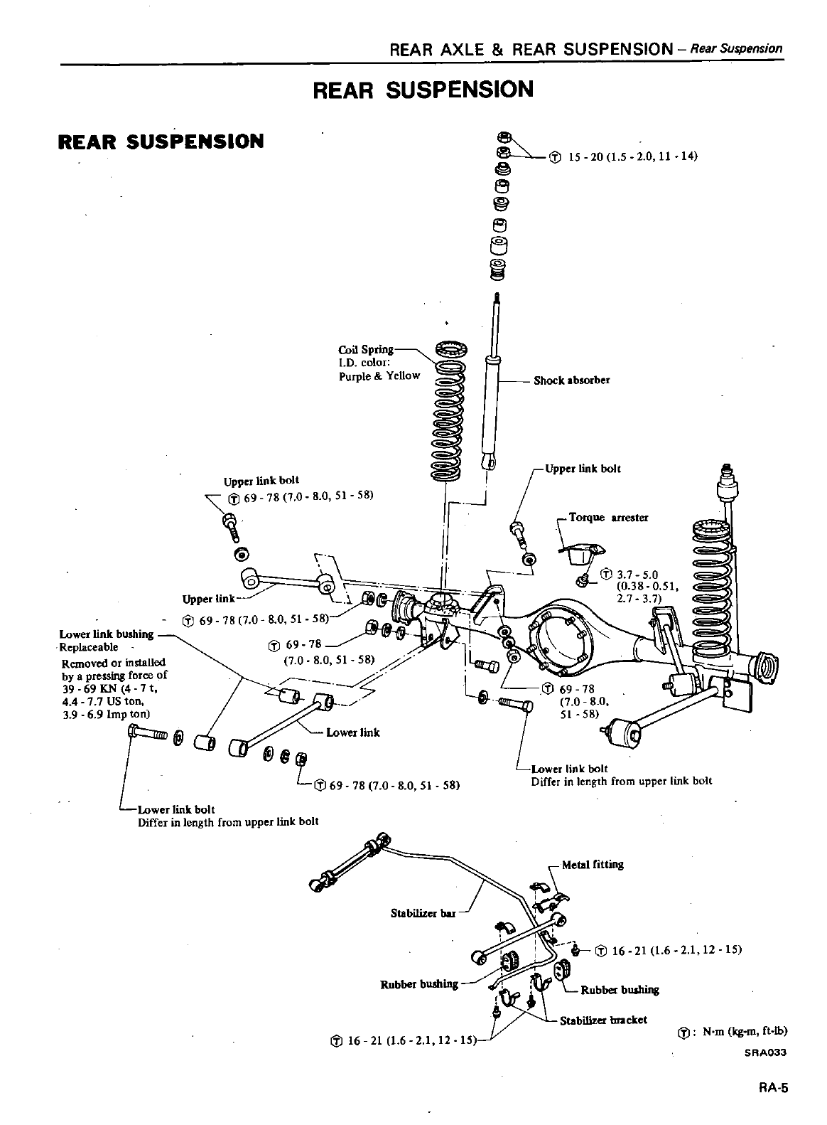
REAR
AXLE
REAR
SUSPENSION
Rear
Suspension
REAR
SUSPENSION
REAR
SUSPENSION
dl
@
e
e
e1
1
15
20
15
2
0
11
14
Coil
Spring
l
D
color
Purple
YeUow
Shock
absorber
Upper
link
bolt
8
0
51
58
dl
3 7
5
0
0 38
0
51
2
7
3 7
Lower
link
bushing
Replaceable
Removed
or
installed
by
a
pressing
force
of
39
69
KN
4
11
4
4
7 7
US
ton
3
9 6
9
Imp
ton
Differ
in
length
from
upper
link
bolt
78
7
0 8 0
51
58
Differ
in
length
from
upper
link
bolt
dl16
21
1
6 2 1
12
21
12 15
dl
N
m
kg
ft
lb
SAA033
AA
5
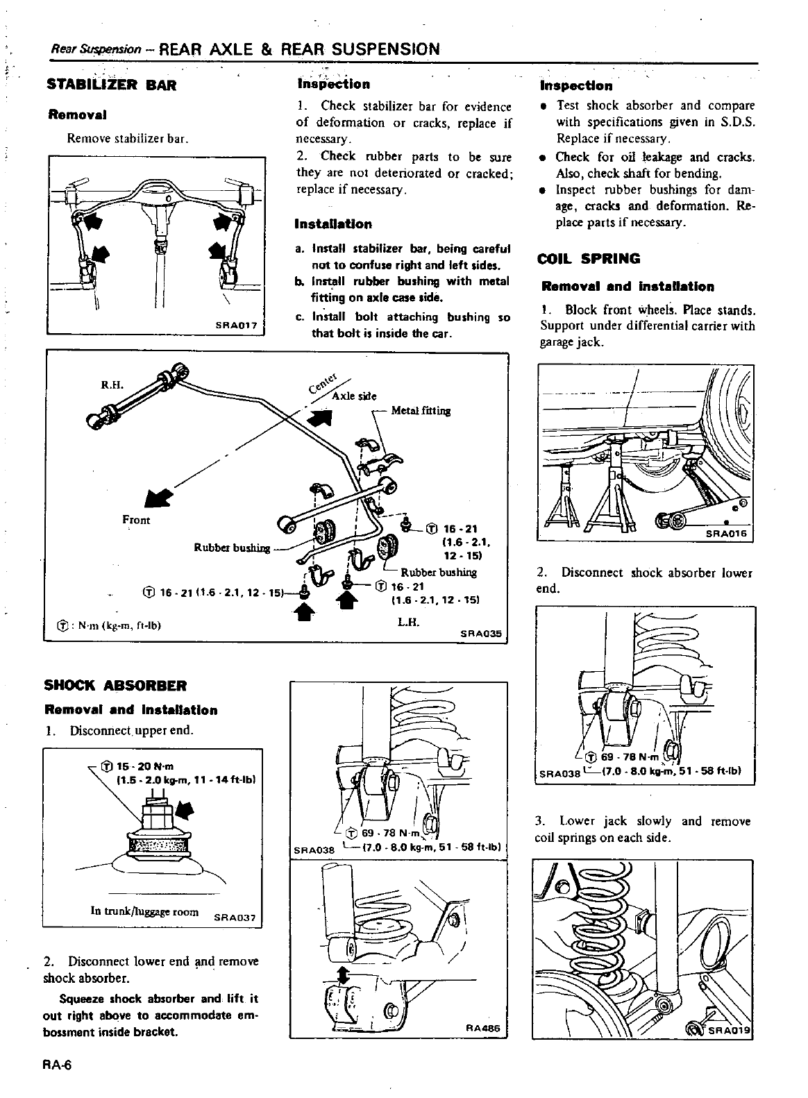
Rear
Suspension
REAR
AXLE
REAR
SUSPENSION
STABILIZER
BAR
Remoyal
Remove
stabilizer
bar
P
fI
II
SRA017
Front
IV
16
2111
6
2
1
12
IV
N
m
kg
m
ft
Ib
SHOCK
ABSORBER
Remoyal
and
Installation
I
Disconnect
upper
end
14ft
lbl
1
T
In
trunk
luggage
room
SRA037
2
Disconnect
lower
end
md
remme
shock absorber
Squeeze
shock
absorber
and
lift
it
out
right
above
to
accommodate
em
bossment
inside
bracket
RA
6
Inspection
I
Check
stabilizer
bar
for
evidence
of
deformation
or
cracks
replace
if
necessary
2
Check
rubber
parts
to
be
sure
they
are
not
deteriorated
or
cracked
replace
if
necessary
Installation
a
Install
stabilizer
bar
being
careful
not to
confuse
right
and
left
sides
b
InstJ
U
rubber
bushing
with
metal
fining
on
axle
case
lide
c
Install
bolt
attaching
bushing
so
that
bolt
is
inside
the
car
21
11
6
2
1
SRA035
s
C
fl
ilr
SAA038
L
7 0
80
kg
m
51
58
ft
lbl
c
i
r
I
I
t
t
r
RA486
Inspection
Test
shock absorber
and
compare
with
specifications
given
in
S
O
S
Replace
if
necessary
Check
for
oil
leakage
and
cracks
Also
check
shaft
for
bending
Inspect
rubber
bushings
for
dam
age
cracks
and
deformation
Re
place
parts
if
necessary
COIL
SPRING
Remoyal
end
Installation
I
Block
front
wheels
Place
stands
Support
under
differential
carrier
with
garage
jack
L
SRA016
2
Disconnect
shock absorber
lower
end
C
IY
LIV6
78N
ml
SRA038
L
7
0 80
kg
m
51
58
ft
lbl
3
Lower
jack
slowly
and
remove
coil
springs
on
each
side
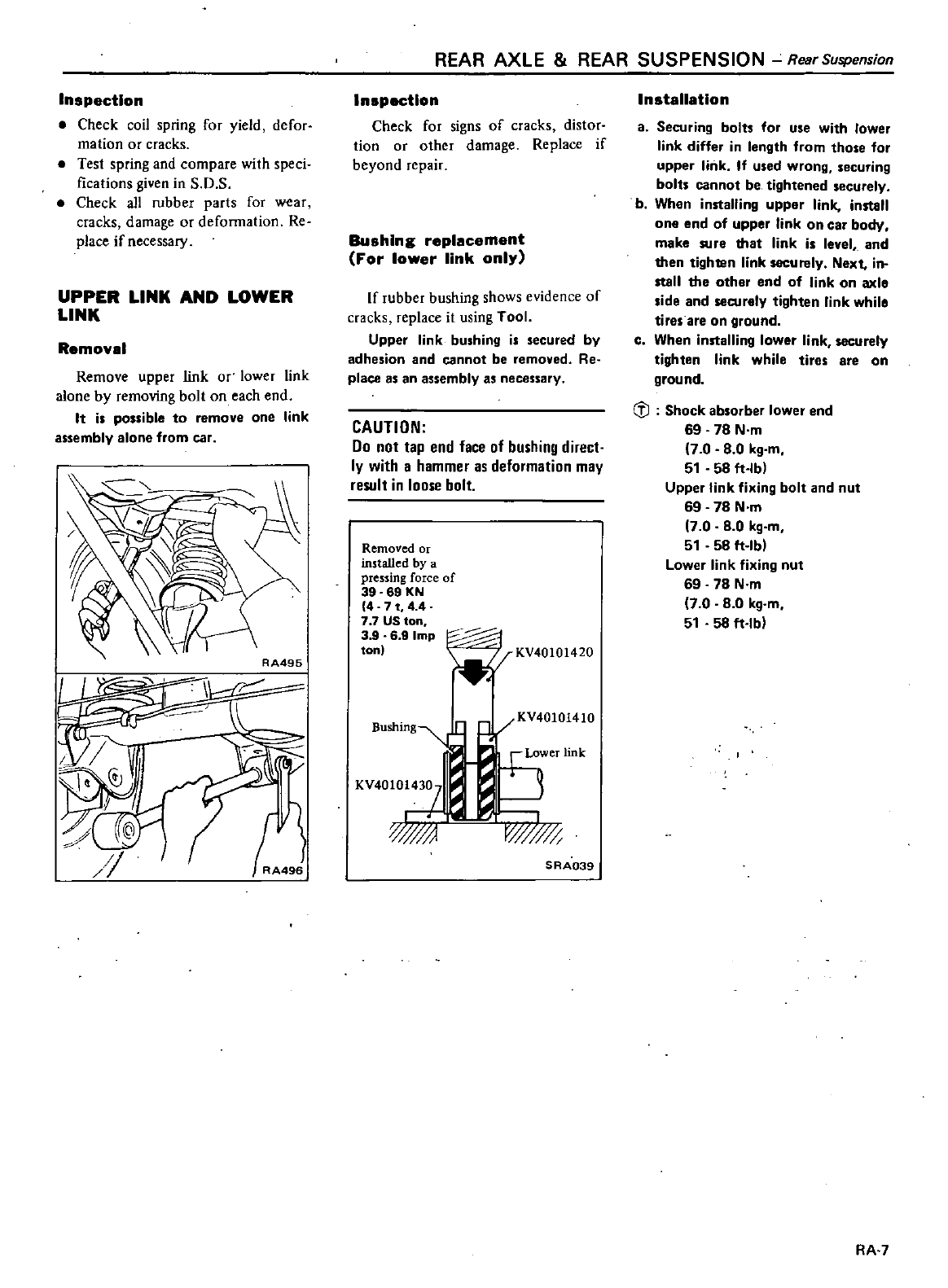
Inspection
Check
coil
spring
for
yield
defor
mation
or
cracks
Test
spring
and
compare
with
speci
fications
given
in
S
D
S
Check
all
rubber
parts
for
wear
cracks
damage
or
deformation
Re
place
if
necessary
UPPER
LINK
AND
LOWER
LINK
Removal
Remove upper
link
or
lower
link
alone
by
removing
bolt
on
each
end
It
is
possible
to
remove
one
link
assembly
alone
from
car
RA495
LI
g
lr
j
REAR
AXLE
REAR
SUSPENSION
Rear
Suspension
Inspection
Check
for
signs
of
cracks
distor
tion
or
other
damage Replace
if
beyond
repair
Bushing
replacement
For
lower
link
only
If
rubber
bushing
shows
evidence
of
cracks
replace
it
using
Tool
Upper
link
bushing
is
secured
by
adhesion
and
cannot
be
removed
Re
place
as
an
assembly
as
necessary
CAUTION
00
not
tap
end
face
of
bushing
direct
ly
with
a
hammer
as
deformation
may
result
in
loose
bolt
Removed
or
installed
by
a
pressing
force
of
39 69
KN
4
71
44
7 7
US
ton
3
9
6
9
Imp
ton
KV40101420
BUshing
t
KV401O
47
a
ww
SRA039
Installation
a
Securing
bolts
for
use
with
lower
link
differ
in
length
from
those
for
upper
link
If
used
wrong
securing
bolts
cannot
be
tightened
securely
b
When
installing
upper
link
install
one
end
of
upper
link
on
car
body
make
sure
that
link
is
level
and
then
tighten
link
securely
Next
in
stall the
other
end
of
link
on
axle
side
and
securely
tighten
link
while
tires
are
on
ground
c
When
installing
lower
link
securely
tighten
link
while
tires
are
on
ground
til
Shock
absorber
lower
end
69 78
N
m
7 0 8 0
kg
m
51
58
ft
Ibl
Upper
link
fixing
bolt
and
nut
69 78
N
m
70 8 0
kg
m
51
58
ft
Ibl
Lower
link
fixing
nut
69 78
N
m
7 0 8 0
kg
m
51
58
ft
Ibl
RA 7
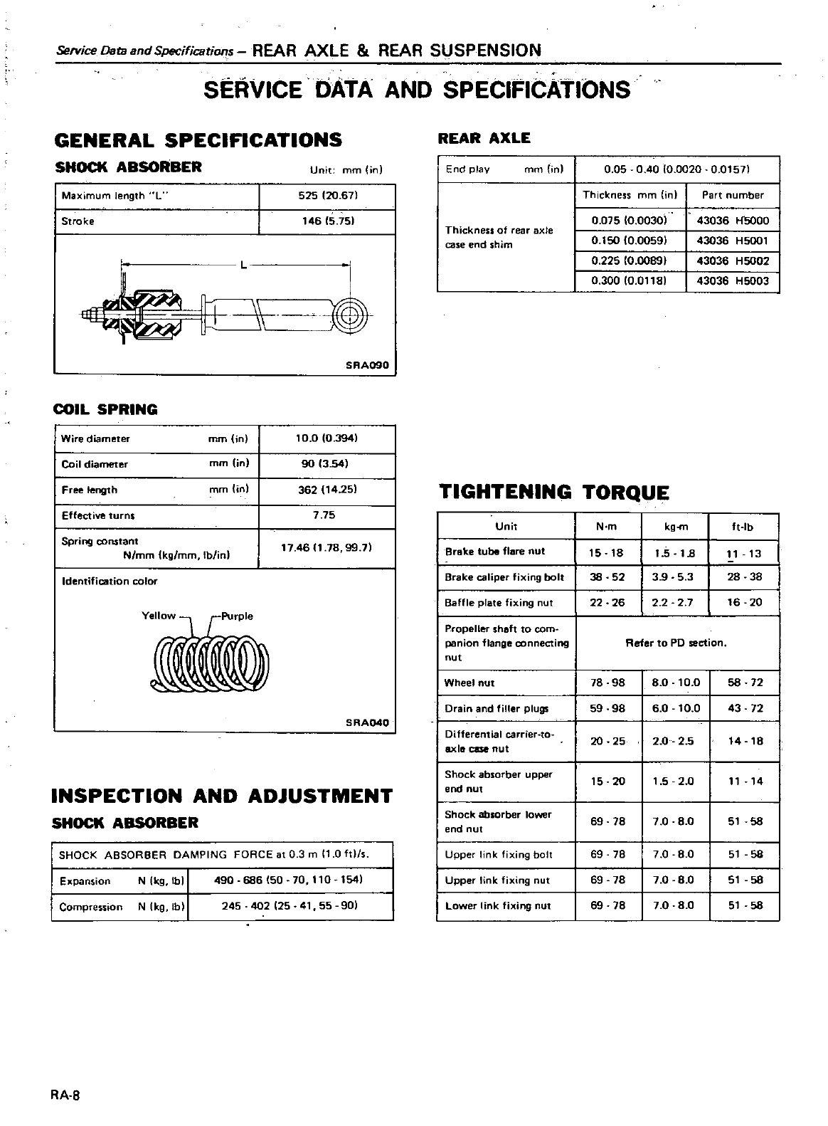
ServireDataandSpecifications
REAR
AXLE
REAR
SlJSPENSION
SERVICE
DATA
AND
SPECIFICATIONS
GENERAL
SPECIFICATIONS
SHOCK
ABSORBER
Unit
mm
in
I
Maximum
length
L 525
120
67
I
Stroke
146 5
75
L
C
0
SRA090
COIL
SPRING
I
Wire
diameter
mm
in
I
Coil
diameter
mm
in
I
Free
length
mm
in
I
Effective
turns
I
Spring
constant
N
mm
kg
mm
Ib
inl
10
010
3941
90
13 541
362
14
251
7
75
17
46
1
78 99
71
Identification
color
Yellow
1
PurPle
ll0
5
RA040
INSPECTION
AND
ADJUSTMENT
SHOCK
ABSORBER
I
SHOCK
ABSORBER
DAMPING
FORCE
at
0 3
m
11
0
hIls
I
Expansion
N
kg
lbl
490
686
50 70
110
154
I
Compression
N
kg
Ib
245
402
25
41
55
901
RA
B
REAR
AXLE
End
play
mm
On
0
05
OAO
10
0020
0
01571
Thickness
mm n
Part
umber
Thickness
of
rear
xle
case
end shim
0
075
10
00301
43036
H5000
0
1SO
10
00591
43036
H5oo1
0
225
10
00891
43036
HS002
0
300
10
01181
43036
H5003
TIGHTENING
TORQUE
Unit
N
m
kg
m
ft
Ib
Broke
tube flare
nut
15 18
1
5
18
11
13
Brake
caliper
fixing
bolt
38
52
3
9
5 3
28 38
Baffle
plate
fixing
ut
22 26
2 2 2 7
16 20
Propeller
shaft
to
com
panion
flange
connecting
Refer
to
PO
section
nut
Wheel
nut
78
98
80
10
0
58 72
Drain
and
filler
plugs
59
98
60
10
0
43 72
I
Differential
carrier
to
20
25
2
0
2 5
14
18
axlll
case
nut
I
Shock
absorber
upper
15
20
1
5 2 0
11
14
end
nut
I
Shock
absorber
lower
69 78
7 0 8
0
51
58
end
nut
I
Upper
link
fixing
bolt
69
78
7 0 8 0
51
58
I
Upper
link
fixing
nut
69
78
7
0 8
0
51
58
I
Lower
link
fixing
nut
69 78
7
0 8
0
51
58
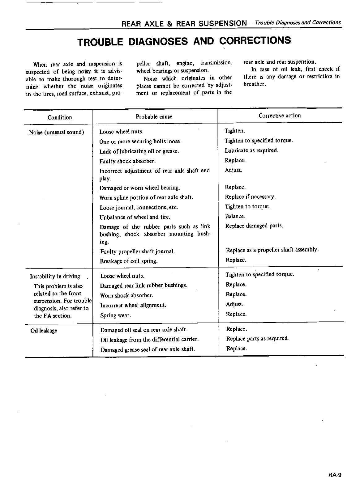
REAR
AXLE
REAR
SUSPENSION
Trouble
Diagnoses
and
Corrections
TROUBLE
DIAGNOSES
AND
CORRECTIONS
When
rear
axle
and
suspension
is
suspected
of
being
noisy
it
is
advis
able
to
make
thorough
test
to
deter
mine
whether the
noise
originates
in
the
tires
road
surface
exhaust
pro
Condition
Noise
unusual
sound
Instability
in
driving
This
problem
is also
related
to
the
front
suspension
For
trouble
diagnosis
also
refer
to
the
FA
section
Oil
leakage
peller
shaft
engine
transmission
wheel
bearings
or
suspension
Noise
which
originates
in
other
places
cannot
be
corrected
by
adjust
ment
or
replacement
of
parts
in
the
rear
axle
and
rear
suspension
In
case
of
oil
leak
first
check
if
there
is
any
damage
or
restriction
in
breather
Probable
cause
Loose
wheel
nuts
One
or
more
securing
bolts
loose
Lack
oflubricating
oil
or
grease
Faulty
shock absorber
Incorrect
adjustment
of
rear
axle
shaft
end
play
Damaged
or
worn
wheel
bearing
Worn
spline
portion
of
rear
axle
shaft
Loose
journal
connections
etc
Unbalance
of
wheel and
tire
Damage
of
the
rubber
parts
such
as link
bushing
shock
absorber
mounting
bush
ing
Faulty
propeller
shaft
journal
Breakage
of
coil
spring
Loose
wheel
nuts
Damaged
rear
link
rubber
bushings
Worn
shock absorber
Incorrect
wheel
alignment
Spring
wear
Damaged
oil
seal
on
rear
axle
shaft
Oil
leakage
from
the
differential
carrier
Damaged
grease
sea
of
rear
axle
shaft
Corrective
action
Tighten
Tighten
to
specified
torque
Lubricate
as
required
Replace
Adjust
Replace
Replace
if
necessary
Tighten
to
torque
Balance
Replace
damaged
parts
Replace
as
a
propeller
shaft
assembly
Replace
Tighten
to
specified
torque
Replace
Replace
Adjust
Replace
Replace
Replace
parts
as
required
Replace
RA
9
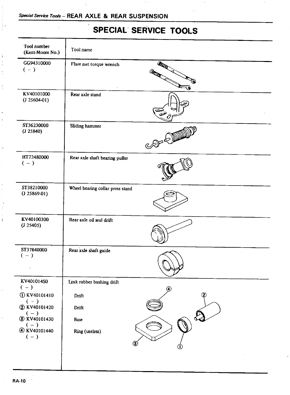
Special
Service
Tools
REAR
AXLE
REAR
SUSPENSION
SPECIAL
SERVICE
TOOLS
Tool
number
knt
Moore
No
GG943
I
0000
Tool
name
Flare
nut
torque
wrench
KV4010I0OO
J
25604
1
Rear
axle
stand
ST36230000
J
25840
Sliding
hammer
lIT72480000
Rear
axle
shaft
bearing
puller
ST38210000
J
25869
1
Wheel
bearing
collar
press
stand
KV40100300
J
25405
Rear
axle
oil
seal
drift
ST37840000
Rear
axle
shaft
guide
@
KV40l0l4S0 Link
rubber
bushing
drift
CD
KV4010141O
Drift
h
V
KV40101420
Drift
@
KV40101430
Base
@
KV40101440
Ring
useless
RA
I0
DATSUN
200SX
Model
S
II
0
Series
SECTIONBR
BRAKE
SYSTEM
CONTENTS
DESCRI
PTION
SERVICE
BRAKE
BRAKE
PEDAL
MASTER
CYLINDER
BRAKE
HYDRAULIC
LINE
BLEEDING
HYDRAULIC
SYSTEM
NP
VALVE
FRONT
DISC
BRAKE
N22
FRONT
DISC
ROTOR
REAR
DISC
BRAKE
AN12H
REAR
DISC
ROTOR
BR
2
BR
3
BR
3
BR
4
BR
5
BR
5
BR
6
BR
6
BR
9
BR
lO
BR
13
BRAKE
BOOSTER
PARKING
BRAKE
PARKING
BRAKE
SERVICE
DATA
AND
SPECIFICATIONS
GENERAL
SPECIFICATIONS
INSPECTION
AND
ADJUSTMENT
TIGHTENING
TORQUE
TROUBLE
DIAGNOSES
AND
CORRECTIONS
SPECIAL
SERVICE
TOOL
BR
14
BR
16
BR
16
BR
1B
BR
18
BR
18
BR
19
BR
20
BR
22
Refe
to
Section
MA
Brake
System
for
CHECKING
FOOT
BRAKE
CHECKING
PARKING
8RAKE
a
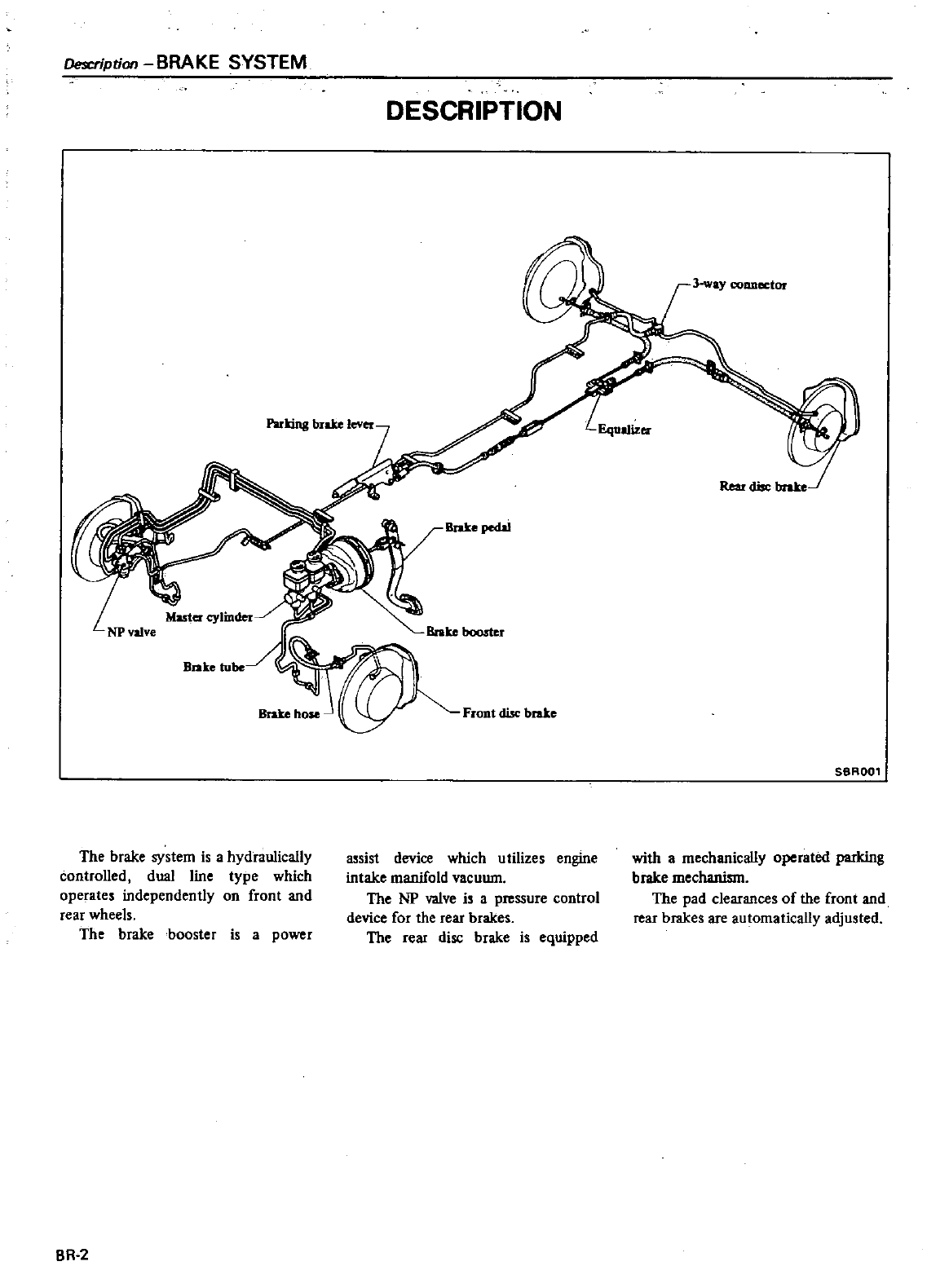
CH
ription
BRAKE
SYSTEM
DESCRIPTION
3
way
connector
Pulling
hrake
lever
Brake
hOle
Front
disc
brake
SBR001
The
brake
system
is
a
hydraulically
controlled
dual
line
type
which
operates
independently
on
front
and
rear
wheels
The
brake
booster
is
a
power
assist
device which
utilizes
engine
intake
manifold
vacuum
The
NP
valve
is
a
pressure
control
device
for
the
rear
brakes
The
rear
disc
brake
is
equipped
with
a
mechanically
operated
parking
brake
mechanism
The
pad
clearances
of
the
front
and
rear
brakes
are
automatically
adjusted
BR
2
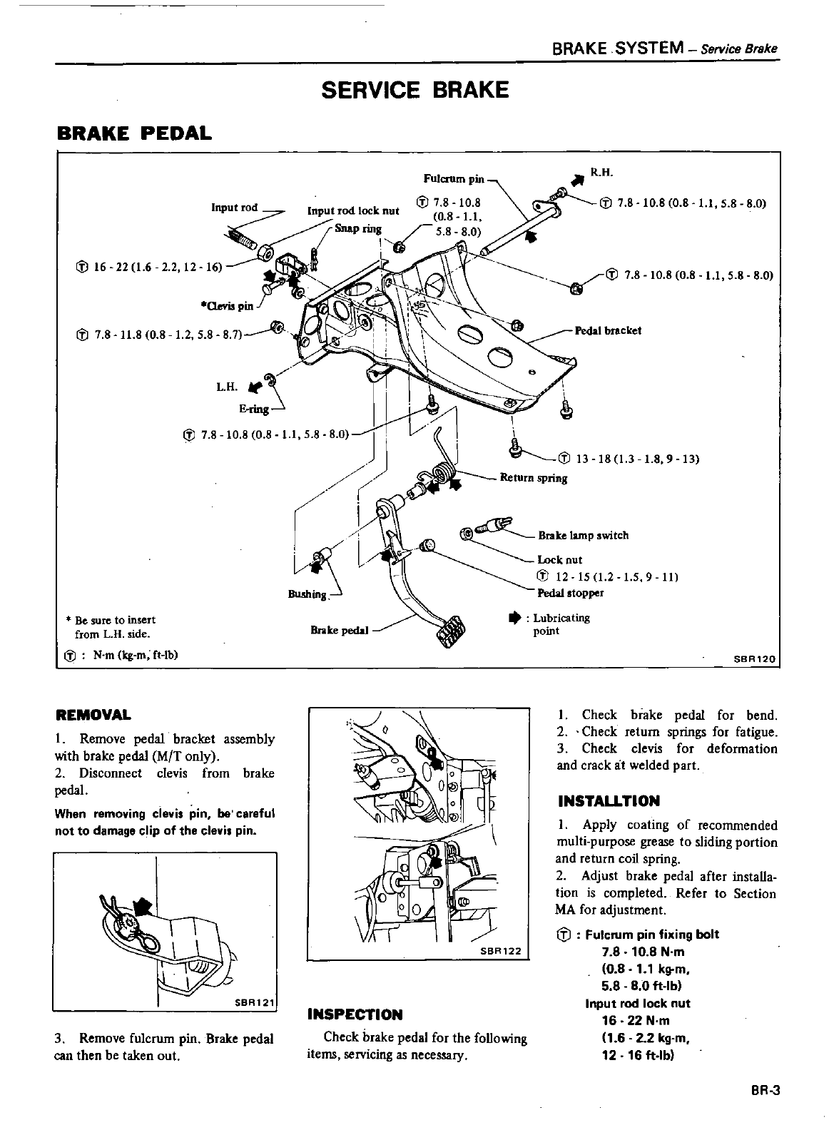
BRAKE
PEDAL
SERVICE
BRAKE
Input
rod
il
7
8
10
8
Input
rod
lock
nut
0
8
11
t
SnaPrin
5 8
8 0
i
l16
22
1
6
2 2
12
Pin
il
7 8
11
8 0
8
12
5
8 8 7
L
HItf
E
ring
il
7
8
10
8
0
8
11
5
8
Be
sure
to
insert
from
L
H
side
il
N
m
kg
m
fHb
REMOVAL
I
Remove
pedal
bracket
assembly
with
brake
pedal
M
T
only
2
Disconnect
clevis
from
brake
pedal
When
removing
clevis
pin
be
careful
not
to
damage
c
ip
of
the
clevi
pin
SBR121
3
Remove
fulcrum
pin
Brake
pedal
can
then
be
taken
out
BRAKE
SYSTEM
Service
Brake
f
R H
il
7
8
10
8 0
8
11
5 8 8 0
10
8
0
8
11
5
8 8 0
Pedal
bracket
ki
l13
Return
spring
18
13
18
9
13
l
t
Brakelamp
witCh
Lock
nut
il
12 15
1
2
1
5
9
11
Pedal
stopper
Lubricating
point
Brake
pedal
o
00
lf
O@
o
I
@II
INSPECTION
Check
brake pedal
for
the
following
items
servicing
as
necessary
SBR120
I
Check
brake
pedal
for
bend
2
Check
return
springs
for
fatigue
3
Check
clevis
for
deformation
and
crack
at
welded
part
SBR122
INSTALLTION
I
Apply
coating
of
recommended
multi purpose
grease
to
sliding
portion
and
return
coil
spring
2
Adjust
brake
pedal
after installa
tion
is
completed
Refer
to
Section
MA
for
adjustment
lil
Fulcrum
pin
fixing
bolt
7
8
10
8
N
m
0
8
1
1
kg
m
5
8
8
0
ft
lb
Input
rod
lock
nut
16
22
N
m
1
6 2 2
kg
m
12
16
ft
lb
BR
3
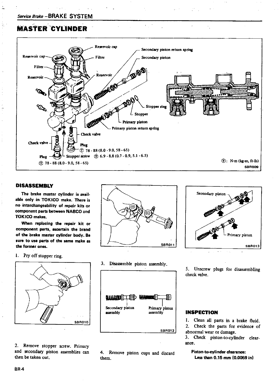
Service
Brake
BRAKE
SYSTEM
MASTER
CYLINDER
Reservoir
cap
Fillet
R
eservoir
teek
Y
alve
88
8 0 9
0 58
65
DISASSEMBLY
The brake
master
cylinder
is
avail
able
only
in
TOKICO
make
There
is
no
interchangeability
of
repair
kits
or
component
part
between
NABCO
and
TOKICO
makes
When
replacing
tha
repair
kit
or
component
part
rtain
tha
brand
of
the
brake
master
cylindar
body
Ba
sure
to
part
of
the
same
make
as
the
former
ones
I
Pry
off
stopper
ring
L
2
Remove
stopper
screw
Primary
and
secondary
piston
assemblies
can
then
be
taken
out
BR
4
H
piston
return
spring
Secondary
pilton
Prim
pilton
Primary
piston
return
spring
88
8
0
90
58 65
tfJ
69 88 0 7
0 9
5
16 5
SBR011
3
Disassemble piston
assembly
Secondary
piston
Primary
piston
assembly
a
uembly
SBR012
4
Remove
piston
cups
and
discard
them
l
J
N
m
ii
m
ft
Ib
SBA009
Secondary
piston
Primary
piston
SBR013
5
Unscrew
plugs
for
disassembling
check
valve
INSPECTION
I
Clean
all
parts
in
a
brake
l1uid
2
Check
the
parts
for
evidence
of
abnoimal
wear
or
damage
3
Check
piston
to
cylinder
clear
ance
Piston
linder
clearance
Less
than
0
15
mm
0
0059
in
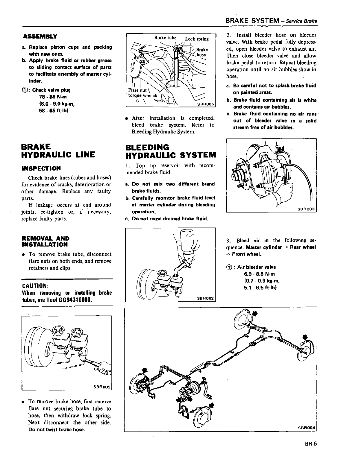
ASSEMBLY
a
Replace
piston
cups
and
packing
with
new
ones
b
Apply
braka
fluid
or
rubber
gre
to
Iiding
contact
urface
of
ports
to
focilitata
aaembly
of
master
cyl
inder
i
J
Chock
01
0
plug
78
88
N
m
8
0
9
0
kg
m
58
65
ft
Ibl
BRAKE
HYDRAULIC
LINE
INSPECTION
Check
brake
lines
tubes
and
hoses
for evidence
of
cracks
deterioration
or
other
damage
Replace
any
faulty
parts
If
leakage
occurs
at
end
around
joints
Ie
tighten
or
if
necessary
replace
faulty
parts
REMOVAL
AND
INSTALLATION
To
remove
brake
tube
disconnect
flare
nuts
on
both
ends
and
remove
retainers
and
clips
CAUTION
When
removing
or
installing
brake
tubes
use
Tool
GG94310000
SBROOS
To
remove
brake
hose
first
remove
l1are
nut
securing
brake tube
to
hose
then
withdraw lock
spring
Next
disconnect
the other
side
Do
not
twist
brake
ho e
Brake
tube
Lock
spring
I
SBA006
a
After
installation
is
completed
bleed
brake
system
Refer
to
Bleeding
Hydraulic
System
BLEEDING
HYDRAULIC
SYSTEM
1
Top
up
reservoir
with
recom
mended
brake
l1uid
a
Do
not
mix
two
different
brand
braka
fluid
b
C
refully
monitor
brake
fluid
le el
at
master
cylinder
during
bleeding
operation
c
Do
not
reuse
drained
brake
fluid
r
BRAKE
SYSTEM
SelYice
Brake
2Install
bleeder
hose
on
bleeder
valve
With
brake
pedal
fully
depress
ed
open
bleeder
valve
to
exhaust
air
Then
close
bleeder
valve
and
allow
brake
pedal
to return
Repeat
bleeding
operation
until
no
air
bubbles
show
in
hose
a
Be
careful
not
to
pla
h
br
ka
fluid
on
painted
areas
b
Brake
fluid
containing
air
is
white
and
contain
air
bubbles
c
Brake
fluid
containing
no
air
runs
out
of
bleeder
valve
in
asolid
stream
free
of
air
bubbles
SBR003
3
Bleed
air
in
the
following
se
quence
Master
cylinder
Rear
wheel
Front
wheel
i
J
Air
bleeder
I
e
6 9 8 8
N
m
0 7 0
9
kg
m
5
1
6
5
ft
Ibl
BR
5
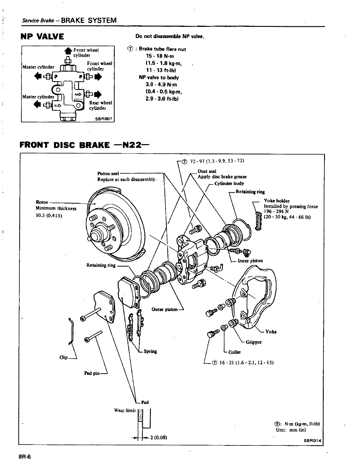
Service
Brake
BRAKE
SYSTEM
NP
VALVE
Do
not
disassemble
NP
val
e
e
Front
wheel
cylinder
Front
wheel
cylinder
If
Brake
tube
f1ere
nut
15 18
N
m
11
5
1
8
kg
m
11
13
ft
Ibl
NP
waive
to
body
3949
N
m
04
0
5
Irg
m
29
3
6
ft
lbl
SBROO1
FRONT
DISC
BRAKE
N22
Piston
eal
Replace
at
each
disassembly
i
J12
91
1
39
9
53
72
Dustse
a1
Apply
cfuc
bJake
grease
r
Cy1inder
body
aet
ainingring
You
holder
D
Installed
by
pressing
force
196
294N
20 30
leg
44 66
Ib
I
1
rupj
Yoke
II
Minimum
thickness
10
5
0
413
Spring
21
1
6 2 1
12 15
Pad
WeaJ
limit
1
J
i
J
N
m
Ieg
mJtlb
Unit
rom
in
2
0
08
SBA014
BR
6
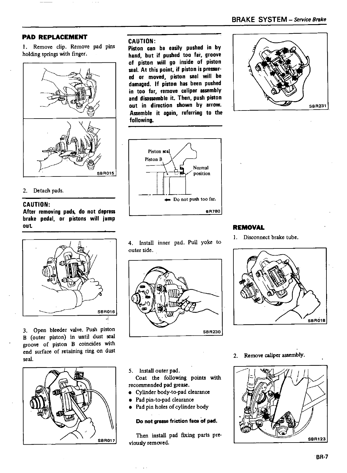
PAD
REPLACEMENT
I
Remove
clip
Remove
pad
pins
holding
springs
with
finger
SBA015
2
Detach
pads
CAUTION
After
removing
pads
do
not
depress
brake
pedal
or
pistons
will
jump
out
SBRG16
3
Open
bleeder
valve
Push
piston
B
outer
piston
in
until
dust
seal
groove
of
piston
B
coincides
with
end
surface
of
retaining
ring
on
dust
seal
CAUTION
Piston
can
be
easily
pushed
in
by
hand
but
if
pushed
too
far
groove
of
piston
will
go
inside
of
piston
seal
At
this
point
if
piston is
pressur
ed
or
moved
piston
seal
will
be
damaged
If
piston
has
been
pushed
in
too
far
remove
caliper
assembly
and
disassemble
it
Then
push
piston
out
in
direction
shown
by
arrow
Assemble
it
again
referring
to
the
following
Piston
seal
2
Piston
B
Y
Normal
POSitiOn
Do
not
push
too
far
BR780
4
Install
inner
pad
Pull
yoke
to
outer
side
SBA230
5
Install
outer
pad
Coat
the
following
points
with
recommended
pad
grease
Cylinder
body
to
pad
clearance
Pad
pin
to
pad
clearance
Pad
pin
holes
of
cylinder
body
Do
not
grllll8
friction
face
of
pIId
Then
install
pad
ftxing
parts
pre
viously
removed
BRAKE
SYSTEM
Service
Brake
REMOVAL
I
Disconnect
brake
tube
2
Remove
caliper
assembly
BR
7
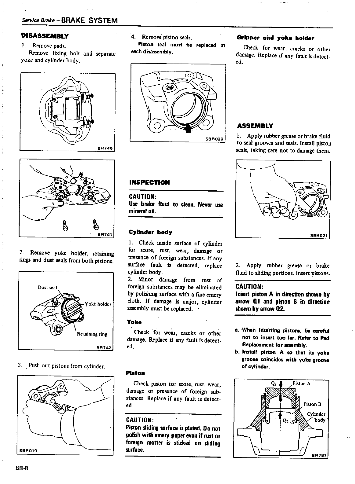
Service
Bl1lke
BRAKE
SYSTEM
DISASSEMBLY
Remove
pads
Remove
fIXing
bolt
and
separate
yoke and
cylinder
body
0
1
D
BR740
J
BA741
2
Remove
yoke
holder
retaining
rings
and
dust
seals
from
both
pistons
Dust
seal
8R742
3
Push
out
pistons
from
cylinder
SBR019
BR
B
4
Remove
piston
seal
Piston
seal
must
be
replaced
at
each
d
bly
SBR020
INSPECTION
CAUTION
Use
bfllke
fluid
to
clean
Never
use
minefllloil
C
llnder
bod
I
Check
inside
surface
of
cylinder
for
score
rust
wear
damage
or
presence
of
foreign
substance
If
any
surface
fault
i
detected
replace
cylinder
body
2
MinoJ
damage
from
Just
of
foreign
sub
tances
may
be
eliminated
by polishing
surface
with
a
fme
emery
cloth
If
damage
is
major
cylindCJ
assembly
must
be
replaced
Yoke
Check
for
wear
cracks
or
other
damage
Replace
if
any
fault
i
detect
ed
PIston
Check
piston
for
score
rust
wear
damage
or
presence
of
foreign
sub
stances
Replace
if
any
fault
is
detect
ed
CAUTION
Piston
sliding
surface
is
plated
00
not
polish
with
emery
paper
eveil
if
rust
or
foreign
matter
is
sticked
on
sliding
surface
Gripper
and oke
holder
Check
for
wear
cracks
or
other
damage
Replace
if
any
fault
is
detect
ed
ASSEMBLY
I
Apply
rubber
grease
or
brake
l1uid
to
seal
grooves
and
seals
Install
piston
seals
taking
care
not
to
damage
them
SBR021
2
Apply
rubber
grease
or
brake
l1uid
to
sliding
portions
Insert
pistons
CAUTION
Iniert
piston
A
in
direction
shown
by
arrow
Q1
and
piston
B
in
direction
shown
by
BrroW 02
B
When
inserting
pistons
be
careful
not
to
insert
too
far
Refer
to
Pad
Replacement
for
assembly
b
Instan
piston
A
10
that
its
yoko
groove
coincides
with
yoke
groove
of
cylinder
1
tonA
PistonB
t
I
Q2
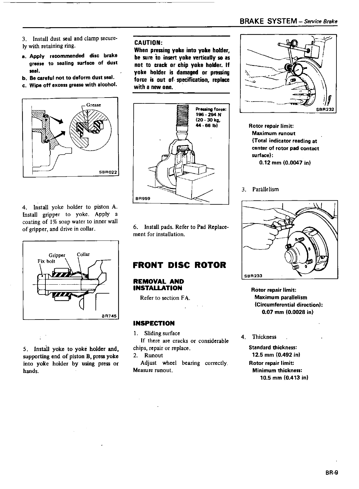
3
Install
dust
seal
and
clamp
secure
ly
with
retaining
ring
a
Apply
recommended
disc
brake
grease
to
sealing
surface
of dUlt
1
b
Be
careful
not
to
deform
dust seal
c
Wipe
off
excess
grease
with
alcohol
SBR022
4
Install
yoke
holder
to
piston
A
Install
gripper
to
yoke
Apply
a
coating
of
1
soap
water
to
inner
wall
of
gripper
and
drive
in collar
F
ll
T
L
BR745
5
Install
yoke
to
yoke
holder
and
supporting
end
of
piston
B
press
yoke
into
yoke
holder
by
using
press
or
hands
CAUTION
When
pressing
yoke
inlo
yoke
holder
be
su
re
to
insert
yoke
vertically
so as
not
to
crack
or
chip yoke
holder
If
yoke
holder
is
damaged
or
pl8uing
force
is
out
of
specification
replace
with
a
new
one
Preaing
force
196
294
N
20 30
kg
44 66
Ibl
BR959
6
Install
pads
Refer
to
Pad
Replace
ment
for
installation
FRONT
DISC
ROTOR
REMOVAL
AND
INSTALLATION
Refer
to
section
FA
INSPECTION
I
Sliding
surface
If
there
are
cracks
or
considerable
chips
repair
or
replace
2
Runout
Adjust
wheel
bearing
correctly
Measure
mnout
BRAKE
SYSTEM
Se
Vice
Brake
n
i
I
SBR232
Rotor
repair
limit
Maximum
runout
Total
indicator
reading
at
center
of
rotor
pad
contact
su
rface
0
12
mm
0
0047
in
3
Pariille
lism
SBR233
Rotor
repair
limit
Maximum
parallelism
Circumferential
direction
007
mm
0
0028
in
4
Thickness
Standard
thickness
12
5
mm
0
492
inl
Rotor
repair
limit
Minimum
thickness
10 5
mm
0
413
in
BR
9
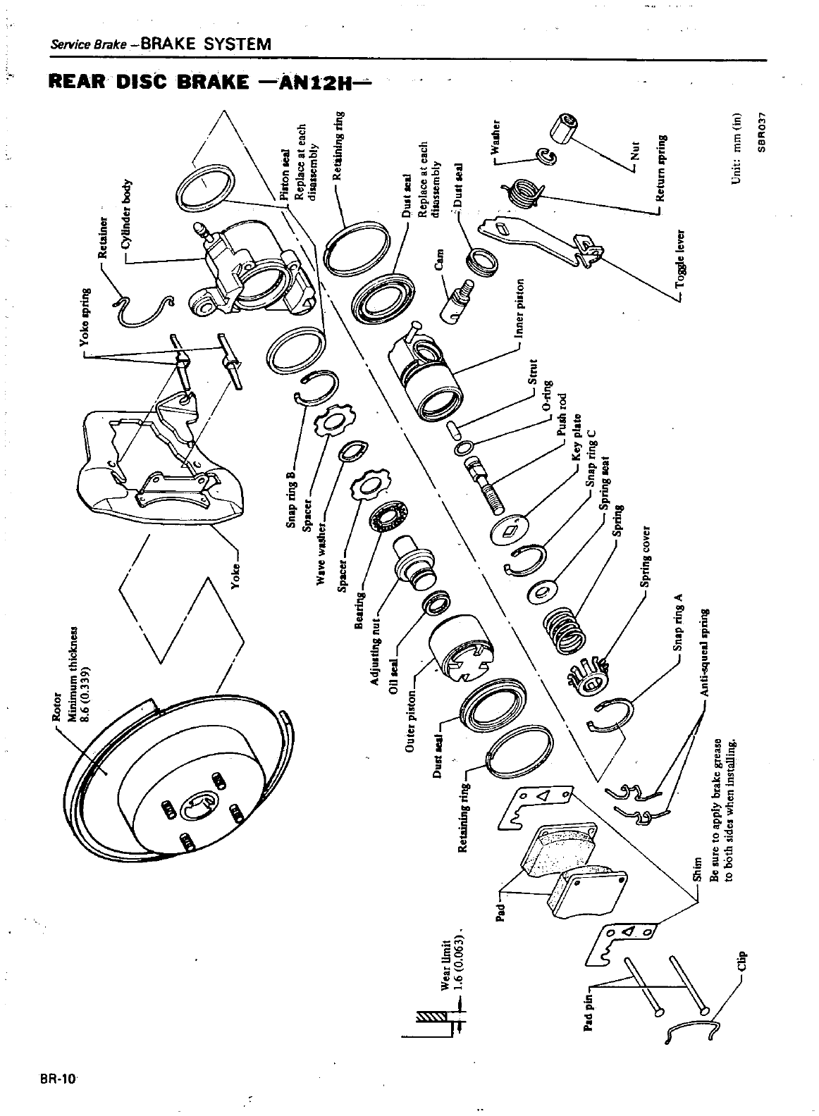
o
J
Wear
limit
1
6
0
063
Pad
Rotor
Minimumthickness
8
6
0
339
ke
Retaining
rins
Spring
cover
Shim
Be
sure
to
apply
brake
grease
to
both
sides
when
installing
Anti
lueal
spring
Yoke
Ipring
I
Retainer
r
CyUnder
body
A
Return
Pring
Toggle
lever
Unit
mm
in
SBA037
a
III
IIa a
Itn
m
aII
III
I
IIz
N
Z
I
2
I
C1l
m
en en
l
m
3
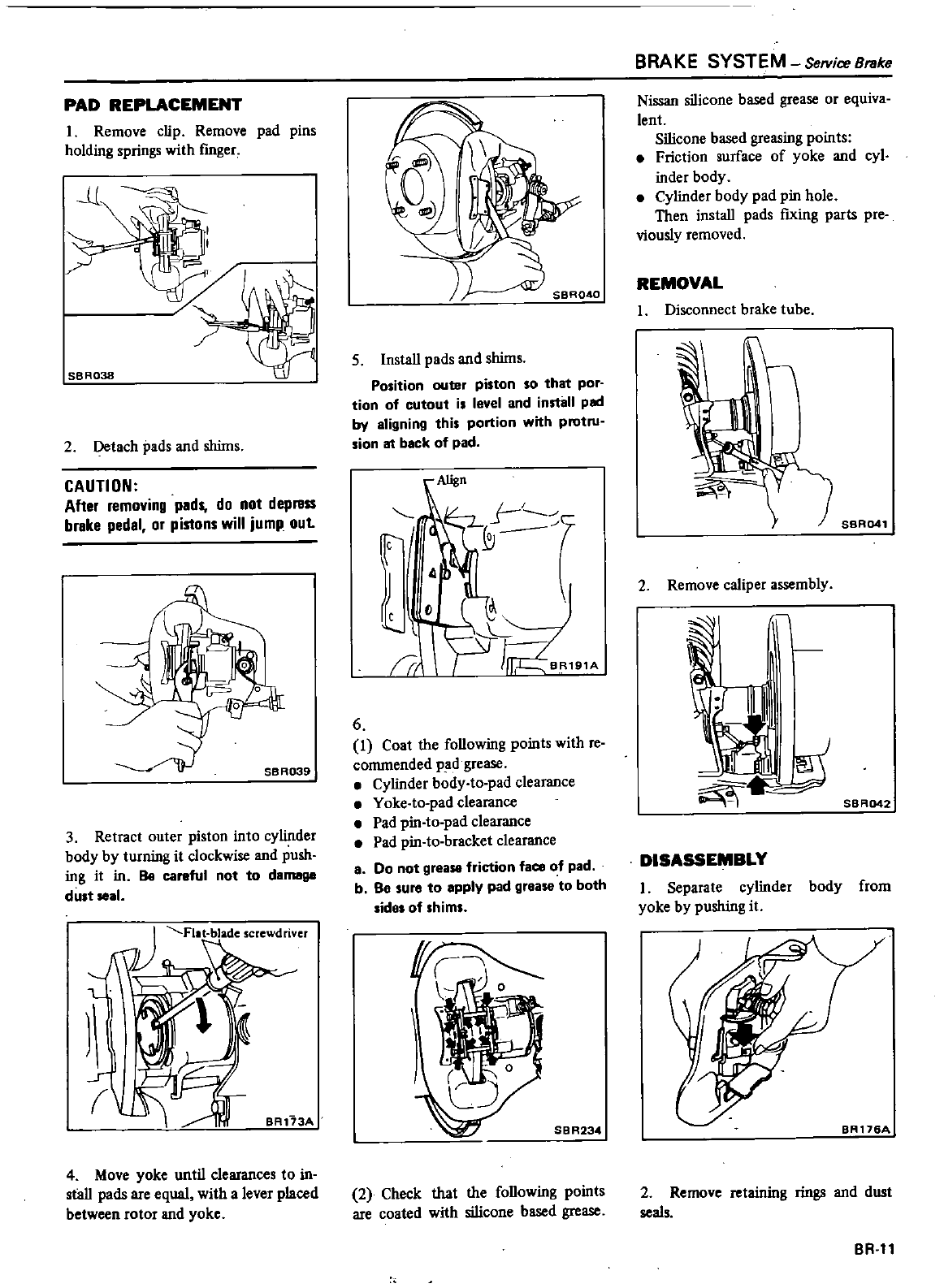
PAD
REPLACEMENT
I
Remove
clip
Remove
pad
pins
holding
springs
with
finger
LL
SBR03B
2
Detach
pads
and
shims
CAUTION
After
removing
peds
do
not
dep
ss
breke
pedel
or
pistons
will
jump
out
3
Retract
outer
piston
into
cylinder
body
by
turning
it
clockwise
and
push
ing
it
in
Be
careful
not to
demell8
dust
seal
1
Fllt
blade
screwdriver
BR173A
4
Move
yoke
until
clearances
to
in
stall
pads
are
equal
with
a
lever
placed
between
rotor
and
yoke
5
Install
pads
and
shims
Position
outer
piston
so that
por
tion
of
cutout
is
level
and
install
pad
by
aligning
this
portion
with
protru
sion
at
back
of
pad
Align
Ie
I
I
J
Ie
1
J
Jrr
rf
BR191A
D
4
7
r
6
1
Coat
the
following points
with
re
commended
pad
grease
Cylinder
body
to
pad
clearance
Y
oke
to
pad
clearance
Pad
pin
to
pad
clearance
Pad
pin
to
bracket
clearance
8
Do
not
grease
friction
face
of
pad
b
Be
sure
to
apply
pad
grease
to
both
sides
of
shims
SBR234
2
Check
that
the
following
points
are
coated
with
silicone
based
grease
BRAKE
SYSTEM
Service
Breke
Nissan
silicone
based
grease
or
equiva
lent
Silicone
based
greasing
points
Friction
surface
of
yoke
and
cyl
inder
body
Cylinder
body
pad
pin
hole
Then
install
pads
fIxing
parts
pre
viously
removed
REMOVAL
I
Disconnect
brake
tube
2
Remove
caliper
assembly
1111
I
I
SBA041
SBRD42
DISASSEMBLY
I
Separate
cylinder
body
from
yoke
by
pushing
it
2
Remove
retaining
rings
and
dust
seals
BR
II
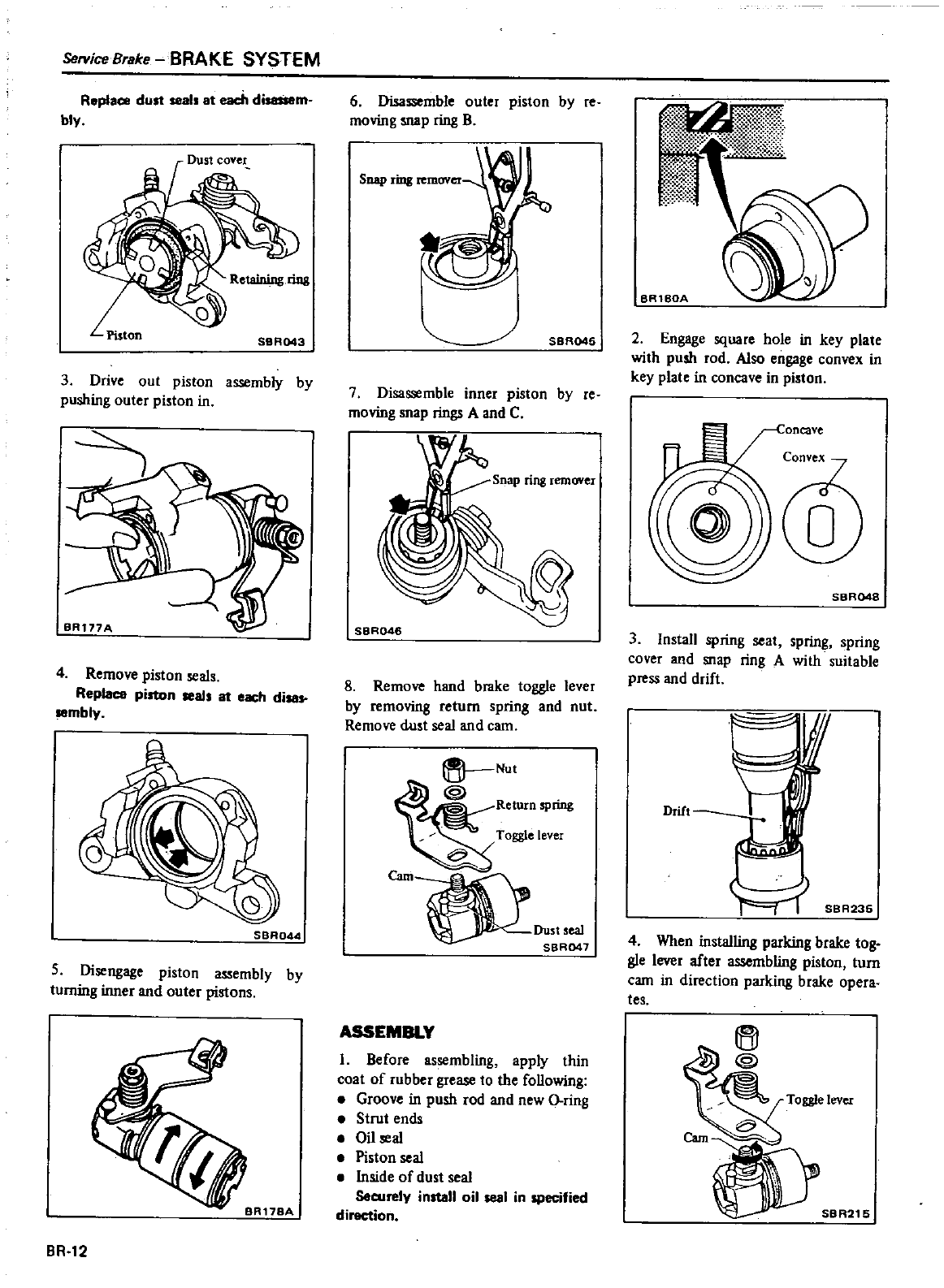
ServiceBrake
BRAKE
SYSTEM
Replace
dust
seal
at
each
di
m
bly
Piston
SBA043
3
Drive
out
piston
assembly
by
pushing
outer
piston
in
4
Remove
piston
seals
Replace
piston
seal
at
each
di
sembly
SBA044
5
Disengage
piston
assembly
by
turning
inner
and
outer
pistons
BR
12
6
Disassemble
outer
piston
by
re
moving
snap
ring
B
Snap
rilll
SBR045
7
Disassemble
inner
piston
by
re
moving
snap
rings
A
and
C
Snap
ring
remover
SBRD46
8
Remove
hand
brake
toggle
lever
by removing
return
spring
and
nut
Remove
dust
seal
and
cam
tt
Nut
Return
spong
8
Toggle
lever
Caml
LDust
seal
SBR047
ASSEMBLY
I
Before
assembling
apply
thin
coat
of
rubber
grease
to
the
following
e
Groove
in
push
rod
and
new
O
ring
Strut
ends
Oil
seal
Piston
seal
Inside
of
dust
seal
Securely
install
oil
seal
in
specified
direction
BAlBOA
2
Engage
square
hole
in
key
plate
with
push
rod
Also
engage
convex
in
key
plate
in
concave
in
piston
SBR048
3Install
spring
seat
spring spring
cover
and
snap
ring
A
with
suitable
press
and
drift
Drift
SBA235
4
When
installing parking
brake
tog
gle
lever
after
assembling
piston
turn
cam
in
direction
parking
brake opera
tes
Toggle
lever
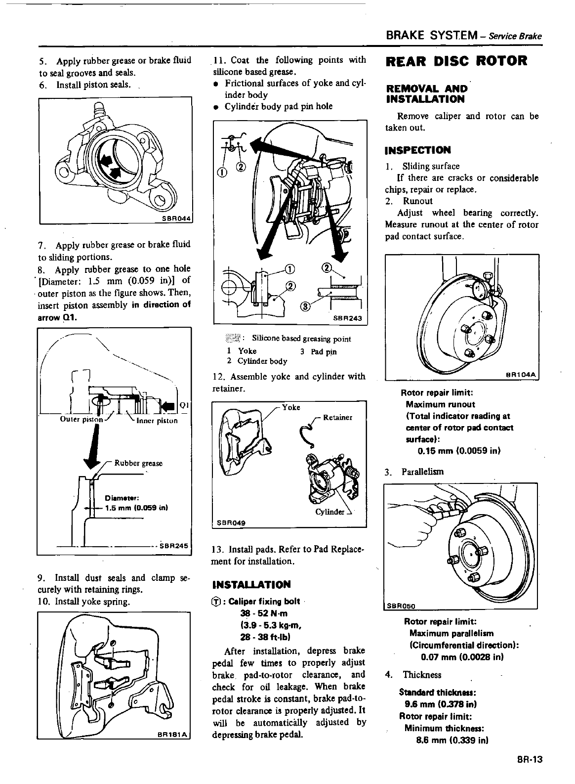
5
Apply
rubber
grease
or
brake
l1uid
to
seal
grooves
and
seals
6 Install
piston
seals
o
SBA044
7
Apply rubber
grease
or
brake
l1uid
to
sliding
portions
8
Apply
rubber
grease
to
one
hole
Diameter
1
5
mm
0
059
in
of
outer
piston
as
the
figure
shows
Then
insert
piston
assembly
in
direction
of
arrow
1
rl
j
l
out
on
Inne
pi
QI
fJ
Di
m
r
1
5
mm
0
059
in
L
SBR245
9
Install
dust
seals
and
clamp
se
curely
with
retaining
rings
10
Install
yoke
spring
BR181A
II
Coat
the
following
points
with
silicone
based
grease
Frictional
surfaces
of
yoke
and
cyl
inder
body
Cylinder body
pad
pin
hole
fi
l
H
SBR243
I
Silicone
based
greasing
point
1
Yoke
3
Pad
pin
2
Cylinder
body
12
Assemble
yoke
and
cylinder
with
retainer
YOke
Retainer
r
SBR049
13 Install
pads
Refer
to
Pad
Replace
ment
for
installation
INSTAUATION
fl
Coliper
fixing
bolt
38
52
N
m
3
9
5
3
kg
m
28
38
ft
Ib
After
installation
depress
brake
pedal
few
times
to
properly
adjust
brake
pad
to
rotor
clearance
and
check
for
oil
leakage
When
brake
pedal
stroke
is constant
brake
pad
to
rotor
clearance
is
properly
adjusted
It
will
be
automatically
adjusted
by
depressing
brake
pedal
BRAKE
SYSTEM
Service
Brake
REAR
DISC
ROTOR
REMOVAL
AND
INSTAUATION
Remove
caliper
and
rotor
can
be
taken
out
INSPECTION
I
Sliding
surface
If
there
are
cracks
or
considerable
chips
repair
or
replace
2
Runout
Adjust
wheel
bearing
correctly
Measure
runout
at
the
center
of
rotor
pad
contact
surface
Rotor
repair
limit
Maximum
runout
Total
indicotor
reading
at
center
of
rotor
pad
contact
surfacel
0
15
mm
00059
in
3
Parallelism
SBR050
Rotor
repair
limit
Maximum
parallelism
Circumferential
diroctionl
0
07
mm
0
0028
in
4
Thickness
Sblndard
thicknou
9 6
mm
0
378
in
Rotor
repair
limit
Minimum
thickness
8
6
mm
0
339
in
BR
13
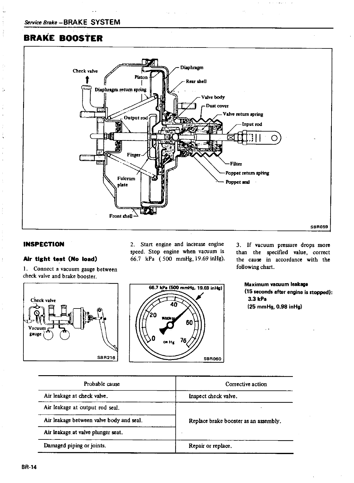
Service
Brake
BRAKE
SYSTEM
BRAKE
BOOSTER
D
hngm
Cheek
valve
I
IJp
Pisto
j
Valve
turn
spring
11
0
Fins
rJ
Fulcrum
plate
l
ID
I
Front
meD
SBR059
INSPECTION
2
Start
engine
and
increase
engine
speed
Stop
engine
when
vacuum
is
66
7
kPa
500
mmHg
19
69
inHg
3
If
vacuum
pressure
drops
more
than
the
specified
value
correct
the
cause
in
accordance
with
the
following
chart
Air
tight
test
No
load
1
Connect
a
vacuum
gauge
between
check
valve
and
brake
booster
Maximum
vacuum
leekege
15
seconds
after
engine
is
stopped
3
3
kPa
25
mmHg
0
98
inHg
J
60
coo
HI
76
J
saRD
D
SBR216
Probable
cause
Corrective
action
Air
leakage
at
check
valve
Air
leakage
at
output
rod
seal
Air
leakage
between
valve
body
and
seal
Air
leakage
at
valve
plunger
seat
Inspect
check
valve
Replace
brake
booster
as
an
assembly
Damaged
piping
or
joints
Repair
or
replace
BR
14
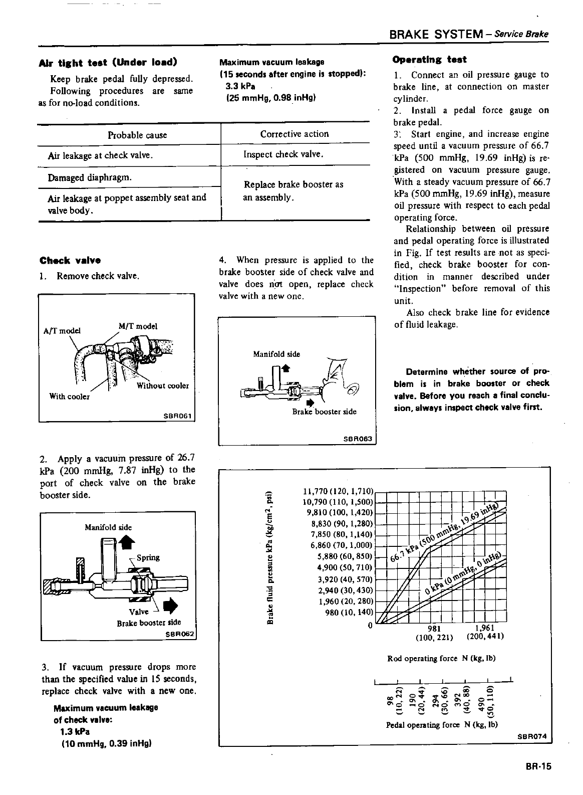
Air
tight
test
Under
loed
Keep
brake
pedal
fully
depressed
Following
procedures
are
same
as
for
no
load
conditions
Probable
cause
Air
leakage
at
check
valve
Damaged
diaphragm
Air
leakage
at
poppet
assembly
seat and
valve
body
Check
velve
Remove
check
valve
M
T
model
With
cooler
SBR061
2
Apply
a
vacuuin
pressure
of
26
7
kPa
200
mmHg
7
87
inHg
to
the
port
of
check
valve
on
the
brake
booster
side
Manifold
side
If
Brake
booster
side
SBR062
3
If
vacuum
pressure
drops
more
than
the
specified
value
in
15
seconds
replace
check
valve
with
a
new
one
Maximum
vacuum
leakage
of
check
01
0
1
3
kPo
10
mmHg
0
39
inHg
Maximum
vacuum
leakage
15
second
after
engine
i
toppedl
3 3
kPa
25
mmHg
0
98
inHg
Corrective
action
Inspecl
check
valve
Replace
brake
booster
as
an
assembly
4
When
pressure
is
applied
to
the
brake
booster
side
of
check
valve
and
valve
does
n
open
replace
check
valve
with
a
new
one
ManVifOI
de
1
c
j
@
L
Brake
booster
side
SBR063
BRAKE
SYSTEM
Service
Brake
Operetlng
test
1
Connect
an
oil
pressure
gauge
to
brake
line
at
connection
on
master
cylinder
2
Install
a
pedal
force
gauge
on
brake
pedal
3
Start
engine
and
increase
engine
speed
until
a
vacuum
pressure
of
66
7
kPa 500
mmHg
19
69
inHg
is
reo
gistered
on
vacuum
pressure
gauge
With a
steady
vacuum
pressure
of
66
7
kPa
500
mmHg
19
69
inHg
measure
oil
pressure
with
respect
to
each
pedal
operating
force
Relationship
between
oil
pressure
and
pedal
operating
force
is
illustrated
in
Fig
If
test
results
are
not
as
speci
fied
check
brake
booster
for
con
dition
in
manner
described
under
Inspection
before
removal
of
this
unit
Also
check brake line
for evidence
of
l1uid
leakage
Determine
whether
source
of
pro
blem
is
in
brake
booster
or
check
valve
Before
you
reach
a
final
conclu
sion
always
inspect
check
valve
fint
M
e
e
e
u
ii
S
u
M
0
11
770
120
1
710
10
190 110
1
500
I
II
I
I
9
810
100
1
420
I
8
830
90
1
280
1
jj
1
850
80
1
140
6
860
10
1
000
I
l
I
5
880
60
850
f
66
jf
4
900
50
710
I
tfl
3
920
40
510
I
2
940
30
430
L
I
J
1
960
20
280
r
J
980
10
140
td
JJ
I I
o
981
1
961
100 221
200 441
Rod
operating
force
N
kg
lb
8
0
0
6
0
66
Pedal
operating
force
N
kg
Ib
SBR074
BR
15
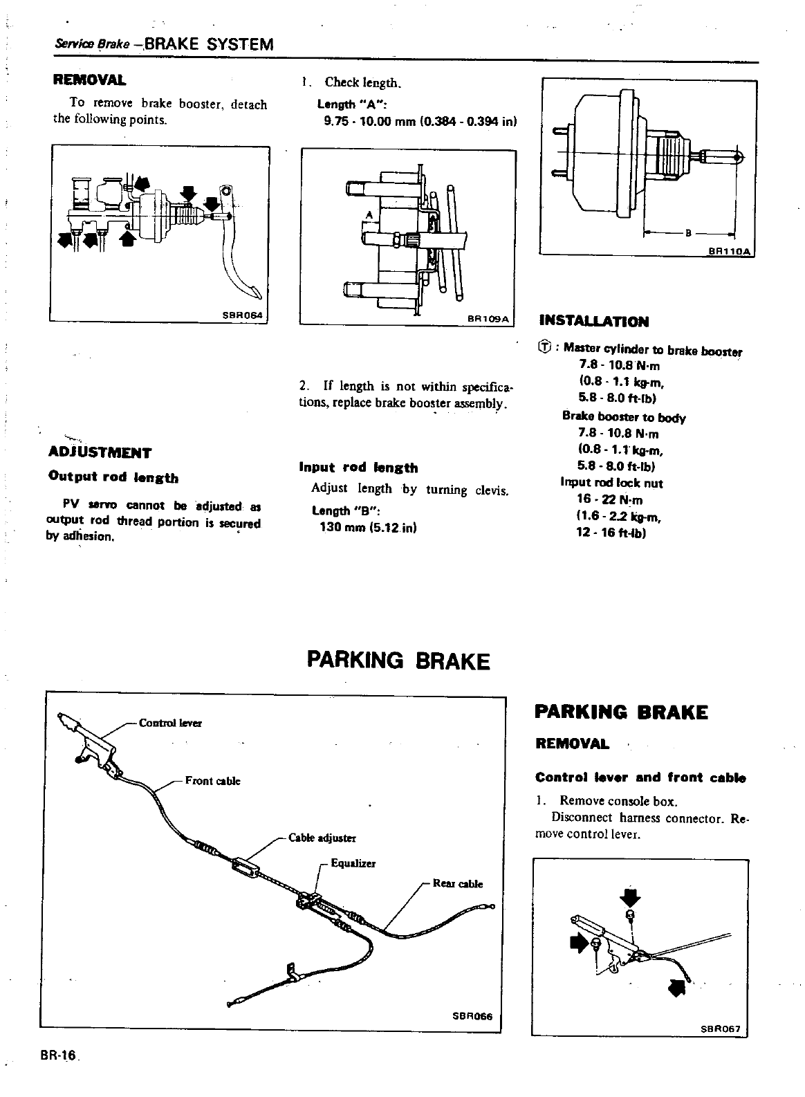
S8rvicsBrake
BRAKE
SYSTEM
REMOVAL
To
remove
brake
booster
detach
the
following
points
S8A064
ADJUSTMENT
Output
rod
length
PV
seno
cannot
be
adjusted
as
output
rod
thread
portion
is
secured
by
adhesion
Check
length
Langth
AH
9 75
10
00
mm
10
384
0
394
in
u
1
1
BR109A
2
If
length
is
not
within
specifica
tions
replace
brake
booster
assembly
Input
rod
length
Adjust
length
by
turning
clevis
Length
8
130
mm
5
12
in
PARKING
BRAKE
Front
cable
BR
16
SBA066
r
j
B
BR110A
INSTAllATION
IiJ
M
cylinder
to
brake
booster
7 8
10
8N
m
10
8
1 1
kg
m
5
8 80
ft
Ibl
Brake
booster
to
body
7
8
10
8
N
m
10
8
1
1
kg
m
58
8
0
fHbl
Input
rod
lock
nut
16
22
N
m
11
6
22
kg
m
12
16
fHb
PARKING
BRAKE
REMOVAL
Control
lever
and
front
cable
Remove
console
box
Disconnect
harness
connector
Re
move
control
lever
SBR067
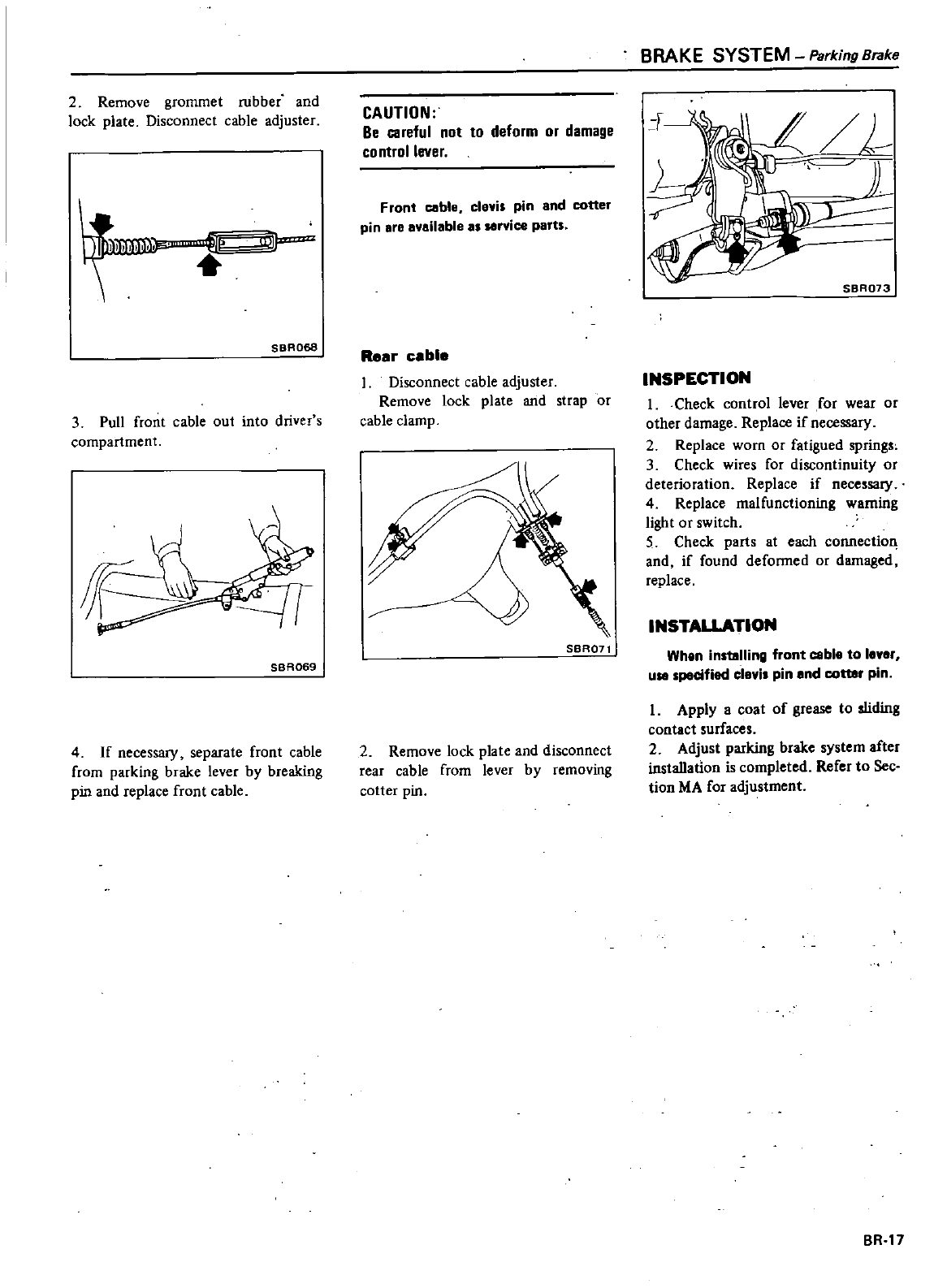
2
Remove
grommet
rubber
and
lock
plate
Disconnect
cable
adjuster
r
t
IJ
SBA068
3
Pull
front
cable
out
into
driver
s
compartment
SBA069
4
If
necessary
separate
front
cable
from
parking
brake
lever
by
breaking
pin
and
replace
front
cable
CAUTION
Be
careful
not
to
deform
or
damage
control
lever
Front
cable
clevis
pin
and
cotter
pin
are
available
as
Hrvice
parts
Rear
cable
Disconnect
cable
adjuster
Remove
lock
plate
and
strap
or
cable
clamp
SBR071
2
Remove
lock
plate
and
disconnect
rear
cable
from
lever
by
removing
cotter
pin
BRAKE
SYSTEM
Parking
Brake
L
l
SBRQ73
INSPECTION
I
Check
control
lever
for
wear
or
other
damage Replace
if
necessary
2
Replace
worn
or
fatigued
spring
3
Check
wires
for
discontinuity
or
deterioration
Replace
if
necessary
4
Replace
malfunctioning
warning
light
or
switch
5
Check parts
at
each
connection
and
if
found
deformed
or
damaged
replace
INSTALLATION
When
installing
front
cable
to
le
r
u
specified
elevis
pin
end
cotter
pin
I
Apply
a
coat
of
grease
to
sliding
contact
surfaces
2
Adjust
parking
brake
system
after
installation
is
completed
Refer
to
Sec
tion
MA
for
adjustment
BR
17
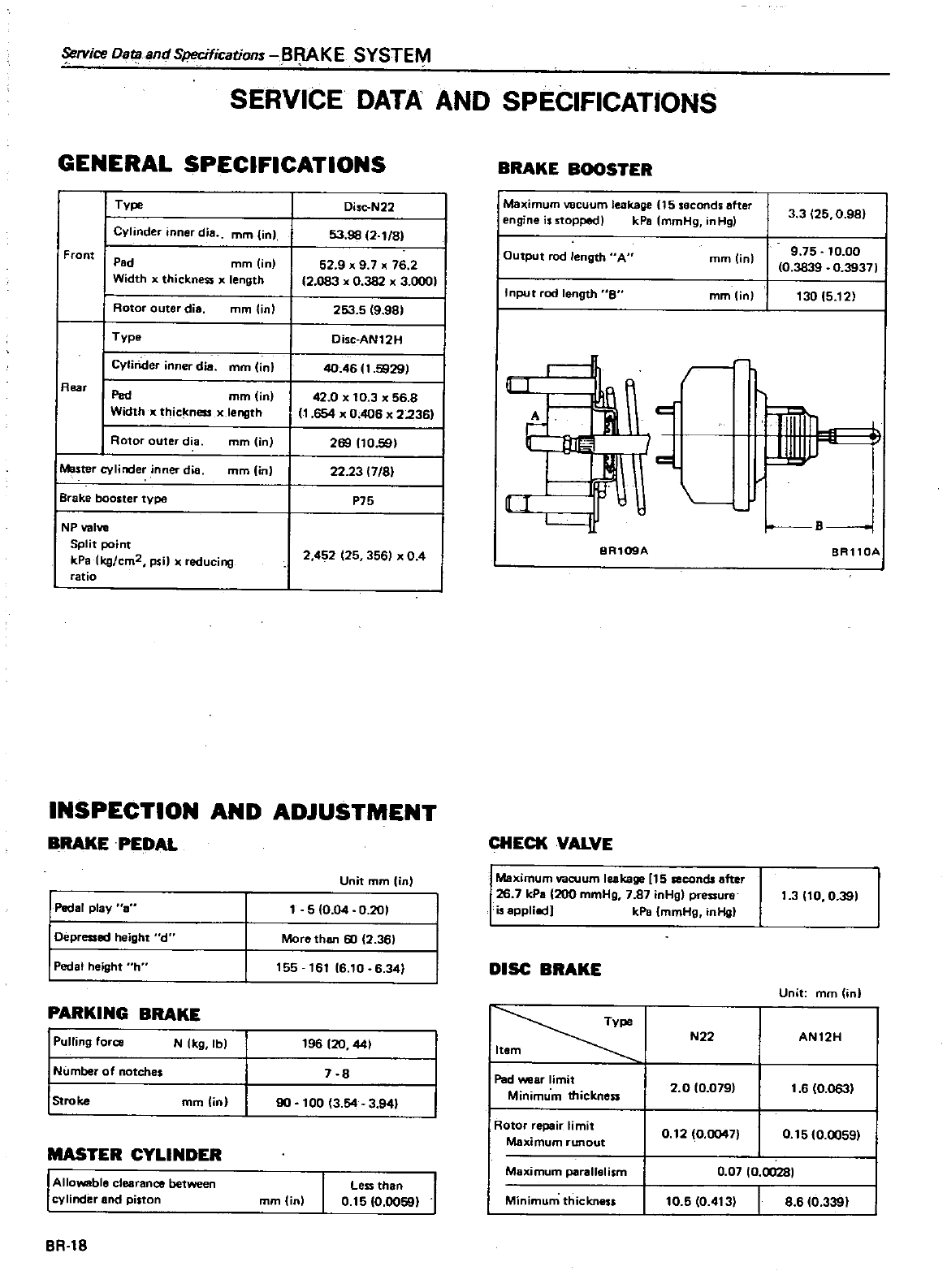
Service
OataandSpecifications
Bf
lAKE
SYSTEM
SERVICE
DATA
AND
SPECIFICATIONS
GENERAL
SPECIFICATIONS
I
Type
J
Cylinder
inner
die
mm
in
Front
Pad
mm
lin
Width
x
thickness
x
length
I
Rotor
outer
die
mm
in
I
Type
I
Cylinder
inner
die
mm
in
Rear
I
Pad
mm
in
Width
x
thic
ness
xlength
I
Rotor
outer
di
amm
in
IMa
ter
cyljnde
inner
die
mm
in
I
Brak
booster
type
NP
valve
Split
point
kPalkg
cm2
psi
reducing
ratio
Disc
N22
53 98
2
1
8
52
9
x
9
7
x
76
2
2
083
x
0
382
x
3
0001
253 5
9 98
Disc
AN
12
H
40
4611
5929
I
42
0
x
10
3
x
56
8
1
654
x
0
406
x
2236
269
10
59
22 23
7
8
P75
2
452
25
356
x
04
INSPECTION
AND
ADJUSTMENT
BRAKEPEDAL
I
Pedal
play
8
I
Depressed
height
d
I
Pedal
height
h
PARKING
BRAKE
1
Pulling
force
N
kg
Ibl
I
Number
of
notches
I
Stroke
mm in
MASTER
CYLINDER
I
Allo
N8ble
clearance
between
cylinder
and
piston
BR
18
Unit
mm
in
5
0 04
0
201
More
than
60
2
36
155
t6t
6
10
6
34
196
20
441
7
8
90
100
3
54
3
941
mmOnl
Less
than
I
0
15
0
0059
BRAKE
BOOSTER
Maximum
vacuum
leakage
15
s8cond
after
engine
iutopped
kPa
mmHg
inHg
Output
rod
length
A
mmlin
Input
rod
length
S
mmlin
3 3
25
0
981
9
75 10 00
0
3839
0
39371
130 5
12
r
r
IW
J
J
I
r
B
BR109A
8Rll0A
CHECKYALYE
Maximum
vacuum
leakage
15
seconds
after
26
7
kPa
200
mmHg
7
87
inHg
pressure
is
applia
tJ
kPa
mmHg
inHg
DISC
BRAKE
Type
Item
I
Pad
wear
limit
Minimum
thickness
N22
2 0 0
079
Rotor
repair
limit
Maximum
I
unout 0
1210
0047
Maximum
pal
allelism
0
07
0
00281
Minimum
thickness
10
5 0
413
1
3
to
0
391
Unit
mm in
AN12H
1
6
10
0631
0
15 10
0059
8
6
0
339
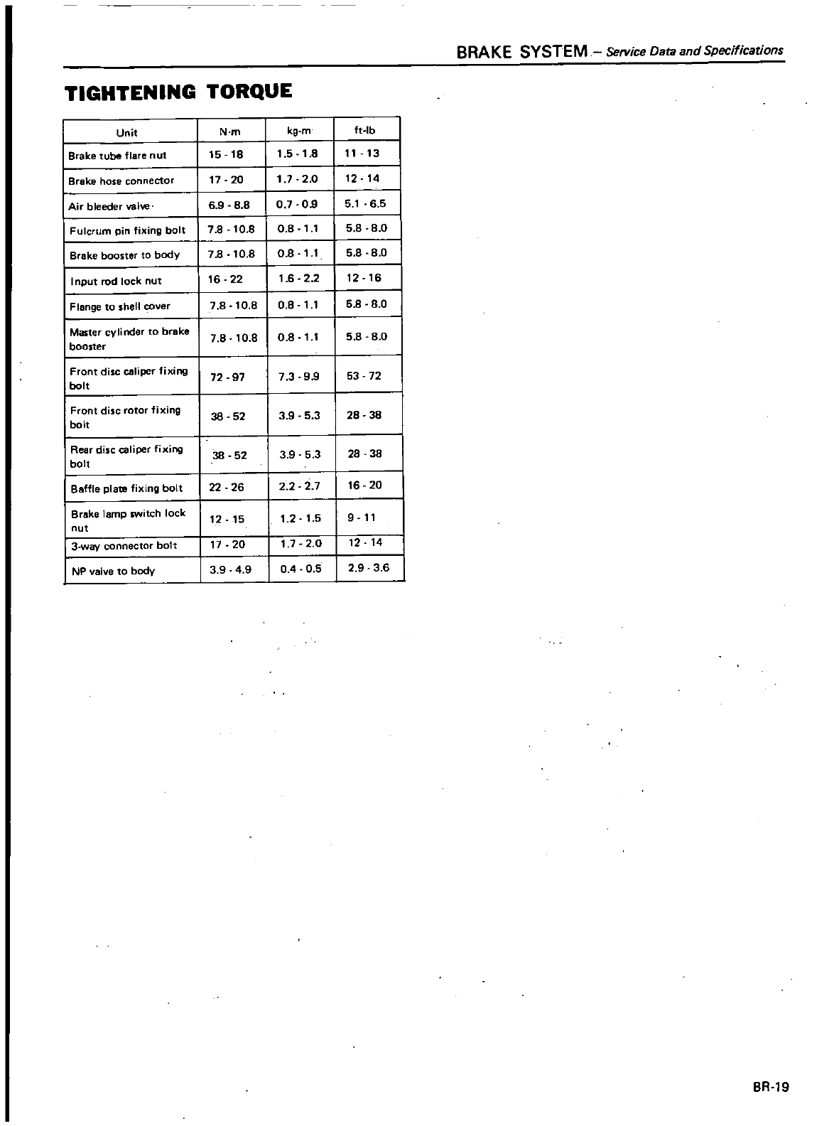
BRAKE
SYSTEM
Service
Oat1l
and
Specifications
TIGHTENING
TORQUE
Unit
N
m
kg
m
ft
Ib
Brake
tube flare
nut
15 18
1
5
1
8
11
13
I
Brake
hose
connector
17
20
1
72
0
t2
t4
I
Air
bleeder
valw
69 8
8
07
09
5
1
6
5
Fulcrum
pin
fixing
bolt
7 8
10
8
0
8
11
5 8 8
0
Brake
booster
to
body
7B
10
8
OB
11
5 8 8
0
I
nput
rod
lock
nut
16
22
1
62 2
12
16
Flange
to
shell
ver
7
8
10
8 0 8
11
5 8
8
0
I
Mas
cylinder
to
broke
7
8
10
8
0 8
11
5 8 8
0
booster
I
Front
disc
per
IIXI
I
72
97
7399
53
72
bolt
I
Front
disc
rotor
fixing
36 52
3
9
5 3
28
38
bolt
Rear
disc
caliper
fixing
38
52
3 9 53
28
38
bolt
Baffle
plate
fixing
bolt
22
26
22 2 7
18
20
I
Brake
lamp
switch
lock
12 15
1
2
1
5 9
11
nut
I
3
way
connectOr
bol
t
17
20
1
7 2
0
12 14
I
NP
valve
to
body
39 49
04
0
5 2
9
3
6
BR
19
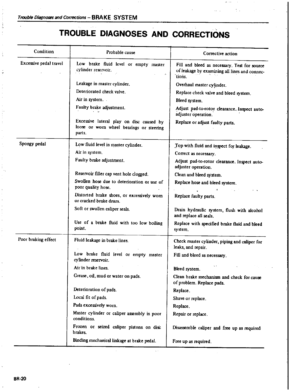
Trouble
Diagnoses
and
Corrections
BRAKE
SYSTEM
TROUBLE
DIAGNOSES
AND
CORRECTIONS
Condition
Probable
cause
Excessive
pedal
travel
Low
brake
l1uid level
or
empty
master
cylinder
reservoir
Leakage
in
master
cylinder
Deteriorated
check
valve
Air
in
system
Faulty
brake
adjustment
Excessive
lateral
play
on
disc
caused
by
loose
or worn
wheel
bearings
or
steering
parts
Spongy
pedal
Low
fluid
level
in
master
cylinder
Air
in
system
Faulty
brake
adjustment
Reservoir
filler
cap
vent
hole
clogged
SwaDen
hose
due
to
deterioration
or
use
of
poor
quality
hose
Distorted
brake
moes
or
excessively
worn
or
cracked
brake
drum
Soft
or
swaDen
caliper
seals
Use
of
a
brake
l1uid
with
too
low
boiling
point
Poor
braking
effect
Fluid
leakage
in
brake
line
Low
brake
fluid
level
or
empty
master
cylinder
reservoir
Air
in
brake
lines
Grease
oil
mud
or
water
on
pads
Deterioration
of
pads
Local
fi
t
of
pads
Pads
excessively
worn
Master
cylinder
Or
caliper
assembly
in
poor
conditions
Frozen
or
seized
caliper
pistons
on
disC
brakes
Binding
mechanical
linkage
at
brake
pedal
BR
20
Corrective
action
Fill
and
bleed
as
necessary
Test
for
source
of
leakage
by
examining
aIllmes
and
connec
tions
Overhaul
master
cYlinder
Replace
check
valve and
bleed
system
Bleed
system
Adjust
pad
to
rotor
clearance
Inspect
auto
adjuster
operation
Replace
or
adjust
faulty
parts
JoP
with fluid
and
inspect
fa
leakage
Correct
as
necessary
Adjust
pad
to
rotor
clearance
Inspect
auto
adjuster
operation
Clean
and
bleed
system
Replace
hose
and
bleed
system
Replace
faulty
parts
Drain
hydraulic
system l1ush
with
alcohol
and
replace
ail
seals
Replace
with
specified
brake
fluid
and
bleed
system
Check
master
cylinder
piping
and
caliper
for
leaks
and
repair
Fill
and
bleed
as
necessary
Bleed
system
Clean
brake
mechani
and check
for
cause
of
problem
Replace
pads
Replace
Shave
or
replace
Replace
Repair
or
replace
Disa
semble
caliper
and
free
up
a
required
Free
up
as
required
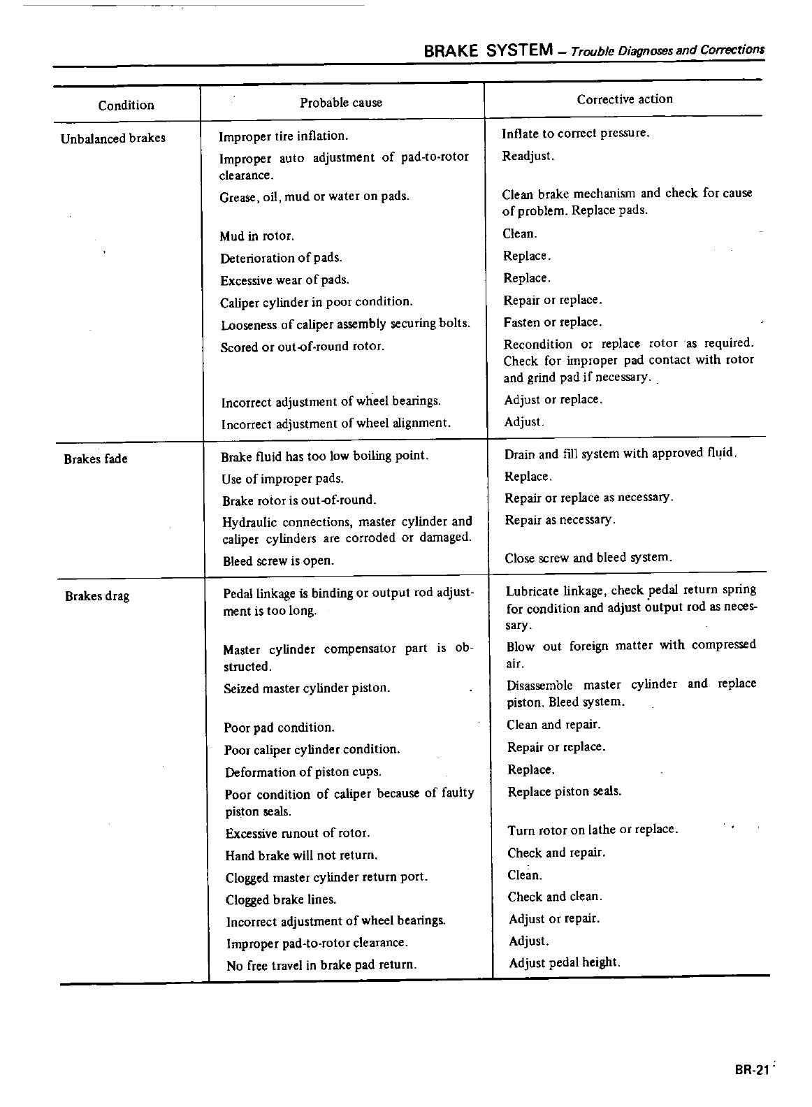
Condition
Unbalanced
brakes
Brakes
fade
Brakes
drag
BRAKE
SYSTEM
Trouble
Diagnoses
and
Corrections
Probable
cause
Improper
tire
inflation
Improper
auto
adjustment
of
pad
to
rotor
clearance
Grease
oil
mud
or
water
on
pads
Mud
in
rotor
Deterioration
of
pads
Excessive
wear
of
pads
Caliper
cylinder
in
poor
condition
Looseness
of
caliper
assembly
securing
bolts
Scored
or
out
of
round
rotor
Incorrect
adjustment
of
wheel
bearings
Incorrect
adjustment
of
wheel
alignment
Brake
l1uid
has
too
low
boiling
point
Use
of
improper
pads
Brake
rotor
is
out
of
round
Hydraulic
connections
master
cylinder
and
caliper
cylinders
are
corroded
or
damaged
Bleed
screw
is
open
Pedal
linkage
is
binding
or
output
rod
adjust
ment
is
too
long
Master
cylinder
compensator
part
is
ob
structed
Seized
master
cylinder
piston
Poor
pad
condition
Poor
caliper
cylinder
condition
Deformation
of
piston
cups
Poor
condition
of
caliper
because
of
faulty
piston
seals
Excessive
ronout
of
rotor
Hand
brake
will
not
return
Clogged
master
cylinder
return
port
Clogged
brake
lines
Incorrect
adjustment
of
wheel
bearings
Improper
pad
to
rotor
clearance
No
free
travel
in
brake
pad
return
Corrective
action
Inflate
to
correct
pressure
Readjust
Clean
brake
mechanism
and
check
for
cause
of
problem
Replace
pads
Clean
Replace
Replace
Repair
or
replace
Fasten
or
replace
Recondition
or
replace
rotor
as
required
Check
for
improper
pad
contact
with
rotor
and
grind
pad
if
necessary
Adjust
or
replace
Adjust
Drain
and
flll
system
with
approved
l1uid
Replace
Repair
or
replace
as
necessary
Repair
as
necessary
Close
screw
and
bleed
system
Lubricate
linkage
check
pedal
return
spring
for
condition
and
adjust
output
rod
as
neces
sary
Blowout
foreign
matter
with
compressed
air
Disassemble
master
cylinder
and
replace
piston
Bleed
system
Clean
and
repair
Repair
or
replace
Replace
Replace
piston
seals
Turn
rotor
on
lathe
or
replace
Check
and
repair
Clean
Check
and clean
Adjust
or
repair
Adjust
Adjust
pedal
height
BR
21
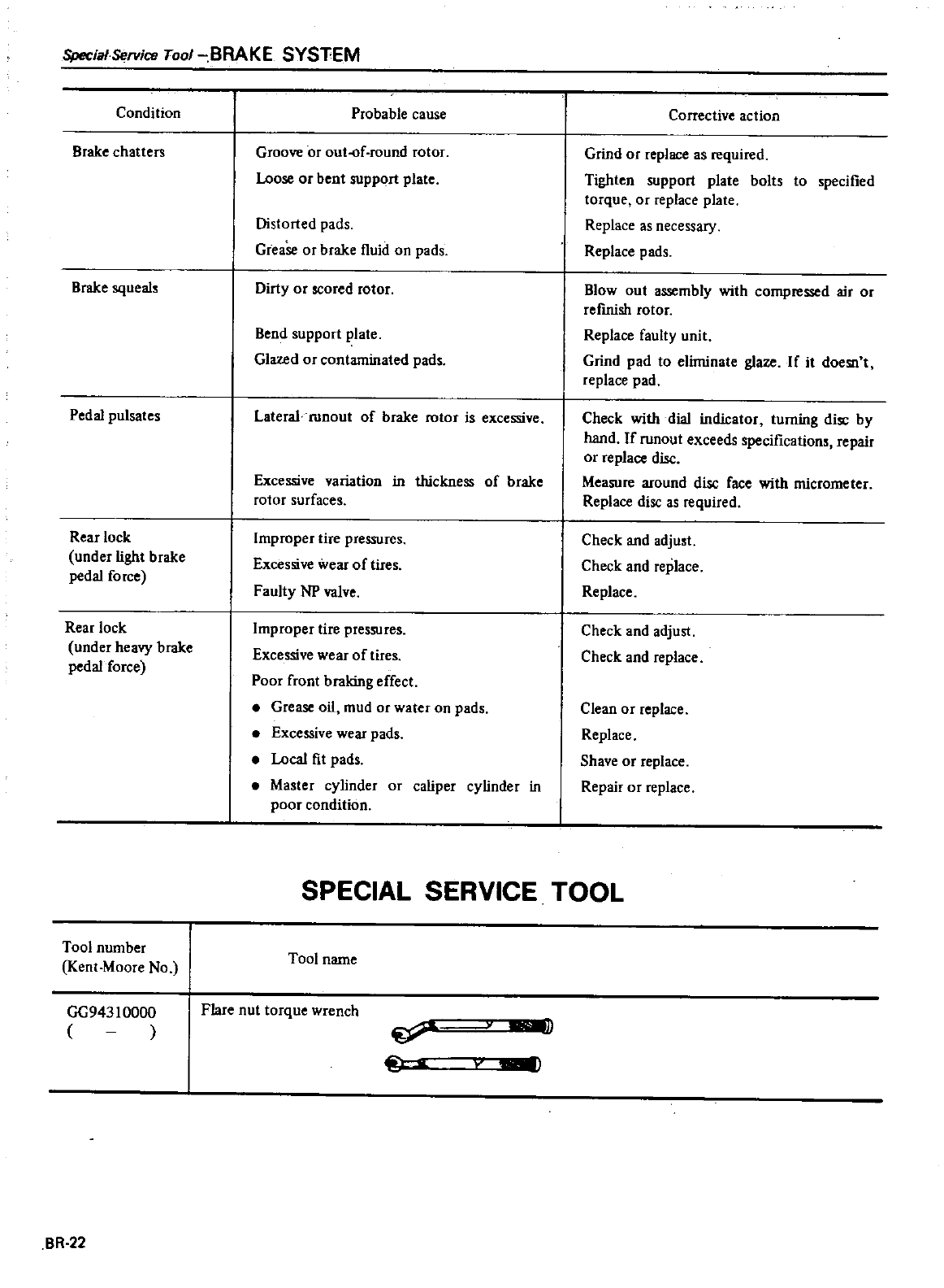
SpeciafService
Tool
BRAKE
SYSTEM
Condition
Brake
chatters
Brake
squeal
Pedal
pulsates
Rear
lock
under
light
brake
pedal
force
Rear
lock
under
heavy
brake
pedal
force
Tool
number
Kent
Moore
No
GG943
10000
BR
22
Probable
cause
Groove
or
out
of
round
rotor
Loose
or
bent
support
plate
Distorted
pads
Grease
or
brake
fluid
on
pads
Dirty
or
scored
rotor
Bend
support
plate
Glazed
or
contaminated
pad
Lateral
roDout
of
brake
rotor
is
excessive
Excessive
variation
in
thickness
of
brake
rotor
surfaces
Improper
tire
pressures
Excessive
wear
of
tires
Faulty
NP
valve
Improper
tire
pressures
Excessive
wear
of
tires
Poor
front
braking
effect
Grease
oil
mud
or
water
on
pads
Excessive
wear
pads
Local
fit
pads
Master
cylinder
or
caliper
cylinder
in
poor
condition
Corrective
action
Grind
or
replace
as
required
Tighten
support
plate
bolts
to
specified
torque
or
replace
plate
Replace
as
necessary
Replace
pads
Blowout
assembly
with
compressed
air
or
refmish
rotor
Replace
faulty
unit
Grind
pad
to
eliminate
glaze
If
it
doesn
t
replace
pad
Check
with
dial
indicator
turrting disc
by
hand
If
runout
exceeds
specification
repair
or
replace
disc
Measure
around
disc
face
with
micrometer
Replace
disc
as
required
Check
and
adju
t
Check
and
replace
Replace
Check
and
adjust
Check
and
replace
Clean
or
replace
Replace
Shave
or
replace
Repair
or
replace
SPECIAL
SERVICE
TOOL
Tool
name
Flare
nut
torque
wrench
u
I
DATSUN
200SX
Model
SIlO
Series
SECTIONST
STEERING
SYSTEM
STEERING
SYSTEM
STEERING
WHEEL
AND
COLUMN
STEERING
WHEEL
STEERING
LOCK
STEERING
COLUMN
Collapsible
type
STEERING
GEAR
Model
VRB47l
POWER
STEERING
GEAR
Model
I
P S
56l
AIiID
Oil
PUMP
STEERING
LINKAGE
CONTENTS
ST
2
ST
3
ST
3
ST
3
ST
4
ST
6
SERVICE
DATA
AND
SPECIFICATIONS
GENERAL
SPECIFICATIONS
INSPECTION
AND
ADJUSTMENT
TIGHTENING
TORQUE
TROUBLE
DIAGNOSES
AND
CORRECTIONS
SPECIAL
SERVICE
TOOLS
ST
23
ST
25
ST
21
ST
21
ST
21
ST
22
ST
10
ST
19
a
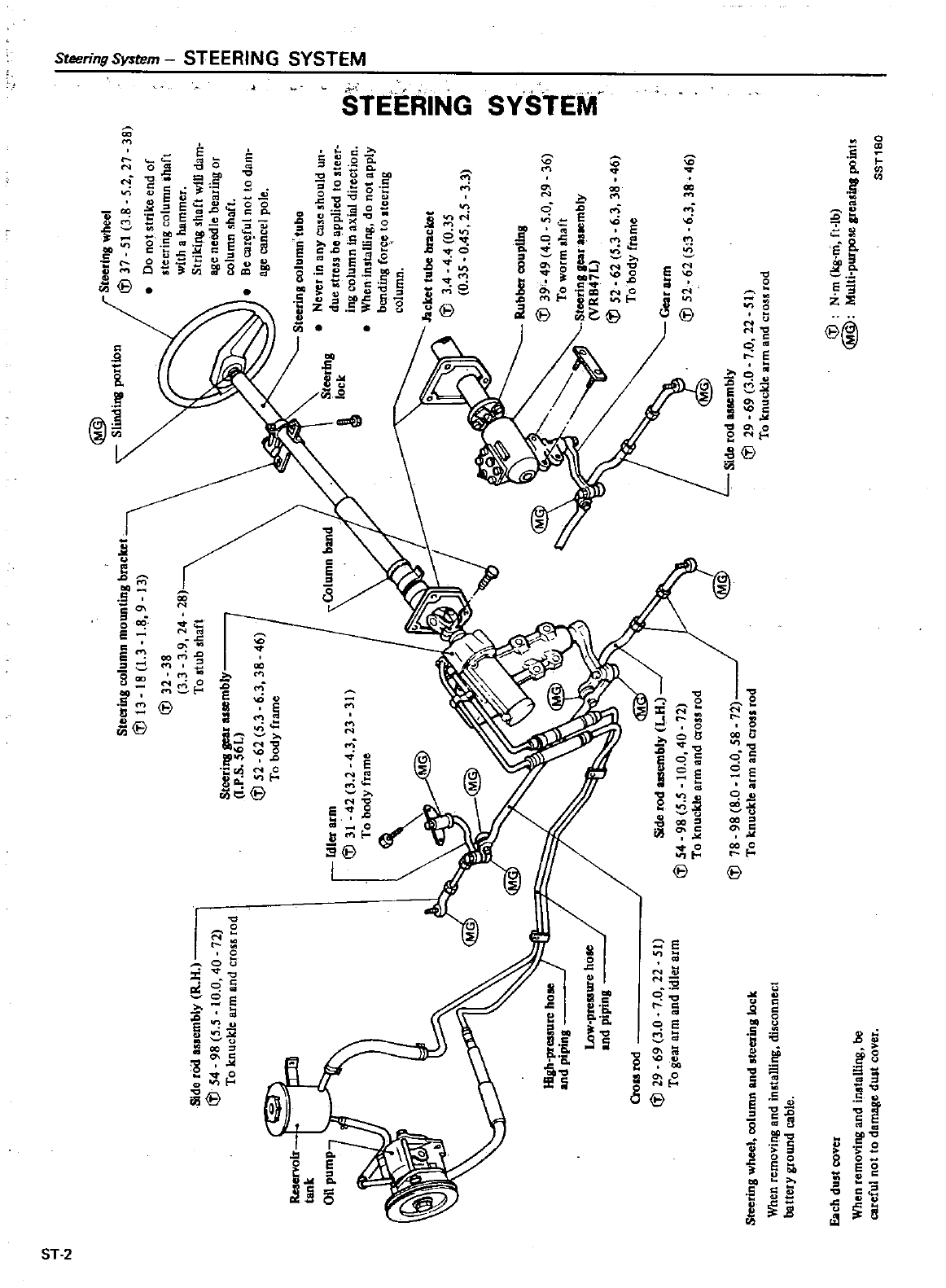
@
s
i1
ll
r
I
t
lon
Steetlng
Vlbeel
1
5
3
8
5
2
21
8
DO
not
sttik
end
of
steerini
column
thaft
W
ith
a
tuu
omer
StIlldt
nO
will
dam
age
needle
bea
IID
or
co
u
U
l
shaft
fie
c
ltefu
not
to
di
m
age
cancel
pole
SId
tOd
em1M
V
1I
54
98
5
5
0
0
40
12
1
0
gnuc
de
nt11l
and
eto
s
rod
Ste
S
column
mount
OS
bracl
et
B
18
I
1
8
9
B
2
8
9
24
28
0
3
tub
haft
Steetitll
u
IY
r
S
56L
52
62
503
6
38
46
0
bOdY
tattle
Steeting
eo
umntube
Ne
ef
in
at
case
snou
d
UI
4ue
ttt
S
be
applied
to
stee1
in
co
utJ
ll
n
a
l
a
direction
Wheninsu
lins
do
not
ap
P
bendin5
fotc
e
to
tcet
n8
column
Q
31
jael
et
tube
bt1
c
101
34
44
0
35
0
35
0
45
2
5
3
3
141
81m
3
42
3
2
4
3
23
0
bOdy
tame
tlU
lbCl
coupUns
39
49
4
0
5
0
29
36
10
wor1
haft
teerl
nllpt
a
ternbW
Vv
l
I1L
52
62
5
3
6
3
8
46
0
bOdY
frame
c
e
r
52
62
5
3
603
38
46
1l
g
l
pte
uto
10
Il
d
pipins
1J
VI
ute
hot
d
pipins
Side
tad
bly
11
J
54
9s
5
5
10
0
40
12
ol
nuc
d
atm
nd
055
tad
18
98
8
0
0
0
58
12
1
0
KnUc
e
arm
and
ClOSS
tod
Side
tad
IY
29
69
3
0
1
0
22
51
to
t
n
1C
a
rm
and
ctOS
fod
00
tad
29
69
3
0
1
0
22
51
To
eaI
aun
and
idle
ann
It
i
Cl
lTI
fft
r
Wi
tj
m
1g
n
I
@
MoIti
Purl
gteaoilll
pO
SST
50
St
tlnS
meel
cOlumn
Il
d
oteerit
S
I
When
temovlng
nd
t
lling
disconnect
l
altetY
gtound
calle
Eacb
dutt
COvel
nnll
and
inatl1
fif4
be
ro
lleJ
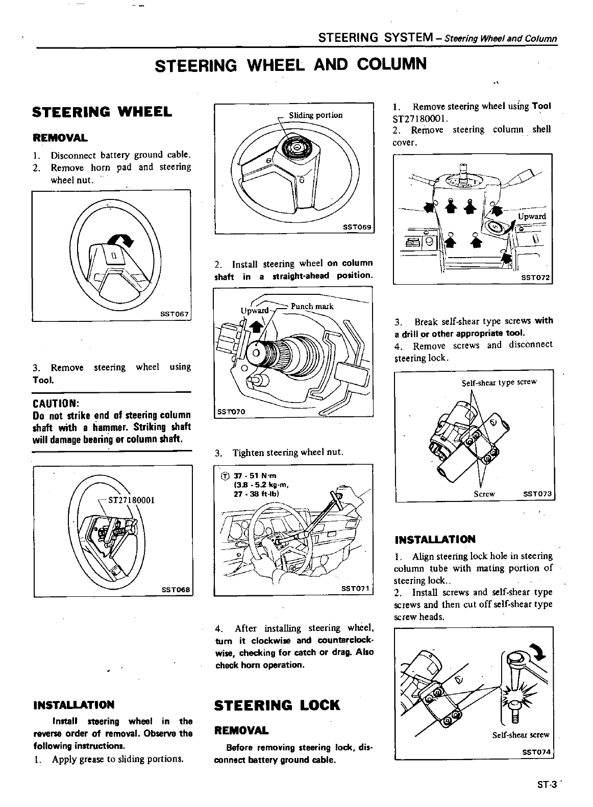
STEERING
SYSTEM
Steering
Wheel
and
Column
STEERING
WHEEL
AND
COLUMN
STEERING
WHEEL
REMOVAL
I
Disconnect
battery
ground
cable
2
Remove
horn
pad
and
steering
wheel
nut
SST067
3
Remove
steering
wheel
using
Tool
CAUTION
Do
not
strike
end
of
steering
column
shaft
with
a
hammer
Striking
shaft
will
damage
bearing
or
column
shaft
80001
SST068
INSTALLATION
Inltall
ltaering
wheel
in
the
reverse
order
of
removal
Observe
the
following
instructions
I
Apply
grease
to
sliding
portions
SST069
2
Install
steering
wheel
on
column
shaft
in a
straight
ahead
position
SSTU70
3
Tighten
steering
wheel
nut
l
J
n
51
N
m
13B
52
kg
m
27
38
ft
lb
SST071
4
After
installing
steering
wheel
bJm
it
clockwise
and
counterclock
wise
checking
for
catch
or
drag
Also
check
horn
operation
STEERING
LOCK
REMOVAL
Before
removing
steering
lock
dis
connect
battery
ground
cable
I
Remove
steering
wheel
using
Tool
8T27180001
2
Remove
steering
column
shell
cover
y
1
Upward
Igi
Ii
SST072
3
Break
self
shear
type
screws
with
a
drill
or
other
appropriate
tool
4
Remove
screws
and
disconnect
steering
lock
Self
shear
type
screw
Screw
SST073
INSTALLATION
I
Align
steering
lock
hole
in
steering
column
tube
with
mating
portion
of
steering
10cL
2Install
screws
and
self
shear
type
screws
and
then
cut
off
self
shear
type
screw
heads
V
V
Self
shear
screw
SST074
ST3
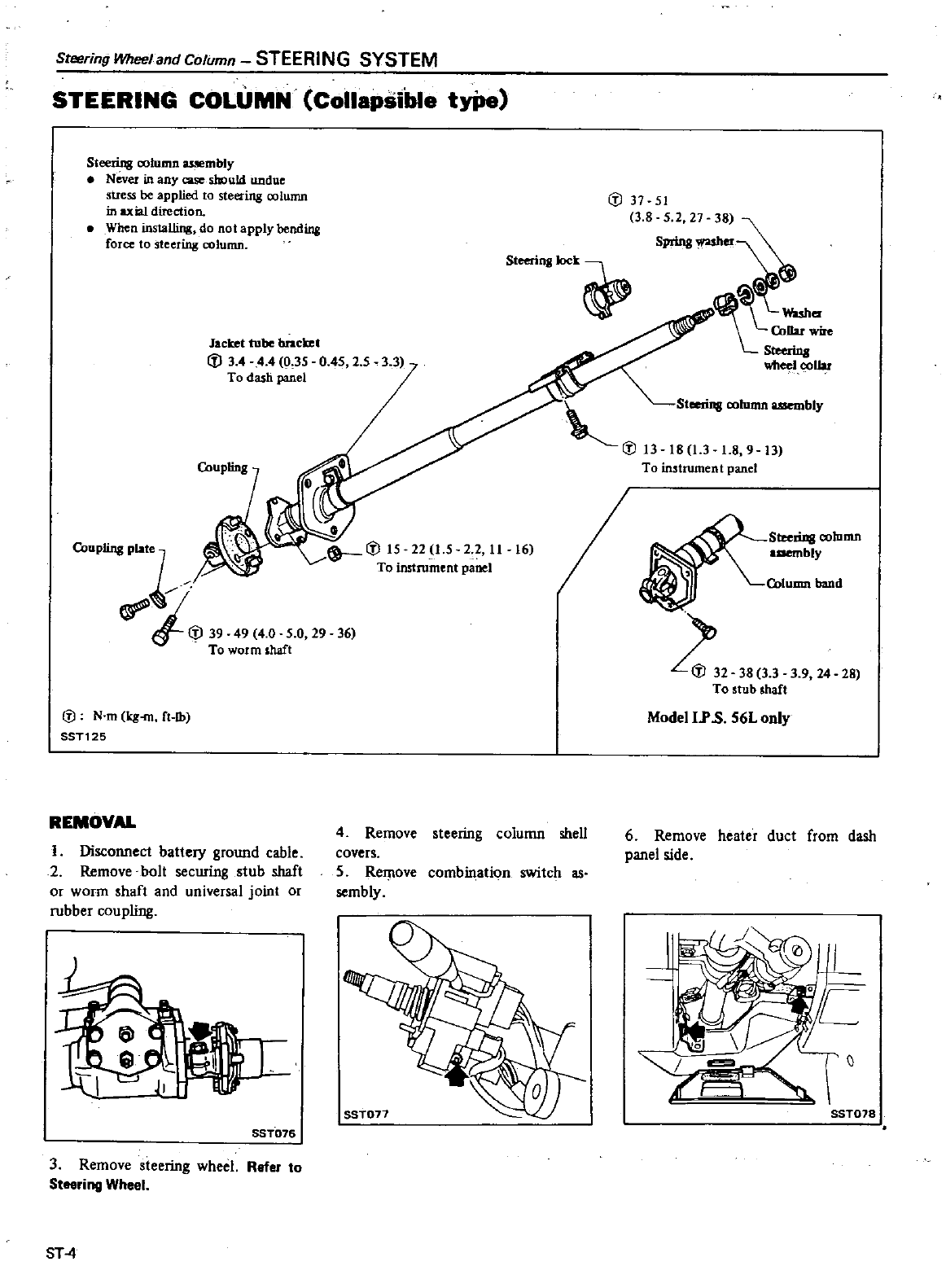
Steering
Wheel
and
Column
STEERING
SYSTEM
STEERING
COLUMN
Collapsible
tYPe
Steering
column
asRmbly
Never
in
any
case
should
undue
stress
be
applied
to
steering
column
in
axial
direction
When
installing
do
not
apply
bending
force
to
steering
column
fJ
37
51
3 8
S
Steerinj
k
Cn
tte
Steerins
eel
oolw
Jacket
tube
bracket
fJ
3
4 4
4
0
35
0
45
2 5
To
dash
panel
Cnuplinj
Plat
j
fJ
39
49
4 0
5
0 29
36
To
worm
shaft
@
N
m
kj
rn
ft
Jb
SST125
REMOVAL
I
Disconnect
battery
ground
cable
2
Remove
bolt
securing
stub
shaft
or
worm
shaft
and
universal
joint
or
rubber
coupling
al
SST076
3
Remove
steering
wheel
Refer
to
Steering
Wheel
ST
4
S
eerillj
oolumn
bly
tiJ
13 18
13
1
8
9
13
To
instrument
panel
16
4
Remove
steering
column
shell
covers
5
Remove
combination
switch
as
sembly
Steerillj
oolumn
aaembly
Column
band
Z32
38
3 3
3
9
24
28
To
stub
shaft
Modell
P
S
56L
only
6
Remove
heater
duct
from
dash
panel
side
SST078
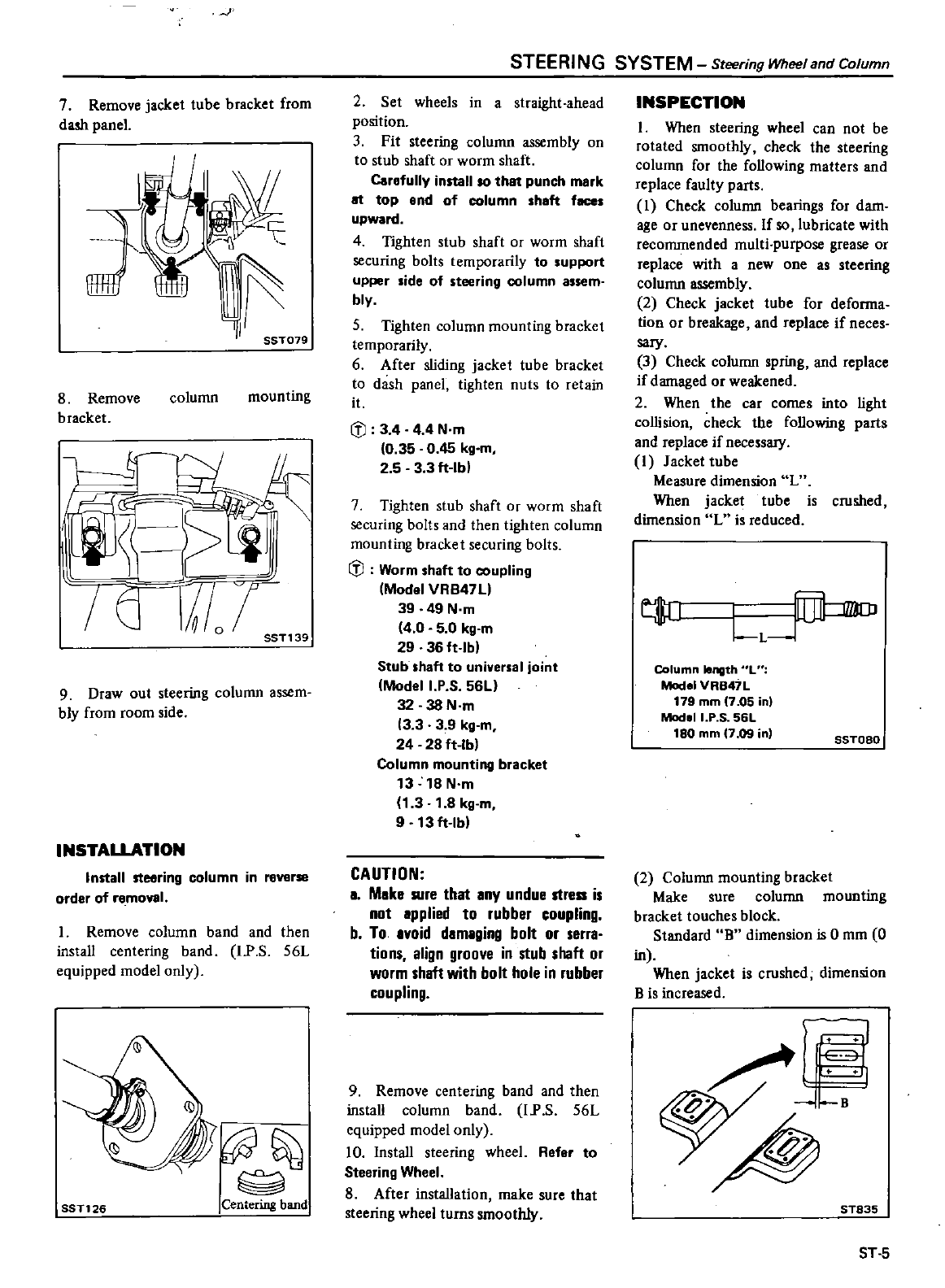
I
7
Remove
jacket
tube
bracket
from
dash
panel
J
SST079
8
Remove
bracket
column
mounting
p
j
I
or
SST1
39
9
Draw
out
steering
column
assem
bly
from
room
side
INSTALLATION
Install
steering
column
in
reverse
order
of
removal
I
Remove
column
band
and
then
install
centering
band
l
P
S
56L
equipped
model
only
@
Centering
band
SST126
STEERI
NG
SYSTEM
Steering
Wheel
and
Column
2
Set
wheels
in
a
straight
ahead
position
3
Fit
steering
column
assembly
on
to
stub
shaft
or
worm
shaft
Carefully
install
so that
punch
mark
at
top
ond
of
column
haft
fece
upward
4
Tighten
stub
shaft
or
worm
shaft
securing
bolts
temporarily
to
upport
upper
side
of
steering
column
assem
bly
5
Tighten
column
mounting
bracket
temporarily
6
After
sliding
jacket
tube
bracket
to
dash
panel
tighten
nuts
to
retain
it
Iil
3
4 4
4
N
m
0
35
0
45
kg
m
2 5 3 3
ft
Ibl
7
Tighten
stub
shaft
or
worm
shaft
securing
bolts
and
then
tighten
column
mounting
bracket
securing
bolts
JJ
Worm
shaft
to
coupling
Model
VRB4711
39 49
N
m
4
0 5 0
kg
m
29
36
ft
Ibl
Stub
shaft
to
universal
joint
Modell
P S
56Ll
32 38
N
m
3 3 3 9
kg
m
24
28
ft
Ibl
Column
mounting
bracket
13
18
N
m
1
3
1
8
kg
m
9
13
ft
Ibl
CAUTION
I
Mike
Rife
that
Iny
undue
strea
is
not
Ipplied
to
rubber
coupling
b
To
Ivoid
dlmlging
bolt
or serrl
tions
align
groove
in
stub
shaft
or
worm
shaft
with
bolt
hole
in
rubber
coupling
9
Remove
centering
band
and
then
install
column
band
l
P
S
56L
equipped
model
only
10
Install
steering
wheel
Refer
to
Steering
Wheel
8
After
installation
make
sure
that
steering
wheel
turns
smoothly
INSPECTION
I
When
steering
wheel
can
not
be
rotated
smoothly
check the
steering
column
for the
following
matters
and
replace
faulty
parts
I
Check
column
bearings
for
darn
age
or
unevenness
If
so
lubricate
with
recommended
multi purpose
grease
or
replace
with
a
new
one
as
steering
column
assembly
2
Check
jacket
tube
for
deforma
tion
or
breakage
and
replace
if
neces
sary
3
Check
column
spring
and
replace
if
damaged
or
weakened
2
When
the
car
comes
into
light
collision
check
the
following
parts
and
replace
if
necessary
I
Jacket
tube
Measure
dimension
L
When
jacket
tube
is crushed
dimension
L
is
reduced
t
L1
LL
F
J
Column
length
L
Model
VRB47L
179
mm
7
05
in
ModoII
P
S
56L
180
mm
7
09
in
SSTOBO
2
Column
mounting
bracket
Make
sure
column
mounting
bracket
touches
block
Standard
B
dimension
is
0
mm
0
in
When
jacket
is crushed
dimension
B is
increased
jg
ST835
ST
5
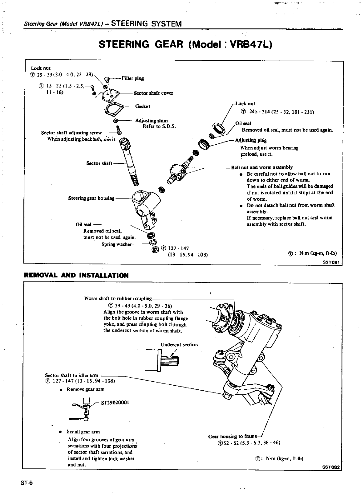
Steering
Gear
Model
VRB47L
STEERING
SYSTEM
m
STEERING GEAR
Model
VRB47L
Lo
5
314
25 32
181 231
Oil
I
Removed
oil
seal
must
not
be
used
agJ
l1L
Adjustins
Pilla
When
adjust
wonn
bearing
preload
use
it
BaD
nut
and
worm
assembly
Be
a
rcful
not
to
allow
ball
nut
to
run
down
to
either
end
of
worm
The
end
ofba1l
guides
will
be
lamag
if nut
is rotated
until
it
stops
at
the
em
of
wonn
Do
not
detach
ball
nut
from
worm
shaft
assembly
If
necessary
replace
ball
nut
and
worm
assembly
with
sector
shaft
Lock
nut
cp
29
3913
0
4
0 22
29
F
d1erpl
l1
J
15 25
1
5
2 5
11
18
SeetorsIWlCOV
v
to
0
rt
J
Goskel
Adjustm
shim
Refer
to
S
O
S
Sector
shar
adjusting
saew
0
When
adjustirj
backla
h
use
it
Sector
maft
Steering
gear
housing
147
15
94
108
REMOVAL
AND
INSTALLATION
Worm
shaft
to
rubber
couplin
I
J
39
49
4 0
5 0
29
36
Align
the
groove
in
worm
shaft
with
the
bolt
hole
in
rubber
coupling
flange
yoke
and
prcssooupling
bolt
through
the
undercut
section
of
wonn
shaft
Undercut
section
1
Sector shaft
to
idler
arm
I
J
127 147
13
15
94
108
Remove
gear
arm
Sf29020001
Install
gear
arm
Align
four
grooves
of gear
arm
serrations
with
four
projections
of
sector
shaft
serrations
and
install
and
tighten
lock
washer
and
nut
ST
6
I
J
N
m
q
m
ft
Ib
SST081
Gear
housing
to
frame
1
J52
62
5
36 3
38
46
I
J
N
m
q
m
ft
Ib
SST082
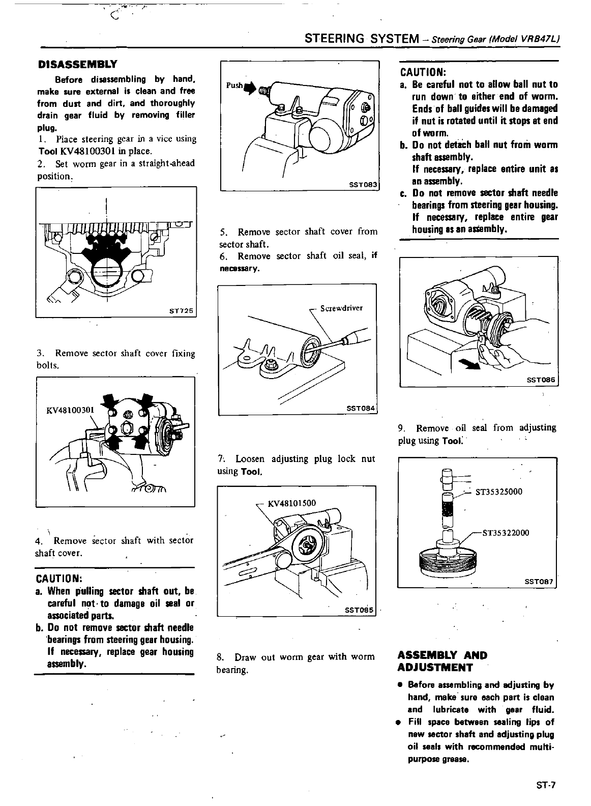
DISASSEMBLY
Before
disassembling
by
hand
make
sure
external
is
clean
and free
from
dust
and
dirt
and
thoroughly
drain
gear
fluid
by
removing
filler
plug
1
Place
steering gear
in a
vice
using
Tool
KV48100301
in
place
2
Set
worm
gear
in
a
straight
ahead
position
ST725
3
Remove
sector
shaft
cover
fixing
bolts
KV48100301
4f
L
4
Remove
sector
shaft
with
sector
shaft
cover
CAUTION
a
When
pulling
sector
shaft
out
be
careful
not
to
damage
oil
seal
or
associated
parts
b
00
not
remove
sector
shaft
needle
bearings
from
steering
gear
housing
If
necessary
replace
gear
housing
assembly
STEERING
SYSTEM
Steering
Gear
Model
VR847L
7fY
0
SST083
5
Remove
sector
shaft
cover
from
sector
shaft
6
Remove
sector
shaft
oil
seal
if
necessary
SST084
7
Loosen
adjusting
plug
lock
nut
using
Tool
SST085
8
Draw
out
worm
gear
with
worm
bearing
CAUTION
a
Be
careful
not
to allow
ball
nut
to
run
down
to
either
end
of
worm
Ends
of
ball
guides
will
be
damaged
if
nut
is
until
it
stops
It
end
of
worm
b
Do
not
detach
ball
nut
from
worm
shaft
assembly
If
necessary
replace
entire
unit
as
en
assembly
c
Do
not
remove
sector
shaft
needle
bearings
from
steering
gear
housing
If
necessary
replace
entire
gear
housing
IS
an
asSembly
SST086
9
Remove
oil
seal
from
adjusting
plug
using
Tool
ST35322000
SST087
ASSEMBLY
AND
ADJUSTMENT
Before
assembling
and
adjusting
by
hand
meke
ure
each
pert
i
elean
and
lubricate
with
geer
fluid
Fill
paee
between
Iing
lip
of
new
ctor
h
ft
and
adju
ting
plug
oil
1
with
rlICOmmendad
multi
purpose
grease
ST7
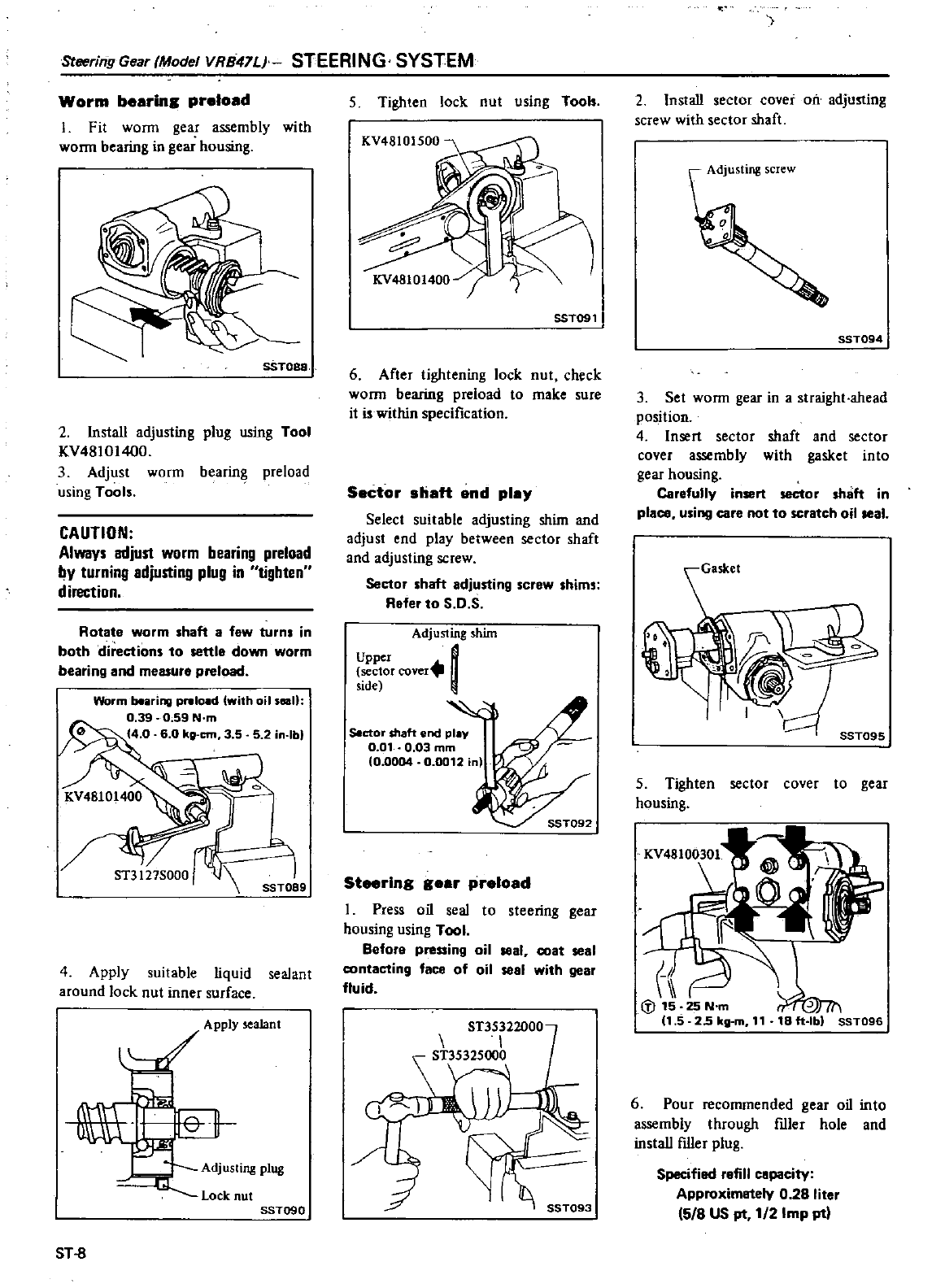
Steering
Gear
fModel
VR847U
STEERING
SYSTEM
Worm
bearins preload
1
Fit
worm
gear
assembly
with
worm
bearing
in
gear
housing
SST088
2 Install
adjusting
plug
using
Tool
KV48101400
3
Adjust
worm
bearing
preload
using
Tools
CAUTION
Always
adjust
worm
bearing preload
by
turning
adjusting
plug
in
tighten
direction
Rotate
worm
shaft
a
few
turns
in
both
directions
to
settle
down
worm
bearing
and
measure
preload
Worm
bearing preload
with
oil
sean
0
39
0
59
N
m
40 60
kg
em
3
5
5
2
lb
4
Apply suitable
liquid
sealant
around
lock
nut
inner
surface
Apply
sealant
Adj
usting
plug
Lock
nut
SST090
ST
8
5
Tighten
lock
nut
using
Tooh
KV48101500
KV48101400
SST091
6
After
tightening
lock
nut
check
worm
bearing
preload
to
make
sure
it
is
within
specification
Sector
shaft
end
play
Select
suitable
adjusting
shim
and
adjust
end
play
between
sector
shaft
and
adjusting
screw
Sector
shaft
adjusting
screw
shims
Refer
to
S
O
S
Adjusting
him
Upper
I
sector
cover
side
Sector
shaft
end
play
O
Ol
0
03
mm
10
0004
0
0012
n
Steering
gear
preload
I
Press
oil
seal
to
steering
gear
housing
using
Tool
Before
pressing
oil
seal
coat
seal
contacting
face
of
oil
seal
with
gear
fluid
2
Install
sector
cover
oil
adjusting
screw
with
sector
shaft
Adjusting
screw
SST094
3
Set
worm
gear
in a
straight
ahead
position
4
Insert
sector
shaft
and
sector
cover
assembly
with
gasket
into
gear
housing
Carefully
insert
sector
shaft
in
place
using
care
not to
scratch
oil
seal
5
Tighten
sector
cover to
gear
housing
f
1iJ15
25
N
m
11
5
25
kg
m
11
6
Pour
recommended
gear
oil
into
assembly
through
flller
hole
and
install
ftller
plug
Specified
refill
capaeity
Approximetely
0
28
liter
5
8
US
pt
112
Imp
pt
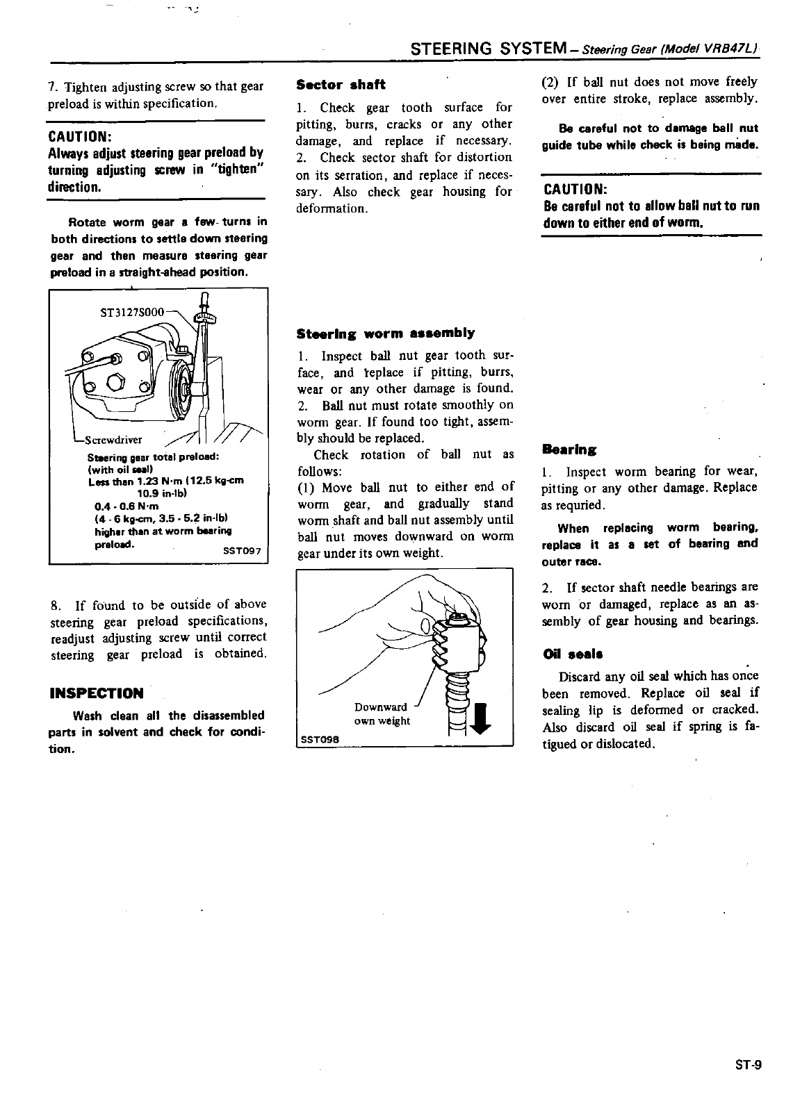
7
Tighten
adjusting
screw
so
that
gear
preload
is
within
specification
CAUTION
Always
adjust
steering
gear
preload
by
turning
adjusting
screw
in
tighten
direction
Rotate
worm
gear
a
fsw
turn
in
both
directions
to
settle
down
steering
gear
and
then
measure
steering
gear
preload
in a
streight
lhead
position
LScrewdriver
J
Steerinlllilear
total
preload
with
oil
1
Less
than
1
23
N
m
12
5
kg
c
m
10
9in
I
b
04
0 6
N
m
4 6
kll
cm
3
5 5
2
in
Ib
higher
than
at
worm
bearing
praia
SST097
8
If
found
to
be
outside
of
above
steering
gear
preload
specifications
readjust
adjusting
screw
until correct
steering
gear
preload
is
obtained
INSPECTION
Wash
clean
all
the
disassembled
parts
in
solvent
and
check
for
condi
tion
STEERING
SYSTEM
Steering
Gear
Model
VR841Li
Sector
shaft
Check
gear
tooth
surface
for
pitting
burrs
cracks
or
any
other
damage
and
replace
if
necessary
2
Check
sector
shaft
for
distortion
on
its
serration
and
replace
if
neces
sary
Also
check
gear housing
for
deformation
Steering
worm
assembl
I
Inspect
ball
nut
gear
tooth
sur
face
and
teplace
if
pitting
burrs
wear
or
any
other
damage
is
found
2
Ball
nut
must
rotate
smoothly
on
worm
gear
If
found
too
tight
assem
bly
should
be
replaced
Check
rotation of
ball
nut
as
follows
I
Move
ball
nut
to
either
end
of
worm
gear
and
gradually
stand
worm
shaft
and
ball
nut
assembly
until
ball
nut
moves
downward
on
worm
gear
under
its
own
weight
Downward
J
own
weight
SST098
2
If
ball
nut
does
not
move
freely
over
entire
stroke
replace assembly
Be
careful
not
to
damage
ball
nut
guide
tuba
whi
Ie
check
is
being
made
CAUTION
Be
caraful
not
to allow
ball
nut
to
run
down
to
either
end
of
worm
Beulng
I
Inspect
worm
bearing
for
wear
pitting
or
any
other
damage Replace
as
requried
When
replacing
worm
bearing
replace
it
as
8
set
of
bearing
and
outer
race
2
If
sector
shaft
needle
bearings
are
worn
or
damaged
replace
as
an
as
sembly
of
gear
housing
and
bearings
Oil
eal
Discard
any
oil
seal
which
has
once
been
removed
Replace
oil
seal
if
sealing
lip
is
deformed
or
cracked
Also
discard
oil
seal
if
spring
is
fa
tigued
or
dislocated
ST
9
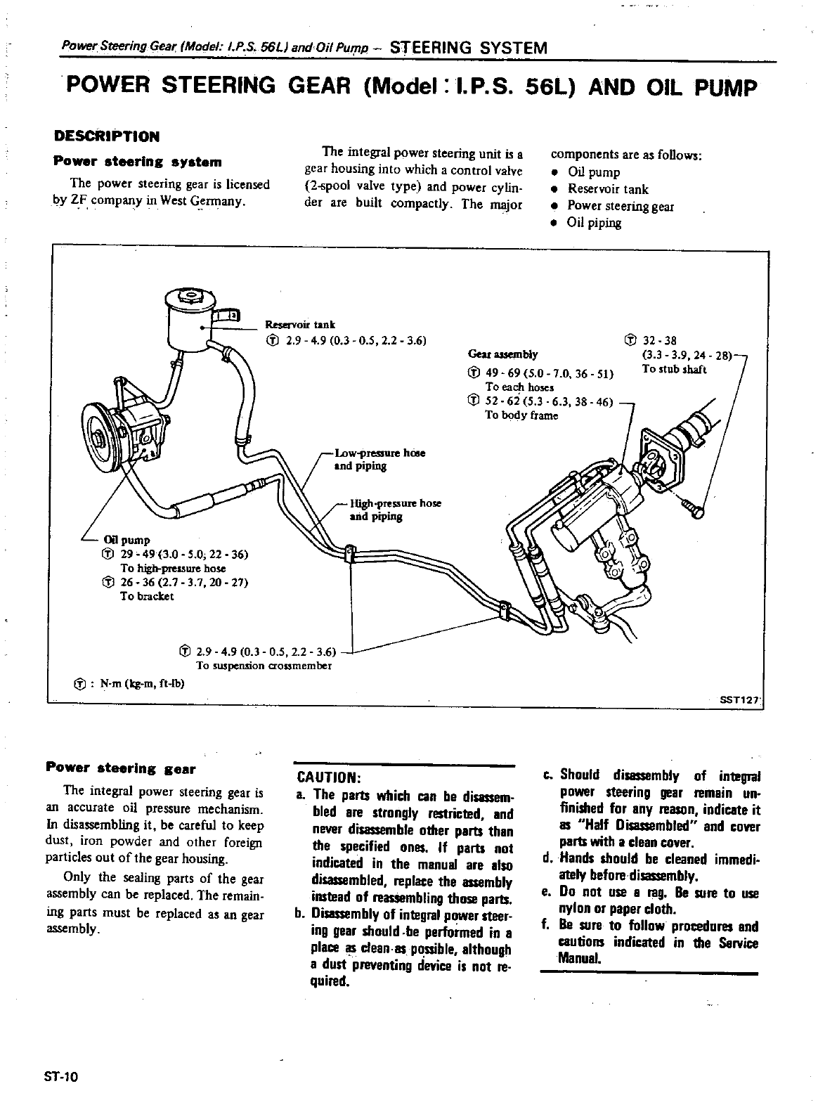
Power
Steering
lear
Model
I
P S
56L
andOil
PUTflP
STEERING
SYSTEM
POWER
STEERING
GEAR
Model
I
P
S
56L
AND
OIL
PUMP
DESCRIPTION
Po
r
steering
s
stem
The
power
steering
gear is
licensed
I1Y
ZF
company
in
West
Germany
The
integral
power
steering
unit
is
a
gear
housing
into
which
a
control
valve
2
pool
valve
type and
power
cylin
der
are
built
compactly
The
major
Reservoir
tank
cfl 2 9
4
90 3
0
5 2
2
36
components
are
as
folloW
Oil
pump
Reservoir
tank
Power
steering
gear
Oil
piping
cfl
32 38
3 3 3
9 24
To
stub
shaft
Gear
assembly
cfl
49 69
5 0 7
0
36
51
To
each
hoses
cfl
52
6i
5 3 6 3
38
46
To
body
frame
High
pressure
hose
and
piping
cfl
2 9 4 9 0 3 0
52 2
3 6
To
suspension
aossmember
cfl
N
m
kg
m
ft
tb
Power
steering
gear
The
integral
power
steering gear
is
an
accurate
oil
pressure
mechanism
In
disassembling
it
be
careful
to
keep
dust
iron
powder
and
other
foreign
particles
out
of
the
gear
housing
Only
the
sealing
parts
of
the
gear
assembly
can
be
replaced
The
remain
ing
parts
must
be
replaced
as
an
gear
assembly
ST10
CAUTION
a
The
parts
which
can
be
disassem
bled
are
strongly
J
and
never
disassemble
other
parts
than
the
specified
ones
If
parts
not
indicated
in
the
manual
are
also
d
Ied
replace
the
assembly
instead
of
bling
those
parts
b
Disassembly
of
integral
power
steer
ing
gear
should
be
performed
in
a
place
l
5
dean
as
pssible although
a
dust
preventing
device
is
not
reo
quired
SST12T
Co
Should
disassembly
of
integral
power
steering
gear
remain
un
finished
for
any
reason
indicate
it
as
Half
Disassembled
and
COVllr
parts
with
a
clean
cover
d
Hands
should
be
cleaned
immedi
ately
before
disassembly
e
Do
not use a
rag
Be
sure
to
use
nylon
or
paper
cloth
f
Be
sure
to
follow
procedures
and
cautions
indicated
in
the
Service
Manual
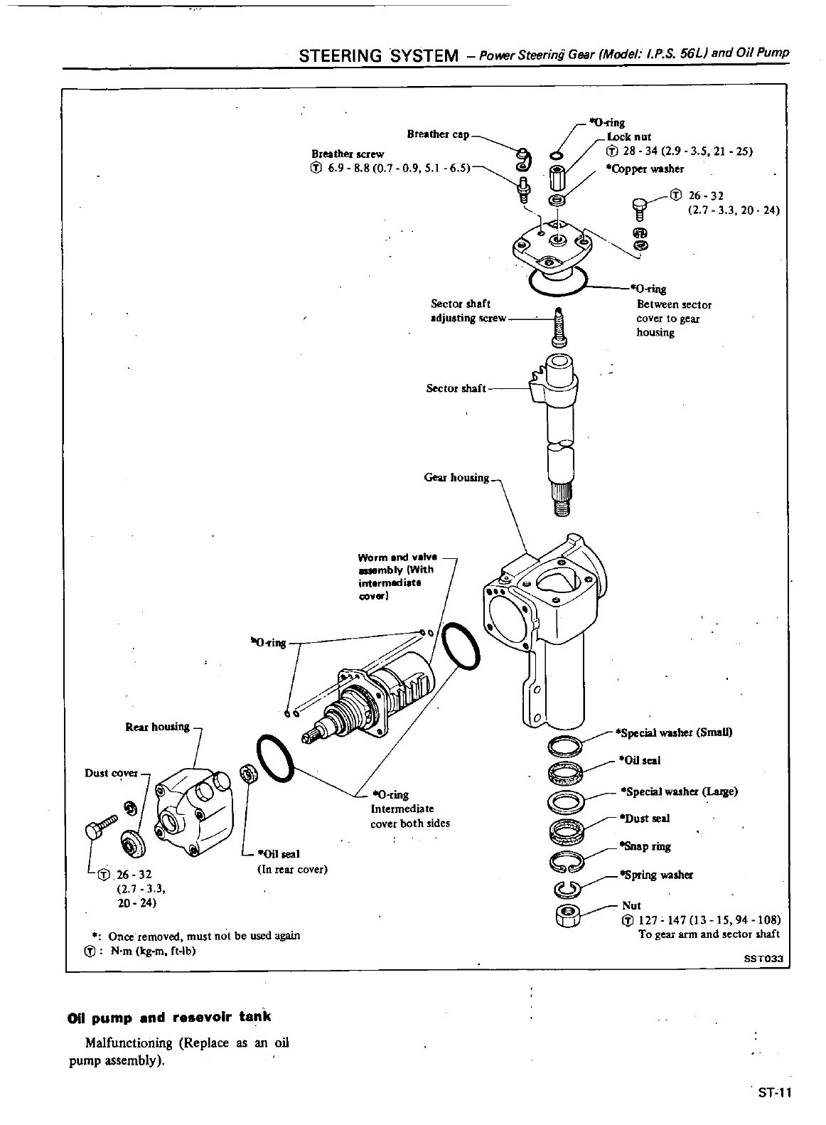
STEERING
SYSTEM
PowerSteeringGear
Model
I
P S
56L
andOilPump
Breather
screw
il
6
9
8 8 0
7
Breather
cap
Sector
shaft
adjusting
screw
Sector
shaft
Worm
end
nlve
mbly
With
interm
t
i
te
cov
l
ru
2
7
3 3
20
24
0il1e3
1
In
rear
cover
Once
removed
must
not
be
used
again
il
N
m
Icg
m
ft
lb
011
pump
and
r
volr
tank
Malfunctioning
Replace
as
an
oil
pump
assembly
I
O
ring
lock
nut
cf
il
28
34
2 9
3
5
21
25
Copper
washer
@
il
26
32
J
V
2
7 3 3
20
fill
@
24
O
rins
Between
sector
cover
to
gear
housing
o
o
Special
washer
Small
OUseal
0
Special
washer
La
IJle
DUst
sea1
apring
ospring
washer
Nut
I
tY
i
l127
147
13
15
94
108
To
gear
arm
and
sector
shaft
SST033
STll
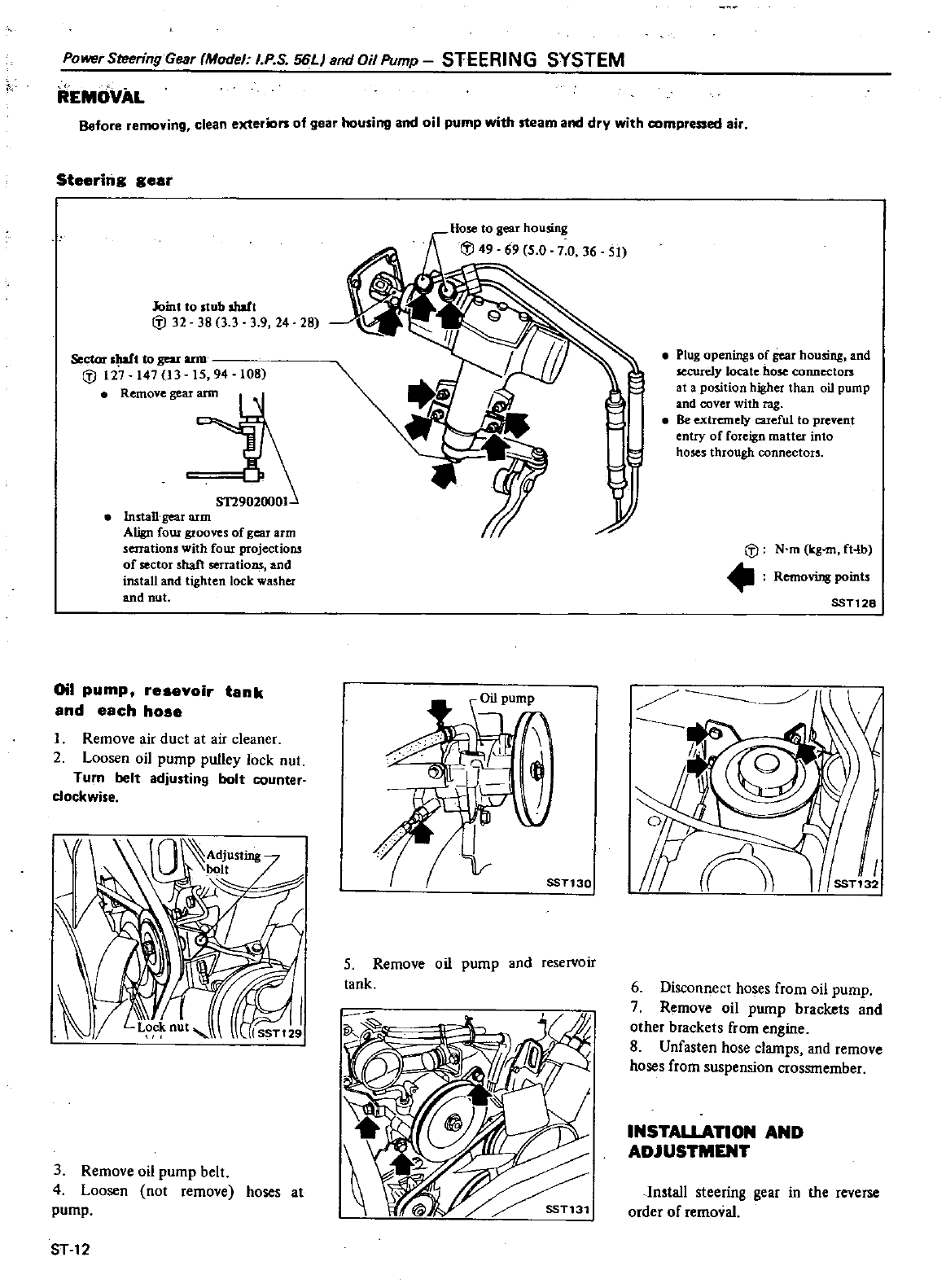
REMOVAL
Power
Steering
Gear
Model
I
PS
56L
and
Oil
Pump
STEERING
SYSTEM
Before
removing
clean
exterion
of
gear
housing
and
oil
pump
with
steam
and
dry
with
compressed
air
Steering
gear
Joint
to
stub
shaft
t
J
32
38
3 3 3 9
24
28
Sector
sIWI
to
sou
ann
t
J
127
147
13
15
94
108
i
Install
gear
arm
Align
fOUI
grooves
of
gear
arm
serrations
with
four
projections
of
sector
shaft
serrations
and
install
and
tighten
lock
washer
and
nut
Oil
pump
resevoir
tank
and
each hose
1
Remove
air
duct
at
air
cleaner
2
Loosen
oil
pump
pulley
lock
nut
Turn
belt
adjusting
bolt
counter
clockwise
3
Remove
oil
pump
belt
4
Loosen
not
remove
hoses
at
pump
ST
12
5
Remove
oil
pump
and
reservoir
tank
51
j1
Plug
openings
of
gear
housing
and
securely
locate
hose
connectors
at
a
position
higher
than
oil
pump
and
cover
with
rag
Be
extremely
cucful
to
prevent
entry
of
foreign
matter
into
hoses
through
connectou
t
J
N
m
kg
m
fHb
R
g
points
SST128
6
Disconnect
hoses
from
oil
pump
7
Remove
oil
pump
brackets
and
other
brackets
from
engine
8
Unfasten
hose
clamps
and
remove
hoses
from
suspension
crossrnember
INSTAUATION
AND
ADJUSTMENT
In
tall
steering
gear
in
the
reverse
order
of
removal
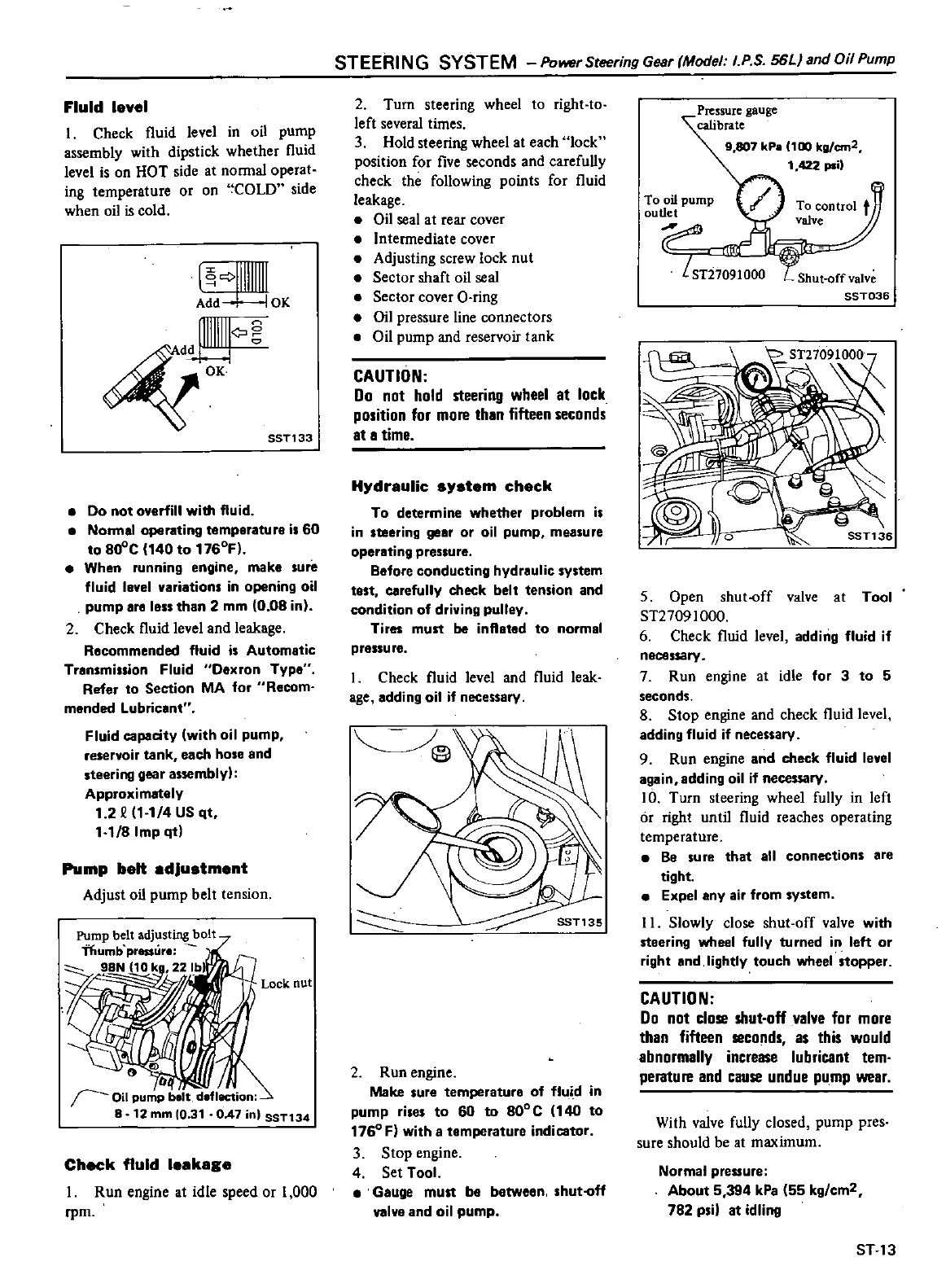
STEERING
SYSTEM
Power
Steering
Gear
Model
I
PS
56LJ
and
Oil
Pump
Fluid
level
I
Check
fluid
level
in
oil
pump
assembly
with
dipstick
whether
fluid
level
is
on
HOT
side
at
normal
operat
ing
temperature
or
on
COLD
side
when oil
is
cold
1
llllllm
Add
IOK
4
Q
OK
SST133
Do
not
overfill
with
fluid
Nanna
operating temperature
i
60
to
8o
C
140
to
1760F
When
running
engine
make
sure
fluid
level
variations
in
opening
oil
pump
ere
Ie
than
2
mm
0
08
in
2
Check
fluid
level
and
leakage
Recommended
fluid
is
Automatic
Transmission
Fluid
Oexron
Type
Refer
to
Seetion
MA
for
Recom
mended
Lubricant
Fluid
capacity
with
oil
pump
reservoir
tank
each
hose
and
steering
gear
assembly
Approximately
1
2
1
1
4
US
qt
1
118
Imp
qt
Pump
belt
edJustment
Adjust
oil
pump
belt
tension
Pump
belt
adjusting
bolt
Thumb
pressure
911Nj10kg
221b
71
I
Lock
nut
G
IJ
I
Oil
pump
belt
deflection
8
12
mm
10
31
OA7
in
SST134
Check
fluid
leekege
I
Run
engine
at idle
speed
or
1
000
rpm
2
Turn
steering
wheel
to
right
to
left
several
times
3
Hold
steering
wheel
at
each
lock
position
for
five
seconds
and
carefully
check
the
following
points
for
fluid
leakage
Oil
seal
at rear
cover
Intermediate
cover
Adjusting
screw
lock
nut
Sector
shaft
oil
seal
Sector
cover
O
ring
Oil
pressure
line
connectors
e
Oil
pump
and
reservoir
tank
CAUTION
Do
not
hold
steering
wheel
at
lock
position
for
more
thin
fifteen
seconds
It
I
time
Hydreulic
system
check
To
determine
whether
problem
is
in
steering
gear
or
oil
pump
measure
operating
pressure
Before
conducting
hydraulic
system
test
carefully
check
belt
tension
and
condition
of
driving
pulley
Tires
must
be
inflated
to
normal
pressu
reo
I
Check fluid
level
and
fluid
leak
age
adding
oil
if
necessary
2
Run
engine
Make
sure
temperature
of
flui
d
in
pump
rises
to
60
to
800
C
140
to
1760
F
with
a
tamperature
indicator
3
Stop
engine
4
Set
Tool
Gauge
must
be
between shut
fl
valve
and
oil
pump
Pressure
gauge
calibrate
9 807
kP
100
kg
em2
1
422
psi
To control
t
valve
Y
To
oil
pump
outlet
f
STi7091000
Shut
off
valve
SST036
5
Open
shut
off
valve
at
Tool
ST27091000
6
Check
fluid
level
adding
fluid
if
necessary
7
Run
engine
at
idle
for
3
to
5
seconds
8
Stop
engine
and
check
fluid level
adding
fluid
if
necessary
9
Run
engine
and
check
fluid
level
again
adding
oil
if
necessary
10
Turn
steering
wheel
fully
in
left
or
right
until
fluid
reaches
operating
temperature
Be
sure
that
all
connections
are
tight
Expel
any
air from
system
II
Slowly
close
shut
off
valve
with
steering
wheel
fully
turned
in left
or
right
and
lightly
touch
wheel
stopper
CAUTION
Do
not
close
shut
off
valve
for
more
thin
fifteen
seconds
as this
would
abnormally
increase
lubricant
tem
perature
and
cause
undue
pump
weir
Wilh
valve
fully
closed
pump
pres
sure
should
be
at
maximum
Normal
preuure
About
5
394
kPa
55
kg
cm2
782
psi
at
idling
ST
13
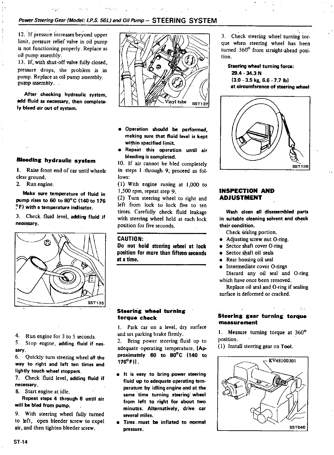
Power
Steering
Gear
Model
I
PS
56LJ
and
Oil
Pump
STEERING
SYSTEM
12
If
pressure
increases
beyond
upper
limit
pressure
relief
valve
in
oil
pump
is
not
functioning
properly
Replace
as
oil
pump
assembly
13
If
with
shut
offvalve
fully
closed
pressure
drops
the
problem
is
in
pump
Replace
as
oil
pump
assembly
pump
assembly
After
checking hydraulic
system
add
fluid
as
necessary
then
complete
ly
bleed
air
out
of
system
Bleeding
h
draullc
s
stem
I
Raise
front
end
of
car
until
wheels
clear
ground
2 Run
engine
Make
lure
temperature
of
fluid
in
pUmp
rises
to
60
to
BOO
C
140
to
176
o
F
with
B
temperature
indicator
3
Check
fluid
level
adding
fluid
if
nece
sary
4
Run
engine
for
3
to
5
seconds
5
Stop
engine
adding
fluid
if
nes
sary
6
Quickly
turn
steering
wheel
all
the
way
to
right
and
left
ten
times
end
lightly
touch
whee
stoppen
7
Check
fluid
level
adding
fluid
if
necessary
8
Start
engine
at
idle
Repeat
steps
4
through
8
until
air
will
be
bled
from
pump
9
With
steering
wheel
fully
turned
to
left
open
bleeder
screw
to
expel
air
and
then
tighten
bleeder
screw
ST
14
I
I
SST137
Operation
should
be
perfonned
making
sure
that
fluid
level
is
kept
wi
in
specified
li
mit
Repeat
this
operation
until
air
bleeding
is
completed
10
If
air
cannot
be
bled
completely
in
steps
1
through
9
proceed
as
fol
lows
I
With
engine
runing
at
1
000
to
1
500
rpm
repeat
step
9
2
Turn
steering
wheel
to
right
and
left
from
lock
to
lock
five
to
ten
times
Carefully
check
fluid
leakage
with
steering
wheel
held
at
each
lock
position
for
five
seconds
CAUTION
00
not
hold
steering
wheel
at
lock
position
for
more
than
fifteen
seconds
at
a
time
Steering
wheel
turning
torque
check
I
Park
car
on
a
level
dry
surface
and
set
parking
b
rake
firmly
2
Bring
power
steering
fluid
up
to
adequate
operating
temperature
Ap
proximately
60
to
80
C
140
to
1760FII
It
is
easy
to
bring
power
steering
fluid
up
to
adequate
operating
tern
perature
by
idling
engine
and at
the
same
time
turning
steering
wheel
from
left
to
right
for
about
two
minutes
Alternatively
drive
car
several
miles
Tires
must
be
inflated
to
normal
pressure
3
Check
steering
wheel
turning
tor
que
when
steering
wheel
has
been
turned
3600
from
straight
ahead
posi
tion
Steering
wheel
turning
force
29
4
34
3
N
3 0 3 5
kg
66 7 7
Ib
at
circumference
of
steering
wheel
SST13B
INSPECTION
AND
ADJUSTMENT
Wash
dean
all d
bled
parts
in suitable
cleaning
solyent
and
ch k
thejr
condition
Check
Sealing
portion
Adjusting
screw
nut
O
ring
Sector
shaft
cover
O
ring
Sector
sl1aft
oil
seals
Rear
housing
oil
seal
Intermediate
cover
Q
rings
Discard
any
oil
seal
and
O
ring
which
have
once
been
removed
Replace
oil
seal
and
O
ring
if
sealing
surface
is
deformed
or
cracked
Steering
gear
turning
torque
measurement
I
Measure
turning
torque
at
3600
position
I
Install
steering
gear
on
Tool
SST040
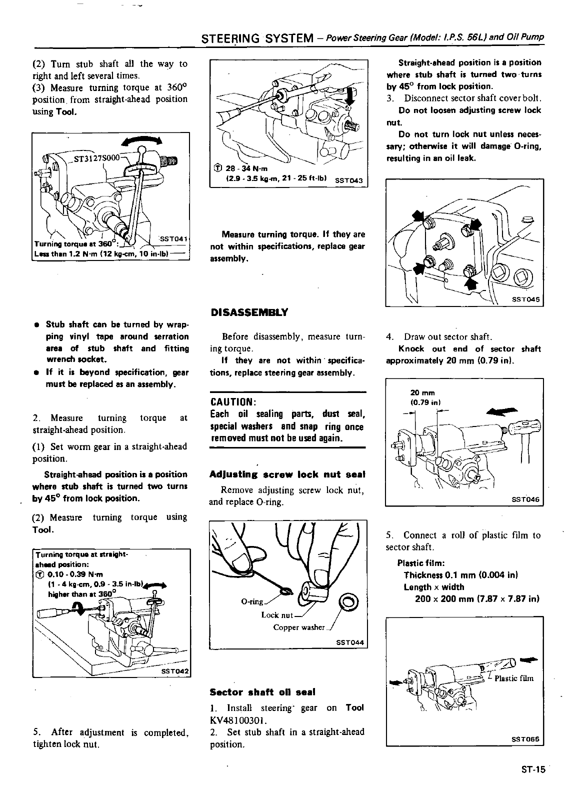
2
Turn
stub
shaft
all
the
way
to
right
and
left
several
times
3
Measure
turning
torque
at
3600
position
from
straight
ahead
position
using
Tool
4
m
Stub
shaft
can
be
turned
by
wrap
ping
vinyl
tape
around
serration
area
of
stub
shaft
and
fitting
wrench lOcket
If it
is
beyond specification
gear
must
be
replaced
as
an
assembly
2
Measure
turning
torque
at
straight
ahead
position
I
Set
worm
gear
in a
straight
ahead
position
Straight
ahead
position
is
8
position
where
stub
shaft
is
turned
two
turns
by
450
from
lock
position
2
Measure
turning
torque
using
Tool
Turning
torque
at
streight
hd
position
il
0
10
0
39
N
m
1
4
kg
cm
09
3 5
in
lb
higher
than
t
3600
LJJ
5
After
adjustment
is
completed
tighten
lock
nut
STEE
ING
SYSTEM
Power
Steering
Gear
Model
I
P S
56LJ
and
Oil
Pump
I
il
28 34
N
m
12
9
35
kg
21
25
h
Ibl
SST043
Measure
turning
torque
If
they
are
not
within
specifications
replace
gear
assembly
DISASSEMBLY
Before
disassembly
measure
turn
ing
torque
If
they
are
not
within
specifica
tions
replace
steering
gear
assembly
CAUTION
Each
oil
sealing
parts
dust
seal
special
washers
and
snap
ring
once
removed
must
not
be
used
again
AdJusting
screw
lock
nut se
1
Remove
adjusting
screw
lock
nut
and
replace
a
ring
O
mg
Lock
nut
Copper
washer
SST044
Sector
sh
ft
011
se
1
I
Install
steering
gear
on
Tool
KV48l00301
2
Set
stub
shaft
in
a
straight
ahead
position
Straight
ahead
position
is
8
position
where
stub
shaft
is
turned
two
turns
by
450
from
lock
position
3
Disconnect
sector
shaft
cover
bolt
Do
not
loosen
adjusting
screw
lock
nut
Do
not
turn
lock
nut
unless
neces
sary
otherwise
it
will
damage
O
ring
resulting
in
an
oil
leak
J
4
Draw
out
sector
shaft
Knock
out
end
of
sector
shaft
approximately
20
mm
0
79
in
20mm
0
79
nl
SST046
5
Connect
a
roll
of
plastic
fIlm
to
sector
shaft
Plastic
film
Thickness
0
1
mm
0
004 in
Length
x
width
200 x
200
mm
7
87 x
7
87 in
1
Plastic
film
SST065
ST
15
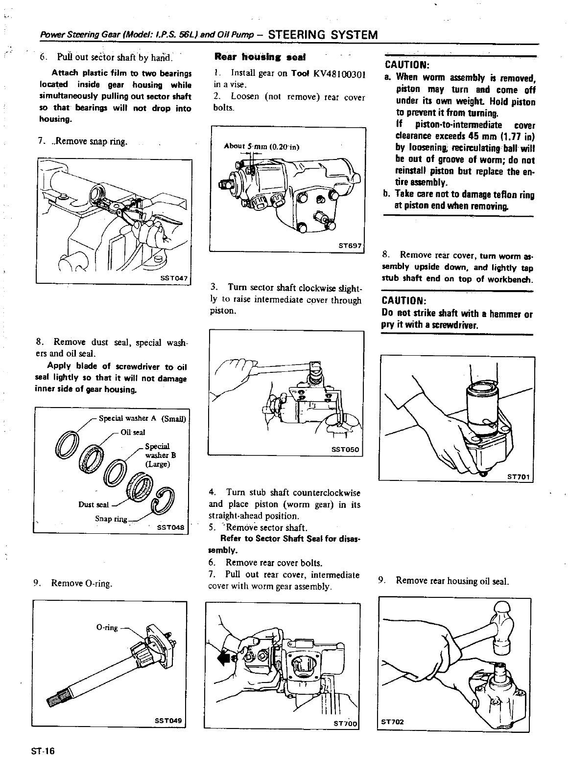
Power
Steering
Gear
Model
I
P
S
56LJ
end
Oil
Pump
STEERING
SYSTEM
6
PuiI
out
sector
shaft
by
harid
Attach
plartie
film
to two
bearings
locat
ed
inside
gear
housing
while
simuttaneously
pulling
out
sector
shaft
so
that
bearings
will
not
drop
into
housing
7
Remove
snap
ring
fs
SSTQ47
8
Remove dust
seal
special
wash
ers
and
oil
seal
Apply
blade
of
screwdriver
to
oil
seal
I
ightly
so
that
it
will
not
damage
inner
side
of
gear
housing
0
Special
washer
A
Smail
n
Oil
sea
L4i
d
Special
ru
lL
B
Dustseal
w
snapring
SST048
9
Remove
a
ring
SST049
ST
16
Rear
housing
seal
Install
gear
on
Tool
KV48l00301
in a
vise
2
Loosen
not
remove rear cover
bolts
ST697
3
Turn
sector
shaft
clockwise
slight
ly
to
raise
intermediate
cpver
through
piston
Q
g
I
I
J
t
I
SST050
4
Turn
stub
shaft
counterclockwise
and
place
piston
worm
gear
in
its
straight
ahead
position
S
Remove
sector
shaft
Refer
to
Seetor
Shalt
Seal
for
disas
sembly
6
Remove
rear
cover
bolts
7
Pull
out
rear
cover
intermediate
cover
with
worm
gear
assembly
ST700
CAUTION
a
When
worm
assembly
is
removed
piston
may
turn
and
come
off
under
iU
own
weight
Hold
piston
to
prevent
it
from
turning
If
piston
to
intermediate
cover
clearance
exceeds
45
mm
1
77
in
by
looseninll
recin
ulating
ball
will
be
out
of
groove
of
worm
do
not
reinstall
piston
but
replace
the
en
tire
assembly
b
Take
care
not
to
damage
tellon
ring
at
piston
end
wilen
removing
8
Remove
rear
cover
turn
worm
as
sembly upside
down
and
lightly
tap
stub
shaft
end
on
top
of
workbench
CAUTION
Do
not
strike
shaft
with
a
hammer
or
pry
it
with
a
screwdriver
ST701
9
Remove
rear
housing
oil
seal
ST702
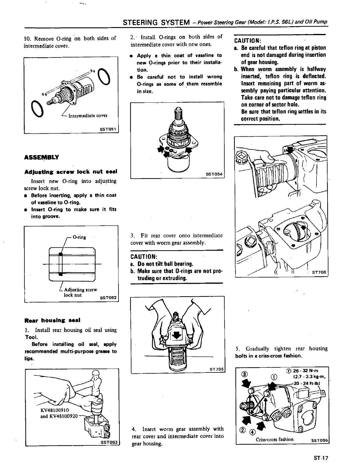
STEERING
SYSTEM
Power
Steering
Gear
Model
I
P S
56LI
and
Oil
Pump
10
Remove
O
ring
on
both
sides
of
intermediate
cover
Intermediate
cover
SST051
ASSEMBLY
AdJusting
screw
lock
nut se
1
Insert
new
a
ring
into
adjusting
screw
lock
nut
Before
inserting apply
a
thin
coat
of
vaseline
to
O
ring
Inort
C
ring
to
make
sure it
fits
into
groove
r
o
ring
L
Adjusting
screw
lock
nut
SST052
Re
r
housing
se
1
I
Install
rear
housing
oil
seal
using
Tool
Before
installing
oil
seal
apply
recommended
multi
purpose
greM
to
lips
SST053
2
Install
O
rings
on
both
sides
of
intermediate
cover
with
new
ones
Apply
a
thin
coat
of
vaseline
to
new
Crings
prior
to
their
installa
tion
Be
careful
not to
install
wrong
O
rings
as
some
of
them
resemble
in
size
t
J
SST054
3
Fit
rear
cover
onto
intermediate
cover
with
worm
gear
assembly
CAUTION
a
Do
not
tilt
ball
bearing
b
Make
sure
that
O
rings
are
not
pro
truding
or
extruding
ST705
4
Insert
worm
gear
assembly
with
rear
cover
and
intermediate
cover into
gear
housing
CAUTION
a
Be
careful
that
teflon
ring
at
piston
end
is
not
damaged
during
insertion
of
gear
housing
b
When
worm
assembly
is halfway
inserted
teflon
ring
is
deflected
Insert
remaining
part
of
worm
as
sembly paying
particular
attention
Take
care
nol
to
damage
teflon
ring
on
corner
of
sector
hole
Be
sure
that
teflon
ring
settles in
its
correct
position
5
Gradually
tighten
rear
housing
bolts
in a
criss
cross
fashion
Crisscross
fashion
SST055
ST
17
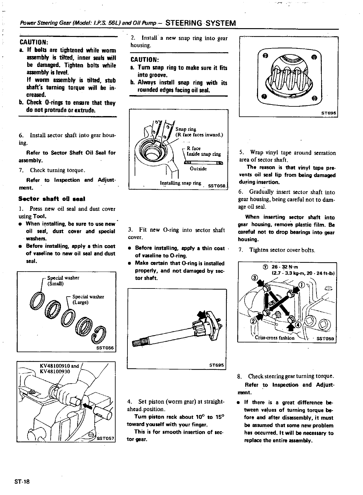
Power
Sreering
Gear
Model
I
P
S
56LJ
and Oil
Pump
STEERING
SYSTEM
CAUTION
L
If
bolts
are
tightened
while
wonn
assembly
is
tilted
inner
seals
will
be
dam8lll
d
Tighten
bolts
while
assembly
is
level
If wonn
assembly
is
tilted
stub
shaft
s
turning
torque
will
be
in
creased
b
Check
O
rings
to
ensure
lhat
they
do
not
protrude
or
extrude
6Install
sector
shaft
into
gear
hous
ing
Refer
to
Sector
Shaft
Oil
Seal
for
assembly
7
Check
turning
torque
Refer
to
Inspection
and
Adjust
ment
Sector
shaft
00
se
1
I
Press
new oil
seal
and
dust
cover
using
Toot
When
ir
stalling
be
lure to use
new
oil
seal
dust
cover
and
special
washen
Before
installing
apply
a
thin
coat
of
vueline
to
new
oil
seal
and
dust
seal
Special
washer
Small
00
SST056
ST
18
2 Install
a
new
snap
ring
into
gear
housing
CAUTION
a
Turn
soap
ring
to
make
sure
it
fits
into
groove
b
Always
inslllll
snap
ring
with
its
rounded
edges
facing
oil
seal
R
face
Imide
snap
ring
Outside
I
talling
snap
ring
SST058
3
Fit
new
O
ring
into
sector
shaft
cover
Before
installing
apply
a
thin
coat
of
vaseline
to
O
ring
Make
certain
that
O
ring
is
installed
properly
and
not
damaged
by
sec
tor
shaft
ST695
4
Set
piston
worm
gear
at
straight
al1ead
position
Turn
piston
rllck
about
100
to
150
toward
youself
with
your
finger
This
is
for
smooth
insertion
of
lec
tor
gear
Q
G
ST696
5
Wrap
vinyl
tape
around
serration
area
of
sector
shaft
The
reason
is
that
vinyl
tape
pre
vents
oil
seal
lip
from
being
damaged
during
insertion
6
Gradually
insert
sector
shaft
into
gear
housing
being
careful
not
to
dam
age
oil
seal
When
insening
seetor
shaft
into
gear
housing
remove
plastic
film
8e
careful
not to
drop
bearings
into
gear
housing
7
Tighten
sector
cover
bolts
IIi
24ft lb
8
Check
steering
gear
turning
torque
Refer
to
Inspeetion
and
Adjust
ment
If
there
is
8
great
difference
be
tween
values
of
turning
torque
be
fore
and
after
disassembly
it
must
be assumed
that
some
new
problem
has
occurred
It
will
be
nece
ary
to
replace
the
entire
assembly
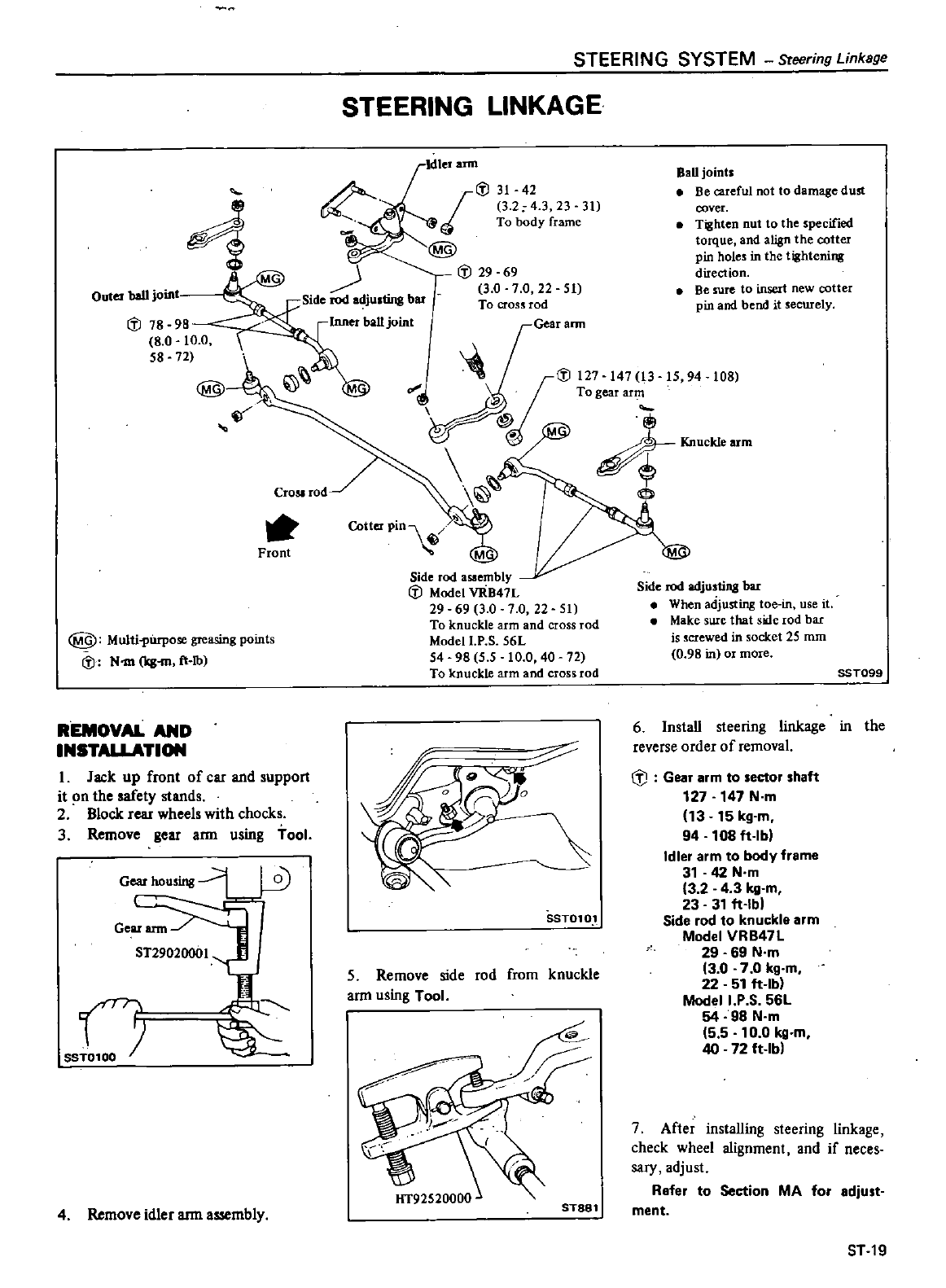
Outer
ball joint
IiJ
78 98
80
10
0
58
72
CroSlrod
Front
@
Multil
urpose
greasing
points
IiJ
N
m
ks
m
ft
Ib
REMOVAL
AND
INSTALLATION
L
Jack
up front
of
car
and
support
it
n
the
safety
stands
2
Block
rear
wheels
with
chocks
3
Remove
gear
arm
using
tool
Gear
housing
Gear
arm
n
SST0100
4
Remove
idler
ann
assembly
STEERING
SYSTEM
Steering
Linkage
STEERING
LINKAGE
Side
rod
adjusting
bar
Inner
ball
joint
IiJ
31
42
I
3 2
4
3
23
31
To
body
frame
@
IiJ
29
69
3 0
7 0
22
51
To
cros
rod
Gear
ann
J
Cotter
PinV
Side
rod
assembly
IiJ
Model
vRB47L
29 69
3 0 7 0
22
51
To
knuckle
arm
and
cross
rod
Modell
P
S
56L
54
98
5 5
10
0
40 72
To
knuckle
arm
and
cross
rod
SST010
5
Remove
side
rod
from
knuckle
ann
using
Tool
STa8l
BaD joints
Be
careful
not
to
damage
dust
cover
Tighten
nut
to
the
specified
torque
and
align
the
cotter
pin
hole
in
the
tightening
direction
Be
sure
to insert
new
cotter
pin
and
bend
it
ecurely
Side
rod
adjusting
bar
When
adjusting
toe
in
use
it
Make
sure
that
side
rod bar
is
crewed
in socket
25
mm
0
98
in
OJ
more
SST099
6Install
steering
linkage
in
the
reverse
order
of
removal
G
J
Gear
arm to
seetor
shaft
127 147
N
m
13 15
kg
m
94
108lt
lb
Idler
arm
to
body
frame
31
42
N
m
3 2
4
3
kg
m
23
31lt
lbl
Side
rod
to
knuckle
arm
Model
VRB47L
29
69
N
m
13
0 7 0
kg
m
22
51lt
lb
Modell
P S
56L
54 98
N
m
5 5
10
0
kg
m
40 72
ft
Ib
7
After
installing
steering
linkage
check wheel
alignment
and
if
neces
sary
adjust
Refer
to
Seetion
MA
for
adjust
ment
ST
19
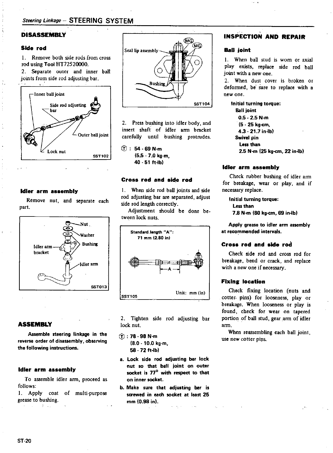
Steering
Linkage
STEERING
SYSTEM
DISASSEMBLY
Side
rod
I
Remove
both
side
rods
from
cross
rod
using
Tool
HT72520000
2
Separate
outer
and
inner
ball
joints
from
side
rod
adjusting
bar
Inner
ball
joint
Lock
nut
SST102
Idler
arm
assembly
Remove
nut
and
separate
each
part
e
Nut
o
BU5hing
Idler
ann
SST013
ASSEMBLY
Assemble
steering
linkage
in the
reverse
order
of
disassembly
observing
the
following
instructions
Idler
erm
assembly
To
assemble
idler
arm
proceed
as
follows
I
Apply
coat
of
multi purpose
grease
to
bushing
ST20
@@
w
I
Z
J
I
J
i
SST104
2
Press
bushing
into
idler
body
and
insert
shaft
of
idler
arm
bracket
catefully
until
bushing
protrudes
t
J
54 69
N
m
5 5 7
0
kg
m
40
51
ft
b
Cross
rod
and
side
rod
I
When side
rod
ball
join
ts
and
side
rod
adjusting
bar
are
separated
adjust
side
rod
length
correctly
Adjustment
should
be
done
be
tween
lock
nuts
StandardJength
A
71
mm
12
80
in
t
SST105 Unit
mm
in
2
Tighten
side
rod
adjusting
bar
lock
nut
r
l
78 98
N
m
18
0
10
0
kg
m
58
72
ft
b
a
Lock
side
rod
adjusting
bar
lock
nut
so
that
ball
joint
on
outer
socket is
770
with
respeet
to
that
on
inner
socket
b
Make
sure
that
adjusting
bar
is
sa
ewed
in
each
socket
at
least
25
mm
0
98 inl
INSPECTION
AND
REPAIR
Ball
joint
I
When
ball
stud
is
worn
or
axial
play
exists
replace
side
rod
ball
joint
with
a
new
one
2
When
dust
cover
is
broken
or
deformed
be
sure
to
replace
with
a
new
one
Initial
turning
torque
Ball
joint
0 5 2 5
N
m
5
25
kg
cm
4 3 21 7
in
b
Swivel
pin
Le
than
2
5
N
m
25
kg
cm
22 in
b
Idler
arm
essembly
Check
rubber
bushing
of
idler
arm
for
breakage
wear
or
play
and
if
necessary
replace
Initial
turning
torque
Less
than
7 8
N
m
80
kg
cm
69 in
bl
Apply
grease
to
idler
arm
assembly
at
recommended
intervals
Cross
rod
and
side
rod
Check
side
rod
and
cross
rod
for
breakage
bend
or
crack
and
replace
with
a
new
one
if
necessary
Flxlns
location
Check
fixing
location
nuts
and
cotter
pins
for
looseness
play
or
breakage
When
looseness
or
play
is
found
check
for
wear
on
tapered
portion
of
ball
stud
gear
arm
of
idler
arm
When
reassembling
each
ball
joint
use
new
cotter
pi
s
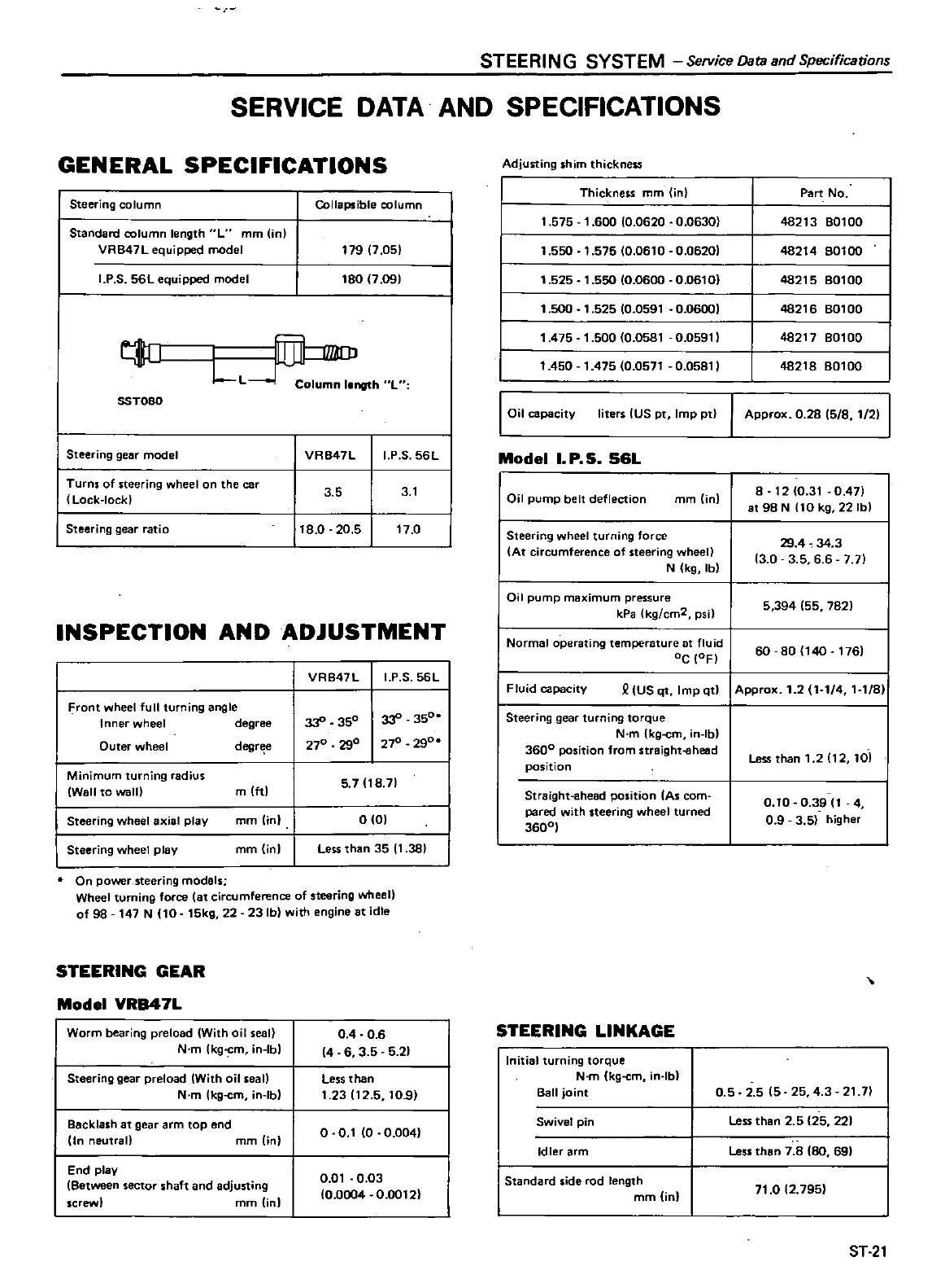
STEERING
SYSTEM
Service
Data and
Specifications
SERVICE
DATA
AND
SPECIFICATIONS
GENERAL
SPECIFICATIONS
Steering
column
Standard
column
length
L
mm
in
VRB47L
equipped
model
I
P S
56L
equipped
model
Collapsible
column
179 7
05
180
7
09
I
LL
h L
SST080
I
Steering
gear
model
I
Turns
of
steering
wheelan the
car
Lock
lock
I
Steering
gear
ratio
VR847L
I
P S
56L
3 5 3
1
18
0
20
5
17
0
INSPECTION
AND
ADJUSTMENT
Front
wheel
full
turning
angle
Inner
wheel
degree
Outer
wheel
degr
e
Minimum
turning
radius
Wall
to
wall
mlttl
Steering
wheel
axial
play
mm
in
Steering
wheel
play
mm
inl
VR847L
I
PS
56L
33
350
33
350
270
290
270 290
5 7
18
71
0
01
Less
than
35
1381
On
power
steering
models
Wheel
turning
force
at
circumference
of
steering
wheel
of
98
147
N
10
15kg
22
231b
with
engine
at
idle
STEERING
GEAR
Model
VRB47L
Worm
bearing
preload
With oil
seal
N
m
lkgcm
Ibl
Steering
gear
preload
With oil
seall
N
m
kg
cm
in
Ib
Backlash
at
gear
arm
top
end
In
neutral
mm
lin
End
play
Between
sector
shaft
and
adjusting
screw
mm
tinl
04 06
14
6
3 5 5
21
Less
than
1
23112
5
10
9
o 0
1
0 0
004
0
01
0
03
0
0004
0
00121
Adjusting
shim
thickness
Thickness
mm
in
1
575
1
600
10
0620
0
0630
1
550
1
575 0
0610
0
06201
1
525
1
550
10
0600
0
0610
1
500
1
525
10
0591
0
06001
1475
1
500 0
0581
0
0591
1450
1
475 0
0571
0
0581
I
0
1
pad
y
I
IUS
p
Imp
p
Model
I
P
5
56L
Oil
pump
belt
deflection
mm
inl
Steering
wheel
turning
force
At
circumference
of
steering
wheel
N
kg
Ib
Part
No
48213
80100
48214
60100
48215
801
00
48216
80100
48217
80100
48218
80100
Approx
0
26
15
8
1
2
8
1210
31
0
47
at
98
N
110
kg
22
Ib
29
4
34
3
13
0
356
6
7
71
I
Oil
pump
maximum
pressure
kPa
kg
cm2
psi
5394
55
782
I
Normal
operating
temperature
at
fluid
I
Oc
10FI
60 80
140
1761
I
Fluid
capacity
USqt
lmpqt
IAPprox
1
2
1 1
4
1 1
8
Steering
gear
turning
torque
N
m
kg
cm
Ib
3600
position
from
straight
ehead
position
Straight
ahead
position
As
com
pared
with
steering
wheel
turned
3600
STEERING
LINKAGE
Initial
turning
torque
N
m
kg
cm
in
Ib
Ball
joint
Swivel
pin
Idler
arm
Standard
side
rod
length
mm
jnl
Less
than
1
2
12
101
0
10
0
3911
4
0
9
3
5
higher
0
5 2 5
15
25
4
3
21
7
Less
than
2 5
25
221
Lessthan
7 8
80
69
71
0
12
795
ST
21
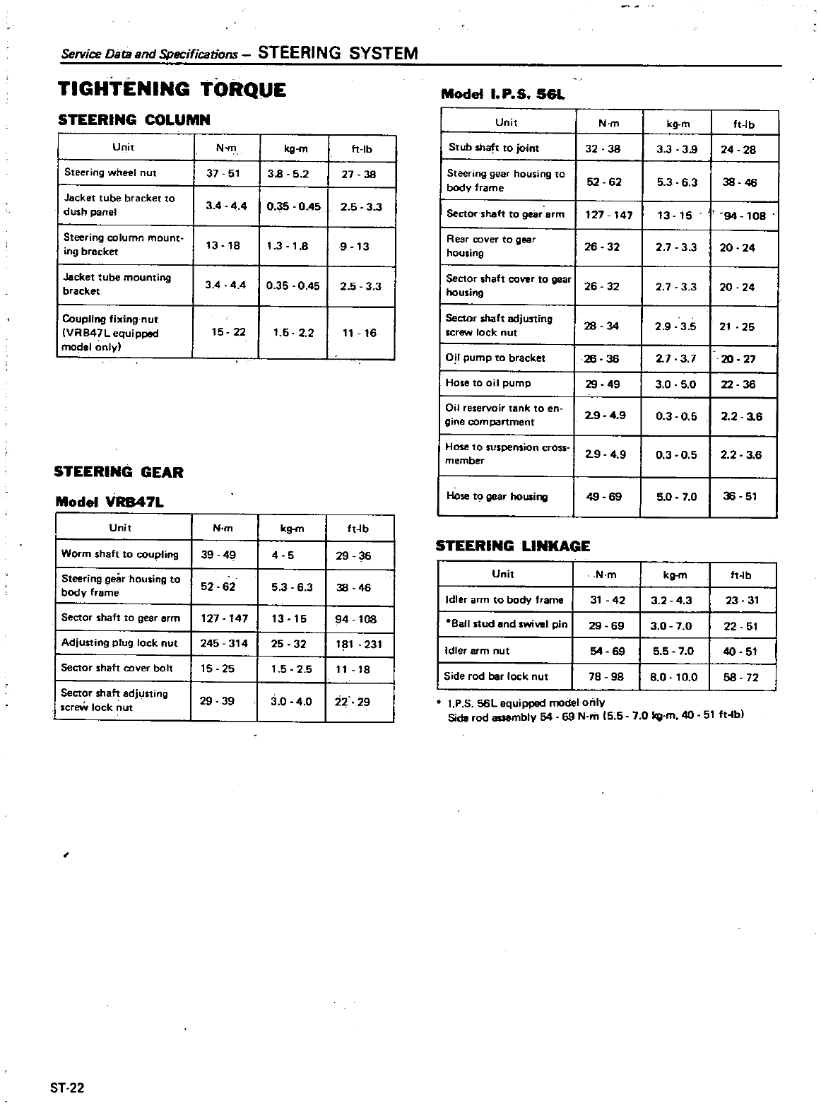
Service
Data and
Specifications
STEERING
SYSTEM
TIGHTENING
TORQUE
Model
I
P S
56L
STEERING
COLUMN
Unit
N
m
kg
m
ft
lb
Unit
N
m
kg
m
ft
Ib
Stub
shaft
to
joint
32 38
3 3
39
24 28
I
Steering
wheel
ut
37 51
38
52
27
38
I
Stee
ing
ge
housing
to
52 62
5
3 6
3
I
38
bOOy
frame
46
I
0 5 0
451
I
Jacket
tube blacket
to
3 4
44 2 5
3
3
I
Sector
shaft
to
gear
arm
I
dush
panel
127 147
13 15 94
108
I
Stee
ing
column
mount
13
18
11
3
1
8
I
9
13
I
Rea
cove
to
gea
26 32
27 3 3
I
20 24
iog
bracket
housing
I
Jacket
tube
mounting
I
3
4 44
0
35
0
451
2 5 3 3 Secto
shaft
cove
to
goa
I
26 32
2 7 3 3
I
20 24
bracket
housing
Coupling
fixing
nut
Sector
shaft
adjusting
28 34
2
9
35
I
21
25
VRB47L
equipped
15
22
1
5
2
2
11
16
screw
lock
nut
mod
1
only
I
0
pump
to
bracket
2
7
3
7
I
20
2726 36
I
Hose
to
oil
pump
29
49
3 0 5
0
I
22 36
I
Oii
seoi
tank
to
en
2
9 49 03 05
I
2 2
3
6
glne
compartment
Hose
to
suspension
c
oss
l
2
9 4
9
0
3
0
5
I
2
2
3
6
member
STEERING
GEAR
Model
VRB47L
Hose
to
gear
housing
49 69
5
0
7
0
I
36
51
Unit
N
m
kg
m
ft
lb
I
Worm
shaft
to
coupling
STEERING
LINKAGE
39 49
4
5
29
35
Steering
gear
housing
to
Unit
N
m
kg
n
ft
lb
52 52
5 3
5
3
38 46
body
frame
Idler
arm
to
body
frame
31
42
3 2
4
3
23
31
Sector
shaft
to
gear
arm
127 147
13
15
94
108
8all
stud
end
swiVIII
pin
29 59
30
7
0
22
51
Adjusting
plug
lock
nut
245
314
25 32
181 231
I
Idler
arm
nut
54
69
5 5 7
0
40
51
Sector
shaft
cover
bolt
15
25
1
5 2 5
11
18
I
Side
rod
bar
lock
nut
78 98
8
0
10
0
58 72
I
Sect
shaft
adjusting
29
39
3
0
4
0
22
29
IP
S
56L
equipped
model
only
screw
lock
nut
Side
rod
assembly
54
69
N
m
15
5
7
0
kg
m
40
511t
b
ST
22
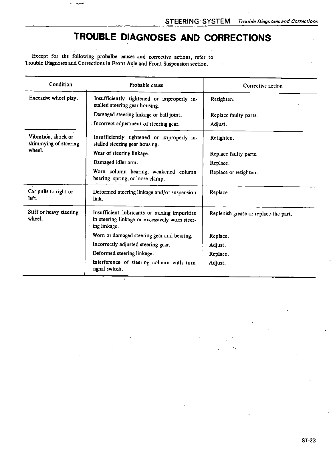
STEERI
NG
SYSTEM
Trouble
Oiagnoses
and
Corrections
TROUBLE
DIAGNOSES
AND
CORRECTIONS
Except
for
the
following
probalbe
causes
and
corrective
actions
refer
to
Trouble
Diagnoses
and
Corrections
in
Front
Axle
and
Front
Suspension
section
Condi1ion
Excessive
wheel
play
Vibration
shock
or
shimmying
of
steering
wheel
Car pulls
to
right
or
left
Stiff
or
heavy
steering
wheel
Probable
cause
Insufficiently
tightened
or
improperly
in
stalled
steering gear
housing
Damaged
steering
linkage
or
ball
joint
Incorrect
adjustment
of
steering
gear
Insufficiently
tightened
or
improperly
in
stalled
steering gear housing
Wear
of
steering
linkage
Damaged
idler
arm
Worn column
bearing
weakened
column
bearing
spring
or
loose
clamp
Deformed
steering
linkage
and
or
suspension
link
Insufficient
lubricants
or
mixing
impurities
in
steering
linkage
or
excessively
worn
steer
ing
linkage
Worn
or
damaged
steering
gear
and
bearing
Incorrectly
adjusted
steering
gear
Deformed
steering
linkage
Interference
of
steering
column
with
turn
signal
switch
Corrective
action
Retighten
Replace
faulty
parts
Adjust
Retighten
Replace
faulty
parts
Replace
Replace
or
retighten
Replace
Replenish
grease
or
replace
the
part
Replace
Adjust
Replace
Adjust
ST
23
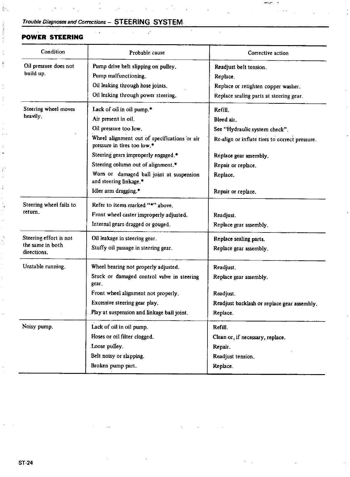
Trouble
DiagnO
tJS
and
Corrections
STEERING
SYSTEM
POWER
STEERING
Condition
Oil
pressure
does
not
build
up
Steering
wheel
moves
heavily
Steering
wheel
fails
to
return
Steering
effort
is
not
the
same
in
both
directions
Unstable
running
Noisy
pump
ST
24
Probable
cause
Pump
drive
belt
slipping
on
pulley
Pump
malfunctioning
Oil
leaking
through
hose
joints
Oil
leaking
through
power
steering
Lack
of
oil
in
oil
pump
Air
present
in
oil
Oil
pressure
too
low
Wheel
alignment
out
of
specifications
or
air
pressure
in
tires
too
low
Steering
gears
improperly
engaged
Steering
column
out
of
alignment
Worn
or
damaged
ball
joint
at
suspension
and
steering
linkage
Idler
arm
dragging
Refer
to
items
marked
above
Front
wheel
caster
improperly
adjusted
Internal
gears
dragged
or
gouged
Oil
leakage
in
steering
gear
Stuffy
oil
passage
in
steering
gear
Wheel
bearing
not
properly
adjusted
Stuck
or
damaged
control
valve
in
steering
gear
Front
wheel
alignment
not
properly
Excessive
steering gear
play
Play
at
suspension
and
linkage
ball
joint
Lack
of
oil
in
oil
pump
Hoses
or
oil
filter
clogged
Loose
pulley
Belt
noisy
or
slapping
Broken
pump
part
r
Corrective
action
Readjust
belt
tension
Replace
Replace
or
retighten
copper
washer
Replace
sealing
parts
at
steering
gear
Refill
Bleed
air
See
Hydraulic
system
check
Re
a1ign
or
inflate
tires
to
correct
pressure
Replace
gear
assembly
Repair
or
replace
Replace
Repair
or
replace
Readjust
Replace
gear
assembly
Replace
sealing
parts
Replace
gear
assembly
Readjust
Replace
gear
assembly
Readjust
Readjust
backlash
or
replace
gear
assembly
Replace
Refill
Clean
or
if
necessary
replace
Repair
Readjust
tension
Replace
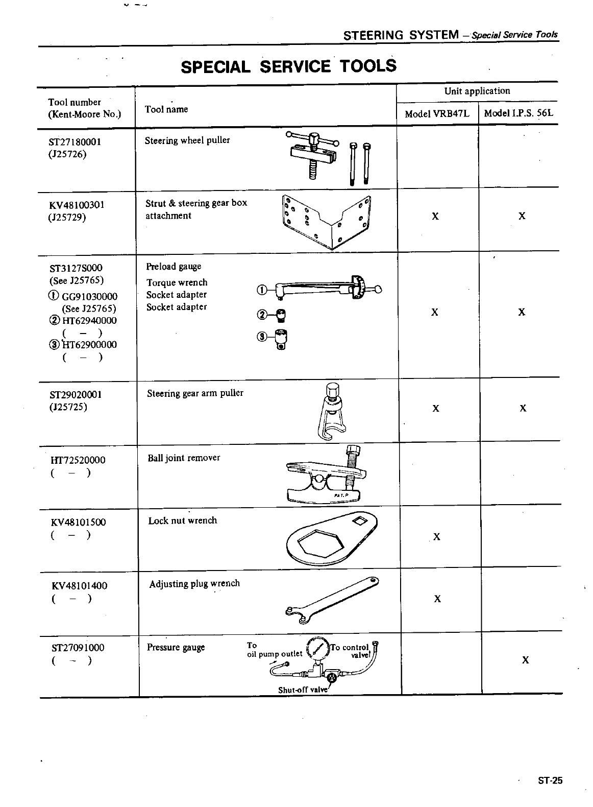
STEERING
SYSTEM
Special
Service
Tools
SPECIAL
SERVICE
TOOLS
Unit
application
Tool
number
Kent
Moore
No
Tool
name
Model
VRB47L
Modell
P
S
56L
ST27l80001
125726
Steering
wheel
puller
1i
KV48
100301
125729
Strut
steering
gear
box
attachment
xx
ST3127S000
Preload
gauge
See
125765
Torque
wrench
CD
i
CD
GG91030000
Socket
adapter
See
125765
Socket
adapter
XX
@
HT62940000
@
@HT62900000
ST29020001
Steering
gear
arm
puller
J25725
XX
HT72520000
Ball
joint
remover
KV48
101
500
Lock
nut
wrench
X
KV48
101
400
Adjusting
plug
wrench
X
ST27091000
Pressure
gauge
X
Shut
ff
valve
ST
25
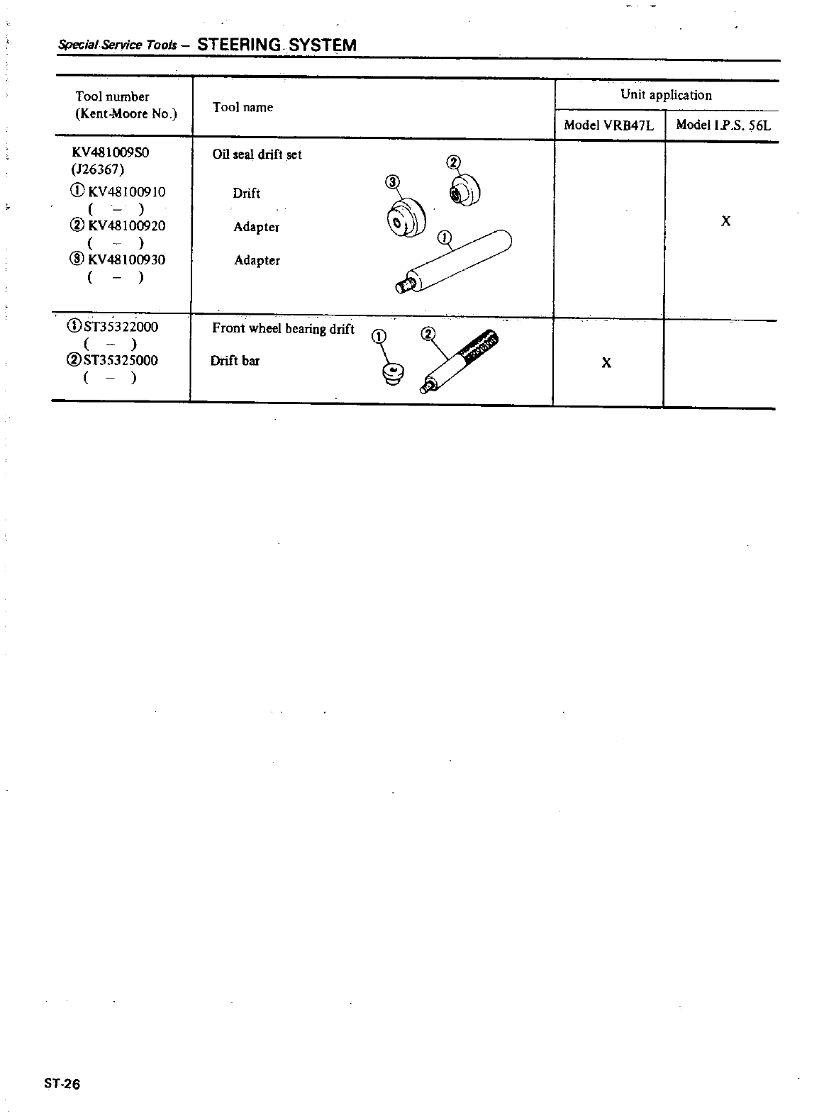
Special
Service
Tools
STEERING
SYSTEM
Tool
number
Tool
name
Kent
Moore
No
KV48I
009S0
Oil
seal
drift
set
126367
CD
KV48lO091O
Drift
@
KV48100920
Adapter
@
KV48100930
Adapter
CDsT35322000
Front
wheel
bearing
drift
@ST35325000
Drift
bar
ST
26
I
Unit
application
I
Model
VRB47L
Model
IP
S
56L
x
x
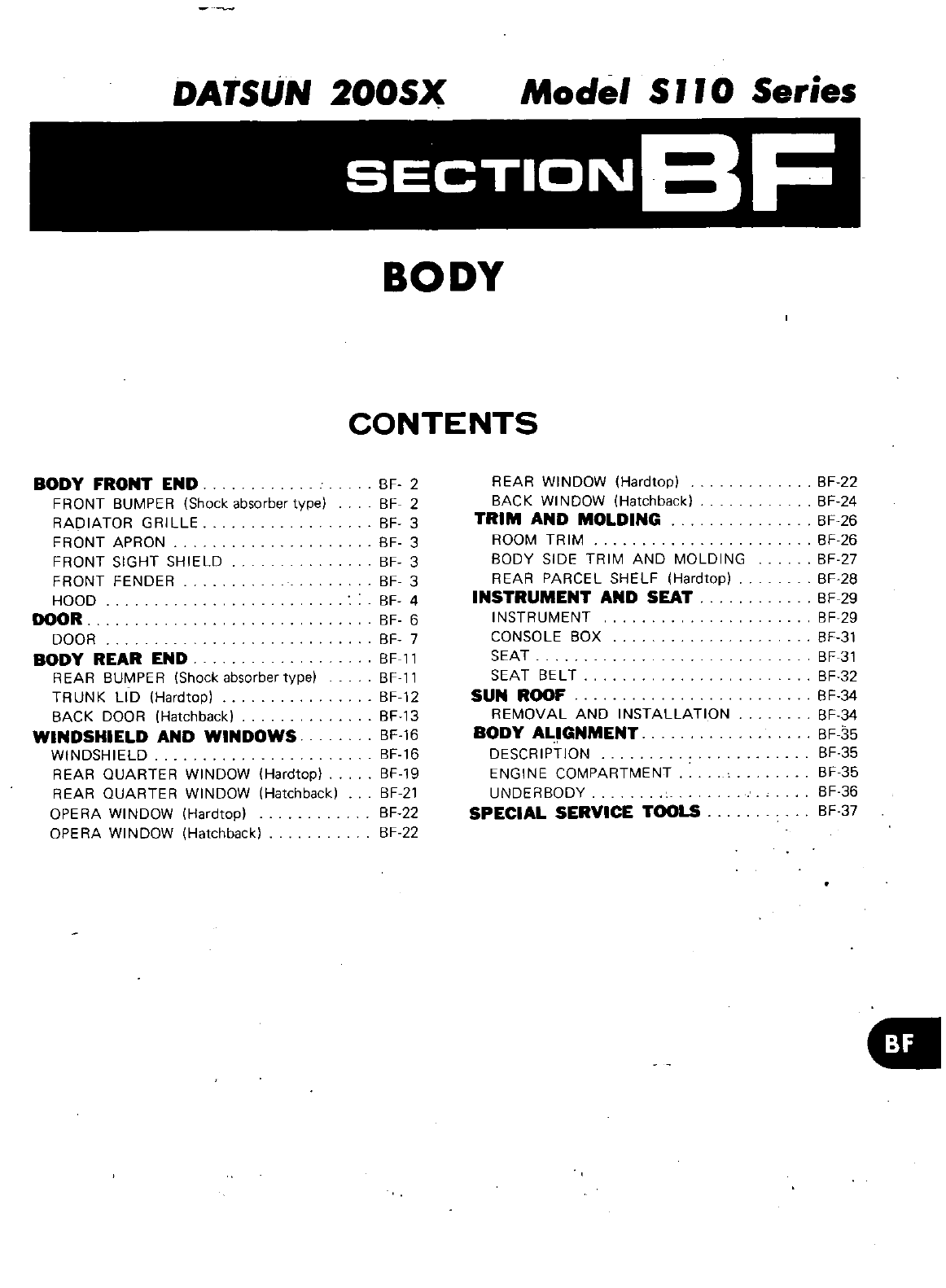
DATSUN
200SX
Model
S
II
0
Series
SECTIONBF
BODY
CONTENTS
BODY
FRONT
END
FRONT
BUMPER
Shock absorber
type
RADIATOR
GRILLE
FRONT
APRON
FRONT
SIGHT
SHIELD
FRONT
FENDER
HOOD
DOOR
DOOR
BODY
REAR
END
REAR
BUMPER
Shock absorber
type
TRUNK
LID
Hardtop
BACK
DOOR
Hatchback
WINDSHIELD
AND
WINDOWS
WINDSHIELD
REAR
OUARTER
WINDOW
Hardtop
REAR
QUARTER
WINDOW Hatchback
OPERA
WINDOW
Hardtop
OPERA
WINDOW
Hatchback
BF
2
BF
2
BF
3
BF
3
BF
3
BF
3
BF
4
BF
6
BF
7
BF
11
BF
11
BF
12
BF13
BF
16
BF
16
BF
19
BF
21
BF
22
BF
22
REAR
WINDOW
Hardtop
BACK
WINDOW Hatchback
TRIM AND
MOLDING
ROOM
TRIM
BODY
SIDE
TRIM
AND
MOLDING
REAR
PARCEL
SHELF
Hardtop
INSTRUMENT
AND
SEAT
INSTRUMENT
CONSOLE
BOX
SEAT
SEAT
BELT
SUN
RDOF
REMOVAL
AND
INSTAllATION
BODY
ALIGNMENT
DESCRIPTION
ENGINE
COMPARTMENT
UNDERBODY
SPECIAL
SERVICE
TDOLS
BF
22
BF
24
BF
26
BF
26
BF
27
BF
28
BF
29
BF
29
BF
31
BF
31
BF
32
BF
34
BF
34
BF
35
BF
35
BF
35
BF
36
BF
37
a
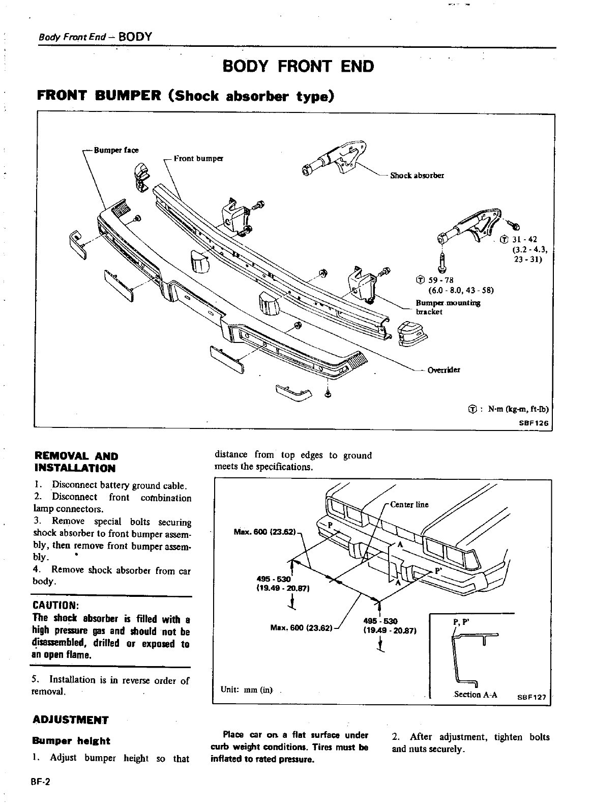
Body
FronrEnd
BODY
BODY
FRONT
END
FRONT
BUMPER
Shock
absorber
type
Front
bumper
REMOVAL
AND
INSTAUATION
I
Disconnect
battery
ground
cable
2
Disconnect
front
combination
lamp
connectOIs
3
Remove
special
bolts
securing
shock
absorber
to
front
bumper
assem
bly
then
remove
front
bumper
assem
bly
4
Remove
shock
absorber
from
car
body
CAUTION
The
shock
absorber
is
filled
with
a
high
pressure
gas
and
should
not
be
disassembled
drilled
or
exposed
to
an
open
flame
5 Installation
is
in
reverse
order
of
removal
ADJUSTMENT
Bumper
height
I
Adjust
bumper
height
so
that
BF
2
Shock
absorber
31 42
32
4
3
23 31
59
78
6 0
8
0
43 58
B
wq
bu
cket
OYerrider
N
m
Icg
rn
ft
lb
SBF126
distance
from
top
edges
to
ground
meets
the
specifications
p p
t
Unit
111m
in
Section
A A
SBF121
Place
car
OB
II flat
surface
under
curb
weight
conditions
Tires
must
be
inflated
to
rated
pressure
2
After
adjustment
tighten
bolts
and
nuts
securely
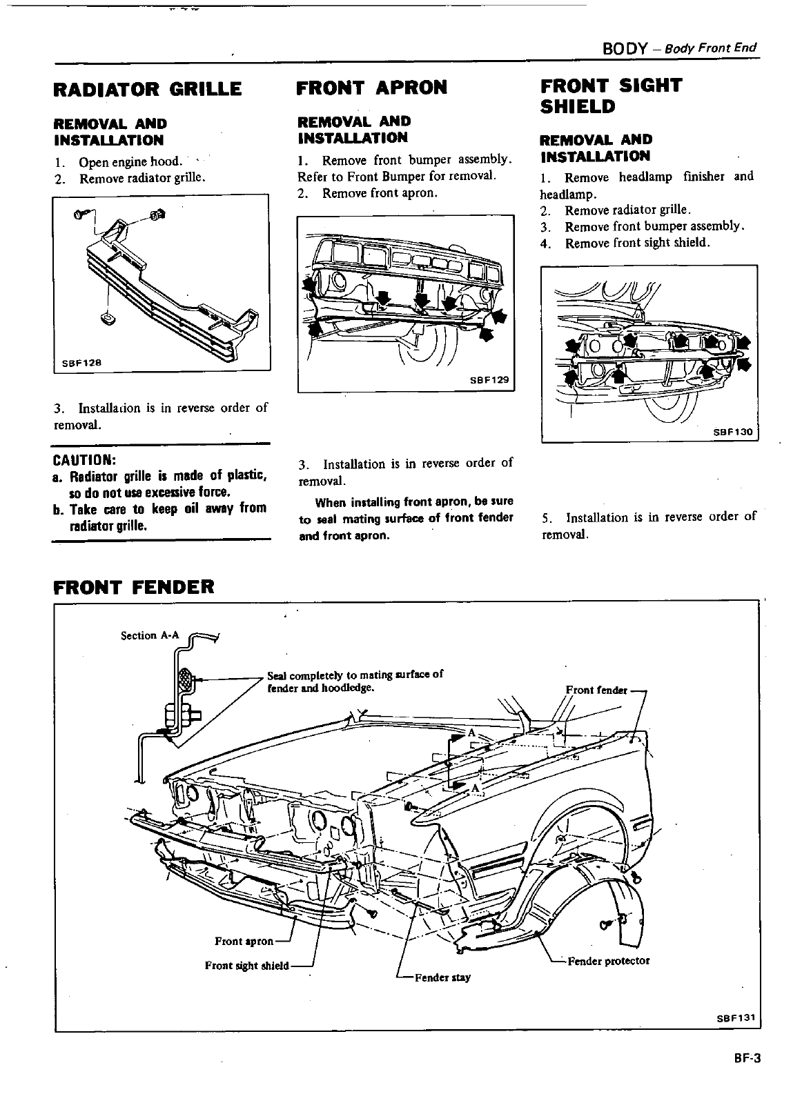
RADIATOR
GRILLE
REMOVAL
AND
INSTALLATION
1
Open
engine
hood
2
Remove
radiator
grille
3Installadon
is
in
reverse
order
of
removal
CAUTION
a
Radiator
grille
is
made
of
plastic
so
do
not
use
excessive
force
b
Take
Clre
to
keep
oil
away from
radiator
grille
FRONT
FENDER
Section
A A
FRONT
APRON
REMOVAL
AND
INSTALLATION
1
Remove
front
bumper
assembly
Refer
to
Front
Bumper
for
removal
2
Remove
front
apron
1
SBF129
3Installation
is
in
reverse
order
of
removal
When
installing
front
apron
be
sure
to
sea
mating
surface
of
front
fender
and
front
apron
Seal
completely
to
mating
surface
of
fender
and
hoodJedse
BO
DY
Body
Front
End
FRONT
SIGHT
SHIELD
REMOVAL
AND
INSTALLATION
1
Remove
headJamp
fmisher
and
headlamp
2
Remove
radiator
grille
3
Remove
front
bumper
assembly
4
Remove
front
sight
shield
Jf
Q
1
SBF130
5
Installation
is
in
reverse
order
of
removal
I
R
a
ff
J1
J
i
A
b
SBF131
BF
3
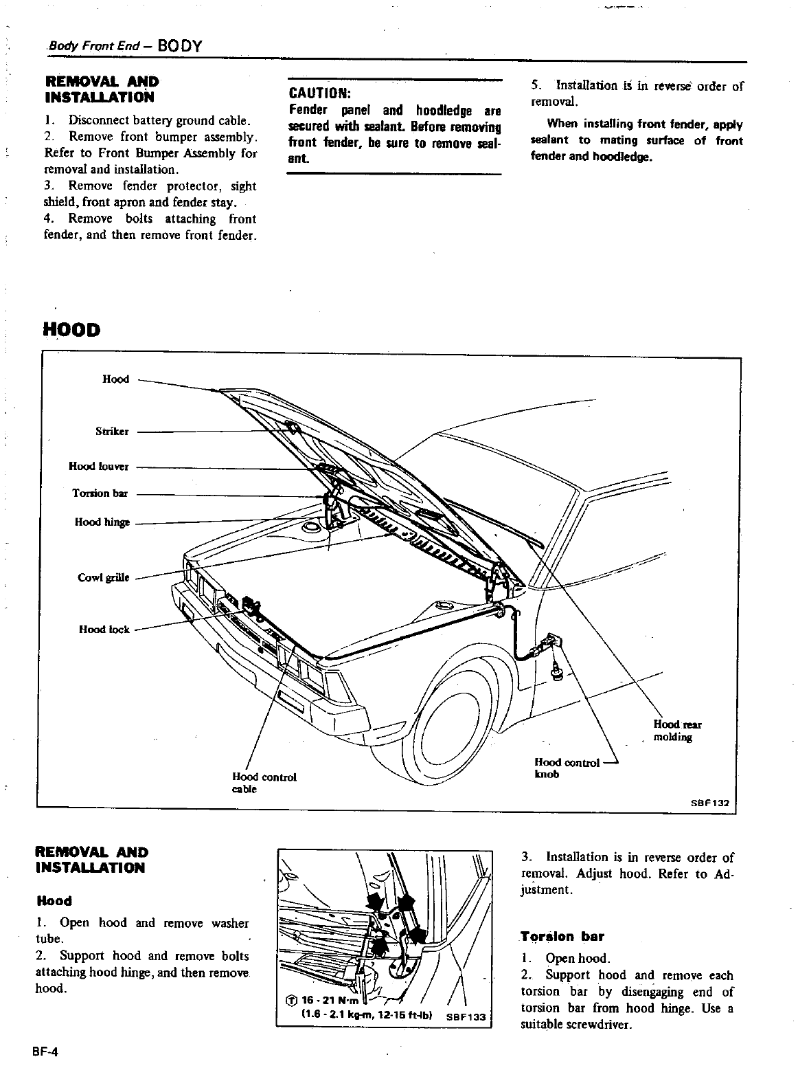
Body
Front
End
BO
DY
REMOVAL
AND
INSTALLATIoN
I
Disconnect
battery
ground
cable
2
Remove
front
bumper
assembly
Refer
to
Front
Bumper
Assembly
for
removal
and
installation
3
Remove
fender
protector
sight
shield
front
apron
and
fender
stay
4
Remove
bolts
attaching
front
fender
and
then
remove
front
fender
HOOD
Hood
Striker
Hood
louver
Torsion
bar
Hood
hinv
Cowl
grille
Hood
lock
REMOVAL
AND
INSTALLATION
Hood
control
cable
Hood
I
Open
hood
and
remove
washer
tube
2
Support
hood
and
remove
bolts
attaching
hood
hinge
and
then
remove
hood
BF
4
CAUTION
Fender
panel
and
hoodledge
are
secured
with
sealant
Before
removing
front
fender
be
sure
to
remove
seal
ent
I
7
lIB
21
N
m
11
6
2
1
kg
m
12
15fHb
S8F133
5
Installation
is
in
reverse
order
of
removal
When
installing
front
fender
apply
sealant
to
mating
surface
of
front
lender
and
hoodledge
Hood
rear
molding
SBF132
3 Installation
is
in
reverse
order
of
removal
Adjust
hood
Refer
to
Ad
justment
Torsion
bar
I
Open
hood
2
Support
hood
and
remove
each
torsion
bar
by
disengaging
end
of
torsion
bar
from
hood
hinge
Use
a
suitable screwdriver
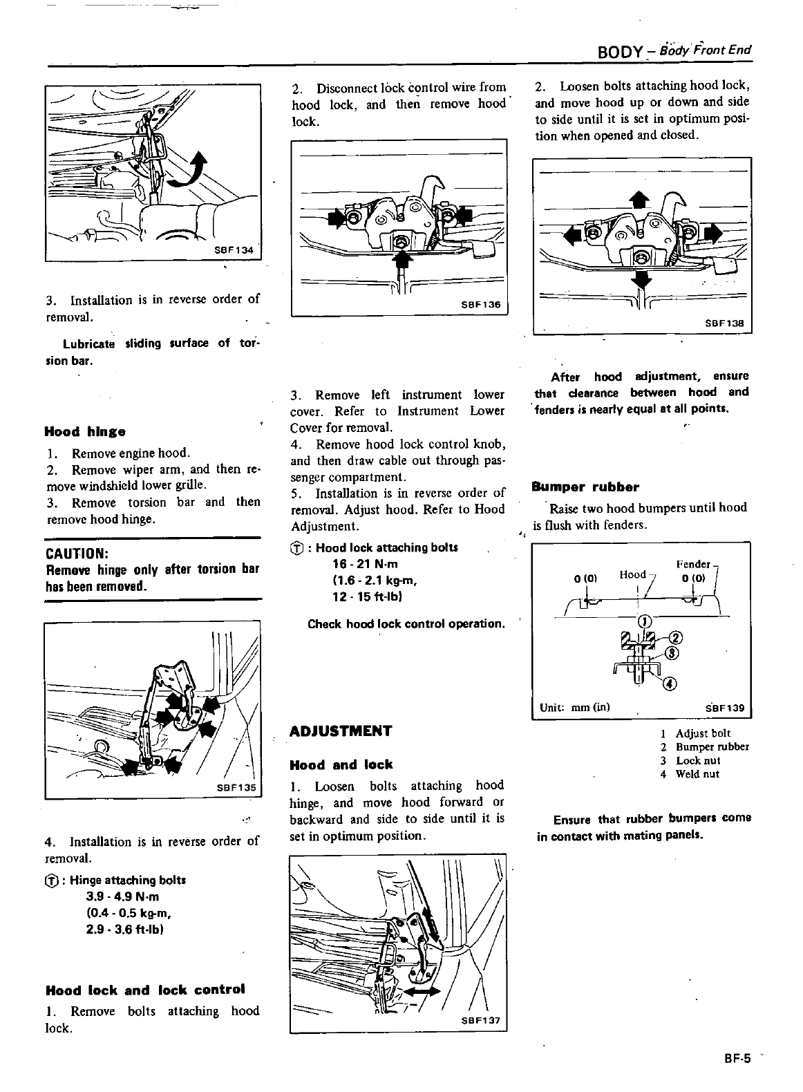
SBF134
3
Installation
is
in
reverse
order
of
removal
Lubricate
sliding
surface
of
tor
sion
bar
Hood
hinge
I
Remove
engine
hood
2
Remove
wiper
arm
and then
re
move
windshield
lower
grille
3
Remove
torsion
bar
and
then
remove
hood
hinge
CAUTION
Remove
hinge
onlv
after torsion
bar
has
been
removed
t7
2
SBF135
4
Installation
is
in
reverse
order
of
removal
fj
Hinge
attaching
bolt
3
9
4
9
N
m
0 4 0 5
kg
m
2 9 3
6
ft
lbl
Hood
lock
and
lock
control
I
Remove
bolts
attaching
hood
lock
2
Disconnect
lock control
wire
from
hood
lock
and
then
remove
hood
lock
SBF136
3
Remove
left
instrument lower
cover
Refer
to
Instrument
Lower
Cover
for removal
4
Remove
hood
lock
control
knob
and
then
draw
cable
out
through
pas
senger
compartment
5
Installation
is
in
reverse
order
of
removal
Adjust
hood
Refer
to
Hood
Adjustment
fj
Hood
lock
attaching
bolU
16
21
N
m
1
6 2
1
kg
m
12 15
ft
lb
Check
hood
lock
control
operation
ADJUSTMENT
Hood
and
lock
I
Loosen
bolts
attaching
hood
hinge
and
move
hood
forward
or
backward
and
side
to
side
until
it
is
set
in
optimum
position
SBF137
BODY
Body
F
ontEnd
2
Loosen
bolts
attaching
hood lock
and
move
hood
up
or
down
and
side
to
side
until
it
is set
in
optimum
posi
tion
when
opened
and
closed
JLlI
t
SBF138
After
hood
adjustment
ensure
that
clearance
between
hood
and
fenders
is
nearly
equal
at
all
points
Bumper
rubber
Raise
two
hood
bumpers
until
hood
is
flush
with
fenders
alaI
1
Fende
r
0101
JJ
I@
I
@
HO
d
7
I
Unit
mm
in SBF139
1
Adjust
bolt
2
Bumper
rubber
3
Lock
nut
4
Weld
nut
Ensure
that
rubber
bumpers
come
in
contact
with
mating
panels
BF
5
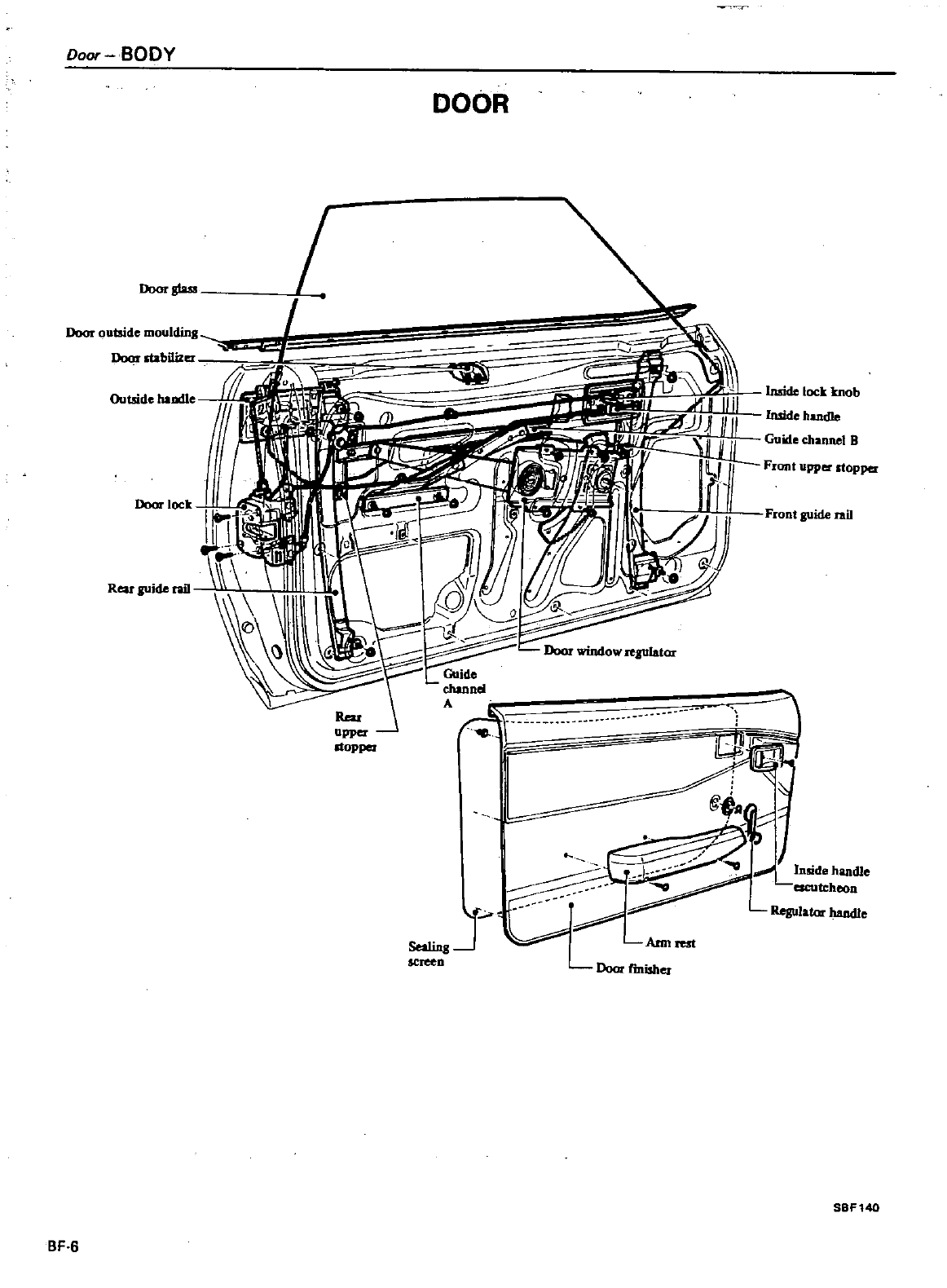
Door
BODY
DOOR
Outside
haodle
Door
gtus
Door
outside
moulding
Doot
stabilizer
i1
II
Front
guide
rail
liar
npper
It
i
@
t
lnad
hand1e
J
screen
Ann
Door
f
misher
SBf140
BF
6
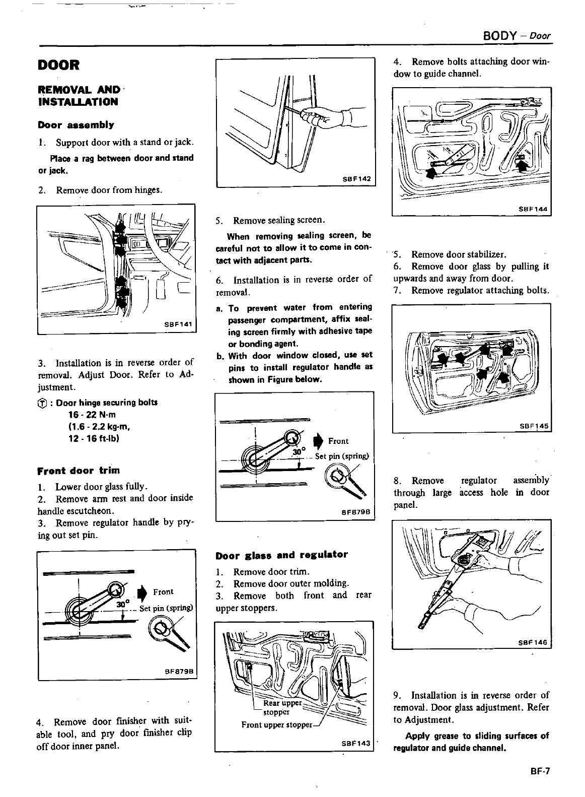
DOOR
REMOVAL
AND
INSTAlLATION
Door
aasembly
Support
door
with
a
stand
or
jack
Place
a
rag
between
door
and
stand
or
jack
2
Remove
door
from
hinges
I
I
00
W
r
JL
0
C
SBF141
3 Installation
is
in
reverse
order
of
removal
Adjust
Door
Refer
to
Ad
justment
tl
Door
hinge
securing
bolts
16 22
N
m
1
62 2
kg
m
12 16
ft
lb
Front
door
trim
1
Lower
door
glass
fully
2
Remove
ann
rest
and
door
inside
handle
escutcheon
3
Remove
regulator
handle
by
pry
ing
out
set
pin
o
Front
t
SF879B
4
Remove
door
fmisher
with
suit
able
tool
and
pry
door
fmisher
clip
off
door
inner
panel
SBF142
5
Remove
sealing
screen
When
removing
sealing
screen
be
careful
not
to
allow
it
to
come
in
con
taet
with
adjacent
parts
6Installation
is
in
reverse
order
of
removal
8
To
prevent
water
from
entering
passenger
compartment
affix
seal
ing
SCreen
firmly
with
adhesive
tape
or
bonding
agent
b
With
door window
closed
use
set
pins
to
install
regulator
handle
as
shown
in
Figure
below
Front
300
r
BF879B
Door
glass
and
regulator
I
Remove
door
trim
2
Remove
door
outer
molding
3
Remove
both
front
and
rear
upper
stoppers
IY
hf
I
J
Rear
uppe
opper
Front
upper
stopper
SBF143
BODY
Door
4
Remove
bolts
attaching
door
win
dow
to
guide
channel
O
c
SSF144
S
Remove
door
stabilizer
6
Remove
door
glass
by
pulling
it
upwards
and away
from
door
7
Remove
regulator attaching
bolts
SBF145
8
Remove
through
large
panel
regulator
assembly
access
hole
in
door
r
SBF146
9 Installation
is
in
reverse
order
of
removal
Door
glass
adjustment
Refer
to
Adjustment
Apply
grease
to
sliding
surfaces
of
regulator
and
guide
channel
BF
7
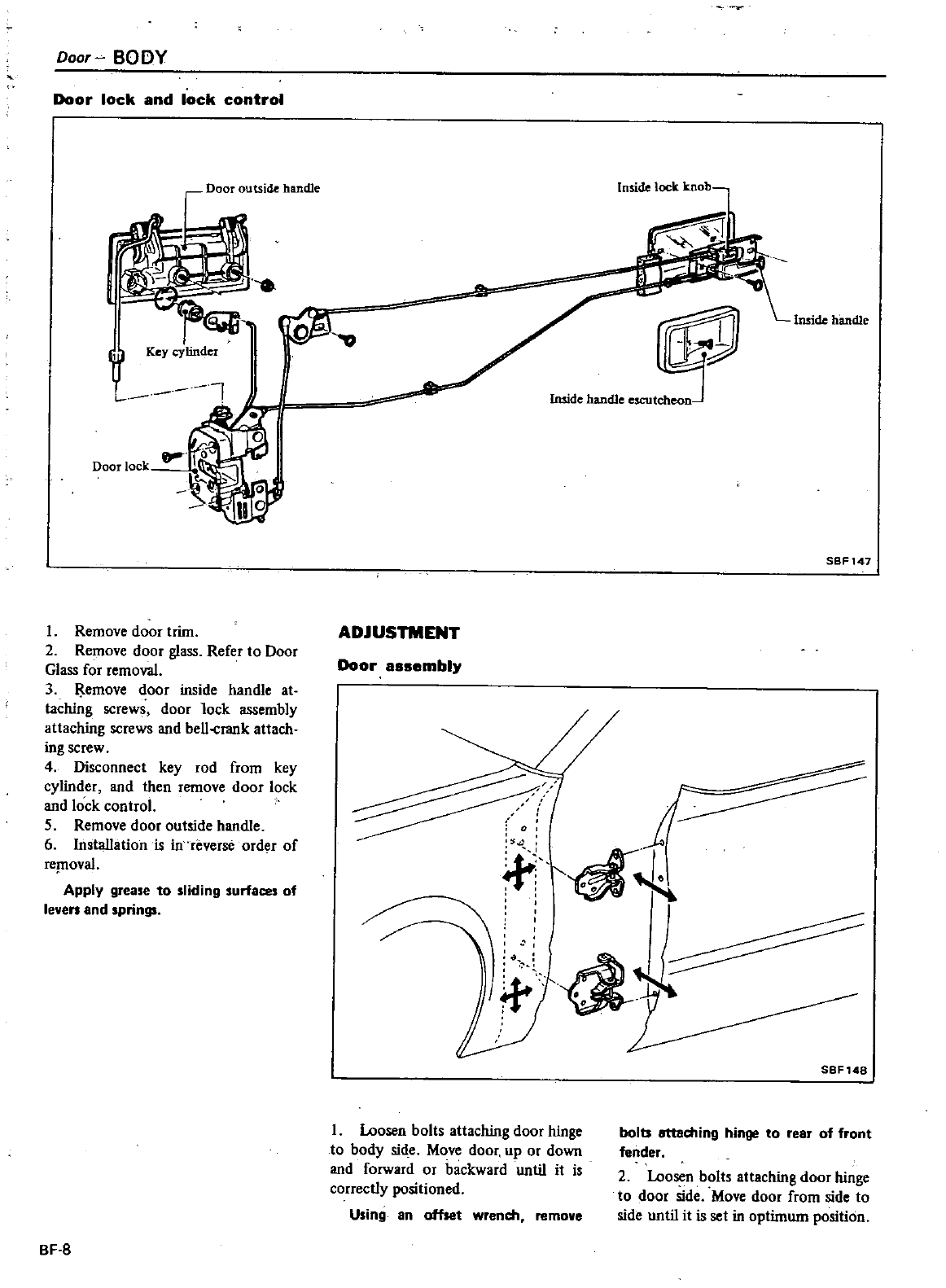
Door
BODY
Door
lock
and
lock
control
Door
outside
handle
J
I
Jb
Key
cylinder
t
l
Door
lock
Remove
door
trim
2
Remove
door
glass
Refer
to
Door
Glass
for
removal
3
Jl
emove
door
inside
handle
at
taching
screws
door
lock
assembly
attaching
screws
and
bell
crank
attach
ing
screw
4
Disconnect
key
rod
from
key
cylinder
and
then
remove
door
lock
and
lock
control
5
Remove
door
outside
handle
6
Installation
is in
reverse
order
of
rcptoval
Apply
grease
to
sliding
surfaces of
leven
and
springs
BF
B
ADJUSTMENT
Door
assembly
Inside
lock
knob
s
Imide
handle
escutcheoD
j
4
i
d
I
l
I
Loosen
bolts
attaching
door
hinge
to
body
sid
e
Move
door
up
or
down
and
forward
or
backward
until
it
is
correctly
positioned
Using
an
offset wrendl
remove
Imide
handle
SBF147
SBF148
bolts
attaching
hinge
to
rear
of
front
lender
2
Loosen
bolts
attaching
door
hinge
to
door
side
Move
door
from
side
to
side
until
it
is
set
in
optimum
position
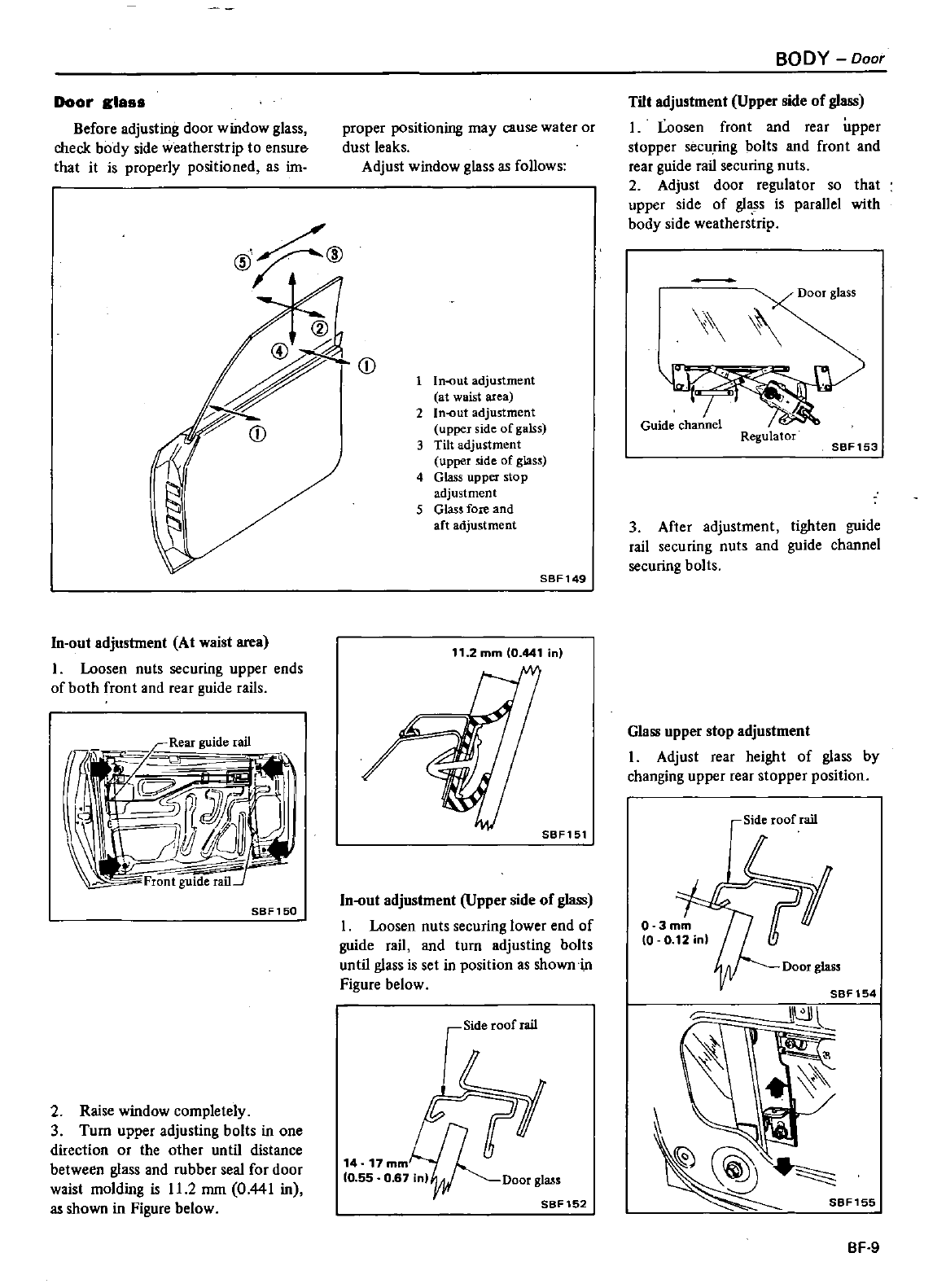
Door
glas
Before
adjusting
door
window
glass
check
body
side
weatherstrip
to
ensurl
that
it
is
properly
positioned
as
im
@1f
@
In
out
adjustment
At
waist
area
1
Loosen
nuts
securing
upper
ends
of
both
front
and
rear
guide
rails
rfjV
idi
I
II
I
l
ll
t
J
Jr
j
C
Front
SBF
150
2Raise
window
completely
3
Turn
upper
adjusting
bolts
in one
direction
or
the
other
until
distance
between
glass
and
rubber
seal
for
door
waist
molding
is
11
2
mm
0
441
in
as
shown
in
Figure
below
proper
positioning
may
cause
water
or
dust
leaks
Adjust
window
glass
as
follows
1
ln
ut
adjustment
at
waist
area
2
In
Gut
adjustment
upper
side
ofgalss
3
Tilt
adjustment
upper
side
of
glass
4
Glass
upper
stop
adjustment
5
Glass
fore
and
aft
adjustment
SBF149
11
2
mm
0
441
in
SBF151
In
out
adjustment
Upper
side
of
glass
1
Loosen
nuts
securing
lower
end
of
guide
rail
and
turn
adjusting
bolts
until
glass
is set
in
position
as
showni
n
Figure
below
Side
roof
rail
crt
14
17
mmLn
g
10
55
0
67
inlrOoorgla
SBF152
BODY
Ooor
Tilt
adjustment
Upper
side
of
glass
I
Loosen
front
and
rear
upper
stopper
securing
bolts
and
front
and
rear
guide
rail
securing
nuts
2
Adjust
door
regulator
so
that
upper
side
of
glass
is
parallel
with
body
side
weatherstrip
Regulator
SBF153
3
After
adjustment
tighten
guide
rail
securing
nuts
and
guide
channel
securing
bolts
Glass
upper
stop
adjustment
I
Adjust
rear
height
of
glass
by
changing
upper
rear
stopper
position
Side
roof
rail
Door
glass
SBF154
BF
9
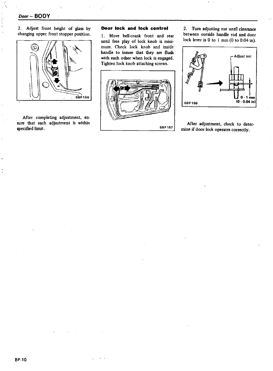
Door
BODY
2
Adjust
front
height
of
glass
by
changing
upper front
stopper
position
@
ri
il
After
completing
adjus1ment
en
sure
that
each
adjustment
is
within
specified
limit
BF
l0
Door
lock
and
lock
control
I
Move
bell
rank
front
and
rear
until
free
play
of
lock
knob
is
mini
mum
Check
lock
knob
and
inside
handle
to
insure
that
they
are
flush
with
each
other
when
lock
is
engaged
Tighten
lock
knob
attaching
screws
11i
U
I
II
J
P
SBF157
2
Turn
adjusting
nut until
clearance
between
outside
handle
rod
and
door
lock
lever
is
0
to
I
mm
0
to
004
in
Adjust
nut
U
0
1mm
0
0
04
inl
SBF158
Mter
adjustment
check
to
deter
mine
if
door
lock
operates
correctly
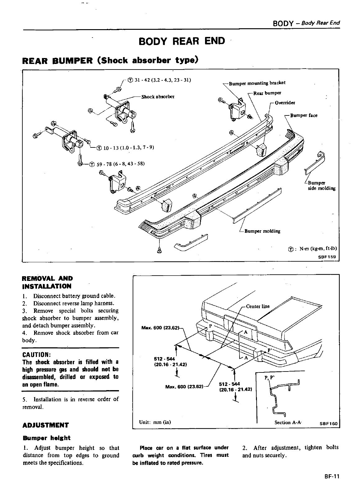
BODY
Body
Rear
End
BODY
REAR END
REAR
BUMPER
Shock
absorber
type
if
i
J
31
42
3 2
4
3
23
31
Shock
absorber
umper
mounti
ll
bracket
Rear
bumper
i
S
O
mder
Bumper
face
1
37
9
i
J
59 78
6 8
43 58
t
side
molding
i
J
N
m
kg
m
fHb
SBF159
REMOVAL
AND
INSTALLATION
I
Disconnect
battery
ground
cable
2
Disconnect
reverse
lamp
harness
3
Remove
special
bolts
securing
shock absorber
to
bumper
assembly
and
detach
bumper
assembly
4
Remove
shock absorber
from
car
body
M
600
23
621
M
600
23 62
CAUTION
The
shock
absorber
is
filled
with
a
high
pressure
gas
and
should
not
be
disassembled
drilled
or
exposed
to
an
open
flame
512 544
20
16 21
42
t
t
5
Installation
is
in
reverse
order
of
removal
ADJUSTMENT
Unit
mm in
Section
A
A
SBF160
Bumper
height
I
Adjust
bumper height
so
that
distance
from
top
edges
to
ground
meets
the
specifications
Place
car
on
a
flat
surface
under
curb
weight
conditions
Tires
must
be
inflated
to
rated
pressure
2
After
adjustment
tighten
bolts
and
nuts
securely
BF
ll
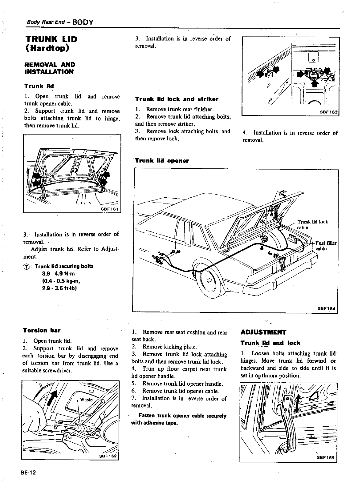
Body
Rear
End
BQDY
TRUNK
LID
Hardtop
REMOVAL
AND
INSTAUATION
Trunk
lid
I
Open
trunk
lid
and
remove
trunk
opener
cable
2
Support
trunk
lid
and
remo
bolts
attaching
trunk
lid
to
hinge
then
remove
trunk
lid
III
3Installation
is
in
reverse
order
of
removal
AdjUst
trunk
lid
Refer
to
Adjust
ment
G
i
Trunk
lid
securing
bolts
39
4
9
N
m
0 4 0
5
kg
m
2
9
3 6
ft
lb
Torsion
bar
I
Open
trunk
lid
2
Support
trunk
lid
and
remove
each
torsion
bar
by
disengaging
end
of
to
ion
bar
from
trunk
lid
Use
a
suitable screwdriver
L
BF
12
3Installation
is
in
reverse
order
of
removal
Trunk
lid
lock
end
striker
I
Remove trunk
rear
fmisher
2
Remove trunk
lid
attaching
bolts
and
then
remove
striker
3
Remove
lock
attaching
bolts
and
then
remove
lock
Trunk
lid
opener
1
Remove
rear
seat
cushion
and
rear
seat
back
2
Remove
kicking
plate
3
Remove
trunk
lid
lock
attaching
bolts
and
then
remove
trunk
lid
lock
4
Trun
up
floor
carpet
near
trunk
lid
opener
handle
S
Remoye
trunk
lid
opener
handle
6
Remove
trunk
lid
opener
cable
7Installation
is
in
reverse
order
of
removal
Fasten
trunk
opener
cable
securely
with
adhesive
tape
I
l
i
SBF163
4
Installation
is
in
reverse
order
of
removal
SBF164
ADJUSTMENT
T
u
n
I
l
an
oc
k
I
Loosen
bolts
attaching
trunk
lid
hinges
Move
trunk
lid
forward
or
backward
and
side
to
side
until
it
is
set
in
optimum
position
v
SBF166
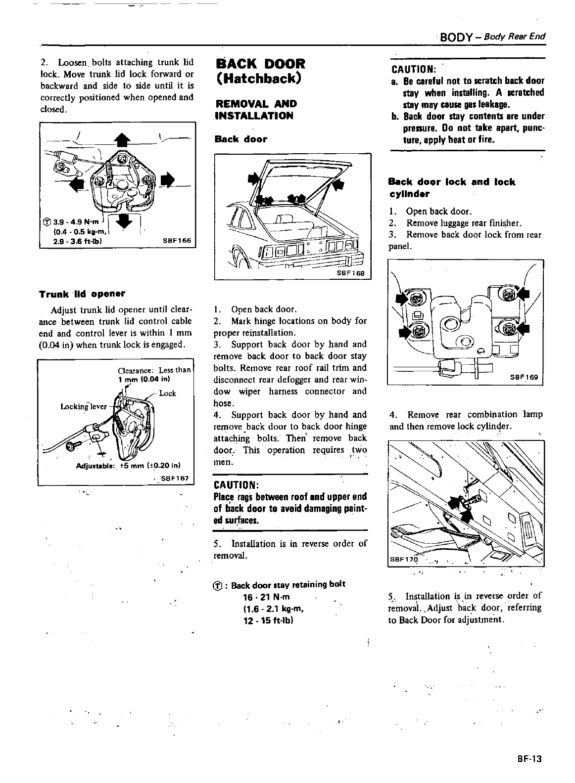
2
Loosen
bolts
attaching
trunk
lid
lock
Move
trunk
lid
lock
forward
or
backward and
side
to
side
until
it
is
correctly
positioned
when
opened
and
closed
I
J
3 9
4
9
N
m
10
4 0
5
kg
m
2 9
36
f1
lbl
SBF166
Trunk
lid
opener
Adjust
trunk
lid
opener
until
clear
ance
between
trunk
lid
control
cable
end
and
control
lever
is
within
1
mm
0
04
in
when
trunk
lock
is
engaged
Clearance
Less
than
1
mm
0
04
in
Lock
Locking
lever
A
AdjusUble
5
mm
1
10
20
inl
SBF167
BACK
DOOR
Hatchback
REMOVAL
AND
INSTALLATION
Back
door
SBF168
Open
back
door
2
Mark
hinge
locations
on
body
for
proper
reinstallation
3
Support
back
door
by
hand
and
remove
back
door
to
back door
stay
bolts
Remove
rear
roof
rail
trim
and
disconnect
rear
defogger
and
rear
win
dow
wiper
harness
connector
and
hose
4
Support
back door
by
hand
and
remove
back
door
to
back door
hinge
attaching
bolts
Then
remove
back
door
This
operation
requires
two
men
CAUTION
Place
rags
between
roof
and
upper
end
of
back
door
to
avoid
damaging
paint
ed
surfaces
5
Installation
is
in
reverse
order
of
removal
tl
Back
door
stay
retaining
bolt
16 21
N
m
1
62
1kg
m
12
15
ft
lb
BODY
Body
Rear
End
CAUTION
a
Be
careful
not
to
scralch
back
door
staV
when
installing
A
scralched
staV
mav
cause
gas
leakage
b
Back
door
staV
contents
are
under
pressure
00
not
take
apart
punc
ture
applv
heat
or
fire
Back
door
lock
end
lock
cylinder
I
Open
back
door
2
Remove
luggage
rear
fmisher
3
Remove
back
door
lock
from
rear
panel
1
0
i
0
Q
SBF
169
4
Remove
rear
combination
lamp
and then
remove
lock
cylin4er
5
Installation
is
in
reverse
order
of
r
mova
Adjust
back door
referring
to
Back
Door
for
adjustment
BF
13
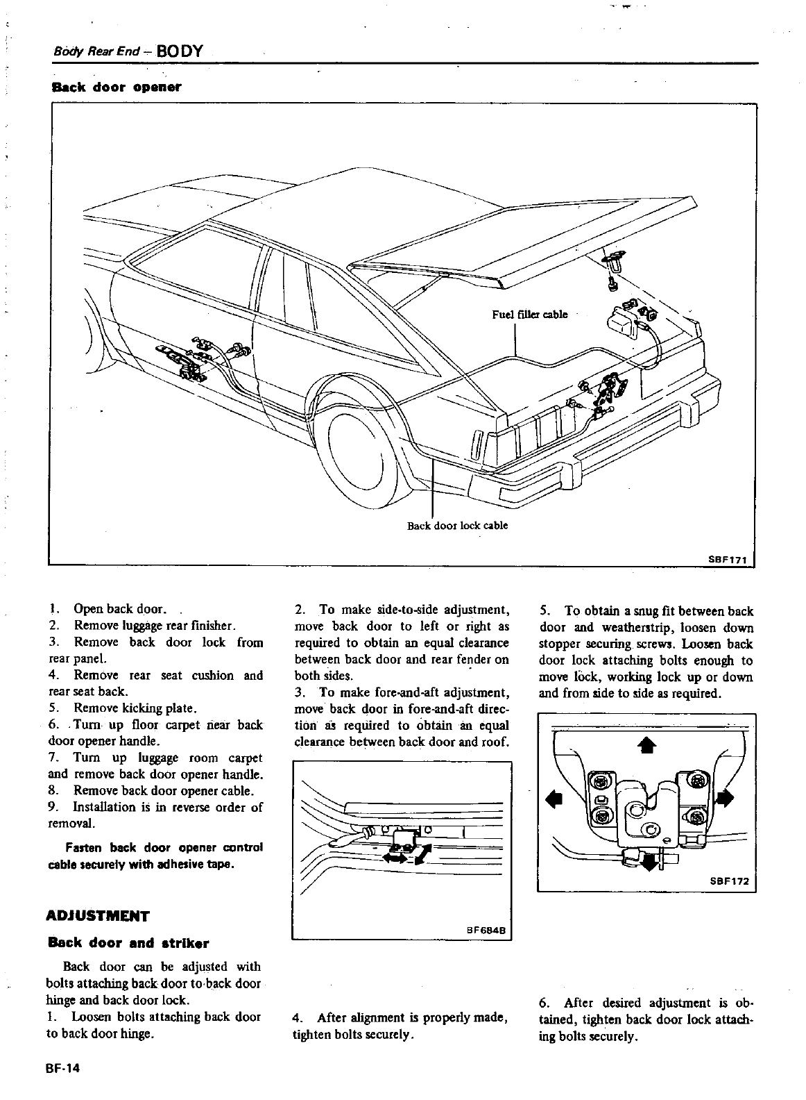
8OdyRearEnd
BODY
Back
door
opener
I
Open
back door
2
Remove
luggage
rear
finisher
3
Remove
back door
lock
from
rear
panel
4
Remove
rear
seat
cushion
and
rear
seat
back
5
Remove
kicking
plate
6
Turn
up
floor
carpet
riear
back
door
opener
handle
7
Turn
up
luggage
room
carpet
and
remove
back
door
opener handle
8
Remove
back
door
opener
cable
9
Insta1Iation
is
in
reverse
order
of
removal
Fastan
back
door
opener
control
cable
securely
with
adhesive
tape
ADJUSTMENT
Back
door
end
striker
Back
door
can
be
adjusted
with
bolts
attaching
back door
to
back door
hinge
and
back door
lock
I
Loosen
bolts
attaching
back door
to
back door
hinge
BF
14
Back
door
lock
cable
2
To
make
side
to
ide
adjustment
move
back
door
to
left
or
right
as
required
to
obtain
an
equal
clearance
between
back
door
and
rear
fender
on
both
sides
3
To
make
foreand
aft
adjustment
move
back door
in
foreand
aft
direc
tion
required
to
obtain
an
equal
clearance
between
backdoor
and
roof
P
U
BF6848
4
After
alignment
is
properly
made
tighten
bolts
securely
SBF171
5
To
obtain
a
snug
fit
between
back
door
and
weatherstrip
loosen
down
stopper
securing
screw
Loosen
back
door
lock
attaching
bolts
enough
to
move
lock
working
lock
up
or
down
and
from
side
to
side
as
required
h
7
1f
0
y
l4
P
SBF172
6
After
desired
adjustment
is
ob
tained
tighten
back door
lock
attach
ing
bolts
securely
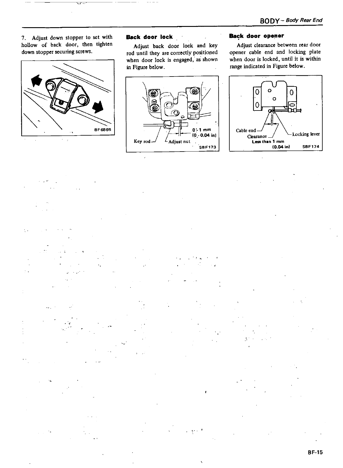
7
Adjust
down
stopper
to
set
with
hollow
of
back
door
then
tighten
down
stopper
securing
screws
BF6868
Back
door
lock
Adjust
back
door
lock
and
key
rod
until
they
are
correctly
positioned
when
door lock
is
engaged
as
shown
in
Figure
below
II
J
C
c
0
mm
0 0
04
inl
Key
rOd
Adjust
nut
SBF173
BODY
Body
Rear
End
Balik
door
opener
Adjust
clearance
between
rear
door
opener
cable
end
and
locking
plate
when
door
is locked
until
it
is
within
range
indicated
in
Figure
below
r
v
o
0
0
o
Locking
lever
SBF174
BF
15
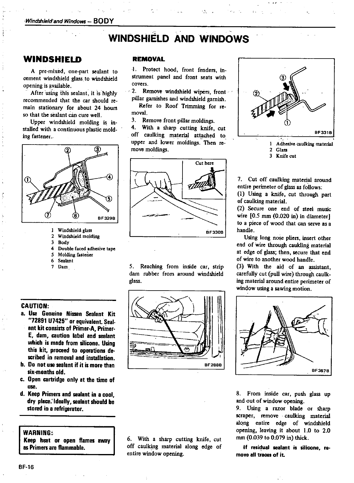
Winrhhieldand
Windows
BODY
WINDSHIELD
AND
WINDOWS
WINDSHIELD
A
pre
mixed
one
part
sealant
to
cement
windshield
glass
to
windshield
opening
is
available
After
using
this
sealant
it
is
highly
recommended
that
the
car
should
reo
main
stationary
for
about
24
hours
so
that
the
sealant
can
cure
welL
Upper
windshield
molding
is
in
stalled
with
a
continuous
plastic
mold
ing
fastener
I
Windshield
glass
2
Windshield
molding
3
Body
4
Double
faced
adhesive
tape
5
Molding
falteDU
6
Sealant
7
Dam
CAUTION
a
Use
Genuine
Nissan
Sealant
Kit
72891
U7425
or
equivalent
Seal
ant
kit
consists
of
Piimer
A
Primer
E
dam
caution
label
and
sealant
which
is
made
from
silicone
Using
this
kit
proceed
to
operations
de
scribed
in
removal
and
installation
b
Do
not
use
sealant
if it
is
more
than
six
months
old
c
Open
cartridge
only
at
the
time
of
use
d
Keep
Primen
and
sealant
in
a
cool
dry
place
ldeally
sealant should
be
stored
in
a
refrigerator
WARNING
Keep
heat
or
open
flames
away
IS
Primen
are
flammable
BF
16
REMOVAL
I
Protect
hood
front
fenders
in
strum
tpanelandftoot
ns
th
covers
2
Remove ndshield pers
front
pillar
gamishes
and
windshield
garnish
Refer
to
Roof
Trimming
for
re
moval
3
Remove
front
pillar
moldings
4
With
a
sharp
cutting
knife
cut
off
caulking
ma1erial
gttached
to
upper
and
lower
moldings
Then
reo
move
moldings
Cut
here
BF330B
5
Reaching
from
inside
car
strip
dam
rubber
from
around
windshield
glass
Ye
I
I
Bf288B
6
With
a
sharp
cutting
knife
cut
off
caulking
material
along
edge
of
entire
window
opening
BF331
B
1
Adhesive
caulking
material
2
Glass
3
Knife
cur
7
Cut
off
caulking
material
around
entire
perimeter
of
glass
as
follows
I
Using
a
knife
cut
through
part
of
caulking
material
2
Secure
one
end
of
steel
music
re
0
5
mm
0
020
in
in
diameter
to
a
piece
of
wood
that
can
serve
as
a
handle
Using
long
nose
pliers
insert
other
end
of
re
through
caukling
material
at
edge
of
glass
then
secure
that
end
of
re
to
another
wood
handle
3
With
the
aid
of
an
assistant
carefully
cut
puJi
re
through
caulk
ing
material around
entire
perimeter
of
ndow
using
a
sawing
motion
1
BF35
B
S
From
inside
car
push
glass
up
and
out
of
window
opening
9
Using
a
razor
blade
or
sharp
scraper
remove
caulking
material
along
entire
edge
of
windshield
opening
leaving
it
about
1
0
to
2
0
mm
0
039
to
0
079
in
thick
If
millual
sealant
i
ilicon
re
move
all
traces
of
it
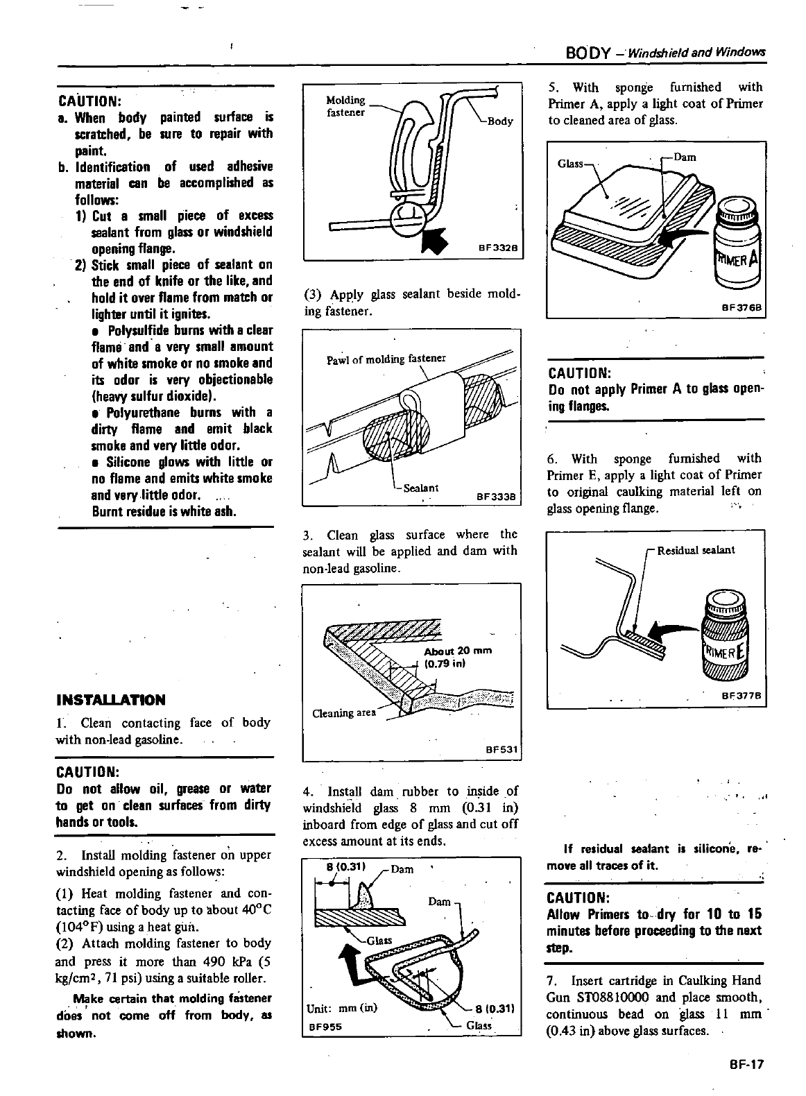
CAUTION
a
When
body
painted
surface
is
scra1Ched
be
sure
to
repair
with
paint
b
Identificetion
of
used
adhesive
material
can
be
accomplished
as
follows
1
Cut
e
smell
piece
of gxcess
sealant
from
glass
or
windshield
opening
flange
2
Stick
small
piece
of
sealant
on
the
end
of
knife
or
the
like
and
hold
it
over
flame
from
match
or
Iighler
until
it
igniles
Polysulfide
burns
with
a
clear
flamg
and
a
very
small
amount
of
white
smoke
or
no
smoke
and
its
odor
is
very
objectionable
heavy
sulfur
dioxide
Polyurethane
burns
with
a
dirty
flame
and
emit
black
smoke
and
very
little
odor
Silicone
glows
with little
or
no
flame
and
emits
white
smoke
and
very
little
odor
Burnt
residue
is
white
ash
INSTALLATION
L
Clean
contacting
face
of
body
with
non
lead
gasoline
CAUTION
00
not
allow
oil
grease
or
waler
to
get
on
clean
surfaces
from
dirty
hands
or
tools
2
Install
molding
fastener
on
upper
windshield
opening
as
follows
1
Heat
molding
fastener
and
con
tacting
face
of
body
up
to
about
400C
I
040
F
using
a
heat
giltl
2
Attach
molding
fastener
to
body
and
press
it
more
than
490
kPa
5
kg
em
71
psi
using
a
suitable
roller
Make
certain
that
molding
fastener
does
t
not
come
off
from
body
as
shown
Molding
fastener
3
Apply
glass
sealant
beside
mold
ing
fastener
Sealant
8 F
3338
3
Clean
glass
surface
where
the
sealant
will
be
applied
and
dam
with
non
lead
gasoline
About
20
mm
0
79
in
Cleaning
area
BF531
4
Install
dam
rubber
to
in
ide
of
windshield
glass
8
mm
0
31
in
inboard
from
edge
of
glass
and
cut
off
excess
amount
at
its
ends
hADam
GlaSS
Dam
Unit
mm
in
8F955
BO
DY
Windshield
and
Windows
5
With
sponge
furnished
with
Primer
A
apply
a
light
coat
of
Primer
to
cleaned
area
of
glass
IlIMERA
BF376B
CAUTION
00
not
apply
Primer
A
to
glass
open
ing
flanges
6
With
sponge
furnished
with
Primer
E
apply
a
light
coat
of
Primer
to
original
caulking
material
left
on
glass
opening
flange
Residual
sealant
ij
IMERE
WJ
BF377B
If
residual
sealant
is
silicone
r8
move
all
traces
of
it
CAUTION
Allow
Primers
to
dry
for
10
to
15
minutes
before
proceeding
to
the
next
step
7
Insert
cartridge
in
Caulking
Hand
Gun
ST08810000 and
place
smooth
continuous
bead
on
glass
11
mm
0
43
in
above
glass
surfaces
BF
17
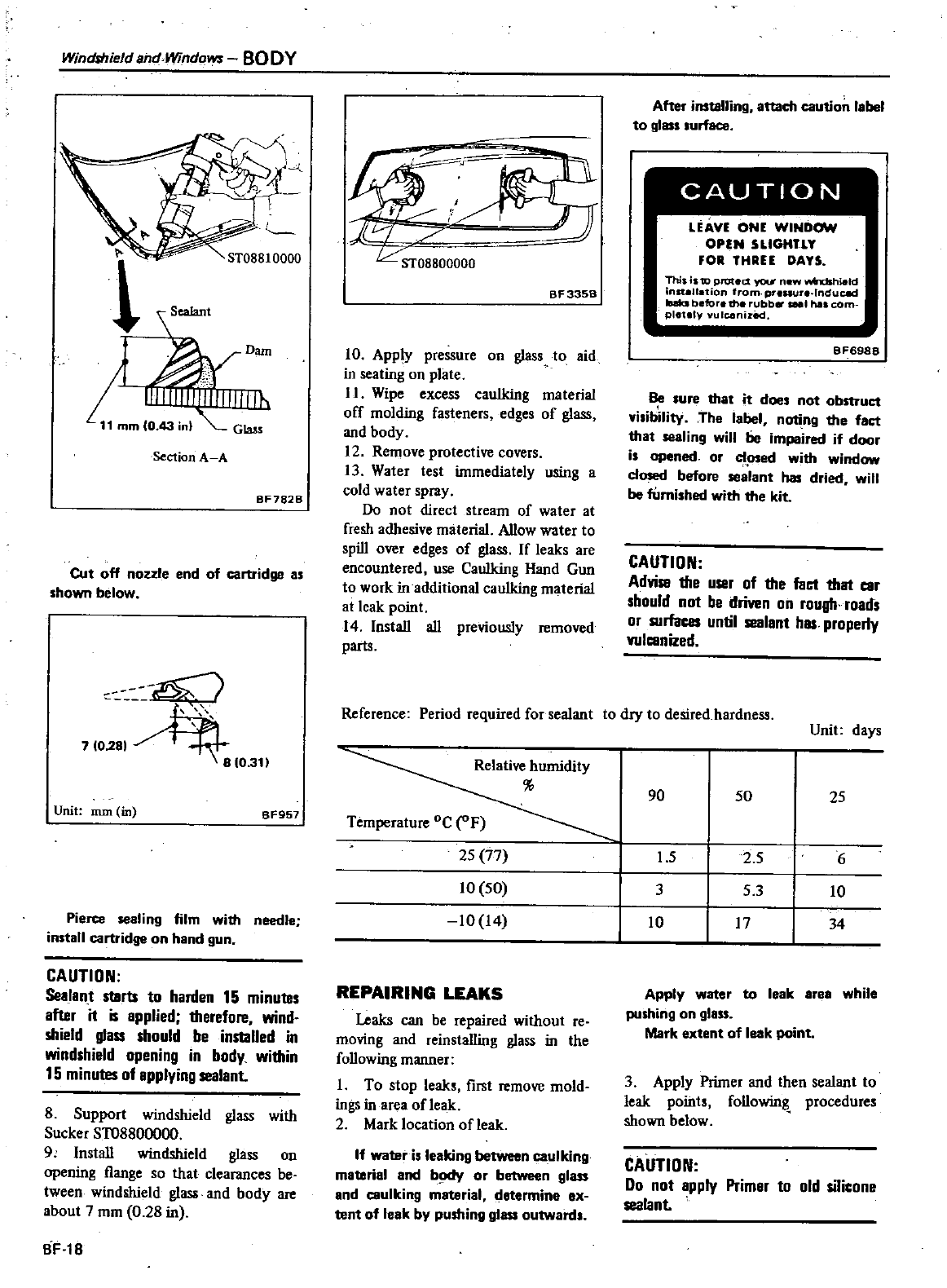
WincMield
and
Windows
BODY
d
Dam
mm
o
nl
Section
A A
BF782B
Cut
off
nozzle
end
of
cartridge
as
shown
below
7
0
h
1
0
311
Unit
mm
in
BF957
Pierce
sealing
film
with
needle
install
cartridge
on
hand
gun
CAUTION
Sealan
t
starts
to
harden
15
minules
after
it
is
applied
1herefore
wind
shield
glass
should
be
installed
in
windshield
opening
in
body
wi1hin
15
minutes
of
applying
sealant
8
Support
windshield
glass
with
SuckerST08800000
9
Install
windshield
glass
on
opening
flange
so
that
clearances
be
tween
windshield
glass
and
body
are
about
7
mm
0
28
in
BF
18
BF335B
10
Apply
pressure
on
glass
10
aid
in
seating
on
plate
II
Wipe
excess
caulking
material
off
molding
fasteners
edges
of
glass
and
body
12
Remove
protective
covers
13
Water
test
immediately
using
a
cold
water
spray
Do
not
direct
stream
of
water
at
fresh
adhesive
material
Allow
water
to
spill
over
edges
of
glass
If
leaks
are
encountered
use
Caulking
Hand
Gun
to
work
in
additional
caulking
material
at
leak
point
14 Install
all
previously
removed
parts
After
installing
attach
caution
label
to
glass
surface
CAUTION
LEAVE
ONE
WINDOW
OPEN
SLlGtlTlT
FOR THREE OATS
This
is
to
protett
f04
ew
wfndshield
nstallation
from
pre
ure
lnduC8d
Iuks
before
the ubb
1
has
com
pletely
ulconizecl
BF6988
Be
lure
that
it
does
not
obstruct
visibility
The
label
noting
the
faet
that
sealing
will
be
impaired
if
door
is
opened
or
osed
with
window
dosed
before
sealant
has
dried
will
be
furnished
with
the
kit
CAUTION
AdviSB
the
user
of the
fact
that
car
should
not
be
driven
on
rough
roads
or
surfaces
until
sealant
has
properly
wlcanized
Reference
Period
required
for
sealant
to
dry
to
desired
hardness
Unit
days
Relative
humidity
90
50
25
Temperature
oC F
25
77
1
5
25
6
10
50
3
53
10
10
14
10 17
34
REPAIRING
LEAKS
Leaks
can
be
repaired
without
reo
moving
and
reinstalling
glass
in
the
following
manner
I
To
stop
leaks
lint
remove
mold
ings
in
area
ofleak
2 Mark location
of
leak
If
water
is
leaking
between
caUlking
matarial
and
b
Kfy
or
between
glass
and
caulking
material
c
ietermine
ex
tent
of
leak
by
pushing
glass
outward
Apply
water
to
leak
area
while
pushing
on
glass
Mark
extent
of
leak
point
3
Apply
Primer
and
then
sealant
to
leak
points
following
procedures
shown
below
CAUTION
Do
not
apply
Primar
to
old
sil
one
sealant
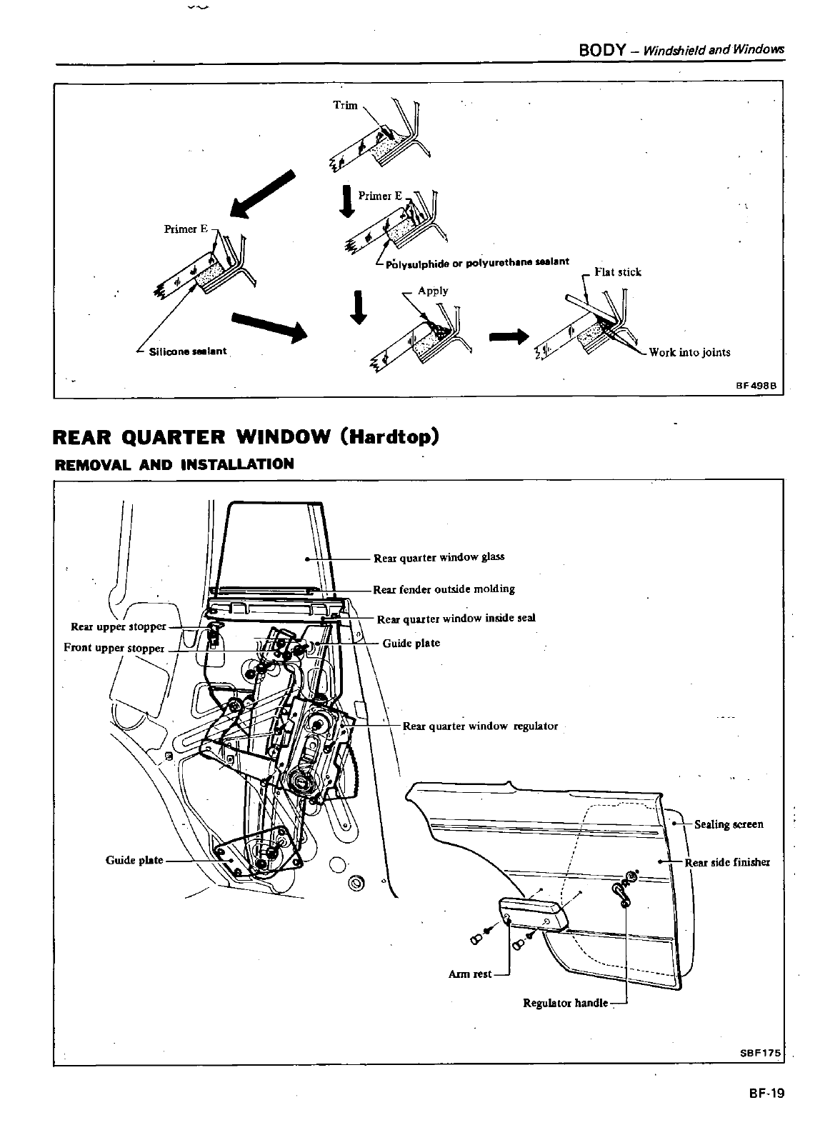
BODY
Windshield
and
Windows
TrUn
1
PrUner
E
PDIYlulphide
or
polyureth
ne
sulant
Work
into
joints
4
l
Silicone
81lant
BF498B
REAR
QUARTER
WINDOW
Hardtop
REMOVAL
AND
INSTALLATION
I
I
J
I
tJf
J
Rear
upper
stopper
Front
upper
stopper
0
V
D
Guide
plate
Rear
quarter
window
glaM
Ann
rest
Regulator
handle
SBF175
BF
19
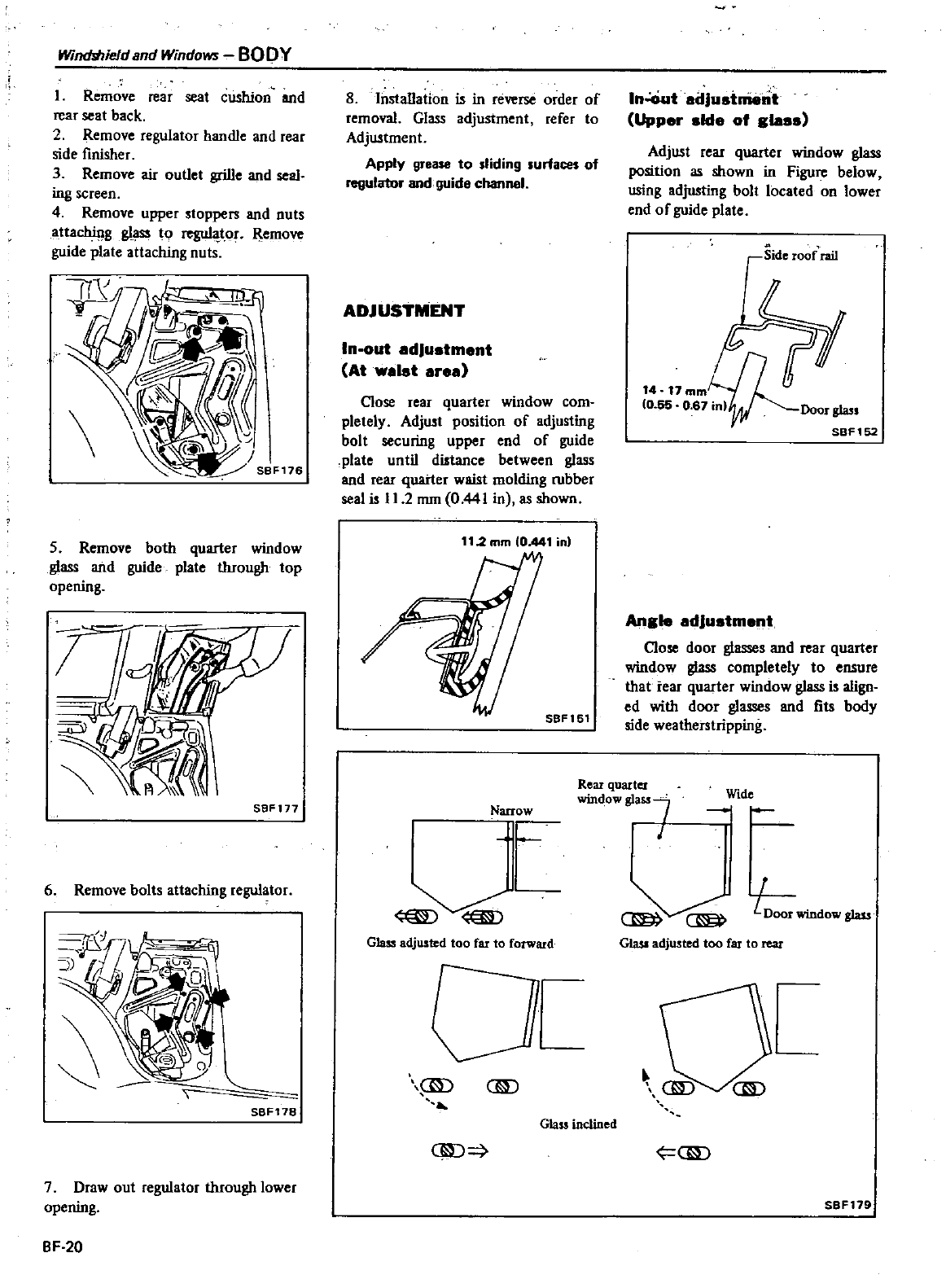
Winchhield
and
Windows
BODY
L
Remove
rear
seat
cushion
and
rear
seat
back
2
Remove
regulator
handle
and
rear
side
finisher
3
Remove
air
outlet
grille
and
seaI
ing
screen
4
Remove
upper
stoppers
and
nuts
attaching
glass
to
reguI
tor
Remove
guide
plate
attaching
nuts
5
Remove
both
quarter
window
glass
and
guide
plate
tIuough
top
opening
SBFl77
6
Remove
bolts
attaching
regulator
7
Draw
out
regulator
tIuough
lower
opening
BF 20
8 Installation
is
in
reverse
order
of
removal
Glass
adjustment
refer
to
Adjustment
Apply
grease
to
sliding
surfaces
of
regulator
and
guide
channel
ADJUSTMENT
In
out
adJu
tment
At
wa
t
erea
Close
rear
quarter
window
com
pletely Adjust
position
of
adjusting
bolt
securing
upper
end
of
guide
plate
until
distance
between
glass
and
rear
quarter
waist
molding
rubber
seal
is
I
1
2
mm
0
441
in
as
shown
11
2mm
0
441
in
SBF161
Narrow
I
L
Glass
adjusted
too
far
to
forward
ID
em
Glass
inclined
liD
In
ciut
adJu
t
nt
Upper
lde
of g
Adjust
rear
quarter
window
glass
position
as
shown
in
Figure
below
using
adjusting
bolt
located
on
lower
end
of
guide
plate
Side
roof
rai
I
r
14 17
mmLn
g
0
55
0
61
inlV
Door
glass
SBFl52
Angle
adJu
tment
Close
door
glasses
and
rear
quarter
window
glass
completely
to
ensure
that
tear
quarter
window
glass
is
align
ed
with
door
glasses
and
fits
body
side
weatherstripping
Rear
quarter
win
ow
glass
I
Wide
L
Door
window
glass
Gla
sI
adjusted
too
far
to
rear
UD
SBF179
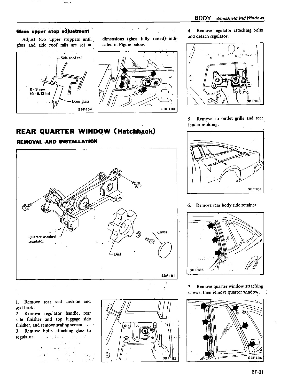
G1
ss
upper
stop
dJustment
Adjust
two
upper
stoppers
until
glass
and
side
roof
rails
are
set
at
Side
roof
rail
Door
glass
SBF154
dimensions
glass
fully
raised
indi
cated
in
Figure
below
y
Q
SBF180
REAR
QUARTER
WINDOW Hatchback
REMOVAL
AND
INSTALLATION
Quarte
r
window
regulator
1
Remove
rear
seat
cushion
and
seal
back
2
Remove
regulator
handle
rear
side
fmisher
and
top
luggage
side
finisher
and
remove
sealing
screen
3
Remove
bolts
attaching
glass
to
regulator
b
SBF181
I
f
SBFl
2
BODY
Windshield
and
Windows
4
Remove
regulator
attaching
bolts
and
detach
regulator
f
00
0
0
0
06
III
5l
SBF18
5
Remove
air
outlet
grille
and
rear
fender
molding
SBF184
6
Remove
rear
body
side
retainer
SBF185
7
Remove
quarter
window
attaching
screws
then
remove
quarter
window
BF
21
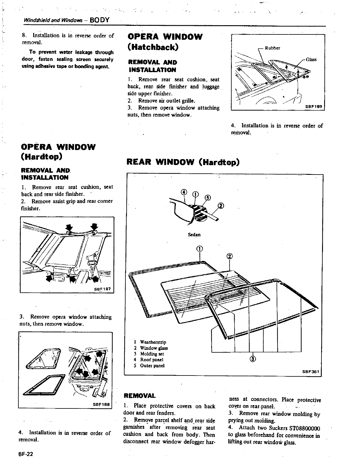
Windlilield
and
Windows
BO
DY
8 Installation
is
in
reverse
order
of
removal
To
prevent
water
leakage
through
door
fasten
sealing
screen
securely
using
adhesive
tape
or
bonding
agent
OPERA
WINDOW
Hardtop
REMOVAL
AND
INSTALLATION
1
Remove
rear
seat
cushion
seat
back
and
rear
side
fmisher
2
Remove
assist
grip
and
rear
corner
fmisher
SB
187
3
Remove opera
window
attaching
nuts
then
remove
window
SBF188
4
Installation
is
in
reverse
order
of
removal
BF
22
OPERA
WINDOW
Hatchback
REMOVAL
AND
INSTALLAnON
1
Remove
rear
seat
cushion
seat
back
rear
side
finisher
and
luggage
side
upper
fInisher
2
Remove
air
outlet
grille
3
Remove
opera
window
attaching
nuts
then
remove
window
REAR
WINDOW
Hardtop
Sedan
CD
Rubber
Glass
y
1
SBF189
4
Installation
is
in
reverse
order
of
removal
1
Weatherstrip
2
Window
glass
3
Molding
set
4
Roof
panel
5
Outer
panel
REMOVAL
L
Place
protective
covers
on
back
door
and
rear
fenders
2
Rem
ve
parsel
shelf
lUId
rear
side
garnishes
after
removing
rear
seat
cushion
and
back from
body
Then
disconnect
rear
window
defogger
har
@
SBF361
ness
at
coMectors
Place
protective
co
r
on
rear
panel
3
Remove
rear
window
molding
by
prying
out
molding
4
Attach
two
Suckers
ST08800000
to
glass
beforehand
for
convenience
in
lifting
out
rear
window
glass
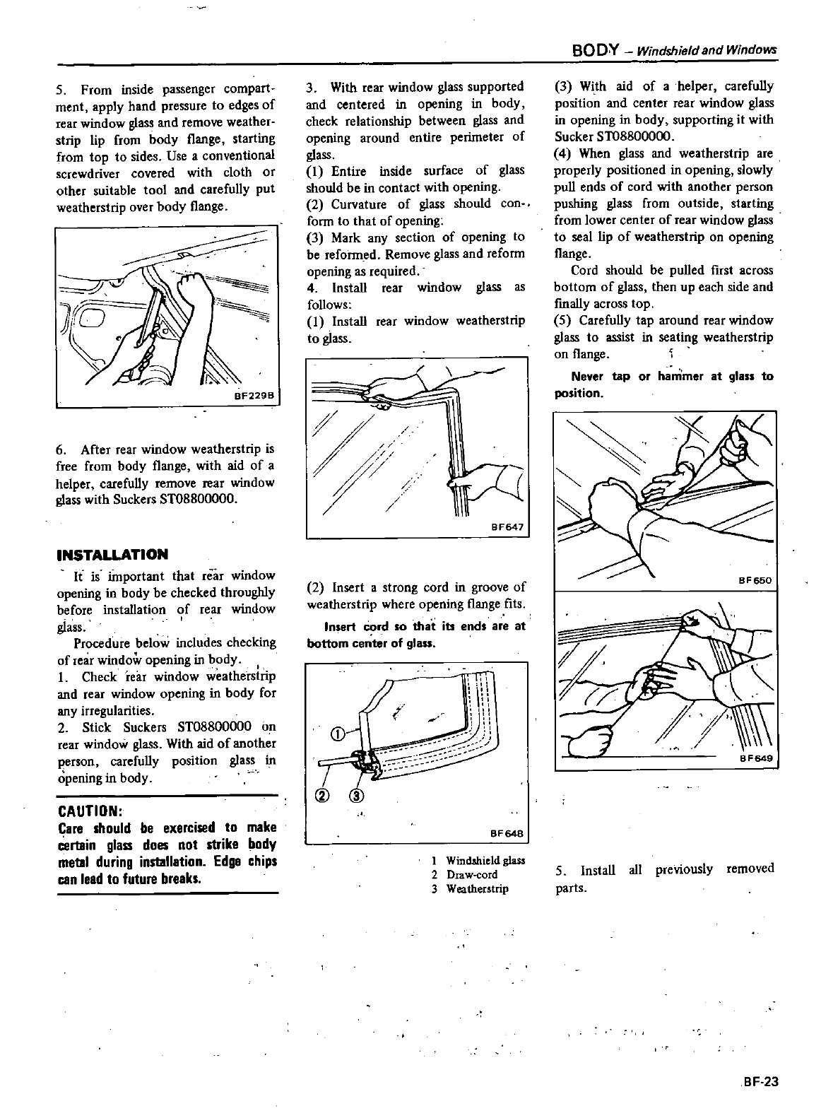
5
From
inside
passenger
compart
ment
apply
hand
pressure
to
edges
of
rear
window
glass
and
remove
weather
strip
lip
from
body
flange
starting
from
top
to
sides
Use
a
conventional
screwdriver covered
with
cloth
or
other
suitable
tool
and
carefully
put
weatherstrip
over
body
flange
J
rO
8F229B
6
After
rear
window
weatherstrip
is
free
from
body
flange
with
aid
of
a
helper
carefully
remove
rear
window
glass
with
Suckers
ST08800000
INSTALLATION
It
is
important
that
rear
window
opening
in
body
be
checked
throughly
before
installation
of
rear
window
glass
Procedure
below
includes
checking
of
rear
window
opening
in
body
L
Check
re
f
window
weatherstrip
and
rear
window
opening
in
body
for
any
irregularities
2Stick
Suckers
ST08800000
on
rear
window
glass
With
aid
of
another
person
carefully
position
glass
in
opening
in
body
CAUTION
Care
should
be
exercised
to
make
Certain
glass
does
not
strike
body
metal
during
installation
Edge
chips
can
lead
to
future
breaks
3
With
rear
window
glass
supported
and
centered
in
opening
in
body
check
relationship
between
glass
and
opening
around
entire
perimeter
of
glass
1
Entire
inside surface
of
glass
should
be
in
contact
with
opening
2
Curvature
of
glass
should
con
form
to
that
of
opening
3
Mark
any
section
of
opening
to
be
reformed
Remove
glass
and
reform
opening
as
required
4
Install
rear
window
glass
as
follows
1
Install
rear
window
weatherstrip
to
glass
t
BF647
2
Insert
a
strong
cord
in
groove
of
weatherstrip
where
opening
flange
fits
Insert
Cord
so
that
ib
ends
are
at
bottom
center
of
glass
BF648
1
Windshield
glass
2
Draw
cord
3
Weatherstrip
BO
O
V
Windshield
and
Windows
3
With
aid
of
a
helper
carefully
position
and
center
rear
window
glass
in
opening
in
body
supporting
it
with
Sucker
ST08800000
4
When
glass
and
weatherstrip
are
properly
positioned
in
opening
slowly
pull
ends
of
cord
with
another
person
pushing
glass
from
outside
starting
from
lower
center
of
rear
window
glass
to
seal
lip
of
weatherstrip
on
opening
flange
Cord
should
be pulled
first
across
bottom
of
glass
then
up
each
side
and
fmally
across
top
5
Carefully
tap
around
rear
window
glass
to
assist
in
seating
weatherstrip
on
flange
Never
tap
or
hammer
at
glass
to
position
BF650
BF649
5
Install
all
previously
removed
parts
BF
23
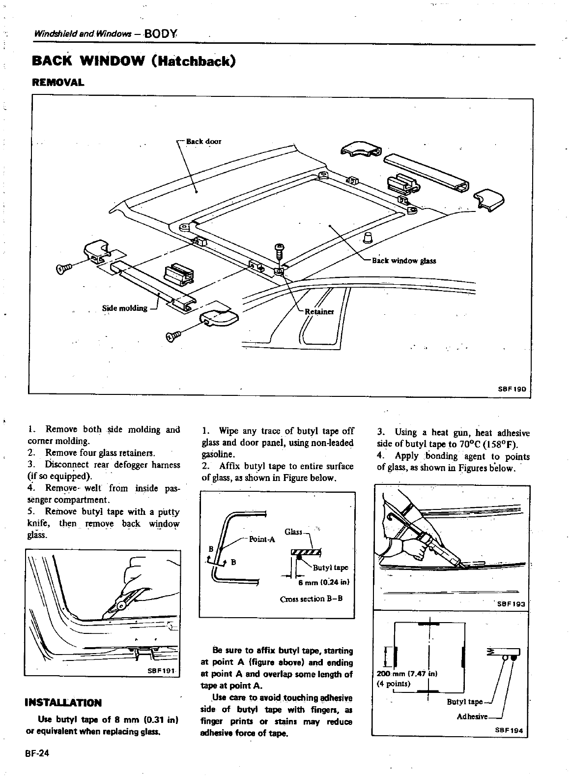
Windshield
and
Windows
BODY
BACK
WINDOW
Hatchback
REMOVAL
l
Remove
both
de
molding
and
corner
molding
2
Remove
four
glass
retainers
3
Disconnect
rear
defogger
harness
if
so
equipped
4
Remove
welt
from
inside
pas
senger
compartment
S
Remove
butyl
tape
with
a
putty
knife
then
remove
back
wil
1do
glass
r5
J
r
SBF191
INSTALLATION
Use
butyl
tape
of
8
mm
0
31
in
or
equi
alent
when
replacing
glass
BF
24
lumm
1
Wipe
any
trace
of
butyl
tape
off
glass
and
door
panel
using
non
leaded
gasoline
2
Affix
butyl
tape
to
entire
surface
of
glass
as
shown
in
Figure
below
1
C
B
Jr
tyltape
6
mm
0
24
in
Cross
section
BB
Be
sure
to
affix
butyl
tape
starting
at
point
A
figure
bon
and
ending
at
point
A
and
overlap
some
length
of
tape
at
point
A
Use
care
to
a
oidtouching
adhesive
side
of
butyl
tape
with
fingen
as
finger
prints
or
stains
may
reduce
adhesi
e
force
of
tape
Back
wbldow
gWs
S8F19Q
3
Using
a
heat
gun
heat
adhesive
side
of
butyl
tape
to
700C
IS80F
4
Apply
bonding
agent
to
points
of
glass
as
shown
in
Figures
below
SBF193
t
I
I
2OO
mm
7
41
in
4
points
O
SBF194
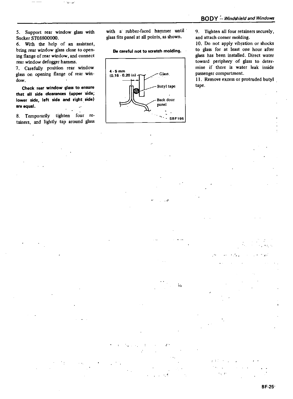
5Support
rear
window
glass
with
Sucker
ST08800000
6
With
the
help
of an
assistant
bring
rear
window
glass
close
to
open
ing
flange
of
rear
window
and
connect
rear
window
defogger
harness
7
Carefully
position
rear
window
glass
on
opening
flange
of
rear
win
dow
Check
rear
window
glass
to
ensure
that
all
side
dearances
upper
side
lower
side
left
side
and
right
side
are
equal
8
Temporarily
tighten
four
reo
tainers
and
lightly
tap
around
glass
with
a
rubber
faced
haJ11ffier
until
glass
fits
panel
at
all points
as
shown
Be
careful
not
to
scratch
molding
4
5mm
0
16
o
20in
G
S
c
Butyltape
ml
J
Backdoor
panel
SBF195
BODY
Windshield
and
WindOM
9
Tighten
all four
retainers
securely
and
attach
corner
molding
10
Do
not
apply
vibration
or
shocks
to
glass
for
at
least
one
hour after
glass
has
been
installed
Direct
water
toward
periphery
of
glass
to
deter
mine
if
there
is
water
leak
inside
passenger compartment
II
Remove
excess
or
protruded
butyl
tape
1
BF
25
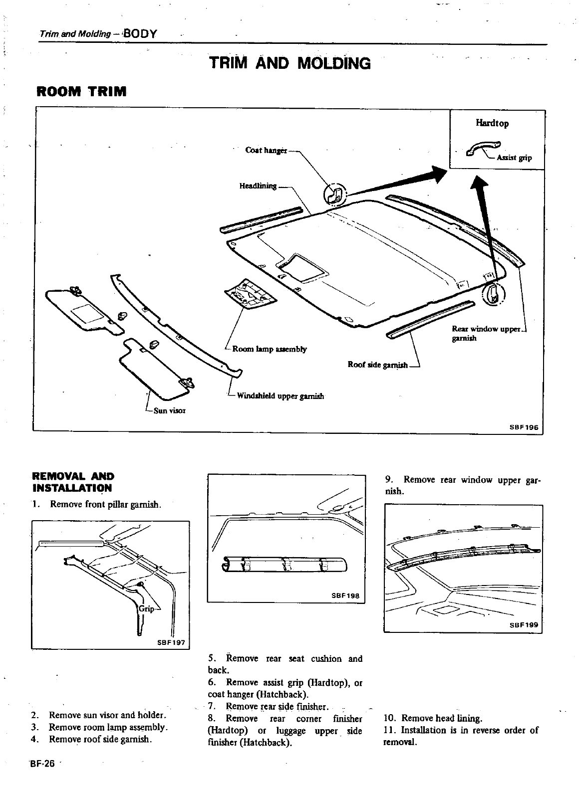
Trim
and
Molding
BODY
ROOM
TRIM
Sun
riser
REMOVAL
AND
INSTALLATlqN
I
Remove
front
pillar
garnish
r
BF197
2
Remove
sun visor
and
holder
3
Remove
room
lamp
assembly
4
Remove
roof
side
garnish
BF
26
TRIM
AND
MOLDiNG
HeadIinins
Room
lamp
mbly
Wirul
hieJd
upper
prnish
I
if
ii
1
tl
SBF198
5
Remove
rear
seat
cushion
and
back
6
Remove
assist
grip
Hardtop
or
coat
hanger
Hatchback
7
Remove
rear
side
finisher
8
Remove
rear
corner
finisher
Hardtop
or
luggage
upper
side
finisher
Hatchback
Hardtop
AssistgriP
Rear
L
upper
garnish
SBF196
9
Remove
rear
window
upper
gar
nish
r
SBF199
10
Remove
head
lining
II
Installation
is
in
reverse
order
of
removal
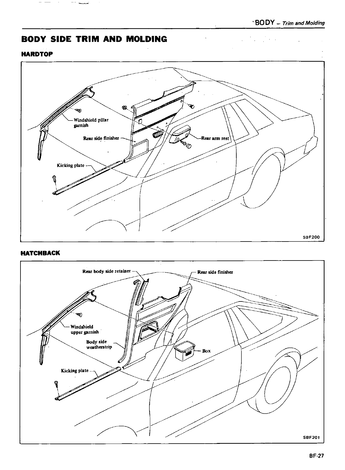
BODY
Trim
and
Molding
BODY
SIDE
TRIM
AND
MOLDING
HARDTOP
Rear
sid
finisher
Kicking
plate
SBF200
HATCHBACK
Rear
body
side
retainer
Rear
side
finisher
SBF201
BF
27
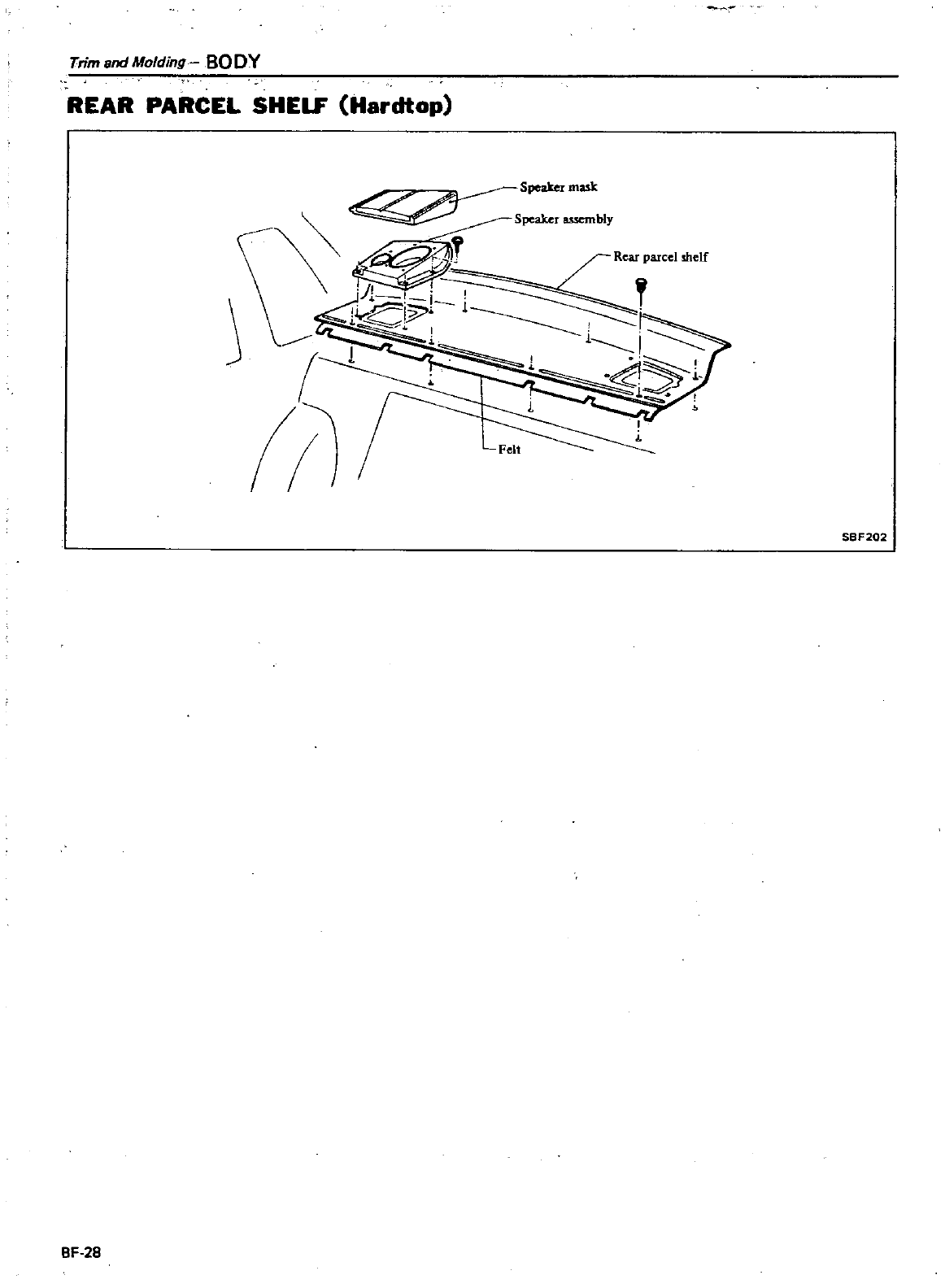
Trim
and
Molding
BO
DY
REAR
PARCEL
SHELF
Hardtop
SBF202
BF
28
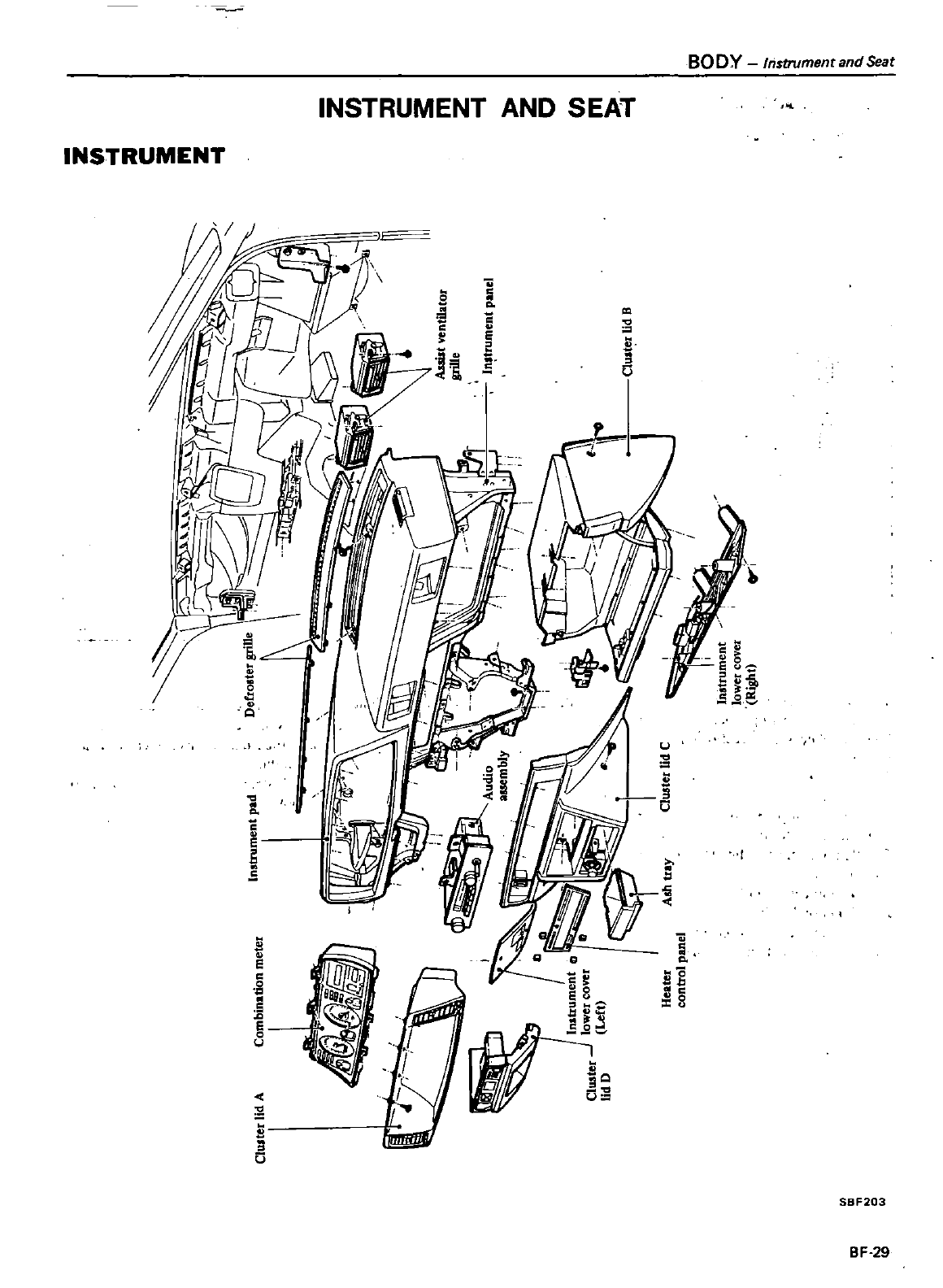
dSeat
ent
an
600
IrislflJ
EA1
AND
S
NS1
RUtAEN1
ft
EtlT
STR
U
i
a
II
1
u
ll
g
II
i
5g
J
u
II
8
e
g
c
u
a
0
lit
l
s
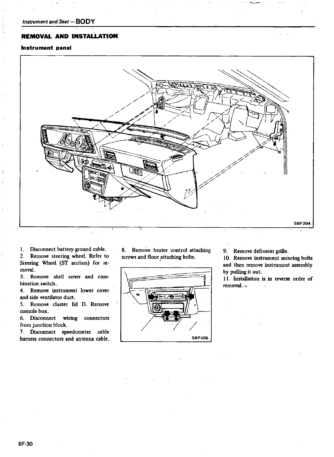
Instrument
and
Seat
BODY
REMOVAL
AND
INSTALLATION
Instrument
panel
Disconnect
battery
ground
cable
2
Remove
steering
wheel
Refer
to
Steering
Wheel
ST
section
for
re
moval
3
Remove
shell
cover
and
com
bination
switch
4
Remove
instrument
lower
cover
and
side
ventilator
duct
S
Remove
cluster
lid
D
Remove
console
box
6
Disconnect
wlOng
connectors
from
junction
block
7
Disconnect
speedometer
cable
harness
connectors
and
antenna
cable
BF 30
SBF204
8
Remove
heater
control
attaching
screws
and
floor
attaching
bolts
9
Remove
defroster
grille
10
Remove
instrument
securing
bolts
and
then
remove
instrument
assembly
by
pulling
it
out
11
Installation
is
in
reverse
order
of
removal
j
SBF205
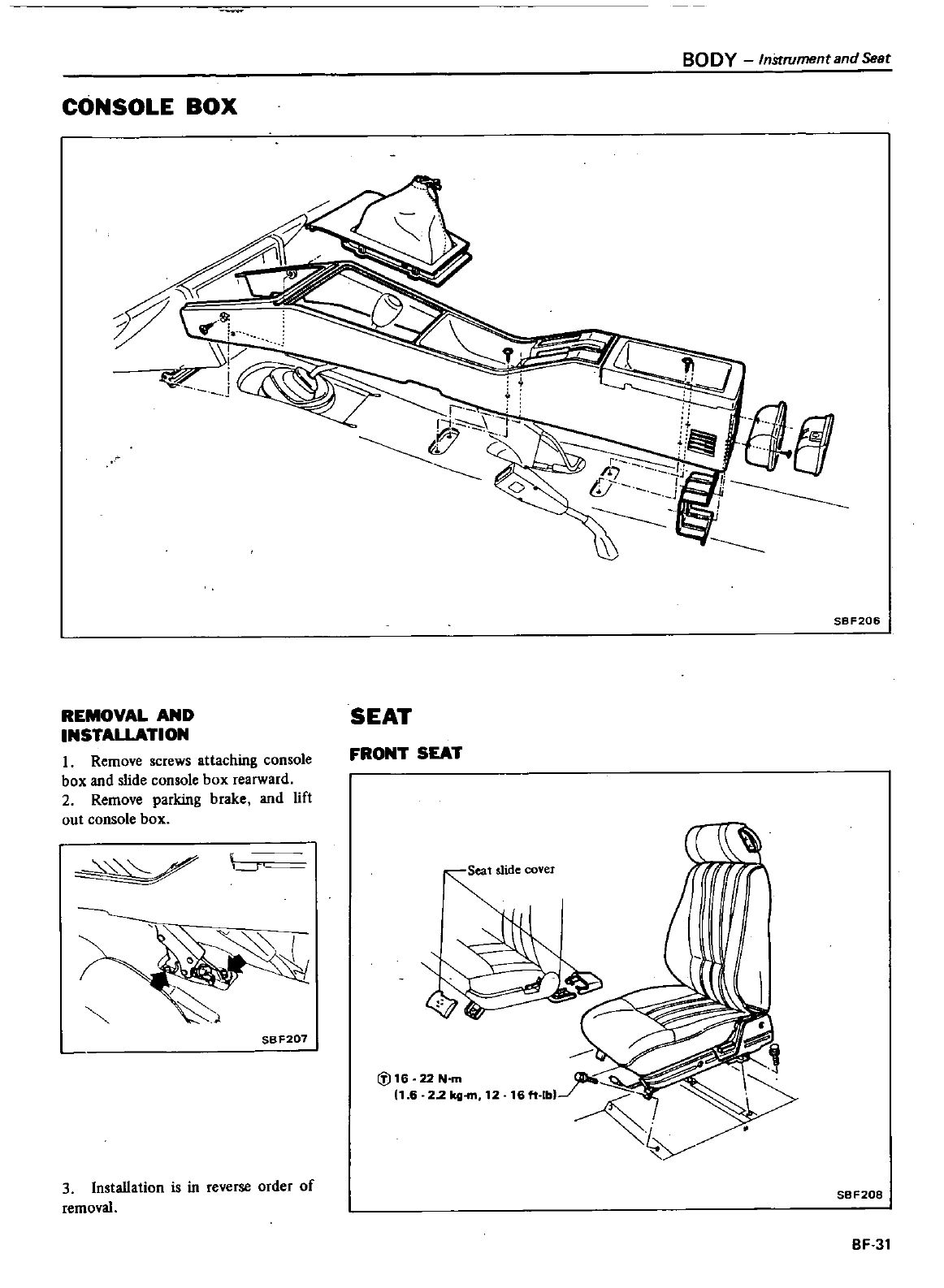
BODY
lnStromentBndSeat
CONSOLE
BOX
SBF206
REMOVAL
AND
INSTALLATION
I
Remove
screws
attaching
console
box and
slide
console
box
rearward
2
Remove
parking
brake
and
lift
out
console
box
SEAT
FRONT
SEAT
I
11
S6
F207
ifi16
22N
m
11
6
22
kg
m
12
3Installation
is
in
reverse
order
of
removal
SBF208
BF
31
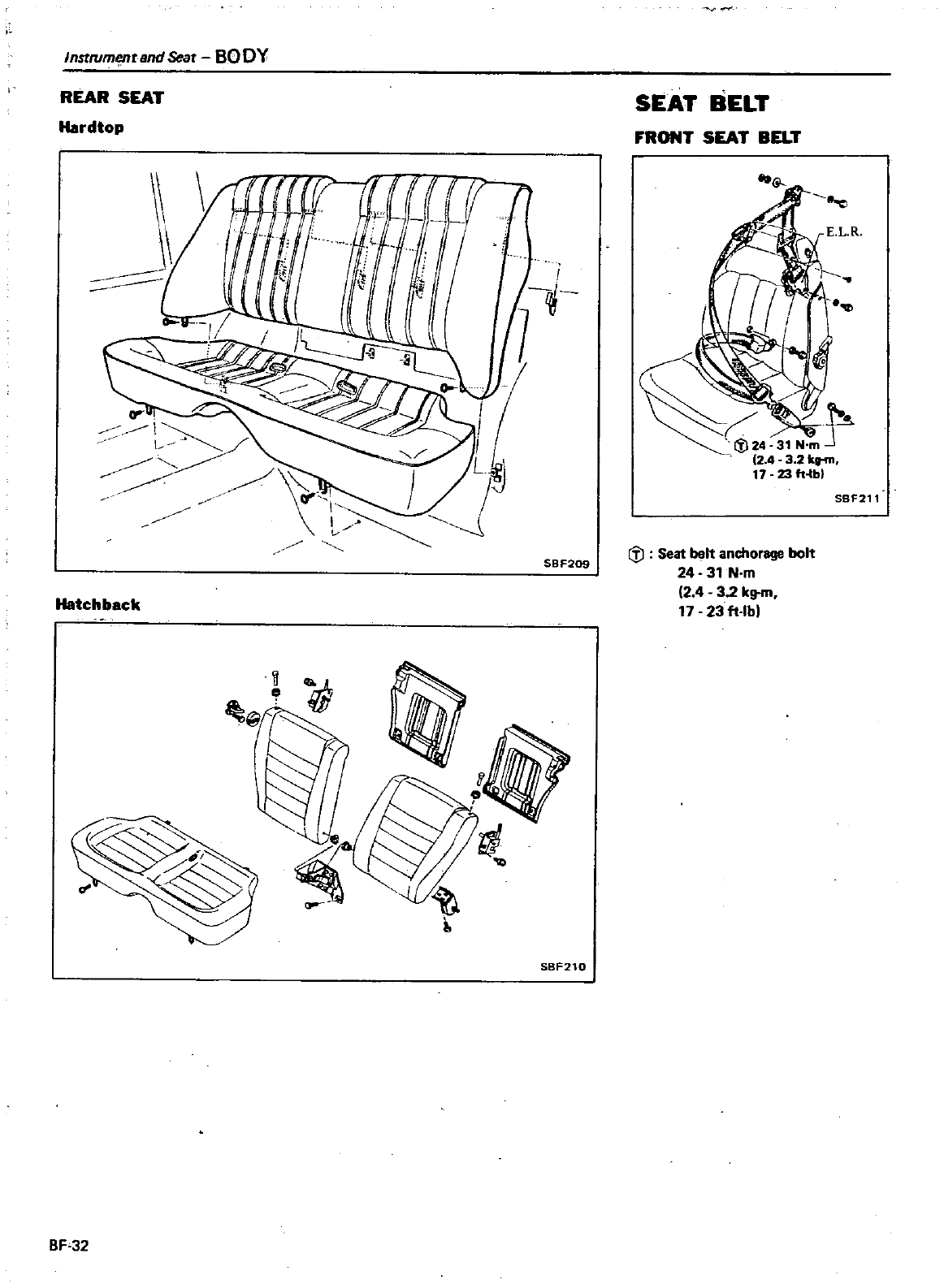
Instrumenund
Seat
BO
DY
REAR
SEAT
Hardtop
SBF209
Hatchback
l
iiiJ
rJ
SBF210
BF
32
SEAT
BELT
FRONT
SEAT
BELT
SBF211
itJ
Seat
belt
anchorage
bolt
24
31 Nm
2
4
32
k
17
23
ft
Ib
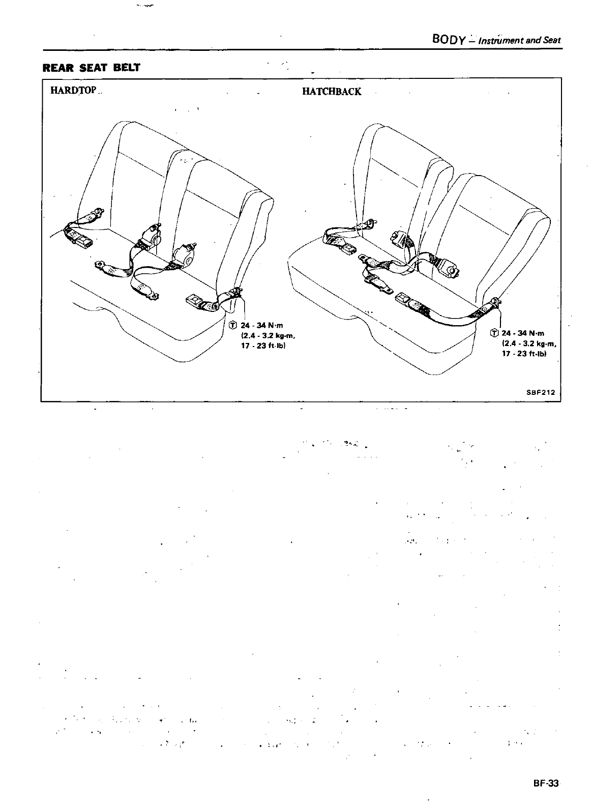
REAR
SEA
r
BEL
r
HARDTOP
I
1
J2434N
m
12
4 32
k
17
g
m
23ft
lbl
HATCHBACK
BODY
Instrument
and
S
eat
I
J
24
34N
m
2
4
32k
g
m
17
23
ft
lbl
SBF212
BF 33
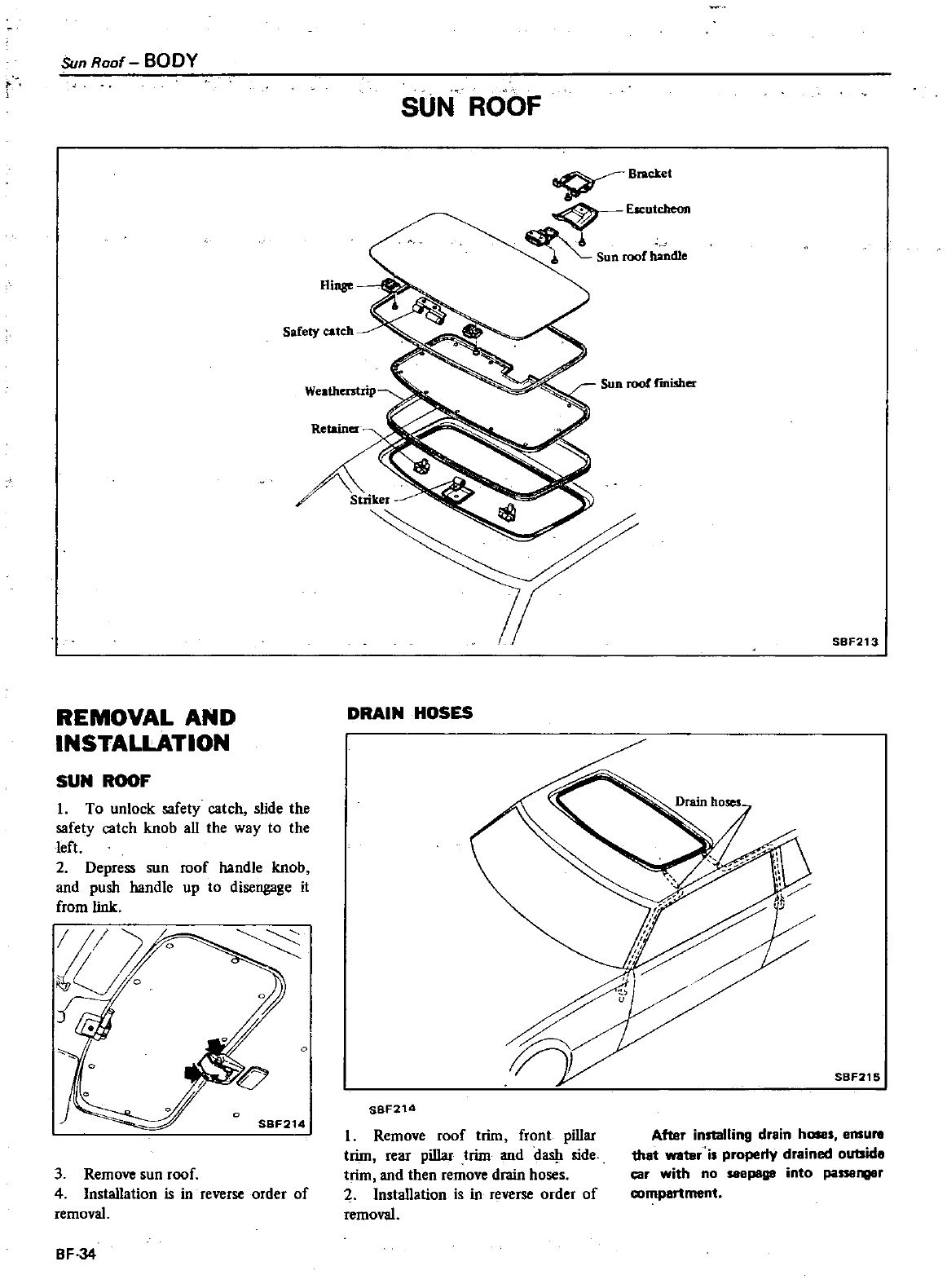
Sun
Roof
BODY
REMOVAL
AND
INSTALLATION
SUN
ROOF
1
To
unlock
safety
catch
slide
the
safety
catch
knob
all
the
way to
the
left
2
Depress
sun
roof
handle
knob
and
push
handle
up
to
disengage
it
from
link
3
Remove
sun
roof
4
Installation
is
in
reverse
order
of
removal
BF
34
SUN
ROOF
Bndet
EICutcheon
Sun
roof
handle
Safety
catch
Sun
roof
rmi5her
SBF213
DRAIN
HOSES
o
SBF215
SBF214
I
Remove
roof
trim
front
pillar
trim
rear
pillar
trim
and
da
side
trim
and
then
remove
drain
hoses
2 Installation
is
in
reverse
order
of
removal
After
installing
drain
h
s
emure
1hat
watar
is
property
drained
outside
car
with
no
seepage
into
passenger
compartment
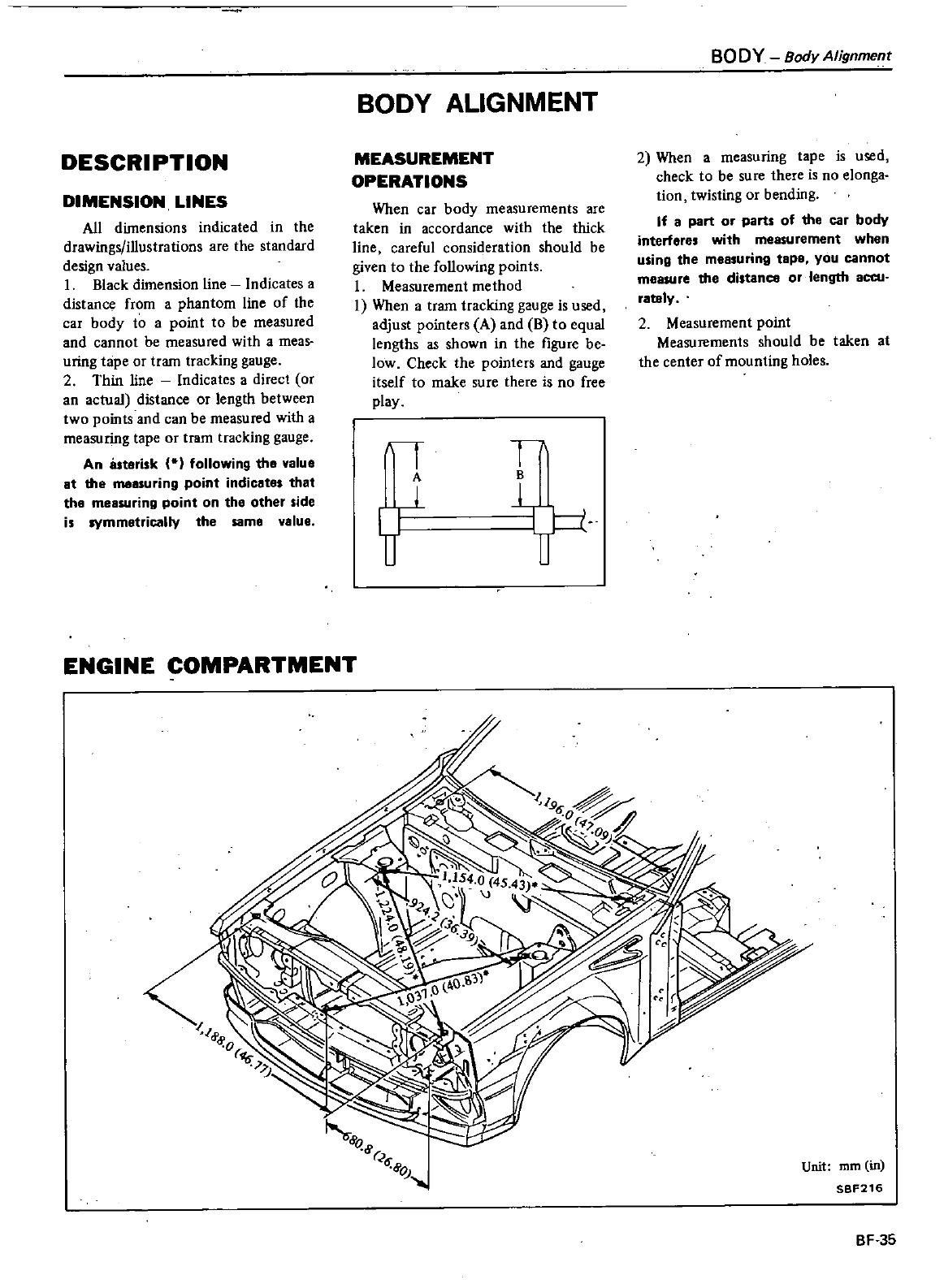
DESCRIPTION
DIMENSION
LINES
All
dimensions
indicated
in
the
drawings
illustrations
are
the
standard
design
values
I
Black
dimension
line
Indicates
a
distance
from a
phantom
line
of
the
car
body
to
a
point
to
be
measured
and
cannot
be
measured
with
a
meas
uring
tape
or
tram
tracking
gauge
2
Thin
line
Indicates
a
direct
or
an
actual
distance
or
length
between
two
points
and
can
be
measured
with
a
measuring
tape
or
tram
tracking
gauge
An
asterisk
following
the
value
at
the
measuring
point
indicates
that
the
measuring
point
on
the
other
side
is
symmetrically
the same
value
ENGINE
COMPARTMENT
BODY
ALIGNMENT
MEASUREMENT
OPERATIONS
When
car
body
measurements
are
taken
in
accordance
with
the
thick
line
careful
consideration
should
be
given
to
the
following
points
1
Measurement
method
I
When
a
tram
tracking
gauge
is
used
adjust
pointe
A
and
B
to
equal
lengths
as
shown
in
the
figure
be
low
Check
the
pointe
and
gauge
itself
to
make
sure
there
is
no
free
play
I
A
f
I
B
BODY
BodyAlignment
2
When
a
measuring
tape
is
used
check
to
be
sure
there
is
no
elonga
tion
twisting
or
bending
If
a
part
or
parts
of
the
car
body
interferes
with
measurement
when
using
the
measuring
tape
you
cannot
measure
the
distance
or
length
accu
rately
2
Measurement
point
Measurements
should
be taken
at
the
center
of
mounting
holes
Unit
mm
in
SBF216
BF
35
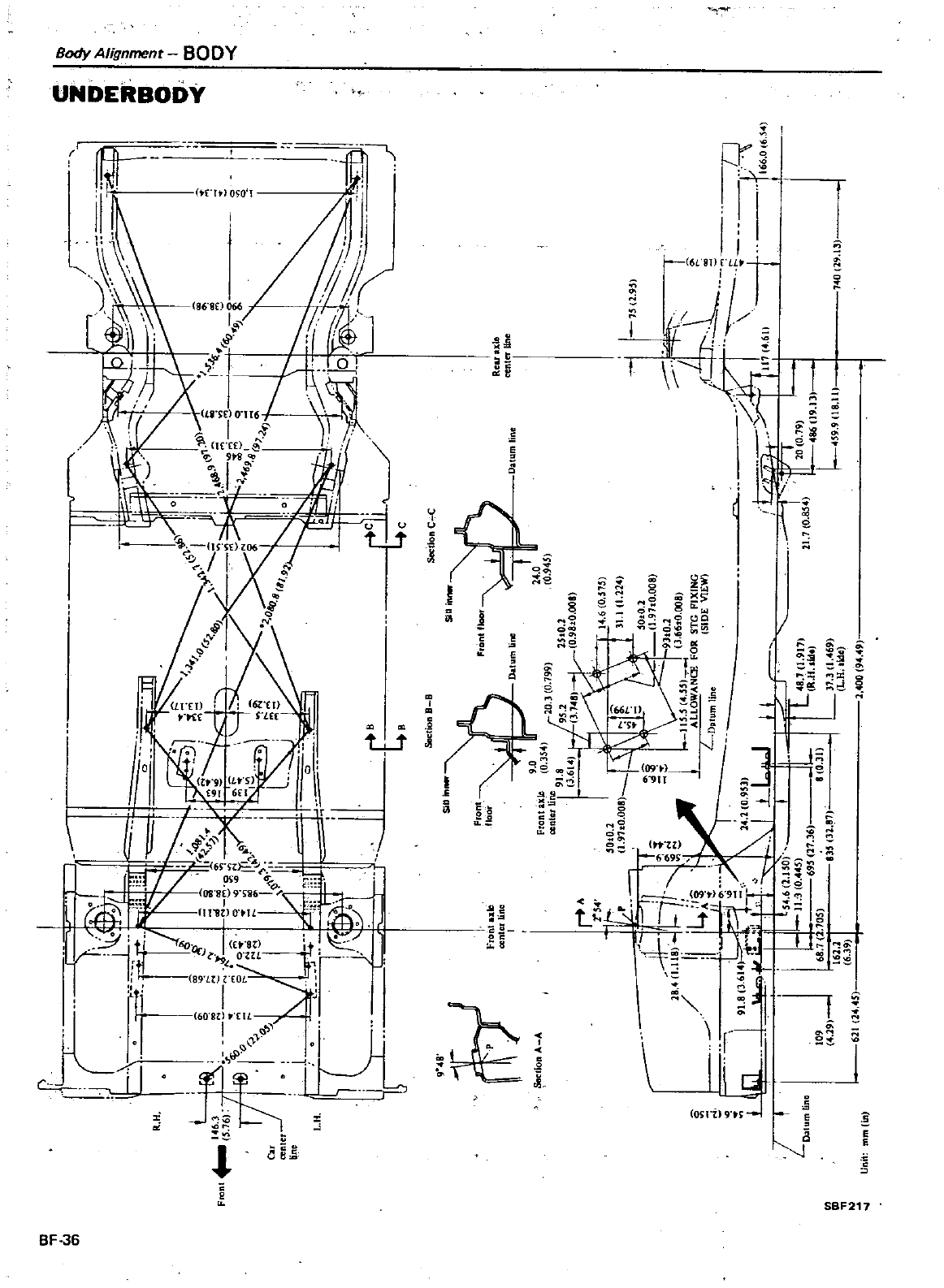
c
l
If
n
J
U
i
1
L
o
1
i
I
R
H
n
Fm
I4
g
ig
l
Il
N
if
76
1
i
i
r
Jlf
1
I
ol
v
l
0
f
N
l
I
y
I
0
51
Cu
Nol
N
I
I
t
i
m7
1
l
db
no
I
I
l
o
q
L
H
r
V
I
W
L
0
Ih
I
0
1
i
h
J
II
u
c
il
9
t
t
O
E
J
c
q
69
I
8
9
0
7
I
l
4J
r
r
2
t
IS
51
SeetionB
B
ScttlonC
C
9
8
rr
p
Seelion
A
A
ntf
n
m
24
0
0
945
Front
floor
Fronlu
1C
ocnIcrlinc
I
RCLUIe
centerline
Oalumlin
en
r
2
4
t
sOtO
2
t
h
1
91tO
008l
0
02
if
rl
J
1
97tO
008
tt
I
0
93tO
2
28
1
l1
l
c
I
11
s5
S5
3
6610
008
o
I
I
0
ALLOWANCE
FOa
STG
PIXING
I
L
A
I
L
SIDE
VIEW
LG
i
J
D
mHo
j
91
83
61
14
1
0
95l
n
IolJ
0
I
I
I
U
11
II
L
IJ
1
11
l
2
0
I
l
L
oJ
L
1
11
3
0
5
L
8
70
917
D
tum
line
695
17
36
R
H
lide
109
68
7
i
70S
8
0
31
19
I
IJ5
3187
37
31
69
161
1
I
L
H
lde
6
39
611
14
45
1
400
9
9
40
19
13
1
6
0
575
31
1
1
21
75
2
95
1
cp
L
If
df
t
I
u
7i
17
r
I
I
1
i
21
7
0
85
EO
7
166
06
I
86
9
f
4S9
9118
111
Unit
rnmlin
c
z
III
aIIo
i
t
I
tD
o
o
I
j
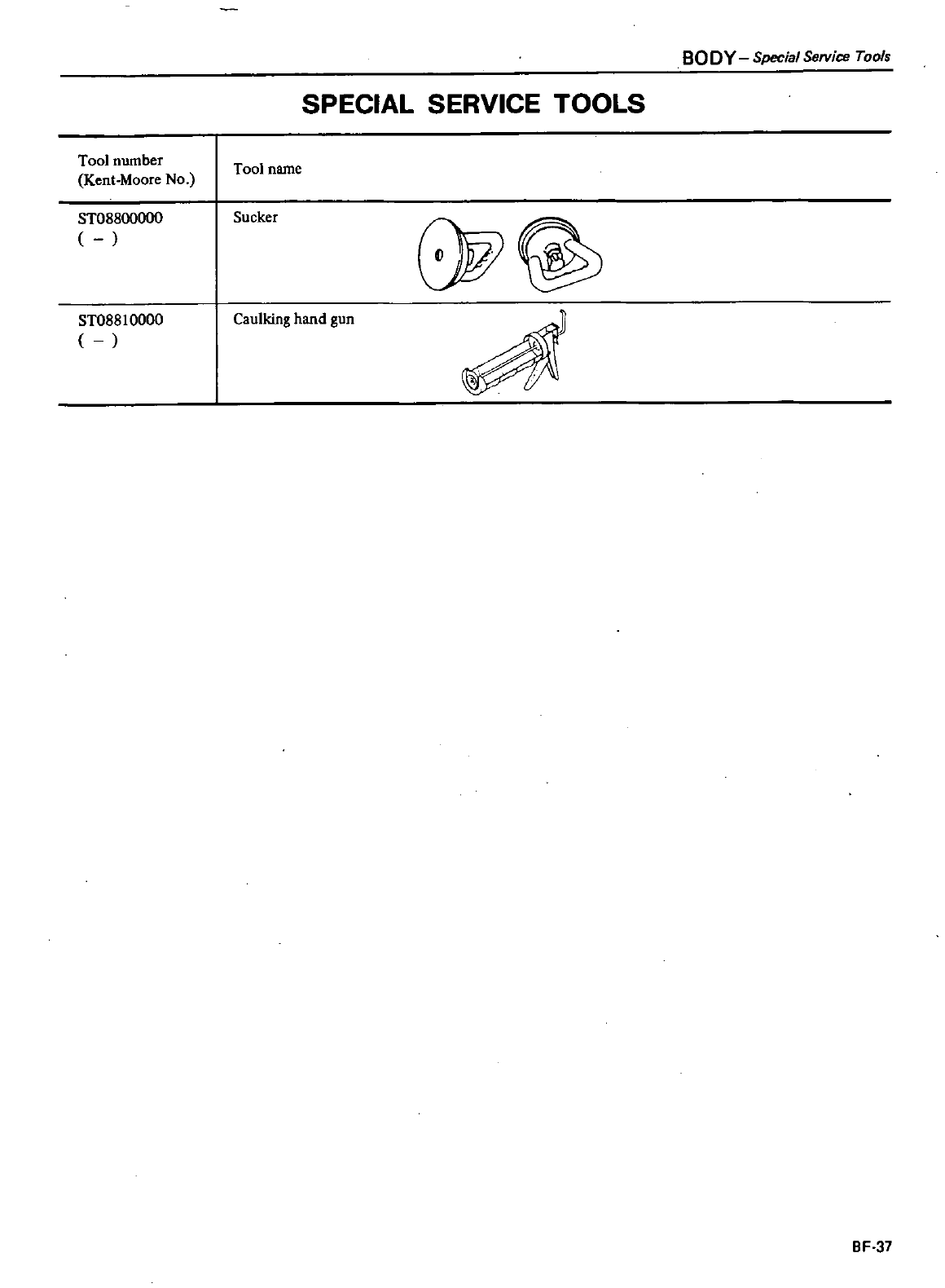
Tool
number
Kent
Moore
No
ST08800000
ST08810000
SPECIAL
SERVICE
TOOLS
Tool
name
Sucker
8W
Caulking
hand
gun
BODY
Special
Service
Tools
BF
37
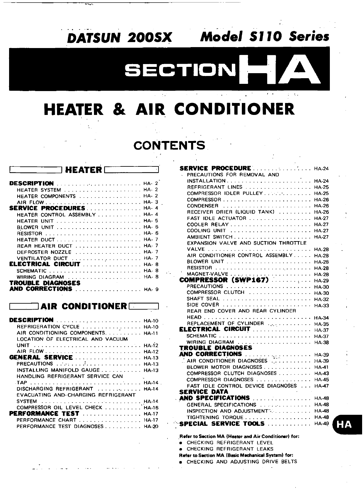
DATSUN
200SX
Model
S
11
0
Series
SECTIONHA
HEATER
AIR
CONDITIONER
CONTENTS
I
HEATER
I
DESCRIPTION
HEATER
SYSTEM
HEATER
COMPONENTS
AIR
FLOW
SERVICE
PROCEDURES
HEATER
CONTROL
ASSEMBLY
HEATER
UNIT
BLOWER
UNIT
RESISTOR
HEATER
DUCT
REAR
HEATER
DUCT
DEFROSTER
NOZZLE
VENTI
LA
TOR
DUCT
ELECTRICAL
CIRCUIT
SCHEMATIC
WIRING
DIAGRAM
TROUBLE
DIAGNOSES
AND
CORRECTIONS
I
AIR
CONDITIONER
I
DESCRIPTION
REFRIGERATION
CYCLE
AIR
CONDITIONING
COMPONENTS
LOCATION
OF
ELECTRICAL
AND
VACUUM
UNIT
AIR
FLOW
GENERAL
SERVICE
PRECAUTIONS
INSTALLING
MANIFOLD
GAUGE
HANDLING
REFRIGERANT
SERVICE
CAN
TAP
DISCHARGING
REFRIGERANT
EVACUATING
AND
CHARGING REFRIGERANT
SYSTEM
COMPRESSOR
OIL
LEVEL
CHECK
PERFORMANCE
TEST
PERFORMANCE
CHART
PERFORMANCE
TEST
DIAGNOSES
HA
2
HA
2
HA
2
HA
3
HA
4
HA
4
HA
5
HA
6
HA
6
HA
7
HA
7
HA
7
HA
7
HA
B
HA
8
HA
8
HA
9
HA
l0
HA
l0
HA
ll
HA
12
HA
12
HA
13
HA
13
HA
13
HA
14
HA
14
HA
14
HA
16
HA
17
HA
17
HA
20
SERVICE
PROCEDURE
PRECAUTIONS
FOR
REMOVAL
AND
INSTALLATION
REFRIGERANT
LINES
COMPRESSOR
IDLER
PULLEY
COMPRESSOR
CONDENSER
RECEIVER DRIER
ILlOUID
TANK
FAST
IDLE
ACTUATOR
COOLER
RELAY
COOLING
UNIT
AMBIENT
SWITCH
EXPANSION
VALVE
AND
SUCTION
THROTTLE
VALVE
AIR
CONDITIONER
CONTROL
ASSEMBLY
BLOWER
UNIT
RESISTOR
MAGNET
VALVE
COMPRESSOR
SWP167
PRECAUTIONS
COMPRESSOR
CLUTCH
SHAFT
SEAL
SIDE
COVER
REAR
END
COVER
AND
REAR
CYLINDER
HEAD
REPLACEMENT
OF
CYLINDER
ELECTRICAL
CIRCUIT
SCHEMATIC
WIRING
DIAGRAM
TROUBLE
DIAGNOSES
AND
CORRECTIONS
AIR
CONDITIONER
DIAGNOSES
BLOWER
MOTOR DIAGNOSES
COMPRESSOR
CLUTCH
DIAGNOSES
COMPRESSOR
DIAGNOSES
FAST
IDLE
CONTROL
DEVICE
DIAGNOSES
SERVICE
DATA
AND
SPECIFICATIONS
GENERAL
SPECIFICATIONS
INSPECTION
ANO
ADJUSTMENT
TIGHTENING
TOROUE
SPECIAL
SERVICE
TOOLS
Ref
to
Section
MA
Heater
and
Air
Conditioner
for
CHECKING
REFRIGERANT
LEVEL
CHECKING
REFRIGERANT
LEAKS
Reflr
to
Section
MA
Basic
MechaniClI
Systam
for
CHECKING
AND
ADJUSTING
DRIVE
BELTS
HA
24
HA
24
HA
25
HA
25
HA
26
HA
26
HA
26
HA
27
HA
27
HA
27
HA
27
HA
28
HA
28
HA
28
HA
28
HA
2B
HA
29
HA
30
HA
30
HA
32
HA
33
HA
34
HA
35
HA
37
HA
37
HA
38
HA
39
HA
39
HA
4l
HA
43
HA
45
HA
47
HA
48
HA
48
HA
48
HA
48
HA
4
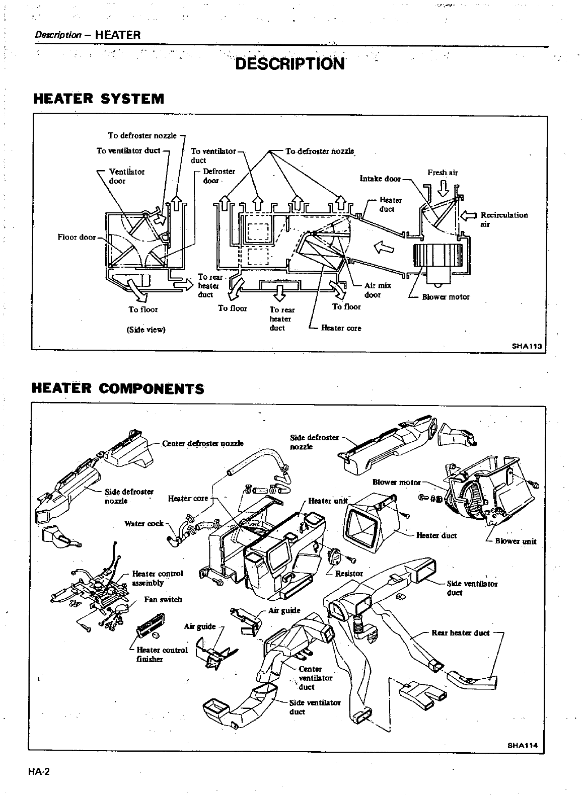
r
Desr
ription
HEATER
DESCRIPTION
HEATER
SYSTEM
To
defroster
nozzle
To
ventilator
duct
To
Yentilator
duct
Floor
door
To
floor
Fresh
air
c
o
t
Intakedoor
Jr
5L
lLJU
J
e
J
I
eciJculatiOD
L
UlT
nn
J
au
J
j
i
1I11
hJ
L
1b
To
ear
L
Air
mix
r
S
er
I
door
Blower
motor
To
floor
To
floor
To
rear
heater
duct
Heater
core
Side
view
SHA113
HEATIE
R
COMPONENTS
Side
defroster
QDterddroster
oo
Side
defrolter
Heater
core
f
IIJrffi5
noule
Heater
control
assembly
II
oClfj
Blower
motor
Water
coet
Heater
duct
0
fr
itch
Air
uide
AirSUide
C
eonaol
tiniaher
Side
ventilatnr
duct
J
SHA114
HA
2
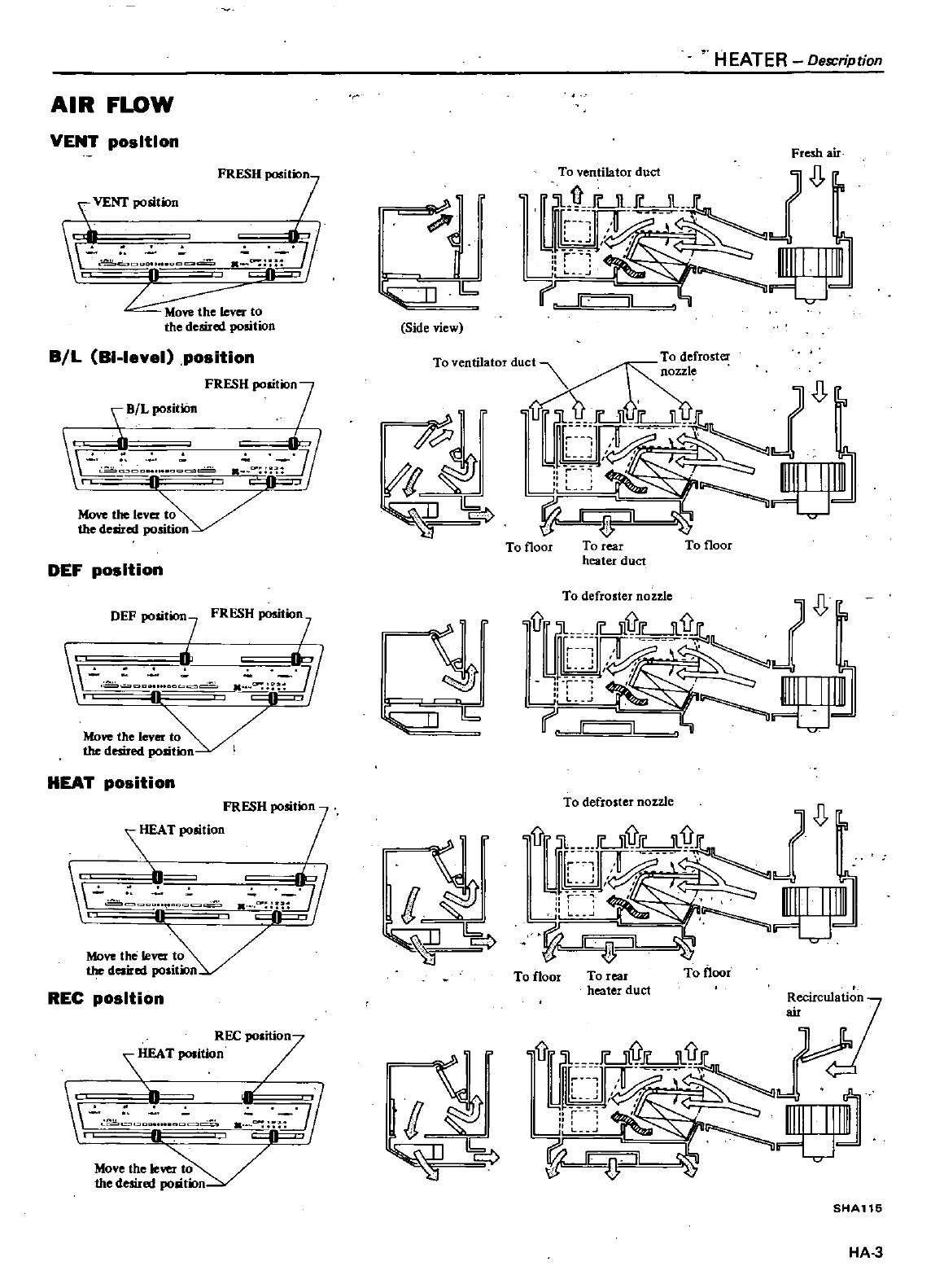
AIR
FLOW
VENT
position
FRESH
positio7n
VE
po
t
n
r
o
o
tjJ
if5
to
the
desired
position
BIL
BI
Ievel
position
br
o
ll
r
r
L
Move
the
lever
the
desired
pos
O
DEF
position
DEF
POsition
FRESH
positixJD1
3
1ky
o
E
Move
thelever
the
desired
position
HEAT
position
FRESH
POsit
7
HEAT
POsitioo
J
tb1
o
II
4
Move
the
lever
daired
POI
V
REC
position
REC7
ition
TpoIition
r
o
o
J
0
Move
the
Ie
the
desired
Ji
io
Y
I
li
C
Side
view
HEATER
Description
Fresh
air
1
j
1
l
H
111111111111
rlrl
1I
Il
Jc
TOVentil
torduc
roster
17
1
l
jfd
o
l
i
ij
L
To
floor
To
rear
To
floor
heater
duct
l
r
To
defroster
nozzle
L
To
floor
To
rear
To
floor
heater
duct
Recirculation
Tfrl
oo
jJ
Il
tjfT
J
LTCi
t
lllllll
I
J
r
If
sL
SHA116
HA
J
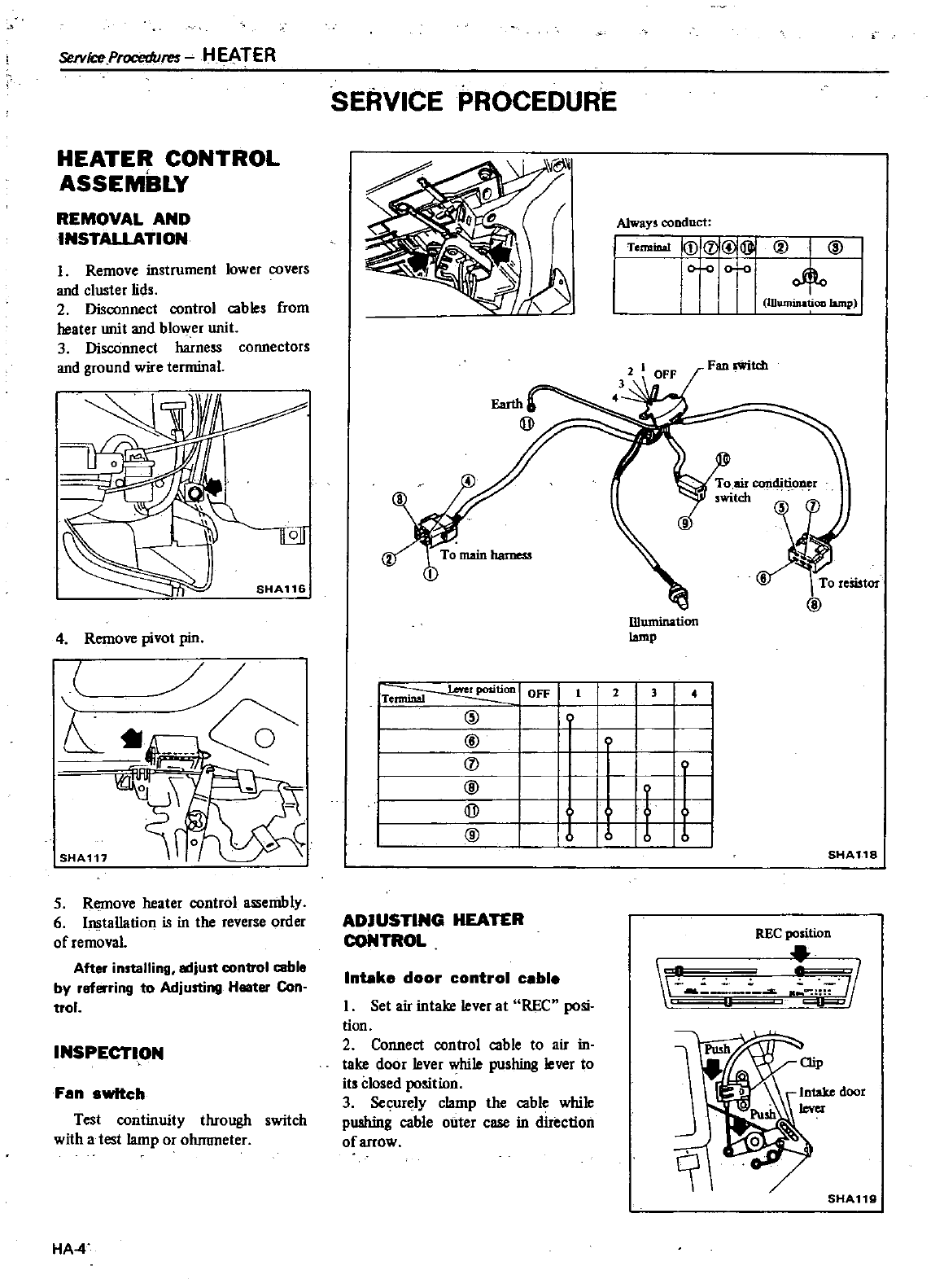
SHA116
@
IDumination
4
Remove
pivot
pin
lamp
I
OFF
II
2
3
I
Terminal
L
I
@
I
I
@
I I
I I
0
I
I
@
I
i1
I
QD
I
I
@
Iv
16
I
ServkeProcedut
f
HEATER
HEATER CONTROL
ASSEMBLY
REMOVAL
AND
INSTAUATION
I
Remove
instrument
lower
covers
and
cluster
lids
2
Disconnect
control
cab
les
from
heater
unit
and
blower
unit
3
DiscOnnect
harness
connectors
and
ground
wire
terminal
SHA117
5
Remove
heater
control
assembly
6 Installation
is
in
the
reverse
order
of
removal
Alter
installing
adjust
control
cable
by
ref
ring
to
Adjusting
Heater
Con
trol
INSPECTION
Fan
switch
Test
continuity
through
switch
with
a
test
lamp
or
ohnuneter
HA
4
SERVICE
PROCEDURE
Always
conduct
I
Tenn
I
DIQ
@
I
r
Wuntinatioo
lamp
SHA118
ADJUSnNG
HEATER
CONTROL
REC
position
I
Inbke
door
control
cable
I
Set
air
intake
lever
at
REC
posi
tion
2
Connect
control
cable
to
air
in
take
door
lever
while
pushing
lever
to
its
Closed
position
3
Securely
clamp
the
cable
while
pushing
cable
outer
case
in
direction
of
arrow
SHA119
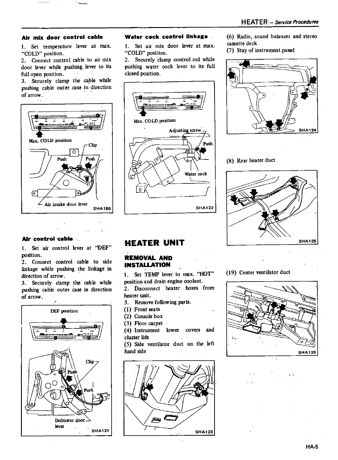
Air
mix
door
control
cable
I
Set
temperature
lever
at
max
COLD
position
2
Connect
control
cable
to
air
mix
door
lever
while
pushing
lever
to
its
full
open
position
3
Securely
clamp
the
ca
ble
while
pushing
cable
outer
case
in
direction
of
arrow
M
M
Max
COLD
position
l
SHA18Q
A1rcontrol
ceble
I
Set
air
control
lever
at
DEF
position
2
Connect
control
cable
to
side
linkage
while
pushing
the
linkage
in
direction
of
arrow
3
Securely
clamp
the
cable
while
pushing
cable
outer
case
in
direction
of
arrow
DEF
position
I
I
SHA121
Water
cock
control
linkage
I
Set
air mix
door
lever
at
max
COW
position
2
Securely
clamp
control
rod
while
pushing
water
cock
lever
to
its
full
closed
position
1
c
c
I4f
a
Max
COLD
position
Adjusting
saew
r
SHA122
HEATER
UNIT
REMOVAL
AND
INSTALLATION
I
Set
TEMP
lever
to
max
HOT
position
and
drain
engine
coolant
2
Disconnect heater
hoses
from
heater
unit
3
Remove
foUowing
Wis
I
Front
seats
2
Console
box
3
Floor
carpet
4
Instrument
lower
covers
and
cluster
lids
5
Side
ventilator
duct
on
the left
hand
side
SHA123
H
EATER
Service
Procedures
6
Radio
sound
balancer
and
stereo
cassette
deck
7
Stay
of
instrument
panel
I
8
Rear
heater
duct
SHA
125
19
Center
ventilator
duct
I
1
SHA126
HA
5
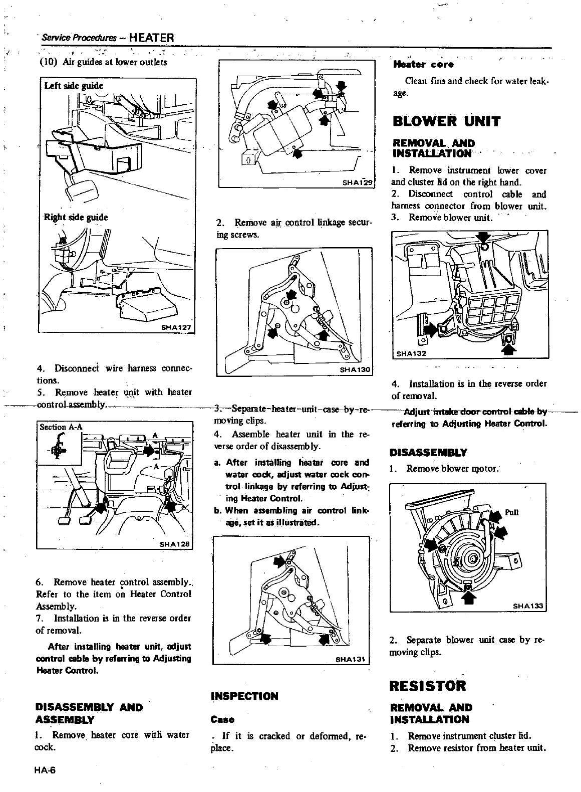
Service
Procedures
HEATER
10
Air
guides
at
lower
outlets
Right
side
guide
1
SHA127
4
Disoonnect
wire
harness
connec
tions
5
Remove
heater
1
J1it
with
heater
lntrohssembly
SHA128
6
Remove
heater
control
assembly
Refer
to
the
item
o
Heater
Control
Assembly
7Installation
is
in
the
reverse
order
of
removal
After
installing
heater
unit
lKljust
control
coble by
referring
to
Adjusting
Heater
Control
DISASSEMBLY
AND
ASSEMBLY
I
Remove
heater
core
witli
water
cock
HA
6
r
SHA1
29
2
Remove
air
control
linkage
secur
ing
screws
SHA130
5eparate
heater
unit
case
by
re
moving
clips
4
Assemble
heater
unit
in
the
reo
verse
order
of
disassembly
a
After
installing
heater
core
and
water
cock
lKljust
water
cock
co
trol
linkage
by
referring
to
Adjust
ing
Heater
Control
b
When
assembling
air
control
link
age
set
it
as
illustrated
SHA131
INSPECTION
Ce
e
If
it
is
cracked
or
deformed
re
place
r
Il
core
Clean
fms and
check
for
water
leak
age
BLOWER
UNIT
REMOVAL
AND
INSTAlLATION
I
Remove
instrument lower
oover
and
cluster
lid
on
tIie
right hand
2
Disconnect
control
cable
and
harness
connector
from blower
unit
3
Remove
blower
unit
I
SHA132
4
Installation
is
in
the
reverse
order
of
removal
Adju
1
r
corrtrolcablebi
referring
to
Adjusting
Heater
Control
DISASSEMBLY
I
Remove
blower
D
otor
2
Separate
blower
unit
case
by
reo
moving
clips
RESISTOR
REMOVAL
AND
INSTALLAnON
I
Remove
instrument
cluster
lid
2
Remove
resistor
from
heater
unit
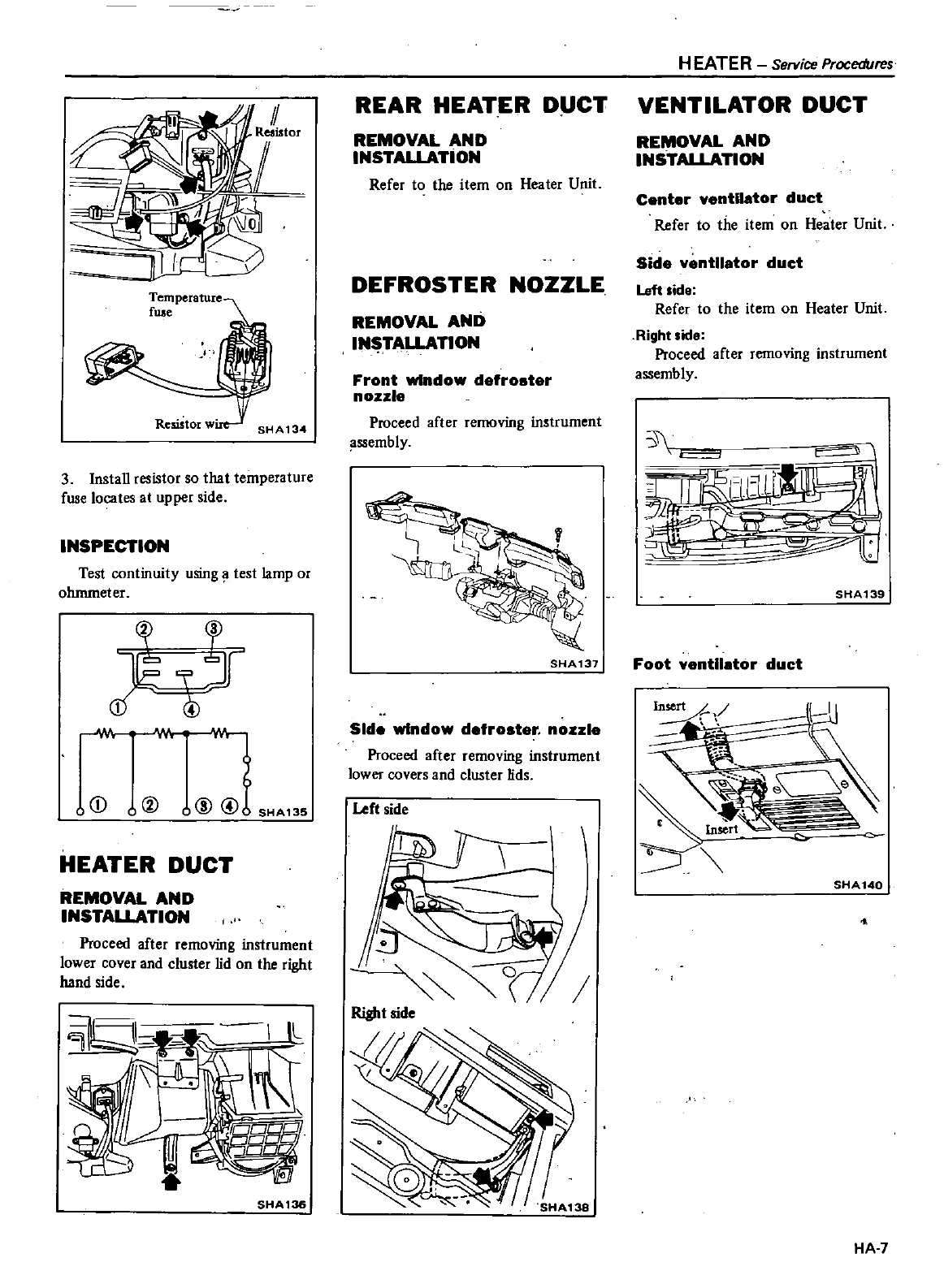
Temperature
fuse
Resistorw
SHA134
3
Install
resistor
so
that
temperature
fuse
locates
at
upper
side
INSPECTION
Test
continuity
using
test
lamp
or
ohmmeter
J
I
T
jf
@
o@
uCD
HEATER
DUCT
REMOVAL
AND
INSTALLATION
Proceed
after
removing
instrument
lower
cover
and
cluster
lid
on
the
right
hand
side
SHA136
REAR
HEATER
D
CT
REMOVAL
AND
INSTALLATION
Refer
to
the
item
on
Heater
Unit
DEFROSTER
NOZZLE
REMOVAL
AND
IN
TALLATION
Front
window
defroster
nozzle
Proceed
after
reJlK
ving
instrument
assembly
SHA137
Side
window
defroster
nozzle
Proceed
after
removing
instrument
lower
covers
and
cluster
lids
Left
side
Right
side
HEATER
Service
Procedures
VENTILATOR
DUCT
REMOVAL
AND
INSTALLATION
Center
ventilator
duct
Refer
to
the
item
on
Heater
Unit
Side
ventilator
duct
Left
ide
Refer
to
the
item
on
Heater
Unit
RighUide
Proceed
after
removing
instrument
assembly
3
F
J
c
SHA139
Foot
ventilator
duct
I
SHA 140
HA 7
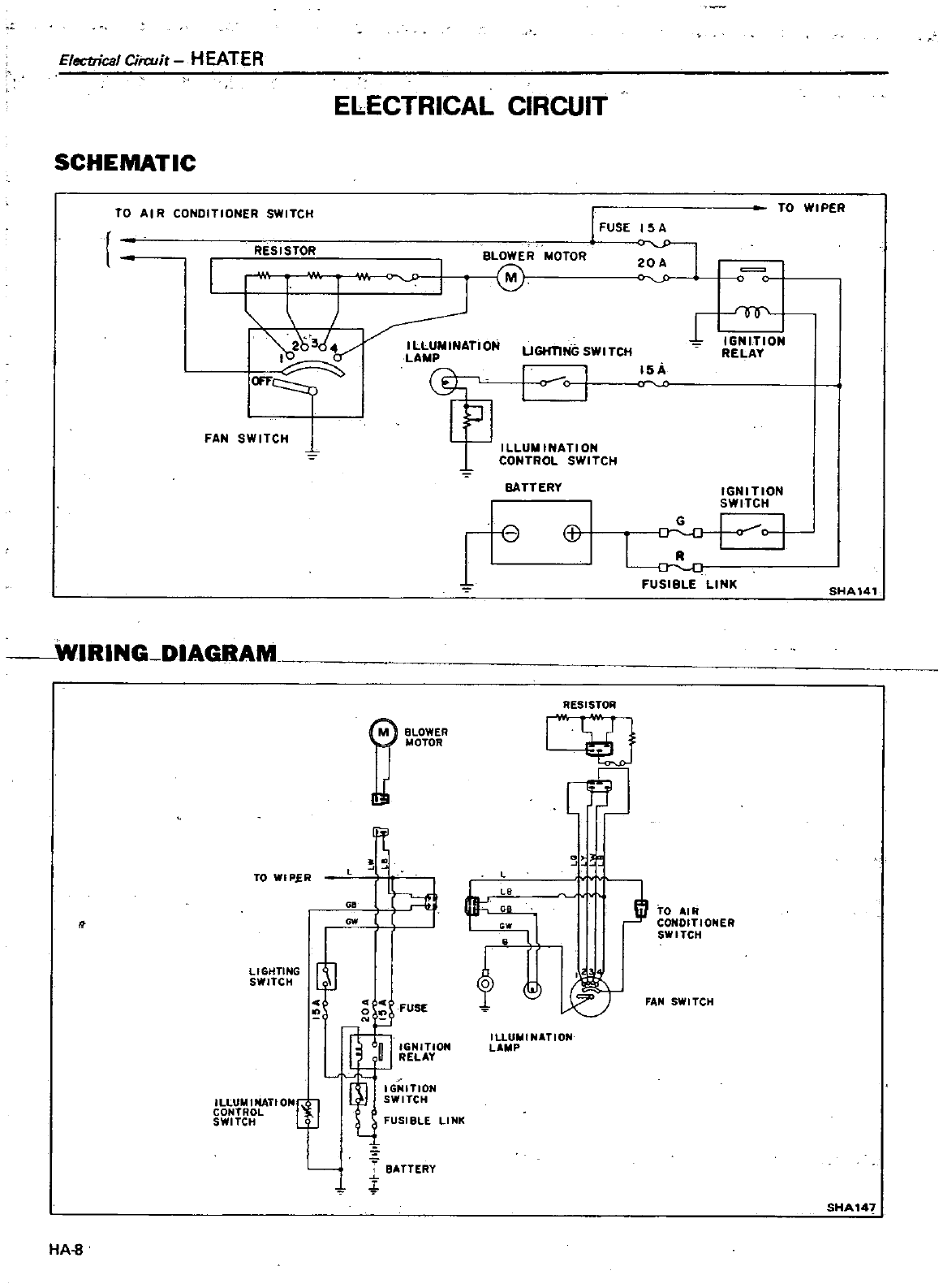
Electrical
Cirwir
HEATER
ELECTRICAL
CIRCUIT
SCHEMATIC
RESISTOR
I
FUSE
ISA
MOToR
u
O
c
TO
WIPER
TO
AI
R
CONOlTlONER
SWITCH
BLOWER
I
1M
Jl
n
u
LAM
FAN
SWITCH
L
1
I
W
r
IGNITION
RELAY
I
c
J
15
1
r
ILLUMINATION
CONTROL
SWITCH
BATTERY
IGNITION
SWITCH
B
Q
I
FUSIBLE
LINK
SHA141
WIRING
DIAGRAM
BLOWER
j
MOTOR
RESISTOR
4J
LHJ
TO
WI
P
fR
G
ow
LIGHTING
SWITCH
3
J
JI
TO
AIR
CONDITIONER
SWITCH
00
4 e
FUSE
2
It
f
j
FAN
SWt
reH
ILlUMlNATIONC
J
CONTROL
SWI
reH
t
l
GN
T
ON
RELAY
1
IG
IITION
SWITCH
IUUIIIINATION
L
P
FUSIBLE
LINK
i
f
BATTERY
SHA14
HA
S
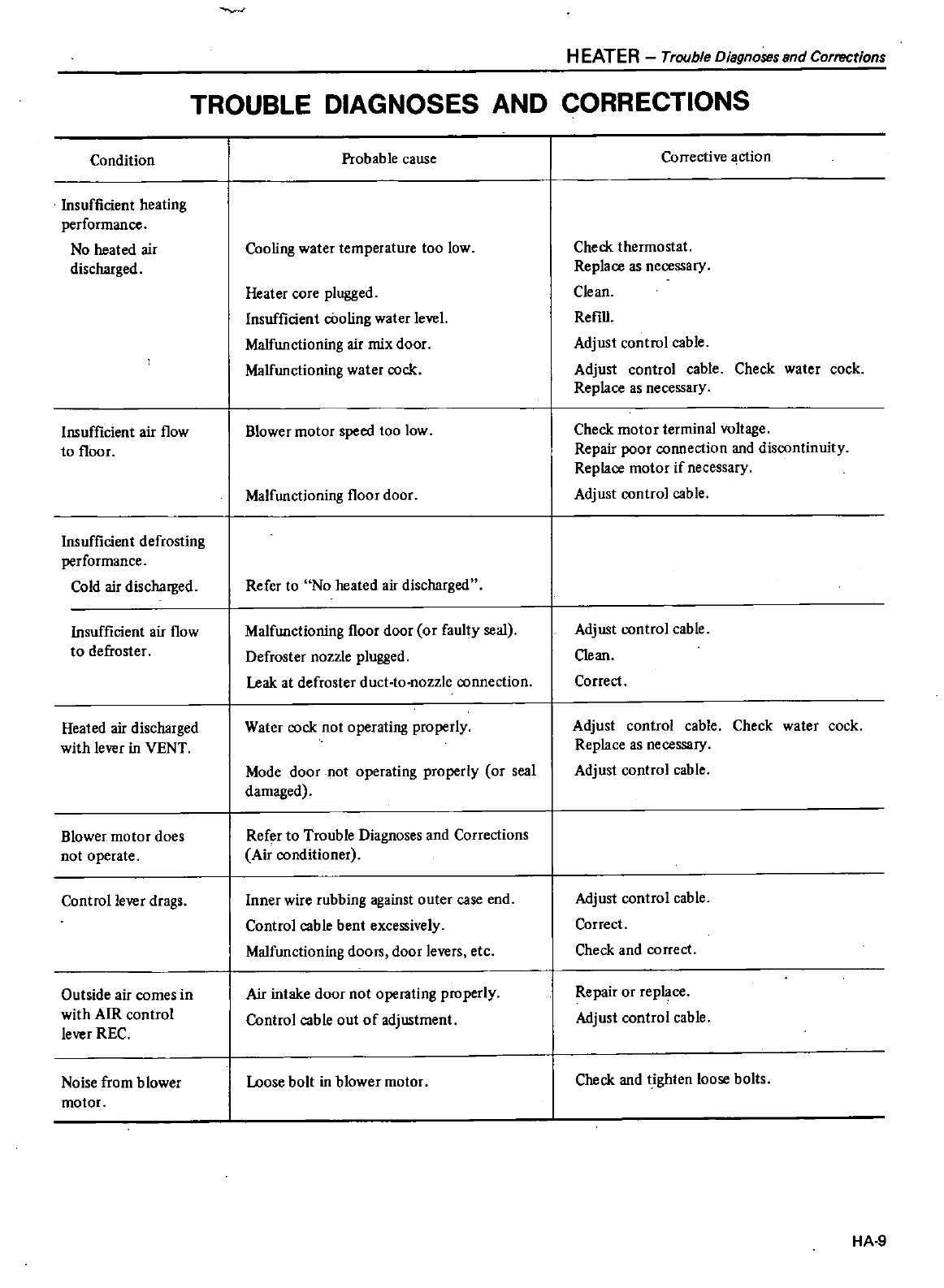
HEATER
Trouble
Diagnoses
and
Corrections
TROUBLE DIAGNOSES
AND
CORRECTIONS
Condition
Insufficient
heating
performance
No
heated
air
discharged
Insufficient
air
flow
to
floor
Insufficient
defrosting
performance
Cold
air
discharged
Insufficient
air
flow
to
defroster
Heated
air
discharged
with
lever
in
VENT
Blower
motor
does
not
operate
Control
lever
drags
Outside
air
comes
in
with
AIR
control
lever
REC
Noise
from blower
motor
Probab
Ie
cause
Cooling
water
temperature
too
low
Heater
core
plugged
Insufficient
cOoling
water
level
Malfunctioning
air
mix
door
Malfunctioning
water
cock
Blower
motor
speed
too
low
Malfunctioning
floor
door
Refer
to
No
heated
air
discharged
Malfunctioning
floor
door
or
faulty
seal
Defroster
nozzle
plugged
Leak at
defroster
duct
to
nozzle
connection
Water
cock
not
operating
properly
Mode
door
not
operating
properly
or
seal
damaged
Refer
to
Trouble
Diagnoses
and
Corrections
Air
conditioner
Inner
wire
rubbing
against
outer
case
end
Control
cable
bent
excessively
Malfunctioning
doorn
door
levers
etc
Air
intake
door not
operating
properly
Control
cable
out
of
adjustment
Loose
bolt
in
blower
motor
Corrective
ction
Check
thermostat
Replace
as
necessary
Clean
Refill
Adjust
control
cable
Adjust
control
cable
Check
water
cock
Replace
as
necessary
Check
motor
terminal
voltage
Repair
poor
connection
and
discontinuity
Replace
motor
if
necessary
Adjust
control
cable
Adjust
control
cable
Clean
Correct
Adjust
control
cable
Check
water
cock
Replace
as
necessary
Adjust
control
cable
Adjust
control
cable
Correct
Check
and
correct
Repair
or
rep
ce
Adjust
control
cable
Check
and
tighten
loose
bolts
HA
9
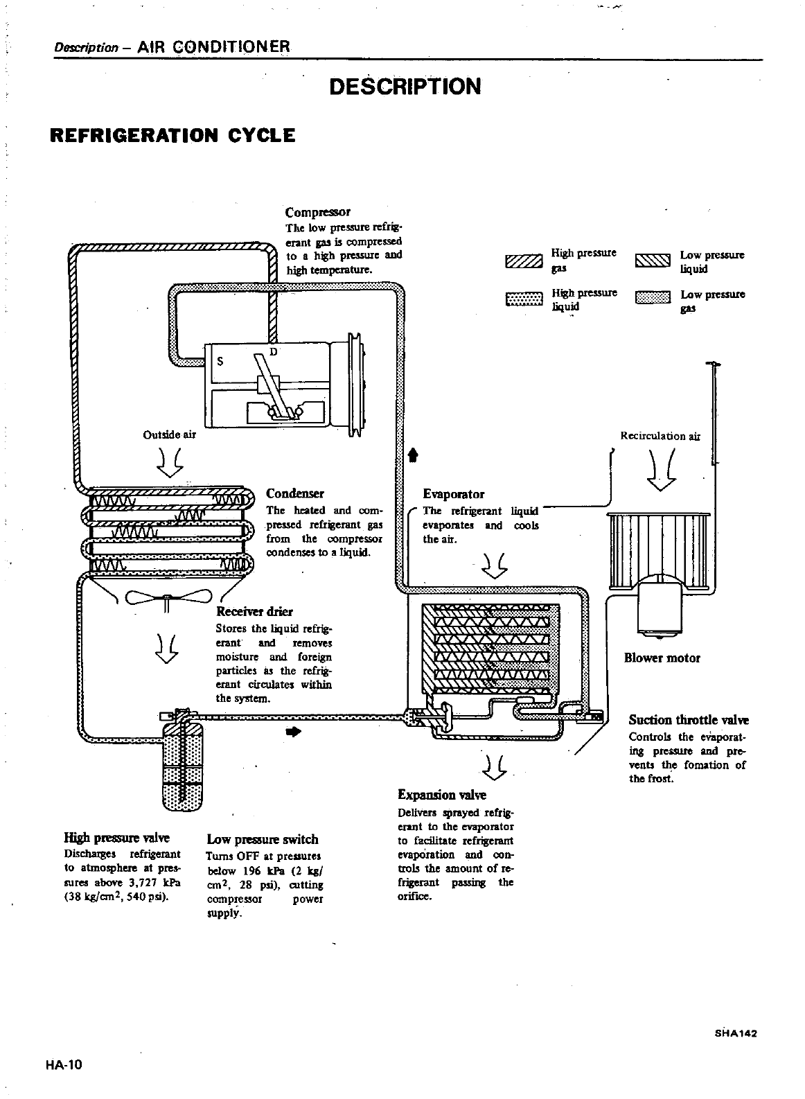
Description
AIR
CONDITIONER
DESCRIPTION
REFRIGERATION
CYCLE
Compressor
The
low
pressure
refrig
erant
is
compressed
to
a
hh
pJe
SU1
C
and
high
Jle
i
N
V
Is
I
l
Outside
air
u
lPIl
I
v
xyyv
I
R
drier
JJ
r
l
Condenser
The
heated
and
com
pressed
refrigerant
gas
from
the compressor
condenses
to
a
liquid
Stores
the liquid
refrig
erant
and
removes
moisture
and
foreign
particles
as
the
refrig
erant
circulates
within
the
system
i
High
pressure valve
Discluuges
refrigerant
to
atmosphere
at
pres
lfes
above
3
727
IcPa
38
kgfem2
540
psi
Low
pmmue
switch
Tums
OFF
at
pressures
below
196
IcPa
2
81
em
2
28
psi
cutting
compressOI
power
supply
HA
l0
w
w
q
v
i
t
e
w
fL
w
tmfJ
High
pressure
gas
t
l
High
presswe
liquid
Evaporator
The
refrigerant
evaporates
and
the
air
liquid
cools
o
Expansion
valve
DeliVers
sprayed
refrig
erant
to
the
eVaporator
to
facilitate
refrigerant
h
hl
and
con
trols
the
amount
of
re
frigerant
possing
the
orifke
Low
pressure
liquid
1
01
Low
pre
sure
gas
Recirculation
air
V
I
J
b
Blower
motor
Controls
the
enporat
ins
pressure
and
pi
vents
e
fomation
of
the
frost
SHA
142
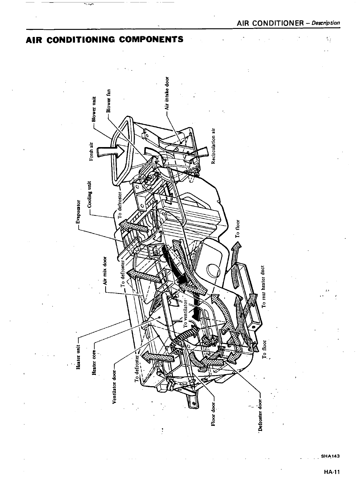
AIR
CON
DITION
ER
Description
AIR
CONDITIONING
COMPONENTS
a
o
I
1I
5
l
s
a
o
5
2
e
l
L
e
8
jj
u
8
SH 143
HA
ll
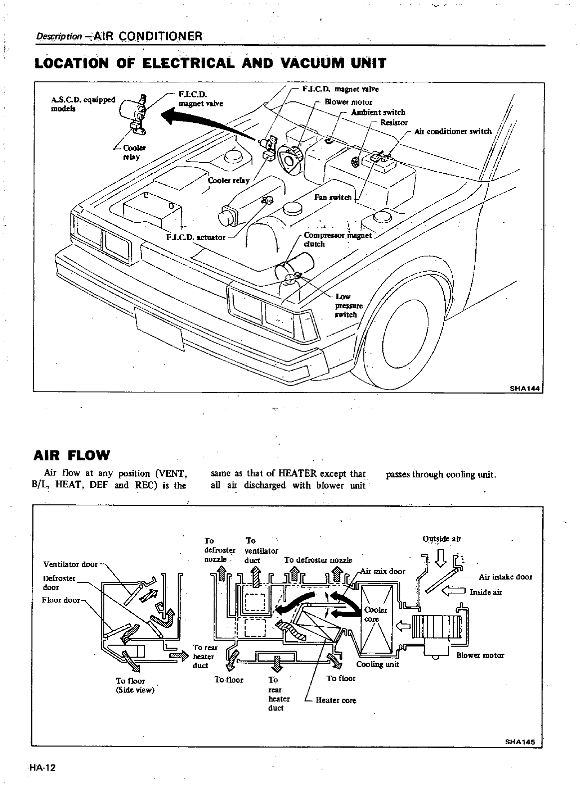
Desr
ription
AIR
CONDITIONER
LOCATION
OF
ELECTRICAL
AND VAcuuM
UNIT
L
SHA1
AIR
FLOW
Air
flow
at
any
position
VENT
B
L
HEAT
DEF
and
REC
is
the
same
as
that
of
HEATER
except
that
passes
through
cooling
unit
aU
air
discharged
with
blower
unit
To
To
O ide
air
defroster
ventilator
n
Ventilator
door
nozzlll
duct
To
delio
tor
now
1
1
r
1t
t
i
7u
1Mi
T
lJ
7
iIllJlL
1
i
ll
Qjr
lr
mower
motor
To
floor
To
f1oor
To
To
floor
Side
view
rear
heater
Heater
core
duct
SMA146
J
HA
12
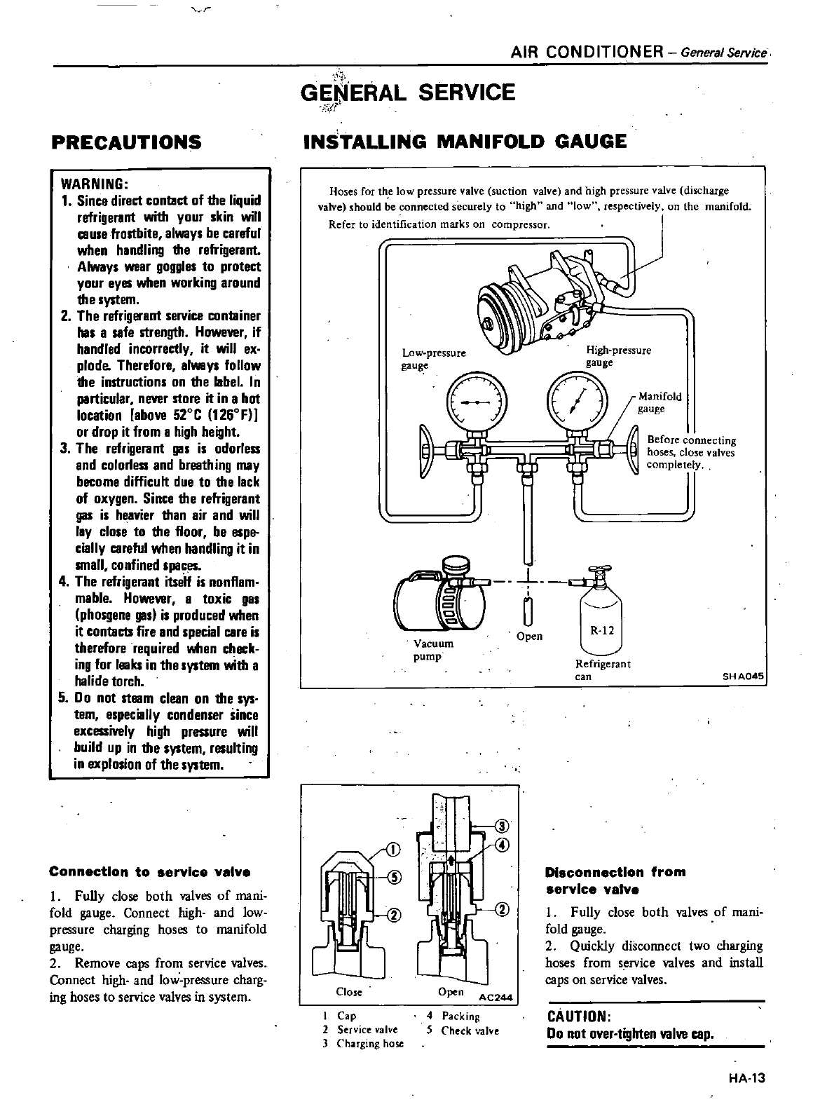
J
PRECAUTIONS
WARNING
1
Since
direct
conlllct
of the
liquid
refrigerant
with
your
skin
will
muse
frostbite
always
be
careful
when
handling
the
refrigerant
Always
wear
goggles
to
protect
your
eyes
when
working
around
the
system
2
The
refrigerant
service
conllliner
has
a
safe
strength
However
if
handled
incorrectly
it
will
ex
plode
Therefore
always
follow
the
instructions
on
the
label
In
particular
never
store
it
in
a
hot
location
above
S20C
1260F
or
drop
it
from
a
high
height
3
The
refrigerant gas is
odorless
and
colorless
and
breath
ing
may
become
difficult
due
to
the
lack
of
oxygen
Since
the
refrigerant
gas is
heavier
than
air
and
will
lay
close
to
the
floor
be
espe
cially
careful
when
handling
it
in
small
confined
spaces
4
The
refrigerant
itseit
is
nonflam
mable
However
a
toxic
gas
phosgene
gas is
produced
when
it
conlllCb
fire
and
special
care
is
therefore
required
when
check
ing
for
leaks
in
the
system
with
a
halide
torch
5
Do
not
steam
clean
on
the
sys
tem
especially
condenser
since
excessively
high
pressure
will
build
up
in
the
system
resulting
in
explosion
of
the
system
Connection
to
service
v
lve
I
Funy
close
both
valves
of
mani
fold
gauge
Connect
high
and
low
pressure
charging
hoses
to
manifold
gauge
2
Remove
caps
from
service
valves
Connect
high
and
low
pressure
charg
ing
hoses
to
service
valves
in
system
i
i
GENERAL
SERVICE
r
AIR
CONDITIONER
General
Service
INSTALLING
MANIFOLD
GAUGE
Hoses
for
the
low
pressure
valve
suction
valve
and
high
pressure
valve
discharge
valve
should
be
connected
securely
to
high
and
low
respectively
on
the
manifold
Refer
to
identification
marks
on
compressor
Low
pressure
gauge
High
pressure
gauge
Manifold
gauge
Before
connecting
hoses
close
valves
completely
Q
1fT
o
en
R
12
Vacuum
pump
r
S
Close
ICap
2
Service
valve
3
Cha
rging
hose
4
Packing
5
Check
valve
Refrigerant
can
SH
A045
Disconnection
from
service
valve
I
Fully
close
both
valves
of
mani
fold
gauge
2
Quickly
disconnect
two
charging
hoses
from
service
valves
and
install
caps
on
service
valves
CAUTIDN
Do
not
over
tighten
valve
cap
HA
13
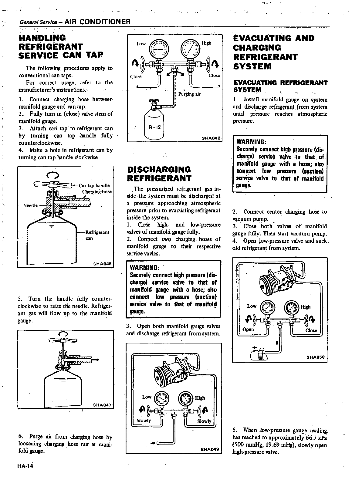
General
Service
AIR
CONDITION
ER
HANDLING
REFRIGERANT
SERVICE
CAN
TAP
The
foUowing
procedures
apply
to
conventional
can
taps
For
correct
usage
refer
to
the
manufacturer
s
instructions
I
Connect
charging
hose
between
manifold
gauge
and
can
tap
2
FuUy
turn
in
close
valve
stem
of
manifold
gauge
3
Attach
can
tap
to
refrigerant
can
by
turning
can
tap
handle
fuUy
counterclockwise
4
Make
a
hole
in
refrigerant
can
by
turning
can
tap
handle
clockwise
n
Needle
Car
tap
handle
Refrigerant
an
r
SHA046
5
TUrn
the
handle
fully
counter
clockwise
to
raise
the
needle
Refriger
ant
gas
will
flow
up
to
the
manifold
gauge
n
SHA041
6
Purge
air
from
charging
hose
by
loosening
charging
hose
nut
at
mani
fold
gauge
HA 14
I
Purging
air
W
Add
Fl
12
SHA04S
DISCHARGING
REFRIGERANT
The
pressurized
refrigerant
gas
in
side
the
system
must
be
discharged
at
a
pressure
approaching
atmospheric
pressure prior
to
evacuating
refrigerant
inside
the
system
I
Close
high
and
low
pressure
valves
of
manifold
gauge
fuUy
2
Connect
two
charging
hoses
of
manifold
gauge
to
their
respective
service
vavles
WARNING
Securely
connect
high
pressure
dis
charge
service valve
to
that
of
manifold
gauge
with
a
hose
also
cOnnect
low
pressure
suction
service valve
to
that
of
manifol
gauge
3
Open
both
manifold
gauge
valves
and
discharge
refrigerant
from
system
LO
rJ
High
1
Slowly
Slowly
40
SHA949
EVACUATING
AND
CHARGING
REFRIGERANT
SYSTEM
EVACUATING
REFRIGERANT
SYSn
W
I
InstaU
manifold
gauge
on
system
and
discharge
refrigerant
from
system
until
pressure
reaches
atmospheric
pressure
WARNING
Securely
connect
high
pressure
dis
charge
service
valve
to
that
of
manifold
gauge
with
a
hose
also
conn
ect
low
pressure
suction
service valve
to
that
of
manifold
gauge
2
Connect
center
charging
hose
to
vacuum
pump
3
Close
both
valves
of
manifold
gauge
fuUy
Then
start
vacuum
pump
4
Open
low
pressure
v
alve
and
SlIck
old
refrigerant
from
system
p
Open
Oose
40
U0
SHA060
5
When
low
pressure
gauge
reading
has
reached
to
approximately
66
7
kPS
500
mrnHg
19
69
inHg
slowly
open
high
pressure valve
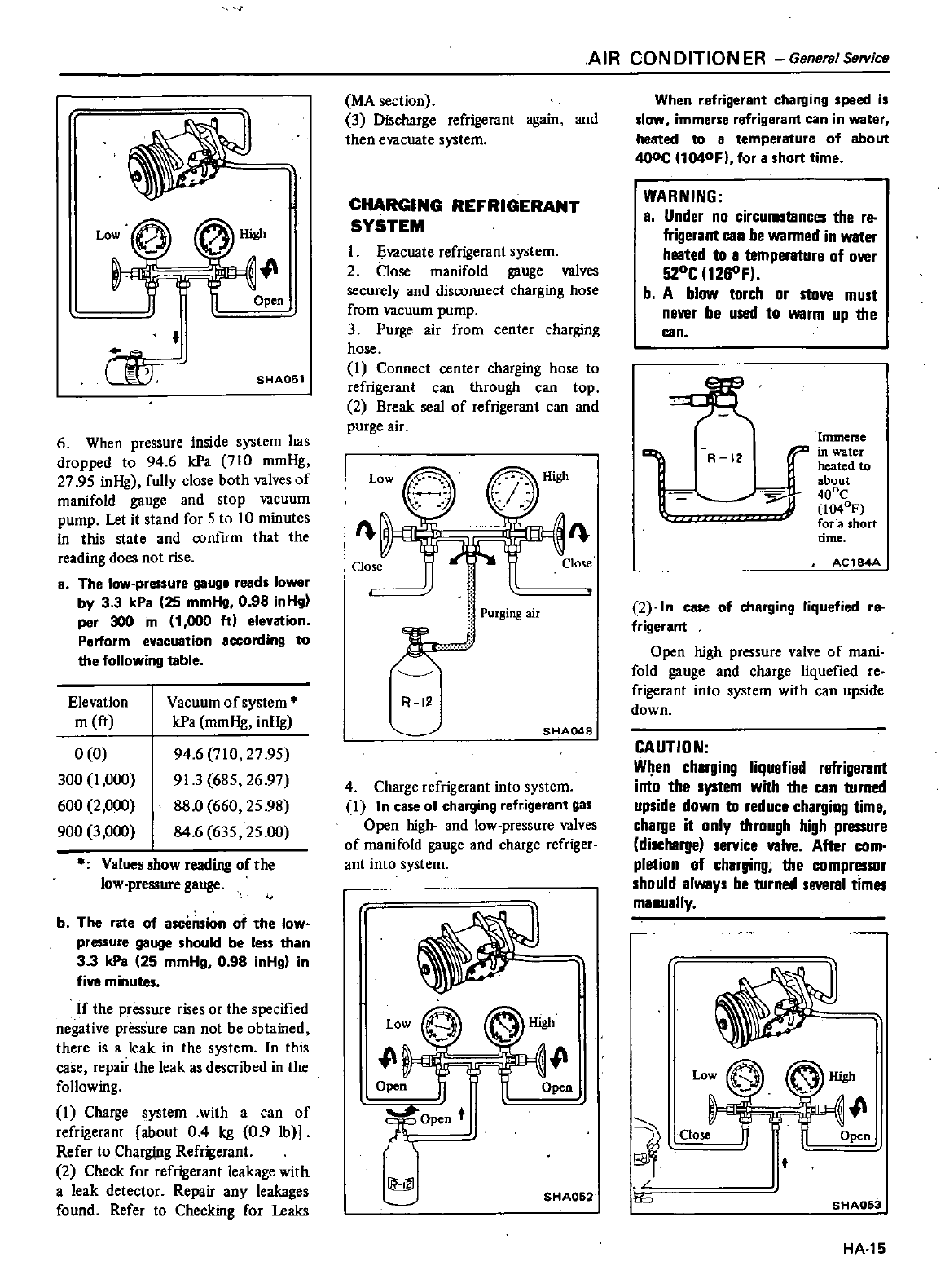
Low
0
lligh
W
lOpen
00
SHA051
6
When
pressure
inside system
has
dropped
to
94
6
kPa
710
mmHg
27
95
inHg
fully
close
both
valves
of
manifold
gauge
and
stop
vacuum
pump
Let
it
stand
for
5
to
10
minutes
in
this
state
and
confIrm
that
the
reading
does
not
rise
B
The
low
pressure
gauge
reads
lower
by
3 3
kPa
25
mmHg
0
98
inHg
per
300
m
1
000
itl
elevation
Perform
evacuation
according
to
the
following
table
Elevation
m
ft
0
0
300
I
000
600
2
000
900
3
000
Vacuum
of
system
kPa
mmHg
inHg
94
6
710
27
95
91
3
685
26
97
88
0
660
25 98
84
6
635
25 00
Valuesshow
reading
ofthe
low
pressure
gauge
b
The
rate
of
ascension
of
the
low
pressure
gauge
should
be
leIS
than
3 3
kPa
25
mmHg
0
98
inHg
in
five
minutes
If
the
pressure
rises
or
the
specified
negative
pressure
ean
not
be
obtained
there
is
a
leak
in
the
system
In this
ease
repair
the
leak
as
described
in
the
following
I
Charge
system
with
a
can
of
refrigerant
about
04
kg
0
9
Ib
Refer
to
Charging
Refrigerant
2
Check
for
refrigerant
leakage
with
a
leak
detector
Repair
any
leakages
found
Refer
to
Checking
for
Leaks
MA
section
3
Discharge
refrigerant
again
and
then
evacuate
system
CHARGING
REFRIGERANT
SYSTEM
I
Evacuate
refrigerant
system
2
Close
manifold
gauge
valves
securely
and
disconnect
charging
hose
from
vacuum
pump
3
Purge
air
from
center
charging
hose
I
Connect
center
charging
hose
to
refrigerant
can
through
can
top
2
Break
seal
of
refrigerant
can
and
purge
air
I
1
Purging
air
k
R
12
SHA048
4
Charge
refrigerant
into
system
I
I
n
case
of
charging
re
igerant
gas
Open
high
and
low
pressure
valves
of
manifold
gauge
and
charge
refriger
ant
into
system
Low
lt lt
o
W
O
n
9ft
Open
t
r
SHA052
AIR
CONDITION
ER
GeneralSefYice
When
refrigerant
charging
peed i
slow
immerse
refrigerant
can
in
water
heated
to
a
temperature
of
about
400c
I1Q4OFl
for
a
short
time
WARNING
a
Under
no
circumstances
the
re
frigerant
can
be
wanned
in
water
heated
to
a
temperature
of
over
520C
1260F
b
A
blow
torch
or
stove
must
never
be
used
to
warm
up
the
can
Immerse
i
zl in
water
heated
to
about
r
400C
1040F
for
a
short
time
A
12
AC184A
2
ln
case
of
charging
liquefied
re
frigerant
Open
high
pressure
valve
of
mani
fold
gauge
and
charge
liquefied
reo
frigerant
into
system
with
can
upside
down
CAUTION
When
charging
liquefied refrigerant
into
the
system
with
the
can
turned
upside
down
to
reduce
charging
tima
charge
it
only
through
high
pressure
discharge
service valve
After
com
pletion
of
charging
the
compressor
should
always
be
turned
several
times
manually
10
Close
Open
t
SHAOS
HA 15
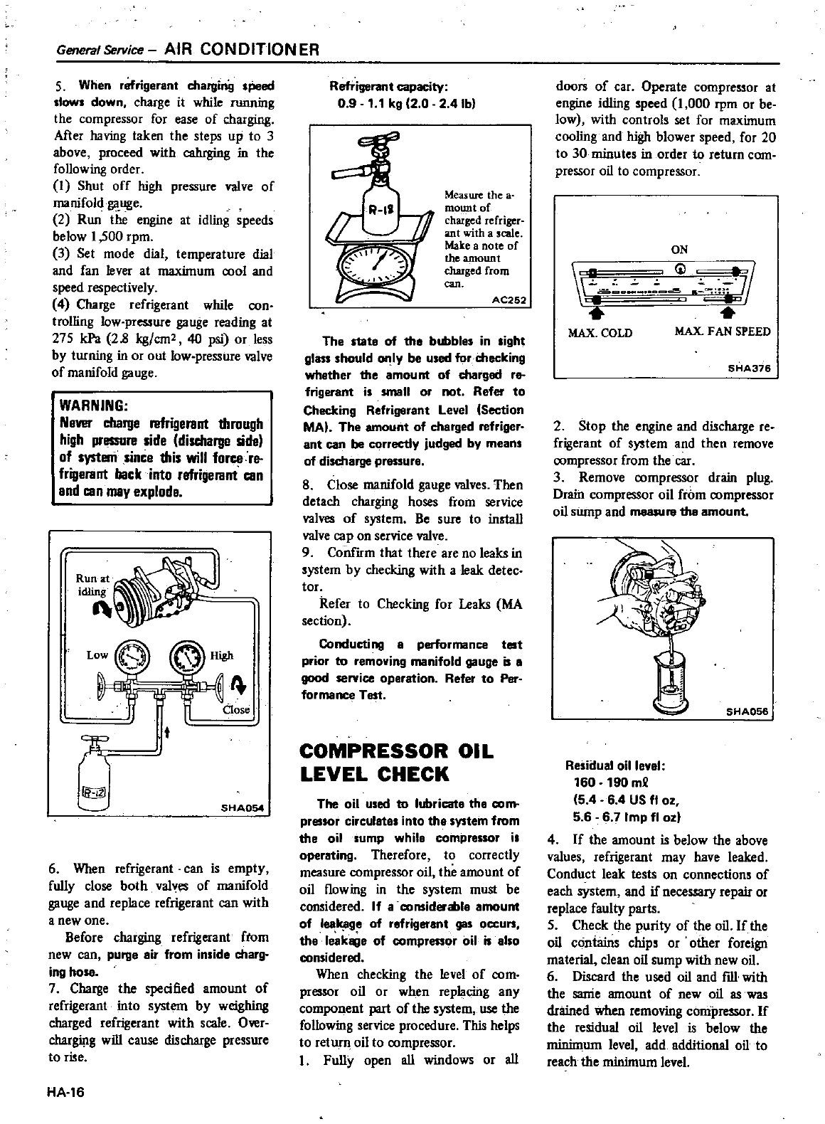
General
SefVice
AIR
CONDITION
ER
5
When
refrigerant
charginiJ
sPeed
slows
down
charge
it
while
running
the
compressor
for
ease
of
charging
After
having
taken
the
steps
up
to
3
above
proceed
with
cahrging
in
the
following
order
I
Shut
off
high
pressure
valve
of
manifold
gauge
2
Run
the
engine
at
idling
speeds
below
1
500
rpm
3
Set
mode
dial
temperature
dial
and
fan
lever
at
maximum
0001
and
speed
respectively
4
Charge
refrigerant
while
oon
trolling
low
pressure
gauge
reading
at
275
kPa
28
kg
em2
40
psi
or
less
by
turning
in
or
out
low
pressure
valve
of
manifold
gauge
WARNING
NgVl
l
wrge
mrigerant
through
high
pressure
side
discharge
side
of
systerri
since
this
will
fon
e
nt
frigerant
back
into
refrigerant
can
and
can
may
explode
Run
at
idling
1
w
aose
T
t
Q
SHA054
6
When
refrigerant
can
is
empty
fully
close
both
valves
of
manifold
gauge
and
replace
refrigerant
can
with
a
new
one
Before
charging
refrigerant
ftom
new
can
purge
air
from
inside
charg
ing
hose
7
Charge
the
specified
amount
of
refrigerant
into
system
by
weighing
charged
refrigerant
with
scale
Owr
chargi
lg
will
cause
discharge
pressure
to
rise
HA
16
Refrigerant
capacity
0 9
1
1
kg
2 0 2
4Ib
Measure
the
a
mount
or
charged
refriger
ant
with
a
scale
Make
a
note
of
the
amount
charged
from
can
AC252
The
state
of
the
bubbles
in
sight
glass
should
only
be
used
for
checking
whgther
the amount
of
charged
r
frigerant
is
small
or
not
Refer
to
Checking
Refrigerant
Level
Section
MAl
The amount
of
charged
refriger
ant
can
be
correctly
judged
by
means
of
discharge
pressure
8
Close
manifold
gauge
valves
Then
detach
charging
hoses
from
service
valves
of
system
Be
sure
to
install
valve
cap
on
service
valve
9
ConIum
that
there
are
no
leaks
in
system
by
checking
with
a
leak
detec
tor
Refer
to
Checking
for
Leaks
MA
section
Conducting
a
performance
test
prior
to
removing
manifold
gauge
is
8
good
service
operation
Refer
to
Per
formance
Test
COMPRESSOR
OIL
LEVEL
CHECK
The
oil
used
to
lubricate
the
com
pressor
circulate
into
the
system
from
the
ail
sump
while
compressor
i
operating
Therefore
to
correctly
measure
compressor
oil
the
amount
of
oil
flowing
in
the
system
must
be
considered
If
a
considerable
amount
of
leakage
of
refrigerant
gas
occurs
tha
leakage
of
compressor
oil
is
also
considered
When
checking
the
level
of
oom
pressor
oil
or
when
replacing
any
w
r
ent
part
ofthe
system
use
the
following
service
procedure
This
helps
to return
oil
to
oompressor
I
Fully
open
all
windows
or
all
doors
of
car
Opernte
compressor
at
engine
idling
speed
1
000
rpm
or
be
low
with
controls
set
for
maximum
cooling
and
high
blower
speed
for
20
to
30
minutes
in
order
to
return
com
pressor
oil
to
compressor
ON
i
1
11
MAX
COLD
MAX
FAN
SPEED
SHA376
2
Stop
the
engine
and
discharge
re
frigerant
of
system
and
then
remove
oompressor
from
the
car
3
Remove
oompressor
drain
plug
Drain
compressor
oil
from
oompressor
oil
siunp
and
measure
the
amount
SHA056
Residual
oille
l
160
190
m
5
4
6
4
US
OZ
5 6 6 7
Imp
fl
ozl
4
If
the
amount
is
below
the
above
values
refrigerant
may
have
leaked
Conduct
leak
tests
on
connections
of
each
system
and
if
necessary
repair
or
replace
faulty
parts
5
Check
the
purity
of
the
oil
If
the
oil
contains
chips
or
other
foreign
material
clean
oil
sump
with
new
oil
6
Discard
the
used
oil
and
fill
with
the
sanie
amount
of
new
oil
as
was
drained
when
removing
compressor
If
the
residual
oil
level
is
below the
minimum
level
add
additional
oil
to
reach
the
minimum level
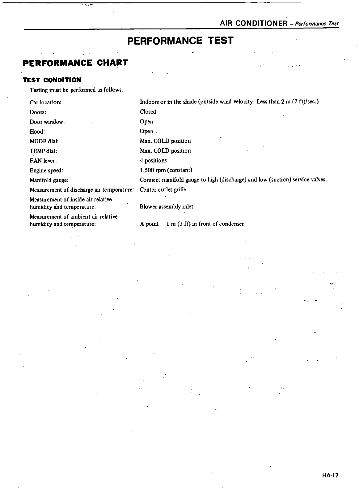
PERFORMANCE
CHART
TEST
CONDITION
Testing
must
be
performed
as
follows
Car
location
Doors
Door
window
Hood
MODE
dial
TEMP
dial
FAN
lever
Engine
speed
Manifold
gauge
Measurement
of
discharge
air
temperature
Measurement
of
inside
air
relative
humidity
and
temperature
Measurement
of
ambient
air
relative
humidity
and
temperature
AIR
CONDITIONER
Performance
Te
t
PERFORMANCE
TEST
Indoors
or
in
the
shade
outside
wind
velocity
Less
than
2
m
7
ft
sec
Closed
Open
Open
Max
COLD
position
Max
COLD
position
4
positions
1
500
rpm
constant
Connect
manifold
gauge
to
high
discharge
and
low
suction
service
valves
Center
outlet
grille
Blower
assembly
inlet
A
point
1
m
3
ft
in
front
of
condenser
0
HA
17
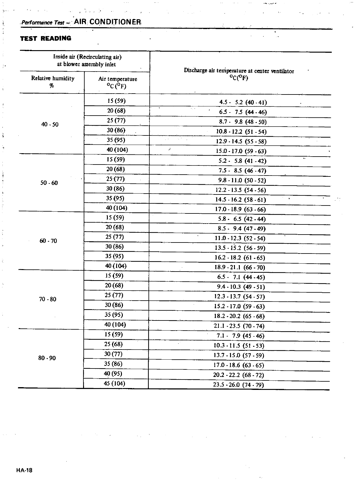
Performance
Test
AIR
CONDITIONER
TEST
READING
Inside
air
Recirculating
air
at
blower
assembly
inlet
Discharge
air
temperature
at
center
ventilator
Relative
humidity
Air
temperature
oC
oF
Oc OF
15
59
4
55
2
40
41
20 68
65
75
44
46
25 77
879 8
48
50
40
50
30 86
10
8
12
2
51
54
35 95
12
9
14
5
55
58
40
104
15
0
17
0
59 63
15
59
5258
41
42
20
68
75 85
46
47
25 77
98
11
0
50 52
50
60
30 86
12
2
13
5
54
56
35
95
14
5
16
2
58
61
40
104
17
0
18
9
63 66
15
59
5
8 6
5
42
44
20
68
85
94
47
49
25
77
11
0
12
3
52 54
60
70
15
2
56
30
86
J3
5
59
35 95 16
218 2
61 65
40
104
18
9
21
1
66
70
15
59
65
71 44
45
20 68
94
10
3
49
51
25
77
12
313 7
54
57
70 80 30 86
15
2
17
0
59
63
35
95
18
2
20
2
65 68
40
104
21
1
23
5
70
74
15
59
71
7 9
45
46
I
25
68
10
3
n
5
51
53
I
30 77
13
7
15
0
57
59
80 90
I
35 86
17
0
18
6
63 65
r
40 95 20
2
22
2
68 72
I
45
104
23
5
26
0
74 79
HA
18
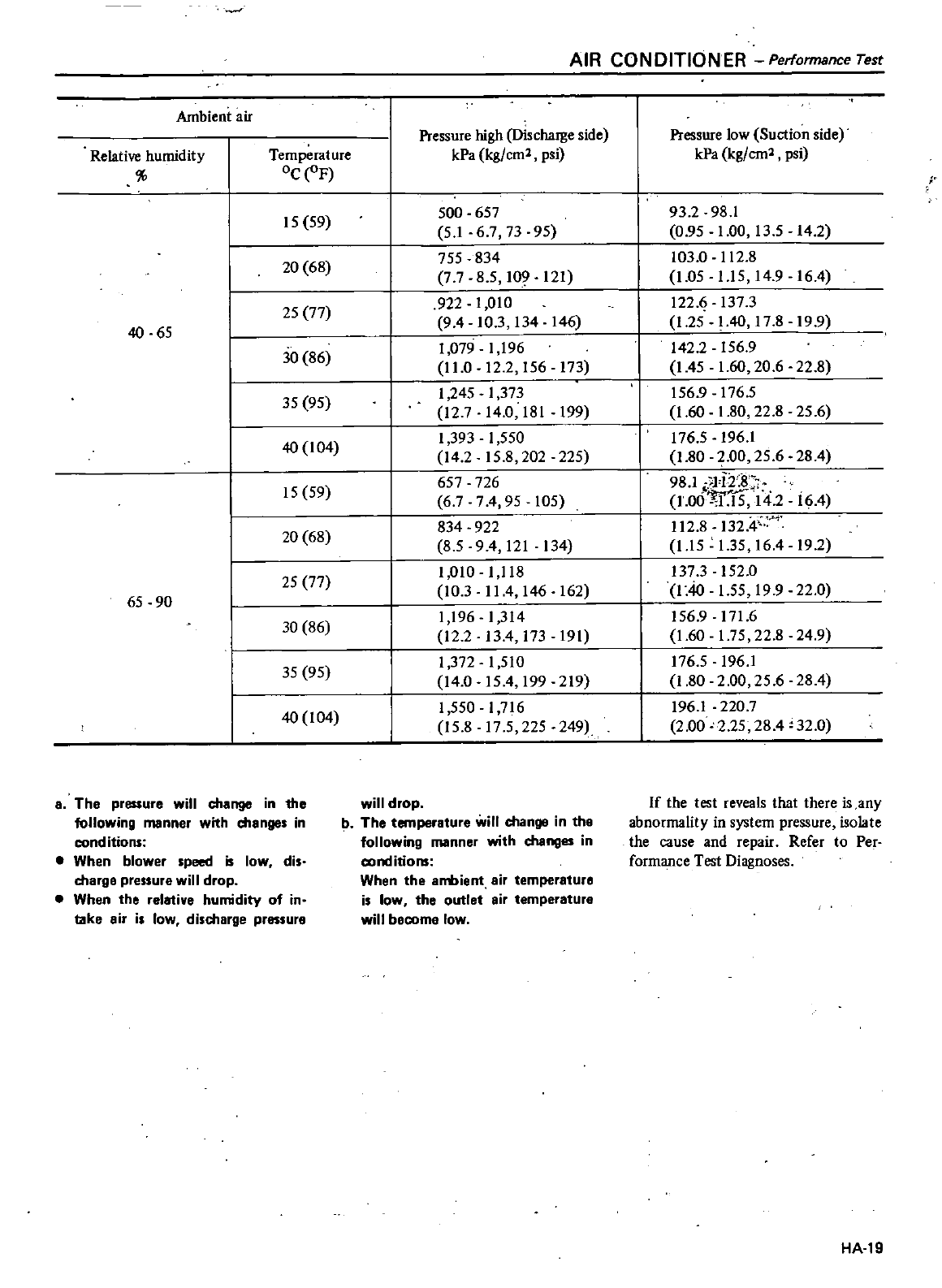
AIR
CONDITIONER
Performance
Test
Ambient
air
Pressure
high
Discharge
side
Pressure
low
Suction
side
Relative
humidity
Temperature
kPa
kg
cm2
psi
kPa
kg
em2
psi
oC
F
15
59
500 657
93
2
98
1
51
67
73
95
0
95
1
00
13
5
14 2
20
68
755
834
103
0
112
8
7
7
85
109
121
1
05
1
15
14
9
16
4
25 77
922
1
010
l22
1i
137
3
40
65
94
10
3
134
146
1
25
I
40
17
819 9
30 86
1
079
1
196
142
2
156
9
11
0
12
2
156
173
I
45
1
60 20
6
22
8
35 95
1
245
1
373
156
9
176
5
12
7
14 0
181
199
1
60
1
80
22
8
25
6
40
104
1
393
1
550
176
5
196
1
14
2
15
8
202 225
1
80
2
00
25
6
28
4
15 59
657
726
98
1
li2
8
67
74
95
105
i6
4
1
00
0115
14
2
1
20
68
834 922
112
8
132
4
85 94
121
134
1
15
1
35
16
4
19
2
25
77
1
010
1
118
137
3
152
0
65
90
10
3
II
4
146
162
140
1
55
19
9
22
0
30
86
1
196
1
314
156
9
171
6
12 2
13
4
173
191
1
60
1
75
22
8
24
9
35
95
1
372
1
510
176
5
196
1
14
0
154
199
219
1
80
2
00
25
6
28
4
40
104
1
550
1
716
196
1
220
7
15 8
17
5
225 249
2
00
2
25
28
4
32
0
aThe
pressure
will
change
in the
following
manner
with
manges
in
cond
itions
When
blower
speed
is
low
dis
charge
pressure
will
drop
When
the
relative
humidity
of
in
take
air
is
low
discharge
pressure
will
drop
b
The
temperature
will
change
in the
following
manner
with
changes
in
conditions
When
the
8rrmient
air
temperature
is
low
the
outlet
air
temperature
will
becomg
low
If
the
test
reveals
that
there
is
any
abnormality
in
system
pressure
isolate
the
cause
and
repair
Refer
to
Per
formance
Test
Diagnoses
HA
19
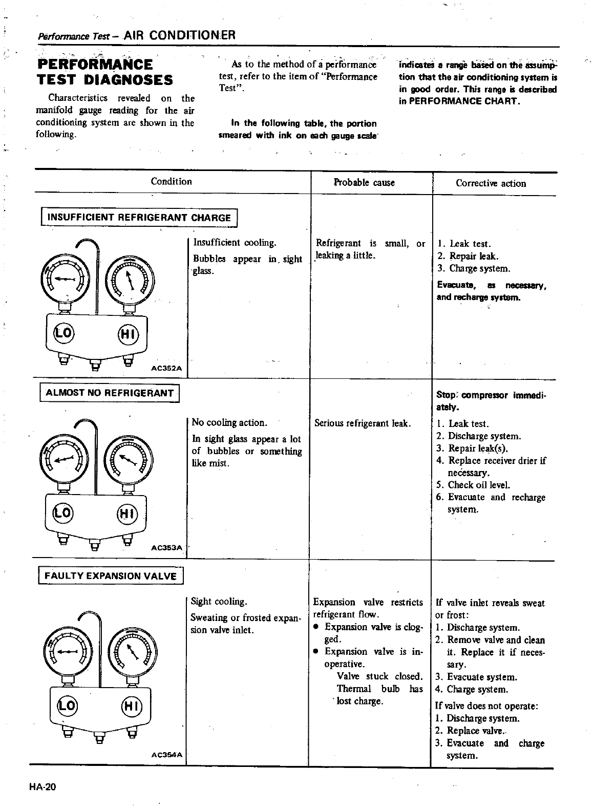
Perfonnance
Te
t
AIR
CONDITIONER
PERFOR
NCE
TEST
DIAGNOSES
Characteristics
revealed
on
the
manifold
gauge
rcading
for
the
air
conditioning
system
are
shown
in
the
following
Condition
As
to
the
method
of
a
performance
test
refer
to
the
item
of
Performance
Test
indicateS
a
range
baSed
on
the
lissump
tion
that
the
air
conditioning
system
is
in
good
order
This
range
is
described
in
PERFORMANCE
CHART
In
the
following
table
the
portion
smeared
with
ink
on
sam
gauge
scale
I
INSUFFICIENT
REFRIGERANT
CHARGE
1
0
0
@@
AC352A
ALMOST
NO
REFRIGERANT
I
00
@@
AC353A
I
FAULTY
EXPANSION
VALVE
I
0
@@
AC354A
HA
20
Insufficient
cooling
Bubbles
appear
in
sight
glass
No
cooling
action
In
sight
glass
appear
a
lot
of
bubbles
or
something
like
mist
Sight
cooling
Sweating
or
frosted
expan
sion
valve
inlet
Probable
cause
Refrigerant
is
small
or
leaking
alittle
Serious
refrigerant
leak
Expansion
valve
restricts
refrigerant
flow
Expansion
valve
is
clog
ged
Expansion
valve
is
in
operative
Valve
stuck
closed
Thermal
bulb
has
lost
charge
Corrective
action
I
Leak
test
2
Repair
leak
3Charge
system
EVKUatB
as
necessary
and
recharge
system
Stop
compressor
immedi
ately
1
Leak
test
2
Discharge
system
3
Repair
leak
s
4
Replace
receiver
drier
if
neCessary
5
Check
oil
level
6
Evacuate
and
recharge
system
If
valve
inlet
reveals
sweat
or
frost
I
Discharge
system
2
Remove
valve
and
clean
it
Replace
it
if
neces
sary
3
Evacuate
system
4
Charge
system
If
valve
does
not
operate
I
Discharge
system
2
Replace
valve
3
Evacuate
and
charge
system
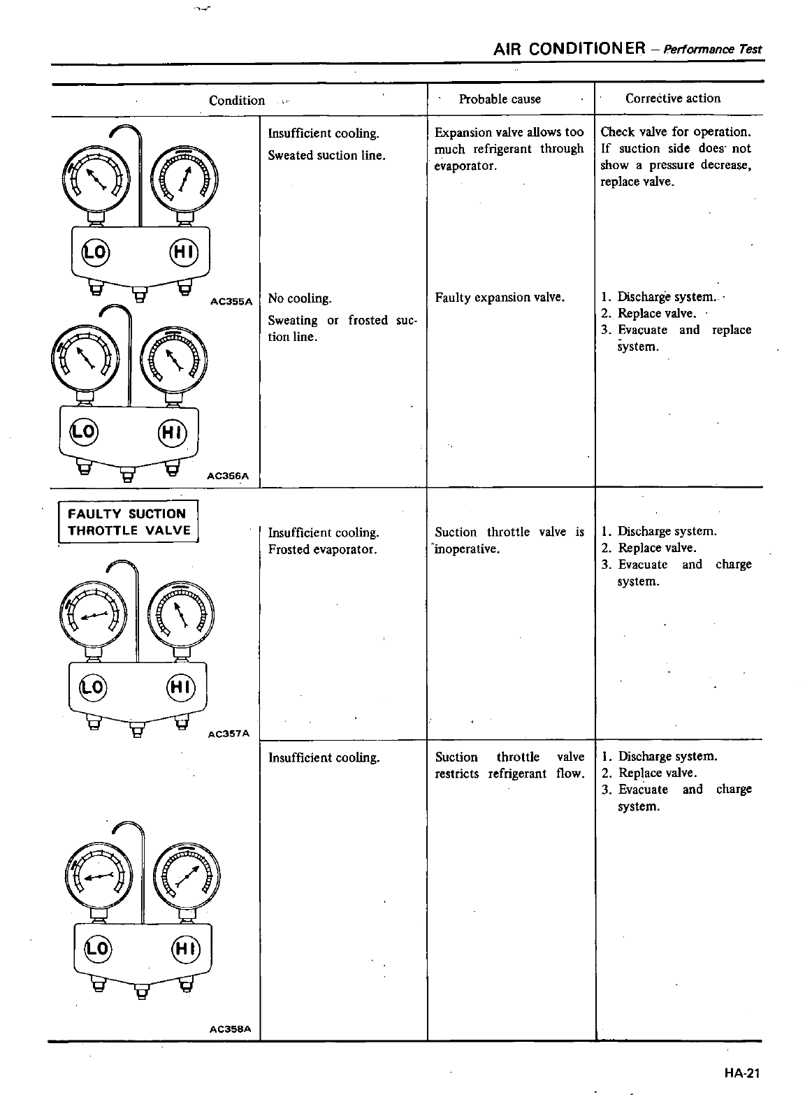
Condition
010
@
f
AC355A
@
fg
fi
0
@@
AC356A
I
FAUL
TV
SUCTION
THROTTLE
VALVE
C0
@ @
AC357A
0
@ @
AC358A
Insufficient
cooling
Sweated
suction
line
No
cooling
Sweating
or
frosted
sue
tion
line
Insufficient
cooling
Frosted
evaporator
Insufficient
cooling
AIR
CONDITION
ER
Performance
rest
Probable
cause
Expansion
valve
allows
too
much
refrigerant
through
evaporator
Faulty
expansion
valve
Suction
throttle
valve
is
inoperative
Suction
throttle
valve
restricts
refrigerant
flow
CorreCtive
action
Check
valve
for
operation
If
suction
side
does
not
show
a
pressure
decrease
replace
valve
L
Discharge
system
2
Replace
valve
3
Evacuate
and
replace
system
I
Discharge
system
2
Replace
valve
3
Evacuate
and
charge
system
I
Discharge
system
2
Replace
valve
3
Evacuate
and
charge
system
HA 21
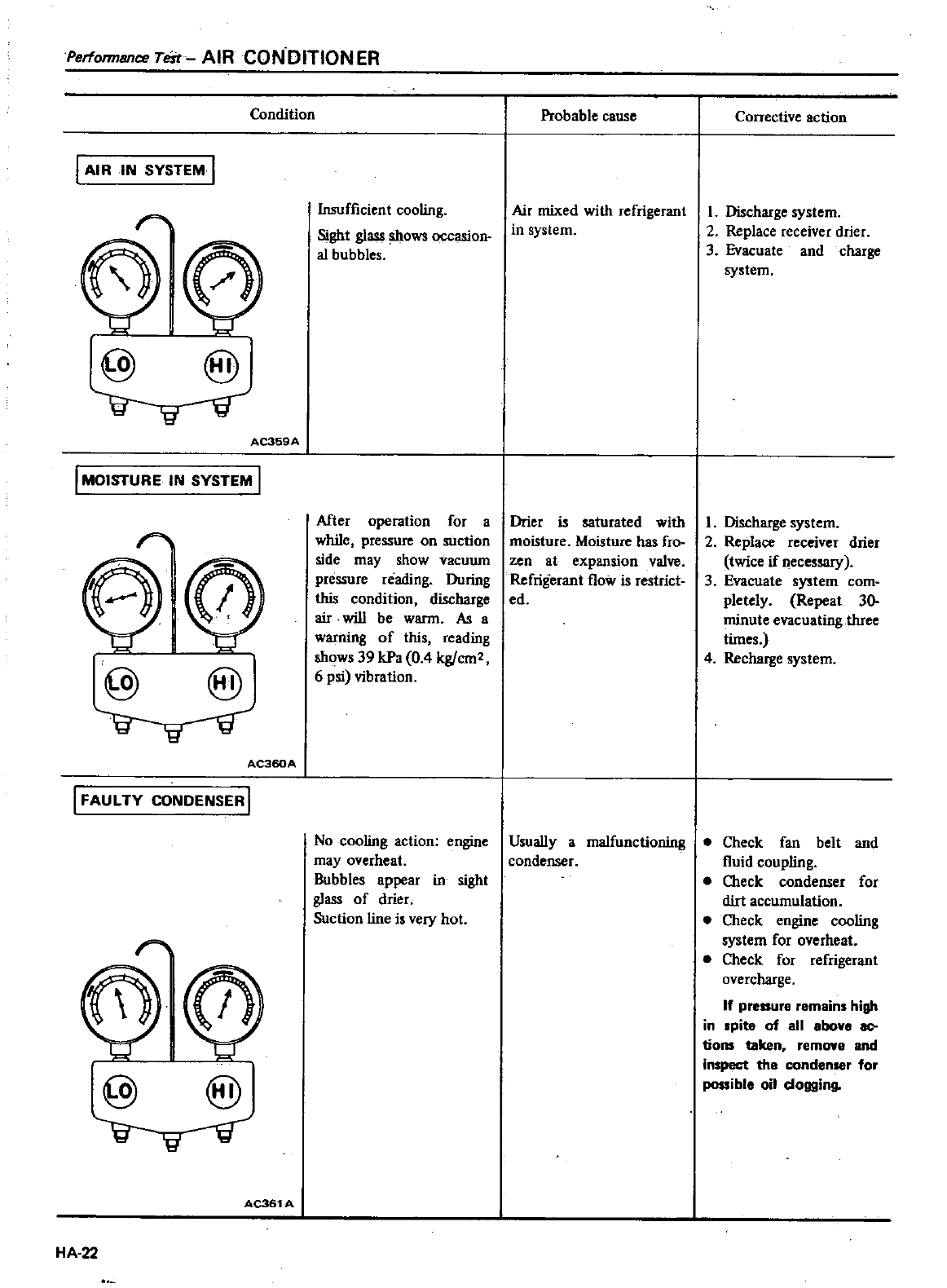
Perfonnance
Test
AIR
CON
DITION
ER
Condition
I
AIR
IN
SYSTEM
I
r
010
@@
AC359A
I
MOISTURE IN
SYSTEM
I
010
@
@
AC360A
I
FAULTY
CONDENSER
I
t
0
0
@ @
AC361
A
HA
22
Insufficient
cooling
Sight
glass
shows
occasion
al
bubbles
After
operation
for
a
while
pressure
on
suction
side
may
show
vacuum
pressure
reading
During
this
condition
discharge
air
will
be
warm
As
a
warning
of
this
reading
shows
39
kPa
0
4
kg
cm2
6
psi
vibration
No
cooling
action
engine
may
overheat
Bubbles
appear
in
sight
glass
of
drier
Suction
line
i
very
hot
Probable
cause
Air
mixed
with
refrigerant
in
system
Drier
is
saturated
with
moisture
Moisture
has
fro
zen
at
expansion
valve
Refrigerant
flow
is restrict
ed
Usually
a
malfunctioning
condenser
Corrective
action
I
Discharge
system
2
Replace
receiver
drier
3
Evacuate
and
charge
system
I
Discharge
system
2
Replace
receiver
drier
twice
if
necessary
3
Evacuate
system
com
pletely
Repeat
30
minute
evacuating
three
times
4
Recharge
system
Check
fan
belt
and
fluid
coupling
e
Check
condenser
for
dirt
accumulation
Check
engine
cooling
system
for
overheat
Check
for
refrigerant
overcharge
If
pressure
remains
high
in
spite
of
all
above
ac
tions
taken
remOW8
and
inspect
the
condenser
for
possible
oil
dogging
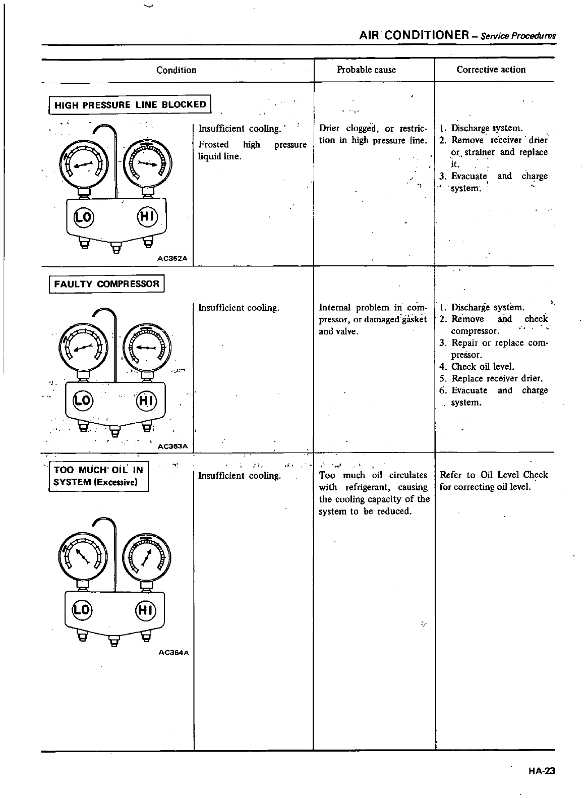
Condition
I
HIGH
PRESSURE
LINE BLOCKED
I
6
@
@
AC362A
I
FAULTY
COMPRESSOR
I
0
0
@@
AC363A
TOO
MUCH
OIL
IN
SYSTEM
Excessivel
r
0
@@
AC364A
Insufficient
cooling
Frosted
high
pressure
liquid
line
Insufficient
cooling
Insufficient
cooling
AIR
CONDITIONER
SelViceProceduref
Probable
cause
Drier
clogged
or
restrie
tion
in
high
pressure
line
Internal
problem
in
com
pressor
or
damaged
gasket
and
valve
Too
much
oil
circulates
with
refrigerant
causing
the
cooling
capacity
of
the
system
to
be
reduced
Corrective
action
I
Discharge
system
2
Remove
receiver
drier
or
strainer
and
replace
it
3
Evacuate
and
charge
system
I
Discharge
system
2
Remove and
check
compressor
3
Repair
or
replace
com
pressor
4
Check
oil
level
5
Replace
receiver drier
6
Evacuate
and
charge
system
Refer
to
Oil
Level
Check
for
correcting
oil level
HA
23
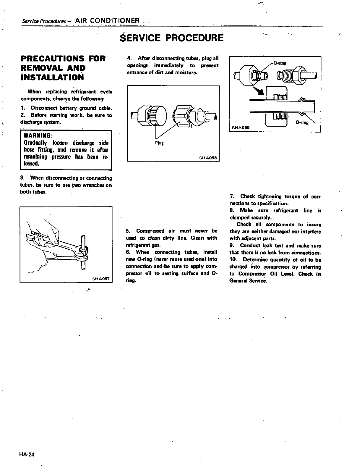
ServiceProcedu
s
AIR
CONDITIONER
PRECAUTIONS
FOR
REMOVAL
AND
INSTALLATION
When
replacing
refrigerant
cycle
components
observe
the
following
1
Discormect
battery
ground
cable
2
Before
starting
work
be
sure
to
discharge
system
WARNING
Gradually
loosen
discharge
side
hOse
fitting
and
remove
it
after
remaining
pressure
has
been
re
IlIIsed
3
When
disconnecting
or
connecting
tubes
be
sure
to
use
wrenches
on
both
tubes
SHA057
HA 24
SERVICE
PROCEDURE
4
After
disconnectinll
tubes
plug
all
openings
immediately
to
prevent
entrance
of
dirt
and
moisture
Plug
SH
A058
5
Compressed
air
must
never
be
usad
to
dean
dirty
line
Clean
with
refrigerant
gas
6
When
connecting
tubes
install
new
a
ring
never reuse
used
one
into
connection
and
be
sure
to
apply
com
pressor
oil
to
seating
surface
and
0
ring
I
uamnr
s
SHA059
7
Check
tightening
torque
of
con
nedions
to
lpecification
8
Make
sure
refrigerant
line
is
clamped securely
Check
all
componenb
t
insure
they
are
neither
damaged
nor
interfere
with
adjacent
parts
9
Conduet
leak
test
and
make
sure
that
there
is
no
leak
from
connections
10
Determine
quantity
of
oil
to
be
charged
into
compressor
by
referring
to
Compressor
Oil
Level
Check
in
General
SerYi
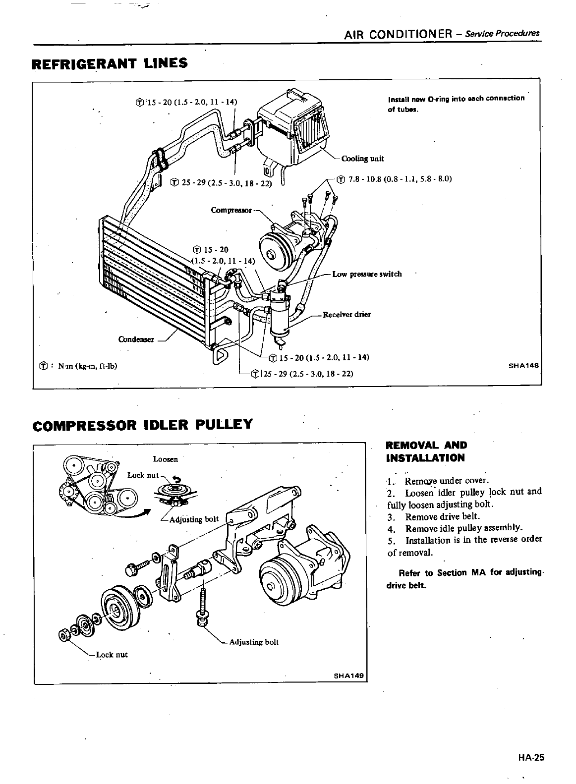
AIR
CONDITIONER
ServiceProcedure
REFRIGERANT
LINES
i
J
N
m
kg
m
ft
lb
Insull
new
O
ing
into
each
connection
of tubes
OloUng
unit
10
8
0
8
11
5 8
8 0
i
J15
20
15
20
11 14
i
J125
29
25
3
0
18
22
SHA148
COMPRESSOR
IDLER
PULLEY
Loosen
REMOVAL
AND
INSTAlLATION
1
Rem
e
under
cover
2
Loosen
idler
pulley
lock
nut
and
fully
loosen
adjusting
bolt
3
Remove
drive
belt
4
Remove
idle
pulley
assembly
5
Installation
is
in
the
reverse
order
of
removal
Refer
to
Section
MA
for
adjusting
drive
belt
Adjusting
bolt
SHA149
HA
25
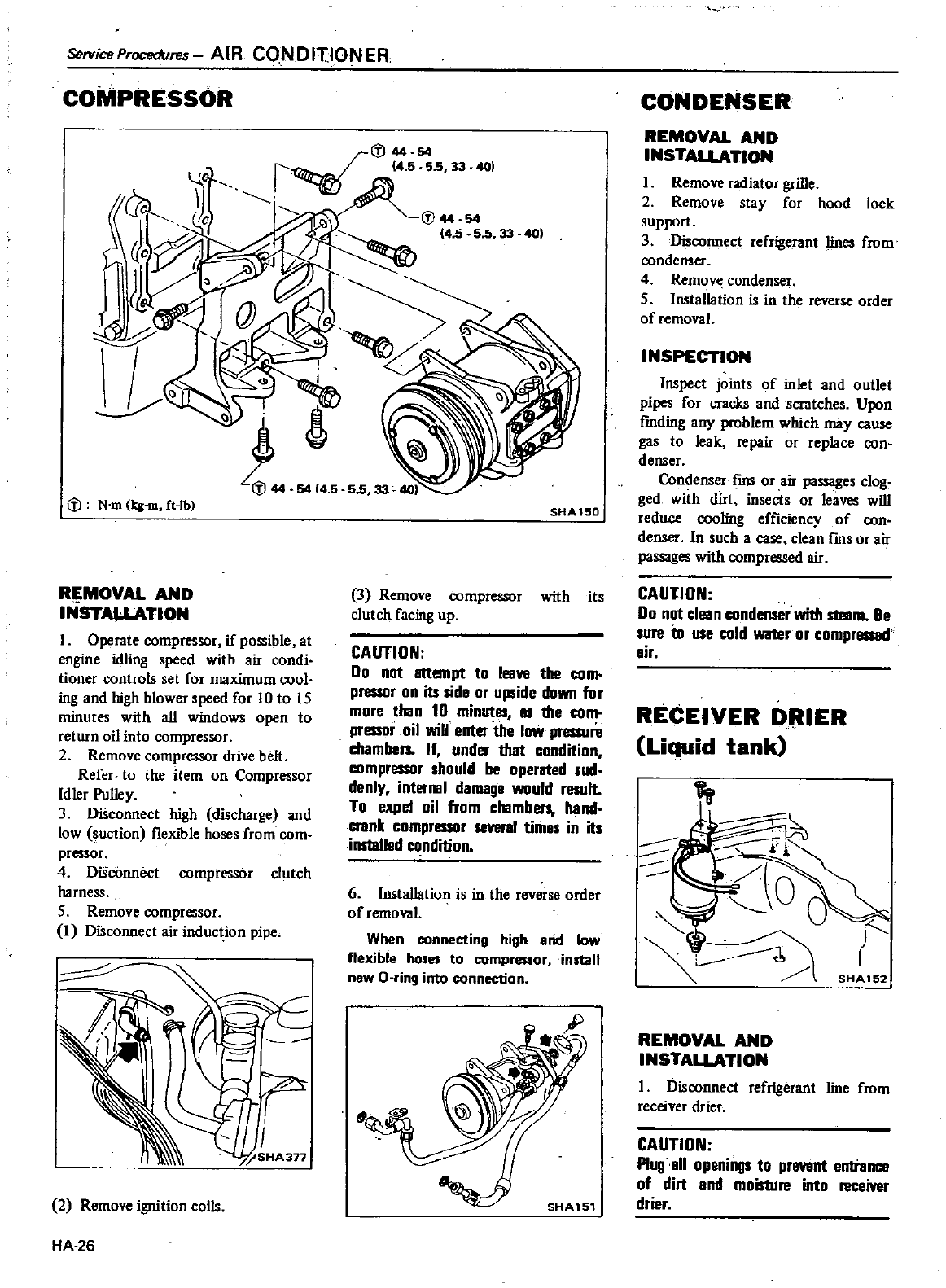
ServiceProcedures
AIR
CONDITIONER
COMPRESSOR
Q
N
m
kg
m
ft
lb
R
MOVAL
AND
INSTALLATION
I
Operate
compressor
if
possible
at
engine
idling
peed
with
air
condi
tioner
controls
set
for
maximum
cool
ing
and
high
blowerspeed
for
10
to
IS
minutes
with
all
windows
open
to
return
oil
into
compressor
2
Remove
compressor
drive
beh
Refer
to
the
item
on
Compressor
Idler
Pulley
3
Disconnect
high
discharge
and
low
uction
fleXible
hose
from
com
pressor
4
DiScOnnect
compressor
clutch
harness
5
Remove
compressor
1
DiSconnect
air
induction
pipe
J
5HA317
2
Remove
ignition
coils
HA
26
401
5414
5
SHA150
3
Remove
compressor
with
it
clutch
facing
up
CAUTION
Do
not
attempt
to
leave
the
com
pressor
on
its
side
or
upside
down
for
more
than
10
minutes
IS
1IIe
com
pressor
oil
will
enter the
low
pressure
chambers
If
under
that
condition
compressor
should
be
operated
sud
denly
interllll
damage
would
result
To
expel
oil
from
chambers
hand
crank
compressor
several
times
in
its
installed
condition
6 Installation
is
in
the
reverse
order
of
removal
When
conneeting
high
and low
flexible
hoses
to
compressor
install
new
O
ring
into
connectiQn
CONDENSER
REMOVAL
AND
INSTALLATION
I
Remove
radiator
grille
2
Remove
stay
for
hood
locI
upport
3
Disconnect
refrigerant
lines
from
condenser
4
Remove
condenser
5 Installation
is
in
the
reverse
order
of
l
l
INSPECTION
Inspect
joints
of
inlet
and
outlet
pipes
for
cracks
and
scratches
Upon
rmding
any
problem
which
may
cause
gas
to
leak
repair
or
replace
con
denser
Condenser
fIns
or
air
passage
clog
ged
with
dirt
insect
or
leaves
will
reduce
cooling
effIciency
of
con
denser
In
such
a case
clean
fms
or
a
passages
with
compr
ed
air
CAUTION
Do
not
clean
condenser
with
steIIm
Be
sure
to
use
cold
water
or
compressed
air
RECEIVER
DillER
Liquid
tank
SHA152
REMOVAL
AND
INSTALLATION
I
Disconnect
refrigerant
line
from
receiver
drier
CAUTION
Plug
all
openings
to
enttem
e
of
din
and
moistUre
into
l1lC
iver
drier
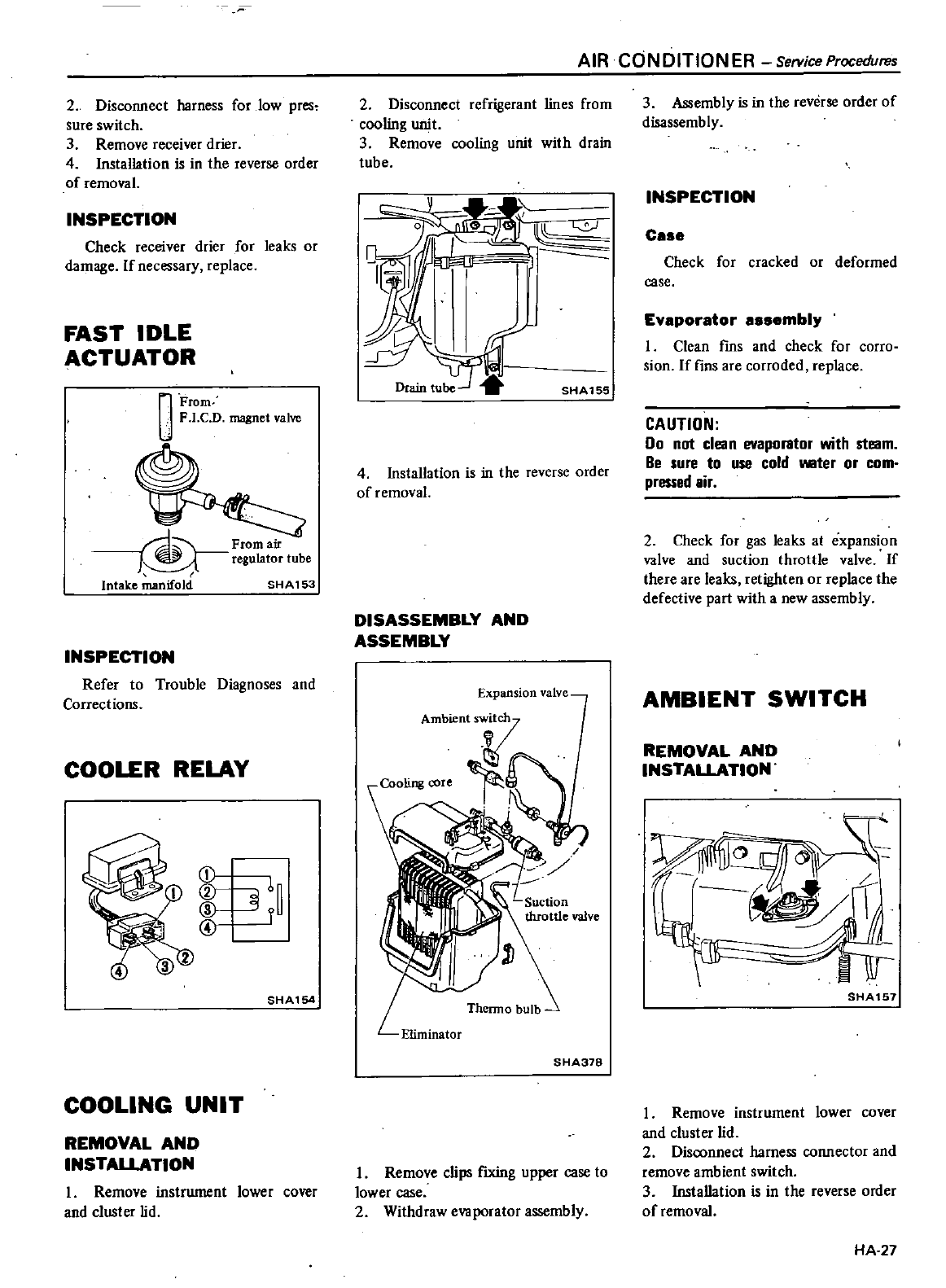
2
Disconnect
harness
for
low
pres
Sure
switch
3
Remove
receiver
drier
4
Installation
is
in
the
reverse
order
of
removal
INSPECTION
Check
receiver
drier
for
leaks
or
damage
If
necessary
replace
FAST
IDLE
ACTUATOR
Q
From
F
I
CD
magnet
valve
FrOmair
regulator
tube
Intake
manifold
SH
A
153
INSPECTION
Refer
to
Trouble
Diagnoses
and
Corrections
COOLER
RELAY
f
6
r
SHA154
COOLING
UNIT
REMOVAL
AND
INSTAlLATION
I
Remove
instrument
lower
cover
and
cluster
lid
AIR
CONDITIONER
ServiceProcedures
2
Disconnect
refrigerant
lines
from
cooling
unit
3
Remove
cooling
unit
with
drain
tube
V
Drain
tu
SHA155
4Installation
is
in
the
reverse
order
of
removal
DISASSEMBLY
AND
ASSEMBLY
Expansion
valve
Thermo
bulb
SHA378
I
Remove
clips
fIxing
upper
case
to
lower
case
2
Withdraw
evaporator
assembly
3
Assembly
is
in
the
reverse
order
of
disassembly
INSPECTION
c
Check
for
cracked
or
deformed
case
Ev
por
tor
mbly
I
Clean
fms and
check
for
corro
sion
If
fins
are
corroded
replace
CAUTION
Do
not
clean
evaporator
with
steam
Be
sure
to
use
cold
IIIIIter
or
com
pressed
lir
2
Check
for
gas
leaks
at
expansion
valve
and
suction
throttle
valve
If
there
are
leaks
retighten
or
replace
the
defective part
with
a
new
assembly
AMBIENT
SWITCH
REMOVAL
AND
INSTALLATION
SHA157
I
Remove
instrument
lower
cover
and
cluster
lid
2
Disconnect
harness
connector
and
remove
ambient
switch
3Installation
is
in
the
reverse
order
of
removal
HA
27
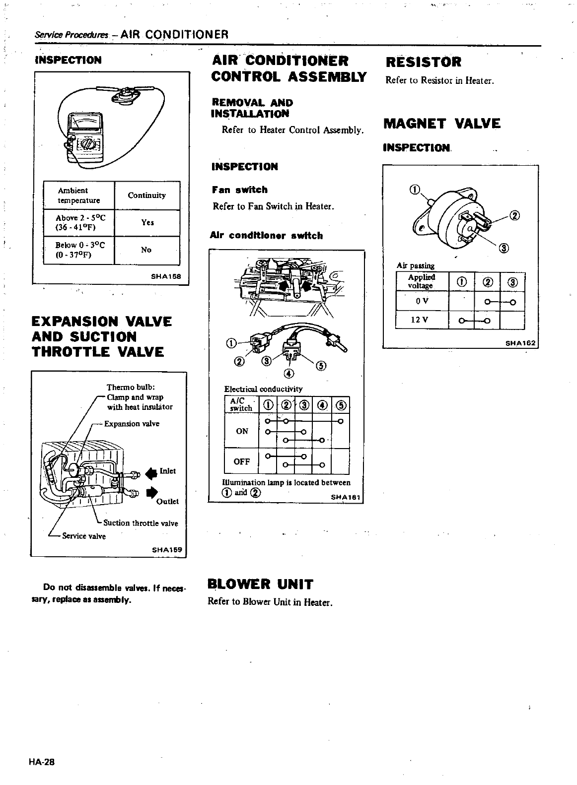
ServiceProcedvres
AIR
CONDITIONER
INSPECTION
r
1101
Ambient
temperatwe
Continuity
Above
2
SoC
36
410F
Ves
Below
O
30C
0
370F
No
SHA158
EXPANSION
VALVE
AND
SUCTION
THROTTLE
VALVE
Thermo
bulb
Clamp
and
wrap
with
heat
insulator
lnle
III
IlJ
outle
Suction
throttle
valve
L
Service
valve
SHA169
Do
not
disassemble
val
neces
sary
replace
as
Iy
HA
28
AIR
CONDITIONER
CONTROL
ASSEMBLY
REMOVAL
AND
INSTALLATION
Refer
to
Heater
Control
Assembly
INSPECTION
F
an
switch
Refer
to
Fan
Switch
in
Heater
Air
conditioner
switch
Electrical
conductivity
Ch
CD
23
@
CID
c
ON
0
0
0
OFF
IUwnination
lamp
is
located between
CD
anCl
00
SHAle1
BLOWER
UNIT
Refer
to
Blower
Unit
in
Heater
RESISTOR
Refer
to
Resistor
in
Heater
MAGNET
VALVE
INSPECTION
00
@
Air
passing
I
Applied
voltage
I
OV
I
12V
CDOO@
0
10
I
SHA162
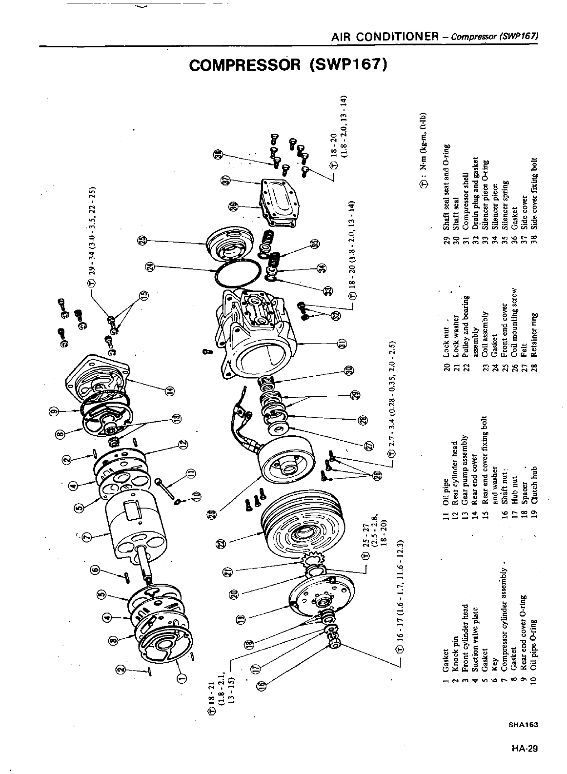
v
@
1
8
rn
ff
0
f
14
II
l
en
0
t
Z
10
j
5
z
rn
II
I
C
l
til18
21
1
8
2
1
13
15
@JJ
tl
ji1
til29
@
34
3
0
35
22
25
@
iJJ
til18
20
1
8
2
0
13
14
j
til
N
m
k8
m
f
4b
1
Gasket
11
Oll
pipe
20
LOCK
nut
29
Shaft
seal
seat
and
O
ring
2
j
nock
pm
12
Rear
cylinder
head
21
LOCK
washet
30
Shaft
seal
3
Front
cylinder
head
13
Gear
pump
as5fmb1y
22
PulloY
and
bearing
31
Compressor
s
hell
4
suction
valVe
plate
14
Rear
end
cover
assembly
32
D
a
in
plug
lnd
gas
ket
5
Gaslo
et
15
Rear
end
cover
i
ling
bolt
23
Coil
assemblY
33
Silencer
piece
ling
6
Key
a
nd
w9
8her
24
Gasket
34
Silencer
piece
7
Compressor
cylinder
assemblY
16
Shan
nut
2S
Front
end
cover
3S
Silencer
spring
l
8
Gasket
11
Hub
nut
26
Coil
mounting
screw
36
Gasket
t
9
Rear
end
covet
O
ring
18
Spaoet
21
Felt
37
Side
cover
10
on
pipe
o
ring
19
Qutch
hub
2
Retainer
ring
38
Side
cavet
fiXing
bOlt
til
25
21
2
5
2
8
18
20
til16
11
1
6
L1
I
6
12
3
til2
1
3
4
0
28
0
35
2
0
2
5
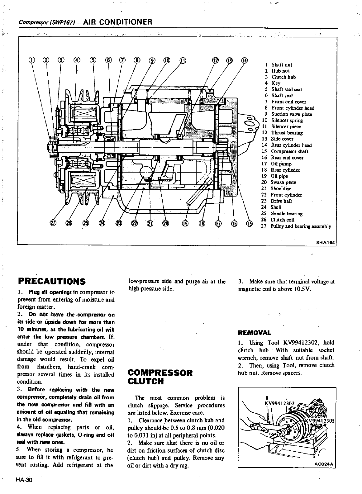
Compressor
SWP167J
AIR
CONDHIONER
2 3
o
C
l
PRECAUTIONS
I
Plug
all
openings
in
compressor
to
prevent
from
entering
of
moisture
and
foreign
matter
2
00
nc
tleave
the
compressor
on
its
side
oruplide
down
for
more
than
10
minutes
as
the
lubricating
oil
will
enter
the
low
pressure
chambers
If
under
that
condition
compressor
should
be
operated
suddenly
internal
damage
would
result
To
expel
oil
from
chambe
hand
crank
com
pressor
several
times
in
its installed
condition
3
Before
replacing
with
the
new
compressor
complately
drain
oil
from
the
new
compressor
and
fill
with
an
emount
of
oil
equaling
that
remaining
in
the old
compressor
4
When
replacing
parts
or
oil
always
replace
gaskets
O
ing
and
oil
eal
with
new
ones
5
When
storing
a
compressor
be
sure
to
fill it
with
refrigerant
to
pre
vent
rusting
Add
refrigerant
at
the
HA
30
Y
r
i1l
f
Jl
i
I
iMt
A
l
r
YJ
t
t
tf
4
II
11
J
I
l
c
4
1
@l
low
pressure
side
and
purge
air
at
the
high
pressure
side
COMPRESSOR
CWTCH
The
most
common
problem
is
clutch
slippage
Service
procedures
are
listed
below
Exercise
care
I
Clearance
between
clutch
hub and
pulley
should
be
0
5
to
0
8
mm
0
D20
to
ODJI
in
at
all
peripheral
points
2
Make
sure
that
there
is
no
oil
or
dirt
on
friction
surfaces
of
clutch
disc
clutch
hub and
pulley
Remove
any
oil
or
dirt
with
a
dry
rag
1
Shaft
nut
2
Hub
nut
3
Clutch
hub
4
Key
5
Shaft
seal seat
6
Shaft
seal
7
Front
end
cover
8
Front
cylinder
head
9
Suction
valve
plate
10
Silencer
spring
11
Silencer
piece
12
Thrust
bearing
13
Side
cover
14
Rear
cylinder
head
15
Compressor
shaft
16
Rear
end
cover
17
Oilp
ump
18
Rear
cylinder
19
Oilpipe
20
Swash
plate
21
Shoe
disc
22
Front
cylinder
23
Drive
ball
24
Shell
2S
Needle
bearing
26
Clutchcoil
27
Pulley
and
bearing
assembly
SHAl64
3
Make
sure
that
terminal
voltage
at
magnetic
coil
is
above
105V
REMOVAL
I
Using
Tool
KV99412302
hold
clutch
hub
With
suitable socket
wrench
remove
shaft
nut
from
shaft
2Then
using
Tool
remove
clutch
hub
nut
Remove
spacers
AC024A
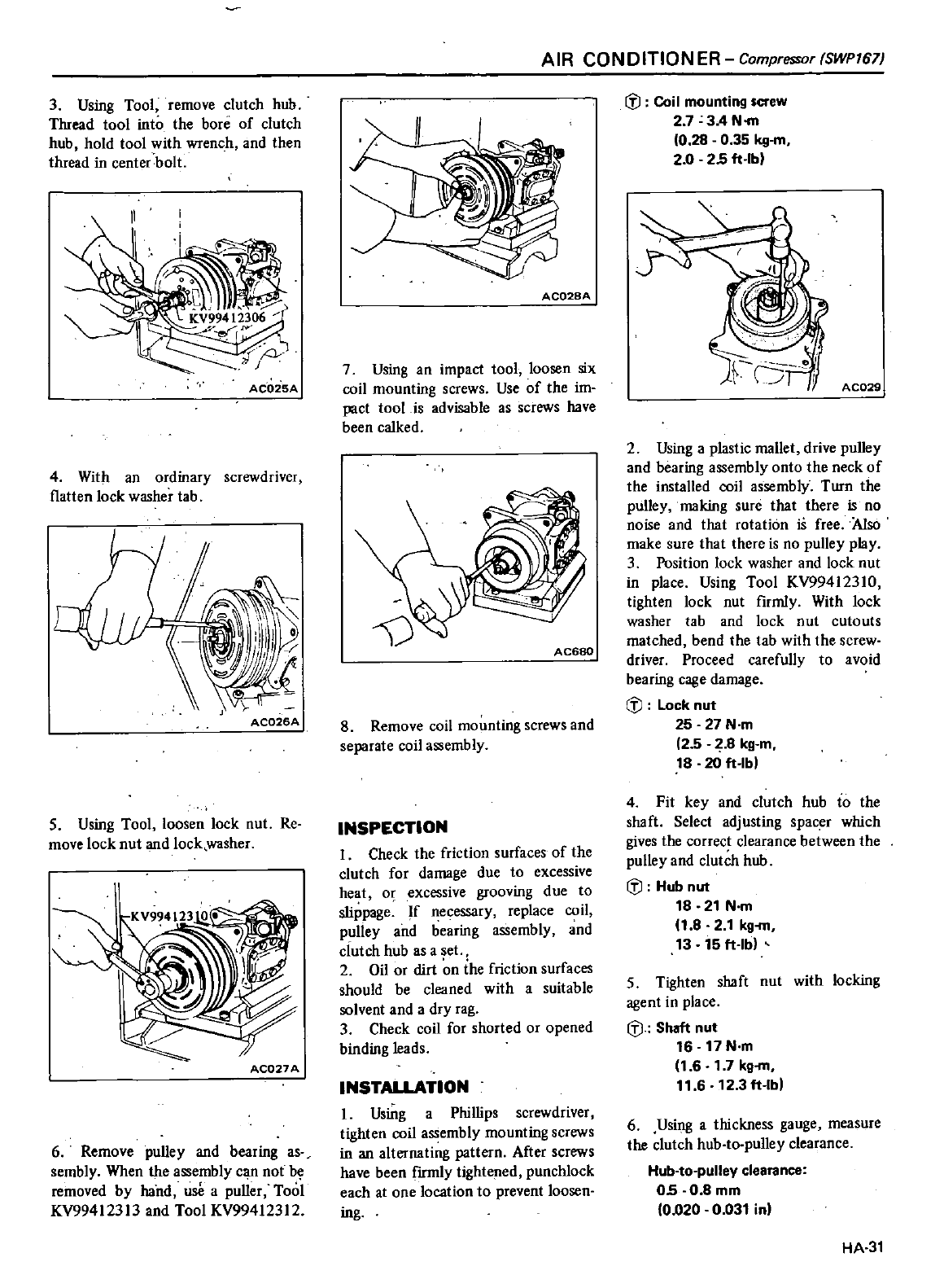
3
Using
Tool
remove
clutch
hub
Thread
tool
into
the
bore
of
clutch
hub
hold
tool
with
wrench
and
then
thread
in
center
bolt
ACQ25A
4
With
an
ordinary
screwdriver
flatten
lock
washer
tab
AC026A
5
Using
Tool
loosen
lock
nut
Re
move
lock
nut
and
lock
washer
AC027
A
6
Remove
pulley
and
bearing
as
sembly
When
the
assembly
can
not
be
removed
by
hand
use
a
puller
Tooi
KV994123I3
and
Tool
KV99412312
AIR
CONDITION
ER
Compressor
SWPI67J
AC028A
7
Using
an
impact
tool
loosen
six
coil
mounting
screws
Use
of
the
im
pact
tool
is
advisable
as
screws
have
been
calked
AC680
8
Remove
coil
mounting
screws
and
separate
coil
assembly
INSPECTION
I
Check
the
friction
surfaces
of
the
clutch
for
damage
due
to
excessive
heat
o
excessive
grooving
due
to
slippage
If
necessary
replace
coil
pulley
and
bearing
assembly
and
dutch
hub
as
aset
2
Oil
or
dirt
n
the
friction
surfaces
should
be
cleaned
with a
suitable
solvent
and
a
dry
rag
3
Check
coil
for
shorted
or
opened
binding
leads
INSTALLATION
I
Using
a
Phillips
screwdriver
tighten
coil
assembly
mounting
screws
in
an
alternating pattern
After
screws
have
been
frrmly
tightened
puncWock
each
at
one
location
to
prevent
loosen
ing
ifJ
Coil
mounting
screw
2 7
3A
N
m
0
28
0
35
kg
m
2
0
25 ft
lb
AC029
2
Using
a
plastic
mallet
drive
pulley
and
bearing
assembly
onto
the
neck
of
the
installed
coil
assembly
Turn
the
pulley
making
sure
that
there
is
no
noise
and
that
rotation
is
free
Also
make
sure
that
there
is
no
pulley
play
3
Position
lock
washer and
lock
nut
in
place
Using
Tool
KV994123IO
tighten
lock
nut
firmly
With
lock
washer
tab
and
lock
nut
cutouts
matched
bend
the
tab
with
the
screw
driver
Proceed
carefully
to
avoid
bearing
cage
damage
ifJ
Lock
nut
25 27
N
m
2 5
1
8
kg
m
18
20
It
lb
4
Fit
key
and
clutch
hub
to
the
shaft
Select
adjusting
spacer
which
gives
the
correct
clearance
between
the
pulley
and
clutch
hub
ifJ
Hub
nut
18 21
N
m
1
82
1
kg
m
13
15lt
lb
5
Tighten
shaft
nut
with
locking
agent
in
place
ifJ
Shaft
nut
16
17 N m
1
6
1
7kg
m
11 6
12
3lt
lb
6
Using
a
thickness
gauge
measure
the clutch
hub
to
pulley
clearance
Hub
to
pulley
clearance
05
0
8
mm
0
020
0
031
in
HA
31
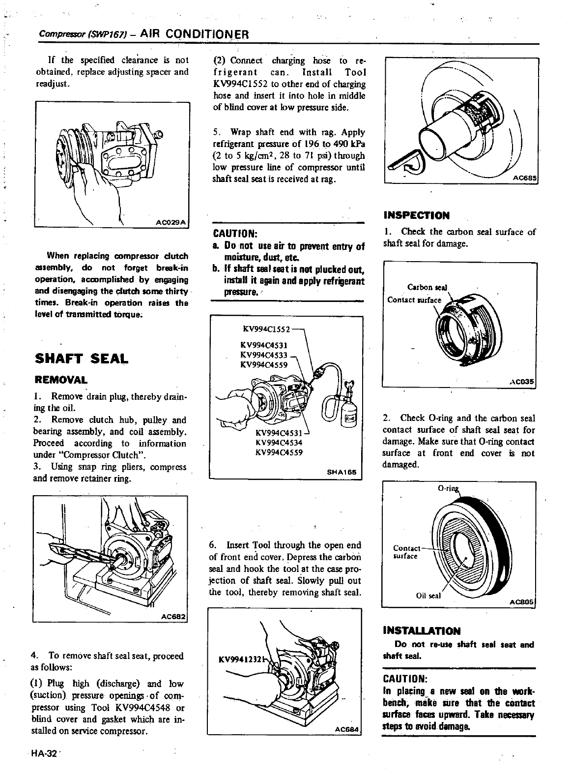
Comprt
lSOr
SWPI67
AIR
CQN
OITlON
ER
If
the
specified
clearance
is
not
obtained
replace
adjusting
spacer
and
rcadjust
AC029A
When
replacing
compressor
dutch
a
embly
do
not
forget
br
k
in
operation
accomplished
by
engaging
and
disengaging
the
clutch
some
thirty
times
Break
in
operation
raises
the
level
of
transmitted
torque
SHAFT
SEAL
REMOVAL
I
Remove
drain
plug
thereby
drain
ing
the
oil
2
Remove
clutch
hub
pulley
and
bearing
assembly
and
coil
assembly
Proceed
according
to
information
under
Compressor
Clutch
3
Using
snap
ring
pliers
compress
and
remove
retainer
ring
4
To
remove
shaft
seal
seat
proceed
as
follows
I
Plug
high
discharge
and
low
suction
pressure
openings
of
com
pressor
using
Tool
KV994C4548
or
blind
cover
and
gasket
which
are
in
stalled
on
service
compressor
HA
32
2
Cormect
charging
hose
to
re
frigerant
can
Install Tool
KV994CI552
to other
end
of
charging
hose
and
insert
it into
hole
in
middle
of
blind
cover
at low
pressure
side
5
Wrap
shaft
end
with
ra8
Apply
refrigerant
pressure
of
196
to
490
kPa
2
to
5
kg
em
28
to
71 psi
thrnugh
low
pressure
line
of
compressor
until
shaft
seal
seat
is
received
at
rag
CAUTION
a
Do
not
use
air
to
prevent
entry
of
moisture
dust
ete
b
If
shaft
slllll
seat
is
not
plucked
out
ins
llll
it
again
and
apply
refrigerant
pressure
KV994C1552
KV994C4531
KV994C4533
KV994C4559
SHA165
6
Insert
Tool
through
the
open
end
of
front
end
cover
Depress
the
carbon
seal
and
hook the
tool
at
the case
pro
jection
of
shaft
seal
Slowly
pull
out
the
tool
thereby
removing
shaft
seal
KV994U32
INSPECTION
I
Check
the
carbon
seal
surface
of
shaft
seal
for
damage
Carbon
seal
Contact
surCace
AC035
2
Check
Q
ring
and
the
carbon
seal
contact
surface
of
shaft
seal
seat
for
damage
Make
sure
that
O
ring
contact
surface
at
front
end
cover
is
not
damaged
Contact
surface
ACS05
INSTALlATION
Do
not
re
use
shaft
seal
seat
and
shaft
seal
CAUTION
In
placing
a
new
seal
on
the
IIIIIrk
belich
mllke
sure
that
the
contact
surface
faces
upwerd
Take
necessary
steps
to
avoid
damage
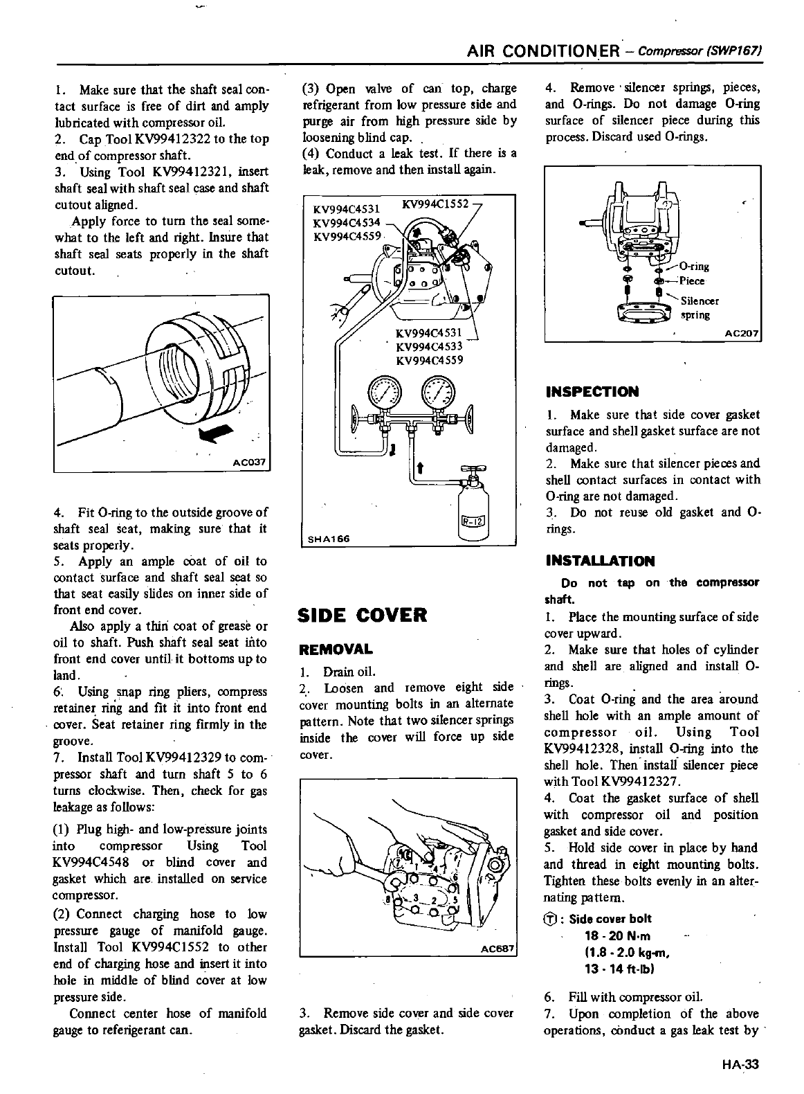
I
Make
sure
that
the
shaft
seal
con
tact
surface
is
free
of
dirt
and
amply
lubricated
with
compressor
oil
2
Cap
Tool
KV994l2322
to
the
top
end
of
compressor
shaft
3
Using
Tool
KV9941232l
insert
shaft
seal
with
shaft
seal
case
and
shaft
cutout
aligned
Apply
force
to
turn
the
seal
some
what
to
the
left
and
right
Insure
that
shaft
seal
seats
properly
in
the
shaft
cutout
AC037
4
Fit
O
ring
to
the
outside
groove
of
shaft
seal
seat
making
sure
that
it
scats
properly
5
Apply
an
ample
coat
of
oil
to
contact
surface
and
shaft
seal
t
so
that
seat
easily
slides
on
inner
side
of
front
end
cover
Also
apply
a
thin
coat
of
grease
or
oil
to
shaft Push shaft
seal
seat
iilto
front
end
cover
until
it
bottoms
up
to
land
6
Using
snap
ring
pliers
compress
retainer
ring
and
fit
it into
front
end
cover
Seat
retainer
ring
firmly
in
the
groove
7Install
Tool
KV99412329
to
com
pressor
shaft
and
turn
shaft
5
to
6
turns
clockwise
Then
check
for
gas
leakage
as
follows
I
Plug
high
and
low
pressure
joints
into
compressor
Using
Tool
KV994C4548
or
blind
cover
and
gasket
which
are
installed
on
service
compressor
2
Connect
charging
hose
to
low
pressure
gauge
of
manifold
gauge
Install
Tool
KV994C1552
to other
end
of
charging
hose
and
insert
it into
hole
in
middle
of
blind
cover
at
low
pressure
side
Connect
center
hose
of
manifold
gauge
to
referlgerant
can
AIR
CONDITIONER
Compressor
SWPI67
3
Open
valve
of
can
top
charge
refrigerant
from
low
pressure
side
and
purge
air
from
high
pressure
side
by
loosening
blind
cap
4
Conduct
a
leak
test
If
there
is
a
leak
remove
and
then
install
again
KV994C4531 KV994C1552
KV994C4534
KV994C4559
t
lbiJ
SHA166
SIDE
COVER
REMOVAL
I
Drain
oil
2
Loosen
and
remove
eight
side
cover
mounting
bolts
in
an
alternate
pattern
Note
that
two
silencer
springs
inside
the
cover
will
force
up
side
cover
AC687
3
Remove
side
cover
and
side
cover
gasket
Discard
the
gasket
4
Remove
silencer
springs
pieces
and
O
rings
Do
not
damage
O
ring
surface
of
silencer
piece
during
this
process
Discard
used
O
rings
9
O
ring
Piece
Silencer
pnng
AC207
INSPECTION
I
Make
sure
that side
cover
gasket
surface
and
shell
gasket
surface
are
not
damaged
2
Make
sure
that
silencer
pieces
and
shell
contact
surfaces
in
contact
with
O
ring
are
not
damaged
3
Do
not
reuse
old
gasket
and
O
rings
INSTALLATION
Do
not
tap
on
the
compressor
shalt
I
Place
the
mounting
swface
of
side
cover
upward
2
Make
sure
that
holes
of
cylinder
and
shell
are
aligned
and
install
O
rings
3
Coat
O
ring
and
the
area
around
shell
hole
with
an
ample
amount
of
compressor
oil
Using
Tool
KV99412328
install
O
ring
into
the
shell
hole
Then
install
silencer
piece
with
Tool
KV99412327
4
Coat
the
gasket
surface
of
shell
with compressor
oil
and position
gasket
and
side
cover
5
Hold
side
cover
in
place
by
hand
and
thread
in
eight
mounting
bolts
Tighten these
bo
Its
evenly
in
an
alter
nating
pattern
lfJ
Side
cover
bolt
18
20
N
m
1
82 0
kg
m
13
14lt
lb
6
Fill
with compressor
oil
7
Upon
completion
of
the
above
operations
cOnduct
a
gas
leak
test
by
HA
33
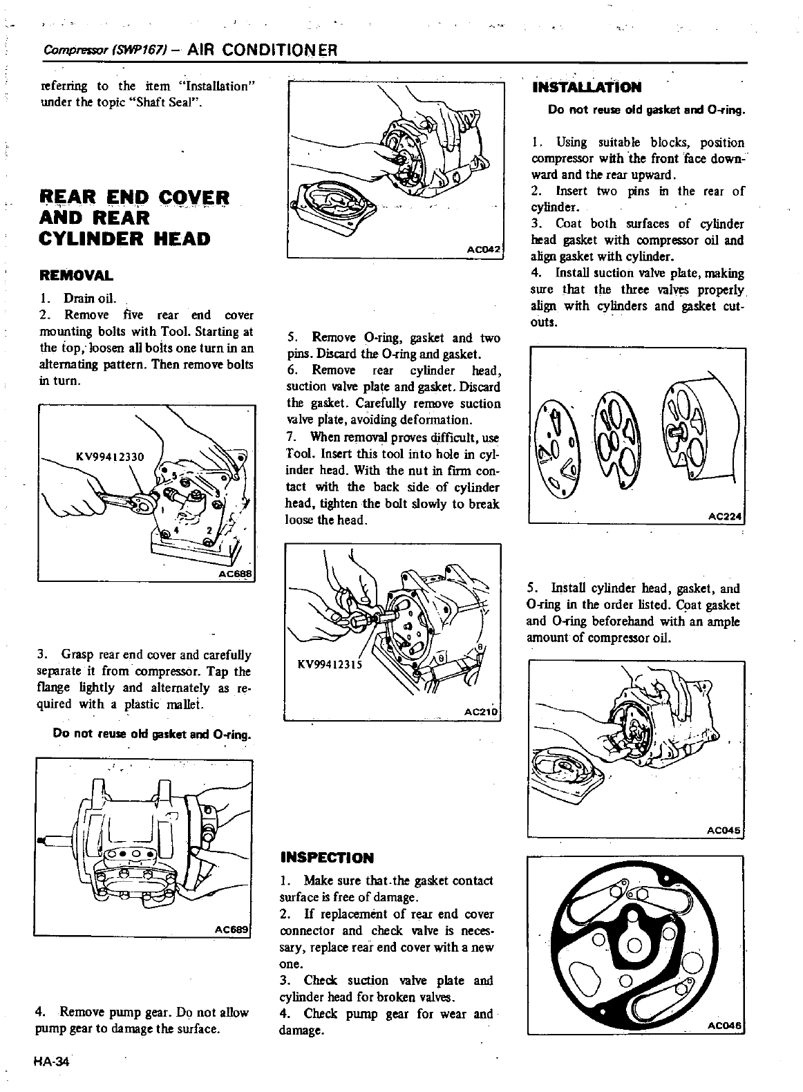
Compressor
SWP167
AIR
CONDITION
ER
referring
to
the
item
Installation
under
the
topic Shaft Seal
AR
Np
CQV
AND
REAR
CYLINDER
HEAD
REMOVAL
L
Drain
oil
2
Remove
five
rear
end
cover
mounting
bolts
with
Tool
Starting
at
the
lop
loosen
all
bolts
one
turn
in
an
alternating
pattern Then
remove
bolts
in
turn
AC6
8
3
Grasp
rear
end
cover
and
carefully
separate
it
from
compressor
Tap
the
flange
lightly
and
alternately
as
reo
quired
with
a
plastic
mallei
Do
not
reuse
old
gasket
and
O
ring
AC689
4
Remove
pump
gear
Do
not
allow
pump
gear
to
damage
the
surface
HA
34
AC042
5
Remove
O
ring
gasket
and
two
pins
Discard
the
O
ring
and
gasket
6
Remove
rear
cylinder
head
suction
valve
plate
and
gasket
Discard
the
gasket
Carefully
remove
suction
valve
plate
avoiding
defonnation
7
When
removal
proves
difficult
use
Tool
Insert
this
tool
into
hole
in
cyl
inder
head
With
the
nut
in
frrm
con
tact
with the
back
side
of
cylinder
head
tighten
the
bolt
slowly
to
break
loose
the
head
AC210
INSPECTION
I
Make
sure
that
the
gasket
contact
surface
is
free
of
damage
2
If
replacement
of
rear
end
cover
connector
and
check
valve
is
neces
sary
replace
rear
end
cover
with
a
new
one
3
Check
suction
valve
plate
and
cylinder
head
for
broken
valves
4
Check
pump
gear
for
wear
and
damage
INSTALLATION
Do
not
reuse
old
gasket
and
O
ring
I
Using
suitable
blocks
position
compressor
with
the
front
face
down
ward
and
the
rear
upward
2
Insert
two
pins
in the
rear
of
cylinder
3
Coat
both
surfaces
of
cylinder
head
gasket
with
compressor
oil
and
align
gaaket
with
cylinder
4
Install
suction
valve
plate
making
slife
that
the
three
valV
S
properly
align
with
cylinders
and
gasket
cut
outs
AC224
5 Install
cylinder
head
gasket
and
O
ring
in
the
order
listed
q
at
gasket
and
O
ring
beforehand
with
an
ample
amount
of
compressor
oil
AC045
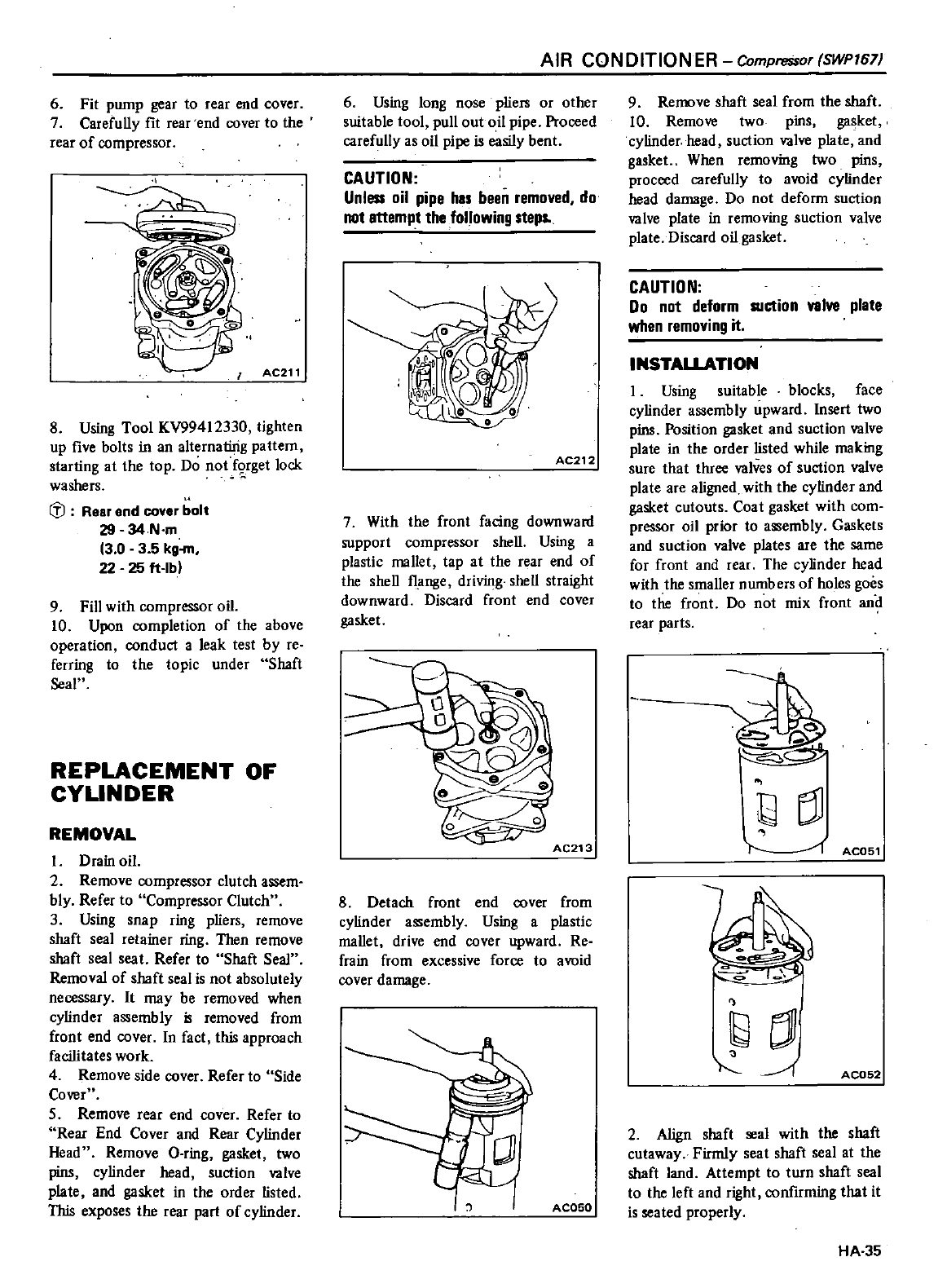
6
Fit
pump
gear
to
rear
end
cover
7
Carefully
fit
rear
end
cover
to
the
rear
of
compressor
AC211
8
Using
Tool
KV99412330
tighten
up
five
bolts
in
an
alternating
pattern
starting
at
the
top
Do
not
f9rget
lock
washers
fl
Rear
end
cover
bolt
29
34N
m
3 0 3 5
kg
22 25
It
lb
9
Fill
with
compressor
oil
10
Upon
completion
of
the
above
operation
conduct
a
leak
test
by
re
ferring
to
the
topic
under
Shaft
Seal
REPLACEMENT
OF
CYLINDER
REMOVAL
I
Drain
oil
2
Remove
compressor
clutch
assem
bly
Refer
to
Compressor
Clutch
3
Using
snap
ring
pliers
remove
shaft
seal
retainer
ring
Then
remove
shaft
seal
seat
Refer
to
Shaft
Seal
Removal
of
shaft
seal
is
not
absolutely
necessary
It
may
be
removed
when
cylinder
assembly
i
removed
from
front
end
cover
In
fact
this
approach
facilitates
work
4
Remove
side
cover
Refer
to
Side
Cover
5
Remove
rear
end
cover
Refer
to
Rear
End
Cover
and
Rear
Cylinder
Head
Remove
O
ring
gasket
two
pins
cylinder
head
suction
valve
plate
and
gasket
in
the
order listed
This
exposes
the
rear
part
of
cylinder
AIR
CONDITION
ER
Compressor
SWP167
6
Using
long
nose
pliers
or
other
suitable
tool
pull
out
oil
pipe
Proceed
carefully
as
oil
pipe
is
easily
bent
CAUTION
Unless
oil
pipe
hIS
been
removed
do
not
attemp
t
the
following
steps
AC212
7
With
the
front
facing
downward
support
compressor
shell
Using
a
plastic
mallet
tap
at
the
rear
end
of
the
shell
flange
driving
shell
straight
downward
Discard
front
end
cover
gasket
AC213
8
Detach
front
end
cover
from
cylinder
assembly
Using
a
plastic
mallet
drive
end
cover
upward
Re
frain
from
excessive
force
to
avoid
cover
damage
AC050
9
Remove
shaft
seal
from
the
shaft
10
Remove
two
pins
gasket
cylinder
head
suction
valve
plate
and
gasket
When
removing
two
pins
proceed
carefully
to
amid
cylinder
head
damage
Do
not
deform
suction
valve
plate
in
removing
suction
valve
plate
Discard
oil
gasket
CAUTION
Do
not
deform
R1ction
valve
plate
when
removing
it
INSTALLATION
I
Using
suitable
blocks
face
cylinder
assembly
upward
Insert
two
pins
Position
gasket
and
suction
valve
plate
in
the
order
listed
while
making
sure
that
three
valves
of
suction
valve
plate
are
aligned
with
the
cylinder
and
gasket
cutouts
Coat
gasket
with
com
pressor
oil
prior
to
assembly
Gaskets
and
suction
valve
plates
are
the
same
for
front
and
rear
The
cylinder
head
with
the smaller
numbers
of
holes
goes
to
the
front
Do
not
mix
front
an
rear
parts
bBJ
l
1
ACOS1
tj
1
AC052
2
Align
shaft
seal
with
the
shaft
cutaway
Firmly
seat
shaft
seal
at
the
shaft
land
Attempt
to
turn
shaft
seal
to
the
left
and
right
confirming
that
it
is
seated
properly
HA
35
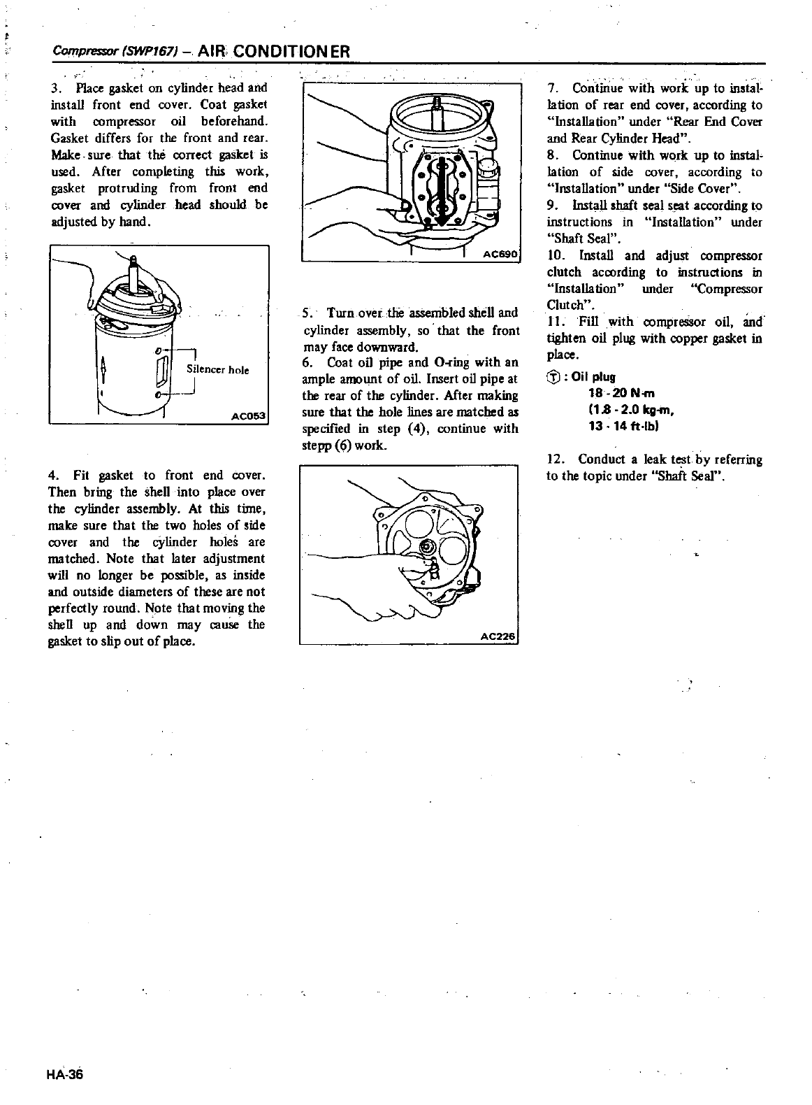
Compre
r
SWP767
AIR
CONDITION
ER
3
Place
gasket
on
cylinder
head
and
install front
end
cover
Coat
gasket
with compressor
oil
beforehand
Gasket
differs
for
the
front
and
rear
Make
sure
that
the
correct
gasket
is
used
After
completing
this
work
gasket
protruding
from
front
end
cover
and
cylinder
head
should
be
adjusted
by
hand
D
t
OJ
SIlencer
hole
J
AC053
4
Fit
gasket
to
front
end
cover
Then
bring
the
shell
into
place
over
the
cylinder
assembly
At
this
tin1e
make
sure
that
the
two
holes
of
side
cover
and
the
cylinder
holes
are
matched
Note
that
later
adjustment
will
no
longer
be
possible
as
inside
and
outside
diameters
of
these
are
not
perfectly
round Note
that
moving
the
shen
up
and
down
may
cause
the
gasket
to
slip
out
of
place
HA
36
AC690
5
Turnover
the
asSembled
shell
and
cylinder
assembly
so
that the
front
may
face
downward
6
Coat
oil
pipe
and
O
ring
with
an
ample
amount
of
oil
Insert
oil
pipe
at
the
rear
of
the
cylinder
After
making
sure
that
the
hole
lines
are
matched
as
specified
in
step
4
continue
with
stepp
6
work
AC226
7
Continue
with
work
up
to
instal
lation
of
rear
end
cover
according
to
Installation
under
Rear
End
Cover
and
Rear
Cylinder
Head
8
Continue
with
work up
to
instal
lation
of
side
cover
according
to
Installation
under
Side
Cover
9 Install
shaft
seal
s
t
according
to
instructions
in
Installation
under
Shaft
Seal
10
Install
and
adjust
compressor
clutch
acoording
to
instructions
in
Installation
under
Compressor
Clutch
II
Fill
with
oompressor
oil
and
tighten
oil
plug
with
copper
gasket
in
place
til
Oil
plug
18 20
N
rn
18
2 0
kg
rn
13
14
ft
lb
12
Conduct
a
leak
test
by
referring
to
the
topic
under
Shaft
Seal
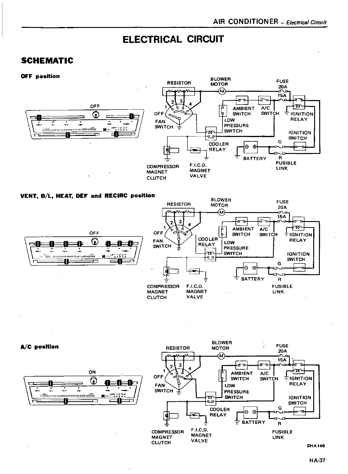
AIR
CONDITIONER
ElectricaICirr
uit
ELECTRICAL
CIRCUIT
SCHEMATIC
OFF
position
OFF
0
D
O
D
7
ft
tJ
VENT
B
L
HEAT
DEF
and
RECIRC
position
OFF
DO
G
0fl8
S
2
n
fP
A
C
positIon
ON
r
GJ
A
I
DDonO a
n
RESISTOR
BLOWER
MOTOR
M
FUSE
20A
5A
AIC
SWITCH
IGNITION
RELAY
COMPR
ESSQR
MAGNET
CLUTCH
RESISTOR
OFF
FAN
SWITCH
COMPRESSOR
MAGNET
CLUTCH
RESISTOR
COMPRESSOR
MAGNET
CLUTCH
AMBIENT
SWITCH
LOW
PRESSURE
SWITCH
I
COOLER
Ie
01
RELAY
1
11
L
BATTERY
R
FUSIBLE
LINK
IGNITION
SWITCH
o
F
I
C O
MAGNET
VALVE
BLOWER
MOTOR
M
FUSE
20A
F
I
C
O
MAGNET
VALVE
AMBI
ENT
SWITCH
LOW
PRESSURE
SWITCH
IGNITION
SWITCH
D
BATTERY
R
FUSIBLE
LINK
BLOWE
R
MOTOR
M
BATTERY
G
IGNITION
SWITCH
G
R
F
I
C
O
MAGNET
VALVE
FUSIBLE
LINK
SHA
146
HA
37
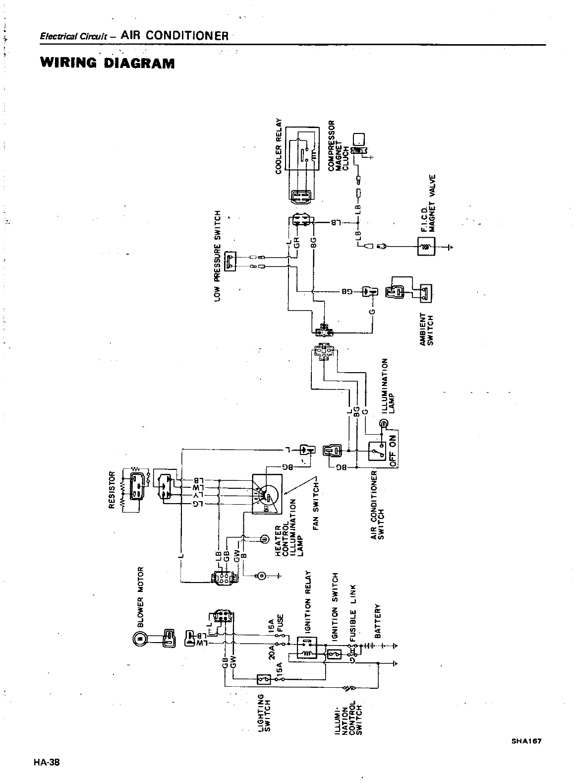
JJ
i
9
II
C
l
1
C
o
zo
5
z
RESIS10R
M010R
Il
4IER
ll
Gll
01
PRESSURE
S
II11CI
I
oO
ERRE
Gf lla
COlolPRESSOR
IoI
GIle
l
C
UCI
I
lll
Il
o
O
c
t
J
IoI
GIle
l
11
1
all
a
N
Ul
J
lEII
1
15
IRO
1I01l
C
UI
I
t
MP
S
II11CI
I
f
ll
UI
IIl
1I01l
lOIlER
tkMP
COllOl1
l
f
ON
IR
lCI
I
0
SIlI
IGI
IIIIlG
S
II11CI
I
aJJ
It
S
Il11CI
I
IGllll101l
S
Il11CI
I
fUSIll
E
I
t
Iu
UI
I
1l
1I01l
COlllRO
S
Ill1CI
I
JI
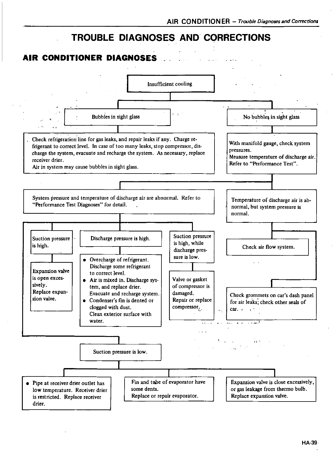
AIR
CONDITIONER
TroubleOiagnosesandCorrecrionr
TROUBLE
DIAGNOSES
AND
CQRRECTIONS
AIR
CONDITIONER
DIAGNOSES
Insufficient
cooling
Bubbles
in
sight
glass
Check
refrigeration
line
for
gas
leaks
and
repair
leaks
if
any
Charge
reo
frigerant
to
correct
level
In
case
of
too
many
leaks
stop
compressor
dig
charge
the
system
evacuate
and
recharge
the
system
As
necessary
replace
receiver
drier
Air
in
system
may
cause
bubbles
in
sight
glass
System
pressure
and
temperature
of
discharge
air
are
abnormal
Refer
to
Performance
Test
Diagnoses
for
detail
Suction
pressure
is
high
Discharge
pressure
is
high
Expansion
valve
is
open
exces
sively
Replace
expan
sian
valve
Overcharge
of
refrigerant
Discharge
some
refrigerant
to
correct
level
Air
is
mixed
in
Discharge
sys
tern
and
replace
drier
Evacuate
and
recharge
system
Condenser
s
fin
is
dented
or
clogged
with
dust
Clean
exterior
surface
with
water
Suction
pressure
is
low
Suction
pressure
is
high
while
discharge
pres
sure
is
low
Valve
or
gasket
of
compressor
is
damaged
Repair
or
replace
compressor
Pipe
at
receiver
drier
outlet
has
low
temperature
Receiver
drier
is
restricted
Replace
receiver
drier
Fin
and
tllbe
of
evaporator
have
some
dents
Replace
or
repair
evaporator
No
bubbles
in
sight
glass
With
manifold
gauge
check
system
pressures
Measure
temperature
of
discharge
air
Refer
to
Performance
Test
Temperature
of
discharge
air
is
ab
normal but
system
pressure
is
normal
Check
air
flow
system
Check
grommets
on
car
s
dash
panel
for
air
leaks
check
other
seals
of
car
Expansion
valve
is
close
excessively
or
gas leakage
from
thermo
bulb
Replace
expansion
valve
HA
39
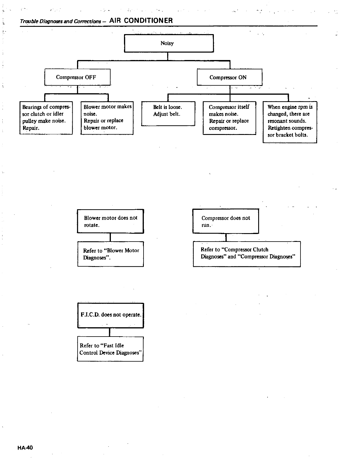
Trouble
Diagnoseund
Conectiom
AIR
CON
DITION
ER
Compressor
OFF
Bearings
of
compres
sor
clutch
or
idler
pulley
make
noise
Repair
HA
40
I
Blower
motor
makes
noise
Repair
or
replace
blower
motor
Blower
motor
does
not
rotate
Refer
to
Blower
Motor
Diagnosesu
F
I
C
D
does
not
operate
Refer
to
Fast
Idle
Control
Device
Diagnoses
Noisy
Belt is loose
Adjust
belt
Compressor
ON
r
Compressor
itself
makes
noise
Repair
or
replace
compressor
Compressor
does
not
run
When
engine
rpm
Is
changed
there
are
resonant
sounds
Retighten
compres
sor
bracket
bolts
Refer
to
Compressor
Clutch
Diagnoses
and
Compressor
DiagnoseS
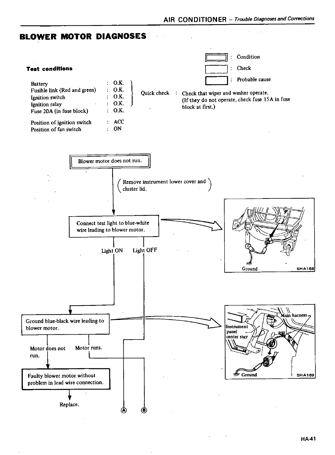
AIR
CON
DITION
ER
Trouble
Diagnosesand
Corrections
BLOWER
MOTOR
DIAGNOSES
Test
conditions
II II
Condition
Check
Battery
Fusible
link
Red
and
green
Ignition
switch
Ignition
relay
Fuse
20A
in
fuse
block
O
K
O
K
O
K
O
K
O K
Probable
cause
Quick
check
Check
that
wiper
and washer
operate
If
they
do
not
operate
check
fuse
l5A
in
fuse
block
at
first
Position
of
ignition
switch
ACC
Position
of
fan
sWitch
ON
II
Blower
motor
does
not
run
II
Remove
instrument
lower
cover
and
cluster
lid
Connect
test
light
to
blue
white
wire
leading
to
blower
motor
I
I
Ught
ON
Ugh
OFF
Ground
SHA168
Ground
blue
black
wire
leading
to
blower
motor
SHA169
I
Motor
does
not
fun
I
Motor
runs
I
Faulty
blower
motor
without
problem
in
lead
wire
connection
t
Replace
@ @
HA
41
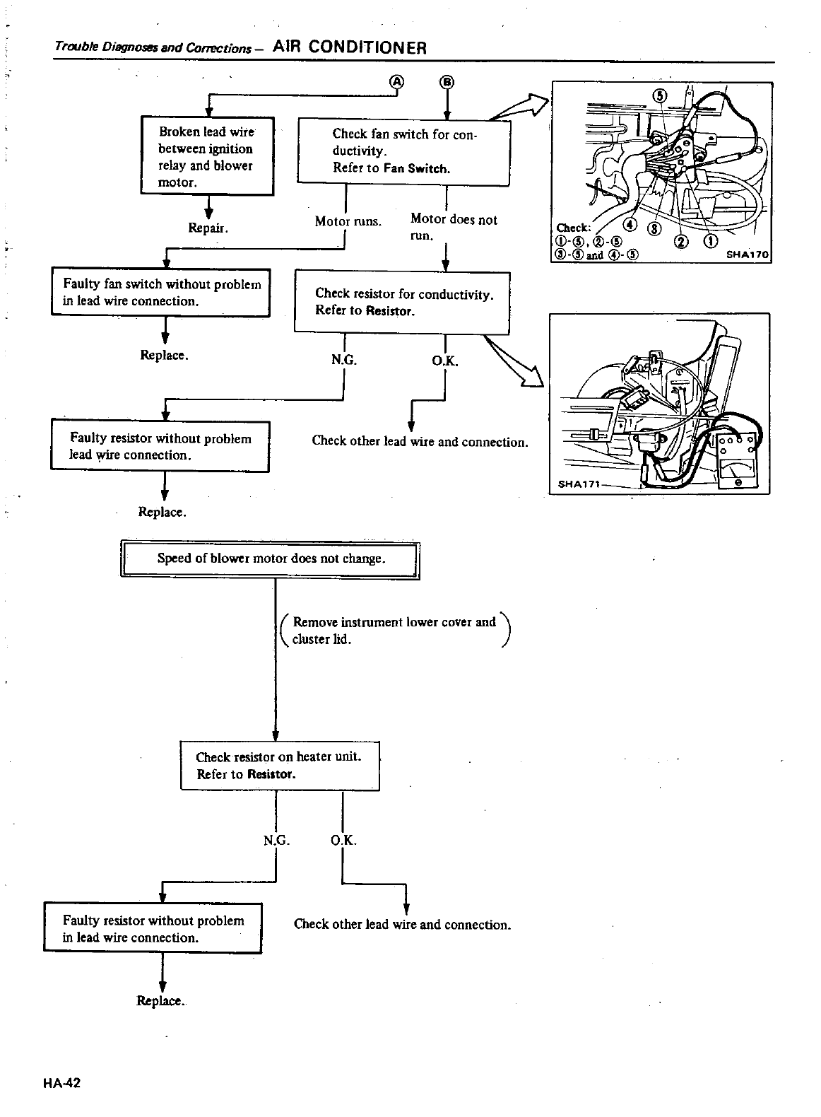
TroubieDiagnosesandCorrections
AIR
CONDITIONER
Broken
lead
wire
between
ignition
relay
and
blower
motor
t
Repair
Faulty
fan
switch
without
problem
I
in
lead
wire
connection
t
Replace
Faulty
resistor
without
problem
lead
e
connection
Replace
Check
fan
switch
for
con
ductivity
Refer
to
Fan
Switch
I
Motor
runs
I
I
Motor
does
not
run
Check
resistor
for
conductivity
Refer
to
Resistor
I
N
G
I
ot
Check
other
lead
wire
and
connection
I
Speed
of
blower
motor
does
not
change
J1
Remove
instrument
lower
cover
and
cluster
lid
Check
resistor
on
heater
unit
Refer
to
Resistor
Faulty
resistor
without
problem
in
lead
wire
connection
l
Replace
HA
42
N
G
I
O
K
I
t
Check
other
lead
wire
and
connection
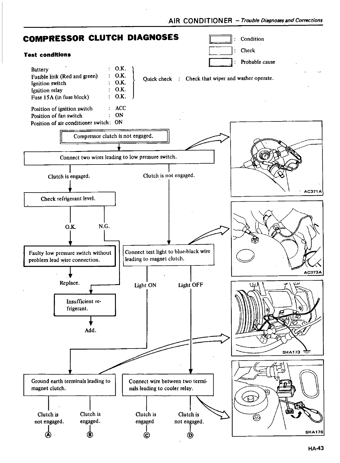
AI
R
CO
N
0
ITIO
N
ER
Trouble
Diagnosesand
Corrections
COMPRESSOR CLUTCH
DIAGNOSES
Test
conditions
Battery
Fusible
link
Red
and
green
Ignition
switch
Ignition
relay
Fuse
I
SA
in
fuse
block
Position
of
ignition
switch
ACC
Position
of
fan
switch
ON
Position
of
air
conditioner
switch
ON
OK
OK
OK
O K
O
K
II
J
Condition
I I
Check
I
I
Probable
cause
Quick
check
Check
that
wiper
and washer
operate
II
AC371
A
I
Compressor
clutch
is
not
engaged
Connect
two
wires
leading
to
low
pressure
switch
I
Clutch
is
engaged
1
Check
refrigerant
level
I I
O
K
N
G
L
Faulty
low
pressure
switch
without
problem
lead
y
ire
connection
Replace
Insufficient
re
frigerant
t
Add
Ground
earth
terminals
leading
to
magnet
clutch
Clutch
is
not
engaged
Clutch
is
engaged
I
Clutch
is
not
engaged
o
Connect
test
light
to
blue
black
wire
leading
to
magnet
clutch
I
light
ON
I
light
OFF
AC373A
Connect
wire
between
two
termi
1
0
00
re
@j
Clutch
is
Clutch
i
@
engaged
not
engaged
I I
@ @
SHA17G
HA43
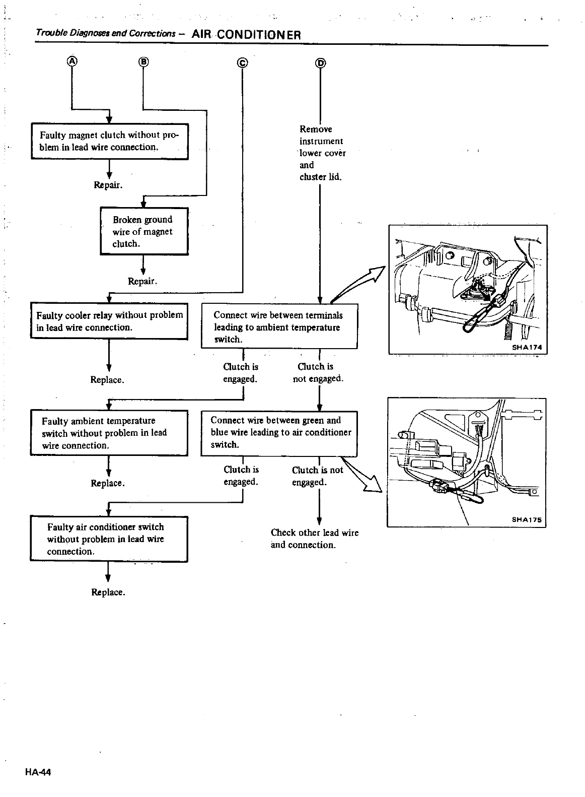
Trouble
Diagnore
end
Correction
AIR
CON
DiTtON
ER
@
Ii
Faulty
magnet
clutch
without
pro
blem
in
lead
wire
connection
t
Repair
Broken
ground
wire of
magnet
clutch
t
Repair
Faulty
cooler
relay
without
problem
in
lead
wire
connection
Replace
Faulty
ambient
temperature
switch
without
problem
in
lead
wire
connection
Replace
Faulty
air
conditioner
switch
without
problem
in
lead
wire
connection
Replace
HA44
@
Remove
instrument
lower
cover
and
clust
r
lid
leading
to
ambient
temperature
switch
I
Clutch
is
engaged
I
I
Clutch
is
not
engaged
Connect
wire
between
green
and
blue
wire
leading
to
air
conditioner
switch
I
Clutch
is
engaged
J
ClutCh1is
no
engaged
U
Check
other
lead
wire
and
connection
SHA 174
SHA
175
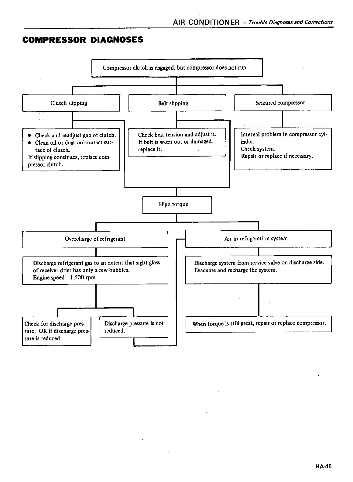
AIR
CONDITIONER
Trouble
Diagnosesand
Corrections
COMPRESSOR
DIAGNOSES
Compressor
clutch
is
engaged
but
compressor
does
not
run
I
Clutch
slipping
II
Belt
slipping
II
Seizured
compressor
Check
and
readjust
gap
of
clutch
Clean
oil
or
dust
on
contact
sur
face
of
clutch
If
slipping
continues
replace
com
pressor
clutch
Check
belt
tension
and
adjust
it
If
belt
is
worn
out
or
damaged
replace
it
Internal
problem
in
compressor
cyl
inder
Check
system
Repair
or
replace
if
necessary
High
torque
Overcharge
of
refrigerant
11
Air
in
refrigeration
system
Discharge
refrigerant
gas
to
an
extent
that
sight
glass
of
receiver
drier
has
only
a
few
bubbles
Engine
speed
1
500
rpm
Discharge
system
from
service
valve
on
discharge
side
Evacuate
and
recharge
the
system
Check
for
discharge
pres
sure
OK
if
discharge
pres
sure
is
reduced
Discharge
pressure
is
not
reduced
I
When
torque
is
still
great
repair
or
replace
compressor
I
HA
45
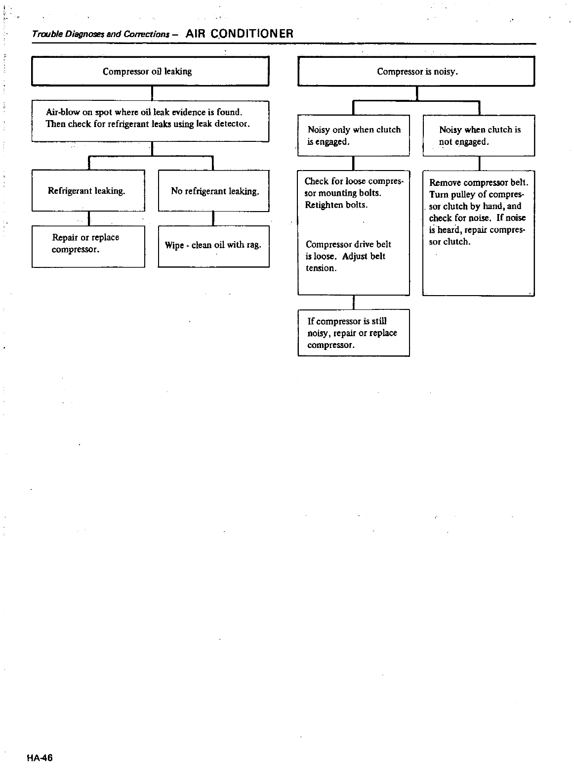
Trouble
Diagnoseund
Corrections
AIR
CONDITION
ER
Compressor
oil
leaking
Air
blow
on
spot
where
oillcak
evidence
is
found
Then
check
for
refrigerant
leaks
using
leak
detecror
I
Refrigerant leaking
No
refrigerant
leaking
Repair
or
replace
compressor
Wipe
clean
oil
with
rag
HA
46
Compressor
is
noisy
Noisy
only
when
clutch
is
engaged
Check
for
loose
compres
sor
mounting
bolts
Retighten
bolts
Compressor
drive
belt
is loose
Adjust
belt
tension
If
compressor
is
still
noisy
repair
or
replace
compressor
Noisy
when
clutch
is
not
engaged
Remove
compressor
belt
Turn
pulley
of
compres
sor
clutch
by
hand
and
check
for
noise
If
noise
is
heard
repair
compres
sor
clutch
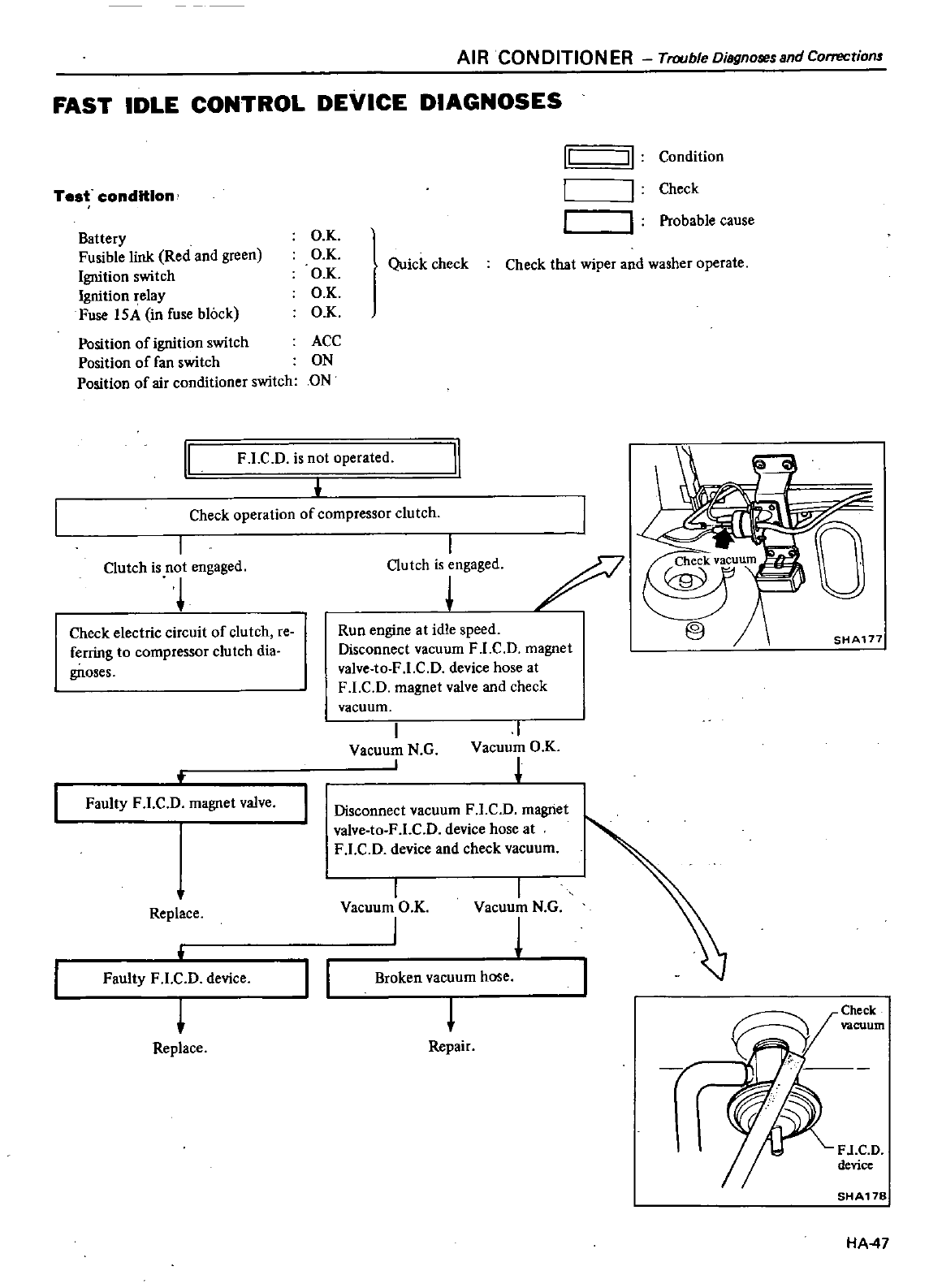
AIR
CONDITIONER
Trouble
Diagnoses
and
Corrections
FAST
IDLE
CONTROL
DEVICE
DIAGNOSES
Test
condition
Battery
Fusible
link
Red
and
green
Ignition
switch
Ignition
relay
Fuse
IS
in
fuse
block
O
K
OK
OX
OK
OX
Quick
check
Check
that
wiper
and
washer
operate
Position
of
ignition
switch
ACC
Position
of
fan
switch
ON
Position
of
air
conditioner
switch
ON
F
LC
D
is
not
operated
II
Check
operation
of
compressor
clutch
I
Clutch
is
not
engaged
Check
electric
circuit
of
clutch
reo
ferring
to
compressor
clutch
dia
gnoses
Faulty
F
l
C
D
magnet
valve
Replace
Faulty
F
l
C
Ddevice
Replace
II
q
Condition
II
Check
I
I
Probable
cause
I
Outch
is
engaged
j
D
Run
engine
at idle
speed
Disconnect
vacuum
F
LC
D
magnet
valve
to
F
LC
D
device
hose
at
F
LC
D
magnet
valve
and
check
vacuum
I
Vacuum
N
G
I
I
Vacuum
O
K
Disconnect
vacuum
F
l
C
D
magnet
valve
lo
F
LC
D device
hose
at
F
l
C
D device
and check
vacuum
I
Vacuum
O
K
j
I
Vacuum
N G
1
J
I
Broken
vacuum
hose
J
Repair
SHA177
7
Check
vacuum
F
l
C
D
device
SHA17S
HA
47
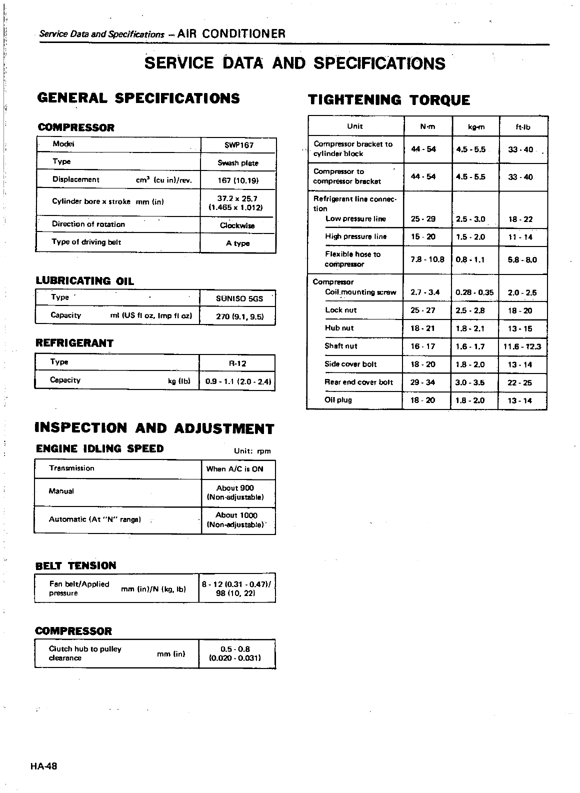
Setvice
Data
and
Specifications
AIR
CONDITIONER
SERVICE
DATA
AND
SPECIFICATIONS
GENERAL
SPECIFICATIONS
TIGHTENING
TORQUE
COMPRESSOR
Unit
N
m
k
ft
lb
Model
SWP167
Compressor
bracket
to
44 54
45 55
33
40
cylinder
block
TVpe
Swash
plate
I
Compressor
to
44 54
4
5
55
33
40
Displacement
cm3
cu
inl
rev
167110
191
compressor
bracket
I
Cylinder
bore
x
stroke
mm
in 37
2
25
7
Refrigerant
line
connec
11
465x
1
0121
tion
I
Low
pressure
line
25 29
2
5
3
0
18
22
Direction
of
fotation
ClOckwise
I
High
pressure
line
15
20
11
5
2
0
11
14
Type
of
driving
belt
A type
flexible hose
to
lOB
corilpreuor
78
10
8
1 1
5
8
0
LUBRICATING
OIL
Compressor
I
0
28
0
35
1
I
Coil
mounting
screw
27
3
4 2
0
2
5
Type
SUNISO
5GS
12
5
I
I
Lock
nut
25 27
2 8
18
20
Capacity
ml
US
fl
OZ
Imp
fI
02
270
19 1
9
51
Hub
nut
18
21
11
8
2
1
I
13 15
REFRIGERANT
Shaft
nut
16 17
11
6
1
7
111
6
12
3
Type
R
12
Side
cover
bolt
18
20
11
8
2
0
I
13 14
Capacity
kg
UbI
09
11
12
0
2
411
Reaf end
coyer
bolt
29
34
13
0
3
5
I
22
25
Oil
plug
18
20
11
8 20
I
13
14
INSPECTION
AND
ADJUSTMENT
ENGINE
IDLING
SPEED
Unit
rpm
Transmission
When
Ale
is
ON
Manual
About
900
Non
cidjustablel
Automatic
At
N
rangsl
About
1000
Nori
adjustable
BELT
TENSION
Fan
belt
Applied
pressure
mm
UnlN
kg
Ibl
18
1210
31
0
4711
98
110
221
COMPRESSOR
Clutch
hub
to
pulley
clearance
mm
in
0
5
0
8
10
020
0
0311
HA
48
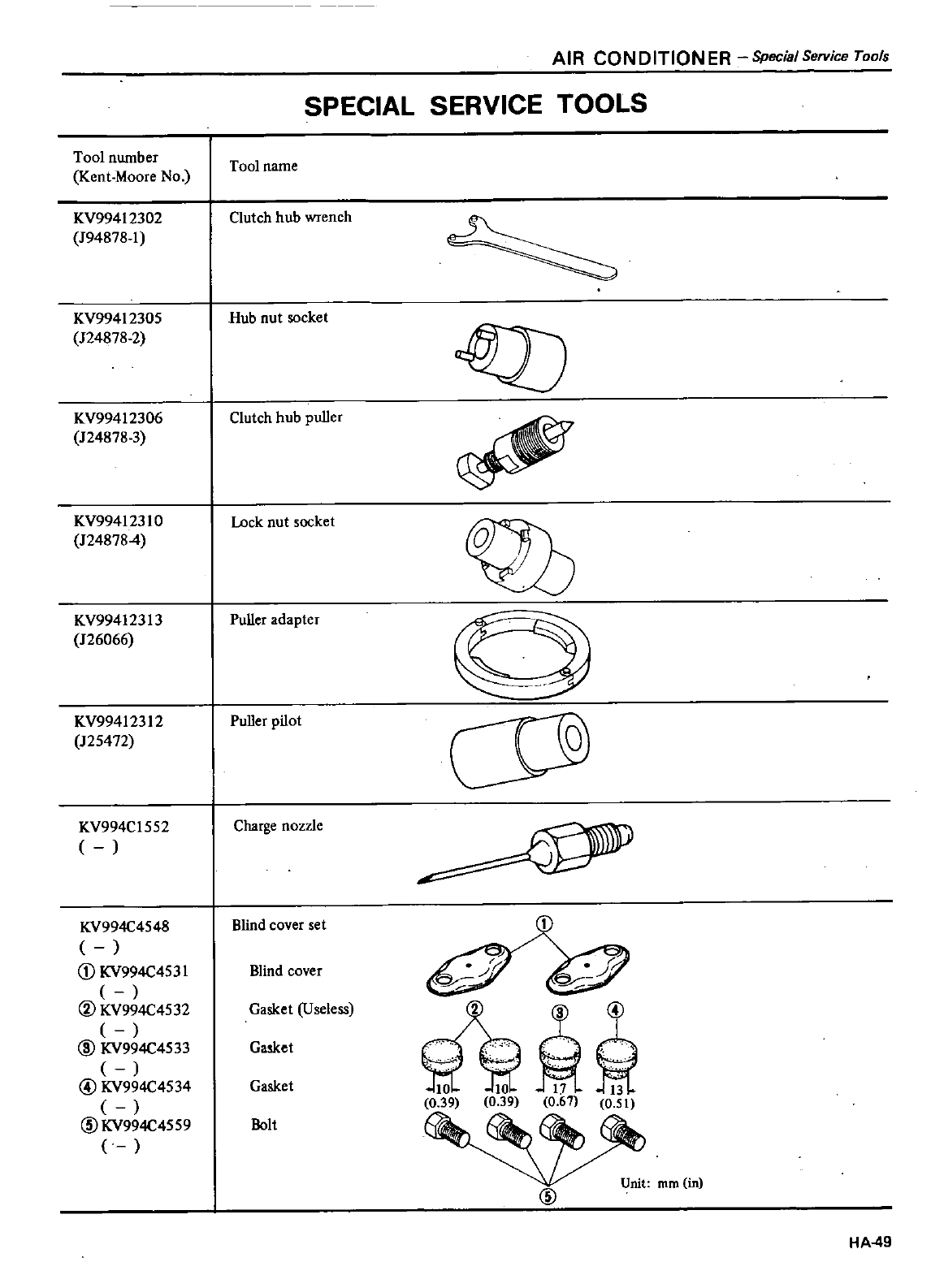
Tool
nwnber
Kent
Moore
No
KV99412302
J94878
1
AIR
CONDITIONER
SpecialService
Tools
SPECIAL
SERVICE
TOOLS
Tool
name
Clutch
hub
wrench
KV99412305
Hub
nut
socket
124878
2
KV99412306
Clutch
hub
puller
124878
3
KV99412310 Lock
nut
socket
QD
1248784
KV99412313
Puller
adapter
126066
KV99412312
125472
KV994C1552
KV994C4548
CD
KV994C453I
@KV994C4532
@
KV994C4533
@
KV994C4534
@KV994C4559
Puller
pilot
Charge
nozzle
Blind
cover
set
Blind
cover
Gasket
Useless
3@
1
c
11
1
039 0
39
0
61
0
51
Gasket
Gasket
Bolt
@
Unit
rom in
HA49
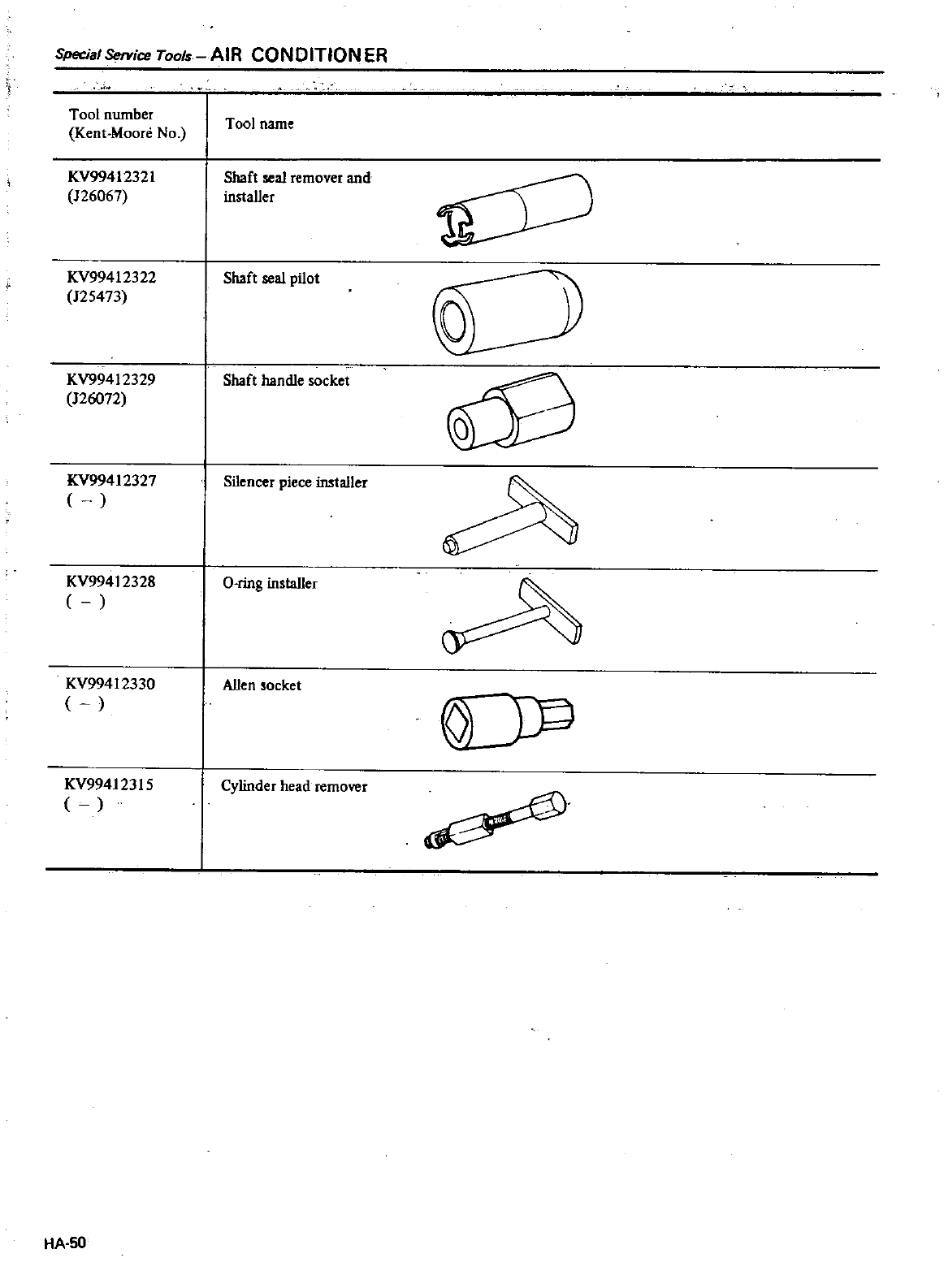
Special
Service
Tools
AIR
CONDITION
ER
Tool
number
Kent
Moore
No
KV9941232I
126067
KV99412322
125473
KV99412329
126072
KV99412327
KV99412328
KV99412330
KV99412315
HA
50
Tool
name
Shaft
seal
remover
and
installer
Shaft
seal
pilot
Shaft
handle
socket
Silencer
piece
installer
O
ring
insta11er
Allen
socket
Cylinder
head
remover
o
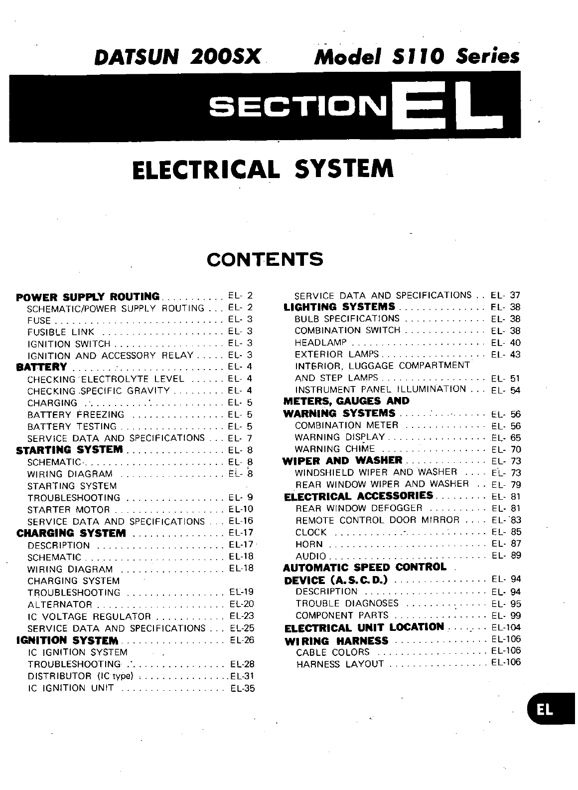
DATSUN
200SX
Model
S
J J
0
Series
SECTIONE
L
ELECTRICAL SYSTEM
CONTENTS
POWER
SUPPLY
ROUTING
EL
2
SERVICE
DATA
AND
SPECIFICATIONS
EL
37
SCHEMATICIPOWER
SUPPLY
ROUTING
EL
2
LIGHTING
SYSTEMS
EL
38
FUSE
EL
3
BULB
SPECIFICATIONS
EL
38
FUSIBLE
LINK
EL
3
COMBINATION
SWITCH
EL
38
IGNITION
SWITCH
EL
3
HEADLAMP
EL
40
IGNITION
AND
ACCESSORY
RELAY
EL
3
EXTERIOR
LAMPS
EL
43
BATTERY
EL
4
INTERIOR
LUGGAGE
COMPARTMENT
CHECKING
ELECTROLYTE
LEVEL
EL
4
AND
STEP
LAMPS
EL
51
CHECKING
SPECIFIC
GRAVITY
EL
4INSTRUMENT
PANEL
ILLUMINATION
EL
54
CHARGING
EL
5
METERS
GAUGES
AND
BATTERY
FREEZING
EL
5
WARNING
SYSTEMS
EL
56
BATTERY
TESTING
EL
5
COMBINATION
METER EL
56
SERVICE
DATA
AND
SPECIFICATIONS
EL
7WARNING
DISPLAY
EL
65
STARTING
SYSTEM
EL
8WARNING
CHIME
EL
70
SCHEMATIC
EL
B
WIPER
AND
WASHER
EL
73
WIRING
DIAGRAM
EL
8
WINDSHIELD
WIPER
AND
WASHER
EL
73
STARTING
SYSTEM
REAR WINDOW
WIPER
AND
WASHER
EL
79
TROUBLESHOOTING
EL
9
ELECTRICAL
ACCESSORIES
EL
81
STARTER
MOTOR
ELla
REAR
WINDOW
DEFOGGER
EL
81
SERVICE
DATA
AND
SPECIFICATIONS
EL
16
REMOTE
CONTROL
DOOR
MIRROR
EL
83
CHARGING
SYSTEM
EL
17
CLOCK
EL
85
DESCRIPTION
EL
17
HORN
EL
87
SCHEMATIC
EL
18
AUDIO
EL
89
WIRING
DIAGRAM
EL
18
AUTOMATIC
SPEED
CONTROL
CHARGING
SYSTEM
DEVICE
A
S
C
D
EL
94
TROUBLESHOOTING
EL
19
DESCRIPTION
EL
94
ALTERNATOR
EL20
TROUBLE
DIAGNOSES
EL 95
IC
VOLTAGE
REGULATOR
EL
23
COMPONENT
PARTS
EL
99
SERVICE
DATA
AND
SPECIFICATIONS
EL25
ELECTRICAL
UNIT
LOCATION
EL
104
IGNITION
SYSTEM
EL
26
WI
RING
HARNESS
EL
106
IC
IGNITION
SYSTEM
CABLE
COLORS
EL
106
TROUBLESHOOTING
EL28
HARNESS
LAYOUT
EL
106
DISTRIBUTOR
IC
type
EL31
IC
IGNITION
UNIT
EL35
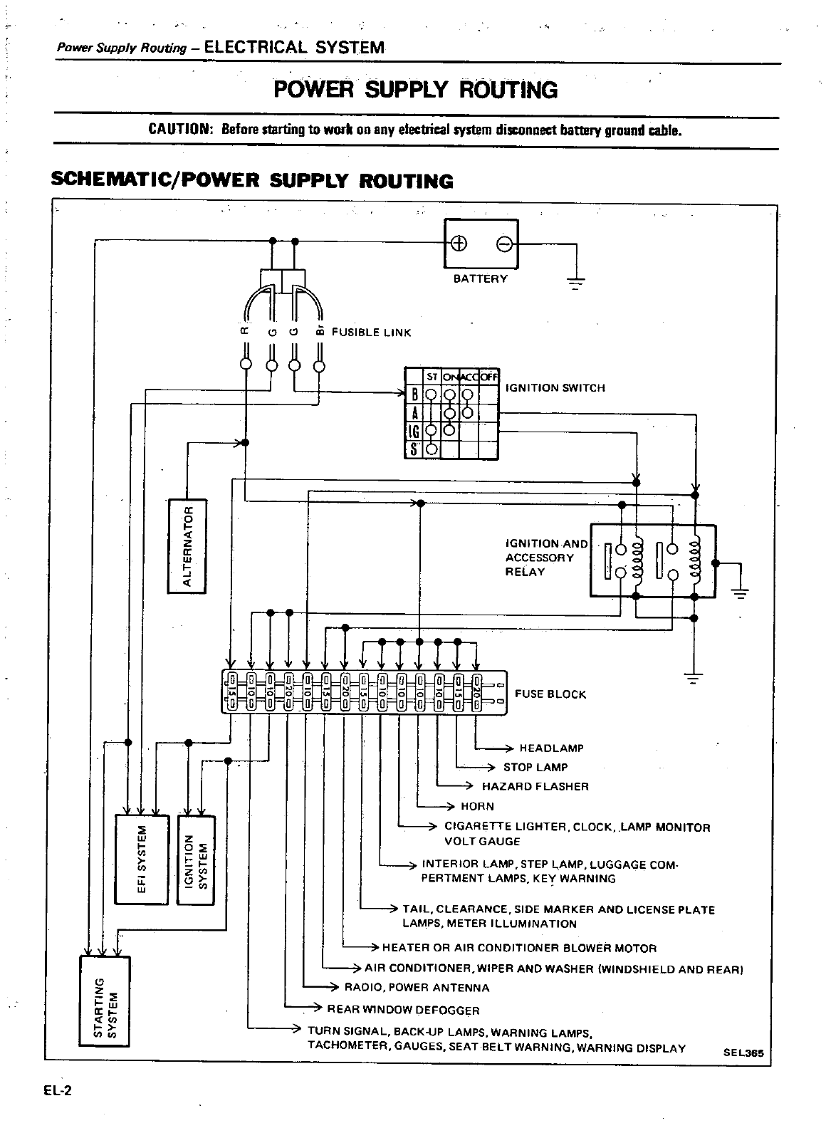
Power
Supply
Routing
ELECTRICAL
SYSTEM
POWER
SUPPLY
ROUTING
CAUTION
Before
starting
to
worll
on
any
J
system
disconnect
battery
ground
cable
SCHEMATIC
POWER
SUPPLY ROUTING
1
w
a
EL
2
V
a
o
z
a
w
J
w
t
u
w
f
T
ci
C
CD
FUSIBLE
LINK
t
Q
1
8
BATTERY
J
I
I
sr
Or
l
occ
E1
BOg
0
IGNITION
SWITCH
AI
0
I
16
Q
S
5
I
IGNITION
AND
ACCESSORY
RELAY
l l
in
ir
1
f
I
I
FUSE
BLOCK
o
L
HEADLAMP
STOP
LAMP
i
HAZARD
FLASHER
HORN
CIGARETTE
LIGHTER
CLOCK
LAMP
MONITOR
VOLT
GAUGE
z
0
w
t
z
i
INTERIOR
LAMP
STEP
LAMP
LUGGAGE
COM
PERTMENT
LAMPS
KE
WARNING
TAIL
CLEARANCE
SIDE
MARKER
AND
LICENSE
PLATE
LAMPS
METER
ILLUMINATION
7
HEATER
OR
AIR
CONDITIONER
BLOWER
MOTOR
7
AIR
CONDITIONER
WIPER
AND
WASHER
WINDSHIELD
AND
REARl
RAOIO
POWER
ANTENNA
REAR
WlNDOW
DEFOGGER
TURN
SIGNAL
BACK
UP
LAMPS
WARNING
LAMPS
TACHOMETER
GAUGES
SEAT
BELT
WARNING WARNING
DISPLAY
SEL365
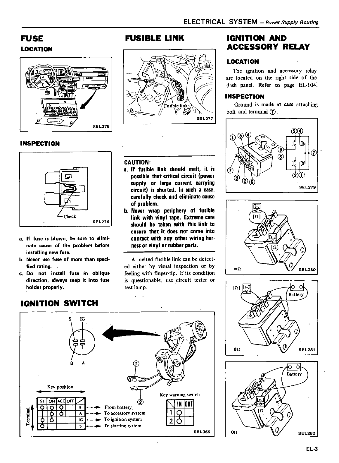
FUSE
LOCAnON
SEL275
INSPECTION
c
l
l
CI
c
SE
L276
8
If
fuse
is
blown
be
sure
to
elimi
nate
cause
of
the
problem
before
installing
new
fuse
b
Never
use
fuse
of
more
than
speci
fied
rating
c
Do
not
install
fuse
in
oblique
direction
always
snap
it into
fUle
holder
properly
IGNITION
SWITCH
S
1G
ELECTRICAL
SYSTEM
Power
Supply
Routing
FUSIBLE
UNK
SEL277
CAUTION
a
If
fusible
link
should
melt
it
is
possible
that
critical
circuit
power
supply
or
large
current
carrying
circuit
is
shorted
In
such
a case
carefully
check
and
eliminate
cause
of
problem
b
Never
wrap
periphery
of
fusible
link
with
vinyl
tape
Extreme
care
should
be
taken
with
this link to
ensure
thet
it
does
not
come
into
contact
with
any
other
wiring
har
ness
or
vinyl
or
rubber
parts
A
melted
fusible
link can
be
detect
ed
either
by
visual
inspection
or
by
feeling
with
fmger
tip
If
its
condition
is
questionable
use
circuit
tester
or
test
lamp
B
A
sr
t
T
01
g
Q
B
From
battery
5
A
To
accessOIY
system
o
IG
To
tionsystem
5s
To
starting
system
c
s
k
U
Key
warning
switch
IN
OUT
I
g
SEL369
IGNITION
AND
ACCESSORY
RELAY
LOCATION
The
ignition
and
accessory
relay
are
located
on
the
right
side
of
the
dash
panel
Refer
to
page
EL
104
INSPECTION
Ground
is
made
at
case
attaching
bolt
and
tenninal
rJ
SE
L279
I
n
EL3
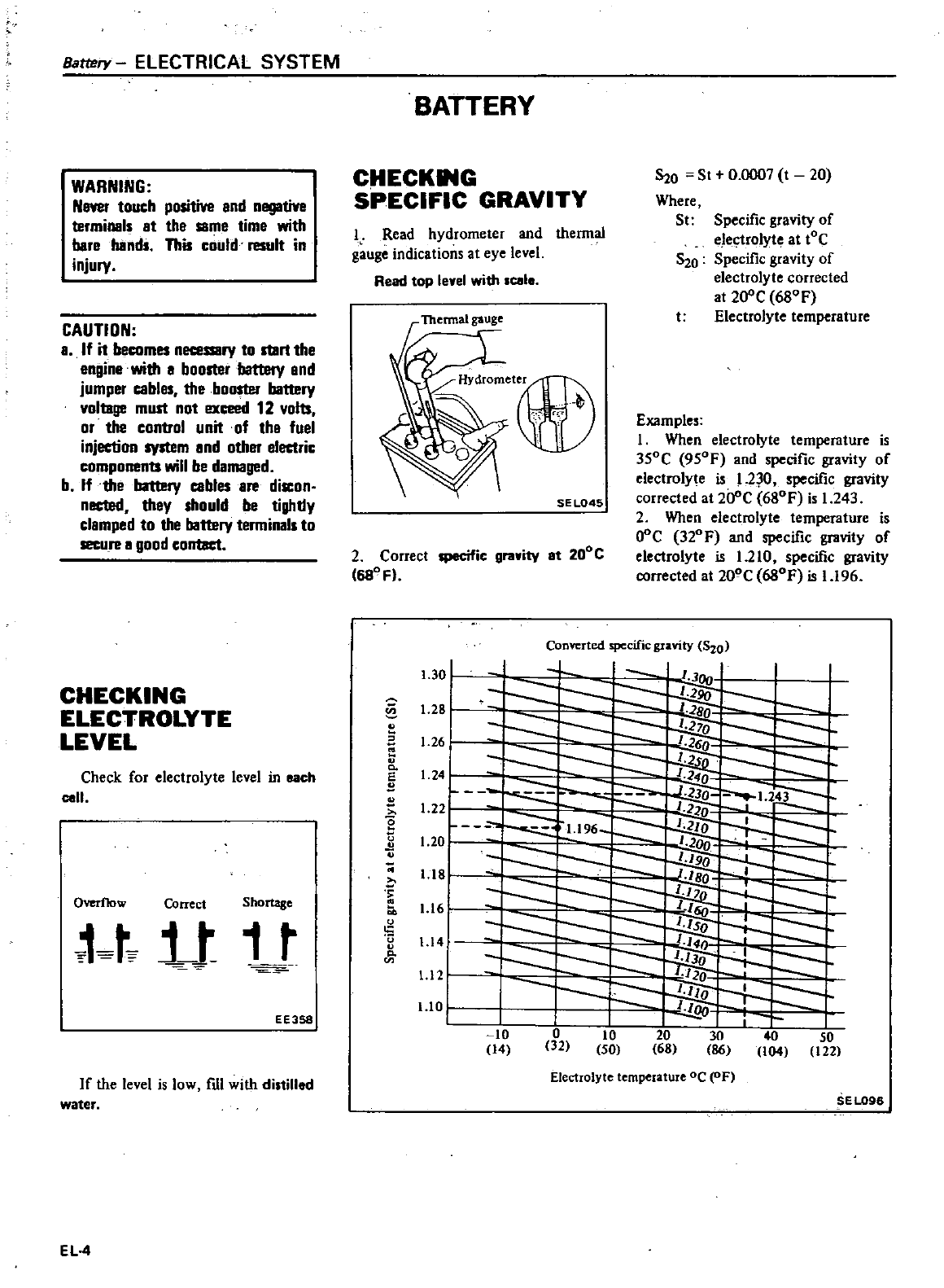
Battery
ELECTRICAL SYSTEM
WARNING
Naver
touch
positive
and
negative
termill8ls
at
the
same
time
with
bare
hands
This
could
result
in
injury
CAUTION
a
If
it
becomes
necessary
to
start
the
engine
with
a
booster
battery
end
jumper
cables
the
booster
battery
voltage
must
not
ex
12
volts
or
the control unit of
the
fuei
injection
system
and
other
electric
components
will
be
damaged
b
If
the
battery
cables
are
discon
nected
they
should
be
tighdy
clamped
to
the
battery
terminals
to
secure
a
good
contact
CHECKING
ELECTROLYTE
LEVEL
Check
for
electrolyte
level
in
each
cell
Overflow
Correct
Shomse
t
j
t
1
t
EE358
If
the
level
is
low
fUI
with
distilled
water
EL
4
BATTERY
CHECK
G
SPECIFIC
GRAVITY
J
Read
hydrometer
and
thermal
gauge
indications
at
eye
level
Reed
top
level
with
leale
r
Thermal
gauge
SE
L045
2
Correct
specific
gravity
et
200C
1680
Fl
O
St
0
0007
t
20
Where
St
S20
Specific
gravity
of
electrolyte
at
tOC
Specific
gravity
of
electrolyte
corrected
at
20
C
680F
Electrolyte
temperature
t
Examples
1
When
electrolyte
temperature
is
350C
950F
and
specific
gravity
of
electrolyte
is
L2
O
specific
gravity
corrected
at 20
C
680F
is
1
243
2
When electrolyte
temperature
is
O
c
320F
and
specific
gravity
of
electrolyte
is
1
210
specific
gravity
corrected
at
200C
680F
is
1
196
1
30
j
specific
gravity
5
0
1
@
1
28
E
u
Co
E
B
u
g
o
u
o
1
14
Co
1
121
1
10
II
10
14
I
o
32
I
10
SO
I
SO
122
r
40
104
Electrolyte
temperature
oC
OF
SEL096
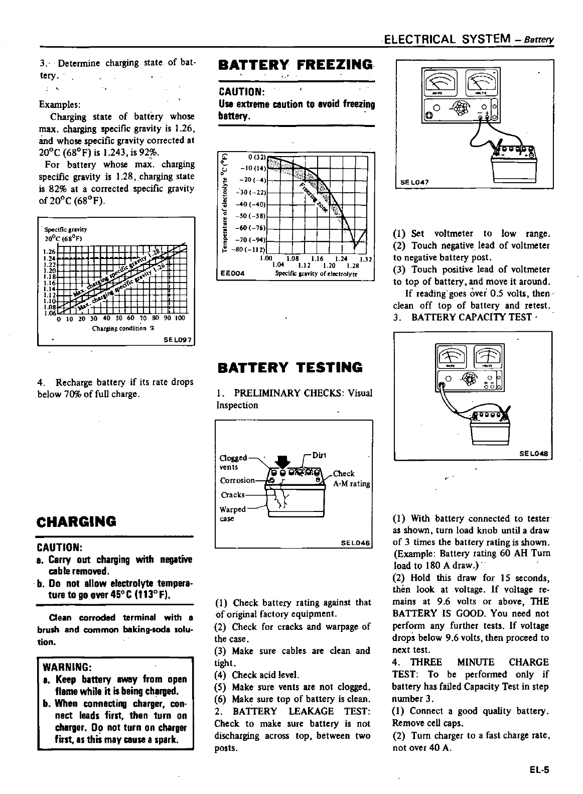
3
Determine
charging
state
of
bat
tery
Examples
Charging
state
of
battery
whose
max
charging
specific
gravity
is
1
26
and
whose
specific
gravity
corrected
at
200C
680F
is
1
243
is
92
For
battery
whose
m
charging
specific
gravity
is
1
28
charging
state
is
82
at
a
corrected
specific
gravity
of
200C
680F
Specific
plvity
20oC
680F
70
80
90 100
Charsin
nditian
l
SE
L097
4
Recharge
battery
if
its
rate
drops
below
7m
of
full
charge
CHARGING
CAUTION
a
Carry
out
charging
with
negative
cab
Ie
removed
b
Do
not
allow
electrolyte
tempera
ture
to
go
over
450C
1130
Fl
Clean
corroded
terminal
with
e
brush
and
common
baking
soda
solu
tion
WARNING
a
Keep
battery
away
from
open
flame
while
it
is
being
charged
b
When
connecting
charger
con
nect
leads
first
then
turn
on
cherger
00
not
turn
on
charger
first
as this
may
cause
a
spark
BATTERY
FREEZING
CAUTION
Usa
extreme
caution
to
avoid
freezing
battery
0
1
U
1014
o
20 4
00
0
22
40
0
o
SO
55 O
I
60
76
70
94
I
80
1I2
L
I
I
to
1
08
1
16
1
24
1
32
1
04
1
12
1
20
1
28
EE004
SpecifIC
Iflvil
oreleclrolyte
BATTERY
TESTING
I
PRELIMINARY
CHECKS
Visual
Inspection
Clogged
I
Dirt
vents
lfil
fil W
Check
Corrosion
r
8A
M
rating
Cracks
I
Y
I
Warped
case
SEL046
1
Check
battery
rating
against
that
of
original
factory
equipment
2
Check
for
cracks
and
warpage
of
the
case
3
Make
sure
cables
are
clean
and
tight
4
Check
acid
level
5
Make
sure
vents
are
not
clogged
6
Make
sure
top
of
battery
is clean
2
BATTERY
LEAKAGE
TEST
Check
to
make
sure
battery
is
not
discharging
across
top
between
two
posts
ELECTRICAL SYSTEM
Battery
1
1
JI
J
Ie
0
4@
Qo
I
SE
L047
1
Set
voltmeter
to
low
range
2
Touch
negative
lead
of
voltmeter
to
negative
battery
post
3
Touch
positive
lead
of
voltmeter
to
top
of
battery
and
move
it
around
If
reading
goes over
0
5
volts
then
clean
off
top
of
battery
and
retest
3
BATTERY
CAPACIlY
TEST
SEL048
1
With
battery
connected
to
tester
as
shown
turn
load
knob
until a
draw
of
3
times
the
battery
rating
is shown
Example
Battery
rating
60
AH
Turn
load
to
180
A
draw
2
Hold
this
draw
for
15
seconds
thim
look
at
voltage
If
voltage
re
mains
at
9 6
volts
or
above
THE
BATTERY
IS
GOOD
You
need
not
perform
any
further
tests
If
voltage
drops
below
9 6
volts
then
proceed
to
next
test
4
THREE
MINUTE
CHARGE
TEST
To
be
performed
only
if
battery
has
failed
Capacity
Test
in
step
nwnber
3
1
Connect
a
good
quality
battery
Remove
cell
caps
2
Tum
charger
to
a
fast
charge
rate
not
over
40
A
EL
5
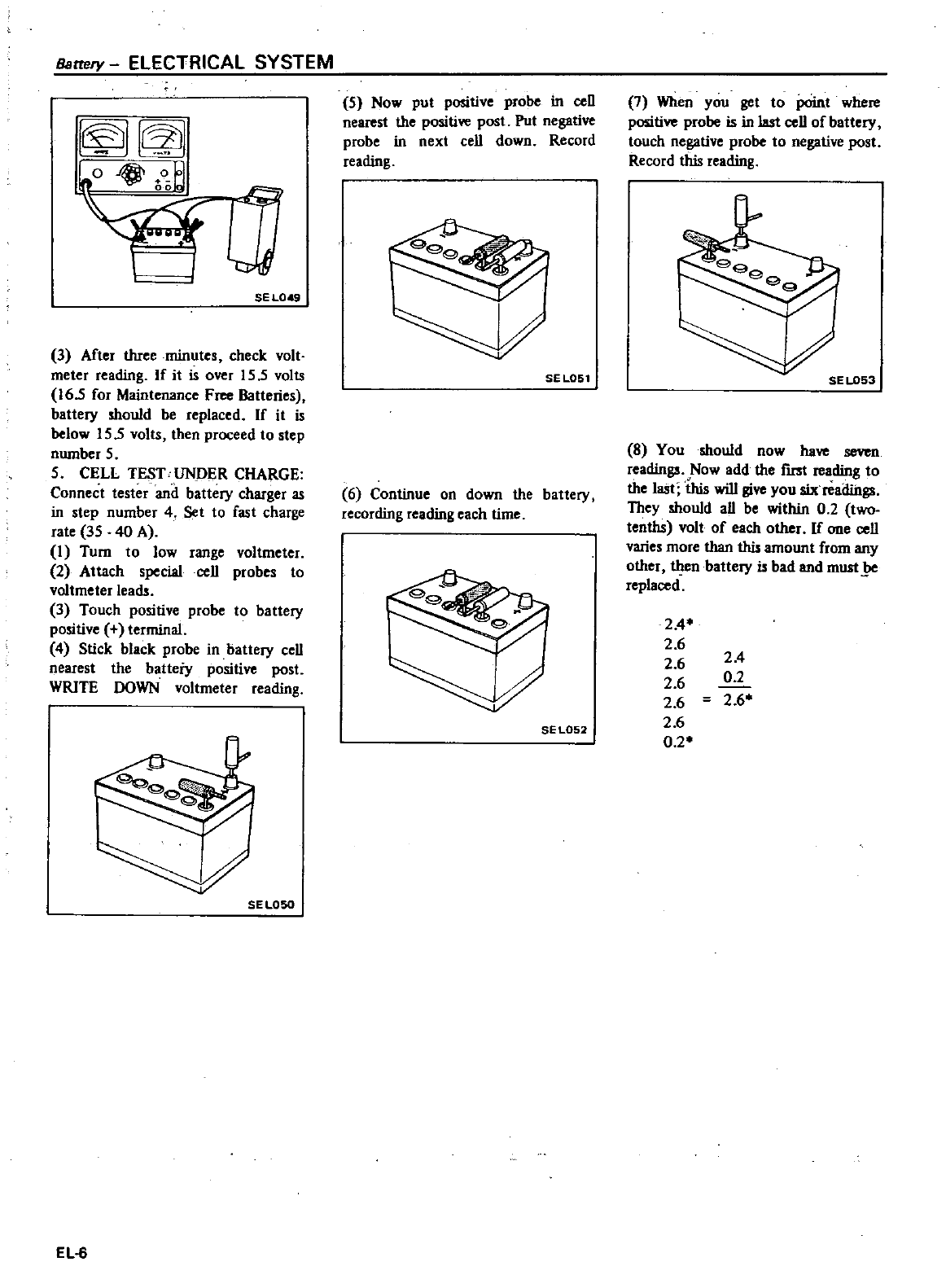
Battery
ELECTRICAL SYSTEM
I
o
0Jol
nnlol
J
SE
L049
3
After
three
minutes
check
volt
meter
reading
If
it
is
over
15
5
volts
16
5
for
Maintenance
Free
Batteries
battery
should
be
replaced
If
it
is
below
15
5
volts
then
proceed
to
step
nwnber
5
5
CELL
TEST
UNPER
CHARGE
Connect
tester
and
battery
charger
as
in
step
number
4
Set
to
fast
charge
rate
35
40
A
I
Turn
to
low range
voltmeter
2
Attach
special
cell
probes
to
voltmeter
leads
3
Touch
positive
probe
to
battery
positive
terminal
4Stick
black
probe
in
battery
cell
nearest
the
batteiy
positive
post
WRITE
DOWN
voltmeter
reading
SEL050
EL
6
5
Now
put
positive
probe
in
ceU
nearest
the
positive
post
Put
negative
probe
in
next
cell
down
Record
reading
SEL051
6
Continue
on
down
the
battery
recording
reading
each
time
SE
L052
7
When
you
get
to
point
where
positive
probe
is
in
last cell
of
battery
touch
negative
probe
to
negative
post
Record
this
reading
ee
9
SE
L053
8
You
should
now
have
seven
readings
Now
add
the
fIrSt
reading
to
the
last
this
will
give
you
six
readings
They
should
aU
be
within
0
2
two
tenths
volt
of
each
other
If
one
cell
varies
more
than
this
amount
from
any
other
then
battery
is
bad and
must
be
replaced
2
4
2
6
2 6
2
6
2
6
2
6
0
2
2
4
0
2
2
6
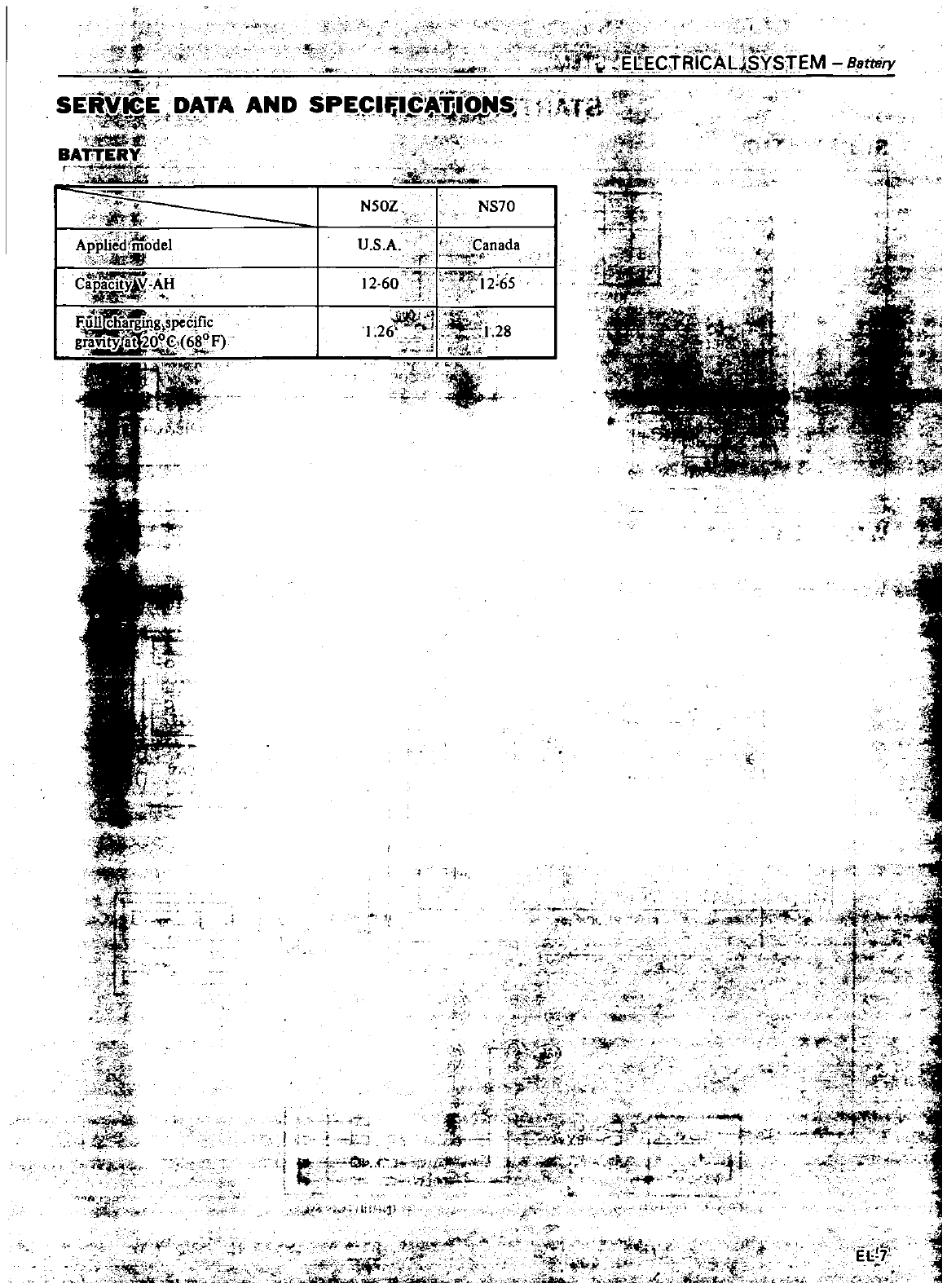
i
V
J
lh
t
S
lE
1
rA
AND
SPE
I
r
H
r
T
C
l
BA
r
E
l
t
g
0
w
r
i
N50Z
NS70
Ii
r
A
ffliiodel
U
S
A
tf
r
nada
f
i
c
r
p
acify
AH
12
60
1
f
Jth65
iliff
Af
A
F
iI
f
n
s
c
ficI26f
1
i
28
g
ili
YJa
6
F
1
t
t
a
4
f
c
l
i
Y
t
C
r1
iICALL
STEM
Battriry
9
j
1
N
i
i
J
t
r
Il
7
i
r
4
ti
tt
I
f
1
l
1
L
j
yj
t
I
i
fT
tlI
f
r
o
O
t
tYt
f
Ii
1Iit
o
4
Jt
rl
t
e
t
j
1i
el
f
V
6
f
t
i
t
j
V
M
7r
1
rt
l
f
7t
j
C
I
t
w
l
r
Jf
j
GI
It
X9
I
i
i
c
p
J
l
Ifi
Jii
t
135
L
ht
c
f
c
S
ti
a
i
Co
jt 1
j
ltii
H
J
t
t
it
AAi
j
i
y
H
3
b
ttj
j
t
1
EIi
7
1
L
7
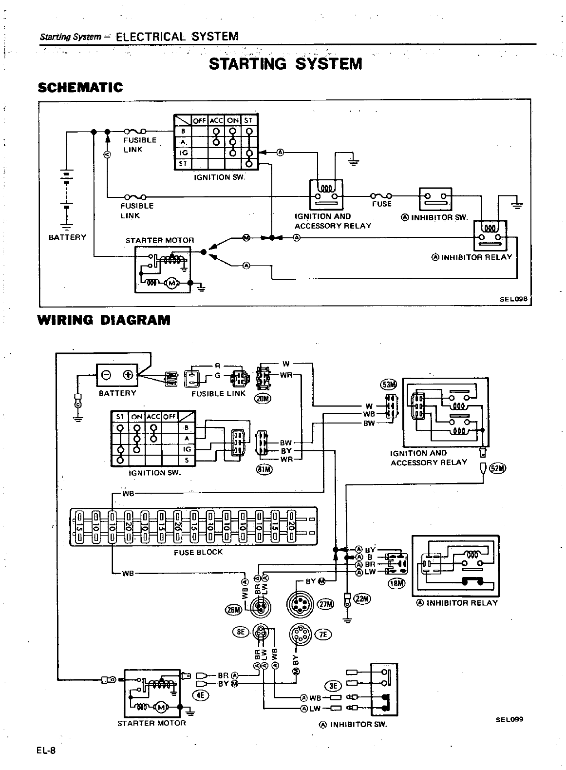
Starting
System
ELECTRICAL
SYSTEM
STARTING
SYSTEM
SCHEMATIC
OFF
Ace
ON
ST
g
Ie
sr
5
l
C
FUSIBLE
LINK
1
IGNITION
SW
I
o
1
C
0
c
I
FUSE
IGNITION
AND
ACCESSORY
RELAY
1 1
FUSIBLE
LINK
@
INHIBITOR
SW
o
0
STARTER
MOTOR
1
BATTERY
@INHIBITOR
RELAY
SEL098
WIRING
DIAGRAM
re Cf
R
o
BATTERY
FUSIBLE
LINK
@
sr
ON
Ace
Off
g
DD
IEI
BW
J
6
Ie
r
ey
5
s
r
WR
@
@ll
w
ID1
WB
BW
oJ
It
@
IGNITION
AND
ACCESSORY
RELAY
IGNITION
SW
r
0
O
Q
tJl
0 0
0
0 0 0 0
o 0
O
ij ij ij ij
o
o
0
COO
000000
0
00
0
0
FUSEBL
CK
Ji
E
@
@
@ri
g@
@INHIBITORRELAY
@
t1
e@
a
m
al 3lD
g
o
g
@
@
@WB
ao
LW
ao
I
We
SEL099
STARTER
MOTOR
@
INHIBITOR
SW
EL
8
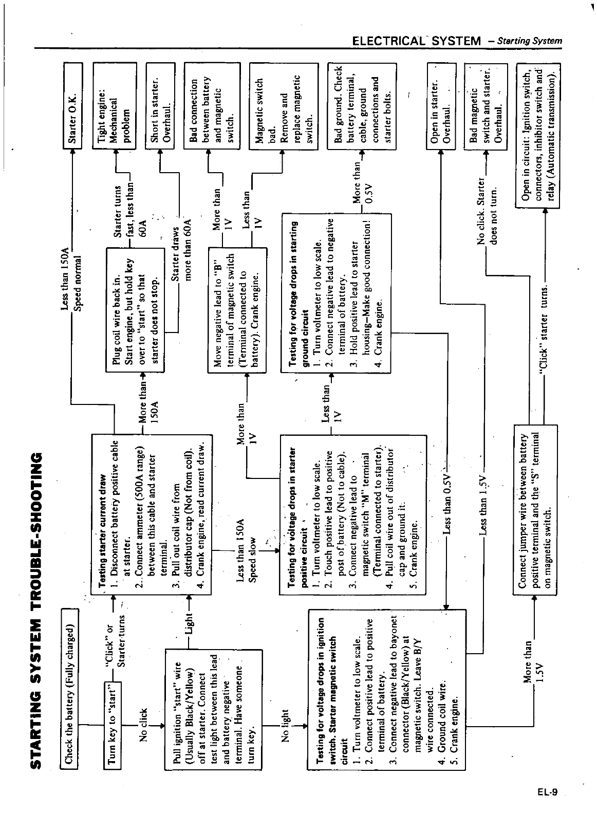
STARTING
SYSTEMTROUBLE
SHOOTING
I
Check
the
battery
Fully
charged
I
Te
ting
tarter
current
drew
I
Turn
key
to
start
r
Click
or
t
I
Disconnect
batteiy
positive
cable
I
Starter
turns
at
starter
N
I
k
2
Connect
ammeter
500A
range
oc
1
between
thIS
cable
and
starter
terminal
3
Pull
out
coil
wire
from
distributor
cap
Not
from
coil
4
Crank
engine
read
current
draw
Pull
ignition
Ustart
wire
Usually
Black
Yellow
off
at
starter
Connect
test
light
between
this
lead
and
battery
negative
terminal
Have
someone
turn
key
Light
t
I
No
light
1
Testing
for
voltage
drops
in
ignition
Iwitch
Starter
magnetic
switch
circuit
I
Turn
voltmeter
to
low
scale
2
Connect
positive
lead
to
positive
terminal
of
battery
3
Connect
negative
lead
to
bayonet
connector
Black
Yellow
at
magnetic
switch
Leave
B
Y
wire
connected
4
Ground
coil
wire
5
Crank
engine
m
r
eO
More
than
l
SV
More
than
l50A
I
Less
than
ISOA
Speed
slow
l
More
than
4
IV
Testing
for
voltage
drops
in
starter
positive
circuit
I
Turn
voltmeter
to
low
scale
2
Touch
positive
lead
to
positive
post
of
battery
Not
to
cable
3
Connect
negative
lead
to
magnetic
switch
uM
terminal
Terminal
connected
to
starter
4
Pull
coil
wire
out
of
distributor
cap
and
ground
it
5
Crank
engine
Less
than
IV
Less
than
05
Less
than
I
5V
Connect
jumper
wire
between
battery
positive
terminal
and
the
s
terminal
on
magnetic
switch
Less
than
150A
Speed
normal
Plug
coil
wire
back
in
Start
engine
but
hold
key
over
to
start
so
that
starter
docs
not
stop
Starter
turns
r
t
fast
less
than
J
60A
Starter
draws
more
than
60A
More
than
I
V
J
Move
negative
lead
to
B
terminal
of
magnetic
switch
Terminal
connected
to
battery
Crank
engine
Testing
f
r
voltage
drops
in
starting
ground
circuit
I
Turn
voltmeter
to
low
scale
2
Connect
negative
lead
to
negative
terminal
of
battery
3
Hold
positive
lead
to
starter
housing
Make
good
conneCtion
4
Crank
engine
Less
than
IV
More
than
O
SV
No
click
Starter
does
not
turn
Click
starter
turns
0
Starter
O
K
Tight
engine
Mechanical
problem
Short
in
starter
Overhaul
Bad
connection
between
battery
and
magnetic
switch
Magnetic
switch
bad
Remove
and
replace
magnetic
switch
Bad
ground
Check
battery
terminal
cable
ground
connections
and
starter
bolts
J
Open
in
starter
1
Overhaul
Bad
magnetic
switch
and
starter
Overhaul
Open
in
circuit
Ignition
s
itch
connectors
inhibitor
switch
and
relay
Automatic
transmission
m
r
m
0
I
I1
n r
rn rn
I
m
s
I
ill
g
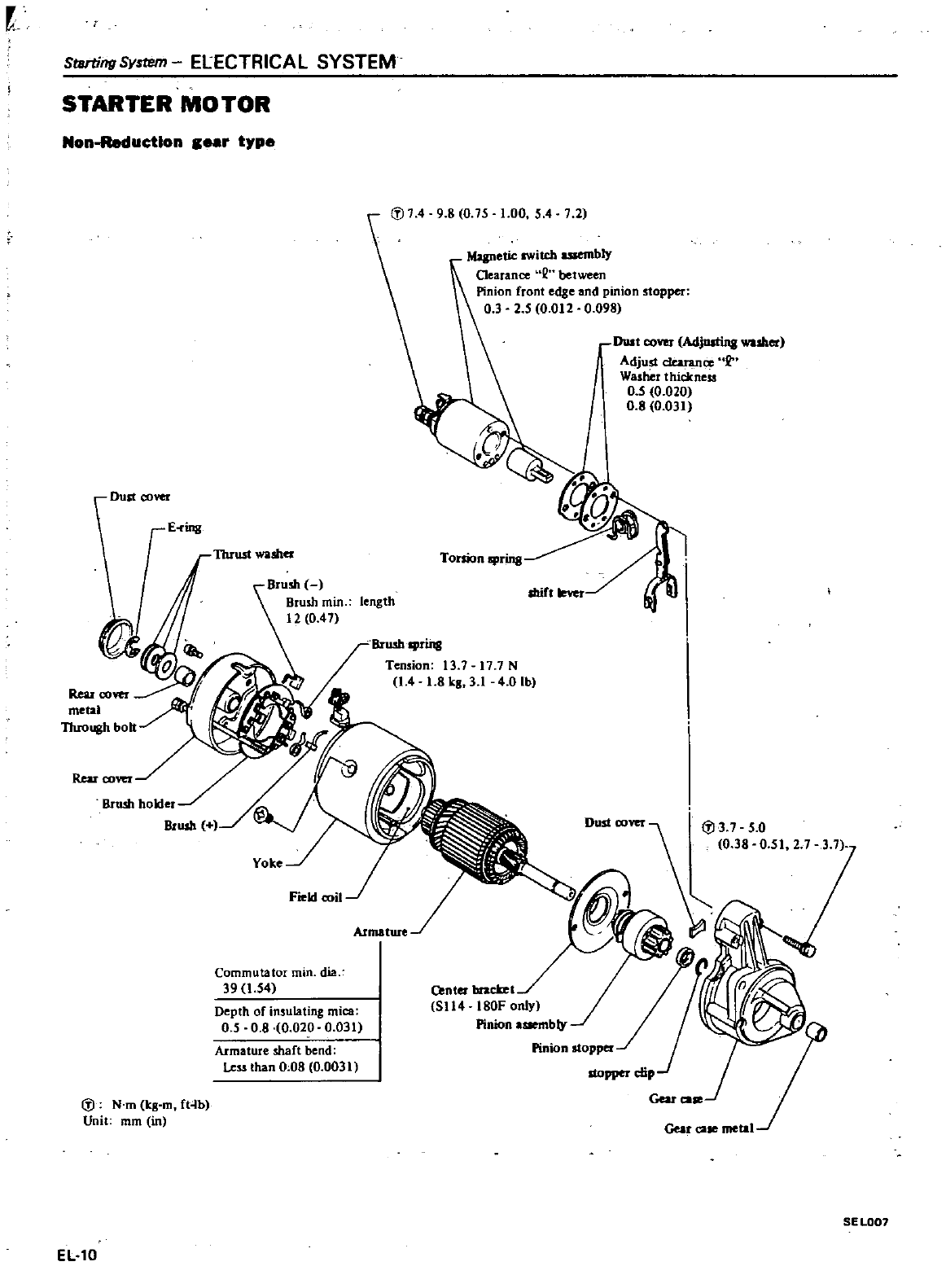
StBrtingSystem
ElECTRICAL
SYSTEM
STARTER MOTOR
Non
Reductlon
ear
type
l
J
74
9 8
0
75
1
00
5
4
7 2
Ileu
00
metal
Through
bo
Brush
Brush
min
length
12
0
47
Mqnetic
lWitcl
asoembly
Ocarance
Q
between
Pinion
front
edge
and
pinion
stopper
0 3 2 5
0
012
0
098
Dust
00
Adjllllin8
er
Adjust
clearance
2
Washer
thickness
0
5 0
020
0
8
0
031
Dust
cover
E
ring
Brush
spring
Tension
13
7
17
7N
1
4
1
8kg 31
4
0
Ib
l
J3
7
5
0
0
38 0
51
2 7
Commutator
min
dia
39
1
54
Center
bracket
5114 180F
only
Pinion
assembly
Pinion
stopper
Depth
of
insulating
mica
0
5
0 8
0
020
0
031
Armature
shaft bend
Les
s
than
0 08 0
0031
l
J
N
m
lcg
m
ft4b
Unit
mm
in
SE
L007
EL10
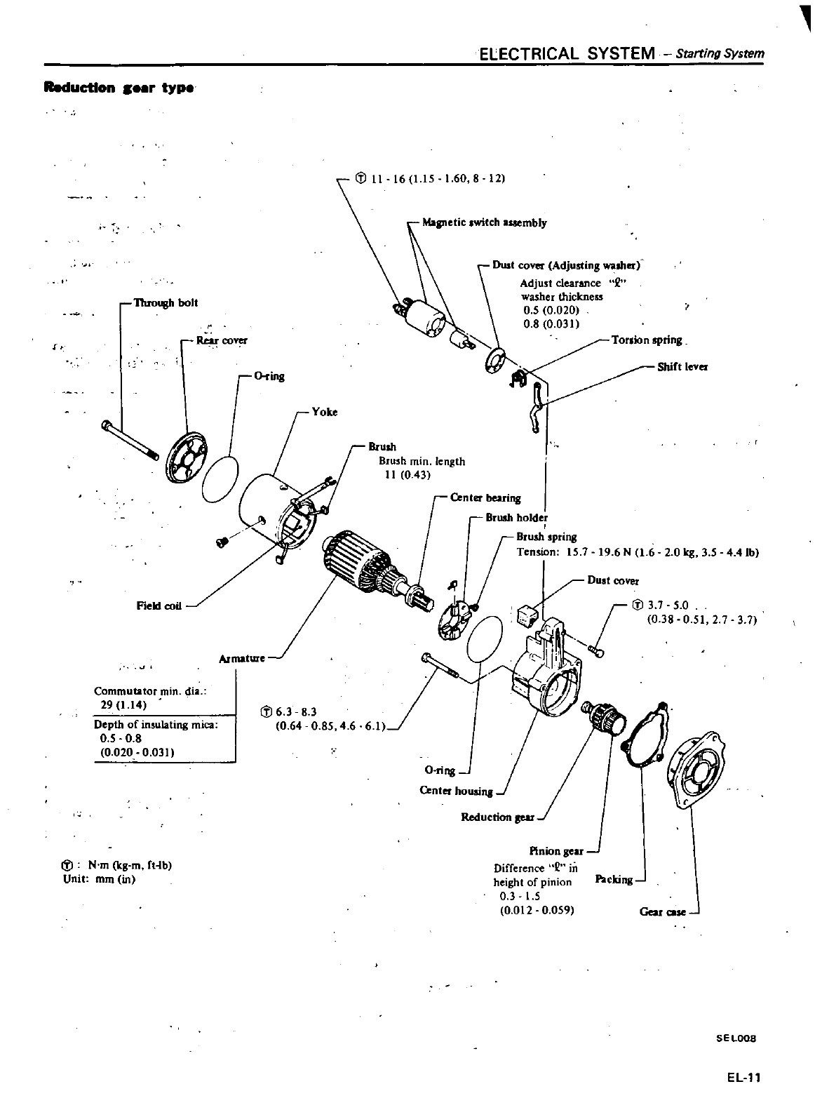
ELECTRICAL SYSTEM
Starting
System
Reduction
r
typo
Q
ring
Dust
cover
Adjusting
washer
Adjust
clearance
washer
thickness
0
5 0
020
0 8 0
031
v
Through
bolt
f
co
Commutator
min
dia
29
1
14
Depth
of
insulating
mica
0
5
0
8
0
020
0
031
Drush
Brush
min
length
11
0 43
Center
bearing
Brush
holder
Brush
spring
Tension
15
1
19
6
N
1
6
2 0 k8 3 5
4
41b
Field
coil
3 1
C
i
6 3
8
3
064 0
85
4
6
O
ring
C
i
N
m
kg
m
fHb
Unit
mm
in
Pinion
gear
Difference
in
height
of
pinion
Packing
0 3
15
0
012
0
059
Gear
ca
SE
LOOS
ELll
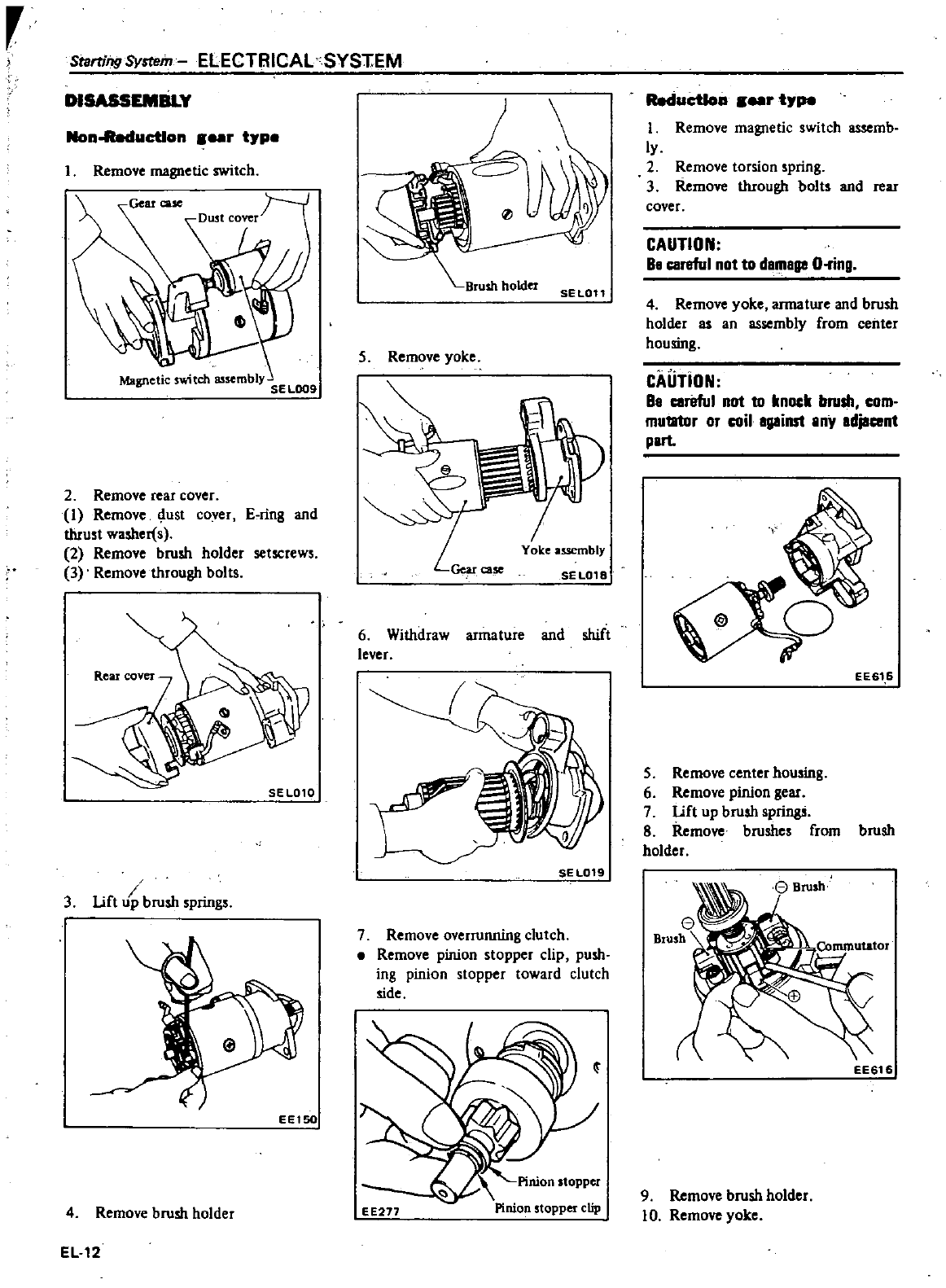
r
Starting
System
ELECTRICAL
SYSTEM
DISASSEMBLY
Non
ucUon
r
tJP
1
Remove
magnetic
switch
2
Remove
rear
cover
1
Remove dust
cover
E
ring
and
thrust
washer
s
2
Remove brush
holder
setscrews
3
Remove
through
bolts
SE
LOtO
I
3
Lift
p
brush
springs
EEt50
4
Remove
brush
holder
EL12
SEL011
5
Remove
yoke
6
Withdraw
armature
and
shift
lever
SE
L019
7
Remove
overrunning
clutch
Remove
pinion
stopper
clip
push
ing
pinion
stopper
toward
clutch
side
EE277
Pinion
stopper
clip
RedueUon
rtJpe
I
Remove
magnetic
switch
assemb
ly
2
Remove
torsion
spring
3
Remove
through
bolts
and
rear
cover
CAUTION
Ba
careful
not
to
damage
O
ring
4
Remove
yoke
armature
and
brush
holder
as
an
assembly
from
center
housing
CAUTiON
Be
careful
not
to
knock
brush
com
mutator
or
coil
against
Iny
edjacent
plrt
EE61
6
5
Remove
center
housing
6
Remove
pinion
gear
7
Lift
up
brush
springs
8
Remove
brushes
from
brush
holder
EE616
9
Remove
brush
holder
10
Remove
yoke
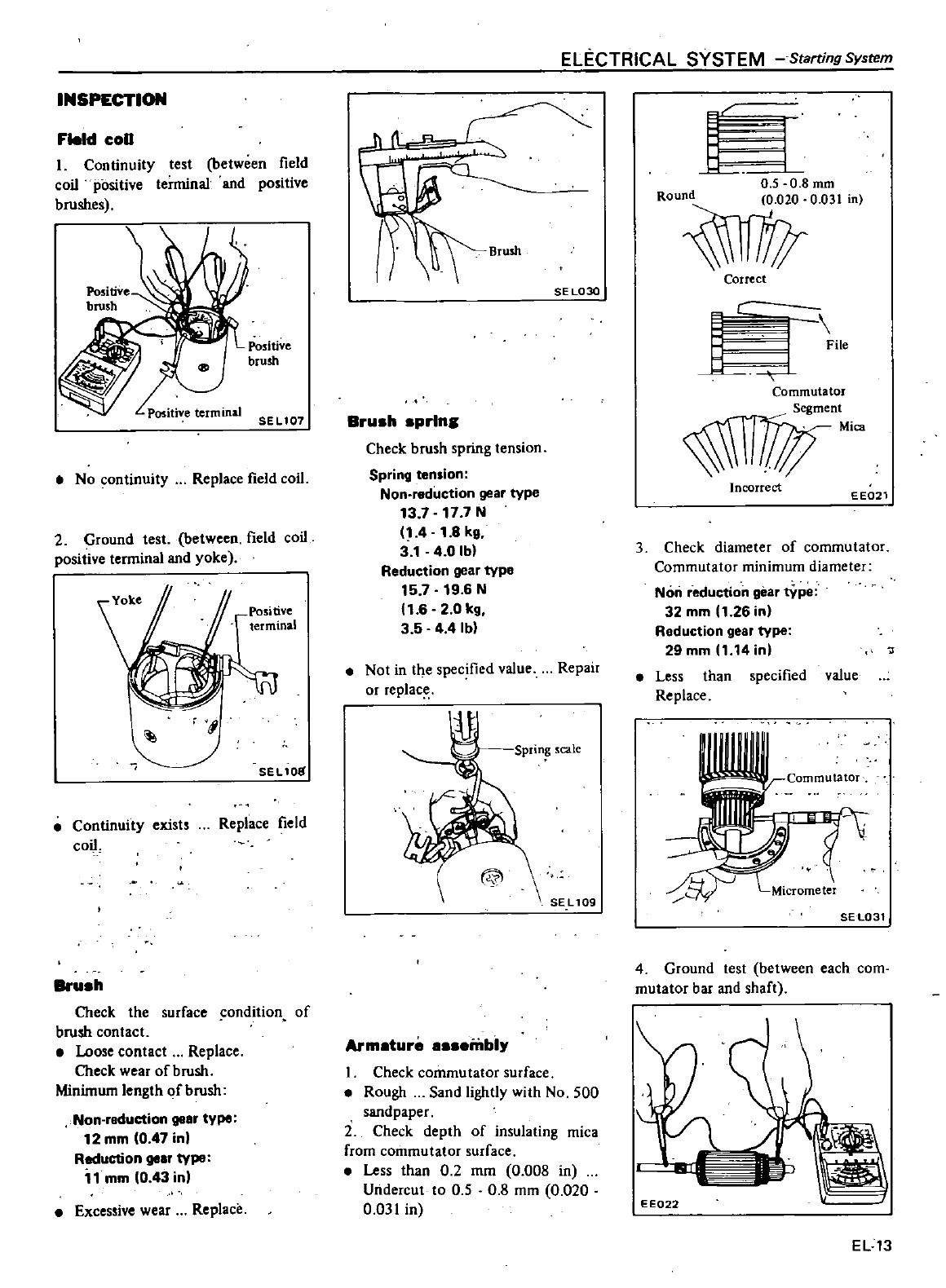
INSPECTION
Field
coD
I
Continuity
test
between
field
coil
positive
terminal
and
positive
brushes
SEL107
No
continuity
Replace
field
coil
2
Ground
test
between
field
coil
positive
terminal
and yoke
Positive
terminal
SEL
1
oS
Conlinuity
exists
coil
Replace
field
Bru
h
Check
the
surface
condition
of
brush
contact
Loose
contact
Replace
Check
wear
of
brush
Minimwn
length
of
brush
Non
reduction
goor
typo
12
mm
0
47 in
Reduction
goor
typo
1
mm
0
43
in
Excessive
wear
Replace
ELECTRICAL
SYSTEM
Starring
System
SE
L030
Bru
h
prlnll
Check
brush
spring
tension
Spring
tension
Non
reduction
gear
type
13
7
17
7
N
14
1
8
kg
3
1
4
0Ib
Reduction
gear
type
15
7
19
6
N
1
6
20
kg
3
5 4 4
Ib
Not
in
the
specified
value
Repair
or
replace
Sprin
scale
WI
SEL
109
Arm
ture
mbl
I
Check
commutator
surface
Rough
Sand
lightly
with
No
500
sandpaper
2
Check
depth
of
insulating
mica
from
commutator
surface
Less
than
0
2
mm
0
008
in
Undercut
to
0
5
0
8
mm
0
020
0
031
in
t
J
0
5
0 8
mm
i
Correct
f
l
1
Commutator
1T1in
i
Incorrect
EE021
3
Check
diameter
of
commutator
Commutator
minimum
diameter
Non
reduction
gear
tYpe
32
mm
11
26
in
Reduction
geor
type
29mm
11
14inl
Less
than
specified
value
Replace
SEL031
4
Ground
test
between
each
com
mutator
bar
and
shaft
EE022
EL
13
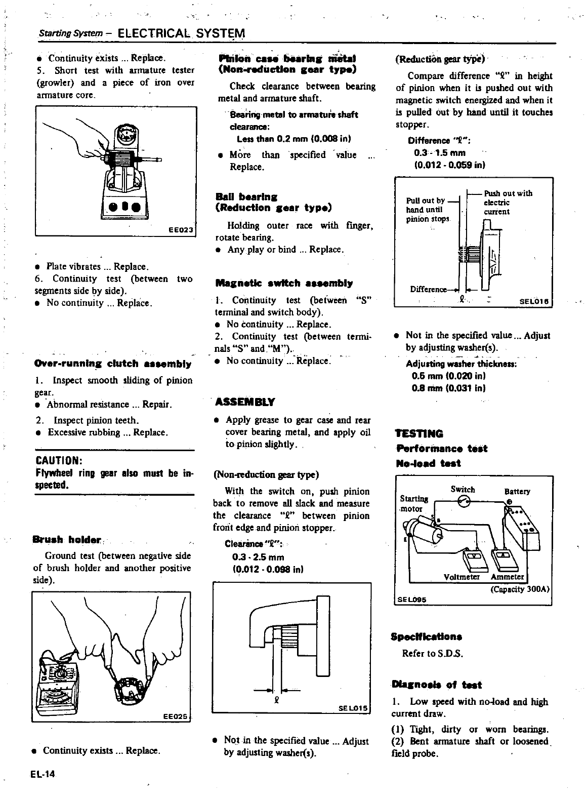
Scarting
System
ELECTRICAL
SYST
M
Continuity
exists
Replace
5
Short
test
with
annature
tester
growler
and
a
piece
of
iron
over
armature
core
EEQ23
Plate
vibrates
Replace
6
Continuity
test
between
two
segments
side by
side
No
continuity
Replace
r
runnln
clutch
mbly
1
Inspect
smooth
sliding
of
pinion
gear
Abnormal
resistance
Repair
2
Inspect
pinion
teeth
Excessive
rubbing
Replace
CAUTION
Flywbeel ring
gear
also
must
be
in
spected
Brush hold
r
Ground
test
between
negative
side
of
brush
holder
and
another
positive
side
EE025
Continuity
exists
Replace
EL14
PInIOn
caN
burin
Iii8taoI
Non
ndilctlon
ear
type
Check
clearance
between
bearing
metal
and
armature
shaft
I
Iearingmetlll
to
Irmatuinhaft
dearance
Less
thin
0
2
mm
0
008
in
More
than
specified
value
Replace
Ball
b
rln
Reduction
ar
tyP
Holding
outer
race
with
fmger
rotate
bearing
Any
play
or
bind
Replace
Me
n
tIc
switch
mbly
I
Con1inuity
test
between
sn
terminal
and
switch
body
No
continuity
Replace
2
Continuity
test
between
tenni
naIs
S
and
M
No
continuity
Replace
ASSEMBLY
Apply
gre
e
to
gear
case
and
rear
cover
bearing
metal
ond
Ipply
oil
to
pinion
slightly
Non
duction
Il8
type
With
the
switch
on
push
pinion
back
to
remove
all
slack
ond
me
ure
the
clearance
en
between
pinion
front
edge
and
pinion
stopper
Clearince
2
03
25
mm
0
012
0
098
in
r
I
J
L
e
SEL015
Not in
the
specified
value
Adjust
by
adjusting
washer
s
Reduction
gear
type
Compare
difference
en
in
height
of
pinion
when
it u
pushed
out
with
magnetic
switch
energized
and
when
it
u
pulled
out
by
hand
until
it
touches
stopper
Difference
1
H
03
1
5
mm
0
012
0
059
inl
PoD
out
by
hand
until
pinion
stops
Pushoutwitb
electric
current
1
r
0
r
Difference
L
e
SEL016
Not
in
the
specified
value
Adjust
by
adjusting
washer
s
Adjusting
washer
thielmo
06
mm
10
020
in
08
mm
0
031
in
TESnNG
Perform
nc
tut
No
load
test
p
b
t
J
Voltmeter
Ammeter
Capacity
300A
SE
LOSS
Specifications
Refer
to
sn
s
Dlqnos
of
test
I
Low
speed
with
no
lold
and
high
current
draw
I
Tight
dirty
or worn
bearings
2
Bent
annature
shaft
or
loosened
field
probe
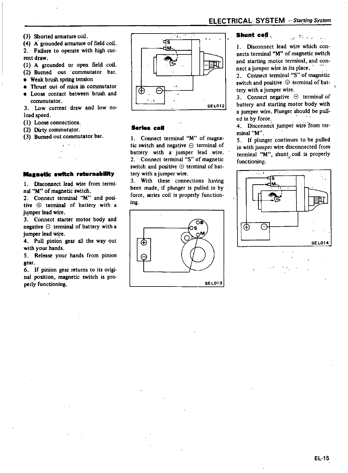
3
Shorted
armature
coil
4
A
grounded
armature
of
field
coil
2 Failure
to
operate
with
high
cur
rent
draw
I
A
grounded
or
open
field
coil
2
Burned
out
commutator
bar
Weak brush
spring
tension
Thrust
out
of
mica
in
commutator
Loose
contact
between brush
and
commutator
3
Low
current
draw
and
low
no
load
speed
I
Loo
e
connections
2
Dirty
commutator
3
Burned
out
commutator
bar
netlc
wttch
r
rn
bllltr
I
Disconnect
lea
wire
from
termi
nal
M
of
magnetic
iwitch
2
Connect
terminal
M
and
posi
tive
tJ
terminal
of
battery
with
a
jumper
lead
wire
3
Connect
starter
motor
body
and
negative
e
terminal
of
battery
with
a
jumper
lead
wire
4
Pull
pinion
gear
all
the
way
out
with
your
hands
5
Release
your
hand
from
pinion
gear
6
If
pinion
gear
returns
to
its
origi
nal
position
magnetic
switch
is
pro
perly
functioning
1
CI
ELECTRICAL
SYSTEM
Sta
ing
Sysrem
jrJ
SEL012
S
rle
coil
I
Connect
terminal
M
of
magne
tic
switch
and
negative
e
terminal
of
battery
with
a
jumper
lead
wire
2
Connect
terminal
S
of
magnetic
switch
and
positive
tJ
terminal
of
bat
tery
with
a
jumper
wire
3
With
these
connections
having
been
made
if
plunger
is
pulled
in
by
force
series
coil
i
properly
function
ing
t
SE
L013
Shunt
co
1
Disconnect
lead
wire
which
con
nects
terminal
M
of
magnetic
switch
and
starting
motor
teoninal
and
con
nect
a
jumper
wire
in
its
place
2
Connect
terminal
S
of
magnetic
switch
and
positive
tJ
terminal
of
bat
tery
with
a
jumper
wire
3
Connect
negative
e
terminal
of
battery
and
starting
motor
body
with
ajumper
wire
Plunger
should
be
pull
ed
in
by
force
4
Disconnect
jumper
wire
from
ter
minal
M
5
If
plunger
continues
to
be pulled
in
with
jumper
wire
disconnected
from
terminal
M
shunt
coil
is
properly
functioning
oJ
i
1
CI
SEL014
EL15
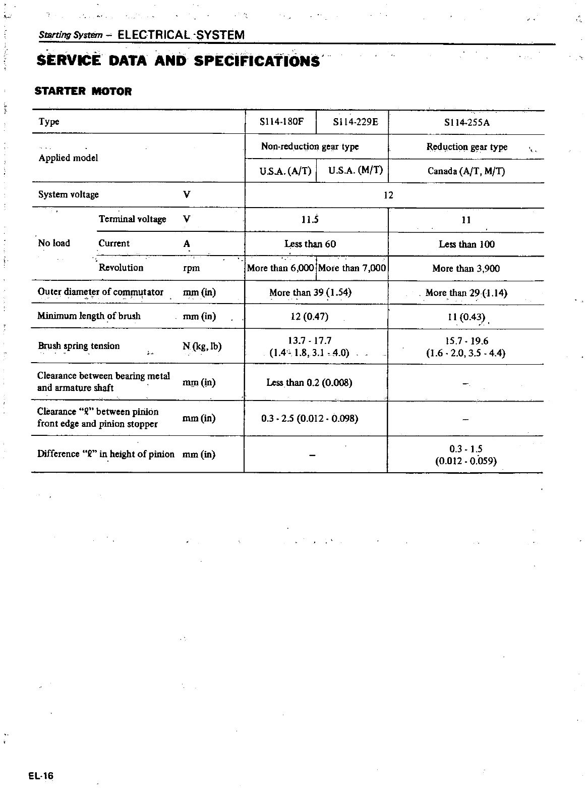
Starting
System
ELECTRICAL
SYSTEM
SERVICE
DATA
AND
SPEciFICATIONS
STARTER
MOTOR
Type
S114
l80F
I
S114
229E
S114
255A
Non
reduction
gear
type
Red
ction
gear
type
Applied
model
U
sA
A
T
I
U
S
A
MfT
Canada
A
T
MfT
V
12
System
voltage
Terminal
voltage
V
11
5
11
No
load
Current
A
Less
than
60
IMore
th
6
ooolMore
than
7
000
I
More
than
39
1
54
1
12
0
47
13
7
17
7
1
4
1
8
3
1
40
Less
than
100
Revolution
rpm
More
than
3
900
Outer
diamet
r
of
commutator
mm
in
mm
in
More
than
29
1
14
Minimum
length
of
brush
11
0
43
Brush
spring
tension
N
kg
lb
15
7
19
6
1
6
2 0
35 44
Clearance
between
bearing
metal
and
armature
shaft
mm
in
Less
than
0 2
0
008
Clearance
between
pinion
front
edge
and
pinion
stopper
mm
in
0
3
25
0
012
0
098
Difference
in
height
of
pinion
mm
in
03
15
0
012
0
059
EL16
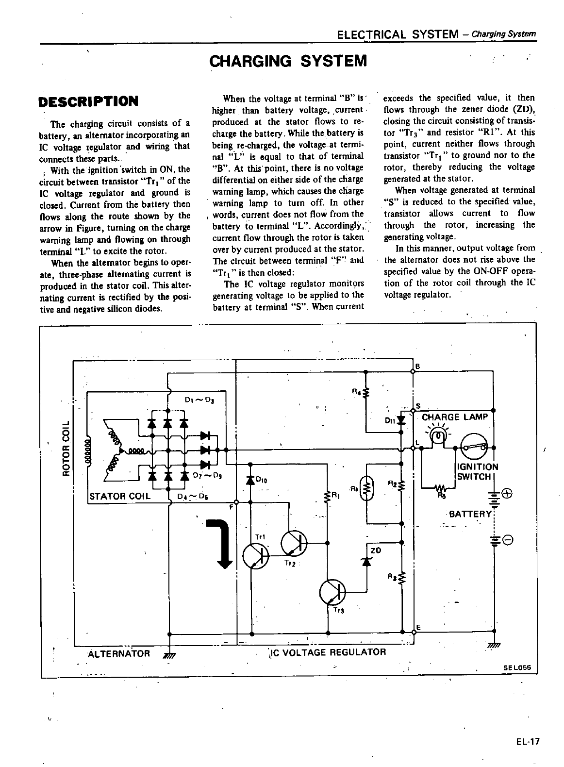
DESCRIPTION
The
charging
circuit
consists
of
a
battery
an
alternator
incorporating
an
IC
voltage
regulator
and
wiring
that
connects
ihese
parts
I
With
the
ignition
switch
in
ON
the
circuit
between
transistor
Tr
I
of
the
IC
voltage
regulator
and
ground
is
closed
Current
from
the
battery
then
flows
along
ihe
route
shown
by
the
arrow
in
Figure
turning
on
the
charge
warning
lamp
and
flowing
on
through
terminal
L
to
excite
the
rotor
When ihe
alternator
begins
to
oper
ate
three
phase
alternating
current
is
produced
in
the
stator
coil
This
alter
nating
current
is
rectified
by
the
posi
tive
and
negative
silicon
diodes
ELECTRICAL
SYSTEM
Charging
System
CHARGING
SYSTEM
When the
voltage
at
terminal
B is
higher
than
battery
voltage
current
produced
at
the
stator
flows
to
re
charge
the
battery
While
the
battery
is
being
re
charged
the
voltage
at
termi
nal
L
is
equal
to
that
of
terminal
B
At
this
point
there
is
no
voltage
differential
on
either
side
of
the
charge
warning
lamp
which
causes
the
charge
warning
lamp
to
turn
off
In
other
words
current
does
not
flow
from
the
battery
to
terminal
L
Accordingly
current
flow
through
the
rotor
is
taken
over
by
current
produced
at
the
stator
The
circuit
between
terminal
F
and
Tr
1
is
then
closed
The
IC
voltage
regulator
monitors
generating voltage
to
be
applied
to
the
battery
at
terminal
S
When
current
I
0
D3
J
7
t0
0
a
0
a
t010
STATOR
COIL
D4
Di
AL
TE
RNA
TOR
it
T
exceeds
the
specified
value
it
then
flows
through
the
zener
diode
ZD
closing
the
circuit
consisting
of
transis
tor
TrJ
and
resistor
R1
At
this
point
current
neither
flows
through
transistor
Tr
to
ground
nor
to
the
rotor
thereby
reducing
the
voltage
generated
at
the
stator
When
voltage
generated
at
terminal
S
is
reduced
to
the
specified
value
transistor
allows
current
to
flow
through
the
rotor
increasing
the
generating
voltage
In this
manner
output
voltage
from
the
alternator
does
not
rise
above
the
specified
value
by
the
ON
OFF
opera
tion
of
the
rotor
coil
through
the
IC
voltage
regulator
RJ
IB
1
is
011
CHARGE
LAMP
L
R
Q
T
T
zo
IGN
ITION
Wv
SW1TC1
R
67
BATTERY
e
R
@
R2
A
F
ld
T
T
IC
VOLTAGE REGULATOR
AI
E
SE
LOSS
EL
17
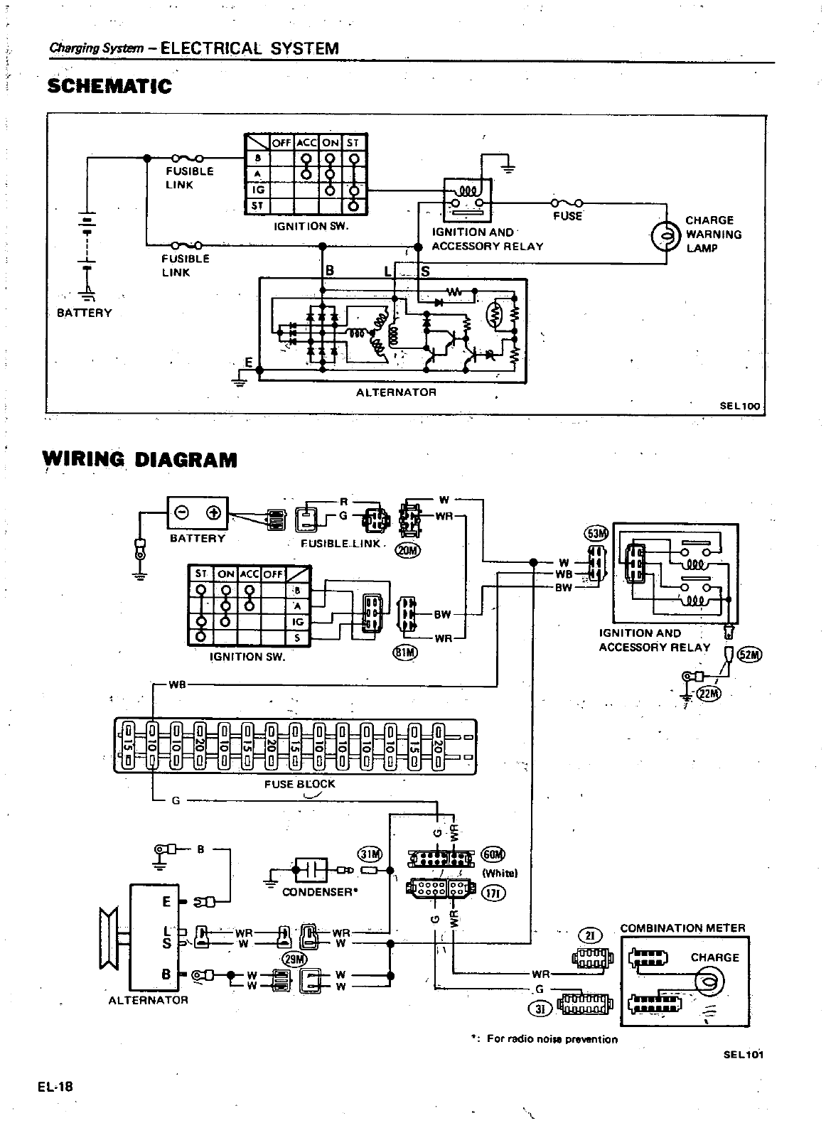
ELECTRICAL SYSTEM
Chargmg
System
SCHEMATIC
FUSIBLE
LINK
OFF
ACC
ON
sr
g
g
Sf
IGNITION
1m
1
I
BATTERY
FUSIBLE
LINK
B
E
ALTERNATOR
I
IGNITION
AND
ACCESSORY
RELAY
t
L
5
WIRING
DIAGRAM
f8
t
l
m
R
BATTE
RY
fUSIBLE
L1NK@
iAgCOFF
lffLBW
J
1
6
IG
r
if
WR
6
s
@
l
IGNITION
SW
c
a
s
00000
O
JCJ
0
0 0
0
0
000000
u
FUSE
BmCK
c
WB
G
B
@
fii
l
CJ
L
CONDENSER
v
E
W
fil
WR
LJ
fil
WR
W
SW
d
B
S
i
I
ALTERNATOR
ELlS
I
I
If
il
rt
I
WhIte
@
a
I
II
r
FUSE
CHARGE
WARNING
LAMP
SEl100
Bj
1
BW
IGNITION
AND
t
ACCESSORY
RELAY
R@
f@t
I
COMBINATION
METER
@
C
RGE
@
J
1
G
@
For
radio
noise
prewntion
SEL10
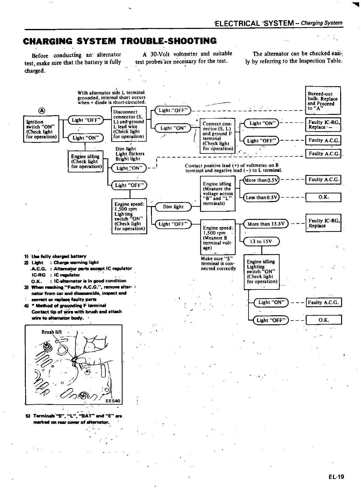
III
ELECTRICAL
SYSTEM
Charging
System
CHARGING
SYSTEM
TROUBLE
SHOOTING
Before
conducting
an
alternator
test
make
sure
that
tlie
battery
i
fully
charged
A
30
Volt
voltmeter
and
suitable
test
probes
are necessary for
the
test
The
alternator
can
be
checked
eaSi
ly
by
referring
to
the
Inspection
Table
@
With
alternator
side
L
terminal
grounded
internal
short
occurs
when
diode
is
short
circuited
Disconnect
Light
OFF
L
ht
OFf
connector
5
11
L
and
g
ound
Connect
con
J
Lioht
ON
I
Faulty
IC
RG
I
L
lead
wue L
ht
ON
e
R
I
Checl
light
ag
I
nec
or
S
l
ep
ace
light
ON
for
operation
and
r
ound
F
term
mal
Ligh
OFF
1
F
I
CG
I
I
Che
ck
light
t
au
ty
A
Dim
light
for
opera
lion
t
rs
1
I
Faulty
A C G
l
J
Light
ON
I
Contact
positive
lead ofvoltmcter
on
B
terminal
and
negative
lead
to
L
terminal
Bumed
out
bulb
Replace
and
Proceed
to
A
Ignition
switch
ON
Check
light
for
operation
Engine
idling
Check
light
for
operation
Dim
light
OFF
J
Mure
than
IS
SV
I
Faulty
1C
RG
1
Engine
speed
Replace
1
500
rpm
Measure
8
teoninal
volt
13
to
15V
age
Engine
idling
Measure
the
voltage
across
8
and
L
terminals
More
thanO
5
I
Faulty
A
C G
I
Light
OFF
1
Engine
speed
1
500
rpm
Ligh
ting
switch
ON
Check
light
for
operation
Less
thanO
SV
I
O K
Light
11
Uao
fully
clio
be
21
Light ming
lith
A
C G
Ar
porta
t
IC
ngulo
Il
RG
IC
ngulOtor
OK
ICI
is
in
good
condition
3
WMn
I
Ftty
A
CG
ren
IOft
1118r
natoI
from
car
end
da
nble
inspect
and
correct
or
I
e
eultv
parts
4
M
od
of
nding
F
18rmiMI
Contlct
tip
of
r
with
brush
and
ttKh
to
body
Make
sure
S
tenninal
is
con
nected
correctly
Engine
idlins
Lighting
switch
ON
Check
light
for
operation
Light
ON
I
Faulty
A
e
G
I
Light
OFF
I
O K
61
T
S
L
SAT
E
on
rear
cover
of
El19
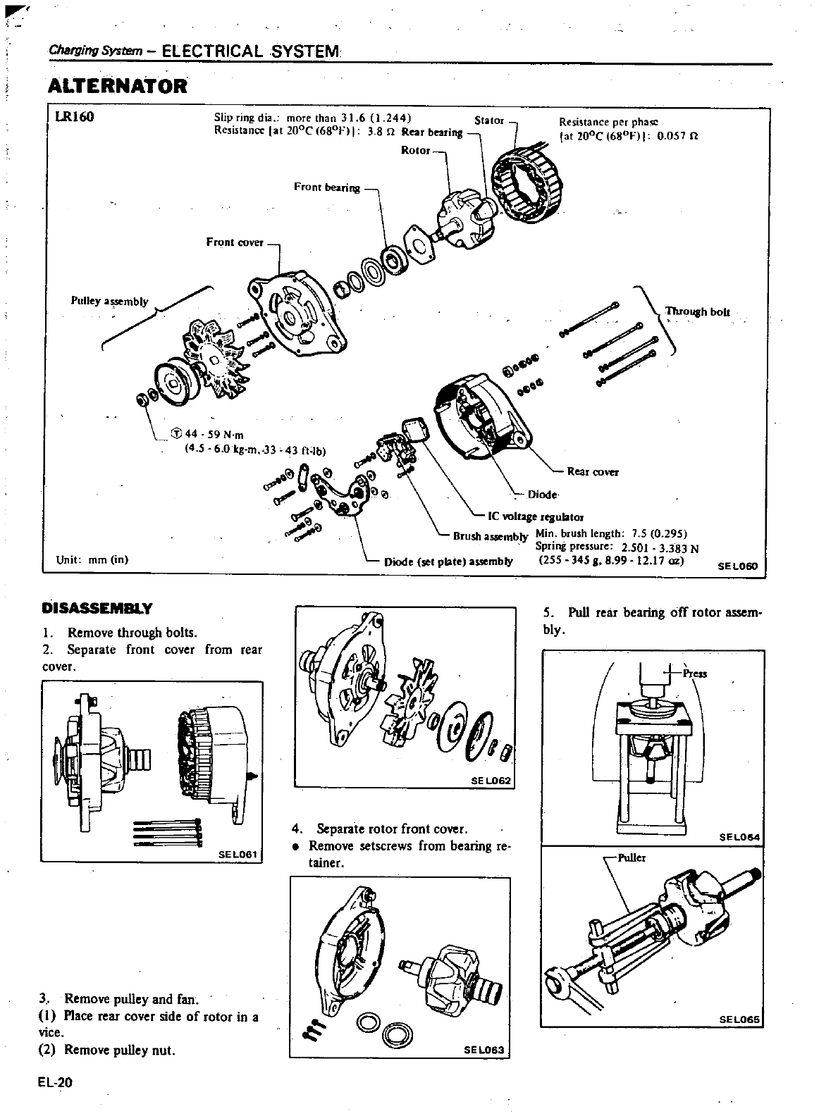
111
Charging
System
ELECTRICAL
SYSTEM
ALTERNATOR
LRl60
Slip
ingdia
more
than
31
6
0
244
Re
listancc
at
lOoe
680f
I3 8
n
Rear
bearing
Rotor
Front
bearing
6
0
lcg
m
33
43
ft
lb
Unit
mm
in
DISASSEMBLY
I
Remove
through
bolts
2
Separate
front
cover
cover
from
rear
UD
1
SELOSl
3
Remove
pulley
and
fan
I
Place
rear
cover
side
of
rotor
in
a
vice
2
Remove
pulley
nut
EL
20
Resistance
per
phuc
la
200C
680
I
0
051
n
Rear
cover
Ie
ro1use
rtBulator
Brushassembly
Min
brush
length
75 0
295
Spring
pressure
2
501
3
383
N
Diode
SOl
plate
a
mbly
255 345
I
8
99
12 17
oz
SEL060
SE
L062
4
Separate
rotor
front
cover
Remove
setscrews
from
bearing
re
tainer
SEL083
5
Pull
rear
bearing
off
rotor
assem
bly
fA
J
l
SEL064
SE
L06S
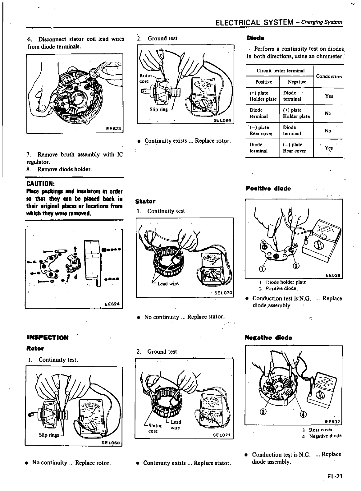
6
Disconnect
stator
coil
lead
wires
from
diode
terminals
EE623
7
Remove
brush
assembly
with
IC
regulator
8
Remove
diode
holder
CAUTION
Pllce
peckin
Ind
insullton
in
order
10
thlt
they
cen
be
placad
back
in
their
originll
p
or
locations
from
which
they
were
removed
t
e
j
0
I
ca
l0
EE624
ELECTRICAL SYSTEM
Charging
System
2
Ground
test
SE
L069
Continuity
exists
Replace
rotor
Stator
I
Continuity
test
SEL070
No
continuity
Replace
stator
Diode
Perform
a
continuity
test
on
diodes
in
both
directions
using
an
ohmmeter
Circuit
tester
terminal
Conduction
Positive
Negative
plate
I
Diode
Yes
Holder
plate
terminal
Diode
I
plate
Nn
terminal
Holder
plate
plate
I
Diode
No
Rear
cover
terminal
Diode
I
plate
Yes
terminal
Rear
cover
Po
ltlve
dlod
EE536
1
Diode
holder
plate
2
Positive
diode
Conduction
test
is
N
G
diode
assembly
Replace
INSPECTION
Me
tlve
diode
Rotor
Continuity
test
SEL068
No
continuity
Replace
rotor
2
Ground
test
SEL071
Continuity
exists
Replace
stator
@
EE537
3
Rear
cover
4
Nega
live
diode
Conduction
test
is
N G
diode
assembly
Replace
EL21
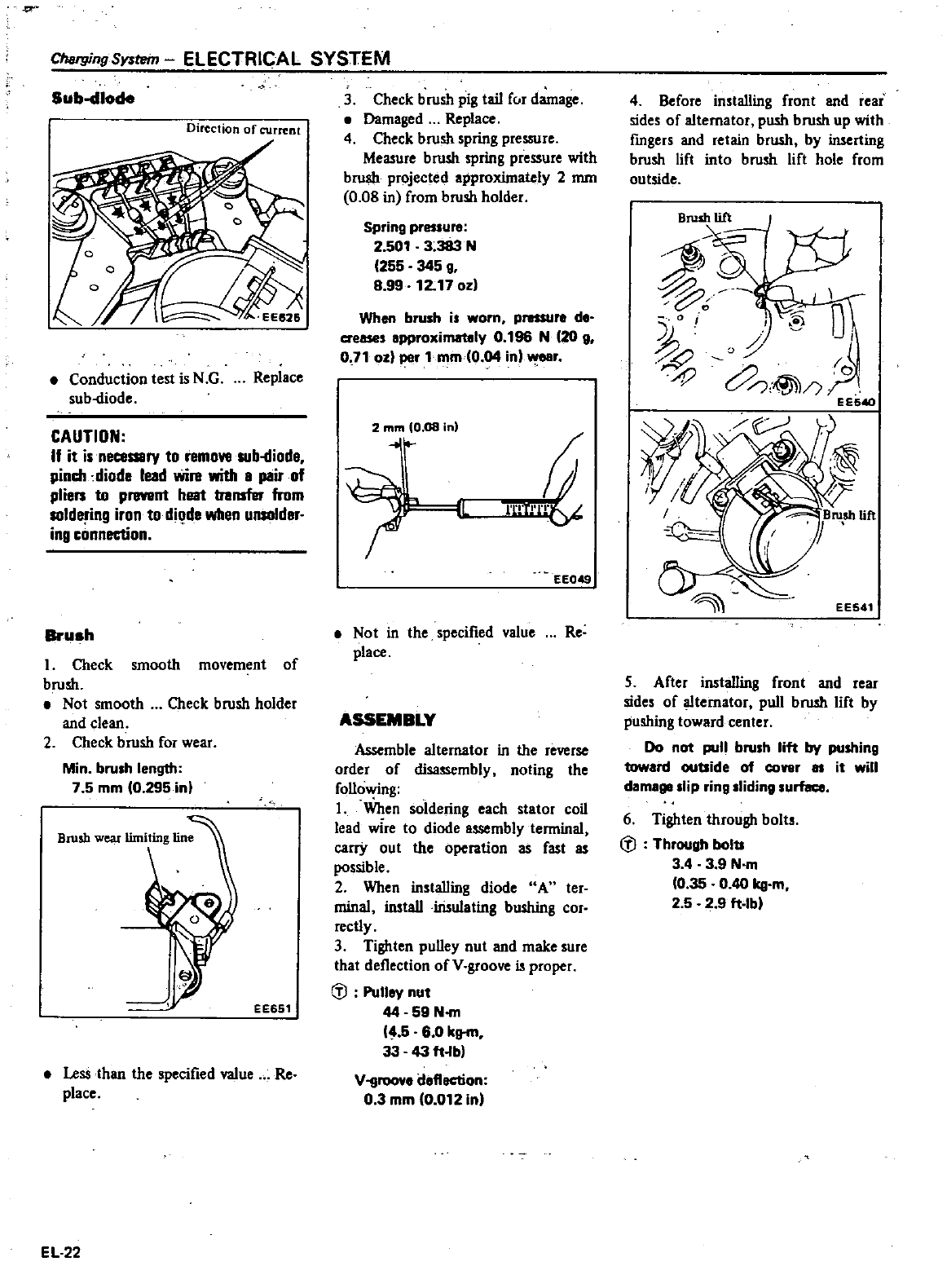
ChargingSY
tWn
ELECTRICAL
SYSTEM
Sub
dlode
Direction
of
current
Conduction
test
is N
G
sub
diode Replace
CAUTION
If
it
isneceSSlry
to
remove
sub
iliode
pinch
diode lead
wire with
8
pair
of
plien
to
prevent
heat
transfer
from
solde
ing
iron
to
dil
de
when
unsolder
ing
connection
Brush
I
Check
smooth
movement
of
brush
Not
smooth
Check
brush
holder
and
clean
2
Check
brush
for
wear
Min
brush
length
7 5
mm
0
295
in
EE651
Less
than
the
specified
value Re
place
EL
22
3
Check
brush
pig
tail
fur
damage
Damaged
Replace
4
Check
brush
spring
pressure
Measure
brush
spring
pressure
with
brush
projected
approximately
2
mm
0
08
in
from
brush
holder
Spring
pressure
2
501
3
383
N
255
345
g
8
99
12
17
0
When
brush
is
worn
pressure
de
crease
epproximatoly
0
196
N
20
g
0
710
1
per
lmm
O
04
in
r
2
mm
10
08
in
nT
I
eeOEf
Not
in
the
specified
value Re
place
ASSEMBLY
Assemble
alternator
in
the
reverse
order
of
disassembly
noting
the
follo
ng
1
When
soldering
each
stator
coil
lead
wire
to
diode
assembly
terminal
carry
out
the
operation
as
fast
as
possible
2
When
installing
diode
A
ter
minal
install
insulating
bushing
cor
rectly
3
Tighten
pulley
nut
and
make
sure
that
deflection
of
V
groove
is
proper
C
l
Pulley
nut
44
59
NofII
5
60
kg
m
33
43
ft
lb
Vllroove
deflection
03
mm
0
012
in
4
Before
installing
front
and
rear
sides
of
alternator
push
brush
up
with
fmgers
and
retain
brush
by
inserting
brush
lift
into
brush
lift
hole
from
outside
Bru
00
1
o
i
EE541
5
After
installing
front
and
rear
sides
of
alternator
pull
brush
lift
by
pushing
toward
center
Do
not
pull
brush
lift
by
pushing
toward
outside
of
cover
as
it
will
damage
slip
ring
sliding
urface
6
Tighten through
bolt
C
l
Through
bolts
3 4
39
N
m
0
35
0
40
kg
m
2
5 2 9
ft
Ib
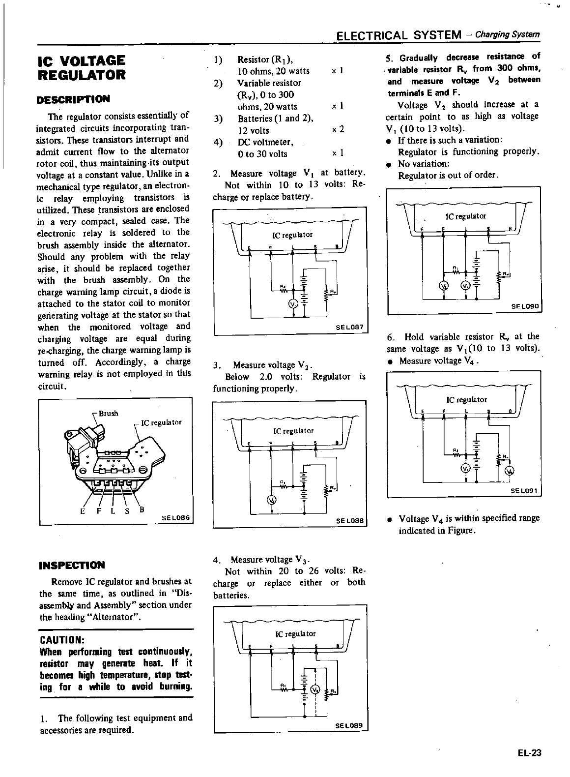
IC
VOLTAGE
REGULATOR
DESCRIPTION
The
regulator
consists
essentially
of
integrated
circuits
incorporating
tran
sistors
These
transistors
interrupt
and
admit
current
flow
to
the
alternator
rotor
coil
thus
maintaining
its
output
voltage
at
aconstant
value
Unlike
in
a
mechanical
type
regulator
an
electron
ic
relay
employing
transistors is
utilized
These
ransistors
are
enclosed
in
a
very
compact
sealed
case The
electronic
relay
is
soldered
to
the
brush
assembly
inside
the
alternator
Should
any
problem
with
the
relay
arise
it
should
be
replaced together
with
the
brush
assembly
On
the
charge
warning
lamp
circuit
a
diode
is
attached
to
the
stator
coil
to
monitor
generating
voltage
at
the
stator
so
that
when
the
monitored
voltage
and
charging
voltage
are
equal
during
re
harging
the
charge
warning
lamp
is
turned
off
Accordingly
a
charge
warning
relay
is
not
employed
in
this
circuit
EFLSB
SE
LOB6
INSPECTION
Remove
IC
regulator
and
brushes
at
the
same
time
as
outlined
in
Dis
assemb4t
and
Assembly
section
under
the
heading
Alternator
CAUTION
When
performing
test
continuously
resistor
may
generate
heat
If
it
becomes
high
temperature
stop
test
ing
for
a
while
to
avoid
burning
I
The
following
test
equipment
and
accessories
are
required
ELECTRICAL
SYSTEM
Charging
System
1
Resistor
R
1
10
ohms
20
watts
x
I
2
Variable
resistor
Rv
O
to
300
ohms
20 watts x
I
3
Batteries
I
and
2
12
volts
x2
4
DC
voltmeter
o
to
30 volts
x
1
2
Measure
voltage
V
I
at
battery
Not
within
10
to
13
volts
Re
charge
or
replace
battery
1
JI
Ie
regulator
L
r
3
I
crT
I
SE
LOB7
3
Measure
voltage
V2
Below
20
volts
Regulator
is
functioning
properly
1
Ic
egulato
1
L
n
cr
l
r
SE
LOBB
4
Measure
voltage
V3
Not
within
20
to
26
volts Re
charge
or
replace
either
or
both
batteries
1
Ie
regu
la
tor
II
L
i
T
SE
L089
S
Gradually
decrease resistance
of
variable
resistor
Rv
from
300
ohms
and
measure
voltage
V2
between
terminals
E
and
F
Voltage
V2
should
increase
at
a
certain
point
to as
high
as
voltage
V
I
10
to
13
volts
If
there
is
such
a
variation
Regulator
is
functioning
properly
No
variation
Regulator
is
out
of
order
L
1
L
l
J1
Ie
regulator
SEL090
6
Hold
variable
resistor
Rv
at
the
same
voltage
as
VI
10
to
13
volts
Measure
voltage
V4
L
IC
e
umlol
11
1
t
t
J
SEL091
Voltage
V4
is
within
specified
range
indicated
in
Figure
EL
23
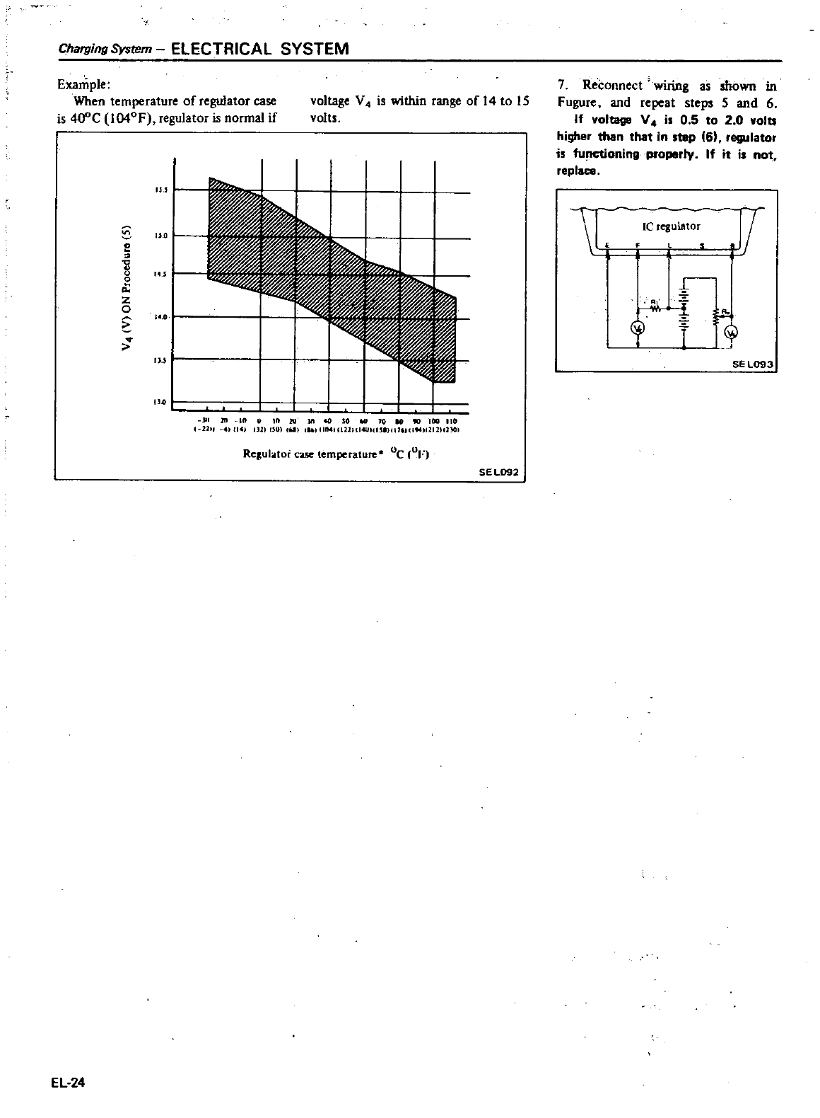
Charging
System
ELECTRICAL SYSTEM
Example
When
temperature
of
regulator
case
is
4O
C
I04OF
regulator
is
normal
if
voltage
V4
is
within
range
ofl4to
15
volts
o
o
o
o
0
z
o
u
1
IU
I
m M
10
cHI
I
IIIIM
ll21l
I
wICIJlICIUICIMllllllUlGl
Rc
ul
tor
case
temperature
Oc
OF
SE
L092
EL
24
7
Reconnect
wlftng
as
shown
in
Fugure
and
repeat
steps
5
and
6
If
voltage
V4
is
0
5
to
2 0
wolb
higher
than
that
in
step
6
regulator
is
functioning
properly
If it
i
not
replace
1
j
Ie
regulator
J
r
SEl093
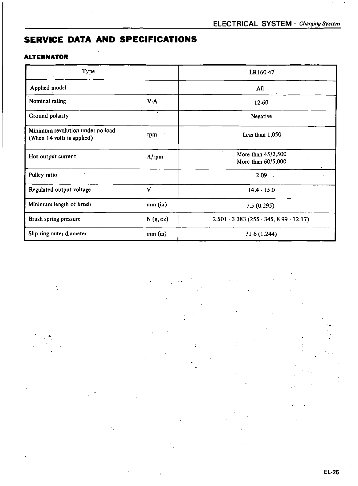
SERVICE
DATA AND
SPECIFICATIONS
ALTERNATOR
Type
Applied
model
Nominal
rating
VA
Ground
polarity
Minimum
revolution
under
no
load
When
14
volts
is
applied
rpm
Hot
output
current
Arpm
Pulley
ratio
Regulated
output
voltage
v
Minimum
length
of
brush
mm
in
Brush
spring
pressure
N
g
oz
Slip
ring
outer
diameter
mm
in
ELECTRICAL
SYSTEM
Charging
System
lR16047
All
1260
Negative
Less
than
1
050
More
than
45
2
500
More
than
60
5
000
2
09
144
15 0
7 5
0
295
2
501
3
383
255 345
8
99
12 17
31
6
1
244
EL
25
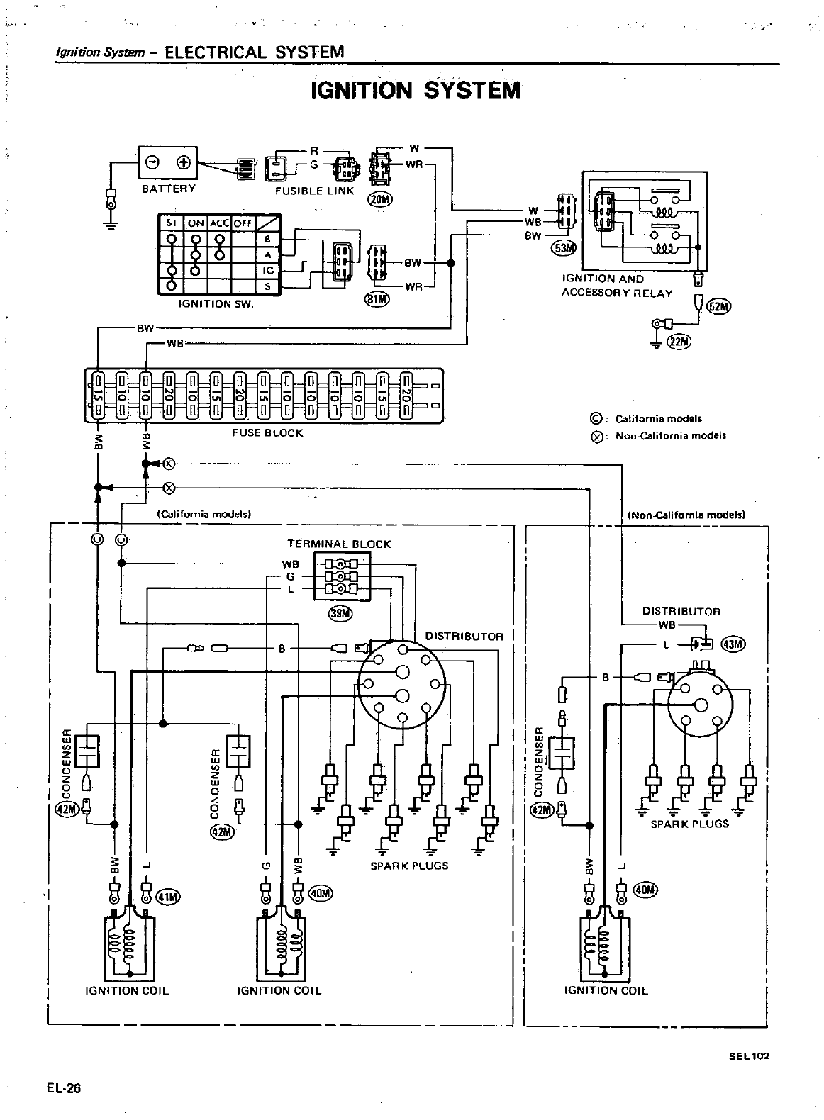
Ignition
System
ELECTRICAL
SYSTEM
IGNITION
SYSTEM
e
t
1
o
g
R
B
IGNITION
SW
rw
i
E
o o
Q
o
0 0 0 0
0
0
0
0 0 0
0 0 0 0 0 0 0
o
f
r
FUSE
BLOCK
f
l
f
ia
models
Q
CIl
I
@L
I
J
@
ff
IGNITION
COIL
EL
26
8
Q
@
TERMINAL
BLOCK
VB
O
G
a
L
a
@
e
Jilj
lJ
1J1J
@
SPAR
K
PLUGS
IGNITION
COIL
w
iP
t
WB
BW
0
0
@
lJlJ
Jf
IGNITION
AND
11
ACCESSORY
RELA
9
@
@
@
California
models
@
Non
California
models
INon
Califomia
models
DISTRIBUTOR
we
L
@
0
B
cJ
I
n
I
if
0
u
@L
J
j
SPARK
PLUGS
J
@
ff
IGNITION
COIL
SEL
102
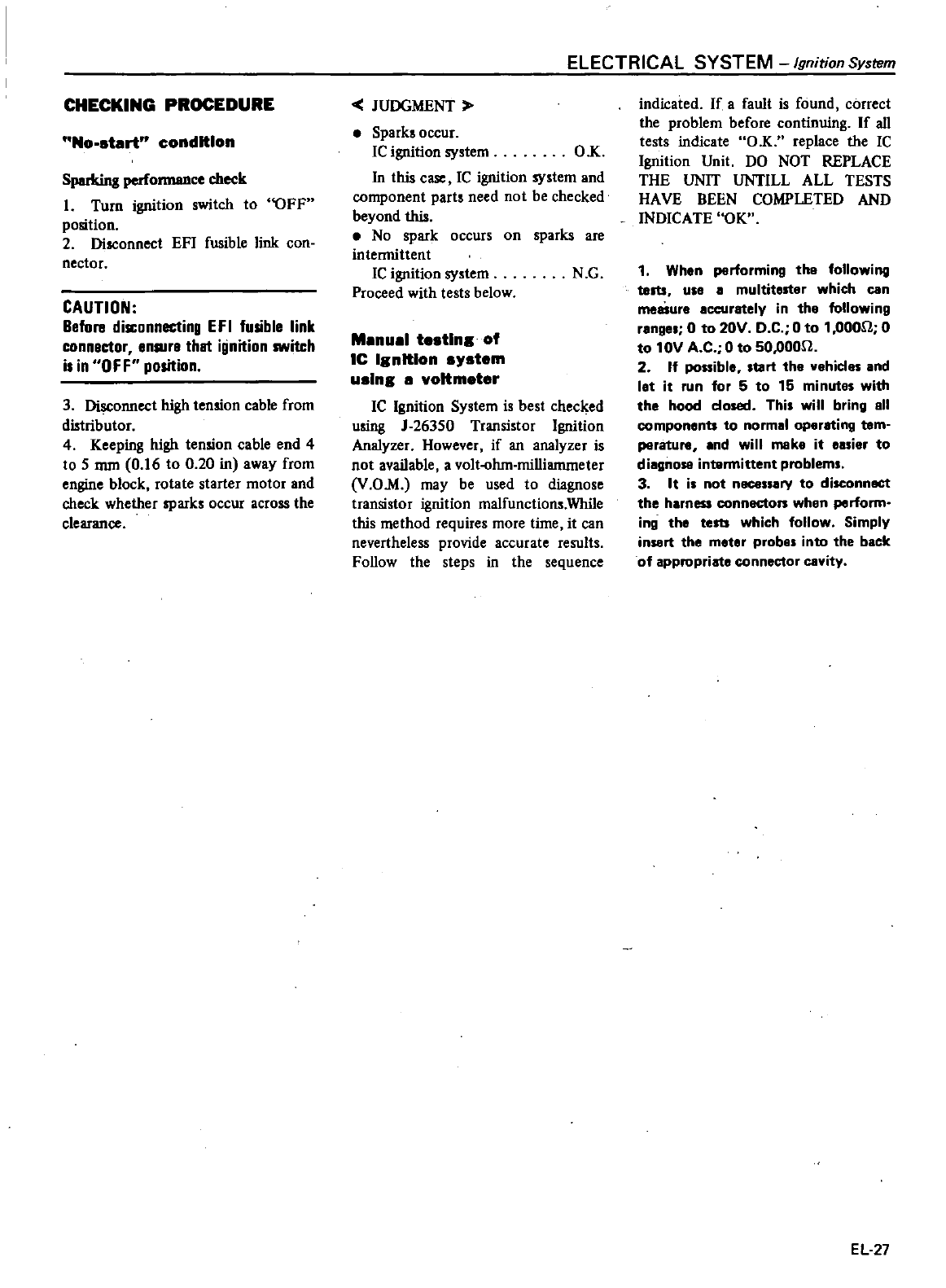
CHECKING
PROCEDURE
No
start
condition
Sparking
once
check
1
Turn
ignition
switch
to
OFF
position
2
Disconnect
EF1
fusible
link
con
nector
CAUTION
Before
disconnecting
EFI
fusible
link
connector
enlllre
thet
ignition
switch
is
in
OFF
position
3
Disconnect
high
tension
cable
from
distributor
4
Keeping
high
tension
cable
end
4
to
5
mrn
0
16
to
0
20
in
away
from
engine
block
rotate
starter
motor
and
check
whether
sparks
occur
across
the
clearance
ELECTRICAL
SYSTEM
Ignition
System
JUDGMENT
Spark
occur
1C
ignition
system
O
K
In this
case
1C
ignition
system
and
component
parts
need
not
be
checked
beyond
this
No
spark
occurs
on
sparks
are
intermittent
1C
ignition
system
N
G
Proceed
with tests
below
Manual
testlna
of
IC
lanltlon
s
stem
uslna
a
voltmeter
1C
Ignition
System
is
best
checked
using
J
26350
Transistor
Ignition
Analyzer
However
if
an
analyzer
is
not
available
a
volt
ohm
milliammeter
V
OM may
be
used
to
diagnose
transistor
ignition
malfunctions
While
this
method
requires
more
time
it
can
nevertheless
provide
accurate
results
Follow
the
steps
in
the
sequence
indicated
If
a
fault
is
found
correct
the
problem
before
continuing
If
all
tests
indicate
O K
replace
the
Ie
Ignition
Unit
DO
NOT
REPLACE
THE
UNIT
UNTILL
ALL
TESTS
HA
VB
BEEN
COMPLETED
AND
INDICATE
OK
1
When
performing
the
following
teltS
USI a
multitester
which
can
measure
accurately
in the
following
ronge
0
to
20V
D
C
0
to
1
0000
0
to
10V
A
C
0
to
50
oOOn
2 If
possible
tart
the
vehicles
and
let
it
run
for
5
to
15
minute
with
the
hood
closed
Thi
will
bring
all
componenu
to
normal
operating
tem
perature
and
will
make
it
easier
to
diagnose
intermittent
problems
3
It
is
not
necessary
to
disconnect
the
harness
connecton
when
perform
ing
the
tests
which
follow
Simply
insert the
meter
probes
into
the back
of
appropriate
connector
cavity
EL27
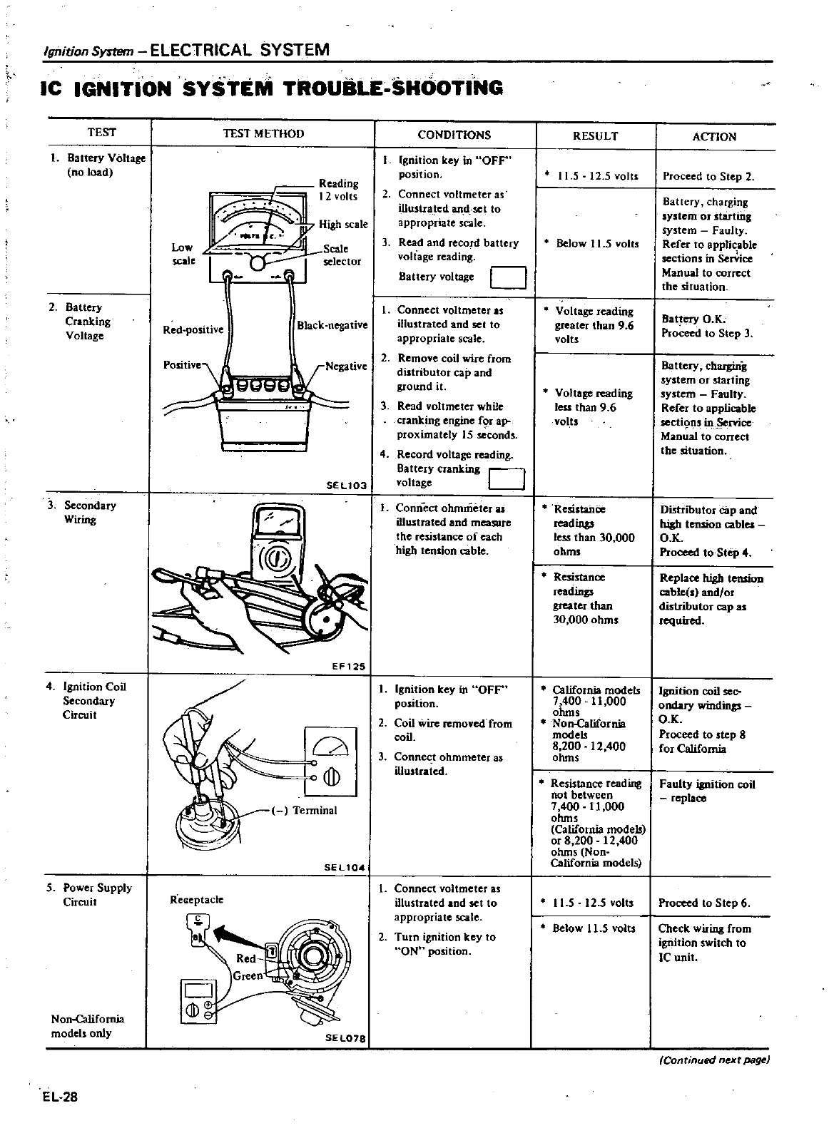
Ignition
SyrnJm
ELECTRICAL
SYSTEM
IC
IGNITION
SYSTEM
TROUBLE
SHOOTING
TEST
1
Battery Voltage
no
load
2
Battery
Cranking
V
oUage
3
Secondary
Wiring
4
Ignition
Coil
Secondary
Circuit
S
Power
Supply
Circuit
Non
catifomia
models
only
EL
28
TEST
METHOD
Reading
12
olts
J
Highscale
Low
t
Scale
scale
selector
1
Red
positi
e
Black
negative
pOlitive
l
I
SEU03
Terminal
SEU04
Reaeptacle
5EL078
EF125
CONDITIONS
Ignition
key
in
OFF
position
2
Connect
voltmeter
as
ilIusua
ted
tnd
sct to
appropriate
scale
3
Read
and record
battery
voltage
reading
Battery
voltage
D
I
Connect
yoltmeter
as
illustrated
and
set
to
appropriate
scale
2
Remove coil
wire
from
distributor
cap
and
ground
it
3
Read
voltmeter
while
cranking
engine
f9
I
ap
proximately
15
seconds
4
Record
voltage
reading
Battery
cranking
D
voltage
1
Conn
eel
ohmmeter
as
illustrated
and
measure
the
resistance
of
each
high
tension
cable
I
Ignition
key
in
OFF
position
2
Coil
wire
removed
from
coil
3
Connec
t
ohmmeter
as
illustrated
L
Connect
voltmeter
35
illustrated
and
set
to
appropriate
scale
2
Turn
ignition
key
to
ON
position
RESULT
11
5
12
5volts
Below
11
5
yolts
Voltage reading
greater
than
9
6
volts
Voltage reading
less
than
9 6
volts
Resistance
readings
less
than
30
000
ohms
Resistance
readings
greater
than
30
000
ohms
California
models
7
400
11
000
ohms
Non
Gllifornia
models
8
200
12
400
ohms
Resistance
reading
not
between
7
400
11
000
ohms
California
models
or
8
200
12
400
ohms
Non
California
models
11
5
12
5
yolts
Below
11
5
volts
ACTION
Proceed
to
Step 2
Battery
charging
system
or
starting
system
Faulty
Refer
to
applicable
sections
in
Sen
ice
Manual
to
correct
the
situation
Battery
O
K
Proceed
to
Step
3
Battery
charging
system
or
starting
system
Faulty
Refer
to
applicable
secti9ns
in
rvice
Manual
to
correct
the
situation
Distiibutor
cap
and
high
tensioo
cables
Q
K
Proceed
to
Step
4
Replace
high
tensiou
cable
s
and
or
distributor
cap
as
required
Ignition
coil
sec
ondary
windittp
O
K
Proceed
to
step
8
for
California
Faulty
ignition
coil
replace
Proceed to
Step
6
Check
wiring
from
ignition
switch
to
ICunit
Continued
n
xt
page
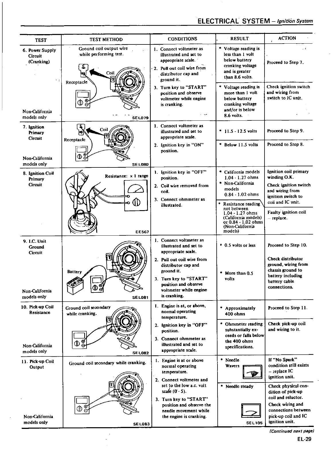
ELECTRICAL
SYSTEM
Ignition
System
TEST
TEST
METHOD
CONDITIONS
RESULT
ACTION
6
Power
Supply
Ground
coil
output
wire
Connect
voltmeter
as
Voltage
reading
is
Circuit
while
performing
test
illustrated
and
set
to
less
than
1
volt
Cranking
appropriate
sCale
below
battery
Proceed
to
Step
7
2
PUU
out
coil
wire
from
cranking
voltage
distributor
cap
and and
is
greater
ground
it
t
an
8
6
volts
3
Tum
key
to
ST
ART
Voltage
reading
is
Check
ignition
switch
position
and
observe
more
than
I
volt
and
wiring
from
voltmeter
while
engine
below
battery
switch
to
Ie
unit
is
cranking cranking
voltage
Non
canfornia
and
or
is
below
models
only
SE
L079
86
volts
7
Ignition
Connect
voltmeter
as
Primary
illustrated
and
set
to
11
5
12
5
volts
Proceed
to
Step
9
Circuit
appropriate
scale
2
Ignition
key
in
ON
Below
1
1
5
volts
Proceed
to
Step
8
position
Non
california
mode1sonly
SELOBO
8
Ignition
Coil
1
range
Ignition
key
in
OFF
California
models
Ignition
coil
primary
Primary
position
1
04
1
27
ohms
winding
O K
Circuit
2
Coil
wire
removed
from
Non
california
Check
ignition
switch
coil
models
and
wiring
from
0 84
1
02
ohms
ignition
switch
to
3
Connect
ohmmeter
as
illustrated
Resistance
reading
coil
and
IC
unit
not
between
1
04
1
27
ohms
Faulty
ignition
coil
California
models
replace
or
0
84
1
02
ohms
Non
california
EE567
models
9 J
C
Unit
I
Connect
voltmeter
as
Ground
illustrated
and
set to
0
5
volts
or
less
Proceed
to
Step
10
Circuit
appropriate
scale
2 Pull
out
coil
wire
from
Check
distributor
distributor
cap
and
ground
wiring
from
ground
it
More
than
0
5
chassis
ground
to
3
Tum
key
to
START
volts
battery including
position
and
observe
battery
cable
Non
ca
tifomia
voltmeter
while
engine
connections
models
only SELOS1
is
cranking
10
Pick
up
Coil
Ground
coil
seoondary
I
Engine
is
at
or
above
Approximately Proceed
to
Step
11
Resistance
while
cranking
normal
operating
400
ohms
l
temperature
0
2
Ignition
key
in
OFF
Ohmmeter
reading
Check
pick
op
coil
position
substantially
ex
and
wiring
to
it
3
Connect
ohmmeter
as
ceeds
or
falls
below
Non
california
dD
illustrated
and
set
to
the
400
ohms
models
only
arr
r
te
scale
specifications
SE
L082
II
Pick
up
Coil
Ground
coil
secondary
while
cranking
I
Engine
is
at
or
above
Needle
If
No
Spark
Output
normal
operating
Wavers
@
condition
stiD
exists
temperature
replace
IC
2
Connect
voltmeter
and
ignition
unit
set
to
the
low
a
c
volt
Needle
steady
Check
physical
con
scale
J
Sj
dition
of
pick
up
3
Turn
key
to
ST
ART
coil
and
reluctor
position
and
observe
the
@
Check
wiring
and
needle
movement
while
connections
between
Non
california
the
engine
is
cranking
pick
up
coil
and
IC
models
only
SE
L083
SEL
105
ignition
unit
Continued
n
xt
pIIg
EL
29
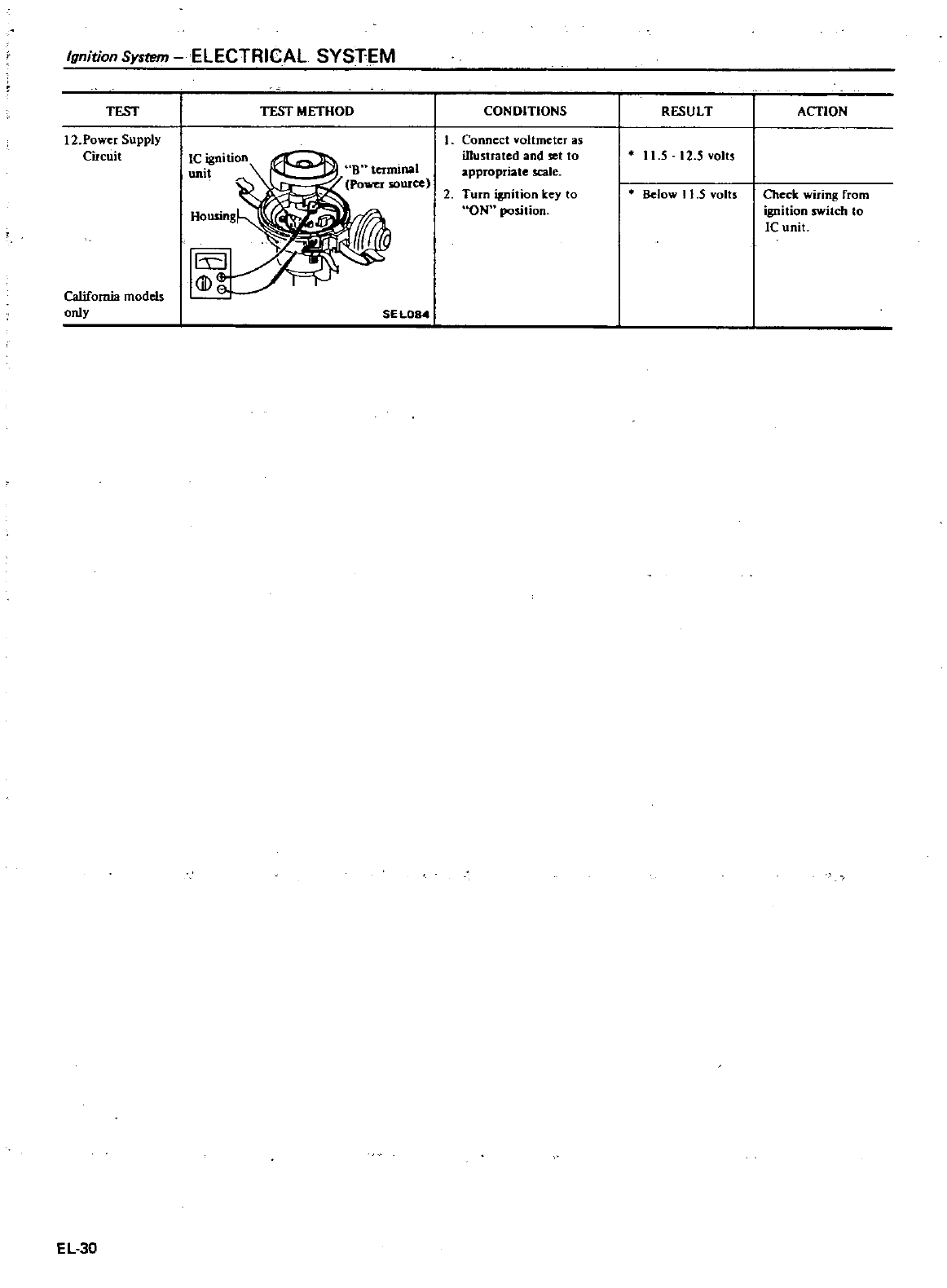
Ignition
System
ELECTRICAL
SYSTEM
TEST
12
Power
Supply
Circuit
California
models
only
EL30
TEST
METHOD
Ie
ignition
uni
SEL084
CONDITIONS
1
Connect
voltmeter
as
illustrated
and
set
to
appropriate
scale
2
Turn
ignition
key
to
ON
position
RESULT
II
S
12
Svolts
Below
11 5
volts
ACTION
Check
wiring
from
ignition
switch
Co
ICunit
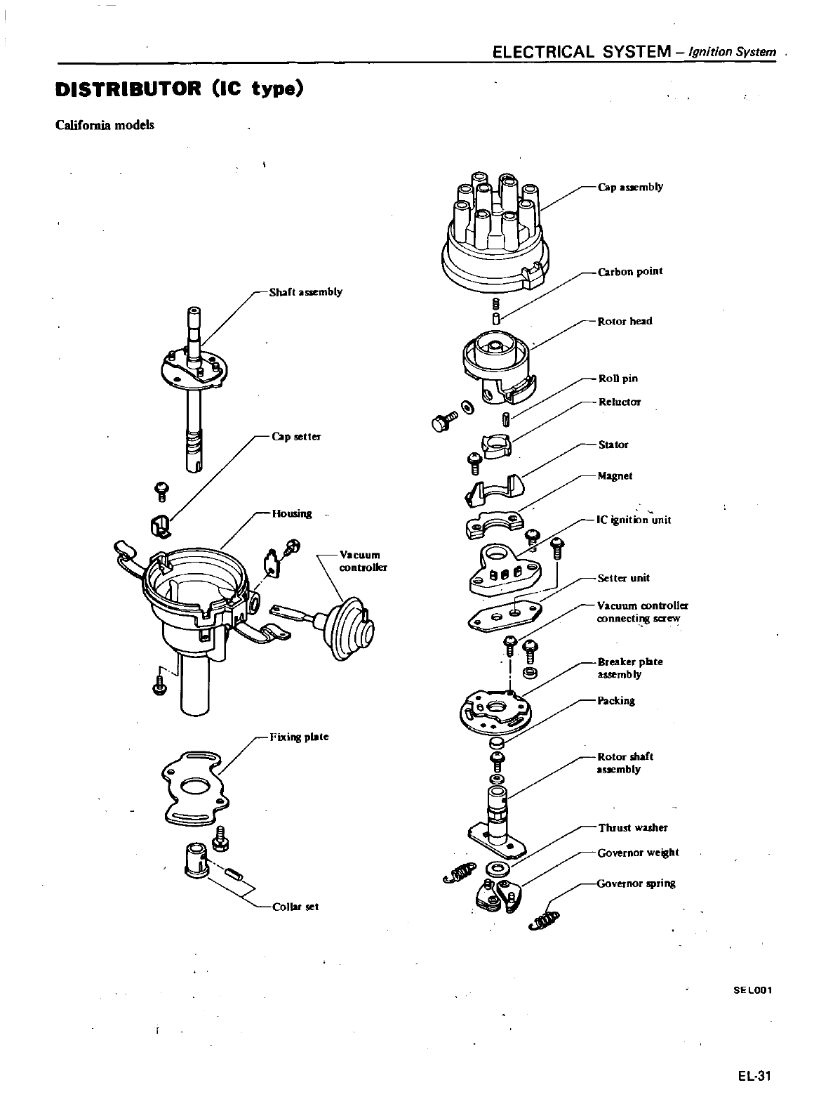
le
type
DISTRIBUTOR
California
models
Shaft
a
mbly
Cap
setter
it
Cl
COllaJ
se
YSTEM
Ignition
System
ELECTRICAL
S
Cap
aSJembly
Carbon
point
g
Y
Ro
orhead
I
RoUpin
RelUclor
S
tor
r
Magnet
ICignitionunit
j
G
J
Setter
unit
Ell
ll
J
m
controller
Vacuu
ow
connecting
Q
Breaker
plate
I
Il
assembly
@
Packing
r
li@
Rotor
shaft
1
sembIY
Thru
t
w
er
GovernorWeight
@
Governor
ng
c
SE
lOOl
EL31
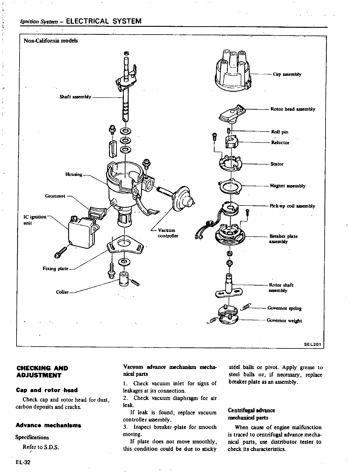
Rotor
bead
usembly
RoUpin
Reluctor
0
Stator
Magnet
assembly
Pick
up
coil
usembly
Vacuum
controller
Breaker
plate
mbly
Rotor
shaft
usembly
Governor
Prins
Governor
weisht
SE
L201
Ignition
Symm
ELECTRICAL
SYSTEM
Non
CaJifomia
models
6
J
Shart
uoembly
Housing
Grommet
Ie
ignition
unit
CoUar
CHECKING
AND
ADJUSTMENT
Vacuum
ad
ce
mechanism
mecha
nical
parts
I
Check
vacuum
inlet
for
signs
of
leakages
at its
connection
2
Check
vacuum
diaphragm
for
air
leak
If
leak
is
found
replace
vacuum
controller
assembly
3
Inspect
breaker
plate
for
smooth
moving
If
plate
doe
not
move
smoothly
this
condition
could
be
due
to
sticky
Cap
and
rotor
head
Check
cap
and
rotor
head
for
dust
carbon
deposits
and
crack
Advance
mechanlsma
Specifications
Refer
to
D
EL32
cap
mbly
st
el
balls
or
pivot
Apply
grease
to
steel balls
or
if
necessary
replace
breaker
plate
as
an
assembly
Centrifugal
ad
ce
mechanil
al
parts
When
cause
of
engine
malfunction
i
traced
to
centrifugai
advance
mecha
nical
parts
use
distributor
tester
to
check
its
characteristics
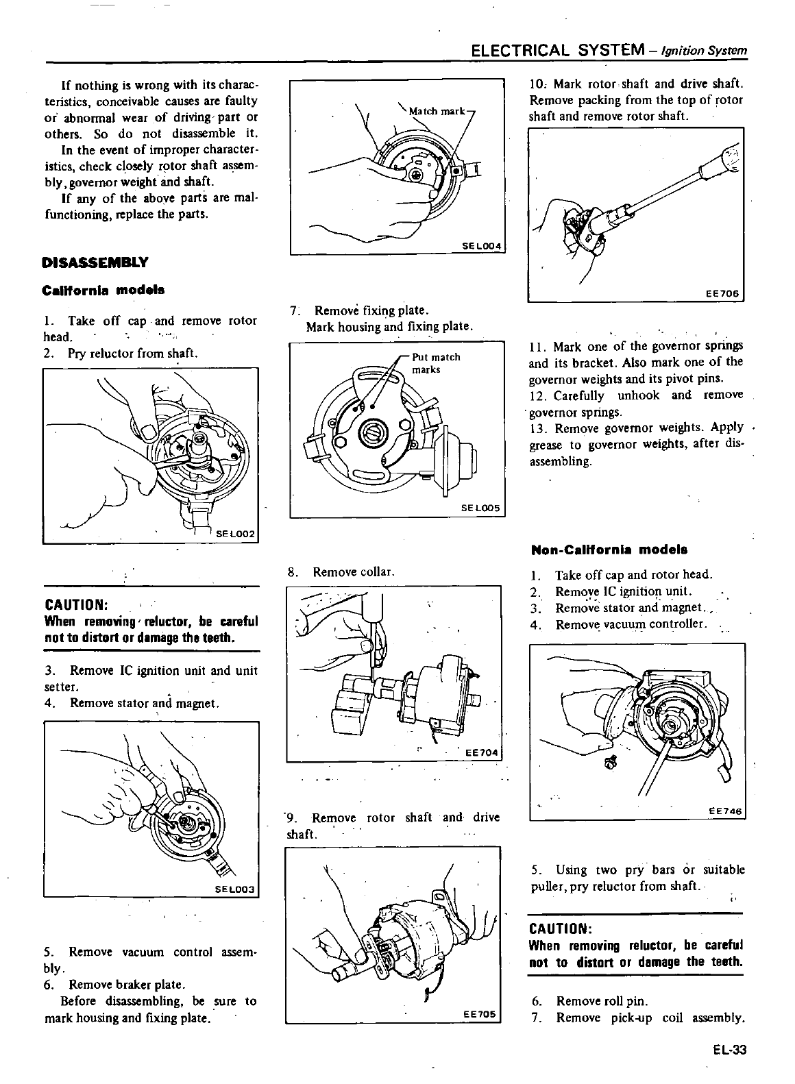
If
nothing
is
wrong
with
its
charac
teristics
conceivable
causes
are
faulty
or
abnonnal
wear
of
driving
part
or
others
So
do
not
disassemble
it
In
the
event
of
improper
character
istics
check
c
osely
rotor
shaft
assem
bly
governor
weight
and
shaft
If
any
of
the
above
parts
are
mal
functioning
place
the
parts
DISASSEMBLY
California
models
I
Take
off
cap
and
remove
rotor
head
2
Pry
reluctor
from
shaft
SEL002
CAUTION
When
removing
reluctor
be
careful
not
to
distort
or
damage
tha teeth
3
Remove
IC
ignition
unit
and
unit
setter
4
Remove
stator
and
magnet
SE
L003
5
Remove
vacuum
control
assem
bly
6
Remove
braker
plate
Before
disassembling
be
sure
to
mark
housing
and
fixing
plate
ELECTRICAL SYSTEM
Ignition
System
SE
L004
7
Remove
fixing
plate
Mark
housing
and
fixing
plate
SE
LOOS
8
Remove
collar
EE104
9
Remove
rotor
shaft
and
drive
shaft
EE705
10
Mark
rotor
shaft
and
drive
shaft
Remove
packing
from
the
top
of
rotor
shaft
and
remove
rotor
shaft
EE706
II
Mark
one
of
the
govemor
springs
and
its
bracket
Also
mark
one
of
the
governor
weights
and
its
pivot
pins
12
Carefully
unhook
and
remove
governor
springs
13
Remove
governor
weights
Apply
grease
to
governor
weights
after
dis
assembling
Non
California
models
1
Take
off
cap
and
rotor
head
2
Remoye
IC
ignitio
unit
3
Remove
stator
and
magnet
4
Remove
vacuu
controller
EE746
5
Using
two
pry
bars
or
suitable
puller
pry
reluctor
from
shaft
CAUTION
When
removing
reluctor
be
careful
not
to
distort
or
damage
the teeth
6
Remove
roll
pin
7
Remove
pick
up
coil
assembly
EL33
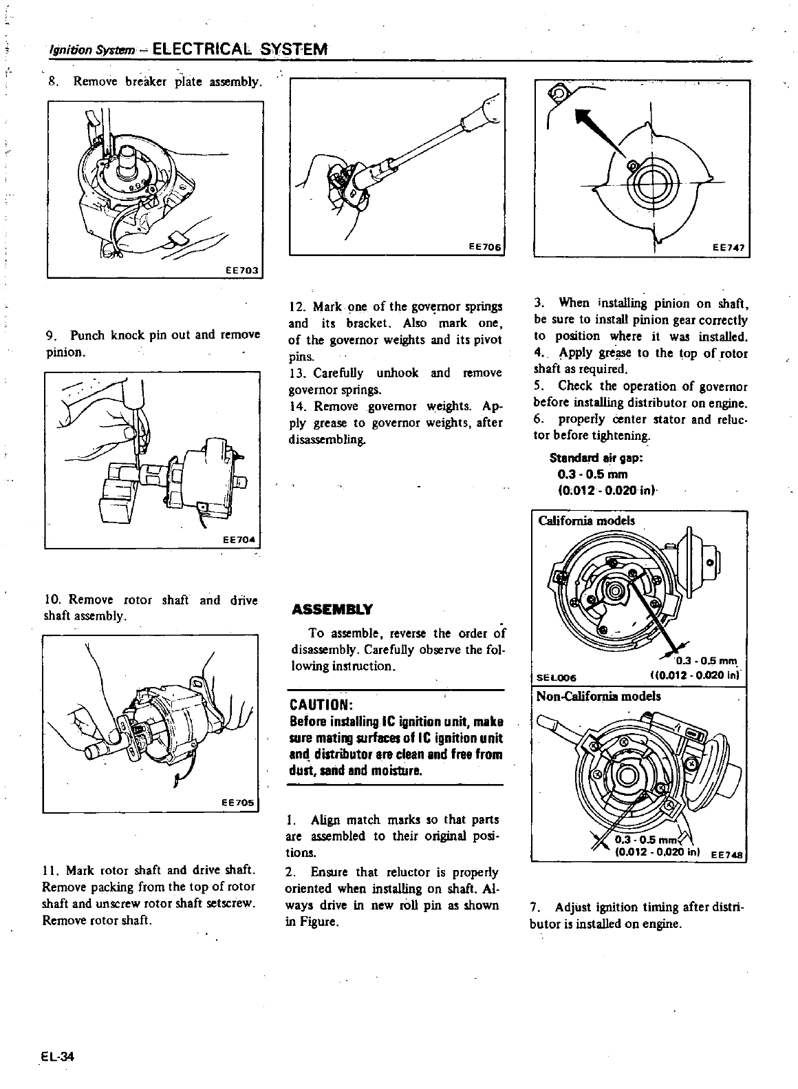
8
Remove
breaker
piate
assembly
Ignition
System
ELECTRICAL
S
VSTEM
EE703
9
Punch
knock
pin
out
and
remove
pinion
@W
EE704
10
Remove
rotor
shaft
and
drive
shaft
assembly
EE705
11
Mark
rotor
shaft
and
drive
shaft
Remove
packing
from
the
top
of
rotor
shaft
and
unscrew
rotor
shaft
setscrew
Remove
rotor
shaft
EL34
EE706
12
Mark
one
of
the
gov
rnor
spring
and
its
bracket
Also
mark
one
of
the
governor
weights
and
its
pivot
pins
13
Carefully
unhook
and
remove
governor
springs
14
Remove
governor
weights
Ap
ply
grease
to
governor
weights
after
disassembling
ASSEMBLY
To
assemble
reverse
the
order
of
disassembly
Carefully
observe
the
fol
lowing
instruction
CAUTION
Before
inslallinglC
ignition
unit
make
sure
mati
R1rfaces
of
IC
ignition
unit
and
distributor
are
clean
and
free
from
dust
sand
and
moisture
Align
match
marks
so
that
part
are
assembled
to
their
original
posi
tions
2
Ensure
that
reluctor
is
properly
oriented
when
installing
on
shaft
Al
ways
drive
in
new
roll
pin
as
shown
in
Figure
3
When
installing
pinion
on
shaft
be
sure
to
install
pinion
gear
correcily
to
position
where
it
was
installed
4
Apply
grei
S
to
the
top
of
rotor
shaft
as
required
5
Check
the
opera1ion
of
governor
before
installing
distributor
on
engine
6
properly
i
enter
stator
and
reluc
tor
before
tightening
Stenderd
eir
gep
0
3
0 5
mm
0
012
0
020
in
CeIifomia
model
3
0 3
05
mm
SEL0ll6
10
012
0
020
in
Non
Celifomia
model
EE148
7
Adjust
ignition
timing
after
distri
butor
is
installed
on
engine
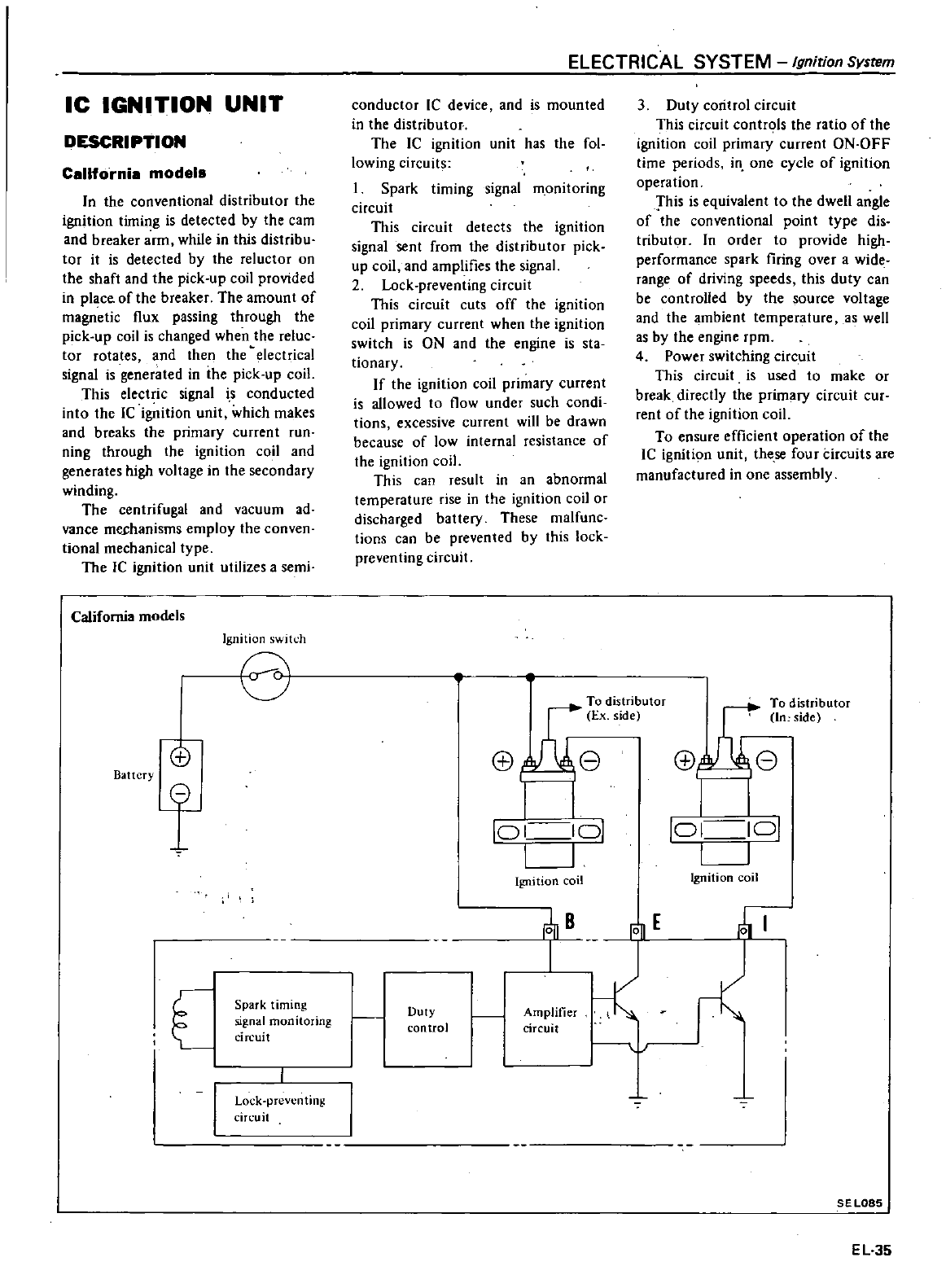
IC
IGNITION
UNIT
DESCRIPTION
California
modals
In
the
conventional
distributor
the
ignition
timing
is
detected
by
the
cam
and
breaker
arm
while
in
this
distribu
tor
it
is
detected
by
the
reluctor
on
the
shaft
and
the
pick
up
coil
provided
in
place
of
the
breaker
The
amount
of
magn
tic
flux
passing
through
the
pick
up
coil
is
changed
when
the
reluc
tor
rotates
and
then
the
electrical
signal
is
generated
in
the
pick
up
coil
This
electric
signal i
s
conducted
into
the
Ie
ignition
unit
which
makes
and
breaks
the
primary
current
run
ning
through
the
ignition
coil
and
generates
high
voltage
in
the
secondary
winding
The
centrifugal
and
vacuum
ad
vance
mechanisms
employ
the
conven
tional
mechanical
type
The
Ie
ignition
unit
utilizes a
semi
California
models
Ignition
swih h
8
Battery
ffi
8
Spark
timing
signal
monitoring
circuit
Lock
prevellting
circuit
ELECTRICAL
SYSTEM
Ignirion
System
conductor
Ie
device
and
is
mounted
in
the
distributor
The
IC
ignition
unit
has
the
fol
lowing
circuits
Spark
timing
signal
ffi9nitoring
circuit
This
circuit
detects
the
ignition
signal
sent
from
the
distributor
pick
up
coil
and
amplifies
the
signal
2
Lock
preventing
circuit
This
circuit
cuts
off
the
ignition
coil
primary
current
when
the
ignition
switch
is
ON and
the
engine
is
sta
tionary
If
the
ignition
coil
primary
current
is
allowed
to
flow
under
such
condi
tions
excessive
current
will
be
drawn
because
of
low
internal
resistance
of
the
ignition
coil
This
can
result
in
an
abnormal
temperature
rise
in
the
ignition
coil
or
discharged
battery
These
malfunc
tions
can
be
prevented
by
this
lock
preventing
circuit
3
Duty
coritrol
circuit
This
circuit
contn
ls
the
ratio
of
the
ignition
coil
primary
current
ON
OFF
time
periods
in
one
cycle
of
ignition
operation
This
is
equivalent
to
the
dwell
angle
of
the
conventional
point
type
dis
tributor
In
order
to
provide
high
performance
spark
firing
over
a
wide
range
of
driving
speeds
this
duty
can
be
controlled
by
the
source
voltage
and
the
ambient
temperature
as
well
as
by
the
engine
rpm
4
Power
switching
circuit
This
circuit
is
used
to
make
or
break
directly
the
primary
circuit
cur
rent
of
the
ignition
coil
To
ensure
efficient
operation
of
the
Ie
igniti9n
unit
these
four
circuits
are
manufactured
in
one
assembly
A
To
distributor
Ex
side
f
8
II
I I
101 101
II
Ignition
coil
s
To
distributor
In
side
f
8
I
r
Lo
1
1
01
I I
Ignition
coil
E
ill
j
ClfCU
Duty
control
SEL085
EL35
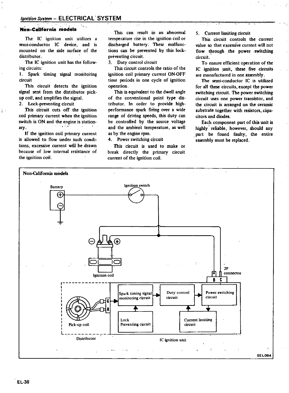
Non
California
models
Ignition
Smem
ELECTRICAL
SYSTEM
The
Ie
ignition
unit
utilizes
a
mi
conductor
Ie
device
and
is
mounted
on
the
side
surface
of
the
distributor
The
IC
ignition
unit
has
the
follow
ing
circuits
I
Spark
timing
signal
monitoring
circuit
This
circuit
detects
the
ignition
signal
sent
from
the
distributor
pick
up
coil and
amplifies
the
signal
2
Lock
preventing
circuit
This
circuit
cuts
off
the
ignition
coil
primary
current
when
the
ignition
switch
is
ON
and
the
engine
is
station
ary
If
the
ignition
coil
primary
current
is
allowed
to
flow
under
such
condi
tions
excessive
current will
be
drawn
because
of
low
internal
resistance
of
the
ignition
coil
Non
Califomia
models
Battery
CD
i
This
can
result
in
an
abnormal
temperature
rise
in the
ignition
coil
or
discharged
battery
These
malfunc
tions
can
be
prevented
by
this
lock
preventing
circuit
3
Duty
control
circuit
This
circuit
controls
the
ratio
of
the
ignition
coil
primary
current
ON
OFF
time
periods
in
one
cycle
of
ignition
operation
This
is
equivalent
to
the
dwell
angle
of
the
conventional
point
type
dis
tributor
In
order
to
provide
high
perfonnancespark
firing
over
awide
range
of
driving
speeds
this
duty
can
be
controlled
by
the
source
voltage
and
the
ambient
temperature
as
well
as
by
the
engine
rpm
4
Power
switching
c
rcuit
This
circuit
is
used
to
make
or
break
directly
the
primary
circuit
current
of
the
ignition
coil
Ige51Ch
eh
B
I
I
J
101
101
LJ
Ignition
coil
r
Pick
up
coil
Lu
Distributor
EL36
Spark
ti
ing
sig
al
G
monitoring
ClICUlt
R
Duty
control
circuit
Lock
Preventing
circuit
IC
ignition
unit
5
Current
limiting
circuit
This
circuit controls the
current
value
so
that
excessive
current will
not
flow
trough
the
power
witching
circuit
To
ensure
efficient
operation
of
the
IC
ignition
unit
these
five
circuits
are
manufactured
in
one
assembly
The
semi
conductor
IC
is
utilized
for
all
these
circuits
except
the
power
switching
circuit
The
power
witching
circuit
uses
one
power
transistor
and
the
circuit
is
arranged
on
the
ceramic
substrate
together
with
resistors
capa
citors
and
diodes
Each
component
part
of
this
unit
is
highly
reliable
however
should
any
part
be
found
faulty
the
entire
assembly
must
be
replaced
2P
rOl
II
connector
rBCl
Power
switching
circuit
Current
timating
circuit
SEL094
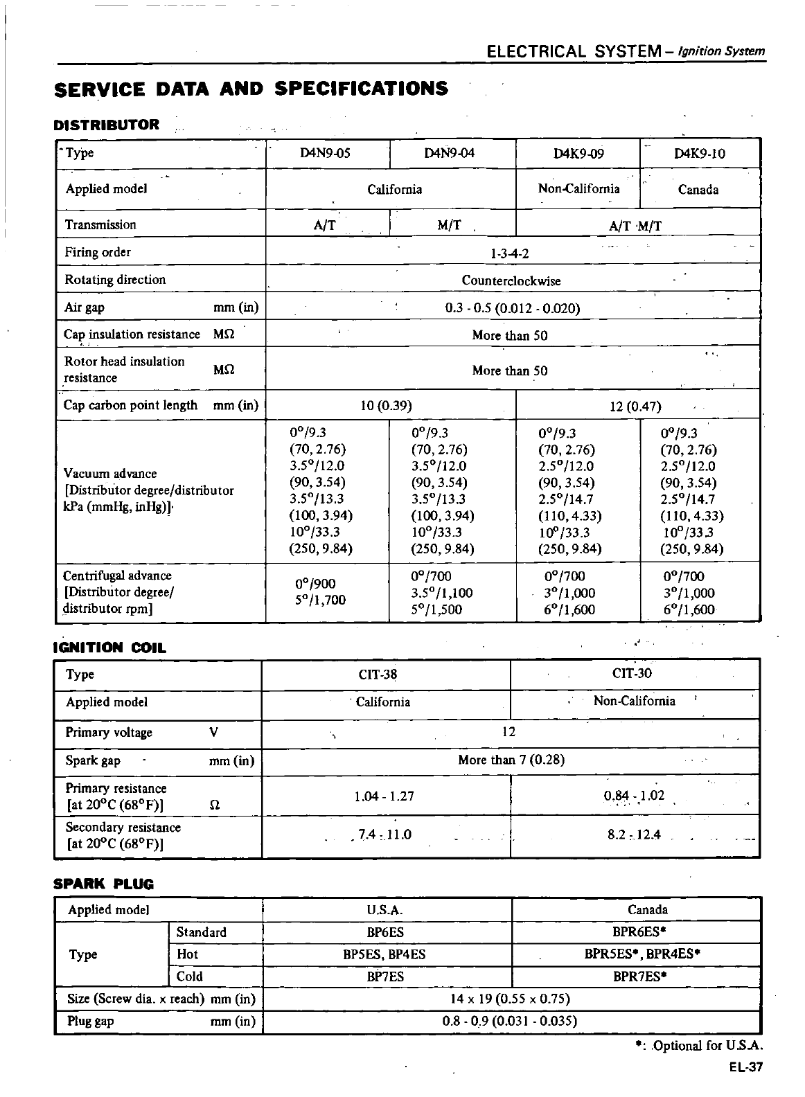
ELECTRICAL
SYSTEM
Ignition
Sysrem
SERVICE
DATA AND
SPECIFICATIONS
DISTRIBUTOR
I
Type
I
pplied
model
I
Transmission
I
Firing
order
I
Rotating
direction
I
Air
gap
I
Ca
insulation
resistance
Rotor
head
insulation
resistance
I
I
I
mm
in
1
Mn
I
Mn
I
cap
carbon point
length
mm
in
I
Vacuum
advance
Distributor
degree
distributor
kPa
mmHg
inHgH
Centrifugal
advance
Distributor
degree
distributor
rpm
IGNITION
COIL
Type
Applied
model
Primary
voltage
Spark
gap
Primary
resistance
at
200C
680
F
Secondary
resistance
at
200C
680F
SPARK
PLUG
Applied
model
Type
v
mm in
n
Standard
Hot
Cold
Size
Screw
dia
x
reach
mm in
Plug
gap
mm
in
D4N9
o5
D4N9
04
D4K9
1O
D4K9
09
California
Non
Califomia
Canada
A
T
I
A
T
M
T
M
T
134
2
Coun
terc10ckwise
03
0
5 0
012
0
020
More
than
50
More
than
50
10
0
39
12
0
47
00
93
00
93
00
93
00
93
70
2
76 70
2
76 70
2
76 70
2
76
3
50
12
0
3
50
12
0
2
50
12
0
2
50
12
0
90
3
54
90
3
54
90
3
54
90
3
54
3
50
13
3
3
50 13
3
2
50
147
2
50
14
7
100
3
94
100
3
94
11
0
4
33
110
4
33
100
33
3
100
33
3
10
33
3
100
33
3
250
9
84
250
9
84
250
9
84
250
9
84
00
900
00
700
00
700
00
700
50
1
700
3
50
1
100
30
1
000
30
1
000
50
1
500
60
1
600
60
1
600
CIT
38
CIT
30
California
Non
California
12
More
than
7
0
28
1
04
12
7
0
84
1
02
74
11
0
82
12
4
U
s
A
BP6ES
BP5ES BP4ES
BP7ES
Canada
BPR6ES
BPR5ES BPR4ES
BPR7ES
14
x
19
0
55
x
0
75
0
8 0 90
031
0
035
Optional
for
U
sA
EL
37
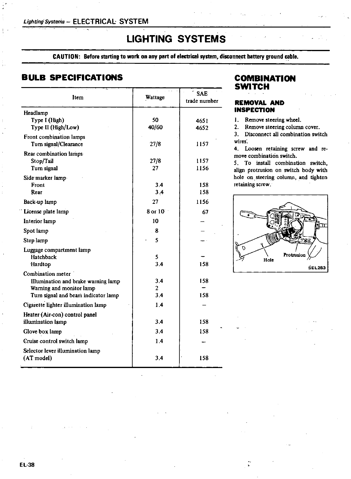
Lighting
Systems
ELECTRICAL SYSTEM
LIGHTING
SYSTEMS
CAUTION
Before
starting
to
work
on
any
part
of
electricel
system
disconneet
battery
ground
ceble
BULB
SPECIFICATIONS
Item
Headlamp
Type
I
High
Type
11
High
Low
Front
combination
lamps
Tum
signal
Clearance
Rear
combination
lamps
Stoprrail
Turn
signal
Side
marker
lamp
Front
Rear
Back
up
lamp
license
plate lamp
Interior
lamp
Spot
lamp
Step
lamp
Luggage
compartment
lamp
Hatchback
Hardtop
Combination
meter
Illumination
and
brake
warning
lamp
Waming
and
monitor
lamp
Turn
signal
and
beam
indicator
lamp
Cigarette
lighter
illumination
lamp
Heater
Air
on
control
panel
illumination
lamp
Glove
box
lamp
Cruise
control
switch
lamp
Selector
lever
illumination
lamp
AT
model
EL38
Wattage
50
40
60
27
8
27
8
27
34
34
27
80r
10
10
8
5
5
34
34
2
34
1
4
34
3
4
14
34
SAE
trade
number
4651
4652
1157
1157
1156
158
158
1156
67
158
158
158
158
158
158
COMBINATION
SWITCH
REMOVAL
AND
INSPECTION
1
Remove
steering
wheel
2
Remove
steering
column
cover
3
Disconnect
all
combination
switch
wires
4
Loosen
retaining
screw
and
re
move
combination
switch
5
To
install
combination
switch
a1ign
protrusion
on
switch
body
wiih
hole
on
steering
column
and
tighten
retaining
screw
SE
L283
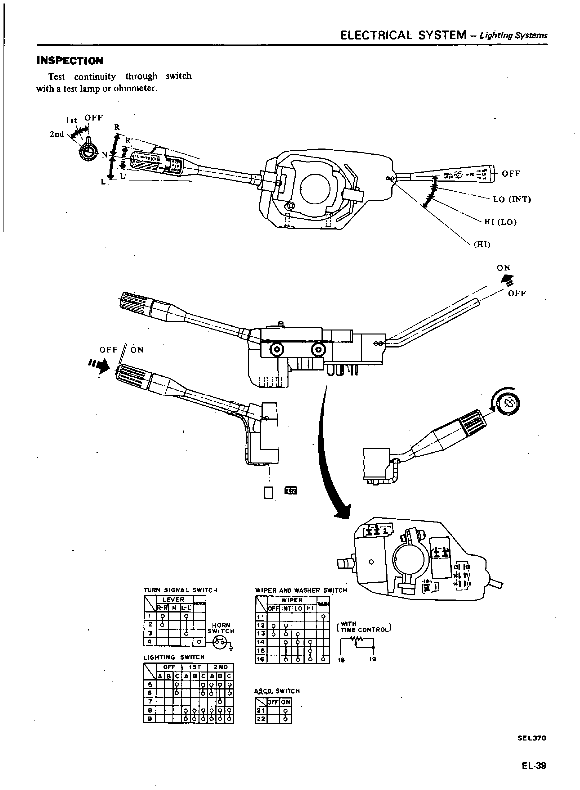
INSPECTION
Test
continuity
through
switch
with
a
test
lamp
or
ohmmeter
1st
OFF
2nd
N
L
OFFI
ON
ELECTRICAL SYSTEM
LighringSystems
o
JI
I
1r
111f
UUJUUU
I
TURN
SIGNAL
SWITCH
1
LEVER
I
I
i
NIL
If
LIGHTING
SWITCH
1
1
OFF
1ST
2ND
I
ABC
A
Be
A
8 C
zuni
I
0
I
tf
M
UMJ
o
iF
90
ON
OFF
WIPER
AND
WASHER
SWITCH
1
1
WIPER
IOFF
INT
LO
HI
111
l
12
WITH
1i
X
TINE
CONTRod
f
rq
tJ
tu
AAQ
SWITCH
nON
22
SEL310
EL39
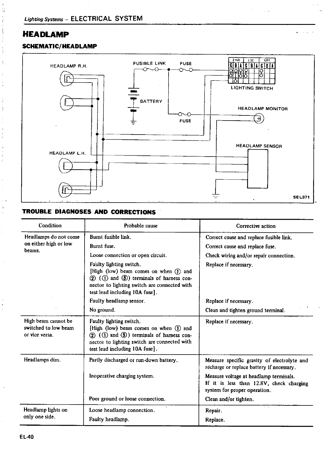
Lighting
Systems
ELECTRICAL SYSTEM
HEADLAMP
SCHEMATIC
HEADLAMP
HEAOLAMP
A H
@
C0
HEAD
LAMP
L
H
CD
@
FUSIBLE
LINK
FUSE
r
c
l
BATTERY
I
oc
FUSE
t
r
I
TROUBLE
DIAGNOSES
AND
CORRECTIONS
Condition
Headlamps
do
not
come
on
either
high
or
low
beams
High
beam
cannot
be
switched
to
low
beam
or
vice
versa
Headlamps
dim
Headlamp lights
on
only
one
side
EL40
Probable
cause
Burnt
fusible
link
Burnt
fuse
Loose
connection
or
open
circuit
Faulty
lighting
switch
High
low
beam
comes
on
when
CD
and
@
CD
and
@
terminals
of
hamess
con
nector
to
lighting
switch
are
connected
with
test
lead
including
lOA
fuse
Faulty
headlamp
sensor
No
ground
Faulty
lighting
switch
High
low
beam
comes
on
when
CD
and
@
D
and
@
terminals
of
hamess
con
nector
to
lighting
switch
are
connected
with
test
lead
including
lOA
fuse
Partly
discharged
or
run
down
battery
Inoperative
charging
system
Poor
ground
or
loose
connection
Loose
headlamp
connection
Faulty
headlamp
udi
LIGHTING
SWITCH
HEAD
LAMP
MONITOR
lj
HEADLAMP
SENSOR
1
SEL371
Corrective
action
Correct
cause
and
replace
fusible
link
Correct
cause
and
replace
fuse
Check
wiring
and
or
repair
connection
Replace
if
necessary
Replace
if
necessary
Clean
and
tighten
ground
terminal
Replace
if
necessary
Measure
specific
gravity
of
electrolyte
and
recharge
or
replace
battery
if
necessary
Measure
voltage
at
headlamp
terminals
If
it
is
less
than
12
8V
check
charging
system
for
proper
operation
Clean
and
or
tighten
Repair
Replace
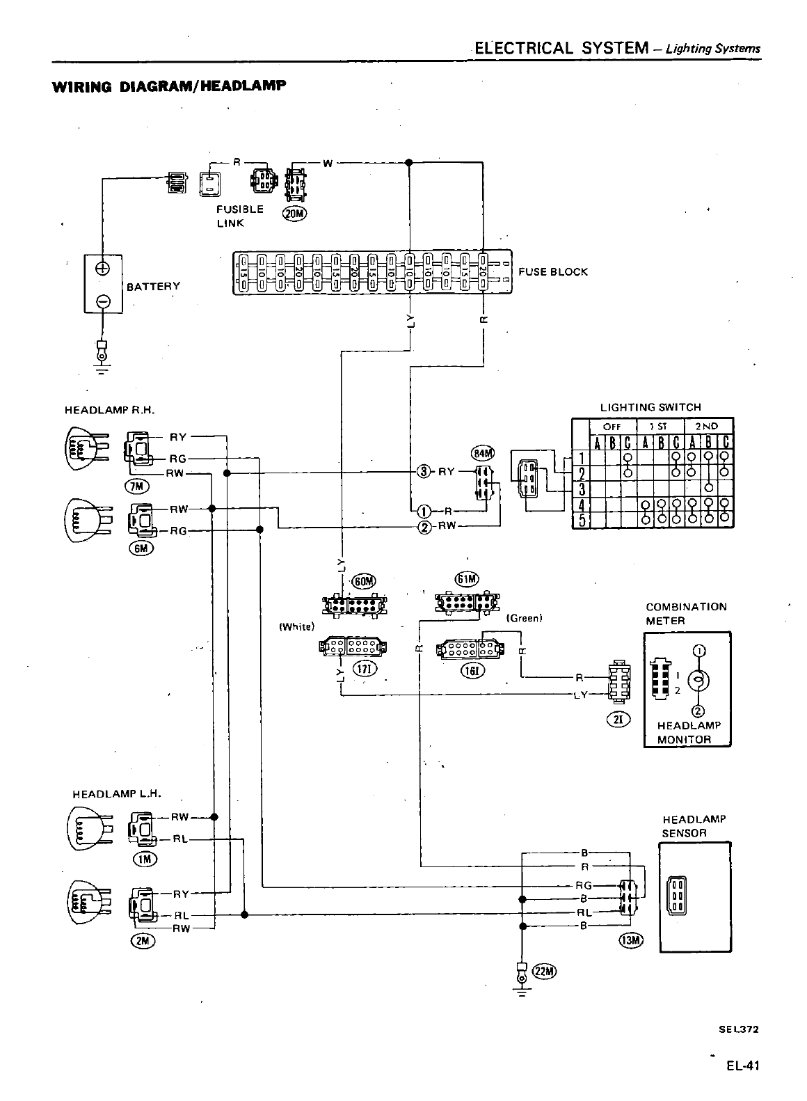
WIRING
DIAGRAM
HEADLAMP
ill
R
OW
FUSIBLE
@
LINK
ELECTRICAL
SYSTEM
Lighting
Systems
o
BATTERY
t
HEADLAMP
R
H
fi
ir
RY
RR
@
Tr
1
RW
R
@
HEADLAMP
L
H
0
@
@
RY
RL
RW
@
II
White
QrJ
g g
giJ
@
I
I
r
@
V
RY1th
j
R
I
Y
RW
LIGHTING
SWITCH
I
OFF
1ST
2ND
4
R
r
4
R
r
4
I
a
lL
661
t
D
L
l3
0
H
gXZ
6 6
g
II
r
Green
J
I
l
lQ
g
gglrgg
CI
I
@
I
COMBINATION
METER
O
U
@
HEADL
MP
MONITOR
HEAD LAMP
SENSOR
@l
D
DO
DO
@
SE
L372
EL
41
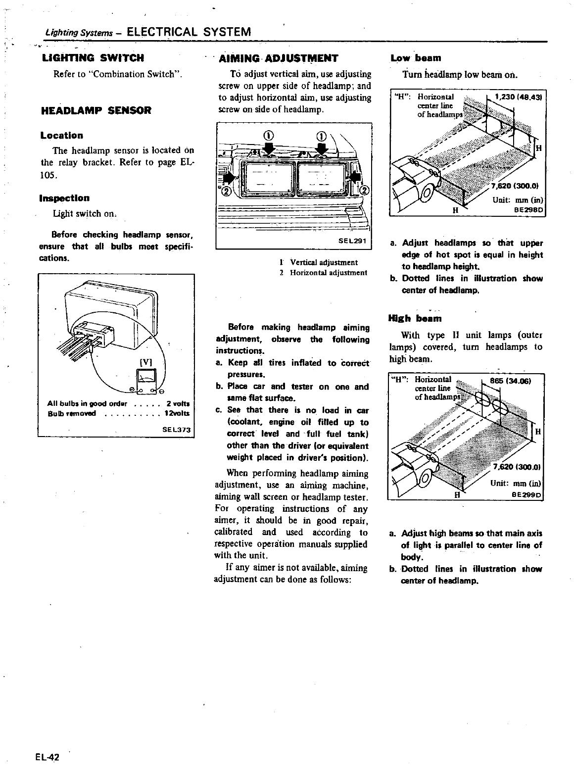
Lighting
Systems
ELECTRICAL
SYSTEM
LIGHTING
SWITCH
Refer
to
Combination Switch
HEADLAMP
SENSOR
Location
The
headlamp
sensor
is
located
on
the
relay
bracket
Refer
to
page
EL
105
Inspection
Ught
swi1ch
on
Before
checking
headlamp
sensor
ensure
that
11
bulb
meet
specifi
cations
All
bulbs
in
good
ordllr
Bulb
removed
e
2
volts
12volu
SEl373
EL42
AIMING
ADJUST
ENT
To
adjust
vertical
aim
use
adjusting
screw
on
upper
side
of
headlamp
and
to
adjust
horizontal
aim
use
adjusting
screw
on
side
of
headlamp
CD
Q2
i
il
i
Gwu
1
SEL291
1
Vertical
adjustment
2
Horizontal
adjumnent
Bafor
m
king
headl
mp Imlng
djustment
ob
rve
the
following
instruction
Keep
11
tires
infl
ted
to
correct
pressures
b
Place
car
and
tester
on
one
and
same
flat
urf
c
See
th
t
there
is
no
load
in
car
cool
nt
engine
oil
filled
up
to
correct
level
and
full
fuel
tank
other
than
the
driver
or
equivalent
weight
pl
ced
in
driver
s
position
When
performing
headlamp
aiming
adjustment
use
an
aiming
machine
aiming
wall
screen
or
headlamp
tester
For
operating
instructions
of
any
aimer
it
should
be
in
good
repair
calibrated
and
used
according
to
respective
operation
manuals
supplied
with
the
unit
If
any
aimer
is
not
available
aiming
adjustment
can
be
done
as
follows
Low
beam
Turn
headlamp
low
beam
on
U
Horizo
tal
n
230
48 43
center
line
I
Ofheadlam
p
Wf
Th
fP
t
s
7R
j
W
Unit
nun
in
BE298D
Adjust
headl
mps
SO
that
upper
edge
of
hot
pot
is
equ
1
in
h
ight
to
heedl
mp
height
b
Dotted
lines
in
illustration
show
canter
of
headl
mp
High
beam
With
type
II
unit
lamps
outer
lamps
covered
tum
headlamps
to
high
beam
U
H
Unit
mm in
BE2990
8
Adjust
high
beams
so that
main
axis
of
light
is
p
rallel
to
center
line
of
body
b
Dotted
lines
in
illustration
show
center
of
headl
mp
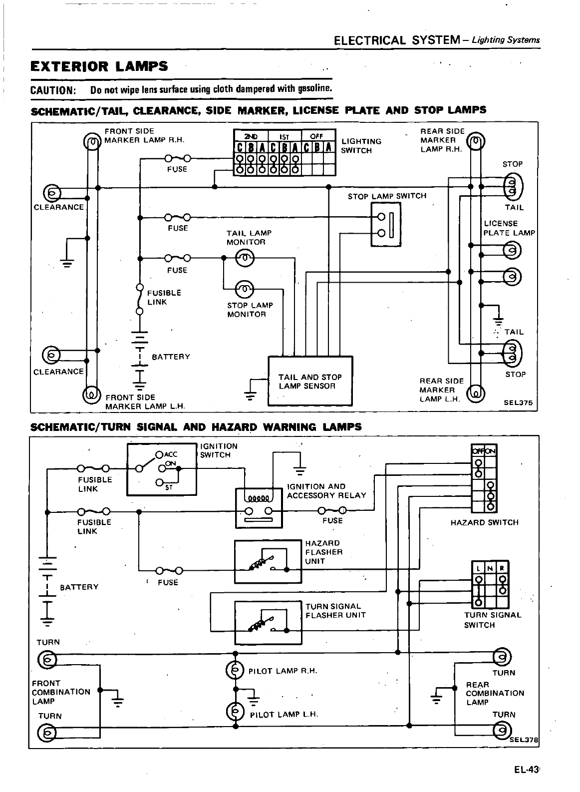
EXTERIOR
LAMPS
ELECTRICAL
SYSTEM
Lighting
Systems
CAUTION
Do
not
wipe
lens
surface
using
cloth
dampered
with
gesoline
SCHEMATIC
TAIL
CLEARANCE
SIDE
MARKER
LICENSE
PLATE
AND
STOP
LAMPS
FRONT
SIDE
MARKER LAMP
R H
oc
FUSE
@
I
CLEARANCE
r
fJ
CLEARANCE
oc
FUSE
oc
FUSE
IFUSIBLE
LINK
T
I
BATTERY
L
I
EJ
FRONT
SIDE
MARKER LAMP
LH
2toI
1ST
OFF
jlmfr
i
STOP
LAMP
SWITCH
TAIL
LAMP
MONITOR
STOP
LAMP
MONITOR
r
TAl
L
ANO
STOP
LAMP
SENSOR
SCHEMATIC
TURN
SIGNAL
AND HAZARD WARNING
LAMPS
OACC
r
o
4
c
FUSleLE
LINK
Sf
oc
FUSIBLE
LINK
T
I
BATTERY
L
I
TURN
fl
FRONT
COMBINATION
l
LAMP
TURN
E1
oc
FUSE
IGNITION
SWITCH
1
L
IGNITION
AND
ACCESSORY
RELAY
C
00
FUSE
Fl
HAZARD
FLASHER
UNIT
Fl
TURN
SIGNAL
FLASHER
UNIT
PILOT
LAMP
R
H
PILOT
LAMP
LH
REAR
SIDE
MARKER
LAMP
R
H
STOP
j
@
TAIL
LICENSE
PLATE
LAMP
@
@
l
TAIL
Il
STOP
REAR
SIDE
MAR
KER
Q
LAMP
LH
SE
L315
g
HAZARD
SWITCH
IN
f
g
TURN
SIGNAL
SWITCH
@
TURN
RE
R
COMBINATION
LAMP
TURN
t3
eL37
EL
43
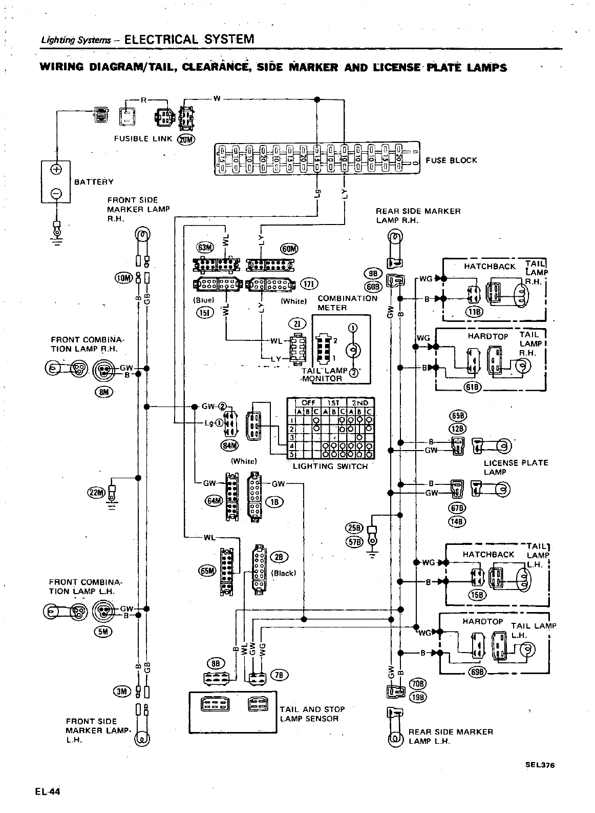
Lighting
Systems
ELECTRICAL
SYSTEM
WIRING
DIAGRAM
TAIL
CLEARANcE
SIDE
MARKER
AND
UCENSE
PLATE
LAMPS
R
I
FUSIBLE
LINK
@
Et
BATTERY
1
FRONT
SlOE
MARKER LAMP
R H
n
@89
ll
FRONT
COMBINA
TION
LAMP
R H
1
GW
8
@
@
il
FRONT
COMBINA
TION
LAMP
LH
GB
@
@I
FRONT
SIDE
Y
MARKER LAMP
LH
ELM
W
I
J
I
GW
I
I
OF
1ST
2ND
ABCABCABC
Lg
j
I
00
1
I
00
3
4
5
LIGHTING
SWITCH
GW
00
00
00
1B
00
V
00
ft
White
@
@
I
G
LICENSE
PLATE
LAMP
l
e
r
GW
i
lI
ltJ
ill
@
Ij
f
ill
@o
WL
@
e
gg
@
00
g g
Black
i5O
g
r
TAIL
WGH
HATC
CK
M
B
I
ry
I
wARD
TOP
TAIL
LA
P
WG
LH
I
I
a
f
B14
Gll
L@j
JJ
@
@j
Gf
REAR
SIDE
MARKER
I
LAMP
LH
II
JtU@
W
l
TAIL
AND
STOP
LAMP
SENSOR
SEL316
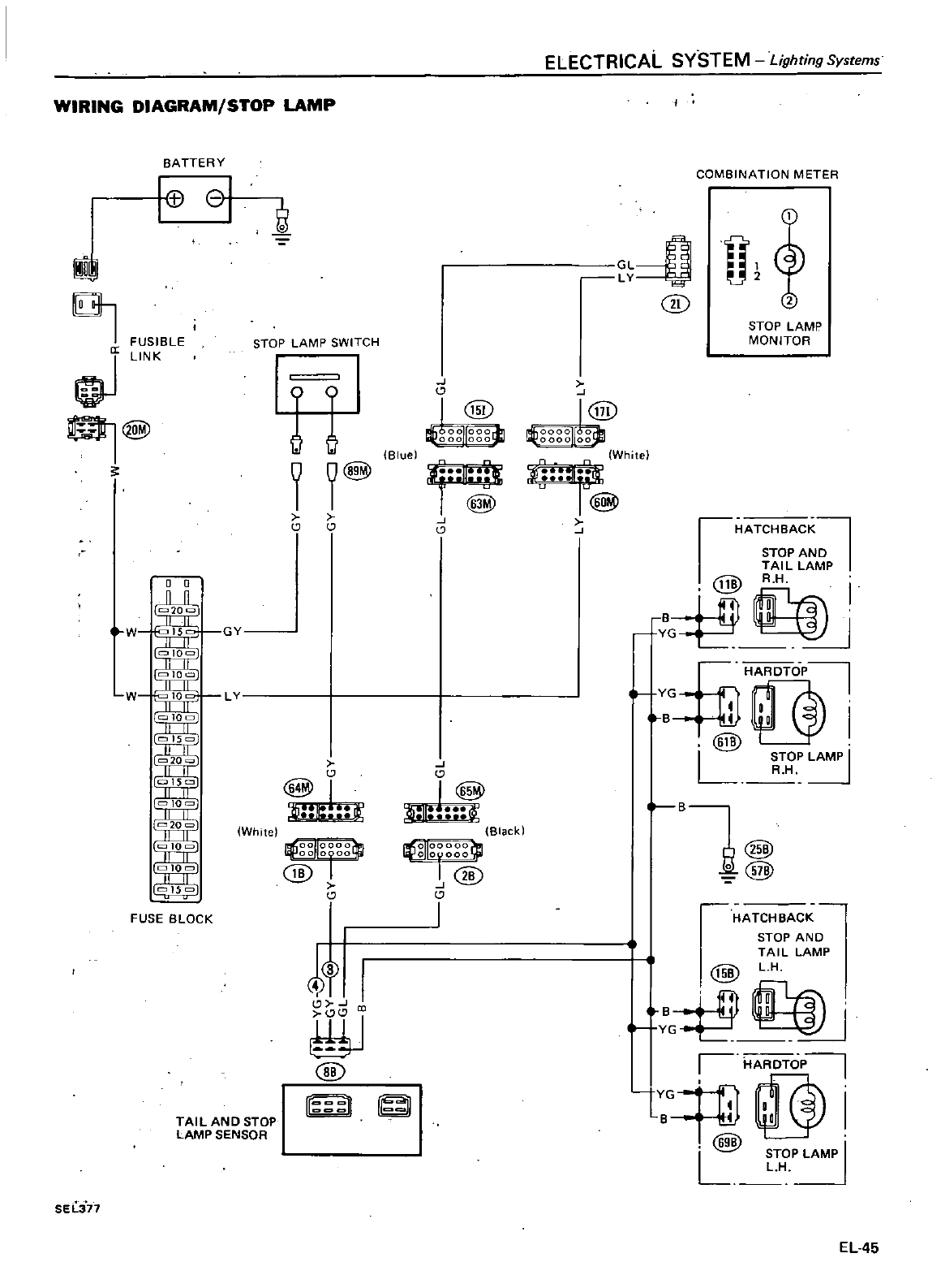
WIRING
DIAGRAM
STOP
LAMP
BATTERY
01
IU
G
I
FUSIBLE
LINK
@
0
0
l
W
w
I
10
15
10
20
10
10
15
FUSE
BLOCK
STOP
LAMP
SWITCH
ELECTRICAL
SYSTEM
Lighting
Systems
COMBINATION
METER
L
Au2
y
U
CID
II
@
J@
ggggllggt
Bluel
White
@
II
J
IIF
@
J
J
GY
L
c
LIi
White
OOIIOOOO
Iqj
oo
0000
11
@
I
f
I
tf11
@
TAIL
AND
STOP
LAMP
SENSOR
SEli71
B
YG
STOP
LAMP
MONITOR
HATCHBACK
STOP
AND
TAIL
LAMP
RH
@
f
HARDTOP
f
YG
I
f
B
41
tJ
I
@
L
STOP
LAMP
I
R H
HATCHeACK
STOP
AND
TAIL
LAMP
@
LH
J
r
II
J
Black
o
ooooo
OJ
rO@
I
B1
@
Cill
u
B
l
YG
r
HARDTOP
@I
@
I
I
STOP
LAMP
L
LH
EL
45
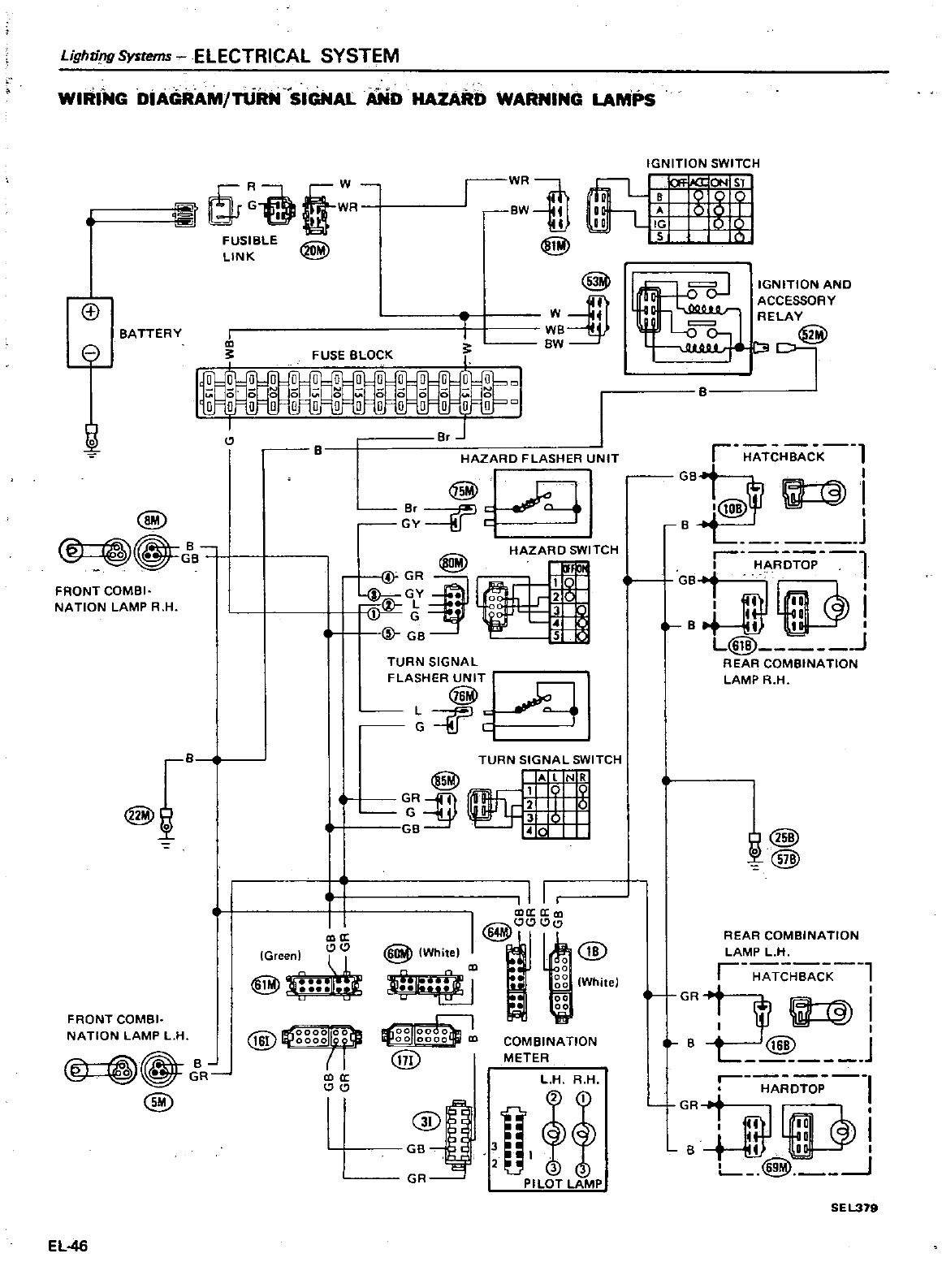
GBbTCHBACK
l
B
m
J
HAZARD
SWITCH
r
l
I
HARDTOP
2
0
8GB1
I
O
I
J
G
3
D
4
0
8tI
I
u
G
B
S I
L
J
REAR
COMBINATION
LAMP
R
H
Lighri
ng
Systems
ELECTRICAL
SYSTEM
WIRING DiAGRAM
TUm
SIGNAL
AND
HAZARD
WARNING
LAMPS
@i
R
FUSIBLE
LINK
i
rn
@
G1
@
W
I
WB
BW
BATTERY
3
FUSE
BLOCK
B
HAZARD
FLASHER
UNIT
@
r
J
B
GB
@
j
I
BI
l
co
fP
1
GY
t
J
FRONT
COMBI
NATION
LAMP
R H
TURN
SIGNAL
FLASHER
UN
IT
L
G C
B
TURN
SIGNAL
SWITCH
@
LN
R
f
1t
i
I
GB
Y
@
j
I
i
II
CD
aJ
I@
IWhi
e
6
Ilt@
00
White
Y
oc
I
00
I
ll
fi
a
IG
een
I
1
i
FRONT
COMBI
NATION
LAMP
L
H
OOllOO
OilfJ I
00
0000
co
ill
@
COMBINATION
METER
L
H
R
H
jJif
GR
PILOT
LAMP
@
R
@
a
I
I
EL
46
IGNITION
SWITCH
I
CJT
iI
t
ICJN ST
U9Q
A0 0
J
IG
b
Q
s
IGNITION
AND
ACCESSORY
RELAY
r
I@
t@
REAR
COMBINATION
LAMP
L
H
r
cl
111
1
GR
I
I
1
B
L
@2
J
ro
I
GRi
fll
l
r1
i
B
t
ID
J
P
I
L
8
SEL379
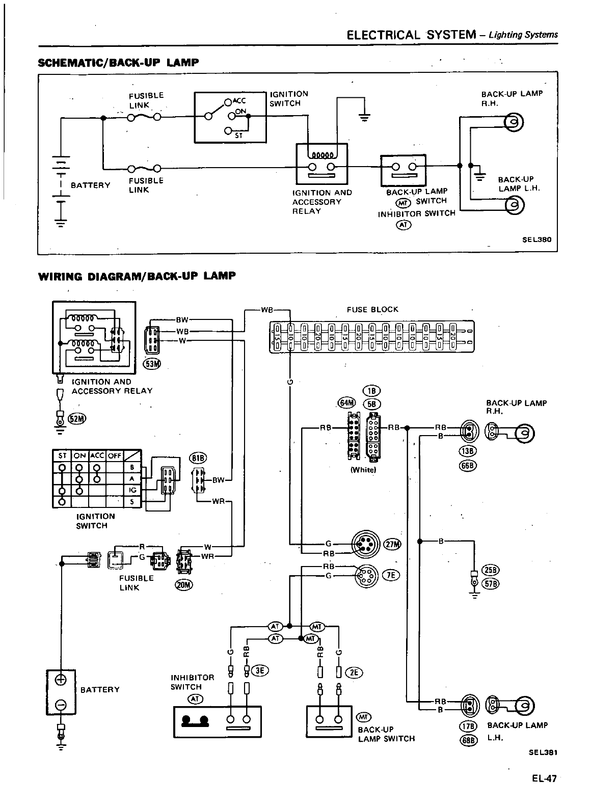
ELECTRICAL
SYSTEM
Lighting
Systems
SCHEMATIC
BACK
UP
LAMP
FUSIBLE
LINK
oc
OACC
if
CON
IGN
1TI0N
SWITCH
1
BACK
UP
LAMP
R H
@
I
BATTERY
L
I
FUSIBLE
LINK
C C
BACK
UP
LAMP
L
H
IGNITION
AND
ACCESSORY
RELAY
BACK
UP
LAMP
@
SWITCH
INHIBITOR
SWITCH
@
13
SEL380
WIRING
DIAGRAM
BACK
UP
LAMP
FUSE
BLOCK
1
IGNITION
AND
9
ACCESSORY
RELAY
Jl
@
@
@@
RB
00
RB
00
i
White
BACK
UP
LAMP
RH
F
T
IGNITION
SWITCH
@
BW
WR
BB
t
@
@
o
tf
R
FUSIBLE
LINK
G
@
B
RB
B
@@
I@
1@
o
BATTERY
INHIBITOR
SWITCH
@
I
ll ll
C
aa
C
9
Q@
0
O@
11
11
t
I@
BACK
UP
LAMP
SWITCH
RBB
t
@
BACK
UP
LAMP
@
L
H
SEL381
EL
47
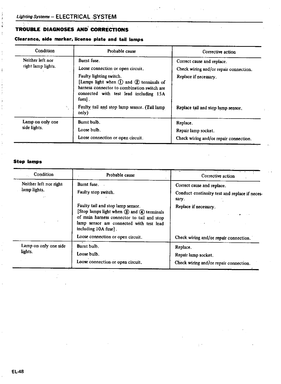
Lighting
Systems
ELECTRICAl
YSTEM
TROUBLE
DIAGNOSES
AND
CORRECTIONS
Clearance
side
marker
lleense
plate
and
tail
lamps
Condition
Neither
left
nor
right
lamp
lights
Lamp
on
only
one
side
lights
Stop
lamps
Condition
Neither
left
nor
right
lamp lights
Lamp
on
only
one
side
lights
EL48
Probable
cause
Burnt
fuse
Loose
connection
or
open
circuit
Faulty
lighting
switch
Lamps
light
when
CD
and
@
terminals
of
harness
connector
to
combination
switch
are
connected
with
test
lead
including
15A
fues
Fa1llly
tail
an
d
stop
lamp
sensor
Tail
lamp
only
Burnt
bulb
Loose
bulb
Loose
connection
or
open
circuit
Probable
cause
Burnt
fuse
Faulty
stop
switch
Faulty
tail
and
stop
lamp
sensor
Stop
lamps
light
when
@
and
@
terminals
of
main
harness
connector
to
tail
and
stop
lamp
sensor
are
connected
with
test
lead
including
lOA
fuse
Loose
connection
or
open
circuit
Bumt
bulb
Loose
bulb
Loose
connection
or
open
circuit
Corrective
action
Correct
cause
and
replace
Check
wiring
and
or
repair
connection
Replace
if
necessary
Replace
t
li1
and
stop
hunp
sensor
Replace
Repair
lamp
socket
Check
wiring
and
or
repair
connection
Corrective
action
Correct
cause
and
replace
Conduct
continuity
test
and
replace
if
neces
sary
Replace
if
necessary
Check
wiring
and
or
repair
connection
Replace
Repair
lamp
socket
Check
wiring
and
or
repair
connection
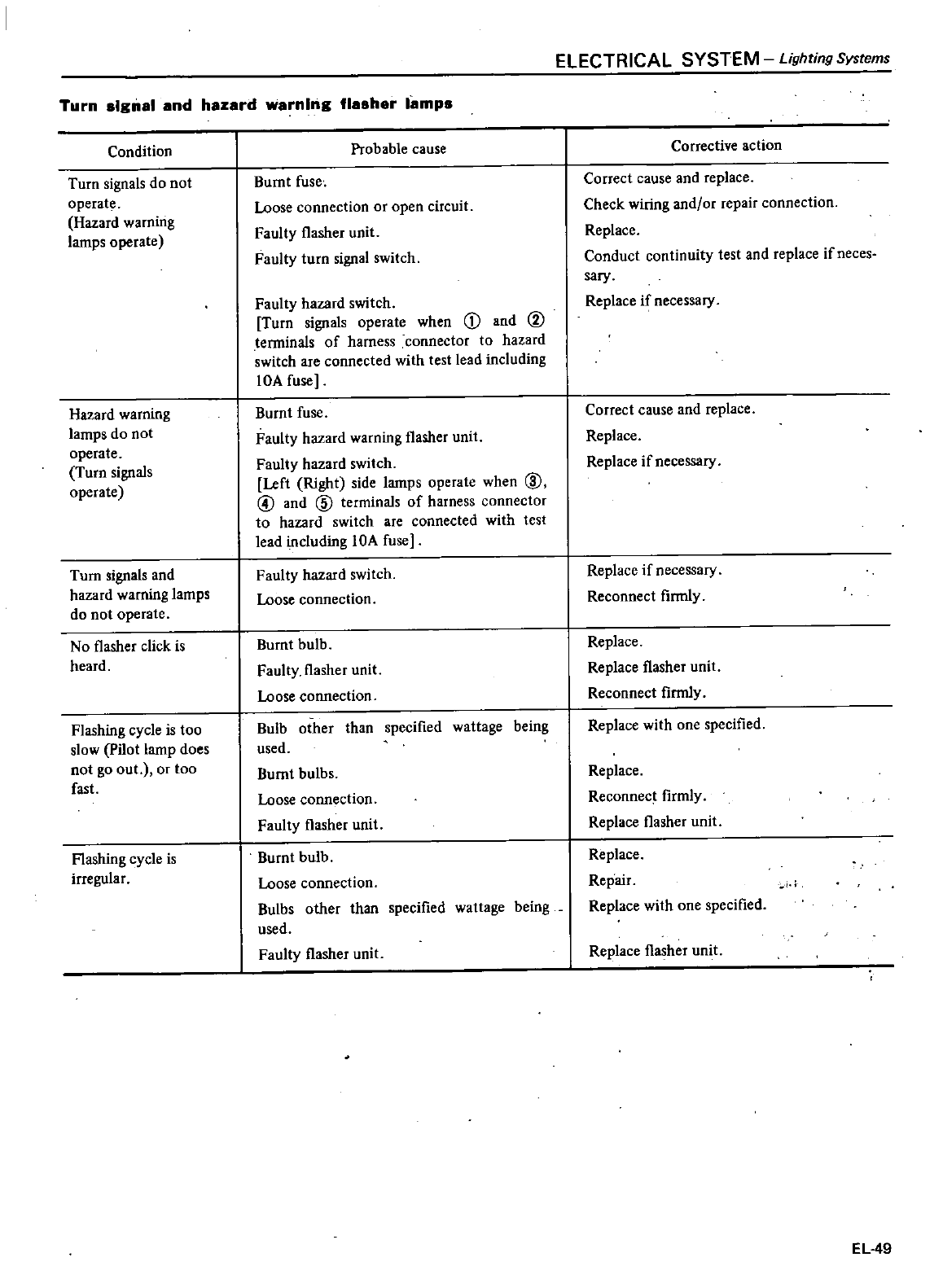
Turn
slgnsl
and
hazard
warnIng
flasher
lamps
Condition
Turn
signals
do
not
operate
Hazard
waming
lamps
operate
Hazard
warning
lamps
do not
operate
Turn
signals
operate
Turn
signals
and
hazard
warning
lamps
do
not
operate
No
flasher
click
is
heard
Flashing
cycle
is
too
slow
pilot
lamp
does
not
go
out
or
too
fast
Flashing
cycle
is
irregular
Probable
cause
Bumt
fuse
Loose
connection
or
open
circuit
Faulty
flasher
unit
Faulty
turn
signal
switch
Faulty
hazard
switch
Turn
signals
operate
when
CD
and
@
terminals
of
harness
connector
to
hazard
switch
are
connected
with
test
lead
including
lOA
fuse
Burnt
fuse
Faulty
hazard
warning
flasher
unit
Faulty
hazard
switch
Left
Right side
lamps
operate
when
@
@
and
@
terminals
of
harness
connector
to
hazard
switch
are
connected
with
test
lead
including
lOA
fuse
Faulty
hazard
switch
Loose
connection
Burnt
bulb
Faulty
flasher
unit
Loose
connection
Bulb
other
than
specified
wattage
being
used
Burnt
bulbs
Loose
connection
Faulty
flasher
unit
Burnt
bulb
Loose
connection
Bulbs
other
than
specified
wattage
being
used
Faulty flasher
unit
ELECTRICAL SYSTEM
Lighting
Systems
Corrective
action
Correct
cause
and
replace
Check
wiring
and
or
repair
connection
Replace
Conduct
continuity
test
and
replace
if
neces
sary
Replace
if
necessary
Correct
cause
and
replace
Replace
Replace
if
necessary
Replace
if
necessary
Reconnect
finnly
Replace
Replace
flasher
unit
Reconnect
finnly
Replace
with
one
specified
Replace
Reconnect
firmly
Replace
flasher
unit
Replace
Repair
Replace
with
one
specified
Replace
flasher
unit
EL
49
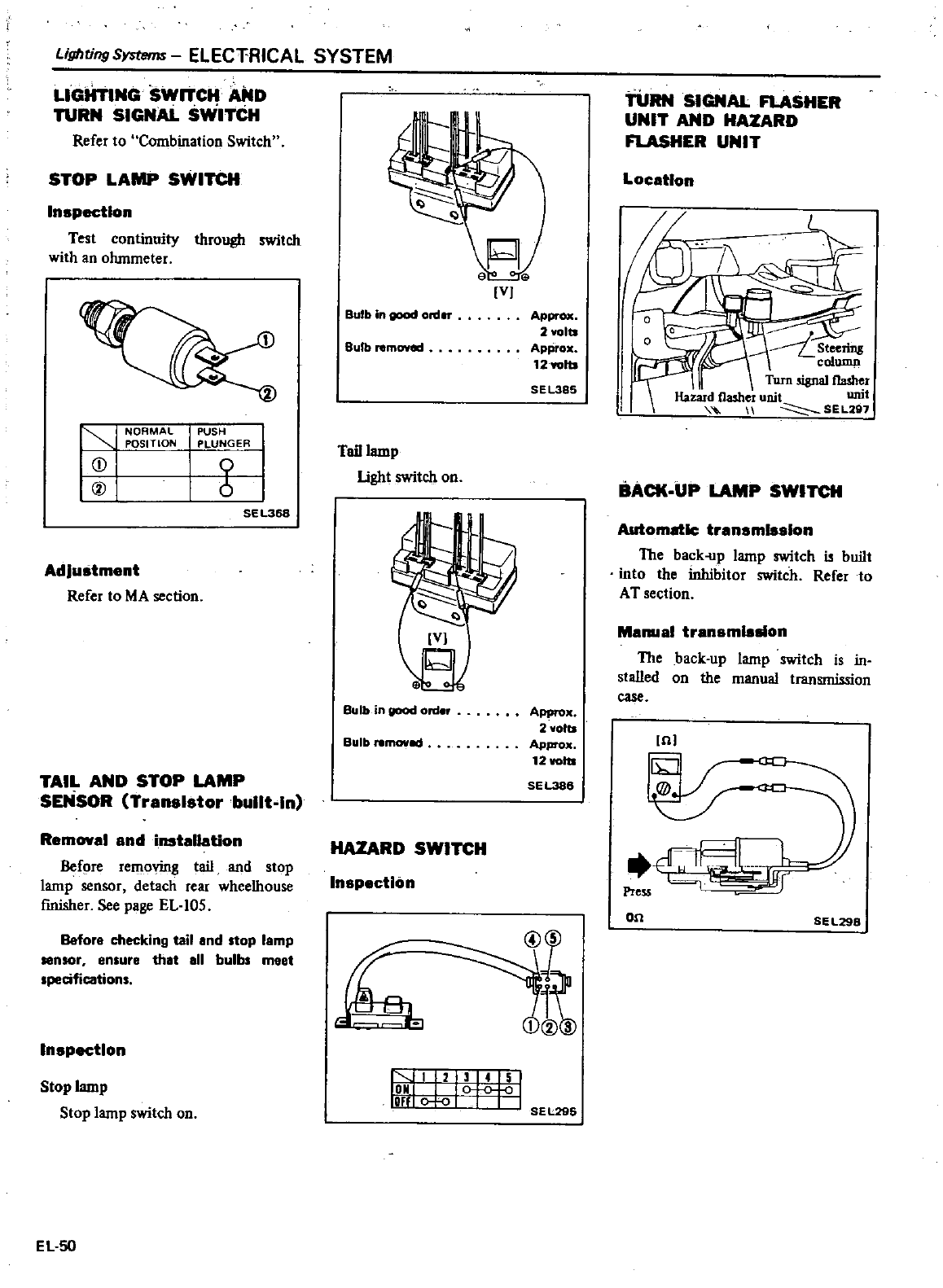
Lighting
Symms
ELECTRICAL SYSTEM
LIGHTING
SWrTCH
AND
TURN
SIGNAL
SWI1
Ct1
Refer
to
Combination Switch
STOP LAMP
SWITCH
Inspection
Test
continuity
through
switch
with
an
ohmmeter
CD
@
NORMAL
POSITION
PUSH
PLUNGER
6
SE
L36S
Adjustment
Refer
to MA
section
TAIL
AND
STOP
LAMP
SENSOR
Transistor
built
In
Removal
and
installation
Before
removing
tail
and
stop
lamp
sensor
detach
rear
wheelhouse
fInisher
See
page
EL
105
Before
checking
tail
end
top
lamp
senIOr en
ure
that
aU
bulb
meet
specifications
Inspection
Stop
lamp
Stop lamp
switch
on
EL
50
VJ
Bulb
in
good
ord
Ap
2
volts
Approx
12wofts
SEL385
Bulb
removed
Tail
lamp
light
switch
on
Bulb
in
good
ord
r
Approx
2
volts
Approx
12voltl
SEL386
Bulb
nmoved
HAZARD
SWITCH
Inspection
lt
145
OM
OF
SEL296
TURN
SIGNAL
FLASHER
UNIT
AND
HAZARD
FLASHER
UNIT
Location
Steering
column
Turn
signal
flasher
Hazard
flasher
unit unit
SEL
Z97
BACK
UP
LAMP
SWITCH
Automatic
transmleslon
The
back
up
lamp
switch
is
built
into
the
inhibitor
switch
Refer
to
AT
section
Manual
transmlealon
The
back
up
Jamp
switch
IS
ID
stalled
on
the
manual
transmission
case
OJ
on
SEL298
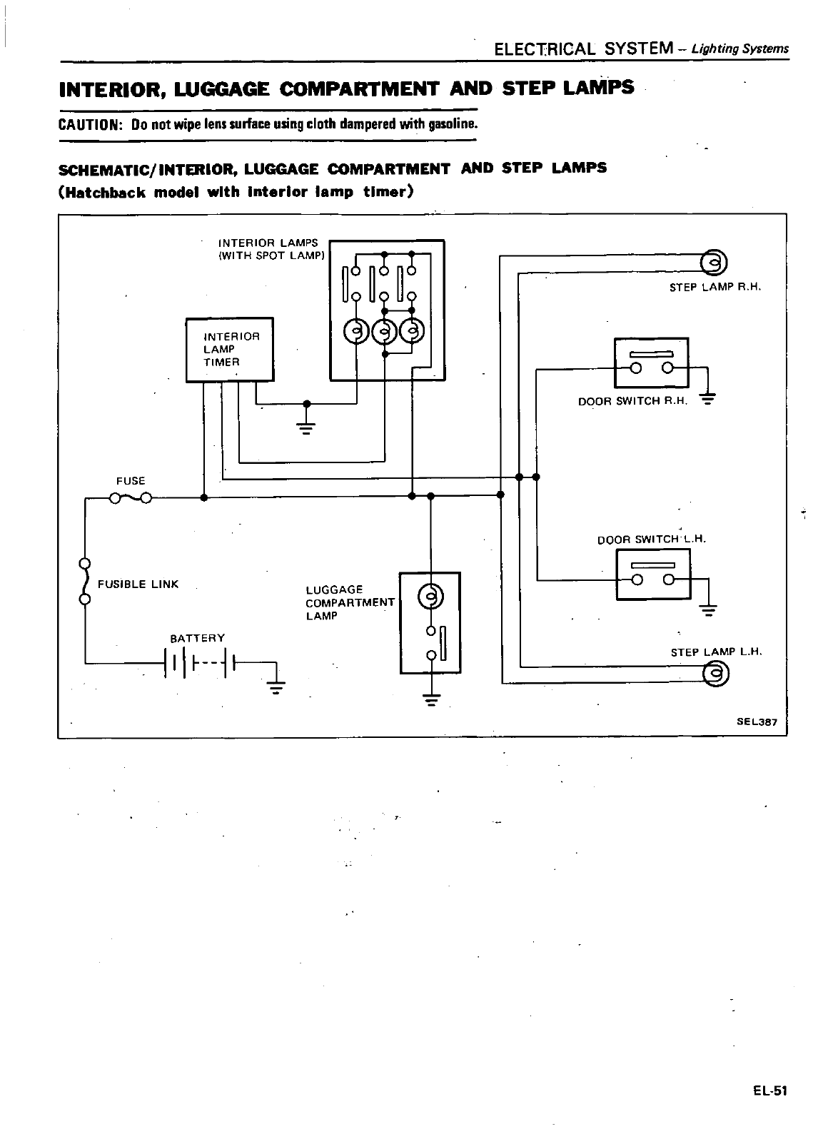
ELECT
RICAL
SYSTEM
Lighting
Systems
INTERIOR
WGGAGE
COMPARTMENT
AND
STEP
LAMPS
CAUTION
00
not
wipe
lens
surface
using
cloth
dampered
with
gasoline
SCHEMATIC INTERIOR
LUGGAGE
COMPARTMENT
AND
STEP
LAMPS
Hatchback
model
with
Interior
lamp
timer
INTERIOR
LAMPS
WITH
SPOT
LAMPI
66 6
ij
011
STEP
LAMP
R
H
INTERIOR
LAMP
TIMER
1
o
DOOR
SWITCH
R
H
FUSE
o
C
j
DOOR
SWITCH
L
H
FUSIBLE
LINK
LUGGAGE
COMPARTMENT
LAMP
1
o
0
1
BATTERY
III
L
STEP
LAMP
L
H
n
SEL3a7
EL
51
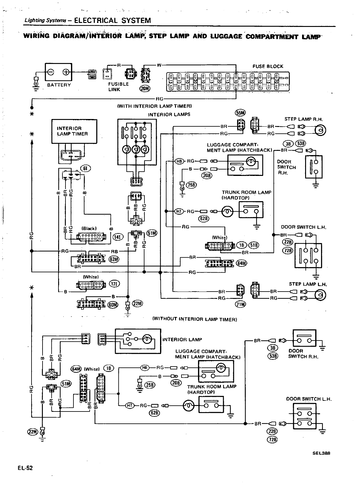
Lighting
Systems
ELECTRICAL
SYSTEM
WIRI
NG
DIAGRAM
INTERIOR
LAMP
STEP
LAMP
AND
LUGGAGE
COMPARTMENT
LAMP
81
i
BATTERY
11
US BL
u
I
LINK
@
0 0 0 0
FUSE
BLOCK
l
lG
IWITH
INTERIOR
LAMP
TIMER
INTERIOR
LAMPS
INTERIOR
6 b 6
LAMP
TIMER
1f
Wl@
II
rif31
II
W
a
U
Black
CD
4
Hgg
I@
fY
@
CC
CD
CD
aa
RG
RB
l
I
H
@
on
White
19b
21
I
i7I
Y
B
B
ib
@
@
1
k9
IrO
jl
a
II
CD
a
co
a
W
White
@
r9l@
0
I
I
tI
00
a
CD
I
i
LUGGAGE
COMPART
MENT
LAMP
IHA
TCHBACK
RG
B
D
0Q
J
i
@
@
TRUNK
ROOM
LAMP
HARDTOP
@
RG
ao
@
t
o
L
@
@
EL
52
@
lR
lG
i
STEP
LAMP
A
H
00
BR
ro
I
A
RG
cJ
LUGGAGE
COMPART
@@
MENT
LAMP
HATCHBACK
eR
@
RG
DOOR
nO
fB@
O
CH
4
@
TRUNK
ROOM
LAMP
HARDTOP
1
@
RG
11
@
Rr
I
Whi
000
1
0
oh
iB
tSiB
V
R
DOOR
SWITCH
LH
BR
W
@I
@
6
l
iR
tt
ER
@
STEP
LAMP
LH
00
BR
cJ
RG
cJ
WITHOUT
INTERIOR
LAMP
TIMER
INTERIOR
LAMP
BR
J
oh
@
DOOR
@
SWITCH
R H
DOOR
SWITCH
LH
0
0
lR
J
0
0
0
2
@
@
SEL388
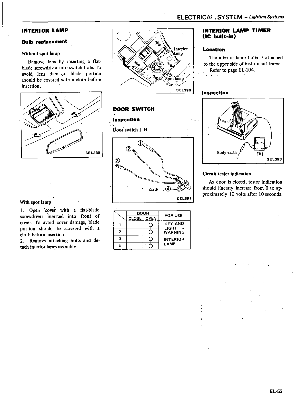
INTER
I
OR
LAMP
Bulb
replacement
Without
spot
lamp
Remove
lens
by
inserting
a
f1at
blade
screwdriver
into
switch
hole
To
avoid lens
damage
blade
portion
should
be
covered
with
a
cloth
before
insertion
With
spot
lamp
1
Open
cover
with
a
f1at
blade
screwdriver inserted
into
front
of
cover
To avoid
cover
damage
blade
portion
should
be
covered
with
a
cloth
before
insertion
2
Remove
attaching
bolts
and
de
tach
interior
lamp
assembly
ELECTRICAL
SYSTEM
Lighting
Systems
DOOR
SWITCH
Inspection
Door
switch
L
R
@
SEL391
I
DOOR
I
CLOSE
OPEN
I
0
126
g
I
FOR
USE
KEY
AND
LIGHT
WARNING
INTERIOR
LAMP
INTERIOR
LAMP
TI
MER
Ic
built
In
Location
The
interior
lamp
timer
is
attached
to
the
upper
side
of
instrument
frame
Refer
to
page
EL
104
Inspection
SEl393
Circuit
tester
indication
As
door
is
closed
tester
indication
should
linearly
increase
from
0
to
ap
proximately
10
volts after
10
seconds
EL
53
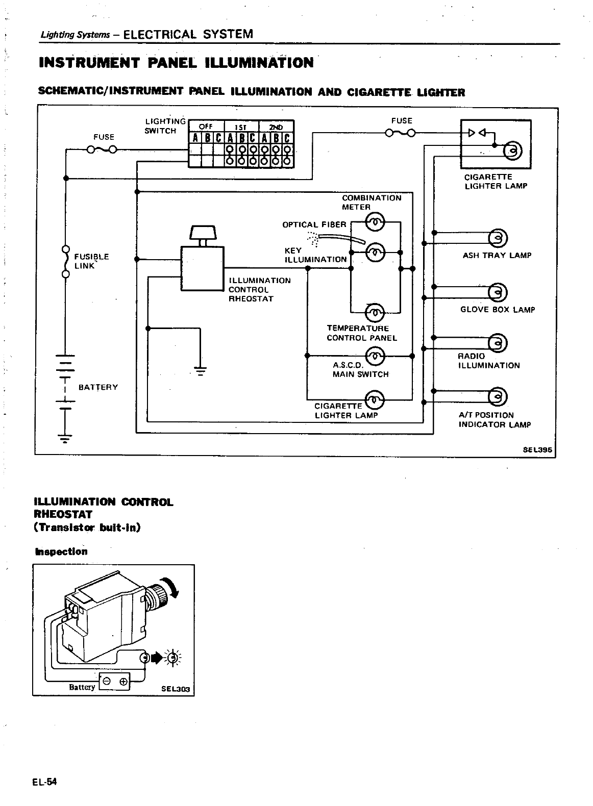
Lighting
Systems
ELECTRICAL
SYSTEM
INSTRUMENT
PANEL
ILLUMINATION
SCHEMATIC
INSTRUMENT
PANEL
IUUMINATION
AND
CIGARETTE
LlGHlER
FUSE
I
I
i
FUSI
LE
bLINK
T
I
BATTERY
L
I
LIGHTING
I
Off
1ST
2ND
SWITCH
ABC
ABC
ABC
IUUMINATION
I
ROL
RHEOSTAT
Transistor
bult
ln
8pectlon
fe
Battery
EL
54
J
E
SEL303
FUSE
c
COMBINATION
METER
OPTICAL
FIBER
r
KEY
ILLUMINATION
o
ILLUMINATION
CONTROL
RHEOSTAT
8
TEMPERATURE
CONTROL
PANEL
A
S
C
D
MAIN
SWITCH
CIGARETTE
LIGHTER LAMP
3
CIGARETTE
LIGHTER
LAMP
13
ASH
TRAY
LAMP
3
GLOVE
BOX
LAMP
13
RADIO
ILLUMINATION
3
AfT
POSITION
INDICATOR
LAMP
SEL396
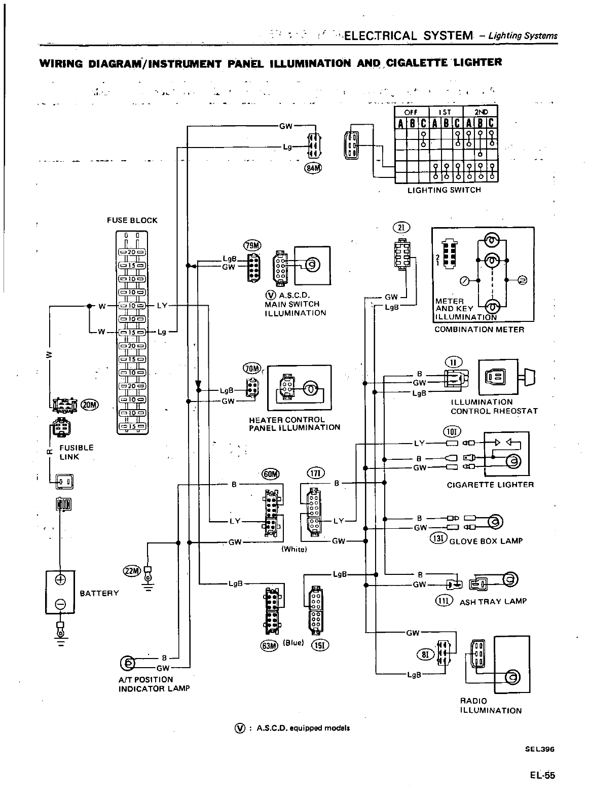
ELEC
rRICAL
SYSTEM
Lighting
Systems
WIRING
DIAGRAM
INSTRUMENT
PANEL
ILLUMINATION
AN
CIGALETTE
LIGHTER
@
SleLE
K
Eli
8
T
BATTERY
FUSE
e
LOCK
00
l
@
a
B
SI
GW
AfT
POSITION
INDICATOR
LAMP
GW
Lg
1
1ill
@
@
L9B1
t
GW
0
00
00
@
A
S
CD
MAIN
SWITCH
ILLUMINATION
@r
r
HEATER
CONTROL
PANEL
ILLUMINATION
@@
B
flJ
Lgg
Lv
i
lI
GW
White
LgB
f
@
Bluel
@
@
A
S
C
D
equipped
models
@
IAO
f
C
A
T
C
A
2i
aI
q
I
q
a
l
6
06
0
aa
LJ
i
nun
LIGHTING
SWITCH
@
0
fi
@
I
0
I
@
I
GW
METER
I
LgS
AND KEY
IllUMINATION
COMBINATION
METER
CiD
G
ij
D
LgB
ILLUMINATION
CONTROL
RHEOSTAT
@
L
Y
l
l
B
Jo
GW
B
CIGARETTE
LIGHTER
LY
S
D
GW
@GLOVEBOX
LAMP
GW
I
LgB
B
Gw
e
I
@
ASH
TRA
Y
LAMP
GW
II
aa
L9
V
191
RADIO
ILLUMINATION
SEL396
EL
55
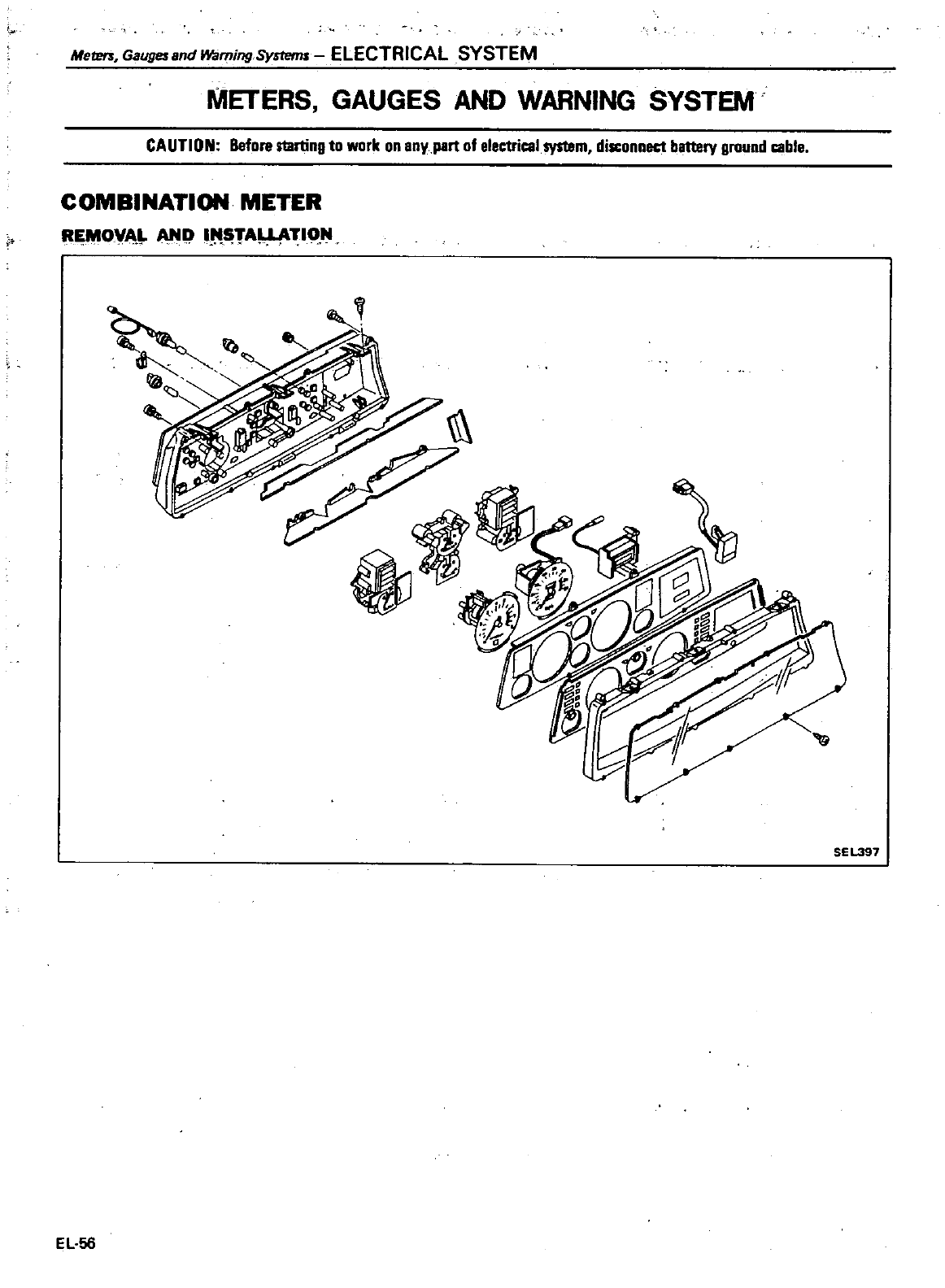
Meters
Gaugesafld
Warning
Systems
ELECTRICAL
SYSTEM
METERS
GAUGES
AND WARNING
SYSTEM
CAUTION
Before
starting
to
work
on
eny
part
of
electrical
system
disconnect
battery
ground
cable
COMBINATION
METER
R O
A
ANI
1
tTA
TION
SE
L397
EL
56
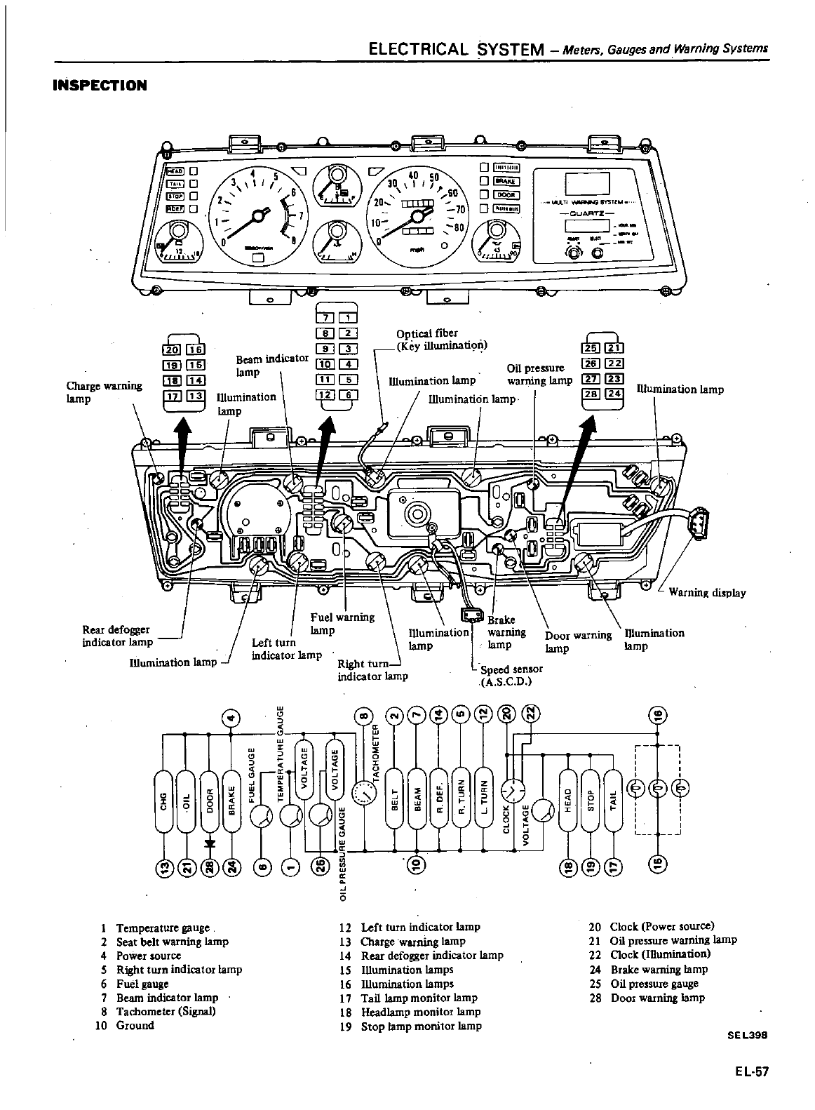
ELECTRICAL
SYSTEM
Meters
Gauges
andWarning
System
INSPECTION
3
0
80
o
@ID
JO
o
rei
0
so
o
l
U
TI S
r
5Tl
OUAFlTZ
1
ReaI
defogger
J
indicator
lamp
lliumination
lamp
w
ill
j
J
U
J
EJ
o
b
m
J
rnm
mill
Beam
indicator
f1Q
m
lamp
ITJ
m
0
i
Optical
fiber
Key illwninati9
w
lli
ll
m
IllJ
Illumination
lamp
Charge
warning
lamp
G
111
w
00
0
0
u0
ll
o
o
w
II
w
o
a
e0
@8@
Jn
n
L
ey
8
CD
J
15
o
u
o
11
J
c
o
i
f
c0
@
1
I
L
1
A A
ll
@
1
Temperature
gauge
2
Seat
belt
warning
lamp
4
Power
source
5
Right
twn
indicator
lamp
6
Fuel
gauge
7
Beam
indicator
lamp
8
Tachometer
Signal
10
Ground
12
Left
turn
indicator
lamp
13
Charge
WaIning
lamp
14
Rear
defogger
indicator
lamp
IS
IDumination
lamps
16
Illumination
lamps
17
Tail
lamp
monitor
lamp
18
Headlamp
monitor
lamp
19
Stop
lamp
monitor
lamp
20 Clock
Power
source
21
Oil pressure
warning
lamp
22
Clock
Illumination
24
Brake
warning
lamp
25
OU
presswe
gauge
28
Door
warning
lamp
SE
L398
EL
57
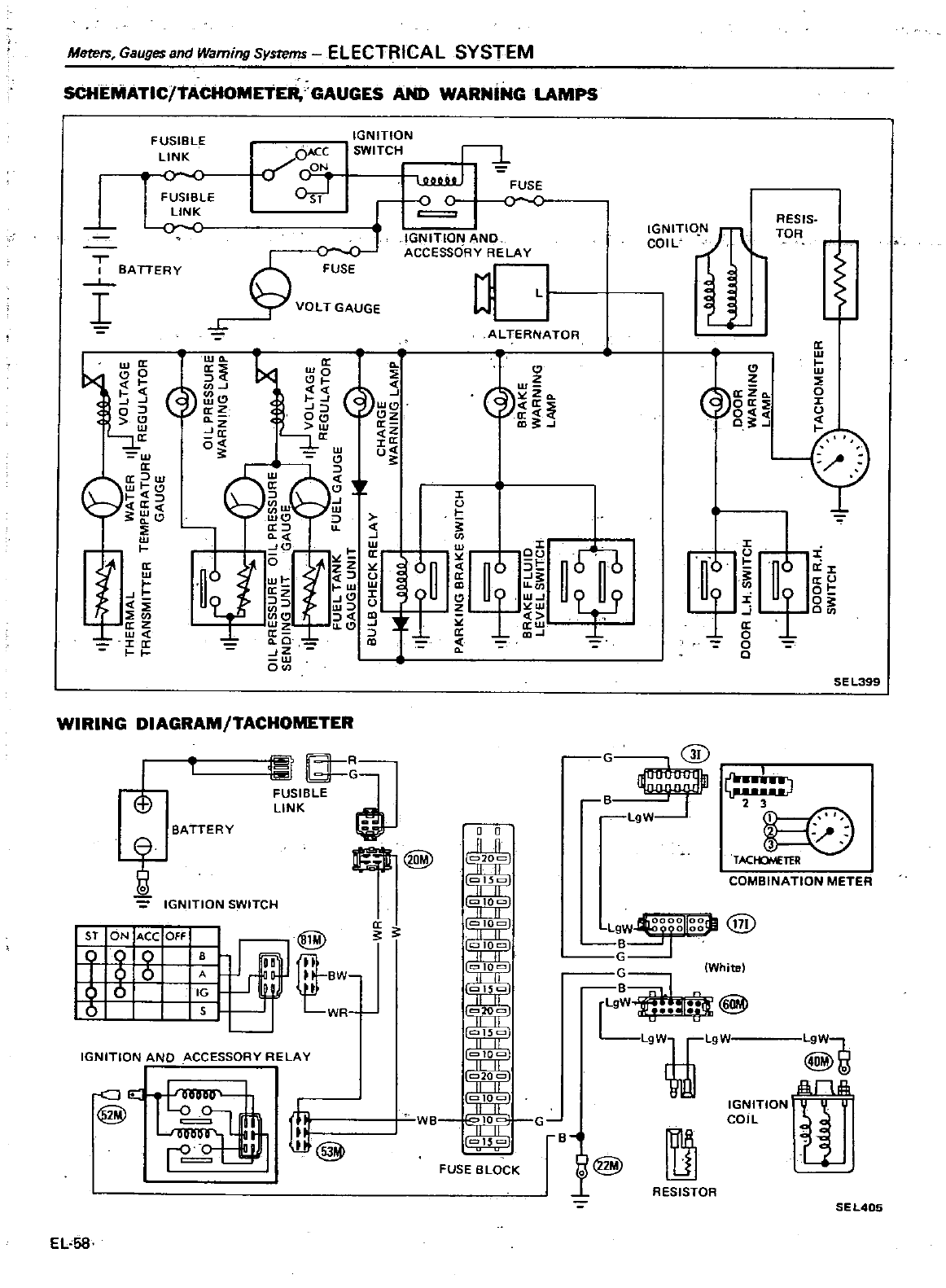
Merers
Gauges
and
Warning
Systems
ELECTRICAL
SYSTEM
SCHEMATIC
TACHOMETER
GAUGES
AND
WARNiNG
LAMPS
T
I
BATTERY
I
1lja
0
oJ
w
a
w
Ga
w
w
J
a
C
w
tJ
az
w
Ja
FUSIBLE
LINK
FUSIBLE
LINk
0
IGNITION
SWITCH
UUUUUJ
FUSE
0
C
Od
IGNITION
AND
ACCESSORY
RELAY
A
VOLT
GAUGE
o
ALTERNATOR
115
4
CI
J
C
t
II
IDCI
J
aZJJ
WC
z
g
II
io
0Wu
Qi
Q
1
n
6V
I
W
z
JCJ
UJw
Cl
Cl
Jc
lLCJ
a
O
JZ
w
0
Z
w
Zo
J
ni
I
r
1
J
0
I
J
u
w
w
a
u
10
WIRING
DIAGRAM
TACHOMETER
I
Et
e
T
l
R
G
FUSIBLE
LINK
a
a
D@
BATTERY
0
0
IGNITION
SWITCH
a
S1
ON
ACe
OFF
@
i
0
B
I
I
II
BW
IT
WR
IGNITION
AND
ACCESSORY
RELAY
CJ
@
EL
58
@
WB
FUSE
BLOCK
J
6f
T
IGNITIO
N
COIL
RESIS
TOR
a
CI
Z
a
za
0
Oa
r
g
f
1
y
J
41
i
0
o
i
0
J
a
Ot
O
0
SE
L399
GD
L
I
J
2 3
0
TACtOYETER
COMBINATION
METER
I
Ih
OOOIIOOri
l
tf7i
L9W
00
y
B
G
G
White
rL9
l
I
It
@
L9WiL9
IGNITION
COIL
L9W
t
ll
G
Bl@
RESISTOR
SEL405
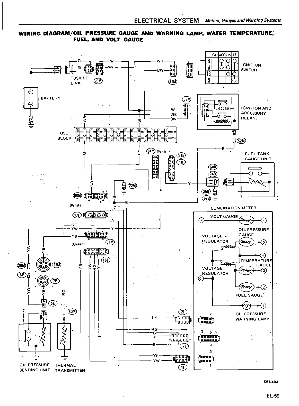
ELECTRICAL
SYSTEM
Meters
Gauges
and
Warning Systems
WIRING
DIAGRAM
OIL
PRESSURE
GAUGE
AND
WARNING
LAMP
WATER
TEMPERATURE
FUEL
AND
VOLT
GAUGE
CfW
FUSIBLE
LINK
E9
BATTERY
t
FUSE
BLOCK
I
i@
@
JU
f
r
1
White
G
Jr
B
@
lJg
Jlgg
LY
Y
Green
I
@60@
@
I
@
sco
V
I
@
OJ
1
U@
OIL
PRESSURE
THERMAL
SENDING
UNIT
TRANSMITTER
WR
rn
BW
II
II
rn
I
I
I
10
ACQON
Sf
1
6
O
I
6t
S
6
1l
J@
B
@
@
y
I
@
IGNITION
SWITCH
IGNITION
AND
ACCESSORY
RELAY
FUEL
TANK
GAUGE
UNIT
J
0
I
COMBINATION
METER
VOLTGAUGE
OIL
PRESSURE
VOLTAGE
GAUGE
EGULATOR
VOLTAGE
REGULATOR
0
I
LY
@
7
R
C
B
0
Y
8
1l
u
Iu
1ll
n
YW
@
362
J
4
5
o
TEMPERATURE
AUGE
@
6Hv
FUEL
GAUGE
@
0
OIL
PRESSURE
WARNING
LAMP
SEL404
EL
59
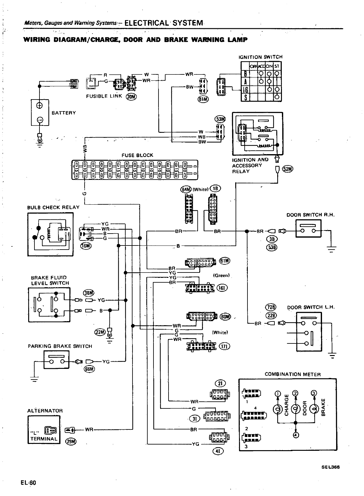
Mere17i
Gauges
and
Warning
Sysrems
ELECTRICAL SYSTEM
WIRING
DIAGRAM
CHARGE
DOOR
AND
BRAKE
WARNING
LAMP
I
o
t
IGNITION
SWITCH
Off
I
X
ON
5T
m
J
WJ
FUSIBLE
LINK
@
WR
BW
rn
B
9
Q
D
6
I
I
g
t1
@
BATTERY
@
w
1
WB
BW
I
m
r
FUSE
BLOCK
I
I
@lil
1Wh
el
jJ
00
00
00
isC
BULB
CHECK
RELAY
i
BRAKE
FLUID
LEVEL
SWITCH
rr
t
B
s
4
@
I
R
Br
B
I
R
G
G
BR
@
@
L
Qtl
YG
Green
@
r
OO
BJ
@o
WR
gfgfllg
@l
8
White
WR
JI
ill
PARKING
BRAKE
SWITCH
o
D
YG
l
@
ALTERNATOR
L
TERMINAL
EL
60
@
G
@
W
@
wr
@
BR
d
@
G
IGNITION
AND
ACCESSORY
RELAY
DOOR
SWITCH
R
H
BR
J4
04
@
1
@
@
DOOR
SWITCH
L
H
@
BR
J
elI
0
0
4
a
J
2
3
COMBINATION
METER
w
2
aW
a
0
J
0
a
u
0
m
SEL368
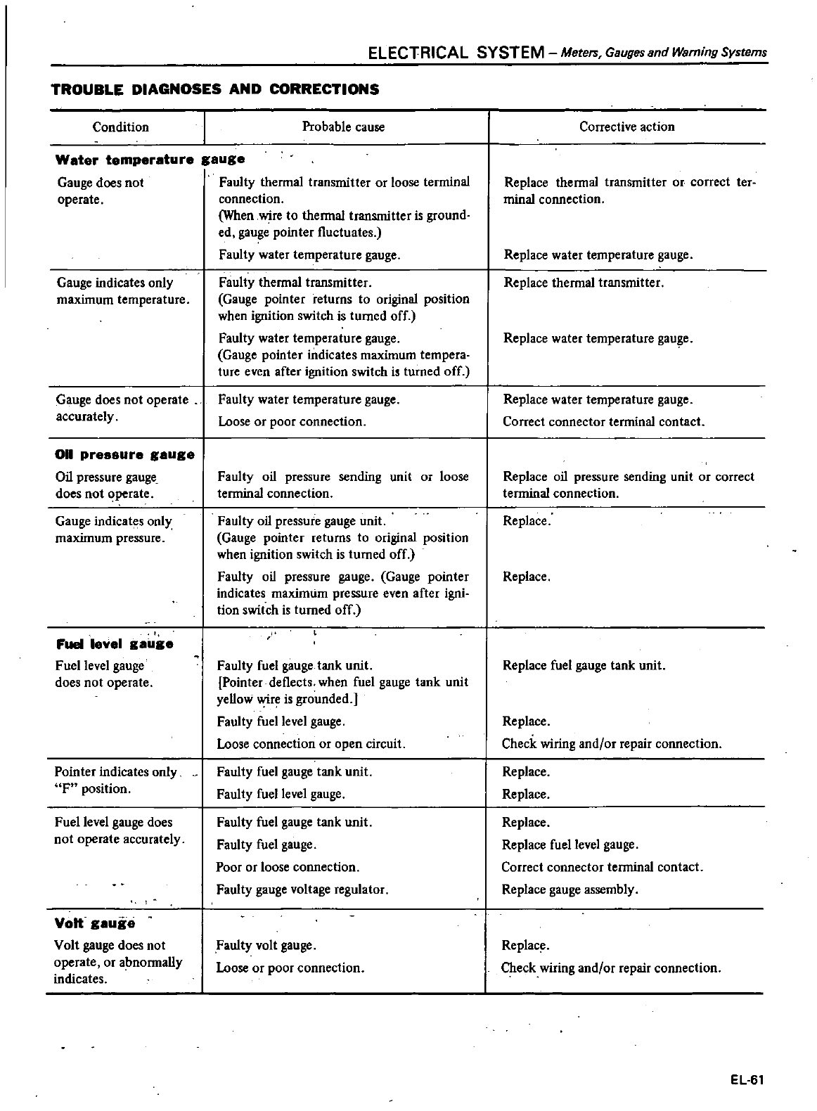
ELECTRICAL SYSTEM
Meters
Gauges
and
Warning
Systems
TROUBLE
DIAGNOSES
AND
CORRECTIONS
Condition
Probable
cause
Water
temperature
gauge
Gauge
does
not
Faulty
thermal
transmitter
or
loose
terminal
operate
connection
When
wire
to
thermal
transmitter
is
ground
ed
gauge
pointer
fluctuates
Faulty
water
temperature
gauge
Faulty
thermal
transmitter
Gauge
pointer
returns
to
original
position
when
ignition
switch
is
turned
off
Faulty
water
temperature
gauge
Gauge
pointer
indicates
maximum
tempera
ture
even
after
ignition
switch
is
turned
off
Gauge
indicates
only
maximum
temperature
Gauge
does
not
operate
accurately
011
pressure
gauge
Oil
pressure
gauge
does
not
operate
Gauge
indicates
only
maximum
pressure
Fuel
level
gailge
Fuel
level
gauge
does
not
operate
Pointer
indicates
only
F
position
Fuel
level
gauge
does
not
operate
accurately
Volt
gauge
Volt
gauge
does
not
operate
or
abnormally
indicates
Faulty
water
temperature
gauge
Loose
or
poor
connection
Faulty
oil
pressure
sending
unit
or
loose
terminal
connection
Faulty
oil
pressure
gauge
unit
Gauge
pointer
retums
to
original
position
when
ignition
switch
is
tumed
off
Faulty
oil
pressure
gauge
Gauge
pointer
indicates
maximtim
pressure
even
after
igni
tion
switch
is
turned
off
Faulty
fuel
gauge
tank
unit
Pointer
deflects when
fuel
gauge
tank
unit
yellow
wire
is
grounded
Faulty
fuel
level
gauge
Loose
connection
or
open
circuit
Faulty
fuel
gauge
tank
unit
Faulty
fuel
level
gauge
Faulty
fuel
gauge
tank
unit
Faulty
fuel
gauge
Poor
or
loose
connection
Faulty
gauge
voltage
regulator
Faulty
volt
gauge
Loose
or
poor
connection
Corrective
action
Replace
thermal
transmitter
or
correct
ter
minal
connection
Replace
water
temperature
gauge
Replace
thermal
transmitter
Replace
water
temperature
gauge
Replace
water
temperature
gauge
Correct
connector
terminal
contact
Replace
oil
pressure
sending
unit
or
correct
terminal
connection
Replace
Replace
Replace
fuel
gauge
tank
unit
Replace
Check
wiring
and
or
repair
connection
Replace
Replace
Replace
Replace
fuel
level
gauge
Correct
connector
teoninal
contact
Replace
gauge
assembly
Replace
Check
wiring
and
or
repair
connection
EL
61
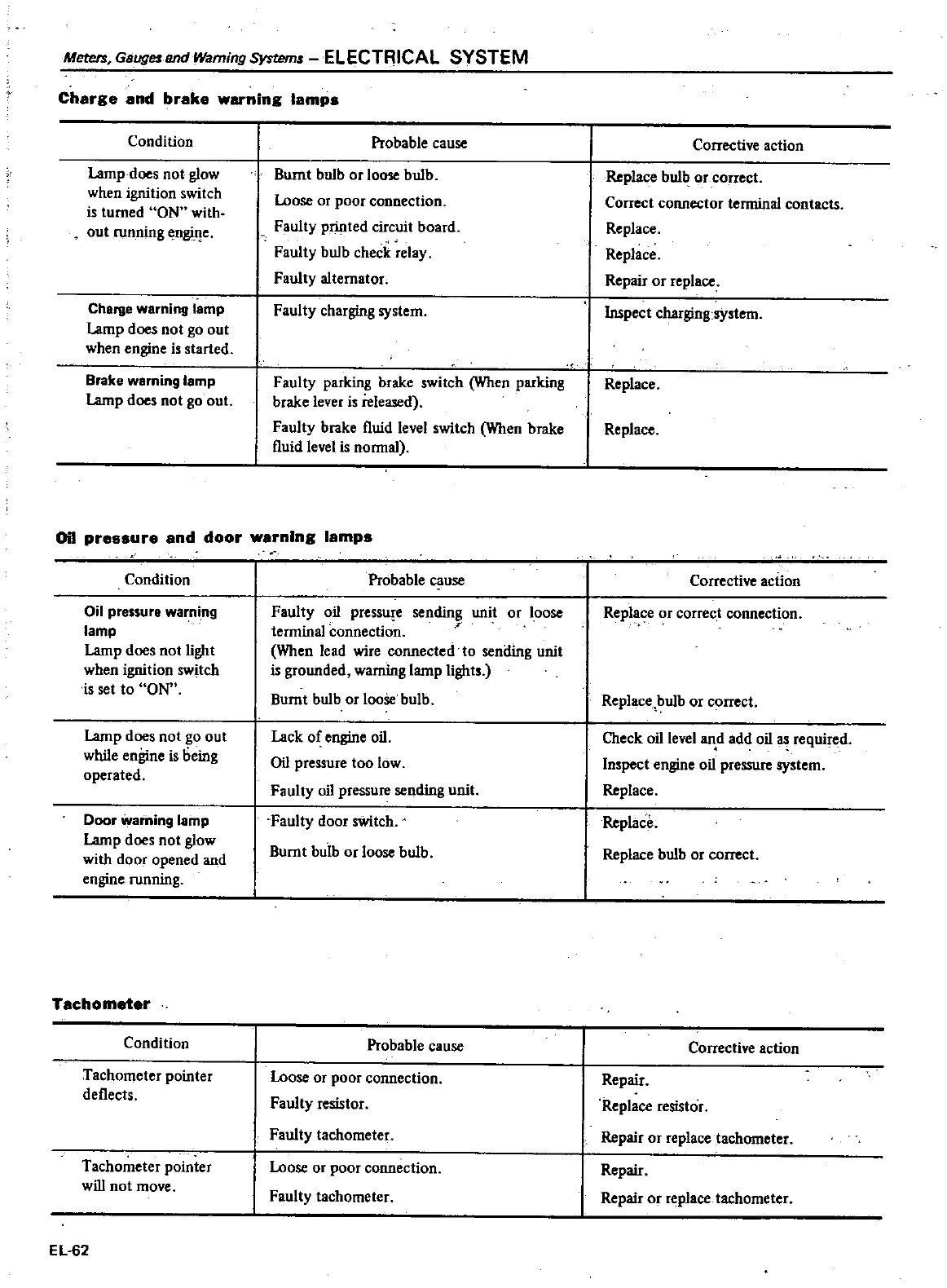
Meters
Gauges
and
Warning
System
ELECTRICAL SYSTEM
Charge
and
brake
warning
lamps
Condition
Lamp
does
not
glow
when
ignition
switch
is
turned
ON
with
out
running
engffi
e
Chellle
werning
lemp
Lamp
does
not
go out
when
engine
is
started
Brake
warning
lamp
Lamp
does
not go
out
Probable
cause
Burnt
bulb
or
loose
bulb
Loose
or
poor
connection
Faulty
printed
circuit
board
Faulty
bulb
check
relay
Faulty
alternator
Faulty
charging
system
Faulty
parking
brake
switch
When
parking
brake
lever
i
released
Faulty
brake
fluid
level
switch
When
brake
fluid
level
is
nonnal
Oil
pre
sure
and
door
warning
lamps
Condition
Ojl
pressure
warning
lamp
Lamp
does
not
light
when
ignition
switch
is set
to
ON
Lamp
does
not
go out
while
engine
is
being
operated
Door
warning
lamp
Lamp
does
not
glow
with
door
opened
and
engine
running
Tachometer
Condition
Tachometer
pointer
deflects
Tachometer
pointer
will
not
move
EL
62
Probable
cause
Faulty
oil
pressure
sending
unit
or
loose
terminal
connectio
r
When
lead
wire
connected
to
sending
unit
is
grounded
warning
lamp lights
Burnt
bulb
or
looSe
bulb
Lack
of
engine
oil
Oil
pressure
too
low
Faulty
oil
pressure
sending
unit
Faul1y
door
switch
Burnt
bulb
orloose
bulb
Probable
cause
Loose
or
poor
connection
Faulty
resistor
Faulty
tachometer
Loose
or
poor
connection
Faulty
tachometer
Corrective
action
Replace
bulb
or
correct
Correct
connector
terminal
contacts
Replace
Replace
Repair
or
replece
Inspect
charging
system
Replace
Replace
Corrective
action
Replace
or
correct
connection
Replace
bulb
or
correct
Check
oil
level
and add
oil
as
required
Inspect
engine
oil
pressure
system
Replace
Replace
Replace
bulb
or
correct
Corrective
action
Repair
Replace
resistor
Repair
or
replace
tachometer
Repair
Repair
or
replace
tachometer
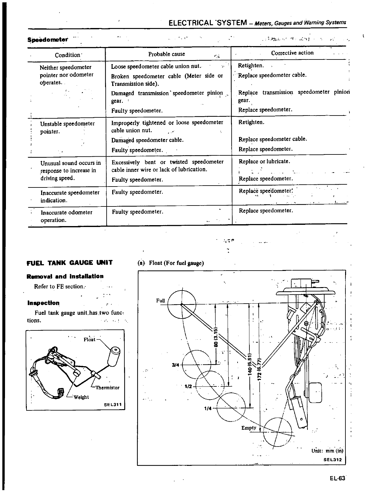
pe
dometer
Condition
Neither
speedometer
pointer
nor
odometer
ol
erates
Unstable
speedometer
pointer
Unusual
sound
occurs
in
response
to
increase
in
driving
speed
Inaccurate
speedometer
indication
Inaccurate
odometer
operation
FUEL
TANK
GAUGE
UNIT
Removal
and
Installation
Refer
to
FE
section
ELECTRICAL SYSTEM
Merers
Gauges
and
Warning
System
1
11
E
t
2
e
l
i
d
Empty
L
Probable
cause
Loose
speedometer
cable
union
nut
Broken
speedometer
cable
Meter
side
or
Transmission
side
Damaged
transmission
speedometer
pinion
gear
Faulty
speedometer
Improperly
tightened
or
loose
speedometer
cable
union
nut
Damaged
speedometer
cable
Faulty
speedometer
Excessively
bent
or
twisted
speedometer
cable
inner
wire
or
lack
oflubrication
Faulty
speedometer
Faulty
speedometer
Faulty
speedometer
a
Float
For
fuel
gauge
Full
Inapectlon
Fuel tank
gauge
unit
has
two
func
tions
II
SEL311
1
4
nVi
f
Corrective
action
Retighten
Replace
speedometer
cable
Repl
ce
transmission
speedometer
pinion
gear
Replace
speedometer
Retighten
Replace
speedometer
cable
Replace
speedometer
Replace
or
lubricate
j
Replace
speedometer
Replace
speedometer
1
Replace
speedometer
Unit
mm
in
SEL312
EL
63
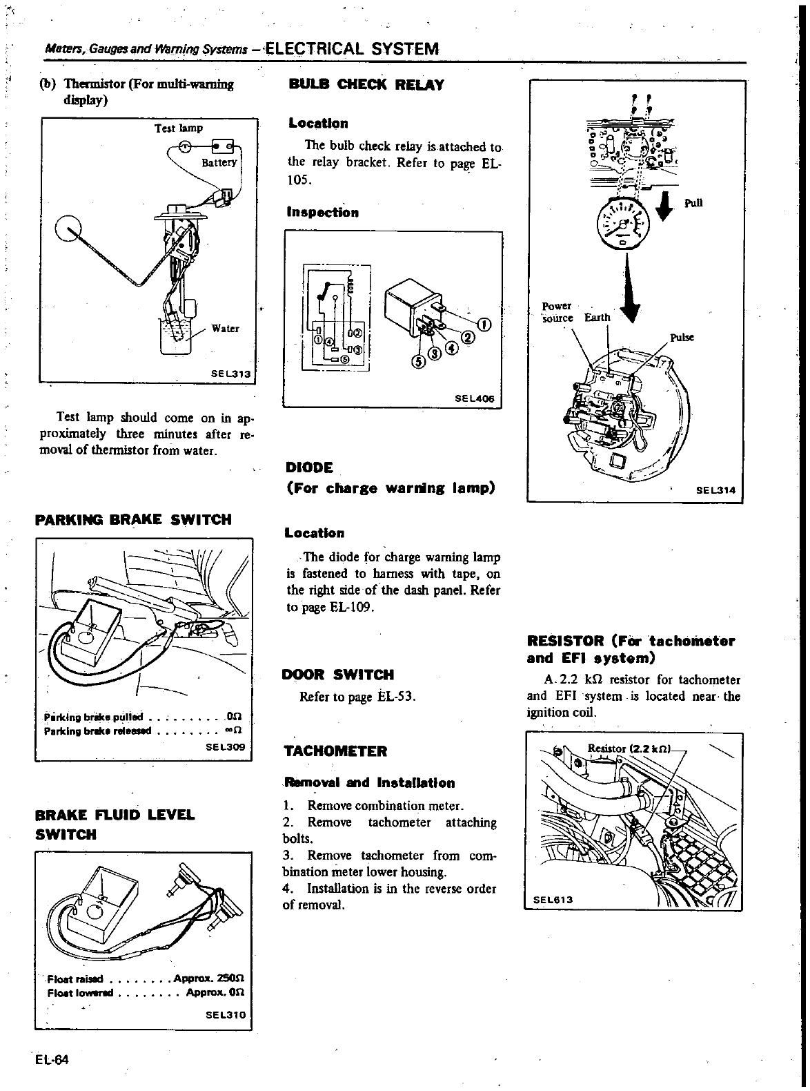
Maters
Gauges
and
Warning
Systems
ELECTRICAL SYSTEM
b
Thermistor
For
multi
warning
display
Test
lamp
s
Water
SEL313
Test
lamp
should
come
on
in
ap
proximately
t1uee
minutes
after
re
moval
of
thermistor
from
water
PARKING
BRAKE
SWITCH
Plirklng
brike
p
lIed
Parking
bnke
released
on
n
SEL309
BRAKE
FLUID
LEVEL
SWITCH
Float
I
Float
1
Approx
zson
Approx
on
SEL310
EL
64
BULB CHECK
RELAY
LocaUon
The
bulb
check
relay
is
attached
to
the
relay
bracket
Refer
to
pa
EL
105
Inspection
l
f
I
t
I
i
lll
L
w
lI
@
SEl406
DIODE
For
charge
warning
lamp
Location
The
diode
for
charge
warning
lamp
is
fastened
to
harness
with
tape
on
the
right
side
of
the
dash
panel
Refer
to
page
EL
109
DOOR
SWITCH
Refer
to
page
EL
53
TACHOMETER
Removal
d Installation
1
Remove
combination
meter
2
Remove
tachometer
attaching
bolts
3
Remove
tachometer
from
com
bination
meter
lower
housing
4
Installation
is
in
the
reverse
order
of
removal
Power
sowce
Earth
SEL314
RESISTOR
FOr
tachometer
and
EFI
system
A
2 2
kfl
resistor
for tachometer
and
EFI
system
is
located
near
the
ignition
coil
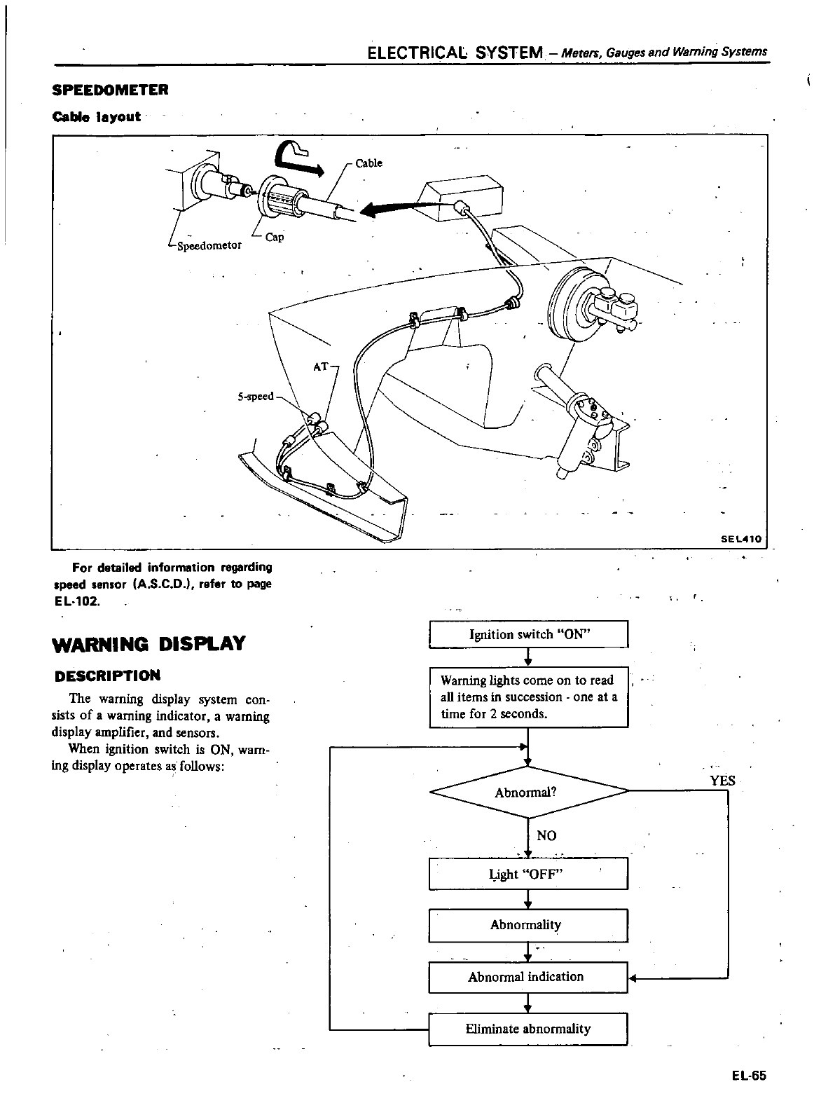
ELECTRICAL SYSTEM
Merers
Gauges
and
Warning
Systems
SPEEDOMETER
Cable
layout
Cable
Speedometor
SEL410
For
detailed
information
regarding
Ipeed
len
or
IA
S
C D
refer
to
page
EL
102
WARNING
DISPLAY
Ignition
switch
ON
DESCRIPTION
Warning
lights
come
on
to
read
aU
items
in
succession
one
at
a
time
for
2
seconds
The
warning
display
system
con
sists
of
a
warning
indicator
a
warning
display
amplifier
and
sensors
When
ignition
switch
is
ON
warn
ing
display
operates
as
follows
J
YES
NO
I
ight
OFF
I
Abnormality
I
Abnormal indication
I
Eliminate
abnormality
I
EL
65
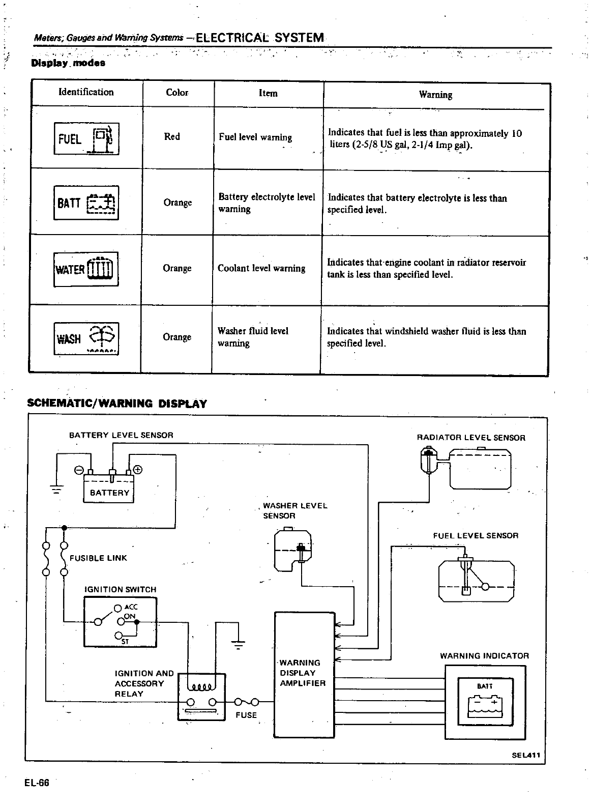
Msters
Gauges
aM
Wa11Iing
Systems
ELECTRICAL SYSTEM
Display
modes
Identification
I
FUEL
fBf
I
I
TTe
BA
WATE
lllliiD
IWASH
Color
Red
Orange
Orange
Orange
SCHEMATIC
WARNING
DISPLAY
BATTERY
LEVEL
SENSOR
1
e
1
f
H
IGNITION
SWITCH
OACX
if
CON
q
I
IGNITION
AND
ACCESSORY
RELAY
EL
66
Item
Fuel
level
warning
Battery
electrolyte
level
warning
Coolant
level
warning
Washer
fluid
level
warning
WASHER
LEVEL
SENSOR
Ir
b
o
WARNING
DISPLAY
AMPLIFIER
FUSE
Warning
Indicates
that
fuel
is
less
than
v
mately
10
liters
2
5
8
US
gal
2
1
4
Imp
gal
Indicates
that
battery
electrolyte
is
less
than
specified
level
Indicates
that
engine
coolant
in
radiator
reservoir
tank
is
less
than
specified
level
Indicates
that
windshield
washer
fluid
is
less
than
specified
level
RADIATOR
LEVEL
SENSOR
iLr
lJl
FUEL
LEVEL
SENSOR
b
E
WARNING
INDICATOR
BATT
SEL411
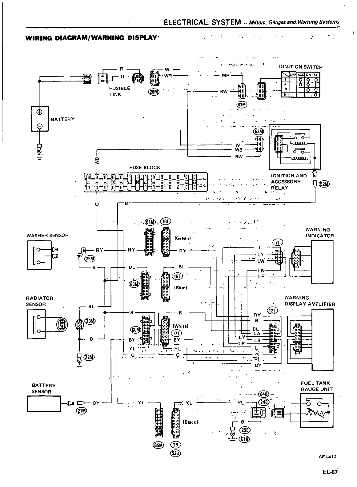
ELECTRICAL
SYS
rEM
Meters
Gauges
and
Waming
Systems
WIRING
DIAGRAM
WARNING
DISPLAY
EJ
BATTERY
t
WASf
jER
SENSOR
0
ClI
JClI
RADIATOR
SENSOR
tfW
WR
II
@
FUSIBLE
LINK
FUSE
eLOCK
BL
J
@
1
B
J
BATTERY
SENSOR
i@
Ln
C
BY
@
YL
@
EYL
00
I
g
Black
00
@
@
J
fj
i@
IGNITION
SWITCH
WR
BW
1ill
@
1
IGNITION
AND
ACCESSORY
ffEU
V
t
n
I
@
L
LY
Lvi
lB
LR
f
WARNING
INDICATOR
WARNING
DISPLAY
AMPLIFIER
@
RY
B
BL
LW
LV
LR
LB
L
G
YL
BY
o
0
0
0
0
0
@
YL
B
I
@
ill
FUEL
TANK
GAUGE
UNIT
SEL412
Et
67
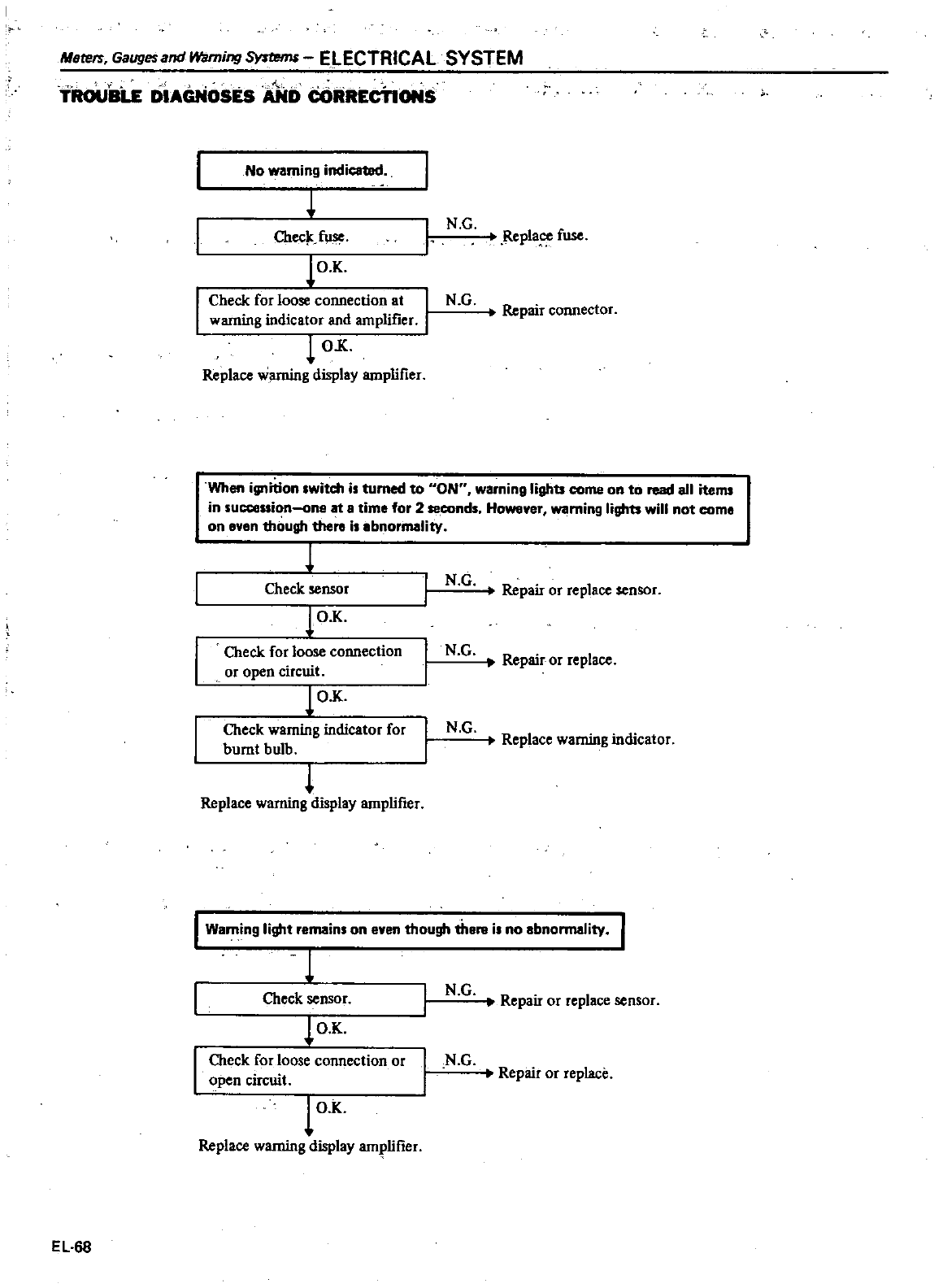
i
1
TROUBLE
DIAGNOSES
AND
CORRECTIONS
MI1te
GaugesandWaming
ELECTRICAL
SYSTEM
No
warning
indica1Bd
Chec
f11se
lO
K
Check
forloose
connection
at
I
warning
indicator
and
amplifier
OX
Replace
warning
display
amplifier
I
N G
r
Repla
fuse
N G
Re
ct
r
pan
conne
or
When
ignition
witch
i
turned
to
ON
warning
lights
come
on
to
read
all
items
in
succeuion
one
at
a
time
for
2
seconds
However
warning
lights
will
not
come
on
even
th
ugh
there
i
Ibnormality
1
Check
sensor
lOX
Check
for
loose
connection
or
open
circuit
lOX
Check
warning
indicator
for
burnt
bulb
Replace
warning
display
amplifier
N G
Re
I
pan
or
rep
ace
sensor
N
G
Repair
or
replace
N G
Replace
warning
indicator
I
Warning
light
remain
on
even
though
th
i
no
IbnormaJity
1
Check
sensor
lO
K
Check
for
loose
connection
or
open
circuit
lOX
Replace
warning
display
amplifier
EL
68
N G
I
Repan
or
rep
ace
sensor
N G
Repair
or
replace
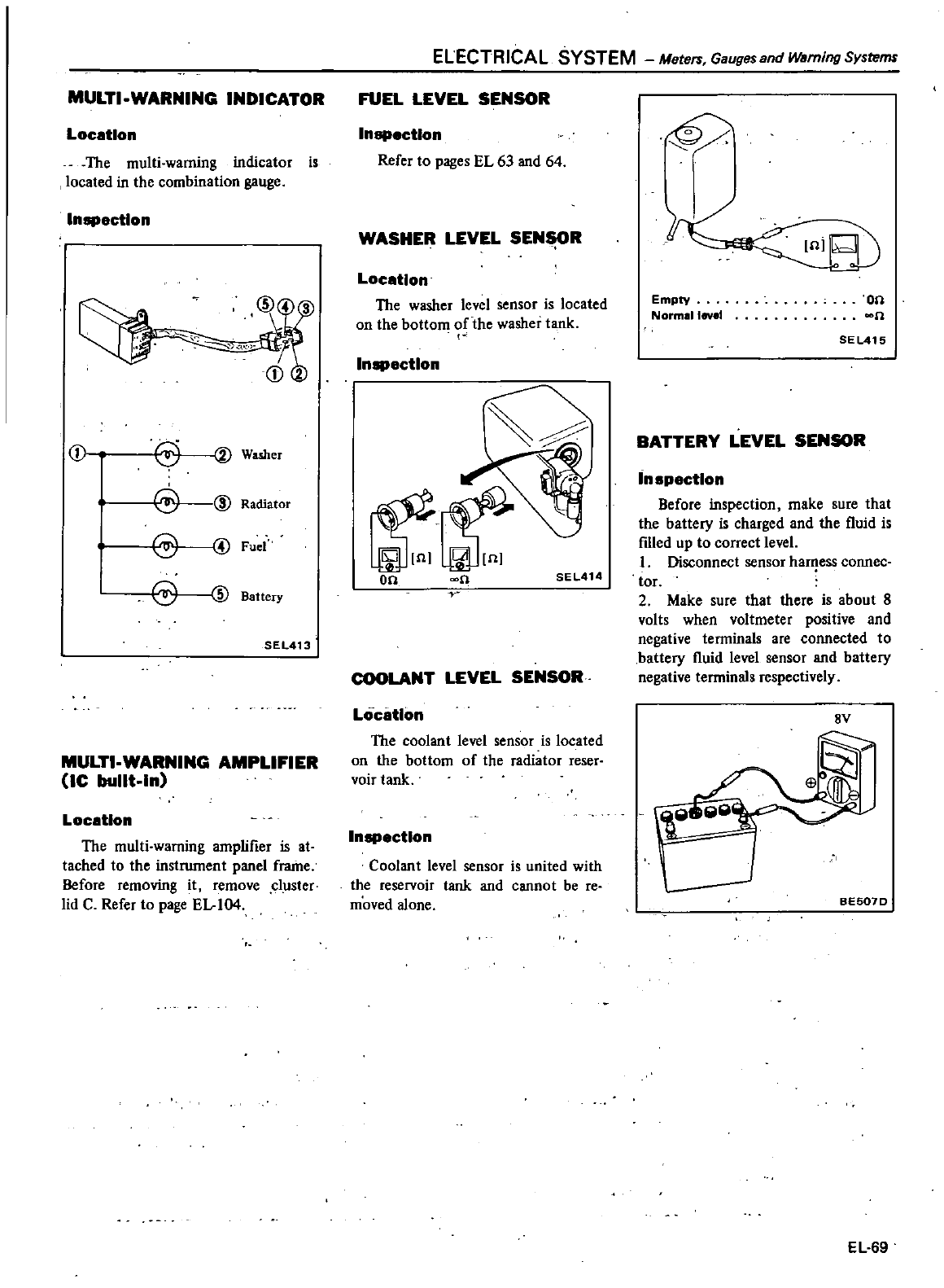
MULTI
WARNING
INDICATOR
Location
The
multi
warning
indicator
is
located
in
the
combination
gauge
InllPectlon
o
j
Washer
@
@
Radiator
Fuel
eID
Battery
SEL413
MULTI
WARNING
AMPLIFIER
JC
bullt
ln
Location
The
multi
warning
amplifier
is
at
tached
to
the
instrwnent
panel
frame
Before
removing
it
remove
cluster
lid
C
Refer
to
page
EL
104
ELECTRICAL
SYSTEM Mete
Gauges
and
Warning
Systems
FUEL
LEVEL
SENSOR
InllPectlon
Refer
to
pages
EL
63
and
64
WASHER
LEVEL
SEN
R
Location
The
washer
level
sensor
is
located
on
the
bottom
of
the
washer
tank
InllPectlon
Q
SEl414
COOLANT
LEVEL
SENSOR
Location
The
coolant
level
sensor
is
located
on
the
bottom
of
the
radiator
reser
voir
tank
InllPectlon
Coolant
level
sensor
is
united
with
the
reservoir
tank and
cannot
be
re
moved
alone
w
Empty
Norm
llev
t
on
n
SEL415
BATTERY
LEVEL
SENSOR
Inspection
Before
inspection
make
sure
that
the
battery
is
charged
and
the
fluid
is
ftlled
up
to
correct
level
1
Disconnect
sensor
ha
ess
connec
tor
2
Make
sure
that
there
is
about
8
volts
when
voltmeter
positive
and
negative
teoninals
are
connected
to
battery
fluid
level
sensor
and
battery
negative
terminals
respectively
8Y
BES07D
EL
69
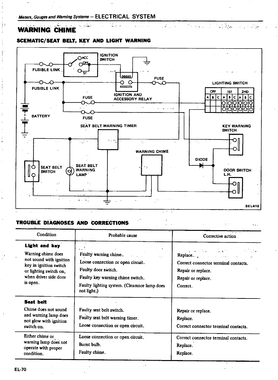
Meters
GaugesandWaming
ms
ELECTRICAL SYSTEM
WARNING
CHIME
l
SCEMATIC
SEAT
BELT
KEY
AND
LIGHT
WARNING
Jc
FUSIBLE
LINK
FUSIBLE
LINK
L
BATTERY
I
6
SEAT
BELT
SW
ITCH
o
ON
C
a
cON
0srJ
IGNITION
SWITCH
L
L
o c
FUSE
oc
IGNITION
AND
ACCESSORY
RELAY
FUSE
r
c
FUSE
SEAT
BELT
WARNING
TIMER
WARNING
CHIME
SEAT
BELT
@
ING
I I
TROUBLE
DIAGNOSES
AND CoRRECTIONS
Condition
Licht
and
key
Warning
chime
doe
not
sound
with
ignition
key
in
ignition
switch
or
lighting
switch
on
when
driver
side
door
is
open
Seat
belt
Chime
does
not
sound
and
warning
lamp
does
not
glow
with
ignition
switch
on
Either
chime
or
warning
lamp
does
not
operate
with
proper
condition
EL
70
Probable
cause
Faulty
warning
chime
Loose
connection
or
open
circuit
Faulty
door
sWitch
Faulty
key
warning
chime
switch
Faulty
lighting
system
Clearance
lamp
does
not
light
Faulty
eat
belt
switch
Faulty
seat
belt
warning
timer
Loose
connection
or
open
circuit
Loose
connection
or
open
circuit
Burnt
bulb
Faulty
chime
A
LIGHTING
SWITCH
OFf
1ST
2ND
A
a
CAB
C
Ala
c
g8g2@
KEY
WARNING
SWITCH
DIODE
I
II
DOOR
SWITCH
L
H
SEL416
Corrective
action
Replace
Correct
connector
terminal
contacts
Repair
or
replace
Repair
or
replace
Correct
Repair
or
replace
Replace
Correct
connector
terminal
contacts
Correct
connector
terminal
contacts
Replace
Replace
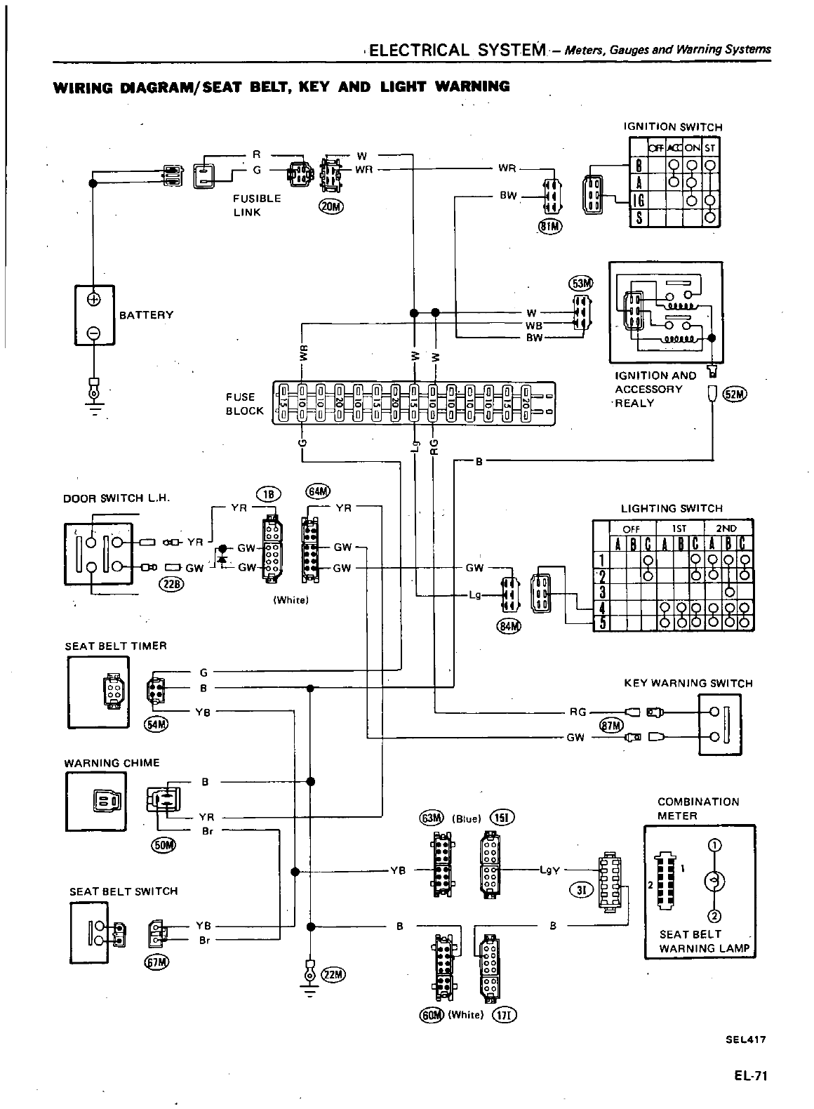
ELECTRICAL
SYSTEM
Meters
Gauges
and
Warning
Systems
WIRING
DIAGRAM
SEAT
BELT
KEY
AND
LIGHT
WARNING
It
O
R
FUSIBLE
LINK
G
BATTERY
n
e
I
1
a
5 5
I
I
WR
aw
41
41
@
@
aJl
W
I
WB
aw
DOOR
SWITCH
L
H
@
rVR
nJ
no
oo
YR
JtGW
U9
Uo
GW
GW
I
@
@
lVR
GW
GW
SEAT
BELTTIMER
A
YB
WARNING
CHIME
R
a
@
SEAT
BELT
SWITCH
gm
2k
YB
Br
@
White
11
GW
Lg
41
41
@
illY
Blue
@
il
w
l@
e
rtfJ1
J
t J
fi
l
Whhe
@
1
1
IillJJ
l
4
15
IGNITION
SWITCH
I
I
B
iA
IG
IS
Ofaa
ON
S1
g
o
g
IGNITION
AND
ACCESSORY
REALY
Ii
O
@
LIGHTING
SWITCH
I
OFf
r
1ST
I
2ND
ABCABCAB
9
0009
o
oObo
888
g
gg
KEY
WARNING
SWITCH
RG
a
iO
oon
w
DlJ
c
U
COMBINATION
METER
L9Y
GD
2
2
B
SEAT
BELT
WARNING
LAMP
SEL417
EL
71
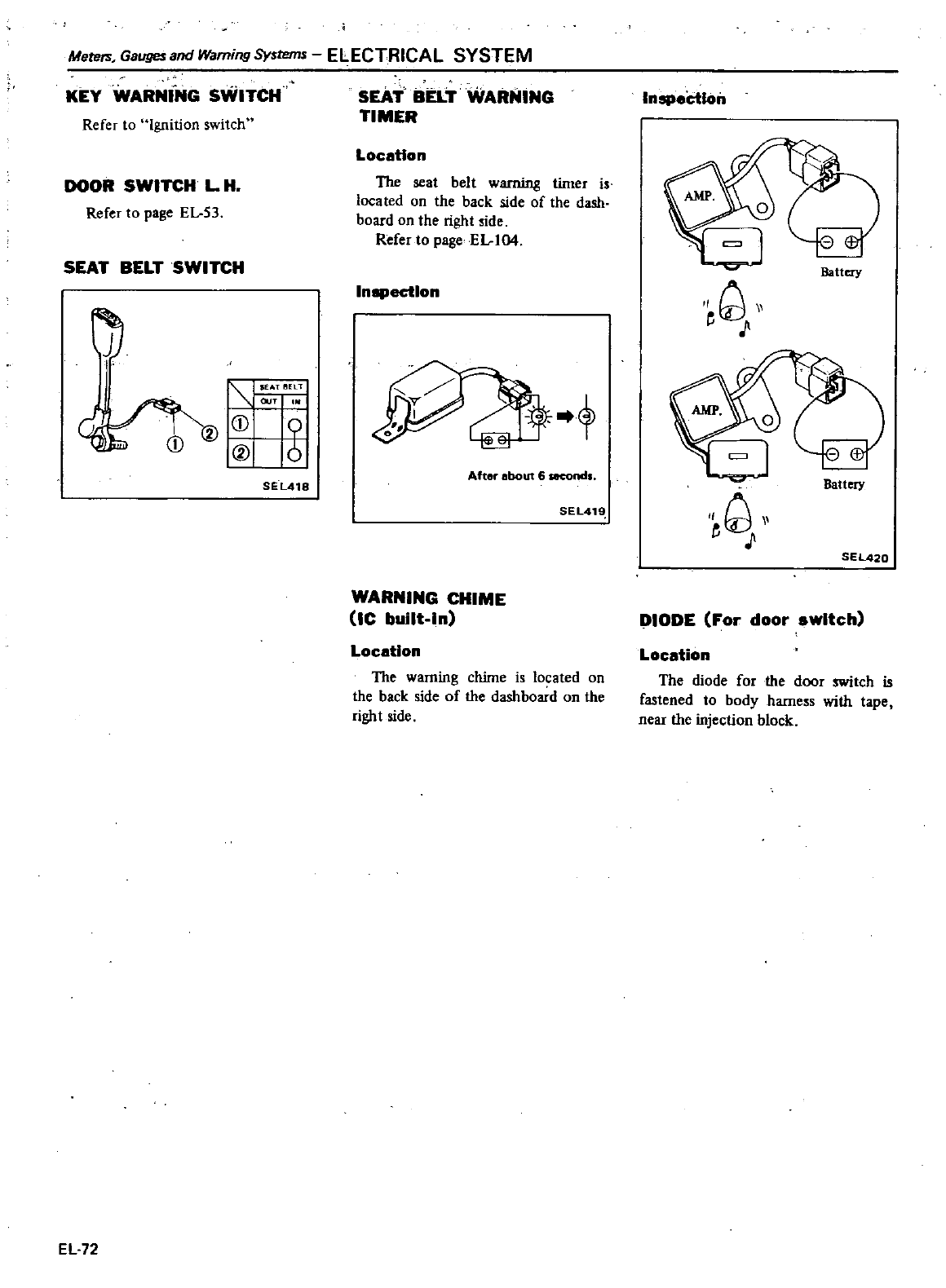
Mete
Gauges
and
Warning
Systems
ELECTRICAL SYSTEM
Refer
to
Ignition
switch
KEY
WARNiNG
SWITCH
DOOR
SWITCH
L
H
Refer
to
page
El
53
SEAT
BELT
SWITCH
EL
72
l
UTl
IElTl
OUT
I
I
I
SEL418
SEAi
BELT
WARNING
TIMER
Location
The
seat
belt
warning
timer
is
located
on
the
back
side
of
the
dash
board
on
the
right
side
Refer
to
page
EL
104
Inspection
After
about
6
secondl
SEL41
WARNING
CHIME
Uc
built
In
Location
The
warning
chime
is
located
on
the
back
side
of
the
dashboard
on
the
right
side
Inspeictloil
Battery
w
Battery
w
SEL420
DIODE
For
door
awltch
Location
The
diode
for
the
door
switch
is
fastened
to
body
hamess
with
tape
near
the
injection
block
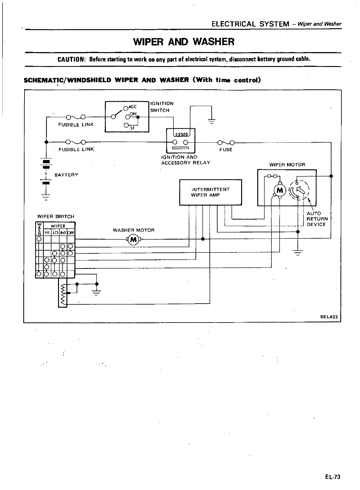
ELECTRICAL
SYSTEM
Wiper
and
Washer
WIPER
AND
WASHER
CAUTION
Before
starting
to
work
on
any
part
of
electrical
system
disconnect
battery
ground
cable
SCHEMATIC
WINDSHIELD
WIPER
AND
WASHER
With
time
control
J
C
FUSIBLE
LINK
FUSIBLE
LINK
I
SA
TTERY
L
I
WIPER
SWITCH
11
WIPER
f
HI
LO
INIp
o
gg
8
JU
1r
OACC
f
CON
OJ
IGNITION
SWITCH
1
oc
r
c
FUSE
IGN
ITlON
AND
ACCESSORY
RELAY
INTERMITTENT
WIPER
AMP
WASHER
MOTOR
@
1
WIPER
MOTOR
AUTO
RETURN
DEVICE
SE
L422
EL73
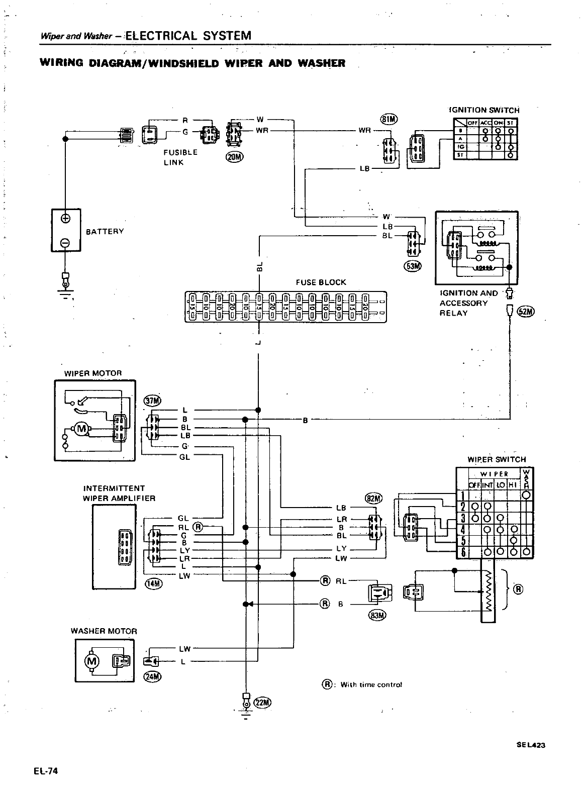
Wiper
and
Washer
ELECTRICAL SYSTEM
WIRING
DIAGRAM
WINDSHIELD
WIPER
AND
WASHER
@
f
R
@
FUSIBLE
LINK
o
BATTERY
t
I
J
I
WR1
LB
B
BL
4
@
FUSE
BLOCK
J
WIPER
MOTOR
l
o
@
M
L
I
I
I
Le
1
G
GL
INTERMITTENT
WIPER
AMPLI
F I
ER
@
It
ill
I
G
ga
IB
80
I
LV
00
I
LR
L
I
@
LW
WASHER
MOTOR
U
W
@
Ji@
EL
74
IGNITION
SWITCH
OfF
iC
i
r
rl
lG
0
P
I
Sf 0
IGNITION
AND
ACCESSORY
RELAV
ld
O@
WIP
ER
SWITCH
WI
PER
W
ff
INIlO
HI
I
L
gg
LJ
T
og9
llifl
5IJO
l
OOO
LB
@j
LR
L
LV
LW
L
LI
@
@
@
With
time
control
SE
L423
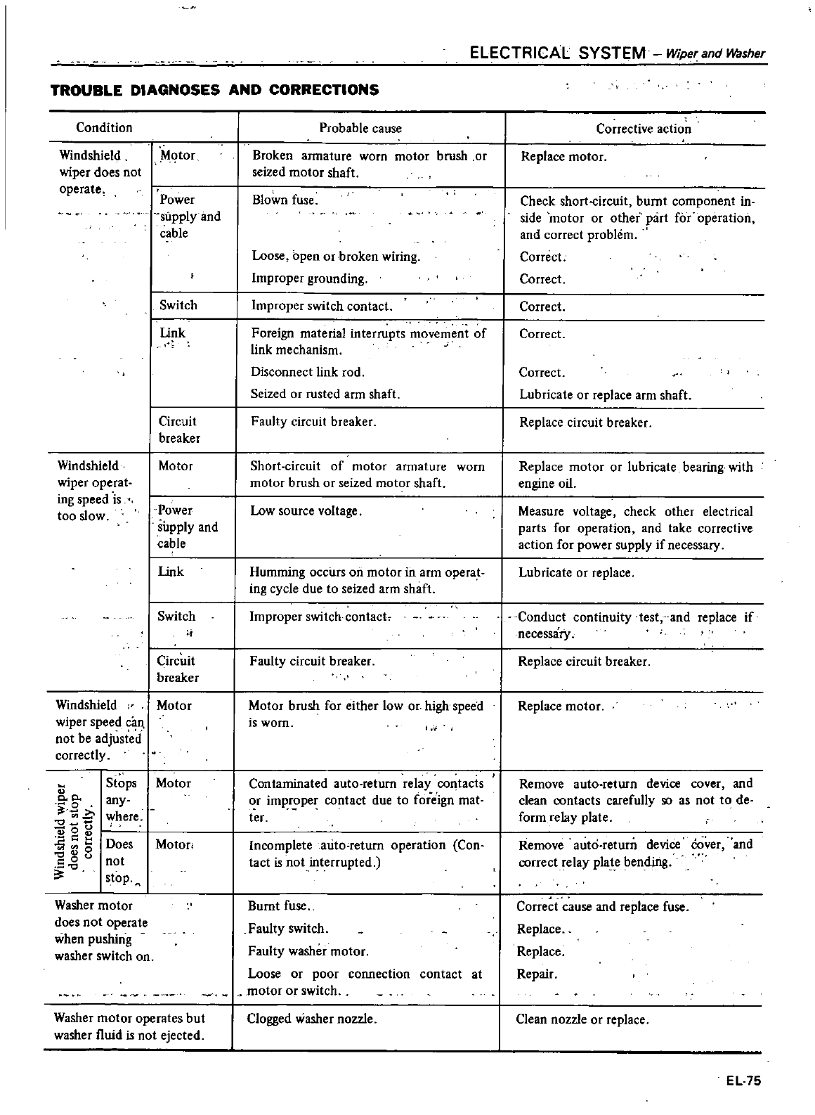
TROUBLE
DIAGNOSES
AND
CORRECTIONS
Condition
Windshield
wiper
does
not
operate
Windshield
wiper
operat
ing
speed
is
too
slow
Mqtor
Power
supply
and
cable
Probable
cause
Broken
armature
worn
motor
brush
or
seized
motor
shaft
Blown
fuse
Loose
open
or
broken
wiring
Improper
grounding
Switch
I
Improper
switch
contact
link
Circuit
breaker
Motor
Power
supply
and
cable
link
Switch
Circuit
breaker
Windshield
dotor
wiper
speed
9
n
not
be
adjusted
correctly
cc
0
v
9
00
2
c
e
0
0
u
Stops
any
where
Does
not
stop
Washer
motor
does
not
operate
when
pushing
washer
switch
on
Motor
dotor
Washer
motor
operates
but
washer
fluid
is
not
ejected
Foreign
material
interrupts
movement
of
link
mechanism
Disconnect
link
rod
Seized
or
rusted
arm
shaft
Faulty
circuit
breaker
Short
circuit of motor
armature
worn
motor
brush
or
seized
motor
shaft
Low
source
voltage
Humming
occurs
on
motor
in
ann
operat
ing
cycle
due
to
seized
arm
shaft
Improper
switch
contact
Faulty
circuit
breaker
Motor
brush
for
either
low
or
high
speed
iswom
Contaminated
auto
return
relay
co
tacts
or
improper
contact
due
to
foreign
mat
ter
Incomplete
auto
return
operation
Con
tact
is
not
interrupted
Bumt
fuse
Faulty
switch
Faulty
washer
motor
Loose
or
poor
connection
contact
at
motor
or
switch
Clogged
washer
nozzle
ELECTRICAL SYSTEM
Wiper
and
w
sher
Corrective
action
Replace
motor
Check
short
circuit
bumt
component
in
side
motor
or
other
part
for
operation
and
correct
problem
Correct
Correct
Correct
Correct
Correct
Lubricate
or
replace
arm
shaft
Replace
circuit
breaker
Replace
motor
or
lubricate
bearing
with
engine
oiL
Measure
voltage
check
other
electrical
parts
for
operation
and
take
corrective
action
for
power
supply
if
necessary
Lubricate
or
replace
Conduct
continuity
test
and
replace
if
necessary
Replace
circuit
breaker
Replace
motor
Remove
auto
return
device
cover
and
clean
contacts
carefully
so as
not
to
de
form
relay
plate
Remove
auto
return
device
Cover
and
correct
relay
pla
e
bending
Corre
t
c
use
and
replace
fuse
Replace
Replace
Repair
Clean
nozzle
or
replace
EL
75
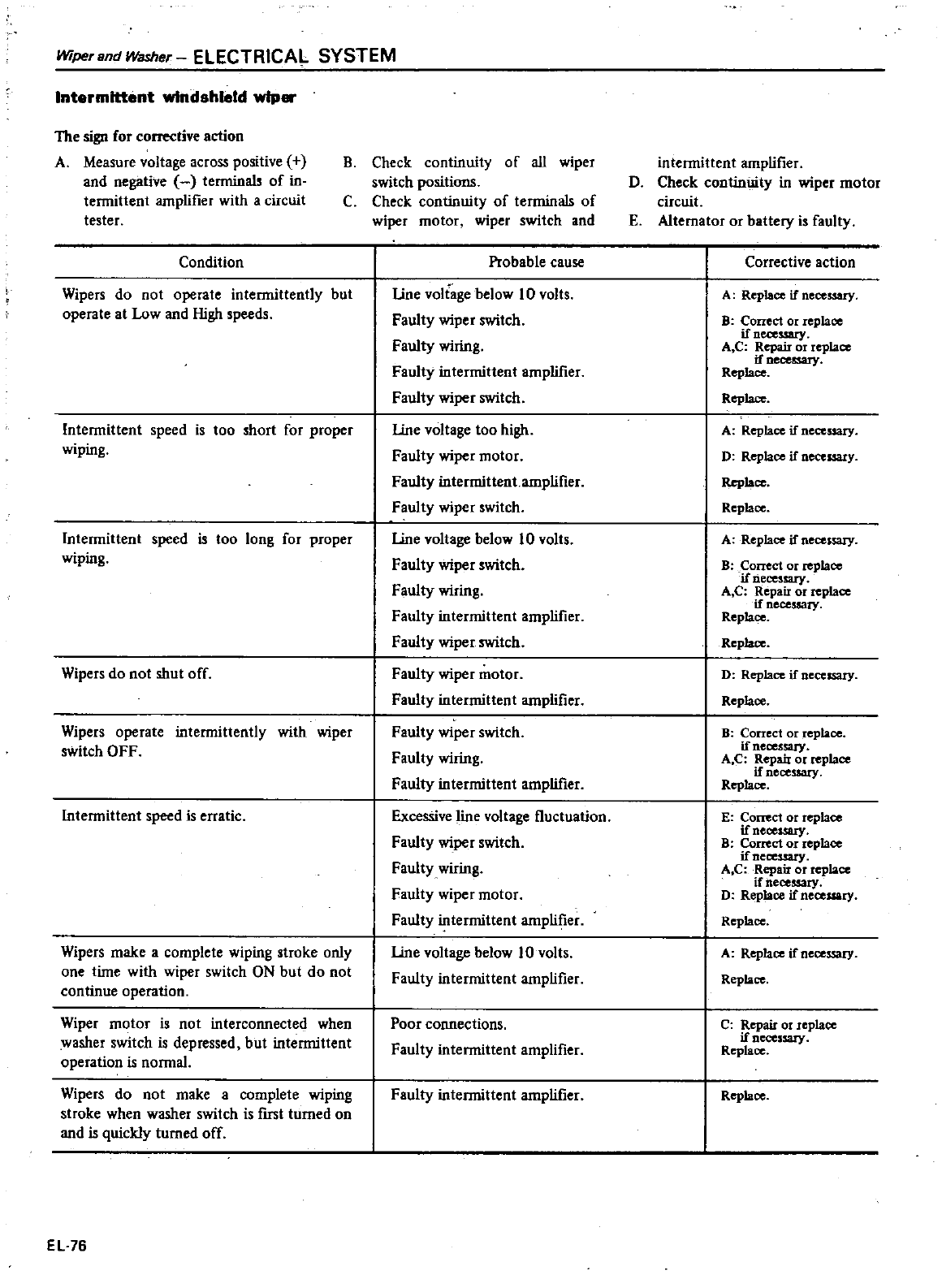
Wiper
and
Washer
ELECTRICAL SYSTEM
Intermittent
windshield
w1p
The
sign
for
action
A
Measure
voltage
across
positive
and
negative
terminals
of
in
termittent
amplifier
with
a
circuit
tester
Condition
Wipers
do
not
operate
intermittently
but
operate
at
Low
and
High
speeds
Intermittent
speed
is
too
short
for
proper
wiping
Intermittent
speed
is
too
long
for
proper
wiping
Wipers
do
not
shut
off
Wipers
operate intermittently
with
wiper
switch
OFF
Intermittent
speed
is
erratic
Wipers
make
a
complete
wiping
stroke
only
one
time
with
wiper
switch
ON
but
do
not
continue
operation
Wiper
motor
is
not
interconnected
when
washer
switch
is
depressed
but
intermittent
operation
is
normal
Wipers
do
not
make
a
complete
Wlpmg
stroke
when
washer
switch
is
fIrst
turned
on
and
is
quickly
turned
off
EL
76
B
Check
continuity
of
all
wiper
switch
positions
C
Check
continuity
of
terminals
of
wiper
motor
wiper
switch
and
Probable
cause
line
voltage
below
10 volts
Faulty
wiper
switch
Faulty
wiring
Faulty
intermittent
amplifIer
Faulty
wiper
switch
line
voltage
too
high
Faulty
wiper
motor
Faulty
intermittent
amplifier
Faulty
wiper
switch
line
voltage
below
10
volts
Faulty
wiper
switch
Faulty
wiring
Faulty
intermittent
amplifier
Faulty
wiper
switch
Faulty
wiper
motor
Faulty
intermittent
amplifier
Faulty
wiper
switch
Faulty
wiring
Faulty
intermittent
amplifier
Excessive
line
voltage
fluctuation
Faulty
wiper
switch
Faulty
wiring
Faulty
wiper
motor
Faulty
intermittent
amplifIer
line
voltage
below
10
volts
Faulty
intermittent
amplifier
Poor
connections
Faulty
intermittent
amplifier
Faulty
intermittent
amplifier
intermittent
amplifIer
D
Check
continUity
in
wiper
motor
circuit
E
Altemator
or
battery
is
faulty
Corrective
action
A
Replace
if
necessary
B
Correct
or
replace
ifneceuary
Ae
Repair
or
replace
if
necessary
Replace
Replace
A
Replace
if
necessary
D
Replace
if
necessary
Repbce
Replace
A
Replace
if
necessary
B
Correct
or
replace
if
necessary
Ae
Repair
or
replace
if
necessary
Replace
Replace
D
Replace
if
necessary
Replace
B
Conect
or
replace
if
neCessary
Ae
Repair
or
replace
if
necessary
Replace
E
Correct
or
replace
if
necessary
B
Correct
or
replace
if
necessary
A
C
Repair
or
replace
if
necessary
D
Replace
if
necessary
Replace
A
Replace
if
necessary
Replace
c
Repair
or
replace
if
necessary
Replace
Repbce
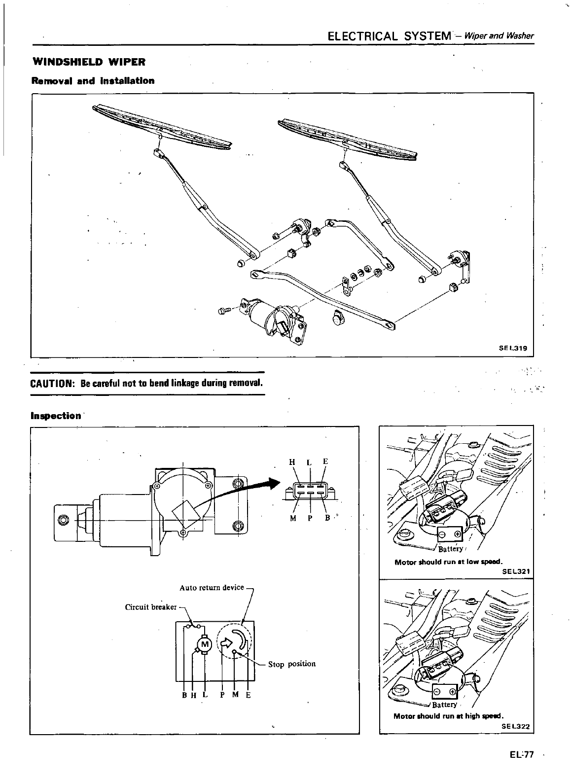
ELECTRICAL SYSTEM
Wiper
and
Washer
WINDSHIELD
WIPER
Removal
and
Installation
OJ
SEL319
CAUTION
Be
careful
not
to
bend
linkage
during
removal
Inspection
9
uL
urff
M
P
B
Motor
should
run
t
low
speed
SEL321
Auto
return
deVicez
Stop
position
I
Ii
M
E
Motor
should
run
at
high
speC
SEL322
EL77
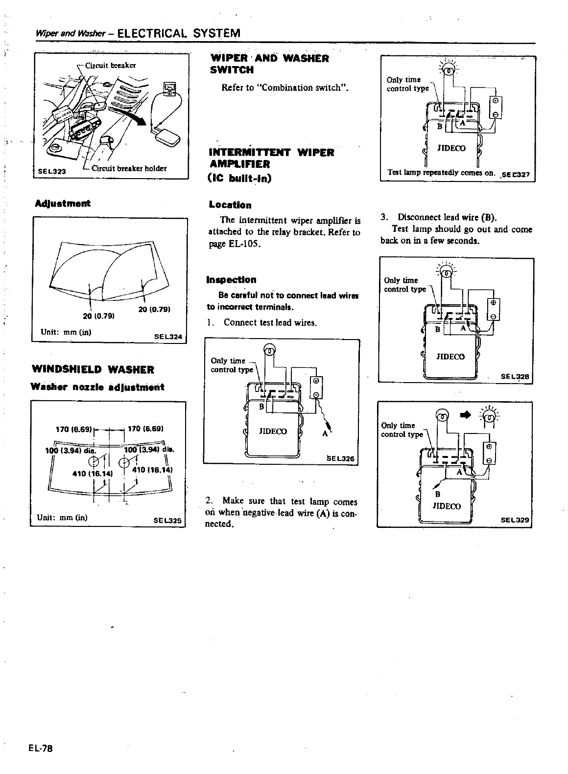
Wiper
Bnd
Washer
ELECTRICAL
SYSTEM
WIPER
AND
WASHER
SWITCH
SE
L323
Adjustment
20
10
791
20
10
191
Unit
mm
in SE
L324
WINDSHIELD
WASHER
Wash
r
nozzl
adJus
11018
69
i
11016
69
F
100
13
941
dili
100
3
94
41
1
rPr1
II
i
410116
141
1
10116
W
Unit
mm
in
SEL325
EL
78
Refer
to
Combination
switch
IInERMI
AMPLIFIER
IC
bullt
ln
WIPER
Location
The
intennittent
wiper
amplil18r
is
attached
to
the
relay
bracket
Refer
to
page
EL
105
Inepectlon
Be
careful
not
to
connect
lead
wir
to
incorrect
te
minals
Connect
test
lead
wire
JIDECO
BE
L326
2
Make
sure
that
test
lamp
comes
oil
when
negative
lead
wire
Ais
con
nected
1
OnlY
time
control
tYP
D
I
e
1
A
i
B
JIDECO
Test
lamp
repeatedly
comes
OD SE
27
3
Disconnect
lead
wire
B
Test
lamp
should
go
out
and
come
back
on
in
a
few
second
JIDECO
I
SEL
28
J
A
Only
time
li
control
type
1
F
Jf
JlDECO
I
I
SEL329
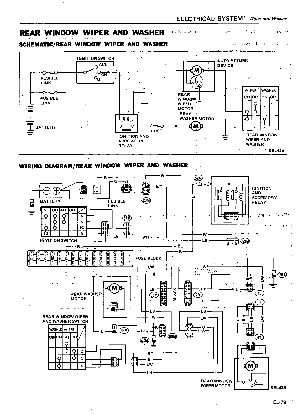
REAR
WINDOW
WIPER
AND
WASHER
r
SCHEMATIC
REAR
WINDOW
WIPER
AND
WASHER
FUSIBLE
LINK
IGN
ITION
SWITCH
o
ACC
y
C
ON
Osr
FUSIBLE
L1N
I
I
I
BATTERY
W
C
Jo
C
c
FUSE
IGNITION
AND
ACCESSORY
RELAY
ELECTRICAL
SYSTEM
Wipe
and
Washer
REAR
WINDOW
WIPER
MOTOR
REAR
WASHER
MOTOR
@
WIRING
DIAGRAM
REAR
WINDOW
WIPER
AND
WASHER
Eflf
L
o
1
BATTERY
FUSIBLE
@
LINK
Age
Off
J
D
ci
o
6
IG
I
o
S
LB
IGNITION
SWITCH
I
r
c
B
L
o 0
0
o
o
0
WR
r
o
FUSE
BLOC
J
Lvi
8
REAR
WAS
iER
MOTOR
@
LB
to
o
U
5
L
CD
1P1
LB
REAR
WINDOW
WIPER
ANO
WASHER
SWITCH
lw
RWIP
V
tl
Ia
f
N
I1
i
b
0
J
L
@
L
Y
LW
L
AUTO
RETURN
DEVICE
WI
PER
WASHER
ON
OFF
ON
f
b
r
o
REAR WINDOW
WIPER
AND
WASHER
SEL434
@
E3
Uf
W
LB
L
B
v
1
LB
W
LW
L
19y
00
Lg
r
u
0
REAR
WINDOW
WIPER
MOTOR
IGNITION
AND
ACCESSORY
RELA
Y
i
hl@
I
DcQ
L
@
LA
@
1@
SEL
35
EUll
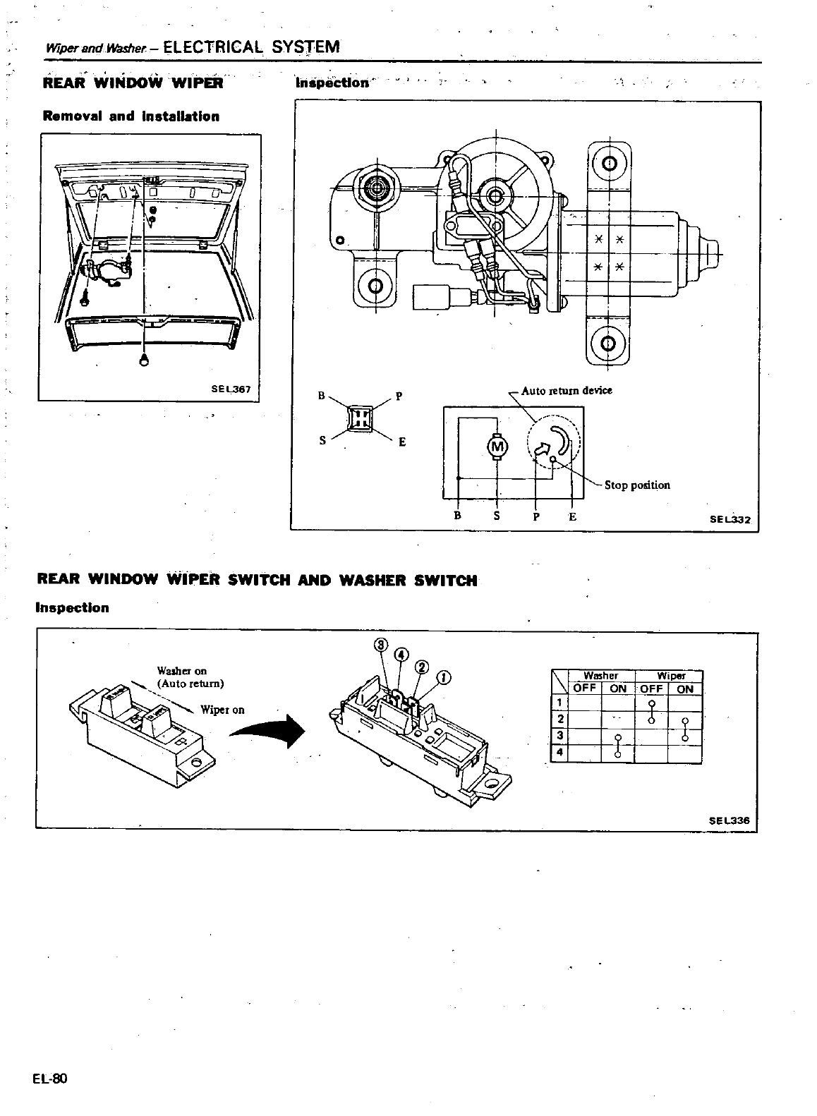
WtperandWasher
ELECTRICAL
SYSTEM
REAR
WlfiiDOW
WIPER
Removal
and
Installation
r
u
i
U
7
t
1
i
i
SEL367
I
spectlon
0
I
j
I
i
t
1
J
I
B
IO
return
device
t
Stop
position
BXP
S
E
1
Inspection
REAR
WINDOW
WIPER
SWITCH
AND
WASHER
SWITCH
Washer
on
Auto
return
Wi
r
EL
80
S
PE
SEL332
r
I
Washer
I
Wiper
I
OFF
ON
OFF
I
ON
IX
t
tl
SE
L336
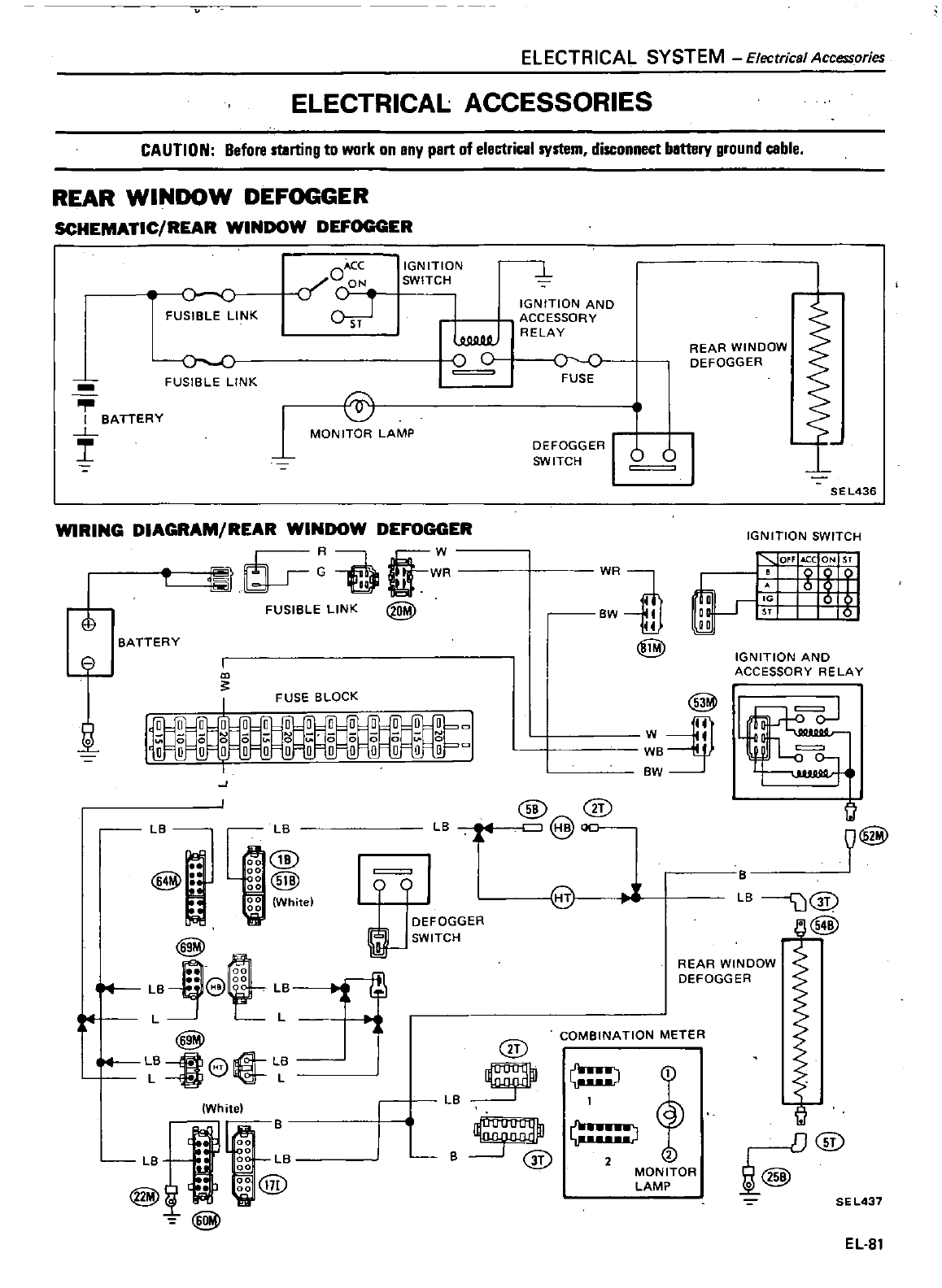
ELECTRICAL
SYSTEM
Electrical
Accessories
ELECTRICAL
ACCESSORIES
CAUTION
Before
muting
to
work
on
any
part
of
electrical
system
disconnect
battery
ground
cable
REAR
WINDOW
DEFOGGER
SCHEMATIC
REAR
WINDOW
DEFOGGER
oc
FUSIBLE
LINK
oc
FUSIBLE
LINK
I
BATTERY
L
I
Ace
c
O
ON
IGNITION
SWITCH
L
IGNITION
AND
ACCESSORY
RELAY
w
u
Q
C
REAR
WINDOW
00
DEFOGGER
FUSE
@
1
MON ITOR
LAMP
DEFOGGER
1
SWITCH
0 0
SEL436
WIRING
DIAGRAM
REAR
WINDOW
DEFOGGER
iJ
i
g
R
FUSIBLE
LINK
BATTERY
0
I
I
FUSE
BLOCK
IGNITION
SWITCH
WR
BW
II
14
@
IGNITION
AND
ACCESSORY
RELAY
@
I
W
I
WB
BW
Ji
J
LB LB
@
@
r
li
@
gg
White
8
e
o
00
t
4
LB
e
LB
LL
e
B
le
@
L
White
J
00
B
0
LB
J
co
LB
00
@
d
gg@
LB
@
@
c
J@ocr
iJ
@
2
4
190
I
1
DEFOGGER
iN
SW
ITCH
e
8rl
REAR
WINDOW
DEFOGG
ER
COMBINATION
METER
@
J1
@
2
MONITOR
LAMP
r
D@
i@
B
SE
L437
EL
81
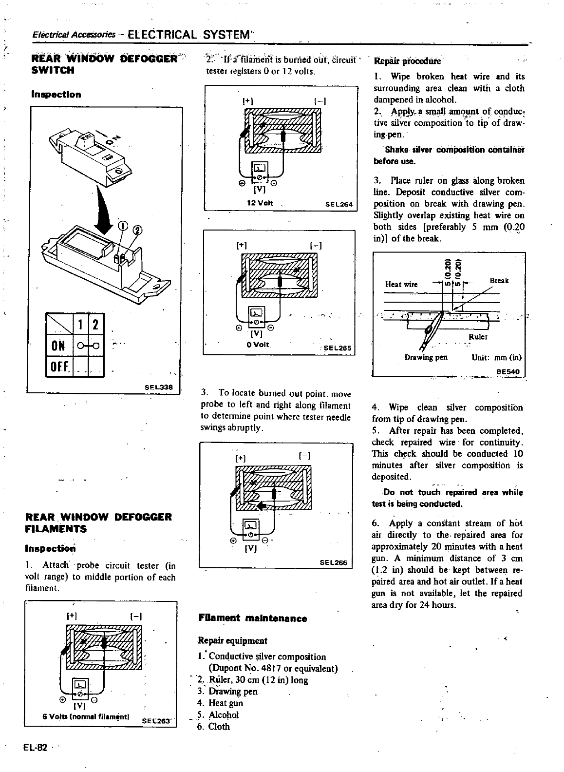
ElliCtrical
Accessories
ELECTRICAL SYSTEM
REAR
WINOOW
DEFOCCER
SWITCH
Inspection
12
ON
0
0
OFF
SEL338
REAR
WINDOW
DEFOGGER
FILAMENTS
Inspection
I
Attach
probe
circuit
tester
in
volt
range
to
middle
portion
of
each
filament
H
r
m
j
Z
I
V
6
Volts
normll
filam
nt
SEL
263
EL
B2
2
If
a
mairieni
is
burned
oill
Circuit
tester
registers
0
or
12
volts
H
lffl
V
12
Volt
SEL264
1 1
H
rTI
l
IV
aValt
E
l265
3
To
locate
burned
out
point
move
probe
to
left
and
right
along
filament
to
determine
point
where
tester
needle
swings
abruptly
J
1
1M
0
j
VJ
SEL266
FUament
maintenance
Repair
equipment
1
Conductive silver
composition
Dupont
No
4817
or
equivalent
2
Ruler
30
em
12
in
Jong
3
Drawing
pen
4
Heat
gun
5
Alcohol
6
Cloth
Repair
pI
L
I
Wipe
broken
heat
wire
and
its
surrounding
area
clean
with
a
cloth
dampened
in alcohol
2
AppJy
snuillam
t
of
c
duc
tive
silver
composition
to
tip
of
draw
ing
pen
Shake
silver
on
container
belore
use
3
Place
ruler
on
glass
along
broken
line
Deposit
conductive
silver
com
position
on
break
with
drawing
pen
Slightly
overlap
existing
heat
wire
on
both
sides
preferably
5
mm
0
20
in
of
the
break
00
Heat
wire
reak
1
Lf
Drawing
pen
Unit
mm
in
eE540
4
Wipe
clean silver
composition
from
tip
of
drawing
pen
5
After
repair
has
been
completed
check
repaired
wire
for
continuity
This
ch
ck
should
be
conducted
10
minutes
after
silver
composition
is
deposited
Do
not
touch
repaired
rea
while
test
is
being
conducted
6
Apply
aconstant
stream
of
hot
air
directly
to
the
repaired
area
for
approximately
20
minutes
with
a
heat
gun
A
minimum
distance
of
3
em
1
2
in
should
be
kept
between
re
paired
area
and
hot
air
outlet
If
a
heat
gun
is
not
available
let
the
repaired
area
dry
for
24
hours
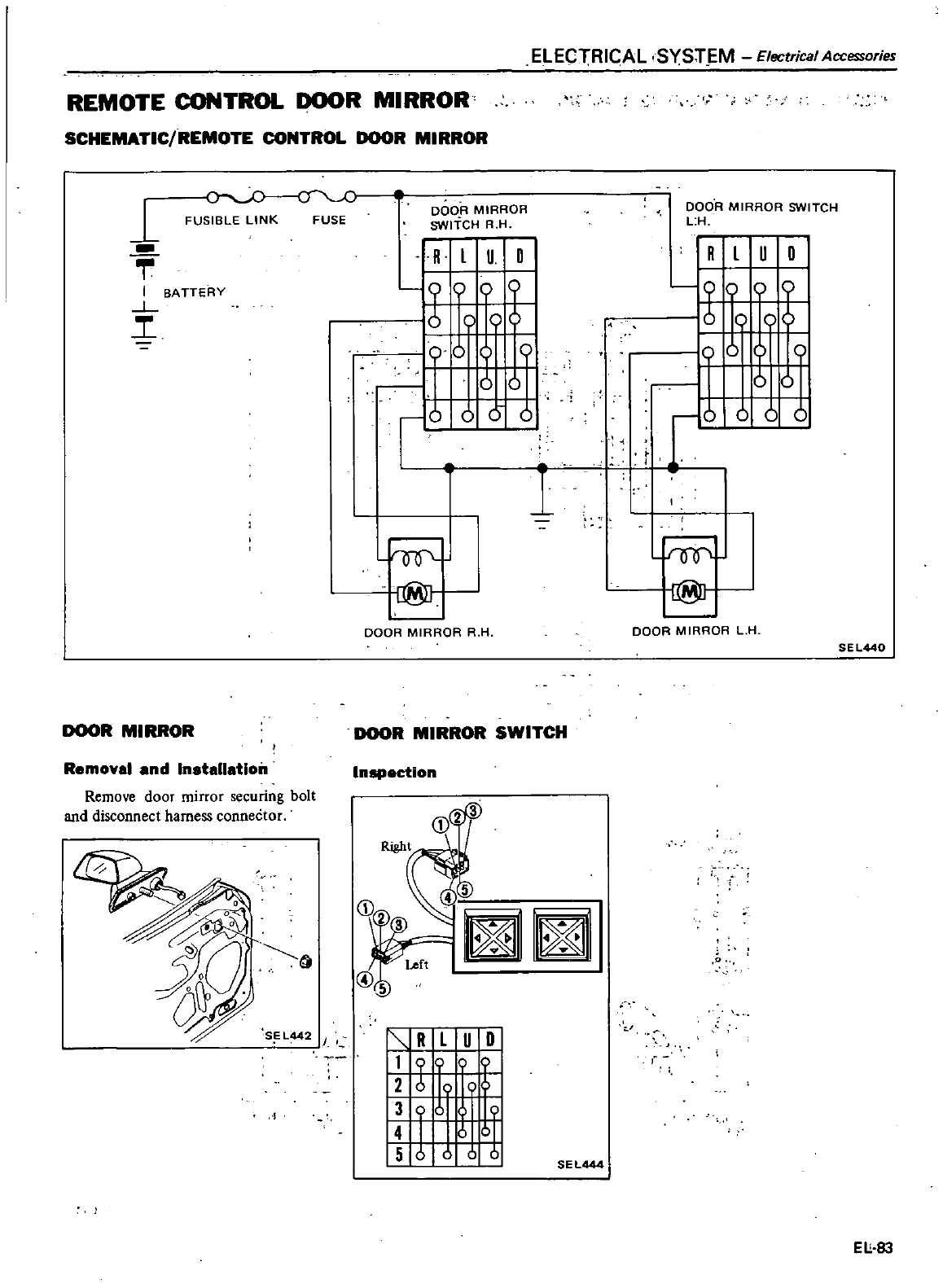
REMOTE
CONTROL
DOOR
MIRROR
SCHEMATIC
REMOTE
CONTROL
DOOR
MIRROR
FUSIBLE
LINK
FUSE DOOR
MIRROR
SWITCH
R H
1
I
BATTERY
L
i
DOOR
MIRROR
Removal
and
Inatallatlon
Remove
door
mirror
securing
bolt
and
disconnect
harness
connector
S
L442
I
I
R
l
I
u 0
00
00
9
0
uO
10
0
0
0
OQ
r@
DOOR
MIRROR
R
H
ELECTRICAL
SYST
M
Electrical
Accessories
1
DOOR
MIRROR
SWITCH
Inspection
4
5
a
1
R
L
U
0
I
11
9
I
I
I
I
01
I
I
6
c
II
15
J
0
oJ
I
EL444
DOOR
MIRROR
SWITCH
L
H
I
R
l
U
0
oOOob
J
00
bo
0
i
IQO
r@
DOOR
MIRROR
L
H
SEL440
o
Ell
8J
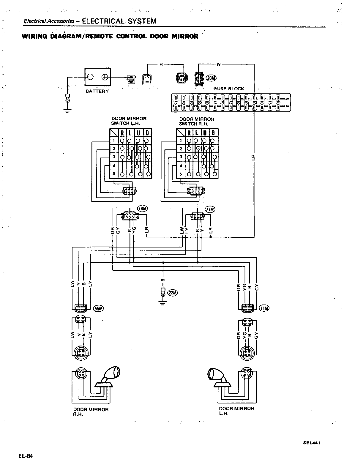
Electrical
Accessories
ELECTRICAL SYSTEM
WIRING
DIAGRAM
REMOTE
CONTROL
DOOR
MIRROR
9
rrR @
o@w
FUSE
BLOCK
1
BATTERY
DOOR
MIRROR
SWITCH
LH
DOOR
MIRROR
SWITCH
R H
RLUD
RLIUD
rU
U
r
tJ
a
@
a
r11
CJ
t
CO
5
I
I
CO
I
III
@
II
a
Clco
i
@
rm
il
@
rTIl
iil
R
J
III
DOOR
MIRROR
R H
DOOR
MIRROR
LH
SEL441
EL
B4
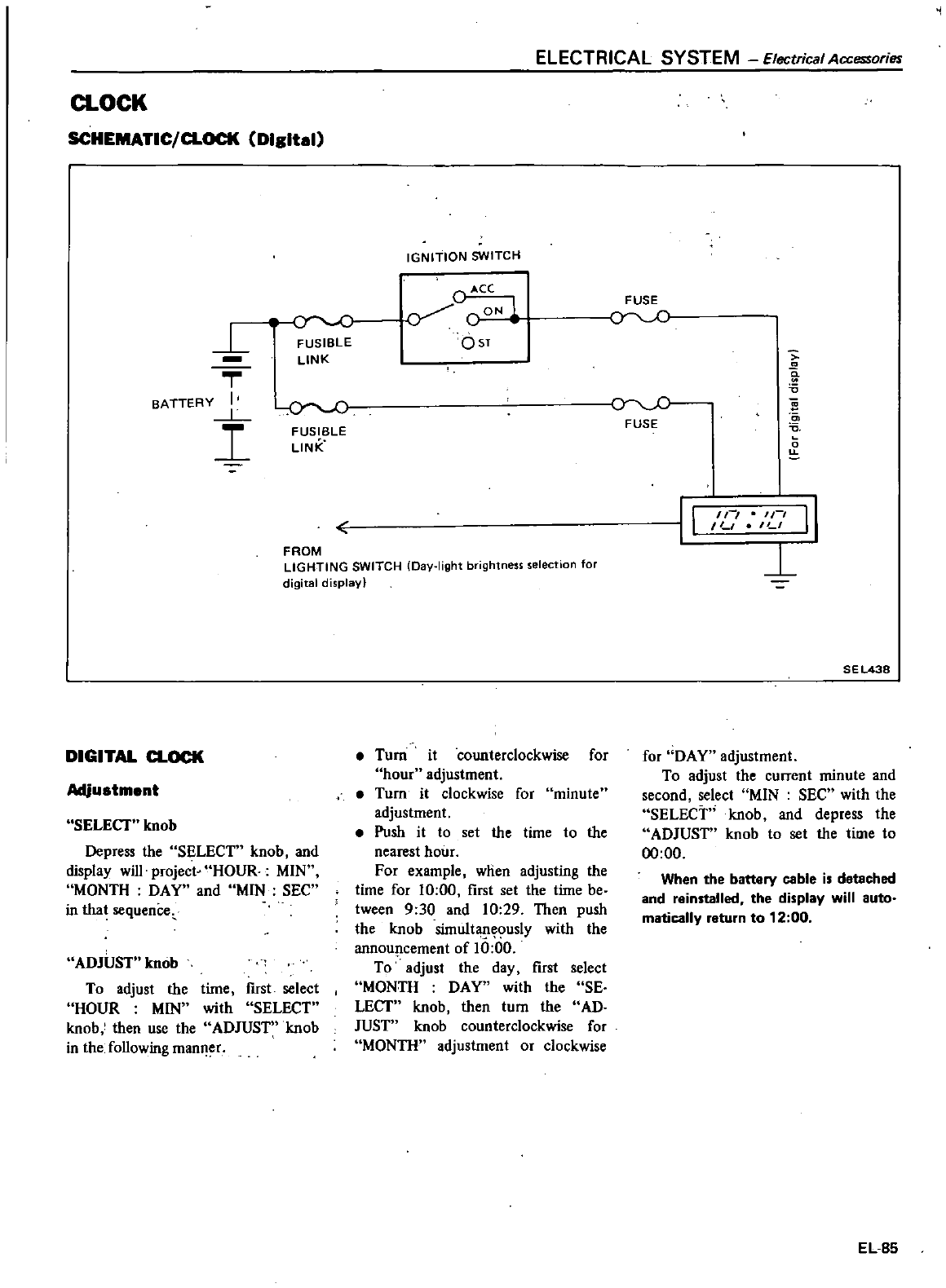
a
OCK
SCHEMATIC
CLOCK
Digital
L
l
C
FUSIBLE
LINK
T
BATTERY
I
L
I
rJ
FUSIBLE
LINK
ELECTRICAL SYSTEM
Electrical
Accessories
IGNITION
SWITCH
C
ACe
o
OST
FROM
LIGHTING
SWITCH
Day
light
brightness
selection
for
digital
display
DIGITAL
CLOCK
Adjustment
SELECT
knob
Depress
the
SELECT
knob
and
display
will
project
HOUR
MIN
MONTH
DAY
and
M1N
SEC
in
that
sequencec
ADJUST
knob
To
adjust
the
time
fust
select
HOUR
MIN
with
SELECT
knob
then
use
the
ADJUST
knob
in
the
following
manl
er
Turn
it
counterclockwise
for
hour
adjustment
Turn it
clockwise
for
minute
adjustment
Push
it
to
set
the
time
to
the
nearest
hour
For
example
when
adjusting
the
time
for
10
00
first
set
the
time
be
tween
9
30
and
10
29
Then
push
the knob
simuJt
usly
with
the
annou
lcement
of
10
00
To
adjust
the
day
first
select
MONTH
DAY
with
the
SE
LECT
knob
then
tum
the
AD
JUST
knob
counterclockwise
for
MONTH
adjustment
or
clockwise
FUSE
a
5
FUSE
s
0
u
II
In
ILl
II
LI
1
SEL438
for
DAY
adjustment
To
adjust
the
current
minute
and
second
select
MIN
SEC
with
the
SELECT
knob
and
depress
the
ADJUST
knob
to
set
the
time
to
00
00
When
the
battery
cable
is
detached
and
reinstalled
the
display
will
auto
matically
return
to
12
00
EL
85
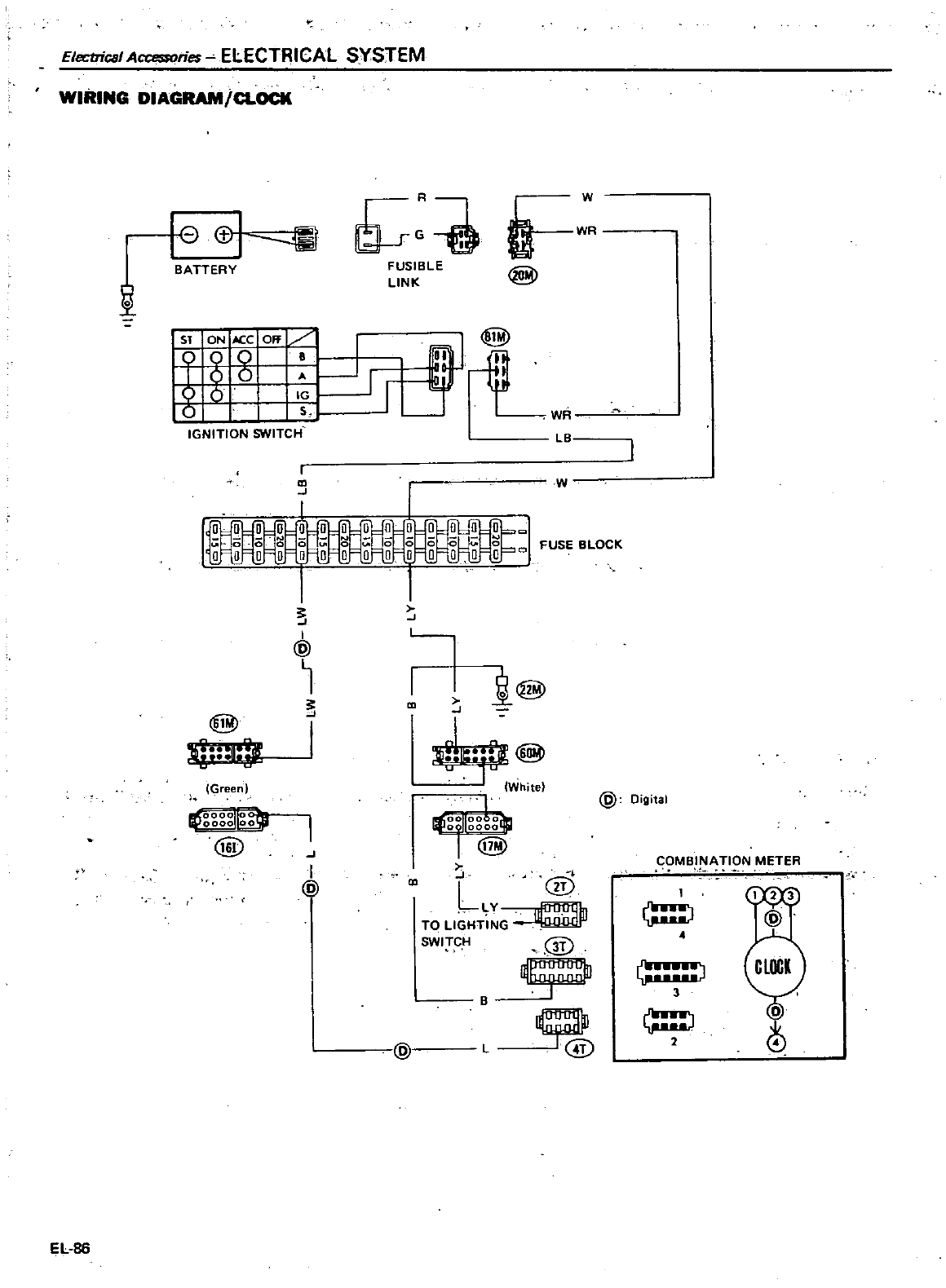
Electrical
Accessories
ELECTRICAL SYSTEM
WIRING
DIAGRAM
CLOCK
EL
86
@I
1ll
D
FUSIBLE
LINK
WR
W
BATTERY
I
1
WR
LB
ST
ON
lCCOff
000
B
J
00
8
b
I
IGNITION
SWITCH
I
J
W
W
u
i
w
C
I
I
J
1
@
j
J
I
J
L
j@
Green
J
j
White
1
Ii00
0
L
01
O@
L
@
TO
L1GHT
SWITC
H
@
l
iOOOOIIO
ho
o
ooo
o
@
J
I
@
e
@
L
@
o
g
COMBINATION
METER
H
GJ
3
2
4
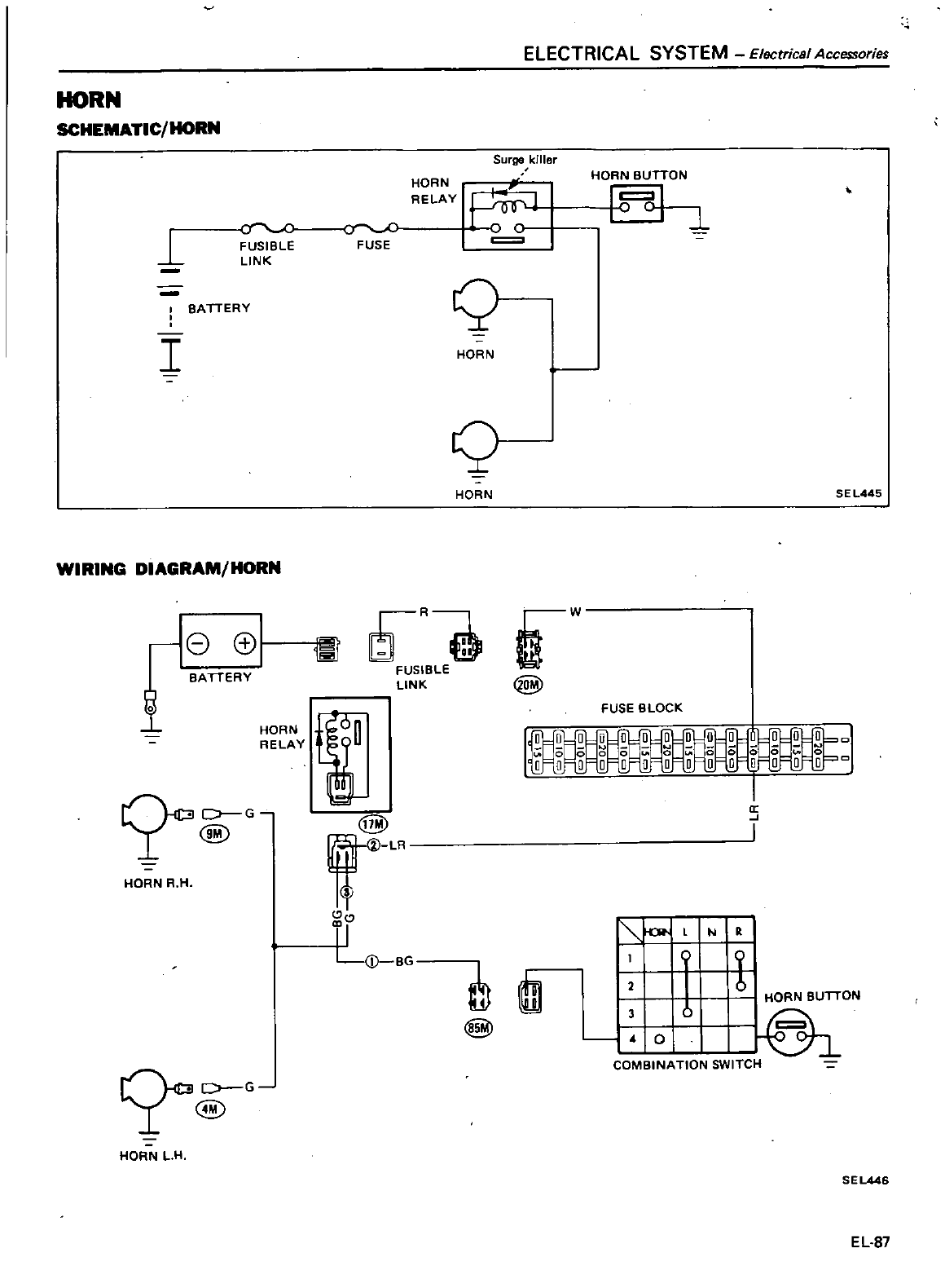
HORN
SCHEMATIC
HORN
1
f
FUSIBLE
LINK
SA
TTERY
I
WIRING
DIAGRAM
HORN
r
80
BATTERY
HORN
RELAY
D
G
r
@
HORN
R H
@G
HORN
L
H
0
FUSE
ELECTRICAL
S
YSTEM
EI
ectncal
Accessories
Surge
killer
HORN
RELAY
I
o
C
1
HOr
B
TN
1
Q
HORN
Q
HORN
SEl445
6
Bfl
gW
LINK
@
i
@
f
I
l
D
BG
FUSE
BLOCK
1
a
J
I
l
N
D
@l
l
3
I
U
HORN
BUTTON
0
I
COMBINATION
SWITCH
2
SEL446
EL
87
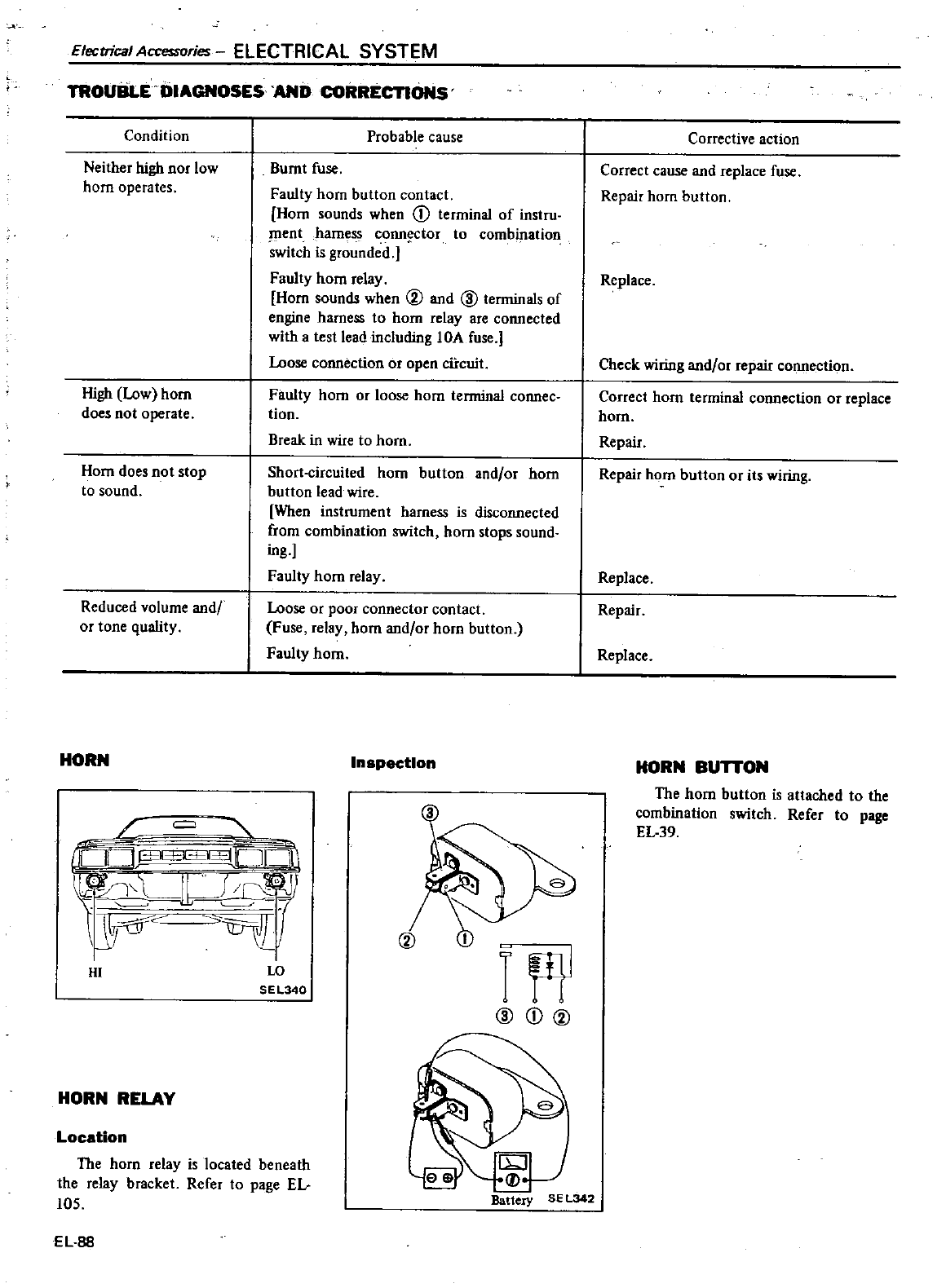
Electrical
Accessories
ELECTRICAL
SYSTEM
TRoUliLE
DIAGNOSES
AND
CORRECTIONS
Condition
Probable
cause
Neither
high
nor
low
horn
operates
Burnt
fuse
Faulty
hom
button
contact
Hom
sounds
when
CD
terminal
of
instru
ment
harness
conn
ctor
to
combination
switch
is
grounded
Faulty
hom
relay
Hom
sounds
when
@
and
@
terminals
of
engine
harness
to
horn
relay
are
connected
with
a
test
lead
including
lOA
fuse
Loose
connection
or
open
cfrcuit
High
Low
horn
does
not
operate
Faulty
horn
or
loose
hom
terminal
connec
tion
Break
in
wire
to
horn
Horn
does
not
stop
to
sound
Short
circuited
horn
button
and
or
hom
button
lead
wire
When
ins1rument
harness
is
disconnected
from
combination
switch
horn
stops
sound
ing
Faulty
hom
relay
Reduced
volume
and
or
tone
quality
Loose
or
poor
connector
contact
Fuse
relay
horn
and
or
horn
button
Faulty
homo
HORN
Inspection
rJ
@CD@
HI
to
SEL340
HORN
RELAY
Locstion
The
horn
relay
is
located
beneath
the
relay
bracket
Refer
to
page
EL
105
Battery
EL
88
Corrective
action
Correct
cause
and
replace
fuse
Repair
horn
button
Replace
Check
wiring
and
or
repair
connection
Correct
horn
terminal
connection
or
replace
horn
Repair
Repair
horn
button
or
its
wiring
Replace
Repair
Replace
HORN
BUTTON
The
horn
button
is
attached
to
the
combination
switch
Refer
to
page
EL39
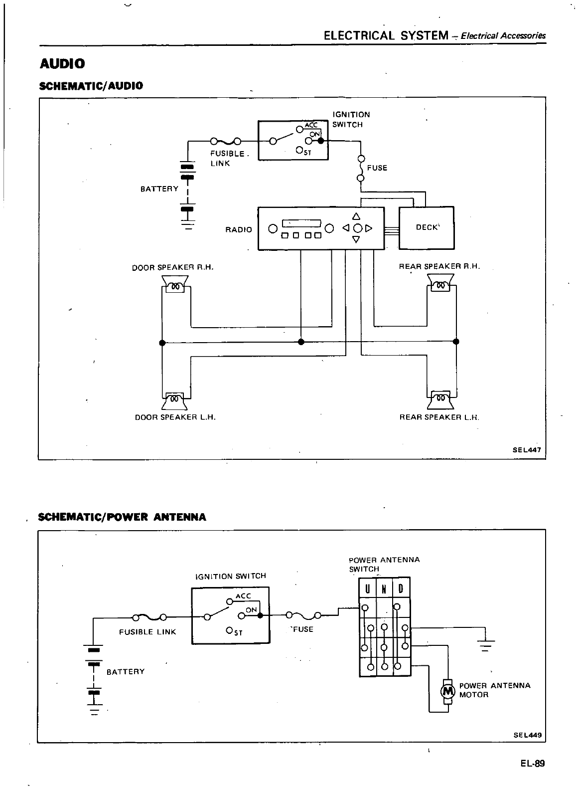
AUDIO
SCHEMATIC
AUDIO
E
LINK
BATTERY
I
L
DOOR
SPEAKER
R H
DOOR
SPEAKER
L
H
SCHEMATIC
POWER
ANTENNA
1
FUSIBLE
LINK
BATTERY
I
L
RADIO
IGNITION
SWITCH
C
ACC
CON
OST
ELECTRICAL SYSTEM
Elecrrical
Accessories
y
OST
IGNITION
SWITCH
m
I
000000
6
J01
V
t
POWER
ANTENNA
SWITCH
I
u
N
0
o
FUSE
0
0
u
I
I
OeCK
REAR
SPEAKER
R H
II
E
REAR
SPEAKER
L
H
SEL447
l
ft
POWER
ANTENNA
3
MOTOR
SEL449
EL
89
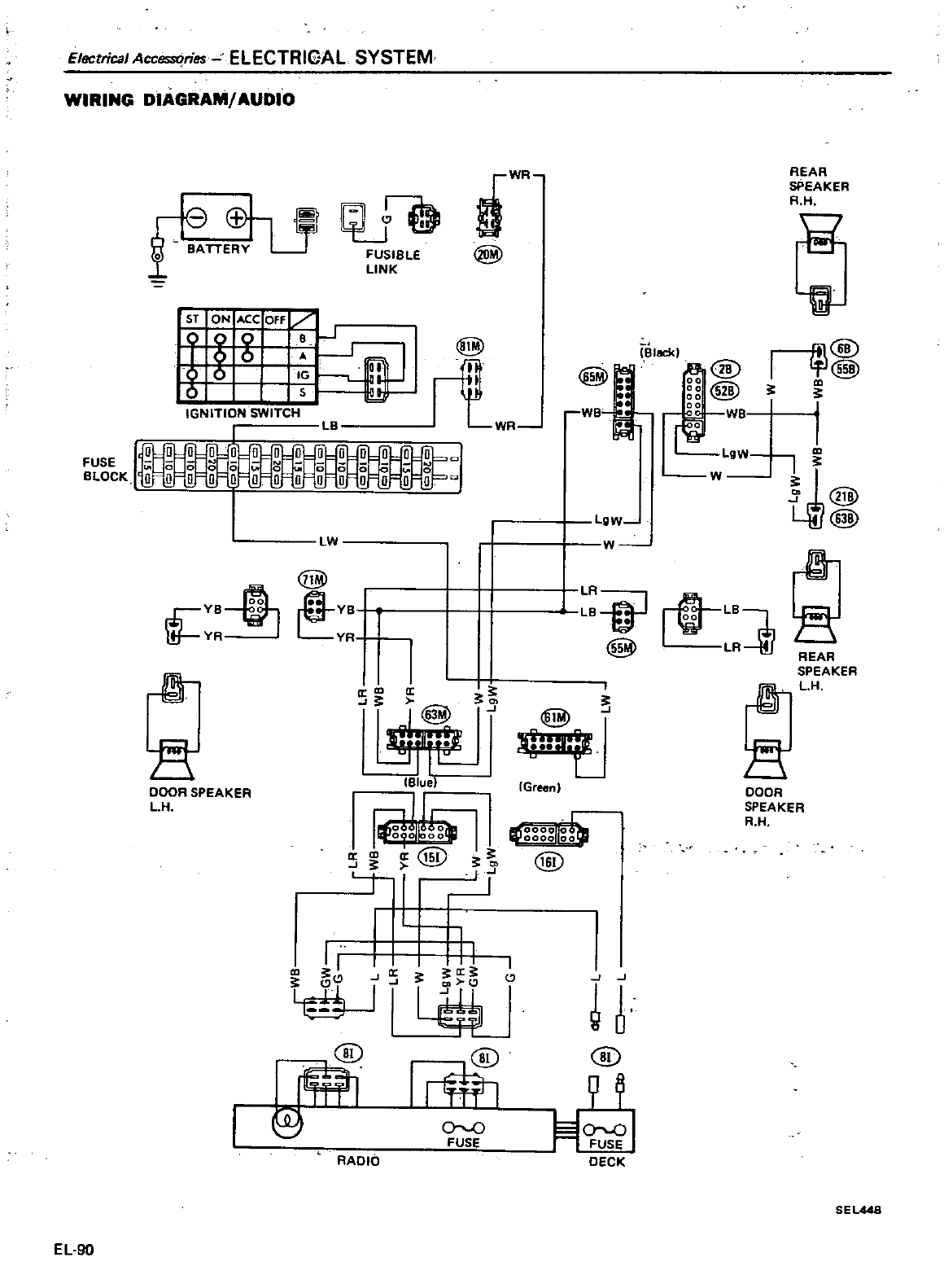
Electrical
Accessories
ELECTRICAL
SYSTEM
WIRING
DIAGRAM
AUDIO
ffih
o
BATTE
Y
U
FUSIBLE
LINK
Sf
o
LW
illY
4YJ
LyR
B
I
a
I
J 0
01
IBlue
I
a
m
a
15i
J 0
t
J
DOOR
SPEAKER
L
H
II
II
I
YUi
U
@@
Irml
9
00
FUSE
RADIO
EL
90
DWR
@
Block
J
lgW
J
I
v
LR
LB
@
i
l@
I
L
Green
0000
0000
00
@
@
DECK
REAR
SPEAKER
R
H
1J
I
@
@
I
I
tk@Y
@
m
rT
REAR
SPEAKER
L
DOOR
SPEAKER
R H
SE
1448
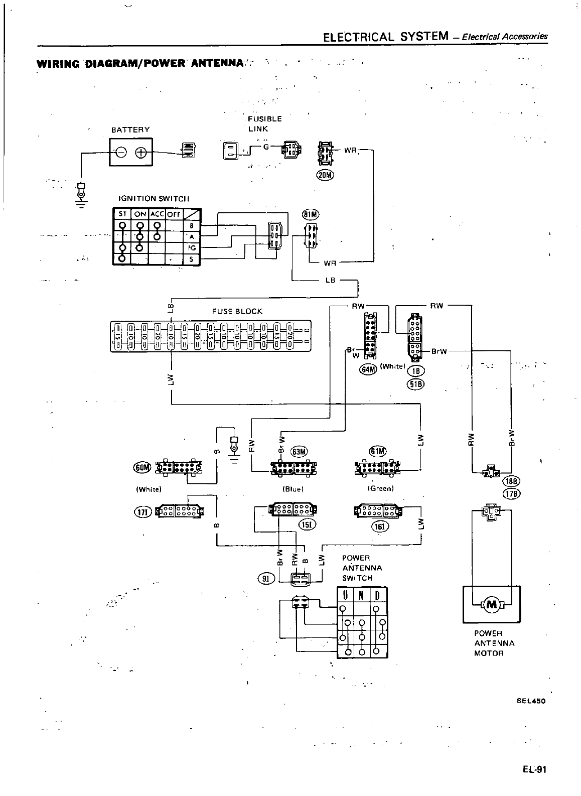
ELECTRICAL SYSTEM
Elecrrical
Accessories
WIRING
DIAGRAM
POWER ANTENNA
1
BATTERY
re
I
IGNITION
SWITCH
ST
ON
ACC
Off
I
8
g
J
I
FUSIBLE
LINK
G
D
ftWR
@
mtl
@
1
1
WR
LBi
FUSE
BLOCK
s
L
n
@
J
Il
li
White
@
Ifg
lIgg1gitl
Whitel@
ill
I
ss
Q
l
0
a
cO
@B
I
I
i
nht
0
Bluel
Green
000000
@
1
1I000ill
lIt
o
@
II
I
CD CD
@L1f3J
IU
N
D
Ig
POWER
ANTENNA
SWITCH
I
s
I
I
s
RW
B
W
s
c
a
w
@
@
@r
POWER
ANTENNA
MOTOR
SEL450
EL
91
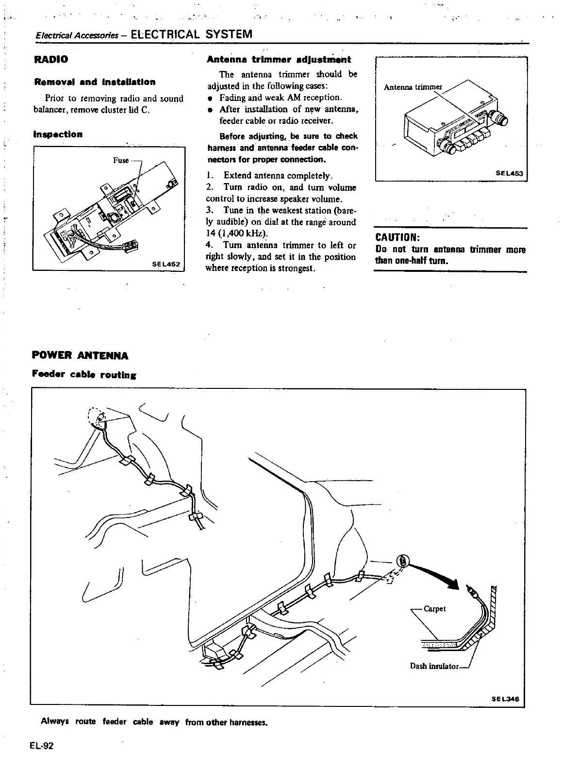
Electrical
Accessories
ELECTRICAL
SYSTEM
RADIO
Removal
and InataUatlon
Prior
to
removing
radio
and
sound
balancer
remove
cluster
lid
C
Inspection
POWER
ANTENNA
Feeder
cable
routing
Antenna
trimmer
adjustment
The
antenna
trimmer
should
be
adjusted
in
the
following
cases
Fading
and
weak
AM
reception
Mter
installation
of
n
w
antenna
feeder
cable
or
radio
receiver
Before
adju
ingt
be
sure
to
check
harness
and
antenna
feeder
cable
con
necton
for
proper
connection
1
Extend
antenna
completely
2
Turn
radio
on
and
turn
volume
control
to increase
speaker
volume
3
Tune
in
the
weakest
sta1ion
bare
ly
audible
on
dial at
the
range
around
14
1
400
kHz
4
Turn
antenna
trinuner
to
left
or
right
slowly
and
set
it
in
the
position
where
reception
is
strongest
Alway
route
feeder
cable away
from
other
harne
EL
92
SEL4S3
CAUTION
00
not
turn
antenna
trimmer
more
than
onehalf
turn
J
t
SEL346
HI
4
r
l
3C
kQTY
OIlUl
I
f
1
c
74
654
CI
OST
YEO
u
s
YAX
T
S
IP
I
5
n
c
O
I
CT
DJO
Q
l
f
O
o
E
SC
R
IP
T
IO N
r
r
r
s
20082
20081
Combined
1IIlIDtJ81
80
D271
26
9
c
ANY
ITEMS
NOT
SHIPP
ARErIMMED1ATELY
BACK
ORDERED
NO
CLAIMSAI
WED
UNLESS
MADE
WITHIN
10
DAYS FROM
DATE
off
INVOI
CE
r
fo
UNAUTHORIZED
RETURNS
ACCEPTED
ThiS
is to
rtity
that the
900ds
herein
were
produced
In
ompllilnce
with
all
provisions
of the Fair
Labor
Standards
Act
of
1938
amended
It is
Intention
o
amply
nd
the
prices
here
Invoiced
do
comply
to
tJ1e
best
of
knowledge
with
sting
price egulations
SHIPPING
11
4l
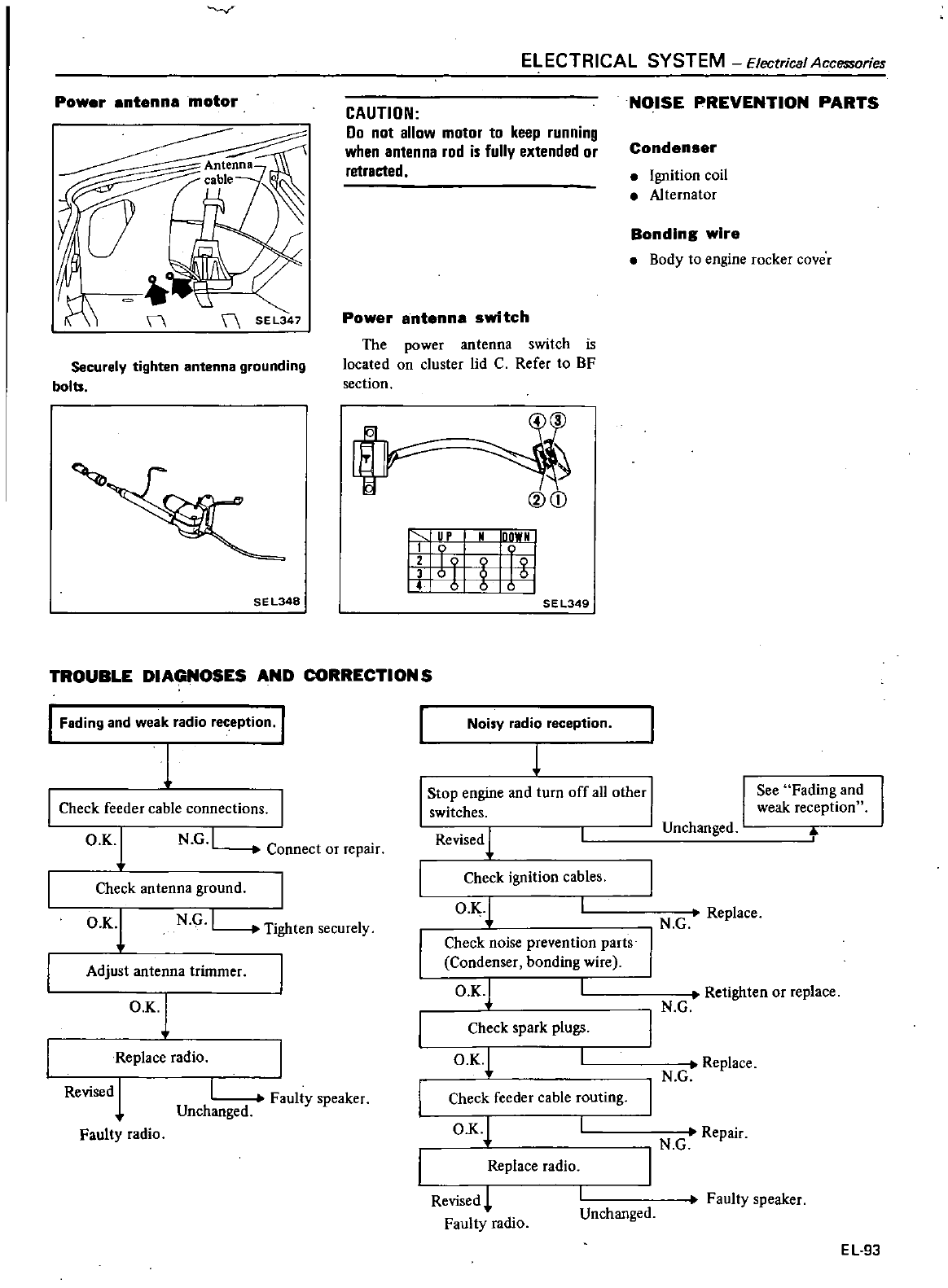
Power
antenna
motor
II
Securely
tighten
antenna
grounding
bolts
SE
L348
ELECTRICAL
SYSTEM
Electrical
Accessories
CAUTION
Do
not
allow
motor
to
keep
running
when
antenna
rod
is
fully
extended
or
retrected
Power
antenna
switch
The
power
antenna
switch
is
located
on
cluster
lid
C
Refer
to
BF
section
v
@CD
i
SEL349
TROUBLE DIAGNOSES
AND
CORRECTIONS
I
Fading
and
weak
radio
reception
Check feeder
cable
connections
O
K
lN
G
I
Connect
or
repair
Noisy
radio
reception
1
Stop
engine
and
turn
off
all
other
I
switches
Revised
1
I
Check
ignition
cables
O
KJ
I
N G
I
T
gh I1
ten
secure
y
O
K
l
Check
antenna
ground
Adjust
antenna
trimmer
O
Kj
Replace
radio
Revised
1
Faulty
radio
Check
noise
prevention
parts
Condenser
bonding
wire
O
K
l
Check
spark
plugs
OK
I
Faulty
speaker
Unchanged
O
K
Check feeder
cable
routing
Replace
radio
Revised
Faulty
radio
I
Unchanged
NOISE
PREVENTION
PARTS
Condenser
Ignition
coil
Alternator
Bonding
wire
Body
to
engine
rocker
cover
See
Fading
and
weak
reception
Unchanged
I
N G
Replace
Retighten
or
replace
N
G
Replace
N G
Repair
N
G
I
Faulty
speaker
EL
93
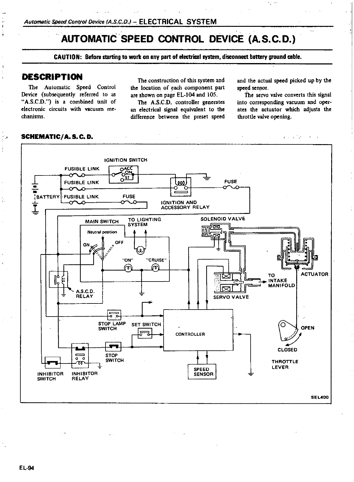
Automatic
Speed
Control
Device
A
S
CD
ELECTRICAL SYSTEM
AUTOMATIC SPEED
CONTROL
DEVICE
A
S C D
CAUTION
Before
starting
to
wort
on
any
part
of
e1ectricel
system
disconnect
battery
ground
ceble
DESCRIPTION
The
Automatic
Speed
Control
Device
subsequently
referred
to
as
A
S
C
D
i
a
combined
unit
of
electronic
circuits
with
vacuum
me
chanisms
SCHEMATIC
A
S
C
D
The
construction
of
this
system
and
the
location
of
each
component part
are
shown
on
page
EL
I04
and
105
The
AS
C
D
controller
generates
an
electrical
signal
equivalent
to
the
difference
between
the
preset
speed
and
the actual
speed
picked
up
by
the
speed
sen
or
The
rvo
valve
converts
this
signal
into
corre
ponding
vacuum
and
oper
ates
the
actuator
which
adjusts
the
throttle
valve
opening
IGNITION
SWITCH
ON
r
OFF
@
I
ON
rc
Y
FUSIBLE
LINK
Y
L
FUSIBLE
LINK
BATTERY
FUSIBLE
LINK
cY
C
1
I
OACC
I
Y
g
r
L
MAIN
SWITCH
Neutral
xmtion
I
ll
RELAY
EJ
STOP
LAMP
SWITCH
I I
STOP
SWITCH
8
o 0
INHIBITOR
RELAY
INHIBITOR
SWITCH
EL
94
FUSE
II
FUSE
YO
IGNITION
AND
ACCESSORY
RELAY
TO
LIGHTING
I
SY
TE
SOLENOID
VALVE
l
CRUISE
@
L
TO
ACl
JATOR
INTAKE
MANIFOLD
SERVO
VALVE
r
I
SET
SWITCH
I
Q
OPEN
CLOSED
CONTROLLER
t
THROTTLE
LEVER
SPEED
I
SENSOR
SE
LAOO
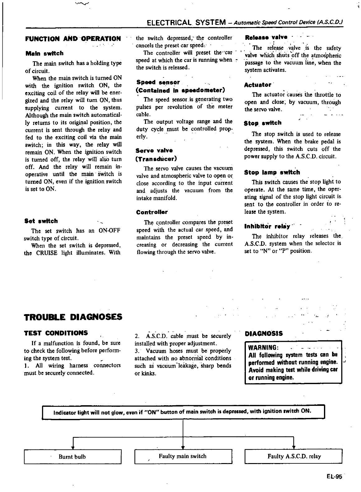
r
FUNCTION
AND
OPERATION
Mln
swttch
The
main
switch
has
a
holding
type
ofcircuit
When
the
main
switch
is
turned
ON
wilh
lhe
ignition
switch
ON
lhe
exciting
coil
of
the
relay
will
be
ener
gized
and
the
relay
will
turn
ON
lhus
supplying
current
to
lhe
system
Although
the
main
switch automatical
ly
retums
to
its
original
position
the
current
is
sent
through
lhe
relay
and
fed
to
the
exciting
coil
via
lhe
main
switch
in
this
way
lhe
relay
will
remain
ON
When
the
ignition
switch
is
tumed
off
lhe
relay
will
also
turn
off
And the
relay
will
remain
in
operative
until
lhe
main
switch
is
turned
ON
even
if
the
ignition
switch
is
set
to
ON
S
t
swttch
The set
switch
has
an
ON
OFF
switch
type
of
circuil
When
the
set
switch
is
depressed
lhe
CRUISE
light
illuminates
Wilh
TROUBLE
DIAGNOSES
TEST
CONDITIONS
If
a
malfunction
is
found
be
sure
to
check
lhe
following
before
perform
ing
the
system
tesl
I
All
wiring harness
connectors
must
be
securely
connected
ELECTRICAL
SYSTEM
Auramatic
Speed
Control
Device
A
S
CD
lhe
switch
depressed
lhe
controller
cancels
the
preset
car
speed
The
controller
will
preset
lhe
car
speed
at
which
lhe
car
is
running
when
the
switch
is
released
Speed
s
nsor
Contaln
d
In
speedom
tr
The
speed
sensor
is
generating
two
pulses
per
revolution
of
the
meter
cable
The
output
voltage
range
and
lhe
duty
cycle
must
be
controlled
prop
erly
S
ryo y
ly
TransdUc
r
The
servo
valve
causes
the
vacuum
valve and
atmospheric
valve
to
open
or
close
according
to
the
input
current
and
adjusts
the
vacuum
from
the
intake
manifold
Controll
r
The
c
ontroller
compares
the
preset
speed
with
the
actual
car
speed
and
maintains
the
preset
speed
by
in
creasing
or
decreasing
the
current
flowing
through
the
servo
valve
2
A
SC
D
cable
must
be
securely
installed
with
proper
adjustment
3
Vacuum
hoses
must
be
properly
attached
wilh
no
abnorrrial
conditions
such
as
vacuum
leakage sharp
bends
or
kinks
R
I
y
ly
The
release
v
ve
is
lhe
safety
valve
wliich
shuts
off
the
atmospheric
passage
to
lhe
vacuum
line
when
the
system
activates
Actu
tor
The
actuator
causes
ihe
throttle
to
open
and close
by
vacuum
through
lhe
servo
valve
Stop
wttch
The
stop
switch
is
used
to
release
lhe
system
When
the
brake
pedal
is
depressed
this
switch
cuts
off
lhe
power
supply
to
the
A
SC
D
circuil
Stop
I
mp
switch
This
switch
causes
the
stop
light
to
operate
At
the
same
time
the
oper
ating
signal
of
the
stop
light
circuit
is
sent
to
lhe
controller
in
order
to
re
lease
the
system
Inhibitor
r
lliy
The
inhibitor
relay
releases
the
A
s
C
D
system
when
the
selector
is
set
to
N
or
P
position
DIAGNOSIS
WARNING
All
following
system
tests
can
be
performed
withoutrunning
engine
Avoid
making
test
while
driving
car
or
running
engine
Indicator
light
will
not
glow
even
if
ON
button
of
main
switch
is
depressed
with
ignition
switch
ON
1
Burnt
bulb
Faulty
main
switch
L
Faulty
A
S C
D
relay
EL
95
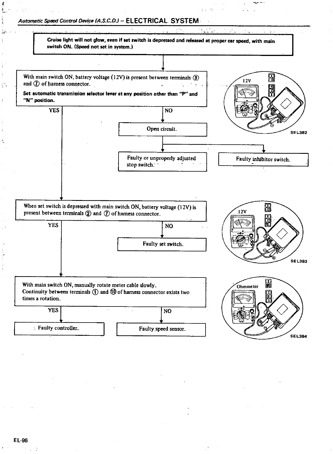
Automatic
Speed
Control
DBVice
A
S
C D
i
ELECTRICAL
SYSTEM
r
Cruise
light
will
not
glow
eyen
if
let
switch
is
depressed
and
released
81
proper
car
speed
with
main
switch
ON
Speed
not
set
in
system
1
1
With
main
switch
ON
battery
voltage
12V
is
present
between
terminals
@
and
V
of
harness
conn
ector
Set automatic
transmission
selector
lever
at
any
position
other
than
Ip and
I
NW
position
YES
to
Open
circuit
I
Faulty
or
unproperly
adjuSted
stop
switch
When
set
switch
is
depressed
with
main switch
ON
battery
voltage
12V is
present
between
terminals
@
and
V
ofhamess
connector
YES
1
NO
Faulty
set
switch
With
main
switch
ON
manually
rotate
meter
cable
slowly
Con1inuity
between
terminals
CD
and
@ofharness
connector
exists
two
times
a
rotation
YES
1
to
Faulty
controller
Faulty
speed
sensor
EL
96
Faulty
inhibitor
switch
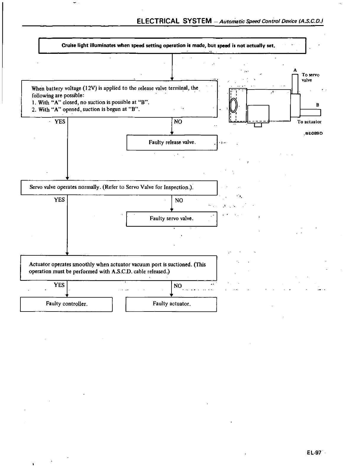
ELECTRICAL
SYSTEM
Automatic
Speed
Control
Device
A
SC
D
Cruise
light
illuminates
when
speed
setting
operation
i
made
but
peed
is
not
actually
set
When battery
voltage
12V is
applied
to
the
release
valve
terminal
the
following
are
possible
1
With
A
closed
no
suction
is
possible
at
B
2
With
A
opened
suction
is
begun
at
B
YES
to
Faulty
release
valve
It
Servo
valve
operates
normally
Refer
to Servo Valve
for
Inspection
YES
1
NO
Faulty
servo
valve
Actuator
operates
smoothly
when
actuator
vacuum
port
is
suctioned
TItis
operation
must
be
performed
with
A
S
C
D
cable
released
YES
1
Faulty
controller
lNO
Faulty
actuator
tl
LL
I
LJ
A
To
servo
valve
1
I
To
actuator
B
BE089D
EL
97
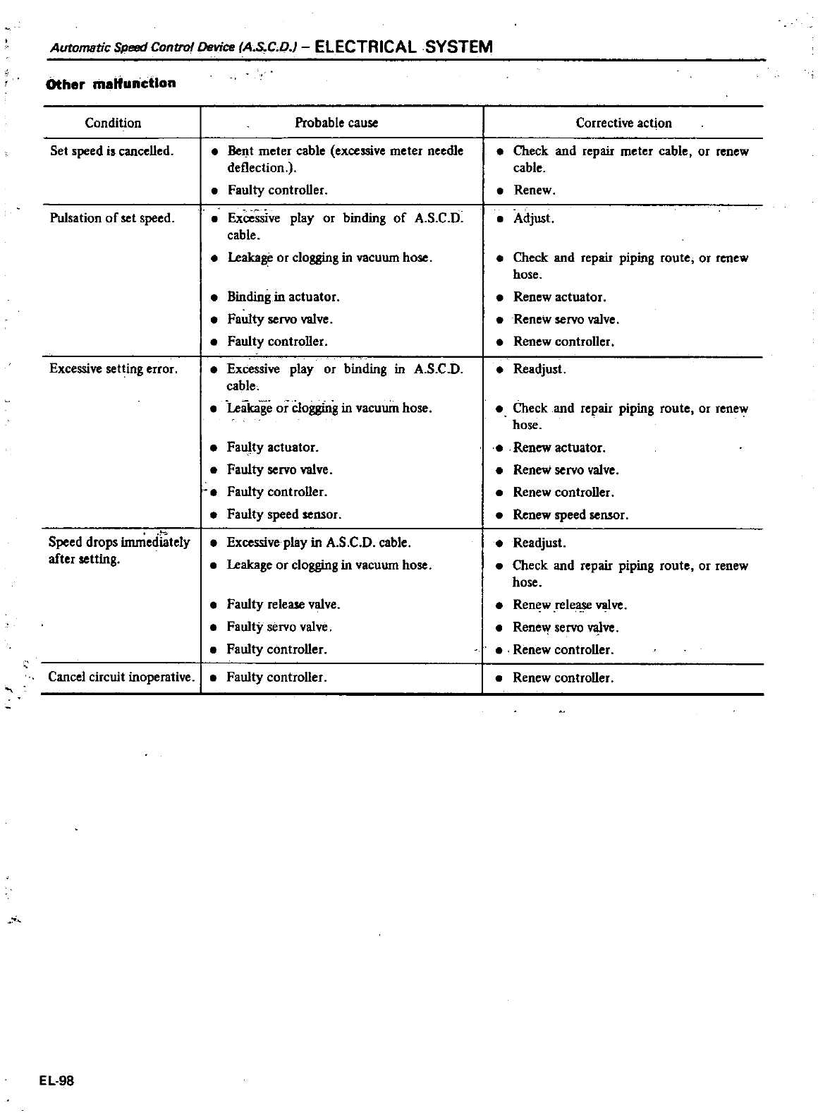
Automatic
Speed
Control
Device
A
S
C
D
ELECTRICAL
SYSTEM
Other
maHunctlon
Condition
Set
speed
is
cancelled
Pulsation
of
set
speed
Excessive
setting
error
Speed
drops
immediately
after
setting
Probable
cause
Bent
meter
cable
excessive
meter
needIe
deflection
Faulty
controller
Excessive
play
or
binding
of
A
S C
D
cable
Leakage
or
clogging
in
vacuum
hose
Binding
in
actuator
Faulty
servo
valve
Faulty
controller
Excessive
play
or
binding
in
A
s
C
D
cable
Leakage
or
clogging
in
vacuum
hose
Faulty
actuator
Faulty
servo
valve
Faulty
controller
Faulty
speed
sensor
Excessive
play
in
A
S C
D
cable
Leakage
or
clogging
in
vacuum
hose
Faulty
release
valve
Faulty
servo
valve
Faulty
controller
Cancel
circuit
inoperative
Faulty
controller
EL
98
Corrective
act
on
Check
and
repair
meter
cable
or
renew
cable
Renew
Adjust
Check
and
repair
piping
route
or
renew
hose
Renew
actuator
Renew
servo
valve
Renew
controller
Readjust
Check
and
repair
piping
route
or
renew
hose
Renew
actuator
Renew
servo
valve
Renew
controller
Renew
speed
sensor
Readjust
Check
and
repair
piping
route
or
renew
hose
Ren
w
rele
valve
Rene
y
servo
valve
Renew
controller
Renew
controller
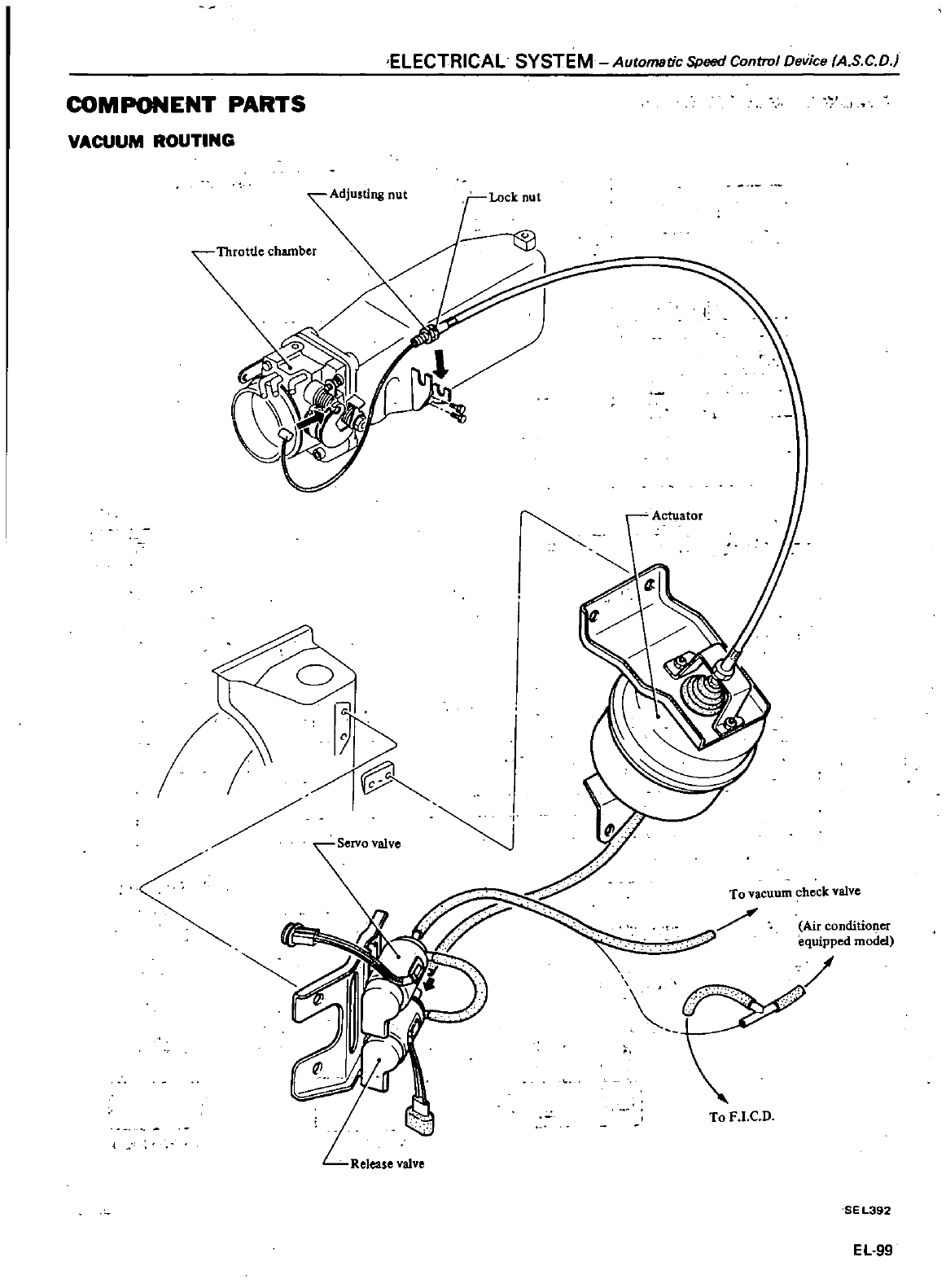
ELECTRICAL
SYSTEM
Automatic
Speed
Control
Device
A
S
C D
COMPONENT
PARTS
VACUUM
ROUTING
Adjusting
nut
Lock
nut
o
f
I
Actuator
To
vacuum
check
valVe
Air
conditioner
equipped
model
ToF
I
C D
SEL392
EL
99
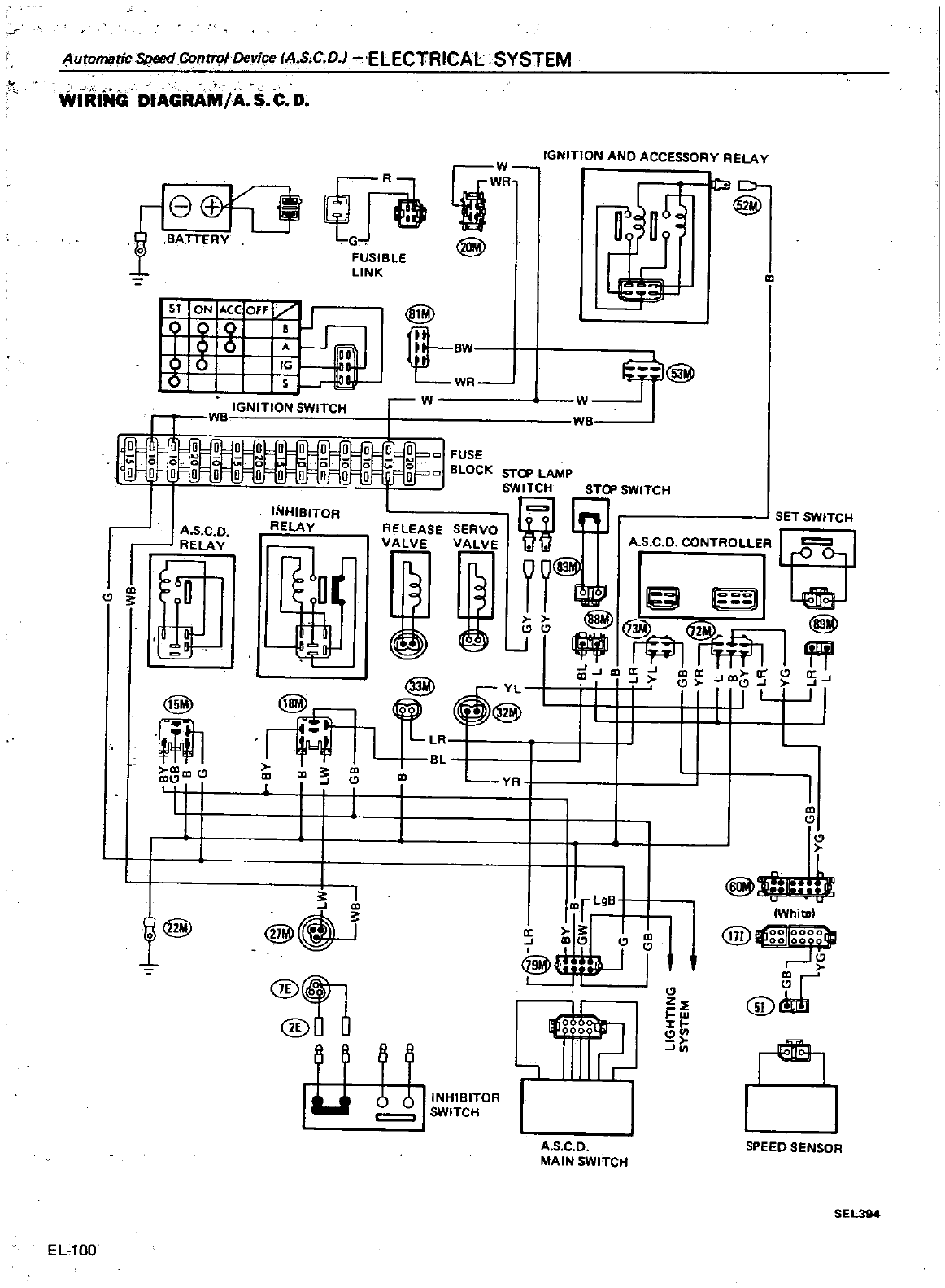
Automatic
Speed
ntrol
Device
IA
S
C
D
ELECTRICAL
SYSTEM
WiltiNG
OIAGRAM1A
S
C
O
f
TT
ffi
FUSIBLE
LINK
W
IGNITION
AND
ACCESSORY
RElAY
lJWR
r
D
t3@
@
J
1T
B
WR
5T
ON
ACC
Off
J
t
g
g
I
s
l
o
s
tf
IGNITION
TCH
r
W
we
o
0
QI
FUSE
0
BLOCK
STcp
LAMP
1
SWI
STeP SWITCH
C1
SET
SWITCH
RELEASE
SERVO
L
U
v
V
E
A
S
C
D
CONTROLLER
I
r
I
II@
jG
I
J
aJ
CD
aJ
CD
a
C
a
J
I
I
i
1
W
@
VB
A
5
C D
f
@
m
I
INHIBITOR
RELAY
@
YL
I
@
@
I
I
L
BL
1
i
m
vn
I
lOr
LgB
J
m
l@
@
iJ
1
m
J
CD
C
C
@
I
@
l
I
W
@
XI
Cl
III
11
1
0
J
A
SC
D
MAIN
SWITCH
EUOO
m
Cl
W
Whits
171
Y
@1r
I
SPEED
SENSOR
SEL3M
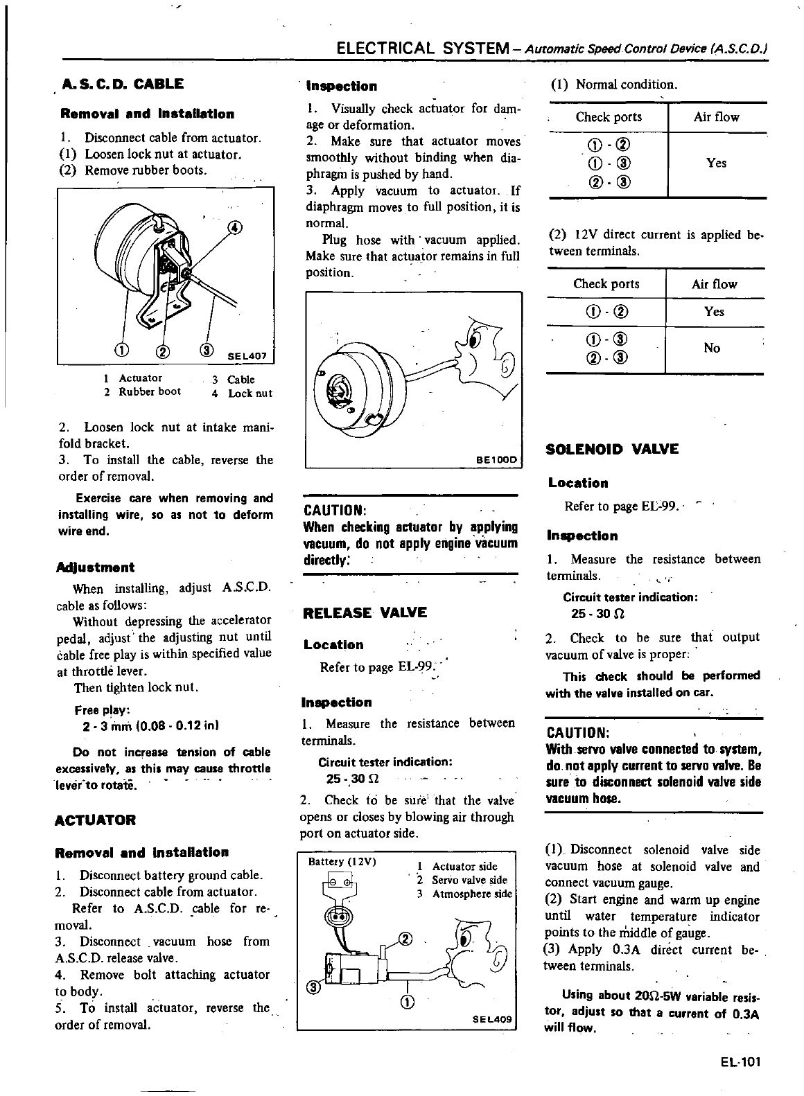
A
S
C
D
CABLE
Removal
and
Inatallatlon
I
Disconnect
cable
from
actuator
1
Loosen
lock
nut
at
actuator
2
Remove
rubber
boots
1
Actuator
2
Rubber
boot
3
Cable
4
Lock
nut
2
Loosen
lock
nut
at
intake
mani
fold
bracket
3
To
install
the
cable
reverse
the
order
of
removal
Exercise
care
when
removing
and
installing
wire
so
as
not
to
deform
wire
end
Adjustment
When
installing
adjust
A
S C
D
cable
as
follows
Without
depressing
the
accelerator
pedal
adjust
the
adjusting
nut
until
cable
free
play
is
within
specified
value
at
throttle
lever
Then
tighten
lock
nut
Free
play
23m
0
08
0
12 in
Do
not
inc
ease
tension
of
cable
excessively
as
this
may
cause
throttle
lever
to
rotate
ACTUATOR
Removal
and
Installation
I
Disconnect
battery
ground
cable
2
Disconnect
cable
from
actuator
Refer
to
A
S C
D
cable
for
reo
moval
3
Disconnect
vacuum
hose
from
A
S C
D
release
valve
4
Remove
bolt
attaching
actuator
to
body
5
To
install
actuator
reverse
the
order
of
removal
ELECTRICAL
SYSTEM
Automatic
Speed
Control
Device
AS
C
D
In
ectlon
I
Visually
check
actuator
for
dam
age
Or
deformation
2
Make
sure
that
actuator
moves
smoothly
without
binding
when
dia
phragm
is
pushed
by
hand
3
Apply
vacuum
to
actuator
If
diaphragm
moves
to
full
position
it
is
normal
Plug
hose
with
vacuum
applied
Make
sure
that
act
laJor
remains
in
full
position
BE100D
CAUTION
When
checking
actuator
by
applying
vacuum
do
not
apply
engina
vacuum
directly
RELEASE VALVE
Location
Refer
to
page
EL
99
In
ction
1
Measure
the
resistance
between
terminals
Circuit
tester
indication
25 30
n
2
Check
to
be
sure that
the
valve
opens
or
closes
by
blowing
air
through
port
on
actuator
side
Battery
12V
1
Actuator
side
2
Serio
valve
side
3
Atmosphere
side
I
CD
n
ZP
S
E
L409
I
Normal
condition
Check
ports
Airflow
CD
V
CD
@
Yes
V
@
2
12V
direct
current
is
applied
be
tween
terminals
Check
ports
Airflow
CD
V
Yes
CD
@
No
V
@
SOLENOID
VALVE
Location
Refer
to
page
EL
99
In
ctlon
1
Measure
the resistance
between
terminals
Circuit
tester
indication
25
30n
2
Check
to
be
sure
that
output
vacuum
of
valve
is
proper
This
check
should
be
performed
with
the
valve
installed
on
car
CAUTION
With
servo
valve
connected
to
system
do
not
apply
current
to
servo
valve
Be
sure
to
disconnect
solenoid
valve
sida
vacuum
hose
i
Disconnect
solenoid
valve
side
vacuum
hose
at
solenoid
valve and
connect
vacuum
gauge
2
Start
engine
and
warm
up
engine
until water
temperature
indicator
points
to
the
middle
of
gauge
3
Apply O
3A
direct
current
be
tween
tenninals
Using
about
20n
5W variable
resis
tor
adjust
so
that
a
current
of
0
3A
will
flow
EL
101
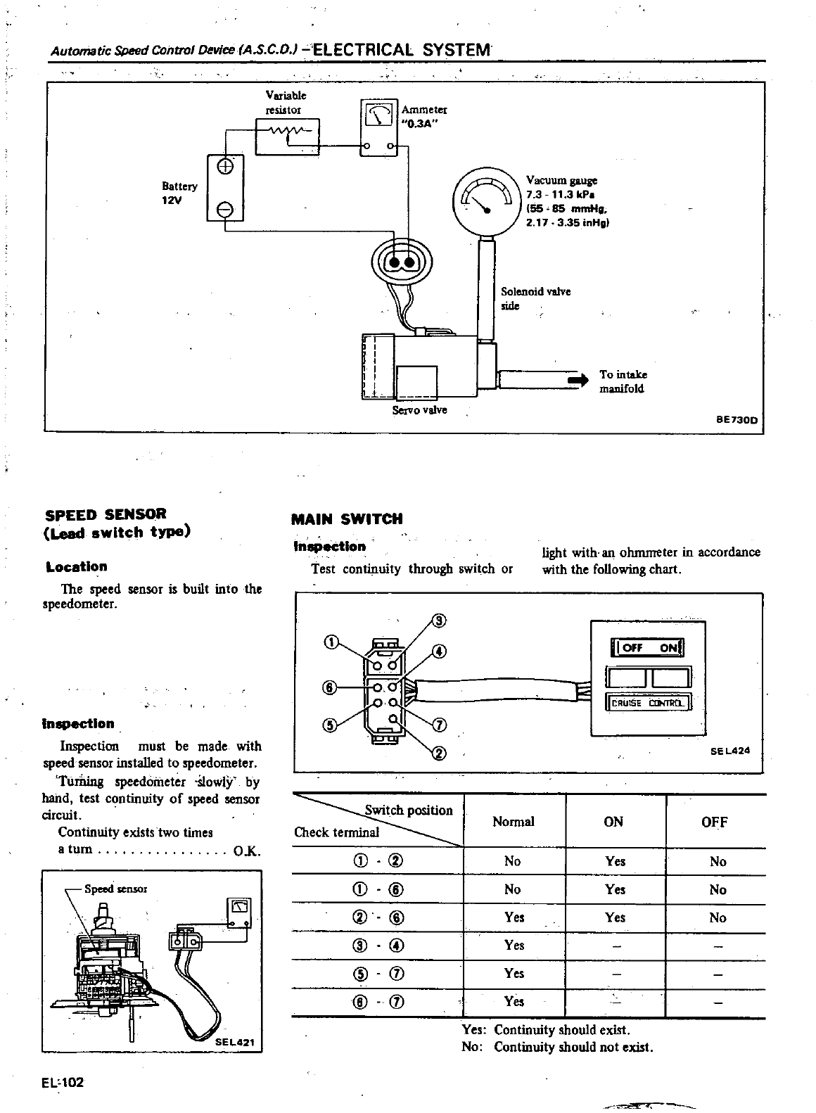
Automatic
Speed
Control
Device
AoS
C O
ELECTRICAL
SYSTEM
Variable
resistor
I I
Ammeter
O
3A
Ir
l
Battery
12V
SPEED
SENSOR
Lead
switch
type
Location
The
speed
sensor
is
built
into
the
speedometer
Inspection
Inspection
must
be
made
with
speed
sensor
installed
to
speedometer
TurDing
speedometer
SlowlY
by
hand
test
continuity
of
speed
sensor
circuit
Continuity
existstwo
times
a
turn
O
K
A
nro
9JD
EL
102
0
IlL
I
I
I
l
Servo
valve
MAIN
SWITCH
e
Yacuumgauge
1II
7
3
11
3
kP
55 85
mmHg
2
17
3
35
inHg
Solenoid
valve
side
To
intake
manifold
BE730D
Inspection
Test
continuity
through
switch
or
f
2Er
Switch
position
Check
terminal
Q
@
Q
@
@@
ID @
@
j
@
j
light
with
an
ohmmeter
in
accordance
with
the
following
chart
l
3
I
I
Off
II
lieAulSE
CIN11lfi
Il
OND
1Il1
SE
L424
Normal
ON
OFF
No
Yes
No
No
Yes
No
Yes Yes
No
Yes
Yes
Yes
Yes
Continuity
should
exist
No
Continuity
should
not
exist
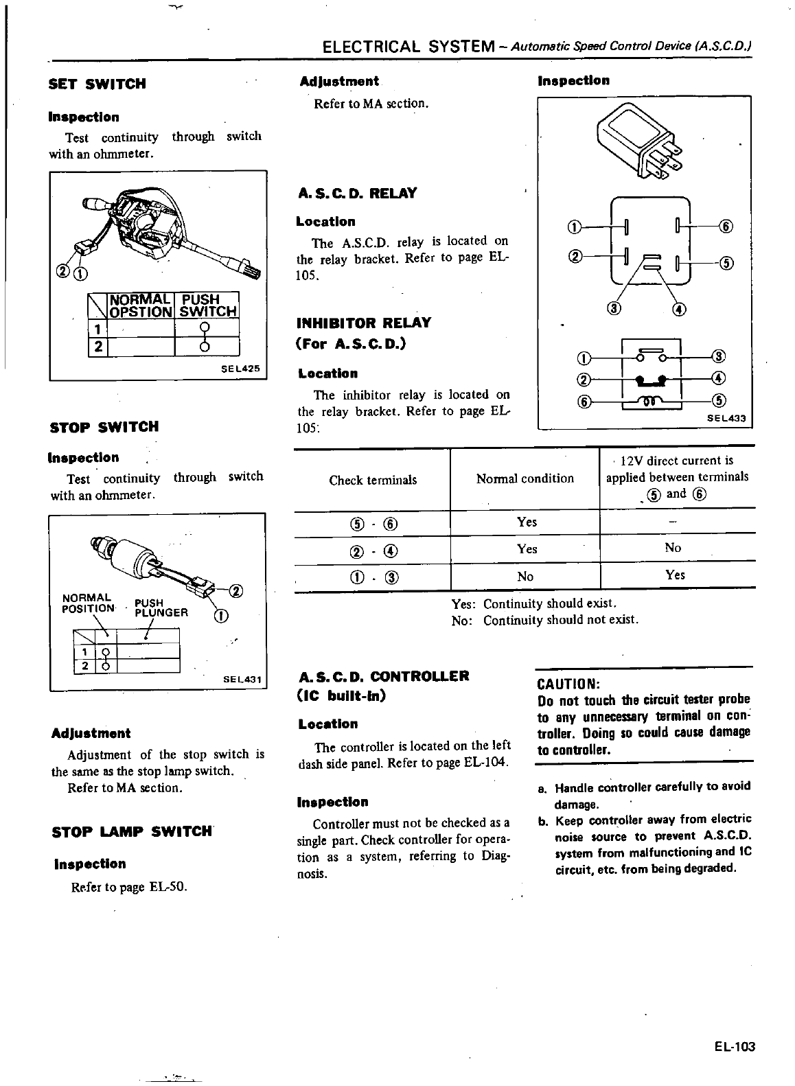
SET
SWITCH
Inspection
Test
continuity
through
switch
with
an
ohmmeter
r
NORMAL
PUSH
1
OPSTION
SWITCH
11
9
12
6
SE
L425
STOP
SWITCH
Inspection
Test
continuity
through
switch
with
an
ohmmeter
NORMAL
POSITION
f
11
9
126
@
PUSH
PLUNGER
SEL431
Adjustment
Adjustment
of
the
stop
switch
is
the
same
as
the
stop
lamp
switch
Refer
to MA
section
STOP
LAMP
SWITCH
Inspection
Rofer
to
page
El
sO
ELECTRICAL
SYSTEM
Automatic
Speed
Control
Device
AS
C
D
Adjustment
Refer
to MA
section
A
S
C
D
RELAY
Location
The
A
SC
D
relay
is
located
on
the
relay
bracket
Refer
to
page
EL
105
INHIBITOR
RELAY
For
A
S
C D
Location
The
inhibitor
relay
is
located
on
the
relay
bracket
Refer
to
page
EL
105
Inspection
a
r
c
1
@@
a
0
o
t
L
I
Gr
@
SEL433
Check
terminals
Normal
condition
l2V
direct
current
is
applied
between
terminals
@and@
@
@
CD
@
@
@
Yes
Yes
No
No
Yes
Yes
Continuity
should
exist
No
Continuity
should
not
exist
A
S
C D
CONTROLLER
lC
built
In
Location
The
controller
is
located
on
the
left
dash
side
panel
Refer
to
page
EL
I04
Inspection
Controller
must
not
be
checked
as
a
single
part
Check
controller
for
opera
tion
as
a
system
referring
to
Diag
nosis
CAUTION
Do
not
touch
the
circuit
tester
probe
to
eny
unnecessery
terminal
on
con
troller
Doing
so
could
cause
damage
to
controller
a
Handle
controller
carefully
to
avoid
damage
b
Keep
controller away
from
electric
noise
source
to
prevent
A
S
C D
system
from
malfunctioning
and
Ie
circuit
etc
from
being
degraded
EL
103
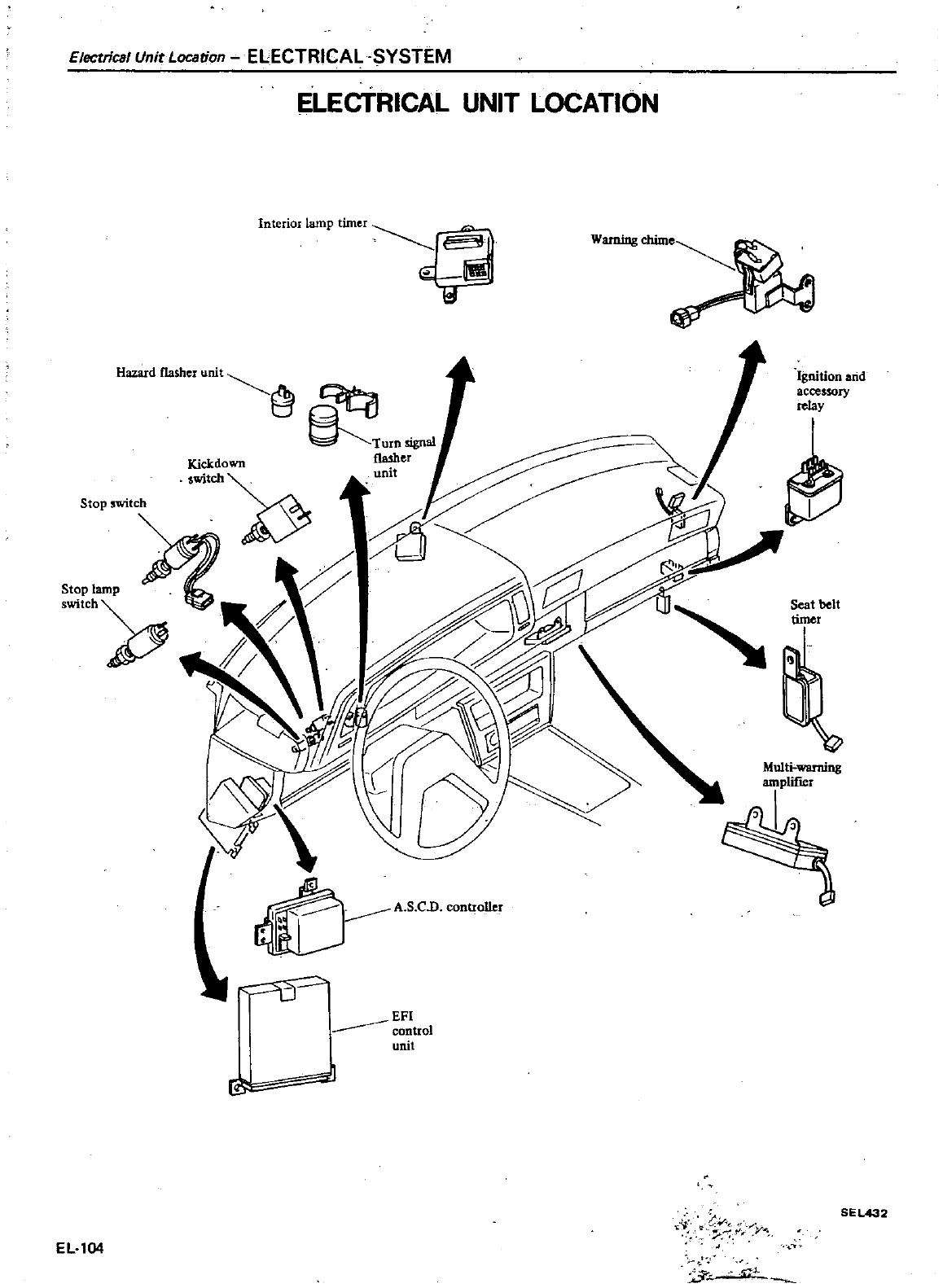
Electrical
Unit
Location
ELECTRICAL SYSTEM
ELECTRICAL
UNIT
LOCATION
Ignition
arid
accessory
relay
sea
tbelt
timer
HI
control
unit
I
to
C
v
SE
L432
EL
104
cJ
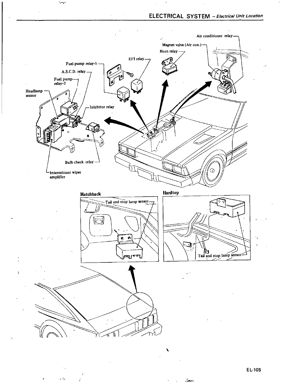
EFI
relay
relay
l
Fuel
pump
A
S
C
D
relay
III
I
@
Headlamp
sensor
Inhibitor
relay
Intermittent
wiper
amplifier
Hatchback
lamp
nso
I
Tai1
and
stop
I
Unit
Location
M
Electrlca
ELECTRICAL
SYSTE
Air
conditioner
relay
alve
Air
con
Magnet
v
H7
lardtop
114
p
sensor
Tail
nd lam
EL
105
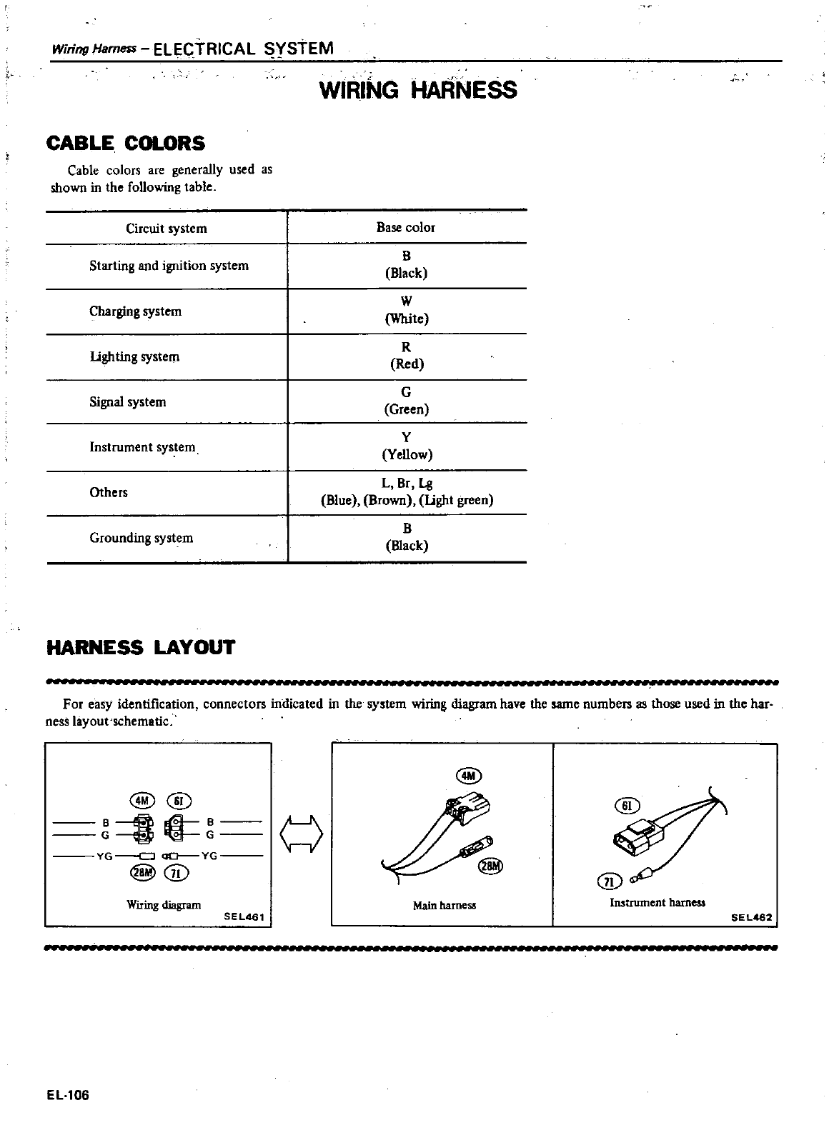
Wiring
Harness
ELECTRICAL
YStEM
WIRING
HARNESS
CABLE
COLORS
Cable
colors
are
generally
used
as
shown
in
the
following
table
Circuit
system
Base
color
Starting
and
ignition
system
B
Black
W
White
R
Red
G
Green
Y
Yellow
Charging
system
lighting
system
Signal
system
Instrument
system
Others
L
8r
Lg
Blue
Brown
light
green
B
mack
Grounding
system
HARNESS
LAYOUT
For
easy
identification
connectors
indicated
in
the
system
wiring
diagram
have
the
same
numbers
as
those
used
in
the
har
ness
layout
schematic
@
@@
I
i
YG
CJ
QO
YG
@@
w
Wiring
diagram
Main
harness
Instrument
harness
SEL461
SEL
2
EL
106
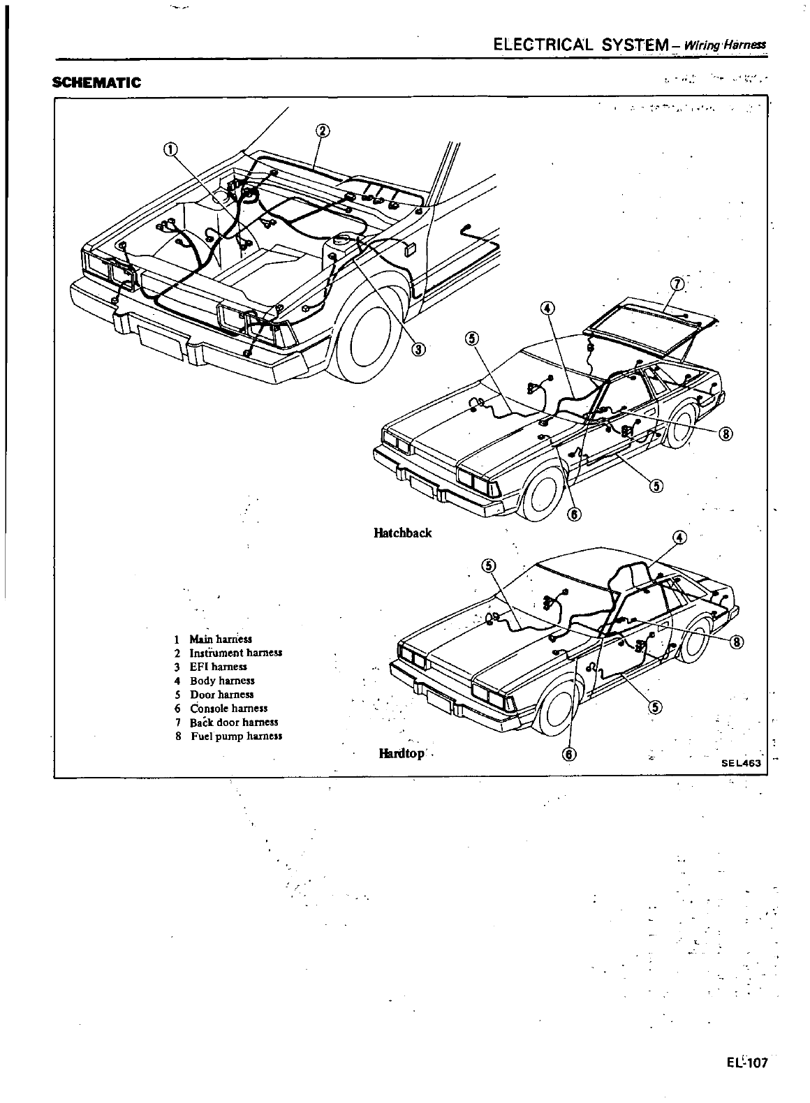
ELECTRICAL SYSTEM
WiringHBrn8S
SCHEMATIC
Hatchback
4
1
Main
harness
2
InstTumcnt
harness
3
EFI
harness
4
Body
harness
S
Door
harness
6
Console
harness
7
Back
door
harness
8
Fuel
pump
harness
SE
L463
Hardtop
EL
107
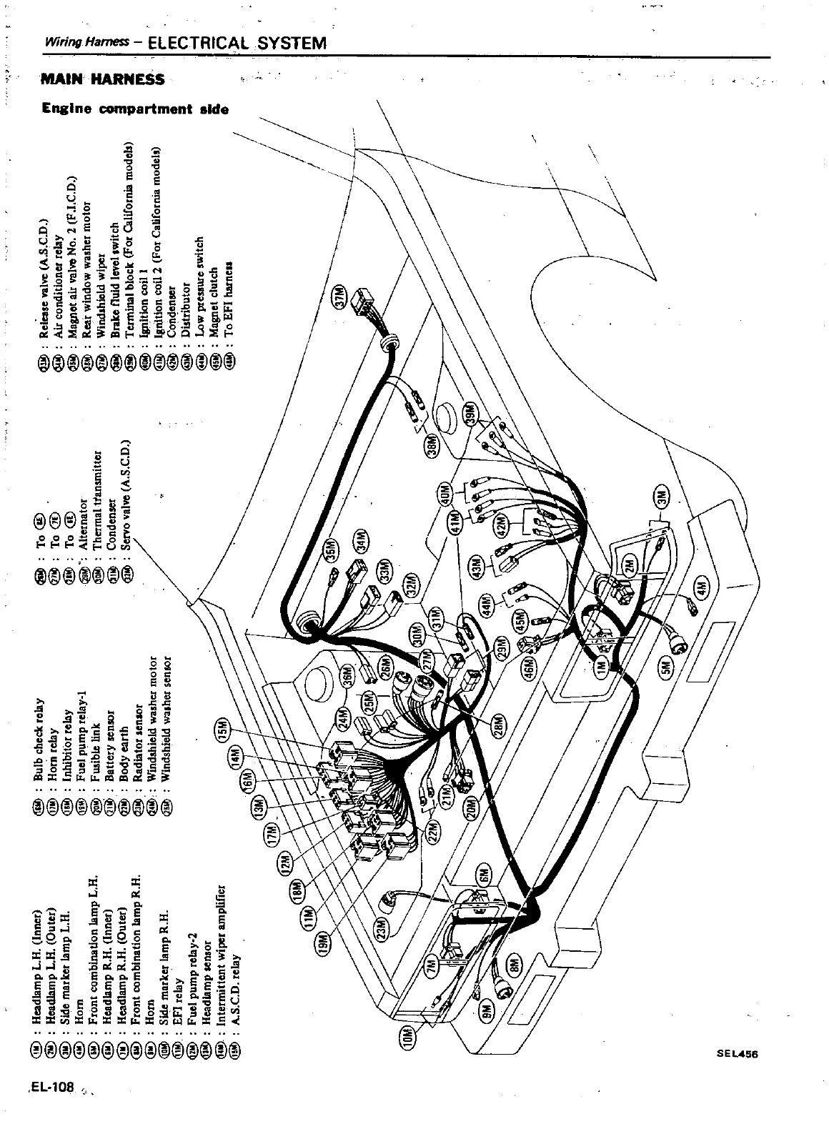
e
CO
ar
n
Il e
i
I
10
Is
ELEClf
CALS
I
SlE
tJ
ttA
RtlESS
i
g
e
0
I
0
s
e
n5
a
iio
U
6
e
Z
o
t
t
I1i
ll
tt li
iJ
s
aa
gg
9
e
5
i
S
u
11
l
ii
i
t
u
tia
eII
a
d0
i
5
t
@
@
@@
j
@@
i
u
Ii
l
s
U
@@
@
et
ooo
g
a
r
ucn
@
@
@@
g9
l
a
i
Ol
c
dod
U
1l
a
t
A
l
0o
9
a
5e
S6
ji
a
eil
eJ
d
0
a
otIS
i
pp
tt J
@@@
@
i
i
a
Po
Po
Po
aIIi e
2l
JJ
t
J
8c
4
58
Po
e
ge
q
ss
5
s
ii
s
II
PoPoal
e
i
5
1
l1
nl
gi
1
i
n
SE
@@@@@@@@@
@@@
d
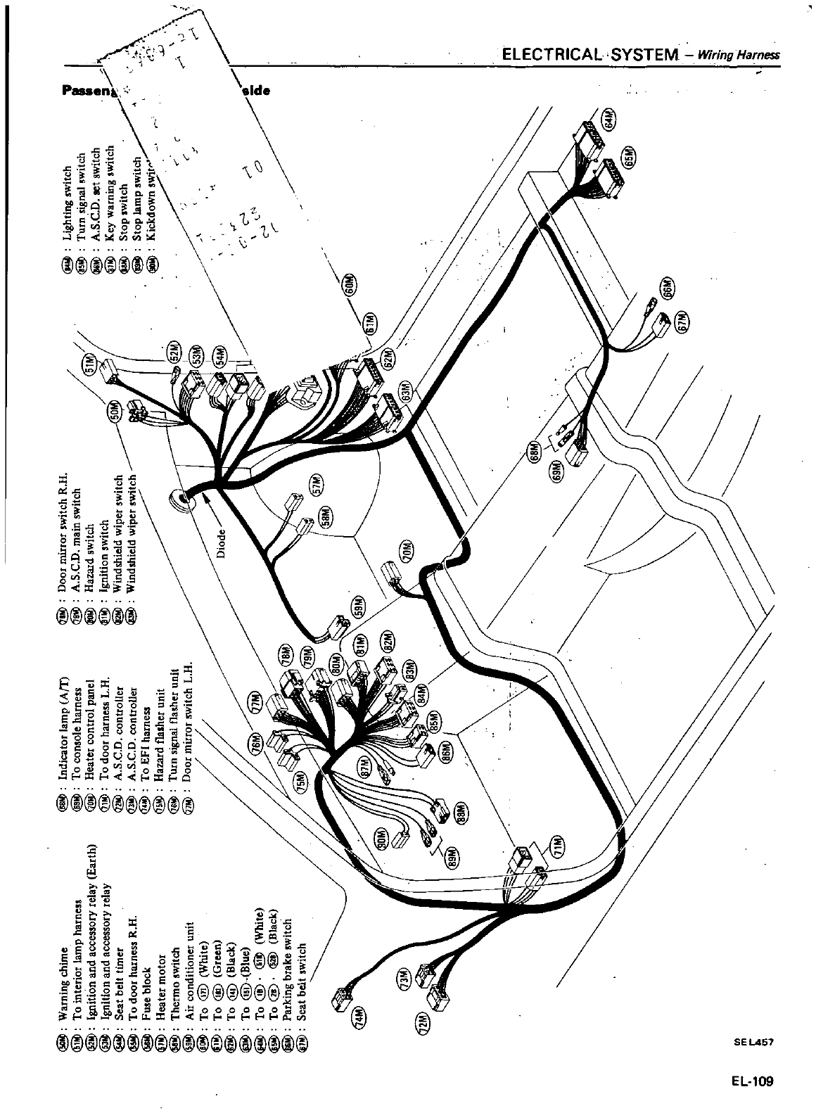
@
Warning
chime
@
To
interior
lamp
harness
Ignition
and
accessory
relay
Earth
@
Ignition
and
accessory
relay
@
Seat
belt
timer
@
To
door
harness
R
H
@
Fuse
block
@
Heater
motor
@
Thermo
switch
Air
conditioner
unit
To
@
White
To
@
Green
@
To
@
Black
@
To
@
Blue
@
To
@
@l
White
@
To
@
lID
Black
@
Parking
brake
switch
8
Seat
belt
switch
Indicator
lamp
Am
To
console
harness
@
Heater
control
panel
1Jjl
To
door
harness
L
H
@
A
S
C
D
controller
@
A
S
C
D
controller
@
To
EFI
harness
Hazard
flasher
unit
Turn
signal
flasher
unit
@
Door
mirror
5Witch
L
H
@@@
i@
@@
Door
mirror
switch
R
H
A
S
C
D
main
switch
A
Hazard
switch
r
Ignition
switch
Windshield
wiper
switch
m
r
m
n
l
0
n r
Ul Ul
l
m
s
I
5
m
if
m
3
0
CO
r
c
c
@Bl
t
@
2
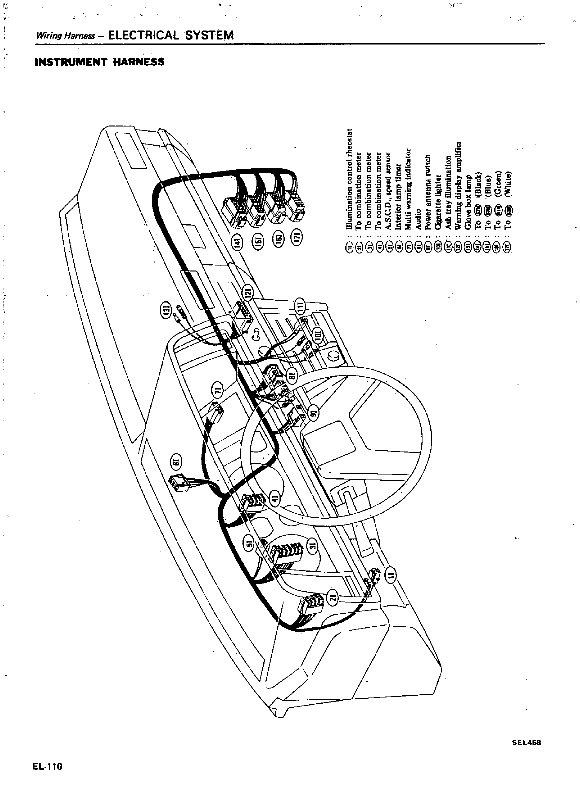
m
z
III
I
Q
C
I
I
m m
n
z
t
e
IJ
n
I
m
3
III m
I
III
@
muminadon
control
rheostat
@
To
combination
meter
@
To
combination
meter
@
To
combination
meter
@
A
S
C
D
peed
aenlOr
@
Interior
lamp
timer
@
Multi
wambtg
indicator
ID
Audio
@
Power
antenna
switch
@
garette
Ughter
@
Ash
tray
illumination
@
Wamlns
dl
pby
amplifier
@
Glove
box
lamp
@
To
@
I
Bbck
@
To
@
Blue
@
To
8
Green
@
To
@
White
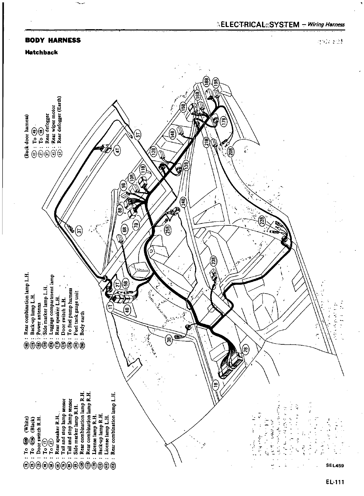
@
To
8
White
@
To
@
Black
@
Door
switch
R
n
@
To@
@
To@
@
Rear
speaker
R
H
@
Tail
and
stop
lamp
sensor
@
Tail
and
stop
lamp
sensor
@
Side
marker
lamp
R
H
@
Rear
combination
lamp
R
H
ill
Rear
combination
lamp
R
n
ill
License
lamp
R
H
@
Back
up
lamp
R
H
@
License
lamp
L
U
ill
Rear
combination
lamp
L
R
J
Tr
l
m
r
m
r
In
@
Rear
combination
lamp
L
n
@
Back
up
lamp
L
U
@
Power
antenna
ffi
Side
marker
lamp
L
R
@
Luggage
ompartment
lamp
@
Rear
speaker
L
U
@
Door
switch
L
R
@
To
fuel
pump
harness
ill
Fuel
tank
gauge
unit
@
Body
earth
Back
door
hameu
@
To@
@
To@
@
Rear
defogger
@
Rear
wiper
motor
@
Rear
defogger
Earth
f
r
rr
IIo 0
a
z
III
I
m
r
m
n
t
n r
en
CIl
l
m
3
I
S
i
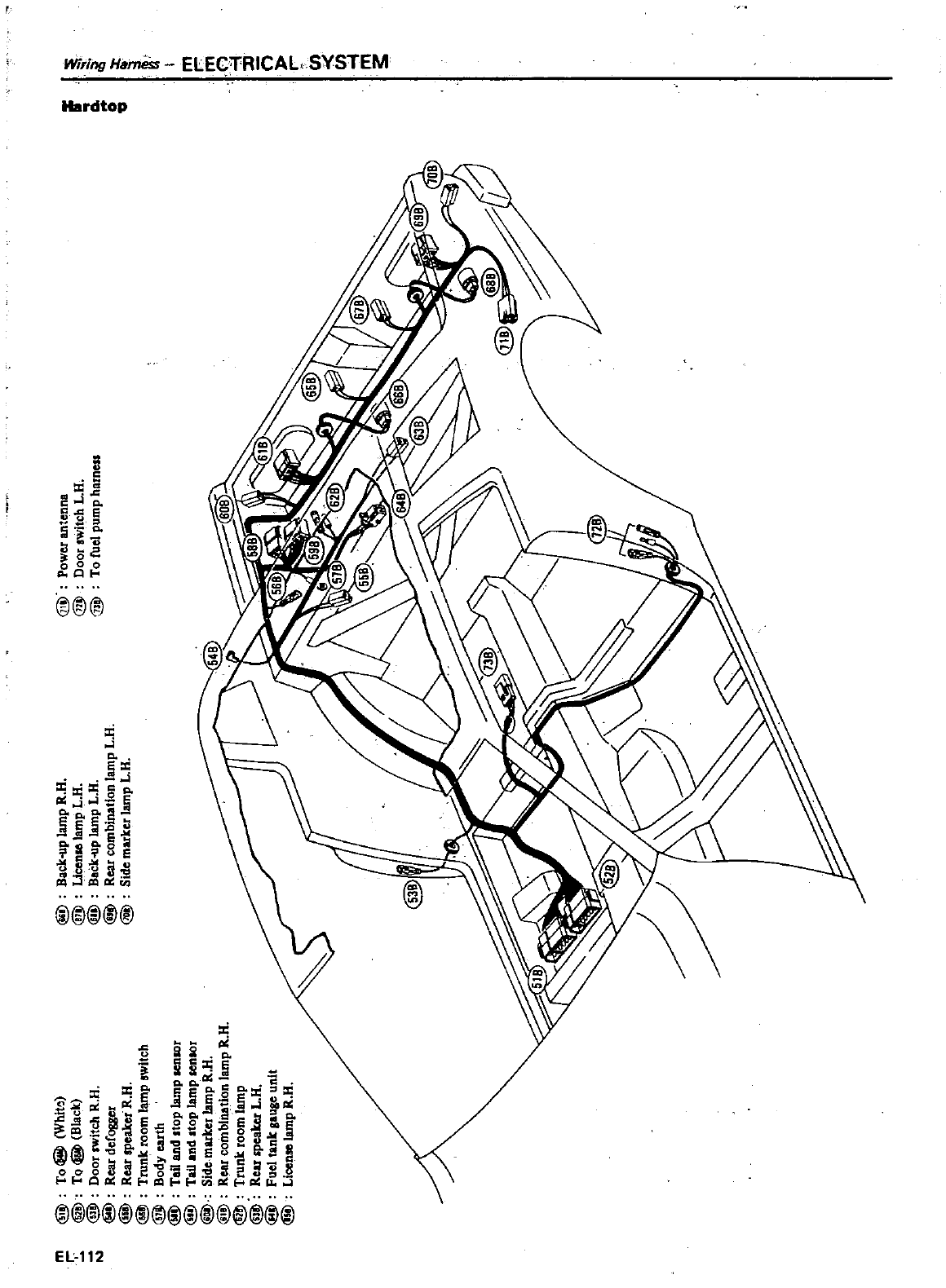
n
@1
Tol@ll
WhitO
@1
To
I@ll
Black
@
Door
switch
R
a
@
Rear
defOSller
@
Rear
speaker
R
a
@
Trunk
room
lamp
awltch
@1
Body
earth
@
Tail
and
top
lamP
aenlOr
@Y
Tail
and
atop
lamP
senIOr
@
ide
marker
lamp
R
a
@1
Rw
combbU
tlon
lamp
R
a
Trunk
room
lamP
@
lear
speaker
L
a
@
Fuel
tank
gauge
unit
@
Licon
lamP
R
a
@
Back
up
lamP
R
a
@
Licen
lampL
a
@
Back
up
lamP
L
a
@
Rear
combination
lamp
L
a
@l
Side
marker
lamp
L
a
@
power
antenna
@
Door
switch
L
a
@
To
fuel
pump
harness
f
i
o
r
1S
m
I
m
0
o
r
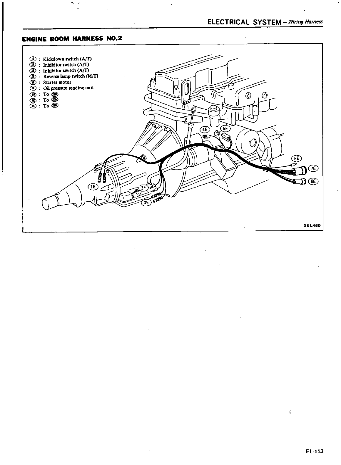
ELECTRICAL SYSTEM
Wiring
Harness
ENGINE
ROOM
HARNESS
NO
2
@
Kickdown
rwitch
Arr
@
Inhibitor
switch
Am
@
Inhibitor
rwitch
Am
@
Rever
bmp
rwitch
Mm
@
Starter
motor
@
Oil
pressUIe
sending
unit
@
To
I@
@
To@
@
To
I@
I
I
r
f
J
0
fr2
fr
@
@
11
1
II
J
@
@
@
SEL460
EL
113
4
i
j
f
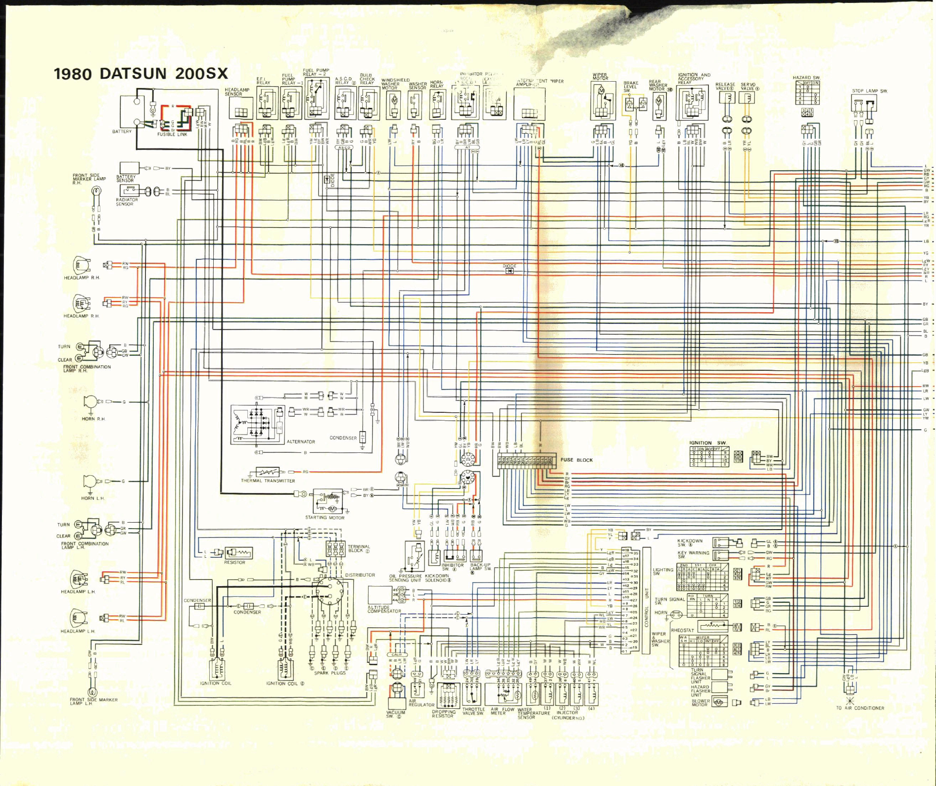
11
u
y
1I1NOlllONOO
lilY
OJ
fI1
S
J
H
MS
d
l
d01S
1
11
il
Illffil
II
SOIlYl
H
r
jJ
J
P
cJ
Q
1lO1OW
1
J1I1
01B
c
pn
all
IYH
lUtJ
lDlS
I
os
lHSV
ISOlHII
1I1
llM
1lIlIB
H
l
I
DlS
1I
1
l
11
JIt
11m
J
JlI
Cl
WHO
1H
a
I
DI
II
a
m
NIIYM
5
19
U
All
McJll
ml
3
jl
rb
m
i
j
mr
1IB1
MS
NOU1l
j
1
j
CbM
i
l3
WA
Y1UIl
1
Jt
lllONn
o
H
lIO
S
JS
llOlSl
illl
@
fill
I
f
Hf
f
l
rT
E9J
gjIjiLtLW
I
or
n
A
IIM
J
80
1
0
U
50
IIA
j
11
u
11
2
II
jj
s
EB
J
l
I
Wn
1
1
fl
lP
J
J
l
J
llr
k
l
g
Hld
YlOY
H
I
m11111nr
I
r
f
fi
IIIii
i
r
I
IB
66
l
a
EJ
III
II
o
Il
l
Wi
h
Jt
J
1
100
IlOl
fl1
1I1
NlO
l00
oo
J
L
ISIS
lI
1Lw
cP1m
J
1
f1
l
811s
lt
1
tRI
c
a
l
Inl
ii
ii
f
rWU
f
JI
1019
3sn
r
f
o
itri
IT
J
Cl
rno
I
i
i
E
tEl
9
B
8
I
r
B
n
0
I
uiI
I
o
Q
KIII
lIl
l
l
J
1
l001
lMl
bIl
l
I
M
ffi
1
I
IM
3
l
300Q
i
J
r
jf
I
H
y
1130
11
1
1
101
0111
O
A
OS
J
d
lmu
J
lOISHIOlU
1
l
cr
III
II
II
I
I
n
i
fill
i
i
Jl
1
CD
i
Cl
J
S
I
lIllII
l
J
18
l@
ll
tP
ftj
ll
iiJB
II
lmalJlJ
Ui
JndWV
rl
ll
NmSY
l
I
H
M
A
I
UlI
Avll11
l
AY
31
A
f
31
n
1
XSOOZ
NnSJ
va
086L
11
tlOII
M
Blntl
z
Av1
1
I
11n1
dwnd
nn
Ullll
flJ
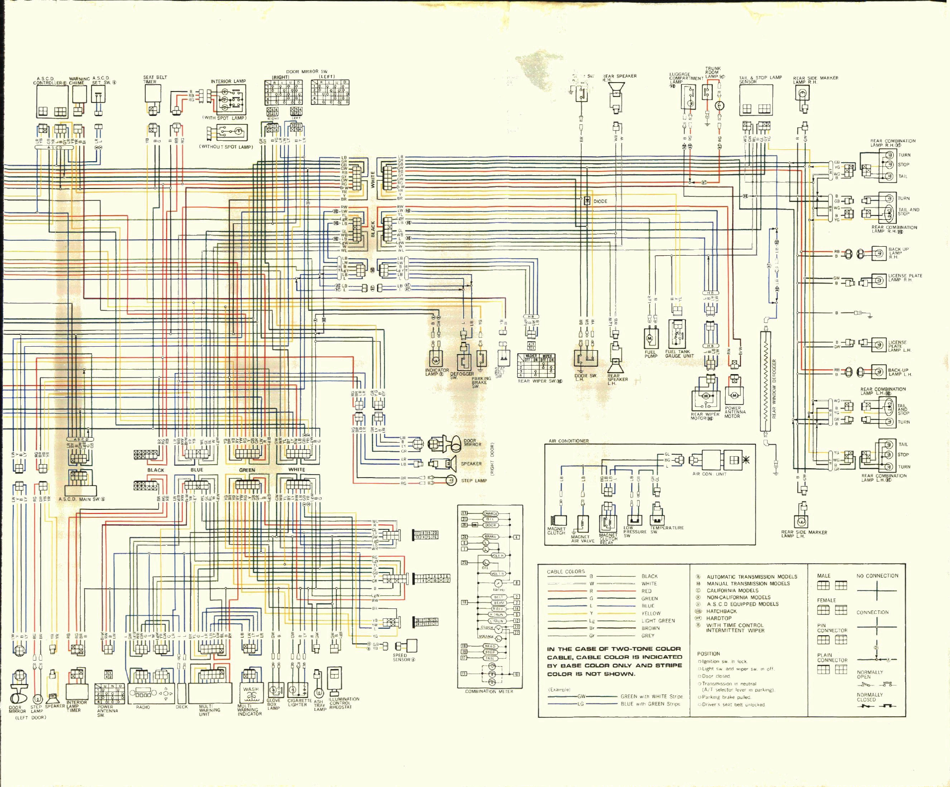
ASCD
WARNING
A
SC
D
Q
W
11ffll11iiill
err
G
IT
In
rr
iE
1
iiiffll
i11
J
WllHD
I
WITHOUT
SPOT
LA
t
lPl
Il
I
I
r91
li
I
II
GB GB
ow
GW
R8
B
GGY
cw
i
GW
FIG
R
BR BR
JI
I
t
I
I
I I
L
I
I
1
J
l
I
I
r
t
oio
I
I
II
t
H
II
lffiJlW
flBl
I
I
I
I
I
AS
C
O
MAIN
SW
I
UYijj
C5
Iii
2W
fOR
5
i
p
SPEA
ER
t
rR
r
E
NA
lLtH
DOOR
SW
I
WI
I
R
lW
W
If
YL
YL
R8
Jll
i
B
LB
1I1
Cl
Gl
we
i
WB
L8
llll
W
W
Ji
L
Ii
B
ril
i
@
ll
B
B
H
l
8
0
B
l
11
u
eo
I
II
L
l
1
I
IP
II
I
1
I
t
I
H
n
Ioo
l
o
AKE
I
T
II
1
I
I
@
fflllWl
il
I
B
sPEAKEII
Z
B
c
STEP
LAMP
t
I
t
l
l
I
i I Ii
1
UJlm
m
1l1lmr
J1
I
II
I
lM litni
BLACK
BLUE
Gfl
EEN
WHITE
jIN
I
I
M1
l
ffiill
llm
fll
Ii
W
if
jft
re
IHEffiHm
I
C
l
1l
l
j
1
liIAI
IW
I
n
11
L
JEl
L
J
W
L
1
I
IlffiM
II
l t
p
ESl
W
B
o
U
i
ll
DECK
NG NG
P
LfGf
m
p
Jre
T
UNIT
INDICATOII
0
l
J
tK
0
r
@
1
@
COMBIN
TlN
llER
RAOIO
J
d
A
REAli
WIPER
SW
U
S
lE
RSPE
ER
i
S
ill
TIIUNK
LUGGAGE
ROOM
fi
C
i
y
I
ffl
i
glJ
I
L
1
mE
Ho
a
sw
AIRCONDITIQNEIl
II
I
I
i
fB1
fUEL
FUEL
TANK
i
f
PUMP GAUGE
ulm
W
ld
J
REAR
SPEAKEII
1
a
11
G
a
G
BLACK
WHITE
co
GREEN
BLUE
YELLOW
LIGHT
GREEN
BROWN
GREY
IN
THE
CASE
OF
TWO
TONE
COLOR
CABLE
CABLE
COLOR
IS
INDICATED
BY
BASE
COLOR
ONLY
AND
STRIPE
COLOR
IS
NOT
SHOWN
GREEN
w
t
WHITE
SI
BlU Wl n
GREEN
Sl
p
REAR
WIPER
I
NTfNNA
MOTORlIl
MOTOR
AUTOMATIC
TRANSMISSION
MQDELS
4
MANUAL
TRANSMISSION
MODELS
@
CALIFORNIA
MODELS
@
NON
CALlFORNIA
MODELS
i
A
SeD
EQUIPPED
MODELS
HATCHBACK
l
i
HARDTOP
WITH
TIME CONTROL
INTERMITTENT
WIPER
POSIT
ON
Qlg
IO
lSwmlocK
L
ghl
w
an
per
sw
0000
Io
e
l
C
r
on
n
neut
al
lA
r
110
lever
n
pa
k
l
P
I
krngD
akepullea
O
ver
Io
lal
l
unlocked
n
Y
mot
o
8
z
IIEAIl
SIDE
MARKEll
tAMP
LH
R
AR
SIDE
MARKEll
i
REAR
COMBINATION
M
STOP
iW9G
P
TAil
TAIL AND
STOP
II
AR
COMBINATION
AMP
II
HlJ
hrt
l
ror
lJ
EB
1
ii
l
@
II
M
1
m
ClUTCHm
PFlESSUIIESW
MAGNET
MAGNET
SW
Alii
VALVE
lS
H
j
CABLE
COlORS
mple
GW
0
u
I
I
I
I
I
a
G
m
e
BACKUP
lAM
GW
LICENSEPlAn
9
cea
LAMPIIH
h
lICENS
wT
PLATE
LAMP
LH
9o
BACIl
UP
Q
LAMPLH
IfI
B
e3
jJ
IIEARCOMBINATlON
q
M
L
STOP
TURN
lJ
y
STOP
we
TURN
REAR
COMBINATION
lAMP
LH
l
MALE NO
CONNECTION
ttBEtE
t
FEMALE
rnHm
CONNECTION
I
CONNECTOR
ttBffiI
J
PLAIN
1
CONNECTOR
ttBtm
NORMALLY
OPEN
0
NORMALLY
CLOSED
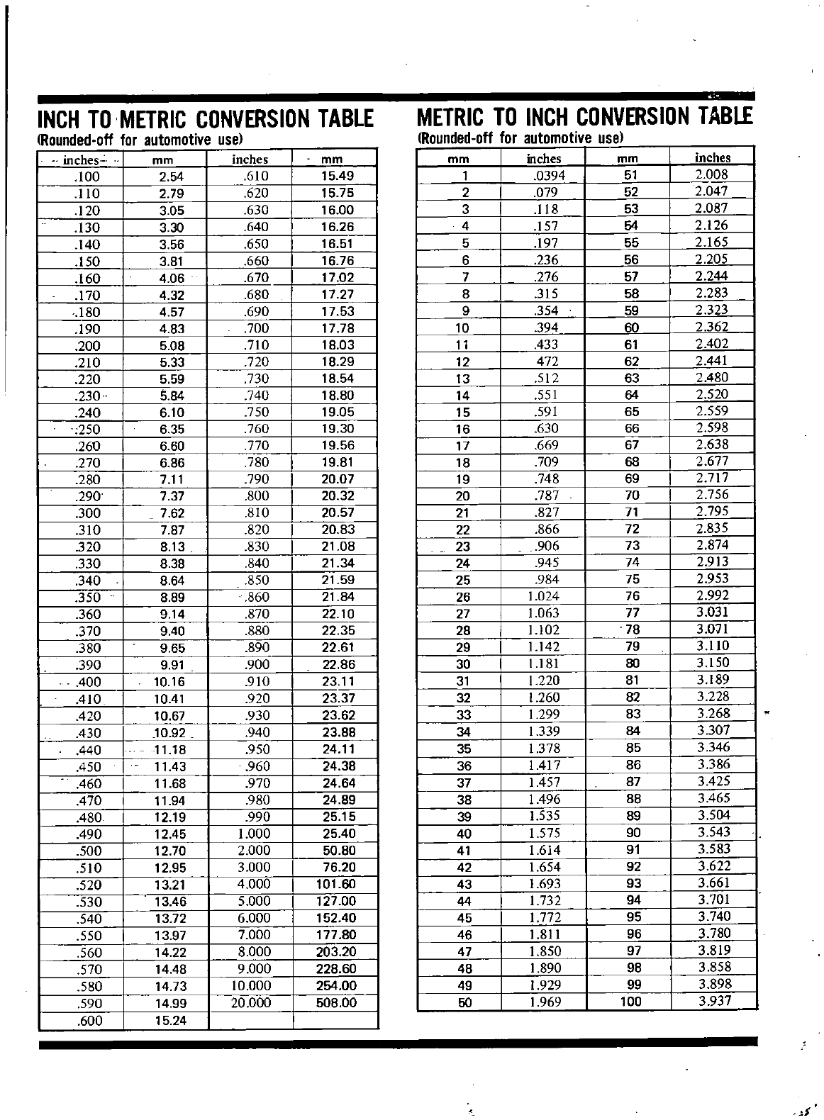
INCH
TO
METRIC
CONVERSION
TABLE
METRIC
TO
INCH
CONVERSION
TABLE
Rounded
of
for
automotivo
use
Rounded
off
for
automotive
use
I
inches
mm
inches
mm mm
inches
mm
inches
100
254
610
1549
1
0394
51
2
008
I
110
279
620
15
75
2
079
52
2
047
I
120
3
05
630
16
00
3
118
53
2
087
I
130
3 30
640
16 26
4
157
54
2
126
I
140
3
56
650
16
51
5
197
55
2
165
150
3
81
660
16
76
6
236
56
2
205
160
4
06 670
17
02
7
276
57
2
244
170
4
32
680
17
27
8
315
58
2
283
180
4
57
690
17
53
9
354
59
2
323
190
4
83
700
17
78
10
394
60
2
362
200
5
08
710
18
03
11
433
61
2
402
210
533
720
18
29
12
472
62
2
441
220
559
730
18
54
13
512
63
2
480
230
5
84
740
18 80
14
551
64
2
520
240
6 10
750
19
05
15
591
65
2
559
250
6 35
760
19
30 16
630
66
2
598
260
6 60
770
19
56
17
669
67
2
638
270
6
86
780
19 81
18
709
68
2
677
280
711
790
20
07
19
748
69
2
717
290
7 37
800
20 32 20
787
70
2
756
300
7 62
810
20
21
827
71 2
795
310
7
87
820 20 83
22
866
72
2
835
320
8 13
830
21
08
23
906
73
2
874
330
8
38
840
21
34 24
945
74
2
913
340
8
64
850
21
59
25
984
75
2
953
350
8
89
860
21
84 26
1
024
76
2
992
360
914
870
22 10
27
1
063
77
3
031
370
9
40
880
22
35
28
1
102
78
3
071
380
9
65
890
22
61
29
1
142
79
3
110
I
390
9
91
900
22
86
30
1
181
80
3
150
I
400
10 16
910 23
11
31
1
220
81
3
189
410
1041
920 23 37 32
1
260
82
3
228
420
10 67
930
23
62 33
1
299
83
3
268
I
430
10
92
940
23
88 34
1339
84
3
307
f
440
1118
950
24
11
35
1
378
85
3
346
450
1143
960
24 38 36
1417
86
3
386
I
460
11
68 970 24 64 37
1457
87
3
425
I
470
11
94 980 24 89 38
1496
88
3465
480
12 19
990
25 15 39
1
535
89
3
504
490
1245
1
000
25
40 40
1
575
90
3
543
500
12
70
2
000
50 80
41
1
614
91 3
583
510
12
95
3
000
76 20 42
1
654
92
3
622
520
13
21 4
000
101
60
43
1
693
93
3
661
530 13
46
5
000
127
00
44
1732
94
3
701
540
13
72
6
000
152
40
45
1
772
95
3
740
550
13 97
7
000
177
80
46
1
811
96
3
780
560
14 22
8
000
203
20 47
1
850
97
3
819
570
1448
9
000
228
60
48 1
890
98
3
858
580
14
73
10
000
254
00
49
1
929
99
3
898
590
14
99
20
000
508
00
50
1
969
100
3
937
600
15 24
I
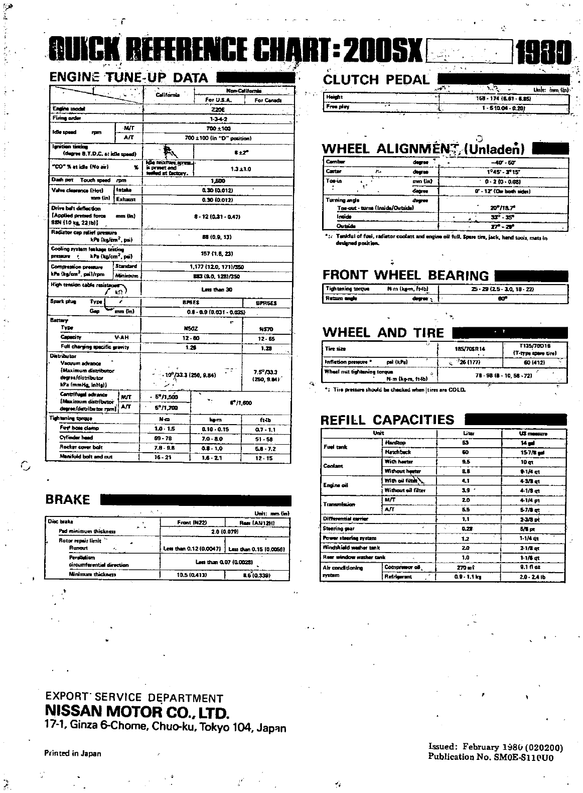
f
DUICK
RIHHINCICHJtHI
2DDSlf
ENGINE
TUNE
UP
DATA
CLUTCH
PEDAL
r
FIrinaDnin
IM
T
I
Arr
Cdow
8
T
Dc at
idle
SpIted
CO
ilh
l
lo
topot
ToudllPftd
rpcn
IV
HOd
Jlfttd
Iud
E
tggn
lom
bII
IApplitd
pnMd
fora
mm
1m
98NHO
2tlbn
IfUdiItoraprtlilfpnslUn
kPl
kJfcm2
p
siJ
CooIi
IYIIlM
btt
uSting
p
f
alll
fcm
l
plil
Com ls
kr
lktfcrta
l1l
illrpm
I
Minilmnn
t
H
hMioftc
lb
llrei
I
ill
1
T
L
I
G
p
Innlfrnl
T
C
it
V
AH
f
ull
P
dfil
fY
Dinributor
V
Ilh
Muilllumdlltrit
tllr
lldl
tributDr
IlF
tnlfllHa
lnH
1l
I
l
i
diA
r
bU1of
6iftJIt
tgr
l
JIIl
Ij
AfT
r
dMIp
Of
itod
t
s
fl
lMktr
baIt
MilnifuldbahMldnut
J
BRAKE
0
P
lIlini
lUlIlthi
kn
RotCll
I
W
rlimit
R
jllnl
tircumter
u
l
dncUon
Ml
CIlircitnm
t
I
8IId
dlXD
n
5
J1
sOO
50
1
7OQ
10 15
Tll
1 8
9
11
16
21
Noft
CIIihdII
ForU
s
A
I
forc
adl
Z2llE
34
2
700
1
103
1OO
tl00
lin
D
pclIitionl
11
1
1 0
o
JOIo
012
0
3Ol0
0121
8
12
Cl
Jl
Q
41J
IICO
8
12
151
18
231
1
1nl12
0
171tl35O
11319
0
1281
J50
BPfiU
I
O
o
9IU31
0
Q3SI
12
m
1
21
10
31
1
250
9
o
0
10
0
15
1
0
0
0
0
1
4
21
1
2
S1O
12
65
1
7
5
1
33
3
1250
9
rl1
600
0
7
1
1
Sl Y
5
8
7
2
11 15
Unit
lIImlilt
R
1AHl1tn
I
2
010
0711
lLeath
lO 2Io
OCM7J
1
Leadl
lO
S
O
OO59I
1
F
tNZ2
m
Q
07
Q
OClZll
10
51D
4111
U
lo
338
EXPORT
SERVICE
DEPARTMENT
NISSAN
MOTOR
CO
LTD
17
1
Ginza
6
Chome
Chuo
ku
Tokyo
104
Jap
Printed
in
Japan
t
J
pq
119BI
1
Unit
lin
161
174
1e
81
e
1SJ
l
S
ta
OiI
a
2D
I
WHEEL
ALlGNMEN
U
Iaden
I
I
I
10
S
rlS
Tot
in
IlMPUnJ
0
2
O
o
osl
deQne
rr
lZ
Cet
blMhlidil
ll
Tuming
81
T
twN
umidIl
o
rt
lidlJ
h
m
11
w
1
T
ruIOr
full
adiIT
o
cDatam
qinlail
fuP
SptN
tn
PeSo
tault
INts
In
dn
rillllfpOlh
I
l
J
I
Ti
tnringflXqUl
R
N
mU
ftlb
FRONT
WHEEL BEARING
25
zg12
5
10
18
l21
er1
WHEEL
AND
TIRE
ITireW
nfl
tionp
N
pIlCk
Wh
1
tilillaoin
1arqut
N
mllt
m
tHbl
Ti
prtdIlN
Ihould
tit
dJlckld
wtIm
tlm
COLD
REFilL
CAPACITIES
I
I
F
tlnk
I
Wid
Mftg
Coobn
IWi
Wlltllllil
jWi1tlou1011fliter
1
EJ9rw
oil
TmMlIlllMott
IDi
Iswring
I
ryrum
I
Windl
lli
tdWllh
1Ift1t
IR
llftlblrtlnk
Aw
candtllllling
I
c
xn
w
rfdam
I
R
lS511OSR14
Tl35J7oo16
IT
1f1III
i
tiN
601412
annl
711 98
1
10
58 72
I
us
1
53
1
71
I
l5
fqt
19
l1qt
4
p
56
7
1qt
1 1
611
12
l
1J4qt
2
1
1q
1
111qt
lflOl
o
lI
1
1tq 2
0
2
4lb
Issued
February
1
811
020200
Publication
No
SMOE
Bll
UO
