Nissan 1997 Pathfinder Owners Manual 13 Dec 1991. OWNER'
1997-Nissan-Pathfinder 1997-Nissan-Pathfinder
2015-09-07
: Nissan Nissan-1997-Pathfinder-Owners-Manual-762789 nissan-1997-pathfinder-owners-manual-762789 nissan pdf
Open the PDF directly: View PDF  .
.
Page Count: 233 [warning: Documents this large are best viewed by clicking the View PDF Link!]
Foreword
Welcome to the growing family of new NISSAN owners. This vehicle has been delivered to you with confidence. Your vehicle has been produced
using the latest techniques and strict quality control.
This manual has been prepared to help you understand the operation and maintenance of your vehicle so that you may enjoy many miles of driving
pleasure. Please read through this manual before operating your vehicle.
A separate Warranty Information and Maintenance Log Booklet explains details about the warranties covering your vehicle and vehicle maintenance
schedules.
Your NISSAN dealer knows your vehicle best. When you require any service or have any questions, he will be glad to assist you with the extensive
resources available to him.
IMPORTANT SAFETY INFORMATION
REMINDERS FOR SAFETY!
Follow these five important driving rules to help ensure a safe
and complete trip for you and your passengers!
INEVER drive under the influence of alcohol or drugs.
IALWAYS observe posted speed limits and never drive too
fast for conditions.
IALWAYS use your seat belts and appropriate child re-
straint systems.
IALWAYS provide information about the proper use of
vehicle safety features to all occupants of the vehicle.
IALWAYS review this Owner’s Manual for important safety
information.
NOTES ON THE INFORMATION CONTAINED IN THIS
OWNER’S MANUAL
This owner’s manual contains descriptions and operating instruc-
tions for all systems, features and optional equipment that might
appear in any model of this vehicle built for any destination in
North America, including the continental United States, Canada
and Hawaii. Therefore, you may very well find information in this
manual that does not apply to your vehicle.
For descriptions specified for 4-wheel drive models, a mark is
placed at the beginning of the applicable sections/items.
ON-PAVEMENT AND OFF-ROAD DRIVING
This vehicle will handle and maneuver differently from an
ordinary passenger car, because it has a higher center of
gravity for off-road use. As with other vehicles with features of
this type, failure to operate this vehicle correctly may result in
loss of control or an accident.
Be sure to read “On-Pavement and Off-Road driving precau-
tions” and “Avoiding collision and rollover” in the “Starting and
driving” section of this manual.
Z01.2.1/R50-D X
MODIFICATION OF YOUR VEHICLE
This vehicle should not be modified. Modification could affect
its performance, safety or durability, and may even violate
governmental regulations. In addition, damage or performance
problems resulting from modification may not be covered under
NISSAN warranties.
All information, specifications and illustrations in this manual are those
in effect at the time of printing. NISSAN reserves the right to change
specifications or design without notice and without obligation.
IMPORTANT INFORMATION ABOUT THIS MANUAL
You will see various symbols in this manual. They are used in the
following ways:
This is used to indicate the presence of a hazard that could
cause death or serious personal injury. To avoid or reduce
the risk, the procedures must be followed precisely.
This is used to indicate the presence of a hazard that could
cause minor or moderate personal injury or damage to
your vehicle. To avoid or reduce the risk, the procedures
must be followed carefully.
If you see this symbol, it means “Do not do this” or “Do not let this
happen”.
© 1996 NISSAN MOTOR CO., LTD.
TOKYO, JAPAN
All rights reserved. No part of this Owner’s Manual may be reproduced or stored in a
retrieval system, or transmitted in any form, or by any means, electronic, mechanical,
photocopying, recording or otherwise, without the prior written permission of Nissan
Motor Co., Ltd.
SIC0697
Z01.2.1/R50-D X
Welcome To The World Of NISSAN
Your new Nissan is the result of our dedication to
produce the finest in safe, reliable and economi-
cal transportation. Your vehicle is the product of
a successful worldwide company that manufac-
tures cars and trucks in over 17 countries and
distributes them in 170 nations.
Nissan vehicles are designed and manufactured
by Nissan Motor Co., Ltd. which was founded in
Tokyo, Japan in 1933, and Nissan affiliates world
wide, collectively growing to become the fifth
largest automaker in the world. In addition to cars
and trucks, Nissan also makes textile machinery,
fork-lift trucks, marine engines, boats and other
products.
Nissan has made a substantial and growing
investment in North America, starting with the
opening of Nissan Motor Corporation U.S.A. in
1960 and continuing with the production of some
cars and trucks at one of the world’s most
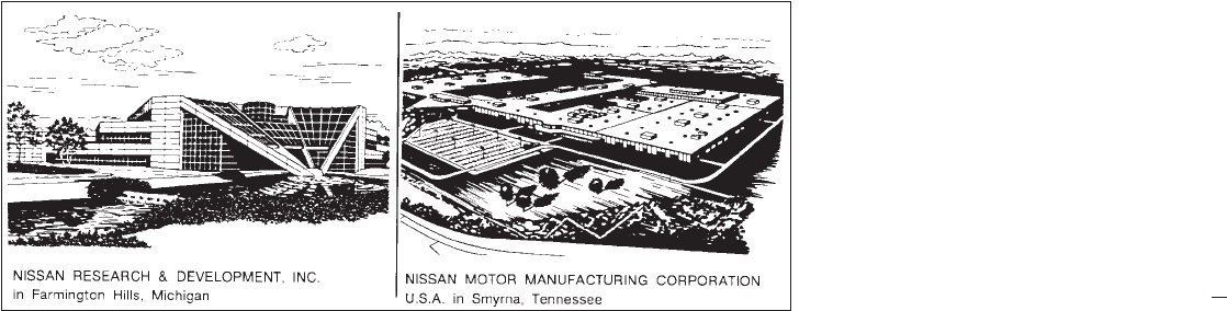
modern manufacturing facilities, Nissan Motor
Manufacturing Corporation U.S.A. in Smyrna,
Tennessee, vehicle styling at Nissan Design
International in San Diego, California, and engi-
neering at Nissan Research and Development in
Farmington Hills, Michigan.
Nissan Motor Corporation U.S.A. and its dealers
indirectly employ about 60,000 Americans.
Nissan is also a substantial contributor to the
Canadian economy. Nissan Canada Inc., its sup-
pliers and over 170 dealers employ approxi-
mately 4,500 people. These include company
employees and the staffs of Nissan dealers all
across Canada. In addition, many Canadians
work for companies that supply Nissan and
Nissan dealers with materials and services rang-
ing from operation of port facilities and transpor-
tation services, to the supply of lubricants, parts
and accessories.
Nissan pioneered the use of electronics and
computers in automobiles, and has led the indus-
try in improving both performance and fuel effi-
ciency through new engine designs and the use
of synthetic materials to reduce vehicle weight.
The company has also developed ways to build
quality into its vehicles at each stage of the
production process, both through extensive use
of automation and — most importantly —
through an awareness that people are the cen-
tral element in quality control.
From the time the parts arrived from our suppli-
ers until you took delivery of your new Nissan,
dozens of checks were made to ensure that only
the best job was being done in producing and
delivering your vehicle. Nissan also takes great
care to ensure that when you take your Nissan to
your dealer for maintenance, the service techni-
cian will perform his work according to the quality
standards that have been established by the
factory.
Safety has also been built into your Nissan. As
you know, seat belts are an integral part of the
safety systems that will help protect you and your
passengers in the event of a sudden stop or an
accident. We urge you to use the belts every time
you drive the vehicle.
The Nissan story of growth and achievement
reflects our major goal: to provide you, our
customer, with a vehicle that is built with quality
and craftsmanship — a product that we can be
proud to build and you can be proud to own.
AFW0001
Z01.2.1/R50-D X

NISSAN CUSTOMER CARE PROGRAM
NISSAN CARES ...
Both NISSAN and your NISSAN dealer are dedicated to serving all your automotive needs. Your satisfaction with your
vehicle and your NISSAN dealer are our primary concerns. Your NISSAN dealer is always available to assist you with all
your automobile sales and service needs.
However, if there is something that your NISSAN dealer
can not assist you with or you would like to provide
NISSAN directly with comments or questions, please
contact our (NISSAN’s) Consumer Affairs Department
using our toll-free number:
For U.S. mainland customers
1-800-NISSAN-1 (1-800-647-7261)
For Hawaii customers
(808) 836-0888 (Oahu Number)
For Canada customers
1-800-387-0122
The Consumer Affairs Department will ask for the following information:
— Your name, address, and telephone number
— Vehicle identification number (on dashboard)
— Date of purchase
— Current odometer reading
— Your NISSAN dealer’s name
— Your comments or questions
OR
You can write to NISSAN with the information on the left
at:
For U.S. mainland and Alaska customers
Nissan Motor Corporation U.S.A.
Consumer Affairs Department
P.O. Box 191
Gardena, California 90248-0191
For Hawaii customers
Nissan Motor Corporation in Hawaii
2880 Kilihau St.
Honolulu, Hawaii 96819
For Canada customers
Nissan Canada Inc.
P.O. Box 1709, Station “B”
Mississauga, Ontario L4Y 4H6
We appreciate your interest in NISSAN and thank you for buying a quality NISSAN vehicle.
Z01.2.1/R50-D X

1 Instruments and controls
Meters and gauges ................................................. 1-3
Speedometer and odometer .................................. 1-3
Tachometer ............................................................ 1-4
Engine coolant temperature gauge ........................ 1-4
Fuel gauge ............................................................. 1-5
Compass and outside temperature display
(If so equipped) ....................................................... 1-5
Clock ....................................................................... 1-8
Warning/indicator light and buzzer .......................... 1-9
Theft warning (If so equipped) .............................. 1-13
Headlight and turn signal switch .......................... 1-15
Windshield wiper and washer switch .................... 1-16
Rear window wiper and washer switch ............... 1-17
Rear window defroster switch .............................. 1-18
Instrument brightness control ............................... 1-18
Front fog light switch ............................................. 1-19
Hazard warning flasher switch ............................. 1-19
Heated seats (If so equipped) ............................... 1-20
Cigarette lighter and ash trays ............................. 1-21
Power socket ......................................................... 1-22
Coin tray ................................................................ 1-22
Cup holder ............................................................. 1-23
Glasses case ......................................................... 1-24
Console box .......................................................... 1-24
Luggage board and box ........................................ 1-26
Tonneau cover ...................................................... 1-26
Power window ....................................................... 1-27
Sunroof (if so equipped) ....................................... 1-29
Interior light ........................................................... 1-30
Spot light ............................................................... 1-31
Vanity mirror light ................................................. 1-31
Integrated HomeLink transmitter
(If so equipped) ....................................................... 1-31
Z01.2.1/R50-D X
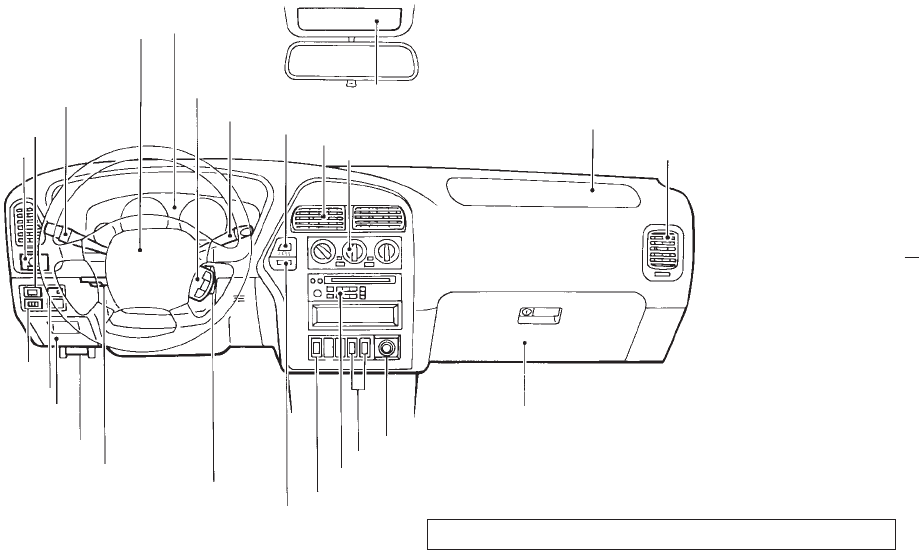
Driver’s supplemental air bag (P.2-23)
Cruise control
set switch
(P.4-14)
Outside mirror remote control
(P.2-42)
Headlight/dimmer/turn signal switch (P.1-15)
Front fog light switch (P.1-19)
Meter/gauge (P.1-3)
Windshield wiper/washer switch (P.1-16)
Hazard warning flasher switch (P.1-19)
Center ventilator (P.3-2)
Heater/air conditioner control (P.3-3)
Compass/outside air temperature display (P.1-5)
Passenger supplemental air bag (P.2-23)
Side ventilator (P.3-2)
Glove box (P.2-10)
Cigarette lighter (P.1-21)
Radio/CD player (P.3-15)/clock (P.1-8)
Rear window wiper/washer switch (P.1-17)
Rear window/outside mirror defroster switch (P.1-18)
Ignition switch/steering lock (P.4-5)
Heated seat switch (P.1-20)
Tilting steering wheel adjust lever (P.2-41)
Hood release handle (P.2-9)
Fuse box cover (P.7-21)
Coin tray (P.1-22)
Theft warning light (P.1-13)
Cruise control main switch (P.4-14)
Instrument brightness control
(P.1-18)
SIC0682
See the page indicated in parentheses for operating details.
1-2
Z01.2.1/R50-D X
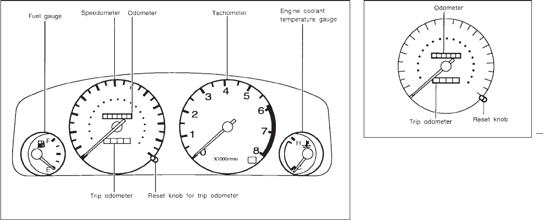
Speedometer
The speedometer indicates vehicle speed.
Odometer
The odometer records the total distance the
vehicle has been driven.
Trip odometer
The trip odometer records the distance of
individual trips. Before each trip, set the trip
odometer to zero by pushing the RESET knob.
SIC0586
SIC0587
METERS AND GAUGES SPEEDOMETER AND ODOMETER
1-3
Z01.2.1/R50-D X
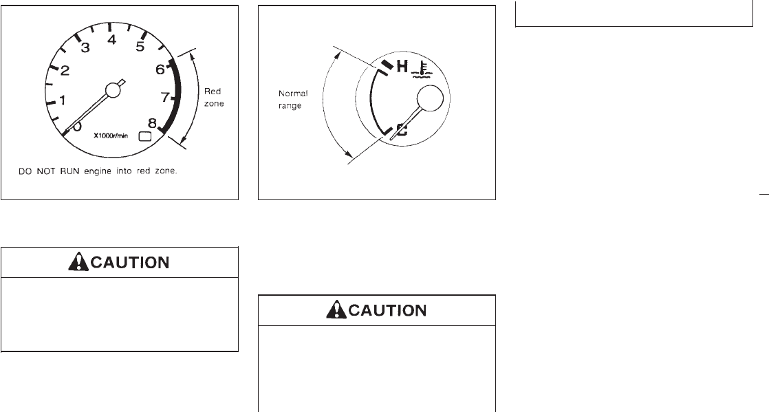
The tachometer indicates engine speed in
revolutions per minute (r/min).
When engine speed approaches the red
zone, shift to a higher gear. Operating
the engine in the red zone may cause
serious engine damage.
The gauge indicates the engine coolant tem-
perature.
The engine coolant temperature will vary with
the outside air temperature and driving condi-
tions.
If the gauge indicates over the normal
range, stop the vehicle as soon as safely
possible. If the engine is overheated,
continued operation of the vehicle may
seriously damage the engine. See “In
case of emergency” section for immedi-
ate action required.
SIC0588 SIC0545
TACHOMETER ENGINE COOLANT
TEMPERATURE GAUGE
1-4
Z01.2.1/R50-D X
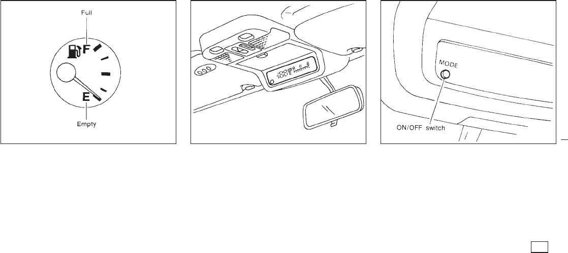
The gauge indicates the APPROXIMATE fuel
level in the tank.
The gauge may move slightly during braking,
turning, acceleration, or going up or down hill.
The gauge needle is designed to remain in
approximately the same position, even when
the ignition key is turned “OFF”.
Refill the fuel tank before the gauge regis-
ters Empty.
This unit is a display unit which possesses the
following functions:
IFunction to measure terrestrial magnetism
and indicate heading direction of vehicle
IFunction to indicate outside air temperature
IFunction to indicate caution for frozen road
surfaces
Outside temperature display
Push the switch when the ignition key is in the
“ACC” or “ON” position. The outside tempera-
ture will be displayed in “°F”.
ISelecting the indication range
Push the switch to change from “°F” to “°C”.
IIf the outside temperature drops below the
freezing point, the display indicates ICE .
SIC0546 SIC0590 SIC0610
FUEL GAUGE COMPASS AND OUTSIDE
TEMPERATURE DISPLAY
(If so equipped)
1-5
Z01.2.1/R50-D X
IWhen the outside temperature is be-
tween 130°F (55°C) and 158°F (70°C), the
display shows 130°F (55°C).
IWhen the outside temperature is lower
than −20°F (−30°C) or higher than 158°F
(70°C), the display shows only “---
”
though it is operating. This is not a
problem.
IThe outside temperature sensor is
installed in the front of the radiator.
The display may not indicate the pre-
cise temperature due to the heat of
the road and engine depending on
the direction of the wind and driving
conditions, etc.
IUse the “ICE” indication for reference
only. Confirm the traffic information
and road conditions to drive safely.
SIC0611
1-6
Z01.2.1/R50-D X
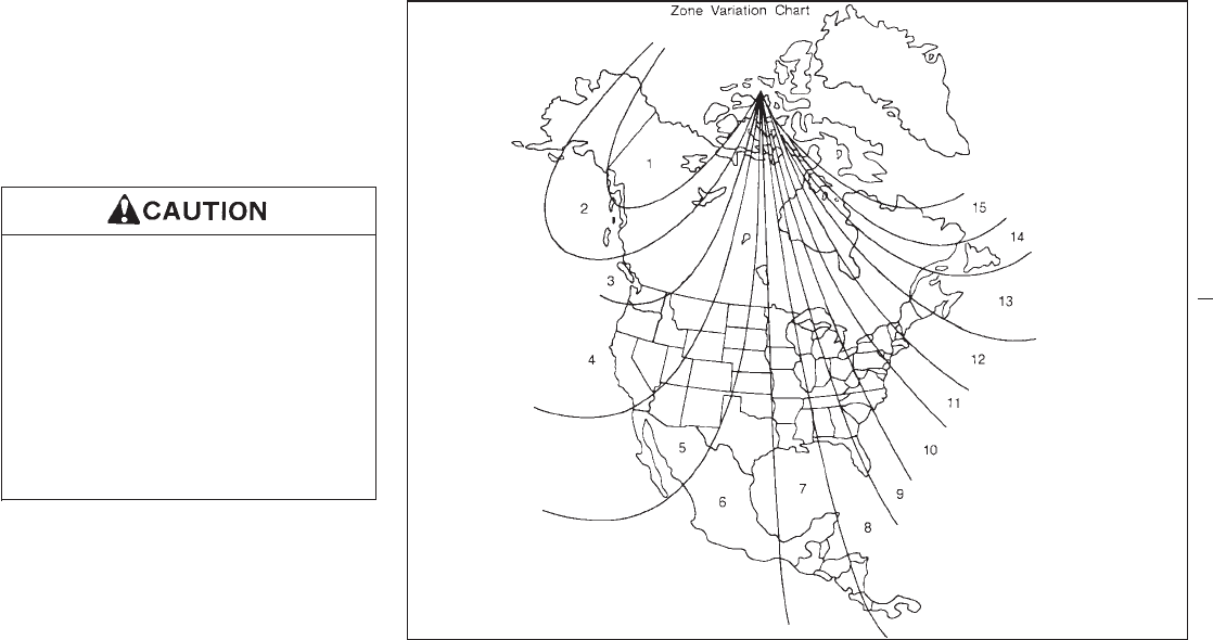
Compass display
Push the switch when the ignition key is in the
“ACC” or “ON” position. The direction will be
displayed.
Zone variation change procedure
The difference between magnetic north and
geographical north is known as variance. In
some areas, this difference can sometimes be
great enough to cause false compass read-
ings. Follow these instructions to set the vari-
ance for your particular location if this hap-
pens:
1. Establish your location on the zone map.
Record your zone number.
2. Push the “ON/OFF” switch in for five sec-
onds until the current zone entry number is
displayed.
3. Press the “ON/OFF” switch repeatedly until
the new zone entry number is displayed.
Once the desired zone number is displayed,
stop pressing the “ON/OFF” switch and the
display will show compass direction within a
few seconds.
IIf a magnet is located near the compass
or the vehicle is driven where the terres-
trial magnetism is disturbed, the com-
pass display may not indicate the cor-
rect direction.
IIn places where the terrestrial magne-
tism is disturbed, the correction of the
direction starts automatically, extin-
guishing the direction bar. If turn is
made one or two times, the correction is
complete and the direction bar comes
back on.
Correction functions of the compass
display
The compass display is equipped with auto-
matic correction function. If the direction is not
shown correctly, carry out manual correction
procedure set out below.
Manual correction procedure
1. Push the switch for about 10 seconds. The
direction bar starts blinking.
2. Drive the vehicle slowly in an open and safe
area. The initial correction is completed
while turning one or two turns.
In places where the terrestrial magnetism
is extremely disturbed, the initial correc-
tion procedure may start automatically.
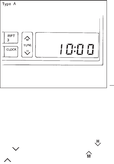
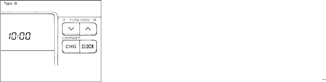
The digital clock displays time when the igni-
tion key is in “ACC” or “ON”.
If the power supply is disconnected, the
clock will not indicate the correct time.
Readjust the time.
Clock set (Adjustment)
Depressing the “CLOCK” and the “ ”
or “ ” buttons together will set hours.
Depressing the “CLOCK” and “ ”or
“” buttons together will set minutes.
SIC0591
CLOCK
1-7
Z01.2.1/R50-D X
Clock operation
By pressing the “CLOCK” button, you can
alternate the clock and the radio/cassette tape
options in the display.
Clock priority mode
In this mode the clock will be shown in the
display. If any radio or cassette tape functions
are activated, the radio, cassette or CD display
will illuminate for ten seconds then return to
the clock mode.
After clock adjustment, the radio is in the
clock priority mode.
SIC0691
1-8
Z01.2.1/R50-D X
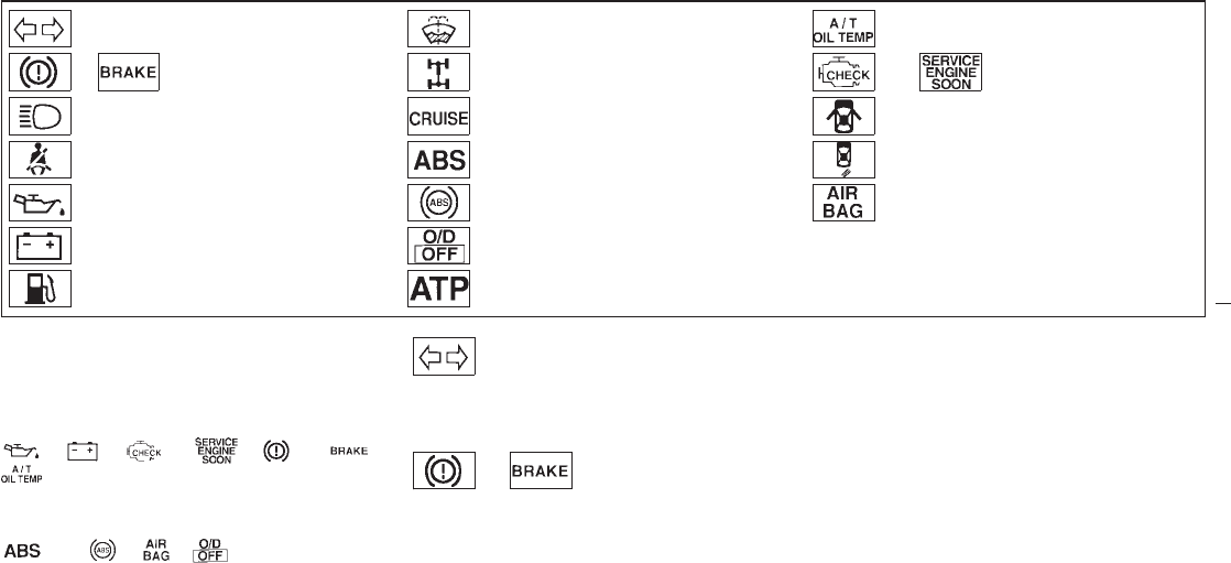
Turn signal/hazard indicator lights Low washer fluid warning light
(For Canada)
Automatic transmission oil temperature
warning light
or Brake warning light 4-wheel drive indicator light or Malfunction indicator light
High beam indicator light (Blue) CRUISE indicator light Door open warning light
Seat belt reminder light and buzzer Anti-lock brake warning light
(Except for Canada) Tire carrier open warning light
Engine oil pressure warning light Anti-lock brake warning light
(For Canada) Supplemental air bag warning light
Charge warning light Overdrive off indicator light
Low fuel warning light Automatic transmission park warning light
Checking bulbs
Turn the ignition key to “ON” without starting
the engine. The following lights will come on:
, , or , or ,
The following lights come on briefly and then
go off: or , ,
If any light fails to come on, it may indicate a
burned-out bulb or an open circuit in the elec-
trical system. Have the system repaired
promptly.
Turn signal/hazard indicator
lights
The light flashes when the turn signal switch
lever or hazard switch is turned on.
or Brake warning light
This light functions for both the parking brake
and the foot brake systems.
Parking brake indicator
The light comes on when the parking brake is
applied.
Low brake fluid warning
The light warns of a low brake fluid level. If the
light comes on while the engine is running,
stop the vehicle and perform the following:
1. Check the brake fluid level. Add brake fluid
as necessary. See “Brake and clutch fluid”
in the “Do-it-yourself operations” section.
WARNING/INDICATOR LIGHT
AND BUZZER
1-9
Z01.2.1/R50-D X
2. If the brake fluid level is correct:
Have the warning system checked by a
NISSAN dealer.
IYour brake system may not be work-
ing properly if the warning light is on.
Driving could be dangerous. If you
judge it to be safe, drive carefully to
the nearest service station for re-
pairs. Otherwise, have your vehicle
towed.
IPressing the brake pedal with the
engine stopped could increase your
stopping distance and braking will
require greater pedal effort as well as
pedal travel.
IIf the level is below the MINIMUM
mark on the brake fluid reservoir, do
not drive until the brake system has
been checked at a NISSAN dealer.
High beam indicator light
(Blue)
This light comes on when the headlight high
beam is on, and goes out when the low beams
are selected.
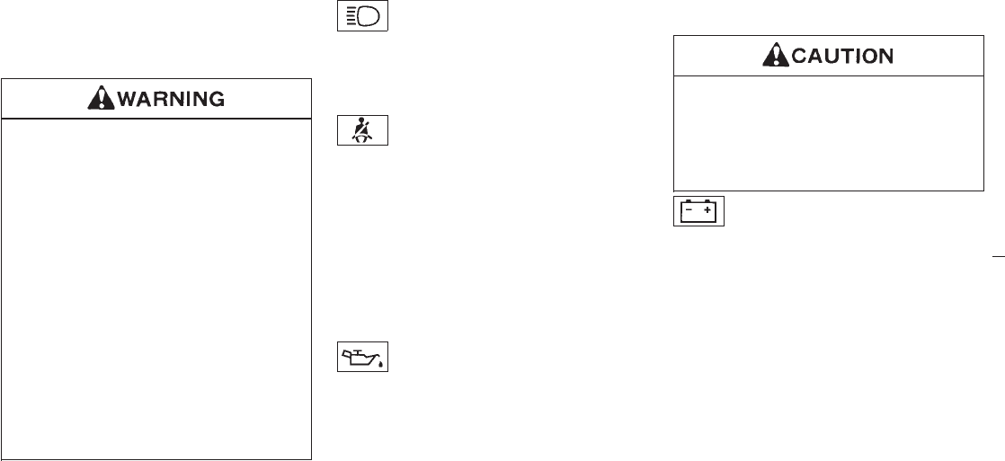
Seat belt reminder light
The light and buzzer remind you to fasten seat
belts. The light illuminates whenever the igni-
tion key is turned to “ON”, and will remain
illuminated until the driver’s seat belt is fas-
tened. At the same time, the buzzer will sound
for about six seconds unless the driver’s seat
belt is securely fastened.
Refer to “Seat belts” in the “Pre-driving checks
and adjustments” section for precautions on
seat belt usage.
Engine oil pressure warning
light
This light warns of low engine oil pressure. If
the light flickers or comes on during normal
driving, pull off the road in a safe area, stop the
engine immediately and call a NISSAN dealer
or other authorized repair shop.
The oil pressure warning light is not de-
signed to indicate a low oil level. Use the
dipstick to check the oil level. See “Engine
oil” in the “Do-it-yourself operations” section.
Running the engine with the oil pressure
warning light on could cause serious
damage to the engine almost immedi-
ately. Turn off the engine as soon as it is
safe to do so.
Charge warning light
If the light comes on while the engine is
running, it may indicate that there is something
wrong with the charging system. Turn the
engine off and check the alternator belt. If the
belt is loose, broken, missing or if the light
remains on, see your NISSAN dealer immedi-
ately.
1-10
Z01.2.1/R50-D X
Do not continue driving if the belt is
loose, broken or missing.
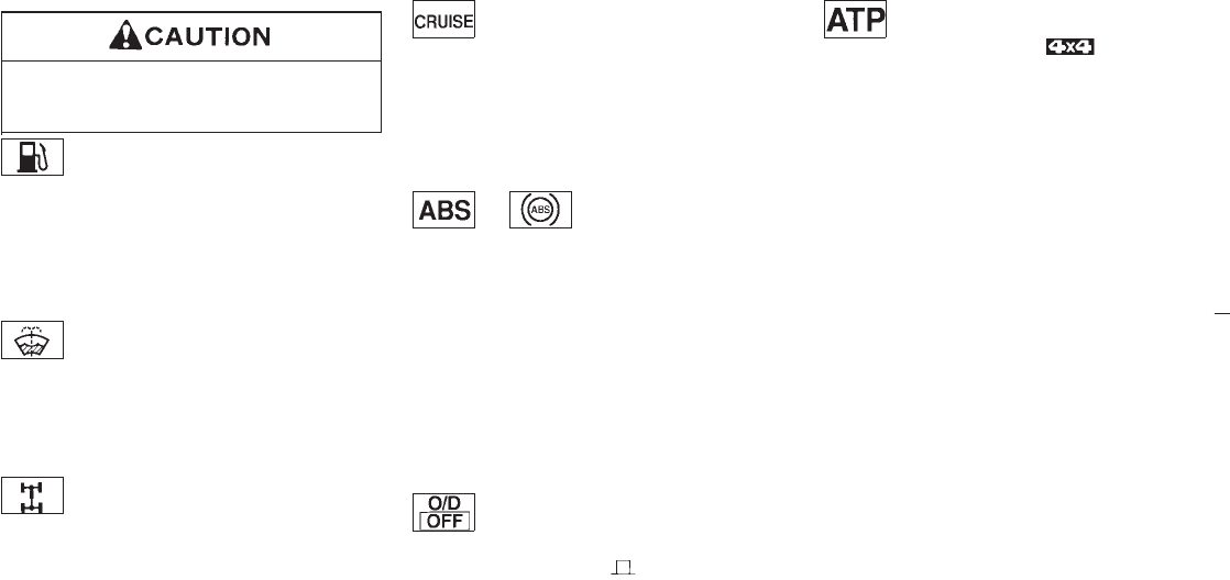
Low fuel warning light
This light comes on when the fuel in the tank is
getting low. Refuel as soon as it is convenient,
preferably before the fuel gauge reaches “E”.
There should be a small reserve of fuel
remaining in the tank when the fuel gauge
needle reaches “E”.
Low washer fluid warning
light (For Canada)
This light comes on when the washer fluid in
the washer tank is at a low level. Add washer
fluid as necessary. See the “Do-it- yourself
operations” section.
4-wheel drive indicator light
This light comes on when the transfer shift
control lever is in the “4H” or “4L” position.
CRUISE indicator light
The light comes on while the vehicle speed is
controlled by the cruise control system.
If the light flickers while the engine is running,
it may indicate there is something wrong with
the cruise control system. Have the system
checked by your NISSAN dealer.
or Anti-lock
brake warning
light
If the light comes on while the engine is
running, it may indicate there is something
wrong with the anti-lock brake system. Have
the system checked by your NISSAN dealer.
If an abnormality occurs in the system, the
anti-lock function will cease but the ordinary
brakes will continue to operate normally.
If the light comes on while you are driving,
contact your NISSAN dealer for repair.
Overdrive off indicator light
This light comes on when the overdrive switch
is pushed in the “OFF ” position.
Automatic transmission park
warning light ( model)
This light indicates that the automatic trans-
mission parking function is not engaged. If the
transfer control is not secured in any drive
position while the automatic transmission se-
lector lever is in the “P” position, the transmis-
sion will disengage and the wheel will not lock.
Shift the transfer control lever into the “2H” or
“4L” position when the warning light comes on.
IWhen parking, always make sure that the
transfer lever is in “H” or “4L” and the
parking brake is set.
IIf the ATP light is “ON”, this indicates that
the automatic transmission “park” position
will not function and the transfer lever is in
neutral.
IFailure to engage the transfer control lever
in “H” or “4L” could result in the vehicle
moving unexpectedly, resulting in serious
personal injury or property damage.
1-11
Z01.2.1/R50-D X
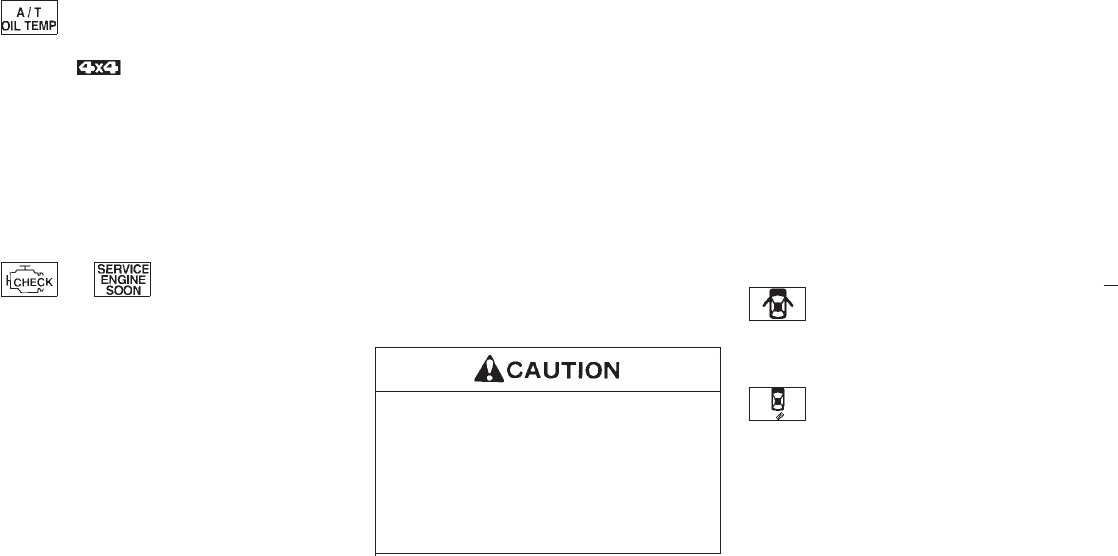
Automatic transmission oil
temperature warning light
(model)
This light comes on when the automatic trans-
mission oil temperature is too high. If the light
comes on while driving, reduce the vehicle
speed as soon as safely possible until the light
turns off.
Continued vehicle operation when the A/T
oil temperature warning light is on may
damage the automatic transmission.
or Malfunction
indicator light
(MIL)
If the Malfunction indicator light comes on
steady or blinks while the engine is running, it
may indicate a potential emission control prob-
lem.
The Malfunction indicator light will come on in
one of two ways:
IMalfunction indicator light on steady — An
emission control system malfunction has
been detected. Have the vehicle inspected
by an authorized NISSAN dealer. You do
not need to have your vehicle towed to the
dealer.
IMalfunction indicator light blinking — An
engine misfire has been detected which
may damage the emission control system.
To reduce or avoid emission control system
damage:
* do not drive at speeds above 45 MPH (72
km/h).
* avoid hard acceleration or deceleration.
* avoid steep uphill grades.
* if possible, reduce the amount of cargo
being hauled or towed.
The malfunction indicator light may stop blink-
ing and come on steady.
Have the vehicle inspected by an authorized
NISSAN dealer. You do not need to have your
vehicle towed to the dealer.
Continued vehicle operation without
having the emission control system
checked and repaired as necessary
could lead to poor driveability, reduced
fuel economy, and possible damage to
the emission control system, which may
affect your warranty coverage.
Some conditions may cause the malfunction
indicator light to come on steady or blink.
Examples are as follows:
Ivehicle ran out of fuel, which caused the
engine to misfire.
Ifuel filler cap was left off or improperly
installed, allowing fuel to evaporate into the
atmosphere.
If you suspect that you experienced one or
both of the above conditions, drive the vehicle
to an authorized NISSAN dealer and have the
vehicle inspected. Avoid any unnecessary di-
agnosis during the service by informing the
dealer of the conditions listed above that may
have occurred.
Door open warning light
This light comes on when any of the doors
and/or back door is not closed securely while
the ignition key is “ON”.
Tire carrier open warning light
(If so equipped)
This light comes on when the tire carrier is not
closed securely while the ignition key is “ON”.
1-12
Z01.2.1/R50-D X
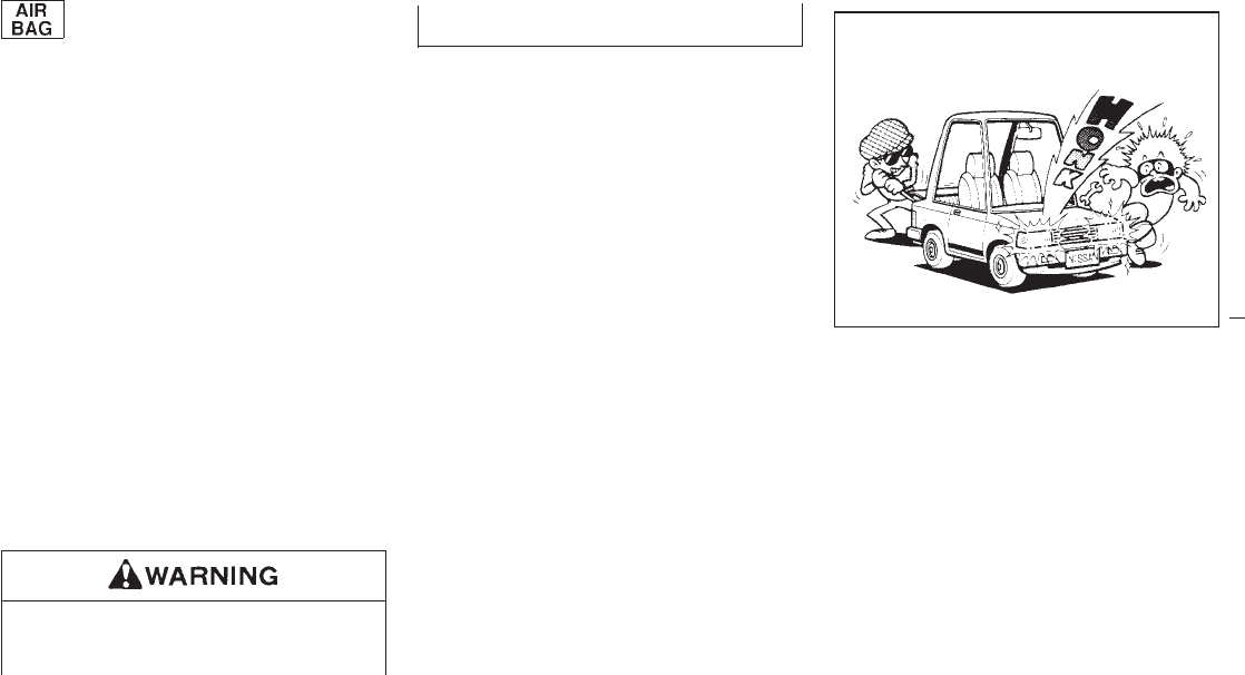
Supplemental air bag warning
light
When the ignition key is in the “ON” or
“START” position, the supplemental air bag
light will illuminate for about 7 seconds and
then turn off. This means the system is opera-
tional.
If any of the following conditions occur, the
supplemental air bag needs servicing and your
vehicle must be taken to your nearest autho-
rized NISSAN dealer.
1. The supplemental air bag light goes off
within 7 seconds.
2. The supplemental air bag light flashes in-
termittently or remains on. (after 7 seconds)
3. The supplemental air bag light does not
come on at all.
Unless checked and repaired, the Supplemen-
tal Restraint System may not function properly.
For additional details on the Supplemental Air
Bag System, see Section 2.
If the supplemental air bag warning light
is on, it could mean that the supplemen-
tal air bag system will not operate in an
accident.
Key reminder buzzer
The buzzer will sound when the driver side
door is opened if the key is left in the ignition
switch. Take the ignition key when you leave
the vehicle.
Light reminder buzzer
A buzzer will sound if the driver’s door is
opened with the light switch on unless the
ignition key in the “ON” position. Turn the light
switch off when you leave the vehicle.
Brake pad wear warning
The disc brake pads have audible wear warn-
ings. When a brake pad requires replacement,
it will make a high pitched scraping sound.
Have the brakes checked as soon as possible
if the warning sound is heard when the vehicle
is moving, whether or not the brake pedal is
depressed.
The theft warning system provides visual and
audio alarm signals if parts of the vehicle are
disturbed.
How to activate the theft warning
system
1. Close all windows.
2. Remove the key from the ignition switch.
3. Close and lock all doors, hood, back door
and glass hatch. The doors can be locked
either with or without the key.
The system can be activated even if the
windows are open.
IC0005
THEFT WARNING (If so equipped)
1-13
Z01.2.1/R50-D X
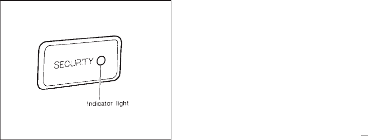
4. Confirm that the indicator light comes on.
The light will glow for about 30 seconds and
then blink. The system is now activated. If,
during this 30 second time period, the door
is unlocked by the key or multi-remote
controller, or the ignition key is turned to
“ACC”, the system will not activate.
IIf the key is turned slowly when locking
the door, the system may not activate.
Furthermore, if the key is turned exces-
sively to the unlock position, the system
may be deactivated when the key is
removed. If the indicator light fails to
glow for 30 seconds, unlock the door
once and lock it again.
IEven when the driver and/or passengers
are in the vehicle, the system will acti-
vate with all doors, hood and back door
locked and ignition key off. Turn the
ignition key to “ACC” to turn the system
off.
Theft warning system operation
The warning system will give the following
alarm:
IThe headlights blink and the horn sounds
intermittently. In addition, the starter motor
will not operate.
IThe alarm automatically turns off after 2 to
3 minutes; however, the alarm will reacti-
vate if the vehicle is tampered with again.
The alarm is activated by:
IUnlocking the door, back door or back door
glass hatch without using the key or multi-
remote controller. (Even if the door is
opened by releasing the door inside lock
knob, the alarm is activated.)
IOpening the hood.
SIC0603
1-14
Z01.2.1/R50-D X
How to stop alarm
The alarm will stop only by unlocking a door or
back door with the key or multi-remote control-
ler. The alarm will not stop if the ignition switch
is turned to “ACC”.
If the system does not operate as de-
scribed above, have it checked by your
NISSAN dealer.
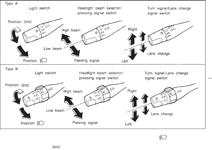
Lighting
Turn the switch to the “ ” position:
The side combination, tail, license plate and
instrument lights will come on.
Turn the switch to the “ ” position:
Headlights will come on and all the other lights
remain on.
To select the high beam, push the lever for-
ward. Pull it back to select the low beam.
SIC0188
HEADLIGHT AND TURN SIGNAL
SWITCH
1-15
Z01.2.1/R50-D X
Daytime running light system
(For Canada)
The headlights automatically illuminate at a
reduced intensity when the engine is started
with the parking brake released. The daytime
running lights operate with the headlight switch
in the “OFF” position or in the “ ” position.
Turn the headlight switch to the “ ” posi-
tion for full illumination when driving at night.
If the parking brake is applied before the
engine is started, the daytime running lights do
not illuminate. The daytime running lights illu-
minate once the parking brake is released.
The daytime running lights will remain on until
the ignition switch is turned off.
When the daytime running light system
is active, tail lights on your vehicle will
not be on. It is necessary at dusk to turn
on your headlights. Failure to do so
could cause an accident injuring your-
self and others.
Passing signal
Pulling the lever toward you will turn on the
passing signal even when the headlight switch
is off.
Turn signal
Move the lever up or down to signal to the
turning direction. When the turn is completed,
the turn signals cancel automatically.
Lane change signal
To indicate a lane change, move the lever up
or down to the point where lights begin flash-
ing.
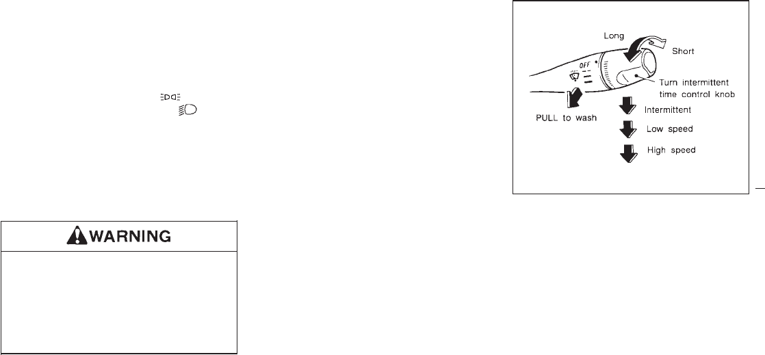
The windshield wiper and washer operates
when the ignition key is in the “ACC” or “ON”
position.
Push the lever down to operate the wiper.
Intermittent operation can be adjusted from 4
to 12 seconds by turning the knob.
Pull the lever toward you to operate the
washer. Then the wiper will also operate sev-
eral times.
SIC0683
WINDSHIELD WIPER AND
WASHER SWITCH
1-16
Z01.2.1/R50-D X
The following could damage the washer
system:
IDo not operate the washer continu-
ously for more than 30 seconds.
IDo not operate the washer if the res-
ervoir tank is empty.
In freezing temperatures the washer so-
lution may freeze on the windshield and
obscure your vision which may lead to
an accident. Warm the windshield with
the defroster before you wash the
windshield.
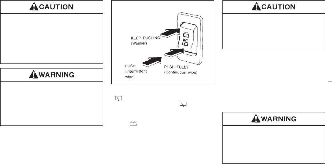
To operate the wiper, push the switch to the
“” side. This wiper operates intermit-
tently. Push the switch to the “ ” side fully,
this operates the wiper continuously.
To operate the washer, hold the switch down
to the “ ” side.
Then the wiper will also operate several times.
IDo not operate the washer continu-
ously for more than 30 seconds.
IDo not operate the washer if reservoir
tank is empty.
IThe rear window wiper will not operate
when the rear window is open.
The rear window wiper will not operate if
the rear window is closed with the wiper
switch “ON”. To operate the window
wiper, turn the switch to “OFF” and then
to “ON”.
IThe rear window will not open while the
rear window wiper is operating.
In freezing temperatures the washer so-
lution may freeze on the rear window
and obscure your vision. Warm the rear
window with the defroster before you
wash the rear window.
SIC0548
REAR WINDOW WIPER AND
WASHER SWITCH
1-17
Z01.2.1/R50-D X
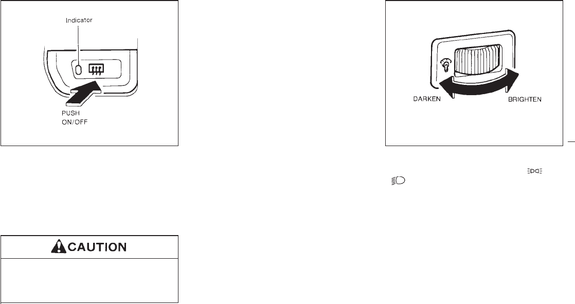
To defrost the rear window glass, start the
engine and push the switch on. (The indicator
light will come on.) Push the switch again to
turn the defroster off.
It will automatically turn off in approximately 15
minutes. If the window clears before this time,
push the switch off manually.
When cleaning the inner side of the rear
window, be careful not to scratch or
damage the rear window defroster.
Outside heated mirror (if so
equipped)
The outside mirrors will be defrosted when the
rear window defroster switch is pushed.
The instrument brightness control operates
when the light switch is in the “ ”or
“” position.
Turn the control to adjust the brightness of
instrument panel lights and power window
switch lights.
When the control is turned to the right until a
click sound is heard, the light intensity will be
at maximum. When the control is turned to the
left until a click sound is heard, the light will be
turned off.
SIC0593 SIC0052
REAR WINDOW DEFROSTER
SWITCH INSTRUMENT BRIGHTNESS
CONTROL
1-18
Z01.2.1/R50-D X
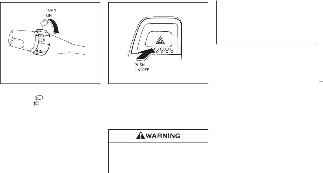
To turn the fog lights on, turn the headlight
switch to the “ ” position, then turn the
switch to the “ ” position. To turn them off,
turn the switch to the “OFF” position.
The headlights must be on for the fog lights to
operate.
Push the switch on to warn other drivers when
you must stop or park under emergency con-
ditions. All turn signal lights will flash.
Some state laws may prohibit the use of the
hazard warning flasher switch while driv-
ing.
IWhen stalled or stopped on the road-
way under emergency conditions,
move the vehicle well off the road.
IDo not use the switch while moving
on the highway unless unusual cir-
cumstances force you to drive so
slowly that your vehicle might be-
come a hazard to other traffic.
ITurn signals do not work when the
switch is operating.
The flasher can be actuated with the ignition
switch either off or on.
IC1292 SIC0594
FRONT FOG LIGHT SWITCH HAZARD WARNING FLASHER
SWITCH
1-19
Z01.2.1/R50-D X
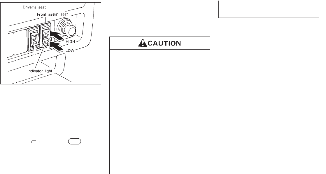
The front seat(s) are warmed by built-in heat-
ers. The switches located on the instrument
panel can be operated independently of each
other.
1. Start the engine.
The battery could run down if the heater is
operated while the engine is not running.
2. Push the “ ” (Low) or “ ” (High)
position of the switch, as desired, depend-
ing on the temperature. The indicator light
in the switch will illuminate.
The heater is controlled by a thermostat,
automatically turning the heater on and off.
The indicator light will remain on as long as
the switch is on.
3. When the vehicle’s interior is warmed or
before you leave the vehicle, be sure to turn
the switch off.
IDo not use the seat heater for a long
time or when no one is seated there.
IDo not put anything on the seat which
insulates heat, such as a blanket,
cushion, seat cover, etc. Otherwise,
the seat may become overheated.
IDo not place anything hard or heavy
on the seat or pierce it with a pin or
similar object. This may result in
damage to the heater.
IAny liquid spilled on the heating seat
should be immediately wiped up with
a dry cloth.
IWhen cleaning the seat, never use
benzine, thinner, or any similar mate-
rials.
IIf any abnormalities are found or the
heating seat does not operate, turn
the switch OFF and have the system
checked by your NISSAN dealer.
SIC0684
HEATED SEATS (If so equipped)
1-20
Z01.2.1/R50-D X
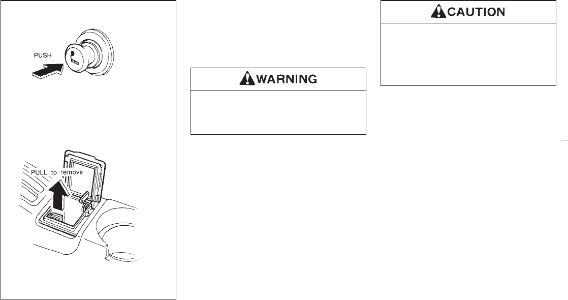
The cigarette lighter operates when the igni-
tion switch is in “ACC” or “ON”.
Push the lighter in all the way. When the lighter
is heated, it will spring out.
Replace the lighter in its original position after
use.
The cigarette lighter should not be used
while driving in order that full attention
may be given to the driving operation.
The cigarette lighter socket is a power
source for the cigarette lighter element
only. The use of the cigarette lighter
socket as a power source for any other
accessory is not recommended.
SIC0685
CIGARETTE LIGHTER AND ASH
TRAYS
1-21
Z01.2.1/R50-D X
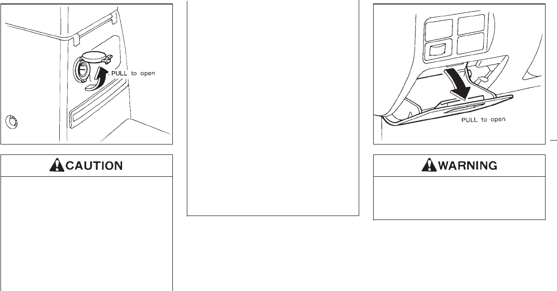
ITake care as the socket and plug may
be hot during or immediately after
use.
IThis power socket is not designed for
use with a cigarette lighter unit.
IDo not use with accessories that ex-
ceed a 12 volt, 120W (10A) power
draw. Do not use double adapters or
more than one electrical accessory.
IUse this power socket with the en-
gine running. (If the engine is
stopped, this could result in a dis-
charged battery.)
IAvoid using when the air conditioner,
headlights or rear window defogger
is on.
IBefore inserting or disconnecting a
plug, be sure to turn off the power
switch of electrical accessory being
used or the ACC power of the vehicle.
IPush the plug in as far as it will go. If
good contact is not made, the plug
may overheat or the internal tempera-
ture fuse may blow.
IWhen not in use, be sure to close the
cap. Do not allow water to contact the
socket.
The coin tray should not be used while
driving in order that full attention may be
given to the driving operation.
Do not place valuable items in the tray.
SIC0686 SIC0596
POWER SOCKET COIN TRAY
1-22
Z01.2.1/R50-D X
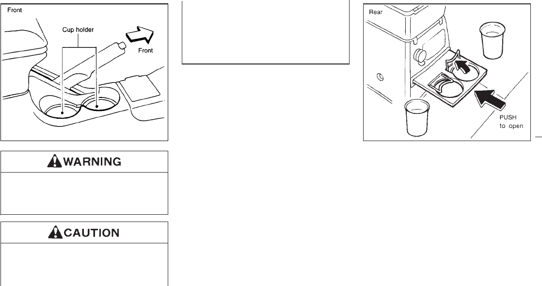
The cup holders should not be used
while driving in order that full attention
may be given to the driving operation.
IAvoid abrupt starting and braking
when the cup holder is being used to
prevent spilling the drink. If the liquid
is hot, it can scald you or your pas-
senger.
IUse only soft cups in the cup holder.
Hard objects can injure you in an
accident.
To open, push the cup holder.
To close, fully push the cup holder.
SIC0553 SIC0698
CUP HOLDER
1-23
Z01.2.1/R50-D X
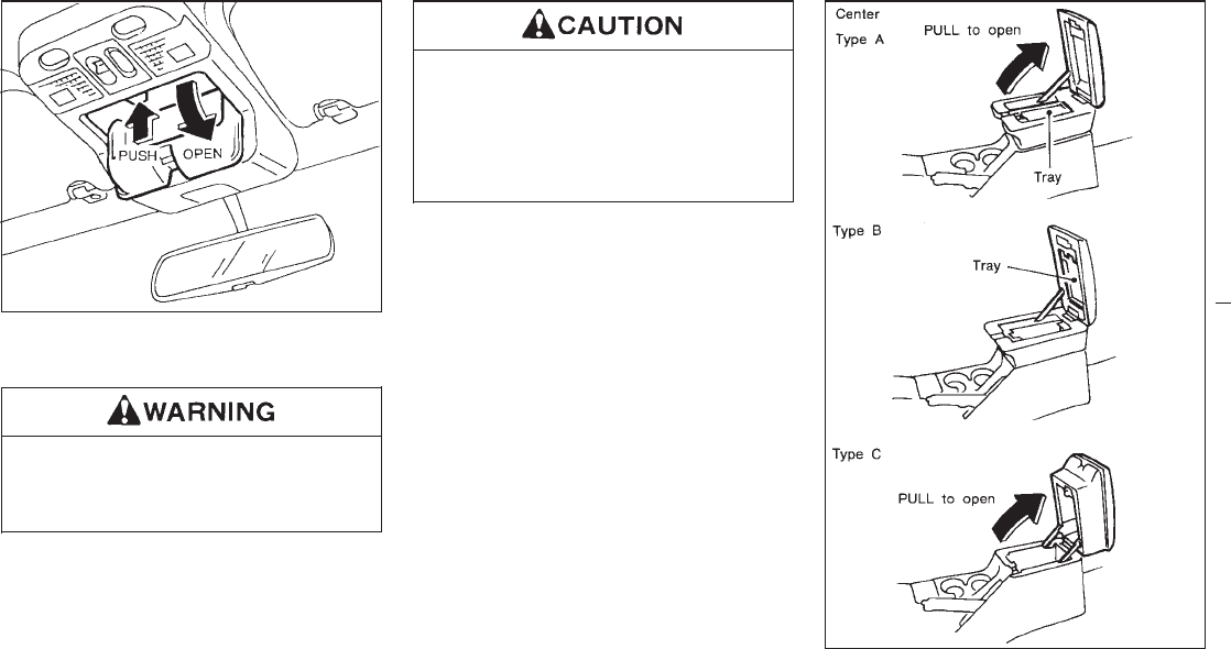
The glasses case can be opened by pushing
the button.
The glasses case should not be used
while driving in order that full attention
may be given to the driving operation.
IDo not use for anything other than
glasses.
IDo not leave glasses in the glasses
case while parking in direct sunlight.
The heat may damage the glasses.
SIC0557
SIC0688
GLASSES CASE CONSOLE BOX
1-24
Z01.2.1/R50-D X
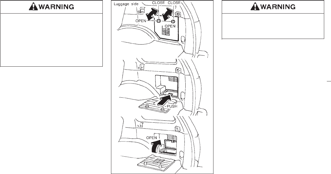
IThe center console box should not be
used while driving in order that full
attention may be given to the driving
operation.
IKeep the center console box lid
closed while driving to prevent injury
in an accident or a sudden stop.
Do not place valuable items in the center
console box.
Keep luggage side console box lids
closed securely while driving to prevent
injury in an accident or sudden stop.
Do not place valuable items in the luggage
side console box.
SIC0598
1-25
Z01.2.1/R50-D X
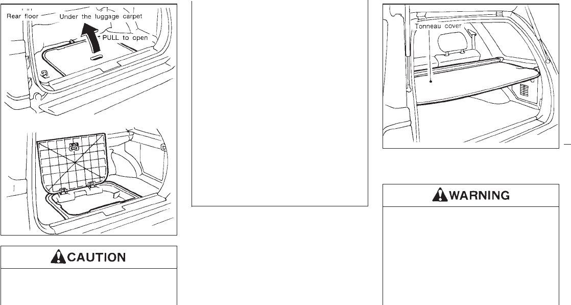
IMake sure the luggage board closes
securely.
IDo not drive with the board removed.
IProperly secure all cargo to help pre-
vent it from sliding or shifting. Do not
place cargo higher than the seat-
backs. In a sudden stop or collision,
unsecured cargo could cause per-
sonal injury.
INever allow anyone to ride in the
luggage area or on the rear seat when
it is in the fold-down position.
IIt is extremely dangerous to ride in a
cargo area inside of a vehicle. In a
collision, people riding in these areas
are more likely to be seriously injured
or killed.
IDo not allow people to ride in any
area of your vehicle that is not
equipped with seats and seat belts.
The tonneau cover keeps the luggage com-
partment contents hidden from the outside.
INever put anything on the tonneau
cover, no matter how small. Any ob-
ject on it could cause an injury in an
accident or sudden stop.
IDo not leave the tonneau cover in the
vehicle with it disengaged from the
holder.
IProperly secure all cargo to help pre-
vent it from sliding or shifting. Do not
SPA0346A
SPA0419
LUGGAGE BOARD AND BOX TONNEAU COVER
1-26
Z01.2.1/R50-D X
place cargo higher than the seat-
backs. In a sudden stop or collision,
unsecured cargo could cause per-
sonal injury.
IMake sure that all passengers have
their hands, etc. inside the vehicle
before closing the windows. Use the
window lock switch to prevent unex-
pected use of the power windows.
IDo not leave children unattended in-
side the vehicle. They could unknow-
ingly activate switches or controls
and become trapped in a window.
Unattended children could become
involved in serious accidents.
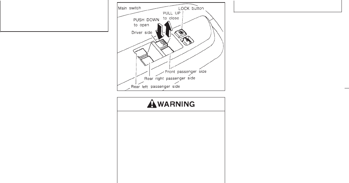
The power window only operates when the
ignition key is in the “ON” position.
To open or close the window, push down or
pull up the switch and hold it. The main switch
(driver side switches) will open or close all the
windows.
Locking passenger’s window
When the lock button is pushed in, only the
driver side window can be opened or closed.
Push it in again to cancel.
SIC0599
POWER WINDOW
1-27
Z01.2.1/R50-D X

The passenger side switch will open or close
only the corresponding window. To open or
close the window, hold the switch down or up.
Automatic operation
To fully open the driver side window, com-
pletely push down the switch and release it; it
need not be held. The window will automati-
cally open all the way. To stop the window, just
pull up the switch toward the “CLOSE” side.
A light press on the switch will cause the
window to open until the switch is released.
SIC0600 SIC0559 SIC0601
1-28
Z01.2.1/R50-D X
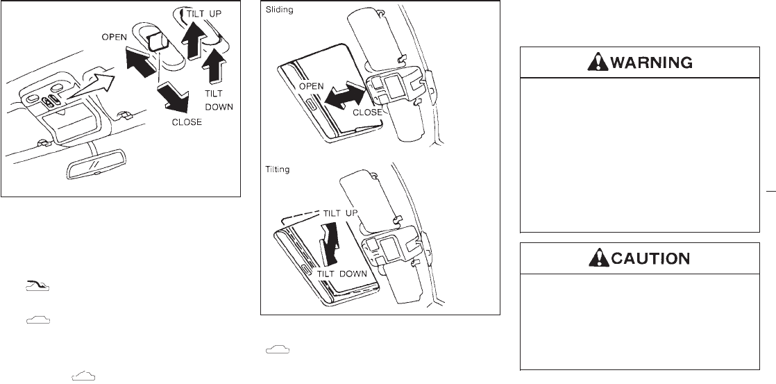
The sunroof will only operate when the ignition
key is in the “ON” position.
Sliding the sunroof
To open the roof, keep pressing the switch to
the “ ” side.
To close the roof, keep pressing the switch to
the “ ” side.
Tilting the sunroof
To tilt up, first close the sunroof, then keep
pushing the “ ” side of the tilt switch.
To tilt down the sunroof, keep pushing the
“” side.
Sun shade
Open/close the sun shade by sliding it
backward/forward.
The shade will open automatically when the
sunroof is opened. However, it must be closed
manually.
IIn an accident you could be thrown
from the vehicle through an open
sunroof. Always use seat belts and
child restraints properly.
IDo not allow anyone to stand up or
extend any portion of their body out
of the opening while the vehicle is in
motion or while the sunroof is
closing.
IRemove water drops, snow, ice or
sand from the sunroof before open-
ing.
IDo not place any heavy object on the
sunroof or surrounding area.
SIC0560
SIC0561
SUNROOF (If so equipped)
1-29
Z01.2.1/R50-D X
If the sunroof does not close
Have your NISSAN dealer check and repair
the sunroof.
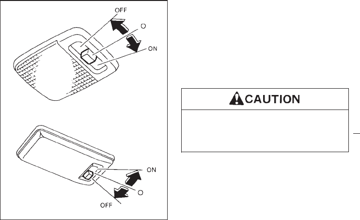
The interior light has a three-position switch.
The interior light will operate regardless of
ignition key position.
IWhen the switch is in the “OFF” position,
the interior light will not illuminate, regard-
less of door position.
IWhen the switch is in the center “q” posi-
tion, the light will illuminate when a door is
opened.
IWhen the switch is in the “ON” position, the
interior light will illuminate, whether any
door is open or closed.
Leaving the interior light switch in the
“ON” position for extended periods of
time will result in a discharged battery.
SIC0564
INTERIOR LIGHT
1-30
Z01.2.1/R50-D X
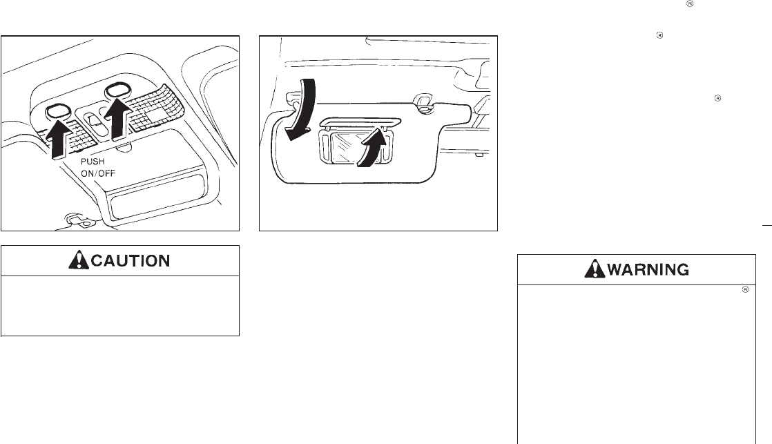
Do not use for extended periods of time
with the engine stopped. This could re-
sult in a discharged battery.
The light on the vanity mirror will turn on when
the cover on the vanity mirror is opened.
The Integrated HomeLink Transmitter pro-
vides a convenient way to consolidate the
functions of up to three individual hand-held
transmitters into one built-in device.
THE INTEGRATED HomeLink
TRANSMITTER:
Iwill operate garage doors, gates, home/
office lighting systems and security sys-
tems by storing and transmitting the pro-
gramming information of your current hand-
held transmitters.
Iis built-in and powered by your vehicle’s
battery and charging system. No separate
batteries are necessary.
Do not use this Integrated HomeLink
Transmitter with any garage door
opener that lacks safety stop and re-
verse features as required by federal
safety standards (these standards be-
came effective for models manufactured
after April 1, 1982). A garage door
opener which cannot “detect” an object
in the path of a closing garage door and
then automatically stop and reverse the
door, does not meet current federal
SIC0565 SIC0186
SPOT LIGHT VANITY MIRROR LIGHT INTEGRATED HomeLink
TRANSMITTER (If so equipped)
1-31
Z01.2.1/R50-D X
safety standards. Using a garage door
opener without these features increases
the risk of serious injury or death.
PROGRAMMING THE HomeLink
TRANSMITTER
During the programming procedure
your garage door or security gate will
open and close (if the transmitter is
within range). Make sure that people or
objects are clear of the garage door,
gate, etc. that you are programming.
Your vehicle’s engine should be turned
off while programming your transmitter.
The Integrated HomeLink Transmitter
may not work with older garage door
openers that do not meet current Fed-
eral Consumer Safety Standards.
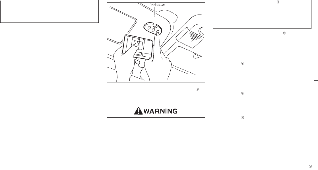
1. Test the Integrated HomeLink Transmitter
by pressing any button. The red indicator
light should come on. If you have previously
programmed a button proceed to step 3.
2. Clear all channels on the Integrated
HomeLink Transmitter by holding down
both outside buttons (#1 & #3) until the red
light begins to flash rapidly (approximately
20 seconds). Then release both buttons.
3. Select which of the three Integrated
HomeLink Transmitter buttons you want to
program.
4. Hold your hand-held transmitter against the
bottom surface of the Integrated
HomeLink Transmitter so that you can still
see the red indicator light.
5. Press the desired button until the red indi-
cator light flashes slowly. Do not release
the button. Continue holding and press the
hand-held transmitter button through step
6.
6. Hold down both buttons until the red indi-
cator light on the Integrated HomeLink
SIC0602
1-32
Z01.2.1/R50-D X

Transmitter flashes rapidly (This may take 1
to 90 seconds). Then release both buttons.
The rapid flashing means that the transmit-
ter has been successfully programmed to
match your hand-held transmitter. You can
now use the Integrated HomeLink Trans-
mitter instead of your hand-held transmitter.
Note to Canadian users:
Prior to 1992, D.O.C. regulations required
many hand-held transmitters to stop transmit-
ting after one or two seconds, even though you
continue to hold down the button. If you think
you have one of these hand-held transmitters,
you should press and re-press the transmitter
button every 2 seconds without ever releasing
the integrated HomeLink Transmitter button.
The indicator light on the Integrated
HomeLink Transmitter should blink rapidly
indicating a successful programming proce-
dure. If it returns to the slow blink of program
mode, continue to periodically reactivate your
hand-held transmitter until a successful pro-
gramming procedure is indicated by the rapidly
flashing indicator light.
OPERATING THE TRANSMITTER
To operate, simply press the appropriate but-
ton on the Integrated HomeLink Transmitter.
The red indicator light illuminates while the
signal is being transmitted. The effective trans-
mission range of the Integrated HomeLink
Transmitter may differ from your hand-held
transmitter.
PROGRAMMING PROBLEM
DIAGNOSIS
Be sure to keep your original hand-held trans-
mitter for possible reprogramming if neces-
sary.
IMake sure batteries in the hand-held trans-
mitter are fully charged.
IHold your hand-held transmitter against the
bottom surface of the Integrated
HomeLink Transmitter so that you can still
see the red indicator light.
IHold buttons for duration of the program-
ming without interruption.
IRotate your hand-held transmitter end-
over-end and program again. For best re-
sults, place the end opposite the battery
compartment against the Integrated
HomeLink Transmitter when program-
ming.
1-33
Z01.2.1/R50-D X
ROLLING CODES (If so equipped)
If your hand held transmitter appears to train to
the HomeLink Transmitter, but does not open
your garage door, and your garage door
opener was manufactured after 1995, your
garage door opener may have a “Code Pro-
tected” or “Rolling Code” feature. This type of
system will change the “code” of your garage
door opener every time you open or close your
garage door.
To determine if you have one of these sys-
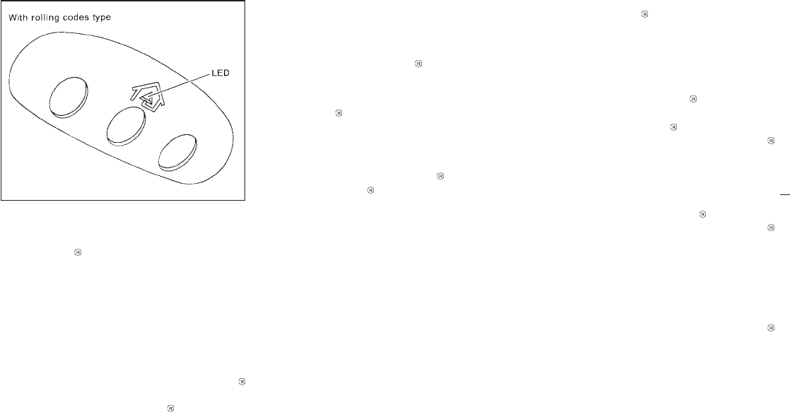
tems, depress the button on the HomeLink
Transmitter that you have just programmed. If
the LED on the HomeLink Transmitter
flashes rapidly for 1 to 2 seconds, then re-
mains on, your garage door opener has a
rolling code system.
To operate your “Rolling Code” garage door
opener from your HomeLink Transmitter, fol-
low these steps:
1. Program your hand held transmitter to the
HomeLink Transmitter by following the
procedures outlined above (if not yet pro-
grammed).
2. Program your garage door opener receiver
to recognize your HomeLink Transmitter
(The HomeLink Transmitter follows the
same procedure to train to the receiver as
your hand held transmitter did when it was
first installed):
a) Remove the cover panel from your ga-
rage door opener receiver. The receiver
should be located by the garage door
opener motor.
b) Locate the training button on the garage
door opener receiver. The exact location
and color of the button may vary by
garage door opener brand. If you have
difficulty locating the training button, ref-
erence your garage door opener
manual. If you have difficulty program-
ming your garage door opener equipped
with a rolling code system to recognize
the HomeLink Transmitter with the
“Rolling Code” feature, call NISSAN
Consumer Affairs Department.
c) Press the training button on the garage
door opener receiver for 1 to 2 seconds.
d) Return to the HomeLink Transmitter in
the vehicle, and depress the pro-
grammed HomeLink button for the du-
ration of the fast blink on the HomeLink
Transmitter (1 to 2 seconds). Release
the button, and re-press to confirm that
the system has trained.
e) Your garage door opener should now
recognize your HomeLink Transmitter.
You may use either your HomeLink
Transmitter or your original hand held
transmitter to open your garage door.
CLEARING THE PROGRAMMING
INFORMATION
Should you sell your vehicle, be sure to clear
the channels of the Integrated HomeLink
Transmitter. To clear the channels, simulta-
neously hold down the outside two buttons (#1
& #3) until the red indicator light begins to flash
rapidly (approximately 20 seconds). This will
clear all three buttons. Individual buttons can-
not be cleared, but can be reprogrammed at
SPA0609
1-34
Z01.2.1/R50-D X

any time by following the programming proce-
dures described above.
IF YOUR VEHICLE IS EVER
STOLEN
If your vehicle has been stolen, you should
change the codes of any device that
was programmed into the Integrated
HomeLink Transmitter as soon as possible.
Consult the owners manual of each device, or
call the manufacturer or dealer of those de-
vices.
When your vehicle is recovered, you
will have to reprogram the Integrated
HomeLink Transmitter with your new
transmitter information.
FCC Notice:
This device complies with FCC rules part
15. Operation is subject to the following
two conditions: (1) This device may not
cause harmful interference and (2) This
device must accept any interference that
may be received, including interference
that may cause undesired operation.
The transmitter has been tested and com-
plies with FCC and DOC/MDC rules.
Changes or modifications not expressly
approved by the party responsible for com-
pliance could void the user’s authority to
operate the device.
DOC: ISTC 1763K1313
FCC I.D.: CB2V67690
1-35
Z01.2.1/R50-D X

MEMO
1-36
Z01.2.1/R50-D X

2 Pre-driving checks and adjustments
Key ......................................................................... 2-2
Door locks .............................................................. 2-2
Multi-remote control system (If so equipped) ......... 2-4
Battery replacement ................................................ 2-6
Spare tire carrier .................................................... 2-7
Back door locks ....................................................... 2-8
Rear window locks .................................................. 2-8
Hood release .......................................................... 2-9
Glove box lock ..................................................... 2-10
Fuel filler lid lock .................................................. 2-10
Fuel filler cap ....................................................... 2-11
Front seats ........................................................... 2-12
Rear seats ............................................................ 2-16
Supplemental restraint system
(Supplemental air bag system) ............................ 2-19
Warning labels ...................................................... 2-25
Supplemental air bag warning light ..................... 2-25
Seat belts ............................................................. 2-27
Child restraints for infants and
small children ....................................................... 2-34
Tilting steering wheel ........................................... 2-41
Sunvisors ............................................................... 2-42
Outside mirror control .......................................... 2-42
Outside mirrors .................................................... 2-43
Inside mirror ......................................................... 2-44
Luggage net .......................................................... 2-44
Luggage hooks........................................................ 2-45
Luggage rack ........................................................ 2-46
Z01.2.1/R50-D X
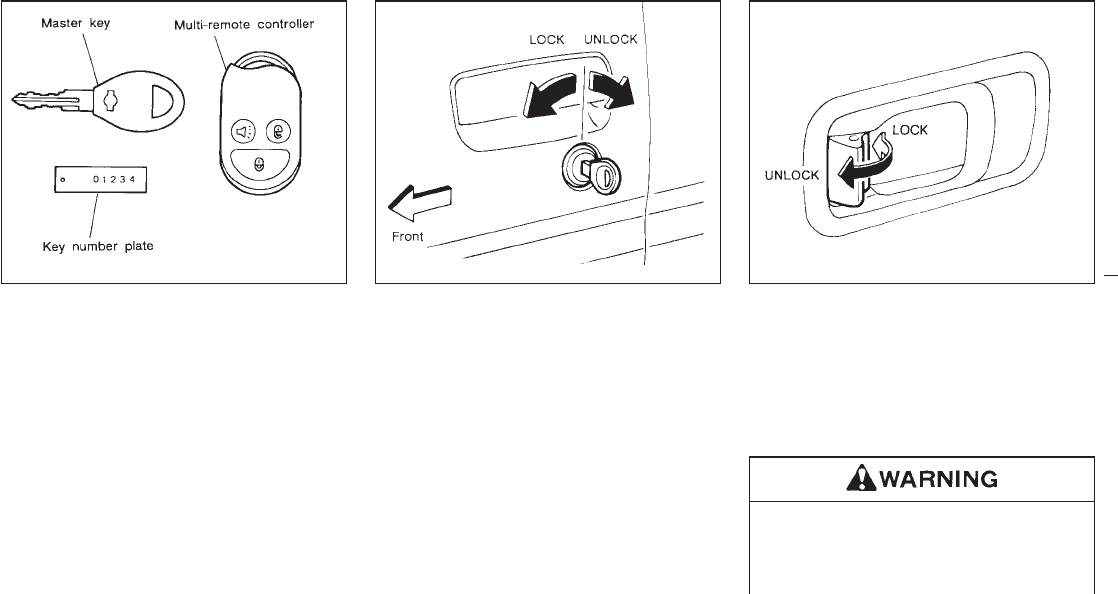
The key can only be inserted fully in the
ignition key cylinder. For the door, back door
and glove box key cylinders, it is normal for the
key not to go into the key cylinder all the way.
Record the key number on the key number
plate and keep it in a safe place (such as your
wallet), NOT IN THE CAR. A key number plate
is supplied with your key. Keep the plate in a
safe place. NISSAN does not record key num-
bers so it is very important to keep track of
your key number plate. A key number is only
necessary when you have lost all keys and do
not have one to duplicate from. If you still have
a key, this key can be duplicated by your
NISSAN dealer or a lock smith shop.
Locking doors with key
To lock the door, turn the key towards the front
of the vehicle. To unlock, turn it towards the
rear.
Locking doors without key
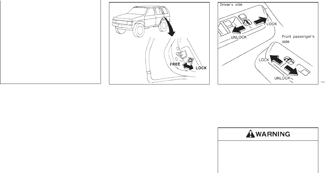
To lock from the outside without a key, move
the inside lock knob to the “LOCK” position.
Then close the door.
When locking the door this way, be certain not
to leave the key inside the vehicle.
IAlways have the doors locked while
driving. Along with the use of seat
belts, this provides greater safety in
the event of an accident by helping to
SPA0461 SPA0383 PD1160M
KEY DOOR LOCKS
2-2
Z01.2.1/R50-D X
prevent persons from being thrown
from the vehicle. This also helps keep
children and others from unintention-
ally opening the doors, and will help
keep out intruders.
IBefore opening any door, always look
for and avoid oncoming traffic.
IDo not leave children unattended in-
side the vehicle. They could unknow-
ingly activate switches or controls.
Unattended children could become
involved in serious accidents.
CHILD SAFETY REAR DOOR
LOCK
Child safety locking helps prevent doors from
being opened accidentally, especially when
small children are in the vehicle.
When the lever is in the lock position, the
rear door can be opened only from the
outside.
POWER DOOR LOCK
The power door lock system allows you to lock
or unlock all doors simultaneously.
Operating the lock-unlock switch will lock or
unlock all doors including the back door.
IBefore opening any door, always look
for and avoid oncoming traffic.
IDo not leave children unattended in-
side the vehicle. They may unknow-
ingly activate switches or controls.
IC1156M SPA0384
2-3
Z01.2.1/R50-D X
Unattended children could become
involved in serious accidents. It is possible to lock/unlock all doors including
the back door.
Be sure to remove the key from the vehicle
before locking the doors and leaving it.
The remote controller can operate at a dis-
tance of approximately 49 ft (15 m) from the
vehicle. (The effective distance depends upon
the conditions around the vehicle.)
As many as four remote controllers can be
used with one vehicle. For information con-
cerning the purchase and use of additional
remote controllers, contact your NISSAN
dealer.
Listed below are conditions or occur-
rences which will damage the remote
controller.
IDo not allow the remote controller to
become wet.
IDo not drop the remote controller.
IDo not strike the remote controller
sharply against another object.
IDo not place the remote controller for
an extended period in an area where
temperatures exceed 140°F (60°C).
Locking doors
1. Remove the ignition key.
2. Close all the doors.
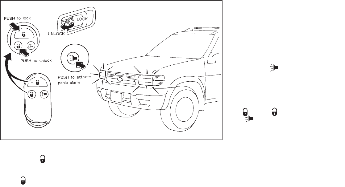
3. Push the “ ” button on the multi-remote
controller.
4. All the doors will lock.
5. The hazard indicator flashes twice.
IWhen the “ ” button is pushed with all
doors locked, the hazard indicator flashes
twice as a reminder that the doors are
already locked.
MULTI-REMOTE CONTROL
SYSTEM (If so equipped)
2-4
Z01.2.1/R50-D X
Unlocking doors
1. Push the “ ” button on the multi-
remote controller.
2. Only the driver side door will unlock. Push
the “ ” button on the multi-remote con-
troller again within 5 seconds.
3. All doors will unlock.
4. The interior light will stay on for 30 seconds
when the interior light switch is in the center
“q” position.
The interior light can be turned off without
waiting for 30 seconds by inserting the key into
the ignition or by locking the doors with the
multi-remote controller or by pushing the inte-
rior light button.
Using the panic alarm
If you are near your vehicle and feel threat-
ened, you may activate the alarm to call atten-
tion as follows:
1. Push the “ ” button on the remote
controller for longer than 1.5 seconds.
2. The theft warning alarm and headlights will
stay on for 30 seconds.
3. The alarm will stop when any of the key
functions are used. For example, when the
“” or the “ ” button is pushed, or the
“” button is pushed for longer than
1.5 seconds on the multi-remote controller,
the panic alarm function will be cancelled.
The remote controller will not function.
IWhen the key is inserted into the key
switch.
IWhen the battery in the remote control-
ler is dead.
IThe distance between the remote con-
SPA0398
2-5
Z01.2.1/R50-D X
troller and vehicle is more than approx.
49 ft (15 m).
IWhen one of the doors is ajar, only the
unlock function can be operated.
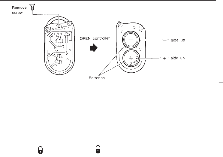
Replace the two batteries as follows:
1. Remove the screw and open the lid.
2. Replace the batteries with new ones. Insert
the batteries as illustrated above.
Recommended batteries: Sanyo CR2016
or equivalent.
3. Close the lid securely and install the screw.
4. Press the “ ” button, then the “ ”
button two or three times to check the
multi-remote controller operation.
If the batteries are removed for any reason
other than replacement, perform step 4
above.
IAn improperly disposed battery can hurt
the environment. Always confirm local
regulations for battery disposal.
IThe multi-remote controller is water-
resistant; however, if it does get wet,
immediately wipe completely dry.
IWhen changing batteries, do not let dust
or oil get on the controller.
SPA0399
BATTERY REPLACEMENT
2-6
Z01.2.1/R50-D X
FCC Notice:
Changes or modifications not expressly
approved by the manufacturer compliance
could void the user’s authority to operate
the equipment.
This device complies with Part 15 of the
FCC Rules and RSS-210 of Industry
Canada. Operation is subject to the follow-
ing two conditions: (1) This device may not
cause harmful interference and (2) this de-
vice must accept any interference received,
including interference that may cause un-
desired operation of the device.
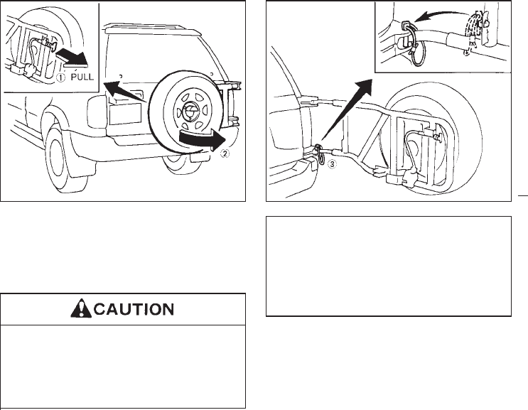
When opening the back door, first open the
spare tire carrier in the sequence shown in the
illustration above. Then insert the stopper into
the hole to secure the carrier in the open
position.
IBe certain that there is adequate area
to allow the carrier to open fully.
IOpen and close the spare tire carrier
slowly.
IBefore driving, be certain that the
spare tire carrier is firmly closed and
latched.
IFailure to do so may injure pedestri-
ans or damage the vehicle.
SPA0385 SPA0386
SPARE TIRE CARRIER
2-7
Z01.2.1/R50-D X
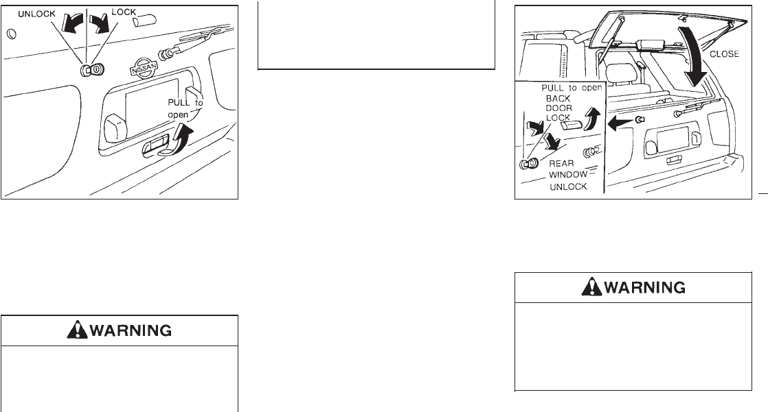
1. Turn the key counterclockwise to unlock the
back door.
2. Pull the opener handle to open the back
door.
3. To lock the back door, push it down firmly
and turn the key clockwise.
IAlways check the back door has been
closed securely to prevent it from
opening while driving.
IDo not drive with the back door open.
This could allow dangerous exhaust
gases to be drawn into the vehicle.
See “Exhaust gas” in the “Starting
and driving” section.
To open the rear window, turn the key fully
clockwise and pull the opener handle. To
close, lower and push the rear window down
securely.
Do not drive with the rear window open.
This could allow dangerous exhaust
gases to be drawn into the vehicle. See
“Exhaust gas” in the “Starting and driv-
ing” section.
SPA0462 SPA0338
BACK DOOR LOCKS REAR WINDOW LOCKS
2-8
Z01.2.1/R50-D X
Do not open the rear window unless the
wiper is in the stowed position.
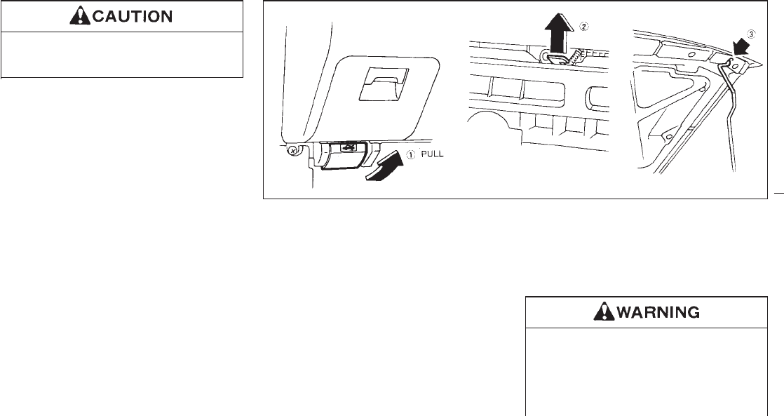
1. Pull the hood lock release handle located
below the instrument panel; the hood will
then spring up slightly.
2. Raise the lever at the front of the hood with
your fingertips and raise the hood.
3. Insert the assist bar into the slot in the front
edge of the hood.
4. When closing the hood, reset the assist bar
to its original position, then slowly close the
hood and make sure it locks into place.
IMake sure the hood is completely
closed and latched before driving.
Failure to do so could cause the hood
to fly open and result in an accident.
IIf you see steam or smoke coming
SPA0387
HOOD RELEASE
2-9
Z01.2.1/R50-D X
from the engine compartment, to
avoid injury, do not open the hood.
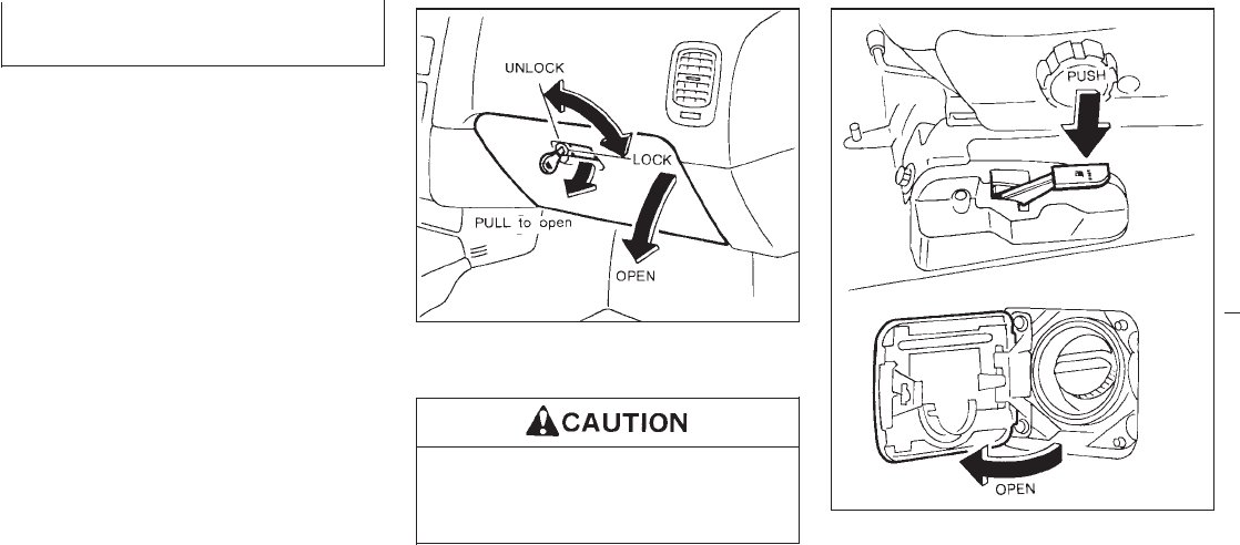
The glove box may be opened by turning the
key as shown.
Keep glove box lid closed while driving
to prevent injury in an accident or during
a sudden stop. Opener lever
To open the fuel filler lid, push the opener lever
down. To lock, close the fuel filler lid securely.
SPA0388
SPA0389
GLOVE BOX LOCK FUEL FILLER LID LOCK
2-10
Z01.2.1/R50-D X
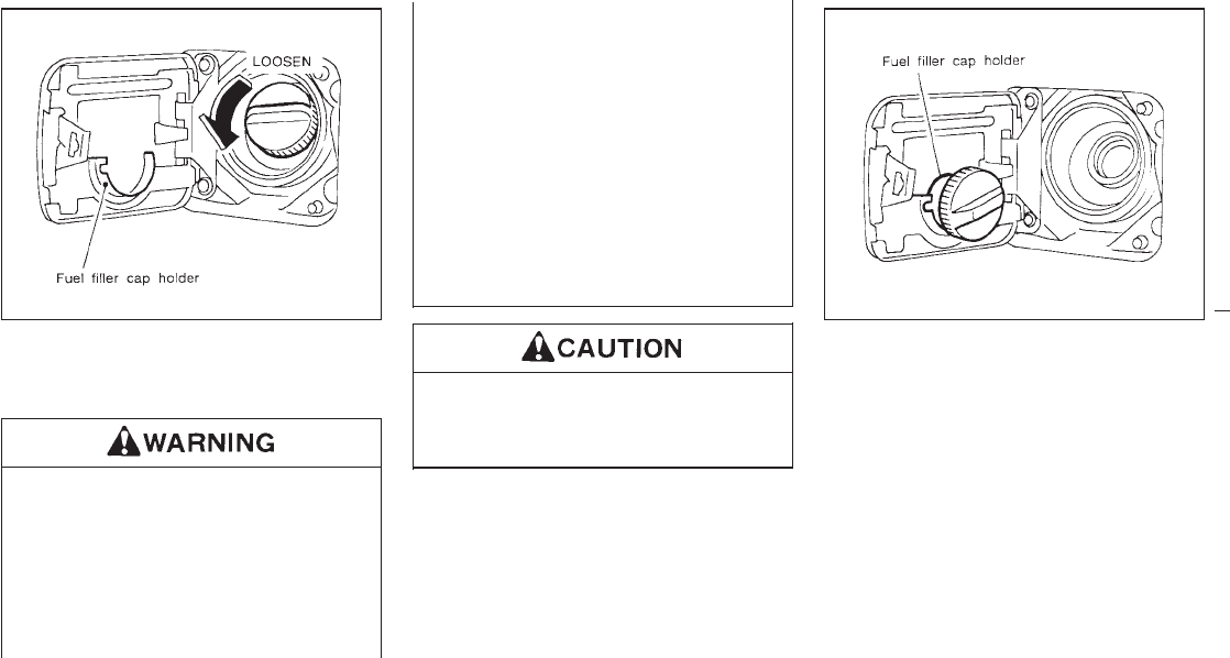
The fuel filler cap is a screw-on ratcheting
type. Tighten the cap clockwise until ratcheting
clicks are heard.
IGasoline is extremely flammable and
highly explosive under certain condi-
tions. You could be burned or seri-
ously injured if it is misused or mis-
handled. Always stop the engine and
do not smoke or allow open flames or
sparks near the vehicle when refuel-
ing.
IFuel may be under pressure. Turn the
cap one-half turn and wait for any
“hissing” sound to stop, to prevent
fuel from spraying out and possible
personal injury. Then remove the cap.
IUse only a genuine NISSAN fuel filler
cap as a replacement. It has a built-in
safety valve needed for proper opera-
tion of the fuel system and emission
control system. An incorrect cap can
result in a serious malfunction and
possible injury.
If fuel is spilled on the vehicle body,
flush it away with water to avoid paint
damage.
If the fuel filler cap is not tightened prop-
erly, the Malfunction indicator light (MIL)
may come on.
Put the fuel filler cap on the cap holder while
refueling.
SPA0341 SPA0342
FUEL FILLER CAP
2-11
Z01.2.1/R50-D X
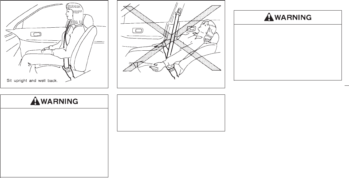
Do not ride in a moving vehicle when the
seatback is reclined. This can be dan-
gerous. The shoulder belt will not be
against your body. In an accident you
could be thrown into it and receive neck
or other serious injuries. You could also
slide under the lap belt and receive se-
rious internal injuries.
For most effective protection when the
vehicle is in motion, the seat should be
upright. Always sit well back in the seat
and adjust the seat belt properly. See
“Precautions on seat belt usage” later in
this chapter.
SEAT ADJUSTMENT
IDo not adjust the driver’s seat while
driving. The seat may move suddenly
and could cause loss of control of the
vehicle.
IAfter adjustment, gently rock in the
seat to make sure it is securely
locked.
SPA0472 SPA0473
FRONT SEATS
2-12
Z01.2.1/R50-D X
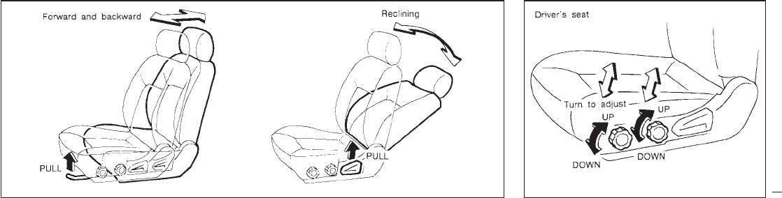
Forward and backward
Pull the lever up while you slide the seat
forward or backward to the desired position.
Release the lever to lock the seat in position.
Reclining
To recline the seatback, pull the lever up and
lean back. To bring the seatback forward
again, pull the lever and move your body
forward. The seatback will move forward.
Seat lifter (Driver’s seat)
Turn either dial to adjust the angle and height
of the seat cushion to the desired position.
SPA0097 SPA0099
2-13
Z01.2.1/R50-D X
POWER SUPPORT SEAT
IDo not adjust the driver’s seat while
driving in order that full attention may
be given to the driving operations.
IDo not leave children unattended in-
side the vehicle. They could unknow-
ingly activate switches and controls.
Operating tips
IThe motor has an auto-reset overload pro-
tection circuit. If the motor stops during
operation, wait 30 seconds, then reactivate
the switch.
IDo not operate the power support seat
for a long period of time when the engine is
off. This will discharge the battery.
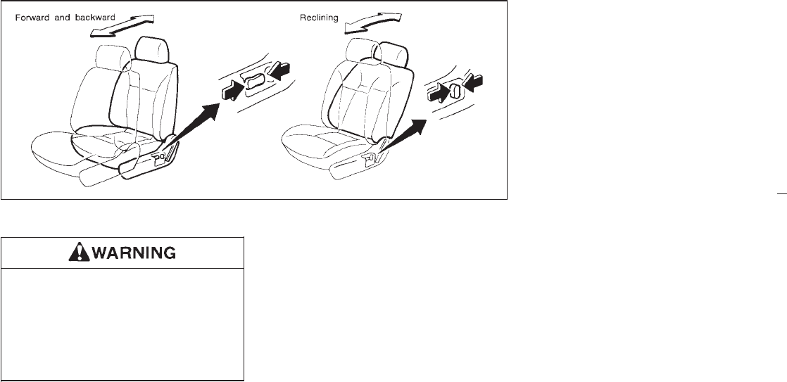
Forward and backward
Moving the switch forward or backward will
slide the seat forward or backward to the
desired position.
Reclining
Move the recline switch backward until the
desired angle is obtained. To bring the seat
back forward again, move the switch forward
and move your body forward. The seat back
will move forward.
SPA0463
2-14
Z01.2.1/R50-D X
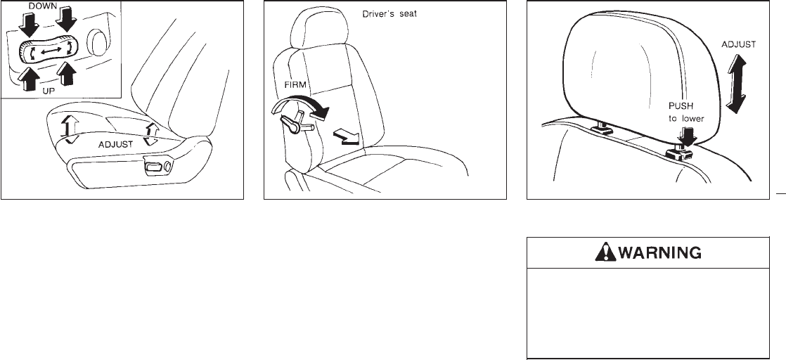
Seat lifter (Driver’s seat)
Push the front or rear end of the switch up or
down to adjust the angle and height of the seat
cushion.
Lumbar support (Driver’s seat)
Turn the lever forward or backward to adjust
the seat lumbar area.
HEAD RESTRAINT
Head restraints should be adjusted
properly as they may provide significant
protection against injury in an accident.
Do not remove them. Check the adjust-
ment after someone else uses the seat.
Adjust the top of the head restraints level with
the top of your ears.
To raise the head restraint, just pull it up. To
SPA0464 SPA0465 SPA0014
2-15
Z01.2.1/R50-D X
lower, push the lock knob and push the head
restraint down.
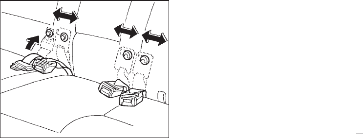
Before folding down the seat, hook the buckle
sideways on to the button and hook on the
tongue from the top.
SPA0350
REAR SEATS
2-16
Z01.2.1/R50-D X
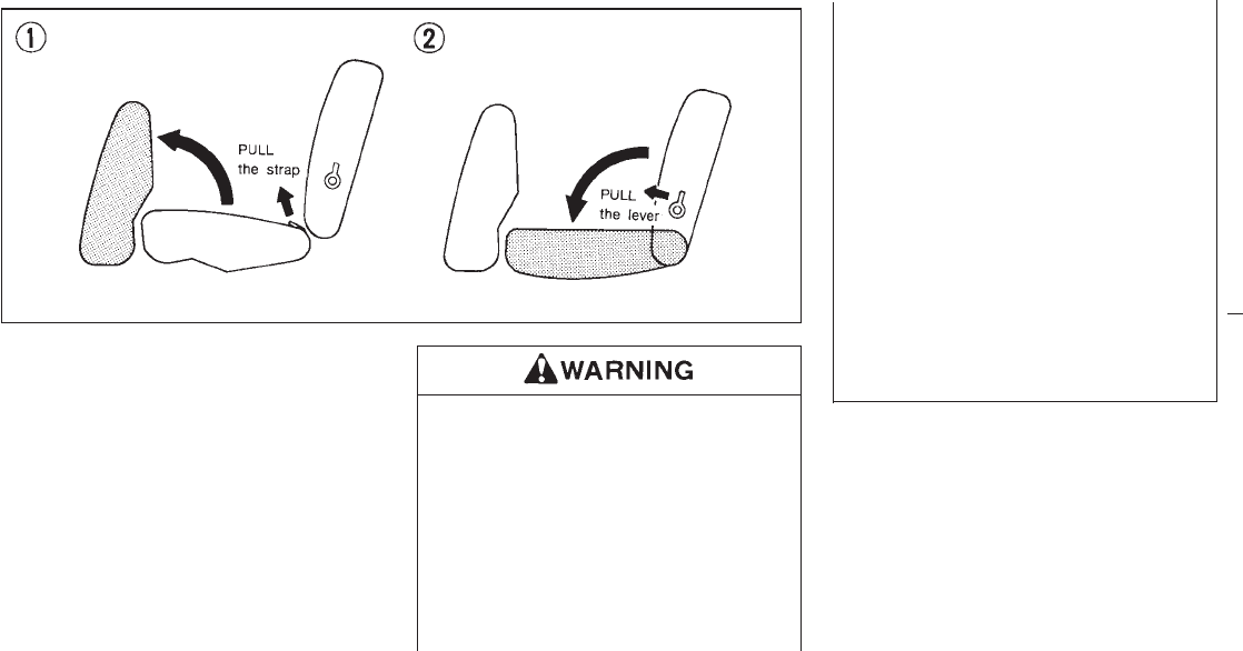
Folding
1. Remove the head restraints.
2. Pull the strap forward and fold the seat
cushion up.
3. Pull the lever and pull the seatback forward
to fold it down.
4. When resetting the seat, be sure to install
the head restraints.
INever allow anyone to ride in the
luggage area or on the rear seat when
it is in the fold-down position.
IIt is extremely dangerous to ride in a
cargo area inside of a vehicle. In a
collision, people riding in these areas
are more likely to be seriously injured
or killed.
IDo not allow people to ride in any
area of your vehicle that is not
equipped with seats and seat belts.
IBe sure everyone in your vehicle is in
a seat and using a seat belt properly.
IHead restraints should be adjusted
properly as they may provide signifi-
cant protection against injury in an
accident. Always replace and adjust
them properly if they have been re-
moved for any reason.
IIf the head restraints are removed for
any reason, they should be securely
stored to prevent them from causing
injury to passengers or damage to
the vehicle in case of sudden braking
or an accident.
IC0371
2-17
Z01.2.1/R50-D X
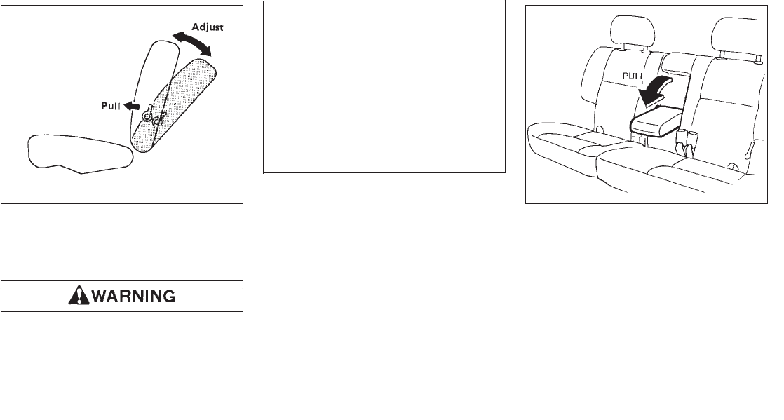
Pull the reclining lever and position the seat
back at the desired angle. Release the reclin-
ing lever after positioning the seat at the
desired angle.
IDo not ride in a moving vehicle when
the seatback is reclined. This can be
dangerous. The shoulder belt will not
be against your body. In an accident
you could be thrown into it and re-
ceive neck or other serious injuries.
You could also slide under the lap
belt and receive serious internal inju-
ries.
IFor most effective protection when
the vehicle is in motion, the seat
should be upright. Always sit well
back in the seat and adjust the seat
belt properly. See “Precautions on
seat belt usage” later in this chapter.
IAfter adjustment, check to be sure
the seat is securely locked.
Center armrest
Pull the armrest forward and lay it horizontal.
IC0385 SPA0351
2-18
Z01.2.1/R50-D X
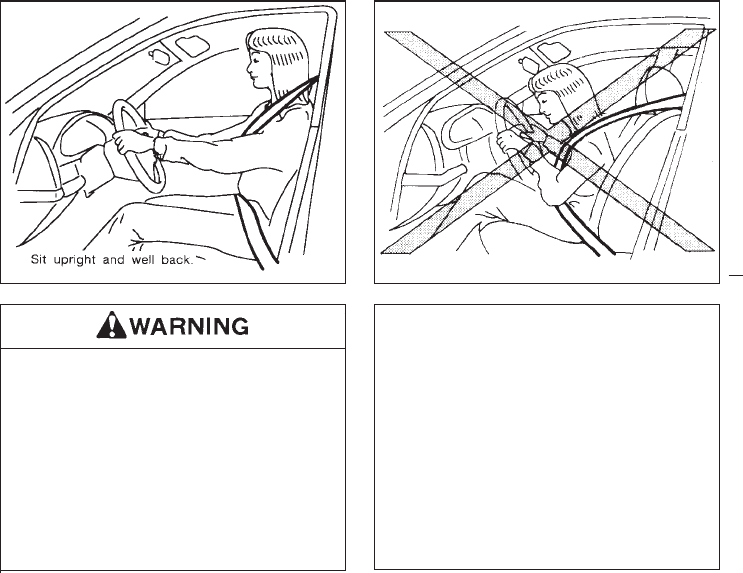
This Supplemental Restraint System section
contains important information concerning the
driver and passenger supplemental air bags.
The Supplemental Restraint System Air Bag
can help reduce impact force to the driver and
to the front passenger in certain frontal colli-
sions. The supplemental air bags are designed
to supplement the crash protection provided
by the driver and passenger seat belts and are
not a substitute for them. The seat belts
should always be correctly worn and the driver
and front passenger seated a suitable distance
away from the steering wheel and instrument
panel. (See “Seat belts” for instructions and
precautions on seat belt usage.)
After turning the ignition key to the “ON”
position, the supplemental air bag warning
light illuminates. The supplemental air bag
warning light will turn off after about 7
seconds if the system is operational. IThe supplemental air bags ordinarily
will not inflate in the event of a side
impact, rear impact, roll over, or
lower severity frontal collision. Al-
ways wear your seat belts to help
reduce the risk or severity of injury in
various kinds of accidents.
IThe seat belts and the supplemental
air bags are most effective when you
are sitting back and upright in the
seat. Supplemental air bags inflate
with great force. If you are unre-
strained, leaning forward, sitting
sideways or out of position in any
way, you are at greater risk of injury
or death in a crash and may also
receive serious or fatal injuries from
the supplemental air bag if you are up
against it when it inflates. Always sit
back against the seatback and as far
away as practical from the steering
SPA0504 SPA0505
SUPPLEMENTAL RESTRAINT
SYSTEM (SUPPLEMENTAL AIR
BAG SYSTEM)
2-19
Z01.2.1/R50-D X
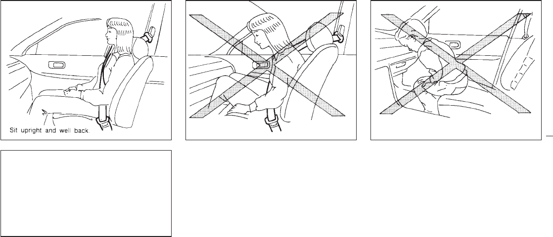
wheel or instrument panel. Always
use the seat belts.
IKeep hands on the outside of the
steering wheel. Placing them inside
the steering wheel rim could increase
the risk that they are injured when the
supplemental air bag inflates.
SPA0476 SPA0477 SPA0478
2-20
Z01.2.1/R50-D X
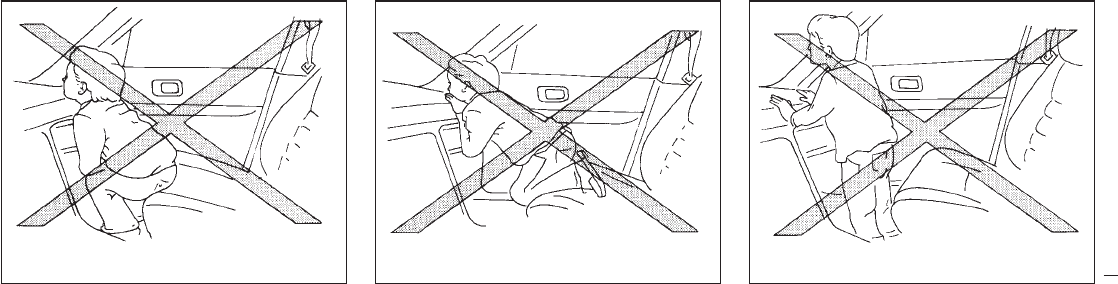
SPA0479 SPA0480 SPA0481
2-21
Z01.2.1/R50-D X
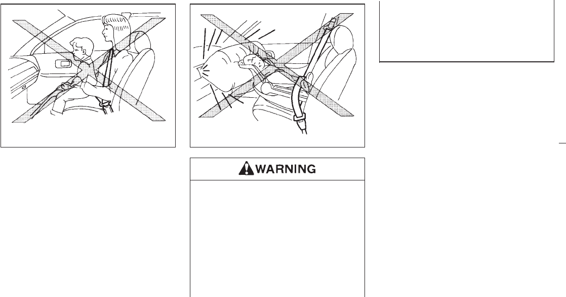
sf
INever let children ride unrestrained.
Do not attempt to hold them in your
lap or arms. Some examples of dan-
gerous riding positions are shown in
the previous illustrations.
IChildren may be severely injured or
killed when the supplemental air bag
inflates if they are not properly re-
strained.
IAlso, never install a rear-facing child
restraint in the front seat. An inflating
supplemental air bag could seriously
injury or kill your child. See “Child
restraints for infants and small chil-
dren” for details.
SPA0482 SPA0483
2-22
Z01.2.1/R50-D X
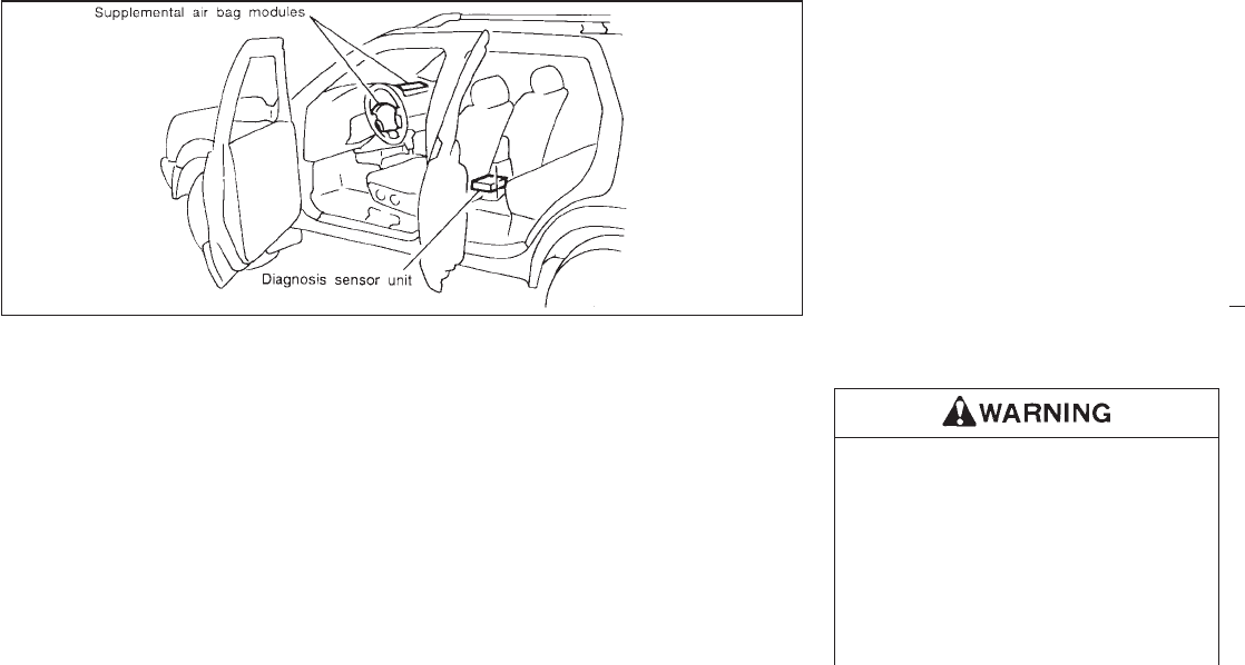
Supplemental air bag system
The driver supplemental air bag is located in
the center of the steering wheel; the front
passenger supplemental air bag is mounted in
the dashboard above the glove box. The
supplemental air bag system is designed to
inflate in higher severity frontal collisions, al-
though it may inflate if the forces in another
type of collision are similar to those of a higher
severity frontal impact. It may not inflate in
certain frontal collisions. Vehicle damage (or
lack of it) is not always an indication of proper
supplemental air bag operation.
When the supplemental air bag inflates, a fairly
loud noise may be heard, followed by release
of smoke. This smoke is not harmful and does
not indicate a fire, but care should be taken not
to inhale it, as it may cause irritation and
choking. Those with a history of breathing
trouble should get fresh air promptly.
Supplemental air bags, along with the use of
seat belts, help to cushion the impact force on
the face and chest of the occupant. They can
help save lives and reduce serious injuries.
However, an inflating supplemental air bag
may cause facial abrasions or other injuries.
Supplemental air bags do not provide restraint
to the lower body.
The seat belts should be correctly worn and
the driver and passenger seated upright as far
as practical away from the steering wheel or
dashboard. Since the supplemental air bag
inflates quickly in order to help protect the
occupant, the force of the supplemental air
bag inflating can increase the risk of injury if
the occupant is too close to or is against the
supplemental air bag module during inflation.
The supplemental air bag will deflate quickly
after a collision.
After turning the ignition key to the “ON”
position, the supplemental air bag warning
light illuminates. The supplemental air bag
warning light will turn off after about 7
seconds if the system is operational.
IDo not attach any objects to the
steering wheel pad and to the instru-
ment panel. Also, do not place any
objects between any occupant and
the steering wheel or instrument
panel. Such objects may become
dangerous projectiles and cause in-
jury if the supplemental air bag in-
flates.
SPA0390B
2-23
Z01.2.1/R50-D X

IRight after inflation, several supple-
mental air bag system components
will be hot. Do not touch them; you
may severely burn yourself.
INo unauthorized changes should be
made to any components or wiring of
the supplemental air bag system.
This is to prevent accidental inflation
of the supplemental air bag or dam-
age to the supplemental air bag sys-
tem.
IDo not make unauthorized changes
to your vehicle’s electrical system,
suspension system or front end
structure. This could affect proper
operation of the supplemental air bag
system.
ITampering with the supplemental air
bag system may result in serious
personal injury. Tampering includes
changes to the steering wheel and
the instrument panel assembly by
placing material over the steering
wheel pad and above the dashboard,
or by installing additional trim mate-
rial around the supplemental air bag
system.
IWork around and on the supplemen-
tal air bag system should be done by
an authorized NISSAN dealer. Instal-
lation of electrical equipment should
also be done by an authorized
NISSAN dealer. The SRS wiring har-
nesses* should not be modified or
disconnected. Unauthorized electri-
cal test equipment and probing de-
vices should not be used on the
supplemental air bag system.
* SRS wiring harnesses are covered
with yellow insulation either just be-
fore the harness connectors or for
the complete harness, for easy
identifi-
cation.
When selling your vehicle, we request that
you inform the buyer about the supplemen-
tal air bag system and guide the buyer to
the appropriate sections in this Owner’s
Manual.
2-24
Z01.2.1/R50-D X
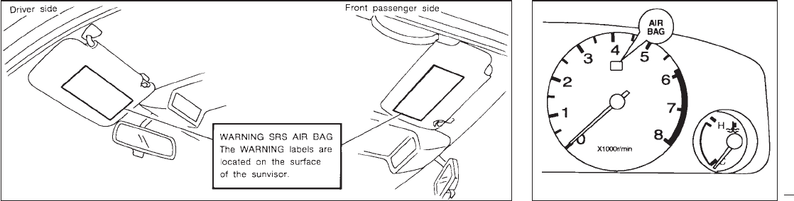
Warning labels about the supplemental air bag
system are placed in the vehicle. The supplemental air bag light, displaying “AIR
BAG” in the instrument panel, monitors the
circuits of the supplemental air bag. The cir-
cuits monitored by the supplemental air bag
light are the diagnosis sensor unit, supplemen-
tal air bag modules and all related wiring.
After turning the ignition key to the “ON” posi-
tion, the air bag warning light illuminates. The
supplemental air bag warning light will turn off
after about 7 seconds if the system is opera-
tional.
SPA0391 SPA0392
WARNING LABELS SUPPLEMENTAL AIR BAG
WARNING LIGHT
2-25
Z01.2.1/R50-D X
If any of the following conditions occurs, the
supplemental air bag needs servicing.
1. The supplemental air bag light goes off
within 7 seconds.
2. The supplemental air bag light flashes in-
termittently or remains on (after 7 seconds).
3. The supplemental air bag light does not
come on at all.
Under these conditions, the Supplemental Re-
straint System Air Bag may not operate prop-
erly. It must be checked and repaired. Take
your vehicle to the nearest authorized NISSAN
dealer.
If the supplemental air bag warning light
is on, it could mean that the supplemen-
tal air bag will not operate in an
accident.
Repair and replacement procedure
The supplemental air bag system is designed
to inflate on a one-time-only basis. As a re-
minder, unless it is damaged, the supplemen-
tal air bag light will remain illuminated after
inflation has occurred. Repair and replace-
ment of the supplemental air bag system
should be done only by authorized NISSAN
dealers.
To ensure long-term functioning, the sys-
tem must be inspected 10 years after the
date of manufacture noted on the certifica-
tion label located on the driver side center
pillar.
When maintenance work is required on the
vehicle, the supplemental air bag system and
related parts should be pointed out to the
person conducting the maintenance. The igni-
tion key should always be in the “LOCK”
position when working under the hood or in-
side the vehicle.
IOnce the supplemental air bag has
inflated, the supplemental air bag
module will not function again and
must be replaced. The supplemental
air bag module should be replaced by
an authorized NISSAN dealer. The
supplemental air bag module cannot
be repaired.
IThe supplemental air bag system
should be inspected by an authorized
NISSAN dealer if there is any damage
to the front end portion of the vehicle.
IIf you need to dispose of a supple-
mental air bag or scrap the vehicle,
contact an authorized NISSAN dealer.
Correct supplemental air bag dis-
posal procedures are set forth in the
appropriate NISSAN Service Manual.
Incorrect disposal procedures could
cause personal injury.
2-26
Z01.2.1/R50-D X
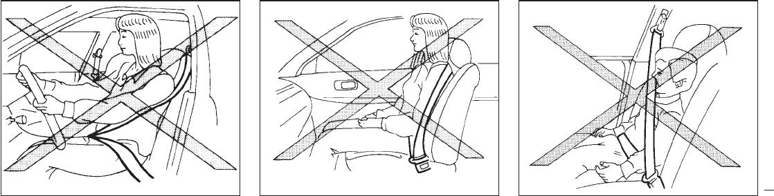
PRECAUTIONS ON SEAT BELT
USAGE
Your chances of being injured or killed in an
accident and/or the severity of injury may be
greatly reduced if you are wearing your seat
belt and it is properly adjusted. NISSAN
strongly encourages you and all of your pas-
sengers to buckle up every time you drive,
even if your seating position includes a supple-
mental air bag.
Some states, provinces or territories re-
quire that seat belts be worn at all times
when a vehicle is being driven.
SPA0506 SPA0485 SPA0486
SEAT BELTS
2-27
Z01.2.1/R50-D X
IEvery person who drives or rides in
this vehicle should use a seat belt at
all times. Children should be properly
restrained and, if appropriate, in a
child restraint.
IThe belt should be properly adjusted
to a snug fit. Failure to do so may
reduce the effectiveness of the entire
restraint system and increase the
chance or severity of injury in an
accident. Serious injury or death can
occur if the seat belt is not worn
properly.
IAlways route the shoulder belt over
your shoulder and across your chest.
Never run the belt behind your back,
under your arm or across your neck.
The belt should be away from your
face and neck, but not falling off your
shoulder.
IPosition the lap belt as low and snug
as possible AROUND THE HIPS, NOT
THE WAIST. A lap belt worn too high
could increase the risk of internal
injuries in an accident.
IBe sure the seat belt tongue is se-
curely fastened to the proper buckle.
IDo not wear the belt inside out or
twisted. Doing so may reduce its ef-
fectiveness.
IDo not allow more than one person to
use the same belt.
INever carry more people in the ve-
hicle than there are seat belts.
IIf the seat belt warning lamp glows
continuously while the ignition is
turned “ON” with all doors closed
and all seat belts fastened, it may
indicate a malfunction in the system.
Have the system checked by your
NISSAN dealer.
IAll seat belt assemblies including re-
tractors and attaching hardware
should be inspected by your NISSAN
dealer after any collision. NISSAN
recommends that all seat belt assem-
blies in use during a collision be
replaced unless the collision was mi-
nor and the belts show no damage
and continue to operate properly.
Seat belt assemblies not in use dur-
ing a collision should also be in-
spected and replaced if either dam-
age or improper operation is noted.
CHILD SAFETY
Children need adults to help protect them.
Infants and children need special pro-
tection. The vehicle’s seat belts may not
fit them properly. The shoulder belt may
come too close to the face or neck. The
lap belt may not fit over their small hip
bones. In an accident, an improperly
fitting seat belt could cause serious or
fatal injury. Always use appropriate
child restraints.
All U.S. states and provinces of Canada re-
quire the use of approved child restraints for
infants and small children. (See “Child re-
straints for infants and small children” later in
this section.)
In addition, there are many types of child
2-28
Z01.2.1/R50-D X
restraints available for larger children which
should be used for maximum protection.
Infant or small child
NISSAN recommends that infants or small
children be placed in child restraints that com-
ply with Federal Motor Vehicle Safety Stan-
dards or Canadian Motor Vehicle Safety Stan-
dards. You should choose a child restraint that
fits your vehicle and always follow the manu-
facturer’s instructions for installation and use.
Children
Children who are too large for child restraints
should be seated and restrained by the seat
belts which are provided.
NISSAN recommends that children sit in the
rear seat if possible. According to accident
statistics, children are safer when properly
restrained in the rear seat than in the front
seat.
If the child’s seating position has a shoulder
belt that fits close to the face or neck, the use
of a booster seat (commercially available) may
help overcome this. The booster seat should
raise the child so that the shoulder belt is
properly positioned across the top, middle
portion of the shoulder and the lap belt is low
on the hips. The booster seat should fit the
vehicle seat and have a label certifying that it
complies with Federal Motor Vehicle Safety
Standards or Canadian Motor Vehicle Safety
Standards. Once the child has grown so the
shoulder belt is no longer on or near the face
and neck, use the shoulder belt without the
booster seat.
Never let a child stand or kneel on any
seat and do not allow a child in the cargo
areas while the vehicle is moving. The
child could be seriously injured or killed
in an accident.
Pregnant women
NISSAN recommends that pregnant women
use seat belts. Contact your doctor for specific
recommendations. The lap belt should be
worn snug and positioned as low as possible
around the hips, not the waist.
Injured persons
NISSAN recommends that injured persons
use seat belts, depending on the injury. Check
with your doctor for specific recommendations.
2-29
Z01.2.1/R50-D X
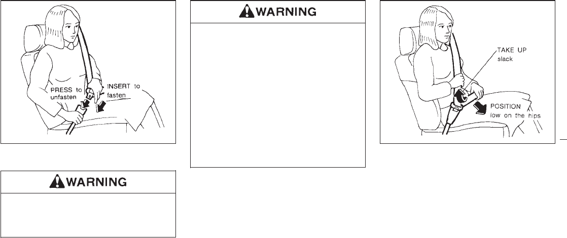
3-POINT TYPE WITH RETRACTOR
Every person who drives or rides in this
vehicle should wear a seat belt at all
times.
Fastening the belts
1. Adjust the seat.
Do not ride in a moving vehicle when the
seatback is reclined. This can be dan-
gerous. The shoulder belt will not be
against your body. In an accident you
could be thrown into it and receive neck
or other serious injuries. You could also
slide under the lap belt and receive se-
rious internal injuries.
For most effective protection when the
vehicle is in motion, the seat should be
upright. Always sit well back in the seat
and adjust the seat belt properly.
2. Slowly pull the seat belt out of the retractor
and insert the tongue into the buckle until it
snaps.
The retractor is designed to lock during a
sudden stop or on impact. A slow pulling
motion will permit the belt to move, and
allow you some freedom of movement in
the seat.
3. Position the lap belt portion low on the
hips as shown.
4. Pull the shoulder belt portion toward the
retractor to take up extra slack.
The front seat passenger side seat belt and
rear 3-point seat belts have a cinching mecha-
nism for child seat installation. It is referred to
as the automatic locking mode.
SPA0492A PD1024M
2-30
Z01.2.1/R50-D X
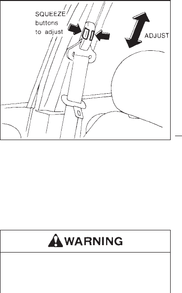
When the cinching mechanism is activated the
seat belt cannot be withdrawn again until the
seat belt tongue is detached from the buckle
and fully retracted. Refer to “Child Restraint
Systems for Infants and Small Children” later
in this section for more information.
The automatic locking mode should be
used only for child seat installation. During
normal seat belt use by a passenger, the
locking mode should not be activated. If it
is activated it may cause uncomfortable
seat belt tension.
Unfastening the belts
To unfasten the belt, press the button on the
buckle. The seat belt will automatically retract.
Checking seat belt operation
Your seat belt retractors are designed to lock
belt movement by two separate methods:
1) When the belt is pulled quickly from the
retractor.
2) When the vehicle slows down rapidly.
You can check the operation as follows:
IGrasp the shoulder belt and pull quickly
forward. The retractor should lock and re-
strict further belt movement.
If the retractor does not lock during this check
or if you have any question about belt opera-
tion, see your NISSAN dealer.
Shoulder belt height adjustment
The shoulder belt anchor height should be
adjusted to the position best suited for you
(see “Precautions on Seat Belt Usage”). To
adjust, squeeze the release buttons, then
move it to the desired position so that the belt
passes over the shoulder.
IAfter adjustment, release the button
and check that it does not move up
and down to make sure the shoulder
PD1328MA
2-31
Z01.2.1/R50-D X
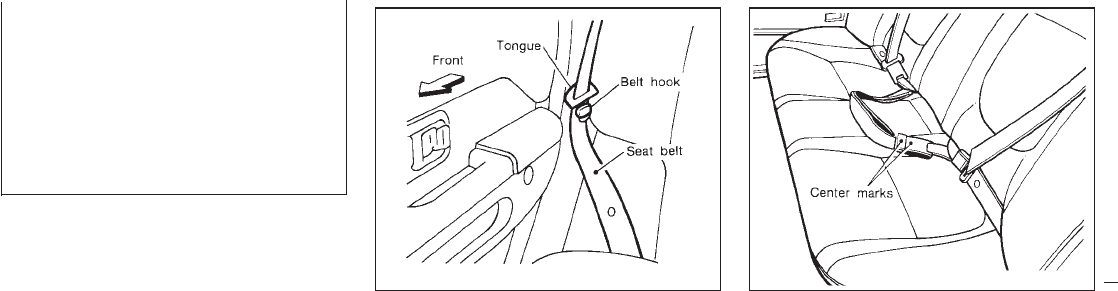
belt anchor is securely fixed in posi-
tion.
IThe shoulder belt anchor height
should be adjusted to snug fit.
Failure to do so may reduce the effec-
tiveness of the entire restraint system
and increase the chance or severity
of injury in an accident.
Belt hook
When the rear seat belt is not in use, hook it at
the belt hook.
2-POINT TYPE WITHOUT
RETRACTOR (Center position of
rear seat)
Selecting correct set of belts
The center seat belt buckle and tongue are
identified by the “CENTER” mark. The center
seat belt tongue can be fastened only into the
center seat belt buckle.
SPA0531 SPA0110
2-32
Z01.2.1/R50-D X
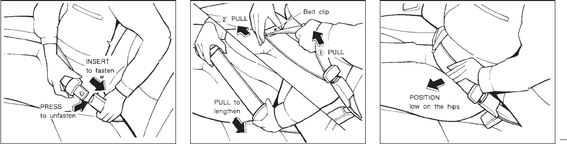
Fastening the belts
1. Slowly pull the seat belt out of the retractor
and insert the tongue into the buckle until it
snaps.
If the retractor locks and restricts further move-
ment, let the belt rewind into the retractor, then
slowly pull the belt out.
2. Position the lap belt low and snug on the
hips as shown.
3. Pull the belt toward the retractor to take up
extra slack.
Unfastening the belts
To unfasten the belt, press the button on the
buckle.
SPA0107 SPA0108 SPA0109
2-33
Z01.2.1/R50-D X
SEAT BELT EXTENDERS
If, because of body size or driving position, it is
not possible to properly fit the lap-shoulder belt
and fasten it, an extender is available which is
compatible with the installed seat belts. The
extender adds approximately 8 inches (200
mm) of length and may be used for either the
driver or right passenger seating position. See
your NISSAN dealer for assistance if the ex-
tender is required.
IOnly NISSAN belt extenders, made by
the same company which made the
original equipment belts, should be
used with NISSAN belts.
IPersons who can use the standard
seat belt should not use an extender.
Such unnecessary use could result in
serious personal injury in the event of
an accident.
SEAT BELT MAINTENANCE
ITo clean the seat belt webbings, apply a
mild soap solution or any solution recom-
mended for cleaning upholstery or carpets.
Then brush the webbing, wipe it with a cloth
and allow it to dry in the shade. Do not allow
the seat belts to retract until they are com-
pletely dry.
IIf dirt builds up in the shoulder belt guide of
the seat belt anchors, the seat belts may
retract slowly. Wipe the shoulder belt guide
with a clean, dry cloth.
IPeriodically check to see that the seat
belt and the metal components such as
buckles, tongues, retractors, flexible wires
and anchors work properly. If loose parts,
deterioration, cuts or other damage on the
webbing is found, the entire belt assembly
should be replaced.
IInfants and small children should al-
ways be placed in an appropriate
child restraint while riding in the ve-
hicle. Failure to use a child restraint
can result in serious injury or death.
IChildren and infants should never be
carried on your lap. It is not possible
for even the strongest adult to resist
the forces of a severe accident. The
child could be crushed between the
adult and parts of the vehicle. Also,
do not put the same seat belt around
both your child and yourself.
INissan recommends that the child
restraint be installed in the rear seat.
According to accident statistics, chil-
dren are safer when properly re-
strained in the rear seat than in the
front seat.
IAn improperly installed child re-
straint could lead to serious injury or
death in an accident.
CHILD RESTRAINTS FOR
INFANTS AND SMALL CHILDREN
2-34
Z01.2.1/R50-D X
In general, child restraints are designed to be
installed with a lap belt or the lap portion of a
three point type seat belt. Child restraints
specially designed for infants and small chil-
dren are offered by several manufacturers.
When selecting any child restraint, keep the
following points in mind:
1) Choose only a restraint with a label certify-
ing that it complies with Federal Motor
Vehicle Safety Standard 213 or Canadian
Motor Vehicle Safety Standard 213.
2) Check that child restraint in your vehicle to
be sure it is compatible with the vehicle’s
seat and seat belt system. Choose a child
restraint that meets the guidelines of the
Society of Automotive Engineers recom-
mended practice J1819 for child restraint
installation.
3) If the child restraint is compatible with your
vehicle, place your child in the child re-
straint and check the various adjustments
to be sure the child restraint is compatible
with your child. Always follow all recom-
mended procedures.
All U.S. states and provinces of Canada
require that infants and small children be
restrained in approved child restraints at
all times while the vehicle is being oper-
ated.
INever install a rear-facing child re-
straint in the front seat. An inflating
supplemental air bag could seriously
injure or kill your child. A rear-facing
child restraint must only be used in
the rear seat. See “Installation on
front passenger seat” for details.
IImproper use of a child restraint can
result in increased injuries for both
the infant or child and other occu-
pants in the vehicle.
IFollow all of the child restraint manu-
facturer’s instructions for installation
and use. When purchasing a child
restraint, be sure to select one which
will fit your child and vehicle. It may
not be possible to properly install
some types of child restraints in your
vehicle.
IIf the child restraint is not anchored
properly, the risk of a child being
injured in a collision or a sudden stop
greatly increases.
IAdjustable seatbacks should be posi-
tioned to fit the child restraint, but as
upright as possible.
IAfter attaching a child restraint, test
the restraint before you place the
child in it. Tilt it from side to side. Try
to tug it forward and check to see if
the belt holds it in place. If the re-
straint is not secure, tighten the belt
as necessary, or put the restraint in
another seat and test it again.
IFor a front facing child restraint, if the
seat position where it is installed has
a 3-point type lap/shoulder belt,
check to make sure the shoulder belt
does not go in front of the child’s face
or neck. If it does, put the shoulder
belt behind the child restraint.
IWhen your child restraint is not in
use, store it in the trunk or keep it
secured with a seat belt to prevent it
from being thrown around in case of
a sudden stop or accident.
2-35
Z01.2.1/R50-D X
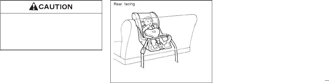
Remember that a child restraint left in a
closed vehicle can become very hot.
Check the seating surface and buckles
before placing your child in the child
restraint.
Installation on rear seat
Center lap belt
When you install a child restraint in a rear
center seat, follow these steps:
1. Position the child restraint on the seat as
illustrated. It can be placed in a forward
facing or rear facing direction, depending
on the size of the child. Always follow the
restraint manufacturer’s instructions.
2. Route the seat belt tongue through the child
restraint and insert it into the buckle until
you hear and feel the latch engage. Be sure
to follow the child restraint manufacturer’s
instructions for belt routing.
3. Remove all slack in the lap belt for a very
tight fit by pulling forcefully on the lap belt
adjustment.
4. Before placing the child in the child re-
straint, use force to tilt the child restraint
from side to side, and tug it forward to make
sure that it is securely held in place.
5. If it is not secure, try to tighten the belt
again, or put the restraint in another seat.
6. Check to make sure the child restraint is
properly secured prior to each use.
SPA0276
2-36
Z01.2.1/R50-D X
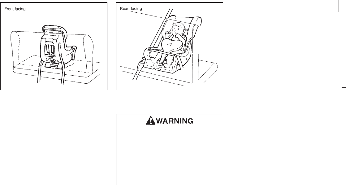
Installation on rear outboard seating
positions
IThe 3-point belt on your vehicle is
equipped with a locking mode retrac-
tor which must be used when install-
ing a child restraint.
IFailure to do so will result in the child
restraint not being properly secured.
It could tip over or otherwise be un-
secured and cause injury to the child
in a sudden stop or collision.
When you install a child restraint in a rear
outboard seat, follow these steps:
1. Position the child restraint on the seat. It
can be placed in a front facing or rear facing
direction, depending on the size of the
child. Always follow the restraint manufac-
turer’s instructions.
2. Route the seat belt tongue through the child
restraint and insert it into the buckle until
you hear and feel the latch engage. Be sure
to follow the child restraint manufacturer’s
instructions for belt routing.
3. Pull on the shoulder belt until all of the belt
is fully extended and a click is heard. At this
time, the belt retractor is in the automatic
locking mode (child restraint mode). It will
revert back to “emergency locking” when
the belt is fully retracted.
4. Allow the belt to retract. A clicking sound
will be heard as the belt retracts. This
indicates that the retractor is in the auto-
matic locking mode. Pull up on the belt to
remove any slack in the belt.
PD1174 PD1331
2-37
Z01.2.1/R50-D X
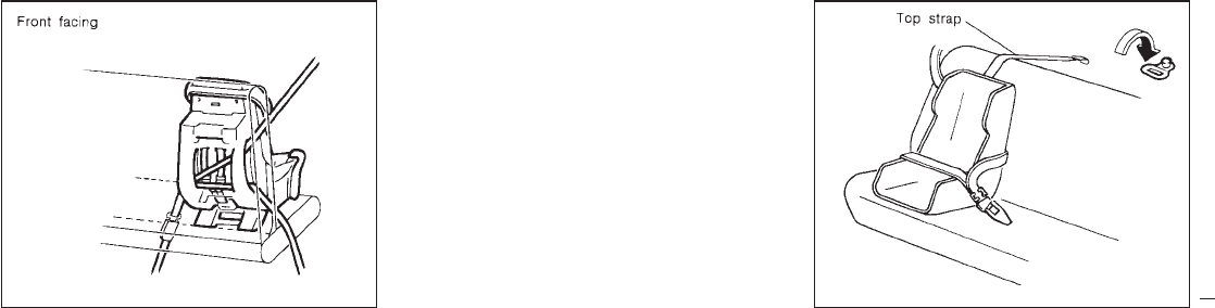
5. Before placing the child in the child re-
straint, use force to tilt the child restraint
from side to side, and tug it forward to make
sure that it is securely held in place.
6. Check that the retractor is in the automatic
locking mode by trying to pull more belt out
of the retractor. If you cannot pull any more
belt webbing out of the retractor, the belt is
in the automatic locking mode.
7. Check to make sure that the child restraint
is properly secured prior to each use. If the
belt is not locked, repeat steps 3 through 6.
After the child restraint is removed and the
seat belt is allowed to wind back into the
retractor, the automatic locking mode (child
restraint mode) is canceled; the seat belt may
be used as normal and will only lock during a
sudden stop or impact.
Top strap child restraint
If your child restraint has a top strap, install the
anchor bracket to the provided anchor point.
The top strap anchor bracket is available
through your NISSAN dealer.
Part No. 88894-89900
Secure the child restraint with the center lap
belt or the lap portion of an outboard 3-point
belt and latch the top strap hook onto the
appropriate anchor bracket. To install the an-
chor bracket, a metric bolt of the dimensions
listed below must be used.
PD1332 SIC0131
2-38
Z01.2.1/R50-D X
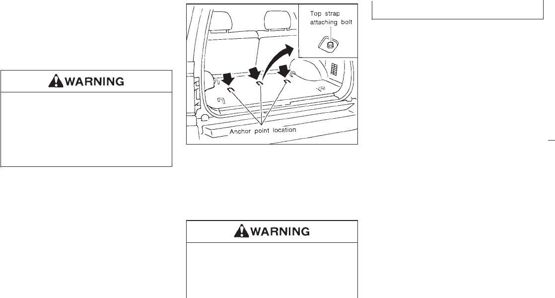
Bolt diameter: 8.0 mm
Bolt length: more than 1.18 in (30 mm)
Thread pitch: 1.25 mm
The top strap should be secured to the attach-
ing bolt which provides the straightest installa-
tion of the top strap.
Child restraint anchor points are de-
signed to withstand only those loads
imposed by correctly fitted child re-
straints. Under no circumstances are
they to be used for adult seat belts or
harnesses. Anchor point locations
Anchor point attaching bolts are located under
the carpet of the rear luggage area floor.
Your NISSAN dealer can assist you with the
installation of your child restraint.
The anchor bolt should be installed at all
times to prevent the possibility of ex-
haust fumes entering the passenger
compartment through the holes. See
“Exhaust gas” in the “Starting and driv-
ing” section.
SPA0393
2-39
Z01.2.1/R50-D X
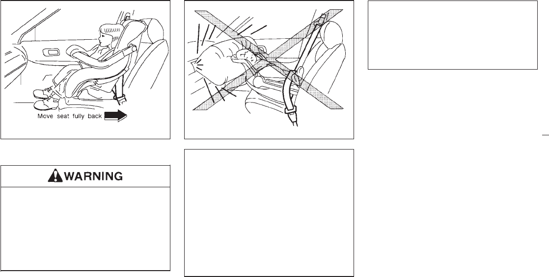
Installation on front passenger seat
INever install a rear-facing child re-
straint in the front passenger seat.
Supplemental air bags inflate with
great force. A rear-facing child re-
straint could be struck by the supple-
mental air bag in a crash and could
seriously injure or kill your child.
IIf you install a front-facing child re-
straint in the front passenger seat,
place the passenger seat as far back
as possible.
IA child restraint with a top strap
should not be used in the front pas-
senger seat.
IThe 3-point belt in your vehicle is
equipped with a locking mode retrac-
tor which must be used when install-
ing a child restraint.
IFailure to use the retractor’s locking
mode may result in the child restraint
not being properly secured. The re-
straint could tip over or otherwise be
unsecured and cause injury to the
child in a sudden stop or collision.
When you install a child restraint in the front
seat, follow these steps:
1. Position the child restraint on the front
passenger seat. It should be placed in a
front-facing direction only. Move the seat
as far back from the instrument panel as
possible. Always follow the child restraint
manufacturer’s instructions. Child re-
straints for infants must be used in the
rear-facing direction and therefore must
not be used in the front seat.
2. Route the seat belt tongue through the child
restraint and insert it into the buckle until
you hear and feel the latch engage.
SPA0487 SPA0483
2-40
Z01.2.1/R50-D X
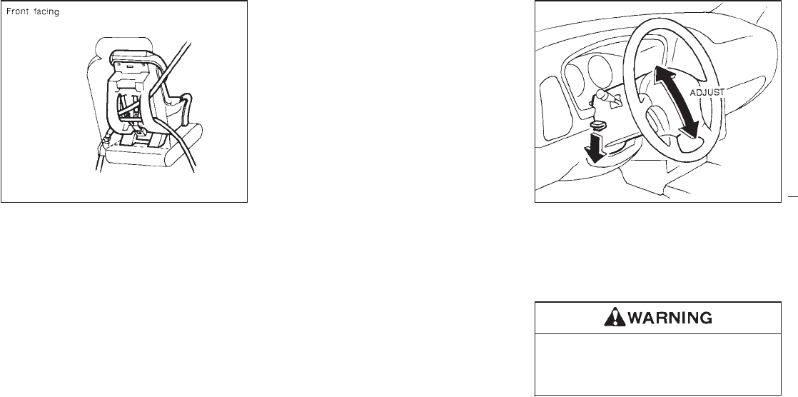
Be sure to follow the child restraint manufac-
turer’s instructions for belt routing.
3. Pull on the shoulder belt until all of the belt
is fully extended and a click is heard. At this
time, the belt retractor is in the automatic
locking mode (child restraint mode). (It will
revert back to “emergency locking” when
the belt is fully retracted.)
4. Allow the belt to retract. A clicking sound
will be heard as the belt retracts. This
indicates that the retractor is in the auto-
matic locking mode. Pull up on the belt to
remove any slack in the belt.
5. Before placing the child in the child re-
straint, use force to tilt the child restraint
from side to side, and tug it forward to make
sure that it is securely held in place.
6. Check that the retractor is in the automatic
locking mode by trying to pull more belt out
of the retractor. If you cannot pull any more
belt webbing out of the retractor, the belt is
in the automatic locking mode.
7. Check to make sure that the child restraint
is properly secured prior to each use. If the
lap belt is not locked, repeat steps 3
through 6.
After the child restraint is removed and the
seat belt is allowed to wind back into the
retractor, the automatic locking mode (child
restraint mode) is canceled; the seat belt may
be used as normal and will only lock during a
sudden stop or impact.
Tilt operation
While pushing down on the lock lever, adjust
the steering wheel up or down to the desired
position. Push the lock lever up securely to
lock the steering wheel in place.
Do not adjust the steering wheel while
driving. You could lose control of your
vehicle and cause an accident.
PD1336 SPA0394
TILTING STEERING WHEEL
2-41
Z01.2.1/R50-D X
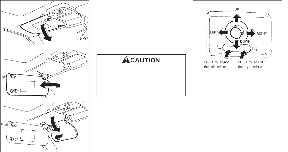
1. To block out glare from the front, swing
down the main sun visor.
2. To block glare from the side, remove the
main sun visor from the center mount and
swing it to the side.
3. Then, to block glare from the front too,
swing down the sub-sun visor.
4. To adjust the glare block position, slide the
sub-sun visor to the left.
IDo not store the main sun visor be-
fore storing the sub-sun visor.
IDo not pull the sub-sun visor forcedly
downwards.
Electrical control type
(If so equipped)
Push the right or left end of the switch to adjust
the right or left side mirror, then control the
lever.
SPA0395
SPA0112
SUN VISORS OUTSIDE MIRROR CONTROL
2-42
Z01.2.1/R50-D X
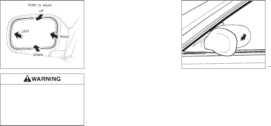
Objects viewed in the outside mirror on
the passenger side are closer than they
appear. Be careful when moving to the
right. Using only this mirror could cause
an accident. Use inside mirror or glance
over your shoulder to properly judge
distances to other objects.
Manual control type
The outside mirror can be moved in any direc-
tion for a better rear view.
Folding outside mirror
Push the mirror backward to fold it.
PD1183M M008
OUTSIDE MIRRORS
2-43
Z01.2.1/R50-D X
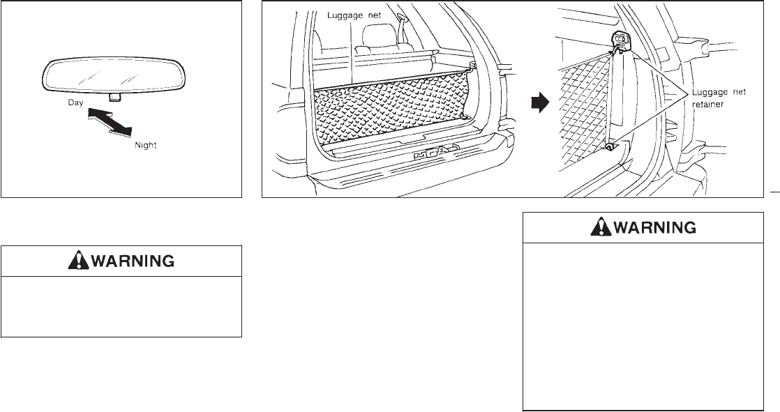
The night position will reduce glare from the
headlights of vehicles behind you at night.
Use the night position only when neces-
sary, because it reduces rear view
clarity.
The luggage net keeps packages in the cargo
area from moving around while your vehicle is
driven.
To install the luggage net, attach the four
hooks to the four retainers.
To remove the luggage net, detach the four
hooks from the luggage net retainers.
IProperly secure all cargo to help pre-
vent it from sliding or shifting. Do not
place cargo higher than the seat-
backs. In a sudden stop or collision,
unsecured cargo could cause per-
sonal injury.
IBe sure to secure all four hooks into
the retainers. The cargo restrained in
the net must not exceed 30 lbs. (13.6
kg) or the net may not stay secured.
PD1006M SPA0396
INSIDE MIRROR LUGGAGE NET
2-44
Z01.2.1/R50-D X
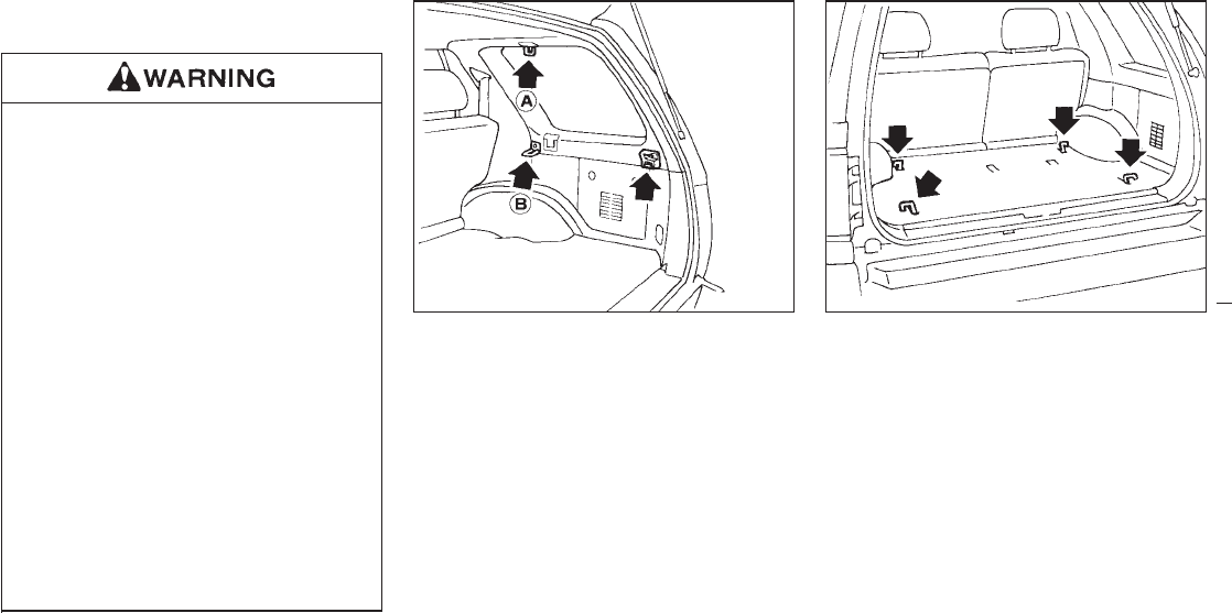
The luggage hooks can be used to secure
cargo with ropes or other types of straps.
IProperly secure all cargo to help pre-
vent it from sliding or shifting. Do not
place cargo higher than the seat-
backs. In a sudden stop or collision,
unsecured cargo could cause per-
sonal injury.
IUse the suitable ropes and hooks to
secure cargo.
INever allow anyone to ride in the
luggage area. It is extremely danger-
ous to ride in a cargo area inside of a
vehicle. In a collision, people riding in
these areas are more likely to be
seriously injured or killed.
IDo not allow people to ride in any
area of your vehicle that is not
equipped with seats and seat belts.
IBe sure everyone in your vehicle is in
a seat and using a seat belt properly.
Side finisher
IWhen hooking on ropes, do not apply a
load of more than 98 N (10 kg, 22 lb) to a
single hook.
IDo not use the luggage net between the
A and B hooks.
Floor hooks
SPA0408A SPA0365
LUGGAGE HOOKS
2-45
Z01.2.1/R50-D X
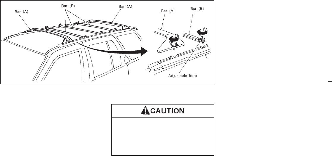
The cross-bars can be adjusted forward and
backward. Place your luggage between the
bars (A), adjust the bars (A), and secure the
luggage with rope to the bars (A). There are
also adjustable loops on the side bars for the
rope attachment.
Always evenly distribute the luggage on the
luggage rack. Do not load more than 100 lbs.
(45 kg). Be careful that your vehicle does not
exceed the Gross Vehicle Weight Rating
(GVWR) or its Gross Axle Weight Rating
(GAWR front and rear). The GVWR and
GAWR are located on the Safety Compliance
Certification Label (located on the driver’s door
pillar). For more information regarding GVWR
and GAWR, refer to “Technical and customer
information”.
Use care when placing or removing
items from the luggage rack. If you can-
not comfortably lift the items onto the
luggage rack from the ground, use a
ladder or stool.
SPA0397
LUGGAGE RACK
2-46
Z01.2.1/R50-D X

3 Heater, air conditioner and audio system
Center and side vent ............................................. 3-2
Heater and air conditioner ....................................... 3-3
Semiautomatic air conditioner ................................. 3-7
Radio .................................................................... 3-15
Power antenna (If so equipped) ............................ 3-26
Manual antenna ................................................... 3-27
CB radio or car phone ......................................... 3-27
Z01.2.1/R50-D X
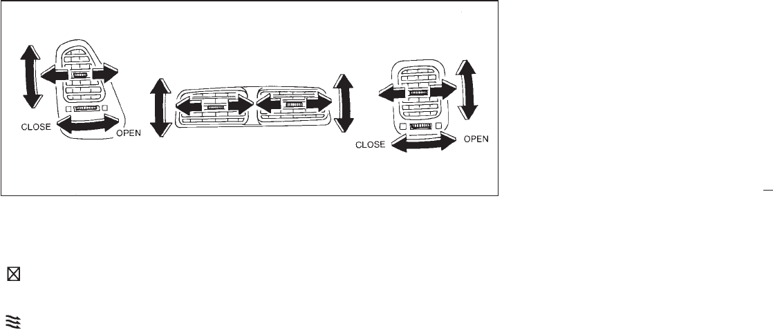
Side ventilators
Open or close, and adjust the air flow direction
of ventilators.
: This symbol indicates that the vents are
closed when the vent switch is moved
to the left.
: This symbol indicates that the vents are
open when the vent switch is moved to
the right.
Center ventilators
Adjust the air flow direction of ventilators.
SAA0159
CENTER AND SIDE VENT
3-2
Z01.2.1/R50-D X
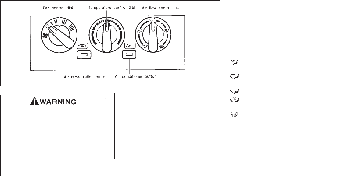
IThe air conditioner cooling function
operates only when the engine is run-
ning.
IDo not leave children, unreliable
adults, or pets alone in your vehicle.
On hot, sunny days, temperatures in
a closed vehicle could quickly be-
come high enough to cause severe or
possibly fatal injuries to people or
animals.
IDo not use the recirculation mode for
long periods as it may cause the
interior air to become stale and the
windows to fog up.
IPositioning of the heating or air con-
ditioning controls should not be done
while driving, in order that full atten-
tion may be given to the driving
operation.
CONTROLS
Fan control dial
This dial turns the fan on and off, and controls
fan speed.
Air flow control dial
This dial allows you to select the air flow
outlets.
— Air flows from center and side venti-
lators.
— Air flows from center and side venti-
lators and foot outlets.
— Air flows mainly from foot outlets.
— Air flows from defroster outlets and
foot outlets.
— Air flows mainly from defroster out-
lets.
Temperature control dial
This dial allows you to adjust the temperature
of the outlet air.
SAA0152B
HEATER AND AIR CONDITIONER
3-3
Z01.2.1/R50-D X
Air recirculation button
OFF position
Outside air is drawn into the passenger com-
partment.
Use the off position for normal heater, or air
conditioner operation.
ON position (Indicator light ON)
Interior air is recirculated inside the vehicle.
Push the air recirculation button to the “ON”
position when driving on a dusty road or to
avoid traffic fumes.
Air conditioner button
This button is provided only for vehicles with
air conditioner.
Start the engine, move the fan control dial to
the desired (1 to 4) position and push the air
conditioner button to turn on the air condi-
tioner. The indicator light will come on when
the air conditioner button is on. To stop the air
conditioner, push the switch again to return it
to the original position.
The air conditioner cooling function oper-
ates only when the engine is running.
HEATER OPERATION
Heating
This mode is used to direct hot air from the
floor outlets.
1. Push the air recirculation button to the
“OFF” position for normal heating.
2. Turn the air control dial to the “ ” posi-
tion.
3. Turn on the fan control dial.
4. Turn the temperature control dial to the
desired position between the middle and
the “HOT” position.
IFor quick heating, move the air recirculation
button to the “ON” position. Be sure to
return the air recirculation button to the
“OFF” position for normal heating.
Ventilation
This mode directs outside air from the side and
centre vents.
1. Push the air recirculation button to the
“OFF” position.
2. Turn the air control dial to the “ ” posi-
tion.
3. Turn on the fan control dial.
4. Turn the temperature control dial to the
desired position.
Defrosting or defogging
This mode is used to defrost/defog the win-
dows.
1. Push the air recirculation button to the
“OFF” position.
2. Turn the air control dial to the “ ”
position.
3. Turn on the fan control dial.
4. Turn the temperature control dial to the
desired position between the middle and
the “HOT” position.
ITo quickly remove ice or fog from the
windows, push the air recirculation button
to the “ON” position, the fan control dial to
“4” and the temperature control dial to the
full “HOT” position. As soon as possible
after the window is clear, push the air
recirculation button to the “OFF” position.
Bi-level heating
This mode directs outside air from the side and
center vents and hot air from the floor outlets.
1. Push the air recirculation button to the
“OFF” position.
3-4
Z01.2.1/R50-D X

2. Turn the air control dial to the “ ” posi-
tion.
3. Turn on the fan control dial.
4. Normally turn the temperature control dial
to the midpoint between “HOT” and
“COLD”.
Heating and defogging
This mode heats the interior and defogs the
windscreen.
1. Push the air recirculation button to the
“OFF” position.
2. Turn the air control dial to the “ ” posi-
tion.
3. Turn on the fan control dial.
4. Turn the temperature control dial to the
desired position between the middle and
the “HOT” position.
Operating tips
IClear snow and ice from the wiper blade
and air inlet in front of the windshield.
This will improve heater operation.
IA slight delay may be experienced when
turning the air control dial. This is not a
problem, it is only the system motors and
solenoids switching from one outlet to an-
other.
AIR CONDITIONER OPERATION
Start the engine, move the fan control dial to
the desired (1 to 4) position and push in the air
conditioner button to activate the air condi-
tioner. When the air conditioner is on, cooling
and dehumidifying functions will be added to
the heater operation.
The air conditioner cooling function oper-
ates only when the engine is running.
Cooling
This mode is used to cool and dehumidify.
1. Push the air recirculation button to the
“OFF” position.
2. Turn the air control dial to the “ ” posi-
tion.
3. Turn on the fan control dial.
4. Push on the air conditioner button. The
indicator light will come on.
5. Turn the temperature control dial to the
desired position.
IFor quick cooling when the outside tem-
perature is high, push the air recirculation
button to the “ON” position. Be sure to
return the air recirculation button to the
“OFF” position for normal cooling.
Dehumidified heating
This mode is used to heat and dehumidify.
1. Push the air recirculation button to the
“OFF” position.
2. Turn the air control dial to the “ ” posi-
tion.
3. Turn on the fan control dial.
4. Push on the air conditioner button. The
indicator light will come on.
5. Turn the temperature control dial to the
desired position.
Dehumidified defogging
This mode is used to defog the windows and
dehumidify.
1. Push the air recirculation button to the
“OFF” position.
2. Turn the air control dial to the “ ”
position.
3. Turn on the fan control dial.
4. Push on the air conditioner button. The
indicator light will come on.
3-5
Z01.2.1/R50-D X

5. Turn the temperature control dial to the
desired position.
Operating tips
IKeep windows and sun roof closed while
the air conditioner is in operation.
IAfter parking in the sun, drive for two or
three minutes with the windows open to
vent hot air from the passenger compart-
ment. Then, close the windows. This will
allow the air conditioner to cool the interior
more quickly.
IThe air conditioning system should be
operated for about ten minutes at least
once a month. This helps prevent dam-
age to the system due to lack of lubrica-
tion.
IIf the coolant temperature gauge exceeds
the HOT position, turn the air conditioner
off. See “If your vehicle overheats” in the “In
case of emergency” section for additional
information.
3-6
Z01.2.1/R50-D X
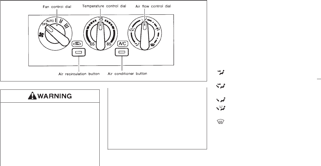
IThe air conditioner cooling function
operates only when the engine is run-
ning.
IDo not leave children, unreliable
adults, or pets alone in your vehicle.
On hot, sunny days, temperatures in
a closed vehicle could quickly be-
come high enough to cause severe or
possibly fatal injuries to people or
animals.
IDo not use the recirculation mode for
long periods as it may cause the
interior air to become stale and the
windows to fog up.
IPositioning of the heating or air con-
ditioning controls should not be done
while driving, in order that full atten-
tion may be given to the driving
operation.
CONTROLS
Fan control dial
This dial turns the fan on and off, and controls
fan speed.
Auto mode: This mode controls the fan speed
automatically.
Air flow control dial
This dial allows you to select the air flow
outlets.
— Air flows from center and side venti-
lators.
— Air flows from center and side venti-
lators and foot outlets.
— Air flows mainly from foot outlets.
— Air flows from defroster outlets and
foot outlets.
— Air flows mainly from defroster out-
lets.
Temperature control dial
This dial allows you to adjust the temperature
of the outlet air.
SAA0153B
SEMIAUTOMATIC AIR
CONDITIONER
3-7
Z01.2.1/R50-D X

Air recirculation button
OFF position
Outside air is drawn into the passenger com-
partment when this button is off.
Use the off position for normal heater or air
conditioner operation.
ON position
Interior air is recirculated inside the vehicle.
Push the button on when driving on a dusty
road. The indicator light will come on.
Air conditioner button
Start the engine, turn the fan control dial to the
desired (Auto, 1 to 3) position and push the air
conditioner button to turn on the air condi-
tioner. The indicator light will come on when
the air conditioner is on. To stop the air con-
ditioner, push the switch again to return it to
the original position.
The air conditioner cooling function oper-
ates only when the engine is running.
HEATER OPERATION
Heating
This mode is used to direct hot air from the
floor outlets.
1. Push the air recirculation button OFF for
normal heating.
2. Turn the air control dial to the “ ” posi-
tion.
3. (Manual mode)
Turn on the fan control dial (1 to 3).
(Auto mode)
Turn the fan control dial to the AUTO
position.
IThe fan speed will be maintained automati-
cally.
4. Turn the temperature control dial to set the
desired temperature.
IAdjust the temperature control dial to about
75°F (24°C) for normal operation.
IThe temperature will be maintained auto-
matically.
IFor quick heating, push the air recirculation
button ON. Be sure to turn off the air
recirculation button for normal heating.
IWhen starting up from cold with the fan
control dial in the AUTO position, the
blower speed will be fixed in the low mode
until the coolant temperature rises.
Ventilation
This mode directs outside air from the side,
center and driver vents.
1. Push the air recirculation button OFF.
2. Turn the air control dial to the “ ” posi-
tion.
3. (Manual mode)
Turn on the fan control dial (1 to 3).
(Auto mode)
Turn the fan control dial to the AUTO
position.
IThe fan speed will be maintained automati-
cally.
4. Turn the temperature control dial to set the
desired temperature.
IThe temperature will be maintained auto-
matically.
3-8
Z01.2.1/R50-D X
Defrosting or defogging
This mode is used to defrost/defog the win-
dows.
1. Push the air recirculation button OFF.
2. Turn the air control dial to the “ ”
position.
3. (Manual mode)
Turn on the fan control dial (1 to 3).
(Auto mode)
Turn the fan control dial to the AUTO
position.
IThe fan speed will be maintained automati-
cally.
4. Turn the temperature control dial to the
desired position.
ITo quickly remove ice or fog from the
windows, turn the fan control dial to “3” and
the temperature control dial fully over to the
“HOT” position.
Bi-level heating
This mode directs outside air from the side and
center vents and hot air from the floor outlets.
1. Push the air recirculation button OFF.
2. Turn the air control dial to the “ ” posi-
tion.
3. (Manual mode)
Turn on the fan control dial (1 to 3).
(Auto mode)
Turn the fan control dial to the AUTO
position.
IThe fan speed will be maintained automati-
cally.
4. Turn the temperature control dial to set the
desired temperature.
IAdjust the temperature control dial to about
75°F (24°C) for normal operation.
IThe temperature will be maintained auto-
matically.
Heating and defogging
This mode heats the interior and defogs the
windshield.
1. Push the air recirculation button OFF.
2. Turn the air control dial to the “ ” posi-
tion.
3. (Manual mode)
Turn on the fan control dial (1 to 3).
(Auto mode)
Turn the fan control dial to the AUTO
position.
IThe fan speed will be maintained automati-
cally.
4. Turn the temperature control dial to set the
desired temperature.
IAdjust the temperature control dial to about
75°F (24°C) for normal operation.
IThe temperature will be maintained auto-
matically.
Operating tips
IClear snow and ice from the wiper blade
and air inlet in front of the windshield.
This will improve heater operation.
AIR CONDITIONER OPERATION
Start the engine, turn the fan control dial to the
desired (Auto, 1 to 3) position and push in the
air conditioner button to activate the air condi-
tioner. When the air conditioner is on, cooling
and dehumidifying functions will be added to
the heater operation.
The air conditioner cooling function oper-
ates only when the engine is running.
3-9
Z01.2.1/R50-D X

Cooling
This mode is used to cool and dehumidify.
1. Push the air recirculation button OFF.
2. Turn the air control dial to the “ ” posi-
tion.
3. (Manual mode)
Turn on the fan control dial (1 to 3).
(Auto mode)
Turn the fan control dial to the AUTO
position.
IThe fan speed will be maintained automati-
cally.
4. Push the air conditioner button on. The
indicator light will come on.
5. Turn the temperature control dial to set the
desired temperature.
IAdjust the temperature control dial to about
75°F (24°C) for normal operation.
IThe temperature will be maintained auto-
matically.
IFor quick cooling when the outside tem-
perature is high, push the air recirculation
button on. Be sure to turn off the air recir-
culation button for normal cooling.
Dehumidified heating
This mode is used to heat and dehumidify.
1. Push the air recirculation button OFF.
2. Turn the air control dial to the “ ” posi-
tion.
3. (Manual mode)
Turn on the fan control dial (1 to 3).
(Auto mode)
Turn the fan control dial to the AUTO
position.
IThe fan speed will be maintained automati-
cally.
4. Push on the air conditioner button. The
indicator light will come on.
5. Turn the temperature control dial to set the
desired temperature.
IAdjust the temperature control dial to about
75°F (24°C) for normal operation.
IThe temperature will be maintained auto-
matically.
Dehumidified defogging
This mode is used to defog the windows and
dehumidify.
1. Push the air recirculation button OFF to
improve the defogging performance.
2. Turn the air control dial to the “ ”
position.
3. (Manual mode)
Turn on the fan control dial (1 to 3).
(Auto mode)
Turn the fan control dial to the AUTO
position.
4. Turn the temperature control dial to the
desired position.
Operating tips
IKeep windows and sun roof closed while
the air conditioner is in operation.
IAfter parking in the sun, drive for two or
three minutes with the windows open to
vent hot air from the passenger compart-
ment. Then, close the windows. This will
allow the air conditioner to cool the interior
more quickly.
IThe air conditioning system should be op-
erated for about ten minutes at least once a
month. This helps prevent damage to the
system due to lack of lubrication.
IIf the coolant temperature gauge exceeds
3-10
Z01.2.1/R50-D X

the “HOT” position, turn the air conditioner
off. See “If your vehicle overheats ”in the “In
case of emergency” section for additional
information.
IIf the engine coolant reaches an extremely
high temperature, the air conditioning sys-
tem will automatically turn off. This may
happen for example if the engine is run at
idle for a long time on a hot day.
AIR FLOW CHARTS
The following charts show the button and dial
positions for MAXIMUM AND QUICK heating,
cooling or defrosting. The air recirculation
switch should always be in the “OFF” po-
sition for heating and defrosting.
3-11
Z01.2.1/R50-D X
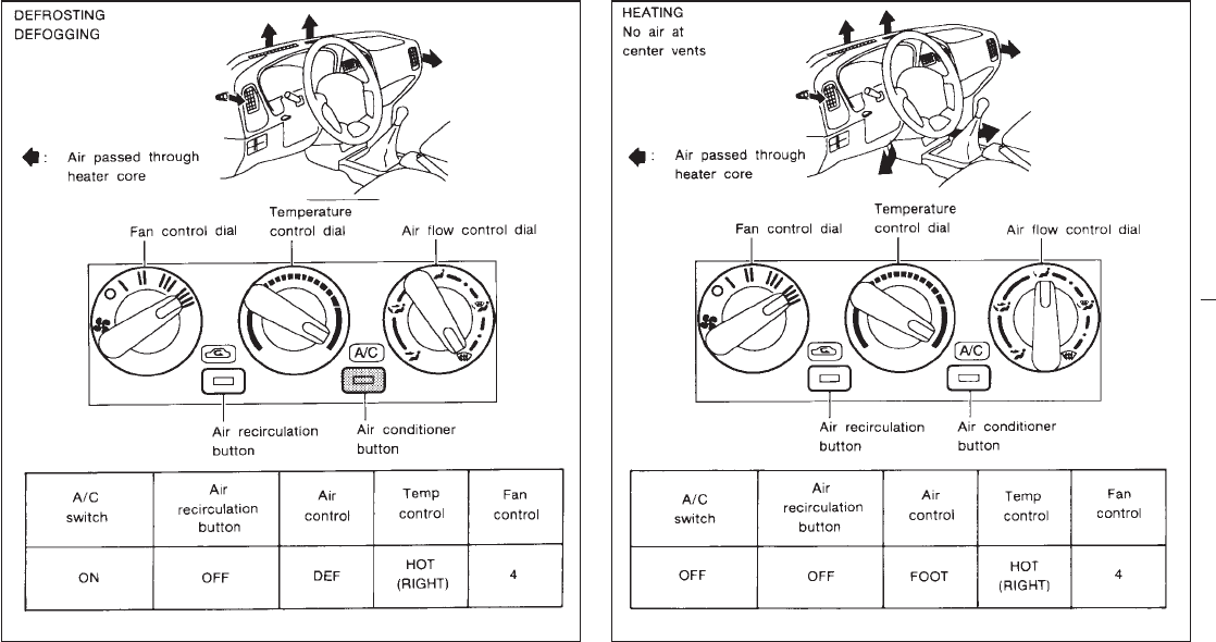
SAA0154A SAA0155A
3-12
Z01.2.1/R50-D X
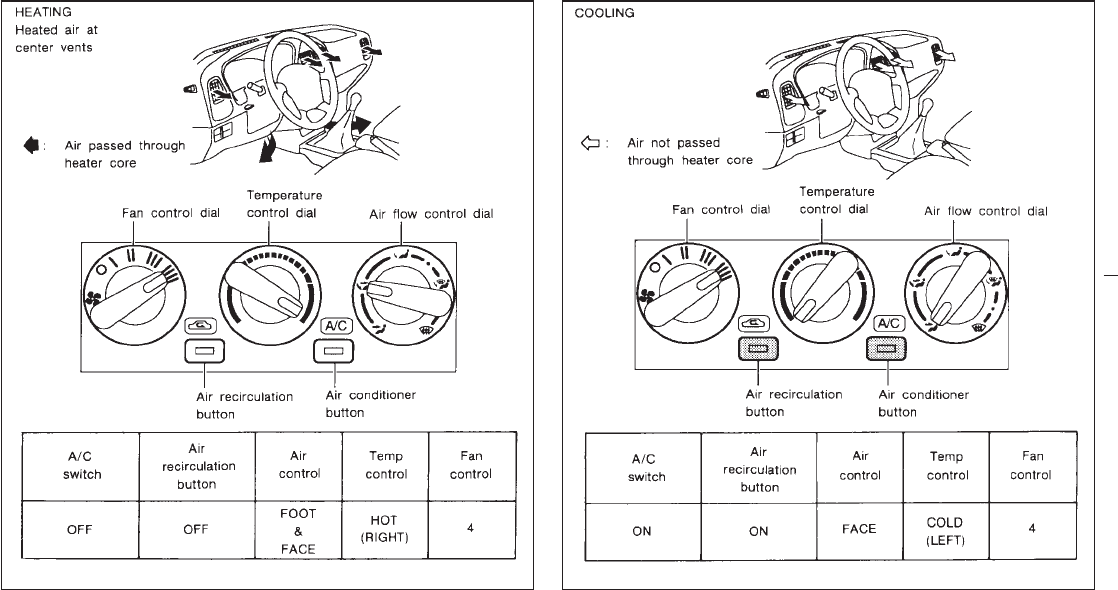
SAA0156A SAA0157A
3-13
Z01.2.1/R50-D X
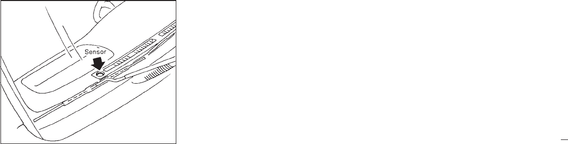
The sensor on the instrument panel helps
maintain a constant temperature. Do not put
anything on or around this sensor.
Servicing air conditioner
The air conditioning system in your NISSAN
vehicle is charged with a refrigerant designed
with the environment in mind.
This refrigerant will not harm the earth’s
ozone layer.
However, special charging equipment and lu-
bricant are required when servicing your
NISSAN air conditioner. Using improper refrig-
erants or lubricants will cause severe damage
to your air conditioning system. See “Air Con-
ditioning system refrigerant and lubricant rec-
ommendations” in the “Technical and con-
sumer information” section of this manual.
Your NISSAN dealer will be able to service
your environmentally “friendly” air conditioning
system.
SAA0158
3-14
Z01.2.1/R50-D X
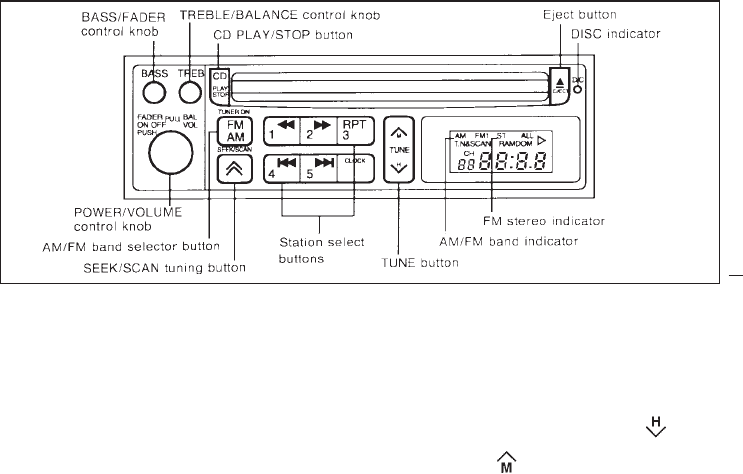
To turn the radio on, turn the ignition key to
“ACC” or “ON”. If you listen to the radio with
the engine not running, turn the key to the
“ACC” position.
Radio reception is affected by station signal
strength, distance from radio transmitter, build-
ings, bridges, mountains, and other external
influences. Intermittent changes in reception
quality normally are caused by these external
influences.
AM-FM RADIO WITH COMPACT
DISC PLAYER
The electronic tuning radio has an FM Diver-
sity reception system, which employs two an-
tennas. One is a rod type antenna; the other is
an antenna printed on the window. This sys-
tem automatically switches to the antenna
which is receiving less noise.
Radio operation
Push the FM/AM button to listen to the radio
and tune in the desired station.
Pushing the FM/AM button while the com-
pact disc is playing will turn off the com-
pact disc player and turn on the radio.
Turn the ON.VOL knob to adjust the volume.
Clock set (Adjustment)
Depressing the “CLOCK” and the “ ” but-
tons together will set hours. Depressing the
“CLOCK” and “ ” buttons together will set
minutes.
Clock operation
By pressing the “CLOCK” button, you can
alternate the clock and the radio/cassette tape
options in the display.
SAA0247
RADIO
3-15
Z01.2.1/R50-D X
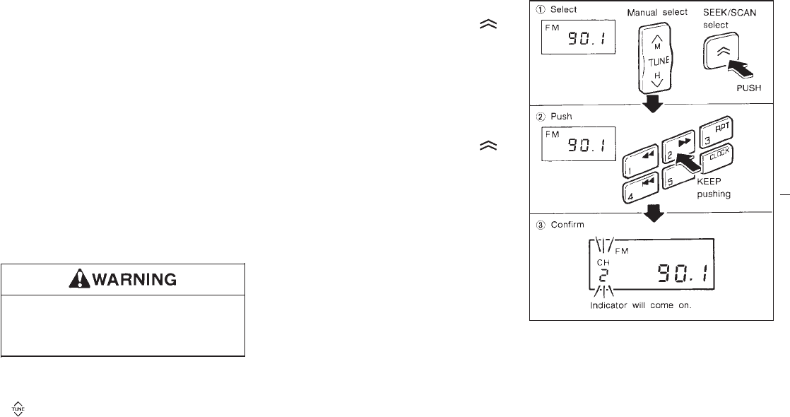
Clock priority mode
In this mode the clock will be shown in the
display. If any radio or CD functions are acti-
vated, the radio or CD display will illuminate for
ten seconds then return to the clock mode.
After clock adjustment, the radio is in the
clock priority mode.
Selecting the desired band
Push the AM/FM button to change from AM to
FM reception.
The FM stereo indicator “ST” will glow during
FM stereo reception. When the stereo broad-
cast signal is weak, the radio will automatically
change from stereo to monaural reception.
Tuning
The radio should not be tuned while
driving in order that full attention may be
given to the driving operation.
Manual tuning
Push either side of the manual tuning button
“”.
SCAN tuning
Push the SEEK/SCAN tuning button “ ”
for more than 1.5 seconds. SCAN tuning be-
gins from low to high frequencies and stops at
each broadcasting station for five seconds.
Pushing the button again during this five sec-
ond period will stop SCAN tuning and the radio
will remain tuned to that station.
SEEK tuning
Push the SEEK/SCAN tuning button “ ”
for less than 1.5 seconds. SEEK tuning begins
from low to high frequencies and stops at the
next broadcasting station.
Station memory operations
Six stations can be set for each band.
1. Tune to the desired station.
2. Push the desired select button for more
SAA0162
3-16
Z01.2.1/R50-D X
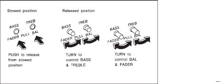
than 1.5 seconds. (For example in the
diagram ch2 is to be memorized. The radio
ceases emitting sounds when the select
button is pushed.)
3. The indicator, “ch2” will then come on and
the sound will resume.
Memorization is now complete.
4. Other buttons can be set in the same
manner.
If the battery cable is disconnected, or if the
fuse blows, the radio memory will be canceled.
In that case, reset the desired stations.
Adjusting tone quality and speaker
sound balance
To adjust BASS, TREB (treble), FADER, and
BAL (balance) the control knobs must be re-
leased from their stowed positions. Pushing
the knobs once moves them to the released
position.
In the released position, the knobs control tone
quality. Turn the control knobs to adjust BASS
and TREB to the most pleasing level.
From the released position, the knobs must be
pulled out in order to control FADER and BAL.
FADER adjusts the sound level between the
front and rear speakers, and BAL adjusts the
sound level between the right and left speak-
ers.
Once sound quality is set to the desired levels,
return the control knobs to the stowed position
by pushing them in completely and releasing.
SAA0185
3-17
Z01.2.1/R50-D X
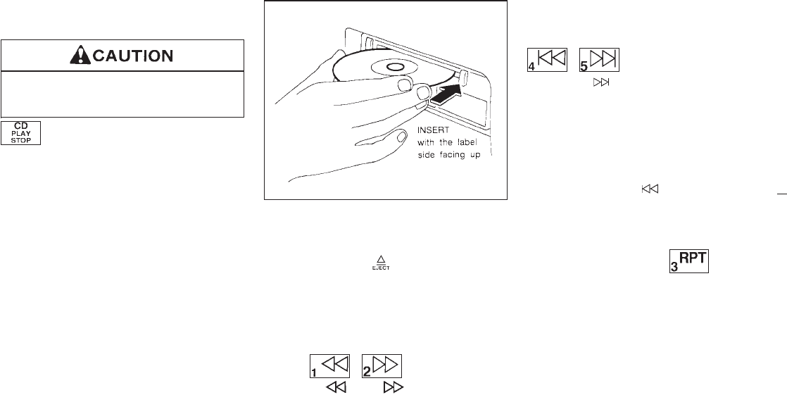
COMPACT DISC PLAYER
OPERATION
Do not force the compact disc into the
slot. This could damage the player.
CD button
IWhen this button is pushed with the system
off and the compact disc loaded, the sys-
tem will turn on and the compact disc will
start to play.
IWhen this button is pushed with the com-
pact disc loaded but the radio playing, the
radio will automatically be turned off and
the compact disc will start to play.
IWhen this button is pushed while the com-
pact disc is playing, the compact disc will
stop playing. When this button is pushed
with the compact disc stopped, the compact
disc will start to play.
Insert the compact disc into the compact disc
player with the label side facing up as illus-
trated. When ejecting the compact disc, press
the EJECT button “ ”.
If the compact disc is left alone for longer than
10 seconds after the EJECT button is pushed,
the compact disc will be automatically inserted
into the player.
FF (fast forward), REW (rewind)
button
When the “ ”or“ ” button is pushed
while the compact disc is being played, the
compact disc will play while fast forwarding or
rewinding. When the button is released, the
compact disc will return to normal play speed.
APS FF, APS REW button
When the “ ” button is pushed while the
compact disc is being played, the program
next to the present one will start to play from its
beginning. Push several times to skip through
programs. The compact disc will advance the
number of times the button is pushed. (When
the last program on the compact disc is
skipped through, the first program will be
played.) When the “ ” button is pushed,
the program being played returns to its begin-
ning. Push several times to skip back through
programs. The compact disc will go back the
number of times the button is pushed.
RPT (Repeat) button
When this button is pushed while the compact
disc is being played, play pattern will change
as follows:
ALL: All the programs will be played repeat-
edly in sequence.
1: Only one program (the one being played
when the PROG button is pushed) will be
repeated.
RANDOM: Programs will be played at random,
SAA0163
3-18
Z01.2.1/R50-D X
not following the sequence on the compact
disc.
l(no mark): All the programs will be played in
sequence and stop when the last program is
finished.
IRANDOM The same program may be re-
peated twice.
IWhen the compact disc is ejected, the play
pattern will automatically change to ALL.
IDuring cold weather or rainy days,
the player may malfunction due to the
humidity. If this occurs, remove the
CD and dehumidify or ventilate the
player completely.
IThe player may skip while driving on
rough roads.
IThe CD player sometimes cannot
function when the compartment tem-
perature is extremely high. Decrease
the temperature before use.
IDo not expose the CD to direct
sunlight.
3-19
Z01.2.1/R50-D X
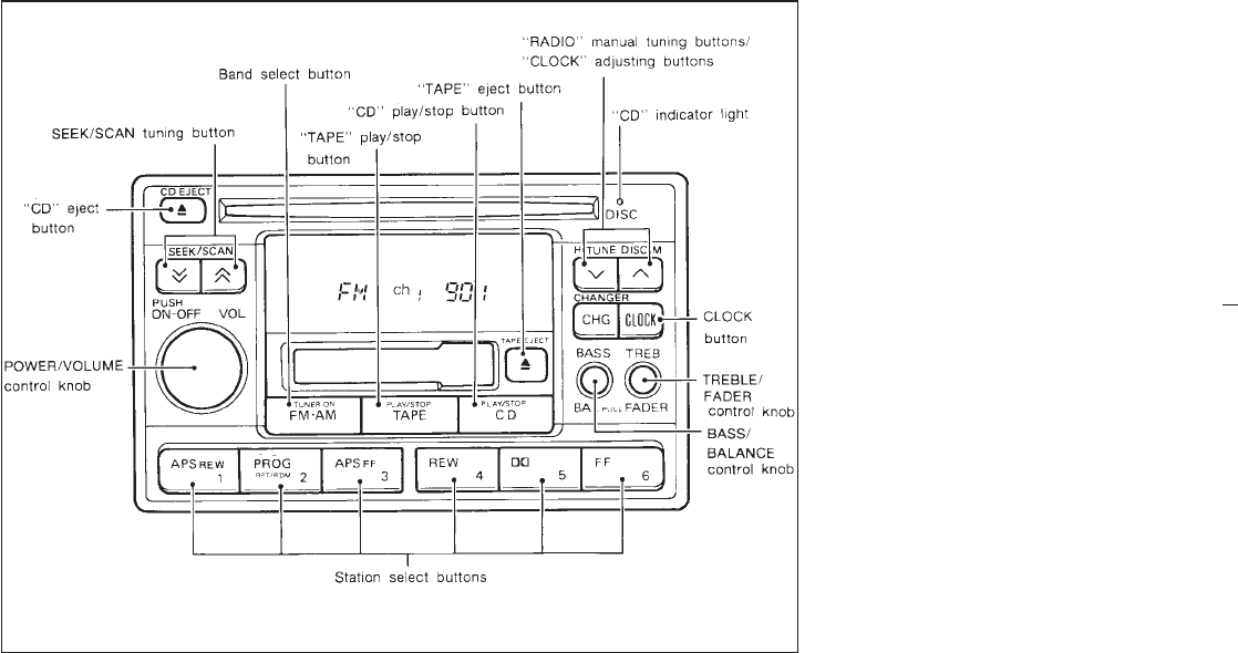
AM-FM RADIO WITH CASSETTE
PLAYER AND COMPACT DISC
PLAYER (Bose audio system)
Head unit
The radio has an FM Diversity reception sys-
tem, which employs two antennas. One is a
rod type antenna; the other is an antenna
printed on the window. This system automati-
cally switches to the antenna which is receiv-
ing less noise.
The tape deck employs a permalloy head
which allows for improved reproduction of high
frequency ranges. Noise is also greatly re-
duced by the combined use of the Dolby NR
(noise reduction) system. The auto loudness
circuit enhances the low frequency range au-
tomatically in both radio reception and tape
playback.
Power button
Turn the ignition key to “ACC” or “ON”, and
then push the POWER/VOLUME control knob
while the system is off to call up the mode
(radio, tape or CD) which was playing imme-
diately before the system was turned off.
When no CD or tape is loaded, the radio will
come on. While the system is on, pushing the
POWER/VOLUME control knob turns the sys-
tem off.
SAA0187
3-20
Z01.2.1/R50-D X
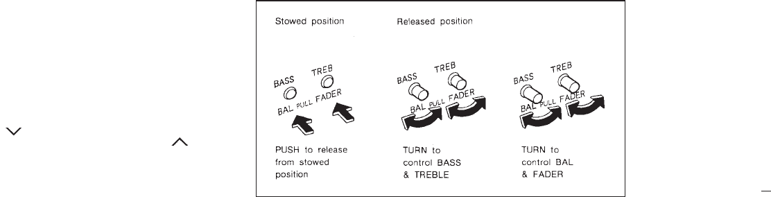
To turn the radio off, press the POWER/
VOLUME control knob.
VOL (volume) control knob
Turn the POWER/VOLUME control knob to
adjust the volume.
Clock set (Adjustment)
Depressing the CLOCK button and the
“ ” button together will set hours. De-
pressing the CLOCK button and “ ” button
together will set minutes.
Clock operation
By pressing the CLOCK button, you can alter-
nate the clock and the radio/cassette tape/CD
options in the display.
Clock priority mode
In this mode the clock will be shown in the
display. If any radio cassette or CD functions
are activated, the radio cassette or CD display
will illuminate for ten seconds then return to
the clock mode.
After clock adjustment, the radio is in the
clock priority mode.
Adjusting tone quality and speaker
sound balance
To adjust BASS, TREB (treble), FADER, and
BAL (balance) the control knobs must be re-
leased from their stowed positions. Pushing
the knobs once moves them to the released
position.
In the released position, the knobs control tone
quality. Turn the control knobs to adjust BASS
and TREB to the most pleasing level.
From the released position, the knobs must be
pulled out in order to control FADER and BAL.
FADER adjusts the sound level between the
front and rear speakers, and BAL adjusts the
sound level between the right and left speak-
ers.
Once sound quality is set to the desired levels,
return the control knobs to the stowed position
by pushing them in completely and releasing.
SAA0188
3-21
Z01.2.1/R50-D X
RADIO OPERATION
FM-AM band select button
Pushing the FM-AM band select button will
change the band FM1, FM2 or AM.
When FM-AM band select button is pushed
while the ignition switch is at “ACC” or “ON”,
the radio will come on at the station last
played.
The last station played will also come on when
the power button is turned to ON.
If a compact disc or tape is inserted when the
FM-AM band select button is turned to ON, the
compact disc or tape will automatically be
turned off and the last radio station played will
come on.
The FM stereo indicator “ST” will glow during
FM stereo reception. When the stereo broad-
cast signal is weak, the radio will automatically
change from stereo to monaural reception.
TUNE button
The radio should not be tuned while
driving in order that full attention may be
given to the driving operation.
Use these buttons for manual tuning. To move
quickly through the channels, hold either of the
tuning buttons down for more than 0.5 sec-
onds.
SEEK/SCAN tuning buttons
SEEK tuning
Push the SEEK/SCAN tuning button “ ”or
“” for less than 1.5 seconds. SEEK tun-
ing begins from low to high frequencies and
stops at the next broadcasting station.
SCAN tuning
Push the SEEK/SCAN tuning button “ ”or
“” for more than 1.5 seconds. SCAN
tuning begins from low to high frequencies and
stops at each broadcasting station for five
seconds. Pushing the button again during this
five second period will stop SCAN tuning and
the radio will remain tuned to that station.
3-22
Z01.2.1/R50-D X
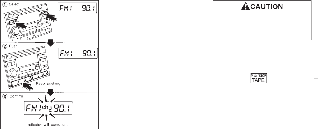
Station memory operations
Twelve stations can be set for the FM band
(FM1 and FM2).
Six stations can be set for the AM band.
1. Tune to the desired station.
2. Push the desired select button for more
than 1.5 seconds. (For example, in the
diagram ch2 is to be memorized. The radio
mutes when the select button is pushed.)
3. The indicator “ch2” will then come on and
the sound will resume. Memorizing is now
complete.
4. Other buttons can be set in the same
manner.
If the battery cable is disconnected, or if the
fuse blows, the radio memory will be can-
celled. In that case, reset the desired stations.
CASSETTE TAPE OPERATION
Turn the ignition key to “ACC” or “ON”, and
then lightly insert the cassette tape into the
tape door. The cassette tape will be automati-
cally pulled into the player.
The radio or CD will turn off (if it is on) and the
cassette tape will begin to play.
Do not force the cassette tape into the
tape door.
This could cause player damage.
If the system is turned off by pushing the
POWER/VOLUME control knob with the cas-
sette tape still in the player, the tape will
resume playing when the POWER/VOLUME
control knob is pushed again.
TAPE button
IWhen this button is pushed with the system
turned off and a tape loaded, the system
will come on and the tape will play.
IWhen this button is pushed with either the
radio or compact disc turned on and the
tape loaded, the compact disc or the radio
will automatically be turned off and the tape
will play.
While the tape is playing, pushing the TAPE
button stops the tape. Pushing the button
again allows the tape to play.
SAA0189
3-23
Z01.2.1/R50-D X
FF (fast forward), REW (rewind)
button
Push the FF (fast forward) button to fast for-
ward the tape. To rewind the tape, push the
REW (rewind) button. Either the
indicator light “ ”, “ ”, “ ”or
“” will come on when the FF or REW
function is started.
APS (automatic program search)
FF, APS REW button
When the APS FF button is pushed while the
tape is being played, the next program will
start to play from the beginning. Push the APS
FF button several times to skip through pro-
grams. The tape will advance the number of
times the button is pushed (up to 9 programs).
When the APS REW button is pushed once,
the program being played starts over from the
beginning. Push several times to fast rewind
programs. The tape will go back the number of
times the button is pushed. Either the indicator
light “ ”, “ ”, “ ”or“ ” will
come on when the APS FF or APS REW
function is started.
This system searches for the blank intervals
between selections. If there is a blank interval
within one program or there is no interval
between programs, the system may not stop in
the desired or expected location.
PROG (program) button
Push the PROG (program) button to change
the tape side while the tape is being played.
The cassette tape will automatically change
directions to play the other side when the first
side is completed.
Dolby NR (noise reduction)
button
Push the “DOLBY NR” button for Dolby
NR encoded tapes to reduce high frequency
tape noise. The indicator will come on.
Dolby noise reduction manufactured under li-
cense from Dolby Laboratories Licensing Cor-
poration. “DOLBY” and the double-D symbol
are trademarks of Dolby Laboratories
Licensing Corporation.
Metal or chrome tape usage
The cassette player will be automatically set to
high performance play when playing a metal or
chrome cassette tape.
TAPE EJECT button
When this button is pushed with the tape
loaded, the tape will be ejected.
When the tape is ejected while it is being
played, the system will be turned off.
Precautions on cassette player
operation
ITo maintain good quality sound,
NISSAN recommends that you use cas-
sette tapes of 60 minutes or shorter in
length.
ICassette tapes should be removed from
the player when not in use. Store cas-
settes in their protective cases and away
from direct sunlight, heat, moisture or
magnetic sources.
Direct sunlight can cause the cassette to
become deformed. The use of deformed
cassettes may cause the cassette to jam
in the player.
IDo not use cassettes that have peeling
or loose labels. If used, the label could
jam in the player.
IIf a cassette has loose tape, insert a
pencil through one of the cassette hubs
and rewind the tape firmly. Loose tape
3-24
Z01.2.1/R50-D X
may cause jamming and wavering
sound quality.
IOver a period of time, the playback
head, capstan and pinch roller may
gather a tape coating residue as the tape
passes over the head. This residue ac-
cumulation can cause a weak or waver-
ing sound and should be removed peri-
odically with a head cleaning tape.
If the residue is not removed periodi-
cally, the player may need to be disas-
sembled for cleaning.
COMPACT DISC (CD) PLAYER
OPERATION
Turn the ignition key to the “ACC” or “ON”
position and insert the compact disc into the
slot with the label side facing up. The compact
disc will be guided automatically into the slot
and start playing.
After loading the disc, the number of tracks on
the disc and the play time will appear on the
display.
If the radio or tape is already operating, it will
automatically turn off and the compact disc will
play.
Do not force the compact disc into the
slot. This could damage the player.
If the system has been turned off while the
compact disc was playing, pushing the
POWER/VOLUME control knob will start the
compact disc.
CD button
When this button is pushed with the system off
and the compact disc loaded, the system will
turn on and the compact disc will start to play.
When this button is pushed with the compact
disc loaded but the tape or the radio playing,
the tape or radio will automatically be turned
off and the compact disc will start to play.
When this button is pushed while the compact
disc is playing, the compact disc will stop
playing. When this button is pushed with the
compact disc stopped, the compact disc will
start to play.
FF (fast forward), REW (rewind)
button
When the FF (fast forward) or REW (rewind)
button is pushed while the compact disc is
being played, the compact disc will play while
fast forwarding or rewinding. When the button
is released, the compact disc will return to
normal play speed.
APS (automatic program search)
FF, APS REW button
When the APS FF button is pushed while the
compact disc is being played, the program
next to the present one will start to play from its
beginning. Push several times to skip through
programs. The compact disc will advance the
number of times the button is pushed. (When
the last program on the compact disc is
skipped through, the first program will be
played.) When the APS REW button is
pushed, the program being played returns to
its beginning. Push several times to skip back
through programs. The compact disc will go
back the number of times the button is pushed.
3-25
Z01.2.1/R50-D X
PROG (program) button
When this button is pushed while the compact
disc is being played, the play pattern will
change as follows:
ALL: All the programs will be played repeat-
edly in sequence.
1: Only one program (the one being played
when the PROG button is pushed) will be
repeated.
RANDOM: Programs will be played at ran-
dom, not following the sequence on the com-
pact disc. The same program may be re-
peated twice.
(no mark): All the programs will be played in
sequence and stop when the last program is
finished.
I
When the compact disc is ejected, the
play pattern will automatically change
to ALL.
CD EJECT button
When the CD EJECT button is pushed with the
compact disc loaded, the compact disc will be
ejected.
When this button is pushed while the compact
disc is being played, the compact disc will
come out and the system will turn off.
If the compact disc comes out and is not
removed, it will be pulled back into the slot
to protect it.
CD (DISC) indicator light
This light comes on when the compact disc is
loaded.
IDuring cold weather or rainy days,
the player may malfunction due to the
humidity. If this occurs, remove the
CD and dehumidify or ventilate the
player completely.
IThe player may skip while driving on
rough roads.
IThe CD player sometimes cannot
function when the compartment tem-
perature is extremely high. Decrease
the temperature before use.
IDo not expose the CD to direct
sunlight.
The antenna will automatically extend when
the radio is turned on, and retract when
switched off. If the radio is left on, the antenna
will retract and extend with the ignition key
“OFF-ON” operation.
IBefore turning the radio on, make
sure that there is no one near the
antenna outlet and there is enough
space for it to extend.
ITo prevent damage, be sure that an-
tenna is fully retracted before the
vehicle enters an automated car
wash.
IDirt and other foreign matter on the
power antenna rod may interrupt its
operation. Clean the rod periodically
with a damp cloth. This type of clean-
ing is especially important during the
winter seasons in areas where road
salt and other chemicals may be
spread on road surfaces and
splashed onto the antenna rod.
POWER ANTENNA (If so
equipped)
3-26
Z01.2.1/R50-D X
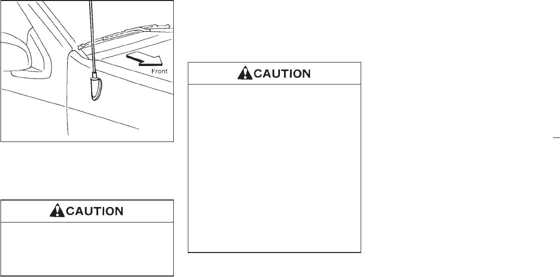
The antenna cannot be shortened but can be
removed.
Turn its root counterclockwise to remove the
antenna.
Be sure to remove the antenna before
washing the vehicle in an automatic car
washing machine, or the antenna may
be damaged.
When installing large capacity wireless equip-
ment or a car phone in your NISSAN, be sure
to observe the following as it may adversely
affect the Multiport fuel injection system and
other electronic parts depending on its instal-
lation location.
IKeep the antenna as far as possible
away from the Electric Control Mod-
ule.
IAlso keep the antenna wire more than
8 inches (20 cm) away from the Elec-
tro Injection harness. Do not route
the antenna wire next to any harness.
IAdjust the antenna standing-wave ra-
tio as recommended by the manufac-
turer.
IConnect the ground wire from the
radio chassis to the body.
IFor details, consult a NISSAN dealer.
SAA0164
MANUAL ANTENNA CB RADIO OR CAR PHONE
3-27
Z01.2.1/R50-D X

MEMO
3-28
Z01.2.1/R50-D X

4 Starting and driving
Precautions when starting and driving ................... 4-2
On-pavement and off-road driving precautions ...... 4-4
Avoiding collision and rollover ................................. 4-4
Drinking alcohol/drugs and driving .......................... 4-4
Ignition switch ........................................................ 4-5
Before starting the engine ..................................... 4-7
Driving with automatic transmission ...................... 4-7
Driving with manual transmission ........................ 4-11
Starting the engine ............................................... 4-13
Parking brake ....................................................... 4-13
Cruise control ....................................................... 4-14
Break-in schedule ................................................ 4-16
Economy hints ..................................................... 4-17
Transfer case shifting procedures
for 4-wheel drive vehicles .................................... 4-17
Parking ................................................................. 4-23
Power steering system ........................................ 4-24
Brake system ....................................................... 4-24
Anti-lock brake system .......................................... 4-25
Cold weather driving ............................................ 4-26
Corrosion protection ............................................. 4-28
Z01.2.1/R50-D X
IDo not leave children, unreliable
adults, or pets alone in your vehicle.
They could accidentally injure them-
selves or others through inadvertent
operation of the vehicle. Also, on hot,
sunny days, temperatures in a closed
vehicle could quickly become high
enough to cause severe or possibly
fatal injuries to people or animals.
IProperly secure all cargo to help pre-
vent it from sliding or shifting. Do not
place cargo higher than the seat-
backs. In a sudden stop or collision,
unsecured cargo could cause per-
sonal injury.
EXHAUST GAS (Carbon Monoxide)
Do not breathe exhaust gases; they con-
tain colorless and odorless carbon mon-
oxide. Carbon monoxide is a dangerous
gas, and can cause unconsciousness or
death.
IIf you suspect that exhaust fumes are
entering the vehicle, drive with all
windows fully open, and have the
vehicle inspected immediately.
IDo not run the engine in closed
spaces such as a garage.
IDo not park the vehicle with the en-
gine running for any extended length
of time.
IKeep the back door and rear window
closed while driving, otherwise ex-
haust gases could be drawn into the
passenger compartment. If you must
drive in this manner for some reason,
take the following steps.
1. Open all the windows.
2. Set the air recirculate switch
“OFF” and the fan control at
“high” to circulate the air.
IIf electrical wiring or other cable con-
nections must pass to a trailer
through the seal on the back door or
the body, follow the manufacturer’s
recommendation to prevent carbon
monoxide entry into the vehicle.
IIf a special body or other equipment
is added for recreational or other us-
age, follow the manufacturer’s rec-
ommendation to prevent carbon
monoxide entry into the vehicle.
(Some recreational vehicle appli-
ances such as stoves, refrigerator,
heaters, etc. may also generate car-
bon monoxide.)
IThe exhaust system and body should
be inspected by a qualified mechanic
whenever:
a. The vehicle is raised for service.
b. You suspect that exhaust fumes
are entering into the passenger
compartment.
PRECAUTIONS WHEN STARTING
AND DRIVING
4-2
Z01.2.1/R50-D X
c. You notice a change in the sound
of the exhaust system.
d. You have had an accident involv-
ing damage to the exhaust system,
underbody, or rear of the vehicle.
THREE-WAY CATALYST
The three-way catalyst is an emission control
device, installed in the exhaust system. In the
converter, exhaust gases are burned at high
temperatures to help reduce pollutants.
IThe exhaust gas and the exhaust sys-
tem are very hot. Keep people or
flammable materials away from the
exhaust system.
IDo not stop or park the vehicle over
flammable materials, such as dry
grass, waste paper or rags. They may
ignite and cause a fire.
IDo not use leaded gasoline. Deposits
from leaded gasoline will seriously
reduce the three-way catalyst’s abil-
ity to help reduce exhaust pollutants.
IKeep your engine tuned up. Malfunc-
tions in the ignition, fuel injection, or
electrical systems can cause over-
rich fuel flow into the three-way cata-
lyst, causing it to overheat. Do not
keep driving if the engine misfires, or
if noticeable loss of performance or
other unusual operating conditions
are detected. Have the vehicle in-
spected promptly by an authorized
NISSAN dealer.
IAvoid driving with an extremely low
fuel level. Running out of fuel could
cause the engine to misfire, damag-
ing the three-way catalyst.
IDo not race the engine while warming
it up.
IDo not push or tow your vehicle to
start the engine.
4-3
Z01.2.1/R50-D X
Utility vehicles have higher ground clearance
than passenger cars and a narrower track to
make them capable of performing in a wide
variety of off-road applications. Specific design
characteristics give them a higher center of
gravity than ordinary cars. An advantage of
higher ground clearance is a better view of the
road, allowing you to anticipate problems.
They are not designed for cornering at the
same speeds as conventional 2-wheel drive
vehicles any more than low-slung sports cars
are designed to perform satisfactorily under
off-road conditions. If at all possible, avoid
sharp turns or abrupt maneuvers. As with
other vehicles of this type, failure to operate
this vehicle correctly may result in loss of
control or vehicle rollover.
Be sure to read the driving safety precautions
later in this section.
Failure to operate this vehicle in a safe
and prudent manner may result in loss
of control or an accident.
Be alert and drive defensively at all times.
Obey all traffic regulations. Avoid excessive
speed, high speed cornering, or sudden steer-
ing maneuvers, because these driving prac-
tices could cause you to lose control of your
vehicle. As with any vehicle, a loss of con-
trol could result in a collision with other
vehicles or objects, or cause the vehicle to
rollover, particularly if the loss of control
causes the vehicle to slide sideways. Be
attentive at all times, and avoid driving when
tired. Never drive when under the influence of
alcohol or drugs (including prescription or
over-the-counter drugs which may cause
drowsiness). Always wear your seat belt as
outlined in the “Seat Belts” section of this
manual, and also instruct your passengers to
do so.
Never drive under the influence of alco-
hol or drugs. Alcohol in the blood
stream reduces coordination, delays re-
action time and impairs judgement. Driv-
ing after drinking alcohol increases the
likelihood of being involved in an acci-
dent injuring yourself and others. Addi-
tionally, if you are injured in the accident
alcohol can increase the severity of
injury.
Nissan is committed to safe driving. But, you
must choose not to drive under the influence of
alcohol. Every year thousands of people are
injured or killed in alcohol related accidents.
Although the local laws vary on what is con-
sidered to be legally intoxicated, the fact is that
alcohol affects all people differently and most
people underestimate the effects of alcohol.
ON-PAVEMENT AND OFF-ROAD
DRIVING PRECAUTIONS AVOIDING COLLISION AND
ROLLOVER DRINKING ALCOHOL/DRUGS
AND DRIVING
4-4
Z01.2.1/R50-D X
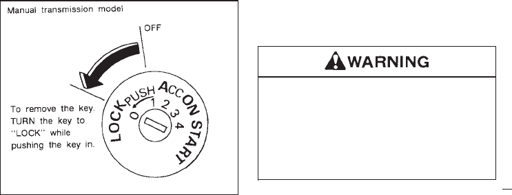
Remember, drinking and driving don’t mix!
And that’s true for drugs too (over the counter,
prescription, and illegal drugs). Don’t drive if
your ability to operate your vehicle is impaired
by alcohol, drugs, or some other physical
condition.
The switch includes an anti-theft steering lock
device.
“LOCK” Normal parking position (0)
The ignition key can only be removed when
the switch is in this position.
On manual transmission models, to turn the
ignition key to “LOCK” from “ACC” or “ON”,
first turn the key to “OFF” and turn the key to
“LOCK” while pushing the key in.
In order for the steering wheel to be locked, it
must be turned about 1/6 of a turn clockwise
from the straight up position.
To lock the steering wheel, remove the key.
To unlock the steering wheel, insert the key
and turn it gently while rotating the steer-
ing wheel slightly right and left.
Never remove the key while driving. If
the key is removed, the steering wheel
will lock. This may cause the driver to
lose control of the vehicle and could
result in serious vehicle damage or per-
sonal injury.
SSD0082
IGNITION SWITCH
4-5
Z01.2.1/R50-D X
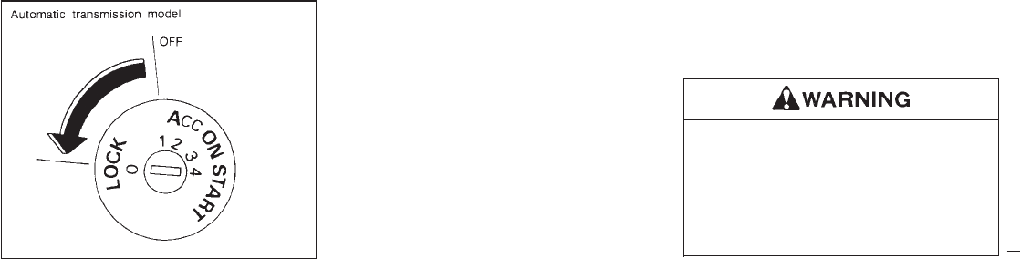
On automatic transmission models, the igni-
tion lock is designed so that the key cannot be
turned to “LOCK” and removed until the selec-
tor lever is moved to the “P” position.
When removing the key from the ignition,
make sure the selector lever is in the “P”
position.
If the selector lever is not returned to “P”
(Park), the key cannot be moved toward
LOCK.
When the key cannot be turned toward the
“LOCK” position, proceed as follows to remove
the key:
1) Move the selector lever into the “P” posi-
tion.
2) Turn the ignition key slightly in the “ON”
direction.
3) Turn the key toward the “LOCK” position.
4) Remove the key.
If the key is removed from the ignition switch,
the selector lever cannot be moved from “P”
(Park). The selector lever can be moved if
the ignition switch is in the “ACC” position.
The selector lever can also be moved if the
ignition switch is in the “ON” position and
the foot brake pedal is depressed.
There is an “OFF” position in between “LOCK”
and “ACC”, although it does not show on the
lock cylinder. When the ignition is in “OFF” the
steering wheel is not locked.
In order for the steering wheel to be locked, it
must be turned about 1/6 of a turn clockwise
from the straight up position.
To lock the steering wheel, remove the key.
To unlock the steering wheel, insert the key
and turn it gently while rotating the steer-
ing wheel slightly right and left.
Never remove the key while driving. If
the key is removed, the steering wheel
will lock. This may cause the driver to
lose control of the vehicle and could
result in serious vehicle damage or per-
sonal injury.
SSD0083
4-6
Z01.2.1/R50-D X

Key positions
“OFF” (1)
The engine can be turned off without locking
the steering wheel.
“ACC” (Accessories) (2)
This position activates electrical accessories
such as the radio when the engine is not
running.
“ON” Normal operating position (3)
This position turns on the ignition system and
the electrical accessories.
“START” (4)
This position activates the starter motor, start-
ing the engine.
IMake sure the area around the vehicle is
clear.
ICheck fluid levels such as engine oil, cool-
ant, brake and clutch fluid, window washer
fluid as frequently as possible, at least
whenever you refuel.
ICheck to be sure that all windows and light
lenses are clean.
IVisually inspect tires for their appearance
and condition. Also check tires for proper
inflation.
ILock all doors.
IPosition seat and adjust head restraints.
IAdjust inside and outside mirrors.
IFasten seat belts and ask all passengers to
do likewise.
ICheck the operation of warning lights when
key is turned to the “ON (3)” position.
The automatic transmission in your vehicle is
electronically controlled by a microcomputer to
produce maximum power and smooth opera-
tion.
Shown on the following pages are the recom-
mended operating procedures for this trans-
mission. Follow these procedures for maxi-
mum vehicle performance and driving
enjoyment. If your vehicle is equipped with
four-wheel drive, see “ Transfer case
shifting procedures” in this section.
Starting the vehicle
IAfter starting the engine, fully depress the
foot brake pedal and push the selector lever
button before shifting the selector lever to
the “D”, “R”, “2” or “1” position. Be sure the
vehicle is fully stopped before attempting to
shift the selector lever.
This automatic transmission is designed
so that the foot brake pedal MUST be de-
pressed before shifting from “P” to any
drive position while the ignition switch is
“ON”.
The selector lever cannot be moved out of
“P” and into any of the other gear positions
if the ignition key is turned to “LOCK” or if
the key is removed from the switch.
When the battery charge is low, the selec-
BEFORE STARTING THE ENGINE DRIVING WITH AUTOMATIC
TRANSMISSION
4-7
Z01.2.1/R50-D X
tor lever can be moved if the ignition switch
is in the “ACC” position.
1. Keep the foot brake pedal depressed and
push the selector lever button to shift into a
driving gear.
2. Release the parking brake and foot brake,
then gradually start the vehicle in motion.
IDo not depress the accelerator pedal
while shifting from “P” or “N” to “R”,
“D”, “2” or “1”. Always depress the
brake pedal until shifting is com-
pleted. Failure to do so could cause
you to lose control and have an acci-
dent.
ICold engine idle speed is high, so use
caution when shifting into a forward
or reverse gear before the engine has
warmed up.
INever shift to “P” or “R” while the
vehicle is moving. This could cause
an accident.
IOn slippery roads, do not downshift.
This may cause a loss of control.
When stopping the vehicle on an uphill
grade, do not hold the vehicle by de-
pressing the accelerator pedal. The foot
brake should be used for this purpose.
Shifting from “P” (Park)
If the ignition switch is in the “ON” position and
the foot brake pedal is depressed, but the
selector lever still cannot be moved out of “P”
(Park), follow these instructions:
1. Shut the engine off and remove the key.
2. Apply the parking brake.
3. Reinsert the ignition key and turn it clock-
wise to the “ACC” position.
4. Depress the brake pedal, move the selector
lever to “N” (Neutral) and start the engine.
5. Check stop light operation.
If the selector lever cannot be moved
from the “P” position while the engine is
running and the brake pedal depressed,
the stop lights may not work. Malfunc-
tioning stop lights could cause an acci-
dent injuring yourself and others.
These instructions for starting the vehicle in
“N” (Neutral) should only be used until service
can be obtained. Never drive the vehicle if the
stop lights are not operating properly.
4-8
Z01.2.1/R50-D X
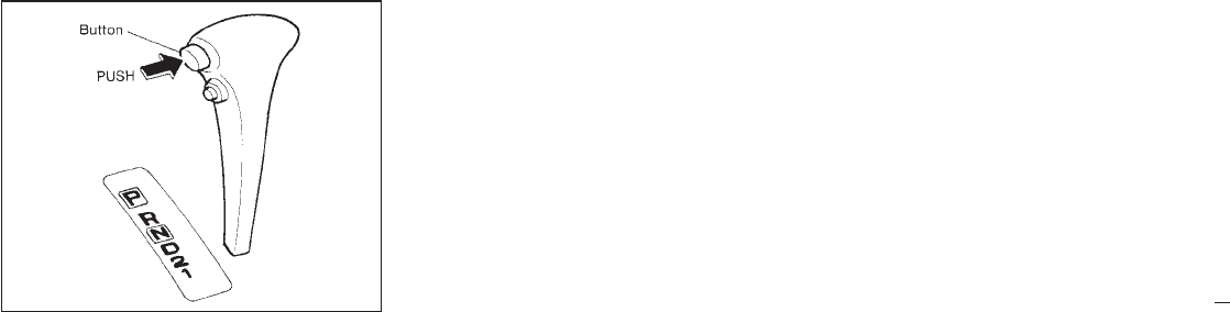
Push the button to shift into “P”, “R” or from “D”
to “2”. All other positions can be selected
without pushing the button.
“P” (Park):
Use this selector position when the vehicle is
parked or when starting the engine. Always be
sure the vehicle is at a complete stop. For
maximum safety, depress the brake pedal,
then push in the select lever button and move
the lever to the “P” position. Apply the parking
brake. When parking on a hill, apply the park-
ing brake first, then shift the lever into the “P”
position.
“R” (Reverse):
Use this position to back up. Shift into this
position only after the vehicle has completely
stopped.
“N” (Neutral):
Neither forward nor reverse gear is engaged.
The engine can be started in this position. You
may shift to “N” and restart a stalled engine
while the vehicle is moving.
“D” (Drive):
Use this position for all normal forward driving.
“2” (Second gear):
Use for hill climbing, effective engine braking
on downhill grades or starting on slippery
roads.
Do not downshift into the “2” position at speeds
over the following speeds and do not exceed
the following speeds in the “2” position:
2-wheel drive:
60 MPH (95 km/h)
4-wheel drive:
50 MPH (80 km/h)
“1” (Low gear):
Use this position when climbing steep hills
slowly or driving slowly through deep snow,
sand or mud, or for maximum engine braking
on steep downhill grades.
Do not shift into “1”position at speeds over the
following speeds:
2-wheel drive:
60 MPH (95 km/h)
4-wheel drive:
50 MPH (80 km/h)
Do not exceed the following speeds in the “1”
position:
2-wheel drive:
30 MPH (50 km/h)
4-wheel drive:
30 MPH (50 km/h)
SD1034
4-9
Z01.2.1/R50-D X
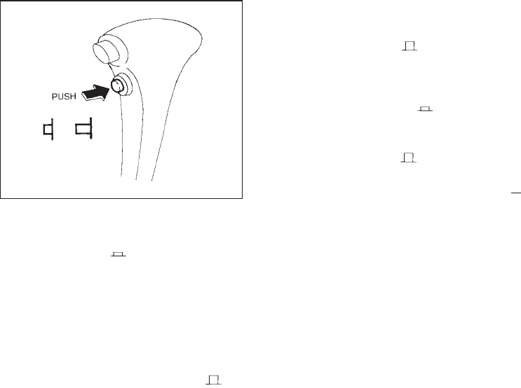
Accelerator downshift
— In “D” position —
For rapid passing or hill climbing, fully depress
the accelerator pedal to the floor. This shifts
the transmission down into second gear or first
gear, depending on the vehicle speed.
Overdrive switch
ON: For normal driving, push the overdrive
switch “ON ” with the selector
switch in the “D” position. The transmis-
sion is upshifted into OVERDRIVE as
the vehicle speed increases.
The overdrive will not engage until the
engine has warmed up.
OFF: For driving up and down long slopes
where engine “braking” would be advan-
tageous, push the switch “OFF ”.
When cruising at a low speeds or climb-
ing a gentle slope, you may feel uncom-
fortable shift shock as the transmission
shifts between 3rd and overdrive repeat-
edly. In this case, set the overdrive
switch in the “OFF ” position.
The indicator light will come on at this
time.
When driving conditions change, push the
overdrive switch in the “ON ” position.
Remember not to drive at high speeds for
extended periods of time with the overdrive
switch set in the “OFF ” position. This
lowers the fuel economy.
Fail-safe
When the Fail-safe operation occurs, the next
time the key is turned to the “ON” position, the
O/D OFF light will blink for approximately 8
seconds after coming on for 2 seconds. While
the vehicle can be driven under these circum-
stances please note that the gears in the
automatic transmission will be locked in third
gear.
If the vehicle is driven under extreme con-
ditions, such as excessive wheel spinning
and subsequent hard braking, the Fail-safe
system may be activated. This will occur
even if all electrical circuits are functioning
properly. In this case, turn the ignition key
“OFF” and wait for 3 seconds. Then turn
SSD0066
4-10
Z01.2.1/R50-D X
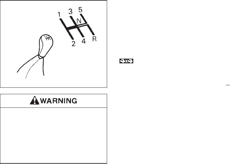
the key back to the “ON” position. The
vehicle should return to its normal operat-
ing condition. If it does not return to its
normal operating condition have your
NISSAN dealer check the transmission and
repair if necessary.
IDo not downshift abruptly on slippery
roads. This may cause a loss of con-
trol.
IDo not over-rev the engine when
shifting to a lower gear. This may
cause a loss of control or engine
damage.
To change gears, fully depress the clutch
pedal, then move the gearshift lever. After
shifting, release the clutch slowly.
You cannot shift directly from 5th gear into
Reverse. First shift into the Neutral position,
then into Reverse.
If it is difficult to move the shift lever into
Reverse or 1st, shift into Neutral, then release
the clutch pedal and shift into Reverse or 1st
again. If your vehicle is equipped with four-
wheel drive, see
“Transfer case shifting procedures” in
this section.
Suggested shift-up speeds
The table below provides suggested speed
ranges for shifting into a higher gear. These
suggestions relate to fuel economy and ve-
hicle performance. Actual shift ranges should
be adjusted for specific road conditions,
weather conditions and individual driving hab-
its.
I2-wheel drive models and 4-wheel drive
models (2H and 4H position)
MPH (km/h)
1st to 2nd 15 (25)
2nd to 3rd 25 (40)
3rd to 4th 40 (65)
4th to 5th 45 (75)
SSD0002
DRIVING WITH MANUAL
TRANSMISSION
4-11
Z01.2.1/R50-D X
*1 Acceleration:
Normal acceleration such as
standing start
*2 Cruise:
Driving without rapid acceleration
or deceleration at moderate speed
which permits maximum fuel
economy
I4-wheel drive model (4L position)
MPH (km/h)
1st to 2nd 8 (13)
2nd to 3rd 12 (20)
3rd to 4th 20 (32)
4th to 5th 22 (36)
Suggested maximum speed in each
gear
Downshift to a lower gear if the engine is not
running smoothly, or if you need to accelerate.
Do not exceed the maximum suggested speed
(shown below) in any gear. For level road
driving, use the highest gear suggested for
that speed. Always observe posted speed
limits, and drive according to the road condi-
tions which will ensure safe operation. Do not
overrev the engine when shifting to a lower
gear as it may cause engine damage or loss of
vehicle control.
Allowable maximum speed in each gear
2-wheel drive models MPH (km/h)
4-wheel drive models
2H position
1st 22 (35)
2nd 37 (60)
3rd 56 (90)
4th & 5th 78 (125)
4-wheel drive models MPH (km/h)
4H position
1st 22 (35)
2nd 37 (60)
3rd 50 (80)
4th & 5th 50 (80)
4L position
1st 9 (15)
2nd 19 (30)
3rd 28 (45)
4th & 5th 31 (50)
IDo not rest your foot on the clutch
pedal while driving. This may cause
clutch damage.
IStop your vehicle completely before
shifting into Reverse.
IWhen the vehicle is stopped for a
duration, for example at a stop light,
shift to “N” and release the clutch
pedal with the foot brake applied.
4-12
Z01.2.1/R50-D X
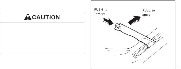
1. Apply the parking brake.
2. Automatic transmission:
Move the selector lever to “P” (Park position
or “N” (Neutral position). (“P” preferred)
The selector lever cannot be moved out
of “P” and into any of the other gear
positions if the ignition key is turned to
“OFF” or if the key is removed from the
switch.
The starter is designed not to operate if
the selector lever is in one of the driving
positions.
Manual transmission:
Move the gearshift lever to “N” (Neutral
position), and depress the clutch pedal to
the floor while starting the engine.
The starter is designed not to operate
unless the clutch pedal is depressed.
3. Crank the engine with your foot off the
accelerator pedal by turning the ignition
key to “START”. Release the key when the
engine starts. If the engine starts, but fails
to run, repeat the above procedure.
— If the engine is very hard to start in
extremely cold or hot weather —
Use the accelerator pedal to help start the
engine.
Do not crank the engine for more than 10
seconds at a time. If the engine does not
start, turn the key off and wait 10 sec-
onds before cranking again, otherwise
the starter could be damaged.
4. Warm-up
Always allow the engine to idle for at least
30 seconds after starting. Drive at moder-
ate speed for a short distance first, espe-
cially in cold weather. To apply: pull the lever up.
To release:
1. Firmly apply foot brake.
2. Manual transmission models:
Place the gearshift lever in the “N” (Neutral)
position.
Automatic transmission models:
Move the selector lever to the “P” (Park)
position.
3. While pulling up on the lever slightly, push
the button and lower completely.
PD1185M
STARTING THE ENGINE PARKING BRAKE
4-13
Z01.2.1/R50-D X
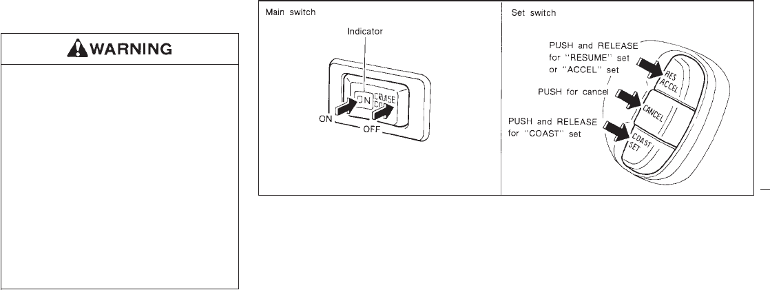
4. Before driving, be sure the brake warning
light goes out.
IBe sure the parking brake is fully
released before driving. Failure to do
so can cause brake failure and lead to
an accident.
IDo not release the parking brake from
outside the vehicle.
IDo not use the gear shift in place of
the parking brake. When parking, be
sure the parking brake is fully en-
gaged.
IDo not leave children unattended in a
vehicle. They could release the park-
ing brake and cause an accident.
The cruise control allows driving at a fixed
speed between 30 to 90 MPH (48 to 144 km/h)
without keeping your foot on the accelerator
pedal.
To turn on the cruise control, push the main
switch on. The indicator light on the switch will
come on.
To set at cruising speed, accelerate your
vehicle to the desired speed, push the
COAST/SET switch and release it. (The
“CRUISE” light will come on.) Take your foot
off the accelerator pedal. Your vehicle will
maintain the set speed.
ITo pass another vehicle, depress the
accelerator pedal. When you release the
pedal, the vehicle will return to the previ-
ously set speed.
IThe vehicle may not maintain the set speed
when going up or down steep hills. If this
happens, drive without the cruise control.
To cancel the preset speed, follow any of
these three methods:
a) Push the cancel switch; The “CRUISE” light
will go out.
b) Tap the brake pedal; The “CRUISE” light
will go out.
SSD0019
CRUISE CONTROL
4-14
Z01.2.1/R50-D X
c) Turn the main switch off. Both the “ON”
indicator and “CRUISE” light will go out.
IIf you depress the brake pedal while push-
ing the “ACCEL” set switch and reset at the
cruising speed, turn the main switch off
once and then turn it on again.
IThe cruise control will automatically be can-
celled if the vehicle slows down more than
8 MPH (13 km/h) below the set speed.
IDepress the clutch pedal (manual transmis-
sion), or move the selector lever to “N”
(automatic transmission). “CRUISE” light
will go out.
To reset at a faster cruising speed, follow
either of these three methods:
a) Depress the accelerator pedal. When the
vehicle attains the desired speed, push and
release the “COAST/SET” switch.
b) Push and hold the “ACCEL” set switch.
When the vehicle attains the speed you
desire, release the switch.
c) Push, then quickly release the “ACCEL” set
switch. Each time you do this, the set speed
will increase by about 1 MPH (1.6 km/h).
To reset at a slower cruising speed, follow
either of these three methods:
a) Lightly tap the brake pedal. When the ve-
hicle attains the desired speed, push the
“COAST/SET” switch and release it.
b) Push and hold the “COAST/SET” switch.
Release the switch when the vehicle slows
down to the desired speed.
c) Push, then quickly release the
“COAST/SET” switch. Each time you do
this, the set speed will decrease by about 1
MPH (1.6 km/h).
To resume the preset speed, push and re-
lease the “RESUME” set switch. The vehicle
will resume the last set cruising speed when
the vehicle speed is over 30 MPH (48 km/h).
Precautions
IThe cruise indicator may sometimes blink
when the cruise control switch (Main
switch) is turned “ON” while pushing the
“RESUME/ACCEL” switch or
“COAST/SET” switch or “CANCEL” switch
(located on the steering wheel). To properly
set the cruise control system perform the
steps above in the order indicated. (This is
a fail-safe mode. Turn the main switch
“OFF” and turn it “ON” again without push-
ing the set switch to return to normal opera-
tion.)
IIf the cruise control system malfunctions, it
will cancel automatically. The cruise indica-
tor in the meter assembly will then blink to
warn the driver.
IWhen the cruise indicator blinks, turn the
cruise control switch (Main switch) “OFF”
and have the system checked by your
NISSAN dealer.
Do not use the cruise control when driv-
ing under the following conditions:
Iwhen it is not possible to keep the
vehicle at set speed.
Iin heavy traffic or in traffic that varies
in speed.
Ion winding or hilly roads.
Ion slippery roads (rain, snow, ice,
etc.)
Iin very windy areas.
4-15
Z01.2.1/R50-D X
Doing so could cause a loss of vehicle
control and result in an accident.
On the manual transmission model, do
not shift into neutral position without
depressing the clutch pedal when the
cruise control is on. This could cause
engine damage. If you shift into neutral
without depressing the pedal, depress
the clutch pedal and turn the main
switch off immediately.
During the first 1,000 miles (1,600 km), follow
these recommendations for the future reliabil-
ity and economy of your new vehicle. Failure to
follow these recommendations may result in
vehicle damage or shortened engine life.
IDo not run the engine over 4,000 rpm.
Do not drive over the following speed limits:
2-wheel drive models:
4-wheel drive models
(2H position):
55 MPH (90 km/h)
4-wheel drive models
(4H position):
50 MPH (80 km/h)
4-wheel drive models
(4L position):
30 MPH (50 km/h)
IDo not accelerate hard in top gear.
IAvoid quick starts and full acceleration.
IAvoid hard stops as much as possible.
I
For the first 300 miles (500 km), it is rec-
ommended that you drive in the 2-wheel
drive (2H) position.
IDo not tow a trailer for the first 500 miles
(800 km).
BREAK-IN SCHEDULE
4-16
Z01.2.1/R50-D X
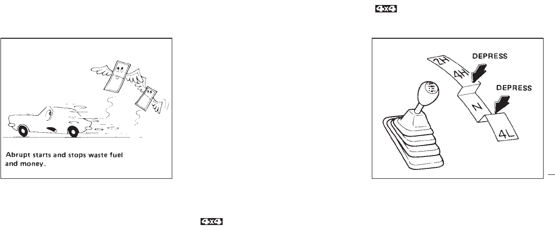
IAccelerate slowly and smoothly. Maintain
cruising speeds with a constant accelerator
position.
IDrive at moderate speeds on the highway.
Driving at high speed will lower fuel
economy.
IAvoid unnecessary stopping and braking.
Maintain a safe distance behind other ve-
hicles.
IUse a proper gear range which suits road
conditions. On level roads, shift into high
gear as soon as possible.
IAvoid unnecessary engine idling.
IKeep your engine tuned up.
IFollow the recommended periodic mainte-
nance schedule.
IKeep the tires inflated at the correct pres-
sure. Low pressure will increase tire wear
and waste fuel.
IKeep the front wheels in correct alignment.
Improper alignment will cause increased
tire wear and lower fuel economy.
IAir conditioner operation lowers fuel
economy. Use the air conditioner only when
necessary.
IWhen cruising at highway speeds, it is
more economical to use the air conditioner
and leave the windows closed to reduce
drag.
I
Use “4H” or “4L” position only when neces-
sary. 4-wheel drive operation lowers fuel
economy.
2H — (2WD, high range) Only the rear wheels
are driven. Use when driving under the same
conditions as standard 2WD vehicle.
4H — (4WD, high range) Four wheels are
driven. Use when driving on roads where it is
difficult to drive in the 2H position (i.e., driving
at normal speeds on snow covered, icy, wet,
muddy or sandy roads).
The “4H” position provides maximum
power and traction. Avoid excessive
speed, as it will cause loss of traction.
Speed over 50 MPH (80 km/h) in 4H is not
recommend.
SD0001 SD0020
ECONOMY HINTS TRANSFER CASE
SHIFTING PROCEDURES FOR
4-WHEEL DRIVE VEHICLES
4-17
Z01.2.1/R50-D X
4L — (4WD, low range) Four wheels are
driven. Use when climbing or descending
steep hills, or during hard driving in sand, mud
or deep snow. The “4L” position provides
maximum power and traction. Avoid raising
vehicle speed excessively, as the maximum
speed is approximately 30 MPH (50 km/h).
N— No wheels are driven. Always keep the
transfer lever out of the “N” position. Shift the
lever quickly and smoothly when moving
across the “N” position with the vehicle
stopped.
IDo not drive on dry hard surface
roads in 4-wheel drive.
Driving on dry hard surfaces in “4H”
or “4L” may cause unnecessary
noise and tire wear. We recommend
driving in the “2H” position under
these conditions.
IWhen parking the vehicle, apply the
parking brake and shift the transfer
control lever in the “2H”, “4H” or “4L”
position.
IDo not leave the transfer control lever
in the “N” position. Otherwise, the
vehicle could roll unexpectedly even
if the manual transmission is in any
gear or the automatic transmission in
the “P” position. If the ATP light is
“ON”, this indicates that the auto-
matic transmission “park” position
will not function and the transfer le-
ver is in neutral.
IFailure to engage the transfer control
lever in “2H”, “4H” or “4L” could
result in the vehicle moving unex-
pectedly, resulting in serious per-
sonal injury or property damage.
4-18
Z01.2.1/R50-D X
Manual transmission models:
TO SHIFT
TRANSFER CASE: SHIFT PROCEDURE
From “2H” to “4H” Move the transfer lever to “4H”. This can be done at any speed up to 50 MPH (80 km/h), and it is not necessary to depress the
clutch pedal. Perform this operation when driving straight.
From “4H” to “2H” Move the transfer lever to “2H”. This can be done at any speed up to 50 MPH (80 km/h), and it is not necessary to depress the
clutch pedal. Perform this operation when driving straight.
From “4H” or “4L” to “4L”
or “4H”
1. Stop the vehicle.
2. Depress the clutch pedal.
3. Depress the transfer lever and move it to the desired “4L” or “4H” position.
From “2H” to “4L”
1. Stop the vehicle.
2. Depress the clutch pedal.
3. Depress the transfer lever and move it to “4L”. Change gears quickly and smoothly.
From “4L” to “2H”
1. Stop the vehicle.
2. Depress the clutch pedal.
3. Depress the transfer lever and move it to “2H”.
4-19
Z01.2.1/R50-D X
Automatic transmission models:
TO SHIFT
TRANSFER CASE: SHIFT PROCEDURE
From “2H” to “4H” Move the transfer lever to “4H”. This can be done at any speed up to 50 MPH (80 km/h), and it is not necessary to move the selec-
tor lever to the “N” position. Perform this operation when driving straight.
From “4H” to “2H” Move the transfer lever to “2H”. This can be done at any speed up to 50 MPH (80 km/h), and it is not necessary to move the selec-
tor lever to the “N” position. Perform this operation when driving straight.
From “4H” or “4L” to “4L”
or “4H”
1. Stop the vehicle.
2. Move the selector lever to the “N” position.
3. Depress the transfer lever and move it to the desired “4L” or “4H” position.
From “2H” to “4L”
1. Stop the vehicle.
2. Move the selector lever to the “N” position.
3. Depress the transfer lever and move it to “4L”. Change gears quickly and smoothly.
From “4L” to “2H”
1. Stop the vehicle.
2. Move the selector lever to the “N” position.
3. Depress the transfer lever and move it to “2H”.
4-20
Z01.2.1/R50-D X

DRIVING SAFETY PRECAUTIONS
Your NISSAN is designed for both normal and
off-road use. However, avoid driving in deep
water or mud as your NISSAN is mainly de-
signed for leisure use, unlike a conventional
off-road vehicle.
Remember that two-wheel drive models are
less capable than four-wheel drive models for
rough road driving and extrication when stuck
in deep snow or mud, or the like.
Please observe the following precautions:
IDrive carefully when off the road and
avoid dangerous areas. Always wear
your seat belts to help keep you and
your passengers in position when
driving over rough terrain.
IDo not drive across steep slopes.
Instead drive either straight up or
straight down the slopes. Off-road
vehicles can tip over sideways much
more easily than they can forward or
backward.
IMany hills are too steep for any ve-
hicle. If you drive up them, you may
stall. If you drive down them, you may
not be able to control your speed. If
you drive across them, you may roll
over.
IStay alert when driving to the top of a
hill. At the top there could be a drop-
off or other hazard that could cause
an accident.
IIf your engine stalls or you cannot
make it to the top of a steep hill, never
attempt to turn around. Your vehicle
could tip or roll over. Always back
straight down in reverse gear. Never
back down in neutral (N) or with the
clutch depressed, using only the
brake, as this could cause loss of
control.
IHeavy braking going down a hill
could cause your brakes to overheat
and fade, resulting in loss of control
and an accident. Apply brakes lightly
and use a low gear to control your
speed.
IUnsecured cargo can be thrown
around when driving over rough ter-
rain. Properly secure it so that it will
not be thrown forward and cause in-
jury to you or your passengers.
IAvoid raising the center of gravity by
loading things on the roof or equip-
ping the vehicle with tires larger than
specified in this manual. This could
cause your vehicle to rollover. Put
heavy loads in the cargo area as far
forward and as low as possible.
IDo not grip the inside or spokes of
the steering wheel when driving off-
road. The steering wheel could jerk
and injure your hands. Instead drive
with your fingers and thumbs on the
outside of the rim.
IBefore operating the vehicle, ensure
that the driver and all passengers
have their seat belts fastened.
IAlways drive with the floor mats in
place as the floor may become very
hot. Particular care should be taken if
you are barefoot.
ILower your speed when encounter-
ing strong crosswinds. With its
higher center of gravity, your NISSAN
is more affected by gusty side winds.
4-21
Z01.2.1/R50-D X

Slower speeds ensure better vehicle
control.
IDo not drive beyond the performance
of the tires even with 4WD.
Accelerating quickly, sharp steering
maneuvers or sudden braking may
cause loss of control.
IInstall the same size of winter tires on
all four (4) wheels (such as studless
tires) or install tire chains to the rear
wheels when driving on slippery
roads (e.g., after a snow) and drive
carefully using 4WD.
IBe sure to check the brakes immedi-
ately after driving in mud or water as
specified in “WET BRAKES” under
the heading “Precautions when driv-
ing”.
IAvoid parking your vehicle on steep
hills. If you get out of the vehicle and
it rolls forward, backward or side-
ways, you could be injured.
IWhenever you drive off-road through
sand, mud or water as deep as the
wheel hub, more frequent mainte-
nance may be required. For details,
refer to “Maintenance under severe
driving conditions” under the head-
ing “Maintenance schedule”.
4-22
Z01.2.1/R50-D X
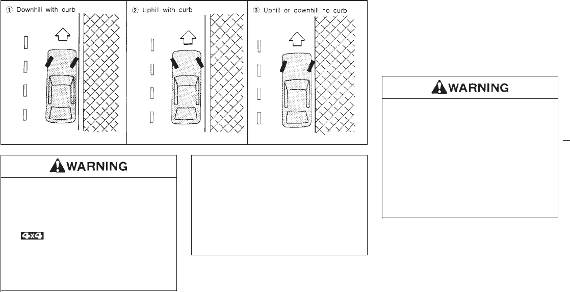
IDo not park the vehicle over flam-
mable materials, such as dry grass,
waste paper, or rags. They may ignite
and cause a fire.
IThe transfer control lever
must be in the “2H”, “4H” or “4L”
position and the parking brake must
be set to prevent the vehicle from
rolling.
INever place the transfer control lever
in the “N” position, otherwise, the
vehicle could roll unexpectedly even
if the manual transmission is in gear
or the automatic transmission is in
the “P” position. This could result in
serious personal injury or property
damage.
1. Firmly apply the parking brake.
2. Manual transmission models:
Place the shift lever in the “REVERSE”
position. When parking on an uphill grade,
place the gearshift lever in the “1st” posi-
tion.
Automatic transmission models:
Move the selector lever to the “P” (PARK)
position.
Safe parking procedures require that
both the parking brake be set and the
transmission placed into the “P” posi-
tion (automatic) or in appropriate gear
(manual). Failure to do so could cause
the vehicle to move unexpectedly or roll
away and result in an accident. Make
sure the shift lever has been pushed as
far forward as it can go and cannot be
moved.
3. To help prevent the vehicle rolling into the
street when parked on a sloping drive way,
it is a good practice to turn the wheels as
illustrated.
IHEADED DOWNHILL WITH CURB: q
1
Turn the wheels into the curb and move the
vehicle forward until the curb side wheel
SSD0067
PARKING
4-23
Z01.2.1/R50-D X

gently touches the curb.
IHEADED UPHILL WITH CURB: q
2
Turn the wheels away from the curb and
move the vehicle back until the curb side
wheel gently touches the curb.
IHEADED UPHILL OR DOWNHILL, NO
CURB: q
3
Turn the wheels toward the side of the road
so the vehicle will move away from the
center of the road if it moves.
4. Turn the ignition key to the “LOCK” position
and remove the key.
INever leave the engine running while
vehicle is unattended.
INever leave children unattended in
the vehicle.
The power assisted steering is designed to
use a hydraulic pump, driven by the engine, to
assist steering.
If the engine stops or drive belt breaks, you will
still have control of the vehicle. However,
much greater steering effort is needed, espe-
cially in sharp turns or at low speeds.
The brake system has two separate hydraulic
circuits. If one circuit develops a problem, you
will still have braking at two wheels.
Vacuum assisted brake
The brake booster aids braking by using en-
gine vacuum. If the engine stops, you can stop
the vehicle by depressing the brake pedal.
However, greater foot pressure on the brake
pedal will be required to stop the vehicle and
the stopping distance will be longer.
Wet brakes
When the vehicle is washed or driven through
water, the brakes may get wet. As a result,
your braking distance will be longer and the
vehicle may pull to one side during braking.
To dry brakes, drive the vehicle at a safe
speed while lightly pressing the brake pedal to
heat-up the brakes. Do this until the brakes
return to normal. Avoid driving the vehicle at
high speeds until the brakes function correctly.
Using the brakes
Avoid resting your foot on the brake pedal
while driving. This will overheat the brakes,
wear out the brake linings and pads faster and
reduce gas mileage.
To help save the brakes and to prevent the
brakes from overheating, before going down a
POWER STEERING SYSTEM BRAKE SYSTEM
4-24
Z01.2.1/R50-D X
slope or long grade, reduce speed and down-
shift to a lower gear.
While driving on a slippery surface, be
careful when braking, accelerating or
downshifting. Abrupt braking or acceler-
ating could cause the wheels to skid and
result in an accident.
The anti-lock brake system controls the brakes
at each wheel so the wheels will not lock when
braking abruptly or when braking on slippery
surfaces. The system detects the rotation
speed at each wheel and varies the brake fluid
pressure to prevent each wheel from locking
and sliding. By preventing wheel lockup, the
system helps the driver maintain steering con-
trol and helps to minimize swerving and spin-
ning on slippery surfaces.
Using the system
Depress the brake pedal and hold it down.
Do not pump the brake pedal. Doing so
may result in increased stopping
distances.
Normal operation
The anti-lock brake system will not operate at
speeds below 3 to 6 MPH (5 to 10 km/h) to
completely stop the vehicle. (The speeds will
vary according to road conditions.) When the
anti-lock system senses that one or more
wheels are close to locking up, the actuator
(under the hood) rapidly applies and releases
hydraulic pressure (like pumping the brakes
very quickly). While the actuator is working,
you may feel a pulsation in the brake pedal
and hear a noise or vibration from the actuator
under the hood. This is normal and indicates
that the anti-lock system is working properly.
However, the pulsation may indicate that road
conditions are hazardous and extra care is
required while driving.
If a tire slips on rough roads for more than
10 seconds, the ABS brake warning light
may come on. Turn OFF the ignition key,
restart the engine and drive the vehicle at
speeds above 20 MPH (30 km/h). If the
warning light does not go out, have the
vehicle checked at a NISSAN dealer.
Self-test feature
The anti-lock brake system consists of elec-
tronic sensors, electric pumps, and hydraulic
solenoids controlled by a computer. The com-
puter has a built-in diagnostic feature that tests
the system each time you start the engine and
move the vehicle at a low speed in forward or
reverse. When the “self-test” occurs, you may
hear a “clunk” noise and/or feel a “pulsation” in
the brake pedal. This is normal and is not an
indication of any malfunction. If the computer
senses any malfunction, it switches the anti-
lock brake system OFF and turns on the “ABS”
brake warning light in the dashboard. The
ANTI-LOCK BRAKE SYSTEM
4-25
Z01.2.1/R50-D X
brake system will then behave normally, but
without anti-lock assistance.
If the light comes on during the self check, or
while you are driving, you should take your
vehicle to your NISSAN dealer for repair at
your earliest convenience.
The anti-lock brake system is a sophis-
ticated device, but it cannot prevent ac-
cidents resulting from careless or dan-
gerous driving techniques. It can help
maintain vehicle control during braking
on slippery surfaces, but remember that
the stopping distance on slippery sur-
faces will be longer than on normal
surfaces, even with the anti-lock sys-
tem. Stopping distances may also be
longer on rough, gravel or snow covered
roads, or if you are using tire chains.
Always maintain a safe distance from
the vehicle in front of you. Ultimately,
the responsibility for safety of self and
others rests in the hands of the driver.
Tire type and condition may also affect
braking effectiveness.
IWhen replacing tires, install the
specified size of tires on all 4 wheels.
Refer to “Wheels and tires” in the
“Do-it-yourself operations” section.
IWhen installing a spare tire, make
sure it is the proper size and type as
specified on the tire placard. For tire
placard location information, refer to
“Tire placard” in the Owner’s Manual
index.
Freeing a frozen door lock
To prevent a door lock from freezing, apply
de-icer or glycerin to it through the key hole. If
the lock becomes frozen, heat the key before
inserting it into the key hole.
Anti-freeze
In the winter when it is anticipated that the
temperature will drop below 32°F (0°C), check
anti-freeze (ethylene glycol base) to assure
proper winter protection. For details, see “En-
gine Cooling System” in the “Do-it-yourself
operations” section.
Battery
If the battery is not fully charged during ex-
tremely cold weather conditions, the battery
fluid may freeze and damage the battery. To
maintain maximum efficiency, the battery
should be checked regularly. For details, see
“Battery” in the “Do-it-yourself operations” sec-
tion.
Draining of coolant water
If the vehicle is to be left outside without
anti-freeze, drain the cooling system by open-
ing the drain valves located under the radiator
and on the engine block. Refill before operat-
ing the vehicle. For details, see “Changing
COLD WEATHER DRIVING
4-26
Z01.2.1/R50-D X

Engine Coolant” in the “Do- it-yourself opera-
tions” section.
Tire equipment
1. SUMMER tires are of a tread design to
provide superior performance on dry pave-
ment. However, the performance of these
tires will be substantially reduced in snowy
and icy conditions. If you operate your
vehicle on snowy or icy roads, Nissan rec-
ommends the use on all four wheels of
MUD & SNOW or ALL SEASON tires.
Please consult your Nissan dealer for the
tire type, size, speed rating and availability
information.
2. For additional traction on icy roads, studded
tires may be used. However, some Prov-
inces and States prohibit their use, so,
before installing studded tires, check local,
state and provincial laws.
Skid and traction capabilities of studded
snow tires, on wet or dry surfaces, may be
poorer than that of non-studded snow tires.
3. Tire chains may be used if desired. Make
sure they are of proper size for the tires on
your vehicle and are installed according to
the chain manufacturer’s suggestions. Use
of tire chains may be prohibited according
to location. Check the local laws before
installing tire chains. When installing tire
chains, make sure they are of proper size
for the tires on your vehicle and are in-
stalled according to the chain manufactur-
er’s suggestions. Use only SAE Class “S”
chains. Other types may damage your
vehicle. Use chain tensioners when recom-
mended by the tire chain manufacturer to
ensure a tight fit. Loose end links of the tire
chain must be secured or removed to pre-
vent the possibility of whipping action dam-
age to the fenders or underbody. If pos-
sible, avoid fully loading your vehicle when
using tire chains. In addition, drive at a
reduced speed. Otherwise, your vehicle
may be damaged and/or vehicle handling
and performance may be adversely af-
fected.
Do not use the chains on dry roads.
Special winter equipment
It is recommended that the following items be
carried in the vehicle during winter:
1. A scraper and stiff-bristled brush to remove
ice and snow from the windows and wiper
blades.
2. A sturdy, flat board to be placed under the
jack to give it firm support.
3. A shovel to dig the vehicle out of snow-
drifts.
4. Extra window washer fluid to refill the res-
ervoir tank.
4-27
Z01.2.1/R50-D X
Driving on snow or ice
IWet ice (32°F, 0°C and freezing rain),
very cold snow or ice can be slick and
very hard to drive on. The vehicle will
have a lot less traction or “grip” un-
der these conditions. Try to avoid
driving on wet ice until the road is
salted or sanded.
IWhatever the condition, drive with
caution. Accelerate and slow down
with care. If accelerating or down-
shifting too fast, the drive wheels will
lose even more traction.
IAllow more stopping distance under
these conditions. Braking should be
started sooner than on dry pavement.
IAllow greater following distances on
slippery roads.
IWatch for slippery spots (glare ice).
These may appear on an otherwise
clear road in shaded areas. If a patch
of ice is seen ahead, brake before
reaching it. Try not to brake while
actually on the ice, and avoid any
sudden steering maneuvers.
IDo not use cruise control on slippery
roads.
ISnow can trap dangerous exhaust
gases under your vehicle. Keep snow
clear of the exhaust pipe and from
around your vehicle.
Engine block heater/Engine heater
(If so equipped)
An engine block heater/engine heater to assist
extreme cold temperature starting is available
through your NISSAN dealer.
Do not use your heater with an un-
grounded electrical system or two-
pronged (cheater) adapters. You can be
injured by an electrical shock if you use
an ungrounded connection.
Chemicals used for road surface de-icing are
extremely corrosive and will accelerate corro-
sion and the deterioration of underbody com-
ponents such as the exhaust system, fuel and
brake lines, brake cables, floor pan and fend-
ers.
In winter, the underbody must be cleaned
periodically. For more detailed information
concerning cleaning the exterior to protect
it from corrosion, please refer to the “Ap-
pearance and interior care” section of this
Manual.
For additional protection against rust and cor-
rosion, which may be required in some areas,
consult your local NISSAN dealer.
CORROSION PROTECTION
4-28
Z01.2.1/R50-D X

5 In case of emergency
Flat tire ................................................................... 5-2
Jump starting ......................................................... 5-7
Push starting .......................................................... 5-9
If your vehicle overheats ........................................ 5-9
Tow truck towing .................................................. 5-10
Z01.2.1/R50-D X
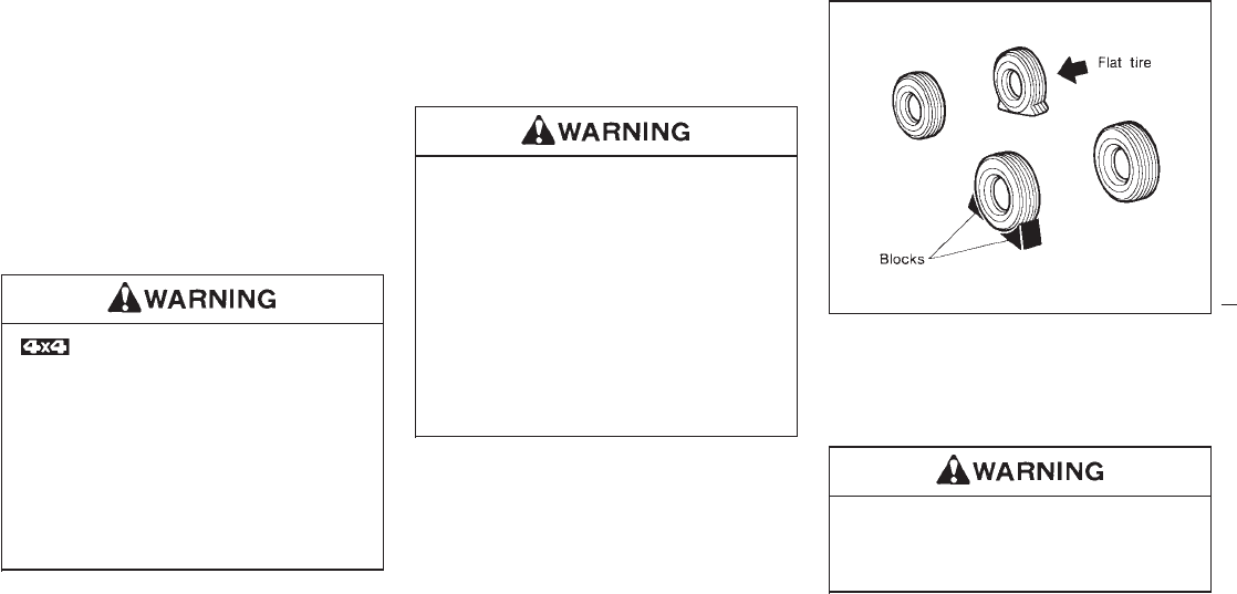
If you have a flat tire, follow the instructions
below.
Stopping the vehicle
1. Safely move the vehicle off the road away
from traffic.
2. Turn on the hazard warning flasher.
3. Park on a level surface and apply the
parking brake. Shift the manual transmis-
sion into reverse (automatic transmission in
“P”).
The transfer control lever must
be in the “2H”, “4H” or “4L” position.
Never place the transfer control lever in
the “N” position. Otherwise, the vehicle
could roll unexpectedly even if the
manual transmission is in gear or the
automatic transmission is in the “P”
position. This could result in serious
personal injury or property damage.
4. Turn off the engine.
5. Raise the hood to warn other traffic and to
signal professional road assistance person-
nel that you require assistance.
6. Have all passengers get out of the vehicle
and stand in a safe place away from traffic
and clear of the vehicle.
IMake sure that the parking brake is
securely applied and the manual
transmission is shifted into reverse
(automatic transmission in “P”).
INever change tires when the vehicle
is on a slope, ice or a slippery area.
This is hazardous.
INever change tires if oncoming traffic
is close to your vehicle. Wait for pro-
fessional road assistance.
Blocking wheels
Place suitable blocks at both the front and
back of the wheel diagonally opposite the flat
tire.
Be sure to block the wheel as the vehicle
may move and could cause personal
injury.
MCE0001
FLAT TIRE
5-2
Z01.2.1/R50-D X
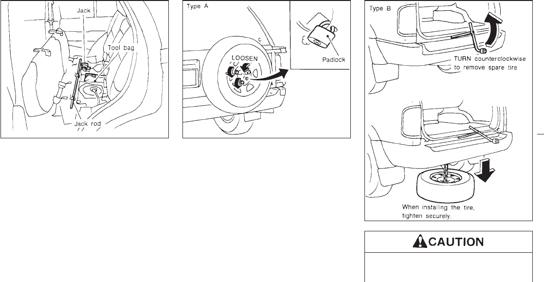
Getting the spare tire and tools
Remove jacking tools and spare tire from
storage area.
Tightening torque of nuts:
48 to 66 ft-lb
(66 to 89 N⋅m)
Use a suitable padlock.
IDo not insert the jack rod straight as
it is designed to be inserted ob-
liquely.
SCE0112 SCE0120
SCE0116A
5-3
Z01.2.1/R50-D X
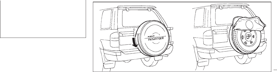
IMake sure the rod tip fits in the fitting
portion of the spare tire hanger and
turn the rod.
IBe sure to center the spare tire sus-
pending plate on the wheel and then
lift the spare tire.
Spare tire cover (If so equipped)
The spare tire cover cannot be removed or
attached unless the spare tire is detached from
the spare tire carrier.
1. Attach the cover to the entire periphery of
the inner half and the top part of the spare
tire.
2. Secure the spare tire to the spare tire
carrier as shown in the illustration.
3. Fasten the zip fastener of the spare tire
cover.
SCE0150
5-4
Z01.2.1/R50-D X
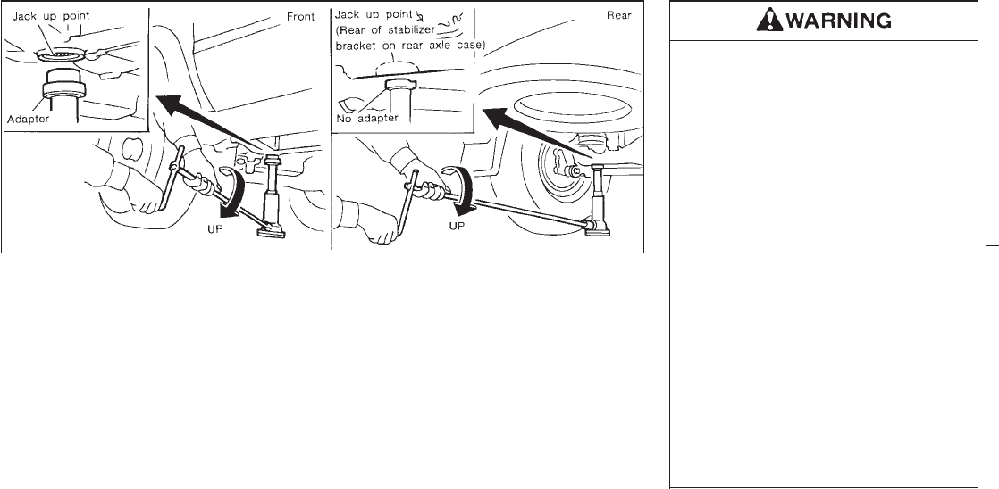
Jacking up and removing wheel
Carefully read the following instructions.
1. On models with 265/70 R15 size tires, put
the adapter stored in the tool bag on the
jack when jacking up the front side.
Do not use the jack adapter for the rear.
2. Place the jack directly under the jack-up
point.
The jack should be used on level firm
ground.
3. Loosen each wheel nut one or two turns by
turning counterclockwise with the wheel nut
wrench.
Do not remove the wheel nuts until the tire
is off the ground.
4. Carefully raise the vehicle until the tire
clears the ground. To lift the vehicle, se-
curely hold the jack lever and rod with both
hands as shown above. Remove the wheel
nuts, and then remove the wheel. Do not
remove the brake drum with the wheel.
INever get under the vehicle while it is
supported only by the jack.
IUse the jack provided with your ve-
hicle. Do not use the jack provided
with your vehicle on other vehicles.
The jack is designed only for lifting
your vehicle during a tire change.
IUse the correct jack up points; never
use any other part of the vehicle for
jack support.
INever jack up the vehicle more than
necessary.
INever use blocks on or under the
jack.
IDo not start or run engine while ve-
hicle is on the jack, as it may cause
the vehicle to move. This is especially
true for vehicle with limited slip dif-
ferential carriers.
IDo not allow passengers to stay in
the vehicle while it is on the jack
SCE0113
5-5
Z01.2.1/R50-D X
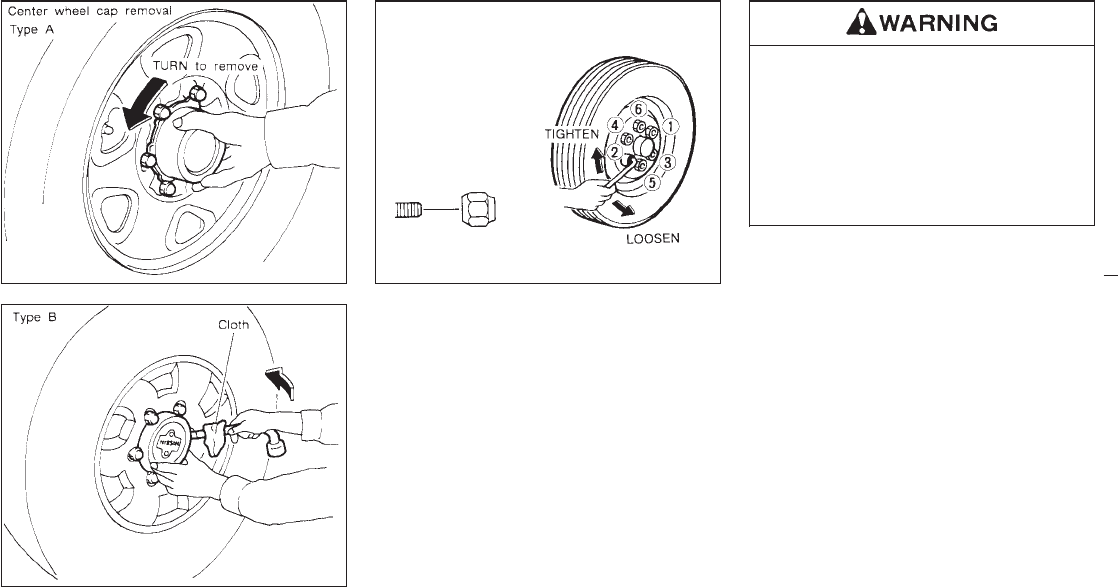
Installing wheel
1. Clean any mud or dirt from the surface
between the wheel and hub.
2. Carefully put the wheel on and tighten the
wheel nuts finger tight.
3. With the wheel nut wrench, tighten wheel
nuts alternately and evenly until they are
tight.
4. Lower the vehicle slowly until the tire
touches the ground. Then, with the wheel
nut wrench, tighten the wheel nuts securely
in the sequence as illustrated.
IIncorrect wheel nuts or improperly
tightened wheel nuts can cause the
wheel to become loose or come off.
This could cause an accident.
IDo not use oil or grease on the wheel
studs or nuts. This could cause the
nuts to become loose.
As soon as possible tighten the wheel nuts
to the specified torque with a torque
wrench.
Wheel nut tightening torque:
87 to 108 ft-lb (118 to 147 N⋅m)
Adjust tire pressure to the COLD pressure.
COLD pressure:
After vehicle has been parked for three
hours or more or driven less than 1 mile
(1.6 km).
COLD tire pressures are shown on the tire
placard affixed to the glove box lid.
Retighten the wheel nuts when the vehicle
has been run for 600 miles (1,000 km) after
installing the aluminum wheel.
SCE0139
SCE0140
SCE0122
5-6
Z01.2.1/R50-D X
5. Securely store the spare tire and jacking
equipment in the vehicle.
Always make sure that the spare tire and
jacking equipment are properly secured
after use. Such items can become dan-
gerous projectiles in an accident or sud-
den stop.
If you try to start your engine with a booster
battery, follow the instructions and precautions
below:
IIf done incorrectly, jump starting can
lead to a battery explosion, resulting
in severe injury or death. It could also
damage your vehicle.
IExplosive hydrogen gas is always
present in the vicinity of the battery.
Keep all sparks and flames away from
it.
IDo not allow battery fluid to come
into contact with eyes, skin, cloth or
painted surfaces. Battery fluid is a
corrosive sulphuric acid solution
which can cause severe burns. If the
fluid should come into contact with
anything, immediately flush the con-
tacted area with water.
IKeep battery out of the reach of chil-
dren.
IThe booster battery must be rated at
12 volts. Use of an improperly rated
battery can damage your vehicle.
IWhenever working on or near a bat-
tery, always wear suitable eye protec-
tors (e.g., goggles or industrial safety
spectacles) and remove rings, metal
bands, or any other metal jewelry. Do
not lean over battery when jump-
starting.
IDo not attempt to jump start a frozen
battery. It could explode and cause
serious injury.
IYour vehicle has an automatic engine
cooling fan. It could come on at any
time. Keep hands and other objects
away from it.
JUMP STARTING
5-7
Z01.2.1/R50-D X
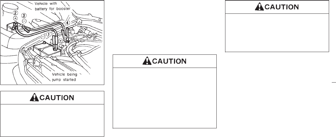
Always follow the instructions below
exactly. Failure to do so could result in
damage to the charging system and
cause personal injury.
1. Position the two vehicles to bring their
batteries into close proximity to each other
if the booster battery is in another vehicle.
Do not allow the two vehicles to touch.
2. Apply parking brakes. Move the shift lever
to “Neutral position” (On automatic trans-
mission models, move the lever to “P”).
Switch off all unnecessary electrical sys-
tems (light, heater, air conditioner, etc.).
3. Remove vent caps on the battery (if so
equipped). Cover the battery with an old
cloth to reduce explosion hazard.
4. Connect jumper cables in the sequence as
illustrated.
IAlways connect positive (+) to posi-
tive (+) and negative (−) to body
ground, engine lift bracket, etc. (not
to the battery).
IMake sure that cables do not touch
any moving parts in the engine com-
partment and that clamps do not con-
tact any other metal.
5. Start the engine of the other vehicle and let
it run for a few minutes.
6. Keep the engine speed of the other vehicle
at about 2,000 rpm, and start your engine in
the normal manner.
Do not keep starter motor engaged for
more than 10 seconds. If the engine
does not start right away, turn the key
off and wait 3 to 4 seconds before trying
again.
7. After starting your engine, carefully discon-
nect the negative cable and then the posi-
tive cable.
8. Replace the vent caps (if so equipped). Be
sure to dispose of the cloth used to cover
the vent holes as it may be contaminated
with corrosive acid.
SCE0149
5-8
Z01.2.1/R50-D X
IAutomatic transmission models can-
not be started by pushing. This may
cause transmission damage.
IThree-way catalyst equipped models
should not be started by pushing
since the three-way catalyst may be
damaged.
INever try to start the vehicle by tow-
ing it; when the engine starts, the
forward surge could cause the ve-
hicle to collide with the tow vehicle.
If your vehicle is overheating indicated by an
extremely high temperature gauge reading, or
if you feel a lack of engine power, detect
abnormal noise, etc., take the following steps:
IDo not continue to drive if your ve-
hicle overheats. Doing so could
cause a vehicle fire.
ITo avoid the danger of being burned,
never remove the radiator cap while
the engine is still hot. When the radia-
tor cap is removed, pressurized hot
water will spurt out, possibly causing
serious injury.
IDo not open the hood if steam is
coming out.
1. Move the vehicle safely off the road, apply
the parking brake and move the gearshift
lever to the neutral position (automatic
transmission to “P”).
Do not stop the engine.
2. Turn off the air conditioner switch. Open all
the windows, move the heater or air condi-
tioner temperature control to “maximum
hot” and fan control to “high speed”.
3. If engine overheating is caused by climbing
a long hill on a hot day, run the engine at a
fast idle (approximately 1,500 rpm) until the
temperature gauge indication returns to
normal.
4. Get out of the vehicle. Look and listen for
steam or coolant escaping from the radiator
before opening the hood. Wait until no
steam or coolant can be seen before pro-
ceeding.
5. Open the engine hood.
If steam or water is coming from the
engine, stand clear to prevent getting
burned.
6. Visually check drive belts for damage or
looseness. Also check if the cooling fan is
running. The radiator hoses and radiator
should not leak water. If coolant is leaking,
the cooling fan belt is missing or loose or
the cooling fan does not run, stop the
engine.
PUSH STARTING IF YOUR VEHICLE OVERHEATS
5-9
Z01.2.1/R50-D X
Be careful not to allow your hands, hair,
jewelry or clothing to come into contact
with, or to get caught in, the running fan
or belts.
7. After the engine cools down, check the
coolant level in the reservoir tank with the
engine running. Add coolant to the reservoir
tank if necessary. Have your vehicle re-
paired at the nearest NISSAN dealer.
When towing your vehicle, all State (Provincial
in Canada) and local regulations for towing
must be followed. Incorrect towing equipment
could damage your vehicle. Towing instruc-
tions are available from your NISSAN dealer.
Local service operators will generally be famil-
iar with the applicable laws and procedures for
towing. To assure proper towing and to pre-
vent accidental damage to your vehicle,
NISSAN recommends that you have a service
operator tow your vehicle. It is advisable to
have the service operator carefully read the
following precautions.
INever ride in a vehicle that is being
towed.
INever get under your vehicle after it
has been lifted by a tow truck.
IWhen towing, make sure that the
transmission, axles, steering system
and power train are in good order. If
any unit is damaged, a dolly must be
used.
IWhen towing with the front wheels on
the ground:
Turn the ignition key to the “OFF”
position and secure the steering
wheel in a straight-ahead position
with a rope or similar device. Never
place the ignition key in the “LOCK”
position. This will result in damage to
the steering lock mechanism.
IWhen towing manual transmission
models with the rear wheels on the
ground, release the parking brake
and move the gearshift lever to the
neutral position.
IFor 4-wheel drive model:
Move the transfer case shift lever into
the “2H” position and the transmis-
sion shift lever into the neutral (“N”)
position.
IAttach safety chains for all towing.
TOW TRUCK TOWING
5-10
Z01.2.1/R50-D X
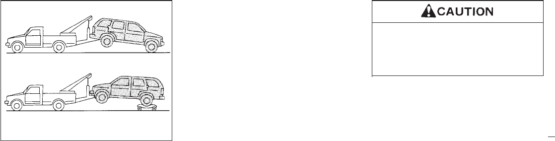
2-WHEEL DRIVE MODELS
NISSAN recommends that your vehicle be
towed with the driving (rear) wheels off the
ground as illustrated.
If you have to tow your vehicle with
four wheels on ground or Towing
with front wheels raised (with rear
wheels on ground)
1. Release the parking brake and move the
gearshift lever to the neutral position (“N”
position).
On automatic transmission models, to
move the selector lever to neutral (“N”
position), turn the ignition key to the “ACC”
position. After moving the selector lever to
neutral (“N” position), be sure to turn the
ignition key to the “OFF” position.
2. Observe the following restricted towing
speeds and distances.
Automatic transmission model:
ISpeed: Below 30 MPH (50 km/h)
IDistance: Less than 40 miles (65 km)
Manual transmission model:
ISpeed: Below 60 MPH (95 km/h)
IDistance: Less than 200 miles (320 km)
If the speed or distance must necessarily be
greater, remove the propeller shaft beforehand
to prevent damage to the transmission.
Never tow your vehicle from the rear
(i.e., backward) with four wheels on the
ground as this may cause serious and
expensive damage to the transmission.
SCE0123
5-11
Z01.2.1/R50-D X
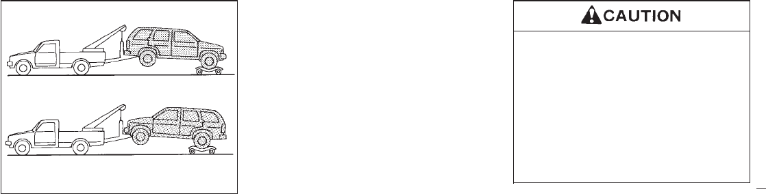
4-WHEEL DRIVE MODELS
NISSAN recommends that a dolly be used as
illustrated when towing your vehicle.
If you have to tow your vehicle with
four wheels on ground or Towing
with front or rear wheels raised
1. Release the parking brake and move the
gearshift lever to the neutral position (“N”
position).
On automatic transmission models, to
move the selector lever to neutral (“N”
position), turn the ignition key to the “ACC”
position. After moving the selector lever to
neutral (“N” position), be sure to turn the
ignition key to the “OFF” position.
2. Observe the following restricted towing
speeds and distances.
Automatic transmission model:
ISpeed: Below 30 MPH (50 km/h)
IDistance: Less than 40 miles (65 km)
Manual transmission model:
ISpeed: Below 60 MPH (95 km/h)
IDistance: Less than 500 miles (800 km)
If the speed or distance must necessarily be
greater, remove the front and rear propeller
shafts beforehand to prevent damage to the
transmission.
INever tow your vehicle from the rear
(i.e., backward) with four wheels on
the ground as this may cause serious
and expensive damage to the trans-
mission.
IBe sure to place the transfer case
shift lever into the “2H” position and
the transmission shift lever into the
neutral (“N”) position.
SCE0124
5-12
Z01.2.1/R50-D X
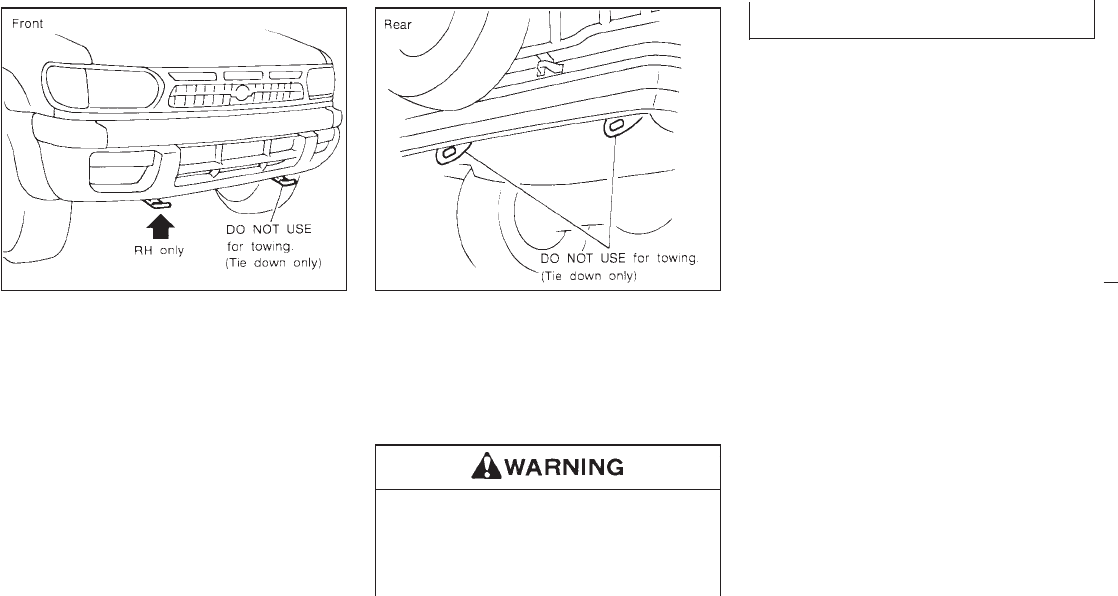
VEHICLE RECOVERY (Freeing a
stuck vehicle)
IUse the towing hook only, not other parts of
the vehicle. Otherwise, the vehicle body will
be damaged.
IUse the towing hook only to free a vehicle
stuck in sand, snow, mud, etc. Never tow
the vehicle for a long distance using only
the towing hook.
IThe towing hook is under tremendous force
when used to free a stuck vehicle. Always
pull the cable straight out from the front of
the vehicle. Never pull on the hook at an
angle.
IStand clear of a stuck vehicle.
Do not spin your tires at high speed.
This could cause them to explode and
result in serious injury. Parts of your
vehicle could also overheat and be
damaged.
SCE0115A SCE0138
5-13
Z01.2.1/R50-D X

MEMO
5-14
Z01.2.1/R50-D X

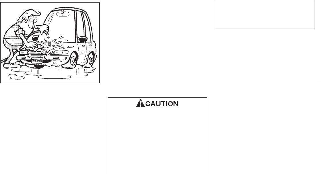
In order to maintain the appearance of your
vehicle, it is important to take proper care of it.
In the following cases, please wash your ve-
hicle as soon as possible to protect the paint
surface.
IAfter a rainfall to prevent possible damage
from acid rain.
IAfter driving on coastal roads
IWhen contaminants such as soot, bird
droppings, tree sap, metal particles or bugs
get on the paint surface
IWhen dust or mud builds up on the surface
Whenever possible, store or park your vehicle
inside a garage or in a covered area.
When it is necessary to park outside, park in a
shady area or protect the vehicle with a body
cover.
Be careful not to scratch the paint surface
when putting on or removing the body
cover.
Washing
Wash dirt off with a wet sponge and plenty of
water. Clean the vehicle thoroughly using a
mild soap such as Nissan Car Wash, or a
general purpose dish-washing liquid mixed
with clean, lukewarm (never hot) water.
IDo not use strong household soap,
strong chemical detergents, gasoline
or solvents.
IDo not wash the vehicle in direct
sunlight or while the vehicle body is
hot, as the surface may become
water-spotted.
IAvoid using tight-napped or rough
cloths, such as washing mitts. Care
must be taken when removing
caked-on dirt or other foreign sub-
stance so that the paint surface is not
scratched or damaged.
Rinse the vehicle thoroughly with plenty of
clean water.
Inside flanges, seams and folds on the doors,
hatches and hood are particularly endangered
by the effects of road salt. Therefore, these
areas must be regularly cleaned. Take care
that the drain holes in the lower edge of the
door are open. Spray water under the body
and in the wheel wells to loosen the dirt and
wash away road salt.
A damp chamois can be used to dry the
vehicle to avoid water spots.
Waxing
Regular waxing protects the paintwork and
keeps the finish. After waxing, polishing is
recommended to remove built-up residue and
avoid a “weathered” appearance.
Your NISSAN dealer can assist you in choos-
ing the proper product.
IWax your vehicle only after a thorough
washing. Follow the instructions supplied
with the wax.
MAI0001
CLEANING EXTERIOR AND
INTERIOR
6-2
Z01.2.1/R50-D X
IDo not use a wax containing any abrasives,
cutting compounds or cleaners that may
damage the vehicle finish.
IIf the surface does not polish easily, use a
“road tar” remover and wax again.
Machine compounding or aggressive pol-
ishing on a base coat/clear coat paint finish
may dull the finish or leave swirl marks.
Only apply black wax or black shoe polish to
the black urethane or polypropylene bumper.
Removing spots
Remove tar and oil spots, industrial dust, in-
sects and tree sap as quickly as possible from
the surface of the paint to avoid lasting dam-
age or staining. Special cleaning products are
available at your NISSAN dealer or any auto-
motive accessories store.
Underbody
In areas where road salt is used in winter, it is
necessary to clean the underbody regularly in
order to prevent dirt and salt from building up
and causing corrosion on the underbody and
suspension. Before the winter period and
again in the spring, the underseal must be
checked and, if necessary, re-treated.
Cleaning glass
Use glass cleaner to remove smoke and dust
film from the glass surfaces. It is normal for
glass to be coated with a film after the vehicle
is parked in the hot sun. Glass cleaner and a
soft cloth will easily remove this film.
IWhen cleaning the inside of the win-
dow, do not use any sharp-edged
tools or abrasive cleaners or
chlorine-based disinfectant cleaners.
IThese may damage the radio antenna
elements or rear window defroster.
Cleaning aluminum alloy wheels
Wash regularly, especially during winter
months in areas where road salt is used. Salt
could discolor the wheel if not removed.
Chrome parts
Clean all chrome parts regularly with a non-
abrasive chrome polish to maintain the finish.
Cleaning interior
Occasionally remove loose dust from the inte-
rior trim, plastic parts and seats using a
vacuum cleaner or soft brush. Wipe the vinyl
and leather surfaces with a clean, soft cloth
dampened in mild soap solution, then wipe
clean with a dry soft cloth. Before using any
fabric protector, read the manufacturer’s rec-
ommendations. Some fabric protectors con-
tains chemicals that stain or bleach the seat
material.
6-3
Z01.2.1/R50-D X
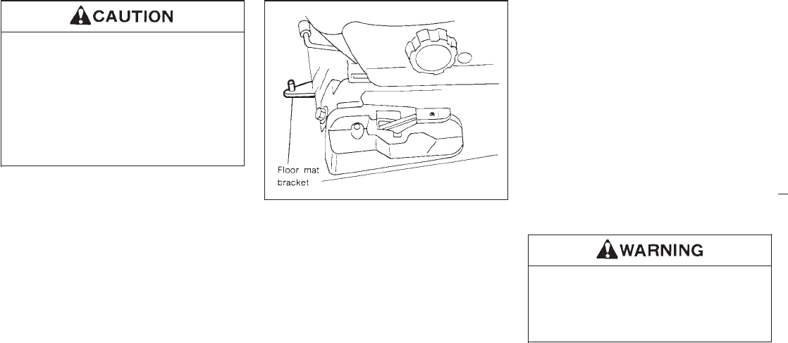
INever use benzine, thinner or any
similar material.
IThe leather seats should be regularly
coated with a leather wax like saddle
soap. Never use car wax.
INever use fabric protectors unless
recommended by the manufacturer.
Floor mat positioning aid
(Driver side only)
This model includes a front floor mat bracket to
act as a floor mat positioning aid. NISSAN floor
mats have been specially designed for your
vehicle model. The driver side floor mat has a
grommet hole incorporated in it. Simply posi-
tion the mat by placing the floor mat bracket
hook through the floor mat grommet hole while
centering the mat in the floorpan contour.
Periodically check to make certain the mats
are properly positioned.
Floor mats
The use of Genuine Nissan floor mats can
extend the life of your vehicle carpet and make
it easier to clean the interior. No matter what
mats are used, be sure they are fitted for
your vehicle and are properly positioned in
the footwell to prevent interference with
pedal operation. Mats should be maintained
with regular cleaning and replaced if they
become excessively worn.
Seat belts
The seat belts can be cleaned by wiping them
with a sponge dampened in a mild soap solu-
tion. Allow the belts to dry completely before
using them.
Do not allow wet belts to roll up in the
retractor. NEVER use bleach, dye or
chemical solvents since these may se-
verely weaken the seat belt webbing.
SAI0009
6-4
Z01.2.1/R50-D X
Most common factors contributing to
vehicle corrosion:
1. The accumulation of moisture-retaining dirt
and debris in body panel sections, cavities,
and other areas.
2. Damage to paint and other protective coat-
ings caused by gravel and stone chips or
minor traffic accidents.
Environmental factors influence the
rate of corrosion:
Moisture
The accumulation of sand, dirt and water on
the underside of the body will accelerate cor-
rosion. Floor sections which have snow and
ice trapped under the floor matting will not dry.
Relative humidity
Corrosion will be accelerated:
Iin areas of high relative humidity
Iespecially in areas where the temperatures
stay above freezing
Iwhere atmospheric pollution exists
Iwhere road salt is used
Temperature
A temperature increase will accelerate the rate
of corrosion to those parts which are not well
ventilated.
Air pollution
Industrial pollution, the presence of salt in the
air in coastal areas, or heavy road salt use will
accelerate the corrosion process. Road salt
will also accelerate the disintegration of paint
surfaces.
To protect your vehicle from
corrosion:
IWash and wax your vehicle often to keep
the vehicle clean.
IAlways check for minor damage to the paint
and repair it as soon as possible.
IKeep drain holes at the bottom of the doors
and tailgate open to avoid water accumula-
tion.
ICheck the underbody. If any sand, dirt or
salt is accumulated, wash it off with water
as soon as possible.
INEVER remove dirt, sand or other
debris from the passenger compart-
ment by washing with a hose. Re-
move dirt with a vacuum cleaner or
broom.
INever allow water or other liquids to
come in contact with electronic com-
ponents inside the vehicle.
PROTECTING AGAINST
CORROSION
6-5
Z01.2.1/R50-D X

MEMO
6-6
Z01.2.1/R50-D X

7 Do-it-yourself operations
Precautions ............................................................ 7-2
Engine cooling system ........................................... 7-4
Engine oil ............................................................... 7-7
Automatic transmission fluid .................................. 7-9
Power steering fluid ............................................. 7-11
Brake and clutch fluid .......................................... 7-11
Window washer fluid ............................................ 7-12
Battery .................................................................. 7-13
Drive belts ............................................................ 7-14
Spark plug replacement ....................................... 7-14
Air cleaner filter .................................................... 7-16
Wiper blade .......................................................... 7-17
Parking brake ....................................................... 7-18
Brake pedal .......................................................... 7-18
Brake booster ....................................................... 7-19
Clutch pedal ......................................................... 7-20
Fuses ................................................................... 7-20
Light bulbs ............................................................ 7-21
Wheels and tires .................................................. 7-26
Clutch housing ........................................... 7-30
Z01.2.1/R50-D X
When performing any inspection or mainte-
nance work on your vehicle, always take care
to prevent serious accidental injury to yourself
or damage to the vehicle. The following are
general precautions which should be closely
observed.
IPark the vehicle on a level surface,
apply the parking brake securely and
block the wheels to prevent the ve-
hicle from moving. For a manual
transmission, move the shift lever to
Neutral. For an automatic transmis-
sion, move the selector lever to “P”
(Park).
IBe sure the ignition key is in the
“OFF” or “LOCK” position when per-
forming any replacement or repair.
IIf you must work with the engine
running, keep your hands, clothing,
hair and tools away from moving fans
and fan belts.
IIt is advisable to remove necktie and
any jewelry, such as rings, watches,
etc. before working on your vehicle.
IIf you must run the engine in an
enclosed space such as a garage, be
sure there is proper ventilation for
exhaust gases.
INever get under the vehicle while it is
supported only by a jack. If it is nec-
essary to work under the vehicle,
support it with safety stands.
IKeep smoking materials, flame and
sparks away from fuel and battery.
IThe fuel filter or fuel lines should be
serviced by a NISSAN dealer because
the fuel lines are under high pressure
even when the engine is off.
IDo not work under the engine hood
while it is hot. Always turn off the
engine and wait until it cools down.
INever connect or disconnect either
the battery or any transistorized com-
ponent connector while the ignition
key is on.
IAvoid direct contact with used engine
oil.Improperlydisposedmotoroiland/
or other vehicle fluids can hurt the
environment. Always conform to lo-
cal regulations for disposal of vehicle
fluid.
This “Do-it-yourself operations” section gives
instructions regarding only those items which
are relatively easy for an owner to perform.
You should be aware that incomplete or im-
proper servicing may result in operating diffi-
culties or excessive emissions, and could af-
fect your warranty coverage. If in doubt about
any servicing, have it done by your NISSAN
dealer.
PRECAUTIONS
7-2
Z01.2.1/R50-D X
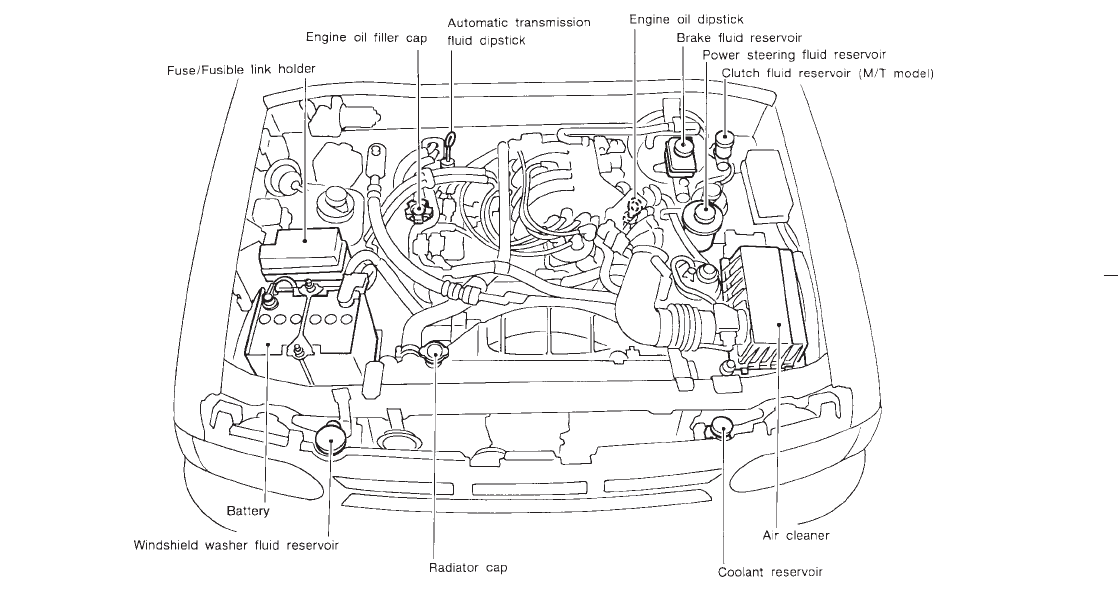
SDI0418
VG33E engine
7-3
Z01.2.1/R50-D X
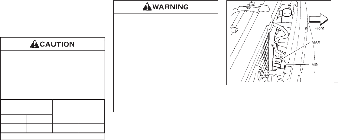
The engine cooling system is filled at the
factory with a high-quality, year-round, anti-
freeze coolant solution. The anti-freeze solu-
tion contains rust and corrosion inhibitors,
therefore additional cooling system additives
are not necessary.
When adding or replacing the coolant,
be sure to use an ethylene glycol anti-
freeze with the proper mixture ratio of
50% anti freeze and 50% distilled water.
The use of other types of coolant solu-
tions may damage your engine cooling
system.
Outside temperature
down to Anti-
freeze
Distilled
water
°C °F
−35 −30 50% 50%
INever remove the radiator cap when
the engine is hot; serious burns
could be caused by high pressure
fluid escaping from the radiator. Wait
until the engine and radiator cool
down. Serious burns could be caused
by high pressure fluid escaping from
the radiator. See precautions in “If
your vehicle overheats” found in the
“In case of emergency” section.
IThe radiator is equipped with a pres-
sure cap. Use a NISSAN genuine cap
or its equivalent when replacement is
required.
CHECKING COOLANT LEVEL
With coolant reservoir
Check the coolant level in the reservoir tank
when the engine is cold. If the coolant level is
below the “MIN” level, add coolant to the
“MAX” level. If the reservoir tank is empty,
check the coolant level in the radiator when
the engine is cold. If there is insufficient
coolant in the radiator, fill the radiator with
coolant up to the filler opening and also add it
to the reservoir tank up to the “MAX” level.
SDI0378
ENGINE COOLING SYSTEM
7-4
Z01.2.1/R50-D X
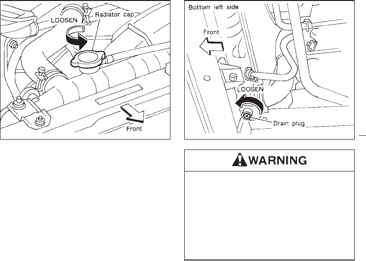
If the engine cooling system frequently
requires coolant, have it checked by your
NISSAN dealer.
CHANGING ENGINE COOLANT
IMajor cooling system repairs should be
performed by your NISSAN dealer. The
service procedures can be found in the
appropriate NISSAN Service Manual.
IImproper servicing can result in reduced
heater performance and engine overheat-
ing.
ITo avoid the danger of being scalded,
never change the coolant when the
engine is hot.
INever remove the radiator cap when
the engine is hot. Serious burns
could be caused by high pressure
fluid escaping from the radiator.
SDI0485 SDI0486
7-5
Z01.2.1/R50-D X
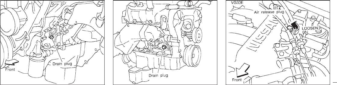
1. Perform the following procedure to open
the heater water cock.
ITurn the ignition key from “OFF” to “ON”.
IMove the heater or air conditioner tem-
perature control dial to the maximum hot
position then turn the ignition key to
“OFF”.
2. Open the radiator drain plug and radiator
cap.
Open the drain plugs on the engine block.
3. Open the air release plug to drain the
coolant.
4. Flush the cooling system by running fresh
water through the radiator.
5. Close the radiator drain plug and engine
block drain plugs securely.
6. See the “Technical information” section for
cooling system capacity.
Fill the radiator slowly with the proper mix-
ture of coolant and water. Fill the reservoir
tank slowly up to the “MAX” level. Then
install the radiator cap and close the air
release plug.
7. Start the engine and warm it up until it
reaches normal operating temperature.
Then race the engine 2 or 3 times under no
load.
Watch the coolant temperature gauge for
signs of overheating.
8. Stop the engine. After it completely cools
down, refill the radiator up to the filler
opening. Fill the reservoir tank up the
“MAX” level.
9. Check the radiator drain plug and engine
block drain plugs for any sign of leakage.
SDI0409 SDI0410 SDI0419
7-6
Z01.2.1/R50-D X
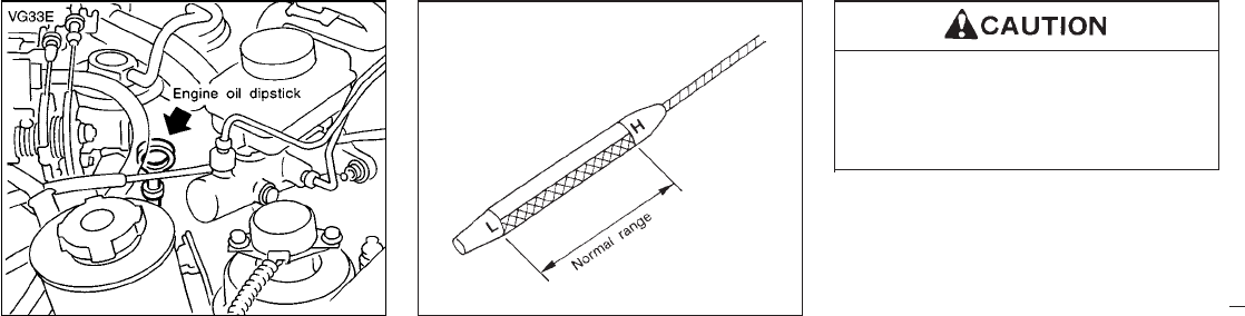
CHECKING ENGINE OIL LEVEL
1. Park the vehicle on a level surface and
apply the parking brake.
2. Run the engine until it reaches operating
temperature.
3. Turn off the engine. Wait more than 10
minutes for the oil to drain back into the
oil pan.
4. Remove the dipstick and wipe it clean.
Reinsert it all the way.
5. Remove the dipstick again and check the
oil level. It should be between the “H” and
“L” marks. If the oil level is below the “L”
mark, remove the oil filler cap and pour
recommended oil through the opening. Do
not overfill.
6. Recheck oil level with dipstick.
It is normal to add some oil between oil
changes or during the break-in period, de-
pending on the severity of operating con-
ditions.
Oil level should be checked regularly.
Operating with insufficient amount of oil
can damage the engine, and such dam-
age is not covered by warranty.
SDI0420 SDI0487
ENGINE OIL
7-7
Z01.2.1/R50-D X
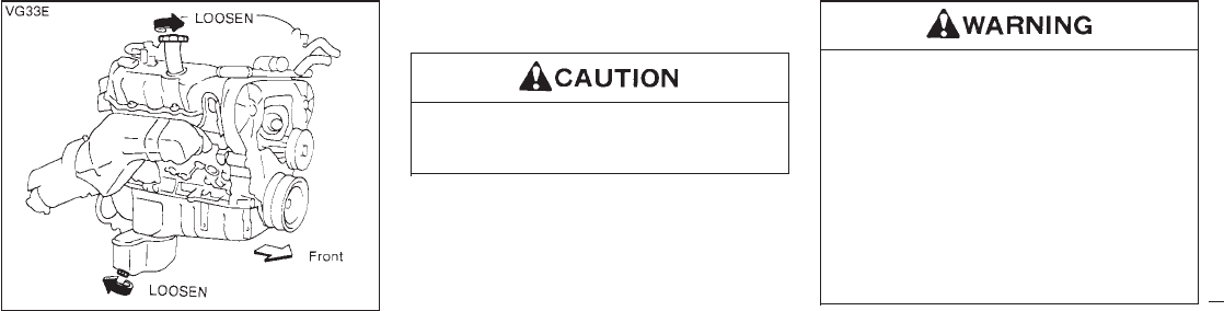
CHANGING ENGINE OIL
1. Park the vehicle on a level surface and
apply the parking brake.
2. Warm up the engine until it reaches oper-
ating temperature, and then turn it off.
3. Place a large drain pan under the drain
plug.
4. Remove the oil filler cap.
5. Remove the drain plug with a wrench and
completely drain the oil.
If the oil filter is to be changed, remove and
replace it at this time. See “Changing oil
filter”.
Be careful not to burn yourself, as the
engine oil is hot.
Waste oil must be disposed of properly.
Check your local regulations.
6. Clean and re-install the drain plug and new
washer. Securely tighten the drain plug with
a wrench. Do not use excessive force.
Drain plug tightening torque:
22 to 29 ft-lb (29 to 39 N⋅m)
7. Refill engine with recommended oil and
install the oil filler cap securely.
See the “Technical information” section for
refill capacity.
8. Start the engine.
Check for leakage around the drain plug.
Correct as required.
9. Turn the engine off and wait several min-
utes. Check the oil level with the dipstick.
Add engine oil if necessary.
IProlonged and repeated contact with
used engine oil may cause skin can-
cer.
ITry to avoid direct skin contact with
used oil. If skin contact is made, wash
thoroughly with soap or hand cleaner
as soon as possible.
IKeep used engine oil out of reach of
children.
SDI0416
7-8
Z01.2.1/R50-D X
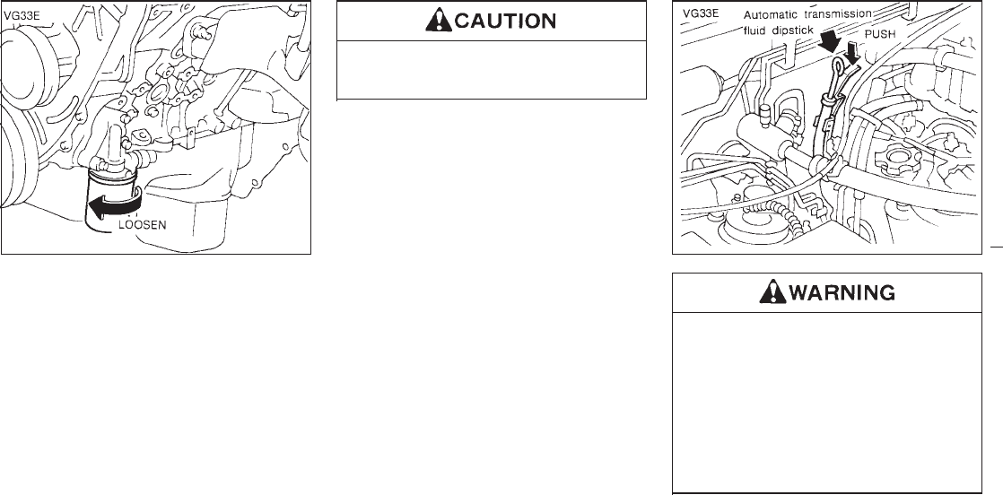
CHANGING OIL FILTER
1. Park the vehicle on a level surface and
apply the parking brake.
2. Turn the engine off.
3. Loosen the oil filter with an oil filter wrench.
(A special cap-type wrench will assist with
oil filter removal on models with the V6
engine. This tool can be purchased from
your NISSAN dealer.) Then remove the oil
filter by turning it by hand.
Be careful not to burn yourself, as the
engine oil may be hot.
4. Wipe the engine oil filter mounting surface
with a clean rag.
Be sure to remove any old rubber gasket
remaining on the mounting surface of the
engine.
5. Coat the rubber gasket on the new filter
with engine oil.
6. Screw in the oil filter until a slight resistance
is felt, then tighten an additional 2/3 turn.
7. Start the engine and check for leakage
around the oil filter. Correct as required.
8. Turn the engine off and wait several min-
utes. Check the oil level. Add engine oil if
necessary.
IWhen engine is running, keep hands,
jewelry, and clothing away from any
moving parts such as fan and drive
belt.
IAutomatic transmission fluid is poi-
sonous and should be stored care-
fully in marked containers out of the
reach of children.
The fluid level should be checked using the
SDI0417 SDI0488
AUTOMATIC TRANSMISSION
FLUID
7-9
Z01.2.1/R50-D X
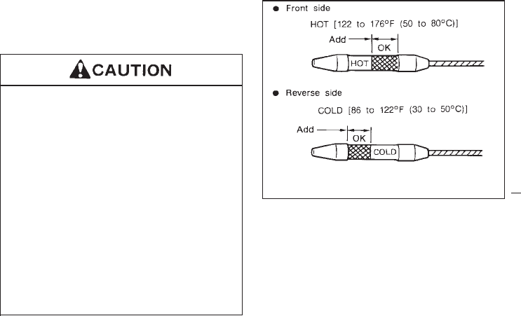
“HOT” range (“L” & “H” marks) on the dipstick
at fluid temperatures between 122 and 176°F
(50 and 80°C) after the vehicle has been
driven approximately 5 minutes in urban areas
after the engine is warmed up. The level can
be checked at fluid temperatures between 86
and 122°F (30 and 50°C) using the “COLD”
range on the dipstick for reference, after the
engine is warmed up but before driving. How-
ever, the fluid level must be rechecked using
the “HOT” range.
1. Park the vehicle on a level surface and set
the parking brake.
2. Start the engine and then move the selector
lever through each gear range, ending in
“P”.
3. Check the fluid level with the engine idling.
If the vehicle has been driven for a long
time at high speeds, or in city traffic in hot
weather, or if it is being used to pull a
trailer, the fluid level cannot be read accu-
rately. You should wait until the fluid has
cooled down (about 30 minutes).
4. Remove the dipstick and wipe it clean with
lint-free paper.
5. Re-insert the dipstick into the charging pipe
as far as it will go.
6. Remove the dipstick and note the reading.
If the level is on the low side of either range,
add fluid to the charging pipe.
IDo not overfill.
IUSE ONLY Nissan Matic “D” (Conti-
nental U.S. and Alaska) or Genuine
Nissan Automatic Transmission
Fluid (Canada). Dexron
TM
III/Mercon
TM
or equivalent may also
be used. Outside the continental
United States and Alaska contact a
NISSAN dealer for more information
regarding suitable fluids, including
recommended brand(s) of Dexron
TM
III/Mercon
TM
or Dexron
TM
IIE/Mercon
TM
Automatic Transmis-
sion Fluid.
SDI0386A
7-10
Z01.2.1/R50-D X
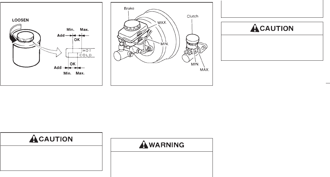
Check the fluid level.
The fluid level should be checked using the
“HOT” range on the dipstick at fluid tempera-
tures of 122 to 176°F (50 to 80°C) or using the
“COLD” range on the dipstick at fluid tempera-
tures of 32 to 86°F (0 to 30°C).
IDo not overfill.
IUse type DEXRON
TM
IIE, DEXRON
TM
III
or equivalent.
Check the fluid level in the reservoir. If the fluid
level is below the Min. line or the brake warn-
ing light comes on, add DOT 3 fluid up to the
Max. line.
If fluid is added frequently, the system should
be thoroughly checked by your
NISSAN dealer.
Use only new fluid. Old, inferior or con-
taminated fluid may damage the brake
and clutch systems. The use of im-
proper fluids can damage the brake sys-
tem and affect the vehicle’s stopping
ability.
Do not spill the fluid on any painted
surfaces. This will damage the paint. If
fluid is spilled, wash with water.
DI0187M SDI0422
POWER STEERING FLUID BRAKE AND CLUTCH FLUID
7-11
Z01.2.1/R50-D X
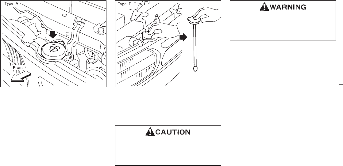
Type A
Add fluid when the low washer fluid warning
light comes on. Add a washer solvent to the
water for better cleaning. In the winter season,
add a windshield washer anti-freeze. Follow
the manufacturer’s instructions for the mixture
ratio.
Type B
To check the fluid level, use your finger to plug
the center hole of the cap/tube assembly (as
shown above), then remove it from the tank. If
there is no fluid in the tube, add
fluid. Add a washer solvent to the water for
better cleaning. In the winter season, add a
windshield washer anti-freeze. Follow the
manufacturer’s instructions for the mixture ra-
tio.
Do not substitute engine anti-freeze
coolant for window washer solution.
This may result in damage to the paint.
Anti-freeze is poisonous and should be
stored carefully marked containers out
of the reach of children.
SDI0389A SDI0423
WINDOW WASHER FLUID
7-12
Z01.2.1/R50-D X
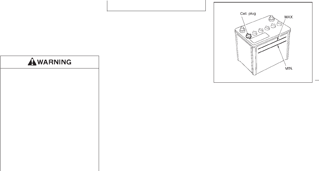
IKeep the battery surface clean and dry. Any
corrosion should be washed off with a
solution of baking soda and water.
IMake certain the terminal connections are
clean and securely tightened.
IIf the vehicle is not to be used for 30 days or
longer, disconnect the “−” negative battery
terminal cable to prevent discharge.
IDo not expose the battery to flames
or electrical sparks. Hydrogen gas
generated by battery action is explo-
sive. Do not allow battery fluid to
contact your skin, eyes, fabrics, or
painted surfaces. After touching a
battery or battery cap, do not touch or
rub your eyes. Thoroughly wash your
hands. If the acid contacts your eyes,
skin or clothing, immediately flush
with water for at least 15 minutes and
seek medical attention.
IWhen working on or near a battery,
always wear suitable eye protection
and remove all jewelry.
IKeep the battery out of the reach of
children.
JUMP STARTING
If jump starting is necessary, see the “In case
of emergency” section. If the engine does not
start by jump starting, the battery may have to
be replaced. Contact your NISSAN dealer.
Check the fluid level in each cell. It should be
between the MAX. and MIN. lines.
If it is necessary to add fluid, add only distilled
water to bring the level to the indicator in each
filler opening. Do not overfill.
1. Remove the cell plugs using a suitable tool.
2. Add distilled water up to the MAX. level.
3. Tighten cell plugs.
DI0137M
BATTERY
7-13
Z01.2.1/R50-D X
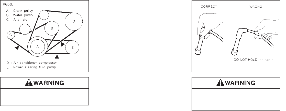
Be sure the ignition key is “OFF”. The
engine could rotate unexpectedly.
1. Visually inspect each belt for signs of un-
usual wear, cuts, fraying or looseness. If
the belt is in poor condition or loose, have it
replaced or adjusted by your NISSAN
dealer.
2. Have the belts checked regularly for condi-
tion and tension in accordance with the
maintenance schedule in this manual.
Be sure the engine and ignition switch
are off and that the parking brake is
engaged securely.
1. Disconnect spark plug cables. Keep track
of the original cable location.
When disconnecting, always hold the
boots — not the cables. Mark all cables to
identify their original location.
SDI0424 DI0064
DRIVE BELTS SPARK PLUG REPLACEMENT
7-14
Z01.2.1/R50-D X
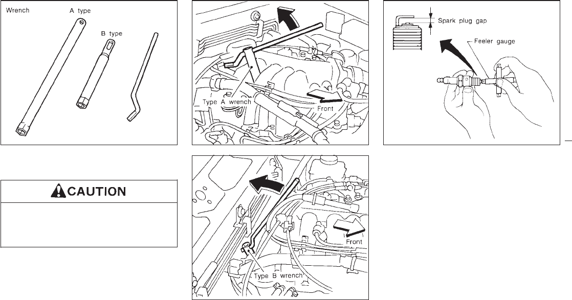
2. Remove spark plugs with a spark plug
wrench. (Type A or B)
Be sure to use the correct wrench to
remove the plugs. An incorrect wrench
can cause damage.
3. Check each new spark plug gap with a
feeler gauge. Correct it as required.
4. Install spark plugs.
When installing a plug, turn it in two or
three turns by hand and then tighten with a
spark plug wrench. Be careful not to over-
tighten it.
Tightening torque:
14 to 22 ft-lb (20 to 29 N⋅m)
5. Reconnect the spark plug cables to their
original positions.
SDI0392 SDI0390
SDI0391
DI0065
7-15
Z01.2.1/R50-D X
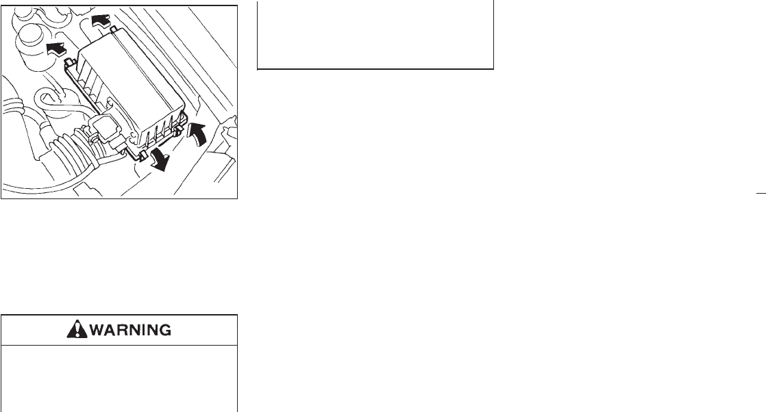
The filter element should not be cleaned and
reused as it is given a special treatment. We
recommended it be replaced according to the
maintenance intervals shown in the “Mainte-
nance schedule” section. When replacing the
filter, wipe the inside of the air cleaner housing
and the cover with a damp cloth.
Operating the engine with the air cleaner
off can cause you or others to be
burned. The air cleaner not only cleans
the air, it stops flame if the engine back-
fires. If it is not there, and the engine
backfires, you could be burned. Do not
drive with it off, and be careful working
on the engine with the air cleaner off.
SDI0393
AIR CLEANER FILTER
7-16
Z01.2.1/R50-D X
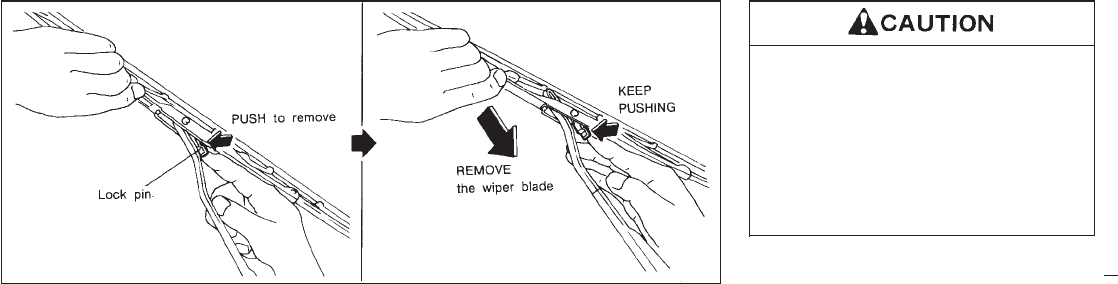
1) CLEANING
If your windshield is not clear after using the
windshield washer of if a wiper blade chat-
ters when running, wax or other material
may be on the blade or windshield.
Clean the outside of the windshield with a
washer solution or a mild detergent. Your
windshield is clean if beads do not form
when rinsing with clear water.
Clean the blade by wiping it with a cloth
soaked in a washer solution or a mild
detergent. Then rinse the blade with clear
water. If your windshield is still not clear
after cleaning the blades and using the
wiper, replace the blades.
2) REPLACEMENT
1. Pull the wiper arm.
2. Push the lock pin, then remove the wiper
blade.
3. Insert the new wiper blade to the wiper arm
until a click sounds.
After wiper blade replacement, return
the wiper arm to its original position.
Otherwise it may be damaged when the
engine hood is opened.
Make sure the wiper blade contacts the
glass. Otherwise, the arm may be dam-
aged from wind pressure.
DI0155MA
WIPER BLADE
7-17
Z01.2.1/R50-D X
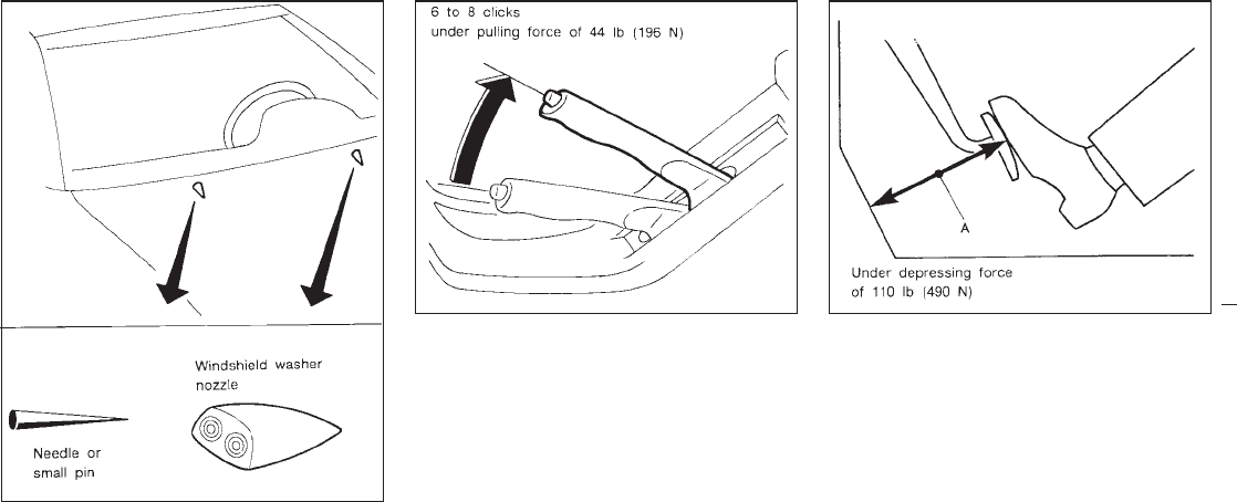
If you wax the surface of the hood, be
careful not to let wax get into the washer
nozzle. This may cause clogging or im-
proper windshield washer operation. If wax
gets into the nozzle, remove it with a needle
or small pin.
Pull the parking brake lever up. If the number
of clicks is out of the range as listed above, see
your NISSAN dealer.
With the engine running, check distance A
between the upper surface of the pedal and
the dash lower panel.
Distance A
M/T models
2-1/2 in (65 mm) or more
A/T models
2-3/4 in (70 mm) or more
If it is out of the range shown above, see your
NISSAN dealer.
SDI0425
DI1010-C DI0453
PARKING BRAKE BRAKE PEDAL
7-18
Z01.2.1/R50-D X

Self-adjusting brakes
Your vehicle is equipped with self-adjusting
brakes.
The front disc-type brakes self-adjust every
time the brake pedal is applied. The rear
drum-type brakes self-adjust every time the
parking brake is applied. If the brake pedal
goes down farther than normal, it may be due
to a lack of adjustment of the rear drum
brakes. Apply the parking brake several times.
See your NISSAN dealer and have it
checked if the brake pedal height does
not return to normal.
Brake pad wear indicators
The disc brake pads on your vehicle have
audible wear indicators. When a brake pad
requires replacement, it will make a high
pitched scraping or screeching sound when
the vehicle is in motion whether or not the
brake pedal is depressed. Have the brakes
checked as soon as possible if the wear indi-
cator sound is heard.
Under some driving or climate conditions, oc-
casional brake squeak, squeal or other noise
may be heard. Occasional brake noise during
light to moderate stops is normal and does not
affect the function or performance of the brake
system.
The rear drum brakes (if so equipped) do not
have audible wear indicators. Should you ever
hear an unusually loud noise from the rear
drum brakes, have them inspected as soon as
possible by your NISSAN dealer.
Proper brake inspection intervals should
be followed. For more information regarding
brake inspections, see the appropriate main-
tenance schedule information in the “Mainte-
nance Schedule” section of this manual.
Check the brake booster function with the
following steps:
1. With the engine off, press and release the
brake pedal several times. When brake
pedal movement (distance of travel) re-
mains the same from one pedal application
to the next, continue on to the next step.
2. While depressing the brake pedal, start the
engine. The pedal height should drop a
little.
3. With the brake pedal depressed, stop the
engine. Keeping the pedal depressed for
about 30 seconds, the pedal height should
not change.
4. Run the engine for one minute without
depressing the brake pedal, then turn it off.
Depress the brake pedal several times. The
pedal travel distance will decrease gradu-
ally with each depression as the vacuum is
released from the booster.
If the brakes do not operate properly, have the
brake checked by your NISSAN dealer.
BRAKE BOOSTER
7-19
Z01.2.1/R50-D X
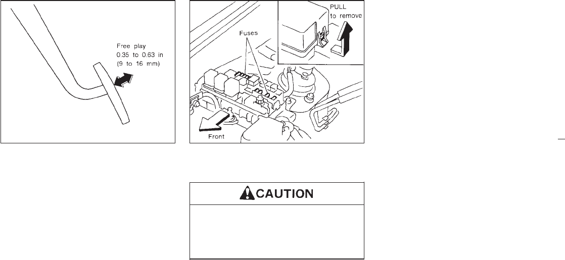
Press the pedal by hand and be sure the free
travel is within the above limit. If free travel is
out of the range shown above, see your
NISSAN dealer.
Engine compartment (Headlight
fuses)
Never use a fuse of higher amperage
rating than that specified on the fuse
box cover. This could damage the elec-
trical system or cause a fire.
If any electrical equipment does not operate,
check for an open fuse.
1. Be sure the ignition key and the headlight
switch are “OFF”.
2. Open the engine hood.
3. Remove the fusible link cover.
4. Remove the fuse with the fuse puller.
5. If the fuse is open, replace it with a new
fuse.
6. If a new fuse opens again, have the elec-
trical system checked and repaired by your
NISSAN dealer.
DI0070-B SDI0395
CLUTCH PEDAL FUSES
7-20
Z01.2.1/R50-D X
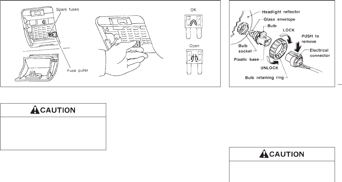
Passenger compartment
Never use a fuse of higher amperage
rating than that specified on the fuse
box cover. This could damage the elec-
trical system or cause a fire.
If any electrical equipment does not operate,
check for an open fuse.
1. Be sure the ignition key and the headlight
switch are “OFF”.
2. Pull to open the fuse box cover/coin tray.
3. Pull the fuse box cover/coin tray horizon-
tally to remove it.
4. Remove the fuse with the fuse puller.
5. If the fuse is open, replace it with a new
fuse.
6. If a new fuse opens again, have the elec-
trical system checked and repaired by your
NISSAN dealer.
HEADLIGHTS
Semi-sealed beam type
The headlight is a semi-sealed beam type
which uses a replaceable headlight (halogen)
bulb. A bulb can be replaced inside the engine
compartment without removing the headlight
assembly.
High pressure halogen gas is sealed
inside the halogen bulb. The bulb may
break if the glass envelope is scratched
SDI0447 DI0156
LIGHT BULBS
7-21
Z01.2.1/R50-D X
or the bulb is dropped.
Hold the plastic base when handling the
bulb. Never touch the glass envelope.
Removing the headlight bulb
1. Disconnect the battery negative cable.
2. Disconnect the electrical connector from
the rear end of the bulb.
3. Turn the bulb retaining ring counterclock-
wise until it is free from the headlight reflec-
tor, then remove it.
4. Remove the headlight bulb. Do not shake
or rotate the bulb when removing it.
Replacing the headlight bulb
1. Insert the bulb into the headlight reflector
with the flat side of the plastic base facing
upward.
2. Install the bulb retaining ring and turn it
clockwise until it stops.
3. Push the electrical connector into the bulb
plastic base until it snaps and stops.
4. Connect the battery negative cable.
DO NOT TOUCH THE BULB.
IUse the same number and wattage as
originally installed:
Wattage 65/45
Bulb no. 9004
IAiming is not necessary after replac-
ing the bulb. When aiming adjust-
ment is necessary, contact your
NISSAN dealer.
IDo not leave the bulb out of the head-
light reflector for a long period of time
as dust, moisture, and smoke may
enter the headlight body and affect
the performance of the headlight.
7-22
Z01.2.1/R50-D X
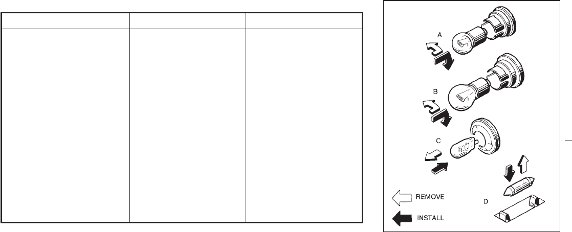
OTHER LIGHTS
Item Wattage (W) Bulb No.
Front turn signal light 27 1156
Front fog light (H3 type) 55
Side combination light 5 168
Rear combination light
Turn signal 27 1156
Stop/Tail 27/8 1157
Back-up 27 1156
High mounted stop light 5 168
License plate light 5or10
7.5
168*1
89*2
Interior light 10 —
Vanity mirror light 1.4 —
Spot light 8 —
*1: For 5W light
*2: Option Replacing procedures
All other lights are either type A, B, C or D.
When replacing a bulb, first remove the lens
and/or cover.
MDI0006
7-23
Z01.2.1/R50-D X
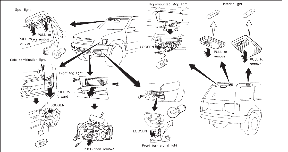
SDI0489
7-24
Z01.2.1/R50-D X
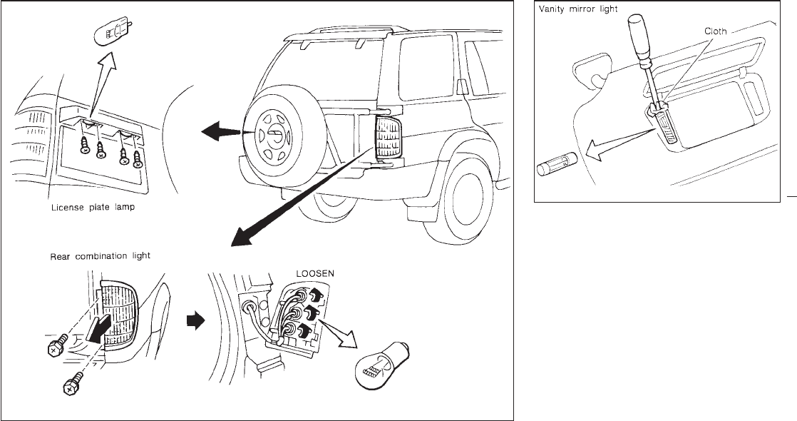
SDI0490
SDI0333
7-25
Z01.2.1/R50-D X
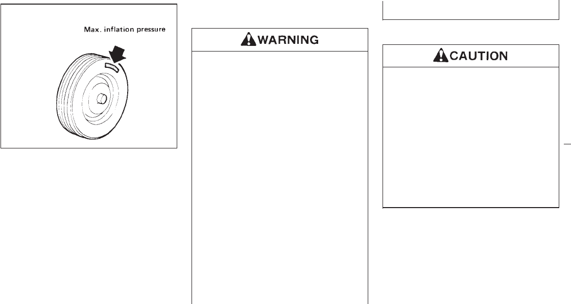
If you have a flat tire, see “In case of
emergency” section.
Maximum inflation pressure
Do not exceed the maximum inflation pres-
sures shown on the side wall of the tire.
Tire inflation pressure
Periodically check the tire pressure (including
spare). Incorrect tire pressure may adversely
affect tire life and vehicle handling. Tire pres-
sure should be checked when tires are COLD.
Tires are considered COLD after the vehicle
has been parked for three or more hours, or
driven less than 1 mile (1.6 km). COLD tire
pressures are shown on the tire placard affixed
to the inside of the glove box lid.
IThe vehicle capacity weight is indi-
cated on the tire placard. Do not load
your vehicle beyond this capacity.
Overloading your vehicle may result
in reduced tire life, unsafe operating
conditions due to premature tire fail-
ure, or unfavorable handling charac-
teristics and could also lead to a
serious accident. Loading beyond the
specified capacity may also result in
failure of other vehicle components.
IBefore taking a long trip, or whenever
you have loaded your vehicle heavily,
use a tire pressure gauge to ensure
that the tire pressure is at the speci-
fied level.
IDo not drive your vehicle over 85
MPH (140 km/h) unless it is equipped
with high speed capability tires. Driv-
ing faster than 85 MPH (140 km/h)
may result in tire failure, loss of con-
trol and possible injury.
Types of tires
When changing or replacing tires, be
sure all four tires are of the same type
(i.e., Summer, All Season or Snow) and
construction. Your NISSAN dealer may
be able to help you with information
about tire type, size, speed rating and
availability. Replacement tires may have
a lower speed rating than the factory
equipped tires, and may not match the
potential maximum vehicle speed. Never
exceed the maximum speed rating of the
tire.
All season tires
NISSAN specifies All Season tires on some
models to provide good performance for use
all year around, including snowy and icy road
conditions. All Season Tires are identified by
“ALL SEASON” and/or “M&S” on the tire side-
wall. Snow tires have better snow traction than
All Season tires and may be more appropriate
in some areas.
DI0047
WHEELS AND TIRES
7-26
Z01.2.1/R50-D X

Summer tires
NISSAN specifies summer tires on some mod-
els to provide superior performance on dry
roads. Summer tire performance in snow and
ice will be substantially reduced. Summer tires
do not have the tire traction rating “M&S” on
the tire sidewall.
If you plan to operate your vehicle in snowy or
icy conditions, NISSAN recommends the use
of “SNOW” or “ALL SEASON” tires on all four
wheels.
Snow tires
If snow tires are needed, it is necessary to
select tires equivalent in size and load rating to
the original equipment tires. If you do not, it
can adversely affect the safety and handling of
your vehicle.
Generally, snow tires will have lower speed
ratings than factory equipped tires and may
not match the potential maximum vehicle
speed. Never exceed the maximum speed
rating of the tire.
For additional traction on icy roads, studded
tires may be used. However, some provinces
and states prohibit their use. Check local, state
and provincial laws before installing studded
tires. Skid and traction capabilities of studded
snow tires, on wet or dry surfaces, may be
poorer than that of non-studded snow tires.
4-wheel drive model
If you install snow tires, they must also be the
same size, brand, construction and tread pat-
tern on all four wheels.
ONLY use spare tires specified for each
4-wheel drive model.
Tire chains
Use of tire chains is prohibited according to
location. Check the local laws before installing
tire chains. When installing tire chains, make
sure they are of proper size for the tires on
your vehicle and are installed according to the
chain manufacturer’s suggestions. Use only
SAE class “S” chains. Other types may
damage your vehicle. Use chain tensioners
when recommended by the tire chain manu-
facturer to ensure a tight fit. Loose end links of
the tire chain must be secured or removed to
prevent the possibility of whipping action dam-
age to the fenders or underbody. If possible,
avoid fully loading your vehicle when using tire
chains. In addition, drive at a reduced speed.
Otherwise, your vehicle may be damaged
and/or vehicle handling and performance may
be adversely affected.
Do not use tire chains on dry roads.
Tire chains must be installed only on the
rear wheels and not on the front wheels.
Do not drive with tire chains on paved roads
which are clear of snow. Driving with chains in
such conditions can cause damage to the
various mechanisms of the vehicle due to
some overstress. When driving on clear paved
roads, be sure to change to 2WD.
7-27
Z01.2.1/R50-D X
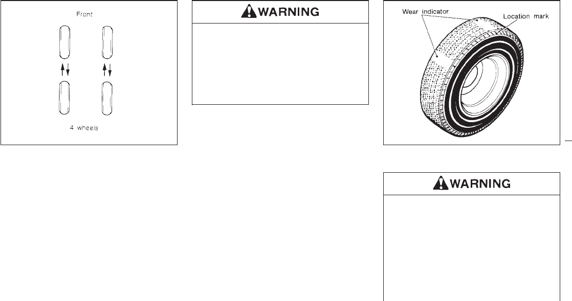
Tire rotation
NISSAN recommends that tires be rotated
every 7,500 miles (12,000 km) for 2WD ve-
hicles and 3,750 miles (6,000 km) for 4WD
vehicles.
See “Flat tire” in the “In case of emergency”
section for tire replacing procedures.
Wheel nut tightening torque:
87 to 108 ft-lb (118 to 147 N⋅m)
IAfter rotating the tires, adjust the tire
pressure.
IRetighten the wheel nuts after the
aluminum wheel has been run for the
first 600 miles (1,000 km). (also in
cases of a flat tire, etc.)
Tire wear and damage
ITires should be periodically in-
spected for wear, cracking, bulging
or objects caught in the tread. If ex-
cessive wear, cracks, bulging or deep
cuts are found, the tire should be
replaced.
IThe original tires have a built-in tread
wear indicator. When the wear indica-
tor is visible, the tire should be
DI0048-B MDI0004
7-28
Z01.2.1/R50-D X
replaced.
Changing tires and wheels
When replacing a tire, use the same size,
speed rating and load carrying capacity as
originally equipped. Recommended types and
sizes are shown in “Wheels and tires” in the
“Technical information” section.
IThe use of tires other than those
recommended or the mixed use of
tires of different brands, construction
(bias, bias-belted or radial), or tread
patterns can adversely affect the ride,
braking, handling, ground clearance,
body-to-tire clearance, snow chain
clearance, speedometer calibration,
headlight aim and bumper height.
Some of these effects may lead to
accidents and could result in serious
personal injury.
IIf the wheels are changed for any
reason, always replace with wheels
which have the same offset dimen-
sion. Wheels of a different offset
could cause early tire wear, possibly
degraded vehicle handling character-
istics and/or interference with the
brake discs/drums. Such interference
can lead to decreased braking effi-
ciency and/or early brake pad/shoe
wear.
IDo not install a deformed wheel or
tire even if it has been repaired. Such
wheels or tires could have structural
damage and could fail without
warning.
4-WHEEL DRIVE MODELS
Always use tires of the same size, brand,
construction (bias, bias-belted or ra-
dial), and tread pattern on all four
wheels. Failure to do so may result in a
circumference difference between tires
on the front and rear axles which will
cause excessive tire wear and may dam-
age the transmission, transfer case and
differential gears.
If excessive tire wear is found, it is recom-
mended that all four tires be replaced with tires
of the same size, brand, construction and
tread pattern. The tire pressure and wheel
alignment should also be checked and cor-
rected as necessary. Contact your NISSAN
dealer.
ONLY use spare tires specified for each
4-wheel drive model.
Wheel balance
Unbalanced wheels may affect vehicle han-
dling and tire life. Even with regular use,
wheels can get out of balance. Therefore, they
should be balanced as required.
Wheel balance service should be performed
with the wheels off the vehicle. Spin balancing
the rear wheels on the vehicle could lead to
transmission damage.
7-29
Z01.2.1/R50-D X
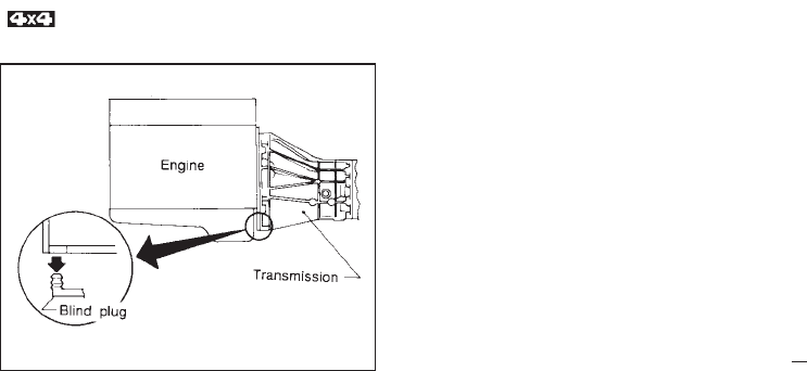
Care of wheels
IWash the wheels when washing the vehicle
to maintain their appearance.
IClean the inner side of the wheels when the
wheel is changed or the underside of the
vehicle is washed.
IDo not use abrasive cleaners when wash-
ing the wheels.
IInspect wheel rims regularly for dents or
corrosion. This may cause loss of pressure
or damage the tire bead.
IWe recommend that the road wheels be
waxed to protect against road salt in areas
where it is used during winter. Checking water entry
Whenever you drive in deep water or mud,
check water entry in the clutch housing by
removing the blind plug at the bottom of the
transmission case. After checking, be sure to
reinstall the plug.
DI0117
CLUTCH HOUSING
7-30
Z01.2.1/R50-D X


Your new NISSAN has been designed to have
minimum maintenance requirements with
longer service intervals to save you both time
and money. However, some day- to-day and
regular maintenance is essential to maintain
your NISSAN’s good mechanical condition, as
well as its emission and engine performance.
It is the owner’s responsibility to make sure
that the specified maintenance, as well as
general maintenance, is performed.
As the vehicle owner, you are the only one
who can ensure that your vehicle receives the
proper maintenance care. You are a vital link
in the maintenance chain.
General maintenance
General maintenance includes those items
which should be checked during normal day-
to-day operation of the vehicle. They are es-
sential if your vehicle is to continue to operate
properly. It is your responsibility to perform
these procedures regularly as prescribed.
These checks or inspections can be done by
yourself, a qualified technician or, if you prefer,
your NISSAN dealer.
Periodic maintenance
The maintenance items listed in this part are
required to be serviced at regular intervals.
However, under severe driving conditions, ad-
ditional or more frequent maintenance will be
required.
Where to go for service
If maintenance service is required or your
vehicle appears to malfunction, have the sys-
tems checked and tuned by an authorized
NISSAN dealer.
NISSAN technicians are well-trained special-
ists and are kept up to date with the latest
service information through technical bulletins,
service tips, and in-dealership training pro-
grams. They are completely qualified to work
on NISSAN’s vehicles before they work on
your vehicle, rather than after they have
worked on it.
You can be confident that your NISSAN deal-
er’s service department performs the best job
to meet the maintenance requirements on your
vehicle — in a reliable and economic way.
During the normal day-to-day operation of the
vehicle, general maintenance should be per-
formed regularly as prescribed in this section.
If you detect any unusual sounds, vibrations or
smell, be sure to check for the cause or have
your NISSAN dealer do it promptly. In addition,
you should notify your NISSAN dealer if you
think that repairs are required.
When performing any checks or maintenance
work, closely observe the precautions in the
“Do-it-yourself operations” section.
Additional information on the following
items with “*” is found in the “Do-it-
yourself operations” section.
OUTSIDE THE VEHICLE
The maintenance items listed here should be
performed from time to time, unless otherwise
specified.
Tires* Check the pressure with a gauge peri-
odically when at a service station, including the
spare, and adjust to the specified pressure if
necessary. Check carefully for damage, cuts
or excessive wear.
Wheel nuts* When checking the tires, make
sure no nuts are missing, and check for any
loose nuts. Tighten if necessary.
Tire rotation* Tires should be rotated every
GENERAL MAINTENANCE
8-2
Z01.2.1/R50-D X

7,500 miles (12,000 km) for 2WD vehicles and
3,750 miles (6,000 km) for 4WD vehicles.
Wheel alignment and balance If the vehicle
should pull to either side while driving on a
straight and level road, or if you detect uneven
or abnormal tire wear, there may be a need for
wheel alignment.
If the steering wheel or seat vibrates at normal
highway speeds, wheel balancing may be
needed.
Windshield wiper blades* Check for cracks
or wear if they do not wipe properly.
Doors and engine hood Check that all doors
and the engine hood, operate properly. Also
ensure that all latches lock securely. Lubricate
hinges, latches, rollers and links if necessary.
Make sure that the secondary latch keeps the
hood from opening when the primary latch is
released.
When driving in areas using road salt or other
corrosive materials, check lubrication fre-
quently.
INSIDE THE VEHICLE
The maintenance items listed here should be
checked on a regular basis, such as when
performing periodic maintenance, cleaning the
vehicle, etc.
Lights* Make sure that the headlights, stop
lights, tail lights, turn signal lights, and other
lights are all operating properly and installed
securely. Also check headlight aim.
Warning lights and buzzers/chimes Make
sure that all warning lights and buzzers/chimes
are operating properly.
Windshield wiper and washer* Check that
the wipers and washer operate properly and
that the wipers do not streak.
Windshield defroster Check that the air
comes out of the defroster outlets properly and
in sufficient quantity when operating the heater
or air conditioner.
Steering wheel Check for changes in the
steering conditions, such as excessive free-
play, hard steering or strange noises.
Seats Check seat position controls such as
seat adjusters, seatback recliner, etc. to en-
sure they operate smoothly and that all latches
lock securely in every position. Check that the
head restraints move up and down smoothly
and that the locks (if so equipped) hold se-
curely in all latched positions.
Seat belts Check that all parts of the seat belt
system (e.g. buckles, anchors, adjusters and
retractors) operate properly and smoothly, and
are installed securely. Check the belt webbing
for cuts, fraying, wear or damage.
Accelerator pedal Check the pedal for
smooth operation and make sure the pedal
does not catch or require uneven effort. Keep
the floor mats away from the pedal.
Clutch pedal* Make sure the pedal operates
smoothly and check that it has the proper free
travel.
Brakes Check that the brakes do not pull the
vehicle to one side when applied.
Brake pedal and booster* Check the pedal
for smooth operation and make sure it has the
proper distance under it when depressed fully.
Check the brake booster function. Be certain
to keep floormats away from the pedal.
Parking brake* Check that the lever has the
proper travel and confirm that your vehicle is
held securely on a fairly steep hill with only the
parking brake applied.
Automatic transmission “Park position”
mechanism On a fairly steep hill check that
8-3
Z01.2.1/R50-D X

your vehicle is held securely with the selector
lever in the “P” position without applying any
brakes.
UNDER THE HOOD AND VEHICLE
The maintenance items listed here should be
checked periodically e.g. each time you check
the engine oil or refuel.
Windshield washer fluid* Check that there is
adequate fluid in the tank.
Engine coolant level* Check the coolant level
when the engine is cold.
Radiator and hoses Check the front of the
radiator and clean off any dirt, insects, leaves,
etc., that may have accumulated. Make sure
the hoses have no cracks, deformation, rot or
loose connections.
Brake and clutch fluid levels* Make sure that
the brake and clutch fluid level is between the
“MAX” and “MIN” lines on the reservoir.
Battery* Check the fluid level in each cell. It
should be between the “MAX” and “MIN” lines.
Engine drive belts* Make sure that no belt is
frayed, worn, cracked or oily.
Engine oil level* Check the level after parking
the vehicle on a level spot and turning off the
engine. (Be sure to wait a few minutes to allow
the oil to drain back into the sump.)
Power steering fluid level* and lines Check
the level when the fluid is cold and the engine
is turned off. Check the lines for proper attach-
ment, leaks, cracks, etc.
Automatic transmission fluid level* Check
the level after putting the selector lever in “P”
with the engine idling.
Exhaust system Make sure there are no
loose supports, cracks or holes. If the sound of
the exhaust seems unusual or there is a smell
of exhaust fumes, immediately locate the
trouble and correct it. (See the carbon monox-
ide warning in the “Starting and driving” sec-
tion)
Underbody The underbody is frequently ex-
posed to corrosive substances such as those
used on icy roads or to control dust. It is very
important to remove these substances, other-
wise rust will form on the floor pan, frame, fuel
lines and around the exhaust system. At the
end of winter, the underbody should be thor-
oughly flushed with plain water, being careful
to clean those areas where mud and dirt may
accumulate. See the “Appearance and Interior
Care” section for additional information.
Fluid leaks Check under the vehicle for fuel,
oil, water or other fluid leaks after the vehicle
has been parked for a while. Water dripping
from the air conditioner after use is normal. If
you should notice any leaks or if gasoline
fumes are evident, check for the cause and
have it corrected immediately.
8-4
Z01.2.1/R50-D X

To ensure smooth, trouble-free, safe and eco-
nomical driving, NISSAN provides two differ-
ent maintenance schedules that may be used,
depending upon the conditions in which you
usually drive. These schedules contain both
distance and time intervals, up to 60,000 miles
(96,000 km)/48 months. For most people, the
odometer reading will indicate when service is
needed. However, if you drive very little, your
vehicle should be serviced at the regular time
intervals shown in the schedule.
After 60,000 miles (96,000 km) or 48
months, continue periodic maintenance at
the same mileage/time intervals.
SCHEDULE 1
Follow Periodic Maintenance Schedule 1 if
your driving habits frequently include one or
more of the following driving conditions:
IRepeated short trips of less than 5 miles
(8 km).
IRepeated short trips of less than 10
miles (16 km) with outside temperatures
remaining below freezing.
IOperating in hot weather in stop-and-go
“rush hour” traffic.
IExtensive idling and/or low speed driv-
ing for long distances, such as police,
taxi or door-to-door delivery use.
IDriving in dusty conditions.
IDriving on rough, muddy, or salt spread
roads.
ITowing a trailer, using a camper or a
car-top carrier.
SCHEDULE 2
Follow Periodic Maintenance Schedule 2 if
none of the driving conditions shown in Sched-
ule 1 apply to your driving habits.
Maintenance for off-road driving
Whenever you drive off-road through sand,
mud or water as deep as the wheel hub, more
frequent maintenance may be required of the
following items:
GBrake pads and discs
GBrake lining and drums
GBrake lines and hoses
GWheel bearing grease
GDifferential, transmission and transfer oil
GSteering linkage
GPropeller shafts and front drive shafts
GAir cleaner filter
GClutch housing (Check water entry. Refer to
“Do-it-yourself operations” section.)
These items should be checked frequently to
assure safe and proper operation of your ve-
hicle.
PERIODIC MAINTENANCE
8-5
Z01.2.1/R50-D X
SCHEDULE 1
Abbreviations: R = Replace I = Inspect. Correct or replace if necessary. [ ]: At the mileage intervals only
MAINTENANCE OPERATION MAINTENANCE INTERVAL
Perform at number of miles, kilometers or
months, whichever comes first.
Miles ×1,000 3.75 7.5 11.25 15 18.75 22.5 26.25 30 33.75 37.5 41.25 45 48.75 52.5 56.25 60
(km ×1,000) (6) (12) (18) (24) (30) (36) (42) (48) (54) (60) (66) (72) (78) (84) (90) (96)
Months 3 6 9 12 15 18 21 24 27 30 33 36 39 42 45 48
Emission control system maintenance
Drive belts I* I*
Air cleaner filter See NOTE (1) [R] [R]
Vapor lines I* I*
Fuel lines I* I*
Fuel filter See NOTE (2)*
Engine coolant See NOTE (3) R*
Engine oil RRRRRRRRRRRRRRRR
Engine oil filter
(Use Part No. 15208 31U00 or equivalent.) RRRRRRRRRRRRRRRR
Spark plugs [R] [R]
Timing belt Replace every 105,000 miles (168,000 km)
NOTE: (1) If operating mainly in dusty conditions, more frequent maintenance may be required.
(2) If vehicle is operated under extremely adverse weather conditions or in areas where ambient temperatures are either extremely low or
extremely high, the filters might become clogged. In such an event, replace them immediately.
(3) After 60,000 miles (96,000 km) or 48 months, replace every 30,000 miles (48,000 km) or 24 months.
(4) Maintenance items and intervals with “*” are recommended by NISSAN for reliable vehicle operation. The owner need not perform such
maintenance in order to maintain the emission warranty or manufacturer recall liability. Other maintenance items and intervals are required.
8-6
Z01.2.1/R50-D X
SCHEDULE 1
Abbreviations: R = Replace I = Inspect. Correct or replace if necessary. L = Lubricate [ ]: At the mileage intervals only
MAINTENANCE OPERATION MAINTENANCE INTERVAL
Perform at number of miles, kilometers
or months, whichever comes first.
Miles ×1,000 3.75 7.5 11.25 15 18.75 22.5 26.25 30 33.75 37.5 41.25 45 48.75 52.5 56.25 60
(km ×1,000) (6) (12) (18) (24) (30) (36) (42) (48) (54) (60) (66) (72) (78) (84) (90) (96)
Months 3 6 9 12 15 18 21 24 27 30 33 36 39 42 45 48
Chassis and body maintenance
Brake lines & cables IIII
Brake pads, discs, drums & linings IIIIIIII
Manual & automatic transmission, transfer &
differential gear oil (exc. LSD) See NOTE (1) IIII
Limited-slip differential (LSD) gear oil See NOTE (1) IRIR
Steering gear & linkage, axle & suspension parts IIIIIIII
Drive shaft boots & propeller shaft ( ) IIIIIIII
Propeller shaft grease See NOTE (2) LLLLLLLL
Steering linkage ball joints & front suspension ball joints IIIIIIII
Front wheel bearing grease (4x2) II
Front wheel bearing grease ( ) See NOTE (3) IRIR
Exhaust system IIIIIIII
Supplemental air bag system See NOTE (4)
NOTE: (1) If towing a trailer, using a camper or a car-top carrier, or driving on rough or muddy roads, change (not just inspect) oil at every 30,000 miles (48,000 km)
or 24 months except for LSD. Change LSD gear oil every 15,000 miles (24,000 km) or 12 months.
(2) The propeller shaft should be re-greased daily if it is immersed in water.
(3) If operating frequently in water, replace grease every 3,750 miles (6,000 km) or 3 months.
(4) Inspect the supplemental air bag system 10 years after the date of manufacture noted on the F.M.V.S.S. certification label.
8-7
Z01.2.1/R50-D X
SCHEDULE 2
Abbreviations: R = Replace I = Inspect. Correct or replace if necessary. [ ]: At the mileage intervals only
MAINTENANCE OPERATION MAINTENANCE INTERVAL
Perform at number of miles, kilometers or
months, whichever comes first.
Miles ×1,000 7.5 15 22.5 30 37.5 45 52.5 60
(km ×1,000) (12) (24) (36) (48) (60) (72) (84) (96)
Months 6 12 18 24 30 36 42 48
Emission control system maintenance
Drive belts I* I*
Air cleaner filter [R] [R]
Vapor lines I* I*
Fuel lines I* I*
Fuel filter See NOTE (1)*
Engine coolant See NOTE (2) R*
Engine oil RRRRRRRR
Engine oil filter (Use Part No. 15208 31U00 or equivalent.) RRRRRRRR
Spark plugs [R] [R]
Timing belt Replace every 105,000 miles (168,000 km)
NOTE: (1) If vehicle is operated under extremely adverse weather conditions or in areas where ambient temperatures are either extremely low or
extremely high, the filters might become clogged. In such an event, replace them immediately.
(2) After 60,000 miles (96,000 km) or 48 months, replace every 30,000 miles (48,000 km) or 24 months.
(3) Maintenance items and intervals with “*” are recommended by NISSAN for reliable vehicle operation. The owner need not perform such
maintenance in order to maintain the emission warranty or manufacturer recall liability. Other maintenance items and intervals are required.
8-8
Z01.2.1/R50-D X
SCHEDULE 2
Abbreviations: R = Replace I = Inspect. Correct or replace if necessary. L = Lubricate [ ]: At the mileage intervals only
MAINTENANCE OPERATION MAINTENANCE INTERVAL
Perform at number of miles, kilometers or
months, whichever comes first.
Miles ×1,000 7.5 15 22.5 30 37.5 45 52.5 60
(km ×1,000) (12) (24) (36) (48) (60) (72) (84) (96)
Months 6 12 18 24 30 36 42 48
Chassis and body maintenance
Brake lines & cables IIII
Brake pads, discs, drums & linings IIII
Manual & automatic transmission, transfer & differential gear oil
(exc. LSD) IIII
Limited-slip differential (LSD) gear oil IRIR
Steering gear & linkage, axle & suspension parts I I
Drive shaft boots ( ) IIII
Propeller shaft grease See NOTE (1) LLLL
Steering linkage ball joints & front suspension ball joints I
Front wheel bearing grease (4x2) II
Front wheel bearing grease ( ) IRIR
Exhaust system II
Supplemental air bag system See NOTE (2)
NOTE: (1) The propeller shaft should be re-greased daily if it is immersed in water.
(2) Inspect the supplemental air bag system 10 years after the date of manufacture noted on the F.M.V.S.S. certification label.
8-9
Z01.2.1/R50-D X

EXPLANATION OF MAINTENANCE
ITEMS
Additional information on the following
items with “*” is found in the “Do-it-
yourself operations” section.
Emission control system
maintenance
Drive belts* Check drive belts for wear, fray-
ing or cracking and also for proper tension.
Replace the drive belts if found damaged.
Air cleaner filter Under normal driving condi-
tions, the air cleaner filter should be replaced
in accordance with the maintenance schedule.
However, driving the vehicle in dusty areas
may cause more rapid clogging of the element.
Consequently, the element may have to be
replaced more frequently.
Vapor lines Check vapor lines and connec-
tions for failure or looseness. If leaks are
found, replace the lines.
Fuel lines Check the fuel hoses, piping and
connections for leaks, looseness or deteriora-
tion. Replace any parts if they are damaged.
Fuel filter If the vehicle is operated under
extremely adverse weather conditions or in
areas where ambient temperatures are either
extremely low or extremely high, the filter
might become clogged. In such an event,
replace the filter immediately.
Engine coolant* Flush and refill the cooling
system.
Engine oil & oil filter* Under normal driving
conditions, the engine oil and oil filter should
be replaced in accordance with the mainte-
nance schedule. However, under severe driv-
ing conditions, they may have to be replaced
more frequently.
Spark plugs* Replace with new plugs having
the correct heat range.
Timing belt
Replace the timing belt for driving the cam-
shafts.
Chassis and body maintenance
Brake lines & cables Check the brake lines
and hoses (including brake booster vacuum
hoses, connections & check valve) and park-
ing brake cables for proper attachment, leaks,
cracks, chafing, abrasion, deterioration, etc.
Brake pads, discs, drums & linings Check
these and the other neighboring brake compo-
nents for wear, deterioration and leaks. Under
severe driving conditions, they may have to be
inspected more frequently.
Manual and automatic transmission, trans-
fer & differential gear oil Visually inspect for
signs of leakage and replace oil for limited-slip
differential. Under severe driving conditions,
the oil should be replaced at the specified
interval.
Steering gear & linkage, axle & suspension
parts & drive axle shaft boots Check for
damage, looseness and leakage of oil or
grease. Under severe driving conditions, more
frequent inspection should be performed.
Steering linkage ball joints & front suspen-
sion ball joints Check the ball joints for dam-
age, looseness and grease leakage. Under
severe driving conditions, more frequent in-
spection should be performed.
Propeller shaft(s) Check the propeller
shaft(s) for damage, looseness and grease
leakage under severe driving condition
(only).
Propeller shaft grease Apply specified
grease to the greasing points of propeller
shafts in accordance with the maintenance
schedule. In the case of driving in water,
greasing should be performed immediately
afterwards.
Front wheel bearing grease Check the wheel
bearing for grease leakage around grease
8-10
Z01.2.1/R50-D X

seals, axial end play and smooth turning (4x2).
Check the wheel bearing grease condition or
repack these in accordance with the mainte-
nance schedule. In case of frequent driving in
muddy water, the bearing grease inspection
should be performed more frequently ( ).
Exhaust system Visually check the exhaust
pipes, muffler, and hangers for proper attach-
ment, leaks, cracks, chafing, abrasion, dete-
rioration, etc. Under severe driving conditions,
inspection should be performed more fre-
quently.
Supplemental air bag system Check the
supplemental air bag system components for
proper attachment, damage, deformities,
cracks, rust, etc. Work around and on the
supplemental air bag system should be done
by an authorized NISSAN dealer.
8-11
Z01.2.1/R50-D X

MEMO
8-1
Z01.2.1/R50-D X

9 Technical and consumer information
Capacities and recommended fuel/lubricants ......... 9-2
Engine .................................................................. 9-10
Wheels and tires .................................................. 9-11
Dimensions and weights ...................................... 9-12
When traveling or registering your vehicle in
another country .................................................... 9-12
Vehicle identification ............................................ 9-13
Trailer towing ....................................................... 9-16
Towing load/specification chart ............................ 9-18
Emission control system warranty ....................... 9-20
Reporting safety defects (For U.S.A.) ................... 9-20
Readiness for inspection/maintenance
(I/M) test (For U.S.A.) ........................................... 9-21
Z01.2.1/R50-D X
The following values are approximate capacities. The actual refill capacities may be a little different from them. When refilling, follow the
procedure instructed in the “Do-it-yourself operations” section to determine the proper refill capacity.
Capacity (Approximate)
Recommended specifications
US
measure
Imp
measure Liter
Fuel 21-1/8 gal 17-5/8 gal 80 Unleaded gasoline with an octane rating
of at least 87 AKI (RON 91)*1
Engine oil (Refill)
with oil filter 3-7/8 qt 3-1/4 qt 3.7 IAPI SG or SH and Energy Conserving
II*2 *3
IAPI Certification Mark
*2 *3
without oil filter 3-5/8 qt 3 qt 3.4
Cooling system
(with heater and
reservoir tank)
11-1/4 qt 9-3/8 qt 10.6 Anti-freeze coolant
(Ethylene glycol base)
*1: For further details, see the “Fuel recommendation” section.
*2: For further details, see recommended SAE viscosity number chart.
*3: For further details, see “Engine oil and oil filter recommendation”.
CAPACITIES AND
RECOMMENDED
FUEL/LUBRICANTS
9-2
Z01.2.1/R50-D X
Capacity (Approximate)
Recommended specifications
US
measure Imp
measure Liter
Manual transmission — — — API GL-4*1
Differential gear oil (exc. LSD) — — — API GL-5*1
Limited-slip differential (LSD) gear oil — — — Only LSD gear oil:
API GL-5 and SAE 80W-90*2 approved for Nissan
LSD*3
Automatic transmission fluid
Refill to the proper oil level according to the instructions in
the “Do-it-yourself operations” section.
Nissan Matic “D” (Continental U.S. and Alaska) or
Genuine Nissan Automatic Transmission Fluid
(Canada).*6
Power steering fluid Type DEXRON
TM
IIE, DEXRON
TM
III or equivalent
Transfer gear oil Type DEXRON
TM
Brake and clutch fluid Genuine Nissan Brake Fluid*4 or equivalent
DOT 3 (U.S. F.M.V.S.S. No. 116)
Propeller shaft grease — — — NLGI No. 2 (Molybdenum disulphide lithium soap
base)
Multi-purpose grease — — — NLGI No. 2 (Lithium soap base)
Air conditioning system refrigerant — — — HFC-134a (R-134a)*5
Air conditioning system lubricants — — — Nissan A/C System Oil Type S or exact equivalent
*1: For further details, see recommended SAE viscosity number chart.
*2: SAE 90 is acceptable in temperatures above 0°F (−18°C).
*3: Contact your NISSAN dealer for a list of approved oils.
*4: Available in mainland U.S.A. through your Nissan dealer.
*5: For further details, see “Air conditioner specification label”.
*6: Dexron
TM
III/Mercon
TM
or equivalent may also be used. Outside the continental United States and Alaska contact a NISSAN dealer for more information regarding
suitable fluids, including recommended brand(s) of Dexron
TM
III/Mercon
TM
or Dexron
TM
IIE/Mercon
TM
Automatic Transmission Fluid.
9-3
Z01.2.1/R50-D X
FUEL RECOMMENDATION
All models are designed to operate on
unleaded gasoline with an octane rating of
at least 87 AKI (Anti-Knock Index) number
(Research octane number 91).
Using a fuel other than that specified
could adversely affect the emission con-
trol devices and systems, and could
also affect the warranty coverage.
Under no circumstances should a
leaded gasoline be used since this will
damage the three-way catalyst.
Reformulated gasoline
Some fuel suppliers are now producing refor-
mulated gasolines. These gasolines are spe-
cially designed to reduce vehicle emissions.
NISSAN supports efforts towards cleaner air
and suggest that you use reformulated gaso-
line when available.
Gasoline containing oxygenates
Some fuel suppliers sell gasoline containing
oxygenates such as ethanol, MTBE and
methanol with or without advertising their pres-
ence. Nissan does not recommend the use of
fuels of which the oxygenate content and the
fuel compatibility for your Nissan cannot be
readily determined.
If you use oxygenate-blend gasoline, please
take the following precautions as the usage of
such fuels may cause vehicle performance
problems and/or fuel system damage.
IThe fuel should be unleaded and have
an octane rating no lower than that rec-
ommended for unleaded gasoline.
IIf an oxygenate-blend, excepting a
methanol blend, is used, it should con-
tain no more than 10% oxygenate.
(MTBE may, however, be added up to
15%.)
IIf a methanol blend is used, it should
contain no more than 5% methanol (me-
thyl alcohol, wood alcohol). It should
also contain a suitable amount of appro-
priate cosolvents and corrosion inhibi-
tors. If not properly formulated with ap-
propriate cosolvents and corrosion
inhibitors, such methanol blends may
cause fuel system damage and/or ve-
hicle performance problems. At this
time, sufficient data is not available to
ensure that all methanol blends are suit-
able for use in Nissan vehicles.
If any undesirable driveability problems such
as engine stalling and hard hot starting are
experienced after using oxygenate-blend fu-
els, immediately change to a non-oxygenate
fuel or a fuel with a low blend of MTBE.
Take care not to spill gasoline during refu-
eling. Gasoline containing oxygenates can
cause paint damage.
After market fuel additives
NISSAN does not recommend the use of any
fuel additives (i.e.: fuel injector cleaner, octane
booster, intake valve deposit removers, etc.)
which are sold commercially. Many of these
additives intended for gum, varnish or deposit
removal may contain active solvents or similar
ingredients that can be harmful to the fuel
system and engine.
Octane rating tips
In most parts of North America, you should use
unleaded gasoline with an octane rating of at
least 87 AKI (Anti-Knock Index) number. How-
ever, you may use unleaded gasoline with an
octane rating as low as 85 AKI (Anti-Knock
Index) number in these high altitude areas
[over 4,000 ft (1,219 m)] such as: Colorado,
Montana, New Mexico, Utah, Wyoming, north-
9-4
Z01.2.1/R50-D X

eastern Nevada, southern Idaho, western
South Dakota, western Nebraska, and that
part of Texas which is directly south of New
Mexico.
Using unleaded gasoline with an octane
rating lower than stated above can cause
persistent, heavy “spark knock”. (“Spark
knock” is a metallic rapping noise.) If se-
vere, this can lead to engine damage. If you
detect a persistent heavy spark knock even
when using gasoline of the stated octane
rating, or if you hear steady spark knock
while holding a steady speed on level
roads, have your dealer correct the condi-
tion. Failure to correct the condition is
misuse of the vehicle, for which NISSAN is
not responsible.
Incorrect ignition timing will result in knocking,
after-run or overheating. This in turn may
cause excessive fuel consumption or damage
to the engine. If any of the above symptoms
are encountered, have your vehicle checked at
a NISSAN dealer or other competent service
facility.
However, now and then you may notice
light spark knock for a short time while
accelerating or driving up hills. This is no
cause for concern, because you get the
greatest fuel benefit when there is light
spark knock for a short time.
9-5
Z01.2.1/R50-D X
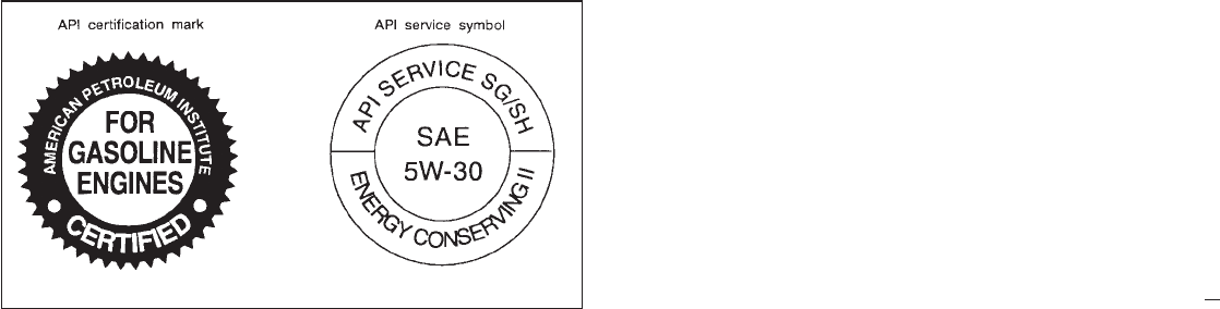
ENGINE OIL AND OIL FILTER
RECOMMENDATION
Selecting the correct oil
It is essential to choose the correct quality, and
viscosity oil to ensure satisfactory engine life
and performance. Nissan recommends the
use of a low friction oil (energy conserving oil)
in order to improve fuel economy and con-
serve energy. Oils which do not have the
specified quality label should not be used as
they could cause engine damage.
Only those engine oils with the American Pe-
troleum Institute (API) CERTIFICATION
MARK on the front of the container should be
used. This type of oil supersedes the existing
API SG or SH and Energy Conserving II
categories.
If you cannot find engine oil with the CERTI-
FICATION MARK, an API SG or SH and
Energy Conserving II oil with API Service
Symbol may be used. An oil with a single
designation “SG” or “SH”, or in combination
with other categories (for example, “SG/CC” or
“SG/CD”) may also be used if one with the API
CERTIFICATION MARK cannot be found.
Mineral based or synthetic type oils may be
used in your NISSAN vehicle. These oils must
however, meet the API quality and SAE vis-
cosity ratings specified for your vehicle. Do not
mix mineral based and synthetic type oils in
the engine at the same time.
Oil additives
NISSAN does not recommend the use of oil
additives. The use of an oil additive is not
necessary when the proper oil type is used
and maintenance intervals are followed.
Oil which may contain foreign matter or has
been previously used should not be used.
Oil viscosity
The engine oil viscosity or thickness changes
with temperature. Because of this, it is impor-
tant that the engine oil viscosity be selected
based on the temperatures at which the ve-
hicle will be operated before the next oil
change. The chart “Recommended SAE vis-
cosity number” shows the recommended oil
viscosities for the expected ambient tempera-
tures. Choosing an oil viscosity other than that
recommended could cause serious engine
damage.
STI0077
9-6
Z01.2.1/R50-D X

Selecting the correct oil filter
Your new vehicle is equipped with a high-
quality genuine Nissan oil filter. When replac-
ing, use the genuine oil filter or its equivalent
for the reason described in “change intervals”.
Change intervals
The oil and oil filter change intervals for your
engine are based on the use of the specified
quality oils and filters. Oil and filter other than
the specified quality, or oil and filter change
intervals longer than recommended could re-
duce engine life. Damage to engines caused
by improper maintenance or use of incorrect
oil and filter quality and/or viscosity is not
covered by the new Nissan vehicle warranties.
Your engine was filled with a high quality
engine oil when it was built. You do not have to
change the oil before the first recommended
change interval. Oil and filter change intervals
depend upon how you use your vehicle. Op-
eration under the following conditions may
require more frequent oil and filter changes.
— repeated short distance driving at cold out-
side temperatures,
— driving in dusty conditions,
— extensive idling,
— towing a trailer.
9-7
Z01.2.1/R50-D X
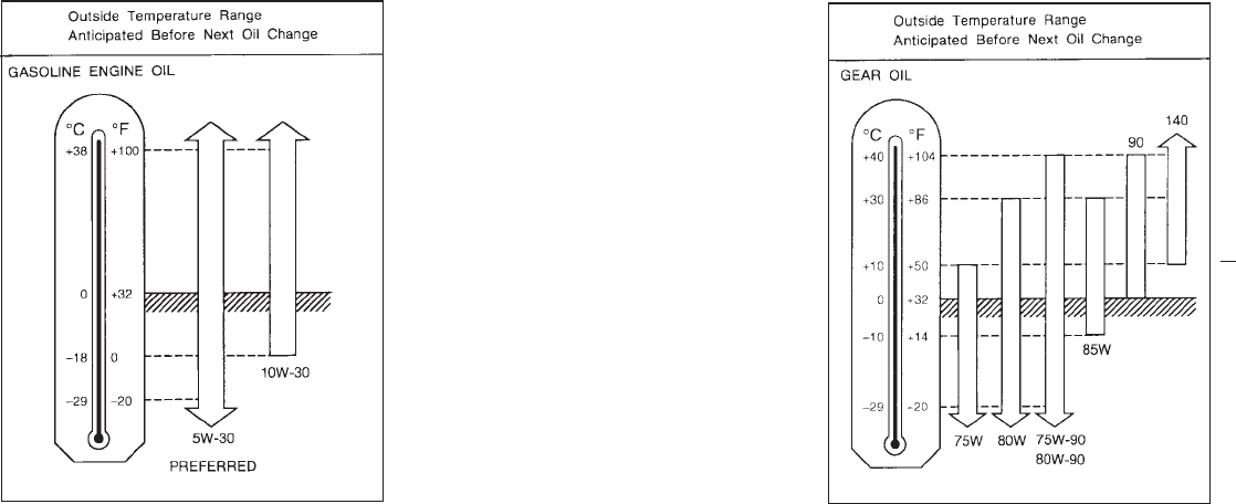
RECOMMENDED SAE VISCOSITY
NUMBER
ISAE 5W-30 viscosity oil is preferred for
all ambient temperatures. SAE 10W-30
viscosity oil may be used if the ambient
temperature is above 0°F (−18°C).
I75W-90 for transmission and 80W-90 for
differential are preferable if the ambient
temperature is below 104°F (40°C).
TI0008-A TI0003
9-8
Z01.2.1/R50-D X

AIR CONDITIONING SYSTEM
REFRIGERANT AND LUBRICANT
RECOMMENDATIONS
The air conditioning system in this NISSAN
vehicle must be charged with the refriger-
ant HFC-134a (R-134a) and the lubricant,
Nissan A/C System Oil Type S or the exact
equivalents. Use of any other refrigerants or
lubricants will cause severe damage and you
will need to replace your vehicle’s entire air
conditioning system.
The refrigerant HFC-134a (R-134a) in your
NISSAN vehicle will not harm the earth’s
ozone layer. Although this refrigerant does not
affect the earth’s atmosphere, certain govern-
mental regulations require the recovery and
recycling of any refrigerant during automotive
air conditioning system service. Your NISSAN
dealer has the trained technicians and equip-
ment needed to recover and recycle your air
conditioning system refrigerant.
Contact your NISSAN dealer when servicing
your air conditioning system.
9-9
Z01.2.1/R50-D X
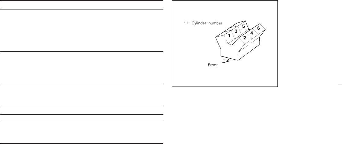
Model VG33E
Type Gasoline, 4-cycle
Cylinder arrangement 6-cylinder, V-slanted at 60°
Bore ×Stroke in (mm) 3.602 ×3.268 (91.5 ×83.0)
Displacement
cu in (cm
3
)199.84 (3,275)
Firing order 1-2-3-4-5-6*1
Idle speed rpm
See the “Emission Control
Label” on the underside of the
hood.
Ignition timing (BTDC)
degree/rpm
CO percentage at idle speed
[No air] %
Spark plug BKR4ES-11 (Hot)
BKR5ES-11 (Standard)
BKR6ES-11 (Cold)
Spark plug gap in (mm) 0.039 to 0.043 (1.0 to 1.1)
Camshaft operation Timing belt*2
Alternator belt size
Width ×Length
in (mm) 0.8409 ×41.93 (21.36 ×1,065)
*2: Periodic maintenance is necessary. Refer to the appropriate maintenance
schedule in chapter 8.
The spark ignition system of this vehicle meets all requirements of
the Canadian Interference-Causing Equipment Regulations.
TI0001-A
ENGINE
9-10
Z01.2.1/R50-D X

FOR U.S.A.
Grade Road wheel/
offset in (mm)
Tire Spare tire size
4x2 PATH-
FINDER
XE
LE
15x6-1/2JJ/1.97
(50)
15x6-1/2JJ
Aluminum/1.97
(50)
P235/75R15
102S
P235/75R15
102S
4x4 PATH-
FINDER
XE
LE
15x6-1/2JJ/1.97
(50)
15x6-1/2JJ
Aluminum/1.97
(50)
P235/75R15
102S
P235/75R15
102S
SE 15x7JJ/1.57 (40)
15x7JJ
Aluminum/1.57
(40)
P265/70R15
110S
P265/70R15
110S
FOR CANADA
Grade Road
wheel/offset in
(mm)
Tire Spare tire size
4x4 PATH-
FINDER
XE
LE
15x6-1/2JJ/1.97
(50)
15x6-1/2JJ
Aluminum/1.97
(50)
P235/75R15
102S
P235/75R15
102S
SE 15x7JJ/1.57 (40)
15x7JJ
Aluminum/1.57
(40)
P265/70R15
110S
P265/70R15
110S
WHEELS AND TIRES
9-11
Z01.2.1/R50-D X
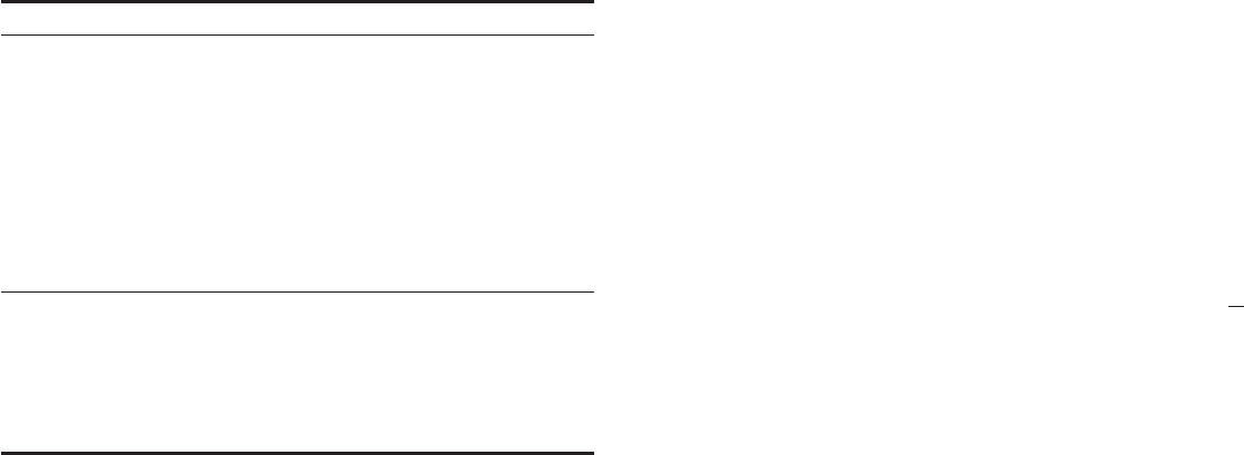
PATHFINDER
Overall length*1 in (mm) 178.3 (4,530)
Overall width in (mm) 68.7 (1,745)
72.4 (1,840)*2*3
Overall height in (mm) 67.1 (1,705)
67.9 (1,725)*2
Front tread in (mm) 58.3 (1,480)
59.1 (1,500)*2
Rear tread in (mm) 58.5 (1,485)
59.3 (1,505)*2
Wheelbase in (mm) 106.3 (2,700)
Gross vehicle weight rating
lb (kg)
See the “F.M.V.S.S. certification
label” on the driver’s side lock
pillar.
Gross axle weight rating
Front lb (kg)
Rear lb (kg)
*1: On spare tire carrier equipped models, the spare tire carrier adds 9.45 in (240
mm) to the overall length.
*2: SE models
*3: XE models with overfender
When planning to travel in another country,
you should first find out if the fuel available is
suitable for your vehicle’s engine.
Using fuel with too low an octane rating
may cause engine damage. All gasoline
vehicles can be operated with unleaded
gasoline. Therefore, avoid taking your ve-
hicle to areas where appropriate fuel is not
available.
When transferring the registration of your
vehicle to another country, state, province
or district, it may be necessary to modify the
vehicle to meet local laws and regulations.
The laws and regulations for motor vehicle
emission control and safety standards vary
according to the country, state, province or
district; therefore, vehicle specifications may
differ.
When any vehicle is to be taken into an-
other country, state, province or district
and registered, its modifications, transpor-
tation and registration are the responsibil-
ity of the user. NISSAN is not responsible
for any inconvenience that may result.
DIMENSIONS AND WEIGHTS WHEN TRAVELING OR
REGISTERING YOUR VEHICLE IN
ANOTHER COUNTRY
9-12
Z01.2.1/R50-D X
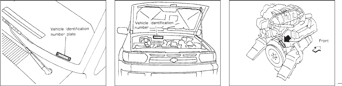
VEHICLE IDENTIFICATION
NUMBER PLATE
The vehicle identification number plate is at-
tached as shown. This number is the identifi-
cation for your vehicle and is used in the
vehicle registration.
VEHICLE IDENTIFICATION
NUMBER (Chassis number) ENGINE SERIAL NUMBER
The number is stamped on the engine as
shown.
STI0095 STI0089 STI0094
VEHICLE IDENTIFICATION
9-13
Z01.2.1/R50-D X
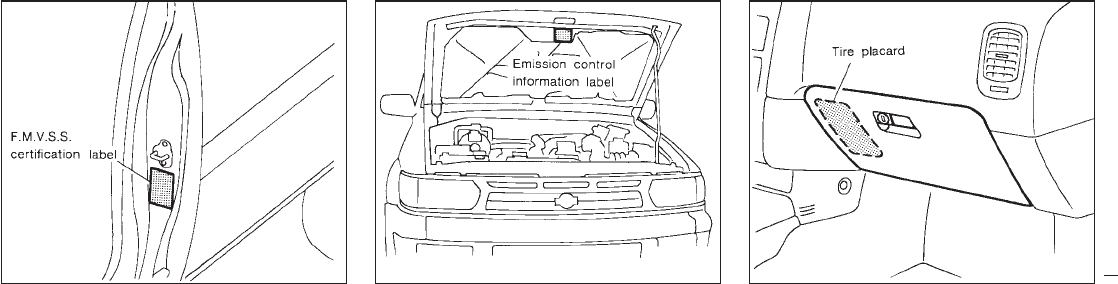
F.M.V.S.S. CERTIFICATION LABEL
The F.M.V.S.S. certification label is affixed as
shown.
EMISSION CONTROL
INFORMATION LABEL
The emission control information label is at-
tached as shown.
TIRE PLACARD
The cold tire pressure is shown on the tire
placard.
STI0096 STI0097 STI0098
9-14
Z01.2.1/R50-D X
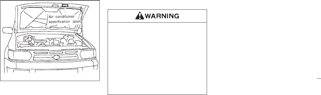
AIR CONDITIONER
SPECIFICATION LABEL
The air conditioner specification label is at-
tached as shown.
VEHICLE LOADING INFORMATION
IIt is extremely dangerous to ride in a
cargo area inside of a vehicle. In a
collision, people riding in these areas
are more likely to be seriously injured
or killed.
IDo not allow people to ride in any
area of your vehicle that is not
equipped with seats and seat belts.
IBe sure everyone in your vehicle is in
a seat and using a seat belt properly.
Terms
It is important to familiarize yourself with the
following terms before loading your vehicle:
ICurb Weight (actual weight of your vehicle)
- vehicle weight including: standard and
optional equipment, fluids, emergency
tools, and spare tire assembly. This weight
does not include passengers and cargo.
IGVW (Gross Vehicle Weight) - curb weight
plus the combined weight of passengers
and cargo.
IGVWR (Gross Vehicle Weight Rating) -
maximum total weight (load) limit specified
for the vehicle.
IGAWR (Gross Axle Weight Rating) - maxi-
mum weight (load) limit specified for the
front or rear axle.
Determining Vehicle Load Capacity
The load capacity of this vehicle is determined
by weight, not by available cargo space. For
example, a luggage rack, bike carrier, cartop
carrier or similar equipment does not increase
load carrying capacity of your vehicle.
To determine vehicle load capacity:
Vehicle weight can be determined by using a
commercial-grade scale, found at places such
as a truck stop, gravel quarry, grain elevator,
or a scrap metal recycling facility.
1) Determine the curb weight of your vehicle.
2) Compare the curb weight amount to the
GVWR specified for your vehicle to deter-
mine how much more weight your vehicle
can carry.
3) After loading (cargo and passengers), re-
weigh your vehicle to determine if either
GVWR or GAWR for your vehicle is ex-
ceeded. If GVWR is exceeded, remove
cargo as necessary. If either the front or
STI0092
9-15
Z01.2.1/R50-D X
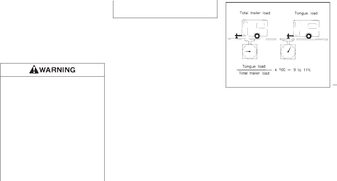
rear GAWR is exceeded, shift the load or
remove cargo as necessary.
Loading Tips
IThe GVW must not exceed GVWR or
GAWR as specified on the FMVSS Certifi-
cation Label.
IDo not load the front and rear axle to the
GAWR. Doing so will exceed the GVWR.
IProperly secure all cargo to help pre-
vent it from sliding or shifting. Do not
place cargo higher than the seat-
backs. In a sudden stop or collision,
unsecured cargo could cause per-
sonal injury.
IDo not load your vehicle any heavier
than the GVWR or the maximum front
and rear GAWRs. If you do, parts on
your vehicle can break, or it can
change the way your vehicle handles.
This could result in loss of control
and cause personal injury.
IOverloading can shorten the life of
your vehicle. Failures caused by
overloading are not covered by your
warranty.
Your new vehicle was designed to be used
primarily to carry passengers and cargo. Re-
member that towing a trailer will place addi-
tional loads on your vehicle’s engine, drive
train, steering, braking and other systems.
Information on trailer towing ability and the
special equipment required should be ob-
tained from your Nissan dealer. He can obtain
aNissan Trailer Towing Guide for you.
CA0009
TRAILER TOWING
9-16
Z01.2.1/R50-D X
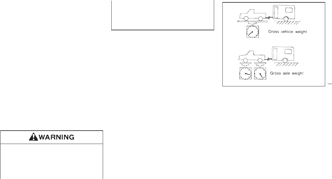
Maximum load limits
Maximum trailer loads
Never allow the total trailer load to exceed the
value specified in the following Towing
Load/Specification Chart. The total trailer load
equals trailer weight plus its cargo weight.
IWhen towing a trailer load of 1,000 lb (454
kg) or more, trailers with a brake system
MUST be used.
The maximum GCWR (Gross Combined
Weight Rating) should not exceed the value
specified in the following Towing Load Speci-
fication Chart.
The GCWR equals the combined weight of the
towing vehicle (including passengers and
cargo) plus the total trailer load. Towing loads
greater than these or using improper towing
equipment could adversely affect vehicle han-
dling, braking and performance.
Vehicle damage and/or personal injury
resulting from improper towing proce-
dures is not covered by NISSAN warran-
ties.
Information on trailer towing and re-
quired towing equipment should be ob-
tained from dealers who specialize in
providing trailers or other towing
equipment.
Tongue load
Keep the tongue load between 9 to 11% of the
total trailer load within the maximum tongue
load limits shown in the following Towing
Load/Specifications Chart. If the tongue load
becomes excessive, rearrange cargo to allow
for proper tongue load.
Maximum gross vehicle weight/maximum
gross axle weight
The gross vehicle weight of the towing vehicle
must not exceed the gross vehicle weight
rating (GVWR) shown on the F.M.V.S.S. cer-
tification label. The gross vehicle weight
equals the combined weight of the unloaded
vehicle, passengers, luggage, hitch, trailer
tongue load and any other optional equipment.
In addition, front or rear gross axle weight must
not exceed the gross axle weight rating
(GAWR) shown on the F.M.V.S.S. certification
label.
CA0036
9-17
Z01.2.1/R50-D X
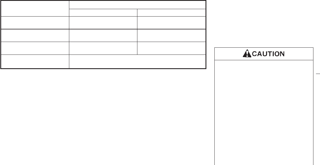
Unit: lb (kg)
MODEL
WEIGHT
PATHFINDER VG33E (6-Cyl.)
M/T A/T
MAXIMUM TRAILER WEIGHT*1 3,500 (1,588) 2,500 (1,134)
5,000 (2,268)*3
MAXIMUM TONGUE LOAD 350 (159) 250 (113)
500 (227)*3
GROSS COMBINED WEIGHT
RATING 8,000 (3,628) 7,000 (3,175)
9,500 (4,308)*3
RECOMMENDED EQUIP-
MENT*2 Sway Control Device (SCD)
*1: All towing above 1,000 lb (454 kg) requires the use of trailer brakes. NISSAN recommends the use
of a tandem axle trailer whenever towing above 3,000 lb (1,361 kg).
*2: A sway control device is recommended for all towing above 2,000 lb (907 kg). Sway control devices
are not offered by NISSAN. See a professional trailer/hitch outlet for a properly designed sway
control device for your trailer.
*3: With oil cooler
Trailer hitch
Check the towing capacity of your receiver
type frame mounted hitch. Choose a proper
hitch for your vehicle and trailer. Make sure the
trailer hitch is securely attached to the vehicle,
to help avoid personal injury or property dam-
age due to sway caused by crosswinds, rough
road surfaces or passing trucks.
ISpecial hitches which include frame
reinforcements are required for tow-
ing above 2,000 lb (907 kg). Suitable
Genuine NISSAN hitches for pickup
truck and Pathfinder models are
available at your Nissan dealer.
IDo not use axle-mounted hitches.
IDo not modify the vehicle exhaust
system, brake system, etc. when the
hitch is installed. After the hitch is
removed, seal the bolt holes to pre-
vent exhaust fumes, water or dust
from entering the passenger com-
partment.
ICheck regularly to make sure that all
TOWING LOAD/SPECIFICATION
CHART
9-18
Z01.2.1/R50-D X

trailer hitch mounting bolts are se-
curely fastened.
ITo reduce the possibility of additional
damage if your vehicle is struck from
the rear, where practical, remove the
hitch when not in use. Remove the
receiver when not in use.
Tire pressures
IWhen towing a trailer, inflate the vehicle
tires to the recommended cold tire pressure
indicated on the tire placard (affixed to the
glove box lid).
ITrailer tire condition, size, load rating and
proper inflation pressure should be in ac-
cordance with the trailer and tire manufac-
turers’ specifications.
Safety chain
Always use a suitable chain between your
vehicle and the trailer. The chain should be
crossed and should be attached to the hitch,
not to the vehicle bumper or axle. Be sure to
leave enough slack in the chain to permit
turning corners.
Trailer lights
Trailer lights should comply with Federal
and/or local regulations.
When wiring vehicle for towing connection,
connect stop and tail light pickup into the
vehicle electrical circuit at point between
the sensor and stop light switch or light
switch.
Trailer brakes
If your trailer is equipped with a braking sys-
tem, make sure it conforms to Federal and/or
local regulations and that it is properly in-
stalled.
Never connect a trailer brake system
directly to the vehicle brake system.
Trailer towing tips
In order to gain skill and an understanding of
the vehicle’s behavior, you should practice
turning, stopping and backing up in an area
which is free from traffic. Steering stability and
braking performance will be somewhat differ-
ent than under normal driving conditions.
IAlways secure items in the trailer to prevent
load shift while driving.
IAvoid abrupt starts, acceleration or stops.
IAvoid sharp turns or lane changes.
IAlways drive your vehicle at a moderate
speed.
IAlways block the wheels on both vehicle
and trailer when parking. Parking on a
slope is not recommended; however, if you
must do so, and if your vehicle is equipped
with automatic transmission, first block the
wheels and apply the parking brake, and
then move the transmission shift lever into
the “P” position. If you move the shift lever
to the “P” position before blocking the
wheels and applying the parking brake,
transmission damage could occur.
IWhen going down a hill, shift into a lower
gear and use the engine braking effect.
When ascending a long grade, downshift
the transmission to a lower gear and reduce
speed to reduce chances of engine over-
loading and/or overheating.
However, for long steep grades, do not stay in
1st or 2nd gear when driving above 35 MPH
(56 km/h).
IIf the engine coolant rises to an extremely
high temperature when the air conditioning
system is on, turn off the air conditioner.
Coolant heat can be additionally vented by
9-19
Z01.2.1/R50-D X

opening the windows, switching the fan
control to high and setting the temperature
control to the “HOT” position.
ITrailer towing requires more fuel than nor-
mal circumstances.
IAvoid towing a trailer for the first 500 miles
(800 km).
IHave your vehicle serviced more often than
at intervals specified in the recommended
Maintenance Schedule.
When towing a trailer, change oil in the
transmission more frequently. See the
Maintenance Schedule.
Your NISSAN is covered by the following
emission warranties.
For U.S.A.
1) Emission Defects Warranty
2) Emissions Performance Warranty
For Canada
Emission Control System Warranty
Details of these warranties may be found with
other vehicle warranties in your Warranty In-
formation and Maintenance Log Booklet which
comes with your NISSAN. If you did not re-
ceive a Warranty Information and Mainte-
nance Log Booklet or it becomes lost, you may
obtain a replacement by writing.
INissan Motor Corporation U.S.A. Con-
sumer Affairs Department P.O. Box 191
Gardena. CA 90248-0191
INissan Canada Inc. P.O. Box 1709, Station
“B” Mississauga, Ontario, L4Y 4H6
If you believe that your vehicle has
a defect which could cause a crash
or could cause injury or death, you
should immediately inform the Na-
tional Highway Traffic Safety Ad-
ministration (NHTSA) in addition to
notifying NISSAN.
If NHTSA receives similar com-
plaints, it may open an investiga-
tion, and if it finds that a safety
defect exists in a group of vehicles,
it may order a recall and remedy
campaign. However, NHTSA can-
not become involved in individual
problems between you, your dealer,
or NISSAN.
To contact NHTSA, you may either
call the Auto Safety Hotline toll-free
at 1-800-424-9393 (or 366-0123 in
Washington, D.C. area) or write to:
NHTSA, U.S. Department of Trans-
portation, Washington, D.C. 20590.
You can also obtain other informa-
tion about motor vehicle safety from
the Hotline.
EMISSION CONTROL SYSTEM
WARRANTY REPORTING SAFETY DEFECTS
(For U.S.A.)
9-20
Z01.2.1/R50-D X
You may notify NISSAN by contact-
ing our Consumer Affairs Depart-
ment, toll- free, at 1-800-NISSAN-1.
In Hawaii call (808) 836-0888.
Due to legal requirements in some states/
areas, your vehicle may be required to be in
what is called the “ready condition” for an
Inspection/Maintenance (I/M) test of the emis-
sion control system.
The vehicle is set to the “ready condition”
when it is driven through certain driving pat-
terns. Usually, the ready condition can be
obtained by ordinary usage of the vehicle.
If a powertrain system component is repaired
or the battery is disconnected, the vehicle may
be reset to a “not ready” condition. Before
taking the I/M test, drive the vehicle through
the following pattern to set the vehicle to the
ready condition. If you cannot or do not want to
perform the driving pattern, an NISSAN dealer
can conduct it for you.
Always drive the vehicle in a safe man-
ner according to traffic conditions and
obey all traffic laws.
1. Start the engine when the engine coolant
temperature gauge needle points to “C”.
Allow the engine to idle until the gauge
needle points between the “C” and “H”
(normal operating temperature).
2. Accelerate the vehicle to 55 MPH (88
km/h), then quickly release the accelerator
pedal completely and keep it released for at
least 6 seconds.
3. Quickly depress the accelerator pedal for a
moment, then drive the vehicle at a speed
of 53 to 60 MPH (86 to 96 km/h) for at least
5 minutes.
4. Stop the vehicle and turn the engine off.
5. Repeat steps 1 through 4 at least one more
time.
If step 1, 2 or 3 is interrupted, repeat the
preceding step. Any safe driving mode is ac-
ceptable between steps. Do not stop the en-
gine until step 3 is completed.
READINESS FOR INSPECTION/
MAINTENANCE (I/M) TEST (For
U.S.A.)
9-21
Z01.2.1/R50-D X

A Genuine Nissan Service Manual is the best
source of service and repair information for
your vehicle. Filled with wiring diagrams, illus-
trations and step-by-step diagnostic and ad-
justment procedures, this manual is the same
one used by the factory trained technicians
working at your Nissan dealership. Also avail-
able are Genuine NISSAN Owner’s Manuals.
For current pricing and availability of a Genu-
ine NISSAN Service Manual or Genuine
NISSAN Owner’s Manual, contact:
In the U.S.A.:
See your NISSAN dealer or contact:
Dyment Distribution Services
20770 Westwood Dr.
Strongsville OH 44136
In a hurry? Call 1-800-247-5321 and charge
your purchase to Visa/Master Card.
In Canada:
To purchase a copy of a Genuine NISSAN
Service Manual or Owner’s Manual please
contact your nearest NISSAN Dealer. For the
phone number and location of a NISSAN
Dealer in your area call the Nissan Satis-
faction Center at 1-800-387-0122 and a
bilingual NISSAN representative will assist
you.
Also available are Genuine NISSAN Service
and Owner’s Manuals for older Nissan models.
9-22
Z01.2.1/R50-D X
10 Index
A
Air bag (See “Supplemental restraint system”)
Air bag warning light (See “Supplemental airbag
warning light or warning”)
Air cleaner filter............................................... 7-16
Air conditioner
Air conditioner operation...................... 3-5, 3-9
Air conditioner specification label.............. 9-15
Heater and air conditioner........................... 3-3
Semiautomatic air conditioner..................... 3-7
Air conditioning system refrigerant and
lubricant recommendations............................... 9-9
Air flow charts ................................................. 3-11
AM-FM radio with cassette player and compact
disc player (Bose audio system) .................... 3-20
AM-FM radio with compact disc player .......... 3-15
Anti-lock brake system ................................... 4-25
Automatic
Automatic transmission fluid ....................... 7-9
Driving with automatic transmission............ 4-7
Semiautomatic air conditioner..................... 3-7
Avoiding collision and rollover .......................... 4-4
B
Back door locks ................................................ 2-8
Battery............................................................. 7-13
Battery replacement.......................................... 2-6
Before starting the engine ................................ 4-7
Belt hook......................................................... 2-32
Brake
Anti-lock brake system.............................. 4-25
Brake and clutch fluid................................ 7-11
Brake booster............................................ 7-19
Brake pedal ............................................... 7-18
Brake system............................................. 4-24
Brake pad wear indicators ............... 1-13, 7-19
Parking brake................................... 4-13, 7-18
Break-in schedule ........................................... 4-16
C
Capacities and recommended fuel/lubricants... 9-2
Cargo (See “vehicle loading information”)
Cassette tape operation ................................. 3-23
CB radio or car phone .................................... 3-27
Center and side vent ........................................ 3-2
Changing
Changing engine coolant ............................ 7-5
Changing engine oil .................................... 7-8
Changing oil filter ........................................ 7-9
Checking coolant level...................................... 7-4
Checking engine oil level.................................. 7-7
Child restraints for infants and small children .... 2-
34
Child safety ..................................................... 2-28
Child safety rear door lock................................ 2-3
Cigarette lighter and ash trays ....................... 1-21
Cleaning exterior and interior ........................... 6-2
Clearing the programming information ........... 1-34
Clock ................................................................. 1-8
Clutch pedal.................................................... 7-20
Coin tray ......................................................... 1-22
Cold weather driving....................................... 4-26
Compact disc (CD) player operation .............. 3-29
Compact disc player operation....................... 3-22
Compass and outside temperature
display............................................................... 1-5
Console box.................................................... 1-24
Controls ..................................................... 3-3, 3-7
Coolant
Changing engine coolant ............................ 7-5
Checking coolant level ................................ 7-4
Engine coolant temperature gauge............. 1-4
Corrosion protection ....................................... 4-28
Cruise control.................................................. 4-14
Cup holder ...................................................... 1-23
D
Defroster switch
Rear window defroster switch ................... 1-18
Dimensions and weights................................. 9-12
Door locks......................................................... 2-2
Drinking alcohol/drugs and driving ................... 4-4
Drive belts....................................................... 7-14
Driving
Cold weather driving ................................. 4-26
Z01.2.1/R50-D X
Drinking alcohol/drugs and driving.............. 4-4
Driving safety precautions......................... 4-21
Driving with automatic transmission............ 4-7
Driving with manual transmission ............. 4-11
On-pavement and off-road driving
precautions.................................................. 4-4
Precautions when starting and driving........ 4-2
E
Economy hints ................................................ 4-17
Emission control information label.................. 9-14
Emission control system warranty.................. 9-20
Engine............................................................. 9-10
Before starting the engine........................... 4-7
Changing engine coolant ............................ 7-5
Changing engine oil .................................... 7-8
Checking engine oil level ............................ 7-7
Engine coolant temperature gauge............. 1-4
Engine cooling system ................................ 7-4
Engine oil..................................................... 7-7
Engine oil and oil filter
recommendation.......................................... 9-6
Engine serial number ................................ 9-13
Starting the engine.................................... 4-13
Exhaust gas (Carbon monoxide)...................... 4-2
Explanation of maintenance items.................. 8-10
F
Flat tire.............................................................. 5-2
Fluid
Automatic transmission fluid ....................... 7-9
Brake and clutch fluid................................ 7-11
Power steering fluid................................... 7-11
Window washer fluid ................................. 7-12
F.M.V.S.S. certification label........................... 9-14
Front fog light switch ...................................... 1-19
Front seats...................................................... 2-12
Fuel
Capacities and recommended
fuel/lubricants .............................................. 9-2
Fuel filler cap............................................. 2-11
Fuel filler lid lock ....................................... 2-10
Fuel gauge .................................................. 1-5
Fuel recommendation.................................. 9-4
Fuses .............................................................. 7-20
G
Gauge
Engine coolant temperature gauge............. 1-4
Fuel gauge .................................................. 1-5
Meters and gauges ..................................... 1-3
General maintenance ....................................... 8-2
Glasses case .................................................. 1-24
Glove box lock ................................................ 2-10
H
Hazard warning flasher switch........................ 1-19
Head restraint ................................................. 2-15
Headlight and turn signal switch..................... 1-15
Headlights ....................................................... 7-21
Heated seats (If so equipped) ........................ 1-20
Heater and air conditioner ................................ 3-3
Heater operation........................................ 3-4, 3-8
Hood release .................................................... 2-9
I
If your vehicle is ever stolen........................... 1-35
If your vehicle overheats .................................. 5-9
Ignition switch ................................................... 4-5
Inside mirror.................................................... 2-44
Instrument brightness control ......................... 1-18
Integrated HomeLink transmitter
(If so equipped)............................................... 1-31
Interior light ..................................................... 1-30
J
Jump starting........................................... 5-7, 7-13
K
Key.................................................................... 2-2
L
Light
Front fog light switch................................. 1-19
Headlight and turn signal switch ............... 1-15
Headlights.................................................. 7-21
Interior light................................................ 1-30
Light bulbs................................................. 7-21
Other lights................................................ 7-23
Spot light ................................................... 1-31
Supplemental air bag warning light........... 2-25
Vanity mirror light ...................................... 1-31
Warning/indicator light and buzzer.............. 1-9
10-2
Z01.2.1/R50-D X
Lock
Anti-lock brake system.............................. 4-25
Back door locks........................................... 2-8
Child safety rear door lock.......................... 2-3
Door locks ................................................... 2-2
Fuel filler lid lock ....................................... 2-10
Glove box lock........................................... 2-10
Power door lock .......................................... 2-3
Rear window locks ...................................... 2-8
Luggage (See “vehicle loading information”)
Luggage board and box ................................. 1-26
Luggage hooks ............................................... 2-45
Luggage net.................................................... 2-44
Luggage rack .................................................. 2-46
M
Maintenance
Explanation of maintenance items ............ 8-10
General maintenance.................................. 8-2
Periodic maintenance.................................. 8-5
Readiness for inspection/maintenance (I/M)
test............................................................. 9-22
Seat belt maintenance .............................. 2-34
Manual antenna .............................................. 3-27
Meters and gauges........................................... 1-3
Mirror
Inside mirror .............................................. 2-44
Outside mirror control................................ 2-42
Outside heated defroster
(If so equipped) ......................................... 1-18
Outside mirrors.......................................... 2-43
Vanity mirror light ...................................... 1-30
Multi-remote control system (If so equipped)... 2-4
O
Oil
Changing engine oil .................................... 7-8
Changing oil filter ........................................ 7-9
Checking engine oil level ............................ 7-7
Engine oil..................................................... 7-7
Engine oil and oil filter
recommendation.......................................... 9-6
On-pavement and off-road driving precautions.. 4-
4
Operating the transmitter................................ 1-33
Outside mirror control ..................................... 2-42
Outside heated defroster (If so
equipped) ........................................................ 1-18
Outside mirrors ............................................... 2-43
Overheat
If your vehicle overheats............................. 5-9
P
Parking............................................................ 4-23
Parking brake................................... 4-13, 7-18
Periodic maintenance ....................................... 8-5
Power
Power antenna (If so equipped)................ 3-26
Power door lock .......................................... 2-3
Power socket............................................. 1-22
Power steering fluid................................... 7-11
Power steering system.............................. 4-24
Power support seat ................................... 2-14
Power window ........................................... 1-27
Precautions ....................................................... 7-2
Driving safety precautions......................... 4-21
On-pavement and off-road driving
precautions.................................................. 4-4
Precautions on seat belt usage ................ 2-27
Precautions when starting and driving........ 4-2
Programming problem diagnosis.................... 1-33
Programming the HomeLink
transmitter ....................................................... 1-32
Protecting against corrosion ............................. 6-5
Push starting..................................................... 5-9
R
Radio............................................................... 3-15
AM-FM radio with cassette player and compact
disc player (Bose audio system)............... 3-20
AM-FM radio with compact disc
player......................................................... 3-15
CB radio or car phone............................... 3-27
Radio operation......................................... 3-22
Readiness for inspection/maintenance (I/M) test
(For U.S.A.)..................................................... 9-21
Rear seats ...................................................... 2-16
Rear window defroster switch......................... 1-18
Rear window locks............................................ 2-8
Rear window wiper and washer switch .......... 1-17
Recommended SAE viscosity number ............. 9-8
Refrigerant recommendation ............................ 9-9
Reporting safety defects (For U.S.A.) ............ 9-20
10-3
Z01.2.1/R50-D X
S
Safety
Child safety................................................ 2-28
Child safety rear door lock.......................... 2-3
Driving safety precautions......................... 4-21
Reporting safety defects (For U.S.A.)....... 9-20
Seat adjustment.............................................. 2-12
Seat belt
2-point type with retractor (Center position of
rear seat)................................................... 2-32
3-point type with retractor ......................... 2-30
Precautions on seat belt usage ................ 2-27
Seat belt extenders ................................... 2-34
Seat belt maintenance .............................. 2-34
Seat belts .................................................. 2-27
Semiautomatic air conditioner .......................... 3-7
Spare tire carrier............................................... 2-7
Spark plug replacement.................................. 7-14
Speedometer and odometer............................. 1-3
Spot light......................................................... 1-31
Starting
Before starting the engine........................... 4-7
Jump starting ..................................... 5-7, 7-13
Precautions when starting and driving........ 4-2
Push starting ............................................... 5-9
Starting the engine.................................... 4-13
Steering
Power steering fluid................................... 7-11
Power steering system.............................. 4-24
Tilting steering wheel ................................ 2-41
Sunroof (If so equipped)................................. 1-29
Sunvisors ........................................................ 2-42
Supplemental air bag warning light ................ 2-25
Supplemental restraint system (Supplemental air
bag system) .................................................... 2-19
Switch
Front fog light switch................................. 1-19
Hazard warning flasher switch .................. 1-19
Headlight and turn signal switch ............... 1-15
Ignition switch.............................................. 4-5
Rear window defroster switch ................... 1-18
Rear window wiper and washer
switch......................................................... 1-17
Windshield wiper and washer switch ........ 1-16
T
Tachometer....................................................... 1-4
Theft warning (If so equipped)........................ 1-13
Three-way catalyst............................................ 4-3
Tilting steering wheel...................................... 2-41
Timing belt ...................................................... 9-10
Tire
Flat tire ........................................................ 5-2
Spare tire carrier ......................................... 2-7
Tire placard ............................................... 9-14
Tire pressure ............................................. 7-26
Wheels and tires.............................. 7-26, 9-11
Tonneau cover................................................ 1-26
Tow truck towing............................................. 5-10
Towing
2-wheel drive models ................................ 5-11
4-wheel drive models ................................ 5-12
Tow truck towing ....................................... 5-10
Towing load/specification chart ................. 9-18
Trailer towing............................................. 9-16
Trailer towing .................................................. 9-16
Transmission
Automatic transmission fluid ....................... 7-9
Driving with automatic transmission............ 4-7
Driving with manual transmission ............. 4-11
V
Vanity mirror light............................................ 1-31
Vehicle identification ....................................... 9-13
Vehicle identification number (Chassis
number) ..................................................... 9-13
Vehicle identification number plate ........... 9-13
Vehicle loading information............................. 9-15
Vehicle recovery (Freeing a stuck
vehicle)............................................................ 5-13
W
Warning
Hazard warning flasher switch .................. 1-19
Supplemental air bag warning light........... 2-25
Theft warning (If so equipped).................. 1-13
Warning labels........................................... 2-25
Warning/indicator light and buzzer.............. 1-9
Wheels and tires ................................... 7-26, 9-11
When traveling or registering your vehicle in an-
other country................................................... 9-12
Window washer fluid....................................... 7-12
Windshield wiper and washer switch.............. 1-16
Wiper
Rear window wiper and washer
switch......................................................... 1-17
Windshield wiper and washer switch ........ 1-16
Wiper blade ............................................... 7-17
10-4
Z01.2.1/R50-D X

Recommended fuel:
Unleaded gasoline, at least 87 AKI number
(RON 91)
For further details such as gasohol or diesel
fuel grade, see “Fuel recommendation” in the
“Technical information” section.
Recommended engine oil:
IAPI SG or SH and Energy Conserving II
IAPI Certification Mark
ISAE 5W-30 viscosity oil is preferred for all
ambient temperatures.
See “Engine oil and oil filter recommendation”
in the “Technical and consumer information”
section.
Tire cold pressure:
See the tire placard affixed to the glove box.
Recommended new vehicle break-
in procedure:
During the first 1,000 miles (1,600 km) of
vehicle use, follow the recommendations out-
lined in the “BREAK-IN SCHEDULE” Informa-
tion found in the “Starting and driving” section
of this Owner’s Manual. Follow these recom-
mendations for the future reliability and
economy of your new vehicle. Failure to follow
these recommendations may result in vehicle
damage or shortened engine life.
GAS STATION INFORMATION
Z01.2.1/R50-D X
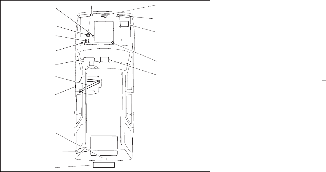
Engine coolant 7-4
Engine oil 7-7
Power steering fluid 7-11
Brake fluid 7-11
Clutch fluid 7-11
Meters and gauges 1-3
Seat belt 2-27
Door lock 2-2
Back door lock 2-8
Fuel 2-10, 9-2
Spare tire 5-3
Hood release 2-9
Window washer fluid 7-12
Battery 7-13
Automatic transmission
fluid 7-9
Air conditioner 3-3
Audio system 3-15
STI0099
QUICK REFERENCE
Z01.2.1/R50-D X
