Nissan 2001 X Trail Owners Manual MT
2015-10-23
: Nissan Nissan-2001-Nissan-X-Trail-Owners-Manual-818350 nissan-2001-nissan-x-trail-owners-manual-818350 nissan pdf
Open the PDF directly: View PDF ![]() .
.
Page Count: 102 [warning: Documents this large are best viewed by clicking the View PDF Link!]
- QUICK REFERENCE INDEX
- Table of Contents
- PRECAUTIONS
- PREPARATION
- NOISE, VIBRATION, AND HARSHNESS (NVH) TROUBLESHOOTING
- DESCRIPTION
- M/T OIL
- SIDE OIL SEAL
- POSITION SWITCH
- CONTROL LINKAGE
- AIR BREATHER HOSE
- TRANSAXLE ASSEMBLY
- INPUT SHAFT AND GEARS
- MAINSHAFT AND GEARS
- REVERSE IDLER SHAFT AND GEARS
- FINAL DRIVE
- SHIFT CONTROL
- SERVICE DATA AND SPECIFICATIONS (SDS)

MT-1
MANUAL TRANSAXLE
C TRANSMISSION/TRANSAXLE
CONTENTS
D
E
F
G
H
I
J
K
L
M
SECTION
A
B
MT
MANUAL TRANSAXLE
PRECAUTIONS .......................................................... 3
Caution ..................................................................... 3
PREPARATION ........................................................... 4
Special Service Tools ............................................... 4
Commercial Service Tools ........................................ 6
NOISE, VIBRATION, AND HARSHNESS (NVH)
TROUBLESHOOTING ................................................ 7
NVH Troubleshooting Chart ..................................... 7
MANUAL TRANSAXLE ......................................... 7
DESCRIPTION ............................................................ 8
Cross-Sectional View ............................................... 8
DOUBLE-CONE SYNCHRONIZER ...................... 9
REVERSE GEAR NOISE PREVENTION FUNC-
TION (SYNCHRONIZING METHOD) ................... 9
M/T OIL ..................................................................... 10
Changing M/T Oil ................................................... 10
DRAINING ........................................................... 10
FILLING ............................................................... 10
Checking M/T Oil .................................................... 10
OIL LEAKAGE AND OIL LEVEL ......................... 10
SIDE OIL SEAL .........................................................11
Removal and Installation .........................................11
REMOVAL ............................................................11
INSTALLATION ....................................................11
POSITION SWITCH .................................................. 12
Checking ................................................................ 12
BACK-UP LAMP SWITCH .................................. 12
PARK/NEUTRAL POSITION SWITCH ............... 12
CONTROL LINKAGE ............................................... 13
Removal and Installation of Control Device and
Cable ...................................................................... 13
AIR BREATHER HOSE ............................................ 14
Removal and Installation ........................................ 14
TRANSAXLE ASSEMBLY ........................................ 15
Removal and Installation ........................................ 15
REMOVAL ........................................................... 15
INSTALLATION ................................................... 16
Component Parts (RS5F51A) ................................ 17
CASE AND HOUSING COMPONENTS .............. 17
GEAR COMPONENTS ....................................... 18
SHIFT CONTROL COMPONENTS ..................... 20
FINAL DRIVE COMPONENTS ........................... 21
Component Parts (RS6F51A) ................................. 22
CASE AND HOUSING COMPONENTS .............. 22
GEAR COMPONENTS ....................................... 23
SHIFT CONTROL COMPONENTS ..................... 25
FINAL DRIVE COMPONENTS ........................... 26
Disassembly and Assembly (RS5F51A) ................. 26
DISASSEMBLY ................................................... 26
ASSEMBLY ......................................................... 30
Disassembly and Assembly (RS6F51A) ................. 35
DISASSEMBLY ................................................... 35
ASSEMBLY ......................................................... 39
Adjustment (RS5F51A) ........................................... 45
INPUT SHAFT END PLAY .................................. 45
MAINSHAFT END PLAY ..................................... 46
DIFFERENTIAL SIDE BEARING PRELOAD ...... 47
REVERSE IDLER GEAR END PLAY .................. 48
Adjustment (RS6F51A) ........................................... 49
INPUT SHAFT END PLAY .................................. 49
MAINSHAFT END PLAY ..................................... 50
DIFFERENTIAL SIDE BEARING PRELOAD ...... 51
REVERSE IDLER GEAR END PLAY .................. 52
INPUT SHAFT AND GEARS .................................... 54
Assembly and Disassembly (RS5F51A) ................. 54
DISASSEMBLY ................................................... 54
INSPECTION AFTER DISASSEMBLY ................ 55
ASSEMBLY ......................................................... 57
Assembly and Disassembly (RS6F51A) ................. 61
DISASSEMBLY ................................................... 61
INSPECTION AFTER DISASSEMBLY ................ 62
ASSEMBLY ......................................................... 64
MAINSHAFT AND GEARS ....................................... 68
Assembly and Disassembly (RS5F51A) ................. 68
DISASSEMBLY ................................................... 68
INSPECTION AFTER DISASSEMBLY ................ 69

MT-2
ASSEMBLY ......................................................... 71
Assembly and Disassembly (RS6F51A) ................. 76
DISASSEMBLY ................................................... 76
INSPECTION AFTER DISASSEMBLY ................ 77
ASSEMBLY ......................................................... 79
REVERSE IDLER SHAFT AND GEARS .................. 84
Assembly and Disassembly (RS5F51A) ................. 84
DISASSEMBLY ................................................... 84
INSPECTION AFTER DISASSEMBLY ................ 84
ASSEMBLY ......................................................... 85
Assembly and Disassembly (RS6F51A) ................. 85
DISASSEMBLY ................................................... 85
INSPECTION AFTER DISASSEMBLY ................ 85
ASSEMBLY ......................................................... 86
FINAL DRIVE ............................................................ 87
Assembly and Disassembly (RS5F51A) ................. 87
PRE-INSPECTION .............................................. 87
DISASSEMBLY ................................................... 87
INSPECTION AFTER DISASSEMBLY ................ 88
ASSEMBLY ......................................................... 88
Assembly and Disassembly (RS6F51A) ................. 90
PRE-INSPECTION .............................................. 90
DISASSEMBLY ................................................... 91
INSPECTION AFTER DISASSEMBLY ................ 92
ASSEMBLY ......................................................... 92
SHIFT CONTROL ...................................................... 95
Inspection (RS5F51A) ............................................ 95
SHIFT FORK ....................................................... 95
Inspection (RS6F51A) ............................................ 96
SHIFT FORK ....................................................... 96
SERVICE DATA AND SPECIFICATIONS (SDS) ......97
General Specifications ............................................97
TRANSAXLE ........................................................97
FINAL GEAR ........................................................98
Gear End Play .........................................................98
Clearance Between Baulk Ring and Gear ..............98
3RD,4TH,5TH,6TH & REVERSE BAULK RING ...98
1ST AND 2ND DOUBLE BAULK RING ...............98
Available Snap Rings ..............................................99
INPUT SHAFT SPACER ......................................99
6TH BUSHING .....................................................99
5TH MAIN GEAR .................................................99
Available C-Rings ...................................................99
MAINSHAFT C-RING ..........................................99
Available Thrust Washer .......................................100
INPUT SHAFT THRUST WASHER ...................100
DIFFERENTIAL SIDE GEAR THRUST WASHER
.100
Available Adjusting Shims .....................................100
MAINSHAFT ADJUSTING SHIM .......................100
INPUT SHAFT REAR BEARING ADJUSTING
SHIM ..................................................................101
MAINSHAFT REAR BEARING ADJUSTING
SHIM ..................................................................101
REVERSE IDLER GEAR ADJUSTING SHIM ....101
6TH MAIN GEAR ADJUSTING SHIM ................101
Available Shims ....................................................102
BEARING PRELOAD .........................................102
DIFFERENTIAL SIDE BEARING ADJUSTING
SHIM(S) .............................................................102

PRECAUTIONS
MT-3
D
E
F
G
H
I
J
K
L
M
A
B
MT
PRECAUTIONS PFP:00001
Caution ECS008BM
●Do not reuse transaxle oil, once it has been drained.
●Check oil level or replace oil with vehicle on level ground.
●During removal or installation, keep inside of transaxle clear of dust or dirt.
●Check for the correct installation status prior to removal or disassembly. If mating marks are required, be
certain they do not interfere with the function of the parts they are applied to.
●In principle, tighten bolts or nuts gradually in several steps working diagonally from inside to outside. If
tightening sequence is specified, observe it.
●Be careful not to damage sliding surfaces and mating surfaces.
MT-4
PREPARATION
PREPARATION PFP:00002
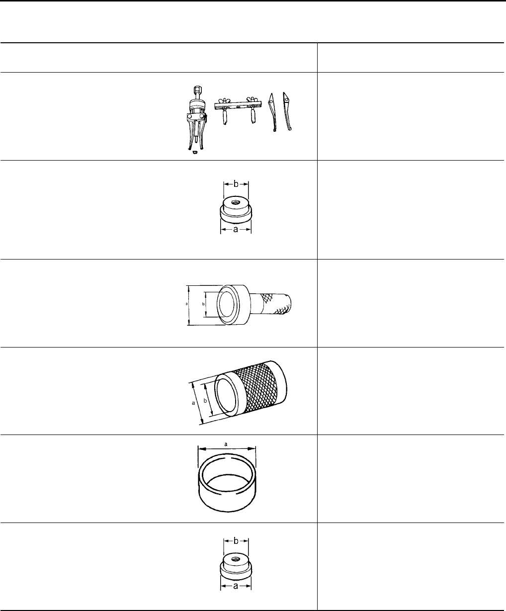
Special Service Tools ECS008BN
Tool name
Tool number Description
Puller
KV381054S0
●Side bearing outer race removal
●Mainshaft front bearing removal
Drift
ST35321000
a: 49 mm (1.93 in) dia.
b: 41 mm (1.61 in) dia.
●Input shaft oil seal installation
●Reverse main gear installation
●1st bushing installation
●1st-2nd synchronizer hub installation
●2nd bushing installation
●3rd main gear installation
●Differential side bearing removal
Drift
ST30720000
a: 77 mm (3.03 in) dia.
b: 55.5 mm (2.185 in) dia.
●Differential oil seal installation
●Differential side bearing outer race
installation
●Mainshaft rear bearing installation
●Differential side bearing installation
Drift
ST33200000
a: 60 mm (2.36 in) dia.
b: 44.5 mm (1.752 in) dia.
●Mainshaft front bearing installation
●6th bushing installation (RS6F51A)
●4th main gear installation
●5th main gear installation
●6th main gear installation (RS6F51A)
Drift
KV40105320
a: 88 mm (3.46 in) dia.
●Differential side bearing outer race
installation
Drift
ST33061000
a: 38 mm (1.50 in) dia.
b: 28.5 mm (1.122 in) dia.
●Bore plug installation
●Differential side bearing removal
ZZA0601D
ZZA1000D
ZZA0811D
ZZA1002D
ZZA0898D
ZZA1000D
PREPARATION
MT-5
D
E
F
G
H
I
J
K
L
M
A
B
MT
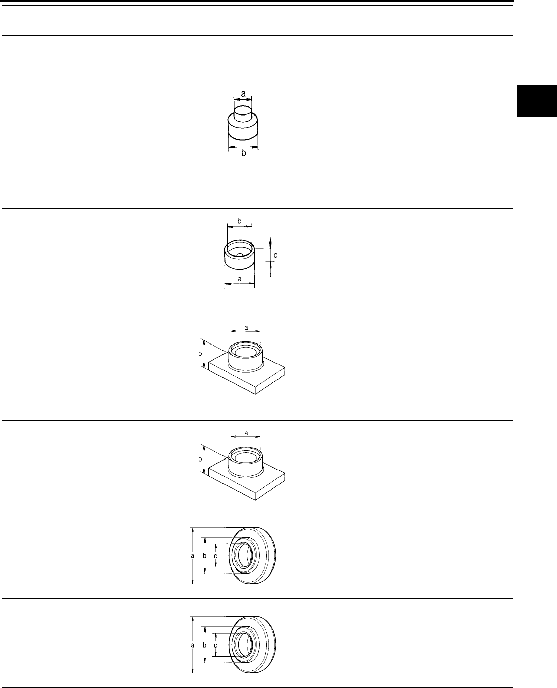
Drift
ST33052000
a: 22 mm (0.87 in) dia.
b: 28 mm (1.10 in) dia.
●Welch plug installation
●Input shaft rear bearing removal
●Input shaft bearing spacer and 5th stopper
removal (RS5F51A)
●5th bushing, thrust washer, 4th input gear,
4th gear bushing, 3rd-4th synchronizer hub
and 3rd input gear removal
●Input shaft front bearing installation
●6th input gear and 6th bushing removal
(RS6F51A)
●Mainshaft rear bearing removal
●4th main gear and 5th main gear removal
●6th main gear removal (RS6F51A)
Drift
KV40105020
a: 39.7 mm (1.563 in) dia.
b: 35 mm (1.38 in) dia.
c: 15 mm (0.59 in)
●5th input gear and synchronizer hub
removal
●3rd main gear, 2nd main gear, 2nd bushing,
1st-2nd synchronizer hub, 1st main gear,
reverse main gear and 1st bushing removal
Press stand
KV40105710
a: 46 mm (1.81 in) dia.
b: 41 mm (1.61 in)
●3rd-4th synchronizer hub installation
●4th bushing installation
●5th bushing installation
●5th synchronizer hub installation
(RS5F51A)
●5th-6th synchronizer hub installation
(RS6F51A)
●2nd bushing installation
●3rd main gear installation
Press stand
ST38220000
a: 63 mm (2.48 in) dia.
b: 65 mm (2.56 in)
●Reverse main gear installation
●1st bushing installation
●1st-2nd synchronizer hub installation
Drift
ST30032000
a: 80 mm (3.15 in) dia.
b: 38 mm (1.50 in) dia.
c: 31 mm (1.22 in) dia.
●5th stopper and input shaft bearing spacer
installation (RS5F51A)
●Input shaft front bearing installation
Drift
ST30901000
a: 79 mm (3.11 in) dia.
b: 45 mm (1.77 in) dia.
c: 35.2 mm (1.386 in) dia.
●Input shaft rear bearing installation
●4th main gear installation
●5th main gear installation
●6th main gear installation (RS6F51A)
●Mainshaft rear bearing installation
Tool name
Tool number Description
ZZA1023D
ZZA1133D
ZZA1058D
ZZA1058D
ZZA0978D
ZZA0978D
MT-6
PREPARATION
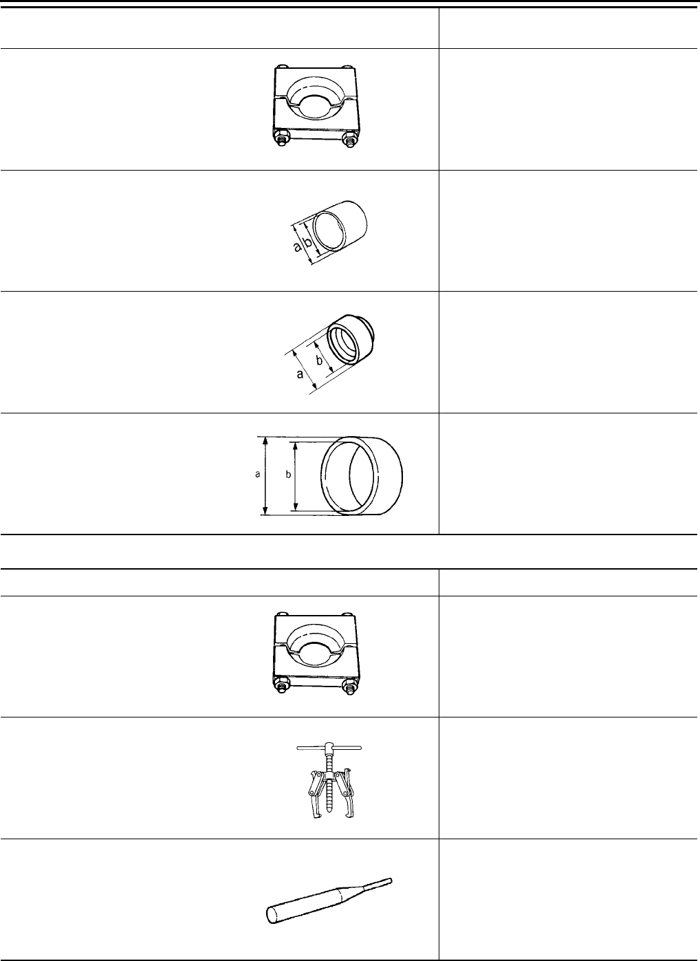
Commercial Service Tools ECS008BO
Puller
ST30031000 ●Measuring wear of 1st and 2nd baulk ring
Drift
KV40101630
a: 68 mm (2.68 in) dia.
b: 60 mm (2.36 in) dia.
●Reverse main gear installation
Drift
KV38102510
a: 71 mm (2.80 in) dia.
b: 65 mm (2.56 in) dia.
●1st bushing installation
●1st-2nd synchronizer hub installation
●Differential side bearing installation
Drift
KV40104830
a: 70 mm (2.76 in) dia.
b: 63.5 mm (2.500 in) dia.
●Differential side bearing installation
Tool name
Tool number Description
ZZA0537D
ZZA1003D
ZZA0838D
ZZA0936D
Tool name Description
Puller Each bearing gear and bushing removal
Puller Each bearing gear and bushing removal
Pin punch
Tip diameter: 4.5 mm (0.177 in) dia. Each retaining pin removal and installation
ZZA0537D
NT077
ZZA0815D
NOISE, VIBRATION, AND HARSHNESS (NVH) TROUBLESHOOTING
MT-7
D
E
F
G
H
I
J
K
L
M
A
B
MT
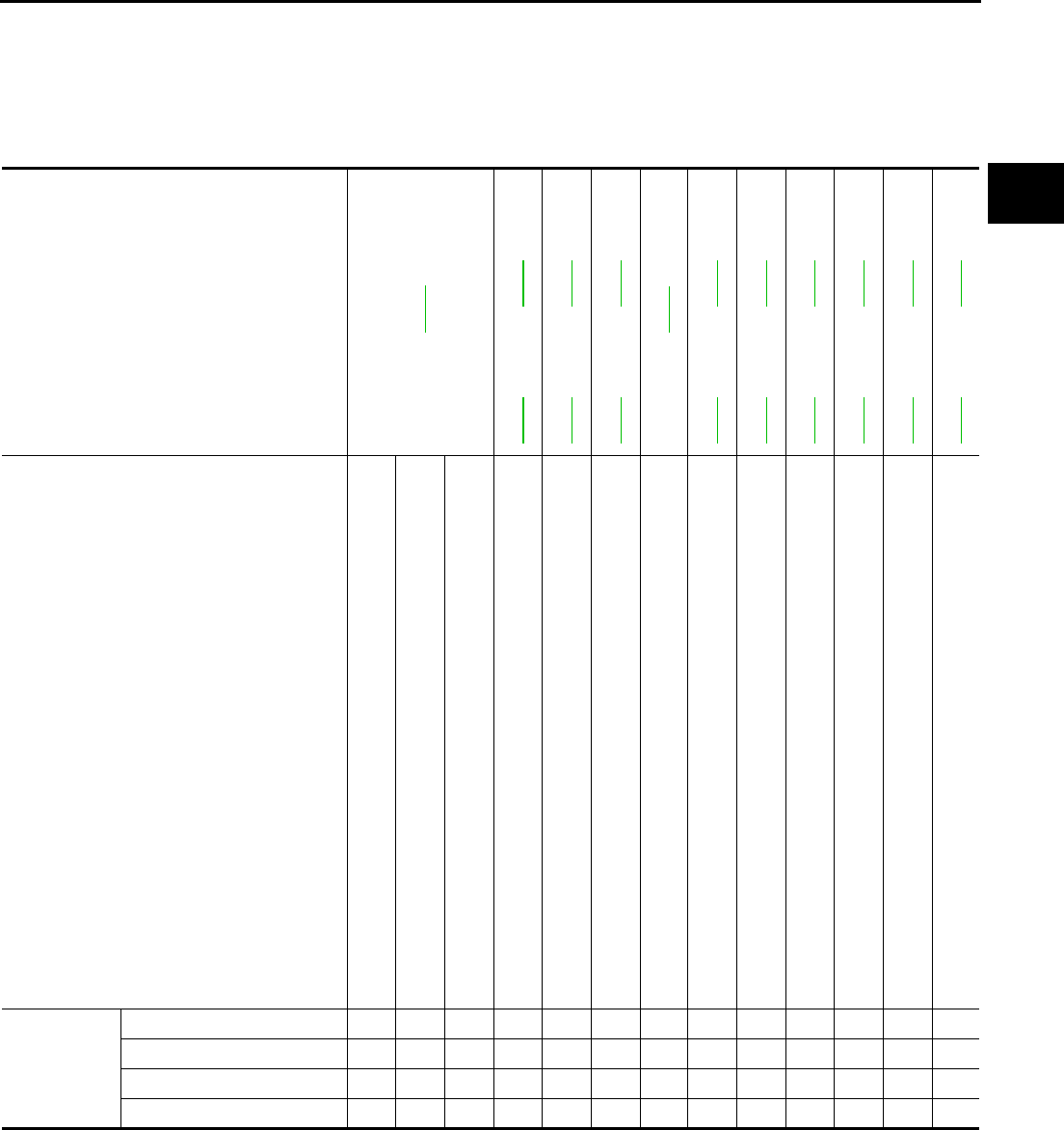
NOISE, VIBRATION, AND HARSHNESS (NVH) TROUBLESHOOTING PFP:00003
NVH Troubleshooting Chart ECS008BP
Use the chart below to help you find the cause of the symptom. The numbers indicate the order of the inspec-
tion. If necessary, repair or replace these parts.
MANUAL TRANSAXLE
Reference page
MA-35
MT-17(RS5F51A), MT-22 (RS6F51A)
MT-17(RS5F51A), MT-22 (RS6F51A)
MT-17(RS5F51A), MT-22 (RS6F51A)
MT-13
MT-20(RS5F51A), MT-25 (RS6F51A)
MT-20(RS5F51A), MT-25 (RS6F51A)
MT-18(RS5F51A), MT-23 (RS6F51A)
MT-18(RS5F51A), MT-23 (RS6F51A)
MT-18(RS5F51A), MT-23 (RS6F51A)
MT-18(RS5F51A), MT-23 (RS6F51A)
SUSPECTED PARTS
(Possible cause)
OIL (Oil level is low.)
OIL (Wrong oil.)
OIL (Oil level is high.)
GASKET (Damaged)
OIL SEAL (Worn or damaged)
O-RING (Worn or damaged)
SHIFT CONTROL LINKAGE (Worn)
CHECK PLUG RETURN SPRING AND CHECK BALL (Worn or damaged)
SHIFT FORK (Worn)
GEAR (Worn or damaged)
BEARING (Worn or damaged)
BAULK RING (Worn or damaged)
INSERT SPRING (Damaged)
Symptoms
Noise 1 2 3 3
Oil leakage 3 1 2 2 2
Hard to shift or will not shift 1 1 2 3 3
Jumps out of gear 1 2 3 3
MT-8
DESCRIPTION
DESCRIPTION PFP:00000
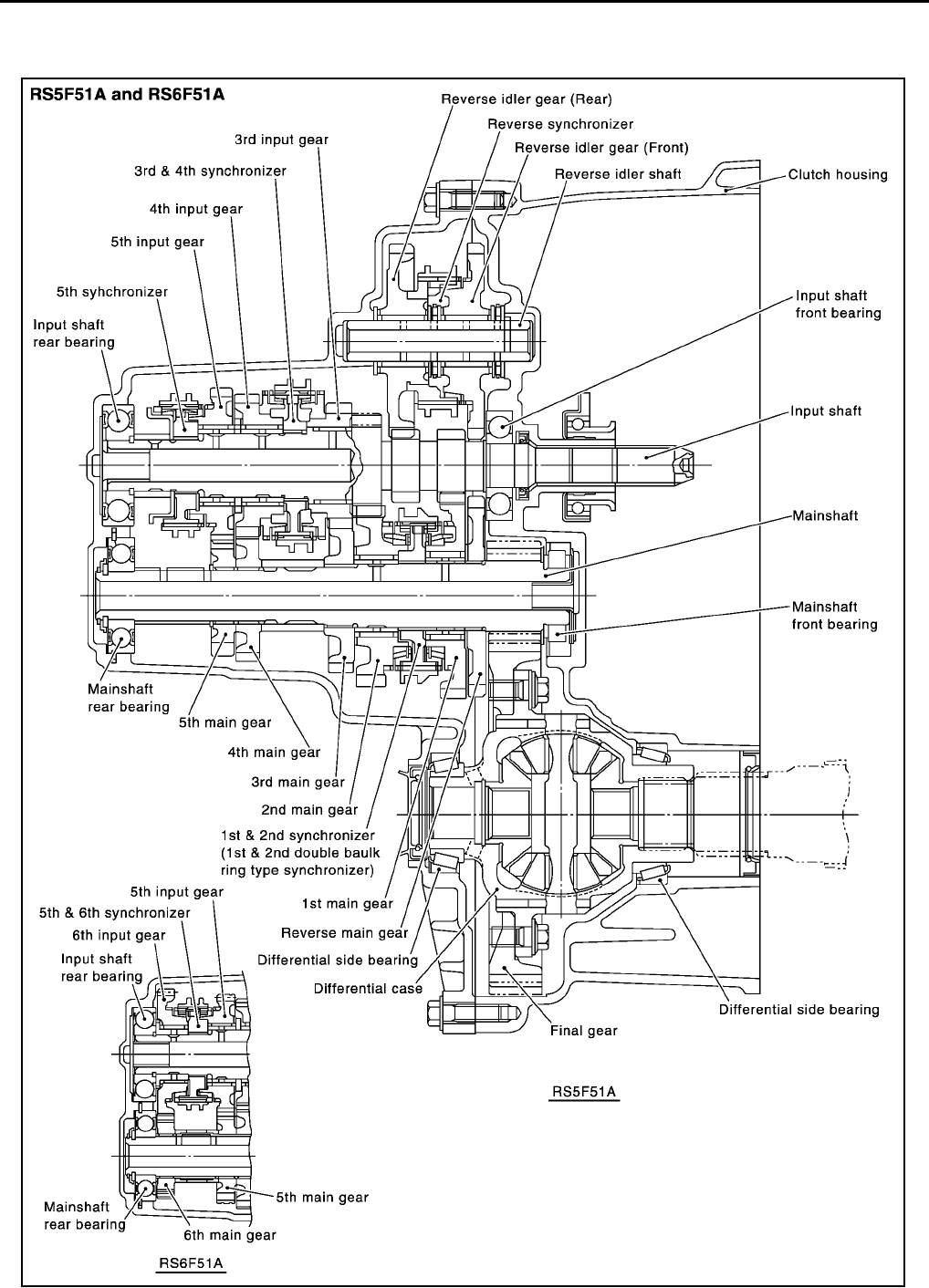
Cross-Sectional View ECS008BQ
SCIA0749E
DESCRIPTION
MT-9
D
E
F
G
H
I
J
K
L
M
A
B
MT
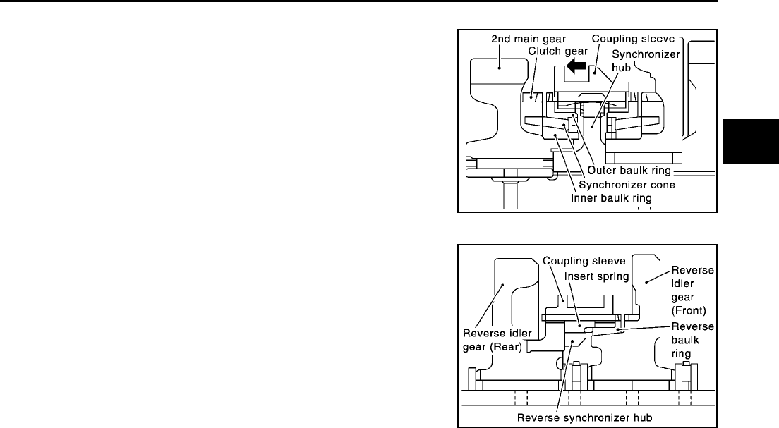
DOUBLE-CONE SYNCHRONIZER
Double-cone synchronizer is adopted for 1st and 2nd gears to
reduce operating force of the shift lever.
REVERSE GEAR NOISE PREVENTION FUNCTION (SYNCHRONIZING METHOD)
The gear can be matched smoothly in a structure by setting synchro-
nizer hub, coupling sleeve, baulk ring and insert spring to reverse
gear, and letting gear be synchronized.
SCIA0750E
SCIA0751E
MT-10
M/T OIL
M/T OIL PFP:KLD20
Changing M/T Oil ECS008BR
DRAINING
1. Start the engine and let it run to warm up the transaxle.
2. Stop the engine. Remove drain plug and drain oil.
3. Set a gasket on the drain plug and install it to the transaxle.
CAUTION:
Do not reuse gasket.
FILLING
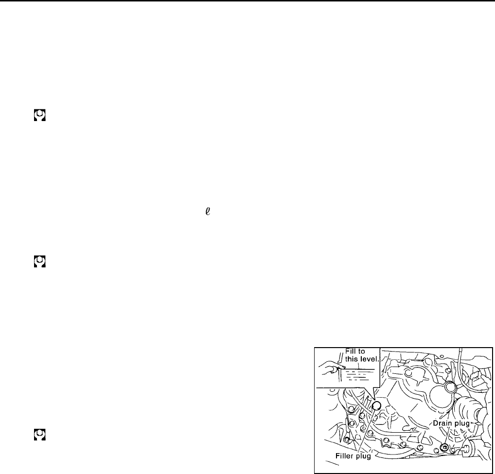
1. Remove filler plug. Fill with new oil until oil level reaches the specified limit near filler plug mounting hole.
2. After refilling oil, check oil level. Assemble gasket to filler plug, then install it to transaxle body.
CAUTION:
Do not reuse gasket.
Checking M/T Oil ECS008BS
OIL LEAKAGE AND OIL LEVEL
●Check that oil is not leaking from transaxle or around it.
●Check oil level from filler plug mounting hole as shown in the fig-
ure.
CAUTION:
Never start engine while checking oil level.
●Set a new gasket on the filler plug and install it on the transaxle.
CAUTION:
Do not reuse gasket.
Drain plug:
: 30 - 39 N·m (3.1 - 3.9 kg-m, 23 - 28 ft-lb)
Oil grade : API GL-4
Capacity (reference) : Approx. 2.3 (4 lmp pt)
Filler plug:
: 30 - 39 N·m (3.1 - 3.9 kg-m, 23 - 28 ft-lb)
Filler plug:
: 30 - 39 N·m (3.1 - 3.9 kg-m, 23 - 28 ft-lb)
SCIA0361E
SIDE OIL SEAL
MT-11
D
E
F
G
H
I
J
K
L
M
A
B
MT
SIDE OIL SEAL PFP:32113
Removal and Installation ECS008BT
REMOVAL
●Clutch housing side oil seal used on 4WD vehicles is attached to the transfer. Be sure to replace it
when transfer is removed.
1. Remove the drive shaft from the transaxle.
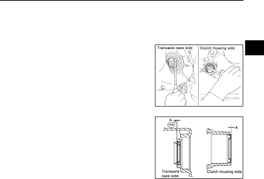
2. Remove oil seal with flat tip screwdriver.
CAUTION:
Be careful not to damage the case surface when removing
the oil seal.
INSTALLATION
1. Using a drift (special service tool), drive the oil seal straight until
it protrudes from the case end equal to dimension A shown in
the figure.
CAUTION:
●When installing oil seals, apply multi-purpose grease to oil seal lips.
●Oil seals are not reusable. Never reuse them.
2. Install all parts in reverse order of removal and check oil level after installation.
SCIA0824E
Dimension "A":
Within 0.5 mm (0.020 in) of flush with the case.
Drift to be used:
Transaxle case side: ST30720000
Clutch housing side: ST30720000
SCIA0352E
MT-12
POSITION SWITCH
POSITION SWITCH PFP:32005
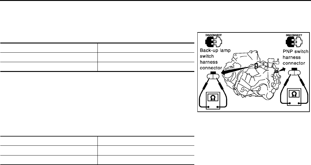
Checking ECS008BU
BACK-UP LAMP SWITCH
●Check continuity.
PARK/NEUTRAL POSITION SWITCH
●Check continuity.
Gear position Continuity
Reverse Yes
Except reverse No
SCIA0708E
Gear position Continuity
Neutral Yes
Except neutral No
CONTROL LINKAGE
MT-13
D
E
F
G
H
I
J
K
L
M
A
B
MT
CONTROL LINKAGE PFP:34103
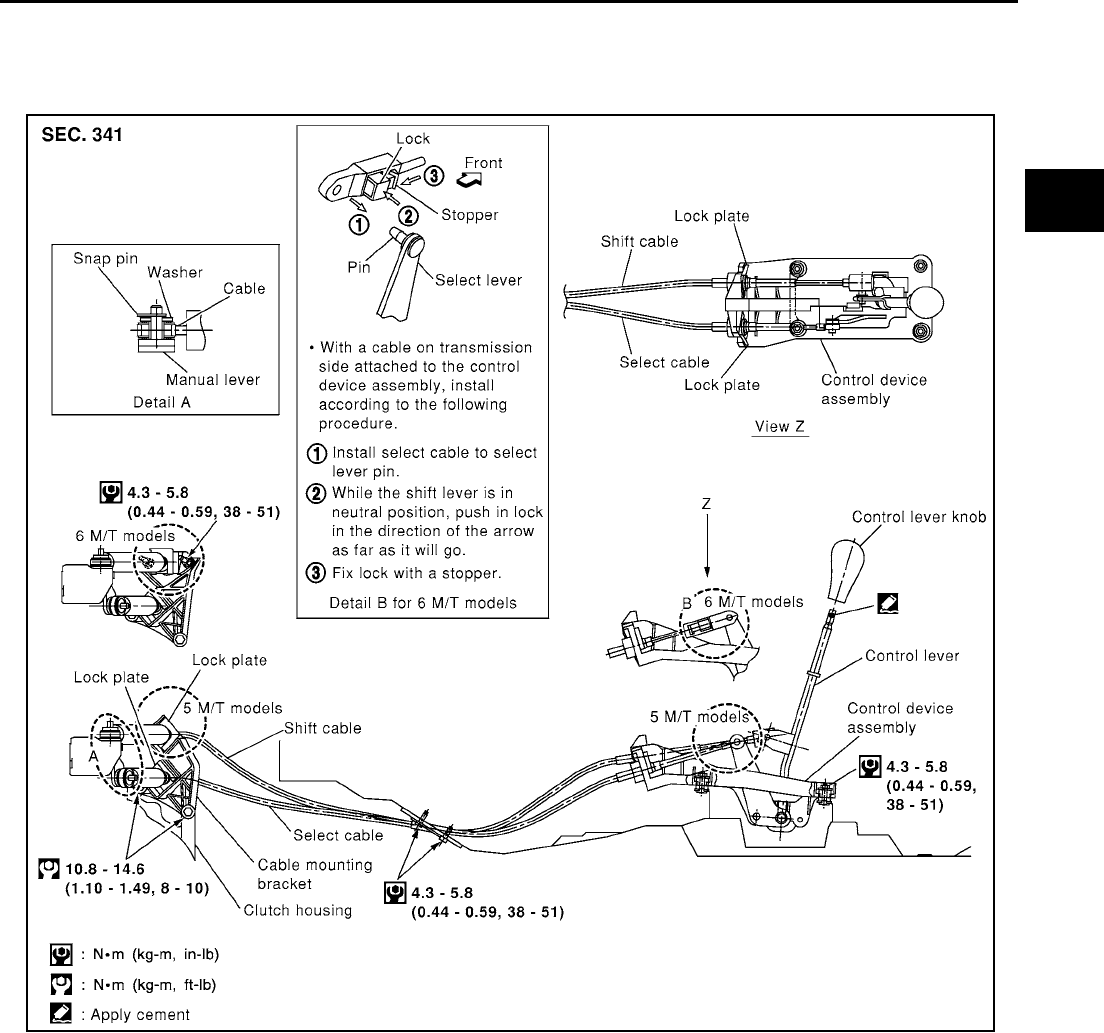
Removal and Installation of Control Device and Cable ECS008BV
Refer to the figure for removal and installation procedure.
CAUTION:
●Keep in mind that the select side lock plate for securing the control cable is different from the one
on the shift side.
●After assembly, make sure selector lever automatically returns to Neutral when it is moved to 1st,
2nd, or Reverse.
SCIA0711E
MT-14
AIR BREATHER HOSE
AIR BREATHER HOSE PFP:31098
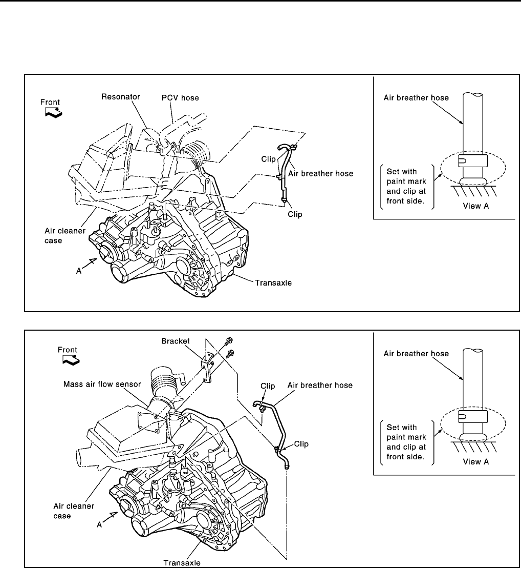
Removal and Installation ECS008BW
Refer to the figure for air breather hose removal and installation information.
QR engine models
YD engine models
CAUTION:
●Make sure there are no pinched or restricted areas on the air breather hose caused by bending or
winding when installing it.
●Be sure to insert hose into the transaxle tube until overlap area reaches the spool.
SCIA0354E
SCIA0747E
TRANSAXLE ASSEMBLY
MT-15
D
E
F
G
H
I
J
K
L
M
A
B
MT
TRANSAXLE ASSEMBLY PFP:32010
Removal and Installation ECS008BX
REMOVAL
1. Remove air cleaner, air duct, and battery.
2. Remove the air breather hose.
3. Remove clutch operating cylinder.
CAUTION:
Do not depress clutch pedal during removal procedure.
4. Disconnect control cable from transaxle.
5. Drain gear oil from transaxle.
6. Disconnect PNP switch, back-up lamp switch, and ground harness connectors.
7. Remove exhaust front tube and the drive shaft.
8. Remove transfer.
●Refer to TF-11, "Removal and Installation from Vehicle" .
9. Remove starter motor.
10. Place a jack onto the transaxle.
CAUTION:
When setting jack, be careful not to bring it into contact with the switch.
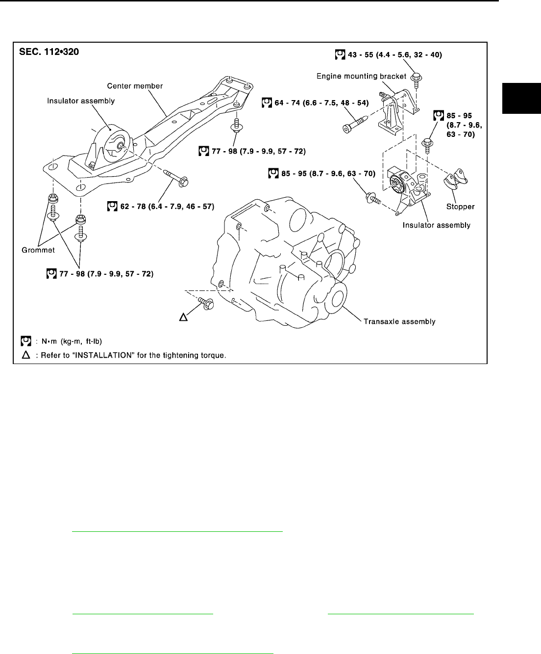
11. Remove center member, engine insulator and engine mount bracket.
●Refer to EM-69, "ENGINE ASSEMBLY" (QR engine models) or EM-193, "ENGINE ASSEMBLY" (YD
engine models).
12. Remove suspension members.
●Refer to FSU-12, "FRONT SUSPENSION MEMBER" .
13. Support engine by placing a jack under oil pan.
14. Remove bolts securing transaxle to engine.
SCIA0845E
MT-16
TRANSAXLE ASSEMBLY
15. Remove transaxle from vehicle.
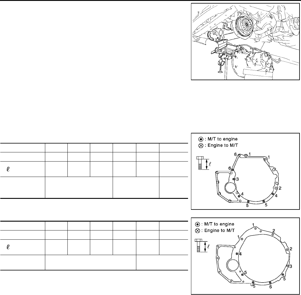
INSTALLATION
Paying attention to the following items, install in the reverse order of removal.
●When installing the transaxle to the engine, tighten to the specified torque.
CAUTION:
When installing transaxle, be careful not to bring transaxle input shaft into contact with the clutch
cover.
QR engine models:
*: Tightening the bolt for 4WD models.
YD engine models:
●After installation, check oil level, and look for leaks and loose
mechanisms.
MTD0062D
Bolt No. 1 2 3* 4 5 6
Quantity 2 1 1 2 2 2
“ ” mm (in) 40
(1.57)
75
(2.95)
45
(1.77)
40
(1.57)
30
(1.18)
40
(1.57)
Tightening torque
N·m (kg - m, ft- lb)
69.6 - 79.4
(7.1 - 8.1, 52 - 58)
39.2 - 46.1
(4.0 - 4.7, 29 - 34)
30.4 - 40.2
(3.1 - 4.1,
23 - 29)
Bolt No. 1 2 3 4 5 6
Quantity 2 2 1 1 3 1
“ ” mm (in) 55
(2.17)
70
(2.76)
120
(4.72)
45
(1.77)
40
(1.57)
35
(1.38)
Tightening torque
N·m (kg - m, ft- lb)
40 - 49
(4.0 - 5.0, 29 - 36)
31 - 36
(3.1 - 3.7, 23 - 26)
SCIA0353E
SCIA0748E
TRANSAXLE ASSEMBLY
MT-17
D
E
F
G
H
I
J
K
L
M
A
B
MT
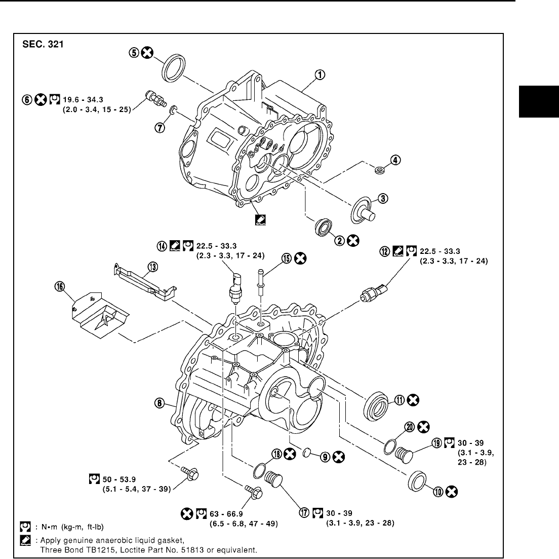
Component Parts (RS5F51A) ECS008BY
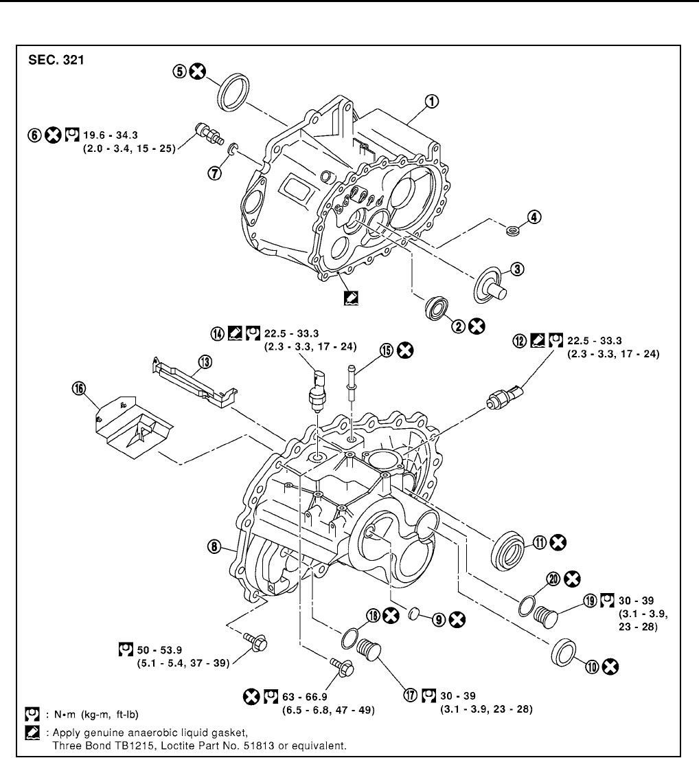
CASE AND HOUSING COMPONENTS
1. Clutch housing 2. Input shaft oil seal 3. Oil channel
4. Magnet 5. Differential oil seal 6. Ball pin
7. Washer 8. Transaxle case 9. Welch plug
10. Bore plug 11. Differential oil seal 12. Park/Neutral position switch
13. Oil gutter 14. Back-up lamp switch 15. Air breather tube
16. Baffle plate 17. Filler plug 18. Gasket
19. Drain plug 20. Gasket
SCIA1112E
MT-18
TRANSAXLE ASSEMBLY
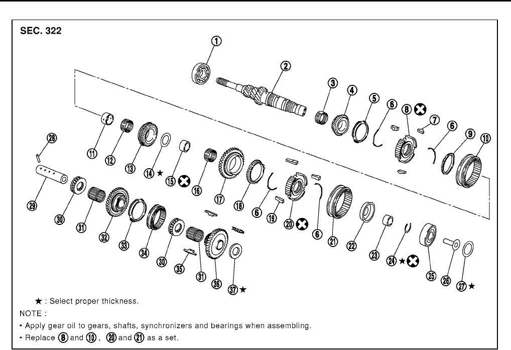
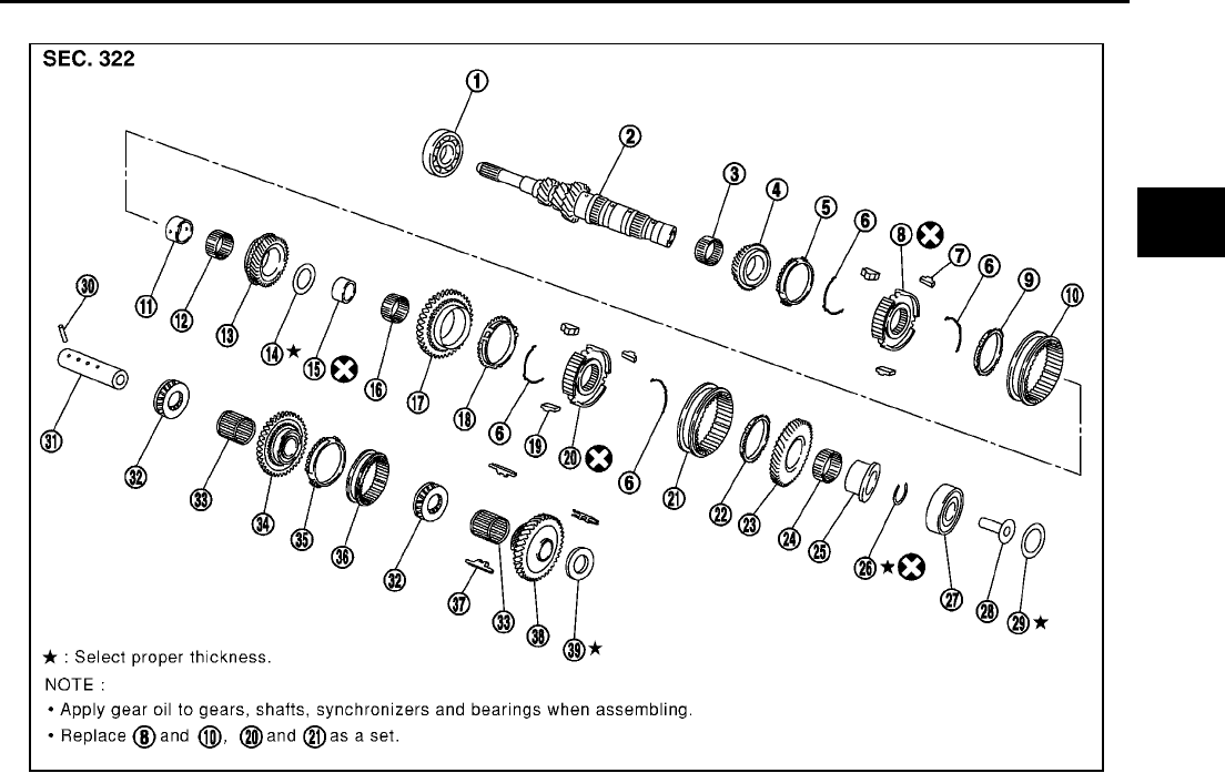
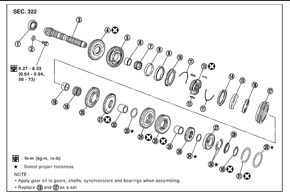
GEAR COMPONENTS
1. Input shaft front bearing 2. Input shaft 3. Needle bearing
4. 3rd input gear 5. 3rd baulk ring 6. Spread spring
7. 3rd & 4th shifting insert 8. 3rd & 4th synchronizer hub 9. 4th baulk ring
10. 3rd & 4th coupling sleeve 11. Bushing 12. Needle bearing
13. 4th input gear 14. Thrust washer 15. Bushing
16. Needle bearing 17. 5th input gear 18. 5th baulk ring
19. 5th shifting insert 20. 5th synchronizer hub 21. 5th coupling sleeve
22. 5th stopper 23. Input shaft bearing spacer 24. Snap ring
25. Input shaft rear bearing 26. Oil channel 27. Input shaft rear bearing adjusting
shim
28. Retaining pin 29. Reverse idler shaft 30. Thrust needle bearing
31. Needle bearing 32. Reverse idler gear (Front) 33. Reverse baulk ring
34. Reverse coupling sleeve 35. Insert spring 36. Reverse idler gear (Rear)
37. Reverse idler gear adjusting shim
SCIA0385E
TRANSAXLE ASSEMBLY
MT-19
D
E
F
G
H
I
J
K
L
M
A
B
MT
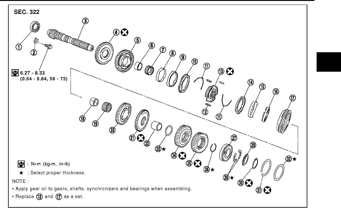
1. Mainshaft front bearing 2. Mainshaft bearing retainer 3. Mainshaft
4. Reverse main gear 5. 1st main gear 6. Bushing
7. Needle bearing 8. 1st inner baulk ring 9. 1st gear synchronizer cone
10. 1st outer baulk ring 11. Spread spring 12. 1st & 2nd shifting insert
13. 1st & 2nd synchronizer hub 14. 2nd outer baulk ring 15. 2nd gear synchronizer cone
16. 2nd inner baulk ring 17. 1st &2nd coupling sleeve 18. Bushing
19. Needle bearing 20. 2nd main gear 21. 3rd main gear
22. 3rd &4th mainshaft spacer 23. 4th main adjusting shim 24. 4th main gear
25. 5th main gear 26. Snap ring 27. Mainshaft rear bearing
28. Mainshaft C ring 29. C ring holder 30. Snap ring
31. Snap ring 32. Mainshaft rear bearing adjusting shim
SCIA0386E
MT-20
TRANSAXLE ASSEMBLY
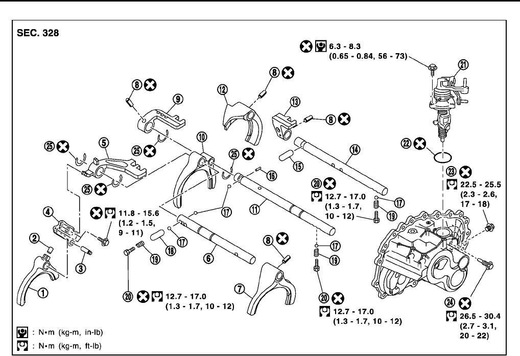
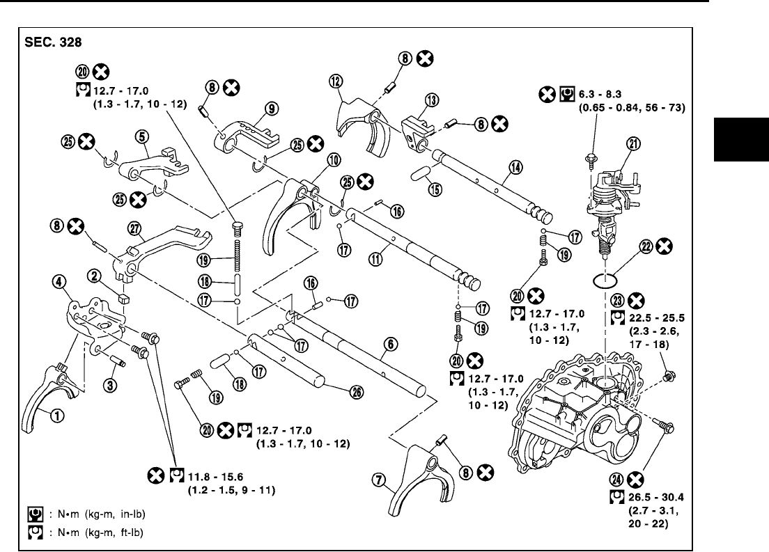
SHIFT CONTROL COMPONENTS
1. Reverse shift fork 2. Shifter cap 3. Reverse fork rod
4. Reverse lever assembly 5. 5th & reverse bracket 6. 5th & reverse fork rod
7. 5th shift fork 8. Retaining pin 9. 3rd & 4th bracket
10. 3rd & 4th shift fork 11. 3rd & 4th fork rod 12. 1st & 2nd shift fork
13. 1st & 2nd bracket 14. 1st & 2nd fork rod 15. Shift check sleeve
16. Inter lock pin 17. Check ball 18. Shift check sleeve
19. Check spring 20. Check plug 21. Control assembly
22. O ring 23. Shift check 24. Stopper bolt
25. Stopper ring
SCIA0387E
TRANSAXLE ASSEMBLY
MT-21
D
E
F
G
H
I
J
K
L
M
A
B
MT
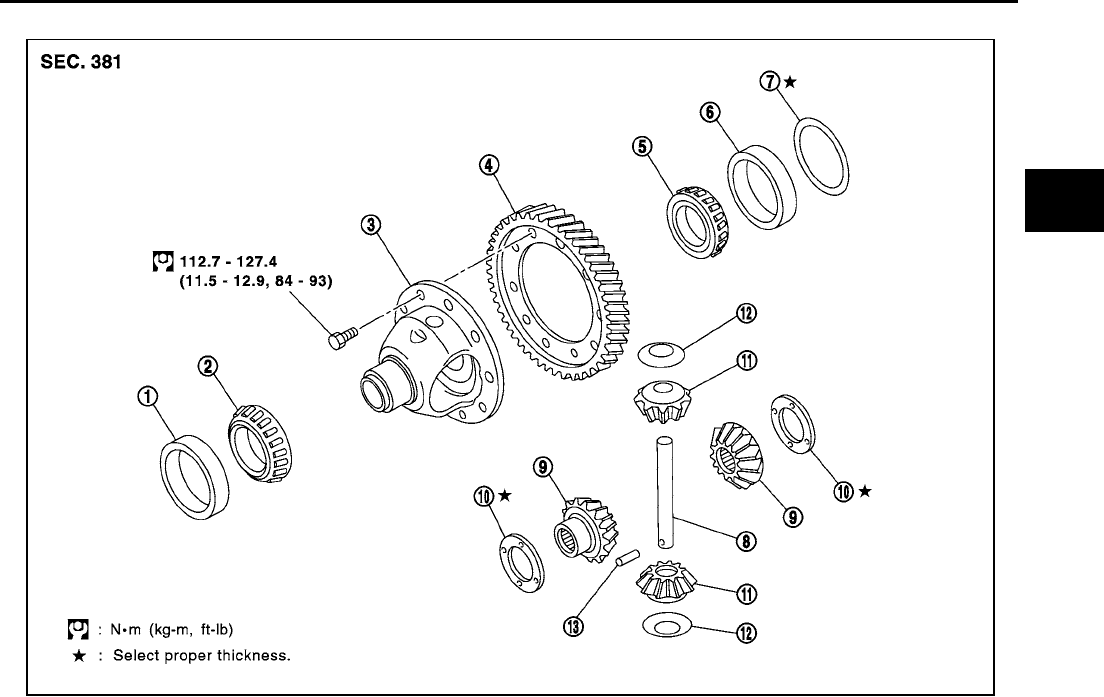
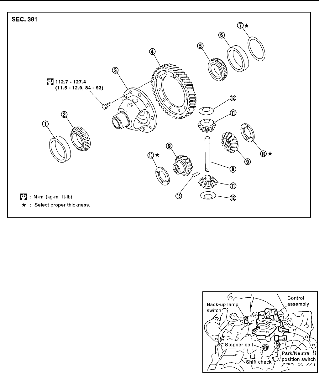
FINAL DRIVE COMPONENTS
1. Differential side bearing outer race 2. Differential side bearing 3. Differential case
4. Final gear 5. Differential side bearing 6. Differential side bearing outer race
7. Differential side bearing adjusting
shim
8. Pinion mate shaft 9. Side gear
10. Side gear thrust washer 11. Pinion mate gear 12. Pinion mate gear washer
13. Retaining pin
SCIA0388E
MT-22
TRANSAXLE ASSEMBLY
Component Parts (RS6F51A) ECS008BZ
CASE AND HOUSING COMPONENTS
1. Clutch housing 2. Input shaft oil seal 3. Oil channel
4. Magnet 5. Differential oil seal 6. Ball pin
7. Washer 8. Transaxle case 9. Welch plug
10. Bore plug 11. Differential oil seal 12. Park/Neutral position switch
13. Oil gutter 14. Back-up lamp switch 15. Air breather tube
16. Baffle plate 17. Filler plug 18. Gasket
19. Drain plug 20. Gasket
SCIA1112E
TRANSAXLE ASSEMBLY
MT-23
D
E
F
G
H
I
J
K
L
M
A
B
MT
GEAR COMPONENTS
1. Input shaft front bearing 2. Input shaft 3. Needle bearing
4. 3rd input gear 5. 3rd baulk ring 6. Spread spring
7. 3rd & 4th shifting insert 8. 3rd & 4th synchronizer hub 9. 4th baulk ring
10. 3rd & 4th coupling sleeve 11. Bushing 12. Needle bearing
13. 4th input gear 14. Thrust washer 15. Bushing
16. Needle bearing 17. 5th input gear 18. 5th baulk ring
19. 5th & 6th shifting insert 20. 5th & 6th synchronizer hub 21. 5th & 6th coupling sleeve
22. 6th baulk ring 23. 6th input gear 24. Needle bearing
25. Bushing 26. Snap ring 27. Input shaft rear bearing
28. Oil channel 29. Input shaft rear bearing adjusting
shim
30. Retaining pin
31. Reverse idler shaft 32. Thrust needle bearing 33. Needle bearing
34. Reverse idler gear (Front) 35. Reverse baulk ring 36. Reverse coupling sleeve
37. Insert spring 38. Reverse idler gear (Rear) 39. Reverse idler gear adjusting shim
SCIA0956E
MT-24
TRANSAXLE ASSEMBLY
1. Mainshaft front bearing 2. Mainshaft bearing retainer 3. Mainshaft
4. Reverse main gear 5. 1st main gear 6. Bushing
7. Needle bearing 8. 1st inner baulk ring 9. 1st gear synchronizer cone
10. 1st outer baulk ring 11. Spread spring 12. 1st & 2nd shifting insert
13. 1st & 2nd synchronizer hub 14. 2nd outer baulk ring 15. 2nd gear synchronizer cone
16. 2nd inner baulk ring 17. 1st & 2nd coupling sleeve 18. Bushing
19. Needle bearing 20. 2nd main gear 21. 3rd main gear
22. 3rd & 4th mainshaft spacer 23. 4th main adjusting shim 24. 4th main gear
25. 5th main gear 26. 6th main gear 27. Mainshaft rear bearing
28. Mainshaft C ring 29. C ring holder 30. Snap ring
31. Snap ring 32. Mainshaft rear bearing adjusting shim 33. 5th & 6th mainshaft spacer
34. 6th main adjusting shim
SCIA0957E
TRANSAXLE ASSEMBLY
MT-25
D
E
F
G
H
I
J
K
L
M
A
B
MT
SHIFT CONTROL COMPONENTS
1. Reverse shift fork 2. Shifter cap 3. Reverse fork rod
4. Reverse lever assembly 5. 5th & 6th bracket 6. 5th & 6th fork rod
7. 5th & 6th shift fork 8. Retaining pin 9. 3rd & 4th bracket
10. 3rd & 4th shift fork 11. 3rd & 4th fork rod 12. 1st & 2nd shift fork
13. 1st & 2nd fork rod bracket 14. 1st & 2nd fork rod 15. Shift check sleeve
16. Inter lock pin 17. Check ball 18. Shift check sleeve
19. Check spring 20. Check plug 21. Control assembly
22. O ring 23. Shift check 24. Stopper bolt
25. Stopper ring 26. Reverse bracket fork rod 27. Reverse bracket
SCIA0958E
MT-26
TRANSAXLE ASSEMBLY
FINAL DRIVE COMPONENTS
Disassembly and Assembly (RS5F51A) ECS008C0
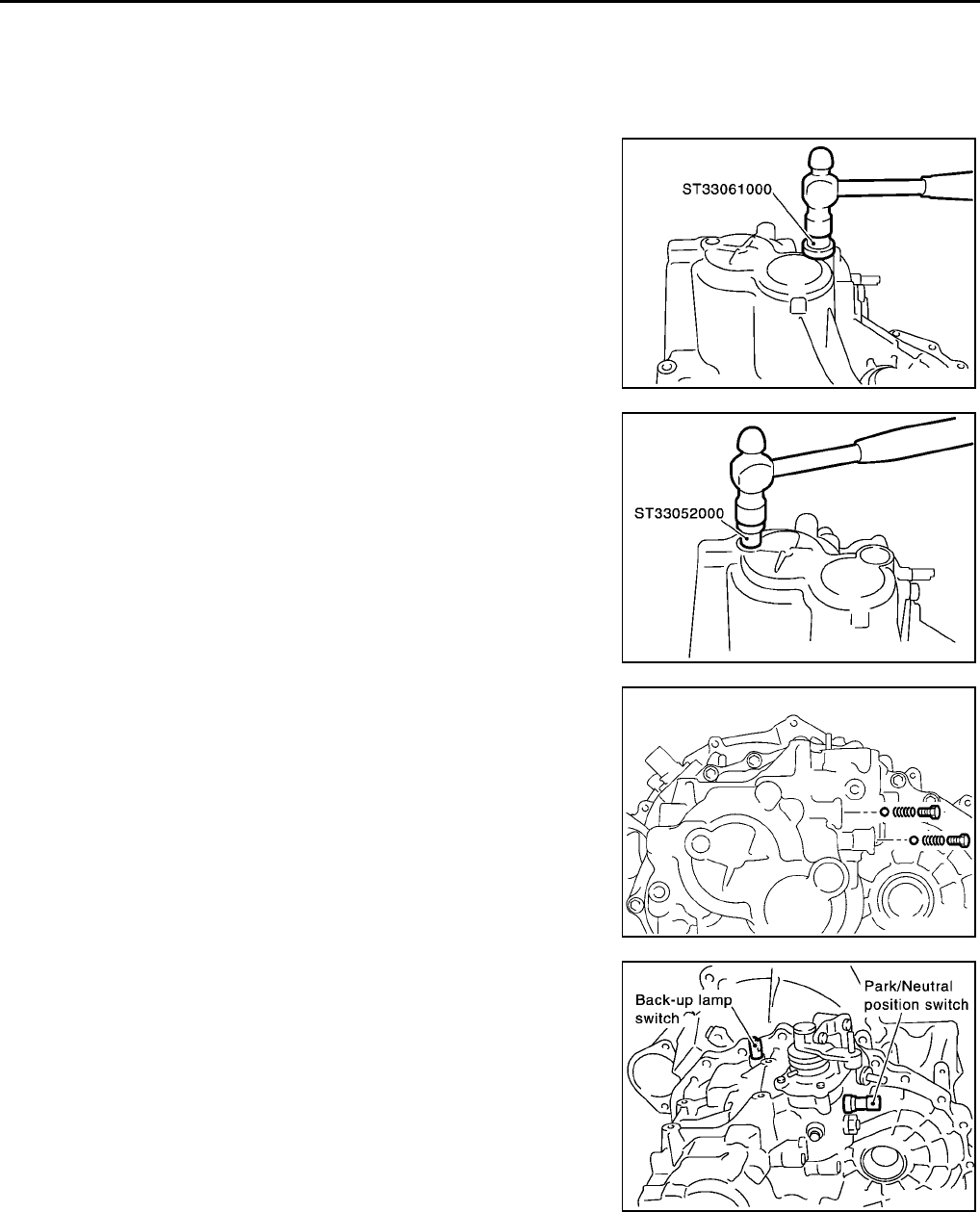
DISASSEMBLY
1. Remove drain plug and filler plug.
2. Remove park/neutral position switch and back-up lamp switch.
3. After removing shift check and stopper bolt, remove control
assembly.
1. Differential side bearing outer race 2. Differential side bearing 3. Differential case
4. Final gear 5. Differential side bearing 6. Differential side bearing outer race
7. Differential side bearing adjusting shim 8. Pinion mate shaft 9. Side gear
10. Side gear thrust washer 11. Pinion mate gear 12. Pinion mate gear washer
13. Retaining pin
SCIA0388E
SCIA0389E
TRANSAXLE ASSEMBLY
MT-27
D
E
F
G
H
I
J
K
L
M
A
B
MT
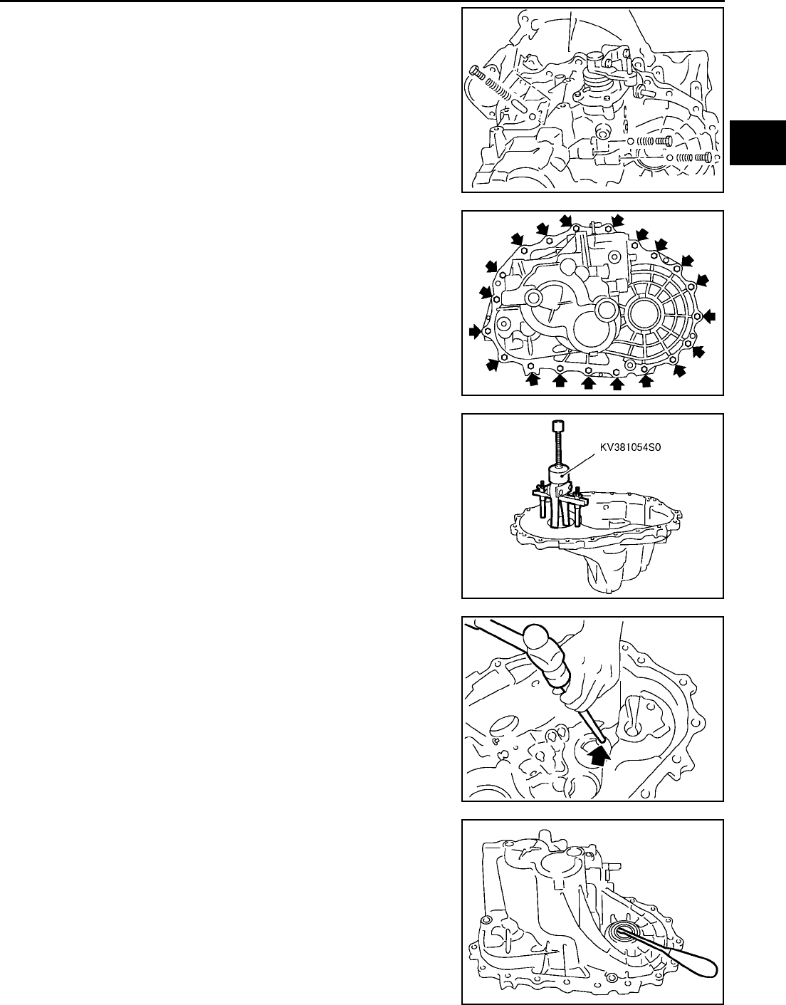
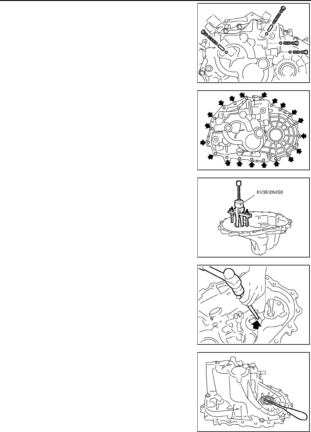
4. Remove check plugs (3 pieces), check springs (3 pieces), check
balls (3 pieces) and shift check sleeve (1 piece).
5. Remove transaxle case fixing bolts.
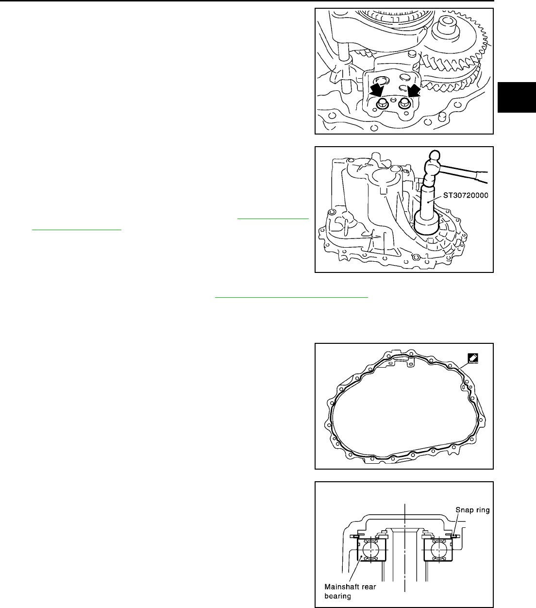
6. Remove bore plug.
CAUTION:
Be careful not to damage transaxle case.
7. While spreading the snap ring of mainshaft rear bearing located
at bore plug hole, remove transaxle case.
8. Remove oil gutter, baffle plate.
9. Remove snap ring, mainshaft rear bearing adjusting shim and
input shaft rear bearing adjusting shim from transaxle case.
10. Remove differential side bearing outer race (transaxle case
side) and then adjust shim.
11. Remove welch plug.
12. Remove differential oil seal (tansaxle case side).
13. Remove magnet from clutch housing.
SCIA0396E
SCIA0983E
SCIA0897E
SCIA0402E
SCIA0397E
MT-28
TRANSAXLE ASSEMBLY
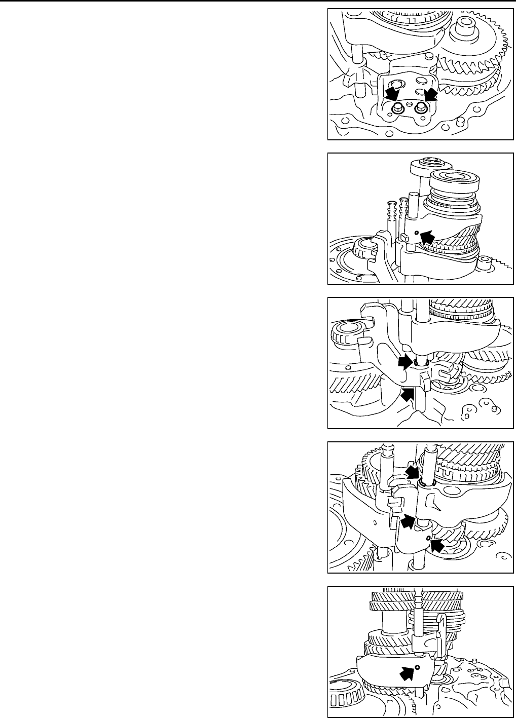
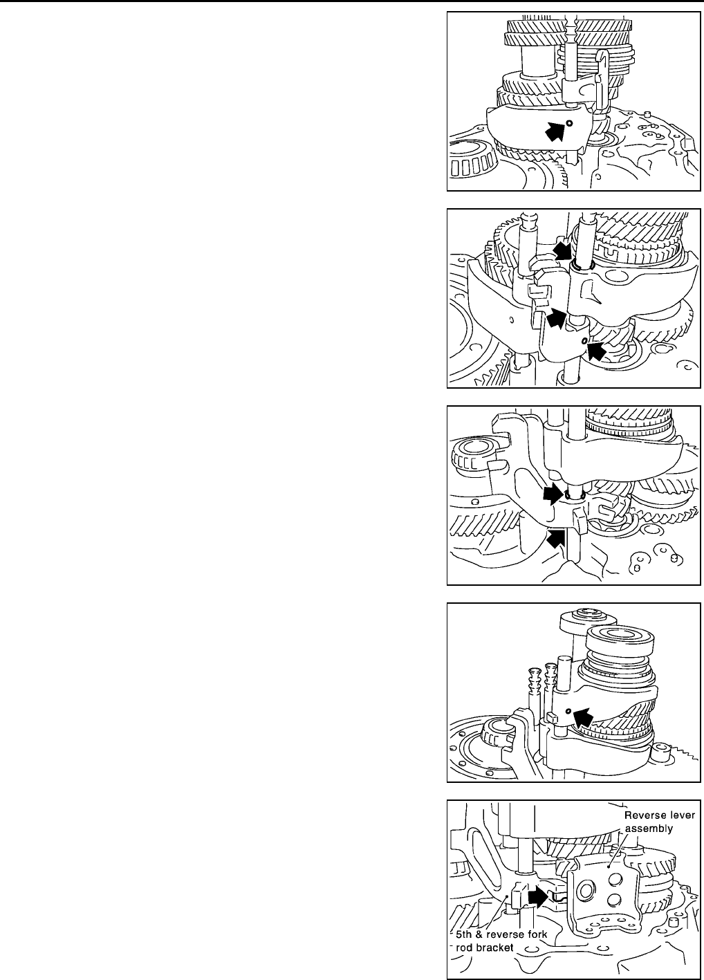
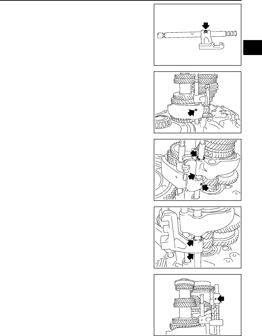
14. With shift lever in 5th position, remove bracket bolts from
reverse lever assembly. Lift reverse lever assembly to remove.
CAUTION:
Be careful not to lose shifter cap.
15. Pull out reverse fork rod then remove reverse shift fork.
16. Shift 3rd & 4th fork rod to 3rd position. Remove retaining pin of
5th shift fork using pin punch.
17. Remove stopper rings for 5th & reverse bracket.
18. Pull out 5th & reverse fork rod and remove 5th shift fork and 5th
& reverse bracket.
19. Remove check balls (2 pieces) and inter lock pin.
20. Remove retaining pin of 3rd & 4th bracket using pin punch.
21. Remove stopper rings for 3rd & 4th shift fork.
22. Pull out 3rd & 4th fork rod and remove 3rd & 4th shift fork and
bracket.
23. Remove shift check sleeve from clutch housing.
24. Remove retaining pin of 1st & 2nd shift fork using pin punch.
25. Pull out 1st & 2nd fork rod with bracket.
26. Remove 1st & 2nd shift fork.
27. Remove retaining pin of 1st & 2nd bracket using pin punch and
separate 1st & 2nd fork rod and bracket.
SCIA0390E
SCIA0391E
SCIA0392E
SCIA0393E
SCIA0394E
TRANSAXLE ASSEMBLY
MT-29
D
E
F
G
H
I
J
K
L
M
A
B
MT
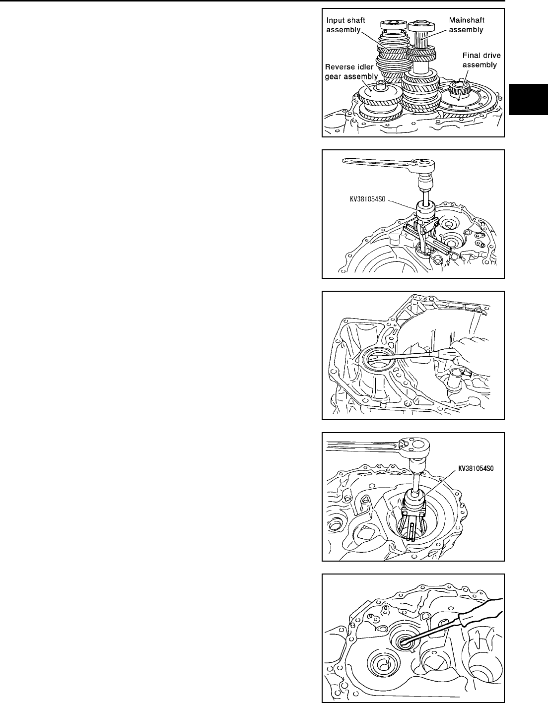
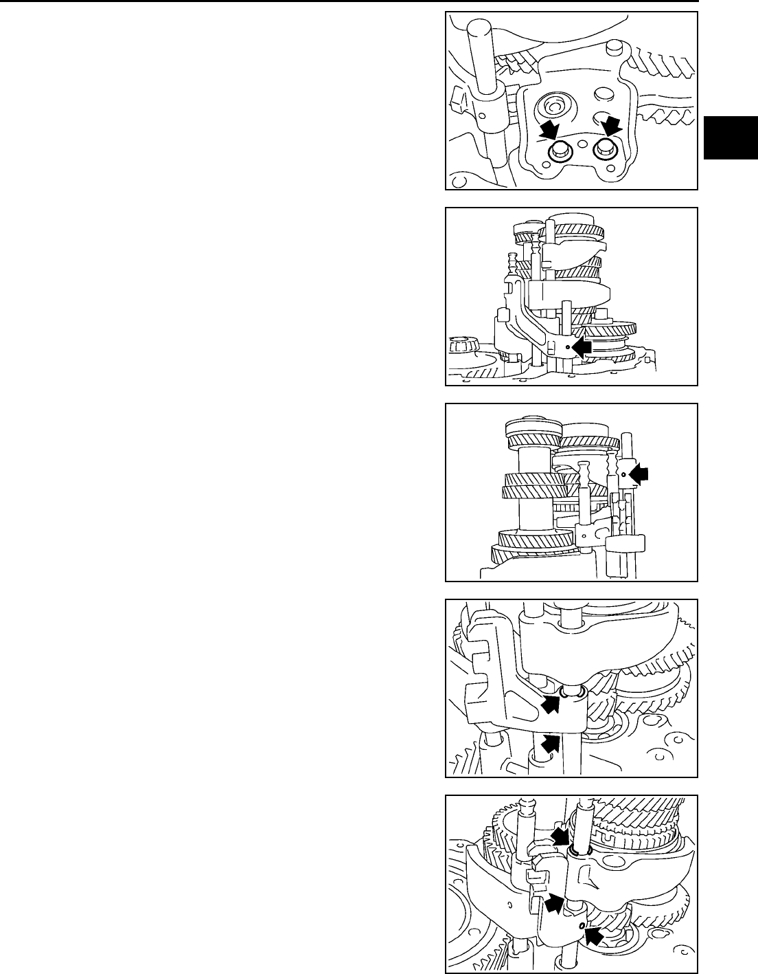
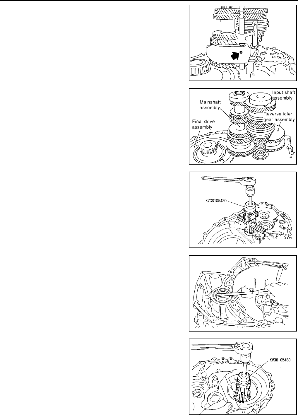
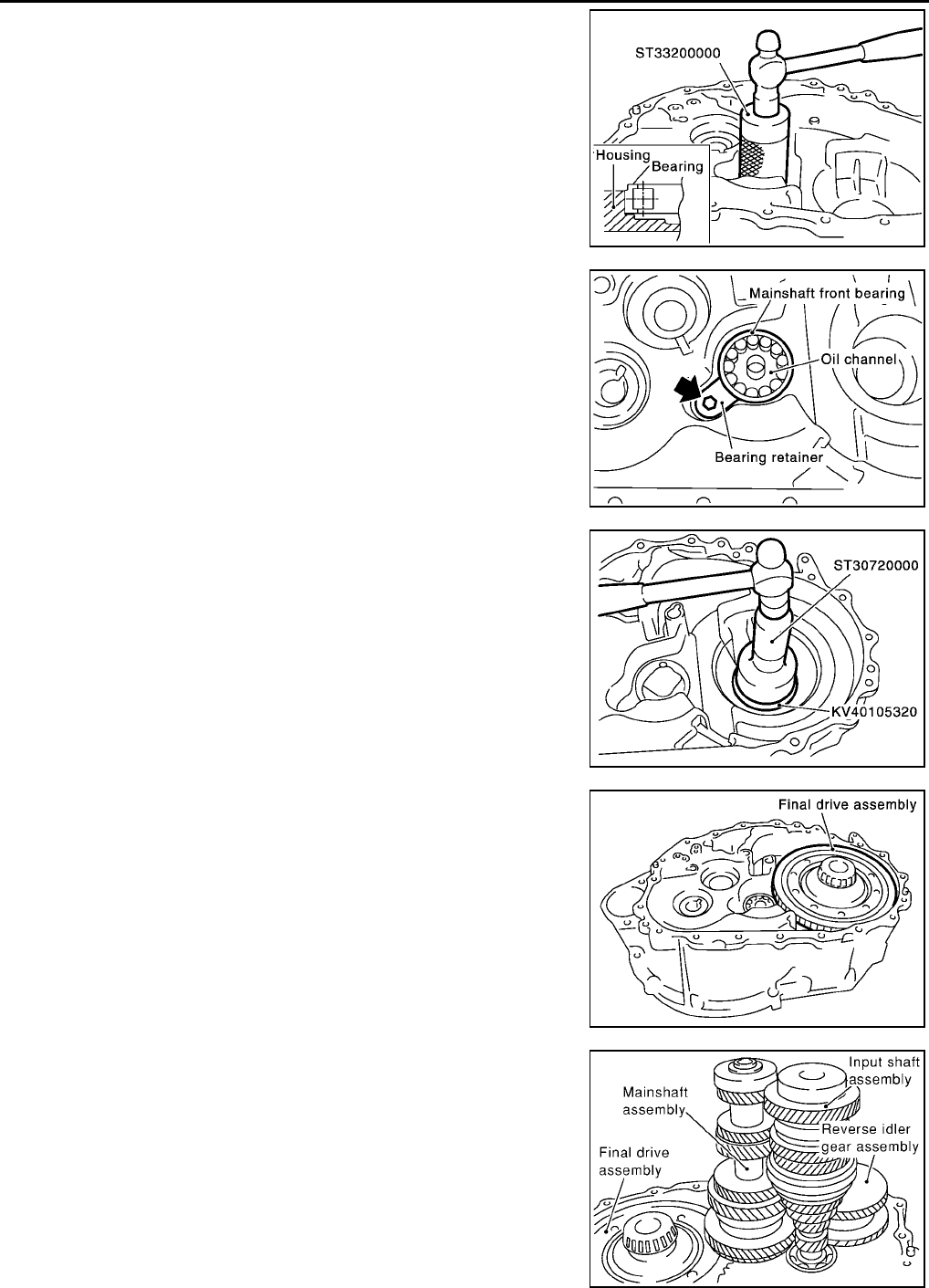
28. Remove gear components from clutch housing in the following
procedure.
a. While tapping input shaft with plastic hammer, remove input
shaft assembly, mainshaft assembly and reverse idler gear
assembly as a set.
CAUTION:
Always withdraw mainshaft straight out. Failure to do so
can damage resin oil channel on clutch housing side.
b. Remove final drive assembly.
29. Remove bearing retainer and then mainshaft front bearing.
30. Remove oil channel on mainshaft side.
31. Remove differential oil seal (clutch housing side).
32. Remove differential side bearing outer race (clutch housing
side).
33. Remove input shaft oil seal.
CAUTION:
Be careful not to damage clutch housing.
SCIA0395E
SCIA1077J
SCIA1068J
SCIA1069J
SCIA0398E
MT-30
TRANSAXLE ASSEMBLY
ASSEMBLY
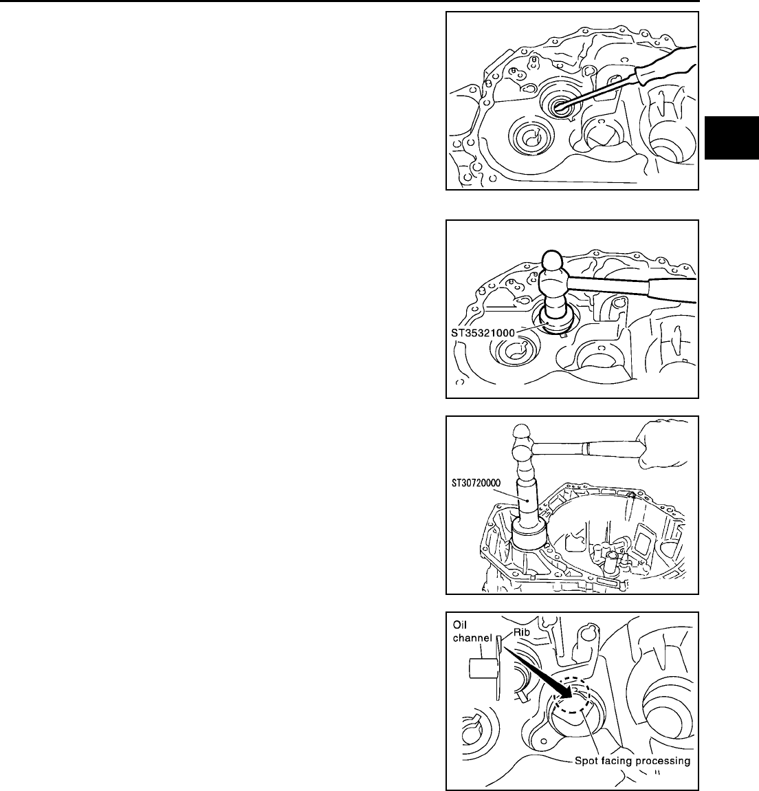
1. Using a drift, install input shaft oil seal from clutch housing end
of side to the depth of 1.8 to 2.8 mm (0.071 to 0.110 in).
CAUTION:
Do not reuse oil seals.
2. Using a drift, install differential oil seal until the face is flush with
clutch housing.
CAUTION:
Do not reuse oil seals.
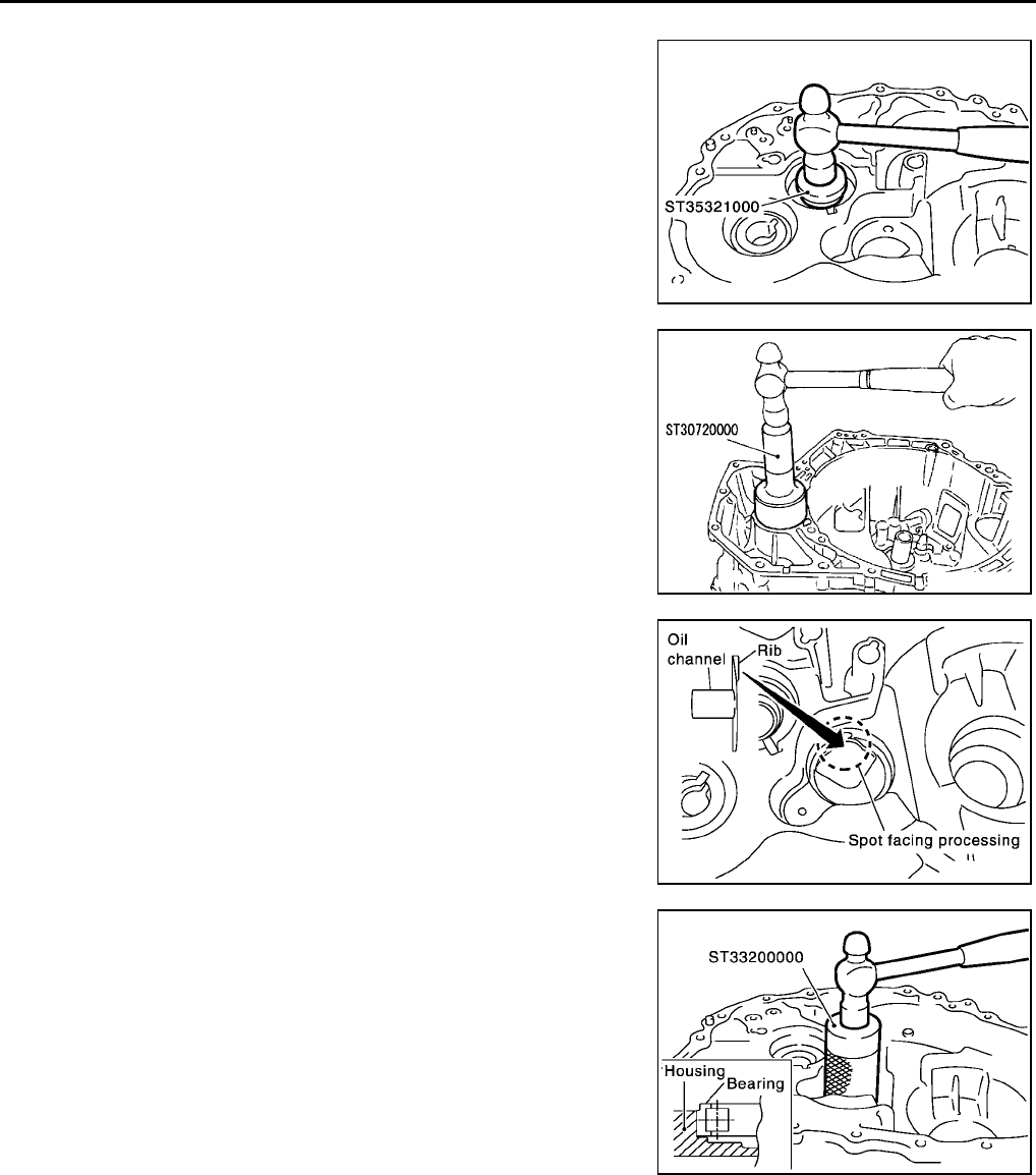
3. Install oil channel on mainshaft side.
CAUTION:
Be careful with orientation of installation.
4. Using a drift, install mainshaft front bearing.
CAUTION:
Be careful with orientation of installation.
SCIA0399E
SCIA1070J
SCIA0986E
SCIA0401E
TRANSAXLE ASSEMBLY
MT-31
D
E
F
G
H
I
J
K
L
M
A
B
MT
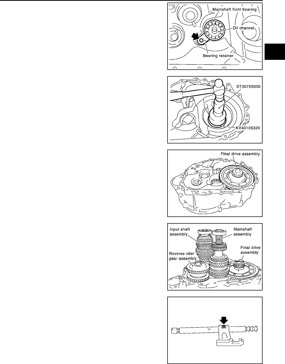
5. Install bearing retainer.
CAUTION:
Install with punched surface facing up.
6. Install differential side bearing outer race.
7. Install final drive assembly into clutch housing.
8. Install input shaft assembly, mainshaft assembly, and reverse
idler gear assembly into clutch housing.
CAUTION:
Be sure not to damage input shaft oil seal.
9. Install 1st-2nd fork rod bracket onto 1st-2nd fork rod, and then
install retaining pin.
CAUTION:
Do not reuse retaining pins.
SCIA0400E
SCIA0987E
SCIA0888E
SCIA0395E
SCIA0889E
MT-32
TRANSAXLE ASSEMBLY
10. Install 1st-2nd fork rod and 1st-2nd shift fork, and then install
retaining pin.
CAUTION:
Do not reuse retaining pins.
11. Install shift check sleeve.
12. Install 3rd-4th bracket, 3rd-4th shift fork, and 3rd-4th fork rod
with inter lock pin.
13. Install stopper ring onto 3rd-4th shift fork.
CAUTION:
Do not reuse stopper ring.
14. Install retaining pin onto 3rd-4th bracket.
CAUTION:
Do not reuse retaining pins.
15. Install 2 check balls.
16. Install 5th-reverse bracket, 5th shift fork, and 5th-reverse fork
rod.
17. Install stopper ring onto 5th-reverse bracket.
CAUTION:
Do not reuse stopper ring.
18. Install retaining pin onto 5th shift fork.
CAUTION:
Do not reuse retaining pins.
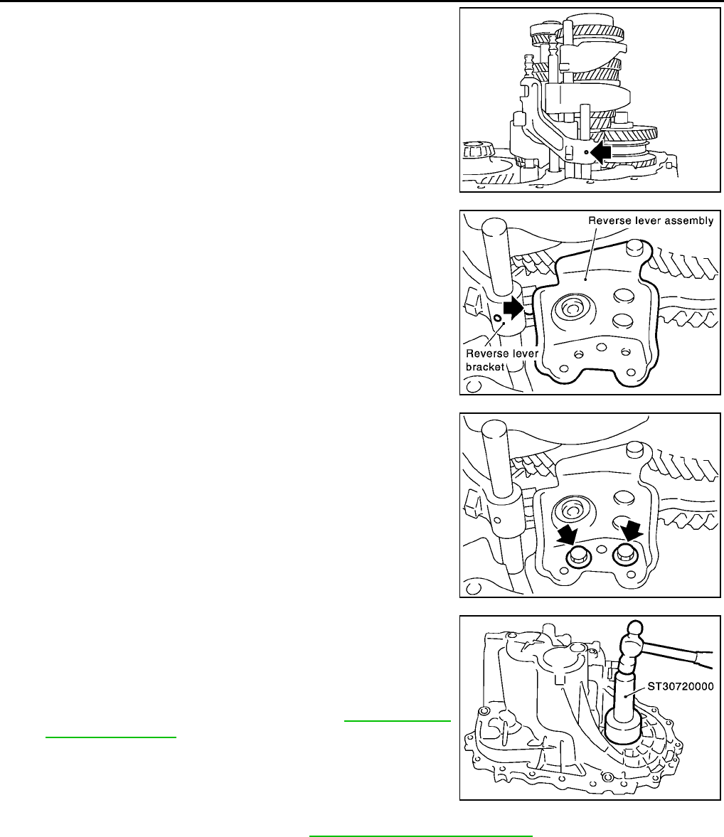
19. Install reverse shift fork and reverse fork rod.
20. Install reverse lever assembly following procedures below.
a. Install shifter cap onto reverse lever assembly cam, and then
install them onto reverse shift fork.
CAUTION:
Do not drop shifter cap.
b. While lifting reverse shift fork, align cam with 5th-reverse
bracket.
SCIA0394E
SCIA0393E
SCIA0392E
SCIA0391E
SCIA0890E
TRANSAXLE ASSEMBLY
MT-33
D
E
F
G
H
I
J
K
L
M
A
B
MT
c. Tighten mounting bolts to specified torque, and then install
reverse lever assembly.
21. Install check ball, 5th-reverse shift check sleeve, check spring
and 5th-reverse check ball plug.
CAUTION:
●Do not reuse check ball plug.
●Do not drop check ball.
22. Install the magnet onto clutch housing.
23. Using a drift, install differential oil seal until it is flush with end
face of transaxle case.
CAUTION:
Do not reuse oil seals.
24. Install selected input shaft adjusting shim onto input shaft.
●For selection of adjusting shims, refer to MT-45, "INPUT
SHAFT END PLAY" .
25. Install baffle plate and oil gutter.
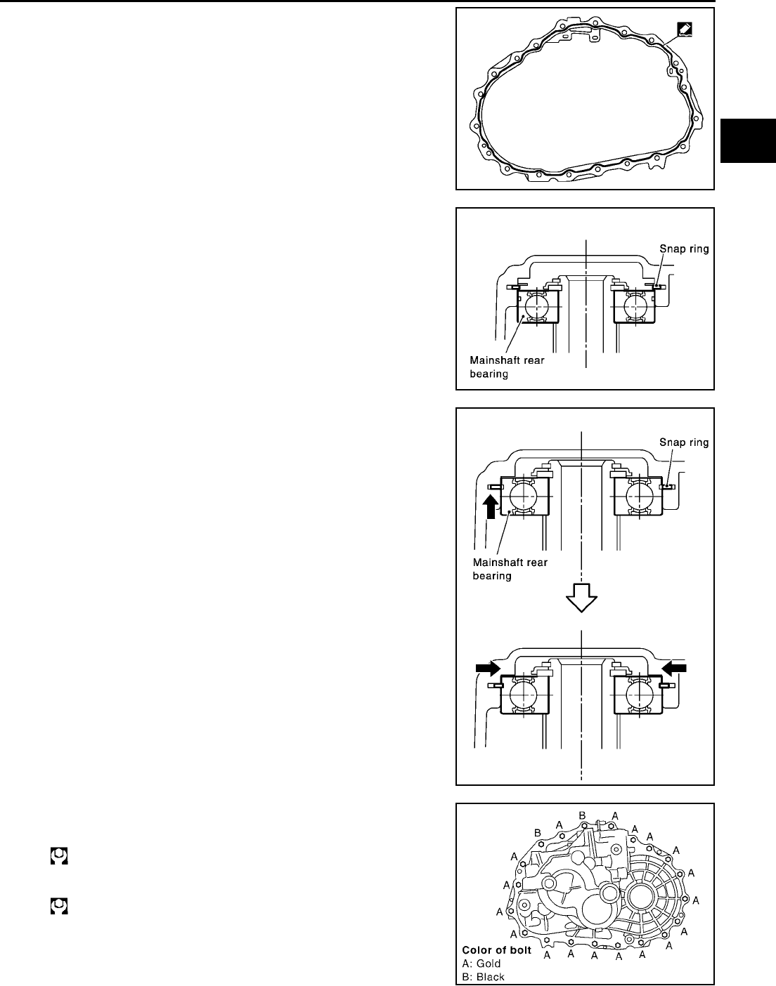
26. Install transaxle case following procedures below.
a. Install selected mainshaft rear bearing adjusting shim into tran-
saxle case.
●For selection of adjusting shims, refer to MT-46, "MAINSHAFT END PLAY" .
b. Temporarily install snap ring of mainshaft rear bearing into transaxle case.
CAUTION:
Do not reuse the snap ring.
c. Apply recommended sealant to mating surfaces of transaxle
case and clutch housing.
CAUTION:
Remove old sealant adhering to mounting surfaces. Also
remove any moisture, oil, or foreign material adhering to
application and mounting surfaces.
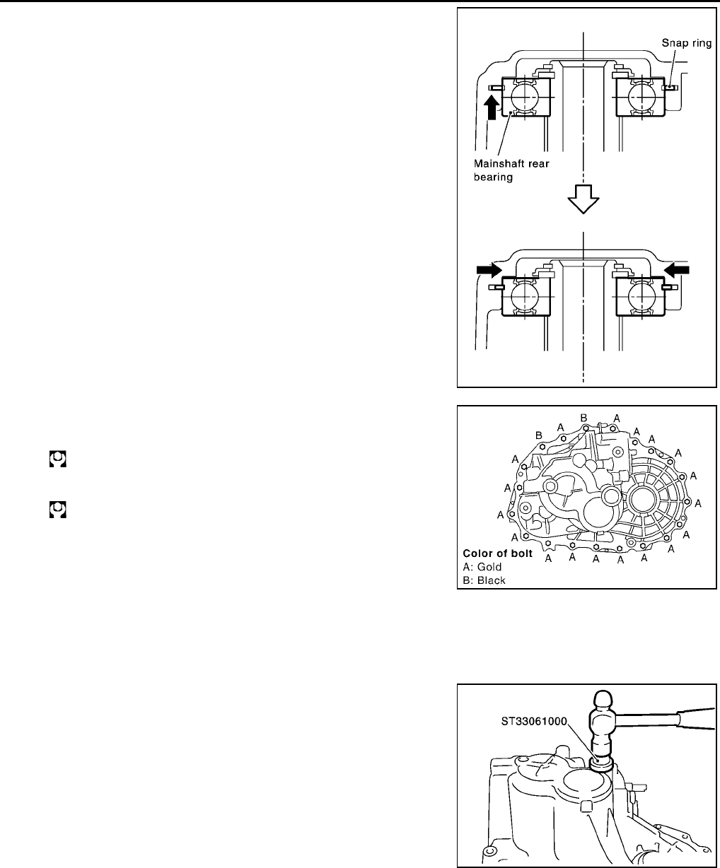
d. With snap ring of mainshaft rear bearing temporarily installed,
place transaxle case over clutch housing.
SCIA0390E
SCIA0887E
SCIA0891E
SCIA0892E
MT-34
TRANSAXLE ASSEMBLY
e. Through bore plug mounting hole, with snap ring stretched, and
lift up mainshaft assembly from the control assembly mounting
hole.
f. Securely install snap ring onto mainshaft rear bearing.
g. Tighten mounting bolts.
CAUTION:
Always replace bolts B as they are self-sealing bolts.
h. Install control assembly.
CAUTION:
Do not reuse the O-ring.
i. Install shift check and stopper bolt.
CAUTION:
Does not reuse shift check and stopper bolt.
27. Using a drift, install bore plug.
CAUTION:
Do not reuse bore plug.
SCIA0893E
Bolt A:
: 50.0 - 53.9 N·m (5.1 - 5.4 kg-m, 37 - 39 ft-lb)
Bolt B:
: 63.0 - 66.9 N·m (6.5 - 6.8 kg-m, 47 - 49 ft-lb)
SCIA1064E
SCIA0894E
TRANSAXLE ASSEMBLY
MT-35
D
E
F
G
H
I
J
K
L
M
A
B
MT
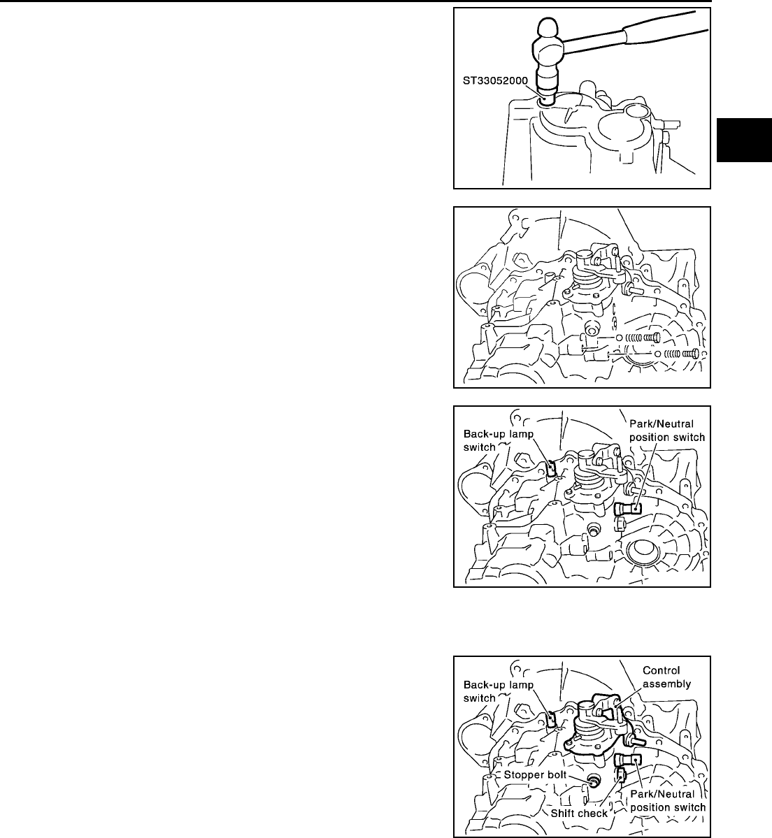
28. Using a drift, install welch plug.
CAUTION:
Do not reuse welch plug.
29. Install 2 check balls, 2 check springs and 2 check ball plugs.
CAUTION:
Do not reuse check ball plug.
30. Apply recommended sealant to threads of neutral switch and
reverse lamp switch. Then install them into transaxle case.
31. Install gaskets onto drain plug and filler plug, and then install
them into transaxle case.
CAUTION:
●Do not reuse gasket.
●After oil is filled, tighten filler plug to specified torque.
Disassembly and Assembly (RS6F51A) ECS008C1
DISASSEMBLY
1. Remove drain plug and filler plug.
2. Remove park/neutral position switch and back-up lamp switch.
3. After removing shift check and stopper bolt, remove control
assembly.
SCIA0403E
SCIA1668J
SCIA0895E
SCIA0389E
MT-36
TRANSAXLE ASSEMBLY
4. Remove check plugs (4 pieces), check springs (4 pieces), check
balls (4 pieces) and shift check sleeve (2 pieces).
5. Remove transaxle case fixing bolts.
6. Remove bore plug.
CAUTION:
Be careful not to damage transaxle case.
7. While spreading the snap ring of mainshaft rear bearing located
at bore plug hole, remove transaxle case.
8. Remove oil gutter, baffle plate.
9. Remove snap ring, mainshaft rear bearing adjusting shim and
input shaft rear bearing adjusting shim from transaxle case.
10. Remove differential side bearing outer race (transaxle case
side) and then adjusting shim.
11. Remove welch plug.
12. Remove differential oil seal (transaxle case side).
13. Remove magnet from clutch housing.
SCIA0959E
SCIA0983E
SCIA0897E
SCIA0402E
SCIA0397E
TRANSAXLE ASSEMBLY
MT-37
D
E
F
G
H
I
J
K
L
M
A
B
MT
14. With shift lever in 5th position, remove bracket bolts from
reverse lever assembly. Lift reverse lever assembly to remove.
CAUTION:
Be careful not to lose shifter cap.
15. Pull out reverse fork rod then remove reverse shift fork.
16. Remove retaining pin of reverse bracket.
17. Pull out reverse bracket and reverse bracket fork rod.
18. Remove check ball (2 pieces) and inter lock pin.
19. Shift 3rd & 4th fork rod to 3rd position. Remove retaining pin of
5th & 6th shift fork using pin punch.
20. Remove stopper rings for 5th & 6th bracket.
21. Pull out 5th & 6th fork rod and remove 5th & 6th shift fork and
5th & 6th bracket.
22. Remove check balls (2 pieces) and inter lock pin.
23. Remove retaining pin of 3rd & 4th bracket using pin punch.
24. Remove stopper rings for 3rd & 4th shift fork.
25. Pull out 3rd & 4th fork rod and remove 3rd & 4th shift fork and
bracket.
26. Remove shift check sleeve from clutch housing.
SCIA0960E
SCIA0961E
SCIA0962E
SCIA0963E
SCIA0393E
MT-38
TRANSAXLE ASSEMBLY
27. Remove retaining pin of 1st & 2nd shift fork using pin punch.
28. Pull out 1st & 2nd fork rod with bracket.
29. Remove 1st & 2nd shift fork.
30. Remove retaining pin of 1st & 2nd bracket using pin punch and
separate fork rod and bracket.
31. Remove gear components from clutch housing in the following
procedure.
a. While tapping input shaft with plastic hammer, remove input
shaft assembly, mainshaft assembly and reverse idler gear
assembly as a set.
CAUTION:
Always withdraw mainshaft straight out. Failure to do so
can damage resin oil channel on clutch housing side.
b. Remove final drive assembly.
32. Remove main bearing retainer and then mainshaft front bearing.
33. Remove oil channel on mainshaft side.
34. Remove differential oil seal (clutch housing side).
35. Remove differential side bearing outer race (clutch housing
side).
SCIA0394E
SCIA0964E
SCIA1077J
SCIA1068J
SCIA1069J
TRANSAXLE ASSEMBLY
MT-39
D
E
F
G
H
I
J
K
L
M
A
B
MT
36. Remove input shaft oil seal.
CAUTION:
Be careful not to damage clutch housing.
ASSEMBLY
1. Using a drift, install input shaft oil seal from clutch housing end
of side to the depth of 1.8 to 2.8 mm (0.071 to 0.110 in).
CAUTION:
Do not reuse oil seals.
2. Using a drift, install differential oil seal until the face is flush with
clutch housing.
CAUTION:
Do not reuse oil seals.
3. Install oil channel on mainshaft side.
CAUTION:
Be careful with orientation of installation.
SCIA0398E
SCIA0399E
SCIA1070J
SCIA0986E
MT-40
TRANSAXLE ASSEMBLY
4. Using a drift, install mainshaft front bearing.
CAUTION:
Be careful with orientation of installation.
5. Install bearing retainer.
CAUTION:
Install with punched surface facing up.
6. Install differential side bearing outer race.
7. Install final drive assembly into clutch housing.
8. Install input shaft assembly, mainshaft assembly, and reverse
idler gear assembly into clutch housing.
CAUTION:
Be sure not to damage input shaft oil seal.
SCIA0401E
SCIA0400E
SCIA0987E
SCIA0888E
SCIA0964E
TRANSAXLE ASSEMBLY
MT-41
D
E
F
G
H
I
J
K
L
M
A
B
MT
9. Install 1st-2nd fork rod bracket onto 1st-2nd fork rod, and then
install retaining pin.
CAUTION:
Do not reuse retaining pin.
10. Install 1st-2nd fork rod and 1st-2nd shift fork, and then install
retaining pin.
CAUTION:
Do not reuse retaining pin.
11. Install shift check sleeve.
12. Install 3rd-4th bracket, 3rd-4th shift fork, and 3rd-4th fork rod
with inter lock pin.
13. Install stopper ring onto 3rd-4th shift fork.
CAUTION:
Do not stopper ring.
14. Install retaining pin onto 3rd-4th bracket.
CAUTION:
Do not reuse retaining pin.
15. Install 2 check balls.
16. Install 5th-6th bracket, 5th-6th shift fork, and 5th-6th fork rod
with inter lock pin.
17. Install stopper ring onto 5th-6th bracket.
CAUTION:
Do not stopper ring.
18. Install retaining pin onto 5th-6th shift fork.
CAUTION:
Do not reuse retaining pin.
19. Install 2 check balls.
20. Install check ball, 5th-6th shift check sleeve, 5th-6th check
spring and 5th-6th check ball plug.
CAUTION:
●Do not reuse check ball plug.
●Do not drop check ball.
21. Install reverse bracket fork rod and reverse lever bracket.
SCIA0889E
SCIA0394E
SCIA0393E
SCIA0963E
SCIA0962E
MT-42
TRANSAXLE ASSEMBLY
22. Install retaining pin onto reverse bracket.
CAUTION:
Do not reuse retaining pin.
23. Install reverse shift fork and reverse fork rod.
24. Install reverse lever assembly following procedures below.
a. Install shifter cap onto reverse lever assembly cam, and then
install them onto reverse shift fork.
CAUTION:
Do not drop shifter cap.
b. While lifting reverse shift fork, align cam with reverse bracket.
c. Tighten mounting bolts to specified torque, and then install
reverse lever assembly.
25. Install check ball, reverse shift check sleeve, reverse check
spring and reverse check ball plug.
CAUTION:
●Do not reuse check ball plug.
●Do not drop check ball.
26. Install the magnet onto clutch housing.
27. Using a drift, install differential oil seal until it is flush with end
face of transaxle case.
CAUTION:
Do not reuse oil seals.
28. Install selected input shaft adjusting shim onto input shaft.
●For selection of adjusting shims, refer toMT-49, "INPUT
SHAFT END PLAY" .
29. Install baffle plate and oil gutter.
30. Install transaxle case following procedures below.
a. Install selected mainshaft rear bearing adjusting shim into tran-
saxle case.
●For selection of adjusting shims, refer toMT-50, "MAINSHAFT END PLAY" .
b. Temporarily install snap ring of mainshaft rear bearing into transaxle case.
CAUTION:
Do not reuse the snap ring.
SCIA0961E
SCIA0965E
SCIA0960E
SCIA0887E
TRANSAXLE ASSEMBLY
MT-43
D
E
F
G
H
I
J
K
L
M
A
B
MT
c. Apply recommended sealant to mating surfaces of transaxle
case and clutch housing.
CAUTION:
Remove old sealant adhering to mounting surfaces. Also
remove any moisture, oil, or foreign material adhering to
application and mounting surfaces.
d. With snap ring of mainshaft rear bearing temporarily installed,
place transaxle case over clutch housing.
e. Through bore plug mounting hole, with snap ring stretched, and
lift up mainshaft assembly from the control assembly mounting
hole.
f. Securely install snap ring onto mainshaft rear bearing.
g. Tighten mounting bolts.
CAUTION:
Always replace bolts B as they are self-sealing bolts.
h. Install control assembly.
SCIA0891E
SCIA0892E
SCIA0893E
Bolt A:
: 50.0 - 53.9 N·m (5.1 - 5.4 kg-m, 37 - 39 ft-lb)
Bolt B:
: 63.0 - 66.9 N·m (6.5 - 6.8 kg-m, 47 - 49 ft-lb)
SCIA1064E
MT-44
TRANSAXLE ASSEMBLY
CAUTION:
Do not reuse the O-ring.
i. Install shift check and stopper bolt.
CAUTION:
Does not reuse shift check and stopper bolt.
31. Using a drift, install bore plug.
CAUTION:
Do not reuse bore plug.
32. Using a drift, install welch plug.
CAUTION:
Do not reuse welch plug.
33. Install 2 check balls, 2 check springs and 2 check ball plugs.
CAUTION:
Do not reuse check ball plug.
34. Apply recommended sealant to threads of neutral switch and
reverse lamp switch. Then install them into transaxle case.
35. Install gaskets onto drain plug and filler plug, and then install
them into transaxle case.
CAUTION:
●Do not reuse gasket.
●After oil is filled, tighten filler plug to specified torque.
SCIA0894E
SCIA0403E
SCIA1667E
SCIA0895E
TRANSAXLE ASSEMBLY
MT-45
D
E
F
G
H
I
J
K
L
M
A
B
MT
Adjustment (RS5F51A) ECS008C2
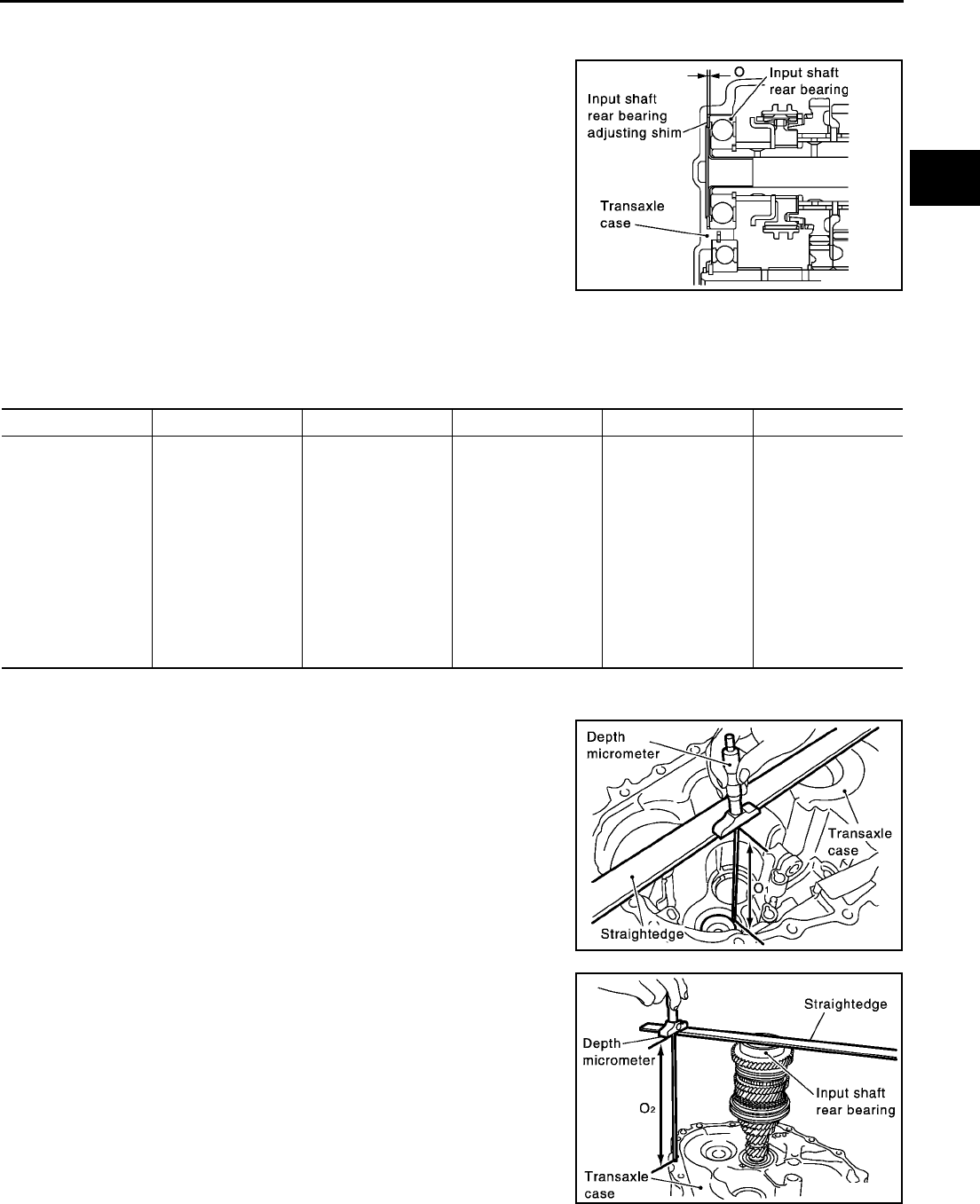
INPUT SHAFT END PLAY
●When adjusting input shaft end play, select adjusting shim for
input shaft bearing. To select adjusting shim, measure clearance
between transaxle case and input shaft rear bearing.
●Calculate dimension "O" (thickness of adjusting shim) using the
following procedure to satisfy specification of end play for input
shaft rear bearing.
Adjusting Shim
CAUTION:
Only 1 adjusting shim can be selected.
1. Using depth micrometer and straight edge, measure dimension
"O1 " between transaxle case end face and mounting face of
adjusting shim.
2. Using depth micrometer and straight edge as shown in the fig-
ure, measure dimension "O2 " between clutch housing case end
face and end face of input shaft rear bearing.
3. Install selected input shaft rear bearing adjusting shim onto input
shaft.
End play: 0 - 0.06 mm (0 - 0.0024 in)
Dimension“O” = (O1 - O2 ) + End play
O: Thickness of adjusting shim
O1 : Distance between transaxle case end face and
mounting face of adjusting shim
O2 : Distance between clutch housing case end
face and end face of input shaft rear bearing
SCIA1006E
Shim thickness Part number Shim thickness Part number Shim thickness Part number
0.40 mm (0.0157 in)
0.44 mm (0.0173 in)
0.48 mm (0.0189 in)
0.52 mm (0.0205 in)
0.56 mm (0.0220 in)
0.60 mm (0.0236 in)
0.64 mm (0.0252 in)
0.68 mm (0.0268 in)
0.72 mm (0.0283 in)
0.76 mm (0.0299 in)
0.80 mm (0.0315 in)
0.84 mm (0.0331 in)
32225 8H500
32225 8H501
32225 8H502
32225 8H503
32225 8H504
32225 8H505
32225 8H506
32225 8H507
32225 8H508
32225 8H509
32225 8H510
32225 8H511
0.88 mm (0.0346 in)
0.92 mm (0.0362 in)
0.96 mm (0.0378 in)
1.00 mm (0.0394 in)
1.04 mm (0.0409 in)
1.08 mm (0.0425 in)
1.12 mm (0.0441 in)
1.16 mm (0.0457 in)
1.20 mm (0.0472 in)
1.24 mm (0.0488 in)
1.28 mm (0.0504 in)
1.32 mm (0.0520 in)
32225 8H512
32225 8H513
32225 8H514
32225 8H515
32225 8H516
32225 8H517
32225 8H518
32225 8H519
32225 8H520
32225 8H521
32225 8H522
32225 8H523
1.36 mm (0.0535 in)
1.40 mm (0.0551 in)
1.44 mm (0.0567 in)
1.48 mm (0.0583 in)
1.52 mm (0.0598 in)
1.56 mm (0.0614 in)
1.60 mm (0.0630 in)
1.64 mm (0.0646 in)
1.68 mm (0.0661 in)
1.72 mm (0.0677 in)
32225 8H524
32225 8H560
32225 8H561
32225 8H562
32225 8H563
32225 8H564
32225 8H565
32225 8H566
32225 8H567
32225 8H568
SCIA1002E
SCIA1004E
MT-46
TRANSAXLE ASSEMBLY
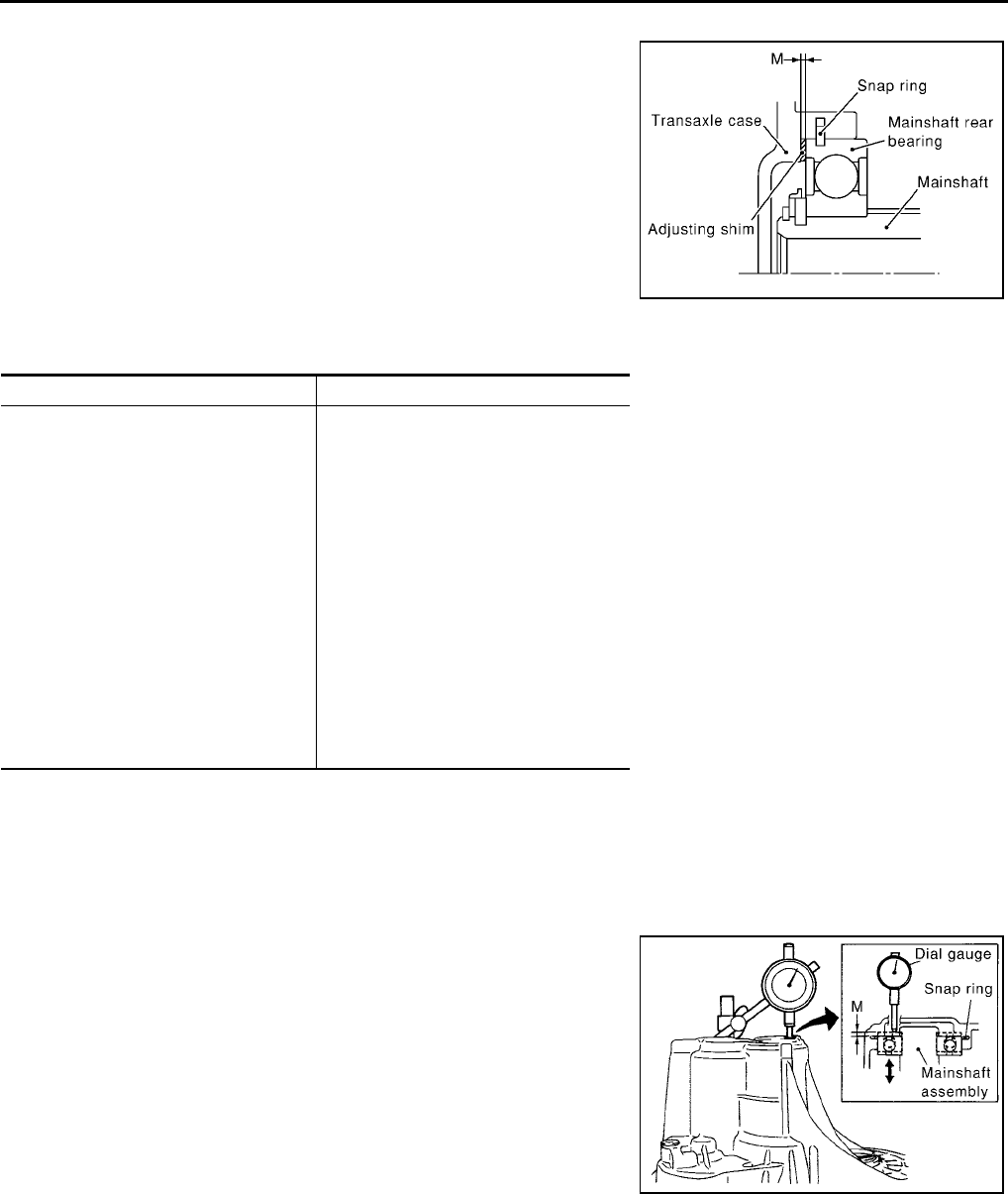
MAINSHAFT END PLAY
●When adjusting mainshaft end play, select adjusting shim for
mainshaft rear bearing. To select adjusting shim, measure clear-
ance “M” between transaxle case and mainshaft rear bearing.
●Calculate dimension "P" (thickness of adjusting shim) using the
following procedure to satisfy specification of end play for main-
shaft rear bearing.
Adjusting Shim
CAUTION:
Only 1 adjusting shim can be selected.
1. Install mainshaft assembly to clutch housing.
2. Install snap ring to transaxle case.
3. Install transaxle case to clutch housing, and temporarily assemble them with fixing bolts. Install tempo-
rarily snap ring to mainshaft rear bearing.
4. Install dial gauge to snap ring access hole, and expand snap
ring. Lift mainshaft assembly through control assembly installa-
tion hole, and push it against transaxle case. This state shall be
defined as base. Moving distance of mainshaft assembly, with
snap ring fit on main bearing, becomes “M”.
End play: 0 - 0.06 mm (0 - 0.0024 in)
Dimension“P” = "M" + End play
P: Thickness of adjusting shim
M: Distance between mainshaft rear bearing and
transaxle case
SCIA0904E
Shim thickness Part number
0.44 mm (0.0173 in)
0.48 mm (0.0189 in)
0.52 mm (0.0205 in)
0.56 mm (0.0220 in)
0.60 mm (0.0236 in)
0.64 mm (0.0252 in)
0.68 mm (0.0268 in)
0.72 mm (0.0283 in)
0.76 mm (0.0299 in)
0.80 mm (0.0315 in)
0.84 mm (0.0331 in)
0.88 mm (0.0346 in)
0.92 mm (0.0362 in)
0.96 mm (0.0378 in)
1.00 mm (0.0394 in)
1.04 mm (0.0409 in)
1.08 mm (0.0425 in)
32238 8H510
32238 8H511
32238 8H512
32238 8H513
32238 8H514
32238 8H515
32238 8H516
32238 8H517
32238 8H518
32238 8H519
32238 8H520
32238 8H521
32238 8H522
32238 8H523
32238 8H524
32238 8H560
32238 8H561
SCIA1017E
TRANSAXLE ASSEMBLY
MT-47
D
E
F
G
H
I
J
K
L
M
A
B
MT
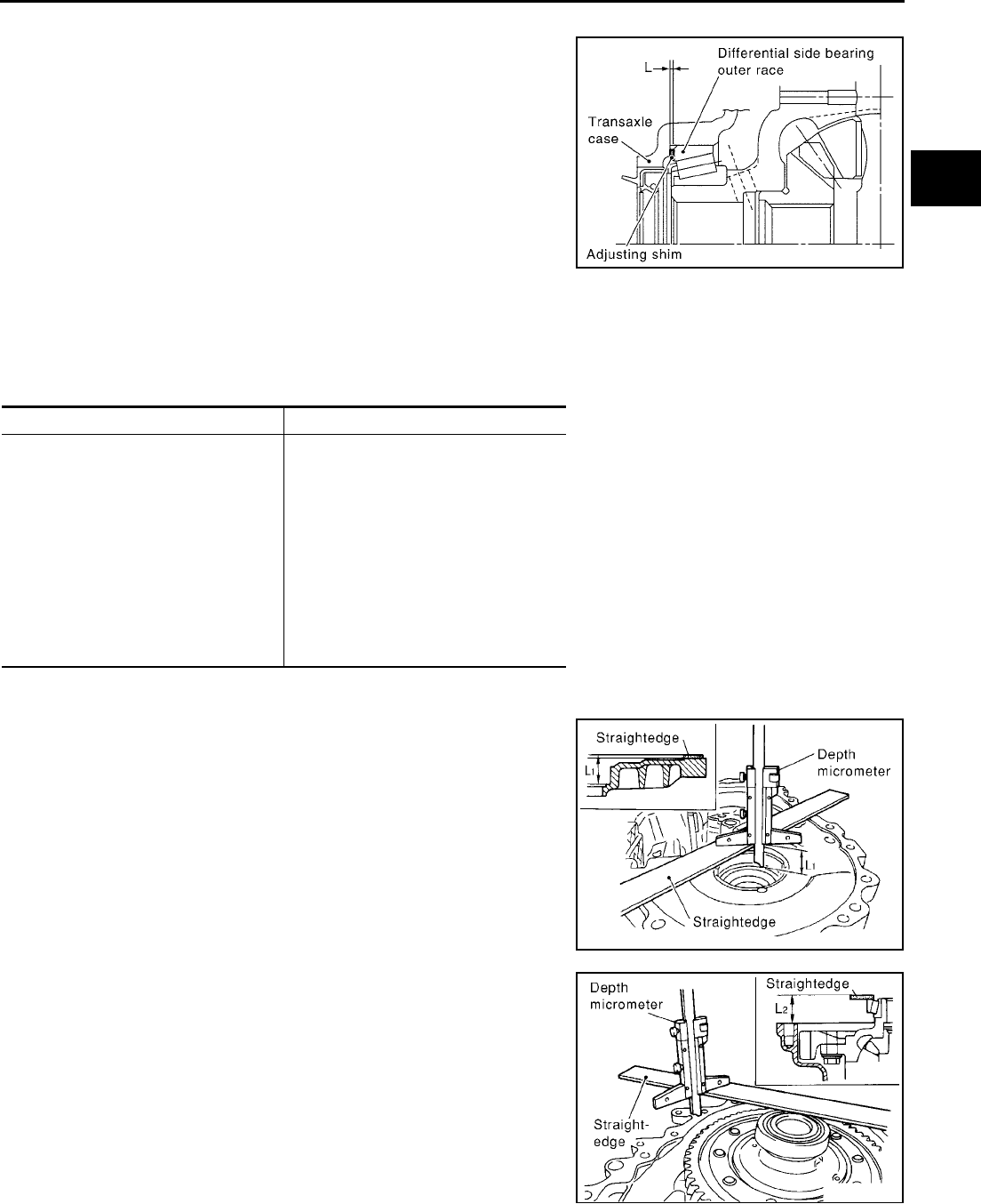
DIFFERENTIAL SIDE BEARING PRELOAD
●When adjusting differential side bearing preload, select adjust-
ing shim for differential side bearing. To select adjusting shim,
measure clearance “L” between transaxle case and differential
side bearing outer race.
●Calculate dimension “L” (thickness of adjusting shim) using the
following procedure to satisfy specification of preload for differ-
ential side bearing.
Adjusting Shim
CAUTION:
Up to 2 adjusting shims can be selected.
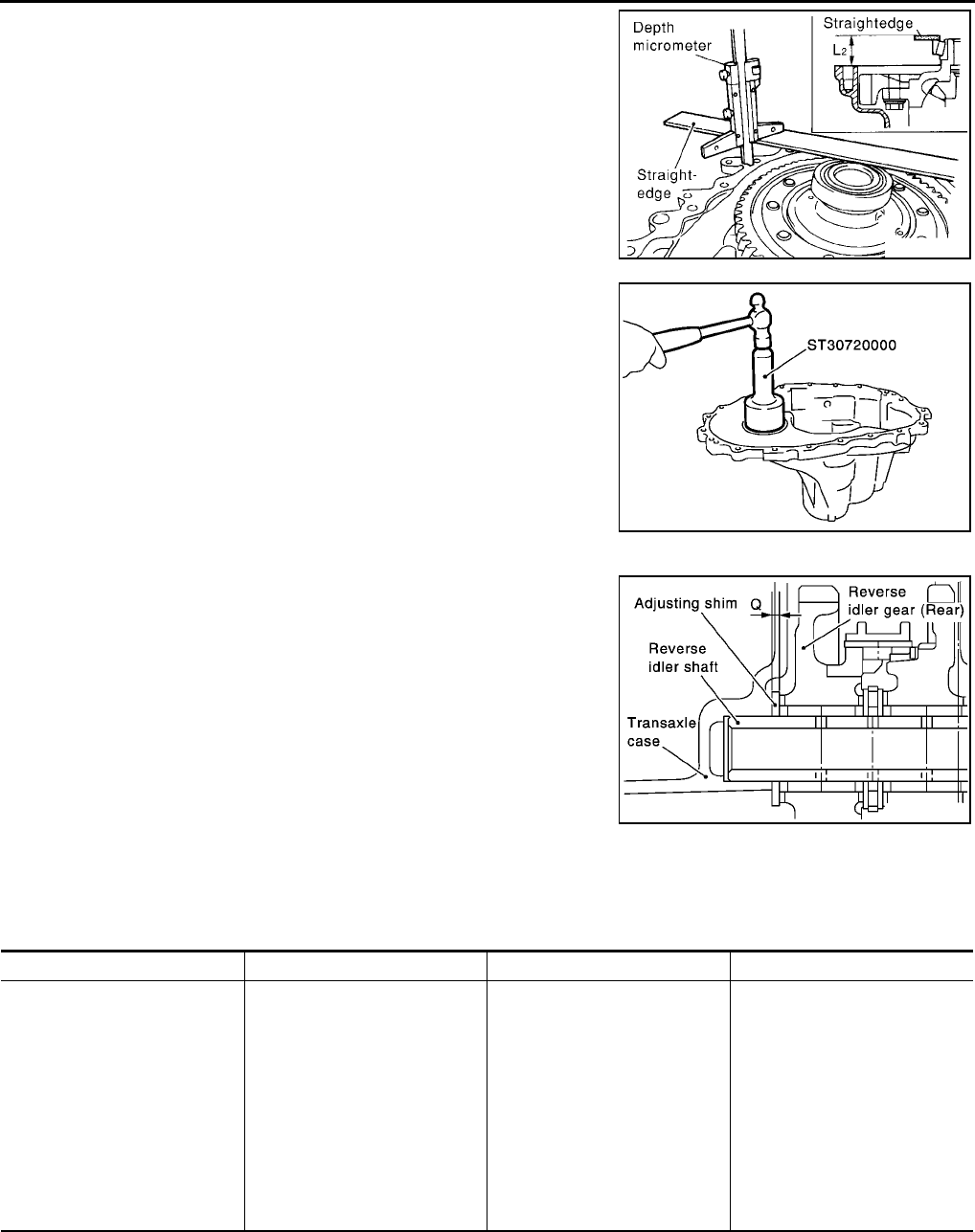
1. Using depth micrometer and straightedge, measure dimension
"L1 " between clutch housing case end face and mounting face
of adjusting shim.
2. Install outer race onto differential side bearing on final gear side.
Holding lightly the outer race horizontally by hand, rotate final
gear five times or more (for smooth movement of bearing roller).
3. Using depth micrometer and straightedge as shown in the fig-
ure, measure dimension "L2 " between differential side bearing
outer race and transaxle case end face.
Preload: 0.15 - 0.21 mm (0.0059 - 0.0083 in)
Dimension“L” = (L1 - L2 ) + Preload
L: Thickness of adjusting shim
L1
:Distance between clutch housing case end
face and mounting face of adjusting shim
L2
:Distance between differential side bearing and
transaxle case
SCIA0896E
Shim thickness Part number
0.48 mm (0.0189 in)
0.52 mm (0.0205 in)
0.56 mm (0.0220 in)
0.60 mm (0.0236 in)
0.64 mm (0.0252 in)
0.68 mm (0.0268 in)
0.72 mm (0.0283 in)
0.76 mm (0.0299 in)
0.80 mm (0.0315 in)
0.84 mm (0.0331 in)
0.88 mm (0.0346 in)
0.92 mm (0.0362 in)
31438 80X00
31438 80X01
31438 80X02
31438 80X03
31438 80X04
31438 80X05
31438 80X06
31438 80X07
31438 80X08
31438 80X09
31438 80X10
31438 80X11
SCIA1078E
SCIA1079E
MT-48
TRANSAXLE ASSEMBLY
4. Install selected adjusting shim and then differential side bearing
outer race.
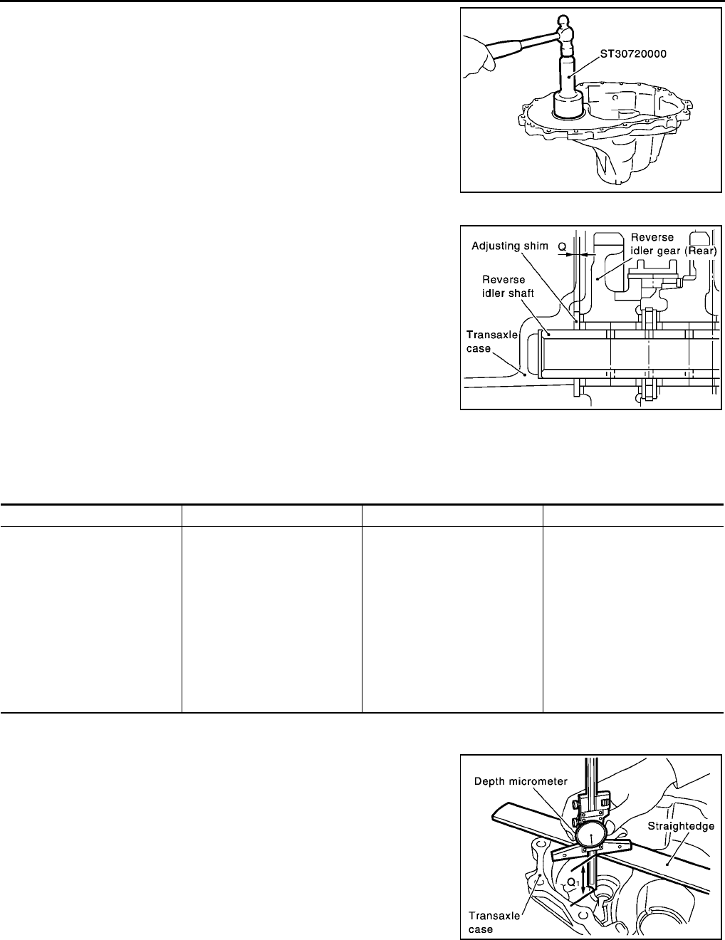
REVERSE IDLER GEAR END PLAY
●When adjusting reverse idler gear end play, select adjusting
shim for reverse idler gear. To select adjusting shim, measure
clearance between transaxle case and reverse idler gear.
●Calculate dimension "Q" (thickness of adjusting shim) using the
following procedure to satisfy specification of end play for
reverse idler gear.
Adjusting Shim
CAUTION:
Only 1 adjusting shim can be selected.
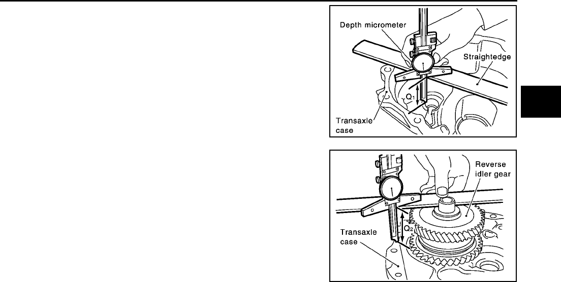
1. Using depth micrometer and straight edge, measure dimension
"Q1 " between transaxle case end face and mounting face of
adjusting shim.
SCIA0898E
End play: 0.04 - 0.10 mm (0.0016 - 0.0039 in)
Dimension“Q” = (Q1 - Q2 ) + End play
Q: Thickness of adjusting shim
Q1 : Distance between transaxle case end face and
mounting face of adjusting shim
Q2 : Distance between clutch housing case end
face and end face of reverse idler gear
SCIA1007E
Shim thickness Part number Shim thickness Part number
1.76 mm (0.0693 in)
1.80 mm (0.0709 in)
1.84 mm (0.0724 in)
1.88 mm (0.0740 in)
1.92 mm (0.0756 in)
1.96 mm (0.0772 in)
2.00 mm (0.0787 in)
2.04 mm (0.0803 in)
2.08 mm (0.0819 in)
2.12 mm (0.0835 in)
2.16 mm (0.0850 in)
2.20 mm (0.0866 in)
32237 8H800
32237 8H801
32237 8H802
32237 8H803
32237 8H804
32237 8H805
32237 8H806
32237 8H807
32237 8H808
32237 8H809
32237 8H810
32237 8H811
2.24 mm (0.0882 in)
2.28 mm (0.0898 in)
2.32 mm (0.0913 in)
2.36 mm (0.0929 in)
2.40 mm (0.0945 in)
2.44 mm (0.0961 in)
2.48 mm (0.0976 in)
2.52 mm (0.0992 in)
2.56 mm (0.1008 in)
2.60 mm (0.1024 in)
2.64 mm (0.1039 in)
32237 8H812
32237 8H813
32237 8H814
32237 8H815
32237 8H816
32237 8H817
32237 8H818
32237 8H819
32237 8H820
32237 8H821
32237 8H822
SCIA1003E
TRANSAXLE ASSEMBLY
MT-49
D
E
F
G
H
I
J
K
L
M
A
B
MT
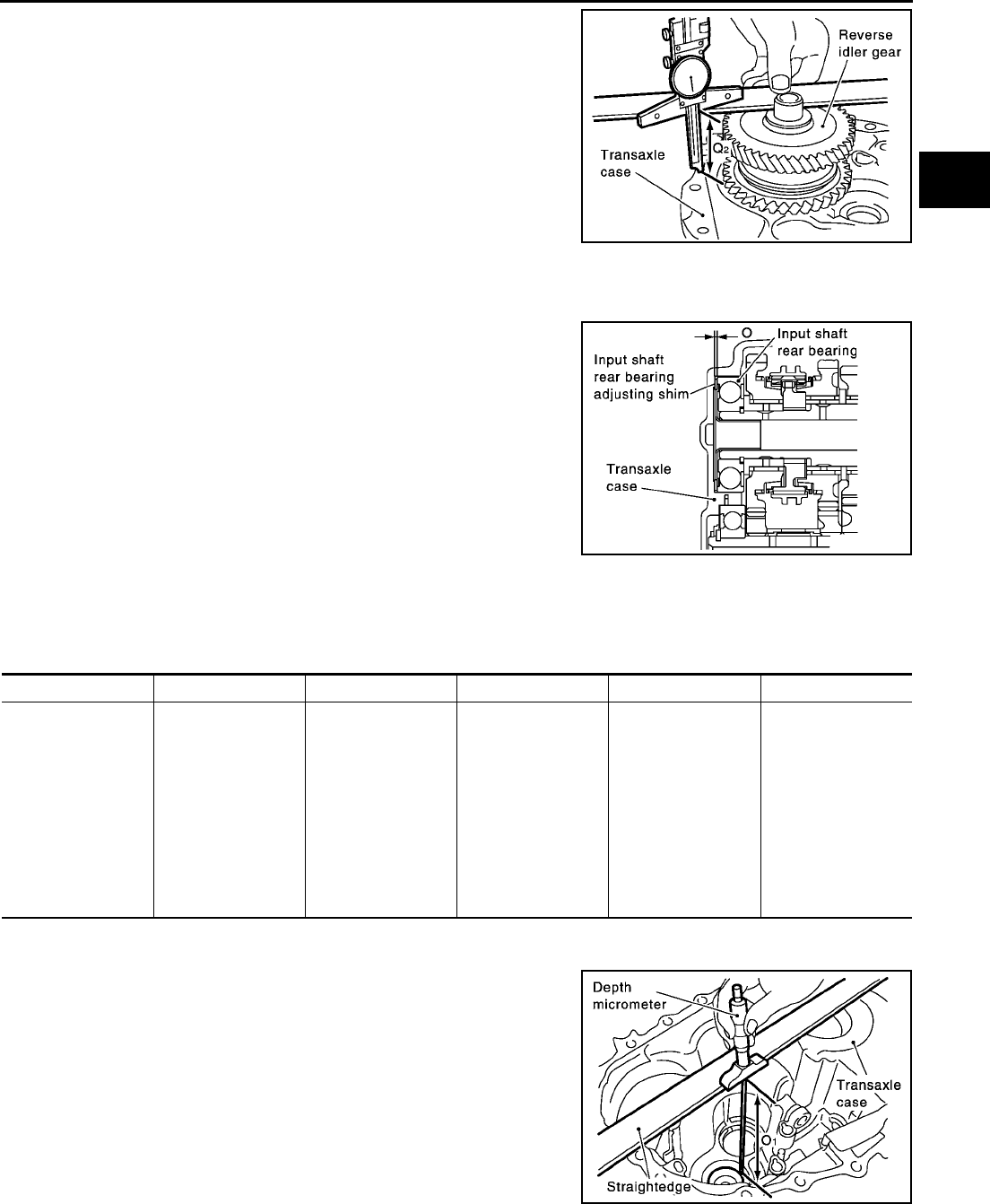
2. Using depth micrometer and straight edge as shown in the fig-
ure, measure dimension "Q2 " between clutch housing case end
face and end face of reverse idler gear.
3. Install selected reverse idler gear adjusting shim onto reverse
idler gear assembly.
Adjustment (RS6F51A) ECS008C3
INPUT SHAFT END PLAY
●When adjusting input shaft end play, select adjusting shim for
input shaft bearing. To select adjusting shim, measure clearance
between transaxle case and input shaft rear bearing.
●Calculate dimension "O" (thickness of adjusting shim) using the
following procedure to satisfy specification of end play for input
shaft rear bearing.
Adjusting Shim
CAUTION:
Only 1 adjusting shim can be selected.
1. Using depth micrometer and straight edge, measure dimension
"O1 " between transaxle case end face and mounting face of
adjusting shim.
SCIA1005E
End play: 0 - 0.06 mm (0 - 0.0024 in)
Dimension“O” = (O1 - O2 ) + End play
O: Thickness of adjusting shim
O1
:Distance between transaxle case end face and
mounting face of adjusting shim
O2
:Distance between clutch housing case end
face and end face of input shaft rear bearing
SCIA1001E
Shim thickness Part number Shim thickness Part number Shim thickness Part number
0.40 mm (0.0157 in)
0.44 mm (0.0173 in)
0.48 mm (0.0189 in)
0.52 mm (0.0205 in)
0.56 mm (0.0220 in)
0.60 mm (0.0236 in)
0.64 mm (0.0252 in)
0.68 mm (0.0268 in)
0.72 mm (0.0283 in)
0.76 mm (0.0299 in)
0.80 mm (0.0315 in)
32225 8H500
32225 8H501
32225 8H502
32225 8H503
32225 8H504
32225 8H505
32225 8H506
32225 8H507
32225 8H508
32225 8H509
32225 8H510
0.84 mm (0.0331 in)
0.88 mm (0.0346 in)
0.92 mm (0.0362 in)
0.96 mm (0.0378 in)
1.00 mm (0.0394 in)
1.04 mm (0.0409 in)
1.08 mm (0.0425 in)
1.12 mm (0.0441 in)
1.16 mm (0.0457 in)
1.20 mm (0.0472 in)
1.24 mm (0.0488 in)
32225 8H511
32225 8H512
32225 8H513
32225 8H514
32225 8H515
32225 8H516
32225 8H517
32225 8H518
32225 8H519
32225 8H520
32225 8H521
1.28 mm (0.0504 in)
1.32 mm (0.0520 in)
1.36 mm (0.0535 in)
1.40 mm (0.0551 in)
1.44 mm (0.0567 in)
1.48 mm (0.0583 in)
1.52 mm (0.0598 in)
1.56 mm (0.0614 in)
1.60 mm (0.0630 in)
1.64 mm (0.0646 in)
32225 8H522
32225 8H523
32225 8H524
32225 8H560
32225 8H561
32225 8H562
32225 8H563
32225 8H564
32225 8H565
32225 8H566
SCIA1002E
MT-50
TRANSAXLE ASSEMBLY
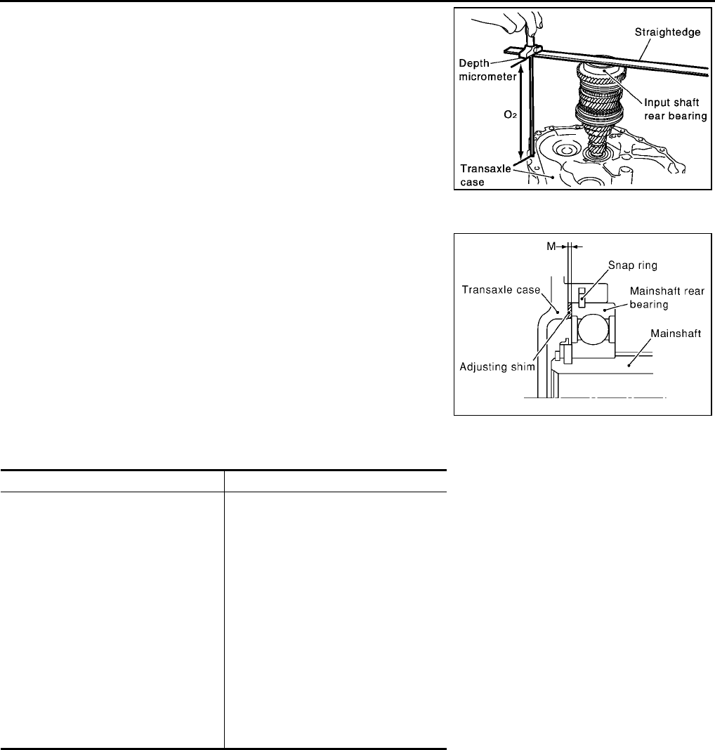
2. Using depth micrometer and straight edge as shown in the fig-
ure, measure dimension "O2 " between clutch housing case end
face and end face of input shaft rear bearing.
3. Install selected input shaft rear bearing adjusting shim onto input
shaft.
MAINSHAFT END PLAY
●When adjusting mainshaft end play, select adjusting shim for
mainshaft rear bearing. To select adjusting shim, measure clear-
ance “M” between transaxle case and mainshaft rear bearing.
●Calculate dimension "P" (thickness of adjusting shim) using the
following procedure to satisfy specification of end play for main-
shaft rear bearing.
Adjusting Shim
CAUTION:
Only 1 adjusting shim can be selected.
1. Install mainshaft assembly to clutch housing.
2. Install snap ring to transaxle case.
3. Install transaxle case to clutch housing, and temporarily assemble them with fixing bolts. Install tempo-
rarily snap ring to mainshaft rear bearing.
SCIA1004E
End play: 0 - 0.06 mm (0 - 0.0024 in)
Dimension“P” = "M" + End play
P: Thickness of adjusting shim
M: Distance between mainshaft rear bearing and
transaxle case
SCIA0904E
Shim thickness Part number
0.44 mm (0.0173 in)
0.48 mm (0.0189 in)
0.52 mm (0.0205 in)
0.56 mm (0.0220 in)
0.60 mm (0.0236 in)
0.64 mm (0.0252 in)
0.68 mm (0.0268 in)
0.72 mm (0.0283 in)
0.76 mm (0.0299 in)
0.80 mm (0.0315 in)
0.84 mm (0.0331 in)
0.88 mm (0.0346 in)
0.92 mm (0.0362 in)
0.96 mm (0.0378 in)
1.00 mm (0.0394 in)
1.04 mm (0.0409 in)
1.08 mm (0.0425 in)
32238 8H510
32238 8H511
32238 8H512
32238 8H513
32238 8H514
32238 8H515
32238 8H516
32238 8H517
32238 8H518
32238 8H519
32238 8H520
32238 8H521
32238 8H522
32238 8H523
32238 8H524
32238 8H560
32238 8H561
TRANSAXLE ASSEMBLY
MT-51
D
E
F
G
H
I
J
K
L
M
A
B
MT
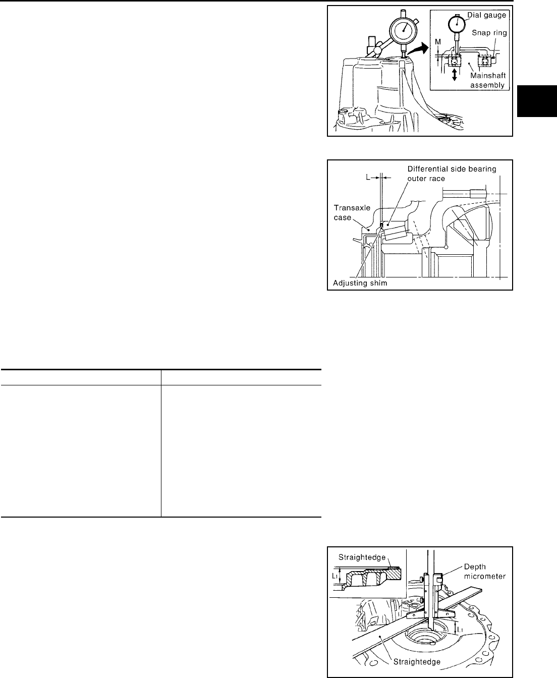
4. Install dial gauge to snap ring access hole, and expand snap
ring. Lift mainshaft assembly through control assembly installa-
tion hole, and push it against transaxle case. This state shall be
defined as base. Moving distance of mainshaft assembly, with
snap ring fit on main bearing, becomes “M”.
DIFFERENTIAL SIDE BEARING PRELOAD
●When adjusting differential side bearing preload, select adjust-
ing shim for differential side bearing. To select adjusting shim,
measure clearance “L” between transaxle case and differential
side bearing outer race.
●Calculate dimension “L” (thickness of adjusting shim) using the
following procedure to satisfy specification of preload for differ-
ential side bearing.
Adjusting Shim
CAUTION:
Up to 2 adjusting shims can be selected.
1. Using depth micrometer and straightedge, measure dimension
"L1 " between clutch housing case end face and mounting face
of adjusting shim.
2. Install outer race onto differential side bearing on final gear side.
Holding lightly the outer race horizontally by hand, rotate final
gear five times or more (for smooth movement of bearing roller).
SCIA1017E
Preload: 0.15 - 0.21 mm (0.0059 - 0.0083 in)
Dimension“L” = (L1 - L2 ) + Preload
L: Thickness of adjusting shim
L1
:Distance between clutch housing case end
face and mounting face of adjusting shim
L2
:Distance between differential side bearing and
transaxle case
SCIA0896E
Shim thickness Part number
0.48 mm (0.0189 in)
0.52 mm (0.0205 in)
0.56 mm (0.0220 in)
0.60 mm (0.0236 in)
0.64 mm (0.0252 in)
0.68 mm (0.0268 in)
0.72 mm (0.0283 in)
0.76 mm (0.0299 in)
0.80 mm (0.0315 in)
0.84 mm (0.0331 in)
0.88 mm (0.0346 in)
0.92 mm (0.0362 in)
31438 80X00
31438 80X01
31438 80X02
31438 80X03
31438 80X04
31438 80X05
31438 80X06
31438 80X07
31438 80X08
31438 80X09
31438 80X10
31438 80X11
SCIA1078E
MT-52
TRANSAXLE ASSEMBLY
3. Using depth micrometer and straightedge as shown in the fig-
ure, measure dimension "L2 " between differential side bearing
outer race and transaxle case end face.
4. Install selected adjusting shim and then differential side bearing
outer race.
REVERSE IDLER GEAR END PLAY
●When adjusting reverse idler gear end play, select adjusting
shim for reverse idler gear. To select adjusting shim, measure
clearance between transaxle case and reverse idler gear.
●Calculate dimension "Q" (thickness of adjusting shim) using the
following procedure to satisfy specification of end play for
reverse idler gear.
Adjusting Shim
CAUTION:
Only 1 adjusting shim can be selected.
SCIA1079E
SCIA0898E
End play: 0.04 - 0.10 mm (0.0016 - 0.0039 in)
Dimension“Q” = (Q1 - Q2 ) + End play
Q: Thickness of adjusting shim
Q1 : Distance between transaxle case end face and
mounting face of adjusting shim
Q2 : Distance between clutch housing case end
face and end face of reverse idler gear
SCIA1007E
Shim thickness Part number Shim thickness Part number
1.76 mm (0.0693 in)
1.80 mm (0.0709 in)
1.84 mm (0.0724 in)
1.88 mm (0.0740 in)
1.92 mm (0.0756 in)
1.96 mm (0.0772 in)
2.00 mm (0.0787 in)
2.04 mm (0.0803 in)
2.08 mm (0.0819 in)
2.12 mm (0.0835 in)
2.16 mm (0.0850 in)
2.20 mm (0.0866 in)
32237 8H800
32237 8H801
32237 8H802
32237 8H803
32237 8H804
32237 8H805
32237 8H806
32237 8H807
32237 8H808
32237 8H809
32237 8H810
32237 8H811
2.24 mm (0.0882 in)
2.28 mm (0.0898 in)
2.32 mm (0.0913 in)
2.36 mm (0.0929 in)
2.40 mm (0.0945 in)
2.44 mm (0.0961 in)
2.48 mm (0.0976 in)
2.52 mm (0.0992 in)
2.56 mm (0.1008 in)
2.60 mm (0.1024 in)
2.64 mm (0.1039 in)
32237 8H812
32237 8H813
32237 8H814
32237 8H815
32237 8H816
32237 8H817
32237 8H818
32237 8H819
32237 8H820
32237 8H821
32237 8H822
TRANSAXLE ASSEMBLY
MT-53
D
E
F
G
H
I
J
K
L
M
A
B
MT
1. Using depth micrometer and straight edge, measure dimension
"Q1 " between transaxle case end face and mounting face of
adjusting shim.
2. Using depth micrometer and straight edge as shown in the fig-
ure, measure dimension "Q2 " between clutch housing case end
face and end face of reverse idler gear.
3. Install selected reverse idler gear adjusting shim onto reverse
idler gear assembly.
SCIA1003E
SCIA1005E
MT-54
INPUT SHAFT AND GEARS
INPUT SHAFT AND GEARS PFP:32200
Assembly and Disassembly (RS5F51A) ECS008C4
DISASSEMBLY
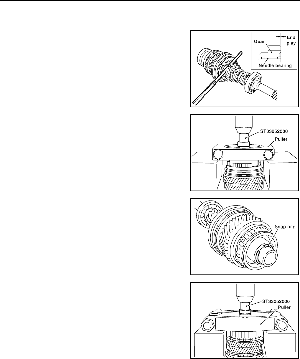
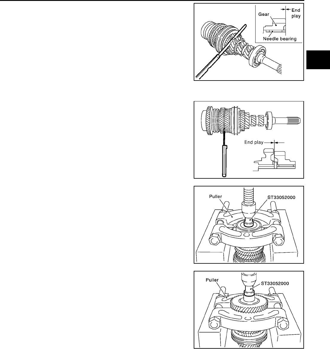
1. Before disassembling, measure end play for 3rd, 4th, and 5th
input gears.
2. Remove oil channel.
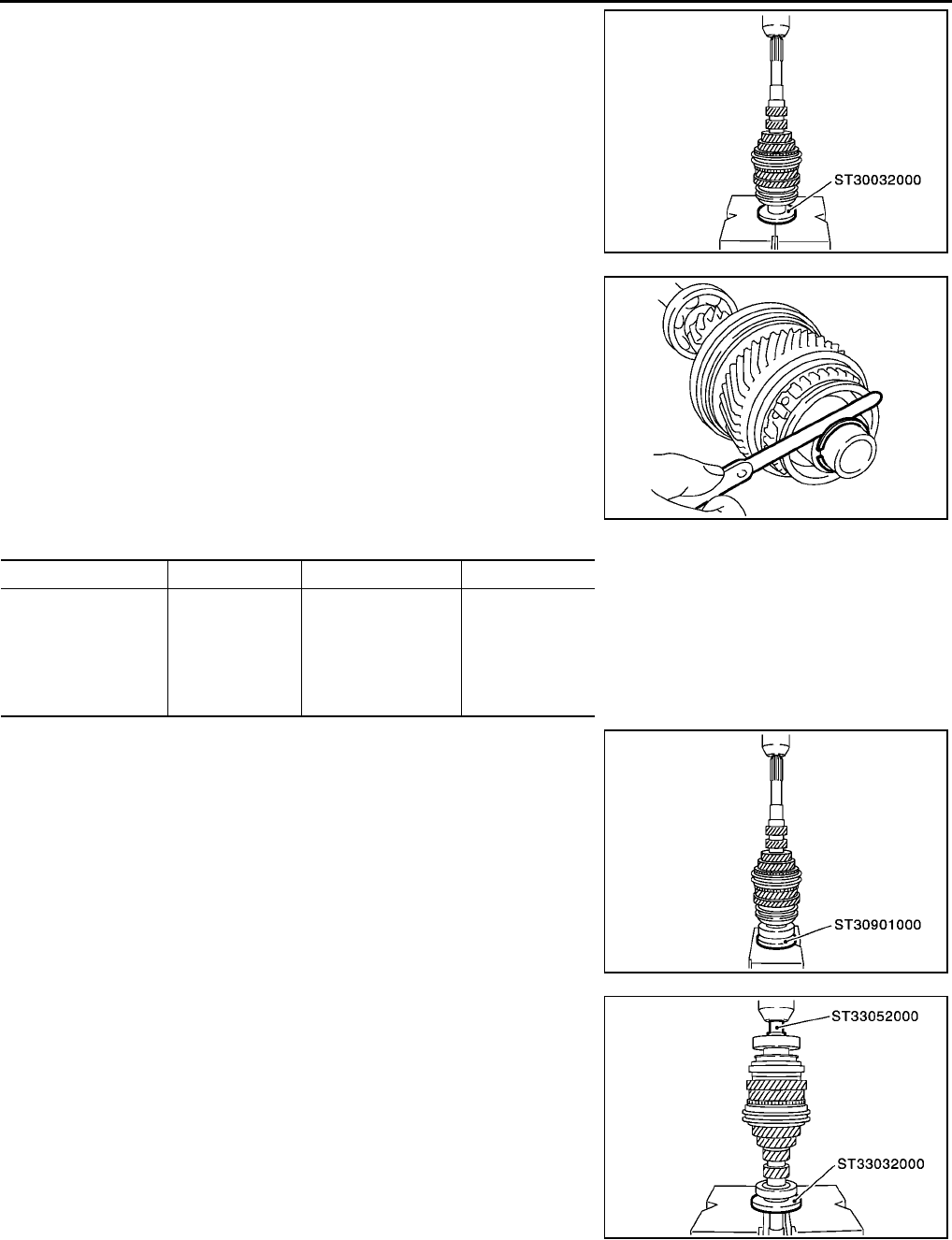
3. Remove input shaft rear bearing.
4. Remove the snap ring.
5. Remove input shaft bearing spacer and 5th stopper simulta-
neously.
End play standard value
3rd gear : 0.18 - 0.31 mm (0.0071 - 0.0122 in)
4th gear : 0.20 - 0.30 mm (0.0079 - 0.0118 in)
5th gear : 0.06 - 0.16 mm (0.0024 - 0.0063 in)
SCIA0914E
SCIA0915E
SCIA0916E
SCIA0917E
INPUT SHAFT AND GEARS
MT-55
D
E
F
G
H
I
J
K
L
M
A
B
MT
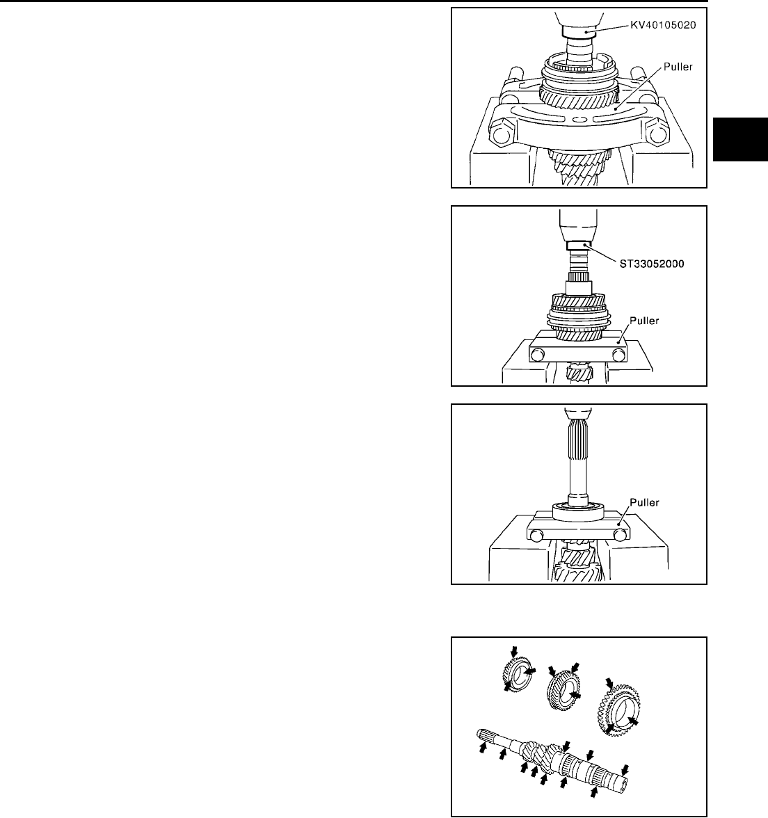
6. Remove 5th input gear and synchronizer hub assembly simulta-
neously.
7. Remove 5th needle bearing.
8. Remove 5th bushing, thrust washer, 4th input gear, 4th needle
bearing, 4th gear bushing, 3rd-4th synchronizer hub assembly,
3rd-4th baulk ring and 3rd input gear simultaneously.
9. Remove 3rd needle bearing.
10. Remove input shaft front bearing.
INSPECTION AFTER DISASSEMBLY
Input Shaft and Gears
Check items below. If necessary, replace them with new ones.
●Damage, peeling, dent, uneven wear, bending, etc. of shaft
●Excessive wear, damage, peeling, etc. of gears
SCIA0918E
SCIA0919E
SCIA0920E
SCIA1073J
MT-56
INPUT SHAFT AND GEARS
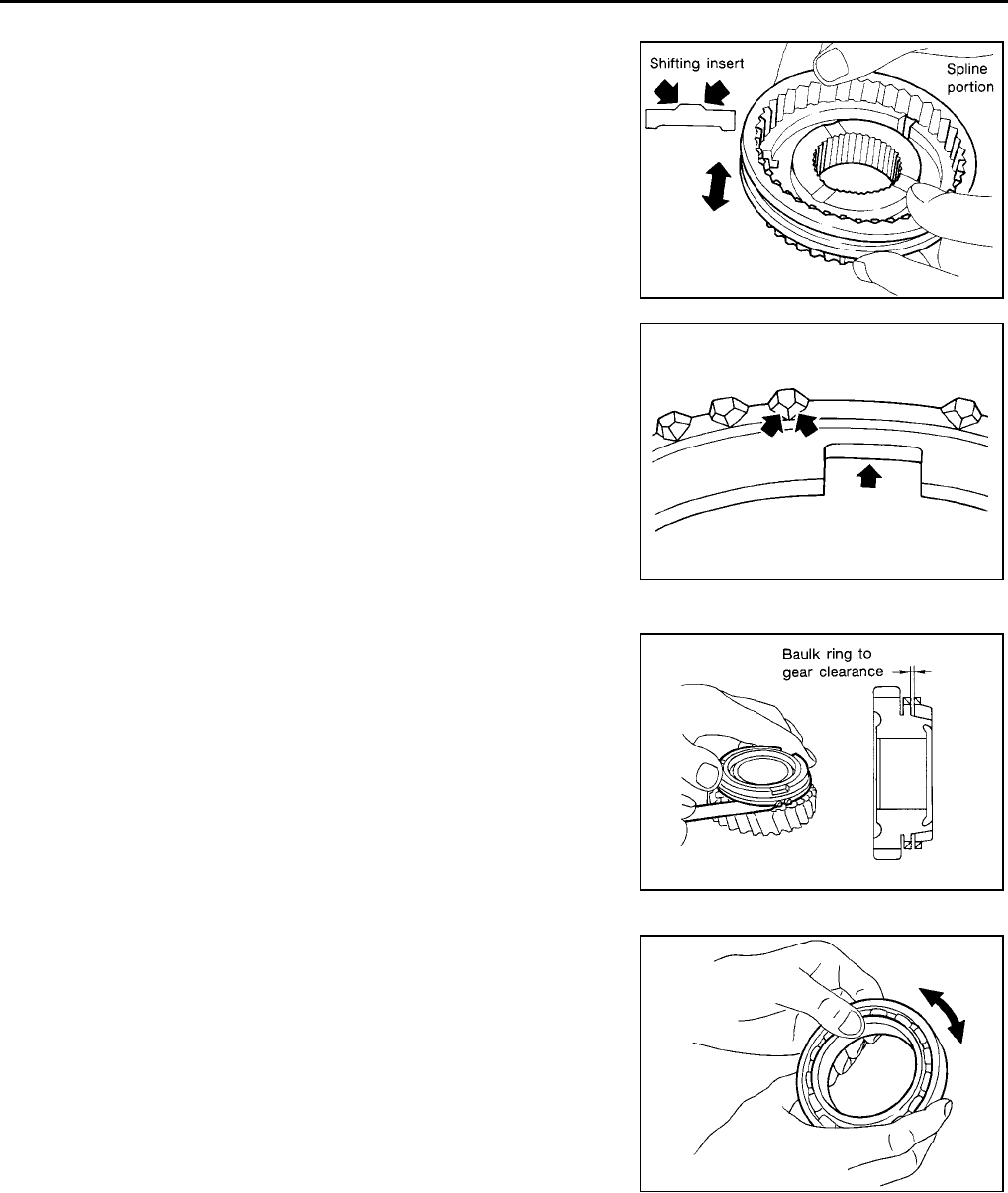
Synchronizer
Check items below. If necessary, replace them with new ones.
●Damage and excessive wear of contact surfaces of coupling
sleeve, synchronizer hub, and shifting insert
●Coupling sleeve and synchronizer hub must move smoothly.
●If any crack, damage, or excessive wear is found on cam face of
baulk ring or working face of insert, replace it.
Baulk ring clearance
●Press baulk ring against cone, and measure clearance between
baulk ring and cone. If measurement is below limit, replace it
with a new one.
Bearing
Check items below. If necessary, replace them with new ones.
●Damage and rough rotation of bearing
SMT387A
SMT867D
Clearance
Standard
3rd and 4th : 0.9 - 1.45 mm (0.0354 - 0.0571 in)
5th : 0.95 - 1.4 mm (0.0374 - 0.0551 in)
Limit value : 0.7 mm (0.0276 in)
SMT140
MTF0041D
INPUT SHAFT AND GEARS
MT-57
D
E
F
G
H
I
J
K
L
M
A
B
MT
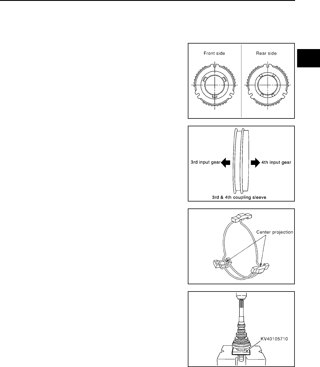
ASSEMBLY
1. Install 3rd needle bearing.
2. Install 3rd input gear and 3rd baulk ring.
3. Install spread spring, shifting insert and 3rd-4th synchronizer hub onto 3rd-4th coupling sleeve.
CAUTION:
●Be careful with orientation of synchronizer hub.
●Do not reuse 3rd-4th synchronizer hub.
●Be careful with orientation of coupling sleeve.
●Be sure not to hook center projection of 2 spread springs
on same shifting insert.
4. Install 3rd-4th synchronizer hub assembly.
CAUTION:
Align grooves of shifting insert and 3rd baulk ring.
SCIA0921E
SCIA0993E
SCIA1083E
SCIA0922E
MT-58
INPUT SHAFT AND GEARS
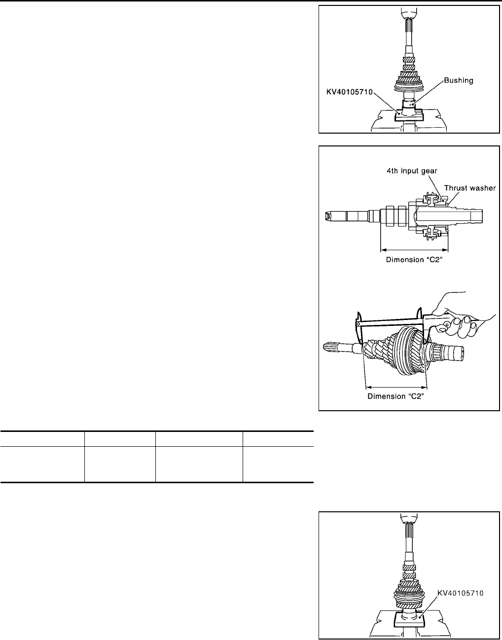
5. Install 4th bushing.
6. Install 4th baulk ring.
7. Install 4th input gear and 4th needle bearing.
8. Select thrust washer so that dimension “C2” satisfies standard
below. Then install it onto input shaft.
Thrust Washer
CAUTION:
Only one thrust washer can be selected.
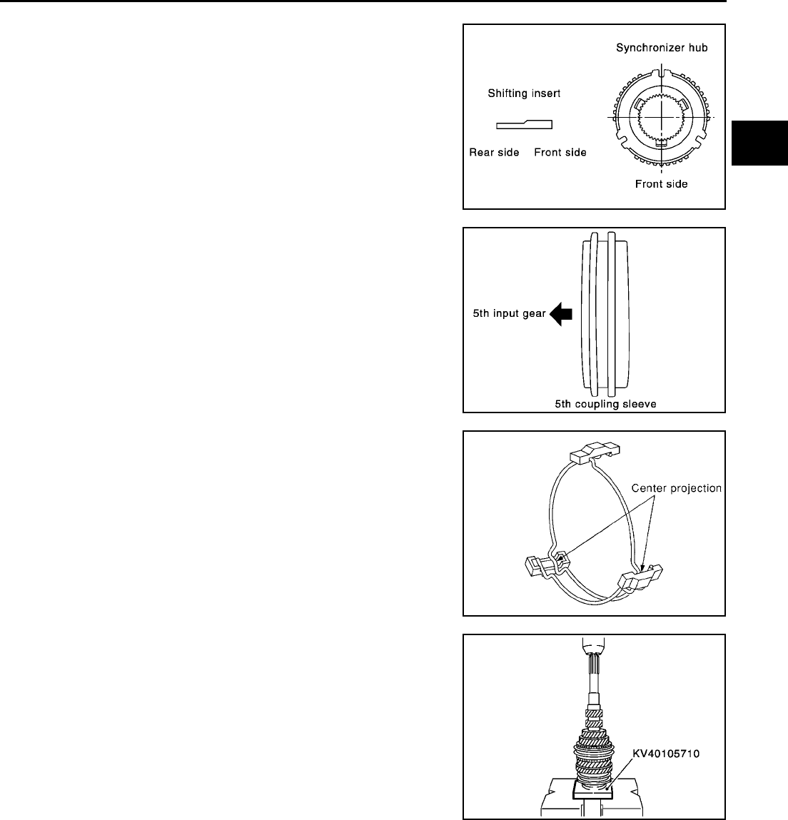
9. Install 5th bushing.
10. Install 5th needle bearing and 5th input gear.
11. Install 5th baulk ring.
12. Install spread spring, shifting insert and 5th synchronizer hub onto 5th coupling sleeve.
SCIA0923E
Standard for dimension C2
: 154.7 - 154.8 mm (6.091 - 6.094 in)
SCIA0925E
Thickness Part number Thickness Part number
3.84mm (0.1512 in)
3.90mm (0.1535 in)
3.96mm (0.1559 in)
32347 8H500
32347 8H501
32347 8H502
4.02mm (0.1583 in)
4.08mm (0.1606 in)
4.14mm (0.1630 in)
32347 8H503
32347 8H504
32347 8H505
SCIA0926E
INPUT SHAFT AND GEARS
MT-59
D
E
F
G
H
I
J
K
L
M
A
B
MT
CAUTION:
●Be careful with orientation of synchronizer hub and shift-
ing insert.
●Be careful with orientation of coupling sleeve.
●Be sure not to hook center projection of 2 spread springs
on same shifting insert.
13. Install 5th synchronizer hub assembly.
CAUTION:
Align grooves of 5th shifting insert and 5th baulk ring.
SCIA0927E
SCIA0994E
SCIA1083E
SCIA0928E
MT-60
INPUT SHAFT AND GEARS
14. Install 5th stopper and then input shaft bearing spacer.
15. Install snap ring onto input shaft, and check that end play (gap
between snap ring and groove) of input shaft bearing spacer
satisfies standard.
●If measurement is outside the standard range, select snap
ring.
Snap Rings
16. Install input shaft rear bearing.
CAUTION:
Install input shaft rear bearing with its brown surface facing
the input gear side.
17. Install input shaft front bearing.
18. Install oil channel onto input shaft.
SCIA0929E
End play standard value : 0 - 0.1 mm (0 - 0.004 in)
SCIA0930E
Thickness Part number Thickness Part number
1.71mm (0.0673 in)
1.76mm (0.0693 in)
1.81mm (0.0713 in)
1.86mm (0.0732 in)
1.91mm (0.0752 in)
1.96mm (0.0772 in)
32204 8H510
32204 8H511
32204 8H512
32204 8H513
32204 8H514
32204 8H515
2.01mm (0.0791 in)
2.06mm (0.0811 in)
2.11mm (0.0831 in)
2.16mm (0.0850 in)
2.21mm (0.0870 in)
2.26mm (0.0890 in)
32204 8H516
32204 8H517
32204 8H518
32204 8H519
32204 8H520
32204 8H521
SCIA0931E
SCIA0932E
INPUT SHAFT AND GEARS
MT-61
D
E
F
G
H
I
J
K
L
M
A
B
MT
19. Check end play of 3rd, 4th, and 5th input gears.
Assembly and Disassembly (RS6F51A) ECS008C5
DISASSEMBLY
1. Before disassembling, measure end play for 3rd, 4th, 5th and
6th input gears.
2. Remove oil channel.
3. Remove input shaft rear bearing.
4. Remove the snap ring.
5. Remove 6th input gear, 6th bushing and 6th needle bearing.
6. Remove 6th baulk ring, 5th-6th coupling sleeve and shifting
insert.
End play standard value
3rd gear : 0.18 - 0.31 mm (0.0071 - 0.0122 in)
4th gear : 0.20 - 0.30 mm (0.0079 - 0.0118 in)
5th gear : 0.06 - 0.16 mm (0.0024 - 0.0063 in)
SCIA0914E
End play standard value
3rd gear : 0.18 - 0.31 mm (0.0071 - 0.0122 in)
4th gear : 0.20 - 0.30 mm (0.0079 - 0.0118 in)
5th gear : 0.06 - 0.16 mm (0.0024 - 0.0063 in)
6th gear : 0.06 - 0.16 mm (0.0024 - 0.0063 in)
SCIA0966E
SCIA0967E
SCIA0968E
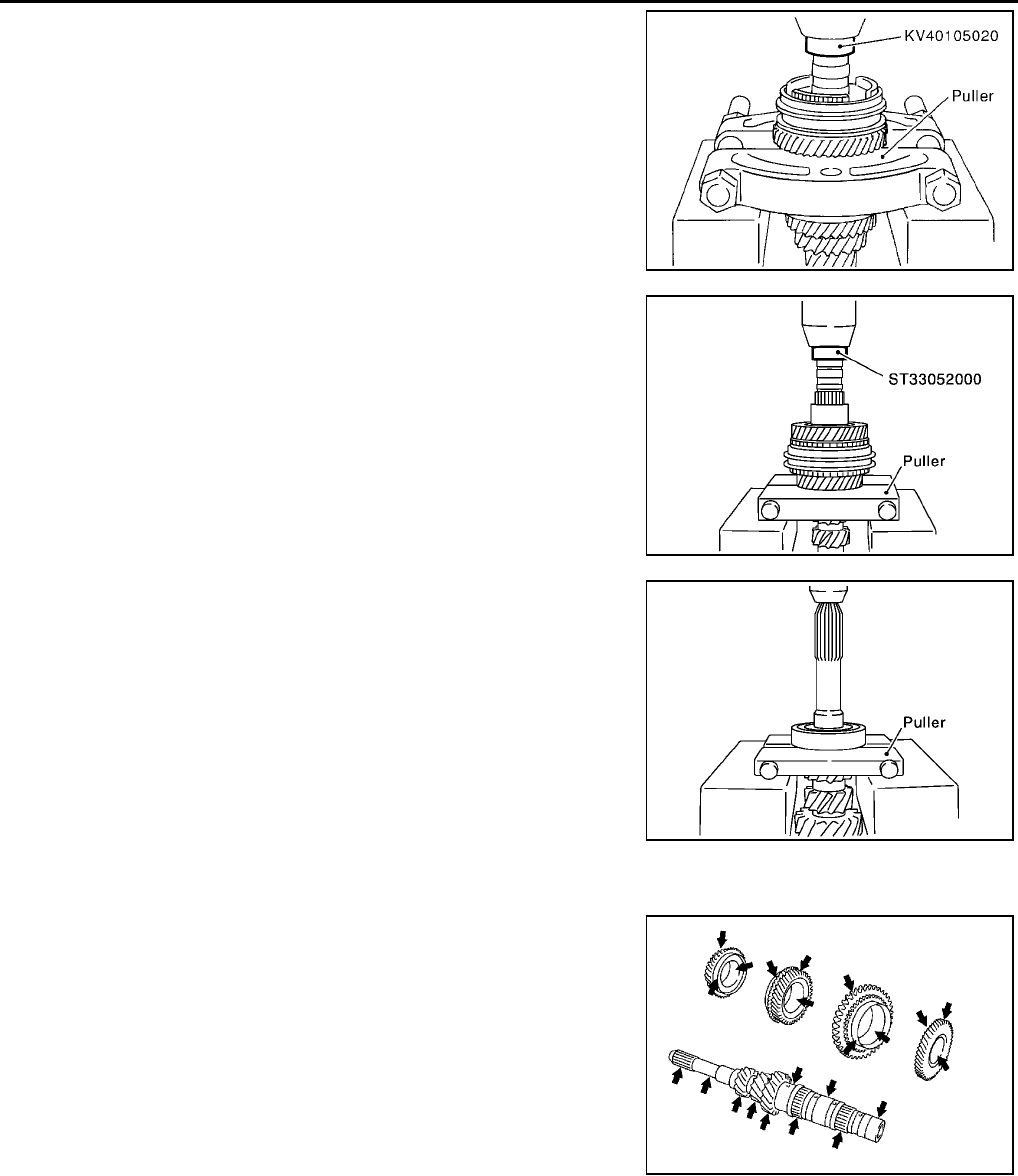
MT-62
INPUT SHAFT AND GEARS
7. Remove 5th input gear and 5th synchronizer hub assembly
simultaneously.
8. Remove 5th needle bearing.
9. Remove 5th bushing, thrust washer, 4th input gear, 4th needle
bearing, 4th gear bushing, 3rd-4th synchronizer hub assembly,
3rd-4th baulk ring and 3rd input gear simultaneously.
10. Remove 3rd needle bearing.
11. Remove input shaft front bearing.
INSPECTION AFTER DISASSEMBLY
Input Shaft and Gears
Check items below. If necessary, replace them with new ones.
●Damage, peeling, dent, uneven wear, bending, etc. of shaft
●Excessive wear, damage, peeling, etc. of gears
SCIA0918E
SCIA0919E
SCIA0920E
SCIA1074J
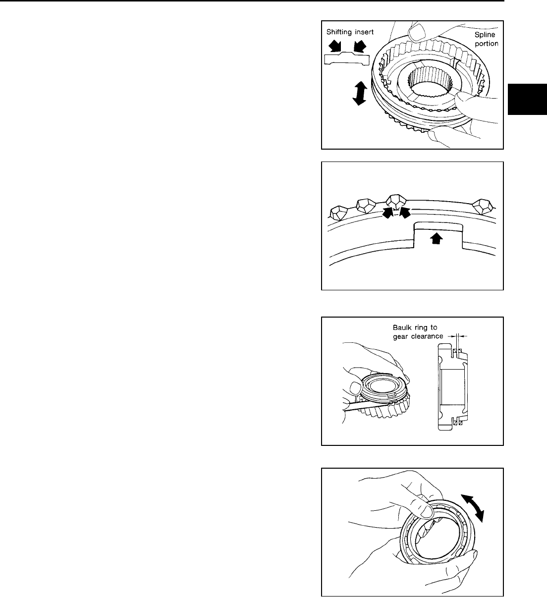
INPUT SHAFT AND GEARS
MT-63
D
E
F
G
H
I
J
K
L
M
A
B
MT
Synchronizer
Check items below. If necessary, replace them with new ones.
●Damage and excessive wear of contact surfaces of coupling
sleeve, synchronizer hub, and shifting insert
●Coupling sleeve and synchronizer hub must move smoothly.
●If any crack, damage, or excessive wear is found on cam face of
baulk ring or working face of insert, replace it.
Baulk ring clearance
●Press baulk ring against cone, and measure clearance between
baulk ring and cone. If measurement is below limit, replace it
with a new one.
Bearing
Check items below. If necessary, replace them with new ones.
●Damage and rough rotation of bearing
SMT387A
SMT867D
Clearance
Standard
3rd and 4th : 0.9 - 1.45 mm (0.0354 - 0.0571 in)
5th and 6th : 0.95 - 1.4 mm (0.0374 - 0.0551 in)
Limit value : 0.7 mm (0.0276 in)
SMT140
MTF0041D
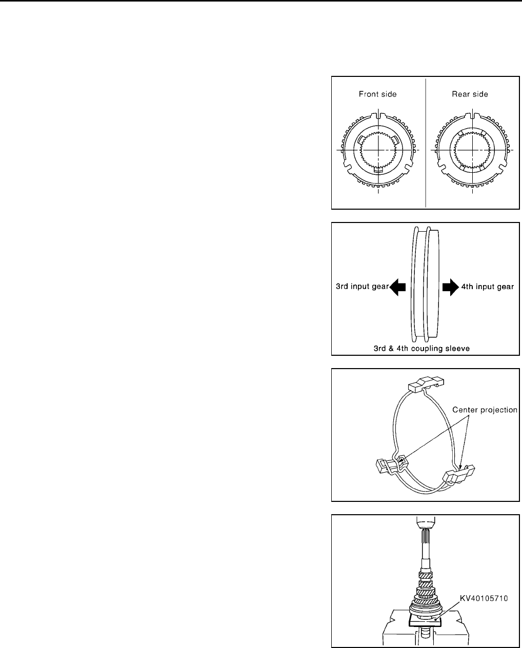
MT-64
INPUT SHAFT AND GEARS
ASSEMBLY
1. Install 3rd needle bearing.
2. Install 3rd input gear and 3rd baulk ring.
3. Install spread spring, shifting insert and 3rd-4th synchronizer hub onto 3rd-4th coupling sleeve.
CAUTION:
●Be careful with orientation of synchronizer hub.
●Do not reuse 3rd-4th synchronizer hub.
●Be careful with orientation of coupling sleeve.
●Be sure not to hook center projection of 2 spread springs
on same shifting insert.
4. Install 3rd-4th synchronizer hub assembly.
CAUTION:
Align grooves of shifting insert and 3rd baulk ring.
SCIA0921E
SCIA0993E
SCIA1083E
SCIA0922E
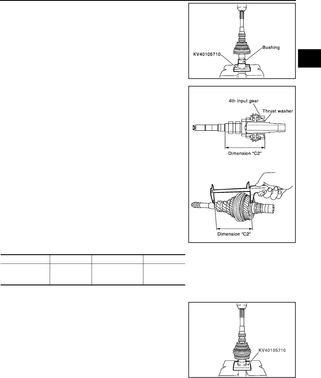
INPUT SHAFT AND GEARS
MT-65
D
E
F
G
H
I
J
K
L
M
A
B
MT
5. Install 4th bushing.
6. Install 4th baulk ring.
7. Install 4th input gear and 4th needle bearing.
8. Select thrust washer so that dimension “C2” satisfies standard
below. Then install it onto input shaft.
Thrust Washer
CAUTION:
Only one thrust washer can be selected.
9. Install 5th bushing.
10. Install 5th needle bearing and 5th input gear.
11. Install 5th baulk ring.
12. Install 5th-6th synchronizer hub, spread spring and shifting insert onto 5th-6th coupling sleeve.
SCIA0923E
Standard for dimension C2
: 154.7 - 154.8 mm (6.091 - 6.094 in)
SCIA0925E
Thickness Part number Thickness Part number
3.84mm (0.1512 in)
3.90mm (0.1535 in)
3.96mm (0.1559 in)
32347 8H500
32347 8H501
32347 8H502
4.02mm (0.1583 in)
4.08mm (0.1606 in)
4.14mm (0.1630 in)
32347 8H503
32347 8H504
32347 8H505
SCIA0926E
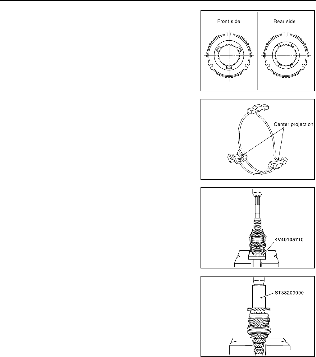
MT-66
INPUT SHAFT AND GEARS
CAUTION:
●Be careful with orientation of synchronizer hub.
●Do not reuse 5th-6th synchronizer hub.
●Be sure not to hook center projection of 2 spread springs
on same shifting insert.
13. Install 5th-6th synchronizer hub assembly.
CAUTION:
Align grooves of 5th-6th shifting insert and 5th-6th baulk
ring.
14. Install 6th needle bearing, 6th input gear onto 6th bushing, and
then install them onto input shaft.
SCIA0921E
SCIA1083E
SCIA0928E
SCIA0969E
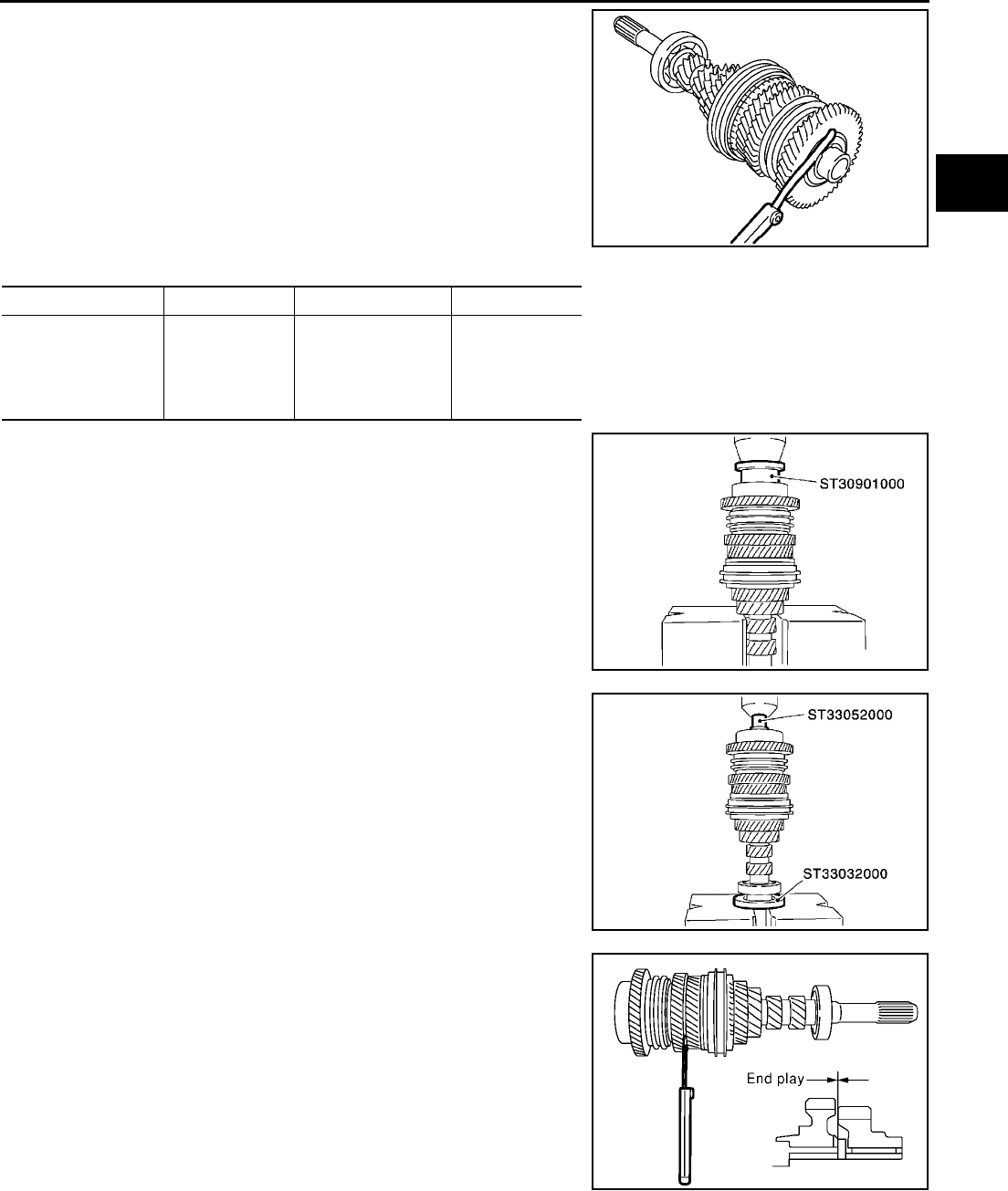
INPUT SHAFT AND GEARS
MT-67
D
E
F
G
H
I
J
K
L
M
A
B
MT
15. Install snap ring onto input shaft, and check that end play (gap
between snap ring and groove) of 6th bushing satisfies stan-
dard.
●If measurement is outside the standard range, select snap
ring.
Snap Rings
16. Install input shaft rear bearing.
CAUTION:
Install input shaft rear bearing with its brown surface facing
the 6th input gear side.
17. Install input shaft front bearing.
18. Install oil channel onto input shaft.
19. Check end play of 3rd, 4th, 5th and 6th input gears.
End play standard value : 0 - 0.1 mm (0 - 0.004 in)
SCIA0970E
Thickness Part number Thickness Part number
1.76 mm (0.0693 in)
1.81 mm (0.0713 in)
1.86 mm (0.0732 in)
1.91 mm (0.0752 in)
1.96 mm (0.0772 in)
32204 8H511
32204 8H512
32204 8H513
32204 8H514
32204 8H515
2.01 mm (0.0791 in)
2.06 mm (0.0811 in)
2.11 mm (0.0831 in)
2.16 mm (0.0850 in)
2.21 mm (0.0870 in)
32204 8H516
32204 8H517
32204 8H518
32204 8H519
32204 8H520
SCIA0971E
SCIA0972E
End play standard value
3rd gear : 0.18 - 0.31 mm (0.0071 - 0.0122 in)
4th gear : 0.20 - 0.30 mm (0.0079 - 0.0118 in)
5th gear : 0.06 - 0.16 mm (0.0024 - 0.0063 in)
6th gear : 0.06 - 0.16 mm (0.0024 - 0.0063 in)
SCIA0966E
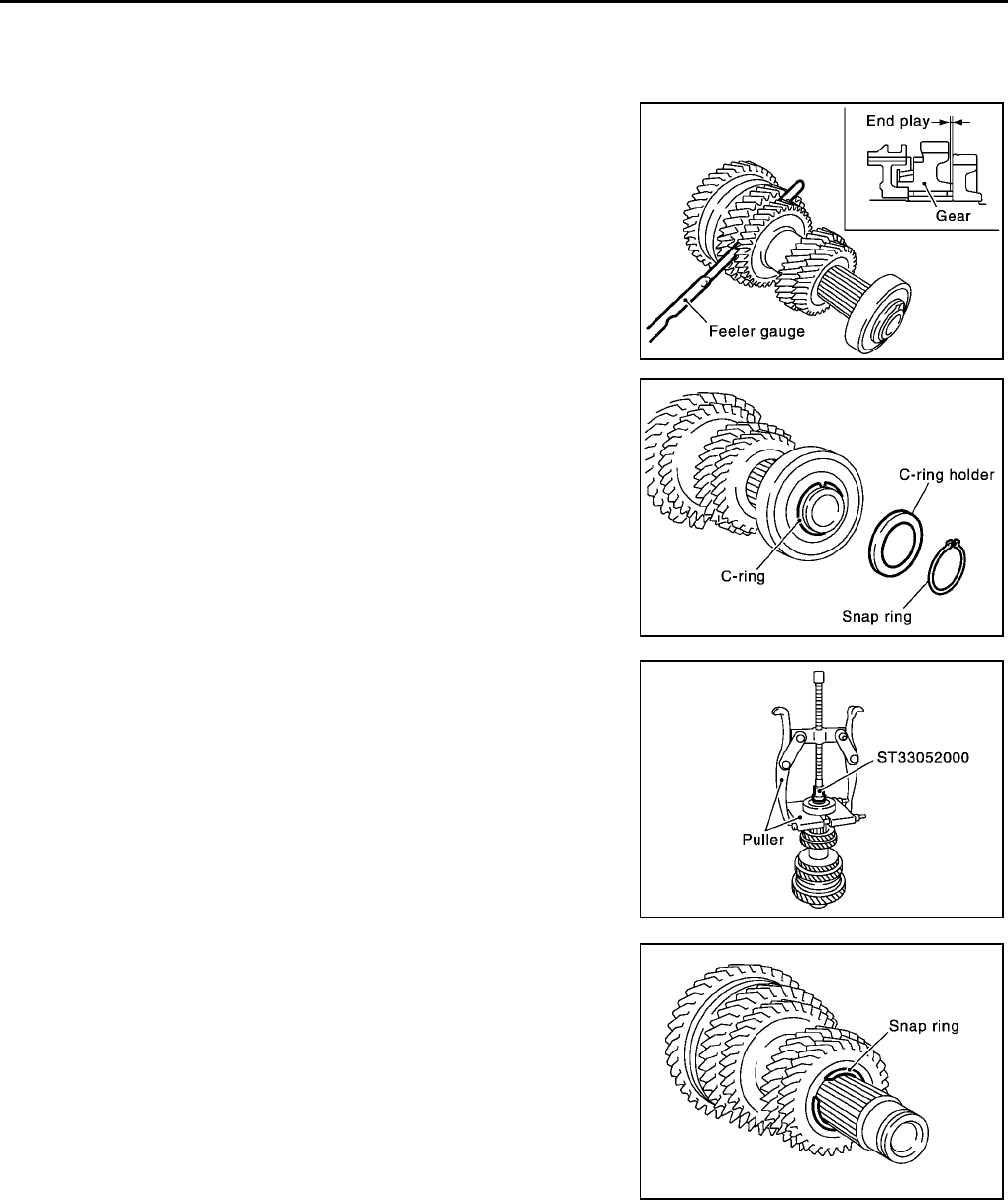
MT-68
MAINSHAFT AND GEARS
MAINSHAFT AND GEARS PFP:32241
Assembly and Disassembly (RS5F51A) ECS008C6
DISASSEMBLY
1. Before disassembling, measure end play of 1st and 2nd main
gears.
2. Remove the snap ring.
3. Remove C-ring holder, and then mainshaft C-ring.
4. Remove mainshaft rear bearing.
5. Remove the snap ring.
End play standard value
1st gear : 0.20 - 0.30 mm (0.0079 - 0.0118 in)
2nd gear : 0.06 - 0.16 mm (0.0024 - 0.0063 in)
SCIA0933E
SCIA0934E
SCIA0935E
SCIA0936E
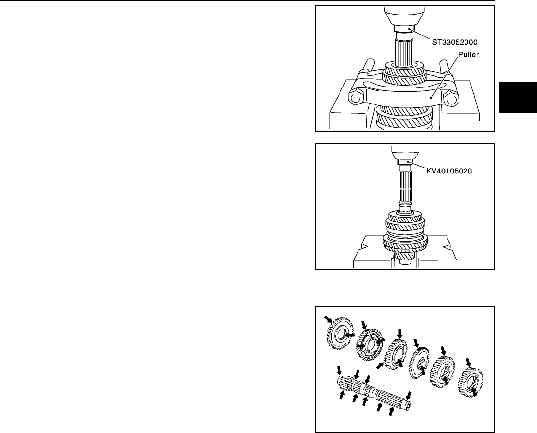
MAINSHAFT AND GEARS
MT-69
D
E
F
G
H
I
J
K
L
M
A
B
MT
6. Remove 4th main gear and 5th main gear simultaneously.
7. Remove adjusting shim.
8. Remove 3rd-4th mainshaft spacer.
9. Remove 3rd main gear, 2nd main gear, 2nd gear needle bear-
ing, 2nd bushing, 1st-2nd synchronizer hub assembly, 1st main
gear, reverse main gear, 1st gear needle bearing, and 1st bush-
ing simultaneously.
INSPECTION AFTER DISASSEMBLY
Mainshaft and Gears
Check items below. If necessary, replace them with new ones.
●Damage, peeling, dent, uneven wear, bending, and other non-
standard conditions of the shaft.
●Excessive wear, damage, peeling, and other non-standard con-
ditions of the gears.
SCIA0937E
SCIA0938E
SCIA1075J
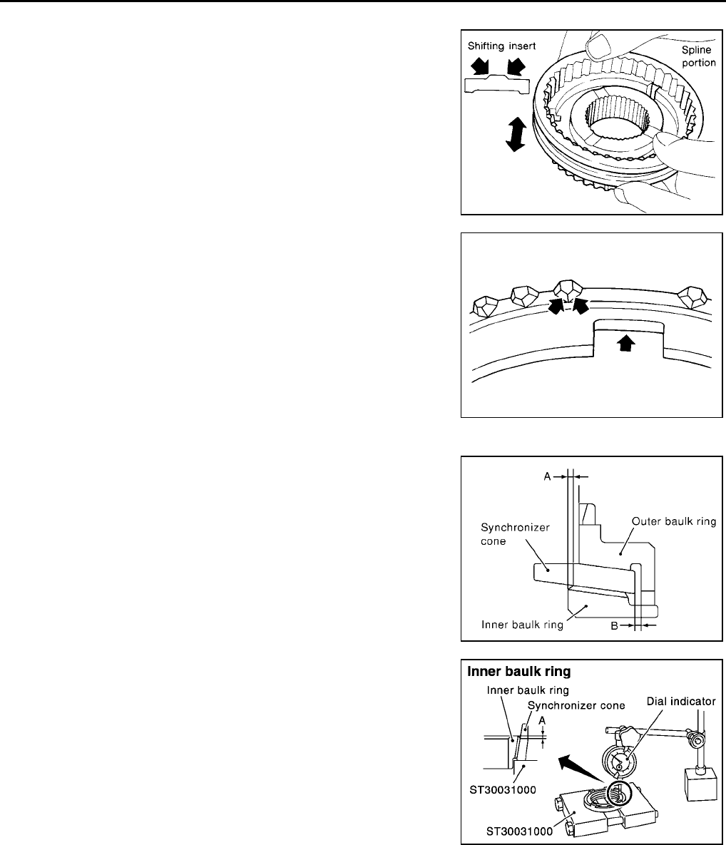
MT-70
MAINSHAFT AND GEARS
Synchronizer
Check items below. If necessary, replace them with new ones.
●Damage and unusual wear on contact surfaces of coupling
sleeve, synchronizer hub, and shifting insert.
●Coupling sleeve and synchronizer hub must move smoothly.
●If any crack, damage, or excessive wear is found on cam face of
baulk ring or working face of insert, replace it.
Baulk ring clearance
●Double cone synchronizer (1st and 2nd)
Check clearance of outer baulk ring, synchronizer cone, and
inner baulk ring of 1st and 2nd double cone synchronizers, fol-
lowing procedure below.
CAUTION:
Outer baulk ring, synchronizer cone, and inner baulk ring
as a set control clearance A and B. If measurement exceeds
service limit value, replace all of them as a set.
1. Using a dial gauge, measure clearance A at 2 or more points
diagonally opposite, and calculate mean value.
SMT387A
SMT867D
SCIA0950E
Clearance A
Standard : 0.6 - 0.8 mm (0.024 - 0.031 in)
Limit value : 0.2 mm (0.008 in) or less
SCIA0951E
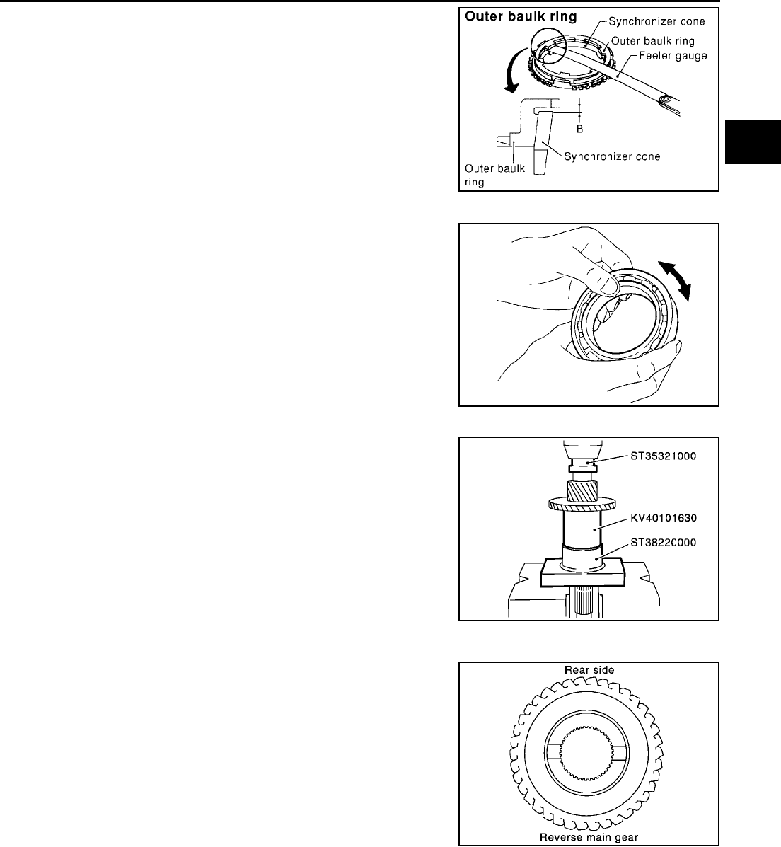
MAINSHAFT AND GEARS
MT-71
D
E
F
G
H
I
J
K
L
M
A
B
MT
2. Using a feeler gauge, measure clearance B at 2 or more points
diagonally opposite, and calculate mean value.
Bearing
Check items below. If necessary, replace them with new ones.
●Damage and rough rotation of bearing
ASSEMBLY
1. Install reverse main gear.
CAUTION:
Be careful with orientation of reverse main gear.
Clearance B
Standard : 0.6 - 1.1 mm (0.024 - 0.043 in)
Limit value : 0.2 mm (0.008 in) or less
SCIA1084E
MTF0041D
SCIA0939E
SCIA0992E
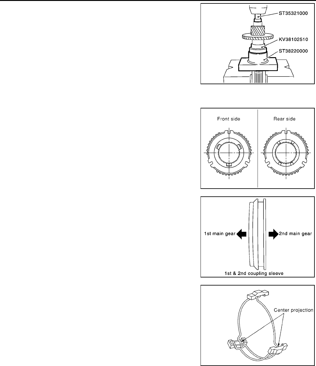
MT-72
MAINSHAFT AND GEARS
2. Install 1st bushing.
3. Install needle bearing, and then 1st main gear.
4. Install spread spring, shifting insert and 1st-2nd synchronizer hub onto 1st-2nd coupling sleeve.
CAUTION:
●Be careful with orientation of synchronizer hub.
●Do not reuse 1st-2nd synchronizer hub.
●Be careful with orientation of coupling sleeve.
●Be sure not to hook center projection of 2 spread springs
on same shifting insert.
SCIA0940E
SCIA0921E
SCIA0989E
SCIA1083E
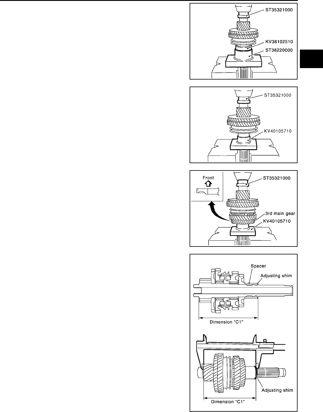
MAINSHAFT AND GEARS
MT-73
D
E
F
G
H
I
J
K
L
M
A
B
MT
5. Install 1st gear synchronizer assembly onto mainshaft, and syn-
chronizer hub assembly onto mainshaft.
CAUTION:
●Outer baulk ring, synchronizer cone, and inner baulk ring
on 2nd gear-side must have been removed.
●Be careful with orientation of coupling sleeve.
6. Install 2nd bushing.
7. Install outer baulk ring, synchronizer cone, and inner baulk ring
on 2nd gear-side.
8. Install 2nd needle bearing and 2nd gear.
9. Install 3rd main gear.
CAUTION:
Be careful with orientation of 3rd main gear.
10. Install 3rd-4th mainshaft spacer.
11. Select suitable adjusting shim so that dimension “C1” satisfies
standard value below, and install it onto mainshaft.
SCIA0941E
SCIA0942E
SCIA0943E
Standard for dimension C1
: 173.85 - 173.95 mm (6.844 - 6.848 in)
SCIA0944E
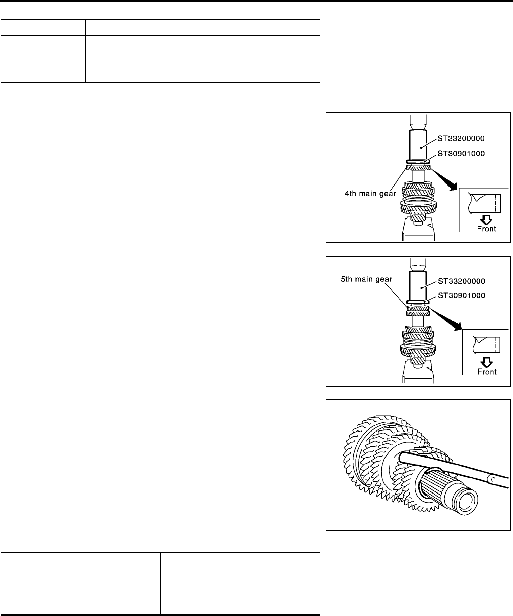
MT-74
MAINSHAFT AND GEARS
Adjusting Shim
CAUTION:
Only one adjusting shim can be selected.
12. Install 4th main gear.
CAUTION:
Be careful with orientation of 4th main gear.
13. Install 5th main gear.
CAUTION:
Be careful with orientation of 5th main gear.
14. Install snap ring onto mainshaft, and check that end play of 5th
main gear satisfies standard value.
●If measurement is outside the standard range, reselect snap
ring.
Snap Rings
Thickness Part number Thickness Part number
0.52 mm (0.0205 in)
0.60 mm (0.0236 in)
0.68 mm (0.0268 in)
0.76 mm (0.0299 in)
32238 8H500
32238 8H501
32238 8H502
32238 8H503
0.84 mm (0.0331 in)
0.92 mm (0.0362 in)
1.00 mm (0.0394 in)
1.08 mm (0.0425 in)
32238 8H504
32238 8H505
32238 8H506
32238 8H507
SCIA0945E
SCIA0946E
End play standard value : 0 - 0.1 mm (0 - 0.004 in)
SCIA0947E
Thickness Part number Thickness Part number
1.85 mm (0.0728 in)
1.90 mm (0.0748 in)
1.95 mm (0.0768 in)
2.00 mm (0.0787 in)
32204 8H500
32204 8H501
32204 8H502
32204 8H503
2.05 mm (0.0807 in)
2.10 mm (0.0827 in)
2.15 mm (0.0846 in)
2.20 mm (0.0866 in)
32204 8H504
32204 8H505
32204 8H506
32204 8H507
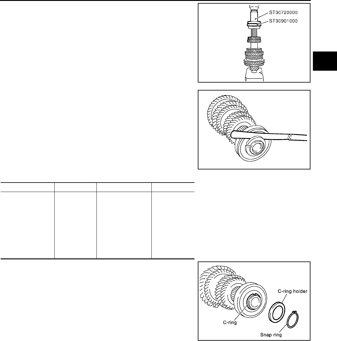
MAINSHAFT AND GEARS
MT-75
D
E
F
G
H
I
J
K
L
M
A
B
MT
15. Install mainshaft rear bearing.
16. Install C-ring onto mainshaft, and check that end play of main-
shaft rear bearing satisfies standard value.
●If measurement is outside the standard range, reselect C-ring.
C-ring
17. Fit C-ring holder, and install snap ring.
18. Check end play of 1st and 2nd main gears.
SCIA0948E
End play standard value : 0 - 0.06 mm (0 - 0.0024 in)
SCIA0949E
Thickness Part number Thickness Part number
2.535 mm (0.0866 in)
2.565 mm (0.1010 in)
2.595 mm (0.1022 in)
2.625 mm (0.1033 in)
2.655 mm (0.1045 in)
2.685 mm (0.1057 in)
2.715 mm (0.1069 in)
2.745 mm (0.1081 in)
2.775 mm (0.1093 in)
2.805 mm (0.1104 in)
32348 8H800
32348 8H801
32348 8H802
32348 8H803
32348 8H804
32348 8H805
32348 8H806
32348 8H807
32348 8H808
32348 8H809
2.835 mm (0.1116 in)
2.865 mm (0.1128 in)
2.895 mm (0.1140 in)
2.925 mm (0.1152 in)
2.955 mm (0.1163 in)
2.985 mm (0.1175 in)
3.015 mm (0.1187 in)
3.045 mm (0.1199 in)
3.075 mm (0.1211 in)
32348 8H810
32348 8H811
32348 8H812
32348 8H813
32348 8H814
32348 8H815
32348 8H816
32348 8H817
32348 8H818
End play standard value
1st gear : 0.20 - 0.30 mm (0.0079 - 0.0118 in)
2nd gear : 0.06 - 0.16 mm (0.0024 - 0.0063 in)
SCIA0934E
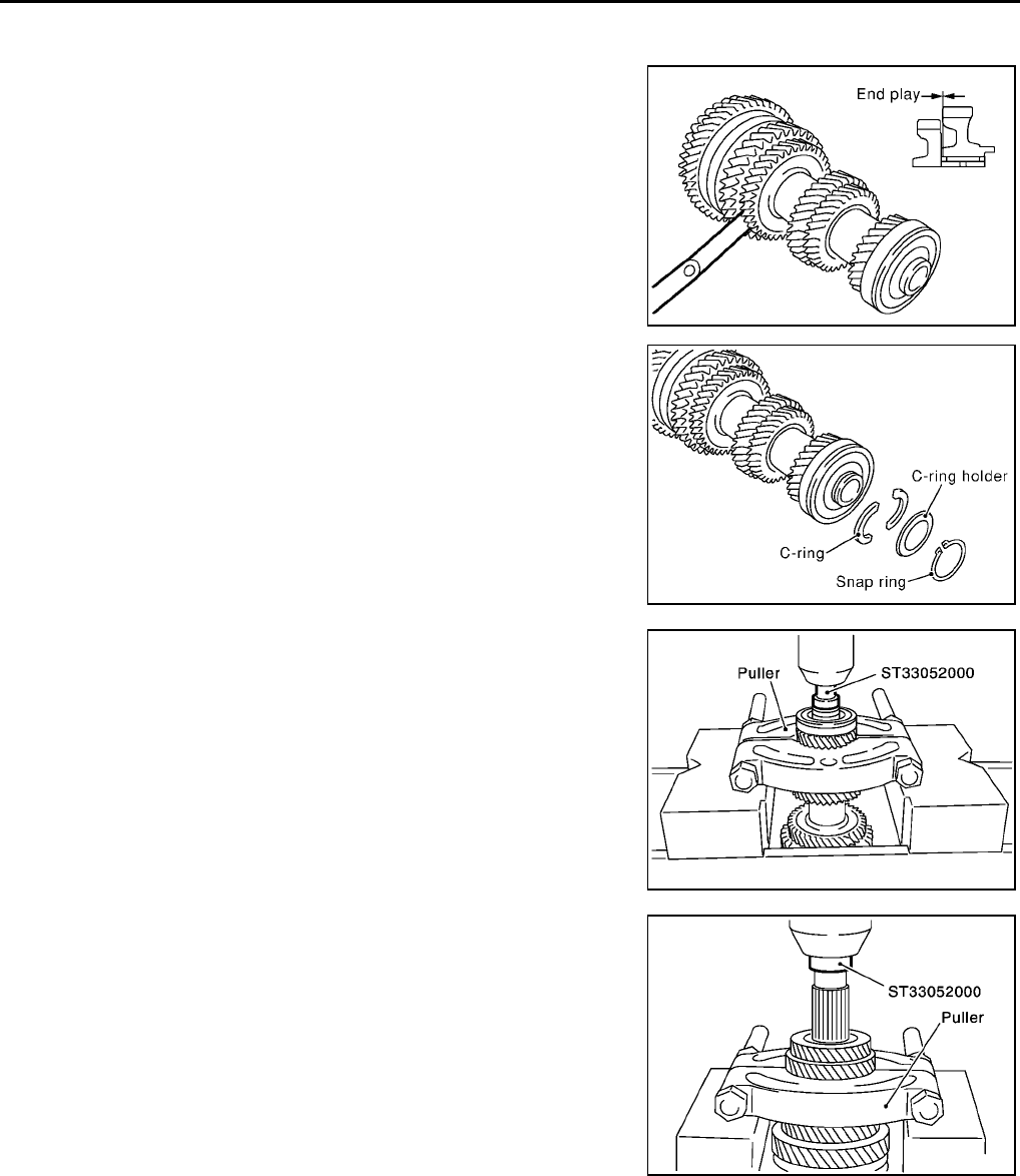
MT-76
MAINSHAFT AND GEARS
Assembly and Disassembly (RS6F51A) ECS008C7
DISASSEMBLY
1. Before disassembling, measure end play of 1st and 2nd main
gears.
2. Remove the snap ring.
3. Remove C-ring holder, and then mainshaft C-ring.
4. Remove mainshaft rear bearing, adjust shim and 6th main gear.
5. Remove 5th-6th mainshaft spacer.
6. Remove 4th main gear and 5th main gear simultaneously.
7. Remove adjusting shim.
8. Remove 3rd & 4th mainshaft spacer.
End play standard value
1st gear : 0.20 - 0.30 mm (0.0079 - 0.0118 in)
2nd gear : 0.06 - 0.16 mm (0.0024 - 0.0063 in)
SCIA0973E
SCIA0974E
SCIA0976E
SCIA0937E
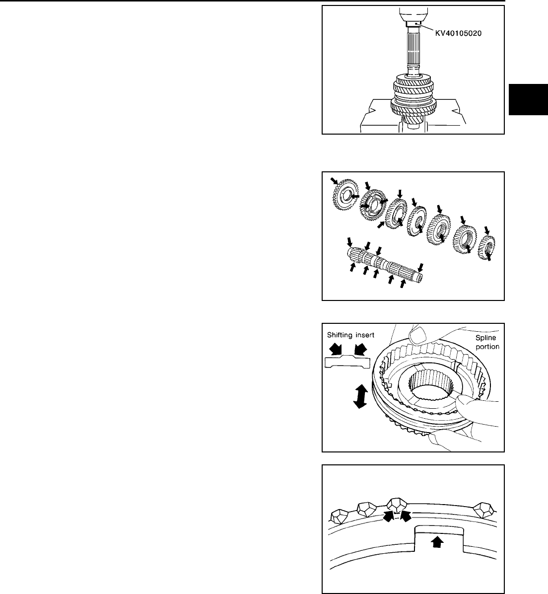
MAINSHAFT AND GEARS
MT-77
D
E
F
G
H
I
J
K
L
M
A
B
MT
9. Remove 3rd main gear, 2nd main gear, 2nd gear needle bear-
ing, 2nd bushing, 1st-2nd synchronizer hub assembly, 1st main
gear, reverse main gear, 1st gear needle bearing, and 1st bush-
ing simultaneously.
INSPECTION AFTER DISASSEMBLY
Mainshaft and Gears
Check items below. If necessary, replace them with new ones.
●Damage, peeling, dent, uneven wear, bending, and other non-
standard conditions of the shaft.
●Excessive wear, damage, peeling, and other non-standard con-
ditions of the gears.
Synchronizer
Check items below. If necessary, replace them with new ones.
●Damage and unusual wear on contact surfaces of coupling
sleeve, synchronizer hub, and shifting insert.
●Coupling sleeve and synchronizer hub must move smoothly.
●If any crack, damage, or excessive wear is found on cam face of
baulk ring or working face of insert, replace it.
SCIA0938E
SCIA1076J
SMT387A
SMT867D
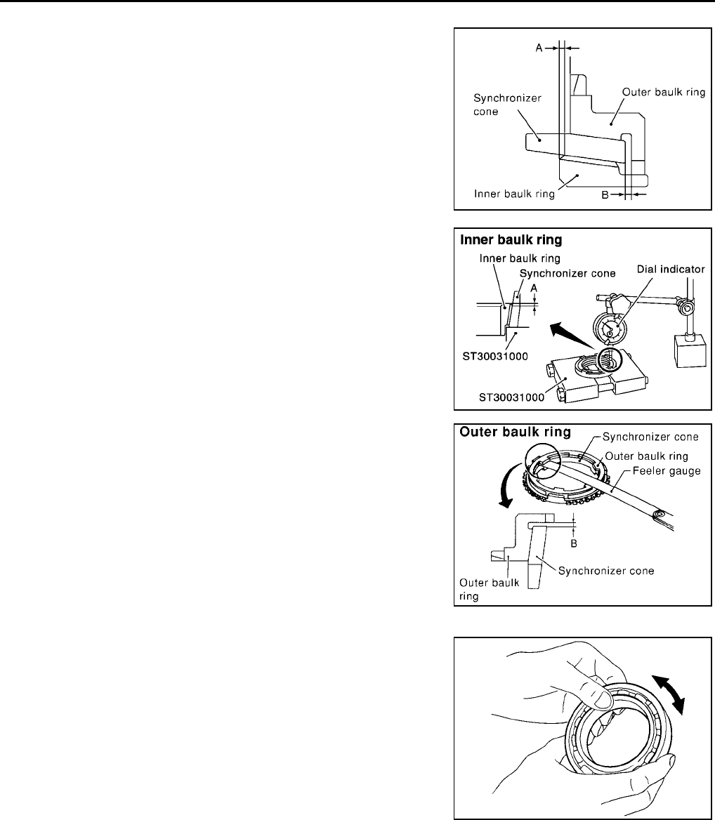
MT-78
MAINSHAFT AND GEARS
Baulk ring clearance
●Double cone synchronizer (1st and 2nd)
Check clearance of outer baulk ring, synchronizer cone, and
inner baulk ring of 1st and 2nd double cone synchronizers, fol-
lowing procedure below.
CAUTION:
Outer baulk ring, synchronizer cone, and inner baulk ring
as a set control clearance A and B. If measurement exceeds
service limit value, replace all of them as a set.
1. Using a dial gauge, measure clearance A at 2 or more points
diagonally opposite, and calculate mean value.
2. Using a feeler gauge, measure clearance B at 2 or more points
diagonally opposite, and calculate mean value.
Bearing
Check items below. If necessary, replace them with new ones.
●Damage and rough rotation of bearing
SCIA0950E
Clearance A
Standard : 0.6 - 0.8 mm (0.024 - 0.031 in)
Limit value : 0.2 mm (0.008 in) or less
SCIA0951E
Clearance B
Standard : 0.6 - 1.1 mm (0.024 - 0.043 in)
Limit value : 0.2 mm (0.008 in) or less
SCIA1084E
MTF0041D
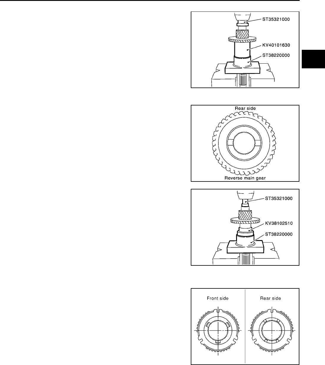
MAINSHAFT AND GEARS
MT-79
D
E
F
G
H
I
J
K
L
M
A
B
MT
ASSEMBLY
1. Install reverse main gear.
CAUTION:
Be careful with orientation of reverse main gear.
2. Install 1st bushing.
3. Install needle bearing, and then 1st main gear.
4. Install spread spring, shifting insert and 1st-2nd synchronizer hub onto 1st-2nd coupling sleeve.
CAUTION:
●Be careful with orientation of synchronizer hub.
●Do not reuse 1st-2nd synchronizer hub.
SCIA0939E
SCIA0992E
SCIA0940E
SCIA0921E
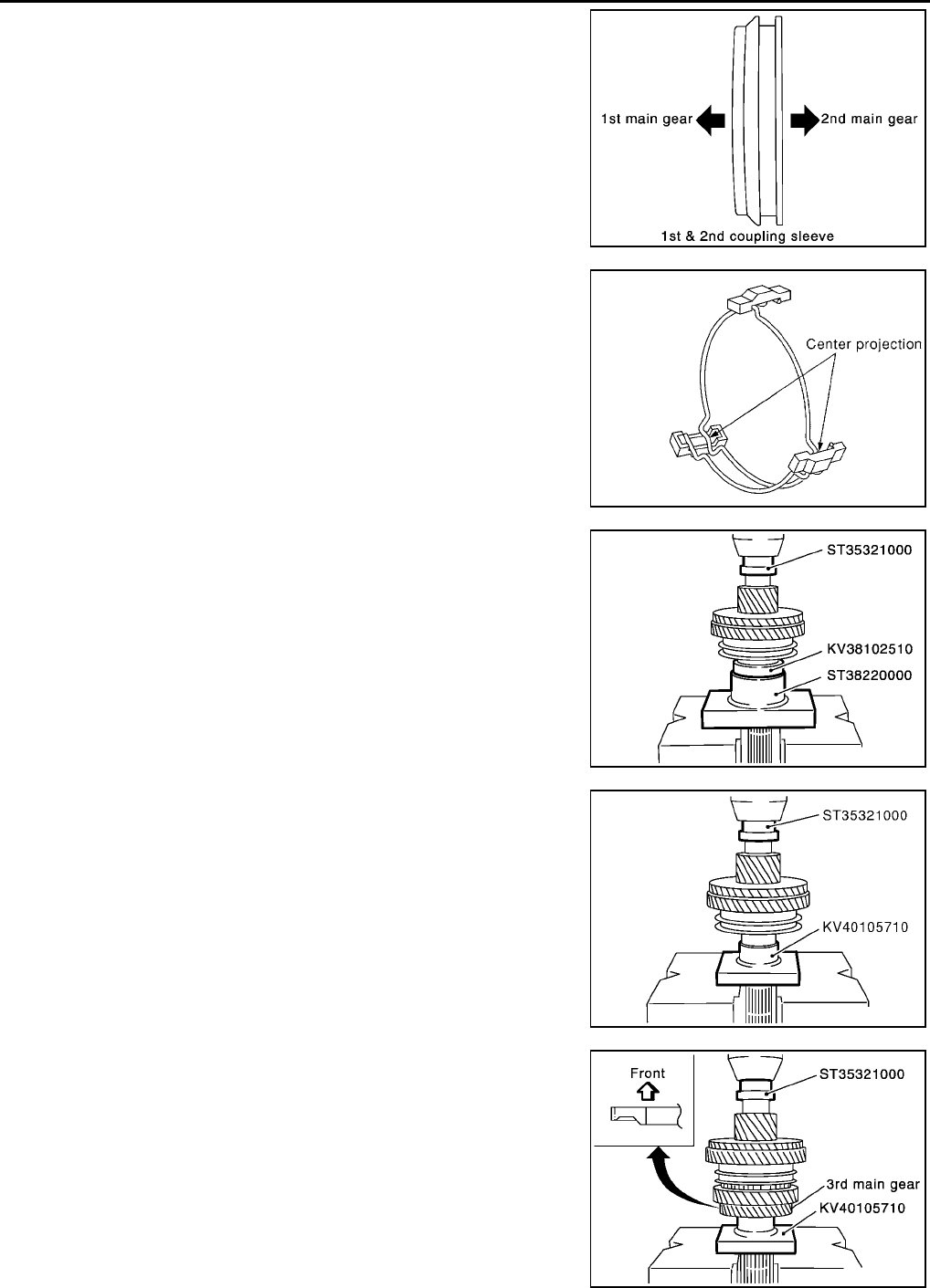
MT-80
MAINSHAFT AND GEARS
●Be careful with orientation of coupling sleeve.
●Be sure not to hook center projection of 2 spread springs
on same shifting insert.
5. Install 1st gear synchronizer assembly onto mainshaft, and syn-
chronizer hub assembly onto mainshaft.
CAUTION:
●Outer baulk ring, synchronizer cone, and inner baulk ring
on 2nd gear-side must have been removed.
●Be careful with orientation of coupling sleeve.
6. Install 2nd bushing.
7. Install outer baulk ring, synchronizer cone, and inner baulk ring
on 2nd gear-side.
8. Install 2nd needle bearing and 2nd gear.
9. Install 3rd main gear.
CAUTION:
Be careful with orientation of 3rd main gear.
10. Install 3rd-4th mainshaft spacer.
SCIA0989E
SCIA1083E
SCIA0941E
SCIA0942E
SCIA0943E
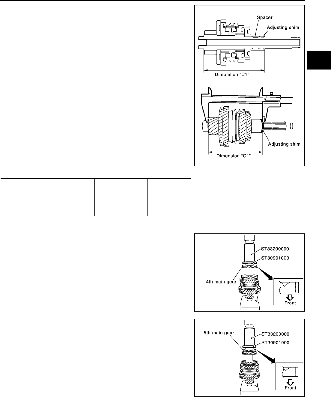
MAINSHAFT AND GEARS
MT-81
D
E
F
G
H
I
J
K
L
M
A
B
MT
11. Select suitable adjusting shim so that dimension “C1” satisfies
standard value below, and install it onto mainshaft.
Adjusting Shim
CAUTION:
Only one adjusting shim can be selected.
12. Install 4th main gear.
CAUTION:
Be careful with orientation of 4th main gear.
13. Install 5th main gear.
CAUTION:
Be careful with orientation of 5th main gear.
14. Install 5th-6th mainshaft spacer.
Standard for dimension C1
: 173.85 - 173.95 mm (6.844 - 6.848 in)
SCIA0944E
Thickness Part number Thickness Part number
0.52 mm (0.0205 in)
0.60 mm (0.0236 in)
0.68 mm (0.0268 in)
0.76 mm (0.0299 in)
32238 8H500
32238 8H501
32238 8H502
32238 8H503
0.84 mm (0.0331 in)
0.92 mm (0.0362 in)
1.00 mm (0.0394 in)
1.08 mm (0.0425 in)
32238 8H504
32238 8H505
32238 8H506
32238 8H507
SCIA0945E
SCIA0946E
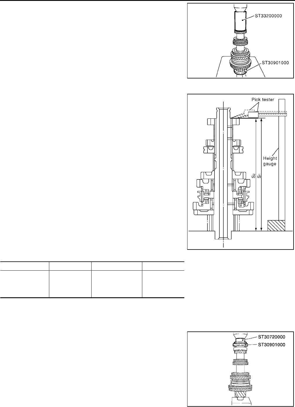
MT-82
MAINSHAFT AND GEARS
15. Install 6th main gear.
16. Select 6th main adjusting shim and then install it onto mainshaft.
●Calculate thickness “S” of 6th main adjusting shim by proce-
dure below so that end play dimension between 6th main
gear and mainshaft rear bearing becomes the dimension
shown below.
Adjusting Shim
CAUTION:
Only one adjusting shim can be selected.
a. Using height gauge, measure dimension “S1 ” and “S2 ”.
b. Install selected 6th main adjusting shim to mainshaft.
17. Install mainshaft rear bearing.
SCIA0977E
End play: 0 - 0.1 mm (0 - 0.004 in)
Dimension“S” = (S1 - S2 ) + End play
S: Thickness of adjusting shim
S1 : Dimension from mainshaft standard face to
mainshaft rear bearing press-fit end face
S2 : Dimension from mainshaft standard face to
6th main gear end face
SCIA0995E
Thickness Part number Thickness Part number
0.88 mm (0.0346 in)
0.96 mm (0.0378 in)
1.04 mm (0.0409 in)
1.12 mm (0.0441 in)
32237 8H560
32237 8H561
32237 8H562
32237 8H563
1.20 mm (0.0472 in)
1.28 mm (0.0504 in)
1.36 mm (0.0535 in)
32237 8H564
32237 8H565
32237 8H566
SCIA0978E
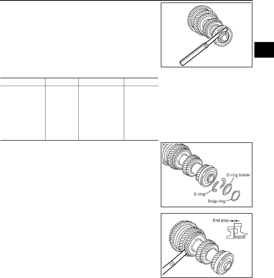
MAINSHAFT AND GEARS
MT-83
D
E
F
G
H
I
J
K
L
M
A
B
MT
18. Install C-ring onto mainshaft, and check that end play of main-
shaft rear bearing satisfies standard value.
●If measurement is outside the standard range, reselect C-ring.
C-ring
19. Fit C-ring holder, and install snap ring.
20. Check end play of 1st and 2nd main gears.
End play standard value : 0 - 0.06 mm (0 - 0.0024 in)
SCIA0979E
Thickness Part number Thickness Part number
2.535 mm (0.0998 in)
2.565 mm (0.1010 in)
2.595 mm (0.1022 in)
2.625 mm (0.1033 in)
2.655 mm (0.1045 in)
2.685 mm (0.1057 in)
2.715 mm (0.1069 in)
2.745 mm (0.1081 in)
2.775 mm (0.1093 in)
2.805 mm (0.1104 in)
32348 8H800
32348 8H801
32348 8H802
32348 8H803
32348 8H804
32348 8H805
32348 8H806
32348 8H807
32348 8H808
32348 8H809
2.835 mm (0.1116 in)
2.865 mm (0.1128 in)
2.895 mm (0.1140 in)
2.925 mm (0.1152 in)
2.955 mm (0.1163 in)
2.985 mm (0.1175 in)
3.015 mm (0.1187 in)
3.045 mm (0.1199 in)
3.075 mm (0.1211 in)
32348 8H810
32348 8H811
32348 8H812
32348 8H813
32348 8H814
32348 8H815
32348 8H816
32348 8H817
32348 8H818
SCIA0974E
End play standard value
1st gear : 0.20 - 0.30 mm (0.0079 - 0.0118 in)
2nd gear : 0.06 - 0.16 mm (0.0024 - 0.0063 in)
SCIA0973E
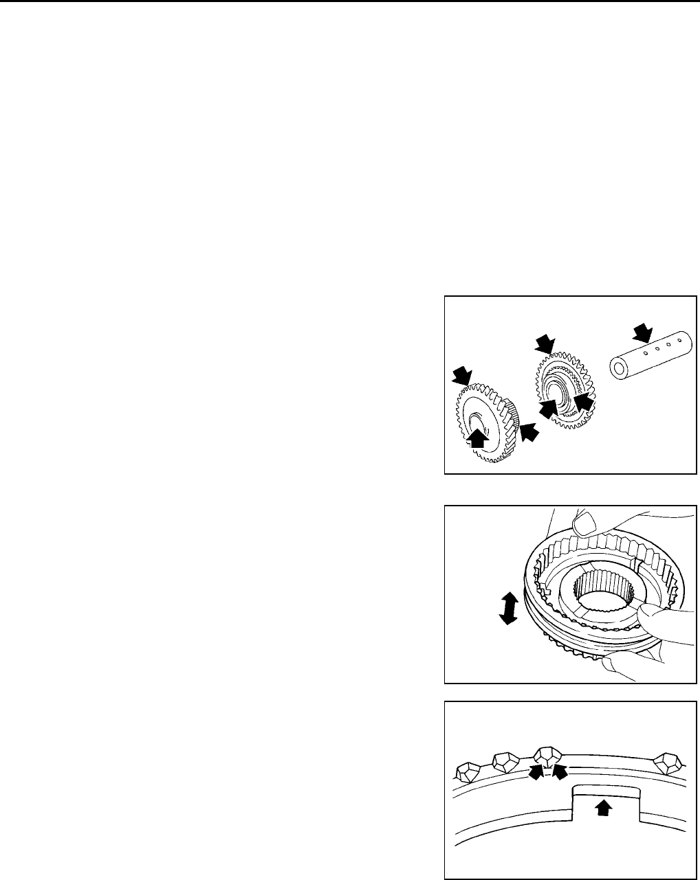
MT-84
REVERSE IDLER SHAFT AND GEARS
REVERSE IDLER SHAFT AND GEARS PFP:32281
Assembly and Disassembly (RS5F51A) ECS008C8
DISASSEMBLY
1. Remove reverse idler gear adjusting shim.
2. Remove reverse idler gear (rear), reverse coupling sleeve and insert spring simultaneously.
3. Remove reverse idler gear needle bearing.
4. Remove thrust needle bearing.
5. Remove reverse baulk ring.
6. Remove reverse idler gear (front).
7. Remove reverse idler gear needle bearing.
8. Remove thrust needle bearing.
9. Pull off locking pin from reverse idler shaft.
INSPECTION AFTER DISASSEMBLY
Reverse Idler Shaft and Gears
Check items below. If necessary, replace them with new ones.
●Damage, peeling, dent, uneven wear, bending, and other non-
standard conditions of the shaft.
●Excessive wear, damage, peeling, and other non-standard con-
ditions of the gears.
Synchronizer
Check items below. If necessary, replace them with new ones.
●Damage and unusual wear on contact surfaces of coupling
sleeve, synchronizer hub, and insert spring.
●Coupling sleeve and synchronizer hub must move smoothly.
●If any crack, damage, or excessive wear is found on cam face of
baulk ring or working face of insert, replace it.
SCIA0953J
SMT637A
SMT867D
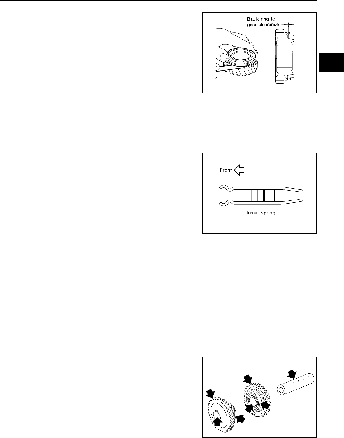
REVERSE IDLER SHAFT AND GEARS
MT-85
D
E
F
G
H
I
J
K
L
M
A
B
MT
Baulk ring clearance
●Press baulk ring against cone, and measure clearance between
baulk ring and cone. If measurement is below limit, replace it
with a new one.
Bearing
Check items below. If necessary, replace them with new ones.
●Damage and rough rotation of bearing.
ASSEMBLY
Paying attention to following work, assemble in reverse order of disassembly.
CAUTION:
●Be careful with orientation of insert spring.
Assembly and Disassembly (RS6F51A) ECS008C9
DISASSEMBLY
1. Remove reverse idler gear adjusting shim.
2. Remove reverse idler gear (rear), reverse coupling sleeve and insert spring simultaneously.
3. Remove reverse idler gear needle bearing.
4. Remove thrust needle bearing.
5. Remove reverse baulk ring.
6. Remove reverse idler gear (front).
7. Remove reverse idler gear needle bearing.
8. Remove thrust needle bearing.
9. Pull off locking pin from reverse idler shaft.
INSPECTION AFTER DISASSEMBLY
Reverse Idler Shaft and Gears
Check items below. If necessary, replace them with new ones.
●Damage, peeling, dent, uneven wear, bending, and other non-
standard conditions of the shaft.
●Excessive wear, damage, peeling, and other non-standard con-
ditions of the gears.
Clearance
Standard : 0.95 - 1.4 mm (0.0374 - 0.0551 in)
Limit value : 0.7 mm (0.0276 in)
SMT140
SCIA0954E
SCIA0953J
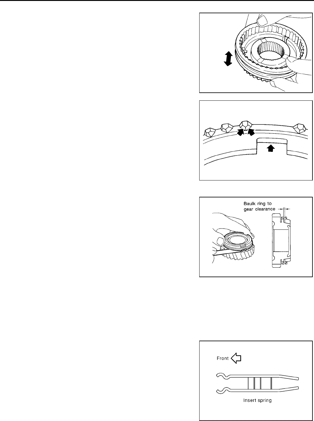
MT-86
REVERSE IDLER SHAFT AND GEARS
Synchronizer
Check items below. If necessary, replace them with new ones.
●Damage and unusual wear on contact surfaces of coupling
sleeve, synchronizer hub, and insert spring.
●Coupling sleeve and synchronizer hub must move smoothly.
●If any crack, damage, or excessive wear is found on cam face of
baulk ring or working face of insert, replace it.
Baulk ring clearance
●Press baulk ring against cone, and measure clearance between
baulk ring and cone. If measurement is below limit, replace it
with a new one.
Bearing
Check items below. If necessary, replace them with new ones.
●Damage and rough rotation of bearing.
ASSEMBLY
Paying attention to following work, assemble in reverse order of disassembly.
CAUTION:
●Be careful with orientation of insert spring.
SMT637A
SMT867D
Clearance
Standard : 0.95 - 1.4 mm (0.0374 - 0.0551 in)
Limit value : 0.7 mm (0.0276 in)
SMT140
SCIA0954E
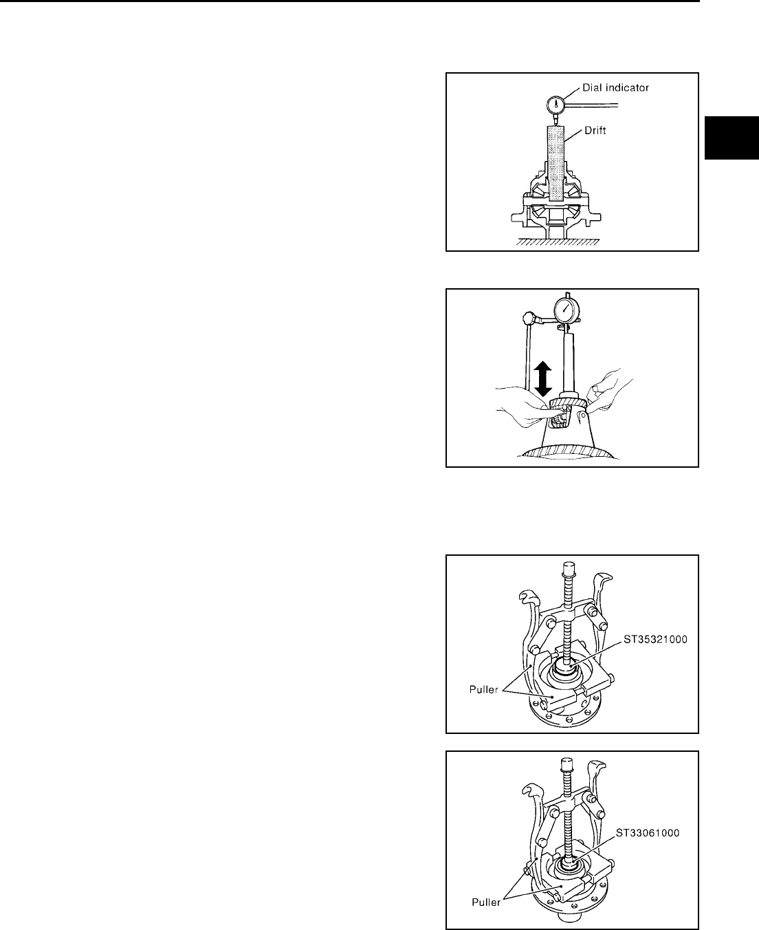
FINAL DRIVE
MT-87
D
E
F
G
H
I
J
K
L
M
A
B
MT
FINAL DRIVE PFP:38411
Assembly and Disassembly (RS5F51A) ECS008CA
PRE-INSPECTION
●Check the clearance between side gear and differential case as
follows.
1. Clean final drive assembly sufficiently to prevent side gear thrust
washer, differential case, side gear, and other parts from sticking
by gear oil.
2. Upright the differential case so that the side gear to be measured faces upward.
3. Place final drive adapter and dial indicator onto side gear. Move
side gear up and down, and measure the clearance.
CAUTION:
There should be no resistance and gears should rotate
freely.
4. If not within specification, adjust the clearance by changing
thrust washer thickness.
5. Turn differential case upside down, and measure the clearance
between side gear and differential case on the other side in the
same way.
DISASSEMBLY
1. Remove mounting bolts.Then, separate the final gear from differential case.
2. Using a drift and puller, remove differential side bearing (clutch
housing side).
3. Using a drift and puller, remove differential side bearing (tran-
saxle case side).
SCIA1020E
Clearance between side gear and differential case
: 0.1 - 0.2 mm (0.004 - 0.008 in)
SMT611A
SCIA0906E
SCIA0907E
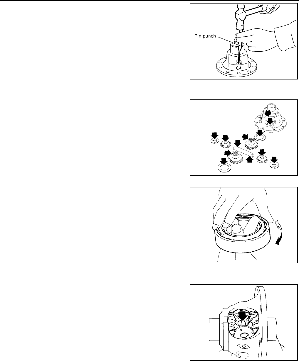
MT-88
FINAL DRIVE
4. Using a pin punch, pull out lock pin and pinion mate shaft.
5. Rotate pinion mate gears, and remove pinion mate gears, pinion
mate thrust washers, side gears, and side gear thrust washers
from differential case.
INSPECTION AFTER DISASSEMBLY
Gear, Washer, Shaft and Case
●Check side gears, side gear thrust washers, pinion mate shaft,
pinion mate gears, pinion mate thrust washers and differential
case. If necessary, replace with a new one.
Bearing
●Check for bearing damage and rough rotation. If necessary,
replace with a new one.
CAUTION:
When replacing tapered roller bearing, replace outer and inner
races as a set.
ASSEMBLY
1. Apply gear oil to sliding area of differential case, each gear, and thrust washer.
2. Install side gear thrust washers and side gears into differential
case.
3. While rotating pinion mate thrust washers and pinion mate
gears, aligning them diagonally, install them into differential
case.
SCIA0908E
MTK0135D
SPD715
SMT839
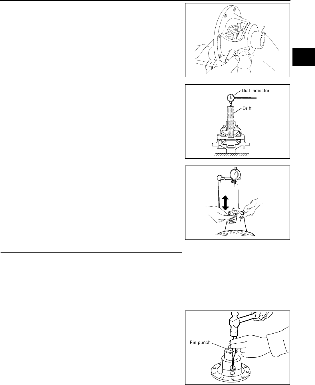
FINAL DRIVE
MT-89
D
E
F
G
H
I
J
K
L
M
A
B
MT
4. Insert pinion mate shaft into differential case.
CAUTION:
Be sure not to damage pinion mate thrust washers.
5. Measure end play of side gears following procedure below.
Then select side gear thrust washer.
a. Upright the differential case so that its side gear to be measured
face upward.
b. Place final drive adapter and dial indicator onto side gears.
c. Move side gears up and down to measure end play, and select
thrust washer so that it satisfies standard.
CAUTION:
●There should be no resistance and gears should rotate
freely.
●Place differential case upside down. Be sure to measure
end play for opposite side-gears likewise.
Thrust washer
CAUTION:
Only one thrust washer can be selected.
6. Using a pin punch, drive a lock pin into the pinion mate shaft.
CAUTION:
Do not reuse the lock pin.
MTK0132D
SCIA1020E
End play standard value
: 0.1 - 0.2 mm (0.004 - 0.008 in)
SMT611A
Thickness Part number
0.75 mm (0.0295 in)
0.80 mm (0.0315 in)
0.85 mm (0.0335 in)
0.90 mm (0.0354 in)
0.95 mm (0.0374 in)
38424 81X00
38424 81X01
38424 81X02
38424 81X03
38424 81X04
SCIA0908E
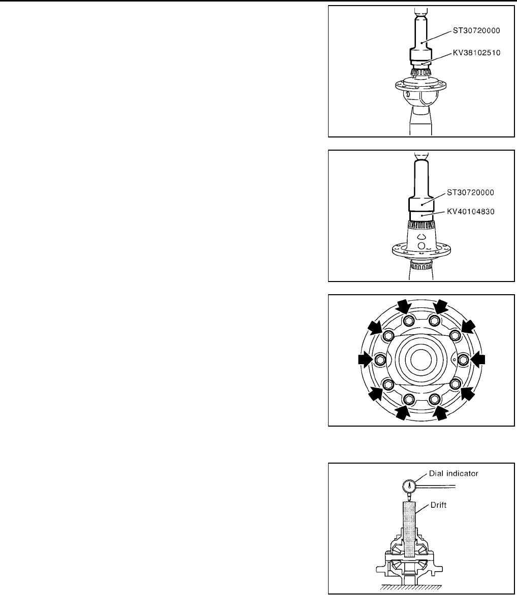
MT-90
FINAL DRIVE
7. Using a drift (special service tool), install differential side bearing
(transaxle case side).
8. Using a drift (special service tool), install differential side bearing
(clutch housing side).
9. Install final gear into differential case, and tighten final gear
mounting bolts.
Assembly and Disassembly (RS6F51A) ECS008CB
PRE-INSPECTION
●Check the clearance between side gear and differential case as
follows.
1. Clean final drive assembly sufficiently to prevent side gear thrust
washer, differential case, side gear, and other parts from sticking
by gear oil.
2. Upright the differential case so that the side gear to be measured faces upward.
SCIA0910E
SCIA0911E
SCIA0912E
SCIA1020E
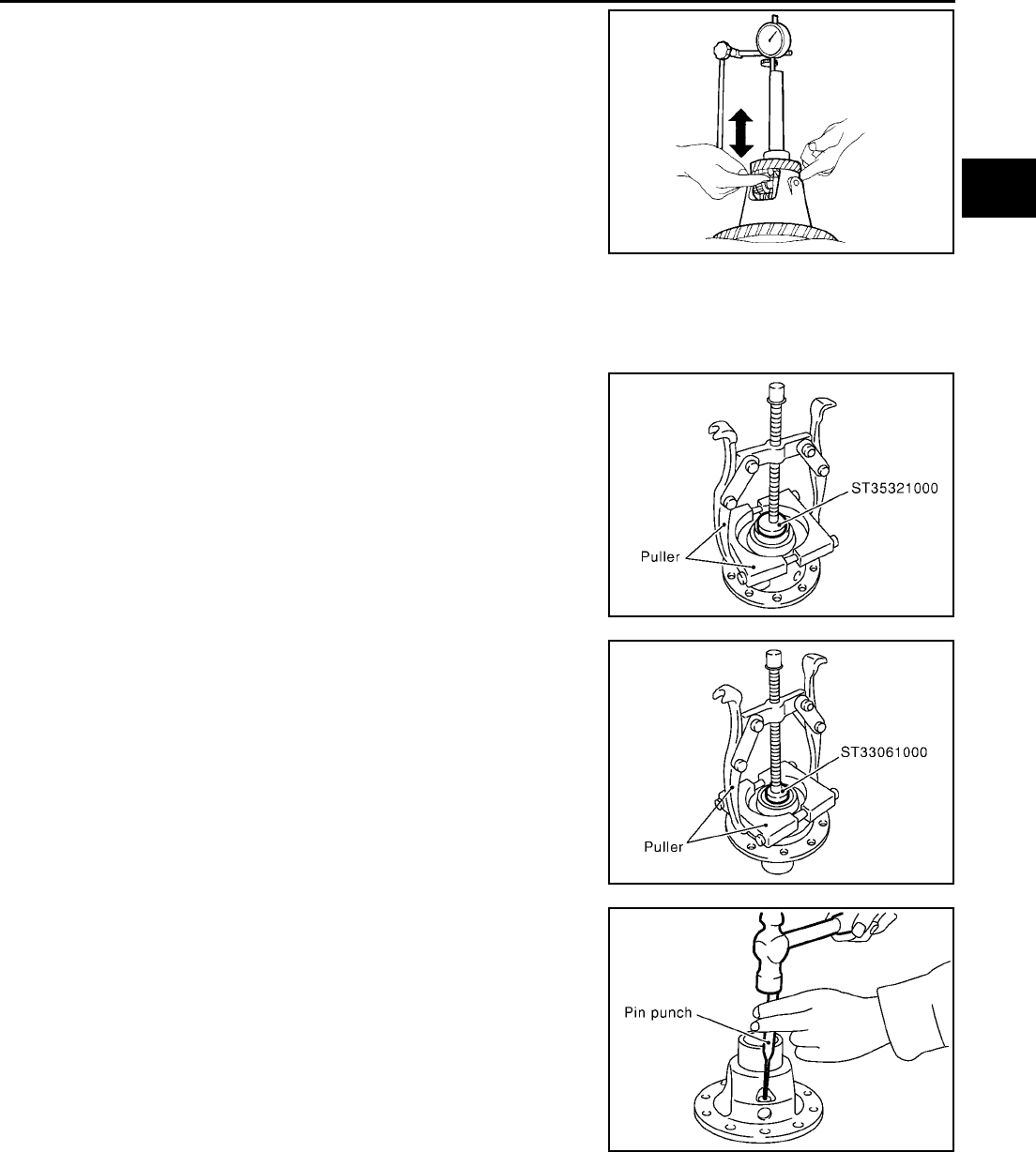
FINAL DRIVE
MT-91
D
E
F
G
H
I
J
K
L
M
A
B
MT
3. Place final drive adapter and dial indicator onto side gear. Move
side gear up and down, and measure the clearance.
CAUTION:
There should be no resistance and gears should rotate
freely.
4. If not within specification, adjust the clearance by changing
thrust washer thickness.
5. Turn differential case upside down, and measure the clearance
between side gear and differential case on the other side in the
same way.
DISASSEMBLY
1. Remove mounting bolts.Then, separate the final gear from differential case.
2. Using a drift and puller, remove differential side bearing (clutch
housing side).
3. Using a drift and puller, remove differential side bearing (tran-
saxle case side).
4. Using a pin punch, pull out lock pin and pinion mate shaft.
5. Rotate pinion mate gears, and remove pinion mate gears, pinion
mate thrust washers, side gears, and side gear thrust washers
from differential case.
Clearance between side gear and differential case
: 0.1 - 0.2 mm (0.004 - 0.008 in)
SMT611A
SCIA0906E
SCIA0907E
SCIA0908E
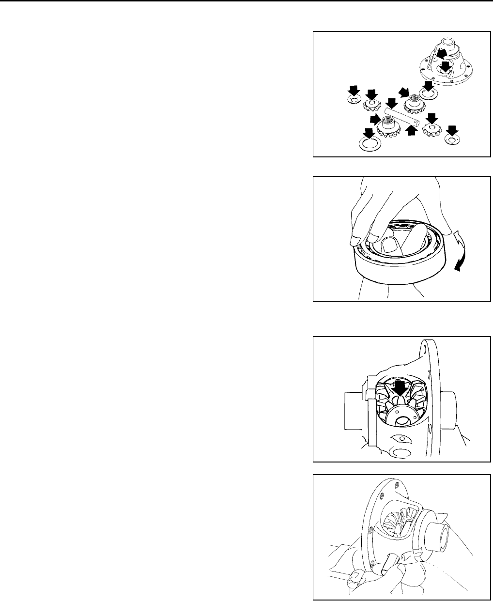
MT-92
FINAL DRIVE
INSPECTION AFTER DISASSEMBLY
Gear, Washer, Shaft and Case
●Check side gears, side gear thrust washers, pinion mate shaft,
pinion mate gears, pinion mate thrust washers and differential
case. If necessary, replace with a new one.
Bearing
●Check for bearing damage and rough rotation. If necessary,
replace with a new one.
CAUTION:
When replacing tapered roller bearing, replace outer and inner
races as a set.
ASSEMBLY
1. Apply gear oil to sliding area of differential case, each gear, and thrust washer.
2. Install side gear thrust washers and side gears into differential
case.
3. While rotating pinion mate thrust washers and pinion mate
gears, aligning them diagonally, install them into differential
case.
4. Insert pinion mate shaft into differential case.
CAUTION:
Be sure not to damage pinion mate thrust washers.
MTK0135D
SPD715
SMT839
MTK0132D
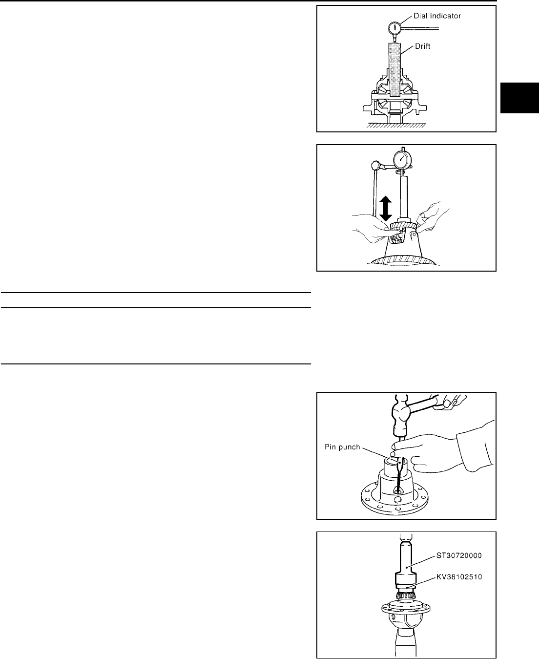
FINAL DRIVE
MT-93
D
E
F
G
H
I
J
K
L
M
A
B
MT
5. Measure end play of side gears following procedure below.
Then select side gear thrust washer.
a. Upright the differential case so that its side gear to be measured
faces upward.
b. Place final drive adapter and dial indicator onto side gears.
c. Move side gears up and down to measure end play, and select
thrust washer so that it satisfies standard.
CAUTION:
●There should be no resistance and gears should rotate
freely.
●Place differential case upside down. Be sure to measure
end play for opposite side-gears likewise.
Thrust washer
CAUTION:
Only one thrust washer can be selected.
6. Using a pin punch, drive a lock pin into the pinion mate shaft.
CAUTION:
Do not reuse the lock pin.
7. Using a drift (special service tool), install differential side bearing
(transaxle case side).
SCIA1020E
End play standard value
: 0.1 - 0.2 mm (0.004 - 0.008 in)
SMT611A
Thickness Part number
0.75 mm (0.0295 in)
0.80 mm (0.0315 in)
0.85 mm (0.0335 in)
0.90 mm (0.0354 in)
0.95 mm (0.0374 in)
38424 81X00
38424 81X01
38424 81X02
38424 81X03
38424 81X04
SCIA0908E
SCIA0910E
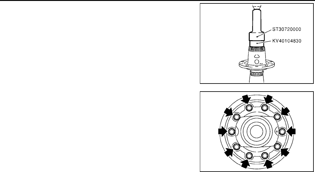
MT-94
FINAL DRIVE
8. Using a drift (special service tool), install differential side bearing
(clutch housing side).
9. Install final gear into differential case, and tighten final gear
mounting bolts.
SCIA0911E
SCIA0912E
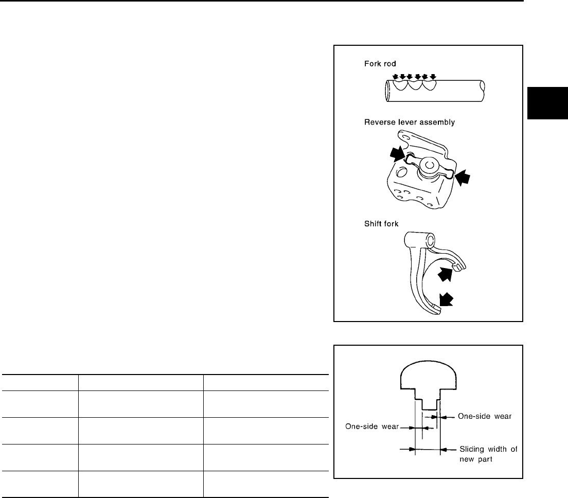
SHIFT CONTROL
MT-95
D
E
F
G
H
I
J
K
L
M
A
B
MT
SHIFT CONTROL PFP:32982
Inspection (RS5F51A) ECS008CC
●Check contact surfaces and sliding area for wear, damage,
bending, etc. If necessary, replace parts.
SHIFT FORK
●Check if the width of shift fork hook (sliding area with coupling
sleeve) is within allowable specification below.
SCIA0913E
Item One-side wear specification Sliding width of new part
1st & 2nd 0.2 mm (0.008 in) 7.80 - 7.93 mm
(0.3071 - 0.3122 in)
3rd & 4th 0.2 mm (0.008 in) 7.80 - 7.93 mm
(0.3071 - 0.3122 in)
5th 0.2 mm (0.008 in) 6.10 - 6.23 mm
(0.2402 - 0.2453 in)
Reverse 0.2 mm (0.008 in) 12.80 - 12.93 mm
(0.5039 - 0.5091 in)
SMT801D
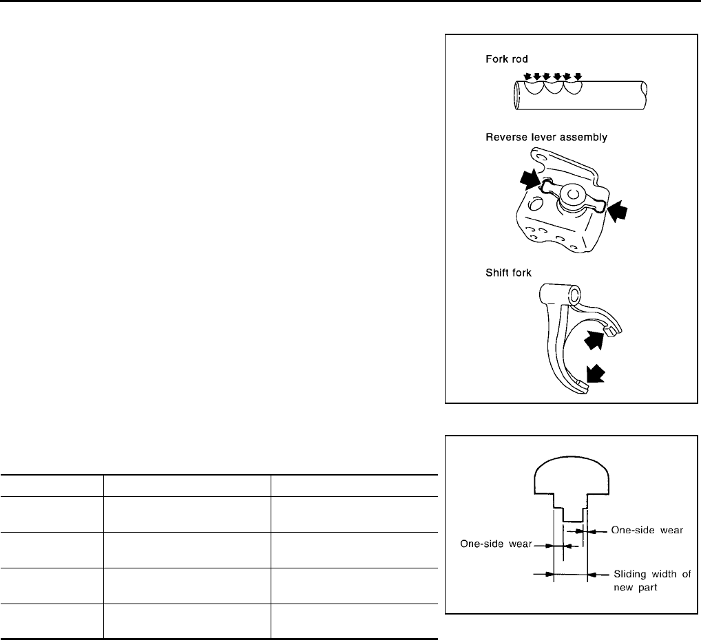
MT-96
SHIFT CONTROL
Inspection (RS6F51A) ECS008CD
●Check contact surfaces and sliding area for wear, damage,
bending, etc. If necessary, replace parts.
SHIFT FORK
●Check if the width of shift fork hook (sliding area with coupling
sleeve) is within allowable specification below.
SCIA0913E
Item One-side wear specification Sliding width of new part
1st & 2nd 0.2 mm (0.008 in) 7.80 - 7.93 mm
(0.3071 - 0.3122 in)
3rd & 4th 0.2 mm (0.008 in) 7.80 - 7.93 mm
(0.3071 - 0.3122 in)
5th & 6th 0.2 mm (0.008 in) 6.10 - 6.23 mm
(0.2402 - 0.2453 in)
Reverse 0.2 mm (0.008 in) 12.80 - 12.93 mm
(0.5039 - 0.5091 in)
SMT801D
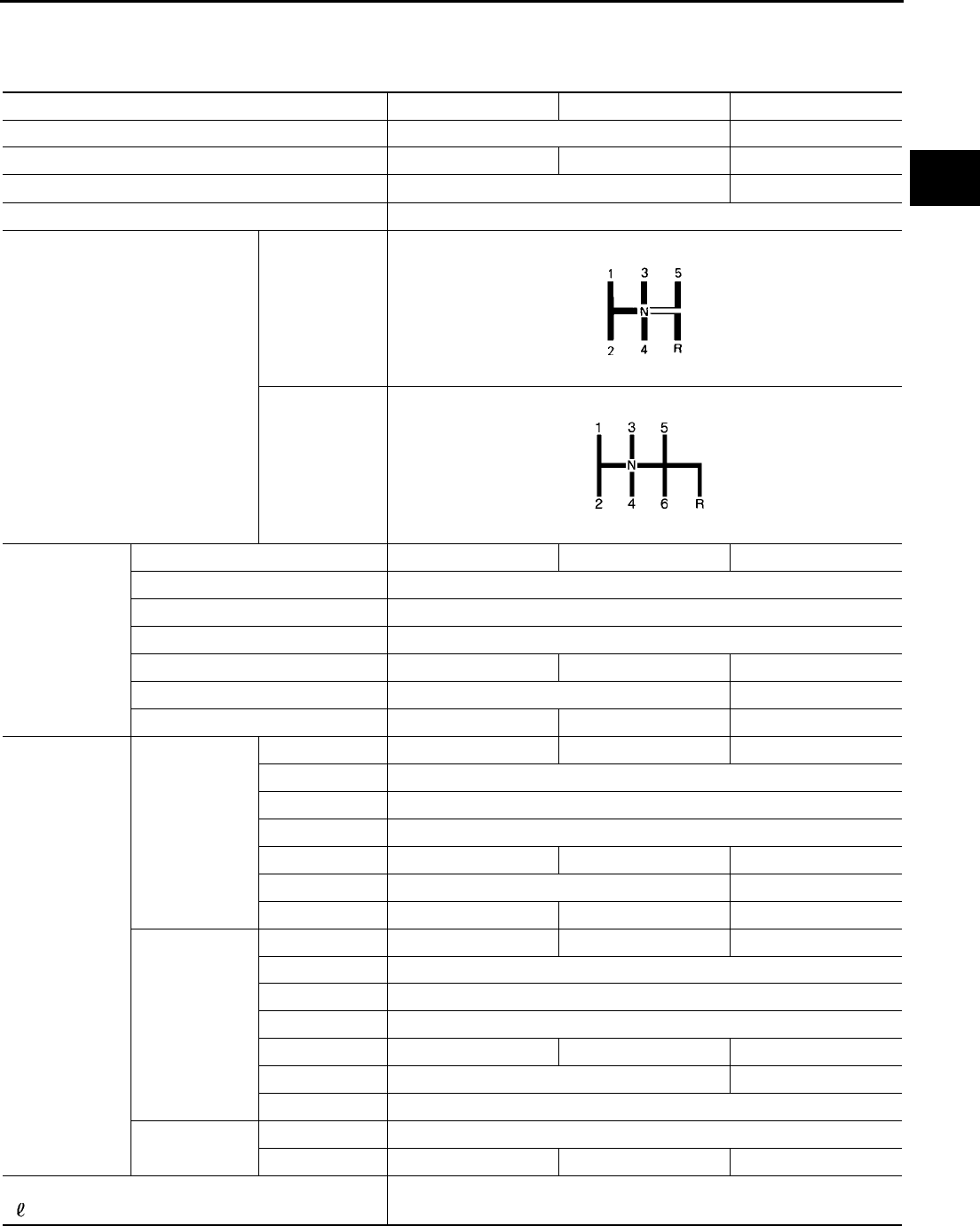
SERVICE DATA AND SPECIFICATIONS (SDS)
MT-97
D
E
F
G
H
I
J
K
L
M
A
B
MT
SERVICE DATA AND SPECIFICATIONS (SDS) PFP:00030
General Specifications ECS008CE
TRANSAXLE
Engine QR20DE QR25DE YD22DDTi
Transaxle model RS5F51A RS6F51A
Model code number 8H500 9H608 8H868
Number of speed 5 6
Synchromesh type Warner
Shift pattern
5 speed
6 speed
Gear ratio 1st 3.500 3.416 3.500
2nd 1.944
3rd 1.258
4th 0.947
5th 0.772 0.733 0.772
6th — 0.630
Reverse 3.374 3.252 3.374
Number of teeth Input gear 1st 14 12 14
2nd 18
3rd 31
4th 38
5th 444544
6th — 46
Reverse141214
Main gear 1st 49 41 49
2nd 35
3rd 39
4th 36
5th 343334
6th — 29
Reverse 38
Reverse idler
gear
Front 37
Rear 46 38 46
Oil capacity
(Imp pt) 2.3 (4)
SCIA0821E
SCIA0955E
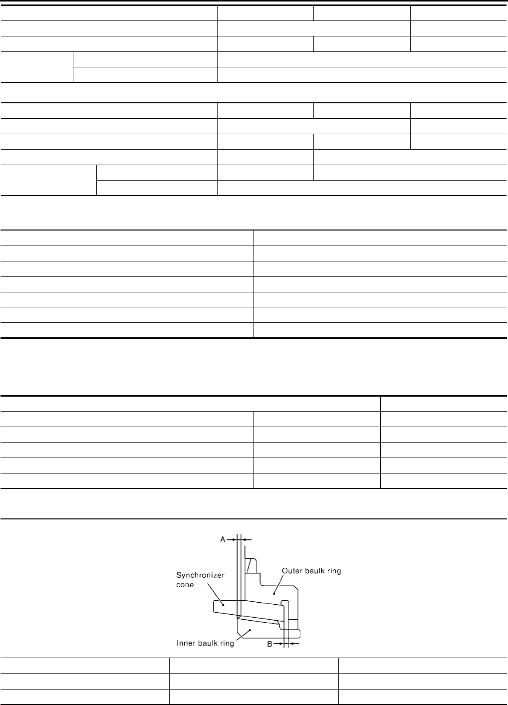
MT-98
SERVICE DATA AND SPECIFICATIONS (SDS)
FINAL GEAR
Gear End Play ECS008CF
Unit: mm (in)
Clearance Between Baulk Ring and Gear ECS008CG
3RD,4TH,5TH,6TH & REVERSE BAULK RING
— 6th for RS6F51A Models —Unit: mm (in)
1ST AND 2ND DOUBLE BAULK RING Unit: mm (in)
Remarks Reverse synchronizer Installed
Double baulk ring type synchronizer 1st & 2nd synchronizer
Engine QR20DE QR25DE YD22DDTi
Transaxle model RS5F51A RS6F51A
Model code number 8H500 9H608 8H868
Engine QR20DE QR25DE YD22DDTi
Transaxle model RS5F51A RS6F51A
Model code number 8H500 9H608 8H868
Final gear ratio 4.750 4.428
Number of teeth Final gear/Pinion 76/16 62/14
Side gear/Pinion mate gear 14/10
Gear End play
1st main gear 0.20 - 0.30 (0.0079 - 0.0118)
2nd main gear 0.06 - 0.16 (0.0024 - 0.0063)
3rd input gear 0.18 - 0.31 (0.0071 - 0.0122)
4th input gear 0.20 - 0.30 (0.0079 - 0.0118)
5th input gear 0.06 - 0.16 (0.0024 - 0.0063)
6th input gear (For RS6F51A model) 0.06 - 0.16 (0.0024 - 0.0063)
Standard Wear limit
3rd 0.9 - 1.45 (0.0354 - 0.0571) 0.7 (0.0276)
4th 0.9 - 1.45 (0.0354 - 0.0571) 0.7 (0.0276)
5th 0.95 - 1.4 (0.0374 - 0.0551) 0.7 (0.0276)
6th (For RS6F51A model) 0.95 - 1.4 (0.0374 - 0.0551) 0.7 (0.0276)
Reverse 0.95 - 1.4 (0.0374 - 0.0551) 0.7 (0.0276)
Dimension Standard Wear limit
A 0.6 - 0.8 (0.024 - 0.031) 0.2 (0.008)
B 0.6 - 1.1 (0.024 - 0.043) 0.2 (0.008)
SCIA0950E
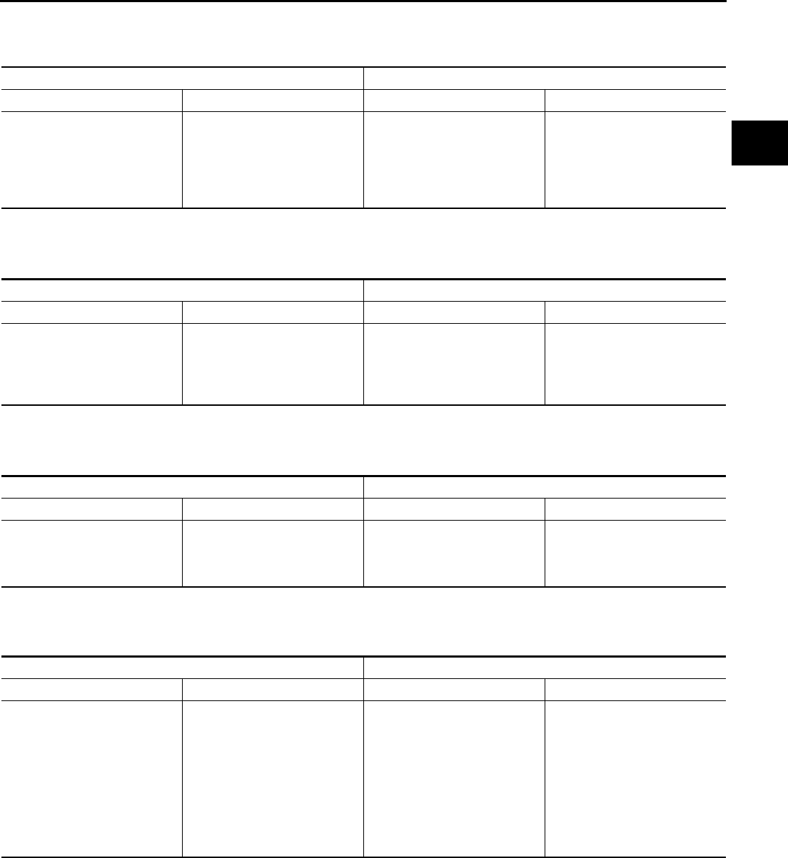
SERVICE DATA AND SPECIFICATIONS (SDS)
MT-99
D
E
F
G
H
I
J
K
L
M
A
B
MT
Available Snap Rings ECS008CH
INPUT SHAFT SPACER
—For RS5F51A Models—
*: Always check with the Parts Department for the latest parts information.
6TH BUSHING
—For RS6F51A Models—
*: Always check with the Parts Department for the latest parts information.
5TH MAIN GEAR
—For RS5F51A Models—
*: Always check with the Parts Department for the latest parts information.
Available C-Rings ECS008CI
MAINSHAFT C-RING
*: Always check with the Parts Department for the latest parts information.
End play 0 - 0.1 mm (0 - 0.004 in)
Thickness mm (in) Part number* Thickness mm (in) Part number*
1.71 (0.0673)
1.76 (0.0693)
1.81 (0.0713)
1.86 (0.0732)
1.91 (0.0752)
1.96 (0.0772)
32204 8H510
32204 8H511
32204 8H512
32204 8H513
32204 8H514
32204 8H515
2.01 (0.0791)
2.06 (0.0811)
2.11 (0.0831)
2.16 (0.0850)
2.21 (0.0870)
2.26 (0.0890)
32204 8H516
32204 8H517
32204 8H518
32204 8H519
32204 8H520
32204 8H521
End play 0 - 0.1 mm (0 - 0.004 in)
Thickness mm (in) Part number* Thickness mm (in) Part number*
1.76 (0.0693)
1.81 (0.0713)
1.86 (0.0732)
1.91 (0.0752)
1.96 (0.0772)
32204 8H511
32204 8H512
32204 8H513
32204 8H514
32204 8H515
2.01 (0.0791)
2.06 (0.0811)
2.11 (0.0831)
2.16 (0.0850)
2.21 (0.0870)
32204 8H516
32204 8H517
32204 8H518
32204 8H519
32204 8H520
End play 0 - 0.1 mm (0 - 0.004 in)
Thickness mm (in) Part number* Thickness mm (in) Part number*
1.85 (0.0728)
1.90 (0.0748)
1.95 (0.0768)
2.00 (0.0787)
32204 8H500
32204 8H501
32204 8H502
32204 8H503
2.05 (0.0807)
2.10 (0.0827)
2.15 (0.0846)
2.20 (0.0866)
32204 8H504
32204 8H505
32204 8H506
32204 8H507
End play 0 - 0.06 mm (0 - 0.0024 in)
Thickness mm (in) Part number* Thickness mm (in) Part number*
2.535 (0.0998)
2.565 (0.1010)
2.595 (0.1022)
2.625 (0.1033)
2.655 (0.1045)
2.685 (0.1057)
2.715 (0.1069)
2.745 (0.1081)
2.775 (0.1093)
2.805 (0.1104)
32348 8H800
32348 8H801
32348 8H802
32348 8H803
32348 8H804
32348 8H805
32348 8H806
32348 8H807
32348 8H808
32348 8H809
2.835 (0.1116)
2.865 (0.1128)
2.895 (0.1140)
2.925 (0.1152)
2.955 (0.1163)
2.985 (0.1175)
3.015 (0.1187)
3.045 (0.1199)
3.075 (0.1211)
32348 8H810
32348 8H811
32348 8H812
32348 8H813
32348 8H814
32348 8H815
32348 8H816
32348 8H817
32348 8H818
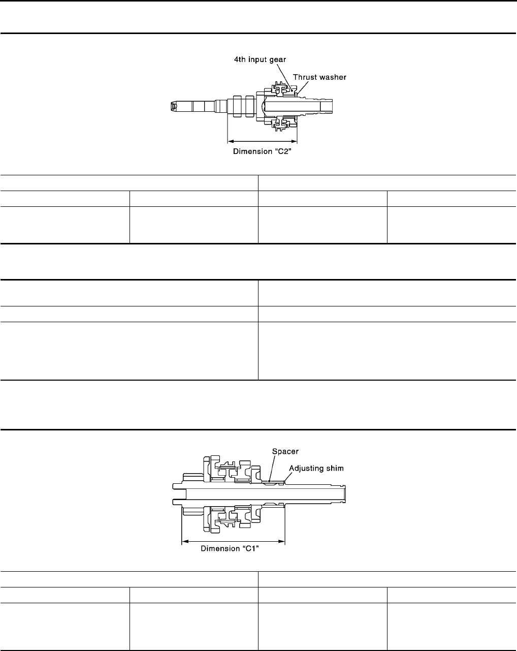
MT-100
SERVICE DATA AND SPECIFICATIONS (SDS)
Available Thrust Washer ECS008CJ
INPUT SHAFT THRUST WASHER
*: Always check with the Parts Department for the latest parts information.
DIFFERENTIAL SIDE GEAR THRUST WASHER
*: Always check with the Parts Department for the latest parts information.
Available Adjusting Shims ECS008CK
MAINSHAFT ADJUSTING SHIM
*: Always check with the Parts Department for the latest parts information.
Standard length “C2” 154.7 - 154.8 mm (6.091 - 6.094 in)
Thickness mm (in) Part number* Thickness mm (in) Part number*
3.84 (0.1512)
3.90 (0.1535)
3.96 (0.1559)
32347 8H500
32347 8H501
32347 8H502
4.02 (0.1583)
4.08 (0.1606)
4.14 (0.1630)
32347 8H503
32347 8H504
32347 8H505
SCIA1008E
Allowable clearance between side gear and differential case with
washer 0.1 - 0.2 mm (0.004 - 0.008 in)
Thickness mm (in) Part number*
0.75 (0.0295)
0.80 (0.0315)
0.85 (0.0335)
0.90 (0.0354)
0.95 (0.0374)
38424 81X00
38424 81X01
38424 81X02
38424 81X03
38424 81X04
Standard length “C1” 173.85 - 173.95 mm (6.844 - 6.848 in)
Thickness mm (in) Part number* Thickness mm (in) Part number*
0.52 (0.0205)
0.60 (0.0236)
0.68 (0.0268)
0.76 (0.0299)
32238 8H500
32238 8H501
32238 8H502
32238 8H503
0.84 (0.0331)
0.92 (0.0362)
1.00 (0.0394)
1.08 (0.0425)
32238 8H504
32238 8H505
32238 8H506
32238 8H507
SCIA1009E
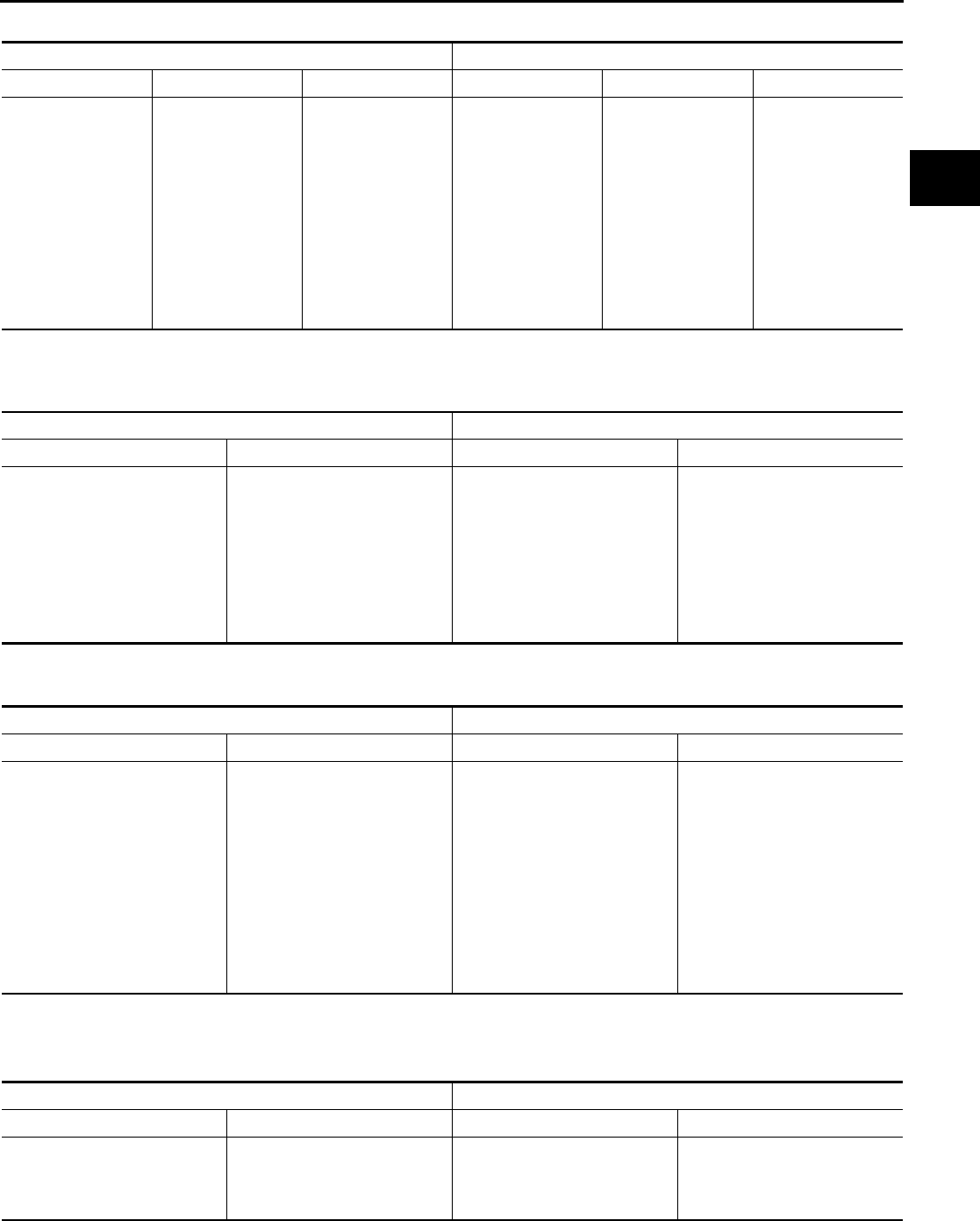
SERVICE DATA AND SPECIFICATIONS (SDS)
MT-101
D
E
F
G
H
I
J
K
L
M
A
B
MT
INPUT SHAFT REAR BEARING ADJUSTING SHIM
*: Always check with the Parts Department for the latest parts information.
**: RS5F51A model only.
MAINSHAFT REAR BEARING ADJUSTING SHIM
*: Always check with the Parts Department for the latest parts information.
REVERSE IDLER GEAR ADJUSTING SHIM
*: Always check with the Parts Department for the latest parts information.
6TH MAIN GEAR ADJUSTING SHIM
—For RS6F51A Models—
*: Always check with the Parts Department for the latest parts information.
End play 0 - 0.06 mm (0 - 0.0024 in)
Thickness mm (in) Part number* Thickness mm (in) Part number* Thickness mm (in) Part number*
0.40 (0.0157)
0.44 (0.0173)
0.48 (0.0189)
0.52 (0.0205)
0.56 (0.0220)
0.60 (0.0236)
0.64 (0.0252)
0.68 (0.0268)
0.72 (0.0283)
0.76 (0.0299)
0.80 (0.0315)
0.84 (0.0331)
32225 8H500
32225 8H501
32225 8H502
32225 8H503
32225 8H504
32225 8H505
32225 8H506
32225 8H507
32225 8H508
32225 8H509
32225 8H510
32225 8H511
0.88 (0.0346)
0.92 (0.0362)
0.96 (0.0378)
1.00 (0.0394)
1.04 (0.0409)
1.08 (0.0425)
1.12 (0.0441)
1.16 (0.0457)
1.20 (0.0472)
1.24 (0.0488)
1.28 (0.0504)
1.32 (0.0520)
32225 8H512
32225 8H513
32225 8H514
32225 8H515
32225 8H516
32225 8H517
32225 8H518
32225 8H519
32225 8H520
32225 8H521
32225 8H522
32225 8H523
1.36 (0.0535)
1.40 (0.0551)
1.44 (0.0567)
1.48 (0.0583)
1.52 (0.0598)
1.56 (0.0614)
1.60 (0.0630)
1.64 (0.0646)
1.68 (0.0661)
1.72 (0.0677)
32225 8H524
32225 8H560
32225 8H561
32225 8H562
32225 8H563
32225 8H564
32225 8H565
32225 8H566
32225 8H567**
32225 8H568**
End play 0 - 0.06 mm (0 - 0.0024 in)
Thickness mm (in) Part number* Thickness mm (in) Part number*
0.44 (0.0173)
0.48 (0.0189)
0.52 (0.0205)
0.56 (0.0220)
0.60 (0.0236)
0.64 (0.0252)
0.68 (0.0268)
0.72 (0.0283)
0.76 (0.0299)
32238 8H510
32238 8H511
32238 8H512
32238 8H513
32238 8H514
32238 8H515
32238 8H516
32238 8H517
32238 8H518
0.80 (0.0315)
0.84 (0.0331)
0.88 (0.0346)
0.92 (0.0362)
0.96 (0.0378)
1.00 (0.0394)
1.04 (0.0409)
1.08 (0.0425)
32238 8H519
32238 8H520
32238 8H521
32238 8H522
32238 8H523
32238 8H524
32238 8H560
32238 8H561
End play 0.04 - 0.10 mm (0.0016 - 0.0039 in)
Thickness mm (in) Part number* Thickness mm (in) Part number*
1.76 (0.0693)
1.80 (0.0709)
1.84 (0.0724)
1.88 (0.0740)
1.92 (0.0756)
1.96 (0.0772)
2.00 (0.0787)
2.04 (0.0803)
2.08 (0.0819)
2.12 (0.0835)
2.16 (0.0850)
2.20 (0.0866)
32237 8H800
32237 8H801
32237 8H802
32237 8H803
32237 8H804
32237 8H805
32237 8H806
32237 8H807
32237 8H808
32237 8H809
32237 8H810
32237 8H811
2.24 (0.0882)
2.28 (0.0898)
2.32 (0.0913)
2.36 (0.0929)
2.40 (0.0945)
2.44 (0.0961)
2.48 (0.0976)
2.52 (0.0992)
2.56 (0.1008)
2.60 (0.1024)
2.64 (0.1039)
32237 8H812
32237 8H813
32237 8H814
32237 8H815
32237 8H816
32237 8H817
32237 8H818
32237 8H819
32237 8H820
32237 8H821
32237 8H822
End play 0 - 0.1 mm (0 - 0.004 in)
Thickness mm (in) Part number* Thickness mm (in) Part number*
0.88 (0.0346)
0.96 (0.0378)
1.04 (0.0409)
1.12 (0.0441)
32237 8H560
32237 8H561
32237 8H562
32237 8H563
1.20 (0.0472)
1.28 (0.0504)
1.36 (0.0535)
32237 8H564
32237 8H565
32237 8H566
MT-102
SERVICE DATA AND SPECIFICATIONS (SDS)
Available Shims ECS008CL
— Differential Side Bearing Preload and Adjusting Shim
BEARING PRELOAD
*: Install shims which are “deflection of differential case” + “L” in thickness.
DIFFERENTIAL SIDE BEARING ADJUSTING SHIM(S)
*: Always check with the Parts Department for the latest parts information.
Differential side bearing preload: L* 0.15 - 0.21 mm (0.0059 - 0.0083 in)
Thickness mm (in) Part number* Thickness mm (in) Part number*
0.48 (0.0189)
0.52 (0.0205)
0.56 (0.0220)
0.60 (0.0236)
0.64 (0.0252)
0.68 (0.0268)
31438 80X00
31438 80X01
31438 80X02
31438 80X03
31438 80X04
31438 80X05
0.72 (0.0283)
0.76 (0.0299)
0.80 (0.0315)
0.84 (0.0331)
0.88 (0.0346)
0.92 (0.0362)
31438 80X06
31438 80X07
31438 80X08
31438 80X09
31438 80X10
31438 80X11
