Nissan 2004 350Z Owners Manual MT
2015-10-23
: Nissan Nissan-2004-Nissan-350Z-Owners-Manual-818422 nissan-2004-nissan-350z-owners-manual-818422 nissan pdf
Open the PDF directly: View PDF ![]() .
.
Page Count: 60
- QUICK REFERENCE INDEX
- Table of Contents

MT-1
MANUAL TRANSMISSION
C TRANSMISSION/TRANSAXLE
CONTENTS
D
E
F
G
H
I
J
K
L
M
SECTION MT A
B
MT
Revision: 2004 December 2004 350Z
MANUAL TRANSMISSION
PRECAUTIONS .......................................................... 2
Caution ..................................................................... 2
Precautions for Battery Service ................................ 2
PREPARATION ........................................................... 3
Special Service Tools ............................................... 3
Commercial Service Tools ........................................ 6
NOISE, VIBRATION AND HARSHNESS (NVH)
TROUBLESHOOTING ................................................ 7
NVH Troubleshooting Chart ..................................... 7
MANUAL TRANSMISSION ................................... 7
DESCRIPTION ............................................................ 8
Cross-Sectional View ............................................... 8
DOUBLE-CONE SYNCHRONIZER ...................... 8
TRIPLE-CONE SYNCHRONIZER ........................ 9
M/T OIL ..................................................................... 10
Replacement .......................................................... 10
DRAINING ........................................................... 10
FILLING ............................................................... 10
Checking ................................................................ 10
OIL LEAKAGE AND OIL LEVEL ......................... 10
REAR OIL SEAL .......................................................11
Removal and Installation .........................................11
REMOVAL ............................................................11
INSTALLATION ....................................................11
POSITION SWITCH .................................................. 12
Checking ................................................................ 12
COMPONENT LOCATION .................................. 12
BACK-UP LAMP SWITCH .................................. 12
NEUTRAL POSITION SWITCH .......................... 12
SHIFT CONTROL ..................................................... 13
Removal and Installation ........................................ 13
REMOVAL ........................................................... 13
INSTALLATION ................................................... 15
INSPECTION AFTER INSTALLATION ................ 17
AIR BREATHER HOSE ............................................ 18
Removal and Installation ........................................ 18
TRANSMISSION ASSEMBLY .................................. 19
Removal and Installation from Vehicle ................... 19
REMOVAL ........................................................... 19
INSTALLATION ................................................... 21
Component Parts Drawing ..................................... 22
CASE COMPONENTS ........................................ 22
GEAR COMPONENTS ....................................... 23
SHIFT CONTROL COMPONENTS ..................... 25
Disassembly and Assembly .................................... 27
DISASSEMBLY ................................................... 27
INSPECTION AFTER DISASSEMBLY ................ 37
ASSEMBLY ......................................................... 41
SERVICE DATA AND SPECIFICATIONS (SDS) ...... 58
General Specifications ............................................ 58
End Play ................................................................. 58
Snap Rings ............................................................. 59
Baulk Ring Clearance ............................................. 60

MT-2
PRECAUTIONS
Revision: 2004 December 2004 350Z
PRECAUTIONS PFP:00001
Caution ACS004NF
●Do not reuse transmission oil, once it has been drained.
●Check oil level or replace oil with vehicle on level ground.
●During removal or installation, keep inside of transmission clear of dust or dirt.
●Check for the correct installation status prior to removal or disassembly. If mating marks are required, be
certain they do not interfere with the function of the parts they are applied to.
●In principle, tighten bolts or nuts gradually in several steps working diagonally from inside to outside. If
tightening sequence is specified, observe it.
●Be careful not to damage sliding surfaces and mating surfaces.
Precautions for Battery Service ACS004NG
Before disconnecting the battery, lower both the driver and passenger windows. This will prevent any interfer-
ence between the window edge and the vehicle when the door is opened/closed. During normal operation, the
window slightly raises and lowers automatically to prevent any window to vehicle interference. The automatic
window function will not work with the battery disconnected.
PREPARATION
MT-3
D
E
F
G
H
I
J
K
L
M
A
B
MT
Revision: 2004 December 2004 350Z
PREPARATION PFP:00002
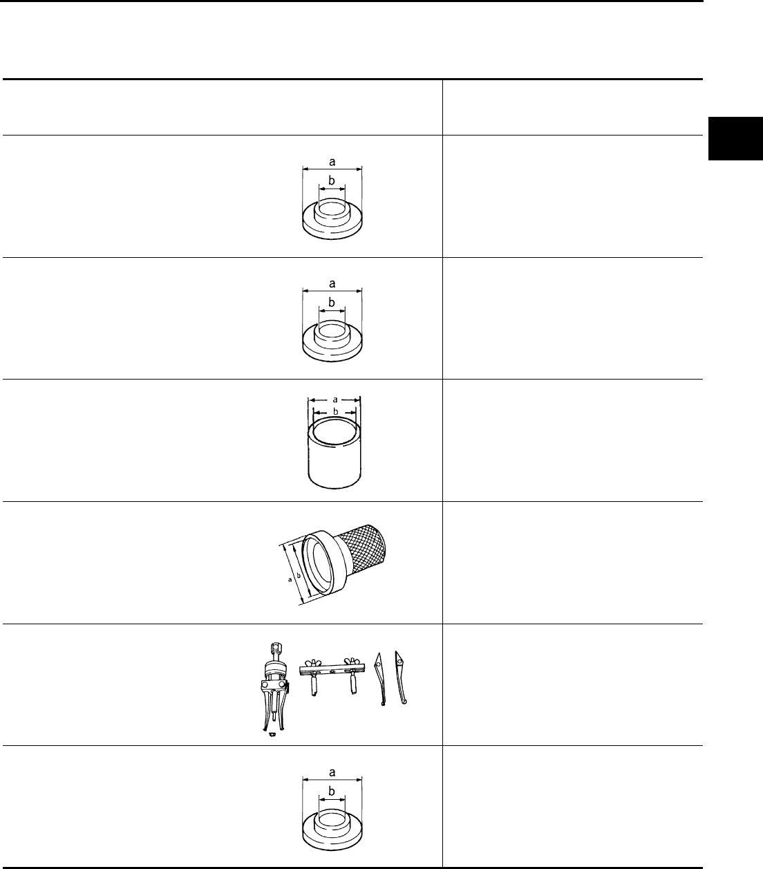
Special Service Tools ACS004NH
The actual shapes of Kent-Moore tools may differ from those of special service tools illustrated here.
Tool number
(Kent-Moore No.)
Tool name
Description
ST30911000
(—)
a: 98 mm (3.86 in) dia.
b: 40 mm (1.57 in) dia.
Inserter
●Main shaft bearing installation
●5th-6th synchronizer assembly installation
●Reverse main gear bushing installation
●3rd gear bushing installation
●3rd-4th synchronizer assembly installation
ST30022000
(—)
a: 110 mm (4.33 in) dia.
b: 46 mm (1.81 in) dia.
Inserter
●3rd main gear installation
●4th main gear installation
ST27861000
(—)
a: 62 mm (2.44 in) dia.
b: 52 mm (2.05 in) dia.
Support ring
●1st-2nd synchronizer assembly installation
●1st gear bushing installation
ST33400001
(J26082)
a: 60 mm (2.36 in) dia.
b: 47 mm (1.85 in) dia.
Drift
Rear oil seal installation
KV381054S0
(—)
Oil seal puller
Remove rear oil seal
ST30032000
(J26010-01)
a: 80 mm (3.15 in) dia.
b: 31 mm (1.22 in) dia.
Inserter
Counter rear bearing inner race installation
ZZA0920D
ZZA0920D
ZZA0832D
ZZA0814D
ZZA0601D
ZZA0920D
MT-4
PREPARATION
Revision: 2004 December 2004 350Z
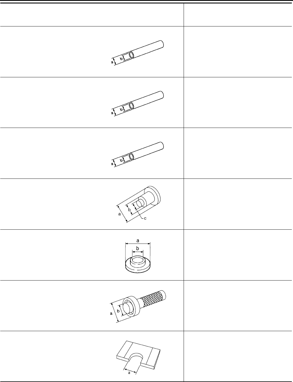
KV32102700
(—)
a: 48 mm (1.89 in) dia.
b: 41 mm (1.61 in) dia.
Drift
Main drive gear bearing installation
ST23860000
(—)
a: 38 mm (1.50 in) dia.
b: 33 mm (1.30 in) dia.
Drift
Reverse counter gear installation
ST01530000
(—)
a: 50 mm (1.97 in) dia.
b: 41 mm (1.61 in) dia.
Drift
Reverse synchronizer assembly installation
ST35291000
(—)
a: 40 mm (1.57 in) dia.
b: 29.5 mm (1.161 in) dia.
c: 22.5 mm (0.886 in) dia.
Drift
Striking rod oil seal installation
KV40100630
(J26092)
a: 67 mm (2.64 in) dia.
b: 38 mm (1.50 in) dia.
Inserter
4th counter gear thrust washer installation
KV38102100
(J25803-01)
a: 44 mm (2.36 in) dia.
b: 28 mm (1.10 in) dia.
Drift
Front cover oil seal installation
KV32103300
(J46529)
Press plate
a: 73 mm (2.87 in)
Reverse synchronizer assembly installation
Tool number
(Kent-Moore No.)
Tool name
Description
ZZA0534D
ZZA0534D
ZZA0534D
SCIA1575E
ZZA0920D
NT084
PCIB0165J
PREPARATION
MT-5
D
E
F
G
H
I
J
K
L
M
A
B
MT
Revision: 2004 December 2004 350Z
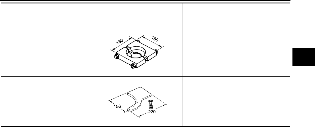
ST30031000
(J22912-01)
Puller
Inner baulk ring support
ST22490000
(—)
Adapter setting plate
Hold a adapter plate
Tool number
(Kent-Moore No.)
Tool name
Description
ZZC0499D
ZZC0465D
MT-6
PREPARATION
Revision: 2004 December 2004 350Z
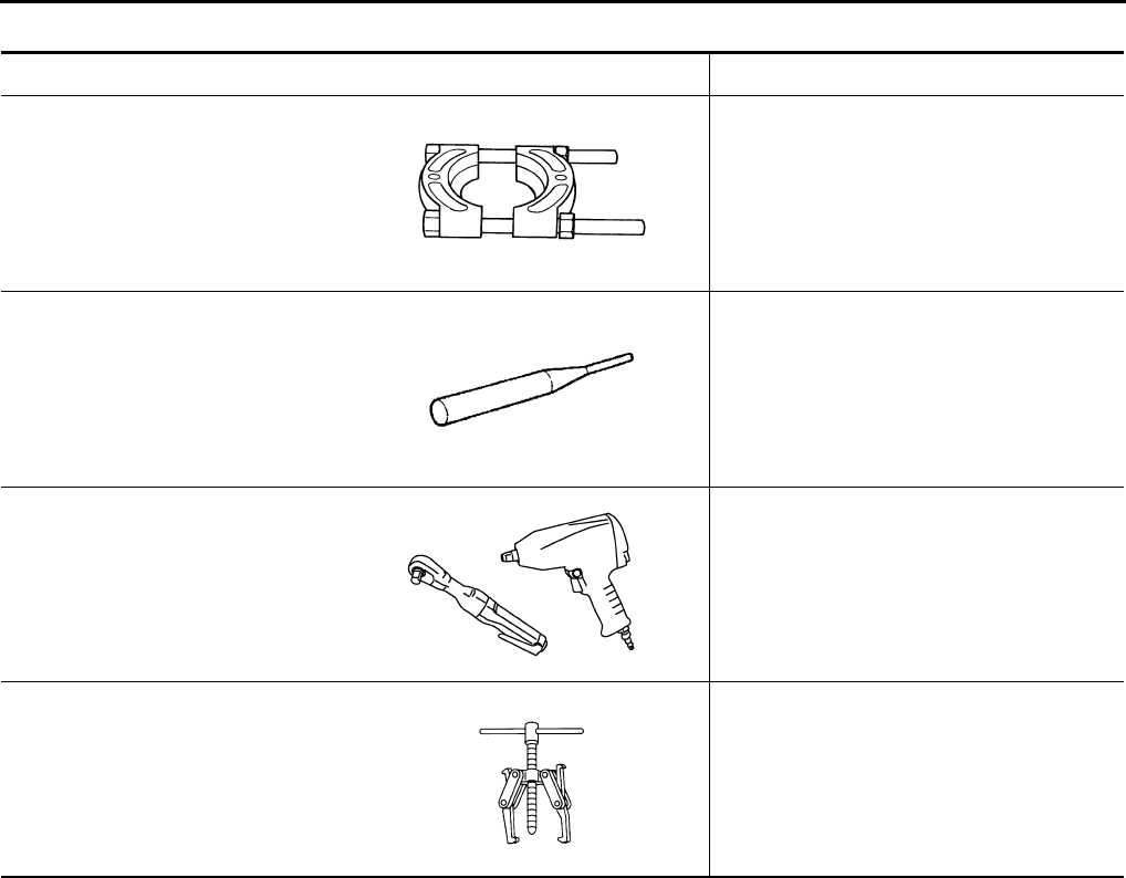
Commercial Service Tools ACS004NI
Tool name Description
Puller Each bearing, gear and bushing removal
Pin punch
Tip diameter: 6.0 mm (0.24 in) dia.
Each retaining pin removal and installation
Power tool Loosening bolts and nuts
Puller Reverse synchronizer assembly removal
Reverse counter gear removal
Reverse main gear removal
ZZB0823D
ZZA0815D
PBIC0190E
NT077
NOISE, VIBRATION AND HARSHNESS (NVH) TROUBLESHOOTING
MT-7
D
E
F
G
H
I
J
K
L
M
A
B
MT
Revision: 2004 December 2004 350Z
NOISE, VIBRATION AND HARSHNESS (NVH) TROUBLESHOOTING PFP:00003
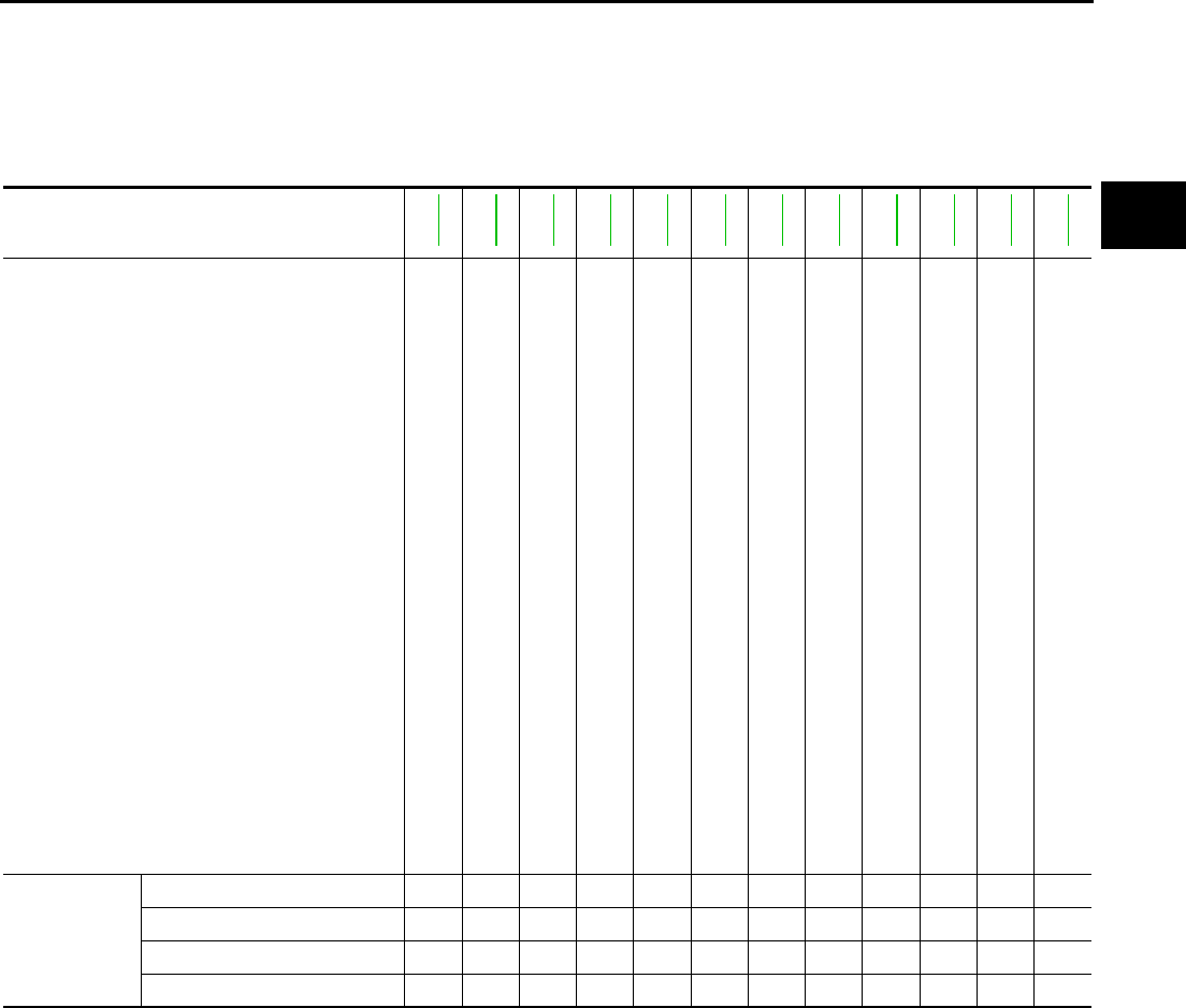
NVH Troubleshooting Chart ACS004NJ
Use the chart below to help you find the cause of the symptom. The numbers indicate the order of the inspec-
tion. If necessary, repair or replace these parts.
MANUAL TRANSMISSION
Reference page
MT-10
MT-10
MT-10
MT-22
MT-22
MT-13
MT-25
MT-25
MT-25
MT-25
MT-25
MT-25
SUSPECTED PARTS
(Possible cause)
OIL (Oil level is low.)
OIL (Wrong oil.)
OIL (Oil level is high.)
GASKET (Damaged)
OIL SEAL (Worn or damaged)
SHIFT CONTROL LINKAGE (Worn)
CHECK PLUG RETURN SPRING AND CHECK BALL (Worn or damaged)
SHIFT FORK (Worn)
GEAR (Worn or damaged)
BEARING (Worn or damaged)
BAULK RING (Worn or damaged)
INSERT SPRING (Damaged)
Symptoms
Noise 1 2 3 3
Oil leakage 3122
Hard to shift or will not shift 1 1 2 2 2
Jumps out of gear 1122
MT-8
DESCRIPTION
Revision: 2004 December 2004 350Z
DESCRIPTION PFP:00000
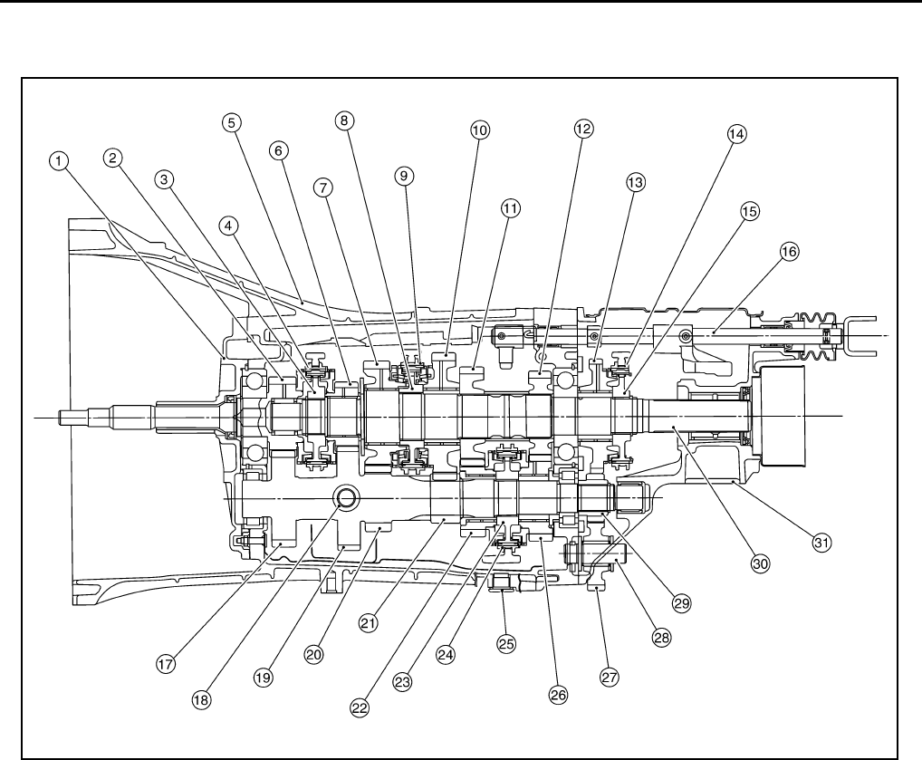
Cross-Sectional View ACS004NK
DOUBLE-CONE SYNCHRONIZER
The 1st and 3rd, 4th gears is equipped with a double-cone synchronizer to reduce the operating force of the
shift lever as shown.
1. Front cover 2. Main drive gear 3. 5th-6th synchronizer hub
4. 5th-6th coupling sleeve 5. Transmission case 6. 6th main gear
7. 2nd main gear 8. 1st-2nd synchronizer hub 9. 1st-2nd coupling sleeve
10. 1st main gear 11. 3rd main gear 12. 4th main gear
13. Reverse main gear 14. Reverse coupling sleeve 15. Reverse synchronizer hub
16. Striking rod 17. Counter shaft 18. Filler plug
19. 6th counter gear 20. 2nd counter gear 21. 1st counter gear
22. 3rd counter gear 23. 3rd-4th synchronizer hub 24. 3rd-4th coupling sleeve
25. Drain plug 26. 4th counter gear 27. Reverse idler gear
28. Reverse idler shaft 29. Reverse counter gear 30. Main shaft
31. Rear extension
PCIB0672E
DESCRIPTION
MT-9
D
E
F
G
H
I
J
K
L
M
A
B
MT
Revision: 2004 December 2004 350Z
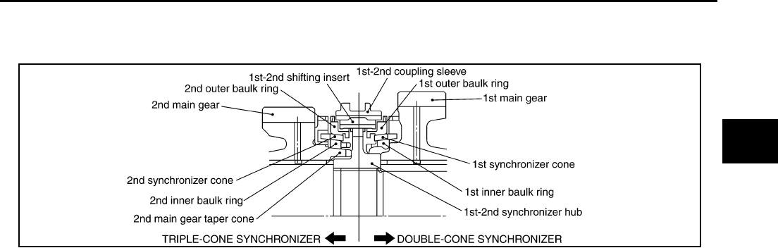
TRIPLE-CONE SYNCHRONIZER
The 2nd gear is equipped with a triple-cone synchronizer to reduce the operating force of the shift lever as
shown.
PCIB0594E
MT-10
M/T OIL
Revision: 2004 December 2004 350Z
M/T OIL PFP:KLD20
Replacement ACS004NL
DRAINING
1. Start the engine and warm up the transmission unit sufficiently.
2. After stopping engine, remove filler plug and drain plug and then drain fluid.
3. After replace a new gasket on drain plug, screw drain plug into transmission body and tighten to the spec-
ified torque. Refer to MT-22, "CASE COMPONENTS" .
CAUTION:
Gaskets are not reusable. Never reuse them.
FILLING
1. Remove filler plug. Fill new oil into the transmission to the level of the filler plug mounting hole.
2. After filling, check fluid level, replace a new gasket on filler plug, screw filler plug into transmission body,
and tighten to the specified torque. Refer to MT-22, "CASE COMPONENTS" .
CAUTION:
Gaskets are not reusable. Never reuse them.
Checking ACS004NM
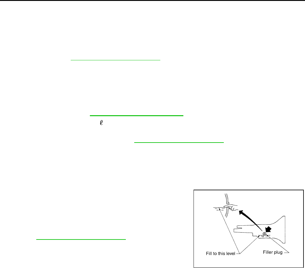
OIL LEAKAGE AND OIL LEVEL
●Check if oil is leaking from transmission or around it.
●Check oil level from filler plug mounting hole as shown in the fig-
ure.
CAUTION:
Never start engine while checking oil level.
●When screwing in filler plug with a new gasket, first screw into
the transmission by hand, then tighten to the specified torque.
Refer to MT-22, "CASE COMPONENTS" .
CAUTION:
Gaskets are not reusable. Never reuse them.
Oil grade: API GL-4
Viscosity: Refer to MA-12, "Fluids and Lubricants" .
Oil capacity: Approx. 2.9 ( 3-1/8 US qt, 2-1/2 lmp qt)
PCIB0268E
REAR OIL SEAL
MT-11
D
E
F
G
H
I
J
K
L
M
A
B
MT
Revision: 2004 December 2004 350Z
REAR OIL SEAL PFP:33140
Removal and Installation ACS004NN
REMOVAL
1. Remove propeller shaft. Refer to PR-7, "REMOVAL" .
CAUTION:
Do not impact or damage propeller shaft tube.
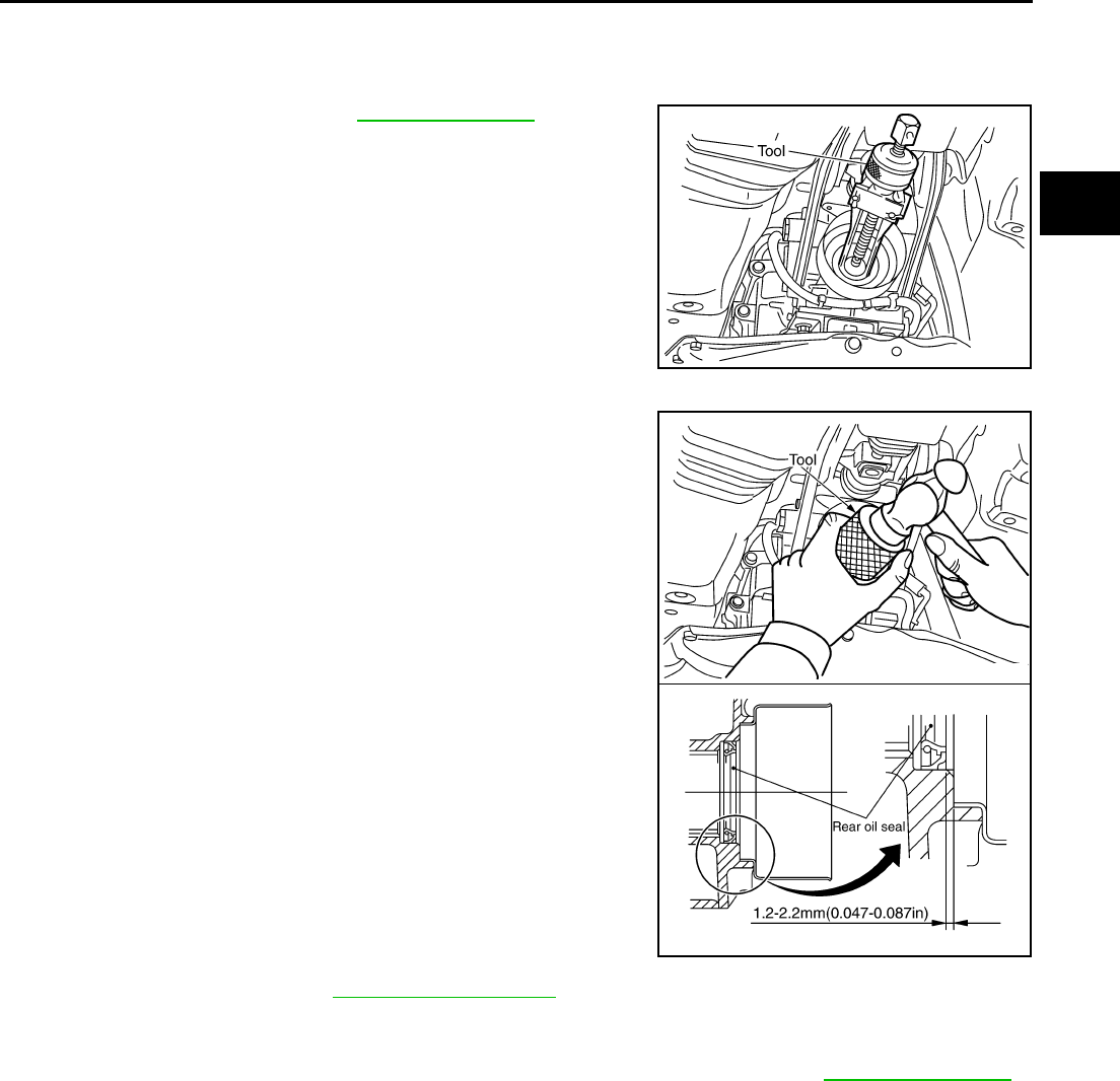
2. Using oil seal puller, remove rear oil seal.
INSTALLATION
1. Apply multi-purpose grease to rear oil seal lip. Using a drift,
drive in rear oil seal until the edge is approximately 1.2 - 2.2 mm
(0.047 - 0.087 in) above the boss edge.
CAUTION:
●Rear oil seals are not reusable. Never reuse them.
●When installing, do not incline the rear oil seal.
2. Install propeller shaft. Refer to PR-8, "INSTALLATION" .
CAUTION:
●Do not impact or damage propeller shaft tube.
●If lubricant leak has occurred, after finishing work, check oil level. Refer to MT-10, "Checking" .
Tool number : KV381054S0 ( — )
PCIB0194E
Tool number : ST33400001 (J26082)
PCIB0595E

MT-12
POSITION SWITCH
Revision: 2004 December 2004 350Z
POSITION SWITCH PFP:32005
Checking ACS004NO
COMPONENT LOCATION
BACK-UP LAMP SWITCH
●Check continuity.
NEUTRAL POSITION SWITCH
●Check continuity.
PCIB0622E
Gear position Continuity
Reverse Yes
Except reverse No
SCIA0645E
Gear position Continuity
Neutral Yes
Except neutral No
SCIA0645E
SHIFT CONTROL
MT-13
D
E
F
G
H
I
J
K
L
M
A
B
MT
Revision: 2004 December 2004 350Z
SHIFT CONTROL PFP:34103
Removal and Installation ACS004NP
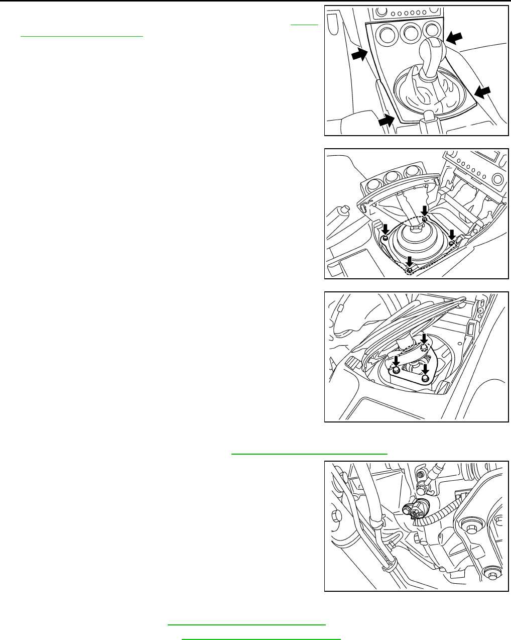
REMOVAL
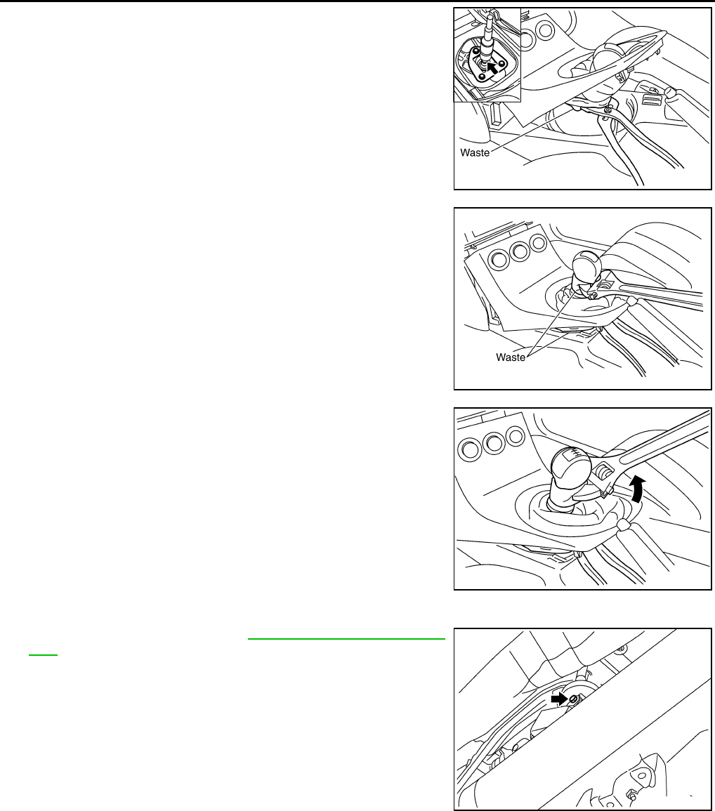
1. Remove the shift knob with the following procedure.
a. Disconnect console boot from center console. Refer to IP-11,
"Removal and Installation" .
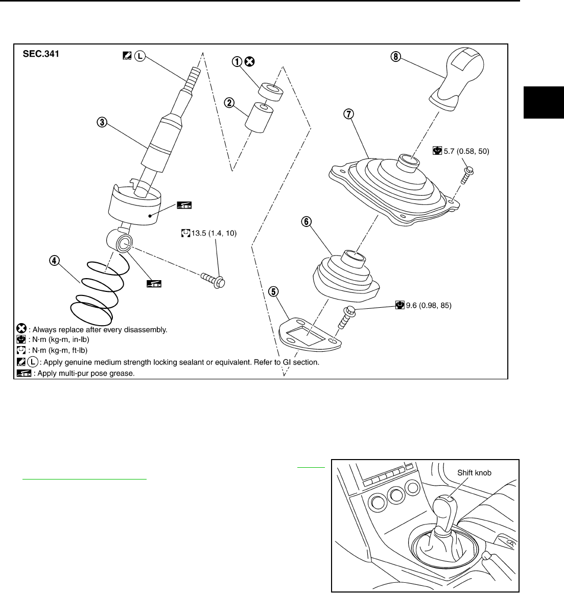
1. Insulator 2. Seat 3. Control lever
4. Control lever spring 5. Guide plate 6. Control lever boot
7. Hole cover 8. Shift knob
PCIB0689E
PCIB0596E
MT-14
SHIFT CONTROL
Revision: 2004 December 2004 350Z
b. Lift console boot, and push down hole cover. Set water pump
plier and others to control lever assembly.
CAUTION:
Put waste cloth between water pump plier and control lever
assembly to avoid damaging control lever assembly.
c. Set monkey wrench to shift knob.
CAUTION:
Put waste cloth between shift knob and suitable plier to
avoid damaging shift knob.
d. Turn monkey wrench with water pump plier and others fixed.
Loosen shift knob, and remove shift knob from control lever
assembly.
NOTE:
Remove shift knob from control assembly with water pump plier
and others fixed. Because a certain power to turn shift knob is
necessary even after adhesive is peeled.
2. Loosen the shift knob to remove the control lever.
3. Remove console boot. Refer to IP-11, "Removal and Installa-
tion" .
4. Push back the boot, remove control lever assembly mounting
bolt, and separate control lever and control rod assembly.
PCIB0222E
PCIB0246E
PCIB0247E
SCIA1671E
SHIFT CONTROL
MT-15
D
E
F
G
H
I
J
K
L
M
A
B
MT
Revision: 2004 December 2004 350Z
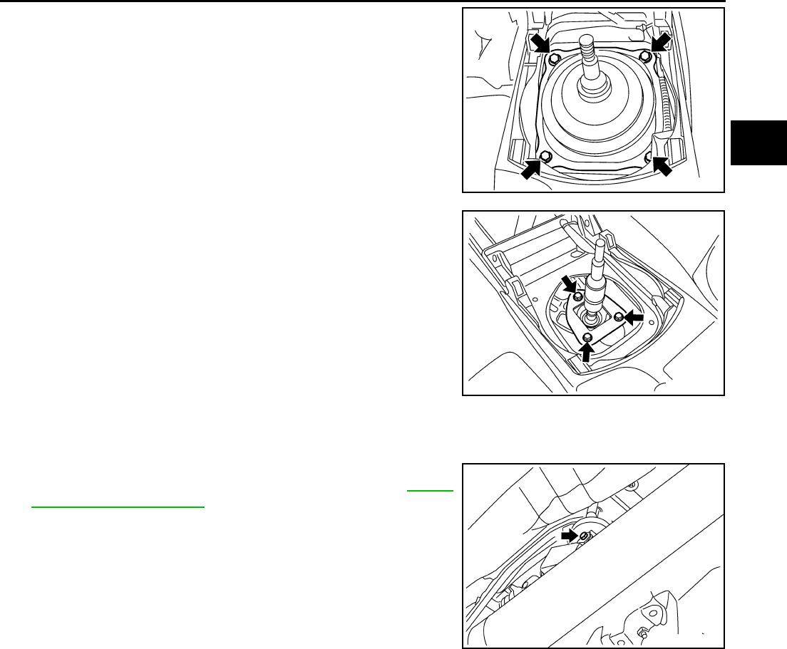
5. Remove the mounting bolts to remove the hole cover.
6. Remove the control lever boot.
7. Remove guide plate mounting bolts, and then remove control
lever assembly and control lever spring.
INSTALLATION
1. Set control lever assembly and control lever spring in the control lever housing assembly and loosely
mount the guide plate.
2. After installing control lever assembly in the control rod assem-
bly, tighten bolts to the specified torque. Refer to MT-13,
"Removal and Installation" .
SCIA1511E
SCIA1365E
SCIA1671E
MT-16
SHIFT CONTROL
Revision: 2004 December 2004 350Z
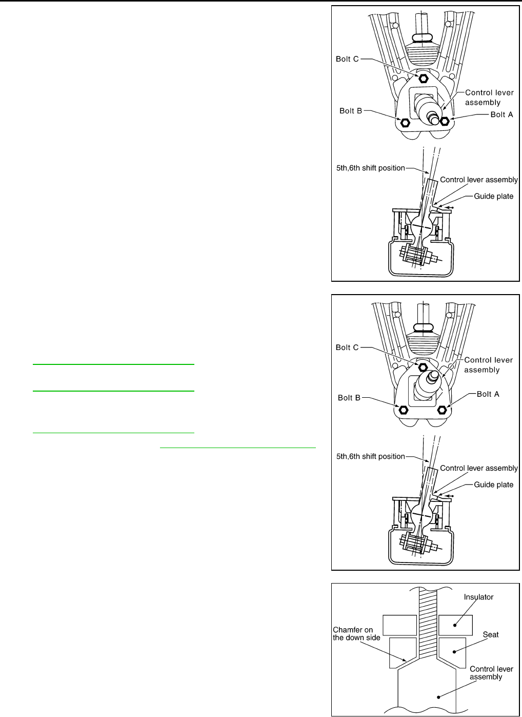
3. Shifting control lever assembly to 6th gear, the control lever
assembly is light pressed to the reverse side.
4. At the point where the control lever assembly stops, bring the
guide plate closer until guide plate stopper contacts control lever
assembly claw, and then loosely tighten mounting bolt A.
5. Shifting control lever assembly to 5th gear, the control lever
assembly light pressed to the reverse side.
6. At the point where control lever assembly stops, bring guide
plate closer until the guide plate stopper contacts control lever
assembly claw, and then loosely tighten mounting bolt C. Refer
to MT-13, "Removal and Installation" .
7. Tighten guide plate bolts A and B to the specified torque. Refer
to MT-13, "Removal and Installation" .
8. Install control lever boot.
9. Install hole cover and tighten bolt to the specified torque. Refer
to MT-13, "Removal and Installation" .
10. Install console boot. Refer to IP-11, "Removal and Installation" .
11. As shown in the figure, assemble seat and insulator to control
lever assembly.
CAUTION:
Do not reuse the insulator.
12. Apply locking sealant to control lever threads, install shift knob.
CAUTION:
Remove the remaining adhesive on control lever and shift
knob threads.
SCIA1665E
SCIA1666E
SCIA1771E
SHIFT CONTROL
MT-17
D
E
F
G
H
I
J
K
L
M
A
B
MT
Revision: 2004 December 2004 350Z
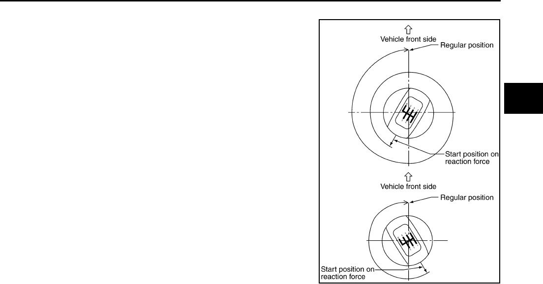
13. Put the shift knob in the correct position as the following indicates.
a. When tightening shift knob, if shift knob position is the correct
position a less than 1/2 rotation from starting resistance, tighten
1 more rotation and set the correct position again.
b. If shift knob position is the correct position more than 1/2 rotation
from starting resistance, tighten and set the correct position.
CAUTION:
●Do not adjust the knob with loosing.
●After adjusting to regular position, until 30 minute passes
since a locking sealant because stiff. Do not operate the
shift intensely such as screwing or turning the shift knob
to opposite direction.
INSPECTION AFTER INSTALLATION
After installing, confirm the following items:
●When control lever assembly is shifted to each position, make sure there is no binding or disconnection in
each boot.
●When shifted to each position, make sure there is no noise, bending, and backlash. Especially when con-
trol lever assembly is shifted to 5th, 6th without pressing downward, check for bending.
●When control lever assembly is shifted to 1st, 2nd side and 5th, 6th side, confirm control lever assembly
returns to neutral position smoothly.
●In any position other than reverse, confirm that control lever assembly can be pressed downward.
●With control lever assembly pressed downward, confirm that it can be shifted to reverse.
●When shifted from reverse to neutral position, confirm control lever assembly returns to neutral position
smoothly with spring power.
●Without control lever assembly pressed downward, confirm that it cannot be shifted to reverse.
SCIA1774E
MT-18
AIR BREATHER HOSE
Revision: 2004 December 2004 350Z
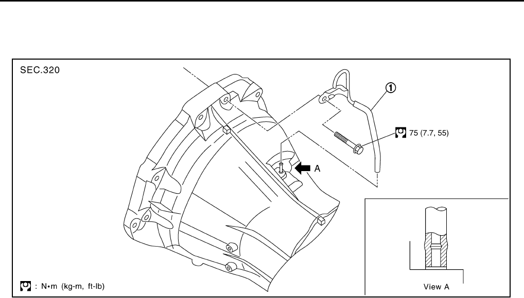
AIR BREATHER HOSE PFP:31098
Removal and Installation ACS004NQ
Refer to the figure for air breather hose removal and installation information.
CAUTION:
●Make sure there are no pinched or blocked areas on the air breather hose caused by bending or
winding when installing it.
●Insert overlap width of air breather hose as far as it will go.
1. Air breather hose
PCIB0690E
TRANSMISSION ASSEMBLY
MT-19
D
E
F
G
H
I
J
K
L
M
A
B
MT
Revision: 2004 December 2004 350Z
TRANSMISSION ASSEMBLY PFP:32010
Removal and Installation from Vehicle ACS004NR
REMOVAL
1. Disconnect battery negative cable.
2. Remove front cross bar with power tool. Refer to FSU-9, "REMOVAL" .
3. Remove catalytic converter stay mounting nuts and bolts, and
then remove catalytic converter bracket. Refer to EX-3,
"Removal and Installation" .
4. Remove nut connecting catalytic converter to exhaust manifold, and then remove catalytic converter and
exhaust front tube as one unit.
5. Remove propeller shaft. Refer to PR-7, "Removal and Installation" .
CAUTION:
Do not impact or damage propeller shaft tube.
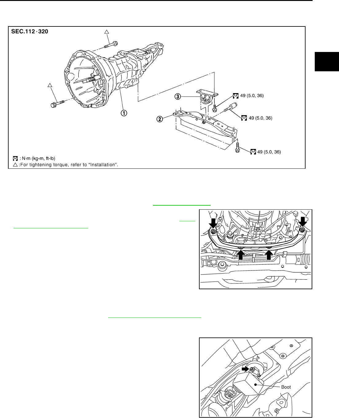
6. Remove control rod mounting bolts and then separate shift lever
assembly from the control rod assembly.
1. Transmission case 2. Rear engine mounting member 3. Insulator
PCIB0691E
SCIA1471E
SCIA1364E
MT-20
TRANSMISSION ASSEMBLY
Revision: 2004 December 2004 350Z
7. Using a screwdriver wrapped in tape to remove claw and then
separate console boot from the center console. Refer to IP-11,
"Removal and Installation" .
8. Remove hole cover mounting bolts and then separate hole
cover from the floor panel.
9. Separate control lever boot from the guide plate.
10. Remove guide plate mounting bolts and then separate shift lever
assembly from the shift lever housing assembly.
11. Remove clutch operating cylinder mounting bolts and then separate heat insulator and clutch operating
cylinder from the transmission case. Refer to CL-11, "Removal and Installation" .
12. Remove crankshaft position sensor (POS).
CAUTION:
●Do not subject it to impact by dropping or hitting.
●Do not disassemble.
●Do not allow metal filings, etc., to get on the sensor's
front edge magnetic area.
●Do not place in an area affected by magnetism.
13. Disconnect neutral position switch and back-up lamp switch.
14. Separate heated oxygen sensor 2 wire harness, crankshaft
position sensor (POS), wire harness, back-up lamp switch wire
harness and PNP switch wire harness from the transmission.
15. Remove starter motor. Refer to SC-19, "Removal and Installation" .
16. Remove rear cover plate. Refer to EM-27, "Removal and Installation" .
17. Set transmission jack to the transmission.
CAUTION:
When setting transmission jack, be careful not to contact with the switch.
SCIA1473E
SCIA1590E
SCIA1591E
SCIA1476E
TRANSMISSION ASSEMBLY
MT-21
D
E
F
G
H
I
J
K
L
M
A
B
MT
Revision: 2004 December 2004 350Z
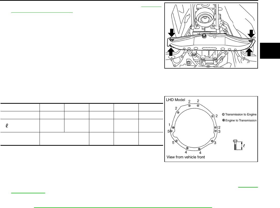
18. Remove rear engine mounting member. Refer to EM-103,
"Removal and Installation" .
19. Remove engine and transmission mounting bolts with power
tool.
20. Remove transmission from the vehicle.
INSTALLATION
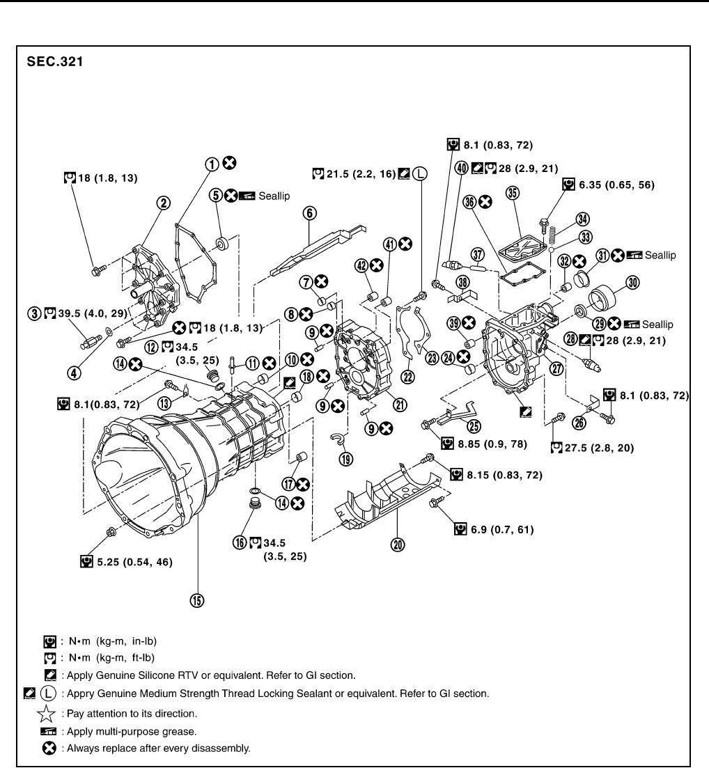
Install in the revers order of removal procedure, following the cautions below:
●When installing transmission to the engine, install mounting bolts in accordance with the standards below.
LHD Model
CAUTION:
●When installing, be careful to avoid interference between transmission main drive shaft and clutch
cover.
●If flywheel is removed, align dowel pin with the smallest hole of flywheel. Refer to EM-115,
"ASSEMBLY" .
●Do not impact or damage propeller shaft tube.
●Refer to MT-15, "INSTALLATION"MT-17, "INSPECTION AFTER INSTALLATION" for control lever
installation information.
●After installation, check oil level, and oil leaks and loose mechanisms.
SCIA1531E
Bolt No. 1 2 3 4 5
Quantity 15222
“ ” mm (in) 55
(2.17)
65
(2.56)
50
(1.97)
35
(1.38)
65
(2.56)
Tightening torque
N·m (kg-m, ft-lb)
75
(7.7, 55)
55.4
(5.7, 41)
46.6
(4.8, 34)
55.4
(5.7,41)
PCIB0700E
MT-22
TRANSMISSION ASSEMBLY
Revision: 2004 December 2004 350Z
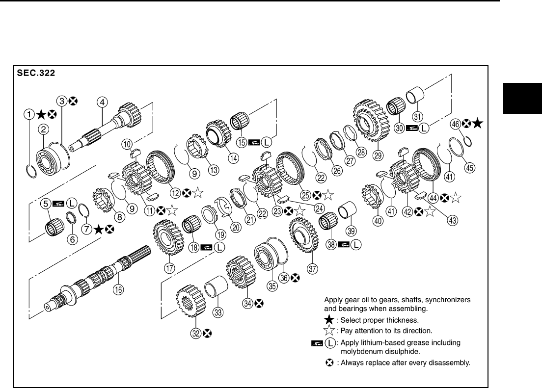
Component Parts Drawing ACS004NS
CASE COMPONENTS
1. Front cover gasket 2. Front cover 3. Withdrawal lever ball pin
4. Washer 5. Front cover oil seal 6. Oil gutter
7. Bushing 8. Bushing 9. Dowel pin
10. Bushing 11. Breather 12. Filler plug
13. Bracket 14. Gasket 15. Transmission case
16. Drain plug 17. Sliding ball bearing 18. Bushing
19. Magnet 20. Baffle plate 21. Adapter plate
22. Main shaft bearing retainer 23. Main shaft bearing retainer 24. Bushing
25. Rear extension oil gutter 26. Bracket 27. Rear extension
28. Back-up lamp switch 29. Rear oil seal 30. Rear extension dust cover
31. Striking rod oil seal 32. Sliding ball bearing 33. Check ball
PCIB0900E
TRANSMISSION ASSEMBLY
MT-23
D
E
F
G
H
I
J
K
L
M
A
B
MT
Revision: 2004 December 2004 350Z
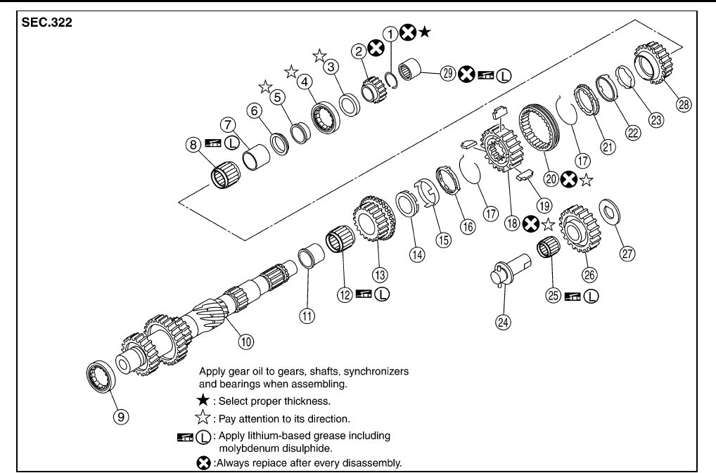
GEAR COMPONENTS
34. Check select spring 35. Rear extension upper cover 36. Rear extension upper cover gasket
37. Plunger 38. Bracket 39. Sliding ball bearing
40. Neutral position switch 41. Sliding ball bearing 42. Sliding ball bearing
1. Snap ring 2. Main drive gear bearing 3. Snap ring
4. Main drive gear 5. Main pilot bearing 6. Pilot bearing spacer
7. Snap ring 8. 5th baulk ring 9. 5th - 6th spread spring
10. 5th-6th shifting insert 11. 5th-6th synchronizer hub 12. 5th - 6th coupling sleeve
13. 6th baulk ring 14. 6th main gear 15. 6th needle bearing
16. Main shaft 17. 2nd main gear 18. 2nd needle bearing
19. 2nd inner baulk ring 20. 2nd synchronizer cone 21. 2nd outer baulk ring
22. 1st-2nd spread spring 23. 1st - 2nd synchronizer hub 24. 1st - 2nd shifting insert
25. 1st - 2nd coupling sleeve 26. 1st outer baulk ring 27. 1st synchronizer cone
28. 1st inner baulk ring 29. 1st main gear 30. 1st needle bearing
31. 1st gear bushing 32. 3rd main gear 33. 3rd - 4th main spacer
34. 4th main gear 35. Main shaft bearing 36. Snap ring
37. Reverse main gear 38. Reverse main needle bearing 39. Reverse main gear bushing
40. Reverse baulk ring 41. Reverse spread spring 42. Reverse synchronizer hub
43. Reverse shifting insert 44. Reverse coupling sleeve 45. Snap ring
46. Snap ring
PCIB0693E
MT-24
TRANSMISSION ASSEMBLY
Revision: 2004 December 2004 350Z
1. Snap ring 2. Reverse counter gear 3. Counter rear bearing spacer
4. Counter rear bearing 5. Counter rear bearing inner race 6. 4th counter gear thrust washer
7. 4th gear bushing 8. 4th needle bearing 9. Counter front bearing
10. Counter shaft 11. 3rd gear bushing 12. 3rd needle bearing
13. 3rd counter gear 14. 3rd inner baulk ring 15. 3rd synchronizer cone
16. 3rd outer baulk ring 17. 3rd - 4th spread spring 18. 3rd - 4th synchronizer hub
19. 3rd - 4th shifting insert 20. 3rd - 4th coupling sleeve 21. 4th outer baulk ring
22. 4th synchronizer cone 23. 4th inner baulk ring 24. Reverse idler shaft
25. Reverse idler needle bearing 26. Reverse idler gear 27. Reverse idler thrust washer
28. 4th counter gear 29. Counter end bearing
PCIB0597E
TRANSMISSION ASSEMBLY
MT-25
D
E
F
G
H
I
J
K
L
M
A
B
MT
Revision: 2004 December 2004 350Z
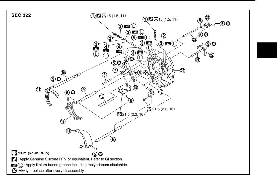
SHIFT CONTROL COMPONENTS
1. Check ball plug 2. Check ball spring 3. Check ball
4. Interlock pin 5. Retaining pin 6. Striking lever
7. 3rd-4th fork rod bracket 8. 3rd-4th fork rod 9. 3rd - 4th fork rod (reversal side)
10. 1st-2nd fork rod 11. 1st-2nd shift fork 12. 3rd-4th shift fork
13. 5th-6th shift fork 14. 5th-6th fork rod (reversal side) 15. 5th-6th fork rod
16. Shifter cap 17. 3rd-4th control lever 18. 5th-6th fork rod bracket
19. 5th-6th control lever 20. Adapter plate 21. Reverse fork rod
22. Reverse shift fork 23. Striking rod 24. Low/high control lever
25. Stopper ring 26. Interlock plunger
PCIB0902E
MT-26
TRANSMISSION ASSEMBLY
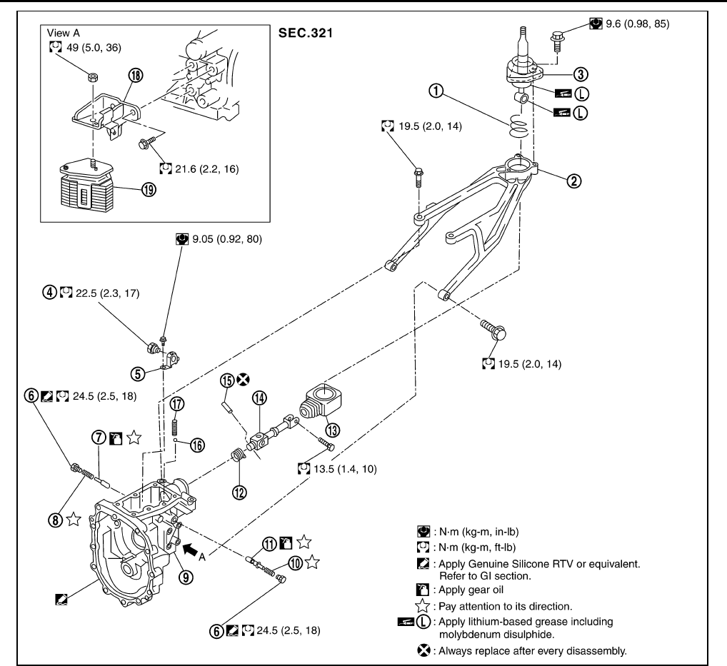
Revision: 2004 December 2004 350Z
1. Control lever spring 2. Control lever housing 3. Control lever
4. Check shift pin 5. Control bracket 6. Return spring plug
7. Return spring plunger 8. Return spring 9. Rear extension
10. Return spring 11. Return spring plunger 12. Boot
13. Boot 14. Control rod 15. Retaining pin
16. Check ball 17. Check select spring 18. Dynamic damper bracket
19. Dynamic damper
PCIB0901E
TRANSMISSION ASSEMBLY
MT-27
D
E
F
G
H
I
J
K
L
M
A
B
MT
Revision: 2004 December 2004 350Z
Disassembly and Assembly ACS004NT
DISASSEMBLY
Case Components
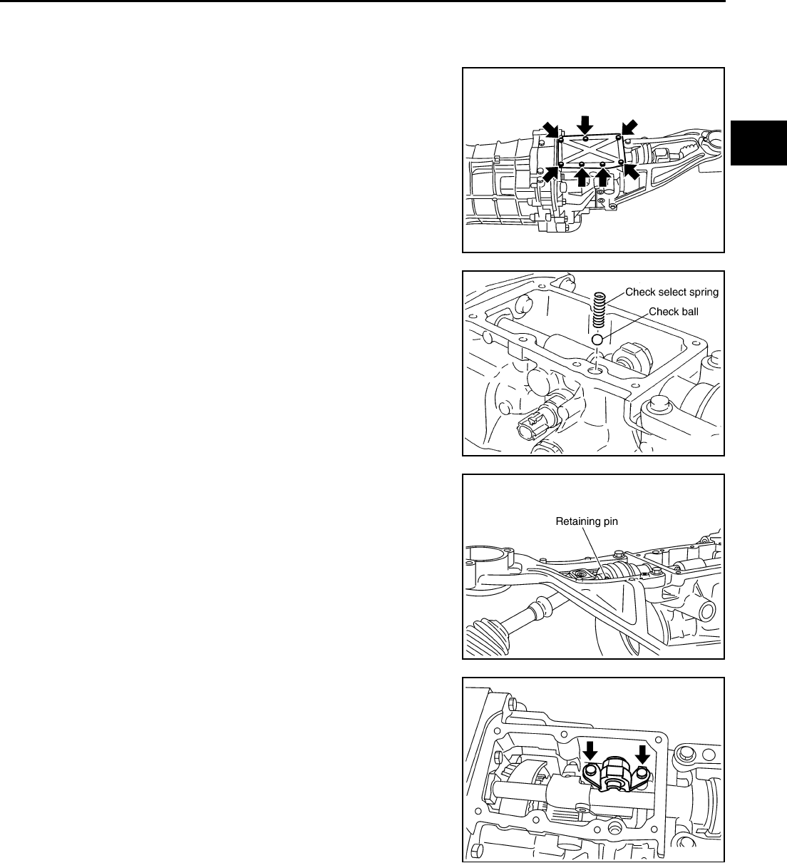
1. Remove rear extension upper cover mounting bolts.
2. Remove rear extension upper cover and rear extension upper
cover gasket from the rear extension.
3. Remove check select spring and check ball from the rear exten-
sion.
4. Remove retaining pin using a pin punch [6 mm (0.24 in) dia.],
and remove control rod.
5. Remove neutral position switch, plunger and back-up lamp
switch from the rear extension.
6. Remove control bracket mounting bolts. Then remove check
shift pin and control bracket as one unit from the rear extension.
SCIA1393E
PCIB0599E
SCIA1437E
SCIA1440E

MT-28
TRANSMISSION ASSEMBLY
Revision: 2004 December 2004 350Z
7. Remove right and left return spring plug. Then remove return
spring and return spring plunger from the rear extension.
CAUTION:
Return spring and return spring plunger have different
lengths for right and left sides. Identify right and left side
and then store.
8. Remove rear oil seal from the rear extension using an oil seal
puller.
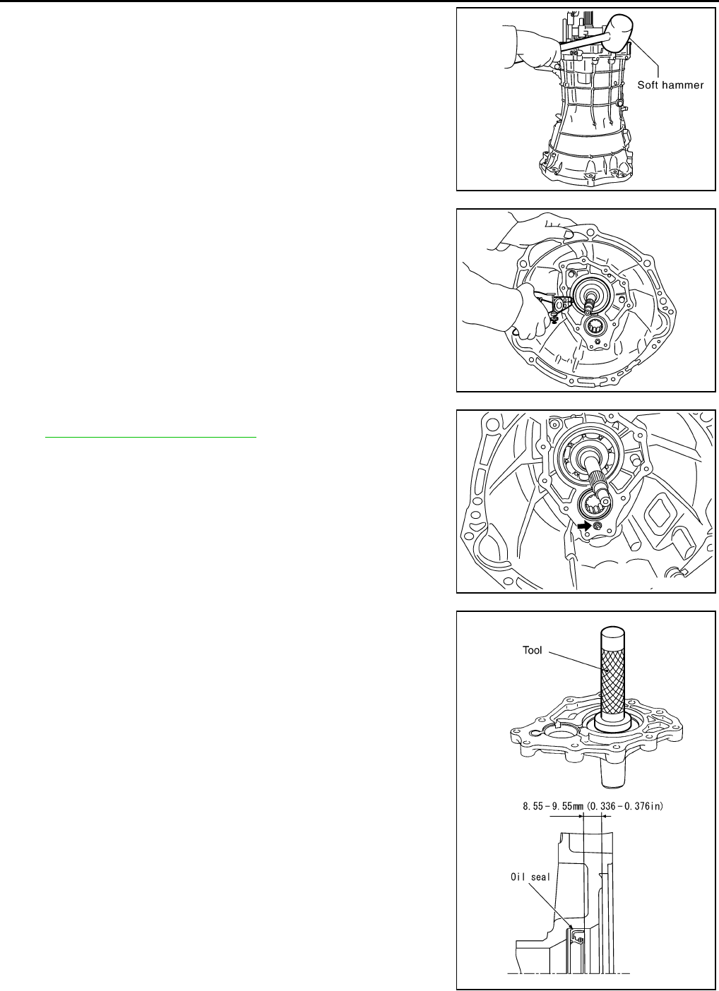
9. Remove rear extension mounting bolts. Using a soft hammer,
tap rear extension assembly to remove.
10. Remove control lever housing mounting bolts, and remove con-
trol lever housing from the rear extension.
11. Remove striking rod oil seal from the rear extension. Refer to
MT-22, "CASE COMPONENTS" .
12. Remove rear extension oil gutter from the rear extension. Refer
to MT-22, "CASE COMPONENTS" .
13. Remove reverse idler thrust washer, revers idler gear, and
reverse idler needle bearing from the reverse idler shaft.
14. Remove reverse idler shaft from the adapter plate.
15. Remove withdrawal lever ball pin and washer from the front
cover.
16. Remove front cover mounting bolts, then remove front cover
assembly and front cover gasket from the transmission case.
SCIA1441E
Tool number : KV381054S0 ( — )
PCIB0196E
PCIB0141E
PCIB0152E
PCIB0600E
TRANSMISSION ASSEMBLY
MT-29
D
E
F
G
H
I
J
K
L
M
A
B
MT
Revision: 2004 December 2004 350Z
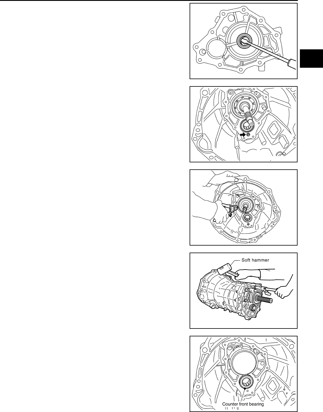
17. Remove front cover oil seal from the front cover assembly, using
a flat-bladed screwdriver.
CAUTION:
Be careful not to damage front cover mating surface.
18. Remove baffle plate mounting nut from the transmission case.
19. Remove snap ring from the main drive gear bearing, using snap
ring pliers.
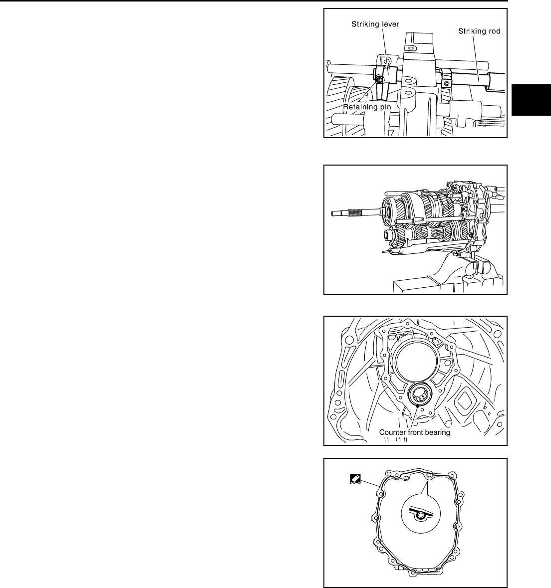
20. Using a soft hammer to carefully tap main shaft and counter
shaft from the transmission case side, and then separate
adapter plate and transmission case.
21. Remove counter front bearing from the transmission case.
22. Remove oil gutter from the transmission case.
SCIA1399E
SCIA1443E
SCIA1532E
SCIA1687E
PCIB0436E

MT-30
TRANSMISSION ASSEMBLY
Revision: 2004 December 2004 350Z
Shift Control Components
1. Install adapter setting plate to the adapter plate and then fixing
in adapter setting plate using a vise.
CAUTION:
Do not directly secure the surface in a vise.
2. Remove baffle plate mounting bolts, and remove baffle plate
from the adapter plate.
3. Remove magnet from the adapter plate.
4. Remove retaining pin using a pin punch [6 mm (0.24 in) dia.],
and remove striking lever and striking rod.
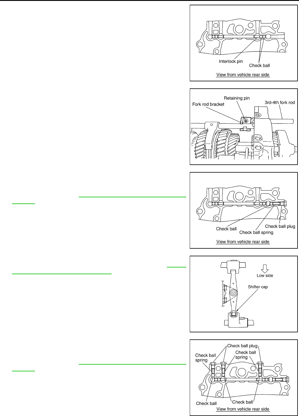
5. Remove check ball plug and then remove check ball spring and
check ball from the adapter plate.
Tool number : ST224490000 ( — )
PCIB0254E
PCIB0154E
PCIB0414E
PCIB0143E
TRANSMISSION ASSEMBLY
MT-31
D
E
F
G
H
I
J
K
L
M
A
B
MT
Revision: 2004 December 2004 350Z
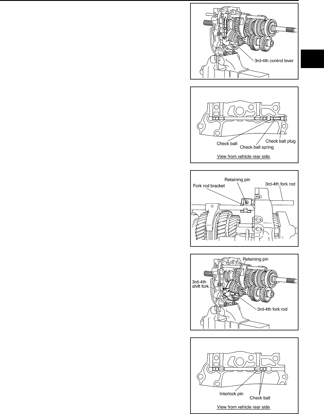
6. Remove 3rd - 4th control lever mounting bolts and then remove
3rd - 4th control lever and shifter cap.
7. Remove check ball plug and then remove check ball spring and
check ball from the adapter plate.
8. Using a pin punch [6 mm (0.24 in) dia.] to knock out retaining
pin, and then remove 3rd - 4th fork rod bracket and 3rd - 4th fork
rod.
9. Using a pin punch [6 mm (0.24 in) dia.] to knock out retaining
pin, and then remove 3rd - 4th shift fork and 3rd - 4th fork rod
(reversal side).
10. Remove check ball and interlock pin from the adapter plate.
PCIB0235E
PCIB0144E
PCIB0145E
PCIB0601E
PCIB0146E
MT-32
TRANSMISSION ASSEMBLY
Revision: 2004 December 2004 350Z
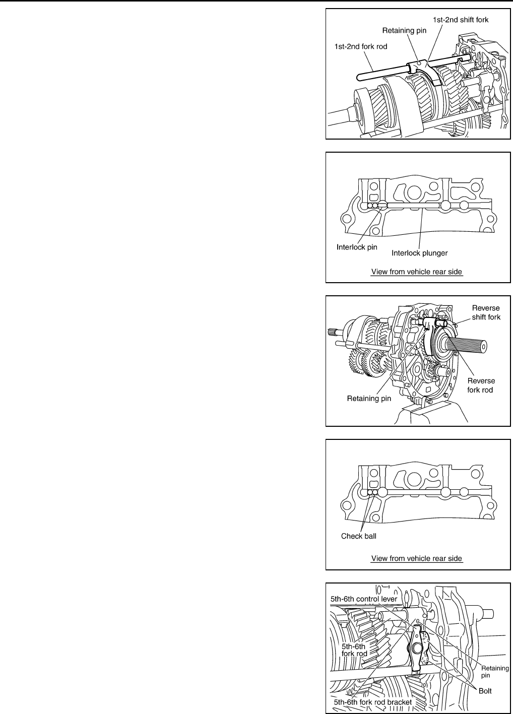
11. Using a pin punch [6 mm (0.24 in) dia.] to knock out retaining
pin, and then remove 1st - 2nd shift fork and 1st - 2nd fork rod.
12. Remove interlock plunger and interlock pin from the adapter
plate.
13. Using a pin punch [6 mm (0.24 in) dia.] to knock out retaining
pin, and then remove reverse shift fork and reverse fork rod.
14. Remove check ball from the adapter plate.
15. Remove 5th - 6th control lever mounting bolts and then remove
5th - 6th control lever from the adapter plate.
PCIB0602E
PCIB0147E
SCIA1447E
PCIB0148E
PCIB0238E
TRANSMISSION ASSEMBLY
MT-33
D
E
F
G
H
I
J
K
L
M
A
B
MT
Revision: 2004 December 2004 350Z
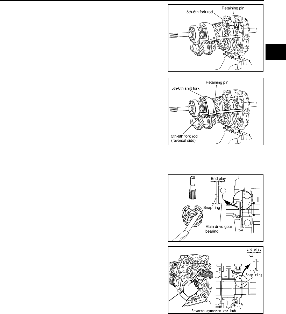
16. Using a pin punch [6 mm (0.24 in) dia.] to knock out retaining
pin, and then remove 5th - 6th fork rod bracket and 5th - 6th fork
rod.
17. Using a pin punch [6 mm (0.24 in) dia.] to knock out retaining
pin, and then remove 5th - 6th fork rod (reversal side) and 5th -
6th shift fork.
Gear Components
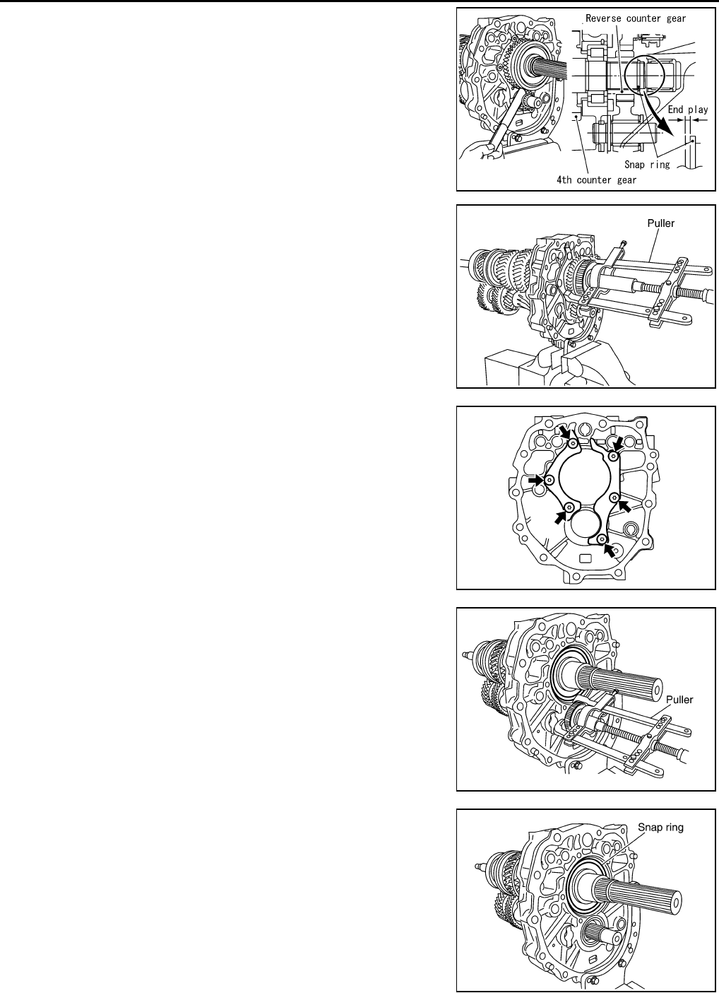
●Before disassembly, measure end play for each position. If the end play is outside the standards, disas-
semble and inspect.
–Main drive gear
–Main shaft
PCIB0239E
PCIB0412E
End play : 0 - 0.10mm (0 - 0.004in)
PCIB0484E
End play : 0 - 0.10mm (0 - 0.004in)
PCIB0225E
MT-34
TRANSMISSION ASSEMBLY
Revision: 2004 December 2004 350Z
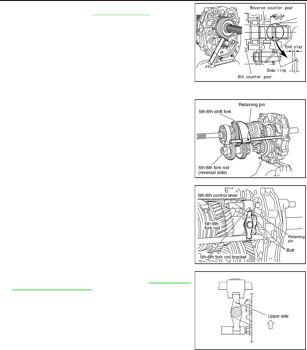
–Counter shaft
1. After removing snap ring and reverse coupling snap ring, using
puller to remove reverse main gear and reverse synchronizer
assembly.
2. Remove reverse main needle bearing.
3. Remove main shaft bearing retainer mounting bolts and then
remove main shaft bearing retainer.
4. After removing snap ring, using the puller to remove reverse
counter gear and counter rear bearing spacer.
5. Remove snap ring from the main shaft bearing.
End play : 0 - 0.10mm (0 - 0.004in)
PCIB0226E
SCIA1683E
SCIA1452E
SCIA1682E
SCIA1691E
TRANSMISSION ASSEMBLY
MT-35
D
E
F
G
H
I
J
K
L
M
A
B
MT
Revision: 2004 December 2004 350Z
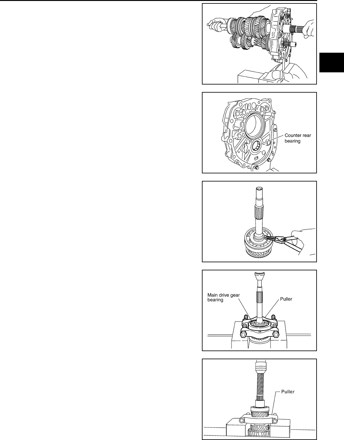
6. Carefully tap main shaft with a plastic hammer and then remove
main shaft, main drive gear, and counter shaft from adapter
plate.
7. Remove pilot bearing spacer and main pilot bearing.
8. Remove counter rear bearing from the adapter plate.
9. Remove snap ring from the main drive gear using snap ring pli-
ers.
10. Set the suitable puller on the main drive gear and then using a
press to remove main drive gear bearing from the main drive
gear.
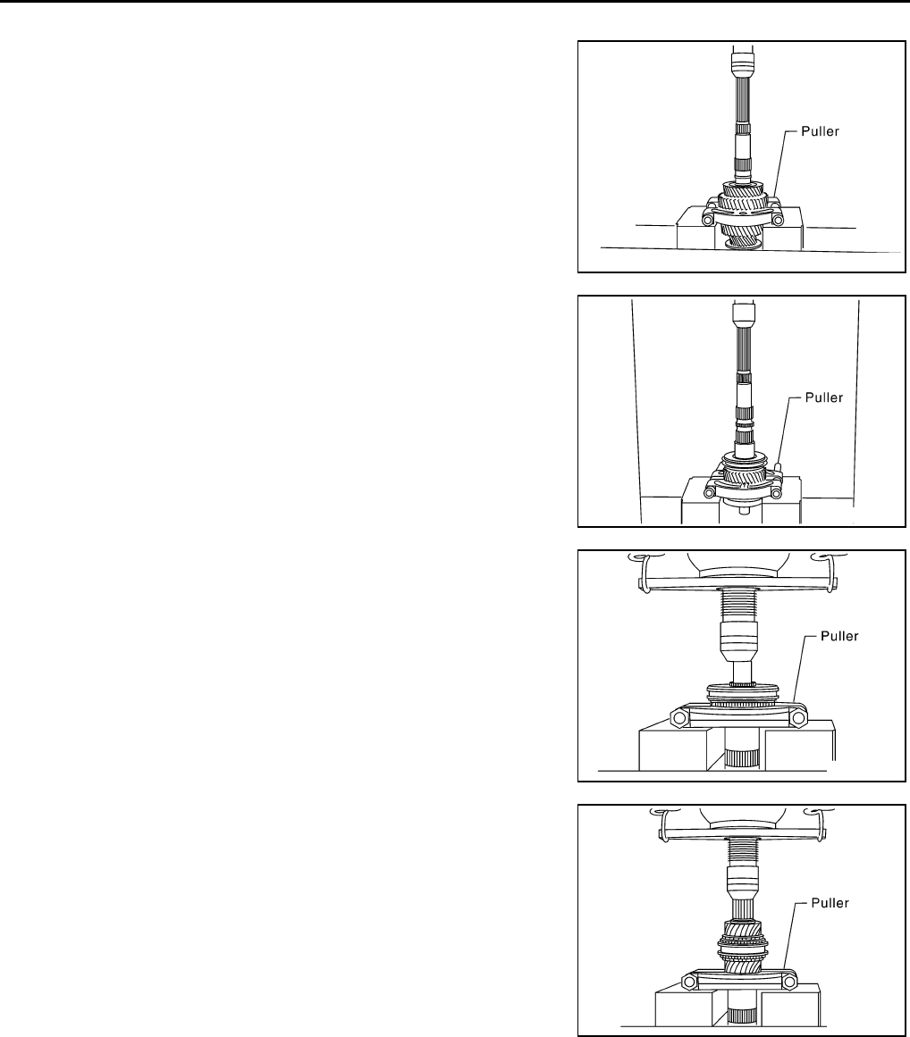
11. Using a press to remove the reverse main gear bushing, main
shaft bearing and 4th main gear.
SCIA1456E
PCIB0244E
SCIA1461E
SCIA1533E
SCIA1386E
MT-36
TRANSMISSION ASSEMBLY
Revision: 2004 December 2004 350Z
12. Remove 3rd - 4th main spacer.
13. Using a press to remove 1st main gear and 3rd main gear.
CAUTION:
Be careful not to damage the baulk ring.
14. Remove 1st needle bearing.
15. Using a press to remove 1st gear bushing, 1st - 2nd synchro-
nizer assembly, and 2nd main gear.
CAUTION:
Be aware that when using the press, if the main shaft gear
positioner catches on the V-block, etc., the main shaft
could be damaged.
16. Remove 2nd needle bearing.
17. After removing snap ring, using a press to remove 6th main gear
and 5th - 6th synchronizer assembly.
18. Remove 6th needle bearing.
19. Using a press to remove the 3rd counter gear, 3rd - 4th synchro-
nizer assembly, 4th counter gear, 4th needle bearing, 4th gear
bushing, 4th counter gear thrust washer, and counter rear bear-
ing inner race.
20. Remove 3rd needle bearing.
SCIA1458E
SCIA1459E
SCIA1460E
SCIA1389E
TRANSMISSION ASSEMBLY
MT-37
D
E
F
G
H
I
J
K
L
M
A
B
MT
Revision: 2004 December 2004 350Z
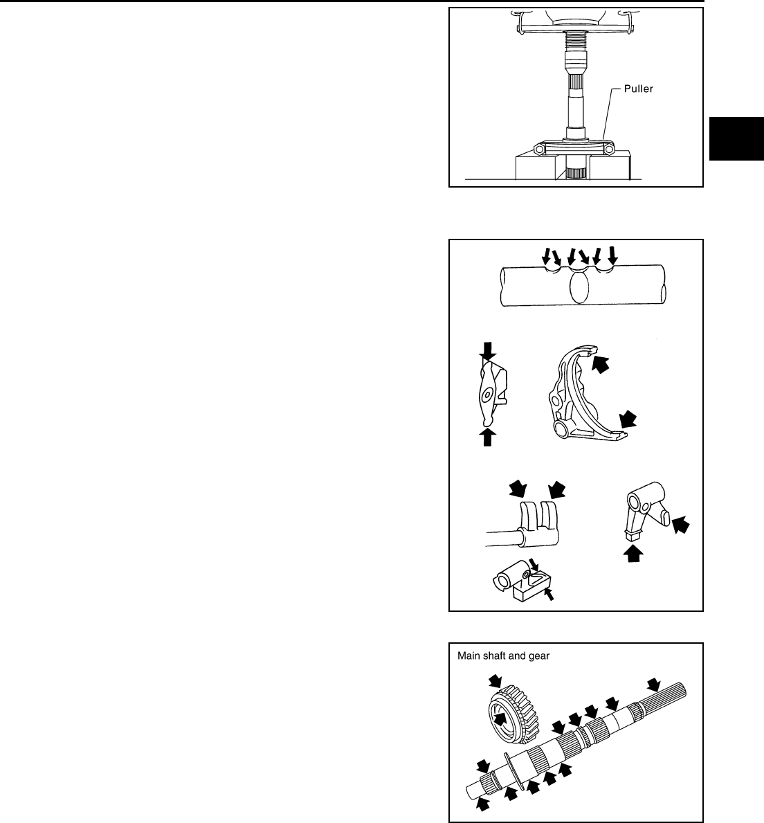
21. Using a press to remove the 3rd gear bushing.
INSPECTION AFTER DISASSEMBLY
Shift Control
If the contact surface on striking lever, fork rod, shift fork, etc. has
excessive wear, abrasion, bend, or any other damage, replace the
components.
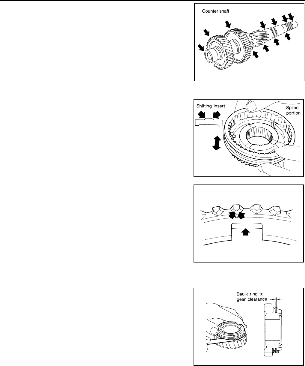
Gear and Shaft
If the contact surface on each gear, main shaft, main drive gear, and
counter shaft, etc. has damage, peeling, abrasion, dent, bent, or any
other damage, replace the components.
SCIA1534E
SCIA1681E
PCIB0437E
MT-38
TRANSMISSION ASSEMBLY
Revision: 2004 December 2004 350Z
Synchronizer
●If the contact surface on coupling sleeve, synchronizer hub, and
shifting insert has damage or abrasion, replace the components.
●Coupling sleeve and synchronizer hub shall move smoothly.
●If the cam surface on baulk ring or contact surface on insert has
damage or excessive wear, replace with a new one.
●If spread spring damaged, replace with a new one.
Baulk Ring Clearance
●Single Cone Synchronizer (5th & 6th)
Push baulk ring on the cone and measure baulk ring back sur-
face clearance at two locations or more on opposite sides, find
the average value, and replace it if it is outside the limit value.
●Double Cone Synchronizer (1st & 3rd & 4th)
PCIB0438E
SMT387A
SCIA0608J
Clearance
Standard : 0.70 - 1.25 mm (0.028 - 0.049 in)
Limit value : 0.5 mm (0.020 in) or less
SMT140
TRANSMISSION ASSEMBLY
MT-39
D
E
F
G
H
I
J
K
L
M
A
B
MT
Revision: 2004 December 2004 350Z
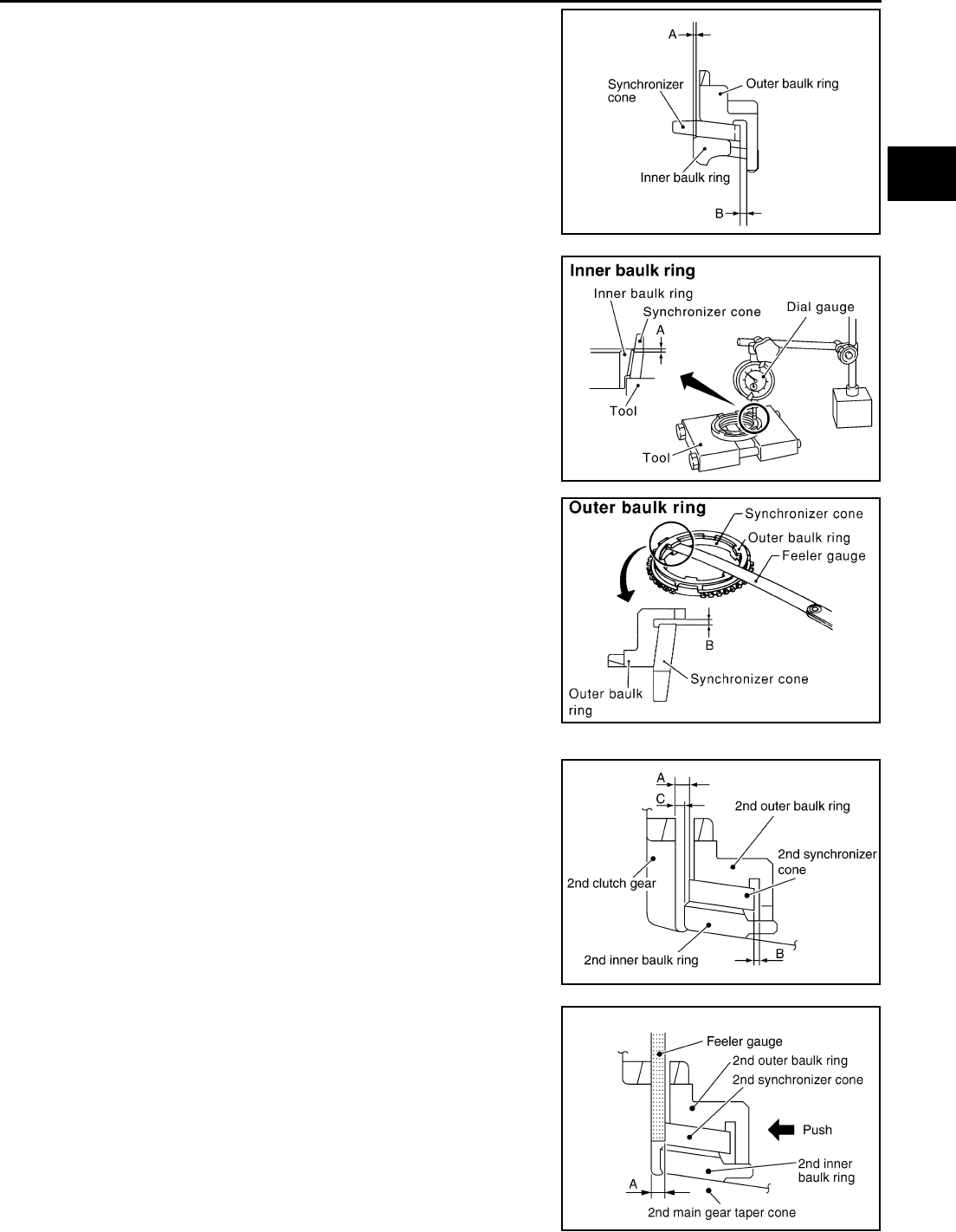
Follow the instructions below and inspect the clearance of the
outer baulk ring, synchronizer cone, inner baulk ring.
CAUTION:
Clearances “A” and “B” of the outer baulk ring, synchro-
nizer cone, and inner baulk ring are controlled as a set, so if
the clearance is outside the limit value, replace the syn-
chronizer assembly.
1. Using a dial gauge, measure clearance A at 2 or more points
diagonally opposite, and calculate mean value.
2. Using a feeler gauge, measure clearance B at 2 or more points
diagonally opposite, and calculate mean value.
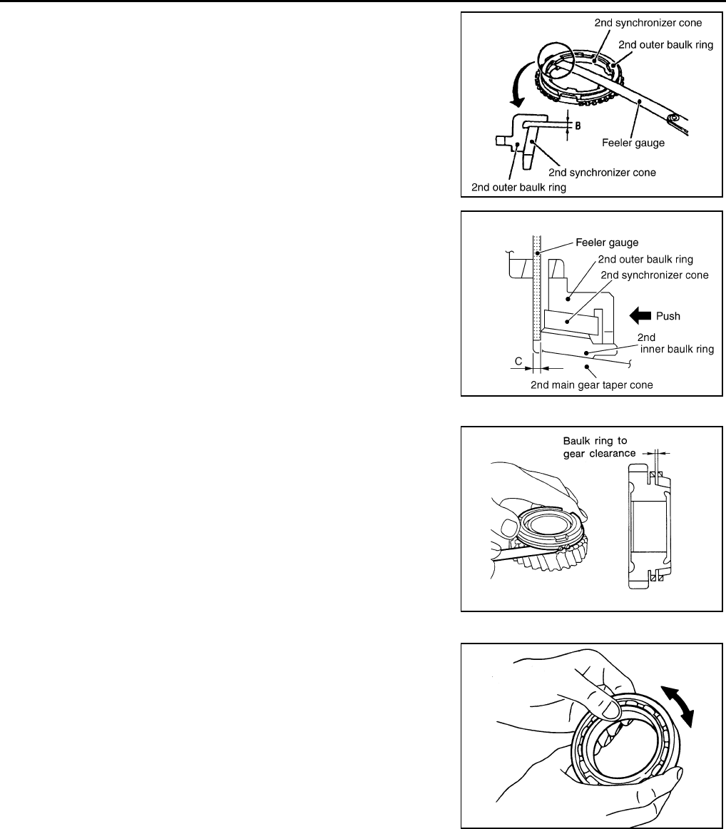
●Triple cone synchronizer (2nd)
Check clearance for 2nd outer baulk ring, 2nd synchronizer
cone, and 2nd inner baulk ring of triple cone synchronizer follow-
ing the direction.
NOTE:
2nd outer baulk ring, 2nd synchronize cone, and 2nd inner baulk
ring, three control“clearance A, B and C” as a three-piece suite.If
the value exceeds the limit value, replace them as a three-piece
suite.
1. Using feeler gauge put and press baulk ring on 2nd main gear
taper cone, and then measure “clearance A” at more then 2
diagonal points, and calculate the average.
SCIA1679E
Clearance A
Standard : 0.5 - 0.7 mm (0.020 - 0.028 in)
Limit value : 0.3 mm (0.012 in) or less
Tool number : ST30031000 (J22912-01)
PCIB0673E
Clearance B
Standard(1st) : 1.0 - 1.5mm(0.039 - 0.059 in)
Standard(3rd,4th) : 0.85 - 1.35mm (0.033 - 0.053 in)
Limit value : 0.7mm(0.028 in) or less
SCIA1084E
PCIB0603E
Clearance A
Reference value : 0.6-1.3 mm (0.024 - 0.051in)
Limit value : 0.3mm (0.012 in) or less
PCIB0887E
MT-40
TRANSMISSION ASSEMBLY
Revision: 2004 December 2004 350Z
2. Using feeler gauge measure “clearance B” at more than 2 diago-
nal positions, and calculate the average.
3. Using filler gauge put and press baulk ring on 2nd main gear
taper cone, and then measure “clearance C” at more then 2
diagonal points, and calculate the average.
●Reverse Synchronizer
Push baulk ring on the cone and measure baulk ring back sur-
face clearance at two locations or more on opposite sides, find
the average value, and replace if it is outside the limit value.
Bearing
If the bearing does not rotate smoothly or the contact surface on ball
or race is damaged or peeled, replace with new ones.
Clearance B
Reference value : 0.85 - 1.35 mm (0.033 - 0.053in)
Limit value : 0.7mm (0.028 in) or less
PCIB0605E
Clearance C
Reference value : 0.7-1.25 mm (0.028 - 0.049in)
Limit value : 0.3mm (0.012 in) or less
PCIB0888E
Clearance
Standard : 0.75-1.2 mm (0.030 - 0.047 in)
Limit value : 0.5 mm (0.020 in) or less
SMT140
SMT418A
TRANSMISSION ASSEMBLY
MT-41
D
E
F
G
H
I
J
K
L
M
A
B
MT
Revision: 2004 December 2004 350Z
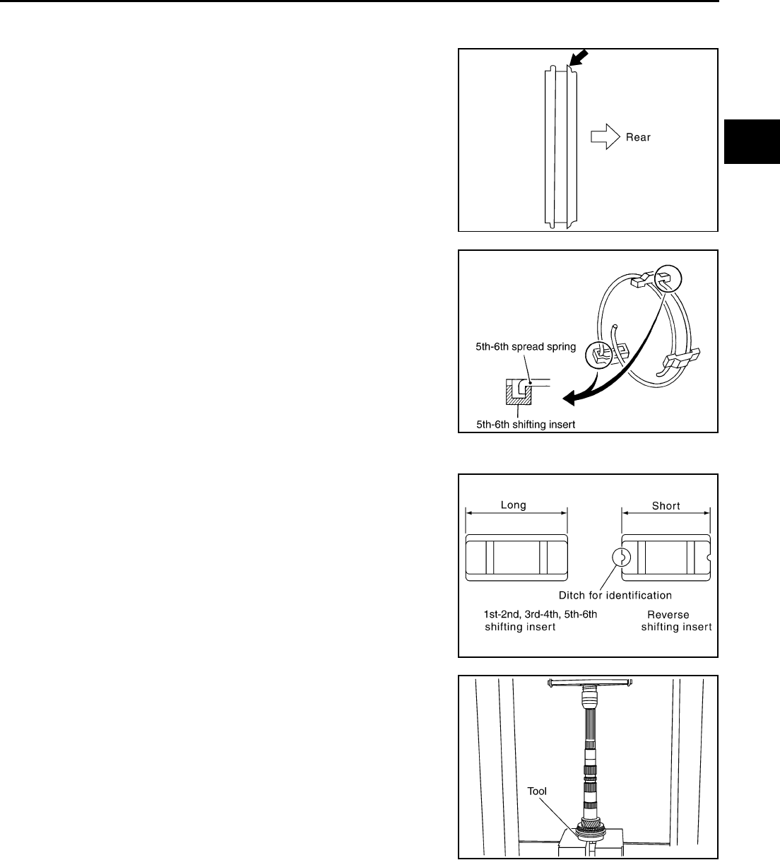
ASSEMBLY
Gear Components
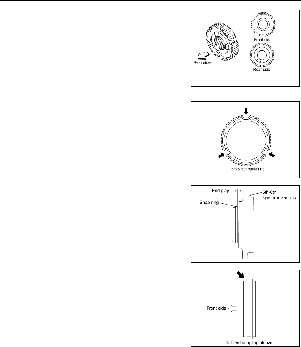
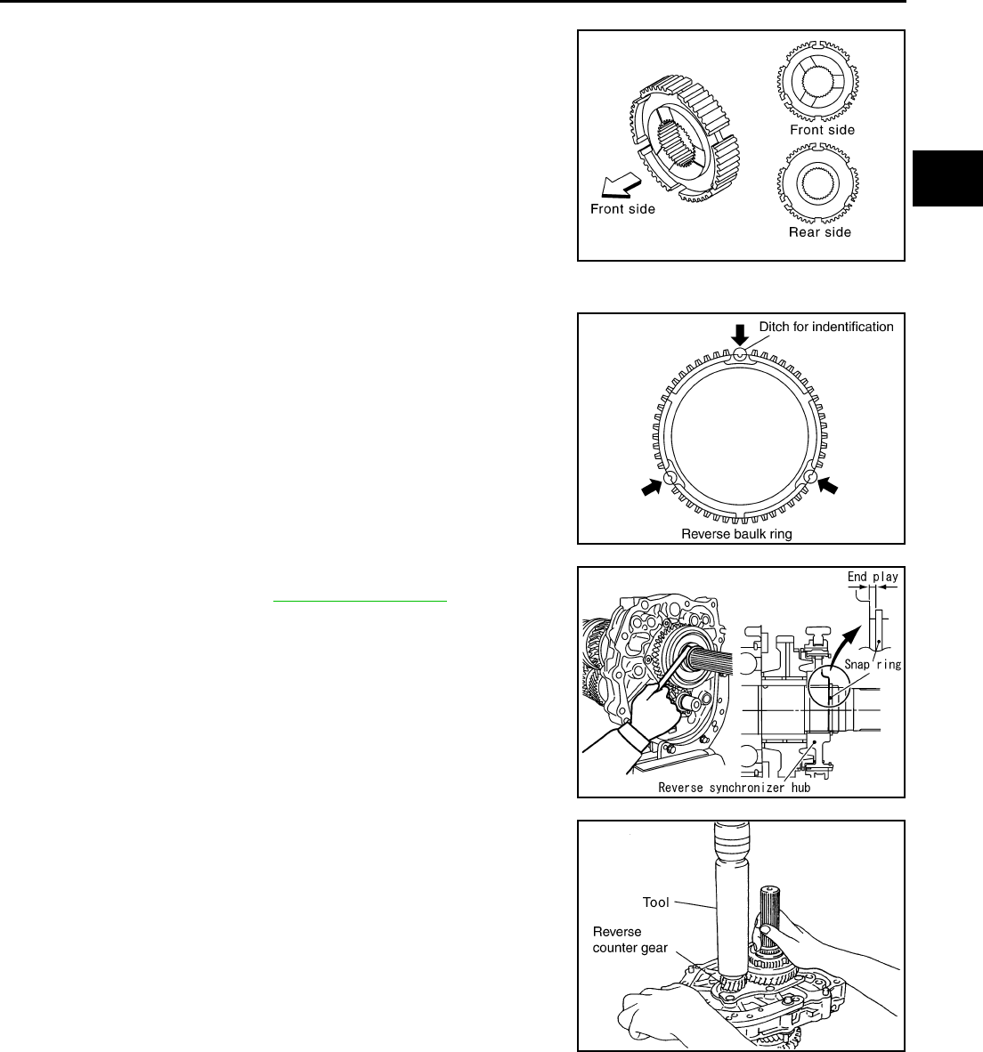
1. Install 5th - 6th coupling sleeve and 5th - 6th shifting insert in the
5th - 6th synchronizer hub.
CAUTION:
Install 5th - 6th coupling sleeve with the larger chamfer on
the rear side.
2. Install 5th - 6th spread spring in the 5th - 6th shifting insert.
CAUTION:
●Do not install 5th - 6th spread spring hook onto the same
5th - 6th shifting insert.
●Be careful with the shape of reserve shifting insert to
avoid misassembly.
3. Install 6th needle bearing, 6th main gear and 6th baulk ring on
the main shaft and then using an inserter and a press to press fit
the 5th - 6th synchronizer assembly.
SCIA1597E
PCIB0607E
PCIB0608E
Tool number : ST30911000 ( — )
PCIB0219E
MT-42
TRANSMISSION ASSEMBLY
Revision: 2004 December 2004 350Z
CAUTION:
●The 5th - 6th synchronizer hub is not reusable. Never
reuse it.
●When press fitting, install with the side having the three
boss edge oil grooves facing the rear side.
NOTE:
5th and 6th baulk rings have three spaces that two gear teeth
are missing as shown in the figure.
4. Select and install a snap ring so that the end play comes within
the standard value. Refer to MT-59, "Snap Rings" .
CAUTION:
Snap rings are not reusable. Never reuse them.
5. Install 1st - 2nd coupling sleeve and 1st - 2nd shifting insert into
the 1st - 2nd synchronizer hub.
CAUTION:
Install 1st - 2nd coupling sleeve with the thicker flange
faced the front side.
SCIA2699E
PCIB0398E
End play : 0 - 0.10 mm (0 - 0.004 in)
PCIB0609E
PCIB0610E
TRANSMISSION ASSEMBLY
MT-43
D
E
F
G
H
I
J
K
L
M
A
B
MT
Revision: 2004 December 2004 350Z
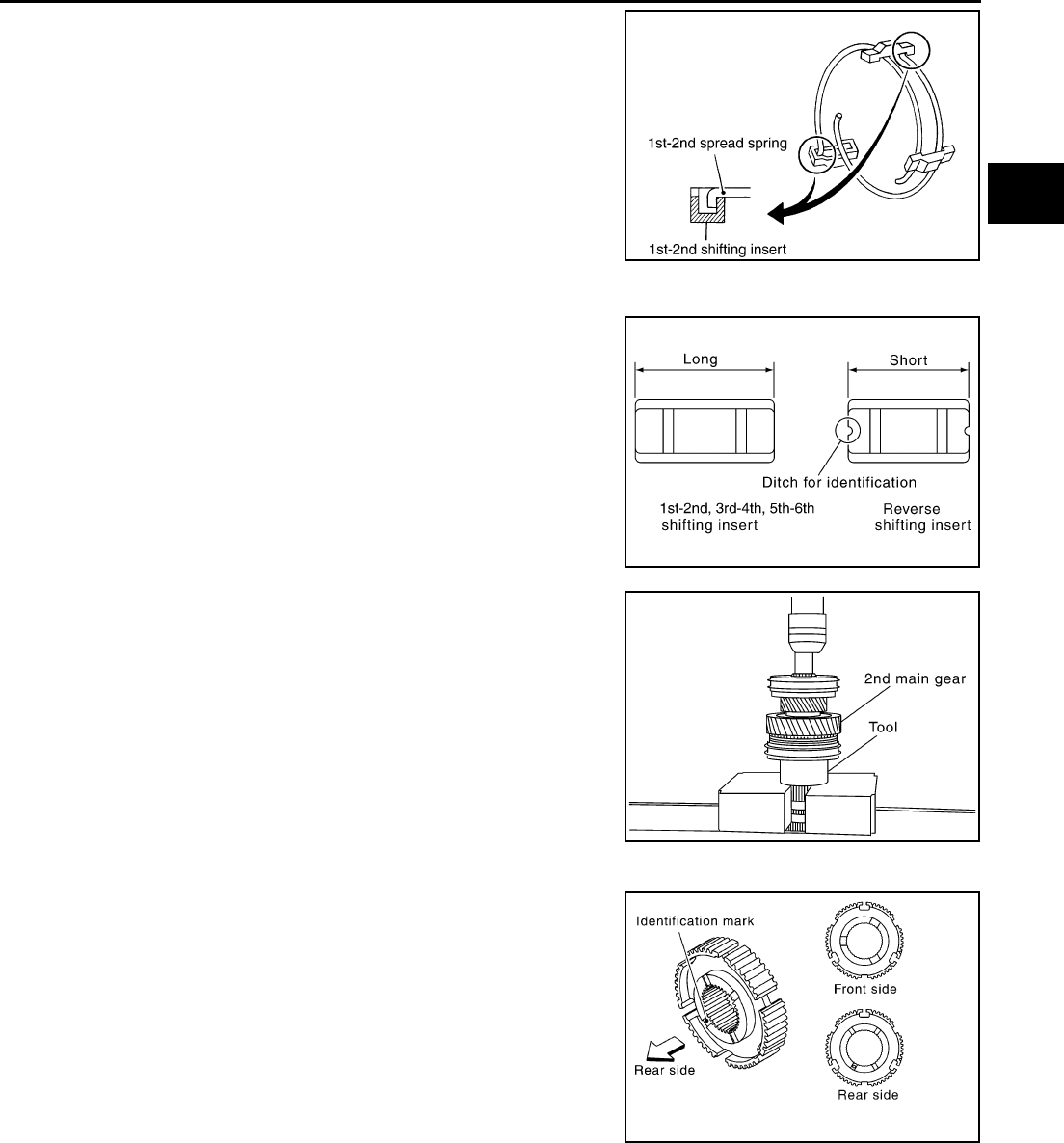
6. Install 1st - 2nd spread spring in the 1st - 2nd shifting insert.
CAUTION:
●Do not install 1st - 2nd spread spring hook onto the same
1st - 2nd shifting insert.
●Be careful with the shape of reverse shifting insert to
avoid misassembly.
7. Install 2nd main gear, 2nd needle bearing, 2nd inner baulk ring,
2nd synchronizer cone, 2nd outer baulk ring on the main shaft
and then using a support ring and a press to press fit the 1st -
2nd synchronizer assembly.
CAUTION:
●The 1st - 2nd synchronizer hub is not reusable. Never
reuse it.
●When press fitting, install with the side having the three
boss edge oil grooves facing the front side.
PCIB0611E
PCIB0608E
Tool number : ST27861000 ( — )
PCIB0202E
SCIA2700E

MT-44
TRANSMISSION ASSEMBLY
Revision: 2004 December 2004 350Z
NOTE:
1st baulk ring has three spaces that one gear tooth is missing
and 2nd baulk ring has three spaces that two gear teeth are
missing.
8. Using a support ring and a press to press fit the 1st gear bush-
ing.
9. Install 1st outer baulk ring, 1st synchronizer cone, 1st inner
baulk ring, 1st needle bearing, and 1st main gear on the main
shaft and then using the inserter and a press to press fit the 3rd
main gear.
CAUTION:
3rd main gear is not reusable. Never reuse it.
10. Install 3rd - 4th main spacer on the main shaft and then using
the inserter and a press to press fit the 4th main gear.
CAUTION:
●4th main gear is not reusable. Never reuse it.
●When installing, set boss to rear side.
11. Using the inserter and a press to press fit the main shaft bearing
onto the main shaft.
PCIB0450E
Tool number : ST27861000 ( — )
PCIB0203E
Tool number : ST30022000 ( — )
PCIB0745E
Tool number : ST30022000 ( — )
PCIB0612E
Tool number : ST30911000 ( — )
PCIB0405E

TRANSMISSION ASSEMBLY
MT-45
D
E
F
G
H
I
J
K
L
M
A
B
MT
Revision: 2004 December 2004 350Z
12. Using the inserter and a press to press fit the reverse main gear
bushing onto the main shaft.
13. Using the inserter and a press to press fit the 3rd gear bushing
onto the counter shaft.
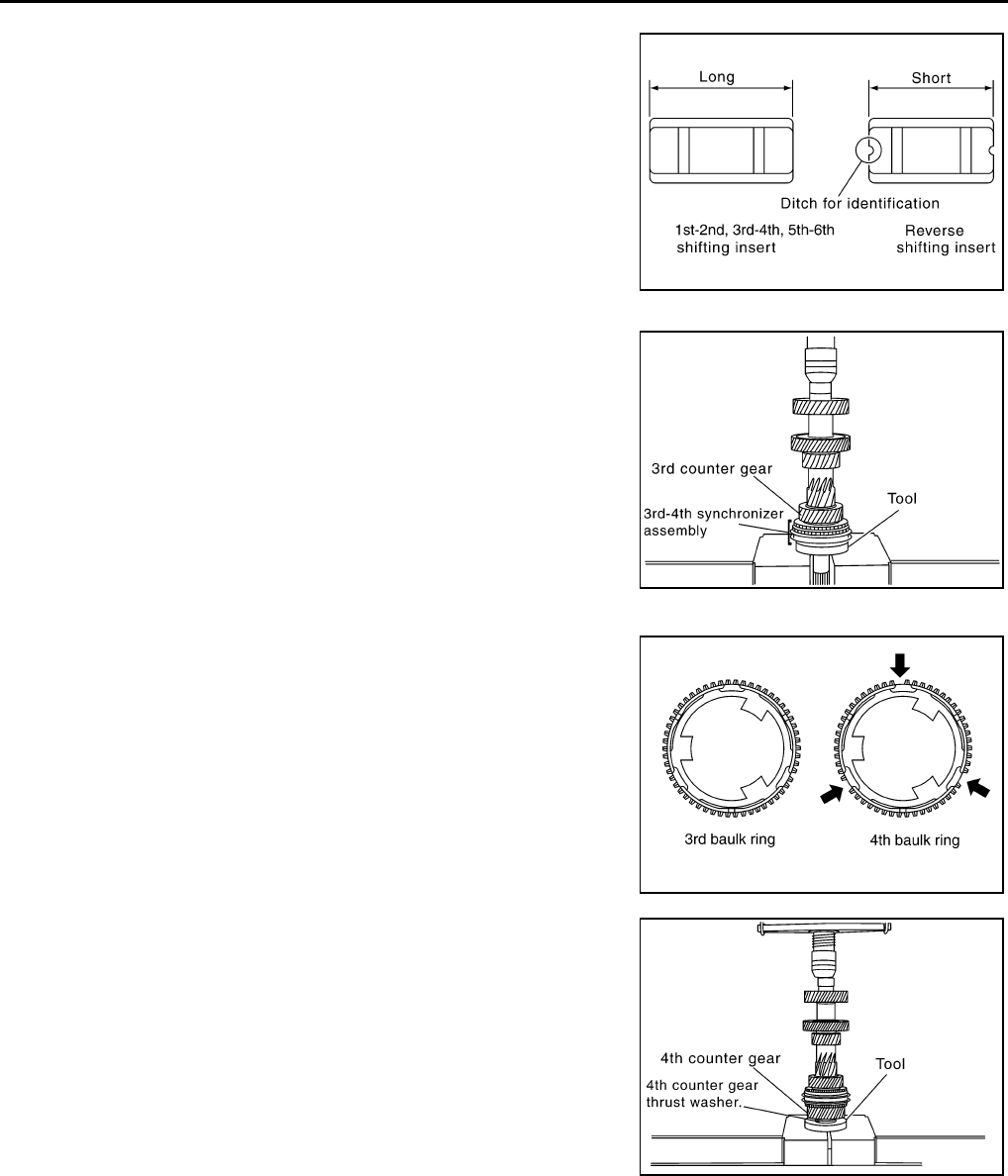
14. Install 3rd - 4th coupling sleeve and 3rd - 4th shifting insert into
the 3rd - 4th synchronizer hub.
CAUTION:
Install 3rd - 4th coupling sleeve with the thicker flange
faced the front side.
15. Install 3rd - 4th spread spring in the 3rd - 4th shifting insert.
Tool number : ST30911000 ( — )
PCIB0206E
Tool number : ST30911000 ( — )
PCIB0406E
PCIB0613E
PCIB0614E
MT-46
TRANSMISSION ASSEMBLY
Revision: 2004 December 2004 350Z
CAUTION:
●Do not install 3rd- 4th spread spring hook onto the same
3rd- 4th shifting insert.
●Be careful with the shape of reverse shifting insert to
avoid misassembly.
16. Install 3rd needle bearing,3rd counter gear,3rd inner baulk
ring,3rd synchronizer cone, and 3rd outer baulk ring on the
counter shaft and then using the inserter and a press to press fit
the 3rd - 4th synchronizer assembly.
CAUTION:
●The 3rd - 4th synchronizer hub is not reusable. Never
reuse it.
NOTE:
4th baulk ring has three spaces that one gear tooth is missing
but 3rd baulk ring doesn't.
17. Install 4th outer baulk ring,4th synchronizer cone,4th inner baulk
ring,4th needle bearing, and 4th counter gear onto the counter
shaft and then using the inserter and a press to press fit the 4th
gear bushing and 4th counter gear thrust washer.
PCIB0608E
Tool number : ST30911000 ( — )
PCIB0615E
PCIB0451E
Tool number : KV40100630 (J26092)
PCIB0209E
TRANSMISSION ASSEMBLY
MT-47
D
E
F
G
H
I
J
K
L
M
A
B
MT
Revision: 2004 December 2004 350Z
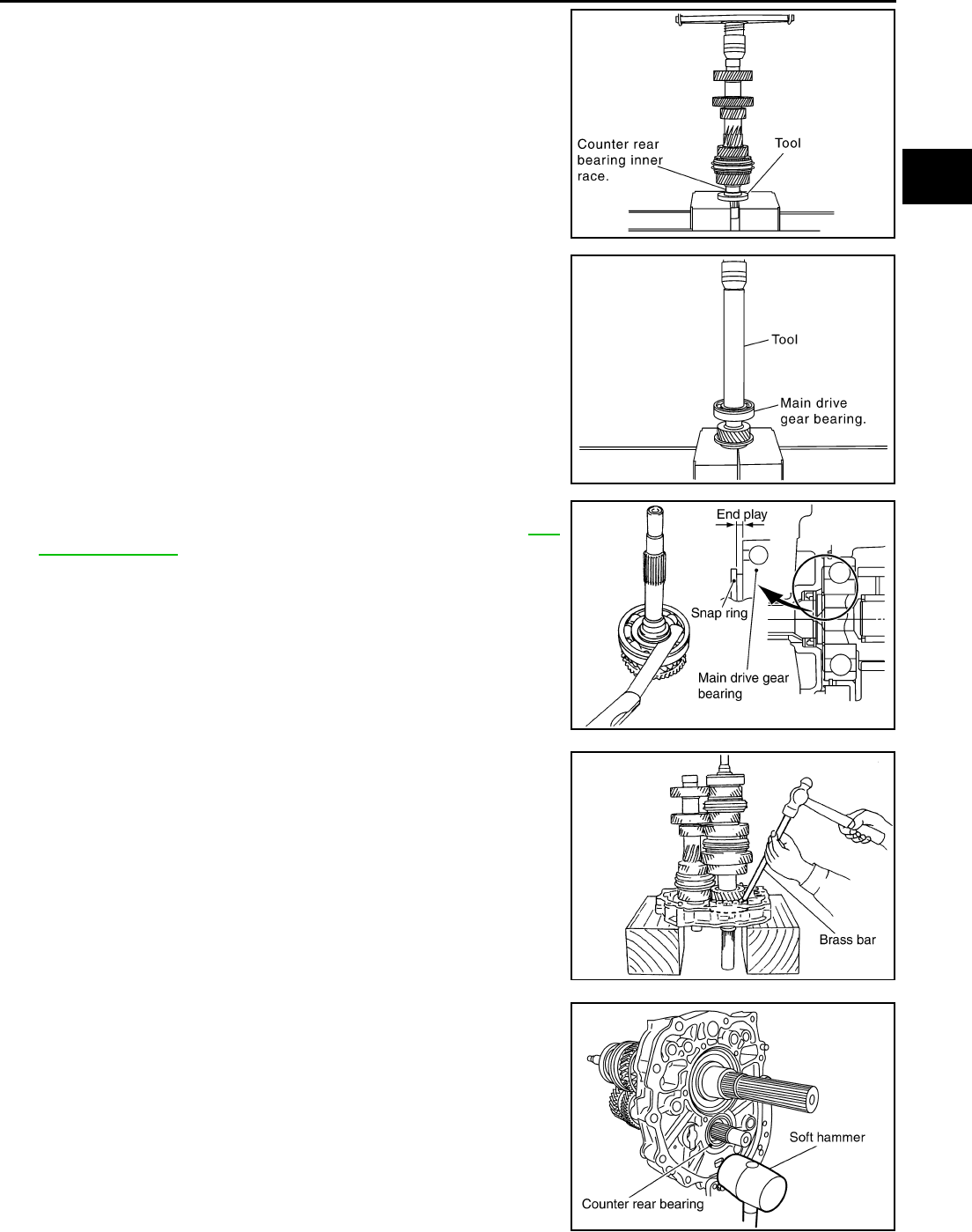
18. Using the inserter and a press to press fit the counter rear bear-
ing inner race onto the counter shaft.
19. Using the drift and a press to press fit the main drive gear bear-
ing onto the main drive gear.
20. Select and install a snap ring to the main drive gear bearing so
that the end play comes within the standard value. Refer to MT-
59, "Snap Rings" .
CAUTION:
Snap rings are not reusable. Never reuse them.
21. Install main shaft and counter shaft combined in one unit to
adapter plate, and fix bearing with snap ring.
CAUTION:
Snap rings are not reusable. Never reuse them.
22. Install counter rear bearing onto the adapter plate using soft
hammer or the equivalent.
Tool number : ST30032000 (J26010-01)
PCIB0210E
Tool number : KV32102700 ( — )
PCIB0215E
End play : 0 - 0.10 mm (0 - 0.004 in)
PCIB0484E
PCIB0151E
PCIB0616E
MT-48
TRANSMISSION ASSEMBLY
Revision: 2004 December 2004 350Z
23. Apply genuine medium strength locking sealant or equivalent
refer to GI section to the end of the bolt (first 3 to 4 threads),
screw the bolt into the main shaft bearing retainer, and tighten it
to the specified torque. Refer to MT-22, "CASE COMPONENTS"
.
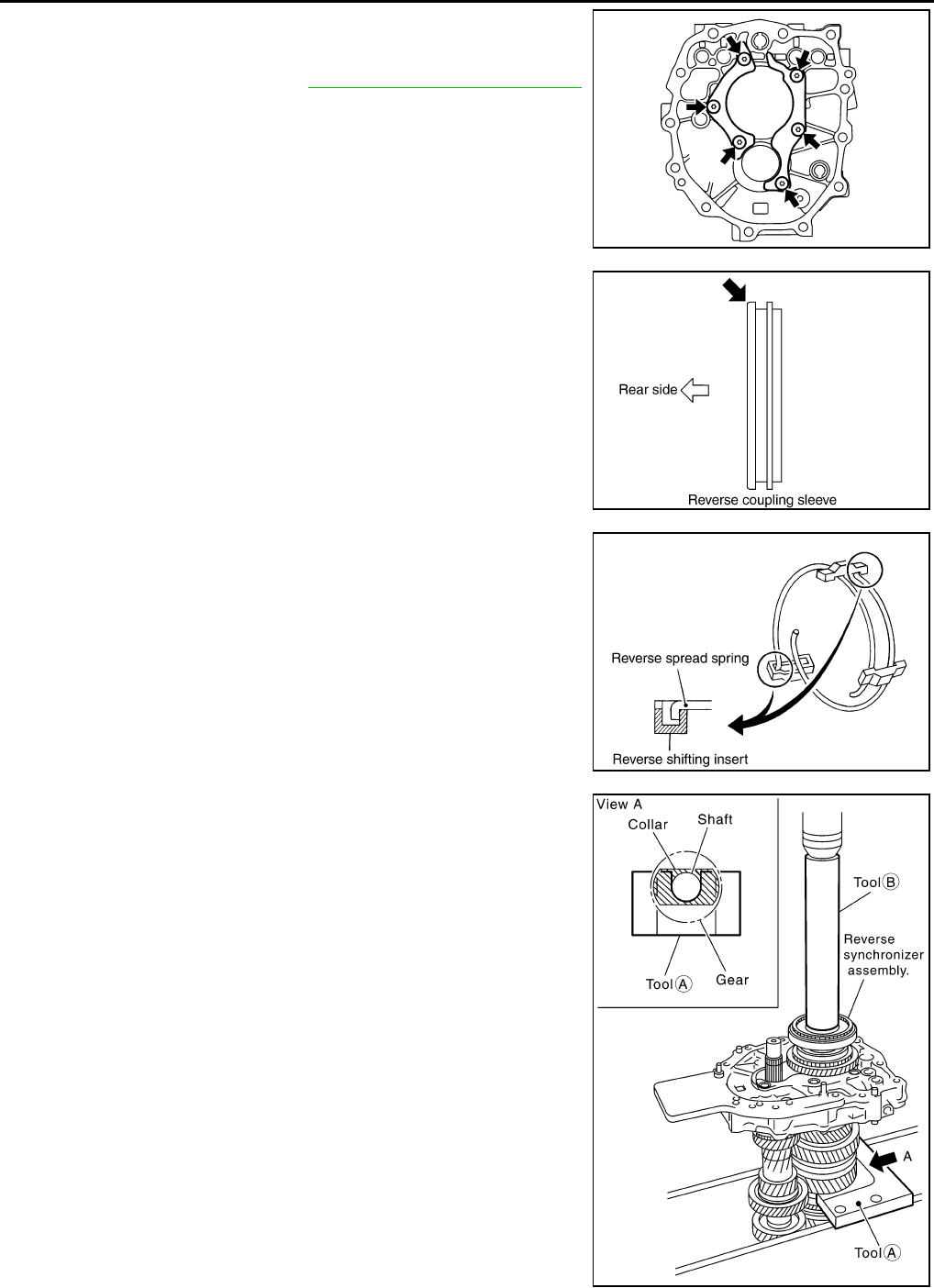
24. Install reverse coupling sleeve and reverse shifting insert into
the reverse synchronizer hub.
CAUTION:
Install reverse coupling sleeve with the flat flange on the
rear side.
25. Install reverse spread spring in the reverse shifting insert.
CAUTION:
Do not install reverse spread spring hook onto the same
reverse shifting insert.
26. After installing reverse main gear bushing, reverse main needle
bearing, reverse main gear, and reverse baulk ring onto the
main shaft, using the drift and press plate and a press to press
fit the reverse synchronizer assembly.
SCIA1452E
PCIB0617E
PCIB0618E
Tool number (A) : KV32103300 (J46529)
Tool number (B) : ST01530000 ( — )
PCIB0242E
TRANSMISSION ASSEMBLY
MT-49
D
E
F
G
H
I
J
K
L
M
A
B
MT
Revision: 2004 December 2004 350Z
CAUTION:
●The reverse synchronizer hub is not reusable. Never
reuse it.
●When installing, face the side with three ditches to the
front side.
27. Install reverse coupling snap ring.
NOTE:
Reverse baulk ring has three spaces that two gear teeth are
missing, and each space has small ditch for identification as
shown in the figure.
28. Select and install a snap ring so that the end play comes within
the standard value. Refer to MT-59, "Snap Rings" .
CAUTION:
Snap rings are not reusable. Never reuse them.
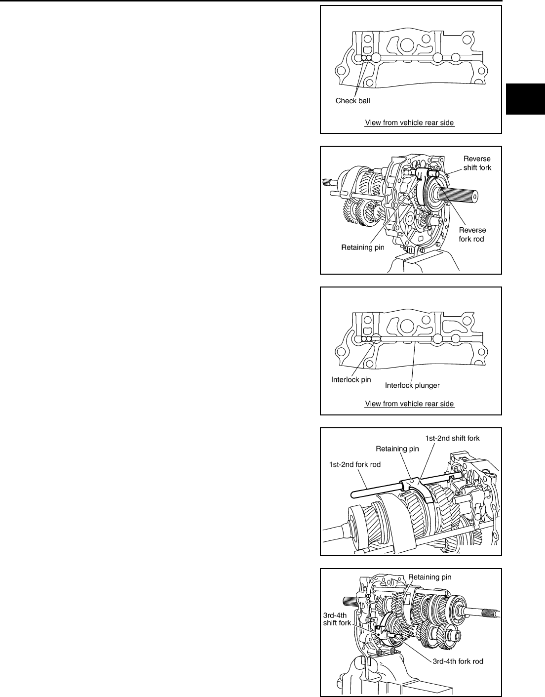
29. After installing counter rear bearing spacer, press and fit reverse
counter gear onto counter shaft with drift and press.
CAUTION:
●Reverse counter gear is not reusable. Never reuse it.
●When installing counter rear bearing spacer, maker's
stamp should face to the rear
PCIB0221E
PCIB0168E
End play : 0 - 0.10 mm (0 - 0.004 in)
PCIB0225E
Tool number : ST23860000 ( — )
PCIB0411E
MT-50
TRANSMISSION ASSEMBLY
Revision: 2004 December 2004 350Z
30. Select and install a snap ring so that the end play comes within
the standard value. Refer to MT-59, "Snap Rings" .
CAUTION:
Snap rings are not reusable. Never reuse them.
Shift Control Components
1. Install 5th-6th shift fork to the 5th - 6th coupling sleeve.
2. Install 5th-6th fork rod (reversal side) to the 5th - 6th shift fork.
3. Using a pin punch [6 mm (0.24in) dia.] to tap the retaining pin
into the 5th - 6th shift fork.
CAUTION:
Retaining pins are not reusable. Never reuse them.
4. Install 5th - 6th fork rod to the adapter plate.
5. Install 5th - 6th fork rod bracket to the 5th - 6th fork rod.
6. Using a pin punch [6 mm (0.24in) dia.] to tap the retaining pin
into the 5th - 6th fork rod bracket.
CAUTION:
Retaining pins are not reusable. Never reuse them.
7. Install 5th - 6th control lever to the adapter plate and then tighten
mounting bolts to the specified torque. Refer to MT-25, "SHIFT
CONTROL COMPONENTS" .
CAUTION:
Set the projection upward.
End play : 0 - 0.10 mm (0 - 0.004 in)
PCIB0226E
PCIB0412E
PCIB0238E
PCIB0172E
TRANSMISSION ASSEMBLY
MT-51
D
E
F
G
H
I
J
K
L
M
A
B
MT
Revision: 2004 December 2004 350Z
8. Install check ball to the adapter plate.
9. Install reverse shift fork to the reverse coupling sleeve.
10. Install reverse fork rod to the reverse shift fork.
11. Using a pin punch [6 mm (0.24 in) dia.] to tap the retaining pin
into the reverse shift fork.
CAUTION:
Retaining pins are not reusable. Never reuse them.
12. Install interlock pin and interlock plunger to the adapter plate.
13. Install 1st-2nd shift fork to the 1st - 2nd coupling sleeve.
14. Install 1st-2nd fork rod to the 1st - 2nd shift fork.
15. Using a pin punch [6 mm (0.24 in) dia.] to tap the retaining pin
into the 1st - 2nd shift fork.
CAUTION:
Retaining pins are not reusable. Never reuse them.
16. Install 3rd-4th shift fork to the 3rd - 4th coupling sleeve.
17. Install 3rd-4th fork rod (reversal side) to the 3rd - 4th shift fork.
18. Using a pin punch [6 mm (0.24 in) dia.] to tap the retaining pin
into the 3rd - 4th shift fork (reversal side).
CAUTION:
Retaining pins are not reusable. Never reuse them.
PCIB0148E
SCIA1447E
PCIB0147E
PCIB0602E
PCIB0601E
MT-52
TRANSMISSION ASSEMBLY
Revision: 2004 December 2004 350Z
19. Install interlock pin and check ball to the adapter plate.
20. Install 3rd-4th fork rod to the adapter plate.
21. Install 3rd-4th fork rod bracket to the 3rd - 4th fork rod.
22. Using a pin punch [6 mm (0.24 in) dia.] to tap the retaining pin
into the 3rd - 4th fork rod bracket.
CAUTION:
Retaining pins are not reusable. Never reuse them.
23. Install check ball, check ball spring into the adapter plate, apply
genuine silicone RTV or equivalent refer to GI section to the
check ball plug threads, and tighten check ball plug to the speci-
fied torque. Refer to MT-25, "SHIFT CONTROL COMPO-
NENTS" .
24. Install 3rd - 4th control lever to the adapter plate, and then
tighten mounting bolts to the specified torque. Refer to MT-25,
"SHIFT CONTROL COMPONENTS" .
CAUTION:
Make sure the top and bottom are oriented correctly.
25. Install check ball, check ball spring into the adapter plate, apply
genuine silicone RTV or equivalent refer to GI section to the
check ball plug threads, and tighten check ball plug to the speci-
fied torque. Refer to MT-25, "SHIFT CONTROL COMPO-
NENTS" .
PCIB0146E
PCIB0145E
PCIB0144E
PCIB0173E
PCIB0143E
TRANSMISSION ASSEMBLY
MT-53
D
E
F
G
H
I
J
K
L
M
A
B
MT
Revision: 2004 December 2004 350Z
26. Install striking rod to the adapter plate.
27. Install striking lever to the striking rod.
28. Using a pin punch [6 mm (0.24 in) dia.] to tap the retaining pin
into the striking lever.
CAUTION:
Retaining pins are not reusable. Never reuse them.
29. Install magnet to the adapter plate.
30. Install baffle plate to the adapter plate, and then tighten mount-
ing bolts to the specified torque.
Case Components
1. Install counter front bearing to the transmission case.
2. Install oil gutter to transmission case.
3. Apply genuine silicone RTV or equivalent refer to GI section to
the transmission case adapter plate mounting surface as shown
in the figure.
CAUTION:
Complete remove all moisture and oil, etc., from the trans-
mission case and adapter plate mounting surfaces.
PCIB0414E
PCIB0154E
PCIB0436E
PCIB1373E
MT-54
TRANSMISSION ASSEMBLY
Revision: 2004 December 2004 350Z
4. Place the adapter plate in the transmission case, using soft
hammer to tap the adapter plate to install it into the transmission
case.
5. Install snap ring to main drive gear bearing, using snap ring pli-
ers.
CAUTION:
Snap rings are not reusable. Never reuse them.
6. Tighten baffle plate mounting nut to the specified torque. Refer
to MT-22, "CASE COMPONENTS" .
7. Apply multi-purpose grease to the lip of the front cover oil seal.
Using a drift, to install oil seal approx. 8.55-9.55 mm (0.336-
0.376 in) above from the front cover edge surface.
CAUTION:
●Front cover oil seals are not reusable. Never reuse them.
●When installing, do not incline the front cover oil seal.
SCIA1436E
SCIA1532E
SCIA1443E
Tool number : KV38102100 (J25803-01)
PCIB0415E
TRANSMISSION ASSEMBLY
MT-55
D
E
F
G
H
I
J
K
L
M
A
B
MT
Revision: 2004 December 2004 350Z
8. Install front cover gasket and front cover to the transmission
case.
CAUTION:
Gasket is not reusable, Never reuse them.
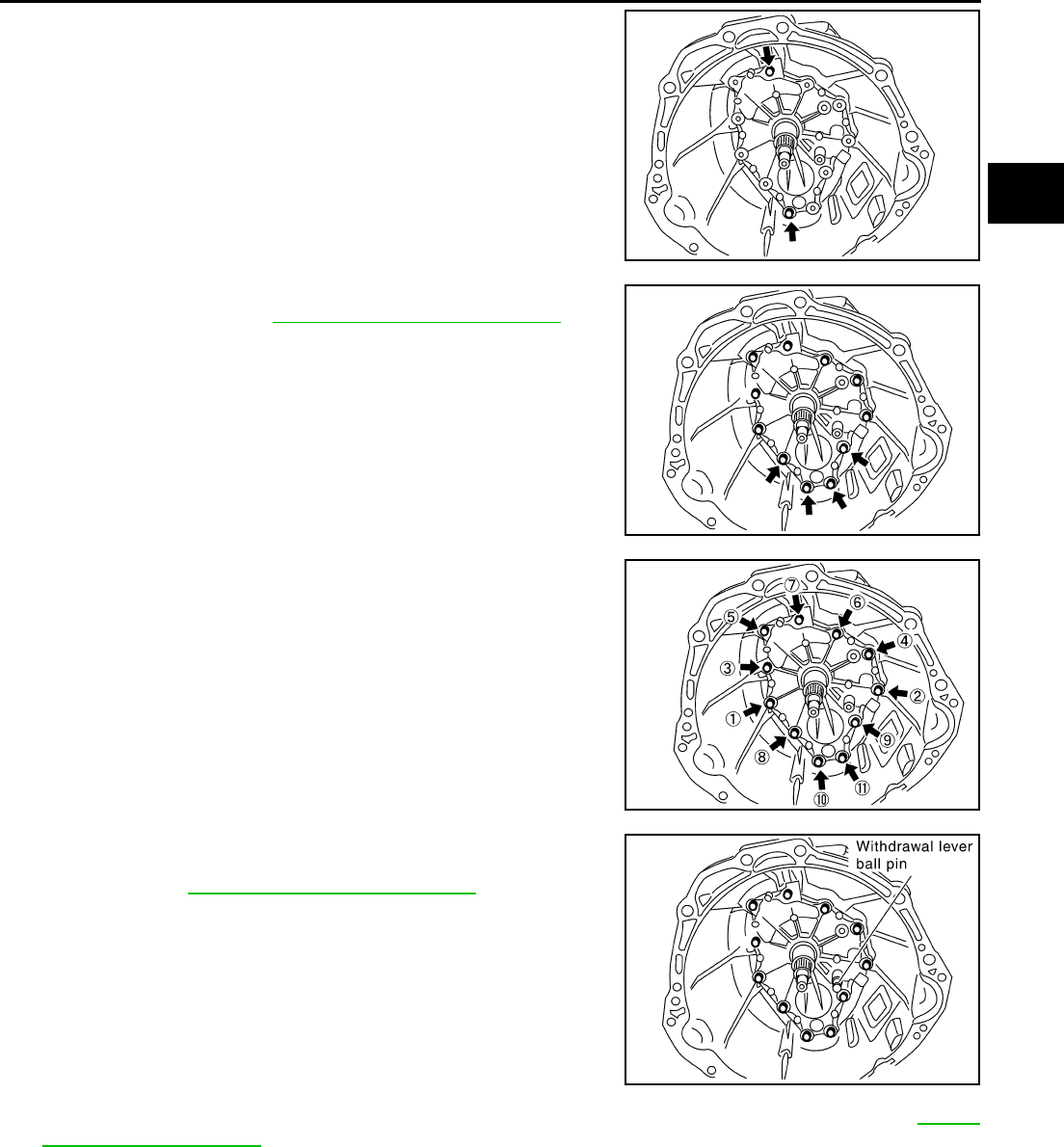
9. Temporary tightening 2 bolts in the positions shown in the fig-
ure.
10. Temporary tightening remaining 9 bolts, tighten bolts to the
specified torque. Refer to MT-22, "CASE COMPONENTS" .
CAUTION:
Four bolts pointed by arrows in the figure are not reusable.
11. Tighten bolts to the specified torque in order as shown on the
figure.
12. Install washer to the withdrawal lever ball pin and then install it
to front cover. Tighten withdrawal lever ball pin to the specified
torque. Refer to MT-22, "CASE COMPONENTS" .
13. Install rear extension oil gutter to rear extension, and then tighten bolt to specified torque. Refer to MT-22,
"CASE COMPONENTS" .
14. Install reverse idler shaft, reverse idler needle bearing, reverse idler gear, and reverse idler thrust washer
to the adapter plate.
PCIB0454J
PCIB0455J
PCIB0258E
PCIB0456E
MT-56
TRANSMISSION ASSEMBLY
Revision: 2004 December 2004 350Z
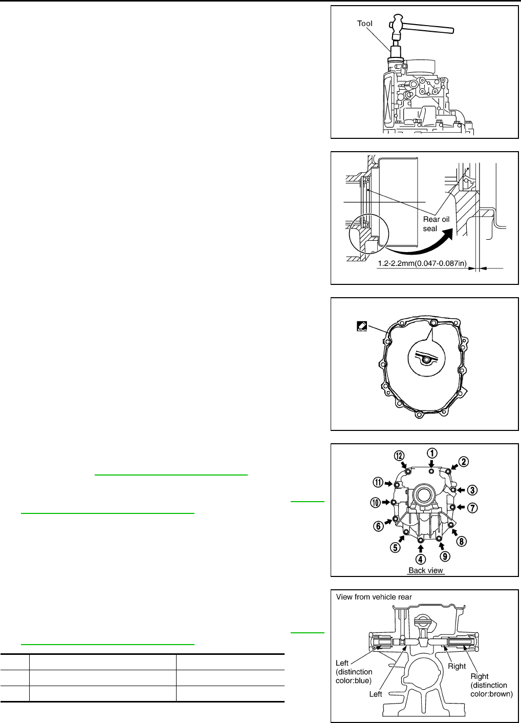
15. Apply multi -purpose grease to the striking rod oil seal lip, and
then using the drift to install striking rod oil seal.
CAUTION:
●Striking rod oil seal are not reusable. Never reuse them.
●When installing, do not incline the striking rod oil seal.
16. Apply multi - purpose grease to the lip of the rear oil seal. Using
a drift to install rear oil seal. 1.2-2.2 mm (0.047-0.87 in) above
from the rear extension edge surface.
CAUTION:
●Rear oil seal are not reusable. Never reuse them.
●When installing, do not incline the rear oil seal.
17. Apply genuine silicone RTV or equivalent refer to GI section to
the adapter plate rear extension mounting surface as shown in
the figure.
CAUTION:
Completely remove all moisture, oil, etc., from the adapter
plate and rear extension mounting surfaces.
18. Install rear extension to the adapter plate and then tighten
mounting bolts to the specified torque in order as shown on the
figure. Refer to MT-22, "CASE COMPONENTS" .
19. Install control lever housing to the rear extension and then
tighten mounting bolts to the specified torque. Refer to MT-25,
"SHIFT CONTROL COMPONENTS" .
20. Install return spring plunger and return spring into the rear
extension, apply genuine silicone RTV gasket or equivalent refer
to GI section to the return spring plug threads, and then tighten
return spring plug to the specified torque. Refer to MT-25,
"SHIFT CONTROL COMPONENTS" .
Tool number : ST35291000 ( — )
PCIB0213E
Tool number : ST33400001 (J26082)
PCIB0619E
PCIB1374E
PCIB0256E
Return spring identification mark Plunger notch
RH Brown No
LH Blue Yes
SCIA1607E
TRANSMISSION ASSEMBLY
MT-57
D
E
F
G
H
I
J
K
L
M
A
B
MT
Revision: 2004 December 2004 350Z
CAUTION:
The right and left return springs and return spring plungers are different, so make sure they are
installed correctly.
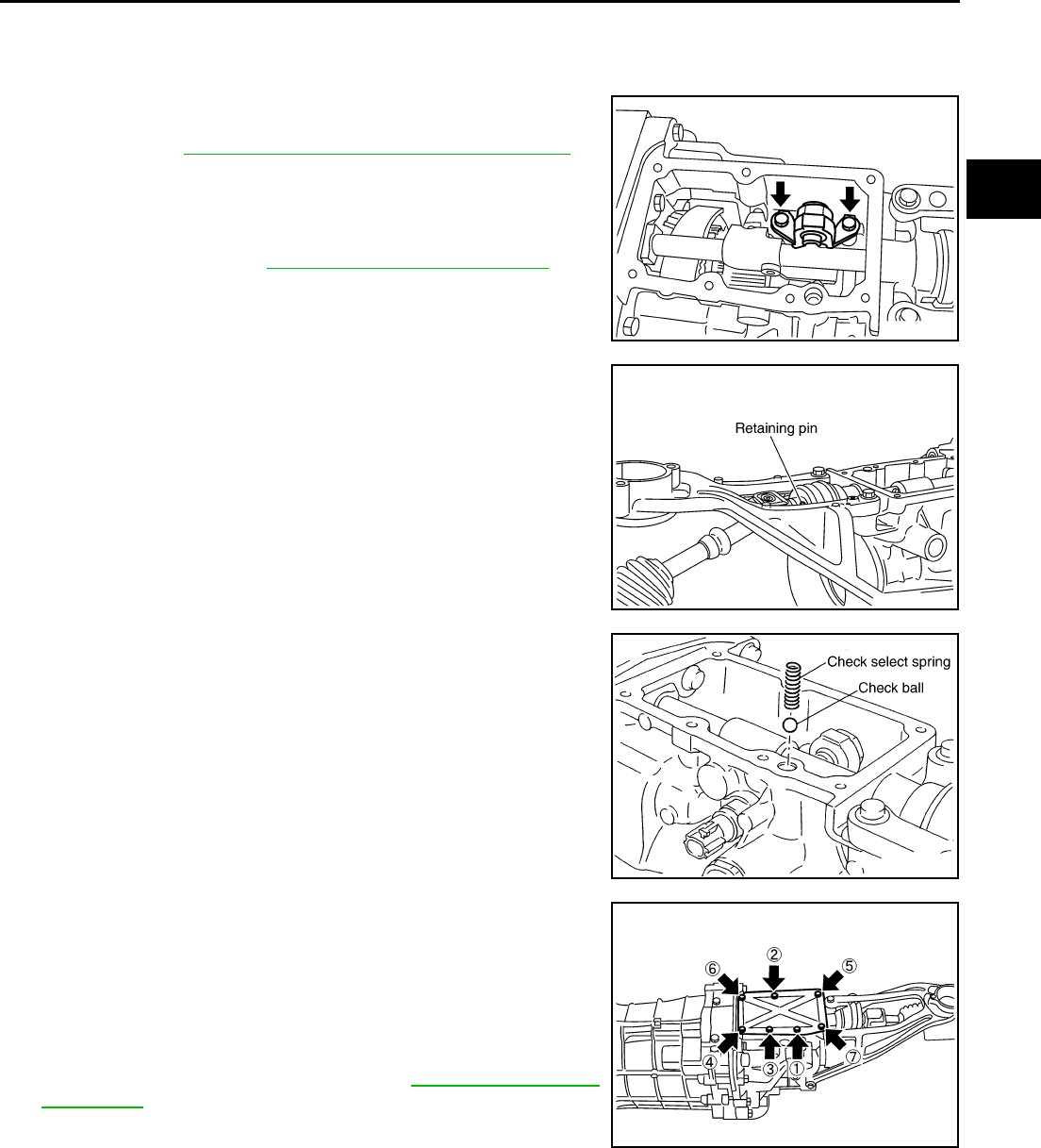
21. Install shift check pin as a one unit with the control bracket to
rear extension and then tighten mounting bolts to the specified
torque. Refer to MT-25, "SHIFT CONTROL COMPONENTS" .
22. Install plunger to the rear extension, and then screwing neutral
position switch and back-up lamp switch to the rear extension
with 1-2 pitches. Apply genuine silicone RTV or equivalent refer
to GI section to the switch threads, and tighten switch to the
specified torque. Refer to MT-22, "CASE COMPONENTS" .
23. Install retaining pin into the control rod, using a pin punch [6 mm
(0.24 in) dia.].
CAUTION:
Retaining pins are not reusable. Never reuse them.
24. Install check ball and check select spring into the rear extension.
25. Install rear extension upper cover gasket and rear extension
upper cover to rear extension.
CAUTION:
●Rear extension upper cover gaskets are not reusable.
Never reuse them.
●Avoid tangling check select spring.
26. Tighten rear extension upper cover bolts to the specified torque
in order as shown on the figure. Refer to MT-22, "CASE COM-
PONENTS" .
SCIA1440E
SCIA1437E
PCIB0599E
PCIB0257E

MT-58
SERVICE DATA AND SPECIFICATIONS (SDS)
Revision: 2004 December 2004 350Z
SERVICE DATA AND SPECIFICATIONS (SDS) PFP:00030
General Specifications ACS004NU
End Play ACS004NV
Unit: mm (in)
Applied model VQ35DE
Transmission FS6R31A
Number of speed 6
Shift pattern
Synchromesh type Warner
Gear ratio
1st 3.794
2nd 2.324
3rd 1.624
4th 1.271
5th 1.000
6th 0.794
Reverse 3.446
Main gear
(Number of teeth)
Drive 26
1st 37
2nd 34
3rd 33
4th 31
6th 31
Reverse 42
Counter gear
(Number of teeth)
Drive 32
1st 12
2nd 18
3rd 25
4th 30
6th 48
Reverse 15
Reverse idler gear (Number of teeth) 26
Oil capacity
( US qt, Imp qt ) Approx. 2.9 ( 3-1/8, 2-1/2)
Remarks
Reverse synchronizer Installed
Double cone synchronizer 1st & 3rd & 4th
Triple cone synchronizer 2nd
SCIA0955E
Item Standard
Counter gear 0 - 0.10 (0 - 0.004)
Main drive gear 0 - 0.10 (0 - 0.004)
Main shaft 0 - 0.10 (0 - 0.004)

SERVICE DATA AND SPECIFICATIONS (SDS)
MT-59
D
E
F
G
H
I
J
K
L
M
A
B
MT
Revision: 2004 December 2004 350Z
Snap Rings ACS004NW
Unit: mm (in)
Selective parts Thickness Part No.
Main drive gear
1.89 (0.0744)
1.95 (0.0768)
1.99 (0.0783)
2.03 (0.0799)
2.07 (0.0815)
2.11 (0.0831)
32204 01G60
32204 01G61
32204 01G62
32204 01G63
32204 01G64
32204 01G65
Counter shaft
1.96 (0.0772)
2.02 (0.0795)
2.08 (0.0819)
2.14 (0.0843)
2.20 (0.0866)
2.26 (0.0890)
2.32 (0.0913)
2.38 (0.0937)
2.44 (0.0961)
2.50 (0.0984)
2.56 (0.1008)
2.62 (0.1031)
32236 CD000
32236 CD001
32236 CD002
32236 CD003
32236 CD004
32236 CD005
32236 CD006
32236 CD007
32236 CD008
32236 CD009
32236 CD010
32236 CD011
Main shaft
Front side
2.08 (0.0819)
2.14 (0.0843)
2.20 (0.0866)
2.26 (0.0890)
32204 CD000
32204 CD001
32204 CD002
32204 CD003
Shaft rear end
2.08 (0.0819)
2.14 (0.0843)
2.20 (0.0866)
2.26 (0.0890)
2.32 (0.0913)
2.38 (0.0937)
2.44 (0.0961)
2.50 (0.0984)
2.56 (0.1008)
2.62 (0.1031)
2.68 (0.1055)
2.74 (0.1079)
2.80 (0.1102)
2.86 (0.1126)
2.92 (0.1150)
2.98 (0.1173)
32204 CD000
32204 CD001
32204 CD002
32204 CD003
32204 CD004
32204 CD005
32204 CD006
32204 CD007
32204 CD008
32204 CD009
32204 CD010
32204 CD011
32204 CD012
32204 CD013
32204 CD014
32204 CD015

MT-60
SERVICE DATA AND SPECIFICATIONS (SDS)
Revision: 2004 December 2004 350Z
Baulk Ring Clearance ACS004NX
Unit: mm (in)
Measurement point Standard Limit value
1st & 3rd & 4th
(Double - cone synchronizer)
Inner baulk ring clearance “A”
Outer baulk ring clearance “B”
A: 0.50 - 0.70(0.020 - 0.028)
B(1st): 1.00 - 1.50(0.039 - 0.059)
B(3rd,4th):0.85 - 1.35(0.033 - 0.053)
0.3(0.012)
0.7(0.028)
0.7(0.028)
2nd
(Triple - cone sychronizer)
Main gear taper corn clearance “ A”
Outer baulk ring clearance “B”
Inner baulk ring clearance “C”
A: 0.60 - 1.30 (0.024 - 0.051)
B: 0.85 - 1.35 (0.033 - 0.053)
C: 0.70 - 1.25 (0.028 - 0.049)
0.3 (0.012)
0.7 (0.028)
0.3 (0.012)
5th & 6th 0.70 - 1.25 (0.028 - 0.049) 0.5 (0.020)
Reverse 0.75 - 1.20 (0.030 - 0.047) 0.5 (0.020)
PCIB0249E
PCIB0261E
