Nissan 2005 Pathfinder Owners Manual MTC
mtc mtc
2015-10-23
: Nissan Nissan-2005-Nissan-Pathfinder-Owners-Manual-818310 nissan-2005-nissan-pathfinder-owners-manual-818310 nissan pdf
Open the PDF directly: View PDF ![]() .
.
Page Count: 114 [warning: Documents this large are best viewed by clicking the View PDF Link!]
- QUICK REFERENCE INDEX
- Table of Contents
- PRECAUTIONS
- Precautions for Supplemental Restraint System (SRS) “AIR BAG” and “SEAT BELT PRE-TENSIONER”
- Precautions for Working with HFC-134a (R-134a)
- Contaminated Refrigerant
- General Refrigerant Precautions
- Precautions for Leak Detection Dye
- A/C Identification Label
- Precautions for Refrigerant Connection
- Precautions for Servicing Compressor
- Precautions for Service Equipment
- Wiring Diagrams and Trouble Diagnosis
- PREPARATION
- REFRIGERATION SYSTEM
- LUBRICANT
- AIR CONDITIONER CONTROL
- TROUBLE DIAGNOSIS
- CONSULT-II Function (BCM)
- How to Perform Trouble Diagnosis for Quick and Accurate Repair
- Component Parts and Harness Connector Location
- Schematic
- Wiring Diagram — A/C,M —
- Front Air Control Terminals and Reference Value
- Operational Check
- Power Supply and Ground Circuit for Front Air Control
- Mode Door Motor Circuit
- Air Mix Door Motor Circuit
- Intake Door Motor Circuit
- Front Blower Motor Circuit
- Magnet Clutch Circuit
- Insufficient Cooling
- Insufficient Heating
- Noise
- Intake Sensor Circuit
- CONTROL UNIT
- INTAKE SENSOR
- BLOWER MOTOR
- IN-CABIN MICROFILTER
- HEATER & COOLING UNIT ASSEMBLY
- HEATER CORE
- INTAKE DOOR MOTOR
- MODE DOOR MOTOR
- AIR MIX DOOR MOTOR
- FRONT BLOWER MOTOR RESISTOR
- DUCTS AND GRILLES
- REFRIGERANT LINES
- HFC-134a (R-134a) Service Procedure
- Components
- Removal and Installation for Compressor
- Removal and Installation for Compressor Clutch
- Removal and Installation for High-pressure Flexible A/C Hose
- Removal and Installation for High-pressure A/C Pipe
- Removal and Installation for Low-pressure Flexible A/C Hose
- Removal and Installation for Low-pressure A/C Pipe
- Removal and Installation for Refrigerant Pressure Sensor
- Removal and Installation for Condenser
- Removal and Installation for Evaporator
- Removal and Installation for Expansion Valve
- Checking for Refrigerant Leaks
- Checking System for Leaks Using the Fluorescent Dye Leak Detector
- Dye Injection
- Electronic Refrigerant Leak Detector
- SERVICE DATA AND SPECIFICATIONS (SDS)
- PRECAUTIONS
- POWER SUPPLY ROUTING CIRCUIT
- ELECTRICAL UNITS
- SUPER MULTIPLE JUNCTION (SMJ)
- FUSE BLOCK — JUNCTION BOX (J/B)
- FUSE AND FUSIBLE LINK BOX
- FUSE AND RELAY BOX

MTC-1
MANUAL AIR CONDITIONER
J AIR CONDITIONER
CONTENTS
C
D
E
F
G
H
I
K
L
M
SECTION MTC A
B
MTC
Revision: November 2005 2005 Pathfinder
PRECAUTIONS .......................................................... 4
Precautions for Supplemental Restraint System
(SRS) “AIR BAG” and “SEAT BELT PRE-TEN-
SIONER” .................................................................. 4
Precautions for Working with HFC-134a (R-134a) ..... 4
Contaminated Refrigerant ........................................ 4
General Refrigerant Precautions .............................. 5
Precautions for Leak Detection Dye ......................... 5
A/C Identification Label ............................................ 6
Precautions for Refrigerant Connection ................... 6
FEATURES OF NEW TYPE REFRIGERANT
CONNECTION ...................................................... 6
O-RING AND REFRIGERANT CONNECTION ..... 7
Precautions for Servicing Compressor ..................... 9
Precautions for Service Equipment .......................... 9
RECOVERY/RECYCLING EQUIPMENT .............. 9
ELECTRONIC LEAK DETECTOR ........................ 9
VACUUM PUMP ................................................. 10
MANIFOLD GAUGE SET .................................... 10
SERVICE HOSES ............................................... 10
SERVICE COUPLERS .........................................11
REFRIGERANT WEIGHT SCALE .......................11
CHARGING CYLINDER .......................................11
Wiring Diagrams and Trouble Diagnosis .................11
PREPARATION ......................................................... 12
Special Service Tools ............................................. 12
HFC-134a (R-134a) Service Tools and Equipment ... 12
Commercial Service Tools ...................................... 15
REFRIGERATION SYSTEM ..................................... 16
Components ........................................................... 16
REFRIGERATION SYSTEM ............................... 16
Refrigerant Cycle ................................................... 17
REFRIGERANT FLOW ....................................... 17
FREEZE PROTECTION ..................................... 17
Refrigerant System Protection ............................... 17
REFRIGERANT PRESSURE SENSOR ............. 17
PRESSURE RELIEF VALVE ............................... 18
LUBRICANT .............................................................. 19
Maintenance of Lubricant Quantity in Compressor ... 19
LUBRICANT ........................................................ 19
CHECKING AND ADJUSTING ............................ 19
AIR CONDITIONER CONTROL ............................... 21
Description .............................................................. 21
Operation ................................................................ 21
AIR MIX DOOR CONTROL ................................. 21
BLOWER SPEED CONTROL ............................. 21
INTAKE DOORS CONTROL ............................... 21
MODE DOOR CONTROL ................................... 21
DEFROSTER DOOR CONTROL ........................ 21
MAGNET CLUTCH CONTROL ........................... 21
Description of Control System ................................ 23
Control Operation ................................................... 24
TEMPERATURE CONTROL DIAL (TEMPERA-
TURE CONTROL) ............................................... 24
RECIRCULATION () SWITCH ............................. 24
DEFROSTER () SWITCH .................................... 24
REAR WINDOW DEFOGGER SWITCH ............. 24
OFF SWITCH (BLOWER SPEED SET TO 0) ..... 24
A/C SWITCH ....................................................... 24
MODE DIAL ......................................................... 24
FRONT BLOWER CONTROL DIAL .................... 24
Discharge Air Flow ................................................. 25
FRONT ................................................................ 25
System Description ................................................. 26
SWITCHES AND THEIR CONTROL FUNCTION ... 26
CAN Communication System Description .............. 27
TROUBLE DIAGNOSIS ............................................ 28
CONSULT-II Function (BCM) ................................. 28
CONSULT-II BASIC OPERATION ....................... 28
DATA MONITOR ................................................. 29
How to Perform Trouble Diagnosis for Quick and
Accurate Repair ...................................................... 30
WORK FLOW ...................................................... 30
SYMPTOM TABLE .............................................. 30
Component Parts and Harness Connector Location ... 31
ENGINE COMPARTMENT .................................. 31
FRONT PASSENGER COMPARTMENT ............ 32

MTC-2
Revision: November 2005 2005 Pathfinder
Schematic ............................................................... 33
Wiring Diagram — A/C,M — ................................... 34
Front Air Control Terminals and Reference Value ... 38
PIN CONNECTOR TERMINAL LAYOUT ............ 38
TERMINALS AND REFERENCE VALUE FOR
FRONT AIR CONTROL ....................................... 38
Operational Check .................................................. 40
CHECKING BLOWER ......................................... 40
CHECKING DISCHARGE AIR ............................ 40
DISCHARGE AIR FLOW ..................................... 40
CHECKING RECIRCULATION ............................ 41
CHECKING TEMPERATURE DECREASE ......... 41
CHECKING TEMPERATURE INCREASE .......... 41
CHECK A/C SWITCH .......................................... 41
Power Supply and Ground Circuit for Front Air Con-
trol ........................................................................... 42
INSPECTION FLOW ........................................... 42
COMPONENT DESCRIPTION ............................ 43
DIAGNOSTIC PROCEDURE FOR A/C SYSTEM ... 43
Mode Door Motor Circuit ........................................ 45
INSPECTION FLOW ........................................... 45
SYSTEM DESCRIPTION .................................... 46
COMPONENT DESCRIPTION ............................ 46
DIAGNOSTIC PROCEDURE FOR MODE
DOOR MOTOR ................................................... 47
Air Mix Door Motor Circuit ...................................... 49
INSPECTION FLOW ........................................... 49
SYSTEM DESCRIPTION .................................... 50
COMPONENT DESCRIPTION ............................ 50
DIAGNOSTIC PROCEDURE FOR AIR MIX
DOOR MOTOR (FRONT) .................................... 51
Intake Door Motor Circuit ........................................ 53
INSPECTION FLOW ........................................... 53
SYSTEM DESCRIPTION .................................... 54
COMPONENT DESCRIPTION ............................ 54
DIAGNOSTIC PROCEDURE FOR INTAKE
DOOR MOTOR ................................................... 55
Front Blower Motor Circuit ...................................... 57
INSPECTION FLOW ........................................... 57
SYSTEM DESCRIPTION .................................... 58
COMPONENT DESCRIPTION ............................ 58
DIAGNOSTIC PROCEDURE FOR BLOWER
MOTOR ............................................................... 59
COMPONENT INSPECTION .............................. 63
Magnet Clutch Circuit ............................................. 65
INSPECTION FLOW ........................................... 65
SYSTEM DESCRIPTION .................................... 66
DIAGNOSTIC PROCEDURE FOR MAGNET
CLUTCH .............................................................. 66
Insufficient Cooling ................................................. 70
INSPECTION FLOW ........................................... 70
PERFORMANCE TEST DIAGNOSES ................ 71
PERFORMANCE CHART ................................... 73
TROUBLE DIAGNOSES FOR UNUSUAL PRES-
SURE ................................................................... 74
Insufficient Heating .................................................77
INSPECTION FLOW ............................................77
Noise .......................................................................78
INSPECTION FLOW ............................................78
Intake Sensor Circuit ...............................................80
COMPONENT DESCRIPTION ............................80
DIAGNOSTIC PROCEDURE FOR INTAKE SEN-
SOR .....................................................................80
COMPONENT INSPECTION ...............................81
CONTROL UNIT ........................................................82
Removal and Installation .........................................82
FRONT AIR CONTROL .......................................82
INTAKE SENSOR ......................................................83
Removal and Installation .........................................83
REMOVAL ............................................................83
INSTALLATION ....................................................83
BLOWER MOTOR .....................................................84
Components ............................................................84
Removal and Installation .........................................84
REMOVAL ............................................................84
INSTALLATION ....................................................84
IN-CABIN MICROFILTER ..........................................85
Removal and Installation .........................................85
FUNCTION ..........................................................85
REPLACEMENT TIMING ....................................85
REPLACEMENT PROCEDURE ..........................85
HEATER & COOLING UNIT ASSEMBLY .................87
Components ............................................................87
Removal and Installation .........................................87
REMOVAL ............................................................87
INSTALLATION ....................................................88
HEATER CORE .........................................................89
Components ............................................................89
Removal and Installation .........................................89
REMOVAL ............................................................89
INSTALLATION ....................................................89
INTAKE DOOR MOTOR ............................................90
Removal and Installation .........................................90
REMOVAL ............................................................90
INSTALLATION ....................................................90
MODE DOOR MOTOR ..............................................91
Removal and Installation .........................................91
REMOVAL ............................................................91
INSTALLATION ....................................................91
AIR MIX DOOR MOTOR ...........................................92
Components ............................................................92
Removal and Installation .........................................92
REMOVAL ............................................................92
INSTALLATION ....................................................92
FRONT BLOWER MOTOR RESISTOR ....................93
Removal and Installation .........................................93
REMOVAL ............................................................93
INSTALLATION ....................................................93
DUCTS AND GRILLES .............................................94

MTC-3
C
D
E
F
G
H
I
K
L
M
A
B
MTC
Revision: November 2005 2005 Pathfinder
Components ........................................................... 94
Removal and Installation ........................................ 95
CONSOLE DUCTS AND CONSOLE GRILLE .... 95
DEFROSTER NOZZLE ....................................... 96
RH AND LH SIDE DEMISTER DUCTS .............. 96
RH AND LH VENTILATOR DUCTS .................... 96
CENTER VENTILATOR DUCT ........................... 96
FLOOR CONNECTOR DUCT ............................. 96
FRONT AND REAR FLOOR DUCTS ................. 96
GRILLES ............................................................. 97
REFRIGERANT LINES ............................................. 98
HFC-134a (R-134a) Service Procedure ................. 98
SETTING OF SERVICE TOOLS AND EQUIP-
MENT .................................................................. 98
Components ......................................................... 100
Removal and Installation for Compressor ............ 101
COMPONENTS ................................................ 101
REMOVAL ......................................................... 101
INSTALLATION ................................................. 101
Removal and Installation for Compressor Clutch . 102
REMOVAL ......................................................... 102
INSPECTION .................................................... 103
INSTALLATION ................................................. 103
BREAK-IN OPERATION ................................... 105
Removal and Installation for High-pressure Flexible
A/C Hose .............................................................. 105
REMOVAL ......................................................... 105
INSTALLATION ................................................. 105
Removal and Installation for High-pressure A/C
Pipe ...................................................................... 105
REMOVAL ......................................................... 105
INSTALLATION ................................................. 105
Removal and Installation for Low-pressure Flexible
A/C Hose .............................................................. 105
REMOVAL .........................................................105
INSTALLATION .................................................105
Removal and Installation for Low-pressure A/C Pipe .106
REMOVAL .........................................................106
INSTALLATION .................................................106
Removal and Installation for Refrigerant Pressure
Sensor ..................................................................106
REMOVAL .........................................................106
INSTALLATION .................................................106
Removal and Installation for Condenser ..............106
REMOVAL .........................................................106
INSTALLATION .................................................107
Removal and Installation for Evaporator ..............108
REMOVAL .........................................................109
INSTALLATION .................................................109
Removal and Installation for Expansion Valve ......109
REMOVAL .........................................................109
INSTALLATION .................................................109
Checking for Refrigerant Leaks ............................109
Checking System for Leaks Using the Fluorescent
Dye Leak Detector ................................................109
Dye Injection .........................................................110
Electronic Refrigerant Leak Detector ....................110
PRECAUTIONS FOR HANDLING LEAK
DETECTOR .......................................................110
CHECKING PROCEDURE ................................111
SERVICE DATA AND SPECIFICATIONS (SDS) ....113
Service Data and Specifications (SDS) ................113
COMPRESSOR ................................................113
LUBRICANT ......................................................113
REFRIGERANT .................................................113
ENGINE IDLING SPEED ..................................113
BELT TENSION .................................................113

MTC-4
PRECAUTIONS
Revision: November 2005 2005 Pathfinder
PRECAUTIONS PFP:00001
Precautions for Supplemental Restraint System (SRS) “AIR BAG” and “SEAT
BELT PRE-TENSIONER” EJS003UK
The Supplemental Restraint System such as “AIR BAG” and “SEAT BELT PRE-TENSIONER”, used along
with a front seat belt, helps to reduce the risk or severity of injury to the driver and front passenger for certain
types of collision. This system includes seat belt switch inputs and dual stage front air bag modules. The SRS
system uses the seat belt switches to determine the front air bag deployment, and may only deploy one front
air bag, depending on the severity of a collision and whether the front occupants are belted or unbelted.
Information necessary to service the system safely is included in the SRS and SB section of this Service Man-
ual.
WARNING:
●To avoid rendering the SRS inoperative, which could increase the risk of personal injury or death
in the event of a collision which would result in air bag inflation, all maintenance must be per-
formed by an authorized NISSAN/INFINITI dealer.
●Improper maintenance, including incorrect removal and installation of the SRS, can lead to per-
sonal injury caused by unintentional activation of the system. For removal of Spiral Cable and Air
Bag Module, see the SRS section.
●Do not use electrical test equipment on any circuit related to the SRS unless instructed to in this
Service Manual. SRS wiring harnesses can be identified by yellow and/or orange harnesses or
harness connectors.
Precautions for Working with HFC-134a (R-134a) EJS003UL
WARNING:
●CFC-12 (R-12) refrigerant and HFC-134a (R-134a) refrigerant are not compatible. If the refrigerants
are mixed compressor failure is likely to occur. Refer MTC-4, "Contaminated Refrigerant" . To
determine the purity of HFC-134a (R-134a) in the vehicle and recovery tank, use Refrigerant
Recovery/Recycling Recharging equipment and Refrigerant Identifier.
●Use only specified lubricant for the HFC-134a (R-134a) A/C system and HFC-134a (R-134a) compo-
nents. If lubricant other than that specified is used, compressor failure is likely to occur.
●The specified HFC-134a (R-134a) lubricant rapidly absorbs moisture from the atmosphere. The fol-
lowing handling precautions must be observed:
–When removing refrigerant components from a vehicle, immediately cap (seal) the component to
minimize the entry of moisture from the atmosphere.
–When installing refrigerant components to a vehicle, do not remove the caps (unseal) until just
before connecting the components. Connect all refrigerant loop components as quickly as possi-
ble to minimize the entry of moisture into system.
–Only use the specified lubricant from a sealed container. Immediately reseal containers of lubri-
cant. Without proper sealing, lubricant will become moisture saturated and should not be used.
–Avoid breathing A/C refrigerant and lubricant vapor or mist. Exposure may irritate eyes, nose and
throat. Remove HFC-134a (R-134a) from the A/C system using certified service equipment meeting
requirements of SAE J2210 [HFC-134a (R-134a) recycling equipment], or SAE J2209 [HFC-134a (R-
134a) recovery equipment]. If accidental system discharge occurs, ventilate work area before
resuming service. Additional health and safety information may be obtained from refrigerant and
lubricant manufacturers.
–Do not allow lubricant, Genuine NISSAN A/C System Lubricant Type S (DH-PS), part number
KLH00-PAGS0 or equivalent, to come in contact with styrofoam parts. Damage may result.
Contaminated Refrigerant EJS003UM
If a refrigerant other than pure HFC-134a (R-134a) is identified in a vehicle, your options are:
●Explain to the customer that environmental regulations prohibit the release of contaminated refrigerant
into the atmosphere.
●Explain that recovery of the contaminated refrigerant could damage your service equipment and refriger-
ant supply.
●Suggest the customer return the vehicle to the location of previous service where the contamination may
have occurred.

PRECAUTIONS
MTC-5
C
D
E
F
G
H
I
K
L
M
A
B
MTC
Revision: November 2005 2005 Pathfinder
●If you choose to perform the repair, recover the refrigerant using only dedicated equipment and contain-
ers. Do not recover contaminated refrigerant into your existing service equipment. If your facility
does not have dedicated recovery equipment, you may contact a local refrigerant product retailer for avail-
able service. This refrigerant must be disposed of in accordance with all federal and local regulations. In
addition, replacement of all refrigerant system components on the vehicle is recommended.
●If the vehicle is within the warranty period, the air conditioner warranty is void. Please contact NISSAN
Customer Affairs for further assistance.
General Refrigerant Precautions EJS003UN
WARNING:
●Do not release refrigerant into the air. Use approved recovery/recycling equipment to capture the
refrigerant every time an air conditioning system is discharged.
●Always wear eye and hand protection (goggles and gloves) when working with any refrigerant or
air conditioning system.
●Do not store or heat refrigerant containers above 52°C (125°F).
●Do not heat a refrigerant container with an open flame; if container warming is required, place the
bottom of the container in a warm pail of water.
●Do not intentionally drop, puncture, or incinerate refrigerant containers.
●Keep refrigerant away from open flames: poisonous gas will be produced if refrigerant burns.
●Refrigerant will displace oxygen, therefore be certain to work in well ventilated areas to prevent
suffocation.
●Do not pressure test or leak test HFC-134a (R-134a) service equipment and/or vehicle air condi-
tioning systems with compressed air during repair. Some mixtures of air and HFC-134a (R-134a)
have been shown to be combustible at elevated pressures. These mixtures, if ignited, may cause
injury or property damage. Additional health and safety information may be obtained from refriger-
ant manufacturers.
Precautions for Leak Detection Dye EJS003UO
●The A/C system contains a fluorescent leak detection dye used for locating refrigerant leaks. An ultraviolet
(UV) lamp is required to illuminate the dye when inspecting for leaks.
●Always wear fluorescence enhancing UV safety goggles to protect your eyes and enhance the visibility of
the fluorescent dye.
●The fluorescent dye leak detector is not a replacement for an electronic refrigerant leak detector. The fluo-
rescent dye leak detector should be used in conjunction with an electronic refrigerant leak detector (J-
41995).
●For your safety and the customer's satisfaction, read and follow all manufacturer's operating instructions
and precautions prior to performing work.
●A compressor shaft seal should not be repaired because of dye seepage. The compressor shaft seal
should only be repaired after confirming the leak with an electronic refrigerant leak detector (J-41995).
●Always remove any remaining dye from the leak area after repairs are complete to avoid a misdiagnosis
during a future service.
●Do not allow dye to come into contact with painted body panels or interior components. If dye is spilled,
clean immediately with the approved dye cleaner. Fluorescent dye left on a surface for an extended period
of time cannot be removed .
●Do not spray the fluorescent dye cleaning agent on hot surfaces (engine exhaust manifold, etc.).
●Do not use more than one refrigerant dye bottle (1/4 ounce / 7.4 cc) per A/C system.
●Leak detection dyes for HFC-134a (R-134a) and CFC-12 (R-12) A/C systems are different. Do not use
HFC-134a (R-134a) leak detection dye in CFC-12 (R-12) A/C systems or CFC-12 (R-12) leak detection
dye in HFC-134a (R-134a) A/C systems or A/C system damage may result.
●The fluorescent properties of the dye will remain for over three (3) years unless a compressor failure
occurs.
MTC-6
PRECAUTIONS
Revision: November 2005 2005 Pathfinder
A/C Identification Label EJS003UP
Vehicles with factory installed fluorescent dye have this identification
label on the underside of hood.
Precautions for Refrigerant Connection EJS003UQ
A new type refrigerant connection has been introduced to all refrigerant lines except the following locations.
●Expansion valve to cooling unit
●Evaporator pipes to evaporator (inside cooling unit)
●Refrigerant pressure sensor
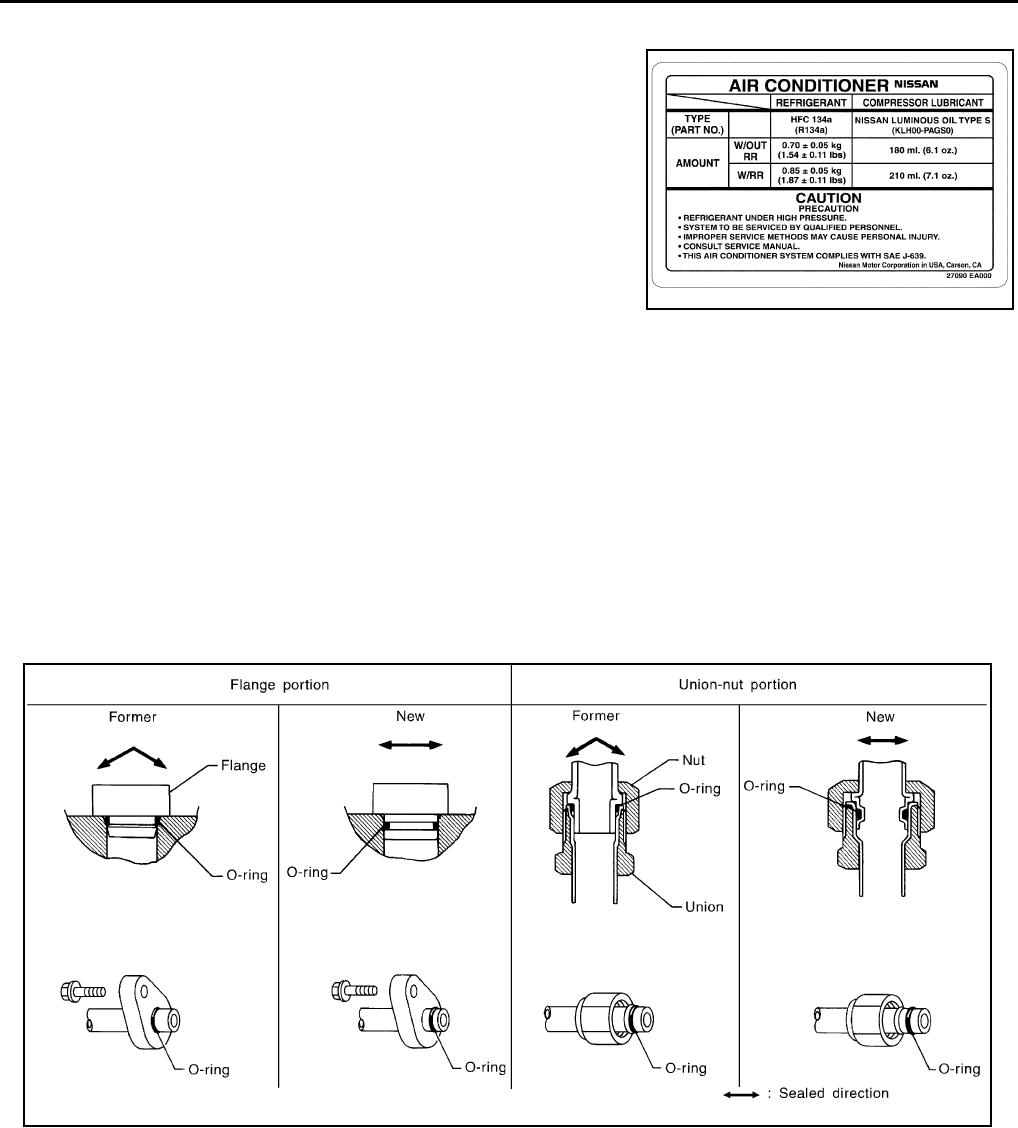
FEATURES OF NEW TYPE REFRIGERANT CONNECTION
●The O-ring has been relocated. It has also been provided with a groove for proper installation. This
reduces the possibility of the O-ring being caught in, or damaged by, the mating part. The sealing direction
of the O-ring is now set vertically in relation to the contacting surface of the mating part to improve sealing
characteristics.
●The reaction force of the O-ring will not occur in the direction that causes the joint to pull out, thereby facil-
itating piping connections.
LJIA0152E
SHA815E
PRECAUTIONS
MTC-7
C
D
E
F
G
H
I
K
L
M
A
B
MTC
Revision: November 2005 2005 Pathfinder
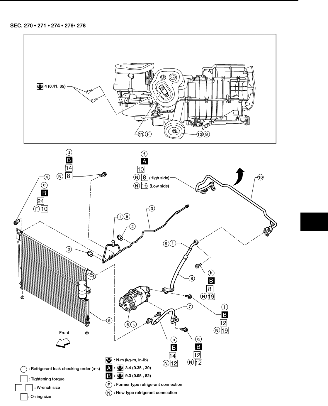
O-RING AND REFRIGERANT CONNECTION
A/C Compressor and Condenser
WJIA1253E
MTC-8
PRECAUTIONS
Revision: November 2005 2005 Pathfinder
CAUTION:
The new and former refrigerant connections use different O-ring configurations. Do not confuse O-
rings since they are not interchangeable. If a wrong O-ring is installed, refrigerant will leak at or
around the connection.
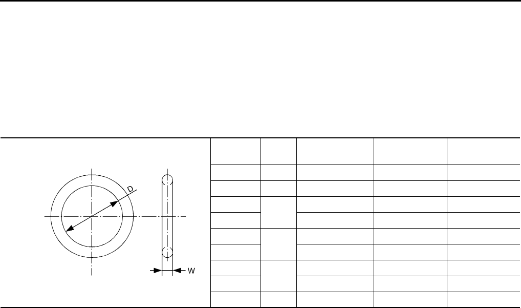
O-Ring Part Numbers and Specifications
*: Always check with the Parts Department for the latest parts information.
WARNING:
Make sure all refrigerant is discharged into the recycling equipment and the pressure in the system is
less than atmospheric pressure. Then gradually loosen the discharge side hose fitting and remove it.
CAUTION:
When replacing or cleaning refrigerant cycle components, observe the following.
●When the compressor is removed, store it in the same position as it is when mounted on the car.
Failure to do so will cause lubricant to enter the low pressure chamber.
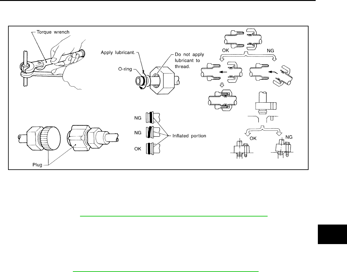
●When connecting tubes, always use a torque wrench and a back-up wrench.
●After disconnecting tubes, immediately plug all openings to prevent entry of dirt and moisture.
●When installing an air conditioner in the vehicle, connect the pipes as the final stage of the opera-
tion. Do not remove the seal caps of pipes and other components until just before required for
connection.
●Allow components stored in cool areas to warm to working area temperature before removing seal
caps. This prevents condensation from forming inside A/C components.
●Thoroughly remove moisture from the refrigeration system before charging the refrigerant.
●Always replace used O-rings.
●When connecting tube, apply lubricant to circle of the O-rings shown in illustration. Be careful not
to apply lubricant to threaded portion.
Lubricant name: Genuine NISSAN A/C System Lubricant Type S (DH-PS) or equivalent
Part number: KLH00-PAGS0
●O-ring must be closely attached to dented portion of tube.
●When replacing the O-ring, be careful not to damage O-ring and tube.
●Connect tube until you hear it click, then tighten the nut or bolt by hand until snug. Make sure that
the O-ring is installed to tube correctly.
1. High-pressure service valve 2. Clip 3. High-pressure A/C pipe
4. Refrigerant pressure sensor 5. Condenser 6. Compressor shaft seal
7. High-pressure flexible A/C hose 8. Low-pressure flexible A/C hose 9. Low-pressure service valve
10. Low-pressure A/C pipe 11. Expansion valve 12. A/C drain hose
Connec-
tion type O-ring
size Part number* D mm (in) W mm (in)
New 8 92471 N8210 6.8 (0.268) 1.85 (0.0728)
Former 10 J2476 89956 9.25 (0.3642) 1.78 (0.0701)
New 12 92472 N8210 10.9 (0.429) 2.43 (0.0957)
Former 92475 71L00 11.0 (0.433) 2.4 (0.094)
New 16 92473 N8210 13.6 (0.535) 2.43 (0.0957)
Former 92475 72L00 14.3 (0.563) 2.3 (0.091)
New 19 92474 N8210 16.5 (0.650) 2.43 (0.0957)
Former 92477 N8200 17.12 (0.6740) 1.78 (0.0701)
New 24 92195 AH300 21.8 (0.858) 2.4 (0.094)
SHA814E
PRECAUTIONS
MTC-9
C
D
E
F
G
H
I
K
L
M
A
B
MTC
Revision: November 2005 2005 Pathfinder
●After connecting line, conduct leak test and make sure that there is no leakage from connections.
When the refrigerant leaking point is found, disconnect that line and replace the O-ring. Then
tighten connections of seal seat to the specified torque.
Precautions for Servicing Compressor EJS003UR
●Plug all openings to prevent moisture and foreign matter from entering.
●When the compressor is removed, store it in the same position as it is when mounted on the car.
●When replacing or repairing compressor, follow “Maintenance of Lubricant Quantity in Compres-
sor” exactly. Refer to MTC-19, "Maintenance of Lubricant Quantity in Compressor" .
●Keep friction surfaces between clutch and pulley clean. If the surface is contaminated with lubri-
cant, wipe it off by using a clean waste cloth moistened with thinner.
●After compressor service operation, turn the compressor shaft by hand more than 5 turns in both
directions. This will equally distribute lubricant inside the compressor. After the compressor is
installed, let the engine idle and operate the compressor for 1 hour.
●After replacing the compressor magnet clutch, apply voltage to the new one and check for normal
operation. Refer to MTC-102, "Removal and Installation for Compressor Clutch" .
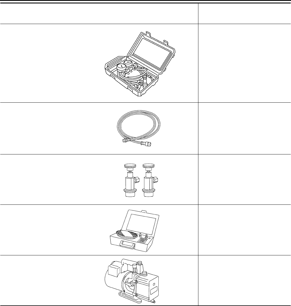
Precautions for Service Equipment EJS003US
RECOVERY/RECYCLING EQUIPMENT
Follow the manufacturer's instructions for machine operation and machine maintenance. Never introduce any
refrigerant other than that specified into the machine.
ELECTRONIC LEAK DETECTOR
Follow the manufacturer's instructions for tester operation and tester maintenance.
RHA861F
MTC-10
PRECAUTIONS
Revision: November 2005 2005 Pathfinder
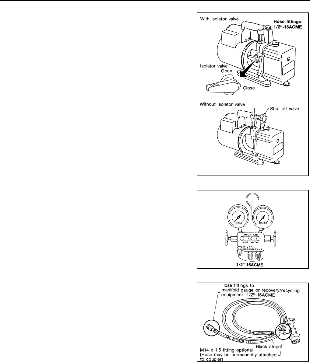
VACUUM PUMP
The lubricant contained inside the vacuum pump is not compatible
with the specified lubricant for HFC-134a (R-134a) A/C systems.
The vent side of the vacuum pump is exposed to atmospheric pres-
sure so the vacuum pump lubricant may migrate out of the pump into
the service hose. This is possible when the pump is switched off
after evacuation (vacuuming) and hose is connected to it.
To prevent this migration, use a manual valve situated near the
hose-to-pump connection, as follows.
●Usually vacuum pumps have a manual isolator valve as part of
the pump. Close this valve to isolate the service hose from the
pump.
●For pumps without an isolator, use a hose equipped with a man-
ual shut-off valve near the pump end. Close the valve to isolate
the hose from the pump.
●If the hose has an automatic shut off valve, disconnect the hose
from the pump: as long as the hose is connected, the valve is
open and lubricating oil may migrate.
Some one-way valves open when vacuum is applied and close
under a no vacuum condition. Such valves may restrict the pump's
ability to pull a deep vacuum and are not recommended.
MANIFOLD GAUGE SET
Be certain that the gauge face indicates HFC-134a (R-134a). Make
sure the gauge set has 1/2″-16 ACME threaded connections for ser-
vice hoses. Confirm the set has been used only with refrigerant
HFC-134a (R-134a) along with specified lubricant.
SERVICE HOSES
Be certain that the service hoses display the markings described
(colored hose with black stripe). All hoses must include positive shut-
off devices (either manual or automatic) near the end of the hoses
opposite the manifold gauge.
RHA270D
SHA533D
RHA272D
PRECAUTIONS
MTC-11
C
D
E
F
G
H
I
K
L
M
A
B
MTC
Revision: November 2005 2005 Pathfinder
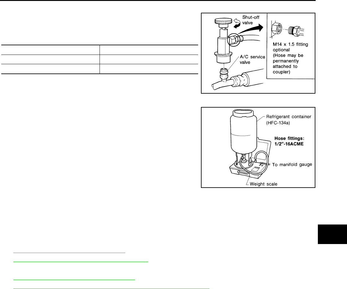
SERVICE COUPLERS
Never attempt to connect HFC-134a (R-134a) service couplers to a
CFC-12 (R-12) A/C system. The HFC-134a (R-134a) couplers will
not properly connect to the CFC-12 (R-12) system. If an improper
connection is attempted, discharging and contamination may occur.
REFRIGERANT WEIGHT SCALE
Verify that no refrigerant other than HFC134a (R-134a) and specified
lubricants have been used with the scale. If the scale controls refrig-
erant flow electronically, the hose fitting must be 1/2”-16 ACME.
CHARGING CYLINDER
Using a charging cylinder is not recommended. Refrigerant may be vented into air from cylinder's top valve
when filling the cylinder with refrigerant. Also, the accuracy of the cylinder is generally less than that of an
electronic scale or of quality recycle/recharge equipment.
Wiring Diagrams and Trouble Diagnosis EJS003UT
When you read wiring diagrams, refer to the following:
●GI-15, "How to Read Wiring Diagrams"
●PG-4, "POWER SUPPLY ROUTING CIRCUIT"
When you perform trouble diagnosis, refer to the following:
●GI-10, "How to Follow Trouble Diagnoses"
●GI-27, "How to Perform Efficient Diagnosis for an Electrical Incident"
Shut-off valve rotation A/C service valve
Clockwise Open
Counterclockwise Close
RHA273D
RHA274D
MTC-12
PREPARATION
Revision: November 2005 2005 Pathfinder
PREPARATION PFP:00002
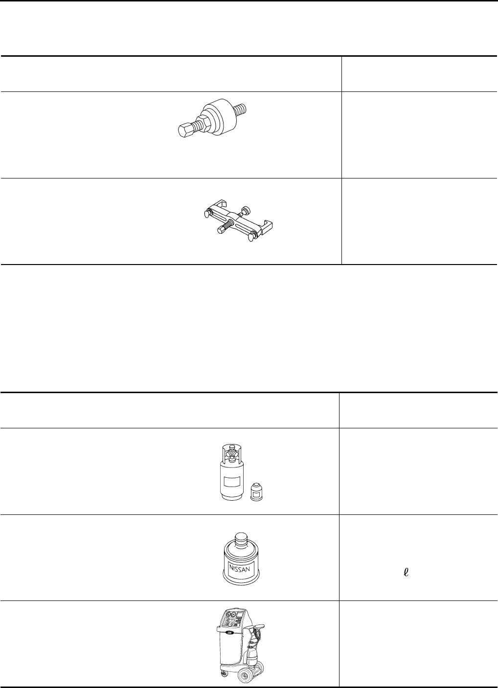
Special Service Tools EJS003UU
The actual shapes of Kent-Moore tools may differ from those of special service tools illustrated here.
HFC-134a (R-134a) Service Tools and Equipment EJS003UV
Never mix HFC-134a (R-134a) refrigerant and/or the specified lubricant with CFC-12 (R-12) refrigerant and/or
the lubricant.
Separate and non-interchangeable service equipment must be used for handling each type of refrigerant/lubri-
cant.
Refrigerant container fittings, service hose fittings and service equipment fittings (equipment which handles
refrigerant and/or lubricant) are different between CFC-12 (R-12) and HFC-134a (R-134a). This is to avoid
mixed use of the refrigerants/lubricant.
Adapters that convert one size fitting to another must never be used refrigerant/lubricant contamination will
occur and compressor failure will result.
Tool number
(Kent-Moore No.)
Tool name
Description
—
(J-38873-A)
Pulley installer
Installing pulley
KV99233130
(J-29884)
Pulley puller
Removing pulley
LHA171
LHA172
Tool number
(Kent-Moore No.)
Tool name
Description
HFC-134a (R-134a)
(—)
Refrigerant
Container color: Light blue
Container marking: HFC-134a (R-
134a)
Fitting size: Thread size
●large container 1/2”-16 ACME
KLH00-PAGS0
(—)
NISSAN A/C System Lubricant
Type S (DH-PS)
Type: Poly alkylene glycol oil (PAG),
type S (DH-PS)
Application: HFC-134a (R-134a)
swash plate compressors (NISSAN
only)
Lubricity: 40 m (1.4 US fl oz, 1.4 Imp
fl oz)
KV991J0130
(ACR2005-NI)
ACR A/C Service Center
Refrigerant Recovery and Recycling
and Recharging
S-NT196
S-NT197
WJIA0293E
PREPARATION
MTC-13
C
D
E
F
G
H
I
K
L
M
A
B
MTC
Revision: November 2005 2005 Pathfinder
—
(J-41995)
Electronic refrigerant leak detector
Power supply:
●DC 12V (battery terminal)
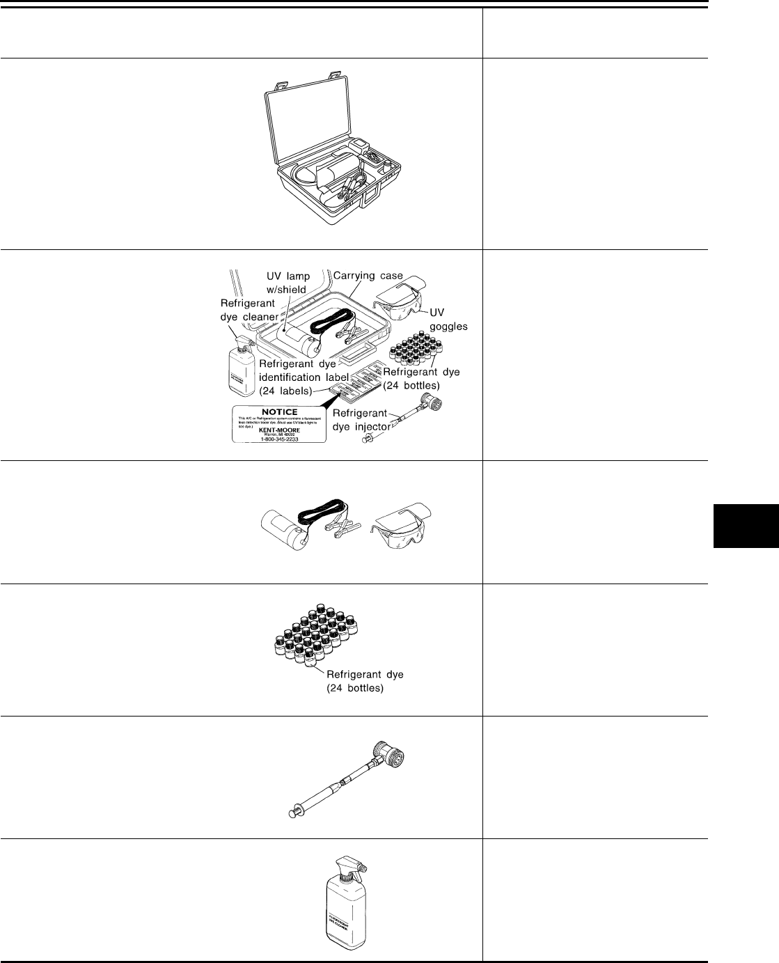
—
(J-43926)
Refrigerant dye leak detection kit
Kit includes:
(J-42220)
UV lamp and UV safety goggles
(J-41459)
Refrigerant dye injector
(J-41447)
HFC-134a (R-134a) Fluorescent
leak detection dye (box of 24, 1/4
ounce bottles)
(J-43872)
Refrigerant dye cleaner
Power supply:
●DC 12V (battery terminal)
—
(J-42220)
Fluorescent dye leak detector
Power supply:
●DC 12V (battery terminal)
For checking refrigerant leak when flu-
orescent dye is installed in A/C system.
Includes: UV lamp and UV safety gog-
gles
—
(J-41447)
HFC-134a (R-134a) Fluorescent
leak detection dye
(box of 24, 1/4 ounce bottles)
Application: For HFC-134a (R-134a)
PAG oil
Container: 1/4 ounce (7.4cc) bottle
(Includes self-adhesive dye identifica-
tion labels for affixing to vehicle after
charging system with dye.)
—
(J-41459)
HFC-134a (R-134a) Refrigerant
dye injector
Use with J-41447, 1/4 ounce bottle
For injecting 1/4 ounce of fluorescent
leak detection dye into A/C system.
—
(J-43872)
Refrigerant dye cleaner
For cleaning dye spills.
Tool number
(Kent-Moore No.)
Tool name
Description
AHA281A
ZHA200H
SHA438F
SHA439F
SHA440F
SHA441F
MTC-14
PREPARATION
Revision: November 2005 2005 Pathfinder
—
(J-39183-C)
Manifold gauge set (with hoses
and couplers)
Identification:
●The gauge face indicates R-134a.
Fitting size-Thread size
●1/2”-16 ACME
Service hoses:
●High side hose
(J-39500-72B)
●Low side hose
(J-39500-72R)
●Utility hose
(J-39500-72Y)
Hose color:
●Low side hose: Blue with black stripe
●High side hose: Red with black stripe
●Utility hose: Yellow with black stripe
or green with black stripe
Hose fitting to gauge:
●1/2”-16 ACME
Service couplers
●High side coupler
(J-39500-20A)
●Low side coupler
(J-39500-24A)
Hose fitting to service hose:
●M14 x 1.5 fitting is optional or perma-
nently attached.
—
(J-39699)
Refrigerant weight scale
For measuring of refrigerant
Fitting size-Thread size
●1/2”-16 ACME
—
(J-39649)
Vacuum pump
(Including the isolator valve)
Capacity:
●Air displacement: 4 CFM
●Micron rating: 20 microns
●Oil capacity: 482 g (17 oz)
Fitting size-Thread size
●1/2”-16 ACME
Tool number
(Kent-Moore No.)
Tool name
Description
RJIA0196E
S-NT201
S-NT202
S-NT200
S-NT203
PREPARATION
MTC-15
C
D
E
F
G
H
I
K
L
M
A
B
MTC
Revision: November 2005 2005 Pathfinder
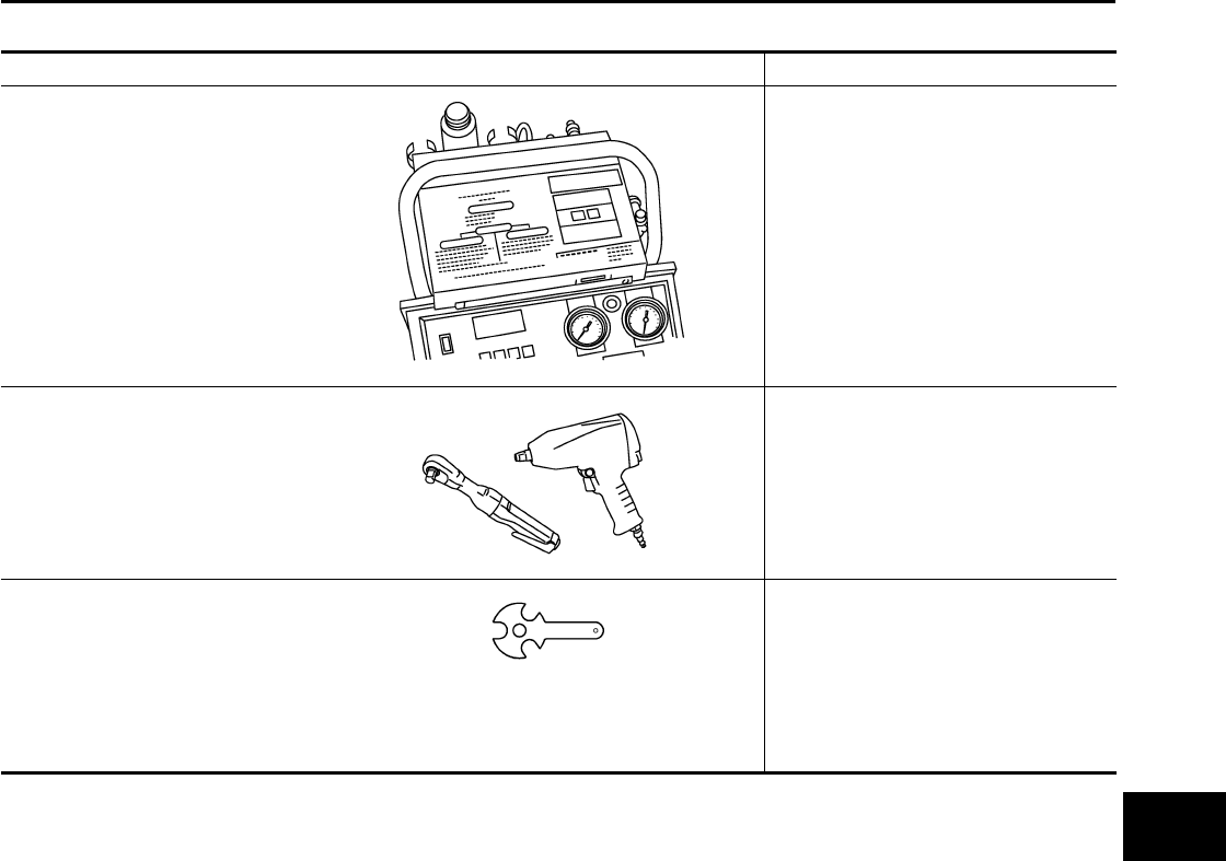
Commercial Service Tools EJS003UW
Tool name Description
(J-41810-NI)
Refrigerant identifier equipment (R-
134a)
For checking refrigerant purity and
system contamination
Power tool Loosening bolts and nuts
(J-44614)
Clutch disc holding tool Clutch disc holding tool
RJIA0197E
PBIC0190E
WHA230
MTC-16
REFRIGERATION SYSTEM
Revision: November 2005 2005 Pathfinder
REFRIGERATION SYSTEM PFP:KA990
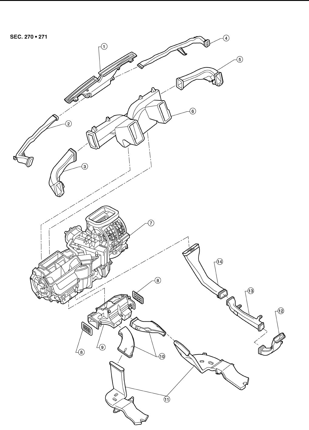
Components EJS003UX
REFRIGERATION SYSTEM
LJIA0155E
REFRIGERATION SYSTEM
MTC-17
C
D
E
F
G
H
I
K
L
M
A
B
MTC
Revision: November 2005 2005 Pathfinder
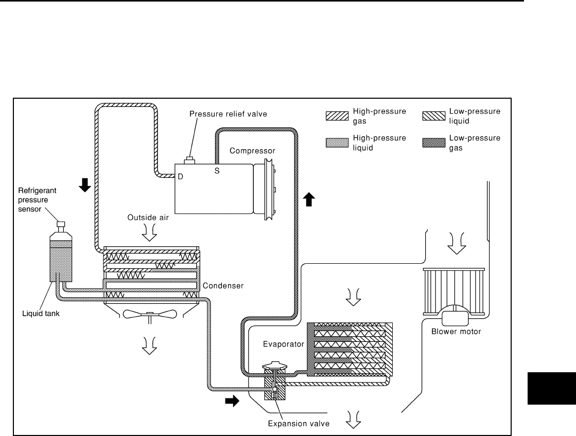
Refrigerant Cycle EJS003UY
REFRIGERANT FLOW
The refrigerant flows in the standard pattern. Refrigerant flows through the compressor, condenser, liquid tank,
expansion valve, evaporator, and back to the compressor. The refrigerant evaporation through the evaporator
coil is controlled by an externally equalized expansion valve, located inside the evaporator case.
FREEZE PROTECTION
The compressor cycles on and off to maintain the evaporator temperature within a specified range. When the
evaporator coil temperature falls below a specified point, the intake sensor interrupts the compressor opera-
tion. When the evaporator coil temperature rises above the specification, the intake sensor allows compressor
operation.
Refrigerant System Protection EJS003UZ
REFRIGERANT PRESSURE SENSOR
The refrigerant system is protected against excessively high- or low-pressures by the refrigerant pressure sen-
sor, located on the condenser. If the system pressure rises above or falls below the specifications, the refriger-
ant pressure sensor detects the pressure inside the refrigerant line and sends a voltage signal to the ECM.
The ECM de-energizes the A/C relay to disengage the magnetic compressor clutch when pressure on the high
pressure side detected by refrigerant pressure sensor is over about 2,746 kPa (28 kg/cm2 , 398 psi), or below
about 120 kPa (1.22 kg/cm2 , 17.4 psi).
1. Defroster nozzle 2. LH side demister duct 3. LH ventilator duct
4. RH side demister duct 5. RH ventilator duct 6. Center ventilator duct
7. Front heater and cooling unit assembly 8. Floor connector duct grilles 9. Floor connector duct
10. Front ducts 11. Floor ducts 12. Rear console duct
13. Center console duct 14. Front console duct
RJIA1552E

MTC-18
REFRIGERATION SYSTEM
Revision: November 2005 2005 Pathfinder
PRESSURE RELIEF VALVE
The refrigerant system is also protected by a pressure relief valve, located in the rear head of the compressor.
When the pressure of refrigerant in the system increases to an abnormal level [more than 2,990 kPa (30.5 kg/
cm2 , 433.6 psi)], the release port on the pressure relief valve automatically opens and releases refrigerant
into the atmosphere.
LUBRICANT
MTC-19
C
D
E
F
G
H
I
K
L
M
A
B
MTC
Revision: November 2005 2005 Pathfinder
LUBRICANT PFP:KLG00
Maintenance of Lubricant Quantity in Compressor EJS003V0
The lubricant in the compressor circulates through the system with the refrigerant. Add lubricant to compres-
sor when replacing any component or after a large refrigerant leakage has occurred. It is important to maintain
the specified amount.
If lubricant quantity is not maintained properly, the following malfunctions may result:
●Lack of lubricant: May lead to a seized compressor
●Excessive lubricant: Inadequate cooling (thermal exchange interference)
LUBRICANT
Name: NISSAN A/C System Lubricant Type S (DH-PS) or equivalent.
Part number: KLH00-PAGS0.
CHECKING AND ADJUSTING
CAUTION:
If excessive lubricant leakage is noted, do not perform the lubricant return operation.
Start the engine and set the following conditions:
Test Condition
●Engine speed: Idling to 1,200 rpm
●A/C switch: On
●Blower speed: Max. position
●Temperature control: Optional [Set so that intake air temperature is 25° to 30° C (77° to 86°F)]
●Intake position: Recirculation ( )
●Perform lubricant return operation for about ten minutes
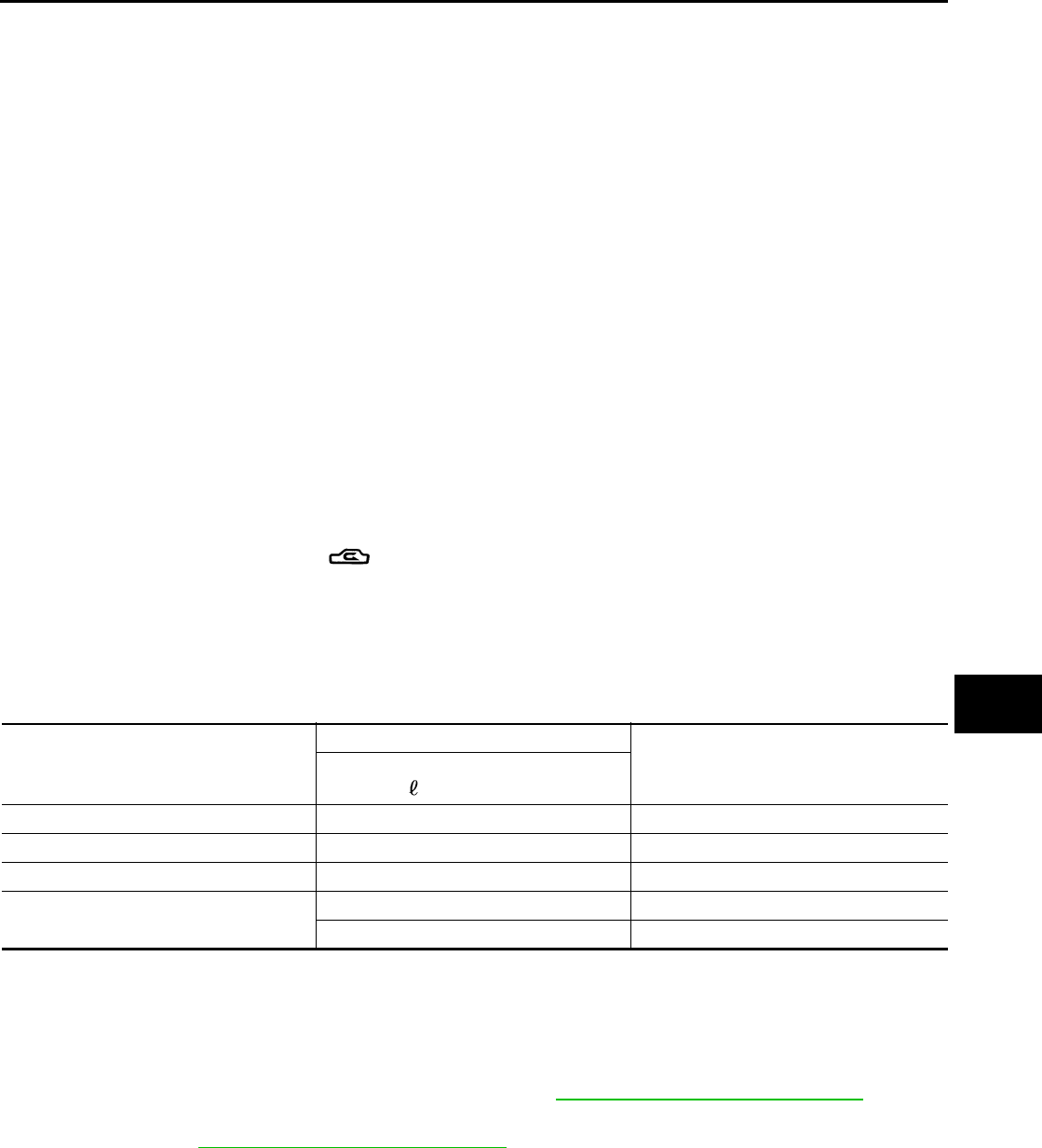
Adjust the lubricant quantity according to the following table.
Lubricant Adjusting Procedure for Components Replacement Except Compressor
After replacing any of the following major components, add the correct amount of lubricant to the system.
Amount of Lubricant to be Added
*1: If refrigerant leak is small, no addition of lubricant is needed.
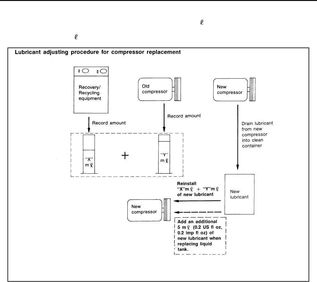
Lubricant Adjustment Procedure for Compressor Replacement
1. Before connecting recovery/recycling equipment to vehicle, check recovery/recycling equipment gauges.
No refrigerant pressure should be displayed. If NG, recover refrigerant from equipment lines.
2. Connect recovery/recycling equipment to vehicle. Confirm refrigerant purity in supply tank using recovery/
recycling equipment and refrigerant identifier. If NG, refer to MTC-4, "Contaminated Refrigerant" .
3. Confirm refrigerant purity in vehicle A/C system using recovery/recycling equipment and refrigerant identi-
fier. If NG, refer to MTC-4, "Contaminated Refrigerant" .
4. Discharge refrigerant into the refrigerant recovery/recycling equipment. Measure lubricant discharged into
the recovery/recycling equipment.
5. Drain the lubricant from the “old” (removed) compressor into a graduated container and recover the
amount of lubricant drained.
6. Drain the lubricant from the “new” compressor into a separate, clean container.
7. Measure an amount of new lubricant installed equal to amount drained from “old” compressor. Add this
lubricant to “new” compressor through the suction port opening.
Part replaced
Lubricant to be added to system
Remarks
Amount of lubricant
m (US fl oz, Imp fl oz)
Evaporator 75 (2.5, 2.6) —
Condenser 75 (2.5, 2.6) —
Liquid tank 5 (0.2, 0.2) Add if compressor is not replaced.
In case of refrigerant leak 30 (1.0, 1.1) Large leak
— Small leak *1
MTC-20
LUBRICANT
Revision: November 2005 2005 Pathfinder
8. Measure an amount of new lubricant equal to the amount recovered during discharging. Add this lubricant
to “new” compressor through the suction port opening.
9. If the liquid tank also needs to be replaced, add an additional 5 m (0.2 US fl oz, 0.2 Imp fl oz) of lubricant
at this time.
Do not add this 5 m (0.2 US fl oz, 0.2 Imp fl oz) of lubricant if only replacing the compressor.
RHA065DD
AIR CONDITIONER CONTROL
MTC-21
C
D
E
F
G
H
I
K
L
M
A
B
MTC
Revision: November 2005 2005 Pathfinder
AIR CONDITIONER CONTROL PFP:27500
Description EJS003V1
The front air control provides regulation of the vehicle's interior temperature. The system is based on the posi-
tion of the front air controls temperature switch selected by the driver. This is done by utilizing a microcom-
puter, also referred to as the front air control, which receives input signals from the following two sensors:
●Intake sensor
●PBR (position balanced resistor)
The front air control uses these signals (including the set position of the temperature switch) to control:
●Outlet air volume
●Air temperature
●Air distribution
Operation EJS003V2
AIR MIX DOOR CONTROL
The air mix door is controlled so that in-vehicle temperature changed based on the position of the temperature
switch.
BLOWER SPEED CONTROL
Blower speed is controlled based on front blower switch settings.
When blower switch is turned, the blower motor starts and increases air flow volume each time the blower
switch is turned counterclockwise, and decreases air flow volume each time the blower switch is turned coun-
terclockwise.
When engine coolant temperature is low, the blower motor operation is delayed to prevent cool air from flow-
ing.
INTAKE DOORS CONTROL
The intake doors are controlled by the recirculation switch setting, and the mode (defroster) switch setting.
MODE DOOR CONTROL
The mode door is controlled by the position of the mode dial.
DEFROSTER DOOR CONTROL
The defroster door is controlled by the defroster dial set to defroster.
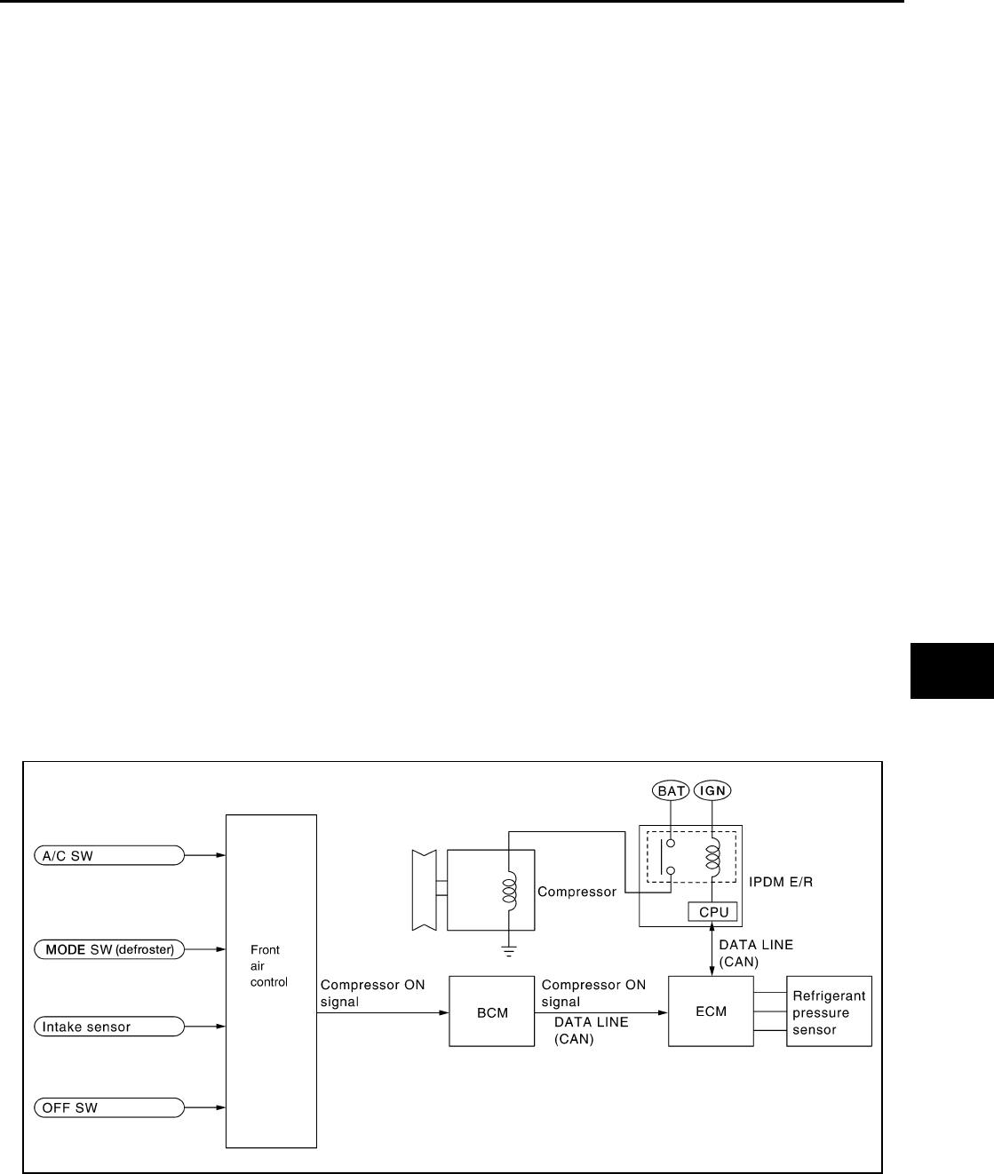
MAGNET CLUTCH CONTROL
When the A/C switch is pressed, or the mode dial is turned to the defroster position, the front air control out-
puts a compressor ON signal to BCM.
The BCM then sends a compressor ON signal to ECM, via CAN communication line.
WJIA1293E

MTC-22
AIR CONDITIONER CONTROL
Revision: November 2005 2005 Pathfinder
ECM judges whether compressor can be turned ON, based on each sensor status (refrigerant pressure sen-
sor signal, throttle angle sensor, etc.). If it judges compressor can be turned ON, it sends compressor ON sig-
nal to IPDM E/R, via CAN communication line.
Upon receipt of compressor ON signal from ECM, IPDM E/R turns air conditioner relay ON to operate com-
pressor.
AIR CONDITIONER CONTROL
MTC-23
C
D
E
F
G
H
I
K
L
M
A
B
MTC
Revision: November 2005 2005 Pathfinder
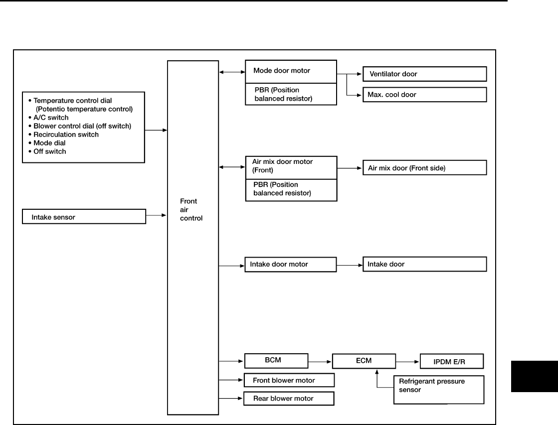
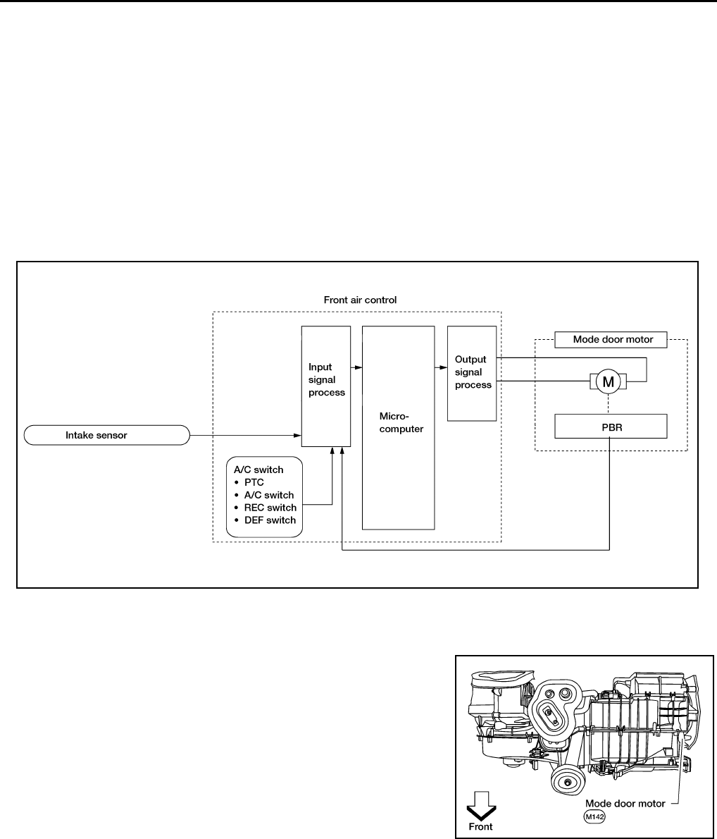
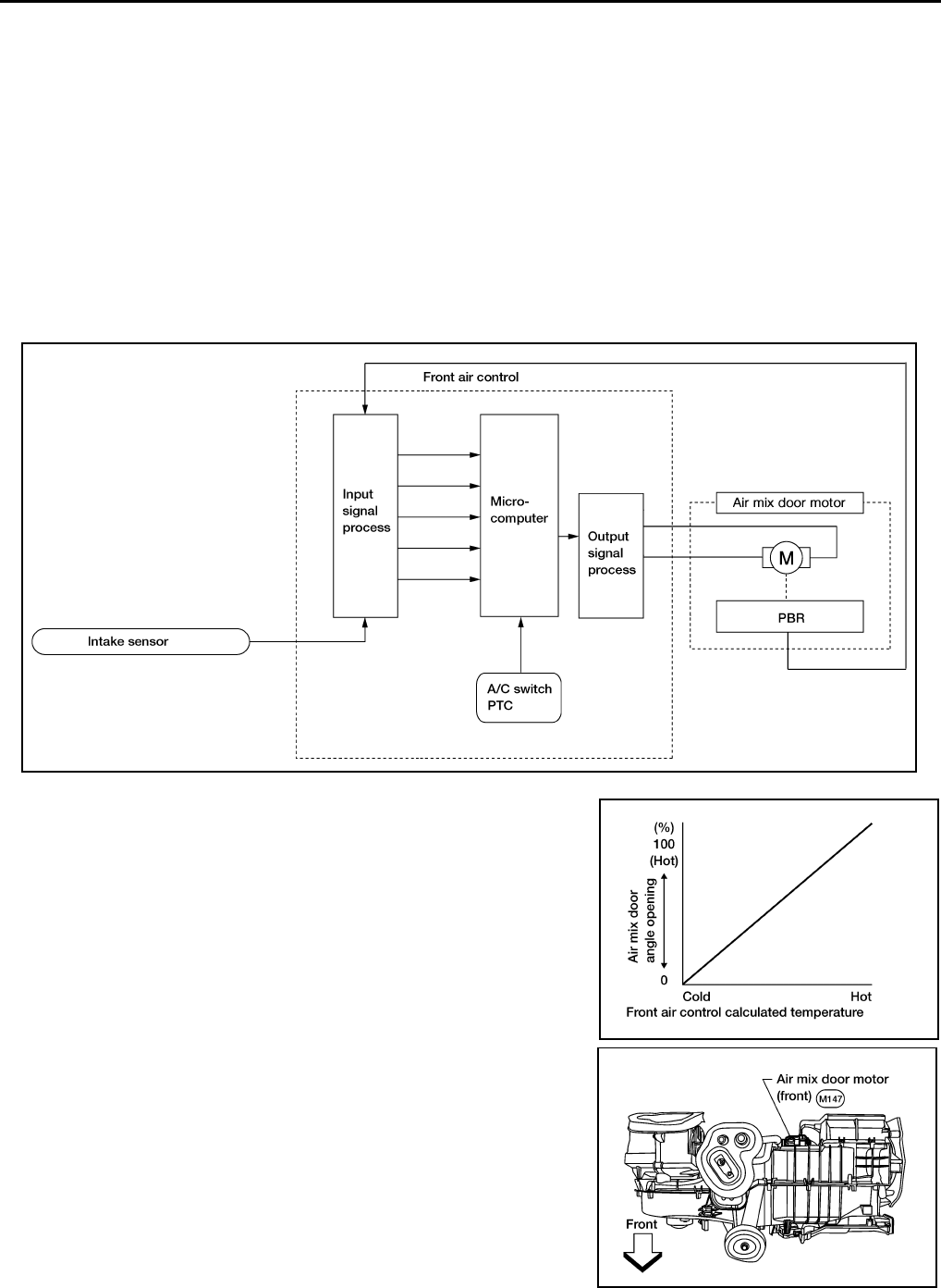
Description of Control System EJS003V3
The control system consists of input sensors, switches, the front air control (microcomputer) and outputs.
The relationship of these components is shown in the figure below:
WJIA1294E
MTC-24
AIR CONDITIONER CONTROL
Revision: November 2005 2005 Pathfinder
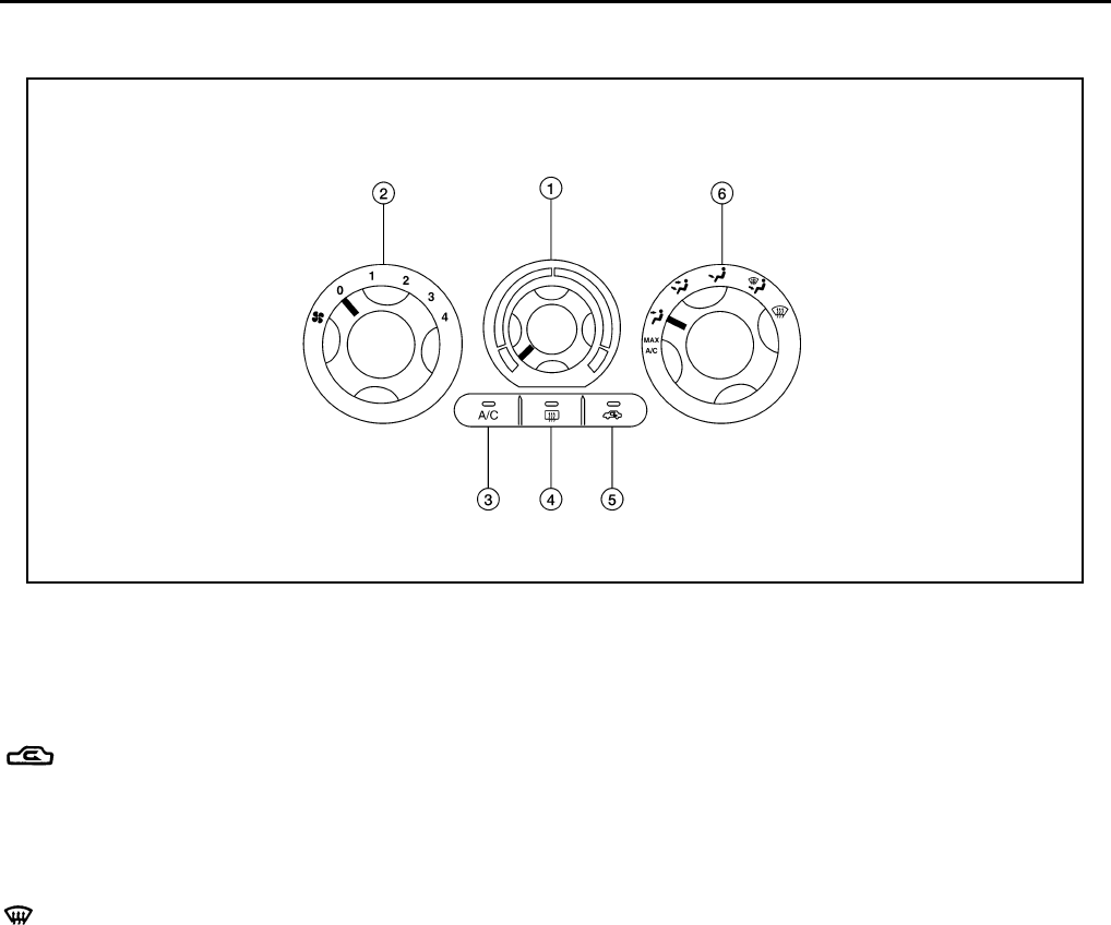
Control Operation EJS003V4
Front air control
TEMPERATURE CONTROL DIAL (TEMPERATURE CONTROL)
Increases or decreases the set temperature.
RECIRCULATION () SWITCH
●When REC switch is ON, REC switch indicator turns ON, and air inlet is set to REC.
●When REC switch is turned OFF, or when compressor is turned from ON to OFF, REC switch is automati-
cally turned OFF. REC mode can be re-entered by pressing REC switch again.
●REC switch is not operated when DEF switch is turned ON, or at the D/F position.
DEFROSTER () SWITCH
Positions the air outlet doors to the defrost position. Also positions the intake doors to the outside air position.
REAR WINDOW DEFOGGER SWITCH
When switch is ON, rear window is defogged.
OFF SWITCH (BLOWER SPEED SET TO 0)
The compressor and blower are OFF.
A/C SWITCH
The compressor is ON or OFF.
(Pressing the A/C switch when the AUTO switch is ON will turn off the A/C switch and compressor.)
MODE DIAL
Controls the air discharge outlets.
FRONT BLOWER CONTROL DIAL
Manually controls the four blower speeds.
WJIA1510E
1 Temperature control dial 2 Blower control dial 3 A/C switch
4 Rear window defogger switch 5 Recirculation switch 6 Mode dial
AIR CONDITIONER CONTROL
MTC-25
C
D
E
F
G
H
I
K
L
M
A
B
MTC
Revision: November 2005 2005 Pathfinder
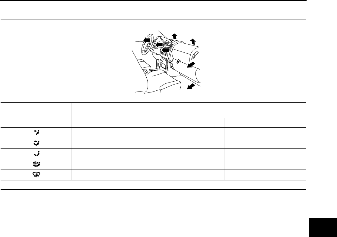
Discharge Air Flow EJS004O3
FRONT
Mode door position Air outlet/distribution
Vent Foot Defroster
95% 5% —
60% 40% —
20% 55% 25%
15% 50% 35%
7% 15% 78%
Airflow always present at driver and passenger side demisters
WJIA1296E
MTC-26
AIR CONDITIONER CONTROL
Revision: November 2005 2005 Pathfinder
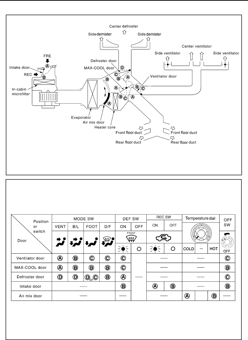
System Description EJS003V6
SWITCHES AND THEIR CONTROL FUNCTION
WJIA1496E
WJIA1497E

AIR CONDITIONER CONTROL
MTC-27
C
D
E
F
G
H
I
K
L
M
A
B
MTC
Revision: November 2005 2005 Pathfinder
CAN Communication System Description EJS003V7
Refer to LAN-24, "CAN COMMUNICATION" .
MTC-28
TROUBLE DIAGNOSIS
Revision: November 2005 2005 Pathfinder
TROUBLE DIAGNOSIS PFP:00004
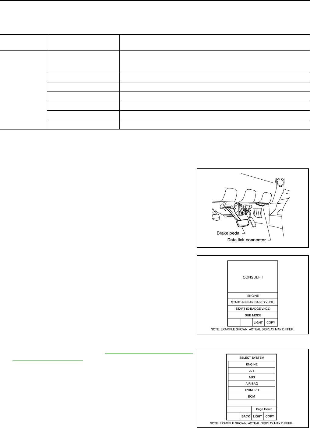
CONSULT-II Function (BCM) EJS003V8
CONSULT-II can display each diagnostic item using the diagnostic test modes shown following.
CONSULT-II BASIC OPERATION
CAUTION:
If CONSULT-II is used with no connection of CONSULT-II CONVERTER, malfunctions might be
detected in self-diagnosis depending on control unit which carries out CAN communication.
1. With the ignition switch OFF, connect CONSULT-II and CON-
SULT-II CONVERTER to the data link connector, and turn the
ignition switch ON.
2. Touch “START (NISSAN BASED VHCL)”.
3. Touch “BCM” on “SELECT SYSTEM” screen.
If “BCM” is not indicated, go to GI-39, "CONSULT-II Data Link
Connector (DLC) Circuit" .
BCM diagnostic
test item Diagnostic mode Description
Inspection by part
WORK SUPPORT
Supports inspections and adjustments. Commands are transmitted to the BCM
for setting the status suitable for required operation, input/output signals are
received from the BCM and received data is displayed.
DATA MONITOR Displays BCM input/output data in real time.
ACTIVE TEST Operation of electrical loads can be checked by sending drive signal to them.
SELF-DIAG RESULTS Displays BCM self-diagnosis results.
CAN DIAG SUPPORT MNTR The result of transmit/receive diagnosis of CAN communication can be read.
ECU PART NUMBER BCM part number can be read.
CONFIGURATION Performs BCM configuration read/write functions.
WJIA1078E
BCIA0029E
BCIA0030E
TROUBLE DIAGNOSIS
MTC-29
C
D
E
F
G
H
I
K
L
M
A
B
MTC
Revision: November 2005 2005 Pathfinder
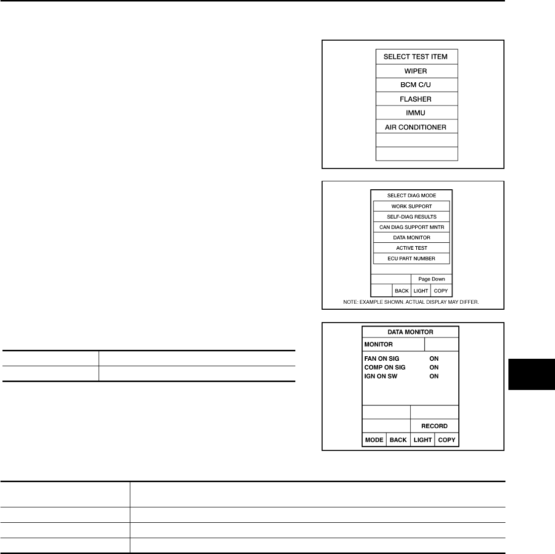
DATA MONITOR
Operation Procedure
1. Touch “AIR CONDITIONER” on “SELECT TEST ITEM” screen.
2. Touch “DATA MONITOR” on “SELECT DIAG MODE” screen.
3. Touch either “ALL SIGNALS” or “SELECTION FROM MENU” on
“DATA MONITOR” screen.
4. When “SELECTION FROM MENU” is selected, touch items to
be monitored. When “ALL SIGNALS” is selected, all the items
will be monitored.
5. Touch “START”.
6. Touch “RECORD” while monitoring, then the status of the moni-
tored item can be recorded. To stop recording, touch “STOP”.
Display Item List
WJIA0468E
BCIA0031E
All signals Monitors all the items.
Selection from menu Selects and monitors the individual item selected.
WJIA0469E
Monitor item name
“OPERATION OR UNIT” Contents
IGN ON SW “ON/OFF” Displays “IGN Position (ON)/OFF, ACC Position (OFF)” status as judged from ignition switch signal.
COMP ON SIG “ON/OFF” Displays “COMP (ON)/COMP (OFF)” status as judged from air conditioner switch signal.
FAN ON SIG “ON/OFF” Displays “FAN (ON)/FAN (OFF)” status as judged from blower motor switch signal.
MTC-30
TROUBLE DIAGNOSIS
Revision: November 2005 2005 Pathfinder
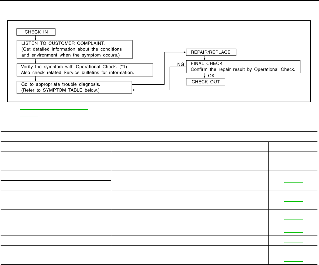
How to Perform Trouble Diagnosis for Quick and Accurate Repair EJS003V9
WORK FLOW
SYMPTOM TABLE
*1 ATC-52, "Operational Check
(Front)".
SHA900E
Symptom Reference Page
A/C system does not come on. Go to Trouble Diagnosis Procedure for A/C System. MTC-42
Air outlet does not change. Go to Trouble Diagnosis Procedure for Mode Door Motor. MTC-45
Mode door motor is malfunctioning.
Discharge air temperature does not change. Go to Trouble Diagnosis Procedure for Air Mix Door Motor. MTC-49
Air mix door motor is malfunctioning.
Intake door does not change. Go to Trouble Diagnosis Procedure for Intake Door Motor. MTC-53
Intake door motor is malfunctioning.
Front blower motor operation is malfunction-
ing. Go to Trouble Diagnosis Procedure for Front Blower Motor. MTC-57
Magnet clutch does not engage. Go to Trouble Diagnosis Procedure for Magnet Clutch. MTC-65
Insufficient cooling Go to Trouble Diagnosis Procedure for Insufficient Cooling. MTC-70
Insufficient heating Go to Trouble Diagnosis Procedure for Insufficient Heating. MTC-77
Noise Go to Trouble Diagnosis Procedure for Noise. MTC-78
TROUBLE DIAGNOSIS
MTC-31
C
D
E
F
G
H
I
K
L
M
A
B
MTC
Revision: November 2005 2005 Pathfinder
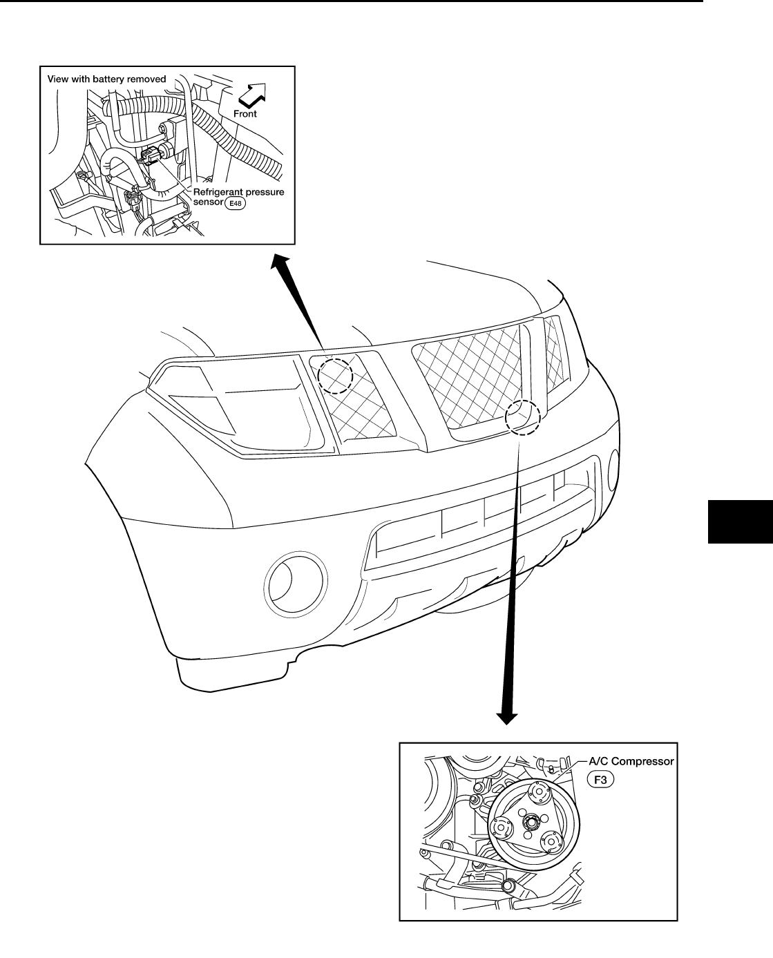
Component Parts and Harness Connector Location EJS003VA
ENGINE COMPARTMENT
WJIA1489E
MTC-32
TROUBLE DIAGNOSIS
Revision: November 2005 2005 Pathfinder
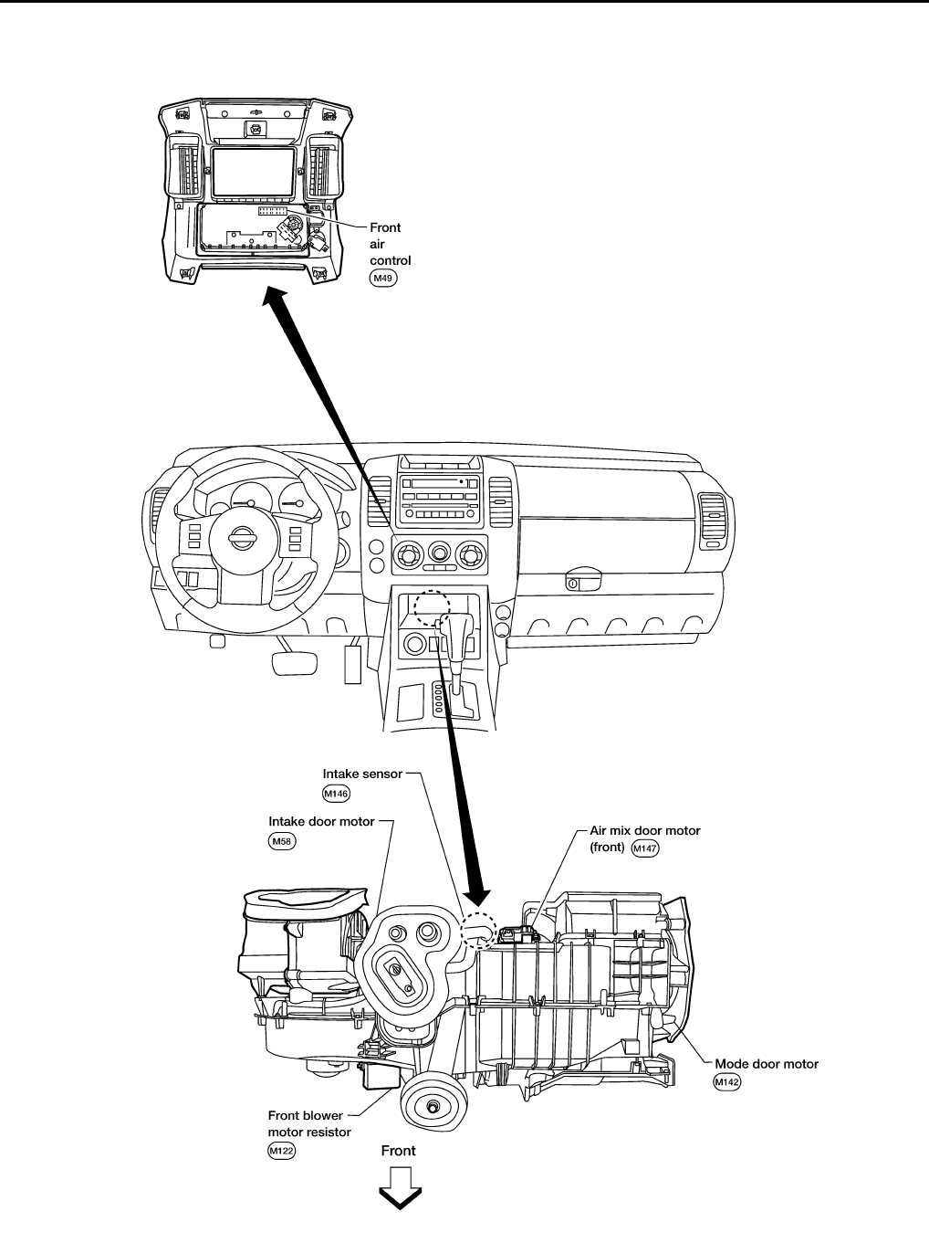
FRONT PASSENGER COMPARTMENT
WJIA1301E
TROUBLE DIAGNOSIS
MTC-33
C
D
E
F
G
H
I
K
L
M
A
B
MTC
Revision: November 2005 2005 Pathfinder
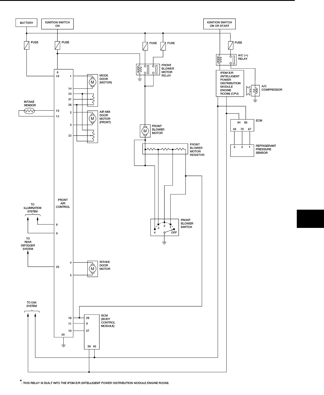
Schematic EJS003VB
WJWA0197E
MTC-34
TROUBLE DIAGNOSIS
Revision: November 2005 2005 Pathfinder
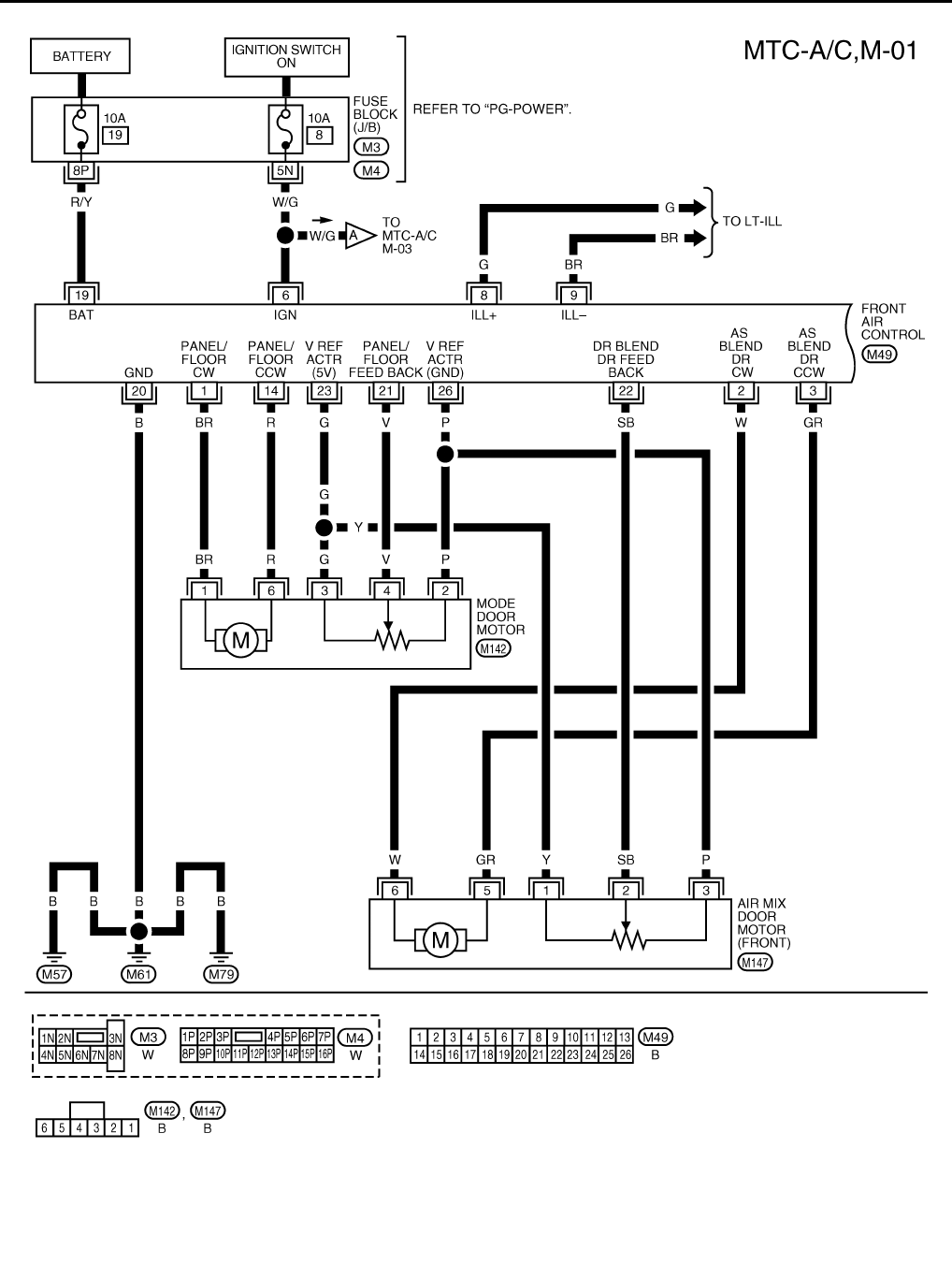
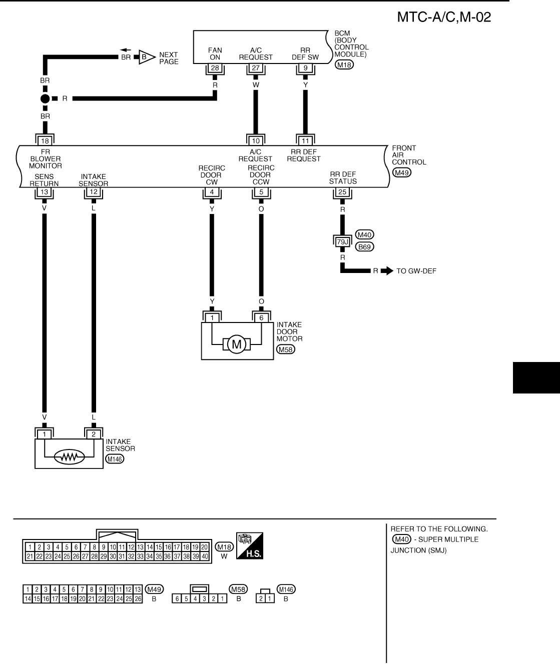
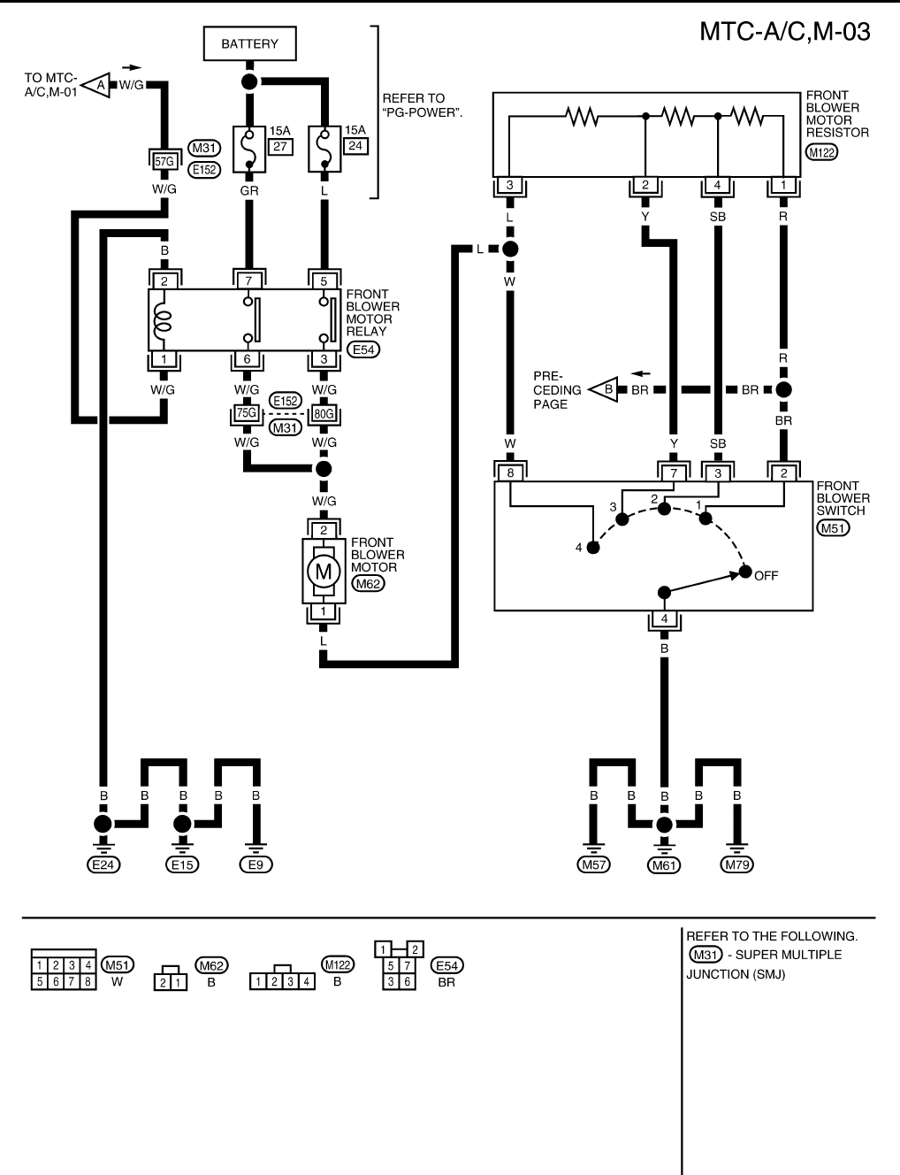
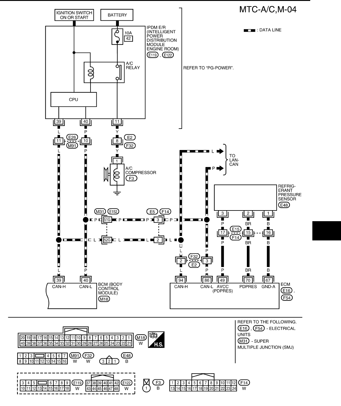
Wiring Diagram — A/C,M — EJS003VC
WJWA0279E
TROUBLE DIAGNOSIS
MTC-35
C
D
E
F
G
H
I
K
L
M
A
B
MTC
Revision: November 2005 2005 Pathfinder
WJWA0280E
MTC-36
TROUBLE DIAGNOSIS
Revision: November 2005 2005 Pathfinder
WJWA0281E
TROUBLE DIAGNOSIS
MTC-37
C
D
E
F
G
H
I
K
L
M
A
B
MTC
Revision: November 2005 2005 Pathfinder
WJWA0199E
MTC-38
TROUBLE DIAGNOSIS
Revision: November 2005 2005 Pathfinder
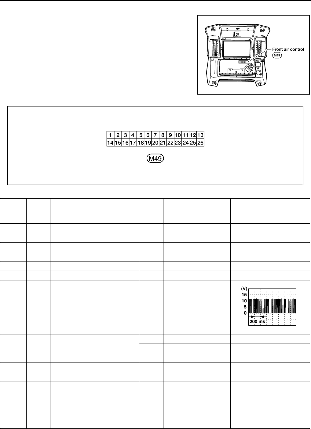
Front Air Control Terminals and Reference Value EJS003VD
Measure voltage between each terminal and ground by following
Terminals and Reference Value for front air control.
PIN CONNECTOR TERMINAL LAYOUT
TERMINALS AND REFERENCE VALUE FOR FRONT AIR CONTROL
WJIA1302E
WJIA1303E
Termi -
nal No.
Wire
color Item Ignition
switch Condition Voltage (V)
(Approx.)
1 BR Mode door motor CW ON Clockwise rotation Battery voltage
2 W Air mix door motor (Driver) CW ON Clockwise rotation Battery voltage
3 G/R Air mix door motor (Driver) CCW ON Counterclockwise rotation Battery voltage
4 Y Intake door motor CW ON Clockwise rotation Battery voltage
5 O Intake door motor CCW ON Counterclockwise rotation Battery voltage
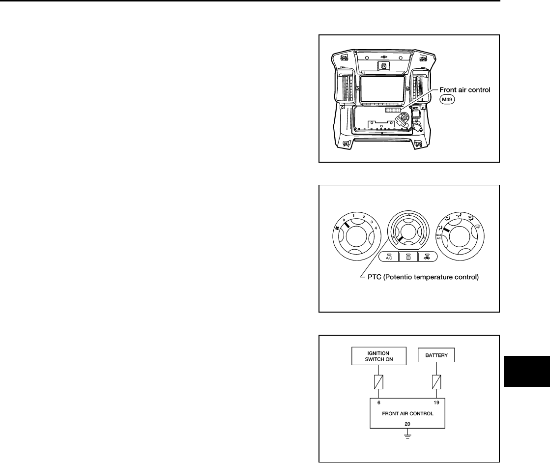
6 W/G Power supply for IGN ON - Battery voltage
8 G Illumination + ON Park lamps ON Battery voltage
9 BR Illumination - - Park lamps ON
10 W Compressor ON signal ON A/C switch OFF 5V
ON A/C switch ON 0V
11 Y Rear defrost request ON - Battery voltage
12 L Intake sensor ON - 0 - 5V
13 V Sensor ground ON - 0 - 5V
14 R Mode door motor CCW ON Counterclockwise rotation Battery voltage
18 BR Front blower monitor ON Front blower motor OFF Battery voltage
Front blower motor ON 0V
19 R/Y Power supply for BAT - - Battery voltage
20 B Ground - - 0V
PIIA2344E

TROUBLE DIAGNOSIS
MTC-39
C
D
E
F
G
H
I
K
L
M
A
B
MTC
Revision: November 2005 2005 Pathfinder
21 V Mode door motor feedback ON - 0 - 5V
22 SB Air mix door motor (Front) feedback ON - 0 - 5V
23 G Power supply for mode door motor
and air mix door motor (Front) PBR ON - 5V
25 R Rear defroster request ON - Battery voltage
26 P Ground for mode door motor and air
mix door motor (Front) PBR ON - 0V
Termi-
nal No.
Wire
color Item Ignition
switch Condition Voltage (V)
(Approx.)
MTC-40
TROUBLE DIAGNOSIS
Revision: November 2005 2005 Pathfinder
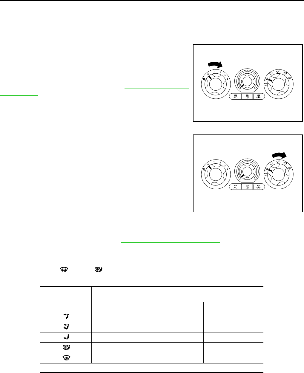
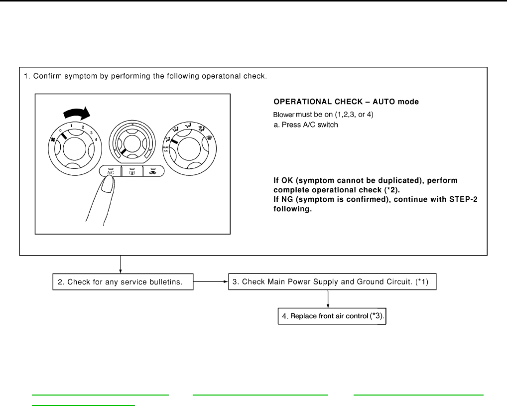
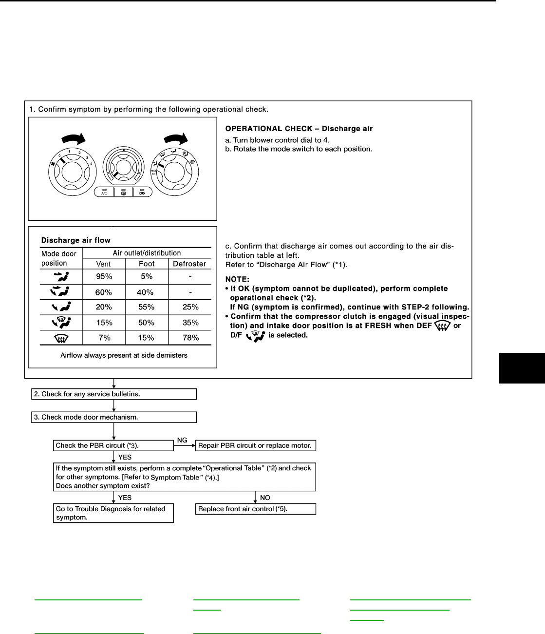
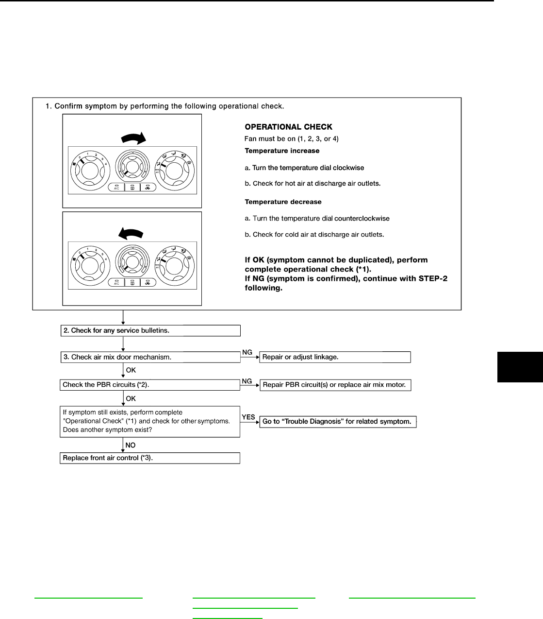
Operational Check EJS003VE
The purpose of the operational check is to confirm that the system operates properly.
CHECKING BLOWER
1. Turn blower control dial clockwise. Blower should operate on
low speed.
2. Turn the blower control dial again, and continue checking each
blower speed until all speeds are checked.
3. Leave blower on speed 4.
If NG, go to trouble diagnosis procedure for MTC-57, "Front Blower
Motor Circuit" .
If OK, continue with next check.
CHECKING DISCHARGE AIR
1. Turn the mode switch to each position.
2. Confirm that discharge air comes out according to the air distribution table.
Mode door position is checked in the next step.
If NG, go to trouble diagnosis procedure for MTC-45, "Mode Door Motor Circuit" .
If OK, continue with next check.
NOTE:
Confirm that the A/C compressor clutch is engaged (sound or visual inspection) and intake door position is at
fresh when the DEF ( ) or D/F ( ) is selected.
DISCHARGE AIR FLOW
Conditions : Engine running and at normal operating temperature
WJIA1488E
WJIA1305E
Mode door position Air outlet/distribution
Vent Foot Defroster
95% 5% —
60% 40% —
20% 55% 25%
15% 50% 35%
7% 15% 78%
Airflow always present at side demisters
TROUBLE DIAGNOSIS
MTC-41
C
D
E
F
G
H
I
K
L
M
A
B
MTC
Revision: November 2005 2005 Pathfinder
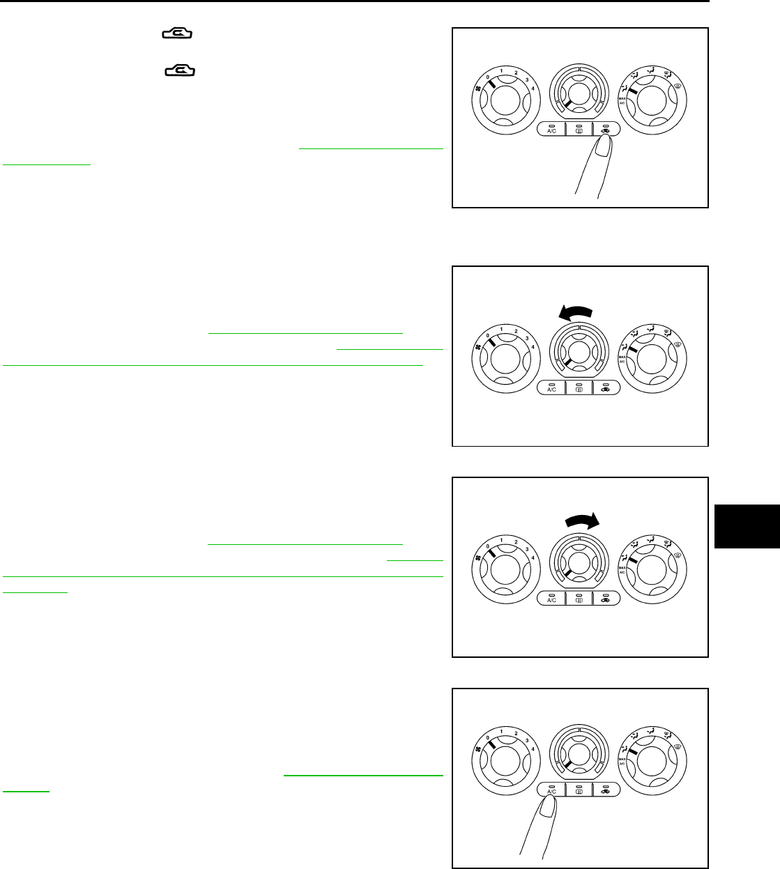
CHECKING RECIRCULATION
1. Press recirculation ( ) switch one time. Recirculation indica-
tor should illuminate.
2. Press recirculation ( ) switch one more time. Recirculation
indicator should go off.
3. Listen for intake door position change (blower sound should
change slightly).
If NG, go to trouble diagnosis procedure for MTC-53, "Intake Door
Motor Circuit" .
If OK, continue with next check.
NOTE:
Confirm that the compressor clutch is engaged (sound or visual
inspection) and intake door position is at fresh when the DEF or D/F is selected.
CHECKING TEMPERATURE DECREASE
1. Rotate temperature control dial counterclockwise.
2. Check for cold air at appropriate discharge air outlets.
If NG, listen for sound of air mix door motor operation if OK, go to
trouble diagnosis procedure for MTC-70, "Insufficient Cooling" . If air
mix door motor appears to be malfunctioning, go to MTC-51, "DIAG-
NOSTIC PROCEDURE FOR AIR MIX DOOR MOTOR (FRONT)" .
If OK, continue with next check.
CHECKING TEMPERATURE INCREASE
1. Rotate temperature control dial clockwise.
2. Check for hot air at appropriate discharge air outlets.
If NG, listen for sound of air mix door motor operation. If OK, go to
trouble diagnosis procedure for MTC-77, "Insufficient Heating" . If air
mix door motor (front) appears to be malfunctioning, go to MTC-51,
"DIAGNOSTIC PROCEDURE FOR AIR MIX DOOR MOTOR
(FRONT)" .
If OK, continue with next check.
CHECK A/C SWITCH
1. Press A/C switch with the blower switch ON.
2. A/C switch indicator will turn ON.
●Confirm that the compressor clutch engages (sound or visual
inspection).
If NG, go to trouble diagnosis procedure for MTC-65, "Magnet Clutch
Circuit" .
If OK, continue with next check.
WJIA1306E
WJIA1307E
WJIA1308E
WJIA1309E
MTC-42
TROUBLE DIAGNOSIS
Revision: November 2005 2005 Pathfinder
Power Supply and Ground Circuit for Front Air Control EJS003VF
SYMPTOM: A/C system does not come on.
INSPECTION FLOW
*1 ATC-56, "Power Supply and Ground
Circuit for Front Air Control".
*2 ATC-52, "Operational Check (Front)" *3 MTC-82, "FRONT AIR CONTROL"
WJIA1498E
TROUBLE DIAGNOSIS
MTC-43
C
D
E
F
G
H
I
K
L
M
A
B
MTC
Revision: November 2005 2005 Pathfinder
COMPONENT DESCRIPTION
Front Air Control
The front air control has a built-in microcomputer which processes
information sent from various sensors needed for air conditioner
operation. The air mix door motor, mode door motor, intake door
motor, defroster door motor, blower motor and compressor are then
controlled.
The front air control is unitized with control mechanisms. When the
various switches and temperature dials are operated, data is input to
the front air control.
Potentio Temperature Control (PTC)
The PTC is built into the front air control. It can be set from cold to
hot or any intermediate position by rotating the temperature dial.
DIAGNOSTIC PROCEDURE FOR A/C SYSTEM
SYMPTOM: A/C system does not come on.
WJIA1302E
WJIA1311E
WJIA1461E
MTC-44
TROUBLE DIAGNOSIS
Revision: November 2005 2005 Pathfinder
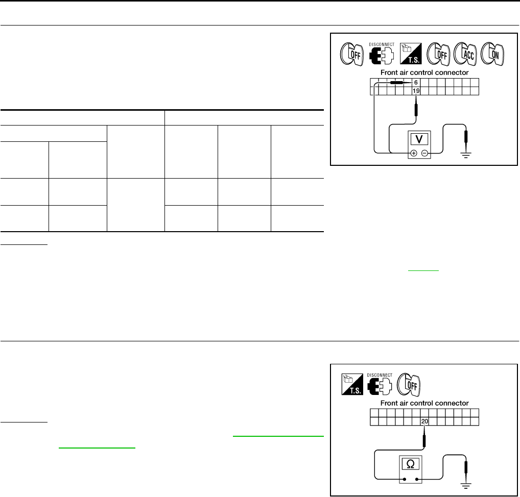
1. CHECK POWER SUPPLY CIRCUITS FOR FRONT AIR CONTROL
1. Turn ignition switch OFF.
2. Disconnect front air control connector.
3. Turn ignition switch ON.
4. Check voltage between front air control harness connector M49
terminals 6 and 19, and ground.
OK or NG
OK >> GO TO 2.
NG >> Check 10A fuses [Nos. 8 and 19, located in the fuse block (J/B)]. Refer to PG-81 .
●If fuses are OK, check harness for open circuit. Repair or replace as necessary.
●If fuses are NG, replace fuse and check harness for short circuit. Repair or replace as neces-
sary.
2. CHECK GROUND CIRCUIT FOR FRONT AIR CONTROL
1. Turn ignition switch OFF.
2. Check continuity between front air control harness connector
M49 terminal 20 and ground.
OK or NG
OK >> Replace front air control. Refer to ATC-127, "FRONT
AIR CONTROL" .
NG >> Repair harness or connector.
Terminals Ignition switch position
(+)
(-) OFF ACC ON
Front air
control
connector
Terminal No.
M49 6
Ground
Approx. 0V Approx. 0V Battery
voltage
M49 19 Battery
voltage
Battery
voltage
Battery
voltage
WJIA1082E
20 - Ground : Continuity should exist.
WJIA1239E
TROUBLE DIAGNOSIS
MTC-45
C
D
E
F
G
H
I
K
L
M
A
B
MTC
Revision: November 2005 2005 Pathfinder
Mode Door Motor Circuit EJS003VG
SYMPTOM:
●Air outlet does not change.
●Mode door motor does not operate normally.
INSPECTION FLOW
*1 ATC-29, "Discharge Air Flow".*2ATC-52, "Operational Check
(Front)".*3 ATC-61, "DIAGNOSTIC PROCE-
DURE FOR MODE DOOR
MOTOR".
*4 MTC-30, "SYMPTOM TABLE".*5MTC-82, "FRONT AIR CONTROL"
WJIA1630E
MTC-46
TROUBLE DIAGNOSIS
Revision: November 2005 2005 Pathfinder
SYSTEM DESCRIPTION
Component Parts
Mode door control system components are:
●Front air control
●Mode door motor
●PBR (built into mode door motor)
●Intake sensor
System Operation
The mode door position (vent, B/L, foot, D/F, and defrost) is set by the front air control by means of the mode
door motor. When a mode door position is selected on the front air control, voltage is applied to one circuit of
the mode door motor while ground is applied to the other circuit, causing the mode door motor to rotate. The
direction of rotation is determined by which circuit has voltage applied to it, and which one has ground applied
to it. The front air control monitors the mode door position by measuring the voltage signal on the PBR circuit.
COMPONENT DESCRIPTION
Mode Door Motor
The mode door motor is attached to the heater & cooling unit. It
rotates so that air is discharged from the outlet as indicated by the
front air control. Motor rotation is conveyed to a link which activates
the mode door.
WJIA1314E
WJIA1484E
TROUBLE DIAGNOSIS
MTC-47
C
D
E
F
G
H
I
K
L
M
A
B
MTC
Revision: November 2005 2005 Pathfinder
DIAGNOSTIC PROCEDURE FOR MODE DOOR MOTOR
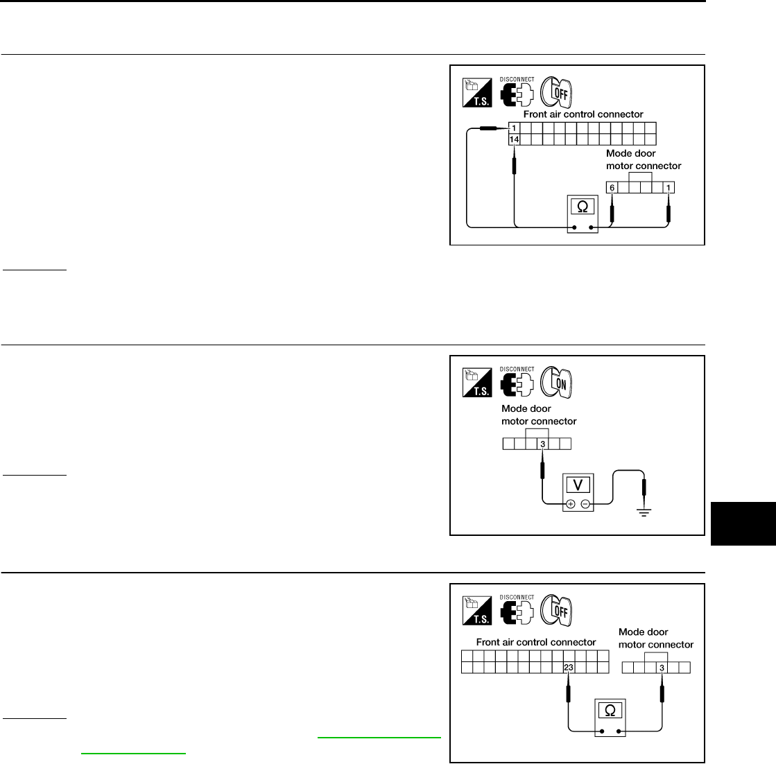
1. CHECK POWER SUPPLY AND GROUND CIRCUITS FOR MODE DOOR MOTOR
1. Turn ignition switch OFF.
2. Disconnect front air control connector and mode door motor
connector.
3. Check continuity between front air control harness connector
M49 terminal 1 and mode door motor harness connector M142
terminal 1 and between front air control harness connector M49
terminal 14 and mode door motor harness connector M142 ter-
minal 6.
OK or NG
OK >> GO TO 2.
NG >> Repair or replace harness as necessary.
2. CHECK PBR REFERENCE SIGNAL VOLTAGE
1. Reconnect the front air control connector.
2. Turn ignition switch ON.
3. Check voltage between mode door motor harness connector
M142 terminal 3 and ground.
OK or NG
OK >> GO TO 4.
NG >> GO TO 3.
3. CHECK PBR REFERENCE VOLTAGE CIRCUIT BETWEEN MODE DOOR AND FRONT AIR CONTROL
1. Turn ignition switch OFF.
2. Disconnect the front air control connector.
3. Check continuity between mode door motor harness connector
M142 terminal 3 and front air control harness connector M49 ter-
minal 23.
OK or NG
OK >> Replace front air control. Refer to ATC-127, "FRONT
AIR CONTROL" .
NG >> Repair or replace harness as necessary.
1 - 1 : Continuity should exist.
14 - 6 : Continuity should exist. WJIA1241E
3 - Ground : Approx. 5V
WJIA1242E
3 - 23 : Continuity should exist.
WJIA1085E
MTC-48
TROUBLE DIAGNOSIS
Revision: November 2005 2005 Pathfinder
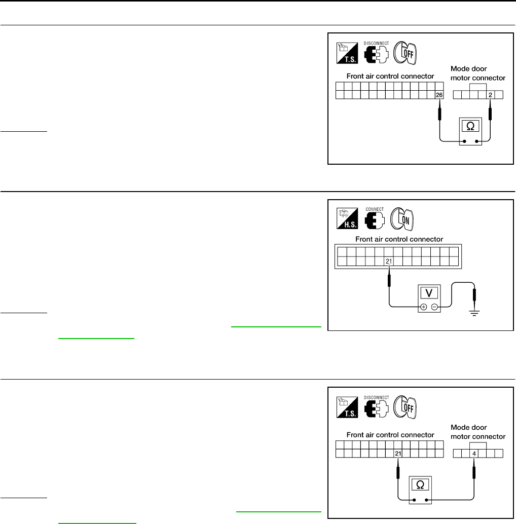
4. CHECK PBR GROUND REFERENCE CIRCUIT
1. Turn ignition switch OFF.
2. Disconnect the front air control connector.
3. Check continuity between mode door motor harness connector
M142 terminal 2 and front air control harness connector M49 ter-
minal 26.
OK or NG
OK >> GO TO 5.
NG >> Repair or replace harness as necessary.
5. CHECK PBR FEEDBACK SIGNAL
1. Reconnect the front air control connector and mode door motor
connector.
2. Turn ignition switch ON.
3. Check voltage between front air control harness connector M49
terminal 21 and ground.
4. Press mode switch through all modes.
OK or NG
OK >> Replace front air control. Refer to ATC-127, "FRONT
AIR CONTROL" .
NG >> GO TO 6.
6. CHECK PBR FEEDBACK CIRCUIT
1. Turn ignition switch OFF.
2. Disconnect the mode door motor connector and front air control
harness connector.
3. Check continuity between mode door motor harness connector
M142 terminal 4 and front air control harness connector M49 ter-
minal 21.
OK or NG
OK >> Replace mode door motor. Refer to ATC-144, "MODE
DOOR MOTOR" .
NG >> Repair or replace harness as necessary.
2 - 26 : Continuity should exist.
WJIA1087E
21 - Ground : Approx. 0 - 5V
WJIA1088E
4 - 21 : Continuity should exist.
WJIA1089E
TROUBLE DIAGNOSIS
MTC-49
C
D
E
F
G
H
I
K
L
M
A
B
MTC
Revision: November 2005 2005 Pathfinder
Air Mix Door Motor Circuit EJS003VH
SYMPTOM:
●Discharge air temperature does not change.
●Air mix door motor does not operate.
INSPECTION FLOW
*1 MTC-40, "Operational Check" *2 MTC-51, "DIAGNOSTIC PROCE-
DURE FOR AIR MIX DOOR
MOTOR (FRONT)".
*3 MTC-82, "FRONT AIR CONTROL"
WJIA1500E
MTC-50
TROUBLE DIAGNOSIS
Revision: November 2005 2005 Pathfinder
SYSTEM DESCRIPTION
Component Parts
Air mix door control system components are:
●Front air control
●Air mix door motor
●PBR (built into air mix door motor)
●Intake sensor
System Operation
The front air control receives data from the temperature selected by the driver. The front air control then
applies a voltage to one circuit of the air mix door motor, while ground is applied to the other circuit, causing
the air mix door motor to rotate. The direction of rotation is determined by which circuit has voltage applied to
it, and which one has ground applied to it. The front air control monitors the air mix door positions by measur-
ing the voltage signal on the PBR circuits of each door.
Air Mix Door Control Specification
COMPONENT DESCRIPTION
Air Mix Door Motors
The air mix door motor is attached to the front heater & cooling unit.
This motor rotates so that the air mix door is opened or closed to a
position set by the front air control. Motor rotation is then conveyed
through a shaft and the air mix door position is then fed back to the
front air control by the PBR built into the air mix door motor.
WJIA1316E
WJIA0435E
WJIA1485E
TROUBLE DIAGNOSIS
MTC-51
C
D
E
F
G
H
I
K
L
M
A
B
MTC
Revision: November 2005 2005 Pathfinder
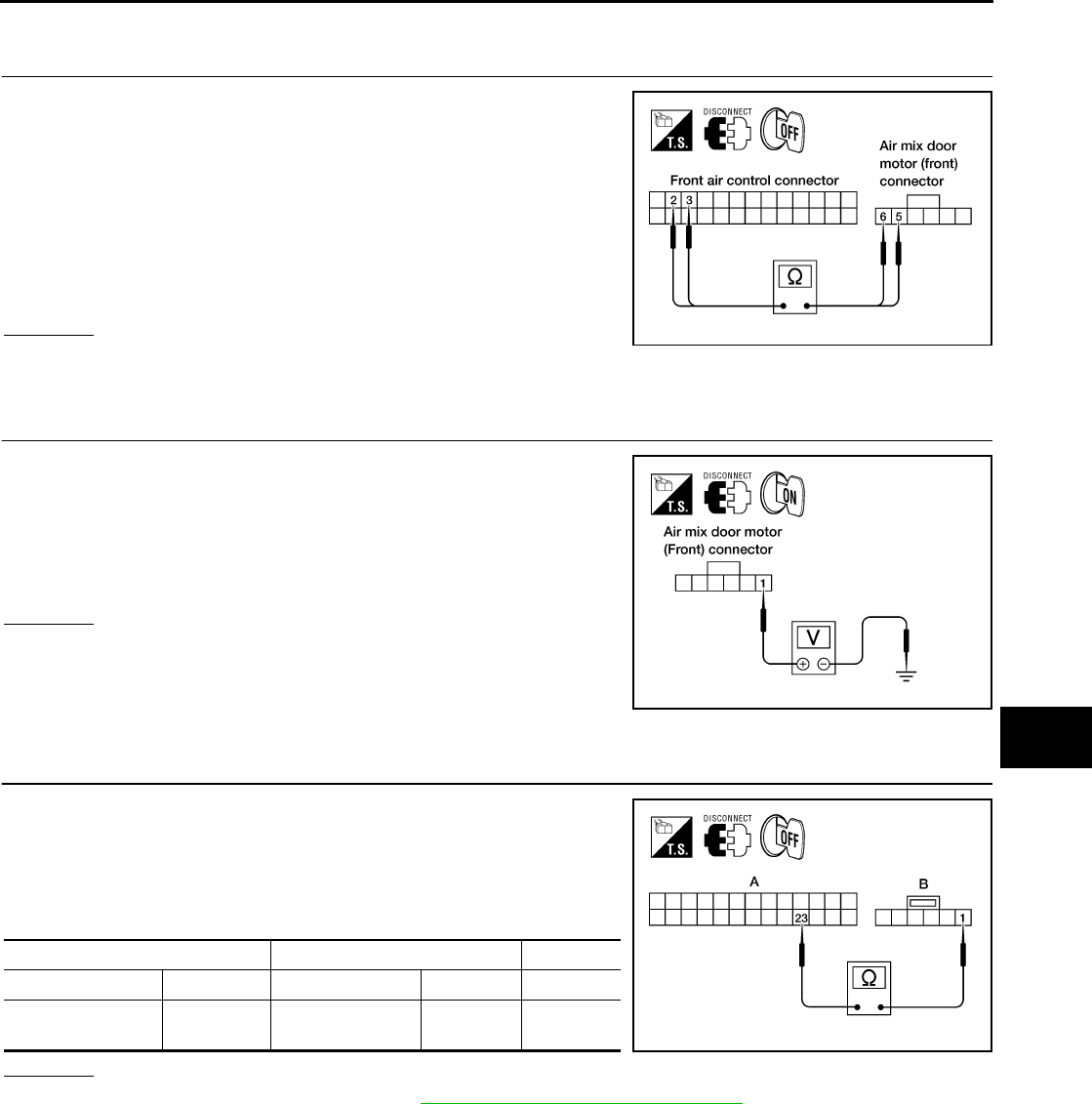
DIAGNOSTIC PROCEDURE FOR AIR MIX DOOR MOTOR (FRONT)
1. CHECK POWER SUPPLY CIRCUITS FOR AIR MIX DOOR MOTOR
1. Turn ignition switch OFF.
2. Disconnect front air control connector and air mix door motor
(front) connector.
3. Check continuity between front air control harness connector
M49 terminal 2 and 3 and air mix door motor (front) harness
connector M147 terminal 6 and 5.
OK or NG
OK >> GO TO 2.
NG >> Repair or replace harness as necessary.
2. CHECK PBR REFERENCE SIGNAL VOLTAGE
1. Reconnect the front air control connector.
2. Turn ignition switch ON.
3. Check voltage between air mix door motor (front) harness con-
nector M147 terminal 1 and ground.
OK or NG
OK >> GO TO 4.
NG >> GO TO 3.
3. CHECK PBR REFERENCE VOLTAGE CIRCUIT BETWEEN AIR MIX DOOR MOTOR (FRONT) AND
FRONT AIR CONTROL
1. Turn ignition switch OFF.
2. Disconnect the front air control connector.
3. Check continuity between air mix door motor (front) harness
connector M147 terminal 1 and front air control harness connec-
tor M49 terminal 23.
OK or NG
OK >> Replace front air control. Refer to ATC-127, "FRONT AIR CONTROL" .
NG >> Repair or replace harness as necessary.
2 - 6 : Continuity should exist.
3 - 5 : Continuity should exist.
WJIA1318E
1 - Ground : Approx. 5V
WJIA1319E
AB
Connector Terminal Connector Terminal Continuity
Front air control:
M49 23 Air mix door motor
(front): M143 1Yes
WJIA1656E
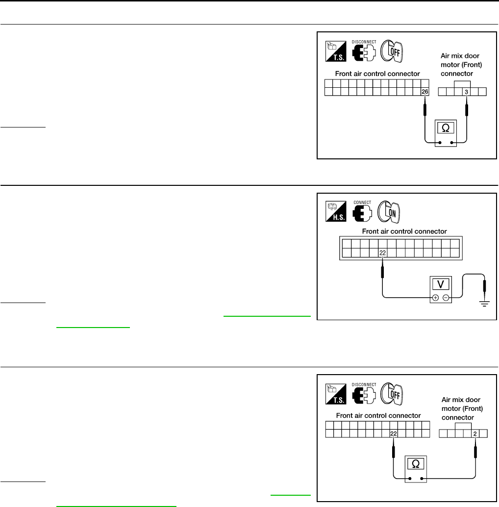
MTC-52
TROUBLE DIAGNOSIS
Revision: November 2005 2005 Pathfinder
4. CHECK PBR GROUND REFERENCE CIRCUIT
1. Turn ignition switch OFF.
2. Disconnect the front air control connector.
3. Check continuity between air mix door motor (front) harness
connector M147 terminal 3 and front air control harness connec-
tor M49 terminal 26.
OK or NG
OK >> GO TO 5.
NG >> Repair or replace harness as necessary.
5. CHECK PBR FEEDBACK SIGNAL
1. Reconnect the front air control connector and air mix door motor
(front) connector.
2. Turn ignition switch ON.
3. Check voltage between front air control harness connector M49
terminal 22 and ground.
4. Rotate temperature control dial through complete range.
OK or NG
OK >> Replace front air control. Refer to ATC-127, "FRONT
AIR CONTROL" .
NG >> GO TO 6.
6. CHECK PBR FEEDBACK CIRCUIT
1. Turn ignition switch OFF.
2. Disconnect the air mix door motor (front) connector and front air
control connector.
3. Check continuity between air mix door motor (front) harness
connector M147 terminal 2 and front air control harness connec-
tor M49 terminal 22.
OK or NG
OK >> Replace air mix door motor (front). Refer to MTC-92,
"AIR MIX DOOR MOTOR" .
NG >> Repair or replace harness as necessary.
3 - 26 : Continuity should exist.
WJIA1320E
22 - Ground : Approx. 0V - 5V
WJIA1096E
2 - 22 : Continuity should exist.
WJIA1321E
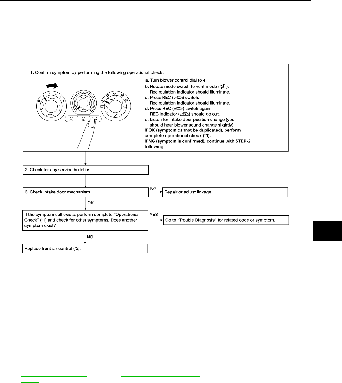
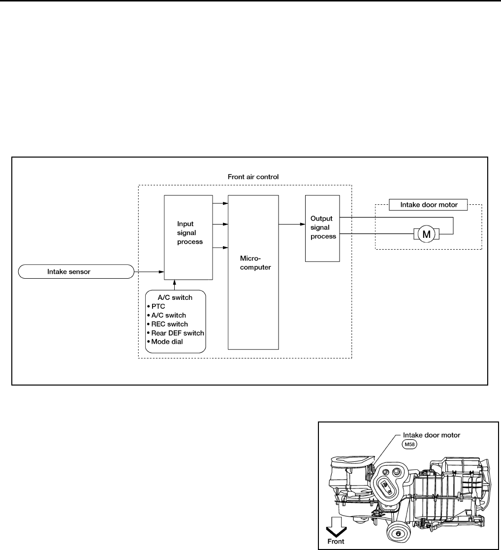
MTC-54
TROUBLE DIAGNOSIS
Revision: November 2005 2005 Pathfinder
SYSTEM DESCRIPTION
Component Parts
Intake door control system components are:
●Front air control
●Intake door motor
●Intake sensor
System Operation
The intake door control determines the intake door position based on the position of the recirculation switch.
When the recirculation switch is depressed the intake door motor rotates closing off the fresh air inlet and
recirculating the cabin air. If the recirculation switch is depressed again, the intake door motor rotates in the
opposite direction, again allowing fresh air into the cabin.
COMPONENT DESCRIPTION
Intake door motor
The intake door motor is attached to the intake unit. It rotates so that
air is drawn from inlets set by the front air control. Motor rotation is
conveyed to a lever which activates the intake door.
WJIA1478E
WJIA1486E
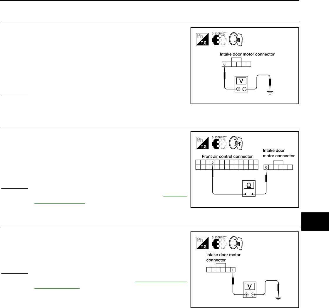
TROUBLE DIAGNOSIS
MTC-55
C
D
E
F
G
H
I
K
L
M
A
B
MTC
Revision: November 2005 2005 Pathfinder
DIAGNOSTIC PROCEDURE FOR INTAKE DOOR MOTOR
1. CHECK INTAKE DOOR MOTOR CIRCUIT VOLTAGE
1. Turn ignition switch OFF.
2. Disconnect intake door motor connector.
3. Turn ignition switch ON.
4. Rotate the temperature control dial counterclockwise.
5. Check voltage between intake door motor harness connector
M58 terminal 6 and ground.
OK or NG
OK >> GO TO 3.
NG >> GO TO 2.
2. CHECK INTAKE DOOR MOTOR CIRCUIT FOR OPEN
1. Turn ignition switch OFF.
2. Disconnect front air control connector.
3. Check continuity between front air control harness connector
M49 terminal 5 and intake door motor harness connector M58
terminal 6.
OK or NG
OK >> Replace front air control connector. Refer to MTC-82,
"CONTROL UNIT" .
NG >> Repair or replace harness as necessary.
3. CHECK INTAKE DOOR MOTOR CIRCUIT VOLTAGE
1. Rotate the temperature control dial clockwise.
2. Check voltage between intake door motor harness connector
M58 terminal 1 and ground.
OK or NG
OK >> Replace intake door motor. Refer to ATC-143, "INTAKE
DOOR MOTOR" .
NG >> GO TO 4.
6 - Ground : Battery voltage
WJIA1324E
5 - 6 : Continuity should exist.
WJIA1468E
1 - Ground :Battery voltage
WJIA1326E
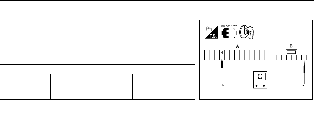
MTC-56
TROUBLE DIAGNOSIS
Revision: November 2005 2005 Pathfinder
4. CHECK INTAKE DOOR MOTOR CIRCUIT FOR OPEN
1. Turn ignition switch OFF.
2. Disconnect front air control connector.
3. Check continuity between front air control harness connector
M49 terminal 4 and intake door motor harness connector M58
terminal 1.
OK or NG
OK >> Replace front air control connector. Refer to MTC-82, "CONTROL UNIT" .
NG >> Repair or replace harness as necessary.
AB
Connector Terminal Connector Terminal Continuity
Front air control:
M49 4 Intake door motor:
M58 1Yes
WJIA1684E
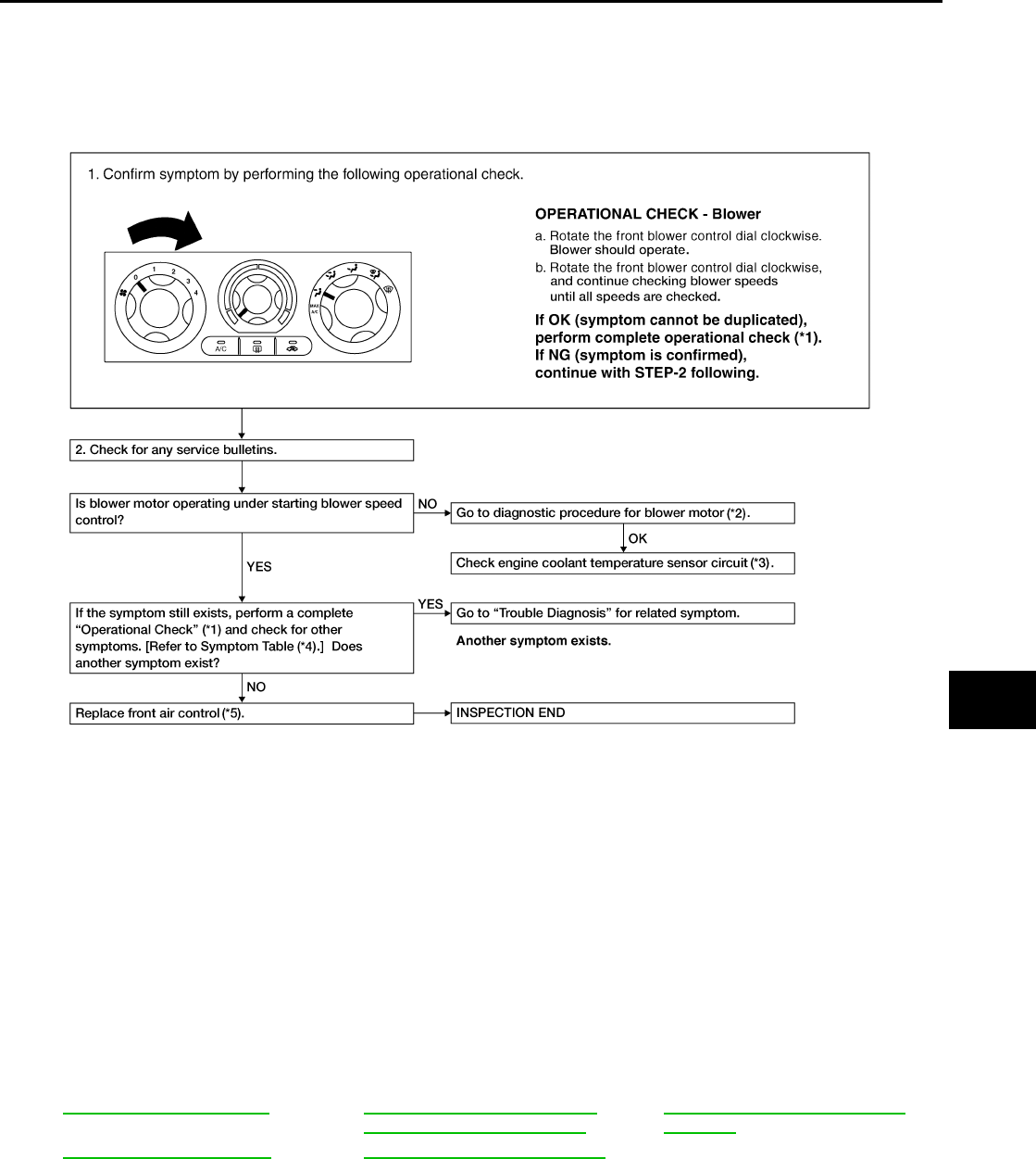
TROUBLE DIAGNOSIS
MTC-57
C
D
E
F
G
H
I
K
L
M
A
B
MTC
Revision: November 2005 2005 Pathfinder
Front Blower Motor Circuit EJS003VJ
SYMPTOM:
●Blower motor operation is malfunctioning.
INSPECTION FLOW
*1 MTC-40, "Operational Check"*2 MTC-59, "DIAGNOSTIC PROCE-
DURE FOR BLOWER MOTOR"
*3 EC-204, "DTC P0117, P0118 ECT
SENSOR"
*4 MTC-30, "SYMPTOM TABLE".*5MTC-82, "FRONT AIR CONTROL"
WJIA1501E
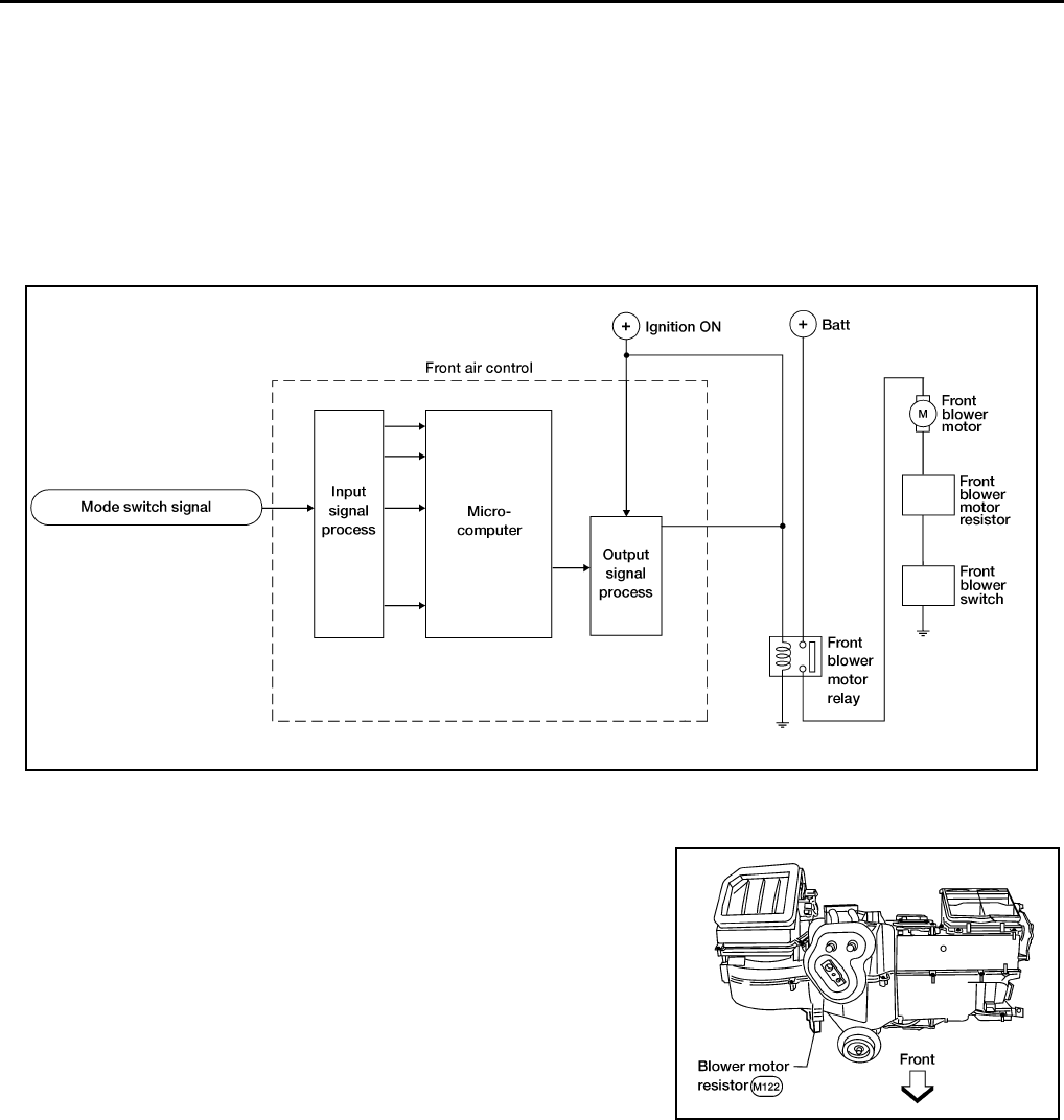
MTC-58
TROUBLE DIAGNOSIS
Revision: November 2005 2005 Pathfinder
SYSTEM DESCRIPTION
Component Parts
Blower speed control system components are:
●Front air control
●Front blower motor resistor
●Front blower motor
●Front blower relay
●Intake sensor
System Operation
COMPONENT DESCRIPTION
Blower Motor Resistor
The front blower motor resistor is located on the cooling unit. The
front blower motor resistor grounds the front blower motor through a
series of 1, 2, or 3 resistors, depending upon speed selected. For
high speed operation the front blower motor resistor is circumvented
and the front blower motor grounds directly.
WJIA1502E
WJIA1487E
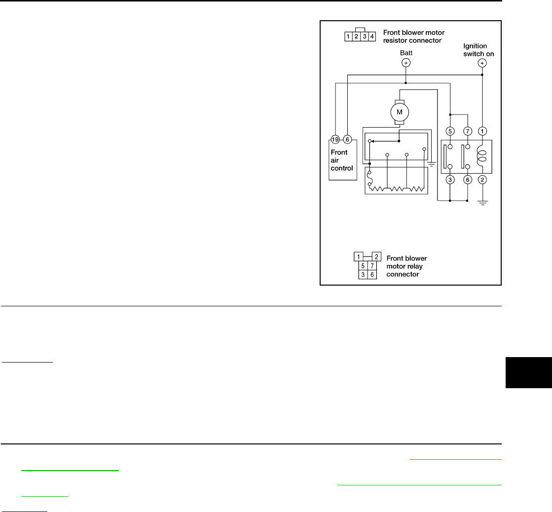
TROUBLE DIAGNOSIS
MTC-59
C
D
E
F
G
H
I
K
L
M
A
B
MTC
Revision: November 2005 2005 Pathfinder
DIAGNOSTIC PROCEDURE FOR BLOWER MOTOR
SYMPTOM: Blower motor operation is malfunctioning under starting
blower speed control.
1. DIAGNOSTIC PROCEDURE
1. Turn ignition switch ON.
2. Turn the front blower switch to each of its four speeds.
Does blower motor rotate normally at each speed?
YES or NO
YES >> Inspection End.
NO >> 1. Does not rotate at any speed, GO TO 2.
2. Does not rotate at 1 - 3 speed, GO TO 13.
3. Does not rotate at 4 speed, GO TO 16.
2. CHECK FUSES
1. Check 15A fuses (Nos. 24 and 27, located in the fuse and fusible link box). Refer to PG-82, "FUSE AND
FUSIBLE LINK BOX" .
2. Check 10A fuse [No. 8, located in the fuse block (JB)]. Refer to PG-81, "FUSE BLOCK-JUNCTION
BOX(J/B)" .
OK or NG
OK >> GO TO 3.
NG >> GO TO 8.
WJIA1503E
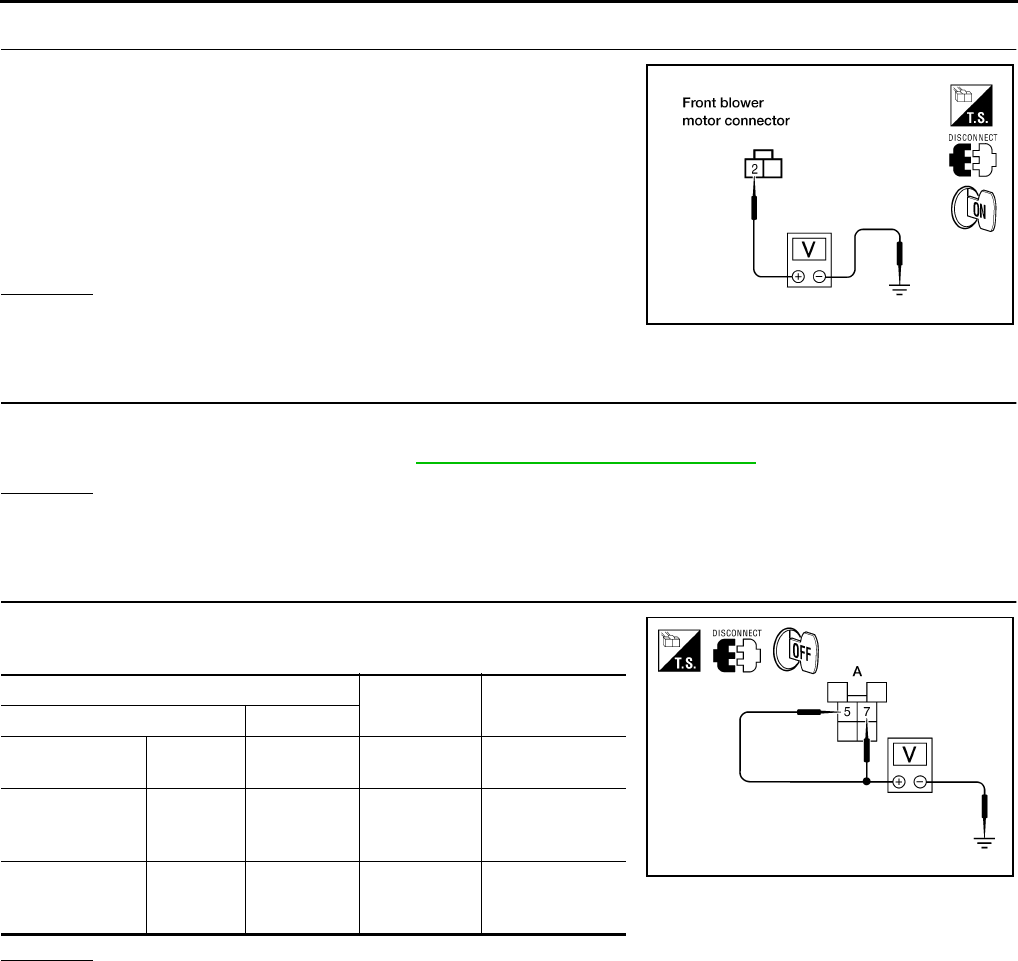
MTC-60
TROUBLE DIAGNOSIS
Revision: November 2005 2005 Pathfinder
3. CHECK FRONT BLOWER MOTOR POWER SUPPLY
1. Turn ignition switch OFF.
2. Disconnect front blower motor harness connector.
3. Turn ignition switch ON.
4. Select any front blower speed except OFF.
5. Check voltage between front blower motor harness connector
M62 terminal 2 and ground.
OK or NG
OK >> GO TO 12.
NG >> GO TO 4.
4. CHECK FRONT BLOWER MOTOR RELAY
1. Turn Ignition switch OFF.
2. Check front blower motor relay. Refer to MTC-63, "Front Blower Motor Relay" .
OK or NG
OK >> GO TO 5.
NG >> Replace front blower motor relay.
5. CHECK FRONT BLOWER MOTOR RELAY POWER SUPPLY (SWITCH SIDE)
Check voltage between front blower motor relay harness connector
E54 terminals 7 and 5 and ground.
OK or NG
OK >> GO TO 6.
NG >> Repair harness or connector.
2 - Ground : Battery voltage
WJIA1331E
A
Condition Voltage
(Approx.)(+)
Front air control
connector Terminal (-)
M54 5 Ground
Blower motor
relay power
supply Battery voltage
M54 7 Ground
Blower motor
relay power
supply Battery voltage
WJIA1634E
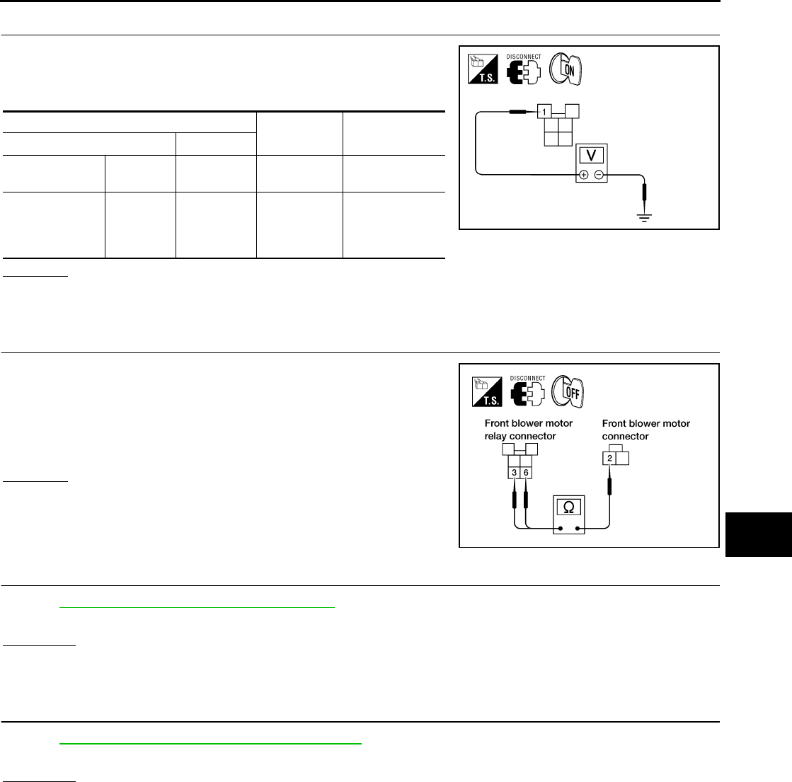
TROUBLE DIAGNOSIS
MTC-61
C
D
E
F
G
H
I
K
L
M
A
B
MTC
Revision: November 2005 2005 Pathfinder
6. CHECK FRONT BLOWER MOTOR RELAY POWER SUPPLY (COIL SIDE)
1. Turn ignition switch ON.
2. Check voltage between front blower motor relay harness con-
nector E54 terminal 1 and ground.
OK or NG
OK >> GO TO 7.
NG >> Repair or replace harness as necessary.
7. CHECK FRONT BLOWER MOTOR POWER FROM RELAY TO FRONT BLOWER MOTOR
1. Turn Ignition switch OFF.
2. Check continuity between front blower motor relay harness con-
nector E54 terminals 6 and 3 and front blower motor harness
connector M62 terminal 2.
OK or NG
OK >> Repair or replace harness as necessary.
NG >> Repair harness or connector between the front blower
motor relay and the front blower motor.
8. REPLACE FUSE
Refer to PG-82, "FUSE AND FUSIBLE LINK BOX" .
Does fuse No. 24 or 27 open when the front blower motor is turned on?
YES or NO
YES >> GO TO 10.
NO >> GO TO 9.
9. REPLACE FUSE
Refer to PG-81, "FUSE BLOCK-JUNCTION BOX(J/B)" .
Does fuse No. 8 open when the ignition switch is turned ON?
YES or NO
YES >> Repair or replace harness as necessary.
NO >> Inspection End.
A
Condition
Voltage
(Approx.)(+)
Front air control
connector Te rm in al (-)
M54 1 Ground
Blower motor
relay power
supply (coil
side)
Battery voltage WJIA0504E
3, 6 - 2 : Continuity should exist.
WJIA1333E
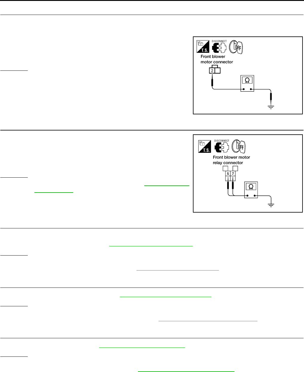
MTC-62
TROUBLE DIAGNOSIS
Revision: November 2005 2005 Pathfinder
10. CHECK FRONT BLOWER MOTOR POWER SUPPLY CIRCUIT FOR SHORT
1. Turn ignition switch OFF.
2. Disconnect front blower motor connector.
3. Check continuity between front blower motor harness connector
M62 terminal 2 and ground.
OK or NG
OK >> GO TO 11.
NG >> Repair or replace harness as necessary.
11. CHECK FRONT BLOWER MOTOR RELAY (SWITCH SIDE) POWER SUPPLY CIRCUIT FOR SHORT
1. Disconnect front blower motor relay connector.
2. Check continuity between the front blower motor relay harness
connector E54 terminal 7 and terminal 5 and ground.
OK or NG
OK >> Check front blower motor. Refer to MTC-64, "Front
Blower Motor" .
NG >> Repair harness or connector.
12. CHECK FRONT BLOWER MOTOR
1. Turn ignition switch OFF.
2. Check front blower motor. Refer to MTC-64, "Front Blower Motor" .
OK or NG
OK >> GO TO 13.
NG >> Replace front blower motor. Refer to MTC-84, "BLOWER MOTOR" .
13. CHECK FRONT BLOWER MOTOR RESISTOR
Check front blower motor resistor. Refer to MTC-58, "Blower Motor Resistor" .
OK or NG
OK >> GO TO 14.
NG >> Replace front blower motor resistor. Refer to MTC-93, "Removal and Installation" .
14. CHECK FRONT BLOWER SWITCH
Check front blower switch. Refer to MTC-64, "Front Blower Switch" .
OK or NG
OK >> GO TO 15.
NG >> Replace front blower switch. Refer to MTC-82, "FRONT AIR CONTROL" .
2 - Ground : Continuity should not exist.
WJIA0649E
7, 5 - Ground : Continuity should not exist.
WJIA1334E
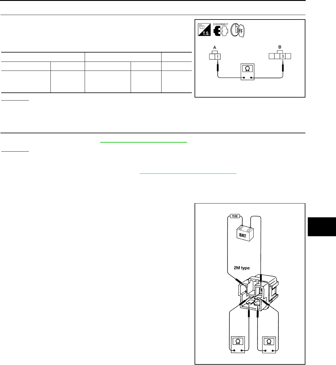
TROUBLE DIAGNOSIS
MTC-63
C
D
E
F
G
H
I
K
L
M
A
B
MTC
Revision: November 2005 2005 Pathfinder
15. CHECK FRONT BLOWER MOTOR GROUND CIRCUIT TO FRONT BLOWER MOTOR RESISTOR
1. Disconnect front blower motor resistor harness connector.
2. Check continuity between front blower motor connector M62 ter-
minal 1 and front blower motor resistor harness connector M122
terminal 3.
OK or NG
OK >> Repair harness or connector between front blower switch connector M51 terminal 4 and ground.
NG >> Repair harness or connector between front blower motor resistor and front blower motor.
16. CHECK FRONT BLOWER SWITCH
Check front blower switch. Refer to MTC-64, "Front Blower Switch" .
OK or NG
OK >> Repair harness or connector between front blower motor switch connector M51 terminal 8 and
front blower motor resistor connector M122 terminal 3.
NG >> Replace front blower switch. Refer to MTC-82, "FRONT AIR CONTROL" .
COMPONENT INSPECTION
Front Blower Motor Relay
Check continuity between terminals by supplying 12 volts and
ground to coil side terminals of relay.
AB
Connector Terminal Connector Terminal Continuity
Front blower motor:
M62 1
Front blower
motor resistor:
M122
3Yes
WJIA1676E
LJIA0068E
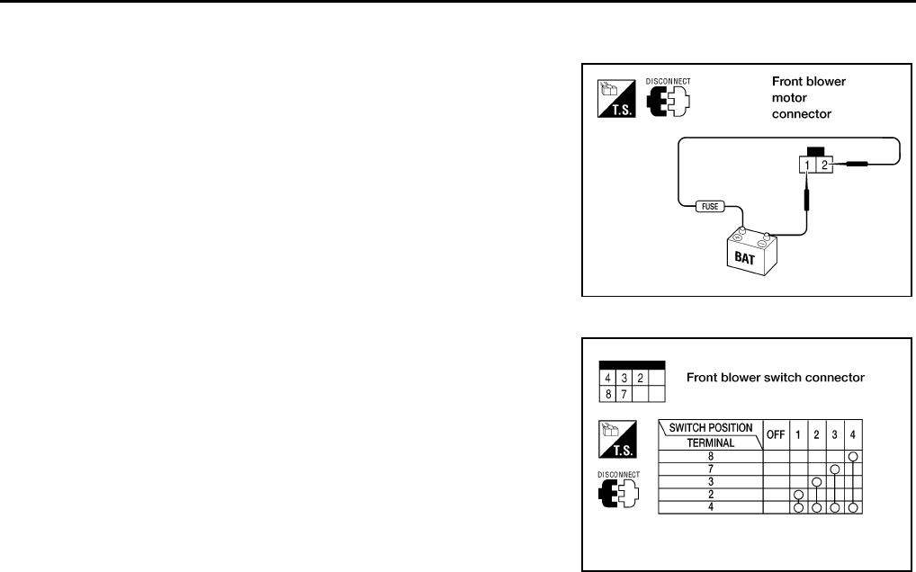
MTC-64
TROUBLE DIAGNOSIS
Revision: November 2005 2005 Pathfinder
Front Blower Motor
Confirm smooth rotation of the blower motor.
●Ensure that there are no foreign particles inside the blower unit.
●Apply 12 volts to terminal 2 and ground to terminal 1 and verify
that the motor operates freely and quietly.
Front Blower Switch
Check continuity between terminals at each switch position.
WJIA1508E
WJIA0508E
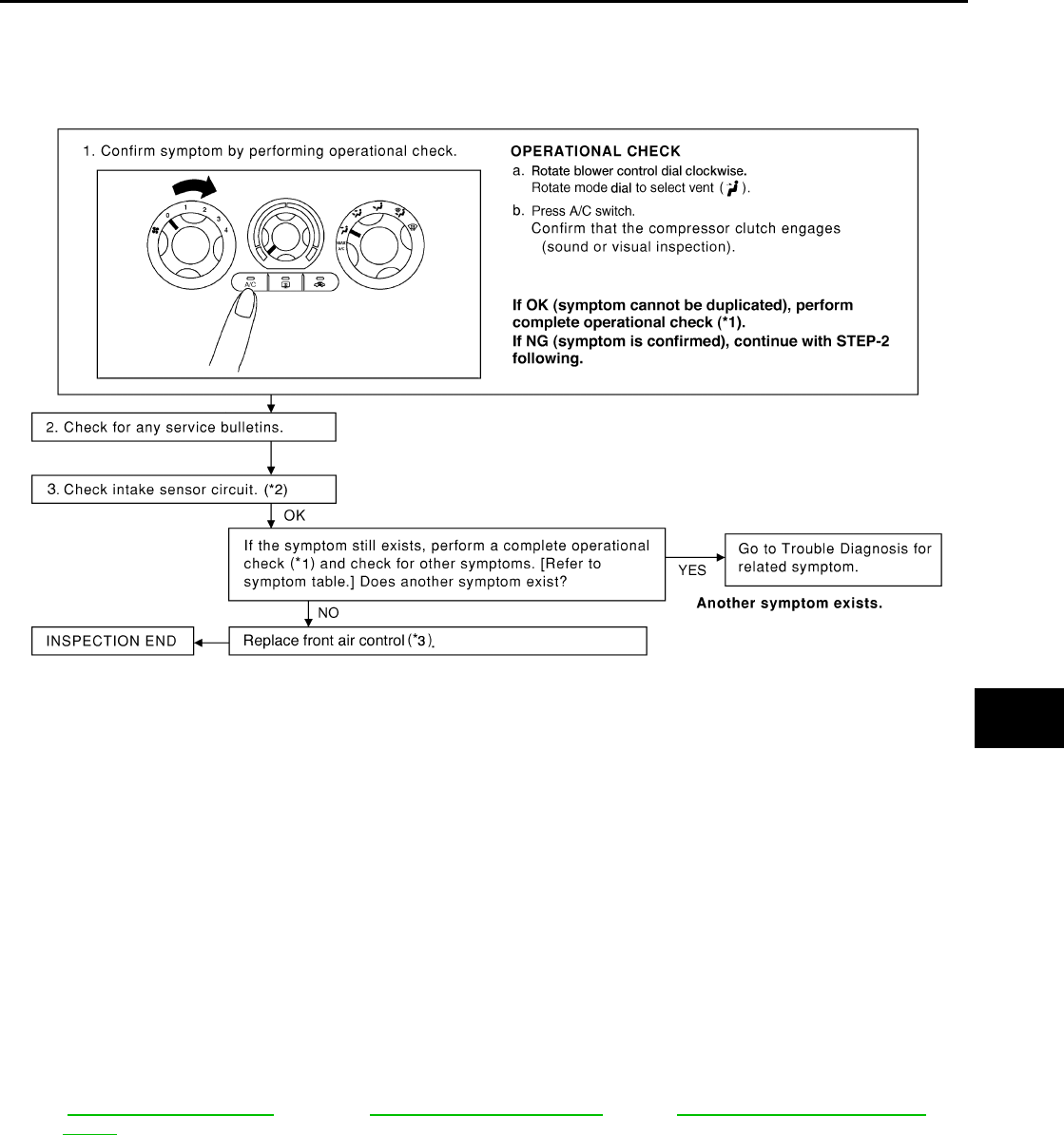
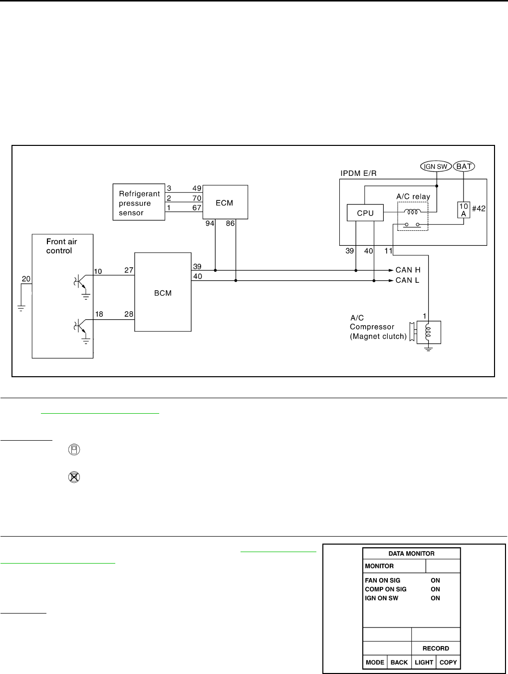
MTC-66
TROUBLE DIAGNOSIS
Revision: November 2005 2005 Pathfinder
SYSTEM DESCRIPTION
The front air control controls compressor operation based on ambient and intake temperature and a signal
from ECM.
Low Temperature Protection Control
The front air control will turn the compressor ON or OFF as determined by a signal detected by the intake sen-
sor and the ambient sensor.
When intake air temperature is higher than 3.5° C (38.3° F), the compressor turns ON. The compressor turns
OFF when intake air temperature is lower than 2.5° C (36.5° F).
DIAGNOSTIC PROCEDURE FOR MAGNET CLUTCH
SYMPTOM: Magnet clutch does not engage when A/C switch is ON.
1. PERFORM AUTO ACTIVE TEST
Refer to PG-22, "Auto Active Test" .
Does magnet clutch operate?
YES or NO
YES >> ●WITH CONSULT-II
GO TO 2.
●WITHOUT CONSULT-II
GO TO 8.
NO >> Check 10A fuse (No. 42, located in IPDM E/R), and GO TO 12.
2. CHECK BCM INPUT (A/C COMPRESSOR ON) SIGNAL
Check A/C compressor ON/OFF signal. Refer to MTC-28, "CON-
SULT-II Function (BCM)" .
OK or NG
OK >> GO TO 3.
NG >> GO TO 8.
WJIA1490E
A/C SW ON : COMP ON SIG ON
A/C SW OFF : COMP ON SIG OFF
WJIA0469E
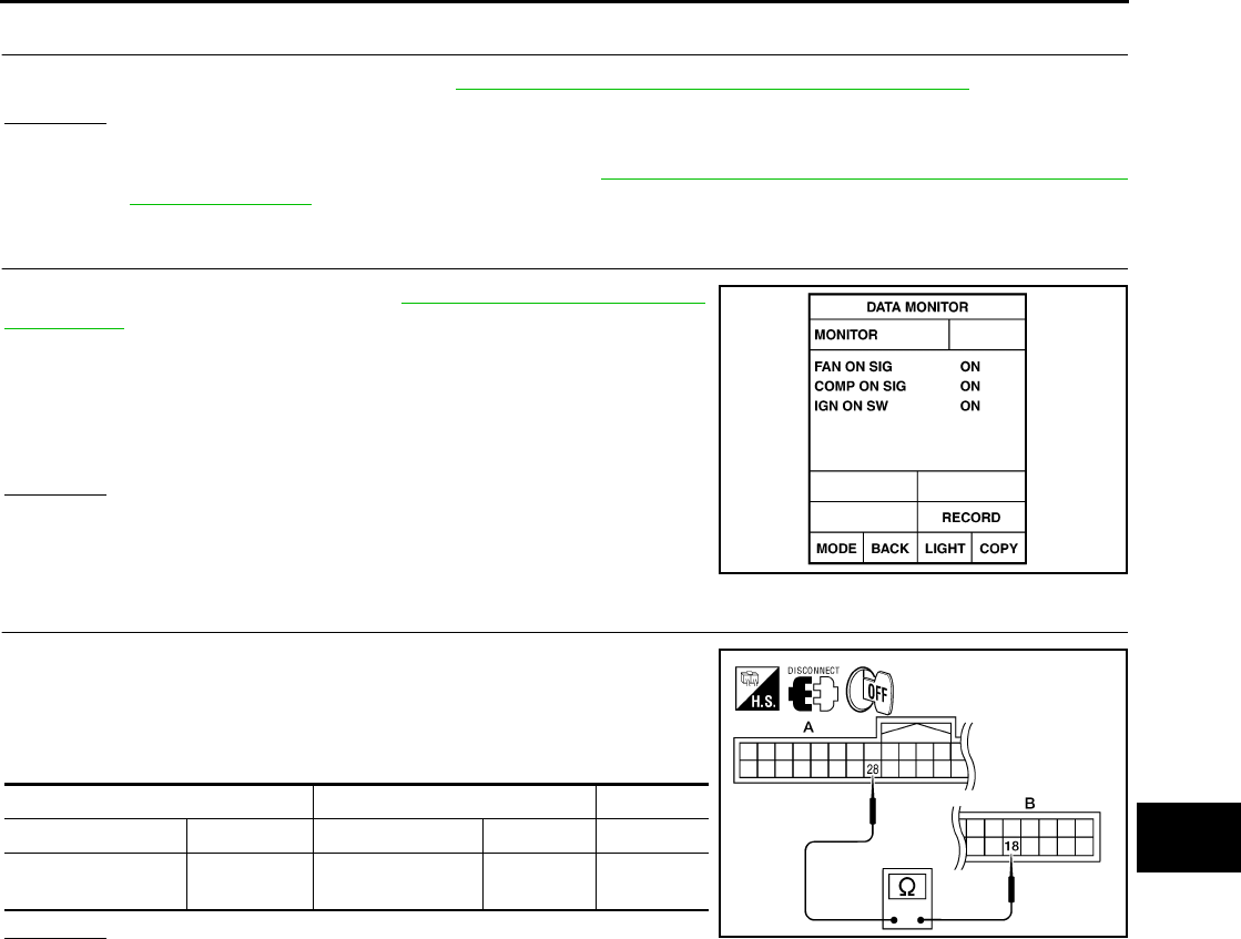
TROUBLE DIAGNOSIS
MTC-67
C
D
E
F
G
H
I
K
L
M
A
B
MTC
Revision: November 2005 2005 Pathfinder
3. CHECK REFRIGERANT PRESSURE SENSOR
Check refrigerant pressure sensor. Refer to EC-691, "REFRIGERANT PRESSURE SENSOR"
OK or NG
OK >> GO TO 4.
NG >> Replace refrigerant pressure sensor. Refer to MTC-106, "Removal and Installation for Refrigerant
Pressure Sensor" .
4. CHECK BCM INPUT (FAN ON) SIGNAL
Check FAN ON/OFF signal. Refer to MTC-28, "CONSULT-II Func-
tion (BCM)" .
OK or NG
OK >> GO TO 7.
NG >> GO TO 5.
5. CHECK CIRCUIT CONTINUITY BETWEEN BCM AND FRONT AIR CONTROL
1. Turn ignition switch OFF.
2. Disconnect BCM connector and front air control connector.
3. Check continuity between BCM harness connector M18 terminal
28 and front air control harness connector M49 terminal 18.
OK or NG
OK >> GO TO 6.
NG >> Repair harness or connector.
BLOWER CONTROL DIAL
ON : FAN ON SIG ON
BLOWER CONTROL DIAL
OFF : FAN ON SIG OFF
WJIA0469E
AB
Connector Terminal Connector Terminal Continuity
BCM: M18 28 Front air control:
M49 18 Yes
WJIA1627E
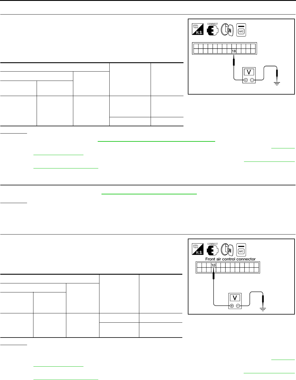
MTC-68
TROUBLE DIAGNOSIS
Revision: November 2005 2005 Pathfinder
6. CHECK VOLTAGE FOR FRONT AIR CONTROL (FAN ON SIGNAL)
1. Reconnect BCM connector and front air control connector.
2. Turn ignition switch ON.
3. Turn A/C switch ON.
4. Check voltage between front air control harness connector M49
terminal 18 and ground.
OK or NG
OK >> Replace BCM. Refer to BCS-20, "Removal and Installation of BCM" .
NG-1 >> If the voltage is approx. 5V when blower motor is ON, replace front air control. Refer to MTC-82,
"CONTROL UNIT" .
NG-2 >> If the voltage is approx. 0V when blower motor is OFF, replace BCM. Refer to BCS-20, "Removal
and Installation of BCM" .
7. CHECK CAN COMMUNICATION
Check CAN communication. Refer to LAN-24, "CAN COMMUNICATION" .
OK or NG
OK >> Inspection End.
NG >> Repair or replace malfunctioning part(s).
8. CHECK VOLTAGE FOR FRONT AIR CONTROL (A/C COMPRESSOR ON SIGNAL)
1. Reconnect BCM connector and front air control connector.
2. Turn ignition switch ON.
3. Check voltage between front air control harness connector M49
terminal 10 and ground.
OK or NG
OK >> GO TO 9.
NG-1 >> If the voltage is approx. 5V when A/C switch is ON, replace front air control. Refer to MTC-82,
"CONTROL UNIT" .
NG-2 >> If the voltage is approx. 0V when A/C switch is OFF, replace BCM. Refer to BCS-20, "Removal
and Installation of BCM" .
Terminals
Condition Voltage
(Approx.)
(+) (-)
Front air con-
trol connector Termi nal No .
M49 18 Ground
A/C switch: ON
Blower motor
operates 0V
A/C switch: OFF 5V
WJIA1628E
Termi nals
Condition Voltage
(Approx.)
(+) (-)
Front air
control con-
nector
Terminal No.
M49 10 Ground
A/C switch: ON 0V
A/C switch:
OFF Battery voltage
WJIA1137E
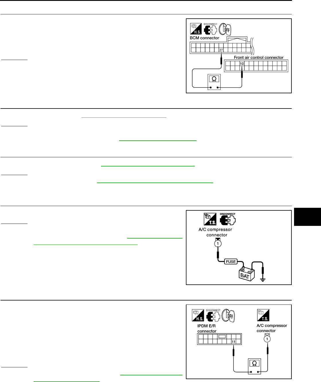
TROUBLE DIAGNOSIS
MTC-69
C
D
E
F
G
H
I
K
L
M
A
B
MTC
Revision: November 2005 2005 Pathfinder
9. CHECK CIRCUIT CONTINUITY BETWEEN BCM AND FRONT AIR CONTROL
1. Disconnect BCM connector and front air control connector.
2. Check continuity between BCM harness connector M18 terminal
27 and front air control harness connector M49 terminal 10.
OK or NG
OK >> GO TO 10.
NG >> Repair harness or connector.
10. CHECK INTAKE SENSOR CIRCUITS
Check intake sensor. Refer to MTC-80, "Intake Sensor Circuit" .
OK or NG
OK >> GO TO 11.
NG >> Replace intake sensor. Refer to MTC-83, "INTAKE SENSOR" .
11. CHECK CAN COMMUNICATION
Check CAN communication. Refer to LAN-24, "CAN COMMUNICATION" .
OK or NG
OK >> Replace BCM. Refer to BCS-20, "Removal and Installation of BCM" .
NG >> Repair or replace malfunctioning part(s).
12. CHECK MAGNET CLUTCH CIRCUIT
Check for operation sound when applying battery voltage to terminal.
OK or NG
OK >> GO TO 13.
NG >> Replace magnet clutch. Refer to MTC-102, "Removal
and Installation for Compressor Clutch" .
13. CHECK CIRCUIT CONTINUITY BETWEEN IPDM E/R AND A/C COMPRESSOR
1. Turn ignition switch OFF.
2. Disconnect IPDM E/R connector and A/C compressor (magnet
clutch) connector.
3. Check continuity between IPDM E/R harness connector E119
terminal 11 and A/C compressor harness connector F3 terminal
1.
OK or NG
OK >> Replace IPDM E/R. Refer to PG-29, "Removal and
Installation of IPDM E/R" .
NG >> Repair harness or connector.
27 - 10 : Continuity should exist.
WJIA1136E
WJIA1472E
11 – 1 : Continuity should exist.
WJIA1470E
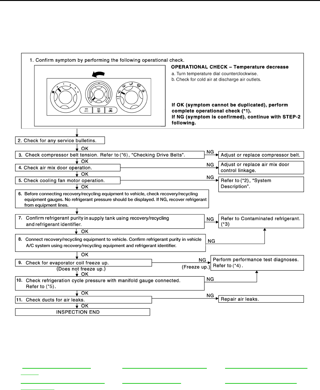
MTC-70
TROUBLE DIAGNOSIS
Revision: November 2005 2005 Pathfinder
Insufficient Cooling EJS003VL
SYMPTOM: Insufficient cooling
INSPECTION FLOW
*1 .ATC-52, "Operational Check
(Front)" . *2 EC-463, "SYSTEM DESCRIPTION".*3 ATC-5, "Contaminated Refrigerant".
*4 ATC-103, "PERFORMANCE TEST
DIAGNOSES".*5 ATC-105, "Test Readi ng"
.*6 MA-13, "Checking Drive Belts"
WJIA1340E
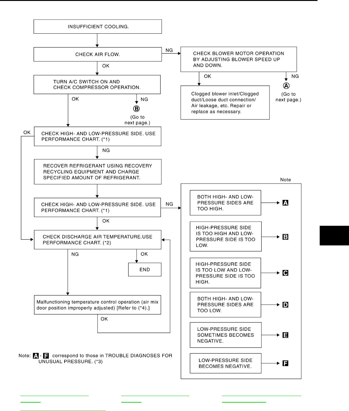
TROUBLE DIAGNOSIS
MTC-71
C
D
E
F
G
H
I
K
L
M
A
B
MTC
Revision: November 2005 2005 Pathfinder
PERFORMANCE TEST DIAGNOSES
*1 ATC-105, "PERFORMANCE
CHART".*2 ATC-105, "PERFORMANCE
CHART".*3 ATC-106, "Trouble Diagnoses for
Unusual Pressure".
*4 ATC-63, "Air Mix Door Motor Circuit".
RJIA1601E
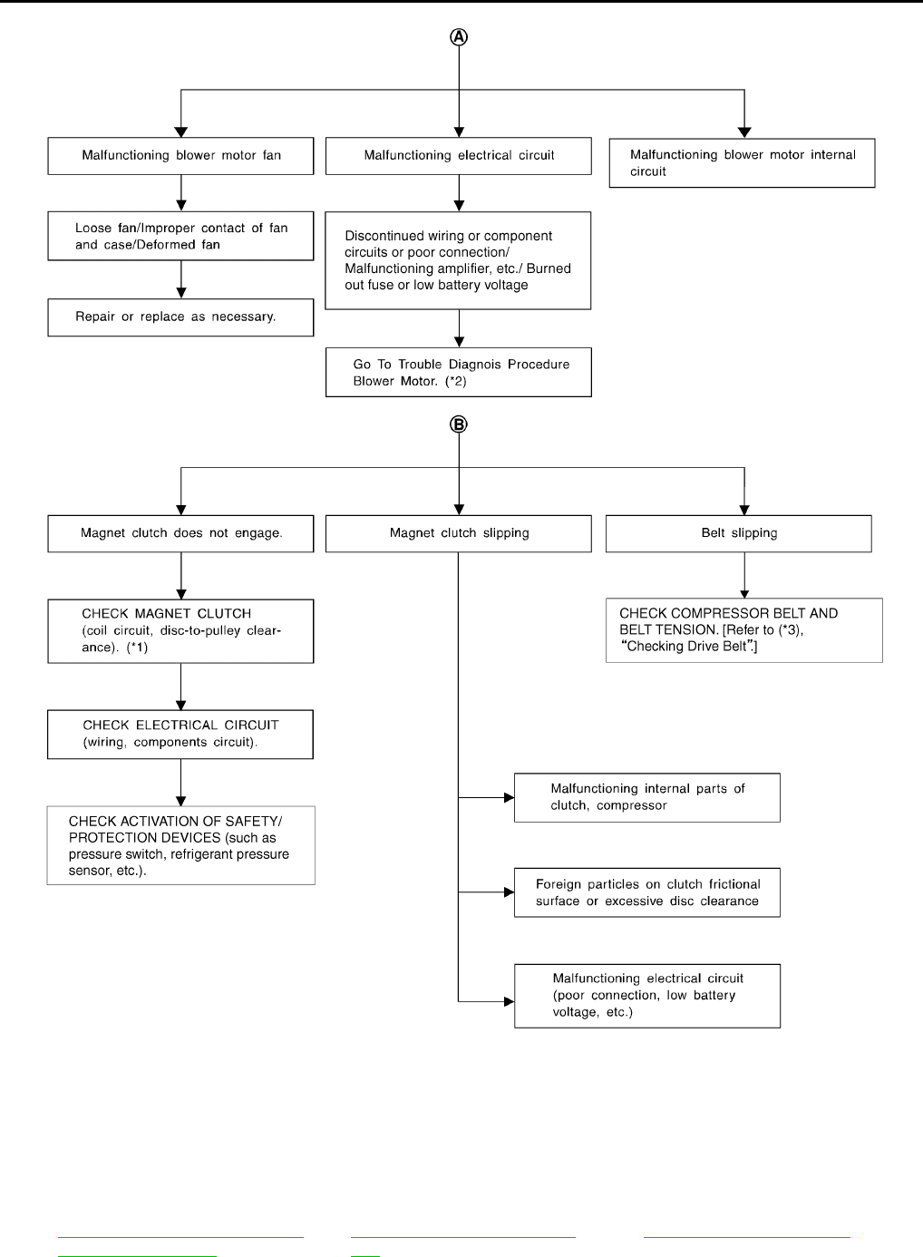
MTC-72
TROUBLE DIAGNOSIS
Revision: November 2005 2005 Pathfinder
*1 ATC-159, "Removal and Installation
for Compressor Clutch".*2 ATC-75, "Front Blower Motor Cir-
cuit".*3 MA-13, "Checking Drive Belts".
RJIA3107E
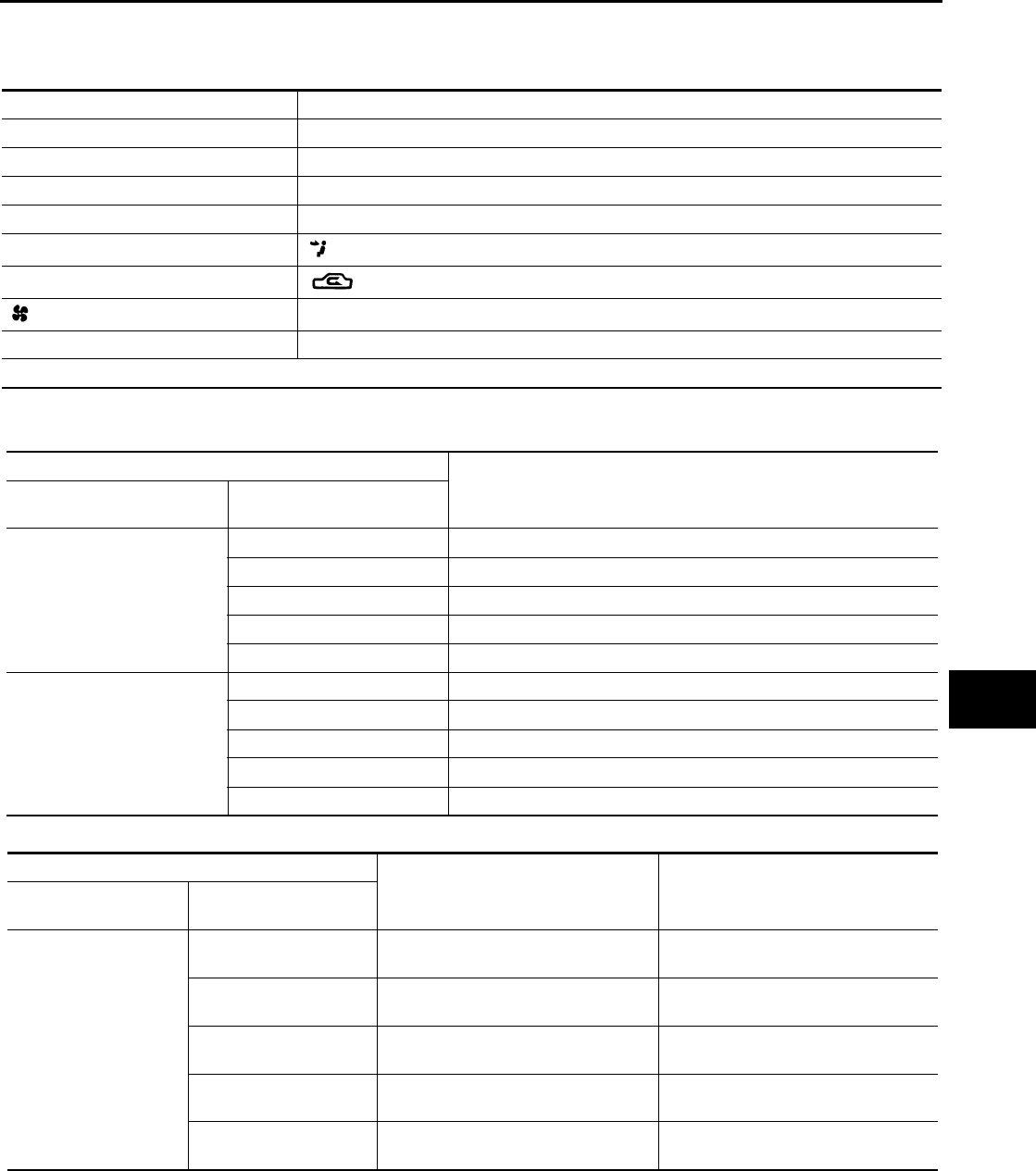
TROUBLE DIAGNOSIS
MTC-73
C
D
E
F
G
H
I
K
L
M
A
B
MTC
Revision: November 2005 2005 Pathfinder
PERFORMANCE CHART
Test Condition
Testing must be performed as follows:
Test Reading
Recirculating-to-discharge Air Temperature Table
Ambient Air Temperature-to-operating Pressure Table
Vehicle location Indoors or in the shade (in a well-ventilated place)
Doors Closed
Door window Open
Hood Open
TEMP. Max. COLD
Mode switch (Ventilation) set
Recirculation (REC) switch (Recirculation) set
Blower speed Max. speed set
Engine speed Idle speed
Operate the air conditioning system for 10 minutes before taking measurements.
Inside air (Recirculating air) at blower assembly inlet Discharge air temperature at center ventilator
°C (°F)
Relative humidity
%
Air temperature
°C (°F)
50 - 60
20 (68) 5.3 - 6.5 (42 - 44)
25 (77) 9.7 - 11.5 (49 - 53)
30 (86) 13.8 - 16.3 (57 - 61)
35 (95) 18.0 - 21.2 (64 - 70)
40 (104) 22.2 - 25.7 (72 - 78)
60 - 70
20 (68) 6.5 - 7.7 (44 - 46)
25 (77) 11.5 - 13.3 (53 - 56)
30 (86) 16.3 - 18.8 (61 - 66)
35 (95) 21.2 - 24.0 (70 - 75)
40 (104) 25.7 - 29.2 (78 - 85)
Ambient air High-pressure (Discharge side)
kPa (kg/cm2 , psi)
Low-pressure (Suction side)
kPa (kg/cm2 , psi)
Relative humidity
%Air temperature
°C (°F)
50 - 70
20 (68) 680 - 840
(6.94 - 8.57, 98.6 - 121.8)
160 - 198
(1.63 - 2.02, 23.2 - 28.7)
25 (77) 800 - 985
(8.16 - 10.05, 116.0 - 142.8)
198 - 245
(2.02 - 2.50, 28.7 - 35.5)
30 (86) 940 - 1,150
(9.59 - 11.73, 136.3 - 166.8)
225 - 278
(2.30 - 2.84, 32.6 - 40.3)
35 (95) 1,160 - 1,410
(11.83 - 14.38, 168.2 - 204.5)
273 - 335
(2.78 - 3.42, 39.6 - 48.6)
40 (104) 1,325 - 1,620
(13.52 - 16.52, 192.1 - 234.9) 325 - 398
(3.32 - 4.06, 47.1 - 57.7)
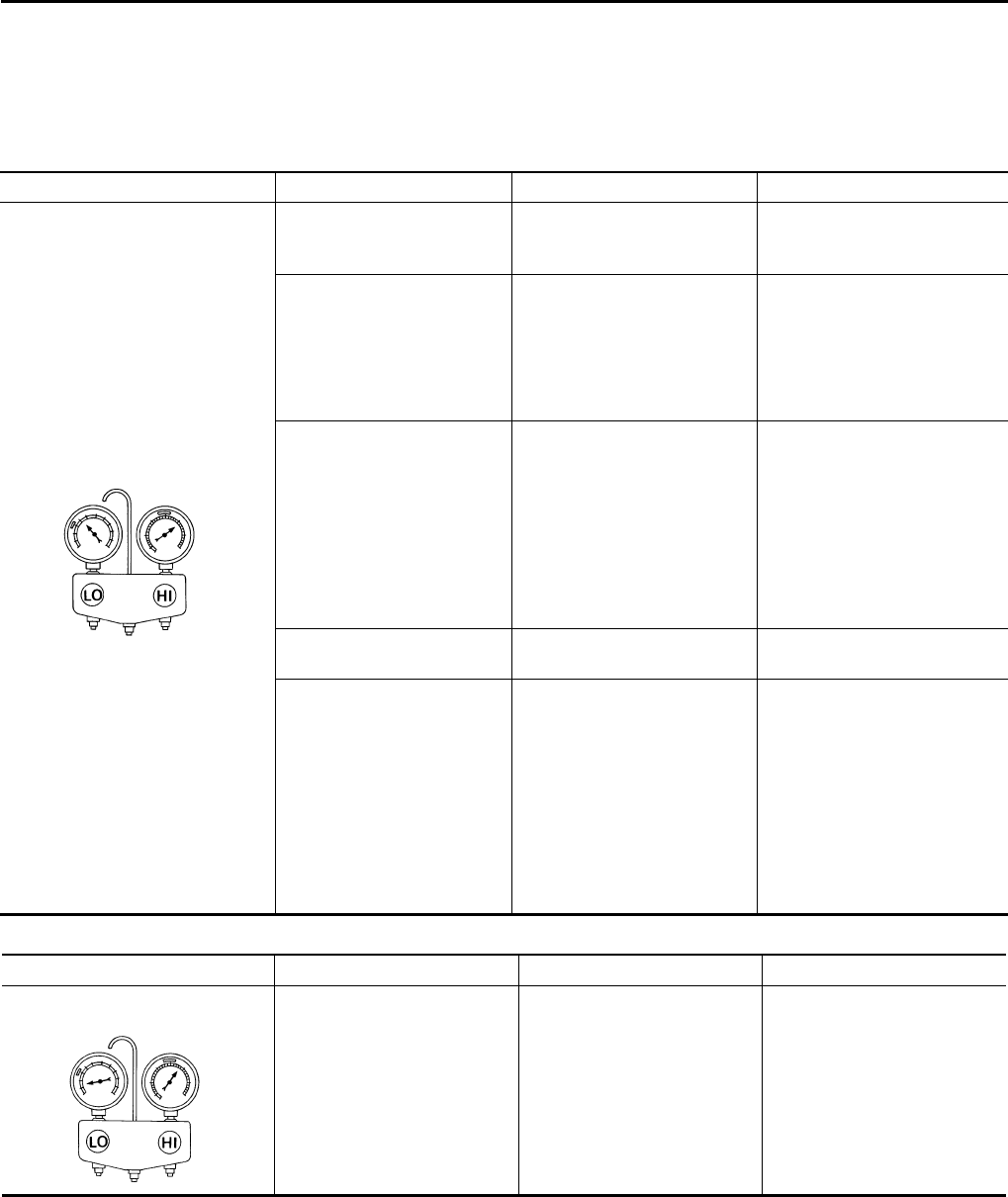
MTC-74
TROUBLE DIAGNOSIS
Revision: November 2005 2005 Pathfinder
TROUBLE DIAGNOSES FOR UNUSUAL PRESSURE
Whenever system′s high and/or low side pressure is unusual, diagnose using a manifold gauge. The marker
above the gauge scale in the following tables indicates the standard (usual) pressure range. Since the stan-
dard (usual) pressure, however, differs from vehicle to vehicle, refer to above table (Ambient air temperature-
to-operating pressure table).
Both High- and Low-pressure Sides are Too High
High-pressure Side is Too High and Low-pressure Side is Too Low
Gauge indication Refrigerant cycle Probable cause Corrective action
Both high- and low-pressure sides
are too high.
Pressure is reduced soon
after water is splashed on
condenser.
Excessive refrigerant charge
in refrigeration cycle
Reduce refrigerant until speci-
fied pressure is obtained.
Air suction by cooling fan is
insufficient.
Insufficient condenser cooling
performance
↓
1.Condenser fins are clogged.
2.Improper fan rotation of
cooling fan
●Clean condenser.
●Check and repair cooling fan
if necessary.
●Low-pressure pipe is not
cold.
●When compressor is
stopped high-pressure
value quickly drops by
approximately 196 kPa (2
kg/cm2 , 28 psi). It then
decreases gradually there-
after.
Poor heat exchange in con-
denser
(After compressor operation
stops, high-pressure
decreases too slowly.)
↓
Air in refrigeration cycle
Evacuate and recharge sys-
tem.
Engine tends to overheat. Engine cooling systems mal-
function. Check and repair engine cool-
ing system.
●An area of the low-pres-
sure pipe is colder than
areas near the evaporator
outlet.
●Plates are sometimes cov-
ered with frost.
●Excessive liquid refrigerant
on low-pressure side
●Excessive refrigerant dis-
charge flow
●Expansion valve is open a
little compared with the
specification.
↓
Improper expansion valve
adjustment
Replace expansion valve.
AC359A
Gauge indication Refrigerant cycle Probable cause Corrective action
High-pressure side is too high and
low-pressure side is too low.
Upper side of condenser and
high-pressure side are hot,
however, liquid tank is not so
hot.
High-pressure tube or parts
located between compressor
and condenser are clogged or
crushed.
●Check and repair or replace
malfunctioning parts.
●Check lubricant for contami-
nation.
AC360A
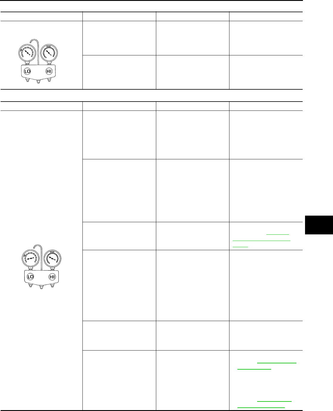
TROUBLE DIAGNOSIS
MTC-75
C
D
E
F
G
H
I
K
L
M
A
B
MTC
Revision: November 2005 2005 Pathfinder
High-pressure Side is Too Low and Low-pressure Side is Too High
Both High- and Low-pressure Sides are Too Low
Gauge indication Refrigerant cycle Probable cause Corrective action
High-pressure side is too low and
low-pressure side is too high. High- and low-pressure sides
become equal soon after com-
pressor operation stops.
Compressor pressure opera-
tion is improper.
↓
Damaged inside compressor
packings.
Replace compressor.
No temperature difference
between high- and low-pres-
sure sides.
Compressor pressure opera-
tion is improper.
↓
Damaged inside compressor
packings.
Replace compressor.
AC356A
Gauge indication Refrigerant cycle Probable cause Corrective action
Both high- and low-pressure sides
are too low.
●There is a big temperature
difference between liquit
tand outlet and inlet. Outlet
temperature is extremely
low.
●Liquid tank inlet and expan-
sion valve are frosted.
Liquid tank inside is slightly
clogged.
●Replace liquid tank.
●Check lubricant for contami-
nation.
●Temperature of expansion
valve inlet is extremely low
as compared with areas
near liquid tank.
●Expansion valve inlet may
be frosted.
●Temperature difference
occurs somewhere in high-
pressure side.
High-pressure pipe located
between liquit tank and expan-
sion valve is clogged.
●Check and repair malfunc-
tioning parts.
●Check lubricant for contami-
nation.
Expansion valve and liquid
tank are warm or only cool
when touched.
Low refrigerant charge.
↓
Leaking fittings or compo-
nents.
Check refrigerant system for
leaks. Refer to ATC-170,
"Checking for Refrigerant
Leaks" .
There is a big temperature dif-
ference between expansion
valve inlet and outlet while the
valve itself is frosted.
Expansion valve closes a little
compared with the specifica-
tion.
↓
1.Improper expansion valve
adjustment.
2.Malfunctioning expansion
valve.
3.Outlet and inlet may be
clogged.
●Remove foreign particles by
using compressed air.
●Check lubricant for contami-
nation.
An area of the low-pressure
pipe is colder than areas near
the evaporator outlet.
Low-pressure pipe is clogged
or crushed.
●Check and repair malfunc-
tioning parts.
●Check lubricant for contami-
nation.
Air flow volume is too low. Evaporator is frozen.
●Check intake sensor circuit.
Refer to ATC-125, "Intake
Sensor Circuit" .
●Replace compressor.
●Repair evaporator fins.
●Replace evaporator.
●Refer to ATC-75, "Front
Blower Motor Circuit" .
AC353A
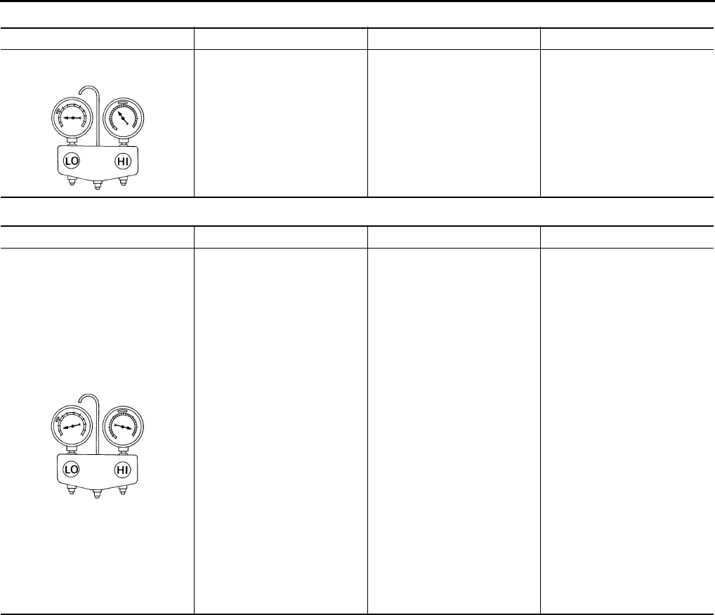
MTC-76
TROUBLE DIAGNOSIS
Revision: November 2005 2005 Pathfinder
Low-pressure Side Sometimes Becomes Negative
Low-pressure Side Becomes Negative
Gauge indication Refrigerant cycle Probable cause Corrective action
Low-pressure side sometimes
becomes negative. ●Air conditioning system
does not function and does
not cyclically cool the com-
partment air.
●The system constantly func-
tions for a certain period of
time after compressor is
stopped and restarted.
Refrigerant does not dis-
charge cyclically.
↓
Moisture is frozen at expan-
sion valve outlet and inlet.
↓
Water is mixed with refriger-
ant.
●Drain water from refrigerant
or replace refrigerant.
●Replace liquid tank.
AC354A
Gauge indication Refrigerant cycle Probable cause Corrective action
Low-pressure side becomes nega-
tive.
Liquid tank or front/rear side of
expansion valve′s pipe is
frosted or dewed.
High-pressure side is closed
and refrigerant does not flow.
↓
Expansion valve or liquid tank
is frosted.
Leave the system at rest until
no frost is present. Start it
again to check whether or not
the malfunction is caused by
water or foreign particles.
●If water is the cause, initially
cooling is okay. Then the
water freezes causing a
blockage. Drain water from
refrigerant or replace refrig-
erant.
●If due to foreign particles,
remove expansion valve
and remove the particles
with dry and compressed air
(not shop air).
●If either of the above meth-
ods cannot correct the mal-
function, replace expansion
valve.
●Replace liquid tank.
●Check lubricant for contami-
nation.
AC362A
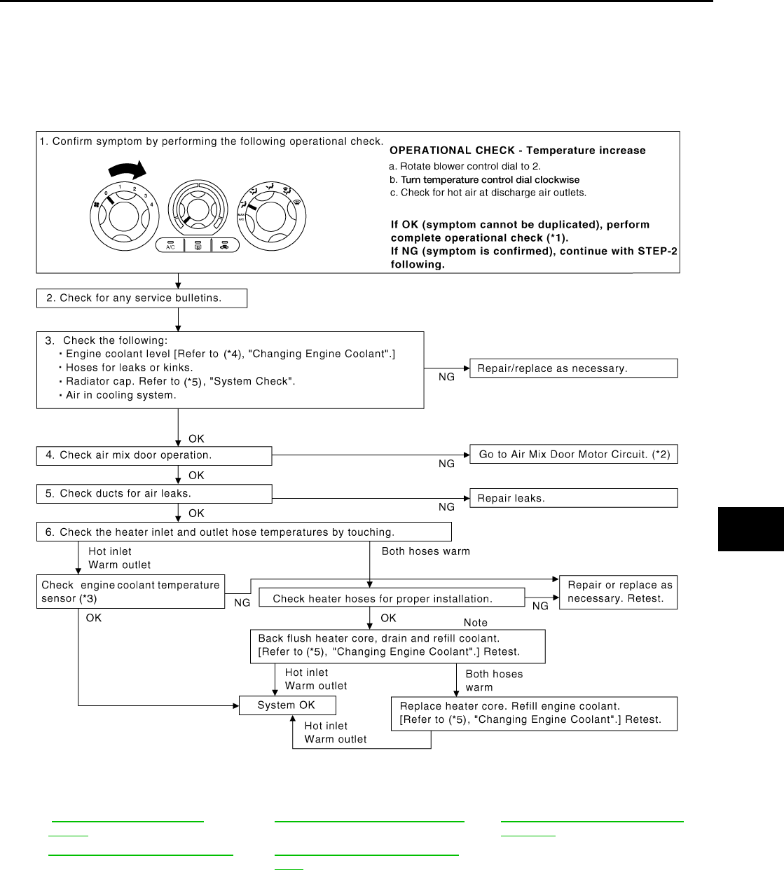
TROUBLE DIAGNOSIS
MTC-77
C
D
E
F
G
H
I
K
L
M
A
B
MTC
Revision: November 2005 2005 Pathfinder
Insufficient Heating EJS003VM
SYMPTOM: Insufficient heating
INSPECTION FLOW
*1 .ATC-52, "Operational Check
(Front)" *2 ATC-63, "Air Mix Door Motor Circuit".*3 EC-204, "DTC P0117, P0118 ECT
SENSOR".
*4 MA-13, "Changing Engine Coolant".*5 CO-10, "CHECKING RESERVOIR
CAP".
WJIA1678E
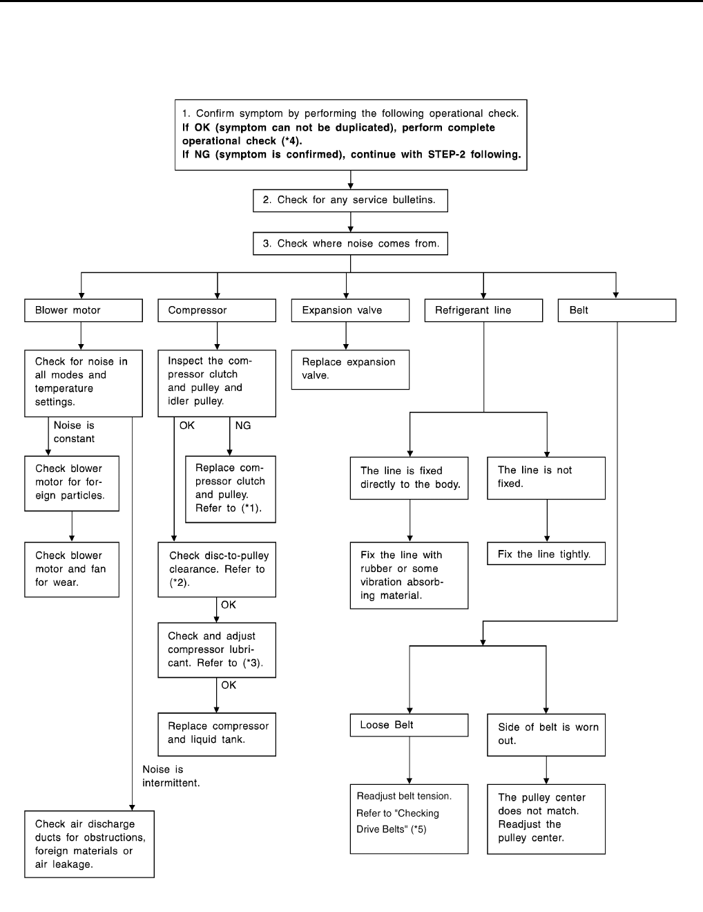
MTC-78
TROUBLE DIAGNOSIS
Revision: November 2005 2005 Pathfinder
Noise EJS003VN
SYMPTOM: Noise
INSPECTION FLOW
WJIA0473E

TROUBLE DIAGNOSIS
MTC-79
C
D
E
F
G
H
I
K
L
M
A
B
MTC
Revision: November 2005 2005 Pathfinder
*1 ATC-159, "REMOVAL".*2ATC-160, "INSTALLATION".*3ATC-22, "Maintenance of Lubricant
Quantity in Compressor".
*4 ATC-52, "Operational Check (Front)"*5 MA-13, "Checking Drive Belts".
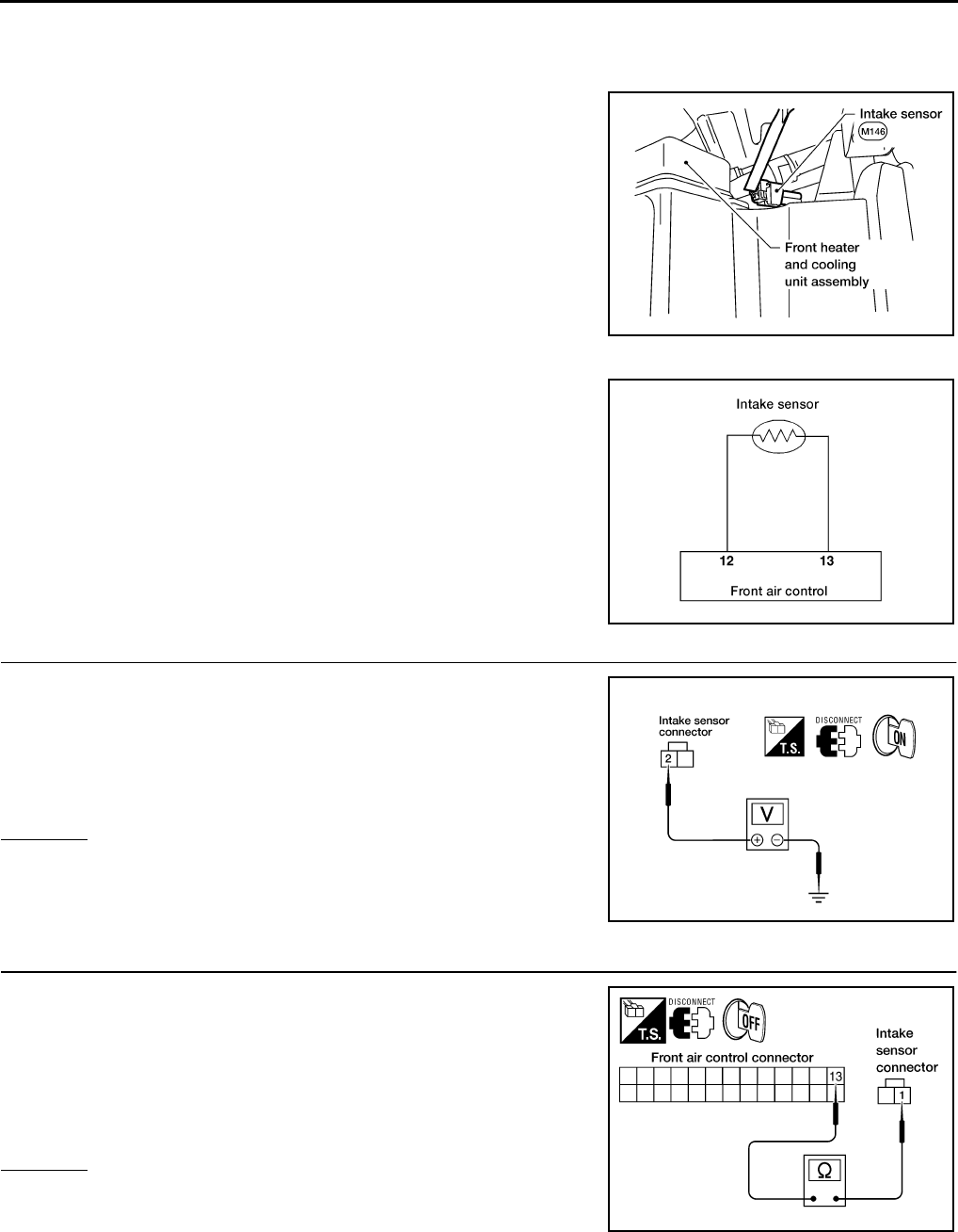
MTC-80
TROUBLE DIAGNOSIS
Revision: November 2005 2005 Pathfinder
Intake Sensor Circuit EJS003VO
COMPONENT DESCRIPTION
Intake Sensor
The intake sensor is located on top of the heater and cooling unit
assembly next to the A/C evaporator cover. It converts temperature
of air after it passes through the evaporator into a resistance value
which is then input to the front air control.
DIAGNOSTIC PROCEDURE FOR INTAKE SENSOR
SYMPTOM: Intake sensor circuit is open or shorted.
1. CHECK VOLTAGE BETWEEN INTAKE SENSOR AND GROUND
1. Disconnect intake sensor connector.
2. Turn ignition switch ON.
3. Check voltage between intake sensor harness connector M146
terminal 2 and ground.
OK or NG
OK >> GO TO 2.
NG >> GO TO 4.
2. CHECK CIRCUIT CONTINUITY BETWEEN INTAKE SENSOR AND FRONT AIR CONTROL
1. Turn ignition switch OFF.
2. Disconnect front air control connector.
3. Check continuity between intake sensor harness connector
M146 terminal 1 and front air control harness connector M49 ter-
minal 13.
OK or NG
OK >> GO TO 3.
NG >> Repair harness or connector.
WJIA1155E
WJIA1156E
2 - Ground : Approx. 5V
WJIA1278E
1 - 13 : Continuity should exist.
WJIA1157E
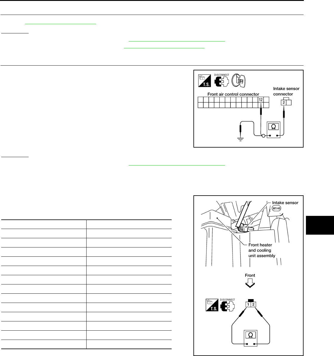
TROUBLE DIAGNOSIS
MTC-81
C
D
E
F
G
H
I
K
L
M
A
B
MTC
Revision: November 2005 2005 Pathfinder
3. CHECK INTAKE SENSOR
Refer to ATC-126, "Intake Sensor" .
OK or NG
OK >> Replace front air control. Refer to MTC-82, "FRONT AIR CONTROL" .
NG >> Replace intake sensor. Refer to MTC-83, "INTAKE SENSOR" .
4. CHECK CIRCUIT CONTINUITY BETWEEN INTAKE SENSOR AND FRONT AIR CONTROL
1. Turn ignition switch OFF.
2. Disconnect front air control connector.
3. Check continuity between intake sensor harness connector
M146 terminal 2 and front air control harness connector M49 ter-
minal 12.
4. Check continuity between intake sensor harness connector
M146 terminal 2 and ground.
OK or NG
OK >> Replace front air control. Refer to MTC-82, "FRONT AIR CONTROL" .
NG >> Repair harness or connector.
COMPONENT INSPECTION
Intake Sensor
After disconnecting intake sensor connector, measure resistance
between terminals 1 and 2 at sensor harness side, using the table
below.
If NG, replace intake sensor.
2 - 12 : Continuity should exist.
2 - Ground : Continuity should not exist. WJIA1158E
Temperature °C (°F) Resistance kΩ
−15 (5) 209.0
−10 (14) 160.0
−5 (23) 123.0
0 (32) 95.8
5 (41) 74.9
10 (50) 58.9
15 (59) 46.7
20 (68) 37.3
25 (77) 30.0
30 (86) 24.2
35 (95) 19.7
40 (104) 16.1
45 (113) 13.2
WJIA1159E
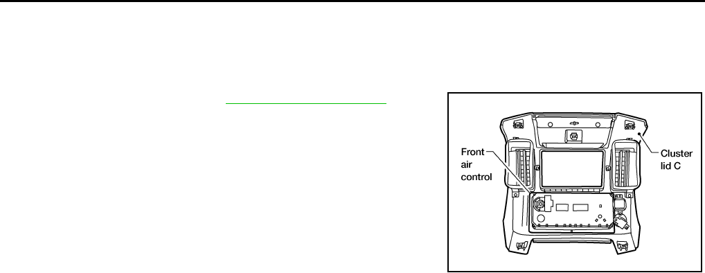
MTC-82
CONTROL UNIT
Revision: November 2005 2005 Pathfinder
CONTROL UNIT PFP:27500
Removal and Installation EJS003VP
FRONT AIR CONTROL
Removal
1. Remove cluster lid C. Refer to IP-11, "CLUSTER LID C" .
2. Remove the four screws securing the front air control to cluster
lid C.
3. Remove the front air control.
Installation
Installation is in the reverse order of removal.
LBIA0416E
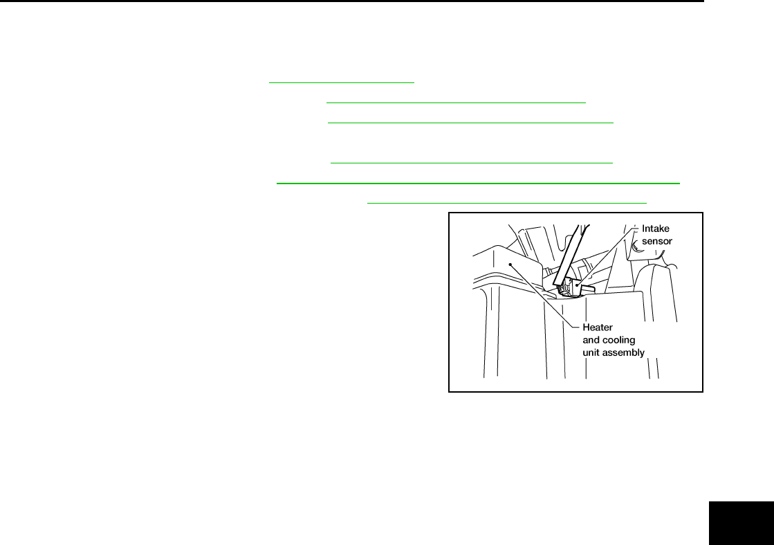
INTAKE SENSOR
MTC-83
C
D
E
F
G
H
I
K
L
M
A
B
MTC
Revision: November 2005 2005 Pathfinder
INTAKE SENSOR PFP:27723
Removal and Installation EJS003VQ
REMOVAL
1. Remove the front kick plate. Refer to EI-28, "KICK PLATES" .
2. Remove the lower dash side finisher. Refer to EI-28, "LOWER DASH SIDE FINISHER" .
3. Remove the front pillar lower finisher. Refer to EI-28, "FRONT PILLAR LOWER FINISHER" .
4. Remove the assist grip handle
5. Remove the front pillar upper finisher. Refer to EI-28, "FRONT PILLAR UPPER FINISHER" .
6. Remove the lower glove box. Refer to IP-14, "LOWER INSTRUMENT PANEL RH AND GLOVE BOX" .
7. Remove the upper glove box (cluster lid E). Refer to IP-10, "INSTRUMENT PANEL ASSEMBLY" .
8. Disconnect the intake sensor electrical connector.
NOTE:
The intake sensor is located on the top of the heater and cooling
unit assembly next to the A/C evaporator cover.
9. Twist the intake sensor to remove the intake sensor from the
heater and cooling unit assembly.
INSTALLATION
Installation is in the reverse order of removal.
WJIA1415E
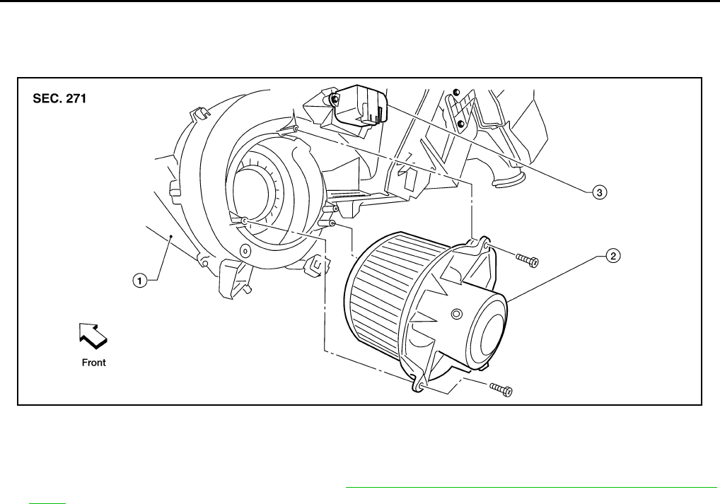
MTC-84
BLOWER MOTOR
Revision: November 2005 2005 Pathfinder
BLOWER MOTOR PFP:27226
Components EJS003VR
Blower Motor
Removal and Installation EJS003VS
REMOVAL
1. Remove the lower glove box assembly. Refer to IP-14, "LOWER INSTRUMENT PANEL RH AND GLOVE
BOX" .
2. Disconnect the blower motor electrical connector.
3. Remove the three screws and remove the blower motor.
INSTALLATION
Installation is in the reverse order of removal.
LJIA0136E
1. Heater and cooling unit assembly 2. Blower motor 3. Blower motor resistor
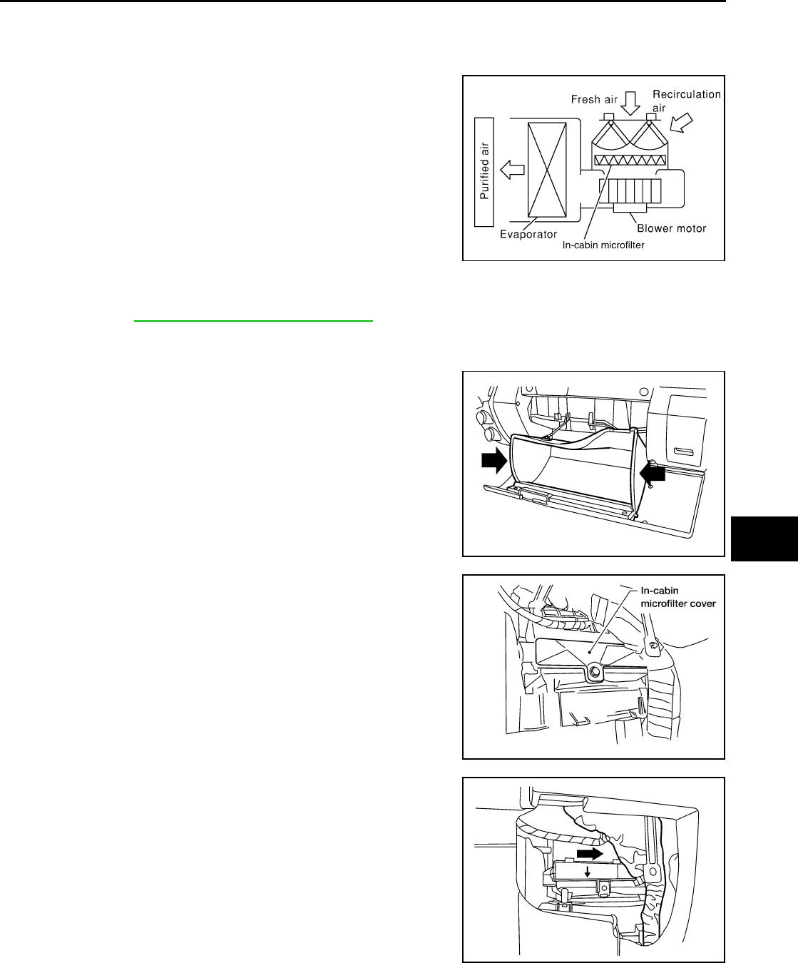
IN-CABIN MICROFILTER
MTC-85
C
D
E
F
G
H
I
K
L
M
A
B
MTC
Revision: November 2005 2005 Pathfinder
IN-CABIN MICROFILTER PFP:27277
Removal and Installation EJS003VT
FUNCTION
The air inside the passenger compartment is filtered by the in-cabin
microfilters when the heater or A/C controls are set on either the
recirculation or fresh mode. The two in-cabin microfilters are located
in the heater and cooling unit assembly.
REPLACEMENT TIMING
Replacement of the two in-cabin microfilters is recommended on a regular interval depending on the driving
conditions. Refer to MA-7, "PERIODIC MAINTENANCE" . It may also be necessary to replace the two in-cabin
microfilters as part of a component replacement if the in-cabin microfilters are damaged.
REPLACEMENT PROCEDURE
1. Open the lower glove box and press in on the sides so that it will
open completely allowing it to hang by the cord.
2. Remove the screw and remove the in-cabin microfilter cover.
3. Remove the in-cabin microfilters from the heater and cooling
unit housing.
4. Insert the first new in-cabin microfilter into the heater and cool-
ing unit housing and slide it over to the right. Insert the second
new in-cabin microfilter into the heater and cooling unit housing.
NOTE:
The in-cabin microfilters are marked with air flow arrows. The
end of the microfilter with the arrow should face the rear of the
vehicle. The arrows should point downward.
LJIA0012E
WLIA0023E
LJIA0134E
LJIA0148E
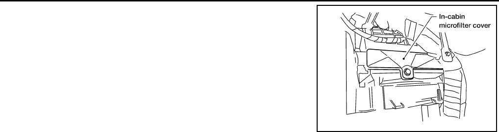
MTC-86
IN-CABIN MICROFILTER
Revision: November 2005 2005 Pathfinder
5. Install the in-cabin microfilter cover.
6. Close the lower glove box completely.
LJIA0134E
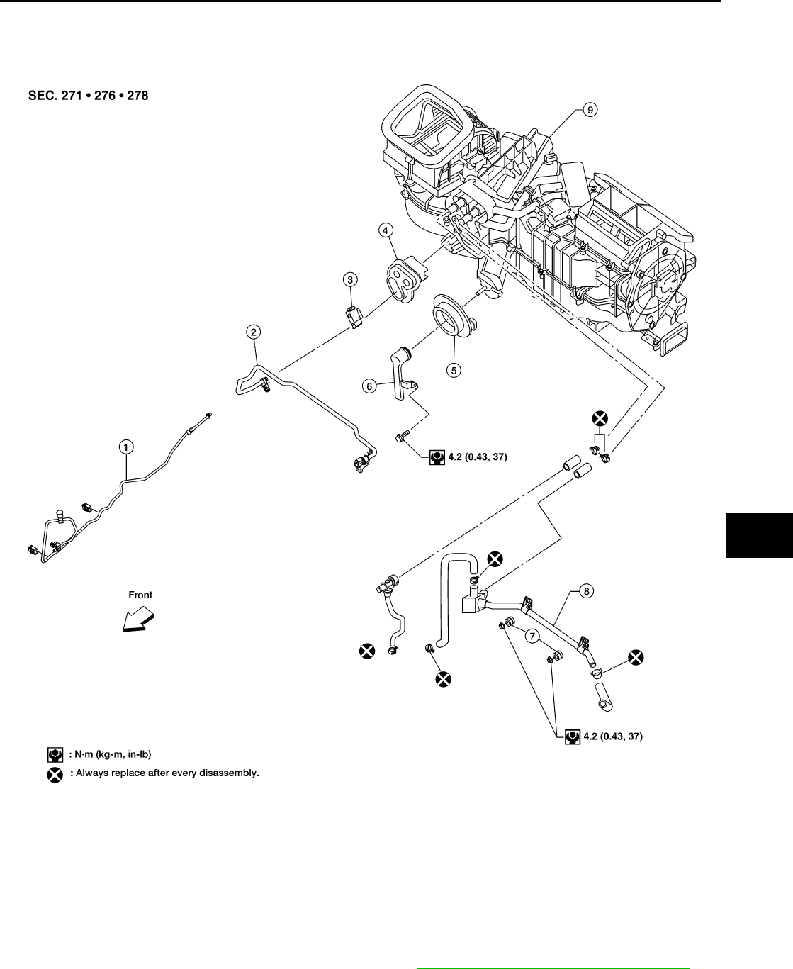
HEATER & COOLING UNIT ASSEMBLY
MTC-87
C
D
E
F
G
H
I
K
L
M
A
B
MTC
Revision: November 2005 2005 Pathfinder
HEATER & COOLING UNIT ASSEMBLY PFP:27110
Components EJS003VU
Heater and Cooling Unit Assembly
Removal and Installation EJS003VV
REMOVAL
1. Discharge the refrigerant from the A/C system. Refer to ATC-154, "Discharging Refrigerant" .
2. Drain the coolant from the engine cooling system. Refer to MA-13, "DRAINING ENGINE COOLANT" .
3. Disconnect the battery negative and positive terminals.
WJIA1416E
1. High-pressure A/C pipe 2. Low-pressure A/C pipe 3. Expansion valve
4. Heater core and evaporator pipes
grommet
5. A/C drain hose grommet 6. A/C drain hose
7. Heater core pipe mounts 8. Heater core pipes 9. Heater and cooling unit assembly
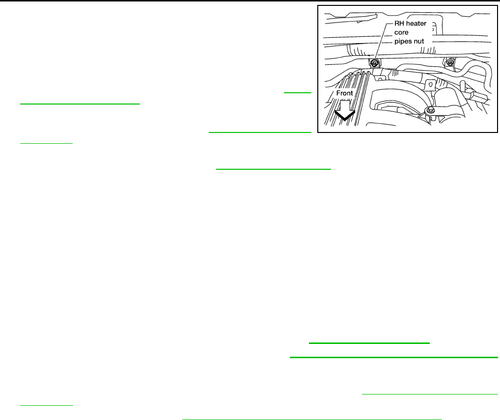
MTC-88
HEATER & COOLING UNIT ASSEMBLY
Revision: November 2005 2005 Pathfinder
4. Remove the RH heater core pipes nut.
5. Disconnect the heater core hoses from the heater core.
6. Disconnect the high- and low-pressure A/C pipes from the
expansion valve.
7. Move the two front seats to the rearmost position on the seat
track.
8. Remove the instrument panel and console panel. Refer to IP-10,
"Removal and Installation" .
9. Remove the two front floor ducts.
10. Remove the steering column. Refer to PS-10, "Removal and
Installation" .
11. Disconnect the instrument panel wire harness at the RH and LH in-line connector brackets, and the fuse
block (SMJ) electrical connectors. Refer to PG-40, "Harness Layout" .
12. Remove the covers then remove the three steering member bolts from each side to disconnect the steer-
ing member from the vehicle body.
13. Remove the heater and cooling unit assembly with it attached to the steering member, from the vehicle.
CAUTION:
●Use care not to damage the seats and interior trim panels when removing the heater and cooling
unit assembly with it attached to the steering member.
●Use suitable plugs on the heater core pipes to prevent coolant leakage.
14. Remove the heater and cooling unit assembly from the steering member.
INSTALLATION
Installation is in the reverse order of removal.
CAUTION:
●Replace the O-ring of the low-pressure A/C pipe and high-pressure A/C pipe with a new one, and
apply compressor oil to the O-ring for installation. Refer to MTC-100, "Components" .
●After charging the refrigerant, check for leaks. Refer to ATC-170, "Checking for Refrigerant Leaks"
.
NOTE:
●Fill the engine cooling system with the specified coolant mixture. Refer to MA-14, "REFILLING ENGINE
COOLANT" .
●Recharge the A/C system. Refer to ATC-154, "Evacuating System and Charging Refrigerant" .
WJIA1292E
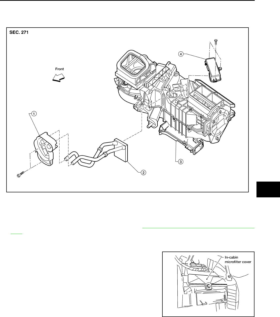
HEATER CORE
MTC-89
C
D
E
F
G
H
I
K
L
M
A
B
MTC
Revision: November 2005 2005 Pathfinder
HEATER CORE PFP:27140
Components EJS003VW
Heater and Cooling Unit Assembly
Removal and Installation EJS003VX
REMOVAL
1. Remove the heater and cooling unit assembly. Refer to MTC-87, "HEATER & COOLING UNIT ASSEM-
BLY" .
2. Remove the three screws and remove the heater core cover.
3. Remove the heater core and evaporator pipe bracket.
4. Remove the heater core.
NOTE:
If the in-cabin microfilters are contaminated from coolant leaking
from the heater core, replace the in-cabin microfilters with new
ones before installing the new heater core.
INSTALLATION
Installation is in the reverse order of removal.
LJIA0167E
1. Heater core and evaporator pipe bracket 2. Heater core 3. Heater and cooling unit assembly
4. Heater core cover
LJIA0134E
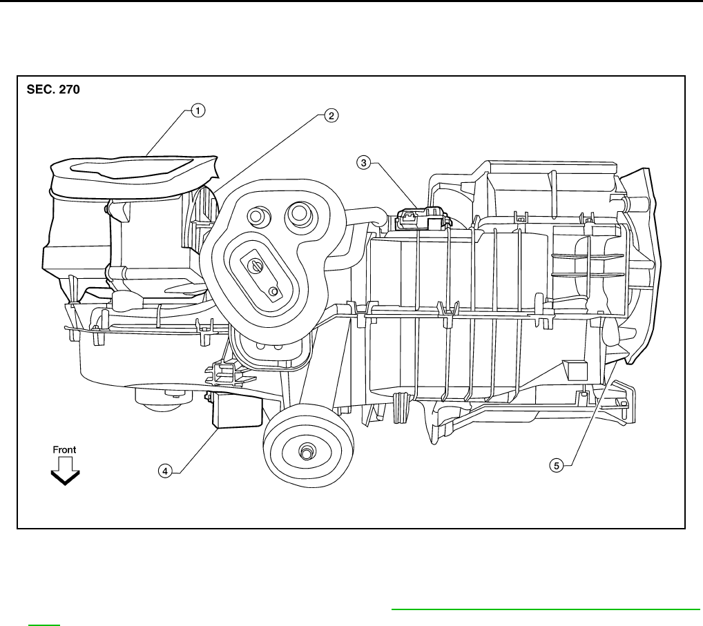
MTC-90
INTAKE DOOR MOTOR
Revision: November 2005 2005 Pathfinder
INTAKE DOOR MOTOR PFP:27730
Removal and Installation EJS003VY
Intake Door Motor - Heater and Cooling Unit Assembly
REMOVAL
1. Remove the heater and cooling unit assembly. Refer to MTC-87, "HEATER & COOLING UNIT ASSEM-
BLY" .
2. Remove the steering member from the heater and cooling unit assembly.
3. Disconnect the intake door motor electrical connector.
4. Remove the three screws and remove the intake door motor.
INSTALLATION
Installation is in the reverse order of removal.
WJIA1312E
1. Heater and cooling unit assembly 2. Intake door motor 3. Air mix door motor
4. Blower motor resistor 5. Mode door motor
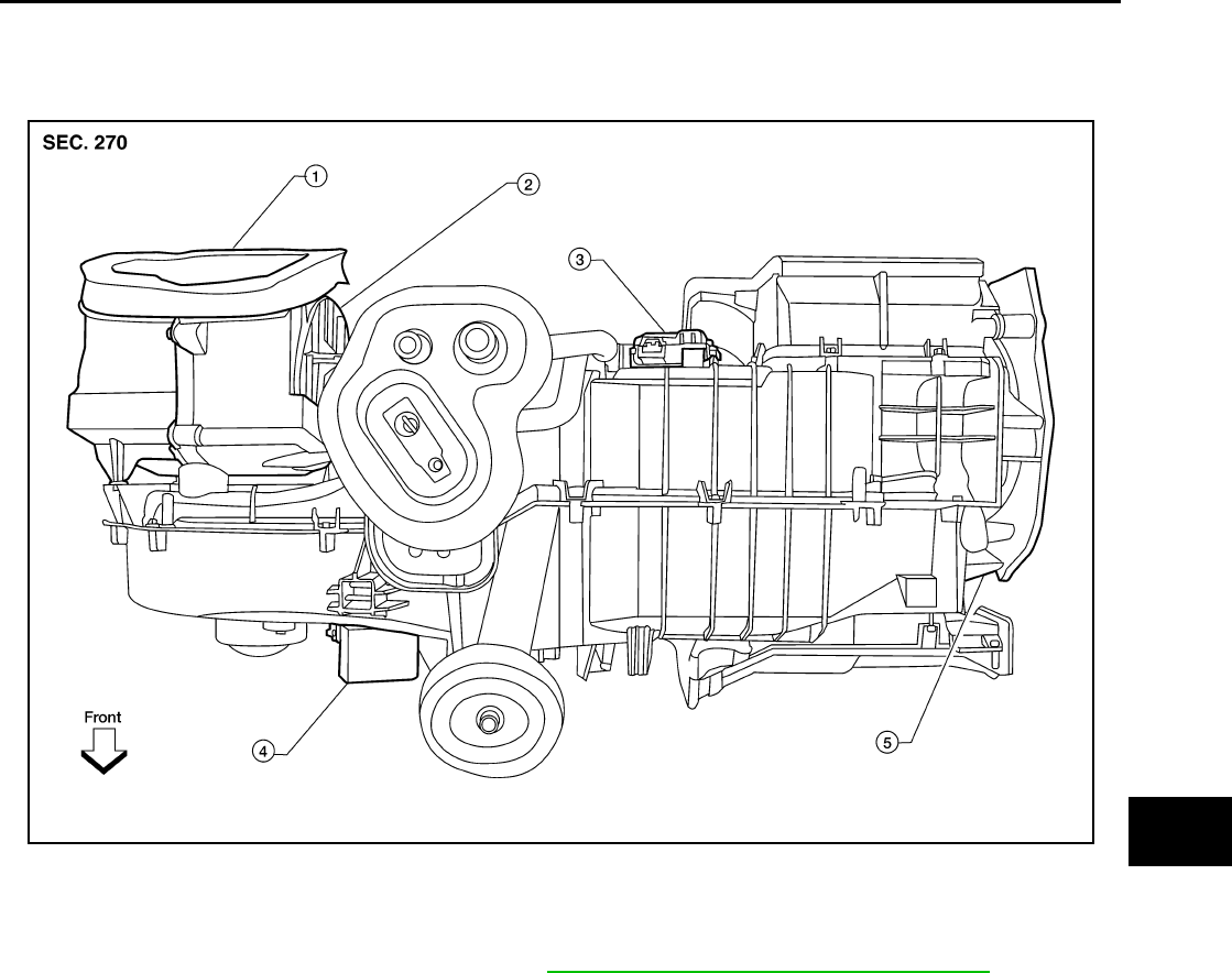
MODE DOOR MOTOR
MTC-91
C
D
E
F
G
H
I
K
L
M
A
B
MTC
Revision: November 2005 2005 Pathfinder
MODE DOOR MOTOR PFP:27731
Removal and Installation EJS003VZ
Mode Door Motor - Heater and Cooling Unit Assembly
REMOVAL
1. Remove the lower instrument panel LH. Refer to IP-13, "LOWER INSTRUMENT PANEL LH" .
2. Disconnect the mode door motor electrical connector.
3. Remove the three screws and remove the mode door motor.
INSTALLATION
Installation is in the reverse order of removal.
WJIA1312E
1. Heater and cooling unit assembly 2. Intake door motor 3. Air mix door motor
4. Blower motor resistor 5. Mode door motor
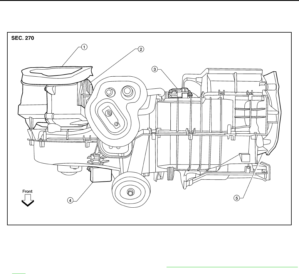
MTC-92
AIR MIX DOOR MOTOR
Revision: November 2005 2005 Pathfinder
AIR MIX DOOR MOTOR PFP:27732
Components EJS003W0
Air Mix Door Motor - Heater and Cooling Unit Assembly
Removal and Installation EJS003W1
REMOVAL
1. Remove the heater and cooling unit assembly. Refer to MTC-87, "HEATER & COOLING UNIT ASSEM-
BLY" .
2. Remove the steering member from the heater and cooling unit assembly.
3. Disconnect the air mix door motor electrical connector.
4. Remove the three screws and remove the air mix door motor.
INSTALLATION
Installation is in the reverse order of removal.
WJIA1312E
1. Heater and cooling unit assembly 2. Intake door motor 3. Air mix door motor
4. Blower motor resistor 5. Mode door motor
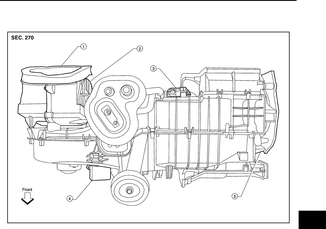
FRONT BLOWER MOTOR RESISTOR
MTC-93
C
D
E
F
G
H
I
K
L
M
A
B
MTC
Revision: November 2005 2005 Pathfinder
FRONT BLOWER MOTOR RESISTOR PFP:27077
Removal and Installation EJS003W2
Blower Motor Resistor - Heater and Cooling Unit Assembly
REMOVAL
1. Disconnect the blower motor resistor electrical connector.
2. Remove the two screws and remove the blower motor resistor.
INSTALLATION
Installation is in the reverse order of removal.
WJIA1312E
1. Heater and cooling unit assembly 2. Intake door motor 3. Air mix door motor
4. Blower motor resistor 5. Mode door motor

MTC-94
DUCTS AND GRILLES
Revision: November 2005 2005 Pathfinder
DUCTS AND GRILLES PFP:27860
Components EJS003W3
Ducts
LJIA0155E
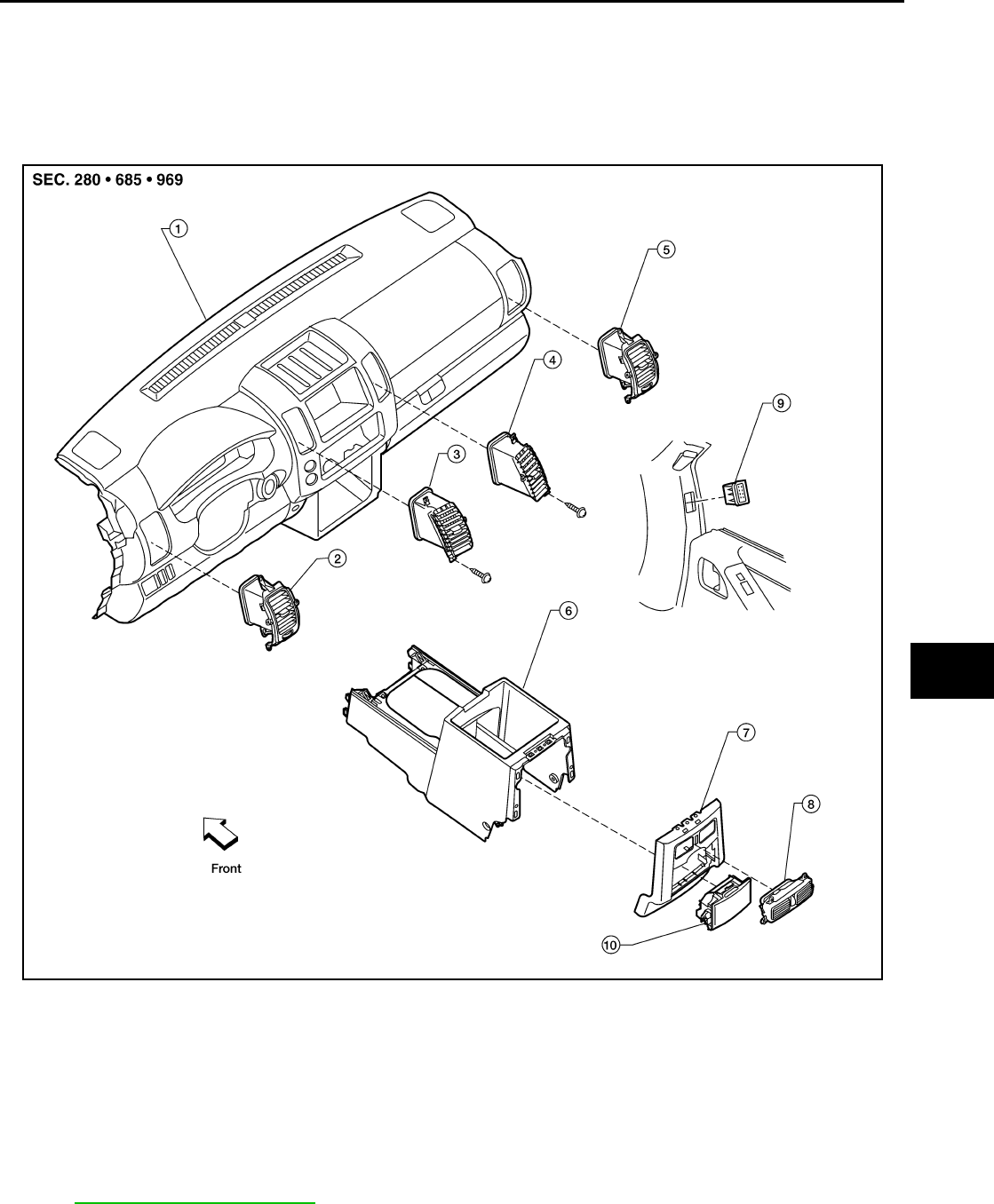
DUCTS AND GRILLES
MTC-95
C
D
E
F
G
H
I
K
L
M
A
B
MTC
Revision: November 2005 2005 Pathfinder
Grilles
Removal and Installation EJS003W4
CONSOLE DUCTS AND CONSOLE GRILLE
Removal
The center console must be removed and disassembled to remove the console ducts and the console grille.
Refer to IP-15, "CENTER CONSOLE" .
Installation
Installation is in the reverse order of removal.
1. Defroster nozzle 2. LH side demister duct 3. LH ventilator duct
4. RH side demister duct 5. RH ventilator duct 6. Center ventilator duct
7. Front heater and cooling unit assembly 8. Floor connector duct grilles 9. Floor connector duct
10. Front floor ducts 11. Floor floor ducts 12. Rear console duct
13. Center console duct 14. Front console duct
WJIA1424E
1. Instrument panel and pad assembly 2. LH side ventilator grille 3. LH ventilator grille
4. RH ventilator grille 5. RH side ventilator grille 6. Console assembly rear base
7. Rear finisher assembly 8. Console grille 9. RH side demister grille
10. Rear cup holder assembly

MTC-96
DUCTS AND GRILLES
Revision: November 2005 2005 Pathfinder
DEFROSTER NOZZLE
Removal
1. Remove the heater and cooling unit assembly. Refer to MTC-87, "HEATER & COOLING UNIT ASSEM-
BLY" .
2. Remove the defroster nozzle.
Installation
Installation is in the reverse order of removal.
RH AND LH SIDE DEMISTER DUCTS
Removal
1. Remove the heater and cooling unit assembly. Refer to MTC-87, "HEATER & COOLING UNIT ASSEM-
BLY" .
2. Remove the RH or LH side demister duct.
Installation
Installation is in the reverse order of removal.
RH AND LH VENTILATOR DUCTS
Removal
1. Remove the heater and cooling unit assembly. Refer to MTC-87, "HEATER & COOLING UNIT ASSEM-
BLY" .
2. Remove the RH or LH ventilator duct.
Installation
Installation is in the reverse order of removal.
CENTER VENTILATOR DUCT
Removal
1. Remove the heater and cooling unit assembly. Refer to MTC-87, "HEATER & COOLING UNIT ASSEM-
BLY" .
2. Remove the defroster nozzle.
3. Remove the RH and LH ventilator ducts.
4. Remove the RH and LH side demister ducts.
5. Remove the center ventilator duct.
Installation
Installation is in the reverse order of removal.
FLOOR CONNECTOR DUCT
Removal
1. Remove the heater and cooling unit assembly. Refer to MTC-87, "HEATER & COOLING UNIT ASSEM-
BLY" .
2. Remove the floor connector duct.
Installation
Installation is in the reverse order of removal.
FRONT AND REAR FLOOR DUCTS
Removal
1. Remove the floor carpet. Refer to EI-29, "FLOOR TRIM" .
2. Remove the clips and front and rear floor ducts.
Installation
Installation is in the reverse order of removal.

DUCTS AND GRILLES
MTC-97
C
D
E
F
G
H
I
K
L
M
A
B
MTC
Revision: November 2005 2005 Pathfinder
GRILLES
Removal
1. Remove the interior trim panel as necessary that contains the grille to be removed. Refer to IP-10,
"INSTRUMENT PANEL ASSEMBLY" and EI-27, "BODY SIDE TRIM" .
2. Remove the grille from the interior trim panel.
Installation
Installation is in the reverse order of removal.
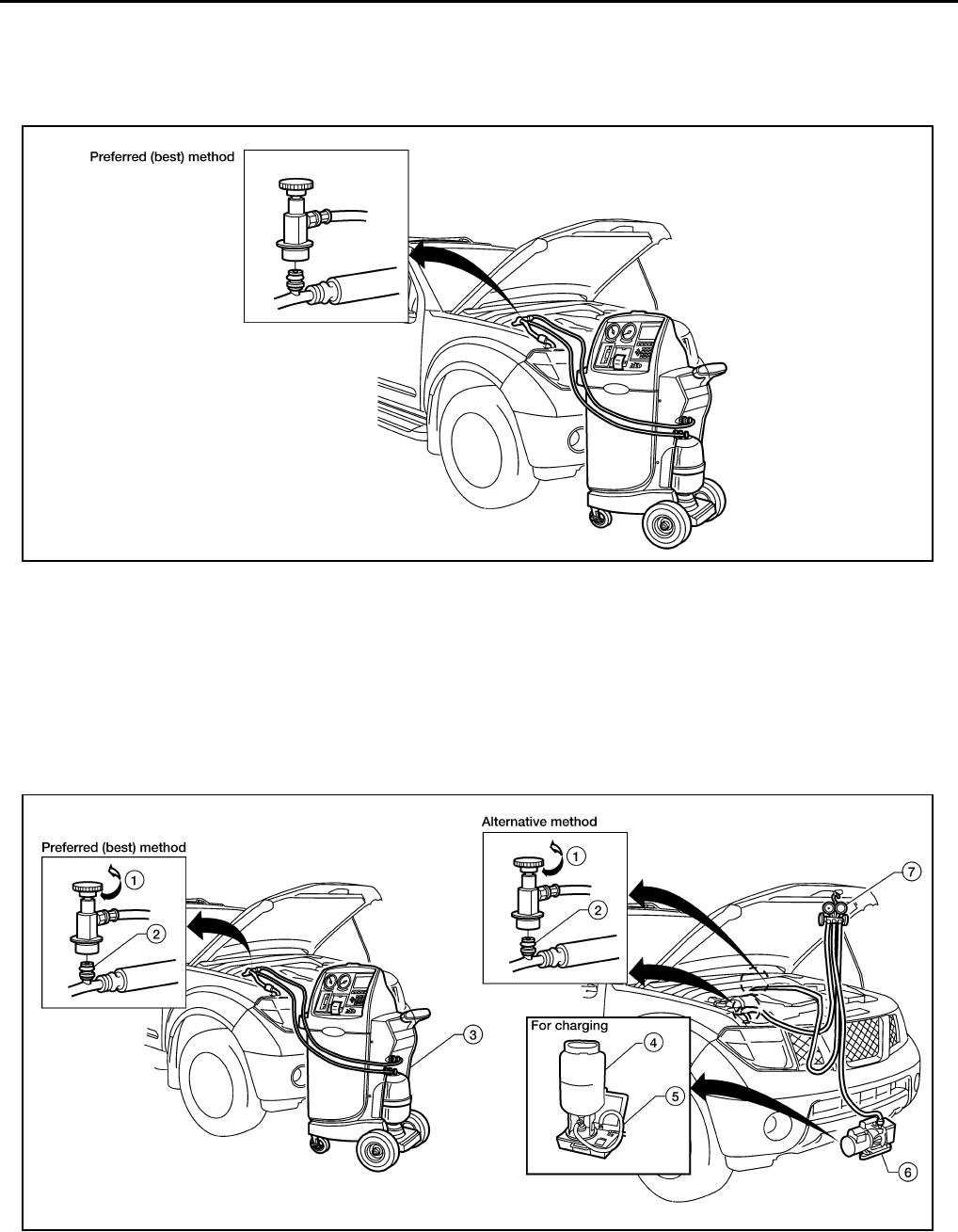
MTC-98
REFRIGERANT LINES
Revision: November 2005 2005 Pathfinder
REFRIGERANT LINES PFP:92600
HFC-134a (R-134a) Service Procedure EJS003W5
SETTING OF SERVICE TOOLS AND EQUIPMENT
Discharging Refrigerant
WARNING:
Avoid breathing A/C refrigerant and lubricant vapor or mist. Exposure may irritate eyes, nose and
throat. Remove HFC-134a (R-134a) refrigerant from the A/C system using certified service equipment
meeting requirements of SAE J2210 HFC-134a (R-134a) recycling equipment or SAE J2201 HFC-134a
(R-134a) recovery equipment. If an accidental system discharge occurs, ventilate the work area before
resuming service. Additional health and safety information may be obtained from the refrigerant and
lubricant manufacturers.
Evacuating System and Charging Refrigerant
1. Shut-off valve 2. A/C service valve 3. Recovery/recycling equipment
WJIA1160E
1. Shut-off valve 2. A/C service valve 3. Recovery/recycling equipment
4. Refrigerant container (HFC-134a) 5. Refrigerant weight scale (J-39699) 6. Vacuum pump (J-39649)
7. Manifold gauge set with hoses and
couplers (J-39183-C)
WJIA1161E
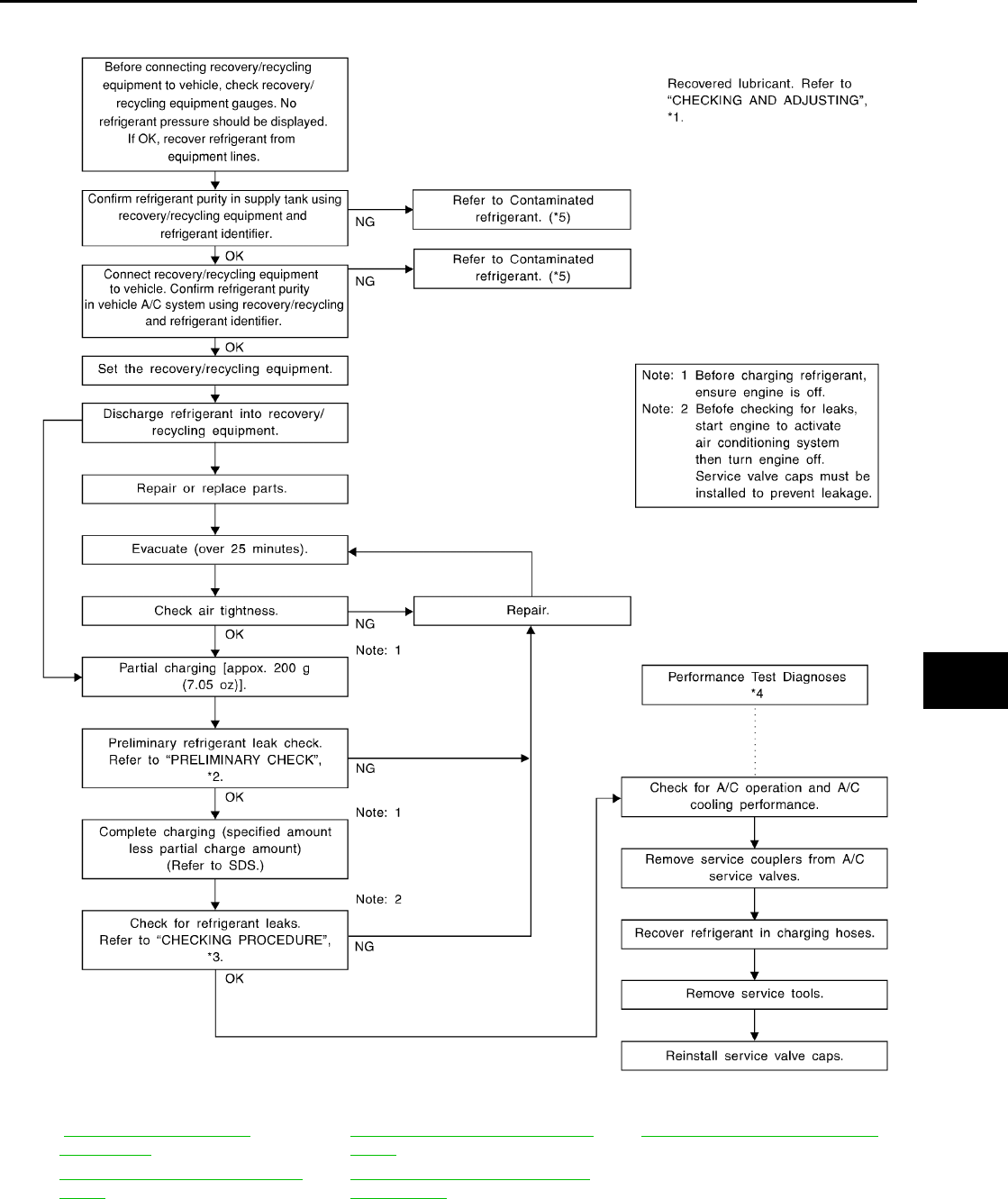
REFRIGERANT LINES
MTC-99
C
D
E
F
G
H
I
K
L
M
A
B
MTC
Revision: November 2005 2005 Pathfinder
*1 ATC-22, "CHECKING AND
ADJUSTING" .
*3 ATC-170, "Checking for Refrigerant
Leaks".
*5 ATC-5, "Contaminated Refrigerant".
*2 ATC-170, "Checking for Refrigerant
Leaks".
*4 ATC-103, "PERFORMANCE TEST
DIAGNOSES".
WJIA0530E
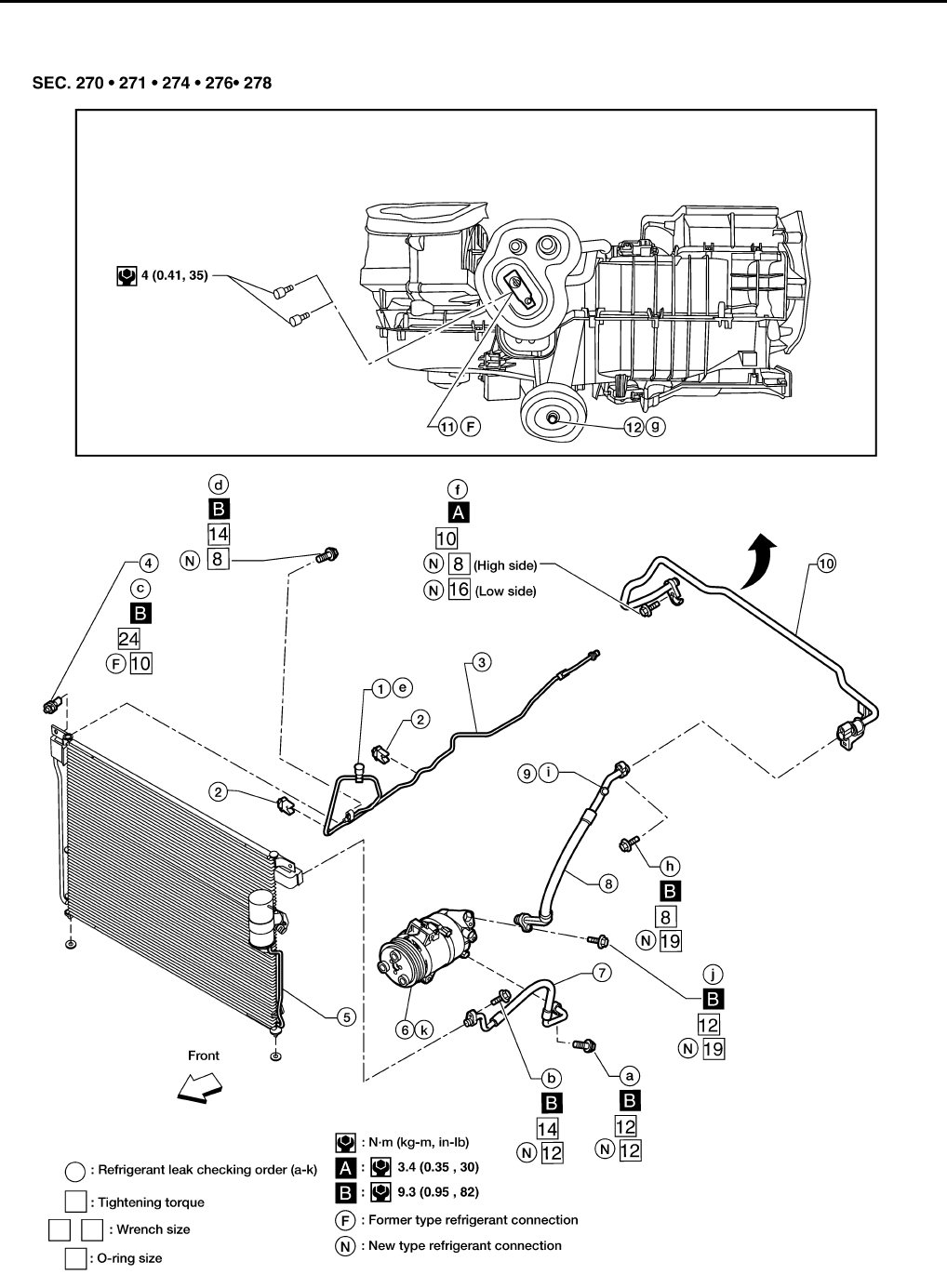
MTC-100
REFRIGERANT LINES
Revision: November 2005 2005 Pathfinder
Components EJS003W6
A/C Compressor and Condenser
WJIA1253E
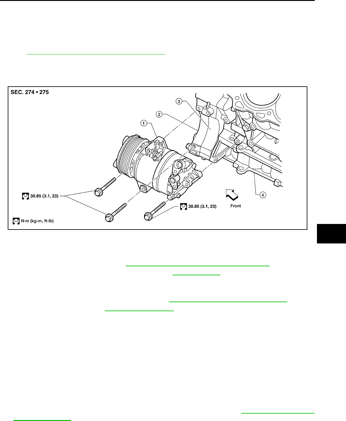
REFRIGERANT LINES
MTC-101
C
D
E
F
G
H
I
K
L
M
A
B
MTC
Revision: November 2005 2005 Pathfinder
NOTE:
Refer to MTC-6, "Precautions for Refrigerant Connection" .
Removal and Installation for Compressor EJS003W7
COMPONENTS
A/C Compressor Mounting
REMOVAL
1. Discharge the A/C refrigerant. Refer to MTC-98, "HFC-134a (R-134a) Service Procedure" .
2. Remove the front left wheel and tire assembly. Refer to WT-6, "Rotation" .
3. Remove the front left mud guard.
4. Remove the front left splash shield.
5. Remove the engine air cleaner and air ducts. Refer to EM-15, "AIR CLEANER AND AIR DUCT" .
6. Remove the drive belt. Refer to EM-13, "DRIVE BELTS" .
7. Disconnect the compressor harness connector.
8. Disconnect both the high-pressure flexible A/C hose and low-pressure flexible A/C hose from the com-
pressor.
CAUTION:
Cap or wrap the joint of the pipe with suitable material such as vinyl tape to avoid the entry of air.
9. Remove the A/C compressor bolts using power tools.
INSTALLATION
Installation is in the reverse order of removal.
CAUTION:
●Replace the O-ring of the low-pressure flexible A/C hose and high-pressure flexible A/C hose with
a new one, apply compressor oil to the O-rings before installation.
●After recharging the A/C system with refrigerant, check for leaks. Refer to MTC-109, "Checking for
Refrigerant Leaks" .
1. High-pressure service valve 2. Clip 3. High-pressure A/C pipe
4. Refrigerant pressure sensor 5. Condenser 6. Compressor shaft seal
7. High-pressure flexible A/C hose 8. Low-pressure flexible A/C hose 9. Low-pressure service valve
10. Low-pressure A/C pipe 11. Expansion valve 12. A/C drain hose
LJIA0176E
1. Compressor 2. Front timing chain case 3. Rear timing chain case
4. Cylinder block
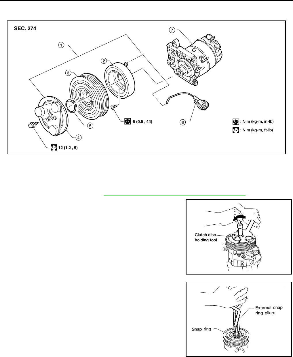
MTC-102
REFRIGERANT LINES
Revision: November 2005 2005 Pathfinder
Removal and Installation for Compressor Clutch EJS003W8
Magnet Clutch Assembly
REMOVAL
1. Remove the compressor. Refer to MTC-101, "Removal and Installation for Compressor" .
2. Remove the center bolt while holding the clutch disc stationary
using Tool as shown.
3. Remove the clutch disc.
4. Remove the snap ring using external snap ring pliers or suitable
tool.
WJIA1162E
1. Magnet clutch assembly 2. Magnet coil 3. Pulley
4. Clutch disc 5. Snap ring 6. Thermal protector (built in)
7. Compressor
Tool number : J-44614
WHA228
RHA072C
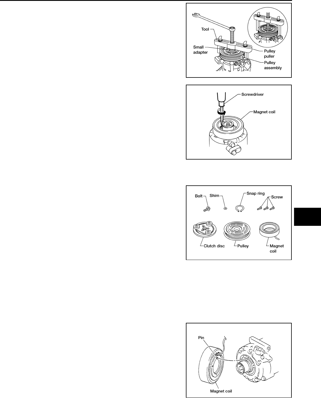
REFRIGERANT LINES
MTC-103
C
D
E
F
G
H
I
K
L
M
A
B
MTC
Revision: November 2005 2005 Pathfinder
5. Remove the pulley using Tool with a small adapter. Position the
small adapter on the end of the drive shaft and the center of the
puller on the small adapter.
CAUTION:
To prevent deformation of the pulley groove, the puller
claws should be hooked under the pulley groove and not
into the pulley groove.
6. Remove the magnet coil harness clip using a screwdriver,
remove the three magnet coil fixing screws and remove the
magnet coil.
INSPECTION
Clutch Disc
If the contact surface shows signs of damage due to excessive heat,
replace clutch disc and pulley.
Pulley
Check the appearance of the pulley assembly. If contact surface of pulley shows signs of excessive grooving,
replace clutch disc and pulley. The contact surfaces of the pulley assembly should be cleaned with a suitable
solvent before reinstallation.
Coil
Check magnet coil for loose connections or any cracked insulation.
INSTALLATION
1. Install the magnet coil.
CAUTION:
Be sure to align the magnet coil pin with the hole in the
compressor front head.
Tool number : KV99233130 (J-29884)
WJIA1017E
WHA212
WHA183
WHA213
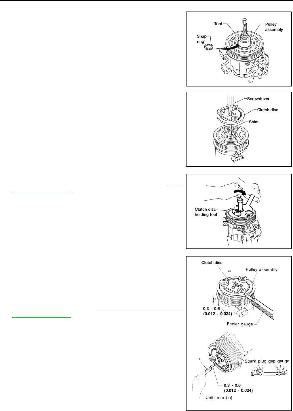
MTC-104
REFRIGERANT LINES
Revision: November 2005 2005 Pathfinder
2. Install the magnet coil harness clip using a screwdriver.
3. Install the pulley assembly using Tool and a wrench, then install
the snap ring using snap ring pliers.
4. Install the clutch disc on the compressor shaft, together with the
original shim(s). Press the clutch disc down by hand.
5. Install the clutch pulley bolt using Tool, to prevent the clutch disc
from turning and tighten the bolt to specification. Refer to MTC-
101, "COMPONENTS" .
CAUTION:
After tightening the clutch pulley bolt, check that the clutch
pulley rotates smoothly.
6. Check the pulley clearance all the way around the clutch disc as
shown.
7. If the specified clearance is not obtained, replace the adjusting
spacer to readjust.
8. Install the compressor. Refer to MTC-101, "Removal and Instal-
lation for Compressor" .
Tool number : — (J-38873-A)
WJIA1016E
WHA184
Tool number : J-44614
WHA229
Clutch disc-to-pulley clearance : 0.3 - 0.6 mm
(0.012 - 0.024 in)
WHA194

REFRIGERANT LINES
MTC-105
C
D
E
F
G
H
I
K
L
M
A
B
MTC
Revision: November 2005 2005 Pathfinder
BREAK-IN OPERATION
When replacing compressor clutch assembly, always conduct the break-in operation. This is done by engag-
ing and disengaging the clutch about 30 times. Break-in operation raises the level of transmitted torque.
Removal and Installation for High-pressure Flexible A/C Hose EJS003W9
REMOVAL
1. Remove the front left wheel and tire assembly. Refer to WT-6, "Rotation" .
2. Remove the front left mud guard.
3. Remove the front left splash shield.
4. Discharge the refrigerant. Refer to MTC-98, "HFC-134a (R-134a) Service Procedure" .
5. Remove the high-pressure flexible A/C hose. Refer to MTC-105, "Removal and Installation for High-pres-
sure Flexible A/C Hose" .
CAUTION:
Cap or wrap the joint of the pipe with suitable material such as vinyl tape to avoid the entry of air.
INSTALLATION
Installation is in the reverse order of removal.
Refer to MTC-100, "Components" .
CAUTION:
●Replace the O-ring of the high-pressure flexible A/C hose with a new one, then apply compressor
oil to it for installation.
●After charging refrigerant, check for leaks.
Removal and Installation for High-pressure A/C Pipe EJS003WA
REMOVAL
1. Remove the front right wheel and tire assembly. Refer to WT-6, "Rotation" .
2. Remove the front right mud guard.
3. Remove the front right splash shield.
4. Discharge the refrigerant. Refer to MTC-98, "HFC-134a (R-134a) Service Procedure" .
5. Remove the low pressure A/C pipe. Refer to MTC-106, "Removal and Installation for Low-pressure A/C
Pipe" .
6. Remove the high-pressure A/C pipe. Refer to MTC-100, "Components" .
CAUTION:
Cap or wrap the joint of the pipe with suitable material such as vinyl tape to avoid the entry of air.
INSTALLATION
Installation is in the reverse order of removal.
Refer to MTC-100, "Components" .
CAUTION:
●Replace the O-ring of the high-pressure A/C pipe with a new one, then apply compressor oil to it
for installation.
●After charging refrigerant, check for leaks.
Removal and Installation for Low-pressure Flexible A/C Hose EJS003WB
REMOVAL
1. Remove the front right wheel and tire assembly. Refer to WT-6, "Rotation" .
2. Remove the front right mud guard.
3. Remove the front right splash shield.
4. Discharge the refrigerant. Refer to MTC-98, "HFC-134a (R-134a) Service Procedure" .
CAUTION:
Cap or wrap the joint of the pipe with suitable material such as vinyl tape to avoid the entry of air.
5. Remove the low-pressure flexible A/C hose. Refer to MTC-105, "Removal and Installation for Low-pres-
sure Flexible A/C Hose" .
INSTALLATION
Installation is in the reverse order of removal.
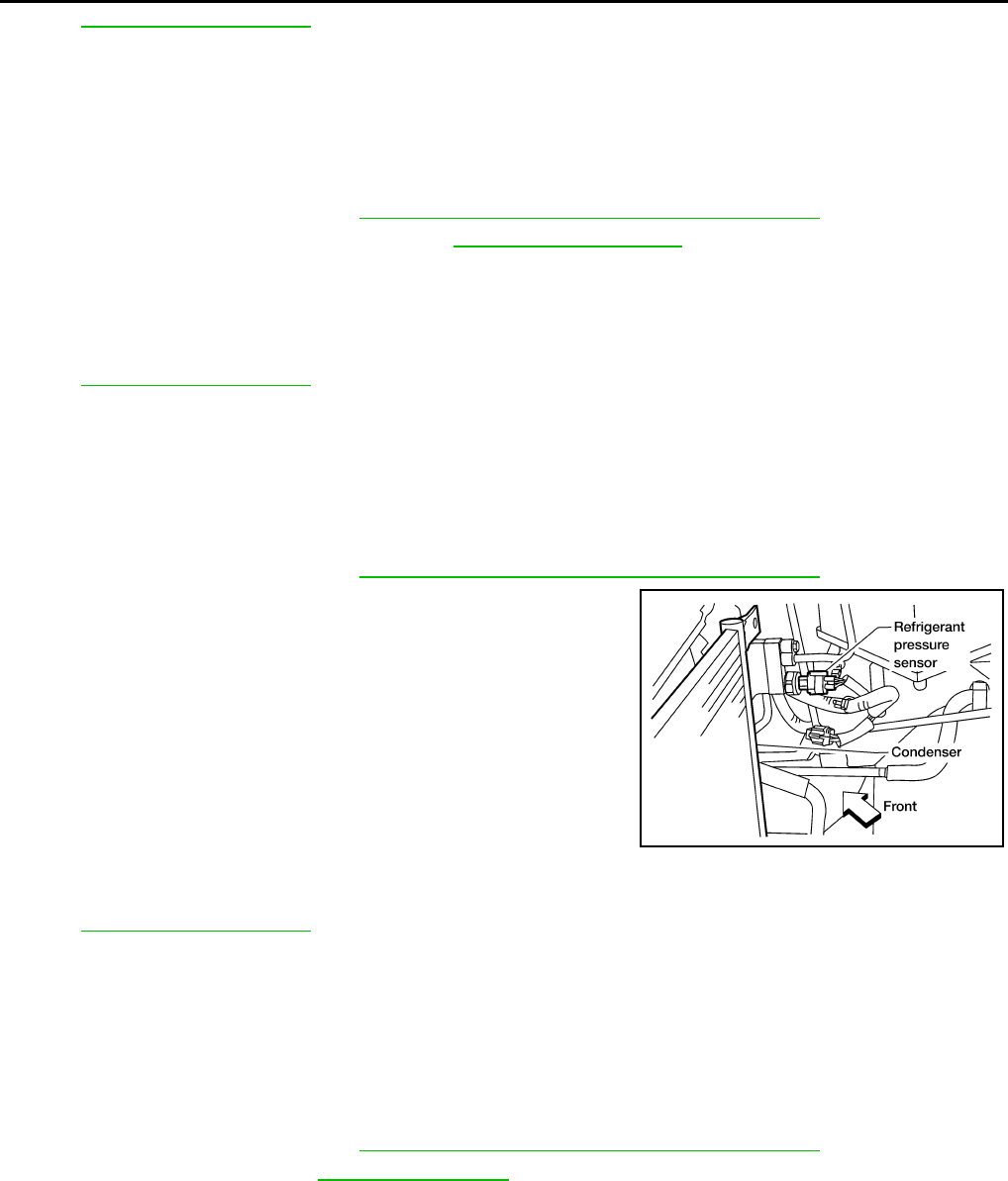
MTC-106
REFRIGERANT LINES
Revision: November 2005 2005 Pathfinder
Refer to MTC-100, "Components" .
CAUTION:
●Replace the O-ring of the low-pressure flexible A/C hose with a new one, then apply compressor
oil to it for installation.
●After charging refrigerant, check for leaks.
Removal and Installation for Low-pressure A/C Pipe EJS003WC
REMOVAL
1. Discharge the refrigerant. Refer to MTC-98, "HFC-134a (R-134a) Service Procedure" .
2. Remove the low-pressure A/C pipe. Refer to MTC-100, "Components" .
CAUTION:
Cap or wrap the joint of the pipe with suitable material such as vinyl tape to avoid the entry of air.
INSTALLATION
Installation is in the reverse order of removal.
Refer to MTC-100, "Components" .
CAUTION:
●Replace the O-ring of the low-pressure A/C pipe with a new one, then apply compressor oil to it for
installation.
●After charging refrigerant, check for leaks.
Removal and Installation for Refrigerant Pressure Sensor EJS003WD
REMOVAL
1. Discharge the refrigerant. Refer to MTC-98, "HFC-134a (R-134a) Service Procedure" .
2. Disconnect the refrigerant pressure sensor harness connector
and remove the refrigerant pressure sensor from the condenser.
CAUTION:
Be careful not to damage the condenser fins.
INSTALLATION
Installation is in the reverse order of removal.
Refer to MTC-100, "Components" .
CAUTION:
●Replace the O-ring of the refrigerant pressure sensor with a new one, then apply compressor oil to
it for installation.
●Be careful not to damage the condenser fins.
●After charging refrigerant, check for leaks.
Removal and Installation for Condenser EJS003WE
REMOVAL
1. Discharge the refrigerant. Refer to MTC-98, "HFC-134a (R-134a) Service Procedure" .
2. Remove the radiator. Refer to CO-11, "RADIATOR" .
CAUTION:
Be careful not to damage the core surface of the condenser and the radiator.
3. Disconnect the high-pressure flexible A/C hose and the high-pressure A/C pipe from the condenser.
CAUTION:
Cap or wrap the joint of the pipes with suitable material such as vinyl tape to avoid the entry of air.
LJIA0177E
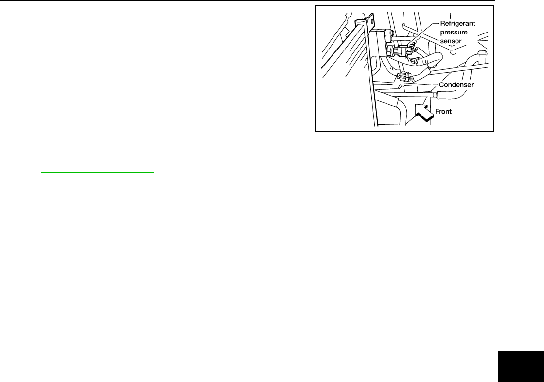
REFRIGERANT LINES
MTC-107
C
D
E
F
G
H
I
K
L
M
A
B
MTC
Revision: November 2005 2005 Pathfinder
4. Disconnect the refrigerant pressure sensor harness connector.
5. Remove the refrigerant pressure sensor from the condenser.
6. Lift the condenser out of the mounting grommets and remove
the condenser.
INSTALLATION
Installation is in the reverse order of removal.
Refer to MTC-100, "Components" .
CAUTION:
●Replace the O-rings of the high-pressure A/C pipe, refrigerant pressure sensor, and high-pressure
flexible A/C hose with new ones, then apply compressor oil to them for installation.
●After charging refrigerant, check for leaks.
●Replace the mounting grommets as necessary.
LJIA0177E
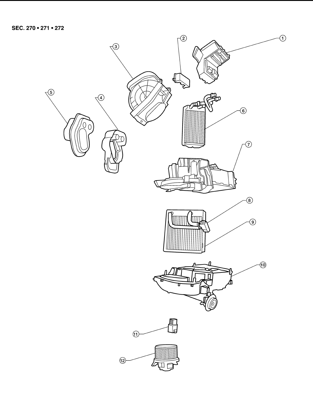
MTC-108
REFRIGERANT LINES
Revision: November 2005 2005 Pathfinder
Removal and Installation for Evaporator EJS003WF
Heater and Cooling Unit Assembly
LJIA0178E
1. Center ventilator connector duct 2. Heater core cover 3. Intake air case
4. Heater core and evaporator pipes
bracket
5. Heater core and evaporator pipes
grommet
6. Heater core
7. Upper heater and cooling unit case 8. Expansion valve 9. Evaporator
10. Lower heater and cooling unit case 11. Blower motor resistor 12. Blower motor

REFRIGERANT LINES
MTC-109
C
D
E
F
G
H
I
K
L
M
A
B
MTC
Revision: November 2005 2005 Pathfinder
REMOVAL
1. Remove the heater core. Refer to MTC-89, "HEATER CORE" .
2. Separate the heater and cooling unit case.
3. Remove the evaporator.
INSTALLATION
Installation is in the reverse order of removal.
CAUTION:
Replace the O-rings on the A/C low-pressure flexible A/C hose and the high-pressure A/C pipe with
new ones. Apply compressor oil to the O-rings for installation.
Removal and Installation for Expansion Valve EJS003WG
REMOVAL
1. Discharge the refrigerant. Refer to MTC-98, "HFC-134a (R-134a) Service Procedure" .
2. Remove the heater and cooling unit assembly. Refer to MTC-87, "HEATER & COOLING UNIT ASSEM-
BLY" .
3. Remove the heater core and evaporator pipes grommet.
4. Remove the expansion valve.
INSTALLATION
Installation is in the reverse order of removal.
CAUTION:
●Replace the O-rings on then expansion valve and the A/C refrigerant pipes with new ones, then
apply compressor oil to them for installation.
●After charging refrigerant, check for leaks.
Checking for Refrigerant Leaks EJS003WH
Perform a visual inspection of all refrigeration parts, fittings, hoses and components for signs of A/C lubricant
leakage, damage, and corrosion. Any A/C lubricant leakage may indicate an area of refrigerant leakage. Allow
extra inspection time in these areas when using either an electronic refrigerant leak detector (J-41995) or fluo-
rescent dye leak detector (J-42220).
If any dye is observed using a fluorescent dye leak detector (J-42220), confirm the leak using a electronic
refrigerant leak detector (J-41995). It is possible that the dye is from a prior leak that was repaired and not
properly cleaned.
When searching for leaks, do not stop when one leak is found but continue to check for additional leaks at all
system components and connections.
When searching for refrigerant leaks using an electronic refrigerant leak detector (J-41995), move the probe
along the suspected leak area at 25 - 50 mm (1 - 2 in) per second and no further than 6 mm (1/4 in) from the
component.
CAUTION:
Moving the electronic refrigerant leak detector probe slower and closer to the suspected leak area will
improve the chances of finding a leak.
Checking System for Leaks Using the Fluorescent Dye Leak Detector EJS003WI
1. Check the A/C system for leaks using the fluorescent dye leak detector and safety goggles (J-42220) in a
low sunlight area (area without windows preferable). Illuminate all components, fittings and lines. The dye
will appear as a bright green/yellow area at the point of leakage. Fluorescent dye observed at the evapo-
rator drain opening indicates an evaporator core assembly leak (tubes, core or expansion valve).
2. If the suspected area is difficult to see, use an adjustable mirror or wipe the area with a clean shop rag or
cloth, then inspect the shop rag or cloth with the fluorescent dye leak detector (J-42220) for dye residue.
3. After the leak is repaired, remove any residual dye using refrigerant dye cleaner (J-43872) to prevent
future misdiagnosis.
Expansion valve bolts : Refer to MTC-100, "Components"
.
A/C refrigerant pipe to expansion valve bolt : Refer to MTC-100, "Components"
.
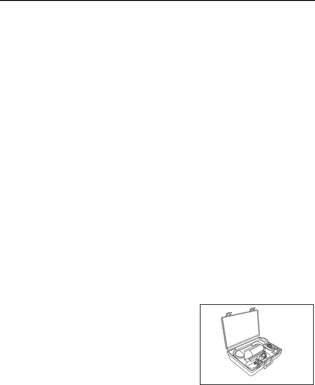
MTC-110
REFRIGERANT LINES
Revision: November 2005 2005 Pathfinder
4. Perform a system performance check and then verify the leak repair using a electronic refrigerant leak
detector (J-41995).
NOTE:
●Other gases in the work area or substances on the A/C components, for example, anti-freeze, wind-
shield washer fluid, solvents and lubricants, may falsely trigger the leak detector. Make sure the sur-
faces to be checked are clean.
●Clean with a dry cloth or blow off with shop air.
●Do not allow the sensor tip of the electronic refrigerant leak detector (J-41995) to contact with any sub-
stance. This can also cause false readings and may damage the detector.
Dye Injection EJS003WJ
NOTE:
This procedure is only necessary when recharging the system or when the compressor has seized and must
be replaced.
1. Check the A/C system static (at rest) pressure. Pressure must be at least 345 kPa (3.52 kg/cm2 , 50 psi).
2. Pour one bottle 7.4 cc (1/4 ounce) of the HFC-134a (R-134a) fluorescent leak detection dye (J-41447) into
the HFC-134a (R-134a) refrigerant dye injector (J-41459).
CAUTION:
If repairing the A/C system or replacing a component, pour the HFC-134a (R-134a) fluorescent leak
detection dye (J-41447) directly into the open system connection and proceed with the service
procedures.
3. Connect the refrigerant dye injector (J-41459) to the low-pressure service valve.
4. Start the engine and switch the A/C system ON.
5. When the A/C system is operating (compressor running), inject one bottle 7.4 cc (1/4 ounce) of HFC-134a
(R-134a) fluorescent leak detection dye (J-41447) through the low-pressure service valve using HFC-
134a (R-134a) refrigerant dye injector (J-41459). Refer to the manufacturer's operating instructions.
6. With the engine still running, disconnect the HFC-134a (R-134a) refrigerant dye injector (J-41459) from
the low-pressure service valve.
7. Operate the A/C system for a minimum of 20 minutes to mix the HFC-134a (R-134a) fluorescent leak
detection dye (J-41447) with the A/C system oil. Depending on the leak size, operating conditions and
location of the leak, it may take from minutes to days for the HFC-134a (R-134a) fluorescent leak detec-
tion dye to penetrate an A/C system leak and become visible.
Electronic Refrigerant Leak Detector EJS003WK
PRECAUTIONS FOR HANDLING LEAK DETECTOR
NOTE:
When performing a refrigerant leak check, use a electronic refrigerant leak detector (J-41995) or equivalent.
Ensure that the electronic refrigerant leak detector (J-41995) is calibrated and set properly according to the
manufacturer's operating instructions.
The electronic refrigerant leak detector (J-41995) is a delicate
device. To use the leak detector properly, read the manufacturer's
operating instructions and perform any specified maintenance.
AHA281A
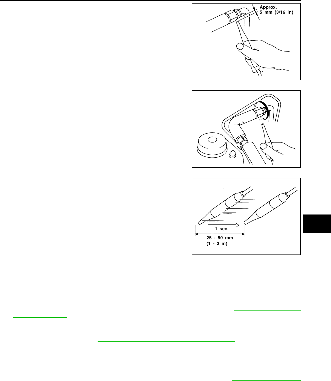
REFRIGERANT LINES
MTC-111
C
D
E
F
G
H
I
K
L
M
A
B
MTC
Revision: November 2005 2005 Pathfinder
1. Position the probe approximately 5 mm (3/16 in) away from the
point to be checked as shown.
2. When checking for leaks, circle each fitting completely with the
probe as shown.
3. Move the probe along each component at a speed of approxi-
mately 25 - 50 mm (1 - 2 in)/second as shown.
CHECKING PROCEDURE
NOTE:
To prevent inaccurate or false readings, make sure there is no refrigerant vapor, shop chemicals, or cigarette
smoke in the vicinity of the vehicle. Perform the leak test in a calm area (low air/wind movement) so that the
leaking refrigerant is not dispersed.
1. Turn the engine OFF.
2. Connect the manifold gauge set (J-39183-C) to the A/C service ports. Refer to MTC-9, "Precautions for
Service Equipment" .
3. Check if the A/C refrigerant pressure is at least 345 kPa (3.52 kg/cm2 , 50 psi) above a temperature of
16°C (61°F). If less than specification, recover/evacuate and recharge the system with the specified
amount of refrigerant. Refer to MTC-98, "HFC-134a (R-134a) Service Procedure" .
NOTE:
At temperatures below 16°C (61°F), leaks may not be detected since the system may not reach 345 kPa
(3.52 kg/cm2 , 50 psi) pressure.
4. Perform the leak test from the high-pressure side (A/C compressor discharge “a” to evaporator inlet “f”) to
the low-pressure side (A/C evaporator drain hose “g” to shaft seal “k”). Refer to MTC-100, "Components"
. Clean the component to be checked and carefully move the electronic refrigerant leak detector probe
completely around the following connections and components.
●Check the compressor shaft seal
●Check the high and low-pressure pipe and hose fittings, relief valve, and compressor shaft seal
●Check the liquid tank
SHA707EA
SHA706E
SHA708EA
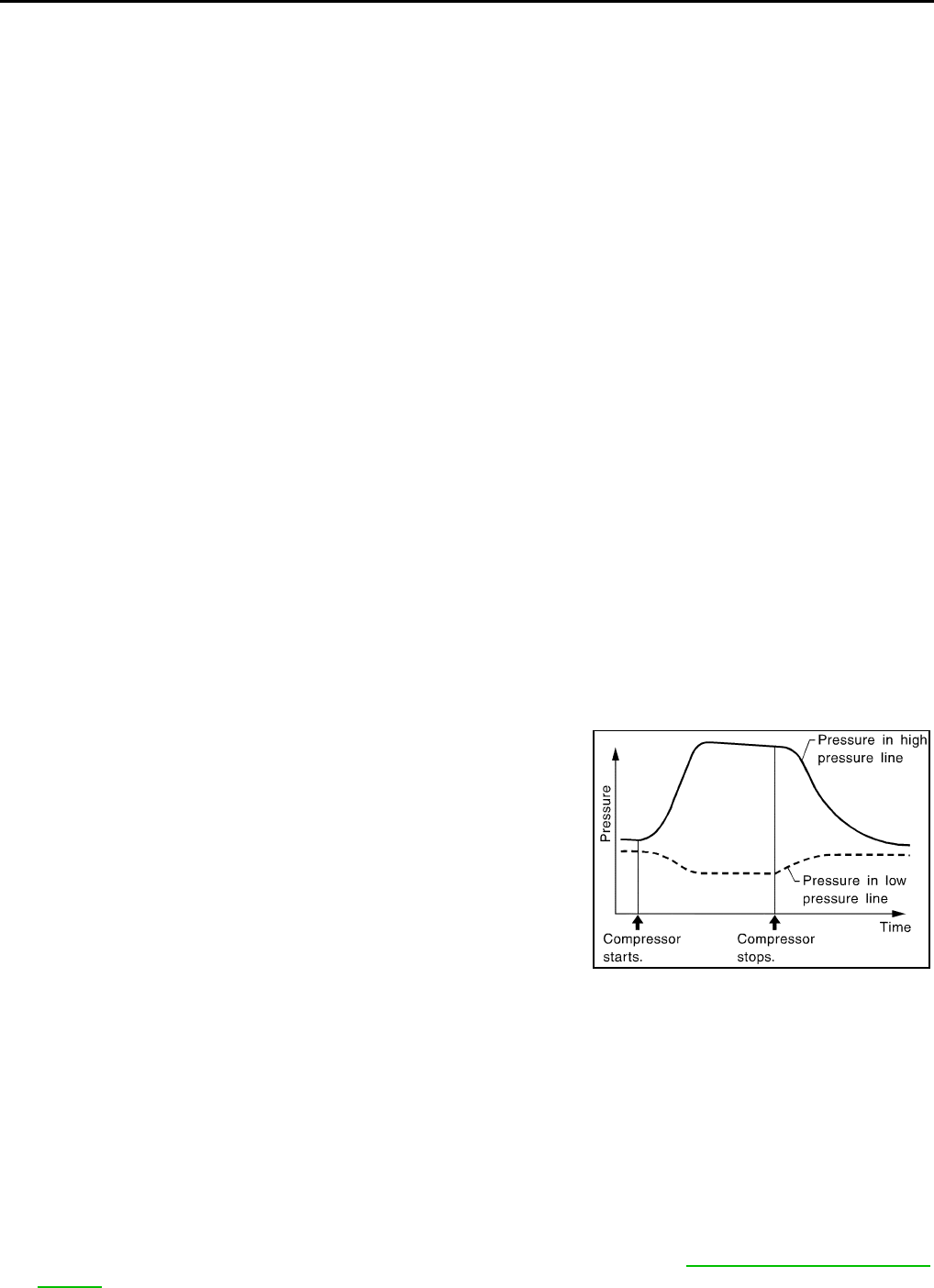
MTC-112
REFRIGERANT LINES
Revision: November 2005 2005 Pathfinder
●Check the refrigerant pressure sensor
●Check all around the service valves. Check that the service valve caps are screwed tightly on the ser-
vice valves (to prevent leaks).
NOTE:
After removing manifold gauge set (J-39183-C) from the service valves, wipe any residue from the ser-
vice valves to prevent any false readings by the electronic refrigerant leak detector (J-41995).
●Evaporator
With engine OFF, turn blower fan on “High” for at least 15 seconds to dissipate any refrigerant trace in
the heater and cooling unit assembly. Wait a minimum of 10 minutes accumulation time (refer to the
manufacturer's recommended procedure for actual wait time) before inserting the electronic refrigerant
leak detector probe into the heater and cooling unit assembly drain hose.
NOTE:
Keep the probe inserted for at least 10 seconds. Use caution not to contaminate the probe tip with
water or dirt that may be in the drain hose.
5. If a leak is detected, verify at least once by blowing compressed air into the area of the suspected leak,
then repeat the leak check.
6. Do not stop when one leak is found. Continue to check for additional leaks at all system components and
connections.
7. If no leaks are found, perform steps 8 - 11.
8. Start the engine.
9. Set the heater A/C controls as follows:
NOTE:
For the automatic system, turn OFF the automatic controls and set the heater A/C controls manually.
a. A/C switch to ON
b. Air flow to VENT mode
c. Intake position to RECIRCULATION mode
d. Temperature to MAX cold
e. Blower speed to HIGH
10. Run the engine at 1,500 rpm for at least 2 minutes.
11. Turn the engine OFF and perform the leak check again following
steps 4 through 6 above.
Refrigerant leaks should be checked immediately after turning
the engine OFF. Begin with the leak detector at the compressor.
The pressure on the high pressure side will gradually drop after
the refrigerant circulation stops and pressure on the low pres-
sure side will gradually rise, as shown in the graph. Some leaks
are more easily detected when the pressure is high.
12. Before connecting the recovery/recycling equipment to the vehicle, check the recovery/recycling equip-
ment gauges. No refrigerant pressure should be displayed. If pressure is displayed, recover the refriger-
ant from the equipment lines and then check the refrigerant purity.
13. Confirm refrigerant purity in supply tank using recovery/recycling equipment and refrigerant identifier
equipment (J-41810-NI).
14. Confirm the refrigerant purity in the vehicle's A/C system using recovery/recycling equipment and refriger-
ant identifier equipment (J-41810-NI).
15. Discharge the A/C system using recovery/recycling equipment. Repair the leaking fitting or component as
necessary.
16. Evacuate and recharge the A/C system and perform the leak test to confirm that there are no refrigerant
leaks.
17. Conduct the Operational Check to ensure system works properly. Refer to ATC-52, "Operational Check
(Front)" .
SHA839E

SERVICE DATA AND SPECIFICATIONS (SDS)
MTC-113
C
D
E
F
G
H
I
K
L
M
A
B
MTC
Revision: November 2005 2005 Pathfinder
SERVICE DATA AND SPECIFICATIONS (SDS) PFP:00030
Service Data and Specifications (SDS) EJS003WL
COMPRESSOR
LUBRICANT
REFRIGERANT
ENGINE IDLING SPEED
Refer to EC-76, "Idle Speed and Ignition Timing Check" .
BELT TENSION
Refer to MA-13, "DRIVE BELT TENSION" .
Make CALSONIC KANSEI CO. LTD.
Model DKS-17D
Type Swash plate
Displacement 144 cm3 (8.79 in3 ) / revolution
Relief valve set pressure 3800 ± 300 kPa (38.76 ± 3.06 kg/cm2 , 551.0 ± 43.5 psi)
Direction of rotation Clockwise (viewed from drive end)
Drive belt Poly V ribbed
Description Genuine NISSAN A/C System Lubricant Type S (DH-PS)
Part number KLH00-PAGS0
Capacity 180 m (6.1 US fl oz, 6.3 Imp fl oz)
Type HFC 134a (R-134a)
Capacity 0.70 ± 0.05 kg (1.54 ± 0.11 lb)

MTC-114
SERVICE DATA AND SPECIFICATIONS (SDS)
Revision: November 2005 2005 Pathfinder
