Nissan 2010 Frontier Owners Manual | Owner's
2015-09-07
: Nissan Nissan-2010-Frontier-Owners-Manual-762759 nissan-2010-frontier-owners-manual-762759 nissan pdf
Open the PDF directly: View PDF ![]() .
.
Page Count: 373 [warning: Documents this large are best viewed by clicking the View PDF Link!]

2010 FRONTIER
OWNER'S MANUAL
2010 NISSAN FRONTIER D40-D
Printing : July 2009 (11)
Publication No.: OM0E-0D40U0
Printed in U.S.A.
For your safety, read carefully and keep in this vehicle.
D40-D
Welcome to the growing family of new NISSAN
owners. This vehicle is delivered to you with
confidence. It was produced using the latest
techniques and strict quality control.
This manual was prepared to help you under-
stand the operation and maintenance of your
vehicle so that you may enjoy many miles (kilome-
ters) of driving pleasure. Please read through this
manual before operating your vehicle.
A separate Warranty Information Booklet
explains details about the warranties cov-
ering your vehicle. The “NISSAN Service
and Maintenance Guide” explains details
about maintaining and servicing your ve-
hicle. Additionally, a separate Customer
Care/Lemon Law Booklet (U.S. only) will
explain how to resolve any concerns you
may have with your vehicle, as well as
clarify your rights under your state’s lemon
law.
Your NISSAN dealership knows your vehicle
best. When you require any service or have any
questions, they will be glad to assist you with the
extensive resources available to them.
Before driving your vehicle, please read this
Owner’s Manual carefully. This will ensure famil-
iarity with controls and maintenance require-
ments, assisting you in the safe operation of your
vehicle.
WARNING
IMPORTANT SAFETY INFORMATION RE-
MINDERS FOR SAFETY!
Follow these important driving rules to
help ensure a safe and comfortable trip
for you and your passengers!
●NEVER drive under the influence of al-
cohol or drugs.
●ALWAYS observe posted speed limits
and never drive too fast for conditions.
●
ALWAYS give your full attention to driving
and avoid using vehicle features or taking
other actions that could distract you.
●
ALWAYS use your seat belts and appro-
priate child restraint systems. Pre-teen
children should be seated in the rear seat.
●ALWAYS provide information about the
proper use of vehicle safety features to
all occupants of the vehicle.
●ALWAYS review this Owner’s Manual
for important safety information.
For descriptions specified for four-wheel drive
models, a mark is placed at the begin-
ning of the applicable sections/items.
As with other vehicles with features for
off-road use, failure to operate four-wheel
drive models correctly may result in loss of
control or an accident. Be sure to read
“Driving safety precautions” in the “Start-
ing and driving” section of this manual.
ON-PAVEMENT AND OFF-ROAD DRIVING
This vehicle will handle and maneuver
differently from an ordinary passenger
car because it has a higher center of
gravity for off-road use. As with other
vehicles with features of this type, fail-
ure to operate this vehicle correctly may
result in loss of control or an accident.
Be sure to read “On-pavement and off-
road driving precautions”, and “Avoid-
ing collision and rollover”, and “Driving
safety precautions”, in the “Starting and
driving” section of this manual.
FOREWORD READ FIRST—THEN DRIVE SAFELY
MODIFICATION OF YOUR VEHICLE
This vehicle should not be modified.
Modification could affect its
performance, safety or durability, and
may even violate governmental
regulations. In addition, damage or per-
formance problems resulting from modi-
fications may not be covered under
NISSAN warranties.
This manual includes information for all options
available on this model. Therefore, you may find
some information that does not apply to your
vehicle.
All information, specifications and illustrations in
this manual are those in effect at the time of
printing. NISSAN reserves the right to change
specifications or design without notice and with-
out obligation.
IMPORTANT INFORMATION ABOUT
THIS MANUAL
You will see various symbols in this manual. They
are used in the following ways:
WARNING
This is used to indicate the presence of a
hazard that could cause death or serious
personal injury. To avoid or reduce the
risk, the procedures must be followed
precisely.
CAUTION
This is used to indicate the presence of a
hazard that could cause minor or moder-
ate personal injury or damage to your ve-
hicle. To avoid or reduce the risk, the pro-
cedures must be followed carefully.
If you see this symbol, it means “Do not do this”
or “Do not let this happen.”
If you see a symbol similar to these in an illustra-
tion, it means the arrow points to the front of the
vehicle.
Arrows in an illustration that are similar to these
indicate movement or action.
Arrows in an illustration that are similar to these
call attention to an item in the illustration.
APD1005
WHEN READING THE MANUAL
CALIFORNIA PROPOSITION 65
WARNING
WARNING
Engine exhaust, some of its constituents,
and certain vehicle components contain
or emit chemicals known to the State of
California to cause cancer and birth de-
fects or other reproductive harm. In addi-
tion, certain fluids contained in vehicles
and certain products of component wear
contain or emit chemicals known to the
State of California to cause cancer and
birth defects or other reproductive harm.
CALIFORNIA PERCHLORATE
ADVISORY
Some vehicle parts, such as lithium batter-
ies, may contain perchlorate material. The
following advisory is provided: “Perchlorate
Material – special handling may apply, See
www.dtsc.ca.gov/hazardouswaste/perchlorate.”
BLUETOOTHtis a
trademark owned by
Bluetooth SIG, Inc.,
U.S.A. and licensed to
Visteon.
XM Radiotrequires
subscription, sold
separately after first 90
days. Not available in
Alaska, Hawaii or
Guam. For more
information, visit
www.xmradio.com.
© 2009 NISSAN NORTH AMERICA, INC.
All rights reserved. No part of this Owner’s
Manual may be reproduced or stored in a retrieval
system, or transmitted in any form, or by any
means, electronic, mechanical, photocopying,
recording or otherwise, without the prior written
permission of Nissan North America, Inc.
NISSAN CARES...
Both NISSAN and your NISSAN dealer are dedicated to serving all your automotive needs. Your satisfaction with your vehicle and your NISSAN dealer are
our primary concerns. Your NISSAN dealer is always available to assist you with all your automobile sales and service needs.
However, if there is something that your NISSAN
dealer cannot assist you with or you would like to
provide NISSAN directly with comments or
questions, please contact the NISSAN Con-
sumer Affairs Department using our toll-free
number:
For U.S. customers
1-800-NISSAN-1
(1-800-647-7261)
For Canadian customers
1-800-387-0122
The Consumer Affairs Department will ask for the
following information:
– Your name, address, and telephone number
– Vehicle identification number (attached to the
top of the instrument panel on the driver’s
side)
– Date of purchase
– Current odometer reading
– Your NISSAN dealer’s name
– Your comments or questions
OR
You can write to NISSAN with the information at:
For U.S. customers
Nissan North America, Inc.
Consumer Affairs Department
P.O. Box 685003
Franklin, TN 37068-5003
For Canadian customers
Nissan Canada Inc.
5290 Orbitor Drive
Mississauga, Ontario L4W 4Z5
We appreciate your interest in NISSAN and thank you for buying a quality NISSAN vehicle.
NISSAN CUSTOMER CARE PROGRAM

Table of
Contents
Illustrated table of contents
Safety—Seats, seat belts and supplemental restraint system
Instruments and controls
Pre-driving checks and adjustments
Heater, air conditioner, audio and phone systems
Starting and driving
In case of emergency
Appearance and care
Maintenance and do-it-yourself
Technical and consumer information
Index
0
1
2
3
4
5
6
7
8
9
10

0 Illustrated table of contents
Air bags, seat belts and child restraints ..............0-2
Exterior front ......................................0-3
Exterior rear.......................................0-4
Passenger compartment ...........................0-5
Instrument panel...................................0-6
Engine compartment check locations ................0-8
Warning/indicator lights ...........................0-10
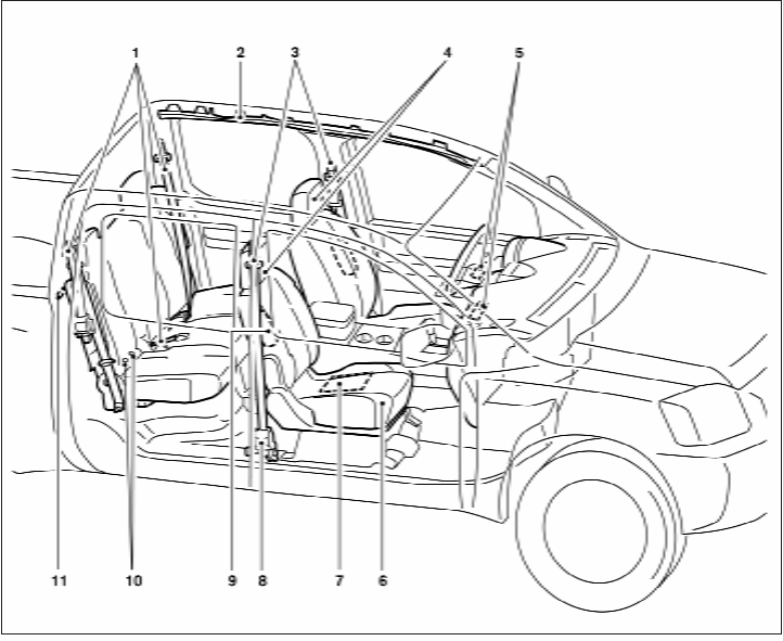
1. 2nd row seat belts (P. 1-16)
2. Roof-mounted curtain side-impact and
rollover supplemental air bag (P. 1-57)
3. Front seat belts (P. 1-16)
4. Head restraints (P.1-6)
5. Supplemental front-impact air bags
(P.1-65)
6. Seats (P. 1-2)
7. Occupant classification sensor
(pressure sensor) (P. 1-65)
8. Seat belt with pretensioners (P. 1-70)
9. Front seat-mounted side-impact
supplemental air bag (P. 1-57)
10. LATCH (Lower Anchors and Tethers for
CHildren) system (P. 1-28)
11. Top tether strap anchor (P. 1-30)
See the page number indicated in paren-
theses for operating details.
WII0135
AIR BAGS, SEAT BELTS AND CHILD
RESTRAINTS
0-2 Illustrated table of contents
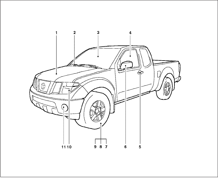
1. Engine hood (P. 8-6)
2. Windshield wiper and washer switch
(P. 2-25)
3. Windshield (P. 8-22)
4. Windows (P. 2-45)
5. Door locks, keyfob (if so equipped),
keys (P. 3-3, 3-6, 3-2)
6. Mirrors (P. 3-13)
7. Tire pressure (P. 8-32)
8. Flat tire (P. 6-3)
9. Tire chains (P. 8-39)
10. Headlight and turn signal switch
(P. 2-26); Replacing bulbs (P. 8-28)
11. Fog light switch (if so equipped)
(P. 2-30)
See the page number indicated in paren-
theses for operating details.
LII0052
EXTERIOR FRONT
Illustrated table of contents 0-3
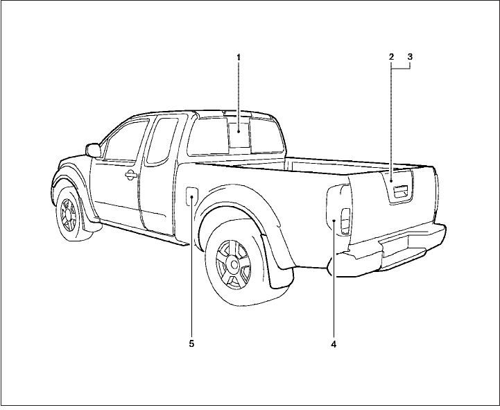
1. Rear sliding window (if so equipped)
(P.2-48)
2. Vehicle loading (P. 9-13)
3. Truck box, tailgate (P. 3-15)
4. Replacing bulbs (P. 8-28)
5. Fuel-filler cap, fuel recommendation
(P. 3-10, P. 9-4)
See the page number indicated in paren-
theses for operating details.
LII0053
EXTERIOR REAR
0-4 Illustrated table of contents
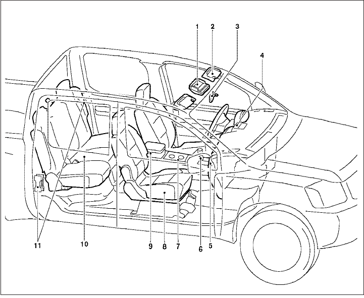
1. Map lights (if so equipped) (P. 2-50)
2. Sun visors (P. 3-12)
3. Rearview mirror (if so equipped)
(P. 3-13)
4. Vents (P. 4-2)
5. Glove box (P. 2-40)
6. Shift selector (automatic transmission, if
so equipped) (P. 5-13)
7. Cup holders (P. 2-42)
8. Front seats (P. 1-2)
9. Console box (P. 2-39)
10. Rear seats (P. 1-15)
11. Flat tire/Jacking equipment storage
(P. 6-3)
See the page number indicated in paren-
theses for operating details.
WII0054
PASSENGER COMPARTMENT
Illustrated table of contents 0-5

1. Vents (P. 4-2)
2. Headlight/fog light (if so equipped)/turn
signal switch (P. 2-26)
3. Steering wheel switch for audio control
(if so equipped)/BluetoothTHands-
Free Phone System (if so equipped)
(P. 4-35, P. 4-37)
4. Driver supplemental air bag/horn
(P. 1-57, P. 2-31)
5. Meters, gauges and warning/indicator
lights (P. 2-3, 2-13)
6. Cruise control main/set switches
(if so equipped) (P. 5-20)
7. Windshield wiper/washer switch
(P. 2-25)
8. Storage (P. 2-36)
9. Audio system controls (if so equipped)
(P. 4-17)
10. Front passenger supplemental air bag
(P. 1-57)
11. Upper and lower glove box (P. 2-40)
12. Passenger air bag status light (P. 1-66)
13. Auxiliary audio input jack
(if so equipped) (P. 4-34)
14. Power outlet (P. 2-35)
LIC1422
INSTRUMENT PANEL
0-6 Illustrated table of contents
15. Electronic locking rear differential
(E-Lock) system switch
(if so equipped) (P.2-34)
Heated seat switch (if so equipped)
(P. 2-32)
Hill descent control switch
(if so equipped) (P. 2-33)
Vehicle Dynamic Control (VDC) OFF
switch (if so equipped) (P. 2-32)
16. Shift selector (P. 5-13,5-17 )
17. 4WD shift switch (if so equipped)
(P. 5-22)
18. Climate controls (P. 4-2, P.4-10)
19. Hazard warning flasher switch (P. 2-30)
20. Ignition switch (P. 5-9)
21. Tilt steering wheel control
(if so equipped) (P. 3-12)
22. Cargo lamp switch (P. 2-31)
23. Clutch interlock (clutch start) switch
(if so equipped) (P. 2-35)
24. Outside mirror controls (if so equipped)
(P. 3-15)
Illustrated table of contents 0-7
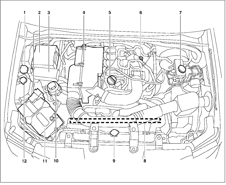
QR25DE engine
1. Window washer fluid reservoir (P. 8-15)
2. Fuse/fusible link box (P. 8-24)
3. Fuse and relay box (P. 8-24)
4. Air cleaner (P. 8-20)
5. Engine oil filler cap (P. 8-9)
6. Engine oil dipstick (P. 8-9)
7. Brake fluid reservoir/Clutch fluid
reservoir (M/T model) (P. 8-14)
8. Drive belt location (P.8-18)
9. Radiator cap (P. 8-8)
10. Power steering fluid reservoir (P. 8-13)
11. Battery (P. 8-15)
12. Engine coolant reservoir (P. 8-8)
See the page number indicated in paren-
theses for operating details.
WDI0643
ENGINE COMPARTMENT CHECK
LOCATIONS
0-8 Illustrated table of contents
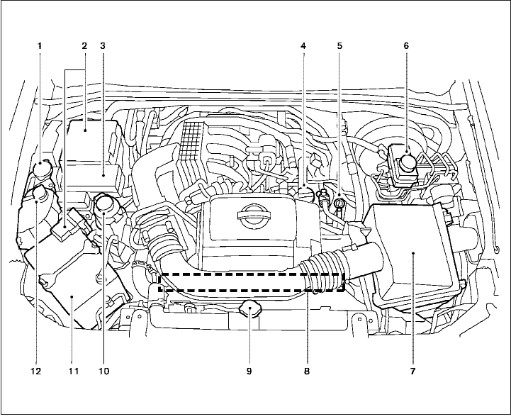
VQ40DE engine
1. Window washer fluid reservoir (P. 8-15)
2. Fuse/fusible link box (P. 8-24)
3. Fuse and relay box (P. 8-24)
4. Engine oil filler cap (P. 8-9)
5. Engine oil dipstick (P. 8-9)
6. Brake fluid reservoir/Clutch fluid
reservoir (M/T model) (P. 8-14)
7. Air cleaner (P. 8-20)
8. Drive belt location (P.8-18)
9. Radiator cap (P. 8-8)
10. Power steering fluid reservoir (P. 8-13)
11. Battery (P. 8-15)
12. Engine coolant reservoir (P. 8-8)
See the page number indicated in paren-
theses for operating details.
LII0167
Illustrated table of contents 0-9
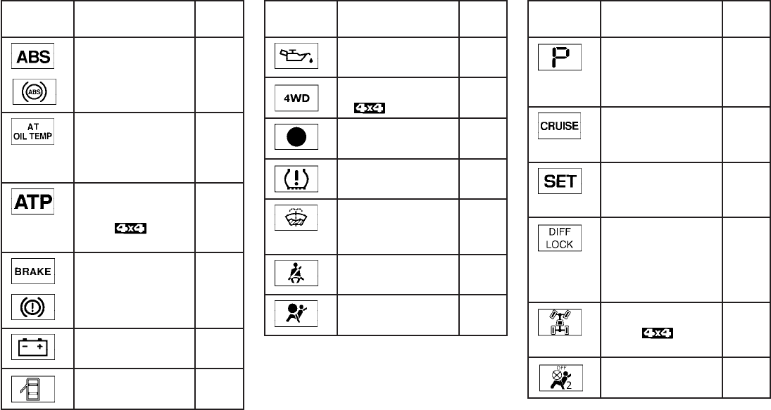
Warning
light
Name Page
or
Anti-lock Braking
System (ABS) warn-
ing light
2-14
Automatic transmis-
sion oil temperature
warning light (if so
equipped)
2-14
Automatic transmis-
sion park warning
light (
model)
2-14
or
Brake warning light 2-15
Charge warning
light
2-15
Door open warning
light
2-15
Warning
light
Name Page
Engine oil pressure
warning light
2-15
4WD warning light
(model)
2-16
Low fuel warning
light
2-16
Low tire pressure
warning light
2-16
Low windshield
washer fluid warning
light
2-18
Seat belt warning
light and chime
2-18
Supplemental air
bag warning light
2-18
Indicator
light
Name Page
Automatic transmis-
sion position indica-
tor light (if so
equipped)
2-18
Cruise main switch
indicator light (if so
equipped)
2-18
Cruise set switch
indicator light (if so
equipped)
2-19
Electronic locking
rear differential (E-
Lock) system on
indicator light (if so
equipped)
2-19
4WD shift indicator
light (
model)
2-19
Front passenger air
bag status light
2-19
WARNING/INDICATOR LIGHTS
0-10 Illustrated table of contents
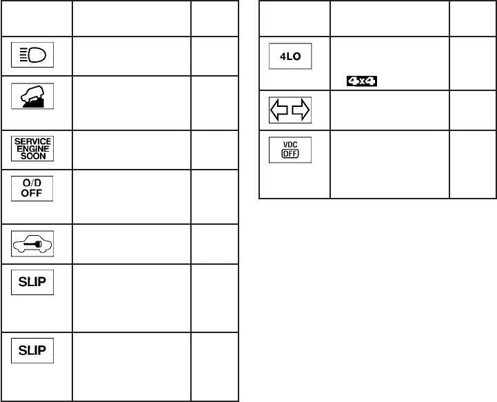
Indicator
light
Name Page
High beam indicator
light (Blue)
2-19
Hill descent control
system on indicator
light (if so equipped)
2-33
Malfunction Indica-
tor Light (MIL)
2-20
Overdrive off indica-
tor light (A/T models
only)
2-20
Security indicator
light (if so equipped)
2-20
Slip indicator light
for models with
ABLS (if so
equipped)
2-21
Slip indicator light
for models with
VDC (if so
equipped)
2-21
Indicator
light
Name Page
Transfer 4LO posi-
tion indicator light
(model)
2-21
Turn signal/hazard
indicator lights
2-21
Vehicle Dynamic
Control (VDC) OFF
indicator light (if so
equipped)
2-22
Illustrated table of contents 0-11
1 Safety—Seats, seat belts and
supplemental restraint system
Seats ............................................1-2
Front manual seat adjustment
(if so equipped) ................................1-2
Front power seat adjustment
(if so equipped) ................................1-4
Jump seat (King cab) ...........................1-5
Armrest .......................................1-6
Head restraints.................................1-6
Adjustable headrest (Crew cab models only)
(if so equipped) ................................1-9
Flexible seating................................1-12
Seat belts .......................................1-16
Precautions on seat belt usage..................1-16
Pregnant women ..............................1-19
Injured persons................................1-19
Three-point type seat belt with retractor..........1-19
Seat belt extenders ............................1-23
Seat belt maintenance .........................1-24
Child safety......................................1-24
Infants........................................1-25
Small children.................................1-25
Larger children ................................1-25
Child restraints...................................1-26
Precautions on child restraints ..................1-26
LATCH (Lower Anchors and Tethers for
CHildren) System .............................1-28
Rear-facing child restraint installation using
LATCH (Crew cab models only).................1-31
Rear-facing child restraint installation using
the seat belts — (Crew cab models only).........1-33
Rear-facing child restraint installation using
the seat belts — passenger’s side jump seat
(King cab models only).........................1-36
Forward-facing child restraint installation
using LATCH (Crew cab model only) ............1-40
Forward-facing child restraint installation
using the seat belts — front passenger and
rear bench seat (Crew cab models only) .........1-42
Foward-facing child restraint installation
using the seat belts — front passenger and
passenger’s side jump seat
(King cab models only).........................1-45
Installing top tether strap (Front passenger
seat – King cab models only) ...................1-50
Installing top tether strap (Passenger’s side
jump seat – King cab models only) ..............1-51
Installing top tether strap (Rear bench seat –
Crew cab models only).........................1-52
Booster seats .................................1-52

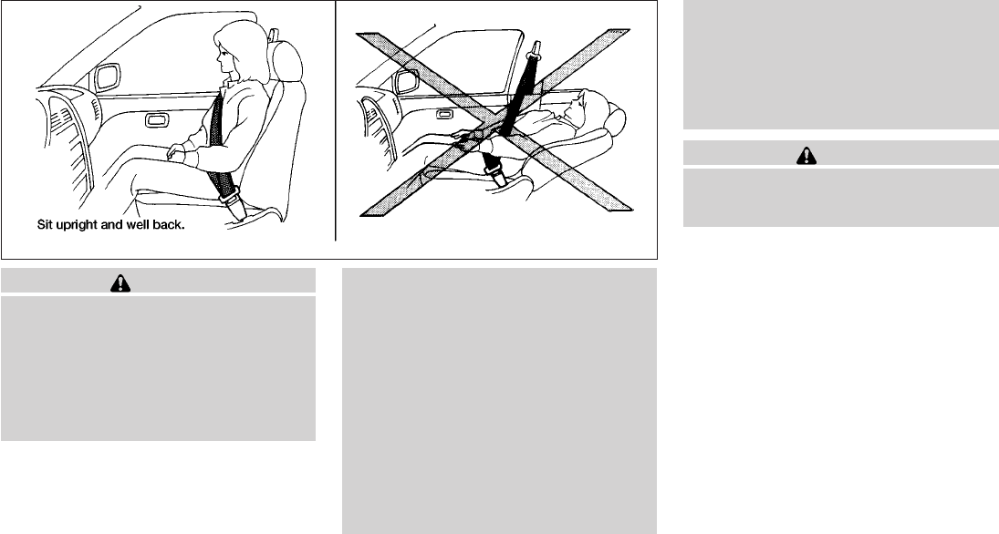
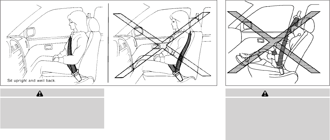
WARNING
●Do not ride in a moving vehicle when
the seatback is reclined. This can be
dangerous. The shoulder belt will not
be against your body. In an accident,
you could be thrown into it and receive
neck or other serious injuries. You
could also slide under the lap belt and
receive serious internal injuries.
●For the most effective protection when
the vehicle is in motion, the seat should
be upright. Always sit well back in the
seat with both feet on the floor and
adjust the seat properly. See “Precau-
tions on seat belt usage” later in this
section.
●After adjustment, gently rock in the seat
to make sure it is securely locked.
●Do not leave children unattended inside
the vehicle. They could unknowingly ac-
tivate switches or controls. Unattended
children could become involved in seri-
ous accidents.
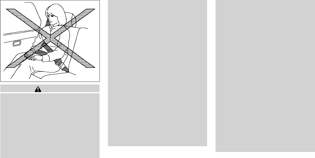
●The seatback should not be reclined
any more than needed for comfort. Seat
belts are most effective when the pas-
senger sits well back and straight up in
the seat. If the seatback is reclined, the
risk of sliding under the lap belt and
being injured is increased.
CAUTION
When adjusting the seat positions, be
sure not to contact any moving parts to
avoid possible injuries and/or damage.
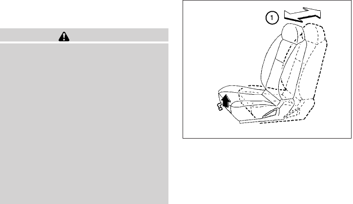
FRONT MANUAL SEAT
ADJUSTMENT (if so equipped)
ARS1152
SEATS
1-2 Safety—Seats, seat belts and supplemental restraint system
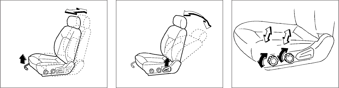
Forward and backward
Pull the lever up and hold it while you slide the
seat forward or backward to the desired position.
Release the lever to lock the seat in position.
Reclining
To recline the seatback, pull the lever up and lean
back. To bring the seatback forward, pull the lever
up and lean your body forward. Release the lever
to lock the seatback in position.
The reclining feature allows adjustment of the
seatback for occupants of different sizes for
added comfort and to help obtain proper seat
belt fit. See “Precautions on seat belt usage”later
in this section. Also, the seatback can be reclined
to allow occupants to rest when the vehicle is
stopped and the transmission is in P (Park) or N
(Neutral) position with the parking brake fully
applied.
Seat lifter (if so equipped for driver’s
seat)
Turn either dial to adjust the angle and height of
the seat cushion to the desired position.
WRS0175 WRS0176 WRS0131
Safety—Seats, seat belts and supplemental restraint system 1-3
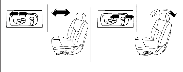
FRONT POWER SEAT
ADJUSTMENT (if so equipped)
Operating tips
●The power seat motor has an auto-reset
overload protection circuit. If the motor
stops during operation, wait 30 seconds,
then reactivate the switch.
●Do not operate the power seat switch for a
long period of time when the engine is off.
This will discharge the battery.
Forward and backward
Moving the switch forward or backward will slide
the seat forward or backward to the desired
position.
Reclining
Move the recline switch backward until the de-
sired angle is obtained. To bring the seatback
forward again, move the switch forward and
move your body forward. The seatback will move
forward.
The reclining feature allows adjustment of the
seatback for occupants of different sizes for
added comfort and to help obtain proper seat
belt fit (see “Precautions on seat belt usage”later
in this section). Also, the seatback can be re-
clined to allow occupants to rest when the ve-
hicle is stopped and the transmission is in P
(Park) or N (Neutral) position with the parking
brake fully applied.
WRS0163
1-4 Safety—Seats, seat belts and supplemental restraint system
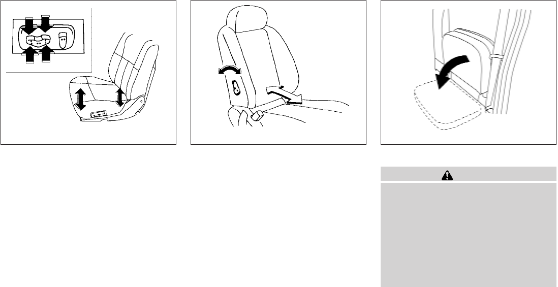
Seat lifter (if so equipped for driver’s
seat)
Push the front or rear end of the switch up or
down to adjust the angle and height of the seat
cushion.
Lumbar support (if so equipped for
driver’s seat)
The lumbar support feature provides lower back
support to the driver. Move the lever forward or
backward to adjust the seat lumbar area.
JUMP SEAT (King cab)
WARNING
●Do not use a child restraint in the driv-
er’s side jump seat. This seating posi-
tion is not suitable for child restraint
installation. A child restraint can be in-
stalled in the passenger’s side jump
seat when the seat extension is un-
folded from the seat base.
●When folding the jump seat, be careful
not to squeeze your finger between the
seat cushion and the body side.
WRS0164 WRS0389 LRS0556
Safety—Seats, seat belts and supplemental restraint system 1-5
ARMREST
To use the center armrest on the 2nd row bench
seat, pull on the tab in the center of the seat and
fold it down to the resting position.
HEAD RESTRAINTS
WARNING
Head restraints supplement the other ve-
hicle safety systems. They may provide
additional protection against injury in cer-
tain rear end collisions. Adjust the head
restraints properly, as specified in this
section. Check the adjustment after
someone else uses the seat. Do not attach
anything to the head restraint stalks or
remove the head restraint. Do not use the
seat if the head restraint has been re-
moved. If the head restraint was removed,
reinstall and properly adjust the head re-
straint before an occupant uses the seat-
ing position. Failure to follow these in-
structions can reduce the effectiveness of
the head restraints. This may increase the
risk of serious injury or death in a
collision.
The illustration shows the seating positions
equipped with head restraints. All of the head
restraints are adjustable.
mIndicates the seating position is equipped with
a head restraint.
LRS0557 LRS0904
1-6 Safety—Seats, seat belts and supplemental restraint system
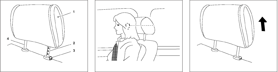
Components
1. Head restraint
2. Adjustment notches
3. Lock knob
4. Stalks
Adjustment
Adjust the head restraint so the center is level
with the center of the seat occupant’s ears.
To raise the head restraint, pull it up.
LRS0887 WRS0134 LRS0888
Safety—Seats, seat belts and supplemental restraint system 1-7
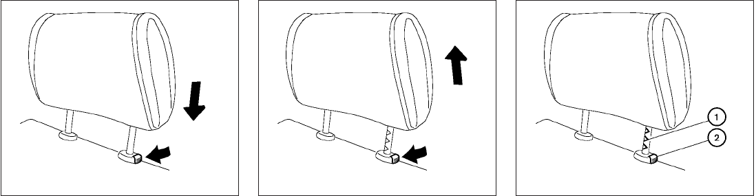
To lower, push and hold the lock knob and push
the head restraint down. Removal
Use the following procedure to remove the ad-
justable head restraints.
1. Pull the head restraint up to the highest
position.
2. Push and hold the lock knob.
3. Remove the head restraint from the seat.
4. Store the head restraint properly so it is not
loose in the vehicle.
5. Install and properly adjust the head restraint
before an occupant uses the seating posi-
tion.
Install
1. Align the head restraint stalks with the holes
in the seat. Make sure the head restraint is
facing the correct direction. The stalk with
the adjustment notches s
1must be installed
in the hole with the lock button s
2.
2. Push and hold the lock knob and push the
head restraint down.
3. Properly adjust the head restraint before an
occupant uses the seating position.
LRS0889 LRS0890 LRS0891
1-8 Safety—Seats, seat belts and supplemental restraint system
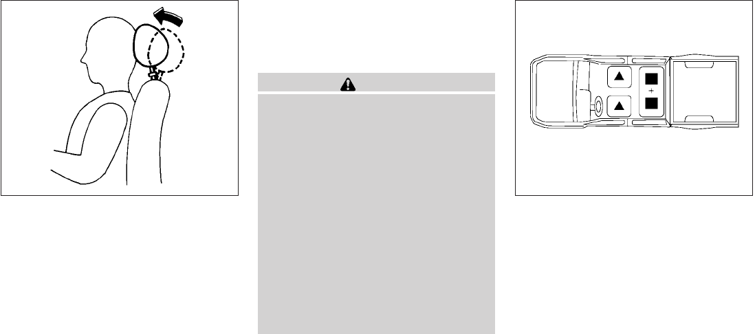
Front-seat Active Head Restraints
The Active Head Restraint moves forward utiliz-
ing the force that the seatback receives from the
occupant in a rear-end collision. The movement
of the head restraint helps support the occu-
pant’s head by reducing its backward movement
and helping absorb some of the forces that may
lead to whiplash-type injuries.
Active Head Restraints are effective for collisions
at low to medium speeds in which it is said that
whiplash injury occurs most.
Active Head Restraints operate only in certain
rear-end collisions. After the collision, the head
restraints return to their original position.
Adjust the Active Head Restraints properly as
described in this section.
ADJUSTABLE HEADREST (Crew cab
models only) (if so equipped)
WARNING
The adjustable headrests supplement the
other vehicle safety systems. They may
provide additional protection against in-
jury in certain rear end collisions. Adjust
the headrests properly, as specified in this
section. Check the adjustment after
someone else uses the seat. Do not attach
anything to the adjustable headrest stalks
or remove the adjustable headrests. Do
not use the seat if the adjustable head-
rests have been removed. If the headrest
was removed, reinstall and properly adjust
the headrest before an occupant uses the
seating position. Failure to follow these
instructions can reduce the effectiveness
of the adjustable headrests. This may in-
crease the risk of serious injury or death in
a collision.
The illustration shows the seating positions
equipped with adjustable headrests. All of the
headrests are adjustable.
nIndicates the seating position is equipped with
an adjustable headrest.
+ Indicates the seating position is not equipped
with a head restraint or adjustable headrest.
SPA1025 LRS0905
Safety—Seats, seat belts and supplemental restraint system 1-9

Components
1. Adjustable headrest
2. Adjustment notches
3. Lock knob
4. Stalks
Adjustment
Adjust the headrest so the center is level with the
center of the seat occupant’s ears.
To raise the headrest, pull it up.
LRS0887 WRS0134 LRS0888
1-10 Safety—Seats, seat belts and supplemental restraint system

To lower, push and hold the lock knob and push
the headrest down. Removal
Use the following procedure to remove the ad-
justable headrests.
1. Pull the headrest up to the highest position.
2. Push and hold the lock knob.
3. Remove the headrest from the seat.
4. Store the headrest properly so it is not loose
in the vehicle.
5. Install and properly adjust the headrest be-
fore an occupant uses the seating position.
Install
1. Align the headrest stalks with the holes in
the seat. Make sure the headrest is facing
the correct direction. The stalk with the ad-
justment notches s
1must be installed in the
hole with the lock button s
2.
2. Push and hold the lock knob and push the
headrest down.
3. Properly adjust the headrest before an oc-
cupant uses the seating position.
LRS0889 LRS0890 LRS0891
Safety—Seats, seat belts and supplemental restraint system 1-11
FLEXIBLE SEATING
WARNING
●Never allow anyone to ride in the cargo
area or on the rear seats when they are
in the fold-down position. In a collision,
people riding in these areas without
proper restraints are more likely to be
seriously injured or killed.
●Do not allow people to ride in any area
of your vehicle that is not equipped with
seats and seat belts. Be sure everyone
in your vehicle is in a seat and using a
seat belt properly.
●Do not fold down the rear seats when
occupants are in the rear seat area or
any luggage is on the rear seats.
●Head restraints should be adjusted
properly as they may provide significant
protection against injury in an accident.
Always replace and adjust them prop-
erly if they have been removed for any
reason.
●If the head restraints are removed for
any reason, they should be securely
stored to prevent them from causing
injury to passengers or damage to the
vehicle in case of sudden braking or an
accident.
●When returning the seatbacks to the
upright position, be certain they are
completely secured in the latched posi-
tion. If they are not completely secured,
passengers may be injured in an acci-
dent or sudden stop.
●Properly secure all cargo to help pre-
vent it from sliding or shifting. Do not
place cargo higher than the seatbacks.
In a sudden stop or collision, unsecured
cargo could cause personal injury.
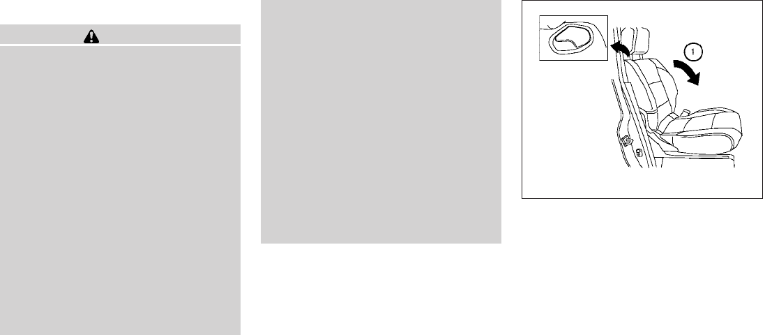
Folding the front passenger’s seatback
(if so equipped)
To fold the front passenger’s seatback flat for
extra storage length when transporting long
items:
s
1Slide the seat to the rearmost position. Lift
up on the recline lever, located on the out-
side edge of the seat, and fold the seatback
forward as far as it will go. Then lift up on the
latch located on the upper corner of the
seatback to release the back of the seat.
LRS0608
1-12 Safety—Seats, seat belts and supplemental restraint system
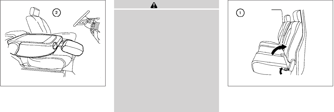
s
2Once the seatback is released, it will enable
you to fold the front passenger seatback flat
over the seat cushion.
3. To return the front passenger’s seat to a
seating position, lift up on the seatback and
push it up to an upright position. Then pull up
on the recline lever and lean the seatback to
a proper seating position. Release the lever
to lock the seatback in position.
WARNING
●If you fold the front passenger’s seat-
back flat forward to carry longer ob-
jects, be sure this cargo is properly se-
cured and not near an air bag. In a
crash, an inflating air bag might force
that object toward a person. This could
cause severe injury or even death. Se-
cure objects away from the area in
which an air bag would inflate. See
“Precautions on supplemental restraint
system” later in this section.
●Never allow anyone to ride in the cargo
area or on the front passenger’s seat
when it is in the fold-down position. Use
of these areas by passengers could re-
sult in serious injury in an accident or
sudden stop.
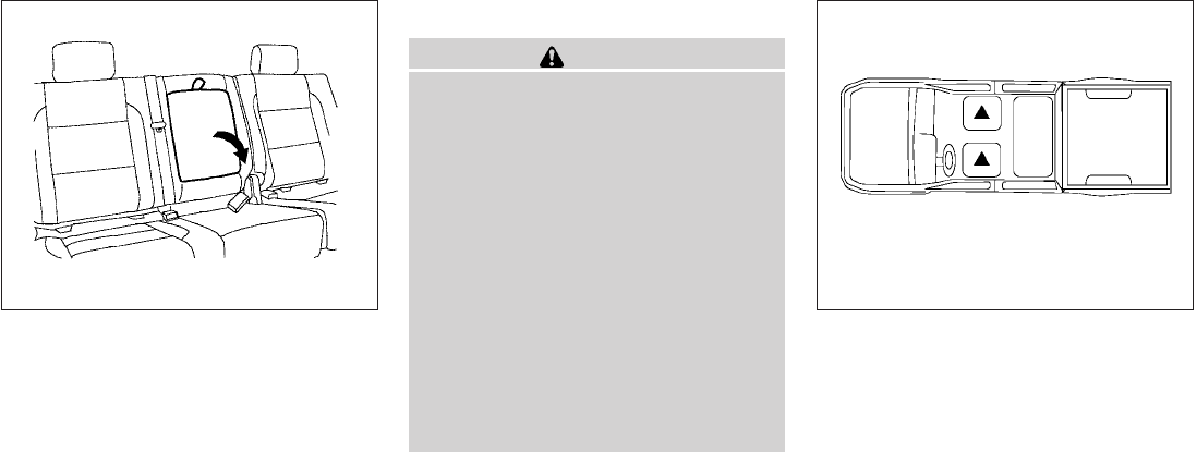
Folding the rear bench seat
To fold the rear bench seat up:
s
1Lift up on the lever, located on the side of the
seat, while lifting the front of the seat cushion
up.
LRS0609 LRS0398
Safety—Seats, seat belts and supplemental restraint system 1-13
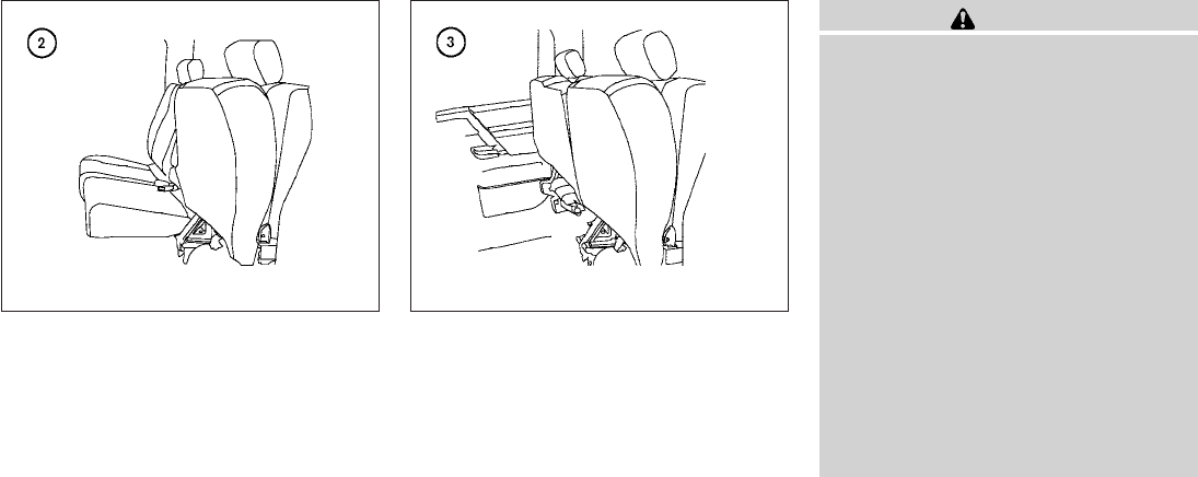
s
2Fold the bottom of the seat cushion toward
the back of the vehicle until it locks in place. s
3Repeat this process to raise and secure the
seat cushion on the other side of the vehicle
for maximum storage capacity.
To return the rear bench seat to a seating posi-
tion, reverse the process. Make sure to prop-
erly push the seat cushion down into place.
WARNING
●When the vehicle is being used to carry
cargo, properly secure all cargo to help
prevent it from sliding or shifting. Do
not place cargo higher than the seat-
backs. In a sudden stop or collision,
unsecured cargo could cause personal
injury.
●Do not allow people to ride in any area
of your vehicle that is not equipped with
seats and seat belts. Be sure everyone
in your vehicle is in a seat and using a
seat belt properly. Never ride in the rear
seat unless the seat bottom cushions
are in place and latched.
●When returning the seatbacks to the
upright position, be certain they are
completely secured in the latched posi-
tion. If they are not completely secured,
passengers may be injured in an acci-
dent or sudden stop.
LRS0566 LRS0567
1-14 Safety—Seats, seat belts and supplemental restraint system
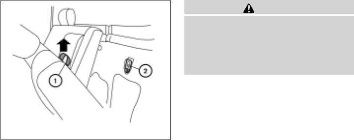
Folding the rear bench seat down
The rear bench seatback can be tilted forward to
access the child restraint anchor point locations
or the jacking equipment.
To tilt the seatback forward, pull the strap up s
1
and tilt the seatback. The child restraint anchor
points s
2can be accessed behind the rear
bench seatback. The jacking equipment can be
accessed from behind the passenger’s side
seatback.
WARNING
Never allow anyone to ride in the cargo
area or on the rear seat when it is in the
fold-down position. Use of these areas by
passengers without proper restraints
could result in serious injury in an acci-
dent or sudden stop.
WRS0840
Safety—Seats, seat belts and supplemental restraint system 1-15
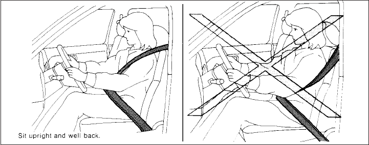
PRECAUTIONS ON SEAT BELT
USAGE
If you are wearing your seat belt properly ad-
justed and you are sitting upright and well back in
your seat with both feet on the floor, your chances
of being injured or killed in an accident and/or the
severity of injury may be greatly reduced.
NISSAN strongly encourages you and all of your
passengers to buckle up every time you drive,
even if your seating position includes a supple-
mental air bag.
Most U.S. states and Canadian provinces
or territories specify that seat belts be worn
at all times when a vehicle is being driven.
SSS0136
SEAT BELTS
1-16 Safety—Seats, seat belts and supplemental restraint system
WARNING
●Every person who drives or rides in this
vehicle should use a seat belt at all
times. Children should be properly re-
strained in the rear seat and, if appro-
priate, in a child restraint.
WARNING
●The seat belt should be properly ad-
justed to a snug fit. Failure to do so may
reduce the effectiveness of the entire
restraint system and increase the
chance or severity of injury in an acci-
dent. Serious injury or death can occur
if the seat belt is not worn properly.
SSS0134 SSS0016
Safety—Seats, seat belts and supplemental restraint system 1-17
WARNING
●Always route the shoulder belt over
your shoulder and across your chest.
Never put the belt behind your back,
under your arm or across your neck. The
belt should be away from your face and
neck, but not falling off your shoulder.
●Position the lap belt as low and snug as
possible AROUND THE HIPS, NOT THE
WAIST. A lap belt worn too high could
increase the risk of internal injuries in
an accident.
●Be sure the seat belt tongue is securely
fastened to the proper buckle.
●Do not wear the seat belt inside out or
twisted. Doing so may reduce its
effectiveness.
●Do not allow more than one person to
use the same seat belt.
●Never carry more people in the vehicle
than there are seat belts.
●If the seat belt warning light glows con-
tinuously while the ignition is turned
ON with all doors closed and all seat
belts fastened, it may indicate a mal-
function in the system. Have the system
checked by a NISSAN dealer.
●No changes should be made to the seat
belt system. For example, do not modify
the seat belt, add material, or install
devices that may change the seat belt
routing or tension. Doing so may affect
the operation of the seat belt system.
Modifying or tampering with the seat
belt system may result in serious per-
sonal injury.
●Once a seat belt pretensioner has acti-
vated, it cannot be reused and must be
replaced together with the retractor.
See your NISSAN dealer.
●Removal and installation of preten-
sioner system components should be
done by a NISSAN dealer.
●All seat belt assemblies, including re-
tractors and attaching hardware,
should be inspected after any collision
by a NISSAN dealer. NISSAN recom-
mends that all seat belt assemblies in
use during a collision be replaced un-
less the collision was minor and the
belts show no damage and continue to
operate properly. Seat belt assemblies
not in use during a collision should also
be inspected and replaced if either
damage or improper operation is noted.
●All child restraints and attaching hard-
ware should be inspected after any col-
lision. Always follow the restraint
manufacturer’s inspection instructions
and replacement recommendations.
The child restraints should be replaced
if they are damaged.
SSS0014
1-18 Safety—Seats, seat belts and supplemental restraint system
PREGNANT WOMEN
NISSAN recommends that pregnant women use
seat belts. The seat belt should be worn snug and
always position the lap belt as low as possible
around the hips, not the waist. Place the shoulder
belt over your shoulder and across your chest.
Never run the lap/shoulder belt over your ab-
dominal area. Contact your doctor for specific
recommendations.
INJURED PERSONS
NISSAN recommends that injured persons use
seat belts. Check with your doctor for specific
recommendations.
THREE-POINT TYPE SEAT BELT
WITH RETRACTOR
WARNING
●Every person who drives or rides in this
vehicle should use a seat belt at all
times.
●Do not ride in a moving vehicle when
the seatback is reclined. This can be
dangerous. The shoulder belt will not
be against your body. In an accident,
you could be thrown into it and receive
neck or other serious injuries. You
could also slide under the lap belt and
receive serious internal injuries.
●For the most effective protection when
the vehicle is in motion, the seat should
be upright. Always sit well back in the
seat with both feet on the floor and
adjust the seat belt properly.
Fastening the seat belts (Front seats
all models and rear seats Crew cab
models)
s
1Adjust the seat. See “Seats” earlier in this
section.
Manual front seat shown
WRS0174
Safety—Seats, seat belts and supplemental restraint system 1-19
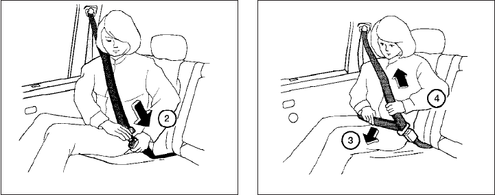
s
2Slowly pull the seat belt out of the retractor
and insert the tongue into the buckle until
you hear and feel the latch engage.
●The retractor is designed to lock during
a sudden stop or on impact. A slow
pulling motion permits the seat belt to
move, and allows you some freedom of
movement in the seat.
●If the seat belt cannot be pulled from
its fully retracted position, firmly pull
the belt and release it. Then smoothly
pull the belt out of the retractor.
s
3Position the lap belt portion low and snug
on the hips as shown.
s
4Pull the shoulder belt portion toward the
retractor to take up extra slack. Be sure the
shoulder belt is routed over your shoulder
and across your chest.
The front passenger seat and the rear seating
positions three-point seat belts have two modes
of operation:
●Emergency Locking Retractor (ELR)
●Automatic Locking Retractor (ALR)
The Emergency Locking Retractor (ELR) mode
allows the seat belt to extend and retract to allow
the driver and passengers some freedom of
movement in the seat. The ELR locks the seat belt
when the vehicle slows down rapidly or during
certain impacts.
The Automatic Locking Retractor (ALR) mode
(child restraint mode) locks the seat belt for child
restraint installation.
When the ALR mode is activated, the seat belt
cannot be extended again until the seat belt
tongue is detached from the buckle and fully
retracted. The seat belt returns to the ELR mode
after the seat belt fully retracts. See “Child re-
straints” later in this section for more information.
The ALR mode should be used only for
child restraint installation. During normal
seat belt use by an occupant, the ALR mode
should not be activated. If it is activated it
may cause uncomfortable seat belt ten-
sion. It can also change the operation of
the front passenger air bag. See “Front
passenger air bag and status light” later in
this section.
LRS0594 LRS0595
1-20 Safety—Seats, seat belts and supplemental restraint system
WARNING
When fastening the seat belts, be certain
that the seatbacks are completely se-
cured in the latched position. If they are
not completely secured, passengers may
be injured in an accident or sudden stop.
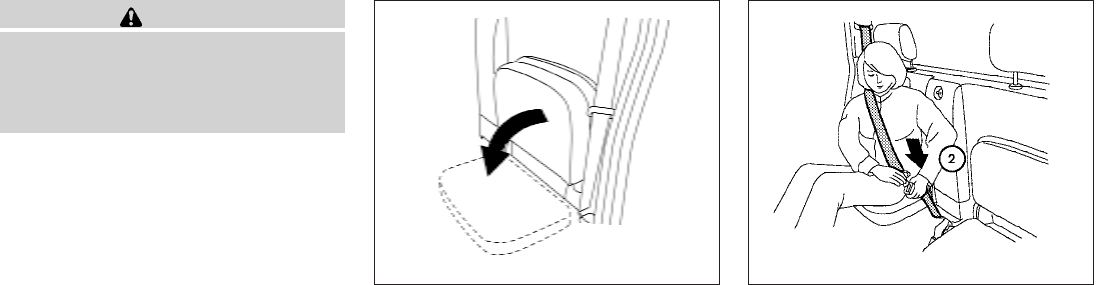
Fastening the seat belts (Jump seats
King cab models)
1. Open the jump seat. See “Seats” earlier in
this section. s
2Slowly pull the seat belt out of the retractor
and insert the tongue into the buckle until
you hear and feel the latch engage.
●The retractor is designed to lock during
a sudden stop or on impact. A slow
pulling motion permits the seat belt to
move, and allows you some freedom of
movement in the seat.
●If the seat belt cannot be pulled from
its fully retracted position, firmly pull
the belt and release it. Then smoothly
pull the belt out of the retractor.
LRS0556 LRS0569
Safety—Seats, seat belts and supplemental restraint system 1-21
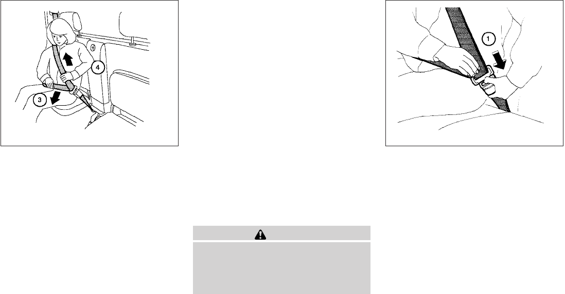
s
3Position the lap belt portion low and snug
on the hips as shown.
s
4Pull the shoulder belt portion toward the
retractor to take up extra slack. Be sure the
shoulder belt is routed over your shoulder
and across your chest.
The jump seat position’s three-point seat belts
have two modes of operation:
●Emergency Locking Retractor (ELR)
●Automatic Locking Retractor (ALR)
The Emergency Locking Retractor (ELR) mode
allows the seat belt to extend and retract to allow
the driver and passengers some freedom of
movement in the seat. The ELR locks the seat belt
when the vehicle slows down rapidly or during
certain impacts.
The Automatic Locking Retractor (ALR) mode
(child restraint mode) locks the seat belt for child
restraint installation.
When the ALR mode is activated, the seat belt
cannot be extended again until the seat belt
tongue is detached from the buckle and fully
retracted. The seat belt returns to the ELR mode
after the seat belt fully retracts. See “Child re-
straints” later in this section for more information.
The ALR mode should be used only for
child restraint installation. During normal
seat belt use by an occupant, the ALR mode
should not be activated. If it is activated it
may cause uncomfortable seat belt ten-
sion. It can also change the operation of
the front passenger air bag. See “Front
passenger air bag and status light” later in
this section.
WARNING
When fastening the seat belts, be certain
that the seatbacks are completely se-
cured in the latched position. If they are
not completely secured, passengers may
be injured in an accident or sudden stop.
Unfastening the seat belts
s
1To unfasten the seat belt, press the button on
the buckle. The seat belt automatically re-
tracts.
Checking seat belt operation
Seat belt retractors are designed to lock seat belt
movement by two separate methods:
●When the seat belt is pulled quickly from the
retractor.
●When the vehicle slows down rapidly.
LRS0570 WRS0139
1-22 Safety—Seats, seat belts and supplemental restraint system
To increase your confidence in the seat belts,
check the operation as follows:
●Grasp the shoulder belt and pull forward
quickly. The retractor should lock and re-
strict further belt movement.
If the retractor does not lock during this check or
if you have any questions about seat belt opera-
tion, see a NISSAN dealer.
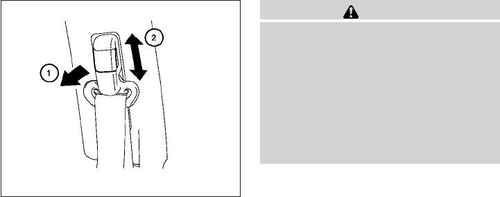
Shoulder belt height adjustment (front
seats)
The shoulder belt anchor height should be ad-
justed to the position best for you. (See “Precau-
tions on seat belt usage” earlier in this section.)
To adjust, pull out the adjustment button s
1and
move the shoulder belt anchor to the desired
position s
2, so the belt passes over the center of
the shoulder. The belt should be away from your
face and neck, but not falling off your shoulder.
Release the adjustment button to lock the shoul-
der belt anchor into position.
WARNING
●After adjustment, release the adjust-
ment button and try to move the shoul-
der belt anchor up and down to make
sure it is securely fixed in position.
●The shoulder belt anchor height should
be adjusted to the position best for you.
Failure to do so may reduce the effec-
tiveness of the entire restraint system
and increase the chance or severity of
injury in an accident.
SEAT BELT EXTENDERS
If, because of body size or driving position, it is
not possible to properly fit the lap/shoulder belt
and fasten it, an extender is available which is
compatible with the installed seat belts. The ex-
tender adds approximately 8 in (200 mm) of
length and may be used for either the driver or
front passenger seating position. See a NISSAN
dealer for assistance if an extender is required.
LRS0242
Safety—Seats, seat belts and supplemental restraint system 1-23

WARNING
●Only NISSAN seat belt extenders, made
by the same company which made the
original equipment seat belts, should
be used with NISSAN seat belts.
●Adults and children who can use the
standard seat belt should not use an
extender. Such unnecessary use could
result in serious personal injury in the
event of an accident.
●Never use seat belt extenders to install
child restraints. If the child restraint is
not secured properly, the child could be
seriously injured in a collision or a sud-
den stop.
SEAT BELT MAINTENANCE
●To clean the seat belt webbing, apply a
mild soap solution or any solution recom-
mended for cleaning upholstery or carpet.
Then wipe with a cloth and allow the seat
belts to dry in the shade. Do not allow the
seat belts to retract until they are completely
dry.
●If dirt builds up in the shoulder belt
guide of the seat belt anchors, the seat
belts may retract slowly. Wipe the shoulder
belt guide with a clean, dry cloth.
●Periodically check to see that the seat
belt and the metal components, such as
buckles, tongues, retractors, flexible wires
and anchors work properly. If loose parts,
deterioration, cuts or other damage on the
webbing is found, the entire seat belt as-
sembly should be replaced.
Children need adults to help protect them.
They need to be properly restrained.
In addition to the general information in this
manual, child safety information is available from
many other sources, including doctors, teachers,
government traffic safety offices, and community
organizations. Every child is different, so be sure
to learn the best way to transport your child.
There are three basic types of child restraint
systems:
●Rear-facing child restraint
●Forward-facing child restraint
●Booster seat
The proper restraint depends on the child’s size.
Generally, infants up to about 1 year and less
than 20 lbs (9 kg) should be placed in rear-facing
child restraints. Forward-facing child restraints
are available for children who outgrow rear-
facing child restraints and are at least 1 year old.
Booster seats are used to help position a vehicle
lap/shoulder belt on a child who can no longer
use a forward-facing child restraint.
CHILD SAFETY
1-24 Safety—Seats, seat belts and supplemental restraint system

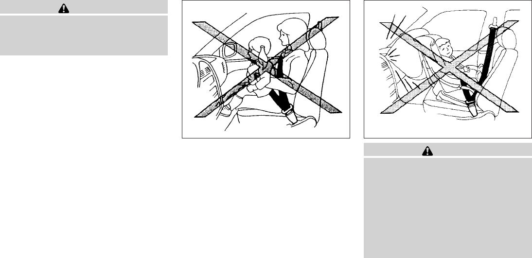
WARNING
Infants and children need special protec-
tion. The vehicle’s seat belts may not fit
them properly. The shoulder belt may
come too close to the face or neck. The
lap belt may not fit over their small hip
bones. In an accident, an improperly fit-
ting seat belt could cause serious or fatal
injury. Always use appropriate child
restraints.
All U.S. states and Canadian provinces or terri-
tories require the use of approved child restraints
for infants and small children. See “Child Re-
straints” later in this section.
A child restraint may be secured in the vehicle by
using either the LATCH (Lower Anchor and Teth-
ers for CHildren) system or with the vehicle seat
belt. See “Child Restraints” section for more in-
formation.
NISSAN recommends that all pre-teens
and children be restrained in the rear seat if
available (Crew Cab models). Studies show
that children are safer when properly re-
strained in the rear seat than in the front
seat.
This is especially important because your
vehicle has a supplemental restraint sys-
tem (Air bag system) for the front passen-
ger. See “Supplemental restraint system”
later in this section.
INFANTS
Infants up to at least 1 year old should be placed
in a rear-facing child restraint. NISSAN recom-
mends that infants be placed in child restraints
that comply with Federal Motor Vehicle Safety
Standards or Canadian Motor Vehicle Safety
Standards. You should choose a child restraint
that fits your vehicle and always follow the manu-
facturer’s instructions for installation and use.
SMALL CHILDREN
Children that are over one year old and weigh at
least 20 lbs (9 kg) can be placed in a forward-
facing child restraint. Refer to the manufacturer’s
instructions for minimum and maximum weight
and height recommendations. NISSAN recom-
mends that small children be placed in child
restraints that comply with Federal Motor Vehicle
Safety Standards or Canadian Motor Vehicle
Safety Standards. You should choose a child
restraint that fits your vehicle and always follow
the manufacturer’s instructions for installation
and use.
LARGER CHILDREN
Children who are too large for child restraints
should be seated and restrained by the seat belts
which are provided. The seat belt may not fit
properly if the child is less than 4 ft 9 in (142.5
cm) tall and weighs between 40 lbs (18 kg) and
80 lbs (36 kg). A booster seat should be used to
obtain proper seat belt fit.
NISSAN recommends that a child be placed in a
commercially available booster seat if the shoul-
der belt fits close to the face or neck or if the lap
portion of the seat belt goes across the abdo-
men. The booster seat should raise the child so
that the shoulder belt is properly positioned
across the top, middle portion of the shoulder
and the lap belt is low on the hips. A booster seat
can only be used in seating positions that have a
three-point type seat belt. The booster seat
should fit the vehicle seat and have a label certi-
fying that it complies with Federal Motor Vehicle
Safety Standards or Canadian Motor Vehicle
Safety Standards. Once the child has grown so
the shoulder belt is no longer on or near the face
and neck, use the shoulder belt without the
booster seat.
Safety—Seats, seat belts and supplemental restraint system 1-25
WARNING
Never let a child stand or kneel on any
seat and do not allow a child in the cargo
area. The child could be seriously injured
or killed in a sudden stop or collision.
PRECAUTIONS ON CHILD
RESTRAINTS WARNING
●Failure to follow the warnings and in-
structions for proper use and installa-
tion of child restraints could result in
serious injury or death of a child or
other passengers in a sudden stop or
collision:
– The child restraint must be used and
installed properly. Always follow all
of the child restraint manufacturer’s
instructions for installation and use.
ARS1098 WRS0256
CHILD RESTRAINTS
1-26 Safety—Seats, seat belts and supplemental restraint system

– Infants and children should never be
held on anyone’s lap. Even the stron-
gest adult cannot resist the forces of
a collision.
– Do not put a seat belt around both a
child and another passenger.
– NISSAN recommends that all child
restraints be installed in the rear
seat. Studies show that children are
safer when properly restrained in the
rear seat than in the front seat. If you
must install a forward-facing child
restraint in the front seat, see
“Forward-facing child restraint in-
stallation using the seat belts” later
in this section.
– Even with the NISSAN Advanced Air
Bag System, never install a rear-
facing child restraint in the front
seat. An inflating air bag could seri-
ously injure or kill a child. A rear-
facing child restraint must only be
used in the rear seat.
– Be sure to purchase a child restraint
that will fit the child and vehicle.
Some child restraints may not fit
properly in your vehicle.
– Child restraint anchor points are de-
signed to withstand loads from child
restraints that are properly fitted.
– Never use the anchor points for adult
seat belts or harnesses.
– A child restraint with a top tether
strap should not be used in the front
passenger seat.
– Keep seatbacks as upright as pos-
sible after fitting the child restraint.
– Infants and children should always
be placed in an appropriate child re-
straint while in the vehicle.
●When the child restraint is not in use,
keep it secured with the LATCH system
or a seat belt. In a sudden stop or colli-
sion, loose objects can injure occu-
pants or damage the vehicle.
CAUTION
A child restraint in a closed vehicle can
become very hot. Check the seating sur-
face and buckles before placing a child in
the child restraint.
This vehicle (Crew cab model only) is equipped
with a universal child restraint anchor system,
referred to as the LATCH (Lower Anchors and
Tethers for CHildren) system. Some child re-
straints include rigid or webbing-mounted at-
tachments that can be connected to these an-
chors. For details, see “LATCH (Lower Anchors
and Tethers for CHildren) system” later in this
section.
If you do not have a LATCH compatible child
restraint, the vehicle seat belts can be used.
Several manufacturers offer child restraints for
infants and children of various sizes. When se-
lecting any child restraint, keep the following
points in mind:
●Choose only a restraint with a label certifying
that it complies with Federal Motor Vehicle
Safety Standard 213 or Canadian Motor
Vehicle Safety Standard 213.
●Check the child restraint in your vehicle to be
sure it is compatible with the vehicle’s seat
and seat belt system.
Safety—Seats, seat belts and supplemental restraint system 1-27
●If the child restraint is compatible with your
vehicle, place your child in the child restraint
and check the various adjustments to be
sure the child restraint is compatible with
your child. Choose a child restraint that is
designed for your child’s height and weight.
Always follow all recommended procedures.
All U.S. states and Canadian provinces or
territories require that infants and small
children be restrained in an approved child
restraint at all times while the vehicle is
being operated. Canadian law requires the
top tether strap on forward-facing child
restraints be secured to the designated an-
chor point on the vehicle.
LATCH (Lower Anchors and Tethers
for CHildren) SYSTEM
Your vehicle is equipped with special anchor
points that are used with LATCH (Lower Anchors
and Tethers for CHildren) system compatible
child restraints. This system may also be referred
to as the ISOFIX or ISOFIX compatible system.
With this system, you do not have to use a vehicle
seat belt to secure the child restraint.
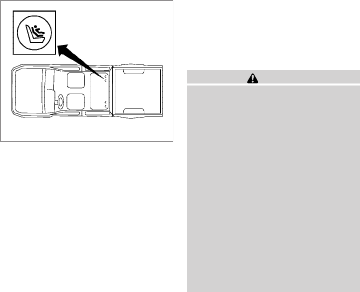
The LATCH lower anchor points are provided to
install child restraints in the rear outboard seating
positions only (Crew cab models only). Do not
attempt to install a child restraint in the center
position using the LATCH lower anchors.
LATCH lower anchor
WARNING
Failure to follow the warnings and instruc-
tions for proper use and installation of
child restraints could result in serious in-
jury or death of a child or other passen-
gers in a sudden stop or collision:
– Attach LATCH system compatible
child restraints only at the locations
shown in the illustration.
– Do not secure a child restraint in the
center rear seating position using
the LATCH lower anchors. The child
restraint will not be secured properly.
– Inspect the lower anchors by insert-
ing your fingers into the lower anchor
area. Feel to make sure there are no
obstructions over the anchors such
as seat belt webbing or seat cushion
material. The child restraint will not
be secured properly if the lower an-
chors are obstructed.
LATCH system lower anchor locations
(Crew cab models only)
LRS0429
1-28 Safety—Seats, seat belts and supplemental restraint system
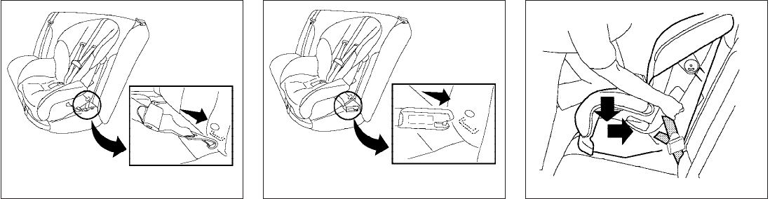
LATCH lower anchor location
The LATCH lower anchors are located at the rear
of the seat cushion near the seatback. A label is
attached to the seatback to help you locate the
LATCH lower anchors.
Installing child restraint LATCH lower
anchor attachments
LATCH compatible child restraints include two
rigid or webbing-mounted attachments that can
be connected to two anchors located at certain
seating positions in your vehicle. With this sys-
tem, you do not have to use a vehicle seat belt to
secure the child restraint. Check your child re-
straint for a label stating that it is compatible with
LATCH. This information may also be in the in-
structions provided by the child restraint manu-
facturer.
LATCH lower anchor location
LRS0748
LATCH label locations (Crew cab models
only)
LRS0571
LATCH webbing-mounted attachment
LRS0661
Safety—Seats, seat belts and supplemental restraint system 1-29
The child restraint top tether strap must be used
when installing the child restraint with the LATCH
lower anchor attachments or seat belts. See “Top
tether anchor” for installation instructions.
When installing a child restraint, carefully read
and follow the instructions in this manual and
those supplied with the child restraint.
Top tether anchor
WARNING
Do not allow cargo to contact the top
tether strap when it is attached to the top
tether anchor. Properly secure the cargo
so it does not contact the top tether strap.
Cargo that is not properly secured or
cargo that contacts the top tether strap
may damage it during a collision. A child
could be seriously injured or killed in a
collision if the top tether strap is
damaged.
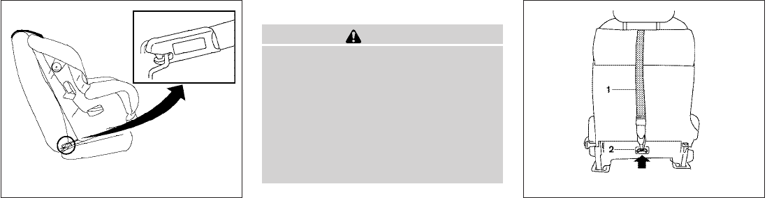
Top tether anchor point locations
Anchor points are located in the following loca-
tions:
●On the back of the front passenger seat
(King cab only) as shown.
LATCH rigid-mounted attachment
LRS0662
Front passenger seat (King cab models
only)
LRS0572
1-30 Safety—Seats, seat belts and supplemental restraint system
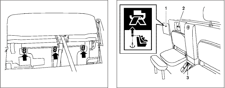
●Under the rear window behind the rear
bench seat (Crew cab only) as shown. ●On the floor between the jump seat belt
buckles in the center of the vehicle (King cab
only) as shown.
The anchor point s
3is located on the floor be-
tween the jump seat belt buckles in the center of
the vehicle. The routing bracket s
2is located
behind the cover plate s
1under the rear window
above the right passenger’s side jump seat.
REAR-FACING CHILD RESTRAINT
INSTALLATION USING LATCH (Crew
cab models only)
Refer to all Warnings and Cautions in the “Child
Safety” and “Child Restraint” sections before in-
stalling a child restraint.
Follow these steps to install a rear-facing child
restraint in the 2nd row seats using the LATCH
system:
1. Position the child restraint on the seat. Al-
ways follow the child restraint manufactur-
er’s instructions.
Rear bench seat (Crew cab models only)
LRS0393
Passenger’s side jump seat
(King cab models)
LRS0551
Safety—Seats, seat belts and supplemental restraint system 1-31
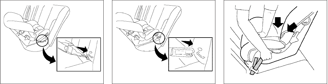
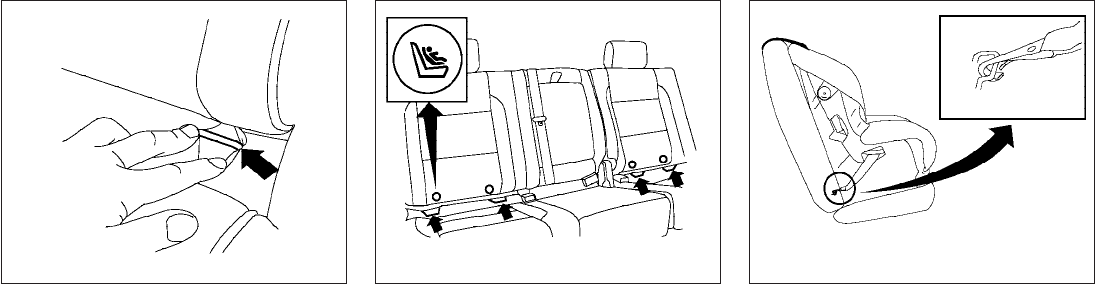
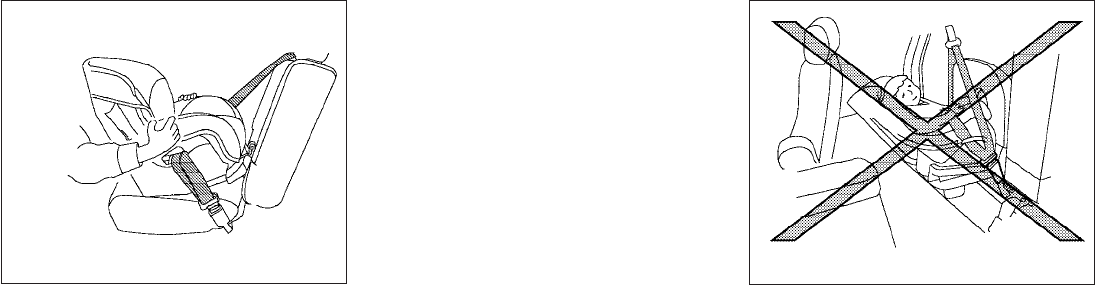
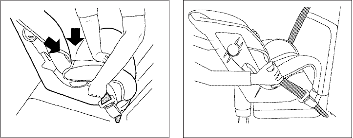
2. Secure the child restraint anchor attach-
ments to the LATCH lower anchors. Check
to make sure the LATCH attachment is prop-
erly attached to the lower anchors.
3. For child restraints that are equipped with
webbing-mounted attachments, remove any
additional slack from the anchor attach-
ments. Press downward and rearward firmly
in the center of the child restraint with your
hand to compress the vehicle seat cushion
and seatback while tightening the webbing
of the anchor attachments.
Rear-facing web-mounted – step 2
WRS0801
Rear-facing rigid-mounted – step 2
WRS0802
Rear-facing – step 3
LRS0673
1-32 Safety—Seats, seat belts and supplemental restraint system
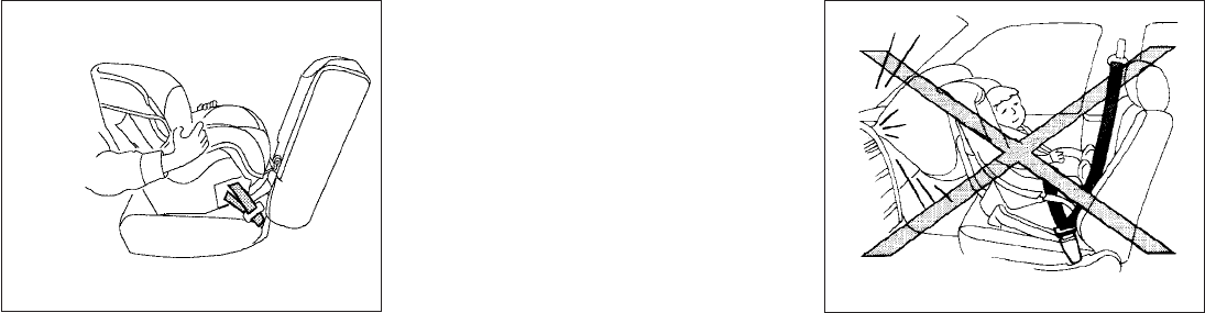
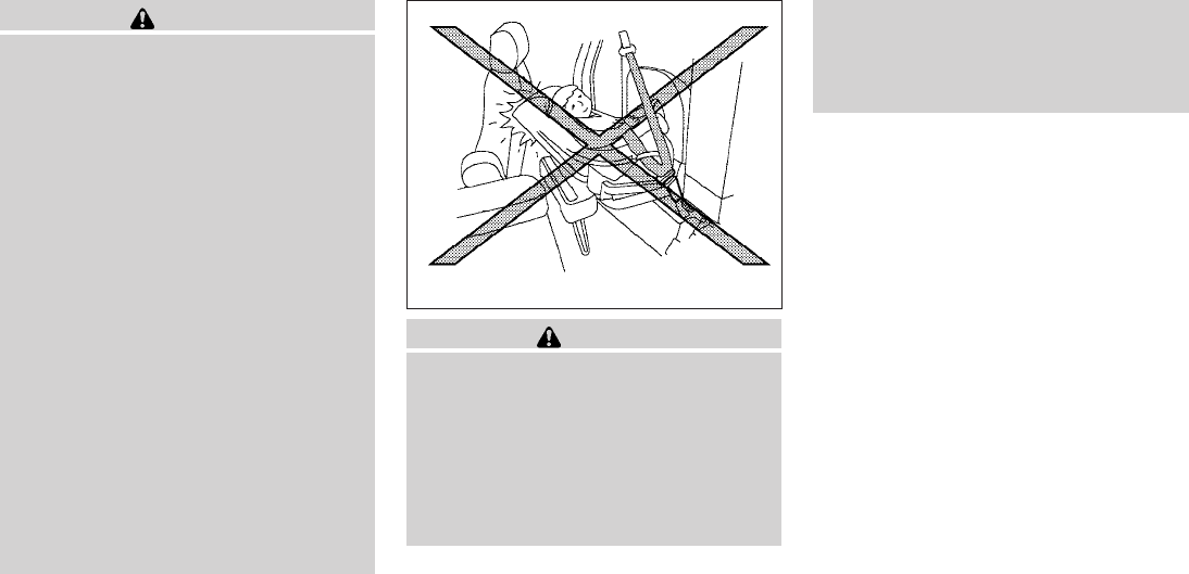
4. After attaching the child restraint, test it be-
fore you place the child in it. Push it from side
to side while holding the child restraint near
the LATCH attachment path. The child re-
straint should not move more than 1 inch (25
mm), from side to side. Try to tug it forward
and check to see if the LATCH attachment
holds the restraint in place. If the restraint is
not secure, tighten the LATCH attachment
as necessary, or put the restraint in another
seat and test it again. You may need to try a
different child restraint or try installing by
using the vehicle seat belt (if applicable).
Not all child restraints fit in all types of ve-
hicles.
5. Check to make sure the child restraint is
properly secured prior to each use. If the
child restraint is loose, repeat steps 2
through 4.
REAR-FACING CHILD RESTRAINT
INSTALLATION USING THE SEAT
BELTS — (Crew cab models only)
Rear-facing – step 4
LRS0674 WRS0256
Safety—Seats, seat belts and supplemental restraint system 1-33
WARNING
The three-point seat belt with Automatic
Locking Retractor (ALR) must be used
when installing a child restraint. Failure to
use the ALR mode will result in the child
restraint not being properly secured. The
restraint could tip over or be loose and
cause injury to a child in a sudden stop or
collision. Also, it can change the opera-
tion of the front passenger air bag. See
“Front passenger air bag and status light”
later in this section.
Refer to all Warnings and Cautions in the “Child
Safety” and “Child Restraint” sections before in-
stalling a child restraint.
Follow these steps to install a rear-facing child
restraint using the vehicle seat belts in the rear
seats:
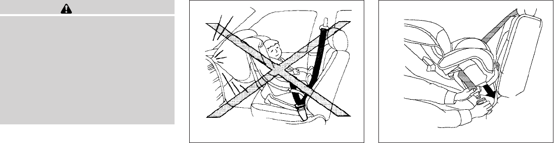
1. Child restraints for infants must be
used in the rear-facing direction and
therefore must not be used in the front
seat. Position the child restraint on the seat.
Always follow the restraint manufacturer’s
instructions.
2. Route the seat belt tongue through the child
restraint and insert it into the buckle until you
hear and feel the latch engage. Be sure to
follow the child restraint manufacturer’s in-
structions for belt routing.
Rear-facing – step 1 WRS0256
Rear-facing – step 2
WRS0761
1-34 Safety—Seats, seat belts and supplemental restraint system
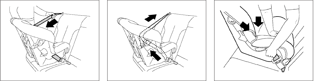
3. Pull the shoulder belt until the belt is fully
extended. At this time, the seat belt retractor
is in the Automatic Locking Retractor (ALR)
mode (child restraint mode). It reverts to the
Emergency Locking Retractor (ELR) mode
when the seat belt is fully retracted.
4. Allow the seat belt to retract. Pull up on the
shoulder belt to remove any slack in the belt. 5. Remove any additional slack from the seat
belt; press downward and rearward firmly in
the center of the child restraint to compress
the vehicle seat cushion and seatback while
pulling up on the seat belt.
Rear-facing – step 3
LRS0669
Rear-facing – step 4
LRS0670
Rear-facing – step 5
WRS0762
Safety—Seats, seat belts and supplemental restraint system 1-35
6. After attaching the child restraint, test it be-
fore you place the child in it. Push it from side
to side while holding the child restraint near
the seat belt path. The child restraint should
not move more than 1 inch (25 mm), from
side to side. Try to tug it forward and check
to see if the belt holds the restraint in place.
If the restraint is not secure, tighten the seat
belt as necessary, or put the restraint in
another seat and test it again. You may need
to try a different child restraint. Not all child
restraints fit in all types of vehicles.
7. Check to make sure that the child restraint is
properly secured prior to each use. If the
seat belt is not locked, repeat steps 3
through 6.
After the child restraint is removed and the seat
belt fully retracted, the ALR mode (child restraint
mode) is canceled.
REAR-FACING CHILD RESTRAINT
INSTALLATION USING THE SEAT
BELTS — PASSENGER’S SIDE
JUMP SEAT (King cab models only)
Rear-facing – step 6
WRS0763 LRS0597
1-36 Safety—Seats, seat belts and supplemental restraint system
WARNING
●The three-point seat belt with Auto-
matic Locking Retractor (ALR) must be
used when installing a child restraint.
Failure to use the ALR mode will result
in the child restraint not being properly
secured. The restraint could tip over or
be loose and cause injury to a child in a
sudden stop or collision. Also, it can
change the operation of the front pas-
senger air bag. See “Front passenger
air bag and status light” later in this
section.
●Do not install a child restraint system
on the passenger’s side jump seat with-
out unfolding the seat extender.
●A child restraint system will not be in-
stalled properly and the child could be
seriously injured or killed in a sudden
stop or collision.
– Never install a child restraint system
on the driver’s side jump seat.
– Do not install a child restraint system
on the passenger’s side jump seat
without unfolding the seat extender.
WARNING
●To install a rear-facing child restraint on
the passenger’s side jump seat, it will
be necessary to move the front passen-
ger’s seat fully forward and place the
front seatback upright or tilt it forward.
Failure to do so may cause the child
restraint to not be installed properly
and cause serious injury or death in a
sudden stop or collision.
– The front seat cannot be used when a
rear-facing child restraint is installed
on the jump seat. Attempting to do so
could cause serious injury in a sud-
den stop or collision.
LRS0549
Safety—Seats, seat belts and supplemental restraint system 1-37
Refer to all Warnings and Cautions in the “Child
Safety” and “Child Restraint” sections before in-
stalling a child restraint.
Follow these steps to install a child restraint on
the passenger’s side jump seat.
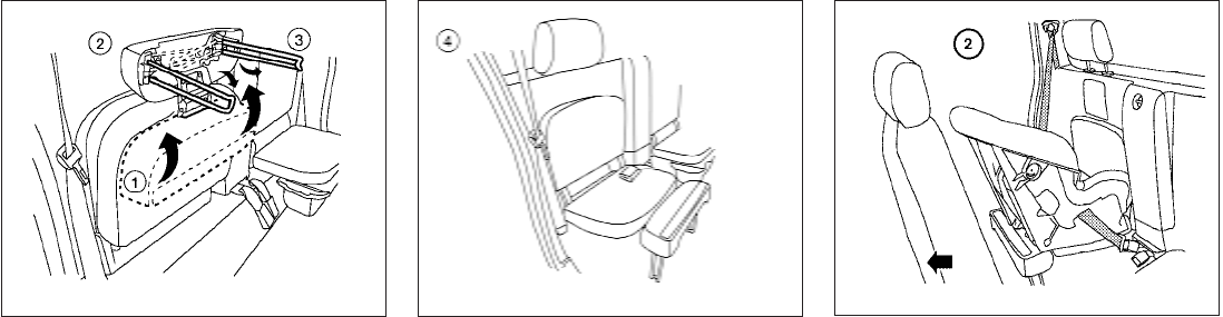
1. To access the jump seat extension s
1on the
passenger’s side jump seat only, pull up s
2
on the extension to unfold it to the open
position. Then unfold the two support legs
s
3and lower the jump seat to the full open
s
4seating position.
s
2Move the front passenger’s seat into the
FULL FORWARD position. Then move the
front seatback to the upright or tilted forward
position. Position the child restraint on the
jump seat. The direction of the child restraint
depends on the type of the child restraint
and the size of the child. Always follow the
restraint manufacturer’s instructions.
LRS0559 LRS0537 Rear-facing (passenger’s side jump seat
only) — step 2
LRS0544
1-38 Safety—Seats, seat belts and supplemental restraint system
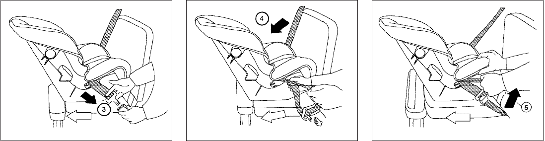
s
3Route the seat belt tongue through the child
restraint and insert it into the buckle until you
hear and feel the latch engage.
Be sure to follow the child restraint manu-
facturer’s instructions for belt routing.
s
4Pull the shoulder belt until the belt is fully
extended. At this time, the seat belt retractor
is in the Automatic Locking Retractor (ALR)
mode (child restraint mode). It reverts to the
Emergency Locking Retractor (ELR) mode
when the seat belt is fully retracted.
s
5Allow the seat belt to retract. Pull up on the
shoulder belt to remove any slack in the belt.
Rear-facing — step 3
LRS0545
Rear-facing — step 4
LRS0546
Rear-facing — step 5
LRS0547
Safety—Seats, seat belts and supplemental restraint system 1-39
6. Remove any additional slack from the seat
belt; press downward and rearward firmly in
the center of the child restraint to compress
the vehicle seat cushion and seatback while
pulling up on the seat belt.
7. After attaching the child restraint, test it be-
fore you place the child in it. Push it from side
to side while holding the seat near the seat
belt path. The child restraint should not
move more than 1 inch (25 mm), from side to
side. Try to tug it forward and check to see if
the seat belt holds the restraint in place. If
the restraint is not secure, tighten the seat
belt as necessary, or put the restraint in
another seat and test it again. You may need
to try a different child restraint. Not all child
restraints fit in all types of vehicles.
8. Check to make sure that the child restraint is
properly secured prior to each use. If the
seat belt is not locked, repeat steps 3
through 7.
After the child restraint is removed and the seat
belt fully retracted, the ALR mode (child restraint
mode) is canceled.
FORWARD-FACING CHILD
RESTRAINT INSTALLATION USING
LATCH (Crew cab model only)
Refer to all Warnings and Cautions in the “Child
Safety” and “Child Restraint” sections before in-
stalling a child restraint.
Follow these steps to install a forward-facing
child restraint in the 2nd row seats using the
LATCH system:
1. Position the child restraint on the seat. Al-
ways follow the child restraint manufactur-
er’s instructions.
Rear-facing – step 6
WRS0762
Rear-facing — step 7
WRS0918
1-40 Safety—Seats, seat belts and supplemental restraint system
2. Secure the child restraint anchor attach-
ments to the LATCH lower anchors. Check
to make sure the LATCH attachment is prop-
erly attached to the lower anchors.
If the child restraint is equipped with a top
tether strap, route the top tether strap and
secure the tether strap to the tether anchor
point. See “Installing top tether strap” in this
section. Do not install child restraints that
require the use of a top tether strap in seat-
ing positions that do not have a top tether
anchor.
3. The back of the child restraint should be
secured against the vehicle seatback.
If necessary, adjust or remove the headrest
to obtain the correct child restraint fit. If the
headrest is removed, store it in a secure
place. Be sure to reinstall the headrest
when the child restraint is removed.
See “Adjustable headrest” in this section for
headrest adjustment information.
If the seating position does not have an
adjustable headrest and it is interfering with
the proper child restraint fit, try another seat-
ing position or a different child restraint.
4. For child restraints that are equipped with
webbing-mounted attachments, remove any
additional slack from the anchor attach-
ments. Press downward and rearward firmly
in the center of the child restraint with your
knee to compress the vehicle seat cushion
and seatback while tightening the webbing
of the anchor attachments.
Forward-facing web-mounted – step 2
WRS0799
Forward-facing rigid-mounted – step 2
WRS0800
Forward-facing – step 4
LRS0671
Safety—Seats, seat belts and supplemental restraint system 1-41
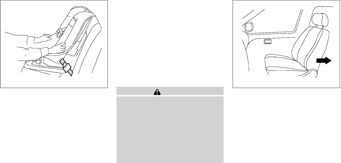
5. After attaching the child restraint, test it be-
fore you place the child in it. Push it from side
to side while holding the child restraint near
the LATCH attachment path. The child re-
straint should not move more than 1 inch (25
mm), from side to side. Try to tug it forward
and check to see if the LATCH attachment
holds the restraint in place. If the restraint is
not secure, tighten the LATCH attachment
as necessary, or put the restraint in another
seat and test it again. You may need to try a
different child restraint. Not all child re-
straints fit in all types of vehicles.
6. Tighten the tether strap according to the
manufacturer’s instructions to remove any
slack.
7. Check to make sure the child restraint is
properly secured prior to each use. If the
child restraint is loose, repeat steps 3
through 5.
FORWARD-FACING CHILD
RESTRAINT INSTALLATION USING
THE SEAT BELTS — FRONT
PASSENGER AND REAR BENCH
SEAT (Crew cab models only)
WARNING
The three-point seat belt with Automatic
Locking Retractor (ALR) must be used
when installing a child restraint. Failure to
use the ALR mode will result in the child
restraint not being properly secured. The
restraint could tip over or be loose and
cause injury to a child in a sudden stop or
collision. Also, it can change the opera-
tion of the front passenger air bag. See
“Front passenger air bag and status light”
later in this section.
Refer to all Warnings and Cautions in the “Child
Safety” and “Child Restraint” sections before in-
stalling a child restraint.
Follow these steps to install a forward-facing
child restraint using the vehicle seat belt in the
rear seats (Crew cab models only) or in the front
passenger seat:
1. If you must install a child restraint in
the front seat, it should be placed in a
forward-facing direction only. Move
the seat to the rearmost position. Child
restraints for infants must be used in
the rear-facing direction and therefore
must not be used in the front seat.
Forward-facing – step 5
WRS0697
Forward-facing (front passenger seat) –
step 1
WRS0699
1-42 Safety—Seats, seat belts and supplemental restraint system
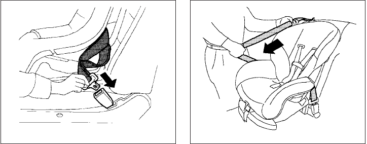
2. Position the child restraint on the seat. Al-
ways follow the child restraint manufactur-
er’s instructions.
The back of the child restraint should be
secured against the vehicle seatback.
If necessary, adjust or remove the head re-
straint or headrest to obtain the correct child
restraint fit. If the head restraint or headrest
is removed, store it in a secure place. Be
sure to reinstall the head restraint or
headrest when the child restraint is
removed. See “Head restraints” or “Adjust-
able headrest” in this section for head re-
straint or headrest adjustment, removal and
installation information.
If the seating position does not have an
adjustable head restraint or headrest and it
is interfering with the proper child restraint
fit, try another seating position or a different
child restraint.
3. Route the seat belt tongue through the child
restraint and insert it into the buckle until you
hear and feel the latch engage. Be sure to
follow the child restraint manufacturer’s in-
structions for belt routing.
If the child restraint is equipped with a top
tether strap, route the top tether strap and
secure the tether strap to the tether anchor
point (rear seat installation only). See “In-
stalling top tether strap” in this section. Do
not install child restraints that require the use
of a top tether strap in seating positions that
do not have a top tether anchor.
4. Pull the shoulder belt until the belt is fully
extended. At this time, the seat belt retractor
is in the Automatic Locking Retractor (ALR)
mode (child restraint mode). It reverts to
Emergency Locking Retractor (ELR) mode
when the seat belt is fully retracted.
Forward-facing – step 3
WRS0680
Forward-facing – step 4
LRS0667
Safety—Seats, seat belts and supplemental restraint system 1-43
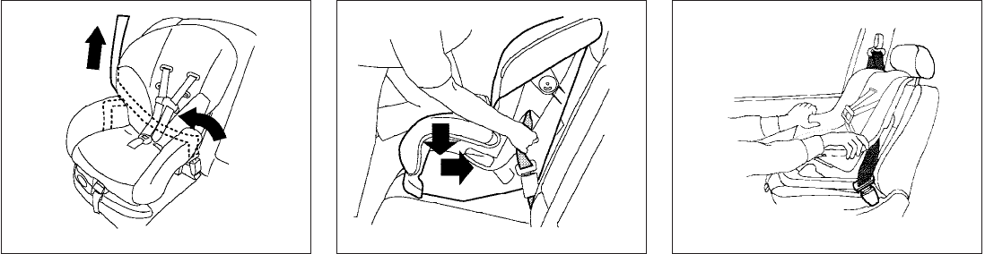
5. Allow the seat belt to retract. Pull up on the
shoulder belt to remove any slack in the belt. 6. Remove any additional slack from the seat
belt; press downward and rearward firmly in
the center of the child restraint with your
knee to compress the vehicle seat cushion
and seatback while pulling up on the seat
belt.
7. After attaching the child restraint, test it be-
fore you place the child in it. Push it from side
to side while holding the child restraint near
the seat belt path. The child restraint should
not move more than 1 inch (25 mm), from
side to side. Try to tug it forward and check
to see if the seat belt holds the restraint in
place. If the restraint is not secure, tighten
the seat belt as necessary, or put the re-
straint in another seat and test it again. You
may need to try a different child restraint. Not
all child restraints fit in all types of vehicles.
Forward-facing – step 5
LRS0668
Forward-facing – step 6
WRS0681 Forward-facing – step 7 WRS0698
1-44 Safety—Seats, seat belts and supplemental restraint system
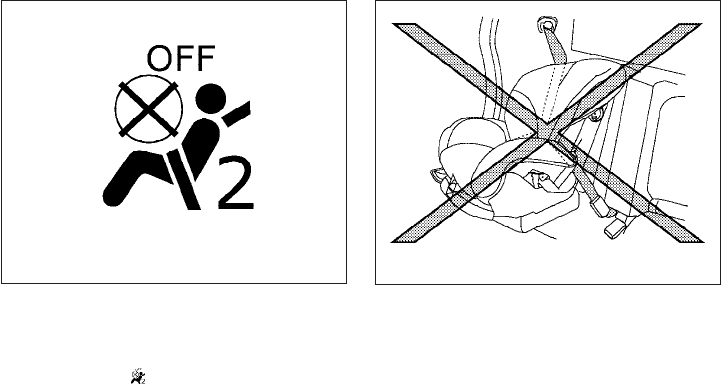
8. Tighten the tether strap according to the
manufacturer’s instructions to remove any
slack.
9. Check to make sure the child restraint is
properly secured prior to each use. If the
seat belt is not locked, repeat steps 3
through 7.
10. If the child restraint is installed in the front
passenger seat, place the ignition switch in
the ON position. The front passenger air bag
status light should illuminate. If this
light is not illuminated see 9Front passenger
air bag and status light9in this section.
Move the child restraint to another
seating position. Have the system
checked by a NISSAN dealer.
After the child restraint is removed and the seat
belt is fully retracted, the ALR mode (child re-
straint mode) is canceled.
FOWARD-FACING CHILD
RESTRAINT INSTALLATION USING
THE SEAT BELTS — FRONT
PASSENGER AND PASSENGER’S
SIDE JUMP SEAT (King cab models
only)
Forward-facing – step 11
WRS0475 LRS0598
Safety—Seats, seat belts and supplemental restraint system 1-45
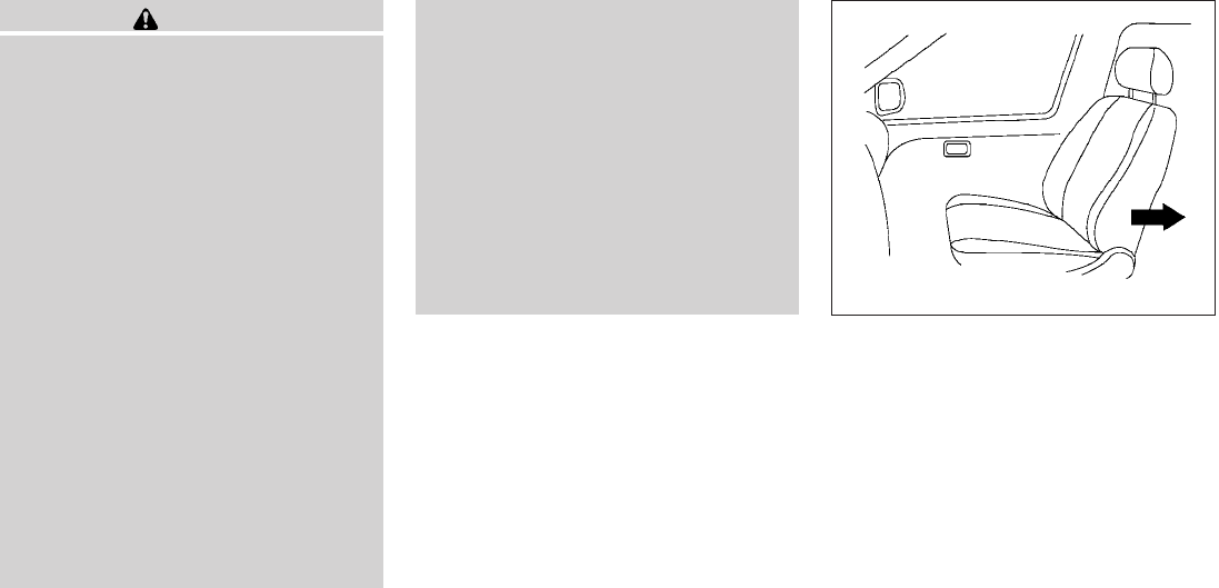
WARNING
●The three-point seat belt with Auto-
matic Locking Retractor (ALR) must be
used when installing a child restraint.
Failure to use the ALR mode will result
in the child restraint not being properly
secured. The restraint could tip over or
be loose and cause injury to a child in a
sudden stop or collision. Also, it can
change the operation of the front pas-
senger air bag. See “Front passenger
air bag and status light” later in this
section.
●Do not install a child restraint system
on the passenger’s side jump seat with-
out unfolding the seat extender.
●A child restraint system will not be in-
stalled properly and the child could be
seriously injured or killed in a sudden
stop or collision.
– Never install a child restraint system
on the driver’s side jump seat.
– Do not install a child restraint system
on the passenger’s side jump seat
without unfolding the seat extender.
●To install a rear-facing child restraint on
the passenger’s side jump seat, it will
be necessary to move the front passen-
ger’s seat fully forward and place the
front seatback upright or tilt it forward.
Failure to do so may cause the child
restraint to not be installed properly
and cause serious injury or death in a
sudden stop or collision.
– The front seat cannot be used when a
rear-facing child restraint is installed
on the jump seat. Attempting to do so
could cause serious injury in a sud-
den stop or collision.
Refer to all Warnings and Cautions in the “Child
Safety” and “Child Restraint” sections before in-
stalling a child restraint.
Follow these steps to install a forward-facing
child restraint using the vehicle seat belt in the
passenger’s side jump seat (King cab models
only) or in the front passenger seat:
1. If you must install a child restraint in
the front seat, it should be placed in a
forward-facing direction only. Move
the seat to the rearmost position. Child
restraints for infants must be used in
the rear-facing direction and therefore
must not be used in the front seat.
Foward-facing (front passenger seat) —
step 1
WRS0699
1-46 Safety—Seats, seat belts and supplemental restraint system
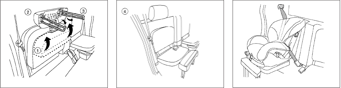
2. To access the jump seat extension s
1on the
passenger’s side jump seat pull up s
2on
the extension to unfold it to the open posi-
tion. Then unfold the two support legs s
3
and lower the jump seat to the full open s
4
seating position.
3. Position the child restraint on the seat. Al-
ways follow the child restraint manufactur-
er’s instructions.
The back of the child restraint should be
secured against the vehicle seat back.
If necessary, adjust or remove the head re-
straint or headrest to obtain the correct child
restraint fit. If the head restraint or headrest
is removed, store it in a secure place. Be
sure to reinstall the head restraint or
headrest when the child restraint is
removed. See “Head restraints” or “Adjust-
LRS0559 LRS0537 Forward-facing (passenger’s side seating
position only) — step 3
WRS0919
Safety—Seats, seat belts and supplemental restraint system 1-47

able headrest” in this section for head re-
straint or headrest adjustment, removal and
installation information.
If the seating position does not have an
adjustable head restraint or headrest and it
is interfering with the proper child restraint
fit, try another seating position or a different
child restraint.
4. Route the seat belt tongue through the child
restraint and insert it into the buckle until you
hear and feel the latch engage. Be sure to
follow the child restraint manufacturer’s in-
structions for belt routing.
If the child restraint is equipped with a top
tether strap, route the top tether strap and
secure the tether strap to the tether anchor
point. See “Installing top tether strap” in this
section. Do not install child restraints that
require the use of a top tether strap to seat-
ing positions that do not have a top tether
anchor.
5. Pull the shoulder belt until the belt is fully
extended. At this time, the seat belt retractor
is in the Automatic Locking Retractor (ALR)
mode (child restraint mode). It reverts to the
Emergency Locking Retractor (ELR) mode
when the seat belt is fully retracted.
Forward-facing — step 4
WRS0680
Forward-facing — step 5
LRS0667
1-48 Safety—Seats, seat belts and supplemental restraint system

6. Allow the seat belt to retract. Pull up on the
shoulder belt to remove any slack in the belt. 7. Remove any additional slack from the seat
belt; press downward and rearward firmly in
the center of the child restraint with your
knee to compress the vehicle seat cushion
and seatback while pulling up on the seat
belt.
8. After attaching the child restraint, test it be-
fore you place the child in it. Push it from side
to side while holding the seat near the seat
belt path. The child restraint should not
move more than 1 inch (25 mm), from side to
side. Try to tug it forward and check to see if
the belt holds the restraint in place. If the
restraint is not secure, tighten the belt as
necessary, or put the restraint in another
seat and test it again. You may need to try a
different child restraint. Not all child re-
straints fit in all types of vehicles.
Forward-facing — step 6
LRS0668
Forward-facing – step 7
WRS0681 Forward-facing — step 8 WRS0698
Safety—Seats, seat belts and supplemental restraint system 1-49
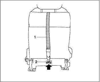
9. Tighten the tether strap according to the
manufacturer’s instructions to remove any
slack.
10. Check to make sure that the child restraint is
properly secured prior to each use. If the
seat belt is not locked, repeat steps 3
through 8.
After the child restraint is removed and the seat
belt is fully retracted, the ALR mode (child re-
straint mode) is canceled.
INSTALLING TOP TETHER STRAP
(Front passenger seat – King cab
models only)
Before securing the child restraint with the seat
belt,
1. If necessary, raise or remove the head re-
straint to position the top tether strap s
1
over the top of the seatback. If the head
restraint is removed, store it in a secure
place. Be sure to reinstall the head restraint
when the child restraint is removed. See
“Head restraint adjustment” in this
section for head restraint adjustment,
removal and installation information.
2. Route the top tether strap s
1between the
head restraint and the top of the seatback.
3. Secure the tether strap to the tether anchor
point s
2on the seatback.
4. Refer back to child restraint installation
steps before tightening the tether strap.
If you have any questions when installing a
top tether strap, consult your NISSAN
dealer for details.
Front passenger seat (King cab models only)
LRS0572
1-50 Safety—Seats, seat belts and supplemental restraint system
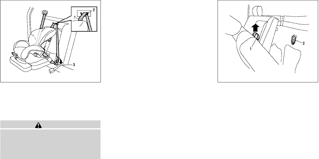
INSTALLING TOP TETHER STRAP
(Passenger’s side jump seat – King
cab models only)
WARNING
Do not secure the top tether strap to the
routing bracket. If the child restraint is not
anchored properly, the risk of a child be-
ing injured or killed in a collision or a
sudden stop greatly increases.
First, secure the child restraint with the seat belt.
1. Pull the cover plate off to access the top
tether strap routing bracket for the passen-
ger’s side jump seat.
2. Route the top tether strap through the rout-
ing bracket.
3. Secure the top tether strap to the tether
anchor point (3) located between the seat
belt buckles in the center of the vehicle.
4. Refer back to child restraint installation
steps before tightening the tether strap.
If you have any questions when installing a
top tether strap, consult your NISSAN
dealer for details.
Passenger’s side jump seat (King cab mod-
els only)
LRS0561
Anchor point access
LRS0392
Safety—Seats, seat belts and supplemental restraint system 1-51
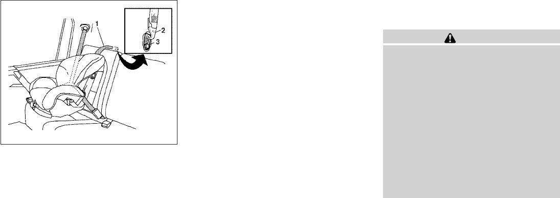
INSTALLING TOP TETHER STRAP
(Rear bench seat – Crew cab models
only)
To access the anchor points s
2behind the rear
bench seat, tilt the rear seatback forward by
lifting up on the pull strap s
1behind the seat-
back.
Before securing the child restraint with the
LATCH lower anchors (rear outboard seating po-
sitions only [crew cab models only]) or the seat
belt, as applicable, follow these steps.
1. If necessary, raise or remove the headrest to
position the top tether strap s
1over the top
of the seatback. If the headrest is removed,
store it in a secure place. Be sure to reinstall
the headrest when the child restraint is re-
moved. See “Adjustable headrest” in
this section for headrest adjustment,
removal and installation information.
2. Position the top tether strap over the top of
the seatback and under the head restraint.
3. Secure the tether strap to the tether anchor
point on the seat directly behind the child
restraint.
4. Return the seatback to the locked position.
5. Refer back to child restraint installation
steps before tightening the tether strap.
If you have any questions when installing a
top tether strap, consult your NISSAN
dealer for details.
BOOSTER SEATS
Precautions on booster seats
WARNING
If a booster seat and seat belt are not used
properly, the risk of a child being injured
in a sudden stop or collision greatly
increases:
– Make sure the shoulder portion of
the belt is away from the child’s face
and neck and the lap portion of the
belt does not cross the stomach.
– Make sure the shoulder belt is not
behind the child or under the child’s
arm.
– A booster seat must only be installed
in a seating position that has a
lap/shoulder belt.
Rear bench seat (Crew cab models only)
LRS0576
1-52 Safety—Seats, seat belts and supplemental restraint system
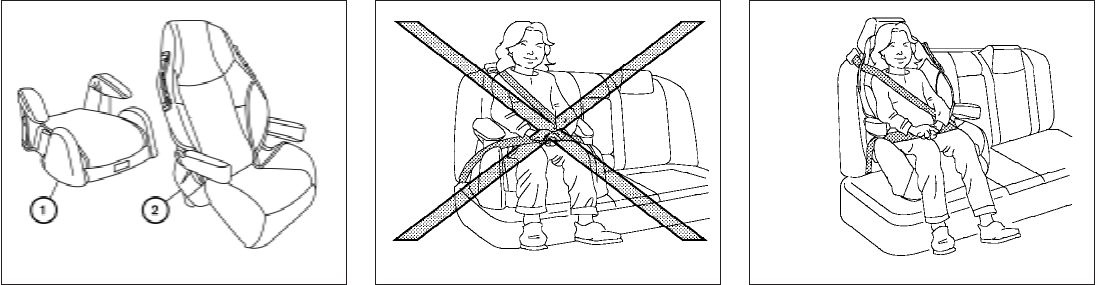
Booster seats of various sizes are offered by
several manufacturers. When selecting any
booster seat, keep the following points in mind:
●Choose only a booster seat with a label
certifying that it complies with Federal Motor
Vehicle Safety Standard 213 or Canadian
Motor Vehicle Safety Standard 213.
●Check the booster seat in your vehicle to be
sure it is compatible with the vehicle’s seat
and seat belt system.
●Make sure the child’s head will be properly
supported by the booster seat or vehicle
seat. The seatback must be at or above the
center of the child’s ears. For example, if a
low back booster seat s
1is chosen, the
vehicle seatback must be at or above the
center of the child’s ears. If the seatback is
lower than the center of the child’s ears, a
high back booster seat s
2should be used.
●If the booster seat is compatible with your
vehicle, place the child in the booster seat
and check the various adjustments to be
sure the booster seat is compatible with the
child. Always follow all recommended pro-
cedures.
All U.S. states and Canadian provinces or
territories require that infants and small
children be restrained in an approved child
restraint at all times while the vehicle is
being operated.
The instructions in this section apply to booster
seat installation in the rear seats or the front
passenger seat.
LRS0455 LRS0453 LRS0464
Safety—Seats, seat belts and supplemental restraint system 1-53
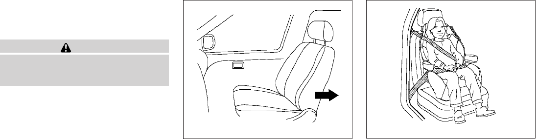
Booster seat installation on front
passenger seat and rear seat (Crew
cab models only)
CAUTION
Do not use the lap/shoulder belt in the
Automatic Locking Retractor mode when
using a booster seat with the seat belts.
Refer to all Warnings and Cautions in the “Child
Safety”, “Child Restraint” and “Booster Seats”
sections before installing a child restraint.
Follow these steps to install a booster seat in the
rear seat or in the front passenger seat:
1. If you must install a booster seat in the
front seat, move the seat to the rear-
most position.
2. Position the booster seat on the seat. Only
place it in a front-facing direction. Always
follow the booster seat manufacturer’s in-
structions.
3. The booster seat should be positioned on
the vehicle seat so that it is stable.
If necessary, adjust or remove the head re-
straint or headrest to obtain the correct
booster seat fit. If the head restraint or head-
rest is removed, store it in a secure place. Be
sure to reinstall the head restraint or
headrest when the booster seat is re-
moved. See “Head restraint adjustment” or
“Adjustable headrest” in this section for
head restraint or headrest adjustment, re-
moval and installation information.
WRS0699 Front passenger position
LRS0454
1-54 Safety—Seats, seat belts and supplemental restraint system
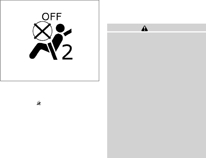
If the seating position does not have an
adjustable head restraint or headrest and it
is interfering with the proper booster seat fit,
try another seating position or a different
booster seat.
4. Position the lap portion of the seat belt low
and snug on the child’s hips. Be sure to
follow the booster seat manufacturer’s in-
structions for adjusting the seat belt routing.
5. Pull the shoulder belt portion of the seat belt
toward the retractor to take up extra slack.
Be sure the shoulder belt is positioned
across the top, middle portion of the child’s
shoulder. Be sure to follow the booster seat
manufacturer’s instructions for adjusting the
seat belt routing.
6. Follow the warnings, cautions and instruc-
tions for properly fastening a seat belt
shown in “Three-point type seat belt with
retractor” earlier in this section.
7. If the booster seat is installed in the front
passenger seat, place the ignition switch in
the ON position. The front passenger air bag
status light may or may not illuminate,
depending on the size of the child and the
type of booster seat being used. See “Front
passenger air bag and status light” later in
this section.
Booster seat installation on
passenger’s side jump seat only (King
cab models only)
WARNING
●Do not install a child restraint system
on the passenger’s side jump seat with-
out unfolding the seat extender.
●A child restraint system will not be in-
stalled properly and the child could be
seriously injured or killed in a sudden
stop or collision.
– Never install a child restraint system
on the driver’s side jump seat.
– Do not install a child restraint system
on the passenger’s side jump seat
without unfolding the seat extender.
●To install a rear-facing child restraint on
the passenger’s side jump seat, it will
be necessary to move the front passen-
ger’s seat fully forward and place the
front seatback upright or tilt it forward.
Failure to do so may cause the child
restraint to not be installed properly
and cause serious injury or death in a
sudden stop or collision.
WRS0475
Safety—Seats, seat belts and supplemental restraint system 1-55
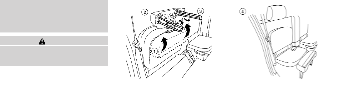
– The front seat cannot be used when a
rear-facing child restraint is installed
on the jump seat. Attempting to do so
could cause serious injury in a sud-
den stop or collision.
CAUTION
Do not use the lap/shoulder belt in the
Automatic Locking Retractor mode when
using a booster seat with the seat belts.
Refer to all Warnings and Cautions in the “Child
Safety”, “Child Restraint” and “Booster Seats”
sections before installing a child restraint.
Follow these steps to install a booster seat in the
passenger’s side jump seat only: 1. To access the jump seat extension s
1on the
passenger’s side jump seat only pull up s
2
on the extension to unfold it to the open
position. Then unfold the two support legs
s
3and lower the jump seat to the full open
s
4seating position.
LRS0559 LRS0537
1-56 Safety—Seats, seat belts and supplemental restraint system
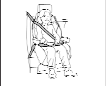
2. Position the booster seat on the seat. Only
place it in a front-facing direction. Always
follow the booster seat manufacturer’s in-
structions.
3. The booster seat should be positioned on
the vehicle seat so that it is stable.
If necessary, adjust or remove the headrest
to obtain the correct booster seat fit. If the
headrest is removed, store it in a secure
place. Be sure to reinstall the headrest
when the booster seat is removed. See
“Adjustable headrest” in this section for
headrest adjustment, removal and installa-
tion information.
If the seating position does not have an
adjustable headrest and it is interfering with
the proper booster seat fit, try another seat-
ing position or a different booster seat.
4. Position the lap portion of the seat belt low
and snug on the child’s hips. Be sure to
follow the booster seat manufacturer’s in-
structions for adjusting the seat belt routing.
5. Pull the shoulder belt portion of the seat belt
toward the retractor to take up extra slack.
Be sure the shoulder belt is positioned
across the top, middle portion of the child’s
shoulder. Be sure to follow the booster seat
manufacturer’s instructions for adjusting the
seat belt routing.
6. Follow the warnings, cautions and instruc-
tions for properly fastening a seat belt
shown in “Three-point type seat belt with
retractor” earlier in this section.
PRECAUTIONS ON
SUPPLEMENTAL RESTRAINT
SYSTEM
This Supplemental Restraint System (SRS) sec-
tion contains important information concerning
the following systems:
●Driver and passenger supplemental front-
impact air bag (NISSAN Advanced Air Bag
System)
●Front seat-mounted side-impact supple-
mental air bag
●Roof-mounted curtain side-impact and roll-
over supplemental air bag
●Seat belt with pretensioner
Supplemental front-impact air bag system:
The NISSAN Advanced Air Bag System can help
cushion the impact force to the head and chest of
the driver and front passenger in certain frontal
collisions.
Front seat-mounted side-impact supple-
mental air bag system: This system can help
cushion the impact force to the chest area of the
driver and front passenger in certain side impact
collisions. The side air bags are designed to
inflate on the side where the vehicle is impacted.
LRS0539
SUPPLEMENTAL RESTRAINT
SYSTEM
Safety—Seats, seat belts and supplemental restraint system 1-57
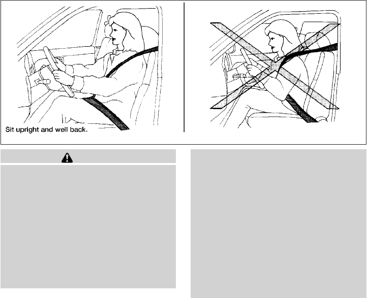
Roof-mounted curtain side-impact and
rollover supplemental air bag system: This
system can help cushion the impact force to the
head of occupants in front and rear outboard
seating positions in certain side impact or rollover
collisions. In a side impact, the curtain and roll-
over air bags are designed to inflate on the side
where the vehicle is impacted. In a rollover, both
curtain and rollover air bags are designed to
inflate and remain inflated for a short time.
These supplemental restraint systems are de-
signed to supplement the crash protection pro-
vided by the seat belts and are not a substitute
for them. Seat belts should always be correctly
worn and the occupant seated a suitable dis-
tance away from the steering wheel, instrument
panel and door finishers. See “Seat belts” earlier
in this section for instructions and precautions on
seat belt usage.
The supplemental air bags operate only
when the ignition switch is in the ON or
START position.
After placing the ignition switch in the ON
position, the supplemental air bag warning
light illuminates. The supplemental air bag
warning light will turn off after about 7
seconds if the system is operational.
WARNING
●The front air bags ordinarily will not
inflate in the event of a side impact, rear
impact, rollover, or lower severity fron-
tal collision. Always wear your seat
belts to help reduce the risk or severity
of injury in various kinds of accidents.
●The front passenger air bag will not
inflate if the passenger air bag status
light is lit or if the front passenger seat
is unoccupied. See “Front passenger air
bag and status light” later in this
section.
●The seat belts and the front air bags are
most effective when you are sitting well
back and upright in the seat. The front
air bags inflate with great force. Even
with the NISSAN Advanced Air Bag Sys-
tem, if you are unrestrained, leaning
forward, sitting sideways or out of posi-
tion in any way, you are at greater risk of
injury or death in a crash. You may also
receive serious or fatal injuries from the
front air bag if you are up against it
when it inflates. Always sit back against
the seatback and as far away as practi-
cal from the steering wheel or instru-
ment panel. Always use the seat belts.
WRS0031
1-58 Safety—Seats, seat belts and supplemental restraint system
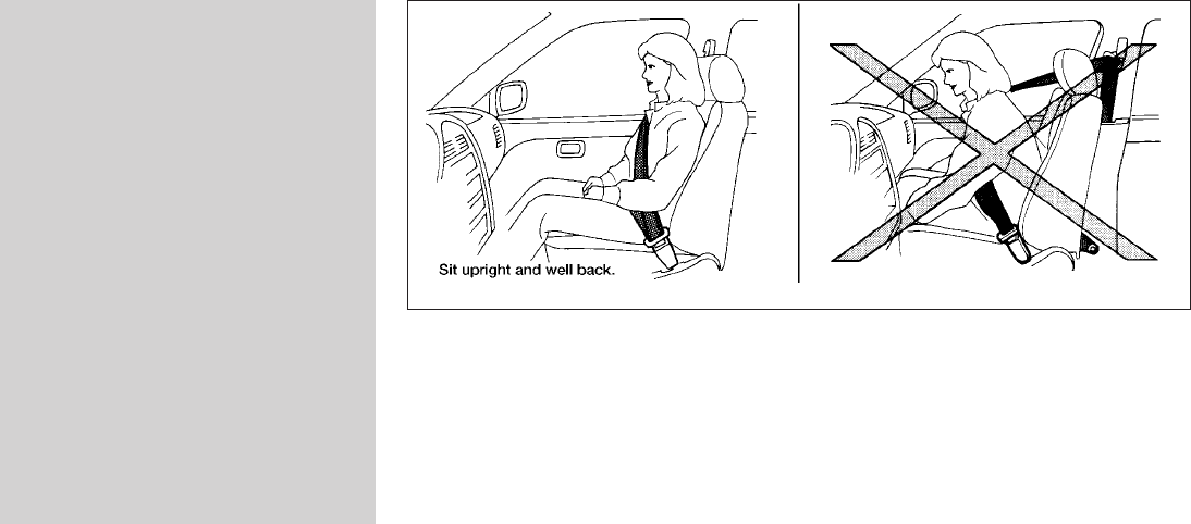
●The driver and front passenger seat belt
buckles are equipped with sensors that
detect if the seat belts are fastened. The
Advanced Air Bag System monitors the
severity of a collision and seat belt us-
age then inflates the air bags. Failure to
properly wear seat belts can increase
the risk or severity of injury in an
accident.
●The front passenger seat is equipped
with an occupant classification sensor
(pressure sensor) that turns the front
passenger air bag OFF under some
conditions. This sensor is only used in
this seat. Failure to be properly seated
and wearing the seat belt can increase
the risk or severity of injury in an acci-
dent. See “Front passenger air bag and
status light” later in this section.
●Keep hands on the outside of the steer-
ing wheel. Placing them inside the
steering wheel rim could increase the
risk that they are injured when the front
air bag inflates.
ARS1133
Safety—Seats, seat belts and supplemental restraint system 1-59
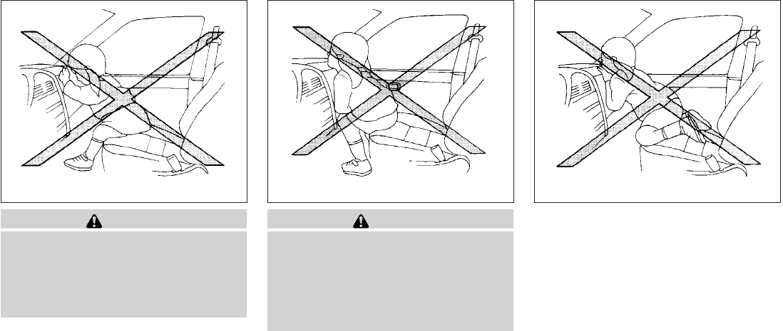
WARNING
●Never let children ride unrestrained or
extend their hands or face out of the
window. Do not attempt to hold them in
your lap or arms. Some examples of
dangerous riding positions are shown
in the illustrations.
WARNING
●Children may be severely injured or
killed when the front air bags, side air
bags or curtain and rollover air bags
inflate if they are not properly re-
strained. Pre-teens and children should
be properly restrained in the rear seat, if
possible.
ARS1041 ARS1042 ARS1043
1-60 Safety—Seats, seat belts and supplemental restraint system
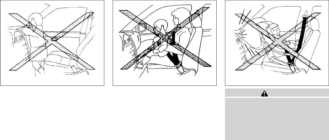
WARNING
●Even with the NISSAN Advanced Air
Bag System, never install a rear-facing
child restraint in the front seat. An in-
flating front air bag could seriously in-
jure or kill your child. See “Child re-
straints” earlier in this section for
details.
ARS1044 ARS1045 WRS0256
Safety—Seats, seat belts and supplemental restraint system 1-61
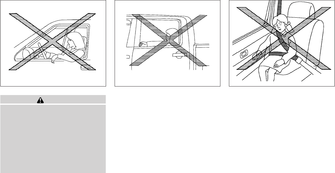
WARNING
Front seat-mounted side-impact supple-
mental air bags and roof-mounted curtain
side-impact and rollover supplemental air
bags:
●The side air bags and curtain and roll-
over air bags ordinarily will not inflate in
the event of a frontal impact, rear im-
pact, or lower severity side collision.
Always wear your seat belts to help
reduce the risk or severity of injury in
various kinds of accidents.
Do not lean against the door.
WRS0431
Do not lean against doors or windows.
LRS0396
Do not lean against doors or windows.
SSS0162
1-62 Safety—Seats, seat belts and supplemental restraint system
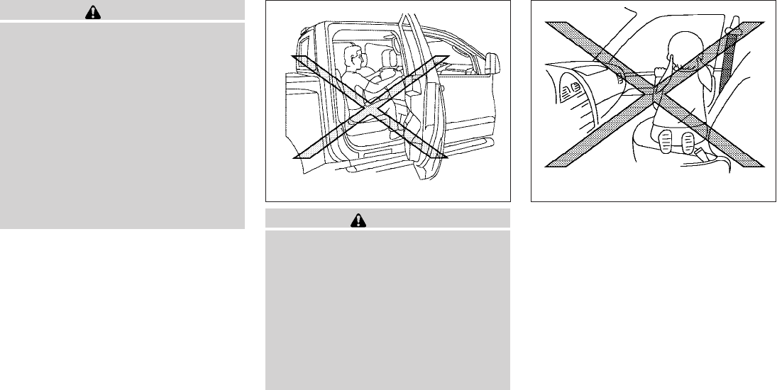
WARNING
●The seat belts, the side air bags and
curtain and rollover air bags are most
effective when you are sitting well back
and upright in the seat. The side air bag
and curtain and rollover air bag inflate
with great force. Do not allow anyone to
place their hand, leg or face near the
side air bag on the side of the seatback
of the front seat or near the side roof
rails. Do not allow anyone sitting in the
front seats or rear outboard seats to
extend their hand out of the window or
lean against the door. Some examples
of dangerous riding positions are
shown in the previous illustrations. WARNING
●When sitting in the rear seat, do not
hold onto the seatback of the front seat.
If the side air bag inflates, you may be
seriously injured. Be especially careful
with children, who should always be
properly restrained. Some examples of
dangerous riding positions are shown
in the illustrations.
●Do not use seat covers on the front
seatbacks. They may interfere with side
air bag inflation.
LRS0421 SSS0159
Safety—Seats, seat belts and supplemental restraint system 1-63
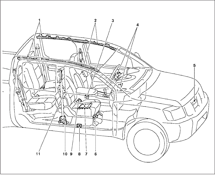
1. Roof-mounted curtain side-impact and
rollover supplemental air bag
2. Roof-mounted curtain side-impact and
rollover supplemental air bag inflators
3. Air bag Control Unit (ACU)
4. Supplemental front-impact air bag mod-
ules
5. Crash zone sensor
6. Occupant classification system control
unit
7. Occupant classification sensor (pres-
sure sensor)
8. Satellite sensors
9. Seat belt buckle switches
10. Seat belt with pretensioner
11. Front seat-mounted side-impact
supplemental air bag modules
LRS0565
1-64 Safety—Seats, seat belts and supplemental restraint system
NISSAN Advanced Air Bag System
(front seats)
This vehicle is equipped with the NISSAN Ad-
vanced Air Bag System for the driver and front
passenger seats. This system is designed to
meet certification requirements under U.S. regu-
lations. It is also permitted in Canada. However,
all of the information, cautions and warn-
ings in this manual still apply and must be
followed.
The driver supplemental front-impact air bag is
located in the center of the steering wheel. The
passenger supplemental front-impact air bag is
mounted in the dashboard above the glove box.
The front air bags are designed to inflate in higher
severity frontal collisions, although they may in-
flate if the forces in another type of collision are
similar to those of a higher severity frontal impact.
They may not inflate in certain frontal collisions.
Vehicle damage (or lack of it) is not always an
indication of proper front air bag system opera-
tion.
The NISSAN Advanced Air Bag System has dual
stage inflators. It also monitors information from
the crash zone sensor, the Air bag Control Unit
(ACU), seat belt buckle sensors, occupant clas-
sification sensor (pressure sensor) and passen-
ger seat belt tension sensor. Inflator operation is
based on the severity of a collision and seat belt
usage for the driver. For the front passenger, it
additionally monitors the weight of an occupant
or object on the seat and seat belt tension. Based
on information from the sensors, only one front air
bag may inflate in a crash, depending on the
crash severity and whether the front occupants
are belted or unbelted. Additionally, the front
passenger air bag may be automatically turned
OFF under some conditions, depending on the
weight detected on the passenger seat and how
the seat belt is used. If the front passenger air bag
is OFF, the passenger air bag status light will be
illuminated (if the seat is unoccupied, the light will
not be illuminated, but the air bag will be off). See
“Front passenger air bag and status light” later in
this section for further details. One front air bag
inflating does not indicate improper performance
of the system.
If you have any questions about your air bag
system, please contact NISSAN or your NISSAN
dealer. If you are considering modification of your
vehicle due to a disability, you may also contact
NISSAN. Contact information is contained in the
front of this Owner’s Manual.
When a front air bag inflates, a fairly loud noise
may be heard, followed by the release of smoke.
This smoke is not harmful and does not indicate a
fire. Care should be taken to not inhale it, as it may
cause irritation and choking. Those with a history
of a breathing condition should get fresh air
promptly.
Front air bags, along with the use of seat belts,
help to cushion the impact force on the face and
chest of the front occupants. They can help save
lives and reduce serious injuries. However, an
inflating front air bag may cause facial abrasions
or other injuries. Front air bags do not provide
restraint to the lower body.
Even with NISSAN advanced air bags, seat belts
should be correctly worn and the driver and pas-
senger seated upright as far as practical away
from the steering wheel or instrument panel. The
front air bags inflate quickly in order to help
protect the front occupants. Because of this, the
force of the front air bag inflating can increase the
risk of injury if the occupant is too close to, or is
against, the front air bag module during inflation.
The front air bags deflate quickly after a collision.
The front air bags operate only when the
ignition switch is in the ON or START posi-
tion.
After placing the ignition switch in the ON
position, the supplemental air bag warning
light illuminates. The supplemental air bag
warning light will turn off after about 7
seconds if the system is operational.
Safety—Seats, seat belts and supplemental restraint system 1-65
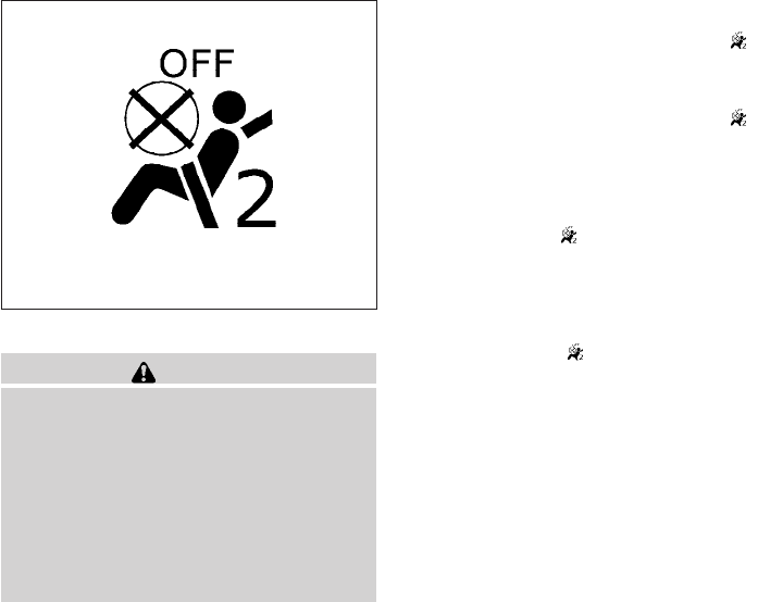
Front passenger air bag and status light
WARNING
The front passenger air bag is designed to
automatically turn OFF under some con-
ditions. Read this section carefully to
learn how it operates. Proper use of the
seat, seat belt and child restraints is nec-
essary for most effective protection. Fail-
ure to follow all instructions in this
manual concerning the use of seats, seat
belts and child restraints can increase the
risk or severity of injury in an accident.
Status light
The front passenger air bag status light is
located near the climate controls. The light oper-
ates as follows:
●Unoccupied passenger’s seat: The is
OFF and the front passenger air bag is OFF
and will not inflate in a crash.
●Passenger’s seat occupied by a small adult,
child or child restraint as outlined in this
section: The illuminates to indicate
that the front passenger air bag is OFF and
will not inflate in a crash.
●Occupied passenger seat and the passen-
ger meet the conditions outlined in this sec-
tion: The light is OFF to indicate that
the front passenger air bag is operational.
Front passenger air bag
The front passenger air bag is designed to auto-
matically turn OFF when the vehicle is operated
under some conditions as described below in
accordance with U.S. regulations. If the front
passenger air bag is OFF, it will not inflate in a
crash. The driver air bag and other air bags in your
vehicle are not part of this system.
The purpose of the regulation is to help reduce
the risk of injury or death from an inflating air bag
to certain front passenger seat occupants, such
as children, by requiring the air bag to be auto-
matically turned OFF. Certain sensors are used
to meet the requirements.
One sensor used is the occupant classification
sensor (pressure sensor). It is in the bottom of the
front passenger seat cushion and is designed to
detect an occupant and objects on the seat by
weight. It works together with seat belt sensors
described later. For example, if a child is in the
front passenger seat, the Advanced Air Bag Sys-
tem is designed to turn the passenger air bag
OFF in accordance with the regulations. Also, if a
child restraint of the type specified in the regula-
tions is on the seat, its weight and the child’s
weight can be detected and cause the air bag to
turn OFF. Occupant classification sensor opera-
tion can vary depending on the front passenger
seat belt sensors.
The front passenger seat belt sensors are de-
signed to detect if the seat belt is buckled and the
amount of tension on the seat belt, such as when
it is in the Automatic Locking Retractor (ALR)
mode (child restraint mode). Based on the
weight on the seat detected by the occupant
classification sensor and the belt tension de-
tected on the seat belt, the Advanced Air Bag
System determines whether the front passenger
air bag should be automatically turned OFF as
required by the regulations.
WRS0475
1-66 Safety—Seats, seat belts and supplemental restraint system

Front passenger seat adult occupants who are
properly seated and using the seat belt as out-
lined in this manual should not cause the passen-
ger air bag to be automatically turned OFF. For
small adults it may be turned OFF, however if the
occupant takes his/her weight off the seat cush-
ion (for example, by not sitting upright, by sitting
on an edge of the seat, or by otherwise being out
of position), this could cause the sensor to turn
the air bag OFF. In addition, if the occupant
improperly uses the seat belt in the ALR mode,
this could cause the air bag to be turned OFF.
Always be sure to be seated and wearing the seat
belt properly for the most effective protection by
the seat belt and supplemental air bag.
NISSAN recommends that pre-teens and children
be properly restrained in a rear seat. NISSAN also
recommends that appropriate child restraints and
booster seats be properly installed in a rear seat. If
this is not possible, the occupant classification
sensor and seat belt sensors are designed to op-
erate as described above to turn the front passen-
ger air bag OFF for specified child restraints as
required by the regulations. Failing to properly se-
cure child restraints and to use the ALR mode may
allow the restraint to tip or move in an accident or
sudden stop. This can also result in the passenger
air bag inflating in a crash instead of being OFF.
See “Child restraints” earlier in this section for
proper use and installation.
If the front passenger seat is not occupied, the
passenger air bag is designed not to inflate in a
crash. However, heavy objects placed on the
seat could result in air bag inflation, because of
the object’s weight detected by the occupant
classification sensor. Other conditions could also
result in air bag inflation, such as if a child is
standing on the seat, or if two children are on the
seat, contrary to the instructions in this manual.
Always be sure that you and all vehicle occupants
are seated and restrained properly.
Using the passenger air bag status light, you can
monitor when the front passenger air bag is au-
tomatically turned OFF with the seat occupied.
The light will not illuminate when the front pas-
senger seat is unoccupied.
If an adult occupant is in the seat but the passen-
ger air bag status light is illuminated (indicating
that the air bag is OFF), it could be that the
person is a small adult, or is not sitting on the seat
properly or not using the seat belt properly.
If a child restraint must be used in the front seat,
the passenger air bag status light may or may not
be illuminated, depending on the size of the child
and the type of child restraint being used. If the air
bag status light is not illuminated (indicating that
the air bag might inflate in a crash), it could be
that the child restraint or seat belt is not being
used properly. Make sure that the child restraint is
installed properly, the seat belt is used properly
and the occupant is positioned properly. If the air
bag status light is not illuminated, reposition the
occupant or child restraint in a rear seat.
If the passenger air bag status light will not illu-
minate even though you believe that the child
restraint, the seat belts and the occupant are
properly positioned, the system may be sensing
an unoccupied seat (in which case the air bag is
OFF). Your NISSAN dealer can check that the
system is OFF by using a special tool. However,
until you have confirmed with your dealer that
your air bag is working properly, reposition the
occupant or child restraint in a rear seat.
The air bag system and passenger air bag status
light will take a few seconds to register a change
in the passenger seat status. For example, if a
large adult who is sitting in the front passenger
seat exits the vehicle, the passenger air bag
status light will go from OFF to ON for a few
seconds and then to OFF. This is normal system
operation and does not indicate a malfunction.
If a malfunction occurs in the front passenger air
bag system, the supplemental air bag warning
light , located in the meter and gauges area
of the instrument panel, will blink. Have the sys-
tem checked by a NISSAN dealer.
Safety—Seats, seat belts and supplemental restraint system 1-67

Other supplemental front-impact air bag
precautions
WARNING
●Do not place any objects on the steer-
ing wheel pad or on the instrument
panel. Also, do not place any objects
between any occupant and the steering
wheel or instrument panel. Such ob-
jects may become dangerous projec-
tiles and cause injury if the front air
bags inflate.
●Immediately after inflation, several
front air bag system components will be
hot. Do not touch them; you may se-
verely burn yourself.
●No unauthorized changes should be
made to any components or wiring of
the supplemental air bag system. This is
to prevent accidental inflation of the
supplemental air bag or damage to the
supplemental air bag system.
●Do not make unauthorized changes to
your vehicle’s electrical system, sus-
pension system or front end structure.
This could affect proper operation of
the front air bag system.
●Tampering with the front air bag system
may result in serious personal injury.
Tampering includes changes to the
steering wheel and the instrument
panel assembly by placing material
over the steering wheel pad and above
the instrument panel or by installing
additional trim material around the air
bag system.
●Modifying or tampering with the front
passenger seat may result in serious
personal injury. For example, do not
change the front seats by placing mate-
rial on the seat cushion or by installing
additional trim material, such as seat
covers, on the seat that are not specifi-
cally designed to assure proper air bag
operation. Additionally, do not stow any
objects under the front passenger seat
or the seat cushion and seatback. Such
objects may interfere with the proper
operation of the occupant classifica-
tion sensor (pressure sensor).
●No unauthorized changes should be
made to any components or wiring of
the seat belt system. This may affect the
front air bag system. Tampering with
the seat belt system may result in seri-
ous personal injury.
●Work on and around the front air bag
system should be done by a NISSAN
dealer. Installation of electrical equip-
ment should also be done by a NISSAN
dealer. The Supplemental Restraint
System (SRS) wiring harnesses* should
not be modified or disconnected. Unau-
thorized electrical test equipment and
probing devices should not be used on
the air bag system.
●A cracked windshield should be re-
placed immediately by a qualified re-
pair facility. A cracked windshield could
affect the function of the supplemental
air bag system.
*The SRS wiring harness connectors are
yellow and orange for easy identification.
When selling your vehicle, we request that you
inform the buyer about the front air bag system
and guide the buyer to the appropriate sections
in this Owner’s Manual.
1-68 Safety—Seats, seat belts and supplemental restraint system
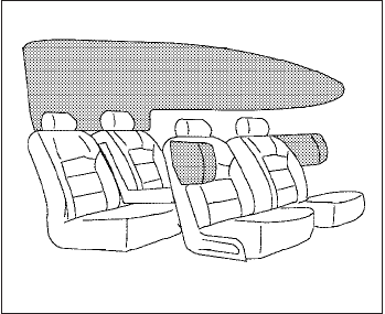
Front seat-mounted side-impact
supplemental air bag and roof-
mounted curtain side-impact and
rollover supplemental air bag systems
The side air bags are located in the outside of the
seatback of the front seats. The curtain and roll-
over air bags are located in the side roof rails.
These systems are designed to meet voluntary
guidelines to help reduce the risk of injury to
out-of-position occupants. However, all of the
information, cautions and warnings in this
manual still apply and must be followed.
The side air bags and curtain and rollover air bags
are designed to inflate in higher severity side
collisions, although they may inflate if the forces
in another type of collision are similar to those of
a higher severity side impact. They are designed
to inflate on the side where the vehicle is im-
pacted. They may not inflate in certain side colli-
sions.
Curtain and rollover air bags are also designed to
inflate in certain types of rollover collisions or near
rollovers. As a result, certain vehicle movements
(for example, during severe off roading) may
cause the curtain and rollover air bags to inflate.
Vehicle damage (or lack of it) is not always an
indication of proper side air bag and curtain and
rollover air bag operation.
When the side air bags and curtain and rollover
air bags inflate, a fairly loud noise may be heard,
followed by release of smoke. This smoke is not
harmful and does not indicate a fire. Care should
be taken not to inhale it, as it may cause irritation
and choking. Those with a history of a breathing
condition should get fresh air promptly.
Side air bags, along with the use of seat belts,
help to cushion the impact force on the chest of
the front occupants. Curtain and rollover air bags
help to cushion the impact force to the head of
occupants in the front and rear outboard seating
positions. They can help save lives and reduce
serious injuries. However, an inflating side air bag
or curtain and rollover air bag may cause abra-
sions or other injuries. Side air bags and curtain
and rollover air bags do not provide restraint to
the lower body.
The seat belts should be correctly worn and the
driver and passenger seated upright as far as
practical away from the side air bag. Rear seat
passengers should be seated as far away as
practical from the door finishers and side roof
rails. The side air bags and curtain and rollover air
bags inflate quickly in order to help protect the
occupants. Because of this, the force of the side
air bag and curtain and rollover air bag inflating
can increase the risk of injury if the occupant is
too close to, or is against, these air bag modules
during inflation. The side air bag will deflate
quickly after the collision is over.
The curtain and rollover air bags will remain in-
flated for a short time.
The side air bags and curtain and rollover
air bags operate only when the ignition
switch is in the ON or START position.
After placing the ignition switch in the ON
position, the supplemental air bag warning
light illuminates. The supplemental air bag
warning light will turn off after about 7
seconds if the system is operational.
WRS0422
Safety—Seats, seat belts and supplemental restraint system 1-69

WARNING
●Do not place any objects near the seat-
back of the front seats. Also, do not
place any objects (an umbrella, bag,
etc.) between the front door finisher
and the front seat. Such objects may
become dangerous projectiles and
cause injury if a side air bag inflates.
●Right after inflation, several side air bag
and curtain and rollover air bag system
components will be hot. Do not touch
them; you may severely burn yourself.
●No unauthorized changes should be
made to any components or wiring of
the side air bag and curtain and rollover
air bag systems. This is to prevent dam-
age to or accidental inflation of the side
air bag and curtain and rollover air bag
systems.
●Do not make unauthorized changes to
your vehicle’s electrical system, sus-
pension system or side panel. This
could affect proper operation of the
curtain and rollover air bag systems.
●Tampering with the side air bag system
may result in serious personal injury.
For example, do not change the front
seats by placing material near the seat-
backs or by installing additional trim
material, such as seat covers, around
the side air bag.
●Work around and on the side air bag
and curtain and rollover air bag systems
should be done by a NISSAN dealer.
Installation of electrical equipment
should also be done by a NISSAN
dealer. The SRS wiring harnesses*
should not be modified or discon-
nected. Unauthorized electrical test
equipment and probing devices should
not be used on the side air bag or cur-
tain and rollover air bag systems.
* The SRS wiring harness or connectors are
yellow or orange for easy identification.
When selling your vehicle, we request that you
inform the buyer about the side air bag and
curtain and rollover air bag systems and guide the
buyer to the appropriate sections in this Owner’s
Manual.
Seat belts with pretensioners (Front
seats)
WARNING
●The pretensioners cannot be reused af-
ter activation. They must be replaced
together with the retractor and buckle
as a unit.
●If the vehicle becomes involved in a
frontal collision but a pretensioner is
not activated, be sure to have the pre-
tensioner system checked and, if nec-
essary, replaced by your NISSAN
dealer.
●No unauthorized changes should be
made to any components or wiring of
the pretensioner system. This is to pre-
vent damage to or accidental activation
of the pretensioners. Tampering with
the pretensioner system may result in
serious personal injury.
●Work around and on the pretensioner
system should be done by a NISSAN
dealer. Installation of electrical equip-
ment should also be done by a NISSAN
dealer. Unauthorized electrical test
equipment and probing devices should
not be used on the pretensioner system.
1-70 Safety—Seats, seat belts and supplemental restraint system
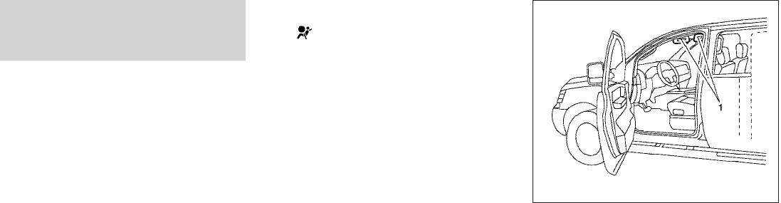
●If you need to dispose of a pretensioner
or scrap the vehicle, contact a NISSAN
dealer. Incorrect disposal procedures
could cause personal injury.
The pretensioner system activates in conjunction
with the front air bag system. The pretensioner
system also activates with the curtain and rollover
air bags in certain types of rollover collisions or
near rollovers. Working with the seat belt retrac-
tor, it helps tighten the seat belt when the vehicle
becomes involved in certain types of collisions,
helping to restrain front seat occupants.
The pretensioner is encased with the seat belt
retractor. These seat belts are used the same way
as conventional seat belts.
When a pretensioner activates, smoke is re-
leased and a loud noise may be heard. This
smoke is not harmful and does not indicate a fire.
Care should be taken not to inhale it, as it may
cause irritation and choking. Those with a history
of a breathing condition should get fresh air
promptly.
After pretensioner activation, load limiters allow
the seat belt to release webbing (if necessary) to
reduce forces against the chest.
If any abnormality occurs in the pretensioner sys-
tem, the supplemental air bag warning
light will not come on, will flash intermit-
tently or will turn on for 7 seconds and remain on
after the ignition switch has been placed in the
ON or START position. In this case, the preten-
sioner system may not function properly. They
must be checked and repaired. Take your vehicle
to the nearest NISSAN dealer.
When selling your vehicle, we request that you
inform the buyer about the pretensioner system
and guide the buyer to the appropriate sections
in this Owner’s Manual.
1. SRS Air Bag Warning Labels
The warning labels are located on the sur-
face of the sun visor.
SUPPLEMENTAL AIR BAG
WARNING LABELS
Warning labels about the supplemental front-
impact air bag system are placed in the vehicle as
shown in the illustration.
WRS0885
Safety—Seats, seat belts and supplemental restraint system 1-71
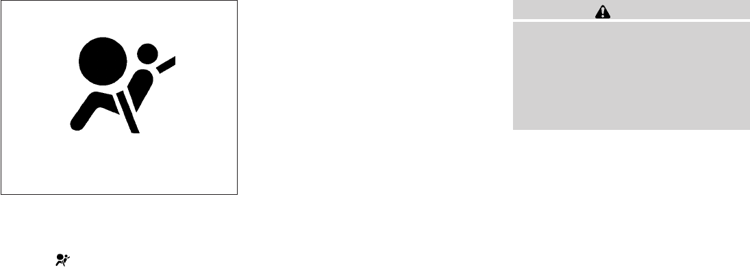
SUPPLEMENTAL AIR BAG
WARNING LIGHT
The supplemental air bag warning light,
displaying in the instrument panel, moni-
tors the circuits of the supplemental front-impact
air bag, front seat-mounted side-impact supple-
mental air bag, roof-mounted curtain side-impact
and rollover supplemental air bag and seat belt
pretensioner systems. The monitored circuits in-
clude the Air bag Control Unit (ACU), crash zone
sensor, satellite sensors, rollover sensor, occu-
pant classification sensor, front air bag modules,
side air bag modules, curtain and rollover air bag
modules, pretensioners and all related wiring.
When the ignition switch is placed in the ON or
START position, the supplemental air bag warn-
ing light illuminates for about 7 seconds and then
turns off. This means the system is operational.
If any of the following conditions occur, the front
air bag, side air bag, curtain and rollover air bag
and pretensioner systems need servicing:
●The supplemental air bag warning light re-
mains on after approximately 7 seconds.
●The supplemental air bag warning light
flashes intermittently.
●The supplemental air bag warning light does
not come on at all.
Under these conditions, the front air bag, side air
bag, curtain and rollover air bag or pretensioner
systems may not operate properly. They must be
checked and repaired. Take your vehicle to the
nearest NISSAN dealer.
WARNING
If the supplemental air bag warning light
is on, it could mean that the front air bag,
side air bag, curtain and rollover air bag
and/or pretensioner systems will not op-
erate in an accident. To help avoid injury
to yourself or others, have your vehicle
checked by a NISSAN dealer as soon as
possible.
Repair and replacement procedure
The front air bags, side air bags, curtain and
rollover air bags and pretensioners are designed
to inflate on a one-time-only basis. As a reminder,
unless it is damaged, the supplemental air bag
warning light remains illuminated after inflation
has occurred. Repair and replacement of these
supplemental air bag systems should be done
only by a NISSAN dealer.
When maintenance work is required on the ve-
hicle, the front air bags, side air bags, curtain and
rollover air bags, pretensioners and related parts
should be pointed out to the person performing
the maintenance. The ignition switch should al-
ways be in the LOCK position when working
under the hood or inside the vehicle.
LRS0100
1-72 Safety—Seats, seat belts and supplemental restraint system

WARNING
●Once a front air bag, side air bag, or
curtain and rollover air bag has inflated,
the air bag module will not function
again and must be replaced. Addition-
ally, if any of the front air bags inflate,
the activated pretensioners must also
be replaced. The air bag module and
pretensioner should be replaced by a
NISSAN dealer. The air bag module and
pretensioner cannot be repaired.
●The front air bag, side air bag, curtain
and rollover air bag systems and the
pretensioner system should be in-
spected by a NISSAN dealer if there is
any damage to the front end or side
portion of the vehicle.
●If you need to dispose of a supplemen-
tal air bag or pretensioner or scrap the
vehicle, contact a NISSAN dealer. Incor-
rect disposal procedures could cause
personal injury.
Safety—Seats, seat belts and supplemental restraint system 1-73
2 Instruments and controls
Instrument panel...................................2-2
Meters and gauges ................................2-3
Speedometer and odometer .....................2-4
Trip computer (if so equipped) ...................2-5
Tachometer ....................................2-6
Engine coolant temperature gauge ...............2-6
Fuel gauge ....................................2-7
Engine oil pressure gauge (if so equipped) ........2-8
Voltmeter (if so equipped) .......................2-8
Compass and outside temperature display
(if so equipped) ...................................2-9
Outside temperature display .....................2-9
Compass display ..............................2-10
Warning/indicator lights and audible reminders ......2-13
Checking bulbs ...............................2-14
Warning lights ................................2-14
Indicator lights ................................2-18
Audible reminders .............................2-22
Security systems (if so equipped) ..................2-23
Vehicle security system (if so equipped)..........2-23
NISSAN vehicle immobilizer system
(if so equipped) ...............................2-24
Windshield wiper and washer switch ...............2-25
Switch operation ..............................2-25
Rear window and outside mirror defroster switch
(if so equipped) ..................................2-26
Headlight and turn signal switch....................2-26
Headlight control switch........................2-26
Daytime running light system (Canada only) ......2-29
Instrument brightness control ...................2-29
Turn signal switch .............................2-30
Fog light switch (if so equipped) ................2-30
Hazard warning flasher switch .....................2-30
Horn ............................................2-31
Cargo lamp switch ...............................2-31
Heated seat (if so equipped).......................2-32
Vehicle Dynamic Control (VDC) off switch
(if so equipped) ..................................2-32
Hill descent control switch (if so equipped)..........2-33
Electronic locking rear differential (E-Lock) system
switch (if so equipped) ............................2-34
Clutch interlock (clutch start) switch
(if so equipped) ..................................2-35
Power outlet .....................................2-35
Storage .........................................2-36
Storage trays .................................2-36
Under-seat storage bins........................2-38

Console box ..................................2-39
Glove box ....................................2-40
Sunglasses holder (if so equipped) ..............2-40
Map pockets..................................2-41
Seat pocket (if so equipped)....................2-42
Cup holders ..................................2-42
Roof rack (if so equipped) ......................2-44
Windows ........................................2-45
Power windows (if so equipped) ................2-45
Manual windows (if so equipped)................2-47
Rear sliding window (if so equipped) ............2-48
Moonroof (if so equipped) .........................2-48
Interior lights .....................................2-50
Map lights (if so equipped) ........................2-51
HomeLinkTuniversal transceiver (if so equipped).....2-51
Programming HomeLinkT.......................2-52
Programming HomeLinkTfor Canadian
customers ....................................2-53
Operating the HomeLinkTuniversal
transceiver....................................2-53
Programming trouble-diagnosis .................2-53
Clearing the programmed information ............2-54
Reprogramming a single HomeLinkTbutton ......2-54
If your vehicle is stolen .........................2-54
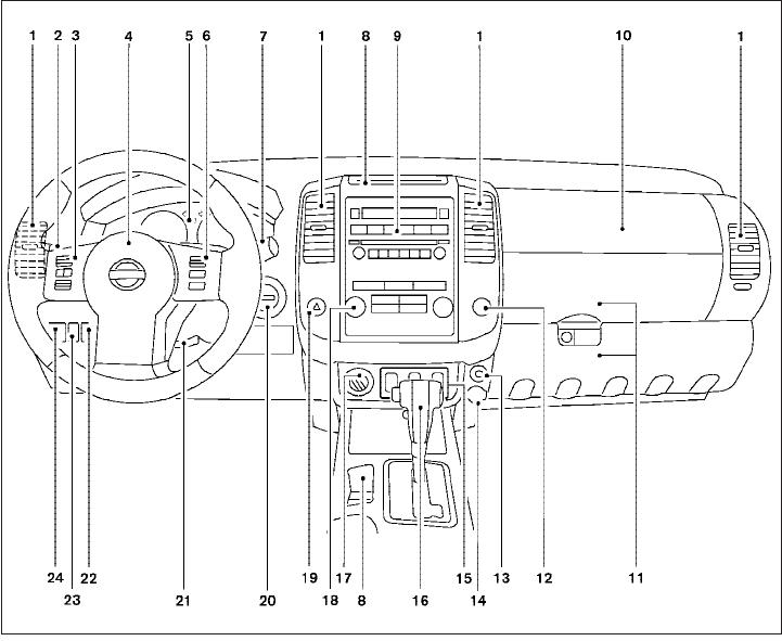
1. Vents (P. 4-2)
2. Headlight/fog light (if so equipped)/turn
signal switch (P. 2-26)
3. Steering wheel switch for audio control
(if so equipped)/BluetoothTHands-
Free Phone System (if so equipped)
(P. 4-35, P. 4-37)
4. Driver supplemental air bag/horn
(P. 1-57, P. 2-31)
5. Meters, gauges and warning/indicator
lights (P. 2-3, 2-13)
6. Cruise control main/set switches
(if so equipped) (P. 5-20)
7. Windshield wiper/washer switch
(P. 2-25)
8. Storage (P. 2-36)
9. Audio system controls (if so equipped)
(P. 4-17)
10. Front passenger supplemental air bag
(P. 1-57)
11. Upper and lower glove box (P. 2-40)
12. Passenger air bag status light (P. 1-66)
13. Auxiliary audio input jack
(if so equipped) (P. 4-34)
14. Power outlet (P. 2-35)
LIC1422
INSTRUMENT PANEL
2-2 Instruments and controls
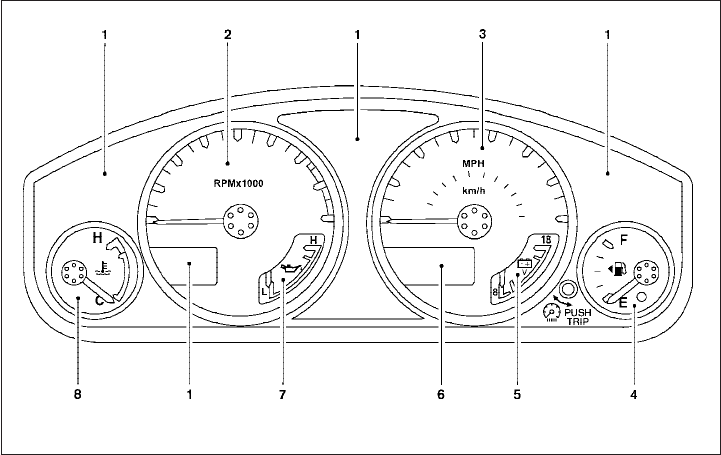
15. Electronic locking rear differential
(E-Lock) system switch
(if so equipped) (P.2-34)
Heated seat switch (if so equipped)
(P. 2-32)
Hill descent control switch
(if so equipped) (P. 2-33)
Vehicle Dynamic Control (VDC) OFF
switch (if so equipped) (P. 2-32)
16. Shift selector (P. 5-13,5-17 )
17. 4WD shift switch (if so equipped)
(P. 5-22)
18. Climate controls (P. 4-2, P.4-10)
19. Hazard warning flasher switch (P. 2-30)
20. Ignition switch (P. 5-9)
21. Tilt steering wheel control
(if so equipped) (P. 3-12)
22. Cargo lamp switch (P. 2-31)
23. Clutch interlock (clutch start) switch
(if so equipped) (P. 2-35)
24. Outside mirror controls (if so equipped)
(P. 3-15) 1. Warning/indicator lights
2. Tachometer
3. Speedometer
4. Fuel gauge
5. Voltmeter (if so equipped)
6. Odometer/Twin trip odometer/Trip
computer (if so equipped)
7. Engine oil pressure gauge
(if so equipped)
8. Engine coolant temperature gauge
WIC1040
METERS AND GAUGES
Instruments and controls 2-3
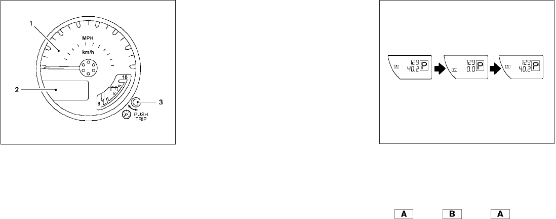
1. Speedometer
2. Odometer/Twin trip odometer
3. Change button
SPEEDOMETER AND ODOMETER
Speedometer
The speedometer indicates vehicle speed.
Odometer/Twin trip odometer
The odometer/twin trip odometer is displayed
when the ignition switch is placed in the ON
position.
The odometer records the total distance the ve-
hicle has been driven.
The twin trip odometer records the distance of
individual trips.
Changing the display:
For vehicles equipped with twin trip odometer,
pushing the change button changes the display
as follows:
Trip →Trip →Trip
WIC0912 With twin trip odometer
LIC0780
2-4 Instruments and controls
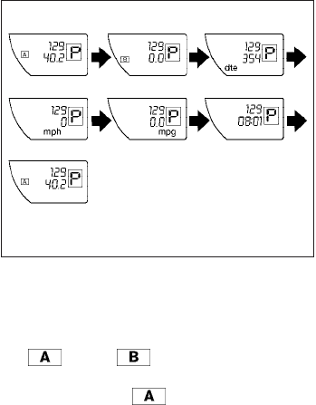
For vehicles equipped with trip computer, push-
ing the change button changes the display as
follows:
Trip →Trip →Distance to Empty →
Average speed →Average fuel consumption →
Journey time →Trip
For additional information, refer to “Trip com-
puter” later in this section.
Resetting the trip odometer:
Pushing the change button for more than 1 sec-
ond resets the currently displayed trip odometer
to zero.
TRIP COMPUTER (if so equipped)
The display of the trip computer is situated in the
speedometer display. When the ignition switch is
placed in the ON position, the display scrolls all
the modes of the trip computer and then shows
the mode chosen before the ignition switch was
placed in the OFF position.
When the ignition switch is placed in the ON
position, modes of the trip computer can be
selected by pushing the trip computer change
button. The following modes can be selected:
Distance to empty (dte—mile or km)
The distance to empty (dte) mode provides you
with an estimation of the distance that can be
driven before refueling. The dte is constantly be-
ing calculated, based on the amount of fuel in the
fuel tank and the actual fuel consumption.
The display is updated every 30 seconds.
The dte mode includes a low range warning
feature: when the fuel level is low, the dte mode is
automatically selected and the digits blink in or-
der to draw the driver’s attention. Press the
change button if you wish to return to the mode
that was selected before the warning occurred.
The dte mark (dte) will remain blinking until the
vehicle is refueled.
When the fuel level drops even lower, the dte
display will change to (----).
NOTE:
●If the amount of fuel added while the
ignition switch is OFF is small, the dis-
play just before the ignition switch is
turned OFF may continue to be dis-
played.
●When driving uphill or rounding curves,
the fuel in the tank shifts, which may
momentarily change the display.
Average speed (MPH or km/h)
The average speed mode shows the average
vehicle speed since last reset. Resetting is done
by pressing the change button for more than
approximately 1 second. The display is updated
every 30 seconds. The first 30 seconds after a
reset, the display shows (----).
With trip computer
LIC0781
Instruments and controls 2-5
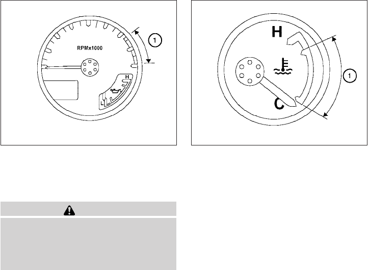
Average fuel consumption (Mpg or
l/100km)
The average fuel consumption mode shows the
average fuel consumption since the last reset.
Resetting is done by pressing the change button
for more than approximately 1 second. The dis-
play is updated every 30 seconds. At about the
first 1/3 miles (500 m) after a reset, the display
shows (----).
Journey time
The journey time mode shows the time since the
last reset. The displayed time can be reset by
pressing the change button for more than ap-
proximately 1 second.
Trip computer reset
Pushing the change button for more than 3 sec-
onds will reset all modes except Trip A and dis-
tance to empty (dte).
TACHOMETER
The tachometer indicates engine speed in revo-
lutions per minute (rpm). Do not rev the engine
into the red zone s
1.
CAUTION
When engine speed approaches the red
zone, shift to a higher gear or reduce en-
gine speed. Operating the engine in the
red zone may cause serious engine
damage.
ENGINE COOLANT TEMPERATURE
GAUGE
The gauge indicates the engine coolant tempera-
ture. The engine coolant temperature is within the
normal range s
1when the gauge needle points
within the zone shown in the illustration.
The engine coolant temperature varies with the
outside air temperature and driving conditions.
LIC0738 LIC0739
2-6 Instruments and controls
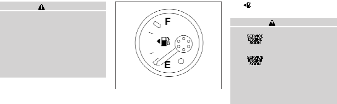
CAUTION
If the gauge indicates coolant tempera-
ture near the hot (H) end of the normal
range, reduce vehicle speed to decrease
temperature. If the gauge is over the nor-
mal range, stop the vehicle as soon as
safely possible. If the engine is over-
heated, continued operation of the ve-
hicle may seriously damage the engine.
See “If your vehicle overheats” in the “In
case of emergency”section for immediate
action required.
FUEL GAUGE
The gauge indicates the approximate fuel level
in the tank.
The gauge may move slightly during braking,
turning, acceleration, or going up or down hills.
The gauge needle returns to E (Empty) after the
ignition switch is placed in the OFF position.
The low fuel warning light comes on when the
amount of fuel in the tank is getting low.
Refill the fuel tank before the gauge regis-
ters E (Empty).
The indicates that the fuel-filler door is
located on the driver’s side of the vehicle.
CAUTION
●If the vehicle runs out of fuel,
the Malfunction Indicator Light
(MIL) may come on. Refuel as soon as
possible. After a few driving trips,
the light should turn off. If the
light remains on after a few driving
trips, have the vehicle inspected by a
NISSAN dealer.
●For additional information, see “Mal-
function Indicator Light (MIL)” later in
this section.
LIC0740
Instruments and controls 2-7
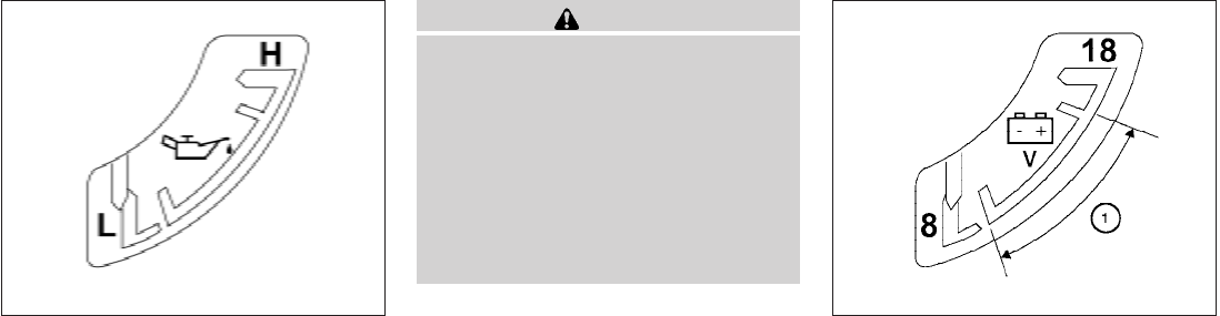
ENGINE OIL PRESSURE GAUGE (if
so equipped)
The gauge indicates the engine lubrication sys-
tem oil pressure while the engine is running. The
needle should be in the middle of the gauge when
the engine is running.
CAUTION
●This gauge is not designed to indicate
low engine oil level. Use the dipstick to
check the oil level. (See “Engine oil” in
the “Maintenance and do-it-yourself”
section.)
●If the gauge needle does not move with
the proper amount of engine oil, have
the vehicle checked by a NISSAN
dealer. Continued vehicle operation in
such a condition could cause serious
damage to the engine.
VOLTMETER (if so equipped)
When the ignition key is turned to the ON posi-
tion, the voltmeter indicates the battery voltage.
When the engine is running, it indicates the gen-
erator voltage.
While cranking the engine, the volts drop below
the normal range. If the needle is not in the normal
range (11 - 15 volts) s
1while the engine is
running, it may indicate that the charging system
is not functioning properly. Have the system
checked by a NISSAN dealer.
LIC0741 WIC0913
2-8 Instruments and controls
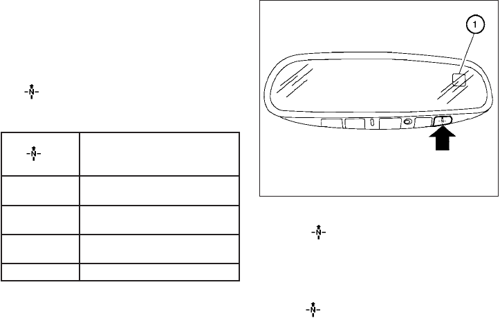
This unit has the following functions:
●Measures terrestrial magnetism and indi-
cates heading direction of vehicle
●Indicates outside air temperature
With the ignition switch in the ON position, press
the button as described in the chart below
to activate various features of the automatic anti-
glare review mirror.
Push and hold
the
button for about:
Feature:
(Push button again for about 1 sec-
ond to change settings)
1 second Compass/outside temperature dis-
play toggles on/off
3 seconds Outside temperature display toggles
between °F and °C
8 seconds Compass zone can be changed to
correct false compass readings
10 seconds Compass enters calibration mode
For information about the automatic anti-glare
feature, refer to “Automatic anti-glare rearview
mirror” in the “Pre-driving checks and adjust-
ments” section.
OUTSIDE TEMPERATURE DISPLAY
Push the button for about 1 second when
the ignition key is in the ON position to toggle the
outside temperature and compass direction dis-
play s
1on or off.
●To change from °F to °C, push and hold
the button for about 3 seconds until
the display begins to flash. Press the button
again to toggle between °F and °C. Once
you have selected °F or °C, the display will
continue to flash for about 5 seconds, then
the temperature will display.
●When the outside temperature is between
140°F (60°C) and 194°F (90°C), the display
will read 140°F (60°C). When the tempera-
ture is above 194°F (90°C), the display will
read “SC”.
●When the outside temperature is between
-40°F (-40°C) and -60°F (-51°C), the dis-
play will read -40°F (-40°C). When the tem-
perature is below -60°F (-51°C), the display
will read “OC”.
●The outside temperature sensor is located in
front of the radiator. The sensor may be
affected by road or engine heat, wind direc-
tion and other driving conditions. The display
may differ from the actual outside tempera-
ture or the temperature displayed on various
signs or billboards.
●Temperature display will not update unless
the vehicle is moving faster than 12 MPH
(20 km/h), or the ignition switch has been
OFF for 4 hours.
LIC0583
COMPASS AND OUTSIDE
TEMPERATURE DISPLAY (if so
equipped)
Instruments and controls 2-9

COMPASS DISPLAY
Push the button for about 1 second when
the ignition key is in the ON position to toggle the
outside temperature and compass direction dis-
play s
1on or off. The display will indicate the
direction of the vehicle’s heading.
N: North
E: East
S: South
W: West
If the display reads “CAL”, calibrate the compass
by driving the vehicle in three complete circles at
less than 5 MPH (8 km/h).
You can also calibrate the compass by driving
your vehicle on your everyday route. The com-
pass will be calibrated once it has tracked three
complete circles.
2-10 Instruments and controls
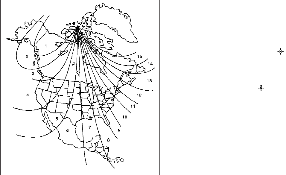
Zone variation change procedure
The difference between magnetic north and geo-
graphical north is known as variance. In some
areas, this difference can sometimes be great
enough to cause false compass readings. Follow
these instructions to set the variance for your
particular location if this happens:
1. Press and hold the button for about 8
seconds. The current zone number will ap-
pear in the display. Release the button.
2. Find your current location on the zone map.
Refer to the illustration.
3. Press the button repeatedly to toggle
through the zone numbers until the desired
number appears in the display. Once you
have selected a zone number, the display
will show a compass direction within a few
seconds.
NOTE:
Use zone number 5 for Hawaii.
Inaccurate compass direction
The compass display is equipped with automatic
correction function. If the correct direction is not
shown, follow this procedure.
WIC0355
Instruments and controls 2-11

1. With the display turned on, press and hold
the button for about 10 seconds. The
“CAL” icon in the compass display will illu-
minate.
2. Calibrate the compass by driving the vehicle
in three complete circles at a maximum
speed of 5 MPH (8 km/h).
3. After completing the circles, the display
should return to normal.
●If the compass deviates from the correct
indication soon after repeated adjustment,
have the compass checked at an authorized
dealer.
●The compass may not indicate the correct
compass point in tunnels or while driving up
or down a steep hill. (The compass returns
to the correct compass point when the ve-
hicle moves to an area where the geomag-
netism is stabilized.)
●If a magnet is located in or near the overhead
console in the front of the vehicle or the
vehicle is driven where the terrestrial mag-
netism is disturbed, the compass display
may not indicate the correct direction.
CAUTION
●Do not install a ski rack, antenna, etc.,
which are attached to the vehicle by
means of a magnet. They affect the op-
eration of the compass.
●When cleaning the mirror, use a paper
towel or similar material dampened
with glass cleaner. Do not spray glass
cleaner directly on the mirror as it may
cause the liquid cleaner to enter the
mirror housing.
2-12 Instruments and controls
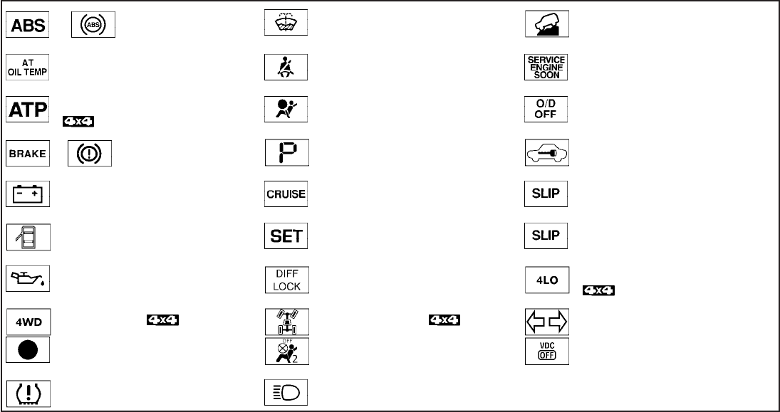
or Anti-lock Braking System (ABS)
warning light
Low windshield washer fluid warning light Hill descent control system on indicator light (if
so equipped)
Automatic transmission oil temperature warning
light (if so equipped)
Seat belt warning light and chime Malfunction Indicator Light (MIL)
Automatic transmission park warning light
(model)
Supplemental air bag warning light Overdrive off indicator light (A/T models only)
or Brake warning light Automatic transmission position indicator light
(if so equipped)
Security indicator light (if so equipped)
Charge warning light Cruise main switch indicator light (if so
equipped)
Slip indicator light for models with ABLS (if so
equipped)
Door open warning light Cruise set switch indicator light (if so equipped) Slip indicator light for models with VDC (if so
equipped)
Engine oil pressure warning light Electronic locking rear differential (E-Lock) sys-
tem on indicator light (if so equipped)
Transfer 4LO position indicator light
(model)
4WD warning light ( model) 4WD shift indicator light ( model) Turn signal/hazard indicator lights
Low fuel warning light Front passenger air bag status light Vehicle Dynamic Control (VDC) OFF indicator
light (if so equipped)
Low tire pressure warning light High beam indicator light (Blue)
WARNING/INDICATOR LIGHTS AND
AUDIBLE REMINDERS
Instruments and controls 2-13
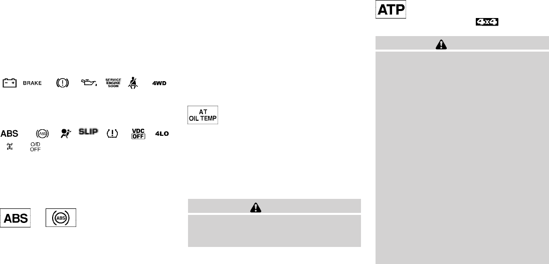
CHECKING BULBS
With all doors closed, apply the parking brake
and turn the ignition key to the ON position
without starting the engine. The following lights
will come on:
, or , , , ,
The following lights come on briefly and then go
off:
or , , , , , ,
,
If any light fails to come on, it may indicate
an open circuit in the electrical system.
Have the system repaired promptly.
WARNING LIGHTS
or Anti-lock Braking
System (ABS)
warning light
When the ignition switch is placed in the ON
position, the Anti-lock Braking System (ABS)
warning light illuminates and then turns off. This
indicates the ABS is operational.
If the ABS warning light illuminates while the
engine is running, or while driving, it may indicate
the ABS is not functioning properly. Have the
system checked by a NISSAN dealer.
If an ABS malfunction occurs, the anti-lock func-
tion is turned off. The brake system then operates
normally, but without anti-lock assistance. See
“Brake system” in the “Starting and driving” sec-
tion.
Automatic transmission oil
temperature warning light (if so
equipped)
This light comes on when the automatic transmis-
sion oil temperature is too high. If the light comes
on while driving, reduce the vehicle speed as
soon as safely possible until the light turns off.
CAUTION
Continued vehicle operation when the A/T
oil temperature warning light is on may
damage the automatic transmission.
Automatic transmission park
warning light ( model)
WARNING
●If the ATP light is ON, this indicates that
the automatic transmission P (Park) po-
sition will not function and the transfer
case is in neutral.
●When parking, always make sure that
the 4WD shift indicator light illuminates
and the parking brake is set. Failure to
engage the transfer position in 2WD, 4H
or 4LO could result in the vehicle mov-
ing unexpectedly, resulting in serious
personal injury or property damage.
●Shift the 4WD switch into the 2WD, 4H
or 4LO position again to turn off the ATP
warning light when the shift selector is
in the P position and the ATP warning
light is ON. (Before shifting the 4WD
switch into the 4LO position, move the
shift selector into the N position once,
shift the shift selector into P again and
make sure the ATP warning light is
OFF.)
2-14 Instruments and controls
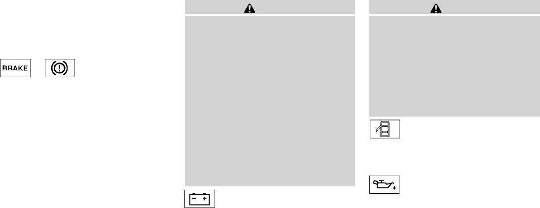
This light indicates that the automatic transmis-
sion parking function is not engaged. If the trans-
fer control is not secured in any drive position
while the shift selector is in the P (Park) position,
the transmission will disengage and the drive
wheels will not lock.
or Brake warning light
This light functions for both the parking brake and
the foot brake systems.
Parking brake indicator
When the ignition switch is placed in the ON
position, the light comes on when the parking
brake is applied.
Low brake fluid warning light
When the ignition switch is placed in the ON
position, the light warns of a low brake fluid level.
If the light comes on while the engine is running
with the parking brake not applied, stop the ve-
hicle and perform the following:
1. Check the brake fluid level. Add brake fluid
as necessary. See “Brake fluid”in the “Main-
tenance and do-it-yourself” section of this
manual.
2. If the brake fluid level is correct, have the
warning system checked by a NISSAN
dealer.
WARNING
●Your brake system may not be working
properly if the warning light is on. Driv-
ing could be dangerous. If you judge it
to be safe, drive carefully to the nearest
service station for repairs. Otherwise,
have your vehicle towed because driv-
ing it could be dangerous.
●Pressing the brake pedal with the en-
gine stopped and/or a low brake fluid
level may increase your stopping dis-
tance and braking will require greater
pedal effort as well as pedal travel.
●If the brake fluid level is below the
MINIMUM or MIN mark on the brake
fluid reservoir, do not drive until the
brake system has been checked at a
NISSAN dealer.
Charge warning light
If this light comes on while the engine is running,
it may indicate the charging system is not func-
tioning properly. Turn the engine off and check
the generator belt. If the belt is loose, broken,
missing, or if the light remains on, see a NISSAN
dealer immediately.
CAUTION
●Do not ground electrical accessories
directly to the battery terminal. Doing
so will bypass the variable control sys-
tem and the vehicle battery may not
charge completely. Refer to “Variable
voltage control system” in the “Mainte-
nance and do-it-yourself” section later
in this manual.
●Do not continue driving if the generator
belt is loose, broken or missing.
Door open warning light
This light comes on when any of the doors are not
closed securely while the ignition switch is
placed in the ON position.
Engine oil pressure warning
light
This light warns of low engine oil pressure. If the
light flickers or comes on during normal driving,
pull off the road in a safe area, stop the engine
immediately and call a NISSAN dealer or other
authorized repair shop.
Instruments and controls 2-15
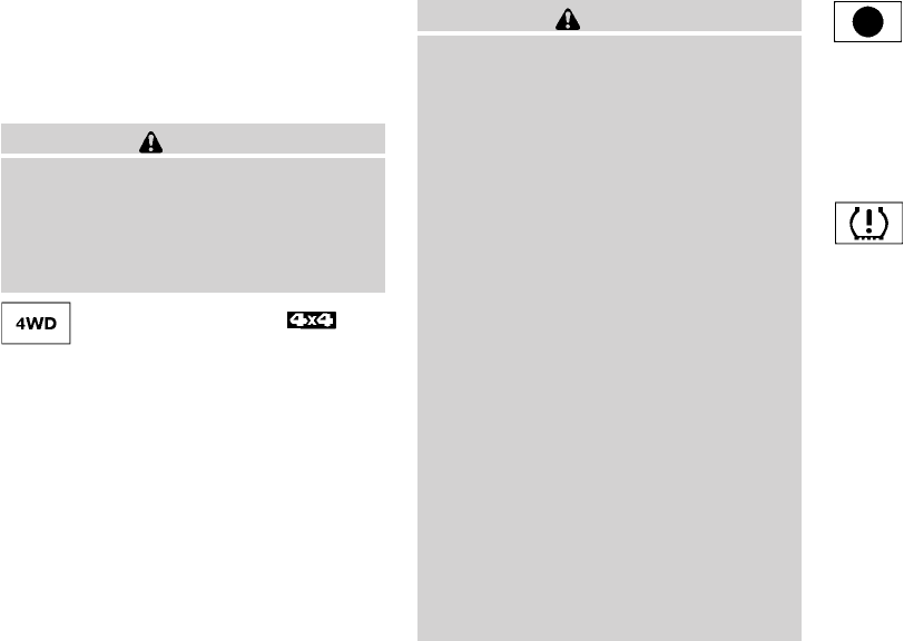
The engine oil pressure warning light is not
designed to indicate a low oil level. Use the
dipstick to check the oil level. See “Engine oil” in
the “Maintenance and do-it-yourself” section of
this manual.
CAUTION
Running the engine with the engine oil
pressure warning light on could cause se-
rious damage to the engine almost imme-
diately. Such damage is not covered by
warranty. Turn off the engine as soon as it
is safe to do so.
4WD warning light (
model)
The 4WD warning light comes on when the igni-
tion switch is turned to ON. It turns off soon after
the engine is started.
If the engine or vehicle is not functioning properly,
the warning light will either remain illuminated or
blink. See “4WD warning light” in the “Starting
and driving” section.
CAUTION
●If the warning light comes on or blinks
during operation, have your vehicle
checked by a NISSAN dealer as soon as
possible.
●Do not drive on dry hard surface roads
in the 4H or 4LO position. If the 4WD
warning light turns on when you are
driving on dry hard surface roads:
– in the 4H position, shift the 4WD shift
switch to 2WD.
– in the 4LO position for automatic
transmission models, stop the ve-
hicle and shift the shift selector to
the N position with the brake pedal
depressed and shift the 4WD shift
switch to 2WD.
– in the 4LO position for manual trans-
mission models, stop the vehicle and
shift the shift selector to the N posi-
tion with the clutch pedal depressed
and shift the 4WD shift switch to
2WD,
●If the warning light is still on after the
above operation, have your vehicle
checked by a NISSAN dealer as soon as
possible.
Low fuel warning light
This light comes on when the fuel level in the fuel
tank is getting low. Refuel as soon as it is conve-
nient, preferably before the fuel gauge reaches E
(Empty). There will be a small reserve of fuel
in the tank when the fuel gauge needle
reaches E (Empty).
Low tire pressure warning light
Your vehicle is equipped with a Tire Pressure
Monitoring System (TPMS) that monitors the tire
pressure of all tires except the spare.
The low tire pressure warning light warns of low
tire pressure or indicates that the TPMS is not
functioning properly.
After the ignition switch is placed in the ON
position, this light illuminates for about 1 second
and turns off.
Low tire pressure warning:
If the vehicle is being driven with low tire
pressure, the warning light will illuminate.
When the low tire pressure warning light
illuminates, you should stop and adjust the
tire pressure of all 4 tires to the recom-
mended COLD tire pressure shown on the
2-16 Instruments and controls

Tire and Loading Information label located
in the driver’s door opening. The low tire
pressure warning light does not automati-
cally turn off when the tire pressure is ad-
justed. After the tire is inflated to the rec-
ommended pressure, the vehicle must be
driven at speeds above 16 MPH (25 km/h)
to activate the TPMS and turn off the low
tire pressure warning light. Use a tire pres-
sure gauge to check the tire pressure.
For additional information, see “Tire Pressure
Monitoring System (TPMS)” in the “Starting and
driving”section and in the “In case of emergency”
section.
TPMS malfunction:
If the TPMS is not functioning properly, the low
tire pressure warning light will flash for approxi-
mately 1 minute when the ignition switch is
placed in the ON position. The light will remain on
after the 1 minute. Have the system checked by a
NISSAN dealer.
For additional information, see “Tire Pressure
Monitoring System (TPMS)” in the “Starting and
driving” section and “Tire pressure” in the “Main-
tenance and do-it-yourself” section.
WARNING
●If the light does not illuminate with the
ignition switch placed in the ON posi-
tion, have the vehicle checked by a
NISSAN dealer as soon as possible.
●If the light illuminates while driving,
avoid sudden steering maneuvers or
abrupt braking, reduce vehicle speed,
pull off the road to a safe location and
stop the vehicle as soon as possible.
Driving with under-inflated tires may
permanently damage the tires and in-
crease the likelihood of tire failure. Se-
rious vehicle damage could occur and
may lead to an accident and could re-
sult in serious personal injury. Check
the tire pressure for all four tires. Adjust
the tire pressure to the recommended
COLD tire pressure shown on the Tire
and Loading Information label located
in the driver’s door opening to turn the
low tire pressure warning light OFF. If
the light still comes on while driving
after adjusting the tire pressure, a tire
may be flat. If you have a flat tire, re-
place it with a spare tire as soon as
possible.
●When a spare tire is mounted or a wheel
is replaced, the TPMS will not function
and the low tire pressure warning light
will flash for approximately 1 minute.
The light will remain on after 1 minute.
Contact your NISSAN dealer as soon as
possible for tire replacement and/or
system resetting.
●Replacing tires with those not originally
specified by NISSAN could affect the
proper operation of the TPMS.
CAUTION
●The TPMS is not a substitute for the
regular tire pressure check. Be sure to
check the tire pressure regularly.
●If the vehicle is being driven at speeds
of less than 16 MPH (25 km/h), the
TPMS may not operate correctly.
●Be sure to install the specified size of
tires to the 4 wheels correctly.
Instruments and controls 2-17
Low windshield washer fluid
warning light
This light comes on when the windshield washer
fluid is at a low level. Add windshield washer fluid
as necessary. See “Window washer fluid” in the
“Maintenance and do-it-yourself” section of this
manual.
Seat belt warning light and
chime
The light and chime remind you to fasten your
seat belts. The light illuminates whenever the
ignition switch is placed in the ON or START
position and remains illuminated until the driver’s
seat belt is fastened. At the same time, the chime
sounds for about 6 seconds unless the driver’s
seat belt is securely fastened.
The seat belt warning light may also illuminate if
the front passenger’s seat belt is not fastened
when the front passenger’s seat is occupied . For
7 seconds after the ignition switch is placed in
the ON position, the system does not activate the
warning light for the front passenger.
Refer to “Seat belts” in the “Safety—Seats, seat
belts and supplemental restraint system” section
for precautions on seat belt usage.
Supplemental air bag warning
light
When the ignition switch is in the ON or START
position, the supplemental air bag warning light
illuminates for about 7 seconds and then turns
off. This means the system is operational.
If any of the following conditions occur, the front
air bag, side air bag, curtain and roll-over air bag,
and pretensioner systems need servicing and
your vehicle must be taken to a NISSAN dealer:
●The supplemental air bag warning light re-
mains on after approximately 7 seconds.
●The supplemental air bag warning light
flashes intermittently.
●The supplemental air bag warning light does
not come on at all.
Unless checked and repaired, the supplemental
restraint system (air bag system) and/or the pre-
tensioners may not function properly. For addi-
tional details see “Supplemental restraint sys-
tem” in the “Safety—Seats, seat belts and
supplemental restraint system” section of this
manual.
WARNING
If the supplemental air bag warning light
is on, it could mean that the front air bag,
side air bag, curtain and roll-over air bag
systems, and/or pretensioner systems will
not operate in an accident. To help avoid
injury to yourself or others, have your ve-
hicle checked by a NISSAN dealer as soon
as possible.
INDICATOR LIGHTS
Automatic transmission
position indicator light (if so
equipped)
See “Driving the vehicle” in the “Starting and
driving” section of this manual.
Cruise main switch indicator
light (if so equipped)
The light comes on when the cruise control main
switch is pushed. The light goes out when the
main switch is pushed again. When the cruise
main switch indicator light comes on, the cruise
control system is operational.
2-18 Instruments and controls
Cruise set switch indicator
light (if so equipped)
The light comes on while the vehicle speed is
controlled by the cruise control system. If the light
blinks while the engine is running, it may indicate
the cruise control system is not functioning prop-
erly. Have the system checked by a NISSAN
dealer.
Electronic locking rear
differential (E-Lock) system on
indicator light (if so equipped)
This light comes on when the electronic locking
rear differential (E-Lock) system clutch is fully
engaged.
The indicator light flashes when the system is first
turned on. When the system fully engages, the
light remains on. If the switch is on and the
indicator light continues to flash, the system is
not engaged.
For additional information, see “Electronic lock-
ing rear differential (E-Lock) system switch” later
in this section and “Electronic locking rear differ-
ential (E-Lock) system” in the “Starting and driv-
ing” section of this manual.
4WD shift indicator light
(model)
The light should turn off within 1 second after
placing the ignition switch in the ON position.
While the engine is running, the 4WD shift indi-
cator light will illuminate the position selected by
the 4WD shift switch.
The 4WD shift indicator light may blink
while shifting from one drive mode to the
other.
Front passenger air bag status
light
The front passenger air bag status light ( )
will be lit and the passenger front air bag will be
OFF depending on how the front passenger seat
is being used.
For front passenger air bag status light operation,
see “Front passenger air bag and status light” in
the “Safety — Seats, seat belts and supplemental
restraint system” section of this manual.
High beam indicator light
(blue)
This blue light comes on when the headlight high
beams are on and goes out when the low beams
are selected.
The high beam indicator light also comes on
when the passing signal is activated.
Hill descent control system on
indicator light (if so equipped)
When the ignition switch is placed in the ON
position, this light comes on briefly and then turns
off.
The light comes on when the hill descent control
system is activated.
If the hill descent control switch is on and the
indicator light blinks, the system is not engaged.
If the indicator light does not come on or blink
when the hill descent switch is on, the system
may not be functioning properly. Have the system
checked by a NISSAN dealer.
For additional information, see “Hill descent con-
trol switch” later in this section and “Hill descent
control system” in the “Starting and driving” sec-
tion of this manual.
Instruments and controls 2-19
Malfunction Indicator Light
(MIL)
If this indicator light comes on steady or blinks
while the engine is running, it may indicate a
potential emission control malfunction.
The Malfunction Indicator Light may also come
on steady if the fuel-filler cap is loose or missing,
or if the vehicle runs out of fuel. Check to make
sure the fuel-filler cap is installed and closed
tightly, and that the vehicle has at least 3 gallons
(11.4 liters) of fuel in the fuel tank.
After a few driving trips, the light should
turn off if no other potential emission control
system malfunction exists.
If this indicator light comes on steady for 20
seconds and then blinks for 10 seconds when
the engine is not running, it indicates that the
vehicle is not ready for an emission control sys-
tem inspection/maintenance test. See “Readi-
ness for inspection/maintenance (I/M) test”in the
“Technical and consumer information” section of
this manual.
Operation
The Malfunction Indicator Light will come on in
one of two ways:
●Malfunction Indicator Light on steady — An
emission control system malfunction has
been detected. Check the fuel-filler cap. If
the fuel-filler cap is loose or missing, tighten
or install the cap and continue to drive the
vehicle. The light should turn off after
a few driving trips. If the light does not
turn off after a few driving trips, have the
vehicle inspected by a NISSAN dealer. You
do not need to have your vehicle towed to
the dealer.
●Malfunction Indicator Light blinking — An
engine misfire has been detected which may
damage the emission control system. To re-
duce or avoid emission control system dam-
age:
– do not drive at speeds above 45 MPH
(72 km/h).
– avoid hard acceleration or deceleration.
– avoid steep uphill grades.
– if possible, reduce the amount of cargo
being hauled or towed.
The Malfunction Indicator Light may stop blinking
and come on steady. Have the vehicle inspected
by a NISSAN dealer. You do not need to have
your vehicle towed to the dealer.
CAUTION
Continued vehicle operation without hav-
ing the emission control system checked
and repaired as necessary could lead to
poor driveability, reduced fuel economy,
and possible damage to the emission con-
trol system.
Overdrive OFF indicator light
(A/T models only)
This light comes on when the overdrive function
is OFF.
The automatic transmission overdrive function is
controlled by the overdrive switch.
See “Driving the vehicle” in the “Starting and
driving” section of this manual.
Security indicator light (if so
equipped)
This light blinks when the ignition switch is in the
OFF, LOCK or ACC position. The blinking secu-
rity indicator light indicates that the security sys-
tems equipped on the vehicle are operational.
For additional information, see “Security sys-
tems” later in this section.
2-20 Instruments and controls
Slip indicator light for models
with ABLS (if so equipped)
This indicator light comes on if the active brake
limited slip is activated. If activated, the system
will apply braking to the slipping drive wheel(s),
giving the non-slipping wheel(s) more traction.
Slip indicator light for models
with VDC (if so equipped)
This indicator light will blink when the traction
control system is limiting wheel spin. Slippery
road conditions may exist if the slip indicator
blinks on. If this happens, adjust your driving
accordingly.
The slip indicator light also comes on when you
turn the ignition key to the ON position. The light
will turn off after about 2 seconds if the system is
operational. If the light does not come on or does
not go off, have the traction control system
checked by a NISSAN dealer.
If the battery is removed or discharged, the trac-
tion control system is disabled and the slip indi-
cator light will not turn off after 2 seconds when
the ignition switch is turned to the ON position.
To reset the system, you must perform the reset
procedure. Refer to “Vehicle Dynamic Control
(VDC) system” in the “Starting and driving” sec-
tion of this manual.
If the light does not go off after performing the
reset procedure, have the traction control system
checked by a NISSAN dealer.
Transfer 4LO position indicator
light ( model)
The light should turn off within 1 second after
turning the ignition switch to ON.
This light comes on when the 4WD shift switch is
set in the 4LO position with the ignition switch in
the ON position.
The transfer case may be damaged if you shift the
switch while driving.
Make sure the transfer 4LO position indicator
light turns on when you shift the 4WD shift switch
to 4LO.
The indicator light may blink while shifting
from one drive mode to the other.
The 4LO indicator light must stop blinking and
remain illuminated or turn off before shifting the
transmission into gear. If the shift selector is
shifted from the N (Neutral) position to any other
gear when the 4LO indicator light is blinking, the
vehicle may move unexpectedly.
When you shift between 4H and 4LO, follow the
instructions below:
●For automatic transmission models, stop the
vehicle and shift the shift selector to the N
(Neutral) position with the brake pedal de-
pressed, then depress and turn the 4WD
shift switch to 4LO or 4H.
●For manual transmission models, stop the
vehicle and shift the shift selector to the N
(Neutral) position with the clutch pedal de-
pressed, then depress and turn the 4WD
shift switch to 4LO or 4H.
You cannot move the transfer 4WD shift switch
between 4H and 4LO unless you stop the vehicle
and shift the shift selector to the N position with
the brake pedal (AT models) or clutch pedal (MT
models) depressed.
Turn signal/hazard indicator
lights
The appropriate light flashes when the turn signal
switch is activated.
Both lights flash when the hazard switch is turned
on.
Instruments and controls 2-21

Vehicle Dynamic Control
(VDC) OFF indicator light (if so
equipped)
This indicator light comes on when the Vehicle
Dynamic Control off switch is pushed to OFF, the
transfer case is in the 4LO position (
model), or when the Vehicle Dynamic Control
system is not functioning properly. This indicates
the Vehicle Dynamic Control system is not oper-
ating.
Push the Vehicle Dynamic Control off switch
again or restart the engine and the system will
operate normally. See “Vehicle Dynamic Control
(VDC) system” in the “Starting and driving” sec-
tion of this manual.
The Vehicle Dynamic Control light also comes on
when you turn the ignition key to the ON position.
The light will turn off after about 2 seconds if the
system is operational. If the light stays on or
comes on along with the SLIP indicator light
while you are driving, have the Vehicle Dynamic
Control system checked by a NISSAN dealer.
If the battery is removed or discharged, the Ve-
hicle Dynamic Control system is disabled and the
VDC indicator light will not turn off after 2 sec-
onds when the ignition switch is turned to the ON
position. To reset the system, you must perform
the reset procedure. Refer to “Vehicle Dynamic
Control (VDC) system” in the “Starting and driv-
ing” section of this manual.
If the light does not go off after performing the
reset procedure, have the traction control system
checked by a NISSAN dealer.
While the Vehicle Dynamic Control system is
operating, you might feel slight vibration or hear
the system working when starting the vehicle or
accelerating, but this is normal.
The VDC system will be disabled and the VDC
light will illuminate when the electronic locking
rear differential (E-lock) system switch (if so
equipped) is turned on and the E-lock system is
engaged. If the E-lock system disengages or the
switch is turned off, the VDC system will be
enabled and the VDC light will turn off.
AUDIBLE REMINDERS
Brake pad wear warning
The disc brake pads have audible wear warnings.
When a disc brake pad requires replacement, it
makes a high pitched scraping sound when the
vehicle is in motion, whether or not the brake
pedal is depressed. Have the brakes checked as
soon as possible if the warning sound is heard.
Key reminder chime
A chime sounds if the driver’s door is opened
while the key is left in the ignition switch. Remove
the key and take it with you when leaving the
vehicle.
Light reminder chime
With the ignition switch placed in the OFF posi-
tion, a chime sounds when the driver’s door is
opened if the headlights or parking lights are on.
Turn the headlight control switch off before leav-
ing the vehicle.
2-22 Instruments and controls
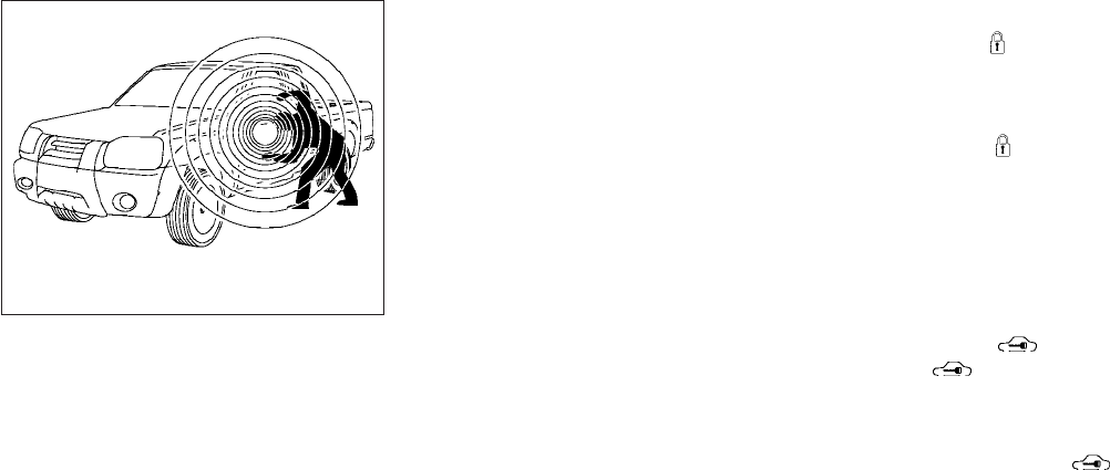
Your vehicle may have two types of security sys-
tems:
●Vehicle security system (if so equipped)
●NISSAN Vehicle Immobilizer System (if so
equipped)
VEHICLE SECURITY SYSTEM (if so
equipped)
The vehicle security system provides visual and
audible alarm signals if someone opens the doors
when the system is armed. It is not, however, a
motion detection-type system that activates
when a vehicle is moved or when a vibration
occurs.
The system helps deter vehicle theft but cannot
prevent it, nor can it prevent the theft of interior or
exterior vehicle components in all situations. Al-
ways secure your vehicle even if parking for a
brief period. Never leave your keys in the ignition,
and always lock the vehicle when unattended. Be
aware of your surroundings, and park in secure,
well-lit areas whenever possible.
Many devices offering additional protection, such
as component locks, identification markers, and
tracking systems, are available at auto supply
stores and specialty shops. Your NISSAN dealer
may also offer such equipment. Check with your
insurance company to see if you may be eligible
for discounts for various theft protection features.
How to arm the vehicle security
system
1. Close all windows. (The system can be
armed even if the windows are open.)
2. Remove the key from the ignition switch.
3. Close all doors. Lock all doors. The doors
can be locked with the key, power door lock
switch (if the door is opened, locked and
then closed), or with the keyfob.
Keyfob operation:
●Push the button on the keyfob.
All doors lock. The hazard lights flash
twice and the horn beeps once to indicate
all doors are locked.
●When the button is pushed with
all doors locked, the hazard lights flash
twice and the horn beeps once as a re-
minder that the doors are already locked.
The horn may or may not beep. Refer to
“Silencing the horn beep feature” in the
“Pre-driving checks and adjustments” sec-
tion later in this manual.
4. Confirm that the indicator light comes
on. The light stays on for about 30
seconds. The vehicle security system is now
pre-armed. After about 30 seconds the ve-
hicle security system automatically shifts
into the armed phase. The light begins
to flash once every 3 seconds. If, during the
30-second pre-arm time period, the driver’s
door is unlocked by the key or the keyfob, or
the ignition switch is placed in ACC or ON
position, the system will not arm.
LIC0359
SECURITY SYSTEMS (if so equipped)
Instruments and controls 2-23

●If the key is turned slowly when locking
the driver’s door, the system may not
arm. Furthermore, if the key is turned
beyond the vertical position toward the
unlock position to remove the key, the
system may be disarmed when the key
is removed. If the indicator light fails to
glow for 30 seconds, unlock the door
once and lock it again.
●Even when the driver and/or passen-
gers are in the vehicle, the system will
arm with all doors closed and locked
with the ignition switch placed in the
OFF position.
Vehicle security system activation
The vehicle security system will give the following
alarm:
●The headlights blink and the horn sounds
intermittently.
●The alarm automatically turns off after ap-
proximately 50 seconds. However, the alarm
reactivates if the vehicle is tampered with
again. The alarm can be shut off by unlocking
the driver’s door with the key or by pressing
the button on the keyfob.
The alarm is activated by:
●opening a door without using the key or
keyfob (even if the door is unlocked by using
the inside lock knob or the power door lock
switch).
How to stop an activated alarm
The alarm stops only by unlocking the driver’s
door with the key or by pressing the button
on the keyfob.
NISSAN VEHICLE IMMOBILIZER
SYSTEM (if so equipped)
The NISSAN Vehicle Immobilizer System will not
allow the engine to start without the use of a
registered key.
If the engine fails to start using a registered key
(for example, when interference is caused by
another registered key, an automated toll road
device or automatic payment device on the key
ring), restart the engine using the following pro-
cedures:
1. Leave the ignition switch in the ON position
for approximately 5 seconds.
2. Turn the ignition switch to the OFF or LOCK
position, and wait approximately 10 sec-
onds.
3. Repeat steps 1 and 2.
4. Restart the engine while holding the device
(which may have caused the interference)
separate from the registered key.
If the no start condition re-occurs, NISSAN rec-
ommends placing the registered key on a sepa-
rate key ring to avoid interference from other
devices.
Statement related to Section 15 of FCC
Rules for NISSAN Vehicle Immobilizer Sys-
tem (CONT ASSY — IMMOBILIZER, ANT
ASSY — IMMOBILIZER)
This device complies with part 15 of the
FCC Rules and RSS-210 of Industry
Canada. Operation is subject to the follow-
ing two conditions;
(1) This device may not cause harmful in-
terference, and (2) this device must accept
any interference received, including inter-
ference that may cause undesired opera-
tion of the device.
CHANGES OR MODIFICATIONS NOT EX-
PRESSLY APPROVED BY THE PARTY RE-
SPONSIBLE FOR COMPLIANCE COULD
VOID THE USER’S AUTHORITY TO OPER-
ATE THE EQUIPMENT.
2-24 Instruments and controls
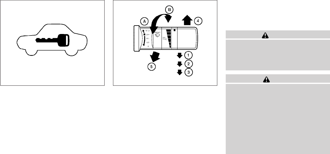
Security indicator light
The security indicator light blinks whenever the
ignition switch is placed in the LOCK, OFF or ACC
position. This function indicates the NISSAN Ve-
hicle Immobilizer System is operational.
If the NISSAN Vehicle Immobilizer System is mal-
functioning, the light will remain on while the
ignition switch is placed in the ON position.
If the light still remains on and/or the en-
gine will not start, see a NISSAN dealer for
NISSAN Vehicle Immobilizer System ser-
vice as soon as possible. Please bring all
registered keys that you have when visiting
your NISSAN dealer for service.
SWITCH OPERATION
The windshield wiper and washer operates when
the ignition switch is placed in the ON position.
Push the lever down to operate the wiper at the
following speed:
s
1Intermittent (INT) — intermittent operation
can be adjusted by turning the knob toward
s
A(Slower) or s
B(Faster).
s
2Low (LO) — continuous low speed operation
s
3High (HI) — continuous high speed opera-
tion
Push the lever up s
4to have one sweep opera-
tion (MIST) of the wiper.
Pull the lever toward you s
5to operate the
washer. The wiper will also operate several times.
WARNING
In freezing temperatures the washer solu-
tion may freeze on the windshield and
obscure your vision which may lead to an
accident. Warm the windshield with the
defroster before you wash the windshield.
CAUTION
●Do not operate the washer continu-
ously for more than 30 seconds.
●Do not operate the washer if the reser-
voir tank is empty.
●Do not fill the window washer reservoir
tank with washer fluid concentrates at
full strength. Some methyl alcohol
based washer fluid concentrates may
permanently stain the grille if spilled
while filling the window washer reser-
voir tank.
LIC0474 WIC0854
WINDSHIELD WIPER AND WASHER
SWITCH
Instruments and controls 2-25
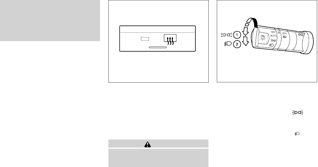
●Pre-mix washer fluid concentrates with
water to the manufacturer’s recom-
mended levels before pouring the fluid
into the window washer reservoir tank.
Do not use the window washer reservoir
tank to mix the washer fluid concen-
trate and water.
To defrost the rear window glass and outside
mirrors (if so equipped), start the engine and
push the rear window defroster switch on. The
rear window defroster indicator light on the
switch comes on. Push the switch again to turn
the defroster off.
The rear window defroster automatically turns off
after approximately 15 minutes.
CAUTION
When cleaning the inner side of the rear
window, be careful not to scratch or dam-
age the rear window defroster.
HEADLIGHT CONTROL SWITCH
Lighting
s
1When turning the switch to the posi-
tion, the front parking, tail, license plate and
instrument panel lights come on.
s
2When turning the switch to the posi-
tion, the headlights come on and all the other
lights remain on.
LIC1419 Type A
WIC1424
REAR WINDOW AND OUTSIDE
MIRROR DEFROSTER SWITCH (if so
equipped)
HEADLIGHT AND TURN SIGNAL
SWITCH
2-26 Instruments and controls
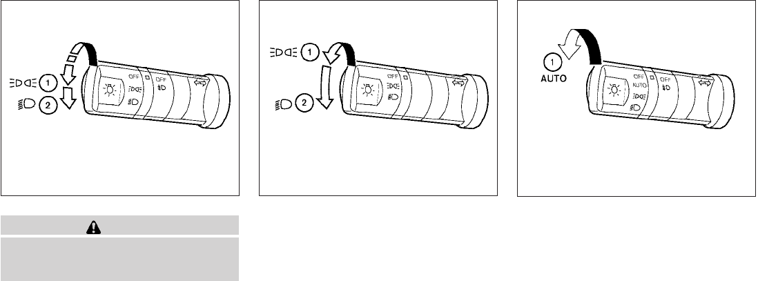
CAUTION
Use the headlights with the engine run-
ning to avoid discharging the vehicle
battery.
Autolight system (if so equipped)
The autolight system allows the headlights to be
set so they turn on and off automatically. The
autolight system can:
●Turn on the headlights, front parking, tail,
license plate and instrument panel lights au-
tomatically when it is dark.
●Turn off all the lights when it is light.
●Keep all the lights on for 45 seconds after
you turn the key to OFF and all doors are
closed.
Type B
WIC1452
Type C
WIC1426 WIC1453
Instruments and controls 2-27
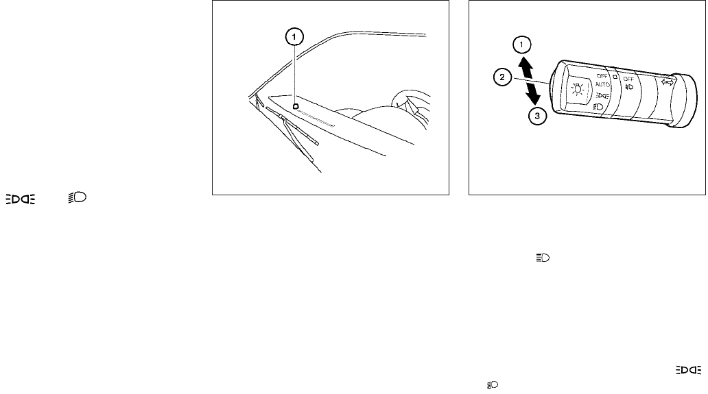
To turn on the autolight system:
1. Turn the headlight switch to the AUTO posi-
tion s
1.
2. Turn the ignition switch to ON.
3. The autolight system automatically turns the
headlights on and off.
Initially, if the ignition switch is turned OFF and a
door is opened and left open, the headlights
remain ON for 5 minutes. If another door is
opened during the 5 minutes, then the 5 minute
timer is reset.
To turn the autolight system off, turn the switch to
the OFF, ,or position. Be sure you do not put anything on top of
the autolight sensor s
1located in the top
side of the instrument panel. The autolight
sensor controls the autolight; if it is cov-
ered, the autolight sensor reacts as if it is
dark out and the headlights will illuminate.
If this occurs while parked with the engine
off and the switch in the ON position, your
vehicle’s battery could become discharged.
Headlight beam select
s
1To select the high beam function, push the
lever forward. The high beam lights come on
and the light illuminates.
s
2Pull the lever back to select the low beam.
s
3Pulling and releasing the lever flashes the
headlight high beams on and off.
Battery saver system
If the ignition switch is placed in the OFF position
while the headlight switch is in the
or position, the headlights will turn off after
5 minutes.
LIC0835 WIC1427
2-28 Instruments and controls
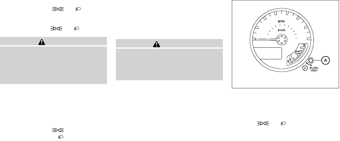
After the headlights automatically turn off with the
headlight switch in the or position,
the headlights will illuminate again for 5 minutes if
the headlight switch is moved to the OFF position
and then turned to the or position.
CAUTION
Even though the battery saver feature au-
tomatically turns off the headlights after a
period of time, you should turn the head-
light switch to the OFF position when the
engine is not running to avoid discharging
the vehicle battery.
DAYTIME RUNNING LIGHT SYSTEM
(Canada only)
The headlights automatically illuminate at a re-
duced intensity when the engine is started with
the parking brake released. The daytime running
lights operate with the headlight switch in the
OFF position or in the position. Turn the
headlight switch to the position for full
illumination when driving at night.
If the parking brake is applied before the engine is
started, the daytime running lights do not illumi-
nate. The daytime running lights illuminate when
the parking brake is released. The daytime run-
ning lights will remain on until the ignition switch
is placed in the OFF position.
WARNING
When the daytime running light system is
active, tail lights on your vehicle are not
on. It is necessary at dusk to turn on your
headlights. Failure to do so could cause
an accident injuring yourself and others.
INSTRUMENT BRIGHTNESS
CONTROL
The instrument brightness control operates when
the headlight control switch is in the AUTO (if so
equipped), or position.
Turn the control s
Ato adjust the brightness of the
instrument panel lights when driving at night.
WIC0917
Instruments and controls 2-29
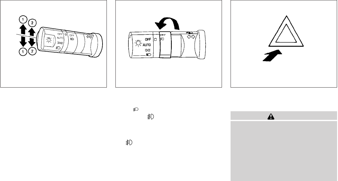
TURN SIGNAL SWITCH
Turn signal
s
1Move the lever up or down to signal the
turning direction. When the turn is com-
pleted, the turn signals cancel automatically.
Lane change signal
s
2To signal a lane change, move the lever up or
down to the point where the indicator light
begins to flash, but the lever does not latch.
FOG LIGHT SWITCH (if so equipped)
To turn the fog lights on, turn the headlight switch
to the position, then turn the fog light
switch to the position.
To turn the fog lights on with the headlight switch
in the AUTO position (if so equipped), the head-
lights must be on, then turn the fog light switch to
the position.
To turn the fog lights off, turn the fog light switch
to the OFF position.
The headlights must be on and the low beams
selected for the fog lights to operate. The fog
lights automatically turn off when the high beam
headlights are selected.
Push the switch on to warn other drivers when
you must stop or park under emergency condi-
tions. All turn signal lights flash.
WARNING
●If stopping for an emergency, be sure to
move the vehicle well off the road.
●Do not use the hazard warning flashers
while moving on the highway unless
unusual circumstances force you to
drive so slowly that your vehicle might
become a hazard to other traffic.
●Turn signals do not work when the haz-
ard warning flasher lights are on.
WIC1428 LIC0393 LIC0394
HAZARD WARNING FLASHER
SWITCH
2-30 Instruments and controls
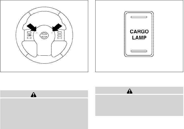
The flashers will operate with the ignition switch
placed in any position.
Some state laws may prohibit the use of
the hazard warning flasher switch while
driving.
To sound the horn, push the area between the
horn icons on the steering wheel.
WARNING
Do not disassemble the horn. Doing so
could affect proper operation of the
supplemental front air bag system. Tam-
pering with the supplemental front air bag
system may result in serious personal
injury.
To turn on the cargo lamp, push the switch down
to the ON position.
CAUTION
Be sure to turn the light switch to the OFF
position when you leave the vehicle for
extended periods of time, otherwise the
battery will go dead.
WIC1449 LIC0616
HORN CARGO LAMP SWITCH
Instruments and controls 2-31
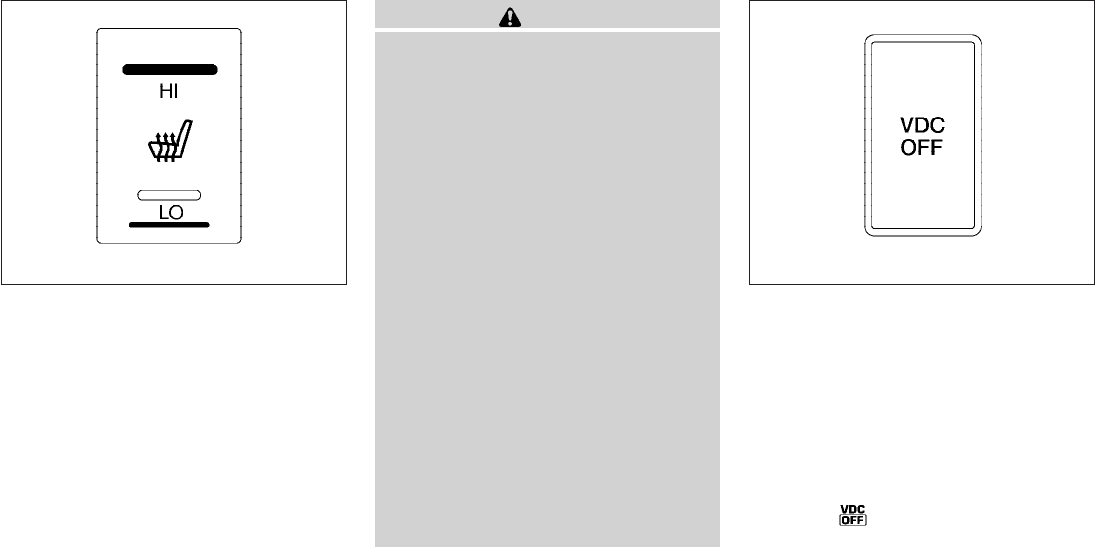
The front seats are warmed by built-in heaters.
1. Start the engine.
2. Push the LO or HI position of the switch, as
desired, depending on the temperature. The
indicator light in the switch will illuminate.
The heater is controlled by a thermostat,
automatically turning the heater on and off.
The indicator light will remain on as long as
the switch is on.
3. When the seat is warmed or before you
leave the vehicle, be sure to turn the switch
off.
CAUTION
●Do not use the seat heater for extended
periods or when no one is using the
seat.
●Do not put anything on the seat which
insulates heat, such as a blanket, cush-
ion, seat cover, etc. Otherwise, the seat
may become overheated.
●Do not place anything hard or heavy on
the seat or pierce it with a pin or similar
object. This may result in damage to the
heater.
●Any liquid spilled on the heated seat
should be removed immediately with a
dry cloth.
●When cleaning the seat, never use
gasoline, benzine, thinner, or any simi-
lar materials.
●If any abnormalities are found or the
heated seat does not operate, turn the
switch off and have the system checked
by your NISSAN dealer.
●The battery could run down if the seat
heater is operated while the engine is
not running.
The vehicle should be driven with the Vehicle
Dynamic Control (VDC) system on for most driv-
ing conditions.
If the vehicle is stuck in mud or snow, the VDC
system reduces the engine output to reduce
wheel spin. The engine speed will be reduced
even if the accelerator is depressed to the floor. If
maximum engine power is needed to free a stuck
vehicle, turn the VDC system off.
To turn off the VDC system, push the VDC OFF
switch. The indicator will come on.
Push the VDC OFF switch again or restart the engine
to turn on the system. See “Vehicle Dynamic Control
(VDC) system” in the “Starting and driving” section.
LIC1041 WIC0534
HEATED SEAT (if so equipped) VEHICLE DYNAMIC CONTROL (VDC)
OFF SWITCH (if so equipped)
2-32 Instruments and controls
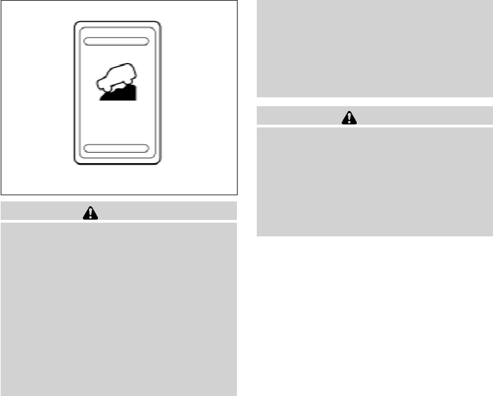
WARNING
●Never rely solely on the hill descent
control system to control vehicle speed
when driving on steep downhill grades.
Always drive carefully when using the
hill descent control system and decel-
erate the vehicle speed by depressing
the brake pedal if necessary. Be espe-
cially careful when driving on frozen,
muddy or extremely steep downhill
roads. Failure to control vehicle speed
may result in a loss of control of the
vehicle and possible serious injury or
death.
●The hill descent control may not control
the vehicle speed on a hill under all load
or road conditions. Always be prepared
to depress the brake pedal to control
vehicle speed. Failure to do so may re-
sult in a collision or serious personal
injury.
CAUTION
When the hill descent control system op-
erates continuously for a long time, the
temperature of the brake pads may in-
crease and the hill descent control system
may be temporarily disabled (the indicator
light will blink). If the indicator light does
not come on continuously after blinking,
stop using the system.
The hill descent control system is designed to
reduce driver workload when going down steep
hills. The hill descent control system helps to
control vehicle speed so the driver can concen-
trate on steering the vehicle.
To activate the hill descent control system:
●the 4WD switch must be in the 4L position
and the vehicle speed must be under 15
mph (25 km/h) or
●the 4WD switch must be in the 4H position
and the vehicle speed must be under 21
mph (35 km/h), and
●the hill descent control system switch must
be ON.
The hill descent control system on indicator light
will come on when the system is activated. Also,
the stop/tail lights illuminate while the hill descent
control system applies the brakes to control ve-
hicle speed.
If the accelerator or brake pedal is depressed
while the hill descent control system is on, the
system will stop operating temporarily. As soon
as the accelerator or brake pedal is released, the
hill descent control system begins to function
again if the hill descent control operating condi-
tions are fulfilled.
The hill descent control system on indicator light
blinks if the switch is on and all conditions for
system activation are not met or if the system
becomes disengaged for any reason.
To turn off the hill descent control system, push
the switch to the OFF position.
For additional information, see “Hill descent con-
trol system on indicator light” earlier in this sec-
tion and “Hill descent control system” in the
“Starting and driving” section of this manual.
LIC0743
HILL DESCENT CONTROL SWITCH (if
so equipped)
Instruments and controls 2-33
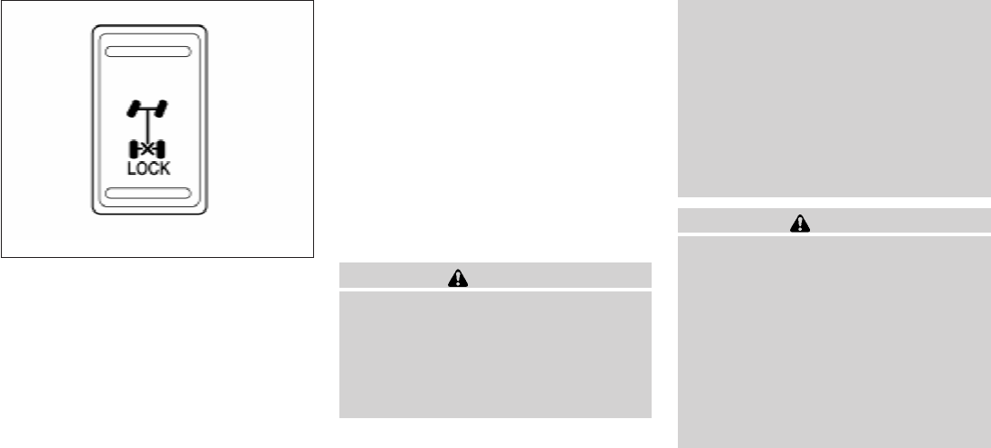
The Electronic Locking Rear Differential (E-Lock)
system can help provide added traction if the
vehicle is stuck or becoming stuck.
To activate the E-Lock system:
●the 4WD switch must be in the 4LO position
(4-wheel drive vehicles),
●the vehicle must be stopped or moving at 4
mph (7 km/h) or less, and
●the E-Lock system switch must be turned
ON.
When the E-Lock switch is turned ON, the indi-
cator light will flash until the system engages.
However, if all operation conditions listed above
are not met or the system becomes disengaged,
the indicator light will continue to flash.
The Anti-Lock Brake (ABS) system is disabled
and the ABS light illuminates when the E-Lock
system is ON. Also, the Vehicle Dynamic Control
(VDC) system is disabled and the VDC light
illuminates when the E-Lock system is ON.
See “Electronic locking rear differential (E-Lock)
system” in the “Starting and Driving” section for
further explanation and system limitations.
WARNING
●Never leave the E-Lock system ON
when driving on paved or hard-surfaced
roads. Turning the vehicle may result in
the rear wheels slipping and result in an
accident and personal injury. After us-
ing the E-Lock system to free the ve-
hicle, turn the system OFF.
●Use the E-Lock system only when free-
ing a stuck vehicle. Try the 4LO position
before using the E-Lock system. Never
use the E-Lock system on a slippery
road surface such as snow or ice sur-
face. Using the E-Lock system when
driving in these road conditions may
cause unexpected movement of the ve-
hicle during engine braking, accelerat-
ing or turning, which may result in an
accident and serious personal injury.
CAUTION
●After using the E-Lock system, turn the
switch OFF to prevent possible damage
to driveline components from extended
use.
●Do not drive over 12 MPH (20 km/h)
when the system is engaged. Doing so
could result in possible damage to the
driveline.
●Do not turn on the E-lock system while
the tires are spinning. Doing so could
damage drivetrain components.
LIC0729
ELECTRONIC LOCKING REAR
DIFFERENTIAL (E-Lock) SYSTEM
SWITCH (if so equipped)
2-34 Instruments and controls
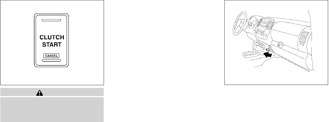
WARNING
Pay special attention to your surround-
ings when using the clutch interlock
switch. The vehicle will move forward or
backward according to the gear selected.
The clutch interlock (clutch start) switch allows
for starting the engine without depressing the
clutch pedal. This feature helps you restart the
engine if it stops under difficult conditions. (For
example, the engine stops on a steep hill and a
slight movement forward or backward might be
dangerous.)
To use the clutch interlock switch:
1. Set the parking brake.
2. Depress the brake pedal with your right foot.
3. Place your left foot on the brake pedal and
release the parking brake.
4. Turn the ignition switch to the ON position.
5. Press and release the clutch interlock
switch. The CANCEL light on the switch will
illuminate.
6. Turn the ignition to the START position to
start the engine and, at the same time, de-
press the accelerator pedal with your right
foot. As the vehicle begins to move, take
your left foot off the brake. Once the engine
has started, the clutch interlock switch
CANCEL light shuts off. Do not use the
interlock switch to start the engine under
normal driving conditions.
The power outlets are for powering electrical
accessories such as cellular telephones.
The bottom power outlet located on instrument
panel is powered directly by the vehicle’s battery.
The power outlet located inside the center con-
sole is powered only when the ignition switch is in
the ACC or ON position.
Open the cap to use a power outlet.
WIC0817 Front row
LIC1430
CLUTCH INTERLOCK (clutch start)
SWITCH (if so equipped) POWER OUTLET
Instruments and controls 2-35
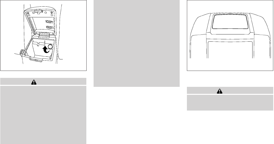
CAUTION
●The outlet and plug may be hot during
or immediately after use.
●Only certain power outlets are designed
for use with a cigarette lighter unit. Do
not use any other power outlet for an
accessory lighter. See your NISSAN
dealer for additional information.
●Do not use with accessories that ex-
ceed a 12 volt, 120W (10A) power draw.
Do not use double adapters or more
than one electrical accessory.
●Use power outlets with the engine run-
ning to avoid discharging the vehicle
battery.
●Avoid using power outlets when the air
conditioner, headlights or rear window
defroster is on.
●Before inserting or disconnecting a
plug, be sure the electrical accessory
being used is turned OFF.
●Push the plug in as far as it will go. If
good contact is not made, the plug may
overheat or the internal temperature
fuse may open.
●When not in use, be sure to close the
cap. Do not allow water to contact the
outlet. STORAGE TRAYS
WARNING
Do not place sharp objects in the trays to
help prevent injury in an accident or sud-
den stop.
Center console
LIC0761
Top center tray
LIC1539
STORAGE
2-36 Instruments and controls
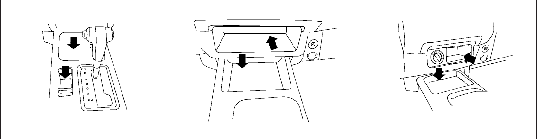
AT model
LIC0818
MT model — Type A (if so equipped)
WIC1431
MT model — Type B (if so equipped)
WIC1432
Instruments and controls 2-37
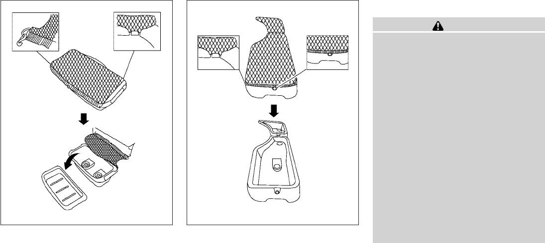
UNDER-SEAT STORAGE BINS
WARNING
●Properly secure all cargo with ropes or
straps to help prevent it from sliding or
shifting. In a sudden stop or collision,
unsecured cargo could cause personal
injury.
●The cargo restrained in the under-seat
storage bins must not exceed the
weight limits listed below or the bins
may not stay secured. In a sudden stop
or collision, the unsecured bins could
cause personal inury.
King cab model: 16 lb (7.25 kg)
Crew cab model
Driver’s side: 16 lb (7.25 kg)
Passenger’s side: 25 lb (11.33 kg)
●If the under-seat storage bins are re-
moved for any reason, they should be
securely stored to prevent them from
causing injury to passengers or damage
to the vehicle in case of sudden braking
or an accident.
2nd row under-seat storage bin
(King cab model)
LIC0821 2nd row under-seat storage bin
(Crew cab model)
LIC0820
2-38 Instruments and controls
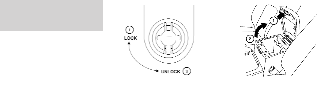
●Do not place sharp objects in the under-
seat storage bins. Such objects may
become dangerous projectiles and
cause injury when the vehicle is moving
or if the vehicle is involved in a collision.
To access the under-seat storage bins:
For King cab model, lift up the jump seat. Refer to
“Jump seat” in the “Safety—Seats, seat belts and
supplemental restraint system” section earlier in
this manual.
For Crew cab model, lift up the rear bench seat.
Refer to “Folding the rear bench seat” in the
“Safety—Seats, seat belts and supplemental re-
straint system” section earlier in this manual. To remove the under-seat storage bins:
1. Remove the storage net.
2. Remove the tray by lifting it out of the stor-
age bin (King cab model).
3. Turn the knobs to the UNLOCK position s
2.
To install the under-seat storage bins:
1. Position the under-seat storage bin so the
holes line up with the holes in the floorboard.
2. Insert the knobs and turn them to the LOCK
position s
1.
CONSOLE BOX
Pull up on the lever s
1to open the console box lid
s
2.
LIC0822 LIC0766
Instruments and controls 2-39
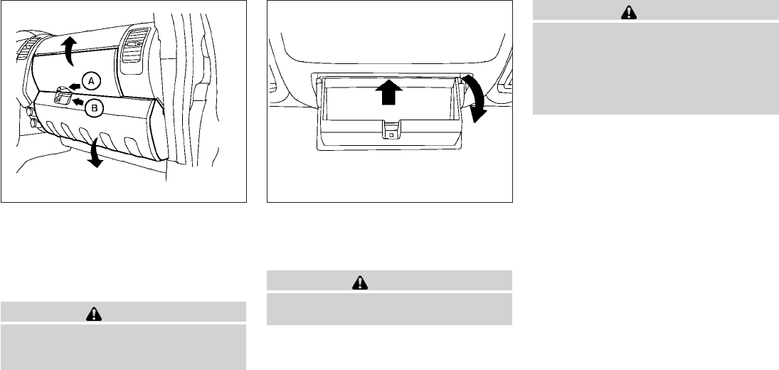
GLOVE BOX
To open the top portion of the glove box, push the
latch s
Aup and raise the lid.
To open the lower portion of the glove box, pull
the handle s
Bdown and lower the lid.
WARNING
Keep glove box lid closed while driving to
help prevent injury in an accident or a
sudden stop.
SUNGLASSES HOLDER (if so
equipped)
To open the sunglasses holder, push and release.
WARNING
●Keep the sunglasses holder closed
while driving to prevent an accident.
CAUTION
●Do not use for anything other than
sunglasses.
●Do not leave sunglasses in the sun-
glasses holder while parking in direct
sunlight. The heat may damage the
sunglasses.
LIC0768 WIC0673
2-40 Instruments and controls
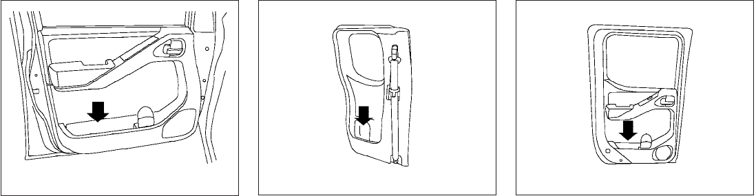
MAP POCKETS
WIC0824 King cab model
LIC0826
Crew cab model
LIC0825
Instruments and controls 2-41
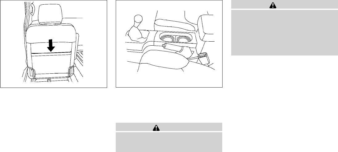
SEAT POCKET (if so equipped)
A pocket is located on the back of the driver’s
seat.
CUP HOLDERS
The front cup holders have adapters that can be
removed to accommodate larger cups.
WARNING
The cup holder should not be used while
driving so full attention may be given to
vehicle operation.
CAUTION
●Avoid abrupt starting and braking when
the cup holder is being used to prevent
spilling the drink. If the liquid is hot, it
can scald you or your passenger.
●Use only soft cups in the cup holder.
Hard objects can injure you in an
accident.
LIC0575 Front
WIC0827
2-42 Instruments and controls
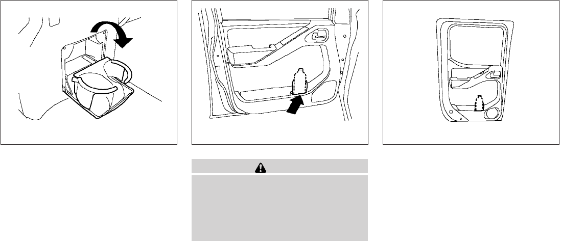
To open the 2nd row cup holders (rear of the front
console), lower the lid. To close, raise the lid. If
stepped on, the cup holder is designed to snap
loose from the console. To re-install, close the
cup holder assembly and push it back into the
console opening.
To fold the 2nd row bench seat back, first close
the cup holder.
CAUTION
●Do not use bottle holder for any other
objects that could be thrown about in
the vehicle and possibly injure people
during sudden braking or an accident.
●Do not use bottle holder for open liquid
containers.
2nd row (rear of front console)
WIC0771
Bottle holder (front row)
LIC0784
Bottle holder (2nd row, Crew cab)
WIC0828
Instruments and controls 2-43
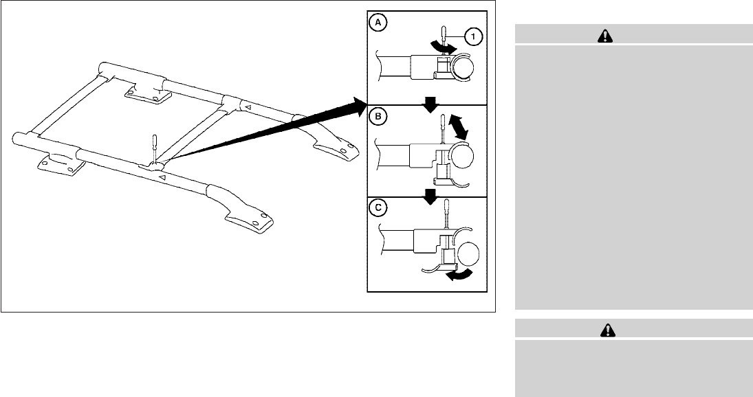
ROOF RACK (if so equipped)
WARNING
●Drive extra carefully when the vehicle is
loaded at or near the cargo carrying
capacity, especially if the significant
portion of that load is carried on the
roof rack.
●Heavy loading of the roof rack has the
potential to affect the vehicle stability
and handling during sudden or abnor-
mal handling maneuvers.
●Roof rack load should be evenly
distributed.
●Do not exceed maximum roof rack load
weight capacity.
●Properly secure all cargo with ropes or
straps to help prevent it from sliding or
shifting. In a sudden stop or collision,
unsecured cargo could cause personal
injury.
CAUTION
Use care when placing or removing items
from the roof rack. If you cannot comfort-
ably lift the items onto the roof rack from
the ground, use a ladder or stool.
WIC0857
2-44 Instruments and controls

Always evenly distribute the cargo on the tubular
roof rack. The maximum total load is 125 lb
(56 kg) evenly distributed. Be careful that your
vehicle does not exceed the Gross Vehicle
Weight Rating (GVWR) or the Gross Axle
Weight Ratings (GAWR front and rear). The
GVWR and GAWR are located on the F.M.V.S.S.
label (located on the driver’s side door jamb
pillar). For more information regarding GVWR
and GAWR, refer to “Vehicle loading information”
in the “Technical and consumer information” sec-
tion later in this manual.
The front crossbar can be adjusted or removed.
Use the Torxdriver provided in the tool kit to
loosen both crossbar adjusting screws.
To adjust:
1. Loosen the adjusting screws with the
Torxdriver s
1by turning counterclockwise
s
A.
2. When the clamp is loosened, move the
crossbar so the cargo can be positioned on
the crossbar s
B.
3. Tighten the crossbar adjusting screws with
the Torxdriver by turning clockwise.
4. Secure the cargo with rope.
5. Always check the tightness of the crossbar
adjusting screws.
To remove:
1. Loosen the adjusting screws with the
Torxdriver s
1by turning counterclockwise
s
A.
2. Rotate the clamps s
C.
3. Remove the crossbar.
4. Reverse to install.
5. Always check the tightness of the crossbar
adjusting screws.
If you hear wind noise coming from the roof rack
while driving, adjust the roof rack crossbar to the
neutral position, rearward of Don the side rails.
POWER WINDOWS (if so equipped)
WARNING
●Make sure that all passengers have
their hands, etc. inside the vehicle while
it is in motion and before closing the
windows. Use the window lock switch
to prevent unexpected use of the power
windows.
●Do not leave children unattended inside
the vehicle. They could unknowingly ac-
tivate switches or controls and become
trapped in a window. Unattended chil-
dren could become involved in serious
accidents.
The power windows operate when the ignition
switch is placed in the ON position, or for about
45 seconds after the ignition switch is placed in
the OFF position. If the driver’s or passenger’s
door is opened during this period of about 45
seconds, power to the windows is canceled.
WINDOWS
Instruments and controls 2-45
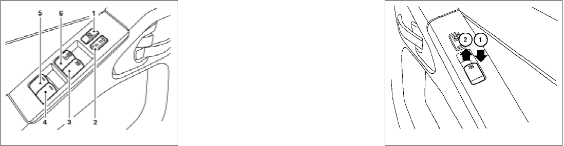
1. Window lock button
2. Power door lock switch
3. Front passenger side window switch
4. Right rear passenger window switch
(Crew Cab models only)
5. Left rear passenger window switch
(Crew Cab models only)
6. Driver’s side automatic switch
Driver’s side power window switch
The driver’s side control panel is equipped with
switches to open or close the front and rear
passenger windows.
To open a window, push the switch and hold it
down. To close a window, pull the switch and
hold it up. To stop the opening or closing function
at any time, simply release the switch.
Front passenger’s power window
switch
The passenger’s window switch operates only
the corresponding passenger’s window. To open
the window, push the switch and hold it down s
1.
To close the window, pull the switch up s
2.
LIC1329 LIC0786
2-46 Instruments and controls
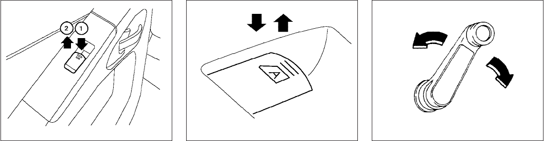
Rear power window switch (Crew
Cab models only)
The rear power window switches open or close
only the corresponding passenger window. To
open the window, push the switch and hold it
down s
1. To close the window, push the switch
up s
2.
Locking passengers’ windows
When the window lock button is depressed, only
the driver’s side window can be opened or
closed. Push it again to cancel the window lock
function.
Automatic operation
To fully open a window equipped with automatic
operation, press the window switch down to the
second detent and release it; it need not be held.
The window automatically opens all the way. To
stop the window, lift the switch up while the
window is opening.
MANUAL WINDOWS (if so equipped)
The side windows can be opened or closed by
turning the hand crank on each door.
LIC0787 LIC0410 WIC0263
Instruments and controls 2-47
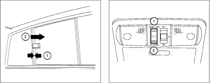
REAR SLIDING WINDOW (if so
equipped)
Squeeze the handles of the lever s
1, then slide
the window open s
2.
Sliding the moonroof
To fully open the moonroof, push the switch to-
ward DOWN/OPEN s
1.
To fully close the moonroof, push the switch
toward UP/CLOSE s
2.
To open or close the moonroof part way, push the
switch in any direction while the moonroof is
sliding to stop it in the desired position.
Tilting the moonroof
Close the moonroof by pushing the switch to-
ward UP/CLOSE s
2. Release the switch, then
push the UP/CLOSE switch again to tilt the
moonroof up.
To tilt the moonroof down, push the switch to-
ward DOWN/OPEN s
1.
Restarting the moonroof sliding switch
The sliding switch will become inoperable after
the battery terminal is disconnected, the electri-
cal supply interrupted and/or some abnormality
detected. Use the following reset procedure to
return moonroof operation to normal.
1. If the moonroof lid is open, push the tilting
switch repeatedly toward the
DOWN/OPEN s
1position to fully close the
lid.
2. Push and hold the tilting switch for more
than 2 seconds toward the DOWN/OPEN
s
1position to reestablish the lid’s home
position.
The moonroof should now operate normally.
WIC0856 WIC0882
MOONROOF (if so equipped)
2-48 Instruments and controls

Auto-reverse function (when closing or
tilting down the moonroof)
The auto-reverse function can be activated when
the moonroof is closed or tilted down by auto-
matic operation when the ignition switch is
placed in the ON position or for about 45 sec-
onds after the ignition switch is placed in the OFF
position.
Depending on the environment or driving
conditions, the auto-reverse function may
be activated if an impact or load similar to
something being caught in the moonroof
occurs.
WARNING
There are some small distances immedi-
ately before the closed position which
cannot be detected. Make sure that all
passengers have their hands, etc., inside
the vehicle before closing the moonroof.
When closing:
If the control unit detects something caught in the
moonroof as it moves to the front, the moonroof
will immediately open backward.
When tilting down:
If the control unit detects something caught in the
moonroof as it tilts down, the moonroof will im-
mediately tilt up.
If the auto-reverse function malfunctions and re-
peats opening or tilting up the moonroof, keep
pushing the tilt down switch within 5 seconds
after it happens; the moonroof will fully close
gradually. Make sure nothing is caught in the
moonroof.
WARNING
●In an accident you could be thrown from
the vehicle through an open moonroof.
Always use seat belts and child
restraints.
●Do not allow anyone to stand up or
extend any portion of their body out of
the moonroof opening while the vehicle
is in motion or while the moonroof is
closing.
CAUTION
●Remove water drops, snow, ice or sand
from the moonroof before opening.
●Do not place heavy objects on the
moonroof or surrounding area.
Sunshade
Open and close the sunshade by sliding it for-
ward or backward.
If the moonroof does not close
Have your NISSAN dealer check and repair the
moonroof.
Instruments and controls 2-49
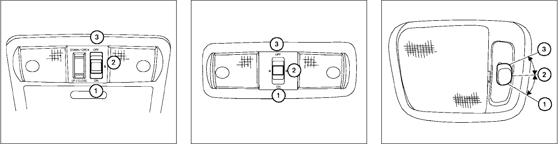
The interior lights have a three-position switch
and operate regardless of ignition switch posi-
tion.
When the switch is in the ON position s
1, the
interior lights illuminate, regardless of door posi-
tion. The lights will go off after about 30 minutes
unless the ignition switch is in the ACC or ON
position.
When the switch is in the O position s
2, the
interior lights will stay on for about 30 seconds
when:
●The doors are unlocked by the keyfob, a key
or the power door lock switch while all doors
are closed and the ignition switch is in the
OFF position.
●The driver’s door is opened and then closed
while the key is removed from the ignition
switch.
●The key is removed from the ignition switch
while all doors are closed.
The lights will turn off while the 30 second timer is
activated when:
●The driver’s door is locked by the keyfob, a
key, or the power door lock switch.
●The ignition switch is turned ON.
The lights will turn off automatically after 30 min-
utes while doors are open to prevent the battery
from becoming discharged.
When the switch is in the OFF position s
3, the
interior lights do not illuminate, regardless of door
position.
Type A
LIC0789
Type B
LIC0792
Type C
LIC0630
INTERIOR LIGHTS
2-50 Instruments and controls
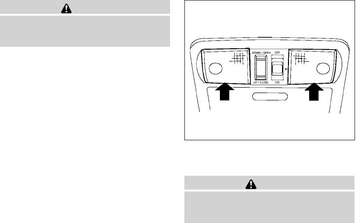
CAUTION
Do not use for extended periods of time
with the engine stopped. This could result
in a discharged battery.
To turn the map lights on, press the lenses. To
turn them off, press the lenses of the lights again.
CAUTION
Do not use for extended periods of time
with the engine stopped. This could result
in a discharged battery.
The HomeLinkTUniversal Transceiver provides a
convenient way to consolidate the functions of up
to three individual hand-held transmitters into
one built-in device.
HomeLinkTUniversal Transceiver:
●Will operate most Radio Frequency (RF)
devices such as garage doors, gates, home
and office lighting, entry door locks and se-
curity systems.
●Is powered by your vehicle’s battery. No
separate batteries are required. If the vehi-
cle’s battery is discharged or is discon-
nected, HomeLinkTwill retain all program-
ming.
Once the HomeLinkTUniversal Transceiver
is programmed, retain the original trans-
mitter for future programming procedures
(Example: new vehicle purchases). Upon
sale of the vehicle, the programmed
HomeLinkTUniversal Transceiver buttons
should be erased for security purposes. For
additional information, refer to “Program-
ming HomeLinkT” later in this section.
LIC0791
MAP LIGHTS (if so equipped) HOMELINKTUNIVERSAL
TRANSCEIVER (if so equipped)
Instruments and controls 2-51
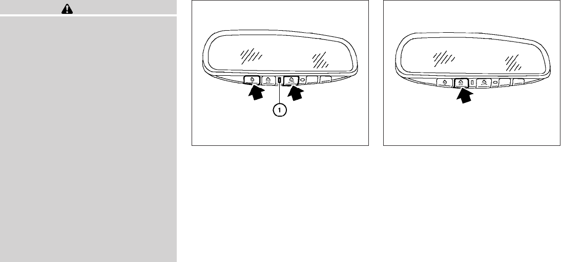
WARNING
●Do not use the HomeLinkTUniversal
Transceiver with any garage door
opener that lacks safety stop and re-
verse features as required by federal
safety standards. (These standards be-
came effective for opener models
manufactured after April 1, 1982). A ga-
rage door opener which cannot detect
an object in the path of a closing garage
door and then automatically stop and
reverse, does not meet current federal
safety standards. Using a garage door
opener without these features in-
creases the risk of serious injury or
death.
●During the programming procedure
your garage door or security gate will
open and close (if the transmitter is
within range). Make sure that people or
objects are clear of the garage door,
gate, etc. that you are programming.
●Your vehicle’s engine should be turned
off while programming the HomeLinkT
Universal Transceiver.
PROGRAMMING HOMELINKT
1. To begin, press and hold the two outer
HomeLinkTbuttons (to clear the memory)
until the indicator light s
1blinks (after 20
seconds). Release both buttons.
2. Position the end of the hand-held transmitter
1 - 3 inches (26 - 76 mm) away from the
HomeLinkTsurface.
3. Using both hands, simultaneously press and
hold both the HomeLinkTbutton you want to
program and the hand-held transmitter but-
ton.
DO NOT release the buttons until step 4 has
been completed.
4. Hold down both buttons until the indicator
light on the HomeLinkTflashes, changing
from a “slow blink” to a “rapidly flashing
blink”. This could take up to 90 seconds.
When the indicator light flashes rapidly, both
buttons may be released. The rapidly flash-
ing light indicates successful programming.
To activate the garage door or other pro-
WIC0986 WIC0987
2-52 Instruments and controls
grammed device, press and hold the pro-
grammed HomeLinkTbutton — releasing
when the device begins to activate.
5. If the indicator light on the HomeLinkTblinks
rapidly for 2 seconds and then turns solid,
HomeLinkThas picked up a “rolling code”
garage door opener signal. You will need to
proceed with the next steps to train the
HomeLinkTto complete the programming
which may require a ladder and another per-
son for convenience.
6. Press and release the “smart” or “learn” pro-
gram button located on the garage door
opener’s motor to activate the “training
mode”. This button is usually located near
the antenna wire that hangs down from the
motor. If the wire originates from under a
light lens, you will need to remove the lens to
access the program button.
NOTE:
Once you have pressed and released the
program button on the garage door open-
er’s motor and the “training light” is lit, you
have 30 seconds in which to perform step 7.
Use the help of a second person for conve-
nience to assist when performing this step.
7. Within 30 seconds of pressing and releas-
ing the garage door opener’s program but-
ton, quickly and firmly press and release the
HomeLinkTbutton you’ve just programmed.
Press and release the HomeLinkTbutton up
to 3 times to complete the training.
8. Your HomeLinkTbutton should now be pro-
grammed. (To program the remaining
HomeLinkTbuttons for additional door or
gate openers, follow steps 2-4 only.)
NOTE:
Do not repeat step 1 unless you want to
“clear” all previously programmed
HomeLinkTbuttons.
If you have any questions or are having difficulty
programming your HomeLinkTbuttons, refer to
the HomeLinkTweb site at: www.homelink.com
or call 1-800-355-3515.
PROGRAMMING HOMELINKTFOR
CANADIAN CUSTOMERS
Prior to 1992, D.O.C. regulations required hand-
held transmitters to stop transmitting after 2 sec-
onds. To program your hand-held transmitter to
HomeLinkT, continue to press and hold the
HomeLinkTbutton (see steps 2 - 4 under “Pro-
gramming HomeLinkT”) while you press and re-
press (“cycle”) your hand-held transmitters every
2 seconds until the indicator light flashes rapidly
(indicating successful programming).
NOTE:
When programming a garage door opener,
etc., it is advised to unplug the device dur-
ing the “cycling” process to prevent pos-
sible damage to the garage door opener
components.
OPERATING THE HOMELINKT
UNIVERSAL TRANSCEIVER
The HomeLinkTUniversal Transceiver (once pro-
grammed) may now be used to activate the ga-
rage door, etc. To operate, simply press the ap-
propriate programmed HomeLinkTUniversal
Transceiver button. The red indicator light will
illuminate while the signal is being transmitted.
PROGRAMMING TROUBLE-
DIAGNOSIS
If the HomeLinkTdoes not quickly learn the hand-
held transmitter information:
●replace the hand-held transmitter batteries
with new batteries.
●position the hand-held transmitter with its
battery area facing away from the
HomeLinkTsurface.
●press and hold both the HomeLinkTand
hand-held transmitter buttons without inter-
ruption.
Instruments and controls 2-53
●position the hand-held transmitter1-3
inches (26 - 76 mm) away from the
HomeLinkTsurface. Hold the transmitter in
that position for up to 15 seconds. If
HomeLinkTis not programmed within that
time, try holding the transmitter in another
position – keeping the indicator light in view
at all times.
If you continue to have programming difficulties,
please contact the NISSAN Consumer Affairs
Department. The phone numbers are located in
the Foreword of this manual.
CLEARING THE PROGRAMMED
INFORMATION
Individual buttons cannot be cleared. However,
to clear all programming, press and hold the two
outside buttons and release when the indicator
light begins to flash (approximately 20 seconds).
REPROGRAMMING A SINGLE
HOMELINKTBUTTON
To reprogram a HomeLinkTUniversal Transceiver
button, complete the following.
1. Press and hold the desired HomeLinkTbut-
ton. Do not release the button until step 4
has been completed.
2. When the indicator light begins to flash
slowly (after 20 seconds), position the
hand-held transmitter1-3inches (26 - 76
mm) away from the HomeLinkTsurface.
3. Press and hold the hand-held transmitter
button.
4. The HomeLinkTindicator light will flash, first
slowly and then rapidly. When the indicator
light begins to flash rapidly, release both
buttons.
The HomeLinkTUniversal Transceiver button has
now been reprogrammed. The new device can
be activated by pushing the HomeLinkTbutton
that was just programmed. This procedure will
not affect any other programmed HomeLinkT
buttons.
IF YOUR VEHICLE IS STOLEN
If your vehicle is stolen, you should change the
codes of any non-rolling code device that has
been programmed into HomeLinkT. Consult the
Owner’s Manual of each device or call the manu-
facturer or dealer of those devices for additional
information.
When your vehicle is recovered, you will
need to reprogram the HomeLinkTUniver-
sal Transceiver with your new transmitter
information.
FCC Notice:
This device complies with FCC rules part 15
and RSS-210 of Industry Canada. Opera-
tion is subject to the following two condi-
tions:
(1) This device may not cause harmful in-
terference and (2) This device must accept
any interference that may be received, in-
cluding interference that may cause undes-
ired operation.
This transmitter has been tested and com-
plies with FCC and DOC/MDC rules.
Changes or modifications not expressly ap-
proved by the party responsible for compli-
ance could void the user’s authority to op-
erate the equipment.
DOC: ISTC 1763K1313
FCC I.D. CV2V67690
2-54 Instruments and controls

3 Pre-driving checks and adjustments
Keys.............................................3-2
NISSAN vehicle immobilizer system keys
(if so equipped) ................................3-2
Doors ............................................3-3
Locking with key................................3-3
Locking with inside lock knob ....................3-4
Locking with power door lock switch
(if so equipped) ................................3-4
Rear doors (King Cab models) ...................3-5
Automatic door locks (if so equipped).............3-5
Child safety rear door lock (Crew Cab
models only) ...................................3-6
Remote keyless entry system (if so equipped).........3-6
How to use remote keyless entry system ..........3-7
Hood ...........................................3-10
Fuel-filler door ...................................3-10
Fuel-filler cap .................................3-10
Steering wheel ...................................3-12
Tilt operation (if so equipped) ...................3-12
Sun visors .......................................3-12
Vanity mirrors (if so equipped)...................3-13
Mirrors ..........................................3-13
Rearview mirror (if so equipped).................3-13
Automatic anti-glare rearview mirror
(if so equipped) ...............................3-14
Outside mirrors ...............................3-14
Truck box ........................................3-15
Tailgate.......................................3-15
Bed Extender (if so equipped) ..................3-17
Tie down hooks (if so equipped) ................3-18
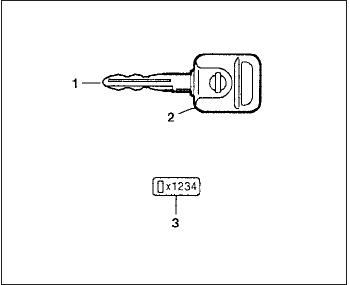
1. Two master keys (black) with transponder
chip and chrome NISSAN brand symbol on
one side.
2. Transponder chip
3. Key number plate
A key number plate is supplied with your keys.
Record the key number and keep the plate in a
safe place (such as your wallet), not in the ve-
hicle. If you lose your keys, see a NISSAN dealer
for duplicates by using the key number. NISSAN
does not record key numbers so it is very impor-
tant to keep track of your key number plate.
A key number is only necessary when you have
lost all keys and do not have one to duplicate
from. If you still have a key, your NISSAN dealer
can duplicate it.
NISSAN VEHICLE IMMOBILIZER
SYSTEM KEYS (if so equipped)
You can only drive your vehicle using the master
key which is registered to the NISSAN Vehicle
Immobilizer System components in your vehicle.
This key has a transponder chip in the key head.
The master key can be used for all the locks.
Never leave these keys in the vehicle.
Additional or replacement keys:
If you still have a key, the key number is not
necessary when you need extra NISSAN Vehicle
Immobilizer System keys. Your dealer can dupli-
cate your existing key. As many as five NISSAN
Vehicle Immobilizer System keys can be used
with one vehicle. You should bring all NISSAN
Vehicle Immobilizer System keys that you have to
your NISSAN dealer for registration. This is be-
cause the registration process will erase the
memory of all key codes previously registered
into the NISSAN Vehicle Immobilizer System.
After the registration process, these components
will only recognize keys coded into the NISSAN
Vehicle Immobilizer System during registration.
Any key that is not given to your dealer at the time
of registration will no longer be able to start your
vehicle.
Do not allow the immobilizer system key, which
contains an electrical transponder, to come into
contact with salt water. This could affect system
function.
LPD0348
KEYS
3-2 Pre-driving checks and adjustments
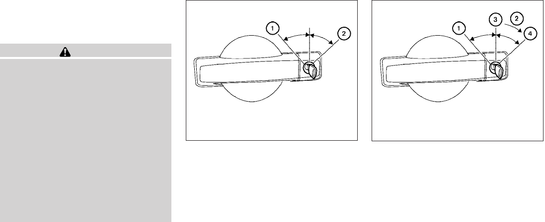
When the doors are locked using one of the
following methods, the doors can not be opened
using the inside or outside door handles. The
doors must be unlocked to open the doors.
WARNING
●Always have the doors locked while
driving. Along with the use of seat belts,
this provides greater safety in the event
of an accident by helping to prevent
persons from being thrown from the
vehicle. This also helps keep children
and others from unintentionally open-
ing the doors, and will help keep out
intruders.
●Before opening any door, always look
for and avoid oncoming traffic.
●Do not leave children unattended inside
the vehicle. They could unknowingly ac-
tivate switches or controls. Unattended
children could become involved in seri-
ous accidents.
LOCKING WITH KEY
Manual (if so equipped)
To lock a door, turn the key toward the front of the
vehicle s
1. To unlock, turn the key toward the rear
s
2.
Power (if so equipped)
The power door lock system allows you to lock or
unlock all doors at the same time.
Turning the key toward the front s
1of the vehicle
locks all doors.
Turning the key one time toward the rear s
2of the
vehicle unlocks that door. From that position,
returning the key to neutral s
3(where the key can
only be removed and inserted) and turning it
toward the rear again within 5 seconds unlocks
all doors s
4.
Driver’s side
WPD0311 LPD0240
DOORS
Pre-driving checks and adjustments 3-3
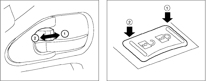
LOCKING WITH INSIDE LOCK
KNOB
To lock the door without the key, move the inside
lock knob to the lock position s
1, then close the
door.
To unlock the door without the key, move the
inside lock knob to the unlock position s
2.
LOCKING WITH POWER DOOR
LOCK SWITCH (if so equipped)
To lock all the doors without a key, push the door
lock switch (driver’s or front passenger’s side) to
the lock position s
1. When locking the door this
way, be certain not to leave the key inside the
vehicle.
To unlock all the doors without a key, push the
door lock switch (driver’s or front passenger’s
side) to the unlock position s
2.
Lockout protection
When the power door lock switch (driver’s or
front passenger’s side) is moved to the lock
position with the key in the ignition switch and any
door open, all doors will lock and then unlock
automatically. This helps to prevent the keys from
being accidently locked inside the vehicle.
Inside lock
LPD0298
Door lock switch
WPD0381
3-4 Pre-driving checks and adjustments
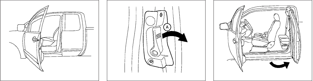
REAR DOORS (King Cab models)
1. Open the driver’s or passenger’s door.
2. From the outside, pull the door handle s
A
toward you. 3. Open the door to the desired position.
AUTOMATIC DOOR LOCKS (if so
equipped)
●All doors lock automatically when the vehicle
speed reaches 15 MPH (24 km/h).
●For automatic transmission models: All
doors unlock automatically when the trans-
mission is placed in the P (Park) position.
●For manual transmission models: All doors
unlock automatically when the key is re-
moved from the ignition switch.
LPD0278 LPD0312 WPD0313
Pre-driving checks and adjustments 3-5
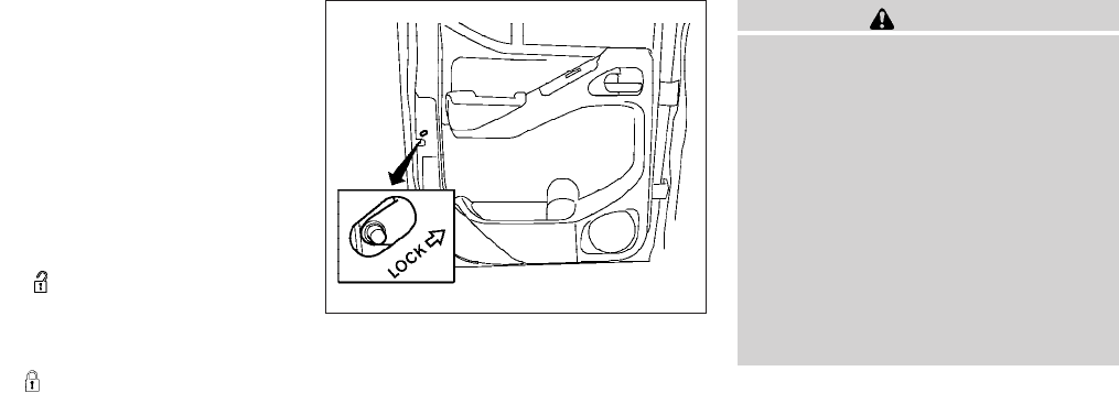
The automatic lock and unlock functions
can be deactivated or activated indepen-
dently of each other. To deactivate or activate
the automatic door lock or unlock system, per-
form the following procedure:
1. Close all doors.
2. Place the ignition switch in the ON position.
3. Do one of the following within 20 seconds of
performing Step #2:
●To change AUTO UNLOCK settings:
push and hold the power door lock switch
to the position (UNLOCK) for more
than 5 seconds.
●To change AUTO LOCK settings: push
and hold the power door lock switch to
the position (LOCK) for more
than 5 seconds.
4. When activated, the hazard warning lights
will flash twice. When deactivated, the haz-
ard warning lights will flash once.
5. The ignition switch must be placed in the
OFF and ON position again between each
setting change.
CHILD SAFETY REAR DOOR LOCK
(Crew Cab models only)
Child safety locks help prevent the rear doors
from being opened accidentally, especially when
small children are in the vehicle.
The child safety lock levers are located on the
edge of the rear doors.
When the lever is in the lock position, the
door can be opened only from the outside.
WARNING
●Radio waves could adversely affect
electric medical equipment. Those who
use a pacemaker should contact the
electric medical equipment manufac-
turer for the possible influences before
use.
●The remote keyless entry keyfob trans-
mits radio waves when the buttons are
pushed. The FAA advises radio waves
may affect aircraft navigation and com-
munication systems. Do not operate the
remote keyless entry keyfob while on
an airplane. Make sure the buttons are
not operated unintentionally when the
unit is stored for a flight
It is possible to lock/unlock all doors, turn the
interior lights on, and activate the panic alarm by
using the keyfob from outside the vehicle.
Be sure to remove the key from the vehicle
before locking the doors.
The keyfob can operate at a distance of approxi-
mately 33 ft (10 m) from the vehicle. The effective
distance depends on the conditions around the
vehicle.
WPD0314
REMOTE KEYLESS ENTRY SYSTEM
(if so equipped)
3-6 Pre-driving checks and adjustments
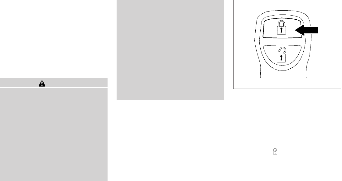
As many as 5 keyfobs can be used with one
vehicle. For information concerning the purchase
and use of additional keyfobs, contact a NISSAN
dealer.
The keyfob will not function when:
●the battery is discharged
●the distance between the vehicle and the
keyfob is over 33 ft (10 m)
The panic alarm will not activate when the
key is in the ignition switch.
CAUTION
Listed below are conditions or occur-
rences which will damage the keyfob:
●Do not allow the keyfob, which contains
electrical components, to come into
contact with water or salt water. This
could affect the system function.
●Do not drop the keyfob.
●Do not strike the keyfob sharply against
another object.
●Do not change or modify the keyfob.
●Wetting may damage the keyfob. If the
keyfob gets wet, immediately wipe until
it is completely dry.
●Do not place the keyfob for an extended
period in an area where temperatures
exceed 140°F (60°C).
●Do not attach the keyfob with a key
holder that contains a magnet.
●Do not place the keyfob near equip-
ment that produces a magnetic field,
such as a TV, audio equipment and per-
sonal computers.
If a keyfob is lost or stolen, NISSAN rec-
ommends erasing the ID code of that key-
fob. This will prevent the keyfob from un-
authorized use to unlock the vehicle. For
information regarding the erasing proce-
dure, please contact a NISSAN dealer. HOW TO USE REMOTE KEYLESS
ENTRY SYSTEM
Locking doors
1. Close all windows.
2. Remove the key from the ignition switch.
3. Close the hood and all doors.
4. Press the button on the keyfob. All
the doors lock. The hazard warning lights
flash twice and the horn beeps once to
indicate all doors are locked.
LPD0209
Pre-driving checks and adjustments 3-7
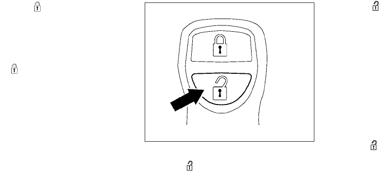
●When the button is pressed with
all doors locked, the hazard warning lights
flash twice and the horn beeps once as a
reminder that the doors are already
locked.
●If a door is open and you press
the button, the doors will lock
but the horn will not beep and the hazard
lights will not flash.
The horn may or may not beep. Refer to “Silenc-
ing the horn beep feature” in this section for
details.
Unlocking doors
Press the button on the keyfob once.
●Only the driver’s door unlocks.
●The hazard warning lights flash once if all
doors are completely closed with the ignition
switch in any position except the ON posi-
tion.
●The interior lights illuminate for 30 seconds
when the interior light switch is in the normal
operation position.
Press the button on the keyfob again
within 5 seconds.
●All doors unlock.
●The hazard warning lights flash once if all
doors are completely closed.
The interior lights can be turned off without wait-
ing 30 seconds by inserting the key into the
ignition switch and placing the ignition switch in
the ON or START position, locking the doors with
the keyfob or pushing the interior light switch to
the OFF position.
Auto relock
When the button on the keyfob is pressed,
all doors will lock automatically within 1 minute
unless one of the following operations is per-
formed:
●Any door is opened.
●A key is inserted into the ignition switch and
the switch is cycled from OFF to ON.
LPD0210
3-8 Pre-driving checks and adjustments
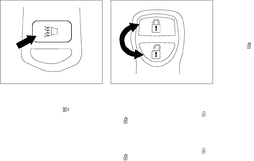
Using the panic alarm
If you are near your vehicle and feel threatened,
you may activate the panic alarm to call attention
by pressing and holding the button on the
keyfob for longer than 0.5 seconds.
The panic alarm and headlights will stay on for 25
seconds.
The panic alarm stops when:
●it has run for 25 seconds, or
●any button is pressed on the keyfob.
Silencing the horn beep feature
If desired, the horn beep feature can be deacti-
vated using the keyfob.
To deactivate: Press and hold the
and buttons for at least 2 seconds.
The hazard warning lights will flash three times to
confirm that the horn beep feature has been
deactivated.
To activate: Press and hold the
and buttons for at least 2 seconds
once more.
The hazard warning lights will flash once and the
horn will sound once to confirm that the horn
beep feature has been reactivated.
Deactivating the horn beep feature does not si-
lence the horn if the alarm is triggered.
Using the interior lights
Press the button on the keyfob once to
turn on the interior lights.
For additional information, refer to “Interior lights”
in the “Instruments and controls” section in this
manual.
LPD0211 LPD0262
Pre-driving checks and adjustments 3-9
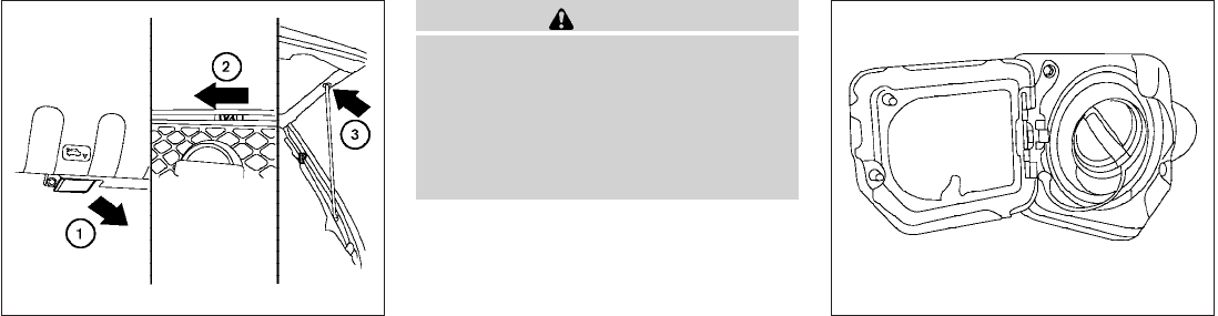
s
1Pull the hood lock release handle located
below the driver’s side instrument panel. The
hood will spring up slightly.
s
2Push the lever at the front of the hood to the
side as illustrated with your fingertips and
raise the hood.
s
3Insert the support rod into the slot on the
underside of the hood.
When closing the hood, return the hood rod to its
original position. Lower the hood approximately
12 inch (30 cm) above the latch and release it.
This allows proper engagement of the hood latch.
WARNING
●Make sure the hood is completely
closed and latched before driving. Fail-
ure to do so could cause the hood to fly
open and result in an accident.
●If you see steam or smoke coming from
the engine compartment, to avoid injury
do not open the hood.
FUEL-FILLER CAP
The fuel-filler cap is a ratcheting type. Turn the
cap counterclockwise to remove. To tighten, turn
the cap clockwise until ratcheting clicks are
heard.
LPD0302 LPD0263
HOOD FUEL-FILLER DOOR
3-10 Pre-driving checks and adjustments
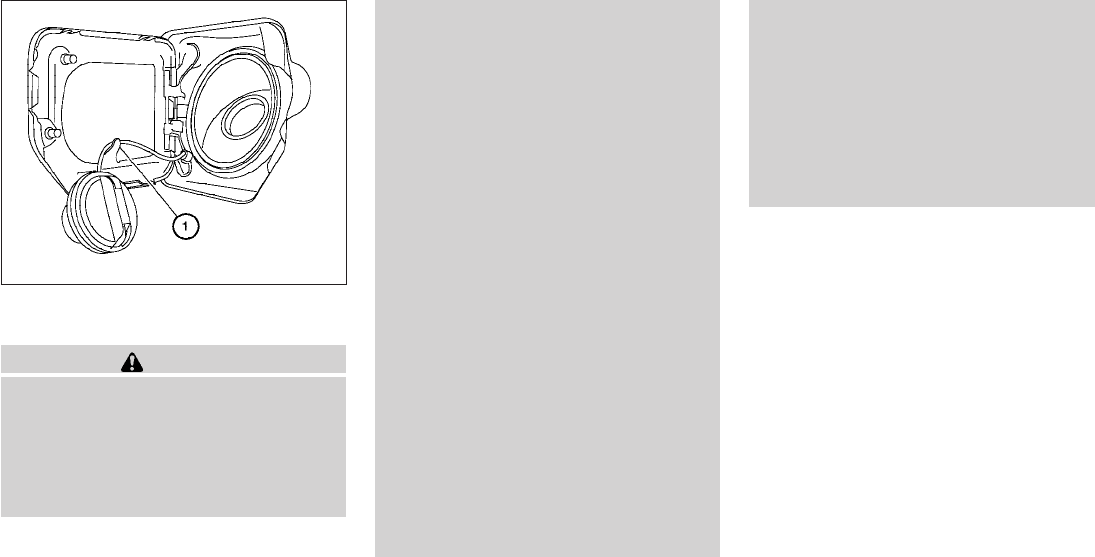
Loop the tether strap around the hook s
1while
refueling.
WARNING
●Gasoline is extremely flammable and
highly explosive under certain condi-
tions. You could be burned or seriously
injured if it is misused or mishandled.
Always stop the engine and do not
smoke or allow open flames or sparks
near the vehicle when refueling.
●Fuel may be under pressure. Turn the
cap a third of a turn, and wait for any
“hissing” sound to stop to prevent fuel
from spraying out and possibly causing
personal injury. Then remove the cap.
●Do not attempt to top off the fuel tank
after the fuel pump nozzle shuts off
automatically. Continued refueling may
cause fuel overflow, resulting in fuel
spray and possibly a fire.
●Use only an original equipment type
fuel-filler cap as a replacement. It has a
built-in safety valve needed for proper
operation of the fuel system and emis-
sion control system. An incorrect cap
can result in a serious malfunction and
possible injury. It could also cause the
malfunction indicator light to come on.
●Never pour fuel into the throttle body to
attempt to start your vehicle.
●Do not fill a portable fuel container in
the vehicle or trailer. Static electricity
can cause an explosion of flammable
liquid, vapor or gas in any vehicle or
trailer. To reduce the risk of serious
injury or death when filling portable fuel
containers:
– Always place the container on the
ground when filling.
– Do not use electronic devices when
filling.
– Keep the pump nozzle in contact
with the container while you are fill-
ing it.
– Use only approved portable fuel con-
tainers for flammable liquid.
LPD0325
Pre-driving checks and adjustments 3-11
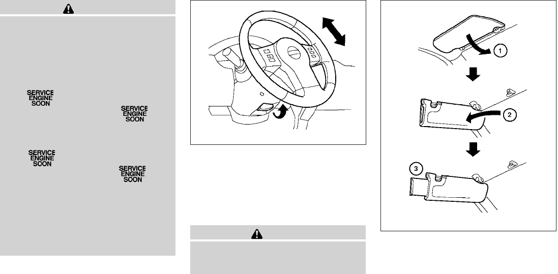
CAUTION
●If fuel is spilled on the vehicle body,
flush it away with water to avoid paint
damage.
●Insert cap straight into the fuel-filler
tube, then tighten until the fuel-filler
cap clicks. Failure to tighten the fuel-
filler cap properly may cause
the Malfunction Indicator Light
(MIL) to illuminate. If the light
illuminates because the fuel-filler cap
is loose or missing, tighten or install the
cap and continue to drive the vehicle.
The light should turn off after a
few driving trips. If the light
does not turn off after a few driving
trips, have the vehicle inspected by a
NISSAN dealer.
●For additional information, see the
“Malfunction Indicator Light (MIL)” in
the “Instruments and Controls” section
in this manual.
TILT OPERATION (if so equipped)
Pull the lock lever forward and hold it to adjust the
steering wheel up or down to the desired posi-
tion.
Release the lock lever to lock the steering wheel
in place.
WARNING
Do not adjust the steering wheel while
driving. You could lose control of your
vehicle and cause an accident.
s
1To block glare from the front, swing down the
main sun visor.
s
2To block glare from the side, remove the
main sun visor from the center mount and
swing the visor to the side.
LPD0304
WPD0315
STEERING WHEEL SUN VISORS
3-12 Pre-driving checks and adjustments
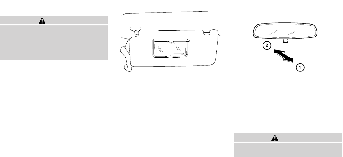
s
3Slide the sun visor extension (if so equipped)
in or out as needed.
CAUTION
●Do not store the sun visor before return-
ing the extension to its original
position.
●Do not pull the extension sun visor forc-
edly downward.
VANITY MIRRORS (if so equipped)
To access the vanity mirror, pull the sun visor
down and flip open the mirror cover. Some vanity
mirrors are illuminated and turn on when the
mirror cover is open.
REARVIEW MIRROR (if so equipped)
The night position s
1reduces glare from the
headlights of vehicles behind you at night.
Use the day position s
2when driving in daylight
hours.
WARNING
Use the night position only when neces-
sary, because it reduces rear view clarity.
WPD0307 WPD0126
MIRRORS
Pre-driving checks and adjustments 3-13
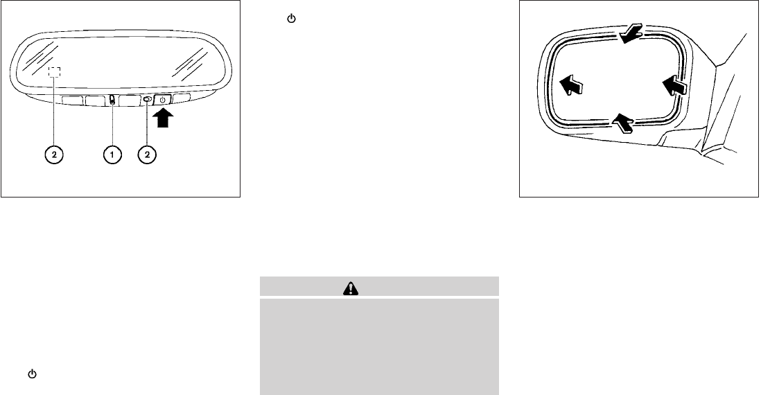
AUTOMATIC ANTI-GLARE
REARVIEW MIRROR (if so equipped)
The inside mirror is designed so that it automati-
cally dims according to the intensity of the head-
lights of the vehicle following you. The automatic
anti-glare feature operates only when the ignition
switch is in the ON position.
The indicator light s
1will illuminate when the
automatic anti-glare feature is operating.
To turn off the automatic anti-glare feature, press
the button. The indicator light will turn off.
To turn on the automatic anti-glare feature, press
the button again. The indicator light will
turn on.
For information on HomeLinkTUniversal Trans-
ceiver operation, see “HomeLinkTUniversal
Transceiver” in the “Instruments and controls”
section of this manual.
For information on the compass and outside tem-
perature display, see “Compass and outside
temperature display”in the “Instruments and con-
trols” section of this manual.
NOTE:
Do not hang any objects over the sensors
s
2or apply glass cleaner to the sensors.
Doing so will reduce the sensitivity of the
sensors, resulting in improper operation.
OUTSIDE MIRRORS
WARNING
●Objects viewed in the outside mirror on
the passenger side are closer than they
appear. Be careful when moving to the
right. Using only this mirror could cause
an accident. Use the inside mirror or
glance over your shoulder to properly
judge distances to other objects.
Manual control type (if so equipped)
The outside mirror can be moved in any direction
for a better rear view.
WPD0333 WPD0170
3-14 Pre-driving checks and adjustments
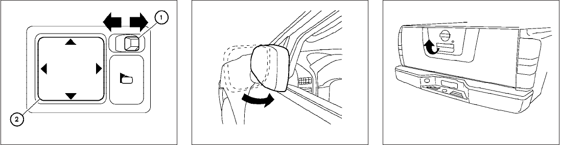
Electric control type (if so equipped)
The outside mirror remote control will operate
only when the ignition switch is placed in the
ACC or ON position.
Move the small switch s
1to select the right or left
mirror. Adjust each mirror to the desired position
using the large switch s
2.
Heated mirrors (if so equipped)
Some outside mirrors can be heated to defrost,
defog, or de-ice for improved visibility. For addi-
tional information, see “Rear window and outside
mirror defroster switch” in the “Instruments and
controls” section of this manual.
Foldable outside mirrors
Pull the outside mirror toward the door to fold it.
TAILGATE
Opening the tailgate
Pull the tailgate handle upward and lower the
tailgate. The support cables hold the tailgate
open.
When closing the tailgate, make sure the latches
are securely locked.
Do not drive the vehicle with the tailgate
down, unless equipped with NISSAN’s Bed
Extender (accessory) or equivalent in the
extended position.
LPD0237 LPD0259 LPD0270
TRUCK BOX
Pre-driving checks and adjustments 3-15
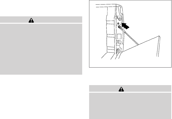
For proper truck box loading see “Vehicle loading
information” in the “Technical and consumer in-
formation” section of this manual.
WARNING
●It is extremely dangerous to ride in a
cargo area inside a vehicle. In a colli-
sion, people riding in these areas are
more likely to be seriously injured or
killed.
●Do not allow people to ride in any area
of your vehicle that is not equipped with
seats and seat belts.
●Be sure everyone in your vehicle is in a
seat and using a seat belt properly. Removing the tailgate
1. Release the tailgate support cables.
CAUTION
●The tailgate is heavy. Two people
should remove or install it. Be careful
not to drop it during removal.
●After releasing the support cables, do
not let the tailgate rest on the bumper.
2. Hold the tailgate at a 45 degree angle.
3. Pull the tailgate out from the right side hinge.
4. Slide the tailgate out of the left side hinge.
Installing the tailgate
1. Insert the tailgate into the left side hinge.
2. Hold the tailgate at a 45 degree angle and
insert into the right side hinge.
3. Continue to hold the tailgate at a 45 degree
angle and attach the tailgate support cables.
4. Close the tailgate securely.
LPD0271
3-16 Pre-driving checks and adjustments
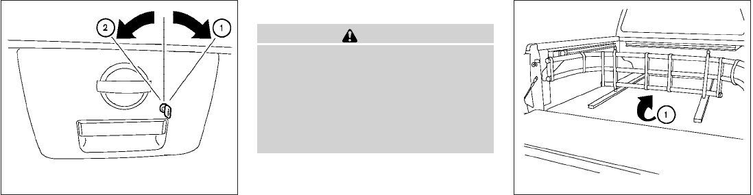
Locking the tailgate
To lock the tailgate, turn the key toward the pas-
senger side of the vehicle s
1. To unlock, turn the
key toward the driver side s
2.
BED EXTENDER (if so equipped)
CAUTION
●Do not overload the bed extender.
Maximum load on the open tailgate is
890N (200 lbs).
●Evenly distribute and properly secure
all cargo.
●Do not use the bed extender or tailgate
to secure cargo.
Positioning the bed extender
To use the bed extender in the inward position
perform the following:
1. Rotate the bed extender s
1toward the cab
of the truck.
2. Close the tailgate.
3. Place cargo inside the bed extender in the
truck bed.
4. Properly secure the cargo.
LPD0272 LPD0480
Pre-driving checks and adjustments 3-17
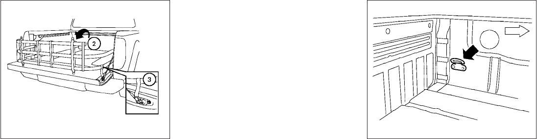
To use the bed extender in the outward position
perform the following:
1. Open the tailgate.
2. Rotate the bed extender s
2away from the
cab of the truck until the extender sits on the
tailgate.
3. Lock the buckles s
3into the tailgate latch.
The bed extender can be adjusted in the outward
position by moving the extender along the rail.
NOTE:
Use care when rotating extender, buckles
may come in contact with the truck bed
railing.
Removing and installing the bed
extender
To remove or install the bed extender perform the
following:
1. Open the tailgate.
2. Rotate the bed extender into a vertical posi-
tion and lift straight up (to remove) or lower
straight down (to install).
To store the bed extender in the front of the truck
when not in use perform the following:
1. Position the sliding brackets past the center
of the wheel well.
2. Re-install the extender into the brackets (see
above).
3. Rotate the extender to the inward position.
4. Push the brackets forward until the extender
comes in contact with the front wall of the
truck box.
TIE DOWN HOOKS (if so equipped)
For your convenience, tie down hooks are placed
at each corner of the truck box. These may be
used to help secure cargo loaded into the truck
box.
●The weight of the cargo load must be evenly
distributed over both the front and the rear
axles.
●All cargo should be securely fastened with
ropes or straps to prevent it from shifting or
sliding within the vehicle.
LPD0479 LTI0102
3-18 Pre-driving checks and adjustments

WARNING
●Properly secure all cargo with ropes or
straps to help prevent it from sliding or
shifting. In a sudden stop or collision,
unsecured cargo could cause personal
injury.
Pre-driving checks and adjustments 3-19
MEMO
3-20 Pre-driving checks and adjustments

4 Heater, air conditioner, audio and phone
systems
Vents ............................................4-2
Heater and air conditioner (manual) (Type A)..........4-2
Controls.......................................4-3
Heater operation ...............................4-4
Air conditioner operation (if so equipped) .........4-6
Air flow charts..................................4-7
Heater and air conditioner (manual) (Type B).........4-10
Controls......................................4-10
Heater operation ..............................4-11
Air conditioner operation .......................4-12
Air flow charts.................................4-14
Servicing air conditioner...........................4-17
Audio system ....................................4-17
Radio (if so equipped) .........................4-17
FM radio reception ............................4-17
AM radio reception ............................4-18
Satellite radio reception (if so equipped) .........4-18
Audio operation precautions ....................4-18
FM/AM radio with compact disc (CD) player
(Type A and B) (if so equipped) .................4-25
FM/AM/SAT radio with compact disc (CD)
changer (if so equipped) .......................4-30
CD care and cleaning..........................4-35
Steering wheel switch for audio control
(if so equipped) ...............................4-35
Antenna ......................................4-36
Car phone or CB radio............................4-36
BluetoothTHands-Free Phone System
(if so equipped) ..................................4-37
Regulatory Information .........................4-39
Using the system ..............................4-39
Control buttons ...............................4-41
Getting started ................................4-42
List of voice commands ........................4-44
Speaker adaptation (SA) mode..................4-48
Manual Control................................4-50
Troubleshooting guide .........................4-51
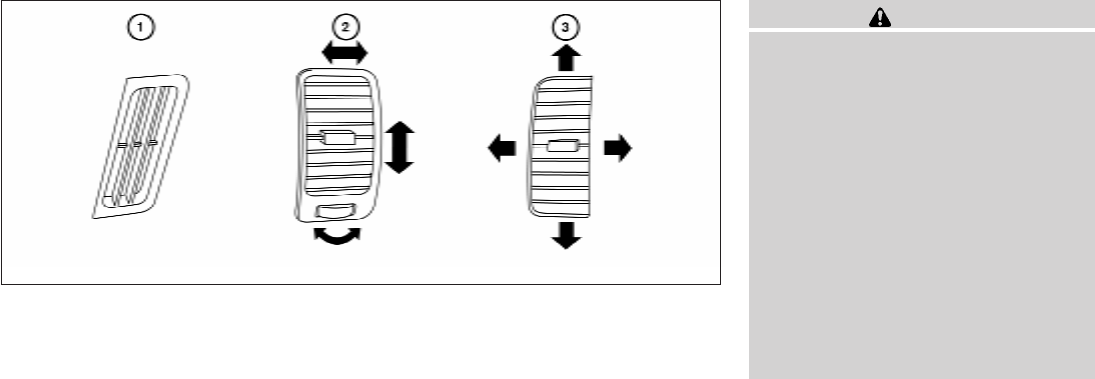
Adjust air flow direction for the driver’s and pas-
senger’s side windows s
1, driver and passenger
s
2, or center s
3vent by moving the vent slide
and/or vent assemblies.
WARNING
●The air conditioner cooling function op-
erates only when the engine is running.
●Do not leave children or adults who
would normally require the assistance
of others alone in your vehicle. Pets
should also not be left alone. They
could accidentally injure themselves or
others through inadvertent operation of
the vehicle. Also, on hot, sunny days,
temperatures in a closed vehicle could
quickly become high enough to cause
severe or possibly fatal injuries to
people or animals.
●Do not use the recirculation mode for
long periods as it may cause the interior
air to become stale and the windows to
fog up.
LHA0534
VENTS HEATER AND AIR CONDITIONER
(manual) (Type A)
4-2 Heater, air conditioner, audio and phone systems
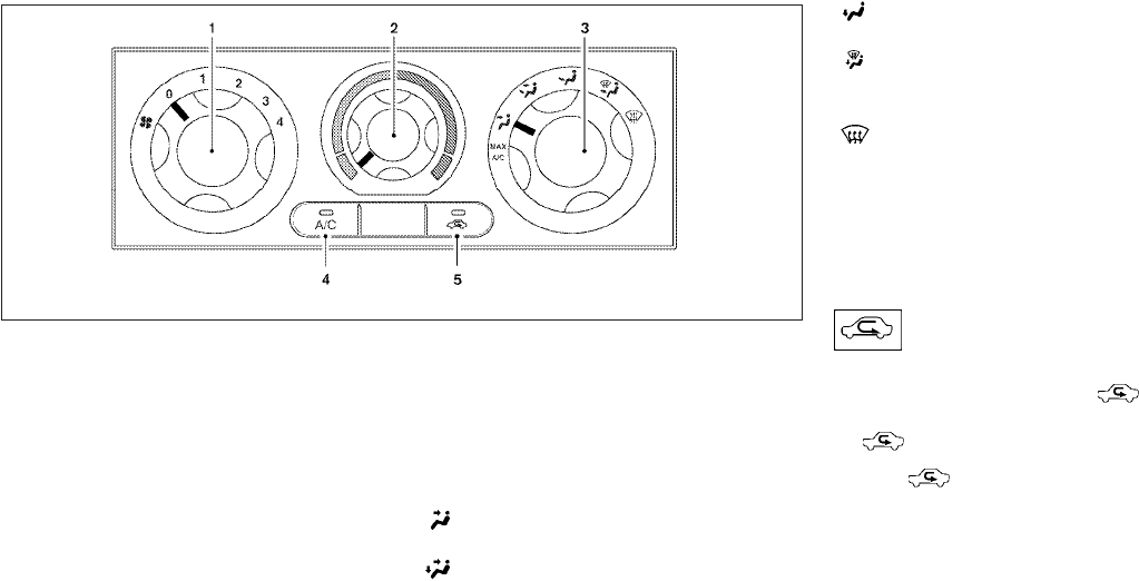
1. Fan control dial
2. Temperature control dial
3. Air flow control dial
4. Air conditioner button (if so equipped)
5. Air recirculation button
CONTROLS
Fan control dial
The fan control dial turns the fan on and off, and
controls fan speed.
Air flow control dial
The air flow control dial allows you to select the
air flow outlets.
MAX
A/C
— Air flows from center and side
vents with maximum cooling (air
conditioning).
— Air flows from center and side
vents.
— Air flows from center and side
vents and the front and rear floor
outlets.
— Air flows mainly from the front and
rear floor outlets.
— Air flows from defroster outlets
and the front and rear floor
outlets.
— Air flows mainly from defroster
outlets.
Temperature control dial
The temperature control dial allows you to adjust
the temperature of the outlet air. To lower the
temperature, turn the dial to the left. To increase
the temperature, turn the dial to the right.
Air recirculation button
ON position:
Push the air recirculation button to recir-
culate air inside the vehicle. The indicator light on
the button will come on.
Push the button to the on position:
●when driving on a dusty road.
●to prevent traffic fumes from entering pas-
senger compartment.
●for maximum cooling when using the air con-
ditioner.
Type A
WHA1384
Heater, air conditioner, audio and phone systems 4-3
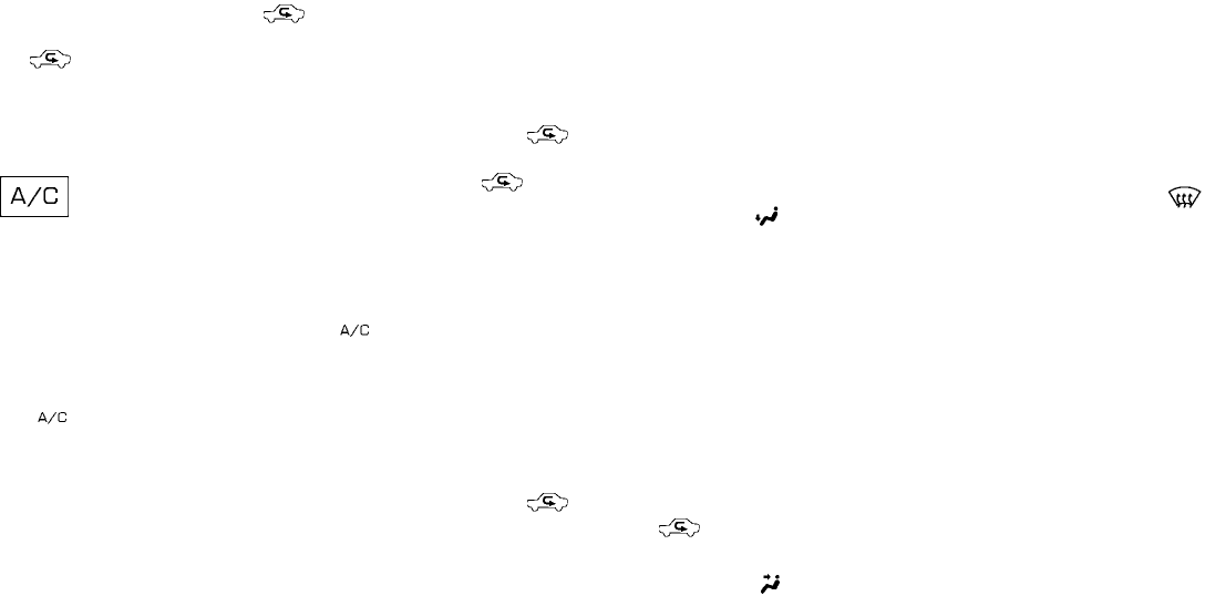
OFF position:
Push the air recirculation button again to
turn air recirculation off. The indicator light on
the button will turn off. Outside air is drawn
into the passenger compartment and distributed
through the selected outlet.
Use the off position for normal heater or air con-
ditioner operation.
Air conditioner button (if so
equipped)
The button is provided only on vehicles equipped
with an air conditioner.
Start the engine, turn the fan control dial to the
desired (1 - 4) position and push the
button to turn on the air conditioner. The indicator
light comes on when the air conditioner is oper-
ating. To turn off the air conditioner, push
the button again.
The air conditioner cooling function oper-
ates only when the engine is running.
HEATER OPERATION
Heating
This mode is used to direct heated air to the foot
outlets. Some air also flows from the defrost
outlets.
1. Push the button to the OFF position
for normal heating. The indicator light on
the button will go off.
2. Turn the air flow control dial to the
position.
3. Turn the fan control dial to the desired posi-
tion.
4. Turn the temperature control dial to the de-
sired position between the middle and the
hot position.
Ventilation
This mode directs outside air to the side and
center vent.
1. Push the button to the OFF position.
The indicator light on the button will
go off.
2. Turn the air flow control dial to the
position.
3. Turn the fan control dial to the desired posi-
tion.
4. Turn the temperature control dial to the de-
sired position.
Defrosting or defogging
This mode directs the air to the defrost outlets to
defrost/defog the windows.
1. Turn the air flow control dial to the
position.
2. Turn the fan control dial to the desired posi-
tion.
3. Turn the temperature control dial to the de-
sired position between the middle and the
hot position.
●To quickly remove ice or fog from the win-
dows, turn the fan control dial to 4 and the
temperature control lever to the full HOT
position.
4-4 Heater, air conditioner, audio and phone systems
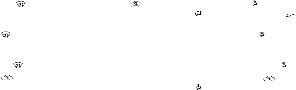
●When the position is selected, the air
conditioner automatically turns on (however,
the indicator light will not illuminate) if the
outside temperature is more than 36°F
(2°C). If the air flow control dial is in
the position for more than one minute,
the air conditioning system will continue to
operate until the fan control dial is turned to
OFF or the vehicle is shut off, even if the air
flow control dial is turned to a position other
than the position. This dehumidifies
the air which helps defog the windshield.
The mode automatically turns off, al-
lowing outside air to be drawn into the pas-
senger compartment to further improve the
defogging performance.
Bi-level heating
This mode directs cooler air from the side and
center vents and warmer air from the floor outlets.
When the temperature control dial is moved to
the full hot or full cool position, the air between
the vents and the floor outlets is the same tem-
perature.
1. Push the button to the off position.
2. Turn the air flow control dial to the
position.
3. Turn the fan control dial to the desired posi-
tion.
4. Turn the temperature control dial to the de-
sired position.
Heating and defogging
This mode heats the interior and defogs the wind-
shield.
1. Turn the air flow control dial to the
position.
2. Turn the fan control dial to the desired posi-
tion.
3. Turn the temperature control dial to the de-
sired position between the middle and the
hot position.
●When the position is selected, the air
conditioner automatically turns on (however,
the indicator light on the button will
not come on) if the outside temperature is
more than 36°F (2°C). If the air flow control
dial is in the position for more than
one minute, the air conditioning system will
continue to operate until the fan control dial
is turned to OFF or the vehicle is shut off,
even if the air flow control dial is turned to a
position other than the position. This
dehumidifies the air which helps defog the
windshield. The mode automatically
turns off, allowing outside air to be drawn
into the passenger compartment to further
improve the defogging performance.
Operating tips
Clear snow and ice from the wiper blades
and air inlet in front of the windshield. This
improves heater operation.
Heater, air conditioner, audio and phone systems 4-5
AIR CONDITIONER OPERATION (if
so equipped)
Start the engine, turn the fan control dial to the
desired position, and push in the button to
activate the air conditioner. When the air condi-
tioner is on, cooling and dehumidifying functions
are added to the heater operation.
The air conditioner cooling function oper-
ates only when the engine is running.
Cooling
This mode is used to cool and dehumidify the air.
1. Push the button to the off position.
2. Turn the air flow control dial to the
position.
3. Turn the fan control dial to the desired posi-
tion.
4. Push the button. The indicator light
comes on.
5. Turn the temperature control dial to the de-
sired position.
●For quick cooling when the outside tem-
perature is high, push the button to
the on position (indicator light on). Be sure
to return the button to the off position
for normal cooling.
Dehumidified heating
This mode is used to heat and dehumidify the air.
1. Push the button to the off position.
2. Turn the air flow control dial to the
position.
3. Turn the fan control dial to the desired posi-
tion.
4. Push the button. The indicator light
comes on.
5. Turn the temperature control dial to the de-
sired position.
Dehumidified defogging
This mode is used to defog the windows and
dehumidify the air.
1. Turn the air flow control dial to the
position.
2. Turn the fan control dial to the desired posi-
tion.
3. Push the button. The indicator light
comes on.
When the air flow control dial is in the
or position, the air conditioner automati-
cally turns on (however, the indicator light will not
illuminate) if the outside temperature is more than
36°F (2°C). If one of these positions is selected
for more than one minute, the air conditioning
system will continue to operate until the fan con-
trol dial is turned to OFF or the vehicle is shut off,
even if the air flow control dial is turned to a
position other than these positions. This dehu-
midifies the air which helps defog the windshield.
The mode automatically turns off, allowing
outside air to be drawn into the passenger com-
partment to further improve the defogging perfor-
mance.
4. Turn the temperature control dial to the de-
sired position.
Operating tips
●Keep the windows and moonroof (if so
equipped) closed while the air conditioner is
in operation.
●After parking in the sun, drive for two or three
minutes with the windows open to vent hot
air from the passenger compartment. Then,
close the windows. This allows the air con-
ditioner to cool the interior more quickly.
4-6 Heater, air conditioner, audio and phone systems
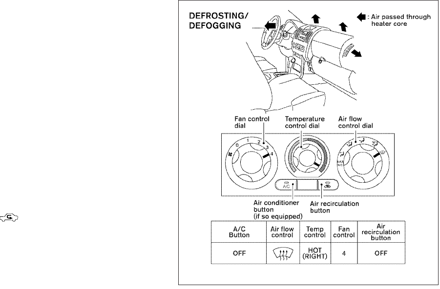
●The air conditioning system should be
operated for approximately 10 minutes
at least once a month. This helps pre-
vent damage to the system due to lack
of lubrication.
●A visible mist may be seen coming from the
vents in hot, humid conditions as the air is
cooled rapidly. This does not indicate a mal-
function.
●If the engine coolant temperature
gauge indicates engine coolant tem-
perature over the normal range, turn
the air conditioner off. See “If your
vehicle overheats” in the “In case of
emergency” section of this manual.
AIR FLOW CHARTS
The following charts show the button and dial
positions for MAXIMUM AND QUICK heating,
cooling or defrosting. For additional information
on heating and cooling, see “Heater and air con-
ditioner” in this section. The air recirculation
() button should always be in the OFF
position for heating and defrosting.
WHA1385
Heater, air conditioner, audio and phone systems 4-7
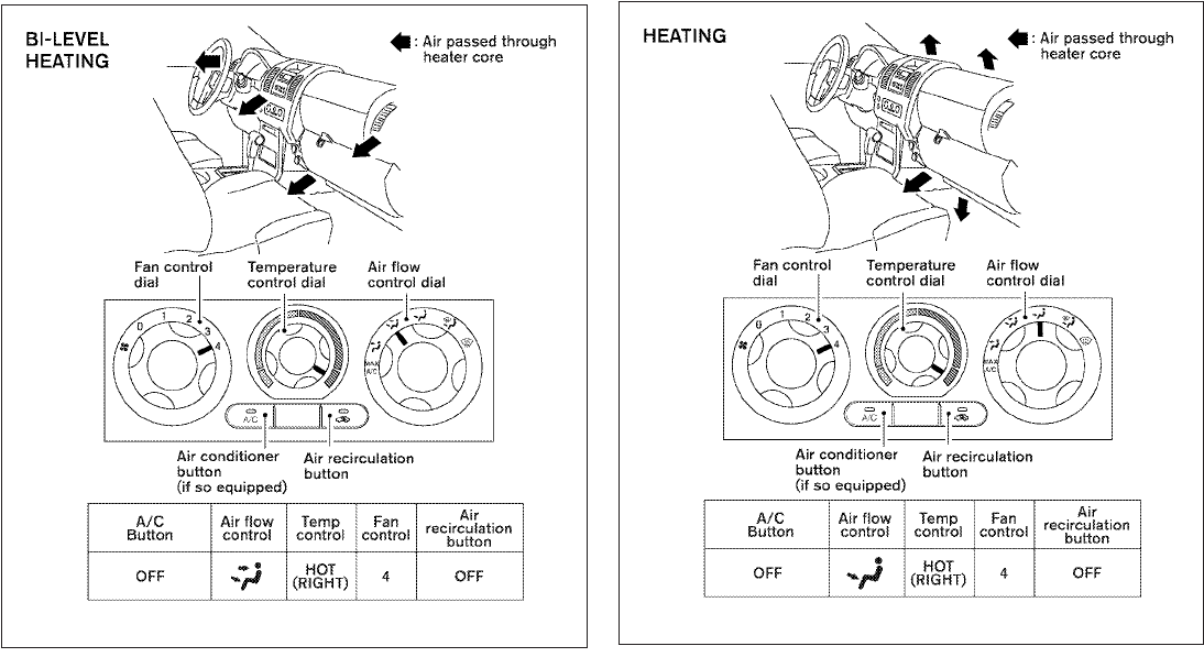
WHA1386 WHA1387
4-8 Heater, air conditioner, audio and phone systems
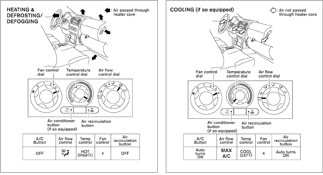
WHA1388 WHA1389
Heater, air conditioner, audio and phone systems 4-9
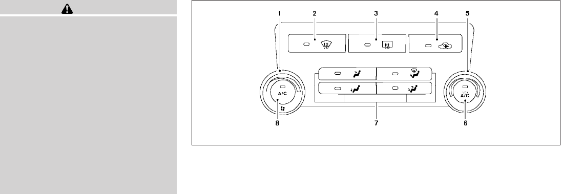
WARNING
●The air conditioner cooling function op-
erates only when the engine is running.
●Do not leave children or adults who
would normally require the assistance
of others alone in your vehicle. Pets
should also not be left alone. They
could accidentally injure themselves or
others through inadvertent operation of
the vehicle. Also, on hot, sunny days,
temperatures in a closed vehicle could
quickly become high enough to cause
severe or possibly fatal injuries to
people or animals.
●Do not use the recirculation mode for
long periods as it may cause the interior
air to become stale and the windows to
fog up.
1. Fan speed control dial
2. Front window defroster button
3. Rear window defroster switch (if so
equipped)
4. Air recirculation button
5. Temperature control dial
6. Max A/C button
7. Air flow control buttons
8. Air conditioner ON/OFF button
CONTROLS
Fan control dial
The fan control dial turns the fan on and off, and
controls fan speed.
Air flow control buttons
The air flow control buttons allow you to select
the air flow outlets.
MAX
A/C
— Air flows from center and side
vents with maximum cooling
(air conditioning).
Type B
WHA1406
HEATER AND AIR CONDITIONER
(manual) (Type B)
4-10 Heater, air conditioner, audio and phone systems
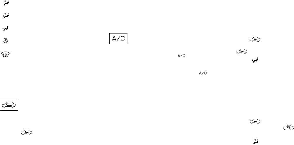
— Air flows from center and side
vents.
— Air flows from center and side
vents and foot outlets.
— Air flows mainly from foot
outlets.
— Air flows from defroster out-
lets and foot outlets.
— Air flows mainly from defroster
outlets.
Temperature control dial
The temperature control dial allows you to adjust
the temperature of the outlet air. To lower the
temperature, turn the dial to the left. To increase
the temperature, turn the dial to the right.
Air recirculation button
ON position (Indicator light on):
Interior air is recirculated inside the vehicle.
Press the button to the on position when:
●driving on a dusty road.
●to prevent traffic fumes from entering pas-
senger compartment.
●for maximum cooling when using the air con-
ditioner.
OFF position (Indicator light off):
Outside air is drawn into the passenger compart-
ment and distributed through the selected outlet.
Use the off position for normal heater or air con-
ditioner operation.
Air conditioner button
Start the engine, turn the fan control dial to the
desired position and push the button to
turn on the air conditioner. The indicator light
comes on when the air conditioner is operating.
To turn off the air conditioner, push the
button again.
The air conditioner cooling function oper-
ates only when the engine is running.
Rear window defroster switch (if so
equipped)
For more information about the rear window de-
froster switch, see “Rear window and outside
mirror defroster switch” in the “Instruments and
controls” section of this manual.
HEATER OPERATION
Heating
This mode is used to direct heated air to the foot
outlets. Some air also flows from the defrost
outlets.
1. Press the button to the OFF position
for normal heating. The indicator light on
the button will go off.
2. Press the air flow control button.
3.
Turn the fan control dial to the desired position.
4. Turn the temperature control dial to the de-
sired position between the middle and the
hot position.
Ventilation
This mode directs outside air to the side and
center ventilators.
1. Press the button to the OFF position.
The indicator light on the button will
go off.
2. Press the air flow control button.
3. Turn the fan control dial to the desired posi-
tion.
4. Turn the temperature control dial to the de-
sired position.
Heater, air conditioner, audio and phone systems 4-11
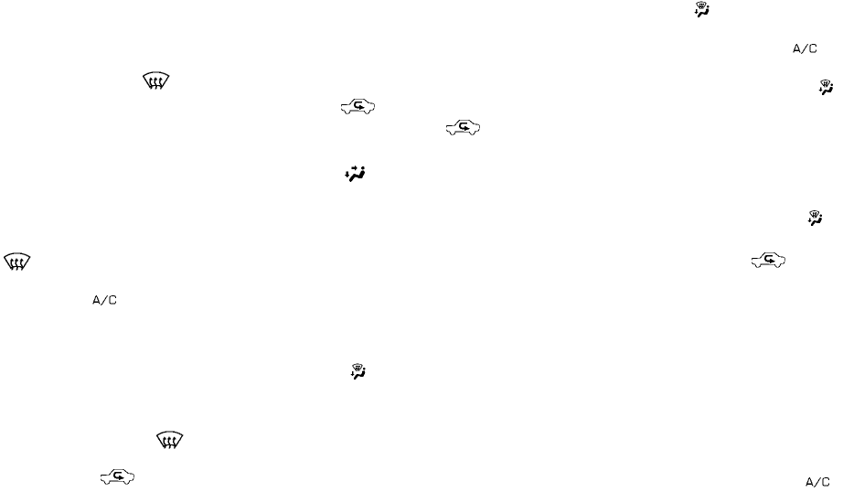
Defrosting or defogging
This mode directs the air to the defrost outlets to
defrost/defog the windows.
1. Press the defrost/defog button .
2.
Turn the fan control dial to the desired position.
3. Turn the temperature control dial to the de-
sired position between the middle and the
hot position.
●To quickly remove ice or fog from the win-
dows, turn the fan control dial to the highest
setting and the temperature control to the
full HOT position.
●
When the position is selected, the air
conditioner automatically turns on (however,
the indicator light on the button will not
come on) if the outside temperature is more
than 36°F (2°C). If in defrost mode for more
than one minute, the air conditioning system
will continue to operate until the fan control
dial is turned to OFF, the vehicle is shut off, or
the A/C button is used to turn off the com-
pressor even if the air flow control dial is
turned to a position other than the po-
sition. This dehumidifies the air which helps
defog the windshield. The mode auto-
matically turns off, allowing outside air to be
drawn into the passenger compartment to
further improve the defogging performance.
Bi-level heating
The bi-level mode directs warmed air to the side
and center vents and to the front and rear floor
outlets.
1. Press the button to the OFF position.
The indicator light on the button will
go off.
2. Press the air flow control button.
3. Turn the fan control dial to the desired posi-
tion.
4. Turn the temperature control dial to the de-
sired position.
Heating and defogging
This mode heats the interior and defogs the wind-
shield.
1. Press the air flow control button.
2. Turn the fan control dial to the desired posi-
tion.
3. Turn the temperature control dial to the de-
sired position between the middle and the
hot position.
●When the position is selected, the air
conditioner automatically turns on (however,
the indicator light on the button will
not come on) if the outside temperature is
more than 36°F (2°C). If the air flow
control button is selected for more than one
minute, the air conditioning system will con-
tinue to operate until the fan control dial is
turned to OFF, the vehicle is shut off, or the
A/C button is used to turn off the compres-
sor even if the air flow control dial is turned to
a position other than the position.
This dehumidifies the air which helps defog
the windshield. The mode automati-
cally turns off, allowing outside air to be
drawn into the passenger compartment to
further improve the defogging performance.
Operating tips
Clear snow and ice from the wiper blades
and air inlet in front of the windshield. This
improves heater operation.
AIR CONDITIONER OPERATION
Start the engine, turn the fan control dial to the
desired position, and push in the button to
activate the air conditioner. When the air condi-
tioner is on, cooling and dehumidifying functions
are added to the heater operation.
4-12 Heater, air conditioner, audio and phone systems
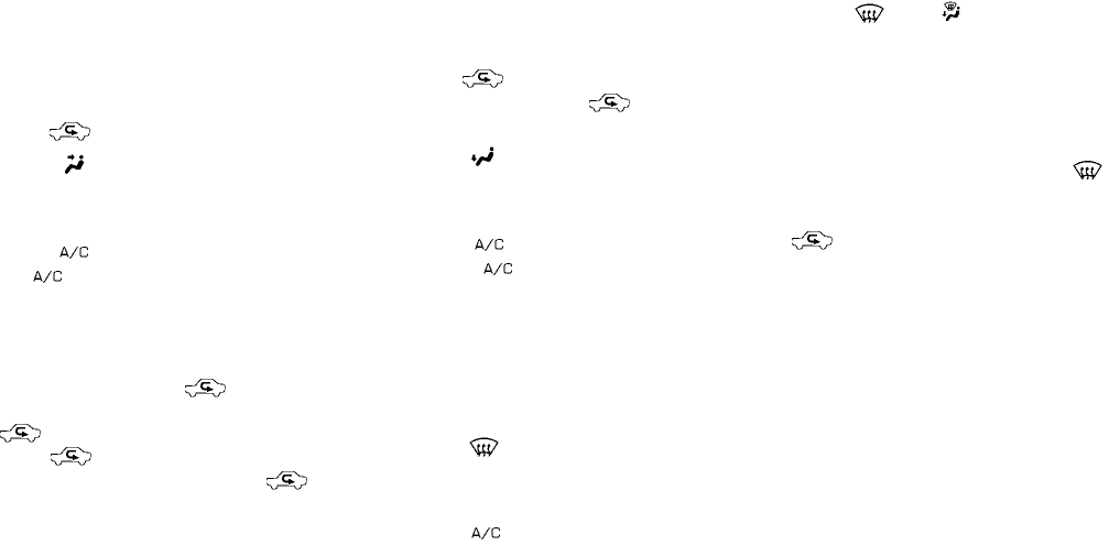
The air conditioner cooling function oper-
ates only when the engine is running.
Cooling
This mode is used to cool and dehumidify the air.
1. Press the button to the OFF position.
2. Press the air flow control button.
3. Turn the fan control dial to the desired posi-
tion.
4. Press the button. The indicator light
on the button will come on.
5. Turn the temperature control dial to the de-
sired position.
●For quick cooling when the outside tem-
perature is high, push the button to
the ON position. The indicator light on
the button will come on. Be sure to
return the to the OFF position for nor-
mal cooling. The indicator light on the
button will go off. You may also select MAX
A/C for quick cooling.
Dehumidified heating
This mode is used to heat and dehumidify the air.
1. Press the button to the OFF position.
The indicator light on the button will
go off.
2. Press the air flow control button.
3. Turn the fan control dial to the desired posi-
tion.
4. Press the button on. The indicator
light on the button will come on.
5. Turn the temperature control dial to the de-
sired position.
Dehumidified defogging
This mode is used to defog the windows and
dehumidify the air.
1. Press the air flow control button.
2. Turn the fan control dial to the desired posi-
tion.
3. Press the button. The indicator light
comes on.
When the or positions are se-
lected, the air conditioner automatically turns on
(however, the indicator light will not illuminate) if
the outside temperature is more than 36°F (2°C).
The air conditioning system will continue to op-
erate until the fan control dial is turned to OFF, the
air conditioner is turned OFF, or the vehicle is
shut off, even if a position other than the air
flow control button is selected. This dehumidifies
the air which helps defog the windshield.
The mode automatically turns off, allowing
outside air to be drawn into the passenger com-
partment to further improve the defogging perfor-
mance.
4. Turn the temperature control dial to the de-
sired position.
Operating tips
●Keep the windows closed while the air con-
ditioner is in operation.
●After parking in the sun, drive for 2 or 3
minutes with the windows open to vent hot
air from the passenger compartment. Then,
close the windows. This allows the air con-
ditioner to cool the interior more quickly.
Heater, air conditioner, audio and phone systems 4-13
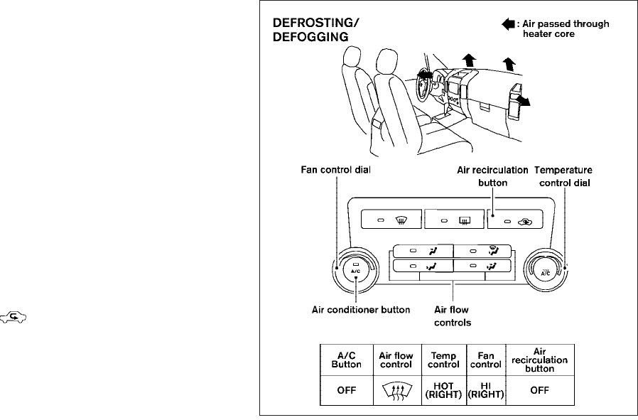
●The air conditioning system should be
operated for approximately 10 minutes
at least once a month. This helps pre-
vent damage to the system due to lack
of lubrication.
●A visible mist may be seen coming from the
ventilators in hot, humid conditions as the air
is cooled rapidly. This does not indicate a
malfunction.
●If the engine coolant temperature
gauge indicates engine coolant tem-
perature over the normal range, turn
the air conditioner off. See “If your
vehicle overheats” in the “In case of
emergency” section of this manual.
AIR FLOW CHARTS
The following charts show the button and dial
positions for MAXIMUM AND QUICK heating,
cooling or defrosting. For additional information
on heating and cooling, see “Heater and air con-
ditioner” in this section. The air recirculation
() button should always be in the OFF
position for heating and defrosting.
WHA0916
4-14 Heater, air conditioner, audio and phone systems
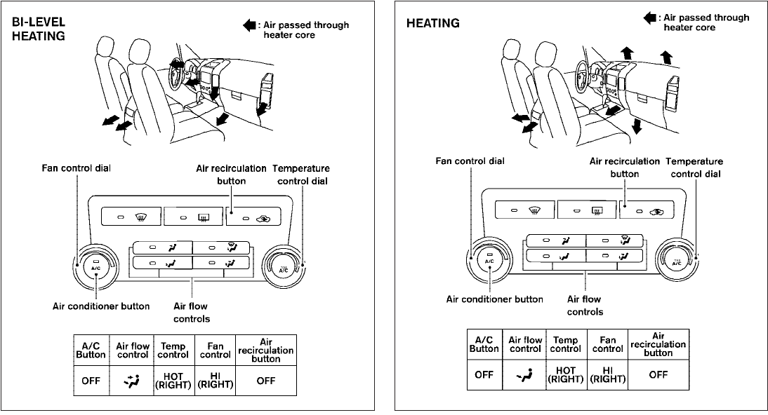
WHA0917 WHA0918
Heater, air conditioner, audio and phone systems 4-15
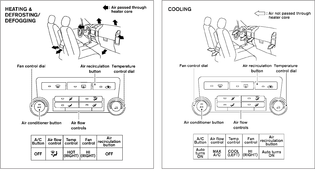
WHA0919 WHA1362
4-16 Heater, air conditioner, audio and phone systems

The air conditioner system in your NISSAN ve-
hicle is charged with a refrigerant designed with
the environment in mind.
This refrigerant does not harm the earth’s
ozone layer.
Special charging equipment and lubricant is re-
quired when servicing your NISSAN air condi-
tioner. Using improper refrigerants or lubricants
will cause severe damage to your air conditioner
system. See “Air conditioner system refrigerant
and oil recommendations” in the “Technical and
consumer information” section of this manual.
A NISSAN dealer is able to service your “environ-
mentally friendly” air conditioning system.
WARNING
The air conditioner system contains re-
frigerant under high pressure. To avoid
personal injury, any air conditioner ser-
vice should be done only by an experi-
enced technician with proper equipment.
RADIO (if so equipped)
Turn the ignition switch to the ACC or ON posi-
tion and press the PWR (power)/VOL (volume)
knob to turn the radio on. If you listen to the radio
with the engine not running, the ignition switch
should be turned to the ACC position.
Radio reception is affected by station signal
strength, distance from radio transmitter, build-
ings, bridges, mountains and other external influ-
ences. Intermittent changes in reception quality
normally are caused by these external influences.
Using a cellular phone in or near the ve-
hicle may influence radio reception quality.
Radio reception
Your NISSAN radio system is equipped with
state-of-the-art electronic circuits to enhance ra-
dio reception. These circuits are designed to
extend reception range, and to enhance the qual-
ity of that reception.
However, there are some general characteristics
of both FM and AM radio signals that can affect
radio reception quality in a moving vehicle, even
when the finest equipment is used. These char-
acteristics are completely normal in a given re-
ception area and do not indicate any malfunction
in your NISSAN radio system.
Reception conditions will constantly change be-
cause of vehicle movement. Buildings, terrain,
signal distance and interference from other ve-
hicles can work against ideal reception. De-
scribed below are some of the factors that can
affect your radio reception.
Some cellular phones or other devices may
cause interference or a buzzing noise to come
from the audio system speakers. Storing the de-
vice in a different location may reduce or elimi-
nate the noise.
FM RADIO RECEPTION
Range: FM range is normally limited to 25 – 30 mi
(40 – 48 km), with monaural (single channel) FM
having slightly more range than stereo FM. Exter-
nal influences may sometimes interfere with FM
station reception even if the FM station is within
25 mi (40 km). The strength of the FM signal is
directly related to the distance between the
transmitter and receiver. FM signals follow a line-
of-sight path, exhibiting many of the same char-
acteristics as light. For example, they will reflect
off objects.
Fade and drift: As your vehicle moves away from
a station transmitter, the signals will tend to fade
and/or drift.
Static and flutter: During signal interference from
buildings, large hills or due to antenna position
SERVICING AIR CONDITIONER AUDIO SYSTEM
Heater, air conditioner, audio and phone systems 4-17
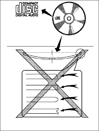
(usually in conjunction with increased distance
from the station transmitter), static or flutter can
be heard. This can be reduced by adjusting the
treble control to reduce treble response.
Multipath reception: Because of the reflective
characteristics of FM signals, direct and reflected
signals reach the receiver at the same time. The
signals may cancel each other, resulting in mo-
mentary flutter or loss of sound.
AM RADIO RECEPTION
AM signals, because of their low frequency, can
bend around objects and skip along the ground.
In addition, the signals can be bounced off the
ionosphere and bent back to earth. Because of
these characteristics, AM signals are also sub-
ject to interference as they travel from transmitter
to receiver.
Fading: Occurs while the vehicle is passing
through freeway underpasses or in areas with
many tall buildings. It can also occur for several
seconds during ionospheric turbulence even in
areas where no obstacles exist.
Static: Caused by thunderstorms, electrical
power lines, electric signs and even traffic lights.
SATELLITE RADIO RECEPTION (if so
equipped)
When the satellite radio is used for the first time
or the battery has been replaced, the satellite
radio may not work properly. This is not a mal-
function. Wait more than 10 minutes with satellite
radio ON and the vehicle outside of any metal or
large building for satellite radio to receive all of
the necessary data.
No satellite radio reception is available and “NO
SAT” is displayed when the SAT band option is
selected unless optional satellite receiver and
antenna are installed and an XMTsatellite radio
service subscription is active. Satellite radio can
only be installed in vehicles that were factory
pre-wired for satellite radio. Satellite radio is not
available in Alaska, Hawaii and Guam.
Satellite radio performance may be affected if
cargo carried on the roof blocks the satellite radio
signal.
If possible, do not put cargo over the satellite
antenna.
A build up of ice on the satellite radio antenna can
affect satellite radio performance. Remove the
ice to restore satellite radio reception.
AUDIO OPERATION PRECAUTIONS
LHA0099
4-18 Heater, air conditioner, audio and phone systems

Compact disc (CD) player
CAUTION
●Do not force a compact disc into the CD
insert slot. This could damage the CD
and/or CD changer/player.
●Trying to load a CD with the CD door
closed could damage the CD and/or CD
changer.
●Only one CD can be loaded into the CD
player at a time.
●Only use high quality 4.7 in (12 cm)
round discs that have the “COMPACT
disc DIGITAL AUDIO” logo on the disc
or packaging.
●During cold weather or rainy days, the
player may malfunction due to the hu-
midity. If this occurs, remove the CD
and dehumidify or ventilate the player
completely.
●The player may skip while driving on
rough roads.
●The CD player sometimes cannot func-
tion when the compartment tempera-
ture is extremely high or low.
Decrease/increase the temperature
before use.
●Do not expose the CD to direct sun-
light.
●CDs that are in poor condition or are
dirty, scratched or covered with finger-
prints may not work properly.
●The following CDs may not work prop-
erly:
●Copy control compact discs (CCCD)
●Recordable compact discs (CD-R)
●Rewritable compact discs (CD-RW)
●Do not use the following CDs as they
may cause the CD player to malfunc-
tion:
●3.1 in (8 cm) discs with an adapter
●CDs that are not round
●CDs with a paper label
●CDs that are warped, scratched, or
have abnormal edges
●This audio system can only play pre-
recorded CDs. It has no capability to
record or burn CDs.
●If the CD cannot be played, one of the
following messages will be displayed.
CHECK DISC:
●Confirm that the CD is inserted cor-
rectly (the label side is facing up,
etc.).
●Confirm that the CD is not bent or
warped and it is free of scratches.
PRESS EJECT:
This is an error due to excessive tem-
perature inside the player. Remove the
CD by pressing the EJECT button. After
a short time, reinsert the CD. The CD
can be played when the temperature of
the player returns to normal.
UNPLAYABLE:
The file is unplayable in this audio sys-
tem (only MP3 or WMA CD).
Heater, air conditioner, audio and phone systems 4-19
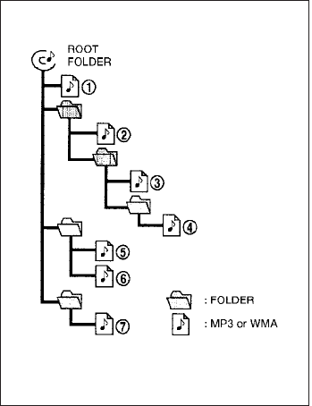
Compact Disc with MP3 or WMA (if
so equipped)
Terms:
●MP3 — MP3 is short for Moving Pictures
Experts Group Audio Layer 3. MP3 is the
most well-known compressed digital audio
file format. This format allows for near “CD
quality” sound, but at a fraction of the size of
normal audio files. MP3 conversion of an
audio track from CD-ROM can reduce the
file size by approximately a 10:1 ratio with
virtually no perceptible loss in quality. MP3
compression removes the redundant and
irrelevant parts of a sound signal that the
human ear doesn’t hear.
●WMA — Windows Media Audio (WMA)* is a
compressed audio format created by Mi-
crosoft as an alternative to MP3. The WMA
codec offers greater file compression than
the MP3 codec, enabling storage of more
digital audio tracks in the same amount of
space when compared to MP3s at the same
level of quality.
●Bit rate — Bit rate denotes the number of
bits per second used by a digital music file.
The size and quality of a compressed digital
audio file is determined by the bit rate used
when encoding the file.
●Sampling frequency — Sampling frequency
is the rate at which the samples of a signal
are converted from analog to digital (A/D
conversion) per second.
●Multisession — Multisession is one of the
methods for writing data to media. Writing
data once to the media is called a single
session, and writing more than once is called
a multisession.
●ID3/WMA Tag — The ID3/WMA tag is the
part of the encoded MP3 or WMA file that
contains information about the digital music
file such as song title, artist, encoding bit
rate, track time duration, etc. ID3 tag infor-
mation is displayed on the Artist/song title
line on the display.
* WindowsTand Windows MediaTare regis-
tered trademarks and trademarks in the United
States of America and other countries of Mi-
crosoft Corporation of the USA.
Playback order chart WHA1078
4-20 Heater, air conditioner, audio and phone systems
Playback order:
Music playback order of a CD with MP3 or WMA
files is as illustrated.
●The names of folders not containing MP3 or
WMA files are not shown in the display.
●If there is a file in the top level of the disc,
“Root Folder” is displayed.
●The playback order is the order in which the
files were written by the writing software.
Therefore, the files might not play in the
desired order.
Heater, air conditioner, audio and phone systems 4-21

Specification chart:
Supported media CD, CD-R, CD-RW
Supported file systems ISO9660 LEVEL1, ISO9660 LEVEL2, Apple ISO, Romeo, Joliet * ISO9660 Level 3 (packet writing) is not supported.
Supported
versions*1
MP3
Version MPEG1, MPEG2, MPEG2.5
Sampling frequency 8 kHz - 48 kHz
Bit rate 8 kbps - 320 kbps, VBR
WMA Version WMA7, WMA8, WMA9
Sampling frequency 32 kHz - 48 kHz
Bit rate 48 kbps - 192 kbps, VBR
Tag information ID3 tag VER1.0, VER1.1, VER2.2, VER2.3 (MP3 only)
Folder levels Folder levels: 8, Max folders: 255 (including root folder), Files: 512 (Max. 255 files for one folder)
Text character number limitation 128 characters
Displayable character codes*2 01: ASCII, 02: ISO-8859-1, 03: UNICODE (UTF-16 BOM Big Endian), 04: UNICODE (UTF-16 Non-BOM Big Endian), 05:
UNICODE (UTF-8), 06: UNICODE (Non-UTF-16 BOM Little Endian)
*1 Files created with a combination of 48 kHz sampling frequency and 64 kbps bit rate cannot be played.
*2 Available codes depend on what kind of media, versions and information are going to be displayed.
4-22 Heater, air conditioner, audio and phone systems

Troubleshooting guide:
Symptom Cause and Countermeasure
Cannot play
Check if the disc was inserted correctly.
Check if the disc is scratched or dirty.
Check if there is condensation inside the player. If there is, wait until the condensation is gone (about 1 hour) before using the player.
If there is a temperature increase error, the CD player will play correctly after it returns to the normal temperature.
If there is a mixture of music CD files (CD-DA data) and MP3/WMA files on a CD, only the music CD files (CD-DA data) will be played.
Files with extensions other than “.MP3”,“.WMA”, “.mp3” or “.wma” cannot be played. In addition, the character codes and number of characters for
folder names and file names should be in compliance with the specifications.
Check if the finalization process, such as session close and disc close, is done for the disc.
Check if the disc is protected by copyright.
Poor sound quality Check if the disc is scratched or dirty.
Bit rate may be too low.
It takes a relatively long time
before the music starts
playing.
If there are many folders or file levels on the MP3/WMA disc, or if it is a multisession disc, some time may be required before the music starts playing.
Music cuts off or skips The writing software and hardware combination might not match, or the writing speed, writing depth, writing width, etc., might not match the
specifications. Try using the slowest writing speed.
Skipping with high bit rate
files
Skipping may occur with large quantities of data, such as for high bit rate data.
Moves immediately to the
next song when playing
When a non-MP3/WMA file has been given an extension of “.MP3”, “.WMA”, .“mp3”or “.wma”, or when play is prohibited by copyright protection, there
will be approximately 5 seconds of no sound and then the player will skip to the next song.
Songs do not play back in
the desired order
The playback order is the order in which the files were written by the writing software. Therefore, the files might not play in the desired order.
Heater, air conditioner, audio and phone systems 4-23
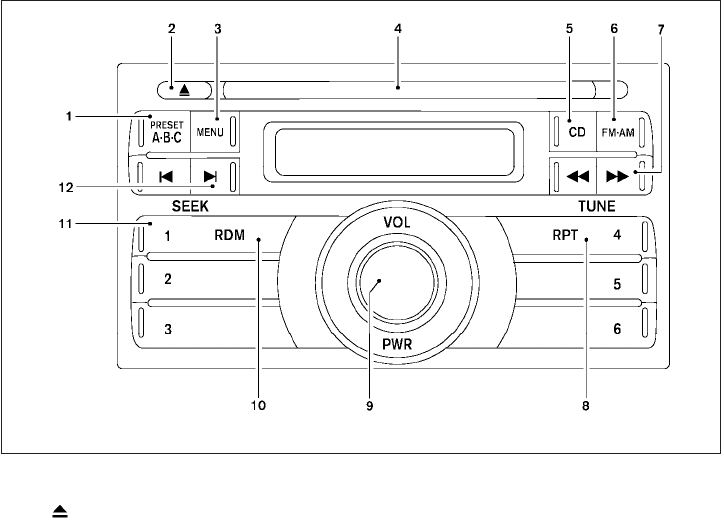
1. PRESET A·B·C button
2. CD eject button
3. MENU button
4. CD insert slot
5. CD button
6. FM·AM button
7. TUNE buttons
8. RPT button
9. PWR button/VOL control knob
10. RDM button
11. Station select (1 - 6) buttons
12. SEEK buttons
Type A WHA1075
4-24 Heater, air conditioner, audio and phone systems
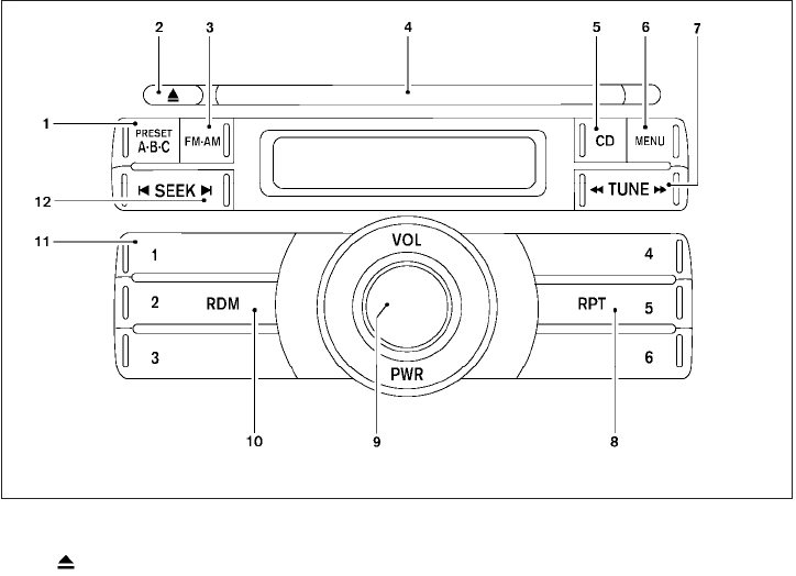
1. PRESET A·B·C button
2. CD eject button
3. FM·AM button
4. CD insert slot
5. CD button
6. MENU button
7. TUNE button
8. RPT button
9. PWR button/VOL control knob
10. RDM button
11. Station select (1 - 6) buttons
12. SEEK button
FM/AM RADIO WITH COMPACT
DISC (CD) PLAYER (Type A and B) (if
so equipped)
For all operation precautions, see 9Audio opera-
tion precautions9earlier in this section.
Audio main operation
Power button and VOL control knob
Place the ignition switch in the ACC or ON
position, then press the PWR (power) button. If
you listen to the radio with the engine not running,
place the ignition switch in the ACC position. The
mode (radio or CD) that was playing immediately
before the system was turned off resumes play-
ing.
When no CD is loaded, the radio comes on.
Pressing the PWR button again turns the system
off.
Turn the VOL control knob to the right to increase
volume or to the left to decrease volume.
Type B WHA1167
Heater, air conditioner, audio and phone systems 4-25

MENU button (BASS, TREBLE, FADE, BAL-
ANCE and CLOCK):
Press the MENU button to change the mode as
follows:
BAS →TRE →FAD →BAL →CLOCK →Audio
→BAS
To adjust Bass, Treble, Fade and Balance, press
the MENU button until the desired mode appears
in the display. Press the SEEK button to adjust
Bass and Treble to the desired level. You can also
use the SEEK button to adjust Fade and Balance
modes. Fade adjusts the sound level between the
front and rear speakers and Balance adjusts the
sound between the right and left speakers.
Once you have adjusted the sound quality to the
desired level, press the MENU button repeatedly
until the radio or CD display reappears. Other-
wise, the radio or CD display will automatically
reappear after about 10 seconds.
NOTE:
If the clock is enabled, pressing the MENU
button will change the mode as follows:
BAS →TRE →FAD →BAL →CLOCK →
Hour adjustment →Minute adjustment →
Audio →BAS
For more information on setting the clock, see
“Clock set” later in this section.
Clock operation
Press the MENU button until CLOCK is dis-
played; use the SEEK button to turn the clock
display on (CLK ON) or off (CLK OFF).
Clock set
If the clock is not displayed with the ignition
switch in the ACC or ON position, you need to
select the CLK ON mode. Press the MENU but-
ton repeatedly until CLOCK is displayed. Use the
SEEK button to enable CLK ON mode.
1. Press the MENU button repeatedly until
CLOCK mode appears; press the SEEK
button until CLK ON appears.
2. Press the MENU button again; the hours will
start flashing.
3. Press the SEEK button or to
adjust the hour.
4. Press the MENU button again; the display
will switch to the minute adjustment mode.
5. The minutes will start flashing. Press SEEK
button or to adjust the minutes.
6. Press the MENU button again to exit the
clock set mode.
The display will return to the regular clock display
after 10 seconds, or press the MENU button
again to return to the regular clock display.
Resetting the time
Hold the MENU button down and then press the
TUNE/SEEK button; the time will reset as fol-
lows:
●If the displayed minutes before the reset are
in the range of :00 - :29, the hour displayed
before the reset will stay the same and the
minutes will be reset to :00.
●If the displayed minutes before the reset are
in the range of :30 - :59, the hour displayed
before the reset will advance by one hour
and the minutes will be reset to :00.
For example, if the MENU button and the
TUNE/SEEK button are pressed while the time
displayed is between 8:00 and 8:29, the display
will be reset to 8:00. If the buttons were pressed
while the time was between 8:30 and 8:59, the
display will be reset to 9:00. At the same time the
display will return to the audio.
FM/AM radio operation
FM·AM button:
Press the FM·AM button to change from AM ←→
FM reception.
4-26 Heater, air conditioner, audio and phone systems
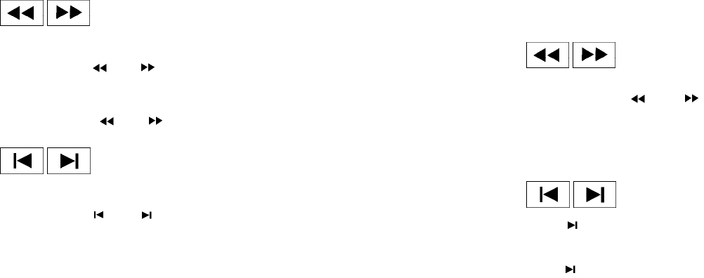
The FM stereo indicator, ST, illuminates during
FM stereo reception. When the stereo broadcast
signal is weak, the radio automatically changes
from stereo to monaural reception.
TUNE buttons:
Manual tuning
Press the TUNE or button for less
than 0.5 seconds for manual tuning.
To move quickly through the channels, press and
hold either TUNE or button down
for more than 1.5 seconds.
SEEK buttons:
SEEK tuning
Press the SEEK or button to seek
through the frequencies. Seek tuning begins
from low to high frequencies, or high to low
frequencies, depending on which button is
pressed, and stops at the next broadcasting sta-
tion. Once the highest broadcasting station is
reached, the radio continues in the seek mode at
the lowest broadcasting station.
Station memory operations:
18 stations can be set for the FM and AM radio to
the A, B and C preset button in any combination
of AM or FM stations.
1. Press the PRESET A·B·C button to change
between storage banks. The radio displays
the icon A, B or C to indicate which set of
presets are active.
2. Tune to the desired station using manual
TUNE or SEEK tuning. Press and hold any of
the desired station memory buttons (1 – 6)
until a beep sound is heard. (The radio mutes
when the select button is pressed.)
3. The channel indicator will then come on and
the sound will resume. Programming is now
complete.
4. Other buttons can be set in the same man-
ner.
If the battery cable is disconnected, or if the fuse
opens, the radio memory will be canceled. In that
case, reset the desired stations.
Compact disc (CD) player operation
Place the ignition switch in the ACC or ON
position and carefully insert the compact disc
into the slot with the label side up. The compact
disc is automatically pulled into the slot and starts
to play.
If the radio is already operating, it automatically
turns off and the compact disc begins to play.
CD button:
When the CD button is pressed with a compact
disc loaded and the radio playing, the radio turns
off and the last used compact disc starts to play.
TUNE (rewind and fast
forward) buttons:
When the TUNE or button is
pressed while the compact disc is playing, the
compact disc plays at an increased speed while
rewinding or fast forwarding. When the button is
released, the compact disc returns to normal play
speed.
SEEK buttons:
When is pressed while the compact disc
is playing, the next track following the present
one starts to play from the beginning.
Press several times to skip several tracks.
Each time the button is pressed, the CD ad-
vances 1 additional track. The track number ap-
pears in the display window. (When the last track
on the compact disc is skipped, the first track is
played.)
Heater, air conditioner, audio and phone systems 4-27
When is pressed, the track being played
returns to the beginning. Press several
times to skip back several tracks. Each time the
button is pressed, the CD moves back one track.
SEEK (Scan CDs) button:
Press and hold the SEEK button for more
than 1.5 seconds to scan through the first 10
seconds of a track on the compact disc. The
SCAN icon is flashed during scan mode.
The scan mode is canceled once it scans through
all the tracks on the disc, or if the SEEK
or button is pressed during the scan
mode.
RPT button:
When the RPT button is pressed while the com-
pact disc is being played, the play pattern can be
changed as follows:
1←→ Normal
1: The track that is currently playing will be re-
peated.
RDM button:
When the RDM button is pressed while the com-
pact disc is being played, the play pattern can be
changed as follows:
RDM ←→ Normal
RDM: Tracks from the disc that is currently play-
ing will be played randomly.
CD EJECT button:
When the button is pressed with a com-
pact disc loaded, the compact disc will be
ejected.
When the button is pressed while the
compact disc is being played, the compact disc
will eject and the system will turn off.
CD IN indicator:
CD IN indicator appears on the display when the
CD is loaded with the system on.
4-28 Heater, air conditioner, audio and phone systems
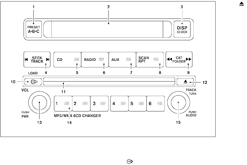
1. PRESET A·B·C button
2. Display screen
3. DISP/CLOCK button
4. SEEK/TRACK button
5. CD button
6. RADIO button*
7. AUX button
8. SCAN RPT button
9. CAT FOLDER button
10. LOAD button
11. CD insert slot
12. CD eject button
13. VOL control knob and PWR button
14. Station and CD select (1 – 6) buttons
15. TUNE/TRACK knob and AUDIO button
*No satellite radio reception is available
when the RADIO button is pressed to
access satellite radio stations unless
optional satellite receiver and antenna
are installed and an XMTsatellite radio
service subscription is active. Satellite
radio can only be installed in vehicles
that were factory pre-wired for satellite
radio. Satellite radio is not available in
Alaska, Hawaii and Guam.
WHA1172
Heater, air conditioner, audio and phone systems 4-29
FM/AM/SAT RADIO WITH
COMPACT DISC (CD) CHANGER (if
so equipped)
For all operation precautions, see 9Audio opera-
tion precautions9earlier in this section.
No satellite radio reception is available when the
RADIO button is pressed to access satellite radio
stations unless optional satellite receiver and an-
tenna are installed and an XMTsatellite radio
service subscription is active. Satellite radio can
only be installed in vehicles that were factory
pre-wired for satellite radio. Satellite radio is not
available in Alaska, Hawaii and Guam.
Audio main operation
POWER/VOLUME control:
Turn the ignition switch to ACC or ON, and then
press the PWR/VOL control knob while the sys-
tem is off to call up the mode (radio or CD) which
was playing immediately before the system was
turned off.
To turn the system off, press the PWR/VOL con-
trol knob.
Turn the PWR/VOL control knob to adjust the
volume.
This vehicle may be equipped with Speed Sen-
sitive Volume (SSV) for audio. The audio volume
changes as the driving speed changes.
AUDIO knob (BASS, MIDRANGE, TREBLE,
FADE, BALANCE and SSV if so equipped):
Press the AUDIO control knob to change the
mode as follows:
BASS →MID →TREBLE →FADE →BALANCE
→SSV (if so equipped)
To adjust Bass, Mid (Midrange), Treble, Fade and
Balance, press the AUDIO knob until the desired
mode appears in the display. Turn the Tuning
knob to adjust Bass and Treble to the desired
level. You can also use the Tuning knob to adjust
Fade and Balance modes. Fader adjusts the
sound level between the front and rear speakers
and Balance adjusts the sound between the right
and left speakers.
To change the SSV mode to OFF, LOW, MID or
HIGH, turn the Tuning knob to the right or left.
Once you have adjusted the sound quality to the
desired level, press the AUDIO knob repeatedly
until the radio or CD display reappears. Other-
wise, the radio or CD display will automatically
reappear after about 10 seconds.
Clock set
1. Press the DISP/CLOCK button until it
beeps (>1.5 seconds).
2. The hours will start flashing. Press the CAT
FOLDER or button or SEEK
TRACK or button to adjust the
hours.
3. Press the DISP/CLOCK button again to
switch to the minute adjustment.
4. Press the CAT FOLDER or
button or SEEK TRACK or
button to adjust the minutes.
5. Press the DISP/CLOCK button again to exit
the clock set mode.
The display will return to the regular clock display
after 7 seconds, or you may press the
DISP/CLOCK button again to return to the regu-
lar clock display.
DISP (display) button:
This DISP (display) button will show text about
MP3, SAT or CD information in the audio display.
4-30 Heater, air conditioner, audio and phone systems
CD display mode
To change the text displayed while playing a CD
with text, press the DISP button. The DISP button
will allow you to scroll through CD text as follows:
Disc title ←→ Track number ←→ Track title.
To change the default display mode, press the
AUDIO knob repeatedly until DISPLAY MODE
appears on the display, then rotate the knob to
select the following display modes: Disc number
←→ Folder number.
Once the display mode is selected, press the
AUDIO knob again to store the setting. If the
AUDIO knob is not pressed within 8 seconds, the
display will refresh with the last selected display
mode setting.
●Track title mode displays the title of the se-
lected CD track.
●Disc title mode displays the title of the CD
being played.
●Track number mode displays the number
selected disc and the track that is currently
being played on the disk.
MP3 display mode
To change the text displayed when listening to an
MP3/WMA CD with MP3/WMA text (when CD
with text is being used), press the DISP button.
The DISP button will scroll through the CD text as
follows: File name ←→ Folder title ←→ Art-
ist ←→ Disc number ←→ Folder number.
To change the default display mode, press the
AUDIO knob repeatedly until DISPLAY MODE
appears on the display, then rotate the knob to
select the following display modes: File name
←→ Folder title ←→ Artist ←→ Disc number
←→ Folder number.
Once a display mode is selected, press the AU-
DIO knob again to store the setting.
●Folder number mode displays the selected
folder number and the track number that is
currently being played.
●Disc number mode displays the selected
disc number and the track number that is
currently being played.
●Artist mode displays the artist title of the
MP3/WMA file.
●File name mode displays the track title of the
MP3/WMA file.
●Folder title mode displays the folder name
given to the MP3 folder.
Display satellite radio display mode (if so
equipped)
To change the text displayed when listening to
satellite radio (if so equipped) press the DISP
button. The DISP button will scroll through the
broadcast information as follows: Name ←→
Title ←→ Current display mode.
To change the default display mode press the
AUDIO button to display mode and press the
TUNE button to select the following display
modes: Channel number ←→ Channel name
←→ Name ←→ Title. Once the display mode is
selected press the AUDIO button again to store
the setting. If the AUDIO button is not pressed
after 8 seconds the display will refresh with the
last selected display mode setting.
●Channel number mode displays the channel
number of the selected satellite radio sta-
tion.
●Channel name mode displays the channel
name of the selected satellite radio station.
●Name mode displays the name of the artist,
host or weather condition of the selected
satellite radio station.
●Title mode displays the song title, show
name, or temperature of the selected satel-
lite radio station.
Heater, air conditioner, audio and phone systems 4-31
FM/AM/SAT radio operation
FM/AM/SAT band select:
Pushing the RADIO button will change the band
as follows:
AM ←→ FM or SAT (satellite, if so equipped)
When the RADIO button is pushed while the
ignition switch is in the ACC or ON position, the
radio will come on at the station last played.
The last station played will also come on when
the PWR/VOL control knob is depressed to ON.
No satellite radio reception is available when the
RADIO button is pressed to access satellite radio
stations unless optional satellite receiver and an-
tenna are installed and an XMTsatellite radio
service subscription is active. Satellite radio can
only be installed in vehicles that were factory
pre-wired for satellite radio. Satellite radio is not
available in Alaska, Hawaii and Guam. If satellite
radio is not operational then the RADIO button is
used to toggle between AM and FM bands.
If a compact disc is playing when the RADIO
button is pushed, the compact disc will automati-
cally be turned off and the last radio station
played will come on.
The FM stereo indicator ST will glow during FM
stereo reception. When the stereo broadcast
signal is weak, the radio will automatically change
from stereo to monaural reception.
CAT FOLDER (tuning)
button:
To manually tune the radio, press the CAT
FOLDER button or or turn the tun-
ing knob to right or left.
To move quickly through the channels, press and
hold either the or button down for
more than 1.5 seconds.
SEEK/TRACK tuning
button:
Press the SEEK/TRACK button or
for less than 1.5 seconds to tune from high to low
or low to high frequencies and stop at the next
broadcasting station.
To seek quickly through the channels, press and
hold the SEEK/TRACK button for more than 1.5
seconds. When the button is released the radio
will seek to the next broadcasting station.
SCAN RPT tuning:
Press the SCAN RPT button for more than 1.5
seconds to stop at each broadcasting station
(AM, FM or SAT if so equipped) for 5 seconds.
Pressing the button again during this 5 second
period will stop scan tuning and the radio will
remain tuned to that station. If the SCAN RPT
button is not pressed within 5 seconds, scan
tuning moves to the next station.
PRESET A·B·C (Station memory opera-
tions):
18 stations can be set for the FM, AM and SAT
(satellite, if so equipped) radio to the A, B and C
preset button in any combination of FM, AM or
SAT stations.
1. Choose preset bank A, B or C using the
PRESET A·B·C select button.
2. Select the desired FM, AM or SAT station
band.
3. Tune to the desired station using manual,
SEEK or SCAN tuning. Press and hold any
of the desired station memory buttons (1 –
6) until a beep sound is heard.
4. The channel indicator will then come on and
the sound will resume. Programming is now
complete.
5. Other buttons can be set in the same man-
ner.
If the battery cable is disconnected, or if the fuse
opens, the radio memory will be canceled. In that
case, reset the desired stations.
4-32 Heater, air conditioner, audio and phone systems
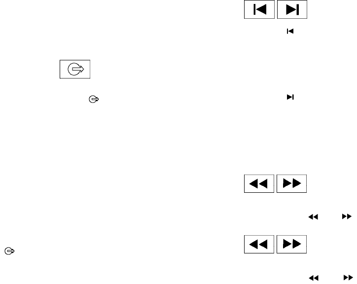
Radio data system (RDS):
RDS stands for Radio Data System, and is a data
information service transmitted by some radio
stations on the FM band (not AM band). Cur-
rently, most RDS stations are in large cities, but
many stations are now considering broadcasting
RDS data.
RDS can display:
●Station call sign, such as “WHFR 98.3”.
●Station name, such as “The Groove”.
●Music or programming type such as “Clas-
sical”, “Country”, or “Rock”.
●Artist and song information.
If the station broadcasts RDS information, the
RDS icon is displayed.
Compact disc (CD) changer operation
Turn the ignition key to the ACC or ON position
and insert the compact disc into the slot with the
label side facing up. The compact disc will be
guided automatically into the slot and start play-
ing. To insert the disc, first press the LOAD
button.
If the radio is already operating, it will automati-
cally turn off and the compact disc will play.
If the system has been turned off while the com-
pact disc was playing, pressing the PWR/VOL
control knob will start the compact disc.
Do not use 3.1 in (8 cm) diameter compact discs
in the CD changer.
LOAD button:
To insert a CD in the CD changer, press the load
button for less than 1.5 seconds. Select
the loading slot by pressing the CD insert select
button (1 – 6), then insert the CD.
To insert 6 CDs to the CD changer, press the
load button for more than 1.5 seconds.
The slot numbers (1 – 6) will illuminate on the
display when CDs are loaded into the changer.
CD button:
When the CD button is pressed with the system
off and the compact disc loaded, the system will
turn on and the compact disc will start to play.
When the CD button is pressed with the com-
pact disc loaded with the radio playing, the radio
will automatically be turned off and the compact
disc will start to play.
SEEK/TRACK button:
When the button is pressed for less than
1.5 seconds while a compact disc is playing, the
track being played returns to its beginning. Press
several times to skip back through tracks. The
compact disc will go back the number of times
the button is pressed.
When the button is pressed for less than
1.5 seconds while the compact disc is playing,
the next track will start to play from its beginning.
Press several times to skip through tracks. The
compact disc will advance the number of times
the button is pressed. (When the last track on the
compact disc is skipped through, the first track
will be played.)
CAT FOLDER button:
While playing a CD, press and hold the CAT
FOLDER button or to fast forward
or rewind a track on a CD.
MP3 CAT FOLDER button:
While playing an MP3 CD, press the CAT
FOLDER button or to scan back-
ward or forward through available folders.
Heater, air conditioner, audio and phone systems 4-33
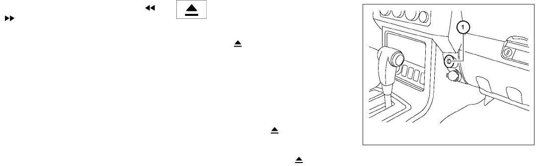
Press and hold the CAT FOLDER button
or to fast forward or rewind a track on an
MP3 CD.
CD select buttons:
To play another CD that has been loaded, press a
CD select button (1 – 6).
SCAN/RPT:
When the SCAN/RPT play button is pushed
while the compact disc is played, the play pattern
can be changed as follows:
ALL DISC RPT →1 DISC RPT→1 TRACK RPT
→ALL DISC RDM →1 DISC RDM →ALL DISC
RPT
ALL DISC RPT: All discs loaded will be repeated.
1 DISC RPT: The disc that is currently playing will
be repeated.
1 TRACK RPT: The track that is currently playing
will be repeated
ALL DISC RDM: Tracks from all discs will be
played randomly
1 DISC RDM: Tracks from the disc that is cur-
rently playing will be played randomly
CD EJECT:
Current/Selected disc:
●Press the button, then press the slot
number (1 – 6) for the desired disc. The
compact disc will be ejected. If no slot num-
ber (1 – 6) is pressed, the current loaded
disc will be ejected. If the ejected disc is not
removed within 15 seconds, the disc will
reload.
All discs:
●Press and hold the button for more
than 1.5 seconds. The compact discs will be
ejected one by one. If a disc is not removed
within 20 seconds or the button is
pressed again during the eject sequence,
the entire disc eject sequence will be can-
celed.
When this button is pressed while a compact
disc is playing, the compact disc will eject and
the last source will be played.
CD IN indicator:
The slot numbers (1 – 6) will illuminate if CDs
have been loaded into the changer in CD mode
only.
AUX jack (if so equipped)
The AUX jack s
1is located above the power
outlet. The AUX audio input jack accepts any
standard analog audio input such as from a por-
table cassette tape player, MP3 player or a laptop
computer.
Press the AUX button to play a compatible device
when it is plugged into the AUX jack.
WHA1168
4-34 Heater, air conditioner, audio and phone systems
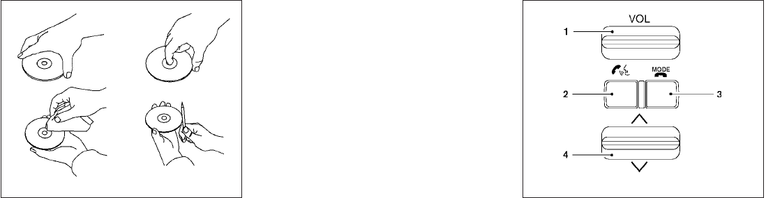
CD CARE AND CLEANING
●Handle a CD by its edges. Do not bend the
disc. Never touch the surface of the disc.
●Always place the discs in the storage case
when they are not being used.
●To clean a disc, wipe the surface from the
center to the outer edge using a clean, soft
cloth. Do not wipe the disc using a circular
motion.
●Do not use a conventional record cleaner or
alcohol intended for industrial use.
●A new disc may be rough on the inner and
outer edges. Remove the rough edges by
rubbing the inner and outer edges with the
side of a pen or pencil as illustrated.
1. Volume control switch
2. Phone operation switch
3. POWER on and MODE select switch
4. Tuning switch
STEERING WHEEL SWITCH FOR
AUDIO CONTROL (if so equipped)
The audio system can be operated using the
controls on the steering wheel.
POWER on/off switch
With the ignition switch placed in the ACC or ON
position, push the MODE switch to turn the audio
system on.
LHA0049 LHA1087
Heater, air conditioner, audio and phone systems 4-35
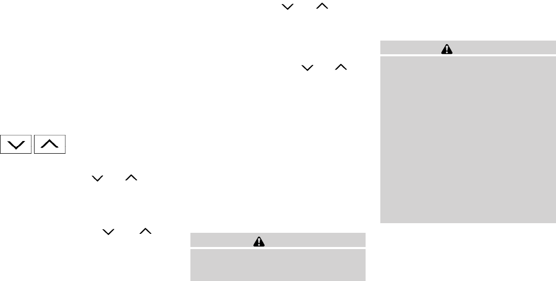
MODE select switch
Push the mode select switch to change the
modes:
PRESET A →PRESET B →PRESET C →CD*
→AUX** →PRESET A
*This mode is only available when a CD is loaded.
**This mode is only available when a compatible
auxiliary device is plugged into the AUX jack.
Volume control switch
Push the volume control switch up or down to
increase or decrease the volume.
Tuning
Memory change (radio):
Push the tuning switch ( or ) for less
than 1.5 seconds to change to the next or previ-
ous preset.
Seek tuning (radio):
Push the tuning switch ( or ) for
more than 1.5 seconds to seek the next or previ-
ous radio station.
Next/Previous track (CD):
Push the tuning switch or for less
than 1.5 seconds to return to the beginning of the
present track or skip to the next track. Push
several times to skip back or skip through tracks.
Change disc (CD) (if so equipped):
Push the SEEK tuning switch or for
more than 1.5 seconds to change the playing
disc up or down.
ANTENNA
The antenna cannot be shortened, but can be
removed. When you need to remove the antenna,
turn the antenna rod counterclockwise.
To install the antenna rod, turn the antenna clock-
wise. Tighten the antenna rod to specification
using a suitable tool such as an open-end
wrench. The antenna rod tightening specification
is 3.4 – 3.6 N·m (30 – 32 in-lb). Do not use pliers
to tighten the antenna as they can leave marks on
the antenna surface. The antenna rod cannot be
hand tightened to the proper specification.
CAUTION
Always properly tighten the antenna rod
during installation or the antenna rod may
break during vehicle operation.
When installing a CB, ham radio or car phone in
your NISSAN, be sure to observe the following
precautions; otherwise, the new equipment may
adversely affect the engine control system and
other electronic parts.
WARNING
●A cellular telephone should not be used
while driving so full attention may be
given to vehicle operation. Some juris-
dictions prohibit the use of cellular tele-
phones while driving.
●If you must make a call while your ve-
hicle is in motion, the hands free cellu-
lar phone operational mode (if so
equipped) is highly recommended. Ex-
ercise extreme caution at all times so
full attention may be given to vehicle
operation.
●If you are unable to devote full attention
to vehicle operation while talking on
the phone, pull off the road to a safe
location and stop your vehicle.
CAR PHONE OR CB RADIO
4-36 Heater, air conditioner, audio and phone systems

CAUTION
●Keep the antenna as far away as pos-
sible from the electronic control
modules.
●Keep the antenna wire more than 8 in
(20 cm) away from the electronic con-
trol system harnesses. Do not route the
antenna wire next to any harness.
●Adjust the antenna standing-wave ratio
as recommended by the manufacturer.
●Connect the ground wire from the CB
radio chassis to the body.
●For details, consult a NISSAN dealer.
●Do not ground electrical accessories
directly to the battery terminal. Doing
so will bypass the variable voltage con-
trol system and the vehicle battery may
not charge completely. Refer to “Vari-
able voltage control system” in the
“Maintenance and do-it-yourself” sec-
tion later in this manual.
●Use electrical accessories with the en-
gine running to avoid discharging the
vehicle battery.
WARNING
●Use a phone after stopping your vehicle
in a safe location. If you have to use a
phone while driving, exercise extreme
caution at all times so full attention may
be given to vehicle operation.
●If you are unable to devote full attention
to vehicle operation while talking on
the phone, pull off the road to a safe
location and stop your vehicle.
CAUTION
To avoid discharging the vehicle battery,
use a phone after starting the engine.
BLUETOOTHTHANDS-FREE PHONE
SYSTEM (if so equipped)
Heater, air conditioner, audio and phone systems 4-37
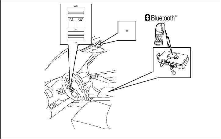
Your NISSAN is equipped with the BluetoothT
Hands-Free Phone System. If you have a com-
patible BluetoothTenabled cellular phone, you
can set up the wireless connection between your
cellular phone and the in-vehicle phone module.
With BluetoothTwireless technology, you can
make or receive a hands-free telephone call with
your cellular phone in the vehicle.
Once your cellular phone is connected to the
in-vehicle phone module, no other phone connect-
ing procedure is required. Your phone is automati-
cally connected with the in-vehicle phone module
when the ignition switch is placed in the ON
position with the previously connected cellular
phone turned on and carried in the vehicle.
You can connect up to 5 different BluetoothT
cellular phones to the in-vehicle phone module.
However, you can talk on only one cellular phone
at a time.
Before using the BluetoothTHands-Free Phone
System, refer to the following notes.
●Set up the wireless connection between a
cellular phone and the in-vehicle phone
module before using the hands-free phone
system.
●Some BluetoothTenabled cellular phones
may not be recognized by the in-vehicle
phone module. Please visit
www.nissanusa.com/bluetooth for a recom-
mended phone list and pairing.
●You will not be able to use a hands-free
phone under the following conditions:
– Your vehicle is outside of the cellular ser-
vice area.
– Your vehicle is in an area where it is
difficult to receive a cellular signal; such
as in a tunnel, in an underground parking
garage, near a tall building or in a moun-
tainous area.
WHA1360
4-38 Heater, air conditioner, audio and phone systems

– Your cellular phone is locked to prevent it
from being dialed.
●When the radio wave condition is not ideal
or ambient sound is too loud, it may be
difficult to hear the other person’s voice dur-
ing a call.
●Do not place the cellular phone in an area
surrounded by metal or far away from the
in-vehicle phone module to prevent tone
quality degradation and wireless connection
disruption.
●While a cellular phone is connected through
the BluetoothTwireless connection, the bat-
tery power of the cellular phone may dis-
charge quicker than usual. The BluetoothT
Hands-Free Phone System cannot charge
cellular phones.
●If the hands-free phone system seems to be
malfunctioning, see “Troubleshooting guide”
later in this section. You can also visit
www.nissanusa.com/bluetooth for trouble-
shooting help.
●Some cellular phones or other devices may
cause interference or a buzzing noise to
come from the audio system speakers. Stor-
ing the device in a different location may
reduce or eliminate the noise.
●Refer to the cellular phone Owner’s Manual
regarding the telephone charges, cellular
phone antenna and body, etc.
REGULATORY INFORMATION
FCC Regulatory information
– CAUTION: To maintain compliance with
FCC’s RF exposure guidelines, use only the
supplied antenna. Unauthorized antenna,
modification, or attachments could damage
the transmitter and may violate FCC regula-
tions.
– Operation is subject to the following two con-
ditions:
1. This device may not cause interference and
2. this device must accept any interference,
including interference that may cause un-
desired operation of the device.
IC Regulatory information
– Operation is subject to the following two con-
ditions: (1) this device may not cause interfer-
ence, and (2) this device must accept any
interference, including interference that may
cause undesired operation of the device.
– This Class B digital apparatus meets all re-
quirements of the Canadian Interference-
Causing Equipment Regulations.
BLUETOOTHtis a
trademark owned by
Bluetooth SIG, Inc.,
U.S.A. and licensed to
Visteon.
USING THE SYSTEM
The NISSAN Voice Recognition system allows
hands-free operation of the BluetoothTPhone
System.
If the vehicle is in motion, some commands may
not be available so full attention may be given to
vehicle operation.
Initialization
When the ignition switch is placed in the ON
position, NISSAN Voice Recognition is initialized,
which takes a few seconds. If the button is
pressed before the initialization completes, the
system will announce “Hands-free phone system
not ready” and will not react to voice commands.
Heater, air conditioner, audio and phone systems 4-39

Operating tips
To get the best performance out of the NISSAN
Voice Recognition system, observe the following:
●Keep the interior of the vehicle as quiet as
possible. Close the windows to eliminate
surrounding noises (traffic noises, vibration
sounds, etc.), which may prevent the system
from recognizing voice commands correctly.
●Wait until the tone sounds before speaking a
command. Otherwise, the command will not
be received properly.
●Start speaking a command within 5 seconds
after the tone sounds.
●Speak in a natural voice without pausing
between words.
Giving voice commands
To operate NISSAN Voice Recognition, press
and release the button located on the
steering wheel. After the tone sounds, speak a
command.
The command given is picked up by the micro-
phone, and voice feedback is given when the
command is accepted.
●If you need to hear the available commands
for the current menu again, say “Help” and
the system will repeat them.
●If a command is not recognized, the system
announces, “Command not recognized.
Please try again.” Repeat the command in a
clear voice.
●If you want to go back to the previous com-
mand, you can say “Go back” or “Correc-
tion” any time the system is waiting for a
response.
●You can cancel a command when the sys-
tem is waiting for a response by saying,
“Cancel” or “Quit.” The system announces
“Cancel” and ends the VR session. You can
also press and hold the button on the
steering wheel for 5 seconds at any time to
end the VR session. Whenever the VR ses-
sion is cancelled, a double beep is played to
indicate you have exited the system.
●If you want to adjust the volume of the voice
feedback, press the volume control switches
(+ or -) on the steering wheel while being
provided with feedback. You can also use
the radio volume control knob.
●In most cases you can interrupt the voice
feedback to speak the next command by
pressing the button on the steering
wheel.
●To use the system faster, you may speak the
second level commands with the main menu
command on the main menu. For example,
press the button and after the tone
say, “Call Redial.”
NOTE:
The combined command of Call and (a
Name) cannot be used.
How to say numbers
NISSAN Voice Recognition requires a certain
way to speak numbers in voice commands. Refer
to the following rules and examples.
●Either “zero” or “oh” can be used for “0”.
Example: 1-800-662-6200
– “One eight oh oh six six two six two oh
oh”, or
– “One eight zero zero six six two six two oh
oh”
●Words can be used for the first 4 digits
places only.
Example: 1-800-662-6200
– “One eight hundred six six two six two oh
oh”,
4-40 Heater, air conditioner, audio and phone systems
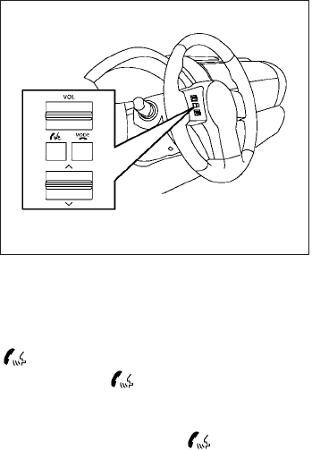
– NOT “One eight hundred six six two sixty
two hundred,” and
– NOT “One eight oh oh six six two sixty two
hundred”
●Numbers can be spoken in small groups.
The system will prompt you to continue en-
tering digits, if desired.
Example: 1-800-662-6200
– “One eight zero zero”
The system repeats the numbers and
prompts you to enter more.
– “six six two”
The system repeats the numbers and
prompts you to enter more.
– “six two zero zero”
●Say “pound” for “#”. Say “star” for “*” (avail-
able when using the “Special Dialing” com-
mand and the “Send” command during a
call).
●Say “plus” for “+” (available only when using
the “Special Dialing” command).
●Say “pause” for a 2-second pause (available
only when storing a phone book number).
●You can say “star” for “*” and “pound”for “#”
at any time in any position of the phone
number (available only when using “Special
Dialing” command).
See “List of voice commands” and “Special
Dialing” in this section for more information.
Example: 1-555-1212 *123
– “One five five five one two one two star
one two three”
NOTE:
For best results, say phone numbers as
single digits.
The voice command “Help” is available at any
time. Please use the “Help” command to get
information on how to use the system.
CONTROL BUTTONS
The control buttons for the BluetoothTHands-
Free Phone System are located on the steering
wheel.
PHONE/SEND
Press the button to initiate a VR
session or answer an incoming call.
You can also use the button to
interrupt the system feedback and give
a command at once. See “List of voice
commands” and “During a call” in this
section for more information.
LHA1086
Heater, air conditioner, audio and phone systems 4-41
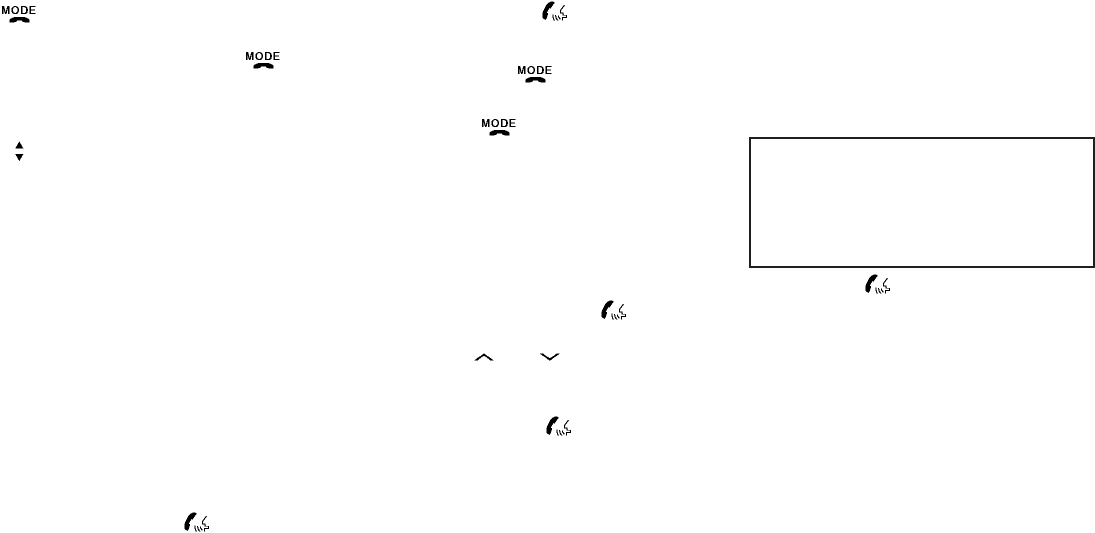
PHONE/END
While the voice recognition system is
active, press and hold the button
for 5 seconds to quit the voice recogni-
tion system at any time.
TUNING SWITCH
While using the voice recognition
system, tilt the tuning switch up or
down to manually control the phone
system.
GETTING STARTED
The following procedures will help you get
started using the BluetoothTHands-Free Phone
System with NISSAN Voice Recognition. For ad-
ditional command options, refer to “List of voice
commands” in this section.
Choosing a language
You can interact with the BluetoothTHands-Free
Phone System using English, Spanish or French.
To change the language, perform the following.
1. Press and hold the button for more
than 5 seconds.
2. The system announces: “Press the
PHONE/SEND ( ) button for the
hands-free phone system to enter the
speaker adaptation mode or press the
PHONE/END ( ) button to select a dif-
ferent language.”
3. Press the button.
For information on speaker adaptation, see
“Speaker adaptation (SA) mode”in this sec-
tion.
4. The system announces the current language
and gives you the option to change the lan-
guage to Spanish (in Spanish) or French (in
French). To select the current language,
press the PHONE/SEND ( ) button. To
select a different language, tilt the tuning
switch ( or ) up or down.
NOTE:
You must press the button within 5
seconds to change the language.
5. If you decide not to change the language, do
not press either button. After 5 seconds, the
VR session will end, and the language will
not be changed.
Pairing procedure
NOTE:
The pairing procedure must be performed
when the vehicle is stationary. If the vehicle
starts moving during the procedure, the
procedure will be cancelled.
Main Menu
“Connect phone” s
A
“Add phone” s
B
Initiate from handset s
C
Name phone s
D
1. Press the button on the steering
wheel. The system announces the available
commands.
2. Say: “Connect phone” s
A. The system ac-
knowledges the command and announces
the next set of available commands.
3. Say: “Add phone” s
B. The system acknowl-
edges the command and asks you to initiate
pairing from the phone handset s
C.
4-42 Heater, air conditioner, audio and phone systems
The pairing procedure of the cellular phone
varies according to each cellular phone
model. See the cellular phone Owner’s
Manual for details. You can also visit
www.nissanusa.com/bluetooth for instruc-
tions on pairing NISSAN recommended cel-
lular phones.
When prompted for a Passkey code, enter
“1234” from the handset. The Passkey code
“1234” has been assigned by NISSAN and
cannot be changed.
4. The system asks you to say a name for the
phone s
D.
If the name is too long or too short, the
system tells you, then prompts you for a
name again.
Also, if more than one phone is paired and
the name sounds too much like a name
already used, the system tells you, then
prompts you for a name again.
Making a call by entering a phone
number
Main Menu
“Call” s
A
“Phone Number” s
B
Speak the digits s
C
“Dial” s
D
1. Press the button on the steering
wheel. A tone will sound.
2. Say: “Call” s
A. The system acknowledges
the command and announces the next set of
available commands.
Say: “Special Dialing” to dial more than 10
digits or any special characters.
3. Say “Phone Number” s
B. The system ac-
knowledges the command and announces
the next set of available commands.
4. Say the number you wish to call starting with
the area code in single digit format s
C.Ifthe
system has trouble recognizing the correct
phone number, try entering the number in
the following groups: 3-digit area code,
3-digit prefix and the last 4-digits. For ex-
ample, 555-121-3354 can be said as “five
five five” as the 1st group, then “one two
one” as the 2nd group, and “three three five
four” as the 3rd group. For dialing more than
10 digits or any special characters, say
“Special Dialing”. See “How to say num-
bers” in this section for more information.
5. When you have finished speaking the phone
number, the system repeats it back and an-
nounces the available commands.
6. Say: “Dial” s
D. The system acknowledges
the command and makes the call.
For additional command options, see “List of
voice commands” in this section.
Receiving a call
When you hear the ring tone, press the
button on the steering wheel.
Once the call has ended, press the button
on the steering wheel.
NOTE:
If you do not wish to take the call when you
hear the ring tone, press the button
on the steering wheel.
For additional command options, see “List of
voice commands” later in this section.
Heater, air conditioner, audio and phone systems 4-43

LIST OF VOICE COMMANDS
Main Menu
“Call”
“Phonebook”
“Recent Calls”
“Connect Phone”
When you press and release the button on
the steering wheel, you can choose from the
commands on the Main Menu. The following
pages describe these commands and the com-
mands in each sub-menu.
Remember to wait for the tone before
speaking.
After the main menu, you can say “Help” to hear
the list of commands currently available any time
the system is waiting for a response.
If you want to end an action without completing it,
you can say “Cancel” or “Quit” at any time the
system is waiting for a response. The system will
end the VR session. Whenever the VR session is
cancelled, a double beep is played to indicate
you have exited the system.
If you want to go back to the previous command,
you can say “Go back” or “Correction” any time
the system is waiting for a response.
“Call”
Main Menu
“Call”
(Speak name) s
A
“Phone Number”
(Speak Digits) s
B
“Special Number” s
C
“Redial” s
D
“Call Back” s
E
(Speak Name) s
A
If you have stored entries in the phonebook, you
can dial a number associated with a name and
location.
See “Phonebook” in this section to learn how to
store entries.
When prompted by the system, say the name of
the phone book entry you wish to call. The system
acknowledges the name.
If there are multiple locations associated with the
name, the system asks you to choose the loca-
tion.
Once you have confirmed the name and location,
the system begins the call.
(Speak Digits) s
B
When prompted by the system, say the number
you wish to call. Refer to “How to say numbers”
and “Making a call by entering a phone number”
in this section for more details.
“Special Number” s
C
For dialing more than 10 digits or any special
characters, say “Special Number”. When the
system acknowledges the command, the system
will prompt you to speak the number.
“Redial” s
D
Use the Redial command to call the last number
that was dialed.
The system acknowledges the command, re-
peats the number and begins dialing.
If a redial number does not exist, the system
announces, “There is no number to redial” and
ends the VR session.
“Call back” s
E
Use the Call Back command to dial the number of
the last incoming call within the vehicle.
The system acknowledges the command, re-
peats the number and begins dialing.
4-44 Heater, air conditioner, audio and phone systems

If a call back number does not exist, the system
announces, “There is no number to call back”and
ends the VR session.
During a call
During a call there are several command options
available. Press the button on the steering
wheel to mute the receiving voice and enter com-
mands.
●“Help” — The system announces the avail-
able commands.
●“Go back/Correction” — The system an-
nounces “Go back,” ends the VR session
and returns to the call.
●“Cancel/Quit” — The system announces
“Cancel,” ends the VR session and returns
to the call.
●“Send/Enter/Call/Dial” — Use the Send
command to enter numbers, “*”or “#”during
a call. For example, if you were directed to
dial an extension by an automated system:
Say: “Send one two three four.”
The system acknowledges the command
and sends the tones associated with the
numbers. The system then ends the VR ses-
sion and returns to the call. Say “star” for “*”,
Say “pound” for “#”.
●“Transfer call” — Use the Transfer Call com-
mand to transfer the call from the BluetoothT
Hands-Free Phone System to the cellular
phone when privacy is desired.
The system announces, “Transfer call. Call
transferred to privacy mode.” The system
then ends the VR session.
To reconnect the call from the cellular phone
to the Bluetooth Hands-Free System, press
the button.
●“Mute” — Use the Mute command to mute
your voice so the other party cannot hear it.
Use the mute command again to unmute
your voice.
NOTE:
If a call is ended or the cellular phone
network connection is lost while the Mute
feature is on, the Mute feature will be reset
to “off” for the next call so the other party
can hear your voice.
“Phonebook” (phones without
automatic phonebook download
function)
NOTE:
The “Transfer Entry” command is not avail-
able when the vehicle is moving.
Main Menu
“Phonebook”
“Transfer Entry” s
A
“Delete Entry” s
B
“List Names” s
C
For phones that do not support automatic down-
load of the phonebook (PBAP BluetoothTpro-
file), the “Phonebook”command is used to manu-
ally add entries to the vehicle phonebook.
The phonebook stores up to 40 names for each
phone paired with the system.
NOTE:
Each phone has its own separate phone-
book. You cannot access Phone A’s phone-
book if you are currently connected with
Phone B.
Heater, air conditioner, audio and phone systems 4-45

“Transfer entry” s
A
Use the Transfer Entry command to store a new
name in the system.
When prompted by the system, say the name you
would like to give the new entry.
For example, say: “Mary.”
If the name is too long or too short, the system
tells you, then prompts you for a name again.
Also, if the name sounds too much like a name
already stored, the system tells you, then prompts
you for a name again.
The system will ask you to transfer a phone
number stored in the cellular phone’s memory.
Enter a phone number by voice command:
For example, say: “five five five one two one two.”
See “How to say numbers” in this section for
more information.
To transfer a phone number stored in the cellular
phone’s memory:
Say “Transfer entry.” The system acknowledges
the command and asks you to initiate the transfer
from the phone handset. The new contact phone
number will be transferred from the cellular
phone via the BluetoothTcommunication link.
The transfer procedure varies according to each
cellular phone. See the cellular phone Owner’s
Manual for details. You can also visit
www.nissanusa.com/bluetooth for instructions
on transferring phone numbers from NISSAN
recommended cellular phones.
The system repeats the number and prompts you
for the next command. When you have finished
entering numbers or transferring an entry, choose
“Store.”
The system confirms the name, location and
number.
“Delete Entry” s
B
Use the Delete Entry command to erase one
entry from the phonebook. After the system rec-
ognizes the command, speak the name to delete
or say “List Names” to choose an entry.
“List names” s
C
Use the List Names command to hear all the
names in the phonebook.
The system recites the phonebook entries but
does not include the actual phone numbers.
When the playback of the list is complete, the
system goes back to the main menu.
You can stop the playback of the list at any time
by pressing the button on the steering
wheel. The system ends the VR session.
“Phonebook” (phones with automatic
phonebook download function)
NOTE:
The “Transfer Entry” command is not avail-
able when the vehicle is moving.
Main Menu
“Phonebook”
“List Names” s
A
“Transfer Entry” s
B
“Delete Entry” s
C
“Record Name” s
D
For phones that support automatic download of the
phonebook (PBAP BluetoothTprofile), the
“Phonebook” command is used to manage entries
to the vehicle phonebook. You can say the name of
an entry at this menu to initiate dialing of that entry.
The phonebook stores up to 1000 names for
each phone paired with the system.
When a phone is connected to the system, the
phonebook is automatically downloaded to the
vehicle. This feature allows you to access your
phonebook from the BluetoothTsystem and call
contacts by name. You can record a custom
voice tag for contact names that the system has
difficulty recognizing. For more information see
“Record Name” in this section.
4-46 Heater, air conditioner, audio and phone systems

NOTE:
Each phone has its own separate phone-
book. You cannot access Phone A’s phone-
book if you are currently connected with
Phone B.
“List names” s
A
Use the List Names command to hear all the
names and locations in the phone book.
The system recites the phone book entries but
does not include the actual phone numbers.
When the playback of the list is complete, the
system goes back to the main menu.
You can stop the playback of the list at any time
by pressing the button on the steering
wheel. The system ends the VR session. See the
“Record Name” command in this section for in-
formation about recording custom voice tags for
list entries that the system has difficulty pro-
nouncing.
“Transfer entry” s
B
Use the Transfer Entry command to store a new
name in the system.
When prompted by the system, say the name you
would like to give the new entry.
For example, say: “Mary.”
If the name is too long or too short, the system
tells you, then prompts you for a name again.
Also, if the name sounds too much like a name
already stored, the system tells you, then prompts
you for a name again.
The system will ask you to transfer a phone
number stored in the cellular phone’s memory.
Enter a phone number by voice command:
For example, say: “five five five one two one two.”
See “How to say numbers” in this section for
more information.
To transfer a phone number stored in the cellular
phone’s memory:
Say “Transfer entry.” The system acknowledges
the command and asks you to initiate the transfer
from the phone handset. The new contact phone
number will be transferred from the cellular
phone via the BluetoothTcommunication link.
The transfer procedure varies according to each
cellular phone. See the cellular phone Owner’s
Manual for details. You can also visit
www.nissanusa.com/bluetooth for instructions
on transferring phone numbers from NISSAN
recommended cellular phones.
The system repeats the number and prompts you
for the next command. When you have finished
entering numbers or transferring an entry, choose
“Store.”
The system confirms the name, location and
number.
“Delete Entry” s
C
Use the Delete Entry command to erase one
entry from the phonebook. After the system rec-
ognizes the command, speak the name to delete
or say “List Names” to choose an entry.
“Record name” s
D
The system allows you to record custom voice
tags for contact names in the phonebook that the
vehicle has difficulty recognizing. This feature can
also be used to record voice tags to directly dial
an entry with multiple numbers. Up to 40 voice
tags can be recorded to the system.
“Recent Calls”
Main Menu
“Recent Calls”
“Outgoing” s
A
“Incoming” s
B
“Missed” s
C
Heater, air conditioner, audio and phone systems 4-47

Use the Recent Calls command to access out-
going, incoming or missed calls.
“Outgoing” s
A
Use the Outgoing command to list the outgoing
calls made from the vehicle.
“Incoming” s
B
Use the Incoming command to list the incoming
calls made to the vehicle.
“Missed” s
C
Use the Missed command to list the calls made to
the vehicle that were not answered.
“Connect Phone”
NOTE:
The Add Phone command is not available
when the vehicle is moving.
Main Menu
“Connect Phone”
“Add Phone” s
A
“Select Phone” s
B
“Delete Phone” s
C
“Turn Bluetooth OFF” s
D
Use the Connect Phone commands to manage
the phones connecting to the vehicle or to enable
the BluetoothTfunction on the vehicle.
“Add Phone” s
A
Use the Add Phone command to add a phone to
the vehicle. See “Pairing procedure” in this sec-
tion for more information.
“Select Phone” s
B
Use the Select Phone command to select from a
list of phones connected to the vehicle. The sys-
tem will list the names assigned to each phone
and then prompt you for the phone you wish to
select. Only one phone can be active at a time.
“Delete Phone” s
C
Use the Delete Phone command to delete a
phone that is connected to the vehicle. The sys-
tem will list the names assigned to each phone
and then prompt you for the phone you wish to
delete. Deleting a phone from the vehicle will also
delete that phonebook for that phone.
“Turn Bluetooth OFF” s
D
Use the Turn Bluetooth OFF command to prevent
a wireless connection to your phone.
SPEAKER ADAPTATION (SA) MODE
Speaker Adaptation allows up to two out-of-
dialect users to train the system to improve rec-
ognition accuracy. By repeating a number of
commands, the users can create a voice model of
their own voice that is stored in the system. The
system is capable of storing a different speaker
adaptation model for each connected phone.
Training procedure
The procedure for training a voice is as follows.
1. Position the vehicle in a reasonably quiet
outdoor location.
2. Sit in the driver’s seat with the engine run-
ning, the parking brake on, and the transmis-
sion in P (Park).
3. Press and hold the button for more
than 5 seconds.
4. The system announces: “Press the
PHONE/SEND ( ) button for the
hands-free phone system to enter the
speaker adaptation mode or press the
PHONE/END ( ) button to select a dif-
ferent language.”
4-48 Heater, air conditioner, audio and phone systems

5. Press the button.
For information on selecting a different lan-
guage, see “Choosing a language” in this
section.
6. Voice memory A or memory B is selected
automatically. If both memory locations are
already in use, the system will prompt you to
overwrite one. Follow the instructions pro-
vided by the system.
7. When preparation is complete and you are
ready to begin, press the button.
8. The SA mode will be explained. Follow the
instructions provided by the system.
9. When training is finished, the system will tell
you an adequate number of phrases have
been recorded.
10. The system will announce that speaker ad-
aptation has been completed and the sys-
tem is ready.
The SA mode will stop if:
●The button is pressed for more than 5
seconds in SA mode.
●The vehicle begins moving during SA mode.
●The ignition switch is placed in the OFF or
LOCK position.
Training phrases
During the SA mode, the system instructs the
trainer to say the following phrases. (The system
will prompt you for each phrase.)
●phonebook transfer entry
●dial three oh four two nine
●delete call back number
●incoming
●transfer entry
●eight pause nine three two pause seven
●delete all entries
●call seven two four zero nine
●phonebook delete entry
●next entry
●dial star two one seven oh
●yes
●no
●select
●missed
●dial eight five six nine two
●Bluetooth on
●outgoing
●call three one nine oh two
●nine seven pause pause three oh eight
●cancel
●call back number
●call star two zero nine five
●delete phone
●dial eight three zero five one
●record name
●four three pause two nine pause zero
●delete redial number
●phonebook list names
●call eight oh five four one
●correction
●connect phone
●dial seven four oh one eight
●previous entry
●delete
●dial nine seven two six six
●call seven six three oh one
●go back
●call five six two eight zero
●dial six six four three seven
Heater, air conditioner, audio and phone systems 4-49
MANUAL CONTROL
While using the voice recognition system, it is
possible to select menu options by using the
steering wheel controls instead of speaking voice
commands. The manual control mode does not
allow dialing a phone number by digits. The user
may select an entry from the Phonebook or Re-
cent Calls lists. To re-activate voice recognition,
exit the manual control mode by pressing and
holding the PHONE/END ( ) button. At that
time, pressing the PHONE/SEND ( ) button
will start the Hands Free Phone System.
Operating tips
●To enter manual control mode, start the
voice recognition system and tilt the tuning
() switch up or down. The system will
speak 9Showing Manual Options9when
manual controls are initially activated.
●To browse the menu options, tilt the tuning
() switch up or down. The system will
always speak the current menu option. De-
pending on the audio display, it will also
show the current menu option.
●To select the current menu option, press the
PHONE/SEND ( ) button.
●To go back to the previous menu, press the
PHONE/END ( ) button. If the current
menu is the Main Menu, pressing the
PHONE/END ( ) button will exit the
Phone system.
●To exit the manual control mode, press and
hold the PHONE/END ( ) button for 5
seconds.
4-50 Heater, air conditioner, audio and phone systems

TROUBLESHOOTING GUIDE
The system should respond correctly to all voice
commands without difficulty. If problems are en-
countered, try the following solutions.
Where the solutions are listed by number, try
each solution in turn, starting with number 1, until
the problem is resolved.
Symptom Solution
System fails to interpret the command correctly.
1. Ensure that the command is valid. See “List of voice commands” in this section.
2. Ensure that the command is spoken after the tone.
3. Speak clearly without pausing between words and at a level appropriate to the ambient noise level in the vehicle.
4. Ensure that the ambient noise level is not excessive (for example, windows open or defroster on). NOTE: If it is too
noisy to use the phone, it is likely that the voice commands will not be recognized.
5. If more than one command was said at a time, try saying the commands separately.
6. If the system consistently fails to recognize commands, the voice training procedure should be carried out to im-
prove the recognition response for the speaker. See “Speaker adaptation (SA) mode” in this section.
The system consistently selects the wrong entry from the
phone book.
1. Ensure that the phone book entry name requested matches what was originally stored. This can be confirmed by
using the “List Names” command. See “Phonebook” in this section.
2. Replace one of the names being confused with a new name.
Heater, air conditioner, audio and phone systems 4-51

5 Starting and driving
Precautions when starting and driving................5-2
Exhaust gas (carbon monoxide) ..................5-2
Three-way catalyst..............................5-3
Tire Pressure Monitoring System (TPMS)..........5-3
On-pavement and off-road driving
precautions ....................................5-5
Avoiding collision and rollover....................5-6
Off-road recovery...............................5-6
Rapid air pressure loss..........................5-6
Drinking alcohol/drugs and driving................5-7
Driving safety precautions .......................5-7
Ignition switch.....................................5-9
Automatic transmission (if so equipped)..........5-10
Manual transmission (if so equipped) ............5-11
Key positions .................................5-11
Nissan Vehicle Immobilizer System
(if so equipped) ...............................5-11
Before starting the engine .........................5-12
Starting the engine ...............................5-12
Driving the vehicle ................................5-13
Automatic transmission (if so equipped)..........5-13
Manual transmission (if so equipped) ............5-17
Parking brake ....................................5-19
Cruise control (if so equipped) .....................5-20
Precautions on cruise control ...................5-20
Cruise control operations.......................5-20
Break-in schedule ................................5-21
Increasing fuel economy...........................5-22
Using four wheel drive (4WD) .............5-22
Transfer case shifting procedures ...............5-23
Electronic locking rear differential (E-Lock) system
(if so equipped) ..................................5-30
Parking/parking on hills............................5-31
Power steering ...................................5-32
Brake system ....................................5-32
Brake precautions .............................5-32
Anti-lock Braking System (ABS).................5-33
Active brake limited slip (ABLS) system
(if so equipped) ..................................5-34
Vehicle Dynamic Control (VDC) system
(if so equipped) ..................................5-34
Hill descent control system (if so equipped) .........5-36
Hill start assist system (if so equipped)..............5-37
Cold weather driving..............................5-37
Freeing a frozen door lock ......................5-37
Anti-freeze....................................5-37
Battery .......................................5-37


WARNING
●Do not leave children or adults who
would normally require the assistance
of others alone in your vehicle. Pets
should also not be left alone. They
could accidentally injure themselves or
others through inadvertent operation of
the vehicle. Also, on hot, sunny days,
temperatures in a closed vehicle could
quickly become high enough to cause
severe or possibly fatal injuries to
people or animals.
●Properly secure all cargo with ropes or
straps to help prevent it from sliding or
shifting. Do not place cargo higher than
the seatbacks. In a sudden stop or col-
lision, unsecured cargo could cause
personal injury.
EXHAUST GAS (carbon monoxide)
WARNING
●Do not breathe exhaust gases; they
contain colorless and odorless carbon
monoxide. Carbon monoxide is danger-
ous. It can cause unconsciousness or
death.
●If you suspect that exhaust fumes are
entering the vehicle, drive with all win-
dows fully open, and have the vehicle
inspected immediately.
●Do not run the engine in closed spaces
such as a garage.
●Do not park the vehicle with the engine
running for any extended length of time.
●Keep the lift gate and rear windows
closed while driving, otherwise exhaust
gases could be drawn into the passen-
ger compartment. If you must drive with
the lift gate or rear windows open, fol-
low these precautions:
1. Open all the windows.
2. Set the air recirculation but-
ton (if so equipped) to off and the fan
control dial to 4 (high) to circulate
the air.
●If electrical wiring or other cable con-
nections must pass to a trailer through
the seal on the lift gate or the body,
follow the manufacturer’s recommen-
dation to prevent carbon monoxide en-
try into the vehicle.
●The exhaust system and body should be
inspected by a qualified mechanic
whenever:
a. The vehicle is raised for service.
b. You suspect that exhaust fumes are
entering into the passenger
compartment.
c. You notice a change in the sound of
the exhaust system.
d. You have had an accident involving
damage to the exhaust system, un-
derbody, or rear of the vehicle.
●If a special body, camper, or other
equipment is added for recreational or
other usage, follow the manufacturer’s
recommendation to prevent carbon
monoxide entry into the vehicle. Do not
occupy these areas while the engine is
running even if the vehicle is parked.
Some recreational vehicle appliances
such as stoves, refrigerators, heaters,
etc. may also generate carbon
monoxide.
PRECAUTIONS WHEN STARTING
AND DRIVING
5-2 Starting and driving

THREE-WAY CATALYST
The three-way catalyst is an emission control
device installed in the exhaust system. Exhaust
gases in the three-way catalyst are burned at
high temperatures to help reduce pollutants.
WARNING
●The exhaust gas and the exhaust sys-
tem are very hot. Keep people, animals
or flammable materials away from the
exhaust system components.
●Do not stop or park the vehicle over
flammable materials such as dry grass,
waste paper or rags. They may ignite
and cause a fire.
CAUTION
●Do not use leaded gasoline. Deposits
from leaded gasoline will seriously re-
duce the three-way catalyst’s ability to
help reduce exhaust pollutants.
●Keep your engine tuned up. Malfunc-
tions in the ignition, fuel injection, or
electrical systems can cause overrich
fuel flow into the three-way catalyst,
causing it to overheat. Do not keep driv-
ing if the engine misfires, or if notice-
able loss of performance or other un-
usual operating conditions are
detected. Have the vehicle inspected
promptly by a NISSAN dealer.
●Avoid driving with an extremely low fuel
level. Running out of fuel could cause
the engine to misfire, damaging the
three-way catalyst.
●Do not race the engine while warming it
up.
●Do not push or tow your vehicle to start
the engine.
TIRE PRESSURE MONITORING
SYSTEM (TPMS)
Each tire, including the spare (if provided),
should be checked monthly when cold and in-
flated to the inflation pressure recommended by
the vehicle manufacturer on the vehicle placard
or tire inflation pressure label. (If your vehicle has
tires of a different size than the size indicated on
the vehicle placard or tire inflation pressure label,
you should determine the proper tire inflation
pressure for those tires.)
As an added safety feature, your vehicle has been
equipped with a Tire Pressure Monitoring System
(TPMS) that illuminates a low tire pressure telltale
when one or more of your tires is significantly
under-inflated. Accordingly, when the low tire
pressure telltale illuminates, you should stop and
check your tires as soon as possible, and inflate
all 4 tires to the proper pressure. Driving on a
significantly under-inflated tire causes the tire to
overheat and can lead to tire failure. Under-
inflation also reduces fuel efficiency and tire tread
life, and may affect the vehicle’s handling and
stopping ability.
Please note that the TPMS is not a substitute for
proper tire maintenance, and it is the driver’s
responsibility to maintain correct tire pressure,
even if under-inflation has not reached the level to
trigger illumination of the TPMS low tire pressure
telltale.
Your vehicle has also been equipped with a
TPMS malfunction indicator to indicate when the
system is not operating properly. The TPMS mal-
function indicator is combined with the low tire
pressure telltale. When the system detects a
malfunction, the telltale will flash for approxi-
mately one minute and then remain continuously
illuminated. This sequence will continue upon
Starting and driving 5-3

subsequent vehicle start-ups as long as the mal-
function exists. When the malfunction indicator is
illuminated, the system may not be able to detect
or signal low tire pressure as intended. TPMS
malfunctions may occur for a variety of reasons,
including the installation of replacement or alter-
nate tires or wheels on the vehicle that prevent
the TPMS from functioning properly. Always
check the TPMS malfunction telltale after replac-
ing one or more tires or wheels on your vehicle to
ensure that the replacement or alternate tires and
wheels allow the TPMS to continue to function
properly.
Additional information:
●The TPMS does not monitor the tire
pressure of the spare tire.
●The TPMS will activate only when the vehicle
is driven at speeds above 16 MPH (25
km/h). Also, this system may not detect a
sudden drop in tire pressure (for example a
flat tire while driving).
●The low tire pressure warning light does not
automatically turn off when the tire pressure
of all 4 tires are adjusted. After the tires are
inflated to the recommended pressure, the
vehicle must be driven at speeds above 16
MPH (25 km/h) to activate the TPMS and
turn off the low tire pressure warning light.
Use a tire pressure gauge to check the tire
pressure.
●Tire pressure rises and falls depending on
the heat caused by the vehicle’s operation
and the outside temperature. Low outside
temperature can lower the temperature of
the air inside the tire which can cause a
lower tire inflation pressure. This may cause
the low tire pressure warning light to illumi-
nate. If the warning light illuminates in low
ambient temperature, check the tire pres-
sure for all four tires.
●The Tire and Loading Information label (also
referred to as the vehicle placard or tire
inflation pressure label) is located in the
driver’s door opening.
For additional information, see “Low tire pressure
warning light” in the “Instruments and controls”
section and “Tire Pressure Monitoring System
(TPMS)” in the “In case of emergency” section.
WARNING
●If the low tire pressure warning light
illuminates while driving, avoid sudden
steering maneuvers or abrupt braking,
reduce vehicle speed, pull off the road
to a safe location and stop the vehicle
as soon as possible. Driving with under-
inflated tires may permanently damage
the tires and increase the likelihood of
tire failure. Serious vehicle damage
could occur and may lead to an acci-
dent and could result in serious per-
sonal injury. Check the tire pressure for
all four tires. Adjust the tire pressure to
the recommended COLD tire pressure
shown on the Tire and Loading Informa-
tion label to turn the low tire pressure
warning light OFF. If you have a flat tire,
replace it with a spare tire as soon as
possible. (See “Flat tire” in the “In case
of emergency” section for changing a
flat tire.)
5-4 Starting and driving

●When a spare tire is mounted or a wheel
is replaced, the TPMS will not function
and the low tire pressure warning light
will flash for approximately 1 minute.
The light will remain on after 1 minute.
Contact your NISSAN dealer as soon as
possible for tire replacement and/or
system resetting.
●Replacing tires with those not originally
specified by NISSAN could affect the
proper operation of the TPMS.
●Do not inject any tire liquid or aerosol
tire sealant into the tires, as this may
cause a malfunction of the tire pressure
sensors.
CAUTION
Do not place metalized film or any metal
parts (antenna, etc.) on the windows. This
may cause poor reception of the signals
from the tire pressure sensors, and the
TPMS will not function properly.
Some devices and transmitters may temporarily
interfere with the operation of the TPMS and
cause the low tire pressure warning light to illu-
minate.
Some examples are:
– Facilities or electric devices using similar radio
frequencies are near the vehicle.
– If a transmitter set to similar frequencies is
being used in or near the vehicle.
– If a computer (or similar equipment) or a
DC/AC converter is being used in or near the
vehicle.
FCC Notice:
Changes or modifications not expressly ap-
proved by the party responsible for compli-
ance could void the user’s authority to op-
erate the equipment.
This device complies with Part 15 of the
FCC Rules and RSS-210 of Industry
Canada.
Operation is subject to the following two
conditions: (1) This device may not cause
harmful interference, and (2) this device
must accept any interference received, in-
cluding interference that may cause undes-
ired operation of the device.
ON-PAVEMENT AND OFF-ROAD
DRIVING PRECAUTIONS
Utility vehicles have a significantly higher
rollover rate than other types of vehicles.
They have higher ground clearance than passen-
ger cars to make them capable of performing in a
variety of on-pavement and off-road applications.
This gives them a higher center of gravity than
ordinary cars. An advantage of higher ground
clearance is a better view of the road, allowing
you to anticipate problems. However, they are not
designed for cornering at the same speeds as
conventional two-wheel drive vehicles any more
than low-slung sports cars are designed to per-
form satisfactorily under off-road conditions. If at
all possible, avoid sharp turns at high speeds. As
with other vehicles of this type, failure to operate
this vehicle correctly may result in loss of control
or vehicle rollover. In a rollover crash, an unbelted
person is significantly more likely to die than a
person wearing a seat belt.
Be sure to read the driving safety precautions
later in this section.
Starting and driving 5-5

AVOIDING COLLISION AND
ROLLOVER
WARNING
Failure to operate this vehicle in a safe
and prudent manner may result in loss of
control or an accident.
Be alert and drive defensively at all times. Obey
all traffic regulations. Avoid excessive speed,
high speed cornering, or sudden steering ma-
neuvers, because these driving practices could
cause you to lose control of your vehicle. As with
any vehicle, loss of control could result in a
collision with other vehicles or objects or
cause the vehicle to roll over, particularly if
the loss of control causes the vehicle to
slide sideways.
Be attentive at all times, and
avoid driving when tired. Never drive when under
the influence of alcohol or drugs (including pre-
scription or over-the-counter drugs which may
cause drowsiness). Always wear your seat belt as
outlined in the “Safety – Seats, seat belts and
supplemental restraint system” section of this
manual, and also instruct your passengers to do so.
Seat belts help reduce the risk of injury in collisions
and rollovers. In a rollover crash, an unbelted
or improperly belted person is significantly
more likely to be injured or killed than a
person properly wearing a seat belt.
OFF-ROAD RECOVERY
While driving, the right side or left side wheels
may unintentionally leave the road surface. If this
occurs, maintain control of the vehicle by follow-
ing the procedure below. Please note that this
procedure is only a general guide. The vehicle
must be driven as appropriate based on the con-
ditions of the vehicle, road and traffic.
1. Remain calm and do not overreact.
2. Do not apply the brakes.
3. Maintain a firm grip on the steering wheel
with both hands and try to hold a straight
course.
4. When appropriate , slowly release the accel-
erator pedal to gradually slow the vehicle.
5. If there is nothing in the way, steer the ve-
hicle to follow the road while vehicle speed
is reduced. Do not attempt to drive the ve-
hicle back onto the road surface until vehicle
speed is reduced.
6. When it is safe to do so, gradually turn the
steering wheel until both tires return to the
road surface. When all tires are on the road
surface, steer the vehicle to stay in the ap-
propriate driving lane.
●If you decide that it is not safe to return the
vehicle to the road surface based on vehicle,
road or traffic conditions, gradually slow the
vehicle to a stop in a safe place off the road.
RAPID AIR PRESSURE LOSS
Rapid air pressure loss or a “blow-out” can occur
if the tire is punctured or is damaged due to
hitting a curb or pothole. Rapid air pressure loss
can also be caused by driving on under-inflated
tires.
Rapid air pressure loss can affect the handling
and stability of the vehicle, especially at highway
speeds.
Help prevent rapid air pressure loss by maintain-
ing the correct air pressure and visually inspect
the tires for wear and damage. See “Wheels and
tires” in the “Maintenance and do-it-yourself”
section of this manual. If a tire rapidly loses air
pressure or “blows-out” while driving, maintain
control of the vehicle by following the procedure
below. Please note that this procedure is only a
general guide. The vehicle must be driven as
appropriate based on the conditions of the ve-
hicle, road and traffic.
5-6 Starting and driving

WARNING
The following actions can increase the
chance of losing control of the vehicle if
there is a sudden loss of tire air pressure.
Losing control of the vehicle may cause a
collision and result in personal injury.
●The vehicle generally moves or pulls in
the direction of the flat tire.
●Do not rapidly apply the brakes.
●Do not rapidly release the accelerator
pedal.
●Do not rapidly turn the steering wheel.
1. Remain calm and do not over react.
2. Maintain a firm grip on the steering wheel
with both hands and try to hold a straight
course.
3. When appropriate, slowly release the accel-
erator pedal to gradually slow the vehicle.
4. Gradually steer the vehicle to a safe location
off the road and away from traffic if possible.
5. Lightly apply the brake pedal to gradually
stop the vehicle.
6. Turn on the hazard warning flashers and
either contact a roadside emergency service
to change the tire or see “Changing a flat
tire” in the “In case of emergency” section of
this manual.
DRINKING ALCOHOL/DRUGS AND
DRIVING
WARNING
Never drive under the influence of alcohol
or drugs. Alcohol in the bloodstream re-
duces coordination, delays reaction time
and impairs judgement. Driving after
drinking alcohol increases the likelihood
of being involved in an accident injuring
yourself and others. Additionally, if you
are injured in an accident, alcohol can
increase the severity of the injury.
NISSAN is committed to safe driving. However,
you must choose not to drive under the influence
of alcohol. Every year thousands of people are
injured or killed in alcohol-related accidents. Al-
though the local laws vary on what is considered
to be legally intoxicated, the fact is that alcohol
affects all people differently and most people
underestimate the effects of alcohol.
Remember, drinking and driving don’t mix! And
that is true for drugs, too (over-the-counter, pre-
scription, and illegal drugs). Don’t drive if your
ability to operate your vehicle is impaired by alco-
hol, drugs, or some other physical condition.
DRIVING SAFETY PRECAUTIONS
Your NISSAN is designed for both normal and
off-road use. However, avoid driving in deep wa-
ter or mud as your NISSAN is mainly designed for
leisure use, unlike a conventional off-road ve-
hicle.
Remember that two-wheel drive models are less
capable than four-wheel drive models for rough
road driving and extrication when stuck in deep
snow or mud, or the like.
Please observe the following precautions:
WARNING
●Drive carefully when off the road and
avoid dangerous areas. Every person
who drives or rides in this vehicle
should be seated with their seat belt
fastened. This will keep you and your
passengers in position when driving
over rough terrain.
●Do not drive across steep slopes. In-
stead drive either straight up or straight
down the slopes. Off-road vehicles can
tip over sideways much more easily
than they can forward or backward.
Starting and driving 5-7

●Many hills are too steep for any vehicle.
If you drive up them, you may stall. If
you drive down them, you may not be
able to control your speed. If you drive
across them, you may roll over.
●Do not shift gears while driving on
downhill grades as this could cause
loss of control of the vehicle.
●Stay alert when driving to the top of a
hill. At the top there could be a drop-off
or other hazard that could cause an
accident.
●If your engine stalls or you cannot make
it to the top of a steep hill, never at-
tempt to turn around. Your vehicle
could tip or roll over. Always back
straight down in R (Reverse) gear. Never
back down in N (Neutral) or with the
clutch depressed (manual transmission
vehicles), using only the brake, as this
could cause loss of control.
●Heavy braking going down a hill could
cause your brakes to overheat and fade,
resulting in loss of control and an acci-
dent. Apply brakes lightly and use a low
gear to control your speed. Use the hill
descent control feature (if so
equipped).
●Unsecured cargo can be thrown around
when driving over rough terrain. Prop-
erly secure all cargo so it will not be
thrown forward and cause injury to you
or your passengers.
●To avoid raising the center of gravity
excessively, do not exceed the rated
capacity of the roof rack (if so
equipped) and evenly distribute the
load. Secure heavy loads in the cargo
area as far forward and as low as pos-
sible. Do not equip the vehicle with tires
larger than specified in this manual.
This could cause your vehicle to roll
over.
●Do not grip the inside or spokes of the
steering wheel when driving off-road.
The steering wheel could move sud-
denly and injure your hands. Instead
drive with your fingers and thumbs on
the outside of the rim.
●Before operating the vehicle, ensure
that the driver and all passengers have
their seat belts fastened.
●Always drive with the floor mats in
place as the floor may become hot.
●Lower your speed when encountering
strong crosswinds. With a higher center
of gravity, your NISSAN is more af-
fected by strong side winds. Slower
speeds ensure better vehicle control.
●Do not drive beyond the performance
capability of the tires, even with 4WD
engaged.
●For 4WD equipped vehicles, do not at-
tempt to raise two wheels off the
ground and shift the transmission to
any drive or reverse position with the
engine running. Doing so may result in
drivetrain damage or unexpected ve-
hicle movement which could result in
serious vehicle damage or personal
injury.
5-8 Starting and driving

●Do not attempt to test a 4WD equipped
vehicle on a 2-wheel dynamometer
(such as the dynamometers used by
some states for emissions testing), or
similar equipment even if the other two
wheels are raised off the ground. Make
sure you inform test facility personnel
that your vehicle is equipped with 4WD
before it is placed on a dynamometer.
Using the wrong test equipment may
result in drivetrain damage or unex-
pected vehicle movement which could
result in serious vehicle damage or per-
sonal injury.
●Accelerating quickly, sharp steering
maneuvers or sudden braking may
cause loss of control.
●If at all possible, avoid sharp turning
maneuvers, particularly at high speeds.
Your NISSAN four-wheel drive vehicle
has a higher center of gravity than a
passenger car. The vehicle is not de-
signed for cornering at the same
speeds as passenger cars. Failure to
operate this vehicle correctly could re-
sult in loss of control and/or a rollover
accident.
●Always use tires of the same type, size,
brand, construction (bias, bias-belted,
or radial), and tread pattern on all four
wheels. Install tire chains on the rear
wheels when driving on slippery roads
and drive carefully.
●Be sure to check the brakes immedi-
ately after driving in mud or water. See
“Brake system” later in this section for
“Wet brakes”.
●Avoid parking your vehicle on steep
hills. If you get out of the vehicle and it
rolls forward, backward or sideways,
you could be injured.
●Whenever you drive off-road through
sand, mud or water as deep as the
wheel hub, more frequent maintenance
may be required. See “Periodic mainte-
nance” in the “NISSAN Service and
Maintenance Guide.”
WARNING
●Never remove the ignition key or place
the ignition switch in the LOCK position
while driving. The steering wheel will
lock (for models with a steering lock
mechanism). This may cause the driver
to lose control of the vehicle and could
result in serious vehicle damage or per-
sonal injury.
IGNITION SWITCH
Starting and driving 5-9
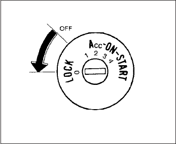
AUTOMATIC TRANSMISSION (if so
equipped)
The ignition lock is designed so the ignition
switch cannot be placed in the LOCK position
and the key removed until the shift selector is
moved to the P (Park) position.
When removing the key from the ignition, make
sure the shift selector is in the P (Park) position.
If the shift selector is not returned to P (Park)
position, the ignition switch cannot be moved to
the LOCK position.
To remove the key from the ignition switch:
1. Shift the shift selector to the P (Park) posi-
tion with the ignition switch in the ON posi-
tion.
2. Place the ignition switch to the LOCK posi-
tion.
3. Remove the key from the ignition.
If the shift selector is shifted to the P (Park)
position after the ignition switch is placed in the
OFF position or when the ignition switch cannot
be turned to the LOCK position, proceed as
follows to remove the key.
1. Move the shift selector into the P (Park)
position.
2. Turn the ignition key slightly toward the ON
position.
3. Turn the key to the LOCK position.
4. Remove the key.
The shift selector is designed so it cannot moved
out of P (Park) and into any of the other gear
positions if the ignition key is turned to OFF
position or if the key is removed from the switch.
The shift selector can be moved if the igni-
tion switch is in the ON position and the
foot brake pedal is depressed.
There is an OFF position between the
LOCK and ACC positions. The OFF position
is indicated by a “1” on the ignition switch.
When the ignition is in the OFF position,
the steering wheel is not locked (for mod-
els with a steering lock mechanism).
In order for the steering wheel to be locked, it
must be turned about 1/8 of a turn clockwise
from the straight up position.
To lock the steering wheel, turn the key to
the LOCK position. Remove the key. To
unlock the steering wheel, insert the key
and turn it gently while rotating the steer-
ing wheel slightly right and left.
If the key will not turn from the LOCK posi-
tion, turn the steering wheel to the left or
right while turning the key to unlock the
key cylinder.
WSD0041
5-10 Starting and driving
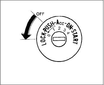
MANUAL TRANSMISSION (if so
equipped)
The ignition switch includes a device that helps
prevent accidental removal of the key while driv-
ing.
The key can only be removed when the ignition
switch is in the LOCK position.
On manual transmission models, to turn the igni-
tion switch to the LOCK position from the ACC or
ON position, place the ignition switch in the OFF
position, push the key in, then place the ignition
switch in LOCK position.
KEY POSITIONS
LOCK: Normal parking position (0)
OFF: (Not used) (1)
ACC: (Accessories) (2)
This position activates electrical accessories
such as the radio when the engine is not running.
ON: Normal operating position (3)
This position turns on the ignition system and the
electrical accessories.
START: (4)
This position starts the engine. As soon as the
engine has started, release the key. It automati-
cally returns to the ON position.
NISSAN VEHICLE IMMOBILIZER
SYSTEM (if so equipped)
The NISSAN Vehicle Immobilizer System will not
allow the engine to start without the use of the
registered key.
If the engine fails to start using a registered key
(for example, when interference is caused by
another registered key, an automated toll road
device or automatic payment device on the key
ring), restart the engine using the following pro-
cedures:
1. Leave the ignition switch in the ON position
for approximately 5 seconds.
2. Turn the ignition switch to the OFF or LOCK
position, and wait approximately 10 sec-
onds.
3. Repeat steps 1 and 2.
4. Restart the engine while holding the device
(which may have caused the interference)
separate from the registered key.
If the no start condition re-occurs, NISSAN rec-
ommends placing the registered key on a sepa-
rate key ring to avoid interference from other
devices.
WSD0052
Starting and driving 5-11

●Make sure the area around the vehicle is
clear.
●Check fluid levels such as engine oil, cool-
ant, brake fluid, and window washer fluid as
frequently as possible, or at least whenever
you refuel.
●Check that all windows and lights are clean.
●Visually inspect tires for their appearance
and condition. Also check tires for proper
inflation.
●Check that all doors are closed.
●Position seat and adjust head restraint and
headrests (if so equipped).
●Adjust inside and outside mirrors.
●Fasten seat belts and ask all passengers to
do likewise.
●Check the operation of warning lights when
the ignition switch is placed in the ON s
D
position. See “Warning/indicator lights and
audible reminders” in the “Instruments and
controls” section of this manual.
1. Apply the parking brake.
2. Automatic transmission:
Move the shift selector to P (Park) or N
(Neutral). P (Park) is recommended.
The shift selector cannot be moved out
of the P (Park) position and into any of
the other gear positions if the ignition
switch is placed in the OFF position or
if the key is removed from the ignition
switch.
The starter is designed not to operate if
the shift selector is in any of the driving
positions.
Manual transmission:
Move the shift selector to N (Neutral). De-
press the clutch pedal to the floor while
cranking the engine.
The starter is designed not to operate
unless the clutch pedal is fully de-
pressed.
3. Crank the engine with your foot off the
accelerator pedal by placing the ignition
switch in the START position. Release the
key when the engine starts. If the engine
starts, but fails to run, repeat the above
procedure.
●
If the engine is very hard to start in extremely
cold weather or when restarting, depress
the accelerator pedal a little (approximately
1/3 to the floor) and hold it and then crank
the engine. Release the key and the accel-
erator pedal when the engine starts.
●If the engine is very hard to start because
it is flooded, depress the accelerator
pedal all the way to the floor and hold it.
Crank the engine for 5-6 seconds. After
cranking the engine, release the accel-
erator pedal. Crank the engine with your
foot off the accelerator pedal by plac-
ing the ignition in the START position.
Release the key when the engine starts. If
the engine starts, but fails to run, repeat
the above procedure.
CAUTION
Do not operate the starter for more than
15 seconds at a time. If the engine does
not start, turn the key off and wait 10
seconds before cranking again, otherwise
the starter could be damaged.
4. Allow the engine to idle for at least 30 sec-
onds after starting. Do not race the engine
while warming it up. Drive at moderate
speed for a short distance first, especially in
cold weather.
BEFORE STARTING THE ENGINE STARTING THE ENGINE
5-12 Starting and driving
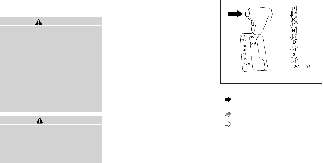
AUTOMATIC TRANSMISSION (if so
equipped)
WARNING
●Do not depress the accelerator pedal
while shifting from P (Park) or N (Neu-
tral) to R (Reverse), D (Drive), 3, 2 or 1.
Always depress the brake pedal until
shifting is completed. Failure to do so
could cause you to lose control and
have an accident.
●Cold engine idle speed is high, so use
caution when shifting into a forward or
reverse gear before the engine has
warmed up.
●Never shift to P (Park) or R (Reverse)
while the vehicle is moving. This could
cause an accident.
CAUTION
●When stopping the vehicle on an uphill
grade, do not hold the vehicle by de-
pressing the accelerator pedal. The foot
brake should be used for this purpose.
●Do not downshift abruptly on slippery
roads. This may cause a loss of control.
The automatic transmission in your vehicle is
electronically controlled to produce maximum
power and smooth operation.
The recommended operating procedures for this
transmission are shown on the following pages.
Follow these procedures for maximum vehicle
performance and driving enjoyment.
Starting the vehicle
1. After starting the engine, fully depress the
foot brake pedal before moving the shift
selector out of the P (Park) position.
2. Keep the foot brake pedal depressed and
move the shift selector into a driving gear.
3. Release the foot brake, then gradually start
the vehicle in motion.
The automatic transmission is designed so
the foot brake pedal MUST be depressed
before shifting from P (Park) to any drive
position while the ignition switch is in the
ON position.
The shift selector cannot be moved out of
the P (Park) position and into any of the
other gear positions if the ignition switch is
placed in the LOCK, OFF or ACC position.
To move the shift selector:
: Push the button while depressing the
brake pedal
: Push the button to shift
: Shift without depressing brake pedal
Shifting
After starting the engine, fully depress the brake
pedal and move the shift selector out of the P
(Park) position.
LSD0151
DRIVING THE VEHICLE
Starting and driving 5-13

WARNING
Apply the parking brake if the shift selec-
tor is in any position while the engine is
not running. Failure to do so could cause
the vehicle to move unexpectedly or roll
away and result in serious personal injury
or property damage.
If the ignition switch is placed in the OFF or ACC
position for any reason while the vehicle is in N
(Neutral), or any D (Drive) position, the ignition
switch cannot be placed in the LOCK position
and the key cannot be removed from the ignition
switch. Move the shift selector to the P (Park)
position, then the ignition switch can be placed in
LOCK.
P (Park):
CAUTION
To prevent transmission damage, use the
P (Park) or R (Reverse) position only when
the vehicle is completely stopped.
Use the P (Park) shift selector position when the
vehicle is parked or when starting the engine.
Make sure the vehicle is completely stopped.
The brake pedal should be depressed to
move the shift selector from N (Neutral) or
any drive position to P (Park). Apply the
parking brake. When parking on a hill, apply the
parking brake first, then move the shift selector
into the P (Park) position.
R (Reverse):
CAUTION
To prevent transmission damage, use the
P (Park) or R (Reverse) position only when
the vehicle is completely stopped.
Use the R (Reverse) position to back up. Make
sure the vehicle is completely stopped before
selecting the R (Reverse) position. The brake
pedal must be depressed to move the shift
selector from P (Park), N (Neutral) or any
drive position to R (Reverse).
N (Neutral):
Neither forward nor reverse gear is engaged. The
engine can be started in this position. You may
shift to N (Neutral) and restart a stalled engine
while the vehicle is moving.
D (Drive):
Use this position for all normal forward driving.
3 (Third gear):
Use this position for driving up and down long
slopes where engine braking would be advanta-
geous.
Do not downshift into the 3 position at speeds
over the following and do not exceed the follow-
ing speeds in the 3 position.
2WD:
99 MPH (160 km/h)
4H:
99 MPH (160 km/h)
4LO:
37 MPH (60 km/h)
2 (Second gear):
Use this position for hill climbing or engine brak-
ing on downhill grades.
Do not downshift into the 2 position at speeds
over the following and do not exceed the follow-
ing speeds in the 2 position.
2WD:
62 MPH (100 km/h)
4H:
62 MPH (100 km/h)
4LO:
21 MPH (35 km/h)
5-14 Starting and driving
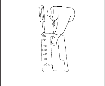
1 (Low gear):
Use this position when climbing steep hills slowly
or slow driving through deep snow, sand or mud,
or for maximum engine braking on steep downhill
grades.
Do not downshift into the 1 position at speeds
over the following and do not exceed the follow-
ing speeds in the 1 position.
2WD:
37 MPH (60 km/h)
4H:
37 MPH (60 km/h)
4LO:
12 MPH (20 km/h)
Shift lock release
If the battery is discharged, the shift selector may
not be moved from the P (Park) position even with
the brake pedal depressed.
To move the shift selector, release the shift lock.
The shift selector can be moved to N (Neutral).
However, the steering wheel will be locked un-
less the ignition switch is placed in the ON posi-
tion (for models with a steering lock mechanism).
This allows the vehicle to be moved if the battery
is discharged.
To push the shift lock release, complete the fol-
lowing procedure:
1. Place the ignition switch in the LOCK posi-
tion and remove the key.
2. Apply the parking brake.
3. Remove the shift lock release cover as
shown.
4. Insert a small screwdriver in the shift lock
release slot and push down.
5. Move the shift selector to the N (Neutral)
position while holding down the shift lock
release.
6. Place the ignition switch in the ON position
to unlock the steering wheel (for models with
a steering lock mechanism).
7. Now the vehicle may be moved to the de-
sired location.
If the shift selector cannot be moved out of P
(Park), have a NISSAN dealer check the auto-
matic transmission system as soon as possible.
LSD0141
Starting and driving 5-15
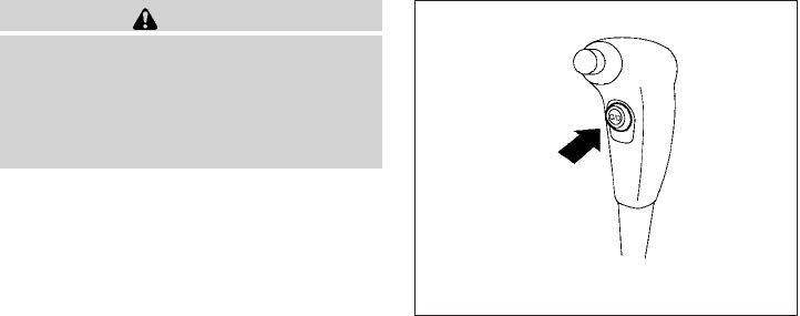
WARNING
If the shift selector cannot be moved from
the P (Park) position while the engine is
running and the brake pedal is depressed,
the stop lights may not work. Malfunction-
ing stop lights could cause an accident
injuring yourself and others.
Accelerator downshift
— in D position —
For passing or hill climbing, depress the accel-
erator pedal to the floor. This shifts the transmis-
sion down into a lower gear, depending on the
vehicle speed. Overdrive switch
Each time your vehicle is started, the transmis-
sion is automatically “reset” to overdrive ON.
ON: With the engine running and the
shift selector in the D (Drive)
position, the transmission upshifts
into Overdrive as vehicle speed
increases.
Overdrive does not engage until the engine
has reached operating temperature.
OFF: For driving up and down long
slopes where engine braking is nec-
essary push the Overdrive switch
once. The O/D OFF indicator light
in the instrument panel comes on at
this time.
When cruising at a low speed or climbing a
gentle slope, you may feel uncomfortable shift
shocks as the transmission shifts into and out of
Overdrive repeatedly. In this case, depress the
Overdrive switch to turn the Overdrive off. The
O/D OFF indicator light in the instrument panel
comes on at this time.
When driving conditions change, depress the
Overdrive switch to turn the Overdrive on.
Remember not to drive at high speeds for ex-
tended periods of time with the Overdrive off.
This reduces fuel economy.
LSD0142
5-16 Starting and driving
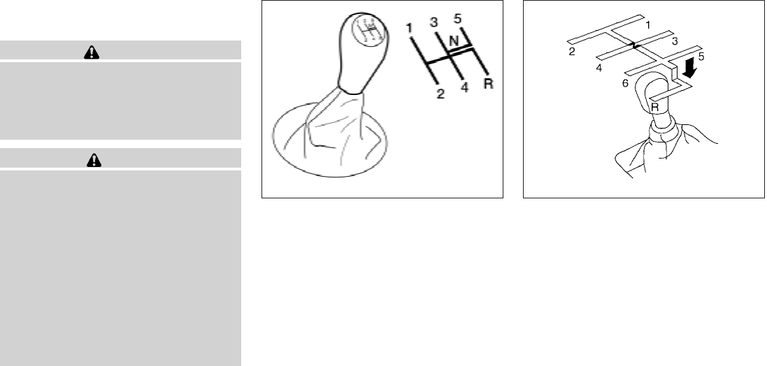
MANUAL TRANSMISSION (if so
equipped)
WARNING
●Do not downshift abruptly on slippery
roads. This may cause a loss of control.
●Do not over-rev the engine when shift-
ing to a lower gear. This may cause a
loss of control or engine damage.
CAUTION
●Do not rest your foot on the clutch pedal
while driving. This may cause clutch
damage.
●Fully depress the clutch pedal before
shifting to help prevent transmission
damage.
●Stop your vehicle completely before
shifting into R (Reverse).
●When the vehicle is stopped with the
engine running (for example, at a stop
light), shift to N (Neutral) and release
the clutch pedal with the foot brake
applied.
Shifting
To change gears, or when upshifting or down-
shifting, depress the clutch pedal fully, shift into
the appropriate gear, then release the clutch
slowly and smoothly.
To ensure smooth gear changes, fully depress the
clutch pedal before operating the shift selector. If
the clutch pedal is not fully depressed before the
transmission is shifted, a gear noise may be heard.
Transmission damage could occur.
Start the vehicle in 1st gear and shift to 2nd, 3rd,
4th, 5th and 6th gear in sequence according to
vehicle speed.
To back up depress the shift selector and then
move it to the R (Reverse) position after stopping
the vehicle completely.
On the 5-speed manual transmission model, you
cannot shift directly from the 5th gear into R
(Reverse). First shift into N (Neutral), then in to R
(Reverse) after stopping the vehicle completely.
If it is difficult to move the shift selector into R
(Reverse) or 1 (First), shift into N (Neutral), then
release the clutch pedal. Fully depress the clutch
pedal again and shift into R (Reverse) or 1 (First).
5 - speed
WSD0154
6 - speed
LSD0148
Starting and driving 5-17
If your vehicle is equipped with 4-wheel drive, see
“Transfer case shifting procedures” later in this
section.
Suggested upshift speeds
The following are suggested vehicle speeds for
shifting into a higher gear. These suggestions
relate to fuel economy and vehicle performance.
Actual upshift speeds will vary according to road
conditions, the weather and individual driving
habits.
●For QR25DE two-wheel drive models:
GEAR CHANGE MPH (km/h)
1st to 2nd 11 (17)
2nd to 3rd 15 (24)
3rd to 4th 24 (38)
4th to 5th 35 (56)
●For VQ40DE two-wheel drive models and
four-wheel drive models (2H and 4H posi-
tion):
GEAR CHANGE MPH (km/h)
1st to 2nd 11 (17)
2nd to 3rd 17 (27)
3rd to 4th 25 (40)
4th to 5th 32 (51)
5th to 6th 45 (72)
Suggested maximum speed in each
gear
Downshift to a lower gear if the engine is not
running smoothly, or if you need to accelerate.
Do not exceed the maximum suggested speed
(shown below) in any gear. For level road driving,
use the highest gear suggested for that speed.
Always observe posted speed limits, and drive
according to the road conditions, which will en-
sure safe operation. Do not over-rev the engine
when shifting to a lower gear as it may cause
engine damage or loss of vehicle control.
Allowable maximum speed in each gear:
2–wheel drive models (QR25DE engine)
GEAR MPH (km/h)
1st 34 (54)
2nd 58 (94)
3rd 89 (144)
4th —
5th —
2–wheel drive models (VQ40DE engine)
GEAR MPH (km/h)
1st 35 (56)
2nd 60 (97)
3rd 87 (141)
4th —
5th —
4–wheel drive models (VQ40DE engine)
2H/4H position
GEAR MPH (km/h)
1st 33 (54)
2nd 58 (93)
3rd 84 (135)
4th —
5th —
6th —
4L position
GEAR MPH (km/h)
1st 12 (20)
2nd 22 (35)
3rd 32 (51)
4th 43 (70)
5th 55 (89)
6th —
5-18 Starting and driving
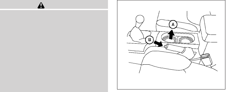
WARNING
●Be sure the parking brake is fully re-
leased before driving. Failure to do so
can cause brake failure and lead to an
accident.
●Do not release the parking brake from
outside the vehicle.
●Do not use the shift selector in place of
the parking brake. When parking, be
sure the parking brake is fully engaged.
●Do not leave children unattended in a
vehicle. They could release the parking
brake and cause an accident.
To engage: Pull the parking brake lever up s
A.
To release:
1. Firmly apply the foot brake.
2. Manual transmission models:
Place the shift selector in the N (Neutral)
position.
Automatic transmission models:
Move the shift selector to the P (Park) posi-
tion.
3. While pulling up on the parking brake lever
slightly, push the button s
Band lower the
lever completely .
4. Before driving, be sure the brake warning
light goes out.
LSD0150
PARKING BRAKE
Starting and driving 5-19
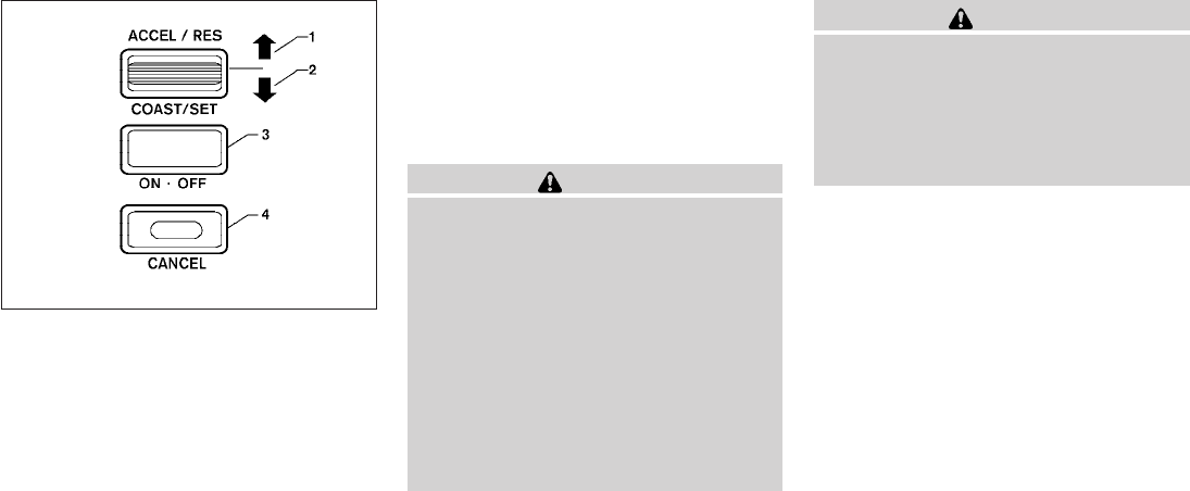
1. ACCEL/RES switch
2. COAST/SET switch
3. ON/OFF switch
4. CANCEL switch
PRECAUTIONS ON CRUISE
CONTROL
●If the cruise control system malfunctions, it
cancels automatically. The SET indicator
light in the instrument panel then blinks to
warn the driver.
●If the SET indicator light blinks, turn the
cruise control main switch off and have the
system checked by a NISSAN dealer.
●The SET indicator light may blink when the
cruise control main switch is turned ON
while pushing the ACCEL/RES,
COAST/SET, or CANCEL switch (located
on the steering wheel). To properly set the
cruise control system, use the following pro-
cedures.
WARNING
Do not use the cruise control when driving
under the following conditions:
●When it is not possible to keep the
vehicle at a set speed.
●In heavy traffic or in traffic that varies in
speed.
●On winding or hilly roads.
●On slippery roads (rain, snow, ice, etc.).
●In very windy areas.
Doing so could cause a loss of vehicle
control and result in an accident.
CAUTION
On manual transmission models, do not
shift into N (Neutral) without depressing
the clutch pedal when the cruise control is
set. Should this occur, depress the clutch
pedal and turn the main switch off imme-
diately. Failure to do so may cause engine
damage.
CRUISE CONTROL OPERATIONS
The cruise control allows driving at a speed be-
tween 25 - 89 MPH (40 - 144 km/h) without
keeping your foot on the accelerator pedal.
To turn on the cruise control, push the main
switch. The CRUISE indicator light in the instru-
ment panel comes on.
To set cruising speed, accelerate the vehicle to
the desired speed, push the COAST/SET switch
and release it. The SET indicator light in the
instrument panel comes on. Take your foot off the
accelerator pedal. Your vehicle maintains the set
speed.
●To pass another vehicle, depress the ac-
celerator pedal. When you release the
pedal, the vehicle returns to the previously
set speed.
WSD0153
CRUISE CONTROL (if so equipped)
5-20 Starting and driving

●The vehicle may not maintain the set speed
when going up or down steep hills. If this
happens, drive without the cruise control.
To cancel the preset speed, use one of the
following three methods.
●Push the CANCEL button; the SET indicator
light in the instrument panel goes out.
●Tap the brake pedal; the SET indicator light
goes out.
●Turn the main switch off. Both the CRUISE
indicator light and SET indicator light in the
instrument panel go out.
The cruise control is automatically canceled and
the SET light in the instrument panel goes out if:
●you depress the brake or clutch pedal while
pushing the ACCEL/RES or COAST/SET
switch. The preset speed is deleted from
memory.
●the vehicle slows down more than 8 MPH
(13 km/h) below the set speed.
●you depress the clutch pedal (manual trans-
mission), or move the shift selector to N
(Neutral) (automatic transmission).
To reset at a faster cruising speed, use one
of the following three methods.
●Depress the accelerator pedal. When the
vehicle attains the desired speed, push and
release the COAST/SET switch.
●Push and hold the ACCEL/RES switch.
When the vehicle attains the speed you de-
sire, release the switch.
●Push and release the ACCEL/RES switch.
Each time you do this, the set speed in-
creases by about 1 MPH (1.6 km/h).
To reset at a slower cruising speed, use one
of the following three methods.
●Lightly tap the brake pedal. When the ve-
hicle attains the desired speed, push the
COAST/SET switch and release it.
●Push and hold the COAST/SET switch. Re-
lease the switch when the vehicle slows to
the desired speed.
●Push and release the COAST/SET switch.
Each time you do this, the set speed de-
creases by about 1 MPH (1.6 km/h).
To resume the preset speed, push and re-
lease the ACCEL/RES switch. The vehicle re-
turns to the last set cruising speed when the
vehicle speed is over 25 MPH (40 km/h).
CAUTION
During the first 1,200 miles (2,000 km),
follow these recommendations to obtain
maximum engine performance and en-
sure the future reliability and economy of
your new vehicle. Failure to follow these
recommendations may result in short-
ened engine life and reduced engine
performance.
●Avoid driving for long periods at constant
speed, either fast or slow, and do not run the
engine over 4,000 rpm.
●Do not accelerate at full throttle in any gear.
●Avoid quick starts.
●Avoid hard braking as much as possible.
●Do not tow a trailer for the first 500 miles
(800 km). Your engine, axle or other parts
could be damaged.
BREAK-IN SCHEDULE
Starting and driving 5-21
●Accelerate slowly and smoothly. Maintain
cruising speeds with a constant accelerator
position.
●Drive at moderate speeds on the highway.
Driving at high speed lowers fuel economy.
●Avoid unnecessary stopping and braking.
Maintain a safe distance behind other ve-
hicles.
●Use a proper gear range which suits road
conditions. On level roads, shift into high
gear as soon as possible.
●Avoid unnecessary engine idling.
●Keep your engine tuned up.
●Follow the recommended periodic mainte-
nance schedule.
●Keep the tires inflated to the correct pres-
sure. Low tire pressure increases tire wear
and lowers fuel economy.
●Keep the front wheels in correct alignment.
Improper alignment increases tire wear and
lowers fuel economy.
●Air conditioner operation lowers fuel
economy. Use the air conditioner only when
necessary.
●When cruising at highway speeds, it is more
economical to use the air conditioner and
leave the windows closed to reduce drag.
●For vehicles equipped with , use 4H
or 4L position only when necessary. Four-
wheel drive operation lowers fuel economy.
WARNING
●For 4WD equipped vehicles, do not at-
tempt to raise two wheels off the
ground and shift the transmission to
any drive or reverse position with the
engine running. Doing so may result in
drivetrain damage or unexpected ve-
hicle movement which could result in
serious vehicle damage or personal
injury.
●Do not attempt to test a 4WD equipped
vehicle on a 2-wheel dynamometer
(such as the dynamometers used by
some states for emissions testing), or
similar equipment even if the other two
wheels are raised off the ground. Make
sure you inform test facility personnel
that your vehicle is equipped with 4WD
before it is placed on a dynamometer.
Using the wrong test equipment may
result in drivetrain damage or unex-
pected vehicle movement which could
result in serious vehicle damage or per-
sonal injury.
INCREASING FUEL ECONOMY USING FOUR WHEEL DRIVE
(4WD)
5-22 Starting and driving

CAUTION
●Do not drive the vehicle in the 4H or 4LO
position on dry hard surface roads. Driv-
ing on dry, hard surfaces in 4H or 4LO
may cause unnecessary noise, tire wear
and increased fuel consumption.
If the 4WD warning light turns on when
you are driving on dry hard surface
roads:
– in the 4H position, shift the 4WD shift
switch to 2WD.
– in the 4LO position for automatic
transmission vehicles, stop the ve-
hicle and shift the shift selector to
the N position with the brake pedal
depressed and shift the 4WD shift
switch to 2WD.
– in the 4LO position for manual trans-
mission vehicles, stop the vehicle
and shift the shift selector to the N
position with the clutch pedal de-
pressed and shift the 4WD shift
switch to 2WD.
●If the warning light is still on after the
above operation, have your vehicle
checked by a NISSAN dealer as soon as
possible.
TRANSFER CASE SHIFTING
PROCEDURES
The part time 4WD system provides 3 positions
(2WD, 4H and 4LO), so you can select the
desired drive mode according to the driving con-
ditions.
Starting and driving 5-23
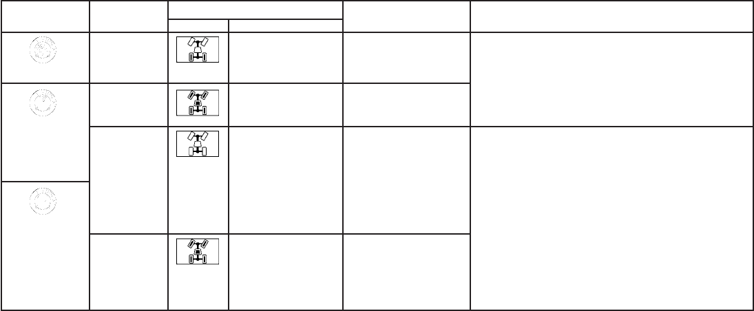
2WD or 4WD shift procedure:
4WD Shift
Switch Position Wheels Driven Indicator Light Use Conditions 4WD Shift Procedure
4WD shift Transfer 4LO position
2WD
Rear wheels For driving on dry, paved
roads (Economy drive)
Move the 4WD switch.
2WD <—> 4H
4WD shift indicator light will indicate transfer shift position en-
gaged.
4H
4 wheels For driving on rocky, sandy
or snow-covered roads
Neutral
*1
May blink
Neutral disengages the
automatic transmission
mechanical parking lock,
which will allow the vehicle
to roll. Do not leave the
transfer shift position in
Neutral.*2
1. Stop the vehicle.
2. For automatic transmission vehicles: Shift the shift selector
to the (N) position with the brake pedal depressed.
For manual transmission vehicles: Shift the shift selector to
the (N) position with the clutch depressed.
3. For automatic transmission vehicles: Depress and turn the
4WD shift switch to 4LO or 4H with the brake pedal de-
pressed.
For manual transmission vehicles: Depress and turn the
4WD switch to 4LO or 4H with the clutch pedal depressed.
THE TRANSFER CASE DOES NOT ENGAGE BETWEEN 4H
AND 4LO (OR 4LO TO 4H) UNLESS YOU HAVE FIRST
STOPPED THE VEHICLE, DEPRESSED THE BRAKE PEDAL
AND MOVED THE SHIFT SELECTOR TO NEUTRAL FOR AU-
TOMATIC TRANSMISSION VEHICLES. FOR MANUAL TRANS-
MISSION VEHICLES YOU MUST MOVE THE SHIFT SELEC-
TOR TO NEUTRAL. *3
4LO
4 wheels
Illuminated
For use when maximum
power and traction is re-
quired (for example: on
steep grades or rocky,
sandy, muddy roads)
*1: Before moving the shift selector from neutral, wait until the 4LO indicator light stays on steady. This indicates that the 4WD shift procedure is completed
and the transfer gear is correctly set in the 4LO position. If the vehicle is shifted into gear before the indicator is on steady, the transfer gear may grind,
not engage correctly or stay in the neutral position.
- If the 4WD warning light illuminates, perform the following procedure to return the transfer case to correct operating condition.
1. Turn off the engine by turning the ignition switch 9OFF9.
5-24 Starting and driving

2. Start the engine.
- Check that the 4WD warning light turns off. If the 4WD warning light illuminates, have the system checked by a NISSAN dealer.
3. Apply the parking brake, for automatic transmission vehicles, depress the brake pedal and move the shift selector to Neutral position. For manual
transmission vehicles, move the shift selector to Neutral position.
4. With the brake pedal depressed on automatic transmission vehicles or with the clutch pedal depressed on manual transmission vehicles, move the
4WD shift switch to desired mode.
- Be sure to wait until the transfer gear change completes before shifting the shift selector from Neutral position.
*2: While changing in and out of 4LO, the ignition key must be ON and the vehicle’s engine must be running for a shift to take place and for the indicator
lights (4WD shift and 4LO position indicator) to be operable. Otherwise, the shift will not take place and no indicator lights will be on or flashing.
*3: Make sure the transfer 4LO position indicator light turns on when you shift the 4WD shift switch to 4LO. The indicator light (if so equipped) will
also turn on when 4LO is selected. See “Vehicle dynamic control (VDC) system” later in this section.
Starting and driving 5-25

The transfer case 4WD shift switch is used to
select either 2WD or 4WD depending on the
driving conditions. There are three types of drive
modes available, 2WD, 4H and 4LO.
The 4WD shift switch electronically controls the
transfer case operation. Rotate the switch to
move between each mode, 2WD, 4H and 4LO.
To change into or out of 4LO, the vehicle
MUST be stationary, shift the shift selector
to Neutral (N), and for automatic transmis-
sion vehicles depress the brake pedal or
for manual transmission vehicles depress
the clutch pedal. The switch must be de-
pressed and turned when changing into or
out of 4LO.
WARNING
●When parking, apply the parking brake
before stopping the engine and make
sure that the 4WD shift indicator light is
on and the ATP warning light goes off.
Otherwise, the vehicle could unexpect-
edly move even if the automatic trans-
mission is in the P position.
●The 4LO indicator light must stop blink-
ing and remain illuminated or turn off
before shifting the transmission into
gear. If the shift selector is shifted from
the (N) position to any other gear when
the 4LO indicator light is blinking, the
vehicle may move unexpectedly.
CAUTION
●Never shift the 4WD shift switch be-
tween 4LO and 4H while driving.
●The 4H position provides greater trac-
tion. Avoid excessive speed, as it will
cause increased fuel consumption and
higher oil temperatures, and could
damage drivetrain components.
Speeds over 62 MPH (100 km/h) in 4H is
not recommended
●The 4LO position provides maximum
power and traction. Avoid raising ve-
hicle speed excessively, as the maxi-
mum speed is approximately 31 MPH
(50 km/h).
●When driving straight, shift the 4WD
shift switch to the 2WD or 4H position.
Do not move the 4WD shift switch when
making a turn or reversing.
●Do not shift the 4WD shift switch (be-
tween 2WD and 4H) while driving on
steep downhill grades. Use the engine
brake and low automatic transmission
gears (D1 or D2) or manual transmis-
sion (1st gear or 2nd gear) for engine
braking.
●Do not operate the 4WD shift switch
(between 2WD and 4H) with the rear
wheels spinning.
●Do not drive on dry hard surface roads
in the 4H or 4LO position. Driving on dry
hard surfaces in 4H or 4LO may cause
unnecessary noise and tire wear.
NISSAN recommends driving in the
2WD position under these conditions.
●The 4WD transfer case may not be
shifted between 4H and 4LO at low am-
bient temperatures and the transfer
4LO position indicator light may blink
even when the 4WD shift switch is
shifted. After driving for a while you can
change the 4WD transfer case between
4H and 4LO.
When driving on rough roads,
●Set the 4WD shift switch to 4H or 4LO.
●Drive carefully according to the road surface
conditions.
5-26 Starting and driving
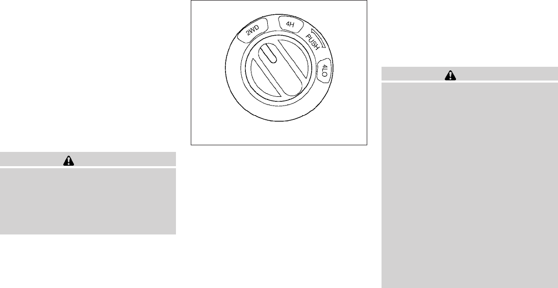
When the vehicle is stuck,
●Set the 4WD shift switch to 4H or 4LO.
●Use the Electronic Locking Rear Differential
(E-Lock) system (if so equipped). Turn the
switch ON while the vehicle is stationary and
apply the throttle to try to free the vehicle.
●If it is difficult to free the vehicle, rock the
vehicle back and forth between reverse and
drive gears.
●If the vehicle is stuck deep in mud, place
stones or wooden blocks under the tires.
Then try the recovery procedures above. Tire
chains may be effective.
CAUTION
●Do not spin the tires excessively. Tires
will sink deep into the mud, making it
difficult to free the vehicle.
●Avoid shifting gears with the engine
running at high speeds as this may
cause malfunction.
4WD shift switch operations
●Shift the 4WD shift switch to either the
2WD, 4H or 4LO position, depending on
driving conditions.
●If the 4WD shift switch is operated
while making a turn, accelerating or
decelerating or if the key switch is
turned off while in the 4H or 4LO posi-
tion, you may feel a jolt. This is not
abnormal.
●When the vehicle is stopped after mak-
ing a turn, you may feel a slight jolt
after the shift selector is shifted to N or
P. This occurs because the transfer
clutch is released and not because of a
malfunction.
CAUTION
●When driving straight, shift the 4WD
shift switch to the 2WD or 4H position.
Do not move the 4WD shift switch when
making a turn or reversing.
●Do not shift the 4WD shift switch while
driving on steep downhill grades. Use
the engine brake and low automatic
transmission gears (D1 or D2) or
manual transmission (1st gear or 2nd
gear) for engine braking.
●Do not operate the 4WD shift switch
with the rear wheels spinning.
●Before placing the 4WD shift switch in
the 4H position from 2WD, ensure the
vehicle speed is less than 62 MPH (100
km/h). Failure to do so can damage the
4WD system.
●Never shift the 4WD shift switch be-
tween 4LO and 4H while driving.
LSD0145
Starting and driving 5-27
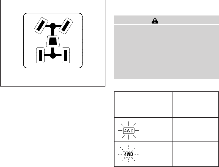
4WD shift indicator light
The 4WD shift indicator light is located in the
odometer display.
The light should turn off within 1 second after
turning the ignition switch to the ON position.
While the engine is running, the 4WD shift indi-
cator light will illuminate the position selected by
the 4WD shift switch.
●The 4WD shift indicator light may blink
while shifting from one drive mode to
the other. When the shifting is com-
pleted, the 4WD shift indicator light
will come on.
●If the 4WD warning light comes on, the
4WD indicator light goes out.
CAUTION
If the 4WD shift indicator light indication
changes to 2WD when the 4WD shift
switch is shifted to the 4H position at low
ambient temperatures, the 2WD mode
may be being engaged due to malfunc-
tioning drive system. If the indicator does
not return to normal and the 4WD warning
light comes on, have the system checked
by the nearest NISSAN dealer.
4WD warning light
Warning light Comes on or blinks
when:
Comes on There is a malfunc-
tion in the 4–wheel
drive system
Blinks slowly The difference in
wheel rotation is
large
The 4WD warning light is located in the meter.
LSD0147
5-28 Starting and driving

The 4WD warning light comes on when the igni-
tion switch is turned to ON. It turns off soon after
the engine is started.
If any malfunction occurs in the 4WD system
when the ignition switch is ON, the warning light
will either remain illuminated or blink.
If the 4WD warning light comes on, the 4WD
shift indicator light goes out.
A large difference between the diameters of front
and rear wheels will make the warning light blink
slowly (about once per two seconds). Change
the 4WD shift switch into 2WD and do not drive
fast.
CAUTION
●If the warning light comes on or blinks
slowly during operation, have your ve-
hicle checked by a NISSAN dealer as
soon as possible.
●Shifting between 4H and 4LO is not
recommended when the 4WD warning
light turns on.
●When the warning light comes on, the
2WD mode may be engaged even if the
4WD shift switch is in 4H. Be especially
careful when driving. If corresponding
parts are malfunctioning, the 4WD
mode will not be engaged even if the
4WD shift switch is shifted.
●Do not drive the vehicle in the 4H or 4LO
position on dry hard surface roads. Driv-
ing on dry, hard surfaces in 4H or 4LO
may cause unnecessary noise, tire wear
and increased fuel consumption.
If the 4WD warning light turns on when
you are driving on dry hard surface
roads:
– in the 4H position, shift the 4WD shift
switch to 2WD.
– in the 4LO position for automatic
transmission vehicles, stop the ve-
hicle and shift the shift selector to
the N position with the brake pedal
depressed and shift the 4WD shift
switch to 2WD.
– in the 4LO position for manual trans-
mission vehicles, stop the vehicle
and shift the shift selector to the N
position with the clutch pedal de-
pressed and shift the 4WD shift
switch to 2WD.
●If the warning light is still on after the
above operation, have your vehicle
checked by a NISSAN dealer as soon as
possible.
●The transfer case may be damaged if
you continue driving with the warning
light blinking.
Starting and driving 5-29

The E-Lock system can provide additional trac-
tion and should only be used when a vehicle has
become or is becoming stuck. This system oper-
ates by electronically “locking” the two rear drive
wheels together, allowing them to turn at the
same speed. The system is used when it is not
possible to free a stuck vehicle even when using
the 4LO position (4 wheel drive vehicles).
When added traction is required, activate the
E-Lock system by pushing the switch ON. See
“Electronic locking rear differential (E-Lock) sys-
tem switch” in the “Instruments and Controls”
section. Once the system fully engages, the indi-
cator light in the instrument panel will remain ON.
When the system is activated, both rear wheels
will engage, providing added traction.
The rear wheels may momentarily slip or move to
engage the system, and the system will only
engage up to approximately 4 MPH (7 km/h).
Once the vehicle is free, the system should be
turned OFF and driving resumed.
The Anti-Lock Brake (ABS) system is disabled
and the ABS light illuminates when the E-Lock
system is ON. Also, the Vehicle Dynamic Control
(VDC) system is disabled and the VDC light
illuminates when the E-Lock system is ON.
WARNING
●Never leave the E-Lock system ON
when driving on paved or hard-surfaced
roads. Turning the vehicle may result in
the rear wheels slipping and result in an
accident and personal injury. After us-
ing the E-Lock system to free the ve-
hicle, turn the system OFF.
●Use the E-Lock system only when free-
ing a stuck vehicle. Try the 4LO position
before using the E-Lock system. Never
use the E-Lock system on a slippery
road surface such as snow or ice sur-
face. Using the E-Lock system when
driving in these road conditions may
cause unexpected movement of the ve-
hicle during engine braking, accelerat-
ing or turning, which may result in an
accident and serious personal injury.
CAUTION
●After using the E-Lock system, turn the
switch OFF to prevent possible damage
to driveline components from extended
use.
●Do not drive the vehicle at speeds faster
than 12 mph (20 km/h) when the system
is engaged. Doing so could damage
drivetrain components.
●Do not turn on the E-lock system while
the tires are spinning. Doing so could
damage drivetrain components.
ELECTRONIC LOCKING REAR
DIFFERENTIAL (E-Lock) SYSTEM (if
so equipped)
5-30 Starting and driving
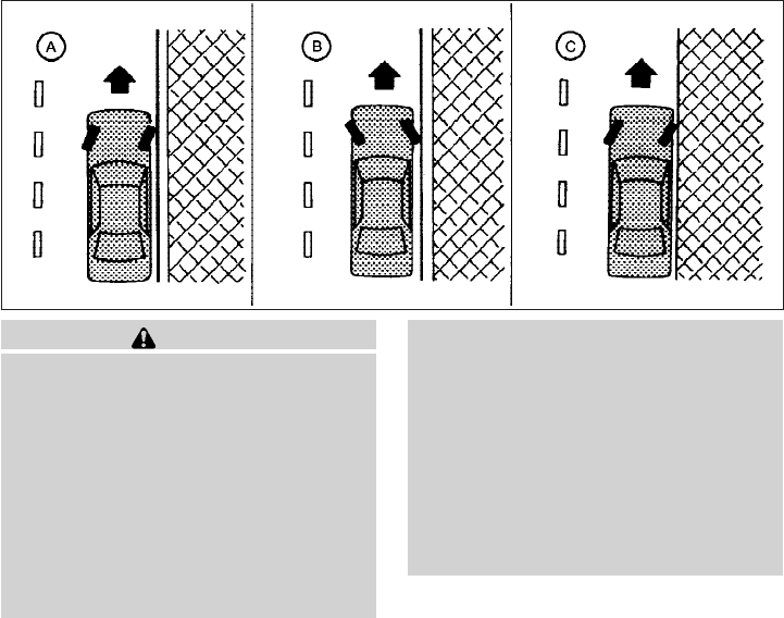
WARNING
●Do not stop or park the vehicle over
flammable materials such as dry grass,
waste paper or rags. They may ignite
and cause a fire.
●Safe parking procedures require that
both the parking brake be set and the
transmission placed into P (Park) for
automatic transmission models or in an
appropriate gear for manual transmis-
sion models. Failure to do so could
cause the vehicle to move unexpectedly
or roll away and result in an accident.
Make sure the shift selector has been
pushed as far forward as it can go and
cannot be moved without depressing
the foot brake pedal.
●Never leave the engine running while
the vehicle is unattended.
●Do not leave children unattended inside
the vehicle. They could unknowingly ac-
tivate switches or controls. Unattended
children could become involved in seri-
ous accidents.
1. Firmly apply the parking brake.
2. Manual transmission models:
Place the shift selector in the R (Reverse)
position. When parking on an uphill grade,
place the shift selector in 1st gear.
Automatic transmission models:
Move the shift selector to the P (Park) posi-
tion.
3. To help prevent the vehicle from rolling into
traffic when parked on an incline, it is a good
practice to turn the wheels as illustrated.
●HEADED DOWNHILL WITH CURB: s
A
Turn the wheels into the curb and move the
vehicle forward until the curb side wheel
gently touches the curb.
●HEADED UPHILL WITH CURB: s
B
Turn the wheels away from the curb and
move the vehicle back until the curb side
wheel gently touches the curb.
●HEADED UPHILL OR DOWNHILL, NO
CURB: s
C
Turn the wheels toward the side of the road
so the vehicle will move away from the cen-
ter of the road if it moves.
4. Turn the ignition switch to the LOCK posi-
tion and remove the key.
WSD0050
PARKING/PARKING ON HILLS
Starting and driving 5-31

The power assisted steering uses a hydraulic
pump, driven by the engine, to assist steering.
If the engine stops or the drive belt breaks, you
will still have control of the vehicle. However,
much greater steering effort is needed, especially
in sharp turns and at low speeds.
WARNING
If the engine is not running or is turned off
while driving, the power assist for the
steering will not work. Steering will be
harder to operate.
The brake system has two separate hydraulic
circuits. If one circuit malfunctions, you will still
have braking at 2 wheels.
BRAKE PRECAUTIONS
Vacuum assisted brakes
The brake booster aids braking by using engine
vacuum. If the engine stops, you can stop the
vehicle by depressing the brake pedal. However,
greater foot pressure on the brake pedal will be
required to stop the vehicle and stopping dis-
tance will be longer.
Using the brakes
Avoid resting your foot on the brake pedal while
driving. This will overheat the brakes, wear out the
brake pads faster, and reduce gas mileage.
To help reduce brake wear and to prevent the
brakes from overheating, reduce speed and
downshift to a lower gear before going down a
slope or long grade. Overheated brakes may
reduce braking performance and could result in
loss of vehicle control.
WARNING
●While driving on a slippery surface, be
careful when braking, accelerating or
downshifting. Abrupt braking or accel-
erating could cause the wheels to skid
and result in an accident.
●If the engine is not running or is turned
off while driving, the power assist for
the brakes will not work. Braking will be
harder.
Wet brakes
When the vehicle is washed or driven through
water, the brakes may get wet. As a result, your
braking distance will be longer and the vehicle
may pull to one side during braking.
To dry the brakes, drive the vehicle at a safe
speed while lightly pressing the brake pedal to
heat up the brakes. Do this until the brakes return
to normal. Avoid driving the vehicle at high
speeds until the brakes function correctly.
Parking brake break-in
Break-in the parking brake shoes whenever the
stopping effect of the parking brake is weakened
or whenever the parking brake shoes and/or
drum/rotors are replaced, in order to assure the
best brake performance.
POWER STEERING BRAKE SYSTEM
5-32 Starting and driving

This procedure is described in the vehicle service
manual and can be performed by a NISSAN
dealer.
ANTI-LOCK BRAKING SYSTEM
(ABS)
WARNING
●The Anti-lock Braking System (ABS) is a
sophisticated device, but it cannot pre-
vent accidents resulting from careless
or dangerous driving techniques. It can
help maintain vehicle control during
braking on slippery surfaces. Remem-
ber that stopping distances on slippery
surfaces will be longer than on normal
surfaces even with ABS. Stopping dis-
tances may also be longer on rough,
gravel or snow covered roads, or if you
are using tire chains. Always maintain a
safe distance from the vehicle in front
of you. Ultimately, the driver is respon-
sible for safety.
●Tire type and condition may also affect
braking effectiveness.
– When replacing tires, install the
specified size of tires on all four
wheels.
– When installing a spare tire, make
sure that it is the proper size and type
as specified on the Tire and Loading
Information label. See “Tire and
Loading Information label” in the
“Technical and consumer informa-
tion” section of this manual.
– For detailed information, see
“Wheels and tires” in the “Mainte-
nance and do-it-yourself” section of
this manual.
The Anti-lock Braking System (ABS) controls the
brakes so the wheels do not lock during hard
braking or when braking on slippery surfaces.
The system detects the rotation speed at each
wheel and varies the brake fluid pressure to pre-
vent each wheel from locking and sliding. By
preventing each wheel from locking, the system
helps the driver maintain steering control and
helps to minimize swerving and spinning on slip-
pery surfaces.
Using the system
Depress the brake pedal and hold it down. De-
press the brake pedal with firm steady pressure,
but do not pump the brakes. The ABS will oper-
ate to prevent the wheels from locking up. Steer
the vehicle to avoid obstacles.
WARNING
Do not pump the brake pedal. Doing so
may result in increased stopping
distances.
Self-test feature
The ABS includes electronic sensors, electric
pumps, hydraulic solenoids and a computer. The
computer has a built-in diagnostic feature that
tests the system each time you start the engine
and move the vehicle at a low speed in forward or
reverse. When the self-test occurs, you may hear
a “clunk”noise and/or feel a pulsation in the brake
pedal. This is normal and does not indicate a
malfunction. If the computer senses a malfunc-
tion, it switches the ABS off and illuminates the
ABS warning light on the instrument panel. The
brake system then operates normally, but without
anti-lock assistance.
If the ABS warning light illuminates during the
self-test or while driving, have the vehicle
checked by a NISSAN dealer.
Normal operation
The ABS operates at speeds above3-6MPH(5
- 10 km/h). The speed varies according to road
conditions.
Starting and driving 5-33
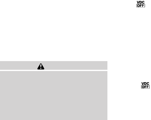
When the ABS senses that 1 or more wheels are
close to locking up, the actuator rapidly applies
and releases hydraulic pressure. This action is
similar to pumping the brakes very quickly. You
may feel a pulsation in the brake pedal and hear a
noise from under the hood or feel a vibration from
the actuator when it is operating. This is normal
and indicates that the ABS is operating properly.
However, the pulsation may indicate that road
conditions are hazardous and extra care is re-
quired while driving.
●ABLS is a form of traction control using
sensors from the Anti-lock Brake System
(ABS) to transfer power from a slipping drive
wheel to a wheel with more traction. The
ABLS system applies braking to the slipping
wheel, which helps redirect power to an-
other wheel.
●On 4WD models the ABLS system operates
in both 4H and 4LO modes. If 4WD mode is
engaged, the ABLS system will operate for
both drive axles. On 2WD vehicles, the
ABLS system operates on the drive axle
only.
●The ABLS system is always ON unless the
system detects brake pad overheating. If
high brake pad temperature is detected, it
will turn OFF, but normal brake function will
continue. ABLS will function even when the
VDC system (if so equipped) is turned OFF.
WARNING
The ABLS system provides increased trac-
tion, but will not prevent accidents due to
abrupt steering operation or by careless
driving or dangerous driving practices.
Reduce vehicle speed and be especially
careful when driving and cornering on
slippery surfaces, and always drive
carefully.
The Vehicle Dynamic Control (VDC) system uses
various sensors to monitor driver inputs and ve-
hicle motion. Under certain driving situations, the
system will control braking and engine output to
help keep the vehicle on its steered path.
●When the Vehicle Dynamic Control (VDC)
system is operating, the SLIP indicator in the
instrument panel blinks.
●If the 4WD transfer case is shifted into 4LO
the indicator light will come on and
the VDC system will be turned off. See
“Transfer case shifting procedures” earlier in
this section.
●If the SLIP indicator blinks, the road condi-
tions may be slippery. Be sure to adjust your
speed and driving to these conditions. See
“Slip indicator light”, and “Vehicle Dynamic
Control (VDC) off indicator light” in the “In-
struments and controls” section.
If the battery is removed or discharged, the trac-
tion control system may be disabled and the
SLIP and indicator lights will not turn off
after 2 seconds when the ignition switch is turned
to the ON position. Perform the following proce-
dure to reset the system:
●Start the engine and set the steering wheel
in the straight forward position.
ACTIVE BRAKE LIMITED SLIP (ABLS)
SYSTEM (if so equipped) VEHICLE DYNAMIC CONTROL (VDC)
SYSTEM (if so equipped)
5-34 Starting and driving

●Drive the vehicle at speeds above 10 mph
(15 km/h) for at least 10 minutes.
●The VDC OFF indicator light should go off
indicating the traction control system is op-
erational.
●If you interrupt the reset procedure by turn-
ing the ignition off, you will need to restart
the reset procedure.
If after driving the vehicle for more than 10 min-
utes and the SLIP and lights remain illumi-
nated in the instrument panel, have the Vehicle
Dynamic Control system checked by a NISSAN
dealer.
If the vehicle is operated with the Vehicle Dy-
namic Control system off using the VDC OFF
switch, most VDC and Traction Control System
(TCS) functions will be turned off. The SLIP
indicator will flash if wheel spin is detected. The
ABS will still operate with the VDC system off.
When the VDC system is operating, you may feel
a pulsation in the brake pedal and hear a noise or
vibration from under the hood. This is not a mal-
function and indicates that the VDC system is
working properly.
The computer has a built in diagnostic feature
that tests the system each time you start the
engine and move the vehicle forward or in reverse
at a slow speed. When the self-test occurs, you
may hear a clunk noise and/or feel a pulsation in
the brake pedal. This is normal and is not an
indication of a malfunction.
WARNING
●The Vehicle Dynamic Control system is
designed to help improve driving stabil-
ity but does not prevent accidents due
to abrupt steering operation at high
speeds or by careless or dangerous
driving techniques. Reduce vehicle
speed and be especially careful when
driving and cornering on slippery sur-
faces and always drive carefully.
●Do not modify the vehicle’s suspension.
If suspension parts such as shock ab-
sorbers, struts, springs, stabilizer bars,
bushings and wheels are not NISSAN
approved for your vehicle or are ex-
tremely deteriorated the Vehicle Dy-
namic Control system may not operate
properly. This could adversely affect ve-
hicle handling performance, and the
VDC OFF indicator light may come on.
●If brake related parts such as brake
pads, rotors and calipers are not stan-
dard equipment or are extremely dete-
riorated, the Vehicle Dynamic Control
system may not operate properly and
the Vehicle Dynamic Control OFF indi-
cator light may come on.
●If engine related parts such as muffler
are not standard equipment or are ex-
tremely deteriorated, the “VDC OFF” in-
dicator or “SLIP” indicator or both indi-
cator lights may illuminate.
●When driving on extremely inclined sur-
faces such as higher banked corners,
the Vehicle Dynamic Control system
may not operate properly and the VDC
OFF indicator light may come on. Do
not drive on these types of roads.
●When driving on an unstable surface
such as a turntable, ferry, elevator or
ramp, the Vehicle Dynamic Control off
indicator light may illuminate. This is
not a malfunction. Restart the engine
after driving onto a stable surface.
Starting and driving 5-35

●If wheels or tires other than the recom-
mended ones are used, the Vehicle Dy-
namic Control system may not operate
properly and the Vehicle Dynamic Con-
trol off indicator light may come on.
●The Vehicle Dynamic Control system is
not a substitute for winter tires or tire
chains on a snow covered road.
WARNING
●Never rely solely on the hill descent
control system to control vehicle speed
when driving on steep down hill grades.
Always drive carefully and attentively
when using the hill descent control sys-
tem and decelerate the vehicle speed
by depressing the brake pedal if neces-
sary. Be especially careful when driving
on frozen, muddy or an extremely steep
downhill roads. Failure to control ve-
hicle speed may result in a loss of con-
trol of the vehicle and possible serious
injury or death.
●The hill descent control may not control
the vehicle speed on a hill under all load
or road conditions. Always be prepared
to depress the brake pedal to control
vehicle speed. Failure to do so may re-
sult in a collision or serious personal
injury.
The hill descent control system helps maintain
vehicle speed when driving under 15-21 mph
(25-35 km/h) on steeper downhill grades. Hill
descent control is useful when engine braking
alone in 4H or 4L cannot control vehicle speed.
Hill descent control applies the vehicle brakes to
control vehicle speed allowing the driver to con-
centrate on steering while reducing the burden of
brake and accelerator operation.
●When additional braking is required on
steep downhill roads activate the hill de-
scent control system by pushing the switch
ON, see “Hill descent control switch” in the
“Instruments and controls” section.
●Once the system is activated the indicator
light will remain on in the instrument panel,
see “Hill descent control system on indicator
light” in the “Instruments and controls” sec-
tion.
If the accelerator or brake pedal is depressed
while the hill descent control system is on, the
system will stop operating temporarily. As soon
as the accelerator or brake pedal is released, the
hill descent control system begins to function
again if the hill descent control operating condi-
tions are fulfilled.
For the best results, when descending steep
downhill grades, the hill descent control switch
should be ON and the shift selector in 2 (Second
gear) or 1 (Low gear) for engine braking.
HILL DESCENT CONTROL SYSTEM (if
so equipped)
5-36 Starting and driving

WARNING
●Never rely solely on the hill start assist
system to prevent the vehicle from mov-
ing backward on a hill. Always drive
carefully and attentively. Depress the
brake pedal when the vehicle is
stopped on a steep hill. Be especially
careful when stopped on a hill on frozen
or muddy roads. Failure to prevent the
vehicle from rolling backwards may re-
sult in a loss of control of the vehicle
and possible serious injury or death.
●The hill start assist system is not de-
signed to hold the vehicle at a standstill
on a hill. Depress the brake pedal when
the vehicle is stopped on a steep hill.
Failure to do so may cause the vehicle
to roll backwards and may result in a
collision or serious personal injury.
●The hill start assist may not prevent the
vehicle from rolling backwards on a hill
under all load or road conditions. Al-
ways be prepared to depress the brake
pedal to prevent the vehicle from rolling
backwards. Failure to do so may result
in a collision or serious personal injury.
The hill start assist system automatically keeps
the brakes applied to help prevent the vehicle
from rolling backwards in the time it takes the
driver to release the brake pedal and apply the
accelerator when the vehicle is stopped on a hill.
Hill start assist will operate automatically under
the following conditions:
●The shift selector is shifted to a forward or
reverse gear.
●The vehicle is stopped completely on a hill
by applying the brake.
The maximum holding time is 2 seconds. After 2
seconds the vehicle will begin to roll back and hill
start assist will stop operating completely.
Hill start assist will not operate when the shift
selector is shifted to N or P or on a flat and level
road.
FREEING A FROZEN DOOR LOCK
To prevent a door lock from freezing, apply de-
icer through the key hole. If the lock becomes
frozen, heat the key before inserting it into the key
hole or use the remote keyless entry keyfob (if so
equipped).
ANTI-FREEZE
In the winter when it is anticipated that the tem-
perature will drop below 32°F (0°C), check the
anti-freeze to assure proper winter protection.
For details, see “Engine cooling system” in the
“Maintenance and do-it-yourself” section of this
manual.
BATTERY
If the battery is not fully charged during extremely
cold weather conditions, the battery fluid may
freeze and damage the battery. To maintain maxi-
mum efficiency, the battery should be checked
regularly. For details, see “Battery” in the “Main-
tenance and do-it-yourself” section of this
manual.
HILL START ASSIST SYSTEM (if so
equipped) COLD WEATHER DRIVING
Starting and driving 5-37

DRAINING OF COOLANT WATER
If the vehicle is to be left outside without anti-
freeze, drain the cooling system, including the
engine block. Refill before operating the vehicle.
For details, see “Changing engine coolant” in the
“Maintenance and do-it-yourself” section of this
manual.
TIRE EQUIPMENT
1. SUMMER tires have a tread designed to
provide superior performance on dry pave-
ment. However, the performance of these
tires will be substantially reduced in snowy
and icy conditions. If you operate your ve-
hicle on snowy or icy roads, NISSAN recom-
mends the use of MUD & SNOW or ALL
SEASON TIRES on all four wheels. Please
consult a NISSAN dealer for the tire type,
size, speed rating and availability informa-
tion.
2. For additional traction on icy roads, studded
tires may be used. However, some U.S.
states and Canadian provinces prohibit their
use. Check local, state and provincial laws
before installing studded tires.
Skid and traction capabilities of studded
snow tires on wet or dry surfaces may be
poorer than that of non-studded snow tires.
3. Tire chains may be used. For details see
“Tire chains” in the “Maintenance and do-it-
yourself” section of this manual.
SPECIAL WINTER EQUIPMENT
It is recommended that the following items be
carried in the vehicle during winter:
●A scraper and stiff-bristled brush to remove
ice and snow from the windows and wiper
blades.
●A sturdy, flat board to be placed under the
jack to give it firm support.
●A shovel to dig the vehicle out of snowdrifts.
●Extra window washer fluid to refill the reser-
voir tank.
DRIVING ON SNOW OR ICE
WARNING
●Wet ice (32°F, 0°C and freezing rain),
very cold snow or ice can be slick and
very hard to drive on. The vehicle will
have much less traction or “grip” under
these conditions. Try to avoid driving on
wet ice until the road is salted or
sanded.
●Whatever the condition, drive with cau-
tion. Accelerate and slow down with
care. If accelerating or downshifting too
fast, the drive wheels will lose even
more traction.
●Allow more stopping distance under
these conditions. Braking should be
started sooner than on dry pavement.
●Allow greater following distances on
slippery roads.
●Watch for slippery spots (glare ice).
These may appear on an otherwise
clear road in shaded areas. If a patch of
ice is seen ahead, brake before reach-
ing it. Try not to brake while on the ice,
and avoid any sudden steering
maneuvers.
●Do not use the cruise control on slip-
pery roads.
●Snow can trap dangerous exhaust
gases under your vehicle. Keep snow
clear of the exhaust pipe and from
around your vehicle.
5-38 Starting and driving

ENGINE BLOCK HEATER (if so
equipped)
WARNING
●Do not use your engine block heater
with an ungrounded electrical system
or a 2-pronged adapter. You can be se-
riously injured by an electrical shock if
you use an ungrounded connection.
●Disconnect and properly store the en-
gine block heater cord before starting
the engine. Damage to the cord could
result in an electrical shock and can
cause serious injury.
●Use a heavy-duty 3-wire, 3-pronged ex-
tension cord rated for at least 10 A. Plug
the extension cord into a Ground Fault
Interrupt (GFI) protected, grounded
110-VAC outlet. Failure to use the
proper extension cord or a grounded
outlet can result in a fire or electrical
shock and cause serious personal
injury.
Engine block heaters are available through
NISSAN dealers to assist in cold temperature
starting. The engine block heater should be used
when the outside temperature is 20° F (-7° C) or
lower.
To use the engine block heater:
1. Turn the engine off.
2. Open the hood and unwrap the engine block
heater cord.
3. Plug the engine block heater cord into a
grounded 3-wire, 3-pronged extension
cord.
4. Plug the extension cord into a Ground Fault
Interrupt (GFI) protected, grounded 110-
volt AC (VAC) outlet.
5. The engine block heater must be plugged in
for at least2-4hours, depending on outside
temperatures, to properly warm the engine
coolant. Use an appropriate timer to turn the
engine block heater on.
6. Before starting the engine, unplug and prop-
erly store the cord to keep it away from
moving parts.
Starting and driving 5-39
MEMO
5-40 Starting and driving

6 In case of emergency
First aid kit (if so equipped) .........................6-2
Flat tire ...........................................6-3
Tire Pressure Monitoring System (TPMS)..........6-3
Changing a flat tire .............................6-3
Jump starting .....................................6-9
Push starting.....................................6-11
If your vehicle overheats ...........................6-11
Towing your vehicle ...............................6-12
Towing recommended by NISSAN ..............6-13
Vehicle recovery (freeing a stuck vehicle).........6-14
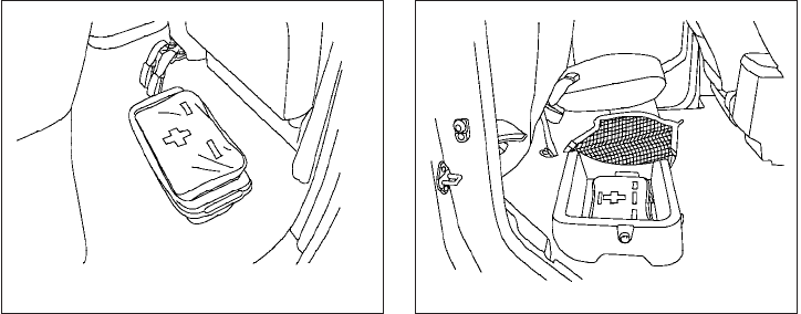
The first aid kit is located in the under-seat stor-
age bins.
To access the first aid kit:
For King cab model, lift up the rear jump seat and
remove net to remove the first aid kit. Refer to
“Jump Seats” in the “Safety — Seats, seat belts
and supplemental restraint system” section ear-
lier in the manual.
For Crew cab model, lift up the rear bench seat
and remove the net to remove the first aid kit.
Refer to “Folding the rear bench seat” in the
“Safety — Seats, seat belts and supplemental
restraint system” section earlier in the manual.
King cab model
LCE0108
Crew cab model
LCE0113
FIRST AID KIT (if so equipped)
6-2 In case of emergency

TIRE PRESSURE MONITORING
SYSTEM (TPMS)
This vehicle is equipped with the Tire Pressure
Monitoring System (TPMS). It monitors tire pres-
sure of all tires except the spare. When the low
tire pressure warning light is lit, one or more of
your tires is significantly under-inflated. If the
vehicle is being driven with low tire pressure, the
TPMS will activate and warn you of it by the low
tire pressure warning light. This system will acti-
vate only when the vehicle is driven at speeds
above 16 MPH (25 km/h). For more details, refer
to “Warning/indicator lights and audible remind-
ers” in the “Instruments and controls” section,
and “Tire Pressure Monitoring System (TPMS)”
in the “Starting and driving” section.
WARNING
●If the low tire pressure warning light
illuminates while driving, avoid sudden
steering maneuvers or abrupt braking,
reduce vehicle speed, pull off the road
to a safe location and stop the vehicle
as soon as possible. Driving with under-
inflated tires may permanently damage
the tires and increase the likelihood of
tire failure. Serious vehicle damage
could occur and may lead to an acci-
dent and could result in serious per-
sonal injury. Check the tire pressure for
all four tires. Adjust the tire pressure to
the recommended COLD tire pressure
shown on the Tire and Loading Informa-
tion label to turn the low tire pressure
warning light OFF. If you have a flat tire,
replace it with a spare tire as soon as
possible.
●When a spare tire is mounted or a wheel
is replaced, the TPMS will not function
and the low tire pressure warning light
will flash for approximately 1 minute.
The light will remain on after 1 minute.
Contact your NISSAN dealer as soon as
possible for tire replacement and/or
system resetting.
●Replacing tires with those not originally
specified by NISSAN could affect the
proper operation of the TPMS.
●Do not inject any tire liquid or aerosol
tire sealant into the tires, as this may
cause a malfunction of the tire pressure
sensors.
CHANGING A FLAT TIRE
If you have a flat tire, follow the instructions be-
low:
Stopping the vehicle
1. Safely move the vehicle off the road and
away from traffic.
2. Turn on the hazard warning flashers.
3. Park on a level surface and apply the parking
brake. Shift the manual transmission into R
(Reverse), or the automatic transmission
into P (Park).
4. Turn off the engine.
5. Raise the hood to warn other traffic and to
signal professional road assistance person-
nel that you need assistance.
6. Have all passengers get out of the vehicle
and stand in a safe place, away from traffic
and clear of the vehicle.
FLAT TIRE
In case of emergency 6-3
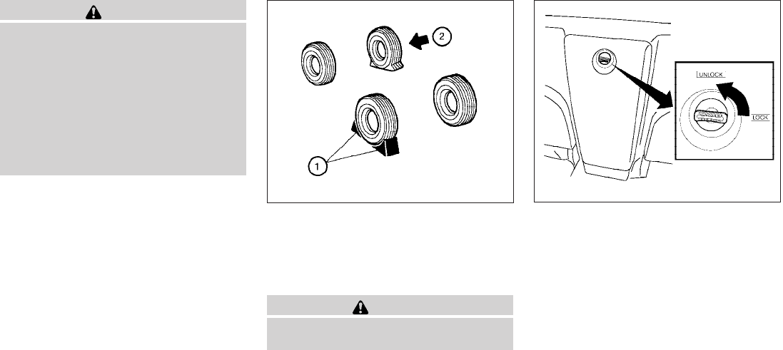
WARNING
●Make sure the parking brake is securely
applied and the manual transmission is
shifted into R (Reverse), or the auto-
matic transmission into P (Park).
●Never change tires when the vehicle is
on a slope, ice or slippery areas. This is
hazardous.
●Never change tires if oncoming traffic is
close to your vehicle. Wait for profes-
sional road assistance.
Blocking wheels
Place suitable blocks s
1at both the front and
back of the wheel diagonally opposite the flat tire
s
2to prevent the vehicle from moving when it is
jacked up.
WARNING
Be sure to block the wheel as the vehicle
may move and result in personal injury.
Getting the spare tire and tools
For King Cab models:
The tool storage compartment is located be-
tween the two rear jump seats.
1. Turn the knob from the lock to the unlock
position and remove the lid from the tool
storage compartment.
2. Release the strap to remove the tool bag.
3. Collapse the jack to remove it from the stor-
age location.
4. Remove the jack and jacking tools.
WCE0044 King Cab models
LCE0109
6-4 In case of emergency
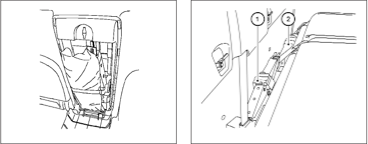
For Crew Cab models:
The tools and tool case are located behind the
rear bench seat.
1. Fold the rear bench seat down. Refer to
“Folding the rear bench seat down” in the
“Safety–Seats, seat belts and supplemental
restraint system” section earlier in this
manual.
2. Remove the jack s
1and jacking tools s
2.
All models:
1. Fit the square end of the jack rod into the
square hole of the wheel nut wrench to form
a handle.
2. Find the oval-shaped opening under the
middle of the tailgate. Pass the T-shaped
end of the jack rod through the opening and
direct it toward the spare tire winch, located
directly above the spare tire.
King Cab models
LCE0110
Crew Cab models
LCE0111
In case of emergency 6-5
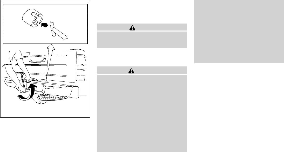
3. Seat the T-shaped end of the jack rod into
the T-shaped opening of the spare tire
winch. Apply pressure to keep the jack rod
engaged in the spare tire winch and turn the
jack rod counterclockwise to lower the
spare tire.
4. Once the spare tire is completely lowered,
reach under the vehicle, remove the retainer
chain, and carefully slide the tire from under
the rear of the vehicle.
CAUTION
Be sure to center the spare tire suspend-
ing plate on the wheel and then lift the
spare tire.
Jacking up vehicle and removing the
damaged tire
WARNING
●Never get under the vehicle while it is
supported only by the jack. If it is nec-
essary to work under the vehicle, sup-
port it with safety stands.
●Use only the jack provided with your
vehicle to lift the vehicle. Do not use the
jack provided with your vehicle on other
vehicles. The jack is designed for lifting
only your vehicle during a tire change.
●Use the correct jack-up points. Never
use any other part of the vehicle for jack
support.
●Never jack up the vehicle more than
necessary.
●Never use blocks on or under the jack.
●Do not start or run the engine while
vehicle is on the jack. It may cause the
vehicle to move. This is especially true
for vehicles with limited slip
differentials.
●Do not allow passengers to stay in the
vehicle while it is on the jack.
●Never run the engine with a wheel(s) off
the ground. It may cause the vehicle to
move.
Always refer to the illustration for the correct
placement and jack-up points for your specific
vehicle model and jack type.
Carefully read the caution label attached to
the jack body and the following instruc-
tions.
1. Loosen each wheel nut one or two turns by
turning counterclockwise with the wheel nut
wrench. Do not remove the wheel nuts
until the tire is off the ground.
WCE0070
6-6 In case of emergency
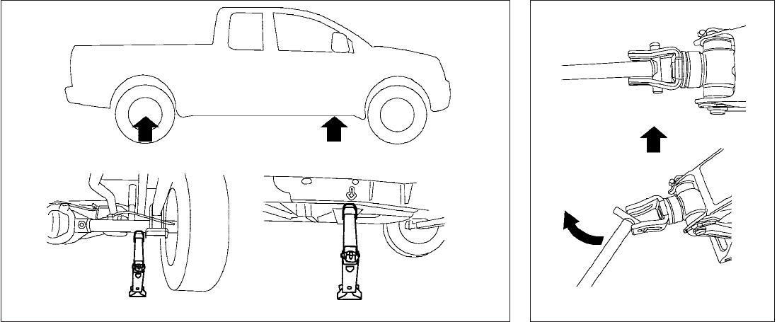
2. Place the jack directly under the jack-up
point as illustrated so the top of the jack
contacts the vehicle at the jack-up point. The
jack-up points are indicated by stamped ar-
rows on the side of the frame.
The jack should be used on firm and
level ground. 3. Install the assembled jack rod into the jack
as shown.
4. To lift the vehicle, securely hold the jack lever
and rod. Carefully raise the vehicle until the
tire clears the ground.
WCE0152 LCE0087
In case of emergency 6-7
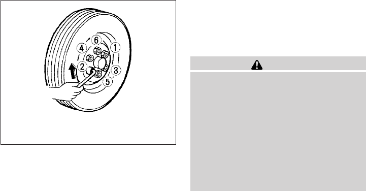
5. Remove the wheel nuts and then remove the
tire.
Installing the spare tire
The spare tire is designed for emergency
use. See specific instructions under the
heading “Wheels and tires” in the “Mainte-
nance and do-it-yourself” section of this
manual.
1. Clean any mud or dirt from the surface be-
tween the wheel and hub.
2. Carefully put the spare tire on and tighten
the wheel nuts finger tight.
3. With the wheel nut wrench, tighten wheel
nuts alternately and evenly as illustrated until
they are tight.
4. Lower the vehicle slowly until the tire
touches the ground. Then, with the wheel
nut wrench, tighten the wheel nuts securely
in the sequence illustrated. Lower the ve-
hicle completely.
WARNING
●Incorrect wheel nuts or improperly
tightened wheel nuts can cause the
wheel to become loose or come off.
This could cause an accident.
●Do not use oil or grease on the wheel
studs or nuts. This could cause the nuts
to become loose.
●Retighten the wheel nuts when the ve-
hicle has been driven for 600 miles
(1,000 km) (also in cases of a flat tire,
etc.).
As soon as possible, tighten the wheel nuts
to the specified torque with a torque
wrench.
Wheel nut tightening torque:
98 ft-lb (133 N·m)
The wheel nuts must be kept tightened to
specification at all times. It is recom-
mended that wheel nuts be tightened to
specifications at each lubrication interval.
WCE0063
6-8 In case of emergency

Adjust tire pressure to the COLD pressure.
COLD pressure: After vehicle has been
parked for three hours or more or driven
less than 1 mile (1.6 km).
COLD tire pressures are shown on the Tire
and Loading Information label located in
the driver’s door opening.
5. Securely store the flat tire and jacking equip-
ment in the vehicle.
WARNING
●Always make sure that the spare tire
and jacking equipment are properly se-
cured after use. Such items can become
dangerous projectiles in an accident or
sudden stop.
●The spare tire is designed for emer-
gency use. See specific instructions un-
der the heading “Wheels and tires” in
the “Maintenance and do-it-yourself”
section of this manual.
To start your engine with a booster battery, the
instructions and precautions below must be fol-
lowed.
WARNING
●If done incorrectly, jump starting can
lead to a battery explosion, resulting in
severe injury or death. It could also
damage your vehicle.
●Explosive hydrogen gas is always
present in the vicinity of the battery.
Keep all sparks and flames away from
the battery.
●Do not allow battery fluid to come into
contact with eyes, skin, clothing or
painted surfaces. Battery fluid is a cor-
rosive sulfuric acid solution which can
cause severe burns. If the fluid should
come into contact with anything, imme-
diately flush the contacted area with
water.
●Keep battery out of the reach of
children.
●The booster battery must be rated at 12
volts. Use of an improperly rated battery
can damage your vehicle.
●Whenever working on or near a battery,
always wear suitable eye protectors (for
example, goggles or industrial safety
spectacles) and remove rings, metal
bands, or any other jewelry. Do not lean
over the battery when jump starting.
●Do not attempt to jump start a frozen
battery. It could explode and cause se-
rious injury.
●Your vehicle has an automatic engine
cooling fan. It could come on at any
time. Keep hands and other objects
away from it.
JUMP STARTING
In case of emergency 6-9
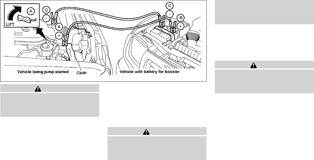
WARNING
Always follow the instructions below.
Failure to do so could result in damage to
the charging system and cause personal
injury.
1. If the booster battery is in another vehicle,
position the two vehicles to bring their bat-
teries near each other.
Do not allow the two vehicles to touch.
2. Apply the parking brake. Move the shift se-
lector to N (Neutral) (manual transmission)
or to P (Park) (automatic transmission).
Switch off all unnecessary electrical sys-
tems (lights, heater, air conditioner, etc.).
3. Remove vent caps on the battery (if so
equipped). Cover the battery with an old
cloth to reduce explosion hazard.
4. Connect jumper cables in the sequence il-
lustrated (s
A,s
B,s
C,s
D).
CAUTION
●Always connect positive (1) to positive
(1) and negative (2) to body ground (for
example, strut mounting bolt, engine
lift bracket, etc.) — not to the battery.
●Make sure the jumper cables do not
touch moving parts in the engine com-
partment and that the cable clamps do
not contact any other metal.
5. Start the engine of the booster vehicle and
let it run for a few minutes.
6. Keep the engine speed of the booster ve-
hicle at about 2,000 rpm, and start the en-
gine of the vehicle being jump started.
CAUTION
Do not keep the starter motor engaged for
more than 10 seconds. If the engine does
not start right away, turn the key off and
wait 3 to 4 seconds before trying again.
7. After starting the engine, carefully discon-
nect the negative cable and then the positive
cable.
8. Replace the vent caps (if so equipped). Be
sure to dispose of the cloth used to cover
the vent holes as it may be contaminated
with corrosive acid.
WCE0066
6-10 In case of emergency

CAUTION
●Do not push start this vehicle. The
three-way catalyst may be damaged.
●Automatic transmission models cannot
be push-started or tow-started. At-
tempting to do so may cause transmis-
sion damage.
●For manual transmission models, never
try to start the vehicle by towing it.
When the engine starts, the forward
surge could cause the vehicle to collide
with the tow vehicle.
WARNING
●Do not continue to drive if your vehicle
overheats. Doing so could cause engine
damage or a vehicle fire.
●To avoid the danger of being scalded,
never remove the radiator cap while the
engine is still hot. When the radiator
cap is removed, pressurized hot water
will spurt out, possibly causing serious
injury.
●Do not open the hood if steam is com-
ing out.
If your vehicle is overheating (indicated by an
extremely high temperature gauge reading), or if
you feel a lack of engine power, detect abnormal
noise, etc. take the following steps.
1. Move the vehicle safely off the road, apply
the parking brake and move the shift selector
to N (Neutral) (manual transmission) or to P
(Park) (automatic transmission).
Do not stop the engine.
2. Turn off the air conditioner (if so equipped).
Open all the windows, move the heater or air
conditioner temperature control to maximum
hot and fan control to high speed.
3. Get out of the vehicle. Look and listen for
steam or coolant escaping from the radiator
before opening the hood. (If steam or cool-
ant is escaping, turn off the engine.) Do not
open the hood further until no steam or
coolant can be seen.
4. Open the engine hood.
WARNING
If steam or water is coming from the en-
gine, stand clear to prevent getting
burned.
5. Visually check drive belts for damage or
looseness. Also check if the cooling fan is
running. The radiator hoses and radiator
should not leak water. If coolant is leaking,
the water pump belt is missing or loose, or
the cooling fan does not run, stop the en-
gine.
WARNING
Be careful not to allow your hands, hair,
jewelry or clothing to come into contact
with, or get caught in, engine belts or the
engine cooling fan. The engine cooling
fan can start at any time.
PUSH STARTING IF YOUR VEHICLE OVERHEATS
In case of emergency 6-11

6. After the engine cools down, check the cool-
ant level in the engine coolant reservoir tank
with the engine running. Add coolant to the
engine coolant reservoir tank if necessary.
Have your vehicle repaired at a NISSAN
dealer.
When towing your vehicle, all State (Provincial in
Canada) and local regulations for towing must be
followed. Incorrect towing equipment could dam-
age your vehicle. Towing instructions are avail-
able from a NISSAN dealer. Local service opera-
tors are generally familiar with the applicable laws
and procedures for towing. To assure proper
towing and to prevent accidental damage to your
vehicle, NISSAN recommends having a service
operator tow your vehicle. It is advisable to have
the service operator carefully read the following
precautions:
WARNING
●Never ride in a vehicle that is being
towed.
●Never get under your vehicle after it has
been lifted by a tow truck.
CAUTION
●When towing, make sure that the trans-
mission, axles, steering system and
powertrain are in working condition. If
any of these conditions apply, dollies or
a flatbed tow truck must be used.
●Always attach safety chains before
towing.
For information about towing your vehicle behind
a recreational vehicle (RV), refer to “Flat towing”
in the “Technical and consumer information” sec-
tion of this manual.
TOWING YOUR VEHICLE
6-12 In case of emergency
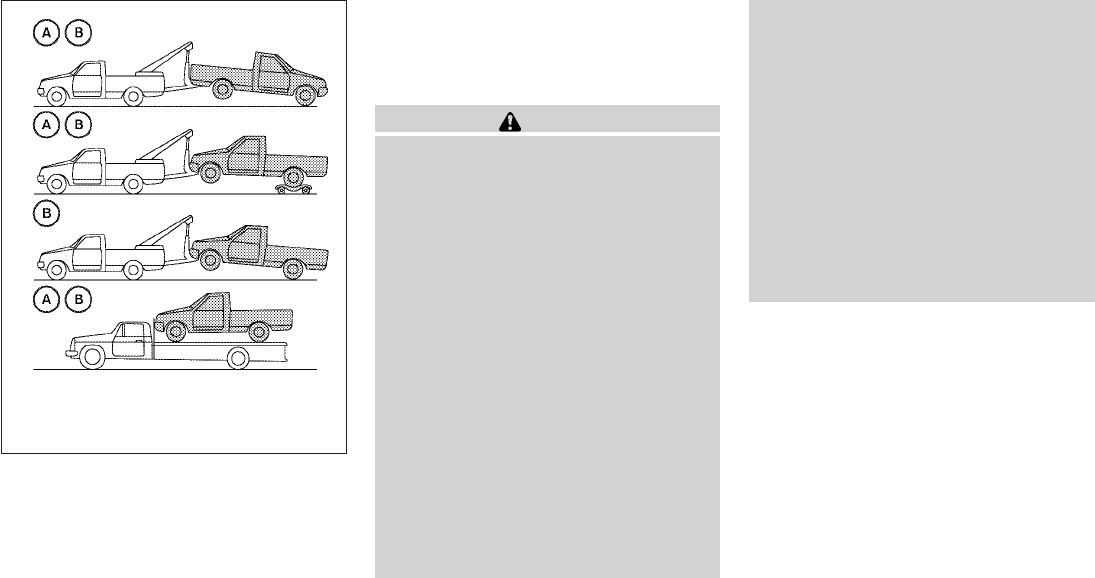
TOWING RECOMMENDED BY
NISSAN
Two-wheel drive models
NISSAN recommends that your vehicle be towed
with the driving (rear) wheels off the ground or
place the vehicle on a flat bed truck as illustrated.
CAUTION
●Never tow automatic transmission
models with the rear wheels on the
ground or four wheels on the ground
(forward or backward), as this may
cause serious and expensive damage to
the transmission. If it is necessary to
tow the vehicle with the front wheels
raised always use towing dollies under
the rear wheels.
●When towing automatic or manual
transmission models with the front
wheels on the ground or on towing
dollies:
– Place the ignition switch in the OFF
position, and secure the steering
wheel in a straight-ahead position
with a rope or similar device. Never
secure the steering wheel by placing
the ignition switch in the LOCK posi-
tion. This may damage the steering
lock mechanism (for models with a
steering lock mechanism).
●If you have to tow manual transmission
models with the rear wheels on the
ground (if you do not use towing dol-
lies) or four wheels on the ground:
●Always release the parking brake.
●Move the transmission shift selector
to the N (Neutral) position
●Observe the following restricted tow-
ing speeds and distances for manual
transmission models only:
Speed: Below 60 MPH (97 km/h)
Distance: Less than 500 miles (805
km)
If the speed or distance must necessarily be
greater, remove the propeller shaft before towing
to prevent damage to the transmission.
s
AAutomatic Transmissions (AT)
s
BManual Transmissions (MT)
WCE0197
In case of emergency 6-13
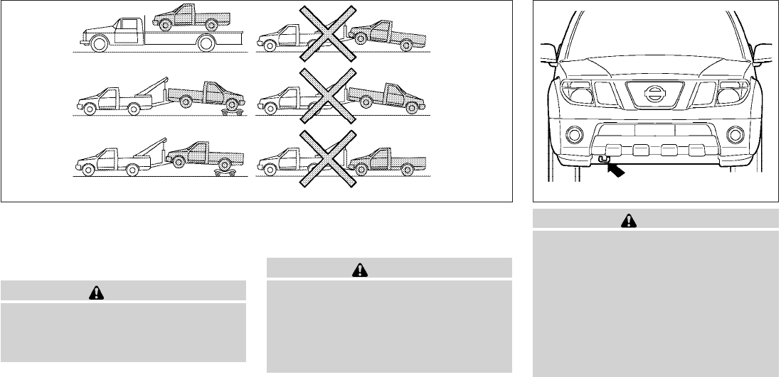
Four-wheel drive models
NISSAN recommends that towing dollies be
used when towing your vehicle or place the ve-
hicle on a flat bed truck as illustrated.
CAUTION
Never tow 4WD models with any of the
wheels on the ground as this may cause
serious and expensive damage to the
transfer case and transmission.
VEHICLE RECOVERY (freeing a stuck
vehicle)
WARNING
●Stand clear of a stuck vehicle.
●Do not spin your tires at high speed.
This could cause them to explode and
result in serious injury. Parts of your
vehicle could also overheat and be
damaged.
CAUTION
●Tow chains or cables must be attached
only to the main structural members of
the vehicle or the towing hooks (if so
equipped). Otherwise, the vehicle body
will be damaged.
●Use the towing hook (if so equipped)
only to free a vehicle stuck in sand,
snow, mud, etc. Never tow the vehicle
for a long distance using only the tow-
ing hook.
WCE0161 LCE0103
6-14 In case of emergency

●The towing hook is under tremendous
force when used to free a stuck vehicle.
Never pull the hook at an angle.
●Always pull the cable straight out from
the front or rear of the vehicle.
●Pulling devices should be routed so
they do not touch any part of the sus-
pension, steering, brake or cooling
systems.
●Pulling devices such as ropes or canvas
straps are not recommended for use in
vehicle towing or recovery.
Pulling a stuck vehicle
If your vehicle is stuck in sand, snow, mud, etc.,
use a tow strap or other device designed specifi-
cally for vehicle recovery. Always follow the re-
covery device manufacturer’s instructions.
Attach the tow strap to the towing hook (if so
equipped).
Rocking a stuck vehicle
If your vehicle is stuck in sand, snow, mud, etc.,
use the following procedure:
1. Turn off the Vehicle Dynamic Control System
(if so equipped).
2. Make sure the area in front and behind the
vehicle is clear of obstructions.
3. Turn the steering wheel right and left to clear
an area around the front tires.
4. Slowly rock the vehicle forward and back-
ward.
●Shift back and forth between R (reverse)
and D (drive) (automatic transmission
models) or 1st (low) and R (reverse)
(manual transmission models).
●Apply the accelerator as little as possible
to maintain the rocking motion.
●Release the accelerator pedal before
shifting between R and D (automatic
transmission models) or 1st and R
(manual transmission models).
●Do not spin the tires above 35 mph (55
km/h).
5. If the vehicle can not be freed after a few
tries, contact a professional towing service
to remove the vehicle.
In case of emergency 6-15
MEMO
6-16 In case of emergency

7 Appearance and care
Cleaning exterior ..................................7-2
Washing ......................................7-2
Waxing........................................7-2
Removing spots ................................7-3
Underbody ....................................7-3
Glass .........................................7-3
Aluminum alloy wheels ..........................7-3
Chrome parts ..................................7-3
Tire dressings..................................7-3
Cleaning interior...................................7-4
Air fresheners ..................................7-4
Floor mats .....................................7-4
Seat belts .....................................7-5
Corrosion protection...............................7-5
Most common factors contributing to vehicle
corrosion ......................................7-5
Environmental factors influence the rate of
corrosion ......................................7-5
To protect your vehicle from corrosion ............7-6

In order to maintain the appearance of your ve-
hicle, it is important to take proper care of it.
To protect the paint surfaces, please wash your
vehicle as soon as you can:
●after a rainfall to prevent possible damage
from acid rain.
●after driving on coastal roads.
●when contaminants such as soot, bird drop-
pings, tree sap, metal particles or bugs get
on the paint surface.
●when dust or mud builds up on the surface.
Whenever possible, store or park your vehicle
inside a garage or in a covered area.
When it is necessary to park outside, park in a
shady area or protect the vehicle with a body
cover.
Be careful not to scratch the paint surface
when putting on or removing the body
cover.
WASHING
Wash dirt off with a wet sponge and plenty of
water. Clean the vehicle thoroughly using a mild
soap, a special vehicle soap or general purpose
dishwashing liquid mixed with clean, lukewarm
(never hot) water.
CAUTION
●Do not use car washes that use acid in
the detergent. Some car washes, espe-
cially brushless ones, use some acid for
cleaning. The acid may react with some
plastic vehicle components, causing
them to crack. This could affect their
appearance, and also could cause them
not to function properly. Always check
with your car wash to confirm that acid
is not used.
●Do not wash the vehicle with strong
household soap, strong chemical deter-
gents, gasoline or solvents.
●Do not wash the vehicle in direct sun-
light or while the vehicle body is hot, as
the surface may become water-spotted.
●Avoid using tight-napped or rough
cloths, such as washing mitts. Care
must be taken when removing
caked-on dirt or other foreign sub-
stances so the paint surface is not
scratched or damaged.
Rinse the vehicle thoroughly with plenty of clean
water.
Inside flanges, seams and folds on the doors,
hatches and hood are particularly vulnerable to
the effects of road salt. Therefore, these areas
must be cleaned regularly. Take care that the
drain holes in the lower edge of the door are
open. Spray water under the body and in the
wheel wells to loosen the dirt and wash away
road salt.
A damp chamois can be used to dry the vehicle to
avoid water spots.
WAXING
Regular waxing protects the paint surface and
helps retain new vehicle appearance. Polishing is
recommended to remove built-up wax residue
and to avoid a weathered appearance before
re-applying wax.
A NISSAN dealer can assist you in choosing the
proper product.
●Wax your vehicle only after a thorough wash-
ing. Follow the instructions supplied with the
wax.
●Do not use a wax containing any abrasives,
cutting compounds or cleaners that may
damage the vehicle finish.
Machine compounding or aggressive polishing
on a base coat/clear coat paint finish may dull the
finish or leave swirl marks.
CLEANING EXTERIOR
7-2 Appearance and care

REMOVING SPOTS
Remove tar and oil spots, industrial dust, insects,
and tree sap as quickly as possible from the
surface of the paint to avoid lasting damage or
staining. Special cleaning products are available
at a NISSAN dealer or any automotive accessory
store.
UNDERBODY
In areas where road salt is used in winter, it is
necessary to clean the underbody regularly in
order to prevent dirt and salt from building up and
causing the acceleration of corrosion on the un-
derbody and suspension. Before the winter pe-
riod and again in the spring, the underseal must
be checked and, if necessary, retreated.
GLASS
Use glass cleaner to remove smoke and dust film
from the glass surfaces. It is normal for glass to
become coated with a film after the vehicle is
parked in the hot sun. Glass cleaner and a soft
cloth will easily remove this film.
CAUTION
When cleaning the inside of the windows,
do not use sharp-edged tools, abrasive
cleaners or chlorine-based disinfectant
cleaners. They could damage the electri-
cal conductors, radio antenna elements or
rear window defroster elements.
ALUMINUM ALLOY WHEELS
Wash the wheels regularly with a sponge damp-
ened in a mild soap solution, especially during
winter months in areas where road salt is used. If
not removed, road salt can discolor the wheels.
CAUTION
Follow the directions below to avoid
staining or discoloring the wheels:
●Do not use a cleaner that uses strong
acid or alkali contents to clean the
wheels.
●Do not apply wheel cleaners to the
wheels when they are hot. The wheel
temperature should be the same as am-
bient temperature.
●Rinse the wheel to completely remove
the cleaner within 15 minutes after the
cleaner is applied.
CHROME PARTS
Clean all chrome parts regularly with a non-
abrasive chrome polish to maintain the finish.
TIRE DRESSINGS
NISSAN does not recommend the use of tire
dressings. Tire manufacturers apply a coating to
the tires to help reduce discoloration of the rub-
ber. If a tire dressing is applied to the tires, it may
react with the coating and form a compound. This
compound may come off the tire while driving and
stain the vehicle paint.
If you choose to use a tire dressing, take the
following precautions:
●Use a water-based tire dressing. The coat-
ing on the tire dissolves more easily than
with an oil-based tire dressing.
●Apply a light coat of tire dressing to help
prevent it from entering the tire
tread/grooves (where it would be difficult to
remove).
●Wipe off excess tire dressing using a dry
towel. Make sure the tire dressing is com-
pletely removed from the tire tread/grooves.
●Allow the tire dressing to dry as recom-
mended by the tire dressing manufacturer.
Appearance and care 7-3

Occasionally remove loose dust from the interior
trim, plastic parts and seats using a vacuum
cleaner or soft bristled brush. Wipe the vinyl and
leather surfaces with a clean, soft cloth damp-
ened in mild soap solution, then wipe clean with a
dry, soft cloth.
Regular care and cleaning is required in order to
maintain the appearance of the leather.
Before using any fabric protector, read the manu-
facturer’s recommendations. Some fabric pro-
tectors contain chemicals that may stain or
bleach the seat material.
Use a cloth dampened only with water to clean
the meter and gauge lens.
WARNING
Do not use water or acidic cleaners (hot
steam cleaners) on the seat. This can
damage the seat or occupant classifica-
tion sensor. This can also affect the opera-
tion of the air bag system and result in
serious personal injury.
CAUTION
●Never use benzine, thinner or any simi-
lar material.
●Small dirt particles can be abrasive and
damaging to leather surfaces and
should be removed promptly. Do not
use saddle soap, car waxes, polishes,
oils, cleaning fluids, solvents, deter-
gents or ammonia-based cleaners as
they may damage the leather’s natural
finish.
●Never use fabric protectors unless rec-
ommended by the manufacturer.
●Do not use glass or plastic cleaner on
meter or gauge lens covers. It may dam-
age the lens cover.
AIR FRESHENERS
Most air fresheners use a solvent that could affect
the vehicle interior. If you use an air freshener,
take the following precautions:
●Hanging-type air fresheners can cause per-
manent discoloration when they contact ve-
hicle interior surfaces. Place the air fresh-
ener in a location that allows it to hang free
and not contact an interior surface.
●Liquid-type air fresheners typically clip on
the vents. These products can cause imme-
diate damage and discoloration when
spilled on interior surfaces.
Carefully read and follow the manufacturer’s in-
structions before using the air fresheners.
FLOOR MATS
The use of genuine NISSAN floor mats can ex-
tend the life of your vehicle carpet and make it
easier to clean the interior. No matter what
mats are used, be sure they are fitted for
your vehicle and are properly positioned in
the footwell to prevent interference with
pedal operation. Mats should be maintained
with regular cleaning and replaced if they be-
come excessively worn.
CLEANING INTERIOR
7-4 Appearance and care
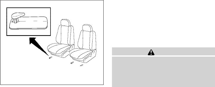
Floor mat positioning aid
This vehicle includes two driver’s side front floor
mat brackets and one passenger’s side front floor
mat bracket to help keep your floor mats in place.
NISSAN floor mats have been specially designed
for your vehicle model. The driver’s side floor mat
has two grommet holes incorporated in it and the
passenger’s side has one grommet hole. Position
each mat by placing the floor mat bracket hook
through the floor mat grommet holes while cen-
tering the mat in the footwell.
Periodically check to make certain the mats are
properly positioned.
SEAT BELTS
The seat belts can be cleaned by wiping them
with a sponge dampened in a mild soap solution.
Allow the belts to dry completely in the shade
before using them. See “Seat belt maintenance”
in the “Safety – Seats, seat belts and supplemen-
tal restraint system” section of this manual.
WARNING
Do not allow wet seat belts to roll up in the
retractor. NEVER use bleach, dye or
chemical solvents to clean the seat belts,
since these materials may severely
weaken the seat belt webbing.
MOST COMMON FACTORS
CONTRIBUTING TO VEHICLE
CORROSION
●The accumulation of moisture-retaining dirt
and debris in body panel sections, cavities,
and other areas.
●Damage to paint and other protective coat-
ings caused by gravel and stone chips or
minor traffic accidents.
ENVIRONMENTAL FACTORS
INFLUENCE THE RATE OF
CORROSION
Moisture
Accumulation of sand, dirt and water on the ve-
hicle body underside can accelerate corrosion.
Wet floor coverings will not dry completely inside
the vehicle and should be removed for drying to
avoid floor panel corrosion.
Relative humidity
Corrosion will be accelerated in areas of high
relative humidity, especially those areas where
the temperatures stay above freezing and where
atmospheric pollution exists and road salt is
used.
LAI0009
CORROSION PROTECTION
Appearance and care 7-5

Temperature
High temperatures accelerate the rate of corro-
sion to those parts which are not well ventilated.
Air pollution
Industrial pollution, the presence of salt in the air
in coastal areas, or heavy road salt use acceler-
ates the corrosion process. Road salt also accel-
erates the disintegration of paint surfaces.
TO PROTECT YOUR VEHICLE
FROM CORROSION
●Wash and wax your vehicle often to keep the
vehicle clean.
●Always check for minor damage to the paint
and repair it as soon as possible.
●Keep drain holes at the bottom of the doors
open to avoid water accumulation.
●Check the underbody for accumulation of
sand, dirt or salt. If present, wash with water
as soon as possible.
CAUTION
●NEVER remove dirt, sand or other de-
bris from the passenger compartment
by washing it out with a hose. Remove
dirt with a vacuum cleaner or broom.
●Never allow water or other liquids to
come in contact with electronic compo-
nents inside the vehicle as this may
damage them.
Chemicals used for road surface de-icing are
extremely corrosive. They accelerate corrosion
and deterioration of underbody components
such as the exhaust system, fuel and brake lines,
brake cables, floor pan and fenders.
In winter, the underbody must be cleaned
periodically.
For additional protection against rust and corro-
sion, which may be required in some areas, con-
sult a NISSAN dealer.
7-6 Appearance and care

8 Maintenance and do-it-yourself
Maintenance requirements..........................8-2
General maintenance ..............................8-2
Explanation of general maintenance items .........8-2
Maintenance precautions...........................8-5
Engine compartment check locations ................8-6
Engine cooling system .............................8-8
Checking engine coolant level ...................8-8
Changing engine coolant........................8-9
Engine oil.........................................8-9
Checking engine oil level ........................8-9
Changing engine oil ...........................8-11
Changing engine oil filter .......................8-12
5-speed automatic transmission fluid ...............8-13
Power steering fluid...............................8-13
Brake and clutch fluid .............................8-14
Brake fluid ....................................8-14
Clutch fluid ...................................8-14
Window washer fluid .............................8-15
Window washer fluid reservoir ..................8-15
Battery ..........................................8-15
Jump starting .................................8-17
Variable voltage control system.....................8-17
Drive belt ........................................8-18
Spark plugs......................................8-19
Replacing spark plugs .........................8-19
Air cleaner .......................................8-20
In-cabin microfilter (if so equipped) ..............8-20
Windshield wiper blades ..........................8-22
Cleaning .....................................8-22
Replacing ....................................8-22
Brakes ..........................................8-23
Fuses ...........................................8-24
Engine compartment...........................8-24
Passenger compartment .......................8-25
Battery replacement ..............................8-26
Keyfob (if so equipped) ........................8-27
Lights ...........................................8-28
Headlights....................................8-28
Exterior and interior lights.......................8-30
Wheels and tires .................................8-32
Tire pressure..................................8-32
Tire labeling...................................8-36
Types of tires..................................8-38
Tire chains....................................8-39
Changing wheels and tires .....................8-39
Your NISSAN has been designed to have mini-
mum maintenance requirements with long ser-
vice intervals to save you both time and money.
However, some day-to-day and regular mainte-
nance is essential to maintain your NISSAN’s
good mechanical condition, as well as its emis-
sions and engine performance.
It is the owner’s responsibility to make sure that
the scheduled maintenance, as well as general
maintenance, is performed.
As the vehicle owner, you are the only one who
can ensure that your vehicle receives proper
maintenance. You are a vital link in the mainte-
nance chain.
Scheduled maintenance
For your convenience, both required and optional
scheduled maintenance items are described and
listed in your “NISSAN Service and Maintenance
Guide”. You must refer to that guide to ensure
that necessary maintenance is performed on your
NISSAN at regular intervals.
General maintenance
General maintenance includes those items which
should be checked during normal day-to-day op-
eration. They are essential for proper vehicle op-
eration. It is your responsibility to perform these
maintenance procedures regularly as prescribed.
Performing general maintenance checks requires
minimal mechanical skill and only a few general
automotive tools.
These checks or inspections can be done by you,
a qualified technician, or, if you prefer, a NISSAN
dealer.
Where to go for service
If maintenance service is required or your vehicle
appears to malfunction, have the systems
checked and corrected by a NISSAN dealer.
NISSAN technicians are well-trained specialists
who are kept up-to-date with the latest service
information through technical bulletins, service
tips, and in-dealership training programs. They
are completely qualified to work on NISSAN ve-
hicles before they work on your vehicle, rather
than after they have worked on it.
You can be confident that a NISSAN dealer’s
service department performs the best job to meet
the maintenance requirements on your vehicle —
in a reliable and economical way.
During the normal day-to-day operation of the
vehicle, general maintenance should be per-
formed regularly as prescribed in this section. If
you detect any unusual sounds, vibrations or
smells, be sure to check for the cause or have a
NISSAN dealer do it promptly. In addition, you
should notify a NISSAN dealer if you think that
repairs are required.
When performing any checks or maintenance
work, closely observe the “Maintenance precau-
tions” later in this section.
EXPLANATION OF GENERAL
MAINTENANCE ITEMS
Additional information on the following
items with“*”isfound later in this section.
Outside the vehicle
The maintenance items listed here should be
performed from time to time, unless otherwise
specified.
Doors and engine hood Check that the doors
and engine hood operate properly. Also ensure
that all latches lock securely. Lubricate hinges,
latches, latch pins, rollers and links as necessary.
Make sure that the secondary latch keeps the
hood from opening when the primary latch is
released.
MAINTENANCE REQUIREMENTS GENERAL MAINTENANCE
8-2 Maintenance and do-it-yourself
When driving in areas using road salt or other
corrosive materials, check lubrication frequently.
Lights* Clean the headlights on a regular basis.
Make sure that the headlights, stop lights, tail
lights, turn signal lights, and other lights are all
operating properly and installed securely. Also
check headlight aim.
Road wheel nuts (lug nuts)* When checking
the tires, make sure no wheel nuts are missing,
and check for any loose wheel nuts. Tighten if
necessary.
Tire rotation* Tires should be rotated every
7,500 miles (12,000 km).
Tires* Check the pressure with a gauge often
and always prior to long distance trips. If neces-
sary, adjust the pressure in all tires, including the
spare, to the pressure specified. Check carefully
for damage, cuts or excessive wear.
Tire Pressure Monitoring System (TPMS)
transmitter components Replace the TPMS
transmitter grommet seal, valve core and cap
when the tires are replaced due to wear or age.
Wheel alignment and balance If the vehicle
should pull to either side while driving on a
straight and level road, or if you detect uneven or
abnormal tire wear, there may be a need for wheel
alignment. If the steering wheel or seat vibrates at
normal highway speeds, wheel balancing may be
needed.
●For additional information regarding tires,
refer to “Important Tire Safety Information”
(US) or “Tire Safety Information”(Canada) in
the Warranty Information Booklet.
Windshield Clean the windshield on a regular
basis. Check the windshield at least every six
months for cracks or other damage. Have a dam-
aged windshield repaired by a qualified repair
facility.
Windshield wiper blades* Check for cracks or
wear if they do not wipe properly.
Inside the vehicle
The maintenance items listed here should be
checked on a regular basis, such as when per-
forming periodic maintenance, cleaning the ve-
hicle, etc.
Additional information on the following
items with an “*” is found later in this sec-
tion.
Accelerator pedal Check the pedal for smooth
operation and make sure the pedal does not bind
or require uneven effort. Keep the floor mat away
from the pedal.
Automatic transmission P (Park) position
mechanism On a fairly steep hill check that your
vehicle is held securely with the shift selector in
the P (Park) position without applying any brakes.
Brake pedal Check the pedal for smooth opera-
tion. If the brake pedal suddenly goes down fur-
ther than normal, the pedal feels spongy or the
vehicle seems to take longer to stop, see a
NISSAN dealer immediately. Keep the floor mat
away from the pedal.
Brakes Check that the brakes do not pull the
vehicle to one side when applied.
Parking brake Check the parking brake opera-
tion regularly. The vehicle should be securely held
on a fairly steep hill with only the parking brake
applied. If the parking brake needs adjustment,
see a NISSAN dealer.
Seats
Check seat position controls such as seat
adjusters, seatback recliner, etc. to ensure they op-
erate smoothly and all latches lock securely in every
position. Check that the head restraints and head-
rests move up and down smoothly and the locks (if
so equipped) hold securely in all latched positions.
Seat belts Check that all parts of the seat belt
system (for example, buckles, anchors, adjusters
and retractors) operate properly and smoothly,
and are installed securely. Check the belt web-
bing for cuts, fraying, wear or damage.
Maintenance and do-it-yourself 8-3
Steering wheel Check for changes in the steer-
ing system, such as excessive freeplay, hard
steering or strange noises.
Warning lights and chimes Make sure all
warning lights and chimes are operating properly.
Windshield wiper and washer* Check that
the wipers and washer operate properly and that
the wipers do not streak.
Windshield defroster Check that the air
comes out of the defroster outlets properly and in
sufficient quantity when operating the heater or
air conditioner.
Under the hood and vehicle
The maintenance items listed here should be
checked periodically (for example, each time you
check the engine oil or refuel).
Battery* Check the fluid level in each cell. It
should be between the MAX and MIN lines. Ve-
hicles operated in high temperatures or under
severe conditions require frequent checks of the
battery fluid level.
Brake and clutch fluid levels* Make sure that
the brake and clutch fluid level is between the
MIN and MAX lines on the reservoir.
Engine coolant level* Check the coolant level
when the engine is cold.
Engine drive belts* Make sure the drive belts
are not frayed, worn, cracked or oily.
Engine oil level* Check the level after parking
the vehicle on a level surface with the engine off.
Wait more than 10 minutes for the oil to drain
back into the oil pan.
Exhaust system Make sure there are no loose
supports, cracks or holes. If the sound of the
exhaust seems unusual or there is a smell of
exhaust fumes, immediately have the exhaust
system inspected by a NISSAN dealer. See the
carbon monoxide warning in the “Starting and
driving” section of this manual.
Fluid leaks Check under the vehicle for fuel, oil,
water or other fluid leaks after the vehicle has
been parked for a while. Water dripping from the
air conditioner after use is normal. If you should
notice any leaks or if gasoline fumes are evident,
check for the cause and have it corrected imme-
diately.
Power steering fluid level* and lines Check
the level when the fluid is cold, with the engine
off. Check the lines for proper attachment, leaks,
cracks, etc.
Radiator and hoses Check the front of the
radiator and clean off any dirt, insects, leaves,
etc., that may have accumulated. Make sure the
hoses have no cracks, deformation, rot or loose
connections.
Underbody The underbody is frequently ex-
posed to corrosive substances such as those
used on icy roads or to control dust. It is very
important to remove these substances from the
underbody, otherwise rust may form on the floor
pan, frame, fuel lines and exhaust system. At the
end of winter, the underbody should be thor-
oughly flushed with plain water, in those areas
where mud and dirt may have accumulated. See
the “Appearance and care” section of this
manual.
Windshield washer fluid* Check that there is
adequate fluid in the reservoir.
8-4 Maintenance and do-it-yourself

When performing any inspection or maintenance
work on your vehicle, always take care to prevent
serious accidental injury to yourself or damage to
the vehicle. The following are general precau-
tions which should be closely observed.
WARNING
●Park the vehicle on a level surface, ap-
ply the parking brake securely and
block the wheels to prevent the vehicle
from moving. Move the shift selector to
P (Park).
●Be sure the ignition switch is in the OFF
or LOCK position when performing any
parts replacement or repairs.
●If you must work with the engine run-
ning, keep your hands, clothing, hair
and tools away from moving fans, belts
and any other moving parts.
●It is advisable to secure or remove any
loose clothing and remove any jewelry,
such as rings, watches, etc. before
working on your vehicle.
●Always wear eye protection whenever
you work on your vehicle.
●Your vehicle is equipped with an auto-
matic engine cooling fan. It may come
on at any time without warning, even if
the ignition switch is in the OFF posi-
tion and the engine is not running. To
avoid injury, always disconnect the
negative battery cable before working
near the fan.
●If you must run the engine in an en-
closed space such as a garage, be sure
there is proper ventilation for exhaust
gases to escape.
●Never get under the vehicle while it is
supported only by a jack. If it is neces-
sary to work under the vehicle, support
it with safety stands.
●Keep smoking materials, flame and
sparks away from the fuel tank and
battery.
●On gasoline engine models, the fuel
filter or fuel lines should be serviced by
a NISSAN dealer because the fuel lines
are under high pressure even when the
engine is off.
CAUTION
●Do not work under the hood while the
engine is hot. Turn the engine off and
wait until it cools down.
●Avoid contact with used engine oil and
coolant. Improperly disposed engine
oil, engine coolant and/or other vehicle
fluids can damage the environment. Al-
ways conform to local regulations for
disposal of vehicle fluid.
●Never leave the engine or automatic
transmission related component har-
nesses disconnected while the ignition
switch is in the ON position.
●Never connect or disconnect the battery
or any transistorized component while
the ignition switch is in the ON position.
This “Maintenance and do-it-yourself” section
gives instructions regarding only those items
which are relatively easy for an owner to perform.
You should be aware that incomplete or improper
servicing may result in operating difficulties or
excessive emissions, and could affect warranty
coverage. If in doubt about any servicing,
have it done by a NISSAN dealer.
MAINTENANCE PRECAUTIONS
Maintenance and do-it-yourself 8-5

QR25DE engine
1. Window washer fluid reservoir
2. Fuse/Fusible link box
3. Fuse and relay box
4. Air cleaner
5. Engine oil filler cap
6. Engine oil dipstick
7. Brake fluid reservoir/Clutch fluid
reservoir (M/T model)
8. Drive belt location
9. Radiator cap
10. Power steering fluid reservoir
11. Battery
12. Engine coolant reservoir
NOTE:
Engine cover removed for clarity.
WDI0643
ENGINE COMPARTMENT CHECK
LOCATIONS
8-6 Maintenance and do-it-yourself

VQ40DE engine
1. Window washer fluid reservoir
2. Fuse/fusible link box
3. Fuse and relay box
4. Engine oil filler cap
5. Engine oil dipstick
6. Brake fluid reservoir/Clutch fluid
reservoir (M/T model)
7. Air cleaner
8. Drive belt location
9. Radiator cap
10. Power steering fluid reservoir
11. Battery
12. Engine coolant reservoir
LII0167
Maintenance and do-it-yourself 8-7
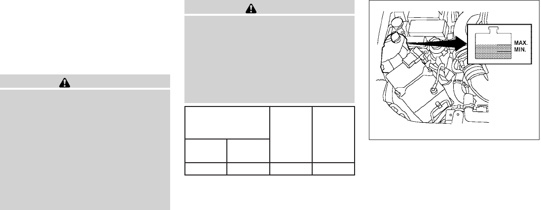
The engine cooling system is filled at the factory
with Genuine NISSAN Long Life
Antifreeze/Coolant to provide year-round anti-
freeze and coolant protection. The anti-freeze
solution contains rust and corrosion inhibitors.
Additional engine cooling system additives are
not necessary.
WARNING
●Never remove the radiator or coolant
reservoir cap when the engine is hot.
Wait until the engine and radiator cool
down. Serious burns could be caused
by high pressure fluid escaping from
the radiator. See precautions in “If your
vehicle overheats” found in the “In case
of emergency” section of this manual.
●The radiator is equipped with a pres-
sure type radiator cap. To prevent en-
gine damage, use only a genuine
NISSAN radiator cap.
CAUTION
When adding or replacing coolant, be sure
to use only a Genuine NISSAN Long Life
Antifreeze/Coolant or equivalent with the
proper mixture ratio of 50% anti-freeze
and 50% demineralized or distilled water.
The use of other types of coolant solu-
tions other than a Genuine NISSAN Long
Life Antifreeze/Coolant or equivalent may
damage the engine cooling system.
Outside temperature
down to
Genuine
NISSAN
Long Life
Antifreeze/
Coolant or
equivalent
Demineral-
ized or dis-
tilled water
°C °F
-35 -30 50% 50%
CHECKING ENGINE COOLANT
LEVEL
Check the coolant level in the reservoir when
the engine is cold. If the coolant level is below
the MIN level, add coolant to the MAX level. If the
reservoir is empty, check the coolant level in the
radiator when the engine is cold. If there is
insufficient coolant in the radiator, fill the radiator
with coolant up to the filler opening and also add
it to the reservoir up to the MAX level.
The engine coolant reservoir is a pressur-
ized tank. When installing the cap, tighten
it until a clicking sound is heard.
VQ40DE
LDI0436
ENGINE COOLING SYSTEM
8-8 Maintenance and do-it-yourself
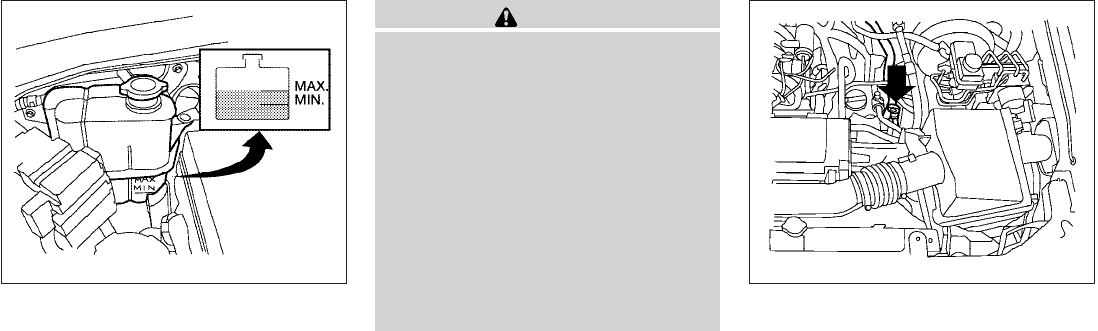
If the cooling system frequently requires
coolant, have it checked by a NISSAN
dealer.
CHANGING ENGINE COOLANT
A NISSAN dealer can change the engine coolant.
The service procedure can be found in the
NISSAN Service Manual.
Improper servicing can result in reduced
heater performance and engine overheat-
ing.
WARNING
●To avoid the danger of being scalded,
never change the coolant when the en-
gine is hot.
●Never remove the radiator or engine
coolant reservoir cap when the engine
is hot. Serious burns could be caused
by high pressure fluid escaping from
the radiator.
●Avoid direct skin contact with used
coolant. If skin contact is made, wash
thoroughly with soap or hand cleaner
as soon as possible.
●Keep coolant out of the reach of chil-
dren and pets.
Engine coolant must be disposed of properly.
Check your local regulations.
CHECKING ENGINE OIL LEVEL
1. Park the vehicle on a level surface and apply
the parking brake.
2. Start the engine and let it idle until it reaches
operating temperature.
3. Turn off the engine. Wait more than 10
minutes for the oil to drain back into
the oil pan.
4. Remove the dipstick and wipe it clean. Re-
insert it all the way.
QR25DE
LDI0466
VQ40DE
WDI0672
ENGINE OIL
Maintenance and do-it-yourself 8-9
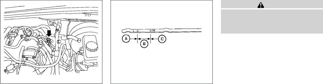
5. Remove the dipstick again and check the oil
level. It should be between the H (High) and
L (Low) marks s
B. This is the normal oper-
ating oil level range. If the oil level is below
the L (Low) mark s
A, remove the oil filler cap
and pour recommended oil through the
opening. Do not overfill s
C.
6. Recheck oil level with the dipstick.
It is normal to add some oil between oil
maintenance intervals or during the
break-in period, depending on the severity
of operating conditions.
CAUTION
Oil level should be checked regularly. Op-
erating the engine with an insufficient
amount of oil can damage the engine, and
such damage is not covered by warranty.
QR25DE
LDI0467 LDI0371
8-10 Maintenance and do-it-yourself
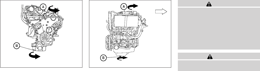
CHANGING ENGINE OIL
1. Park the vehicle on a level surface and apply
the parking brake.
2. Start the engine and let it idle until it reaches
operating temperature, then turn it off.
3. Remove the oil filler cap s
Aby turning it
counterclockwise.
4. Place a large drain pan under the drain plug.
5. Remove the drain plug s
Bwith a wrench by
turning it counterclockwise and completely
drain the oil.
If the oil filter is to be changed, remove and
replace it at this time. See “Changing engine
oil filter” later in this section.
●Waste oil must be disposed of prop-
erly.
●Check your local regulations.
WARNING
●Prolonged and repeated contact with
used engine oil may cause skin cancer.
●Try to avoid direct skin contact with
used oil. If skin contact is made, wash
thoroughly with soap or hand cleaner
as soon as possible.
●Keep used engine oil out of reach of
children.
CAUTION
Be careful not to burn yourself. The engine
oil may be hot.
6. Clean and reinstall the drain plug and a new
washer. Securely tighten the drain plug with
a wrench. Do not use excessive force.
Drain plug tightening torque:
22 - 29 ft-lb (29 - 39 N·m)
7. Refill engine with recommended oil through
the oil filler opening, then install the oil filler
cap securely.
See “Capacities and recommended
fuel/lubricants” in the “Technical and con-
sumer information” section of this manual for
drain and refill capacity.
VQ40DE
WDI0500
QR25DE
WDI0501
Maintenance and do-it-yourself 8-11
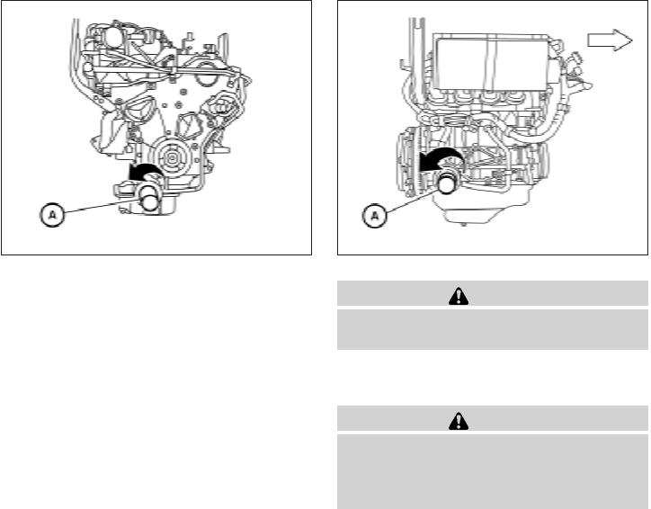
The drain and refill capacity depends on the
oil temperature and drain time. Use these
specifications for reference only. Always use
the dipstick to determine when the proper
amount of oil is in the engine.
8. Start the engine. Check for leakage around
the drain plug and oil filter. Correct as re-
quired.
9. Turn the engine off and wait more than 10
minutes. Check the oil level with the dipstick.
Add engine oil if necessary.
CHANGING ENGINE OIL FILTER
1. Park the vehicle on a level surface and apply
the parking brake.
2. Turn the engine off.
3. Place a large drain pan under the oil filter.
4. Unscrew the plate covering the oil filter ex-
posing the filter. (For VQ40DE engine only)
5. Loosen the oil filter s
Awith an oil filter
wrench by turning it counterclockwise. Then
remove the oil filter by turning it by hand.
CAUTION
Be careful not to burn yourself. The engine
oil may be hot.
6. Wipe the engine oil filter sealing surface with
a clean rag.
CAUTION
Be sure to remove any old gasket material
remaining on the sealing surface of the
engine. Failure to do so could lead to
engine damage.
VQ40DE
WDI0502
QR25DE
WDI0503
8-12 Maintenance and do-it-yourself
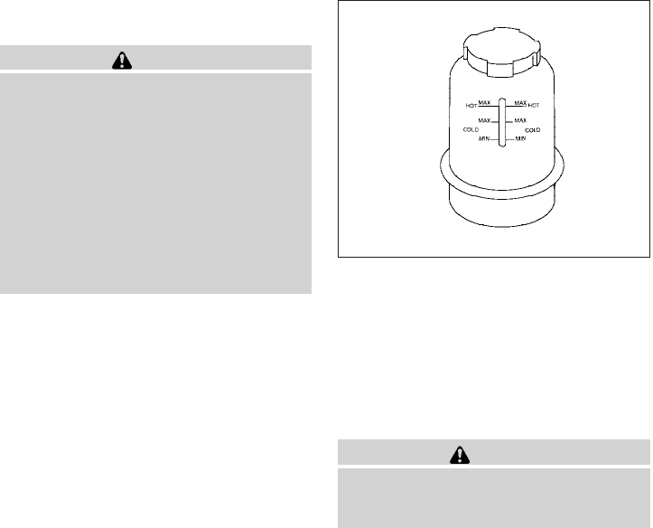
7. Coat the gasket on the new filter with clean
engine oil.
8. Screw on the oil filter until a slight resistance
is felt, then tighten an additional 2/3 turn.
9. Start the engine and check for leakage
around the oil filter. Correct as required.
10. Turn the engine off and wait more than 10
minutes. Check the oil level. Add engine oil if
necessary.
When checking or replacement is required, we
recommend your NISSAN dealer for servicing.
CAUTION
●Use Genuine NISSAN Matic S ATF. If
Genuine NISSAN Matic S ATF is not
available, Genuine NISSAN Matic J ATF
may also be used.
●Using automatic transmission fluid
other than Genuine NISSAN Matic S
ATF or Matic J ATF will cause deteriora-
tion in driveability and automatic trans-
mission durability, and may damage the
automatic transmission, which is not
covered by the NISSAN new vehicle lim-
ited warranty.
The specified automatic transmission fluid is also
described on caution labels located in the engine
compartment.
The fluid level should be checked using the HOT
MAX range on the power steering fluid reservoir
at fluid temperatures of 122° - 176°F (50° -
80°C) or using the COLD MAX range on the
power steering fluid reservoir at fluid tempera-
tures of 32° - 86°F (0° - 30°C).
If the fluid is at or below the MIN line, add Genu-
ine NISSAN PSF. Remove the cap and fill
through the opening.
CAUTION
●DO NOT OVERFILL.
●Recommended fluid is Genuine
NISSAN PSF or equivalent.
WDI0256
5-SPEED AUTOMATIC
TRANSMISSION FLUID POWER STEERING FLUID
Maintenance and do-it-yourself 8-13
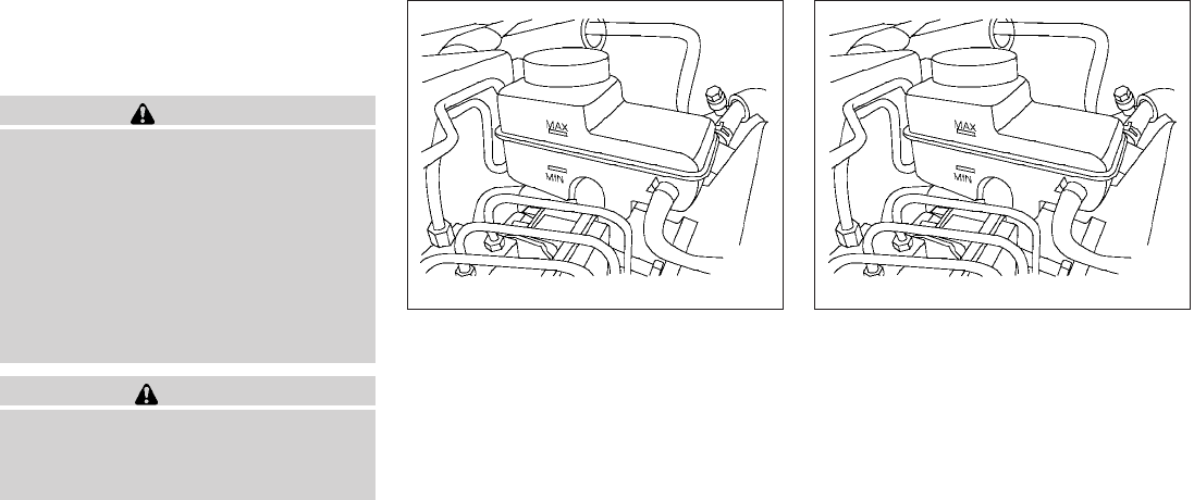
For further brake and clutch fluid specification
information, refer to “Capacities and recom-
mended fuel/lubricants” in the “Technical and
consumer information” section of this manual.
WARNING
●Use only new fluid from a sealed con-
tainer. Old, inferior or contaminated
fluid may damage the brake and clutch
systems. The use of improper fluids can
damage the brake system and affect
the vehicle’s stopping ability.
●Clean the filler cap before removing.
●Brake and clutch fluid is poisonous and
should be stored carefully in marked
containers out of reach of children.
CAUTION
Do not spill the fluid on any painted sur-
faces. This will damage the paint. If fluid is
spilled, immediately wash the surface
with water.
BRAKE FLUID
Check the brake fluid level in the reservoir. If the
fluid level is below the MIN line or the brake
warning light comes on, add Genuine NISSAN
Super Heavy Duty Brake Fluid or equivalent DOT
3fluid up to the MAX line. If fluid must be added
frequently, the system should be checked by a
NISSAN dealer.
CLUTCH FLUID
Check the clutch fluid level in the reservoir
(manual transmissions only). If the fluid level is
below the MIN line, add Genuine NISSAN Super
Heavy Duty Brake Fluid or equivalent DOT 3 fluid
up to the MAX line. If fluid must be added fre-
quently, the system should be checked by a
NISSAN dealer.
For further brake and clutch fluid specification
information, refer to “Capacities and recom-
mended fuel/lubricants” in the “Technical and
consumer information” section of this manual.
LDI0463 LDI0463
BRAKE AND CLUTCH FLUID
8-14 Maintenance and do-it-yourself
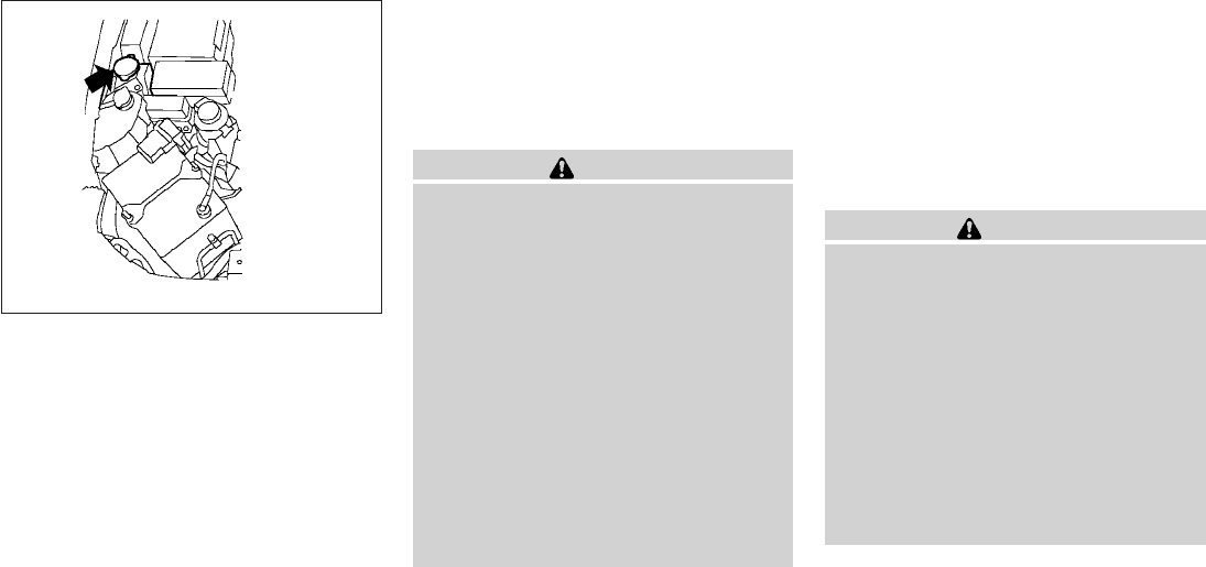
WINDOW WASHER FLUID
RESERVOIR
Fill the window washer fluid reservoir periodically.
Add window washer fluid when the low window
washer fluid warning light comes on.
To fill the window washer fluid reservoir, lift the
cap off the reservoir tank and pour the window
washer fluid into the tank opening.
Add a washer solvent to the washer for better
cleaning. In the winter season, add a windshield
washer antifreeze. Follow the manufacturer’s in-
structions for the mixture ratio.
Refill the reservoir more frequently when driving
conditions require an increased amount of win-
dow washer fluid.
Recommended fluid is Genuine NISSAN Wind-
shield Washer Concentrate Cleaner & Anti-
freeze or equivalent.
CAUTION
●Do not substitute engine anti-freeze
coolant for window washer solution.
This may result in damage to the paint.
●Do not fill the window washer reservoir
tank with washer fluid concentrates at
full strength. Some methyl alcohol
based washer fluid concentrates may
permanently stain the grille if spilled
while filling the window washer reser-
voir tank.
●Pre-mix washer fluid concentrates with
water to the manufacturer’s recom-
mended levels before pouring the fluid
into the window washer reservoir tank.
Do not use the window washer reservoir
tank to mix the washer fluid concen-
trate and water.
●Keep the battery surface clean and dry.
Clean the battery with a solution of baking
soda and water.
●Make certain the terminal connections are
clean and securely tightened.
●If the vehicle is not to be used for 30 days or
longer, disconnect the negative (-) battery
terminal cable to prevent discharge.
WARNING
●Do not expose the battery to flames, an
electrical spark or a cigarette. Hydro-
gen gas generated by the battery is ex-
plosive. Explosive gases can cause
blindness or injury. Do not allow battery
fluid to contact your skin, eyes, fabrics
or painted surfaces. Sulfuric acid can
cause blindness or injury. After touch-
ing a battery or battery cap, do not
touch or rub your eyes. Thoroughly
wash your hands. If the acid contacts
your eyes, skin or clothing, immediately
flush with water for at least 15 minutes
and seek medical attention.
LDI0441
WINDOW WASHER FLUID BATTERY
Maintenance and do-it-yourself 8-15
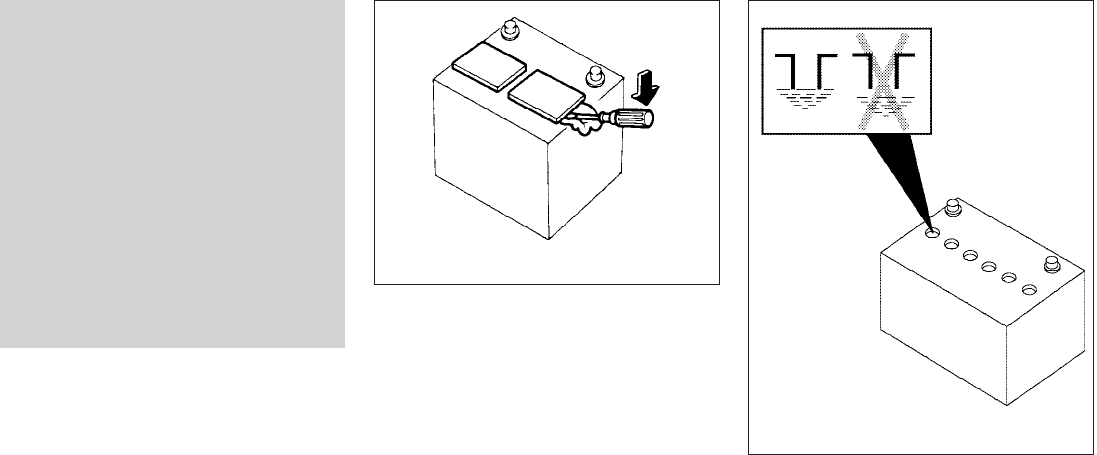
●Do not operate the vehicle if the fluid in
the battery is low. Low battery fluid can
cause a higher load on the battery
which can generate heat, reduce bat-
tery life, and in some cases lead to an
explosion.
●When working on or near a battery, al-
ways wear suitable eye protection and
remove all jewelry.
●Battery posts, terminals and related ac-
cessories contain lead and lead com-
pounds. Wash hands after handling.
●Keep battery out of the reach of
children.
●Do not tip the battery. Keep the vent
caps tight and the battery level.
1. Remove the vent caps with a screwdriver as
shown. Use a cloth to protect the battery
case.
2. Check the fluid level in each cell. If it is
necessary to add fluid, add only distilled
water to bring the level up to the bottom of
the filler opening. Do not overfill. . Reinstall
the vent caps.
WDI0224
WDI0529
8-16 Maintenance and do-it-yourself
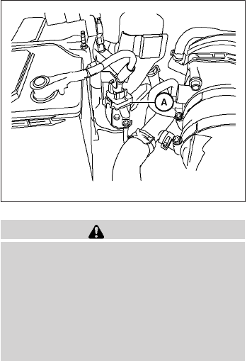
Vehicles operated in high temperatures or under
severe conditions require frequent checks of the
battery fluid level.
JUMP STARTING
If jump starting is necessary, see “Jump starting”
in the “In case of emergency” section of this
manual. If the engine does not start by jump
starting, the battery may have to be replaced.
Contact a NISSAN dealer.
CAUTION
●Do not ground accessories directly to
the battery terminal. Doing so will by-
pass the variable voltage control sys-
tem and the vehicle battery may not
charge completely.
●Use electrical accessories with the en-
gine running to avoid discharging the
vehicle battery.
Your vehicle is equipped with a variable voltage
control system. This system measures the
amount of electrical discharge from the battery
and controls voltage generated by the generator.
The current sensor s
Ais located near the battery
along the negative battery cable. If you add elec-
trical accessories to your vehicle, be sure to
ground them to a suitable body ground such as
the frame or engine block area.
LDI0454
VARIABLE VOLTAGE CONTROL
SYSTEM
Maintenance and do-it-yourself 8-17
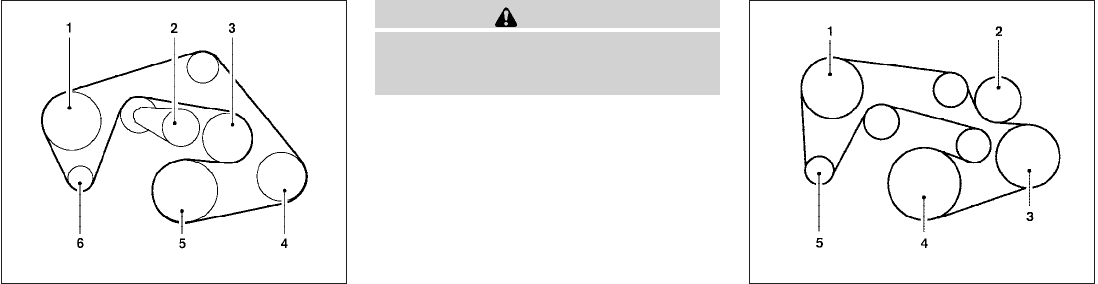
1. Power steering fluid pump
2. Automatic belt tensioner
3. Cooling fan
4. Air conditioner compressor
5. Crankshaft pulley
6. Generator
WARNING
Be sure the ignition key is in the OFF or
LOCK position before servicing drive belt.
The engine could rotate unexpectedly.
1. Visually inspect the belt for signs of unusual
wear, cuts, fraying or looseness. If the belt is
in poor condition or is loose, have it replaced
or adjusted by a NISSAN dealer.
2. Have the belt checked regularly for condi-
tion and tension in accordance with the
maintenance schedule found in the
“NISSAN Service and Maintenance Guide”.
1 Power steering fluid pump
2 Water pump
3 Air conditioner compressor
(if so equipped)
4 Crankshaft pulley
5 Generator
VQ40DE
WDI0639
QR25DE
LDI0461
DRIVE BELT
8-18 Maintenance and do-it-yourself
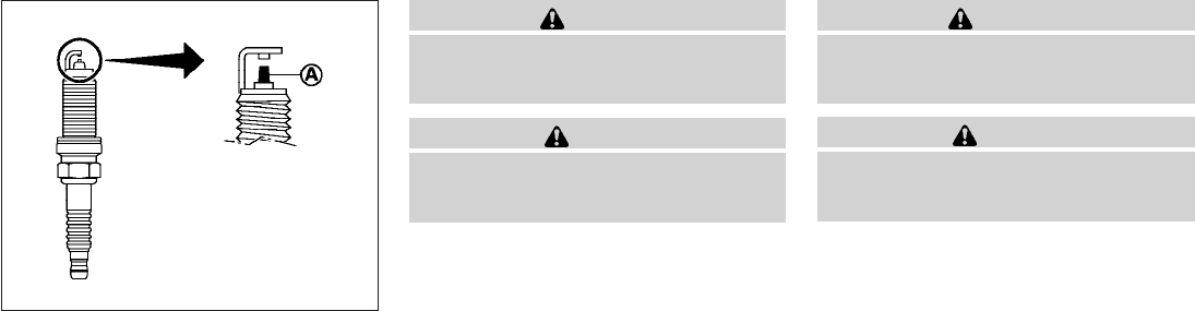
REPLACING SPARK PLUGS
Platinum-tipped spark plugs (if so
equipped)
It is not necessary to replace platinum-tipped s
A
spark plugs as frequently as conventional type
spark plugs because they last much longer. Fol-
low the maintenance log shown in the “NISSAN
Service and Maintenance Guide”. Do not service
platinum-tipped spark plugs by cleaning or re-
gapping.
●Always replace spark plugs with rec-
ommended or equivalent ones.
WARNING
Be sure the engine and ignition switch are
off and that the parking brake is engaged
securely.
CAUTION
Be sure to use the correct socket to re-
move the spark plugs. An incorrect socket
can damage the spark plugs.
If replacement is required, see your NISSAN
dealer for assistance.
Iridium-tipped spark plugs (if so
equipped)
It is not necessary to replace iridium-tipped s
A
spark plugs as frequently as conventional type
spark plugs because they last much longer. Fol-
low the maintenance log shown in the “NISSAN
Service and Maintenance Guide”. Do not service
iridium-tipped spark plugs by cleaning or regap-
ping.
●Always replace spark plugs with rec-
ommended or equivalent ones.
WARNING
Be sure the engine and ignition switch are
off and that the parking brake is engaged
securely.
CAUTION
Be sure to use the correct socket to re-
move the spark plugs. An incorrect socket
can damage the spark plugs.
If replacement is required, see your NISSAN
dealer for assistance.
SDI1895
SPARK PLUGS
Maintenance and do-it-yourself 8-19
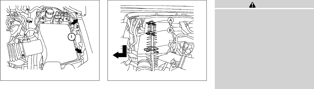
The air cleaner filter should not be cleaned and
reused. Replace it according to the maintenance
log shown in the “NISSAN Service and Mainte-
nance Guide.”When replacing the filter, wipe the
inside of the air cleaner filter housing and the
cover with a damp cloth.
To remove the VQ40DE air cleaner filter:
s
1Push down on the clips and remove the air
cleaner cover. Remove the air cleaner filter.
To remove the QR25DE air cleaner filter:
1. Unlatch the clips s
A,s
B,s
C.
2. Push down half of air cleaner to clear the
bottom retainers.
3. Lift up on half of air cleaner to remove the air
cleaner filter
WARNING
●Operating the engine with the air
cleaner removed can cause you or oth-
ers to be burned. The air cleaner not
only cleans the air, it stops the flame if
the engine backfires. If it isn’t there, and
the engine backfires, you could be
burned. Do not drive with the air cleaner
removed, and be careful when working
on the engine with the air cleaner
removed.
●Never pour fuel into the throttle body or
attempt to start the engine with the air
cleaner removed. Doing so could result
in serious injury.
IN-CABIN MICROFILTER (if so
equipped)
The in-cabin microfilter restricts the entry of air-
borne dust and pollen particles and reduces
some objectionable outside odors. The filter is
located behind the glove box. Refer to the
“NISSAN Service and Maintenance Guide” for
change intervals.
To replace the filter, perform the following proce-
dure:
VQ40DE
WDI0686
QR25DE
LDI0465
AIR CLEANER
8-20 Maintenance and do-it-yourself
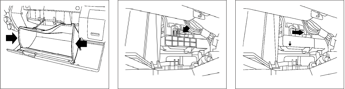
1. Open the glove box and press in on the
sides so that it will open completely allowing
it to hang by the cord.
2. Lift upward to release the filter cover and
remove the filter cover. NOTE:
The filters are marked with air flow arrows.
The end of the filter with the arrow should
face the rear of the vehicle. The arrows
should face downward.
3. Insert the first filter into the housing and slide
it over to the right. Insert the second filter
into the housing.
4. Replace the filter cover.
5. Install the glove box door.
LDI0442 LDI0676 LDI0473
Maintenance and do-it-yourself 8-21
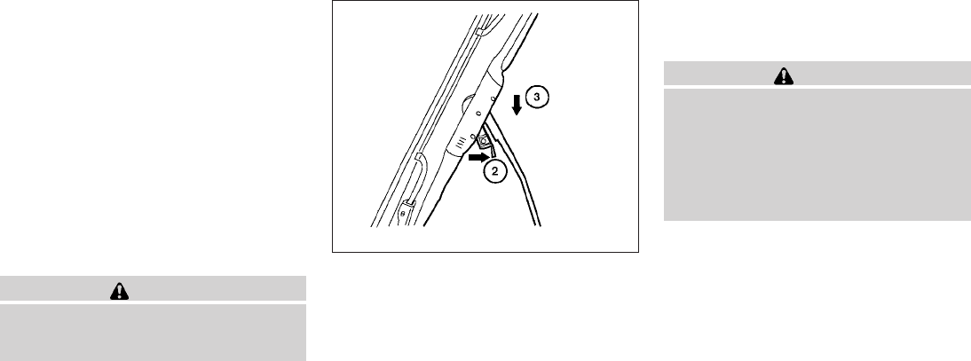
CLEANING
If your windshield is not clear after using the
windshield washer or if a wiper blade chatters
when running, wax or other material may be on
the blade or windshield.
Clean the outside of the windshield with a washer
solution or a mild detergent. Your windshield is
clean if beads do not form when rinsing with clear
water.
Clean each blade by wiping it with a cloth soaked
in a washer solution or a mild detergent. Then
rinse the blades with clear water. If your wind-
shield is still not clear after cleaning the blades
and using the wiper, replace the blades.
CAUTION
Worn windshield wiper blades can dam-
age the windshield and impair driver
vision.
REPLACING
Replace the wiper blades if they are worn.
1. Lift the wiper arm away from the windshield.
s
2Push the release tab, then move the wiper
blade down the wiper arm to remove.
s
3Remove the wiper blade.
4. Insert the new wiper blade onto the wiper
arm until it clicks into place.
5. Rotate wiper blade so the dimple is in the
groove.
6. Return the wiper to its original position and
release it until it has made contact with the
windshield.
CAUTION
●After wiper blade replacement, return
the wiper arm to its original position;
otherwise it may be damaged when the
hood is opened.
●Make sure the wiper blades contact the
glass; otherwise the arms may be dam-
aged from wind pressure.
WDI0408
WINDSHIELD WIPER BLADES
8-22 Maintenance and do-it-yourself
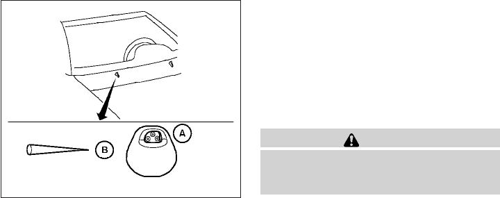
If you wax the surface of the hood, be careful not
to let wax get into the washer nozzle s
A. This may
cause clogging or improper windshield washer
operation. If wax gets into the nozzle, remove it
with a needle or small pin s
B.
If the brakes do not operate properly, have the
brakes checked by a NISSAN dealer.
Self-adjusting brakes
Your vehicle is equipped with self-adjusting
brakes.
The front and rear disc-type brakes self-adjust
every time the brake pedal is applied.
WARNING
See a NISSAN dealer for a brake system
check if the brake pedal height does not
return to normal.
Brake pad wear indicators
The disc brake pads on your vehicle have audible
wear indicators. When a brake pad requires re-
placement, a high pitched scraping or screech-
ing sound will be heard when the vehicle is in
motion. The noise will be heard whether or not the
brake pedal is depressed. Have the brakes
checked as soon as possible if the wear indicator
sound is heard.
Under some driving or climate conditions, occa-
sional brake squeak, squeal or other noise may
be heard. Occasional brake noise during light to
moderate stops is normal and does not affect the
function or performance of the brake system.
Proper brake inspection intervals should
be followed. For more information regarding
brake inspections, see the appropriate mainte-
nance schedule information in the “NISSAN Ser-
vice and Maintenance Guide”.
WDI0595
BRAKES
Maintenance and do-it-yourself 8-23
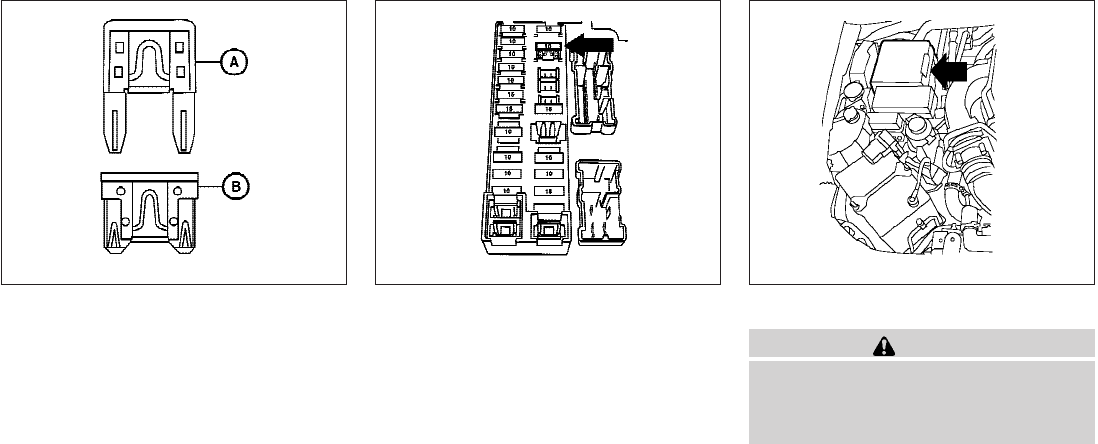
Two types of fuses are used. Type s
Ais used in
the fuse boxes in the engine compartment. Type
s
Bis used in the passenger compartment fuse
box.
Type A fuses are provided as spare fuses. They
are stored in the passenger compartment fuse
box.
Type A fuses can be installed in the engine com-
partment and passenger compartment fuse
boxes.
If a type A fuse is used to replace a type B fuse,
the type A fuse will not be level with the fuse
pocket as shown in the illustration. This will not
affect the performance of the fuse. Make sure the
fuse is installed in the fuse box securely.
Type B fuses cannot be installed in the under-
hood fuse boxes. Only use type A fuses in the
underhood fuse boxes.
ENGINE COMPARTMENT
CAUTION
Never use a fuse of a higher or lower
amperage rating than specified on the
fuse box cover. This could damage the
electrical system or cause a fire.
If any electrical equipment does not come on,
check for an open fuse.
1. Be sure the ignition switch and the headlight
switch are OFF.
2. Open the engine hood.
LDI0455 LDI0457 LDI0444
FUSES
8-24 Maintenance and do-it-yourself
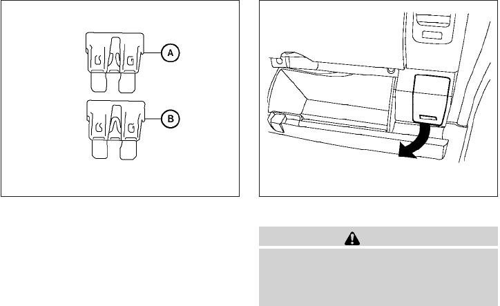
3. Remove the fuse box cover by pushing the
tab and lifting the cover up.
4. Remove the fuse with the fuse puller. The
fuse puller is located in the center of the fuse
block in the passenger compartment.
5. If the fuse is open s
A, replace it with a new
fuse s
B.
6. If a new fuse also opens, have the electrical
system checked and repaired by a NISSAN
dealer.
Fusible links
If the electrical equipment does not operate and
fuses are in good condition, check the fusible
links. If any of these fusible links are melted,
replace with only genuine NISSAN parts.
PASSENGER COMPARTMENT
CAUTION
Never use a fuse of a higher or lower
amperage rating than specified on the
fuse box cover. This could damage the
electrical system or cause a fire.
If any electrical equipment does not operate,
check for an open fuse.
1. Be sure the ignition switch and the headlight
switch are OFF.
2. Pull the fuse box cover to remove.
3. Remove the fuse with the fuse puller.
WDI0452 LDI0445
Maintenance and do-it-yourself 8-25
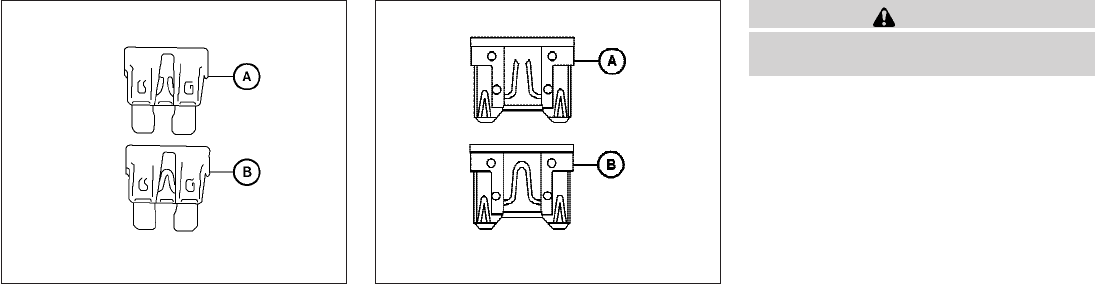
4. If the fuse is open s
A, replace it with an
equivalent good fuse s
B.
5. Push the fuse box cover to install.
6. If a new fuse also opens, have the electrical
system checked and repaired by a NISSAN
dealer.
CAUTION
Be careful not to allow children to swallow
the battery or removed parts.
Type A
WDI0452
Type B
LDI0456
BATTERY REPLACEMENT
8-26 Maintenance and do-it-yourself
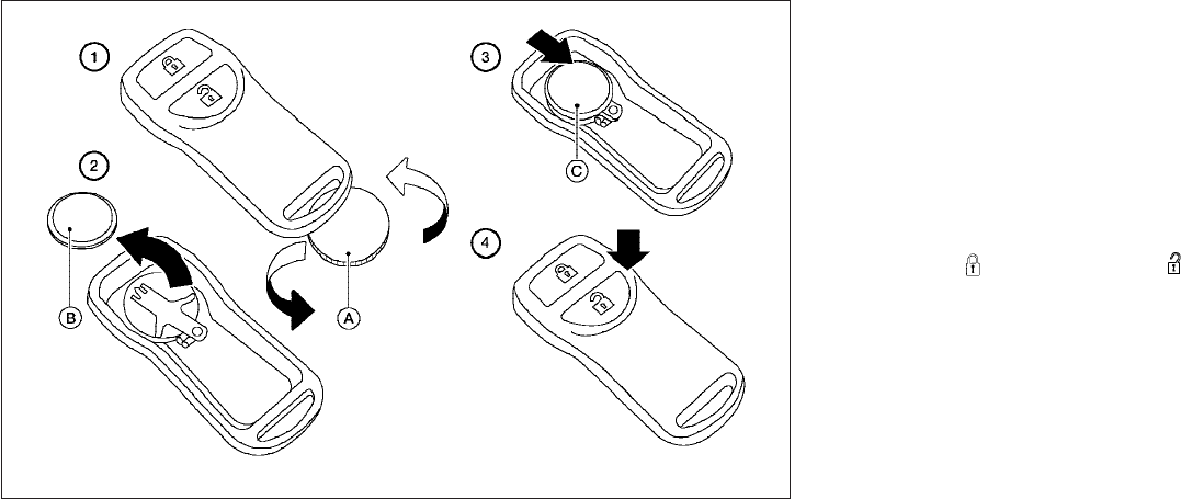
KEYFOB (if so equipped)
Replace the battery in the keyfob as follows:
s
1Open the lid using a coin s
A.
s
2Remove the battery s
B.
s
3Install a new battery s
Cwith the “+” facing
down.
●Hold the battery by the edges. Holding the
battery across the contact points will seri-
ously deplete the storage capacity.
●Do not touch the internal circuit and electric
terminals as it could cause a malfunction.
●When changing the battery, do not let dust
or oil get on the keyfob.
●There is danger of explosion if a lithium bat-
tery is incorrectly replaced. Replace only
with the same or equivalent type.
Recommended battery: CR2025 or equivalent.
s
4Close the lid securely.
5. Press the button, then the
button two or three times to check the key-
fob operation.
If the battery is removed for any reason
other than replacement, perform step 5.
●An improperly disposed battery can
hurt the environment. Always confirm
local regulations for battery disposal.
●The keyfob is water-resistant; how-
ever, if it does get wet, immediately
wipe completely dry.
●The operational range of the keyfob
extends to approximately 33 ft (10 m)
from the vehicle. This range may vary
with conditions.
LDI0484
Maintenance and do-it-yourself 8-27

FCC Notice:
Changes or modifications not expressly ap-
proved by the party responsible for compli-
ance could void the user’s authority to op-
erate the equipment.
This device complies with Part 15 of the
FCC Rules and RSS-210 of Industry
Canada.
Operation is subject to the following two
conditions: (1) This device may not cause
harmful interference, and (2) this device
must accept any interference received, in-
cluding interference that may cause undes-
ired operation of the device.
HEADLIGHTS
The headlight is a semi-sealed beam type which
uses a replaceable headlight (halogen) bulb. A
bulb can be replaced from inside the engine
compartment without removing the headlight as-
sembly.
CAUTION
●High pressure halogen gas is sealed
inside the halogen bulb. The bulb may
break if the glass envelope is scratched
or the bulb is dropped.
●When handling the bulb, do not touch
the glass envelope.
●DO NOT TOUCH THE BULB WITH BARE
HANDS.
●Use the same number and wattage as
shown in the chart.
●Do not leave the bulb out of the head-
light reflector for a long period of time
as dust, moisture and smoke may enter
the headlight body and affect the per-
formance of the headlight.
●Aiming is not necessary after replacing
the bulb. When aiming adjustment is
necessary, contact a NISSAN dealer.
Fog may temporarily form inside the lens of the
exterior lights in the rain or in a car wash. A
temperature difference between the inside and
the outside of the lens causes the fog. This is not
a malfunction. If large drops of water collect
inside the lens, contact a NISSAN dealer.
LIGHTS
8-28 Maintenance and do-it-yourself
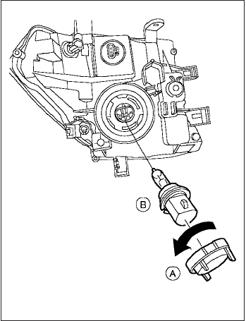
Removing the headlight bulb
1. Open the hood.
2. Disconnect the negative (-) battery cable.
3. Disconnect the electrical connector from the
rear end of the bulb.
4. Turn the bulb retaining ring counterclock-
wise until it is free from the headlight reflec-
tor and then remove it s
A.
5. Carefully remove the headlight bulb. Do not
shake or rotate the bulb when removing it
s
B.
Replacing the headlight bulb
1. Insert the bulb.
DO NOT TOUCH THE BULB WITH BARE
HANDS.
2. Install and tighten the bulb retainer.
●Be sure the lip of the bulb socket con-
tacts the headlight body.
3. Push the electrical connector into the bulb
plastic base until it snaps and stops.
4. Connect the negative (-) battery cable.
5. Close the hood.
LDI0446
Maintenance and do-it-yourself 8-29
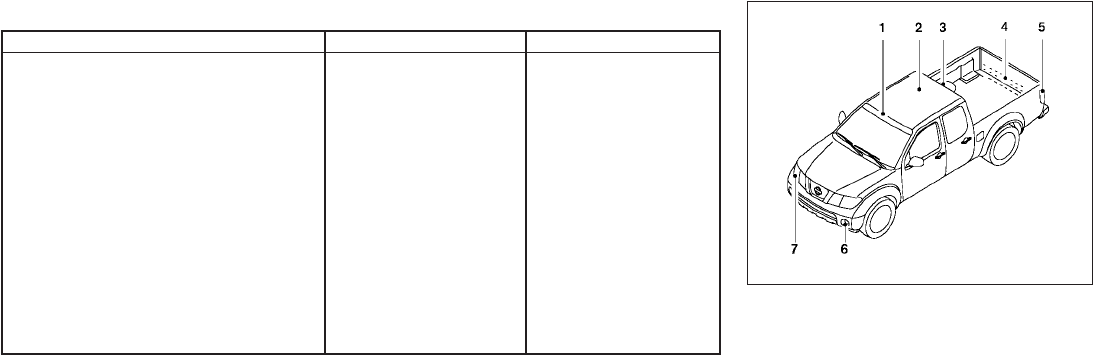
EXTERIOR AND INTERIOR LIGHTS
Item Wattage (W) Bulb No.*
1
Headlight 65/55 9007 (HB5)
Turn signal light/Parking light 28/8 T-20 NA
Side marker 3.8 194
Rear combination light
Turn signal 27 3156AK
Stop/Tail 27/8 3157K
Back-up 18 921
License plate light 5 2J6
Fog light*
2
(if so equipped) 55 H11
Map lights (if so equipped) 8 AL38
Room light 8 AL41
High-mounted stop light/cargo lights*
2
——
*
1
Always check with the Parts Department at a NISSAN dealer for the latest parts information.
*
2
The bulb is not serviceable in-vehicle. See a NISSAN dealer for assistance.
1. Map lights (if so equipped)
2. Room light
3. High-mount stoplight/cargo lights
4. License plate light
5. Rear combination light
6. Fog light (if so equipped)
7. Headlight assembly
LDI0713
8-30 Maintenance and do-it-yourself
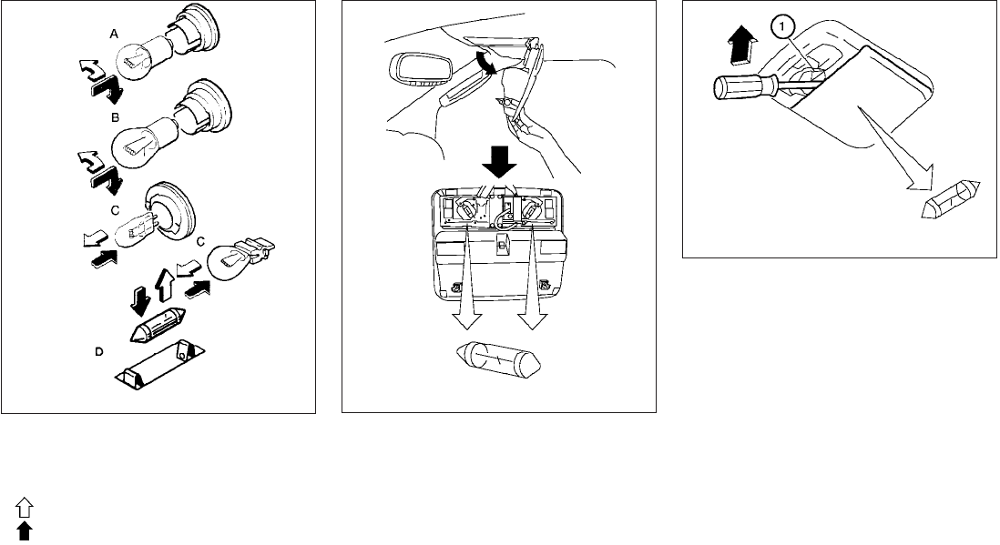
Replacement procedures
All other lights are either type A, B, C or D. When
replacing a bulb, first remove the lens and/or
cover.
: Indicates bulb removal
: Indicates bulb installation
Use a cloth s
1to protect the housing.
WDI0306 Map lights/personal lights LDI0459
Room light
WDI0206
Maintenance and do-it-yourself 8-31
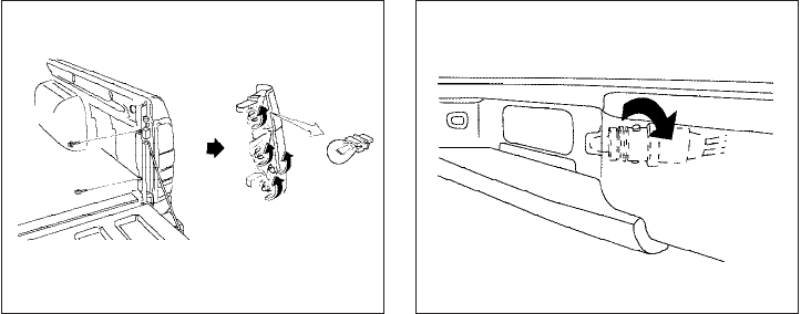
If you have a flat tire, see “Flat tire” in the
“In case of emergency” section of this
manual.
TIRE PRESSURE
Tire Pressure Monitoring System
(TPMS)
This vehicle is equipped with the Tire
Pressure Monitoring System (TPMS). It
monitors tire pressure of all tires except
the spare. When the low tire pressure
warning light is lit, one or more of your
tires is significantly under-inflated.
The TPMS will activate only when the
vehicle is driven at speeds above 16 MPH
(25 km/h). Also, this system may not de-
tect a sudden drop in tire pressure (for
example a flat tire while driving).
For more details, refer to “Low tire pres-
sure warning light”in the “Instruments and
controls” section, “Tire Pressure Monitor-
ing System (TPMS)” in the “Starting and
driving” section, and “Flat tire” in the “In
case of emergency” section.
Rear combination light
WDI0300
License plate light
WDI0411
WHEELS AND TIRES
8-32 Maintenance and do-it-yourself

Tire inflation pressure
Check the tire pressures (including the
spare) often and always prior to long dis-
tance trips. The recommended tire pres-
sure specifications are shown on the
F.M.V.S.S./C.M.V.S.S. certification label
or the Tire and Loading Information label
under the “Cold Tire Pressure” heading.
The Tire and Loading Information label is
affixed to the driver side center pillar. Tire
pressures should be checked regularly
because:
●Most tires naturally lose air over time.
●Tires can lose air suddenly when
driven over potholes or other objects
or if the vehicle strikes a curb while
parking.
The tire pressures should be checked
when the tires are cold. The tires are
considered COLD after the vehicle has
been parked for 3 or more hours, or driven
less than 1 mile (1.6 km) at moderate
speeds.
Incorrect tire pressure, including un-
der inflation, may adversely affect
tire life and vehicle handling.
WARNING
●Improperly inflated tires can fail
suddenly and cause an accident.
●The Gross Vehicle Weight Rating
(GVWR) is located on the
F.M.V.S.S./C.M.V.S.S. certifica-
tion label. The vehicle weight ca-
pacity is indicated on the Tire and
Loading Information label (if so
equipped). Do not load your ve-
hicle beyond this capacity. Over-
loading your vehicle may result in
reduced tire life, unsafe operat-
ing conditions due to premature
tire failure, or unfavorable han-
dling characteristics and could
also lead to a serious accident.
Loading beyond the specified ca-
pacity may also result in failure of
other vehicle components.
●Before taking a long trip, or
whenever you heavily load your
vehicle, use a tire pressure gauge
to ensure that the tire pressures
are at the specified level.
●For additional information re-
garding tires, refer to “Important
Tire Safety Information” (US) or
“Tire Safety Information”
(Canada) in the Warranty Infor-
mation Booklet.
Maintenance and do-it-yourself 8-33
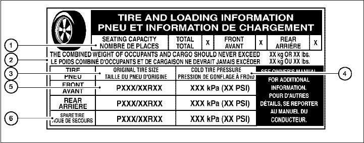
Tire and loading information label
s
1Seating capacity: The maximum num-
ber of occupants that can be seated
in the vehicle.
s
2Vehicle load limit: See loading infor-
mation in the “Technical and con-
sumer information” section.
s
3Original tire size: The size of the tires
originally installed on the vehicle at
the factory.
s
4Cold tire pressure: Inflate the tires to
this pressure when the tires are cold.
Tires are considered COLD after the
vehicle has been parked for 3 or more
hours, or driven less than 1 mile (1.6
km) at moderate speeds. The recom-
mended cold tire inflation is set by the
manufacturer to provide the best bal-
ance of tire wear, vehicle handling,
driveability, tire noise, etc., up to the
vehicle’s GVWR.
s
5Tire size – refer to “Tire labeling” later
in this section.
s
6Spare tire size or compact spare tire
size (if so equipped).
LDI0485
8-34 Maintenance and do-it-yourself
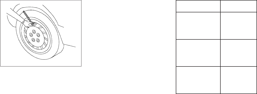
Checking tire pressure
1. Remove the valve stem cap from the
tire.
2. Press the pressure gauge squarely
onto the valve stem. Do not press too
hard or force the valve stem side-
ways, or air will escape. If the hissing
sound of air escaping from the tire is
heard while checking the pressure,
reposition the gauge to eliminate this
leakage.
3. Remove the gauge.
4. Read the tire pressure on the gauge
stem and compare to the specifica-
tion shown on the
F.M.V.S.S./C.M.V.S.S. label or the
Tire and Loading Information label (if
so equipped).
5. Add air to the tire as needed. If too
much air is added, press the core of
the valve stem briefly with the tip of
the gauge stem to release pressure.
Recheck the pressure and add or
release air as needed.
6. Install the valve stem cap.
7. Check the pressure of all other tires,
including the spare.
Size Cold Tire Infla-
tion Pressure
Front Original Tire:
P235/75R15
P265/70R16
P265/75R16
P265/60R18
240 kPa, 35 PSI
Rear Original Tire:
P235/75R15
P265/70R16
P265/75R16
P265/60R18
240 kPa, 35 PSI
Spare Tire:
P235/75R15
P265/70R16
P265/75R16
P265/60R18
240 kPa, 35 PSI
LDI0393
Maintenance and do-it-yourself 8-35
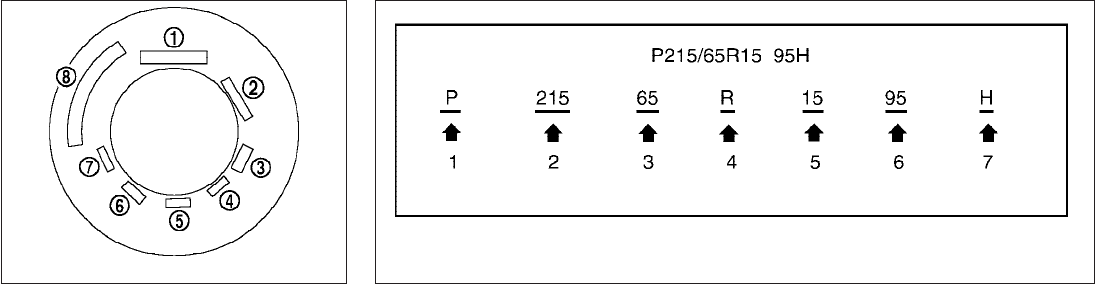
TIRE LABELING
Federal law requires tire manufacturers to
place standardized information on the
sidewall of all tires. This information iden-
tifies and describes the fundamental
characteristics of the tire and also pro-
vides the tire identification number (TIN)
for safety standard certification. The TIN
can be used to identify the tire in case of a
recall.
s
1Tire size (example: P215/65R15 95H)
1. P: The “P” indicates the tire is de-
signed for passenger vehicles (not all
tires have this information).
2. Three-digit number (215): This num-
ber gives the width in millimeters of
the tire from sidewall edge to side-
wall edge.
3. Two-digit number (65): This number,
known as the aspect ratio, gives the
tire’s ratio of height to width.
4. R: The “R” stands for radial.
5. Two-digit number (15): This number
is the wheel or rim diameter in inches.
6. Two- or three-digit number (95): This
number is the tire’s load index. It is a
measurement of how much weight
each tire can support. You may not
find this information on all tires be-
cause it is not required by law.
7. H: Tire speed rating. You should not
drive the vehicle faster than the tire
speed rating.
Example WDI0394
Example
WDI0395
8-36 Maintenance and do-it-yourself
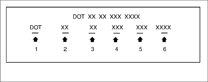
s
2TIN (Tire Identification Number) for a
new tire (example: DOT XX XX XXX
XXXX)
1. DOT: Abbreviation for the “Depart-
ment Of Transportation”. The symbol
can be placed above, below or to the
left or right of the Tire Identification
Number.
2. Two-digit code: Manufacturer’s
identification mark.
3. Two-digit code: Tire size.
4. Three-digit code: Tire type code
(Optional).
5. Three-digit code: Date of Manufac-
ture.
6. Four numbers represent the week
and year the tire was built. For ex-
ample, the numbers 3103 means the
31st week of 2003. If these numbers
are missing, then look on the other
sidewall of the tire.
s
3Tire ply composition and material
The number of layers or plies of rubber-
coated fabric in the tire. Tire manufactur-
ers also must indicate the materials in the
tire, which include steel, nylon, polyester,
and others.
s
4Maximum permissible inflation pres-
sure
This number is the greatest amount of air
pressure that should be put in the tire. Do
not exceed the maximum permissible in-
flation pressure.
s
5Maximum load rating
This number indicates the maximum load
in kilograms and pounds that can be car-
ried by the tire. When replacing the tires
on the vehicle, always use a tire that has
the same load rating as the factory in-
stalled tire.
s
6Term of “tubeless” or “tube type”
Indicates whether the tire requires an in-
ner tube (“tube type”) or not (“tubeless”).
Example
WDI0396
Maintenance and do-it-yourself 8-37

s
7The word “radial”
The word “radial” is shown if the tire has
radial structure.
s
8Manufacturer or brand name
Manufacturer or brand name is shown.
Other Tire-related Terminology
In addition to the many terms that are
defined throughout this section, Intended
Outboard Sidewall is (1) the sidewall that
contains a whitewall, bears white lettering
or bears manufacturer, brand, and/or
model name molding that is higher or
deeper than the same molding on the
other sidewall of the tire, or (2) the out-
ward facing sidewall of an asymmetrical
tire that has a particular side that must
always face outward when mounted on a
vehicle.
TYPES OF TIRES
WARNING
●When changing or replacing tires, be
sure all four tires are of the same type
(i.e., Summer, All Season or Snow) and
construction. A NISSAN dealer may be
able to help you with information about
tire type, size, speed rating and
availability.
●Replacement tires may have a lower
speed rating than the factory equipped
tires, and may not match the potential
maximum vehicle speed. Never exceed
the maximum speed rating of the tire.
●For additional information regarding
tires, refer to “Important Tire Safety In-
formation”(US) or “Tire Safety Informa-
tion” (Canada) in the Warranty Informa-
tion Booklet.
All season tires
NISSAN specifies All Season tires on some mod-
els to provide good performance all year, includ-
ing snowy and icy road conditions. All Season
tires are identified by ALL SEASON and/or M&S
on the tire sidewall. Snow tires have better snow
traction than All Season tires and may be more
appropriate in some areas.
Summer tires
NISSAN specifies summer tires on some models
to provide superior performance on dry roads.
Summer tire performance is substantially re-
duced in snow and ice. Summer tires do not have
the tire traction rating “M&S” on the tire sidewall.
If you plan to operate your vehicle in snowy or icy
conditions, NISSAN recommends the use of
SNOW tires or ALL SEASON tires on all four
wheels.
Snow tires
If snow tires are needed, it is necessary to select
tires equivalent in size and load rating to the
original equipment tires. If you do not, it can
adversely affect the safety and handling of your
vehicle.
Generally, snow tires have lower speed ratings
than factory equipped tires and may not match
the potential maximum vehicle speed. Never ex-
ceed the maximum speed rating of the tire.
If you install snow tires, they must be the same
size, brand, construction and tread pattern on all
four wheels.
For additional traction on icy roads, studded tires
may be used. However, some U.S. states and
Canadian provinces prohibit their use. Check
local, state and provincial laws before installing
8-38 Maintenance and do-it-yourself
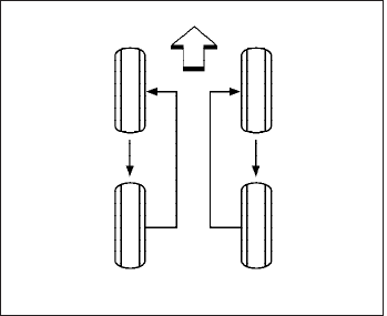
studded tires. Skid and traction capabilities of
studded snow tires on wet or dry surfaces may be
poorer than that of non-studded snow tires.
TIRE CHAINS
Use of tire chains may be prohibited according to
location. Check the local laws before installing
tire chains. When installing tire chains, make sure
they are the proper size for the tires on your
vehicle and are installed according to the chain
manufacturer’s suggestions. Use only SAE
class “S” chains. Class “S” chains are used on
vehicles with restricted tire to vehicle clearance.
Vehicles that can use Class “S” chains are de-
signed to meet the minimum clearances between
the tire and the closest vehicle suspension or
body component required to accommodate the
use of a winter traction device (tire chains or
cables). The minimum clearances are determined
using the factory equipped tire size. Other types
may damage your vehicle. Use chain tensioners
when recommended by the tire chain manufac-
turer to ensure a tight fit. Loose end links of the
tire chain must be secured or removed to prevent
the possibility of whipping action damage to the
fenders or underbody. If possible, avoid fully load-
ing your vehicle when using tire chains. In addi-
tion, drive at a reduced speed. Otherwise, your
vehicle may be damaged and/or vehicle handling
and performance may be adversely affected.
Tire chains must be installed only on the
rear wheels and not on the front wheels.
Do not use tire chains on dry roads. Driving with
chains in such conditions can cause damage to
the various mechanisms of the vehicle due to
some overstress.
Use only the 2WD range when driving on clear
paved roads.
CHANGING WHEELS AND TIRES
Tire rotation
NISSAN recommends rotating the tires
every 7,500 miles (12,000 km).
See “Flat tire” in the “In case of emer-
gency” section in this manual for tire re-
placing procedures.
As soon as possible, tighten the
wheel nuts to the specified torque
with a torque wrench.
WDI0258
Maintenance and do-it-yourself 8-39
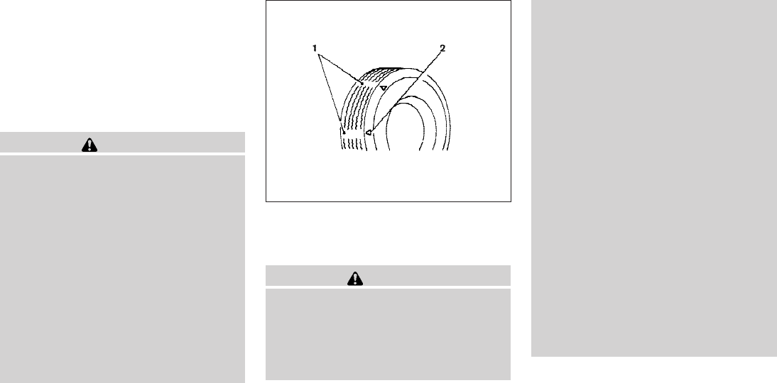
Wheel nut tightening torque:
98 ft-lb (133 N·m)
The wheel nuts must be kept tight-
ened to specifications at all times. It
is recommended that wheel nuts be
tightened to specification at each
tire rotation interval.
WARNING
●After rotating the tires, check and
adjust the tire pressure.
●Retighten the wheel nuts when
the vehicle has been driven for
600 miles (1,000 km) (also in
cases of a flat tire, etc.).
●Do not include the spare tire in
the tire rotation.
●For additional information re-
garding tires, refer to “Important
Tire Safety Information” (US) or
“Tire Safety Information”
(Canada) in the Warranty Infor-
mation Booklet.
1. Wear indicator
2. Location mark
Tire wear and damage
WARNING
●Tires should be periodically in-
spected for wear, cracking, bulg-
ing or objects caught in the tread.
If excessive wear, cracks, bulging
or deep cuts are found, the tire(s)
should be replaced.
●The original tires have built-in
tread wear indicators. When the
wear indicators are visible, the
tire(s) should be replaced.
●Tires degrade with age and use.
Have tires, including the spare,
over 6 years old checked by a
qualified technician because
some tire damage may not be ob-
vious. Replace the tires as neces-
sary to prevent tire failure and
possible personal injury.
●Improper service of the spare tire
may result in serious personal in-
jury. If it is necessary to repair the
spare tire, contact a NISSAN
dealer.
●For additional information re-
garding tires, refer to “Important
Tire Safety Information” (US) or
“Tire Safety Information”
(Canada) in the Warranty Infor-
mation Booklet.
WDI0259
8-40 Maintenance and do-it-yourself

Replacing wheels and tires
When replacing a tire, use the same size, tread
design, speed rating and load carrying capacity
as originally equipped. Recommended types and
sizes are shown in “Wheels and tires” in the
“Technical and consumer information” section of
this manual.
WARNING
●The use of tires other than those recom-
mended or the mixed use of tires of
different brands, construction (bias,
bias-belted or radial), or tread patterns
can adversely affect the ride, braking,
handling, VDC system, ground clear-
ance, body-to-tire clearance, tire chain
clearance, speedometer calibration,
headlight aim and bumper height.
Some of these effects may lead to acci-
dents and could result in serious per-
sonal injury.
●If your vehicle was originally equipped
with 4 tires that were the same size and
you are only replacing 2 of the 4 tires,
install the new tires on the rear axle.
Placing new tires on the front axle may
cause loss of vehicle control in some
driving conditions and cause an acci-
dent and personal injury.
●If the wheels are changed for any rea-
son, always replace with wheels which
have the same off-set dimension.
Wheels of a different off-set could
cause premature tire wear, degrade ve-
hicle handling characteristics, affect
the VDC system and/or interference
with the brake discs/drums. Such inter-
ference can lead to decreased braking
efficiency and/or early brake pad/shoe
wear. Refer to “Wheels and tires” in the
“Technical and consumer information”
section of this manual for wheel off-set
dimensions.
●When a spare tire is mounted or a wheel
is replaced, tire pressure will not be
indicated, the TPMS will not function
and the low tire pressure warning light
will flash for approximately 1 minute.
The light will remain on after 1 minute.
Contact your NISSAN dealer as soon as
possible for tire replacement and/or
system resetting.
●Replacing tires with those not originally
specified by NISSAN could affect the
proper operation of the TPMS.
●Do not install a damaged or deformed
wheel or tire even if it has been re-
paired. Such wheels or tires could have
structural damage and could fail with-
out warning.
●The use of retread tires is not
recommended.
●For additional information regarding
tires, refer to “Important Tire Safety In-
formation”(US) or “Tire Safety Informa-
tion” (Canada) in the Warranty Informa-
tion Booklet.
Four-wheel drive models
CAUTION
Always use tires of the same type, size,
brand, construction (bias, bias-belted or
radial), and tread pattern on all four
wheels. Failure to do so may result in a
circumference difference between tires
on the front and rear axles which will
cause excessive tire wear and may dam-
age the transmission, transfer case and
differential gears.
If excessive tire wear is found, it is recommended
that all four tires be replaced with tires of the
same size, brand, construction and tread pattern.
Maintenance and do-it-yourself 8-41

The tire pressure and wheel alignment should
also be checked and corrected as necessary.
Contact a NISSAN dealer.
Wheel balance
Unbalanced wheels may affect vehicle handling
and tire life. Even with regular use, wheels can get
out of balance. Therefore, they should be bal-
anced as required.
Wheel balance service should be per-
formed with the wheels off the vehicle.
Spin balancing the wheels on the vehicle
could lead to mechanical damage.
●For additional information regarding
tires, refer to “Important Tire Safety
Information” (US) or “Tire Safety Infor-
mation” (Canada) in the Warranty In-
formation Booklet.
Care of wheels
●Wash the wheels when washing the vehicle
to maintain their appearance.
●Clean the inner side of the wheels when the
wheel is changed or the underside of the
vehicle is washed.
●Do not use abrasive cleaners when washing
the wheels.
●Inspect wheel rims regularly for dents or
corrosion. Such damage may cause loss of
pressure or poor seal at the tire bead.
●NISSAN recommends waxing the road
wheels to protect against road salt in areas
where it is used during winter.
Spare tire (FULL SIZE TEMPORARY
USE ONLY spare tire) (if so equipped)
Your vehicle may be equipped with a full size
spare that is a different size or brand than the tires
originally installed on the vehicle. This full size
spare tire is intended for temporary use only and
should be replaced at the first opportunity.
Observe the following precautions if the full size
temporary use only spare tire must be used.
Otherwise, your vehicle could be damaged or
involved in an accident:
WARNING
●The spare tire should be used for emer-
gency use only. It should be replaced
with the standard tire at the first oppor-
tunity to avoid possible tire or differen-
tial damage.
●Drive carefully while the spare tire is
installed. Avoid sharp turns and abrupt
braking while driving. The vehicle driv-
ing performance may be affected when
driving on wet or snow covered roads.
●When the temporary full size spare is
installed, the following systems may
not work correctly:
– Tire Pressure Monitoring System
(TPMS).
– Vehicle Dynamic Control (VDC)
System.
●Periodically check spare tire inflation
pressure. Always keep the spare tire
inflated to the pressure specification
shown on the tire and loading informa-
tion label.
●With the spare tire installed do not drive
the vehicle at speeds faster than 50
MPH (80 km/h).
●When driving on roads covered with
snow or ice, the temporary spare tire
should be used on the front wheels and
the original tire used on the rear
wheels. Use tire chains only on the drive
wheels.
8-42 Maintenance and do-it-yourself

●Do not use the spare tire on other
vehicles.
●Do not use more than one spare tire at
the same time.
CAUTION
●Do not use tire chains on a spare tire.
Tire chains will not fit properly and may
cause damage to the vehicle.
Maintenance and do-it-yourself 8-43
MEMO
8-44 Maintenance and do-it-yourself

9 Technical and consumer information
Capacities and recommended fuel/lubricants .........9-2
Fuel recommendation ...........................9-4
Engine oil and oil filter recommendations ..........9-6
Air conditioner system refrigerant and oil
recommendations ..............................9-7
Specifications.....................................9-8
Engine ........................................9-8
Wheels and tires ...............................9-9
Dimensions and weights ........................9-9
When traveling or registering your vehicle in
another country ..................................9-10
Vehicle identification ..............................9-10
Vehicle identification number (VIN) plate .........9-10
Vehicle identification number
(chassis number) ..............................9-10
Engine serial number...........................9-11
F.M.V.S.S./C.M.V.S.S. certification label ..........9-11
Emission control information label ...............9-12
Tire and loading information label................9-12
Air conditioner specification label................9-12
Installing front license plate ........................9-13
Installing front license plate with grommets .......9-13
Installing front license plate without
grommets ....................................9-13
Vehicle loading information ........................9-13
Terms ........................................9-13
Vehicle load capacity ..........................9-14
Securing the load..............................9-16
Utili-track™ channel system (if so equipped) ......9-17
Loading tips ..................................9-22
Truck-camper loading information ..................9-23
Crew Cab Models .............................9-23
King Cab models ..............................9-23
Special Body vehicles..........................9-23
Location for center of gravity....................9-23
Vehicle load weight capacity ....................9-24
Measurement of weights .......................9-24
Towing a trailer ...................................9-24
Maximum load limits ...........................9-25
Towing load/specification.......................9-28
Towing safety .................................9-29
Flat towing....................................9-35
Uniform tire quality grading ........................9-36
Emission control system warranty ..................9-37
Reporting safety defects (US only) .................9-37
Readiness for inspection/maintenance (I/M) test .....9-37
Event Data Recorders (EDR).......................9-38
Owner’s Manual/Service Manual order information . . . 9-39
In the event of a collision .......................9-39

The following are approximate capacities. The actual refill capacities may be a little different. When refilling, follow the procedure
described in the “Maintenance and do-it-yourself” section to determine the proper refill capacity.
Capacity (Approximate) Recommended Fluids and Lubricants
US measure Imp measure Liter
Fuel 21 1/8gal 17-5/8 gal 80 See “Fuel recommendation” later in this section.
Engine oil *7
Drain and Refill
With oil filter change
QR25DE
4-7/8 qt 4 qt 4.6 • Engine oil with API Certification Mark *1
• Viscosity SAE 5W-30
Without oil filter
change 4-1/2 qt 3-3/4 qt 4.3
With oil filter change
VQ40DE
5-3/8 qt 4-1/2 qt 5.1 • Engine oil with API Certification Mark *1
• Viscosity SAE 5W-30
Without oil filter
change 5-1/8 qt 4-1/4 qt 4.8
Cooling system
With reservoir
QR25DE 2-1/2 gal 2-1/8 gal 9.4 50% Genuine NISSAN Long Life Antifreeze/Coolant or equivalent
50% Demineralized or distilled water
VQ40DE 2-3/4 gal 2-1/4 gal 10.2
Manual transmission gear oil
5M/T 3 qt 2-1/2 qt 2.89 Genuine NISSAN Manual Transmission Fluid (MTF) HQ Multi
75W-85 or API GL-4, Viscosity SAE 75W-85
6 M/T 4X2 4-1/4 qt 3-1/2 qt 3.98 Genuine NISSAN Manual Transmission Fluid (MTF) HQ Multi
75W-85 or API GL-4, Viscosity SAE 75W-85 or 75W-90
6 M/T 4X4 4-3/8 qt 3-5/8 qt 4.18
Automatic transmission fluid Refill to the proper level according to the instruc-
tions in the “Maintenance and do-it-yourself”
section.
Genuine NISSAN Matic S ATF *2
Power steering fluid (PSF) Genuine NISSAN PSF or equivalent.*3
Brake and clutch fluid Genuine NISSAN Super Heavy Duty Brake Fluid *4 or equivalent
DOT 3
Multi-purpose grease ———NLGINo.2(Lithium Soap base)
Air conditioning system refrigerant — — — HFC-134a (R-134a) *5
CAPACITIES AND RECOMMENDED
FUEL/LUBRICANTS
9-2 Technical and consumer information

Capacity (Approximate) Recommended Fluids and Lubricants
US measure Imp measure Liter
Air conditioning system oil — — — NISSAN A/C System Oil Type R or equivalent *5
Transfer fluid 2-1/8 qt 4-1/2 qt 2.0 Genuine NISSAN Matic D ATF recommended *6
Front final drive oil 1-3/4 pt 1-1/2 pt 0.85 Genuine NISSAN Differential Oil Hypoid Super GL-5 80W-90 or API
GL-5 SAE 80W-90
Rear final drive oil (except 6 speed MT and O/R vehicles) 3-3/8 pt 2-7/8 pt 1.6 Genuine NISSAN differential oil synthetic 75W-90 or API GL-5 syn-
thetic gear oil, Viscosity SAE 75W-90 *7
Rear final drive oil 6 speed MT and O/R vehicles only 4-1/4 pt 3-1/2 pt 2.0 Genuine NISSAN differential oil synthetic 75W-140 or API GL-5 syn-
thetic gear oil, Viscosity SAE 75W-140 *8
Windshield washer fluid 1-1/4 gal 1 gal 4.5 Genuine NISSAN Windshield Washer Concentrate Cleaner & Anti-
freeze or equivalent
*1: For further details, see “Engine oil and oil filter recommendations.”
*2: If Genuine NISSAN Matic S ATF is not available, Genuine NISSAN Matic J ATF may also be used. Using automatic transmission fluid other than Genuine NISSAN Matic S ATF or
Matic J ATF will cause deterioration in driveability and automatic transmission durability, and may damage the automatic transmission, which is not covered by the NISSAN new ve-
hicle limited warranty.
*3: DEXRON™ VI type ATF or Canada NISSAN Automatic Transmission Fluid may also be used.
*4: Available in mainland USA through your NISSAN dealer.
*5: For further details, see “Air conditioner specification label.”
*6: Using automatic transmission fluid other than Genuine NISSAN Matic D ATF may cause deterioration in driveability and transfer durability, and may damage the transfer, which is not
covered by the NISSAN new vehicle limited warranty.
*7: For further details, see “Changing engine oil.”
*8: See your NISSAN dealer for service for synthetic oil.
Technical and consumer information 9-3

FUEL RECOMMENDATION
Use unleaded regular gasoline with an octane
rating of at least 87 AKI (Anti-Knock Index) num-
ber (Research octane number 91).
CAUTION
●Using a fuel other than that specified
could adversely affect the emission
control system, and may also affect the
warranty coverage.
●Under no circumstances should a
leaded gasoline be used, because this
will damage the three-way catalyst.
●Do not use E-85 fuel in your vehicle.
Your vehicle is not designed to run on
E-85 fuel. Using E-85 fuel can damage
the fuel system components and is not
covered by the NISSAN new vehicle lim-
ited warranty.
Gasoline specifications
NISSAN recommends using gasoline that meets
the World-Wide Fuel Charter (WWFC) specifi-
cations where it is available. Many of the automo-
bile manufacturers developed this specification
to improve emission control system and vehicle
performance. Ask your service station manager if
the gasoline meets the WWFC specifications.
Reformulated gasoline
Some fuel suppliers are now producing reformu-
lated gasolines. These gasolines are specially
designed to reduce vehicle emissions. NISSAN
supports efforts towards cleaner air and sug-
gests that you use reformulated gasoline when
available.
Gasoline containing oxygenates
Some fuel suppliers sell gasoline containing oxy-
genates such as ethanol, MTBE and methanol
with or without advertising their presence.
NISSAN does not recommend the use of fuels of
which the oxygenate content and the fuel com-
patibility for your NISSAN cannot be readily de-
termined. If in doubt, ask your service station
manager.
If you use oxygenate-blend gasoline, please take
the following precautions as the usage of such
fuels may cause vehicle performance problems
and/or fuel system damage.
●The fuel should be unleaded and have
an octane rating no lower than that
recommended for unleaded gasoline.
●If an oxygenate-blend other than
methanol blend is used, it should con-
tain no more than 10% oxygenate.
(MTBE may, however, be added up to
15%.)
●If a methanol blend is used, it should
contain no more than 5% methanol
(methyl alcohol, wood alcohol). It
should also contain a suitable amount
of appropriate cosolvents and corro-
sion inhibitors. If not properly formu-
lated with appropriate cosolvents and
corrosion inhibitors, such methanol
blends may cause fuel system damage
and/or vehicle performance problems.
At this time, sufficient data is not avail-
able to ensure that all methanol blends
are suitable for use in NISSAN ve-
hicles.
If any driveability problems such as engine stall-
ing and difficult hot-starting are experienced after
using oxygenate-blend fuels, immediately
change to a non-oxygenate fuel or a fuel with a
low blend of MTBE.
Take care not to spill gasoline during refu-
eling. Gasoline containing oxygenates can
cause paint damage.
9-4 Technical and consumer information

E–85 fuel
E-85 fuel is a mixture of approximately 85% fuel
ethanol and 15% unleaded gasoline. E-85 can
only be used in a Flexible Fuel Vehicle (FFV). Do
not use E-85 in your vehicle. U.S. government
regulations require fuel ethanol dispensing
pumps to be identified by a small, square, orange
and black label with the common abbreviation or
the appropriate percentage for that region.
Aftermarket fuel additives
NISSAN does not recommend the use of any
aftermarket fuel additives (for example, fuel injec-
tor cleaner, octane booster, intake valve deposit
removers, etc.) which are sold commercially.
Many of these additives intended for gum, varnish
or deposit removal may contain active solvents or
similar ingredients that can be harmful to the fuel
system and engine.
Octane rating tips
Using unleaded gasoline with an octane
rating lower than recommended can cause
persistent, heavy “spark knock.” (“Spark
knock” is a metallic rapping noise.) If se-
vere, this can lead to engine damage. If you
detect a persistent heavy spark knock even
when using gasoline of the stated octane
rating, or if you hear steady spark knock
while holding a steady speed on level
roads, have a NISSAN dealer correct the
condition. Failure to correct the condition
is misuse of the vehicle, for which NISSAN
is not responsible.
Incorrect ignition timing may result in spark
knock, after-run and/or overheating, which may
cause excessive fuel consumption or engine
damage. If any of the above symptoms are en-
countered, have your vehicle checked at a
NISSAN dealer.
However, now and then you may notice
light spark knock for a short time while
accelerating or driving up hills. This is not a
cause for concern, because you get the
greatest fuel benefit when there is light
spark knock for a short time under heavy
engine load.
CAUTION
●Your vehicle is not designed to run on
E-85 fuel. Using E-85 fuel in a vehicle
not specifically designed for E-85 fuel
can damage fuel system components
and is not covered by the NISSAN new
vehicle limited warranty.
●E-85 is a mixture of approximately 85%
fuel ethanol and 15% unleaded
gasoline.
●U.S. government regulations require
ethanol dispensing pumps to be identi-
fied by a small, square, orange and
black label with the common abbrevia-
tion or the appropriate percentage for
that region.
Technical and consumer information 9-5
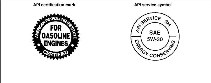
ENGINE OIL AND OIL FILTER
RECOMMENDATIONS
Selecting the correct oil
It is essential to choose the correct grade, quality
and viscosity engine oil to ensure satisfactory
engine life and performance. See “Capacities
and recommended fuel/lubricants” earlier in this
section. NISSAN recommends the use of an
energy conserving oil in order to improve fuel
economy.
Select only engine oils that meet the American
Petroleum Institute (API) certification or Interna-
tional Lubricant Standardization and Approval
Committee (ILSAC) certification and SAE vis-
cosity standard. These oils have the API certifica-
tion mark on the front of the container. Oils which
do not have the specified quality label should not
be used as they could cause engine damage.
Oil additives
NISSAN does not recommend the use of oil
additives. The use of an oil additive is not neces-
sary when the proper oil type is used and main-
tenance intervals are followed.
Oil which may contain foreign matter or has been
previously used should not be used.
Oil viscosity
The engine oil viscosity or thickness changes
with temperature. Because of this, it is important
to select the engine oil viscosity based on the
temperatures at which the vehicle will be oper-
ated before the next oil change. Choosing an oil
viscosity other than that recommended could
cause serious engine damage.
Selecting the correct oil filter
Your new NISSAN vehicle is equipped with a
high-quality genuine NISSAN oil filter. When re-
placing, use a genuine NISSAN oil filter or its
equivalent for the reason described in “Change
intervals.”
Change intervals
The oil and oil filter change intervals for your
engine are based on the use of the specified
quality oils and filters. Using engine oil and filters
that are not of the specified quality, or exceeding
recommended oil and filter change intervals
could reduce engine life. Damage to the engine
caused by improper maintenance or use of incor-
rect oil and filter quality and/or viscosity is not
covered by the NISSAN new vehicle limited war-
ranty.
WTI0183
9-6 Technical and consumer information

Your engine was filled with a high-quality engine
oil when it was built. You do not have to change
the oil before the first recommended change
interval. Oil and filter change intervals depend
upon how you use your vehicle.
Operation under the following conditions may
require more frequent oil and filter changes:
●repeated short distance driving at cold out-
side temperatures
●driving in dusty conditions
●extensive idling
●towing a trailer
●stop and go commuting
Refer to the “NISSAN Service and Maintenance
Guide” for the maintenance schedule.
AIR CONDITIONER SYSTEM
REFRIGERANT AND OIL
RECOMMENDATIONS
The air conditioner system in your NISSAN
vehicle must be charged with the refriger-
ant HFC-134a (R-134a) and the oil, NISSAN
A/C system oil Type R or the exact equiva-
lents.
CAUTION
The use of any other refrigerant or oil will
cause severe damage to the air condition-
ing system and will require the replace-
ment of all air conditioner system
components.
The refrigerant HFC-134a (R-134a) in your
NISSAN vehicle does not harm the earth’s ozone
layer. Although this refrigerant does not affect the
earth’s atmosphere, certain government regula-
tions require the recovery and recycling of any
refrigerant during automotive air conditioner sys-
tem service. A NISSAN dealer has the trained
technicians and equipment needed to recover
and recycle your air conditioner system refriger-
ant.
Contact a NISSAN dealer when servicing your air
conditioner system.
Technical and consumer information 9-7

ENGINE
Model QR25DE VQ40DE
Type Gasoline, 4-cycle, DOHC Gasoline, 4-cycle, DOHC
Cylinder arrangement 4-cylinder in-line 6-cylinder, V-block, Slanted at 60°
Bore x Stroke in (mm) 3.5 x 3.9 (89.0 x 100.0) 3.760 x 3.622 (95.5 x 92)
Displacement cu in (cm
3
) 151.82 (2,488) 241.30 (3,954)
Firing order 1–3–4–2 1–2–3–4–5–6
Idle speed
M/T
A/T (in “N” position) See the “Emission Control Information label” on the underside of the hood.
Ignition timing (degree B.T.D.C. at idle
speed)
CO % at idle
Spark plug Standard PLZKAR6A-11 DILFR5A11
Spark plug gap (Nominal) in (mm) 0.043 (1.1) 0.043 (1.1)
Camshaft operation Timing chain Timing chain
This spark ignition system complies with the Canadian standard ICES-002.
SPECIFICATIONS
9-8 Technical and consumer information

WHEELS AND TIRES
Wheels
15 x 7.0J
16 x 7.0J
18 x 7.5J
Tires
P235/75R15
P265/70R16
P265/75R16
P265/60R18
Spare tire Full size
DIMENSIONS AND WEIGHTS
Overall length
Short wheel base in (mm) 205.5(5220)
Long wheel base in (mm) 219.4(5574)
Overall width in (mm) 72.8(1850)
Overall height
With roof rack in (mm) 74.0(1880)
Without roof rack
XE and SE King cab
models
SE, LE, Pro-4X King cab
models
Crew cab models
in (mm) 68.7(1745)
69.7(1770)
70.1(1780)
Front Track in (mm) 61.8(1570)
Rear Track in (mm) 61.8(1570)
Wheelbase
Short wheel base in (mm) 125.9(3200)
Long wheel base in (mm) 139.8(3550)
Gross vehicle weight
rating
lb (kg) See the “F.M.V.S.S./C.M.
V.S.S. certification label”
on the center pillar be-
tween the driver’s side
front and side doors.
Gross axle weight rating
Front lb (kg)
Rear lb (kg)
Technical and consumer information 9-9
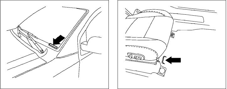
When planning to drive your NISSAN ve-
hicle in another country, you should first find
out if the fuel available is suitable for your vehi-
cle’s engine.
Using fuel with an octane rating that is too low
may cause engine damage. All gasoline vehicles
must be operated with unleaded gasoline. There-
fore, avoid taking your vehicle to areas where
appropriate fuel is not available.
When transferring the registration of your
vehicle to another country, state, province
or district, it may be necessary to modify the
vehicle to meet local laws and regulations.
The laws and regulations for motor vehicle emis-
sion control and safety standards vary according
to the country, state, province or district; there-
fore, vehicle specifications may differ.
When any vehicle is to be taken into an-
other country, state, province or district
and registered, its modifications, transpor-
tation, and registration are the responsibil-
ity of the user. NISSAN is not responsible
for any inconvenience that may result.
VEHICLE IDENTIFICATION NUMBER
(VIN) PLATE
The vehicle identification number (VIN) plate is
attached as shown. This number is the identifica-
tion for your vehicle and is used in the vehicle
registration.
VEHICLE IDENTIFICATION NUMBER
(chassis number)
The vehicle identification number is located as
shown.
LTI0085 LTI0086
WHEN TRAVELING OR REGISTERING
YOUR VEHICLE IN ANOTHER
COUNTRY
VEHICLE IDENTIFICATION
9-10 Technical and consumer information
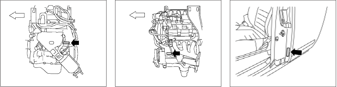
ENGINE SERIAL NUMBER
The number is stamped on the engine as shown.
F.M.V.S.S./C.M.V.S.S.
CERTIFICATION LABEL
The Federal/Canadian Motor Vehicle Safety
Standard (F.M.V.S.S./C.M.V.S.S.) certification la-
bel is affixed as shown. This label contains valu-
able vehicle information, such as: Gross Vehicle
Weight Ratings (GVWR), Gross Axle Weight
Rating (GAWR), month and year of manufacture,
Vehicle Identification Number (VIN), etc. Review
it carefully.
QR25DE engine
LTI0130
VQ40DE engine
LTI0127 LTI0136
Technical and consumer information 9-11
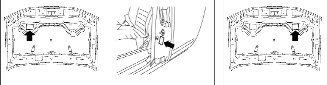
EMISSION CONTROL
INFORMATION LABEL
The emission control information label is at-
tached to the underside of the hood as shown.
TIRE AND LOADING INFORMATION
LABEL
The cold tire pressure is shown on the Tire and
Loading Information label. The label is located as
shown.
AIR CONDITIONER SPECIFICATION
LABEL
The air conditioner specification label is affixed to
the underside of the hood as shown.
LTI0133 LTI0135 LTI0206
9-12 Technical and consumer information
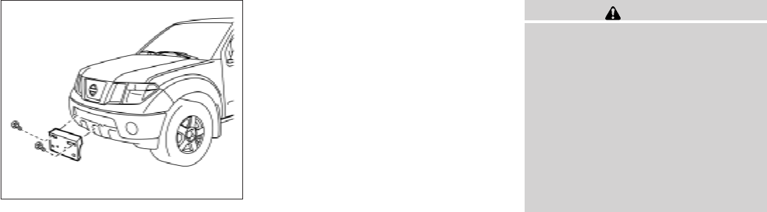
INSTALLING FRONT LICENSE
PLATE WITH GROMMETS
Use the following steps to mount the front license
plate with grommets:
1. Make holes on the plastic finisher at the
location mark (small dimple) using a 0.37 in
(9.5 mm) drill. Apply light pressure to the
drill. Insert two plastic grommets provided.
Install the license plate holder using the two
bolts (and washers) provided.
2. Mount the license plate using two M6-14
mm bolts.
License plate bolt tightening torque:
3.8 - 4.7 ft-lb (5.10 - 6.37 N·m)
INSTALLING FRONT LICENSE
PLATE WITHOUT GROMMETS
Use the following steps to mount the front license
plate without grommets:
1. Make a shallow hole in each plastic finisher
at the location mark (small dimple) using a
0.31 in (8 mm) drill. To avoid damaging the
threads behind the finisher, apply only light
pressure to the drill.
2. Mount the license plate bracket using two 8
mm slotted hex head screws.
WARNING
●It is extremely dangerous to ride
in a cargo area inside a vehicle. In
a collision, people riding in these
areas are more likely to be seri-
ously injured or killed.
●Do not allow people to ride in any
area of your vehicle that is not
equipped with seats and seat
belts.
●Be sure everyone in your vehicle
is in a seat and using a seat belt
properly.
TERMS
It is important to familiarize yourself with
the following terms before loading your
vehicle:
●Curb Weight (actual weight of your
vehicle) - vehicle weight including:
standard and optional equipment, flu-
ids, emergency tools, and spare tire
assembly. This weight does not in-
clude passengers and cargo.
LTI0137
INSTALLING FRONT LICENSE PLATE VEHICLE LOADING INFORMATION
Technical and consumer information 9-13
●GVW (Gross Vehicle Weight) - curb
weight plus the combined weight of
passengers and cargo.
●GVWR (Gross Vehicle Weight Rat-
ing) - maximum total combined
weight of the unloaded vehicle, pas-
sengers, luggage, hitch, trailer
tongue load and any other optional
equipment. This information is lo-
cated on the F.M.V.S.S./C.M.V.S.S.
certification label.
●GAWR (Gross Axle Weight Rating) -
maximum weight (load) limit specified
for the front or rear axle. This informa-
tion is located on the
F.M.V.S.S./C.M.V.S.S. certification
label.
●GCWR (Gross Combined Weight
rating) - The maximum total weight
rating of the vehicle, passengers,
cargo, and trailer.
●Vehicle Capacity Weight, Load limit,
Total load capacity - maximum total
weight limit specified of the load
(passengers and cargo) for the ve-
hicle. This is the maximum combined
weight of occupants and cargo that
can be loaded into the vehicle. If the
vehicle is used to tow a trailer, the
trailer tongue weight must be in-
cluded as part of the cargo load. This
information is located on the Tire and
Loading Information label (if so
equipped).
●Cargo capacity - permissible weight
of cargo, the subtracted weight of
occupants from the load limit.
VEHICLE LOAD CAPACITY
Before driving a loaded vehicle, confirm
that you do not exceed the Gross Vehicle
Weight Rating (GVWR) or the Gross Axle
Weight Rating (GAWR) for your vehicle.
Both the GVWR and GAWR are located
on the F.M.V.S.S./C.M.V.S.S. certification
label. See “Measurement of Weights”
later in this section.
Do not exceed the load limit of your ve-
hicle shown as “The combined weight of
occupants and cargo” on the Tire and
Loading Information label (if so
equipped). Do not exceed the number of
occupants shown as “Seating Capacity”
on the Tire and Loading Information label
(if so equipped).
To get “the combined weight of occu-
pants and cargo”, add the weight of all
occupants, then add the total luggage
weight. Examples are shown in the follow-
ing illustration.
9-14 Technical and consumer information
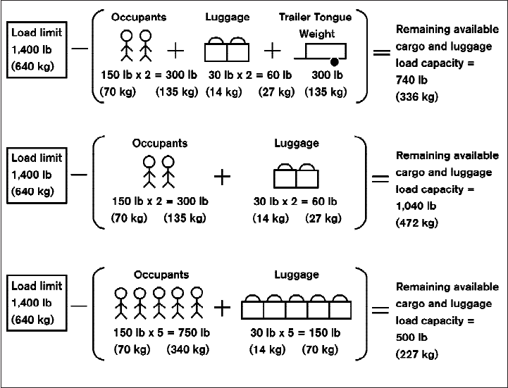
Steps for determining correct load
limit
1. Locate the statement “The combined
weight of occupants and cargo
should never exceed XXX kg or XXX
lbs” on your vehicle’s placard.
2. Determine the combined weight of
the driver and passengers that will be
riding in your vehicle.
3. Subtract the combined weight of the
driver and passengers from XXX kg
or XXX lbs.
4. The resulting figure equals the avail-
able amount of cargo and luggage
load capacity. For example, if the
XXX amount equals 1400 lbs. and
there will be five 150 lb. passengers
in your vehicle, the amount of avail-
able cargo and luggage load capac-
ity is 650 lbs. (1400-750 (5 X 150)
= 650 lbs) or (640-340 (5 X 70) =
300 kg.)
Example LTI0152
Technical and consumer information 9-15
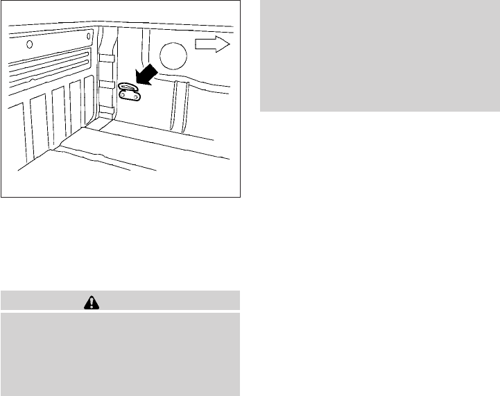
5. Determine the combined weight of
luggage and cargo being loaded on
the vehicle. That weight may not
safely exceed the available cargo and
luggage load capacity calculated in
Step 4.
6. If your vehicle will be towing a trailer,
load from your trailer will be trans-
ferred to your vehicle. Consult this
manual to determine how this re-
duces the available cargo and lug-
gage load capacity of your vehicle.
Before driving a loaded vehicle, confirm
that you do not exceed the Gross Vehicle
Weight Rating (GVWR) or the Gross Axle
Weight Rating (GAWR) for your vehicle.
See “Measurement of Weights” later in
this section.
Also check tires for proper inflation pres-
sures. See the Tire and Loading Informa-
tion label.
SECURING THE LOAD
For your convenience, tie down hooks (if so
equipped) are placed at each corner of the truck
box. These may be used to help secure cargo
loaded into the truck box.
WARNING
●Properly secure all cargo with ropes or
straps to help prevent it from sliding or
shifting. Do not place cargo higher than
the seatbacks. In a sudden stop or col-
lision, unsecured cargo could cause
personal injury.
●Do not load your vehicle any heavier
than the GVWR or the maximum front
and rear GAWRs. If you do, parts of your
vehicle can break, tire damage could
occur, or it can change the way your
vehicle handles. This could result in
loss of control and cause personal
injury.
LTI0102
9-16 Technical and consumer information
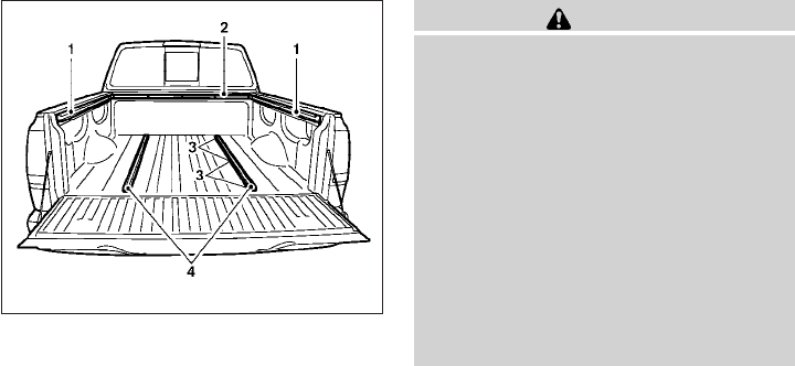
1. Side channels
2. Header channel
3. Channel sections
4. Floor channels
UTILI-TRACK™ CHANNEL SYSTEM
(if so equipped)
WARNING
●Properly install and tighten the tie-
down cleats into the Utili-track™ chan-
nel system. Also, do not attach any rope
or straps directly to the channel. Failure
to properly install the tie-down cleats or
attaching ropes or straps directly to the
channel can cause the cargo to become
unsecured. In a sudden stop or colli-
sion, unsecured cargo could cause per-
sonal injury.
●Properly secure all cargo with ropes or
straps to help prevent it from sliding or
shifting. In a sudden stop or collision,
unsecured cargo could cause personal
injury.
The Utili-track™ channel system allows you to
move tie-down clamps in the bed to the best
location to secure a load.
The tie-down cleats must be installed so the
clamp is properly seated in the notches in the rail.
If the tie-down cleat is not seated in the notches,
it will not be flush with the rail and cannot be
properly tightened. The bolt in the center of the
cleat must be tightened hand tight (20 – 40 inch
pounds)
Check the tightness of the tie-down cleat peri-
odically during a trip to make sure the center bolt
has not become loose.
Install the tie-down cleat as follows:
1. Remove the channel protectors by sliding
them out the back of the truck bed. Properly
store the channel protectors.
2. Loosen the center bolt completely.
LTI0107
Technical and consumer information 9-17
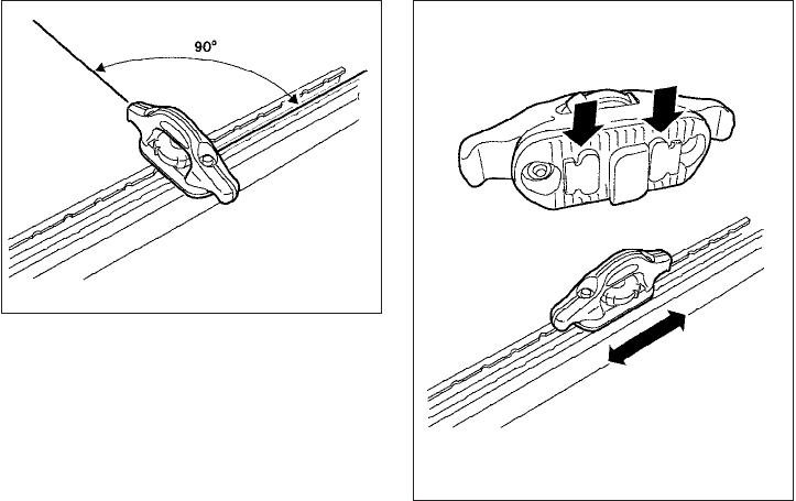
3. Insert the cleat into the channel perpendicu-
lar to the channel as shown. Then rotate the
cleat clockwise 90° and slide it to the de-
sired location.
4. Position the cleat so the nubs on the bottom
fully seat into the channel detents.
LTI0103
LTI0104
9-18 Technical and consumer information
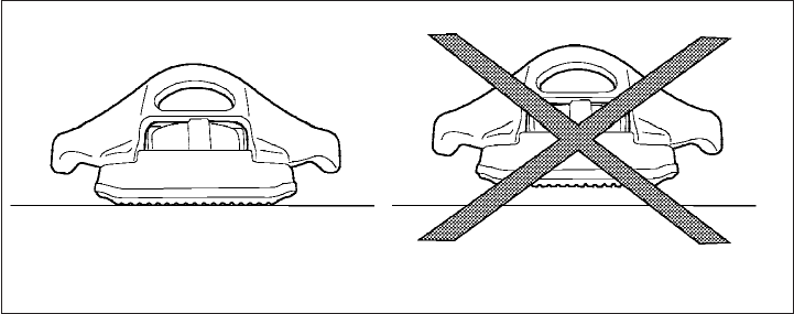
5. There should be no gap between the bottom
of the cleat and the top of the channel.
Tighten the center bolt hand tight (20-40
inch pounds).
WTI0124
Technical and consumer information 9-19
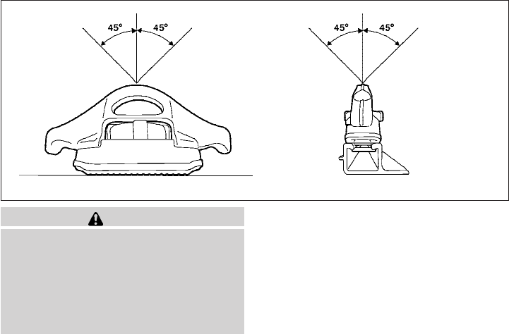
CAUTION
●Install only one cleat per section of
channel.
●Applying loads at angles to the cleats
greater then 45° or loads greater than
150 lbs. (header and floor channels) or
200 lbs. (side channels) may cause
damage to the channel or bed.
LTI0106
9-20 Technical and consumer information
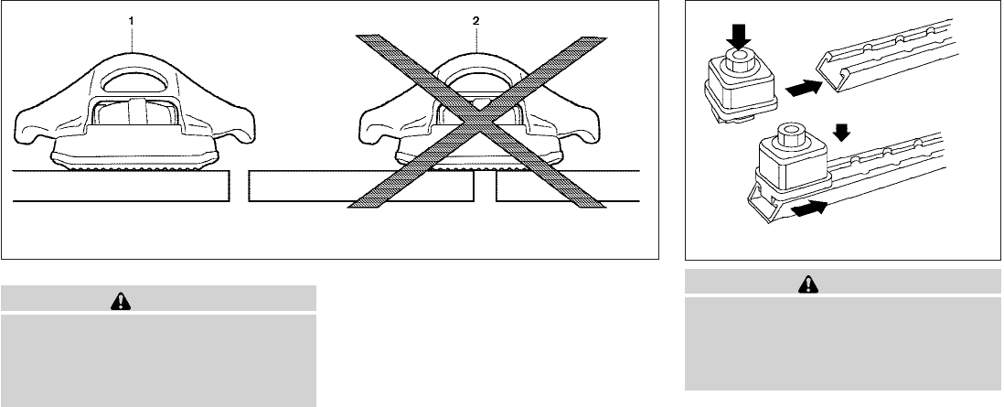
WARNING
Do not install accessories over the gap
between the front and rear side channels.
Doing this could affect the rear structure
in certain rear impacts, which could result
in serious injury.
CAUTION
Properly secure all cargo with ropes or
straps to prevent it from sliding or shifting.
Use the channel end stoppers to help se-
cure items in the channels from sliding off
the end of the truck bed.
Channel end stoppers (if so equipped)
The channel end stoppers should be used to help
prevent accessories installed in the channels
from sliding or shifting off the end of the truck
bed.
They must be installed so they are properly
seated in the detents in the channel.
1 correct installation, 2 incorrect installation
LTI0123 WTI0119
Technical and consumer information 9-21

Install the channels end stoppers as follows:
1. Remove the channel protectors by sliding
them out the back of the truck bed. Properly
store the channel protectors.
2. Loosen the bolt on the center of the end
stopper with the provided wrench and insert
it into the channel.
3. Position the end stopper to the desired lo-
cation on the channel so the nubs on the
bottom of the end stopper fully seat into the
channel detents.
4. Tighten the bolt on the center of the end
stopper with the provided wrench.
LOADING TIPS
●The GVW must not exceed GVWR
or GAWR as specified on the
F.M.V.S.S./C.M.V.S.S. certification
label.
●Do not load the front and rear axle to
the GAWR. Doing so will exceed the
GVWR.
WARNING
●Properly secure all cargo with
ropes or straps to help prevent it
from sliding or shifting. Do not
place cargo higher than the seat-
backs. In a sudden stop or colli-
sion, unsecured cargo could
cause personal injury.
●Do not load your vehicle any
heavier than the GVWR or the
maximum front and rear GAWRs.
If you do, parts of your vehicle
can break, tire damage could oc-
cur, or it can change the way your
vehicle handles. This could result
in loss of control and cause per-
sonal injury.
●Overloading not only can shorten
the life of your vehicle and the
tire, but can also cause unsafe
vehicle handling and longer brak-
ing distances. This may cause a
premature tire failure which
could result in a serious accident
and personal injury. Failures
caused by overloading are not
covered by the vehicle’s
warranty.
9-22 Technical and consumer information
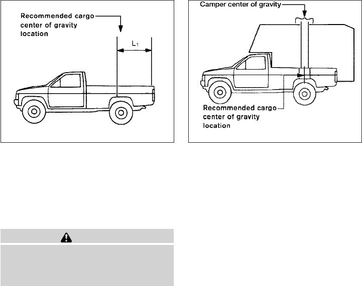
CREW CAB MODELS
Crew Cab short wheel base models should
not be used to carry a slide-in camper.
KING CAB MODELS
This information is provided for you to properly
install a slide-in camper and is based on the
National Highway Traffic Safety Administration
regulations. It is recommended that, before in-
stalling the camper, you carefully read the follow-
ing information and ensure that the camper
meets the specifications.
This information may not apply to some Canada
model vehicles.
SPECIAL BODY VEHICLES
Some vehicles are equipped with commercial or
camper bodies. However, this Owner’s Manual
does not cover these options. For further infor-
mation, please refer to the body manufacturer’s
instruction manual.
LOCATION FOR CENTER OF
GRAVITY
The illustration indicates the recommended
cargo center of gravity location.
King Cab:
L1 = 1054 mm (41.5 in)
WARNING
Improper loading may be dangerous. If a
load is too far back, it can affect handling
characteristics. If a load is too far forward,
the front axle may be overloaded.
When the truck is used to carry a slide-in camper,
the total cargo load of the truck consists of the
camper manufacturer’s weight figure, plus:
●the weight of installed additional camper
equipment not included in the camper
manufacturer’s weight figure,
●the weight of camper cargo,
●and the weight of occupants in the camper.
The total cargo load should not exceed the
truck’s pay load weight rating and the camper’s
center of gravity should fall within the truck’s
recommended center of gravity location when
installed.
LTI0128 LTI0129
TRUCK-CAMPER LOADING
INFORMATION
Technical and consumer information 9-23

WARNING
Overloading or improper loading can ad-
versely affect vehicle handling, braking
and performance and may lead to
accidents.
VEHICLE LOAD WEIGHT CAPACITY
The vehicle payload weight capacity shown on
the Tire and Loading Information label, see “Tire
and Loading Information label” in this section,
indicates the maximum total weight of passen-
gers, optional equipment (air conditioning, trailer
hitch, etc) and cargo that your vehicle is designed
to carry.
Before driving a loaded vehicle, confirm that you
do not exceed the Gross Vehicle Weight Rating
(GVWR) or the Gross Axle Weight Rating
(GAWR) for your vehicle. See ’’Vehicle Loading
Information’’ earlier in this section for details.
Also check tires for proper inflation pressures.
See the Tire and Loading Information label.
MEASUREMENT OF WEIGHTS
Secure loose items to prevent weight
shifts that could affect the balance of your
vehicle. When the vehicle is loaded, drive
to a scale and weigh the front and the rear
wheels separately to determine axle
loads. Individual axle loads should not ex-
ceed either of the gross axle weight rat-
ings (GAWR). The total of the axle loads
should not exceed the gross vehicle
weight rating (GVWR). These ratings are
given on the vehicle certification label. If
weight ratings are exceeded, move or re-
move items to bring all weights below the
ratings.
WARNING
Overloading or improper loading of a
trailer and its cargo can adversely affect
vehicle handling, braking and perfor-
mance and may lead to accidents.
CAUTION
●Do not tow a trailer or haul a heavy load
for the first 500 miles (800 km). Your
engine, axle or other parts could be
damaged.
●For the first 500 miles (800 km) that you
tow a trailer, do not drive over 50 mph
(80 km/h) and do not make starts at full
throttle. This helps the engine and other
parts of your vehicle wear in at the
heavier loads.
Your new vehicle was designed to be used pri-
marily to carry passengers and cargo. Remember
that towing a trailer places additional loads on
your vehicle’s engine, drive train, steering, brak-
ing and other systems.
A NISSAN Towing Guide (U.S. only) is available
on the website at www.nissanusa.com. This
guide includes information on trailer towing ca-
pability and the special equipment required for
proper towing.
TOWING A TRAILER
9-24 Technical and consumer information
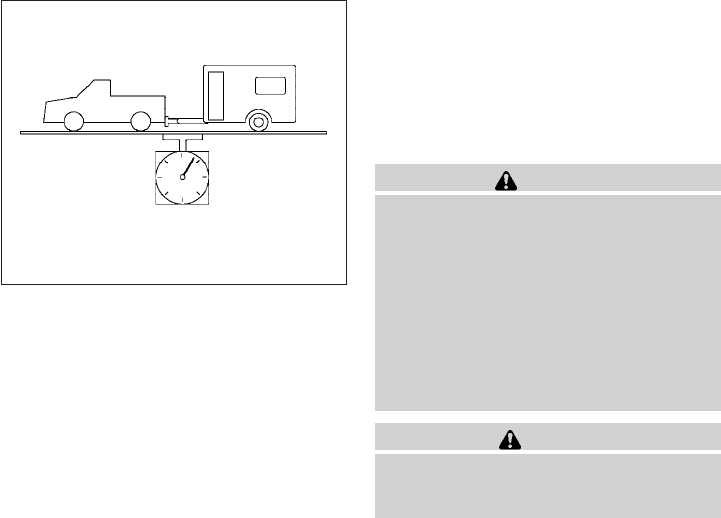
MAXIMUM LOAD LIMITS
Maximum trailer loads
Never allow the total trailer load to exceed the
value specified in the “Towing
Load/Specification” chart found later in this sec-
tion. The total trailer load equals trailer weight
plus its cargo weight.
●When towing a trailer load of 3,500 lbs.
(1587 kg) or more, trailers with a brake
system MUST be used.
The maximum Gross Combined Weight Rating
(GCWR) should not exceed the value specified
in the following “Towing Load/Specification”
chart. The GCWR equals the combined weight of the
towing vehicle (including passengers and cargo)
plus the total trailer load. Towing loads greater
than these or using improper towing equipment
could adversely affect vehicle handling, braking
and performance.
The ability of your vehicle to tow a trailer is not
only related to the maximum trailer loads, but also
the places you plan to tow. Tow weights appro-
priate for level highway driving may have to be
reduced for low traction situations (for example,
on slippery boat ramps).
Temperature conditions can also affect towing.
For example, towing a heavy trailer in high outside
temperatures on graded roads can affect engine
performance and cause overheating. The engine
protection mode, which helps reduce the chance
of engine damage, could activate and automati-
cally decrease engine power. Vehicle speed may
decrease under high load. Plan your trip carefully
to account for trailer and vehicle load, weather
and road conditions.
WARNING
Overheating can result in reduced engine
power and vehicle speed. The reduced
speed may be lower than other traffic,
which could increase the chance of a col-
lision. Be especially careful when driving.
If the vehicle cannot maintain a safe driv-
ing speed, pull to the side of the road in a
safe area. Allow the engine to cool and
return to normal operation. See “If your
vehicle overheats”in the “In case of emer-
gency” section of this manual.
CAUTION
Vehicle damage resulting from improper
towing procedures is not covered by
NISSAN warranties.
LTI0161
Technical and consumer information 9-25
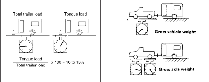
Tongue load
When using a weight carrying or a weight distrib-
uting hitch, keep the tongue load between 10 -
15 percent of the total trailer load or use the
trailer tongue load specified by the trailer manu-
facturer. The tongue load must be within the
maximum tongue load limits shown in the follow-
ing “Towing Load/Specification” chart. If the
tongue load becomes excessive, rearrange cargo
to allow for proper tongue load.
Maximum Gross Vehicle Weight
(GVW)/maximum Gross Axle Weight
(GAW)
The GVW of the towing vehicle must not exceed
the Gross Vehicle Weight Rating (GVWR)
shown on the F.M.V.S.S./C.M.V.S.S. certification
label. The GVW equals the combined weight of
the unloaded vehicle, passengers, luggage,
hitch, trailer tongue load and any other optional
equipment. In addition, front or rear GAW must
not exceed the Gross Axle Weight Rating
(GAWR) shown on the F.M.V.S.S./C.M.V.S.S.
certification label.
Towing capacities are calculated assuming a
base vehicle with driver and any options required
to achieve the rating. Additional passengers,
cargo and/or optional equipment, such as the
trailer hitch, will add weight to the vehicle and
reduce your vehicle’s maximum towing capacity
and trailer tongue load.
The vehicle and trailer need to be weighed to
confirm the vehicle is within the GVWR, Front
GAWR, Rear GAWR, Gross Combined Weight
Rating (GCWR) and Towing capacity.
All vehicle and trailer weights can be measured
using platform type scales commonly found at
truck stops, highway weigh stations, building
supply centers or salvage yards.
To determine the available payload capacity for
tongue load, use the following procedure.
1. Locate the GVWR on the
F.M.V.S.S./C.M.V.S.S. certification label.
2. Weigh your vehicle on the scale with all of
the passengers and cargo that are normally
in the vehicle when towing a trailer.
3. Subtract the actual vehicle weight from the
GVWR. The remaining amount is the avail-
able maximum tongue load.
To determine the available towing capacity, use
the following procedure.
WTI0160 CA0036
9-26 Technical and consumer information

1. Find the GCWR for your vehicle on the
9Towing Load/Specification9chart found
later in this section.
2. Subtract the actual vehicle weight from the
GCWR. The remaining amount is the avail-
able maximum towing capacity.
To determine the Gross Trailer Weight, weigh
your trailer on a scale with all equipment and
cargo, that are normally in the trailer when it is
towed. Make sure the Gross Trailer Weight is not
more than the Gross Trailer Weight Rating shown
on the trailer and is not more than the calculated
available maximum towing capacity.
Also weigh the front and rear axles on the scale to
make sure the Front Gross Axle Weight and Rear
Gross Axle Weight are not more than Front
Gross Axle Weight and Rear Gross Axle Weight
on the F.M.V.S.S./C.M.V.S.S. certification label.
The cargo in the trailer and vehicle may need to
be moved or removed to meet the specified rat-
ings.
Example:
●Gross Vehicle Weight (GVW) as weighed
on a scale- including passengers, cargo and
hitch - 5,185 lb. (2352 kg).
●Gross Vehicle Weight Rating (GVWR) from
F.M.V.S.S./C.M.V.S.S. certification label -
5,815 lb. (2638 kg).
●Gross Combined Weight Rating (GCWR)
from “Towing Load/Specification9chart -
11,133 lb. (5050 kg).
●Maximum Trailer towing capacity from “Tow-
ing Load/Specification9chart - 6,100 lb.
(2767 kg).
5,815 lb. (2638 kg) GVWR
– 5,185 lb. (2352 kg) GVW
= 630 lb. (286 kg) Available for tongue
weight
11,133 lb. (5050 kg) GCWR
– 5,185 lb. (2352 kg) GVW
= 5,948 lb. (2698 kg) Capacity available for
towing
630 lb. (286 kg) Available tongue weight
/ 5,948 lb. (2698 kg) Available capacity
= 10 % tongue weight
The available towing capacity may be less than
the maximum towing capacity due to the passen-
ger and cargo load in the vehicle.
Remember to keep trailer tongue weight be-
tween 10 - 15% of the trailer weight or within the
trailer tongue load specification recommended
by the trailer manufacturer. If the tongue load
becomes excessive, rearrange the cargo to ob-
tain the proper tongue load. Do not exceed the
maximum tongue weight specification shown in
the “Towing load/specification” chart even if the
calculated available tongue weight is greater
than 15%. If the calculated tongue weight is less
than 10% , reduce the total trailer weight to
match the available tongue weight.
Always verify that available capacities are within
the required ratings.
Trailer frontal area
CAUTION
Exceeding the maximum trailer frontal area
specification may exceed the towing capac-
ity of the vehicle. This may affect the towing
performance and lead to vehicle damage.
The trailer frontal area affects the towing load of a
trailer. The frontal area is the total area of the
vehicle and trailer that is affected by air resis-
tance while towing. Do not exceed the maximum
trailer frontal area specification shown in the
9Towing Load/Specification” chart. The frontal
area can be determined by multiplying the width
of the trailer by the height of the trailer. For
example, a trailer that is 8 feet wide by 6 feet tall
has a trailer frontal area of 48 square feet.
Technical and consumer information 9-27

TOWING LOAD/SPECIFICATION
King Cab 2WD (4 cyl) King Cab 2WD (6 cyl) King Cab 4WD (6 cyl) Crew Cab 2WD Crew Cab 4WD
Maximum Towing Capacity*1, *2, *3 3,500 lb. (1,588 kg) 6,500 lb. (2,949 kg) 6,300 lb. (2,858 kg) 6,300 lb. (2,858 kg) 6,100 lb. (2,767 kg)
Maximum Tongue Load*2, *3 350 lb. (158 kg) 650 lb. (295 kg) 630 lb. (285 kg) 630 lb. (285 kg) 610 lb. (276 kg)
Maximum Gross Combined Weight
Rating 7,936 lb. (3,600 kg) 11,133 lb. (5,050 kg) 11,133 lb. (5,050 kg) 11,133 lb. (5,050 kg) 11,133 lb. (5,050 kg)
Maximum trailer frontal area 60 sq feet (5.52 sq meters)
*1:
●The towing capacity values are calculated assuming a base vehicle with driver and any options required to achieve the rating. Additional passengers,
cargo and/or optional equipment will add weight to the vehicle and reduce your vehicle’s maximum towing capacity.
●All towing above 1,000 lb (454 kg) requires the use of trailer brakes. NISSAN recommends the use of a tandem axle trailer whenever towing above
3,000 lb (1,361 kg).
*2: The maximum towing capacity when using the genuine NISSAN step bumper as a ball mount is 3,500 lb. (1,588 kg) and 350 lb. (158 kg) tongue load.
*3: Use of a weight-distributing hitch system is recommended when towing over 5,000 lbs.
9-28 Technical and consumer information

TOWING SAFETY
Trailer hitch
Your vehicle may be equipped with an optional
trailer tow package. The trailer tow package in-
cludes a receiver-type frame mounted hitch. This
hitch is rated for the maximum towing capacity of
this vehicle when the proper towing equipment is
used. Choose a proper ball mount and hitch ball
that is rated for the trailer to be towed. Genuine
NISSAN ball mounts and hitch balls are available
from your NISSAN dealer.
If your vehicle is not equipped with the optional
trailer tow package, check the towing capacity of
your bumper hitch or receiver-type frame
mounted hitch. Choose a proper hitch for your
vehicle and trailer. A genuine NISSAN trailer
hitch is available from your NISSAN dealer. Make
sure the trailer hitch is securely attached to the
vehicle to help avoid personal injury or property
damage due to sway caused by crosswinds,
rough road surfaces or passing trucks.
WARNING
Trailer hitch components have specific
weight ratings. Your vehicle may be ca-
pable of towing a trailer heavier than the
weight rating of the hitch components.
Never exceed the weight rating of the
hitch components. Doing so can cause
serious personal injury or property
damage.
Hitch ball
Choose a hitch ball of the proper size and weight
rating for your trailer:
●The required hitch ball size is stamped on
most trailer couplers. Most hitch balls also
have the size printed on the top of the ball.
●Choose the proper class hitch ball based on
the trailer weight.
●The diameter of the threaded shank of the
hitch ball must be matched to the ball mount
hole diameter. The hitch ball shank should
be no more than 1/16” smaller than the hole
in the ball mount.
●The threaded shank of the hitch ball must be
long enough to be properly secured to the
ball mount. There should be at least 2
threads showing beyond the lock washer
and nut.
Ball mount
The hitch ball is attached to the ball mount and
the ball mount is inserted into the hitch receiver.
Choose a proper class ball mount based on the
trailer weight. Additionally, the ball mount should
be chosen to keep the trailer tongue level with the
ground.
Technical and consumer information 9-29
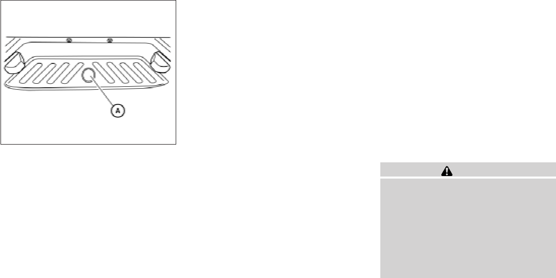
Bumper towing
The genuine NISSAN step bumper has provi-
sions to install a trailer hitch ball and is designed
to tow trailers of a maximum weight of 3,500 lb
(1,588 kg).
To install a trailer hitch ball cut out the circle in the
center of the step bumper s
A, then remove it to
install the trailer hitch ball.
Weight carrying hitches
A weight carrying or “dead weight” ball mount is
one that is designed to carry the whole amount of
tongue weight and gross weight directly on the
ball mount and on the receiver.
Weight distribution hitch
This type of hitch is also called a “load-leveling”or
“equalizing” hitch. A set of bars attach to the ball
mount and to the trailer to distribute the tongue
weight (hitch weight) of your trailer. Many ve-
hicles can’t carry the full tongue weight of a given
trailer, and need some of the tongue weight
transferred through the frame and pushing down
on the front wheels. This gives stability to the tow
vehicle.
A weight-distributing hitch system (Class IV) is
recommended if you plan to tow trailers with a
maximum weight over 5,000 lbs. Check with the
trailer and towing equipment manufacturers to
determine if they recommend the use of a weight-
distributing hitch system.
NOTE:
A weight-distributing hitch system may af-
fect the operation of trailer surge brakes. If
you are considering use of a weight-
distributing hitch system with a surge
brake-equipped trailer, check with the
surge brake, hitch or trailer manufacturer
to determine if and how this can be done.
Follow the instructions provided by the manufac-
turer for installing and using the weight-
distributing hitch system.
General set-up instructions are as follows:
1. Park unloaded vehicle on a level surface.
With the ignition on and the doors closed,
allow the vehicle to stand for several minutes
so that it can level.
2. Measure the height of a reference point on
the front and rear bumpers at the center of
the vehicle.
3. Attach the trailer to the vehicle and adjust
the hitch equalizers so that the front bumper
height is within0-.5inches (0 – 13 mm) of
the reference height measured in step 2. The
rear bumper should be no higher than the
reference height measured in step 2.
WARNING
Properly adjust the weight distributing
hitch so the rear of the bumper is no
higher than the measured reference
height when the trailer is attached. If the
rear bumper is higher than the measured
reference height when loaded, the vehicle
may handle unpredictably which could
cause a loss of vehicle control and cause
serious personal injury or property
damage.
LTI0132
9-30 Technical and consumer information

Sway control device
Sudden maneuvers, wind gusts, and buffeting
caused by other vehicles can affect trailer han-
dling. Sway control devices may be used to help
control these affects. If you choose to use one,
contact a reputable trailer hitch supplier to make
sure the sway control device will work with the
vehicle, hitch, trailer and the trailer’s brake sys-
tem. Follow the instructions provided by the
manufacturer for installing and using the sway
control device.
Class I hitch
Class I trailer hitch equipment (receiver, ball
mount and hitch ball) can be used to tow trailers
of a maximum weight of 2,000 lb (909 kg).
Class II hitch
Class II trailer hitch equipment (receiver, ball
mount and hitch ball) can be used to tow trailers
of a maximum weight of 3,500 lb (1,510 kg).
The genuine NISSAN step bumper is considered
a Class II ball mount.
Class III hitch
Class III trailer hitch equipment (receiver, ball
mount and hitch ball) can be used to tow trailers
of a maximum weight of 5,000 lb (2,272 kg).
Class IV hitch
Class IV trailer hitch equipment (receiver, ball
mount and hitch ball) can be used to tow trailers
of a maximum weight of 10,000 lb (4,545 kg). A
weight distributing hitch should be used to tow
trailers that weigh over 5,000 lb (2,272 kg).
Your vehicle may be equipped with Class IV
trailer hitch equipment that has a 10,000 lb
(4,545 kg) maximum weight rating, but your ve-
hicle is only capable of towing the maximum
trailer weights shown in the “Towing
Load/Specification” chart earlier in this section.
CAUTION
●
Special hitches which include frame rein-
forcements are required for towing above
2,000 lb (907 kg). Suitable genuine
NISSAN hitches, ball mounts and hitch
balls for pickup trucks and sport utility
vehicles are available at a NISSAN dealer.
●The hitch should not be attached to or
affect the operation of the impact-
absorbing bumper.
●Do not use axle-mounted hitches.
●Do not modify the vehicle exhaust sys-
tem, brake system, etc. to install a
trailer hitch.
●To reduce the possibility of additional
damage if your vehicle is struck from
the rear, where practical, remove the
receiver when not in use.
●Regularly check that all trailer hitch
mounting bolts are securely mounted.
Tire pressures
●When towing a trailer, inflate the ve-
hicle tires to the recommended cold
tire pressure indicated on the Tire
and Loading Information label.
●Trailer tire condition, size, load rating
and proper inflation pressure should
be in accordance with the trailer and
tire manufacturer’s specifications.
Safety chains
Always use suitable safety chains between your
vehicle and the trailer. The safety chains should
be crossed and should be attached to the hitch,
not to the vehicle bumper or axle. The safety
chains can be attached to the bumper if the hitch
ball is mounted to the bumper. Be sure to leave
enough slack in the chains to permit turning
corners.
Technical and consumer information 9-31

Trailer lights
CAUTION
When splicing into the vehicle electrical
system, a commercially available power-
type module/converter must be used to
provide power for all trailer lighting. This
unit uses the vehicle battery as a direct
power source for all trailer lights while
using the vehicle tail light, stoplight and
turn signal circuits as a signal source. The
module/converter must draw no more
that 15 milliamps from the stop and tail
lamp circuits. Using a module/converter
that exceeds these power requirements
may damage the vehicle’s electrical sys-
tem. See a reputable trailer dealer to ob-
tain the proper equipment and to have it
installed.
Trailer lights should comply with federal and/or
local regulations. For assistance in hooking up
trailer lights, contact a NISSAN dealer or repu-
table trailer dealer. Vehicles equipped with the
optional trailer tow package are equipped with a
7-pin trailer harness connector. A flat 4–pin har-
ness is available from your dealer for vehicles
without a tow package. If your trailer is equipped
with a flat 4-pin connector, an adapter will be
needed to connect the trailer lights to the vehicle.
Adapters are available at auto parts stores and
hitch retailers.
Trailer brakes
If your trailer is equipped with a braking system,
make sure it conforms to federal and/or local
regulations and that it is properly installed.
Vehicles equipped with a 7–pin trailer harness
connector are pre-wired for a trailer brake con-
troller. See a NISSAN dealer for a trailer brake
adapter harness.
WARNING
Never connect a trailer brake system di-
rectly to the vehicle brake system.
When towing a trailer load of 3,500 lbs.
(1587 kg) or more, trailers with a brake
system MUST be used. However, most states
require a separate braking system on trailers with
a loaded weight above a specific amount. Make
sure the trailer meets the local regulations and
the regulations where you plan to tow.
Several types of braking systems are available.
Surge Brakes - The surge brake actuator is
mounted on the trailer tongue with a hydraulic line
running to each trailer wheel. Surge brakes are
activated by the trailer pushing against the hitch
ball when the tow vehicle is braking. Hydraulic
surge brakes are common on rental trailers and
some boat trailers. In this type of system, there is
no hydraulic or electric connection for brake op-
eration between the tow vehicle and the trailer.
Electric Trailer Brakes - Electric braking sys-
tems are activated by an electronic signal sent
from a trailer brake controller (special brake-
sensing module). If electric trailer brakes are
used, see 9Electric trailer brake controller9in this
section.
Have a professional supplier of towing equip-
ment make sure the trailer brakes are properly
installed and demonstrate proper brake function
testing.
Electric trailer brake controller
Trailers equipped with electric brakes may re-
quire the installation of an aftermarket trailer
brake controller.
A Genuine NISSAN jumper harness is available
that is specifically designed to be used when
installing an aftermarket brake controller.
Install the aftermarket electric trailer brake con-
troller according to the manufacturer’s instruc-
tions.
9-32 Technical and consumer information
Pre-towing tips
●Be certain your vehicle maintains a level
position when a loaded and/or unloaded
trailer is hitched. Do not drive the vehicle if it
has an abnormal nose-up or nose-down
condition; check for improper tongue load,
overload, worn suspension or other possible
causes of either condition.
●Always secure items in the trailer to prevent
load shift while driving.
●Keep the cargo load as low as possible in
the trailer to keep the trailer center of gravity
low.
●Load the trailer so approximately 60% of the
trailer load is in the front half and 40% is in
the back half. Also make sure the load is
balanced side to side.
●Check your hitch, trailer tire pressure, ve-
hicle tire pressure, trailer light operation, and
trailer wheel lug nuts every time you attach a
trailer to the vehicle.
●Be certain your rearview mirrors conform to
all federal, state or local regulations. If not,
install any mirrors required for towing before
driving the vehicle.
●
Determine the overall height of the vehicle and
trailer so the required clearance is known.
Trailer towing tips
In order to gain skill and an understanding of the
vehicle’s behavior, you should practice turning,
stopping and backing up in an area which is free
from traffic. Steering stability and braking perfor-
mance will be somewhat different than under
normal driving conditions.
●Always secure items in the trailer to prevent
load shift while driving.
●Lock the trailer hitch coupler with a pin or
lock to prevent the coupler from inadvert-
ently becoming unlatched.
●Avoid abrupt starts, acceleration or stops.
●Avoid sharp turns or lane changes.
●Always drive your vehicle at a moderate
speed.
●When backing up, hold the bottom of the
steering wheel with one hand. Move your
hand in the direction in which you want the
trailer to go. Make small corrections and
back up slowly. If possible, have someone
guide you when you are backing up.
Always block the wheels on both vehicle and
trailer when parking. Parking on a slope is not
recommended; however, if you must do so:
CAUTION
If you move the shift selector to the P
(Park) position before blocking the
wheels and applying the parking brake,
transmission damage could occur.
1. Apply and hold the brake pedal.
2. Have someone place blocks on the downhill
side of the vehicle and trailer wheels.
3. After the wheel blocks are in place, slowly
release the brake pedal until the blocks ab-
sorb the vehicle load.
4. Apply the parking brake.
5. Shift the transmission into P (Park).
6. Make sure the indicator light (if so
equipped) indicates the transfer case is in
4H, 4L, or 2H and that the ATP light is off. If
the indicator light is flashing, or the
ATP light is ON, make sure the transmission
is in P (Park) (AT) and turn the 4WD switch
to 2WD or 4H. See “Automatic transmission
park warning light” in the “Instruments and
controls” section and “Using four wheel
drive (4WD)” in the “Starting and driving”
section.
7. Turn off the engine.
Technical and consumer information 9-33
To drive away:
1. Start the vehicle.
2. Apply and hold the brake pedal.
3. Shift the transmission into gear.
4. Release the parking brake.
5. Drive slowly until the vehicle and trailer are
clear from the blocks.
6. Apply and hold the brake pedal.
7. Have someone retrieve and store the blocks.
●While going downhill, the weight of the
trailer pushing on the tow vehicle may de-
crease overall stability. Therefore, to main-
tain adequate control, reduce your speed
and shift to a lower gear. Avoid long or
repeated use of the brakes when descend-
ing a hill, as this reduces their effectiveness
and could cause overheating. Shifting to a
lower gear instead provides “engine brak-
ing” and reduces the need to brake as fre-
quently.
●If the engine coolant temperature rises to a
high temperature, refer to “If your vehicle
overheats” in the “In case of emergency”
section of this owner’s manual.
●Trailer towing requires more fuel than normal
circumstances.
●Avoid towing a trailer for your vehicle’s first
500 miles (805 km).
●For the first 500 miles (805 km) that you do
tow, do not drive over 50 MPH (80 km/h).
●Have your vehicle serviced more often than
at intervals specified in the recommended
Maintenance Schedule in the “NISSAN Ser-
vice and Maintenance Guide”.
●When making a turn, your trailer wheels will
be closer to the inside of the turn than your
vehicle wheels. To compensate for this,
make a larger than normal turning radius
during the turn.
●Crosswinds and rough roads will adversely
affect vehicle/trailer handling, possibly caus-
ing vehicle sway. When being passed by
larger vehicles, be prepared for possible
changes in crosswinds that could affect ve-
hicle handling.
Do the following if the trailer begins to sway:
1. Take your foot off the accelerator pedal to
allow the vehicle to coast and steer as
straight ahead as the road conditions allow.
This combination will help stabilize the ve-
hicle
– Do not correct trailer sway by steering or
applying the brakes.
2. When the trailer sway stops, gently apply the
brakes and pull to the side of the road in a
safe area.
3. Try to rearrange the trailer load so it is bal-
anced as described earlier in this section.
●Be careful when passing other vehicles.
Passing while towing a trailer requires con-
siderably more distance than normal pass-
ing. Remember, the length of the trailer must
also pass the other vehicle before you can
safely change lanes.
●Downshift the transmission to a lower gear
for engine braking when driving down steep
or long hills. This will help slow the vehicle
without applying the brakes.
●Avoid holding the brake pedal down too long
or too frequently. This could cause the
brakes to overheat, resulting in reduced
braking efficiency.
●Increase your following distance to allow for
greater stopping distances while towing a
trailer. Anticipate stops and brake gradually.
●NISSAN recommends that the cruise con-
trol not be used while towing a trailer.
9-34 Technical and consumer information

●Some states or provinces have specific
regulations and speed limits for vehicles that
are towing trailers. Obey the local speed
limits.
●Check your hitch, trailer wiring harness con-
nections, and trailer wheel lug nuts after 50
miles (80 km) of travel and at every break.
●When launching a boat, don’t allow the wa-
ter level to go over the exhaust tail pipe or
rear bumper.
●Make sure you disconnect the trailer lights
before backing the trailer into the water or
the trailer lights may burn out.
When towing a trailer, final drive gear oil
should be replaced and transmission
oil/fluid should be changed more fre-
quently. For additional information, see the
“Maintenance and do-it-yourself” section
earlier in this manual.
FLAT TOWING
Towing your vehicle with all four wheels on the
ground is sometimes called flat towing. This
method is sometimes used when towing a vehicle
behind a recreational vehicle, such as a motor
home.
CAUTION
●Failure to follow these guidelines can
result in severe transmission damage.
●Whenever flat towing your vehicle, al-
ways tow forward, never backward.
●DO NOT tow any automatic transmis-
sion vehicle with all four wheels on the
ground (flat towing). Doing so WILL
DAMAGE internal transmission parts
due to lack of transmission lubrication.
●For emergency towing procedures refer
to “Towing recommended by NISSAN”
in the “In case of emergency” section of
this manual.
Automatic Transmission (if so
equipped)
To tow a vehicle equipped with an automatic
transmission, an appropriate vehicle dolly MUST
be placed under the towed vehicle’s drive
wheels. Always follow the dolly manufacturer’s
recommendations when using their product.
Manual Transmission (if so equipped)
●Always tow with the manual transmission in
Neutral.
●On four-wheel drive vehicles, place the
transfer case in the 2H range. Failure to do
so will cause the powertrain to bind up.
●After towing 500 miles (805 km), start and
idle the engine with the transmission in Neu-
tral for two minutes. Failure to idle the engine
after every 500 miles (805 km) of towing
may cause damage to internal transmission
parts.
Technical and consumer information 9-35

DOT (Department of Transportation) Quality
Grades: All passenger car tires must conform to
federal safety requirements in addition to these
grades.
Quality grades can be found where applicable on
the tire sidewall between tread shoulder and
maximum section width. For example:
Treadwear 200 Traction AA Temperature A
Treadwear
The treadwear grade is a comparative rating
based on the wear rate of the tire when tested
under controlled conditions on a specified gov-
ernment test course. For example, a tire graded
150 would wear one and one-half (1 1/2) times
as well on the government course as a tire graded
100. The relative performance of tires depends
upon the actual conditions of their use, however,
and may depart significantly from the norm due to
variations in driving habits, service practices and
differences in road characteristics and climate.
Traction AA, A, B and C
The traction grades, from highest to lowest, are
AA, A, B, and C. Those grades represent the
tire’s ability to stop on wet pavement as mea-
sured under controlled conditions on specified
government test surfaces of asphalt and con-
crete. A tire marked C may have poor traction
performance.
WARNING
The traction grade assigned to this tire is
based on straight-ahead braking traction
tests, and does not include acceleration,
cornering, hydroplaning, or peak traction
characteristics.
Temperature A, B and C
The temperature grades are A (the highest), B,
and C, representing the tire’s resistance to the
generation of heat, and its ability to dissipate heat
when tested under controlled conditions on a
specified indoor laboratory test wheel. Sustained
high temperature can cause the material of the
tire to degenerate and reduce tire life, and exces-
sive temperature can lead to sudden tire failure.
The grade C corresponds to a level of perfor-
mance which all passenger car tires must meet
under the Federal Motor Safety Standard No.
109. Grades B and A represent higher levels of
performance on the laboratory test wheel than
the minimum required by law.
WARNING
The temperature grade for this tire is es-
tablished for a tire that is properly inflated
and not overloaded. Excessive speed,
under-inflation, or excessive loading, ei-
ther separately or in combination, can
cause heat build-up and possible tire
failure.
UNIFORM TIRE QUALITY GRADING
9-36 Technical and consumer information
Your NISSAN vehicle is covered by the following
emission warranties:
For USA
1. Emission Defects Warranty
2. Emissions Performance Warranty
Details of this warranty may be found with other
vehicle warranties in your Warranty Information
Booklet which comes with your NISSAN vehicle.
If you did not receive a Warranty Information
Booklet, or it is lost, you may obtain a replace-
ment by writing to:
●Nissan North America, Inc.
Consumer Affairs Department
P.O. Box 685003
Franklin, TN 37068-5003
For Canada
Emission Control System Warranty
Details of this warranty may be found with other
vehicle warranties in your Warranty Information
Booklet which comes with your NISSAN vehicle.
If you did not receive a Warranty Information
Booklet, or it is lost, you may obtain a replace-
ment by writing to:
●Nissan Canada Inc.
5290 Orbitor Drive
Mississauga, Ontario, L4W 4Z5
If you believe that your vehicle has a de-
fect which could cause a crash or could
cause injury or death, you should immedi-
ately inform the National Highway Traffic
Safety Administration (NHTSA) in addi-
tion to notifying NISSAN.
If NHTSA receives similar complaints, it
may open an investigation, and if it finds
that a safety defect exists in a group of
vehicles, it may order a recall and remedy
campaign. However, NHTSA cannot be-
come involved in individual problems be-
tween you, your dealer, or NISSAN.
To contact NHTSA, you may call the Ve-
hicle Safety Hotline toll-free at 1-888-
327-4236 (TTY: 1-800-424-9153); go
to http://www.safercar.gov; or write to:
Administrator, NHTSA, 400 Seventh
Street, SW., Washington, D.C. 20590.
You can also obtain other information
about motor vehicle safety from
http://www.safercar.gov.
You may notify NISSAN by contacting our
Consumer Affairs Department, toll-free, at
1-800-NISSAN-1.
Due to legal requirements in some states and
Canadian Provinces, your vehicle may be re-
quired to be in what is called the “ready condi-
tion” for an Inspection/Maintenance (I/M) test of
the emission control system.
The vehicle is set to the “ready condition” when it
is driven through certain driving patterns. Usually,
the ready condition can be obtained by ordinary
usage of the vehicle.
If a powertrain system component is repaired or
the battery is disconnected, the vehicle may be
reset to a “not ready” condition. Before taking the
I/M test, check the vehicle’s
inspection/maintenance test readiness condi-
tion. Turn the ignition switch ON without starting
the engine. If the Malfunction Indicator Light
(MIL) comes on steady for 20 seconds and then
blinks for 10 seconds , the I/M test condition is
“not ready”. If the MIL does not blink after 20
seconds, the I/M test condition is “ready”. If the
MIL indicates the vehicle is in a “not ready” con-
dition, drive the vehicle through the following
pattern to set the vehicle to the ready condition. If
you cannot or do not want to perform the driving
pattern, a NISSAN dealer can conduct it for you.
EMISSION CONTROL SYSTEM
WARRANTY REPORTING SAFETY DEFECTS (US
only) READINESS FOR INSPECTION/
MAINTENANCE (I/M) TEST
Technical and consumer information 9-37

WARNING
Always drive the vehicle in a safe and
prudent manner according to traffic con-
ditions and obey all traffic laws.
1. Start the engine when the engine coolant
temperature gauge needle points to C. Al-
low the engine to idle until the gauge needle
points between the C and H (normal oper-
ating temperature).
2. Accelerate the vehicle to 55 MPH (88
km/h), then quickly release the accelerator
pedal completely and keep it released for at
least 10 seconds.
3. Quickly depress the accelerator pedal for a
moment, then drive the vehicle at a speed of
53 - 60 MPH (86 - 96 km/h) for at least 9
minutes.
4. Stop the vehicle.
5. Accelerate the vehicle to 35 MPH (55 km/h)
and maintain the speed for 20 seconds.
6. Repeat steps 4 through 5 at least 10 times.
7. Accelerate the vehicle to 55 MPH (88 km/h)
and maintain the speed for at least 3 min-
utes.
8. Stop the vehicle. Place the shift selector in
the P (Park) or N (Neutral) position.
9. Turn the engine off.
10. Repeat steps1-8atleast one more time.
If steps 1 through 7 are interrupted, repeat the
preceding step. Any safe driving mode is accept-
able between steps. Do not stop the engine until
step 7 is completed.
This vehicle is equipped with an Event Data Re-
corder (EDR). The main purpose of an EDR is to
record, in certain crash or near crash-like situa-
tions, such as an air bag deployment or hitting a
road obstacle, data that will assist in understand-
ing how a vehicle’s systems performed. The EDR
is designed to record data related to vehicle
dynamics and safety systems for a short period of
time, typically 30 seconds or less. The EDR in this
vehicle is designed to record such data as:
●How various systems in your vehicle were
operating;
●Whether or not the driver and passenger
safety belts were buckled/fastened;
●How far (if at all) the driver was depressing
the accelerator and/or brake pedal; and,
●How fast the vehicle was traveling.
●Sounds are not recorded.
These data can help provide a better understand-
ing of the circumstances in which crashes and
injuries occur. NOTE: EDR data are recorded by
your vehicle only if a nontrivial crash situation
occurs; no data are recorded by the EDR under
normal driving conditions and no personal data
(e.g. name, gender, age and crash location) are
recorded. However, other parties, such as law
enforcement, could combine the EDR data with
the type of personally identifying data routinely
acquired during a crash investigation.
EVENT DATA RECORDERS (EDR)
9-38 Technical and consumer information
To read data recorded by an EDR, special equip-
ment is required and access to the vehicle or the
EDR is needed. In addition to the vehicle manu-
facturer and NISSAN dealer, other parties, such
as law enforcement, that have the special equip-
ment, can read the information if they have ac-
cess to the vehicle or the EDR. EDR data will only
be accessed with the consent of the vehicle
owner or lessee or as otherwise required or per-
mitted by law.
A genuine NISSAN Service Manual is the best
source of service and repair information for your
vehicle. Filled with wiring diagrams, illustrations
and step-by-step diagnostic and adjustment pro-
cedures, this manual is the same one used by the
factory-trained technicians working at NISSAN
dealerships. Also available are genuine NISSAN
Owner’s Manuals, and genuine NISSAN Service
and Owner’s Manuals for older NISSAN models.
For USA
For current pricing and availability of genuine
NISSAN Service Manuals for the 2000 model
year and later contact:
1-800-450-9491
www.nissan-techinfo.com
For current pricing and availability of genuine
NISSAN Service Manuals for the 1999 model
year and prior, see a NISSAN dealer, or contact:
1-800-247-5321
For current pricing and availability of genuine
NISSAN Owner’s Manuals for this model year
and prior, see a NISSAN dealer, or contact:
1-800-247-5321
For Canada
To purchase a copy of a genuine NISSAN Ser-
vice Manual or Owner’s Manual please contact
your nearest NISSAN dealer. For the phone num-
ber and location of a NISSAN dealer in your area
call the NISSAN Information Center at 1-800-
387-0122 and a bilingual NISSAN representa-
tive will assist you.
Also available are genuine NISSAN Service and
Owner’s Manuals for older NISSAN models.
IN THE EVENT OF A COLLISION
Unfortunately, accidents do occur. In this unlikely
event, there is some important information you
should know.
Many insurance companies routinely authorize
the use of non-genuine collision parts in order to
cut costs, among other reasons.
OWNER’S MANUAL/SERVICE
MANUAL ORDER INFORMATION
Technical and consumer information 9-39
Insist on the use of genuine NISSAN
collision parts!
If you want your vehicle to be restored using parts
made to NISSAN’s original exacting specifica-
tions – if you want to help it to last and hold its
resale value, the solution is simple. Tell your
insurance agent and your repair shop to
only use Genuine NISSAN Collision Parts.
NISSAN does not warrant non-NISSAN parts,
nor does NISSAN’s warranty apply to damage
caused by a non-genuine part.
Using Genuine NISSAN Parts can help protect
your personal safety, preserve your warranty pro-
tection and maintain the resale value of your
vehicle. And if your vehicle was leased, using
Genuine NISSAN Parts may prevent or limit un-
necessary excess wear and tear expenses at the
end of your lease.
NISSAN designs its hoods with crumple zones to
minimize the risk that the hood will penetrate the
windshield of your vehicle in an accident. Non-
genuine (imitation) parts may not provide such
built-in safeguards. Also, non-genuine parts of-
ten show premature wear, rust and corrosion.
Why should you take a chance?
In over 40 states, the law says you must be
advised if non-genuine parts are used to repair
your vehicle. And some states have enacted laws
that restrict insurance companies from authoriz-
ing the use of non-genuine collision parts during
the new vehicle warranty. These laws help pro-
tect you, so you can take action to protect your-
self.
It’s your right!
If you should need further information visit us at:
www.nissanusa.com (for U.S. customers) or
www.nissan.ca (for Canadian customers).
9-40 Technical and consumer information

10 Index
4WD warning light ...............2-16
A
Active brake limited slip (ABLS) system
(if so equipped) .................5-34
Air bag (See supplemental restraint system)
. .1-57
Air bag system
Front (See supplemental front impact
air bag system) ...............1-65
Air bag warning labels .............1-71
Air bag warning light...........1-72, 2-18
Air cleaner housing filter ............8-20
Air conditioner
Air conditioner operation .......4-6, 4-12
Air conditioner service ...........4-17
Air conditioner specification label .....9-12
Air conditioner system refrigerant and
oil recommendations .............9-7
Heater and air conditioner
controls ................4-2, 4-10
Servicing air conditioner ..........4-17
Air flow charts ...............4-7, 4-14
Alarm system (See vehicle security system)
. .2-23
Anchor point locations .............1-30
Antenna .....................4-36
Anti-lock brake warning light..........2-14
Anti-lock Braking System (ABS)........5-33
Audible reminders ...............2-22
Audio system ..................4-17
Compact Disc (CD) changer . . . .4-30, 4-33
Compact disc (CD) player .........4-27
FM-AM radio with compact disc (CD)
changer ...................4-30
FM/AM radio with compact disc (CD)
player ....................4-25
Radio ....................4-17
Steering wheel audio control switch . . .4-35
Autolight switch.................2-27
Automatic
Automatic power window switch .....2-47
Automatic transmission position indicator
light .....................2-18
Driving with automatic transmission . . . .5-13
Automatic anti-glare inside mirror .......3-14
Automatic door locks ..............3-5
AUX jack ....................4-34
B
Battery......................8-15
Charge warning light ............2-15
Before starting the engine ...........5-12
Belt (See drive belt) ..............8-18
Block heater
Engine ....................5-39
BluetoothThands-free phone system .....4-37
Booster seats ..................1-52
Brake
Anti-lock Braking System (ABS)......5-33
Brake fluid..................8-14
Brake light (See stop light).........8-30
Brake system ................5-32
Brake warning light .............2-15
Brake wear indicators ........2-22, 8-23
Parking brake operation ..........5-19
Self-adjusting brakes ............8-23
Brakes ......................8-23
Break-in schedule ...............5-21
Brightness control
Instrument panel ..............2-29
Bulb check/instrument panel..........2-14
Bulb replacement ................8-30
C
Capacities and recommended
fuel/lubricants...................9-2
Car phone or CB radio.............4-36
Cargo light switch ...............2-31
Cargo (See vehicle loading information) . . .9-13
CD care and cleaning .............4-35
CD changer (See audio system) . . . .4-30, 4-33
CD player (See audio system) .........4-27
Child restraint with top tether strap ......1-30
Child restraints.......1-24, 1-25, 1-26, 1-28
Precautions on child
restraints ........1-26, 1-33, 1-42, 1-52
Top tether strap anchor point locations . .1-30
Child safety rear door lock............3-6
Chimes, audible reminders...........2-22
Cleaning exterior and interior ..........7-2
Clock ......................4-26
Clutch
Clutch fluid .................8-14
Clutch interlock (clutch start) switch .....2-35

C.M.V.S.S. certification label ..........9-11
Cold weather driving ..............5-37
Compact disc (CD) player ...........4-27
Compass display .................2-9
Console box ...................2-39
Controls
Audio controls (steering wheel).......4-35
Heater and air conditioner controls . .4-2, 4-10
Coolant
Capacities and recommended
fuel/lubricants .................9-2
Changing engine coolant ...........8-9
Checking engine coolant level ........8-8
Engine coolant temperature gauge .....2-6
Corrosion protection ...............7-5
Cruise control ..................5-20
Cup holders ...................2-42
Curtain side-impact and rollover air bag . . . .1-69
D
Daytime running light system (Canada only) . .2-29
Defroster switch
Rear window defroster switch .......2-26
Dimensions and weights .............9-9
Dimmer switch for instrument panel ......2-29
Door locks .....................3-3
Door open warning light.............2-15
Drive belt .....................8-18
Driving
Cold weather driving ............5-37
Driving with automatic transmission . . . .5-13
Driving with manual transmission ......5-17
Precautions when starting and driving . . . .5-2
E
Economy - fuel ..................5-22
Electronic locking rear differential (E-Lock)
system ......................5-30
Electronic locking rear differential (E-Lock)
system switch ..................2-34
Emission control information label .......9-12
Emission control system warranty .......9-37
Engine
Before starting the engine..........5-12
Block heater .................5-39
Capacities and recommended
fuel/lubricants .................9-2
Changing engine coolant ...........8-9
Changing engine oil .............8-11
Changing engine oil filter ..........8-12
Checking engine coolant level ........8-8
Checking engine oil level ...........8-9
Engine compartment check locations . . . .8-6
Engine coolant temperature gauge .....2-6
Engine cooling system ............8-8
Engine oil ...................8-9
Engine oil and oil filter recommendation . . .9-6
Engine oil pressure warning light ......2-15
Engine oil viscosity ..............9-6
Engine serial number ............9-11
Engine specifications .............9-8
Starting the engine .............5-12
Engine oil pressure gauge ............2-8
Event data recorders ..............9-38
Exhaust gas (Carbon monoxide) .........5-2
F
First aid kit .....................6-2
Flashers
(See hazard warning flasher switch) ......2-30
Flat tire .......................6-3
Floor mat positioning aid .............7-5
Fluid
Brake fluid ..................8-14
Capacities and recommended
fuel/lubricants .................9-2
Clutch fluid ..................8-14
Engine coolant.................8-8
Engine oil ...................8-9
Power steering fluid .............8-13
Window washer fluid ............8-15
F.M.V.S.S. certification label...........9-11
Fog light switch .................2-30
Front air bag system
(See supplemental restraint system) ......1-65
Front seats.....................1-2
Fuel
Capacities and recommended
fuel/lubricants .................9-2
Fuel economy ................5-22
Fuel gauge ...................2-7
Fuel octane rating ...............9-5
Fuel recommendation .............9-4
Fuel-filler cap.................3-10
Fuel-filler door and cap ...........3-10
Fuel-filler lid .................3-10
Fuses .......................8-24
Fusible links ...................8-25
10-2

G
Garage door opener, HomeLinkTUniversal
Transceiver ....................2-51
Gascap..................3-10, 3-10
Gauge
Engine coolant temperature gauge .....2-6
Engine oil pressure gauge ..........2-8
Fuel gauge ...................2-7
Odometer ...................2-4
Speedometer .................2-4
Tachometer ..................2-6
Trip computer .................2-5
Trip odometer .................2-4
Voltmeter....................2-8
General maintenance ...............8-2
Glove box.....................2-40
H
Hands-free phone system, BluetoothT.....4-37
Hazard warning flasher switch .........2-30
Headlight and turn signal switch ........2-26
Headlight control switch ............2-26
Headlights ....................8-28
Heated seats ...................2-32
Heater
Heater and air conditioner controls . .4-2, 4-10
Heater operation ............4-4, 4-11
Hill descent control switch ...........2-33
Hill descent control system ...........5-36
Hill start assist system..............5-37
HomeLinkTUniversal Transceiver........2-51
Hood release...................3-10
Horn .......................2-31
I
Ignition switch ...................5-9
Immobilizer system .........2-24, 3-2, 5-11
Important vehicle information label .......9-11
In-cabin microfilter ................8-20
Increasing fuel economy.............5-22
Indicator lights and audible reminders
(See warning/indicator lights and audible
reminders) ....................2-13
Inside automatic anti-glare mirror........3-14
Inside mirror ...................3-13
Instrument brightness control ..........2-29
Instrument panel ...............0-6, 2-2
Instrument panel dimmer switch ........2-29
Interior light....................2-50
ISOFIX child restraints .............1-28
J
Jump seat .....................1-5
Jump starting ...................6-9
K
Key.........................3-2
Keyfob battery replacement ...........8-26
Keyless entry system (See remote keyless entry
system).......................3-6
L
Labels
Air conditioner specification label .....9-12
C.M.V.S.S. certification label ........9-11
Emission control information label .....9-12
Engine serial number ............9-11
F.M.V.S.S. certification label.........9-11
Tire and Loading Information label .....9-12
Vehicle identification number (VIN) plate. .9-10
Warning labels (for SRS) ..........1-71
LATCH (Lower Anchors and Tethers for CHildren)
System ......................1-28
License plate
Installing the license plate..........9-13
Light
Air bag warning light .........1-72, 2-18
Brake light (See stop light) .........8-30
Bulb check/instrument panel ........2-14
Bulb replacement ..............8-30
Charge warning light ............2-15
Fog light switch ...............2-30
Headlight and turn signal switch ......2-26
Headlight control switch ..........2-26
Headlights ..................8-28
Interior light..................2-50
Light bulbs ..................8-28
Low tire pressure warning light .......2-16
Low washer fluid warning light .......2-18
Passenger air bag and status light .....1-66
Security indicator light............2-20
Warning/indicator lights and audible
reminders...................2-13
Lights
Map lights ..................2-51
10-3

Lock
Child safety rear door lock ..........3-6
Door locks ...................3-3
Power door locks ...............3-4
Low fuel warning light ..............2-16
Low tire pressure warning light .........2-16
Low washer fluid warning light .........2-18
Luggage rack (see roof rack) ..........2-44
Luggage (See vehicle loading information) . .9-13
M
Maintenance
General maintenance .............8-2
Inside the vehicle ...............8-3
Maintenance precautions ...........8-5
Outside the vehicle ..............8-2
Seat belt maintenance............1-24
Under the hood and vehicle .........8-4
Malfunction indicator light ............2-20
Manual front seat adjustment...........1-2
Manual windows .................2-47
Map lights ....................2-51
Map pocket....................2-41
Meters and gauges ................2-3
Instrument brightness control ........2-29
Mirror
Automatic anti-glare inside mirror......3-14
Inside mirror .................3-13
Outside mirrors ...............3-14
Vanity mirror .................3-13
Moonroof .....................2-48
Multi-remote control system
(See remote keyless entry system)........3-6
N
NISSAN vehicle immobilizer
system ................2-24, 3-2, 5-11
O
Octane rating (See fuel octane rating)......9-5
Odometer .....................2-4
Oil Capacities and recommended
fuel/lubricants .................9-2
Changing engine oil .............8-11
Changing engine oil filter ..........8-12
Checking engine oil level ...........8-9
Engine oil ...................8-9
Engine oil and oil filter recommendation . . .9-6
Engine oil viscosity ..............9-6
Outside mirrors .................3-14
Overdrive switch .................5-16
Overheat
If your vehicle overheats...........6-11
Owner’s manual order form ...........9-39
Owner’s manual/service manual order
information ....................9-39
P
Parking
Parking brake operation ...........5-19
Parking/parking on hills ...........5-31
Phone, BluetoothThands-free system .....4-37
Power
Front seat adjustment .............1-4
Power door locks ...............3-4
Power outlet .................2-35
Power steering fluid .............8-13
Power steering system ...........5-32
Power windows ...............2-45
Rear power windows ............2-47
Precautions
Maintenance precautions ...........8-5
On-pavement and off-road driving
precautions ..................5-5
Precautions on child
restraints.........1-26, 1-33, 1-42, 1-52
Precautions on seat belt usage .......1-16
Precautions on supplemental restraint
system ....................1-57
Precautions when starting and driving . . . .5-2
Pre-tensioner seat belt system .........1-70
Push starting ...................6-11
R
Radio
Car phone or CB radio ...........4-36
Compact Disc (CD) changer . . . .4-30, 4-33
FM-AM radio with compact disc (CD)
changer....................4-30
FM/AM radio with compact disc (CD)
player .....................4-25
Steering wheel audio control switch . . . .4-35
Readiness for inspection maintenance (I/M)
test ........................9-37
Rear power windows ..............2-47
Rear sliding window ...............2-48
Rear window defroster switch .........2-26
10-4

Recorders
Event data ..................9-38
Refrigerant recommendation ...........9-7
Registering your vehicle in another country . .9-10
Remote keyless entry system...........3-6
Reporting safety defects (US only) .......9-37
Roof rack .....................2-44
S
Safety
Child safety rear door lock ..........3-6
Child seat belts .....1-26, 1-33, 1-42, 1-52
Reporting safety defects (US only) .....9-37
Seat
Jump seat ...................1-5
Seat adjustment
Front manual seat adjustment ........1-2
Front power seat adjustment .........1-4
Seat belt
Child safety..................1-24
Infants and small children ..........1-25
Injured Person ................1-19
Larger children ................1-25
Precautions on seat belt usage .......1-16
Pregnant women...............1-19
Pre-tensioner seat belt system .......1-70
Seat belt extenders .............1-23
Seat belt maintenance............1-24
Seat belts...................1-16
Shoulder belt height adjustment ......1-23
Three-point type with retractor .......1-19
Seat belt warning light..............2-18
Seatback pockets ................2-42
Seats
Adjustment...................1-2
Front seats...................1-2
Heated seats .................2-32
Manual front seat adjustment.........1-2
Security indicator light..............2-20
Security system (NISSAN vehicle immobilizer
system), engine start ........2-24, 3-2, 5-11
Self-adjusting brakes ..............8-23
Service manual order form ...........9-39
Servicing air conditioner.............4-17
Shift lock release.................5-15
Shifting
Automatic transmission ...........5-13
Manual transmission .............5-17
Shoulder belt height adjustment ........1-23
Side air bag system (See supplemental side air
bag, curtain and rollover air bag systems) . . .1-69
Spark plug replacement .............8-19
Speedometer ...................2-4
SRS warning label ................1-71
Starting
Before starting the engine..........5-12
Jump starting .................6-9
Precautions when starting and driving . . . .5-2
Push starting .................6-11
Starting the engine .............5-12
Steering
Power steering fluid .............8-13
Power steering system ...........5-32
Tilting steering wheel ............3-12
Steering wheel audio control switch ......4-35
Stop light .....................8-30
Storage ......................2-36
Storage tray ................2-36, 2-38
Sun visors ....................3-12
Sunglasses case.................2-40
Sunroof (see Moonroof) .............2-48
Supplemental air bag warning labels ......1-71
Supplemental air bag warning light . . .1-72, 2-18
Supplemental front impact air bag system . . .1-65
Supplemental restraint system
Information and warning labels .......1-71
Precautions on supplemental restraint
system ....................1-57
Supplemental restraint system
(Supplemental air bag system) .........1-57
Switch
Autolight switch ...............2-27
Automatic power window switch ......2-47
Clutch interlock (clutch start) switch . . . .2-35
Electronic locking rear differential (E-Lock)
system switch ................2-34
Fog light switch ...............2-30
Hazard warning flasher switch .......2-30
Headlight and turn signal switch ......2-26
Headlight control switch ..........2-26
Hill descent control switch .........2-33
Ignition switch .................5-9
Overdrive switch ...............5-16
Power door lock switch ............3-4
Rear window defroster switch .......2-26
Turn signal switch ..............2-30
Vehicle dynamic control (VDC) off
switch.....................2-32
Windshield wiper and washer switch . . .2-25
T
Tachometer ....................2-6
Tailgate latch ............3-15, 3-17, 3-18
10-5

Temperature gauge
Engine coolant temperature gauge .....2-6
Theft (NISSAN vehicle immobilizer system),
engine start .............2-24, 3-2, 5-11
Three-way catalyst ................5-3
Tie down hooks .................3-18
Tilting steering wheel ..............3-12
TireFlat tire .....................6-3
Spare tire ................6-4, 8-42
Tire and Loading Information label .....9-12
Tire chains ..................8-39
Tire placard..................9-12
Tire pressure .................8-32
Tire rotation..................8-39
Tires of 4-wheel drive ............8-41
Types of tires .................8-38
Uniform tire quality grading .........9-36
Wheels and tires...............8-32
Wheel/tire size.................9-9
Tire pressure
Low tire pressure warning light .......2-16
Tire Pressure Monitoring System (TPMS) . . . .5-3
Top tether strap child restraint .........1-30
Towing
2-wheel drive models ............6-13
4-wheel drive models ............6-14
Flat towing ..................9-35
Tow truck towing...............6-12
Towing load/specification ..........9-28
Trailer towing .................9-24
Transceiver
HomeLinkTUniversal Transceiver......2-51
Transmission
Driving with automatic transmission . . . .5-13
Driving with manual transmission ......5-17
Travel (See registering your vehicle in
another country) .................9-10
Trip computer ...................2-5
Trip odometer ...................2-4
Truck - camper loading .............9-23
Turn signal switch ................2-30
U
Uniform tire quality grading ...........9-36
V
Vanity mirror ...................3-13
Variable voltage control system.........8-17
Vehicle dimensions and weights .........9-9
Vehicle dynamic control (VDC) off switch . . .2-32
Vehicle dynamic control (VDC) system.....5-34
Vehicle identification...............9-10
Vehicle identification number (VIN)
(Chassis number) ................9-10
Vehicle identification number (VIN) plate. . . .9-10
Vehicle loading information ...........9-13
Vehicle recovery..............6-14, 6-15
Vehicle security system .............2-23
Vehicle security system (NISSAN vehicle immobi-
lizer system), engine start......2-24, 3-2, 5-11
Ventilators .....................4-2
Visors .......................3-12
Voltmeter......................2-8
W
Warning
4WD warning light..............2-16
Air bag warning light .........1-72, 2-18
Anti-lock brake warning light ........2-14
Battery charge warning light ........2-15
Brake warning light .............2-15
Door open warning light...........2-15
Engine oil pressure warning light ......2-15
Hazard warning flasher switch .......2-30
Low fuel warning light ............2-16
Low tire pressure warning light .......2-16
Low washer fluid warning light .......2-18
Passenger air bag and status light .....1-66
Seat belt warning light............2-18
Vehicle security system ...........2-23
Warning labels (for SRS) ..........1-71
Warning/indicator lights and audible
reminders...................2-13
Warning lights ..................2-13
Washer switch
Windshield wiper and washer switch . . .2-25
Weights (See dimensions and weights) .....9-9
Wheels and tires.................8-32
Wheel/tire size...................9-9
When traveling or registering your vehicle
in another country ................9-10
Window washer fluid ..............8-15
Windows
Locking passengers’ windows .......2-47
Manual windows ...............2-47
Power windows ...............2-45
Rear power windows ............2-47
Rear sliding window .............2-48
10-6
Windshield wiper and washer switch .....2-25
Wiper
Windshield wiper and washer switch . . .2-25
Wiper blades.................8-22
10-7

RECOMMENDED FUEL:
Use unleaded regular gasoline with an octane
rating of at least 87 AKI (Anti-Knock Index) num-
ber (Research octane number 91).
CAUTION
●Using a fuel other than that specified
could adversely affect the emission
control system, and may also affect the
warranty coverage.
●Under no circumstances should a
leaded gasoline be used, because this
will damage the three-way catalyst.
●Do not use E-85 fuel in your vehicle.
Your vehicle is not designed to run on
E-85 fuel. Using E-85 fuel can damage
the fuel system components and is not
covered by the NISSAN new vehicle lim-
ited warranty.
For additional information, see “Capacities and
recommended fuel/lubricants in the “Technical
and consumer information” section.
RECOMMENDED ENGINE OIL:
●Engine oil with API Certification Mark
●Viscosity SAE 5W-30
See “Engine oil and oil filter recommendations”in
the “Technical and consumer information” sec-
tion of this manual.
COLD TIRE PRESSURE:
See Tire and Loading Information label.
The label is typically located on the driver side
center pillar or on the driver’s door. For additional
information, see “Wheels and tires” in the “Main-
tenance and do-it-yourself” section of this
manual.
RECOMMENDED NEW VEHICLE
BREAK-IN PROCEDURE:
During the first 1,200 miles (2,000 km) of vehicle
use, follow the recommendations outlined in the
“Break-in schedule” information found in the
“Starting and driving” section of this manual. Fol-
low these recommendations for the future reli-
ability and economy of your new vehicle. Failure
to follow these recommendations may result in
vehicle damage or shortened engine life.
GAS STATION INFORMATION

2010 FRONTIER
OWNER'S MANUAL
2010 NISSAN FRONTIER D40-D
Printing : July 2009 (11)
Publication No.: OM0E-0D40U0
Printed in U.S.A.
For your safety, read carefully and keep in this vehicle.
D40-D
