Nissan 2010 Sentra Owners Manual SM0E 1B16U1(MTC)
2015-10-23
: Nissan Nissan-2010-Nissan-Sentra-Owners-Manual-818338 nissan-2010-nissan-sentra-owners-manual-818338 nissan pdf
Open the PDF directly: View PDF ![]() .
.
Page Count: 94
- QUICK REFERENCE INDEX
- Table of Contents
- SERVICE INFORMATION
- PRECAUTIONS
- Precaution for Supplemental Restraint System (SRS) "AIR BAG" and "SEAT BELT PRE-TENSIONER"
- Precaution Necessary for Steering Wheel Rotation After Battery Disconnect
- Precaution for Working with HFC-134a (R-134a)
- Contaminated Refrigerant
- General Refrigerant Precaution
- Precaution for Leak Detection Dye
- A/C Identification Label
- Precaution for Refrigerant Connection
- Precaution for Service of Compressor
- Precaution for Service Equipment
- PREPARATION
- REFRIGERATION SYSTEM
- OIL
- AIR CONDITIONER CONTROL
- TROUBLE DIAGNOSIS
- How to Perform Trouble Diagnosis for Quick and Accurate Repair
- Component Parts and Harness Connector Location
- Schematic
- Wiring Diagram - HEATER -
- Wiring Diagram - A/C,M -
- Front Air Control Terminal and Reference Value
- Operational Check
- Power Supply and Ground Circuit for Front Air Control
- LAN System Circuit
- Mode Door Motor Circuit
- Air Mix Door Motor Circuit
- Intake Door Motor Circuit
- Blower Motor Circuit
- Magnet Clutch Circuit (If Equipped)
- Insufficient Cooling
- Insufficient Heating
- Noise
- CONTROL UNIT
- FRONT BLOWER MOTOR
- IN-CABIN MICROFILTER
- HEATER & COOLING UNIT ASSEMBLY
- HEATER CORE
- INTAKE DOOR MOTOR
- MODE DOOR MOTOR
- AIR MIX DOOR MOTOR
- FAN CONTROL AMPLIFIER
- DUCTS AND GRILLES
- Removal and Installation
- REFRIGERANT LINES
- HFC-134a (R-134a) Service Procedure
- Component
- Removal and Installation for Compressor - MR20DE
- Removal and Installation for Compressor - QR25DE
- Removal and Installation for Low-Pressure Flexible Hose and Muffler Pipe
- Removal and Installation for High-pressure Flexible Hose
- Removal and Installation for High-pressure Pipe
- Removal and Installation for Refrigerant Pressure Sensor
- Removal and Installation for Condenser
- Removal and Installation for Evaporator
- Removal and Installation for Expansion Valve
- Checking of Refrigerant Leaks
- Checking System for Leaks Using the Fluorescent Leak Detector
- Dye Injection
- Electronic Refrigerant Leak Detector
- SERVICE DATA AND SPECIFICATIONS (SDS)
- PRECAUTIONS
- SERVICE INFORMATION
- POWER SUPPLY ROUTING CIRCUIT
- ELECTRICAL UNITS
- FUSE BLOCK-JUNCTION BOX (J/B)
- FUSE AND FUSIBLE LINK BOX

MTC-1
AIR CONDITIONER
C
D
E
F
G
H
I
K
L
M
SECTION MTC A
B
MTC
N
O
P
CONTENTS
MANUAL AIR CONDITIONER
SERVICE INFORMATION ............................ 3
PRECAUTIONS ................................................... 3
Precaution for Supplemental Restraint System
(SRS) "AIR BAG" and "SEAT BELT PRE-TEN-
SIONER" ...................................................................3
Precaution Necessary for Steering Wheel Rota-
tion After Battery Disconnect .....................................3
Precaution for Working with HFC-134a (R-134a) ......4
Contaminated Refrigerant .........................................4
General Refrigerant Precaution ................................4
Precaution for Leak Detection Dye ...........................5
A/C Identification Label .............................................5
Precaution for Refrigerant Connection ......................5
Precaution for Service of Compressor ......................9
Precaution for Service Equipment .............................9
PREPARATION ..................................................12
HFC-134a (R-134a) Service Tool and Equipment ....12
Commercial Service Tool ........................................14
REFRIGERATION SYSTEM ..............................16
Refrigerant Cycle ....................................................16
Refrigerant System Protection ................................ 16
Component Part Location ....................................... 17
OIL ......................................................................18
Maintenance of Oil Quantity in Compressor ........... 18
AIR CONDITIONER CONTROL .........................21
Overview Air Conditioner LAN Control System ....... 21
System Construction ............................................... 21
Overview of Control system ....................................23
Control Operation .................................................... 24
Discharge Air Flow .................................................. 25
System Description ................................................. 25
TROUBLE DIAGNOSIS .....................................27
How to Perform Trouble Diagnosis for Quick and
Accurate Repair ...................................................... 27
Component Parts and Harness Connector Loca-
tion ..........................................................................27
Schematic ................................................................31
Wiring Diagram - HEATER - ....................................32
Wiring Diagram - A/C,M - ........................................34
Front Air Control Terminal and Reference Value ....36
Operational Check ...................................................38
Power Supply and Ground Circuit for Front Air
Control .....................................................................39
LAN System Circuit .................................................41
Mode Door Motor Circuit .........................................43
Air Mix Door Motor Circuit .......................................45
Intake Door Motor Circuit .........................................47
Blower Motor Circuit ................................................48
Magnet Clutch Circuit (If Equipped) .........................53
Insufficient Cooling ..................................................56
Insufficient Heating ..................................................63
Noise .......................................................................64
CONTROL UNIT ................................................66
Removal and Installation .........................................66
FRONT BLOWER MOTOR ...............................67
Removal and Installation .........................................67
IN-CABIN MICROFILTER .................................68
Removal and Installation .........................................68
HEATER & COOLING UNIT ASSEMBLY ........70
Removal and Installation .........................................70
HEATER CORE .................................................72
Removal and Installation .........................................72
INTAKE DOOR MOTOR ...................................73
Removal and Installation .........................................73
MODE DOOR MOTOR ......................................74
Removal and Installation .........................................74
AIR MIX DOOR MOTOR ...................................75
Removal and Installation .........................................75
FAN CONTROL AMPLIFIER ............................76
Removal and Installation .........................................76
Revision: January 2010 2010 Sentra

MTC-2
DUCTS AND GRILLES ...................................... 77
Removal and Installation ........................................ 77
REFRIGERANT LINES ...................................... 81
HFC-134a (R-134a) Service Procedure ................. 81
Component ............................................................. 83
Removal and Installation for Compressor -
MR20DE ................................................................. 85
Removal and Installation for Compressor -
QR25DE ................................................................. 86
Removal and Installation for Low-Pressure Flexi-
ble Hose and Muffler Pipe ...................................... 87
Removal and Installation for High-pressure Flexi-
ble Hose ................................................................. 87
Removal and Installation for High-pressure Pipe ... 87
Removal and Installation for Refrigerant Pressure
Sensor ..................................................................... 88
Removal and Installation for Condenser ................. 88
Removal and Installation for Evaporator ................. 89
Removal and Installation for Expansion Valve ........ 90
Checking of Refrigerant Leaks ................................ 90
Checking System for Leaks Using the Fluorescent
Leak Detector .......................................................... 90
Dye Injection ........................................................... 91
Electronic Refrigerant Leak Detector ...................... 91
SERVICE DATA AND SPECIFICATIONS
(SDS) ................................................................. 94
Service Data and Specification (SDS) .................... 94
Revision: January 2010 2010 Sentra

PRECAUTIONS
MTC-3
< SERVICE INFORMATION >
C
D
E
F
G
H
I
K
L
M
A
B
MTC
N
O
P
SERVICE INFORMATION
PRECAUTIONS
Precaution for Supplemental Restraint System (SRS) "AIR BAG" and "SEAT BELT
PRE-TENSIONER" INFOID:0000000005602372
The Supplemental Restraint System such as “AIR BAG” and “SEAT BELT PRE-TENSIONER”, used along
with a front seat belt, helps to reduce the risk or severity of injury to the driver and front passenger for certain
types of collision. This system includes seat belt switch inputs and dual stage front air bag modules. The SRS
system uses the seat belt switches to determine the front air bag deployment, and may only deploy one front
air bag, depending on the severity of a collision and whether the front occupants are belted or unbelted.
Information necessary to service the system safely is included in the SRS and SB section of this Service Man-
ual.
WARNING:
• To avoid rendering the SRS inoperative, which could increase the risk of personal injury or death in
the event of a collision which would result in air bag inflation, all maintenance must be performed by
an authorized NISSAN/INFINITI dealer.
• Improper maintenance, including incorrect removal and installation of the SRS, can lead to personal
injury caused by unintentional activation of the system. For removal of Spiral Cable and Air Bag
Module, see the SRS section.
• Do not use electrical test equipment on any circuit related to the SRS unless instructed to in this
Service Manual. SRS wiring harnesses can be identified by yellow and/or orange harnesses or har-
ness connectors.
PRECAUTIONS WHEN USING POWER TOOLS (AIR OR ELECTRIC) AND HAMMERS
WARNING:
• When working near the Airbag Diagnosis Sensor Unit or other Airbag System sensors with the Igni-
tion ON or engine running, DO NOT use air or electric power tools or strike near the sensor(s) with a
hammer. Heavy vibration could activate the sensor(s) and deploy the air bag(s), possibly causing
serious injury.
• When using air or electric power tools or hammers, always switch the Ignition OFF, disconnect the
battery, and wait at least 3 minutes before performing any service.
Precaution Necessary for Steering Wheel Rotation After Battery Disconnect
INFOID:0000000005602373
NOTE:
• This Procedure is applied only to models with Intelligent Key system and NATS (NISSAN ANTI-THEFT SYS-
TEM).
• Remove and install all control units after disconnecting both battery cables with the ignition knob in the
″LOCK″ position.
• Always use CONSULT-III to perform self-diagnosis as a part of each function inspection after finishing work.
If DTC is detected, perform trouble diagnosis according to self-diagnostic results.
For models equipped with the Intelligent Key system and NATS, an electrically controlled steering lock mech-
anism is adopted on the key cylinder.
For this reason, if the battery is disconnected or if the battery is discharged, the steering wheel will lock and
steering wheel rotation will become impossible.
If steering wheel rotation is required when battery power is interrupted, follow the procedure below before
starting the repair operation.
OPERATION PROCEDURE
1. Connect both battery cables.
NOTE:
Supply power using jumper cables if battery is discharged.
2. Use the Intelligent Key or mechanical key to turn the ignition switch to the ″ACC″ position. At this time, the
steering lock will be released.
3. Disconnect both battery cables. The steering lock will remain released and the steering wheel can be
rotated.
4. Perform the necessary repair operation.
Revision: January 2010 2010 Sentra

MTC-4
< SERVICE INFORMATION >
PRECAUTIONS
5. When the repair work is completed, return the ignition switch to the ″LOCK″ position before connecting
the battery cables. (At this time, the steering lock mechanism will engage.)
6. Perform a self-diagnosis check of all control units using CONSULT-III.
Precaution for Working with HFC-134a (R-134a) INFOID:0000000005282755
WARNING:
• CFC-12 (R-12) refrigerant and HFC-134a (R-134a) refrigerant are not compatible. If the refrigerants
are mixed compressor failure is likely to occur. Refer to MTC-4, "Contaminated Refrigerant". To
determine the purity of HFC-134a (R-134a) in the vehicle and recovery tank, use Refrigerant Recov-
ery/Recycling Recharging equipment and Refrigerant Identifier.
• Use only specified oil for the HFC-134a (R-134a) A/C system and HFC-134a (R-134a) components. If
oil other than that specified is used, compressor failure is likely to occur.
• The specified HFC-134a (R-134a) oil rapidly absorbs moisture from the atmosphere. The following
handling precautions must be observed:
- When removing refrigerant components from a vehicle, immediately cap (seal) the component to
minimize the entry of moisture from the atmosphere.
- When installing refrigerant components to a vehicle, do not remove the caps (unseal) until just
before connecting the components. Connect all refrigerant loop components as quickly as possible
to minimize the entry of moisture into system.
- Only use the specified oil from a sealed container. Immediately reseal containers of oil. Without
proper sealing, oil will become moisture saturated and should not be used.
- Avoid breathing A/C refrigerant and oil vapor or mist. Exposure may irritate eyes, nose and throat.
Remove HFC-134a (R-134a) from the A/C system using certified service equipment meeting require-
ments of SAE J2210 [HFC-134a (R-134a) recycling equipment], or J2209 [HFC-134a (R-134a) recy-
cling equipment], If accidental system discharge occurs, ventilate work area before resuming
service. Additional health and safety information may be obtained from refrigerant and oil manufac-
turers.
- Do not allow A/C oil to come in contact with styrofoam parts. Damage may result.
Contaminated Refrigerant INFOID:0000000005282756
If a refrigerant other than pure HFC-134a (R-134a) is identified in a vehicle, your options are:
• Explain to the customer that environmental regulations prohibit the release of contaminated refrigerant into
the atmosphere.
• Explain that recovery of the contaminated refrigerant could damage your service equipment and refrigerant
supply.
• Suggest the customer return the vehicle to the location of previous service where the contamination may
have occurred.
• If you choose to perform the repair, recover the refrigerant using only dedicated equipment and contain-
ers. Do not recover contaminated refrigerant into your existing service equipment. If your facility does
not have dedicated recovery equipment, you may contact a local refrigerant product retailer for available ser-
vice. This refrigerant must be disposed of in accordance with all federal and local regulations. In addition,
replacement of all refrigerant system components on the vehicle is recommended.
• If the vehicle is within the warranty period, the air conditioner warranty is void. Please contact NISSAN Cus-
tomer Affairs for further assistance.
General Refrigerant Precaution INFOID:0000000005282757
WARNING:
• Do not release refrigerant into the air. Use approved recovery/recycling equipment to capture the
refrigerant every time an air conditioning system is discharged.
• Always wear eye and hand protection (goggles and gloves) when working with any refrigerant or air
conditioning system.
• Do not store or heat refrigerant containers above 52°C (125°F).
• Do not heat a refrigerant container with an open flame; if container warming is required, place the
bottom of the container in a warm pail of water.
• Do not intentionally drop, puncture, or incinerate refrigerant containers.
• Keep refrigerant away from open flames: poisonous gas will be produced if refrigerant burns.
• Refrigerant will displace oxygen, therefore be certain to work in well ventilated areas to prevent suf-
focation.
Revision: January 2010 2010 Sentra
PRECAUTIONS
MTC-5
< SERVICE INFORMATION >
C
D
E
F
G
H
I
K
L
M
A
B
MTC
N
O
P
• Do not pressure test or leak test HFC-134a (R-134a) service equipment and/or vehicle air condition-
ing systems with compressed air during repair. Some mixtures of air and HFC-134a (R-134a) have
been shown to be combustible at elevated pressures. These mixtures, if ignited, may cause injury or
property damage. Additional health and safety information may be obtained from refrigerant manu-
facturers.
Precaution for Leak Detection Dye INFOID:0000000005282758
• The A/C system contains a fluorescent leak detection dye used for locating refrigerant leaks. An ultraviolet
(UV) lamp is required to illuminate the dye when inspecting for leaks.
• Always wear fluorescence enhancing UV safety goggles to protect your eyes and enhance the visibility of
the fluorescent dye.
• A compressor shaft seal should not be repaired because of dye seepage. The compressor shaft seal should
only be repaired after confirming the leak with an electronic refrigerant leak detector (J-41995).
• Always remove any dye from the leak area after repairs are complete to avoid a misdiagnosis during a future
service.
• Do not allow dye to come into contact with painted body panels or interior components. If dye is spilled,
clean immediately with the approved dye cleaner. Fluorescent dye left on a surface for an extended period of
time cannot be removed.
• Do not spray the fluorescent dye cleaning agent on hot surfaces (engine exhaust manifold, etc.).
• Do not use more than one refrigerant dye bottle (1/4 ounce / 7.4 cc) per A/C system.
• Leak detection dyes for HFC-134a (R-134a) and CFC-12 (R-12) A/C systems are different. Do not use HFC-
134a (R-134a) leak detection dye in CFC-12 (R-12) A/C systems or CFC-12 (R-12) leak detection dye in
HFC-134a (R-134a) A/C systems or A/C system damage may result.
• The fluorescent properties of the dye will remain for over three (3) years unless a compressor failure occurs.
A/C Identification Label INFOID:0000000005282759
Vehicles with factory installed fluorescent dye have this green identification label on the underside of hood.
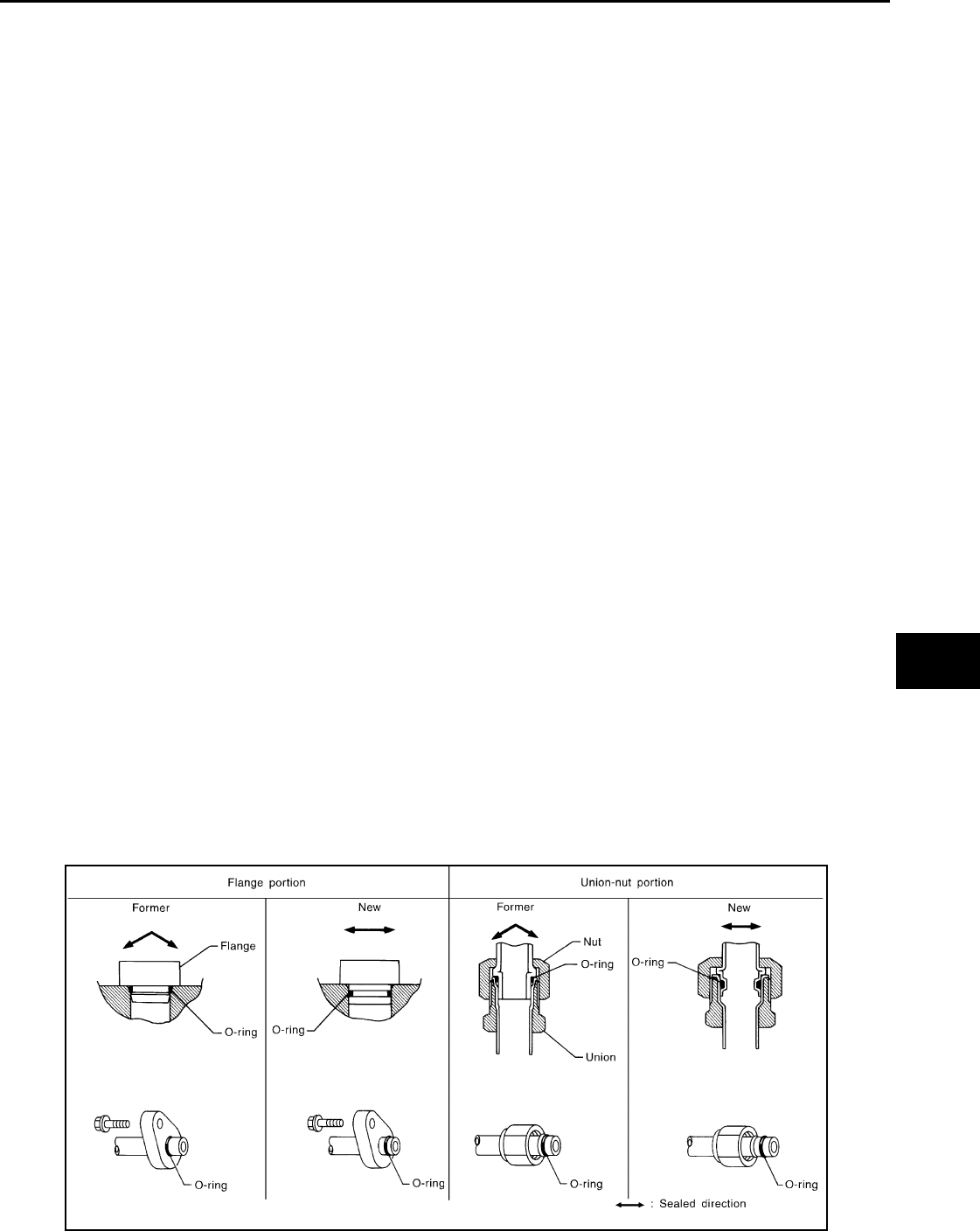
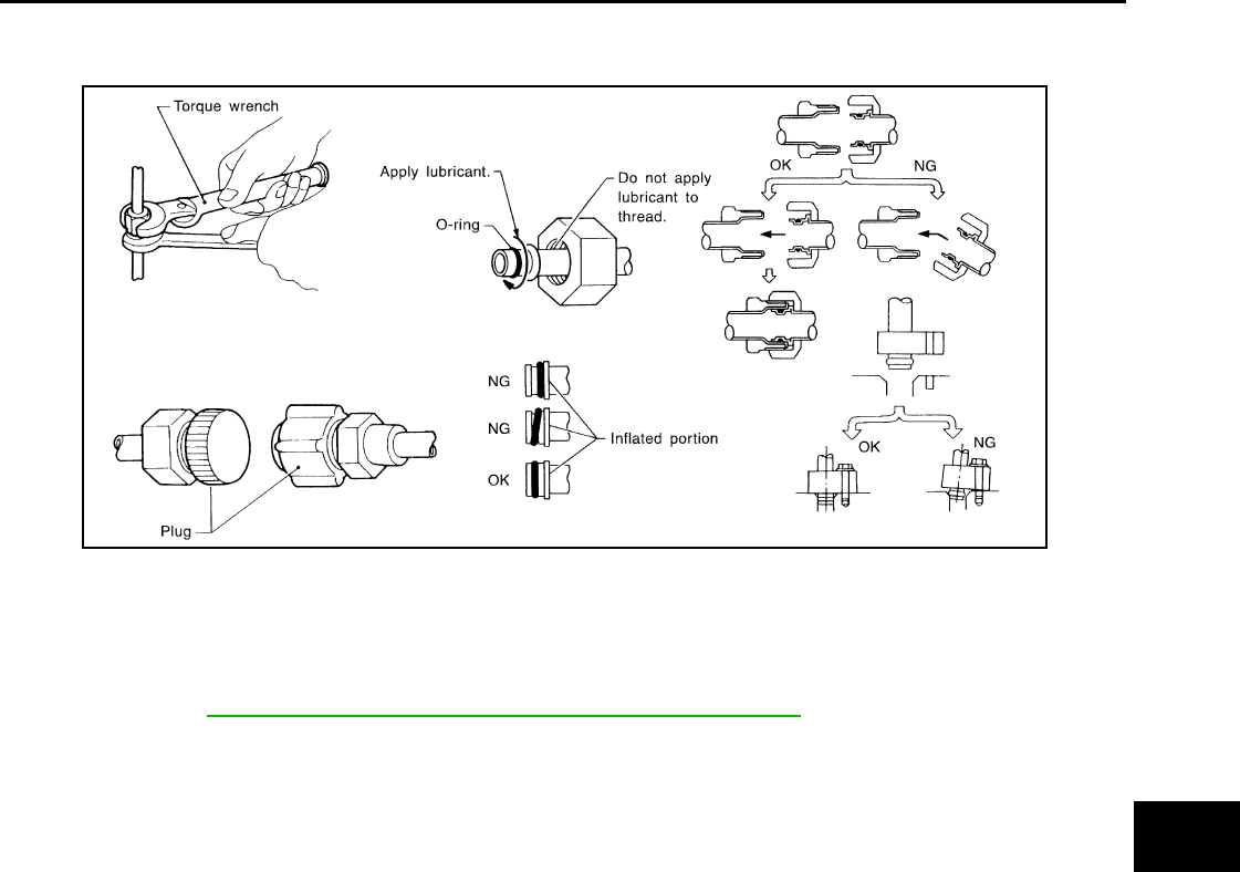
Precaution for Refrigerant Connection INFOID:0000000005282760
A new type refrigerant connection has been introduced to all refrigerant lines except the following locations.
• Expansion valve to cooling unit
• Evaporator pipes to evaporator (inside cooling unit)
• Refrigerant pressure sensor
FEATURES OF NEW TYPE REFRIGERANT CONNECTION
• The O-ring has been relocated. It has also been provided with a groove for proper installation. This elimi-
nates the chance of the O-ring being caught in, or damaged by, the mating part. The sealing direction of the
O-ring is now set vertically in relation to the contacting surface of the mating part to improve sealing charac-
teristics.
• The reaction force of the O-ring will not occur in the direction that causes the joint to pull out, thereby facili-
tating piping connections.
SHA815E
Revision: January 2010 2010 Sentra
MTC-6
< SERVICE INFORMATION >
PRECAUTIONS
O-RING AND REFRIGERANT CONNECTION
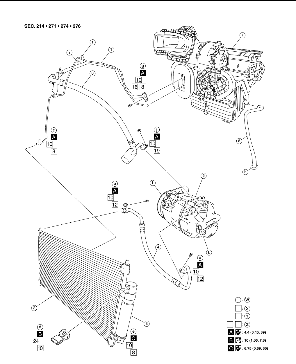
MR20DE
AWIIA1293GB
1. High-pressure pipe 2. Condenser 3. Liquid tank
4. High-pressure flexible hose 5. Compressor 6. Low-pressure flexible hose
7. Heater and cooling unit assembly 8. Drain hose W. Refrigerant leak checking order
X. Tightening torque (A-C) Y. Wrench size Z. O-ring size
Revision: January 2010 2010 Sentra
PRECAUTIONS
MTC-7
< SERVICE INFORMATION >
C
D
E
F
G
H
I
K
L
M
A
B
MTC
N
O
P
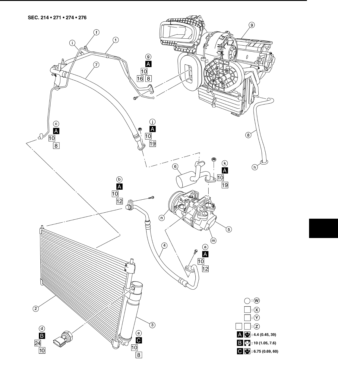
QR25DE
CAUTION:
AWIIA1294GB
1. High-pressure pipe 2. Condenser 3. Liquid tank
4. High-pressure flexible hose 5. Compressor 6. Muffler pipe
7. Low-pressure flexible hose 8. Drain hose 9. Heater and cooling unit assembly
W. Refrigerant leak checking order X. Tightening torque (A-C) Y. Wrench size
Z. O-ring size
Revision: January 2010 2010 Sentra
MTC-8
< SERVICE INFORMATION >
PRECAUTIONS
The new and former refrigerant connections use different O-ring configurations. Do not confuse O-
rings since they are not interchangeable. If a wrong O-ring is installed, refrigerant will leak at, or
around, the connection.
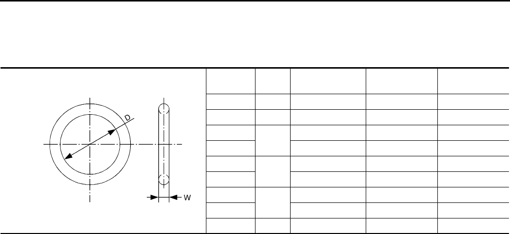
O-Ring Part Numbers and Specifications
*: Always check with the Parts Department for the latest parts information.
WARNING:
Make sure all refrigerant is discharged into the recycling equipment and the pressure in the system is
less than atmospheric pressure. Then gradually loosen the discharge side hose fitting and remove it.
CAUTION:
When replacing or cleaning refrigerant cycle components, observe the following.
• When the compressor is removed, store it in the same position as it is when mounted on the car.
Failure to do so will cause oil to enter the low pressure chamber.
• When connecting tubes, always use a torque wrench and a back-up wrench.
• After disconnecting tubes, immediately plug all openings to prevent entry of dirt and moisture.
• When installing an air conditioner in the vehicle, connect the pipes as the final stage of the opera-
tion. Do not remove the seal caps of pipes and other components until just before required for con-
nection.
• Allow components stored in cool areas to warm to working area temperature before removing seal
caps. This prevents condensation from forming inside A/C components.
• Thoroughly remove moisture from the refrigeration system before charging the refrigerant.
• Always replace used O-rings.
• When connecting tube, apply oil to circle of the O-rings shown in illustration. Be careful not to apply
oil to threaded portion.
Oil name: NISSAN A/C System Oil Type S or equivalent
• O-ring must be closely attached to grooved portion of tube.
• When replacing the O-ring, be careful not to damage O-ring and tube.
• Connect tube until you hear it click, then tighten the nut or bolt by hand until snug. Make sure that
the O-ring is installed to tube correctly.
Connec-
tion type
O-ring
size Part number* D mm (in) W mm (in)
New 8 92471 N8210 6.8 (0.268) 1.85 (0.0728)
Former 10 J2476 89956 9.25 (0.3642) 1.78 (0.0701)
New 12 92472 N8210 10.9 (0.429) 2.43 (0.0957)
Former 92475 71L00 11.0 (0.433) 2.4 (0.094)
New 16 92473 N8210 13.6 (0.535) 2.43 (0.0957)
Former 92475 72L00 14.3 (0.563) 2.3 (0.091)
New 19 92474 N8210 16.5 (0.650) 2.43 (0.0957)
Former 92477 N8200 17.12 (0.6740) 1.78 (0.0701)
New 24 92195 AH300 21.8 (0.858) 2.4 (0.094)
SHA814E
Revision: January 2010 2010 Sentra
PRECAUTIONS
MTC-9
< SERVICE INFORMATION >
C
D
E
F
G
H
I
K
L
M
A
B
MTC
N
O
P
• After connecting line, conduct leak test and make sure that there is no leakage from connections.
When the gas leaking point is found, disconnect that line and replace the O-ring. Then tighten con-
nections of seal seat to the specified torque.
Precaution for Service of Compressor INFOID:0000000005282761
•Plug all openings to prevent moisture and foreign matter from entering.
•When the compressor is removed, store it in the same position as it is when mounted on the car.
•When replacing or repairing compressor, follow “Maintenance of Oil Quantity in Compressor”
exactly. Refer to MTC-18, "Maintenance of Oil Quantity in Compressor".
•Keep friction surfaces between clutch and pulley clean. If the surface is contaminated, with oil, wipe
it off by using a clean waste cloth moistened with thinner.
•After compressor service operation, turn the compressor shaft by hand more than 5 turns in both
directions. This will equally distribute oil inside the compressor. After the compressor is installed,
let the engine idle and operate the compressor for 1 hour.
•After replacing the compressor magnet clutch, apply voltage to the new one and check for normal
operation. [Gap between clutch disc and pulley is 0.3 - 0.6 mm (0.012 - 0.024 in)]
Precaution for Service Equipment INFOID:0000000005282762
RECOVERY/RECYCLING EQUIPMENT
Follow the manufacturer's instructions for machine operation and machine maintenance. Never introduce any
refrigerant other than that specified into the machine.
ELECTRONIC LEAK DETECTOR
Follow the manufacturer's instructions for tester operation and tester maintenance.
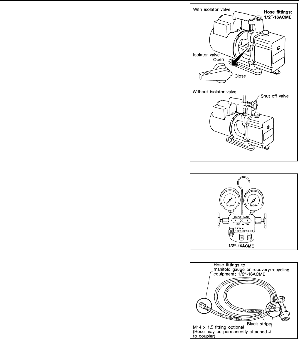
VACUUM PUMP
RHA861F
Revision: January 2010 2010 Sentra
MTC-10
< SERVICE INFORMATION >
PRECAUTIONS
The oil contained inside the vacuum pump is not compatible with the
specified oil for HFC-134a (R-134a) A/C systems. The vent side of
the vacuum pump is exposed to atmospheric pressure so the vac-
uum pump oil may migrate out of the pump into the service hose.
This is possible when the pump is switched off after evacuation (vac-
uuming) and hose is connected to it.
To prevent this migration, use a manual valve situated near the
hose-to-pump connection, as follows.
• Usually vacuum pumps have a manual isolator valve as part of the
pump. Close this valve to isolate the service hose from the pump.
• For pumps without an isolator, use a hose equipped with a manual
shut-off valve near the pump end. Close the valve to isolate the
hose from the pump.
• If the hose has an automatic shut off valve, disconnect the hose
from the pump: as long as the hose is connected, the valve is open
and lubricating oil may migrate.
Some one-way valves open when vacuum is applied and close
under a no vacuum condition. Such valves may restrict the pump's
ability to pull a deep vacuum and are not recommended.
MANIFOLD GAUGE SET
Be certain that the gauge face indicates R-134a or 134a. Make sure
the gauge set has 1/2″-16 ACME threaded connections for service
hoses. Confirm the set has been used only with refrigerant HFC-
134a (R-134a) along with specified oil.
SERVICE HOSES
Be certain that the service hoses display the markings described
(colored hose with black stripe). All hoses must include positive shut-
off devices (either manual or automatic) near the end of the hoses
opposite the manifold gauge.
SERVICE COUPLERS
RHA270D
SHA533D
RHA272D
Revision: January 2010 2010 Sentra
PRECAUTIONS
MTC-11
< SERVICE INFORMATION >
C
D
E
F
G
H
I
K
L
M
A
B
MTC
N
O
P
Never attempt to connect HFC-134a (R-134a) service couplers to a
CFC-12 (R-12) A/C system. The HFC-134a (R-134a) couplers will
not properly connect to the CFC-12 (R-12) system. However, if an
improper connection is attempted, discharging and contamination
may occur.
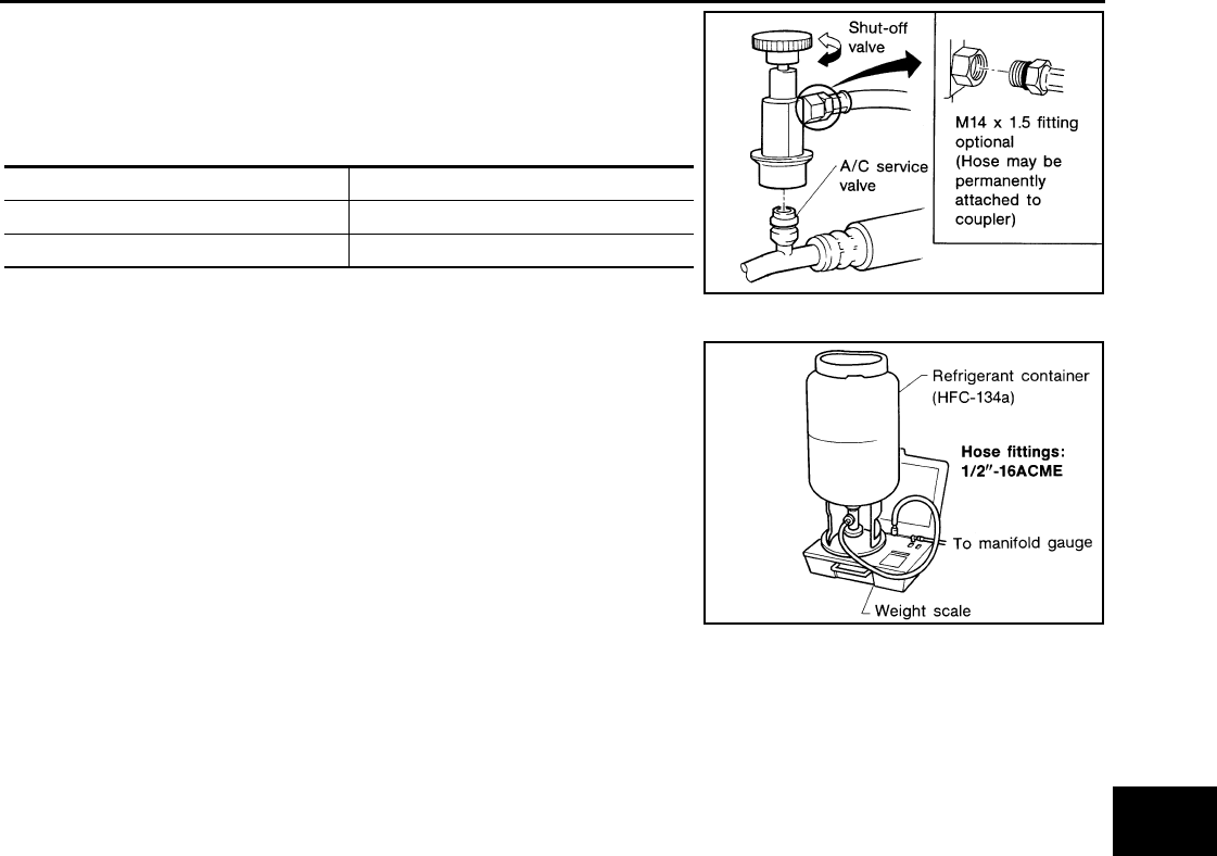
REFRIGERANT WEIGHT SCALE
Verify that no refrigerant other than HFC134a (R-134a) and specified
oils have been used with the scale. If the scale controls refrigerant
flow electronically, the hose fitting must be 1/2”-16 ACME.
CHARGING CYLINDER
Using a charging cylinder is not recommended. Refrigerant may be vented into air from cylinder's top valve
when filling the cylinder with refrigerant. Also, the accuracy of the cylinder is generally less than that of an
electronic scale or of quality recycle/recharge equipment.
Shut-off valve rotation A/C service valve
Clockwise Open
Counterclockwise Close
RHA273D
RHA274D
Revision: January 2010 2010 Sentra
MTC-12
< SERVICE INFORMATION >
PREPARATION
PREPARATION
HFC-134a (R-134a) Service Tool and Equipment INFOID:0000000005282763
Never mix HFC-134a refrigerant and/or its specified oil with CFC-12 (R-12) refrigerant and/or its oil.
Separate and non-interchangeable service equipment must be used for handling each type of refrigerant/oil.
Refrigerant container fittings, service hose fittings and service equipment fittings (equipment which handles
refrigerant and/or oil) are different between CFC-12 (R-12) and HFC-134a (R-134a). This is to avoid mixed
use of the refrigerants/oil.
Adapters that convert one size fitting to another must never be used: refrigerant/oil contamination will occur
and compressor failure will result.
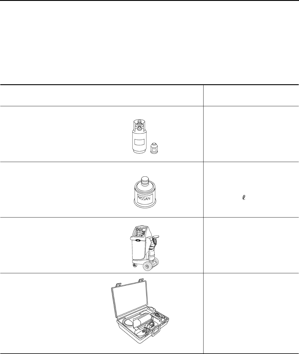
Tool number
(Kent-Moore No.)
Tool name
Description
—
(—)
Refrigerant HFC-134a (R-134a)
Container color: Light blue
Container marking: HFC-134a (R-
134a)
Fitting size: Thread size
• large container 1/2 in -16 ACME
—
(—)
Genuine NISSAN A/C System Oil
Type S
Type: Poly alkaline glycol oil (PAG),
type S
Application: HFC-134a (R-134a)
swash plate compressors (NISSAN
only)
Lubricity: 40 m (1.4 US fl oz, 1.4 Imp
fl oz)
K991J0130
(ACR2005-NI)
ACR A/C Service Center
Refrigerant recovery, recycling and re-
charging
—
(J-41995)
Electronic refrigerant leak detector
Power supply: DC 12V (Battery termi-
nal)
S-NT196
S-NT197
WJIA0293E
AHA281A
Revision: January 2010 2010 Sentra
PREPARATION
MTC-13
< SERVICE INFORMATION >
C
D
E
F
G
H
I
K
L
M
A
B
MTC
N
O
P
—
(J-43926)
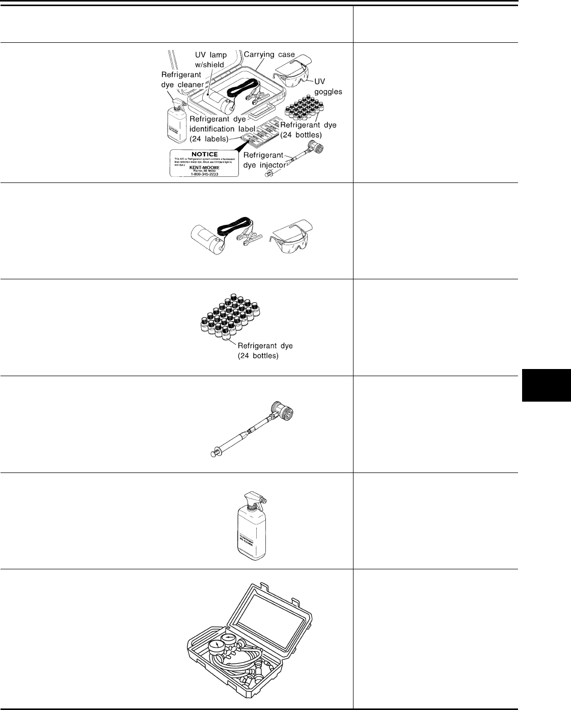
Refrigerant dye leak detection kit
Kit includes:
(J-42220) UV lamp and UV safety
goggles
(J-41459) Refrigerant dye injector
(J-41447) qty. 24
HFC-134a (R-134a) refrigerant
dye
(J-43872) Refrigerant dye cleaner
Power supply: DC 12V (Battery termi-
nal)
—
(J-42220)
Fluorescent dye leak detector
Power supply: DC 12V (Battery termi-
nal)
For checking refrigerant leak when flu-
orescent dye is installed in A/C system.
Includes: UV lamp and UV safety gog-
gles
—
(J-41447)
HFC-134a (R-134a) Fluorescent
leak detection dye
(Box of 24, 1/4 ounce bottles)
Application: For HFC-134a (R-134a)
PAG oil
Container: 1/4 ounce (7.4cc) bottle
(Includes self-adhesive dye identifica-
tion labels for affixing to vehicle after
charging system with dye.)
—
(J-41459)
HFC-134a (R-134a) Dye injector
Use with J-41447, 1/4 ounce bottle
For injecting 1/4 ounce of fluorescent
leak detection dye into A/C system.
—
(J-43872)
Refrigerant dye cleaner
For cleaning dye spills.
—
(J-39183-C)
Manifold gauge set (with hoses
and couplers)
Identification:
• The gauge face indicates R-134a.
Fitting size: Thread size
• 1/2 in -16 ACME
Tool number
(Kent-Moore No.)
Tool name
Description
ZHA200H
SHA438F
SHA439F
SHA440F
SHA441F
RJIA0196E
Revision: January 2010 2010 Sentra
MTC-14
< SERVICE INFORMATION >
PREPARATION
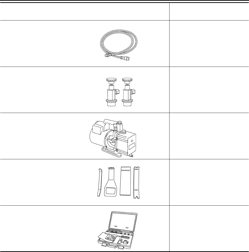
Commercial Service Tool INFOID:0000000005282764
Service hoses
• (J-39500-72B)
High side hose
• (J-39500-72R)
Low side hose
• (J-39500-72Y)
Utility hose
Hose color:
• Low side hose: Blue with black stripe
• High side hose: Red with black stripe
• Utility hose: Yellow with black stripe
or green with black stripe
Hose fitting to gauge:
• 1/2 in -16 ACME
Service couplers
• (J-39500-20A)
High side coupler
• (J-39500-24A)
Low side coupler
Hose fitting to service hose:
• M14 x 1.5 fitting is optional or perma-
nently attached.
—
(J-39649)
Vacuum pump
(Including the isolator valve)
Capacity:
• Air displacement: 4 CFM
• Micron rating: 20 microns
• Oil capacity: 482 g (17 oz)
Fitting size: Thread size
• 1/2 in -16 ACME
—
( J-46534 )
Trim tool set
For removing trim
—
(J-41425-NIS)
Aluminum tube repair kit
Repairing leaks in A/C tubes
Tool number
(Kent-Moore No.)
Tool name
Description
S-NT201
S-NT202
S-NT203
AWJIA0483ZZ
ALIIA0390ZZ
Revision: January 2010 2010 Sentra
PREPARATION
MTC-15
< SERVICE INFORMATION >
C
D
E
F
G
H
I
K
L
M
A
B
MTC
N
O
P
Tool number
Tool name
Description
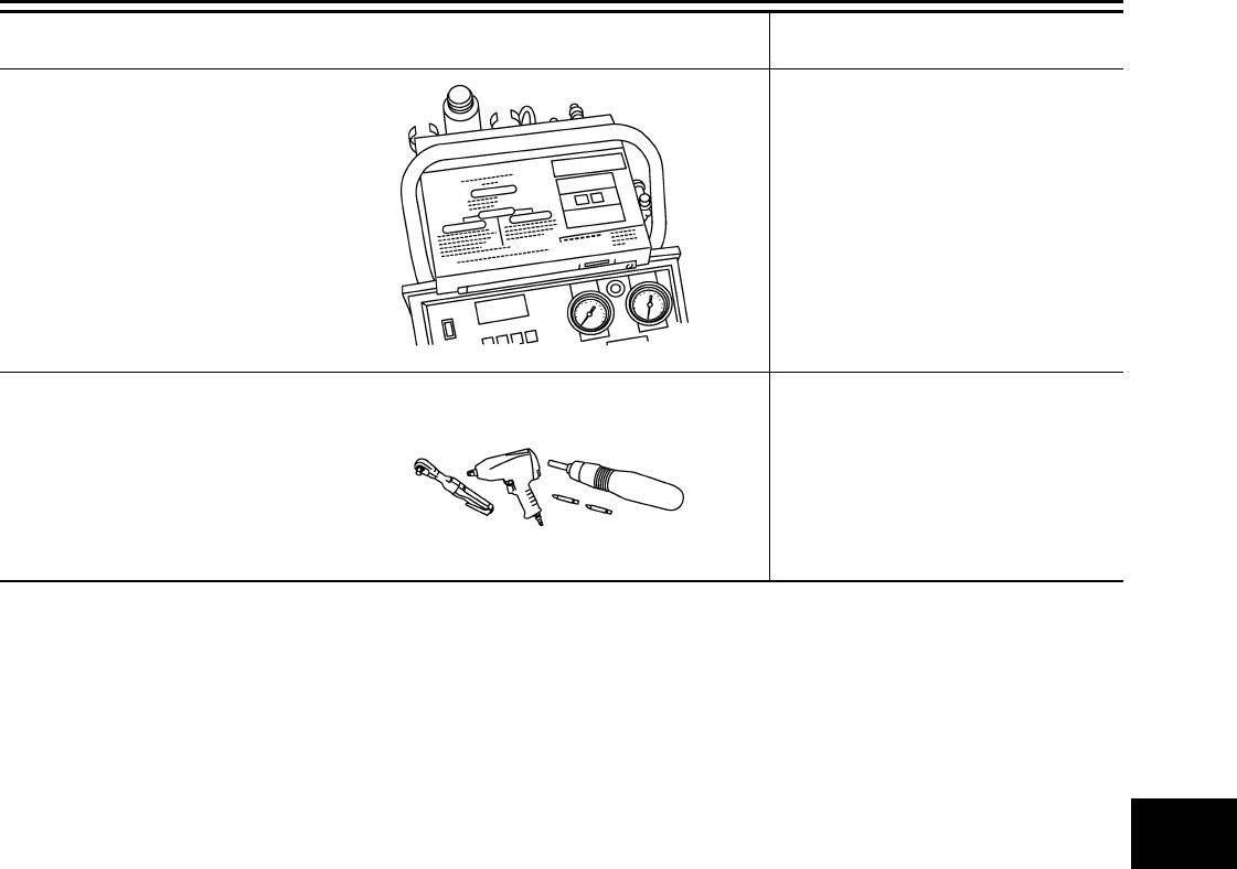
J-41810-NI
Refrigerant identifier equipment
HFC 134a (R-134a)
Checking refrigerant purity and system
contamination
Power tool Removing bolts and nuts
RJIA0197E
PIIB1407E
Revision: January 2010 2010 Sentra
MTC-16
< SERVICE INFORMATION >
REFRIGERATION SYSTEM
REFRIGERATION SYSTEM
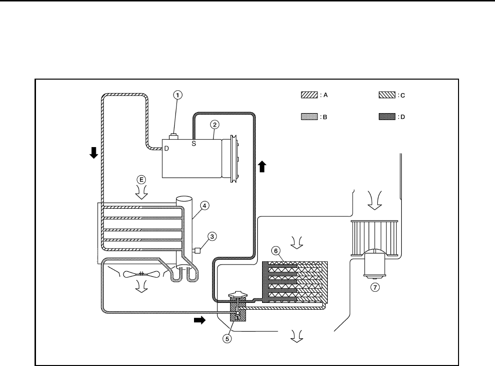
Refrigerant Cycle INFOID:0000000005282765
REFRIGERANT FLOW
The refrigerant flows in the standard pattern, that is, through the compressor, the condenser with liquid tank,
through the evaporator, and back to the compressor. The refrigerant evaporation through the evaporator coil is
controlled by an externally equalized expansion valve, located inside the evaporator case.
Refrigerant System Protection INFOID:0000000005282766
REFRIGERANT PRESSURE SENSOR
The refrigerant system is protected against excessively high or low pressures by the refrigerant pressure sen-
sor, located on the liquid tank. If the system pressure rises above or falls below the specifications, the refriger-
ant pressure sensor detects the pressure inside the refrigerant line and sends the voltage signal to the ECM.
The ECM then signals the BCM (via CAN communication lines) to cease suppling power to the A/C relay
which disengages and stops the compressor. This occurs when pressure on the high pressure side (as
detected by refrigerant pressure sensor) is over approximately 2,746 kPa (28 kg/cm2, 398 psi), or below
approximately 120 kPa (1.22 kg/cm2, 17.4 psi).
PRESSURE RELIEF VALVE
The refrigerant system is also protected by a pressure relief valve, located in the rear head of the compressor.
When the refrigerant pressure in the system increases to an abnormal level [more than 3,600 kPa (36.7 kg/
cm2, 522 psi)], the release port on the pressure relief valve automatically opens and releases refrigerant into
the atmosphere.
1. Pressure relief valve 2. Compressor 3. Refrigerant pressure sensor
4. Condenser (with liquid tank) 5. Expansion valve 6. Evaporator
7. Front blower motor A. High-pressure gas B. High-pressure liquid
C. Low-pressure liquid D. Low-pressure gas E. Outside air
WJIA2295E
Revision: January 2010 2010 Sentra
REFRIGERATION SYSTEM
MTC-17
< SERVICE INFORMATION >
C
D
E
F
G
H
I
K
L
M
A
B
MTC
N
O
P
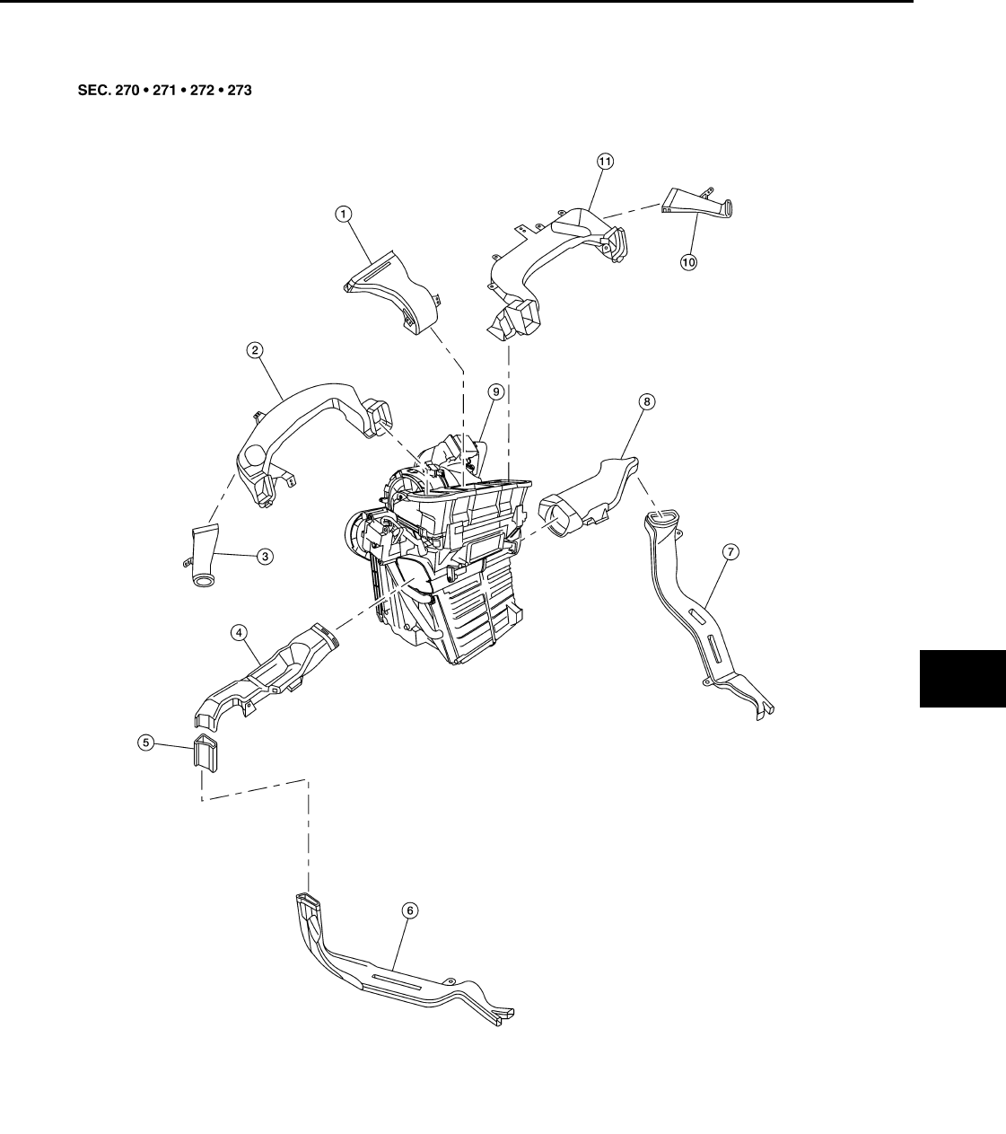
Component Part Location INFOID:0000000005282767
1. Defroster nozzle 2. Side ventilator duct (LH) 3. Side defroster duct (LH)
4. Front foot duct (LH) 5. Rear floor connector duct (Canada
only)
6. Rear floor duct (LH) (Canada only)
7. Rear floor duct (RH) (Canada only) 8. Front foot duct (RH) 9. Heater and cooling unit assembly
10. Side defroster duct (RH) 11. Side ventilator duct (RH)
BJIA0023E
Revision: January 2010 2010 Sentra
MTC-18
< SERVICE INFORMATION >
OIL
OIL
Maintenance of Oil Quantity in Compressor INFOID:0000000005282768
The oil in the compressor circulates through the system with the refrigerant. Add oil to compressor when
replacing any component or after a large refrigerant leakage has occurred. It is important to maintain the spec-
ified amount.
If oil quantity is not maintained properly, the following malfunctions may result:
• Lack of oil: May lead to a seized compressor
• Excessive oil: Inadequate cooling (thermal exchange interference)
OIL
• Oil type: NISSAN A/C System Oil Type S or equivalent
CHECKING AND ADJUSTING
CAUTION:
If excessive oil leakage is noted, do not perform the oil return operation.
Start the engine and set the following conditions:
Test Condition
•Engine speed: Idling to 1,200 rpm
•A/C switch: On
•Blower fan speed: Max. position
•Temp. control: Optional [Set so that intake air temperature is 25° to 30° C (77° to 86°F).]
•Intake position: Recirculation ( )
•Perform oil return operation for about ten minutes
Adjust the oil quantity according to the following table.
Oil Adjusting Procedure for Components Replacement Except Compressor
After replacing any of the following major components, add the correct amount of oil to the system.
Amount of Oil to be Added
*1: If refrigerant leak is small, no addition of oil is needed.
Oil Adjustment Procedure for Compressor Replacement
Part replaced
Oil to be added to system
Remarks
Amount of oil
m (US fl oz, Imp fl oz)
Evaporator 75 (2.5, 2.6) —
Condenser 75 (2.5, 2.6) —
Liquid tank 5 (0.2, 0.2) Add if compressor is not replaced.
In case of refrigerant leak 30 (1.0, 1.1) Large leak
— Small leak *1
Revision: January 2010 2010 Sentra
OIL
MTC-19
< SERVICE INFORMATION >
C
D
E
F
G
H
I
K
L
M
A
B
MTC
N
O
P
1. Before connecting recovery/recycling equipment to vehicle, check recovery/recycling equipment gauges.
No refrigerant pressure should be displayed. If NG, recover refrigerant from equipment lines.
2. Connect recovery/recycling equipment to vehicle. Confirm refrigerant purity in supply tank using recovery/
recycling equipment and refrigerant identifier. If NG, refer to MTC-4, "Contaminated Refrigerant".
3. Confirm refrigerant purity in vehicle A/C system using recovery/recycling equipment and refrigerant identi-
fier. If NG, refer to MTC-4, "Contaminated Refrigerant".
4. Discharge refrigerant into the refrigerant recovery/recycling equipment. Measure oil discharged into the
recovery/recycling equipment.
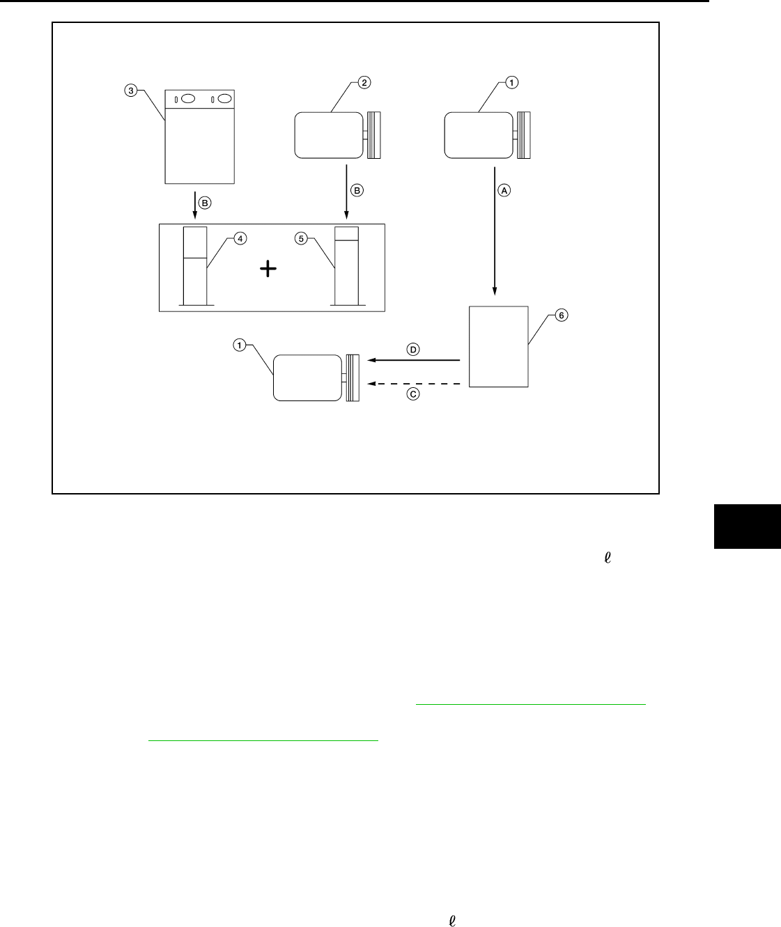
5. Drain the oil from the “old” (removed) compressor into a graduated container and recover the amount of
oil drained.
6. Drain the oil from the “new” compressor into a separate, clean container.
7. Measure an amount of new oil installed equal to amount drained from “old” compressor. Add this oil to
“new” compressor through the suction port opening.
8. Measure an amount of new oil equal to the amount recovered during discharging. Add this oil to “new”
compressor through the suction port opening.
9. If the liquid tank also needs to be replaced, add an additional 5 m (0.2 US fl oz, 0.2 Imp fl oz) of oil at this
time.
CAUTION:
1. New compressor 2. Old compressor 3. Recovery/recycling equipment
4. Measuring cup X 5. Measuring cup Y 6. New oil
A. Drain oil from the new compressor
into clean container
B. Record amount of oil recovered C. Add an additional 5 m (0.2 US fl oz,
0.2 Imp fl oz) of new oil when replacing
liquid tank
D. Install new oil equal to recorded
amounts in measuring cups X plus Y
WJIA1716E
Revision: January 2010 2010 Sentra

MTC-20
< SERVICE INFORMATION >
OIL
Do not add this 5 m (0.2 US fl oz, 0.2 Imp fl oz) of oil if only replacing the compressor and not the
liquid tank.
Revision: January 2010 2010 Sentra
AIR CONDITIONER CONTROL
MTC-21
< SERVICE INFORMATION >
C
D
E
F
G
H
I
K
L
M
A
B
MTC
N
O
P
AIR CONDITIONER CONTROL
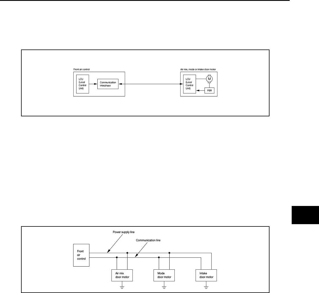
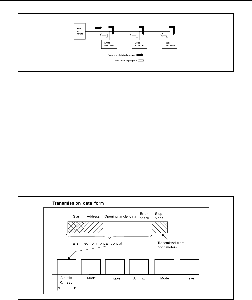
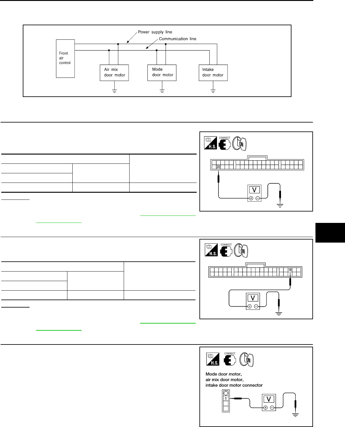
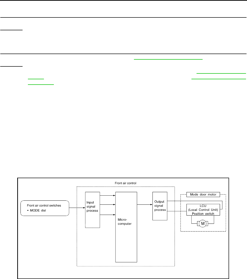
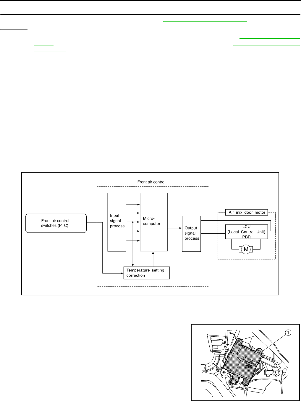
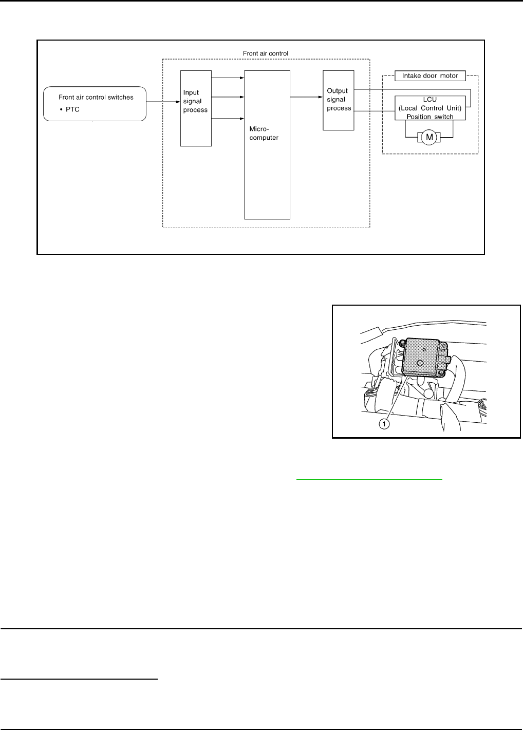
Overview Air Conditioner LAN Control System INFOID:0000000005282769
The LAN (local area network) system consists of front air control, air mix door motor, intake door motor, and
mode door motor.
A configuration of these components is shown in the diagram below.
System Construction INFOID:0000000005282770
A small network is constructed between the front air control, air mix door motor, intake door motor, and mode
door motor. The front air control and motors are connected by data transmission lines and motor power supply
lines. The LAN network is built through the ground circuits of the two motors.
Addresses, motor opening angle signals, motor stop signals and error checking messages are all transmitted
through the data transmission lines connecting the front air control and each motor.
The following functions are contained in LCUs built into the air mix door motor, intake door motor, and the
mode door motor.
• Address
• Motor opening angle signals
• Data transmission
• Motor stop and drive decision
• Opening angle sensor (PBR function)
• Comparison
• Decision (front air control indicated value and motor opening angle comparison)
Operation
The front air control receives signals from its various dials and switches. The front air control then sends air
mix door, mode door and intake door opening angle data to the air mix door motor LCU, mode door motor LCU
and intake door motor LCU.
The air mix door motor, mode door motor and intake door motor read their respective signals according to the
address signal. Opening angle indication signals received from the front air control and each of the motor posi-
tion sensors are compared by the LCUs in each motor with the existing decision and opening angles. Subse-
WJIA0876E
WJIA0877E
Revision: January 2010 2010 Sentra
MTC-22
< SERVICE INFORMATION >
AIR CONDITIONER CONTROL
quently, HOT/COLD, DEFROST/VENT or FRESH/RECIRCULATION operation is selected. The new selection
data is returned to the front air control.
Transmission Data and Transmission Order
Front air control data is transmitted consecutively to each of the door motors following the form shown in figure
below.
Start: Initial compulsory signal sent to each of the door motors.
Address: Data sent from the front air control is selected according to data-based decisions made by the air mix
door motor, mode door motor and intake door motor.
If the addresses are identical, the opening angle data and error check signals are received by the door motor
LCUs. The LCUs then make the appropriate error decision. If the opening angle data is normal, door control
begins.
If an error exists, the received data is rejected and corrected data received. Finally, door control is based upon
the corrected opening angle data.
Opening angle: Data that shows the indicated door opening angle of each door motor.
Error check: Procedure by which sent and received data is checked for errors. Error data is then compiled.
The error check prevents corrupted data from being used by the air mix door motor, mode door motor and
intake door motor. Error data can be related to the following problems.
• Abnormal electrical frequency
• Poor electrical connections
• Interference from other signal transmission lines
• Signal level fluctuation
Stop signal: At the end of each transmission, a stop operation, in-operation, or internal problem message is
delivered to the front air control. This completes one data transmission and control cycle.
Air Mix Door Control
The air mix door is controlled by the front air control based on input from the temperature dial setting.
Blower Speed Control
Blower speed is controlled by the front air control based on the position of the blower control dial.
With the blower control dial set to any position except OFF, the blower will begin to operate.
Intake Door Control
WJIA0878E
WJIA0882E
Revision: January 2010 2010 Sentra
AIR CONDITIONER CONTROL
MTC-23
< SERVICE INFORMATION >
C
D
E
F
G
H
I
K
L
M
A
B
MTC
N
O
P
The intake door is controlled by the front air control based on input from the recirculation switch setting, and
the MAX A/C switch setting.
Mode Door Control
The mode door is controlled by the front air control based on input from the mode dial setting.
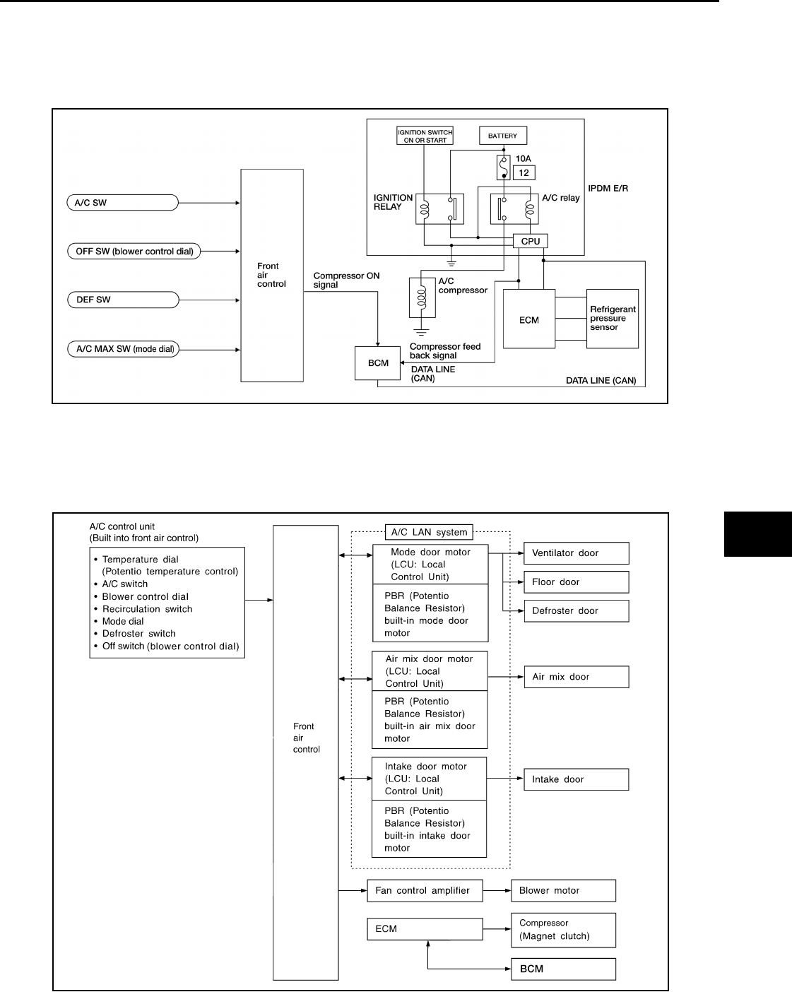
Magnet Clutch Control
The ECM controls compressor operation using input signals from the throttle position sensor and front air con-
trol.
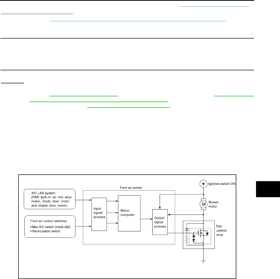
Overview of Control system INFOID:0000000005282771
The control system consists of an input sensor, switches, the front air control and outputs.
The relationship of these components is shown in the diagram below:
WJIA2307E
BJIA0003E
Revision: January 2010 2010 Sentra
MTC-24
< SERVICE INFORMATION >
AIR CONDITIONER CONTROL
Control Operation INFOID:0000000005282772
AIR CONDITIONER (A/C) SWITCH (IF EQUIPPED)
The air conditioner switch controls the A/C system. When the switch is pressed with the blower ON, the com-
pressor will turn ON. The indicator lamp will also illuminate.
The air conditioner cooling function operates only when the engine is running.
TEMPERATURE DIAL (Potentio Temperature Control)
Increases or decreases the set temperature.
BLOWER CONTROL DIAL/OFF SWITCH
Manually controls the blower speed.
In the off position, the compressor and blower are OFF, the intake door is set to the chosen position, and the
air mode doors are set to the chosen position.
RECIRCULATION ( ) SWITCH
OFF position: Outside air is drawn into the passenger compartment.
ON position: Interior air is recirculated inside the vehicle.
DEFROSTER SWITCH
Positions the air mode doors to the defrost position. Also positions the intake doors to the outside air position.
The compressor remains ON until the ignition is turned OFF or if the customer turns the mode to a non-defrost
mode and turns the A/C button to OFF.
MODE DIAL
Controls the air discharge through control of mode door, also controls MAX A/C function.
REAR WINDOW DEFOGGER SWITCH
This switch turns the rear window defogger ON and OFF.
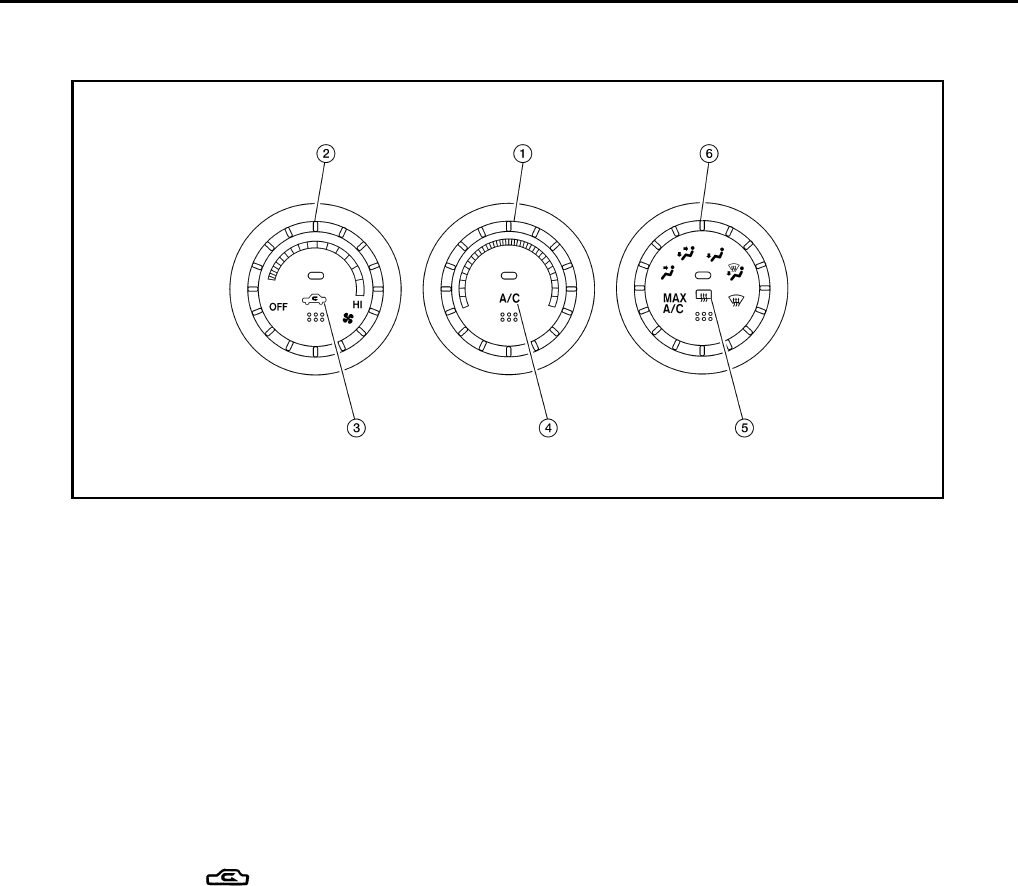
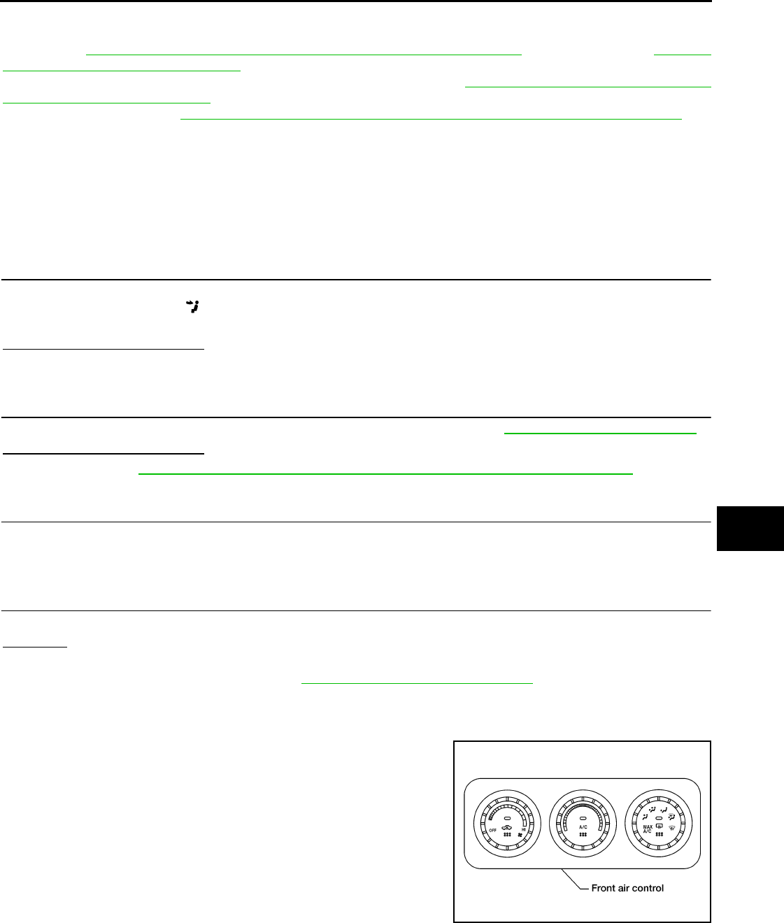
1. Temperature dial 2. Blower control dial 3. Recirculation switch
4. A/C switch (if equipped) 5. Rear window defogger switch 6. Mode dial
BJIA0004E
Revision: January 2010 2010 Sentra
AIR CONDITIONER CONTROL
MTC-25
< SERVICE INFORMATION >
C
D
E
F
G
H
I
K
L
M
A
B
MTC
N
O
P
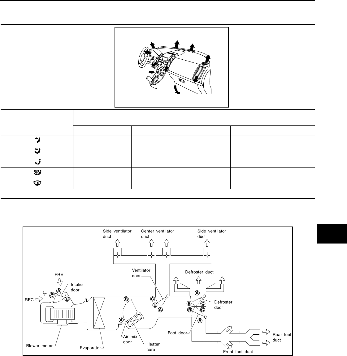
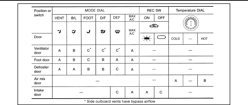
Discharge Air Flow INFOID:0000000005282773
System Description INFOID:0000000005282774
SWITCHES AND THEIR CONTROL FUNCTION
Mode door position Air outlet/distribution
Vent Foot Defroster
100% — —
60% 40% —
10% 60% 30%
11% 50% 39%
15% — 85%
Airflow always present at driver and passenger side demisters
BJIA0006E
RHA044GA
Revision: January 2010 2010 Sentra
MTC-26
< SERVICE INFORMATION >
AIR CONDITIONER CONTROL
WJIA2294E
Revision: January 2010 2010 Sentra
TROUBLE DIAGNOSIS
MTC-27
< SERVICE INFORMATION >
C
D
E
F
G
H
I
K
L
M
A
B
MTC
N
O
P
TROUBLE DIAGNOSIS
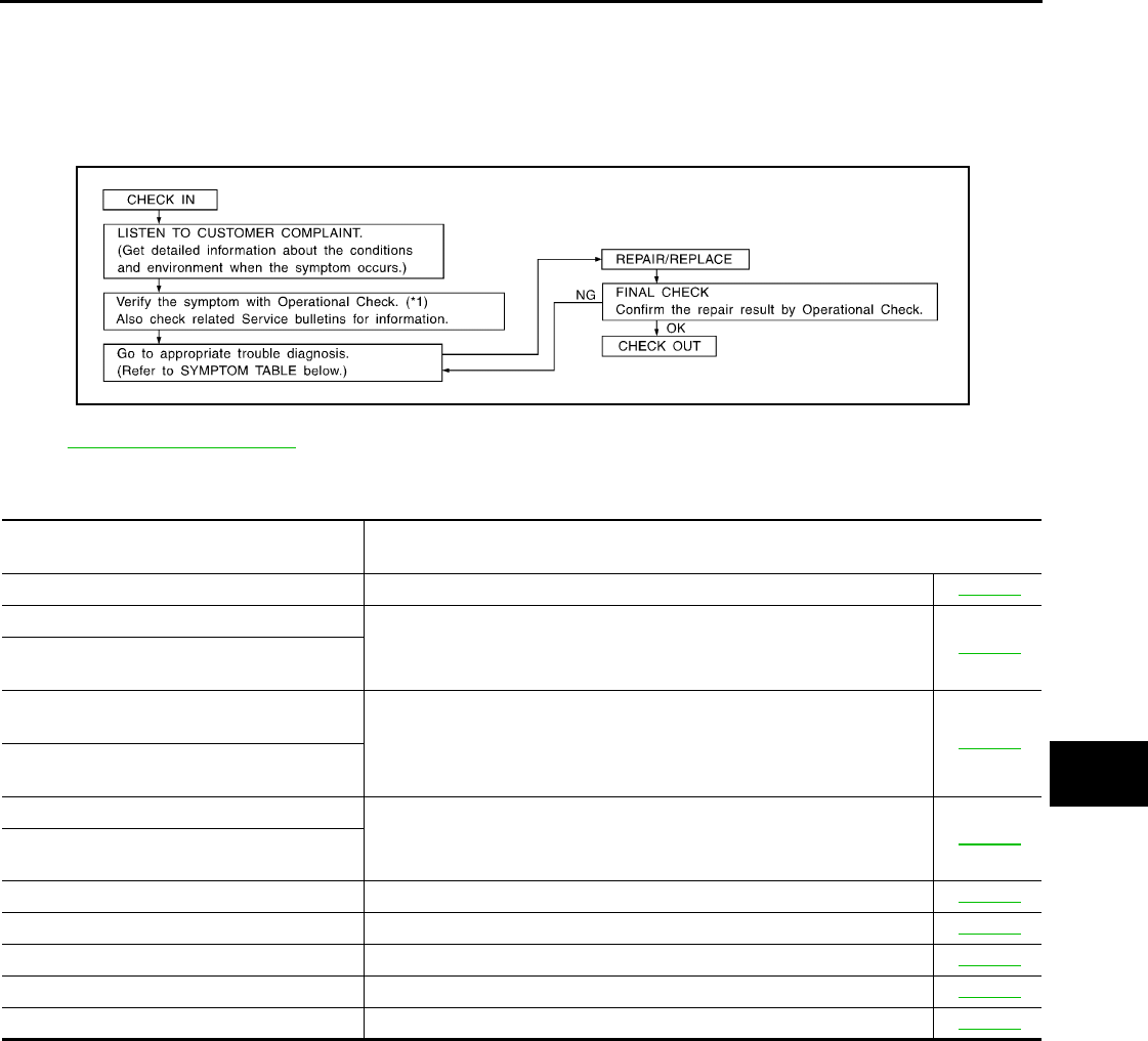
How to Perform Trouble Diagnosis for Quick and Accurate Repair INFOID:0000000005282775
WORK FLOW
SYMPTOM TABLE
Component Parts and Harness Connector Location INFOID:0000000005282776
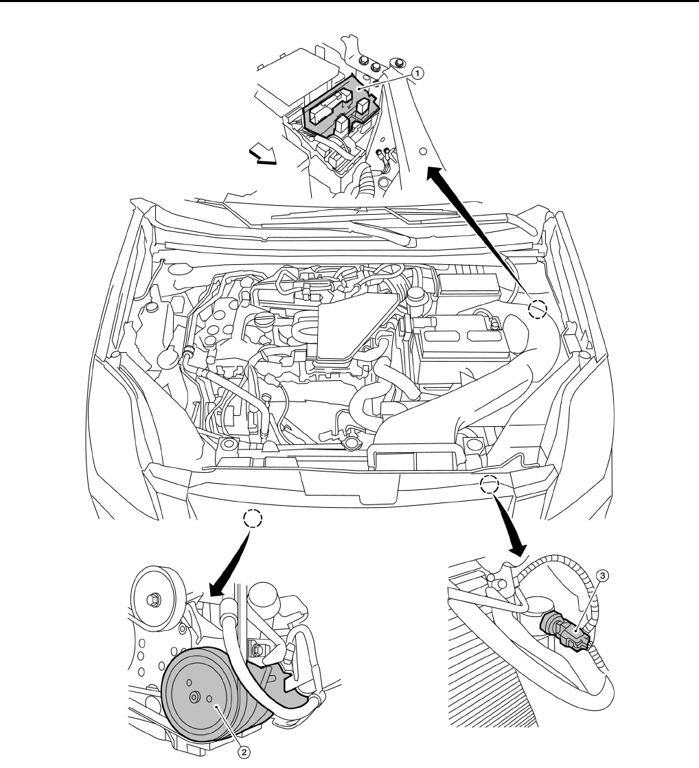
ENGINE COMPARTMENT - QR25DE
*1: MTC-38, "Operational Check"
SHA900E
Symptom Reference
Page
• A/C system does not come on. • Go to Trouble Diagnosis Procedure for A/C system. MTC-39
• Air outlet does not change.
• Go to Trouble Diagnosis Procedure for Mode Door Motor. (LAN) MTC-43
• Mode door motor does not operate normal-
ly.
• Discharge air temperature does not
change. • Go to Trouble Diagnosis Procedure for Air Mix Door Motor. (LAN) MTC-45
• Air mix door motor does not operate nor-
mally.
• Intake door does not change.
• Go to Trouble Diagnosis Procedure for Intake Door Motor. (LAN) MTC-47
• Intake door motor does not operate normal-
ly.
• Blower motor operation is malfunctioning. • Go to Trouble Diagnosis Procedure for Blower Motor. MTC-48
• Magnet clutch does not engage. • Go to Trouble Diagnosis Procedure for Magnet Clutch. MTC-53
• Insufficient cooling. • Go to Trouble Diagnosis Procedure for Insufficient Cooling. MTC-56
• Insufficient heating. • Go to Trouble Diagnosis Procedure for Insufficient Heating. MTC-63
• Noise. • Go to Trouble Diagnosis Procedure for Noise. MTC-64
Revision: January 2010 2010 Sentra
MTC-28
< SERVICE INFORMATION >
TROUBLE DIAGNOSIS
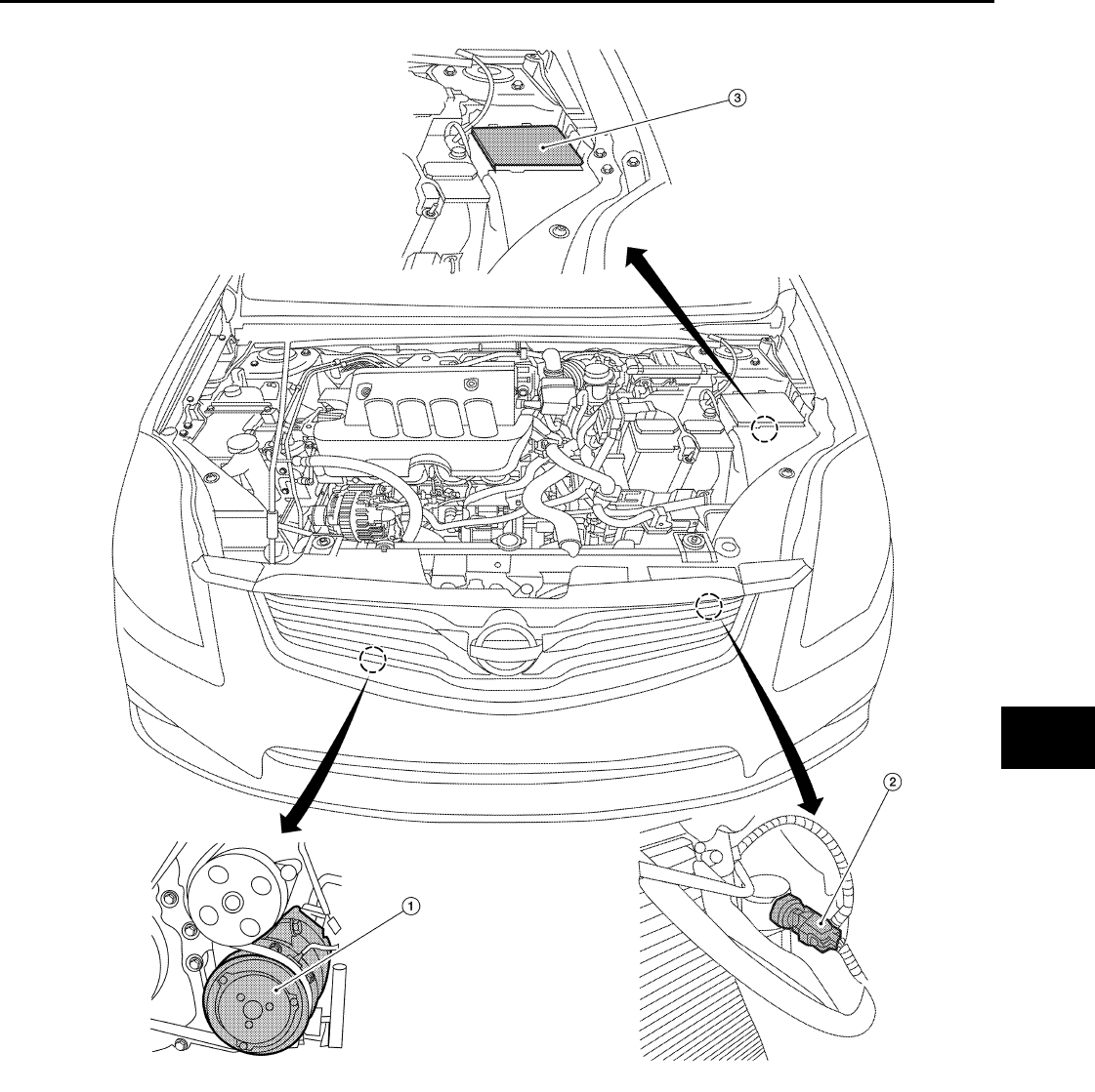
ENGINE COMPARTMENT - MR20DE
1. A/C relay (internal to the IPDM E/R) 2. A/C Compressor F3 3. Refrigerant pressure sensor E35
(view with grille removed)
WJIA2303E
Revision: January 2010 2010 Sentra
TROUBLE DIAGNOSIS
MTC-29
< SERVICE INFORMATION >
C
D
E
F
G
H
I
K
L
M
A
B
MTC
N
O
P
PASSENGER COMPARTMENT
1. A/C Compressor F3 (if equipped) 2. Refrigerant pressure sensor E35 (if
equipped), (view with grille re-
moved)
3. A/C relay (if equipped), (internal to
the IPDM E/R)
AWIIA1310ZZ
Revision: January 2010 2010 Sentra
MTC-30
< SERVICE INFORMATION >
TROUBLE DIAGNOSIS
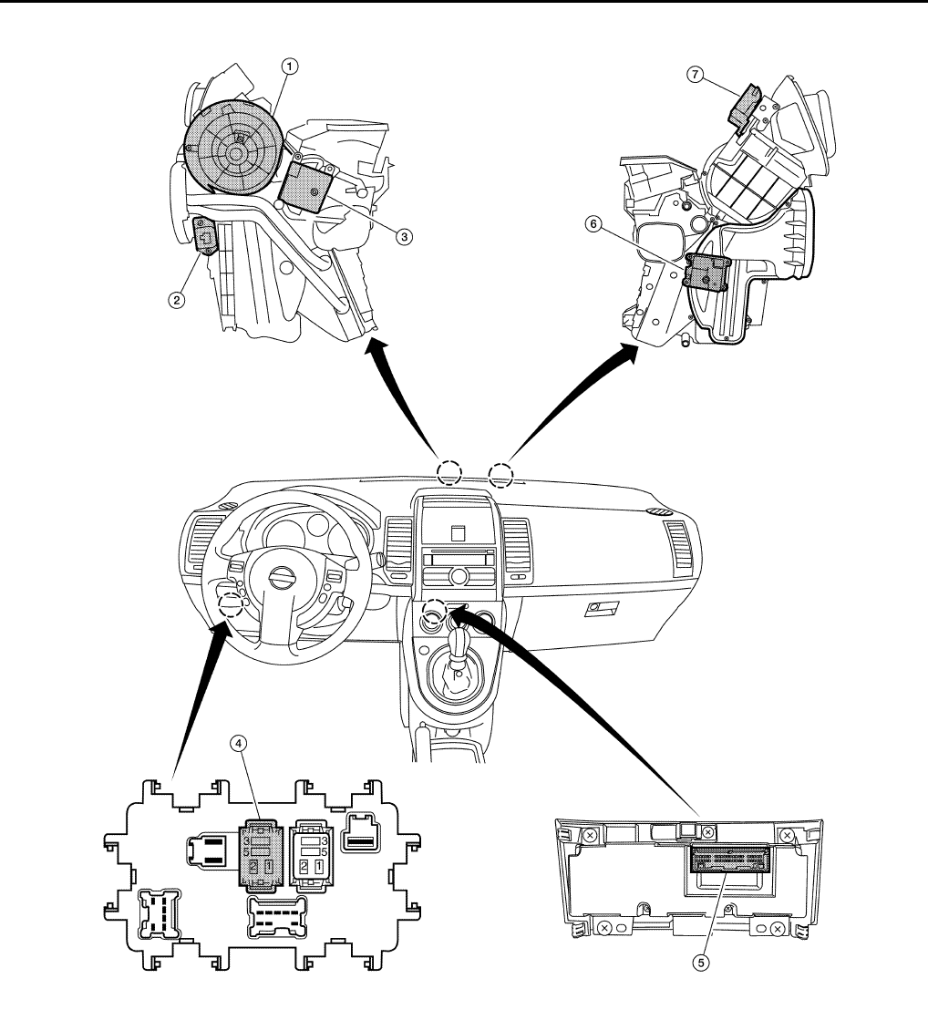
1. Front blower motor M62 2. Fan control amp. M52 3. Mode door motor M51
4. Front blower motor relay J1 5. Front air control M33 6. Air mix door motor M34
7. Intake door motor M48
BJIA0012E
Revision: January 2010 2010 Sentra
TROUBLE DIAGNOSIS
MTC-31
< SERVICE INFORMATION >
C
D
E
F
G
H
I
K
L
M
A
B
MTC
N
O
P
Schematic INFOID:0000000005282777
WJWA0490E
Revision: January 2010 2010 Sentra
MTC-32
< SERVICE INFORMATION >
TROUBLE DIAGNOSIS
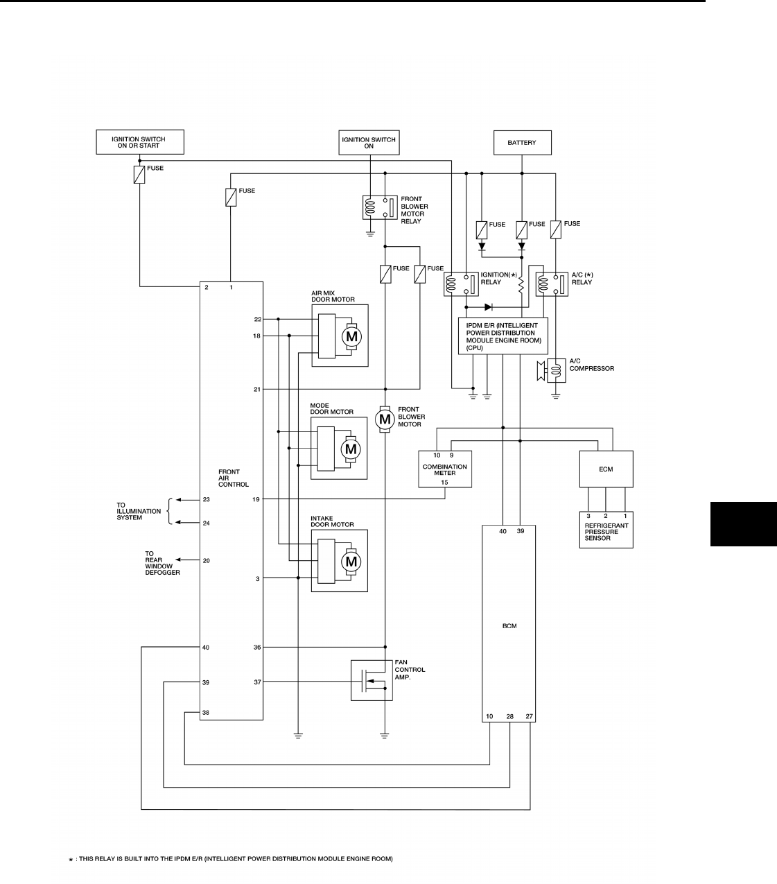
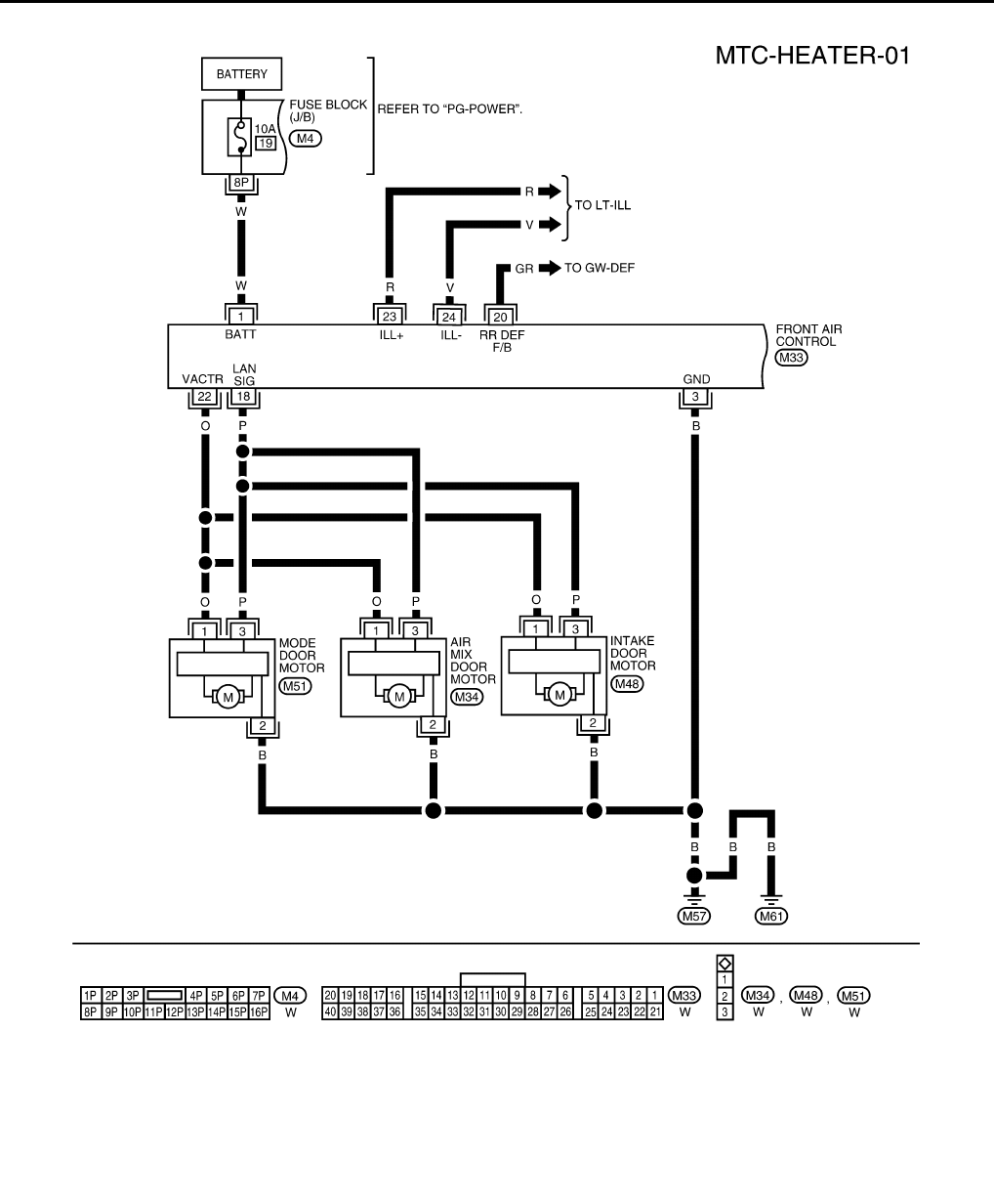
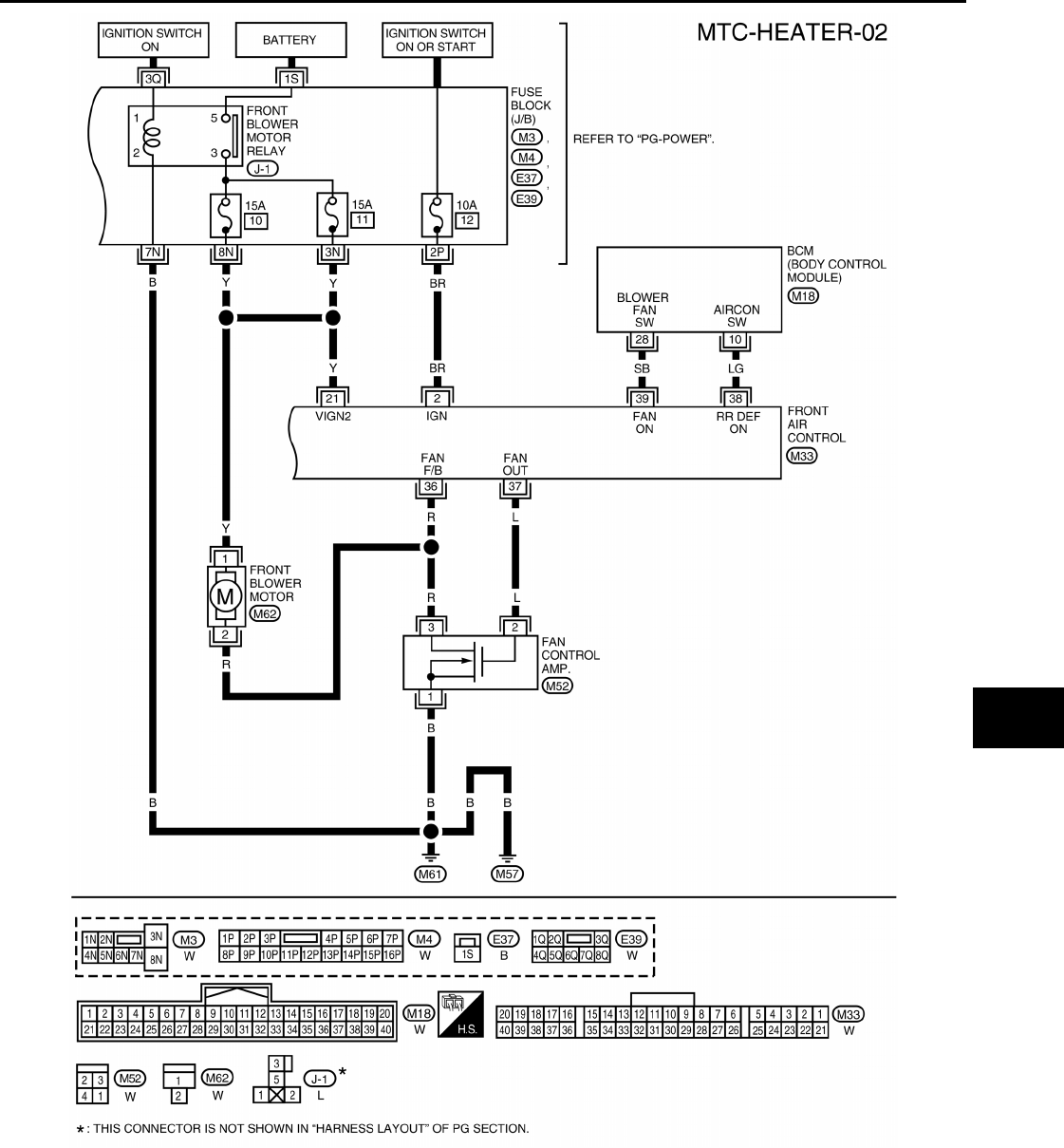
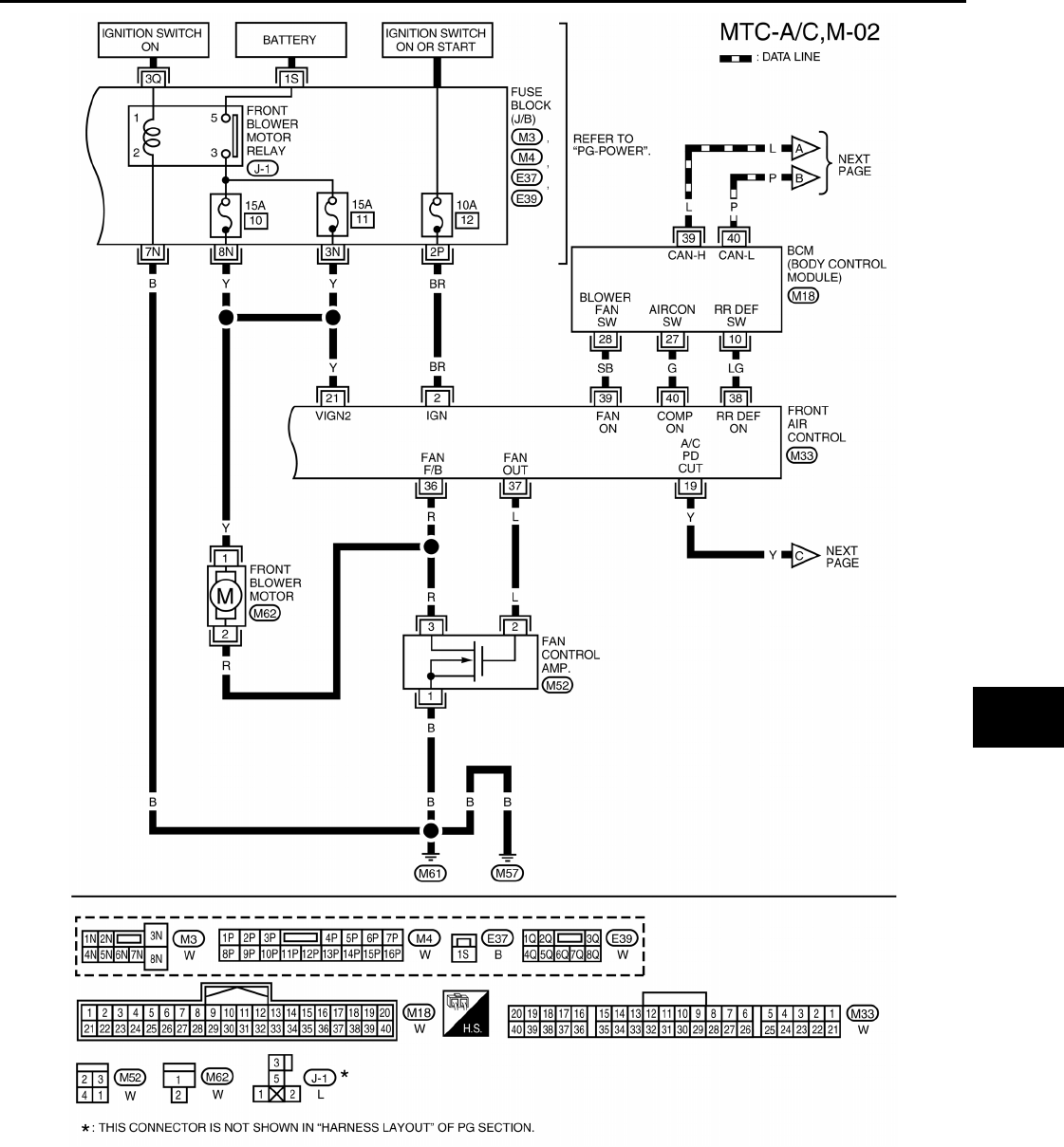
Wiring Diagram - HEATER - INFOID:0000000005282778
ABIWA0047GB
Revision: January 2010 2010 Sentra
TROUBLE DIAGNOSIS
MTC-33
< SERVICE INFORMATION >
C
D
E
F
G
H
I
K
L
M
A
B
MTC
N
O
P
WJWA0501E
Revision: January 2010 2010 Sentra
MTC-34
< SERVICE INFORMATION >
TROUBLE DIAGNOSIS
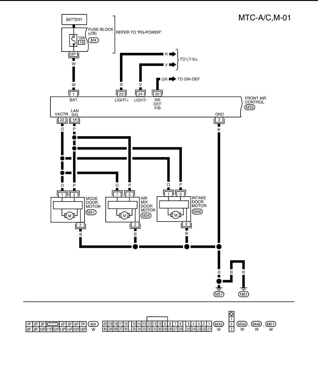
Wiring Diagram - A/C,M - INFOID:0000000005282779
ABIWA0050GB
Revision: January 2010 2010 Sentra
TROUBLE DIAGNOSIS
MTC-35
< SERVICE INFORMATION >
C
D
E
F
G
H
I
K
L
M
A
B
MTC
N
O
P
WJWA0502E
Revision: January 2010 2010 Sentra
MTC-36
< SERVICE INFORMATION >
TROUBLE DIAGNOSIS
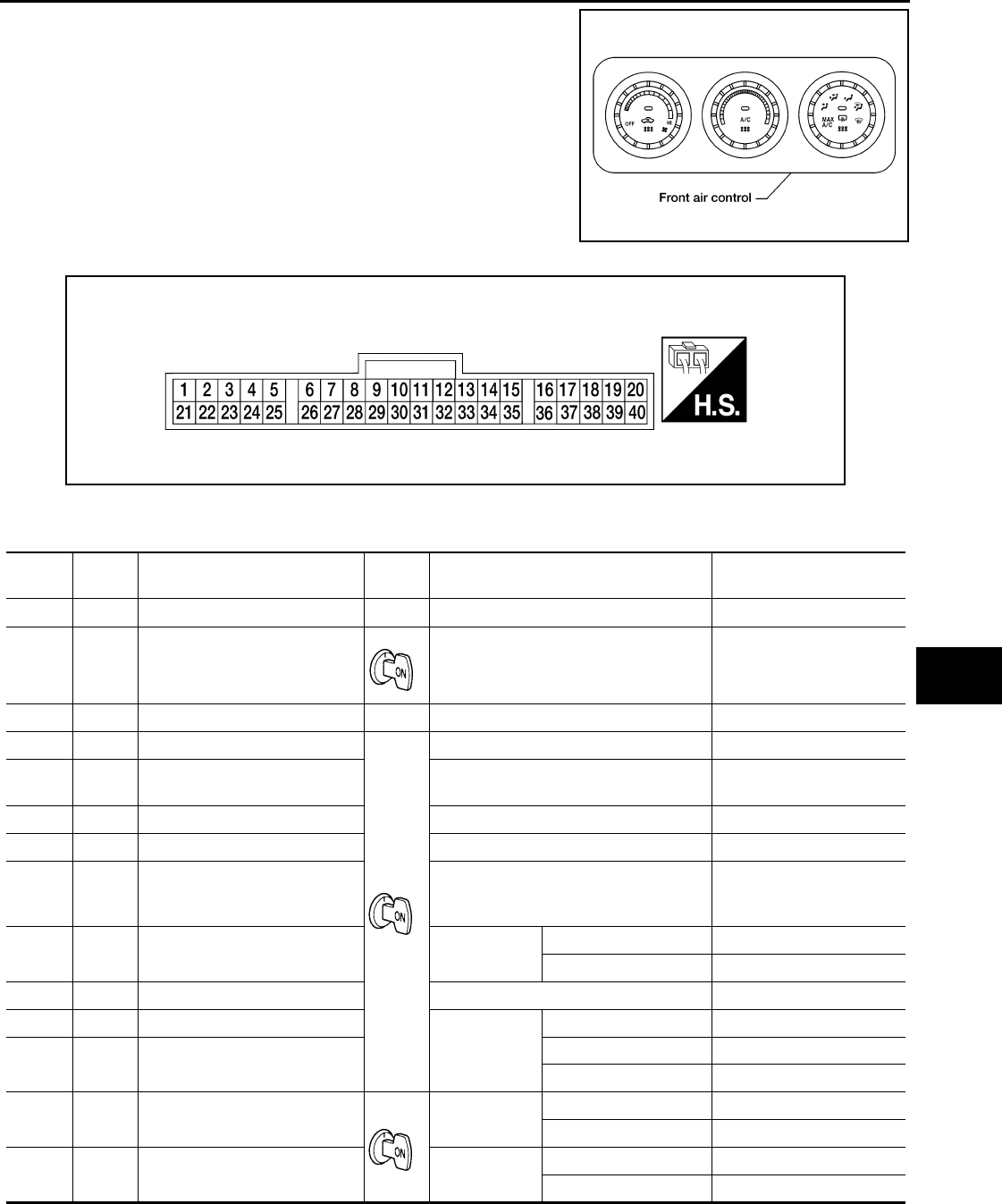
Front Air Control Terminal and Reference Value INFOID:0000000005282780
INSPECTION OF FRONT AIR CONTROL
AAIWA0069GB
Revision: January 2010 2010 Sentra
TROUBLE DIAGNOSIS
MTC-37
< SERVICE INFORMATION >
C
D
E
F
G
H
I
K
L
M
A
B
MTC
N
O
P
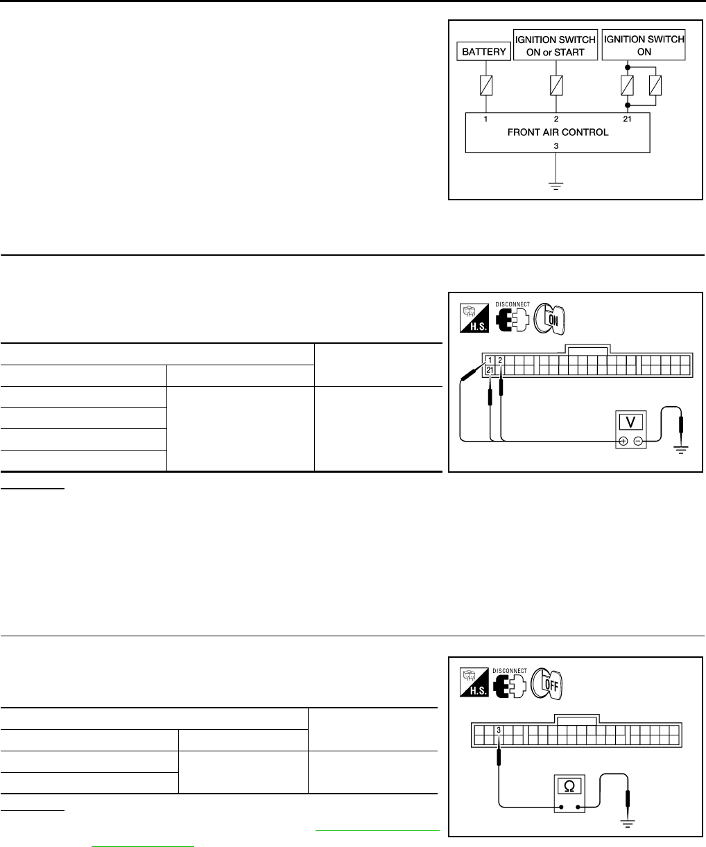
• Measure voltage between each terminal and body ground by fol-
lowing Terminals and Reference Value for front air control.
FRONT AIR CONTROL HARNESS CONNECTOR TERMINAL LAYOUT
TERMINAL AND REFERENCE VALUES FOR FRONT AIR CONTROL
WJIA0909E
BJIA0005E
Termi-
nal No.
Wire
color Item Ignition
switch Condition Voltage (V)
(Approx.)
1 W Power supply for BAT — — 12
2 BR Power supply for IGN — 12
3 B Ground — — 0
18 P A/C LAN signal (with A/C) — 5.5
19 Y A/C PD Cut
(with A/C) — 5
20 GR Sensor ground — 0
21 Y Power supply for IGN — 12
22 O
Power supply for mode door
motor, intake door motor, and
air mix door motor
—12
23 R Light (+) Lighting
switch
OFF 0
1st position 12
24 V Light (-) — 0
36 R Blower motor feed back
Fan speed
Low 7 - 10
37 L Fan control AMP. control signal Any speed except high 2.5 - 3
High 9- 10
38 LG Rear defrost ON signal Defroster
switch
ON 0
OFF 5
39 SB Fan ON signal Fan ON 0
OFF 5
Revision: January 2010 2010 Sentra
MTC-38
< SERVICE INFORMATION >
TROUBLE DIAGNOSIS
Operational Check INFOID:0000000005282781
The purpose of the operational check is to confirm that the system operates properly.
CHECKING BLOWER
1. Turn blower control dial clockwise, blower should operate on low speed.
2. Continue turning blower control dial clockwise, and continue checking blower speeds until all speeds are
checked.
3. Leave blower on Maximum speed.
If NG, go to MTC-48, "Blower Motor Circuit".
If OK, continue the check.
CHECKING DISCHARGE AIR
1. Turn mode door control dial to each position.
2. Confirm that discharge air comes out according to the air distribution table. Refer to MTC-25, "Discharge
Air Flow".
NOTE:
Confirm that the compressor clutch is engaged (audio or visual inspection) and intake door is in the fresh
( ) position when the DEF is selected.
Intake door position is checked in the next step.
If NG, go to MTC-43, "Mode Door Motor Circuit", MTC-74, "Removal and Installation".
If OK, continue the check.
CHECKING RECIRCULATION
1. Press REC switch.
Recirculation indicator should illuminate.
2. Press REC switch a second time.
Recirculation indicator should turn off.
3. Listen for intake door position change (you should hear blower sound change slightly).
If NG, go to MTC-47, "Intake Door Motor Circuit".
If OK, continue with the check.
CHECKING TEMPERATURE DECREASE
1. Turn temperature control dial counterclockwise to full cold position.
2. Check for cold air at discharge air outlets.
If NG, go to MTC-56, "Insufficient Cooling".
If OK, continue the check.
CHECKING TEMPERATURE INCREASE
1. Turn temperature control dial clockwise to full hot position.
2. Check for hot air at discharge air outlets.
If NG, go to MTC-63, "Insufficient Heating".
If OK, continue the check.
CHECKING A/C SWITCH (IF EQUIPPED)
1. Turn blower control dial to the desired position and push the air conditioner switch (if equipped) to turn ON
the air conditioner.
40 G Compressor ON signal
(with A/C) Compressor
ON 0
OFF 5
Termi-
nal No.
Wire
color Item Ignition
switch Condition Voltage (V)
(Approx.)
Conditions : Engine running at normal operating temperature
Revision: January 2010 2010 Sentra
TROUBLE DIAGNOSIS
MTC-39
< SERVICE INFORMATION >
C
D
E
F
G
H
I
K
L
M
A
B
MTC
N
O
P
2. Confirm that the A/C indicator lamp illuminates and that the compressor clutch engages (audio or visual
inspection).
If NG, go to MTC-39, "Power Supply and Ground Circuit for Front Air Control", then if necessary, MTC-53,
"Magnet Clutch Circuit (If Equipped)".
If all operational checks are OK (symptom can not be duplicated), go to GI-26, "How to Perform Efficient Diag-
nosis for an Electrical Incident" and perform tests as outlined to simulate driving condition environment. If
symptom appears, refer to MTC-27, "How to Perform Trouble Diagnosis for Quick and Accurate Repair" and
perform applicable trouble diagnosis procedures.
Power Supply and Ground Circuit for Front Air Control INFOID:0000000005282782
SYMPTOM:
•Heater and A/C system (if equipped) does not come on.
INSPECTION FLOW
1.CONFIRM SYMPTOM BY PERFORMING OPERATIONAL CHECK
1. Turn blower control dial to any speed.
2. Turn mode dial to vent ( ) position, and press A/C switch (if equipped).
3. Confirm that the compressor clutch engages (sound or visual inspection).
Can a symptom be duplicated?
YES >> GO TO 3.
NO >> GO TO 2.
2.PERFORM COMPLETE OPERATIONAL CHECK
Perform a complete operational check and check for any symptoms. Refer to MTC-38, "Operational Check".
Can a symptom be duplicated?
YES >> Refer to MTC-27, "How to Perform Trouble Diagnosis for Quick and Accurate Repair".
NO >> System OK.
3.CHECK FOR SERVICE BULLETINS
Check for any service bulletins.
>> GO TO 4.
4.CHECK POWER AND GROUND CIRCUIT
Check main power supply and ground circuit. Refer to "DIAGNOSTIC PROCEDURE".
OK or NG
OK >> System OK.
NG >> Replace front air control. Refer to MTC-66, "Removal and Installation".
COMPONENT DESCRIPTION
FRONT AIR CONTROL
The front air control has a built-in microcomputer which processes
information sent from the temperature control dial, and various
switches needed for air conditioner operation. The air mix door
motor, mode door motor, intake door motor, blower motor and com-
pressor are then controlled.
POTENTIO TEMPERATURE CONTROL (PTC)
The PTC is built into the front air control.
DIAGNOSTIC PROCEDURE
WJIA0917E
Revision: January 2010 2010 Sentra
MTC-40
< SERVICE INFORMATION >
TROUBLE DIAGNOSIS
SYMPTOM:
•Heater and A/C system (if equipped) does not come on.
1.CHECK POWER SUPPLY CIRCUIT FOR FRONT AIR CONTROL
1. Disconnect front air control connector M33.
2. Turn ignition switch ON.
3. Check voltage between front air control connector M33 termi-
nals 1, 2, and 21, and ground.
OK or NG
OK >> GO TO 2.
NG >> Check the following.
• 10A fuse [Nos. 12 and 19, located in the fuse block (J/B)] and 15A fuses [Nos. 10 and 11,
located in the fuse block (J/B)].
• If fuses are OK, check for open circuit in wiring harness. Repair or replace as necessary.
• If fuses are NG, replace fuse and check wiring harness for short circuit. Repair or replace as
necessary.
2.CHECK BODY GROUND CIRCUIT FOR FRONT AIR CONTROL
1. Turn ignition switch OFF.
2. Check continuity between front air control connector M33 termi-
nal 3 and ground.
OK or NG
OK >> • Replace front air control. Refer to MTC-66, "Removal
and Installation".
• Inspection End.
NG >> Repair or replace harness.
BJIA0007E
Termin a l s Voltage (V)
(Approx.)
(+) (-)
Connector - Terminal
Body ground 12V
M33-1
M33-2
M33-21 BJIA0008E
Te r m i n a l Continuity
(+) (-)
Connector - Terminal Body ground Yes
M33-3
BJIA0009E
Revision: January 2010 2010 Sentra
TROUBLE DIAGNOSIS
MTC-41
< SERVICE INFORMATION >
C
D
E
F
G
H
I
K
L
M
A
B
MTC
N
O
P
LAN System Circuit INFOID:0000000005282783
SYMPTOM: Mode door motor, intake door motor and/or air mix door motor do not operate normally.
DIAGNOSTIC PROCEDURE
1.CHECK POWER SUPPLY FOR DOOR MOTORS
1. Turn ignition switch ON.
2. Check voltage between front air control connector M33 terminal
22 and ground.
OK or NG
OK >> GO TO 2.
NG >> Replace front air control. Refer to MTC-66, "Removal
and Installation".
2.CHECK SIGNAL FOR DOOR MOTORS
Check voltage between front air control connector M33 terminal 18
and ground.
OK or NG
OK >> GO TO 3.
NG >> Replace front air control. Refer to MTC-66, "Removal
and Installation".
3.CHECK POWER SUPPLY FOR MOTOR
Check voltage between mode door motor connector M51 terminal 1
and ground, between air mix door motor connector M34 terminal 1
and ground, and between intake door motor connector M48 terminal
1 and ground.
WJIA0883E
Termin a l s
Voltage (V)
(Approx.)
(+) (-)
Connector
M33-22 Body ground 12V
BJIA0010E
Termina l s
Voltage (V)
(Approx.)
(+) (-)
Connector
M33-18 Ground 5.5V
BJIA0011E
WJIA0038E
Revision: January 2010 2010 Sentra
MTC-42
< SERVICE INFORMATION >
TROUBLE DIAGNOSIS
OK or NG
OK >> GO TO 4.
NG >> Replace harness or connector.
4.CHECK SIGNAL FOR MOTOR
Check voltage between mode door motor connector M51 terminal 3
and ground, between air mix door motor connector M34 terminal 3
and ground, and between intake door motor connector M48 terminal
3 and ground.
OK or NG
OK >> GO TO 5.
NG >> Replace harness or connector.
5.CHECK MOTOR GROUND CIRCUIT
1. Turn ignition switch OFF.
2. Disconnect door motor connectors.
3. Check continuity between mode door motor connector M51 ter-
minal 2 and ground, between air mix door motor connector M34
terminal 2 and ground, and between intake door motor connec-
tor M48 terminal 2 and ground.
OK or NG
OK >> GO TO 6.
NG >> Replace harness or connector.
6.CHECK MOTOR OPERATION
Disconnect and reconnect the motor connectors and confirm the motor operation.
OK or NG
OK >> (Returns to normal operation.)
• Motor connector contacts dirty or damaged
NG >> (Does not operate normally.)
•GO TO 7.
Door motors
Termin a l s
Voltage (V)
(Approx.)
(+) (-)
Connector
Mode M51-1
Body ground 12VAir mix M34-1
Intake M48-1
Door motors
Te r m i n a l s
Voltage (V)
(Approx.)
(+) (-)
Connectors
Mode M51-3
Body ground 5.5VAir mix M34-3
Intake M48-3
WJIA1188E
Door motors
Te r m i n a l s
Continuity(+) (-)
Connector
Mode M51-2
Body ground YesAir mix M34-2
Intake M48-2
WJIA0884E
Revision: January 2010 2010 Sentra

TROUBLE DIAGNOSIS
MTC-43
< SERVICE INFORMATION >
C
D
E
F
G
H
I
K
L
M
A
B
MTC
N
O
P
7.CHECK MODE DOOR MOTOR AND AIR MIX DOOR MOTOR OPERATION
1. Disconnect the intake door motor connector.
2. Reconnect the mode door motor connector and air mix door motor connector, confirm the mode door
motor and air mix door motor operation.
OK or NG
OK >> (Mode door motor and air mix door motor operate normally.)
• Replace the intake door motor. Refer to MTC-73, "Removal and Installation".
NG >> (Mode door motor and air mix door motor do not operate normally.)
• GO TO 8.
8.CHECK AIR MIX DOOR MOTOR AND INTAKE DOOR MOTOR OPERATION
1. Disconnect mode door motor connector.
2. Reconnect the intake door motor connector, confirm the air mix door motor and intake door motor opera-
tion.
OK or NG
OK >> (Air mix door motor and intake door motor operate normally.)
• Replace mode door motor. Refer toMTC-74, "Removal and Installation".
NG >> (Air mix door motor and intake door motor do not operate normally.)
• GO TO 9.
9.CHECK INTAKE DOOR MOTOR AND MODE DOOR MOTOR OPERATION
1. Disconnect air mix door motor connector.
2. Reconnect mode door motor connector, confirm the intake door motor and mode door motor operation.
OK or NG
OK >> (Intake door motor and mode door motor operate normally.)
• Replace air mix door motor. Refer to MTC-75, "Removal and Installation".
NG >> (Intake door motor and mode door motor do not operate normally.)
• Replace front air control. Refer to MTC-66, "Removal and Installation".
Mode Door Motor Circuit INFOID:0000000005282784
SYMPTOM:
• Air outlet does not change.
• Mode door motor does not operate normally.
INSPECTION FLOW
1.CONFIRM SYMPTOM BY PERFORMING OPERATIONAL CHECK - DISCHARGE AIR
1. Turn mode dial to all five positions.
2. Confirm that discharge air comes out according to the air distribution table. Refer to MTC-25, "Discharge
Air Flow".
Can a symptom be duplicated?
YES >> GO TO 3.
NO >> GO TO 2.
2.PERFORM COMPLETE OPERATIONAL CHECK
Perform a complete operational check and check for any symptoms. Refer to MTC-38, "Operational Check".
Can a symptom be duplicated?
YES >> Refer to MTC-27, "How to Perform Trouble Diagnosis for Quick and Accurate Repair".
NO >> System OK.
3.CHECK FOR SERVICE BULLETINS
Check for any service bulletins.
Revision: January 2010 2010 Sentra
MTC-44
< SERVICE INFORMATION >
TROUBLE DIAGNOSIS
>> GO TO 4.
4.CHECK MODE DOOR OPERATION
Check and verify mode door mechanism for smooth operation in each mode.
OK or NG
OK >> GO TO 5.
NG >> Repair as necessary.
5.CHECK LAN SYSTEM CIRCUIT
Perform diagnostic procedure for the LAN system. Refer to MTC-41, "LAN System Circuit".
OK or NG
OK >> If the symptom still exists, perform a complete operational check. Refer to MTC-38, "Operational
Check". If no other symptom exists replace front air control. Refer to MTC-66, "Removal and
Installation".
NG >> Repair as necessary.
SYSTEM DESCRIPTION
Component Parts
Mode door control system components are:
• Front air control
• Mode door motor (LCU)
System Operation
The front air control receives signals from its various dials and switches. The front air control then sends air
mix door, mode door and intake door motor opening angle data to the air mix door motor LCU, mode door
motor LCU and intake door motor LCU.
The mode door motor reads their respective signals according to the address signal. Opening angle indication
signals received from the front air control and each of the motor position sensors are compared by the LCU's
in each motor with the existing decision and opening angles. Subsequently, HOT/COLD or DEFROST/VENT
or FRESH/RECIRCULATION operation is selected. The new selection data is returned to the front air control.
COMPONENT DESCRIPTION
Mode Door Motor
WJIA0920E
Revision: January 2010 2010 Sentra

TROUBLE DIAGNOSIS
MTC-45
< SERVICE INFORMATION >
C
D
E
F
G
H
I
K
L
M
A
B
MTC
N
O
P
The mode door motor (1) is attached to the heater and cooling unit
assembly. It rotates so that air is discharged from the outlet set by
the front air control. Motor rotation is conveyed to a link which acti-
vates the mode door.
DIAGNOSTIC PROCEDURE
SYMPTOM: Mode door motor and/or air mix door motor does not operate normally.
Perform diagnostic procedure for LAN system circuit. Refer to MTC-41, "LAN System Circuit".
Air Mix Door Motor Circuit INFOID:0000000005282785
SYMPTOM:
• Discharge air temperature does not change.
• Air mix door motor does not operate.
INSPECTION FLOW
1.CONFIRM SYMPTOM BY PERFORMING OPERATIONAL CHECK - TEMPERATURE INCREASE
1. Turn the temperature control dial clockwise.
2. Check for hot air at discharge air outlets.
>> GO TO 2.
2.CONFIRM SYMPTOM BY PERFORMING OPERATIONAL CHECK - TEMPERATURE DECREASE
1. Turn the temperature control dial counterclockwise.
2. Check for cold air at discharge air outlets.
Can a symptom be duplicated?
YES >> GO TO 4.
NO >> GO TO 3.
3.PERFORM COMPLETE OPERATIONAL CHECK
Perform a complete operational check and check for any symptoms. Refer to MTC-38, "Operational Check".
Can a symptom be duplicated?
YES >> Refer to MTC-27, "How to Perform Trouble Diagnosis for Quick and Accurate Repair".
NO >> System OK.
4.CHECK FOR SERVICE BULLETINS
Check for any service bulletins.
>> GO TO 5.
5.CHECK AIR MIX DOOR OPERATION
Check and verify air mix door mechanism for smooth operation in each mode.
OK or NG
OK >> GO TO 6.
NG >> Repair as necessary.
WJIA2282E
Revision: January 2010 2010 Sentra
MTC-46
< SERVICE INFORMATION >
TROUBLE DIAGNOSIS
6.CHECK LAN SYSTEM CIRCUIT
Perform diagnostic procedure for the LAN system. Refer to MTC-41, "LAN System Circuit".
OK or NG
OK >> If the symptom still exists, perform a complete operational check. Refer to MTC-38, "Operational
Check". If no other symptom exists replace front air control. Refer to MTC-66, "Removal and
Installation".
NG >> Repair as necessary.
SYSTEM DESCRIPTION
Component Parts
Air mix door control system components are:
• Front air control
• Air mix door motor (LCU)
System Operation
The front air control receives signals from its various dials and switches. The front air control then sends air
mix door, mode door and intake door motor opening angle data to the air mix door motor LCU, mode door
motor LCU and intake door motor LCU.
The air mix door motor, mode door motor and intake door motor read their respective signals according to the
address signal. Opening angle indication signals received from the front air control and each of the motor posi-
tion sensors are compared by the LCUs in each motor with the existing decision and opening angles. Subse-
quently, HOT/COLD or DEFROST/VENT or FRESH/RECIRCULATION operation is selected. The new
selection data is returned to the front air control.
COMPONENT DESCRIPTION
Air Mix Door Motor
The air mix door motor (1) is attached to the heater and cooling unit
assembly. It rotates so that the air mix door is opened or closed to a
position set by the front air control. Motor rotation is then conveyed
through a shaft and the air mix door position is then fed back to the
front air control by PBR built-in air mix door motor.
DIAGNOSTIC PROCEDURE
SYMPTOM: Discharge air temperature does not change.
WJIA0922E
WJIA2283E
Revision: January 2010 2010 Sentra
TROUBLE DIAGNOSIS
MTC-47
< SERVICE INFORMATION >
C
D
E
F
G
H
I
K
L
M
A
B
MTC
N
O
P
Perform diagnostic procedure for LAN system circuit. Refer to MTC-41, "LAN System Circuit".
Intake Door Motor Circuit INFOID:0000000005282786
SYMPTOM:
• Intake door does not change.
• Intake door motor does not operate normally.
INSPECTION FLOW
1.CONFIRM SYMPTOM BY PERFORMING OPERATIONAL CHECK - REC ( )
1. Press REC ( ) switch. Recirculation indicator should illuminate.
2. Press REC ( ) switch again. The REC ( ) indicator should go out.
3. Listen for intake door position change (blower sound should change slightly).
Can a symptom be duplicated?
YES >> GO TO 3.
NO >> GO TO 2.
2.PERFORM COMPLETE OPERATIONAL CHECK
Perform a complete operational check and check for any symptoms. Refer to MTC-38, "Operational Check".
Can a symptom be duplicated?
YES >> Refer to MTC-27, "How to Perform Trouble Diagnosis for Quick and Accurate Repair".
NO >> System OK.
3.CHECK FOR SERVICE BULLETINS
Check for any service bulletins.
>> GO TO 4.
4.CHECK INTAKE DOOR OPERATION
Check and verify intake door mechanism for smooth operation in each mode.
OK or NG
OK >> GO TO 5.
NG >> Repair as necessary.
5.CHECK LAN SYSTEM CIRCUIT
Perform diagnostic procedure for the LAN system. Refer to MTC-41, "LAN System Circuit".
OK or NG
OK >> If the symptom still exists, perform a complete operational check. Refer to MTC-38, "Operational
Check". If no other symptom exists replace front air control. Refer to MTC-66, "Removal and
Installation".
NG >> Repair as necessary.
SYSTEM DESCRIPTION
Component Parts
Intake door control system components are:
• Front air control
• Intake door motor
System Operation
Revision: January 2010 2010 Sentra
MTC-48
< SERVICE INFORMATION >
TROUBLE DIAGNOSIS
The intake door control determines intake door position based on the position of the recirculation switch.
When the front air control is set to DEFROST, or OFF, the front air control sets the intake door at the fresh
position.
COMPONENT DESCRIPTION
Intake door motor
The intake door motor (1) is attached to the intake unit. It rotates so
that air is drawn from inlets set by the front air control. Motor rotation
is conveyed to a lever which activates the intake door. Door position
is then fed back to the front air control by PBR built-in air mix door
motor.
DIAGNOSTIC PROCEDURE
SYMPTOM: Intake door motor does not operate normally.
Perform diagnostic procedure for LAN system circuit. Refer to MTC-41, "LAN System Circuit".
Blower Motor Circuit INFOID:0000000005282787
SYMPTOM:
• Blower motor operation is malfunctioning.
INSPECTION FLOW
1.CONFIRM SYMPTOM BY PERFORMING OPERATIONAL CHECK - FRONT BLOWER
1. Turn blower control dial clockwise one detent. Blower should operate on low speed.
2. Continue checking blower speed until all speeds are checked.
3. Leave blower on HI speed.
Can the symptom be duplicated?
YES >> GO TO 3.
NO >> GO TO 2.
2.PERFORM COMPLETE OPERATIONAL CHECK
WJIA0924E
WJIA2284E
Revision: January 2010 2010 Sentra
TROUBLE DIAGNOSIS
MTC-49
< SERVICE INFORMATION >
C
D
E
F
G
H
I
K
L
M
A
B
MTC
N
O
P
Perform a complete operational check and check for any symptoms. Refer to MTC-38, "Operational Check".
Can a symptom be duplicated?
YES >> Refer to MTC-27, "How to Perform Trouble Diagnosis for Quick and Accurate Repair".
NO >> System OK.
3.CHECK FOR SERVICE BULLETINS
Check for any service bulletins.
>> GO TO 4.
4.CHECK BLOWER MOTOR CIRCUIT
Perform diagnostic procedure for the blower motor circuit. Refer to "DIAGNOSTIC PROCEDURE".
OK or NG
OK >> If the symptom still exists, perform a complete operational check and check for other symptoms.
Refer to MTC-38, "Operational Check". and check for other symptoms. Refer to MTC-27, "How to
Perform Trouble Diagnosis for Quick and Accurate Repair". If no other symptom exists replace
front air control. Refer to MTC-66, "Removal and Installation".
NG >> Repair as necessary.
SYSTEM DESCRIPTION
Component Parts
Fan speed control system components are:
• Front air control
• LAN system (PBR built-in mode door motor, air mix door motor and intake door motor)
• Blower motor
• Fan control amplifier
System Operation
COMPONENT DESCRIPTION
Fan Control Amplifier
WJIA0926E
Revision: January 2010 2010 Sentra
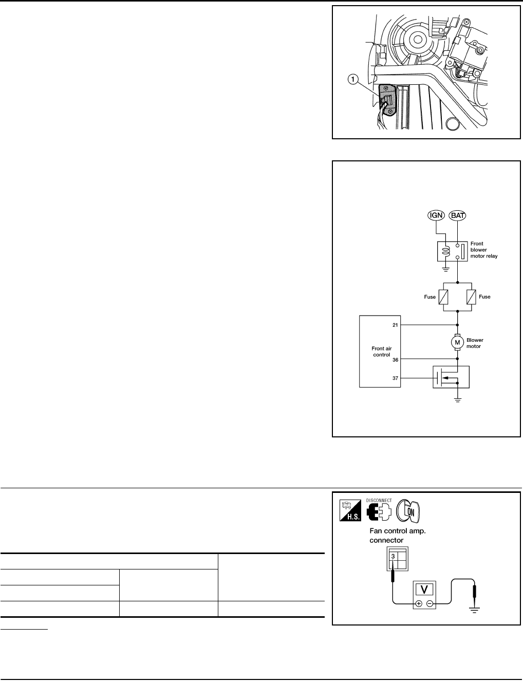
MTC-50
< SERVICE INFORMATION >
TROUBLE DIAGNOSIS
The fan control amplifier (1) is located on the cooling unit. The fan
control amp. receives a gate voltage from the front air control to
smoothly maintain the blower fan motor voltage in the 5 to the 12V
range (approx.).
DIAGNOSTIC PROCEDURE
SYMPTOM: Blower motor is malfunctioning.
1.CHECK POWER SUPPLY FOR FAN CONTROL AMP.
1. Disconnect fan control amp. connector.
2. Turn ignition switch ON.
3. Check voltage between fan control amp. harness connector
M52 terminal 3 and ground.
OK or NG
OK >> GO TO 2.
NG >> GO TO 7.
2.CHECK FAN FEEDBACK CIRCUIT
WJIA2285E
BJIA0013E
Terminal
Voltage (V)
(Approx.)
(+) (-)
Connector - Terminal
M52-3 Body ground 12V
WJIA0855E
Revision: January 2010 2010 Sentra
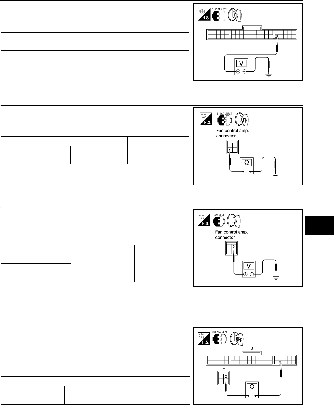
TROUBLE DIAGNOSIS
MTC-51
< SERVICE INFORMATION >
C
D
E
F
G
H
I
K
L
M
A
B
MTC
N
O
P
1. Disconnect front air control connector.
2. Check voltage between front air control harness connector M33
terminal 36 and ground.
OK or NG
OK >> GO TO 3.
NG >> Check for open circuit in wiring harness. Repair or replace as necessary.
3.CHECK BODY GROUND CIRCUIT FOR FAN CONTROL AMP.
1. Turn ignition switch OFF.
2. Check continuity between fan control amp. harness connector
M52 terminal 1 and ground.
OK or NG
OK >> Reconnect fan control amp. harness connector and GO
TO 4.
NG >> Repair harness or connector.
4.CHECK VOLTAGE FOR FAN CONTROL AMP.
1. Turn ignition switch ON.
2. Turn blower control dial to any position except OFF or AUTO.
3. Check voltage between fan control amp. harness connector
M52 terminal 2 and ground.
OK or NG
OK >> 1. Replace fan control amp. Refer to MTC-76, "Removal and Installation".
2. Confirm that blower motor operation is normal.
NG >> GO TO 5.
5.CHECK FAN CONTROL AMP. CIRCUIT BETWEEN FAN CONTROL AMP. AND FRONT AIR CONTROL
1. Turn ignition switch OFF.
2. Disconnect front air control and fan control amp. harness con-
nectors.
3. Check continuity between fan control amp. harness connector
M52 (A) terminal 2 and front air control harness connector M33
(B) terminal 37.
If OK, check harness for short.
Te r m i n a l Voltage (V)
(Approx.)
(+) (-)
Connector - Terminal Body ground 12V
M33-18
BJIA0014E
Terminal Continuity
Connector - Terminal Body ground Yes
M52-1
WJIA0856E
Te r m i n a l
Voltage (V)
(Approx.)
(+) (-)
Connector - Terminal
M52-2 Body ground 12V
WJIA0847E
Terminals Continuity
Connector - Terminal Connector - Terminal Yes
M52-2 M33-37 BJIA0015E
Revision: January 2010 2010 Sentra
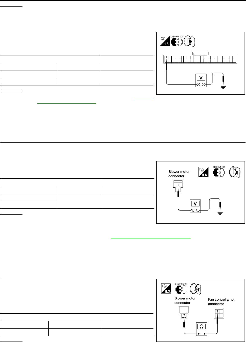
MTC-52
< SERVICE INFORMATION >
TROUBLE DIAGNOSIS
OK or NG
OK >> GO TO 6.
NG >> Repair harness or connector.
6.CHECK POWER SUPPLY FOR FRONT AIR CONTROL
1. Turn ignition switch ON.
2. Check voltage between front air control harness connector M33
terminal 1 and ground.
OK or NG
OK >> 1. Replace front air control. Refer to MTC-66,
"Removal and Installation".
2. Confirm that blower motor operation is normal.
NG >> • Check for open circuit in wiring harness.
Repair or replace as necessary.
• If OK, replace fuse and check wiring harness for short circuit.
Repair or replace an necessary.
7.CHECK POWER SUPPLY FOR BLOWER MOTOR
1. Turn ignition OFF.
2. Disconnect blower motor harness connector.
3. Turn ignition switch ON.
4. Check voltage between blower motor harness connector M62
terminal 1 and ground.
OK or NG
OK >> GO TO 8.
NG >> Check power supply circuit and 15A fuses [Nos. 10
and 11, located in the fuse block (J/B)].
• Check blower motor relay. Refer to PG-5, "Wiring Diagram - POWER -".
Repair or replace as necessary.
• If OK, check for open circuit in wiring harness.
Repair or replace as necessary.
• If OK, replace fuse and check wiring harness for short circuit.
Repair or replace as necessary.
8.CHECK CIRCUIT CONTINUITY BETWEEN BLOWER MOTOR AND FAN CONTROL AMP.
1. Turn ignition switch OFF.
2. Disconnect front air control connector.
3. Check continuity between blower motor harness connector M62
terminal 2 and fan control amp. harness connector M52 terminal
3.
OK or NG
Te r m i n a l Voltage (V)
(Approx.)
(+) (-)
Connector - Terminal Body ground 12V
M33-1
BJIA0016E
Te r m i n a l Voltage (V)
(Approx.)
(+) (-)
Connector - Terminal Body ground 12V
M62-1
WJIA0056E
Termina l s Continuity
Connector - Terminal Connector - Terminal
M62-2 M52-3 Yes
WJIA0857E
Revision: January 2010 2010 Sentra
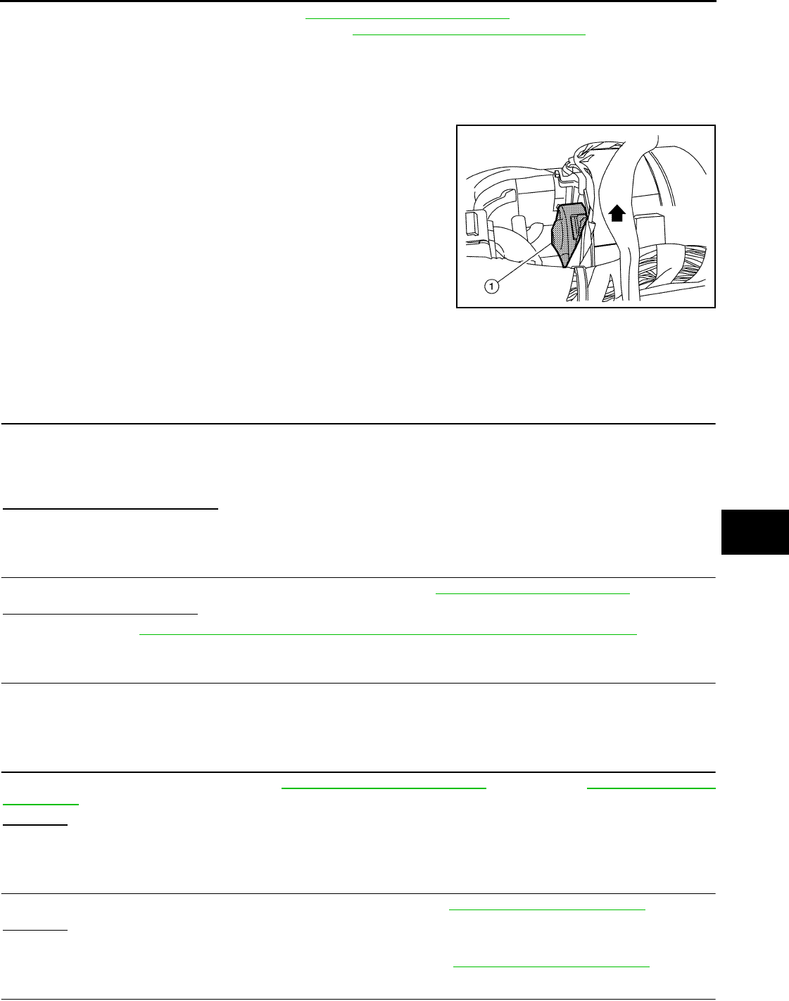
TROUBLE DIAGNOSIS
MTC-53
< SERVICE INFORMATION >
C
D
E
F
G
H
I
K
L
M
A
B
MTC
N
O
P
OK >> Check blower motor. Refer to MTC-48, "Blower Motor Circuit".
1. If NG, replace blower motor. Refer to MTC-67, "Removal and Installation".
2. Confirm that blower motor operation is normal.
NG >> Repair harness or connector.
COMPONENT INSPECTION
Blower Motor
Confirm smooth rotation of the blower motor (1).
• Ensure that there are no foreign particles inside the intake unit.
Magnet Clutch Circuit (If Equipped) INFOID:0000000005282788
SYMPTOM: Magnet clutch does not engage.
INSPECTION FLOW
1.CONFIRM SYMPTOM BY PERFORMING OPERATIONAL CHECK - MAGNET CLUTCH
1. Turn ignition switch ON.
2. Turn blower control dial to the desired position.
3. Press the A/C switch. A/C indicator will turn on.
4. Confirm that the compressor clutch engages (sound or visual inspection).
Can the symptom be duplicated?
YES >> GO TO 3.
NO >> GO TO 2.
2.CHECK FOR ANY SYMPTOMS
Perform a complete operational check for any symptoms. Refer to MTC-38, "Operational Check".
Does another symptom exist?
YES >> Refer to MTC-27, "How to Perform Trouble Diagnosis for Quick and Accurate Repair".
NO >> System OK.
3.CHECK FOR SERVICE BULLETINS
Check for any service bulletins.
>> GO TO 4.
4.CHECK COMPRESSOR BELT TENSION
Check compressor belt tension. Refer to EM-13, "Checking Drive Belts" (MR20DE) or EM-130, "Checking
Drive Belts" (QR25DE).
OK or NG
OK >> GO TO 5.
NG >> Adjust or replace A/C compressor belt.
5.CHECK REFRIGERANT PRESSURE
Check refrigerant pressure with manifold gauge connected. Refer to MTC-56, "Insufficient Cooling".
OK or NG
OK >> GO TO 6.
NG >> Perform trouble diagnosis for unusual pressure. Refer to MTC-56, "Insufficient Cooling".
6.CHECK MAGNET CLUTCH CIRCUIT
WJIA2286E
Revision: January 2010 2010 Sentra
MTC-54
< SERVICE INFORMATION >
TROUBLE DIAGNOSIS
Perform diagnostic procedure for the magnetic clutch. Refer to "DIAGNOSTIC PROCEDURE".
OK or NG
OK >> If the symptom still exists, perform a complete operational check. Refer to MTC-38, "Operational
Check". If other symptoms exist, refer to MTC-27, "How to Perform Trouble Diagnosis for Quick
and Accurate Repair".
NG >> Repair as necessary.
SYSTEM DESCRIPTION
Front air control controls compressor operation by a signal from ECM.
DIAGNOSTIC PROCEDURE
SYMPTOM: Magnet clutch does not engage when A/C switch is ON.
1.CHECK CIRCUIT CONTINUITY BETWEEN A/C RELAY IN IPDM E/R AND COMPRESSOR
1. Disconnect IPDM E/R connector E43 and compressor connec-
tor.
2. Check continuity between A/C compressor harness connector
F3 (B) terminal 2 and IPDM E/R harness connector E43 (A) ter-
minal 11.
If OK, check harness for short to ground.
OK or NG
OK >> GO TO 2.
NG >> Repair harness or connector.
2.CHECK POWER SUPPLY FOR COMPRESSOR
WJIA2305E
Terminals Continuity
Connector - Terminal Connector - Terminal Yes
F3 (A) - 2 E43 (B) - 11
WJIA2291E
Revision: January 2010 2010 Sentra
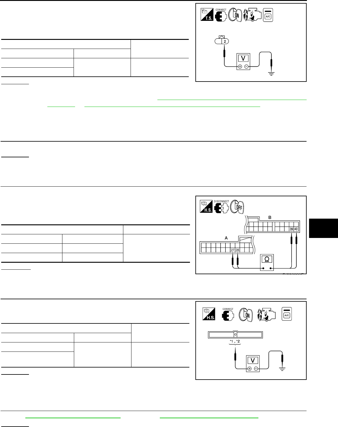
TROUBLE DIAGNOSIS
MTC-55
< SERVICE INFORMATION >
C
D
E
F
G
H
I
K
L
M
A
B
MTC
N
O
P
1. Reconnect IPDM E/R harness connectors.
2. Start engine and press A/C switch.
3. Check voltage between A/C compressor harness connector F3
terminal 2 and ground.
OK or NG
OK >> Check magnet clutch coil.
1. If NG, replace magnet clutch. Refer to MTC-85, "Removal and Installation for Compressor -
MR20DE" or MTC-86, "Removal and Installation for Compressor - QR25DE".
2. If OK, check A/C compressor mounting points for looseness or corrosion and repair as neces-
sary.
NG >> GO TO 3.
3.CHECK FUSE IN IPDM E/R
Check 10A fuse [No. 42 located at the IPDM E/R].
OK or NG
OK >> GO TO 4.
NG >> Replace fuse and check IPDM E/R for short circuit. Replace if necessary.
4.CHECK CONTINUITY BETWEEN BCM AND FRONT AIR CONTROL
1. Disconnect BCM connector M18 and front air control connector M33.
2. Check continuity between BCM harness connector M18 (A) ter-
minals 27, 28 and front air control connector M33 (B) terminals
40, 39.
OK or NG
OK >> GO TO 5.
NG >> Repair harness or connector.
5.CHECK REFRIGERANT PRESSURE SENSOR INPUT SIGNAL
Check voltage between ECM harness connector F25 terminal 41
[*1(with MR20DE)], 39 [(*2 with QR25DE)] and ground.
OK or NG
OK >> GO TO 6.
NG >> 1. Repair harness or connector.
2. Confirm that magnet clutch operation is normal.
6.CHECK REFRIGERANT PRESSURE SENSOR
Refer to EC-570, "Component Description"(MR20DE) or EC-1666, "Component Description" (QR25DE).
OK or NG
Te r m i n a l Voltage (V)
(Approx.)
(+) (-)
Connector - Terminal Body ground 12V
F3-2
BJIA0019E
Terminals Continuity
Connector - Terminal Connector - Terminal
YesM18 (A) - 27 M33 (B) - 40
M18 (A) - 28 M33 (B) - 39
BJIA0020E
Termin a l Voltage (V)
(Approx.)
(+) (-)
Connector - Terminal
Body ground 12V
F25 - 41 with MR20DE
F25 - 39 with QR25DE
WJIA2306E
Revision: January 2010 2010 Sentra
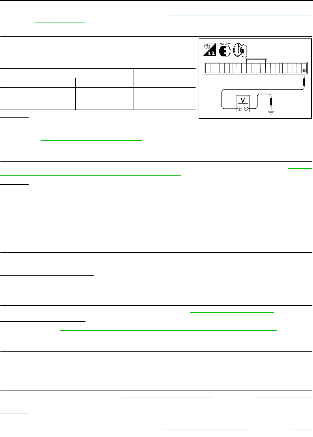
MTC-56
< SERVICE INFORMATION >
TROUBLE DIAGNOSIS
OK >> GO TO 7.
NG >> Replace refrigerant pressure sensor. Refer to MTC-88, "Removal and Installation for Refrigerant
Pressure Sensor".
7.CHECK COMPRESSOR ON SIGNAL
Check voltage between front air control connector M33 terminal 40
and ground, with A/C compressor ON and with A/C compressor
OFF.
OK or NG
OK >> GO TO 8.
NG >> • When A/C compressor is ON and voltage is not approx. 0V, Replace front air control. Refer to
MTC-66, "Removal and Installation".
• When A/C compressor is OFF and voltage is not approx. 5V, BCM is malfunctioning.
8.CHECK CAN COMMUNICATION CIRCUITS
Check CAN communication circuits between BCM to ECM and between ECM to IPDM E/R. Refer to LAN-10,
"Symptom When Error Occurs in CAN Communication System".
OK or NG
OK >> ECM malfunctioning.
NG >> Repair or replace component based on the result of diagnosis.
Insufficient Cooling INFOID:0000000005282789
SYMPTOM: Insufficient cooling
INSPECTION FLOW
1.CONFIRM SYMPTOM BY PERFORMING OPERATIONAL CHECK - TEMPERATURE DECREASE
1. Turn temperature control dial counterclockwise to maximum cold position.
2. Check for cold air at discharge air outlets.
Can the symptom be duplicated?
YES >> GO TO 3.
NO >> GO TO 2.
2.CHECK FOR ANY SYMPTOMS
Perform a complete operational check for any symptoms. Refer to MTC-38, "Operational Check".
Does another symptom exist?
YES >> Refer to MTC-27, "How to Perform Trouble Diagnosis for Quick and Accurate Repair".
NO >> System OK.
3.CHECK FOR SERVICE BULLETINS
Check for any service bulletins.
>> GO TO 4.
4.CHECK COMPRESSOR DRIVE BELT TENSION
Check compressor belt tension. Refer to EM-13, "Checking Drive Belts" (MR20DE) or EM-130, "Checking
Drive Belts" (QR25DE).
OK or NG
OK >> GO TO 5.
NG >> Adjust or replace compressor belt. Refer to EM-13, "Tension Adjustment" (MR20DE) or EM-13,
"Tension Adjustment" (QR25DE).
Termin a l Voltage (V)
(Approx.)
(+) (-)
Connector - Terminal
Body ground
A/C Compressor ON: 0V
A/C Compressor OFF:
5V
M33 - 40
BJIA0021E
Revision: January 2010 2010 Sentra

TROUBLE DIAGNOSIS
MTC-57
< SERVICE INFORMATION >
C
D
E
F
G
H
I
K
L
M
A
B
MTC
N
O
P
5.CHECK AIR MIX DOOR OPERATION
Check and verify air mix door mechanism for smooth operation in each mode.
Does air mix door operate correctly?
YES >> GO TO 6.
NO >> Repair or replace as necessary.
6.CHECK COOLING FAN MOTOR OPERATION
Check and verify cooling fan motor for smooth operation. Refer to EC-436, "System Description".
Does cooling fan motor operate correctly?
YES >> GO TO 7.
NO >> Check cooling fan motor. Refer to EC-436.
7.CHECK RECOVERY/RECYCLING EQUIPMENT BEFORE USAGE
Check recovery/recycling equipment before connecting to vehicle. Verify there is no pressure in the recovery/
recycling equipment by checking the gauges. If pressure exists, recover refrigerant from equipment lines.
>> GO TO 8.
8.CHECK REFRIGERANT PURITY
1. Connect recovery/recycling equipment to vehicle.
2. Confirm refrigerant purity in supply tank using recovery/recycling and refrigerant identifier.
OK or NG
OK >> GO TO 9.
NG >> Check contaminated refrigerant. Refer to MTC-4, "Contaminated Refrigerant".
9.CHECK FOR REFRIGERANT PRESSURE
Check refrigerant pressure with manifold gauge connected. Refer to "TEST READING".
OK or NG
OK >> Perform diagnostic work flow. Refer to "DIAGNOSTIC WORK FLOW".
NG >> GO TO 10.
10.CHECK FOR EVAPORATOR FREEZE UP
Start engine and run A/C. Check for evaporator freeze up.
Does evaporator freeze up?
YES >> Perform diagnostic work flow. Refer to "DIAGNOSTIC WORK FLOW".
NO >> GO TO 11.
11.CHECK AIR DUCTS
Check ducts for air leaks.
OK or NG
OK >> If the symptom still exists, perform a complete operational check. Refer to MTC-38, "Operational
Check". If other symptoms exist, refer to MTC-27, "How to Perform Trouble Diagnosis for Quick
and Accurate Repair".
NG >> Repair air leaks.
DIAGNOSTIC WORK FLOW
Revision: January 2010 2010 Sentra
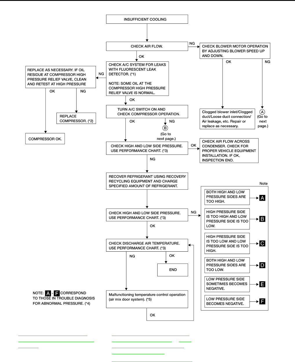
MTC-58
< SERVICE INFORMATION >
TROUBLE DIAGNOSIS
*1 MTC-90, "Checking System for
Leaks Using the Fluorescent Leak
Detector"
*2 MTC-85, "Removal and Installation
for Compressor - MR20DE" or MTC-
86, "Removal and Installation for
Compressor - QR25DE"
*3 "PERFORMANCE CHART"
*4 "TROUBLE DIAGNOSIS FOR AB-
NORMAL PRESSURE"
*5 MTC-45, "Air Mix Door Motor Circuit"
AWIIA0999GB
Revision: January 2010 2010 Sentra
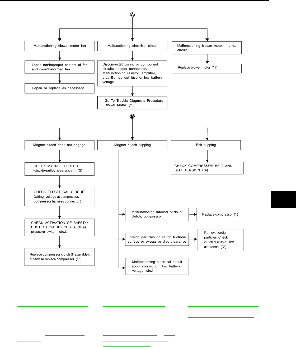
TROUBLE DIAGNOSIS
MTC-59
< SERVICE INFORMATION >
C
D
E
F
G
H
I
K
L
M
A
B
MTC
N
O
P
PERFORMANCE CHART
Test Condition
*1 MTC-67, "Removal and Installation"*2 MTC-48, "Blower Motor Circuit"*3 MTC-85, "Removal and Installation
for Compressor - MR20DE" or MTC-
86, "Removal and Installation for
Compressor - QR25DE"
*4 EM-13, "Checking Drive Belts"
(MR20DE) or EM-130, "Checking
Drive Belts" (QR25DE)
*5 MTC-85, "Removal and Installation
for Compressor - MR20DE" or MTC-
86, "Removal and Installation for
Compressor - QR25DE"
AWIIA1000GB
Revision: January 2010 2010 Sentra
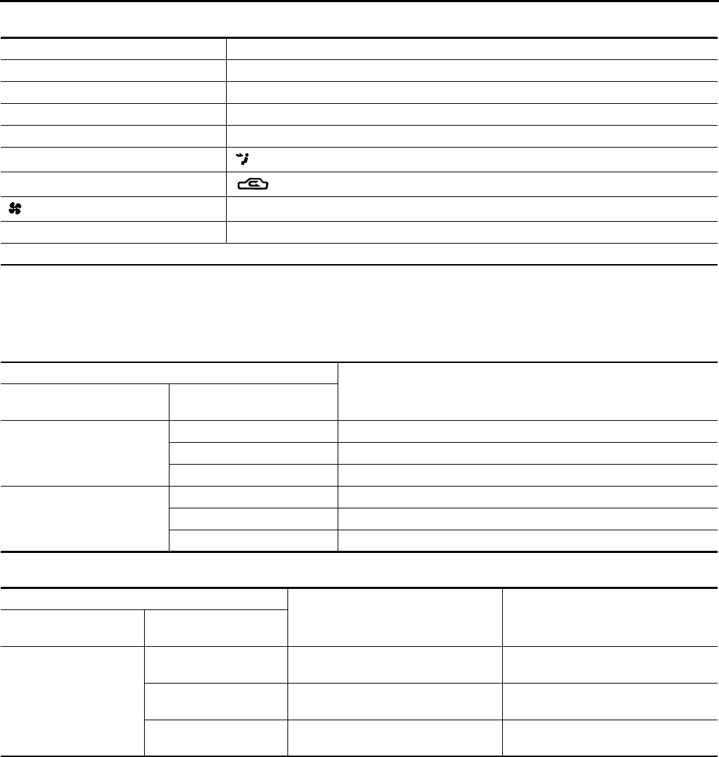
MTC-60
< SERVICE INFORMATION >
TROUBLE DIAGNOSIS
Testing must be performed as follows:
TEST READING
Recirculating-to-discharge Air Temperature Table
Ambient Air Temperature-to-operating Pressure Table
TROUBLE DIAGNOSIS FOR ABNORMAL PRESSURE
Whenever system's high and/or low side pressure is abnormal, diagnose using a manifold gauge. The marker
above the gauge scale in the following tables indicates the standard (normal) pressure range. Since the stan-
dard (normal) pressure differs from vehicle to vehicle, refer to Ambient Air Temperature-to-operating Pressure
Table above.
Both High- and Low-pressure Sides are Too High
Vehicle location Indoors or in the shade (in a well-ventilated place)
Doors Closed
Door windows Open
Hood Open
TEMP. Max. COLD
Mode switch (Ventilation) set
Intake switch (Recirculation) set
(fan) speed Max. speed set
Engine speed Idle speed
Operate the air conditioning system for 10 minutes before taking measurements.
Inside air (Recirculating air) at blower assembly inlet Discharge air temperature at center ventilator
°C (°F)
Relative humidity
%
Air temperature
°C (°F)
50 - 60
25 (77) 10.0 - 12.3 (50 - 54)
30 (86) 13.2 - 15.3 (56 - 60)
35 (95) 17.2 - 21.0 (63 - 70)
60 - 70
25 (77) 12.3 - 14.9 (54 - 59)
30 (86) 15.3 - 19.3 (60 - 67)
35 (95) 21.0 - 24.4 (70 - 76)
Ambient air High-pressure (Discharge side)
kPa (kg/cm2, psi)
Low-pressure (Suction side)
kPa (kg/cm2, psi)
Relative humidity
%
Air temperature
°C (°F)
50 - 70
30 (86) 1,220 - 1,500
(12.44 - 15.30, 176.9 - 217.5)
240 - 295
(2.45 - 3.01, 34.8 - 42.8)
35 (95) 1,360 - 1,690
(13.87 - 17.24, 197.2 - 245.1)
275 - 335
(2.81 - 3.42, 39.9 - 48.6)
40 (104) 1,500 - 1,830
(12.44 - 18.67, 176.9 - 265.4)
310 - 375
(3.16 - 3.83, 45.0 - 54.4)
Revision: January 2010 2010 Sentra
TROUBLE DIAGNOSIS
MTC-61
< SERVICE INFORMATION >
C
D
E
F
G
H
I
K
L
M
A
B
MTC
N
O
P
High-pressure Side is Too High and Low-pressure Side is Too Low
High-pressure Side is Too Low and Low-pressure Side is Too High
Gauge indication Refrigerant cycle Probable cause Corrective action
Both high and low-pressure
sides are too high.
Pressure is reduced soon after
water is splashed on condens-
er.
Excessive refrigerant charge in
refrigeration cycle
Reduce refrigerant until speci-
fied pressure is obtained.
Air suction by cooling fan is in-
sufficient.
Insufficient condenser cooling
performance
↓
1. Condenser fins are
clogged.
2. Improper fan rotation of
cooling fan
• Clean condenser.
• Check and repair cooling fan
as necessary.
• Low-pressure pipe is not
cold.
• When compressor is stopped
high-pressure value quickly
drops by approximately 196
kPa (2 kg/cm2, 28 psi). It then
decreases gradually thereaf-
ter.
Poor heat exchange in con-
denser
(After compressor operation
stops, high pressure decreases
too slowly.)
↓
Air in refrigeration cycle
Evacuate and recharge system.
Engine tends to overheat. Engine cooling systems mal-
function.
Check and repair each engine
cooling system.
• An area of the low-pressure
pipe is colder than areas near
the evaporator outlet.
• Plates are sometimes cov-
ered with frost.
• Excessive liquid refrigerant
on low-pressure side
• Excessive refrigerant dis-
charge flow
• Expansion valve is open a lit-
tle compared with the specifi-
cation.
↓
1. Improper thermal valve in-
stallation
2. Improper expansion valve
adjustment
Replace expansion valve.
AC359A
Gauge indication Refrigerant cycle Probable cause Corrective action
High-pressure side is too high and
low-pressure side is too low.
Upper side of condenser and
high-pressure side are hot,
however, liquid tank is not so
hot.
High-pressure tube or parts lo-
cated between compressor
and condenser are clogged or
crushed.
• Check and repair or replace
malfunctioning parts.
• Check oil for contamination.
AC360A
Revision: January 2010 2010 Sentra
MTC-62
< SERVICE INFORMATION >
TROUBLE DIAGNOSIS
Both High- and Low-pressure Sides are Too Low
Low-pressure Side Sometimes Becomes Negative
Gauge indication Refrigerant cycle Probable cause Corrective action
High-pressure side is too low and
low-pressure side is too high.
High and low-pressure sides
become equal soon after com-
pressor operation stops.
Compressor pressure opera-
tion is improper.
↓
Damaged inside compressor
pickings
Replace compressor.
No temperature difference be-
tween high and low-pressure
sides
Compressor pressure opera-
tion is improper.
↓
Damaged inside compressor
pickings.
Replace compressor.
AC356A
Gauge indication Refrigerant cycle Probable cause Corrective action
Both high- and low-pressure sides
are too low.
• There is a big temperature
difference between liquid
tank outlet and inlet. Outlet
temperature is extremely
low.
• Liquid tank inlet and expan-
sion valve are frosted.
Liquid tank inside is slightly
clogged.
• Replace desiccant assem-
bly.
• Check oil for contamination.
• Temperature of expansion
valve inlet is extremely low
as compared with areas
near liquid tank.
• Expansion valve inlet may
be frosted.
• Temperature difference oc-
curs somewhere in high-
pressure side
High-pressure pipe located be-
tween receiver drier and ex-
pansion valve is clogged.
• Check and repair malfunc-
tioning parts.
• Check oil for contamination.
Expansion valve and liquid
tank are warm or only cool
when touched.
Low refrigerant charge
↓
Leaking fittings or components
Check refrigerant for leaks.
Refer to Checking Refrigerant
Leaks, MTC-90, "Checking of
Refrigerant Leaks" and MTC-
91, "Electronic Refrigerant
Leak Detector".
There is a big temperature dif-
ference between expansion
valve inlet and outlet while the
valve itself is frosted.
Expansion valve closes a little
compared with the specifica-
tion.
↓
1. Improper expansion
valve adjustment
2. Malfunctioning thermal
valve
3. Outlet and inlet may be
clogged.
• Remove foreign particles by
using compressed air.
• Check oil for contamination.
An area of the low-pressure
pipe is colder than areas near
the evaporator outlet.
Low-pressure pipe is clogged
or crushed.
• Check and repair malfunc-
tioning parts.
• Check oil for contamination.
Air flow volume is not enough
or is too low. Evaporator is frozen.
• Check thermo control amp.
and intake sensor operation.
• Replace compressor.
AC353A
Revision: January 2010 2010 Sentra
TROUBLE DIAGNOSIS
MTC-63
< SERVICE INFORMATION >
C
D
E
F
G
H
I
K
L
M
A
B
MTC
N
O
P
Low-pressure Side Becomes Negative
Insufficient Heating INFOID:0000000005282790
SYMPTOM: Insufficient heating
INSPECTION FLOW
1.CONFIRM SYMPTOM BY PERFORMING OPERATIONAL CHECK - TEMPERATURE INCREASE
1. Turn temperature control dial clockwise to maximum heat position.
2. Check for hot air at discharge air outlets.
Can the symptom be duplicated?
YES >> GO TO 3.
NO >> GO TO 2.
2.CHECK FOR ANY SYMPTOMS
Perform a complete operational check for any symptoms. Refer to MTC-38, "Operational Check".
Does another symptom exist?
YES >> Refer to MTC-27, "How to Perform Trouble Diagnosis for Quick and Accurate Repair".
NO >> System OK.
3.CHECK FOR SERVICE BULLETINS
Check for any service bulletins.
Gauge indication Refrigerant cycle Probable cause Corrective action
Low-pressure side sometimes be-
comes negative.
• Air conditioning system does
not function and does not cy-
clically cool the compart-
ment air.
• The system constantly func-
tions for a certain period of
time after compressor is
stopped and restarted.
Refrigerant does not discharge
cyclically.
↓
Moisture is frozen at expan-
sion valve outlet and inlet.
↓
Water is mixed with refrigerant.
• Drain water from refrigerant
or replace refrigerant.
• Replace desiccant assem-
bly.
AC354A
Gauge indication Refrigerant cycle Probable cause Corrective action
Low-pressure side becomes nega-
tive.
Liquid tank or front/rear side of
expansion valve's pipe is frost-
ed or dewed.
High-pressure side is closed
and refrigerant does not flow.
↓
Expansion valve or liquid tank
is frosted.
Leave the system at rest until
no frost is present. Start it
again to check whether or not
the problem is caused by water
or foreign particles.
• If water is the cause, initially
cooling is okay. Then the wa-
ter freezes causing a block-
age. Drain water from
refrigerant or replace refrig-
erant.
• If due to foreign particles, re-
move expansion valve and
remove the particles with dry
and compressed air (not
shop air).
• If either of the above meth-
ods cannot correct the prob-
lem, replace expansion
valve.
• Replace desiccant assem-
bly.
• Check oil for contamination.
AC362A
Revision: January 2010 2010 Sentra

MTC-64
< SERVICE INFORMATION >
TROUBLE DIAGNOSIS
>> GO TO 4.
4.CHECK COOLANT SYSTEM
1. Check engine coolant level. Refer to CO-11, "Inspection" (MR20DE) or CO-39, "Inspection" (QR25DE).
2. Check hoses for leaks or kinks.
3. Check radiator cap. Refer to CO-11, "Inspection" (MR20DE) or CO-39, "Inspection" (QR25DE).
OK or NG
OK >> GO TO 5.
NG >> Repair/replace as necessary.
5.CHECK AIR MIX DOOR OPERATION
Check and verify air mix door mechanism for smooth operation in each mode.
OK or NG
OK >> GO TO 6.
NG >> Adjust or replace air mix door.
6.CHECK AIR DUCTS
Check ducts for air leaks.
OK or NG
OK >> GO TO 7.
NG >> Repair air leaks.
7.CHECK HEATER HOSE TEMPERATURES
1. Start engine and warm it up to normal operating temperature.
2. Touch both the inlet and outlet heater hoses.
Is the inlet hose hot and the outlet hose warm?
YES >> GO TO 8.
NO >> Both hoses warm: GO TO 9.
8.CHECK THERMOSTAT
Check thermostat for smooth operation.
OK or NG
OK >> System OK.
NG >> Repair or replace as necessary. Retest.
9.CHECK HEATER HOSES
Check heater hoses for proper installation.
OK or NG
OK >> GO TO 10.
NG >> Repair /replace as necessary. Retest GO TO 7.
10.BACK FLUSH HEATER CORE
1. Back flush heater core.
2. Drain the water from the system.
3. Refill system with new engine coolant. Refer to CO-12, "Changing Engine Coolant" (MR20DE) or CO-40,
"Changing Engine Coolant" (QR25DE).
4. Start engine and warm it up to normal operating temperature.
5. Touch both the inlet and outlet heater hoses.
Is the inlet hose hot and the outlet hose warm?
YES >> System OK.
NO >> Replace heater core and refill engine coolant. Refer to MTC-72, "Removal and Installation".
Noise INFOID:0000000005282791
SYMPTOM: Noise
INSPECTION FLOW
Revision: January 2010 2010 Sentra
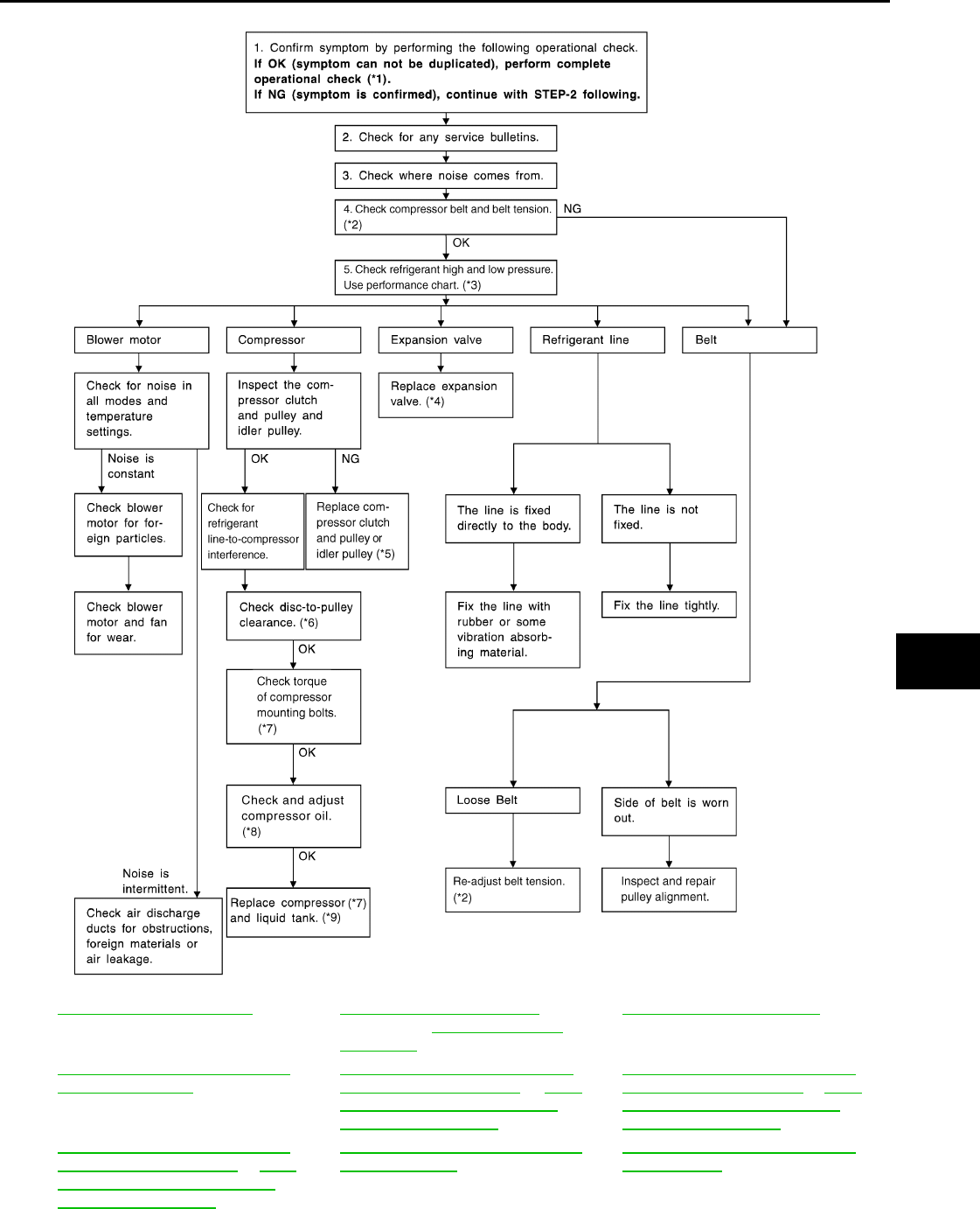
TROUBLE DIAGNOSIS
MTC-65
< SERVICE INFORMATION >
C
D
E
F
G
H
I
K
L
M
A
B
MTC
N
O
P
*1 MTC-38, "Operational Check"*2 EM-13, "Checking Drive Belts"
(MR20DE) or EM-130, "Checking
Drive Belts" (QR25DE)
*3 MTC-56, "Insufficient Cooling"
*4 MTC-90, "Removal and Installation
for Expansion Valve"
*5 MTC-85, "Removal and Installation
for Compressor - MR20DE" or MTC-
86, "Removal and Installation for
Compressor - QR25DE"
*6 MTC-85, "Removal and Installation
for Compressor - MR20DE" or MTC-
86, "Removal and Installation for
Compressor - QR25DE"
*7 MTC-85, "Removal and Installation
for Compressor - MR20DE" or MTC-
86, "Removal and Installation for
Compressor - QR25DE"
*8 MTC-18, "Maintenance of Oil Quanti-
ty in Compressor"
*9 MTC-88, "Removal and Installation
for Condenser"
AWIIA1001GB
Revision: January 2010 2010 Sentra
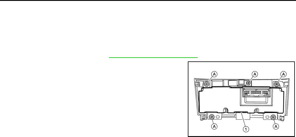
MTC-66
< SERVICE INFORMATION >
CONTROL UNIT
CONTROL UNIT
Removal and Installation INFOID:0000000005282792
FRONT AIR CONTROL
Removal
1. Remove controller finisher. Refer to IP-12, "Removal and Installation".
2. Remove the five screws (A) and remove the front air control (1).
Installation
Installation is in the reverse order of removal.
BJIA0024E
Revision: January 2010 2010 Sentra
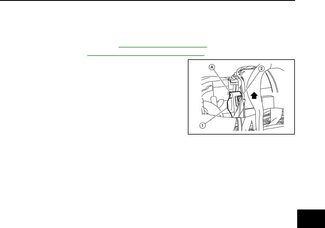
FRONT BLOWER MOTOR
MTC-67
< SERVICE INFORMATION >
C
D
E
F
G
H
I
K
L
M
A
B
MTC
N
O
P
FRONT BLOWER MOTOR
Removal and Installation INFOID:0000000005282793
REMOVAL
1. Remove the instrument panel. Refer to IP-12, "Removal and Installation".
2. Remove the BCM. Refer to BCS-18, "Removal and Installation of BCM".
3. Disconnect the front blower motor connector (2).
4. Remove the one screw (A) from the front blower motor (1).
5. Turn the front blower motor (1) counterclockwise and remove it.
•⇐ : Front
INSTALLATION
Installation is in the reverse order of removal.
BJIA0025E
Revision: January 2010 2010 Sentra
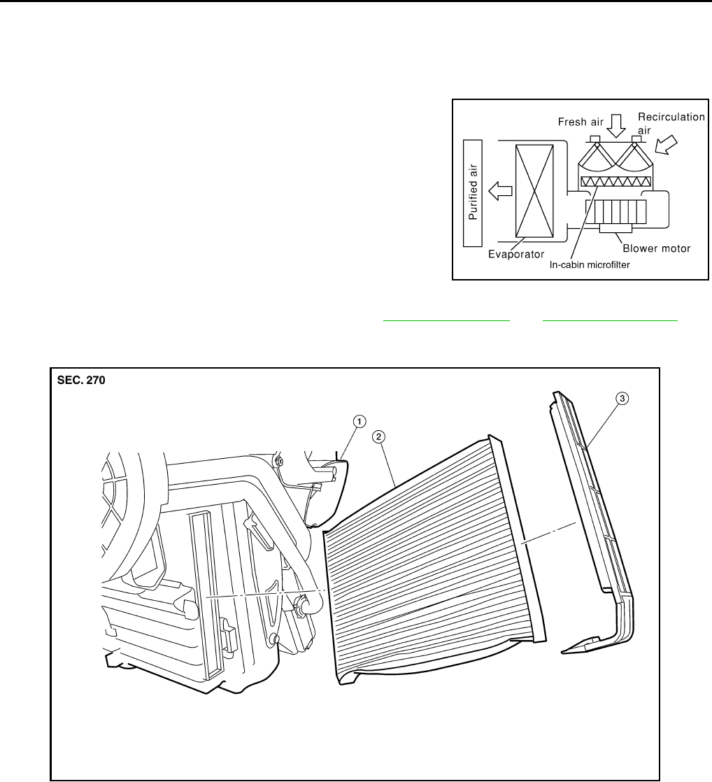
MTC-68
< SERVICE INFORMATION >
IN-CABIN MICROFILTER
IN-CABIN MICROFILTER
Removal and Installation INFOID:0000000005282794
FUNCTION
Air inside passenger compartment is kept clean at either recircula-
tion or fresh mode by installing in-cabin microfilter into heater and
cooling unit assembly.
REPLACEMENT TIMING
Replace the in-cabin microfilter as recommended. Refer to MA-9, "Schedule 1" and MA-12, "Schedule 2".
REPLACEMENT PROCEDURES
LJIA0012E
1. Heater and cooling unit assembly 2. In-cabin microfilter 3. Filter cover
BJIA0027E
Revision: January 2010 2010 Sentra
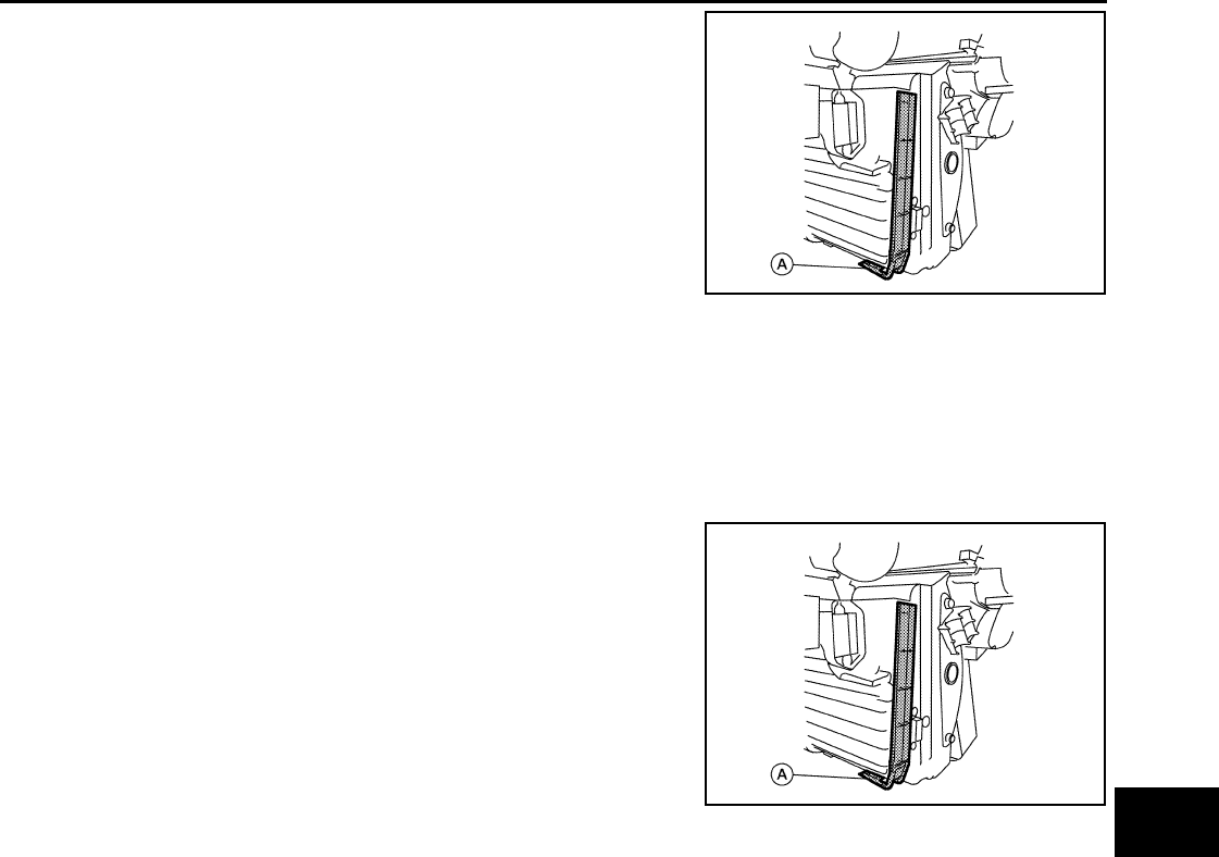
IN-CABIN MICROFILTER
MTC-69
< SERVICE INFORMATION >
C
D
E
F
G
H
I
K
L
M
A
B
MTC
N
O
P
1. Remove the filter cover.
a. Release the filter cover tab (A) the pull the bottom of the filter
cover out tilting it at an angle
b. Pull down the filter cover to disengage the hook at the top and
remove the filter cover.
2. Remove the in-cabin microfilter.
3. Install the new in-cabin microfilter.
CAUTION:
• Insert the new filter with the “UP” arrow in the correct orientation.
• Insert the new filter with the “UP” arrow side of the filter facing the front of the vehicle.
4. Install the filter cover.
a. Insert the hook at the top of the filter cover into the heater and cooling unit case.
b. Swing the filter cover into the heater and cooling unit case until
the filter cover tab (A) snaps securely on the heater and cooling
unit case.
CAUTION:
Check the filter cover to make sure it is securely fastened to
the heater and cooling unit case.
BJIA0026E
BJIA0026E
Revision: January 2010 2010 Sentra
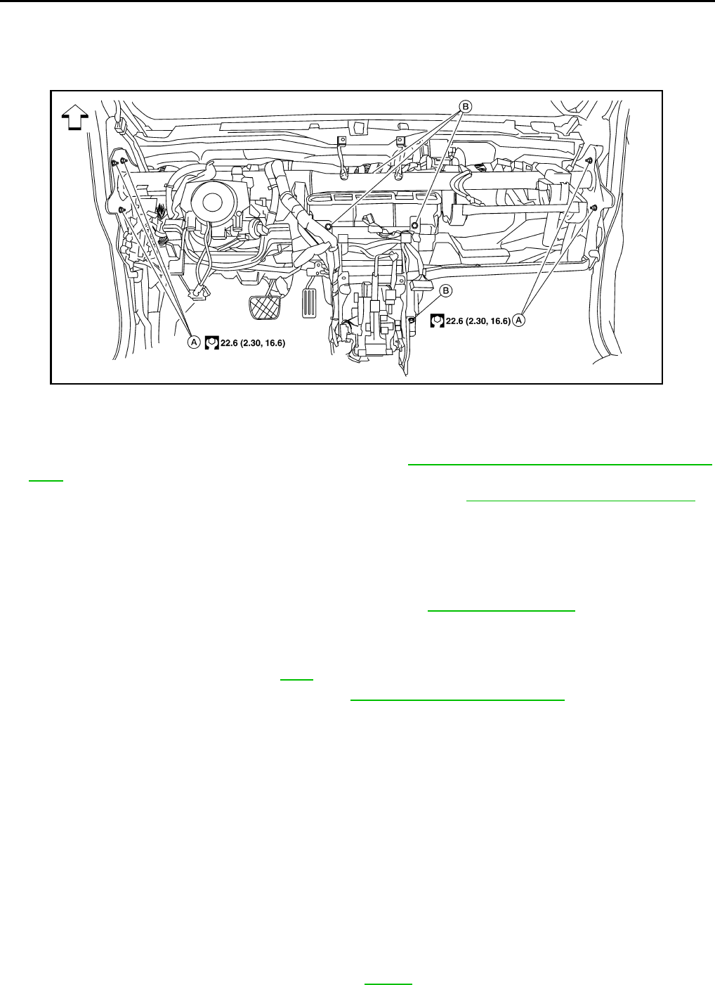
MTC-70
< SERVICE INFORMATION >
HEATER & COOLING UNIT ASSEMBLY
HEATER & COOLING UNIT ASSEMBLY
Removal and Installation INFOID:0000000005282795
REMOVAL
1. Discharge the refrigerant from the A/C system. Refer to MTC-81, "HFC-134a (R-134a) Service Proce-
dure".
2. Partially drain the engine coolant from the cooling system. Refer to CO-12, "Changing Engine Coolant".
3. Reposition the lower dash insulator out of the way.
4. Disconnect the heater hoses from the heater core pipes.
CAUTION:
Cap or wrap the joint of the pipe with suitable material such as vinyl tape to avoid entry of contam-
inants.
5. Disconnect the refrigerant lines from the evaporator. Refer to MTC-83, "Component".
CAUTION:
Cap or wrap the joint of the pipe with suitable material such as vinyl tape to avoid entry of contam-
inants.
6. Remove the steering column. Refer to PS-8.
7. Remove the instrument panel assembly. Refer to IP-12, "Removal and Installation".
8. Remove the lower steering member stays.
9. Disconnect the following components.
• Shift lock cable
• Steering harness clips
•SMJ
• Fuse box
• Door harness
• Front pillar harness
• CVT shift cable (if equipped)
• M/T shift cable (if equipped)
• A/C drain hose
• Air bag module control unit
10. Disconnect the evaporator drain hose.
11. Remove the steering member bolt caps.
12. Support both front doors with a suitable jack.
13. Remove both front door upper hinge bolts. Refer to BL-130.
A. Steering member bolts B. Heater and cooling unit assembly bolts ⇐Vehicle front
BJIA0028E
Revision: January 2010 2010 Sentra

HEATER & COOLING UNIT ASSEMBLY
MTC-71
< SERVICE INFORMATION >
C
D
E
F
G
H
I
K
L
M
A
B
MTC
N
O
P
14. Remove the steering member bolts.
15. Temporarily install the front door upper hinge bolts.
16. Remove the heater and cooling unit and the steering member from the vehicle as one unit.
CAUTION:
Be careful not to damage the interior and seat trim when removing the heater and cooling unit
assembly and steering member from the vehicle.
17. Disconnect the following components to separate the heater and cooling unit assembly from the steering
member.
• Front blower motor
• Fan control amplifier
• air mix door motor
• Mode door motor
• Intake door motor
18. Remove the heater and cooling unit assembly from the steering member.
INSTALLATION
Installation is in the reverse order of removal.
• Fill the radiator with the specified water and coolant mixture. Refer to CO-12, "Changing Engine Coolant".
• Recharge the A/C system. Refer to MTC-81, "HFC-134a (R-134a) Service Procedure".
• Check and adjust the front door alignment as necessary. Refer to BL-130, "Fitting Adjustment".
Revision: January 2010 2010 Sentra
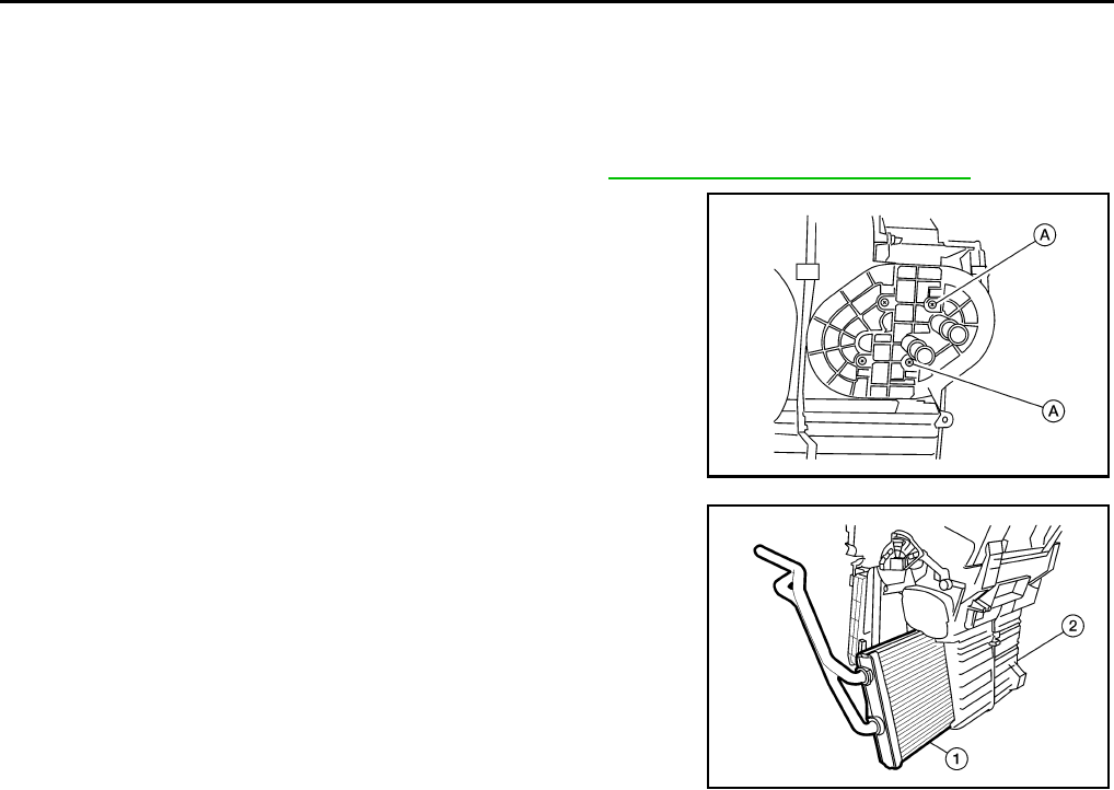
MTC-72
< SERVICE INFORMATION >
HEATER CORE
HEATER CORE
Removal and Installation INFOID:0000000005282796
REMOVAL
1. Remove the heater and cooling unit assembly. Refer to MTC-70, "Removal and Installation".
2. Remove the heater core foam seal to access and remove the
heater core pipe support screws (A) and then remove the heater
core pipe support.
3. Remove the heater core (1) from the heater and cooling unit
assembly (2).
INSTALLATION
Installation is in the reverse order of removal.
BJIA0029E
BJIA0030E
Revision: January 2010 2010 Sentra
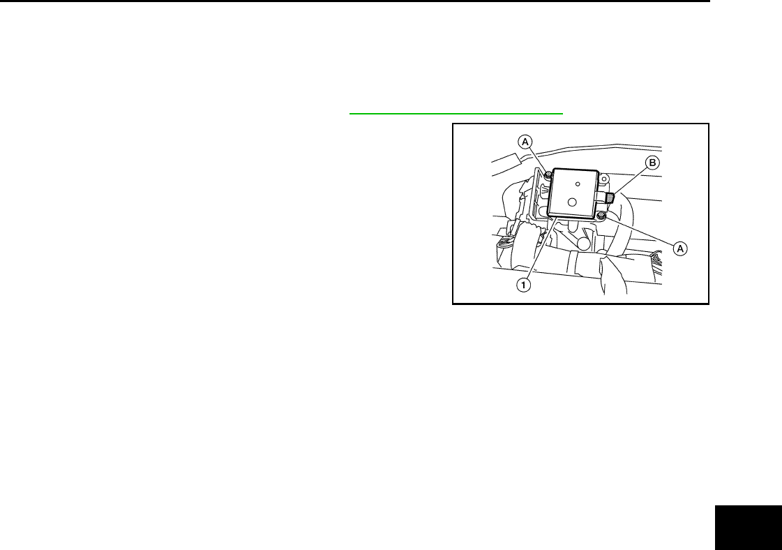
INTAKE DOOR MOTOR
MTC-73
< SERVICE INFORMATION >
C
D
E
F
G
H
I
K
L
M
A
B
MTC
N
O
P
INTAKE DOOR MOTOR
Removal and Installation INFOID:0000000005282797
REMOVAL
1. Remove the instrument panel assembly. Refer to IP-12, "Removal and Installation".
2. Disconnect the intake door motor connector (B).
3. Remove the screws (A) and then the intake door motor (1) from
the heater and cooling unit assembly.
INSTALLATION
Installation is in the reverse order of removal.
BJIA0031E
Revision: January 2010 2010 Sentra
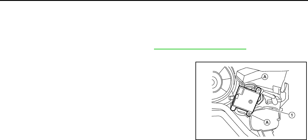
MTC-74
< SERVICE INFORMATION >
MODE DOOR MOTOR
MODE DOOR MOTOR
Removal and Installation INFOID:0000000005282798
REMOVAL
1. Remove the instrument lower cover (LH). Refer to IP-12, "Removal and Installation".
2. Disconnect the mode door motor connector.
3. Remove the two mode door motor screws (A) and then remove
the mode door motor (1).
INSTALLATION
Installation is in the reverse order of removal.
BJIA0032E
Revision: January 2010 2010 Sentra
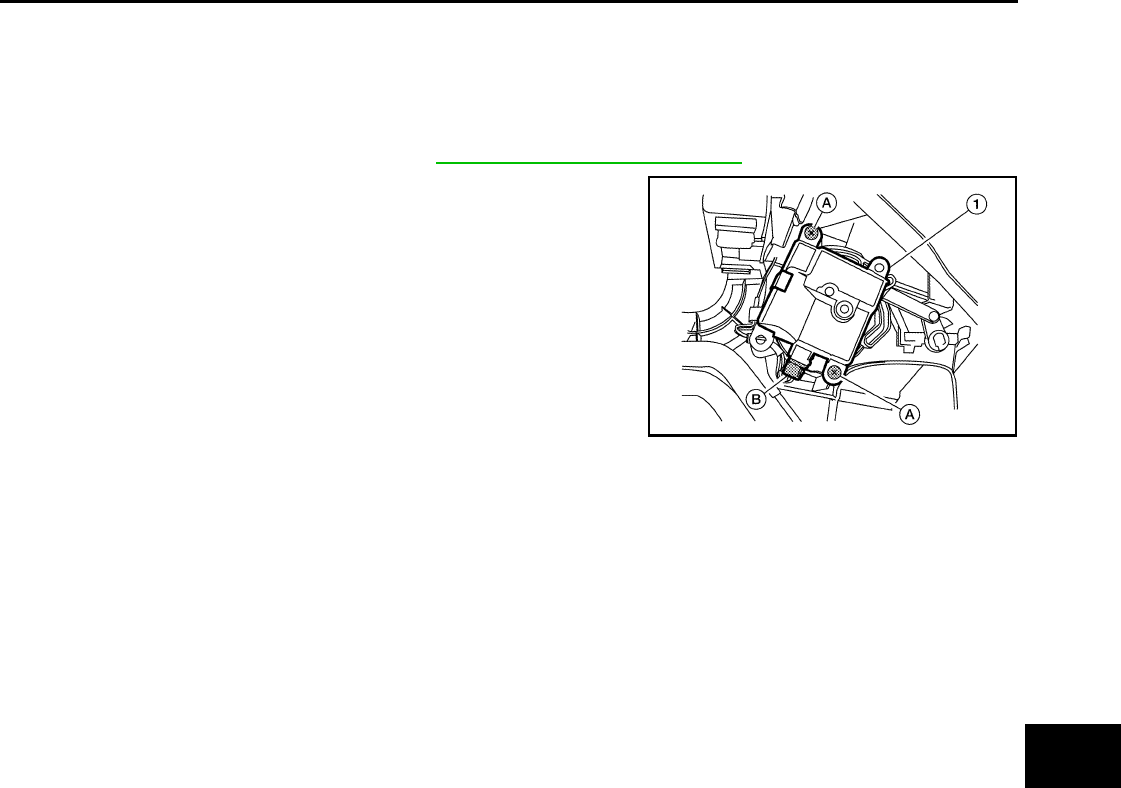
AIR MIX DOOR MOTOR
MTC-75
< SERVICE INFORMATION >
C
D
E
F
G
H
I
K
L
M
A
B
MTC
N
O
P
AIR MIX DOOR MOTOR
Removal and Installation INFOID:0000000005282799
REMOVAL
1. Remove the glove box assembly. Refer to IP-12, "Removal and Installation".
2. Disconnect the air mix door motor connector (B).
3. Remove the two air mix door motor screws (A) and then remove
the air mix door motor (1).
INSTALLATION
Installation is in the reverse order of removal.
BJIA0033E
Revision: January 2010 2010 Sentra
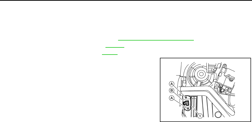
MTC-76
< SERVICE INFORMATION >
FAN CONTROL AMPLIFIER
FAN CONTROL AMPLIFIER
Removal and Installation INFOID:0000000005282800
REMOVAL
1. Remove the instrument lower finisher. Refer to IP-12, "Removal and Installation".
2. Remove the front foot duct (LH). Refer to MTC-77.
3. Remove the accelerator pedal. Refer to ACC-4.
4. Disconnect the fan control amplifier connector (B).
5. Remove the two screws (A) from the fan control amplifier (1)
and then remove the fan control amplifier (1).
INSTALLATION
Installation is in the reverse order of removal.
BJIA0034E
Revision: January 2010 2010 Sentra
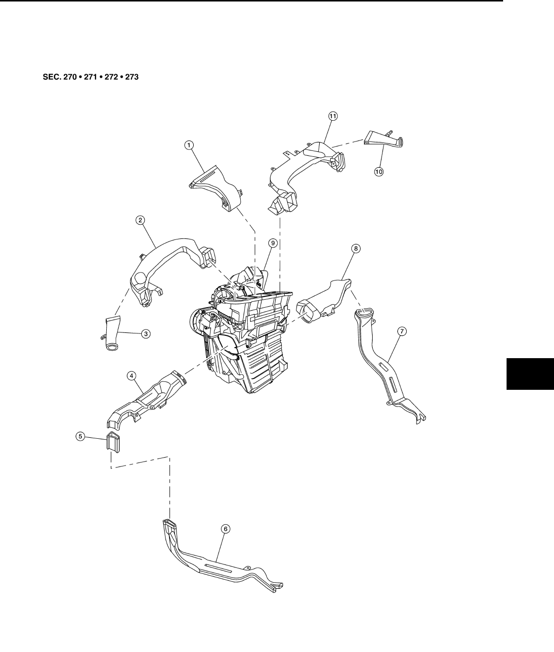
DUCTS AND GRILLES
MTC-77
< SERVICE INFORMATION >
C
D
E
F
G
H
I
K
L
M
A
B
MTC
N
O
P
DUCTS AND GRILLES
Removal and Installation INFOID:0000000005282801
Ducts
BJIA0023E
1. Defroster nozzle 2. Side ventilator duct (LH) 3. Side defroster duct (LH)
4. Front foot duct (LH) 5. Rear floor connector duct (Canada
only)
6. Rear floor duct (LH) (Canada only)
Revision: January 2010 2010 Sentra
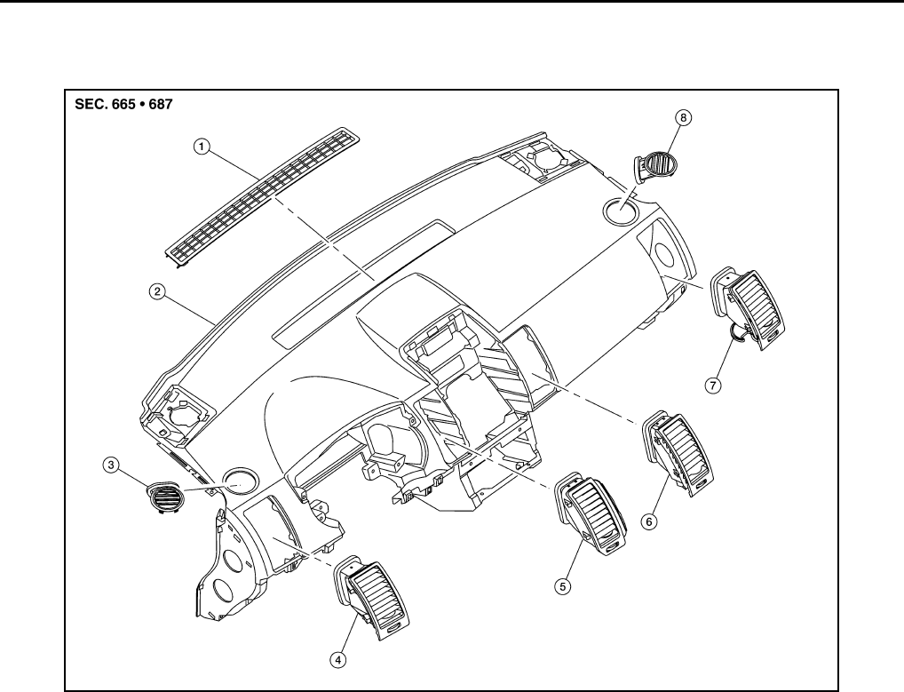
MTC-78
< SERVICE INFORMATION >
DUCTS AND GRILLES
Grilles
CENTER VENTILATOR GRILLE RH, LH
Removal
Release the tabs using a suitable tool and then remove the center ventilator grille.
Installation
Installation is in the reverse order of removal.
UPPER DEFROSTER GRILLE
Removal
1. Pry from the rear (farthest from windshield) edge to release the tabs using a suitable tool.
2. Pry from the front (closest to windshield) edge to release the tabs using a suitable tool.
3. Remove the upper defroster grille.
Installation
Installation is in the reverse order of removal.
SIDE VENTILATOR GRILLE RH, LH
Removal
Release the tabs using a suitable tool and then remove the side ventilator grille.
Installation
Installation is in the reverse order of removal.
7. Rear floor duct (RH) (Canada only) 8. Front foot duct (RH) 9. Heater and cooling unit assembly
10. Side defroster duct (RH) 11. Side ventilator duct (RH)
BJIA0035E
1. Upper defroster grille 2. Instrument panel assembly 3. Side defroster grille (LH)
4. Side ventilator grille (LH) 5. Center ventilator grille (LH) 6. Center ventilator grille (RH)
7. Side ventilator grille (RH) 8. Side defroster grille (RH)
Revision: January 2010 2010 Sentra

DUCTS AND GRILLES
MTC-79
< SERVICE INFORMATION >
C
D
E
F
G
H
I
K
L
M
A
B
MTC
N
O
P
SIDE DEFROSTER GRILLE RH, LH
Removal
Release the tabs using a suitable tool and then remove the side defroster grille.
Installation
Installation is in the reverse order of removal.
SIDE VENTILATOR DUCT RH, LH
Removal
1. Remove the instrument panel assembly. Refer to IP-12, "Removal and Installation".
2. Remove the defroster nozzle.
3. Remove the side ventilator duct.
Installation
Installation is in the reverse order of removal.
DEFROSTER NOZZLE
Removal
1. Remove the instrument panel assembly. Refer to IP-12, "Removal and Installation".
2. Remove the defroster nozzle.
Installation
Installation is in the reverse order of removal.
SIDE DEFROSTER DUCT RH, LH
Removal
1. Remove the instrument panel assembly. Refer to IP-12, "Removal and Installation".
2. Remove the defroster nozzle.
3. Remove the side defroster duct.
Installation
Installation is in the reverse order of removal.
FRONT FOOT DUCT RH
Removal
1. Remove the glove box assembly. Refer to IP-12, "Removal and Installation".
2. Remove the front foot duct.
Installation
Installation is in the reverse order of removal.
FRONT FOOT DUCT LH
Removal
1. Remove the instrument lower finisher. Refer to IP-12, "Removal and Installation".
2. Remove the front foot duct.
Installation
Installation is in the reverse order of removal.
REAR FLOOR CONNECTOR DUCT
Removal
1. Push up to disengage the rear floor connector duct from the rear floor duct (LH).
2. Remove the rear floor connector duct.
Installation
Installation is in the reverse order of removal.
REAR FLOOR DUCT RH
Revision: January 2010 2010 Sentra

MTC-80
< SERVICE INFORMATION >
DUCTS AND GRILLES
Removal
1. Remove the floor carpet from the front floor area and remove the front floor spacer. Refer to EI-39.
2. Remove the rear floor duct bolt.
3. Remove the rear floor duct.
Installation
Installation is in the reverse order of removal.
REAR FLOOR DUCT LH
Removal
1. Remove the floor carpet from the front floor area and remove the front floor spacer. Refer to EI-39.
2. Remove the rear floor connector duct.
3. Remove the rear floor duct bolt.
4. Remove the rear floor duct.
Installation
Installation is in the reverse order of removal.
Revision: January 2010 2010 Sentra
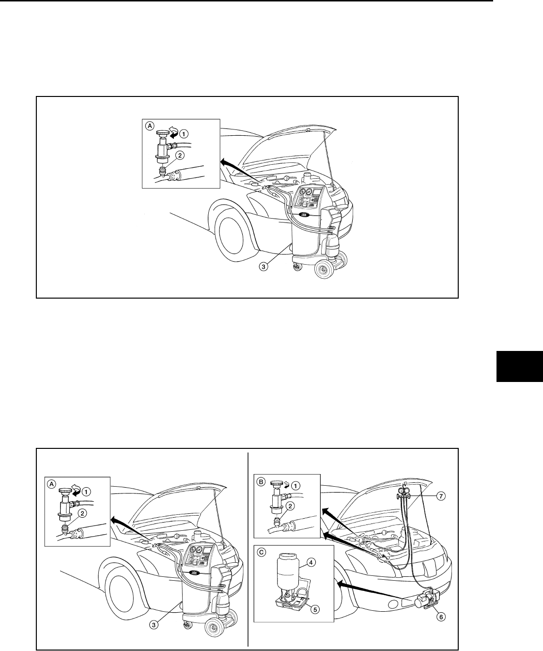
REFRIGERANT LINES
MTC-81
< SERVICE INFORMATION >
C
D
E
F
G
H
I
K
L
M
A
B
MTC
N
O
P
REFRIGERANT LINES
HFC-134a (R-134a) Service Procedure INFOID:0000000005282802
SETTING OF SERVICE TOOLS AND EQUIPMENT
Discharging Refrigerant
WARNING:
Avoid breathing the A/C refrigerant and oil vapor or mist. Exposure may irritate eyes, nose, and throat.
Remove the HFC-134a (R-134a) from the A/C system using certified service equipment meeting the
requirements of SAE J2210 HFC-134a (R-134a) recycling equipment or J2201 HFC-134a (R-134a)
recovery equipment. If an accidental system discharge occurs, ventilate the work area before resum-
ing service. Additional health and safety information may be obtained from the refrigerant and oil man-
ufacturers.
Evacuating System and Charging Refrigerant
1. Shut-off valve 2. A/C service valve 3. Recovery/recycling equipment
A. Preferred (best) method
WJIA2195E
1. Shut-off valve 2. A/C service valve 3. Recovery/recycling equipment
4. Refrigerant container (HFC-134a) 5. Weight scale (J-39650) 6. Evacuating vacuum pump (J-39699)
WJIA2196E
Revision: January 2010 2010 Sentra
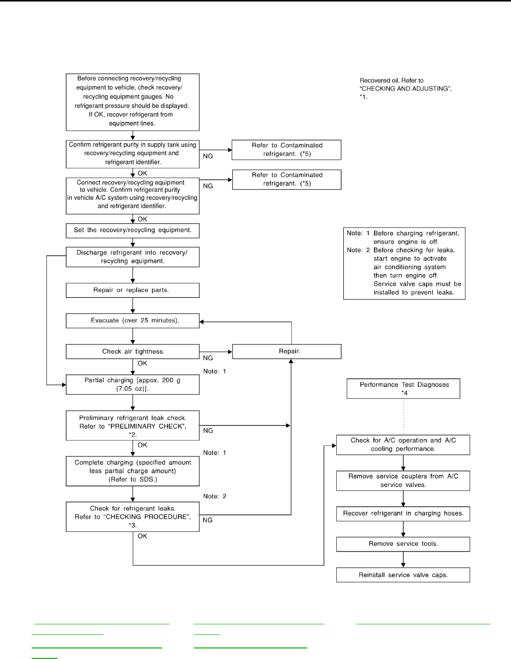
MTC-82
< SERVICE INFORMATION >
REFRIGERANT LINES
Discharging, Evacuating, and Recharging the A/C System
7. Manifold gauge set (J-39183) A. Preferred (best) method B. Alternative method
C. For charging
WJIA1923E
*1 MTC-18, "Maintenance of Oil Quan-
tity in Compressor"
*3 MTC-90, "Checking of Refrigerant
Leaks"
*5 MTC-4, "Contaminated Refrigerant"
*2 MTC-90, "Checking of Refrigerant
Leaks"
*4 MTC-56, "Insufficient Cooling"
Revision: January 2010 2010 Sentra
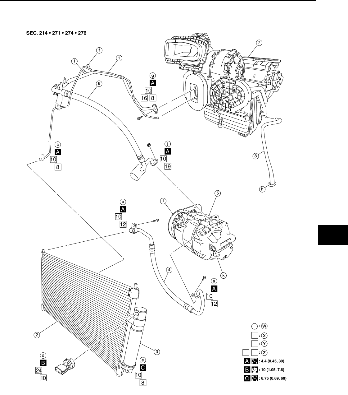
REFRIGERANT LINES
MTC-83
< SERVICE INFORMATION >
C
D
E
F
G
H
I
K
L
M
A
B
MTC
N
O
P
Component INFOID:0000000005282803
MR20DE
AWIIA1293GB
1. High-pressure pipe 2. Condenser 3. Liquid tank
4. High-pressure flexible hose 5. Compressor 6. Low-pressure flexible hose
7. Heater and cooling unit assembly 8. Drain hose W. Refrigerant leak checking order
X. Tightening torque (A-C) Y. Wrench size Z. O-ring size
Revision: January 2010 2010 Sentra
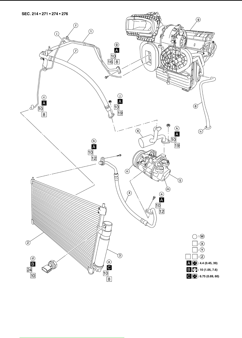
MTC-84
< SERVICE INFORMATION >
REFRIGERANT LINES
QR25DE
NOTE:
Refer to MTC-5, "Precaution for Refrigerant Connection".
AWIIA1294GB
1. High-pressure pipe 2. Condenser 3. Liquid tank
4. High-pressure flexible hose 5. Compressor 6. Muffler pipe
7. Low-pressure flexible hose 8. Drain hose 9. Heater and cooling unit assembly
W. Refrigerant leak checking order X. Tightening torque (A-C) Y. Wrench size
Z. O-ring size
Revision: January 2010 2010 Sentra
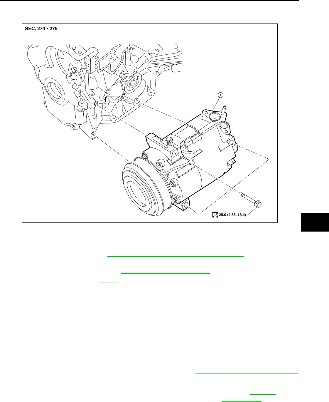
REFRIGERANT LINES
MTC-85
< SERVICE INFORMATION >
C
D
E
F
G
H
I
K
L
M
A
B
MTC
N
O
P
Removal and Installation for Compressor - MR20DE INFOID:0000000005282804
REMOVAL
1. Discharge the refrigerant. Refer to MTC-81, "HFC-134a (R-134a) Service Procedure".
2. Remove the engine undercover.
3. Remove the splash shield RH. Refer to EI-22, "Removal and Installation".
4. Remove the drive belt. Refer to EM-13.
5. Disconnect the compressor connector.
6. Disconnect the high-pressure flexible hose and low-pressure flexible hose.
CAUTION:
Cap or wrap the joint of the hose with a suitable material such as vinyl tape to avoid the entry of
any contaminants.
7. Remove the compressor bolts using power tool, then remove the compressor.
INSTALLATION
Installation is in the reverse order of removal.
CAUTION:
• Replace the O-ring of the low-pressure flexible hose and high-pressure flexible hose with new ones,
then apply A/C oil to them for installation.
• After charging the A/C refrigerant, check for leaks. Refer to MTC-90, "Checking of Refrigerant
Leaks".
1. Compressor
BJIA0036E
High and low-pressure flexible hose and muffler pipe nuts and bolt : Refer to MTC-83,
"Component".
Revision: January 2010 2010 Sentra
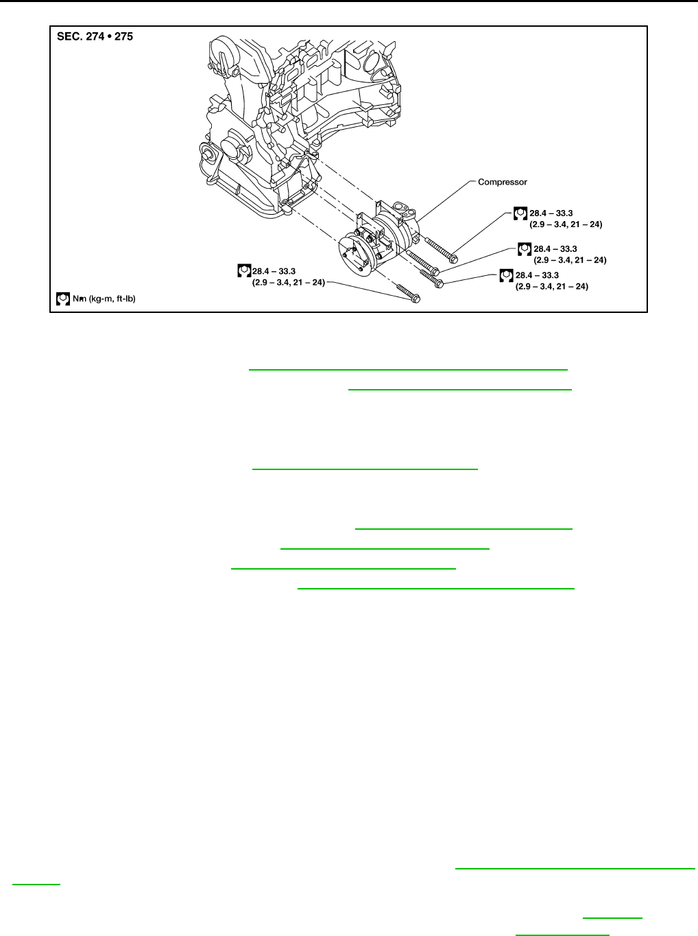
MTC-86
< SERVICE INFORMATION >
REFRIGERANT LINES
Removal and Installation for Compressor - QR25DE INFOID:0000000005282805
REMOVAL
1. Discharge the refrigerant. Refer to MTC-81, "HFC-134a (R-134a) Service Procedure".
2. Partially drain the engine cooling system. Refer to CO-40, "Changing Engine Coolant".
3. Disconnect the battery negative terminal.
4. Remove the front RH wheel and tire.
5. Remove the engine undercover.
6. Remove the front air duct. Refer to EM-133, "Removal and Installation".
7. Disconnect the upper radiator hose from the radiator.
8. Disconnect the coolant reservoir hose from the radiator.
9. Remove the electric cooling fan assembly. Refer to CO-46, "Removal and Installation".
10. Remove the splash shield RH. Refer to EI-22, "Removal and Installation".
11. Remove the drive belt. Refer to EM-130, "Removal and Installation".
12. Remove the generator assembly. Refer to SC-33, "Removal and Installation QR25DE".
13. Disconnect the compressor connector.
14. Disconnect the high-pressure flexible hose and low-pressure flexible hose.
CAUTION:
Cap or wrap the joint of the hose with a suitable material such as vinyl tape to avoid the entry of
any contaminants.
15. Remove the muffler pipe from the compressor.
CAUTION:
Cap or wrap the joint of the hose with a suitable material such as vinyl tape to avoid the entry of
any contaminants.
16. Remove the compressor bolts using power tool, then remove the compressor.
INSTALLATION
Installation is in the reverse order of removal.
CAUTION:
• Replace the O-ring of the low-pressure flexible hose, muffler pipe and high-pressure flexible hose
with new ones, then apply A/C oil to them for installation.
• After charging the A/C refrigerant, check for leaks. Refer to MTC-90, "Checking of Refrigerant
Leaks".
WJIA0182E
High and low-pressure flexible hose and muffler pipe nuts and bolt : Refer to MTC-83,
"Component".
Revision: January 2010 2010 Sentra

REFRIGERANT LINES
MTC-87
< SERVICE INFORMATION >
C
D
E
F
G
H
I
K
L
M
A
B
MTC
N
O
P
Removal and Installation for Low-Pressure Flexible Hose and Muffler Pipe INFOID:0000000005282806
NOTE:
The QR25DE models are equipped with a two piece low-pressure flexible hose and muffler pipe. The
MR20DE models are a one piece low-pressure flexible hose and muffler assembly.
REMOVAL
1. Discharge the refrigerant. Refer to MTC-81, "HFC-134a (R-134a) Service Procedure".
2. Remove the cowl extension panel (QR25DE only). Refer to EI-19, "Removal and Installation".
3. Reposition the lower dash insulator.
4. Remove the low-pressure flexible hose (with muffler on MR20DE only) and muffler pipe as an assembly
(QR25DE only). Refer to MTC-83, "Component".
CAUTION:
Cap or wrap the joint of the hose with a suitable material such as vinyl tape to avoid the entry of
contaminants.
5. Separate the low-pressure flexible hose and muffler pipe as necessary (QR25DE only). Refer to MTC-83,
"Component".
CAUTION:
Cap or wrap the joint of the hose with a suitable material such as vinyl tape to avoid the entry of
contaminants.
INSTALLATION
Installation is in the reverse order of removal.
CAUTION:
• Replace the O-rings on the low-pressure flexible hose and muffler pipe with new ones, then apply A/
C oil to them for installation.
• After recharging the refrigerant, check for leaks. Refer to MTC-90, "Checking of Refrigerant Leaks".
Removal and Installation for High-pressure Flexible Hose INFOID:0000000005282807
REMOVAL
1. Discharge the refrigerant. Refer to MTC-81, "HFC-134a (R-134a) Service Procedure".
2. Remove the high-pressure flexible hose. Refer to MTC-83, "Component".
CAUTION:
Cap or wrap the joint of the hose with a suitable material such as vinyl tape to avoid the entry of
contaminants.
INSTALLATION
Installation is in the reverse order of removal.
CAUTION:
• Replace the O-ring of the high-pressure flexible hose with a new one, then apply A/C oil to it for
installation.
• After charging the refrigerant, check for leaks. Refer to MTC-90, "Checking of Refrigerant Leaks".
Removal and Installation for High-pressure Pipe INFOID:0000000005282808
REMOVAL
1. Discharge the refrigerant. Refer to MTC-81, "HFC-134a (R-134a) Service Procedure".
2. Remove the cowl extension panel (QR25DE only). Refer to EI-19, "Removal and Installation".
3. Reposition the lower dash insulator.
4. Disconnect the low-pressure flexible hose bracket to reposition it out of the way.
5. Remove the high-pressure pipe. Refer to MTC-83, "Component".
CAUTION:
Cap or wrap the joint of the pipe with suitable material such as vinyl tape to avoid the entry of air.
INSTALLATION
Installation is in the reverse order of removal.
CAUTION:
Revision: January 2010 2010 Sentra
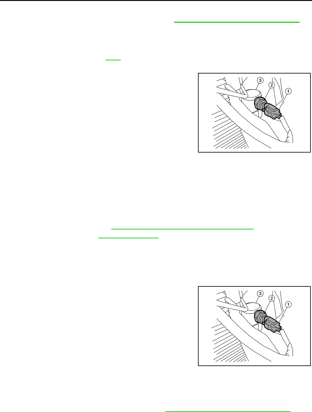
MTC-88
< SERVICE INFORMATION >
REFRIGERANT LINES
• Replace the O-ring of the high-pressure pipe with a new one, then apply compressor oil to it when
installing it.
• After charging the refrigerant, check for leaks. Refer to MTC-90, "Checking of Refrigerant Leaks".
Removal and Installation for Refrigerant Pressure Sensor INFOID:0000000005282809
REMOVAL
1. Remove the front grille. Refer to EI-18.
2. Reposition the LH air guide out of the way.
3. Disconnect the refrigerant pressure sensor connector (1) and
remove the refrigerant pressure sensor (2) from the liquid tank
(3).
CAUTION:
Do not damage the condenser fins.
INSTALLATION
Installation is in the reverse order of removal.
CAUTION:
Replace the O-ring of the refrigerant pressure sensor with a new one, then apply compressor oil to it
when installing it.
Removal and Installation for Condenser INFOID:0000000005282810
REMOVAL
1. Discharge the refrigerant. Refer to MTC-81, "HFC-134a (R-134a) Service Procedure".
2. Remove the radiator. Refer to CO-15, "Component".
CAUTION:
Be careful not to damage the core surface of the condenser and the radiator.
3. Disconnect the high-pressure flexible hose and the high-pressure pipe from the condenser.
CAUTION:
Cap or wrap the joint of the pipe and hose with suitable material such as vinyl tape to avoid the
entry of contaminants.
4. Disconnect the refrigerant pressure sensor connector (1) and
remove the refrigerant pressure sensor (2) from the liquid tank
(3).
CAUTION:
Do not damage the condenser fins.
5. Remove the condenser bracket bolts.
6. Remove the condenser.
INSTALLATION
Installation is in the reverse order of removal.
CAUTION:
• Replace the O-rings of the high-pressure pipe, refrigerant pressure sensor, and high-pressure flexi-
ble hose with new ones, then apply A/C oil to them after installing them.
• When charging refrigerant, check for leaks. Refer to MTC-90, "Checking of Refrigerant Leaks".
BJIA0037E
BJIA0037E
Revision: January 2010 2010 Sentra
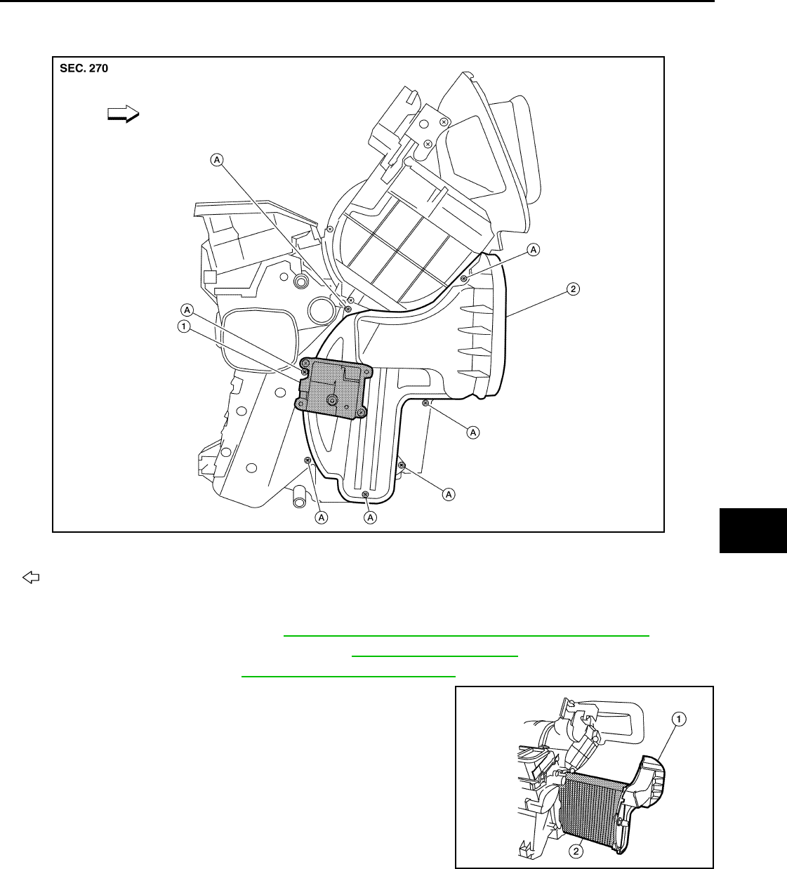
REFRIGERANT LINES
MTC-89
< SERVICE INFORMATION >
C
D
E
F
G
H
I
K
L
M
A
B
MTC
N
O
P
Removal and Installation for Evaporator INFOID:0000000005282811
REMOVAL
1. Remove the expansion valve. Refer to MTC-90, "Removal and Installation for Expansion Valve".
2. Remove the instrument lower cover RH. Refer to IP-11, "Component Parts".
3. Remove the glove box. Refer to IP-12, "Removal and Installation".
4. Remove the evaporator cover (1).
5. Remove the evaporator (2).
INSTALLATION
Installation is in the reverse order of removal.
CAUTION:
• Replace the O-rings with new ones, then apply compressor oil to them when installing them.
1. Air mix door motor 2. Evaporator cover A. Screws
Front
BJIA0038E
BJIA0039E
Revision: January 2010 2010 Sentra
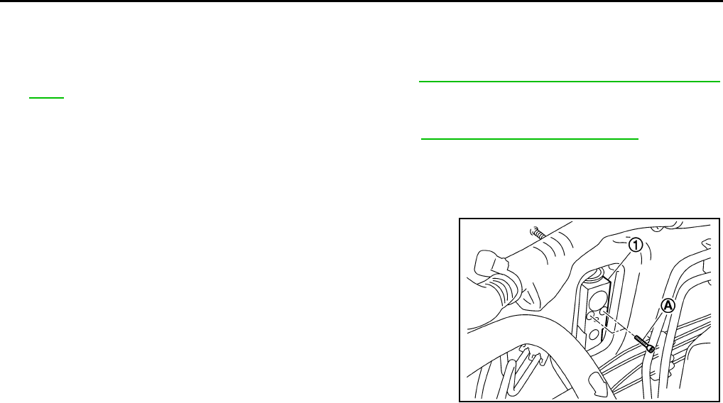
MTC-90
< SERVICE INFORMATION >
REFRIGERANT LINES
Removal and Installation for Expansion Valve INFOID:0000000005282812
REMOVAL
1. Evacuate and recover the A/C system refrigerant. Refer to MTC-81, "HFC-134a (R-134a) Service Proce-
dure".
2. Reposition the lower dash insulator out of the way.
3. Remove the cowl extension panel (QR25DE only). Refer to EI-19, "Removal and Installation".
4. Disconnect the low-pressure flexible hose and the high-pressure pipe from the expansion valve.
CAUTION:
Cap or wrap the joint of the pipe and hose with suitable material such as vinyl tape to avoid the
entry of contaminants.
5. Remove the expansion valve bolts (A) and then remove the
expansion valve (1).
INSTALLATION
Installation is in the reverse order of removal.
CAUTION:
• Replace the O-rings with new ones, then apply compressor oil to them when installing them.
Checking of Refrigerant Leaks INFOID:0000000005282813
Perform a visual inspection of all refrigeration parts, fittings, hoses and components for signs of A/C oil leak-
age, damage and corrosion. A/C oil leakage may indicate an area of refrigerant leakage. Allow extra inspec-
tion time in these areas when using either an electronic refrigerant leak detector or fluorescent dye leak
detector.
If dye is observed, confirm the leak with an electronic refrigerant leak detector. It is possible a prior leak was
repaired and not properly cleaned.
When searching for leaks, do not stop when one leak is found but continue to check for additional leaks at all
system components and connections.
When searching for refrigerant leaks using an electronic leak detector, move the probe along the suspected
leak area at 25 - 50 mm (1 - 2 in) per second and no further than 6 mm (1/4 in) from the component.
CAUTION:
Moving the electronic leak detector probe slower and closer to the suspected leak area will improve
the chances of finding a leak.
Checking System for Leaks Using the Fluorescent Leak Detector INFOID:0000000005282814
1. Check A/C system for leaks using the UV lamp and safety goggles (J-42220) in a low sunlight area (area
without windows preferable). Illuminate all components, fittings and lines. The dye will appear as a bright
green/yellow area at the point of leakage. Fluorescent dye observed at the evaporator drain opening indi-
cates an evaporator core assembly (tubes, core or expansion valve) leak.
2. If the suspected area is difficult to see, use an adjustable mirror or wipe the area with a clean shop rag or
cloth, with the UV lamp for dye residue.
3. After the leak is repaired, remove any residual dye using refrigerant dye cleaner (J-43872) to prevent
future misdiagnosis.
4. Perform a system performance check and verify the leak repair with an approved electronic refrigerant
leak detector.
SJIA0683E
Expansion valve bolts : 3.9 N·m (0.40 kg-m, 35 in-lb)
Revision: January 2010 2010 Sentra
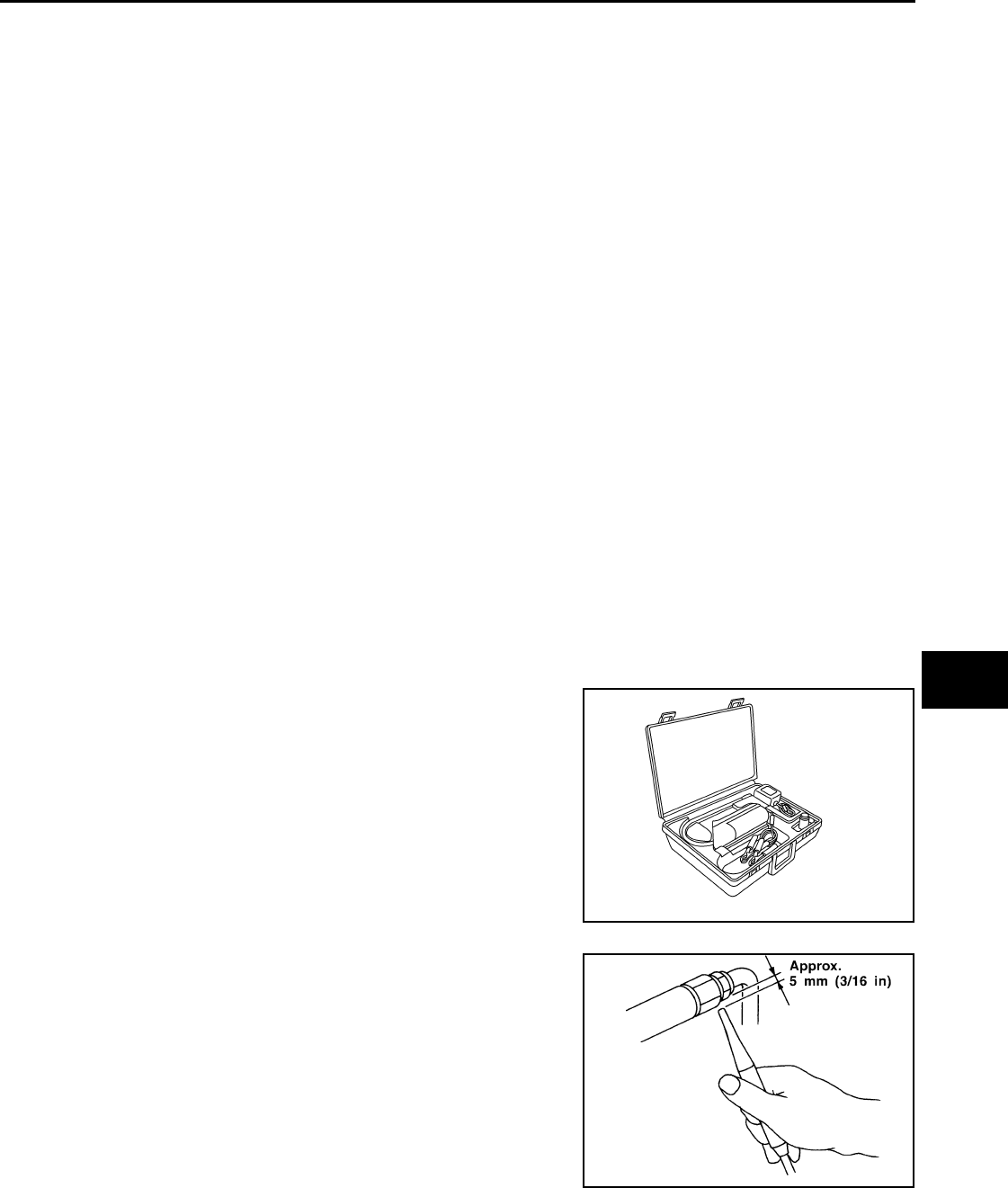
REFRIGERANT LINES
MTC-91
< SERVICE INFORMATION >
C
D
E
F
G
H
I
K
L
M
A
B
MTC
N
O
P
NOTE:
Other gases in the work area or substances on the A/C components, for example, anti-freeze, windshield
washer fluid, solvents and oils, may falsely trigger the leak detector. Make sure the surfaces to be checked are
clean.
Clean with a dry cloth or blow off with shop air.
Do not allow the sensor tip of the detector to contact with any substance. This can also cause false readings
and may damage the detector.
Dye Injection INFOID:0000000005282815
NOTE:
This procedure is only necessary when recharging the A/C system or when the compressor has seized and
has been replaced.
1. Check the A/C system static (at rest) pressure. Pressure must be at least 345 kPa (3.52 kg/cm2, 50 psi).
2. Pour one bottle (1/4 ounce / 7.4 cc) of the A/C refrigerant dye into the injector tool (J-41459).
CAUTION:
If repairing the A/C system or replacing a component, pour the dye directly into the open system
connection and proceed with the service procedures.
3. Connect the injector tool to the A/C LOW PRESSURE side service valve.
4. Start the engine and switch the A/C ON and fan ON.
5. While the A/C is operating (compressor running), inject one bottle (1/4 ounce / 7.4 cc) of fluorescent dye
through the low-pressure service valve using dye injector tool (J-41459), refer to the manufacturer's oper-
ating instructions.
6. With the engine still running, disconnect the injector tool from the low-pressure service valve.
7. Operate the A/C system for a minimum of 20 minutes to mix the dye with the system oil. Depending on the
leak size, operating conditions and location of the leak, it may take from a few minutes to a few days for
the dye to penetrate the leak and become visible.
Electronic Refrigerant Leak Detector INFOID:0000000005282816
PRECAUTIONS FOR HANDLING THE LEAK DETECTOR
When performing a refrigerant leak check, use a electronic refriger-
ant leak detector (J-41995) or equivalent. Ensure that the instrument
is calibrated and set properly per the manufacturer's operating
instructions.
The leak detector is a delicate device. In order to use the leak detec-
tor properly, read the manufacturer's operating instructions and per-
form any specified maintenance.
1. Position the leak detector probe approximately 5 mm (3/16 in)
away from the point to be checked.
AHA281A
SHA707EA
Revision: January 2010 2010 Sentra
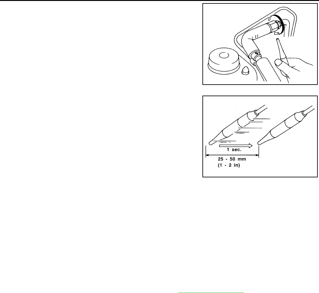
MTC-92
< SERVICE INFORMATION >
REFRIGERANT LINES
2. When testing, circle each fitting completely with the leak detec-
tor probe.
3. Move the leak detector probe along the component at approxi-
mately 25 to 50 mm (1 to 2 in)/sec.
CHECKING PROCEDURE
NOTE:
To prevent inaccurate or false readings, make sure there is no refrigerant vapor, shop chemicals, or cigarette
smoke in the vicinity of the vehicle. Perform the leak test in a calm area (low air/wind movement) so that the
leaking refrigerant is not dispersed.
1. Turn engine OFF.
2. Connect a suitable A/C manifold gauge set to the A/C service ports.
3. Check if the A/C refrigerant pressure is at least 345 kPa (3.52 kg/cm2, 50 psi) above 16°C (61°F). If less
than specification, recover/evacuate and recharge the system with the specified amount of refrigerant.
NOTE:
At temperatures below 16°C (61°F), leaks may not be detected since the system may not reach 345 kPa
(3.52 kg/cm2, 50 psi) pressure.
4. Conduct the leak test from the high side (compressor discharge to evaporator inlet) to the low side (evap-
orator drain hose to the compressor shaft seal). Refer to MTC-83, "Component". Clean the component to
be checked and move the leak detector probe completely around the connection/component.
Perform a leak check for the following areas:
• Compressor
• High and low-pressure hose fittings, relief valve and shaft seal.
• Liquid tank
• Refrigerant pressure sensor
• Service valves
- Check that all the service valve caps are secure on the service valves (to prevent leaks).
- After removing A/C manifold gauge set from service valves, wipe any residue from the valves to prevent
any false readings by the leak detector.
• Evaporator
- With engine OFF, turn blower fan on “High” for at least 15 seconds to dissipate any refrigerant trace
around the evaporator. Wait a minimum of 10 minutes accumulation time (refer to the manufacturer's
recommended procedure for actual wait time) before inserting the leak detector probe into the drain
hose.
- Keep the probe inserted for at least 10 seconds. Use caution not to contaminate the probe tip with water
or dirt that may be in the drain hose.
5. If a leak detector detects a leak, verify at least once by blowing compressed air into area of suspected
leak, then repeat check as outlined above.
6. Do not stop when one leak is found. Continue to check for additional leaks at all system components.
SHA706E
SHA708EA
Revision: January 2010 2010 Sentra
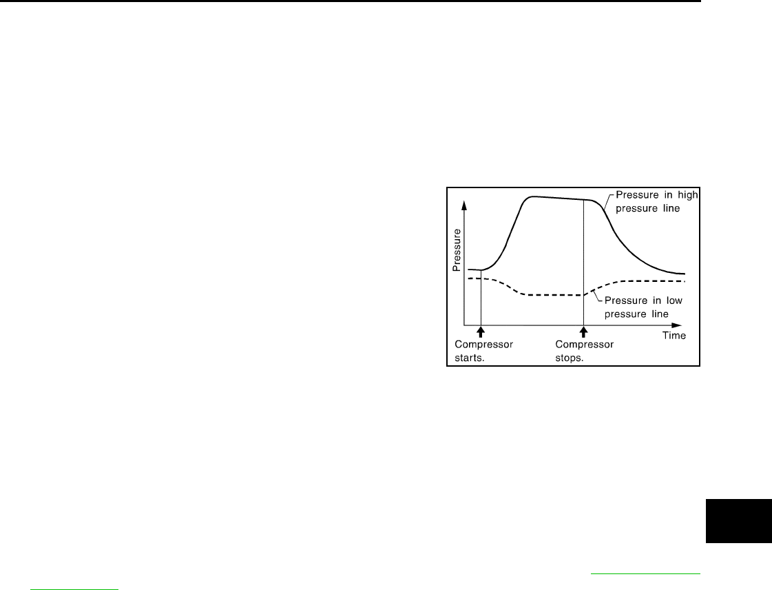
REFRIGERANT LINES
MTC-93
< SERVICE INFORMATION >
C
D
E
F
G
H
I
K
L
M
A
B
MTC
N
O
P
If no leaks are found, perform steps 7 - 10.
7. Start engine.
8. Set the front air control as follows;
a. A/C switch: ON
b. Mode: Vent
c. Intake position: Recirculation
d. Temperature: MAX cold
e. Blower fan speed: High
9. Run engine at 1,500 rpm for at least 2 minutes.
10. Turn engine off and perform leak check again following steps 4
through 6 above.
Refrigerant leaks should be checked immediately after stopping
the engine. Begin with the leak detector at the compressor. The
pressure on the high pressure side will gradually drop after
refrigerant circulation stops and pressure on the low pressure
side will gradually rise, as shown in the graph. Some leaks are
more easily detected when pressure is high.
11. Before connecting the recovery/recycling equipment to the A/C system, check the recovery/recycling
equipment gauges. No refrigerant pressure should be displayed. If pressure is displayed, recover the
refrigerant from the equipment lines and then check the refrigerant purity.
12. Confirm the refrigerant purity in the supply tank using the recovery/recycling equipment and the refrigerant
identifier equipment.
13. Confirm the refrigerant purity in the A/C system using the recovery/recycling equipment and the refriger-
ant identifier equipment.
14. Discharge the A/C system using approved refrigerant recovery/recycling equipment. Repair the leaking fit-
ting or component as necessary.
15. Evacuate and recharge the A/C system and perform the leak test to confirm there are no refrigerant leaks.
16. Conduct the A/C performance test to ensure that the system works properly. Refer to MTC-56, "Insuffi-
cient Cooling".
SHA839E
Revision: January 2010 2010 Sentra
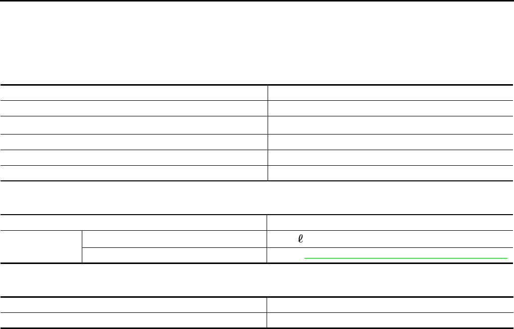
MTC-94
< SERVICE INFORMATION >
SERVICE DATA AND SPECIFICATIONS (SDS)
SERVICE DATA AND SPECIFICATIONS (SDS)
Service Data and Specification (SDS) INFOID:0000000005282817
COMPRESSOR
OIL
REFRIGERANT
Model Valeo
Type DCS-171C
Displacement 171 cm3 (10.43 in3) / revolution
Cylinder bore × stroke 32 mm (1.260 in) x 30.5 mm (1.201 in)
Direction of rotation Clockwise (viewed from drive end)
Drive belt Poly V 6-grooves
Name Genuine NISSAN A/C System Oil Type S
Capacity Total in system 150 m (5.03 US fl oz, 5.3 lmp fl oz)
Compressor (service part) charging amount Refer to MTC-18, "Maintenance of Oil Quantity in Compressor".
Type HFC-134a (R-134a)
Capacity 0.50 ± 0.05 kg (1.10 ± 0.11 lb)
Revision: January 2010 2010 Sentra
