Nissan 2011 Versa Owners Manual SM1E 1C11U0(MT)
2015-10-24
: Nissan Nissan-2011-Nissan-Versa-Owners-Manual-818457 nissan-2011-nissan-versa-owners-manual-818457 nissan pdf
Open the PDF directly: View PDF ![]() .
.
Page Count: 95
- QUICK REFERENCE INDEX
- Table of Contents
- RS5F91R
- SERVICE INFORMATION
- PRECAUTIONS
- PREPARATION
- NOISE, VIBRATION AND HARSHNESS (NVH) TROUBLESHOOTING
- DESCRIPTION
- M/T OIL
- SIDE OIL SEAL
- POSITION SWITCH
- CONTROL LINKAGE
- AIR BREATHER HOSE
- TRANSAXLE ASSEMBLY
- INPUT SHAFT AND GEAR
- MAINSHAFT AND GEAR
- FINAL DRIVE
- SHIFT CONTROL
- SERVICE DATA AND SPECIFICATIONS (SDS)
- SERVICE INFORMATION
- RS6F94R
- SERVICE INFORMATION
- PRECAUTIONS
- PREPARATION
- NOISE, VIBRATION AND HARSHNESS (NVH) TROUBLESHOOTING
- DESCRIPTION
- M/T OIL
- VEHICLE SPEED SENSOR
- SIDE OIL SEAL
- POSITION SWITCH
- CONTROL LINKAGE
- AIR BREATHER HOSE
- TRANSAXLE ASSEMBLY
- INPUT SHAFT AND GEARS
- MAINSHAFT AND GEARS
- REVERSE IDLER SHAFT AND GEARS
- FINAL DRIVE
- SHIFT CONTROL
- SERVICE DATA AND SPECIFICATIONS (SDS)
- SERVICE INFORMATION
- RS5F91R

MT-1
TRANSMISSION/TRANSAXLE
D
E
F
G
H
I
J
K
L
M
SECTION MT A
B
MT
N
O
P
CONTENTS
MANUAL TRANSAXLE
RS5F91R
SERVICE INFORMATION ............................ 3
PRECAUTIONS ................................................... 3
Precaution for Supplemental Restraint System
(SRS) "AIR BAG" and "SEAT BELT PRE-TEN-
SIONER" ...................................................................3
Precaution Necessary for Steering Wheel Rota-
tion After Battery Disconnect .....................................3
Precaution for Procedure without Cowl Top Cover ......4
Service Notice or Precaution .....................................4
PREPARATION ................................................... 5
Special Service Tools ..............................................5
Commercial Service Tools .......................................7
NOISE, VIBRATION AND HARSHNESS
(NVH) TROUBLESHOOTING ............................. 8
NVH Troubleshooting Chart ......................................8
DESCRIPTION .................................................... 9
System Diagram ........................................................9
System Description ...................................................9
M/T OIL ...............................................................11
Draining ...................................................................11
Refilling ...................................................................11
Inspection ................................................................11
SIDE OIL SEAL ..................................................12
Removal and Installation .........................................12
POSITION SWITCH ............................................13
Checking .................................................................13
CONTROL LINKAGE .........................................14
Exploded View ........................................................ 14
Removal and Installation .........................................14
Inspection ................................................................15
AIR BREATHER HOSE ......................................16
Exploded View ........................................................ 16
Removal and Installation .........................................16
TRANSAXLE ASSEMBLY ................................17
Exploded View .........................................................17
Removal and Installation .........................................17
Disassembly and Assembly .....................................18
INPUT SHAFT AND GEAR ...............................36
Disassembly and Assembly .....................................36
MAINSHAFT AND GEAR .................................37
Disassembly and Assembly .....................................37
FINAL DRIVE ....................................................41
Disassembly and Assembly .....................................41
SHIFT CONTROL ..............................................42
Inspection ................................................................42
SERVICE DATA AND SPECIFICATIONS
(SDS) .................................................................43
General Specification ..............................................43
RS6F94R
SERVICE INFORMATION ...........................44
PRECAUTIONS .................................................44
Precaution for Supplemental Restraint System
(SRS) "AIR BAG" and "SEAT BELT PRE-TEN-
SIONER" .................................................................44
Precaution Necessary for Steering Wheel Rota-
tion After Battery Disconnect ...................................44
Precaution for Procedure without Cowl Top Cover ....45
Precaution ...............................................................45
PREPARATION .................................................46
Special Service Tool ................................................46
Commercial Service Tool ........................................48
NOISE, VIBRATION AND HARSHNESS
(NVH) TROUBLESHOOTING ...........................51
NVH Troubleshooting Chart ....................................51
Revision: May 2010 2011 Versa

MT-2
DESCRIPTION ................................................... 52
Cross-Sectional View ............................................. 52
M/T OIL .............................................................. 54
Changing M/T Oil .................................................... 54
Checking M/T Oil .................................................... 54
VEHICLE SPEED SENSOR .............................. 55
Removal and Installation ........................................ 55
SIDE OIL SEAL ................................................. 56
Removal and Installation ........................................ 56
POSITION SWITCH ........................................... 57
Checking ................................................................. 57
CONTROL LINKAGE ........................................ 58
Component of Control Device and Cable ............... 58
Removal and Installation ........................................ 58
AIR BREATHER HOSE ..................................... 60
Removal and Installation ........................................ 60
TRANSAXLE ASSEMBLY ................................ 61
Component ............................................................. 61
Removal and Installation ......................................... 61
Disassembly and Assembly .................................... 62
INPUT SHAFT AND GEARS ............................. 80
Disassembly and Assembly .................................... 80
MAINSHAFT AND GEARS ............................... 85
Disassembly and Assembly .................................... 85
REVERSE IDLER SHAFT AND GEARS ........... 90
Disassembly and Assembly .................................... 90
FINAL DRIVE ..................................................... 92
Disassembly and Assembly .................................... 92
SHIFT CONTROL .............................................. 94
Inspection ................................................................ 94
SERVICE DATA AND SPECIFICATIONS
(SDS) ................................................................. 95
General Specification .............................................. 95
Revision: May 2010 2011 Versa

PRECAUTIONS
MT-3
< SERVICE INFORMATION > [RS5F91R]
D
E
F
G
H
I
J
K
L
M
A
B
MT
N
O
P
SERVICE INFORMATION
PRECAUTIONS
Precaution for Supplemental Restraint System (SRS) "AIR BAG" and "SEAT BELT
PRE-TENSIONER" INFOID:0000000005929653
The Supplemental Restraint System such as “AIR BAG” and “SEAT BELT PRE-TENSIONER”, used along
with a front seat belt, helps to reduce the risk or severity of injury to the driver and front passenger for certain
types of collision. This system includes seat belt switch inputs and dual stage front air bag modules. The SRS
system uses the seat belt switches to determine the front air bag deployment, and may only deploy one front
air bag, depending on the severity of a collision and whether the front occupants are belted or unbelted.
Information necessary to service the system safely is included in the SRS and SB section of this Service Man-
ual.
WARNING:
• To avoid rendering the SRS inoperative, which could increase the risk of personal injury or death in
the event of a collision which would result in air bag inflation, all maintenance must be performed by
an authorized NISSAN/INFINITI dealer.
• Improper maintenance, including incorrect removal and installation of the SRS can lead to personal
injury caused by unintentional activation of the system. For removal of Spiral Cable and Air Bag
Module, see the SRS section.
• Do not use electrical test equipment on any circuit related to the SRS unless instructed to in this
Service Manual. SRS wiring harnesses can be identified by yellow and/or orange harnesses or har-
ness connectors.
PRECAUTIONS WHEN USING POWER TOOLS (AIR OR ELECTRIC) AND HAMMERS
WARNING:
• When working near the Airbag Diagnosis Sensor Unit or other Airbag System sensors with the Igni-
tion ON or engine running, DO NOT use air or electric power tools or strike near the sensor(s) with a
hammer. Heavy vibration could activate the sensor(s) and deploy the air bag(s), possibly causing
serious injury.
• When using air or electric power tools or hammers, always switch the Ignition OFF, disconnect the
battery, and wait at least 3 minutes before performing any service.
Precaution Necessary for Steering Wheel Rotation After Battery Disconnect
INFOID:0000000005929654
NOTE:
• This Procedure is applied only to models with Intelligent Key system and NATS (NISSAN ANTI-THEFT SYS-
TEM).
• Remove and install all control units after disconnecting both battery cables with the ignition knob in the
″LOCK″ position.
• Always use CONSULT-III to perform self-diagnosis as a part of each function inspection after finishing work.
If DTC is detected, perform trouble diagnosis according to self-diagnostic results.
For models equipped with the Intelligent Key system and NATS, an electrically controlled steering lock mech-
anism is adopted on the key cylinder.
For this reason, if the battery is disconnected or if the battery is discharged, the steering wheel will lock and
steering wheel rotation will become impossible.
If steering wheel rotation is required when battery power is interrupted, follow the procedure below before
starting the repair operation.
OPERATION PROCEDURE
1. Connect both battery cables.
NOTE:
Supply power using jumper cables if battery is discharged.
2. Use the Intelligent Key or mechanical key to turn the ignition switch to the ″ACC″ position. At this time, the
steering lock will be released.
3. Disconnect both battery cables. The steering lock will remain released and the steering wheel can be
rotated.
4. Perform the necessary repair operation.
Revision: May 2010 2011 Versa
MT-4
< SERVICE INFORMATION > [RS5F91R]
PRECAUTIONS
5. When the repair work is completed, return the ignition switch to the ″LOCK″ position before connecting
the battery cables. (At this time, the steering lock mechanism will engage.)
6. Perform a self-diagnosis check of all control units using CONSULT-III.
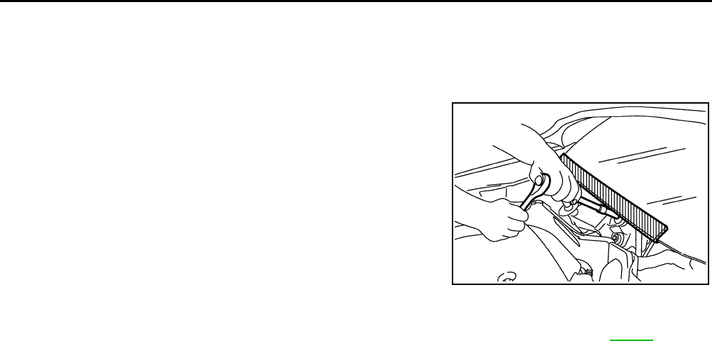
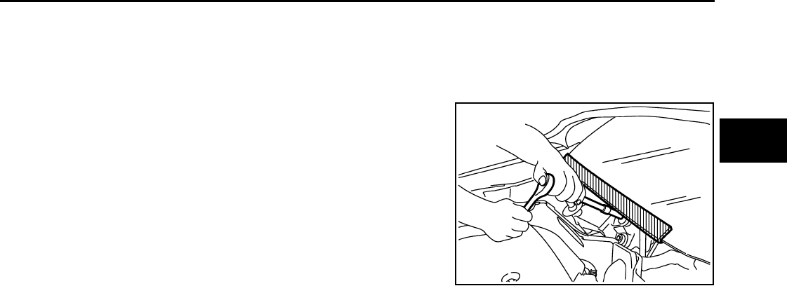
Precaution for Procedure without Cowl Top Cover INFOID:0000000005929655
When performing the procedure after removing cowl top cover, cover
the lower end of windshield with urethane, etc.
Service Notice or Precaution INFOID:0000000005929656
•Use recommended brake fluid when adding fluid to the clutch reservoir tank. Refer to MA-14.
•Never reuse fluid drained from clutch system.
•Be careful not to splash brake fluid on painted areas.
•Use new brake fluid to clean or wash all parts of master cylinder and operating cylinder.
•Never use mineral oils such as gasoline or kerosene. It will ruin the rubber parts of the hydraulic sys-
tem.
•If transaxle assembly is removed from the vehicle, always replace CSC (Concentric slave cylinder).
Return CSC to original position to remove transaxle assembly. Dust on clutch disc sliding parts may
damage CSC seal and may cause clutch fluid leakage.
•Do not disassemble clutch master cylinder and CSC.
WARNING:
After cleaning clutch disc, clean it with a dust collector. Do not use compressed air.
PIIB3706J
Revision: May 2010 2011 Versa
PREPARATION
MT-5
< SERVICE INFORMATION > [RS5F91R]
D
E
F
G
H
I
J
K
L
M
A
B
MT
N
O
P
PREPARATION
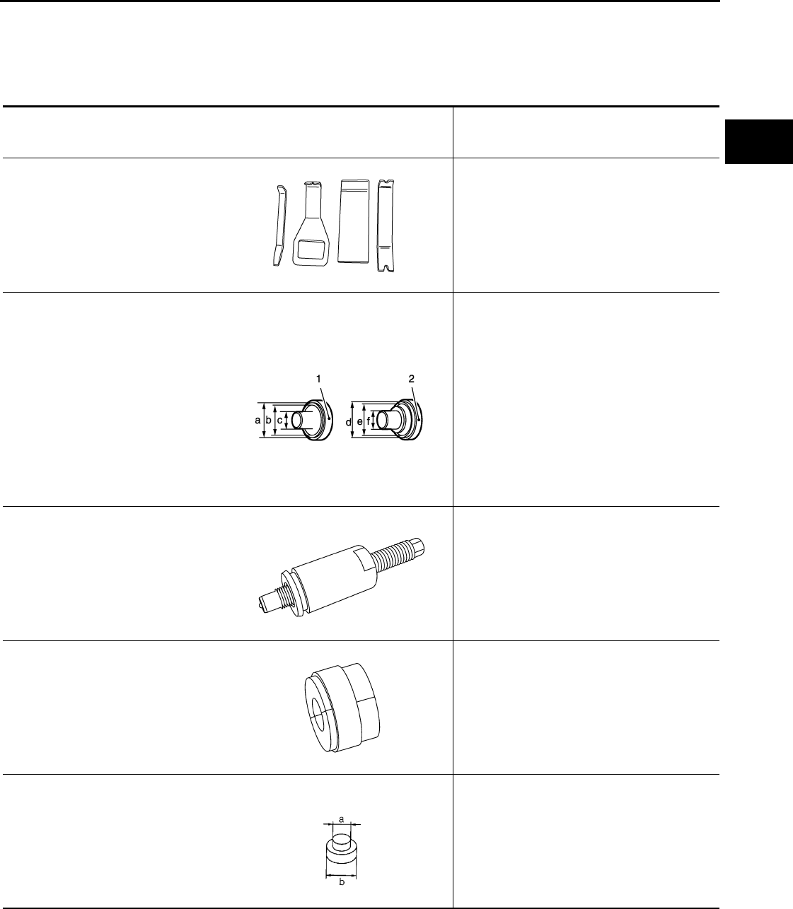
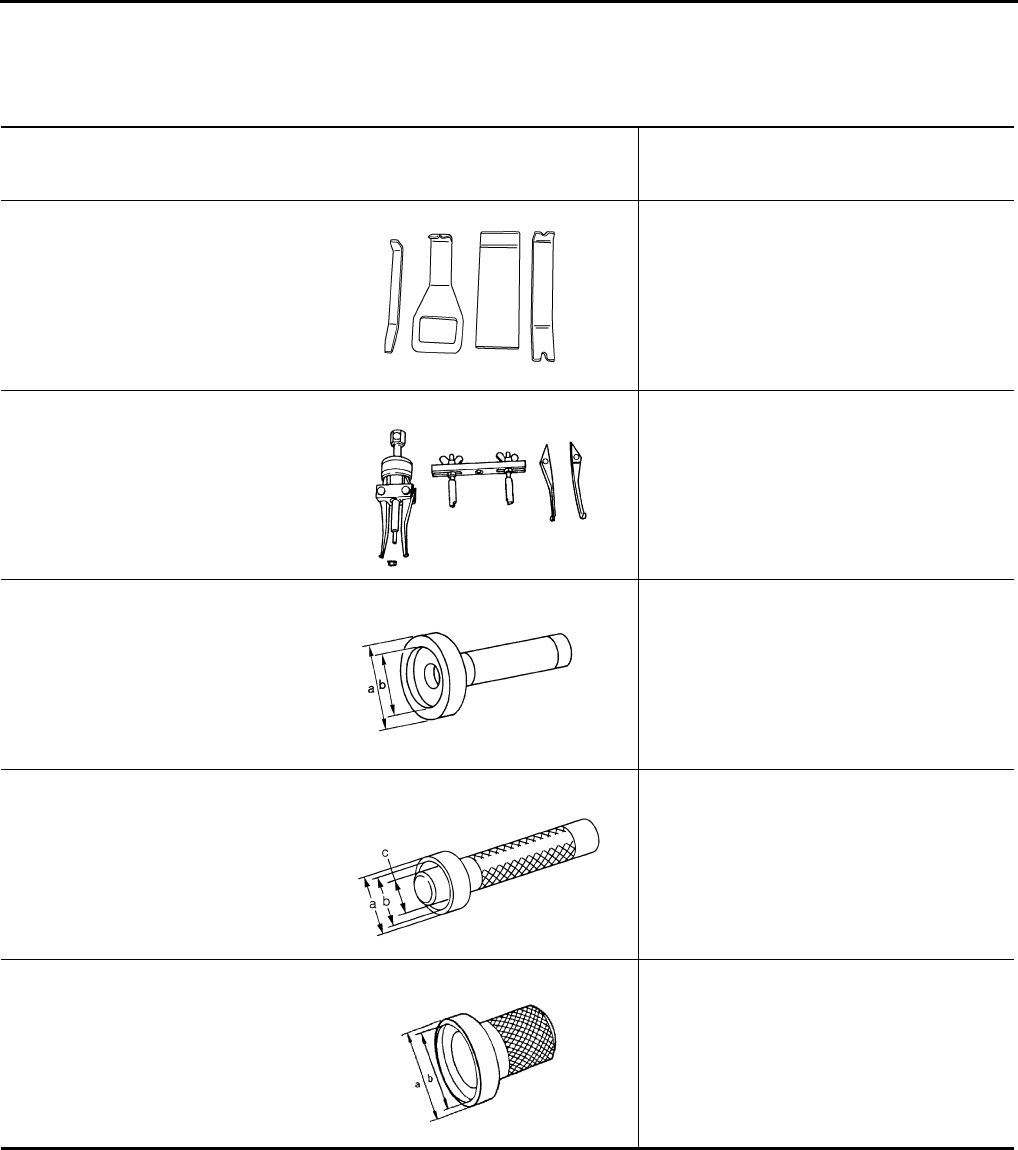
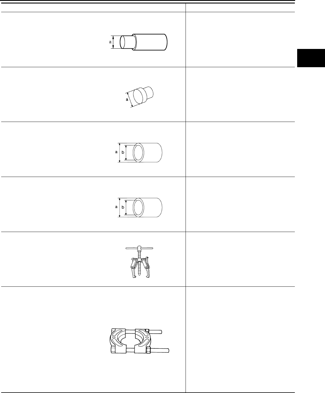
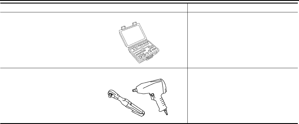
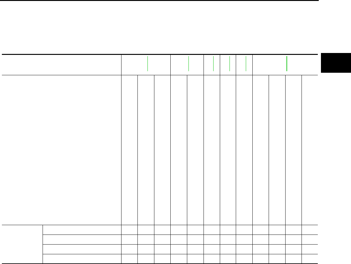
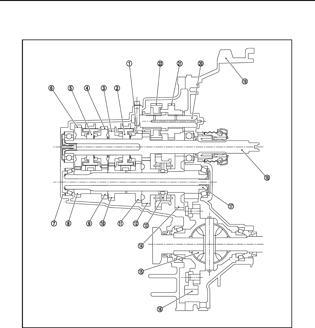
Special Service Tools INFOID:0000000005929657
The actual shapes of tools may differ from those of special service tools illustrated here.
Tool number
(Kent-Moore No.)
Tool name
Description
—
( J-46534 )
Trim tool set
For removing trim
KV32500QAA
(—)
(Renault SST: B.vi 1666)
Drift set
Installing differential side oil seal
1. ( – )
(Stamping number: B.vi 1666-A)
Drift
a: 54.3 mm (2.138 in) dia
b: 45 mm (1.77 in) dia
c: 26.6 mm (1.047 in) dia
2. ( – )
(Stamping number: B.vi 1666-B)
Drift
a: 54 mm (2.13 in) dia
b: 48.6 mm (1.913 in) dia
c: 26.6 mm (1.047 in) dia
KV32300QAC
(—)
Puller
Removing 5th main gear
KV32300QAD
(—)
Puller
Removing 5th main gear
ST35300000
(—)
Drift
• Removing and installing input shaft rear
bearing
• Removing and installing mainshaft rear
bearing
a: 45 mm (1.77 in) dia.
b: 59 mm (2.23 in) dia.
AWJIA0483ZZ
JPDIC0730ZZ
SCIA1781J
SCIA1782J
ZZA0969D
Revision: May 2010 2011 Versa
MT-6
< SERVICE INFORMATION > [RS5F91R]
PREPARATION
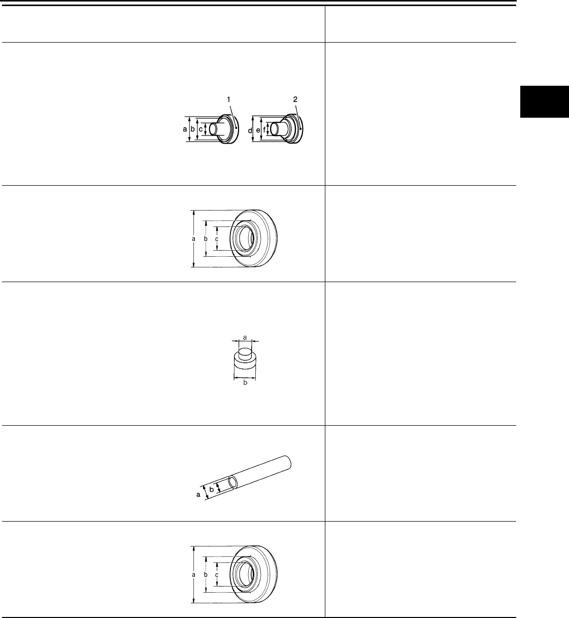
KV111011S0
(—)
Valve seat remover
Removing mainshaft front bearing
ST33400001
(J-26082)
Drift
Installing mainshaft front bearing
a: 60 mm (2.36 in) dia.
a: 47 mm (1.85 in) dia.
KV40100900
(—)
Drift
Installing input shaft front bearing
a: 52 mm (2.05 in) dia.
a: 39.5 mm (1.55 in) dia.
KV32300QAE
(—)
Drift
Installing differential side bearing outer race
a: 65 mm (2.56 in) dia.
a: 63 mm (2.48 in) dia.
ST33052000
(—)
Drift
Removing differential side bearing
a: 22 mm (0.87 in) dia.
a: 28 mm (1.10 in) dia.
KV40104920
(—)
Drift
Installing differential side bearing
a: 21.7 mm (0.85 in) dia.
a: 44.7 mm (1.76 in) dia.
Tool number
(Kent-Moore No.)
Tool name
Description
ZZA0872D
ZZA0814D
NT084
SCIA1783J
ZZA0969D
ZZA0969D
Revision: May 2010 2011 Versa
PREPARATION
MT-7
< SERVICE INFORMATION > [RS5F91R]
D
E
F
G
H
I
J
K
L
M
A
B
MT
N
O
P
Commercial Service Tools INFOID:0000000005929658
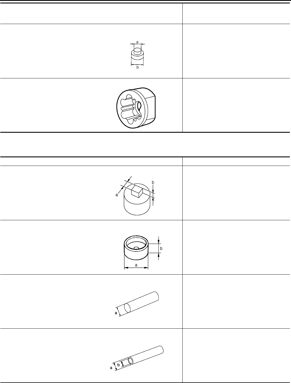
Tool name Description
Drift Removing input shaft front bearing
a: 38 mm (1.50 in) dia.
Drift Installing bushing
a: 14.5 mm (0.571 in) dia.
Socket Removing and installing drain plug
a: 8 mm (0.31 in)
b: 5 mm (0.20 in)
Puller • Removing 5th-reverse synchronizer hub
• Removing differential side bearing
Bearing remover Removing bushing
S-NT063
S-NT063
PCIB1776E
NT077
S-NT134
Revision: May 2010 2011 Versa
MT-8
< SERVICE INFORMATION > [RS5F91R]
NOISE, VIBRATION AND HARSHNESS (NVH) TROUBLESHOOTING
NOISE, VIBRATION AND HARSHNESS (NVH) TROUBLESHOOTING
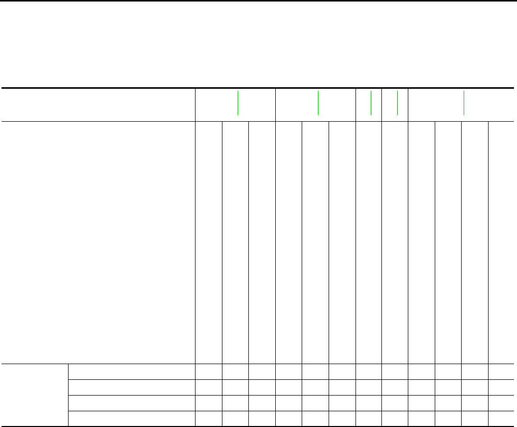
NVH Troubleshooting Chart INFOID:0000000005929659
Use the chart below to help you find the cause of the symptom. The numbers indicate the order of the inspec-
tion. If necessary, repair or replace these parts.
Reference page
MT-18
MT-18
MT-14
MT-18
MT-18
SUSPECTED PARTS
(Possible cause)
OIL (Oil level is low.)
OIL (Wrong oil.)
OIL (Oil level is high.)
GASKET (Damaged)
OIL SEAL (Worn or damaged)
O-RING (Worn or damaged)
SHIFT CONTROL LINKAGE (Worn)
SHIFT FORK (Worn)
GEAR (Worn or damaged)
BEARING (Worn or damaged)
BAULK RING (Worn or damaged)
INSERT SPRING (Damaged)
Symptoms
Noise 1 2 3 3
Oil leakage 31222
Hard to shift or will not shift 1 1 2 3 3
Jumps out of gear 1 2 2
Revision: May 2010 2011 Versa
DESCRIPTION
MT-9
< SERVICE INFORMATION > [RS5F91R]
D
E
F
G
H
I
J
K
L
M
A
B
MT
N
O
P
DESCRIPTION
System Diagram INFOID:0000000005929660
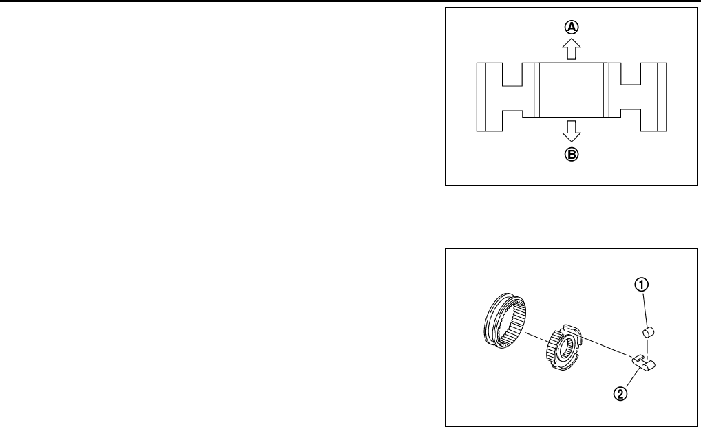
CROSS-SECTIONAL VIEW
System Description INFOID:0000000005929661
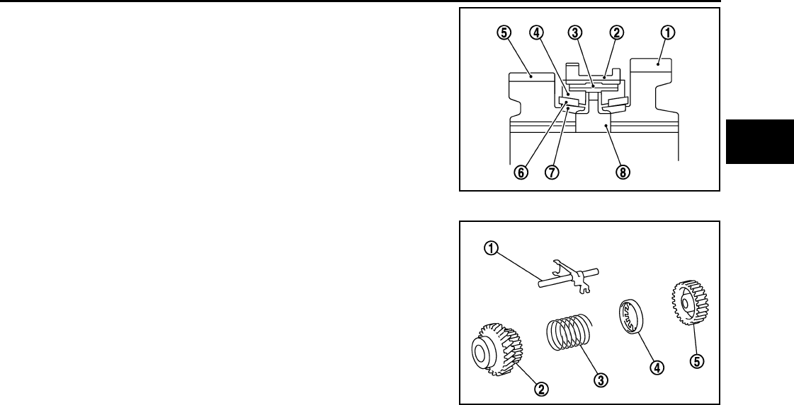
DOUBLE-CONE SYNCHRONIZER
1. Clutch housing 2. 1st-2nd synchronizer hub assembly 3. 3rd-4th synchronizer hub assembly
4. 5th input gear 5. 5th-reverse synchronizer hub assembly 6. 5th-reverse baulk ring
7. 5th main gear 8. 4th main gear 9. 3rd main gear
10. 2nd main gear 11. 2nd double cone synchronizer 12. 1st double cone synchronizer
13. 1st main gear 14. Differential side bearing 15. Differential
16. Final gear 17. Mainshaft 18. Input shaft
JPDIC0580ZZ
Revision: May 2010 2011 Versa
MT-10
< SERVICE INFORMATION > [RS5F91R]
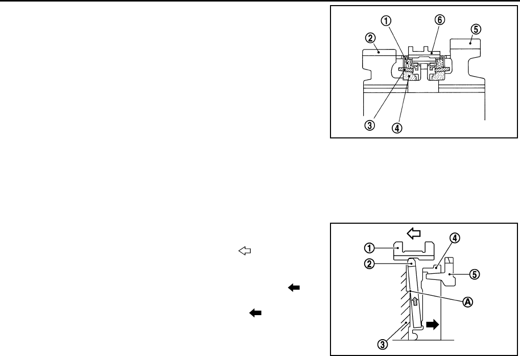
DESCRIPTION
Double-cone synchronizer is adopted for 1st and 2nd gears to
reduce operating force of the shift lever.
(1): Outer baulk ring
(2): 2nd main gear
(3): Synchronizer cone
(4): Inner baulk ring
(5): 1st main gear
(6): 1st-2nd coupling sleeve
REVERSE GEAR NOISE PREVENTION FUNCTION (SYNCHRONIZING METHOD)
Description
Soon after the clutch is disengaged, the input shaft is still rotating due to inertia. This may cause a gear noise
when the gear is shifted to reverse position. The reverse gear noise prevention function stops the rotation of
the input shaft and enables smooth gear shifting when the reverse gear is selected.
Operation Principle
1. When the gear is shifted to reverse position, 5th-reverse cou-
pling sleeve (1) slides in the reverse direction( )
5: 5th input gear
2. Synchronizer levers (2) with support point (A) at 5th-reverse
synchronizer hub (3) presses 5th-reverse baulk ring (4).( )
3. Friction that is generated at 5-reverse baulk ring presses syn-
chronizer lever on 5th-reverse coupling sleeve. ( )
4. 5th-reverse coupling sleeve that is presses by synchronizer
lever stops the rotation of input shaft.
SCIA7117E
JPDIC0415ZZ
Revision: May 2010 2011 Versa
M/T OIL
MT-11
< SERVICE INFORMATION > [RS5F91R]
D
E
F
G
H
I
J
K
L
M
A
B
MT
N
O
P
M/T OIL
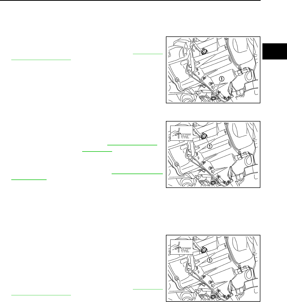
Draining INFOID:0000000005929662
1. Start engine and let it run to warm up transaxle.
2. Stop engine. Remove drain plug (1) and drain oil.
3. Set a new gasket on drain plug (1) and install it to transaxle and
tighten drain plug to the specified torque. Refer to MT-18, "Dis-
assembly and Assembly".
CAUTION:
Do not reuse gasket.
Refilling INFOID:0000000005929663
1. Remove filler plug (1). Fill with new oil until oil level reaches the
specified limit near filler plug hole as shown.
2. After refilling oil, check oil level.
3. Set a new gasket on filler plug (1), then install it to transaxle and
tighten to the specified torque. Refer to MT-18, "Disassembly
and Assembly".
CAUTION:
Do not reuse gasket.
Inspection INFOID:0000000005929664
LEAKAGE
Make sure that oil is not leaking from transaxle or around it.
LEVEL
1. Remove filler plug (1) and check oil level at filler plug hole as
shown.
CAUTION:
Do not start engine while checking oil level.
2. Set a new gasket on filler plug (1) and install it to the transaxle
case.
CAUTION:
Do not reuse gasket.
3. Tighten filler plug to the specified torque. Refer to MT-18, "Dis-
assembly and Assembly".
PCIB1504E
Oil grade and capacity : Refer to MA-14, "Fluids and
Lubricants".
SCIA7119E
SCIA7119E
Revision: May 2010 2011 Versa
MT-12
< SERVICE INFORMATION > [RS5F91R]
SIDE OIL SEAL
SIDE OIL SEAL
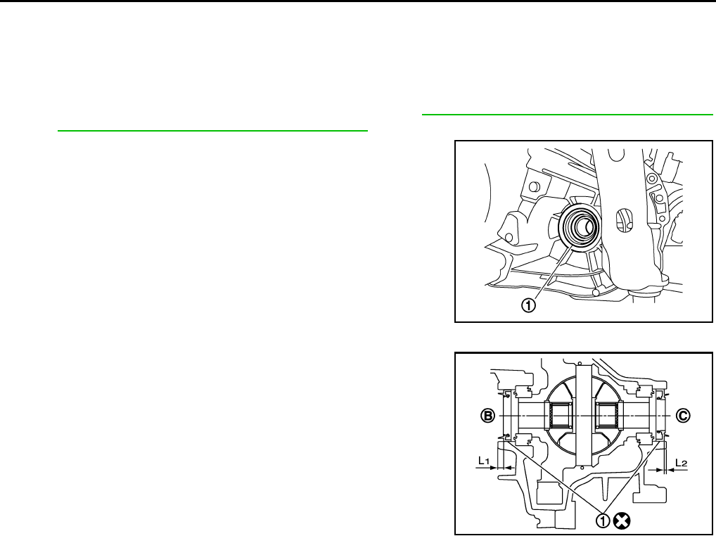
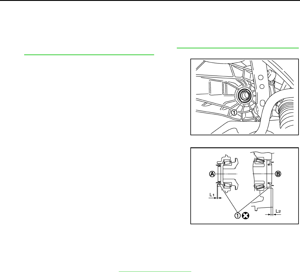
Removal and Installation INFOID:0000000005929665
REMOVAL
1. Remove front drive shafts from transaxle assembly. Refer to FAX-9, "Removal and Installation (Left Side)"
and FAX-10, "Removal and Installation (Right Side)".
2. Remove differential side oil seal (1) using suitable tool.
CAUTION:
Do not damage transaxle case or clutch housing.
INSTALLATION
Installation is in the reverse order of removal.
• B: Transaxle case side
• C: Clutch housing side
CAUTION:
• Do not reuse differential side oil seal
• Never incline differential side oil seal.
• Never damage clutch housing and transaxle case.
PCIB1505E
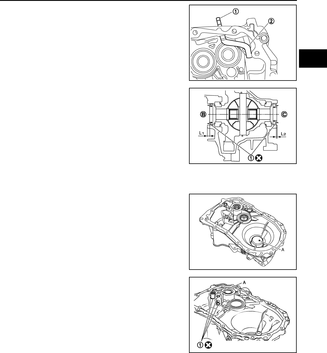
Tool number KV32500QAA ( – ) B.vi 1666-B
Dimension
L1: 5.7 – 6.3 mm (0.224 – 0.248 in)
L2: 2.4 – 3.0 mm (0.094 – 0.118 in)
JPDIC0401ZZ
Revision: May 2010 2011 Versa
POSITION SWITCH
MT-13
< SERVICE INFORMATION > [RS5F91R]
D
E
F
G
H
I
J
K
L
M
A
B
MT
N
O
P
POSITION SWITCH
Checking INFOID:0000000005929666
NOTE:
For removal and installation of the switches, refer to MT-18, "Disassembly and Assembly"
BACK-UP LAMP SWITCH
• Check continuity between terminals 1 and 2.
PARK/NEUTRAL POSITION SWITCH
• Check continuity between terminals 2 and 3.
Gear position Continuity
Reverse Yes
Except reverse No
MCIA0157E
Gear position Continuity
Neutral Yes
Except neutral No
JPDIC0092ZZ
Revision: May 2010 2011 Versa
MT-14
< SERVICE INFORMATION > [RS5F91R]
CONTROL LINKAGE
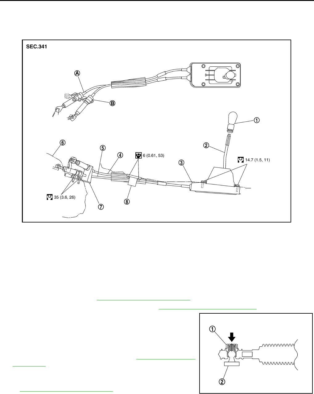
CONTROL LINKAGE
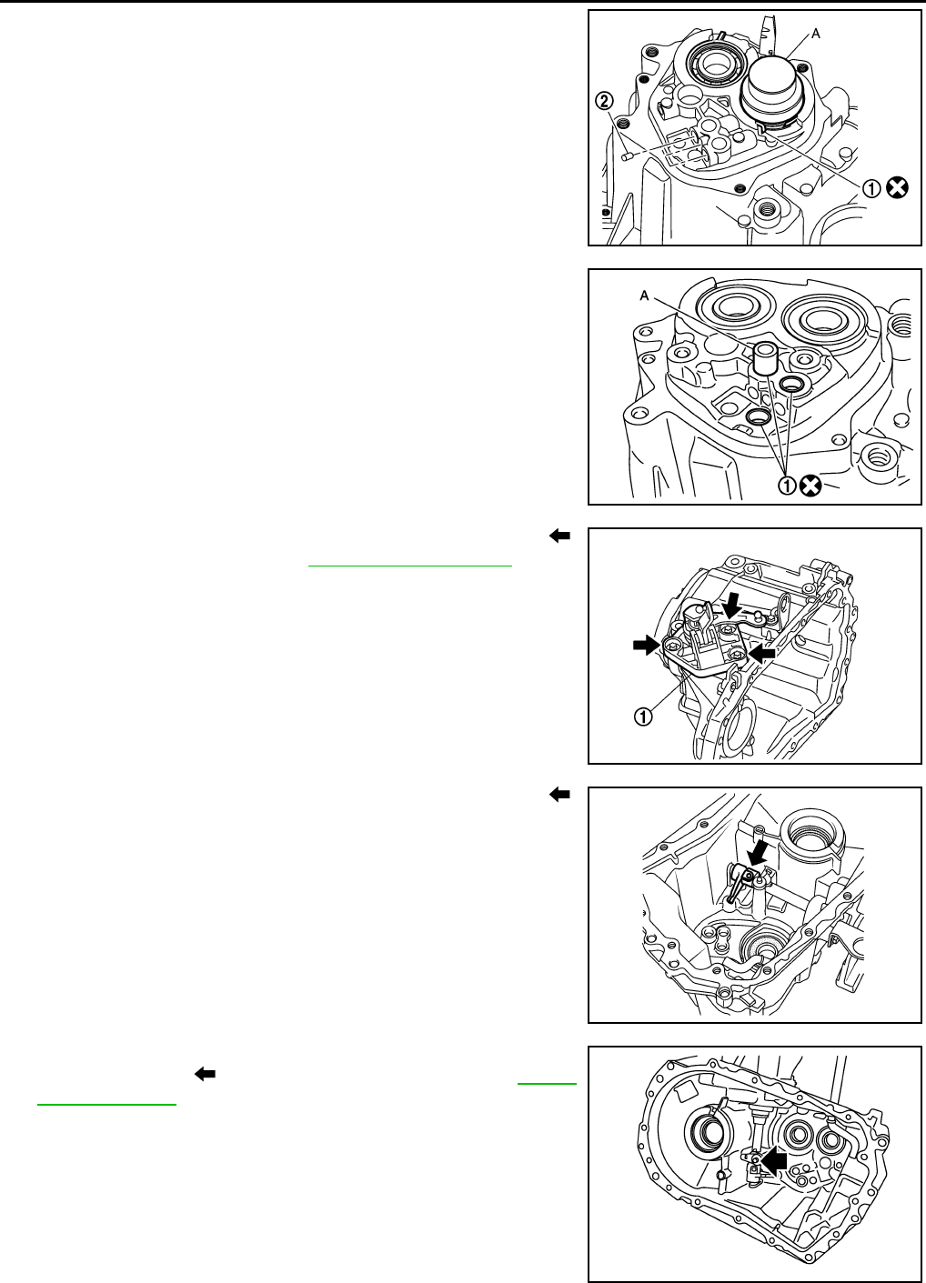
Exploded View INFOID:0000000005929667
Removal and Installation INFOID:0000000005929668
REMOVAL
1. Remove the battery. Refer to SC-7, "Removal and Installation".
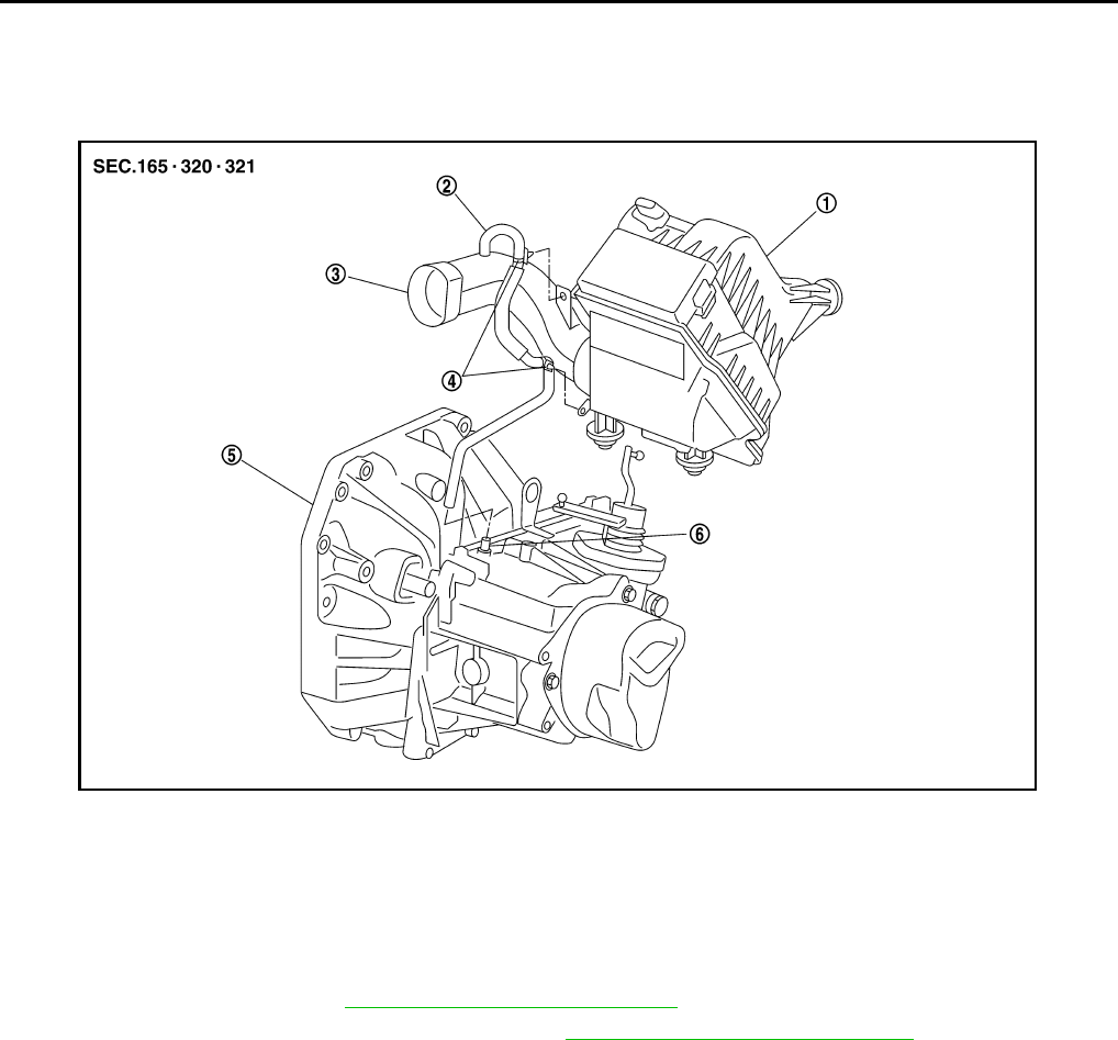
2. Remove the air duct and air cleaner case. Refer to EM-25, "Removal and Installation" .
3. Press the release button (1) of select cable and shift selector
cable, and then remove select cable and shift selector cable
from select lever of control shaft (2).
4. Move shift selector to neutral position.
5. Remove shift selector handle.
6. Remove center console assembly. Refer to IP-12, "Removal and
Installation".
7. Remove M/T shift selector assembly bolts.
8. Remove exhaust front tube, center muffler and heat plate. Refer
to EX-5, "Removal and Installation".
9. Remove cable support bracket.
10. Remove select cable and shift selector cable from cable mounting bracket.
11. Remove M/T shift selector assembly from the vehicle.
INSTALLATION
Installation is in the reverse order of removal.
1. Shift selector handle 2. Shift selector lever 3. M/T shift selector assembly
4. Select cable 5. Shift selector cable 6. Clutch housing
7. Cable mounting bracket 8. Bracket
A: Black color B: White color
PCIB1508E
SCIA7077E
Revision: May 2010 2011 Versa
CONTROL LINKAGE
MT-15
< SERVICE INFORMATION > [RS5F91R]
D
E
F
G
H
I
J
K
L
M
A
B
MT
N
O
P
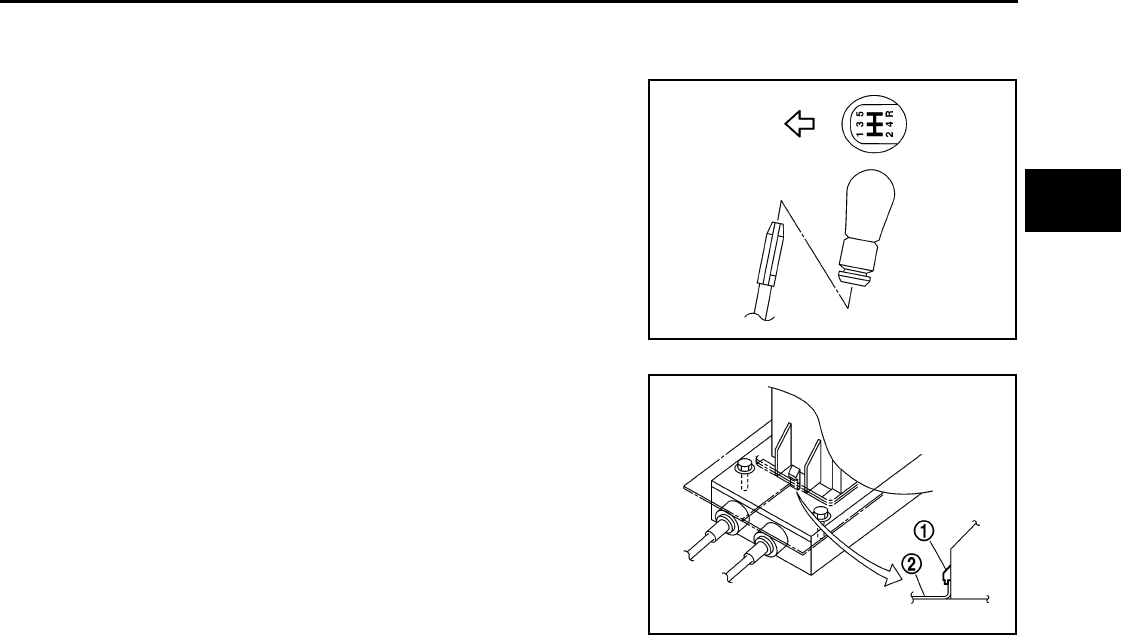
• Move the shift selector to the neutral position.
• Securely assemble each of the cables to each select lever of control shaft, mounting bracket, and the M/T
shift selector assembly.
• Be careful about the installation direction, and push shift selector
handle onto shift selector.
CAUTION:
Do not reuse shift selector handle.
• Make sure that the front/rear claws (1) of M/T shift selector assem-
bly are in contact with flange of the floor (2).
Inspection INFOID:0000000005929669
Inspect the following items:
• When shift selector is moved to 1st-2nd side and 5th-reverse side, confirm shift selector returns to neutral
position smoothly.
• When the shift selector is shifted to each position, make sure there is no binding or disconnection in each
boot.
PCIB1509E
PCIB1510E
Revision: May 2010 2011 Versa
MT-16
< SERVICE INFORMATION > [RS5F91R]
AIR BREATHER HOSE
AIR BREATHER HOSE
Exploded View INFOID:0000000005929670
Removal and Installation INFOID:0000000005929671
REMOVAL
1. Remove the battery. Refer to SC-7, "Removal and Installation".
2. Remove the air duct and air cleaner case. Refer to EM-16, "Removal and Installation".
3. Remove air breather hose.
CAUTION:
When air breather hose is removed, be sure to hold two way connector securely.
INSTALLATION
Installation is in the reverse order of removal.
CAUTION:
Make sure air breather hose is not collapsed or blocked due to folding or bending when installed.
• When installing air breather hose on two way connector, aim paint mark toward the vehicle rear.
• When installing air breather hose on two way connector, push it until it hits the transaxle case.
• When installing air breather hose to air duct and air cleaner case, make sure that clips are fully inserted.
1. Air cleaner case 2. Air breather hose 3. Air duct
4. Clip 5. Transaxle assembly 6. Two way connector
PCIB1511E
Revision: May 2010 2011 Versa
TRANSAXLE ASSEMBLY
MT-17
< SERVICE INFORMATION > [RS5F91R]
D
E
F
G
H
I
J
K
L
M
A
B
MT
N
O
P
TRANSAXLE ASSEMBLY
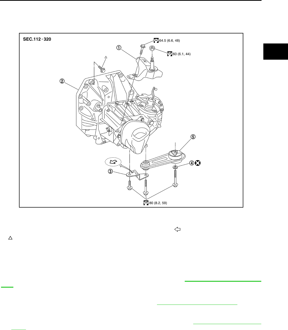
Exploded View INFOID:0000000005929672
Removal and Installation INFOID:0000000005929673
CAUTION:
If transaxle assembly is removed from the vehicle, always replace CSC (Concentric Slave Cylinder).
Return CSC insert to original position to remove transaxle assembly. Dust on clutch disc sliding parts
may damage seal of CSC and may cause clutch fluid leakage. Refer to CL-13, "Removal and Installa-
tion".
REMOVAL
1. Drain clutch fluid and remove clutch tube from CSC. Refer to CL-13, "Removal and Installation".
CAUTION:
Do not depress clutch pedal during removal procedure.
2. Remove the engine and transaxle as an assembly from the vehicle. Refer to EM-82, "Removal and Instal-
lation".
3. Remove the transaxle to engine and engine to transaxle bolts.
4. Separate the transaxle assembly from the engine.
INSTALLATION
Installation is in the reverse order of removal.
1. LH engine mount bracket (transaxle
side)
2. Transaxle assembly 3. Rear engine mount bracket
4. Washer 5. Rear torque rod Front
:Refer to installation.
PCIB1514E
Revision: May 2010 2011 Versa
MT-18
< SERVICE INFORMATION > [RS5F91R]
TRANSAXLE ASSEMBLY
CAUTION:
• Make sure the transaxle assembly does not interfere with the wire harnesses and clutch tube.
• When installing transaxle assembly, do not bring input shaft into contact with clutch cover.
• If transaxle is removed from the vehicle, always replace CSC. Refer to CL-13, "Removal and Installa-
tion".
• When installing the transaxle assembly to the engine, install the
bolts according to the following:
(A): Transaxle to engine
(B): Engine to transaxle
• After installation perform the following:
- Bleed the air from the clutch hydraulic system. Refer to CL-9, "Air Bleeding Procedure".
- Check for oil leakage and oil level. Refer to MT-11, "Inspection".
- Check the control linkage. Refer to MT-15, "Inspection".
Disassembly and Assembly INFOID:0000000005929674
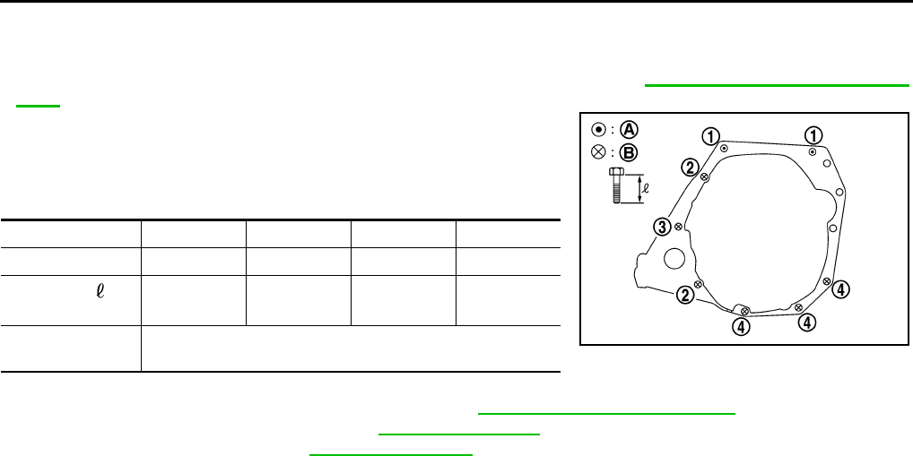
COMPONENTS
Case and Housing Component
Bolt No. 1 2 3 4
Quantity 2 2 1 3
Bolt length “ ”
mm (in)
55
(2.17)
49
(1.93)
69
(2.72)
55
(2.17)
Tightening torque
N·m (kg-m, ft-lb)
48.0
(4.9, 35)
PCIB1517E
Revision: May 2010 2011 Versa
TRANSAXLE ASSEMBLY
MT-19
< SERVICE INFORMATION > [RS5F91R]
D
E
F
G
H
I
J
K
L
M
A
B
MT
N
O
P
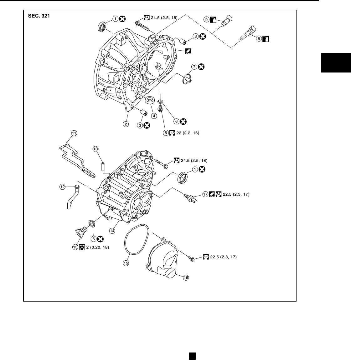
Gear Component
1. Differential side oil seal 2. Clutch housing 3. Dowel pin
4. Magnet 5. Drain plug 6. Gasket
7. Oil channel 8. Plug (with ABS models) 9. Vehicle speed sensor (w/o ABS models)
10. Two way connector 11. Oil gutter 12. Air breather inner tube
13. Filler plug 14. Transaxle case 15. O-ring
16. Rear housing 17. Position switch Replace parts as a set
AWDIA0791GB
Revision: May 2010 2011 Versa
MT-20
< SERVICE INFORMATION > [RS5F91R]
TRANSAXLE ASSEMBLY
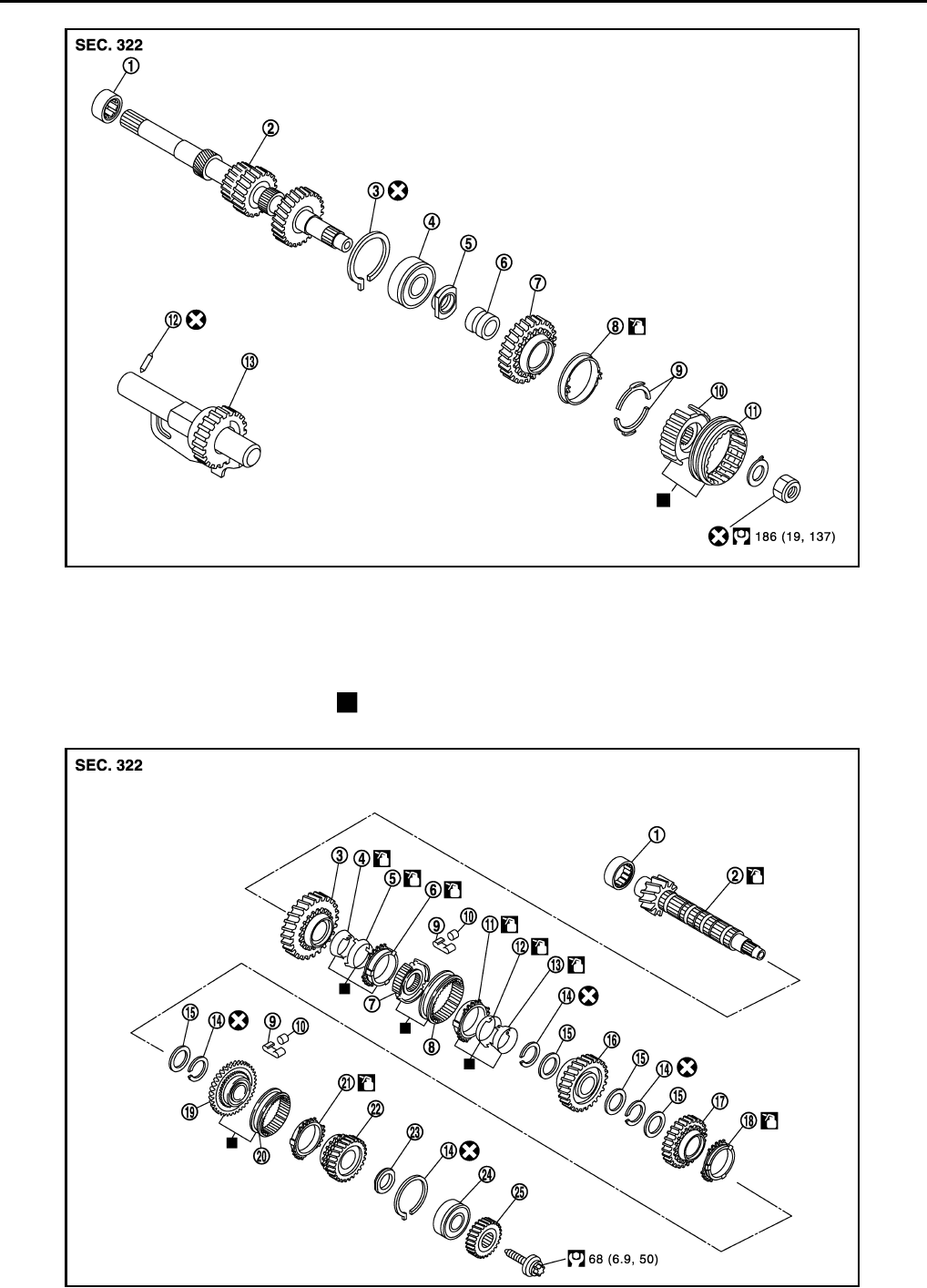
1. Input shaft front bearing 2. Input shaft 3. Snap ring
4. Input shaft rear bearing 5. Adapter plate 6. Bushing
7. 5th input gear 8. 5th-reverse baulk ring 9. Synchronizer lever
10. 5th-reverse synchronizer hub 11. 5th-reverse coupling sleeve 12. Retaining pin
13. Reverse gear assembly Replace parts as a set
JPDIC0480GB
JPDIC0531GB
Revision: May 2010 2011 Versa
TRANSAXLE ASSEMBLY
MT-21
< SERVICE INFORMATION > [RS5F91R]
D
E
F
G
H
I
J
K
L
M
A
B
MT
N
O
P
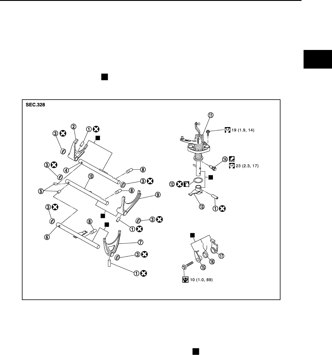
Shift Control Component
Final Drive Component
1. Mainshaft front bearing 2. Mainshaft 3. 1st main gear
4. 1st inner baulk ring 5. 1st synchronizer cone 6. 1st outer baulk ring
7. 1st-2nd synchronizer hub 8. 1st-2nd coupling sleeve 9. Spring
10. Insert key 11. 2nd outer baulk ring 12. 2nd synchronizer cone
13. 2nd inner baulk ring 14. Snap ring 15. Thrust washer
16. 2nd main gear 17. 3rd main gear 18. 3rd baulk ring
19. 3rd-4th synchronizer hub 20. 3rd-4th coupling sleeve 21. 4th baulk ring
22. 4th main gear 23. Spacer 24. Mainshaft rear bearing
25. 5th main gear Replace parts as a set
1. Retaining pin 2. 1st-2nd shift fork 3. Bushing
4. 1st-2nd fork rod 5. Lock pin 6. 5th-reverse fork rod
7. 5th-reverse shift fork 8. Check ball 9. 3rd-4th shift fork
10. 3rd-4th fork rod 11. Control shaft 12. O-ring
13. Selector 14. Check ball plug 15. Bushing
16. Spring 17. Gear catch Replace parts as a set
JPDIC0485GB
Revision: May 2010 2011 Versa
MT-22
< SERVICE INFORMATION > [RS5F91R]
TRANSAXLE ASSEMBLY
DISASSEMBLY
1. Remove drain plug and gasket from clutch housing using a suitable tool and drain gear oil.
2. Remove filler plug and gasket from transaxle case.
3. Remove rear housing and O-ring.
CAUTION:
Remove to axial direction of input shaft ( ) because rear
housing oil channel is inserted to input shaft center hole.
4. Shift control shaft shift lever (1) to the 3rd gear position.
NOTE:
• If it is not shifted to the 3rd gear position, transaxle case can-
not be removed from clutch housing.
• The 3rd gear position means that control shaft select lever is
fully rotated clockwise and it is returned approximately 10
degrees.
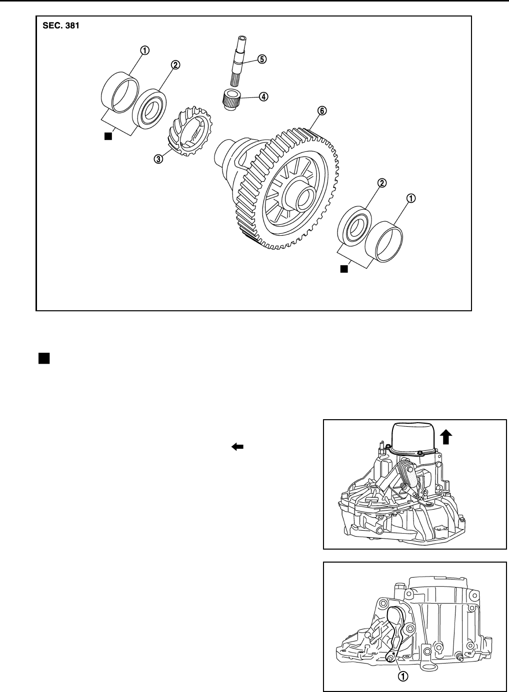
1. Differential side bearing outer race 2. Differential side bearing 3. Speedometer drive gear
4. Pinion gear 5. Pinion shaft 6. Final drive assembly
Replace parts as a set
JPDIC0602ZZ
SCIA1709J
PCIB1524E
Revision: May 2010 2011 Versa
TRANSAXLE ASSEMBLY
MT-23
< SERVICE INFORMATION > [RS5F91R]
D
E
F
G
H
I
J
K
L
M
A
B
MT
N
O
P
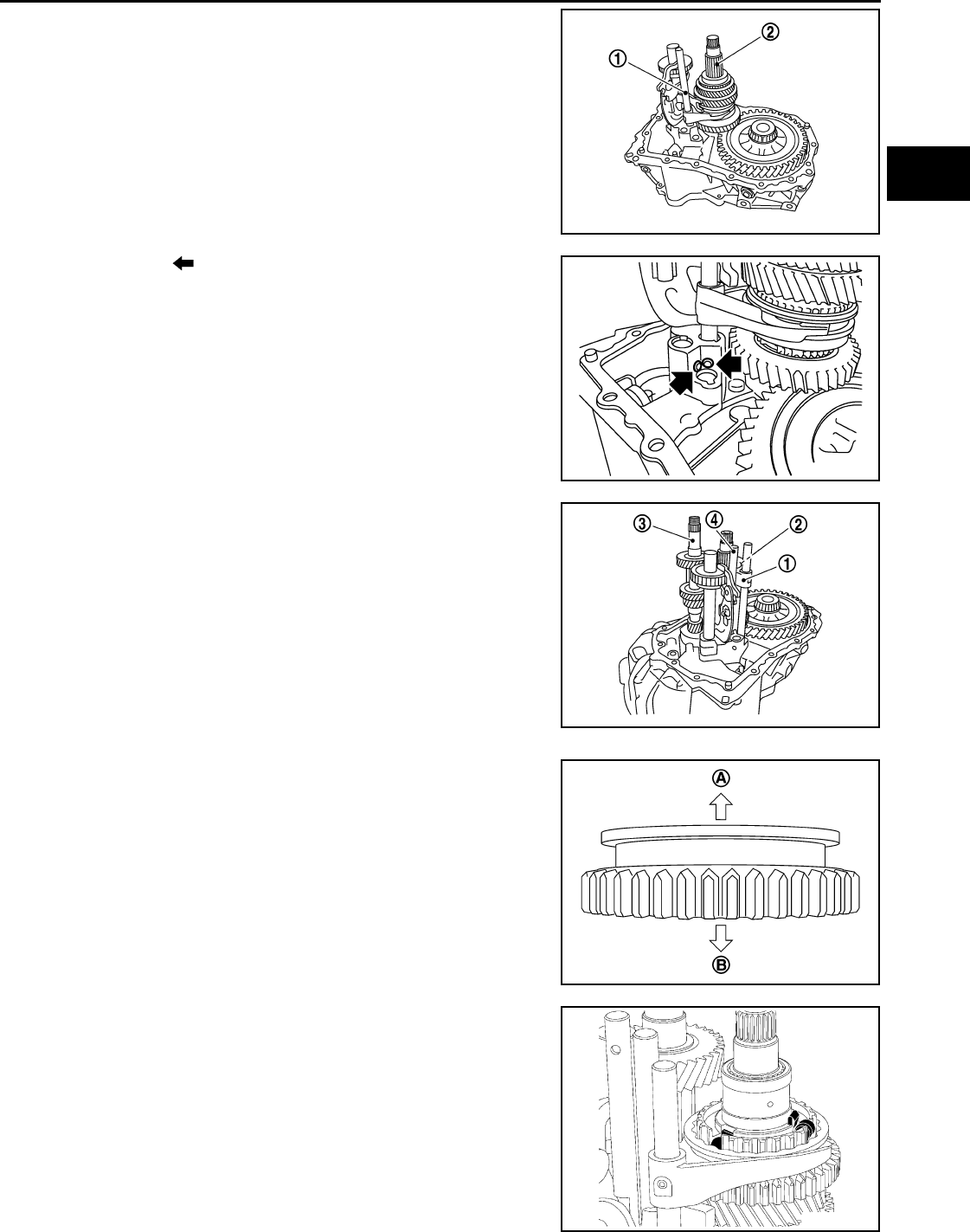
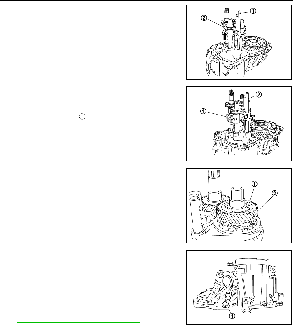
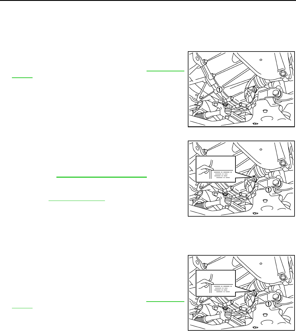
5. Remove 5th-reverse shift fork (1) and 5th-reverse coupling
sleeve according to the following procedures.
a. Remove retaining pin from 5th-reverse shift fork using a suitable
tool (A).
b. Press 5th-reverse shift fork, shift to 5th, and then engage it with
3rd gear.
c. Remove bolt (B).
d. Remove nut (C) and washer.
CAUTION:
Never use an impact wrench for removal, or otherwise each
gear may be damaged.
e. Remove 5th-reverse shift fork and 5th-reverse coupling sleeve from 5th-reverse synchronizer hub.
6. Remove 5th-reverse synchronizer hub from input shaft using a
suitable tool.
CAUTION:
Set claw of the puller to the wider side of the hub when set-
ting the puller in 5th-reverse synchronizer hub.
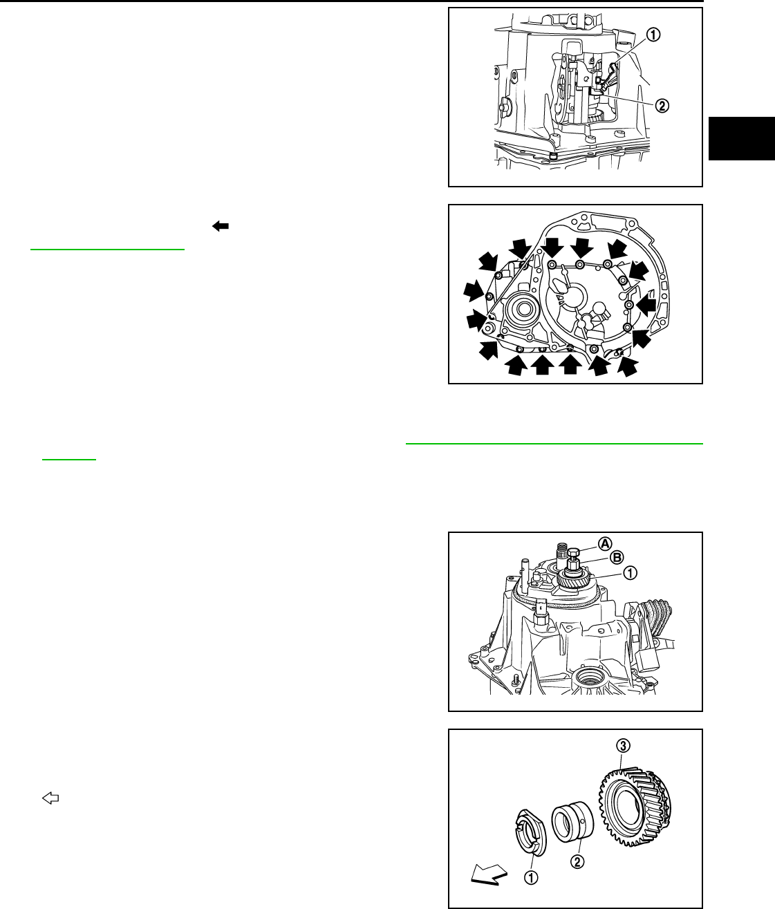
7. Remove synchronizer levers, 5th-reverse baulk ring, 5th input
gear, bushing, and adapter plate from input shaft.
8. Remove 5th main gear from mainshaft using the pullers.
9. Remove position switch from transaxle case.
JPDIC0532ZZ
PCIB1526E
Tool number A: KV32300QAC ( — )
B: KV32300QAD ( — )
PCIB1527E
PCIB1627E
Revision: May 2010 2011 Versa
MT-24
< SERVICE INFORMATION > [RS5F91R]
TRANSAXLE ASSEMBLY
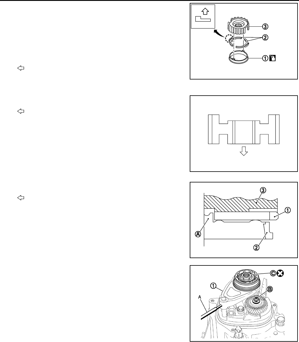
10. Remove transaxle case bolts ( ).
11. Remove transaxle case from clutch housing.
12. Remove spacer (1) and 4th main gear (2) from mainshaft.
13. Remove 5th-reverse fork rod (1) according to the following pro-
cedures.
a. Pull 5th-reverse fork rod up until it contacts claw ( ) of reverse
gear assembly (2).
b. Press gear portion of reverse gear assembly down, and then
remove 5th-reverse fork rod from clutch housing.
14. Remove 3rd-4th fork rod assembly (1), 3rd-4th coupling sleeve
(2), and input shaft assembly (3) according to the following pro-
cedures.
a. Remove 4th baulk ring, insert keys, and springs from mainshaft.
b. Pull gear of reverse gear assembly (4) up.
c. Pull 1st-2nd fork rod (5) up, and then maintain the neutral posi-
tion.
d. Remove 3rd-4th fork rod assembly, 3rd-4th coupling sleeve, and
input shaft assembly from clutch housing at the same time.
15. Remove retaining pin from 3rd-4th shift fork using a suitable tool.
16. Remove 3rd-4th shift fork from 3rd-4th shift fork rod.
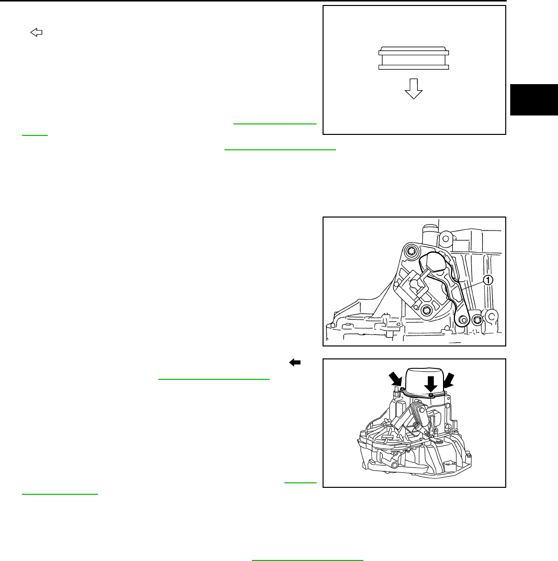
17. Remove lock pins ( ) from clutch housing.
JPDIC0610ZZ
PCIB1529E
PCIB1530E
PCIB1531E
JPDIC0534ZZ
Revision: May 2010 2011 Versa
TRANSAXLE ASSEMBLY
MT-25
< SERVICE INFORMATION > [RS5F91R]
D
E
F
G
H
I
J
K
L
M
A
B
MT
N
O
P
18. Remove 1st-2nd fork rod assembly (1) and mainshaft assembly
(2) from clutch housing at the same time.
19. Remove retaining pin from 1st-2nd shift fork using a suitable
tool.
20. Remove 1st-2nd shift fork from 1st-2nd shift fork rod.
21. Remove retaining pin from reverse gear assembly using a suit-
able tool.
22. Remove reverse gear assembly from clutch housing.
23. Remove final drive assembly (1) from clutch housing.
24. Remove plug from the clutch housing (with ABS models).
25. Remove the vehicle speed sensor (without ABS models).
26. Remove pinion shaft and pinion gear from clutch housing.
27. Remove magnet and dowel pins (2) from clutch housing.
28. Remove input shaft front bearing from clutch housing using a
suitable tool.
29. Cut oil channel tube at the root.
30. Remove mainshaft front bearing and oil channel from clutch
housing using Tool (A).
PCIB1532E
MCIB0033E
PCIB1533E
MCIB0044E
Tool number A: KV111011S0 ( — )
PCIB1536E
Revision: May 2010 2011 Versa
MT-26
< SERVICE INFORMATION > [RS5F91R]
TRANSAXLE ASSEMBLY
31. Remove bushings (1) from clutch housing using a suitable tool.
32. Remove differential side oil seals (1) from clutch housing and
transaxle case using a suitable tool.
CAUTION:
Never damage transaxle case and clutch housing.
33. Remove differential side bearing outer races (1) from clutch
housing and transaxle case using a suitable tool.
CAUTION:
Never damage transaxle case and clutch housing.
34. Pull two way connector (1) straight to remove it from air breather
inner tube (2).
35. Remove air breather inner tube from transaxle case.
36. Remove bushings (1) from transaxle case using a suitable tool.
37. Remove retaining pin ( ) from selector using a suitable tool.
38. Remove selector from control shaft.
39. Remove oil gutter from transaxle case.
PCIB1537E
PCIB1534E
JPDIC0484ZZ
PCIB1541E
PCIB1538E
Revision: May 2010 2011 Versa
TRANSAXLE ASSEMBLY
MT-27
< SERVICE INFORMATION > [RS5F91R]
D
E
F
G
H
I
J
K
L
M
A
B
MT
N
O
P
40. Remove bolt ( ), and then remove bushing, spring, and gear
catch from transaxle case.
41. Remove check ball plug from transaxle case.
42. Remove bolts ( ), and then remove control shaft (1) from tran-
saxle case.
43. Remove O-ring from control shaft.
44. Expand snap rings (1) and remove input shaft rear bearing and
mainshaft rear bearing from transaxle case using Tool (A).
45. Remove snap rings from transaxle case.
46. Remove check balls (2) from transaxle case.
ASSEMBLY
1. Install snap rings (1) along transaxle case groove so that notch
mates with housing as shown.
CAUTION:
Check snap ring installing direction. Never misassemble.
JPDIC0533ZZ
PCIB1540E
Tool number A: ST35300000 ( — )
PCIB1535E
PCIB1547E
Revision: May 2010 2011 Versa
MT-28
< SERVICE INFORMATION > [RS5F91R]
TRANSAXLE ASSEMBLY
2. Expand snap rings (1) and install input shaft rear bearing and
mainshaft rear bearing to transaxle case using Tool (A).
CAUTION:
Check that snap ring is correctly installed within bearing
groove.
3. Install check balls (2) to transaxle case.
4. Install bushings (1) until they reach transaxle case using a suit-
able tool (A).
5. Apply gear oil to O-ring, and then install it to control shaft.
6. Install control shaft (1) to transaxle case, and tighten bolts ( )
to the specified torque. Refer to MT-17, "Exploded View".
CAUTION:
Replace control shaft and selector as a set.
7. Install selector to control shaft, and then install retaining pin ( )
to selector using a suitable tool.
CAUTION:
• Be careful with the orientation of selector.
• Replace control shaft and selector as a set.
• Never reuse retaining pin.
8. Install gear catch, spring, and bushing to transaxle case, and
then tighten bolt ( ) to the specified torque. Refer to MT-17,
"Exploded View".
CAUTION:
Replace gear catch, spring, and bushing as a set.
9. Install oil gutter to transaxle case.
Tool number A: ST35300000 ( — )
PCIB1548E
JPDIC0636ZZ
PCIB1540E
SCIA1726J
JPDIC0533ZZ
Revision: May 2010 2011 Versa
TRANSAXLE ASSEMBLY
MT-29
< SERVICE INFORMATION > [RS5F91R]
D
E
F
G
H
I
J
K
L
M
A
B
MT
N
O
P
10. Install air breather inner tube (2) to transaxle case.
CAUTION:
Never damage air breather inner tube.
NOTE:
It is easier to install when air breather inner tube end is wrapped
and narrowed by tape. Remove tape after installation.
11. Insert two way connector (1) straight, and then install it to air
breather inner tube.
CAUTION:
Check air breather inner tube for twists after installing.
12. Install differential side oil seals (1) to clutch housing and tran-
saxle case, using Tool
• B: Transaxle case side
• C: Clutch housing side
CAUTION:
• Never incline differential side oil seal.
• Never damage clutch housing and transaxle case.
13. Install differential side bearing outer races until they reach clutch
housing and transaxle case using the Tool (A).
CAUTION:
Replace differential side bearing outer race and differential
side bearing as a set.
14. Install bushings (1) until they reach clutch housing using a suit-
able tool (A).
15. Install oil channel to clutch housing.
CAUTION:
Never reuse oil channel.
PCIB1541E
Tool number KV32500QAA ( – ) B.vi 1666-B
Dimension
L1: 5.7 – 6.3 mm (0.224 – 0.248 in)
L2: 2.4 – 3.0 mm (0.094 – 0.118 in)
JPDIC0401ZZ
Tool number A: KV32300QAE ( — )
PCIB1549E
JPDIC0637ZZ
Revision: May 2010 2011 Versa
MT-30
< SERVICE INFORMATION > [RS5F91R]
TRANSAXLE ASSEMBLY
16. Install mainshaft front bearing so that it becomes even to clutch
housing surface using Tool (A).
17. Install input shaft front bearing so that it becomes even to clutch
housing surface using Tool (A).
18. Install pinion gear and pinion shaft to clutch housing.
19. Install plug to clutch housing (with ABS models).
20. Install vehicle speed sensor to clutch housing (without ABS models).
NOTE:
Apply specific M/T fluid to the vehicle speed sensor O-ring prior to installation.
21. Install final drive assembly (1) to clutch housing.
22. Install dowel pins (2) and magnet to clutch housing.
23. Install reverse gear assembly to clutch housing, and then install
retaining pin to clutch housing using a suitable tool.
CAUTION:
Never reuse retaining pin.
24. Install 1st-2nd shift fork to 1st-2nd fork rod, and then install
retaining pin to 1st-2nd shift fork.
CAUTION:
• Never reuse retaining pin.
• Replace 1st-2nd fork rod and 1st-2nd shift fork as a set.
Tool number A: ST33400001 (J-26082)
PCIB1544E
Tool number A: KV40100900 ( — )
PCIB1545E
PCIB1533E
MCIB0033E
Revision: May 2010 2011 Versa
TRANSAXLE ASSEMBLY
MT-31
< SERVICE INFORMATION > [RS5F91R]
D
E
F
G
H
I
J
K
L
M
A
B
MT
N
O
P
25. Set 1st-2nd fork rod assembly (1) onto mainshaft assembly (2),
and then install them to clutch housing.
26. Install lock pins ( ) to clutch housing.
27. Install 3rd-4th shift fork to 3rd-4th fork rod, and then install
retaining pin to 3rd-4th shift fork.
CAUTION:
• Never reuse retaining pin.
• Replace 3rd-4th fork rod and 3rd-4th shift fork as a set.
28. Install 3rd-4th fork rod assembly (1), 3rd-4th coupling sleeve (2),
and input shaft assembly (3) to clutch housing according to the
following procedures.
a. Pull 1st-2nd fork rod (4) up, and then maintain the neutral posi-
tion.
b. Set 3rd-4th fork rod assembly onto 3rd-4th coupling sleeve, and
then install them together with input shaft assembly to clutch
housing.
CAUTION:
• Set lock pin (3rd-4th fork rod side) onto 1st-2nd fork rod
groove and then install 3rd-4th fork rod assembly.
• Be careful with the orientation of 3rd-4th coupling sleeve.
- A: 4th main gear side
- B: 3rd main gear side
• Install 3rd input gear of input shaft assembly so that it is
set under reverse main gear of 3rd-4th coupling sleeve.
• Replace 3rd-4th coupling sleeve and 3rd-4th synchronizer
hub as a set.
c. Install springs and insert keys to 3rd-4th synchronizer hub.
d. Apply gear oil to 4th baulk ring.
e. Install 4th baulk ring.
PCIB1532E
JPDIC0534ZZ
PCIB1628E
PCIB1551E
MCIB0061E
Revision: May 2010 2011 Versa
MT-32
< SERVICE INFORMATION > [RS5F91R]
TRANSAXLE ASSEMBLY
29. Install 5th-reverse fork rod (1) to clutch housing according to the
following procedures.
CAUTION:
Replace 5th-reverse fork rod and 5th-reverse shift fork as a
set.
a. Pull gear of reverse gear assembly (2) up.
b. Temporarily install 5th-reverse fork rod to clutch housing.
c. Press gear of reverse gear assembly (1) down and then install
5th-reverse fork rod (2) to clutch housing.
CAUTION:
Set levers of 5th-reverse fork rod so as to align with reverse
gear assembly groove ( ).
30. Install 4th main gear (2) and spacer (1) to mainshaft.
CAUTION:
Install spacer so that spacer protrusion faces to transaxle
rear side.
31. Press 3rd-4th shift fork down and then shift 3rd-4th coupling
sleeve to 3rd gear side.
32. Shift control shaft shift lever (1) to the 3rd gear position.
NOTE:
• If it is not shifted to the 3rd gear position, transaxle case can-
not be installed to clutch housing.
• The 3rd gear position means that control shaft select lever is
fully rotated clockwise and it is returned approximately 10
degrees.
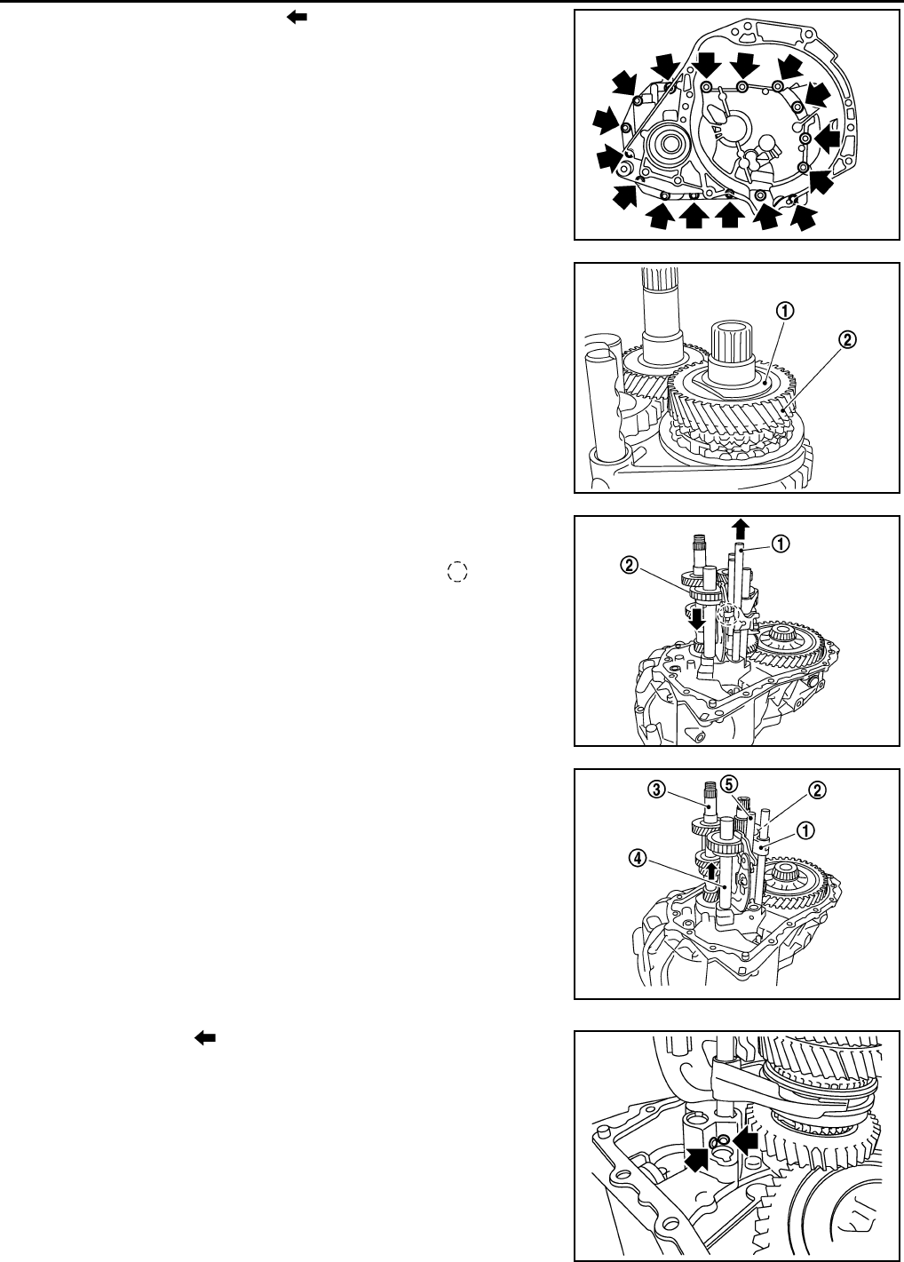
33. Apply recommended sealant to transaxle case mounting surface
of clutch housing.
•Use Genuine Silicone RTV or an equivalent. GI-42, "Rec-
ommended Chemical Product and Sealant".
CAUTION:
• Never allow old liquid gasket, moisture, oil, or foreign matter to remain on mounting surface.
• Check that mounting surface is not damaged.
• Apply a continuous bead of liquid gasket to the mounting surface.
PCIB1629E
PCIB1552E
PCIB1529E
PCIB1524E
Revision: May 2010 2011 Versa
TRANSAXLE ASSEMBLY
MT-33
< SERVICE INFORMATION > [RS5F91R]
D
E
F
G
H
I
J
K
L
M
A
B
MT
N
O
P
34. Install transaxle case to clutch housing. If it is difficult to install,
slightly rotate control shaft shift lever counterclockwise, and then
install.
•1: Selector
• 2: Shift fork
CAUTION:
• Never disrupt liquid gasket bead with transaxle case or
other objects during installation.
• Be careful to align the lever of 5th-reverse fork rod with
reverse gear assembly groove.
35. Rotate input shaft so that bearing and shaft fit each other, and
then tighten transaxle bolts ( ) to the specified torque. Refer to
MT-17, "Exploded View".
36. Apply recommended sealant to the position switch thread and check ball plug thread. tighten them to tran-
saxle case to specified torque.
•Use Genuine Silicon RTV or an equivalent. Refer to GI-42, "Recommended Chemical Product and
Sealant".
CAUTION:
Never allow old liquid gasket, moisture, oil, or foreign matter to remain on thread.
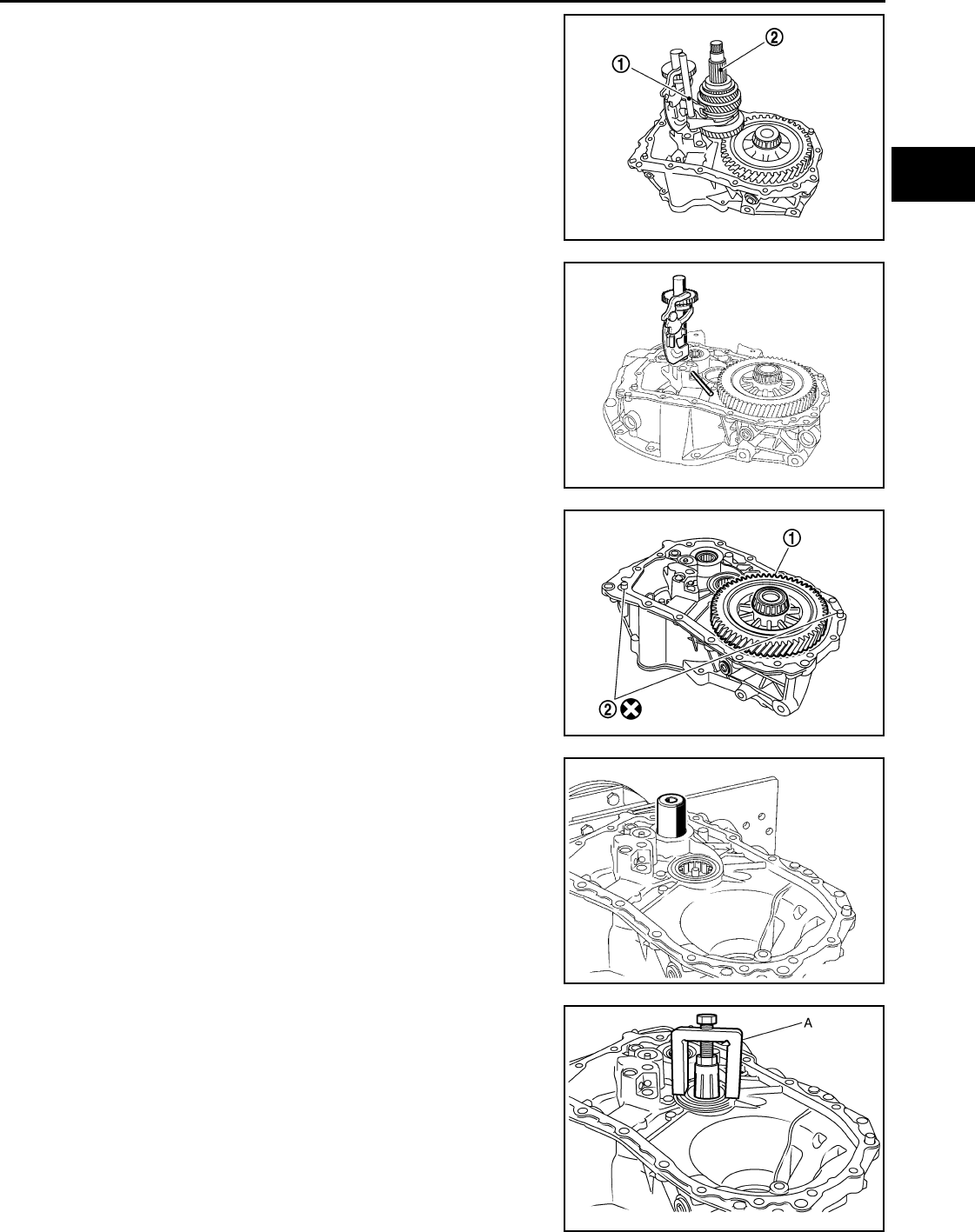
37. Apply gear oil to mainshaft spline.
38. Install 5th main gear (1) to mainshaft using a suitable bolt (A)
[M10 x 1.0] and a suitable nut (B).
39. Install adapter plate (1), bushing (2), and 5th input gear (3) to
input shaft.
CAUTION:
Be careful with the orientation of adapter plate.
• : Transaxle case side
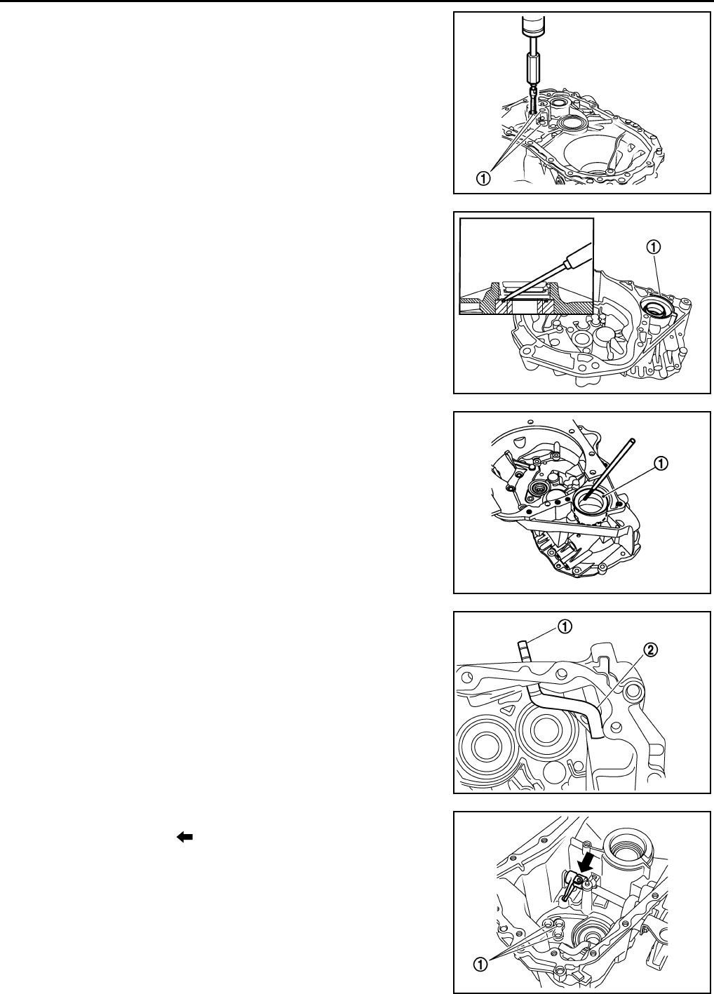
40. Install 5th-reverse synchronizer hub, 5th-reverse coupling sleeve, and 5th-reverse shift fork according to
the following procedures.
a. Apply gear oil to 5th-reverse baulk ring.
PCIB1553E
JPDIC0610ZZ
PCIB1554E
PCIB1555E
Revision: May 2010 2011 Versa
MT-34
< SERVICE INFORMATION > [RS5F91R]
TRANSAXLE ASSEMBLY
b. Install 5th-reverse baulk ring (1) to 5th input gear.
CAUTION:
Be careful with the orientation of 5th-reverse baulk ring.
c. Install synchronizer levers (2) to 5th-reverse synchronizer hub
(3).
CAUTION:
• Replace 5th-reverse synchronizer hub and 5th-reverse
coupling sleeve as a set.
• Be careful with the orientation of synchronizer lever.
• : 5th-reverse synchronizer hub side
d. Install 5th-reverse synchronizer hub assembly and washer to
input shaft.
CAUTION:
• Be careful with the orientation of 5th-reverse synchro-
nizer hub.
- : 5th input gear side
• Never allow synchronizer lever (1) to mount on to 5th-
reverse baulk ring (2) protrusion (A).
• : 5th-reverse sychronizer hub
e. Set 5th-reverse shift fork (1) to 5th-reverse coupling sleeve, and
then install them to 5th-reverse fork rod and input shaft.
• A: Pin punch
•B: Bolt
•C: Nut
CAUTION:
JPDIC0421ZZ
PCIB1556E
JPDIC0408ZZ
JPDIC0532ZZ
Revision: May 2010 2011 Versa
TRANSAXLE ASSEMBLY
MT-35
< SERVICE INFORMATION > [RS5F91R]
D
E
F
G
H
I
J
K
L
M
A
B
MT
N
O
P
• Be careful with the orientation of 5th-reverse coupling
sleeve.
- : 5th input gear side
• Replace 5th-reverse synchronizer hub and 5th-reverse
coupling sleeve as a set.
• Replace 5th-reverse shift fork and 5th-reverse fork rod as
a set.
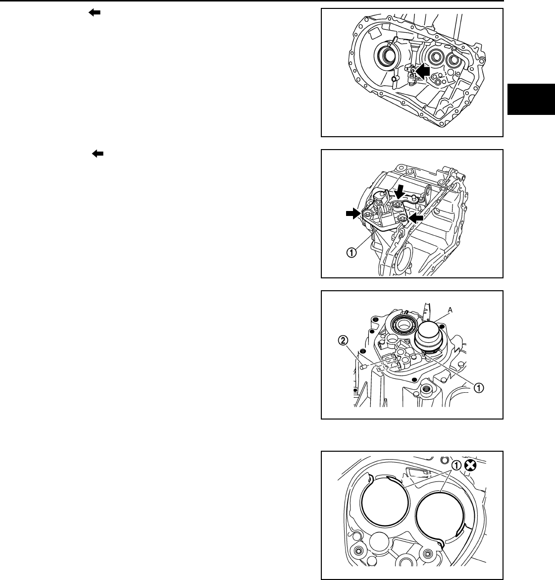
f. Check that the gear position is in the 3rd position. Press 5th-
reverse shift fork and shift to 5th gear.
g. Tighten bolt to the specified torque. Refer to MT-17, "Exploded
View".
h. Tighten nut to the specified torque. Refer to MT-17, "Exploded View".
CAUTION:
Never reuse nut.
i. Install retaining pin to 5th-reverse shift fork using a suitable tool.
CAUTION:
Never reuse retaining pin.
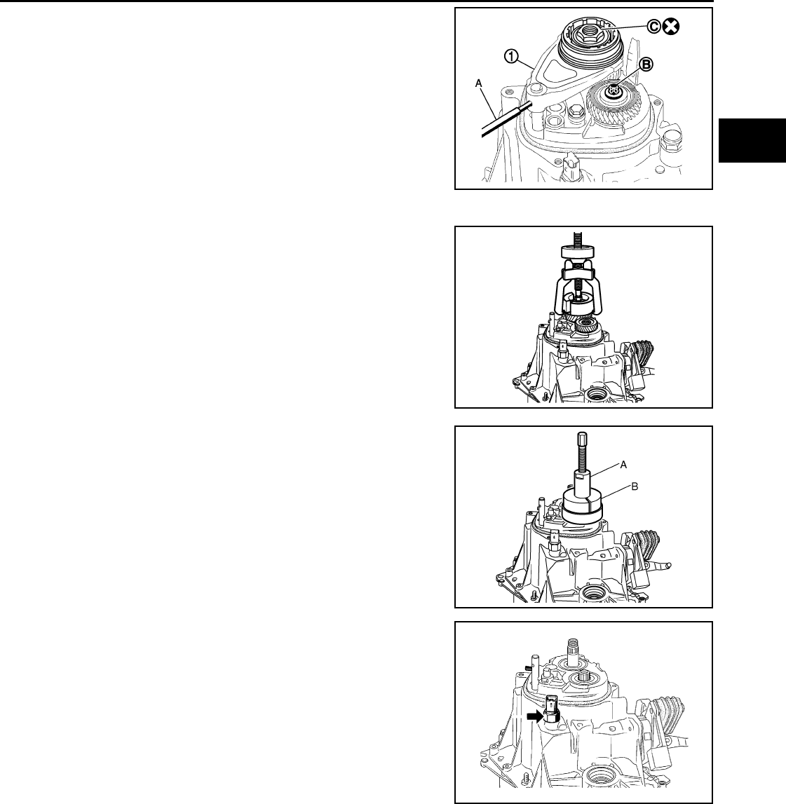
41. Shift control shaft shift lever (1) to the neutral position.
42. Install O-ring to rear housing.
43. Install rear housing to transaxle case, and tighten bolts ( ) to
the specified torque. Refer to MT-17, "Exploded View".
CAUTION:
Never pinch O-ring when installing rear housing.
44. Install drain plug according to the following procedures.
a. Install gasket to drain plug.
CAUTION:
Never reuse gasket.
b. Install drain plug to clutch housing using a suitable tool.
c. Tighten drain plug to the specified torque. Refer to MT-17,
"Exploded View".
45. Install filler plug according to the following procedures.
a. Install gasket to filler plug, and then install them to transaxle case.
CAUTION:
Never reuse gasket.
b. Tighten filler plug to the specified torque. Refer to MT-17, "Exploded View".
CAUTION:
Fill with gear oil before tightening filler plug to the specified torque.
JPDIC0409ZZ
SCIA7130E
PCIB1558E
Revision: May 2010 2011 Versa
MT-36
< SERVICE INFORMATION > [RS5F91R]
INPUT SHAFT AND GEAR
INPUT SHAFT AND GEAR
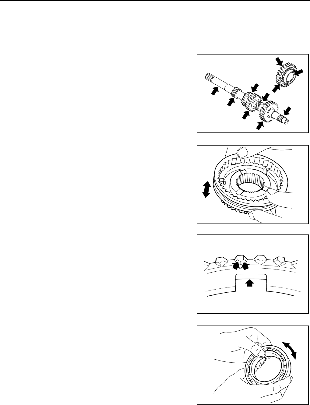
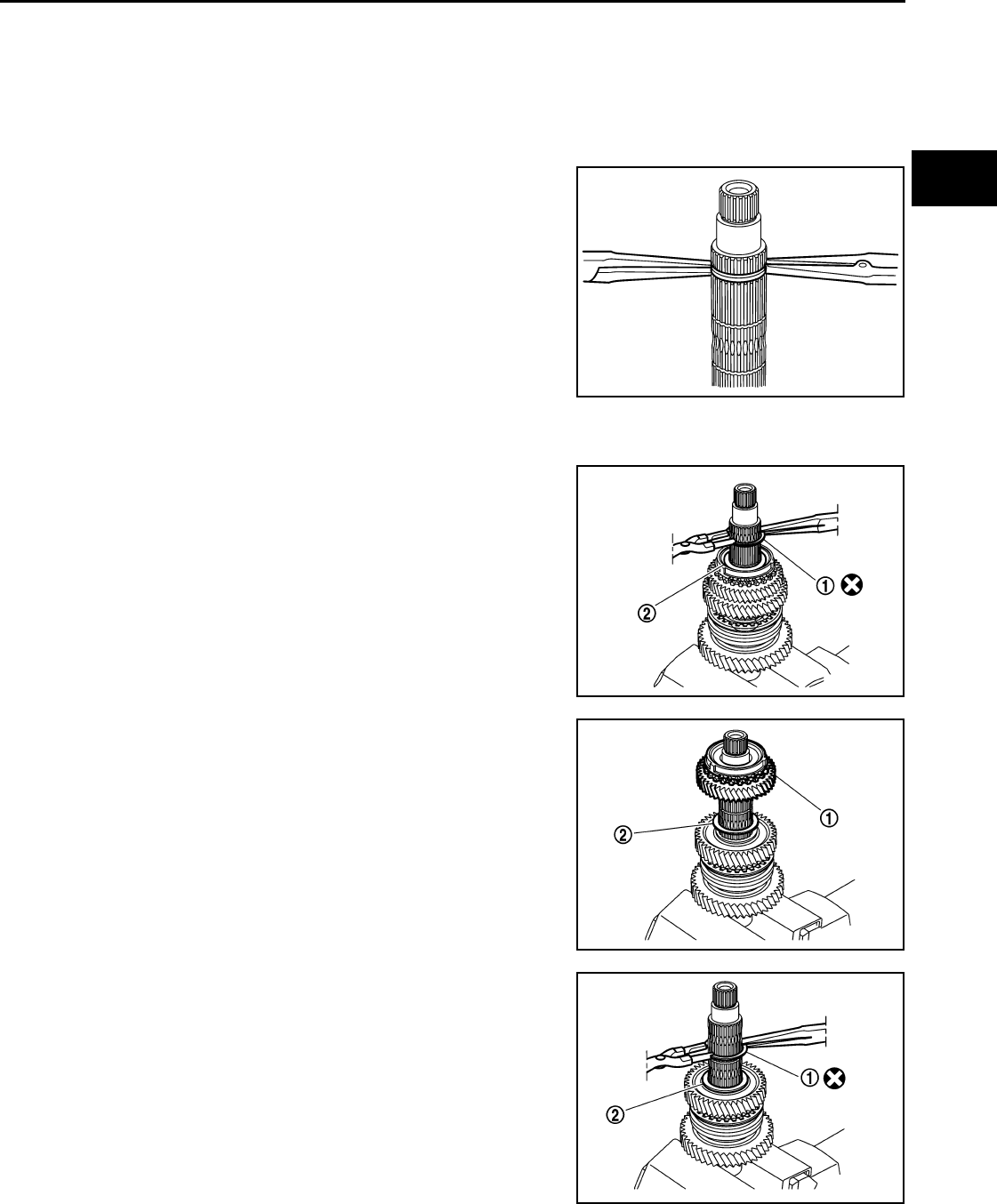
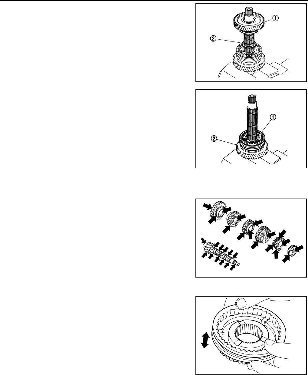
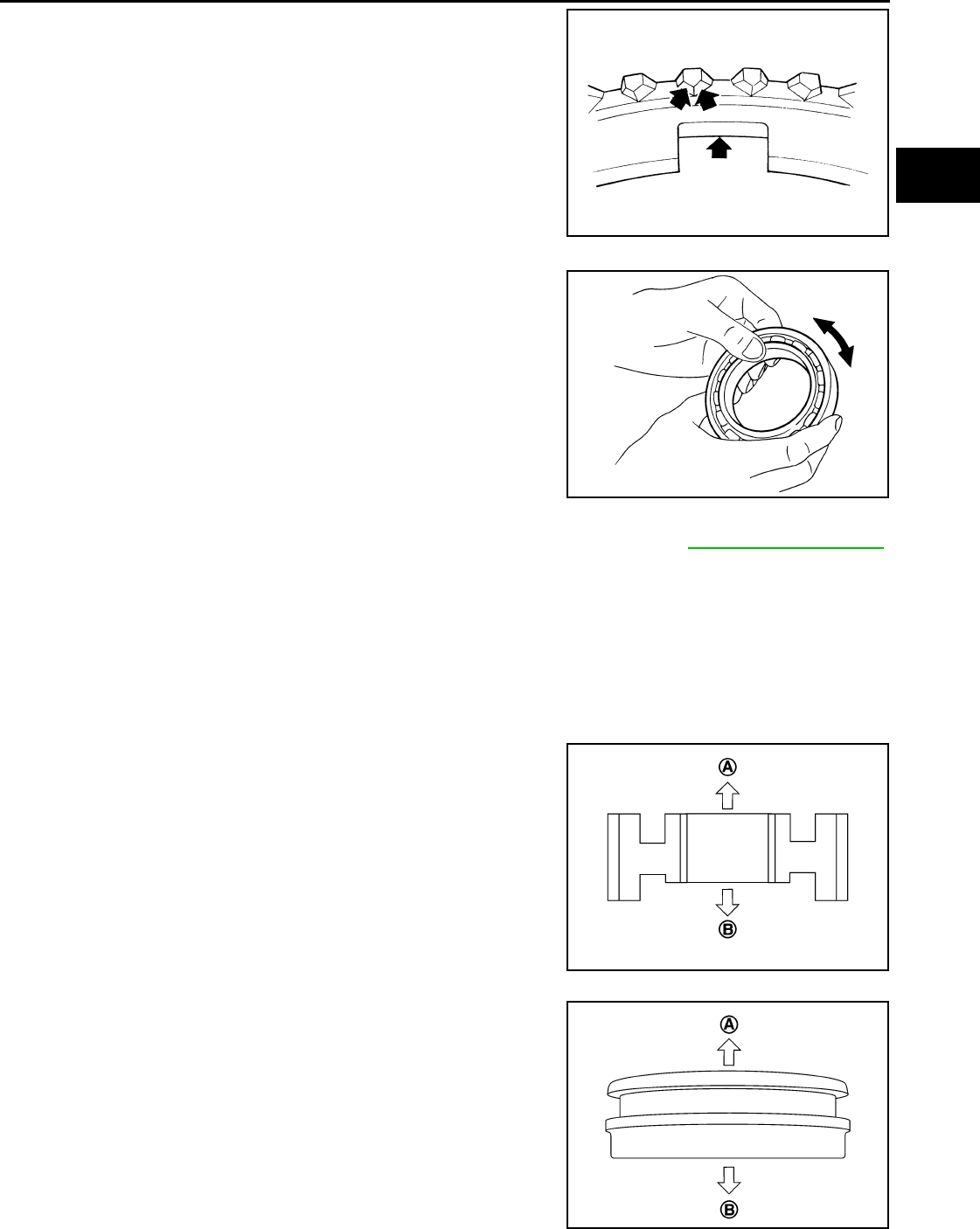
Disassembly and Assembly INFOID:0000000005929675
INSPECTION AFTER DISASSEMBLY
Input Shaft and Gears
Check the following items and replace if necessary.
• Damage, peeling, bend, uneven wear, and distortion of shaft
• Excessive wear, damage, and peeling of gear
Synchronizer
Check for the following and replace if necessary.
• Contact surface breakage, damage, and unusual wear of coupling
sleeve, synchronizer hub, and synchronizer lever.
• Coupling sleeve and synchronizer hub move smoothly.
• Breakage, damage, and excessive wear of baulk ring cam surface
and synchronizer lever contact surface.
Bearing
Check bearing for damage and unsmooth rotation. Replace if neces-
sary.
PCIB0987J
SCIA1753J
SCIA0608J
MTF0041D
Revision: May 2010 2011 Versa
MAINSHAFT AND GEAR
MT-37
< SERVICE INFORMATION > [RS5F91R]
D
E
F
G
H
I
J
K
L
M
A
B
MT
N
O
P
MAINSHAFT AND GEAR
Disassembly and Assembly INFOID:0000000005929676
GENERAL PRECAUTIONS
• Never reuse snap ring.
• Secure mainshaft in a vise with backplate, and then remove gears and snap rings.
• For installation and removal of snap ring, set snap ring pliers and
flat pliers at both sides of snap ring. While expanding snap ring
with snap ring pliers, move snap ring with flat pliers.
• Disassemble gear components putting direction marks on the parts
that never affect any functions.
DISASSEMBLY
1. Remove 3rd-4th synchronizer hub and 3rd baulk ring.
2. Remove snap ring (1) and thrust washer (2) using suitable tools.
3. Remove 3rd main gear (1) and thrust washer (2).
4. Remove snap ring (1) and thrust washer (2) using suitable tools.
SCIA1755J
PCIB1559E
PCIB1560E
PCIB1561E
Revision: May 2010 2011 Versa
MT-38
< SERVICE INFORMATION > [RS5F91R]
MAINSHAFT AND GEAR
5. Remove 2nd main gear (1) and thrust washer (2).
6. Remove snap ring (1), and then remove 2nd inner baulk ring,
2nd synchronizer cone, and 2nd outer baulk ring.
7. Remove 1st-2nd coupling sleeve, insert keys, springs, and 1st-
2nd synchronizer hub.
8. Remove 1st outer baulk ring, 1st synchronizer cone, 1st inner
baulk ring, and 1st main gear (2).
INSPECTION AFTER DISASSEMBLY
Mainshaft and Gear
Check the following items and replace if necessary.
• Damage, peeling, bend, uneven wear, and distortion of shaft
• Excessive wear, damage, and peeling of gear
Synchronizer
Check the following items and replace if necessary.
• Contact surface breakage, damage, and unusual wear of coupling
sleeve, synchronizer hub, insert key, and spring.
• Coupling sleeve and synchronizer hub move smoothly.
PCIB1562E
JPDIC0541ZZ
SCIA1762J
SCIA1753J
Revision: May 2010 2011 Versa
MAINSHAFT AND GEAR
MT-39
< SERVICE INFORMATION > [RS5F91R]
D
E
F
G
H
I
J
K
L
M
A
B
MT
N
O
P
• Breakage, damage, and excessive wear of baulk ring cam surface
and insert contact surface
Bearing
Check bearing for damage and unsmooth rotation. Replace if neces-
sary.
ASSEMBLY
Note the following items, and assemble in the reverse order of disassembly. Refer to MT-17, "Exploded View".
CAUTION:
• Never reuse snap ring.
• Check that snap ring is securely installed to the groove.
• Apply gear oil to 3rd baulk ring.
• Apply gear oil to 1st outer baulk ring, 1st synchronizer cone, and 1st inner baulk ring.
• Apply gear oil to 2nd outer baulk ring, 2nd synchronizer cone, and 2nd inner baulk ring.
• Replace 1st outer baulk ring, 1st synchronizer cone, and 1st inner baulk ring as a set.
• Replace 2nd outer baulk ring, 2nd synchronizer cone, and 2nd outer baulk ring as a set.
• Be careful with the orientation of 1st-2nd synchronizer hub.
- A: 1st main gear side
- B: 2nd main gear side
• Replace 1st-2nd synchronizer hub and 1st-2nd coupling
sleeve as a set.
• Be careful with the orientation of 1st-2nd coupling sleeve.
- A: 2nd main gear side
- B: 1st main gear side
SCIA0608J
MTF0041D
PCIB1566E
PCIB1567E
Revision: May 2010 2011 Versa
MT-40
< SERVICE INFORMATION > [RS5F91R]
MAINSHAFT AND GEAR
• Be careful with the orientation of 3rd-4th synchronizer hub.
- A: 4th main gear side
- B: 3rd main gear side
• Replace 3rd-4th synchronizer hub and 3rd-4th coupling sleeve as a set.
• Be careful with the orientation of insert key (1) and spring (2).
PCIB1565E
PCIB1564E
Revision: May 2010 2011 Versa
FINAL DRIVE
MT-41
< SERVICE INFORMATION > [RS5F91R]
D
E
F
G
H
I
J
K
L
M
A
B
MT
N
O
P
FINAL DRIVE
Disassembly and Assembly INFOID:0000000005929677
DISASSEMBLY
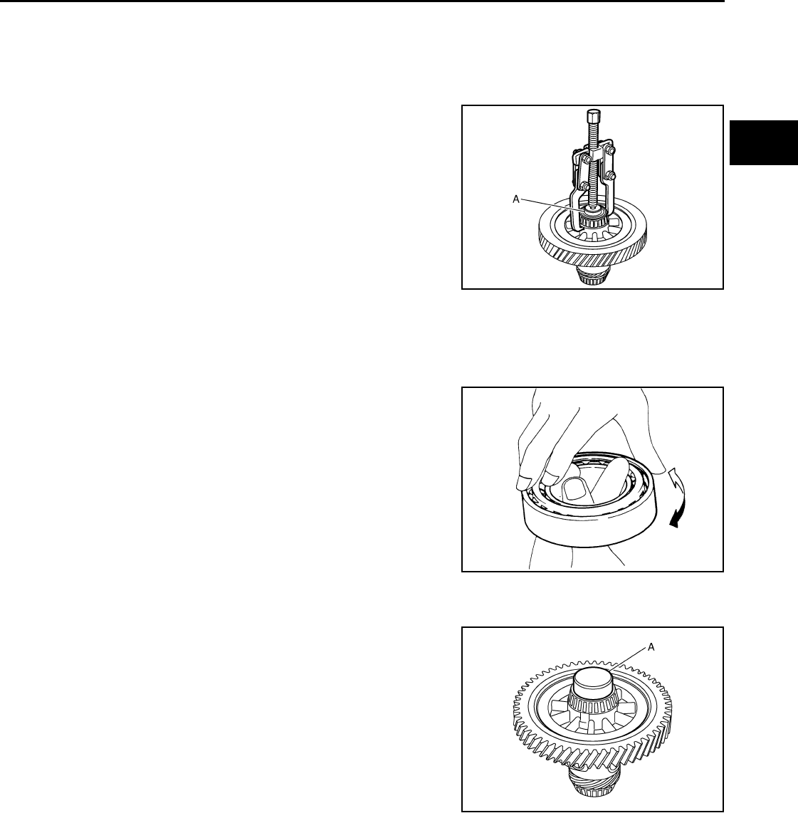
1. Remove differential side bearings using Tool (A) and a suitable
tool.
2. Remove speedometer drive gear.
INSPECTION AFTER DISASSEMBLY
Case
Check differential case and replace if necessary.
Bearing
Check bearing for damage and unsmooth rotation. Replace if neces-
sary.
CAUTION:
Replace differential side bearing outer race and differential side
bearing as a set.
ASSEMBLY
1. Install speedometer drive gear.
2. Install differential side bearings using Tool (A).
CAUTION:
Replace differential side bearing outer race and differential
side bearing as a set.
Tool number A: ST33052000 ( — )
PCIB1568E
SPD715
Tool number A: KV40104920 ( — )
PCIB1570E
Revision: May 2010 2011 Versa
MT-42
< SERVICE INFORMATION > [RS5F91R]
SHIFT CONTROL
SHIFT CONTROL
Inspection INFOID:0000000005929678
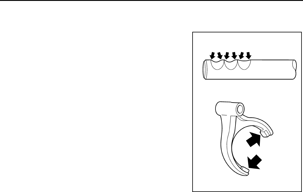
Check contact surface and sliding surface of fork rod and shift fork
for excessive wear, uneven wear, bend, and damage. Replace if
necessary.
PCIB1571E
Revision: May 2010 2011 Versa
SERVICE DATA AND SPECIFICATIONS (SDS)
MT-43
< SERVICE INFORMATION > [RS5F91R]
D
E
F
G
H
I
J
K
L
M
A
B
MT
N
O
P
SERVICE DATA AND SPECIFICATIONS (SDS)
General Specification INFOID:0000000005929679
TRANSAXLE
Transaxle type RS5F91R
Engine type HR16DE
Number of speed 5
Synchromesh type Warner
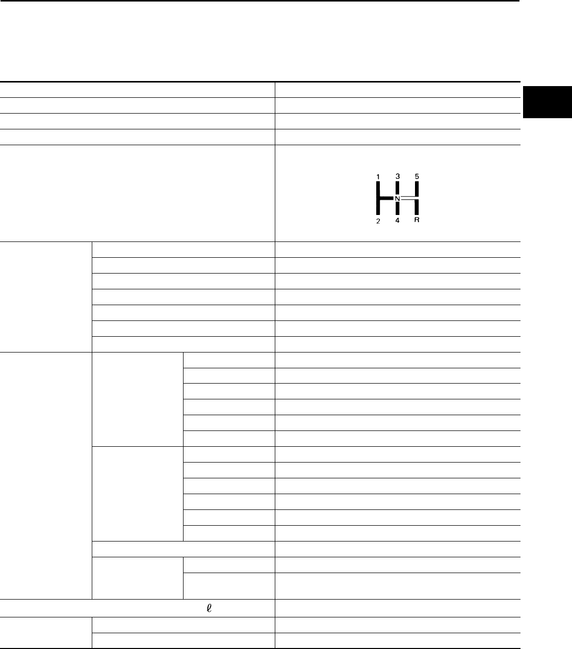
Shift pattern
Gear ratio 1st 3.7272
2nd 2.0476
3rd 1.3928
4th 1.0294
5th 0.8205
Reverse 3.5454
Final gear 4.0666
Number of teeth Input gear 1st 11
2nd 21
3rd 28
4th 34
5th 39
Reverse 11
Main gear 1st 41
2nd 43
3rd 39
4th 35
5th 32
Reverse 39
Reverse idler gear 26
Final gear Final gear/Pinion 61/15
Side gear/Pinion
mate gear 13/9
Oil capacity (Reference) (US pt, Imp pt) Approx. 2.6 (5-1/2, 4-5/8)
Remarks Reverse synchronizer Installed
Double-cone synchronizer 1st and 2nd
SCIA0821E
Revision: May 2010 2011 Versa

MT-44
< SERVICE INFORMATION > [RS6F94R]
PRECAUTIONS
SERVICE INFORMATION
PRECAUTIONS
Precaution for Supplemental Restraint System (SRS) "AIR BAG" and "SEAT BELT
PRE-TENSIONER" INFOID:0000000005929680
The Supplemental Restraint System such as “AIR BAG” and “SEAT BELT PRE-TENSIONER”, used along
with a front seat belt, helps to reduce the risk or severity of injury to the driver and front passenger for certain
types of collision. This system includes seat belt switch inputs and dual stage front air bag modules. The SRS
system uses the seat belt switches to determine the front air bag deployment, and may only deploy one front
air bag, depending on the severity of a collision and whether the front occupants are belted or unbelted.
Information necessary to service the system safely is included in the SRS and SB section of this Service Man-
ual.
WARNING:
• To avoid rendering the SRS inoperative, which could increase the risk of personal injury or death in
the event of a collision which would result in air bag inflation, all maintenance must be performed by
an authorized NISSAN/INFINITI dealer.
• Improper maintenance, including incorrect removal and installation of the SRS can lead to personal
injury caused by unintentional activation of the system. For removal of Spiral Cable and Air Bag
Module, see the SRS section.
• Do not use electrical test equipment on any circuit related to the SRS unless instructed to in this
Service Manual. SRS wiring harnesses can be identified by yellow and/or orange harnesses or har-
ness connectors.
PRECAUTIONS WHEN USING POWER TOOLS (AIR OR ELECTRIC) AND HAMMERS
WARNING:
• When working near the Airbag Diagnosis Sensor Unit or other Airbag System sensors with the Igni-
tion ON or engine running, DO NOT use air or electric power tools or strike near the sensor(s) with a
hammer. Heavy vibration could activate the sensor(s) and deploy the air bag(s), possibly causing
serious injury.
• When using air or electric power tools or hammers, always switch the Ignition OFF, disconnect the
battery, and wait at least 3 minutes before performing any service.
Precaution Necessary for Steering Wheel Rotation After Battery Disconnect
INFOID:0000000005929681
NOTE:
• This Procedure is applied only to models with Intelligent Key system and NATS (NISSAN ANTI-THEFT SYS-
TEM).
• Remove and install all control units after disconnecting both battery cables with the ignition knob in the
″LOCK″ position.
• Always use CONSULT-III to perform self-diagnosis as a part of each function inspection after finishing work.
If DTC is detected, perform trouble diagnosis according to self-diagnostic results.
For models equipped with the Intelligent Key system and NATS, an electrically controlled steering lock mech-
anism is adopted on the key cylinder.
For this reason, if the battery is disconnected or if the battery is discharged, the steering wheel will lock and
steering wheel rotation will become impossible.
If steering wheel rotation is required when battery power is interrupted, follow the procedure below before
starting the repair operation.
OPERATION PROCEDURE
1. Connect both battery cables.
NOTE:
Supply power using jumper cables if battery is discharged.
2. Use the Intelligent Key or mechanical key to turn the ignition switch to the ″ACC″ position. At this time, the
steering lock will be released.
3. Disconnect both battery cables. The steering lock will remain released and the steering wheel can be
rotated.
4. Perform the necessary repair operation.
Revision: May 2010 2011 Versa
PRECAUTIONS
MT-45
< SERVICE INFORMATION > [RS6F94R]
D
E
F
G
H
I
J
K
L
M
A
B
MT
N
O
P
5. When the repair work is completed, return the ignition switch to the ″LOCK″ position before connecting
the battery cables. (At this time, the steering lock mechanism will engage.)
6. Perform a self-diagnosis check of all control units using CONSULT-III.
Precaution for Procedure without Cowl Top Cover INFOID:0000000005929682
When performing the procedure after removing cowl top cover, cover
the lower end of windshield with urethane, etc.
Precaution INFOID:0000000005929683
• If transaxle assembly is removed from the vehicle, always replace CSC (Concentric Slave Cylinder).
Installed CSC returns to the original position when removing transaxle assembly. Dust on clutch disc sliding
parts may damage CSC seal, and may cause clutch fluid leakage.
• Do not reuse transaxle oil.
• Drain, fill and check transaxle oil with the vehicle on level surface.
• During removal or installation, keep inside of transaxle clear of dust or dirt.
• Check for the correct installation orientation prior to removal or disassembly. If matching marks are required,
be certain they do not interfere with the function of the parts they are applied to.
• In principle, tighten bolts or nuts gradually in several steps working diagonally from inside to outside. If tight-
ening sequence is specified, follow it.
• Be careful not to damage the sliding surfaces and mating surfaces of parts.
PIIB3706J
Revision: May 2010 2011 Versa
MT-46
< SERVICE INFORMATION > [RS6F94R]
PREPARATION
PREPARATION
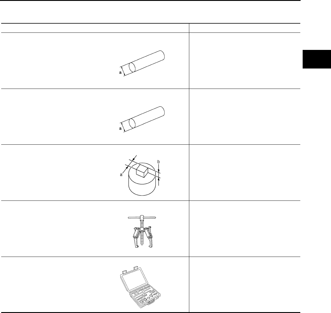
Special Service Tool INFOID:0000000005929684
The actual shapes of Kent-Moore tools may differ from those of special service tools illustrated here.
Tool number
(Kent-Moore No.)
Tool name
Description
—
( J-46534 )
Trim tool set
For removing trim
KV381054S0
(J-34286)
Puller
Removing mainshaft front bearing outer race
KV38100200
(—)
Drift
• Installing mainshaft front bearing outer race
• Installing mainshaft rear bearing outer race
• Installing differential side bearing outer race
(clutch housing side)
a: 65 mm (2.56 in) dia.
b: 49 mm (1.93 in) dia.
ST33220000
(—)
Drift
Installing input shaft oil seal
a: 37 mm (1.46 in) dia.
b: 31 mm (1.22 in) dia.
c: 22 mm (0.87 in) dia.
ST33400001
(J-26082)
Drift
Installing differential side bearing outer race
(transaxle case side)
a: 60 mm (2.36 in) dia.
b: 47 mm (1.85 in) dia.
AWJIA0483ZZ
ZZA0601D
ZZA1143D
ZZA1046D
ZZA0814D
Revision: May 2010 2011 Versa
PREPARATION
MT-47
< SERVICE INFORMATION > [RS6F94R]
D
E
F
G
H
I
J
K
L
M
A
B
MT
N
O
P
KV32500QAA
(Renault SST: B.vi 1666))
Drift set
Installing differential side oil seal
1. —
(Stamping number: B.vi 1666-A)
Drift
a: 54.3 mm (2.138 in) dia.
b: 45 mm (1.77 in) dia.
c: 26.6 mm (1.047 in) dia.
2. —
(Stamping number: B.vi 1666-B)
Drift
a: 54.3 mm (2.138 in) dia.
b: 45 mm (1.77 in) dia.
c: 26.6 mm (1.047 in) dia.
ST36720030
(—)
Drift
• Installing input shaft rear bearing
• Installing mainshaft front bearing inner race
a: 70 mm (2.76 in) dia.
b: 40 mm (1.57 in) dia.
c: 29 mm (1.14 in) dia.
ST33052000
(—)
Drift
• Removing mainshaft rear bearing inner race
• Removing 6th main gear
• Removing 5th main gear
• Removing 4th main gear
• Removing 1st main gear
• Removing 1st-2nd synchronizer assembly
• Removing 2nd main gear
• Removing bushing
• Removing 3rd main gear
• Removing mainshaft front bearing inner
race
a: 22 mm (0.87 in) dia.
b: 28 mm (1.10 in) dia.
KV32102700
(—)
Drift
• Installing bushing
• Installing 2nd main gear
• Installing 3rd main gear
• Installing 4th main gear
• Installing 5th main gear
• Installing 6th main gear
a: 54 mm (2.13 in) dia.
b: 32 mm (1.26 in) dia.
ST30901000
(J-26010-01)
Drift
Installing mainshaft rear bearing inner race
a: 79 mm (3.11 in) dia.
b: 45 mm (1.77 in) dia.
c: 35.2 mm (1.386 in) dia.
Tool number
(Kent-Moore No.)
Tool name
Description
JPDIC0730ZZ
ZZA0978D
ZZA0969D
S-NT065
ZZA0978D
Revision: May 2010 2011 Versa
MT-48
< SERVICE INFORMATION > [RS6F94R]
PREPARATION
Commercial Service Tool INFOID:0000000005929685
ST33061000
(J-8107-2)
Drift
Removing differential side bearing inner race
(clutch housing side)
a: 28.5 mm (1.122 in) dia.
b: 38 mm (1.50 in) dia.
KV32300QAM
(Renault SST: B.vi 1823)
Drift
Removing and installing input shaft rear bear-
ing bolt
Tool number
(Kent-Moore No.)
Tool name
Description
ZZA0969D
PCIB2078J
Tool name Description
Socket Removing and installing drain plug
a: 8 mm (0.31 in)
b: 5 mm (0.20 in)
Spacer Removing mainshaft front bearing outer race
a: 25 mm (0.98 in) dia.
b: 25 mm (0.98 in)
Drift Installing bushing
a: 17 mm (0.67 in) dia.
Drift Installing input shaft front bearing
a: 35 mm (1.38 in) dia.
b: 25 mm (0.98 in) dia.
PCIB1776E
PCIB1780E
S-NT063
S-NT065
Revision: May 2010 2011 Versa
PREPARATION
MT-49
< SERVICE INFORMATION > [RS6F94R]
D
E
F
G
H
I
J
K
L
M
A
B
MT
N
O
P
Drift Removing input shaft rear bearing
a: 24 mm (0.94 in) dia.
Drift • Removing differential side bearing inner
race (transaxle case side)
• Installing input shaft rear bearing
a: 43 mm (1.69 in) dia.
Drift Installing differential side bearing inner race
(clutch housing side)
a: 45 mm (1.77 in) dia.
b: 39 mm (1.54 in) dia.
Drift Installing differential side bearing inner race
(transaxle case side)
a: 52 mm (2.05 in) dia.
b: 45 mm (1.77 in) dia.
Puller Removing differential side bearing inner race
(clutch housing side)
Removing differential side bearing inner race
(transaxle case side)
Puller • Removing differential side bearing inner
race (clutch housing side)
• Removing differential side bearing inner
race (transaxle case side)
• Removing input shaft rear bearing
• Removing input shaft front bearing
• Removing mainshaft rear bearing inner race
• Removing 6th main gear
• Removing 4th main gear
• Removing 5th main gear
• Removing 1st main gear
• Removing 1st - 2nd synchronizer hub as-
sembly
• Removing 2nd main gear
• Removing 3rd main gear
• Removing mainshaft front bearing outer
race
Tool name Description
PCIB1779E
NT109
S-NT474
S-NT474
NT077
ZZB0823D
Revision: May 2010 2011 Versa
MT-50
< SERVICE INFORMATION > [RS6F94R]
PREPARATION
Remover • Removing bushing
• Removing mainshaft rear bearing outer
race
Power tool • Loosening bolts and nuts
Tool name Description
S-NT134
PBIC0190E
Revision: May 2010 2011 Versa
NOISE, VIBRATION AND HARSHNESS (NVH) TROUBLESHOOTING
MT-51
< SERVICE INFORMATION > [RS6F94R]
D
E
F
G
H
I
J
K
L
M
A
B
MT
N
O
P
NOISE, VIBRATION AND HARSHNESS (NVH) TROUBLESHOOTING
NVH Troubleshooting Chart INFOID:0000000005929686
Use the chart below to help you find the cause of the symptom. The numbers indicate the order of the inspec-
tion. If necessary, repair or replace these parts.
Reference page
MT-54
MT-61
MT-61
MT-58
MT-94
MT-61
SUSPECTED PARTS
(Possible cause)
OIL (Oil level is low.)
OIL (Wrong oil.)
OIL (Oil level is high.)
GASKET (Damaged)
OIL SEAL (Worn or damaged)
O-RING (Worn or damaged)
SHIFT CONTROL LINKAGE (Worn)
SHIFT FORK (Worn)
GEAR (Worn or damaged)
BEARING (Worn or damaged)
BAULK RING (Worn or damaged)
INSERT SPRING (Damaged)
Symptoms
Noise 1 2 3 3
Oil leakage 31222
Hard to shift or will not shift 1 1 2 3 3
Jumps out of gear 1 3 3
Revision: May 2010 2011 Versa
MT-52
< SERVICE INFORMATION > [RS6F94R]
DESCRIPTION
DESCRIPTION
Cross-Sectional View INFOID:0000000005929687
TRIPLE-CONE SYNCHRONIZER
1. 3rd input gear 2. 3rd-4th synchronizer assembly 3. 4th input gear
4. 5th input gear 5. 5th-6th synchronizer assembly 6. 6th input gear
7. Transaxle case 8. 6th main gear 9. 5th main gear
10. 4th main gear 11. 3rd main gear 12. 2nd main gear
13. 1st-2nd synchronizer assembly 14. 1st main gear 15. Differential
16. Final gear 17. Mainshaft 18. Input shaft
19. Clutch housing 20. Reverse idler shaft 21. Reverse input gear
22. Reverse output gear
JPDIC0631ZZ
Revision: May 2010 2011 Versa
DESCRIPTION
MT-53
< SERVICE INFORMATION > [RS6F94R]
D
E
F
G
H
I
J
K
L
M
A
B
MT
N
O
P
Triple-cone synchronizer is used for the 1st and the 2nd gears to
reduce operating force of the shift lever.
• 1st main gear (1)
• 1st-2nd coupling sleeve (2)
• Insert key (3)
• Outer baulk ring (4)
• 2nd main gear (5)
• Synchronizer cone (6)
• Inner baulk ring (7)
• 1st-2nd synchronizer hub (8)
REVERSE GEAR NOISE PREVENTION FUNCTION (SYNCHRONIZING METHOD)
Reverse gear assembly consists of reverse input gear, return spring,
reverse baulk ring and reverse output gear. When the shift lever is
shifted to the reverse position, the construction allows smooth shift
operation by stopping the reverse idler shaft rotation by frictional
force of synchronizer.
• Reverse fork rod (1)
• Reverse output gear (2)
• Return spring (3)
• Reverse baulk ring (4)
• Reverse input gear (5)
SCIA7636E
SCIA7621E
Revision: May 2010 2011 Versa
MT-54
< SERVICE INFORMATION > [RS6F94R]
M/T OIL
M/T OIL
Changing M/T Oil INFOID:0000000005929688
DRAINING
1. Start engine and let it run to warm up transaxle.
2. Stop engine. Remove drain plug (1) and drain oil.
3. Install a new gasket onto drain plug (1) and install it into tran-
saxle. Tighten drain plug to specification. Refer to MT-61, "Com-
ponent".
CAUTION:
Do not reuse gasket.
FILLING
1. Remove filler plug (1). Fill with new oil until oil level reaches the
specified limit at filler plug hole as shown.
2. After refilling oil, check oil level. Install a new gasket on filler plug
(1), then install it into transaxle. Tighten filler plug to specifica-
tion. Refer to MT-61, "Component".
CAUTION:
Do not reuse gasket.
Checking M/T Oil INFOID:0000000005929689
OIL LEAKAGE AND OIL LEVEL
1. Make sure that oil is not leaking from transaxle or around it.
2. Remove filler plug (1) and check oil level at filler plug hole as
shown.
CAUTION:
Do not start engine while checking oil level.
3.
Install a new gasket onto filler plug (1) and install it into tran-
saxle. Tighten filler plug to specification. Refer to MT-61, "Com-
ponent".
CAUTION:
Do not reuse gasket.
SCIA7622E
Oil grade and capacity
: Refer to MA-14, "Fluids and Lubricants"
SCIA7623E
SCIA7623E
Revision: May 2010 2011 Versa

VEHICLE SPEED SENSOR
MT-55
< SERVICE INFORMATION > [RS6F94R]
D
E
F
G
H
I
J
K
L
M
A
B
MT
N
O
P
VEHICLE SPEED SENSOR
Removal and Installation INFOID:0000000005929690
REMOVAL
1. Disconnect vehicle speed sensor.
2. Remove vehicle speed sensor.
INSTALLATION
Installation is in the reverse order of removal.
Revision: May 2010 2011 Versa
MT-56
< SERVICE INFORMATION > [RS6F94R]
SIDE OIL SEAL
SIDE OIL SEAL
Removal and Installation INFOID:0000000005929691
REMOVAL
1. Remove front drive shafts from transaxle assembly. Refer to FAX-9, "Removal and Installation (Left Side)"
and FAX-10, "Removal and Installation (Right Side)".
2. Remove differential side oil seal (1) using a suitable tool.
CAUTION:
Be careful not to damage transaxle case and clutch hous-
ing.
INSTALLATION
Installation is in the reverse order of removal.
• Install differential side oil seal (1) to clutch housing and transaxle
case using Tool.
CAUTION:
Do not reuse oil seal.
- A: Transaxle case side
- B: Clutch housing side
CAUTION:
• Never reuse differential oil seal
• Never incline differential oil seal.
• Never damage clutch housing and transaxle case.
• Check oil level after installation. Refer to MT-54, "Checking M/T Oil".
SCIA7625E
Tool number : KV32500QAA (B.vi 1666-B)
Dimension (L1) : 1.2 - 1.8 mm (0.047 - 0.071 in)
Dimension (L2) : 2.7 - 3.3 mm (0.106 - 0.130 in)
JPDIC0454ZZ
Revision: May 2010 2011 Versa
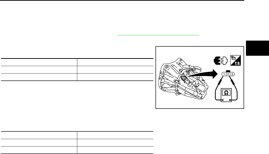
POSITION SWITCH
MT-57
< SERVICE INFORMATION > [RS6F94R]
D
E
F
G
H
I
J
K
L
M
A
B
MT
N
O
P
POSITION SWITCH
Checking INFOID:0000000005929692
NOTE:
For removal and installation of the switches, refer to MT-62, "Disassembly and Assembly"
BACK-UP LAMP SWITCH
• Check continuity between terminals 1 and 2.
PARK/NEUTRAL POSITION SWITCH
• Check continuity between terminals 2 and 3.
Gear position Continuity
Reverse Yes
Except reverse No
PCIB1781E
Gear position Continuity
Neutral Yes
Except neutral No
Revision: May 2010 2011 Versa
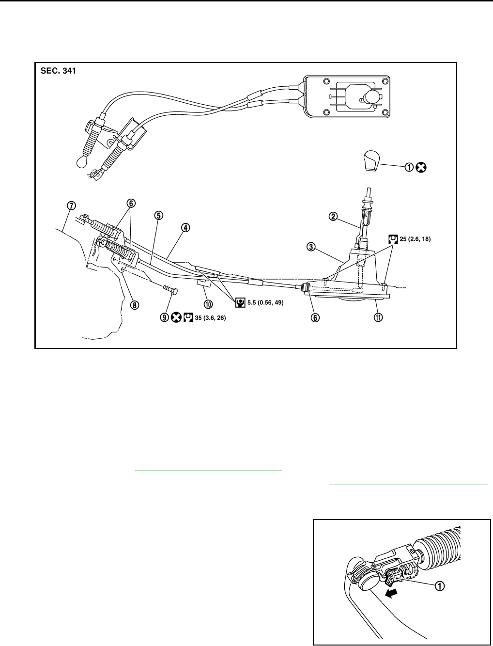
MT-58
< SERVICE INFORMATION > [RS6F94R]
CONTROL LINKAGE
CONTROL LINKAGE
Component of Control Device and Cable INFOID:0000000005929693
Removal and Installation INFOID:0000000005929694
REMOVAL
1. Remove battery. Refer to SC-7, "Removal and Installation".
2. Remove air duct (front), air duct (Inlet) and air cleaner case. Refer to EM-135, "Removal and Installation".
3. Remove shift selector cable from control shaft shift lever.
4. Remove select cable according to the following.
a. Move stopper (1) to the unlocked position.
1. Shift selector handle 2. Shift selector 3. M/T shift selector assembly
4. Select cable 5. Shift selector cable 6. Lock plate
7. Clutch housing 8. Cable bracket 9. Tapping bolt
10. Cable support bracket 11. Adapter plate
WCIA0626E
SCIA7842E
Revision: May 2010 2011 Versa
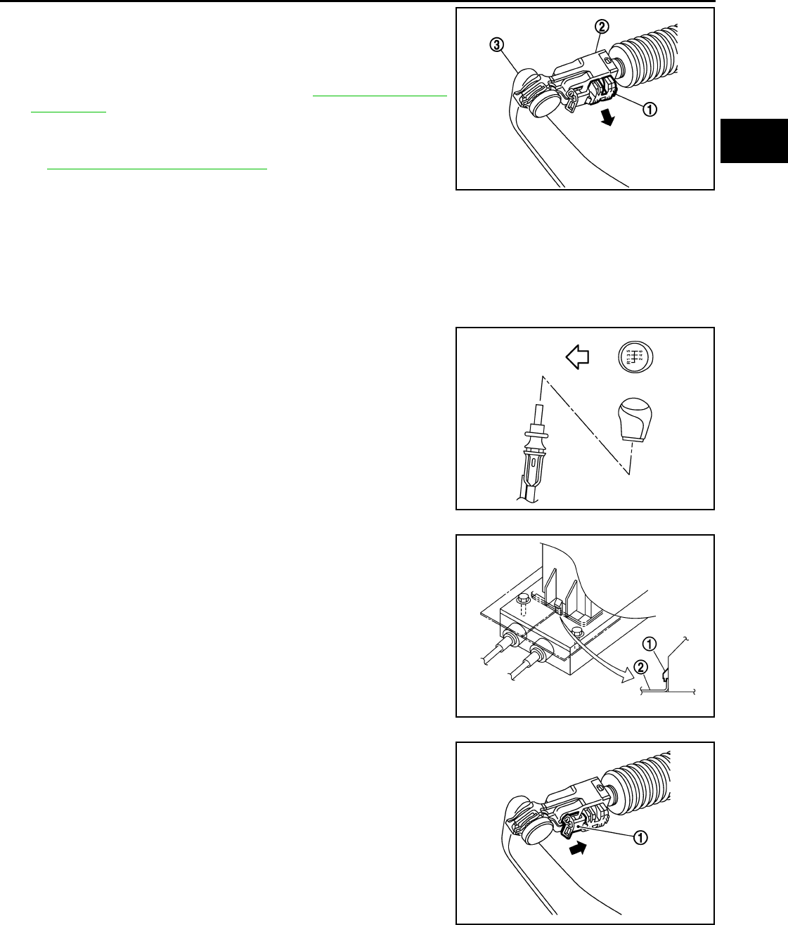
CONTROL LINKAGE
MT-59
< SERVICE INFORMATION > [RS6F94R]
D
E
F
G
H
I
J
K
L
M
A
B
MT
N
O
P
b. Pull the release button (1) of select cable (2) and then remove it
from control shaft select lever (3).
5. Move shift selector to neutral position.
6. Remove shift selector handle.
7. Remove center console assembly. Refer to IP-12, "Removal and
Installation".
8. Remove M/T shift selector assembly bolts.
9. Remove exhaust front tube, center muffler and heat plate. Refer
to EX-10, "Removal and Installation".
10. Remove cable support bracket.
11. Remove select cable and shift selector cable from cable bracket.
12. Remove M/T shift selector assembly from the vehicle.
INSTALLATION
Installation is in the reverse order of removal.
NOTE:
Self tapping bolts are used to attach cables to the clutch housing.
• Securely assemble each cable and lever of control shaft.
• Be careful about the installation direction, and push shift selector
handle onto shift selector.
CAUTION:
Do not reuse shift selector handle.
• Make sure that the front/rear claws (1) of M/T shift selector assem-
bly are in contact with flange of the floor (2).
• When shift selector is selected to 1st-2nd side and 5th-6th side,
confirm shift lever returns to neutral position smoothly.
• When shift selector is shifted to each position, make sure there is
no binding or disconnection in each boot.
• Move stopper (1) to lock position when installing the shift cable
onto the control shaft shift lever.
WCIA0606E
SCIA7630E
PCIB1510E
SCIA7846E
Revision: May 2010 2011 Versa
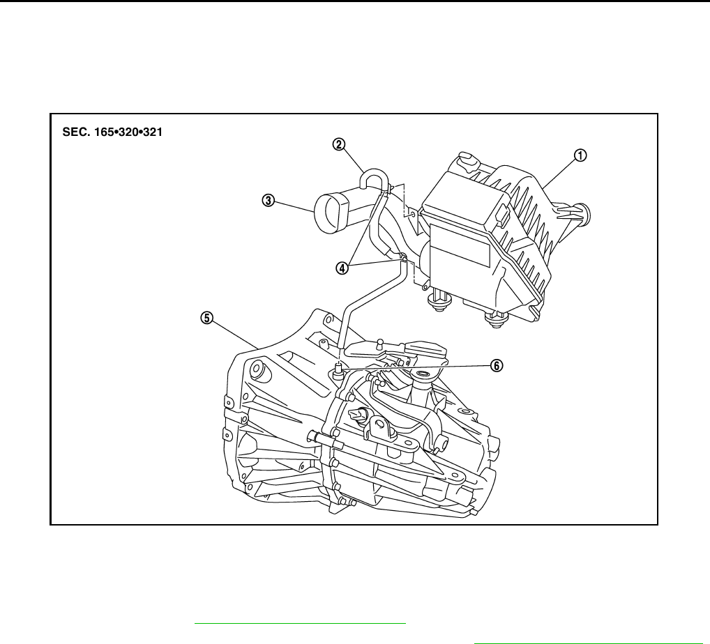
MT-60
< SERVICE INFORMATION > [RS6F94R]
AIR BREATHER HOSE
AIR BREATHER HOSE
Removal and Installation INFOID:0000000005929695
COMPONENTS
REMOVAL
1. Remove battery. Refer to SC-7, "Removal and Installation".
2. Remove air duct (front), air duct (inlet) and air cleaner case. Refer to EM-135, "Removal and Installation".
3. Remove air breather hose.
CAUTION:
When air breather hose is removed, be sure to hold two way connector securely.
INSTALLATION
Installation is in the reverse order of removal.
• When installing air breather hose on two way connector, aim paint mark face toward the vehicle front.
• When installing air breather hose on two way connector, push it until it hits transaxle case.
• When installing air breather hose to air duct and air cleaner case, make sure that clips are fully inserted.
CAUTION:
Make sure air breather hose is not collapsed or blocked due to folding or bending when installed.
1. Air cleaner case 2. Air breather hose 3. Air duct (inlet)
4. Clip 5. Transaxle assembly 6. Two way connector
SCIA7629E
Revision: May 2010 2011 Versa
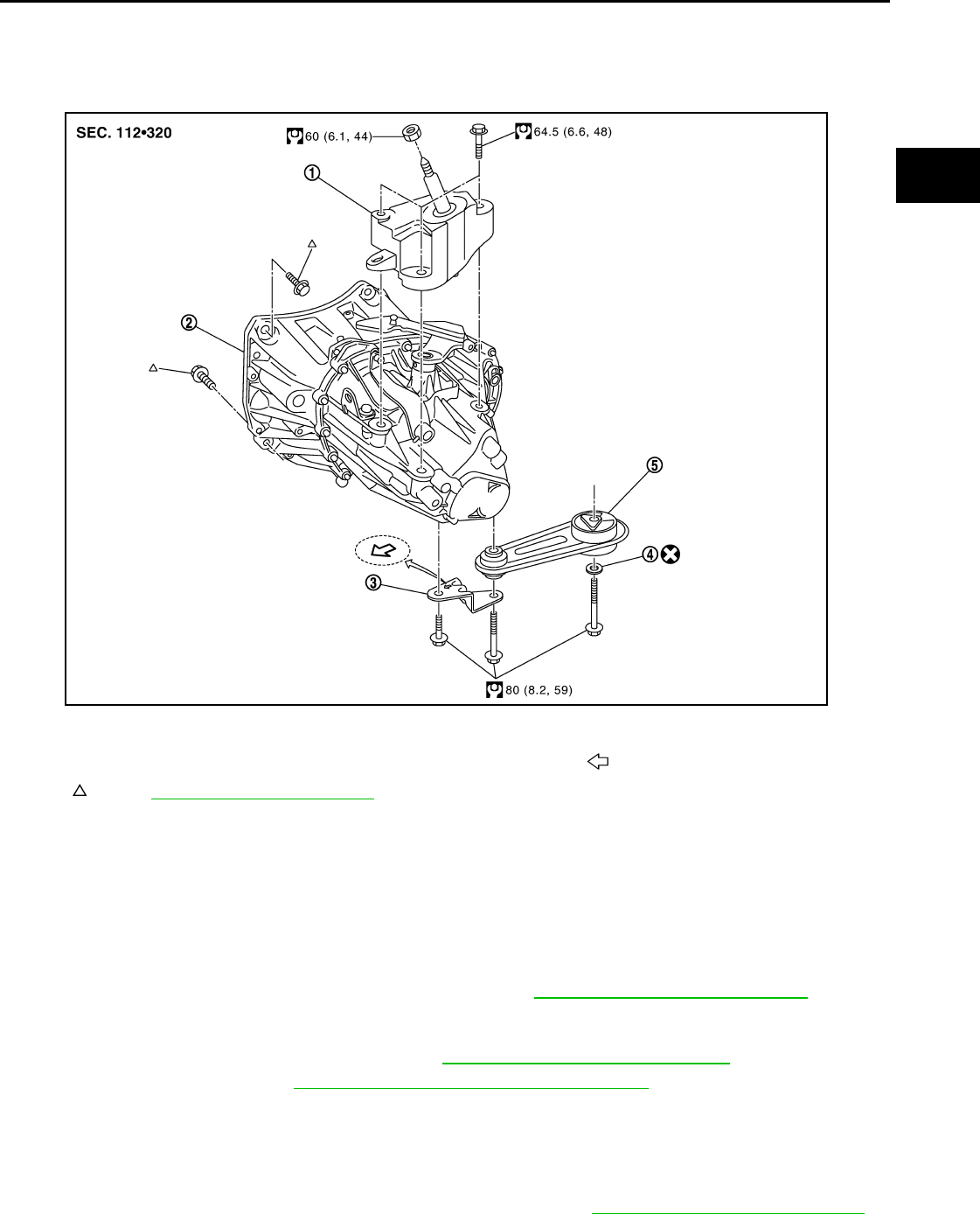
TRANSAXLE ASSEMBLY
MT-61
< SERVICE INFORMATION > [RS6F94R]
D
E
F
G
H
I
J
K
L
M
A
B
MT
N
O
P
TRANSAXLE ASSEMBLY
Component INFOID:0000000005929696
Removal and Installation INFOID:0000000005929697
CAUTION:
If transaxle assembly is removed from the vehicle, always replace CSC (Concentric Slave Cylinder).
Inserted CSC returns to the original position when removing transaxle assembly. Dust on clutch disc
sliding parts may damage CSC seal, and may cause clutch fluid leakage.
REMOVAL
1. Drain clutch fluid and remove clutch tube from CSC. Refer to CL-13, "Removal and Installation".
CAUTION:
Do not depress clutch pedal during removal procedure.
2. Remove engine and transaxle assembly. Refer to EM-197, "Removal and Installation".
3. Remove starter motor. Refer to SC-20, "Removal and Installation MR18DE".
4. Remove transaxle assembly to engine bolts.
5. Separate transaxle assembly from engine.
INSTALLATION
Installation is in the reverse order of removal.
• If transaxle is removed from the vehicle, always replace CSC. Refer to CL-13, "Removal and Installation" .
1. LH engine mount bracket (transaxle side) 2. Transaxle assembly 3. Rear engine mount bracket
4. Washer 5. Rear torque rod Front
: Refer to MT-61, "Removal and Installation".
SCIA7631E
Revision: May 2010 2011 Versa
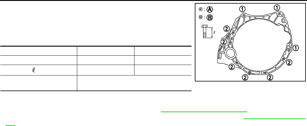
MT-62
< SERVICE INFORMATION > [RS6F94R]
TRANSAXLE ASSEMBLY
• When installing the transaxle assembly to the engine, install the
bolts as shown.
CAUTION:
When installing transaxle assembly, be careful not to bring
transaxle input shaft into contact with clutch cover.
A: M/T to engine
B: Engine to M/T
• Bleed the air from the clutch hydraulic system. Refer to CL-9, "Air Bleeding Procedure".
• After installation, check oil level, and check for leaks and loose mechanisms. Refer to MT-54, "Checking M/T
Oil".
Disassembly and Assembly INFOID:0000000005929698
COMPONENTS
Case and Housing Components
Bolt No. 1 2
Quantity 3 6
Bolt length “ ” mm (in) 60 (2.36) 50 (1.97)
Tightening torque
N·m (kg-m, ft-lb) 62.0 (6.3, 46)
PCIB1786E
Revision: May 2010 2011 Versa
TRANSAXLE ASSEMBLY
MT-63
< SERVICE INFORMATION > [RS6F94R]
D
E
F
G
H
I
J
K
L
M
A
B
MT
N
O
P
Gear Components
1. Filler plug 2. Gasket 3. Transaxle case
4. Bushing 5. Snap ring 6. Oil channel
7. Oil gutter 8. Position switch 9. Bracket
10. Differential side oil seal 11. Magnet 12. Drain plug
13. Input shaft oil seal 14. Clutch housing 15. Two way connector
16. Plug (With ABS models) 17. Vehicle speed sensor (Without
ABS models)
18. Pinion shaft
19. Pinion gear Use specified transaxle fluid. Refer to MA-14, "Fluids and Lubricants"
: Apply Genuine Liquid Gasket, Three Bond 1215 or an equivalent.
AWDIA0715ZZ
Revision: May 2010 2011 Versa
MT-64
< SERVICE INFORMATION > [RS6F94R]
TRANSAXLE ASSEMBLY
1. Input shaft front bearing 2. Input shaft 3. 3rd input gear
4. Spacer 5. Snap ring 6. 3rd baulk ring
7. 3rd-4th coupling sleeve 8. 3rd-4th synchronizer hub 9. Insert key
10. 4th baulk ring 11. 4th input gear 12. 5th input gear
13. 5th baulk ring 14. 5th-6th coupling sleeve 15. 5th-6th synchronizer hub
16. 6th baulk ring 17. Needle bearing 18. 6th input gear
19. Input shaft rear bearing
A: First step B: Final step
: Apply gear oil.
: Replace the parts as a set.
JPDIC0407GB
Revision: May 2010 2011 Versa
TRANSAXLE ASSEMBLY
MT-65
< SERVICE INFORMATION > [RS6F94R]
D
E
F
G
H
I
J
K
L
M
A
B
MT
N
O
P
1. Mainshaft front bearing outer
race
2. Mainshaft front bearing inner race 3. Mainshaft
4. 1st main gear 5. 1st inner baulk ring 6. 1st synchronizer cone
7. 1st outer baulk ring 8. 1st-2nd coupling sleeve 9. Insert key
10. 1st-2nd synchronizer hub 11. 2nd outer baulk ring 12. 2nd synchronizer cone
13. 2nd inner baulk ring 14. 2nd main gear 15. Bushing
16. 3rd main gear 17. Mainshaft adjusting shim 18. 4th main gear
19. 5th main gear 20. 6th main gear 21. Mainshaft rear bearing inner
race
22. Mainshaft rear bearing outer
race
23. Snap ring 24. Mainshaft rear bearing adjust-
ing shim
: Apply gear oil.
: Replace the parts as a set.
SFIA3293E
Revision: May 2010 2011 Versa
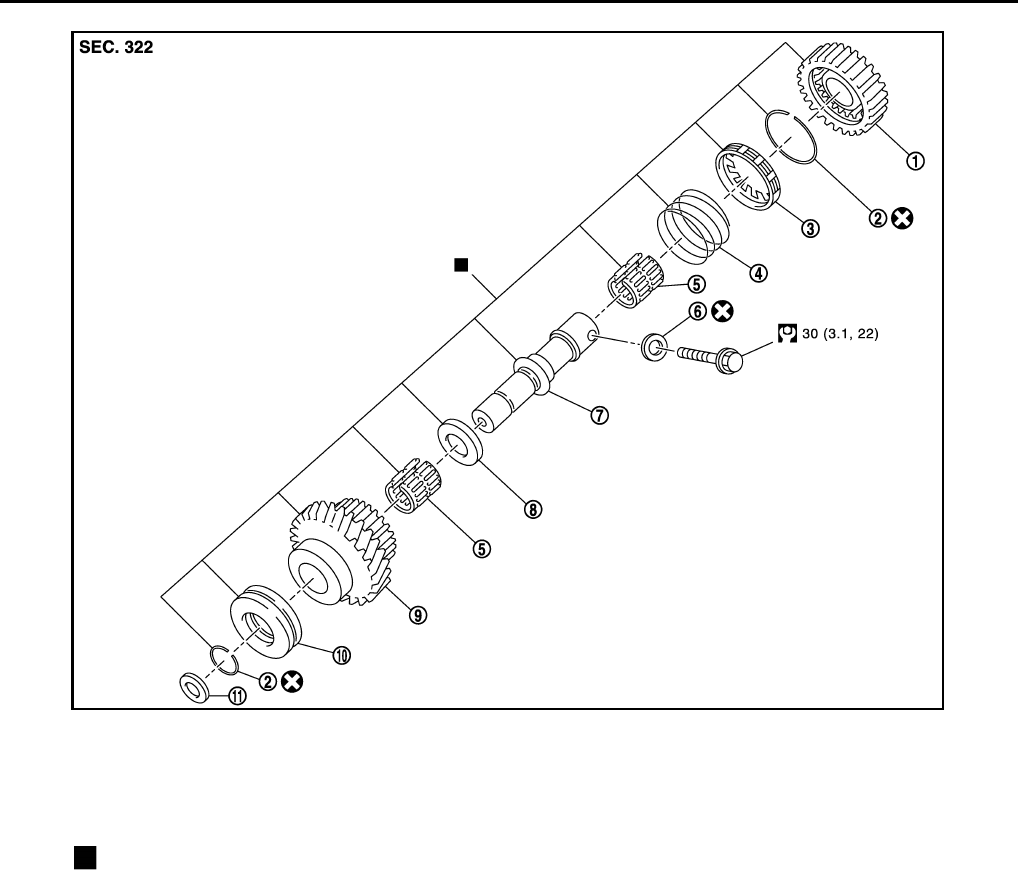
MT-66
< SERVICE INFORMATION > [RS6F94R]
TRANSAXLE ASSEMBLY
Shift Control Components
1. Reverse output gear 2. Snap ring 3. Reverse baulk ring
4. Return spring 5. Needle bearing 6. Seal washer
7. Reverse idler shaft 8. Spacer 9. Reverse input gear
10. Lock washer 11. Spring washer
: Replace the parts as a set.
JPDIC0425GB
Revision: May 2010 2011 Versa
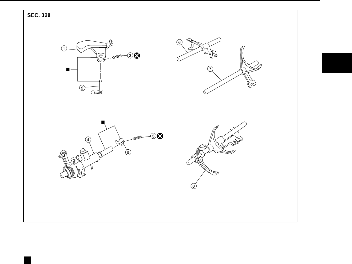
TRANSAXLE ASSEMBLY
MT-67
< SERVICE INFORMATION > [RS6F94R]
D
E
F
G
H
I
J
K
L
M
A
B
MT
N
O
P
Final Drive Components
1. Shifter lever A 2. Shifter lever B 3. Retaining pin
4. Selector 5. Selector lever 6. Reverse fork rod
7. 1st-2nd fork rod 8. Fork rod
: Replace the parts as a set.
AWDIA0716ZZ
Revision: May 2010 2011 Versa
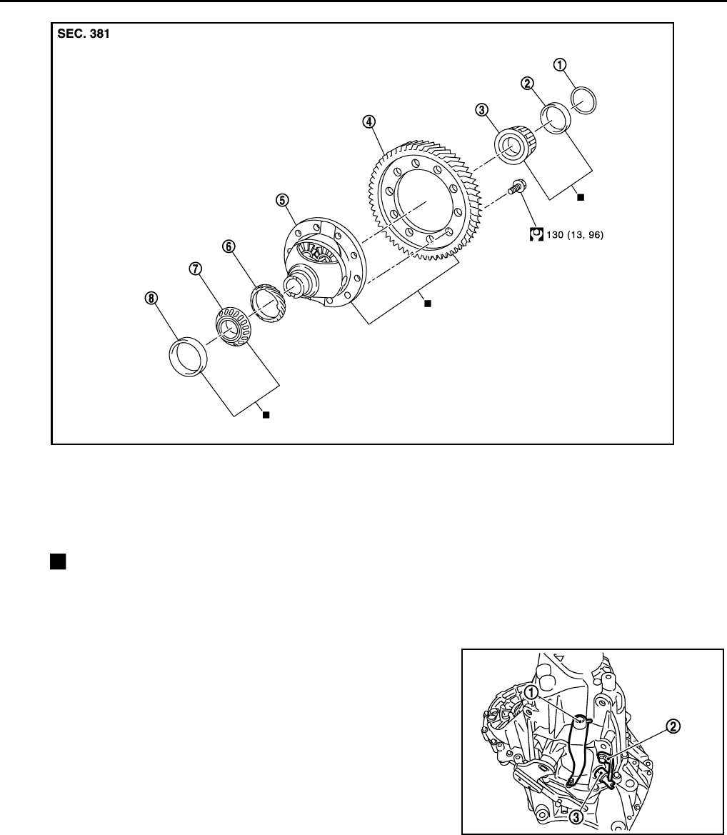
MT-68
< SERVICE INFORMATION > [RS6F94R]
TRANSAXLE ASSEMBLY
DISASSEMBLY
1. Remove drain plug and gasket from clutch housing, using a suitable tool and then drain gear oil.
2. Remove filler plug and gasket from transaxle case.
3. Remove selector lever (1) retaining pin with a pin punch to
remove selector lever.
4. Remove bracket (2) and position switch (3) from transaxle case.
1. Shim 2. Differential side bearing outer
race (transaxle case side)
3. Differential side bearing inner race
(transaxle case side)
4. Final gear 5. Differential case 6. Speedometer drive gear
7. Differential side bearing inner
race (clutch housing side)
8. Differential side bearing outer
race (clutch housing side)
: Replace the parts as a set.
JPDIC0604GB
PCIB1693E
Revision: May 2010 2011 Versa
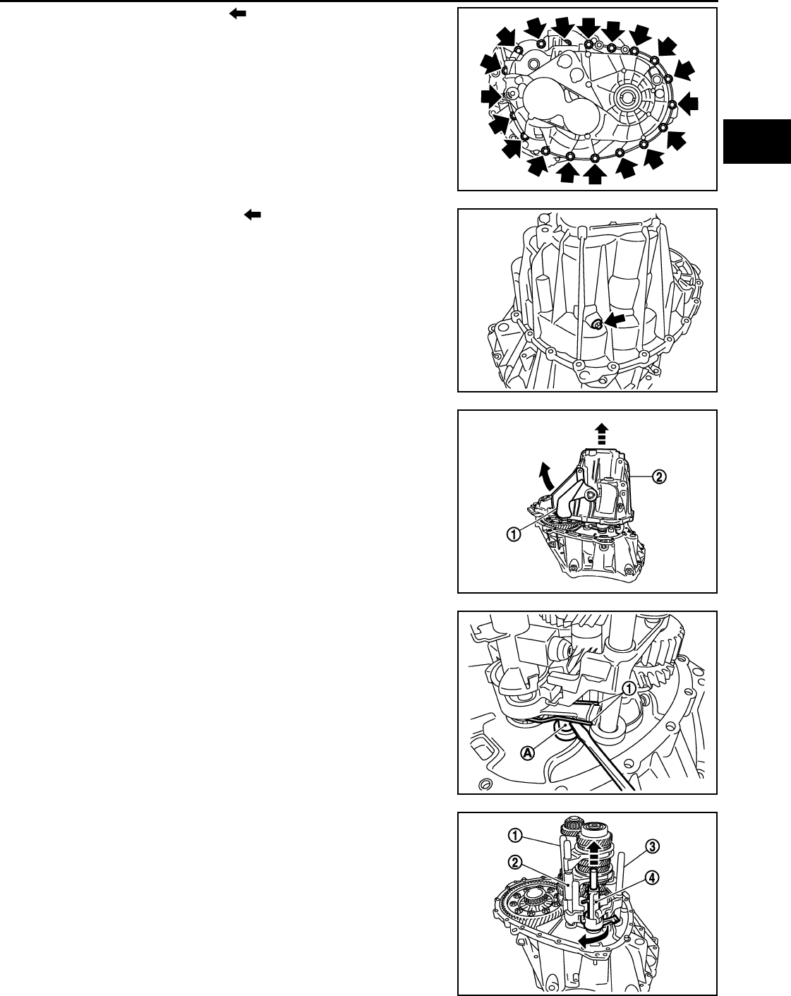
TRANSAXLE ASSEMBLY
MT-69
< SERVICE INFORMATION > [RS6F94R]
D
E
F
G
H
I
J
K
L
M
A
B
MT
N
O
P
5. Remove transaxle case bolts ( ).
6. Remove reverse idler shaft bolt ( ) and seal washer.
7. Remove transaxle case (2) while rotating shifter lever A (1) in
the direction as shown.
8. Remove selector spring (1) from return bushing (A).
9. Shift 1st-2nd fork rod (1), fork rod (2), and reverse fork rod (3) to
the neutral position.
10. Remove selector (4) from clutch housing.
PCIB1694E
PCIB1695E
JPDIC0444ZZ
JPDIC0445ZZ
PCIB1698E
Revision: May 2010 2011 Versa
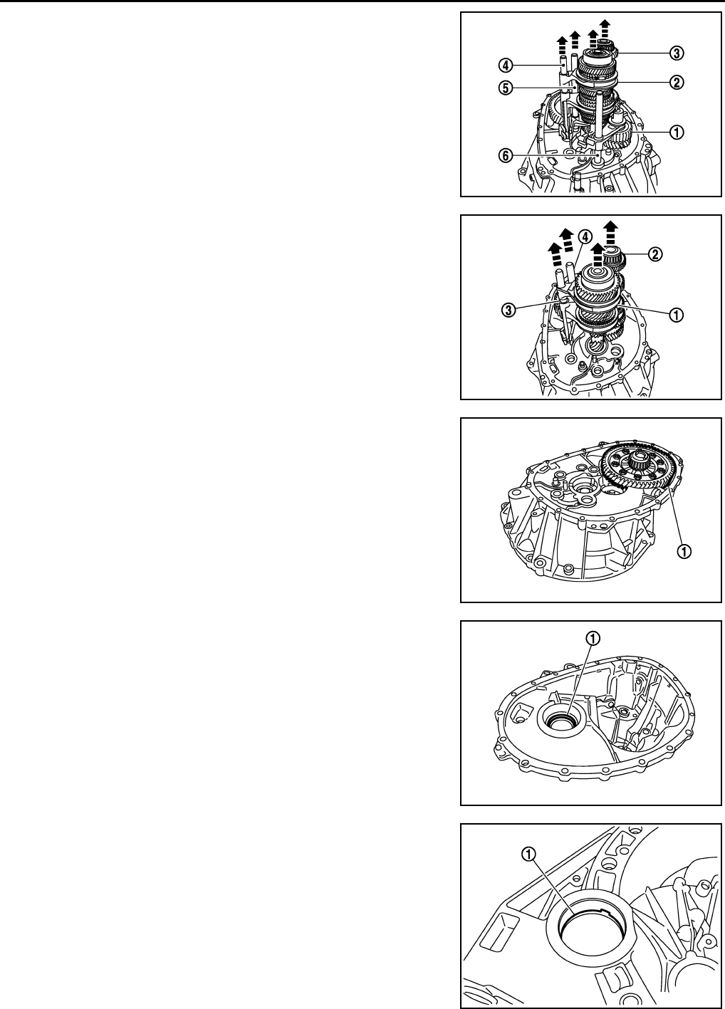
MT-70
< SERVICE INFORMATION > [RS6F94R]
TRANSAXLE ASSEMBLY
11. Remove reverse idler shaft assembly (1) according to the follow-
ing procedures.
a. Pull up input shaft assembly (2), mainshaft assembly (3), fork
rod (4), and 1st-2nd fork rod (5).
NOTE:
It is easier to pull up when shifting each fork rod to each shaft
side.
b. Remove reverse idler shaft assembly and reverse fork rod (6)
from clutch housing.
12. Remove spring washer from clutch housing.
13. Pull up and remove input shaft assembly (1), mainshaft assem-
bly (2), fork rod (3), and 1st-2nd fork rod (4) from clutch housing.
NOTE:
It is easier to pull up when shifting each fork rod to each shaft
side.
14. Remove final drive assembly (1) from clutch housing.
15. Remove magnet from clutch housing.
16. Remove differential side oil seals (1) from clutch housing and
transaxle case.
CAUTION:
Never damage clutch housing and transaxle case.
17. Remove differential side bearing outer race (1) from clutch hous-
ing, using a brass rod.
CAUTION:
Never damage clutch housing.
JPDIC0606ZZ
JPDIC0607ZZ
PCIB1703E
PCIB1704E
PCIB1716E
Revision: May 2010 2011 Versa
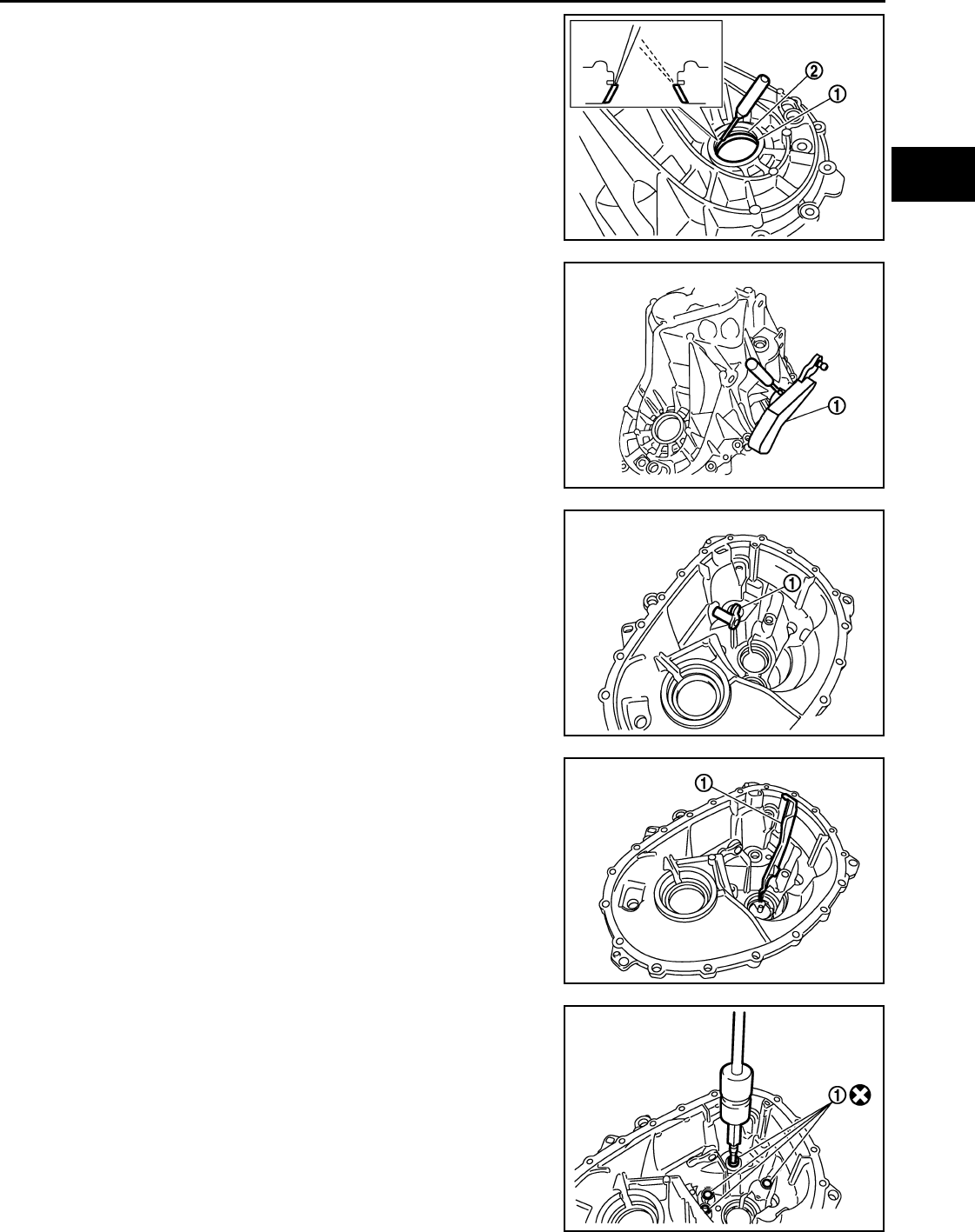
TRANSAXLE ASSEMBLY
MT-71
< SERVICE INFORMATION > [RS6F94R]
D
E
F
G
H
I
J
K
L
M
A
B
MT
N
O
P
18. Remove differential side bearing outer race (1) from transaxle
case, using a brass rod.
CAUTION:
Never damage transaxle case.
19. Remove shim (2) from transaxle case.
20. Remove shifter lever A (1) retaining pin, using a suitable tool.
21. Remove shifter lever A from transaxle case.
22. Remove shifter lever B (1) from transaxle case.
23. Remove oil gutter (1) from transaxle case.
24. Remove bushings (1) from transaxle case, using a suitable tool.
PCIB1705E
JPDIC0106ZZ
PCIB1712E
PCIB1707E
PCIB1710E
Revision: May 2010 2011 Versa
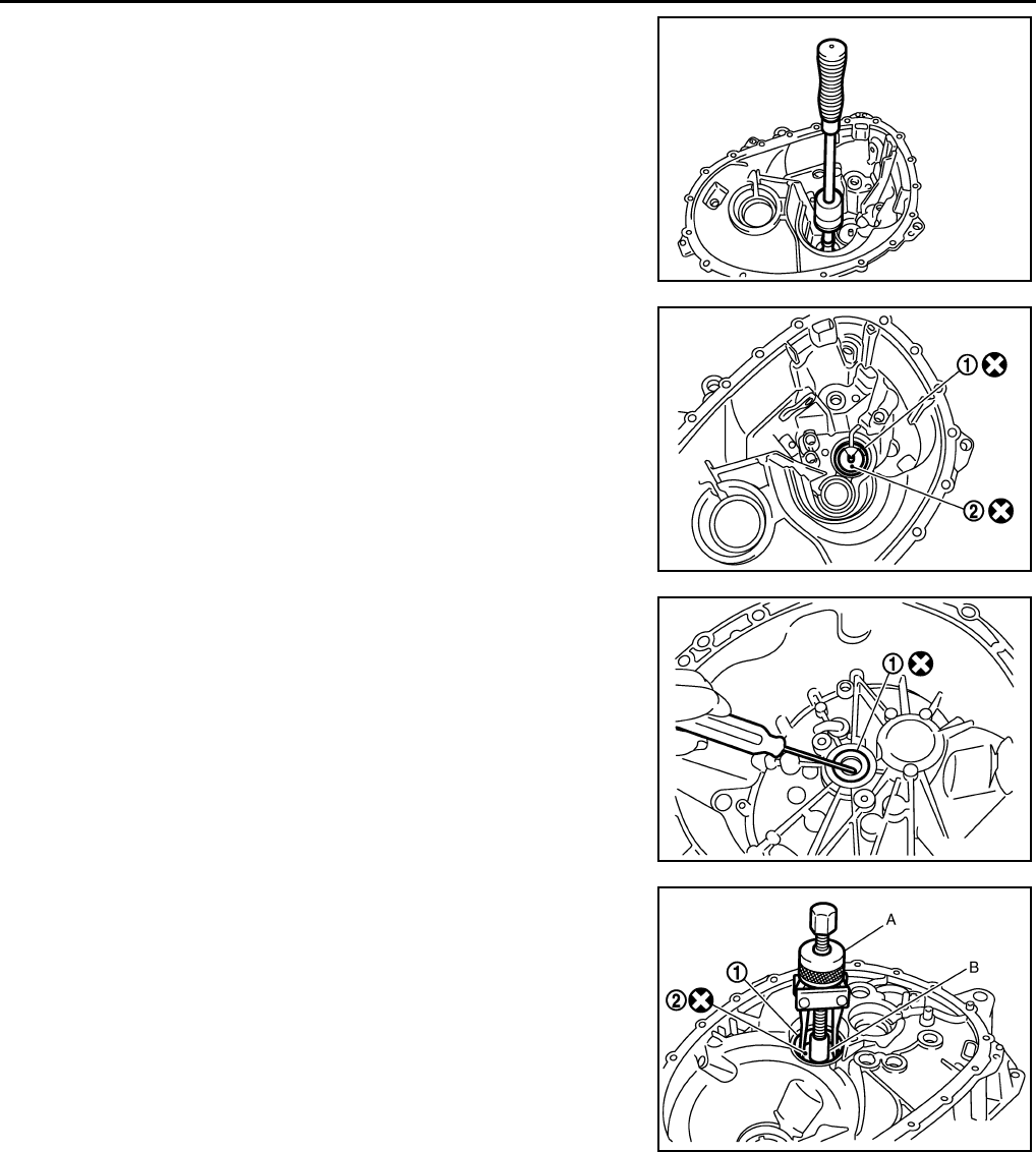
MT-72
< SERVICE INFORMATION > [RS6F94R]
TRANSAXLE ASSEMBLY
25. Remove mainshaft rear bearing outer race from transaxle case,
using a suitable tool.
26. Remove mainshaft rear bearing adjusting shim from transaxle
case.
27. Remove snap ring (1) and oil channel (2) from transaxle case.
28. Remove input shaft oil seal (1) from clutch housing, using a suit-
able tool.
CAUTION:
Never damage clutch housing.
29. Remove mainshaft front bearing outer race (1) from clutch hous-
ing, using Tool (A) and a suitable tool (B).
30. Remove oil channel (2) from clutch housing.
PCIB1706E
PCIB1708E
PCIB1714E
Tool number : KV381054S0 (J-34286)
JPDIC0107ZZ
Revision: May 2010 2011 Versa
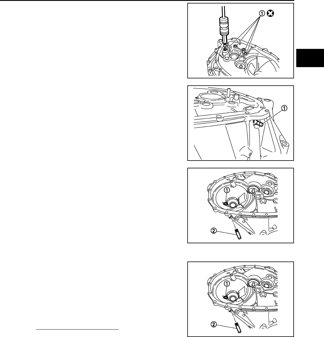
TRANSAXLE ASSEMBLY
MT-73
< SERVICE INFORMATION > [RS6F94R]
D
E
F
G
H
I
J
K
L
M
A
B
MT
N
O
P
31. Remove bushing (1) from clutch housing, using suitable tool.
32. Remove two way connector (1) from clutch housing.
33. Remove plug from clutch housing. (With ABS models)
34. Remove vehicle speed sensor from clutch housing. (Without
ABS models)
35. Remove pinion gear (1) and pinion shaft (2) from clutch housing.
ASSEMBLY
1. Install pinion gear (1) and pinion shaft (2) to clutch housing.
CAUTION:
Replace transaxle assembly when replacing clutch hous-
ing.
2. Install plug to clutch housing. (With ABS models)
3. Install vehicle speed sensor to clutch housing. (Without ABS
models)
NOTE:
Apply specified transaxle fluid to O-rings prior to installation.
Refer to MA-14, "Fluids and Lubricants".
PCIB1717E
PCIB1720E
PCIB1719E
PCIB1719E
Revision: May 2010 2011 Versa
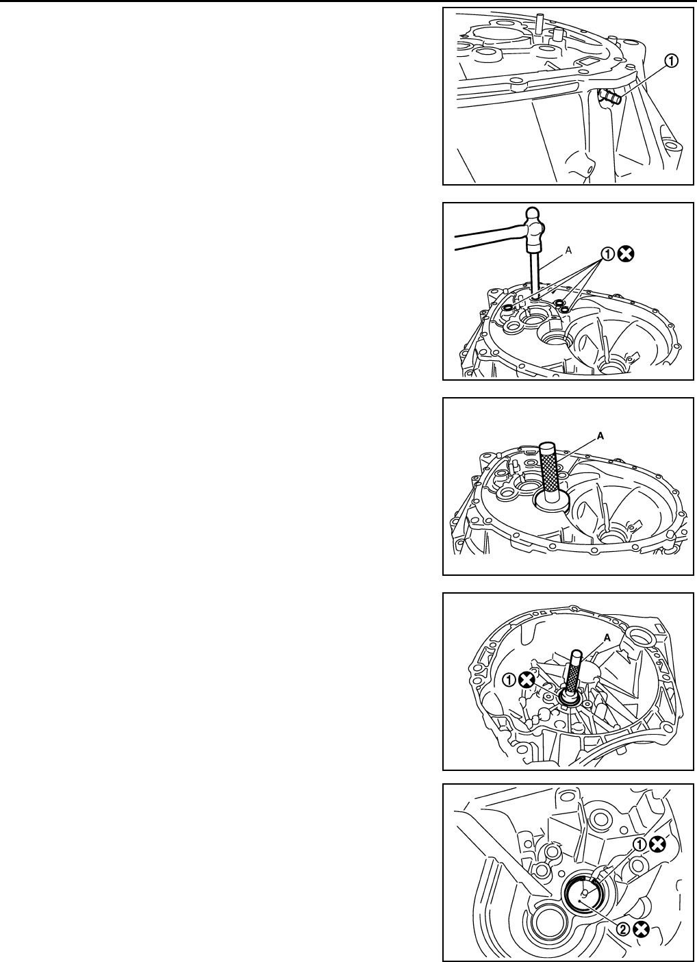
MT-74
< SERVICE INFORMATION > [RS6F94R]
TRANSAXLE ASSEMBLY
4. Install two way connector (1) to clutch housing.
5. Install bushings (1) so that they becomes even to clutch housing
edge surface, using a suitable tool (A).
6. Install oil channel to clutch housing.
CAUTION:
Never reuse oil channel.
7. Install mainshaft front bearing outer race to clutch housing,
using Tool (A).
CAUTION:
Replace mainshaft front bearing outer race and mainshaft
front bearing inner race as a set.
8. Install input shaft oil seal (1) to clutch housing, using Tool (A).
9. Install snap ring (1) and oil channel (2) to transaxle case.
CAUTION:
• Select and install snap ring that has the same thickness
as previous one.
• Replace transaxle assembly when replacing transaxle
case.
10. Install mainshaft rear bearing adjusting shim to transaxle case.
CAUTION:
Select mainshaft rear bearing adjusting shim according to
the following procedures when replacing mainshaft adjust-
ing shim, 6th main gear, 5th main gear, or 4th main gear.
• Replace mainshaft adjusting shim.
PCIB1720E
JPDIC0108ZZ
Tool number : KV38100200 ( — )
PCIB1724E
Tool number : ST33220000 ( — )
PCIB1721E
PCIB1729E
Revision: May 2010 2011 Versa
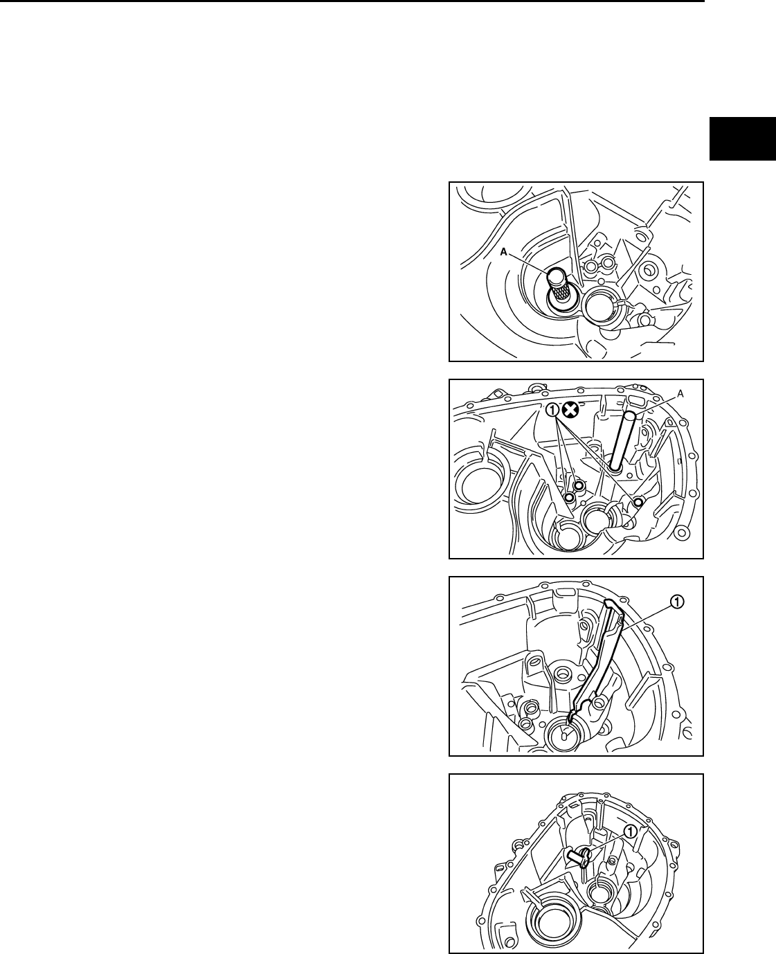
TRANSAXLE ASSEMBLY
MT-75
< SERVICE INFORMATION > [RS6F94R]
D
E
F
G
H
I
J
K
L
M
A
B
MT
N
O
P
- If new mainshaft adjusting shim is thinner than previous one, offset the thickness difference by
selecting thicker mainshaft rear bearing adjusting shim.
- If new mainshaft adjusting shim is thicker than previous one, offset the thickness difference by
selecting thinner mainshaft rear bearing adjusting shim.
• Replace 6th main gear, 5th main gear, or 4th main gear.
- Measure the thickness of the main gear used before and the new main gear
- Increase the thickness of the mainshaft rear bearing adjusting shim, if the difference is smaller
than 0.025 mm (0.0010 in).
- Decrease the thickness of the mainshaft rear bearing adjusting shim, if the difference is greater
than 0.025 mm (0.0010 in).
11. Install mainshaft rear bearing outer race to transaxle case, using
Tool (A).
CAUTION:
Replace mainshaft rear bearing outer race and mainshaft
rear bearing inner race as a set.
12. Install bushings (1) to transaxle case, using suitable (A).
13. Install oil gutter (1) to transaxle case.
14. Install shifter lever B (1) to transaxle case.
CAUTION:
Replace shifter lever A and shifter lever B as a set.
15. Install shifter lever A to transaxle case.
CAUTION:
Replace shifter lever A and shifter lever B as a set.
Tool number : KV38100200 ( — )
PCIB1728E
JPDIC0109ZZ
PCIB1730E
PCIB1712E
Revision: May 2010 2011 Versa
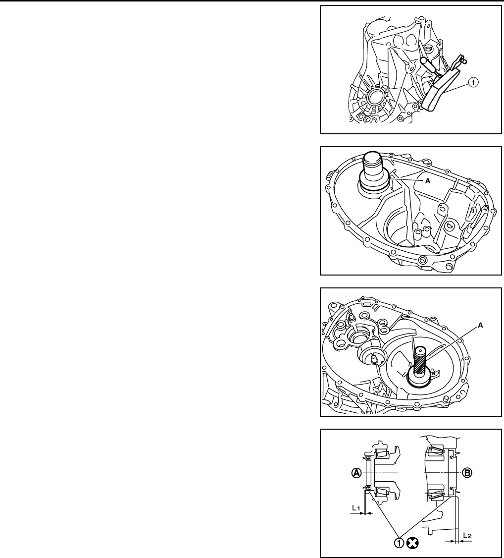
MT-76
< SERVICE INFORMATION > [RS6F94R]
TRANSAXLE ASSEMBLY
16. Install retaining pin to shifter lever A (1), using a pin punch.
CAUTION:
Never reuse retaining pin.
17. Install shim to transaxle case.
18. Install differential side bearing outer race (transaxle case side)
to transaxle case, using Tool (A).
CAUTION:
Replace differential side bearing outer race (transaxle case
side) and differential side bearing inner race (transaxle case
side) as a set.
19. Install differential side bearing outer race (clutch housing side) to
clutch housing, using Tool (A).
CAUTION:
Replace differential side bearing outer race (clutch housing
side) and differential side bearing inner race (clutch hous-
ing side) as a set.
20. Install differential side oil seals (1) to clutch housing and tran-
saxle case, using Tool.
CAUTION:
• Do not reuse differential side oil seal.
• Never incline differential side oil seal.
• Never damage clutch housing and transaxle case.
21. Install magnet to clutch housing.
22. Install final drive assembly to clutch housing.
BCIA0047E
Tool number : ST33400001 (J-26082)
PCIB1726E
Tool number : KV38100200 ( — )
PCIB1722E
Tool number : KV32500QAA (B.vi 1666-B)
A : Transaxle case side
B : Clutch housing side
Dimension L1: 1.2 – —1.8 mm (0.047– 0.071 in)
Dimension L2: 2.7 – 3.3 mm (0.106 – 0.130 in) JPDIC0454ZZ
Revision: May 2010 2011 Versa
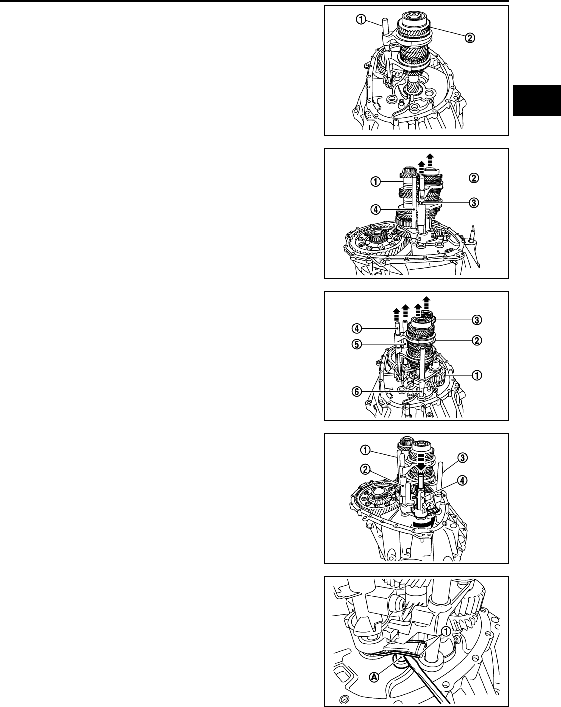
TRANSAXLE ASSEMBLY
MT-77
< SERVICE INFORMATION > [RS6F94R]
D
E
F
G
H
I
J
K
L
M
A
B
MT
N
O
P
23. Set fork rod (1) to input shaft assembly (2), and then install them
to clutch housing.
24. Install mainshaft assembly (1) according to the following proce-
dures.
a. Pull up input shaft assembly (2) and fork rod (3).
b. Set 1st-2nd fork rod (4) to mainshaft assembly, and then install
them to clutch housing.
25. Install reverse idler shaft assembly (1) according to the following
procedures.
a. Install spring washer to clutch housing.
b. Pull up input shaft assembly (2), mainshaft assembly (3), fork
rod (4), and 1st-2nd fork rod (5).
NOTE:
It is easier to pull up when shifting each fork rod to each shaft
side.
c. Set reverse fork rod (6) to reverse idler shaft assembly, and then
install them to clutch housing.
26. Shift 1st-2nd fork rod (1), fork rod (2), and reverse fork rod (3) to
the neutral position.
27. Install selector (4) to clutch housing.
CAUTION:
Replace selector lever and selector as a set.
28. Install selector spring (1) to return bushing (A).
29. Apply recommended sealant to transaxle case mounting sur-
face.
•Use Genuine Liquid Gasket, Three Bond 1215 or an equiv-
alent.
CAUTION:
• Never allow old liquid gasket, moisture, oil, or foreign
matter to remain on mounting surface.
• Check that mounting surface is not damaged.
• Apply liquid gasket bead continuously.
JPDIC0608ZZ
JPDIC0609ZZ
JPDIC0606ZZ
SCIA7782E
JPDIC0445ZZ
Revision: May 2010 2011 Versa
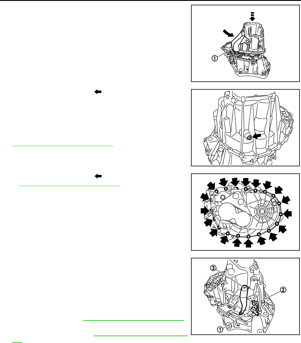
MT-78
< SERVICE INFORMATION > [RS6F94R]
TRANSAXLE ASSEMBLY
30. Install transaxle case to clutch housing while rotating shifter
lever A (1) in the direction as shown.
31. Install reverse idler shaft bolt ( ) according to the following pro-
cedures.
a. Install seal washer to reverse idler shaft mounting bolt, and
install reverse idler shaft bolt to transaxle case.
CAUTION:
Never reuse seal washer.
b. Tighten reverse idler shaft bolt to the specified torque. Refer to
MT-62, "Disassembly and Assembly".
32. Tighten transaxle case bolts ( ) to the specified torque. Refer
to MT-62, "Disassembly and Assembly".
33. Install position switch (1) according to the following procedures.
a. Apply recommended sealant to position switch thread.
•Use Genuine Liquid Gasket, Three Bond 1215 or an equiv-
alent.
CAUTION:
Never allow old liquid gasket, moisture, oil, or foreign mat-
ter to remain on thread.
b. Install position switch to transaxle case, and tighten it to the
specified torque. Refer to MT-62, "Disassembly and Assembly".
34. Install bracket (2) to transaxle case, and tighten mounting bolt to
the specified torque. Refer to MT-62, "Disassembly and Assem-
bly".
35. Install selector lever (3) according to following the procedures.
a. Install selector lever to transaxle case.
CAUTION:
Replace selector lever and selector as a set.
b. Install retaining pin to selector lever, using a suitable tool.
CAUTION:
Never reuse retaining pin.
36. Install drain plug according to the following procedures.
a. Install gasket to drain plug.
CAUTION:
JPDIC0110ZZ
PCIB1695E
PCIB1694E
SCIA7784E
Revision: May 2010 2011 Versa

TRANSAXLE ASSEMBLY
MT-79
< SERVICE INFORMATION > [RS6F94R]
D
E
F
G
H
I
J
K
L
M
A
B
MT
N
O
P
Never reuse gasket.
b. Install drain plug to clutch housing, using a suitable tool.
c. Tighten drain plug to the specified torque. Refer to MT-62, "Disassembly and Assembly".
37. Install filler plug according to the following procedures.
a. Install gasket to filler plug, and then install them to transaxle case.
CAUTION:
Never reuse gasket.
b. Tighten filler plug to the specified torque. Refer to MT-62, "Disassembly and Assembly".
CAUTION:
Fill with gear oil before tighten filler plug to the specified torque.
Revision: May 2010 2011 Versa
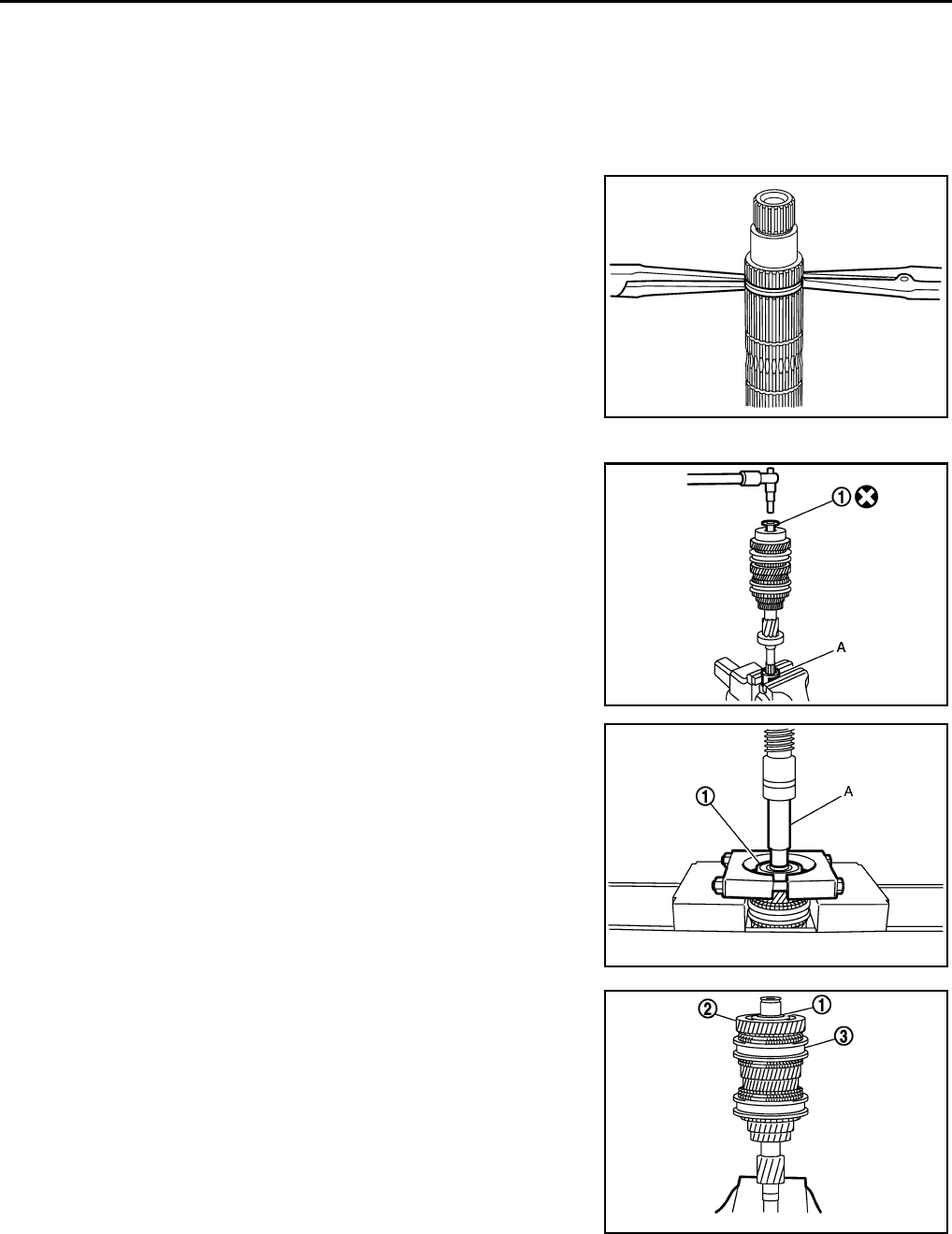
MT-80
< SERVICE INFORMATION > [RS6F94R]
INPUT SHAFT AND GEARS
INPUT SHAFT AND GEARS
Disassembly and Assembly INFOID:0000000005929699
GENERAL PRECAUTIONS
• Never reuse snap ring.
• Secure input shaft in a vise with backplate, and then remove gears and snap rings.
• For installation and removal of snap ring, set snap ring pliers and
flat pliers at both sides of snap ring. While expanding snap ring
with snap ring pliers, move snap ring with flat pliers.
• Disassemble gear components putting direction marks on the parts
that do not affect any functions.
DISASSEMBLY
1. Remove input shaft rear bearing bolt (1) using Tool (A).
2. Remove input shaft rear bearing (1) according to the following
procedures.
a. Set a suitable puller to input shaft rear bearing.
b. Remove input shaft rear bearing using a suitable drift (A).
3. Remove spacer (1), 6th input gear (2), needle bearing, 6th baulk
ring, and 5th-6th synchronizer hub assembly (3).
4. Remove insert keys and 5th-6th coupling sleeve from 5th-6th
synchronizer hub.
SCIA1755J
Tool number A: KV32300QAM ( — )
JPDIC0449ZZ
JPDIC0111ZZ
PCIB1750E
Revision: May 2010 2011 Versa
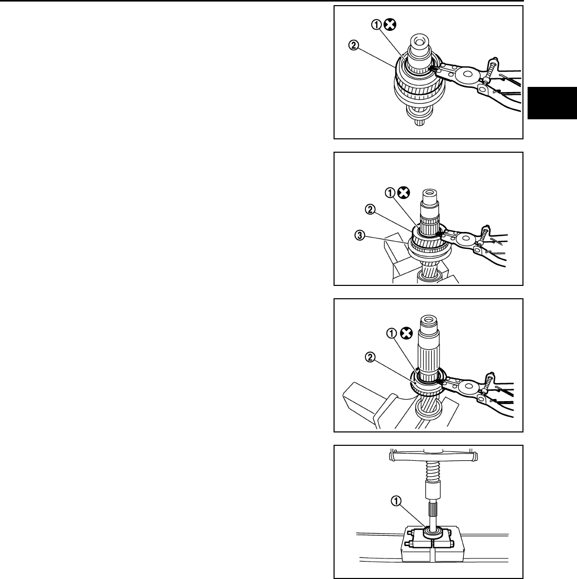
INPUT SHAFT AND GEARS
MT-81
< SERVICE INFORMATION > [RS6F94R]
D
E
F
G
H
I
J
K
L
M
A
B
MT
N
O
P
5. Remove snap ring (1) using suitable tool.
6. Remove spacer, 5th baulk ring, 5th input gear (2), and spacer.
7. Remove snap ring (1) using suitable tool.
8. Remove spacer, 4th input gear (2), 4th baulk ring, and 3rd-4th
synchronizer hub assembly (3).
9. Remove insert keys and 3rd-4th coupling sleeve from 3rd-4th
synchronizer hub.
10. Remove snap ring (1).
11. Remove spacer, 3rd baulk ring, 3rd input gear (2).
12. Set a suitable puller to input shaft front bearing (1), and then
remove input shaft front bearing.
INSPECTION AFTER DISASSEMBLY
Input shaft and gear
Check the following items and replace if necessary.
PCIB1754E
PCIB1753E
PCIB1752E
PCIB1751E
Revision: May 2010 2011 Versa
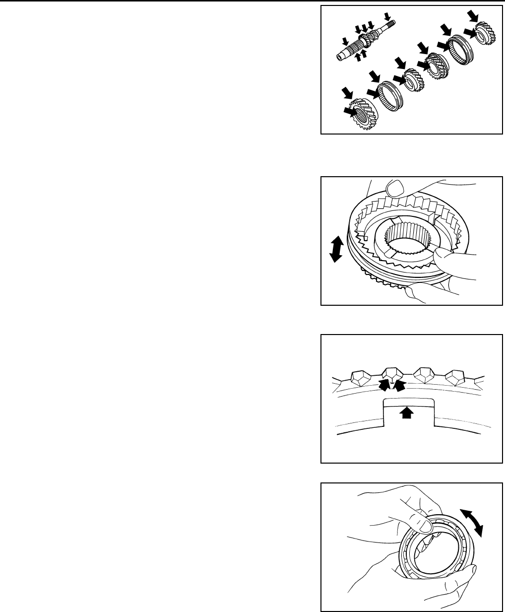
MT-82
< SERVICE INFORMATION > [RS6F94R]
INPUT SHAFT AND GEARS
• Damage, peeling, bend, uneven wear, and distortion of shaft.
• Excessive wear, damage, and peeling of gear.
Synchronizer
• Synchronizer hub and coupling sleeve
Check the following items and replace if necessary.
- Breakage, damage, and unusual wear on contact surface of cou-
pling sleeve, synchronizer hub, and insert key.
- Coupling sleeve and synchronizer hub move smoothly.
• Baulk ring
Check contact surface of baulk ring cam and insert key for exces-
sive wear, uneven wear, bend, and damage. Replace if necessary.
Bearing
Check bearing for damage and unsmooth rotation. Replace if neces-
sary.
ASSEMBLY
Note the following procedures, and assemble in the reverse order of disassembly.
CAUTION:
• Replace transaxle assembly when replacing input shaft.
• Never reuse snap ring.
• Check that snap ring is securely installed in a groove.
• Replace 3rd-4th coupling sleeve and 3rd-4th synchronizer hub as a set.
SCIA7736E
SCIA1753J
SCIA0608J
MTF0041D
Revision: May 2010 2011 Versa
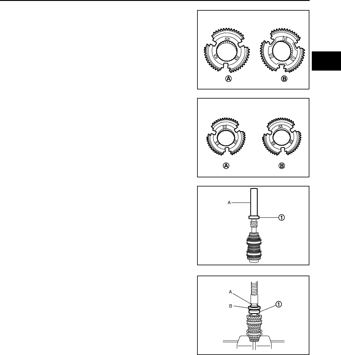
INPUT SHAFT AND GEARS
MT-83
< SERVICE INFORMATION > [RS6F94R]
D
E
F
G
H
I
J
K
L
M
A
B
MT
N
O
P
• Replace 5th-6th coupling sleeve and 5th-6th synchronizer hub as a set.
• Be careful to install 3rd-4th synchronizer hub according to the
specified direction.
• Be careful to install 5th-6th synchronizer hub according to the
specified direction.
• Install input shaft front bearing (1) using a suitable drift (A).
• Install input shaft rear bearing (1) using a suitable drift (A) and the
Tool (B).
• Apply gear oil to 3rd baulk ring, 4th baulk ring, 5th baulk ring, and
6th baulk ring.
A : 3rd input gear side
B : 4th input gear side
PCIB1748E
A : 5th input gear side
B : 6th input gear side
PCIB1749E
JPDIC0112ZZ
Tool number B: ST36720030 ( — )
JPDIC0113ZZ
Revision: May 2010 2011 Versa
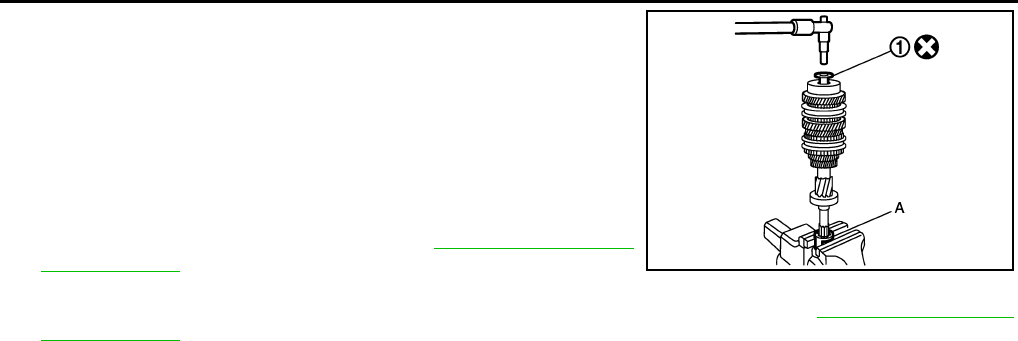
MT-84
< SERVICE INFORMATION > [RS6F94R]
INPUT SHAFT AND GEARS
• Install input shaft rear bearing bolt (1) according to the following
procedures.
CAUTION:
Follow the procedures. Otherwise it may cause a transaxle
malfunction.
1. Secure the Tool (A) in a vise, and then set input shaft assembly.
2. Install input shaft rear bearing bolt, and then tighten it to the
specified torque of the 1st step. Refer to MT-62, "Disassembly
and Assembly".
3. Loosen input shaft rear bearing bolt by a half turn.
4. Tighten input shaft rear bearing bolt to the specified torque of the 2nd step. Refer to MT-62, "Disassembly
and Assembly".
Tool number A: KV32300QAM ( — )
JPDIC0449ZZ
Revision: May 2010 2011 Versa
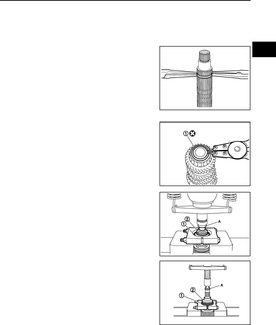
MAINSHAFT AND GEARS
MT-85
< SERVICE INFORMATION > [RS6F94R]
D
E
F
G
H
I
J
K
L
M
A
B
MT
N
O
P
MAINSHAFT AND GEARS
Disassembly and Assembly INFOID:0000000005929700
GENERAL PRECAUTIONS
• Never reuse snap ring.
• Secure mainshaft in a vise with backplate, and then remove gears and snap rings.
• For installation and removal of snap ring, set snap ring pliers and
flat pliers at both sides of snap ring. While expanding snap ring
with snap ring pliers, move snap ring with flat pliers.
• Disassemble gear components putting direction marks on the parts
that never affect any functions.
DISASSEMBLY
1. Remove snap ring (1) using suitable tool.
2. Remove 6th main gear (1) and mainshaft rear bearing inner race
(2) according to the following procedures.
a. Set a suitable puller to 6th main gear.
b. Remove mainshaft rear bearing inner race and 6th main gear
using the Tool (A).
3. Remove 4th main gear (1) and 5th main gear (2) according to
the following procedures.
a. Set a suitable tool to 4th main gear.
b. Remove 5th main gear and 4th main gear using Tool (A).
4. Remove mainshaft adjusting shim.
SCIA1755J
PCIB1745E
Tool number A: ST33052000 ( — )
PCIB1744E
Tool number A: ST33052000 ( — )
PCIB1743E
Revision: May 2010 2011 Versa
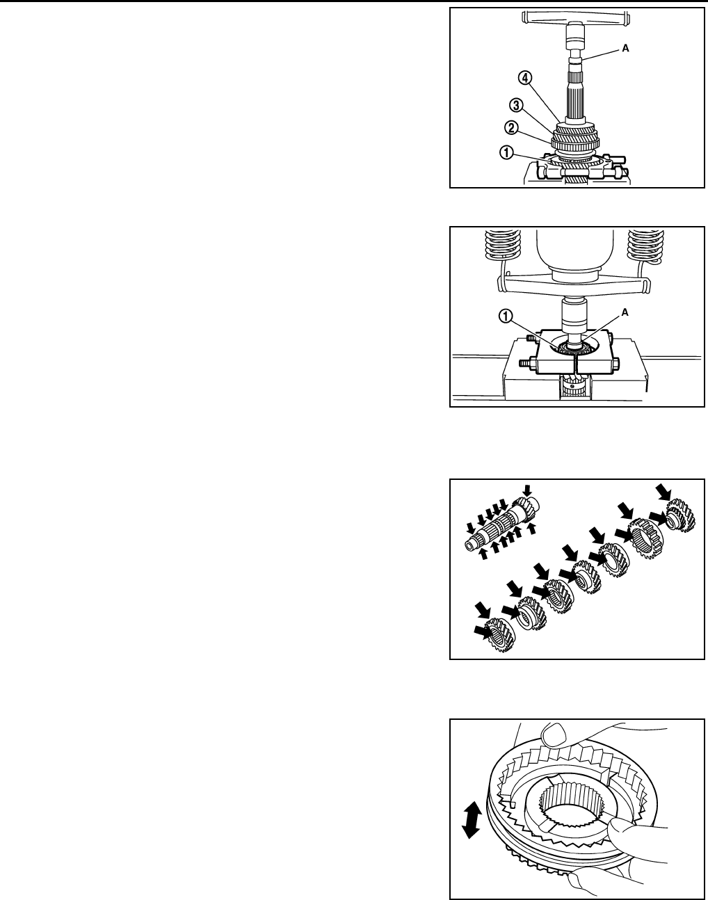
MT-86
< SERVICE INFORMATION > [RS6F94R]
MAINSHAFT AND GEARS
5. Remove 1st main gear (1), 1st-2nd synchronizer hub assembly
(2) , 2nd main gear (3), and 3rd main gear (4) according to the
following procedures.
a. Set a suitable tool to 1st main gear.
b. Remove 3rd main gear, busing, 2nd main gear, 2nd inner baulk
ring, 2nd synchronizer cone, 2nd outer baulk ring, 1st-2nd syn-
chronizer hub assembly, 1st outer baulk ring, 1st synchronizer
cone, 1st inner baulk ring, and 1st main gear using the Tool (A).
c. Remove insert keys and 1st-2nd coupling sleeve from 1st-2nd
synchronizer hub.
6. Remove mainshaft front bearing inner race (1) according to the
following procedures.
a. Set a suitable puller to mainshaft front bearing inner race.
b. Remove mainshaft front bearing inner race using the Tool (A).
INSPECTION AFTER DISASSEMBLY
Mainshaft and Gear
Check the following items and replace if necessary.
• Damage, peeling, bend, uneven wear, and distortion of shaft.
• Excessive wear, damage, and peeling of gear.
Synchronizer
• Synchronizer hub and coupling sleeve
Check the following items and replace if necessary.
- Breakage, damage, and unusual wear on contact surface of cou-
pling sleeve, synchronizer hub, and insert key.
- Coupling sleeve and synchronizer hub move smoothly.
• Baulk ring
Tool number A: ST33052000 ( — )
Tool number A: ST33052000 ( — )
PCIB1742E
PCIB1741E
PCIB1775E
SCIA1753J
Revision: May 2010 2011 Versa
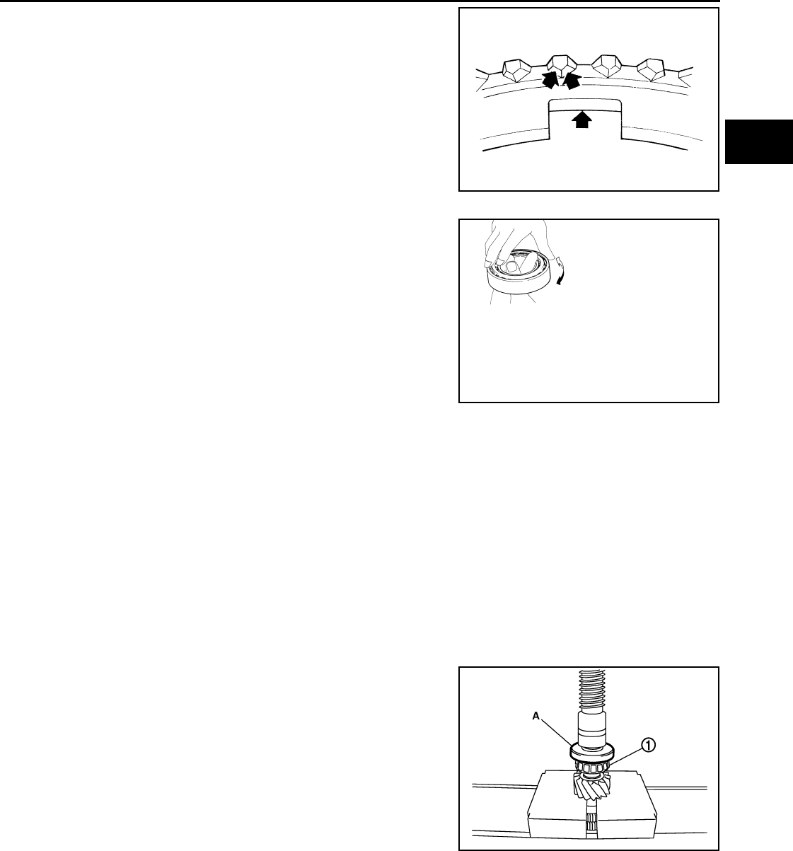
MAINSHAFT AND GEARS
MT-87
< SERVICE INFORMATION > [RS6F94R]
D
E
F
G
H
I
J
K
L
M
A
B
MT
N
O
P
Check contact surface of baulk ring cam and insert key for exces-
sive wear, uneven wear, bend, and damage. Replace if necessary.
Bearing
Check bearing for damage and unsmooth rotation. Replace if neces-
sary.
CAUTION:
• Replace mainshaft front bearing outer race and mainshaft
front bearing inner race as a set.
• Replace mainshaft rear bearing inner race and mainshaft rear
bearing outer race as a set.
ASSEMBLY
CAUTION:
• Select mainshaft rear bearing adjusting shim according to the following procedures when replacing
mainshaft adjusting shim, 6th main gear, 5th main gear, or 4th main gear.
- Replace mainshaft adjusting shim.
• If new mainshaft adjusting shim is thinner than previous one, offset the thickness difference by
selecting thicker mainshaft rear bearing adjusting shim.
• If new mainshaft adjusting shim is thicker than previous one, offset the thickness difference by
selecting thinner mainshaft rear bearing adjusting shim.
- Replace 6th main gear, 5th main gear, or 4th main gear.
• Measure the thickness of the main gear used before and the new main gear
• Increase the thickness of the mainshaft rear bearing adjusting shim, if the difference is smaller than
0.025 mm (0.0010 in).
• Replace transaxle assembly when replacing mainshaft.
1. Install mainshaft front bearing inner race (1) using the Tool (A).
CAUTION:
Replace mainshaft front bearing outer race and mainshaft
front bearing inner race as a set.
2. Apply gear oil to 1st inner baulk ring, 1st synchronizer cone, 1st
outer baulk ring, 2nd inner baulk ring, 2nd synchronizer cone,
and 2nd outer baulk ring.
CAUTION:
• Replace 1st inner baulk ring, 1st synchronizer cone, and
1st outer baulk ring as a set.
• Replace 2nd inner baulk ring, 2nd synchronizer cone, and 2nd outer baulk ring as a set.
3. Install insert keys and 1st-2nd coupling sleeve to 1st-2nd synchronizer hub.
CAUTION:
Replace 1st-2nd synchronizer hub and 1st-2nd coupling sleeve as a set.
SCIA0608J
SPD715
Tool number A: ST36720030 ( — )
PCIB1733E
Revision: May 2010 2011 Versa
MT-88
< SERVICE INFORMATION > [RS6F94R]
MAINSHAFT AND GEARS
4. Install 1st main gear (1), 1st inner baulk ring, 1st synchronizer
cone, 1st outer baulk ring, 1st-2nd synchronizer hub assembly
(2), 2nd inner baulk ring, 2nd synchronizer cone, and 2nd outer
baulk ring.
5. Install bushing (3) using the Tool (A).
6. Install 3rd main gear (1) and 2nd main gear (2) using Tool (A).
7. Measure dimension (L) as shown. Select mainshaft adjusting
shim (1) according to the following list, and then install it to main-
shaft.
Unit: mm (in)
8. Install 4th main gear (1) using Tool (A).
Tool number A: KV32102700 ( — )
PCIB1734E
Tool number A: ST32102700 ( — )
PCIB1735E
2: Mainshaft
3 : 3rd main gear
Dimension (L) Mainshaft adjusting shim thickness
147.690 – 147.666 (5.8146 – 5.8136) 1.500 (0.0591)
147.665 – 147.641 (5.8136 – 5.8126) 1.525 (0.0600)
147.640 – 147.616 (5.8126 – 5.8116) 1.550 (0.0610)
147.615 – 147.591 (5.8116 – 5.8107) 1.575 (0.0620)
147.590 – 147.566 (5.8106 – 5.8097) 1.600 (0.0630)
147.565 – 147.541 (5.8096 – 5.8087) 1.625 (0.0640)
147.540 – 147.516 (5.8086 – 5.8077) 1.650 (0.0650)
147.515 – 147.491 (5.8077 – 5.8067) 1.675 (0.0659)
147.490 – 147.466 (5.8067 – 5.8057) 1.700 (0.0669)
147.465 – 147.441 (5.8057 – 5.8048) 1.725 (0.0679)
147.440 – 147.416 (5.8047 – 5.8038) 1.750 (0.0689)
147.415 – 147.391 (5.8037 – 5.8028) 1.775 (0.0699)
Tool number A: KV32102700 ( — )
PCIB1736E
PCIB1737E
Revision: May 2010 2011 Versa
MAINSHAFT AND GEARS
MT-89
< SERVICE INFORMATION > [RS6F94R]
D
E
F
G
H
I
J
K
L
M
A
B
MT
N
O
P
9. Install 5th main gear (1) using Tool (A).
10. Install 6th main gear (1) using Tool (A).
11. Install mainshaft rear bearing inner race (1) usingTool (A).
CAUTION:
Replace mainshaft rear bearing inner race and mainshaft
rear bearing outer race as a set.
12. Install snap ring.
CAUTION:
Never reuse snap ring.
Tool number A: KV32102700 ( — )
PCIB1738E
Tool number A: KV32102700 ( — )
PCIB1739E
Tool number A: ST30901000 (J-26010-
01)
PCIB1740E
Revision: May 2010 2011 Versa
MT-90
< SERVICE INFORMATION > [RS6F94R]
REVERSE IDLER SHAFT AND GEARS
REVERSE IDLER SHAFT AND GEARS
Disassembly and Assembly INFOID:0000000005929701
DISASSEMBLY
1. Remove reverse output gear (1).
2. Remove snap ring (1) using suitable tool.
3. Remove reverse baulk ring (1) and return spring (2).
4. Remove snap ring (1), lock washer (2), and reverse input gear
(3) using suitable tool.
PCIB1760E
PCIB1759E
PCIB1758E
PCIB1757E
Revision: May 2010 2011 Versa
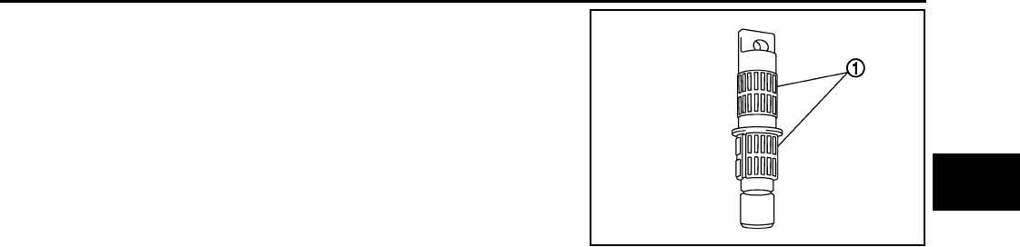
REVERSE IDLER SHAFT AND GEARS
MT-91
< SERVICE INFORMATION > [RS6F94R]
D
E
F
G
H
I
J
K
L
M
A
B
MT
N
O
P
5. Remove needle bearings (1) and spacer.
INSPECTION AFTER DISASSEMBLY
Shaft and Gear
Check the following items. Replace reverse output gear, snap ring, reverse baulk ring, return spring, needle
bearing, reverse idler shaft, spacer, reverse input gear, and lock washer as a set, if necessary.
• Damage, peeling, bend, uneven wear, and distortion of shaft
• Excessive wear, damage, and peeling of gear
Bearing
Check damage and rotation of bearing. Replace reverse output gear, snap ring, reverse baulk ring, return
spring, needle bearing, reverse idler shaft, spacer, reverse input gear, and lock washer as a set, if necessary.
ASSEMBLY
Note the following procedures, and assemble in the reverse order of disassembly.
CAUTION:
• Never reuse snap ring.
• Check that snap ring is securely installed in a groove.
• Replace reverse output gear, snap ring, reverse baulk ring, return spring, needle bearing, reverse
idler shaft, spacer, reverse input gear, and lock washer as a set.
PCIB1761E
Revision: May 2010 2011 Versa
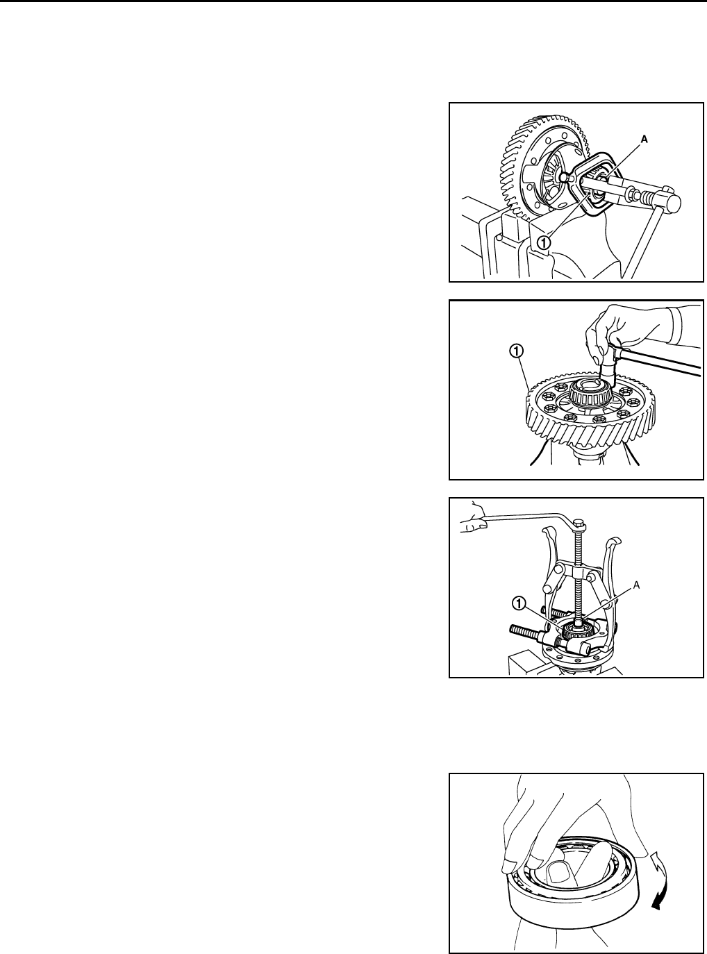
MT-92
< SERVICE INFORMATION > [RS6F94R]
FINAL DRIVE
FINAL DRIVE
Disassembly and Assembly INFOID:0000000005929702
DISASSEMBLY
1. Remove differential side bearing inner race (clutch housing side)
(1) according to the following procedures.
a. Set a suitable toolto differential side bearing inner race (clutch
housing side).
b. Remove differential side bearing inner race (clutch housing side)
using Tool (A).
2. Remove speedometer drive gear.
3. Remove final gear bolts, and then remove final gear (1).
4. Remove differential side bearing inner race (transaxle case
side) (1) according to the following procedures.
a. Set a suitable tool to differential side bearing inner race (tran-
saxle case side).
b. Remove differential side bearing inner race (transaxle case
side) using a suitable tool (A).
INSPECTION AFTER DISASSEMBLY
Gear and Case
Check final gear and differential case. Replace if necessary.
Bearing
Check bearing for damage and unsmooth rotation. Replace if neces-
sary.
CAUTION:
• Replace differential side bearing outer race (clutch housing
side) and differential side bearing inner race (clutch housing
side) as a set.
• Replace differential side bearing inner race (transaxle case
side) and differential side bearing outer race (transaxle case
side) as a set.
ASSEMBLY
Tool number A: ST33061000 (J-8107-2)
PCIB1767E
JPDIC0446ZZ
JPDIC0114ZZ
SPD715
Revision: May 2010 2011 Versa
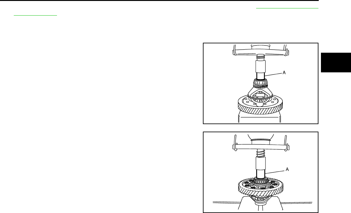
FINAL DRIVE
MT-93
< SERVICE INFORMATION > [RS6F94R]
D
E
F
G
H
I
J
K
L
M
A
B
MT
N
O
P
1. Install final gear, and then tighten final gear bolts to the specified torque. Refer to MT-92, "Disassembly
and Assembly".
CAUTION:
Replace final gear and differential case as a set.
2. Install speedometer drive gear.
3. Install differential side bearing inner race (clutch housing side)
using a suitable tool (A).
CAUTION:
Replace differential side bearing inner race (clutch housing
side) and differential side bearing outer race (clutch hous-
ing side) as a set.
4. Install differential side bearing inner race (transaxle case side)
using a suitable tool (A).
CAUTION:
Replace differential side bearing inner race (transaxle case
side) and differential side bearing outer race (transaxle
case side) as a set.
JPDIC0115ZZ
JPDIC0116ZZ
Revision: May 2010 2011 Versa
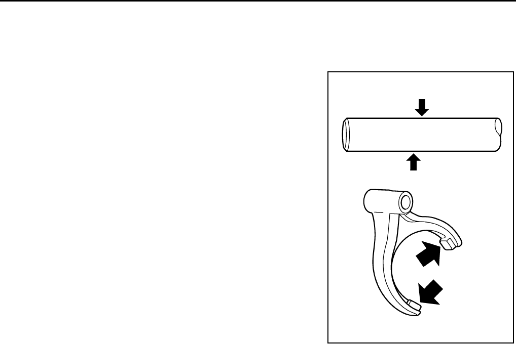
MT-94
< SERVICE INFORMATION > [RS6F94R]
SHIFT CONTROL
SHIFT CONTROL
Inspection INFOID:0000000005929703
FORK ROD AND SHIFT FORK
Check contact surface and sliding surface for excessive wear,
uneven wear, bend, and damage. Replace if necessary.
SCIA7785E
Revision: May 2010 2011 Versa
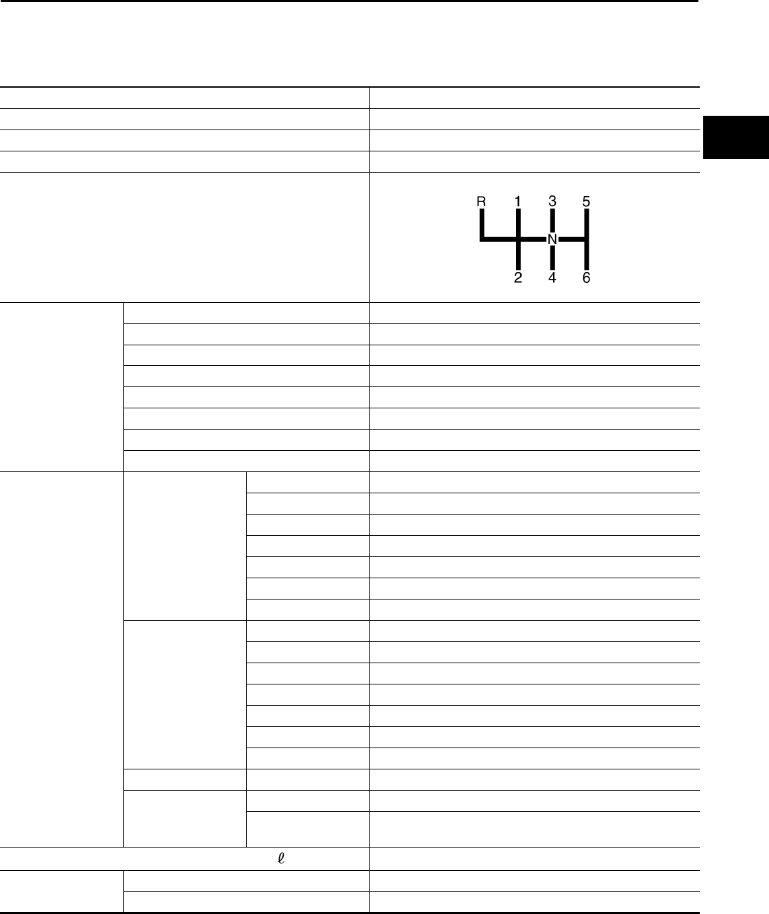
SERVICE DATA AND SPECIFICATIONS (SDS)
MT-95
< SERVICE INFORMATION > [RS6F94R]
D
E
F
G
H
I
J
K
L
M
A
B
MT
N
O
P
SERVICE DATA AND SPECIFICATIONS (SDS)
General Specification INFOID:0000000005929704
Transaxle type RS6F94R
Engine type MR18DE
Number of speed 6
Synchromesh type Warner
Shift pattern
Gear ratio 1st 3.727
2nd 2.105
3rd 1.452
4th 1.171
5th 0.971
6th 0.811
Reverse 3.687
Final gear 3.933
Number of teeth Input gear 1st 11
2nd 19
3rd 31
4th 35
5th 35
6th 37
Reverse 11
Main gear 1st 41
2nd 40
3rd 45
4th 41
5th 34
6th 30
Reverse 42
Reverse idler gear Input/Output 28/29
Final gear Final gear/Pinion 59/15
Side gear/Pinion
mate gear 21/18
Oil capacity (Reference) (US pt, Imp pt) Approx. 2.0 (4-1/4, 3-1/2)
Remarks Reverse synchronizer Installed
Triple-cone synchronizer 1st and 2nd
PCIB1769E
Revision: May 2010 2011 Versa
