Nissan Pathfinder R50 Users Manual Transmission Conversion
R50 to the manual af20cec7-c6cf-4f00-9321-a7d1ff10d48b
2015-01-21
: Nissan Nissan-Pathfinder-R50-Users-Manual-348770 nissan-pathfinder-r50-users-manual-348770 nissan pdf
Open the PDF directly: View PDF ![]() .
.
Page Count: 24
1
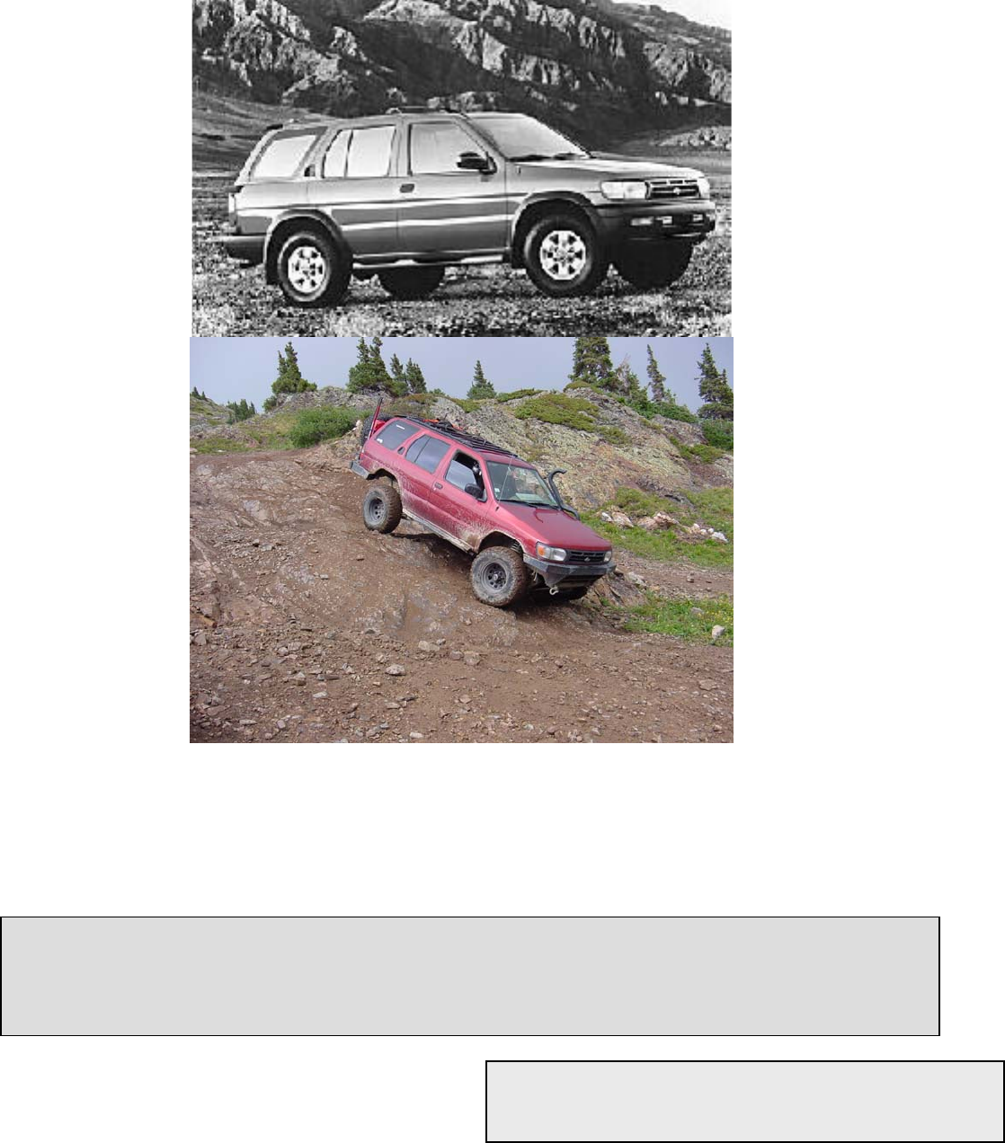
1996 – 1999 Nissan Pathfinder (R50)
Automatic to Manual Transmission
Conversion Manual
2
1996 – 1999 Nissan Pathfinder (R50) Automatic to Manual
Transmission Conversion Manual
Conversion performed and Manual Created by Keith Maddox
11/23/2005
3
Table of Contents
Overview 5
Tools Required 6
Parts List 7
Automatic Transmission 8
Removing the Automatic 9
Remove the interior 11
Electrical 12
Electronic Control Module Replacement 13
ASCD Modification 14
Park Neutral Switch Modification 14
Clutch 15
Clutch activation system 16
Clutch lines installation 16
Pilot bushing adapter removal 17
Pilot bearing installation 17
Clutch installation 18
4
Table of Contents Continued
Manual Transmission 19
Manual Transmission Wiring 20
Manual Transmission Installation 21
Interior Installation 22
Motor Mount Conversion 23
Illustration list 24

5
Overview
This manual will, in detail, give the information you will
need to convert a 4x4 1996-1999 Nissan Pathfinder from an
automatic transmission to a manual transmission. Having a
manual transmission in your Pathfinder gives you more control,
lower gears, and more power than you would have with an
automatic. Other benefits include better gas mileage, lower
maintenance cost and reduced electronic dependence.
Although the part prices and part numbers are directly
from the dealership many auto recyclers will have serviceable
parts at a much lower price. It is highly recommended that
you contact auto recyclers in your area for the manual
transmission and transfer case assembly, or transmission only in
the case of 2wd vehicles.
WARNING: perform these procedures only if you have
advanced mechanical knowledge. Certain aspects such as
the definition of common tools or how to use them will not be
within the pages of this manual. Before attempting any of
these procedures on your Pathfinder be aware that this is a
labor intensive and time consuming operation; your vehicle
will be out of commission for days if not weeks. Parts of this
operation will require the assistance of a helper.
Model designation is for 4x4 1996-1999 models, but most
of the instructions will cross over to 2wd and the later 1999.5-
2004 years
Notice: 2001 and later models require a different transmission than earlier models.
6
Tools Required
3/8” Socket set with metric sizes from 8mm to 19mm
½” Socket set with metric sizes from 12mm to 27mm
3/8” Ratchet
3/8” Extensions in 3” 6” and 9” lengths
3/8” Universal joint (swivel)
½” Ratchet
½” Extensions in 3” or longer lengths
½” Breaker bar
½” Torque wrench
Open ended wrench set from 8mm to 27mm
Hydraulic jack capable of 2 tons
Transmission jack capable of holding 325lbs
Phillips head screw driver set
Standard head (flat head) screw driver set
Blind Hole Puller
Dikes
Pliers (Kline type pliers work well)
Needle nose pliers
Standard size vice grips
7
Parts List
Part Description for clutch activation Part Numbers Quantity Needed
Clutch Pedal Bracket 46550-0W501- 1
Brake Pedal and Bracket 46501-0W000- 1
Clutch Master cylinder 30610-0W050- 1
Clutch to dampener line 30850-0W000- 1
Clutch Dampener bolts 08146-6162G- 2
Clutch Dampener 30660-0W000- 1
Clutch Dampener to passenger fender line 30851-1W200- 1
Brake/Clutch transfer block ???? 1
Transfer block to Slave Cylinder hose line 30851-1W211- 1
Slave Cylinder hose bracket 50915-0W010- 1
Slave Cylinder hose bracket bolt 08156-8161F- 1
Slave Cylinder hose clip 46206-2J000- 1
Slave Cylinder rubber hose 30855-0W010- 1
Slave Cylinder banjo bolt copper seals 46237-A4600- 2
Slave cylinder banjo bolt 46356-0E000- 1
Slave cylinder 30620-0W020- 1
Slave cylinder bolts 08121-0251E- 2
Driveline Parts
Clutch kit (clutch, pressure plate, throw out bearing) NU31214-1 (AutoZone part) 1
Throw out bearing support 30501-1C100- 1
throw out bearing control arm 30531-01S00- 1
throw out bearing control arm boot 30542-75P00- 1
transmission 32010-0W020- 1
transmission isolator (mount) bolts (bottom) 11258-D0101- 2
transmission isolator (mount) 11320-1W200- 1
Transmission bolts (top) 11393-0W000- 8
bell housing bolts M10 1.50 60-80mm 01121-06291- 8
Flywheel 12310-0W000- 1
Flywheel bolts M10 1.00 30mm 12315-D0210- 6
Pilot bearing 32202-B9500- 1
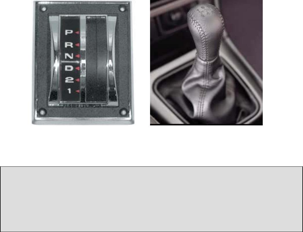
Transmission shifter 32839-62G00- 1
Transmission shifter knob 32865-50Y00- 1
Interior pieces
Inspection hole cover 74810-0W000- 1
Body to transfer case and transmission mount with boots 74967-0W020- 1
Outer rubber boot with mount 74910-0W010- 1
Finisher console with boot 96934-0W010- 1
Electronic pieces
ECM for Manual transmission 23710-1W600- 1
8
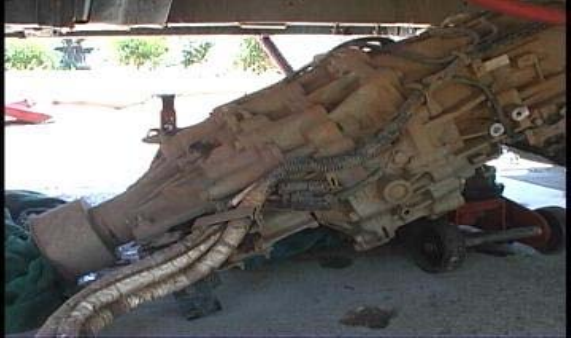
Section 1: Automatic Transmission
Fig. 1.1 Automatic transmission and Wiring Harness
9
Removing the Automatic Transmission
Before starting this procedure drain the automatic transmission fluid and
transfer case fluid (4wd models). It’s important to dispose of all fluids at
an authorized recycling center.
1. Remove the negative battery cable.
2. Remove the crankshaft position sensor. It is located on the top
driver’s side of the bell housing.
3. Remove exhaust tubes from the catalytic converters all the way
back.
4. Unbolt and remove the fluid change pipe from the engine and
transmission.
In order for the fluid change pipe to clear the engine completely remove the automatic
transmission.
5. Remove the oil cooler lines from the transmission and plug all
open transmission holes.
6. Remove transfer control linkage on the driver side rear of the
transmission. (4wd models only)
7. Remove front (4wd only) and rear driveshaft.
8. Remove the transmission control cable.
9. Remove the passenger side exhaust heat shields.
10. Disconnect the wiring harnesses from the transmission located at
the rear passenger side.
11. Remove the starter wires and then the starter.
12. Remove both engine gussets
13. Remove the lower splash shield.
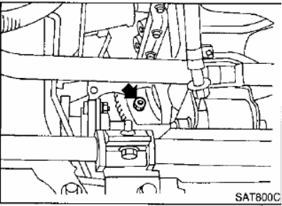
14. Remove the bolts securing the torque converter to drive plate.
Access the torque converter bolts through the starter hole. (see illustration)
Fig 1.2 Torque converter bolts through starter hole.
15. Remove remaining bell housing bolts.
10
16. Check to make sure you have removed all wires and cables from
the transmission.
17. Support the automatic transmission with the transmission jack
18. Remove the transmission cross member.
19. Lower the automatic transmission with transfer case (4wd models).
Warning: Be careful not to let the torque converter slide off.
11
Removing the Interior Panels
1. Remove the ashtray. Remove the screw under the ashtray and
pull out the bezel that covers the automatic transmission shifter.
2. Remove all screws holding the center console and lift it up. Under
the rear of the console unplug the rear power outlet connection.
3. Remove the automatic transmission cable on the passenger side
of the automatic transmission shifter.
4. Remove the plate that the automatic transmission cable passes
through and completely remove the automatic transmission
cable.
5. Remove the climate control/radio bezel’s screws at the bottom
then pull out.
6. Remove the lower center console piece.
7. Remove the automatic transmission shifter.
8. Remove the transfer case boot from the transmission tunnel plate
(4wd models).
9. Remove the transmission tunnel plate.
12
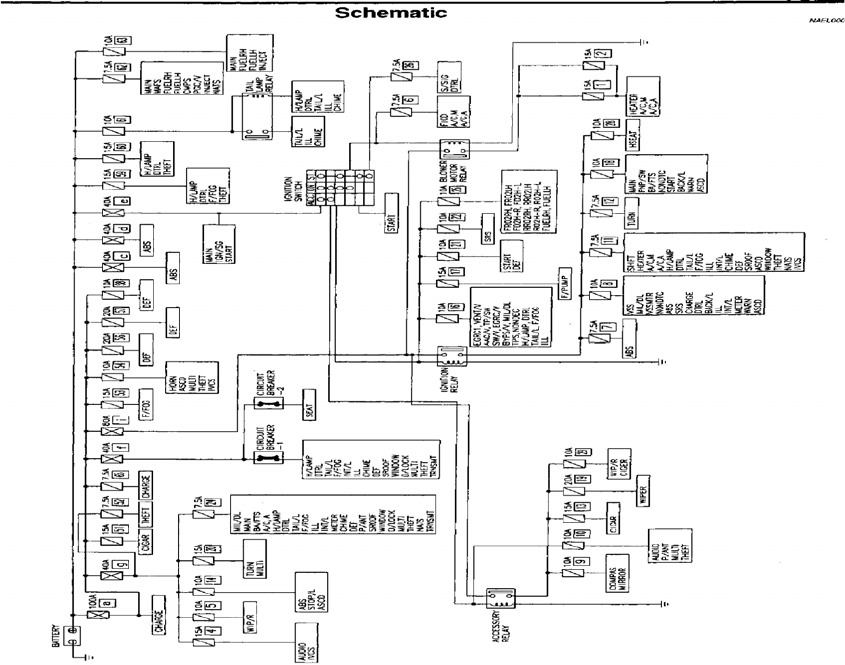
Section 2: Electrical
Fig. 2.1 Power Supply Routing
Electronic Control Module Replacement
Information about the Nissan ECM: There are several year breaks in the
Pathfinder model line. Below is a listing of ECM part numbers and the
month/year that part number applies to.
13
Build Date Part Number
1095-0796 23710-0W000-
0796-1296 23710-1W201-
1296-0797 23710-1W203-
0797-0398 23710-1W600-
0398-0998 23710-1W602-
0998-1298 23710-1W608-
1298-0999 23710-2W601-
0999-0100 23710-2W602-
The above parts list only applies to vehicles with the VG33 motor and FED emissions.
1. Make sure the negative battery cable is disconnected.
2. Remove the existing ECM from under the dash above the
accelerator pedal. It’s easiest to remove the plastic panel under
the steering column.
3. Using a 10mm socket unbolt the ECM’s electrical connector and
unplug.
4. Plug in the electrical connector to the new ECM and tighten the
10mm bolt.
5. Reinstall the ECM.
The date of manufacture for your vehicle can be located on the stamp inside of the
driver door jam.
14
ASCD and Park Neutral Switch Conversion
(Automatic speed control device)
Notice: Make sure to follow these instructions or the truck will not start.
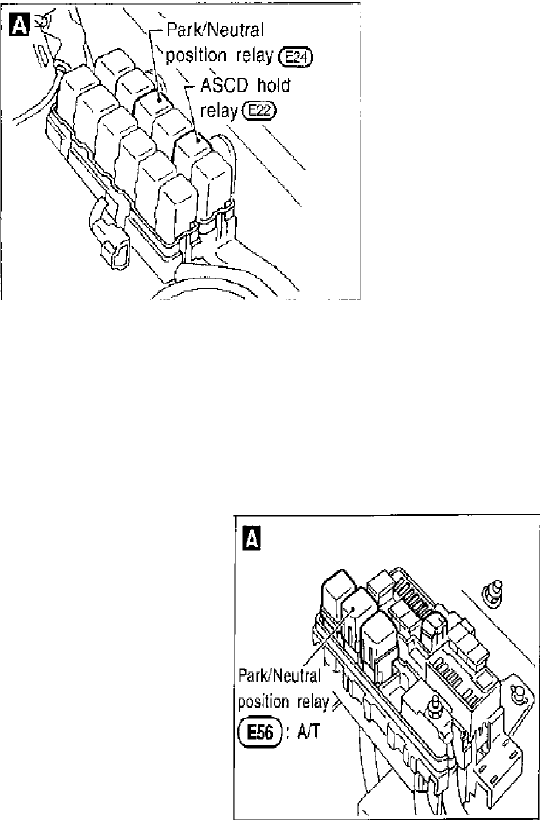
1. Locate the park neutral relay.
96 and some 97 models
In some 97 and earlier vehicles it is locate in the driver side relay box
in the engine compartment and is labeled N*P. Remove the N*P
relay and cross connections 6 to 7 and 3 to 4.
Fig. 2.2 Relay assembly, 96 model shown.
98 and later models
In some 98 and later vehicles the relay is locate in the passenger
relay box in the engine compartment and is labeled N*P. Remove
the N*P relay and cross connections 6 to 7 and 3 to 4.
Fig. 2.3 Relay assembly, 97 and later.
15
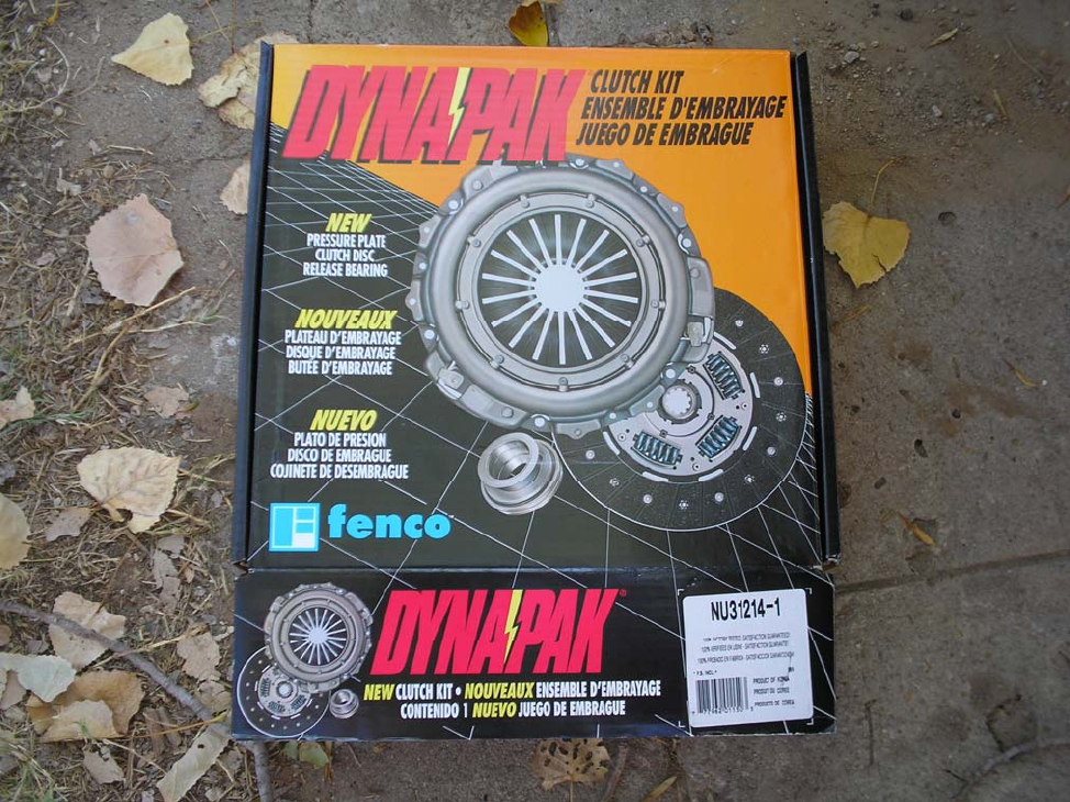
Section 3: Clutch
Fig 3.1 Clutch kit from AutoZone
16
Installing the Clutch activation system
This section deals with tight spaces under the dash and in the
engine compartment. All items we are installing either use fasteners
from the item they replace or there are already unused mounts in the
vehicle.
WARNING: DO NOT ROTATE THE STEERING WHEEL WHILE DISCONNECTED!
1. Remove trim under steering column.
2. Remove Steering column trim
3. Remove Steering column
4. Remove and unplug automatic brake pedal assembly. (4 12mm
nuts and one bolt)
5. Install smaller brake pedal assembly and plug in.
6. Remove Automatic computer and unplug, push firewall hole
cover out.
7. Install clutch master cylinder from engine compartment and push
mounting bolts through firewall holes.
8. Install clutch pedal bracket on master cylinder bolts that went
through the firewall and install nuts. One bolt also attaches to the
top of the clutch pedal assembly.
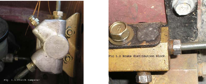
1. Install the clutch dampener on the driver’s side fender well and
the clutch master cylinder to clutch dampener line. (fig. 1.1)
Fig. 3.2 Clutch Dampener Fig. 3.3 Clutch transfer block, passenger
Fender.
2. Remove the passenger side inner fender splash shields.
17
3. Remove the top most brass brake distribution block and bracket.
Fig 1.2
4. Loosely install the new brake/clutch distribution block and loosely
reinstall all brake lines.
3. Install clutch line (part number 30851-1W200) across the firewall. It
is easiest to feed this line down on the passenger side and into the
new distribution block (fig 1.2).
4. Loosely thread the line into the distribution block and then secure
it along the firewall and threat it into the clutch dampener.
5. Once you have the distribution block and the firewall clutch line
installed you may tighten all lines and brackets.
Clutch Installation
Warning: Do not allow grease to contaminate the clutch surface.
1. Remove the drive plate by having a helper keep the crankshaft
from turning while you remove the drive plate bolts.
2. Inspect the crankshaft mounting surface and make sure no debris
are in the thread holes.
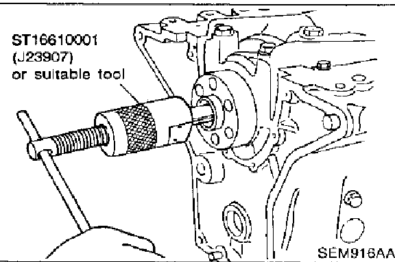
3. Remove the pilot adapter for the automatic transmission using the
blind hole puller. The blind hole puller is available at auto part
stores.
Fig. 3.4 Blind hole puller tool.
4. Install the new pilot bushing into the crankshaft.
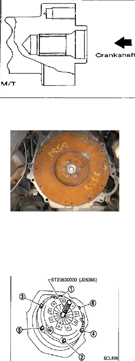
18
Fig. 3.5 Pilot bearing installed in crankshaft.
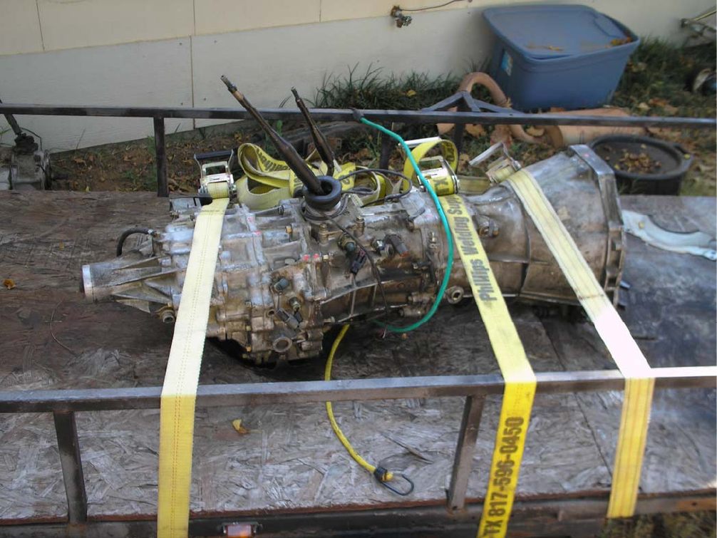
5. Place the flywheel on the crankshaft mount and install the new
crankshaft bolts. (part 12315-D0210)
Fig. 3.6 Flywheel installed.
6. Apply grease to clutch splines.
7. Install the clutch with tool springs facing outward.
8. Install the pressure plate and bolts.
9. Tighten pressure plate bolts in a two step numerical order. (see
illustration) For the first step use 7-14 ft-lbs of torque. For the
second step use 16-22 ft-lbs of torque.
Fig. 3.7 Clutch pressure plate torque sequence.
19
Section 4: Manual Transmission
Fig. 4.1 FS5R30A and TX-10 Assembly
20
Manual transmission wiring
Before installing the manual transmission you need to make
sure the neutral, reverse, 4x4 high and 4x4 low switches are in
working order.
1. To test the reverse switch simply put the transmission in reverse and
check continuity, any other position should not have continuity.
2. To test the neutral switch leave the transmission in neutral and test
for continuity, any other position should not have continuity.
3. To test the 4x4high put the transfer case in 4x4 high and test for
continuity, any other position should not have continuity.
4. To test the 4x4 low put the transfer case in 4x4 low and test the
switch for continuity, any other position should not have continuity.
Once you have tested all of the applicable switches
install new wires to the existing plugs as indicated below.
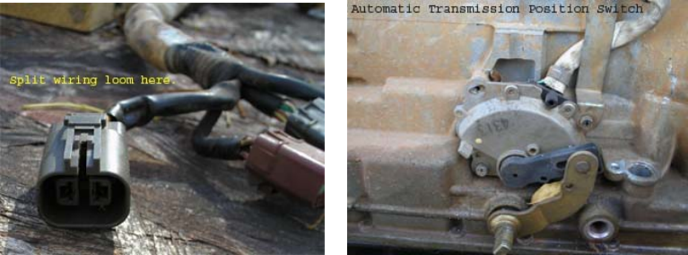
1. On the automatic transmission split the wiring loom apart starting
at the connections end.
2. Separate each wiring bundle from the others.
Fig. 4.2 Large plug Fig. 4.3 Automatic Transmission position switch
3. The transmission position switch and its wiring harness is the device
you will need to remove from the automatic. 8mm bolts attach
the automatic transmission position switch. (Fig. 4.2)
The automatic position switch consists of 9 wires and two
plugs. The two large wires which are colored brown and
black go to their own plug. The rest of the wires go to another
plug.
21
4. Cut all of the wires from the automatic position switch off at the
switch.
5. Leave the wires attached to their plugs.
6. Set aside the plug with the two large brown and black wires, you
will use this later.
7. Take the black and green wire from the other plug with many
wires and solder them to the wires coming off the reverse switch
on the manual transmission
8. After installing the manual transmission this plug can attach to the
existing wiring.
9. Take the plug with the two large brown and black wires and solder
it to the neutral position switch.
Installing the Manual Transmission
1. Support the manual transmission with transfer case (4wd models)
on the transmission jack. Leave the transmission in 4th gear and the
transfer case in 4wd high (4wd models).
2. Remove the transmission and transfer case (4wd models) shifters
before installing the manual transmission in the truck.
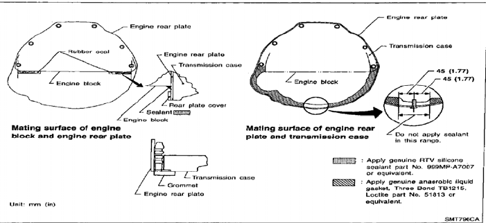
3. Apply sealant to the bell housing as shown in the diagram from
the Nissan Factory Service Manual below.
Fig. 4.4 Bell housing sealant instructions
4. Make sure you have removed the clutch alignment tool from the
clutch.
5. Lift the transmission and work it into the engine, you can use your
hand to turn the front transfer case output shaft to help align the
clutch splines with the input shaft splines (4wd model).
6. Use the diagram from the Nissan Service Manual below for bolt
torque sequence.
Don’t forget to use your new bell housing bolts!!!
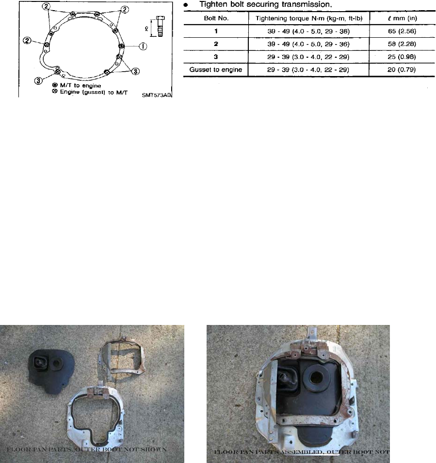
22
Fig. 4.5 Bell housing bolt pattern and bolt torque information
7. Refer to section 11 for information on converting the automatic
transmission mount to work on the manual transmission.
8. Reinstall the transmission cross member.
9. Reinstall the front (4wd models) and rear drive shaft.
10. Reinstall the starter and wiring.
11. Plug in all electrical connections.
12. Reinstall any other items not mentioned.
Interior Reinstallation
1. Reinstall the transmission and transfer case (4wd models) shifters.
2. Install the new outer manual transmission tunnel cover. (part
number 74967-0W020)
Fig 4.6 Transmission Tunnel Covers Fig 4.7 Tunnel Covers Assembled
3. Install the inner transmission tunnel cover with boots. (part number
74910-0W010)
4. Reinstall all interior components removed.
5. Install the new outer shifter cover.
(part number 74910-0W010)
23
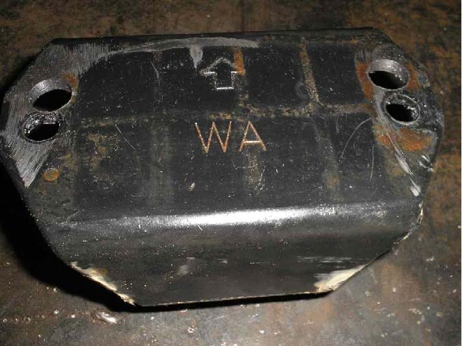
Motor Mount Conversion
1. Re-drill the top holes as shown below to convert the motor mount.
Fig. 4.8 Automatic Transmission motor mount red-drilled for Manual Transmission.
Illustrations List
24
Figure 1.1 Automatic Transmission
Figure 1.2 Torque converter bolts through starter hole.
Figure 2.1 Power Supply Routing
Figure 2.2 Relay Assembly, 96 model shown.
Figure 2.3 Relay Assembly, 97 and later.
Figure 3.1 Clutch kit from AutoZone
Figure 3.2 Clutch Dampener
Figure 3.3 Clutch transfer block, passenger
Figure 3.4 Blind hole puller tool.
Figure 3.5 Pilot bearing installed in crankshaft
Figure 3.6 Flywheel installed.
Figure 3.7 Clutch pressure plate torque sequence.
Figure 4.1 FS5R30A and TX-10 Assembly
Figure 4.2 Large plug
Figure 4.3 Automatic Transmission position switch
Figure 4.4 Bell housing sealant instructions
Figure 4.5 Bell housing bolt pattern and bolt torque information
Figure 4.6 Transmission Tunnel Covers
Figure 4.7 Tunnel Covers Assembled
Figure 4.8 Automatic Transmission motor mount red-drilled for Manual
Transmission.
