Nokia Bell A240ZA Digital Home CPE User Manual User Guide
Alcatel-Lucent Shanghai Bell Co. Ltd. Digital Home CPE User Guide
User Guide

7368 Intelligent Services Access
Manager CPE
7368 ISAM CPE A-240Z-A Product Guide
3FE-46615-AAAA-TCZZA
Issue: 01
Nokia — Proprietary and confidential
Use pursuant to applicable agreements

7368 ISAM CPE A-240Z-A Product Guide
2 3FE-46615-AAAA-TCZZA Issue: 01
Nokia is a registered trademark of Nokia Corporation. Other products and company
names mentioned herein may be trademarks or tradenames of their respective
owners.
The information presented is subject to change without notice. No responsibility is
assumed for inaccuracies contained herein.
© 2017 Nokia.
Contains proprietary/trade secret information which is the property of Nokia and must
not be made available to, or copied or used by anyone outside Nokia without its
written authorization. Not to be used or disclosed except in accordance with
applicable agreements.

7368 ISAM CPE A-240Z-A Product Guide Preface
Issue: 01 3FE-46615-AAAA-TCZZA 3
1 Preface
This preface provides general information about the documentation set for CPEs.
1.1 Scope
This documentation set provides information about safety, features and functionality,
ordering, hardware installation and maintenance, and software installation
procedures for the current release.
1.2 Audience
This documentation set is intended for planners, administrators, operators, and
maintenance personnel involved in installing, upgrading, or maintaining the CPEs.
1.3 Required knowledge
The reader must be familiar with general telecommunications principles.
1.4 Acronyms and initialisms
The expansions and optional descriptions of most acronyms and initialisms appear
in the glossary.
1.5 Assistance and ordering phone numbers
Nokia provides global technical support through regional call centers. Phone
numbers for the regional call centers are available at the following URL:
http://support.alcatel-lucent.com.
For ordering information, contact your Nokia sales representative.

4 3FE-46615-AAAA-TCZZA Issue: 01
Preface 7368 ISAM CPE A-240Z-A Product Guide
1.6 Nokia quality processes
Nokia’s CPE quality practices are in compliance with TL 9000 requirements. These
requirements are documented in the Fixed Networks Quality Manual
3FQ-30146-6000-QRZZA. The quality practices adequately ensure that technical
requirements and customer end-point requirements are met. The customer or its
representatives may be allowed to perform on-site quality surveillance audits, as
agreed upon during contract negotiations
1.7 Safety information
For safety information, see the appropriate safety guidelines chapter.
1.8 Documents
Documents are available using ALED or OLCS.
Procedure 1 To download a ZIP file package of the customer documentation
1
Navigate to http://support.alcatel-lucent.com and enter your user name and password. If you
are a new user and require access to this service, please contact your Nokia sales
representative.
2
From the Technical Content for drop-down menu, choose the product.
3
Click on Downloads: Electronic Delivery.
4
Choose Documentation from the drop-down menu and click Next.
5
Select the image from the drop-down menu and click Next.
6
Follow the on-screen directions to download the file.
Issue: 01 3FE-46615-AAAA-TCZZA 5
7368 ISAM CPE A-240Z-A Product Guide Preface
Procedure 2 To access individual documents
Individual PDFs of customer documents are also accessible through the Nokia Customer Support
website.
1
Navigate to http://support.alcatel-lucent.com and enter your user name and password. If you
are a new user and require access to this service, please contact your Nokia sales
representative.
2
From the Technical Content for drop-down menu, choose the product.
3
Click on Manuals and Guides to display a list of customer documents by title and part
number. You can filter this list using the Release drop-down menu.
4
Click on the PDF to open or save the file.
1.9 Special information
The following are examples of how special information is presented in this document.
Danger — Danger indicates that the described activity or
situation may result in serious personal injury or death; for
example, high voltage or electric shock hazards.
Warning — Warning indicates that the described activity or
situation may, or will, cause equipment damage or serious
performance problems.
Caution — Caution indicates that the described activity or
situation may, or will, cause service interruption.
Note — A note provides information that is, or may be, of
special interest.

6 3FE-46615-AAAA-TCZZA Issue: 01
Preface 7368 ISAM CPE A-240Z-A Product Guide
1.9.1
Procedures with options or substeps
When there are options in a procedure, they are identified by letters. When there are
required substeps in a procedure, they are identified by roman numerals.
Procedure 3 Example of options in a procedure
At step 1, you can choose option a or b. At step 2, you must do what the step indicates.
1
This step offers two options. You must choose one of the following:
a
This is one option.
b
This is another option.
2
You must perform this step.
Procedure 4 Example of required substeps in a procedure
At step 1, you must perform a series of substeps within a step. At step 2, you must do what the
step indicates.
1
This step has a series of substeps that you must perform to complete the step. You must
perform the following substeps:
i
This is the first substep.
ii
This is the second substep.
iii
This is the third substep.
2
You must perform this step.

Issue: 01 3FE-46615-AAAA-TCZZA 7
7368 ISAM CPE A-240Z-A Product Guide Preface
1.10 Multiple PDF document search
You can use Adobe Reader Release 6.0 and later to search multiple PDF files for a
common term. Adobe Reader displays the results in a single display panel. The
results are grouped by PDF file, and you can expand the entry for each file.
Note — The PDF files in which you search must be in the same
folder.
Procedure 5 To search multiple PDF files for a common term
1
Open Adobe Acrobat Reader.
2
Choose EditSearch from the Acrobat Reader main menu. The Search PDF panel appears.
3
Enter the search criteria.
4
Click on the All PDF Documents In radio button.
5
Select the folder in which to search using the drop-down menu.
6
Click on the Search button.
Acrobat Reader displays the search results. You can expand the entries for each document
by clicking on the + symbol.

8 3FE-46615-AAAA-TCZZA Issue: 01
Preface 7368 ISAM CPE A-240Z-A Product Guide

Issue: 01 3FE-46615-AAAA-TCZZA 9
7368 ISAM CPE A-240Z-A Product Guide
Table of contents
1
Preface ................................................................................................. 3
1.1
Scope ..............................................................................................................3
1.2
Audience .........................................................................................................3
1.3
Required knowledge ...................................................................................... 3
1.4
Acronyms and initialisms ............................................................................... 3
1.5
Assistance and ordering phone numbers ..................................................... 3
1.6
Nokia quality processes ................................................................................ 4
1.7
Safety information .......................................................................................... 4
1.8
Documents ......................................................................................................4
1.9
Special information ........................................................................................ 5
1.9.1
Procedures with options or substeps ........................................................... 6
1.10
Multiple PDF document search ..................................................................... 7
2
ETSI CPE safety guidelines ............................................................ 17
2.1
Safety instructions ....................................................................................... 17
2.1.1
Safety instruction boxes .............................................................................. 17
2.1.2
Safety-related labels .................................................................................... 18
2.2
Safety standards compliance ...................................................................... 19
2.2.1
EMC, EMI, and ESD compliance ................................................................ 19
2.2.2
Equipment safety standard compliance ..................................................... 19
2.2.3
Environmental standard compliance .......................................................... 20
2.2.4
Resistibility requirements compliance ........................................................ 20
2.2.5
Acoustic noise emission standard compliance .......................................... 20
2.3
Electrical safety guidelines .......................................................................... 20
2.3.1
Power supplies ............................................................................................ 20
2.3.2
Cabling ......................................................................................................... 21
2.3.3
Protective earth ............................................................................................ 21
2.4
ESD safety guidelines ................................................................................. 21
2.5
Environmental requirements ....................................................................... 21
3
ETSI environmental and CRoHS guidelines ................................ 23
3.1
Environmental labels ................................................................................... 23
3.1.1
Overview ...................................................................................................... 23
3.1.2
Environmental related labels ....................................................................... 23
3.1.2.1
Products below Maximum Concentration Value (MCV) label .................... 23
3.1.2.2
Products containing hazardous substances above Maximum Concentration
Value (MCV) label ...................................................................................... 24
3.2
Hazardous Substances Table (HST) ......................................................... 25
3.3
Other environmental requirements ............................................................ 26
3.3.1
CPE environmental requirements .............................................................. 26
3.3.2
Storage ........................................................................................................ 26
3.3.3
Transportation .............................................................................................. 26
3.3.4
Stationary use .............................................................................................. 26
3.3.5
Thermal limitations ...................................................................................... 26
3.3.6
Material content compliance ........................................................................ 27
3.3.7
End-of-life collection and treatment............................................................ 27

13FE-46615-AAAA-TCZZA Issue: 01
7368 ISAM CPE A-240Z-A Product Guide
4
ANSI CPE safety guidelines ........................................................... 29
4.1
Safety instructions ....................................................................................... 29
4.1.1
Safety instruction boxes in customer documentation ................................ 29
4.1.2
Safety-related labels .................................................................................... 30
4.2
Safety standards compliance ...................................................................... 31
4.2.1
EMC, EMI, and ESD standards compliance .............................................. 31
4.2.2
Equipment safety standard compliance ..................................................... 32
4.2.3
Environmental standards compliance ........................................................ 32
4.2.4
Resistibility requirements compliance ........................................................ 32
4.3
Electrical safety guidelines .......................................................................... 33
4.3.1
Power supplies ............................................................................................ 33
4.3.2
Cabling ......................................................................................................... 33
4.3.3
Protective earth ............................................................................................ 33
4.4
ESD safety guidelines ................................................................................. 33
4.5
Environmental requirements ....................................................................... 34
5
A-240Z-A unit data sheet ............................................................... 35
5.1
A-240Z-A part numbers and identification ................................................. 36
5.2
A-240Z-A general description ..................................................................... 37
5.2.1
TR-069 object support for WiFi parameters ............................................... 39
5.2.2
TR69 authentication using TLS and CA certificates ................................... 39
5.2.3
TR-104 parameter extension support for voice service ............................. 40
5.3
A-240Z-A software and installation feature support................................... 40
5.4
A-240Z-A interfaces and interface capacity ............................................... 40
5.4.1
A-240Z-A connections and components ................................................... 41
5.5
A-240Z-A LEDs............................................................................................ 42
5.6
A-240Z-A detailed specifications ................................................................. 43
5.7
A-240Z-A functional blocks ......................................................................... 44
5.8
A-240Z-A standards compliance ................................................................ 45
5.8.1
Responsible party ........................................................................................ 46
5.8.2
Energy-related products standby and off modes compliance .................... 46
5.8.3
FCC statement ............................................................................................. 47
5.8.4
FCC Radiation Exposure Statement ........................................................... 47
5.9
A-240Z-A special considerations ................................................................ 47
5.9.1
Wi-Fi service ................................................................................................ 48
5.9.1.1
Wi-Fi standards and certifications ............................................................... 48
5.9.1.2
Wi-Fi GUI features ....................................................................................... 48
5.9.2
A-240Z-A CPE considerations and limitations ........................................... 48
6
Install an A-240Z-A CPE ................................................................ 49
6.1
Purpose........................................................................................................ 49
6.2
General ........................................................................................................ 49
6.3
Prerequisites ................................................................................................ 49
6.4
Recommended tools.................................................................................... 49
6.5
Safety information ........................................................................................ 50
6.6
Procedure .................................................................................................... 51
7
Replace an A-240Z-A CPE ............................................................. 53
7.1
Purpose........................................................................................................ 53
7.2
General ........................................................................................................ 53
7.3
Prerequisites ................................................................................................ 53

Issue: 01 3FE-46615-AAAA-TCZZA 1
7368 ISAM CPE A-240Z-A Product Guide
7.4
Recommended tools.................................................................................... 53
7.5
Safety information ........................................................................................ 54
7.6
Procedure ..................................................................................................... 54
8
Configure an A-240Z-A CPE ......................................................... 57
8.1
General ........................................................................................................ 57
8.2
GUI configuration ......................................................................................... 57
8.2.1
Login ............................................................................................................ 57
8.2.2
Device and connection status ..................................................................... 58
8.2.3
Network configuration .................................................................................. 73
8.2.4
Security configuration .................................................................................. 90
8.2.5
Application configuration ........................................................................... 100
8.2.6
Maintenance .............................................................................................. 110
8.2.7
RG troubleshooting counters .................................................................... 122
8.2.8
Smart Home configuration ......................................................................... 124
8.3
IOT application software package download ........................................... 129

7368 ISAM CPE A-240Z-A Product Guide
12 3FE-46615-AAAA-TCZZA Issue: 01

7368 ISAM CPE A-240Z-A Product Guide
Issue: 01 3FE-46615-AAAA-TCZZA 13
List of figures
2
ETSI CPE safety guidelines ............................................................ 17
Figure 1 PSE certification ......................................................................................... 19
3
ETSI environmental and CRoHS guidelines ................................. 23
Figure 2 Products below MCV value label ............................................................... 24
Figure 3 Products above MCV value label ................................................................ 25
Figure 4 Recycling/take back/disposal of product symbol ........................................ 27
4
ANSI CPE safety guidelines ............................................................ 29
Figure 5 Sample safety label on the CPE equipment ............................................... 31
5
A-240Z-A unit data sheet ............................................................... 35
Figure 6 A-240Z-A CPE in its stand ........................................................................... 38
Figure 7 A-240Z-A CPE physical connections ......................................................... 41
Figure 8 A-240Z-A CPE LEDs ................................................................................... 42
Figure 9 Single-residence Wi-Fi CPE with Gigabit Ethernet and POTS and
without RF video .......................................................................................... 44
Figure 10 A-240Z-A US safety label ............................................................................ 45
Figure 11 A-240Z-A European (EU) safety label ......................................................... 45
Figure 12 A-240Z-A Australian (AU) safety label ....................................................... 46
6
Install an A-240Z-A CPE ................................................................. 49
Figure 13 A-240Z-A CPE connections ....................................................................... 51
7
Replace an A-240Z-A CPE ............................................................. 53
Figure 14 A-240Z-A CPE connections ....................................................................... 55
8
Configure an A-240Z-A CPE .......................................................... 57
Figure 15 Web login window ........................................................................................ 58
Figure 16 Device Information window ........................................................................ 59
Figure 17 LAN status window ...................................................................................... 61
Figure 18 WAN status window ..................................................................................... 63
Figure 19 WAN status IPv6 window ............................................................................ 65
Figure 20 Dongle Status window ................................................................................. 67
Figure 21 Home networking information window ........................................................ 69
Figure 22 LAN ports statistics window ......................................................................... 71
Figure 23 Voice Information window .......................................................................... 72
Figure 24 LAN network window ................................................................................... 74
Figure 25 LAN IPv6 network window ........................................................................... 76
Figure 26 WAN network window .................................................................................. 78
Figure 27 WAN DHCP window .................................................................................... 79
Figure 28 Wireless 2.4GHz network window .............................................................. 81
Figure 29 Wireless 5GHz network window ................................................................. 83
Figure 30 Wireless Schedule window .......................................................................... 85
Figure 31 Routing network window .............................................................................. 86
Figure 32 DNS network window ................................................................................... 88
Figure 33 TR-069 network window .............................................................................. 89
Figure 34 Firewall window .......................................................................................... 91

7368 ISAM CPE A-240Z-A Product Guide
14 3FE-46615-AAAA-TCZZA Issue: 01
Figure 35 MAC filter window ........................................................................................ 92
Figure 36 IP filter window ............................................................................................ 93
Figure 37 URL Filter window ...................................................................................... 95
Figure 38 Parental Control window ............................................................................ 96
Figure 39 DMZ and ALG window ............................................................................... 97
Figure 40 Access Control window ............................................................................... 99
Figure 41 Port forwarding window ........................................................................... 101
Figure 42 Port Triggering window ............................................................................ 102
Figure 43 DDNS window ............................................................................................ 104
Figure 44 NTP window ............................................................................................... 105
Figure 45 USB window .............................................................................................. 106
Figure 46 UPnP and DLNA window .......................................................................... 108
Figure 47 Voice setting window ............................................................................... 109
Figure 48 Password window ...................................................................................... 111
Figure 49 Speed Test window ................................................................................... 112
Figure 50 Device management window .................................................................... 113
Figure 51 Uplink Management window .................................................................... 114
Figure 52 Dongle management window .................................................................. 115
Figure 53 Backup and Restore window ................................................................... 116
Figure 54 Firmware upgrade window ........................................................................ 117
Figure 55 Reboot window .......................................................................................... 118
Figure 56 Factory default window ............................................................................ 119
Figure 57 Diagnostics window ................................................................................... 120
Figure 58 Log window ................................................................................................ 121
Figure 59 RG Troubleshooting Counters window .................................................... 123
Figure 60 Smart Home Status window .................................................................... 125
Figure 61 Smart Home Configuration window ......................................................... 127
Figure 62 Smart Home Maintenance window .......................................................... 128

7368 ISAM CPE A-240Z-A Product Guide
Issue: 01 3FE-46615-AAAA-TCZZA 15
List of tables
2
ETSI CPE safety guidelines ............................................................ 17
Table 1 Safety labels ................................................................................................ 18
4
ANSI CPE safety guidelines ............................................................ 29
Table 2 Safety labels ................................................................................................ 30
5
A-240Z-A unit data sheet ............................................................... 35
Table 3 Identification of A-240Z-A CPEs ................................................................ 36
Table 4 A-240Z-A power supply .............................................................................. 37
Table 5 A-240Z-A CPE interface connection capacity ............................................ 40
Table 6 A-240Z-A CPE physical connections ......................................................... 41
Table 7 A-240Z-A CPE LEDs ................................................................................... 42
Table 8 A-240Z-A CPE physical specifications ....................................................... 43
Table 9 A-240Z-A CPE power consumption specifications ..................................... 43
Table 10 A-240Z-A CPE environmental specifications .............................................. 44
Table 11 Responsible party contact information ....................................................... 46
Table 12 A-240Z-A CPE considerations and limitations ............................................ 48
8
Configure an A-240Z-A CPE .......................................................... 57
Table 13 Device Information parameters .................................................................. 59
Table 14 LAN status parameters ................................................................................ 61
Table 15 WAN status parameters .............................................................................. 63
Table 16 WAN status IPv6 parameters ...................................................................... 65
Table 17 Dongle Status parameters ........................................................................... 68
Table 18 Home networking parameters .................................................................... 69
Table 19 Voice Information parameters .................................................................... 72
Table 20 LAN network parameters ............................................................................. 74
Table 21 LAN IPv6 network parameters ..................................................................... 76
Table 22 WAN network parameters ............................................................................ 78
Table 23 WAN DHCP parameters .............................................................................. 80
Table 24 Wireless 2.4GHz network parameters ........................................................ 81
Table 25 Wireless 5GHz network parameters ............................................................ 84
Table 26 Routing network parameters ........................................................................ 87
Table 27 DNS network parameters ............................................................................ 88
Table 28 TR-069 network parameters ........................................................................ 89
Table 29 Firewall parameters ..................................................................................... 92
Table 30 MAC filter parameters .................................................................................. 93
Table 31 IP filter parameters ...................................................................................... 94
Table 32 URL Filter parameters ................................................................................ 95
Table 33 Parental control parameters ........................................................................ 96
Table 34 DMZ and ALG parameters ......................................................................... 97
Table 35 Access control parameters .......................................................................... 99
Table 36 Port forwarding parameters ....................................................................... 101
Table 37 Port triggering parameters ......................................................................... 102
Table 38 DDNS parameters ...................................................................................... 104
Table 39 USB parameters ........................................................................................ 106
Table 40 Voice setting parameters ......................................................................... 109

7368 ISAM CPE A-240Z-A Product Guide
16 3FE-46615-AAAA-TCZZA Issue: 01
Table 41 Password parameters................................................................................ 111
Table 42 Device management parameters............................................................. 113
Table 43 Dongle management parameters ............................................................ 115
Table 44 RG Troubleshooting Counters parameters .............................................. 123
Table 45 Smart Home Status parameters .............................................................. 126
Table 46 Smart Home Configuration parameters ................................................... 127
Table 47 Smart Home maintenance parameters .................................................... 128
Issue: 01 3FE-46615-AAAA-TCZZA 17
7368 ISAM CPE A-240Z-A Product Guide ETSI CPE safety guidelines
2 ETSI CPE safety guidelines
This chapter provides information about the mandatory regulations that govern the
installation and operation of CPEs.
2.1 Safety instructions
This section describes the safety instructions that are provided in the CPE customer
documentation and on the equipment.
2.1.1
Safety instruction boxes
The safety instruction boxes are provided in the CPE customer documentation.
Observe the instructions to meet safety requirements.
The following is an example of the Danger box.
Danger — Possibility of personal injury.
The Danger box indicates that the described activity or situation may pose a threat
to personal safety. It calls attention to a situation or procedure which, if not correctly
performed or adhered to, may result in death or serious physical harm.
Do not proceed beyond a Danger box until the indicated conditions are fully
understood and met.
The following is an example of the Warning box.
Warning 1 — Possibility of equipment damage.
Warning 2 — Possibility of data loss.
The Warning box indicates that the described activity or situation may, or will, cause
equipment damage, loss of data, or serious performance problems. It identifies a
possible equipment-damaging situation or provides essential information to avoid the
degradation of system operations or data.
Do not proceed beyond a warning until the indicated conditions are fully understood
and met.
18 3FE-46615-AAAA-TCZZA Issue: 01
ETSI CPE safety guidelines 7368 ISAM CPE A-240Z-A Product Guide
The following is an example of the Caution box.
Caution 1 — Possibility of service interruption.
Caution 2 — Service interruption.
The Caution box indicates that the described activity or situation may, or will, cause
service interruption.
Do not proceed beyond a caution until the indicated conditions are fully understood
and met.
The following is an example of the Note box.
Note — Information of special interest.
The Note box provides information that assists the personnel working with CPEs. It
does not provide safety-related instructions.
2.1.2
Safety-related labels
The CPE equipment is labeled with the specific safety instructions and compliance
information that is related to a variant of the CPE. Observe the instructions on the
safety labels.
Table 1 provides sample safety labels on the CPE equipment.
Table 1 Safety labels
Description Label text
ESD warning Caution: This assembly contains an electrostatic sensitive device.
PSE marking These power supplies are Japan PSE certified and compliant with
Japan VCCI emissions standards.
Figure 1 shows the PSE certification.
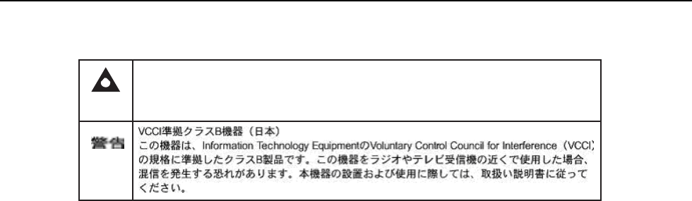
Issue: 01 3FE-46615-AAAA-TCZZA 19
7368 ISAM CPE A-240Z-A Product Guide ETSI CPE safety guidelines
Figure 1 PSE certification
Warning
This is a Class B product based on the standard of the Voluntary Control Council for Interference
from Information Technology Equipment (VCCI). If this is used near a radio or television receiver in
a domestic environment, it may cause radio interference. Install and use the equipment according
to the instruction manual.
19841
2.2 Safety standards compliance
This section describes the CPE compliance with the European safety standards.
2.2.1
EMC, EMI, and ESD compliance
The CPE equipment complies with the following EMC, EMI, and ESD requirements:
• EN 300-386 V1.5.1: Electromagnetic Compatibility and Radio Spectrum Matters
(ERM): Telecommunications Network Equipment; Electromagnetic Compatibility
(EMC) requirements; Electrostatic Discharge (ESD) requirements
• EN 55022 (2006): Class B, Information Technology Equipment, Radio
Disturbance Characteristics, limits and methods of measurement
• EN 55024 (2010): Information Technology Equipment, Immunity Characteristics,
limits and methods of measurement
• European Council Directive 2004/108/EC
• EN 300-386 V1.4.1: 2008
• EN 55022:2006 Class B (CPEs)
2.2.2
Equipment safety standard compliance
The CPE equipment complies with the requirements of EN 60950-1, Safety of
Information Technology Equipment for use in a restricted location (per R-269).

ETSI CPE safety guidelines 7368 ISAM CPE A-240Z-A Product Guide
20 3FE-46615-AAAA-TCZZA Issue: 01
2.2.3
Environmental standard compliance
The CPE equipment complies with the EN 300 019 European environmental
standards.
2.2.4
Resistibility requirements compliance
The CPE equipment complies with the requirements of ITU Recommendation K.21
for resistibility of telecommunication equipment installed in customer premises to
over voltage and overcurrents.
2.2.5
Acoustic noise emission standard compliance
The CPE equipment complies with EN 300 753 acoustic noise emission limit and test
methods.
2.3 Electrical safety guidelines
This section provides the electrical safety guidelines for the CPE equipment.
Note 1 — The CPEs comply with the U.S. National Electrical
Code. However, local electrical authorities have jurisdiction
when there are differences between the local and U.S.
standards.
Note 2 — The CPEs comply with BS EN 61140.
2.3.1
Power supplies
The use of any non-Nokia approved power supplies or power adapters is not
supported or endorsed by Nokia. Such use will void any warranty or support contract
with Nokia. Such use greatly increases the danger of damage to equipment or
property.

7368 ISAM CPE A-240Z-A Product Guide ETSI CPE safety guidelines
Issue: 01 3FE-46615-AAAA-TCZZA 21
2.3.2
Cabling
The following are the guidelines regarding cables used for the CPE equipment:
• All cables must be approved by the relevant national electrical code.
• The cables for outdoor installation of CPEs must be suitable for outdoor use.
• POTS wiring run outside the subscriber premises must comply with the
requirements of local electrical codes. In some markets, the maximum allowed
length of the outside run is 140 feet (43 m). If the outside run is longer, NEC
requires primary protection at both the exit and entry points for the wire.
2.3.3
Protective earth
Earthing and bonding of the CPEs must comply with the requirements of local
electrical codes.
2.4 ESD safety guidelines
The CPE equipment is sensitive to ESD. Operations personnel must observe the
following ESD instructions when they handle the CPE equipment.
Caution — This equipment is ESD sensitive. Proper ESD
protections should be used when you enter the TELCO Access
portion of the CPE.
During installation and maintenance, service personnel must wear wrist straps to
prevent damage caused by ESD.
2.5 Environmental requirements
See the CPE technical specification documentation for more information about
temperature ranges.

ETSI CPE safety guidelines 7368 ISAM CPE A-240Z-A Product Guide
22 3FE-46615-AAAA-TCZZA Issue: 01
During operation in the supported temperature range, condensation inside the CPE
caused by humidity is not an issue. To avoid condensation caused by rapid changes
in temperature and humidity, Nokia recommends:
• The door of the CPE not be opened until temperature inside and outside the
enclosure has stabilized.
• If the door of the CPE must be opened after a rapid change in temperature or
humidity, use a dry cloth to wipe down the metal interior to prevent the risk of
condensation.
• When high humidity is present, installation of a cover or tent over the CPE helps
prevent condensation when the door is opened.

Issue: 01 3FE-46615-AAAA-TCZZA 23
7368 ISAM CPE A-240Z-A Product Guide ETSI environmental and CRoHS guidelines
3 ETSI environmental and CRoHS
guidelines
This chapter provides information about the ETSI environmental China Restriction of
Hazardous Substances (CRoHS) regulations that govern the installation and
operation of CPEs. This chapter also includes environmental operation parameters
of general interest.
3.1 Environmental labels
This section describes the environmental instructions that are provided with the
customer documentation, equipment, and location where the equipment resides.
3.1.1
Overview
CRoHS is applicable to Electronic Information Products (EIP) manufactured or sold
and imported in the territory of the mainland of the People’s Republic of China. EIP
refers to products and their accessories manufactured by using electronic
information technology, including electronic communications products and such
subcomponents as batteries and cables.
3.1.2
Environmental related labels
Environmental labels are located on appropriate equipment. The following are
sample labels.
3.1.2.1
Products below Maximum Concentration Value
(MCV) label
Figure 2 shows the label that indicates a product is below the maximum
concentration value, as defined by standard SJ/T11363-2006 (Requirements for
Concentration Limits for Certain Hazardous Substances in Electronic Information
Products). Products with this label are recyclable. The label may be found in this
documentation or on the product.

24 3FE-46615-AAAA-TCZZA Issue: 01
ETSI environmental and CRoHS guidelines 7368 ISAM CPE A-240Z-A Product Guide
Figure 2 Products below MCV value label
18986
3.1.2.2
Products containing hazardous substances above
Maximum Concentration Value (MCV) label
Figure 3 shows the label that indicates a product is above the maximum
concentration value, as defined by standard SJ/T11363-2006 (Requirements for
Concentration Limits for Certain Hazardous Substances in Electronic Information
Products). The number contained inside the label indicates the Environment-Friendly
User Period (EFUP) value. The label may be found in this documentation or on the
product.

Issue: 01 3FE-46615-AAAA-TCZZA 25
7368 ISAM CPE A-240Z-A Product Guide ETSI environmental and CRoHS guidelines
Figure 3 Products above MCV value label
18985
Together with major international telecommunications equipment companies, Nokia
has determined it is appropriate to use an EFUP of 50 years for network
infrastructure equipment and an EFUP of 20 years for handsets and accessories.
These values are based on manufacturers' extensive practical experience of the
design, manufacturing, maintenance, usage conditions, operating environments,
and physical condition of infrastructure and handsets after years of service. The
values reflect minimum values and refer to products operated according to the
intended use conditions. See “Hazardous Substances Table (HST)” for more
information.
3.2 Hazardous Substances Table (HST)
This section describes the compliance of the OLT and CPE equipment to the CRoHS
standard when the product and subassemblies contain hazardous substances
beyond the MCV value. This information is found in this user documentation where
part numbers for the product and subassemblies are listed. It may be referenced in
other OLT and CPE documentation.
In accordance with the People’s Republic of China Electronic Industry Standard
Marking for the Control of Pollution Caused by Electronic Information Products
(SJ/T11364-2006), customers may access the Nokia Hazardous Substance Table,
in Chinese, from the following location:
• http://www.alcatel-sbell.com.cn/wwwroot/images/upload/private/1/media/ChinaRo
HS.pdf

26 3FE-46615-AAAA-TCZZA Issue: 01
ETSI environmental and CRoHS guidelines 7368 ISAM CPE A-240Z-A Product Guide
3.3 Other environmental requirements
Observe the following environmental requirements when handling the P-OLT or CPE
equipment.
3.3.1
CPE environmental requirements
See the CPE technical specification documentation for more information about
temperature ranges.
3.3.2
Storage
According to ETS 300-019-1-1 - Class 1.1, storage of OLT equipment must be in
Class 1.1, weather-protected, temperature-controlled locations.
3.3.3
Transportation
According to EN 300-019-1-2 - Class 2.3, transportation of the OLT equipment must
be in packed, public transportation with no rain on packing allowed.
3.3.4
Stationary use
According to EN 300-019-1-3 - Class 3.1/3.2/3.E, stationary use of OLT equipment
must be in a temperature-controlled location, with no rain allowed, and with no
condensation allowed.
3.3.5
Thermal limitations
When the OLT is installed in the CO or CEV, install air filters on the P-OLT. The
thermal limitations for OLT operation in a CO or CEV are:
• operating temperature: 5C to 40C (41F to 104F)
• short-term temperature: –5C to 50C (23F to 122F)
• operating relative humidity: 5% to 85%
• short-term relative humidity: 5% to 95%, but not to exceed 0.024 kg of water/kg
Issue: 01 3FE-46615-AAAA-TCZZA 27
7368 ISAM CPE A-240Z-A Product Guide ETSI environmental and CRoHS guidelines
3.3.6
Material content compliance
European Union (EU) Directive 2002/95/EC, “Restriction of the use of certain
Hazardous Substances” (RoHS), restricts the use of lead, mercury, cadmium,
hexavalent chromium, and certain flame retardants in electrical and electronic
equipment. This Directive applies to electrical and electronic products placed on the
EU market after 1 July 2006, with various exemptions, including an exemption for
lead solder in network infrastructure equipment. Nokia products shipped to the EU
after 1 July 2006 comply with the EU RoHS Directive.
Nokia has implemented a material/substance content management process. The
process is described in: Nokia process for ensuring RoHS Compliance
(1AA002660031ASZZA). This ensures compliance with the European Union
Directive 2011/65/EU on the Restriction of the Use of Certain Hazardous Substances
in Electrical and Electronic Equipment (RoHS2). With the process equipment is
assessed in accordance with the Harmonised Standard EN50581:2012 (CENELEC)
on Technical documentation for the assessment of electrical and electronic products
with respect to the restriction of hazardous substances.
3.3.7
End-of-life collection and treatment
Electronic products bearing or referencing the symbol shown in Figure 4, when put
on the market within the European Union (EU), shall be collected and treated at the
end of their useful life, in compliance with applicable EU and local legislation. They
shall not be disposed of as part of unsorted municipal waste. Due to materials that
may be contained in the product, such as heavy metals or batteries, the environment
and human health may be negatively impacted as a result of inappropriate disposal.
Note — In the European Union, a solid bar under the symbol for
a crossed-out wheeled bin indicates that the product was put on
the market after 13 August 2005.
Figure 4 Recycling/take back/disposal of product symbol

28 3FE-46615-AAAA-TCZZA Issue: 01
ETSI environmental and CRoHS guidelines 7368 ISAM CPE A-240Z-A Product Guide
At the end of their life, the OLT and CPE products are subject to the applicable local
legislations that implement the European Directive 2012/19EU on waste electrical
and electronic equipment (WEEE).
There can be different requirements for collection and treatment in different member
states of the European Union.
In compliance with legal requirements and contractual agreements, where
applicable, Nokia will offer to provide for the collection and treatment of Nokia
products bearing the logo shown in Figure 4 at the end of their useful life, or products
displaced by Nokia equipment offers. For information regarding take-back of
equipment by Nokia, or for more information regarding the requirements for
recycling/disposal of product, contact your Nokia account manager or Nokia take
back support at sustainability.global@nokia.com.
Issue: 01 3FE-46615-AAAA-TCZZA 29
7368 ISAM CPE A-240Z-A Product Guide ANSI CPE safety guidelines
4 ANSI CPE safety guidelines
This chapter provides information about the mandatory regulations that govern the
installation and operation of CPEs in the North American or ANSI market.
4.1 Safety instructions
This section describes the safety instructions that are provided in the CPE customer
documentation and on the equipment.
4.1.1
Safety instruction boxes in customer
documentation
The safety instruction boxes are provided in the CPE customer documentation.
Observe the instructions to meet safety requirements.
The following is an example of the Danger box.
Danger — Possibility of personal injury.
The Danger box indicates that the described activity or situation may pose a threat
to personal safety. It calls attention to a situation or procedure which, if not correctly
performed or adhered to, may result in death or serious physical harm.
Do not proceed beyond a Danger box until the indicated conditions are fully
understood and met.
The following is an example of the Warning box.
Warning 1 — Possibility of equipment damage.
Warning 2 — Possibility of data loss.
The Warning box indicates that the described activity or situation may, or will, cause
equipment damage, loss of data, or serious performance problems. It identifies a
possible equipment-damaging situation or provides essential information to avoid the
degradation of system operations or data.
Do not proceed beyond a warning until the indicated conditions are fully understood
and met.
ANSI CPE safety guidelines 7368 ISAM CPE A-240Z-A Product Guide
30 3FE-46615-AAAA-TCZZA Issue: 01
The following is an example of the Caution box.
Caution 1 — Possibility of service interruption.
Caution 2 — Service interruption.
The Caution box indicates that the described activity or situation may, or will, cause
service interruption.
Do not proceed beyond a caution until the indicated conditions are fully understood
and met.
The following is an example of the Note box.
Note — Information of special interest.
The Note box provides information that assists the personnel working with CPEs. It
does not provide safety-related instructions.
4.1.2
Safety-related labels
The CPE equipment is labeled with specific safety compliance information and
instructions that are related to a variant of the CPE. Observe the instructions on the
safety labels.
Table 2 provides examples of the text in the various CPE safety labels.
Table 2 Safety labels
Description Label text
ETL compliance Communication service equipment US listed. Type 3R enclosure - Rainproof.
TUV compliance Type 3R enclosure - Rainproof.
ESD warning Caution: This assembly contains electrostatic sensitive device.
FCC standards compliance Tested to comply with FCC standards for home or office use.
CDRH compliance Complies with 21 CFR 1040.10 and 1040.11.
Operation conditions This device complies with Part 15 of the FCC Rules. Operation is subject to the
following two conditions: (1) this device may not cause harmful interference, and
(2) this device must accept any interference received, including interference that
may cause undesired operation.
CE marking There are various CE symbols for CE compliance.
Figure 5 shows a sample safety label on the CPE equipment.
7368 ISAM CPE A-240Z-A Product Guide ANSI CPE safety guidelines
Issue: 01 3FE-46615-AAAA-TCZZA 31
Figure 5 Sample safety label on the CPE equipment
Tested to Comply
with FCC Standards
FOR HOME OR OFFICE USE
COMMUNICATION SERVICE EQUIPMENT
c ®
US LISTED
27FY
Type 3R Enclosure - Rainproof
This device complies with Part 15 of the FCC Rules. Operation is subject
to the following two conditions: (1) this device may not cause harmful
interference, and (2) this device must accept any interference
received, including interference that may cause undesired operation.
This Class A digital apparatus complies with Canadian ICES-003. Cet appareil
numerique de la class A est conforme a la norme NMB-003 du Canada
CAUTION
This Assembly Contains Electrostatic Sensitive Devices
18533
4.2 Safety standards compliance
This section describes the CPE compliance with North American safety standards.
Warning — Changes or modifications to this unit not expressly
approved by the party responsible for compliance could void
the user's authority to operate the equipment.
4.2.1
EMC, EMI, and ESD standards compliance
The CPE equipment complies with the following requirements:
• Federal Communications Commission (FCC) CFR 47, Part 15, Subpart B, Class
A requirements for OLT equipment
• GR-1089-CORE requirements, including:
• Section 3 Electromagnetic Interference, Emissions Radiated and Conducted
• Section 3 Immunity, Radiated and Conducted
• Section 2 ESD Discharge Immunity: System Level Electrostatic Discharge and EFT
Immunity: Electrically Fast Transients

ANSI CPE safety guidelines 7368 ISAM CPE A-240Z-A Product Guide
32 3FE-46615-AAAA-TCZZA Issue: 01
This equipment has been tested and found to comply with the limits for a Class B
digital device, pursuant to Part 15 of the FCC Rules. These limits are designed to
provide reasonable protection against harmful interference in a residential
installation. This equipment generates, uses and can radiate radio frequency energy
and, if not installed and used in accordance with the instructions, may cause harmful
interference to radio communications.
However, there is no guarantee that interference will not occur in a particular
installation. If this equipment does cause harmful interference to radio or television
reception, which can be determined by turning the equipment off and on, the user is
encouraged to try to correct the interference by one or more of the following
measures:
• Reorient or relocate the receiving antenna.
• Increase the separation between the equipment and receiver.
• Connect the equipment into an outlet on a circuit different from that to which the
receiver is needed.
• Consult the dealer or an experienced radio/TV technician for help.
4.2.2
Equipment safety standard compliance
The CPE equipment complies with the requirements of UL60950-1, Outdoor CPEs
to “Communication Service Equipment” (CSE) and Indoor CPEs to Information
Technology Equipment (ITE).
4.2.3
Environmental standards compliance
The CPE equipment complies with the following standards:
• GR-63-CORE (NEBS): requirements related to operating, storage, humidity,
altitude, earthquake, office vibration, transportation and handling, fire resistance
and spread, airborne contaminants, illumination, and acoustic noise
• GR-487-CORE: requirements related to rain, chemical, sand, and dust
• GR-487 R3-82: requirements related to condensation
• GR-3108: Requirements for Network Equipment in the Outside Plant (OSP)
• TP76200: Common Systems Equipment Interconnections Standards
4.2.4
Resistibility requirements compliance
The CPE equipment complies with the requirements of ITU Recommendation K.21
for resistibility of telecommunication equipment installed in customer premises to
overvoltage and overcurrents.

7368 ISAM CPE A-240Z-A Product Guide ANSI CPE safety guidelines
Issue: 01 3FE-46615-AAAA-TCZZA 33
4.3 Electrical safety guidelines
This section provides the electrical safety guidelines for the CPE equipment.
Note — The CPEs comply with the U.S. National Electrical
Code. However, local electrical authorities have jurisdiction
when there are differences between the local and U.S.
standards.
4.3.1
Power supplies
The use of any non-Nokia approved power supplies or power adapters is not
supported or endorsed by Nokia. Such use will void any warranty or support contract
with Nokia. Such use greatly increases the danger of damage to equipment or
property.
4.3.2
Cabling
The following are the guidelines regarding cables used for the CPE equipment:
• Use only cables approved by the relevant national electrical code.
• Use cables suitable for outdoor use for outdoor installation of CPEs.
• The CPEs have been evaluated for use with external POTS wiring without primary
protection that may not exceed 140 ft (43 m) in reach. However, the power cable
must not exceed 100 ft (31 m).
4.3.3
Protective earth
Earthing and bonding of the CPEs must comply with the requirements of NEC article
250 or local electrical codes.
4.4 ESD safety guidelines
The CPE equipment is sensitive to ESD. Operations personnel must observe the
following ESD instructions when they handle the CPE equipment.
Caution — This equipment is ESD sensitive. Proper ESD
protections should be used when entering the TELCO Access
portion of the CPE.

ANSI CPE safety guidelines 7368 ISAM CPE A-240Z-A Product Guide
34 3FE-46615-AAAA-TCZZA Issue: 01
During installation and maintenance, service personnel must wear wrist straps to
prevent damage caused by ESD.
Nokia recommends that you prepare the site before you install the CPE equipment.
In addition, you must control relative humidity, use static dissipating material for
furniture or flooring, and restrict the use of air conditioning.
4.5 Environmental requirements
See the CPE technical specification documentation for temperature ranges for
CPEs.
During operation in the supported temperature range, condensation inside the CPE
caused by humidity is not an issue. To avoid condensation caused by rapid changes
in temperature and humidity, Nokia recommends:
• The door of the CPE not be opened until temperature inside and outside the
enclosure has stabilized.
• If the door of the CPE must be opened after a rapid change in temperature or
humidity, use a dry cloth to wipe down the metal interior to prevent the risk of
condensation.
• When high humidity is present, installation of a cover or tent over the CPE helps
prevent condensation when the door is opened.

Issue: 01 3FE-46615-AAAA-TCZZA 35
7368 ISAM CPE A-240Z-A Product Guide A-240Z-A unit data sheet
5 A-240Z-A unit data sheet
5.1 A-240Z-A part numbers and identification
5.2 A-240Z-A general description
5.3 A-240Z-A software and installation feature support
5.4 A-240Z-A interfaces and interface capacity
5.5 A-240Z-A LEDs
5.6 A-240Z-A detailed specifications
5.7 A-240Z-A functional blocks
5.8 A-240Z-A standards compliance
5.9 A-240Z-A special considerations

36 3FE-46615-AAAA-TCZZA Issue: 01
A-240Z-A unit data sheet 7368 ISAM CPE A-240Z-A Product Guide
5.1 A-240Z-A part numbers and identification
Table 3 provides part numbers and identification information for the A-240Z-A CPE.
Table 3 Identification of A-240Z-A CPEs
Ordering part
number
Provisioning
number
Description CLEC CPR ECI/
Bar
code
3FE 46615 AA
(CPE only;
no power
supply)
3FE 46615 AA CPE with 1 GE uplink, 2 POTS ports, 4 10/100/1000
Base-T Ethernet interfaces, and 802.11ac 4x4 and
802.11n 2x2 WiFi radio with on/off switch.
This CPE has 2 USB 2.0 ports.
This CPE has integrated ZigBee and Z-Wave (US) band
chip sets for use in wireless home automation systems.
BVMF510BRA — —
3FE 46615 AB
(CPE only;
no power
supply)
3FE 46615 AB CPE with 1 GE uplink, 2 POTS ports, 4 10/100/1000
Base-T Ethernet interfaces, and 802.11ac 4x4 and
802.11n 2x2 WiFi radio with on/off switch.
This CPE has 2 USB 2.0 ports.
This CPE has integrated ZigBee and Z-Wave (EU band
chip sets for use in wireless home automation systems.
— — —
3FE 46615 AC
(CPE only;
no power
supply)
3FE 46615 AC CPE with 1 GE uplink, 2 POTS ports, 4 10/100/1000
Base-T Ethernet interfaces, and 802.11ac 4x4 and
802.11n 2x2 WiFi radio with on/off switch.
This CPE has 2 USB 2.0 ports.
This CPE has integrated ZigBee and Z-Wave (AUS band)
chip sets for use in wireless home automation systems.
— — —
3FE 46614 AA 3FE 46615 AA CPE with 1 GE uplink, 2 POTS ports, 4 10/100/1000
Base-T Ethernet interfaces, and 802.11ac 4x4 and
802.11n 2x2 WiFi radio with on/off switch.
This CPE has 2 USB 2.0 ports.
This CPE has integrated ZigBee and Z-Wave (US band)
chip sets for use in wireless home automation systems.
Includes power supply with US plug.
BVMF510BRA — —
3FE 46614 BA 3FE 46615 AB CPE with 1 GE uplink, 2 POTS ports, 4 10/100/1000
Base-T Ethernet interfaces, and 802.11ac 4x4 and
802.11n 2x2 WiFi radio with on/off switch.
This CPE has 2 USB 2.0 ports.
This CPE has integrated ZigBee and Z-Wave (EU band)
chip sets for use in wireless home automation systems.
Includes power supply with EU plug.
— — —
3FE 46614 CA 3FE 46615 AB CPE with 1 GE uplink, 2 POTS ports, 4 10/100/1000
Base-T Ethernet interfaces, and 802.11ac 4x4 and
802.11n 2x2 WiFi radio with on/off switch.
This CPE has 2 USB 2.0 ports.
This CPE has integrated ZigBee and Z-Wave (EU band)
chip sets for use in wireless home automation systems.
Includes power supply with UK plug.
— — —
(1 of 2)

Issue: 01 3FE-46615-AAAA-TCZZA 37
7368 ISAM CPE A-240Z-A Product Guide A-240Z-A unit data sheet
Ordering part
number
Provisioning
number
Description CLEC CPR ECI/
Bar
code
3FE 46614 DA 3FE 46615 AC CPE with 1 GE uplink, 2 POTS ports, 4 10/100/1000
Base-T Ethernet interfaces, and 802.11ac 4x4 and
802.11n 2x2 WiFi radio with on/off switch.
This CPE has 2 USB 2.0 ports.
This CPE has integrated ZigBee and Z-Wave (AUS band)
chip sets for use in wireless home automation systems.
Includes power supply with AUS plug.
— — —
(2 of 2)
Table 4 provides the detail for the power supply for the A-240Z-A.
Table 4 A-240Z-A power supply
Power/UPS model Power UPS and cabling part number
information
Customer
category or
country
compliance
tested for
Notes
Fuhua AC/DC switching
power adapter
(1)
Part number: 1AF30114 AAAA
(2)
AC power cord, 1AB07676xxxx:
• 0098: Australia
• 0099: United Kingdom
• 0100: Europe
• 0101: United States
ANSI municipality
United States,
Canada
Common
European Union
countries
12V, 36W, 3A, 6kV surge protection
5.2 A-240Z-A general description
The A-240Z-A CPE is the answer for home networking delivered by Gigabit Ethernet.
The device is a fully integrated residential gateway with the latest Wi-Fi technology
that allows for a full gigabit experience toward every device with limited wiring and
boxes.
The A-240Z-A has built-in concurrent dual-band Wi-Fi® 802.11b/g/n and 802.11ac
networking with triple play capability that simplifies the home equipment experience.
A-240Z-A CPEs contain integrated ZigBee and Z-Wave chip sets for use in wireless
home automation systems. These Zigbee and Z-wave interfaces can connect to a
wide range of Internet of Things (IOT) devices.
For information about configuring home automation files, see the section “Smart
Home configuration” in the chapter “Configure an A-240Z-A CPE”.
A-240Z-A CPEs can also be configured using the Nokia Smart Home Mobile App,
which can be downloaded on both iOS and Android devices.
38 3FE-46615-AAAA-TCZZA Issue: 01
A-240Z-A unit data sheet 7368 ISAM CPE A-240Z-A Product Guide
Additional information about Smart Home configuration, including instructions for the
Nokia Digital ONU mobile application, can be found by visiting:
https://resources.nokia.com/asset/200375.
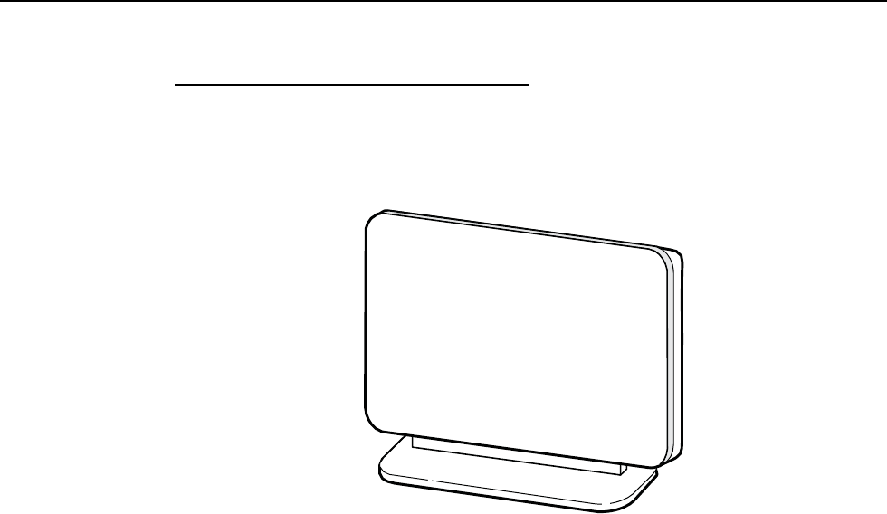
The A-240Z-A is a compact CPE that can easily fit on a desk or shelf. For
dimensions, see section 5.6. Figure 6 shows the A-240Z-A in its stand.
Figure 6 A-240Z-A CPE in its stand
26017
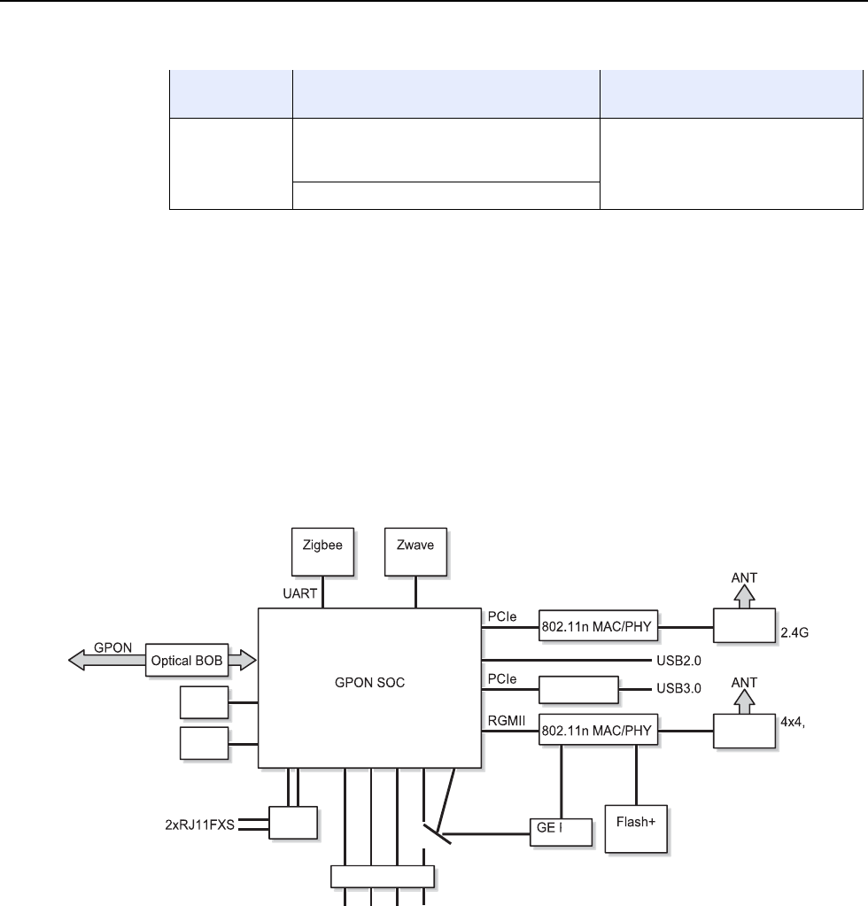
A-240Z-A CPEs provide the following functions:
• GE Ethernet uplink
• Zigbee and Zwave interfaces
• Concurrent 802.11n 2x2 MIMO in 2.4GHz and 802.11ac 4x4 MIMO in 5GHz
• auto-negotiation for speed and duplex on a port by port basis
• Bridged mode or routed mode per LAN port
• Advanced data features: VLAN tag manipulation, classification, and filtering
• Traffic classification and QoS capability
• Analog Telephone Adapter (ATA) function integrated based on SIP (RFC3261)
and H.248, with various CLASS services supported, including Caller ID, Call
Waiting, Call Forwarding, and Call Transfer
• 5 REN per line
• Multiple voice Codec
• MDI/MDIX auto-negotiation
• Line Rate L2 traffic
• Internal Switch
• UPnP IGD2.0 support
• Internal DHCP server, with configurable DHCP pool and gateway
• 64/128 WEP encryption
• WPA, WPA-PSK/TKIP

Issue: 01 3FE-46615-AAAA-TCZZA 39
7368 ISAM CPE A-240Z-A Product Guide A-240Z-A unit data sheet
• WPA2, WPA2-PSK/AES
• support for multiple SSIDs (private and public instances); contact your Nokia
representative for further details.
• LED on/off button (on back of ONT)
• WPS LED buttons for 2.4G and 5G
• Ethernet-based Point-to-Point (PPPoE)
• Network Address Translation (NAT)
• Network Address Port Translation (NAPT)
• ALG and UPnP port forwarding
• DMZ
• IP/MAC filter
• Multi-level firewall
• DNS server
• DHCP client/server
• support for HT40 mode for increased channel bandwidth
• support for up to 32 simultaneous wireless connections
• External USB HD (Hard Drive) support, accessible to all LAN devices
• support for AIS with DOWN MEP
• remote software image download
5.2.1
TR-069 object support for WiFi parameters
The ONT supports the status retrieval and configuration of the following Wi-Fi
parameters via TR-069:
• channel
• SSID
• password for WPA and WEP
• Tx power (transmission rate in dBm)
These are the same TR-069 object parameters that are supported in the GUI. For
more information, see Tables 24 and 25 in the chapter “Configure an A-240Z-A
CPE”.
5.2.2
TR69 authentication using TLS and CA certificates
A-240Z-A ONTs support TLS, as well as ACS authentication using SHA-256
pre-installed certificates.
If the URL is set to the https://... format, by default, the connection will use TLS
without authentication mode. The ONT can also authenticate the ACS using a
pre-installed CA certificate.

A-240Z-A unit data sheet 7368 ISAM CPE A-240Z-A Product Guide
40 3FE-46615-AAAA-TCZZA Issue: 01
5.2.3
TR-104 parameter extension support for voice
service
A proprietary attribute has been added to the TR-104 Voice Service object structure
to enable the ACS to configure the name of the embedded GSIP XML file to be
selected.
The TR-104 Voice Service Object is:
InternetGatewayDevice.Services.VoiceService.{i}.Capabilities.SIP.
The proprietary attribute is: X_ALU-COM_XML_File_Name_Path.
5.3 A-240Z-A software and installation feature
support
For information on installing or replacing the A-240Z-A see:
• Install an A-240Z-A CPE
• Replace an A-240Z-A CPE
For information on the following topics, see the 7368 ISAM CPE Product Overview
Guide:
• CPE and MDU general descriptions of features and functions
• Ethernet interface specifications
• POTS interface specifications
• Wi-Fi specifications
• SLID entry via Ethernet port
• CPE management using a CPE interface
5.4 A-240Z-A interfaces and interface capacity
Table 5 describes the supported interfaces and interface capacity for A-240Z-A
CPEs.
Table 5 A-240Z-A CPE interface connection capacity
CPE type
and model
Maximum capacity
POTS 10/ 100
BASE-T
10/ 100/1000
1000 BASE-T RF video
(CATV)
MoCA VDSL2 E1/T1 Local
craft
GE uplink
A-240Z-A (1) 2 — 4 — — — — — 1
Note
(1) The A-240Z-A CPEs provide Wi-Fi service that is enabled and disabled using a Wi-Fi on/off switch.
7368 ISAM CPE
A
-240Z-
A
Product Guide
A
-240Z-
A
unit data sheet
Issue: 01 3FE-46615-AAAA-TCZZA 41
5.4.1
A-240Z-A connections and components
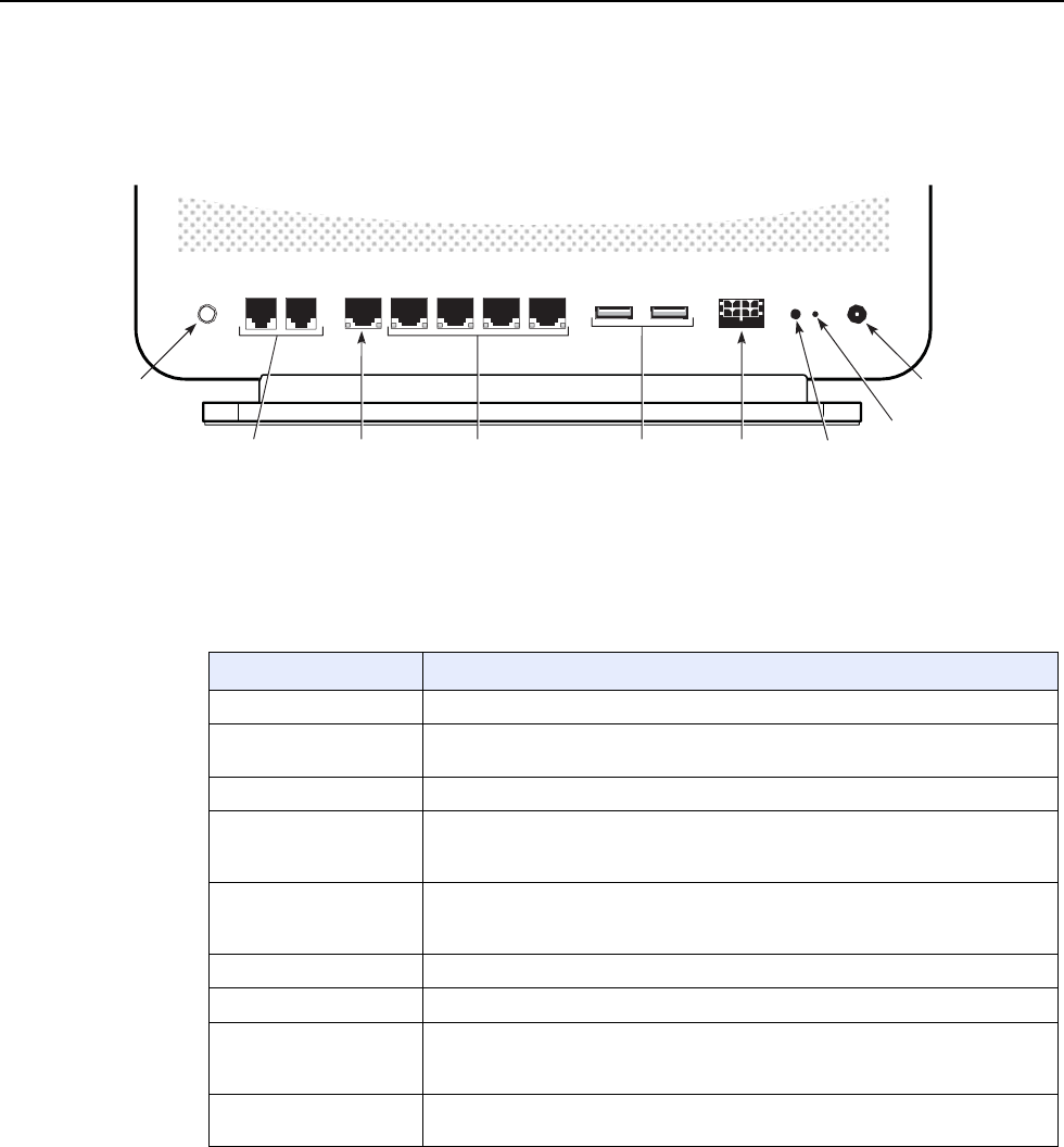
Figure 7 shows the physical connections for A-240Z-A CPEs.
Figure 7 A-240Z-A CPE physical connections
ON/OFF TEL1 TEL2 WAN LAN1 LAN2 LAN3 LAN4 USB USB UPS LED
POWER
ON/OFF
button
TEL1 and TEL2
POTS ports
(RJ-11)
WAN port
(RJ-45)
LAN ports (4)
(RJ-45)
USB 2.0
ports (2)
Power supply
connector
LED on/off
button
Power
connector
Reset
button
26018
Table 6 describes the physical connections for A-240Z-A CPEs.
Table 6 A-240Z-A CPE physical connections
Connection
(1)
Description
On/Off button This button turns the CPE on or off.
POTS ports This connection is provided through RJ-11 ports. Up to two POTS connections are
supported.The POTS ports support voice services.
WAN port This connection is provided through an RJ-45 GE interface.
Ethernet ports (LAN) This connection is provided through Ethernet RJ-45 connectors. Up to four
10/100/1000 Base-T Ethernet interfaces are supported.The Ethernet ports can
support both data and in-band video services on all four interfaces.
USB ports This connection is provided through 2 USB 2.0 ports. The maximum combined
current is 1000mA. The throughput for each port is 90 Mbps. The CPE supports
external USB hard drives that can be made accessible to all LAN devices.
UPS (power supply) input This connection is provided through a UPS connector.
LED ON/Off button This button is used to turn all LEDs on or off.
Reset button Pressing the Reset button for less than 10 seconds reboots the CPE; pressing the
Reset button for 10 seconds resets the CPE to the factory defaults, except for the
LOID and SLID.
Power input This connection is provided through the power connector. A power cable fitted with
a barrel connector is used to make the connection.
Note
(1)
The primary path for the earth ground for these CPEs is provided by the 12V Return signal in the power
connector.
A-240Z-A unit data sheet 7368 ISAM CPE A-240Z-A Product Guide
42 3FE-46615-AAAA-TCZZA Issue: 01
5.5 A-240Z-A LEDs
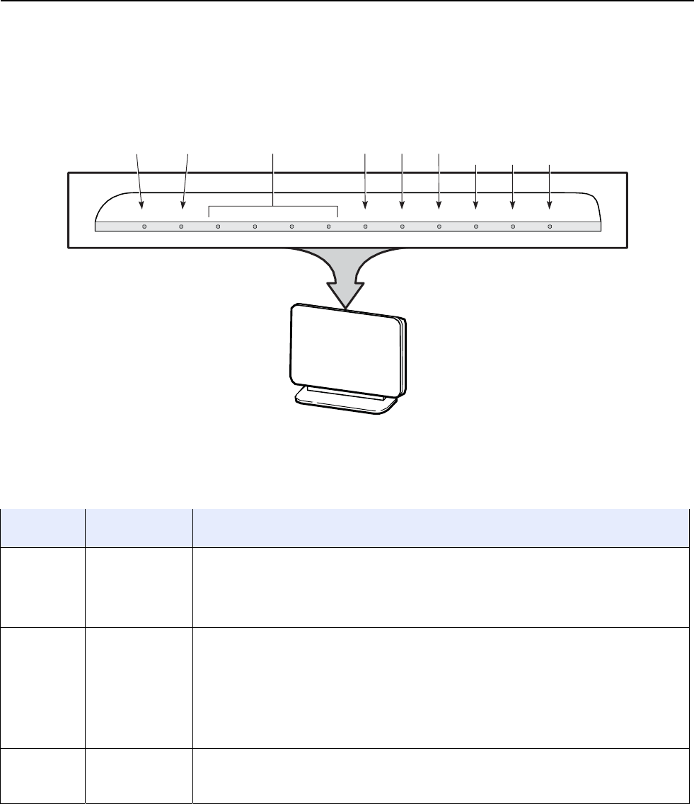
Figure 8 shows the A-240Z-A CPE LEDs.
Figure 8 A-240Z-A CPE LEDs
Power
Internet
LAN 1 to 4
Tel1
Tel2 VoIP
WPS
WLAN WLAN
2.4G
2.4G
5G
POWER INTERNET LAN1 LAN2 LAN3 LAN4 TEL1 TEL2 VOIP WPS 2.4G WLAN 2.4G WLAN 5G
26019
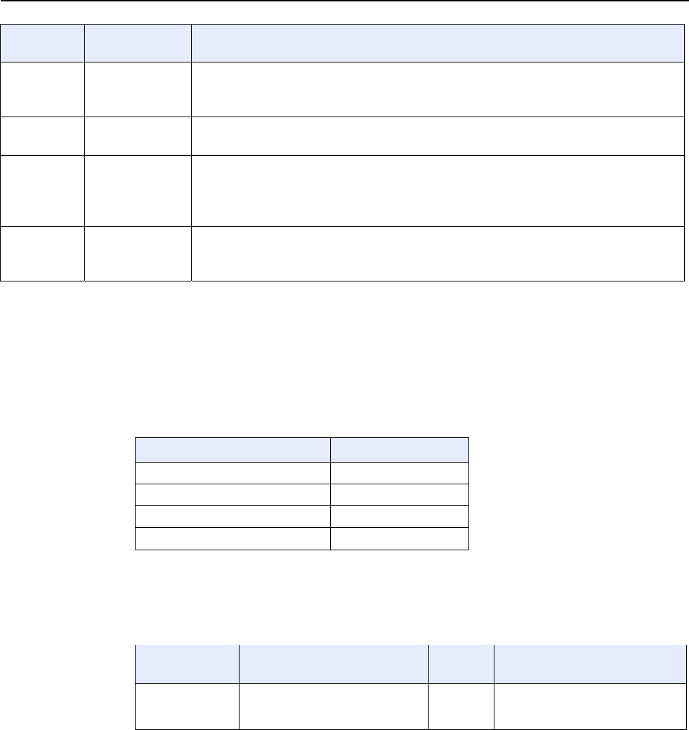
Table 7 provides LED descriptions for A-240Z-A CPEs.
Table 7 A-240Z-A CPE LEDs
Indicator LED color and
behavior
LED behavior description
Power Green solid
Off
Red solid (default
until software is
running)
Power on
Power off
CPE is operating on battery power, or light failed on startup (for example corrupt flash), or self test
failed on startup, or self test failed during regular operation.
INTERNET Green solid
Green flashing
Off
HSI WAN is connected: a) the device has an IP address assigned from IPCP, DHCP, or static, and
no traffic has been detected; b) the session is dropped due to idle timeout but the PON link is still
present.
PPPoE or DHCP connection in progress
HSI WAN is not connected: a) there is no physical interface connection; b) the device is in bridged
mode without an assigned IP address; c) the session has been dropped for reasons other than idle
timeout.
LAN 1 to 4 Green solid
Green flashing
Off
Ethernet is linked
LAN activity is present (in either direction)
Ethernet is not connected, or no power to CPE
(1 of 2)
7368 ISAM CPE A-240Z-A Product Guide A-240Z-A unit data sheet
Issue: 01 3FE-46615-AAAA-TCZZA 43
Indicator LED color and
behavior
LED behavior description
TEL 1 to 2 Green solid
Green flashing
Off
Telephone on POTS port has been provisioned and phone is off hook
Telephone on POTS port is in ‘call in’ or ‘talking’ condition, or battery is low
Telephone on POTS port is on hook, or battery missing or no power to CPE
VOIP Green solid
Off
VOIP service is built up and can provide service
VOIP service is not built up or out of service, or no power to CPE
WPS 2.4G
and 5G Green solid
Green flashing
Off
RED
WPS is enabled or WPS negotiation is successful
WPS is in progress
WPS is disabled, or no power to CPE
WPS error or session overlap
WLAN
2.4G and 5G
Green solid
Green flashing
Off
WLAN link is enabled (up)
Traffic is passing on the WLAN link
WLAN link is disabled (down)
(2 of 2) 5.6 A-240Z-A detailed specifications
Table 8 lists the physical specifications for A-240Z-A CPEs.
Table 8 A-240Z-A CPE physical specifications
Description Specification
Width 10.8 in. (273.5 mm)
Height 6.8 in. (173 mm)
Depth 3.0 in. (76.6 mm)
Weight [within 0.5 lb (0.23 kg)] 2.1 lb (.94 kg)
Table 9 lists the power consumption specifications for A-240Z-A CPE.
Table 9 A-240Z-A CPE power consumption specifications
Maximum power
(Not to exceed)
Condition Minimum
power
Condition
25 W 2 POTS off-hook, 4 10/100/1000
Base-T Ethernet, Wi-Fi operational,
USB not connected
8.9 W 2 POTS on-hook, other
interfaces/services not provisioned
Table 10 lists the environmental specifications for A-240Z-A CPE.
A-240Z-A unit data sheet 7368 ISAM CPE A-240Z-A Product Guide
44 3FE-46615-AAAA-TCZZA Issue: 01
Table 10 A-240Z-A CPE environmental specifications
Mounting
method
Temperature range and humidity Altitude
On desk or shelf Operating: 23F to 113F (-5C to 45C)
ambient temperature
5% to 85% relative humidity, non-condensing
Contact your Nokia technical support
representative for more information
Storage: -4F to 158F (-20C to 70C)
5.7 A-240Z-A functional blocks
A-240Z-A CPEs are single-residence CPEs that support Wireless (Wi-Fi) service.
Wi-Fi service on these CPEs is compliant with the IEEE 802.11 standard. In addition
to the Wi-Fi service, these CPEs transmit Ethernet packets to four RJ-45 Ethernet
ports and voice traffic to two RJ-11 POTS ports. These CPEs also feature USB and
power connectors.
Figure 9 shows the functional blocks for A-240Z-A CPE.
Figure 9 Single-residence Wi-Fi CPE with Gigabit Ethernet and POTS and without RF video
4xGE
25241
PHY PHY
PCM/SPI GE GE GE GE GPIO
PA/LNA
uPD720202
NAND
PA/LNA
DDR
SLIC RAM
XFMR
3x3,
5G
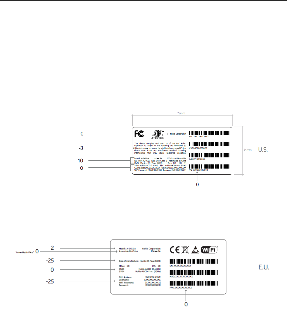
7368 ISAM CPE A-240Z-A Product Guide A-240Z-A unit data sheet
Issue: 01 3FE-46615-AAAA-TCZZA 45
5.8 A-240Z-A standards compliance
A-240Z-A CPEs are compliant with the following standards:
• IEEE 802.1D (QoS), 802.1p (bridging), 802.1q (VLAN)
• IEEE 802.3 (2012) (Ethernet standard)
• IEEE 802.11ac 4x4 (WiFi 5G) and 802.11b/g/n 2x2 (WiFi 2.4G)
• G.711, G.722, G.723, G.726, G.729 A, B (voice)
• ITU-T 1.552 for POTS ports
Figure 10 shows the US safety label for the A-240Z-A CPE.
Figure 10 A-240Z-A US safety label
Figure 11 shows the European (EU) safety label for the A-240Z-A CPE.
Figure 11 A-240Z-A European (EU) safety label
Figure 12 shows the Australian (AU) safety label for the A-240Z-A CPE.
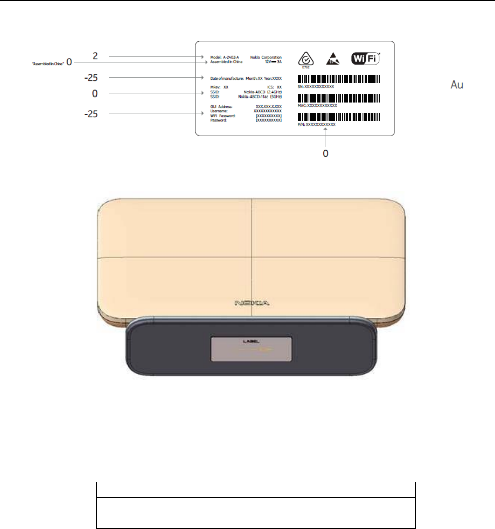
A-240Z-A unit data sheet 7368 ISAM CPE A-240Z-A Product Guide
46 3FE-46615-AAAA-TCZZA Issue: 01
Figure 12 A-240Z-A Australian (AU) safety label
A-240Z-A Label location
5.8.1
Responsible party
Table 11 lists the party in the US responsible for this CPE.
Table 11 Responsible party contact information
Legal Company name Nokia USA Inc.
Address 2301 SUGAR BUSH RD. STE 300, RALEIGH,NC 27612
Phone, Fax +1 919 850 6000
5.8.2
Energy-related products standby and off modes
compliance
Hereby, Nokia declares that the A-240Z-A CPEs are in compliance with the essential

7368 ISAM CPE A-240Z-A Product Guide A-240Z-A unit data sheet
Issue: 01 3FE-46615-AAAA-TCZZA 47
requirements and other relevant provisions of Directive 2009/125/EC together with
Commission Regulation (EC) No 1275/2008 and Commission Regulation (EC) No
801/2013.
The A-240Z-A CPES qualify as equipment with high network availability (HiNA)
functionality. Since the main purpose of A-240Z-A CPEs is to provide network
functionality with HiNA 7 days /24 hours, the modes Off/Standby, Power
Management, and Networked Standby are inappropriate.
For information about the type and number of network ports, see “A-240Z-A
interfaces and interface capacity” in this chapter.
For information about power consumption, see “A-240Z-A detailed specifications” in
this chapter.
5.8.3
Canadian Additional Statement:
This device complies with Industry Canada’s licence-exempt RSSs. Operation is
subject to the following two conditions:
(1) This device may not cause interference; and
(2) This device must accept any interference, including interference that may
cause undesired operation of the device.
Le présent appareil est conforme aux CNR d'Industrie Canada applicables aux
appareils radio exempts de licence. L'exploitation est autorisée aux deux
conditions
suivantes : (1) l'appareil ne doit pas produire de brouillage, et (2) l'utilisateur de
l'appareil doit accepter tout brouillage radioélectrique subi, même si le brouillage
est
susceptible d'en compromettre le fonctionnement.
To satisfy IC RF exposure requirements, a separation distance of 20 cm or more
should be maintained between the antenna of this device and persons during
device operation.
To ensure compliance, operations at closer than this distance is not
recommended.
Les antennes installées doivent être situées de facon à ce que la population ne
puisse
y être exposée à une distance de moin de 20 cm. Installer les antennes de facon
à ce
que le personnel ne puisse approcher à 20 cm ou moins de la position centrale de
l’
antenne. La FCC des éltats-unis stipule que cet appareil doit être en tout temps
éloigné d’au moins 20 cm des personnes pendant son functionnement.
i. the device for operation in the band 5150–5250 MHz is only for indoor use to
reduce the potential for harmful interference to co-channel mobile satellite
systems;4
les dispositifs fonctionnant dans la bande de 5 150 à 5 250 MHz sont réservés
uniquement pour une utilisation à l'intérieur afin de réduire les risques de
brouillage préjudiciable aux systèmes de satellites mobiles utilisant les mêmes
canaux;
ii. for devices with detachable antenna(s), the maximum antenna gain permitted
for devices in the bands 5250-5350 MHz and 5470-5725 MHz shall be such that
the equipment still complies with the e.i.r.p. limit;
pour les dispositifs munis d’antennes amovibles, le gain maximal d'antenne
permis pour les dispositifs utilisant les bandes de 5 250 à 5 350 MHz et de 5 470

A-240Z-A unit data sheet 7368 ISAM CPE A-240Z-A Product Guide
48 3FE-46615-AAAA-TCZZA Issue: 01
à 5 725 MHz doit être conforme à la limite de la p.i.r.e;
iii. for devices with detachable antenna(s), the maximum antenna gain permitted
for devices in the band 5725-5850 MHz shall be such that the equipment still
complies with the e.i.r.p. limits as appropriate; and
pour les dispositifs munis d’antennes amovibles, le gain maximal d'antenne
permis (pour les dispositifs utilisant la bande de 5 725 à 5 850 MHz) doit être
conforme à la limite de la p.i.r.e. spécifiée pour l'exploitation point à point et
l’exploitation non point à point, selon le cas;
iv. where applicable, antenna type(s), antenna models(s), and worst-case tilt
angle(s) necessary to remain compliant with the e.i.r.p. elevation mask
requirement set forth in section 6.2.2.3 shall be clearly indicated.
les pires angles d’inclinaison nécessaires pour rester conforme à l’exigence de la
p.i.r.e. applicable au masque d’élévation, et énoncée à la section 6.2.2 3), doivent
être clairement indiqués.

7368 ISAM CPE A-240Z-A Product Guide A-240Z-A unit data sheet
Issue: 01 3FE-46615-AAAA-TCZZA 49
5.8.4
FCC statement
This equipment has been tested and found to comply with the limits for a Class B
digital device, pursuant to part 15 of the FCC Rules. These limits are designed to
provide reasonable protection against harmful interference in a residential
installation. This equipment generates, uses and can radiate radio frequency energy
and, if not installed and used in accordance with the instructions, may cause harmful
interference to radio communications. However, there is no guarantee that
interference will not occur in a particular installation. If this equipment does cause
harmful interference to radio or television reception, which can be determined by
turning the equipment off and on, the user is encouraged to try to correct the
interference by one or more of the following measures:
• Reorient or relocate the receiving antenna.
• Increase the separation between the equipment and receiver.
• Connect the equipment into an outlet on a circuit different from that to which the
receiver is connected.
• Consult the dealer or an experienced radio/TV technician for help.
5.8.5
FCC Radiation Exposure Statement
This device complies with FCC radiation exposure limits set forth for an uncontrolled
environment and it also complies with Part 15 of the FCC RF Rules. This equipment
must be installed and operated in accordance with provided instructions and the
antenna(s) used for this transmitter must be installed to provide a separation
distance of at least 20 cm from all persons and must not be co-located or operating
in conjunction with any other antenna or transmitter. End-users and installers must
be provided with antenna installation instructions and consider removing the
no-collocation statement.
This device complies with Part 15 of the FCC Rules. Operation is subject to the
following two conditions:
1
this device may not cause harmful interference, and
2
this device must accept any interference received, including interference that
may cause undesired operation.
Caution — Any changes or modifications not expressly
approved by the party responsible for compliance could void
the user's authority to operate the equipment.
5.9 A-240Z-A special considerations
This section describes the special considerations for A-240Z-A CPEs.

A-240Z-A unit data sheet 7368 ISAM CPE A-240Z-A Product Guide
50 3FE-46615-AAAA-TCZZA Issue: 01
5.9.1
Wi-Fi service
A-240Z-A CPEs feature Wi-Fi service as well as voice and data services. Wi-Fi is a
wireless networking technology that uses radio waves to provide wireless HSI and
network connections. This CPE complies with the IEEE 802.11 standards, which the
Wi-Fi Alliance defines as the basis for Wi-Fi technology.
5.9.1.1
Wi-Fi standards and certifications
The Wi-Fi service on A-240Z-A CPEs supports the following IEEE standards and
Wi-Fi Alliance certifications:
• compliant with IEEE 802.11 standards
• certified for IEEE 802.11b/g/n standards
• WPA support including WPA-PSK
• certified for WPA2-Personal and WPA2-Enterprise
5.9.1.2
Wi-Fi GUI features
A-240Z-A CPEs have HTML-based Wi-Fi configuration GUIs.
5.9.2
A-240Z-A CPE considerations and limitations
Table 12 lists the considerations and limitations for A-240Z-A CPEs.
Table 12 A-240Z-A CPE considerations and limitations
Considerations and limitations
Call History Data collection (CPECALLHST) is supported, except for the following parameters:
RTP packets (discarded), far-end RTCP and RTCP-XR participation, RTCP average and peak round trip delay,
MOS, average jitter, number of jitter-buffer over-runs and under runs.
Some voice features are configurable on a per CPE basis, including Call Waiting, Call Hold, 3-Way Calling, and
Call Transfer.
The following voice features / GSIP parameters are configurable on a per-Client/ per-CPE basis (not
per-Subscriber):
• Enable Caller ID and Enable Caller Name ID
• Digitmap and the associated Interdigit and Critical timers and Enter key parameters
• Warmline timer is enabled per subscriber, but the warmline timer value is configured per CPE and must have
a lower value than the Permanent time
• Miscellaneous timers: Permanent, Timed-release, Reanswer, Error-tone, and CW-alert timers
• Features / functions: Message waiting mode, WMWI refresh interval, DTMF volume level
• Service Codes for the following features: CCW, Call Hold and Warmline

Issue: 01 3FE-46615-AAAA-TCZZA 51
7368 ISAM CPE A-240Z-A Product Guide Install an A-240Z-A CPE
6 Install an A-240Z-A CPE
6.1
Purpose
6.2
General
6.3
Prerequisites
6.4
Recommended tools
6.5
Safety information
6.6
Procedure
6.1 Purpose
This chapter provides the steps to install an A-240Z-A CPE.
6.2 General
The steps listed in this chapter describe mounting and cabling for an A-240Z-A CPE.
6.3 Prerequisites
You need the following items before beginning the installation:
• all required cables
6.4 Recommended tools
You need the following tools for the installation:
• #2 Phillips screwdriver
• 1/4 in. (6 mm) flat blade screwdriver
• wire strippers
• RJ-45 cable plug crimp tool
• voltmeter or multimeter
• drill and drill bits
• paper clip

Install an A-240Z-A CPE 7368 ISAM CPE A-240Z-A Product Guide
50 3FE-46615-AAAA-TCZZA Issue: 01
6.5 Safety information
Read the following safety information before installing the unit.
Danger 1 — Hazardous electrical voltages and currents can
cause serious physical harm or death. Always use insulated
tools and follow proper safety precautions when connecting or
disconnecting power circuits.
Danger 2 — Make sure all sources of power are turned off and
have no live voltages present on feed lines or terminals. Use a
voltmeter to measure for voltage before proceeding.
Danger 3 — Always contact the local utility company before
connecting the enclosure to the utilities.
Caution — Keep indoor CPEs out of direct sunlight. Prolonged
exposure to direct sunlight can damage the unit.
Note 1 — Observe the local and national laws and regulations
that may be applicable to this installation.
Note 2 — Observe the following:
• The CPE should be installed in accordance with the
applicable requirements of the NEC or CEC. Local
authorities and practices take precedent when there is
conflict between the local standard and the NEC or CEC.
• The CPE must be installed by qualified service personnel.
• Indoor CPEs must be installed with cables that are suitably
rated and listed for indoor use.
• See the detailed specifications in the A-240Z-A unit data
sheet for the temperature ranges for these CPEs.
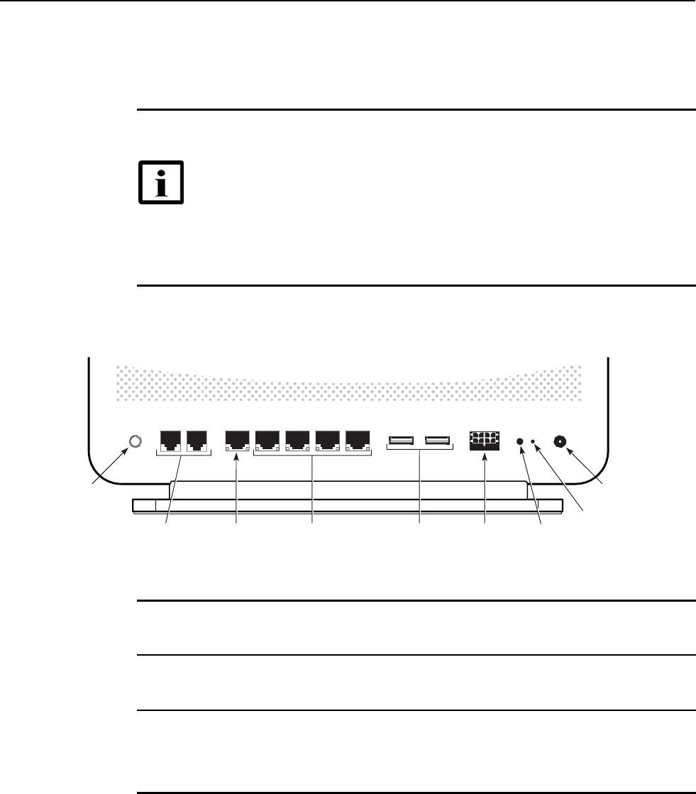
7368 ISAM CPE
A
-240Z-
A
Product Guide Install an
A
-240Z-
A
CPE
Issue: 01 3FE-46615-AAAA-TCZZA 51
6.6 Procedure
Use this procedure to install an A-240Z-A CPE.
1
Place the CPE unit on a flat surface, such as a desk or shelf.
Note —
The A-240Z-A cannot be stacked with another CPE or with
other equipment. The CPE mounting requirements are:
•
allow a minimum 100 mm clearance above the top cover
•
allow a minimum 50 mm clearance from the side vents
•
do not place any heat source directly above the top cover or below the
bottom cover
2
Review the connection locations as shown in Figures 13.
Figure 13 A-240Z-A CPE connections
ON/OFF TEL1 TEL2 WAN LAN1 LAN2 LAN3 LAN4 USB USB UPS LED
POWER
ON/OFF
button
TEL1 and TEL2
POTS ports
(RJ-11)
WAN port
(RJ-45)
LAN ports (4)
(RJ-45)
USB 2.0
ports (2)
Power supply
connector
LED on/off
button
Power
connector
Reset
button
26018
3
Connect the Ethernet cables to the RJ-45 ports; see Figure 13 for the location of the RJ-45
ports.
4
Connect the WAN cable to the RJ-45 WAN port; see Figure 13 for the location of the RJ-45
WAN port.
5
Route the POTS cables directly to the RJ-11 ports as per local practices.
The POTS port to the left is labeled TEL1 for Line 1 while the port on the right is labeled TEL2
for Line 2, as shown in Figure 13.
6
Connect the power cable to the power connector.

Install an A-240Z-A CPE 7368 ISAM CPE A-240Z-A Product Guide
52 3FE-46615-AAAA-TCZZA Issue: 01
7
If applicable, install the power supply according to manufacturer specifications.
Note — Observe the following:
• Units must be powered by a Listed or CE approved and marked
limited power source power supply with a minimum output rate of
12 V dc, 1.25 A.
8
Power up the CPE unit by using the power switch.
9
Verify the CPE LEDs and voltage status; see the 7368 Hardware and Cabling Installation
Guide.
10
Activate and test the services; see the 7368 Hardware and Cabling Installation Guide.
11
If necessary, reset the CPE.
i
Locate the Reset button on an A-240Z-A CPE as shown in Figure 13.
ii
Insert the end of a straightened paper clip or other narrow object into the hole in the
Reset button to reset the CPE.
12
STOP. This procedure is complete.

Issue: 01 3FE-46615-AAAA-TCZZA 53
7368 ISAM CPE A-240Z-A Product Guide Replace an A-240Z-A CPE
7 Replace an A-240Z-A CPE
7.1
Purpose
7.2
General
7.3
Prerequisites
7.4
Recommended tools
7.5
Safety information
7.6
Procedure
7.1 Purpose
This chapter provides the steps to replace an A-240Z-A CPE.
7.2 General
The steps listed in this chapter describe mounting and cabling for an A-240Z-A CPE.
7.3 Prerequisites
You need the following items before beginning the installation:
• all required cables
7.4 Recommended tools
You need the following tools for replacing the CPE:
• #2 Phillips screwdriver
• 1/4 in. (6 mm) flat blade screwdriver
• wire strippers
• RJ-45 cable plug crimp tool
• voltmeter or multimeter
• drill and drill bits
54 3FE-46615-AAAA-TCZZA Issue: 01
Replace an A-240Z-A CPE 7368 ISAM CPE A-240Z-A Product Guide
7.5 Safety information
Read the following safety information before replacing the unit.
Danger 1 — Hazardous electrical voltages and currents can
cause serious physical harm or death. Always use insulated
tools and follow proper safety precautions when connecting or
disconnecting power circuits.
Danger 2 — Make sure all sources of power are turned off and
have no live voltages present on feed lines or terminals. Use a
voltmeter to measure for voltage before proceeding.
Danger 3 — Always contact the local utility company before
connecting the enclosure to the utilities.
Caution — Keep indoor CPEs out of direct sunlight. Prolonged
exposure to direct sunlight can damage the unit.
Note 1 — Observe the local and national laws and regulations
that may be applicable to this installation.
Note 2 — Observe the following:
• The CPE should be installed in accordance with the
applicable requirements of the NEC or CEC. Local
authorities and practices take precedent when there is
conflict between the local standard and the NEC or CEC.
• The CPE must be installed by qualified service personnel.
• Indoor CPEs must be installed with cables that are suitably
rated and listed for indoor use.
• See the detailed specifications in the A-240Z-A unit data
sheet for the CPE temperature ranges for these CPEs.
7.6 Procedure
Use this procedure to replace an A-240Z-A CPE.
1
Deactivate the CPE services at the P-OLT.
i
Use the RTRV-CPE command to verify the CPE status and th associated services.
Record the serial number of the CPE displayed in the command output.
Example:
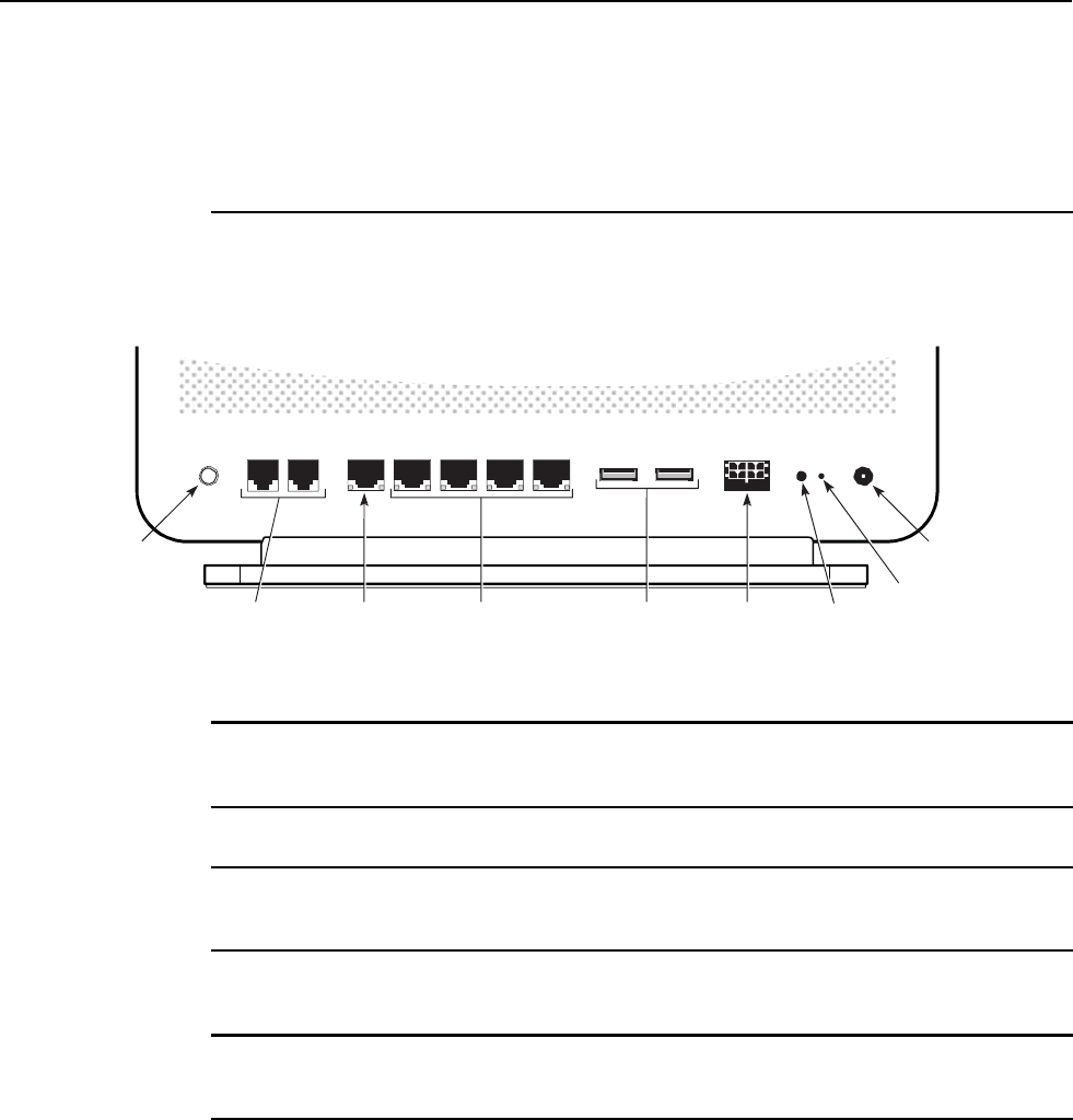
Issue: 01 3FE-46615-AAAA-TCZZA 55
7368 ISAM CPE
A
-240Z-
A
Product Guide Replace an
A
-240Z-
A
CPE
RTRV-CPE::CPE-1-1-1-1-1;
ii
If the CPE is in service, place the CPE in OOS state.
Example:
ED-CPE::CPE-1-1-1-1-1;
2
Power down the unit by using the on/off power switch. See Figure 14 for the connections on
the A-240Z-A CPE.
Figure 14 A-240Z-A CPE connections
ON/OFF TEL1 TEL2 WAN LAN1 LAN2 LAN3 LAN4 USB USB UPS LED
POWER
ON/OFF
button
TEL1 and TEL2
POTS ports
(RJ-11)
WAN port
(RJ-45)
LAN ports (4)
(RJ-45)
USB 2.0
ports (2)
Power supply
connector
LED on/off
button
Power
connector
Reset
button
26018
3
Disconnect the POTS, WAN, Ethernet, and power cables from the CPE; see Figure 14 for
the connector locations on the A-240Z-A CPE.
4
If applicable, disconnect the UPS.
5
Replace the CPE with the new unit. The CPE can be placed on any flat surface, such as a
desk or shelf.
6
Connect the Ethernet cables directly to the RJ-45 ports; see Figure 14 for the location of the
RJ-45 ports.
7
Connect the WAN cable directly to the RJ-45 port; see Figure 14 for the location of the RJ-45
WAN port.
8
Connect the POTS cables directly to the RJ-11 ports as per local practices; see Figure 14 for
the location of the RJ-11 ports.
The RJ-11 port to the left is labeled TEL1 for Line 1 while the port on the right is labeled TEL2
for Line 2.

56 3FE-46615-AAAA-TCZZA Issue: 01
Replace an A-240Z-A CPE 7368 ISAM CPE A-240Z-A Product Guide
9
Connect the power cable to the power connector.
10
If applicable, install the power supply according to manufacturer specifications.
Note — Observe the following:
• Units must be powered by a Listed or CE approved and marked
limited power source power supply with a minimum output rate of
12 V dc, 1.25 A.
11
Power up the unit by using the power switch.
12
Verify the CPE LEDs and voltage status; see the 7368 Hardware and Cabling Installation
Guide.
13
Activate and test the services; see the 7368 Hardware and Cabling Installation Guide.
14
If necessary, reset the CPE.
i
Locate the Reset button on an A-240Z-A CPE as shown in Figure 14.
ii
Insert the end of a straightened paper clip or other narrow object into the hole in the
Reset button to reset the CPE.
15
STOP. This procedure is complete.

Issue: 01 3FE-46615-AAAA-TCZZA 57
7368 ISAM CPE A-240Z-A Product Guide Configure an A-240Z-A CPE
8 Configure an A-240Z-A CPE
8.1
General
8.2
GUI configuration
8.3
IOT application software package download
8.1 General
Please refer to the configuration information provided with your OLT for the software
configuration procedure for an A-240Z-A CPE.
For HTTP configuration procedures, please refer to the 7368 ISAM CPE
Configuration, Management, and Troubleshooting Guide.
8.2 GUI configuration
Use the procedures below to use the web-based GUI for the A-240Z-A.
The A-240Z-A is used as an Ethernet gateway to connect devices in the home to the
Internet. The GUI provides a variety of features for the home network including
routing and firewall capability. By using the GUI, users can connect all smart
equipment in their home, including personal computers, set-top boxes, mobile
phones, and other consumer electronics devices, to the Internet.
8.2.1
Login
Use the procedure below to login to the web-based GUI for the A-240Z-A.
Procedure 6 Login to web-based GUI
1
Open a web browser and enter the IP address of the CPE in the address bar.
The login window appears.
The default gateway IP address is http://192.168.1.1. You can connect to this IP address
using your web browser after connecting your PC to one of Ethernet ports of the CPE. The
static IP address of your PC must be in the same 192.168.1.x subnet as the CPE.
2
Enter your username and password in the Log in window, as shown in Figure 15.
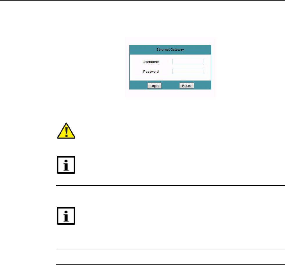
58 3FE-46615-AAAA-TCZZA Issue: 01
Configure an A-240Z-A CPE 7368 ISAM CPE A-240Z-A Product Guide
The default user name is admin. The default password is a random number, which is included
in the CPE kit.
Figure 15 Web login window
Caution — Pressing the Reset button for less than 10 seconds reboots
the CPE; pressing the Reset button for 10 seconds resets the CPE to the
factory defaults.
Note — If you forget the current username and password, press the
reset button for 5 s and the default values for the username and password
will be recovered at startup.
3
Click Login. The Device Information screen appears.
Note — To help protect the security of your Internet connection, the
application displays a pop-up reminder to change both the Wi-Fi
password and the CPE password.
To increase password security, use a minimum of 10 characters,
consisting of a mix of numbers and upper and lower case letters.
4
STOP. This procedure is complete.
8.2.2
Device and connection status
A-240Z-A CPEs support the retrieval of a variety of device and connection
information, including:
• device information
• LAN status
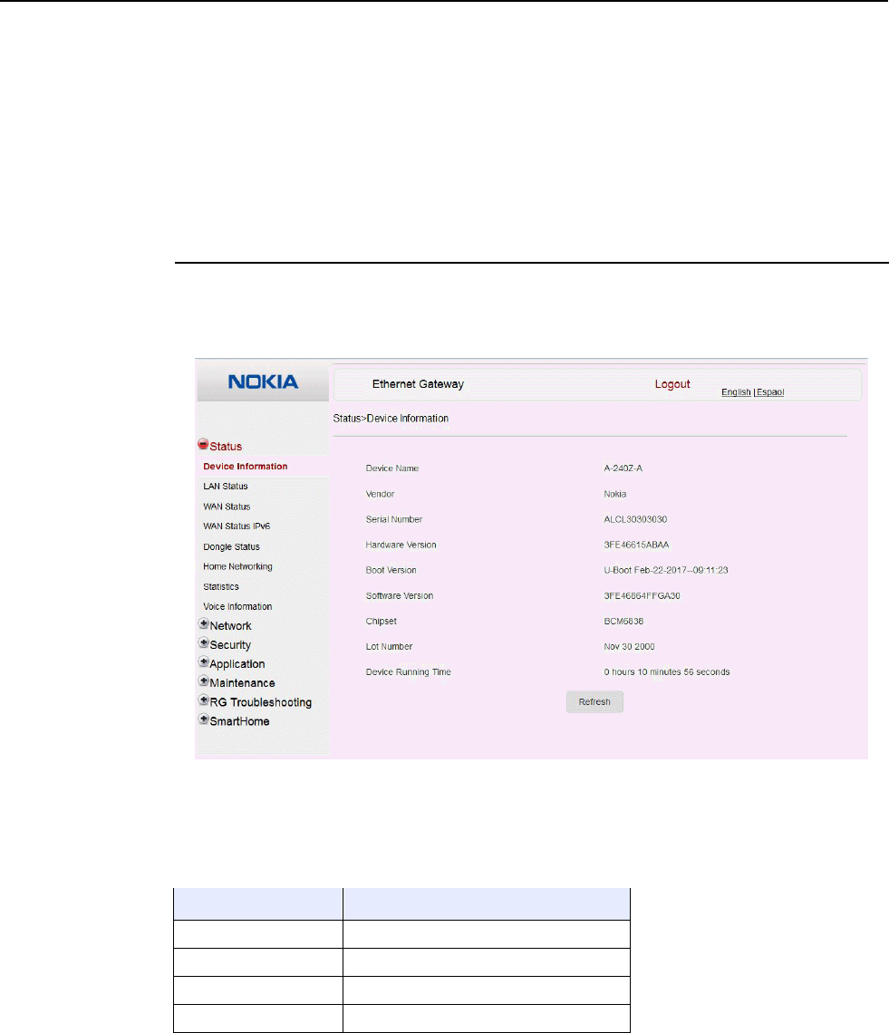
Issue: 01 3FE-46615-AAAA-TCZZA 59
7368 ISAM CPE A-240Z-A Product Guide Configure an A-240Z-A CPE
• WAN status
• WAN status IPv6
• dongle status
• home networking information
• statistics
• voice information
Procedure 7 Device information retrieval
1
Select Status > Device Information from the top-level menu in the Ethernet Gateway window,
as shown in Figure 16.
Figure 16 Device Information window
Table 13 describes the fields in the Device Information window.
Table 13 Device Information parameters
Field Description
Device Name Name on the CPE
Vendor Name of the vendor
Serial Number Serial number of the CPE
Hardware version Hardware version of the CPE
(1 of 2)

Configure an A-240Z-A CPE 7368 ISAM CPE A-240Z-A Product Guide
60 3FE-46615-AAAA-TCZZA Issue: 01
Field Description
Boot version Boot version of the CPE
Software version Software version of the CPE
Chipset Chipset of the CPE
Lot Number Production date of the CPE
Device Running Time Amount of time the device has run since
last reset in hours, minutes, and seconds
(2 of 2)
2
Click Refresh to update the displayed information.
3
STOP. This procedure is complete.
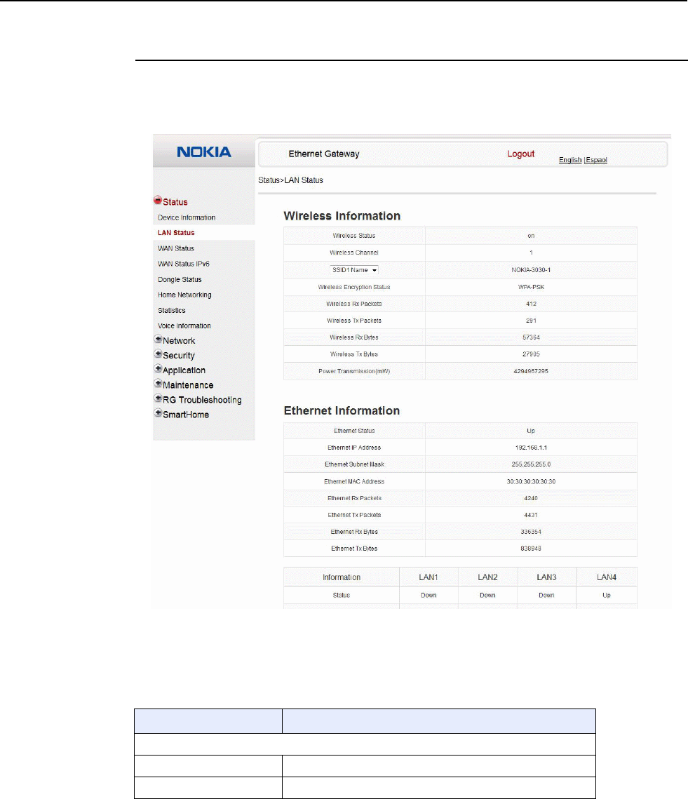
7368 ISAM CPE A-240Z-A Product Guide Configure an A-240Z-A CPE
Issue: 01 3FE-46615-AAAA-TCZZA 61
Procedure 8 LAN status retrieval
1
Select Status > LAN Status from the top-level menu in the Ethernet Gateway window, as
shown in Figure 17.
Figure 17 LAN status window
Table 14 describes the fields in the LAN status window.
Table 14 LAN status parameters
Field Description
Wireless Information
Wireless Status Indicates whether the wireless is on or off
Wireless Channel Wireless channel number
(1 of 2)

Configure an A-240Z-A CPE 7368 ISAM CPE A-240Z-A Product Guide
62 3FE-46615-AAAA-TCZZA Issue: 01
Field Description
SSID Name Name of each SSID
Wireless Encryption Status Encryption type used on the wireless connection
Wireless Rx Packets Number of packets received on the wireless connection
Wireless Tx Packets Number of packets transmitted on the wireless connection
Wireless Rx Bytes Number of bytes received on the wireless connection
Wireless Tx Bytes Number of bytes transmitted on the wireless connection
Power Transmission (mW) Power of the wireless transmission, in mW
Ethernet Information
Ethernet Status Indicates whether the Ethernet connection is on or off
Ethernet IP Address IP address of the Ethernet connection
Ethernet Subnet Mask Subnet Mask of the Ethernet connection
Ethernet MAC Address MAC address of the Ethernet connection
Ethernet Rx Packets Number of packets received on the Ethernet connection
Ethernet Tx Packets Number of packets transmitted on the Ethernet connection
Ethernet Rx Bytes Number of bytes received on the Ethernet connection
Ethernet Tx Bytes Number of bytes transmitted on the Ethernet connection
(2 of 2)
2
Click Refresh to update the displayed information.
3
STOP. This procedure is complete.
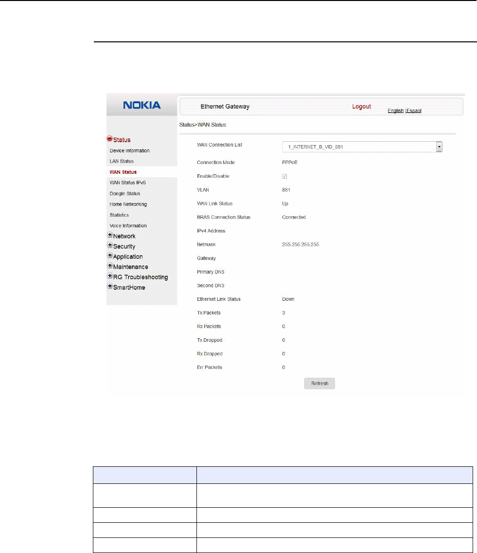
7368 ISAM CPE A-240Z-A Product Guide Configure an A-240Z-A CPE
Issue: 01 3FE-46615-AAAA-TCZZA 63
Procedure 9 WAN status retrieval
1
Select Status > WAN Status from the top-level menu in the Ethernet Gateway window, as
shown in Figure 18.
Figure 18 WAN status window
Table 15 describes the fields in the WAN status window.
Table 15 WAN status parameters
Field Description
WAN connection list Drop-down menu listing all WAN connections. The connection shown is the
connection for which WAN status will be shown.
Connection Mode Connection mode of the WAN connection
Enable/Disable Select this checkbox to enable the WAN connection
VLAN VLAN ID
(1 of 2)

Configure an A-240Z-A CPE 7368 ISAM CPE A-240Z-A Product Guide
64 3FE-46615-AAAA-TCZZA Issue: 01
Field Description
WAN Link Status Whether the WAN link is up or down
BRAS Connection Status Whether the BRAS is connected or disconnected
IPv4 Address IPv4 address
Netmask Netmask
Gateway IPv4 gateway address
Primary DNS Primary Domain Name Server
Second DNS Secondary Domain Name Server
Ethernet Link Status Whether the PON link is up or down
Tx Packets Number of packets transmitted on the WAN connection
Rx Packets Number of packets received on the WAN connection
Tx Dropped Number of packets dropped on the transmit WAN connection
Rx Dropped Number of packets dropped on the receive WAN connection
Err Packets Number of errored packets on the WAN connection
(2 of 2)
2
Click Refresh to update the displayed information.
3
STOP. This procedure is complete.
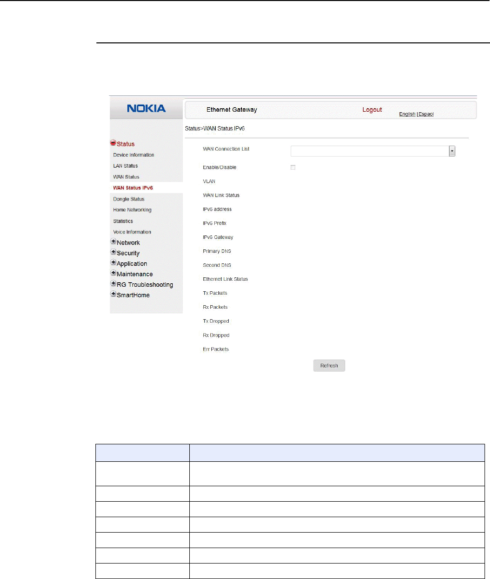
7368 ISAM CPE A-240Z-A Product Guide Configure an A-240Z-A CPE
Issue: 01 3FE-46615-AAAA-TCZZA 65
Procedure 10 WAN status IPv6 retrieval
1
Select Status > WAN Status IPv6 from the top-level menu in the Ethernet Gateway window,
as shown in Figure 19.
Figure 19 WAN status IPv6 window
Table 16 describes the fields in the WAN status IPv6 window.
Table 16 WAN status IPv6 parameters
Field Description
WAN connection list Drop-down menu listing all WAN connections. The connection shown is the
connection for which WAN status will be shown.
Enable/Disable Select this checkbox to enable the WAN connection
VLAN VLAN ID
WAN Link Status Whether the WAN link is up or down
IPv6 Address IPv6 address that identifies the device and its location
IPv6 Prefix IPv6 prefix
IPv6 Gateway IPv6 gateway address
(1 of 2)

Configure an A-240Z-A CPE 7368 ISAM CPE A-240Z-A Product Guide
66 3FE-46615-AAAA-TCZZA Issue: 01
Field Description
Primary DNS Primary Domain Name Server
Second DNS Secondary Domain Name Server
Ethernet Link Status Whether the PON link is up or down
Tx Packets Number of packets transmitted on the WAN connection
Rx Packets Number of packets received on the WAN connection
Tx Dropped Number of packets dropped on the transmit WAN connection
Rx Dropped Number of packets dropped on the receive WAN connection
Err Packets Number of errored packets on the WAN connection
(2 of 2)
2
Click Refresh to update the displayed information.
3
STOP. This procedure is complete.
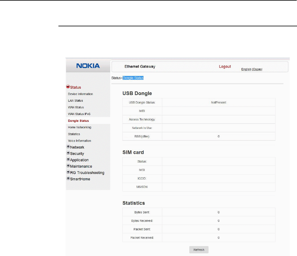
7368 ISAM CPE A-240Z-A Product Guide Configure an A-240Z-A CPE
Issue: 01 3FE-46615-AAAA-TCZZA 67
Procedure 11 Dongle status retrieval
1
Select Status > Dongle Status from the top-level menu in the Ethernet Gateway window, as
shown in Figure 20.
Figure 20 Dongle Status window
Table 17 describes the fields in the Dongle Status window.

Configure an A-240Z-A CPE 7368 ISAM CPE A-240Z-A Product Guide
68 3FE-46615-AAAA-TCZZA Issue: 01
Table 17 Dongle Status parameters
Field Description
USB Dongle Displays the USB dongle information:
• USB Dongle Status
• IMEI
• Access Technology
• Network in Use
• RSSI (dBm)
SIM card Displays the SIM card information
• Status
• IMSI
• ICCID
• MSISDN
Statistics Displays the number of bytes, sent and received, and the packet sent and received
2
Click Refresh to update the displayed information.
3
STOP. This procedure is complete.
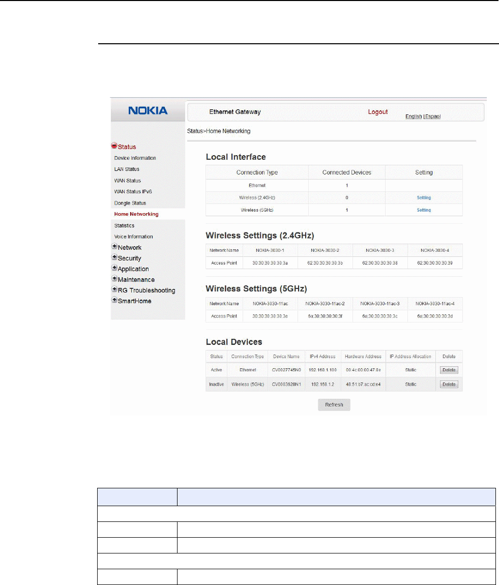
7368 ISAM CPE A-240Z-A Product Guide Configure an A-240Z-A CPE
Issue: 01 3FE-46615-AAAA-TCZZA 69
Procedure 12 Home networking information retrieval
1
Select Status > Home Networking from the top-level menu in the Ethernet Gateway window,
as shown in Figure 21.
Figure 21 Home networking information window
Table 18 describes the fields in the Home networking window.
Table 18 Home networking parameters
Field Description
Local Interface
Ethernet Table displays the number of Ethernet connections and their settings
Wireless Table displays the number of wireless connections and their settings
Wireless Settings
Network Name Name of the wireless network
(1 of 2)

Configure an A-240Z-A CPE 7368 ISAM CPE A-240Z-A Product Guide
70 3FE-46615-AAAA-TCZZA Issue: 01
Field Description
Access Point Hexadecimal address of the wireless access point
Local Devices
Table entry Each entry indicates the status (active or inactive), connection type, device name, IP
address, hardware address, and IP address allocation of each connected local device.
(2 of 2)
2
Click Delete to delete a particular local device connection.
3
Click Refresh to update the displayed information.
4
STOP. This procedure is complete.
Procedure 13 Statistics retrieval
1
Select Status > Statistics from the top-level menu in the Ethernet Gateway window.
Statistics are available for LAN ports and WLAN ports.
Figure 22 shows the statistics for the LAN ports.
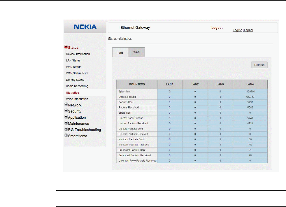
7368 ISAM CPE A-240Z-A Product Guide Configure an A-240Z-A CPE
Issue: 01 3FE-46615-AAAA-TCZZA 71
Figure 22 LAN ports statistics window
2
STOP. This procedure is complete.
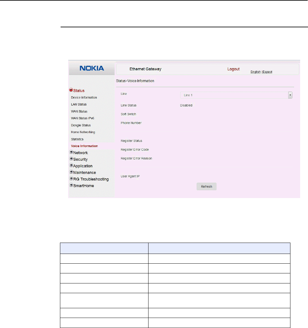
Configure an A-240Z-A CPE 7368 ISAM CPE A-240Z-A Product Guide
72 3FE-46615-AAAA-TCZZA Issue: 01
Procedure 14 Voice information retrieval
1
Select Status > Voice Information from the top-level menu in the Ethernet Gateway window,
as shown in Figure 23.
Figure 23 Voice Information window
Table 19 describes the fields in the Voice Information window.
Table 19 Voice Information parameters
Field Description
Line Select the POTS line: 1 or 2
Line Status Status of the selected POTS line: IDLE, Off Hook, or On Hook
Softswitch(1) Proxy IP address; blank if the line is not registered
Phone number(1) Phone number configured for the selected telephone line
Register Status Registration status of the selected POTS port: registered or
unregistered
Register Error Code Error code for the unregistered POTS port
Register Error Reason Error reason for the unregistered POTS port
Note
(1) This field is only visible at the admin level; it is not visible at the userAdmin level.

7368 ISAM CPE A-240Z-A Product Guide Configure an A-240Z-A CPE
Issue: 01 3FE-46615-AAAA-TCZZA 73
2
Click Refresh to update the displayed information.
3
STOP. This procedure is complete.
8.2.3
Network configuration
A-240Z-A CPEs also support network configuration, including:
• LAN
• LAN IPv6
• WAN
• WAN DHCP
• Wireless 2.4G
• Wireless 5G
• wireless schedule
• routing
• DNS
• TR-069
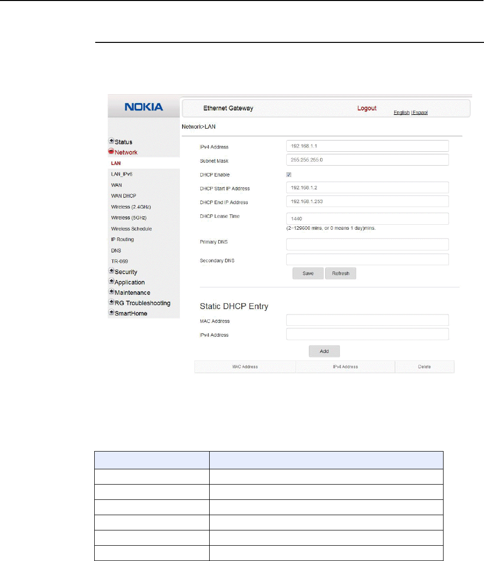
Configure an A-240Z-A CPE 7368 ISAM CPE A-240Z-A Product Guide
74 3FE-46615-AAAA-TCZZA Issue: 01
Procedure 15 LAN networking configuration
1
Select Network > LAN from the top-level menu in the Ethernet Gateway window, as shown
in Figure 24.
Figure 24 LAN network window
Table 20 describes the fields in the LAN network window.
Table 20 LAN network parameters
Field Description
IPv4 Address IP Address of the CPE
Subnet Mask Subnet mask of the CPE
DHCP enable Select this checkbox to enable DHCP
DHCP Start IP Address Starting DHCP IP address
DHCP End IP Address Ending DHCP IP address
DHCP Lease Time DHCP lease time (in min)
(1 of 2)

7368 ISAM CPE A-240Z-A Product Guide Configure an A-240Z-A CPE
Issue: 01 3FE-46615-AAAA-TCZZA 75
Field Description
Primary DNS Primary domain name server
Secondary DNS Secondary domain name server
Static DHCP MAC Address MAC address to associate to the LAN
Static DHCP IP Address IP address to associate to the bound MAC address
(2 of 2)
2
Configure the LAN.
3
Click Save.
4
Bind a MAC address to the LAN by entering the MAC and IP addresses in the Static DHCP
Entry fields and then clicking Add. Repeat for all MAC addresses to be bound.
5
STOP. This procedure is complete.
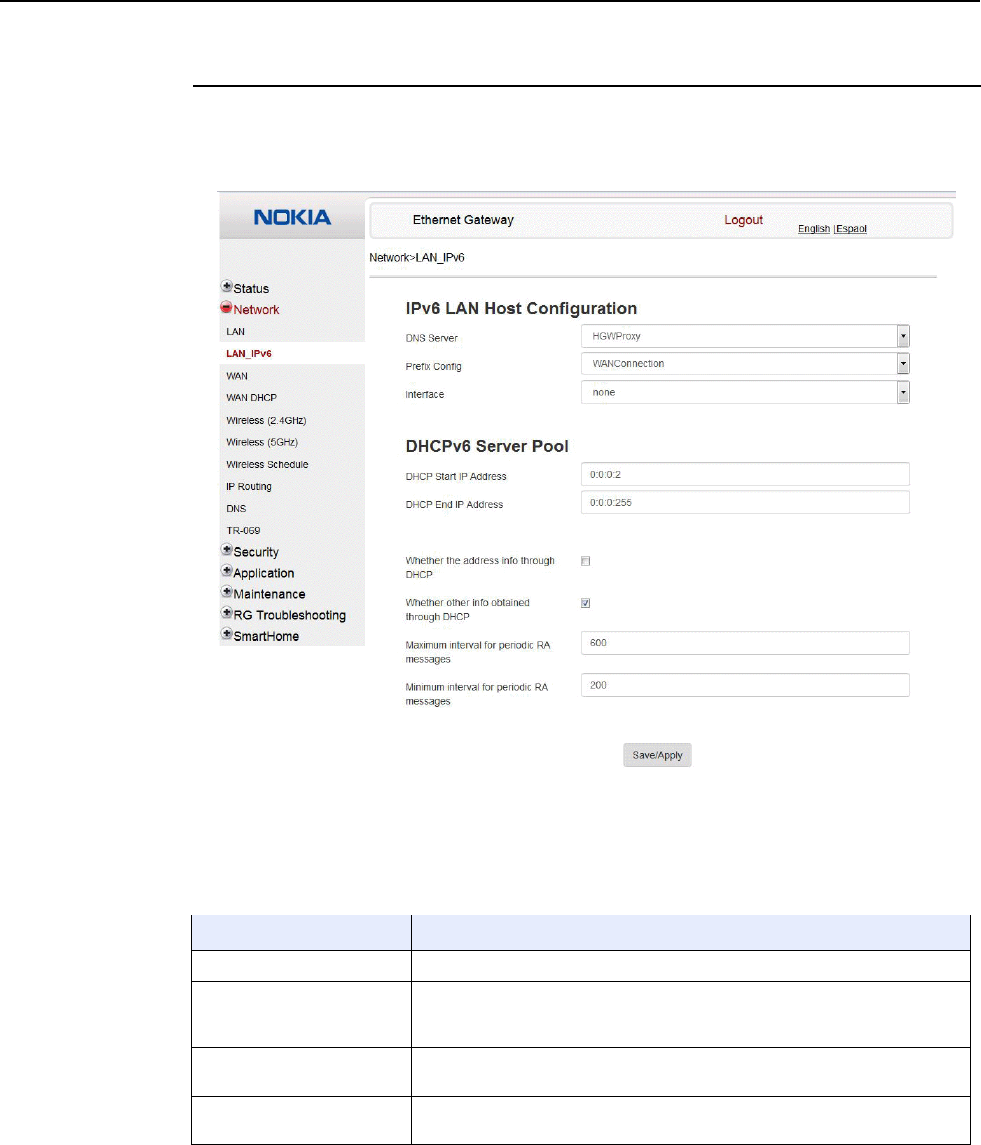
Configure an A-240Z-A CPE 7368 ISAM CPE A-240Z-A Product Guide
76 3FE-46615-AAAA-TCZZA Issue: 01
Procedure 16 LAN IPv6 networking configuration
1
Select Network > LAN_IPv6 from the top-level menu in the Ethernet Gateway window, as
shown in Figure 25.
Figure 25 LAN IPv6 network window
Table 21 describes the fields in the LAN IPv6 network window.
Table 21 LAN IPv6 network parameters
Field Description
DNS Server Choose a DNS server from the drop-down menu.
prefix config Choose a prefix config option from the drop-down menu, either
WANConnection (prefix will be obtained from the WAN) or Static (enables you
to enter the prefix).
prefix This field appears if you selected the “Static” option for the “prefix config” field.
Type a connection.
Interface This field appears if you selected the Wan Connection option for the “prefix
config” field. Choose a WAN connection interface from the drop-down menu.
(1 of 2)

7368 ISAM CPE A-240Z-A Product Guide Configure an A-240Z-A CPE
Issue: 01 3FE-46615-AAAA-TCZZA 77
Field Description
DHCP Start IP Address Enter the starting DHCP IP address.
DHCP End IP Address Enter the ending DHCP IP address.
Whether the address info
through DCHP Select this checkbox to enable address information retrieval through DHCP.
Whether other info obtained
through DHCP Select this checkbox to enable retrieval of other information through DHCP.
Maximum interval for
periodic RA messages Enter the maximum interval (in seconds) for periodic Router Advertisement
messages. The interval range is from 4 to 1800.
Minimum interval for periodic
RA messages Enter the minimum interval (in seconds) for periodic Router Advertisement
messages. The interval range is from 4 to 1800.
(2 of 2)
2
Choose a DNS server, prefix config, and interface.
3
Select or enter the DHCP configuration information.
4
Enter the maximum and minimum intervals for RA messages.
5
Click Save/Apply.
6
STOP. This procedure is complete.
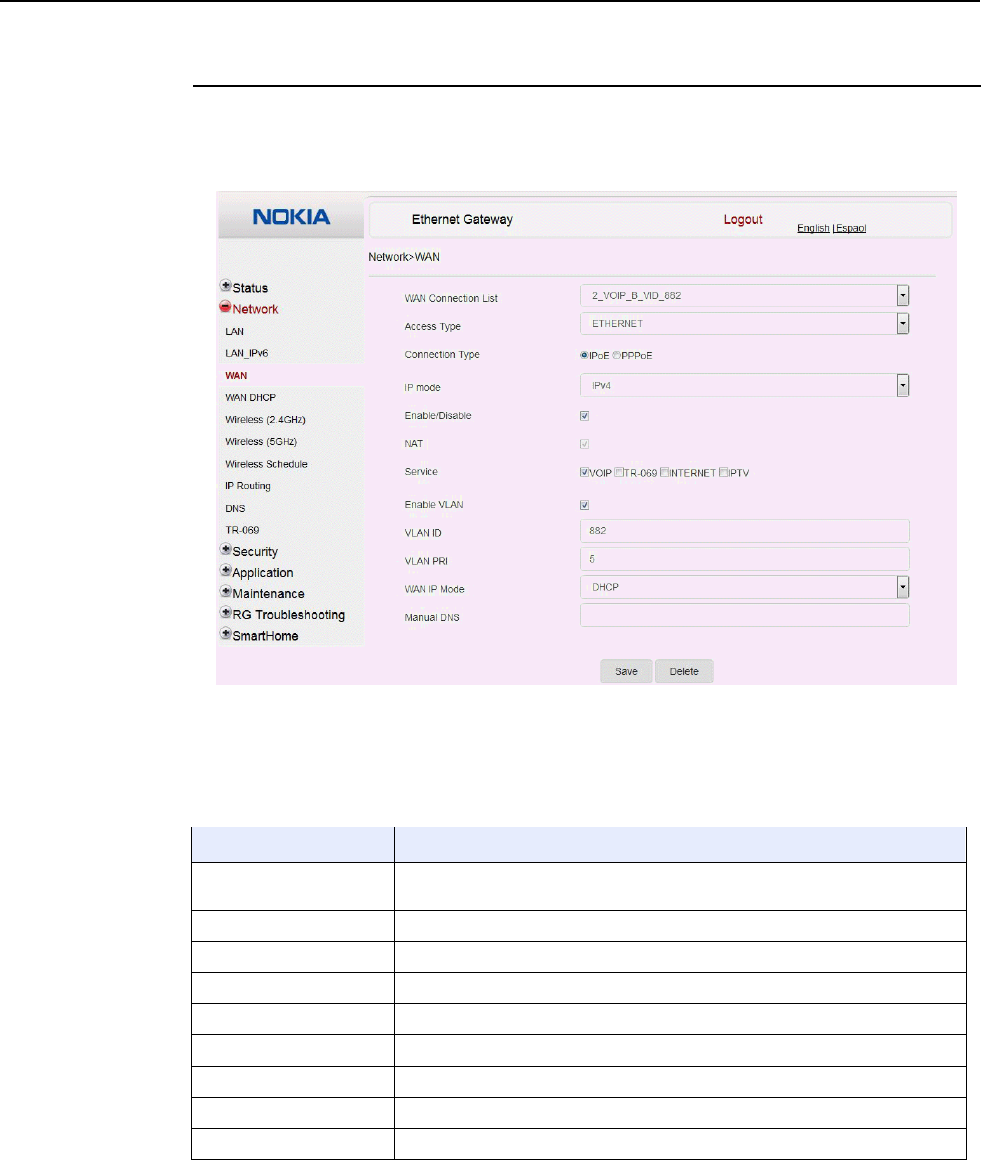
Configure an A-240Z-A CPE 7368 ISAM CPE A-240Z-A Product Guide
78 3FE-46615-AAAA-TCZZA Issue: 01
Procedure 17 WAN networking configuration
1
Select Network > WAN from the top-level menu in the Ethernet Gateway window, as shown
in Figure 26.
Figure 26 WAN network window
Table 22 describes the fields in the WAN network window.
Table 22 WAN network parameters
Field Description
WAN Connection List Choose a WAN connection from the drop-down menu to set the connection
parameters
Access Type Choose an access type from the drop-down menu
Connection Type Select a connection type: IPoE or PPPoE
IP Mode Choose an IP mode from the drop-down menu: IPv4 or IPv6
Enable/Disable Select this checkbox to enable the WAN connection
NAT Select this checkbox to enable NAT
Service Select the checkboxes to enable service types for this connection
Enable VLAN Select this checkbox to enable VLAN
VLAN ID Enter the VLAN ID
(1 of 2)
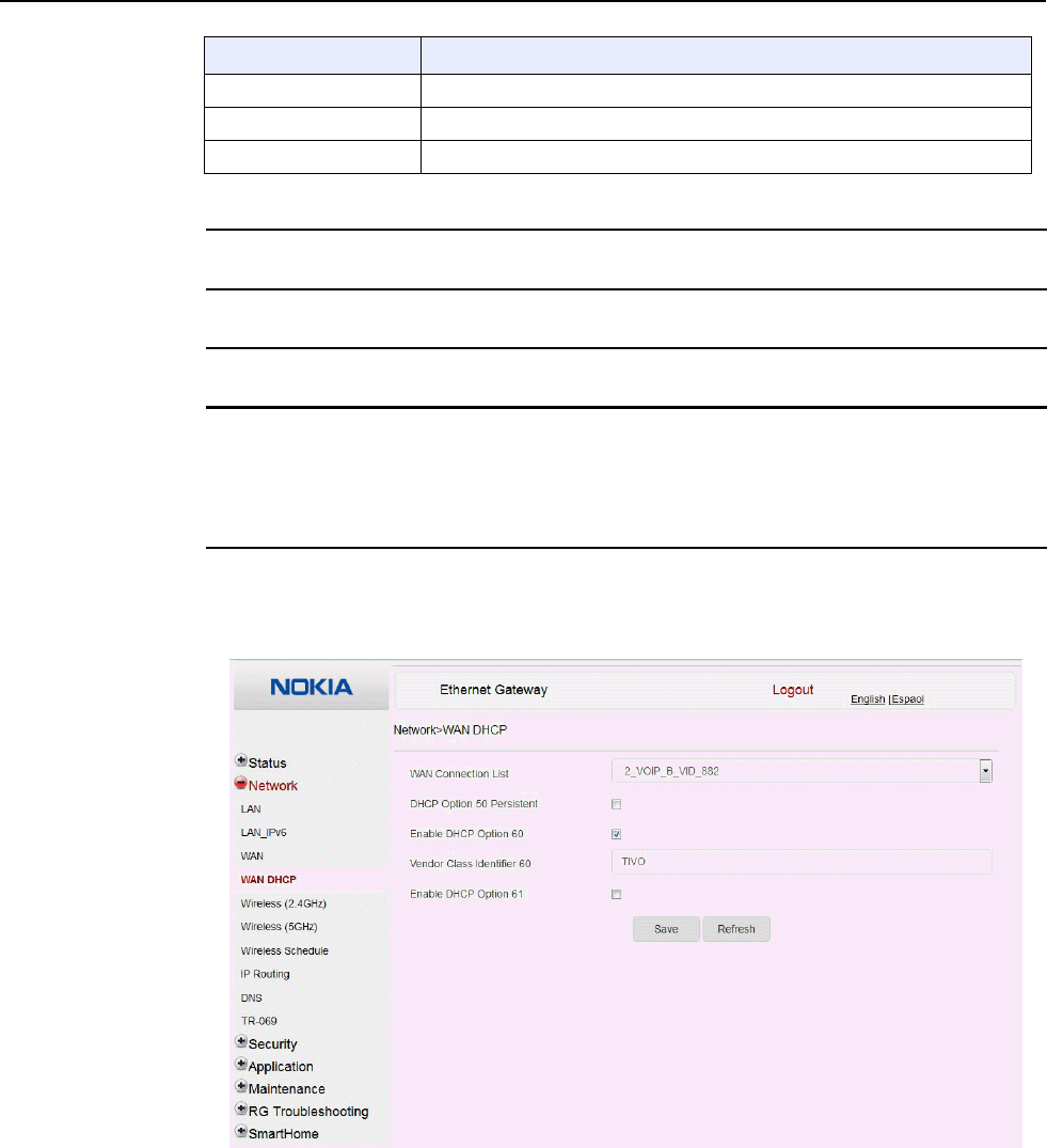
7368 ISAM CPE A-240Z-A Product Guide Configure an A-240Z-A CPE
Issue: 01 3FE-46615-AAAA-TCZZA 79
Field Description
VLAN PRI Enter the VLAN PRI
WAN IP Mode Choose an IP mode from the drop-down menu
Manual DNS Enter a DNS
(2 of 2)
2
Configure a specific WAN connection.
3
Click Save.
4
STOP. This procedure is complete.
Procedure 18 WAN DHCP configuration
1
Select Network > WAN DHCP from the top-level menu in the Ethernet Gateway window, as
shown in Figure 27.
Figure 27 WAN DHCP window
Table 23 describes the fields in the WAN DHCP window.

Configure an A-240Z-A CPE 7368 ISAM CPE A-240Z-A Product Guide
80 3FE-46615-AAAA-TCZZA Issue: 01
Table 23 WAN DHCP parameters
Field Description
WAN Connection List Choose a WAN connection from the drop-down menu
DHCP Option 50 persistent Select this checkbox to enable DHCP Option 50
Enable DHCP Option 60 Select this checkbox to enable DHCP Option 60 (vendor class identifier)
Vendor Class Identifier 60 Enter the identifier for the vendor class
Enable DHCP Option 61 Select this checkbox to enable DHCP Option 61 (client identifier)
2
Configure a WAN DHCP option.
3
Click Save.
4
STOP. This procedure is complete.
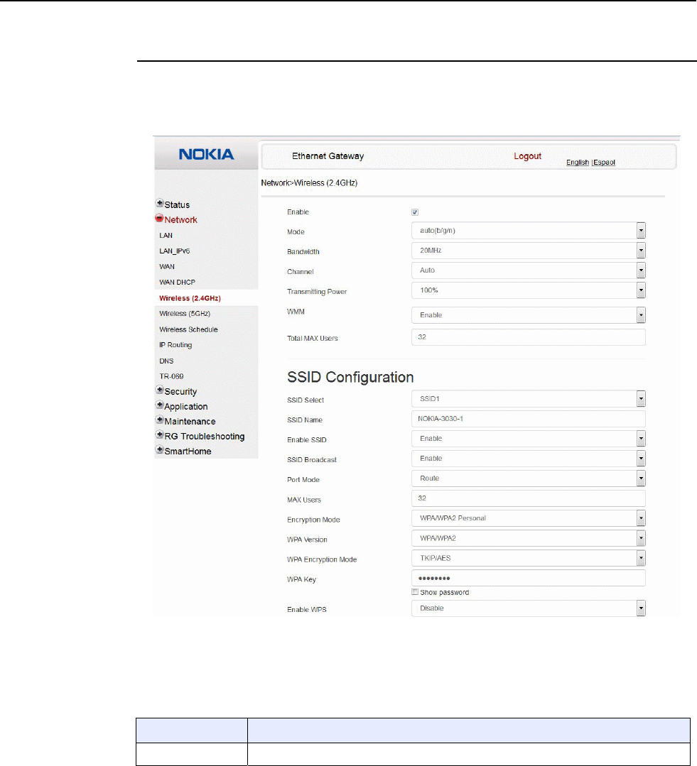
7368 ISAM CPE A-240Z-A Product Guide Configure an A-240Z-A CPE
Issue: 01 3FE-46615-AAAA-TCZZA 81
Procedure 19 Wireless 2.4G networking configuration
1
Select Network > Wireless 2.4GHz from the top-level menu in the Ethernet Gateway window,
as shown in Figure 28.
Figure 28 Wireless 2.4GHz network window
Table 24 describes the fields in the Wireless 2.4GHz network window.
Table 24 Wireless 2.4GHz network parameters
Field Description
Enable Select this checkbox to enable WiFi
(1 of 2)

Configure an A-240Z-A CPE 7368 ISAM CPE A-240Z-A Product Guide
82 3FE-46615-AAAA-TCZZA Issue: 01
Field Description
Mode Choose a Wi-Fi mode from the drop-down menu:
• auto (b/g/n)
• b
• g
• n
• b/g
Channel Choose a channel from the drop-down menu or choose Auto to have the channel
automatically assigned
Bandwidth Choose 20 MHz or 40 MHz from the drop-down menu.
Transmitting Power Choose the percentage transmitting power from the drop-down menu
WMM Select this checkbox to enable or disable wireless multi media
Total MAX Users Enter the total number of MAX users
SSID Select Choose the SSID from the drop-down menu
SSID Name Enter the SSID name
Enable SSID Enable or disable SSID from this drop-down menu
SSID Broadcast Enable or disable SSID broadcast from this drop-down menu
Port Mode Choose a port mode from the drop-down menu:
• Route
• Bridge
Encryption Mode Choose an encryption mode from the drop-down menu:
• OPEN
• WEP
• WPA/WPA2 Personal
• WPA/WPA2 Enterprise
WPA Version Choose a WPA version from the drop-down menu:
• WPA1
• WPA2
• WPA1/WPA2
WPA Encryption
Mode Choose a WPA encryption mode from the drop-down menu:
• TKIP
• AES
• TKIP/AES
WPA Key Enter the WPA key
Enable WPS Enable or disable WPS from this drop-down menu
WPS Mode Select a WPS mode from the drop-down menu: PBC (Push Button Connect) or PIN
(Personal Identification Number)
(2 of 2)
2
Configure the WiFi connection.
3
If you have enabled and configured WPS, click WPS connect.
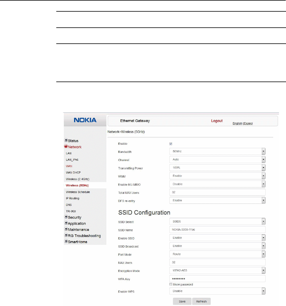
7368 ISAM CPE A-240Z-A Product Guide Configure an A-240Z-A CPE
Issue: 01 3FE-46615-AAAA-TCZZA 83
4
Click Save.
5
STOP. This procedure is complete.
Procedure 20 Wireless 5G networking configuration
1
Select Network > Wireless 5GHz from the top-level menu in the Ethernet Gateway window,
as shown in Figure 29.
Figure 29 Wireless 5GHz network window
Table 25 describes the fields in the Wireless 5GHZ network window.

Configure an A-240Z-A CPE 7368 ISAM CPE A-240Z-A Product Guide
84 3FE-46615-AAAA-TCZZA Issue: 01
Table 25 Wireless 5GHz network parameters
Field Description
Enable Select this checkbox to enable WiFi
Bandwidth Choose from:
• 20 MHz
• 40 MHz
• 80 MHz
Channel Choose a channel from the drop-down menu or choose Auto to have the
channel automatically assigned
Transmitting Power Choose a percentage for the transmitting power from the drop-down menu:
• Low (20%)
• Medium (40%)
• High (60%)
• Maximum (100%)
WMM Select this checkbox to enable or disable wireless multi media
Enable MU-MIMO Choose Enable or disable MU-MIMO from this drop-down menu
The default is Enable, which enables users and wireless terminals to
communicate with each other.
MU-MIMO may decrease Wi-Fi performance for clients who do not support it,
in which case Nokia recommends that you choose Disable.
Total MAX Users Enter the total number of MAX users
DFS re-entry Select this checkbox to enable or disable DFS re-entry
SSID Select Choose the SSID from the drop-down menu
SSID Name Change the name of the selected SSID
Enable SSID Choose Enable or disable SSID from this drop-down menu
SSID Broadcast Choose Enable or disable SSID broadcast from this drop-down menu
Port Mode Choose Route or Bridge from the drop-down menu
MAX Users Enter the number of MAX users
Encryption Mode Choose an encryption mode from the drop-down menu:
• OPEN
• WEP
• WPA/WPA2 Personal
• WPA/WPA2 Enterprise (1)(2)
WPA Key Enter the WPA key
Enable WPS Choose Enable or disable WPS from this drop-down menu
Notes
(1) When Encryption Mode is set to “WPA/WPA2 Enterprise”, the following options are no longer available: WPA
version, WPA encryption mode, WPA key, Enable WPS, WPS mode.
(2) When Encryption Mode is set to “WPA/WPA2 Enterprise”, the following options become available: Primary
RADIUS server, port and password; Secondary RADIUS server, port, and password; RADIUS accounting port.
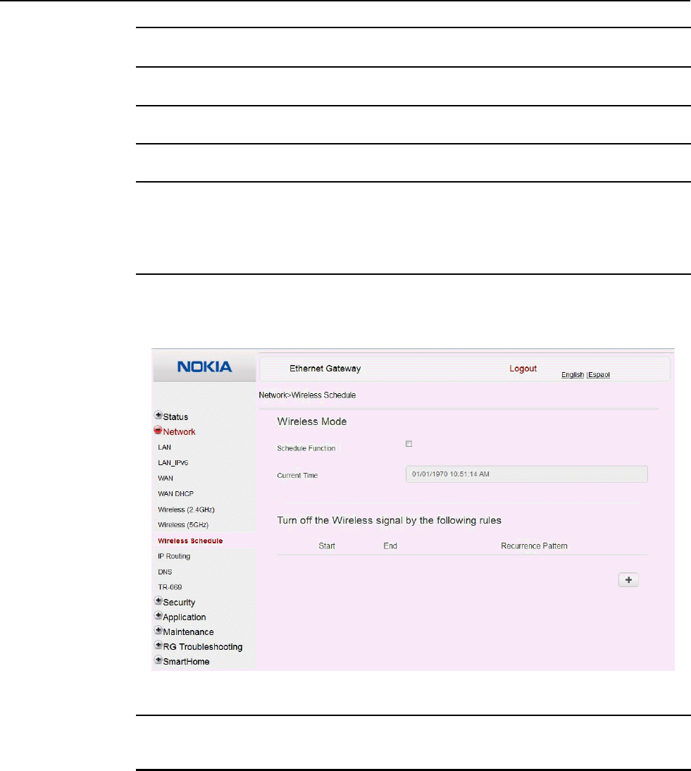
7368 ISAM CPE A-240Z-A Product Guide Configure an A-240Z-A CPE
Issue: 01 3FE-46615-AAAA-TCZZA 85
2
Configure the Wireless connection.
3
If you have enabled and configured WPS, click WPS connect.
4
Click Save.
5
STOP. This procedure is complete.
Procedure 21 Wireless scheduling
1
Select Network > Wireless Schedule from the top-level menu in the Ethernet Gateway
window, as shown in Figure 30.
Figure 30 Wireless Schedule window
2
Select the Schedule Function checkbox to turn the wireless signal off for the configured
period.
3
Click the plus sign (+) to add a scheduling rule.
A separate panel displays for configuring wireless schedule rules.
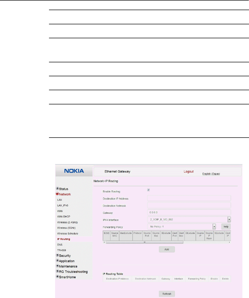
Configure an A-240Z-A CPE 7368 ISAM CPE A-240Z-A Product Guide
86 3FE-46615-AAAA-TCZZA Issue: 01
4
Enter a start time and end time for the period in which you want the wireless signal off.
5
Choose Everyday or Individual Days from the drop-down menu.
6
If you chose Individual Days, select the checkboxes for the desired days.
The Recurrence Pattern shows the rules created to date.
7
If desired, click the plus sign (+) to add more rules.
8
Click Save Changes.
9
STOP. This procedure is complete.
Procedure 22 Routing configuration
1
Select Network > Routing from the top-level menu in the Ethernet Gateway window, as
shown in Figure 31.
Figure 31 Routing network window

7368 ISAM CPE A-240Z-A Product Guide Configure an A-240Z-A CPE
Issue: 01 3FE-46615-AAAA-TCZZA 87
Table 26 describes the fields in the Routing network window.
Table 26 Routing network parameters
Field Description
Enable Routing Select this checkbox to enable routing
Destination IP Address Enter the destination IP address
Destination Netmask Enter the destination network mask
Gateway Enter the gateway address
IPv4 Interface Choose a WAN connection previously created in the
WAN network window from the drop-down menu
Forwarding Policy Choose a forwarding policy from the drop-down menu
2
Enter the routing information.
3
Click Add.
4
STOP. This procedure is complete.
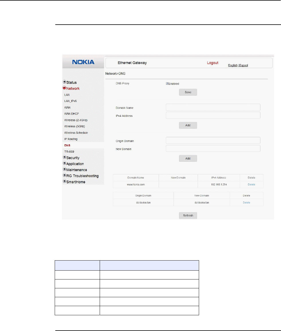
Configure an A-240Z-A CPE 7368 ISAM CPE A-240Z-A Product Guide
88 3FE-46615-AAAA-TCZZA Issue: 01
Procedure 23 DNS configuration
1
Select Network > DNS from the top-level menu in the Ethernet Gateway window, as shown
in Figure 32.
Figure 32 DNS network window
Table 27 describes the fields in the DNS network window.
Table 27 DNS network parameters
Field Description
DNS Proxy Select this checkbox to enable DNS proxy
Domain Name Domain name
IPv4 Address Domain IP address
Origin Domain Origin domain name
New Domain New domain name
2
Enter the domain name and IP address and click Add.
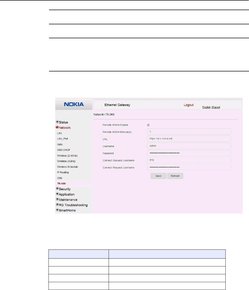
7368 ISAM CPE A-240Z-A Product Guide Configure an A-240Z-A CPE
Issue: 01 3FE-46615-AAAA-TCZZA 89
3
If required, associate an origin domain with a new domain, click Add.
4
STOP. This procedure is complete.
Procedure 24 TR-069 configuration
1
Select Network > TR-069 from the top-level menu in the Ethernet Gateway window, as
shown in Figure 33.
Figure 33 TR-069 network window
Table 28 describes the fields in the TR-069 network window.
Table 28 TR-069 network parameters
Field Description
Periodic Inform Enable Select this checkbox to enable periodic inform updates
Periodic Inform Interval(s) Time between periodic inform updates, in seconds
URL URL of the auto-configuration server
Username Username used to log in to the CPE
(1 of 2)

Configure an A-240Z-A CPE 7368 ISAM CPE A-240Z-A Product Guide
90 3FE-46615-AAAA-TCZZA Issue: 01
Field Description
Password Password used to log in to the CPE
Connect Request Username Username used to log in to the auto-configuration server
Connect Request Password Password used to log in to the auto-configuration server
(2 of 2)
2
Configure TR-069 by entering the required information.
3
Click Save.
4
STOP. This procedure is complete.
8.2.4
Security configuration
A-240Z-A CPE also supports security configuration, including:
• firewall
• MAC filter
• IP filter
• URL filter
• parental control
• DMZ and ALG
• access control
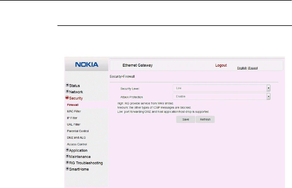
7368 ISAM CPE A-240Z-A Product Guide Configure an A-240Z-A CPE
Issue: 01 3FE-46615-AAAA-TCZZA 91
Procedure 25 Firewall configuration
1
Select Security > Firewall from the top-level menu in the Ethernet Gateway window, as
shown in Figure 34.
Figure 34 Firewall window
Firewall security applies only to services provided by the CPE. Internet access from the LAN
side is not affected by this firewall.
Three security levels are available: Low, Medium, and High.
At the Low level, pre-routing is supported: port forwarding, DMZ, host application, and host
drop. Also supported are application services: DDNS, DHCP, DNS, H248, IGMP, NTP client,
SSH, Telnet, TFTP, TR-069, and VoIP.
At the Medium level, pre-routing is supported: port forwarding, DMZ, host application, and
host drop. Also supported are application services: DDNS, DHCP, DNS, H248, IGMP, NTP
client, TFTP, TR-069, and VoIP. The following types of ICMP messages are permitted: echo
request and reply, destination unreachable, and TTL exceeded. Other types of ICMP
messages are blocked. DNS proxy is supported from LAN to WAN but not from WAN to LAN.
At the High level, pre-routing and application services are not supported. UDP Port 8000 can
be used to access the services, for example FTP can use 8021 and Telnet can use 8023.
Regular UDP cannot be used. RG access is permitted via the LAN side but not via the WAN
side.
Table 29 describes the fields in the firewall window.
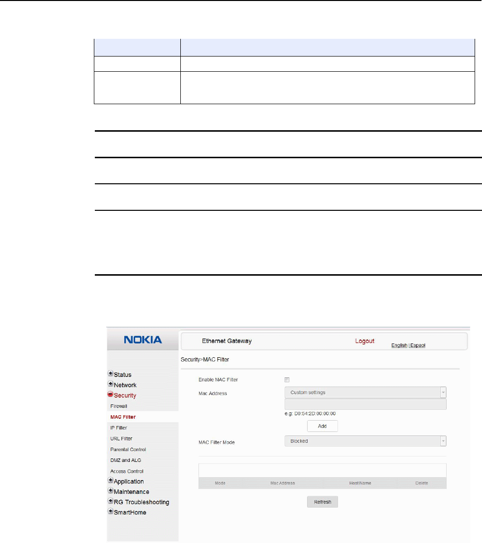
Configure an A-240Z-A CPE 7368 ISAM CPE A-240Z-A Product Guide
92 3FE-46615-AAAA-TCZZA Issue: 01
Table 29 Firewall parameters
Field Description
Security level Choose the security level from the drop-down menu: low, medium, or high
Attack Protect
(Protection against
DoS or DDoS attacks)
Choose enable or disable attack protect from the drop-down menu
The default is disable
2
Configure the firewall.
3
Click Save.
4
STOP. This procedure is complete.
Procedure 26 MAC filter configuration
1
Select Security > MAC Filter from the top-level menu in the Ethernet Gateway window, as
shown in Figure 35.
Figure 35 MAC filter window
Table 30 describes the fields in the MAC filter window.
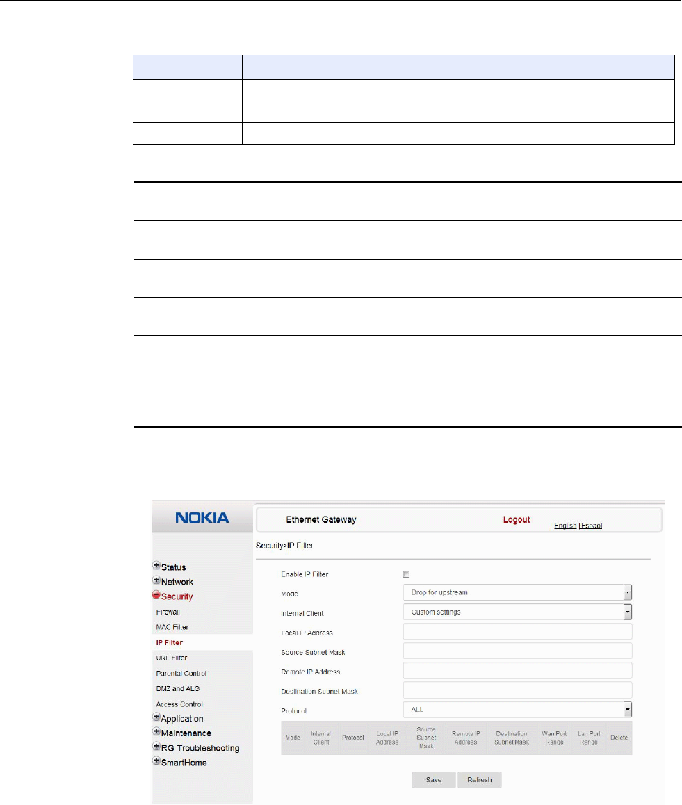
7368 ISAM CPE A-240Z-A Product Guide Configure an A-240Z-A CPE
Issue: 01 3FE-46615-AAAA-TCZZA 93
Table 30 MAC filter parameters
Field Description
Enable MAC filter Select this checkbox to enable the MAC filter
MAC Address Select a MAC address from the drop-down menu or enter the address in the text field
MAC Filter Mode Choose the MAC filter mode from this drop-down menu: Blocked or Allowed
2
Click Refresh to update the information.
3
Configure a MAC filter.
4
Click Add.
5
STOP. This procedure is complete.
Procedure 27 IP filter configuration
1
Select Security > IP filter from the top-level menu in the Ethernet Gateway window, as shown
in Figure 36.
Figure 36 IP filter window
Table 31 describes the fields in the IP filter window.

Configure an A-240Z-A CPE 7368 ISAM CPE A-240Z-A Product Guide
94 3FE-46615-AAAA-TCZZA Issue: 01
Table 31 IP filter parameters
Field Description
Enable IP Filter Select this checkbox to enable an IP filter
Mode Choose an IP filter mode from the drop-down menu:
• Drop for upstream
• Drop for downstream
Internal Client Choose an internal client from the drop-down menu:
• Customer setting - uses the IP address input below
• IP - uses the connecting devices' IP to the CPE
Local IP Address Local IP address
Source Subnet Mask Source subnet mask
Remote IP Address Remote IP address
Destination Subnet Mask Destination subnet mask
Protocol Choose an application protocol or all from the drop-down menu
2
Configure the IP filter.
3
Click Add.
4
STOP. This procedure is complete.
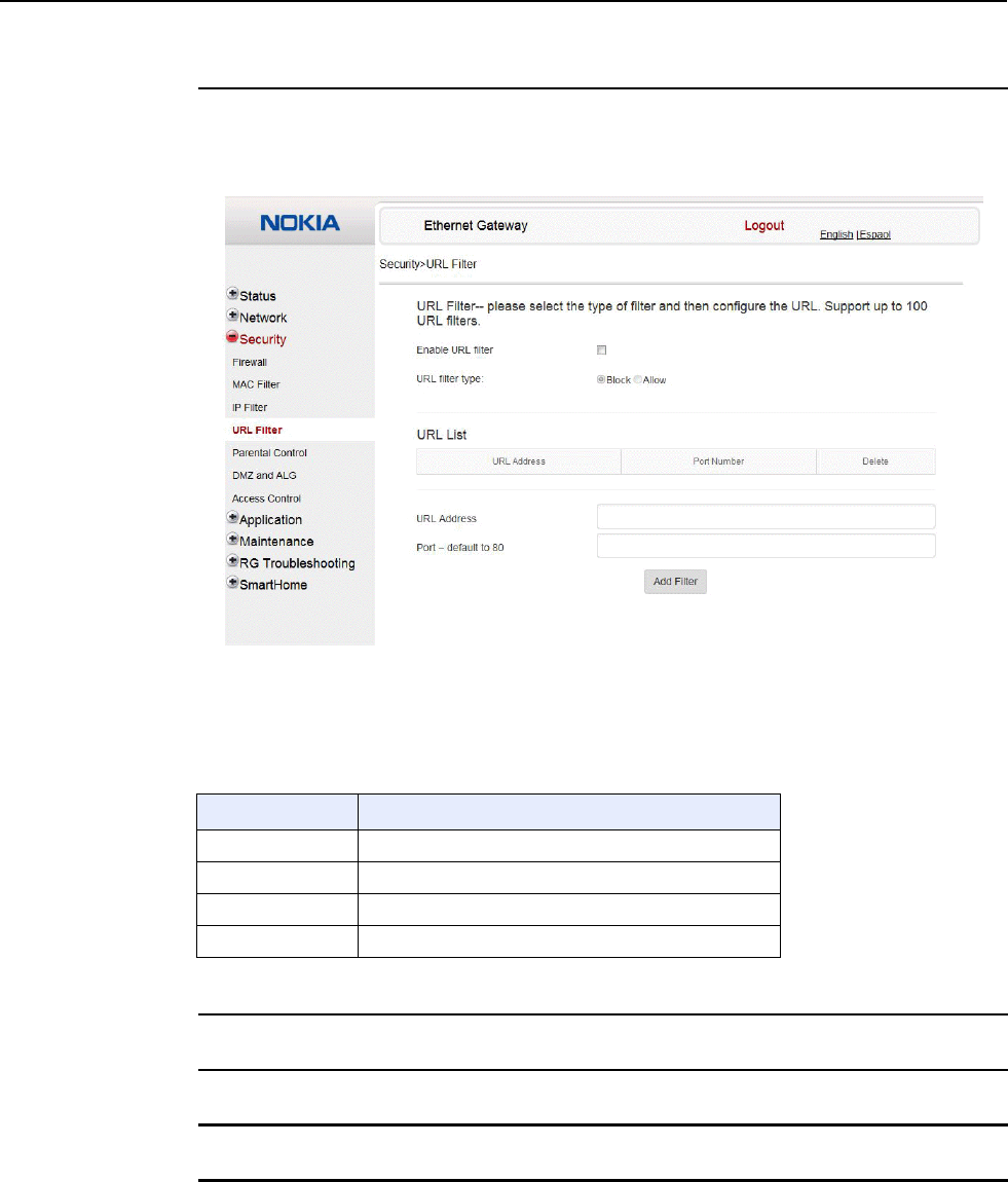
7368 ISAM CPE A-240Z-A Product Guide Configure an A-240Z-A CPE
Issue: 01 3FE-46615-AAAA-TCZZA 95
Procedure 28 URL filter configuration
1
Select Security > URL Filter from the top-level menu in the Ethernet Gateway window, as
shown in Figure 37.
Figure 37 URL Filter window
Table 32 describes the fields in the URL Filter window.
Table 32 URL Filter parameters
Field Description
Enable URL filter Select the checkbox to enable the URL filter
URL filter type Select the checkbox for Exclude URL or Include URL
URL Address Type the URL address
Port Number Type the port number; the default is 80
2
Configure the URL Filter.
3
Click Add Filter.
4
STOP. This procedure is complete.
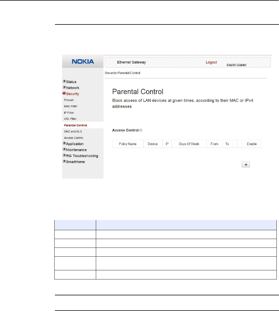
Configure an A-240Z-A CPE 7368 ISAM CPE A-240Z-A Product Guide
96 3FE-46615-AAAA-TCZZA Issue: 01
Procedure 29 Parental control
1
Select Security > Parent Control from the top-level menu in the Ethernet Gateway window,
as shown in Figure 38.
Figure 38 Parental Control window
Table 33 describes the fields in the Parental Control window.
Table 33 Parental control parameters
Field Description
Policy Name Enter a name for the parental control policy or choose a policy from the list
MAC Address Enter the MAC address or choose a MAC address from the list
IPv4 Address Enter the IPv4 address for the device or choose an IPv4 address from the list
Days of the week Choose Every Day, or Individual Days and select the checkboxes for the days of the week
for which the policy applies
From/To Enter the times for the policy to be in effect
2
Select the Access Control checkbox.
3
Click the plus sign (+) to add a policy.
A separate panel displays for configuring the policy name, IP address of the device, and
dates and times for the policy.

7368 ISAM CPE A-240Z-A Product Guide Configure an A-240Z-A CPE
Issue: 01 3FE-46615-AAAA-TCZZA 97
4
Configure the parental control policy.
5
Click Enable to activate the policy.
6
STOP. This procedure is complete.
Procedure 30 DMZ and ALG configuration
1
Select Security > DMZ and ALG from the top-level menu in the Ethernet Gateway window,
as shown in Figure 39.
Figure 39 DMZ and ALG window
Table 34 describes the fields in the DMZ and ALG window.
Table 34 DMZ and ALG parameters
Field Description
ALG Config Select the checkboxes to enable the protocols to be supported by the ALG: FTP,
TFTP, SIP, H323, RTSP, L2TP, IPSEC, PPTP
DMZ Config
(1 of 2)

Configure an A-240Z-A CPE 7368 ISAM CPE A-240Z-A Product Guide
98 3FE-46615-AAAA-TCZZA Issue: 01
Field Description
WAN Connection List Choose a WAN connection from the drop-down menu
Enable DMZ Select this checkbox to enable DMZ on the chosen WAN connection
DMZ IP Address Choose Customer Setting and enter the DMZ IP address or choose the IP address
of a connected device from the drop-down menu
(2 of 2)
2
Configure ALG.
3
Click Save ALG.
4
Configure DMZ.
5
Click Save DMZ.
6
STOP. This procedure is complete.
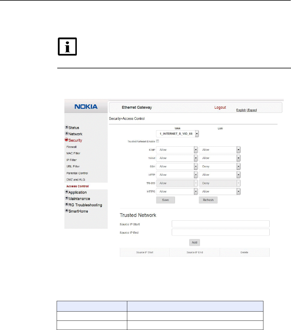
7368 ISAM CPE A-240Z-A Product Guide Configure an A-240Z-A CPE
Issue: 01 3FE-46615-AAAA-TCZZA 99
Procedure 31 Access control configuration
This procedure describes how to configure the access control level (ACL).
Note 1 — ACL takes precedence over the firewall policy.
Note 2 — The trusted network object will be shared for all WAN
connections; it is not applied individually to a WAN connection.
1
Select Security > Access Control from the top-level menu in the Ethernet Gateway window,
as shown in Figure 40.
Figure 40 Access Control window
Table 35 describes the fields in the Access Control window.
Table 35 Access control parameters
Field Description
WAN Choose a connection from the drop-down menu
Trusted Network Enable Click to enable or disable
(1 of 2)

Configure an A-240Z-A CPE 7368 ISAM CPE A-240Z-A Product Guide
100 3FE-46615-AAAA-TCZZA Issue: 01
Field Description
ICMP, Telnet, SSH, HTTP,
TR-069, HTTPS Select an access control level for each protocol:
WAN side: Allow, Deny, or Trusted Network Only
LAN side: Allow or Deny
Source IP Start Enter a start IP address for the new subnet trusted network
Source IP End Enter an end IP address for the new subnet trusted network
(2 of 2)
2
Select a WAN connection from the drop-down menu.
3
Click to enable or disable Trusted Network.
4
Select an access control level for each of the six protocols: ICMP, Telnet, SSH, HTTP,
TR-069, and HTTPS for both the WAN and the LAN side.
5
Click Save.
6
Optionally, add one or more subnet trusted networks.
The maximum number of entries is 32.
You can also use the Source IP fields to delete a previously created entry for a subnet trusted
network.
7
STOP. This procedure is complete.
8.2.5
Application configuration
A-240Z-A CPE also supports application configuration, including:
• port forwarding
• port triggering
• DDNS
• NTP
• USB
• UPnP and DLNA
• voice setting
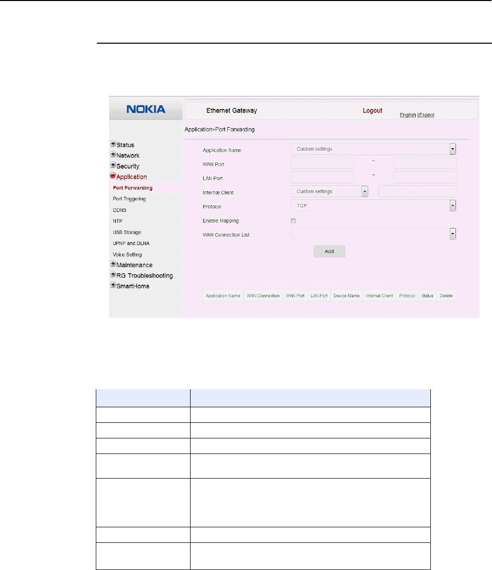
7368 ISAM CPE A-240Z-A Product Guide Configure an A-240Z-A CPE
Issue: 01 3FE-46615-AAAA-TCZZA 101
Procedure 32 Port forwarding configuration
1
Select Application > Port forwarding from the top-level menu in the Ethernet Gateway
window, as shown in Figure 41.
Figure 41 Port forwarding window
Table 36 describes the fields in the port forwarding window.
Table 36 Port forwarding parameters
Field Description
Application Name Choose an application name from the drop-down menu
WAN Port WAN port range
LAN Port LAN port range
Internal Client Choose a connected device from the drop-down menu and enter
the associated IP address
Protocol Choose the port forwarding protocol from the drop-down menu:
• TCP
• UDP
• TCP/UDP
Enable Mapping Select this checkbox to enable mapping
WAN Connection List Choose a WAN connection from the drop-down menu
Note: only active devices are shown on this menu
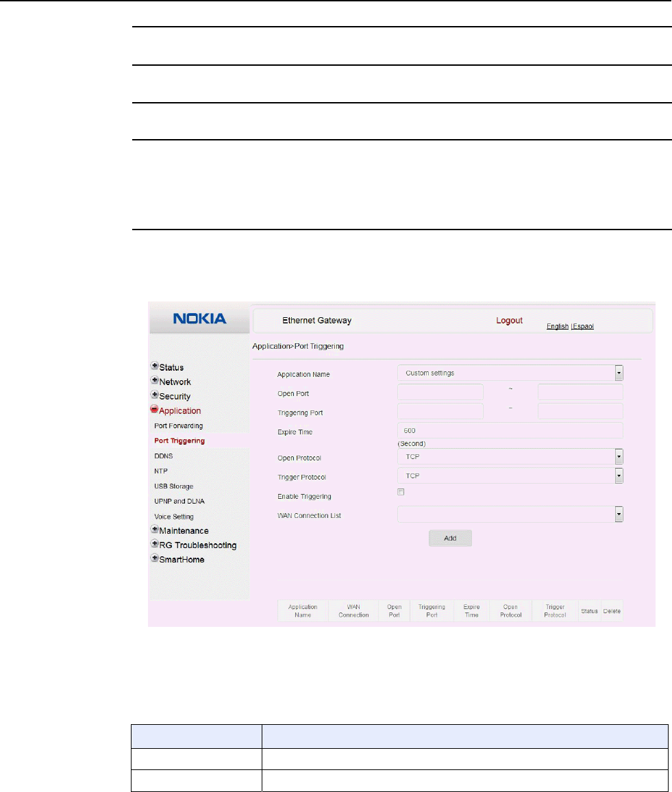
Configure an A-240Z-A CPE 7368 ISAM CPE A-240Z-A Product Guide
102 3FE-46615-AAAA-TCZZA Issue: 01
2
Configure port forwarding.
3
Click Add.
4
STOP. This procedure is complete.
Procedure 33 Port triggering
1
Select Application > Port Triggering from the top-level menu in the Ethernet Gateway
window, as shown in Figure 42.
Figure 42 Port Triggering window
Table 36 describes the fields in the Port Triggering window.
Table 37 Port triggering parameters
Field Description
Application Name Choose an application name from the drop-down menu
Open Port Enter the open port range
(1 of 2)

7368 ISAM CPE A-240Z-A Product Guide Configure an A-240Z-A CPE
Issue: 01 3FE-46615-AAAA-TCZZA 103
Field Description
Triggering Port Enter the triggering port range
Expire Time Enter the expiration time in seconds
Open Protocol Choose the open port protocol from the drop-down menu:
• TCP
• UDP
• TCP/UDP
Trigger Protocol Choose the triggering port protocol from the drop-down menu:
• TCP
• UDP
• TCP/UDP
Enable Triggering Select this checkbox to enable port triggering
WAN Connection List Choose a WAN connection from the drop-down menu
Note: only active devices are shown on this menu
(2 of 2)
2
Configure port triggering.
3
Click Add.
4
STOP. This procedure is complete.
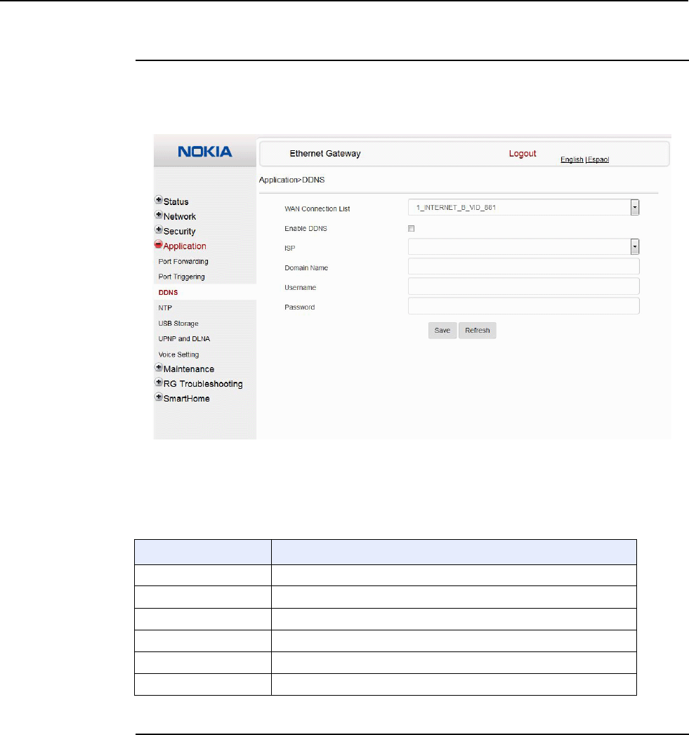
Configure an A-240Z-A CPE 7368 ISAM CPE A-240Z-A Product Guide
104 3FE-46615-AAAA-TCZZA Issue: 01
Procedure 34 DDNS configuration
1
Select Application > DDNS from the top-level menu in the Ethernet Gateway window, as
shown in Figure 43.
Figure 43 DDNS window
Table 38 describes the fields in the DDNS window.
Table 38 DDNS parameters
Field Description
WAN Connection List Choose a WAN connection from the drop-down menu
Enable DDNS Select this checkbox to enable DDNS on the chosen WAN connection
ISP Choose an ISP from the drop-down menu.
Domain Name Domain name
Username Username
Password Password
2
Configure DDNS.
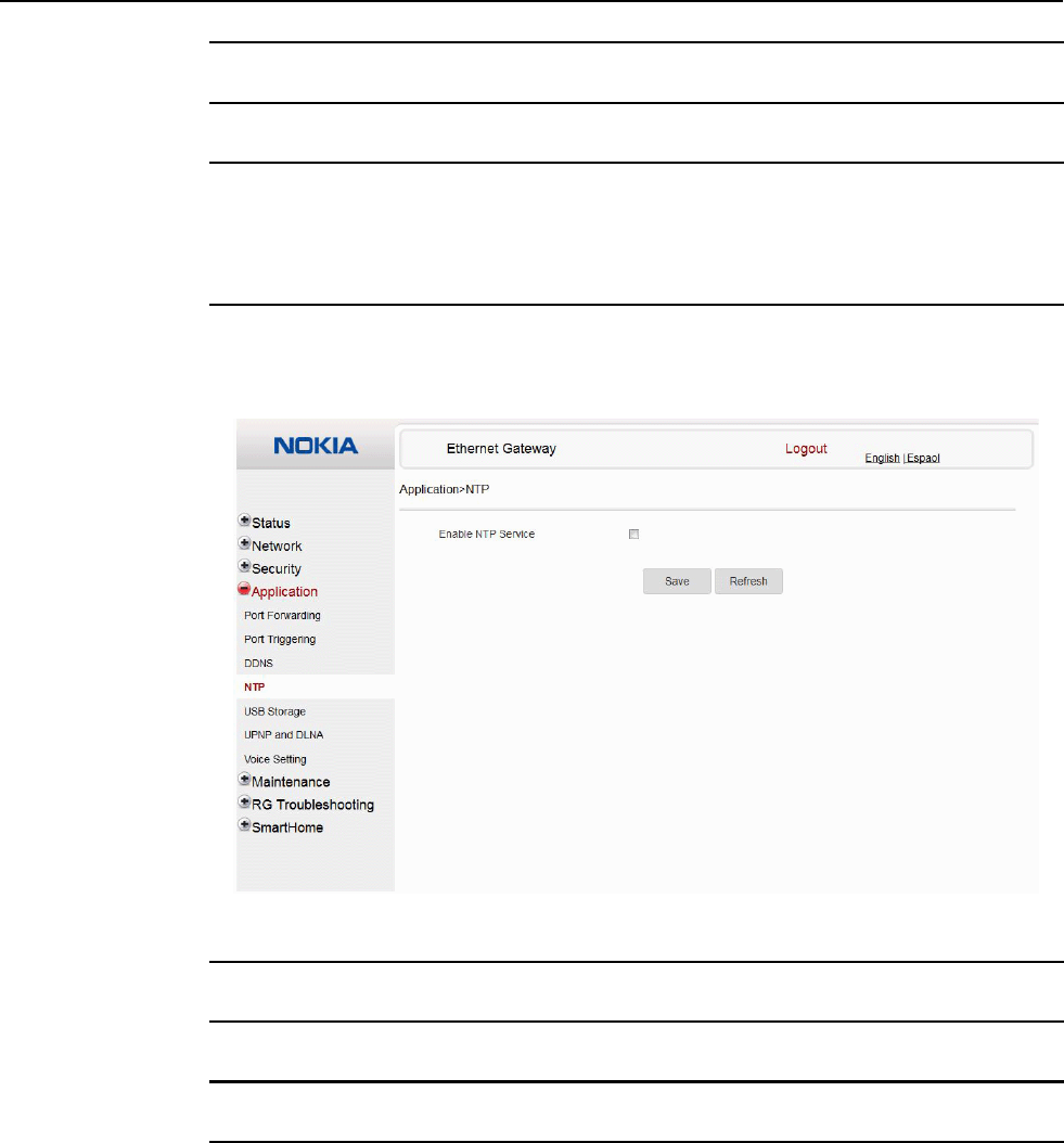
7368 ISAM CPE A-240Z-A Product Guide Configure an A-240Z-A CPE
Issue: 01 3FE-46615-AAAA-TCZZA 105
3
Click Save.
4
STOP. This procedure is complete.
Procedure 35 NTP configuration
1
Select Application > NTP from the top-level menu in the Ethernet Gateway window, as shown
in Figure 44.
Figure 44 NTP window
2
Select the Enable NTP Service checkbox.
3
Click Save.
4
STOP. This procedure is complete.
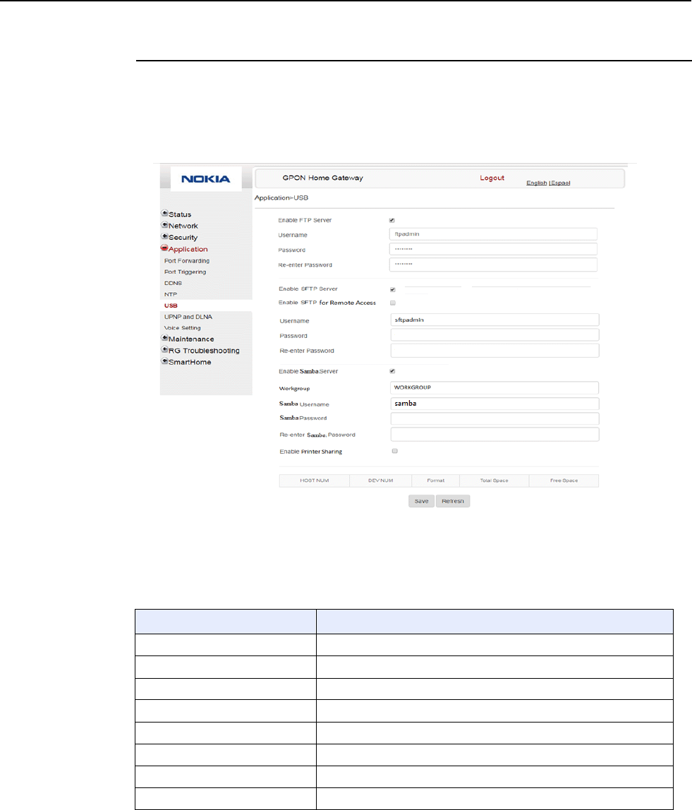
Configure an A-240Z-A CPE 7368 ISAM CPE A-240Z-A Product Guide
106 3FE-46615-AAAA-TCZZA Issue: 01
Procedure 36 USB configuration
1
Select Application > USB from the top-level menu in the Ethernet Gateway window, as shown
in Figure 45.
A USB printer that is connected to the ONT is available to all LAN devices.
Figure 45 USB window
Table 39 describes the fields in the USB window.
Table 39 USB parameters
Field Description
Enable FTP server Select this checkbox to enable using an FTP server
Username Username for FTP server
Password Password for FTP server
Re-enter Password Password for FTP server
Enable SFTP server Select this checkbox to enable using an SFTP server
Enable SFTP for Remote Access Select this checkbox to enable SFTP for remote access
Username Username for SFTP server
Password Password for SFTP server
(1 of 2)

7368 ISAM CPE A-240Z-A Product Guide Configure an A-240Z-A CPE
Issue: 01 3FE-46615-AAAA-TCZZA 107
Field Description
Re-enter Password Password for SFTP server
Enable Samba server Select this checkbox to enable using a Samba server
Workgroup Enter the name for the Samba work group
Samba Username Username for Samba server
Samba Password Password for Samba server
Re-enter Samba Password Password for Samba server
Enable Printer Sharing Select this checkbox to enable printer sharing
Printer sharing is disabled by default
Connected USB devices For each printer that is connected to the ONT, the following fields are
displayed:
• Host NUM: for example: Printer1, Printer2
• Dev NUM: name or identification for the printer
• Format: printer format, for example: raw or LPR
• Total space
• Free space
(2 of 2)
2
Configure USB.
3
Click Save.
4
STOP. This procedure is complete.
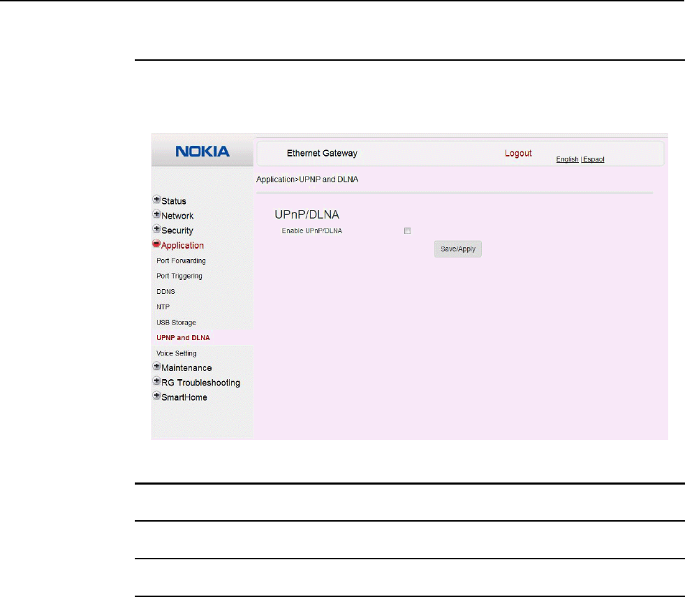
Configure an A-240Z-A CPE 7368 ISAM CPE A-240Z-A Product Guide
108 3FE-46615-AAAA-TCZZA Issue: 01
Procedure 37 UPnP and DLNA configuration
1
Select Application > UPnP and DLNA from the top-level menu in the Ethernet Gateway
window, as shown in Figure 46.
Figure 46 UPnP and DLNA window
2
Select the Enable UPnP checkbox to enable UPnP.
3
Click Save/Apply.
4
STOP. This procedure is complete.
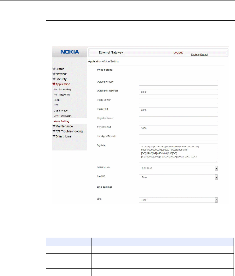
7368 ISAM CPE A-240Z-A Product Guide Configure an A-240Z-A CPE
Issue: 01 3FE-46615-AAAA-TCZZA 109
Procedure 38 Voice setting
1
Select Application > Voice Setting from the top-level menu in the Ethernet Gateway window,
as shown in Figure 47.
Figure 47 Voice setting window
Table 40 describes the fields in the Voice Setting window.
Table 40 Voice setting parameters
Field Description
Outbound Proxy Enter the SIP outbound proxy
Outbound Proxy Port Enter the outbound proxy port
Proxy Server Enter the proxy server
Proxy Port Enter the proxy port
(1 of 2)

Configure an A-240Z-A CPE 7368 ISAM CPE A-240Z-A Product Guide
110 3FE-46615-AAAA-TCZZA Issue: 01
Field Description
Register Server Enter the register server
Register Port Enter the register port
User Agent Domain Enter the user agent domain
DTMF Mode Choose InBand, rfc2822, Info, or Auto from the drop-down menu
FaxT38 Choose False or True from the drop-down menu
Line Choose a line from the drop-down menu
Enable Choose Enabled or Disabled from the drop-down menu
Directory Number Enter a directory number
AuthUserName Enter an authorized user name
AuthPassword Enter a password for the user
URL Enter the URL
(2 of 2)
2
Configure voice setting.
3
Click Save.
4
STOP. This procedure is complete.
8.2.6
Maintenance
A-240Z-A CPE also supports maintenance tasks, including:
• password change
• WAN speed test
• device management
• uplink management
• dongle management
• backup and restore
• firmware upgrade
• device reboot
• restore factory defaults
• diagnose
• log
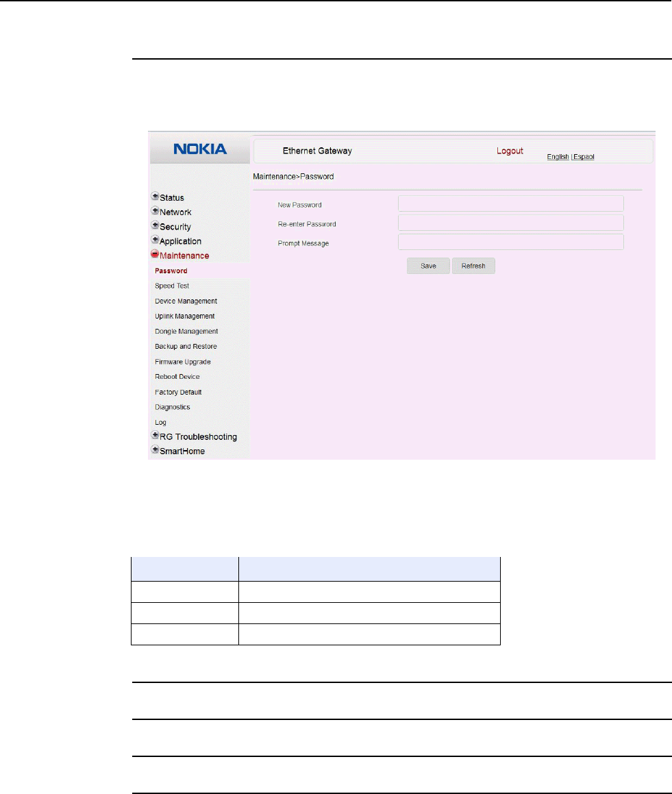
7368 ISAM CPE A-240Z-A Product Guide Configure an A-240Z-A CPE
Issue: 01 3FE-46615-AAAA-TCZZA 111
Procedure 39 Password configuration
1
Select Maintenance > Password from the top-level menu in the Ethernet Gateway window,
as shown in Figure 48.
Figure 48 Password window
Table 41 describes the fields in the password window.
Table 41 Password parameters
Field Description
New Password New password
Re-enter password Password must match password entered above
Prompt message Password prompt message
2
Configure the new password.
3
Click Save.
4
STOP. This procedure is complete.
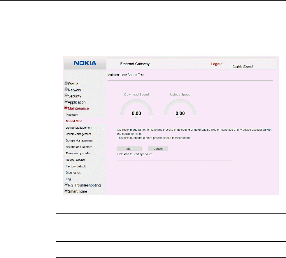
Configure an A-240Z-A CPE 7368 ISAM CPE A-240Z-A Product Guide
112 3FE-46615-AAAA-TCZZA Issue: 01
Procedure 40 WAN speed test
1
Select Maintenance > Speed Test from the top-level menu in the Ethernet Gateway window,
as shown in Figure 49.
Figure 49 Speed Test window
2
Click Start to start the speed test.
Enter the URL for the test server in the pop-up window.
3
STOP. This procedure is complete.
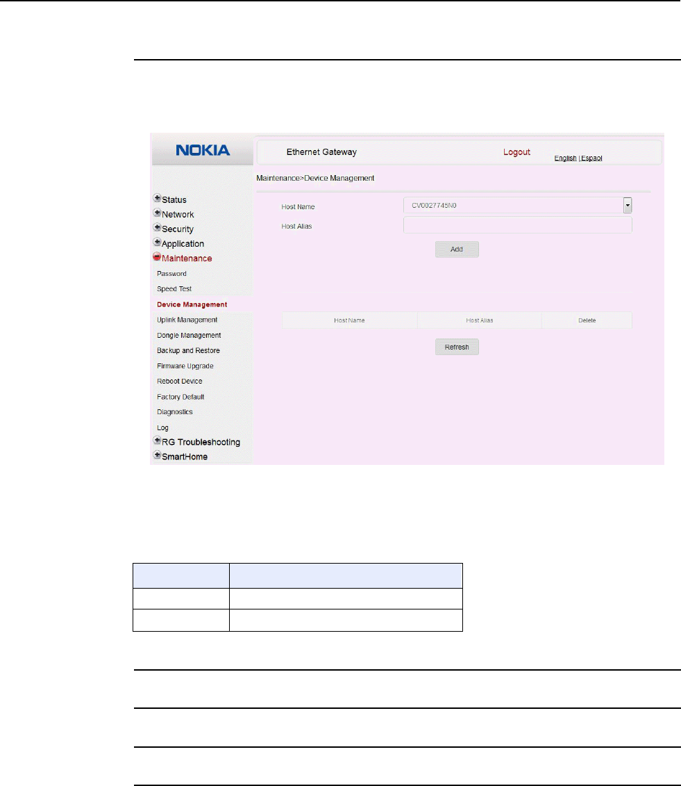
7368 ISAM CPE A-240Z-A Product Guide Configure an A-240Z-A CPE
Issue: 01 3FE-46615-AAAA-TCZZA 113
Procedure 41 Device management
1
Select Maintenance > Device Management from the top-level menu in the Ethernet Gateway
window, as shown in Figure 50.
Figure 50 Device management window
Table 42 describes the fields in the Device management window.
Table 42 Device management parameters
Field Description
Host Name Choose a host from the drop-down menu
Host Alias Enter an alias for the chosen host
2
Configure an alias for a specific host.
3
Click Add.
4
STOP. This procedure is complete.
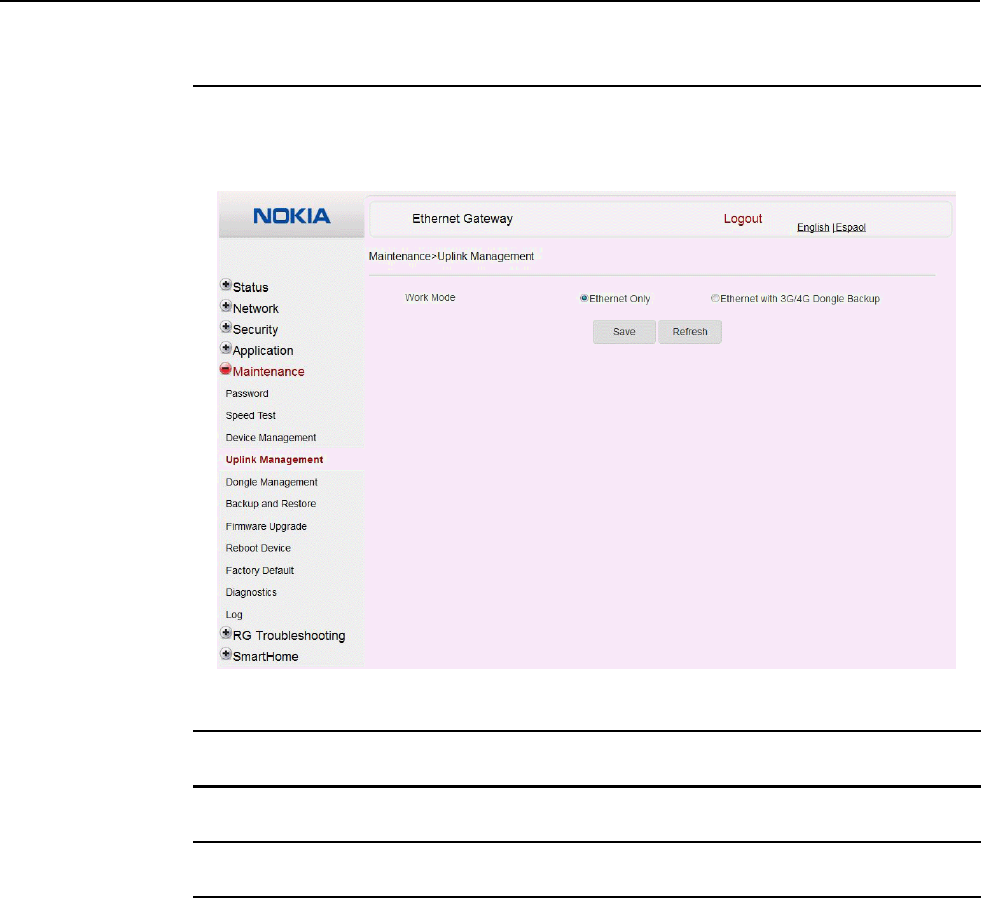
Configure an A-240Z-A CPE 7368 ISAM CPE A-240Z-A Product Guide
114 3FE-46615-AAAA-TCZZA Issue: 01
Procedure 42 Uplink management
1
Select Maintenance > Uplink Management from the top-level menu in the Ethernet Gateway
window, as shown in Figure 51.
Figure 51 Uplink Management window
2
Select a Work Mode: Ethernet Only or Ethernet with 3G/4G Dongle Backup.
3
Click Save.
4
STOP. This procedure is complete.
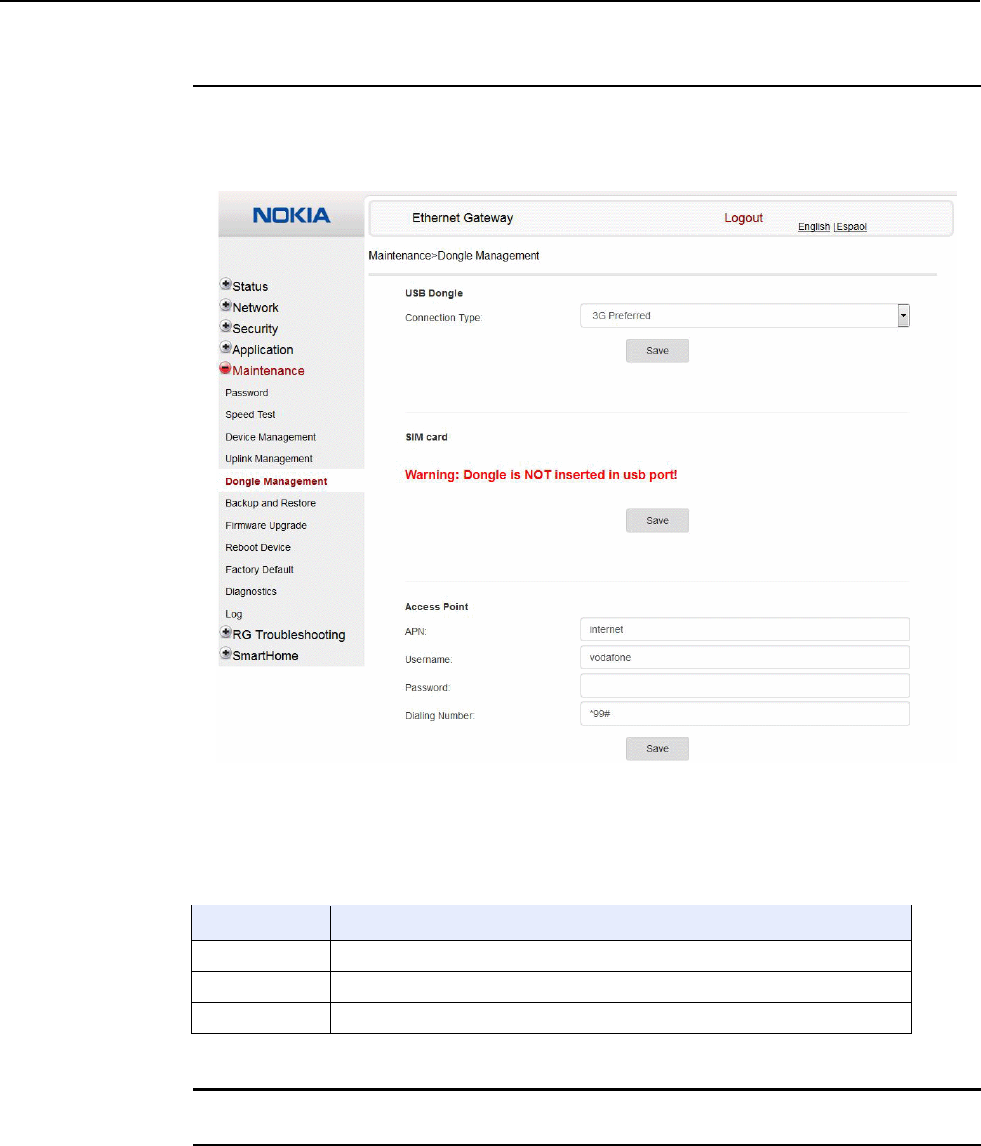
7368 ISAM CPE A-240Z-A Product Guide Configure an A-240Z-A CPE
Issue: 01 3FE-46615-AAAA-TCZZA 115
Procedure 43 Dongle management
1
Select Maintenance > Dongle Management from the top-level menu in the Ethernet Gateway
window, as shown in Figure 52.
Figure 52 Dongle management window
Table 42 describes the fields in the Dongle management window.
Table 43 Dongle management parameters
Field Description
USB Dongle Choose a connection type from the drop-down menu
SIM card Choose a SIM card from the drop-down menu
Access Point Enter the APN, username, password, and dialing number for the access point
2
Configure the USB dongle.
3
Click Save.
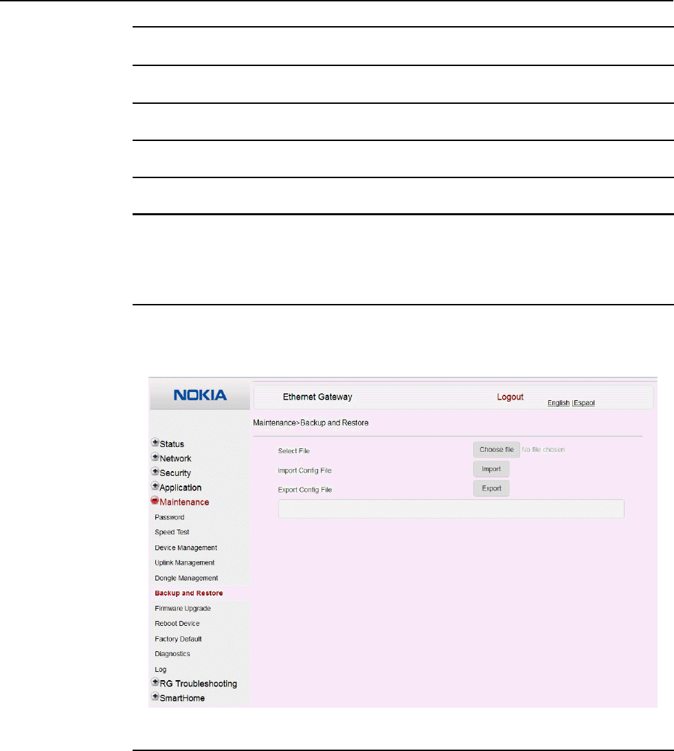
Configure an A-240Z-A CPE 7368 ISAM CPE A-240Z-A Product Guide
116 3FE-46615-AAAA-TCZZA Issue: 01
4
Configure the SIM card.
5
Click Save.
6
Configure the access point.
7
Click Save.
8
STOP. This procedure is complete.
Procedure 44 Backup and restore
1
Select Maintenance > Backup and Restore from the top-level menu in the Ethernet Gateway
window, as shown in Figure 53.
Figure 53 Backup and Restore window
2
Click Select File and choose the backup file.
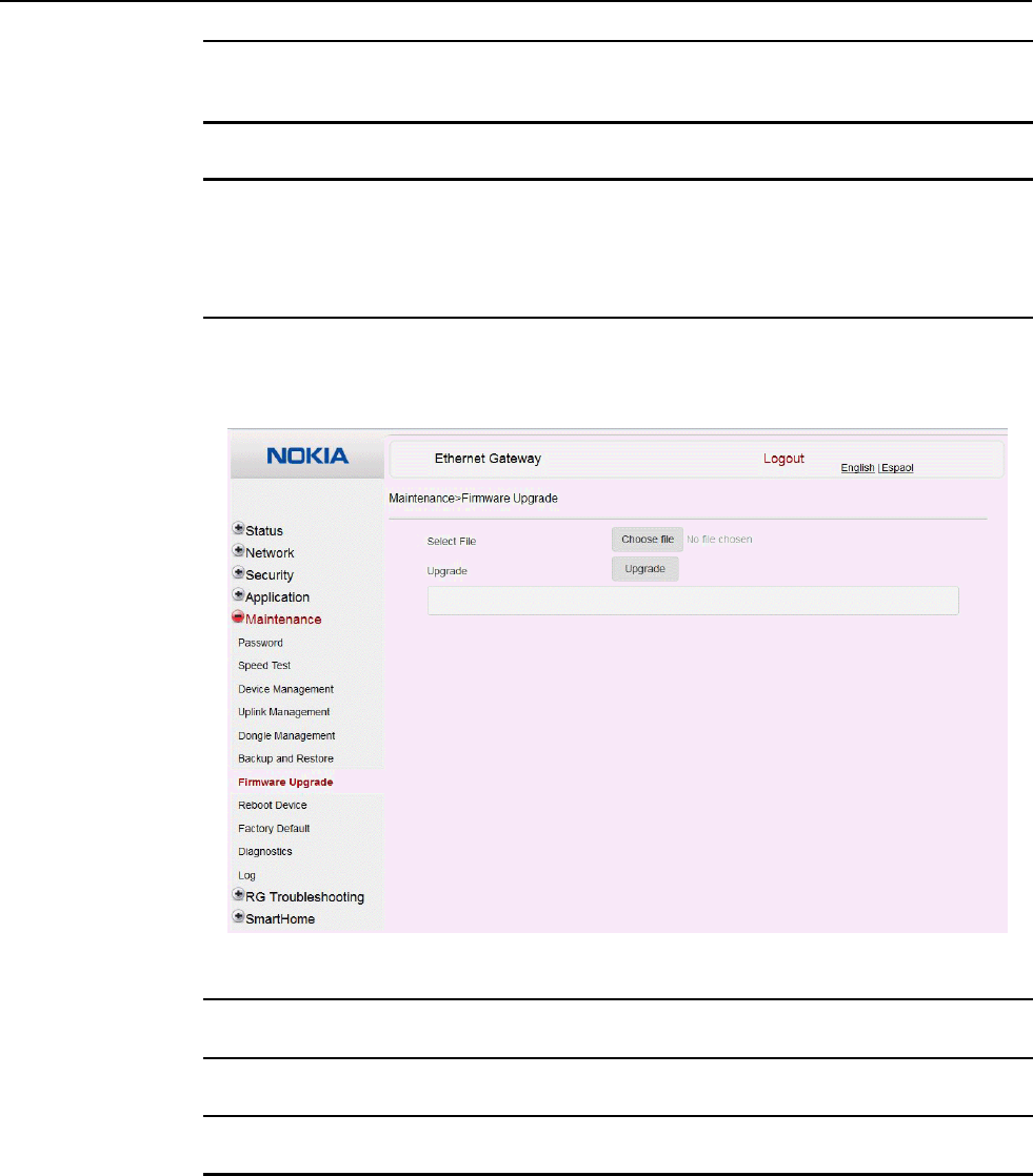
7368 ISAM CPE A-240Z-A Product Guide Configure an A-240Z-A CPE
Issue: 01 3FE-46615-AAAA-TCZZA 117
3
Click Import Config File to restore the CPE to the saved backup or click Export Config File to
export the current CPE configuration to the backup file.
4
STOP. This procedure is complete.
Procedure 45 Upgrade firmware
1
Select Maintenance > Firmware Upgrade from the top-level menu in the Ethernet Gateway
window, as shown in Figure 54.
Figure 54 Firmware upgrade window
2
Click Select File and choose the firmware file.
3
Click Upgrade to upgrade the firmware.
4
STOP. This procedure is complete.
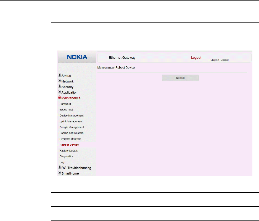
Configure an A-240Z-A CPE 7368 ISAM CPE A-240Z-A Product Guide
118 3FE-46615-AAAA-TCZZA Issue: 01
Procedure 46 Reboot CPE
1
Select Maintenance > Reboot Device from the top-level menu in the Ethernet Gateway
window, as shown in Figure 55.
Figure 55 Reboot window
2
Click Reboot to reboot the CPE.
3
STOP. This procedure is complete.
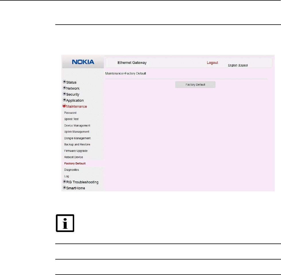
7368 ISAM CPE A-240Z-A Product Guide Configure an A-240Z-A CPE
Issue: 01 3FE-46615-AAAA-TCZZA 119
Procedure 47 Restore factory defaults
1
Select Maintenance > Factory Default from the top-level menu in the Ethernet Gateway
window, as shown in Figure 56.
Figure 56 Factory default window
Note — A factory reset also removes the IoT software image that was
installed separately; see “IOT application software package download”.
2
Click Factory Default to reset the CPE to its factory default settings.
3
STOP. This procedure is complete.
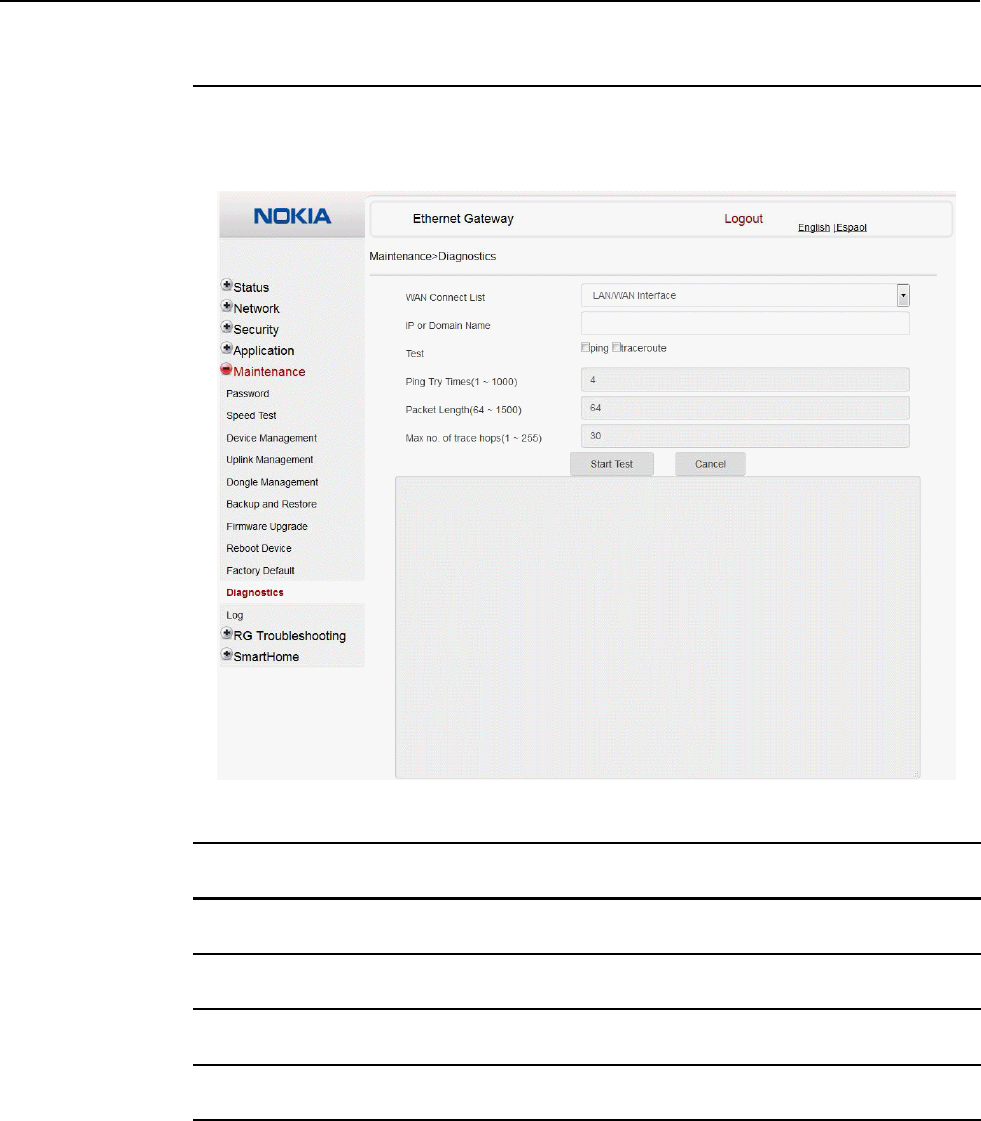
Configure an A-240Z-A CPE 7368 ISAM CPE A-240Z-A Product Guide
120 3FE-46615-AAAA-TCZZA Issue: 01
Procedure 48 Diagnose connections
1
Select Maintenance > Diagnostics from the top-level menu in the Ethernet Gateway window,
as shown in Figure 57.
Figure 57 Diagnostics window
2
Choose a WAN connection to diagnose from the drop-down menu.
3
Enter the IP address or domain name.
4
Select the test type: ping, traceroute, or both.
5
Enter the number of ping attempts to perform (1 - 1000); the default is 4.
6
Enter a ping packet length (64-1024); the default is 64.
7
Enter the maximum number of trace hops (1-255); the default is 30.
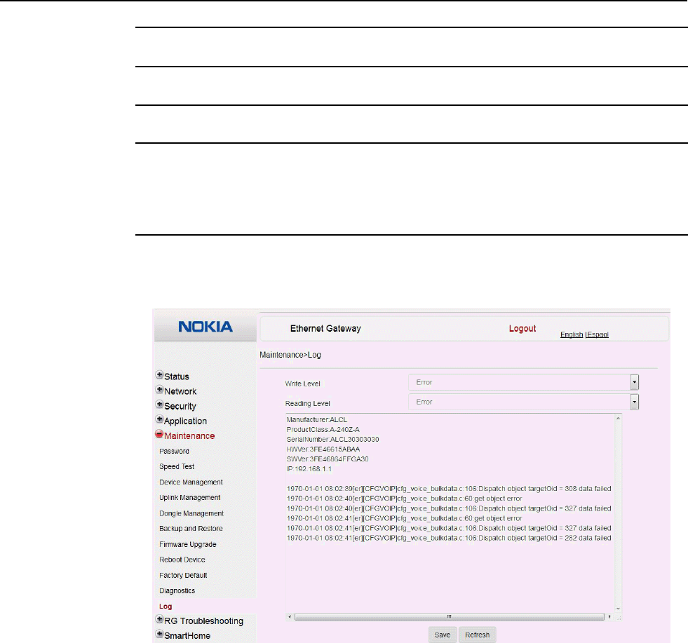
7368 ISAM CPE A-240Z-A Product Guide Configure an A-240Z-A CPE
Issue: 01 3FE-46615-AAAA-TCZZA 121
8
Click Start Test. Results will be displayed at the bottom of the window.
9
Click Cancel to cancel the test.
10
STOP. This procedure is complete.
Procedure 49 View log files
1
Select Maintenance > Log from the top-level menu in the Ethernet Gateway window, as
shown in Figure 58.
Figure 58 Log window

Configure an A-240Z-A CPE 7368 ISAM CPE A-240Z-A Product Guide
122 3FE-46615-AAAA-TCZZA Issue: 01
2
Choose a write level from the drop-down menu to determine which types of events are
recorded in the log file:
• Emergency
• Alert
• Critical
• Error
• Warning
• Notice
• Informational
• Debug
3
Choose a reading level from the drop-down menu to determine which types of events to
display from the log file:
• Emergency
• Alert
• Critical
• Error
• Warning
• Notice
• Informational
• Debug
4
The log file is displayed at the bottom of the window.
5
STOP. This procedure is complete.
8.2.7
RG troubleshooting counters
The Troubleshooting Counters feature enables service providers and end users to
monitor the performance of their broadband connection.
Tests are run to retrieve upstream and downstream throughput, latency, and DNS
response time. The Troubleshooting Counters window also displays upstream and
downstream packet loss and Internet status.
Procedure 50 Retrieve Residential Gateway (RG) troubleshooting counters
1
Select RG Troubleshooting Counters from the left menu in the Ethernet Gateway window.
The RG Troubleshooting Counters window appears; see Figure 59.
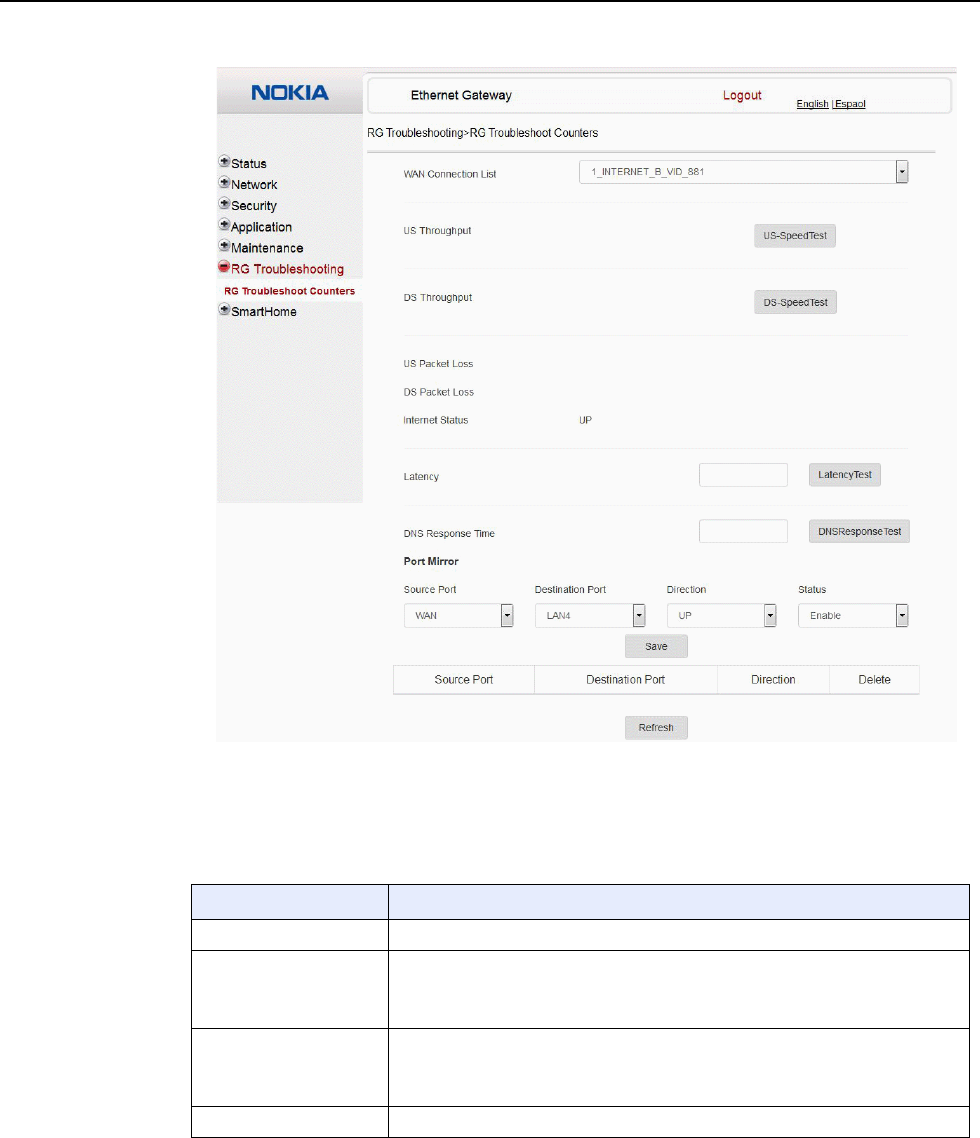
7368 ISAM CPE A-240Z-A Product Guide Configure an A-240Z-A CPE
Issue: 01 3FE-46615-AAAA-TCZZA 123
Figure 59 RG Troubleshooting Counters window
Table 44 describes the fields in the RG Troubleshooting Counters window.
Table 44 RG Troubleshooting Counters parameters
Field Description
WAN Connection List Select a WAN connection from the list
US Throughput This test is used to determine the upstream throughput/speed
Click US Speed Test to specify the time for the upstream test
The default is weekly, performed at idle to a public server
DS Throughput This test is used to determine the downstream throughput/speed
Click DS Speed Test to specify the time for the downstream test
The default is weekly, performed at idle to a public server
US Packet Loss The number of upstream packages lost
(1 of 2)

Configure an A-240Z-A CPE 7368 ISAM CPE A-240Z-A Product Guide
124 3FE-46615-AAAA-TCZZA Issue: 01
Field Description
DS Packet Loss The number of downstream packages lost
Internet Status Whether the broadband connections is active (UP) or not (DOWN)
Latency This test is used to determine the lowest round-trip time in milliseconds by pinging
the target server multiple times
Click Latency Test to specify the time for the test
The default is weekly, performed at idle to a public server
DNS Response Time This test is used to determine the lowest round-trip time in milliseconds by sending
a request to the target DNS server
Click DNS Response Test to specify the time for the test
The default is weekly, performed at idle to a public server
Port Mirror Select Source Port, Destination Port, Direction (Up or Down) and Status (Enable
or Disable)
(2 of 2)
2
Configure the test times if desired.
3
Click Refresh to update the data.
4
STOP. This procedure is complete.
8.2.8
Smart Home configuration
The Smart Home configuration feature is used to manage the devices for home
monitoring systems. Both Zwave and Zigbee are supported. The Smart Home
configuration feature supports:
• status retrieval
• configuration
• maintenance
Procedure 51 Smart Home status retrieval
1
Select Smart Home>Status from the left menu in the Ethernet Gateway window.
The Smart Home Status window appears; see Figure 60.
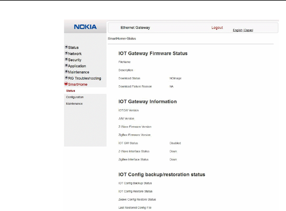
7368 ISAM CPE A-240Z-A Product Guide Configure an A-240Z-A CPE
Issue: 01 3FE-46615-AAAA-TCZZA 125
Figure 60 Smart Home Status window
Table 45 describes the fields in the Smart Home Status window.

Configure an A-240Z-A CPE 7368 ISAM CPE A-240Z-A Product Guide
126 3FE-46615-AAAA-TCZZA Issue: 01
Table 45 Smart Home Status parameters
Field Description
IOT Gateway Firmware Status
Filename Firmware name
Description Firmware description
Download Status Download status: success or failure
Download Failure Reason Failure reason (if applicable)
IOT Gateway Information
IOT GW version IOT gateway identifier
JVM version Java Virtual Machine identifier
Zwave Firmware version Zwave firmware identifier (if applicable)
Zigbee Firmware version Zigbee firmware identifier (if applicable)
IOT GW Status IOT gateway status: active or inactive, or disabled
Zwave Interface Status Zwave interface status: up or down
Zigbee Interface Status Zigbee interface status: up or down
IOT Config backup/restoration status
IOT Config Backup Status Status of IOT configuration backup
IOT Config Restore Status Status of IOT configuration restoration
Zwave Config Restore Status Status of Zwave configuration restoration
Last Restored Config file Last restored configuration file
2
STOP. This procedure is complete.
Procedure 52 Smart Home configuration
1
Select Smart Home>Configuration from the left menu in the Ethernet Gateway window.
The Smart Home Configuration window appears; see Figure 61.
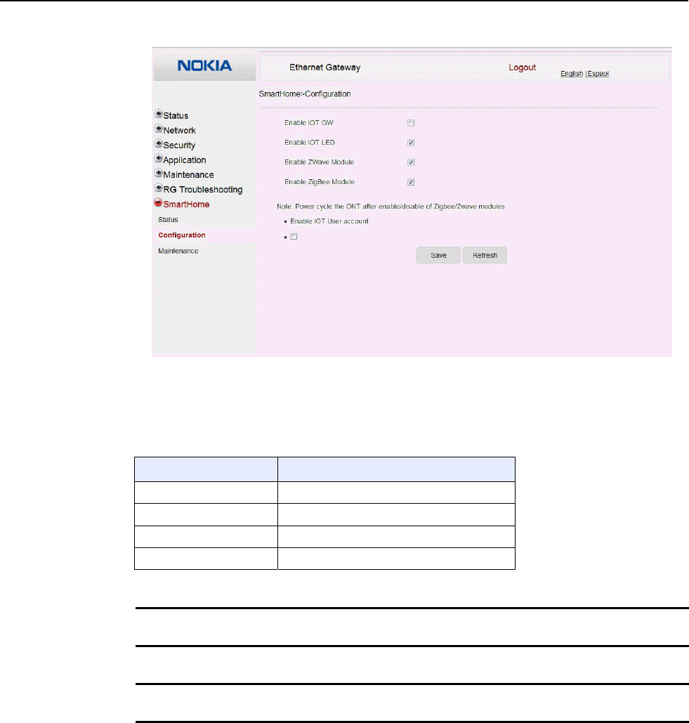
7368 ISAM CPE A-240Z-A Product Guide Configure an A-240Z-A CPE
Issue: 01 3FE-46615-AAAA-TCZZA 127
Figure 61 Smart Home Configuration window
Table 46 describes the fields in the Smart Home Configuration window.
Table 46 Smart Home Configuration parameters
Field Description
Enable IOT GW Select this checkbox to enable IOT gateway
Enable IOT LED Select this checkbox to enable IOT LED
Enable Zwave Module Select this checkbox to enable Zwave
Enable Zigbee Module Select this checkbox to enable Zigbee
2
Configure the Smart Home parameters.
3
Click Save.
4
STOP. This procedure is complete.
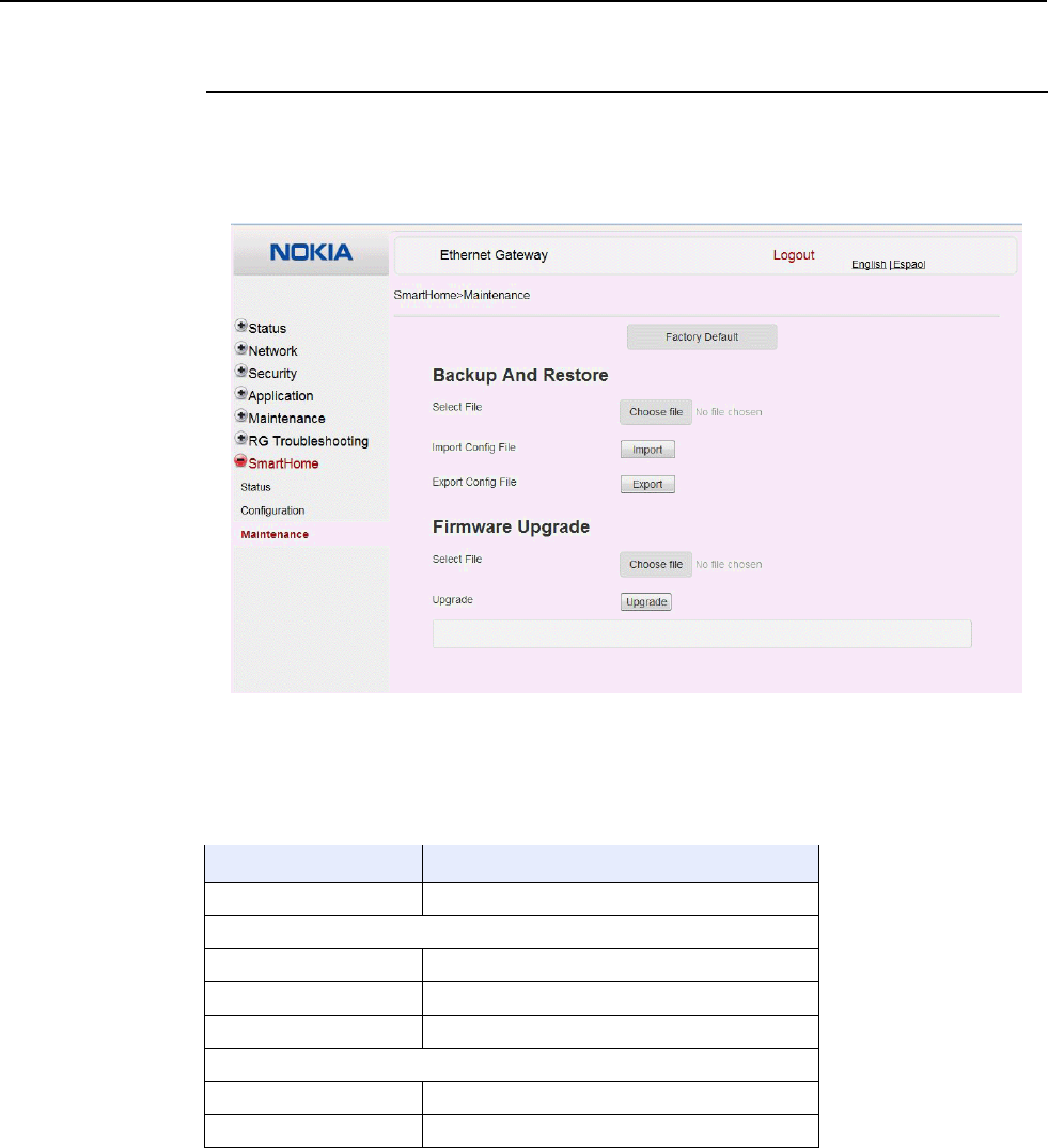
Configure an A-240Z-A CPE 7368 ISAM CPE A-240Z-A Product Guide
128 3FE-46615-AAAA-TCZZA Issue: 01
Procedure 53 Smart Home maintenance
1
Select Smart Home>Maintenance from the left menu in the Ethernet Gateway window.
The Smart Home Maintenance window appears; see Figure 62.
Figure 62 Smart Home Maintenance window
Table 47 describes the fields in the Smart Home Maintenance window.
Table 47 Smart Home maintenance parameters
Field Description
Factory Default Click to reset the device to its factory default values
Backup and Restore
Select File Select a file from the drop down menu.
Import Config File Click Import to import the configuration file.
Export Config File Click Export to export the configuration file.
Firmware Upgrade
Select File Select a file from the drop-down menu.
Upgrade Click Upgrade to upgrade the firmware.

7368 ISAM CPE A-240Z-A Product Guide Configure an A-240Z-A CPE
Issue: 01 3FE-46615-AAAA-TCZZA 129
2
Configure the Smart Home maintenance.
3
STOP. This procedure is complete.
8.3 IOT application software package download
The A-240Z-A CPE supports IOT. This section describes how to download the IOT
application software package from the Auto Configuration Server (ACS) to the CPE
and to activate the software.
The filename for the IOT application software package is 3FE46043XXXXXX. The
software image file should be placed on the HTTP server accessible by the CPE.
The format of the URL for downloading the IOT application software package should
be “http://<IP_address>/3FE46043<build_version>, for example:
http://192.168.5.142/3FE46043FFEB38
Procedure 54 Downloading the IOT application software package
1
Log into the ACS with your username and password.
2
Select the Download RPC method for upgrading the CPE.
3
Provide the HTTP URL and file size to be downloaded.
4
Initiate the download process.
5
Verify that the software package has been downloaded successfully:
a
On the ACS, execute the GetParameterValue command on the CPE
object:InternetGatewayDevice.X_ALU-COM_SmartHome.lotFirmwareInfo.1.FileName
b
On the ACS, execute the GetParameterValue command on the CPE object:
InternetGatewayDevice.X_ALU-COM_SmartHome.lotFirmwareInfo.1.IOTDownloadSt
atus
The status should be DownloadSuccess.
If the status is DownloadFailure, repeat the procedure.
c
On the ACS, execute the SetParameterValue command on the CPE object:
InternetGatewayDevice.X_ALU-COM_SmartHome.IotGWCtrl.Enable

Configure an A-240Z-A CPE 7368 ISAM CPE A-240Z-A Product Guide
130 3FE-46615-AAAA-TCZZA Issue: 01
This will start the IOT application.
6
STOP. This procedure is complete.

Customer document and product support
Customer documentation
Customer Documentation Welcome Page
Technical Support
Customer Documentation Technical Support
Documentation feedback
Customer Documentation Feedback
Copyright 2017 Nokia.
3FE-46615-AAAA-TCZZA