Nokia Networks T55800-01 User Manual bcover
Nokia Networks OY bcover
Contents
- 1. users manual
- 2. revised 105 statement page
- 3. request for admin info
users manual

© Nokia Networks Oy 1 (2)
Nokia MetroHopper Radio with FC RRI/
FXC RRI
User Manual B0
Binder 1/1
C33512.22

2 (2) © Nokia Networks Oy
The information in this document is subject to change without notice and describes
only the product defined in the introduction of this documentation. This document is
intended for the use of Nokia Networks' customers only for the purposes of the
agreement under which the document is submitted, and no part of it may be
reproduced or transmitted in any form or means without the prior written permission of
Nokia Networks. The document has been prepared to be used by professional and
properly trained personnel, and the customer assumes full responsibility when using it.
Nokia Networks welcomes customer comments as part of the process of continuous
development and improvement of the documentation.
The information or statements given in this document concerning the suitability,
capacity, or performance of the mentioned hardware or software products cannot be
considered binding but shall be defined in the agreement made between Nokia
Networks and the customer. However, Nokia Networks has made all reasonable
efforts to ensure that the instructions contained in the document are adequate and free
of material errors and omissions. Nokia Networks will, if necessary, explain issues
which may not be covered by the document.
Nokia Networks' liability for any errors in the document is limited to the documentary
correction of errors. Nokia Networks WILL NOT BE RESPONSIBLE IN ANY EVENT
FOR ERRORS IN THIS DOCUMENT OR FOR ANY DAMAGES, INCIDENTAL OR
CONSEQUENTIAL (INCLUDING MONETARY LOSSES), that might arise from the
use of this document or the information in it.
This document and the product it describes are considered protected by copyright
according to the applicable laws.
NOKIA logo is a registered trademark of Nokia Corporation.
Other product names mentioned in this document may be trademarks of their
respective companies, and they are mentioned for identification purposes only.
Copyright © Nokia Networks Oy 2000. All rights reserved.

User Manual B0
NOKIA / C33512.22 © Nokia Networks Oy 1 (2)
M = Missing Document
P = Preliminary
Contents
Binder 1/1
Title Document Identifier Div. Rem
1
Document Note DN99617961 Issue 2-0 en 1.0
2
Guide to Documentation DN99611449 Issue 2-0 en 2.0
3
Installation Overview DN99611437 Issue 2-0 en 3.0
4
Installation DN99592289 Issue 2-1 en 4.0
5
Commissioning and Maintenance DN99611394 Issue 2-0 en 5.0
6
Product Description DN99592717 Issue 2-2 en 6.0
7
Glossary DN99593058 Issue 2-1 en 7.0

2 (2) © Nokia Networks Oy NOKIA / C33512.22
M = Missing Document
P = Preliminary

C33512.20 D0
Nokia MetroHopper Radio
User Manual
DN99592241 © Nokia Networks Oy Draft 1 (11)
Issue 3-0 en Nokia Proprietary and Confidential
Document Note
Document Note
2 (11) © Nokia Networks Oy Draft DN99592241
Nokia Proprietary and Confidential Issue 3-0 en
The information in this document is subject to change without notice and describes only the
product defined in the introduction of this documentation. This document is intended for the
use of Nokia Networks' customers only for the purposes of the agreement under which the
document is submitted, and no part of it may be reproduced or transmitted in any form or
means without the prior written permission of Nokia Networks. The document has been
prepared to be used by professional and properly trained personnel, and the customer
assumes full responsibility when using it. Nokia Networks welcomes customer comments as
part of the process of continuous development and improvement of the documentation.
The information or statements given in this document concerning the suitability, capacity, or
performance of the mentioned hardware or software products cannot be considered binding
but shall be defined in the agreement made between Nokia Networks and the customer.
However, Nokia Networks has made all reasonable efforts to ensure that the instructions
contained in the document are adequate and free of material errors and omissions. Nokia
Networks will, if necessary, explain issues which may not be covered by the document.
Nokia Networks' liability for any errors in the document is limited to the documentary correction
of errors. Nokia Networks WILL NOT BE RESPONSIBLE IN ANY EVENT FOR ERRORS IN
THIS DOCUMENT OR FOR ANY DAMAGES, INCIDENTAL OR CONSEQUENTIAL
(INCLUDING MONETARY LOSSES), that might arise from the use of this document or the
information in it.
This document and the product it describes are considered protected by copyright according to
the applicable laws.
NOKIA logo is a registered trademark of Nokia Corporation.
Other product names mentioned in this document may be trademarks of their respective
companies, and they are mentioned for identification purposes only.
Copyright © Nokia Networks Oy 2001. All rights reserved.
Nokia Citytalk, Nokia Extratalk, Nokia FlexiHopper, Nokia Flexitalk, Nokia Hopper Manager,
Nokia Intratalk, Nokia MetroHopper, Nokia MetroHub, and Nokia MetroSite are trademarks of
Nokia Networks Oy.
Hereby, Nokia Corporation, declares that this Nokia MetroHopper radio is in compliance with the
essential requirements and other relevant provisions of Directive: 1999/5/EC.
FCC ID:PM5T55800–01
This device complies with Part 15 of the FCC Rules. Operation is subject to the following two
conditions: (1) This device may not cause harmful interference, and (2) this device must accept
any interference received, including interference that may cause undesired operation.
The product is marked with the CE marking and Notified Body number according to the
Directive 1999/5/EC
0889

DN99592241 © Nokia Networks Oy Draft 3 (11)
Issue 3-0 en Nokia Proprietary and Confidential
Summary of changes
Document Date Comment
C33512002PE_00 24 Jun 1999
C33512002PE_A0 06 Sep 1999
C33512002PE_B0 26 Oct 1999
C33512009XE_A0 29 Oct 1999
DN99592241 Issue 1-0 en 01 Nov 1999 New document numbering scheme adopted.
DN99592241 Issue 2-0 en 11 Feb 2000
DN99592241 Issue 2-1 en 16 Mar 2000
DN99592241 Issue 2-2 en 11 May 2000
DN99592241 Issue 3-0 en 31 Aug 2001

Document Note
4 (11) © Nokia Networks Oy Draft DN99592241
Nokia Proprietary and Confidential Issue 3-0 en
User Manual / Product version compatibility
DN99592241 © Nokia Networks Oy Draft 5 (11)
Issue 3-0 en Nokia Proprietary and Confidential
1User Manual / Product version
compatibility
C33512.20 Nokia MetroHopper with FIU 19 / RRIC User Manual
Version D0
This user manual provides the instructions for the installation and operation of the
products listed below.
All units are labelled with a sticker stating the product code and version.
Table 1. Outdoor unit
Product code Product name Product
version
T55800.01 Nokia MetroHopper OU 58 GHz B
Table 2. Alignment unit pole clamp
Product code Product name Product
version
T55851.01 Nokia MetroHopper Mounting Adapter Plate A
Table 3. Optical alignment unit
Product code Product name Product
version
T55875.01 MetroHopper Optical Alignment Tool A
Document Note
6 (11) © Nokia Networks Oy Draft DN99592241
Nokia Proprietary and Confidential Issue 3-0 en
Note
Note
The ordering practice will change so that the product codes, comprimising of both
a main unit and plug-in units, are not used any longer. Now the main unit
(T55240.01) and the needed number of plug-in units are ordered with seperate
codes. For example, to get a 12 x 2M 1+0 configuration, place an order for one
main unit and three 4 x 2M plug-in units. For 16 x 2M 1+0 you have to order a
main unit a suitable upgrade kit (T55246.4x).
The capacity of Nokia MetroHopper is fixed to 4 x 2 Mbit/s.
Table 4. FIU 19 indoor units
Product code Product name Product
version
T55240.01 FIU 19 0x2M 1+0 C
T55240.80 FIU 19 16x2M 1+1 120 C
55240.81 FIU 19 16x2M 1+1 75 C
55240.82 FIU 19 16x2M 1+1 120 RJ-45 C
Table 5. FIU 19 upgrades
Product code Product name Product
version
P55044.01 Hopper SW upgrade kit CD-ROM
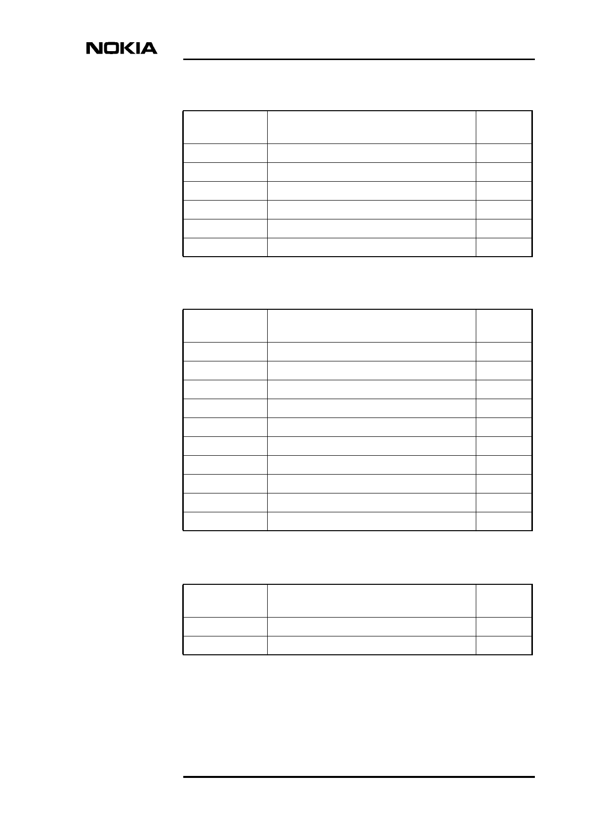
T55220.01 FIU 19 4x2M 120 Plug-in Unit TQ C
T55220.02 FIU 19 4x2M 75 Plug-in Unit C
T55220.03 FIU 19 4x2M Plug-in Units 120 RJ-45 C
T55221.01 FIU 19 Flexbus Plug-in Unit A
T55223.01 FIU 19 Aux Data plug-in Unit A
T55241.04 FIU 19 Mounting Kit for TM4 rack A
T55241.05 FIU 19 Mounting Kit for ETSI rack A
T55246.40 FIU 19 UPG for 4-12x2M 1+0 120 TQ C
User Manual / Product version compatibility
DN99592241 © Nokia Networks Oy Draft 7 (11)
Issue 3-0 en Nokia Proprietary and Confidential
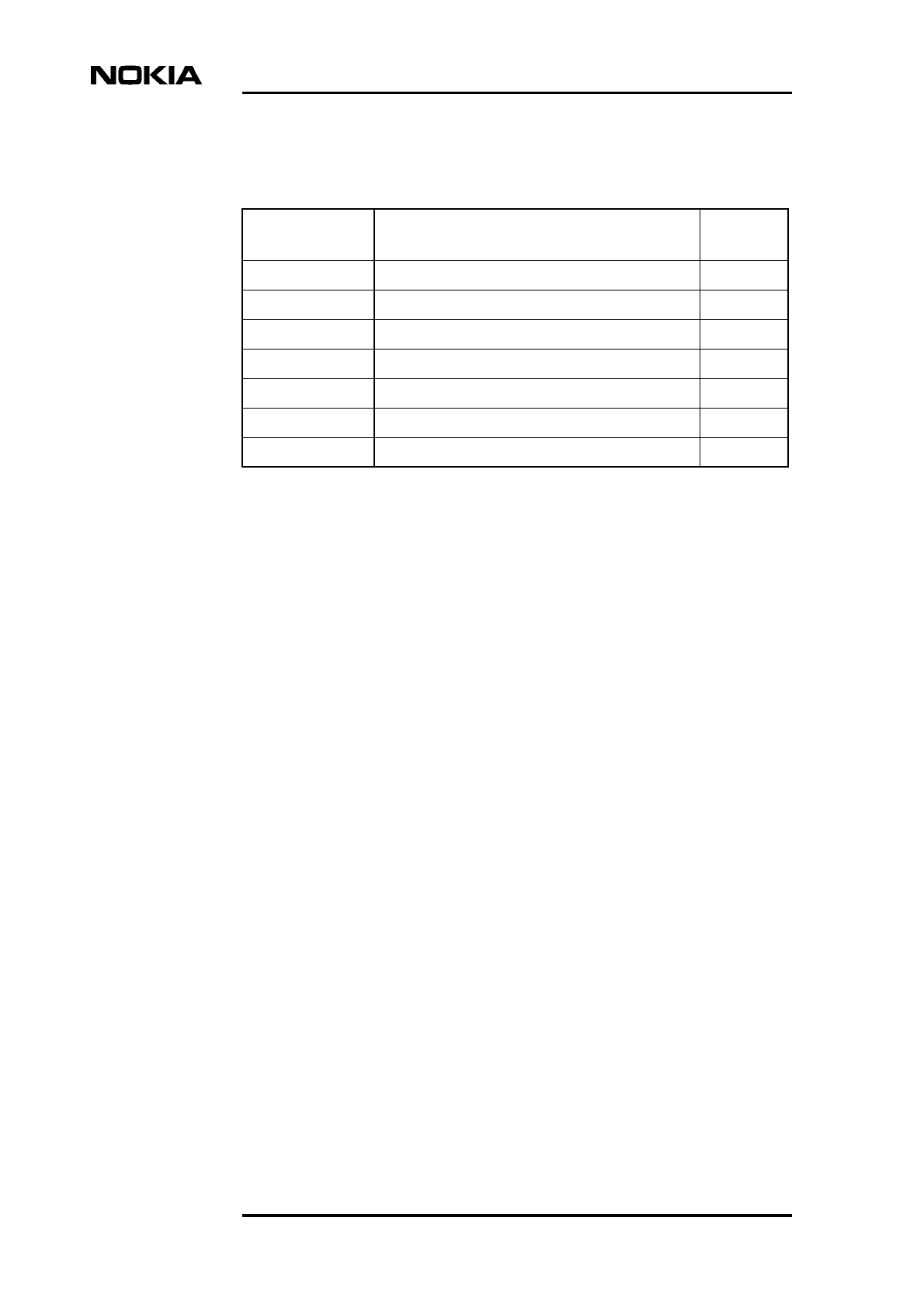
T55246.41 FIU 19 UPG for 4-12x2M 1+0 75 C
T55246.42 FIU 19 UPG for 4–12x2M 1+0 120 RJ-45 C
T55246.51 FIU 19 UPG FOR 16 X 2M TO 1+1 C
T55246.80 FIU 19 UPG to 16x2M 1+1 120 C
T55246.81 FIU 19 UPG to 16x2M 1+1 75 C
T55246.82 FIU 19 UPG to 16x2M 1+1 120 RJ-45 C
Table 6. FIU 19 spare parts
Product code Product name Product
version
T55210.01 FIU 19 Backplane 1+0 A
T52210.02 FIU 19 Backplane 1+1 B
T55211.01 FIU 19 EXU 16x2M 120 Ohms TQ B
T55211.02 FIU 19 EXU 16x2M 75 Ohms B
T55211.03 FIU 19 EXU 16x2M 120 Ohms TQ RJ-45 B
T55212.01 FIU 19 16x2M IC Plug-In Unit C
T55240.01 FIU 19 0x2M 1+0 C
T55241.01 FIU 19 Mounting Kit for 4-12x2M 1+0 A
T55241.02 FIU 19 Mounting Kit for 16x2M 1+0 A
T55241.03 FIU 19 Mounting Kit for 16x2M 1+1 A
Table 7. RRIC indoor unit
Product code Product name Product
version
T55290.01 RRIC Radio Relay Interface C
T55291.01 RRIC Power Supply for AC Intratalk BTS A
Table 5. FIU 19 upgrades (Continued)
Product code Product name Product
version
Document Note
8 (11) © Nokia Networks Oy Draft DN99592241
Nokia Proprietary and Confidential Issue 3-0 en
Table 8. Node manager programs and accessories
Product code Product name Product
version
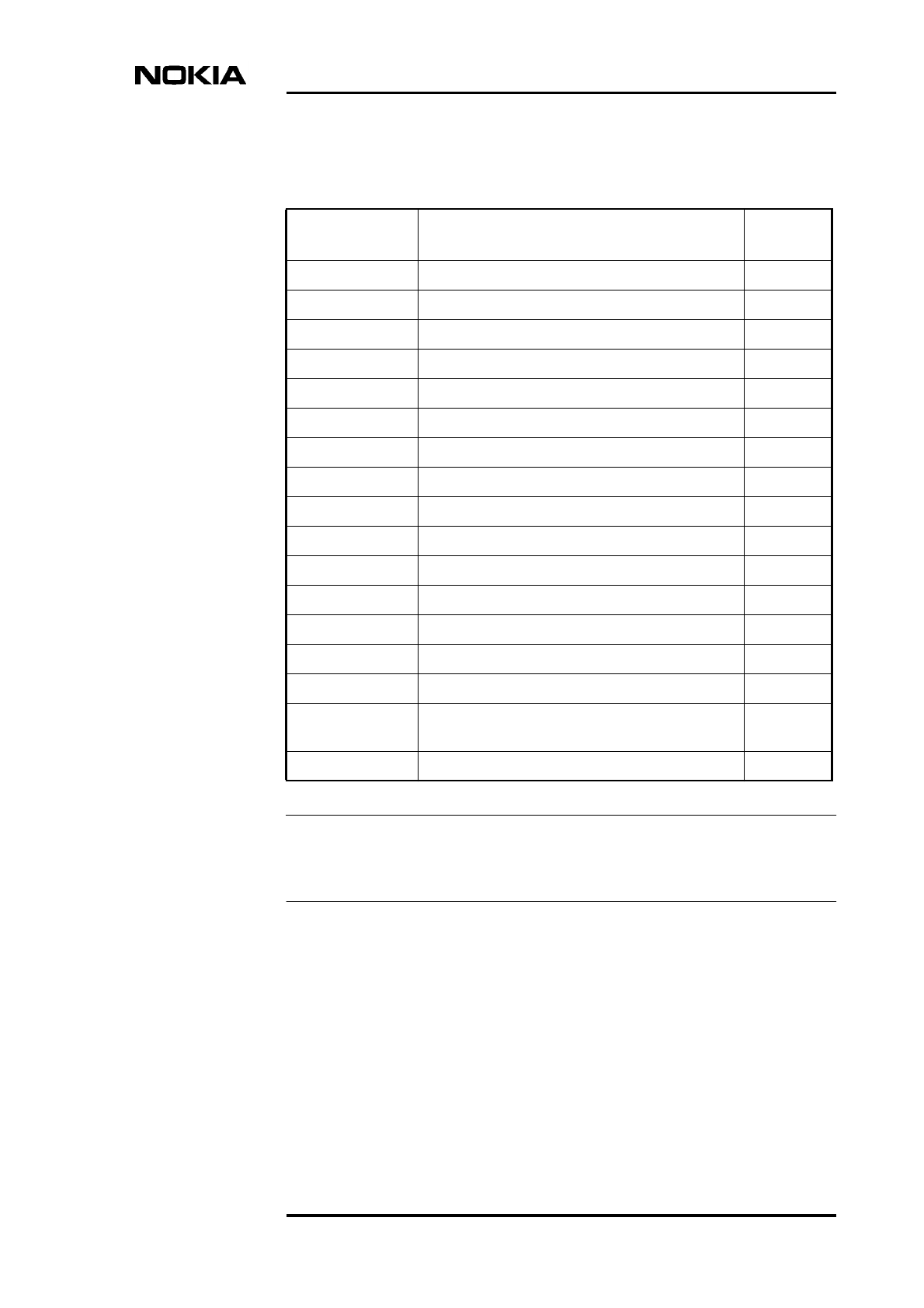
P38206.01 Hopper Manager C4.2 CD-ROM + Cable (2.5 m) C
CS72451.01 LMP Cable (5.0 m)
P31711.01 TruMan C8.0 K
E62717.01 V.11/V.28 converter cable set (PC-TRUx)
E62717.03 V.11/V.28 converter cable set (PC-TRUx)
26287.01 Chassis 20T/14U
T55270.01 Nokia Q1 LMP cable C
User Manual / Product version compatibility
DN99592241 © Nokia Networks Oy Draft 9 (11)
Issue 3-0 en Nokia Proprietary and Confidential
Note
Jumper cables for connecting the RRIC indoor unit to the connector board on top
of the base station cabinet are included with the base station.
Table 9. Flexbus cables, connectors and accessories
Product code Product name Product
version
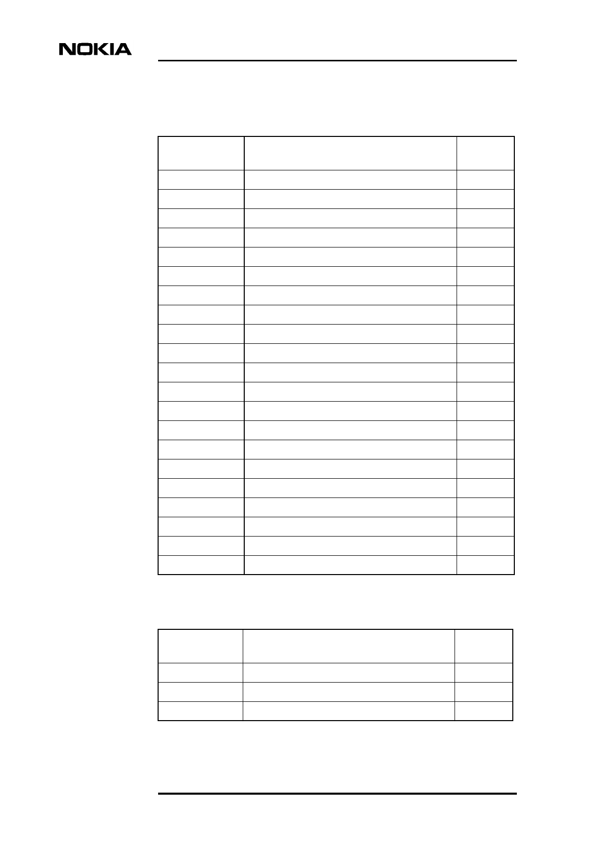
T36625.01 TNC-M/0–TNC-M/0, 1.5 m
T36625.02 Cable TNC-M/0–TNC-M/0, 4 m
T36625.03 Cable TNC-M/0–TNC-M/0, 8 m
T36625.04 Cable TNC-M/0–TNC-M/0, 15 m
T36626.01 Cable Reel Flexbus, RG223, 500 m
T36629.01 Cable Reel Flexbus, RG214, 500 m
T55255.01 Flexbus TNC-TNC (RG-223) Connector Kit B
T55255.02 Flexbus TNC-TNC (RG-214) Connector Kit B
T55255.11 Flexbus N-TNC (RG-223) Connector Kit B
T55255.12 Flexbus N-TNC (RG-214) Connector Kit B
T55257.01 Flexbus TNC-TNC Jumper Cable B
T55257.02 Flexbus TNC-TNC Cable (500 mm) B
T38094.01 Jumper Cables DMR 18-38CE BBU1 A
T55271.01 TNC-N Adapter for Jumper Cable 0
CS72749.60 Grounding kit KTM P 1/4” for RG-213/214
CS72749.61 Grounding kit for RG-223 – RG-58 (61 1540
0006)
CS72746.20 Clamp RF A4 2 x 1/4” for L-profile 40 x 40
Document Note
10 (11) © Nokia Networks Oy Draft DN99592241
Nokia Proprietary and Confidential Issue 3-0 en
Table 10. FIU 19 2M and Q1 cables and connectors
Product code Product name Product
version
T55250.01 FIU 19 D9M-TQ Q1 Jumper Cable F
T55250.02 FIU 19 D9F-TQ Q1 Jumper Cable F
T55250.03 FIU 19 D9F-TQ 2x2M Jumper Cables F
T55250.20 FIU 19 TQ-TQ Q1 or 2M Cable (500 mm) F
T55250.21 FIU 19 TQ-TQ 2M Cable (30 m) G
T55250.31 FIU 19 4xTQ Cable 5m open G
T55250.32 FIU 19 4xTQ Cable 15m open G
T55251.01 FIU 19 4xTQ 2M Connector Kit A
T55252.01 FIU 19 4xRJ 45 2M Connector Kit A
T55252.02 FIU 19 4xRJ 45 Aux Card Connector Kit A
T55253.01 FIU 19 2M Cable 500 m A
T55260.01 FIU 19 2xTQ-DB9 Q1 Adapter D
T55265.01 Cable sets 1/4–Euro; TQ + Converter D9 A
T38122.02 Q1 Interconnection Cable B
T38122.04 Q1 Chaining Cable 2, CE, (6xIU/SSS) B
T38122.10 Q1 Coupling Connector, CE B
T38127.01 Interconn. Cable, 2M, 75, C/CE (SSS/BTS) B
T38127.02 Jumper Cable, 2x2M, 75, C/CE (SSS) B
T38127.04 Cross-Conn. Cable, 2M, 75, CE (SSS) B
T38128.01 Interconn. Cable, 2M, 120, C/CE (SSS/BTS) C
T38081 4x2 Connector set DMR 18–38CE SMB A
Table 11. Power supplies and cables
Product code Product name Product
version
T55254.01 TALK FIU 19 Power Connector Kit 0
T55258.02 FIU 19 Power Cable 15m 0
T55259.02 FB Plug-In Power Cable 15m 0

User Manual / Product version compatibility
DN99592241 © Nokia Networks Oy Draft 11 (11)
Issue 3-0 en Nokia Proprietary and Confidential
T30839.01 Power AC/DC 1x100W 19/ETS 1.5U B
T30839.02 Power AC/DC 2x100W 19/ETS 1.5U B
T30839.03 Power DC/DC 1x100W 19/ETS 1.5U B
T30839.04 Power DC/DC 2x100W 19/ETS 1.5U B
Table 11. Power supplies and cables (Continued)
Product code Product name Product
version

DN99611394 © Nokia Networks Oy 1 (42)
Issue 2-0 en
Nokia MetroHopper Radio with FC RRI/FXC RRI
User Manual B0
C33512.22
Commissioning and Maintenance

Commissioning and Maintenance
2 (42) © Nokia Networks Oy DN99611394
Issue2-0en
The information in this document is subject to change without notice and describes only the
product defined in the introduction of this documentation. This document is intended for the
use of Nokia Networks' customers only for the purposes of the agreement under which the
document is submitted, and no part of it may be reproduced or transmitted in any form or
means without the prior written permission of Nokia Networks. The document has been
prepared to be used by professional and properly trained personnel, and the customer
assumes full responsibility when using it. Nokia Networks welcomes customer comments as
part of the process of continuous development and improvement of the documentation.
The information or statements given in this document concerning the suitability, capacity, or
performance of the mentioned hardware or software products cannot be considered binding
but shall be defined in the agreement made between Nokia Networks and the customer.
However, Nokia Networks has made all reasonable efforts to ensure that the instructions
contained in the document are adequate and free of material errors and omissions. Nokia
Networks will, if necessary, explain issues which may not be covered by the document.
Nokia Networks' liability for any errors in the document is limited to the documentary correction
of errors. Nokia Networks WILL NOT BE RESPONSIBLE IN ANY EVENT FOR ERRORS IN
THIS DOCUMENT OR FOR ANY DAMAGES, INCIDENTAL OR CONSEQUENTIAL
(INCLUDING MONETARY LOSSES), that might arise from the use of this document or the
information in it.
This document and the product it describes are considered protected by copyright according to
the applicable laws.
NOKIA logo is a registered trademark of Nokia Corporation.
Other product names mentioned in this document may be trademarks of their respective
companies, and they are mentioned for identification purposes only.
Copyright © Nokia Networks Oy 2000. All rights reserved.
Nokia FlexiHopper, Nokia MetroHopper, Nokia MetroSite, and Nokia MetroHub are trademarks
of Nokia Networks Oy. Any other trademarks mentioned in the documents are the property of
their respective owners.

DN99611394 © Nokia Networks Oy 3 (42)
Issue 2-0 en
Contents
Contents 3
1 About this document 7
2 Commissioning Nokia MetroHopper 9
2.1 Precautions 9
2.2 Commissioning with Nokia BTS Manager 10
2.3 Commissioning with Nokia MetroHub Manager 13
2.4 Configuring identifications and settings 13
2.4.1 Identifications 14
2.4.2 Unit settings 14
2.4.3 Outdoor unit settings 14
2.5 Verifying commissioning 16
3 Maintaining Nokia MetroHopper 17
3.1 Preventive maintenance 17
3.2 Performance monitoring 17
3.2.1 Measurements 18
3.2.2 Error counters 18
3.2.3 Reading statistics 18
3.3 Using loopbacks 19
3.4 Replacing or removing outdoor unit 21
Appendix A. Alarm descriptions 23
A.1 FC RRI unit alarms 23
A.2 FXC RRI unit alarms 36
A.3 MetroHopper unit alarms 40

Commissioning and Maintenance
4 (42) © Nokia Networks Oy DN99611394
Issue2-0en

DN99611394 © Nokia Networks Oy 5 (42)
Issue 2-0 en
Summary of changes
Document Date Comment
C33512012SE_00 29 Oct 1999 Prerelease version
DN99611394 Issue 1-0 en 28 Dec 1999 New document numbering scheme adopted
DN99611394 Issue 2-0 en 30 May 2000 Valid for Nokia SiteWizard C1.0

Commissioning and Maintenance
6 (42) © Nokia Networks Oy DN99611394
Issue2-0en

About this document
DN99611394 © Nokia Networks Oy 7 (42)
Issue 2-0 en
Note
1About this document
This document gives task-oriented instructions for the commissioning of Nokia
MetroHopper Radio with FC RRI or FXC RRI indoor unit. Commissioning and
maintenance actions are carried out using the Nokia BTS Manager or Nokia
MetroHub Manager software included in the Nokia SiteWizard CD-ROM.
This document describes only outdoor unit -related settings and functions. To
commission Nokia MetroHopper with FC RRI or FXC RRI you need also Nokia
MetroSite GSM BTS User Manual or Nokia MetroHub User Manual which
describe all node-level and RRI-related settings and functions.
For information about installing FC RRI and FXC RRI transmission units, please
refer to Nokia MetroSite GSM BTS User Manual or Nokia MetroHub User
Manual. The instructions for installing the MetroHopper outdoor unit are found
in Outdoor Unit Installation document in this manual. Read the Product
Description document before commissioning Nokia MetroHopper. Product
Description serves as a reference document and explains all relevant terms.
Please familiarise yourself with Microsoft Windows before operating Nokia BTS
Manager or Nokia MetroHub Manager.
Screenshots included are representations only. The actual node manager program
may differ slightly from the shots depicted.

Commissioning and Maintenance
8 (42) © Nokia Networks Oy DN99611394
Issue2-0en

Commissioning Nokia MetroHopper
DN99611394 © Nokia Networks Oy 9 (42)
Issue 2-0 en
2Commissioning Nokia MetroHopper
This chapter describes the commissioning process of the Nokia MetroHopper
Radio. All commissioning tasks are performed with Nokia BTS Manager in case
the radio is used with Nokia MetroSite GSM BTS or with Nokia MetroHub
Manager in case the radio is used with Nokia MetroHub.
2.1 Precautions
The following pre-requisites must be fulfilled before starting the commissioning:
• you have already either
• the FC RRI unit logically installed in the BTS
or
• the FXC RRI unit(s) logically installed in the BTS or the
transmission node.
• the outdoor unit is installed and aligned in accordance with the instructions
given in this manual.
• you already have a connection to the network element with the node
manager.
Please refer to Nokia MetroSite GSM BTS User Manual or Nokia MetroHub User
Manual for more instructions.
Commissioning and Maintenance
10 (42) © Nokia Networks Oy DN99611394
Issue2-0en
Note
Note
2.2 Commissioning with Nokia BTS Manager
Nokia BTS Manager contains a Commissioning Wizard, which facilitates the
base station commissioning process. Run the Commissioning Wizard as
instructed in Nokia MetroSite GSM BTS User Manual. Fill in all the required
settings. Whenever an FC RRI or FXC RRI unit is included in the BTS
configuration, a specific Radio Link Settings page is displayed during the wizard
sequence. By clicking the Radio hop(s) button on the page you can launch a
Radio Wizard sequence during which you can check or set any required outdoor
unit related settings.
Commissioning with the Radio Wizard
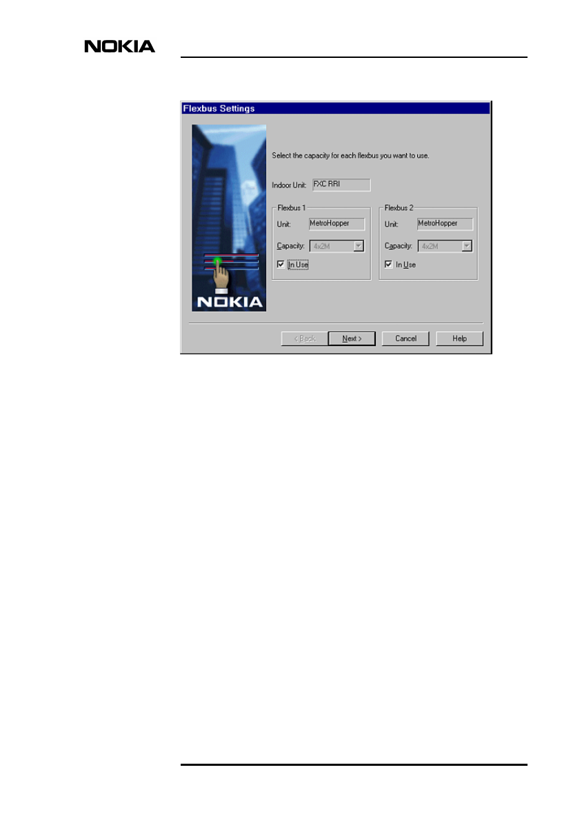
1. The first page in the Radio Wizard sequence displays the type of the indoor
unit (FC RRI or FXC RRI) and the outdoor units (MetroHopper or
FlexiHopper) connected to each Flexbus interface.
Select the In use option for each Flexbus interface you want to use. At least
one outdoor unit must be connected and one Flexbus in use before you can
proceed to the next page.
The radio capacity of Nokia MetroHopper is fixed to 4 x 2 Mbit/s.
If the transmission unit is FC RRI, only Flexbus 1 settings are displayed.
Commissioning Nokia MetroHopper
DN99611394 © Nokia Networks Oy 11 (42)
Issue 2-0 en
Figure 1. Flexbus settings page
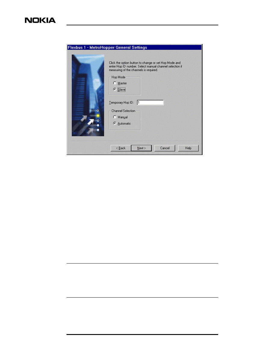
2. The MetroHopper General Settings page is displayed next. On this page,
you can select the settings for the outdoor unit connected to the Flexbus 1
interface.
• Hop Mode: one of the terminals forming a radio hop must be
configured as the master and the other end as the slave. The
hierarchy is decided in the network planning phase.
• Temporary Hop ID: the master and the slave must have the same
temporary hop ID. When the commissioning is completed, this is
automatically changed to a unique hop ID.
• Channel Selection: you can choose either Manual or Automatic
channel selection. When you click Next, the corresponding channel
selection page will open.
• If you choose Manual channel selection, select the desired
channel. You can also click Measure to measure the
interference level on the selected channels and then select the
best available channel.
• If you choose Automatic channel selection, mark the channels
among which the channel is to be selected. The software
automatically measures the interference levels on each
channel, and selects the best one.
Commissioning and Maintenance
12 (42) © Nokia Networks Oy DN99611394
Issue2-0en
Note
Figure 2. MetroHopper General Settings page
3. If the transmission unit in use is FXC RRI, define the settings for the
Flexbus interface 2 and the connected outdoor unit as described above. If
the transmission unit is FC RRI, only one Flexbus is available and you can
proceed to step 4 directly.
4. When you have entered all the required settings, Summary of
Commissioning Settings page is displayed. It contains all the settings you
have defined for the radio(s). Check that the settings are correct and click
Next to send the settings to the node. You can also go back in case you want
to adjust the settings on previous pages.
5. Monitoring Hop page displays the status of the hops during and after the
commissioning. If the commissioning is successful, the status becomes
Ready.
The status of the hop will not be Ready before also the other end of the hop is
commissioned successfully. Thus, the status of the terminal that is commissioned
first will have the status Commissioning until the far-end terminal is
commissioned.

Commissioning Nokia MetroHopper
DN99611394 © Nokia Networks Oy 13 (42)
Issue 2-0 en
Note
Note
Click Report to see a more detailed commissioning report for each outdoor
unit. The commissioning report contains, for example, the measured
interference level of the selected channel, and the fading margin
measurement.
Click Next to return to the Nokia BTS Manager Commissioning Wizard.
2.3 Commissioning with Nokia MetroHub Manager
Nokia MetroHub Manager contains Commissioning Wizard, which facilitates the
commissioning process. Commissioning Wizard will first ask you to accept the
selected site configuration file (.SDF) and to send the node settings to the node.
In case radio link equipment is installed, you can monitor the radio hops in the
Check and Fine-tune Hops page. The Commissioning Wizard will
automatically draw a commissioning report which is displayed on the last page of
the wizard sequence.
In case you will later install new radios, you can commission the equipment by
launching the Radio Wizard from the FXC RRI menu. The procedure is exactly
the same as described in the previous section.
FC RRI is not compatible with Nokia MetroHub.
2.4 Configuring identifications and settings
This section describes how to view or change outdoor unit related identifications
or settings with Nokia BTS Manager or Nokia MetroHub Manager. When you are
using Nokia BTS Manager, all Nokia MetroHopper related identifications and
settings are accessed through the Transmission menu. In case you are using
Nokia MetroHub Manager, these are found under the FXC RRI menu.
For simplicity, both the Transmission menu of Nokia BTS Manager and the FXC
RRI menu of Nokia MetroHub Manager are henceforth referred to as
Transmission / FXC RRI.

Commissioning and Maintenance
14 (42) © Nokia Networks Oy DN99611394
Issue2-0en
To view or change unit identifications, click Transmission / FXC RRI →
Identifications, and select the required unit. A window detailing the
identifications of the selected unit will open.
To view or change unit settings, click Transmission / FXC RRI →Settings, and
select the required unit. A window detailing the settings of the selected unit will
open.
Any changes you make are sent to the node as you click on the OK or Apply
button of the dialog in question.
2.4.1 Identifications
User defined identifications for a network element or a unit include, for example,
notes on the installation. Identifications used in alarm display can also be
changed. Some of the information (such as the serial number of the product)
cannot be altered, because it is read directly from the equipment.
To change the identifications of a functional entity, type the desired identification
information in the text box.
2.4.2 Unit settings
Flexbus 1 and Flexbus 2
Click Transmission / FXC RRI →Settings, and select Unit. The Unit settings
dialog box will open. Select the required Flexbus interface. In these windows you
can enable or disable Flexbus interfaces and set the appropriate capacity. Note
that with Nokia MetroHopper the capacity is fixed to4x2Mbit/s. You can also
switch the OU power feed on or off.
To enable/disable a Flexbus interface, select or clear the In Use checkbox.
To set the OU power supply on/off, select the appropriate option.
2.4.3 Outdoor unit settings
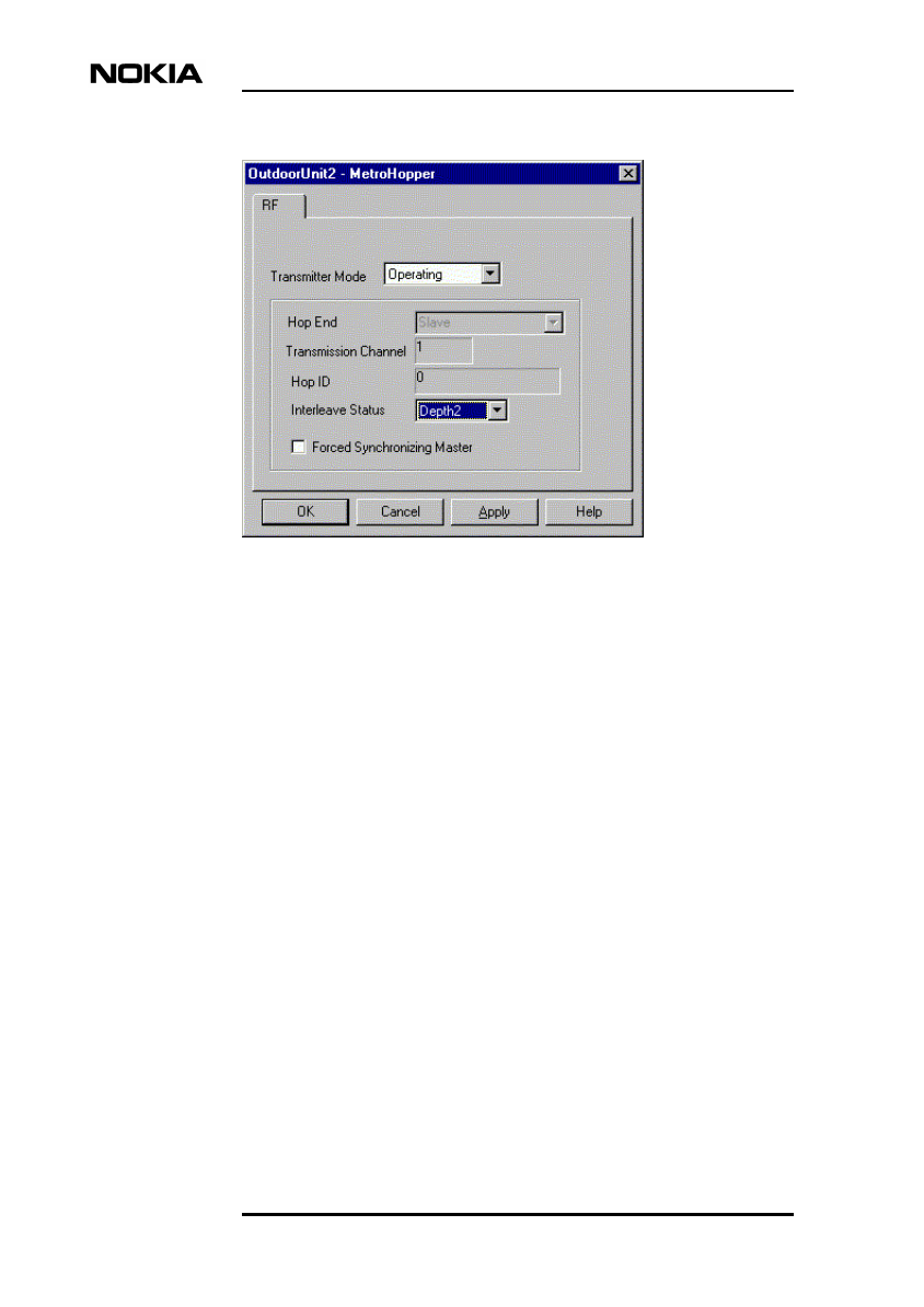
Click Transmission / FXC RRI →Settings, and select either Outdoor unit 1 or
Outdoor unit 2. The corresponding MetroHopper settings dialog box will open.
Transmitter mode
The possible values for Transmitter mode are Operating,Forced transmit,
Receiving only, and Commissioning. Note that it is not possible to switch to
certain modes at all times.

Commissioning Nokia MetroHopper
DN99611394 © Nokia Networks Oy 15 (42)
Issue 2-0 en
Hop end mode
One of the terminals forming a hop must be configured as the master and the
other as the slave. In order to change the hop end mode, you will need to
recommission the hop by using Radio Wizard.
In case external synchronisation is used, you can select a terminal also to function
as the synchronising master. See Product Description for more information
about burst synchronisation.
Transmission channel
Displays the channel in use.
Hop ID
This field displays the unique hop ID. Note that the master and the slave must
have the same hop ID.
Interleave status
Possible values for Interleave status are Off,Depth 2, and Depth 4. See Product
Description for more information about interleaving.
To change the interleave status, select the required value from the list. Note that
both ends of a radio hop must have the same interleave status.
Commissioning and Maintenance
16 (42) © Nokia Networks Oy DN99611394
Issue2-0en
Figure 3. Outdoor Unit Settings
2.5 Verifying commissioning
It is recommended to monitor the hop for at least half an hour after all settings
have been made at both ends of the hop. Reset the statistics and the error counters
and let the hop operate for half an hour (or longer, if desired). After the time has
passed, check that the signal quality statistics and the error counters do not show
any undesired values (see Section 3.2.).
If the signal quality is OK (unavailability time = 0) and there are no unexpected
alarms, the commissioning of the hop is complete. If there occurs any
unavailability time during the monitoring, repeat the monitoring.

Maintaining Nokia MetroHopper
DN99611394 © Nokia Networks Oy 17 (42)
Issue 2-0 en
3Maintaining Nokia MetroHopper
This chapter contains the following information:
• preventive maintenance
• performance monitoring
• replacing or removing equipment.
3.1 Preventive maintenance
Maintenance of the radio includes measurements which do not interfere with the
communication. Measurements which do interfere with the communication can
also be conducted when the radio is in operation, provided that the measurements
are performed at a time when there is no traffic or the traffic can be rerouted. With
the Nokia Network Management System (NMS), service measurements can be
performed in a centralised manner for the entire network without having to move
physically from station to station. However, any measurements performed with
external measuring instruments must be conducted locally.
Record the measurements so that they can be compared with earlier results and
used to detect significant changes in the results. Store the measurement records at
the location where the measurements are conducted, that is, the records of
centralised measurements in the central monitoring room, and the records of
external measurements at the equipment station.
3.2 Performance monitoring
The indoor units record information regarding the performance of the network
element.
The performance information is divided into three areas:

Commissioning and Maintenance
18 (42) © Nokia Networks Oy DN99611394
Issue2-0en
• measurements
• error counters
• signal quality statistics.
Each of these is available from the Measurements or Statistics menu in the node
manager, in some cases, from the toolbar.
The measurement and error counter windows both display information about the
performance of the network element and its current operating condition. The
statistics are collected for the signal.
3.2.1 Measurements
The Interface Measurements window, which is opened from Transmission /
FXC RRI →Measurements, displays selected information about the network
element. This information is in the form of, for example, bit error rates and
voltage or power levels recorded from particular units inside the functional
entities of the network element.
Monitoring measurements
These values are automatically refreshed according to the time interval that you
can enter into the Auto Refresh field. If the refresh rate is set to 0 seconds, the
refresh is done only once. The values can also be manually refreshed by clicking
the Refresh button.
3.2.2 Error counters
Error counters in the network element record the number of times that an error
had occurred in a particular unit or functional entity.
Click Transmission / FXC RRI →Statistics to open the Statistics dialog box,
which displays the error counters for the selected interface.
All error counters in the network element can be reset to zero by selecting the
corresponding Reset radio button in the Statistics dialog box.
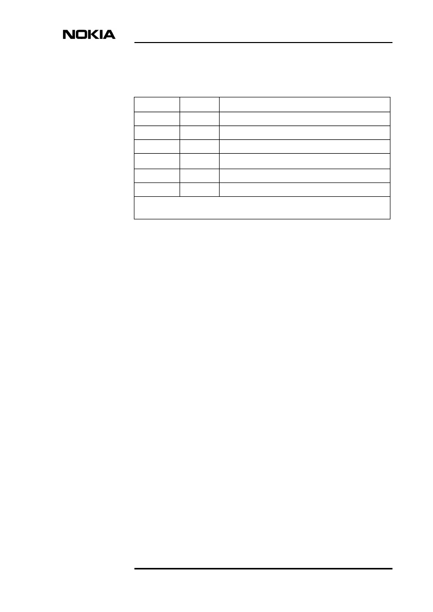
3.2.3 Reading statistics
The statistics that the network element records for signal quality are kept to ITU-
T recommendation G.826. These values are available for 2M platform interfaces
of FXC RRI (last 16 measurements).
The following statistics are recorded:
Maintaining Nokia MetroHopper
DN99611394 © Nokia Networks Oy 19 (42)
Issue 2-0 en
To see the signal quality counters, click Transmission / FXC RRI →Statistics
on the menu. This will open the Statistics dialog box, in which you can choose
the interface for which the statistics will be displayed.
It is possible to reset all the signal quality statistics by selecting the corresponding
Reset radio button in the Statistics dialog box.
3.3 Using loopbacks
Each unit contains several loopback points, which you can set manually to test the
node. These loopbacks are accessed by clicking Transmission / FXC RRI →
Interface loops on the menu.
The loopback status can change without the user changing it, for example, if the
time-out has been reached. Because of this, the Loopback window has its own
private status bar, which shows the last time the status of the loopbacks was
checked, and how long till the next refresh. You can set the refresh value by
selecting Manage →Service Interface on the menu and entering the required
value on the Time-outs tab.
Table 1. Statistics
ID text Value Description
G.826 TT seconds Total Time as specified in G.826
G.826 AT seconds Available Time as specified in G.826
G.826 ES seconds Errored Seconds as specified in G.826
G.826 SES seconds Severely Errored Seconds as specified in G.8261)
G.826 BBE counter Background Block Errors as specified in G.826
G.826 EB counter Errored Blocks as specified in G.826
1) G.826 gives two definitions for SES. In Nokia Q1, the definition of SES as “≥30%
errored blocks in one-second period" is adopted.
Commissioning and Maintenance
20 (42) © Nokia Networks Oy DN99611394
Issue2-0en
Caution
Setting a Flexbus loop cuts the connection to the outdoor unit until the loop
expires. This includes all data and management information.
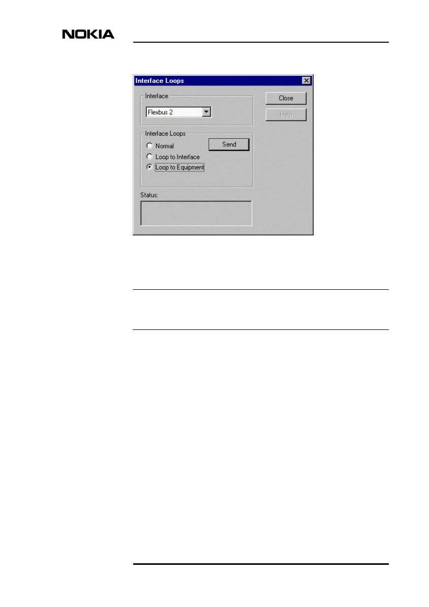
To set a loopback point:
1. Select the required interface from the list.
2. Define the required loop type by selecting the appropriate radio button.
3. Send the changes to the node by clicking the Send button.
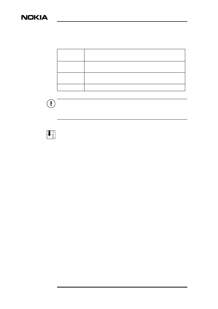
Table 2. Loopbacks
Loopback
title
Description
Platform
interfaces
Loopbacks in the 2 Mbit/s platform interfaces.
FB channels Loopbacks in the 2 Mbit/s signals in the cross-connection section.
These channels are also connected to a Flexbus.
Flexbuses Loopbacks in Flexbus interfaces.
Maintaining Nokia MetroHopper
DN99611394 © Nokia Networks Oy 21 (42)
Issue 2-0 en
Note
Figure 4. Interface loops window
When a loopback has been set, no other settings will take effect until the
equipment is returned to normal state.
To force the equipment to normal state, select the Normal radio button and click
the Send button.
3.4 Replacing or removing outdoor unit
Detailed instructions on removing and installing the outdoor unit can be found in
the OU Installation part of this manual.
Commissioning and Maintenance
22 (42) © Nokia Networks Oy DN99611394
Issue2-0en
Caution
Note
Switch the Flexbus OU power supply off with the node manager before replacing
a faulty outdoor unit.
If the units to be removed or replaced carry important traffic, reroute the traffic
before starting the work. The removal or replacement of equipment cuts traffic.
To replace or remove the Nokia MetroHopper outdoor unit:
1. Set the OU to Receiving only transmitter mode (see Section ). This ensures
that the radio will not transmit accidentally in case it is reinstalled.
2. Uninstall the OU logically by clicking with the right mouse button the unit
in the Equipment window and selecting the command Uninstall.
3. Switch the power to the OU off. The power can be turned off with the node
manager. Click Transmission / FXC RRI →Settings →Unit and clear
the OU power setting of the appropriate Flexbus interface.
4. Disconnect the cabling.
5. Remove the unit. Follow the instructions found in the OU Installation part
of this manual.
6. Install a new unit (if applicable). Follow the instructions found in the OU
Installation part of this manual.
If the replacement of the radio is done carefully, the alignment will not be
affected.
After replacing the outdoor unit, run the Radio Wizard to make the link
operational.
Alarm descriptions
DN99611394 © Nokia Networks Oy 23 (42)
Issue 2-0 en
Appendix A. Alarm descriptions
This appendix lists the alarms that a Nokia MetroHopper with FC RRI or
FXC RRI network element can give. Each table also gives a short description of
the fault generating the alarm and provides some guidelines on how to remedy the
fault.
The alarms are presented in alphabetical order according to the long alarm names.
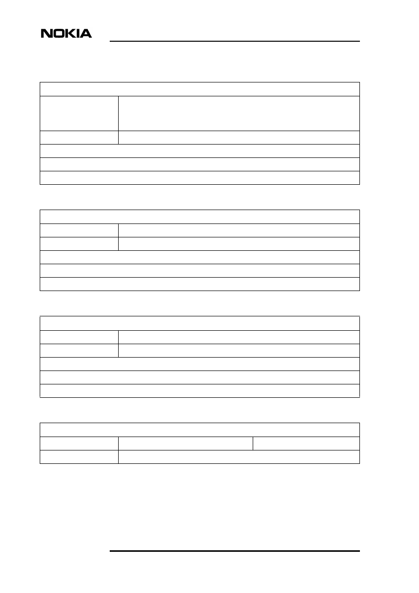
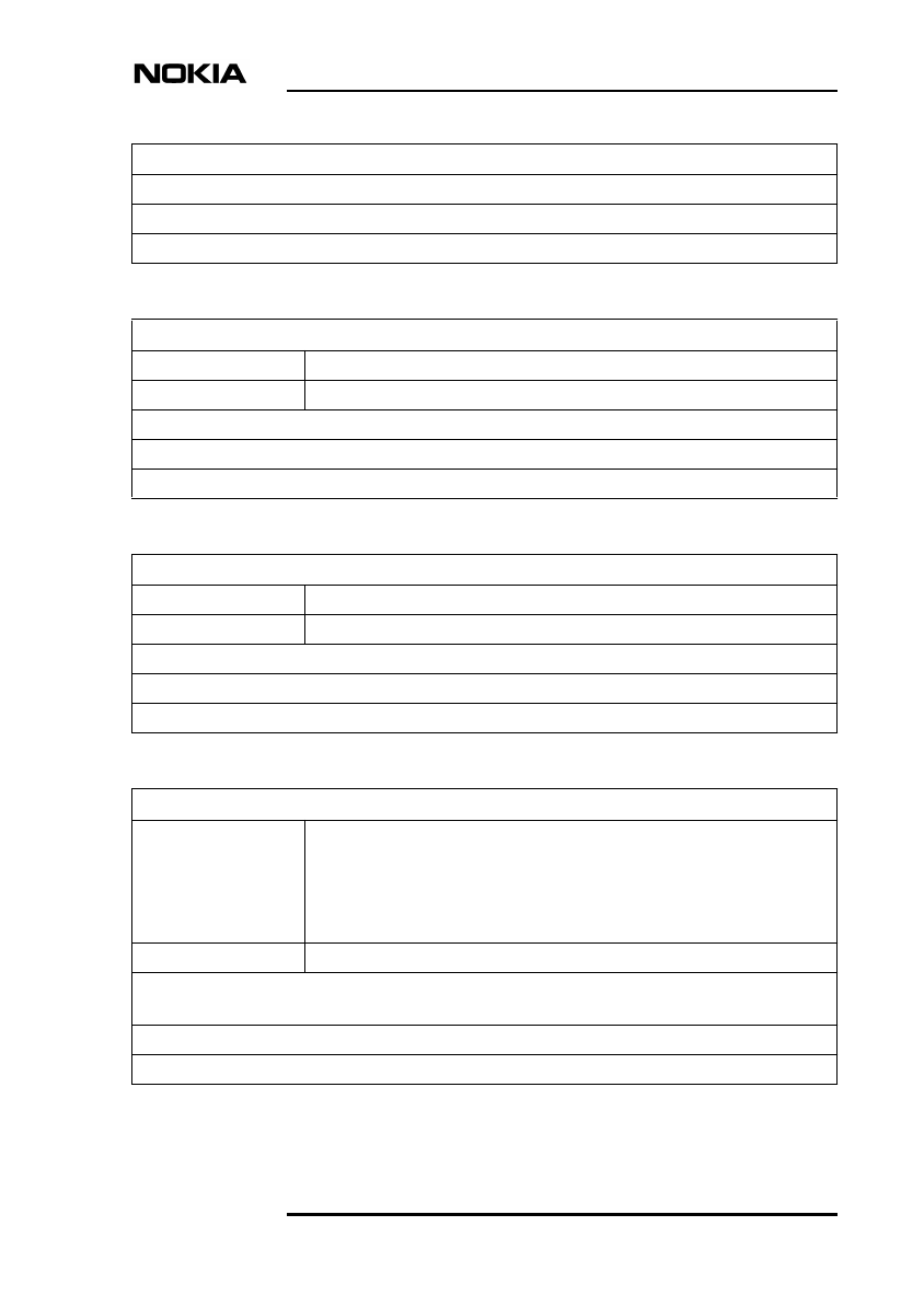
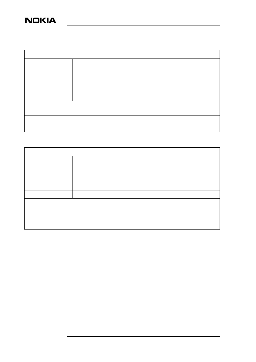
The alarm tables give the following information:
•Title row shows the long alarm name.
•Severity shows the severity class of the alarm as it appears in the Node
Manager.
•Unit/SB type shows the plug-in unit indicating the alarm or the type of the
supervision block (SB) indicating the alarm.
•FE shows the functional entity indicating the alarm.
•SB shows the supervision block indicating the alarm.
•Fault code shows the fault code (in decimal).
•Consequence shows whether an indication signal is sent upstream or
downstream.
•Meaning gives the possible cause of the alarm.
•Instructions give instructions on how to remedy the fault.
•Cancelling gives instructions on how the alarm is cancelled.
A.1 FC RRI unit alarms
Active alarm point
Severity: Major Unit/SB type: EAC input 1-10
Fault code: 240 Consequence:
Meaning: EAC inputs from BTS
Instructions:
Cancelling:
Commissioning and Maintenance
24 (42) © Nokia Networks Oy DN99611394
Issue2-0en
AIS 2M
Severity: Major Unit/SB type:
1) 2M LIF
2) BFI channel
Fault code: 66 Consequence:
Meaning: Alarm signal is received in RX direction
Instructions:
Cancelling:
Alarm signal is received
Severity: Critical Unit/SB type: Flexbus
Fault code: 64 Consequence:
Meaning: OU is sending pseudo frame (OU not locked to RX signal)
Instructions:
Cancelling:
Buffer overflow
Severity: Critical Unit/SB type: BFI channel
Fault code: 113 Consequence:
Meaning: 2M signal buffer overflow/underflow
Instructions:
Cancelling:
Configuration error
Severity: Minor Unit/SB type: Identifications
Fault code: 186 Consequence:
Alarm descriptions
DN99611394 © Nokia Networks Oy 25 (42)
Issue 2-0 en
Meaning: Identifications missing
Instructions:
Cancelling:
Configuration error
Database full
Severity: Warning Unit/SB type: FM event history
Fault code: 162 Consequence:
Meaning: Fault management database full
Instructions: Read all alarms and reset
Cancelling:
Equipment reset
Severity: Warning Unit/SB type: HW setup
Fault code: 148 Consequence:
Meaning:
Instructions:
Cancelling:
Error rate > 1 E-3
Severity: Critical Unit/SB type:
1) Flexbus
2) PRBS2
3) PRBSF
4) 2M LIF
Fault code: 99 Consequence:
Meaning: 1, 4) Received signal BER over limit
2, 3) Detector BER over limit
Instructions:
Cancelling:
Commissioning and Maintenance
26 (42) © Nokia Networks Oy DN99611394
Issue2-0en
Error rate > 1 E-4
Severity: Major Unit/SB type:
1) Flexbus
2) PRBS2
3) PRBSF
4) 2M LIF
Fault code: 100 Consequence:
Meaning: 1, 4) Received signal BER over limit
2, 3) Detector BER over limit
Instructions:
Cancelling:
Error rate > 1 E-5
Severity: Major Unit/SB type:
1) Flexbus
2) PRBS2
3) PRBSF
4) 2M LIF
Fault code: 101 Consequence:
Meaning: 1, 4) Received signal BER over limit
2, 3) Detector BER over limit
Instructions:
Cancelling:
Alarm descriptions
DN99611394 © Nokia Networks Oy 27 (42)
Issue 2-0 en
Error rate > 1 E-6
Severity: Major Unit/SB type:
1) Flexbus
2) PRBS2
3) PRBSF
4) 2M LIF
Fault code: 102 Consequence:
Meaning: 1, 4) Received signal BER over limit
2, 3) Detector BER over limit
Instructions:
Cancelling:
Far-end alarm
Severity: Major Unit/SB type:
1) Flexbus
2) 2M LIF
Fault code: 179 Consequence:
Meaning: Far end is sending R-bit or T-bit
Instructions:
Cancelling:
Fault in installation of equipment
Severity:
1) Warning
2) Critical
Unit/SB type:
1) HW setup
2) Flexbus
Fault code: 142 Consequence:
Meaning: 1) Incompatibility detected
2) Flexbus not in use but OU (or IU) is connected to it
Instructions:
Cancelling:
Commissioning and Maintenance
28 (42) © Nokia Networks Oy DN99611394
Issue2-0en
Fault in oscillator
Severity: Critical Unit/SB type: Clock monitor
Fault code: 137 Consequence:
Meaning: Fault in oscillator
Instructions:
Cancelling:
Fault in power supply
Severity: Critical Unit/SB type:
1) Flexbus
2) Power supply
Fault code: 0 Consequence:
Meaning: OU power supply fault
Instructions:
Cancelling:
Fault in unit
Severity: Critical Unit/SB type: Unit
Fault code: 150 Consequence:
Meaning: Unit temperature crossed higher threshold
Instructions:
Cancelling:
Alarm descriptions
DN99611394 © Nokia Networks Oy 29 (42)
Issue 2-0 en
Forced control on
Severity: Critical Unit/SB type:
1) Flexbus
2) Measurement point
Fault code: 141 Consequence:
Meaning: 1) OU power supply forced on or off
2) Signal connected to measurement point
Instructions:
Cancelling:
Forced indication
Severity: Warning Unit/SB type: Flexbus
Fault code: 149 Consequence:
Meaning: Flexbus LED state is forced
Instructions:
Cancelling:
Loop to equipment
Severity: Major Unit/SB type: Flexbus
Fault code: 22 Consequence:
Meaning: Loopback to terminal
Instructions:
Cancelling:
Commissioning and Maintenance
30 (42) © Nokia Networks Oy DN99611394
Issue2-0en
Loop to interface
Severity: Major Unit/SB type:
1) Flexbus
2) 2M LIF
3) BFI channel
Fault code: 21 Consequence:
Meaning: 1) Loopback to radio path
2) Signal looped back to BTS
3) Loopback to Flexbus
Instructions:
Cancelling:
Loss of CRC multiframe alignment
Severity: Critical Unit/SB type: 2M LIF
Fault code: 86 Consequence:
Meaning: Frame alignment lost (CRC in use)
Instructions:
Cancelling:
Loss of frame alignment
Severity: Critical Unit/SB type:
1) Flexbus
2) 2M LIF
Fault code: 81 Consequence:
Meaning: 1) RX frame lock lost / FEC header error / Frame alignment lost
2) Frame alignment lost (CRC not in use)
Instructions:
Cancelling:
Alarm descriptions
DN99611394 © Nokia Networks Oy 31 (42)
Issue 2-0 en
Loss of incoming signal
Severity: Critical Unit/SB type: Flexbus
Fault code: 48 Consequence:
Meaning: RX clock is missing
Instructions:
Cancelling:
Operating error
Severity: Critical Unit/SB type: SW setup
Fault code: 144 Consequence:
Meaning: File system error / SW error
Instructions:
Cancelling:
Real time lost fault
Severity: Major Unit/SB type: Real time clock
Fault code: 165 Consequence:
Meaning: Real time clock is not set after reset
Instructions:
Cancelling:
Real time updated
Severity: Warning Unit/SB type: Real time clock
Fault code: 184 Consequence:
Meaning: Updated real time clock difference more than 500 ms
Instructions:
Cancelling:
Commissioning and Maintenance
32 (42) © Nokia Networks Oy DN99611394
Issue2-0en
Settings have changed
Severity: Warning Unit/SB type:
1) FM setup
2) Identifications
3) Flexbus
4) 2M LIF
5) BFI channel
Fault code: 185 Consequence:
Meaning: 1-2) Checksum has changed
3) G.826 settings have changed
Instructions:
Cancelling:
Statistics reset
Severity: Warning Unit/SB type:
1) Flexbus
2) 2M LIF
Fault code: 263 Consequence:
Meaning:
Instructions:
Cancelling:
Subrack has excessive units
Severity: Major Unit/SB type:
1) HW setup
Fault code: 140 Consequence:
Meaning:
Instructions:
Cancelling:
Alarm descriptions
DN99611394 © Nokia Networks Oy 33 (42)
Issue 2-0 en
Subrack is missing units
Severity: Critical Unit/SB type: HW setup
Fault code: 139 Consequence:
Meaning:
Instructions:
Cancelling:
Temperature alarm
Severity: Major Unit/SB type: Unit
Fault code: 145 Consequence:
Meaning: Unit temperature crossed lower threshold
Instructions:
Cancelling:
Test generator on
Severity: Major Unit/SB type:
1) PRBS2
2) PRSF
Fault code: 25 Consequence:
Meaning: Test generator on / Test detector on / Polynomial selected / Test running
Instructions:
Cancelling:
Unavailability
Severity: Critical Unit/SB type:
1) Flexbus
2) 2M LIF
Fault code: 262 Consequence:
Commissioning and Maintenance
34 (42) © Nokia Networks Oy DN99611394
Issue2-0en
Meaning:
Instructions:
Cancelling:
Unavailability
15 min G.826 ES threshold crossed
Severity: Minor Unit/SB type:
1) Flexbus
2) 2M LIF
Fault code: 256 Consequence:
Meaning:
Instructions:
Cancelling:
15 min G.826 SES threshold crossed
Severity: Major Unit/SB type:
1) Flexbus
2) 2M LIF
Fault code: 257 Consequence:
Meaning:
Instructions:
Cancelling:
15 min G.826 BBE threshold crossed
Severity: Minor Unit/SB type:
1) Flexbus
2) 2M LIF
Fault code: 258 Consequence:
Meaning:
Instructions:
Cancelling:
Alarm descriptions
DN99611394 © Nokia Networks Oy 35 (42)
Issue 2-0 en
24 h G.826 ES threshold crossed
Severity: Warning Unit/SB type:
1) Flexbus
2) 2M LIF
Fault code: 259 Consequence:
Meaning:
Instructions:
Cancelling:
24 h G.826 SES threshold crossed
Severity: Warning Unit/SB type:
1) Flexbus
2) 2M LIF
Fault code: 260 Consequence:
Meaning:
Instructions:
Cancelling:
24 h G.826 BBE threshold crossed
Severity: Warning Unit/SB type:
1) Flexbus
2) 2M LIF
Fault code: 261 Consequence:
Meaning:
Instructions:
Cancelling:
Commissioning and Maintenance
36 (42) © Nokia Networks Oy DN99611394
Issue2-0en
A.2 FXC RRI unit alarms
AIS 2M
Severity: Major Unit/SB type:
1) Flexbus channel
2) Platform interface
Fault code: 66 Consequence:
Meaning: Alarm signal is received, the received signal has no framing and it is all ones.
Instructions: The signal is cut somewhere in the network and AIS replacement has taken place. Follow the 2M
signal in the network to find out the place where AIS replacement has been done. This link is usually faulty or
has configuration errors. Other alarms may cause this alarm because of AIS switching in the receiving direction
as shown in the Consequence field of some alarms.
Cancelling:
Alarm signal received
Severity: Critical Unit/SB type: Flexbus
Fault code: 64 Consequence: AIS is connected to all received Flexbus channels. This will cause
AIS 2 Mbit/s alarm to all used platform interfaces that are connected to the alarming
Flexbus interface.
Meaning: OU has lost the frame lock and it has replaced the frame with a pseudo frame to ensure IU - OU
communication.
Instructions: The signal may be faded in the radio path. In this case the OU has the loss of incoming radio signal
alarm. If this is not active in the OU, check the radios at both ends of the hop. They must have the right
configuration (frequency, interleaving and TX power on). Check also that the same capacity has been selected
for both ends of the hop.
Cancelling: If the radio signal is faded it will come back when the fading stops. If the OU is FlexiHopper, check
the maximum TX power setting. If a stronger TX power is allowed, it will withstand fading better.
Alarm descriptions
DN99611394 © Nokia Networks Oy 37 (42)
Issue 2-0 en
Error rate > 1 E-3
Severity: Critical Unit/SB type:
1) Flexbus
2) Platform interface
Fault code: 99 Consequence:
1) AIS is connected to all received Flexbus channels.
2) AIS is connected to the receiving direction of the platform interface.
Meaning: 1) Received signal bit error rate is worse than 1.0 * 10-3
2) Received platform interface error rate is worse than 1.0 * 10-3
Instructions: 1) -‘Alarm signal received’ causes also this alarm
- Signal may be faded in the radio path or antenna alignment has changed.
2) -If the Flexbus where this interface has been connected has the same alarm, see its instructions.
-If Flexbus does not have this alarm, use loop to equipment for both the platform interface and the Flexbus. If
either of the loops gives this alarm, replace the unit.
Cancelling: If the radio signal is faded it will be restored when the fading stops. If antenna alignment has
changed, align the antennas according to the instructions in the radio documentation.
Error rate > 1 E-6
Severity: Critical Unit/SB type: Platform interface
Fault code: 102 Consequence:
Meaning: Received platform interface error rate is worse than 1.0 * 10-6
Instructions: Most probably radio path fading causes this. If it remains for a long time, use loop to equipment for
both the platform interface and Flexbus. If either of the loops gives this alarm, replace the unit.
Cancelling:
Far-end alarm
Severity: Major Unit/SB type: Platform interface
Fault code: 179 Consequence:
Meaning: Far end has lost frame alignment.
Instructions: Check the signal flow from the transmit direction of the alarming interface to the far end.
Cancelling:
Commissioning and Maintenance
38 (42) © Nokia Networks Oy DN99611394
Issue2-0en
Fault in power supply
Severity: Critical Unit/SB type: Flexbus
Fault code: 0 Consequence: AIS is connected to all received Flexbus channels.
Meaning: Flexbus overcurrent protection circuit has cut off +55 V power feed.
Instructions: Check the OU cabling, remove short circuits and connect the power feed back with the Manager.
Note: It is recommended to switch the DC power feed off when connecting OU to the Flexbus interface. If the
OU is connected to a Flexbus interface with the DC power feed on, the overcurrent protection may cut the power
feed.
Cancelling:
Loop to equipment
Severity: Major Unit/SB type:
1) Flexbus
2) Platform interface
Fault code: 22 Consequence: 1) AIS is connected to all transmitted Flexbus channels in the
receiving equipment.
2) AIS is connected to the TX direction of the looped interface.
Meaning: 1) Flexbus equipment loop is active. The whole transmitted Flexbus signal is looped back to IU. The IU
- OU communication will be cut during the loop.
2) Platform interface loop to equipment is active. The whole transmitted platform interface signal is looped back
to the IU.
Instructions: Loops are normally used to locate faults.
Cancelling: A loopback will be removed automatically after a control timeout has expired. A loop can also be
removed with Manager back to the normal state.
Alarm descriptions
DN99611394 © Nokia Networks Oy 39 (42)
Issue 2-0 en
Loop to interface
Severity: Major Unit/SB type:
1) Flexbus
2) Flexbus channel
3) Platform interface
Fault code: 21 Consequence: 1) AIS is connected to all received Flexbus channels.
2) AIS is connected to the receiving direction of the looped channel.
3) AIS is connected to the receiving direction of the looped interface.
Meaning: 1) Flexbus interface loop is active. The whole received Flexbus signal is looped back to the OU (or
another IU). The IU - OU communication will be cut during the loop.
2) Flexbus channel loop to interface is active. The whole received Flexbus signal is looped back to the OU (or
another IU).
3) Platform interface loop to interface active. The whole received platform signal is looped back to the OU (or
another IU) without regenerating time slot 0.
Instructions: Loops are normally used to locate faults.
Cancelling: A loopback will be removed automatically after a control timeout has expired. A loop can also be
removed with Manager back to the normal state.
Loss of CRC multiframe alignment
Severity: Critical Unit/SB type: Platform interface
Fault code: 86 Consequence: AIS is connected to the receiving direction of the platform interface.
Meaning: Platform interface has lost CRC frame alignment.
Instructions: Check that the other end of the link has CRC in use. Use the same instructions as in the loss of
frame alignment to locate the fault.
Cancelling:
Commissioning and Maintenance
40 (42) © Nokia Networks Oy DN99611394
Issue2-0en
A.3 MetroHopper unit alarms
Loss of frame alignment
Severity: Critical Unit/SB type:
1) Flexbus
2) Platform interface
Fault code: 81 Consequence: 1) AIS is connected to all received Flexbus channels.
2) AIS is connected to the receiving direction of the platform interface.
Meaning: 1) IU has lost frame alignment
2) Platform interface has lost frame alignment.
Instructions: 1) -Check from the Configuration view that all installed units are present. A faulty OU may not be
displayed in Configuration view. Try connecting power feed off and back on. If the OU still is not present, replace
it.
- Check that the radios are configured correctly (i.e. no ‘configuration error’ or ‘fault in unit’ alarms).
-If RX level is good enough, check that both ends of the hop are set to same capacity and that Flexbus
interfaces are in use, and that the outdoor units’ interleaving settings are same at both ends of the hop. Check
with Flexbus loop to equipment whether the IU locks to its own signal. If not, replace the indoor unit.
2) -Check from the Cross-connection view that the right signal is connected to this interface at both ends of the
hop.
-Use platform interface loop to equipment to check that platform interface locks to its own TX signal. If not,
replace the unit.
-Use Flexbus loop to equipment and check that platform interface locks to its own signal. If not, replace the unit.
Cancelling:
Fault in power supply
Severity: Critical SB: Radio interface
Fault code: 0 Consequence:
Meaning: One (or more) of the supply voltages is low (difference between nominal and real voltage is bigger
than 10%).
Instructions: Replace the unit and return the faulty one to maintenance.
Cancelling:
Alarm descriptions
DN99611394 © Nokia Networks Oy 41 (42)
Issue 2-0 en
Fault in unit
Severity: Critical SB: Radio interface
Fault code: 150 Consequence:
Meaning: Initialisation fault: data missing from EEPROM or the file system; EEPROM not readable due to
hardware fault or EEPROM not initialised properly.
Instructions:
Cancelling:
Incoming signal level incorrect
Severity: Critical SB: Radio interface
Fault code: 59 Consequence:
Meaning: Received signal level is below the limit (-75 dBm). Possible reasons: far-end transmitter off;
misalignment; hop distance too long; line-of-sight obstructed; heavy rain; antenna broken or extremely dirty.
Instructions: Check the alignment. Return a faulty unit to maintenance.
Cancelling:
Loss of incoming radio signal
Severity: Critical SB: Radio interface
Fault code: 60 Consequence:
Meaning: Frame alignment word lock lost. Signal level too low or no far-end radio present. Possible HW fault in
near-end radio.
Instructions: Check the far-end radio, alignment and/or the radio path. Return a faulty unit to maintenance.
Cancelling:
No free channel
Severity: Critical SB: Radio interface
Fault code: 40 Consequence:
Commissioning and Maintenance
42 (42) © Nokia Networks Oy DN99611394
Issue2-0en
Meaning: Commissioning failed: no free channel available or all allowed channels have excessive interference.
Instructions:
Cancelling:
No free channel
Temperature alarm
Severity: Major SB: Radio interface
Fault code: 145 Consequence:
Meaning: Operating temperature below -50 °C or above +80 °C. Possibility of measurement sensor fault.
Instructions:
Cancelling:

DN99611449 © Nokia Networks Oy 1 (16)
Issue 2-0 en
Nokia MetroHopper Radio with FC RRI/FXC RRI
User Manual B0
C33512.22
Guide to Documentation

Guide to Documentation
2 (16) © Nokia Networks Oy DN99611449
Issue2-0en
The information in this document is subject to change without notice and describes only the
product defined in the introduction of this documentation. This document is intended for the
use of Nokia Networks' customers only for the purposes of the agreement under which the
document is submitted, and no part of it may be reproduced or transmitted in any form or
means without the prior written permission of Nokia Networks. The document has been
prepared to be used by professional and properly trained personnel, and the customer
assumes full responsibility when using it. Nokia Networks welcomes customer comments as
part of the process of continuous development and improvement of the documentation.
The information or statements given in this document concerning the suitability, capacity, or
performance of the mentioned hardware or software products cannot be considered binding
but shall be defined in the agreement made between Nokia Networks and the customer.
However, Nokia Networks has made all reasonable efforts to ensure that the instructions
contained in the document are adequate and free of material errors and omissions. Nokia
Networks will, if necessary, explain issues which may not be covered by the document.
Nokia Networks' liability for any errors in the document is limited to the documentary correction
of errors. Nokia Networks WILL NOT BE RESPONSIBLE IN ANY EVENT FOR ERRORS IN
THIS DOCUMENT OR FOR ANY DAMAGES, INCIDENTAL OR CONSEQUENTIAL
(INCLUDING MONETARY LOSSES), that might arise from the use of this document or the
information in it.
This document and the product it describes are considered protected by copyright according to
the applicable laws.
NOKIA logo is a registered trademark of Nokia Corporation.
Other product names mentioned in this document may be trademarks of their respective
companies, and they are mentioned for identification purposes only.
Copyright © Nokia Networks Oy 2000. All rights reserved.
Nokia FlexiHopper, Nokia MetroHopper, Nokia MetroHub, Nokia MetroSite, and Nokia UltraSite
are trademarks of Nokia Networks Oy.

DN99611449 © Nokia Networks Oy 3 (16)
Issue 2-0 en
Contents
Contents 3
1 About this document 7
2 User Manual Contents 9
2.1 Navigation aid 9
2.2 Contents of the documents 10
3 Ordering documents 11
3.1 Delivery media 11
3.1.1 Electronic documents 11
3.1.2 Paper documents 11
3.2 Sales items 11
4 Conventions used in the documents 13
4.1 User manual identification 13
4.2 Document identification 13
4.3 Typographic conventions 14

Guide to Documentation
4 (16) © Nokia Networks Oy DN99611449
Issue2-0en

DN99611449 © Nokia Networks Oy 5 (16)
Issue 2-0 en
Summary of changes
Document Date Comment
C33512010SE_00 29 Nov 1999
DN99611449 Issue 1-0 en 28 Dec 1999 New document numbering scheme adopted.
DN99611449 Issue 2-0 en 30 May 2000

Guide to Documentation
6 (16) © Nokia Networks Oy DN99611449
Issue2-0en

About this document
DN99611449 © Nokia Networks Oy 7 (16)
Issue 2-0 en
1About this document
This document describes the scope, structure, and use of Nokia MetroHopper
with FC RRI / FXC RRI User Manual, which is also a subset of Nokia MetroSite
solution documentation.
This document provides the following information:
• a navigation aid for the documents included in the user manual
• a short description of the documents included in the user manual
• a list of the Nokia MetroHopper documents and other related documents
• instructions for ordering the documents
• a description of typographic conventions.
Readership
This manual is intended for the application planning, installation and
commissioning personnel of Nokia MetroHopper. The reader is assumed to have
the basic knowledge of microwave transmission systems.
Your comments
We appreciate your feedback. If you have any comments about this or any other
manual, please fill in the documentation comment form in the beginning of this
manual and return it to your local Nokia representative.

Guide to Documentation
8 (16) © Nokia Networks Oy DN99611449
Issue2-0en

User Manual Contents
DN99611449 © Nokia Networks Oy 9 (16)
Issue 2-0 en
2User Manual Contents
2.1 Navigation aid
This chapter helps you to find the documents that you need in order to accomplish
a certain task.
Instructions on how to use Nokia BTS Manager and Nokia MetroHub Manager
(included in Nokia SiteWizard) are given in Nokia MetroSite GSM Base Station
User Manual and Nokia MetroHub User Manual respectively, and in the online
Help of the manager software.
Table 1. Navigation aid
Task Documents
Finding your way through the manual Guide to Documentation
Index
Glossary
Familiarising with the product Product Description
Planning the application Product Description
Installing the radio Installation Overview
Outdoor Unit Installation
Commissioning Commissioning and Maintenance
Outdoor Unit Installation
Maintaining and upgrading Outdoor Unit Installation
Commissioning and Maintenance

Guide to Documentation
10 (16) © Nokia Networks Oy DN99611449
Issue2-0en
2.2 Contents of the documents
This section describes the general contents of individual documents in this user
manual.
Installation Overview
• overall work order
• principles of grounding.
Nokia MetroHopper Outdoor Unit Installation
• instructions for installing the outdoor unit (OU)
• instructions for alignment
• instructions for connecting cables.
Commissioning & Maintenance
• instructions for the commissioning procedure
• maintenance principles.
Product Description
• description of features
• examples of network and site applications
• information about application and installation planning
• description of management tools
• description of the mechanical structure of the outdoor unit and the indoor
units
• technical specifications and standards.
Glossary
• technical abbreviations used in this manual
• other technical key terms used in this manual.
Index
• easy-to-use tool for finding information.

Ordering documents
DN99611449 © Nokia Networks Oy 11 (16)
Issue 2-0 en
3Ordering documents
You can order Nokia MetroHopper and related documents in electronic or/and
paper format. The documents are always delivered in NED package or User
Manual binders. To order the documents, contact your local Nokia representative.
3.1 Delivery media
3.1.1 Electronic documents
The NED viewer provides electronic access to Nokia documentation.
Each NED package includes the needed software and documentation:
• Nokia Documentation CD-ROM, containing document sets and NED
Viewer
• NED User Guide
• NED Quick Reference Card.
For more information about NED, refer to the NED User Guide.
3.1.2 Paper documents
Paper documents are delivered in binders.
• Each binder contains a Contents list, helping you to locate the required
document.
• The binder label tells the product name and product code.
3.2 Sales items
Nokia MetroHopper customer documentation consists of the following items:

Guide to Documentation
12 (16) © Nokia Networks Oy DN99611449
Issue2-0en
• Nokia MetroHopper Radio Product Overview
• Nokia MetroHopper Radio with FC RRI / FXC RRI User Manual
• Nokia MetroHopper Radio with FIU 19 / RRIC User Manual
• Nokia MetroHopper OU Quick Reference Guide
Product Overview describes the basic features and applications of the Nokia
MetroHopper Radio. It presents general information about the product and
describes also features that will be implemented in future.
Quick Reference Guide is a short installation instruction for the product, and it is
included in the product package.
The following Nokia MetroSite document sales items are related to the Nokia
MetroHopper documentation:
• Nokia FlexiHopper Microwave Radio with FC RRI / FXC RRI User
Manual
• Nokia MetroHub Transmission Node User Manual
• Nokia MetroSite GSM Base Station User Manual
• Nokia MetroSite NED (CD-ROM)
The Nokia MetroSite NED contains all Nokia MetroSite User Manuals.
The following document is helpful in the transmission planning of Nokia
MetroHopper links:
• Route Design for Radio Links above 17 GHz

Conventions used in the documents
DN99611449 © Nokia Networks Oy 13 (16)
Issue 2-0 en
4Conventions used in the documents
4.1 User manual identification
For identification and version management purposes, the user manual and all
documents in it are coded according to specific principles. The code and the
version of the user manual can be found on the binder label. The code for NED
can be found on the back cover of the CD-ROM package.
4.2 Document identification
All documents are identified by number, version, and language. These elements
combined form a document indentifier.
Example of a document identifier :
DN98123 Issue 1-0 en
•DN98123 is the document number
•1is the issue number, which is increases when the contents of the document
are changed; 0is the editorial number, which increases when the document
format is corrected without changes being made to documents.
•en is the language code, corresponding to standard ISO 639
In paper documents, the document identifier is located in the lower left corner of
the page. In electronic documents, the document identifier can be viewed by
clicking the icon in the upper right corner at the beginning of each document.
When the document is printed, the document indentifier and name appear on each
page.
Guide to Documentation
14 (16) © Nokia Networks Oy DN99611449
Issue2-0en
WARNING
Caution
Note
4.3 Typographic conventions
Icons and different fonts are used to emphasise special elements of a document.
The icons are located in the left side of the text.
Warnings
Warnings alert the reader to dangers which may cause loss of life, physical injury
or ill health.
This is a warning!
Cautions
Cautions are used to indicate possible damage to equipment but not danger to
personnel.
This is a caution!
Notes
Notes are used to call attention to a certain piece of information.
This is a note.
Task sequences
Task sequence symbol is used to indicate the beginning of a task sequence.
Task sequence title
1. Step 1
2. Step 2

Conventions used in the documents
DN99611449 © Nokia Networks Oy 15 (16)
Issue 2-0 en
3. Step 3
The following table presents the typographic conventions used in Nokia
MetroHopper with FC RRI / FXC RRI User Manual:
Table 2. Typographic conventions
Convention Meaning
Italic font
Indicates a word or phrase that is emphasised, or a
reference to the title of a document, example:
See document
Commissioning and Maintenance
.
Bold font Indicates the title of a window, or an option,
command, field or group, or anything that you must
type exactly as it appears, examples:
Help Index → means: on the Help menu, click
Index.
A:\install means: type A:\install.

Guide to Documentation
16 (16) © Nokia Networks Oy DN99611449
Issue2-0en

DN99611437 © Nokia Networks Oy 1 (14)
Issue 2-0 en
Nokia MetroHopper Radio with FC RRI/FXC RRI
User Manual B0
C33512.22
Installation Overview

Installation Overview
2 (14) © Nokia Networks Oy DN99611437
Issue2-0en
The information in this document is subject to change without notice and describes only the
product defined in the introduction of this documentation. This document is intended for the
use of Nokia Networks' customers only for the purposes of the agreement under which the
document is submitted, and no part of it may be reproduced or transmitted in any form or
means without the prior written permission of Nokia Networks. The document has been
prepared to be used by professional and properly trained personnel, and the customer
assumes full responsibility when using it. Nokia Networks welcomes customer comments as
part of the process of continuous development and improvement of the documentation.
The information or statements given in this document concerning the suitability, capacity, or
performance of the mentioned hardware or software products cannot be considered binding
but shall be defined in the agreement made between Nokia Networks and the customer.
However, Nokia Networks has made all reasonable efforts to ensure that the instructions
contained in the document are adequate and free of material errors and omissions. Nokia
Networks will, if necessary, explain issues which may not be covered by the document.
Nokia Networks' liability for any errors in the document is limited to the documentary correction
of errors. Nokia Networks WILL NOT BE RESPONSIBLE IN ANY EVENT FOR ERRORS IN
THIS DOCUMENT OR FOR ANY DAMAGES, INCIDENTAL OR CONSEQUENTIAL
(INCLUDING MONETARY LOSSES), that might arise from the use of this document or the
information in it.
This document and the product it describes are considered protected by copyright according to
the applicable laws.
NOKIA logo is a registered trademark of Nokia Corporation.
Other product names mentioned in this document may be trademarks of their respective
companies, and they are mentioned for identification purposes only.
Copyright © Nokia Networks Oy 2000. All rights reserved.
Nokia MetroHopper, Nokia MetroHub, and Nokia MetroSite are trademarks of Nokia Networks
Oy.

Installation Overview
4 (14) © Nokia Networks Oy DN99611437
Issue2-0en

DN99611437 © Nokia Networks Oy 5 (14)
Issue 2-0 en
Summary of changes
Document Date Comment
C33512011SE_00 29 Oct 1999
DN99611437 Issue 1-0 en 28 Dec 1999 New document numbering scheme adopted.
DN99611437 Issue 2-0 en 30 May 2000 FC RRI added.

Installation Overview
6 (14) © Nokia Networks Oy DN99611437
Issue2-0en

About this document
DN99611437 © Nokia Networks Oy 7 (14)
Issue 2-0 en
1About this document
This document gives general instructions on installing Nokia MetroHopper
outdoor unit. Detailed instructions for installing the outdoor unit can be found in
Nokia MetroHopper Outdoor Unit Installation included in this manual.
Installation instructions for FC RRI and FXC RRI can be found in Nokia
MetroSite GSM Base Station User Manual and Nokia MetroHub User Manual.

Installation Overview
8 (14) © Nokia Networks Oy DN99611437
Issue2-0en

Precautions
DN99611437 © Nokia Networks Oy 9 (14)
Issue 2-0 en
2Precautions
The instructions are intended for trained installation personnel. Before starting
the installation, note the following precautions:
• Familiarise yourself thoroughly with the installation instructions.
• Plan the installation in advance.
• Take the precautions given in the beginning of the outdoor unit installation
document into account.

Installation Overview
10 (14) © Nokia Networks Oy DN99611437
Issue2-0en

Work order
DN99611437 © Nokia Networks Oy 11 (14)
Issue 2-0 en
Note
3Work order
The following is the recommended task list for the installation of Nokia
MetroHopper with FC RRI or FXC RRI. The document detailing the task is
indicated after the task.
1. Prepare the cabling.
2. Install the alignment bracket (see Nokia MetroHopper OU Installation).
3. Perform the alignment (see Nokia MetroHopper OU Installation).
4. Attach the radio section (see Nokia MetroHopper OU Installation).
5. Connect cables to the OU (see Nokia MetroHopper OU Installation).
6. Connect the Flexbus cable(s) to the FC RRI or FXC RRI indoor unit (see
Nokia MetroSite GSM Base Station User Manual or Nokia MetroHub User
Manual).
If it is likely that moisture will condense in the outdoor unit, do not leave it
outdoors without power.

Installation Overview
12 (14) © Nokia Networks Oy DN99611437
Issue2-0en

Protective grounding
DN99611437 © Nokia Networks Oy 13 (14)
Issue 2-0 en
Note
4Protective grounding
To ensure safe installation conditions for both personnel and equipment, the
grounding of and equipment station must be done before installing the equipment.
The purpose of protective grounding is to keep the potential of the equipment at
the same level as the potential of the surrounding ground. This prevents
generation of dangerous voltages between the equipment and the ground.
Because of the high locations of the radio and base station equipment, equipment
stations are particularly suspectible to lightning strokes.
The grounding should be done according to the rules and regulations issued by
the local authorities. Refer also to site level documentation, if applicable.
To ensure the operation of the equipment, all equipment of an equipment station
must be connected to the same grounding potential.
Follow the grounding instructions presented in the Nokia MetroHopper Outdoor
Unit Installation document.
Ground the sheath of the Flexbus cable between the indoor unit and the outdoor
unit at approximately 50 m intervals. Ground the sheath also at the inlet to the
equipment space. National regulations may require grounding every 20 m.

Installation Overview
14 (14) © Nokia Networks Oy DN99611437
Issue2-0en

DN99592289 © Nokia Networks Oy 1 (26)
Issue 2-1 en
Nokia MetroHopper Radio with FC RRI/FXC RRI
User Manual B0
C33512.22
Installation

Installation
2 (26) © Nokia Networks Oy DN99592289
Issue2-1en
The information in this document is subject to change without notice and describes only the
product defined in the introduction of this documentation. This document is intended for the
use of Nokia Networks' customers only for the purposes of the agreement under which the
document is submitted, and no part of it may be reproduced or transmitted in any form or
means without the prior written permission of Nokia Networks. The document has been
prepared to be used by professional and properly trained personnel, and the customer
assumes full responsibility when using it. Nokia Networks welcomes customer comments as
part of the process of continuous development and improvement of the documentation.
The information or statements given in this document concerning the suitability, capacity, or
performance of the mentioned hardware or software products cannot be considered binding
but shall be defined in the agreement made between Nokia Networks and the customer.
However, Nokia Networks has made all reasonable efforts to ensure that the instructions
contained in the document are adequate and free of material errors and omissions. Nokia
Networks will, if necessary, explain issues which may not be covered by the document.
Nokia Networks' liability for any errors in the document is limited to the documentary correction
of errors. Nokia Networks WILL NOT BE RESPONSIBLE IN ANY EVENT FOR ERRORS IN
THIS DOCUMENT OR FOR ANY DAMAGES, INCIDENTAL OR CONSEQUENTIAL
(INCLUDING MONETARY LOSSES), that might arise from the use of this document or the
information in it.
This document and the product it describes are considered protected by copyright according to
the applicable laws.
NOKIA logo is a registered trademark of Nokia Corporation.
Other product names mentioned in this document may be trademarks of their respective
companies, and they are mentioned for identification purposes only.
Copyright © Nokia Networks Oy 2000. All rights reserved.
Nokia MetroHopper is a trademark of Nokia Networks Oy. Any other trademarks mentioned in
the documents are the property of their respective owners.

DN99592289 © Nokia Networks Oy 3 (26)
Issue 2-1 en
Contents
Contents 3
1 About this document 7
2 Precautions 9
2.1 Precautions 9
2.2 Installation restrictions 9
3 Work order 11
3.1 Parts 11
3.2 Tools 11
3.3 Task list 12
4 Installing Nokia MetroHopper outdoor unit 13
4.1 Mounting the alignment bracket on a pole 13
4.2 Mounting the alignment bracket on a wall 14
4.3 Attaching the optical alignment tool 15
4.4 Coarse alignment 16
4.5 Fine alignment 17
4.6 Finishing alignment 19
4.7 Attaching the radio section 19
4.8 Alignment with AGC voltage 20
4.9 Uninstalling the outdoor unit 21
5 Connecting interfaces 23
5.1 Grounding 24
5.2 Connecting the Flexbus cable 24
5.3 Connecting the synchronisation cable 25
5.4 Closing the connector cover 25

Installation
4 (26) © Nokia Networks Oy DN99592289
Issue2-1en

DN99592289 © Nokia Networks Oy 5 (26)
Issue 2-1 en
Summary of changes
Document Date Comment
C33512006SE_00 24 Jun 1999
C33512006SE_A0 30 Aug 1999 Instructions updated
C33512006SE_B0 29 Oct 1999 Instructions updated
DN99592289 Issue 1-0 en 28 Dec 1999 New document numbering scheme adopted.
DN99592289 Issue 2-0 en 11 Feb 2000

Installation
6 (26) © Nokia Networks Oy DN99592289
Issue2-1en

About this document
DN99592289 © Nokia Networks Oy 7 (26)
Issue 2-1 en
1About this document
This document gives instructions on how to install Nokia MetroHopper Outdoor
Unit (OU). The document covers the following topics:
• precautions and installation restrictions
• tools and work order
• installing Nokia MetroHopper OU
• connecting interfaces
The OU can be used with different types of indoor units. The instructions
presented in this document apply irrespective of the indoor unit used.
Refer to the Installation Overview part of this manual for general work order and
precautions when installing Nokia microwave radios. Refer to the model-specific
Indoor Unit Installation part when installing radio indoor units.

Installation
8 (26) © Nokia Networks Oy DN99592289
Issue2-1en

Precautions
DN99592289 © Nokia Networks Oy 9 (26)
Issue 2-1 en
Caution
2Precautions
This chapter describes the issues you must take into account before installing the
outdoor unit. Familiarise yourself thoroughly with the installation instructions
before starting the installation.
2.1 Precautions
Before starting installation, note the following pre-requisites:
• Transmission and installation have been planned.
• The far-end radio is installed or the installation space for the far-end radio
has been planned. In case of reduced visibility it is advisable to mark the
far-end location clearly.
• If it is likely that moisture will condense in the outdoor unit, do not leave
it outdoors without power.
• The outdoor unit must not be stored outdoors without packaging.
Never connect or disconnect the Flexbus cable when the power is on. Damage to
the equipment may result.
2.2 Installation restrictions
Refer to Chapter 7 ('Installation planning') in Product Description for important
site requirements related information.

Installation
10 (26) © Nokia Networks Oy DN99592289
Issue2-1en

Work order
DN99592289 © Nokia Networks Oy 11 (26)
Issue 2-1 en
3Work order
This chapter lists the parts and tools needed when installing Nokia MetroHopper
outdoor unit and presents a suggested work order.
3.1 Parts
The following items are needed when installing the Nokia MetroHopper outdoor
unit:
• radio section (included in the package)
• alignment bracket with clamp (included in the package)
• Flexbus cable (RG-223 or RG-214) with a TNC connector (waterproof)
• grounding wire
• synchronisation cables (optional)
• cable ties.
3.2 Tools
The following tools and equipment are recommended when installing the Nokia
MetroHopper outdoor unit:
• optical alignment tool
• 5 mm Allen key
• 6 mm Allen key
• torque wrench, 17 - 20 Nm
• two 10 mm spanners
• cable strippers and cable ties

Installation
12 (26) © Nokia Networks Oy DN99592289
Issue2-1en
• protective clothing, helmet
• drill in case of wall installation
• two suitable wall bolts in case of wall installation
• DC voltage meter and a cable with BNC connector in case the alignment is
done with AGC voltage measurement.
3.3 Task list
Plan the work in advance. The following work order is recommended for the
installation of the Nokia MetroHopper outdoor unit:
Prepare the cabling beforehand so that the cables can be connected to the outdoor
unit immediately after it has been installed.
1. Mount the alignment bracket (see 4.1 and 4.2)
2. Attach the optical alignment tool (see 4.3).
3. Perform the coarse alignment (pre-alignment) (see 4.4).
4. Perform the fine alignment (see 4.5).
5. Finish the alignment (see 4.6).
6. Attach the radio section (see 4.7).
7. Connect the grounding wire (see 5.1).
8. Connect the Flexbus cable (see 5.2).
9. Connect the synchronisation cable, if needed (see 5.3).
10. Close the connector cover (see 5.4).
Installing Nokia MetroHopper outdoor unit
DN99592289 © Nokia Networks Oy 13 (26)
Issue 2-1 en
4Installing Nokia MetroHopper outdoor
unit
This chapter gives instructions for installing and uninstalling the Nokia
MetroHopper outdoor unit.
4.1 Mounting the alignment bracket on a pole
To install the alignment bracket on a pole:
1. Place the bracket and the clamp around the pole. The diameter of the pole
may vary from 30 to 120 mm. Diameters over 120 mm require the use of
an adapter.
2. Align the bracket roughly towards the far end.
3. Tighten the mounting bolts with the 6 mm Allen key.
4. Tighten the bolts to 17 − 20 Nm with a torque wrench.
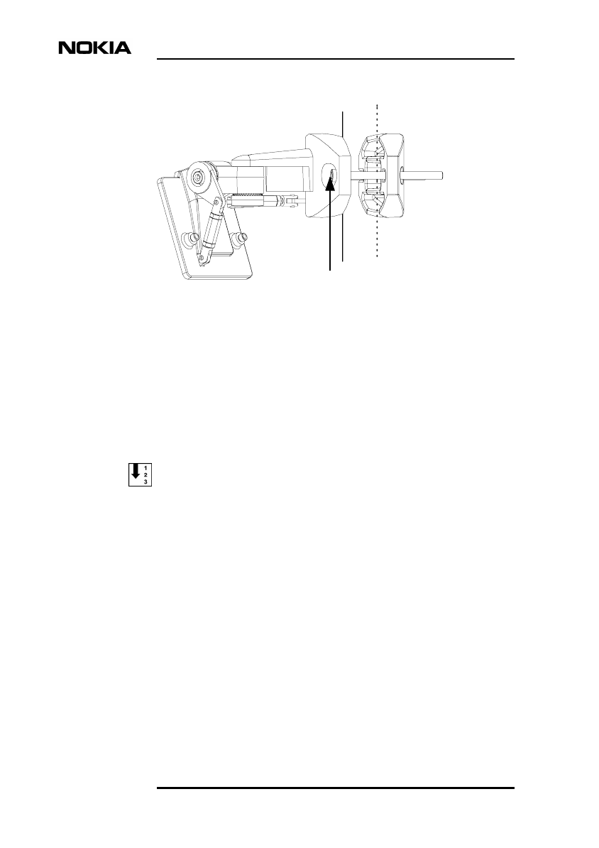
Installation
14 (26) © Nokia Networks Oy DN99592289
Issue2-1en
Figure 1. Installing the alignment bracket on a pole
4.2 Mounting the alignment bracket on a wall
The same alignment bracket can be used for pole and wall installation. In wall
installation, remove the clamp of the alignment bracket. After installing the
alignment bracket, the installation procedure is exactly the same in both pole and
wall installation.
To install the alignment bracket on a wall:
1. Drill the holes for wall installation.
2. Remove the clamp.
3. Install the bracket on a wall with two suitable bolts (not supplied with the
package).
Tighten the mounting bolts
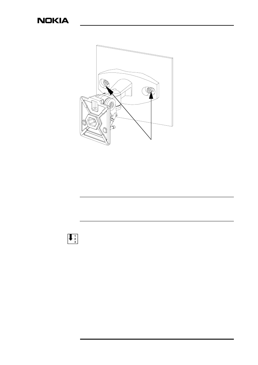
Installing Nokia MetroHopper outdoor unit
DN99592289 © Nokia Networks Oy 15 (26)
Issue 2-1 en
Note
Figure 2. Installing the alignment bracket on a wall
4.3 Attaching the optical alignment tool
The use of the optical alignment tool is strongly recommended in order to attain
the required level of accuracy.
To attach the optical alignment tool:
1. Place the optical alignment tool on the bracket.
2. Tighten the M6 screws with 5 mm Allen key.
Tighten the bolts

Installation
16 (26) © Nokia Networks Oy DN99592289
Issue2-1en
4.4 Coarse alignment
To pre-align:
1. Loosen the locking (M8) screws with 6 mm Allen key.
2. Turn on the optical alignment tool. You may adjust the brightness of the
red dot visible inside the optical alignment tool.
3. View the far end with the optical alignment tool and aim the red dot
towards thecentre of the far-end radio.
4. Align the bracket towards the far end.
5. Tighten the M8 screws to approximately 10 Nm.
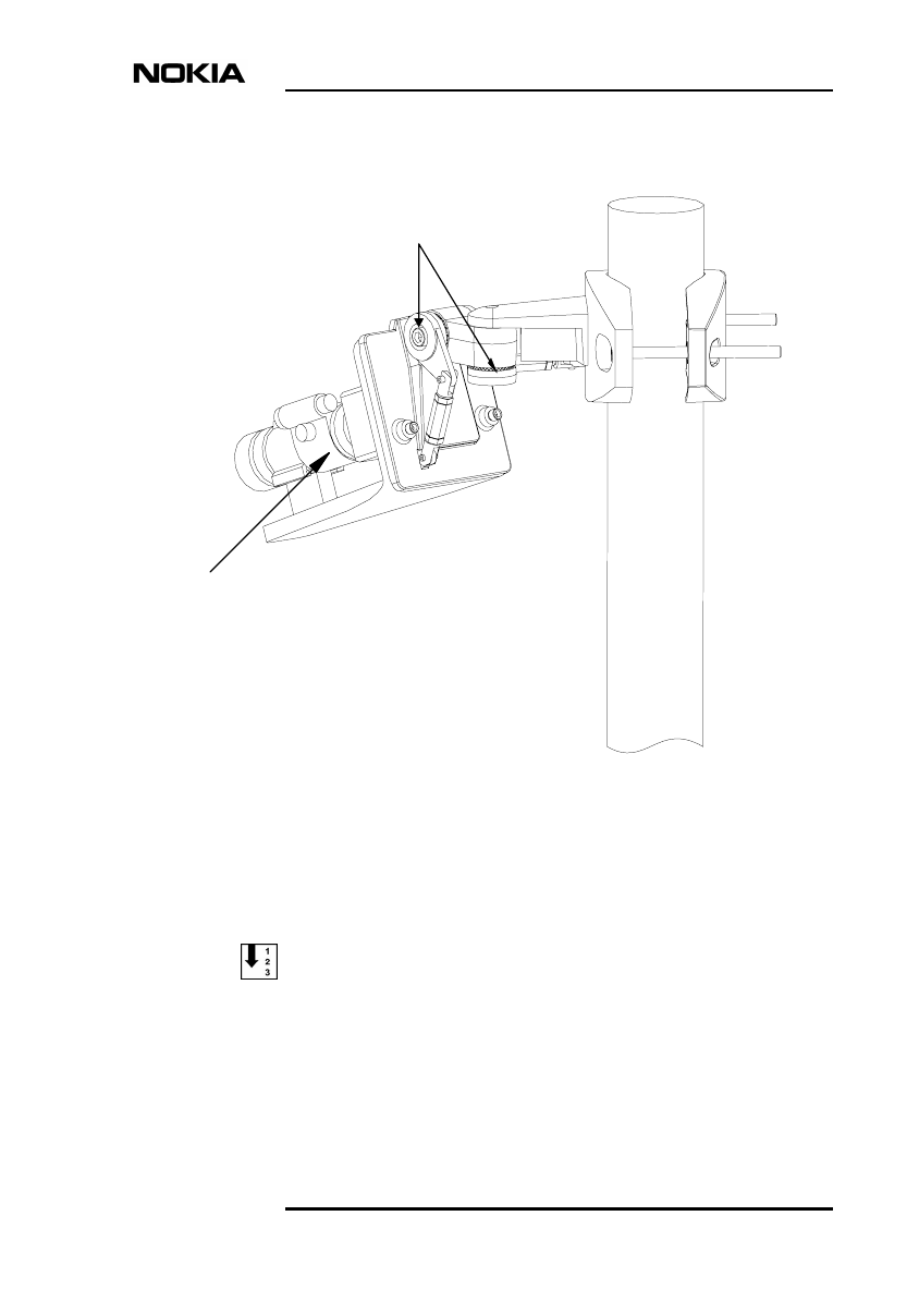
Installing Nokia MetroHopper outdoor unit
DN99592289 © Nokia Networks Oy 17 (26)
Issue 2-1 en
Figure 3. Coarse alignment (pre-alignment)
4.5 Fine alignment
To fine-align:
1. Loosen the locking nuts with 10 mm spanner.
2. View the far end with the optical alignment tool. Align the bracket towards
the far end by adjusting the fine alignment bars shown in Figure 4.
Optical alignment tool
Loosen the locking screws
Turn the bracket
towards far end
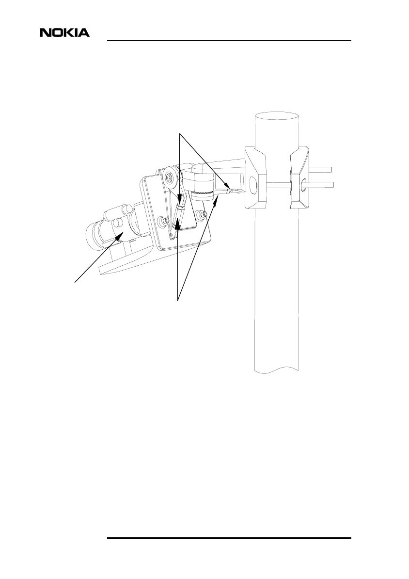
Installation
18 (26) © Nokia Networks Oy DN99592289
Issue2-1en
3. Tighten the locking nuts. Hold the fine alignment bar in place with a
spanner and tighten the nut with another spanner.
Figure 4. Fine alignment
Optical alignment tool
Loosen the locking nuts
Adjust the fine alignment bars
Installing Nokia MetroHopper outdoor unit
DN99592289 © Nokia Networks Oy 19 (26)
Issue 2-1 en
4.6 Finishing alignment
To finish the alignment:
1. Tighten the locking screws with a torque wrench to 17 − 20Nm. Tighten
first the joint that is closer to the installation pole.
2. Check the alignment with the optical alignment tool.
3. Switch the optical alignment tool off. Unscrew the M6 screws with 5 mm
Allen key and remove the alignment tool.
4.7 Attaching the radio section
To attach the radio section:
1. Place the radio section on the alignment bracket.
2. Tighten the M6 screws with 5 mm Allen key.
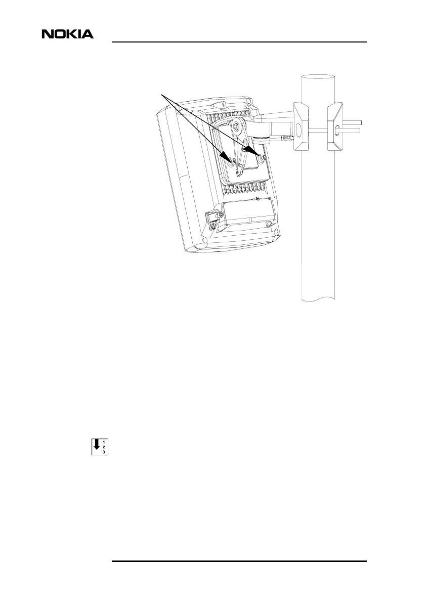
Installation
20 (26) © Nokia Networks Oy DN99592289
Issue2-1en
Figure 5. Attaching the radio section
4.8 Alignment with AGC voltage
In order to obtain maximum alignment accuracy, Nokia MetroHopper can be fine
aligned also by measuring the AGC (Automatic Gain Control) voltage which is
inversely proportional to the input level of the signal received from the radio hop.
Alignment with AGC voltage can be performed during commissioning. For more
information, refer to Commissioning and Maintenance document.
To align by measuring AGC voltage:
1. Connect a DC voltage meter to the AGC connector via an adapter or a cable
with BNC connector (male).
2. Loosen the locking screws to approximately 10 Nm.
Tighten the screws
Installing Nokia MetroHopper outdoor unit
DN99592289 © Nokia Networks Oy 21 (26)
Issue 2-1 en
Caution
3. Adjust the fine alignment bars with a spanner as described in Section 4.5
until you find the minimum AGC voltage value. See Table 1 for
approximate voltage values at different Rx input levels.
4. Lock the fine alignment bars.
5. Tighten the locking screws back to a torque of 17 − 20 Nm. Tighten first
the joint that is closer to the installation pole.
6. Remove the DC voltage meter.
4.9 Uninstalling the outdoor unit
If you need to remove or replace a radio, follow the instructions below. If the
replacement of the radio is done carefully the alignment will not be affected.
Switch the Flexbus OU power supply off (with the node manager) before
removing an outdoor unit.
Table 1. AGC voltage levels in proportion to the receiver input level
Rx input level AGC voltage
0 dBm 0.0 V
-10 dBm 0.5 V
-20 dBm 1.1 V
-30 dBm 1.6 V
-40 dBm 2.2 V
-50 dBm 2.7 V
-60 dBm 3.3 V
-70 dBm 3.8 V
-80 dBm 4.4 V
-90 dBm 5.0 V

Installation
22 (26) © Nokia Networks Oy DN99592289
Issue2-1en
To uninstall a radio:
1. Turn the power supply to the OU off with Nokia Hopper Manager (Refer
to Commissioning and Maintenance for more information).
2. Disconnect the Flexbus cable (see Section 5.2).
3. Disconnect the grounding wire (see Section 5.1).
4. Disconnect the synchronisation cable, if in use (see Section 5.3).
5. Open the M6 screws of the alignment bracket with 5 mm Allen key (see
Section 4.7).
6. Remove the radio section from the alignment bracket.
To uninstall an alignment bracket:
• In case of pole installation, open the mounting bolts with 6 mm Allen key
and remove the alignment bracket from the pole.
• In case of wall installation, open the wall bolts with a suitable tool and
remove the alignment bracket.
Installation
24 (26) © Nokia Networks Oy DN99592289
Issue2-1en
Caution
Caution
5.1 Grounding
The radio section must be connected to an external grounding electrode
immediately after installation. The grounding wire is of type 16 mm2 Cu.
To connect the grounding wire:
1. Peel the tip of the grounding wire (15 mm).
2. Connect the grounding wire to the grounding clamp of the outdoor unit and
tighten the M6 screw.
3. Connect the other end of the grounding wire to the general grounding wire
or bar of the installation pole.
Make sure that general grounding is performed according to regulations issued by
the local authorities.
5.2 Connecting the Flexbus cable
A clamp-type (watertight) straight TNC connector fitted into, for example, RG−
223 cable can be used to connect the IU and the OU. Leave the cable slack enough
to allow the outdoor unit to be turned during the alignment. It is advisable to label
the cables (for example with the hop ID) in order to facilitate identification later.
In case the cables are completed on site, protect the connectors from water with
adhesive tape or shrink-on wrapping. The ready-made cables have a shrink-wrap
protection.
If the cable is already connected to the indoor unit, make sure the Flexbus OU
power supply is switched off before connecting the cable to the outdoor unit.
Power can be switched off using the manager software.

Connecting interfaces
DN99592289 © Nokia Networks Oy 25 (26)
Issue 2-1 en
To connect the IU - OU Flexbus cable:
1. Connect the TNC connector of the Flexbus cable to the FB+ interface.
Tighten theconnector manually (0.5 Nm).
2. Tie the cable to the installation pole with cable ties or with special holders
(FIMO, for example).
If the Flexbus cable is taken to the radio but left unplugged, protect the connector.
Ground the sheath of the Flexbus cable between the indoor unit and the outdoor
unit at approximately 50 m intervals. Ground the sheath also at the inlet to the
equipment space. National regulations may require grounding every 20 m.
5.3 Connecting the synchronisation cable
If synchronisation is required, remove the connector cap and connect the
synchronisation cable to Sync-connector. See Product Description for further
details on planning the synchronisation.
5.4 Closing the connector cover
After connecting all the required cables, close the connector cover and tighten the
screw.

Installation
26 (26) © Nokia Networks Oy DN99592289
Issue2-1en

NOKIA / C33512.22 © Nokia Networks Oy 1 (8)
Nokia MetroHopper Radio with FC RRI/
FXC RRI
Master Index
C33512.22

2 (8) © Nokia Networks Oy NOKIA / C33512.22
The information in this document is subject to change without notice and describes
only the product defined in the introduction of this documentation. This document is
intended for the use of Nokia Networks' customers only for the purposes of the
agreement under which the document is submitted, and no part of it may be
reproduced or transmitted in any form or means without the prior written permission of
Nokia Networks. The document has been prepared to be used by professional and
properly trained personnel, and the customer assumes full responsibility when using it.
Nokia Networks welcomes customer comments as part of the process of continuous
development and improvement of the documentation.
The information or statements given in this document concerning the suitability,
capacity, or performance of the mentioned hardware or software products cannot be
considered binding but shall be defined in the agreement made between Nokia
Networks and the customer. However, Nokia Networks has made all reasonable
efforts to ensure that the instructions contained in the document are adequate and free
of material errors and omissions. Nokia Networks will, if necessary, explain issues
which may not be covered by the document.
Nokia Networks' liability for any errors in the document is limited to the documentary
correction of errors. Nokia Networks WILL NOT BE RESPONSIBLE IN ANY EVENT
FOR ERRORS IN THIS DOCUMENT OR FOR ANY DAMAGES, INCIDENTAL OR
CONSEQUENTIAL (INCLUDING MONETARY LOSSES), that might arise from the
use of this document or the information in it.
This document and the product it describes are considered protected by copyright
according to the applicable laws.
NOKIA logo is a registered trademark of Nokia Corporation.
Other product names mentioned in this document may be trademarks of their
respective companies, and they are mentioned for identification purposes only.
Copyright © Nokia Networks Oy 2000. All rights reserved.

NOKIA / C33512.22 © Nokia Networks Oy 3 (8)
Index
key to index: index entry
Manual/binder, section in binder,
document title
, page number
Main index entry
Subentry:
Manual/binder, section in binder,
document title
,page number
58 GHz band:
User Manual B0 1, 6.0, Product Description, 13
A
adjacent channel interference:
User Manual B0 1, 6.0, Product Description, 60
AGC
alignment:
User Manual B0 1, 4.0, Installation, 20
alarm list:
User Manual B0 1, 5.0, Commissioning and
Maintenance, 23
alignment:
User Manual B0 1, 6.0, Product Description, 14
alignment
coarse alignment:
User Manual B0 1, 4.0, Installation, 16
fine alignment:
User Manual B0 1, 4.0, Installation, 17
with AGC voltage:
User Manual B0 1, 4.0, Installation, 20
alignment bracket
mounting on a pole:
User Manual B0 1, 4.0, Installation, 13
mounting on a wall:
User Manual B0 1, 4.0, Installation, 14
alignment tool
attaching:
User Manual B0 1, 4.0, Installation, 15
antenna:
User Manual B0 1, 6.0, Product Description, 64
antenna radiation pattern:
User Manual B0 1, 6.0, Product Description, 65
application planning:
User Manual B0 1, 6.0, Product Description, 18
applications:
User Manual B0 1, 6.0, Product Description, 25
attaching radio section:
User Manual B0 1, 4.0, Installation, 19
attenuation:
User Manual B0 1, 6.0, Product Description, 18
automatic channel selection:
User Manual B0 1, 6.0, Product Description, 15
User Manual B0 1, 6.0, Product Description, 17
B
BER measurement:
User Manual B0 1, 6.0, Product Description, 13
branching Q1 bus:
User Manual B0 1, 6.0, Product Description, 39
burst synchronisation:
User Manual B0 1, 6.0, Product Description, 18
C
capacity:
User Manual B0 1, 6.0, Product Description, 57
chaining Q1 bus:
User Manual B0 1, 6.0, Product Description, 39
User Manual B0 1, 6.0, Product Description, 41
channel bandwidth:
User Manual B0 1, 6.0, Product Description, 13
channel selection:
User Manual B0 1, 5.0, Commissioning and
Maintenance, 11
channel spacing:
User Manual B0 1, 6.0, Product Description, 59
co-channel interference:
User Manual B0 1, 6.0, Product Description, 59

4 (8) © Nokia Networks Oy NOKIA / C33512.22
commissioning:
User Manual B0 1, 5.0, Commissioning and
Maintenance, 9
commissioning
Nokia BTS Manager:
User Manual B0 1, 5.0, Commissioning and
Maintenance, 10
Nokia MetroHub Manager:
User Manual B0 1, 5.0, Commissioning and
Maintenance, 13
Radio Wizard:
User Manual B0 1, 5.0, Commissioning and
Maintenance, 10
verifying:
User Manual B0 1, 5.0, Commissioning and
Maintenance, 16
commissioning report:
User Manual B0 1, 6.0, Product Description, 15
connecting
Flexbus cable:
User Manual B0 1, 4.0, Installation, 24
grounding wire:
User Manual B0 1, 4.0, Installation, 24
synchronisation cable:
User Manual B0 1, 4.0, Installation, 25
connecting interfaces:
User Manual B0 1, 4.0, Installation, 23
connector cover
closing:
User Manual B0 1, 4.0, Installation, 25
cross-connection level:
User Manual B0 1, 6.0, Product Description, 57
cross-connections:
User Manual B0 1, 6.0, Product Description, 16
D
DDD:
User Manual B0 1, 6.0, Product Description, 13
demodulation:
User Manual B0 1, 6.0, Product Description, 59
dimensions
outdoor unit:
User Manual B0 1, 6.0, Product Description, 63
Doubly Differential Detection:
User Manual B0 1, 6.0, Product Description, 13
E
EMC:
User Manual B0 1, 6.0, Product Description, 58
environmental specifications:
User Manual B0 1, 6.0, Product Description, 58
error counters:
User Manual B0 1, 5.0, Commissioning and
Maintenance, 18
expansion unit:
User Manual B0 1, 6.0, Product Description, 49
F
fading margin measurement:
User Manual B0 1, 6.0, Product Description, 15
fault codes:
User Manual B0 1, 5.0, Commissioning and
Maintenance, 23
fault handling:
User Manual B0 1, 6.0, Product Description, 42
FC RRI
dimensions:
User Manual B0 1, 6.0, Product Description, 67
features:
User Manual B0 1, 6.0, Product Description, 20
installation options:
User Manual B0 1, 6.0, Product Description, 67
interfaces:
User Manual B0 1, 6.0, Product Description, 66
mechanical structure:
User Manual B0 1, 6.0, Product Description, 47
power supply:
User Manual B0 1, 6.0, Product Description, 67
site configurations:
User Manual B0 1, 6.0, Product Description, 28
FEC:
User Manual B0 1, 6.0, Product Description, 18
fine alignment:
User Manual B0 1, 4.0, Installation, 17
finishing alignment:
User Manual B0 1, 4.0, Installation, 19
FIU 19
auxiliary interfaces:
User Manual B0 1, 6.0, Product Description, 22
dimensions:
User Manual B0 1, 6.0, Product Description, 71

NOKIA / C33512.22 © Nokia Networks Oy 5 (8)
features:
User Manual B0 1, 6.0, Product Description, 21
installation options:
User Manual B0 1, 6.0, Product Description, 71
interfaces:
User Manual B0 1, 6.0, Product Description, 69
mechanical structure:
User Manual B0 1, 6.0, Product Description, 49
power supply:
User Manual B0 1, 6.0, Product Description, 71
site configurations:
User Manual B0 1, 6.0, Product Description, 29
Flexbus:
User Manual B0 1, 6.0, Product Description, 15
Flexbus
cable type:
User Manual B0 1, 6.0, Product Description, 66
interface:
User Manual B0 1, 6.0, Product Description, 21
settings:
User Manual B0 1, 5.0, Commissioning and
Maintenance, 10
forward error correction:
User Manual B0 1, 6.0, Product Description, 18
frequency range:
User Manual B0 1, 6.0, Product Description, 59
Fresnel zone:
User Manual B0 1, 6.0, Product Description, 53
FXC RRI
dimensions:
User Manual B0 1, 6.0, Product Description, 69
features:
User Manual B0 1, 6.0, Product Description, 20
installation options:
User Manual B0 1, 6.0, Product Description, 69
interfaces:
User Manual B0 1, 6.0, Product Description, 68
mechanical structure:
User Manual B0 1, 6.0, Product Description, 48
power supply:
User Manual B0 1, 6.0, Product Description, 69
site configurations:
User Manual B0 1, 6.0, Product Description, 28
G
grounding:
User Manual B0 1, 3.0, Installation Overview, 13
H
hop ID:
User Manual B0 1, 5.0, Commissioning and
Maintenance, 11
I
identifications:
User Manual B0 1, 5.0, Commissioning and
Maintenance, 14
installation planning:
User Manual B0 1, 6.0, Product Description, 53
installation pole:
User Manual B0 1, 6.0, Product Description, 55
installing
OU:
User Manual B0 1, 4.0, Installation, 13
installing OU
task list:
User Manual B0 1, 4.0, Installation, 12
interfaces
FC RRI:
User Manual B0 1, 6.0, Product Description, 47
FIU 19:
User Manual B0 1, 6.0, Product Description, 50
Flexbus:
User Manual B0 1, 4.0, Installation, 24
FXC RRI:
User Manual B0 1, 6.0, Product Description, 48
RRIC:
User Manual B0 1, 6.0, Product Description, 52
synchronisation:
User Manual B0 1, 4.0, Installation, 25
interleaving:
User Manual B0 1, 5.0, Commissioning and
Maintenance, 15
User Manual B0 1, 6.0, Product Description, 18
international recommendations:
User Manual B0 1, 6.0, Product Description, 74
L
line-of-sight:
User Manual B0 1, 6.0, Product Description, 53
loop protection:
User Manual B0 1, 6.0, Product Description, 35

6 (8) © Nokia Networks Oy NOKIA / C33512.22
loopbacks:
User Manual B0 1, 5.0, Commissioning and
Maintenance, 19
M
manuals
delivery media:
User Manual B0 1, 2.0, Guide to Documentation,
11
master:
User Manual B0 1, 5.0, Commissioning and
Maintenance, 15
User Manual B0 1, 6.0, Product Description, 17
measurements
monitoring:
User Manual B0 1, 5.0, Commissioning and
Maintenance, 18
mechanical structure
FC RRI:
User Manual B0 1, 6.0, Product Description, 47
FIU 19:
User Manual B0 1, 6.0, Product Description, 49
FXC RRI:
User Manual B0 1, 6.0, Product Description, 48
outdoor unit:
User Manual B0 1, 6.0, Product Description, 46
RRIC:
User Manual B0 1, 6.0, Product Description, 51
modulation:
User Manual B0 1, 6.0, Product Description, 13
User Manual B0 1, 6.0, Product Description, 59
monitoring
measurements:
User Manual B0 1, 5.0, Commissioning and
Maintenance, 18
performance:
User Manual B0 1, 5.0, Commissioning and
Maintenance, 16
User Manual B0 1, 5.0, Commissioning and
Maintenance, 17
MSK modulation:
User Manual B0 1, 6.0, Product Description, 13
N
NED:
User Manual B0 1, 2.0, Guide to Documentation, 11
Network Management System:
User Manual B0 1, 6.0, Product Description, 37
NMS:
User Manual B0 1, 6.0, Product Description, 37
Nokia BTS Manager:
User Manual B0 1, 6.0, Product Description, 38
Nokia Hopper Manager:
User Manual B0 1, 6.0, Product Description, 38
Nokia Hopper Manager
system requirements:
User Manual B0 1, 6.0, Product Description, 73
Nokia MetroHub:
User Manual B0 1, 6.0, Product Description, 28
Nokia MetroHub Manager:
User Manual B0 1, 6.0, Product Description, 38
Nokia MetroSite BTS:
User Manual B0 1, 6.0, Product Description, 28
Nokia SiteWizard:
User Manual B0 1, 5.0, Commissioning and
Maintenance, 7
O
operation mode:
User Manual B0 1, 6.0, Product Description, 57
ordering documents:
User Manual B0 1, 2.0, Guide to Documentation, 11
outdoor unit
features:
User Manual B0 1, 6.0, Product Description, 13
interfaces:
User Manual B0 1, 6.0, Product Description, 63
mechanical structure:
User Manual B0 1, 6.0, Product Description, 45
power supply:
User Manual B0 1, 5.0, Commissioning and
Maintenance, 14
User Manual B0 1, 6.0, Product Description, 46
settings:
User Manual B0 1, 5.0, Commissioning and
Maintenance, 14
oxygen absorption:
User Manual B0 1, 6.0, Product Description, 13

NOKIA / C33512.22 © Nokia Networks Oy 7 (8)
P
performance monitoring:
User Manual B0 1, 5.0, Commissioning and
Maintenance, 17
power consumption
outdoor unit:
User Manual B0 1, 6.0, Product Description, 63
power supply
FC RRI:
User Manual B0 1, 6.0, Product Description, 47
FIU 19:
User Manual B0 1, 6.0, Product Description, 51
FXC RRI:
User Manual B0 1, 6.0, Product Description, 48
outdoor unit:
User Manual B0 1, 6.0, Product Description, 63
RRIC:
User Manual B0 1, 6.0, Product Description, 52
precautions
installing outdoor unit:
User Manual B0 1, 4.0, Installation, 9
preventive maintenance:
User Manual B0 1, 5.0, Commissioning and
Maintenance, 17
Q
Q1 address:
User Manual B0 1, 6.0, Product Description, 42
Q1 branching:
User Manual B0 1, 6.0, Product Description, 39
Q1 bus:
User Manual B0 1, 6.0, Product Description, 39
Q1 group address:
User Manual B0 1, 6.0, Product Description, 42
Q1 signal:
User Manual B0 1, 6.0, Product Description, 39
R
RBER:
User Manual B0 1, 6.0, Product Description, 57
receiver bandwidth:
User Manual B0 1, 6.0, Product Description, 60
receiver BER thresholds:
User Manual B0 1, 6.0, Product Description, 61
removing
OU:
User Manual B0 1, 4.0, Installation, 21
replacing equipment:
User Manual B0 1, 5.0, Commissioning and
Maintenance, 21
RRIC
dimensions:
User Manual B0 1, 6.0, Product Description, 73
features:
User Manual B0 1, 6.0, Product Description, 24
installation options:
User Manual B0 1, 6.0, Product Description, 73
interfaces:
User Manual B0 1, 6.0, Product Description, 72
mechanical structure:
User Manual B0 1, 6.0, Product Description, 51
power supply:
User Manual B0 1, 6.0, Product Description, 73
site configurations:
User Manual B0 1, 6.0, Product Description, 33
S
settings
Flexbus:
User Manual B0 1, 5.0, Commissioning and
Maintenance, 10
User Manual B0 1, 5.0, Commissioning and
Maintenance, 14
outdoor unit:
User Manual B0 1, 5.0, Commissioning and
Maintenance, 14
site configurations
FC RRI:
User Manual B0 1, 6.0, Product Description, 28
FIU 19:
User Manual B0 1, 6.0, Product Description, 29
FXC RRI:
User Manual B0 1, 6.0, Product Description, 28
RRIC:
User Manual B0 1, 6.0, Product Description, 33
slave:
User Manual B0 1, 5.0, Commissioning and
Maintenance, 15
User Manual B0 1, 6.0, Product Description, 17
spurious outputs:
User Manual B0 1, 6.0, Product Description, 61

8 (8) © Nokia Networks Oy NOKIA / C33512.22
statistics:
User Manual B0 1, 5.0, Commissioning and
Maintenance, 18
User Manual B0 1, 6.0, Product Description, 57
statistics
reading:
User Manual B0 1, 5.0, Commissioning and
Maintenance, 18
synchronisation:
User Manual B0 1, 6.0, Product Description, 18
synchronising master:
User Manual B0 1, 6.0, Product Description, 18
T
TDD:
User Manual B0 1, 6.0, Product Description, 14
technical specifications:
User Manual B0 1, 6.0, Product Description, 57
Time Division Duplex:
User Manual B0 1, 6.0, Product Description, 14
time division duplex:
User Manual B0 1, 6.0, Product Description, 17
tool list
outdoor unit:
User Manual B0 1, 4.0, Installation, 11
transmitter mode:
User Manual B0 1, 5.0, Commissioning and
Maintenance, 14
Tx frequency stability:
User Manual B0 1, 6.0, Product Description, 59
TX power:
User Manual B0 1, 6.0, Product Description, 60
typographic conventions:
User Manual B0 1, 2.0, Guide to Documentation, 14
U
uninstalling
OU:
User Manual B0 1, 4.0, Installation, 21
user manual
contents:
User Manual B0 1, 2.0, Guide to Documentation, 9
W
work order
installing outdoor unit:
User Manual B0 1, 4.0, Installation, 11

DN99593058 © Nokia Networks Oy 1 (10)
Issue 2-1 en
Nokia MetroHopper Radio with FC RRI/FXC RRI
User Manual B0
C33512.22
Glossary

Glossary
2 (10) © Nokia Networks Oy DN99593058
Issue2-1en

Abbreviations
DN99593058 © Nokia Networks Oy 3 (10)
Issue 2-1 en
Abbreviations
2M 2 Mbit/s
8k 8 kbit/s
AGC Automatic Gain Control
AIS Alarm Indication Signal
AT Available Time
BBE Background Block Error
BER Bit Error Ratio
BNC Bayonet-lock RF coaxial connector
BQ Bayonet-lock 4-pin connector
BSC Base Station Controller
BTS Base Transceiver Station
C/I Carrier to Interference Ratio
CC Cross-Connection
CEPT Conference Européenne des Administrations des Postes et des
Télécommunications
CPU Central Processing Unit
DC Direct Current
DDD Doubly Differential Detection
DM Degraded Minute
EB Errored Block
EMC Electromagnetic Compatibility
ES Errored Seconds
ETSI European Telecommunications Standards Institute
EXU Expansion Unit
F/B Front-to-Back (ratio of an antenna)

Glossary
4 (10) © Nokia Networks Oy DN99593058
Issue2-1en
FB Flexbus
FBP Flexbus Plug-in Unit
FC Fault Code
FC RRI Integrated radio interface unit for Nokia MetroSite BTS
FE Functional Entity
FEC Forward Error Correction
FIU 19 19″ Indoor Unit
FXC RRI Integrated radio interface unit with enhanced capabilities for Nokia MetroSite
BTS and for Nokia MetroHub Transmission Node
GND Ground
IC Interface Circuit
ID Identification
IF Interface
ITU−RInternational Telecommunication Union − Radiocommunication Assembly
(former CCIR)
ITU-T International Telecommunication Union − Telecommunication Standardization
Sector (former CCITT)
IU Indoor Unit
LED Light-Emitting Diode
LIF Line Interface
LMP Local Management Port
MP Measurement Point
MSC Mobile Switching Centre
MSK Minimum-shift Keying
nc Not connected
NE Network Element
NMS Network Management System

Abbreviations
DN99593058 © Nokia Networks Oy 5 (10)
Issue 2-1 en
NRZ Non-return-to-Zero
OU Outdoor Unit
PC Personal Computer
PDH Plesiochronous Digital Hierarchy
PMR Professional Mobile Radio
PRBS Pseudo−Random Binary Sequence
PWR Power Supply Connector / power switch
Q1 Nokia’s proprietary management interface (= V.11)
RBER Residual Bit Error Ratio
RD Received Data
RF Radio Frequency
RPE Radiation Pattern Envelope
RRI Radio Relay Interface
RRIC Integrated radio interface unit for Nokia Talk-family base stations
Rx Receiver
SB Supervision Block
SDH Synchronous Digital Hierarchy
SES Severely Errored Seconds
Sync Synchronisation
TD Transmitted Data
TDD Time Division Duplex
TNC Threaded RF coaxial connector
TQ Threaded 4-pin connector
TRU Base Station Transmission Unit
TRX Transceiver
TT Total time

Glossary
6 (10) © Nokia Networks Oy DN99593058
Issue2-1en
Tx Transmitter
UUnit of height, 44.45 mm
Terms
19-inch rack Rack which is 19 inches wide and conforms to the IEC 297 specification.
adjacent channel
interference; ACI Interference caused by a transmitter operating on an adjacent radio channel.
ACI tolerance is expressed in dB as a carrier to interference ratio.
AGC tracking Ability of the AGC (Automatic Gain Control) circuit to follow fast changes in the
level of the received signal.
alignment unit Set of mounting brackets of the antenna which is used to attach the antenna to the
mast and to align it towards the opposite station.
An outdoor unit can also be attached to the alignment unit.
bit error ratio;
BER Ratio of the number of bit errors to the total number of bits transmitted in a given
time interval.
branching
station Station which distributes one or more transmission channels to other transmission
paths.
burst
synchronisation Synchronisation of the TDD bursts of several radios. The synchronisation is
achieved by connecting several master radios with the synchronisation bus and
selecting one of them to act as the synchronising master unit.
chaining station Station which transmits into two directions as a part of a transmission chain.
Data can be added/dropped to the signals going in either direction. A chaining
station where no add/drop occurs is called a repeater station.
co-channel
interference; CCI Interference between two signals of the same type on the same radio channel.
CCI tolerance is expressed in dB as a carrier to interference ratio.
commissioning Process of bringing software or hardware into use for the first time.
cross-
connection; CC Connection between input port(s) and output port(s) in a network element.
There are different types of cross-connections.
cross-
connection bank Information base which defines the cross-connections of a network element.
NE contains two or more banks, one of which is always active.

Terms
DN99593058 © Nokia Networks Oy 7 (10)
Issue 2-1 en
degraded
minute; DM Minute containing an error ratio exceeding 1 x 10⁻⁶ but not exceeding 1 x 10⁻³.
duplex spacing Difference between transmitting and receiving frequencies.
errored block;
EB Block of bits containing one or more bit errors.
errored second;
ES Second containing one or more digital transmission errors, excluding any
unavailable time.
FC RRI Radio indoor unit for Nokia MetroHopper and Nokia FlexiHopper.
FC RRI supports one outdoor unit through a Flexbus connection and provides one
2 Mbit/s connection to the BTS. FC RRI is integrated into Nokia MetroSite BTS.
FIU 19 Radio indoor unit for Nokia MetroHopper and Nokia FlexiHopper.
Depending on configuration, FIU 19 supports up to four outdoor units through
Flexbus connections. FIU 19 can be installed in any standard 19-inch rack or TM4
slim rack
Flexbus Bidirectional coaxial cable that carries up to 16 x 2 Mbit/s signals and power
between transmission units, for example, between radio outdoor unit and indoor
unit.
forward error
correction; FEC Technique allowing the receiver to correct errors occurring on a transmission
channel without requiring retransmission of the data.
front-to-back
ratio; F/B ratio For a directional antenna, ratio of field strength in front of the antenna to field
strength behind the antenna (180 degrees ±40 degrees). The ratio is measured at
a fixed distance from the radiator and expressed in dB.
functional entity;
FE Part of a network element, for example, MetroHopper outdoor unit or 4 x 2M
plug-in unit.
The functional entities are numbered so that the network element is always FE 0
and numbers 1through254 are reserved for the actual FEs. A functional entity can
contain several supervision blocks (SB).
FXC RRI Radio indoor unit for Nokia MetroHopper and Nokia FlexiHopper, which has
cross-connection capability at 8 kbit/s level.
FXC RRI supports two outdoor units through Flexbus connections. FXC RRI can
be installed in Nokia MetroHub or Nokia MetroSite BTS.
gain Amplification. Gain of an antenna is expressed dBi, decibels over a theoretic,
isotropic, uniformingly radiating antenna.
indoor unit Part of the microwave radio which is installed indoors and usually contains the
baseband parts.

Glossary
8 (10) © Nokia Networks Oy DN99593058
Issue2-1en
The indoor unit is installed in, for example, a base station cabinet or a 19-inch
rack.
interleaving Distribution of symbols in one block over a plurality of adjacent blocks, whereby
burst errors can be corrected more effectively than without interleaving.
2-depth interleaving: symbols are distributed over two blocks.
4-depth interleaving: symbols are distributed over four blocks.
loop protection Protection method where traffic is routed via two routes around a ring.
Loop protection protects against hardware faults as well as disturbances in the
propagation path.
loop to
equipment Method for testing the operation of an interface in which a signal transmitted from
an interface of the equipment is connected back to the equipment.
loop to interface Method for testing the operation of an interface in which a signal fed into an
interface is connected to the output of the same interface.
loopback See loop to equipment and loop to interface.
microwave radio Radio equipment for establishing an aligned and fixed radio connection between
two points.
networkelement;
NE Telecommunication equipment having capability for surveillance, reporting and/
or control. Identified by a unique management address. Also called a node.
Nokia Q1 network element contains two or more functional entities. FE number
zero refers to the whole network element.
Network
Management
System; NMS
System for controlling and monitoring the resources of a telecommunications
network and recording their use and performance, in order to provide
telecommunication services.
node See network element.
node manager PC software application which allows the user to manage individual network
elements.
Nokia
FlexiHopper Nokia’s family of Flexbus-compatible microwave radios for the 13, 15, 18, 23,
26, and 38 GHz frequency bands.
The radio transmission capacity of Nokia FlexiHopper can be selected using
software (from 2 x 2 Mbit/s to 16 x 2 Mbit/s). FlexiHopper outdoor unit can be
used with different indoor units (FIU 19, RRIC, FC RRI, and FXC RRI).
Nokia Hopper
Manager PC software application for managing Nokia FlexiHopper and Nokia
MetroHopper radios connected to FIU 19 or RRIC indoor units.

Terms
DN99593058 © Nokia Networks Oy 9 (10)
Issue 2-1 en
Nokia
MetroHopper Nokia’s Flexbus-compatible radio for the 58 GHz frequency band, which does
not require coordinated frequency planning.
Transmission capacity of Nokia MetroHopper is 4 x 2 Mbit/s. MetroHopper
outdoor unit can be used with different indoor units (FIU 19, RRIC, FC RRI, and
FXC RRI).
Nokia MetroHub Nokia’s compact transmission node with cross-connection and grooming
functions. Nokia MetroHub contains one to five transmission units (FXC RRI, for
example).
Nokia MetroSite
Base Station Compact 4-TRX GSM base station for Nokia MetroSite Solution. Nokia
MetroSite BTS can contain one transmission unit.
Nokia Q1
Connection Tool Program that allows to make connection definitions and node definitions for
identifying objects on a Nokia Q1 managed network.
outdoor unit Part of the microwave radio which is installed outdoors.
The outdoor unit of Nokia MetroHopper is composed of the radio section and the
alignment unit.
product code Code which is used for identifying sales items: plug-in units, programs, manuals
etc.
Q1 bus Management channel to which Q1-managed devices have been connected.
radio channel
spacing Difference between centre frequencies of two adjacent radio channels.
repeater station Radio station which receives and retransmits radio signals carrying the same
information. See chaining station.
return loss Ratio of incident to reflected power expressed in dB.
RRIC Radio indoor unit for Nokia MetroHopper and Nokia FlexiHopper.
RRIC supports two outdoor units through Flexbus connections. RRIC can be
installed in Nokia Citytalk and Nokia Intratalk BTS.
RS(63,59) Reed-Solomon algorithm. Code for forward error correction, which uses 4
redundancy symbols for every 59 data symbols and is able to correct two symbol
errors in the formed 63-symbol block.
severely errored
second; SES Second with a binary error ratio greater than or equal to 10−3.
site Location where telecommunication equipment has been installed. Site can
contain, for example, a base station and transmission equipment, with an
equipment shelter and antenna tower.

Glossary
10 (10) © Nokia Networks Oy DN99593058
Issue2-1en
Several network elements can be located at a site.
spurious
emission Emission on a frequency or frequencies which are outside the necessary
bandwidth and the level of which may be reduced without affecting the
corresponding transmission of information.
Includes harmonic emissions, parasitic emissions, intermodulation products and
frequency conversion products, but excludes out-of-band emission.
supervision
block; SB Part of a functional entity, for example, power supply of the FIU 19 unit.
Each supervision block has its own alarms, statistics, measurements, loops, and
so on. The numbering of SBs within a functional entity runs from 0 to 255.
Talk-family Nokia’s product family of GSM Base Transceiver Stations, including Nokia
Citytalk, Nokia Intratalk, and Nokia Flexitalk.
Citytalk or Intratalk cabinets can house two RRIC indoor units.
time division
duplex (TDD) Time-division-based duplexing method in which each end of a bi-directional
connection alternates between transmitting and receiving bursts of data. TDD
application uses the same frequency for both transmission directions.
TM4 rack CEPT A type slim rack.
TRUx Base Station Transmission Unit, x denoting the submodel, for example, TRUA in
Nokia Talk-family base stations.
virtual node Image of a real network element on a computer file, managed offline.

