Nokia Solutions and Networks BTS2500E Fixed Non-Line of Site Wireless Data Link User Manual CBR BTS
Nokia Solutions and Networks Fixed Non-Line of Site Wireless Data Link CBR BTS
User Manual

Section 8 FCC ID: PHX-BTS2500E
Users Manual IC: 4022A-BTS2500E
Section 8
Users Manual
NextNet Wireless, Inc.
9555 James Ave. South Suite 270
Bloomington, MN 55431 Page 8-1 of 127 5/4/2006
®

i
Configuring, Installing, and
Using Carrier Infrastructure
Broadband Wireless Access System
Part Number: 104-0300-0004-01

ii
BaseConnect, Expedience, NetProvision, and ProvisionLink are trademarks of NextNet Wireless, Inc.
©2000-2006 NextNet Wireless, Inc. All rights reserved. Revision 4_3_B
WARNING: This equipment has been tested with a 19 dBi gain antenna and found to comply with FCC and
Industry Canada guidelines for Radio Frequency Radiation Exposure Limits as detailed below. For a single
base 5 watt transmitter connected to the antenna, a minimum of 2 meters or 6.5 feet of separation between
the antenna and all persons must be maintained. The minimum separation increases when additional base
transmitting signals are combined and applied to the same antenna. Four base 5 watt transmitters combined
to use a single antenna need a minimum separation of 4 meters or 13 feet from all persons.
Radio Frequency Radiation Exposure Limits.
f = frequency in MHz
* = Plane-wave equivalent power density
NOTE 1 TO TABLE 1: Occupational/controlled limits apply in situations in which persons are exposed as a
consequence of their employment provided those persons are fully aware of the potential for exposure and can
exercise control over their exposure.
Limits for occupational/controlled exposure also apply in situations when an individual is transient through a
location where occupational/controlled limits apply provided he or she is made aware of the potential for
exposure.
NOTE 2 TO TABLE 1: General population/uncontrolled exposures apply in situations in which the general
public may be exposed, or in which persons that are exposed as a consequence of their employment may not
be fully aware of the potential for exposure or can not exercise control over their exposure.
Note: This equipment has been tested and found to comply with the limits for a Class A digital device,
pursuant to part 15 of the FCC rules. These limits are designed to provide reasonable protection against
harmful interference when the equipment is operated in a commercial environment. This equipment generates,
uses, and can radiate radio-frequency energy, and, if not installed and used in accordance with the installation
manual, may cause harmful interference to radio communications. Operation of this equipment in a residential
area is likely to cause harmful interference, in which case users will be required to correct the interference at
their own expense.
This Class A digital apparatus complies with Canadian ICES-003.
Cet appareil numérique de la classe A est conforme à la norme NMB-003 du Canada.
TABLE 1. Limits for Maximum Permissible Exposure (MPE)
Frequency range
(MHz)
Electric field-
strength (V/m)
Magnetic field-
strength (A/m)
Power density
(mW/cm 2)
Averaging time
(minutes)
(A) Limits for Occupational/Controlled Exposures
0.3-3.0 614 1.63 *(100) 6
3.0-30 1842/f 4.89/f *(900/f2)6
30-300 61.4 0.163 1.0 6
300-1500 — — f/300 6
1500-100,000 — — 5 6
(B) Limits for General Population/Uncontrolled Exposure
0.3-1.34 614 1.63 *(100) 30
1.34-30 824/f 2.19/f *(180/f2)30
30-300 27.5 0.073 .2 30
300-1500 — — f/1500 30
1500-100,000 — — 1.0 30

iii
THE SPECIFICATIONS AND INFORMATION REGARDING THE PRODUCTS IN THIS MANUAL
ARE SUBJECT TO CHANGE WITHOUT NOTICE. ALL STATEMENTS, INFORMATION, AND
RECOMMENDATIONS IN THIS MANUAL ARE BELIEVED TO BE ACCURATE BUT ARE
PRESENTED WITHOUT WARRENTY OF ANY KIND. USERS MUST TAKE FULL
RESPONSIBILITY FOR THEIR APPLICATION OF ANY PRODUCT.
NOTWITHSTANDING ANY OTHER WARRANTY HEREIN, ALL DOCUMENT FILES AND
SOFTWARE ARE PROVIDED “AS IS” WITH ALL FAULTS. NEXTNET WIRELESS DISCLAIMS ALL
WARRANTIES, EXPRESSED OR IMPLIED, INCLUDING, WITHOUT LIMITATION, THOSE OF
MERCHANTABILITY, FITNESS FOR A PARTICULAR PURPOSE AND NONINFRINGEMENT OR
ARISING FOM A COUSRE OF DEALING, USAGE, OR TRADE PRACTICE.
IN NO EVENT SHALL NEXTNET WIRELESS OR ITS SUPPLIERS BE LIABLE FOR ANY
INDIRECT, SPECIAL, CONSEQUENTIAL, OR INCIDENTAL DAMAGES, INCLUDING,
WITHOUT LIMITATION, LOST PROFITS OR LOSS OF DAMAGE TO DATA ARISING OUT OF
THE USE OR INABILITY TO USE THIS MANUAL, EVEN IF NEXTNET WIRELESS HAS BEEN
ADVISED OF THE POSSIBILITY OF SUCH DAMAGES.
NextNet Wireless, Inc. recommends the antennas listed on the next page for base station installations:
TABLE 2. Technical Information
Transmitting power .001 watts to 2 watts
.001 watts to 5 watts (high power option)
Operating voltage 48 Vdc or 85-264 Vac, 47-63 Hz with optional
external power supply.
Frequency band 2496 - 2690 MHz TX/RX
Frequency stability ±1.0 ppm
Channel bandwidth 5.5 or 6 MHz
Modulation Orthogonal frequency division multiplex
Transmission Time division duplex/time division multiplex

iv
2 GHz Vertically Polarized Antennas
N e x t N e t W i r e l e s s
Part Number Model / Part
Number Manufacturer Frequency (MHz) Gain
(dBi)
Azimuth
Beamwidth
(Degrees)
Elevation
Beamwidth
(Degrees)
Special
Characteristics
Front to
Back
Ratio
(dB)
Cross Pol.
Disc. (dB)
Antenna
Weight
(lbs) Length (in) Width /
Diameter
(in)
Depth
(in) Windage
501-1009-2301 24SD9890NV Stella Doradus 2300-2500 16 90 7 null fill
501-1002-2701 26SD98120NV Stella Doradus 2500-2700 15 120 7 null fill 21 30 8.5 35.8 5.5 5.3 86 lbs @ 125
mph
501-1006-2701 26SD9860NV Stella Doradus 2500-2700 17.5 60 7 null fill 40 30 8.75 35.8 5.5 4.7 86 lbs @ 125
mph
501-1009-2701 26SD9890NV Stella Doradus 2500-2700 16 90 7 null fill 35 35 8.6 35.8 5.5 4.7 86 lbs @ 125
mph
501-1009-2791 26SD9890NV-
SUS1
Stella Doradus 2500-2700 15.8 92 9 null fill / 1º
down tilt
30 30 8.5 35.8 5.5 4.7 86 lbs @ 125
mph
501-1009-2792 26SD9890NV-
T2
Stella Doradus 2500-2700 16.2 90 7 null fill / 2º
down tilt
30 30 8.5 35.8 5.5 4.7 86 lbs @ 125
mph
501-1009-2793 26SD9890NV-
SUS3
Stella Doradus 2500-2700 15.7 92 9 null fill / 3º
down tilt
30 30 8.5 35.8 5.5 4.7 86 lbs @ 125
mph
501-1009-2794 26SD9890NV-
T4
Stella Doradus 2500-2700 15.8 91 8 null fill / 4º
down tilt
30 30 8.5 35.8 5.5 4.7 86 lbs @ 125
mph
501-1009-2795 26SD9890NV-
SUS5
Stella Doradus 2500-2700 15.5 90 9.5 null fill / 5º
down tilt
30 30 8.5 35.8 5.5 4.7 86 lbs @ 125
mph
501-3004-2601 25SD2360 Stella Doradus 2500-2700 10 360 9 Omni N/A 26 2.86 43.3 1.9 -- 100 lbs @ 125
mph
-- 26SD9005V Stella Doradus 2500-2700 19 90 5 -- 34 20 35.3 63.0 9.1 5.5 237 lbs @ 125
mph
-- 26SD9007VN Stella Doradus 2500-2700 19 90 7.5 null fill 35.3 63.0 9.1 5.5 237 lbs @ 125
mph
-- 26SD12005V Stella Doradus 2500-2700 18 120 5 -- 40 28 35.3 63.0 9.1 5.5 237 lbs @ 125
mph
-- TA-2550 TIL-TEK 2500-2700 10 360 8 omni N/A 20 15 48.0 2.3 -- 31 lbs @ 125
mph

v
2 GHz Horizontally Polarized Antennas
NextNet
W i r e l e s s
Part Number
Model / Part
Number Manufacturer Frequency
(MHz) Gain (dBi)
(L/M/H)
Azimuth
Beamwidth
(Degrees)
(L/M/H)
Elevation
Beamwidth
(Degrees)
(L/M/H)
Special
Characteristics
Front to
Back Ratio
(dB)
Cross Pol.
Disc. (dB) Antenna
Weight (lbs) Length
(in)
Width /
Diameter
(in)
Depth
(in) Windage
-- 26SD9005H Stella Dora-
dus
2500-2700 19 90 5 -- 32 28 35.3 63 9.1 5.5 237 lbs @ 125
mph
3 GHz Vertically Polarized Antennas
N e x t N e t W i r e l e s s
Part Number Model / Part
Number Manufacturer Frequency Gain (dBi)
(L/M/H)
Azimuth
Beamwidth
(Degrees)
(L/M/H)
Elevation
Beamwidth
(Degrees)
(L/M/H)
Special
Characteristics
Front to
Back Ratio
(dB)
Cross Pol.
Disc. (dB)
Antenna
Weight
(lbs)
Length
(in)
Width /
Diameter
(in)
Depth
(in) Windage
501-3004-3301 33SD3360 Stella Dora-
dus
3300-3400 13.4 360 5 Omni N/A 25 5.72 42.1 1.9 -- 22 lbs @ 135
mph
501-1002-3401 35SD98120NV Stella Dora-
dus
3300-3600 15 120 7 null fill 25 30 5.4 28 5.4 5.3 67 lbs @ 125
mph
501-1006-3401 35SD9860NV Stella Dora-
dus
3300-3600 17.5 60 7 null fill 33 30 6.5 28 5.5 4.7 67 lbs @ 125
mph
501-1009-3401 35SD9890NV Stella Dora-
dus
3300-3600 16 90 7 null fill 35 35 5.4 28 5.5 4.7 67 lbs @ 125
mph
501-3004-3601 35SD3360 Stella Dora-
dus
3300-3600 13 360 6 Omni N/A 28 5.72 42.1 1.9 -- 4.95 lbs @
135 mph
vi
vii
C
HAPTER
0
CONTENTS
About this guide
Preface overview .................................................................. preface-xv
About this guide .................................................................. preface-xv
Chapters in this guide ............................................................. preface-xvi
Additional documentation ................................................. preface-xvii
Typographical conventions this guide uses ..................... preface-xviii
Where to go for more help ................................................ preface-xviii
Technical support .................................................................. preface-xviii
Documentation additions and corrections ............................. preface-xviii
Introduction to backhaul installations
Chapter overview ..............................................................................1-1
System overview ................................................................................1-1
System overview .................................................................................. 1-1
Infrastructure overview ........................................................................ 1-2
Installation overview .........................................................................1-5
Installation steps common to RMB and BTS ...................................... 1-5
Planning the installation ..................................................................1-6
Choosing an installation location ......................................................... 1-7
Assessing network access provider equipment needs .......................... 1-8
Planning for the antennas and antenna installation tips ....................... 1-9
Designing the deployment of base stations .......................................... 1-9
Configuring network architecture
Chapter overview ............................................................................ 2-11
Architecture overview ..................................................................... 2-11
Configuring switches ......................................................................2-12
Configuring the switch at the cell site ............................................... 2-12
Configuring the head end switch ....................................................... 2-12
Configuring the ISP switch ................................................................ 2-12
Selecting backhaul links and circuits .............................................2-12
Selecting links based on maximum rate needed ................................ 2-12
Selecting links based on another rate ................................................. 2-12
Configuring the AP server
Chapter overview ............................................................................3-13
AP server overview ..........................................................................3-13
Starting the AP server .....................................................................3-13
viii Configuring, Installing, and Using Carrier Infrastructure
Configuring the AP server ..............................................................3-14
Defining AP server users and administrators .................................... 3-14
Defining zone names ......................................................................... 3-18
Defining ISPs ..................................................................................... 3-20
Changing ISP information ................................................................. 3-21
Monitoring ISPs and base stations ..................................................... 3-23
Configuring a standby AP server
Chapter overview ............................................................................4-27
Standby AP server overview ............................................................4-27
Configuring the base station with standby AP server information 4-27
Setting up common configuration file and directory ......................... 4-28
Switching from the primary AP server to the secondary AP server .. 4-29
Configuring base stations
Chapter overview ............................................................................5-31
Before you begin .............................................................................5-31
Setting up connection methods used to configure base stations ..5-32
Setting up terminal emulation access ................................................. 5-32
Setting up Telnet access ..................................................................... 5-32
Setting up SNMP access .................................................................... 5-33
Setting base station configuration parameters ...............................5-35
set airlink channel ............................................................................. 5-36
set airlink downlink power ................................................................ 5-36
set airlink downlink bias ................................................................... 5-37
set system location ............................................................................. 5-39
set system name ................................................................................. 5-39
set airlink state ................................................................................... 5-39
Recommended parameter changes ................................................5-40
set system cell .................................................................................... 5-40
set system sector ................................................................................ 5-40
set DHCP state ................................................................................... 5-40
Setting legacy and management VLAN IDs ...................................... 5-40
Setting up Syslog ............................................................................5-41
Configuring the authority that grants network access to CPEs ....5-42
Using base station caching feature for re-registering CPEs .............. 5-42
Remote authority: setting up the provisioning server to grant
CPEs network access ......................................................................... 5-42
Local authority: setting up the base station to grant CPEs
network access ................................................................................... 5-43
Configuring the time signal used by base stations ........................5-44
Configuring the GPS to supply the time signal ................................. 5-44
Configuring a base station to supply a time signal ............................ 5-44
ix
Installing the integral base transceiver station
Chapter overview ............................................................................6-49
Before you begin .............................................................................6-49
Cell wiring .......................................................................................6-50
Installation overview .......................................................................6-51
Installing the antenna and base station as a single unit ................6-52
Attaching antenna cable to base station ............................................. 6-53
Determining the degree of tilt for the antenna ................................... 6-53
Attaching lower antenna brackets to bolts on lower sides of antenna 6-56
Mounting the base station ..............................................................6-59
Mounting the base station to a wall ................................................... 6-59
Mounting the base station to a pole or tower ..................................... 6-60
Mounting the base station to a 19 inch rack ...................................... 6-66
Base station connectors ..................................................................6-67
Ethernet (data) and power connector ................................................. 6-67
TVS module connectors ..................................................................... 6-69
GPS connectors .................................................................................. 6-71
Serial interface connector .................................................................. 6-72
Antenna connector ............................................................................. 6-73
Connecting the antenna to the base station ...................................6-73
Antenna connection tips ..................................................................... 6-73
Connecting the antenna to the base station ........................................ 6-74
Connecting the GPS equipment to a base station .........................6-74
GPS equipment mounting tips ........................................................... 6-74
Connecting the GPS unit to the base station ...................................... 6-74
Connecting to the backbone network ............................................6-75
Grounding base stations .................................................................6-75
Powering base stations ...................................................................6-75
Powering tips ..................................................................................... 6-76
Powering the base station .................................................................. 6-76
Installing the rackmount base station (RMB)
Chapter overview ............................................................................7-77
Before you begin .............................................................................7-77
Installation overview .......................................................................7-78
Installing the mounting bracket and attaching cabinet to the
19-inch rack .....................................................................................7-79
Attaching the switch and power supply to the rack .......................7-80
Installing the RMBs into the cabinet .............................................7-80
Connecting RMBs to cell (cell wiring) ...........................................7-81
xConfiguring, Installing, and Using Carrier Infrastructure
Connecting power to the RMBs .....................................................7-83
Powering the base station .................................................................. 7-83
Powering tips ..................................................................................... 7-84
Grounding the RMBs .....................................................................7-85
Turning on the RMB’s power ........................................................7-86
Base station connectors ..................................................................7-86
GPS connectors .................................................................................. 7-87
Power supply cable connections ........................................................ 7-87
Diagnostic cable DB9 connector pins ................................................ 7-88
Fuses and Ethernet cable connections on cabinet .............................. 7-88
Wiring alarms for RMBs .................................................................7-90
Connecting to the backbone network ............................................7-90
Testing and managing the network
Chapter overview ............................................................................8-93
Testing the setup overview .............................................................8-93
Installing the ISP’s provisioning server ............................................. 8-93
Ensuring CPE access to ISP VLAN .................................................. 8-94
Network management overview .....................................................8-94
Fault isolation overview ..................................................................... 8-94
Performance management overview .................................................. 8-95
Configuration management overview ................................................ 8-96
Accounting feature overview ............................................................. 8-96
GPS status codes
Appendix overview ........................................................................A-97
xi
FIGURES
About this guide
Introduction to backhaul installations
Rackmount base station (RMB) ...................................................................... 1-2
Rackmount base stations inside cabinet ........................................................ 1-3
Base station for indoor or outdoor installation ............................................ 1-4
Configuring network architecture
Configuring the AP server
AP server login page ....................................................................................... 3-14
Access Provider Management page .............................................................. 3-15
Configure page ................................................................................................ 3-16
Administrators page ........................................................................................ 3-17
New User page ................................................................................................ 3-18
Base Station Attributes page .......................................................................... 3-19
ISP Management page .................................................................................... 3-20
Create new ISP page ....................................................................................... 3-21
ISP details page ................................................................................................ 3-22
Exclude Zones page ....................................................................................... 3-23
Monitor ISPs - Base Stations page ............................................................... 3-24
Base Station Properties page ......................................................................... 3-25
Configuring a standby AP server
Configuration files to share between primary and secondary AP servers 4-28
Configuring base stations
Installing the integral base transceiver station
Cell wiring diagram ......................................................................................... 6-50
Overview of entire antenna-to-BTS assembly ............................................ 6-52
Attaching antenna cable to base station ...................................................... 6-53
Brackets which help set antenna tilt ............................................................. 6-55
Bracket on antenna bolt ................................................................................. 6-56
Attaching L-shaped brackets to base station .............................................. 6-56
Attaching antenna bracket to the L-shape bracket .................................... 6-57
Attaching tilt guide bracket to the bracket on the antenna ......................6-57
Attaching tilt guide bracket to antenna bracket .......................................... 6-58
Antenna brackets on bottom left and right sides of base station ............ 6-59
Base station mounting template .................................................................... 6-60
Overview of entire BTS pole mounting bracket assembly ....................... 6-61
Location of bolts on the back of the base station ...................................... 6-62
Pole mounting clamps MP2 and MP 1 ........................................................ 6-63
Threaded rod assembly, top clamp .............................................................. 6-64
MP2 top pole clamp, slots used to hang base station ............................... 6-64
Base stations installed on rack ....................................................................... 6-66
Base station connectors .................................................................................. 6-67
xii Configuring, Installing, and Using Carrier Infrastructure
Ethernet (data) and power connector .......................................................... 6-68
Ethernet (data) and power connector .......................................................... 6-68
TVS module connector: Base station connector ........................................ 6-70
TVS module connector: power/Ethernet connector ................................ 6-70
Connecting power cable to TVS module .................................................... 6-71
GPS connector ................................................................................................ 6-71
Serial interface connector ............................................................................... 6-73
Installing the rackmount base station (RMB)
Cabinet mounting bracket ............................................................................. 7-79
Location of switch and power supply in rack ............................................. 7-80
Cell wiring diagram ......................................................................................... 7-82
Power connections on bottom of cabinet ................................................... 7-84
Grounding the RMBs ..................................................................................... 7-85
RMB LEDs ...................................................................................................... 7-86
GPS connector ............................................................................................... 7-87
Diagnostic cable: DB9 connector pins ........................................................ 7-88
Fuses and Ethernet cable connections on cabinet ..................................... 7-89
Removing fuse from cabinet ......................................................................... 7-89
External alarm connections ........................................................................... 7-90
Testing and managing the network
GPS status codes
xiii
TABLES
About this guide
Chapters and appendices in the guide .............................................. preface-xvi
Additional documentation ................................................................ preface-xvii
Typographical conventions ............................................................. preface-xviii
Contacting technical support .......................................................... preface-xviii
Introduction to backhaul installations
Advantages/disadvantages of location choices ............................................ 1-7
Recommended cable length ranges for 2.3 - 2.7 GHz ................................ 1-8
Recommended cable length ranges for 3.3 - 3.6 GHz ................................ 1-8
Configuring network architecture
Configuring the AP server
Create new ISP page ....................................................................................... 3-21
Configuring a standby AP server
Configuring base stations
Transmit power levels ..................................................................................... 5-36
Transmit power levels ..................................................................................... 5-37
Downlink rate based on modulation method ............................................. 5-38
Uplink data rate for 4-QAM modulation method ..................................... 5-38
Uplink data rate for 16-QAM modulation method ................................... 5-38
Uplink data rate for 64-QAM modulation method ................................... 5-38
Uplink data rate for 16-QAM lite modulation method ............................. 5-39
Methods used to grant CPEs access to ISPs’ VLANs .............................. 5-42
Installing the integral base transceiver station
Ethernet/power base station cable choices ................................................ 6-68
Ethernet/power cable pins ............................................................................ 6-69
Function of wires in cable 597-6027-0xxx .................................................. 6-69
GPS kits and cables ........................................................................................ 6-72
Daisy chain cable choices ............................................................................... 6-72
Installing the rackmount base station (RMB)
Description of LEDs on the base station ................................................... 7-86
Power cable pins .............................................................................................. 7-87
Testing and managing the network
GPS status codes
GPS status codes and meaning .................................................................... A-97
xiv Configuring, Installing, and Using Carrier Infrastructure

xv
PREFACE
ABOUT THIS GUIDE
Preface overview
Thank you for choosing the Expedience™ system from NextNet Wireless. This guide
describes how to configure and install the system’s base transceiver station (BTS) and the
rack-mounted base stations system (RMB).
This preface describes:
• Audience for this guide
• Additional documentation
• Typographical conventions used in this guide
• Where to go for more help
About this guide
This guide describes how to configure and install the system’s base station. It also describes
how to configure and work with the access provider (AP) server.
This guide is intended for network and system administrators who must install, configure, and
manage base stations and the AP server. This guide provides detailed configuration and
installation instructions.
It is assumed readers of this guide are familiar with:
• Basic networking concepts
• Layer 2 (link layer) of OSI model
• Cell structure engineering

xvi Configuring, Installing, and Using Carrier Infrastructure
Chapters in this guide
Table i describes the chapters and appendices in this guide.
Table i Chapters and appendices in the guide
Chapter Description
Preface Provides an overview of the guide, related documentation,
the guide’s intended audience, typographical conventions,
and methods for obtaining technical support.
Chapter 1 Introduction to
backhaul installations
Provides an overview of the Expedience system and of the
system’s base station component. It provides an installation
overview and describes things you need to consider before
installing base stations.
Chapter 2 Configuring
network architecture
Describes a simple network topology and provides an
overview of how to configure switches at the cell site, the
head end, and the ISP sites.
Chapter 3 Configuring the
AP server
Describes how to configure and use the access provider (AP)
server.
Chapter 4 Configuring a
standby AP server
Explains how to configure a standby AP server. The
network will use the standby server if the primary server
becomes unavailable.
Chapter 5 Configuring base
stations
Describes how to configure base stations, including how to
use Telnet or Term to set up a base station before deploying
it and mounting it to a tower or building. The chapter also
describes how to configure base stations after you have
deployed them, for example, to maintain the system and
optimize system performance.
Chapter 6 Installing the
integral base transceiver
stations (I-BTS)
Explains how to install a base station at a cell site. Also
describes the components used to mount the base station on
a building or tower.
Chapter 7 Installing the
rackmount base station
(RMB)
Describes how to install the rackmount base station (RMB),
including installing the cabinet onto a 19 inch rack, installing
the power supply and switch, installing the RMB into the
base station cabinet and connecting the RMBs to the cell and
to cell-site components.
Chapter 8 Testing and
managing the network
Explains how to work with the ISP to ensure the network is
installed and running correctly.
Appendix A GPS status
codes
Describes the codes that the GPS can generate.
Appendix B Supported
frequency ranges
Provides reference information about the frequency ranges
in which the equipment can operate.

xvii
Additional documentation
If you cannot find the information you need in this guide, you may want to refer to the
documents described in Table ii.
Table ii Additional documentation
Guide Description
Getting Started with the
Expedience System
Provides an overview of the Expedience system, its
components, its network architecture, and options for
selecting a deployment scheme for the system in the service
provider (backbone) network.
Configuring, Installing, and
Using Carrier Infrastructure
This is the guide you are currently reading. Describes how to
set up and configure base stations, including how to connect
antenna systems, the backbone network equipment, and
global positioning system (GPS) equipment.
Also provides an overview of the AP server and how to
configure the AP server for your network.
Using the NextNet
Operating System (NNOS)
Describes the NextNet operating system (NNOS), which is
the common operating system for the system’s base station
devices and customer premise equipment (CPE) devices.
This guide describes how you can configure the operating
system on devices by using commands issued from Telnet,
Terminal, or a Web interface.
Configuring and monitoring
the ISP network
Intended for use by an ISP. Provides an overview of the
Expedience system, its components, and its network
architecture. This guide describes how to install and
configure the ISP’s provisioning server. It describes how to
define service level agreements (SLAs).
Expedience Broadband
Wireless Access Modem
Intended for use by your subscribers, this guide describes
how to install a RSU (that is, an indoor CPE) at a subscriber
site. Your subscribers can completely install the RSU.
The guide explains, in detail, how to connect the RSU to a
computer or to a network device. It explains system pre-
requisites, and provides troubleshooting information.
This guide is available in electronic (pdf) format, on the
CD-ROM that accompanies the LinkMonitor software.
Installing the RSU Intended for use by your subscribers, this guide describes
how to quickly install a RSU directly to a computer.
Expedience NLOS
Outdoor Broadband
Wireless Access Modem
Intended for use by a professional installer, this guide
describes how to install an outdoor CPE.

xviii Configuring, Installing, and Using Carrier Infrastructure
Typographical conventions this guide uses
Table iii describes the typographical conventions that this guide uses.
Where to go for more help
This section describes how to obtain support for your NextNet Wireless product. It also
describes how to provide comments on the product documentation.
Technical support
NextNet Wireless is committed to providing our customers with high quality technical
support. Table iv describes how to contact technical support.
Documentation additions and corrections
If you find documentation errors, or want to see additional information not presented in this
guide, please contact our documentation group at the following e-mail address:
techdocs@nextnetwireless.com
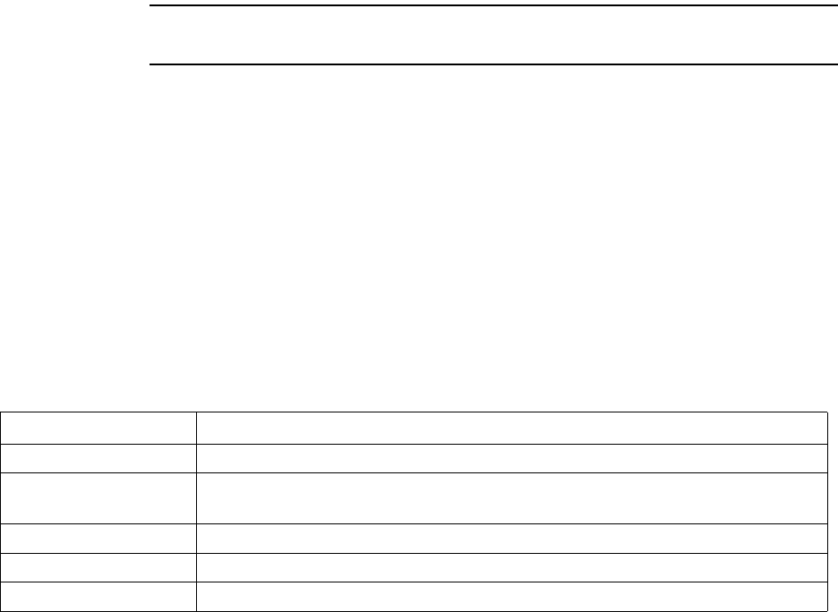
Table iii Typographical conventions
Convention Meaning
Bold face If you are using a graphical user interface (GUI), bold face indicates a
button, menu option, icon, and so on, that you manipulate directly.
If you are using a command line interface, bold face indicates commands
and keywords.
Bold face can also indicate information that you must enter.
Italic face Arguments for which you supply values are in italic face.
Courier
(mono-spaced) font
A command you type in, exactly as it appears, at a command line.
[ ... ] Arguments that appear inside square brackets [ ], are optional.
Also, when the guide shows a system prompt, the default system prompt
appears inside square brackets.
{..} | {..} Required keywords are grouped in braces and separated by vertical bars.
Note Notes contain helpful suggestions for the reader.
<...> Non-printing characters, such as passwords, appear in angle brackets.
Caution Cautions contain information about which the reader must exercise care.
Warning Warnings contain information about how readers might do something
resulting in harm to themselves or in damage to equipment or data.
Table iv Contacting technical support
Contact Description
Phone 1.877.962.2200
E-mail support@nextnetwireless.com
Web site www.nextnetwireless.com

1-1
CHAPTER
1
Introduction to backhaul installations
Chapter overview
This chapter provides an overview of the Expedience system and of the system’s
infrastructure components:
• The base station, which comes in two forms:
• The base transceiver station (BTS)
• The rackmount base station (RMB)
• The access provider (AP) server
• The network switches
The chapter provides an installation overview. It also describes things you need to consider
before installing base stations.
System overview
This section provides a brief overview of the Expedience system, as well as the infrastructure
that network access providers must install. For additional system overview information, refer
to the guide “Getting Started with the Expedience System.”
System overview
NextNet Wireless designed the Expedience system to give small office, home office (SOHO),
and residential subscribers high speed, wireless access to network communication systems,
such as the Internet. The Expedience system is an end-to-end broadband wireless access
system and operates in several frequency ranges.
The system was designed to allow network access providers to re-sell network bandwidth to
ISPs on a wholesale basis. In turn, the ISPs sell access to their subscribers on a retail basis. To
support multiple ISPs on the network, the system uses virtual LAN (VLAN) technology.
The system does not have a line-of-sight (LOS) requirement between the base station and the
CPEs. The air link between base stations and CPEs functions as an Ethernet bridge carrying
IP/ARP packets. Time division duplex (TDD) and cellular deployment offer you flexibility in
adjusting downlink versus uplink airtime.
1-2 Configuring, Installing, and Using Carrier Infrastructure
Infrastructure overview
The base station and AP server are network infrastructure components supplied by NextNet
Wireless. The network access provider configures and maintains this equipment.
Additional infrastructure components include switches for use at the base station cell sites,
and the head-end switch. These switches are supplied by the network access provider. If
desired, the network access provider can purchase the switches through NextNet Wireless.
Base station overview
The base station maintains contact with CPEs at your subscribers’ sites. The base station
integrates the transceiver and modem into one device.
Under typical configurations, the base station covers an approximate radius of 2 to 3 miles,
with a 5 mile maximum. If desired, network access providers can configure their base stations
to cover a maximum radius of 18 miles. To cover up to 18 miles, the network access provider
enables the extended range feature.
There are two types of base stations offered by NextNet Wireless:
• An indoor-only base station that slides into a base station cabinet after the cabinet has
been installed on a standard 19 inch rack. This base station is known as the rackmount
base station (RMB).
• A base station that can be installed indoors or outdoors. This base station can be installed
on a tower, on a roof, on a wall, or on a rack. The antenna can be installed on the base
station itself, or the antenna can be installed separately. This base station is known as the
integral base transceiver station (BTS).
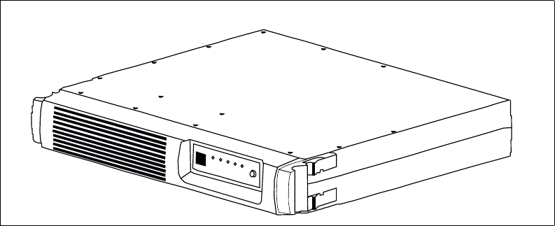
Figure 1.1 shows an individual RMB which will be installed inside a cabinet. This cabinet is
then installed on a standard 19 inch rack. Up to 8 RMBs can be installed inside a cabinet.
Figure 1.1 Rackmount base station (RMB)
1-3
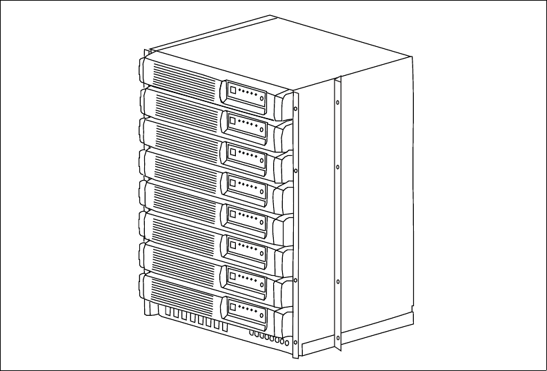
Figure 1.2 shows 8 RMBs installed inside the base station cabinet.
Figure 1.2 Rackmount base stations inside cabinet
1-4 Configuring, Installing, and Using Carrier Infrastructure
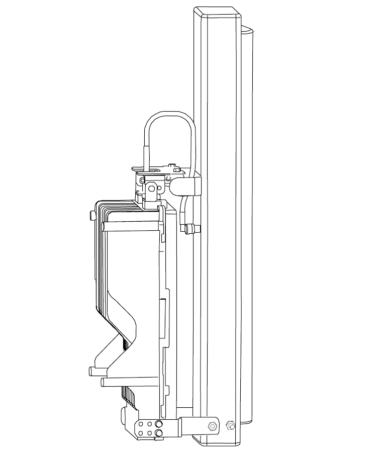
Figure 1.3 shows a base station that can be installed outdoors or indoors The figure shows the
antenna installed on the base station. If desired, you can install the antenna separately from
the base station.
AP server overview
The AP server acts as a relay for the CPE registration events which arrive from base stations
(on the management VLAN) and are forwarded to the correct ISP provisioning server (over
the control VLAN).
The base stations each have a TCP/IP connection to the AP server. The base stations use
their connection to forward CPE registration requests to the AP server.
The AP server is provided by NextNet Wireless.
Head-end switch, base station cell site switch, and ISP
switch overview
The network access provider must supply switches for their network, which include the head-
end switch and the switches used at the base station cell site. The network access provider
Figure 1.3 Base station for indoor or outdoor installation

1-5
must also assist their ISPs when the ISPs program their switches with the proper ISP VLAN
IDs.
The base stations are grouped together into cells, with between 1 and 6 base stations at a cell
site. (If the network access provider chooses to stack base stations, more than 6 base stations
can exist in a cell.) To form the base station LAN, the base stations are connected to a switch
at the cell site.
WAN links are then used to connect the cell sites to the head-end switch. The head-end
switch splits incoming traffic to the management VLAN and to the appropriate ISP VLAN.
The ISP then has a configured switch that controls traffic coming into and out of the ISP
VLANs.
Installation overview
This section provides a high-level overview of how to install the indoor, rackmount base
station (RMB), as well as the integral base transceiver stations (BTS) that can be installed
outdoors or indoors.
Installation steps common to RMB and BTS
1Plan the installation of base stations:
a Choose an appropriate location for the base station installation. For more information,
refer to the section “Choosing an installation location” on page 1-7 in this chapter.
b Design the deployment of base stations. Determine how base stations will be deployed
by marking a location on a map that shows where each base station will be installed.
Also determine naming conventions for cells, sectors, zones, and base stations names.
For more information, refer to the section, “Designing the deployment of base
stations” on page 1-9.
2Plan for system components that you need to supply to complete the network. For more
information, refer to the section “Assessing network access provider equipment needs” on
page 1-8 in this chapter.
3Install and configure the access provider (AP) server. For more information, refer to
Chapter 3, “Installing the AP server,” in this guide.
4On the AP server, configure zone names, VLAN IDs, and the ISP IDs. For more
information, refer to Chapter 3, “Installing the AP server,” in this guide.
5Using the NextNet Operating System (NNOS), configure the base stations before
deploying them in the field. For more information, refer to the chapter “Configuring base
stations” in this guide.
RMB installation overview
This section provides a high-level overview of how to install the base station cabinet onto a
19 inch rack, and then how to install the base stations into the cabinet.
1Slide the metal base station cabinet into the 19 inch rack.
2Install the power supply onto the 19 inch rack.
3Install the switch onto the 19 inch rack.
4Slide each base station into the appropriate slot in the cabinet on the rack.
5If you are using a 5 watt base station, install the 5 watt channel specific filter.
6Plug in the cables which include:

1-6 Configuring, Installing, and Using Carrier Infrastructure
• GPS cables
• Antenna cables
• Ethernet cables
• Power cables
• Alarm cables
Also, make sure that the fuses are installed properly.
7Plug in the power cable to the RMBs in the cabinet, make sure the power supply is
working, then turn on each RMB.
BTS installation overview
This section provides a high-level overview of the base station installation process. Other
sections in this guide then explain these installation tasks in detail.
The tasks you perform to deploy base stations are:
1Mount the base station at the site you selected. For more information, refer to the section
“Mounting and grounding the base station” on page 6-57 in this guide.
2Connect the antenna to the base station, as described in the section “Connecting the
antenna to the base station” on page 6-59.
3Mount the GPS device and connect it to the base station. One GPS device can service the
multiple base stations at a cell site. For more information, refer to the section “Connecting
the GPS equipment to a base station” on page 6-59 in this guide.
4Connect the base station to the transcient voltage suppressor (TVS) module, then connect
the TVS module to your network switch.
The TVS module splits the connection: one connection goes to a switch that connects to
your network, and the other goes to a power supply. For more information, refer to the
section “Connecting to the backbone network” on page 6-60 in this guide.
5Power the base stations by connecting the TVS module to the power supply. For more
information, refer to the section “Powering base stations” on page 6-61 in this guide.
The TVS module provides lightning protection. The TVS module also splits the
connection: one connection goes to the switch and the other goes to a power supply.
6Configure cell site switches, the head-end switch, and the ISP switches. For more
information, refer to “Configuring switches” on page 2-12 in this guide.
7Test the network by working with an ISP to:
• Install the ISP’s provisioning server
• Test the AP server to Provisioning server connection.
• Test that CPEs can access the ISP’s VLAN(s).
Planning the installation
This section describes issues you need to consider before you install the base stations,
including:
• Choosing locations for the base station installation
• Planning for service provider equipment components
• Selecting antennas

1-7
• Defining naming conventions for cells, sectors, base stations and VLANs
Choosing an installation location
The base station’s location at a site depends on many factors, including the site’s physical
environment, the coverage pattern you want to achieve, and the ease of maintenance you
require.
RMB installation location
The RMB is always installed indoors, inside the base station cabinet and on a standard 19 inch
rack. In turn, the rack is installed in an indoor equipment room or in another type of indoor
housing unit such as a shed near the tower.
BTS installation location
Table 1.1 describes some of the locations you might want to consider for a BTS.
Note: Regardless of the location you choose, plan to provide a weatherproof housing unit for
the network switch, the power supply, and the TVS equipment.
Table 1.1 Advantages/disadvantages of location choices
Location Advantages Disadvantages
On tower, at
antennas
Installing at the antennas offers
cost savings, due to the fact that
you can use a shorter coaxial cable
to connect the base stations to your
antennas. There is lower signal loss
in shorter cables.
When you install base stations near
the top of the tower, installation and
maintenance are more difficult.
At base of
tower
Placing the base stations at the base
of a tower offers simpler
installation and maintenance than a
base station installed on the tower,
at the antennas.
Base station installation and
maintenance are simpler than other
options.
If you install at the base of the
tower, you need to run a coaxial
cable from the base stations to the
antennas. This cable must be of
sufficient size to reduce signal loss,
which may increase costs.
Installation still requires you to
install the antennas and coaxial
cable.
On rooftop You can use a shorter coaxial cable
to connect base stations to
antennas. As such, you can
probably operate at higher power
levels, and still stay within signal
loss criteria.
Rooftop access is usually available,
making installation and
maintenance easier. Also, a housing
unit for the backbone network
switch, power supplies, and other
equipment is typically available.
You need to obtain permission to
use a rooftop, and comply with
building codes.

1-8 Configuring, Installing, and Using Carrier Infrastructure
Cable loss ranges
Use tables Table 1.2 and Table 1.3 to determine the cable size you need, based on signal loss.
Placement of base stations and switches on network
Make sure your network design places the base stations behind a switch so that the base
station sees only Ethernet traffic addressed to it. The switch you choose needs to be able to
handle the Ethernet traffic on your network
Assessing network access provider equipment needs
Before you install and deploy the base station, ensure you have made provisions for the
following components:
• Power and data connection between the base station and your network
• Global position system (GPS) for proper TDD functions. You must use the GPS supplied
with the Expedience system.
• Antenna system for transmitting and receiving signals for the base stations.
•SNMP server
• DHCP server, if desired, to supply IP addresses to base stations
• AP server
• Weatherproof housing for the backbone network switch, power supplies, and UPS. Also
supply weatherproof housing for the TVS module, which provides lightning protection.
• Coaxial cable to connect the base station to the antenna.
• Tower or building structure on which to mount cell site equipment.
Equipment needs of ISP
As a network access provider, you provide network bandwidth to ISPs. The ISPs in turn sell
network access to subscribers. Make sure your ISPs plan for the following pieces of
equipment on the ISP VLAN:
Table 1.2 Recommended cable length ranges for 2.3 - 2.7 GHz
Length of
cable drop Cable type Signal loss per
100 feet Signal loss
range
4 ft to 85 ft 1/2 inch LDF 3.52 .14 to 2.99
50 ft to 110 ft 5/8 inch LDF 2.65 1.33 to 2.92
90 ft to 150 ft 7/8 inch LDF 2.02 1.82 to 3.03
125 ft to 200 ft 1 1/4 inch LDF 1.47 1.84 to 2.94
Table 1.3 Recommended cable length ranges for 3.3 - 3.6 GHz
Length of
cable drop Cable type Signal loss per
100 feet Signal loss
range
4 ft to 85 ft 1/2 inch LDF 4.39 .18 to 2.85
50 ft to 110 ft 5/8 inch LDF 3.35 1.68 to 2.85
90 ft to 150 ft 7/8 inch LDF 2.55 1.91 to 2.93
125 ft to 200 ft 1 1/4 inch LDF* 1.84 2.30 to 2.94
*Note: The 1 1/4 inch LDF cable is not recommended for systems running at a
range higher than 3.3 GHz.
1-9
•DHCP server
• Customer care server and a customer relationship management application
• Provisioning server
• Switch to receive and direct traffic from the network access provider
• Router to route traffic to the Internet
Planning for the antennas and antenna installation tips
The type of antenna you choose depends on the cell type and pattern you want to use. Make
sure:
• The antenna provides an appropriate pattern for the application, with uptilt and downtilt
as required.
• The installation of the antenna complies with the vendor’s installation directions, and that
it meets building codes.
After you have installed an antenna, you need to connect it to a mounted base station. For
instructions on connecting the antenna to a base station, refer to the section “Connecting the
antenna to the base station” on page 6-59.
Designing the deployment of base stations
To plan for how base stations will be deployed:
1Determine a naming convention for base stations.
2Using a map of the area to be covered, define the zone names that will be used.
For example, an access provider can divide a metropolitan areas into North, South, East,
West, and Central zones. The network access provider then assigns base stations to a
specific zone by using the set system location command. Keep in mind that multiple base
stations may be assigned to the same zone. Zones allow the ISPs to differentiate services to
subscribers by allowing subscribers to operate in specific regions or clusters of zones.
3On a map, mark each location where base stations are installed.
4For each base station, document your design choices. Please note that some parameters are
optional, depending on how you design the system.
• Base station name (required)
• Zone name (required)
• Cell name (optional)
• Sector name (optional)
•Channel (required)
• Default VLAN for legacy CPEs (optional, default is 1)
• Management VLAN ID (optional; default ID is 1)
1-10 Configuring, Installing, and Using Carrier Infrastructure

2-11
CHAPTER
2
CONFIGURING NETWORK ARCHITECTURE
Chapter overview
This chapter describes a simple network topology. It provides an overview of how to
configure switches at the cell site, the head end, and the ISP sites.
Architecture overview
The hierarchy of the network architecture uses the concept of two layers: the access layer and
the backbone layer.
The functions of the access layer include connecting users — which include subscribers and
the ISPs — to the backbone layer.
Subscribers use components on the access layer (the CPEs and the base stations) to obtain
physical access to the network. The subscriber’s CPE communicates with a base station over
a radio link which is commonly called the air link. The base stations that communicate with
the CPEs are grouped into cells. The base stations in each cell are connected to a switch at the
cell site and a base station LAN is formed. The switches at the cell sites then use WAN links
to connect to the head-end switch.
The ISPs also use the access layer to connect to the backbone layer. An ISP receives network
access requests from components on the backbone layer (specifically the AP server on the
management VLAN). These requests for access are sent to the appropriate ISP. The ISP then
grants or denies the request. If access is granted, the ISP provides the subscriber’s host
computer with an IP address and traffic is shaped for that host computer according to the
subscriber’s service level agreement (SLA). Traffic to and from the host computer travels
through the backbone layer
The functions of the backbone layer include quickly switching incoming WAN trunk traffic
to the management VLAN and to the ISP VLANs. The backbone layer also returns Internet
traffic from the ISP to the appropriate base station and subscriber’s CPE.

2-12 Configuring, Installing, and Using Carrier Infrastructure
Configuring switches
This section describes configuration of the following switches:
• Switch connecting base stations at the cell site
• Head end switch
• ISP switch
Configuring the switch at the cell site
At the cell site, the network access provider must program a port on the switch to be a WAN
trunk to the head end switch.
Configuring the head end switch
WAN trunk ports on the head end switch must be configured to accept traffic from the cell
sites.
The head end switch then splits the traffic to the Management VLAN and the ISP VLANs.
The network access provider configures edge ports on the head end switch with the
Management VLAN ID, and the IDs of all the ISP VLANs.
Configuring the ISP switch
The ISP switch must be configured with the IDs of VLANs provided to the ISP by the
network access provider. A port on the switch is also configured with the ID of the control
VLAN.
Selecting backhaul links and circuits
Network access providers must select the links or circuits that connect the cells to the
backbone network. Each cell may have one or more base stations, and each base station
serves a sector within a cell. Service providers typically deploy cells in four or six sectors.
Depending on the upstream/downstream ratio selected and the configuration of the sector
covered by the base station, downlink capacity of up to 8 mb per second and uplink capacity
up to 4 mb per second may be required.
Adequate backhaul facilities must be provided to support this throughput.
Selecting links based on maximum rate needed
You can choose a link based on the maximum bit-transfer rate you might need. For example,
you might use DS-3 circuits to connect cells to a switch, and then connect those switches
together, using the appropriate higher-rate links.
Selecting links based on another rate
You might want to choose a link providing another data transfer rate. The link you choose
might depend on the expected and actual traffic rates for a given cell.
Choosing this option means you get lower cost circuits, but you also might get lower
throughput, increased response latency, and so on.

3-13
CHAPTER
3
CONFIGURING THE AP SERVER
Chapter overview
This chapter describes how to configure and use the access provider (AP) server.
AP server overview
All base stations connect to the AP server using a TCP/IP session. Using this connection, the
base stations transfer incoming registration requests from CPEs to the AP server. The AP
server forwards the request to the proper provisioning server for authorization.
The AP server defines the zones and ISPs that comprise network access provider’s network.
Note the following about the AP server:
• The connection between the AP server and the provisioning server is always established
from the AP server to the Provisioning server. Network access providers or ISPs cannot
use the provisioning server to define or attempt a connection back to the AP server.
• The AP server does NOT accept CPE registrations from base stations that do not have a
zone setting that the AP server can recognize.
Starting the AP server
The AP server was designed to use a Java servlet called Tomcat.
1To run the Tomcat servlet, type the following at a command prompt:
net start tomcat
2To stop the Tomcat servlet, type the following at a command prompt:
net stop tomcat
3To verify that the AP server is installed correctly, open an Internet browser. In the
browser’s address field, type the following address:
http://localhost:8080/ap
3-14 Configuring, Installing, and Using Carrier Infrastructure
Configuring the AP server
To configure the AP server, you must define AP server users, configure zone names, VLAN
IDs, ISP names, and ISP IDs.
Defining AP server users and administrators
To define users and administrators of the AP server:
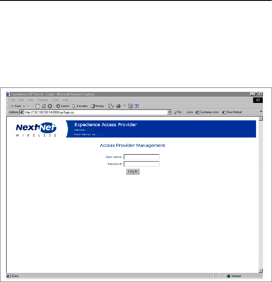
1Open a web browser. In the browser’s address field, type the address of the AP server.
A login page appears.
If you are logging into the server for the first time, log in with the following defaults:
• User name: administrator
• Password: password
If you are logging in for the second or subsequent time, enter your user name and
password in the appropriate fields.
Figure 3.1 AP server login page
4.0.0
3-15
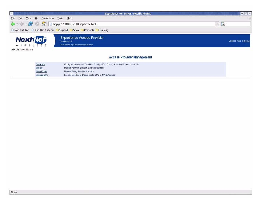
The Access Provider Management page opens.
Figure 3.2 Access Provider Management page
3-16 Configuring, Installing, and Using Carrier Infrastructure
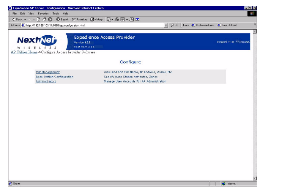
2From the Access Provider Management page, click the Configure link. The Configure
page opens.
Figure 3.3 Configure page
3-17
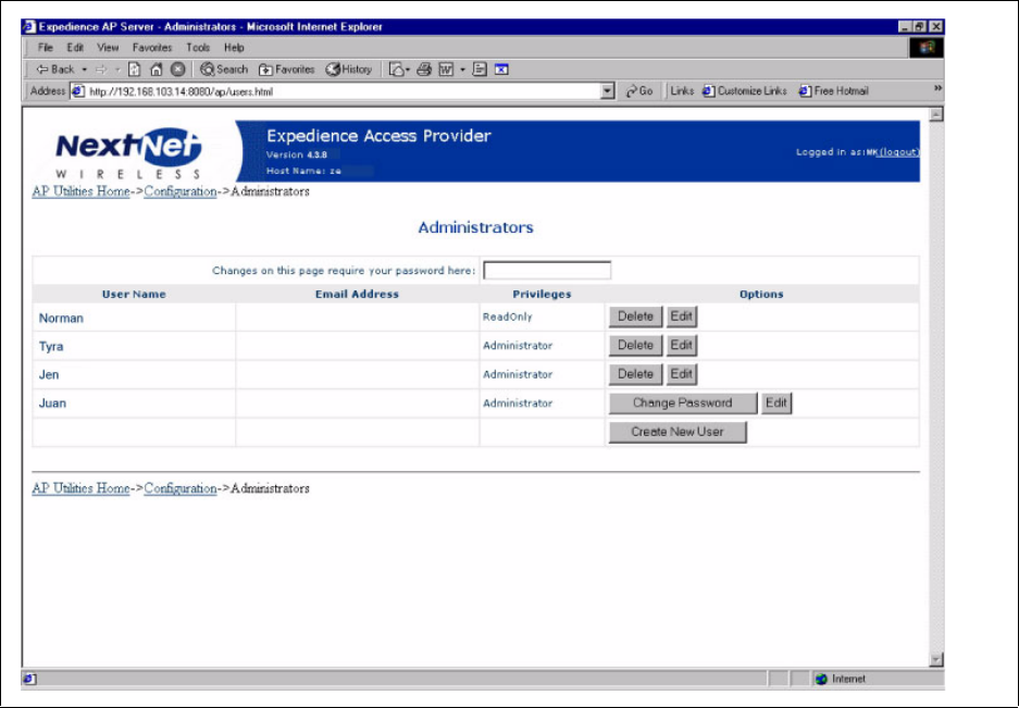
3From the Configure page, click Administrators.The Administrators page opens.
4In the Changes on this page require your password here: field, type your password.
Figure 3.4 Administrators page
3-18 Configuring, Installing, and Using Carrier Infrastructure
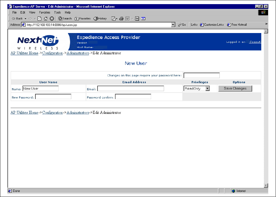
5Click Create New User. The New User page opens.
6In the Changes on this page require your password here: field, type your password.
7Complete the fields on the page, then click Save Changes.
Defining zone names
To define zone names:
1From the AP server’s home page, click Configure.
Figure 3.5 New User page
4.3.8 MK
ap4.nextnetwireless.com
3-19
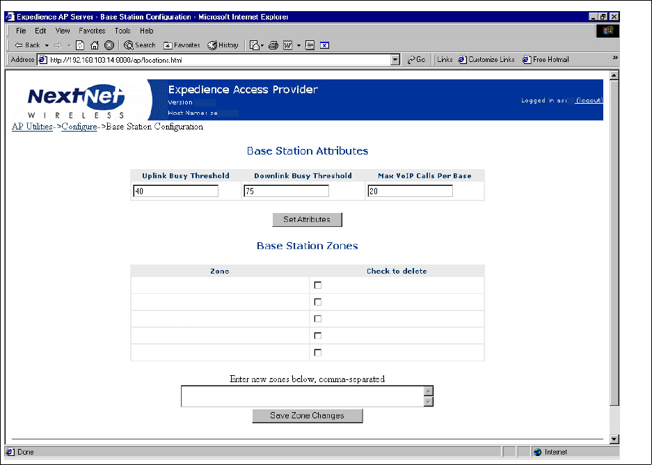
2From the Configure page, click the Base Station Configuration link.
3In the Enter new zones below, comma separated field, type the names of base station
zones. Use commas to separate names.
4For load balancing purposes, you can enter limits on the amount of traffic that a base
station can handle on both the uplink and downlink. If a CPE tries to register with a base
station when either of the limits are met, the CPE will receive a notice that it should try to
register with another, less busy base station. If no such base station is available, the CPE
registers with the first base station.
• To specify the limit of uplink traffic that a base station can handle before the base
stations indicates to registering CPEs to look for another base station, type the limit in
the Uplink Base Threshold field.
• To specify the limit of downlink traffic, type the limit in the Downlink Base
Threshold field.
5To specify the maximum number of VoIP calls that a base station can handle, type the
limit in the Max VoIP calls per Base field.
6Click Save Zone Changes. The new zone names appear in the Zone column.
Registering with the AP server after Zones defined
After you define zones, the base stations must re-register with the AP server so that the AP
server recognizes the base station as having a correct zone.
To re-register the base station with the AP server:
1Establish a terminal session with the base station.
Figure 3.6 Base Station Attributes page
CityCentral
CityNorth
CitySouth
CityEast
CityWest
4.3.8 MK
3-20 Configuring, Installing, and Using Carrier Infrastructure
a From the Base Station Properties page (see Figure 3.12), click on the IP address of the
base station.
b A terminal session starts, where you can log in to the NNOS.
2To assign the base station to a zone, use the NNOS command “set system location”. This
generates a base station registration record.
3To save the settings on the base station, type write. The change is written to Flash memory
on the base station.
4Close the terminal session.
5To verify that the base station’s zone name is correct, refresh the web browser.
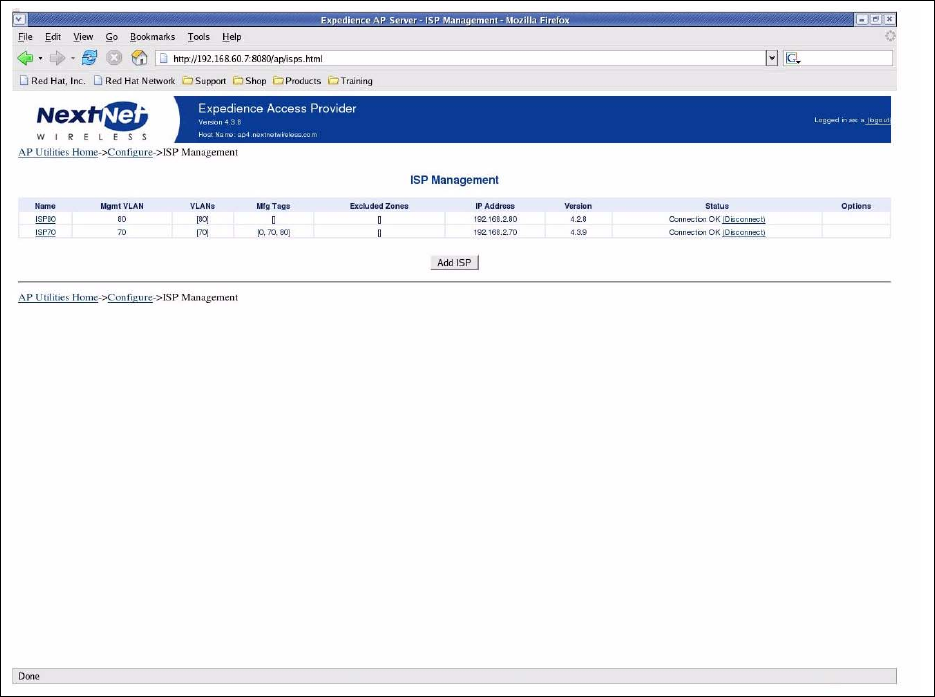
Defining ISPs
To define ISPs:
1From the AP server’s home page, click Configure.
2On the Configure page, click the ISP Management link.
Figure 3.7 ISP Management page
3-21
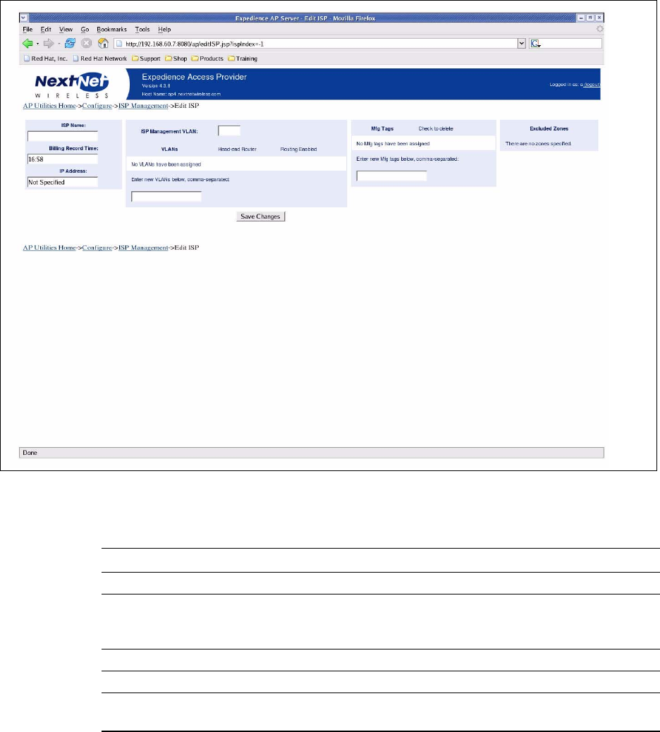
3To add a new ISP, click the Add ISP button.The Create new ISP page opens.
Table 3.1 describes the fields on the Create new ISP page that access providers must
complete to add ISPs.
Changing ISP information
To change the information about the ISP:
Figure 3.8 Create new ISP page
Table 3.1 Create new ISP page
Field Description
ISP Name A name for the ISP
Billing Record Time The time of day when the provisioning server is polled for billing
information. This information includes the number of CPEs that
are assigned to a service level agreement.
IP address IP address of the ISP provisioning server
VLANs ID numbers of the VLANs assigned to the ISP
Mfg Tags An embedded number on the CPE that determines which Internet
Service Provider (ISP) owns the CPE device
3-22 Configuring, Installing, and Using Carrier Infrastructure
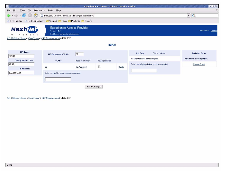
1From the ISP Management page, click the link of the name of the ISP whose information
you want to change.
2Alter the fields on the page as desired. Click Save Changes.
Excluding zones
Available Zones
Include Zone
Exclude Zone
Figure 3.9 ISP details page
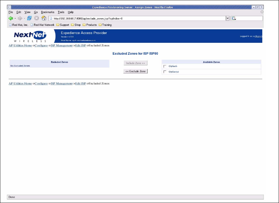
3-23
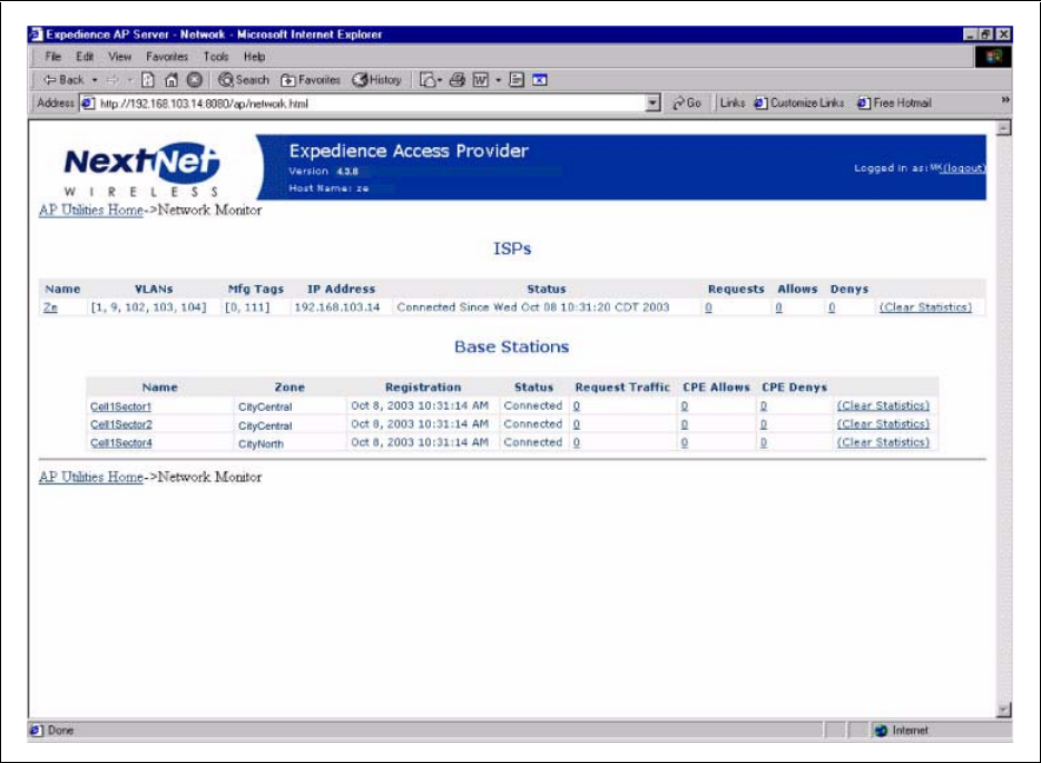
Monitoring ISPs and base stations
Using the AP server, you can view information about the status of ISPs and base stations that
are part of the network access provider network.
To view information about ISPs and base stations:
Figure 3.10 Exclude Zones page
3-24 Configuring, Installing, and Using Carrier Infrastructure
1From the AP server home page, click Monitor. The Monitor ISPs - Base Stations page
opens.
Figure 3.11 Monitor ISPs - Base Stations page
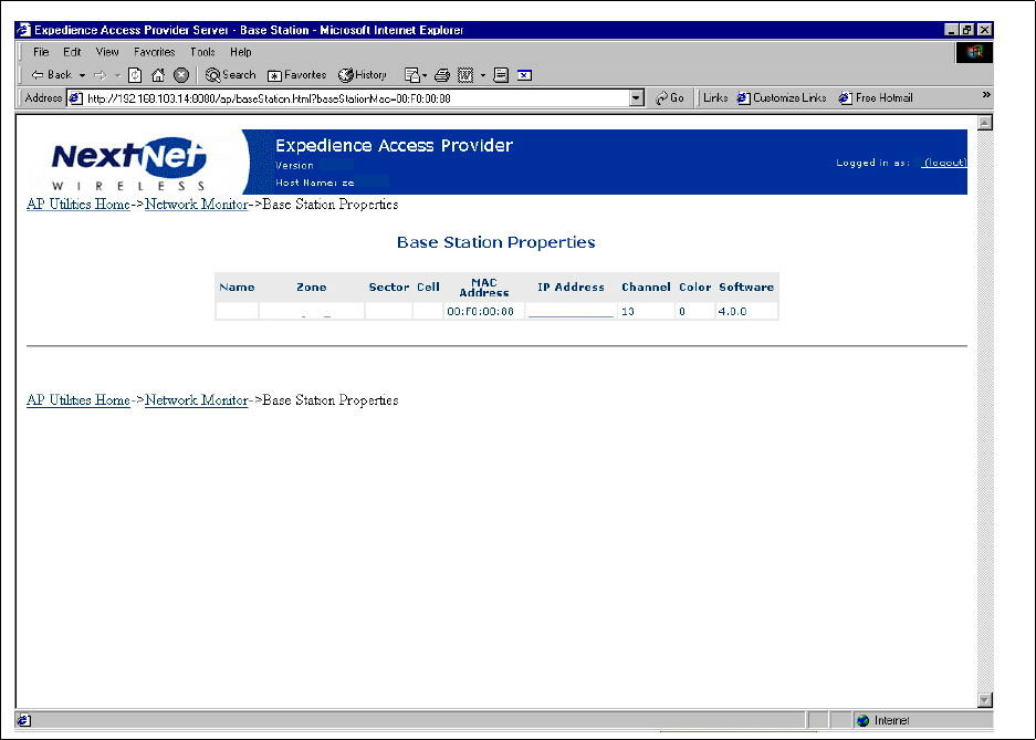
3-25
2To start a terminal session with the base station, and change the base station’s parameters
using the NextNet Operating System (NNOS), click the name of the base station.The Base
Station Properties page opens.
3Click the IP address. A terminal session starts with the base station.
For more information about changing NNOS parameters on base stations, refer to the
guide “Using the NextNet Operating System (NNOS).”
Figure 3.12 Base Station Properties page
4.0.0
CityCentralS1C2 12 153.149.100.54
MK
3-26 Configuring, Installing, and Using Carrier Infrastructure

4-27
CHAPTER
4
CONFIGURING A STANDBY AP SERVER
Chapter overview
This chapter describes how to configure a standby AP server. The network will use the
standby server if the primary server becomes unavailable.
Standby AP server overview
The standby AP server can be put into service if the primary AP server is not available.
Note: Make sure that the primary and secondary server are not running at the same time.
Also, make sure that the server on which shared AP configuration files reside is not powered
off while either the primary or secondary server is running.
During AP server outage, subscriber data traffic is passed from CPEs and VLANs.
The elements of the standby AP server solution are:
• Primary AP server
• Secondary AP server
• Shared AP server configuration files
To maintain overall network integrity, configure the primary and secondary AP server with
identical information, including the ISP ID assignments and VLAN assignments.
Configuring the base station with standby AP server
information
To configure the base station so it can use a standby AP server:
1Set the address of the primary and secondary server:
set aaa server address p.p.p.p,s.s.s.s
where:
p.p.p.p is the address of the primary AP server.
s.s.s.s is the IP address of the secondary AP server.
4-28 Configuring, Installing, and Using Carrier Infrastructure
2To save the changes to Flash memory, type the following:
write
3To make sure the setting is correct, type:
show aaa
The following information appears:
aaa authority => remote
aaa cache => enabled
aaa port => 12541
aaa server address => 000.111.222.333 999.888.777.666
Note: 000.111.222.333 999.888.777.666 represent the IP addresses of the primary and
secondary AP server respectively.
aaa state => enabled
Setting up common configuration file and directory
This section describes how to set up a common configuration directory on a shared network
drive.
After the AP server software is installed, the following directories exist:
• NextNetHome
• NextNetConfigFolder
The NextNetConfigFolder contains the following configuration files which need to be shared
between the primary and secondary AP servers.
Create a shared directory on a server that stores these files. This shared directory can reside
on either the primary or secondary server, if desired.
To create a shared directory:
1Create the shared directory on the chosen machine:
\\ConfigServer\nn\config
2Create a user called TomcatServiceUser. Set permissions on the shared directory to
grant all privileges to the user.
3On both the primary and secondary servers, set up the same user name:
TomcatServiceUser
This user ID is used to run the Tomcat service. The ID must have permission from both
primary and secondary AP servers to access the shared directory on the ConfigServer.
Figure 4.1 Configuration files to share between primary and secondary AP servers
File Description
nextnet.properties Specifies application parameters and the location of billing record folder
ap_logging.properties Specifies the location of audit logs and application logs. Also lists logging
parameters
users.xml A list of user names
isps.xml A list of ISPs
zones.xml A list of zone names
4-29
This user should be a member of the group users. The user name and password must
match the user account and password on the ConfigServer.
4Install the AP server using the standard installation program. When the installation
program prompts you:
a Place the NextNetHomedirectory on a local drive.
b Specify that the NextNetConfigFolder resides on the remote share.
5On the primary and secondary servers, specify that the Tomcat service logs on as
TomcatServiceUser:
aFrom the Start menu, select Settings, Control Panel, Administrative Tools. From
the list of items that appears, select Services. The Services window opens.
b Double click on the Tomcat service. A Properties window for the service opens.
c Click the Log On tab.
dIn the This Account: field, type the account name. In the Password: and Confirm
Password: fields, type the password of the user account.
6On the primary AP server, specify the startup type as Automatic.
7On the secondary AP server specify the startup type as Manual.
8Click on the General tab, and specify the following:
a For the primary AP server, from the Startup type drop down list box, select
Automatic.
b For the secondary AP server, from Startup type the drop down list box, select
Manual.
Testing the installation
To test the installation:
1From a command prompt, type:
net start Tomcat
If the service starts correctly, the Administrative Tools/Event Viewer shows that the
service started.
2Reboot the AP server. Without being logged on, you should be able to browse to the AP
web application from another machine.
Location of audit files and log files
Directories within the NextNetConfigFolder directory contain the audit logs and application
logs. If you configured a shared space on a network directory for the primary and secondary
AP server, the log files will be stored in the shared directory named NextNetConfigFolder.
If you have turned on the feature than enables debugging information to be written to a file,
note that the performance of the AP server might degrade, as the server might be saving a lot
of information to a network drive.
If desired, you can configure a different location where the files can be stored, such as
C:/nn/logs.
Switching from the primary AP server to the secondary AP
server
To switch from the primary AP server to the secondary AP server:
4-30 Configuring, Installing, and Using Carrier Infrastructure
1Stop the primary AP server. To do so, from a command prompt on the primary AP server,
type:
net stop Tomcat
2Start the secondary AP server. To do so, from a command prompt on the secondary AP
server, type:
net start Tomcat
After the primary server is stopped, each base station automatically detects the loss of the
primary connection. The base station then attempts to connect with the secondary AP server.
The secondary server connects to the ISP provisioning servers. Since this connection
overrides any previous connection with the provisioning servers, you must stop the primary
AP server before starting the secondary AP server.

5-31
CHAPTER
5
CONFIGURING BASE STATIONS
Chapter overview
This chapter describes how to configure base stations. It describes:
• How to configure the base station so you can communicate with the base station using a
term connection, an SNMP connection, a web connection, and a Telnet connection
• The operating system parameters to configure before you deploy base stations
• How to set up a system component (called an “authority”) that grants CPEs access to your
network
Before you begin
To configure base stations before you deploy them on towers or buildings, you must first
supply power to the base station, and connect the base station to a PC using the serial cable/
serial connection. To perform these tasks:
1Place an RF 50 ohm load or at least a 10dB RF attenuator on the RF connector. The load
or attenuator must be capable of 10 watts of dissipation.
2Connect the base station to the TVS module by plugging the provided cable into the left-
most connector on the bottom of the base station. Then, plug the TVS module into a
power source.
3Use the serial interface cable to connect your computer to the base station.
4On your computer, set up terminal emulation access to the base station, as described in the
section “Setting up terminal emulation access” on page 5-32 in this guide.
5If you have not already done so, start a terminal emulation session with the base station
you want to configure and log on to NNOS. (If you are using a Windows operating
system, you may want to use the Hyperterminal application to open the connection
defined in step 4.)
6Configure the base station as described in the following sections of this chapter:
• “Setting base station configuration parameters” on page 5-35
• “Recommended parameter changes” on page 5-40
• “Setting up Syslog” on page 5-41
• “Configuring the authority that grants network access to CPEs” on page 5-42
• “Configuring the time signal used by base stations” on page 5-44

5-32 Configuring, Installing, and Using Carrier Infrastructure
Setting up connection methods used to configure
base stations
The Expedience system allows you to connect to a base station using many methods:
• Terminal emulation over a serial line
•Telnet
•Web server
•SNMP server
Before you can use a particular method to connect to the base station, you must configure its
connection.
To configure the base station initially, you will most likely use a serial connection and a
terminal emulation session. Terminal emulation allows access through a direct RS-232
connection from a personal computer to the base station.
Setting up terminal emulation access
The terminal emulation connection is a physical RS-232 cable connection, between the base
station and a PC. Once the connection is set up, you can use a program—such as
Hyperterminal under the Windows operating system—to configure and communicate with
the base station.
Terminal emulation connection settings
To set up a terminal emulation connection:
1Use these settings:
• 19.2k baud
• 8 data bits
•No parity
• 1 stop bit
• no flow control
2To test the connection, from an NNOS command prompt, issue an airping command, or
the NNOS command of your choice.
Setting up Telnet access
To set up your system to use Telnet to access a base station:
1Using your Term connection, at the NNOS command prompt, issue the following
command to enable Telnet:
set telnet state enabled
2If you want to change the default port on which the Telnet server listens:
set telnet port
{portnumber}
The factory default is 23.

5-33
3To set the IP address, or range of IP addresses, of the remote computers that are allowed
to use Telnet to access the base station:
set telnet remote
{IPaddress | IPaddress mask}
where:
IPaddress is the IP address of the computer that is allowed to use Telnet to access the base
station.
IPaddress mask is a mask for a range IP addresses that are allowed to use Telnet to access
the base station.
4If you want to change the Telnet timeout from the factory default of 5 minutes:
set telnet timeout
{time}
where {time} is the time, in seconds, that the Telnet session is allowed to sit idle before the
session ends.
5Before you can telnet to the base station, you need to set the base station’s IP address.
a To set the base station’s IP address, at a NNOS prompt, type:
set IP address
{IPaddress}
where:
IPaddress is the IP address of the base station.
b To determine the base station’s address, use Terminal emulation over a serial line
connection to the base station. At a term connection’s NNOS prompt:
show IP address
Remember the base station’s IP address. You will need it later if you want to use Telnet
a web browser, or SNMP session to configure or monitor the base station.
Note: If you have assigned names to your base stations, you can also use the “show name”
command to determine the base station’s name. Then, you can telnet to the base station
using its name. For further information, refer to the section “Recommended parameter
changes” on page 5-40 in this guide.
6For changed settings to take effect, you must write the changes to Flash memory and then
restart the base station.
a At the NNOS command prompt, type
write
.
b At the next NNOS command prompt, type
reboot
.
Setting up SNMP access
This section describes how to set up your base station for SNMP access.
Note: To determine how parameters are currently configured, issue a “show” command for
the parameter you want to check. For example, a “show snmp state” command will tell you if
the base station already has the SNMP agent enabled. Most of the system’s default settings for
parameters will help ensure your base station is ready for SNMP access when the factory
ships the base station.
To setup your system for SNMP access:
1Using a Term or telnet connection, at the NNOS command prompt, issue the following
command to enable SNMP:
5-34 Configuring, Installing, and Using Carrier Infrastructure
set snmp state enabled
2To specify the IP address of the remote computer or computers allowed to access the
SNMP server on the base station, specify a mask appropriate to your network. Type the
following command:
set snmp remote
{IPaddress | IPaddress mask}
where:
IPaddress is the address of the remote machine that is allowed to access the SNMP server.
IPaddress mask is a mask for a range of all IP addresses that are allowed to access the base
station’s SNMP server.
3If you want to use SNMP traps:
set snmp traps enabled
4To specify the IP address of the SNMP trap server on the network management
workstation:
set snmp trap server
{IPaddress}
where {IPaddress} is the IP address of the machine to receive SNMP traps.
5Specify the trap level for the functions whose traps can be reported. To specify the level of
the SNMP trap messages that are sent to the trap server:
set snmp
{function}
traplevel
{variable}
where:
{function} is the feature whose trap level you want to set. Functions you can specify include
airlink
,
config
,
nnmgr
,
reg mgr
,
relay
, and
stack
.
{variable} is the trap level, with a value of
0
,
3
,
4
,
5
, or
7
.
For more information, refer to the guide “Using the NextNet Operating System
(NNOS).”

5-35
6Specify the SNMP community name. A community is a logical relationship between an
SNMP agent and one or more SNMP managers. The community has a name, and all
members of a community have the same access privileges.
To specify the community that will have read privileges:
set snmp read community
{name}
To specify the community that will have write privileges:
set snmp write community
{name}
For both parameters, {name} specifies the name of the community.
7To allow the ability to configure parameters through SNMP access:
set snmp access enabled
8If you changed the settings for the set snmp state, write your changes to Flash memory
and then restart the base station.
a At the NNOS command prompt, type
write
.
b At the next NNOS command prompt, type
reboot
.
Configuring SNMPc 5.0 for use with Expedience base
stations
If you are using the network management application SNMPc 5.0 from Castle Rock, change
the default community name of base stations.
1Open the SNMPc 5.0 application and select a base station.
2Within the application, use the set community command to set the base station’s
community name to “public”.
Note: The default community name is netman.
3Repeat step 2 for each base station you want to manage.
Setting base station configuration parameters
This section describes configuration parameters to set for proper base station operation.
You can use terminal emulation, Telnet, the web interface, or an SNMP session to configure
the parameters on the base station.Before you can use these methods, make sure the
connection is set up. For further information, refer to the section “Setting up connection
methods used to configure base stations” on page 5-32 in this guide.
To set up the base station:
1Set the following parameters, in the order that follows:
• set airlink channel, as described on page 5-36 in this guide.
• set airlink downlink power, as described on page 5-36 in this guide.
• set airlink downlink bias, as described on page 5-37 in this guide.
• set vlan legacy id, as described on page 5-40 in this guide.
• set vlan mgmt id, as described on page 5-40 in this guide.
• set airlink state, as described on page 5-39 in this guide.

5-36 Configuring, Installing, and Using Carrier Infrastructure
For more information about these configuration parameters, as well as a full list of
configuration parameters, refer to the guide “Using the NextNet Operating System.”
2After setting the parameters, use the write command to write the settings into the flash,
non-volatile memory.
3For changes to take effect, perform one of the following:
• Re-boot the base station
—OR—
• Power down the base station, and then re-power it.
set airlink channel
Set this configuration parameter to the frequency channel on which to run the airlink. For an
illustration of the channels that are supported in the various frequency ranges, refer to
Appendix B.
Example: set airlink channel 15
This parameter has changed to radio frequency, has it not?
set airlink downlink power
This parameter specifies the base station’s transmit power level.
The power levels you can specify depend on the type of base station you are using: a 2 watt
base station, or a 5 watt base station.
2 watt base station
Specify a power value from 10 to 31.
The maximum system power level is 10, which specifies +33 dBm (2 watts). The other power
levels are measured in 1 dB steps down from the maximum.
Example:
set airlink downlink power 10
Table 5.1 Transmit power levels
Power value Power level
10 +33 dBm = 2.0 watts
.
.
13 +30 dBm = 1.0 watt
.
.
16 +27 dBm = 500 milliwatts
.
.
23 +20 dBm = 100 milliwatts
.
.
31 +12 dBm = 15.8 milliwatts

5-37
5 watt base station
Specify a power value from 6 to 31. The maximum system power level is 6, which specifies
+37 dBm (5 watts) at the RF connector. The other power levels are measured in 1 dB down
steps from the maximum.
To operate the base station at the 5 watt level, you must install a supplied channel filter.
Example:
set airlink downlink power 10
set airlink downlink bias
This parameter specifies the portion of airtime (slots) available for use on the downlink
relative to the airtime for the uplink. There are always at least 6 slots available for the uplink.
The higher the bias, the more bandwidth is available for the downlink, due to more time
allocated to the downlink.
Example: set airlink downlink bias 2
You must specify the same downlink bias for all base stations in a cell. Likewise, all base
stations within your system, regardless of the cell they are in, must have the same downlink
bias.
Note: If you are using both 4-QAM only RSUs and AMOD RSUs, do NOT use bias 1.
Table 5.2 Transmit power levels
Power value Power level
6 +37 dBm = 5 watts
7 +36 dBm = 4.0 watts
8 +35 dBm = 3.1 watts
9 +34 dBm = 2.5 watts
10 +33 dBm = 2.0 watts
.
.
13 +30 dBm = 1.0 watt
.
.
16 +27 dBm = 500 milliwatts
.
.
23 +20 dBm = 100 milliwatts
.
.
31 +12 dBm = 15.8 milliwatts

5-38 Configuring, Installing, and Using Carrier Infrastructure
Table 5.3 describes the downlink rates for various modulation methods for 6 MHz channel
bandwidths.
Table 5.4 describes the uplink data rate when 4-QAM (QPSK) is the modulation method.
Table 5.5 describes the uplink data rate when 16-QAM is the modulation method.
Table 5.6 describes the uplink data rate when 64-QAM is the modulation method.
Table 5.3 Downlink rate based on modulation method
4-QAM 16-QAM 64-QAM 16-QAM lite
Bias Downlink rate Downlink rate Downlink rate Downlink rate
0 1,337,358 2,100,580 2,863,803 3,627,025
1 1,719,413 2,975,037 4,230,661 5,486,284
2 2,127,308 3,906,987 5,686,667 7,466,347
3 2,294,515 4,288,741 6,282,967 ---
4 2,424,466 4,587,929 6,750,392 ---
5 2,530,766 4,828,640 7,126,514 ---
Table 5.4 Uplink data rate for 4-QAM modulation method
Bias Uplink all 1 slot 2 slot
0 1,314,152 210,264 431,545
1 1,080,996 172,959 354,981
2 835,728 133,716 274,439
3 735,804 117,729 241,625
4 657,076 105,132 215,772
5 593,488 94,958 194,891
Table 5.5 Uplink data rate for 16-QAM modulation method
Bias Uplink all 1 slot 2 slot
0 2,867,241 438,051 926,489
1 2,358,537 360,332 762,112
2 1,823,407 278,576 589,196
3 1,605,391 245,268 518,749
4 1,433,620 219,025 463,245
5 1,294,883 197,829 418,415
Table 5.6 Uplink data rate for 64-QAM modulation method
Bias Uplink all 1 slot 2 slot
0 3,942,456 584,068 1,260,876
1 3,242,988 480,443 1,037,172
2 2,507,184 371,435 801,847
3 2,207,412 327,024 705,974
4 1,971,228 292,034 630,438
5 1,780,464 263,772 569,428

5-39
Table 5.7 describes the uplink data rate when 16 QAM lite is the modulation method
set system location
This parameter defines the zone to which the base station belongs.
During the design of the network, the access provider defines zones of coverage for the
network. For example, an access provider can divide a metropolitan areas into North, South,
East, West, and Central zones.
In the North zone, the network access provider decides to install three base station cells. All
base stations in this zone—regardless of their cell assignment—have the same zone name of
North.
The network access provider then assigns base stations to a specific zone by using the set
system location command.
Example: set system location North
set system name
The parameter specifies the name of the base station.
For example, the network access provider has three base station cells in the zone called
North. All base stations in this zone—regardless of their cell assignment—have the same
zone name: North.
Using the system name, the network access provider provides a name for each base station.
This system name reflects where the base station is installed in the North zone.
To continue the example, a base station assigned the zone name of “North” is to be installed
near the intersection of 7th street and Randolph avenue. The base station is given the name
sevenandrandolphbase2. This name indicates that this is the second base station installed near
the street. Another base station (also in the North zone) is to be installed near the intersection
of Carmody drive and 45th avenue. It is given the name carmodyand45base1.
Example: set system name SevenandRandolphBase2
set airlink state
This parameter enables the airlink.
After you specify the set airlink channel number, set airlink downlink power, and set
downlink bias parameters, set the airlink state to enabled, so changes can take effect.
Example: set airlink state enabled
You can take the base station off the air by disabling the airlink.
Table 5.7 Uplink data rate for 16-QAM lite modulation method
Bias Uplink all 1 slot 2 slot
0 5,256,608 750,944 1,661,571
1 4,323,964 617,712 1,366,777
2 3,342,912 477,559 1,056,668
3 --- --- ---
4 --- --- ---
5 --- --- ---

5-40 Configuring, Installing, and Using Carrier Infrastructure
Recommended parameter changes
Before deploying a base station, it is recommended that you assign the base station a cell
name and a sector name.
set system cell
This parameter specifies the cell name in which the base station is installed.
Example: set system cell RiverBendRoad
set system sector
This parameter specifies the sector in which the base station is installed.
Example: set system sector north
set DHCP state
If you want to use a DHCP server to assign IP addresses to base stations, set this parameter
to enabled.
Example: set DHCP state enabled
Setting legacy and management VLAN IDs
When the base station is shipped from the factory, the identification numbers for the legacy
VLAN and for the management VLAN are both set to 1.
If you or your ISPs use only CPEs that run Version 2.x software code or later, you do not
need to change the default id for either VLAN.
However, if you have some CPEs running version 1.x code, you need to set up a legacy
VLAN with an identification number different from the management VLAN ID. The legacy
VLAN then services all CPEs that run version 1.x software code.
set vlan legacy id
This command specifies the identification number for all legacy CPEs—CPEs that run
version 1.x software code. Make sure the legacy VLAN configuration setting is identical on all
base stations in the network.
Example: set vlan legacy id 4
set vlan mgmt id
This command specifies the identification of the management VLAN. The management
VLAN is used for network management. It also handles authorization protocol messages. All
base stations attach to the management VLAN. A network access provider must have one
management VLAN. The VLAN identification number must be the same number on all base
stations in the network.
Example: set vlan mgmt id 1

5-41
Setting up Syslog
This section describes how to set up Syslog options. Syslog is a tool that records operational
data, unusual system occurrences, system commands, and messages. To set up your system’s
Syslog options:
1To enable Syslog, use a command line interface run over the network (such as telnet) or
use a serial line connection to the base station.
2At an sNNOS command prompt, issue the following command to enable Syslog:
set syslog state enabled
3Specify the level for the functions whose syslog events can be reported. To specify the
level of the messages:
set syslog
{function}
level
{variable}
where:
{function} is the feature whose level you want to set. Functions you can specify include
airlink
,
config
,
nnmgr
,
reg mgr
, and
relay
.
{variable} is the level, with a value of
0
,
3
,
4
,
5
, or
7
.
For further information about the functions and Syslog levels, refer to the guide “Using
the NextNet Operating System (NNOS).”
4To set the Syslog port number:
set syslog port 514

5-42 Configuring, Installing, and Using Carrier Infrastructure
5Set the Syslog server to the address of the network management workstation
set syslog server
{IPaddress}
where {IPaddress} is the address of the workstation that is running the Syslog application.
6To verify the operation of Syslog, open the Syslog server, where you can view messages or
create Syslog message reports.
Configuring the authority that grants network access
to CPEs
This section describes how to set up a system component (called an authority) that grants
CPEs the ability to access the ISPs’ VLANs.
Table 5.8 describes the methods the network can use to grant network access to CPEs.
Note: The AP server, which acts to relay CPE service requests to the proper ISP VLAN, is
sometimes referred to as an AAA (“authentication authorization accounting” or “triple A”)
server.
Using base station caching feature for re-registering CPEs
Network access providers can also set up the base station to grant access to CPEs that have
already been granted permission to operate on the network. When a CPE re-registers, the
base station uses the existing parameters stored on the base station, such as the CPE’s VLAN
assignment and the number of hosts the CPE is allowed to service. For more information on
this feature, refer to “set aaa cache” in the guide “Using the NextNet Operating System
(NNOS).”
Remote authority: setting up the provisioning server to grant
CPEs network access
Under remote authority the provisioning server grants CPEs network access. All requests for
access are relayed to the appropriate ISP through the network access provider’s AP server.
To set up remote authority:
Table 5.8 Methods used to grant CPEs access to ISPs’ VLANs
Type of authority Description
Remote authority The ISP’s provisioning server resides on the ISP VLAN and is
used to grant network access to CPEs.
When the base station is configured to use remote authority, the
CPE’s network access request travels to the base station. The
base station then forwards the request to the network access
provider’s AP server. The AP server relays the request to the
proper ISP and the provisioning server.
The provisioning server is checked to ensure the CPE is
allowed to access the ISP’s VLAN. If so, the provisioning
server sends a record that grants access back to the base station.
Local authority The base station grants network access to CPEs. When this type
of authority is used, all CPEs are placed on the same VLAN,
which is the legacy VLAN.

5-43
1Contact the appropriate ISP to make sure the provisioning server hardware and software
are properly installed.
2Add appropriate routes to the base station’s routing table.
Use the NNOS “route add” command to add a route (from the base station to the AP
server), and a reverse route (from the AP server to the base station) to the base station’s
route table.
Note: Steps 3 through 6 help you configure the base station to use the AP server as a relay
for CPE registration requests. The AP server forwards the registration requests to the
appropriate provisioning server. To complete these steps, use Terminal emulation and a
serial line connection to the base station. You can also use Telnet, SNMP, or web access if
access for these connection methods is configured.
3To specify the address of the AP server that receives records:
set aaa server address
{IPaddress1}
,
{IPaddress2}
where
{IPaddress1} is the address of the workstation that runs the AP server.
{IPaddress2} is the address of a redundant workstation that runs the AP server if the
workstation identified by IPaddress1 goes down. Control returns to the workstation
identified by IPaddress1 when the redundant workstation goes down.
4To specify the port on which the AP server listens:
set aaa port 12451
5Configure the method the base station uses to grant network access to CPEs:
set aaa authority remote
where
remote
indicates the provisioning server (through the AP server relay) grants
network access to CPEs that are attempting to connect to the network.
6To activate the AP server feature:
set aaa server enabled
7To store the changes in Flash memory:
write
Local authority: setting up the base station to grant CPEs
network access
If you establish local authority, the base station always grants CPEs network access. All CPEs
are placed on the same VLAN, which is the legacy VLAN.
To set up local authority:
1Disable the AAA server feature:
set aaa state disabled
2Configure the method the base station will use to grant network access to CPEs:
set aaa authority local
where
local
indicates the base station grants access to CPEs that want to connect to your
network.
3To store the changes in Flash memory:
write

5-44 Configuring, Installing, and Using Carrier Infrastructure
4Reboot the base station. When the CPEs re-register with the base station, the base station
places them on the legacy VLAN.
Configuring the time signal used by base stations
Expedience base stations require a time synchronization signal in order to determine the
proper timing for time division duplexing (TDD).
Because most Expedience system deployments use multiple base stations, at multiple cell
sites, most service providers will configure their base stations to use the time synchronization
signal generated by the Expedience system’s global positioning system (GPS).
However, if your deployment includes only one base station or one cell site, you can disable
the use of an external GPS. Your base station will then use a time signal generated by the base
station itself or another base station in the cell for time synchronization.
The GPS supplied time signal is known as an external time signal, which is the default setting
of the base station when shipped from the factory.
The base station generated time signal is known as an internal time signal.
Configuring the GPS to supply the time signal
To use the GPS to supply the time signal to base stations:
1Supply power to the entire system, as described in the section “Powering base stations” on
page 6-61 in this guide.
2Connect the GPS to a base station, as described in the section “Connecting the GPS
equipment to a base station” on page 6-59 in this guide.
3Connect all base stations in your cell to each other, in a daisy chain manner. For further
information, refer to the section “Connecting the GPS equipment to a base station” on
page 6-59 in this guide.
4Configure the base station to use an external time synchronization signal:
set airlink timing external
5Save changes in Flash memory by issuing the
write
command.
6For changes to take effect, reboot or reset the base station’s power. To reboot, type the
following at the command prompt:
reboot
Configuring a base station to supply a time signal
There are two scenarios in which you might want to set up a base station to use internal time
synchronization.
The first is a single base station at a cell that is not part of a larger system with other sites.
This base station may be set to use internal time synchronization.
The second scenario is a multiple base station site that is not part of a larger system with other
sites. One of the base stations is set as a master base station. The master base station is set for
internal time synchronization. It generates the 1-pulse-per-second (pps) for itself, and also
outputs the 1 pps pulse for the other base stations. As such, you then set the other base
stations to use external time synchronization.
To use a base-station generated time signal:
5-45
1Connect all base stations in your cell to each other, in a daisy chain manner.
2Supply power to the entire system, as described in the section,“Powering base stations” on
page 6-61 in this guide.
3Configure the single base station or the master base stations to use an internal time
synchronization signal:
set airlink timing internal
4Disable the set airlink afc parameter. You must disable this parameter, which otherwise
would allow a base station to automatically frequency lock to the external pulse from the
GPS.
set airlink afc disabled
5Store your changes in Flash memory by issuing the
write
command.
6For changes to take effect, reboot or reset the base station’s power. To reboot, type the
following at the command prompt:
reboot
5-46 Configuring, Installing, and Using Carrier Infrastructure
5-47

5-48 Configuring, Installing, and Using Carrier Infrastructure

6-49
CHAPTER
6
INSTALLING THE INTEGRAL BASE
TRANSCEIVER STATION
Chapter overview
This chapter describes how to install the integral base transceiver station (BTS). The base
station enables you to install the base station and the antenna as one item, which could save
tower rental costs. You can also install the base station and antenna separately, if desired.
This chapter describes:
• Components used to mount the base station on a building or tower
• Connecting the base station to the cell and to cell-site components
Before you begin
Before you install a base station on a roof top or tower:
• It is recommended that you assign a name to the base station. For more information refer
to Chapter 2, “Configuring base stations‚” in this guide.
• It is also a good idea to configure the base station.
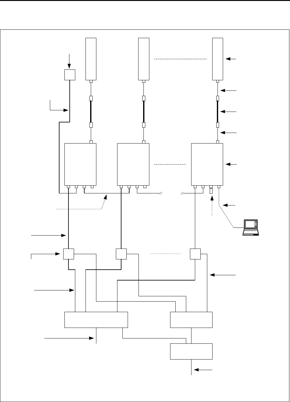
6-50 Configuring, Installing, and Using Carrier Infrastructure
Cell wiring
Figure 6.1 shows how a cell, base stations, and ancillary equipment are wired together.
Figure 6.1 Cell wiring diagram
1 2 6
Panel antenna
Coax jumper
Coax - main feed
Coax jumper
GPS unit
GPS Interface
cable
TVS
module
Backbone swtich Power supply
UPS
AC power cord
DC power cable
Base station
GPS inter-base
station cable
Ethernet/power
cable
Load
Termination
Optional serial
connection and
laptop computer
Backbone
connection cable
Ethernet
cable

6-51
Installation overview
To install a base station as a single unit:
1Attach the straight end of the antenna cable to the antenna connector on the base station
and tighten. Apply weatherproofing tape to the connector.
2If you want to install the base station and antenna as a single unit, use the antenna bracket
integral base kit (part number 123-0350-1002) to attach the necessary brackets to the base
station and antenna.
a Determine the degree of tilt you need. This determination impacts which holes on the
various brackets you will use.
b Attach the lower antenna mounting brackets to the bottom bolts on the antenna.
c Attach the other antenna mounting brackets to the base station.
d Onto the bottom of the base station, attach the other end of the bracket that was
attached to the antenna in step a.
3Attach the right-angled end of the antenna cable onto the connector on the antenna. Apply
weatherproofing tape to the connector.
4Install the base station to the tower, pole, or wall.
a If you are installing the antenna separately from the base station, hang each piece on the
tower.
b If you are using a pole to install the base station, attach the pole mounting bracket to the
back of the BTS.
5On the bottom of the base station:
• Attach the serial cable
• Attach the GPS cables
• Attach the Ethernet/power cable
6Connect to the backbone network.
7Ground the base station.
8Power the base station.
These steps are explained in greater detail in the sections that follow.
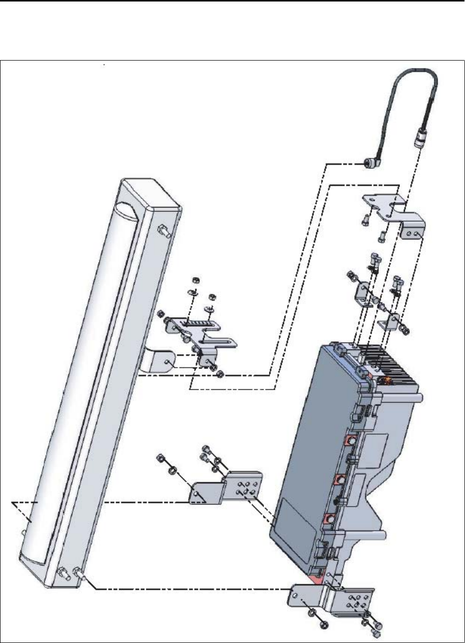
6-52 Configuring, Installing, and Using Carrier Infrastructure
Installing the antenna and base station as a single
unit
Figure 6.2 provides an overview of the assembly. Specific assembly illustrations accompany
the detailed installation steps in the sections that follow.
Figure 6.2 Overview of entire antenna-to-BTS assembly
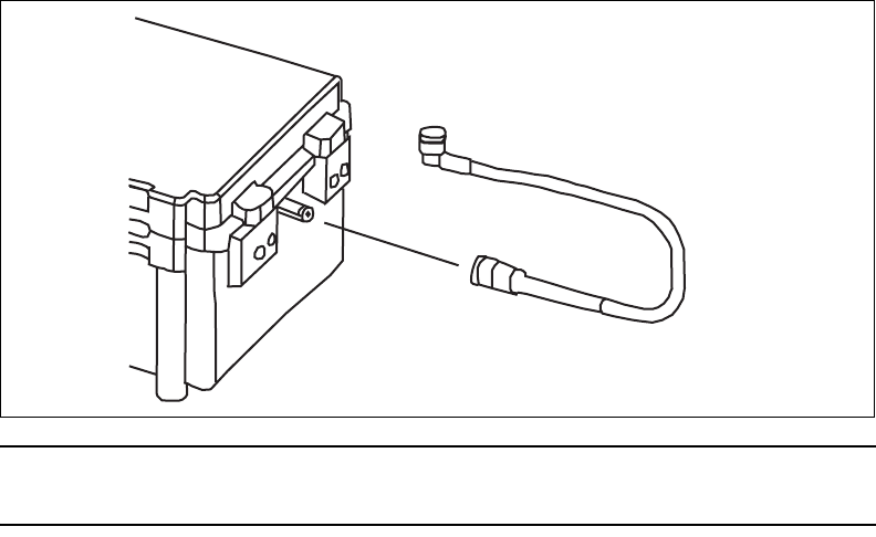
6-53
Attaching antenna cable to base station
To attach the antenna cable to the base station:
1Attach the straight end of the antenna cable to the filter on the base station.
2Apply weather proofing tape to the connector.
Note: For further information about the antenna connection, refer to “Connecting the
antenna to the base station” on page 6-73 in this chapter.
Determining the degree of tilt for the antenna
You can tilt the antenna downward or upward. To do so, you install the antenna mounting
brackets using the appropriate holes on the various brackets.
Figure 6.3 Attaching antenna cable to base station
6-54 Configuring, Installing, and Using Carrier Infrastructure
The brackets illustrated in Figure 6.4 help to alter the antenna tilt.
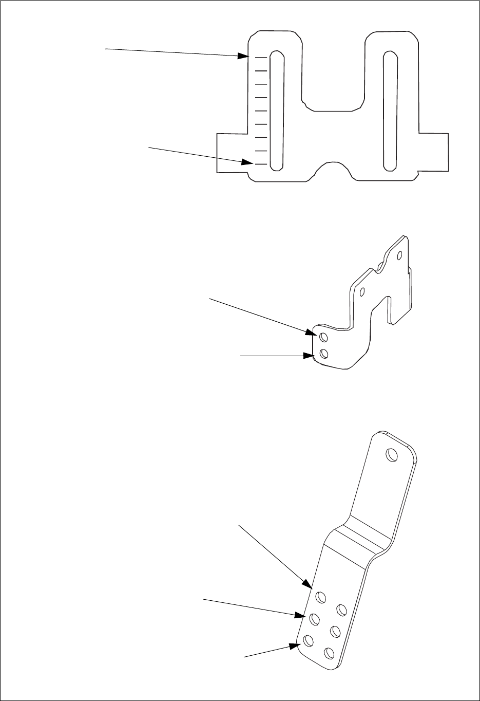
6-55
Figure 6.4 Brackets which help set antenna tilt
0 degrees downtilt (no tilt)
8 degrees downtilt
Default installation position for no tilt or downtilt
Installation position for 2 degrees uptilt
Default installation position for no tilt or downtilt
Installation position for 2 degrees uptilt
Installation position for 2 additional degrees uptilt
Also, default installation position for
uptilt
Each mark represents 1 degree tilt
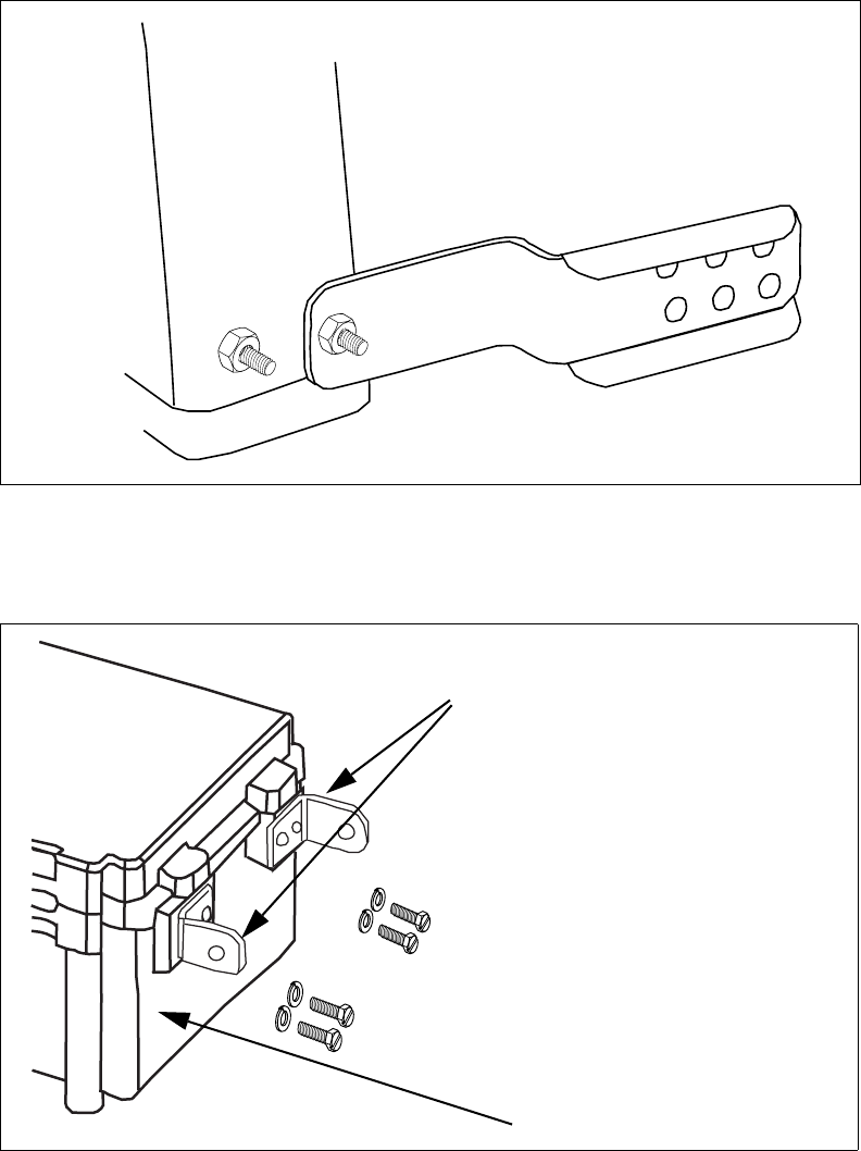
6-56 Configuring, Installing, and Using Carrier Infrastructure
Attaching lower antenna brackets to bolts on lower sides of
antenna
Attach the antenna brackets to the bolts on the left and right side of the antenna
(Figure 6.5). You must attach these brackets to the antenna bolts before attaching the
brackets to the base station.
Attach the bracket to the rear set of bolts on the antenna. The front bolts are NOT used
when installing the antenna onto the base station.
1Attach the L-shaped brackets (MP2) to the upper left and right of the base station (see
Figure 6.6). You must attach these brackets first, so that your wrench can access the
screws holding the bracket to the base station.
Figure 6.5 Bracket on antenna bolt
Figure 6.6 Attaching L-shaped brackets to base station
MP2
Top of base station
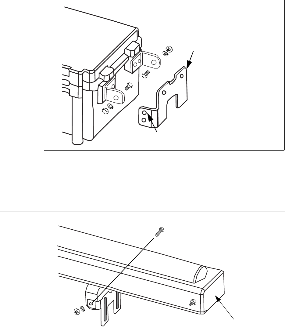
6-57
2Attach the antenna bracket (MP4) to the L-shaped bracket (see Figure 6.7) To tilt the
antenna upward by 2 degrees, use the top set of holes to attach the antenna bracket to the
L-shaped bracket.
3Attach the tilt guide bracket to the bracket on the antenna (see Figure 6.8):
a Align the holes on the side of the bracket with the holes on either side of the antenna’s
bracket.
b Insert a bolt through each hole, and tighten a nut and washer on each bolt to hold the
tilt guide bracket to the antenna.
4Attach the tilt guide bracket (MP3) to the antenna bracket.Make sure the domed-side of
the washer faces the nut.
Figure 6.7 Attaching antenna bracket to the L-shape bracket
Top holes provide 2 degrees antenna uptilt
MP4
Figure 6.8 Attaching tilt guide bracket to the bracket on the antenna
Top of antenna
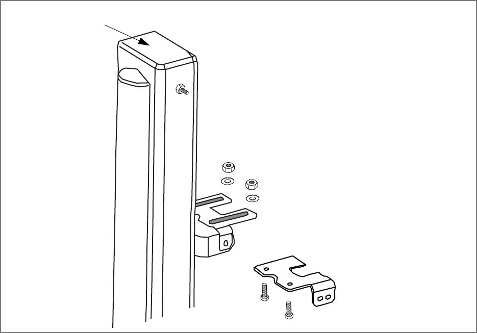
6-58 Configuring, Installing, and Using Carrier Infrastructure
Figure 6.9 Attaching tilt guide bracket to antenna bracket
Top of antenna
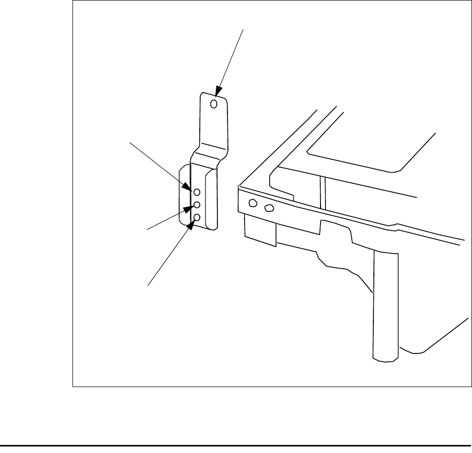
6-59
5Attach the antenna brackets to the bottom left and right sides of the base station.
If you want to tilt the antenna upward, use the middle or lower holes on the bracket.
• The second set of holes tilts the antenna 2 degrees upward.
• The third set of hole provides an additional 2 degrees of uptilt.
6Tighten all hardware.
Mounting the base station
You can mount the base station to a wall, a pole or a rack.
Mounting the base station to a wall
To mount the base station to a wall:
1Find a surface suited to base station installation.
a Use installation kit 123-0100-0130 to install the base station to a wall or back board. The
kit supplies a bracket and hardware that are necessary to mount the base station.
b Plan to install the base station vertically, so the antenna connector is at the top (facing
skyward), and the other circular connectors are at the bottom (facing the ground).
Figure 6.10 Antenna brackets on bottom left and right sides of base station
Top hole set
Middle holes
Bottom holes
2 additional degrees uptilt
2 degrees
uptilt
No tilt
Downtilt or
Top single hole for no tilt or downtilt
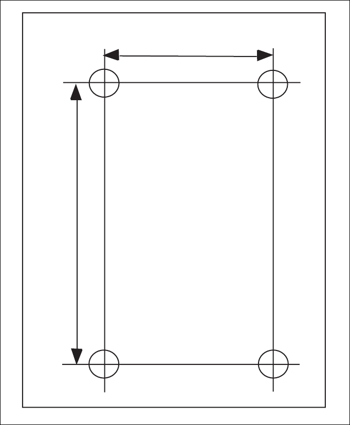
6-60 Configuring, Installing, and Using Carrier Infrastructure
c Make sure the area above and below the location where you want to install the base
station has a good distance for clearance. This clearance allows for proper air circulation
and heat flow from the heat sink fins on the back of the base station. The clearance also
allows for the coaxial cable and the other cable connections.
2Drill mounting holes into the surface, according to the dimensions shown in Figure 6.11.
3To attach the base station to a wall, use the mounting brackets. Install them on the base
station first, then attach the brackets to the wall. To attach the brackets to the base station,
use 5/16 inch x 18 inch UNC thread bolts and a lock washer which are supplied in the
installation kit. Use the optional bolts to then attach the bracket to the surface.
Mounting the base station to a pole or tower
Use the pole mounting kit (part number 123-0350-1010) to mount the BTS to a pole. Once
the BTS is installed on a pole, you can attach the pole to a tower, if desired.
Figure 6.11 Base station mounting template
10.375”
13.00"
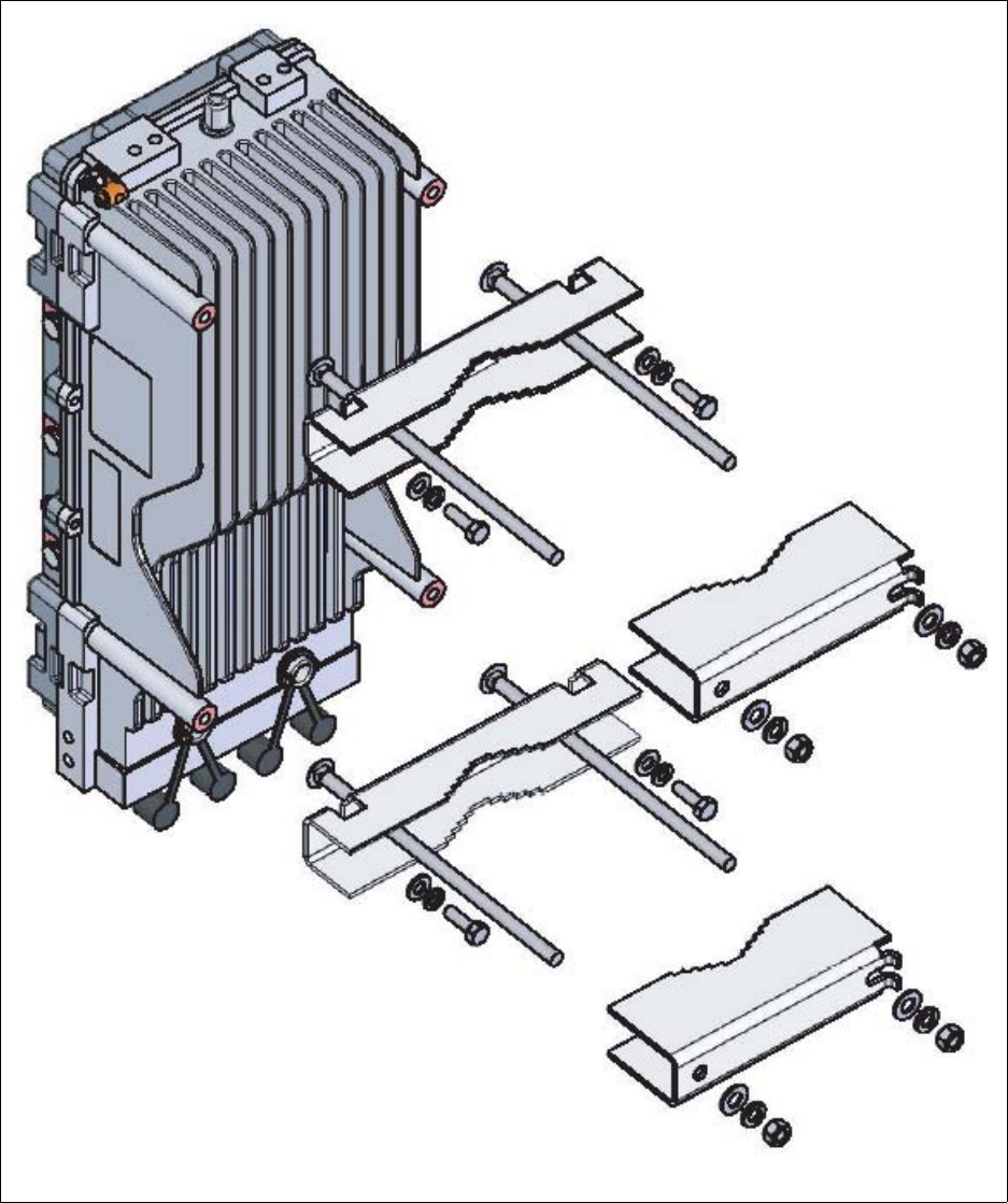
6-61
Figure 6.12 shows an overview of how to attach the BTS to the pole mounting bracket.
To mount the base station on a tower:
1Attach the pole mounting bracket to the base station and to the pole.
2Install the pole and attached base station onto the tower.
Figure 6.12 Overview of entire BTS pole mounting bracket assembly
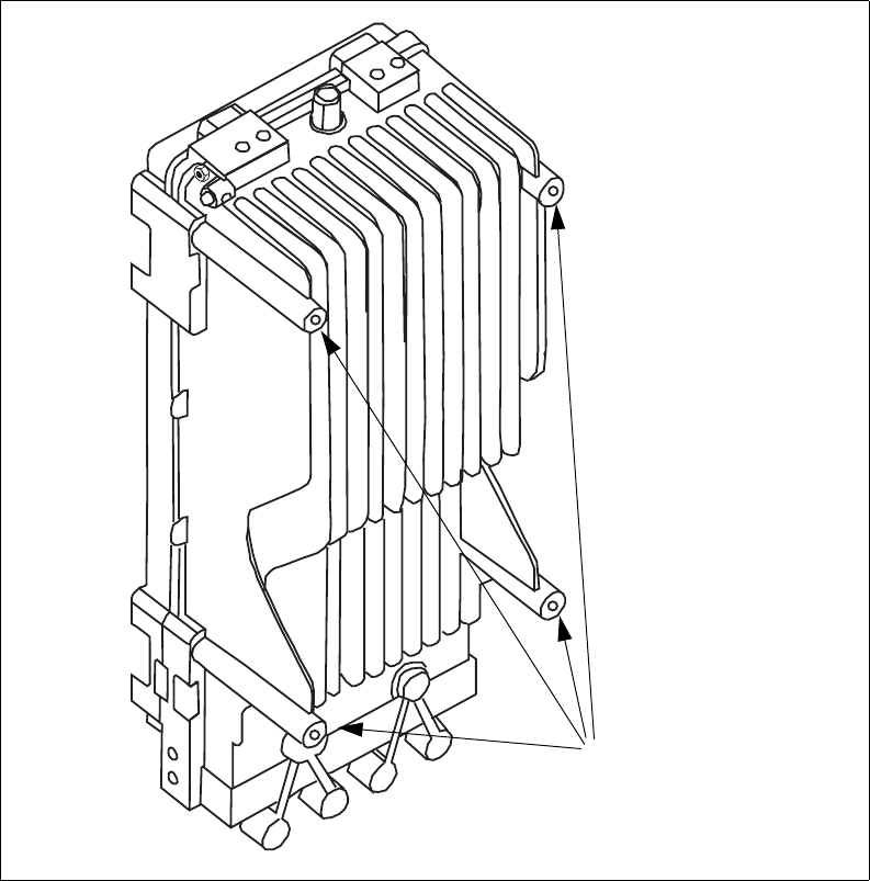
6-62 Configuring, Installing, and Using Carrier Infrastructure
Attaching mounting clamps to base station and around
pole
The pole mounting kit (part number 123-0350-1010) contains the hardware needed to mount
the base station to a pole.
• 2 front clamps (MP2)
• 2 back clamps (MP1)
• 4 threaded rods
• 4 large flat washers
• 4 small flat washers
• 4 large lock washers
• 4 small lock washers
•4 nuts
In addition to this hardware, you also use the 4 bolts that are pre-installed in the base station’s
4 legs (2 at top corners, 2 at bottom corners).
To install the pole mounting brackets to the base station and pole:
1Remove the 4 bolts that are pre-installed on the base station.
Figure 6.13 Location of bolts on the back of the base station
Remove pre-installed bolts
from 4 corners of BTS
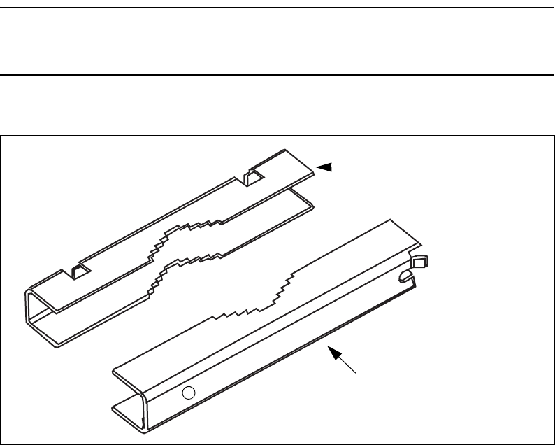
6-63
2Slip a small flat washer and small lock washer on the end of each bolt, then loosely re-
install the bolts into the 4 corners of the base station.
Note: Do NOT tighten the bolts into the base station fully. You will tighten the bolts in step
4, after you have hung the bolts, and therefore the attached base station, in the slots of the
top mounting clamp.
3Install the top mounting clamps (brackets) around the pole
a Insert the threaded rods through the MP2 clamp.
Figure 6.14 Pole mounting clamps MP2 and MP 1
MP2 clamp (front clamp,
close to base station)
MP1 clamp (back clamp)
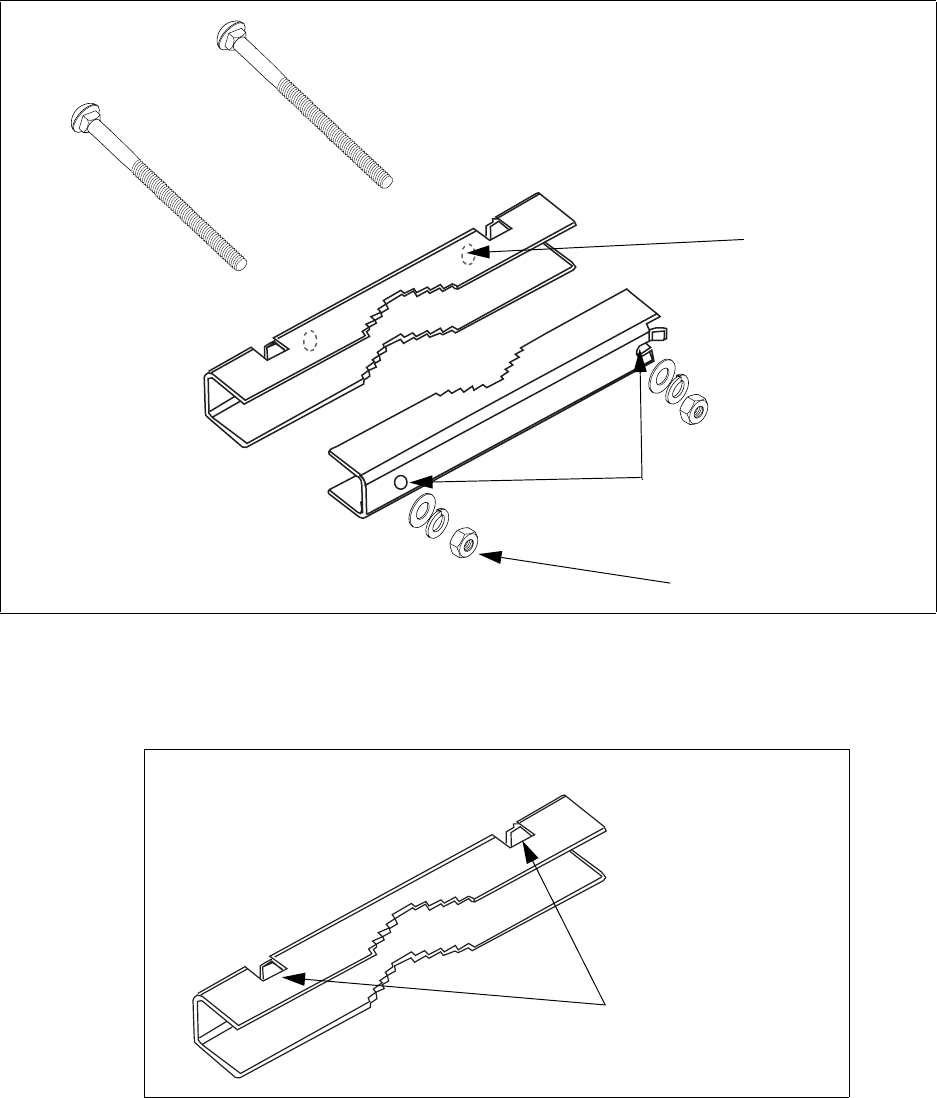
6-64 Configuring, Installing, and Using Carrier Infrastructure
b Insert the threaded end of the rod through the corresponding opening on the MP1
clamp.
c Assemble a large washer, large lock washer and nut around the threaded end of the rod.
Tighten the nut.
4Hang the base station on the TOP clamp, using the slots in the MP2 clamp.
a Make sure the flat washers, lock washers, and bolt are behind the clamp bracket.
b Tightly fasten the bolts into the base station, in order to securely hold the base station to
the bracket.
Figure 6.15 Threaded rod assembly, top clamp
Step 3a
Step 3c
Step 3b
Figure 6.16 MP2 top pole clamp, slots used to hang base station
Slots used to hang base station

6-65
5To install the bottom mounting brackets around the pole:
a Repeat steps 3a through 3c for the bottom set of clamps, threaded bolts, washers, lock
washers and nuts.
Note: To more easily shimmy the bottom bracket up the pole, fully install the left-most
threaded bolt, but leave the right most bolt loose. Once the bracket is in place, slide the bolt
through the side slot opening, then tighten the bolt using the washer, lock washer and bolt.
b To hold the base station tightly into the bottom MP2 clamp, make sure the base stations
flat washers, lock washers, and bolt are behind the clamp bracket.
c Tightly fasten the bolts into the base station, in order to securely hold the base station to
the bracket.
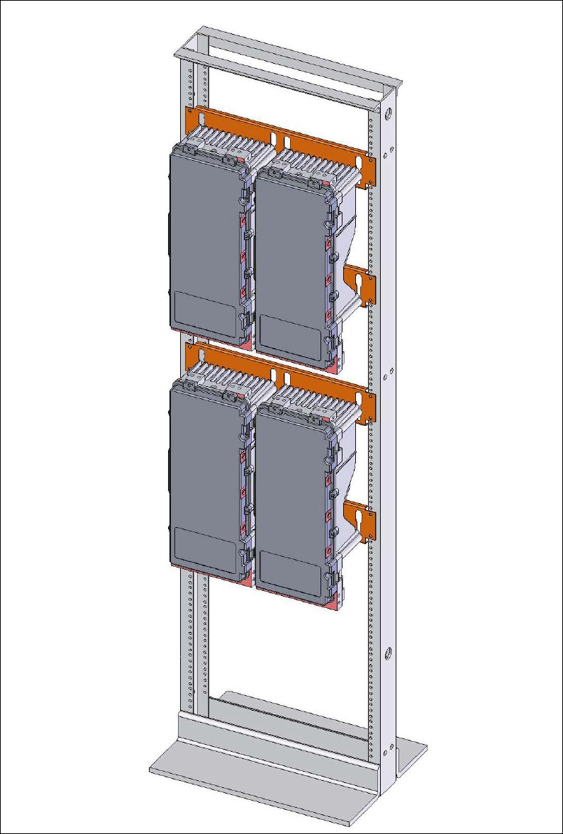
6-66 Configuring, Installing, and Using Carrier Infrastructure
Mounting the base station to a 19 inch rack
Base stations can be mounted to a 19 inch relay rack. Typically, NextNet Wireless stages this
rack for customers as a service.
After staging, the base stations are mounted in the rack and wired to the TVS modules, the
power supply, the backbone switch, and grounding plate.
Figure 6.17 Base stations installed on rack
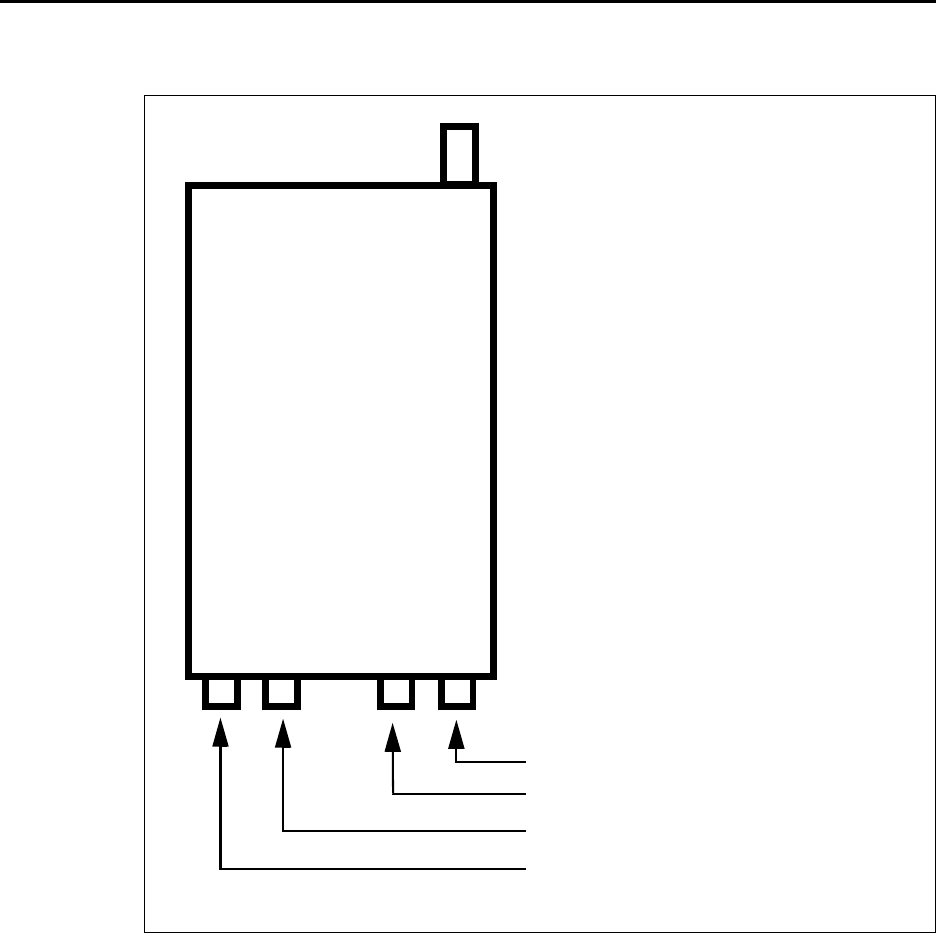
6-67
If you desire to stage your own relay rack, you must use two 19 inch brackets (part number
350-0100-0101) and at least one grounding plate (part number 30-0100-0020).
Base station connectors
Figure 6.18 shows the connectors that the base station supports.
Ethernet (data) and power connector
On the base station, the Ethernet/power connector is orange.
The Ethernet and power connector supplies data and DC power to the base station. The
connector to the TVS module has 8 pins:
• Ethernet transmit uses 2 pins.
• Ethernet receive uses 2 pins.
• Power V- uses 2 pins.
• Power V+ uses 2 pins.
Figure 6.18 Base station connectors
Antenna connector
J4—Serial connector (green)
J3—GPS connector (black)
J2—GPS connector (black)
J1—Ethernet/power connecto
r
(orange)
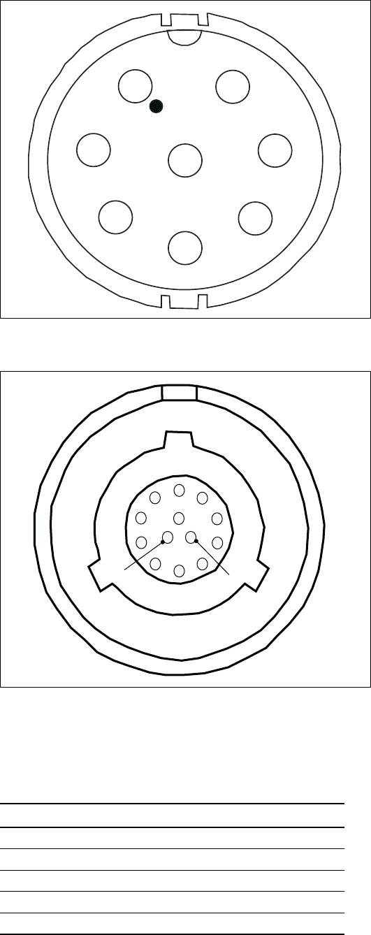
6-68 Configuring, Installing, and Using Carrier Infrastructure
Figure 6.19 shows the Ethernet and power connector which plugs into the TVS module.
The connector to the base station has 13 pins.
Ethernet/power connecting cable
Depending on your needs, you can order any of the following cables to connect the base
station to the TVS module.
Figure 6.19 Ethernet (data) and power connector
Figure 6.20 Ethernet (data) and power connector
Table 6.1 Ethernet/power base station cable choices
Cable part number Length (feet)
597-6027-0002 2
597-6027-0004 4
597-6027-0006 6
597-6027-0010 10
597-6027-0025 25
8
1
2
3
4
5
6
7
1
2
3
4
5
6
7
8
9
10
11
12
13

6-69
Table 6.2 describes the pins of the Ethernet/power cable that connects the base station to the
TVS device.
Table 6.3 describes the color and function of the wires in cable 597-6027-0xxx.
TVS module connectors
The TVS module has connectors on both its right and left sides.
597-6027-0050 50
597-6027-0100 100
597-6027-0200 200
597-6027-0300 300
Table 6.2 Ethernet/power cable pins
Pin TVS connection Base connection
1 Tx+ -48 VDC
2 Tx- -48 VDC
3 Rx+ +48 VDC
4 Rx- +48 VDC
5+48 VDC Rx-
6+48 VDC Rx+
7 -48 VDC not used
8 -48 VDC not used
9Tx-
10 Tx+
11 not used
12 not used
13 not used
Table 6.3 Function of wires in cable 597-6027-0xxx
Wire color Wire function
White/orange Tx+ Ethernet
Orange Tx- Ethernet
White/green Rx+ Ethernet
Green Rx- Ethernet
Red +48 VDC
Red/white +48 VDC
Black -48 VDC
Black/white -48 VDC
Table 6.1 Ethernet/power base station cable choices
Cable part number Length (feet)
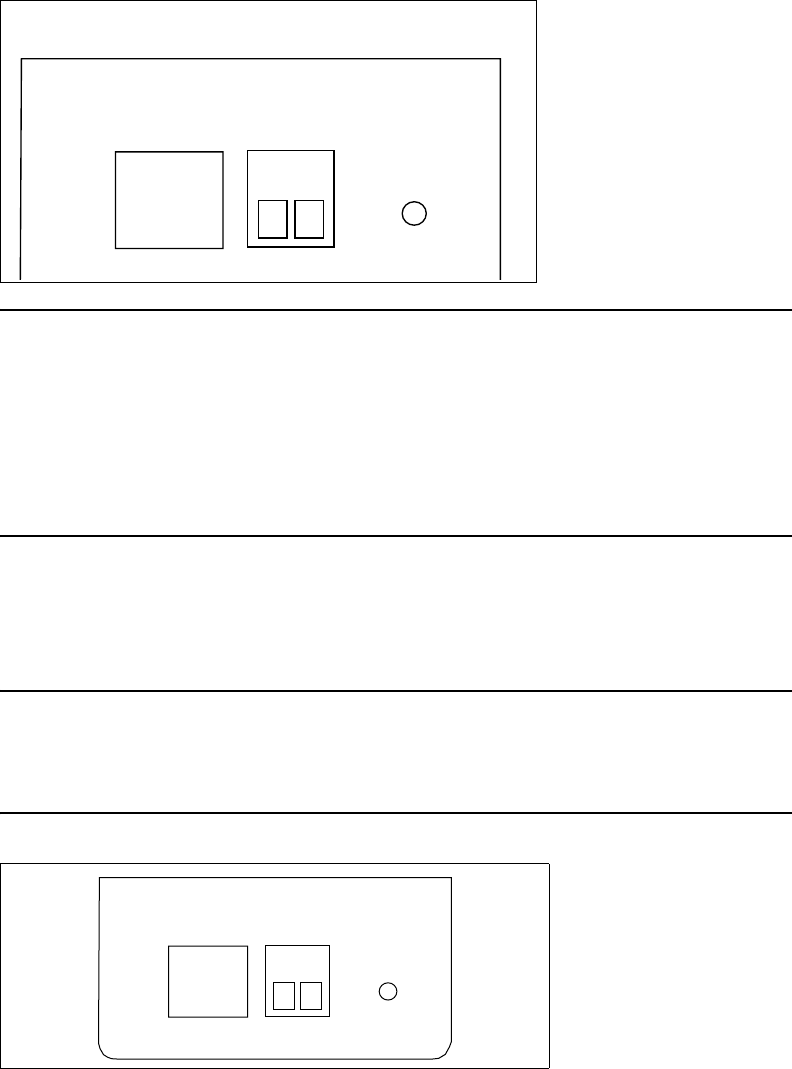
6-70 Configuring, Installing, and Using Carrier Infrastructure
Base station to TVS connector
The base station connector supplies power and an Ethernet connection to the base station.
Connect cable 597-6027-0xxx to this side of the TVS module.
Note: Use the AUX +48 VDC and AUX ETHERNET connections only if you need to cut
off the circular connector from the power/Ethernet cable (597-6013-0xxx). For example, you
might not be able to use the circular connector if it cannot fit through a space or hole in a wall
at the installation site. Instead, you may split the cable and put a 4 position .150" spaced
terminal block on the Ethernet wires, and a 4 position .200" spaced terminal block on the
power wires. Then, you will plug the appropriate connector from the split cable into the
corresponding connector in the TVS module. Table 6.3, “Function of wires in cable 597-
6027-0xxx” on page 6-69 describes the wires in the cable.
Power supply cable and ISP Ethernet network connector
The other side of the module has a connector for both an Ethernet cable coming from your
ISP network and for the +48 VDC power coming from a power supply.
Note: To ensure your base station is properly protected from possible lightning strikes,
ensure you plug the power cable coming from your power supply into this connector in the
TVS module. If you plug the power cable into the base station connector side, the base
station will power up, but you will not be properly protected against possible lightning strikes.
Connecting power cable to green TVS module connector
To connect the power cable to the TVS module:
1Cut the power cable to the desired length.
2Insert the wires into the appropriate opening on the green TVS module connector.
Figure 6.21 TVS module connector: Base station connector
Figure 6.22 TVS module connector: power/Ethernet connector
+48 VDC
POWER
ISP
ETHERNET
+-
+48 VDC
POWER
ISP
ETHERNET
+-
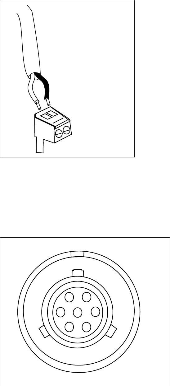
6-71
3Screw down the wires using the screws on the top of the connector.
GPS connectors
On the base station, the GPS connectors are black.
The base station supports two GPS connectors: one connector is used to supply the GPS
signal, either by a direct connection to the GPS device, or by a daisy chain connection to
another base station in the cell. The other GPS connector is used to make a daisy-chain
connection from the current base station to the next base station.
An RS-422 line feeds 1PPS+ and 1PPS- with the time synchronization pulse from the GPS
equipment to the base station.
Figure 6.23 Connecting power cable to TVS module
Figure 6.24 GPS connector
A
B
C
D
EG
F

6-72 Configuring, Installing, and Using Carrier Infrastructure
An RS-422 line also feeds 422Data+ and 422Data-, to allow data communication from the
GPS device to the base station. This is one-way communication, with the GPS device giving
the base station time information.
The 18V+ and ground pin supply power to the GPS device from the base station. The GPS
device uses 18 volts DC at 150 milliamperes.
Note: If you move the GPS receiver after supplying power to the GPS, you must reconfigure
the receiver using the Trimble synchronization kit.
GPS connecting cable/Inter-base station connecting
cables
You need one GPS device per cell. You then directly connect one base station within that cell
to the GPS device. Next, the other base stations are connected to each other, using a daisy
chain wiring scheme, so that all base stations in the cell can receive a GPS signal.
You can choose the length of the cable that connects the base station to the GPS receiver.
You can also choose the length of the daisy-chain cable that connects one base station to
another base station.
• If you need to remove a base station for service, you can a longer cable to jumper the GPS
cables together, and continue cell operation.
The last base station in the daisy chain requires a load termination to be connected to the
GPS connection. This base terminator plug is 100 ohm (part number 515-6005-0001).
Serial interface connector
On the base station, the serial interface connector is green.
Table 6.4 GPS kits and cables
GPS kit part number Length of GPS cable
250-0150-0200 GPS system 200’
250-0150-0100 GPS system 100’
250-0150-0050 GPS system 50’
250-0150-0025 GPS system 25’
250-0150-0010 GPS system 10’
NOTE: The GPS kits listed in this table are for use with AMOD BTSs.
Table 6.5 Daisy chain cable choices
Part number Cable length
597-6026-0200 200 ft
597-6026-0100 100 ft
597-6026-0050 50 ft
597-6026-0025 25 ft
597-6026-0010 10 ft
597-6026-0004 4 ft
NOTE: The daisy chain cables listed in this table are for BTSs with the AMOD
feature.
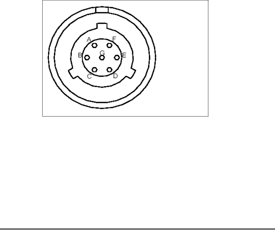
6-73
For base station configuration, the serial interface connector lets you directly connect the
base station to a computer. The seven-pin connector is an RS-232 cable (10 ft.), physical
interface.
Serial interface connecting cable
Cable 597-6028-0010 has a female, circular connector on one end, and a DB-9 female
connector on the other end. Plug the DB-9 end of the cable into a computer. Plug the other
end of the cable into the serial interface connector.
Antenna connector
The antenna connector is a type N female connector. It has a built-in, internal 1/4 wave
lightning protector. Connect the base station to the antenna using a coaxial cable. Connect
the proper lightning ground wiring to the antenna lightning protector.
Connecting the antenna to the base station
This section provides tips you can use to connect the antenna to the base station for
installations where the antenna is not mechanically mounted to the Integrated Base Station
It also provides step-by-step instructions for connecting the components to each other.
Antenna connection tips
Use the following tips when connecting the base station to the antenna:
• You connect the antenna to the base station using a coaxial cable. The size of the cable
depends on the distance between the base station and the antenna.
• The greater the distance, the larger your coaxial cable needs to be, in order to maintain
low signal loss.
• It is recommended that you keep signal loss to a minimum. At a maximum, the signal
loss should be no more than 2 dB, including all coaxial cable and connectors.
• Use short coaxial jumpers from the base station to the main coaxial line, and from the
main coaxial line to the antenna. It is recommended you use 1/2 inch flexible line, of the
shortest length possible, while still allowing the flexibility to make a good connection.
Figure 6.25 Serial interface connector
A Ground
B Not used
C Not used
D Not used
E Tx data
F Rx data
G Not used

6-74 Configuring, Installing, and Using Carrier Infrastructure
• The base station contains an antenna connector with a 1/4 wave lightning protector. You
do not need to place an external lightning protector in the coaxial cable.
Connecting the antenna to the base station
To attach the antenna to the base station:
1Mount the antenna according to the manufacturer’s instructions.
2Connect one end of a short coaxial jumper to the antenna. Connect the other jumper end
to the main coaxial cable.
3On the base station’s antenna connector, connect one end of a short coaxial jumper.
Connect the other jumper end to the main coaxial cable coming from the antenna.
4Make sure the coaxial line is properly grounded.
5Properly seal the co-axial connections with weatherproof components, tape and wrap.
Connecting the GPS equipment to a base station
The GPS equipment provides a time synchronization signal to the base station. This signal is
needed to ascertain the proper timing for time division duplexing (TDD).
The equipment is a smart antenna in a sealed, shielded, self-contained unit that houses a GPS
receiver, GPS antenna, and interface circuitry.
When powered, the GPS provides accurate time, with a time pulse of one pulse per second,
synchronized to Universal Time, Coordinated (UTC) within 150 nanoseconds.
For information about which GPS kit to use when installing and connecting the GPS, refer to
Table 6.4 and Table 6.5.
GPS equipment mounting tips
You must use the NextNet Wireless supplied GPS system to supply a time synchronization
signal to the base stations in a cell. You cannot use a GPS from another manufacturer.
The GPS does not ship with mounting accessories. You can obtain these accessories from
many suppliers around the world, especially distributors of marine products.
Follow these tips when mounting the GPS:
• Mount the GPS unit on a threaded pipe or pole.
• The GPS mounting socket accepts a 1.0000 x 14 straight thread. It is recommended that
the pole/pipe you use be 1.000 inch.
• Secure the pipe or pole to the building or other support structure.
• Ensure at least half of the sky is clearly visible to the unit.
• Expose the unit to the southern portion of the sky. In the northern hemisphere, GPS
satellites move generally from the southwest to the northeast.
• Mount the GPS away from potential interference sources.
Connecting the GPS unit to the base station
One GPS unit can support numerous base stations in the same cell.

6-75
Use the GPS-to-base station cable to attach the GPS unit to one of the base stations in the
cell.
To connect the cable to the GPS unit and to the base station (both of which have already
been installed and mounted):
1Connect the cable’s molded, circular female connector to the GPS unit.
2After connecting the cable to the GPS unit, run the cable to the base station. Plug the
cable’s other end into the base station’s GPS connector.
3Secure the cable that you just ran to an appropriate support structure. Coil and tie any
excess cable.
4The GPS unit receives its power from the base station. The base station supplies power to
the GPS device, which uses 18 volts DC at 150 milliamperes.
5So that the remaining base stations in the cell can receive a GPS signal, connect a base
station adjacent to the base station you just connected to the GPS unit. For more
information about cables that you can use, refer to Table 6.5.
Continue to use the daisy chain wiring scheme to connect the remaining base stations, until
all of the base stations within the cell are connected to each other.
On the last base station in the daisy chain, connect the load termination on the open GPS
connection.
Connecting to the backbone network
The base station connects to a TVS module. You then connect the TVS module to your
network. Typically, base stations connect to a level 2 switch at the cell site, using a 10BaseT
connection. The switch controls the base station data traffic to and from the backbone
network.
Connect the switch to the backhaul network using the appropriate cabling.
Grounding base stations
The grounding location differs depending on the type of base station you are using.
• Base stations with the ability to change their modulation method (AMOD base stations)
have a ground lug located at the top right corner.
• Base stations without the ability to change their modulation method have a grounding
connection at the base of the antenna connection.
To ground either type of base station, run a 6-gauge or larger grounding wire from this
connection to the ground bar on the rack, to the building’s ground connection on the roof, or
to the grounding location at the tower.
The ground to which you connect the base station should be 6 ohms or less to ground.
The 48 volt power input to the base station is floating, so either the positive or negative can
be grounded.
Powering base stations
This section describes tips for powering base stations, as well as the component connection
sequence you need to use to properly power base stations.
6-76 Configuring, Installing, and Using Carrier Infrastructure
Powering tips
• It is recommended that you use a redundant power supply for base stations.
• Each base station requires 48 volts DC at 3.0 amps maximum.
• The ground of the power can be either negative or positive. The 48 volt power input to the
base station is floating, so either the positive or negative can be grounded.
• Power input is polarity sensitive, so be sure you connect V+ and V- properly.
• Depending on the type of equipment you own, supply power to the Ethernet switch and
backbone network equipment.
• It is recommended that you use an uninterruptable power supply (UPS).
Tips for sizing the UPS include:
• Size the voltage and amperage of the power supply according to the number of base
stations at your cell site.
• Size the UPS according to the efficiency of the DC power supplies and power
requirements of the other ancillary equipment, such as the Ethernet switch and
backbone network equipment.
• Consider the time you want to allow the system to operate on the UPS.
Powering the base station
The base station does not have a power switch. Rather, it receives its power when the UPS,
power supply, and TVS module are connected to the base station through the Ethernet/
power cable.
To connect the base station to a power supply, connect these components in the order that
follows:
1Connect the base station to the antenna.
2Connect the GPS to a base station, and use a daisy chain wiring scheme to connect the
other base stations.
3Connect the base station to the TVS module using the Ethernet/power cable of the
desired length.
4Use an Ethernet cable to connect the TVS module to the network. Use a standard DC
power cable to connect the TVS module to the power supply.
5Connect the power supply to the UPS.
6Connect the UPS to an AC power supply.

7-77
CHAPTER
7
INSTALLING THE RACKMOUNT BASE
STATION (RMB)
Chapter overview
This chapter describes how to install the rackmount base station (RMB). It describes:
• Installing the cabinet onto a 19 inch rack
• Installing the power supply and switch
• Installing the RMB into the base station cabinet
• Connecting the RMBs to the cell and to cell-site components
Before you begin
Before you install RMBs:
• It is recommended that you assign a name to the RMB. For more information refer to
Chapter 4, “Configuring base stations” in this guide.
• It is a good idea to configure the base station with channel, VLAN, power, and other
parameters, as described in Chapter 4, “Configuring base stations” in this guide.
• It is a good idea to limit access to the room where the RMBs are installed.

7-78 Configuring, Installing, and Using Carrier Infrastructure
Installation overview
This section provides an overview of the tasks you will perform when installing RMBs.
To install the RMBs:
1Install the mounting brackets to the cabinet, then attach the cabinet to the 19" rack.
Note: Do not operate the system before you have securely mounted the cabinet to a standard
19" rack that can handle the weight of the total system. To calculate the weight of your
system, note that the cabinet housing weighs 43 pounds, each base station weighs 18 pounds,
and each filter weighs 3.5 pounds.
So, if you have one cabinet, one RMB, and one filter, the weight of the total system is 64.5
pounds. Adjust this figure according to the number of RMBs and filters that you are using.
Also, remember to factor in the weight of any switches, power supplies, or similiar items that
you might want to attach to the rack.
2Attach the power supply and switch to the rack.
3Insert the pre-configured RMBs into the cabinet.
4Connect the cabinet to the following components:
•Switch
•Power supply
• Antennas or antenna filters, if filters are required.
•GPS
5Follow your company’s good grounding practices. Typically, you will ground the cabinet
bus bar and the power supply.
6Power on the base stations.
For further information about these tasks, refer to the sections in this chapter.
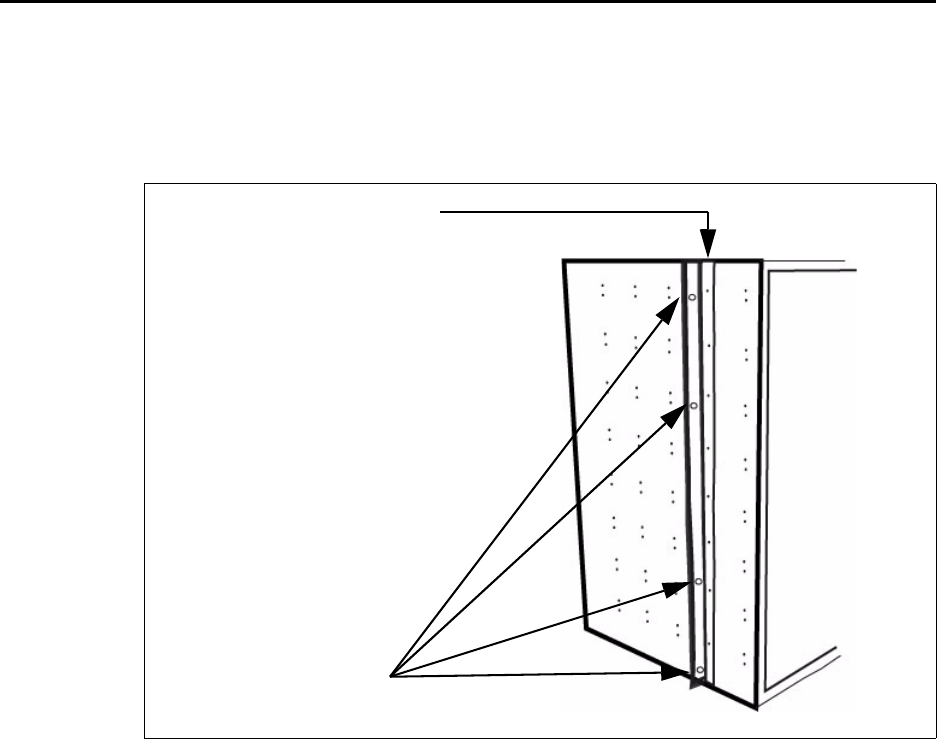
7-79
Installing the mounting bracket and attaching
cabinet to the 19-inch rack
Before inserting RMBs into the cabinet, attach the cabinet to the rack. To attach the cabinet
to the rack:
1Attach a mounting bracket to the left side and right side of the cabinet using the 16
supplied screws (8 per side).
2Attach the cabinet to the rack with the 8 supplied screws, 4 for each side.
Figure 7.1 Cabinet mounting bracket
Step 2: Attach to rack.
Step 1: Attach to cabinet.
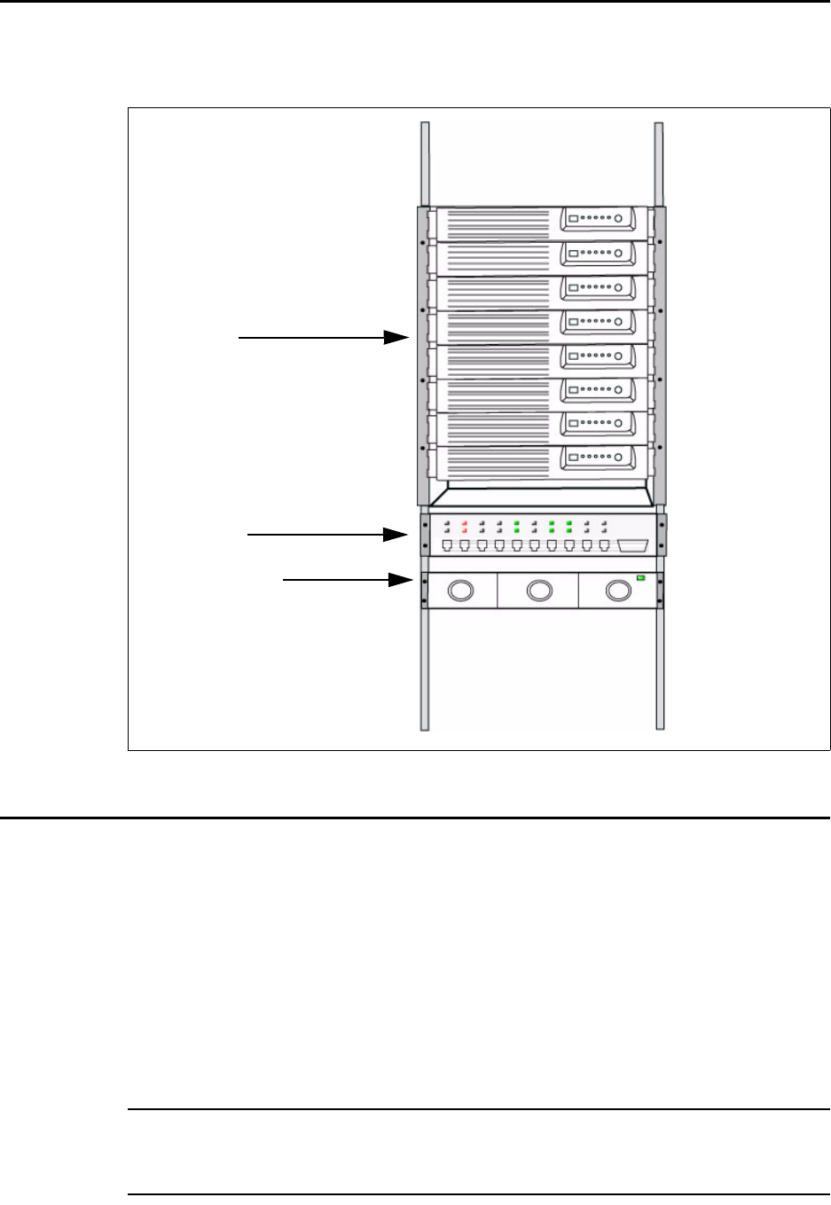
7-80 Configuring, Installing, and Using Carrier Infrastructure
Attaching the switch and power supply to the rack
Figure 7.2 shows where the switch and power supply should be installed on the rack, in
relation to the cabinet and RMBs.
Installing the RMBs into the cabinet
To install the RMB in the cabinet:
1Grasp the RMB by handles on each side of the RMB.
2Slide the RMB into the cabinet, aligning the guides along the side of the RMB with the
gliders inside the cabinet.
To ensure you align the RMB properly into the pre-installed harness connections, there is a
guide pin on the back of the cabinet that fits into a guide pin opening on the back of the
RMB. This guide pin will help the connectors on the back to align correctly.
3When the RMB is properly installed and aligned in the cabinet, the plastic latches on the
side of the front plate snap into place.
Note: Always make sure the RMB is slid greater than halfway into the cabinet. An RMB that
is not at least halfway installed in the cabinet could fall out of the cabinet or could cause
damage to the tracks.
Figure 7.2 Location of switch and power supply in rack
RMBs
Power supply
Switch

7-81
Connecting RMBs to cell (cell wiring)
There are minimal wiring tasks for you to perform, as the RMB simply slides into the pre-
existing wiring when you place the RMB in the cabinet.
The cabinet into which the RMB is installed has a pre-wired harness. This harness supplies
power and Ethernet connectivity to the RMB. After you connect the antenna to the
appropriate connector, the RMB also receives airlink traffic. Finally, the harness supplies an
alarm capability to the RMB, as well as a GPS signal.
Note: Make sure you have made all antenna connections before attempting to transmit. Do
not attempt to transmit before the antennas are connected.
Note: In earthquake zones, consider additional methods for securing the base stations in the
rack.
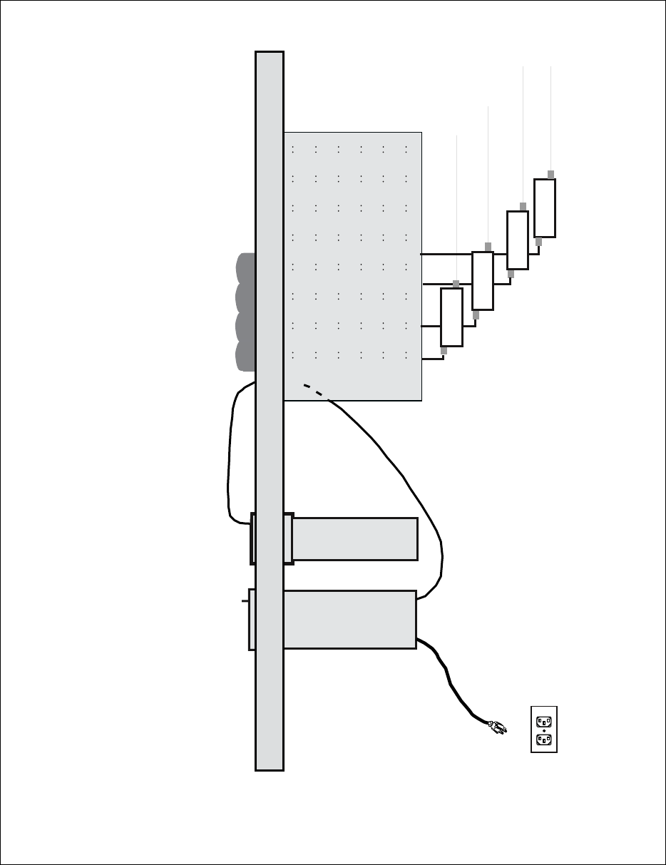
7-82 Configuring, Installing, and Using Carrier Infrastructure
Figure 7.3 shows how a cell, 4 RMBs, and ancillary equipment are wired together.
Figure 7.3 Cell wiring diagram
Switch
Power supply
Channel filters
To antennas
Ethernet cables
Cabinet mounted
base radios (if required)
AC power
Power cables

7-83
Connecting power to the RMBs
This section describes how to supply power to RMBs in the cabinet, as well as
recommendations for the type of power supply to use.
When choosing a power supply, keep in mind:
• Each base station requires 150 watts at 48 volts. So, if your cabinet holds 8 RMBs, the
power supply should provide 1250 watts, at a minimum.
• The power supply you choose should use an “n + 1” configuration, so that the RMBs have
a backup power source in case one of the power supply modules fails.
Powering the base station
To connect the base station to a power supply, connect these components in the order that
follows:
1Connect the RMB to the antenna.
2If you are using a GPS to supply a timing pulse to the base stations, connect the GPS to
the GPS connector on the cabinet. Place a terminal plug on the other GPS connector on
the cabinet.
Note: If you are using an RMB to supply the timing pulse to the other RMBs, set up the base
station as described in the section “Configuring the time signal used by base stations.” The
cable harness in the cabinet then supplies the other RMBs in the cabinet with timing
information.
3Connect the Ethernet cable to the switch.
4Connect the cabinet to the power supply.
5Connect the power supply to the UPS, if a UPS is available.
6Connect the power supply and the UPS to an AC power supply.
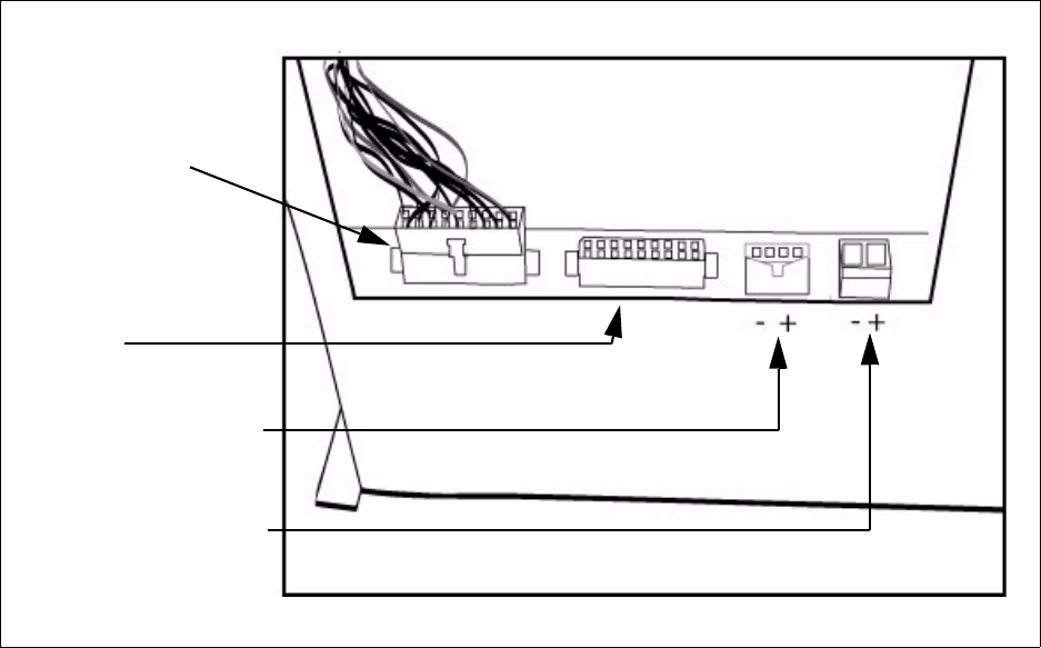
7-84 Configuring, Installing, and Using Carrier Infrastructure
Figure 7.4 shows the location of the power connection on the bottom of the cabinet.
To connect power:
1Perform one of the following:
• If you are using a power supply from or recommended by Nextnet Wireless, plug that
connector into the NextNet Wireless supplied power connector on the bottom of the
cabinet. The NextNet Wireless recommended power supply is part number 420-0160-
0048.
• If you are using a different power supply, connect it to the 50-amp power connector,
found on the bottom of the cabinet.
2If desired, connect a battery backup power supply to the battery backup connector.
Powering tips
• It is recommended that you use a redundant power supply for base stations.
• Each base station requires 150 watts of power at 48 volts.
• The ground of the power can be either negative or positive. The 48 volt power input to the
base station is floating, so either the positive or negative can be grounded.
• Power input is polarity sensitive, so be sure you connect V+ and V- properly.
• Depending on the type of equipment you own, supply power to the Ethernet switch and
backbone network equipment.
• It is recommended that you use an uninterruptable power supply (UPS).
Tips for sizing the UPS include:
• Size the voltage and amperage of the power supply according to the number of base
stations at your cell site.
Figure 7.4 Power connections on bottom of cabinet
50 Amp power connector
(optional, for customer-
provided power supply)
30 Amp battery backup
connector
NextNet Wireless
preferred power supply
connector
DO NOT
DISCONNECT.
Pre-wired power
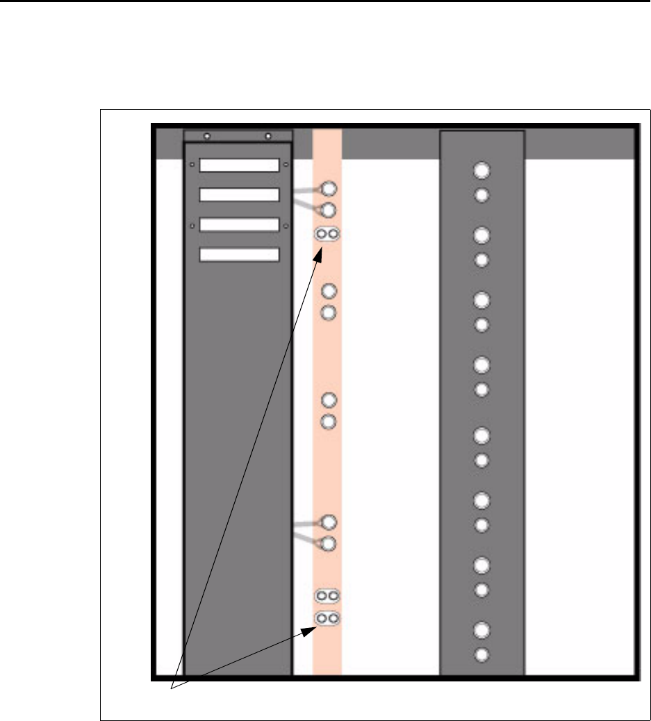
7-85
• Size the UPS according to the efficiency of the DC power supplies and power
requirements of the other ancillary equipment, such as the Ethernet switch and
backbone network equipment.
• Consider the time you want to allow the system to operate on the UPS battery power.
Grounding the RMBs
There is one grounding bar in each cabinet. Each bank of 4 RMBs are grounded to the bar.
The grounding bar also contains locations for grounding terminals so that you can ground the
RMBs to your building’s ground bar.
Figure 7.5 Grounding the RMBs
Grounding lugs
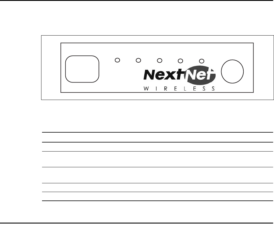
7-86 Configuring, Installing, and Using Carrier Infrastructure
Turning on the RMB’s power
The front panel of the RMB has a programming (diagnostics) cable connection, 5 light-
emitting diodes, and a power button. Figure 7.6 shows the front panel of the RMB.
To turn on the RMB, press the power button. The LEDs then light. Table 7.1 describes what
the base station LEDs indicate.
Base station connectors
This section describes the GPS connectors and the serial cable connectors. The serial cable is
used to configure the base station with information that is unique to the carrier.
Figure 7.6 RMB LEDs
Table 7.1 Description of LEDs on the base station
LED Description
(PWR) When this green LED is lit, the RMB has power.
(NET) When this yellow LED is lit and blinking, information is being received on the
RMB’s Ethernet port.
(PPS) A blinking LED indicates that the RMB is receiving the 1 pulse per second
signal.
(AIR) When this LED is lit, the airlink on the RMB is operating.
(ALM) When this red LED is lit, an alarm on the RMB has been triggered.
POWERALMAIRPPSNETPWRDIAGNOSTICS
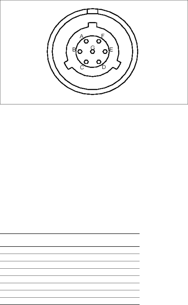
7-87
GPS connectors
Figure 7.7 shows the GPS connectors that the base station supports.
An RS-422 line feeds 1PPS+ and 1PPS- with the time synchronization pulse from the GPS
equipment to the base station.
An RS-422 line also feeds 422Data+ and 422Data-, to allow data communication from the
GPS device to the base station. This is one-way communication, with the GPS device giving
the base station time information.
The 18V+ and ground pin supply power to the GPS device from the base station. The GPS
device uses 18 volts DC at 150 milliamperes.
GPS connecting cable/Inter-base station connecting
cables
A single GPS device can support up to 8 base stations. You directly connect one GPS
connector on the cabinet to the GPS device. Then, on the remaining GPS connector on the
cabinet, you connect the load termination.
Power supply cable connections
Table 7.2 describes the pins of the power cable used with the RMB.
Figure 7.7 GPS connector
Table 7.2 Power cable pins
Pin number American wire
gauge (AWG) Color
Pin 1 18 AWG Black
Pin 2 18 AWG Black
Pin 3
Pin 4 18 AWG Black
Pin 5 18 AWG Black
Pin 6
Pin 7 18 AWG Black
Pin 8 18 AWG Black
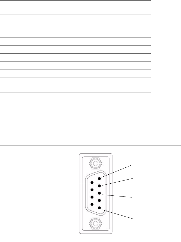
7-88 Configuring, Installing, and Using Carrier Infrastructure
Diagnostic cable DB9 connector pins
To configure the RMBs, use a standard, straight-through cable. Connect one end of the cable
to the DB9 cable connector. The DB9 cable connector is supplied with the base station
Figure 7.8 describes the cable’s pins.
Fuses and Ethernet cable connections on cabinet
Each RMB has a corresponding fuse and Ethernet cable connection on the cabinet. The
RMB that occupies the lowest position in the cabinet is number 1, and the RMB that occupies
the highest point in the cabinet is number 8.
Pin 9 22 AWG White
Pin 10 22 AWG Green
Pin 11 18 AWG Red
Pin 12 18 AWG Red
Pin 13
Pin 14 18 AWG Red
Pin 15 18 AWG Red
Pin 16
Pin 17 18 AWG Red
Pin 18 18 AWG Red
Table 7.2 Power cable pins
Pin number American wire
gauge (AWG) Color
Figure 7.8 Diagnostic cable: DB9 connector pins
Yellow/RXD
Green/TXD
Red/GND
Pin 1
Pin 6
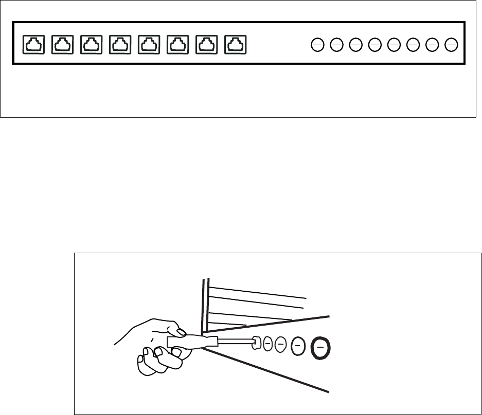
7-89
Figure 7.9 illustrates the Ethernet cable and fuses that correspond to each RMB.
Checking and replacing fuses
The system uses a standard fuse, AG3, 5 amps, 250 volts.
To remove a fuse from the cabinet:
1Insert a flat head screw driver into the slot on the front of the gray fuse case.
2Press in and turn the screw driver counter-clockwise about 1/8th of a turn, until the fuse
case pops out of the slot.
3The fuse slides out of the back of the case.
Figure 7.9 Fuses and Ethernet cable connections on cabinet
1......................8 1..............8
Figure 7.10 Removing fuse from cabinet
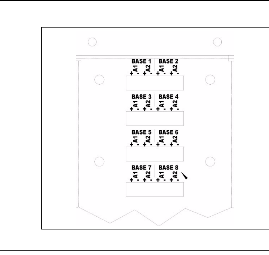
7-90 Configuring, Installing, and Using Carrier Infrastructure
Wiring alarms for RMBs
Figure 7.11 shows the alarm connections on the cabinet.
Connecting to the backbone network
Typically, base stations connect to a level 2 switch, which is also installed on the rack. The
switch controls the base station data traffic to and from the backbone network.
Connect the switch to the backhaul network using the appropriate cabling.
Figure 7.11 External alarm connections
7-91

7-92 Configuring, Installing, and Using Carrier Infrastructure

8-93
CHAPTER
8
TESTING AND MANAGING THE NETWORK
Chapter overview
This chapter describes how to test the network before the network is used by ISPs. The
chapter also provides an overview of network management tasks.
Testing the setup overview
This section provides an overview of the steps that help network access providers test the
setup of the network before the network is rolled out.
To test the network setup:
1Install and configure the AP server, as described in this guide.
2Install and configure the base station, as described in this guide.
3Power the base station, as described in this guide.
4Work with the ISP to install the ISP’s provisioning server
5Test the connection between the AP server and the ISP provisioning server.
6Ensure that CPEs can access the ISP’s VLAN.
Steps 4 through 6 are described in the sections that follow.
Installing the ISP’s provisioning server
The provisioning server on the ISP VLAN contains a record for each CPE used by the ISP’s
subscribers.
The ISP is responsible for installing and configuring the provisioning server, and for adding
CPE records to the CPE database on the provisioning server.
For information about installing and using the provisioning server, refer to the guide,
“Configuring and monitoring the ISP network.”
As a network access provider, you must work closely with the ISP to ensure the server is set
up correctly and is operating with the network access provider’s control VLAN.

8-94 Configuring, Installing, and Using Carrier Infrastructure
Testing the connection between the AP server and the
provisioning server
To make sure that the AP server and the provisioning server are communicating:
1On the provisioning server, open the home page of the provisioning server interface.
For more information about the provisioning server, refer to Chapter 2, “Working with
the provisioning server” in the guide “Configuring and monitoring the ISP network.”
2On the home page, check the Access Provider Connection group. The Status field shows
if the provisioning server and the AP server are connected.
3To refresh the status, click the Refresh Status link.
Ensuring CPE access to ISP VLAN
Use an indoor CPE to test CPE access to the ISP’s VLAN.
To ensure that CPEs can access the ISP VLAN:
1Make sure the ISP has integrated their customer relationship management (CRM)
application with the provisioning server and the server’s CPE database. Use the CRM
application to add a CPE to the CPE database on the provisioning server.
2Install and power up the indoor CPE as described in the guide “Expedience Broadband
Wireless Access Modem”. This guide describes how to set up the CPE and scan for
service. During installation, the CPE attempts to register with the base station on which
you are performing the test.
3If the AP server recognizes the base station’s zone (as defined in the section “set system
location” on page 5-39) the AP server forwards the request to the proper ISP, that is the
ISP that is being tested.
4The ISP’s provisioning server recognizes the CPE in the CPE database. Permission to
access the ISP network is granted to the CPE.
5Once the CPE has received permission to access, the indication lights on the CPE stop
blinking and remain continuously lit. On the host computer attached to the CPE, you
should be able to access web sites.
Network management overview
This section provides an overview of the network management features. These features are
grouped into the following categories:
• Fault isolation
• Performance management
• Configuration management
• Accounting
Fault isolation overview
This section describes the fault isolation features of the network.
8-95
Using SNMP server to receive and report trap information
The network access provider can use an SNMP management station. This station reports all
abnormal system conditions. Based on the severity of the event, the SNMP management
system issues visual, audio, email and paging alerts.
Using Syslog to receive system information
The base stations and CPEs use Syslog to record system information to a remote Syslog
server for processing. Network access providers configure which remote server will handle
the Syslog messages.
The following levels of Syslog messages are supported: emergency, error, warning, notice, and
debug.
Using the AP server interface to monitor base station and
ISP network activity
The network access provider can monitor network activity and diagnose network problems
by using the AP server interface. This web-based interface allows service providers to
monitor base station statistics such as the records that were successfully handled by the base
station and how many requests for network access that the base station received.
Information about specific ISPs and how many requests for network access have been
recorded for a specific ISP also appears in the AP server interface.
Network access providers can see detailed log files for all CPEs that were allowed network
access and for CPEs that were denied network access. Details in the log files include the date
of the network registration request, the base station with which the CPE is registered, and
how many hosts the CPE is allowed to serve.
For more information about this feature, refer to “Monitoring ISPs and base stations” on
page 3-23.
Remote CPE diagnostics
For CPEs, ISPs can use the provisioning server interface to show information about CPEs
such as their serial number, the host computers they serve, the IP addresses assigned to the
host computers, and the base station that serves the CPE.
The provisioning server interface allows ISPs to establish an SNMP session with a specific
CPE, in order to retrieve diagnostic information from the CPE. For more information about
this feature, refer to the guide “Configuring and Monitoring the ISP Network”.
Network access providers can also use the Element Manager or other SNMP tool to access
information about a particular CPE.
Performance management overview
This section describes the performance management features of the network.
Using SNMP features to monitor network activity
The base station runs an SNMP agent supporting MIB-II and a NextNet Wireless enterprise
MIB. The SNMP agent allows a standard way of managing the Expedience system.
The NetManage Element Management system (NetManage EMS) provides a complete set of
management tools that allow network access providers to configure, manage, monitor and
report on elements that make up their network. This tool, based on SNMPc, is customized
for the Expedience network.
8-96 Configuring, Installing, and Using Carrier Infrastructure
Alternatively, network access providers can use any SNMP interface (such as OpenView/
Netview) to perform system configuration and management tasks.
For CPEs, ISPs can use the provisioning server interface to show information about CPEs
such as their serial number, the host computers they serve, the IP addresses assigned to the
host computers, and the base station that serves the CPE.
Configuration management overview
This section describes features that help you configure devices on your network.
Using Telnet, terminal session, or web interface to
configure and monitor base stations
In addition to using an SNMP interface to configure the base station, network access
providers can use Telnet, a terminal session, or a web interface with the base station to view
and change base station settings.
In addition to many operating system parameters that can be configured, the network access
provider can display device statistics such as downlink and uplink traffic, buffer information,
and the number of CPEs communicating with a base station.
For more information about these features, refer to the user guide “Using the NextNet
Operating System (NNOS)”.
Using FTP in network management
The network access provider can use FTP to transfer files to a device, in order to maintain the
operating system on the device. FTP is also used for over-the-air upgrades for CPEs.
Accounting feature overview
This section describes a feature of the network that helps you bill the ISPs for their use of
your network.
Managing billing information
Network access providers can use network generated records about the number of CPEs that
exist on an ISP’s VLAN.
The records contain information about the total number of known CPEs on the ISPs VLAN,
as well as the service level agreement assigned to the CPEs. Using this information, the
network access provider can bill the ISP for network use according to the business
relationship with the ISP.

A-97
APPENDIX
A
GPS STATUS CODES
Appendix overview
This appendix describes codes that the GPS can generate. These codes are displayed on a
hand-held device manufactured to work with the GPS. Use these codes to determine if the
time output of the GPS is valid.
Table A.1 GPS status codes and meaning
Code Status Meaning
0 DOING_FIXES Receiver is navigating
1 GOOD_1SV Receiver is limiting using one satellite
2 APPX_1SV Approximate time
3 NEED_TIME Start-up
4 NEED_INITALIZATION Start-up
5 PDOP_HIGH Dilution of precision too high
6 BAD_1SV Satellite is unstable
7 0SVs No satellites usable
8 1SV Only 1 satellite usable
9 2SVs Only 2 satellites usable
10 3SVs Only 3 satellites usable
11 NO_INTEGRITY Invalid solution
12 DCORR_GEN Differential corrections
13 OVERDET_CLK Overdetermined fixes

A-98 Configuring, Installing, and Using Carrier Infrastructure

B-99
APPENDIX
B
C
HAPTER
0
SUPPORTED FREQUENCY RANGES
Appendix overview
This appendix provides reference information about the frequency ranges in which the
equipment can operate.
MMDS frequency range
MMDS stands for multichannel multipoint distribution service and is a system of transmitting
signals through microwave. MMDS represents frequencies in the 2.5 to 2.686 GHz band.
Although initially used to transmit video signals, MMDS has gone through regulatory changes
which allow licensees of the frequency range to engage in fixed, two-way digital
transmissions. The MMDS frequencies are ideally suited for broadband delivery of data,
voice, and Internet services.
Note that the MMDS band shares it range with the instructional television fixed service
(ITFS) band. ITFS makes up the A, B, C, D and G blocks. Each block contains 4 channels.
Blocks A through D occupy the contiguous space from 2500-2596 MHz and the G block
occupies space from 2644 to 2680 MHz, alternating every other channel with the H block.
BRS & EBS Radio Services
The Broadband Radio Service (BRS), formerly known as the Multipoint Distribution Service
(MDS)/Multichannel Multipoint Distribution Service (MMDS), is a commercial service. In
the past, it was generally used for the transmission of data and video programming to
subscribers using high-powered systems, also known as wireless cable. However, over the
years, the uses have evolved to include digital two-way systems capable of providing high-
speed, high-capacity broadband service, including two-way Internet service via cellularized
communication systems. Such services provide consumers integrated access to voice, high-
speed data, video-on-demand, and interactive delivery services from a wireless device.
The Educational Broadband Service (EBS), formerly known as the Instructional Television
Fixed Service (ITFS), is an educational service that has generally been used for the
transmission of instructional material to accredited educational institutions and non-
educational institutions such as hospitals, nursing homes, training centers, and rehabilitation
centers using high-powered systems. The recent revamping (January, 2005) of the EBS
spectrum will now make it possible for EBS users to continue their instructional services
utilizing low-power broadband systems while also providing students with high-speed
internet access.
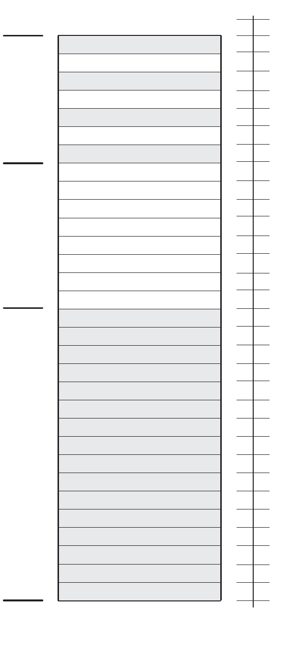
B-100 Configuring, Installing, and Using Carrier Infrastructure
Channel
2690
A1
B1 B2 B3 B4 D1 D2 D3 D4 F1 F2 F3 F4 H1 H2 H3
ITFS MMDS ITFS & MMDS
2500 2524 2548 2572 2596 2620 2644 2668
A2 A3 A4 C1 C2 C3 C4 E1 E2 E3 E4 G1 G2 G3 G4
1 2 3 4 5 6 7 8 9 10111213141516171819202122232425262728293031
Frequency
(MHz)
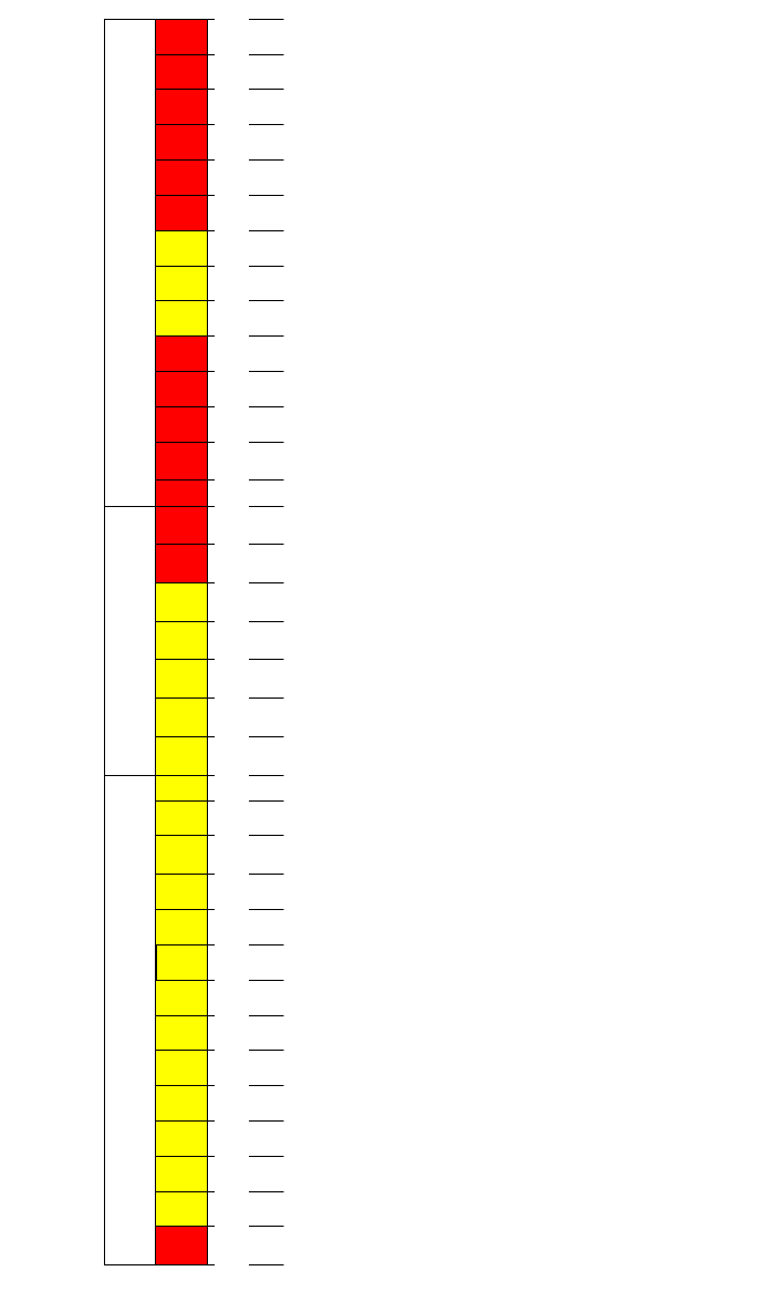
B-101
3.3 GHz frequency range
The Expedience system operates in the 3.3 GHz frequency range. For more information
about channel assignments in this range, contact NextNet Wireless.
1
6
BRS
A1
5.5
EBS
A2
5.5
EBS
A3
5.5
EBS
B1
5.5
EBS
2496.0
B2
5.5
EBS
B3
5.5
EBS
C1
5.5
EBS
Lower Band Segment (LBS)
2502.0
2507.5
2513.0
2518.5
2524.0
2529.5
2535.0
2540.5
C2
5.5
EBS
C3
5.5
EBS
D1
5.5
EBS
D2
5.5
EBS
D3
5.5
EBS
2546.0
2551.5
2557.0
2562.5
2568.0
JA1-
JD3
.3 3 3
3
each
EBS
2572.0
A4
6
EBS
2578.0
B4
6
EBS
2584.0
C4
6
EBS
2590.0
D4
6
EBS
2596.0
G4
6
EBS
2602.0
F4
6
BRS
2608.0
E4
6
BRS
2614.0
Middle Band Segment (MBS)
KH1-
KE3
.333
3
each
BRS
2
6
BRS
E1
5.5
BRS
E2
5.5
BRS
E3
5.5
BRS
F1
5.5
EBS
F2
5.5
EBS
F3
5.5
EBS
H2
5.5
BRS
H3
5.5
BRS
G1
5.5
BRS
G2
5.5
BRS
H1
5.5
BRS
G3
5.5
BRS
2618.0
2624.0
2629.5
2635.0
2640.5
2646.0
2651.5
2657.0
2662.5
2668.0
2673.5
2679.0
2684.5
2690.0
Upper Band Segment(UBS)
B-102 Configuring, Installing, and Using Carrier Infrastructure
3.5 GHz frequency range
The Expedience system operates in the 3.5 GHz frequency range. For more information
about channel assignments in this range, contact NextNet Wireless.
B-103
B-104 Configuring, Installing, and Using Carrier Infrastructure
Index-105
A
AAA server See AP server
airlink
enabling, 5-39
alarm
triggered on RMB, 7-86
ancilliary equipment
housing requirements, 1-8
antenna
coaxial cable, 6-73
connector, 6-73
gain recommended, 1-9
installation tips, 6-73
lightning protection, 6-73
planning installation, 1-9
type used to transmit MMDS channels, B-
99
AP server
configuring, 3-14
defining users and administrators, 3-14
installing, 3-13
overview, 1-4
setting up redundant, 5-43
standby, 4-27
starting, 3-13
authority
definitions, 5-42
setting up local authority, 5-43
setting up remote authority, 5-42
AUX +48 VDC connector, 6-70
AUX ETHERNET connector, 6-70
B
backbone network
connecting to, 6-75, 7-90
bandwidth
increasing on the downlink, 5-37
base station
connecting to TVS module, 6-70
connectors, 6-67, 7-86, 7-87
daisy chaining within cell, 6-75, 7-87
mounting, 6-59
power, 6-75, 7-83
setting configuration parameters, 5-35
base stations
starting term session, 3-25
battery backup connector
RMB, 7-84
BTS
installation overview, 1-6
C
cabinet
Ethernet cable connection, 7-88
cable
coaxial cable, 6-73
Ethernet/power, 6-68
GPS inter-base station cable, 6-72, 7-87
GPS interface cable, 6-72, 7-87
serial interface, 6-73
cell wiring diagram
for RMB, 7-82
channel number
setting, 5-36
channels
in MMDS frequencies, B-99
coaxial cable, 6-73
jumpers recommended, 6-73
maximum signal loss allowed, 6-73
configuration parameters
setting before deploying base station, 5-35
connector
data, 6-67
Ethernet, 6-67
GPS, 6-71
ISP Ethernet in TVS module, 6-70
power, 6-67
serial interface, 6-72
TVS module, 6-69
connectors
supported by base station, 6-67, 7-86
CPEs
how access is granted, 5-42
D
daisy chain cable see GPS Inter-base station
cable
daisy-chaining base stations, 6-75, 7-87
DHCP server equipment, 1-9
diagnostic cable
connections, 7-88
documentation
finding additional, preface-xv
E
equipment
provided by service providers, 1-8
Ethernet
LED indicator, 7-86
Ethernet/power cable, 6-68
function of wires within, 6-69
splitting, 6-70
Expedience system
obtaining technical support for, preface-xvi
I
NDEX
Index-106 Configuring, Installing, and Using Carrier Infrastructure
F
fuses
replacing, 7-89
RMB, 7-88
G
GPS
components of, 6-74
connecting to base station, 6-74
connector, 6-71
daisy-chained base stations, 6-75, 7-87
determining validity of output, A-97
exposure requirements, 6-74
interface cable, 6-72, 7-87
mounting pole and socket, 6-74
powering, 6-75
status codes, A-97
TDD impact, 1-8
time pulse generated, 6-74
used to generate time signal, 5-44
GPS inter-base station cable, 6-72, 7-87
grounding
RMB, 7-85
H
Hyperterminal
using to configure base station, 5-32
I
indoor/outdoor base station
overview, 1-2
inter-base station cable, 6-72, 7-87
ISPs
defining names, 3-20
L
lightning protection, 1-8, 6-74
antenna, 6-73
supplied through TVS module, 6-70
links
selecting, 2-12
local authority
setting up, 5-43
LOS requirement elimination, 1-1
M
MMDS frequency range
channels, B-99
mounting
brackets, 6-59
template, 6-60
N
network access
setting up for CPEs, 5-42
NNOS web interface
setting base station configuration
parameters, 5-35
P
power supply
for RMB, 7-83
provisioning server
user interface
New User page, 3-18
R
rack
attaching switch and power supply, 7-80
remote authority
setting up, 5-42
RMB
cell wiring diagram, 7-82
diagnostic cable, 7-88
Ethernet cable connection, 7-88
fuses, 7-88
grounding, 7-85
installation overview, 1-5
installing in cabinet, 7-80
LED locations and meaning, 7-86
overview, 1-2
power cable connectors, 7-87
power connectors, 7-84
power supply requirements, 7-83
wiring to cell, 7-81
RS-232 cable, 5-32
S
serial interface
cable, 6-73
connector, 6-72
set airlink channel, 5-36
set airlink downlink power, 5-36
set airlink state, 5-39
set downlink bias, 5-37
SNMP server equipment, 1-8
SNMP session
setting base station configuration
parameters, 5-35
subscribers
typical of the Expedience system, 1-1
Syslog
setting up options, 5-41
T
TDD, 5-44
technical support, preface-xvi
telnet access to base station, 5-32
telnet session
Index-107
setting base station configuration
parameters, 5-35
terminal emulation
access to base station, 5-32
connection settings, 5-32
setting base station configuration
parameters, 5-35
terminal emulation connection
settings, 5-32
time
setting up on base station, 5-44
time signal
external, 5-44
internal, 5-44
transmit power level of base station, 5-36
TVS module, 1-6
connectors, 6-70
typographical conventions
overview, preface-xvi
U
UPS
sizing considerations, 6-76, 7-85
W
weatherproof housing requirements, 1-7
Z
zones
defining, 3-18

Index-108 Configuring, Installing, and Using Carrier Infrastructure