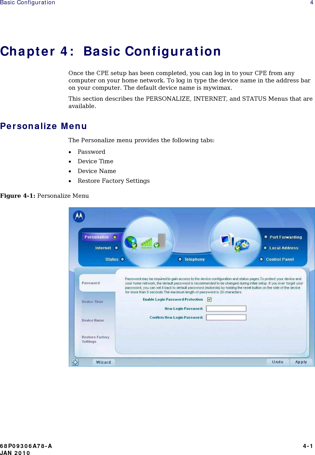
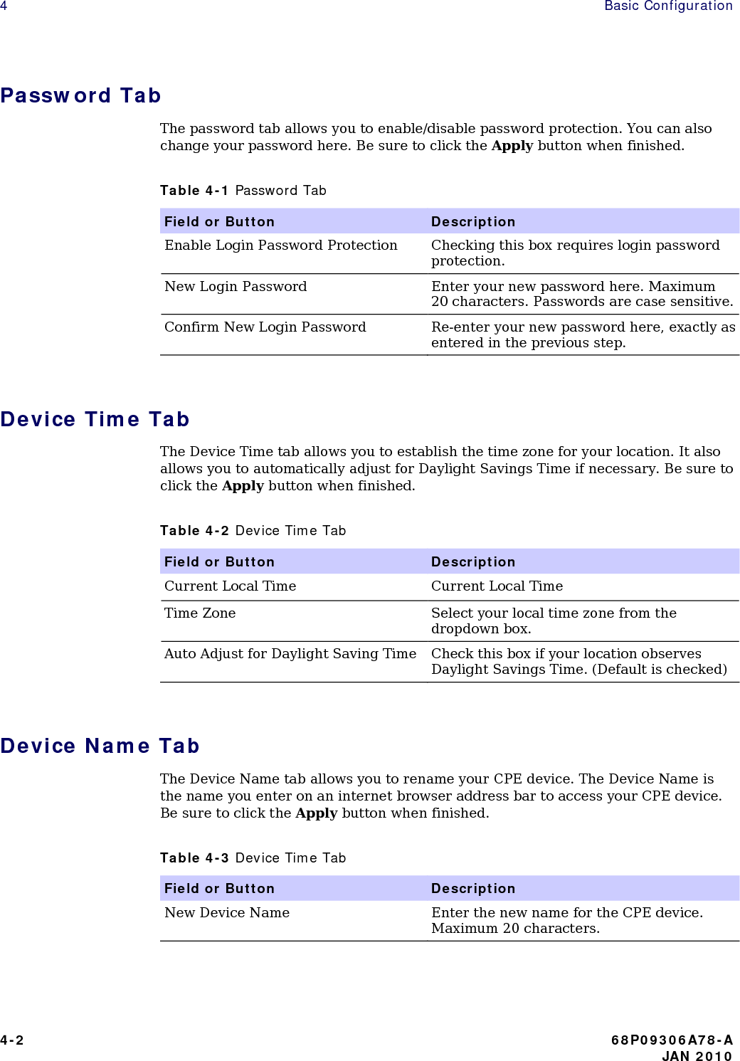
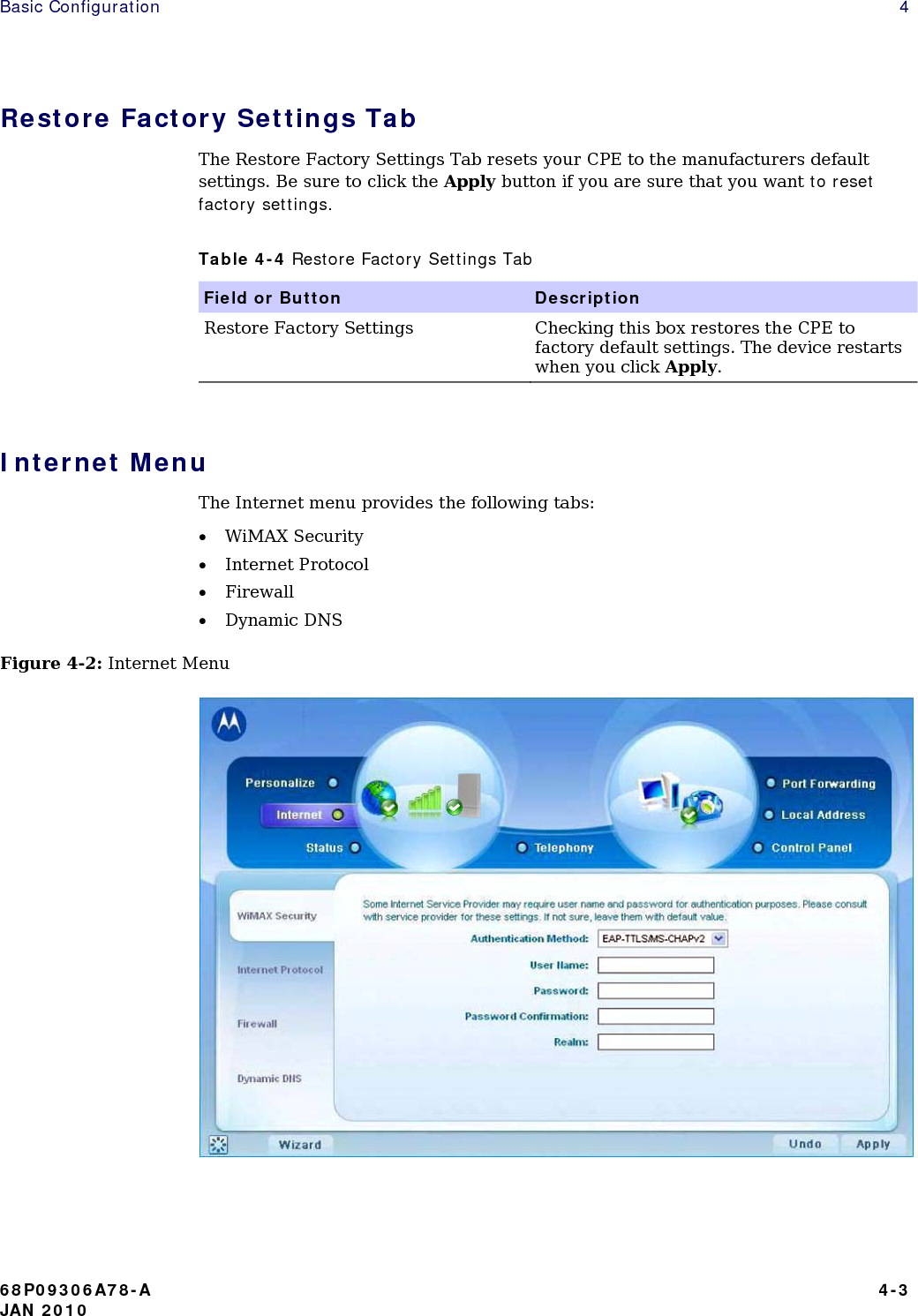
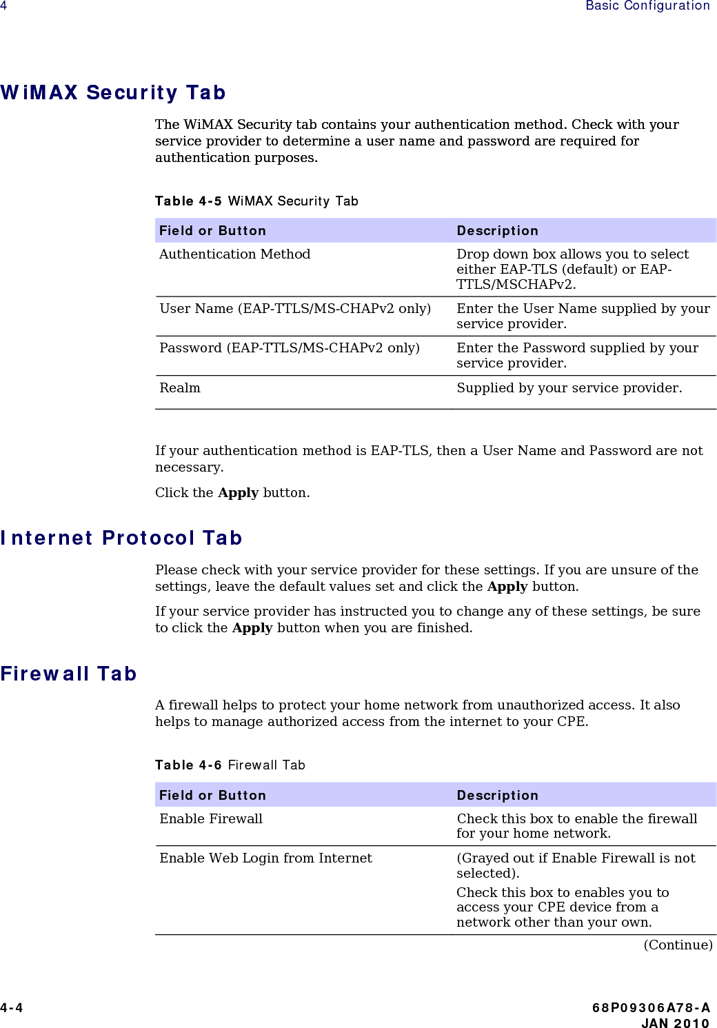
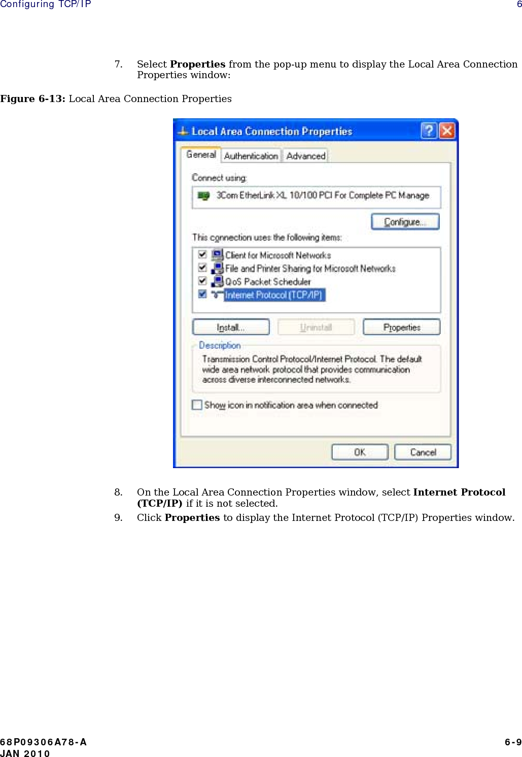
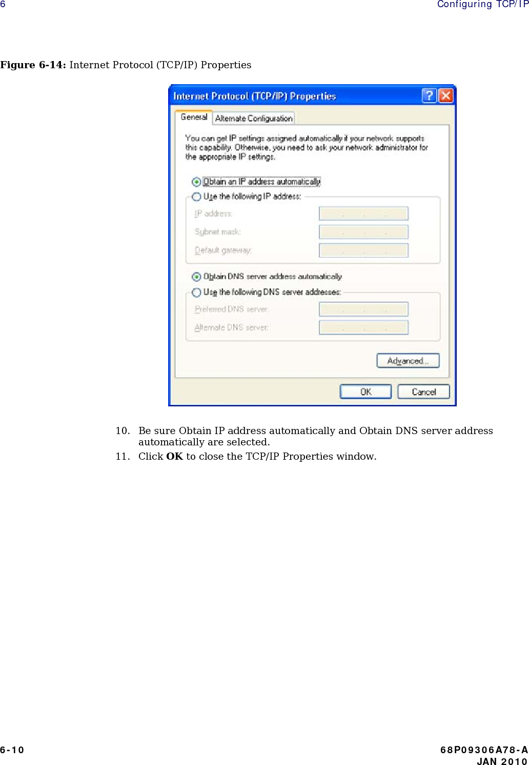
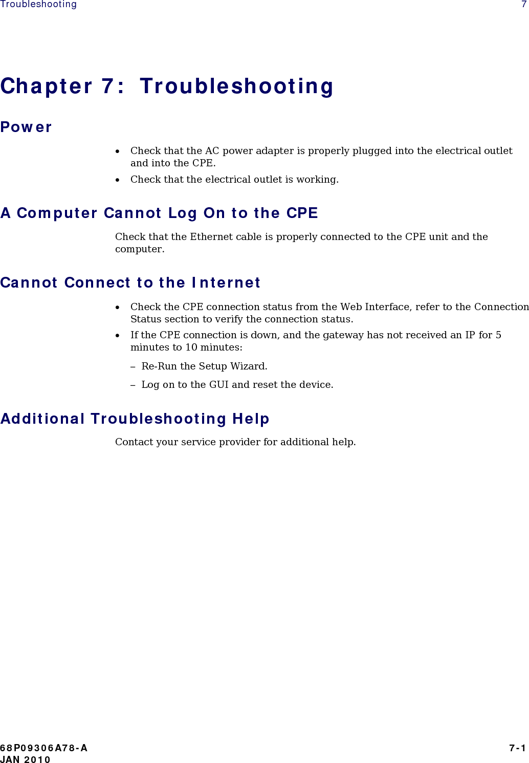
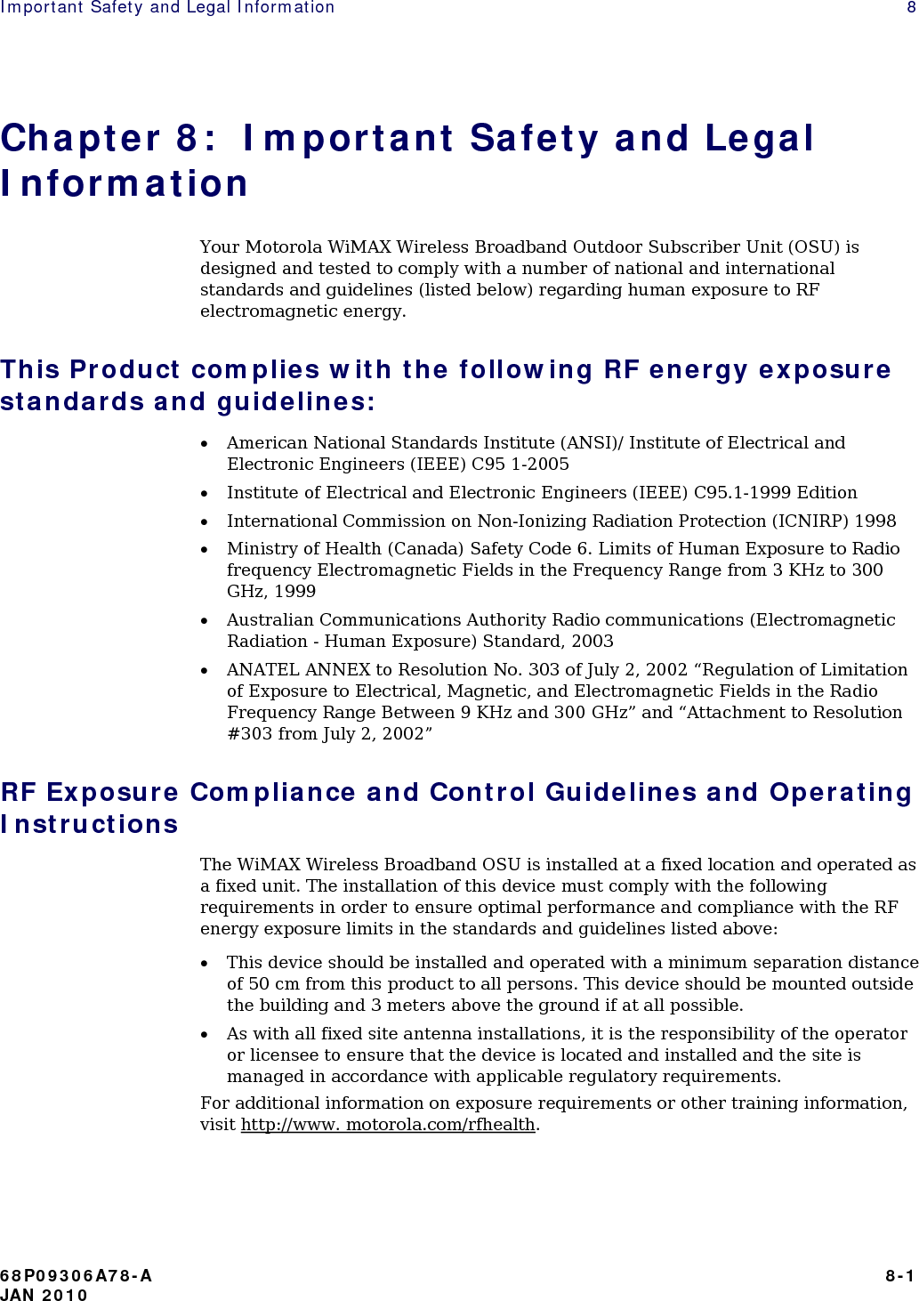
Nokia Solutions and Networks CPE25450 WiMAX 2.5G Outdoor CPE User Manual Chapter 1 Desktop CPEo 450 User Guide

Nokia Solutions and Networks WiMAX 2.5G Outdoor CPE Chapter 1 Desktop CPEo 450 User Guide

User Manual

CPEo 450SeriesMOTOROLA and the Stylized M Logo are registered in the US Patent & Trademark Office.All other product or service names are the property of their respective owners. © 2010 Motorola, Inc.
 68P09306A78-A   i JAN 2010   Contents  Chapter 1:  CPEo 450 User Guide Overview.............................................................................................................................. 1-1 Powerful Features in a Single Unit ..................................................................................... 1-2 Bottom Side Panel LED Indicator........................................................................................ 1-2 Bottom Panel ....................................................................................................................... 1-3 Operating Information......................................................................................................... 1-4 Chapter 2:  Installation Overview.............................................................................................................................. 2-1 Chapter 3:  Configuration Before you Begin ................................................................................................................. 3-1 Logging in to the CPE.......................................................................................................... 3-1 Setup Wizard and Authentication........................................................................................ 3-2 Chapter 4:  Basic Configuration Personalize Menu ................................................................................................................ 4-1 Password Tab ...................................................................................................................... 4-2 Device Time Tab .................................................................................................................. 4-2 Device Name Tab ................................................................................................................ 4-2 Restore Factory Settings Tab .............................................................................................. 4-3 Internet Menu ..................................................................................................................... 4-3 WiMAX Security Tab ........................................................................................................... 4-4 Internet Protocol Tab .......................................................................................................... 4-4 Firewall Tab......................................................................................................................... 4-4 Dynamic DNS Tab ............................................................................................................... 4-5 Status Menu ........................................................................................................................ 4-5 Network Tab........................................................................................................................ 4-6 Telephony Tab ..................................................................................................................... 4-6 Telephony Menu .................................................................................................................. 4-6 Account Tab......................................................................................................................... 4-7 Ring Tone Tab ..................................................................................................................... 4-8 Caller ID Tab ....................................................................................................................... 4-8 Call Forwarding Tab............................................................................................................ 4-9
 Voice Mail Tab................................................................................................................... 4-11 Special Number Tab.......................................................................................................... 4-11 Chapter 5:  Advanced Configuration Port Forwarding Menu ........................................................................................................ 5-1 Forwarding Tab ................................................................................................................... 5-2 Local Address Menu ............................................................................................................ 5-3 DHCP Server Tab ................................................................................................................ 5-3 Lease Status Tab ................................................................................................................. 5-4 Lease Reservation Tab ........................................................................................................ 5-5 Control Panel....................................................................................................................... 5-5 Software Tab ....................................................................................................................... 5-6 Certificate Tab..................................................................................................................... 5-6 System Tab .......................................................................................................................... 5-7 About Tab ............................................................................................................................ 5-7 Chapter 6:  Configuring TCP/IP Configuring TCP/IP in Windows 2000 ................................................................................. 6-1 Configuring TCP/IP in Windows XP..................................................................................... 6-6 Chapter 7:  Troubleshooting Power................................................................................................................................... 7-1 A Computer Cannot Log On to the CPE .............................................................................. 7-1 Cannot Connect to the Internet........................................................................................... 7-1 Additional Troubleshooting Help......................................................................................... 7-1 Chapter 8:  Important Safety and Legal Information This Product complies with the following RF energy exposure standards and guidelines:.8-1 RF Exposure Compliance and Control Guidelines and Operating Instructions................... 8-1 FCC Regulatory Information ............................................................................................... 8-2 Industry Canada Statement................................................................................................. 8-2 IC Radiation Exposure Statement: ...................................................................................... 8-3 EU Declaration of Conformity ............................................................................................. 8-3 Caring for the Environment................................................................................................. 8-4 Disposal of Motorola Equipment in EU Countries............................................................... 8-4 Disposal of Motorola Networks Equipment in Non-EU countries ....................................... 8-4 CMM Disclosure .................................................................................................................. 8-4 Copyrights and Trademarks ................................................................................................ 8-5 Copyrights ........................................................................................................................... 8-6 Usage and Disclosure Restrictions...................................................................................... 8-6  ii  68P09306A78-A    JAN 2010
CPEo 450 User Guide    1 Chapter 1:  CPEo 450 User Guide Overview Thank you for purchasing the Motorola CPE Outdoor (CPEo 450) device. The CPEo 450 allows you to connect to the wireless world easily and seamlessly, offering you broadband data and Voice over Internet Protocol (VoIP) calls.  The CPEo 450 device provides the user: • Performance – CPEo 450 contains a high performance antenna module, and a highly sensative receiver. This combination offers best in class Radio Performance, reliable outdoor coverage. • Control – Intuitive LED’s and detailed graphical user interface (GUI) allows you to monitor the state of the device and also customize your home network. In addition the remote management capability allows your service provider to offer timely support when required. • Security – CPEo 450 employs security certificate based authentication and also offers residential firewall.  The features and the physical appearance of your CPEo 450 device may differ slightly from the illustration.  Figure 1-1: CPEo 450      For the most recent documentation, visit the Product Documentation page on www.motorola.com. 68P09306A78-A   1-1 JAN 2010
1  CPEo 450 User Guide Powerful Features in a Single Unit The CPE device provides the following features: • WiMAX standard based Authentication • WAN DHCP Client • LAN DHCP Server • Home Gateway Functions • Firewall Protection • Port Forwarding Bottom Side Panel LED Indicator The WiMAX Wireless Broadband Outdoor Subscriber Unit (OSU) contains five LED indicators on the Bottom side of the unit. The LEDs provide the status of the unit and the signal strength for easy adjustment during setup. It is blue when on, or blinking. The five LED are on, off or blinking together to indicate the status.     1-2  68P09306A78-A    JAN 2010
CPEo 450 User Guide    1 Table 1-1 LED Indicators LED   Status Power Status    The LED indicator is:   • On - the power to Gateway is on  • Chasing - power to the Gateway is off Gateway Status  The status of the LED indicators:   • Off - the Gateway is not powered on • On - normal operation • Flashing - error condition. Contact your service provider for additional details. WiMAX Status  The status of some or all of the LED indicators:     • Off - the Gateway is not powered on • On - normal operation • Flashing - error condition. Contact your service provider for additional details. LAN Port  The LED indicator is:     • On - LAN Port is connected • Off - LAN Port is not connected • Blinking - LAN port is active. Phone Port    Typical RJ 11 ports do not support LED indicators. Please check for dial tone. Signal Strength     • All LEDs are off, no signal • LEDs will display a left to right chase pattern when the device is attempting to locate and connect to the network • All LEDs are on, full signal * NOTE* Number of LED’s lit indicate the received signal strength.      Bottom Panel The bottom panel of the units contains a VoIP port, and an Ethernet port.  68P09306A78-A   1-3 JAN 2010
1  CPEo 450 User Guide    Table 1-2 Port Descriptions Port   Description RJ 11 Port   VoIP phone port RJ 45 Port  Ethernet switch port and AC Power supply  Operating Information Temperature Range and power rating for the WiMAX Wireless Broadband Outdoor Subscriber Unit (OSU): Operating temperature for the units is -20c to +80c. AC Power Rating of the unit (CPEo 450) 100V - 240 V AC 0.5A RMS MAX @ 120V AC 0.25A RMS MAX @ 240V AC 47Hz - 63Hz  1-4  68P09306A78-A    JAN 2010
Installation   2 Chapter 2:  Installation Overview The CPEo 450 is an outdoor unit and the hardware installation is beyond the scope of this document. A separate installation document is included with the device. Before installation, check that you have received the following items with your  CPEo 450: • CPEo 450 Unit • AC Power Adapter with integrated Ethernet cable and phone port junction box • Installation Guide In addition, you need: • A computer • An RJ-11 telephone cable (optional). Two RJ-11 telephone cables are required if your service provider has supplied you with two telephone numbers.                          68P09306A78-A   2-1 JAN 2010
2   Installation       2-2  68P09306A78-A    JAN 2010
Configuration   3 Chapter 3:  Configuration Before you Begin Some settings on your computer need to be verified or changed to ensure that your computer configuration can support the CPE. Verify that the IP addresses and DNS settings are automatically generated in your Local Area connection of your Internet Protocol (TCP/IP) properties. Refer to the chapter titled “Configuring TCP/IP” for additional information. Logging in to the CPE Use the following procedure to log into the CPE: 1. On a computer that is connected to the CPE, open a web browser. 2. In the Address or Location field, type http://mywimax. and press ENTER to display the login screen. Include the period (.) after http://mywimax. in order to access the login screen.   In case the user friendly link does not open the web GUI enter the IP address: http://192.168.15.1 into Address field. If you still cannot access the CPE, refer to the chapter titled: Configuring TCP/IP for more information.  3. The Welcome to Motorola WiMAX CPE screen is displayed and prompts you for a password.          68P09306A78-A   3-1 JAN 2010
3   Configuration Figure 3-1: Login Screen   4. In the Password field, type the password (default is motorola). 5. Click Login. 6. First time users see a pop-up box that states: “The Wizard application will guide you through for the first time configuration”. Click OK button to continue. 7. Click the OK button to launch the wizard application. Setup Wizard and Authentication Step 1 - Change Password Once you have launched the setup wizard, you are prompted to change your password. Motorola recommends using a password to protect your home network and CPE device. Passwords are case sensitive. To change your password: • Ensure the “Enable Login Password Protection” box is checked. • Enter a New Login Password in the box. Passwords can be no more than 20 characters in length. • Re-type your new password in the Confirm New Login Password box. • Click Next. If you forget your password, you can reset it back to the default (motorola) password. To reset the password, press and hold the reset button on the back of your CPE for 5 or more seconds. Before resetting the CPE, ensure that the power is ON.  3-2  68P09306A78-A    JAN 2010
Configuration   3 Step 2 - Device Time This screen allows you to set the time zone and to enable Daylight Savings Time (when applicable) for your location. • Select the appropriate time zone for your location from the drop-down box. • Check the box that is called “Auto Adjust for Daylight Savings Time” if you live in a region that observes Daylight Savings Time. This box is checked by default. • Click the Next button.  Step 3 - WiMAX Security The WiMAX Security tab contains your authentication method. Check with your service provider to determine if they require a user name and password for authentication purposes. • If the Authentication Method is EAP-TLS, no User Name and Password are required. Enter the Realm information supplied by your service provider. Click the Next button. • If the Authentication Method is EAP-TTLS/MS-CHAPv2, enter a User Name and Password, and Realm information supplied by your Service Provider. Once you have entered the User Name/Password/Realm information, click the Next button. • If you are unsure of the Authentication Method, select EAP-TLS (which is the default) and click the Next button.  Step 4 – Account The Account tab allows you to manage Voice over IP (VoIP) related services. Please consult with your telephony service provider for these settings. Click the Apply button when finished. Congratulations! You have now completed the setup of your WiMAX connection. Click OK on the Congratulations! dialog box. A status screen appears that shows Network status and telephony status. The Network Status screen provides any status associated with your WiMAX Wireless Broadband connection. The Telephony Status screen provides status of your telephony service. • The Restart button is used to restart the device. The restart button is available on every screen. • The Wizard button starts the set-up wizard over again. • The Refresh button refreshes the screen with the current status. • The Auto Refresh button allows the web browser to automatically refresh at the interval determined in the Control Panel menu.   68P09306A78-A   3-3 JAN 2010
3   Configuration Figure 3-2: Status Screen   Restart Button Figure 3-3: Restart Button                   3-4  68P09306A78-A    JAN 2010
Basic Configuration    4 Chapter 4:  Basic Configuration Once the CPE setup has been completed, you can log in to your CPE from any computer on your home network. To log in type the device name in the address bar on your computer. The default device name is mywimax. This section describes the PERSONALIZE, INTERNET, and STATUS Menus that are available. Personalize Menu The Personalize menu provides the following tabs: • Password • Device Time • Device Name • Restore Factory Settings Figure 4-1: Personalize Menu    68P09306A78-A   4-1 JAN 2010
4  Basic Configuration Password Tab The password tab allows you to enable/disable password protection. You can also change your password here. Be sure to click the Apply button when finished. Table 4-1 Password Tab Field or Button   Description Enable Login Password Protection   Checking this box requires login password protection. New Login Password  Enter your new password here. Maximum 20 characters. Passwords are case sensitive. Confirm New Login Password  Re-enter your new password here, exactly as entered in the previous step.  Device Time Tab The Device Time tab allows you to establish the time zone for your location. It also allows you to automatically adjust for Daylight Savings Time if necessary. Be sure to click the Apply button when finished. Table 4-2 Device Time Tab Field or Button   Description Current Local Time   Current Local Time Time Zone  Select your local time zone from the dropdown box. Auto Adjust for Daylight Saving Time  Check this box if your location observes Daylight Savings Time. (Default is checked)  Device Name Tab The Device Name tab allows you to rename your CPE device. The Device Name is the name you enter on an internet browser address bar to access your CPE device. Be sure to click the Apply button when finished. Table 4-3 Device Time Tab Field or Button   Description New Device Name   Enter the new name for the CPE device. Maximum 20 characters. 4-2  68P09306A78-A    JAN 2010
Basic Configuration    4 Restore Factory Settings Tab The Restore Factory Settings Tab resets your CPE to the manufacturers default settings. Be sure to click the Apply button if you are sure that you want to reset factory settings. Table 4-4 Restore Factory Settings Tab Field or Button   Description Restore Factory Settings   Checking this box restores the CPE to factory default settings. The device restarts when you click Apply.  Internet Menu The Internet menu provides the following tabs: • WiMAX Security • Internet Protocol • Firewall • Dynamic DNS Figure 4-2: Internet Menu   68P09306A78-A   4-3 JAN 2010
4  Basic Configuration WiMAX Security Tab WiMAX Security Tab The WiMAX Security tab contains your authentication method. Check with your service provider to determine a user name and password are required for authentication purposes. The WiMAX Security tab contains your authentication method. Check with your service provider to determine a user name and password are required for authentication purposes. Table 4-5 WiMAX Security Tab Table 4-5 WiMAX Security Tab Field or Button   Description Authentication Method   Drop down box allows you to select either EAP-TLS (default) or EAP-TTLS/MSCHAPv2. User Name (EAP-TTLS/MS-CHAPv2 only)  Enter the User Name supplied by your service provider. Password (EAP-TTLS/MS-CHAPv2 only)  Enter the Password supplied by your service provider. Realm   Supplied by your service provider.  If your authentication method is EAP-TLS, then a User Name and Password are not necessary. Click the Apply button. Internet Protocol Tab Please check with your service provider for these settings. If you are unsure of the settings, leave the default values set and click the Apply button. If your service provider has instructed you to change any of these settings, be sure to click the Apply button when you are finished. Firewall Tab A firewall helps to protect your home network from unauthorized access. It also helps to manage authorized access from the internet to your CPE. Table 4-6 Firewall Tab Field or Button   Description Enable Firewall   Check this box to enable the firewall for your home network. Enable Web Login from Internet  (Grayed out if Enable Firewall is not selected).  Check this box to enables you to access your CPE device from a network other than your own. (Continue) 4-4  68P09306A78-A    JAN 2010 N 2010
Basic Configuration    4 Table 4-6 Firewall Tab (continued) Field or Button   Description Web Login Port from Internet   Choose a port number to connect to when logging in from a network other than your own. The default is 8080. Enable ping from Internet  Enables the CPE to respond to a ping from the Internet. This option would be enabled to allow testing only. Do not leave this enabled.  Click the Apply button once you are finished. Dynamic DNS Tab Dynamic Domain Name Service (DDNS) allows a user with a non-static IP address to keep their domain name associated with an ever changing IP address. As an example, DDNS is used when you are hosting your own website. Table 4-7 Dynamic DNS Tab Field or Button   Description Enable DDNS   Check this box to Enable DDNS (default is unchecked). DDNS Service Provider  Select DDNS Service Provider that you belong to from the drop-down box. DDNS User Name  Only valid if Enable DDNS is checked. Enter your DDNS account user name. DDNS Password   Only valid if Enable DDNS is checked. Enter your DDNS account password. DDNS Host Name   Only valid if Enable DDNS is checked. Enter the DDNS Host Name. This is assigned by the DDNS service.  Click the Apply button once you are finished. Status Menu The Status menu provides the following tabs: • Network • Telephony   68P09306A78-A   4-5 JAN 2010
4  Basic Configuration Figure 4-3: Status Menu   Network Tab The Network tab provides any status associated with your WiMAX Wireless Broadband connection. Telephony Tab The Telephony tab provides any status associated with your telephony connection. Telephony Menu The telephony menu allows you to manage your Voice over Internet Protocol (VoIP) services.   Contact your service provider to obtain VoIP service, if you do not already have this service.    4-6  68P09306A78-A    JAN 2010
Basic Configuration    4 The Telephony menu provides the following tabs: • Account • Ring Tone • Caller ID • Call Forwarding • Voice Mail • Special Numbers Figure 4-4: Telephony Menu   Account Tab Please consult with your service provider for these settings. The Account Tab contains the following settings: Table 4-8 Account Tab Field or Button   Description Line 1 User Name  If Line 1 is an active VoIP, enter the User Name as provided by your service provider. Line 1 Password  Enter the Line 1 password as provided by your service provider. Passwords are case sensitive. (Continue) 68P09306A78-A   4-7 JAN 2010
4  Basic Configuration Table 4-8 Account Tab (continued) Field or Button   Description Confirm Line 1 Password  Reenter your Line 1 password exactly as entered in the field from the previous step. Line 2 User Name  If Line 2 is an active VoIP, enter the User Name as provided by your service provider. Line 2 Password  Enter the Line 2 password as provided by your service provider. Passwords are case sensitive. Confirm Line 2 Password  Re-enter your Line 2 password exactly as entered in the field from the previous step.  Click the Apply button once you have made changes. Ring Tone Tab The Ring Tone tab allows you to customize ring tones for your telephone(s).   You need a phone connected to your CPE to hear ring tones.   Table 4-9 Ring Tone Tab Field or Button   Description Default Line 1 Ring Type  Use the drop-down box to select a ring tone for Line 1. The default is ring tone R0. Test  Click to hear how the selected ring tone sounds. Default Line 2 Ring Type  Use the drop-down box to select a ring tone for Line 2. The default is ring tone R0. Test  Click to hear how the selected ring tone sounds.  Click the Apply button once you have made changes. Caller ID Tab The Caller ID tab allows you to manage the Caller ID functions for your telephones:  4-8  68P09306A78-A    JAN 2010
Basic Configuration    4 Table 4-10 Caller ID Tab Field or Button   Description Enable Line 1 Anonymous Incoming Call Rejection If Line 1 is your active telephone port, check this box if you would like to reject telephone calls from anonymous incoming callers. The default is checked. Enable Line 1 Permanent Anonymous Outgoing Call If Line 1 is your active telephone port, check this box if you would like to permanently block your telephone number from appearing on others’ Caller ID. The default is unchecked. Enable Line 2 Anonymous Incoming Call Rejection If Line 2 is your active telephone port, check this box if you would like to reject telephone calls from anonymous incoming callers. The default is checked. Enable Line 2 Permanent Anonymous Outgoing Call If Line 2 is your active telephone port, check this box if you would like to permanently block your telephone number from appearing on others’ Caller ID. The default is unchecked.  Click the Apply button once you have made changes. Call Forwarding Tab The Call Forwarding tab allows you to manage the call forwarding features for your telephone(s). The Call Forwarding tab contains the following: Table 4-11 Call Forwarding Tab Field or Button   Description Enable Line 1 Basic Forwarding  Check this box to enable basic call forwarding on Line 1. The default is unchecked. Line 1 Basic Forwarding to Number  If “Enable Line 1 Basic Forwarding” is checked, enter the telephone number you would like to forward calls to. Enable Line 1 Forwarding on No Answer  Check this box to forward calls received on Line 1 if there is no answer. This function is not available if “Enable Line 1 Basic Forwarding” is checked. (Continue)  68P09306A78-A   4-9 JAN 2010
4  Basic Configuration Table 4-11 Call Forwarding Tab (Continued) Table 4-11 Call Forwarding Tab (Continued) Field or Button   Description Line 1 No Answer Forwarding to Number  If “Line 1 No Answer Forwarding to Number” is checked, enter the telephone number you would like to forward calls to when there is no answer on Line 1. This function is not available if “Enable Line 1 Basic Forwarding” is checked. Line 1 No Answer Forwarding Ring Count  Enter the number of rings allowed before the call forwards to the number identified above. The default is six rings. Enable Line 1 Forwarding on Busy  Check this box to forward calls received while Line 1 is in use. Line 1 Busy Forwarding To Number  If “Enable Line 1 Forwarding on Busy” is checked, enter the telephone number you would like calls forwarded to when Line 1 is in use. Enable Line 2 Basic Forwarding  If “Enable Line 2 Basic Forwarding” is checked, enter the telephone number you would like to forward calls to. Line 2 Basic Forwarding to Number  If “Enable Line 2 Basic Forwarding” is checked, enter the telephone number you would like to forward calls to. Enable Line 2 Forwarding on No Answer  Check this box to forward calls received on Line 2 if there is no answer. This function is not available if “Enable Line 2 Basic Forwarding” is checked. Line 2 No Answer Forwarding to Number  If “Line 2 No Answer Forwarding to Number” is checked, enter the telephone number you would like to forward calls to when there is no answer on Line 2. This function is not available if “Enable Line 2 Basic Forwarding” is checked. Line 2 No Answer Forwarding Ring Count  Enter the number of rings allowed before the call forwards to the number identified above. The default is six rings. Enable Line 2 Forwarding on Busy  Check this box to forward calls received while Line 2 is in use.  Line 2 Busy Forwarding To Number  If “Enable Line 2 Forwarding on Busy” is checked, enter the telephone number you would like calls forwarded to when Line 2 is in use. (Continue) Click the Apply button once you have made changes. 4-10   68P09306A78-A    JAN 2010 N 2010
Basic Configuration    4 Voice Mail Tab The voice mail tab allows you to see the status of your voice mail. Please contact your service provider to activate the voice mail feature if it is not already active. The Voice Mail Tab contains the following: Table 4-12 Voice Mail Tab Field or Button   Description Line 1 Server Based Voice Mail Status  Shows the status of Line 1 voice mail as either enabled or disabled. Line 1 Number of New Voice Mails  Shows the number of new, unheard voice mails on Line 1. Line 1 Number of Old Voice Mails  Shows the number of previously heard voice mails on Line 1. Line 2 Server Based Voice Mail Status  Shows the status of Line 2 voice mail as either enabled or disabled. Line 2 Number of New Voice Mails  Shows the number of new, unheard voice mails on Line 2. Line 2 Number of Old Voice Mails  Shows the number of previously heard voice mails on Line 2.  Click the Apply button once you have made changes. Special Number Tab The Special Number tab provides a list of special dialing numbers for your VoIP Phone Service. The Special Number Tab contains the following: Table 4-13 Special Number Tab Field or Button   Description Service Provider Contact Number  Use this number to contact customer service for your service provider. Emergency Number  Dial this number to reach local emergency services. Redial  Dial this number to redial the last number called. Blind Call transfer  Dial this number to transfer a call directly to a third party. Consultation Call Transfer  Dial this number to speak with the third party before you transfer the call to them. (Continue) 68P09306A78-A   4-11 JAN 2010
4  Basic Configuration Table 4-13 Special Number Tab (continued) Table 4-13 Special Number Tab (continued) Field or Button   Description Call Hold  Dial this number to place your current call on hold. Automatic Recall Activate  Dial this number to automatically call back the last number dialed when that number becomes available. Call Forwarding Activate  Dial this number to forward your calls to a different number. Call Forwarding Deactivate   Dial this number to deactivate call forwarding. Call Forwarding Busy Activate  Dial this number to forward calls to a different number when the line is busy. Call Forwarding Busy Deactivate  Dial this number to de-activate calls from forwarding to a different number when the line is busy. Call Forwarding Busy Change Number  Dial this number to change the phone number to which calls will be forwarded when the line is busy. Call Forwarding No Answer Activate  Dial this number to forward calls to a different number when there is no answer on Line 1 or Line 2. Call Forwarding No Answer Deactivate  Dial this number to de-activate calls from forwarding to a different number when there is no answer on Line 1 or Line 2. Call Forwarding No Answer Change Number Dial this number to change the phone number to which calls will be forwarded when there is no answer on Line 1 or Line 2. Automatic Callback Activate  Dial this number to hear the most recent call you missed and to return the call. If the number is busy, you can hang up. When the number is available, your phone will ring. Pick up your phone and the call will be connected. Automatic Callback Deactivate  Dial this number to de-activate automatic callback. Do Not Disturb Activate  Dial this number to have calls automatically routed to voice mail. Do Not Disturb Deactivate  Dial this number to cancel automatic call routing to voice mail. (Continue)  4-12   68P09306A78-A    JAN 2010 N 2010
Basic Configuration    4 Table 4-13 Special Number Tab (continued) Field or Button   Description Calling Number Delivery Blocking  Dial this number to block your number from appearing on the Caller ID of the people you call. Your calls may appear as “Private” or “Anonymous”. Line Blocking Deactivate  Dial this number to unblock your telephone number from appearing on Caller ID. Call Waiting Toggle  Dial this number to toggle between call waiting ON and call waiting OFF. Anonymous Call Rejection Activate  Dial this number to have anonymous calls rejected. Anonymous Call Rejection Deactivate  Dial this number to allow anonymous calls to go through.                            68P09306A78-A   4-13 JAN 2010
4  Basic Configuration      4-14   68P09306A78-A    JAN 2010
Advanced Configuration    5 Chapter 5:  Advanced Configuration The Advanced Configuration section describes the Port Forwarding, Local Address, and Control Panel menus. Port Forwarding Menu Port forwarding enables you to direct incoming traffic to specific LAN hosts (computers on your network) based on the protocol and port number. It is used to play Internet games or provide local services (such as web hosting) for a LAN group. The Port Forwarding menu provides the following tabs: • Basic • Forwarding Figure 5-1: Port Forwarding      68P09306A78-A   5-1 JAN 2010
5  Advanced Configuration Table 5-1 Port Forwarding Menu Field or Button  Description Enable UPnP IGD  Enables the Universal Plug and Play (UPnP) Internet Gateway Device (IGD) profile to allow certain Windows applications to set up the port forwarding rule dynamically when NAT is enabled on this device. DMZ (DeMilitarized Zone) IP Address  Enter the DMZ IP Address.  Click the Apply button once you have made changes. Forwarding Tab Click the ADD button to create additional Port Forwarding rules. The Forwarding tab contains the following selections: Table 5-2 Forwarding TabField or Button  Description Select  Select a box when you want to delete the specific row. Protocol  Select TCP (Transmission Control Protocol) or UDP (User Datagram Protocol). WAN Port Start  Enter the beginning port range for external network access. WAN Port End  Enter the ending port range for external network access. LAN IP Address  Enter the IP address to host the service. LAN Port Start  Enter the beginning port range for internal network access. LAN Port End  Enter the ending port range for internal network access. Enabled  Check to enable specific port forwarding.  Click the Apply button once you have made changes.    5-2  68P09306A78-A    JAN 2010
Advanced Configuration    5 Local Address Menu The Local Address menu allows you to configure your Local Area Network (LAN) connections. The Local Address menu provides the following tabs: • DHCP Server • Lease Status • Lease Reservation Figure 5-2: Local Address Menu   DHCP Server Tab The DHCP Server tab enables Dynamic Host Configuration Protocol (DHCP) server functionality on the LAN, allowing the router to dynamically assign lease IP addresses to clients that connect to it from the local network. The DHCP Server Tab contains the following selections:     68P09306A78-A   5-3 JAN 2010
5  Advanced Configuration Table 5-3 DHCP Server Tab Table 5-3 DHCP Server Tab Field or Button  Description Enable DHCP Server  If selected, the DHCP server on the gateway assigns IP addresses to the computers and other hosts on your network if they have DHCP enabled. By default, the gateway server is enabled. If there is another DHCP server running on your network (on another router), disable one of the DHCP servers. DHCP Server IP Address  Enter the default port forwarding LAN Client IP Address. DHCP Starting IP Address  Sets the first IP address assigned by the DHCP server, in dotted-decimal format. It must be greater than the IP address value of the gateway. For example, if the IP address of the gateway is 192.168.15.1(default), the starting IP address must be 192.168.15.2 (or higher). DHCP Ending IP Address  Sets the final IP address assigned by the DHCP server. If the DHCP server runs out of DHCP addresses, users cannot access network resources. If this happens, increase the Ending IP or reduce the Lease Time. DHCP Lease Time  Sets the time, in seconds, that a network computer remains connected to the gateway using its current assigned IP address. At the end of this time, the DHCP server renews the lease or assigns the computer a new IP address. The default is 3600 seconds (one hour). The maximum is 999999 seconds (about 278 hours).  Click the Apply button once you have made changes Lease Status Tab The Lease Status tab in the Local Address menu displays the active DHCP leases since the last reboot. The Lease Status Tab contains the following selections: Table 5-4 Lease Status Tab Field or Button  Description Client Host Name  Displays the client host name. The Name field is limited to 20 characters (only 5 appear in display). MAC Address  Media Access Control (MAC) address. IP Address  Shows the IP Address for each active lease. (Continue) 5-4  68P09306A78-A    JAN 2010 68P09306A78-A    JAN 2010
Advanced Configuration    5 Table 5-4 Lease Status Tab (continued) Field or Button  Description Remaining Lease Duration  Shows the amount of time, in seconds, remaining in the lease.  Click the Apply button once you have made changes. Lease Reservation Tab This tab allows you to manage the lease reservation so that the same client receives the same IP address each time. The Lease Reservation Tab contains the following selections: Table 5-5 Lease Reservation Tab Field or Button  Description Select  Select this box if you want to delete an established lease reservation. Be sure to click the Delete button once you have selected the exception to be deleted. Client Host Name  Enter the client host name. The Name field is limited to 20 characters (only 5 appear in display) MAC Address  Media Access Control (MAC) address. Enter the MAC address of the device. IP Address  Enter the IP address that you want assigned to the MAC Address. Enabled  Clicking this box enables the lease reservation.  Click the Apply button once you have made changes. Control Panel The Control Panel sections allow you to view/update your software information. The Control menu provides the following tabs: • Software • Certificate • System • About    68P09306A78-A   5-5 JAN 2010
5  Advanced Configuration Figure 5-3: Control Panel Menu  Software Tab The Software tab manages the software on your CPE device. It is also where you can upgrade device software. Use the BROWSE button to browse your computer for additional software packages. Once you have located the software package/update you would like to add to your device, click the Upgrade button. You should see the available software updates in the “Available Software Packages” table. If you cannot see the list, click the View button. Select the software you would like to install and click the Install button. If you would like to remove software, select the software package you would like to remove and click Uninstall. Certificate Tab The Certificate tab is where you manage the certificates that are stored on the device. Use the BROWSE button to locate the certificate file on your computer, and then click the IMPORT button. Use the REMOVE button to remove any selected certificate(s). 5-6  68P09306A78-A    JAN 2010
Advanced Configuration    5 System Tab This tab allows you to manage additional features of your CPE device Table 5-6 System Tab Field or Button  Description Language Used in User Interface  Select the desired language for the user interface. The default language is English. Enable WiMAX Radio Interface  Check this box to enable the WiMAX Radio Interface. Enable LED  Check this box to enable the LEDs on the front of your CPE device. Auto Refresh Interval  Enter, in seconds, the interval for status Auto Refresh. Valid range is 2 seconds - 9999 seconds. The default value is 3 seconds. Rebootstrap EMS  Check this box to reconnect the device with the EMS. Only perform this function under the supervision of a Customer Support Representative. About Tab The About Tab displays basic properties of your CPE device such as: Product Name, Model ID, Hardware Version, Serial Number, and the WiMAX MAC Address.               68P09306A78-A   5-7 JAN 2010
5  Advanced Configuration               5-8  68P09306A78-A    JAN 2010
Configuring TCP/IP    6 Chapter 6:  Configuring TCP/IP This section contains two examples of configuring TCP/IP in a Windows environment. Most computers already have the TCP/IP configuration enabled. Use the following procedures to verify that the configuration is set up. Configure all client computers on your network for TCP/IP (the protocol that controls communication among computers). Two examples are provided in this document: • Configuring TCP/IP in Windows 2000 • Configuring TCP/IP in Windows XP   Follow the instructions in your computer user manual for other Operating Systems. Configuring TCP/IP in Windows 2000 1. On the Windows, click Start. 2. Select Settings and then Control Panel from the pop-up menus to display the Control Panel window: Figure 6-1: Windows Control Panel            68P09306A78-A   6-1 JAN 2010
6  Configuring TCP/IP 3. Double-click the Network and Dial-up Connections icon to display the Network and Dial-up Connections window: Figure 6-2: Network and Dial-up Connections             In the steps that follow, a connection number like 1, 2, 3, etc., is a reference that is displayed on computers with multiple network interfaces. Computers with only one network interface may only see the label: Local Area Connection.  4. Click Local Area Connection number. The value of number varies from system to system. The Local Area Connection number Status window is displayed:          6-2  68P09306A78-A    JAN 2010
Configuring TCP/IP    6 Figure 6-3: Local Area Connection                                  5. Click Properties. Information like the following window is displayed: Figure 6-4: Properties                           68P09306A78-A   6-3 JAN 2010
6  Configuring TCP/IP  6. If Internet Protocol (TCP/IP) is in the list of components, TCP/IP is installed. You can skip to Step 10. Figure 6-5: Select Network Connection Type                                  If Internet Protocol (TCP/IP) is not in the list, click Install. The Select Network Component Type window is displayed:  7. Click Protocol on the Select Network Component Type window and click Add. The Select Network Protocol window is displayed: Figure 6-6: Select Network Protocol                                 6-4  68P09306A78-A    JAN 2010
Configuring TCP/IP    6  You might have to use the scroll bar to locate the Internet Protocol (TCP/IP) setting.  8. Click Internet Protocol (TCP/IP). 9. Click OK. The Local Area Connection number Properties window is re-displayed. 10. Be sure the box next to Internet Protocol (TCP/IP) is checked. 11. Click Properties. The Internet Protocol (TCP/IP) Properties window is displayed: Figure 6-7: Internet Protocol (TCP/IP) Properties                             12. Be sure Obtain IP address automatically and Obtain DNS server address automatically are selected. 13. Click OK to accept the TCP/IP settings. 14. Click Close to close the Local Area Connection number Properties window. 15. Click OK. 16. If prompted to restart the computer and click OK again. 68P09306A78-A   6-5 JAN 2010
6  Configuring TCP/IP Configuring TCP/IP in Windows XP  1. On the Windows , click Start to display the Start window: Figure 6-8: Windows XP Start Window                                  2. Click Control Panel to display the Control Panel window. The display varies, depending on your Windows XP view options. If the display is a Category view as shown in Figure 6-9, continue with Step 3. Otherwise, skip to Step 5.         6-6  68P09306A78-A    JAN 2010
Configuring TCP/IP    6 Figure 6-9: Control Panel                             3. Click Network and Internet Connections to display the Network and Internet Connections window: Figure 6-10: Network and Internet Connections                            68P09306A78-A   6-7 JAN 2010
6  Configuring TCP/IP 4. Click Network Connections. Skip to Step 6. 5. If a classic view like Figure 6-11 is displayed, double-click Network Connections to display the LAN or High-speed Internet connections. Figure 6-11: Control Panel Classic View                              6. Right-click the Local Area Connection. If more than one connection is displayed, be sure to select the one for your network interface. Figure 6-12: Network Connections                            6-8  68P09306A78-A    JAN 2010
Configuring TCP/IP    6 7. Select Properties from the pop-up menu to display the Local Area Connection Properties window: Figure 6-13: Local Area Connection Properties                            8. On the Local Area Connection Properties window, select Internet Protocol (TCP/IP) if it is not selected. 9. Click Properties to display the Internet Protocol (TCP/IP) Properties window.        68P09306A78-A   6-9 JAN 2010
6  Configuring TCP/IP Figure 6-14: Internet Protocol (TCP/IP) Properties                         10. Be sure Obtain IP address automatically and Obtain DNS server address automatically are selected. 11. Click OK to close the TCP/IP Properties window.                6-10   68P09306A78-A    JAN 2010
Troubleshooting   7 Chapter 7:  Troubleshooting Power • Check that the AC power adapter is properly plugged into the electrical outlet and into the CPE. • Check that the electrical outlet is working. A Computer Cannot Log On to the CPE Check that the Ethernet cable is properly connected to the CPE unit and the computer. Cannot Connect to the Internet • Check the CPE connection status from the Web Interface, refer to the Connection Status section to verify the connection status. • If the CPE connection is down, and the gateway has not received an IP for 5 minutes to 10 minutes: –  Re-Run the Setup Wizard. –  Log on to the GUI and reset the device. Additional Troubleshooting Help Contact your service provider for additional help.              68P09306A78-A   7-1 JAN 2010
7  Troubleshooting            7-2  68P09306A78-A    JAN 2010
Important Safety and Legal Information    8  Chapter 8:  Important Safety and Legal Information Your Motorola WiMAX Wireless Broadband Outdoor Subscriber Unit (OSU) is designed and tested to comply with a number of national and international standards and guidelines (listed below) regarding human exposure to RF electromagnetic energy. This Product complies with the following RF energy exposure standards and guidelines: • American National Standards Institute (ANSI)/ Institute of Electrical and Electronic Engineers (IEEE) C95 1-2005 • Institute of Electrical and Electronic Engineers (IEEE) C95.1-1999 Edition • International Commission on Non-Ionizing Radiation Protection (ICNIRP) 1998 • Ministry of Health (Canada) Safety Code 6. Limits of Human Exposure to Radio frequency Electromagnetic Fields in the Frequency Range from 3 KHz to 300 GHz, 1999 • Australian Communications Authority Radio communications (Electromagnetic Radiation - Human Exposure) Standard, 2003 • ANATEL ANNEX to Resolution No. 303 of July 2, 2002 “Regulation of Limitation of Exposure to Electrical, Magnetic, and Electromagnetic Fields in the Radio Frequency Range Between 9 KHz and 300 GHz” and “Attachment to Resolution #303 from July 2, 2002” RF Exposure Compliance and Control Guidelines and Operating Instructions The WiMAX Wireless Broadband OSU is installed at a fixed location and operated as a fixed unit. The installation of this device must comply with the following requirements in order to ensure optimal performance and compliance with the RF energy exposure limits in the standards and guidelines listed above: • This device should be installed and operated with a minimum separation distance of 50 cm from this product to all persons. This device should be mounted outside the building and 3 meters above the ground if at all possible. • As with all fixed site antenna installations, it is the responsibility of the operator or licensee to ensure that the device is located and installed and the site is managed in accordance with applicable regulatory requirements. For additional information on exposure requirements or other training information, visit http://www. motorola.com/rfhealth.   68P09306A78-A   8-1 JAN 2010
8    Important Safety and Legal Information  FCC Regulatory Information The 2.5 GHz WiMAX device (Model Name: CPEo 25450) complies with Part 15 of the FCC Rules. Operation is subject to the following two conditions: (1) this device may not cause harmful interference, and (2) this device must accept any interference received; including interference that may cause undesired operation. This equipment has been tested and found to comply with the limits for a Class B digital device pursuant to Part 15 of the FCC rules. These limits are designed to provide reasonable protection against harmful interference in a residential installation. This equipment generates, uses, and can radiate radio frequency energy and, if not installed and used in accordance with the instructions, may cause harmful interference to radio communications. However there is no guarantee that interference will not occur in a particular installation, which can be determined by turning the equipment off and on, the user is encouraged to try to connect the interference by one of the following measures: • Reorient or relocate the receiving antenna. • Increase the separation between the equipment and receiver. • Connect the equipment into an outlet on a circuit different from that to which the receiver is connected. • Consult the dealer or an experienced radio/TV technician for help. This Gateway desktop transmitter must not be co-located or operating in conjunction with any other antenna or transmitter. FCC Caution: Any changes or modifications not expressly approved by the party responsible for compliance could void the user’s authority to operate this equipment. Industry Canada Statement Specific 2.5 GHz Information 2.5 GHz WiMAX device (Model Name: CPEo 25450) complied with RSS-Gen and RSS-193 of the Industry Canada Rules. Specific 3.5 GHz Information 3.5 GHz WiMAX device (Model Name: CPEo 35450) complied with RSS-Gen and RSS-192 of the Industry Canada Rules. Operation is subject to the following two conditions: • This device may not cause interference and • This device must accept any interference, including interference that may cause undesired operation of the device. This Class B digital apparatus complies with Canadian ICES-003. Cet appariel numérique de la class B est conforme à la norme NMB-003 du Canada.  8-2  68P09306A78-A    JAN 2010
Important Safety and Legal Information    8  IC Radiation Exposure Statement:    EU Declaration of Conformity           Table 8-1 For the following equipment: WiMAX 3.5 GHz (Model Name: CPEo 35450)  Is herewith confirmed to comply with the requirements set out in the Council (European Parliament) R&TTE Directive (1999/5/EC). For the evaluation regarding this Directive, the following standards were applied: EN 302 326-2 V1.2.2 (06-2007), EN 302 326-3 V1.3.1 (02-2008) EN 301 489-1 V1.8.1 (04-2008); EN 301 489-4 V1.3.1 (08-2002) EN 50385 (2002) EN 60950-1:2001(IEC 60950-1:2001)   68P09306A78-A   8-3 JAN 2010
8    Important Safety and Legal Information  Caring for the Environment The following information is provided to enable regulatory compliance with the European Union (EU) Directive 2002/96/EC Waste Electrical and Electronic Equipment (WEEE) when using Motorola Networks equipment in EU countries.                          Disposal of Motorola Equipment in EU Countries This product is compliant with the requirements of the European Union Restriction of Hazardous Substances (EU RoHS) directive. Please do not dispose of Motorola Networks equipment in landfill sites. In the EU, Motorola Networks in conjunction with a recycling partner will ensure that equipment is collected and recycled according to the requirements of EU environmental law. Disposal of Motorola Networks Equipment in Non-EU countries In non-EU countries, dispose of Motorola Networks equipment in accordance with national and regional regulations. CMM Disclosure The China Management Methods (CMM) Disclosure Table is intended only to communicate compliance with China requirements; it is not intended to communicate compliance with EU RoHS or any other environmental requirements.  8-4  68P09306A78-A    JAN 2010
Important Safety and Legal Information    8                Copyrights and Trademarks Notice While reasonable efforts have been made to assure the accuracy of this document, Motorola, Inc. assumes no liability resulting from any inaccuracies or omissions in this document, or from use of the information obtained herein. The information in this document has been carefully checked and is believed to be entirely reliable. However, no responsibility is assumed for inaccuracies or omissions. Motorola, Inc. reserves the right to make changes to any products described herein and reserves the right to revise this document and to make changes from time to time in content hereof with no obligation to notify any person of revisions or changes. Motorola, Inc. does not assume any liability arising out of the application or use of any product, software, or circuit described herein; neither does it convey license under its patent rights or the rights of others.  It is possible that this publication may contain references to, or information about Motorola products (machines and programs), programming, or services that are not announced in your country. Such references or information must not be construed to mean that Motorola intends to announce such Motorola products, programming, or services in your country. 68P09306A78-A   8-5 JAN 2010
8    Important Safety and Legal Information  Copyrights This instruction manual and the Motorola products described in this instruction manual may be, include or describe copyrighted Motorola material, such as computer programs stored in semiconductor memories or other media. Laws in the United States and other countries preserve for Motorola and its licensors certain exclusive rights for copyrighted material, including the exclusive right to copy, reproduce in any form, distribute and make derivative works of the copyrighted material. Accordingly, any copyrighted material of Motorola and its licensors contained herein or in the Motorola products described in this instruction manual may not be copied, reproduced, distributed, merged or modified in any manner without the express written permission of Motorola. Furthermore, the purchase of Motorola products shall not be deemed to grant either directly or by implication, estoppel, or otherwise, any license under the copyrights, patents or patent applications of Motorola, as arises by operation of law in the sale of a product. Usage and Disclosure Restrictions License Agreements The software described in this document is the property of Motorola, Inc. and its licensors. It is furnished by express license agreement only and may be used only in accordance with the terms of such an agreement. Copyrighted Materials Software and documentation are copyrighted materials. Making unauthorized copies is prohibited by law. No part of the software or documentation may be reproduced, transmitted, transcribed, stored in a retrieval system, or translated into any language or computer language, in any form or by any means, without prior written permission of Motorola, Inc. High Risk Materials Components, units, or third-party products used in the product described herein are NOT fault-tolerant and are NOT designed, manufactured, or intended for use as online control equipment in the following hazardous environments requiring fail-safe controls: the operation of Nuclear Facilities, Aircraft Navigation or Aircraft Communication Systems, Air Traffic Control, Life Support, or Weapons Systems (High Risk Activities). Motorola and its supplier(s) specifically disclaim any expressed or implied warranty of fitness for such High Risk Activities. Trademarks MOTOROLA and the Stylized M Logo are registered in the US Patent & Trademark Office. All other product or service names are the property of their respective owners. © 2010 Motorola, Inc.  8-6  68P09306A78-A    JAN 2010

Navigation menu