Nokia Solutions and Networks MMDS-CPE2 Non-Line of Site Wireless Data Link User Manual InstallExternalOSU
Nokia Solutions and Networks Non-Line of Site Wireless Data Link InstallExternalOSU
Manual
i
Installing and
using the
Expedience
OSU-2510
Directions for connecting your
OSU to a computer or LAN and
obtaining high-speed Internet
access.
ii
Expedience and LinkMonitor are trademarks of NextNet Wireless, Inc.
Other brand and product names may be registered trademarks or trademarks of their respective holders.
Part number: 104-0009-0001
©2002 NextNet Wireless, Inc. All rights reserved.
THE SPECIFICATIONS AND INFORMATION REGARDING THE PRODUCTS IN THIS
GUIDE ARE SUBJECT TO CHANGE WITHOUT NOTICE. ALL STATEMENTS,
INFORMATION, AND RECOMMENDATIONS IN THIS GUIDE ARE BELIEVED TO BE
ACCURATE BUT ARE PRESENTED WITHOUT WARRANTY OF ANY KIND. USERS MUST
TAKE FULL RESPONSIBILITY FOR THEIR APPLICATION OF ANY PRODUCT.
NOTWITHSTANDING ANY OTHER WARRANTY HEREIN, ALL DOCUMENT FILES AND
SOFTWARE ARE PROVIDED “AS IS” WITH ALL FAULTS. NEXTNET WIRELESS DISCLAIMS
ALL WARRANTIES, EXPRESSED OR IMPLIED, INCLUDING, WITHOUT LIMITATION,
THOSE OF MERCHANTABILITY, FITNESS FOR A PARTICULAR PURPOSE AND
NONINFRINGEMENT OR ARISING FROM A COURSE OF DEALING, USAGE, OR TRADE
PRACTICE.
IN NO EVENT SHALL NEXTNET WIRELESS OR ITS SUPPLIERS BE LIABLE FOR ANY
INDIRECT, SPECIAL, CONSEQUENTIAL, OR INCIDENTAL DAMAGES, INCLUDING,
WITHOUT LIMITATION, LOST PROFITS OR LOSS OF DAMAGE TO DATA ARISING OUT
OF THE USE OR INABILITY TO USE THIS GUIDE, EVEN IF NEXTNET WIRELESS HAS
BEEN ADVISED OF THE POSSIBILITY OF SUCH DAMAGES.
Contents
1
Welcome............................................. 1
Before you begin ................................1
Connecting your OSU to a computer ... 6
Installation overview ..........................6
Setting up the computer to dynamically re-
ceive an IP address ............................6
Windows 95, Windows NT, Windows 98,
Windows ME: Setting up the network con-
nection .............................................7
Windows 2000: Setting up the network
connection ........................................7
Installing the OSU ..............................8
Attaching the NIM box to the outside of
house .............................................13
Cabling overview ..............................16
Running cables through house’s wall ...17
Plugging cables into NIM box .............17
Connecting ground wires ...................18
Plugging in power cord and RJ-45 cord 19
Finding the strongest service provider sig-
nal .................................................19
Using the software-assisted method to find
the strongest signal ..........................21
Using the sound (auditory) method to find
the strongest signal ..........................22
Connecting to the Internet ................22
Refreshing the OSU’s connection ...... 23
Windows users: Refreshing the
connection ......................................23
Non-Windows users: Refreshing the
connection ......................................23
2
Connecting the OSU to a network ..... 24
FCC information ...............................25
1
Welcome
This document describes how to install and use your Expedience
outdoor subscriber unit (OSU) to obtain wireless high-speed Internet
access. You can connect your OSU to a computer or to a small office/
home office (SOHO) local area network (LAN) through a hub,
switch, or router.
BEFORE YOU BEGIN
• Make sure your computer is equipped with an Ethernet network
interface card (NIC).
• The Ethernet cable that is supplied with your OSU plugs into
any standard Ethernet NIC. The NIC is not provided with
the OSU, but you can purchase a NIC at most computer and
electronics stores.
• Make sure you have purchased an RJ-45 cable. The length of this
cable depends on where you plan to install the OSU on your
house.
• Make sure you have purchased grounding wire of sufficient
length to run between the OSU and a grounding pole. Also, you
need to purchase grounding wire to run between the NIM box
and the grounding rod.
• The grounding wire you purchase should be an 8 gauge, solid
aluminum wire.
• It is recommended that the grounding rod you use be 8 foot
copper. Note that every house has a grounding rod outside.
If desired, you can install a rod into the ground outside the
house.
• Find an appropriate location on the outside of the house to
mount OSU.
• To provide Internet service, your OSU communicates with a
device on your service provider’s communications tower.
Your service provider must provide you with information
about the nearest communications tower. For example, if the
tower nearest to your home is north of your home, you will
install the OSU on the north side of your house.
• Mount the OSU in a high location on your home, such as un-
der the eaves of your house.
• Find an appropriate location on the outside of your house to
mount the NIM box.
2
• Locate the components shipped with your OSU device:
•OSU device
• Network interface manager (NIM) box
•Software CD-ROM
• Power cable and power supply box
• Power/Ethernet cable
•Lag bolt (6)
•Hex screws (2)
•Washers (2)
• Split lock washers (2)
• Double tab washer (2)
3
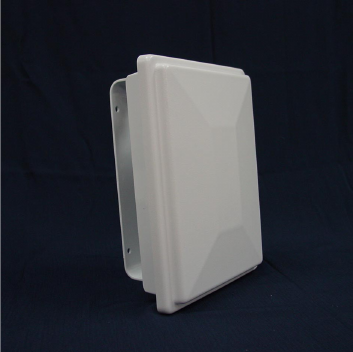
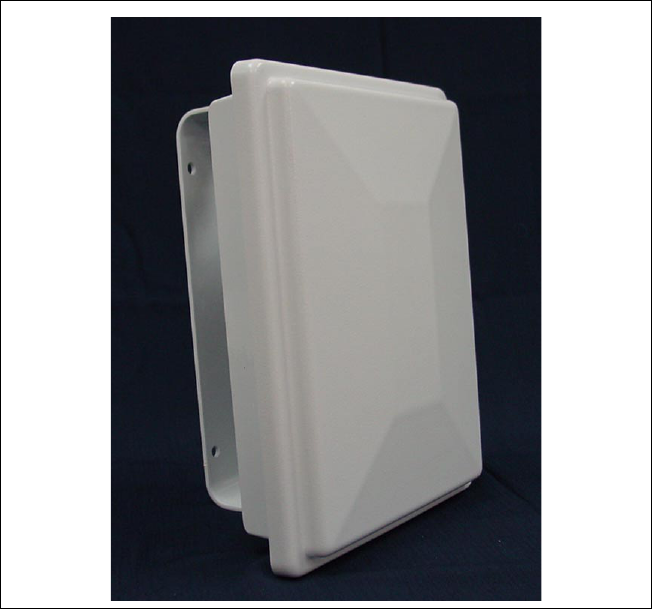
Figure 1 shows the OSU.
Figure 1: OSU
4
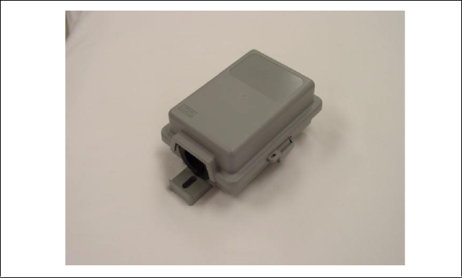
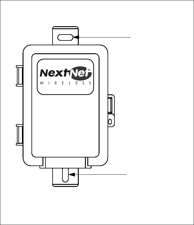
Figure 2 shows the network interface manager box.
Figure 2: NIM box

5
Table 1 lists the standard contents in your OSU package.
Table 1: OSU package components
Component Part number
External OSU device (vertical) 123-0009-1001
External OSU device (horizontal) 123-0009-2001
Mounting bracket 350-0009-0010
1/4 X 2" Lag Bolt, Hex Hd, Grade 2
Galv.
594-9907-1464
1/4-20X.875 Bolt, Hex HD, SS 594-9909-1428
1/4 Split Lock Washer, SS 596-3003-1416
1/4 Flat Washer, SS 596-3004-1420
External OSU network interface box 123-0009-0055
Power cord 420-0010-1010
OSU Installation Guide 104-0009-0001
Ethernet cable 597-6020-0050
Installation software CD-ROM 110-0002-0001
6
Connecting your OSU to a computer
This section describes how to connect your OSU to a computer.
If you want to connect your OSU to a network device (such as a
router or switch), refer to the section “Connecting the OSU to a
network” on page 24, in this guide.
INSTALLATION OVERVIEW
The installation consists of the following major tasks, each of which
is explained in greater detail in the sections that follow:
1 After ensuring your Ethernet NIC is installed properly, make sure
your computer is set up to automatically obtain an IP address.
2 Attach the OSU mounting bracket to the outside of the house,
then snap the OSU into the bracket.
3 Mount the NIM box to the outside of the house.
4 Run the power cable, the Power/Ethernet cable, and RJ-45 cable
through a hole drilled through house’s wall.
5 Plug the cables into the NIM box.
6 Connect the grounding wires.
7 Back inside the house, plug in the power cord to standard
household power.
8 Scan for the strongest service provider signal.
9 Connect to the Internet.
1SETTING UP THE COMPUTER TO DYNAMICALLY
RECEIVE AN IP ADDRESS
You must set up your computer so it can dynamically receive an IP
address. Your service provider assigns your computer an IP address
so that the Internet information you request can reach your computer.
• If you are running Windows 95, Windows NT, Windows 98 or
Windows ME, go to “Windows 95, Windows NT, Windows 98,
Windows ME: Setting up the network connection” on page 7.
• If you are running Windows 2000, go to “Windows 2000: Setting
up the network connection” on page 7.
• If you don’t see your operating system listed here, check the sys-
tem’s help file. Most explain how to set up a system to dynami-
cally receive an IP address.
7
1AWINDOWS 95, WINDOWS NT, WINDOWS 98,
WINDOWS ME: SETTING UP THE NETWORK
CONNECTION
1From the Start menu, select Settings. Then select Control
Panel.
2 In the window that appears, double click the Network icon.
3 Select the TCP/IP entry for the NIC.
4 Click Properties.
5 Select the IP Address tab.
6 Activate the Obtain an IP Address automatically radio button.
7 To close the windows, click OK.
8 Turn off your computer.
1BWINDOWS 2000: SETTING UP THE NETWORK
CONNECTION
1From the Start menu, select Settings. Then select Network and
Dial-up Connections.
2 Right click the connection you want to alter; that is, the name of
your NIC. From the pop-up menu, select Properties.
3 The Local Area Connection Properties window appears. Select
the Internet Protocol (TCP/IP) item. Click Properties.
4 In the window that appears, activate the Obtain an IP address
automatically radio button. To close the window, click OK. On
the remaining open window, click OK again.
5 Turn off your computer.
8
2INSTALLING THE OSU
To install the OSU:
1 Attach the mounting bracket to the outside of the house.
2 Set the OSU inside the mounting bracket.
3 Tighten the lower mounting bolt to hold the OSU in place.
The following sections describe these steps in greater detail.
Attach the mounting bracket to the outside of the
house
1 Make sure you install the OSU on the side of the house that has
the greatest exposure to the communications tower of your ser-
vice provider.
When you purchase your OSU, the service provider can provide
you with information about tower locations that can provide the
OSU with greatest signal exposure. This information will help
you understand the best side of the house on which to mount
the OSU.
2 Install the mounting bracket to the house. The bracket (like the
OSU) must be installed vertically.
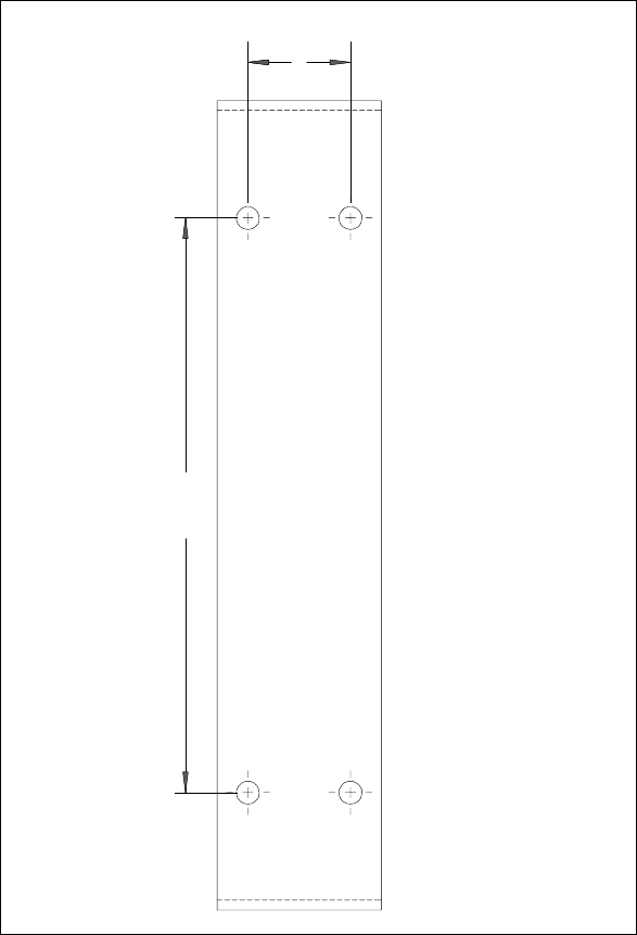
• Drill the two top holes 1.25 inches apart. Drill the bottom
hole 7 inches below the top hole.
• If possible, drill one upper hole and its corresponding lower
hole into a stud.
• After the holes are drilled into the house, drive the screws
through the holes on the mounting bracket and into the
house.
9
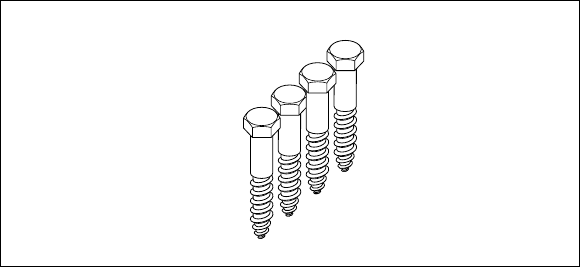
Figure 3 illustrates the screws to use to attach the mounting
bracket to the house.
Figure 3: Screws to attach mounting bracket to
house
10
Figure 4 provides a template (not to scale) for drilling holes into
the side of the house.
Figure 4: Mounting bracket template
2X 1.25
2X 7.00
11
Setting the OSU inside the mounting bracket
The OSU must be installed vertically. The OSU has a peg on top, and
a peg on bottom. The upper and lower pegs snap into the mounting
bracket’s peg holes.
After you search for the strongest signal from the service provider,
you insert a screw through the adjustment arch into the adjustment
screw opening on the OSU.
Tighten this screw fully only after you have performed the tasks in
step 8 “Finding the strongest service provider signal” on page 19.
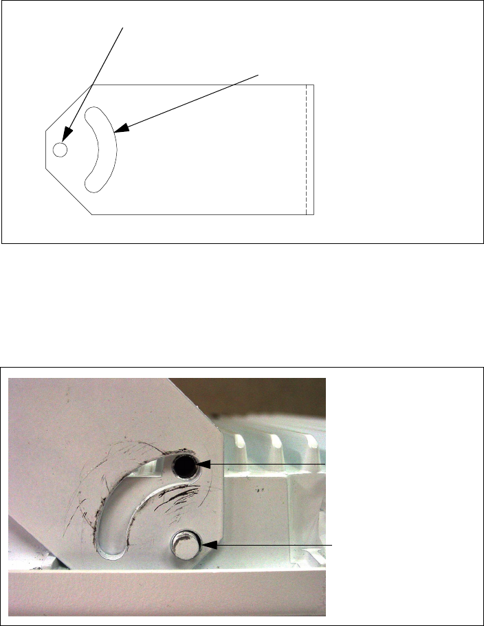
Figure 5: Adjustment arch and peg hole in mounting bracket
Adjustment arch
Peg hole
Figure 6: OSU peg in mounting bracket
Insert adjustment
screw here
OSU peg inserted
in mounting

12
You must install the OSU vertically. To install the OSU in the
mounting bracket:
1 Make sure the bottom of the OSU faces the earth. This is the side
of the OSU labelled with a sticker “MOUNT THIS SIDE
DOWN”.
2 On the bottom arm of the mounting bracket, snap the OSU’s peg
into the peg hole.
To accommodate the height of the peg, you may need to bend
the mounting bracket’s edge down slightly.
3 On the top arm of the mounting bracket, snap the OSU’s upper
peg into the adjustment arch.
To accommodate the height of the peg, you may need to lift the
mounting bracket’s edge up slightly.
Figure 7: MOUNT THIS SIDE DOWN Sticker
MOUNT THIS
SIDE DOWN

13
Partially tightening adjustment screws to hold OSU
in place
To make sure the OSU doesn’t slip out of the mounting bracket,
partially tighten the screws in the adjustment arch.
Because you still need to pivot the OSU along the adjustment arch—
in order to find the strongest signal from the service provider—do
not fully tighten the screws yet.
You will fully tighten the screws after completely. When the screws
are fully tightened, the OSU will no longer move along he adjustment
arch.
Figure 8 illustrates how the screw, split lock, flat washer and double-
tab washer are put together.
1 Assemble the screw, split lock washer, flat washer and double-tab
washer as shown in Figure 8.
2 On the upper arm of the mounting bracket, insert the screw
through the adjustment arch on the mounting bracket.
3 Partially tighten the screw on the OSU in hold it in place.
4 Because you still need to ground the OSU, do NOT fully tighten
the bolt on the bottom of the OSU yet. You will tighten this bolt
in step 6.
3ATTACHING THE NIM BOX TO THE OUTSIDE OF
HOUSE
To attach the NIM to the outside of your house:
Figure 8: Mounting screw assembly

14
1 Make sure the bottom of the NIM is facing the ground. A rub-
ber grommet is installed on the bottom of the NIM.
2 The screws provided with the NIM are self-drilling.
• Drive the upper screw through the opening in the upper
bracket and into the side of the house.
• Drive the lower screw through the opening in the lower
bracket and into the side of the house.
Figure 9: Screws to attach NIM box to house
15
Figure 10 illustrates where to drive the screws through the NIM
box brackets and into the side of the house.
Figure 10: Mounting NIM to house’s exterior
Drive screw
through upper
bracket
Drive screw
through lower
bracket
16
CABLING OVERVIEW
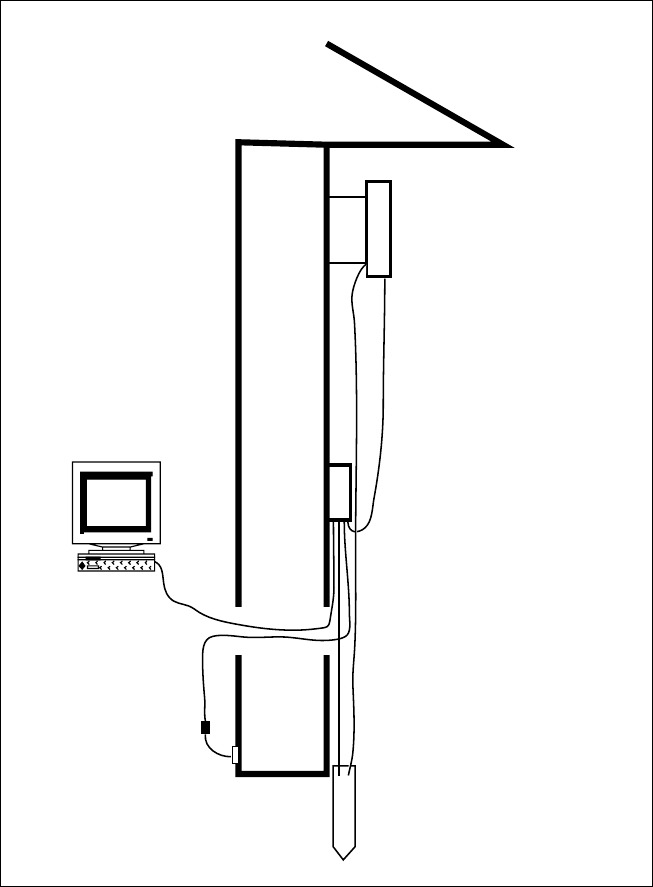
Figure 11 illustrates where ground cables, the RJ-45 cable, the power
cord, and the Ethernet/power cable run.
Figure 11: Connecting cables overview
OSU mounted
to home's exterior
Home's roof
Home's
wall
NIM box mounted
to home's exterior
Ground rod
Home's wall
Power supply
17
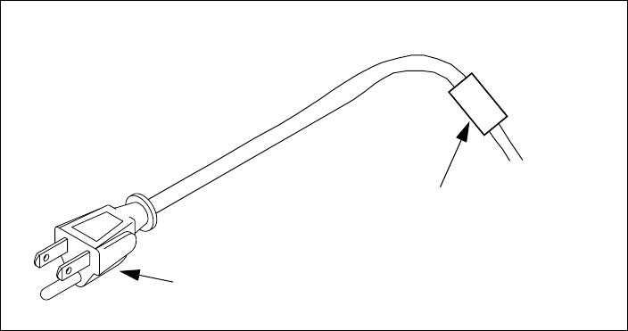
4 RUNNING CABLES THROUGH HOUSE’S WALL
The hole through the house must be no further than 10 feet from the
NIM box. This is because the power cord—from the power
connector to the ferrite bead—must be inside the house.
1 Near the NIM box, drill a 3/4 inch hole through the house.
2 Draw the power/Ethernet cord through the hole.
3 Draw the power cable through the hole. Make sure that the length
of the power cord, from power connector to the ferrite bead, are
inside the house.
4 Draw the RJ-45 cable through the hole.
5PLUGGING CABLES INTO NIM BOX
You must connect cables into the NIM box in the order shown below.
Failure to connect the cable in the proper order makes it difficult to
run the cables through the rubber grommet on the bottom of the
NIM box.
1 Connect the power/Ethernet cord. This is the cord that runs
from the NIM box to the OSU device.
2 Plug in the RJ-45 cord.
3 Plug in the circular end of the power cord. This is the cord that
runs from the power supply in your house to the NIM box.
Note: Do not plug in the power cord to the indoor power supply yet.
Figure 12: Length of power cable that must be inside house
Ferrite bead
Power connector
18
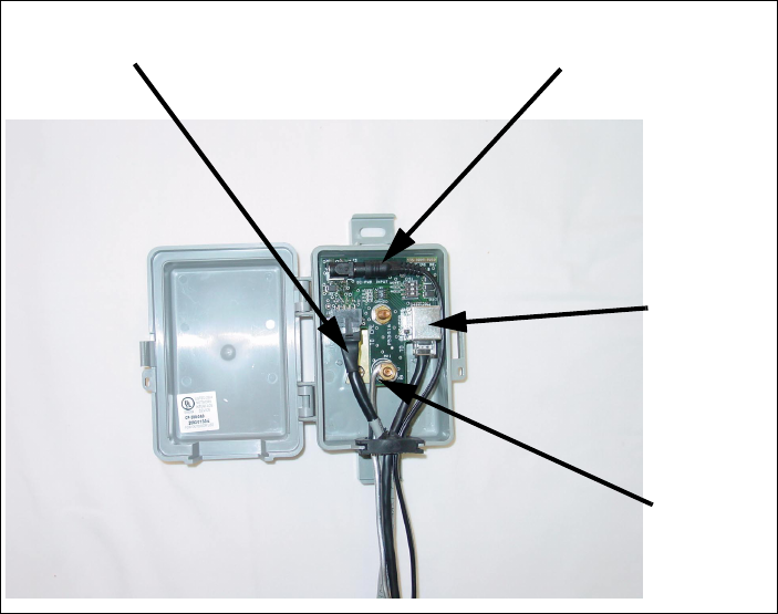
Figure 13 shows the cables and the ground wire connected inside the
NIM box.
6CONNECTING GROUND WIRES
Both the OSU and the NIM box must be grounded to a grounding
rod in the earth near your house. Make sure your grounding rod does
not exceed a 50 feet maximum.
To ground the NIM box and the OSU:
1 Inside the NIM box, unscrew the hex nut labelled GND.
2 Insert one end of the grounding wire through the rubber
grommet on the bottom of the NIM box.
3 Loop the grounding wire around the ground post.
4 Re-tighten the hex nut around the wire to hold it in place.
5 Connect the other end of the grounding wire to the grounding
rod in the ground next to the house.
Figure 13: Cables and ground wire plugged into NIM box
Power cable
Ethernet/power cable
Ground
wire
RJ-45
cable
19
6 On the OSU device, loop the grounding wire around the bottom
bolt that holds the OSU to the bracket.
7 Connect the other end of the grounding wire to the grounding
rod in the ground next to the house.
7PLUGGING IN POWER CORD AND RJ-45 CORD
1 The power cord uses standard household power. Plug the power
cord in the power source.
2 Plug the RJ-45 cord into the NIC on your computer or switching
device.
8FINDING THE STRONGEST SERVICE PROVIDER
SIGNAL
Your OSU is equipped with an internal antenna. To provide the best
service, the OSU searches for the strongest signal transmitted by your
service provider.
You can find the strongest signal from your service provider by using
one of the following methods:
• Software-assisted method
• Sound (auditory) method
Both methods require you to install the LinkMonitor program
Installing the LinkMonitor program
1 Locate the software CD supplied with your OSU.
2 Insert the CD into your computer’s CD drive. If the installation
program does not start automatically, start it by clicking on the
Setup.exe icon.
Follow the instructions in the dialog boxes to complete the
installation of the LinkMonitor program.
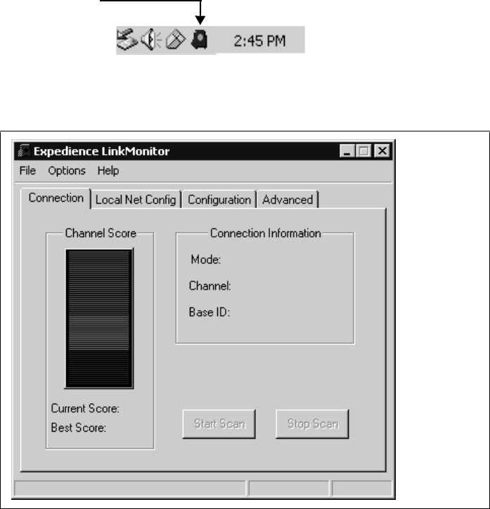
3 After the software is installed, a blue RSU icon appears in your
computer’s system tray.
20
To run the LinkMonitor program, right click on the icon, and
select Open.
The Expedience LinkMonitor window appears (Figure 15).
Figure 14: Starting the LinkMonitor program
LinkMonitor program’s icon in
system tray
Figure 15: Expedience LinkMonitor window
21
8AUSING THE SOFTWARE-ASSISTED METHOD TO FIND
THE STRONGEST SIGNAL
Note: It may be beneficial to have two people perform this
procedure. One person will monitor software statistics inside the
house. The other person will rotate the OSU outside the house.
To scan for the strongest signal from your service provider:
1 Install the LinkMonitor program as described in the section
“Installing the LinkMonitor program” on page 19.
2 On the LinkMonitor window, click Start Scan.
3 Return to the OSU on the side of the house.
4 Rotate the OSU along the adjustment arch.
5 The LinkMonitor program searches for a signal from your service
provider. In the Channel Score group, the strength of the signal
received at the starting position is indicated in two ways:
• The indicator bar shows varying levels of red, yellow, and
green. Red indicates weak signal strength, yellow indicates
moderate signal strength, and green indicates strong signal
strength.
•The Current Score field shows the signal strength. During
this procedure, the program compares the Current Score to
the Best Score. Best Score indicates the strongest signal the
program has ever seen during the scanning procedure.
6 After about five seconds, point the front of the OSU to the right
of the starting position.
7 Rotate the OSU along the arch again.
The software program determines and reports the strength of
the signal that the OSU receives while the OSU is in its current
orientation.
8 After about five seconds, note the strength of the signal received
at its current position.
9 Rotate the OSU along the arch. The program determines and
reports the strength of the signal that the OSU receives while the
OSU is in its current orientation.
22
10 Remembering the strongest signal reported, re-orient the front of
the OSU in the direction that the OSU was pointed when the
strongest signal was found.
11 Tighten the screws fully that hold the OSU in place.
12 Return to the LinkMonitor program. Click Stop Scan.
8BUSING THE SOUND (AUDITORY) METHOD TO FIND
THE STRONGEST SIGNAL
To use the sound (auditory) method to find the strongest signal:
1 Install the LinkMonitor program as described in the section
“Installing the LinkMonitor program” on page 19.
2 On the LinkMonitor window, click Start Scan.
3 Return to the OSU outside. You should hear the OSU beeping.
4 The constancy/frequency of the beeps indicate the strength of
the signal that the OSU detects.
5 Rotate the OSU along the adjustment arch, noting constancy/
frequency of the beeps.
6 Point the OSU in the direction where the beeps are most
constant.
7 Tighten the screws.
9CONNECTING TO THE INTERNET
To connect to the Internet:
Start your Internet browser, and try to open a few Internet sites.
• If you can open numerous sites, enjoy your new, high-speed ser-
vice.
• If yon cannot open any sites—for example if your browser dis-
plays a message “This page cannot be displayed” for all the sites
you tried to access—refresh the OSU’s connection, as described
in the section “Refreshing the OSU’s connection” on page 23.

23
Refreshing the OSU’s connection
When you refresh the OSU’s connection, your service provider is
assigning your computer a new IP address. You need to refresh your
OSU’s connection with your service provider when your Internet
browser does not let you open any Internet sites.
WINDOWS USERS: REFRESHING THE CONNECTION
To refresh the connection:
1 Make sure you have installed the LinkMonitor program.
2 In the system tray, right click the blue RSU icon (Figure 14) and
select Open.
3 In the window that appears, on the Local Net Config tab, click
the Renew IP Address button.
NON-WINDOWS USERS: REFRESHING THE
CONNECTION
If you do not run the Windows operating system, you can reboot your
computer to refresh the connection. You may want to refer to your
operating system’s help files to determine if other methods exist to
refresh the connection (that is, to find a method for refreshing the IP
address).

24
Connecting the OSU to a network
Note: Use only one OSU on a network. Do not use multiple OSUs
on the same network.
To directly connect the OSU to a computer, use the supplied
Ethernet cable (also known as a straight-through cable).
However, to connect the OSU to a hub or switch, use an Ethernet
cable appropriate for your network device. This might be a straight
through or cross-over cable, depending on how your network device
switches signals. When determining how to set up your network,
remember that the OSU device operates as a hub or a bridge.
After connecting the OSU to the network device, power the OSU and
scan for a service provider signal, as described in earlier sections of
this guide.

25
FCC INFORMATION
NOTICE: This equipment has been tested and found to comply with the Radio Frequency Radiation
Exposure Limits detailed below. A minimum of 20 centimeters (8 inches) separation between the RSU
and the operator and all other persons should be maintained.
Radio Frequency Radiation Exposure Limits
f = frequency in MHz
* = Plane-wave equivalent power density
NOTE 1 to Table 2: Occupational/controlled limits apply in situations in which persons are exposed as
a consequence of their employment provided those persons are fully aware of the potential for exposure
and can exercise control over their exposure.
Limits for occupational/controlled exposure also apply in situations when an individual is transient
through a location where occupational/controlled limits apply provided he or she is made aware of the
potential for exposure.
NOTE 2 to Table 2: General population/uncontrolled exposures apply in situations in which the
general public may be exposed, or in which persons that are exposed as a consequence of their
employment may not be fully aware of the potential for exposure or cannot exercise control over their
exposure.
Table 2 Limits for Maximum Permissible
Exposure (MPE)
Frequency
range (MHz)
Electric field
strength
(V/m)
Magnetic field
strength
(A/m)
Power
density
(mW/cm2)
Averag-
ing time
(minutes)
(A) Limits for Occupational/Controlled Exposures
0.3-3.0 614 1.63 *(100) 6
3.0-30 1842/f 4.89/f *(900/f2)6
30-300 61.4 0.163 1.0 6
300-1500 — — f/300 6
1500-100,000 — — 5 6
(B) Limits for General Population/Uncontrolled Exposure
0.3-1.34 614 1.63 *(100) 30
1.34-30 824/f 2.19/f *(180/f2)30
30-300 27.5 0.073 .2 30
300-1500 — — f/1500 30
1500-100,000 — — 1.0 30

26
Note: This equipment has been tested and found to comply with the limits for a Class B digital device,
pursuant to part 15 of the FCC rules. These limits are designed to provide reasonable protection against
harmful interference when the equipment is operated in a commercial environment. This equipment
generates, uses, and can radiate radio-frequency energy, and, if not installed and used in accordance with
the installation manual, may cause harmful interference to radio communications. Operation of this
equipment in a residential area is likely to cause harmful interference, in which case users will be
required to correct the interference at their own expense.
Table 3 Technical information
Transmitting power Up to 2 watts
Operating voltage 120 VAC nominal
Frequency band 2500 - 2686 MHz TX/RX
Frequency stability ±10 ppm
Number of channels 31
Channel bandwidth 6 MHz
Modulation Orthogonal frequency division multiplex
Transmission Time division duplex/time division multiplex
Index
1
C
computer
NIC requirement 1
cross-over cable 24
I
IP address (host computer)
refreshing 23
setting up for dynamic assign-
ment 6
L
LAN
connecting to OSU 24
N
network device
connecting to OSU 24
NIC requirement 1
O
OSU
connecting to network 24
P
part numbers list 5
R
router
connecting to OSU 24
RSU
choosing installation location 1
min. separation distance of
equipment and persons 25
package components 5
S
switch
connecting to OSU 24
2