Nokia Solutions and Networks RBTS2500 Non-Line of Site Wireless Data Link User Manual CBR BTS
Nokia Solutions and Networks Non-Line of Site Wireless Data Link CBR BTS
UserManual.wiki
>
Nokia Solutions and Networks
>
RBTS2500 User Manual
Manual
Navigation menu
Upload a User Manual
Namespaces
Wiki Guide
HTML
PDF
Info
Views
User Manual
Discussion / Help
Navigation

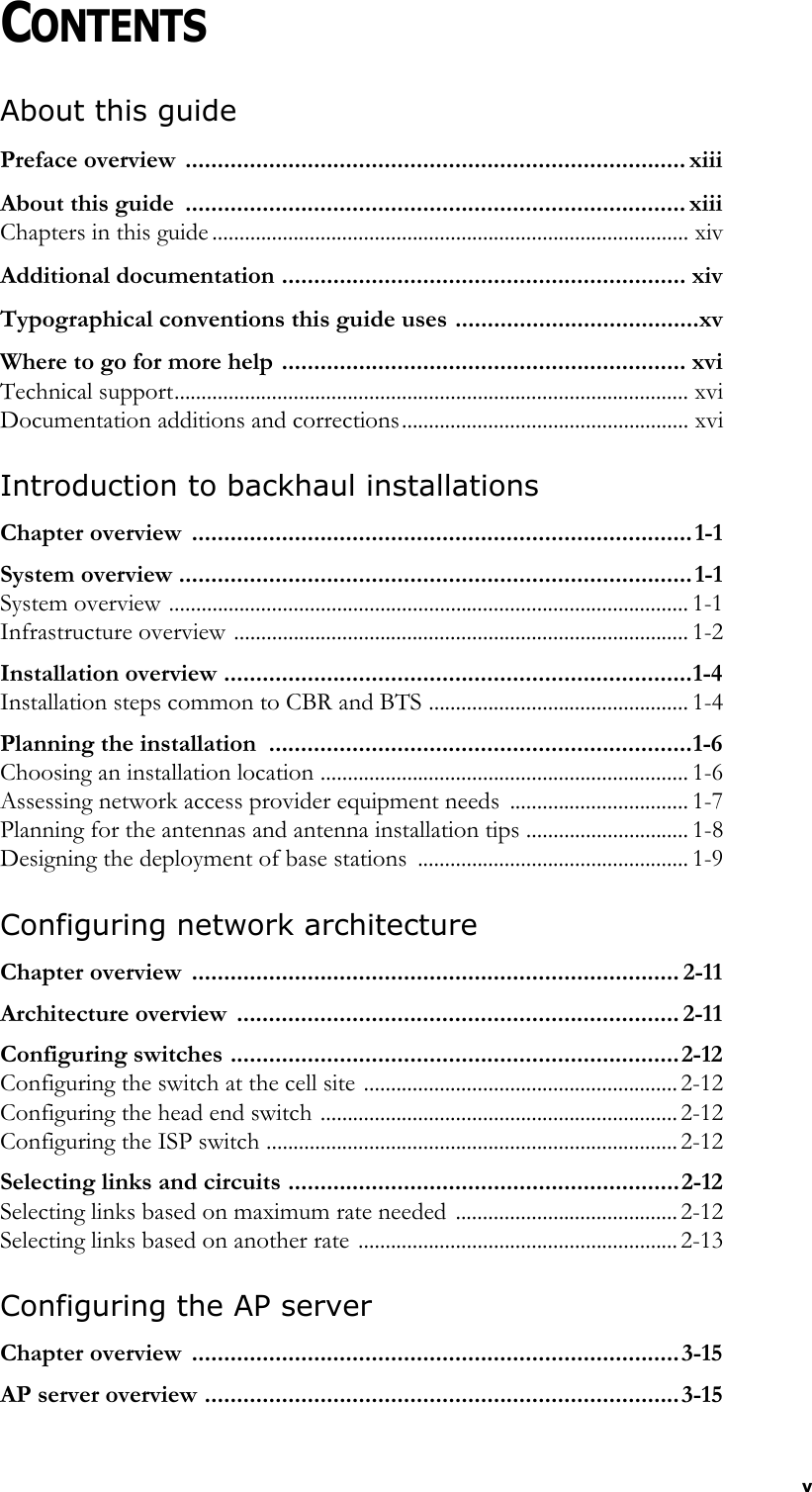
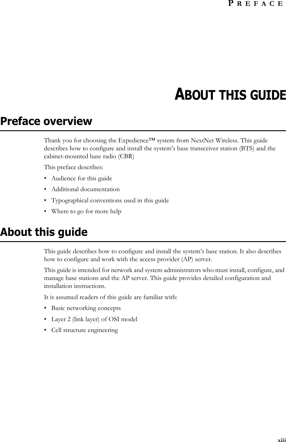
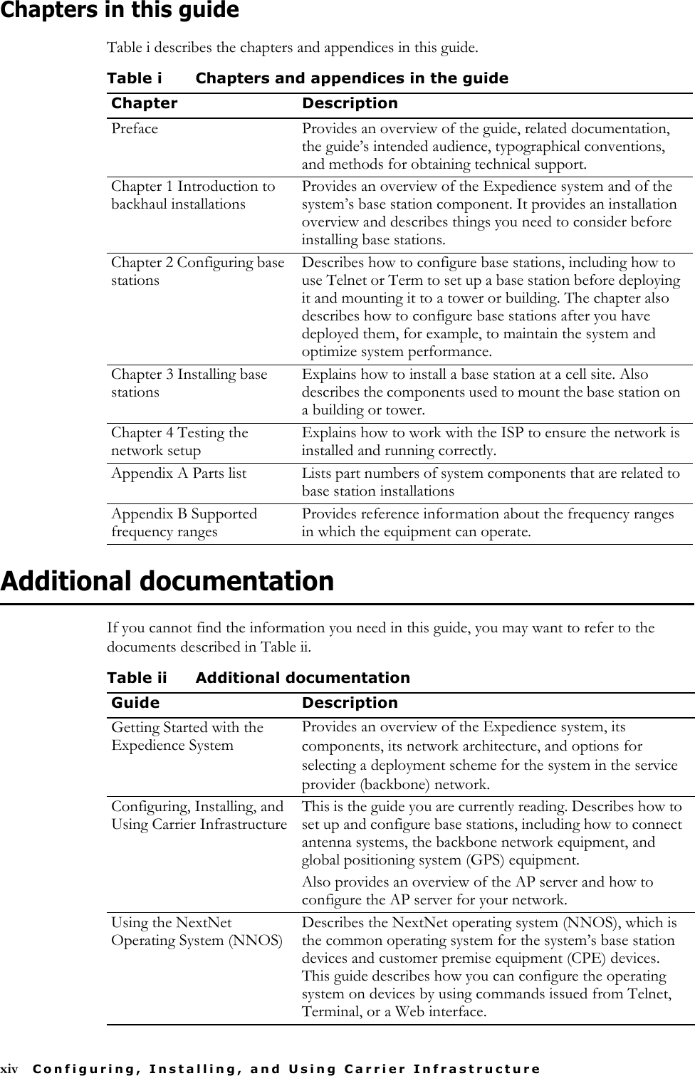
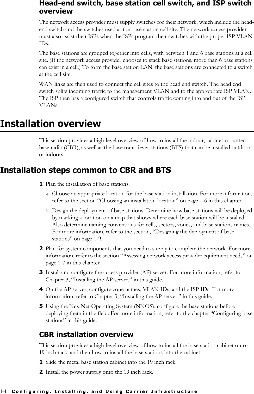
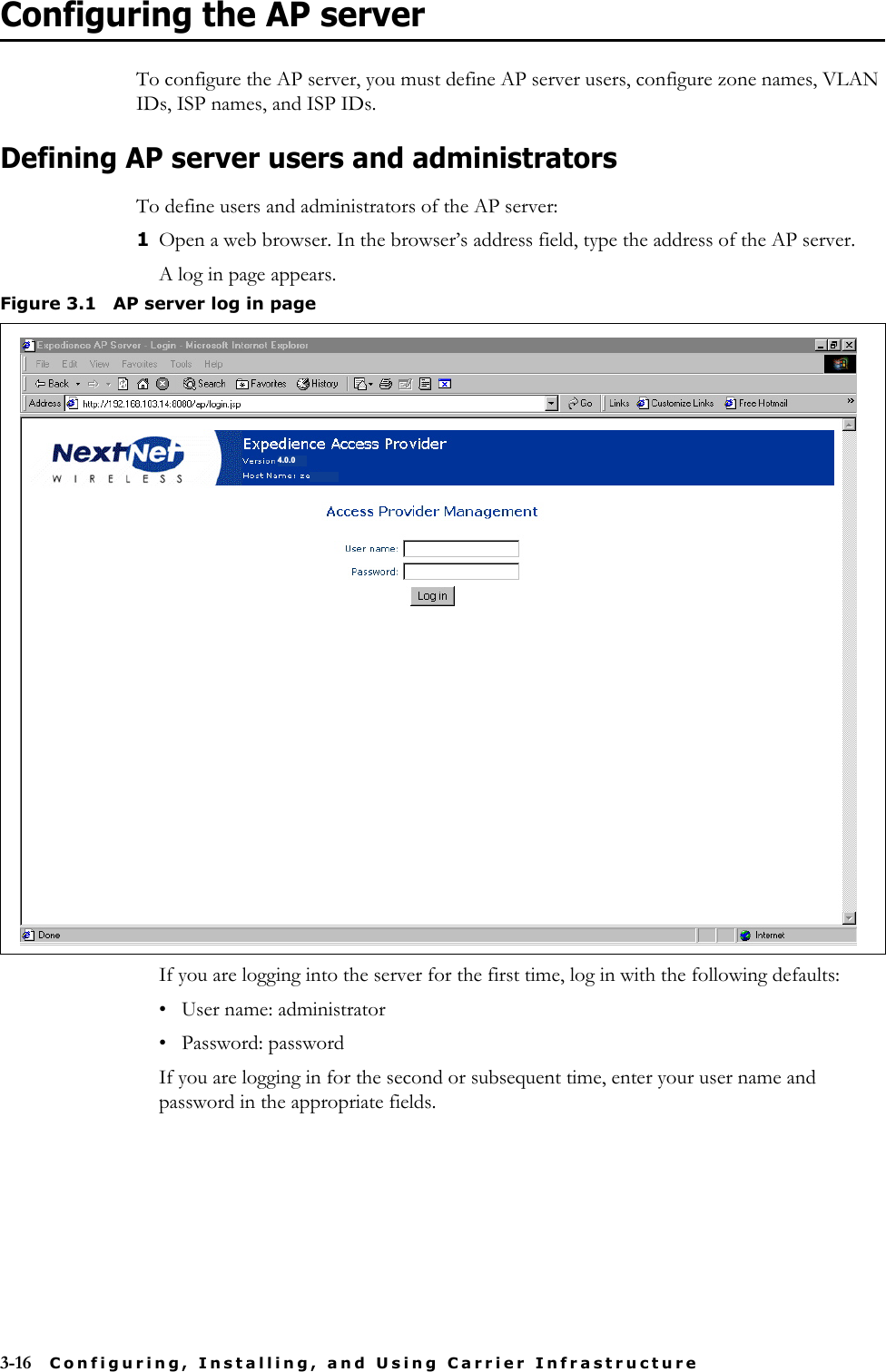
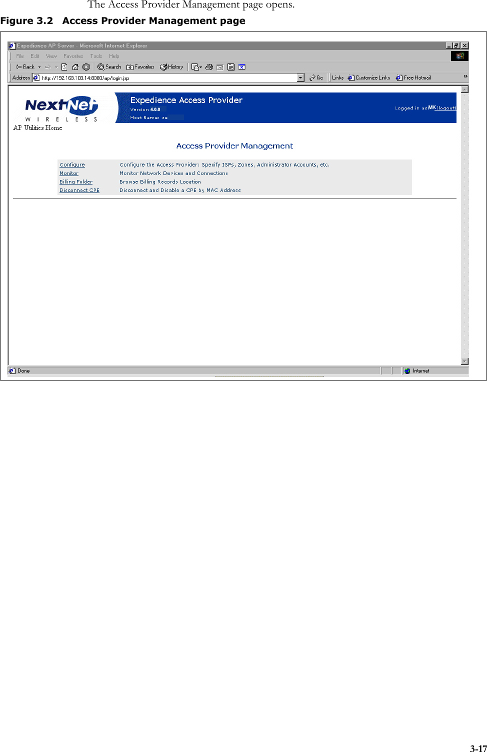
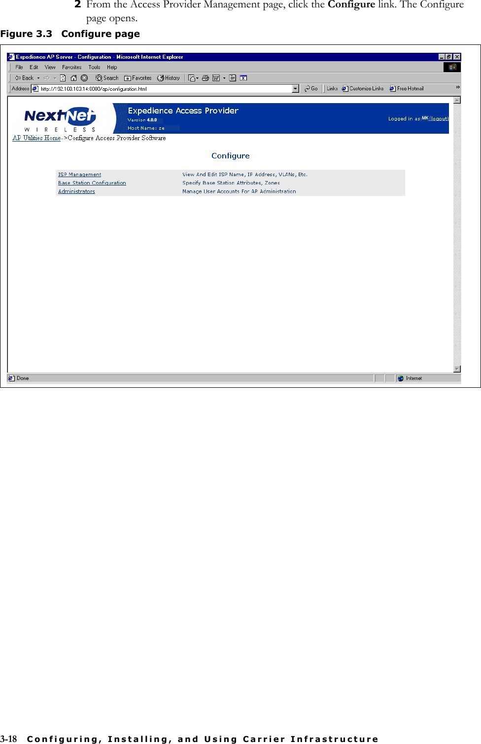
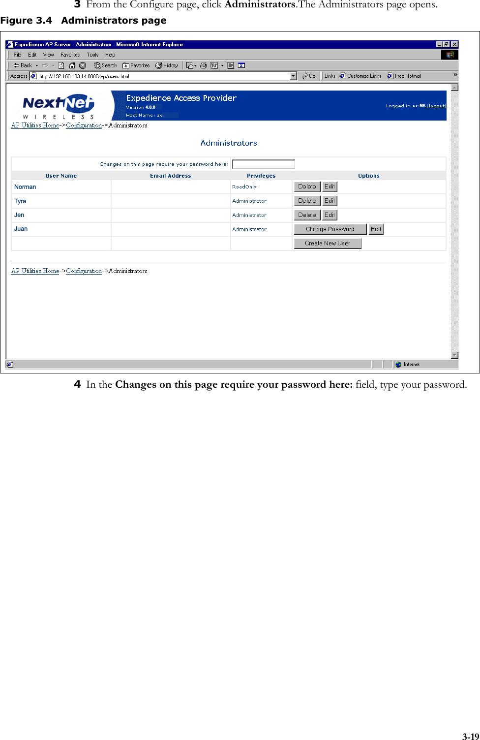
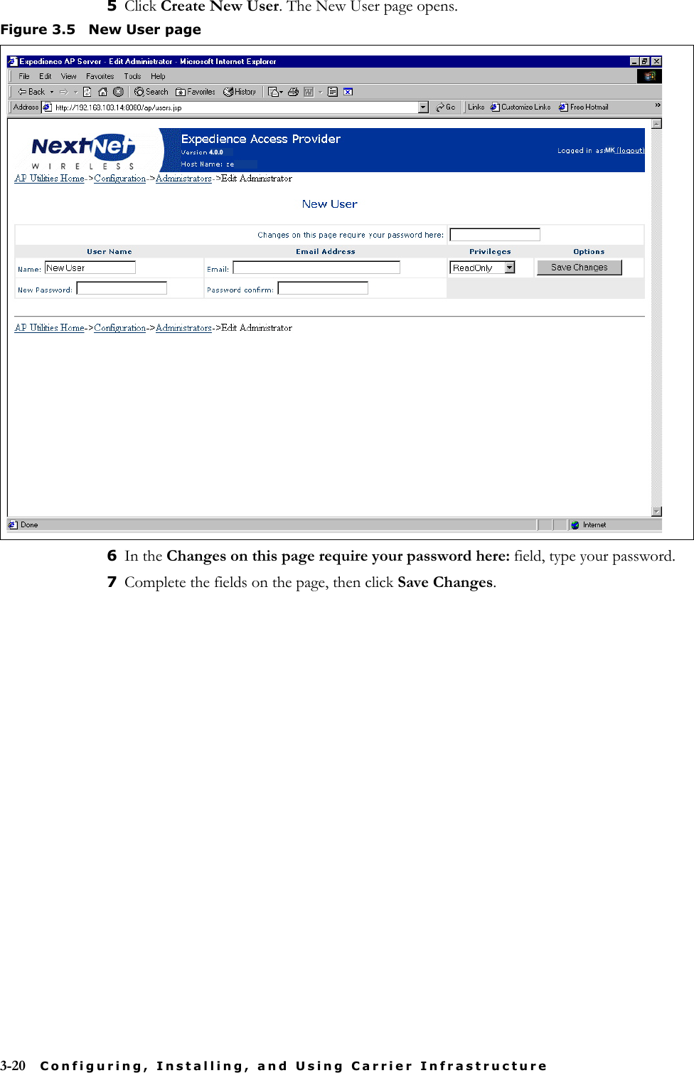
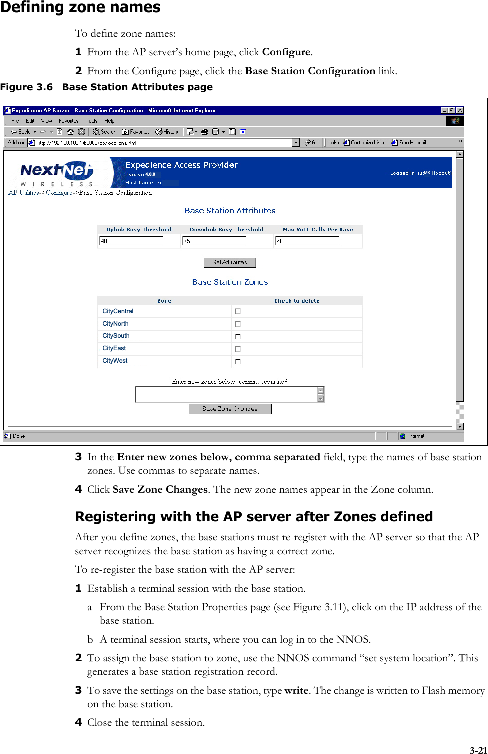
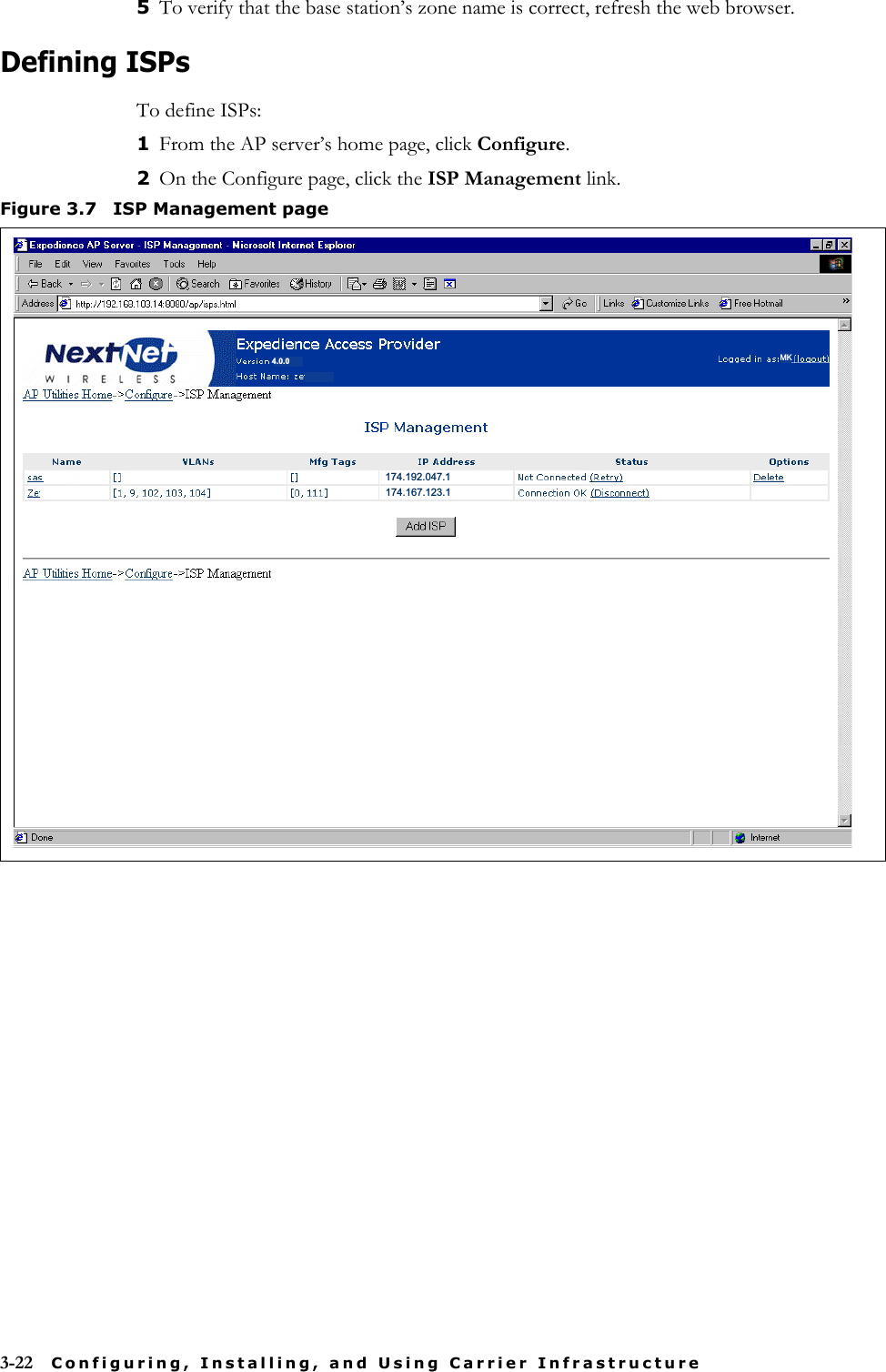
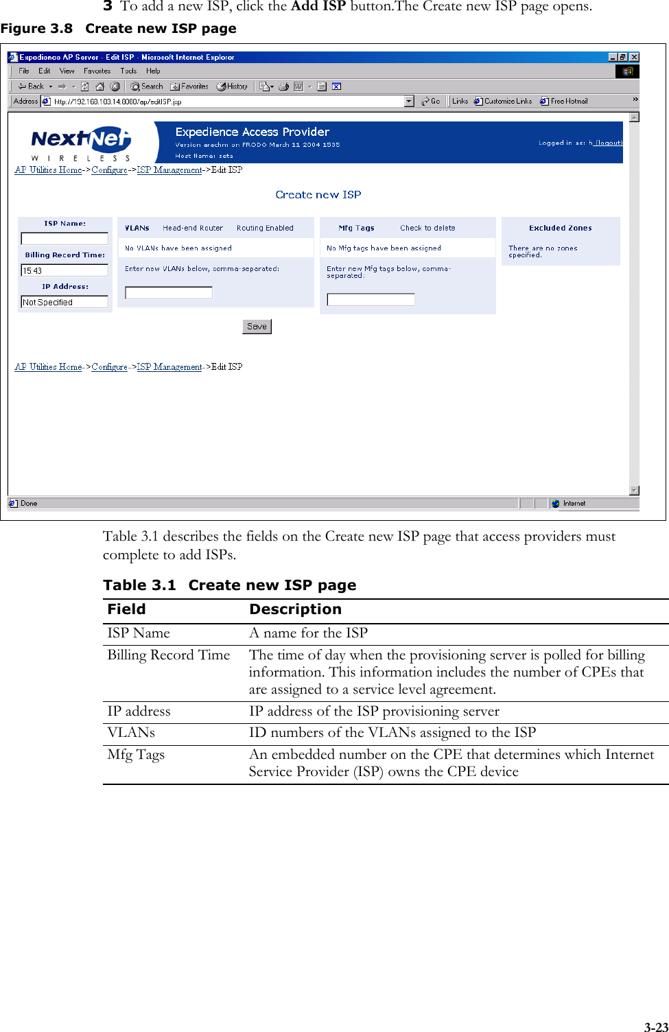
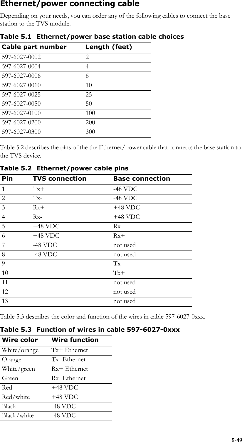
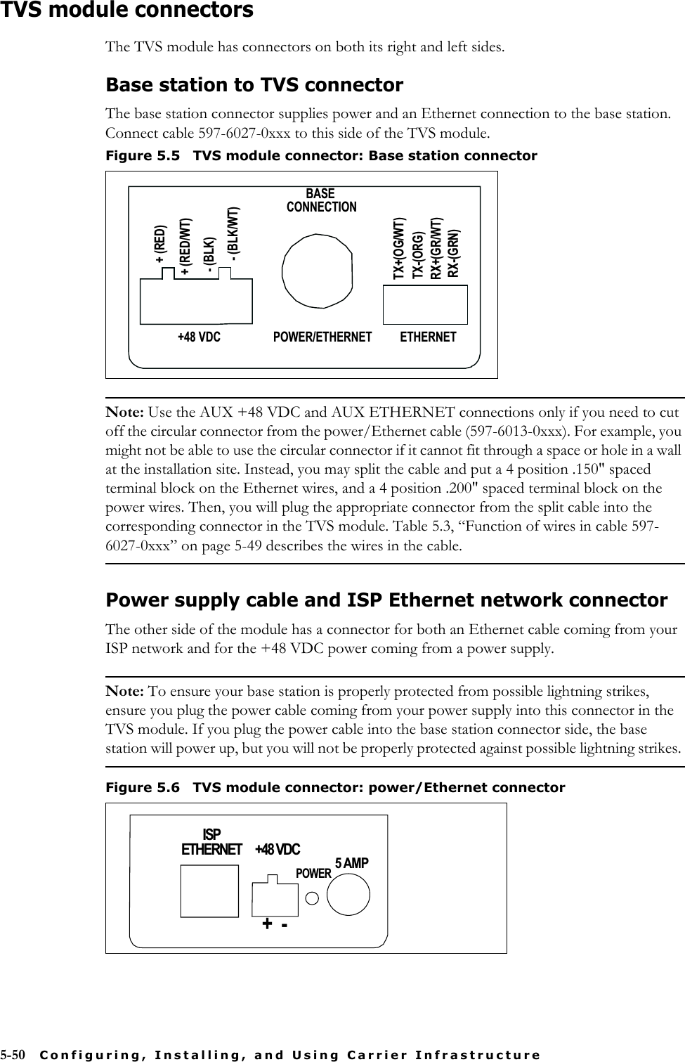
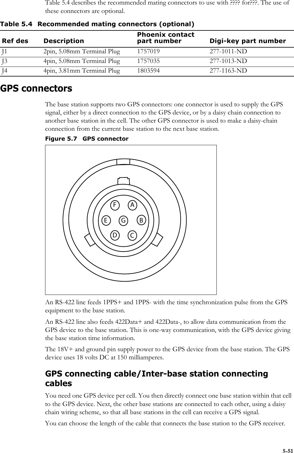
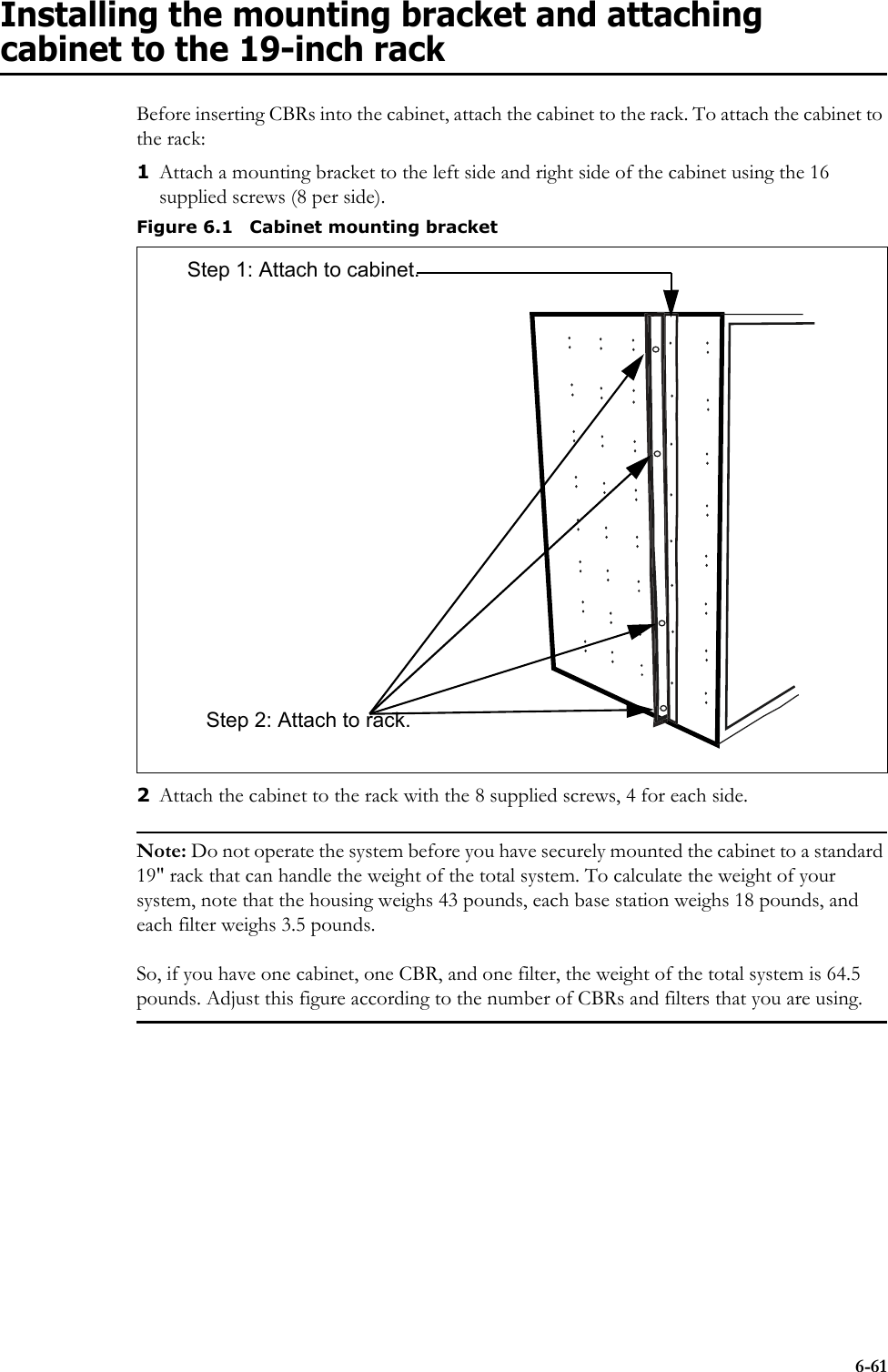
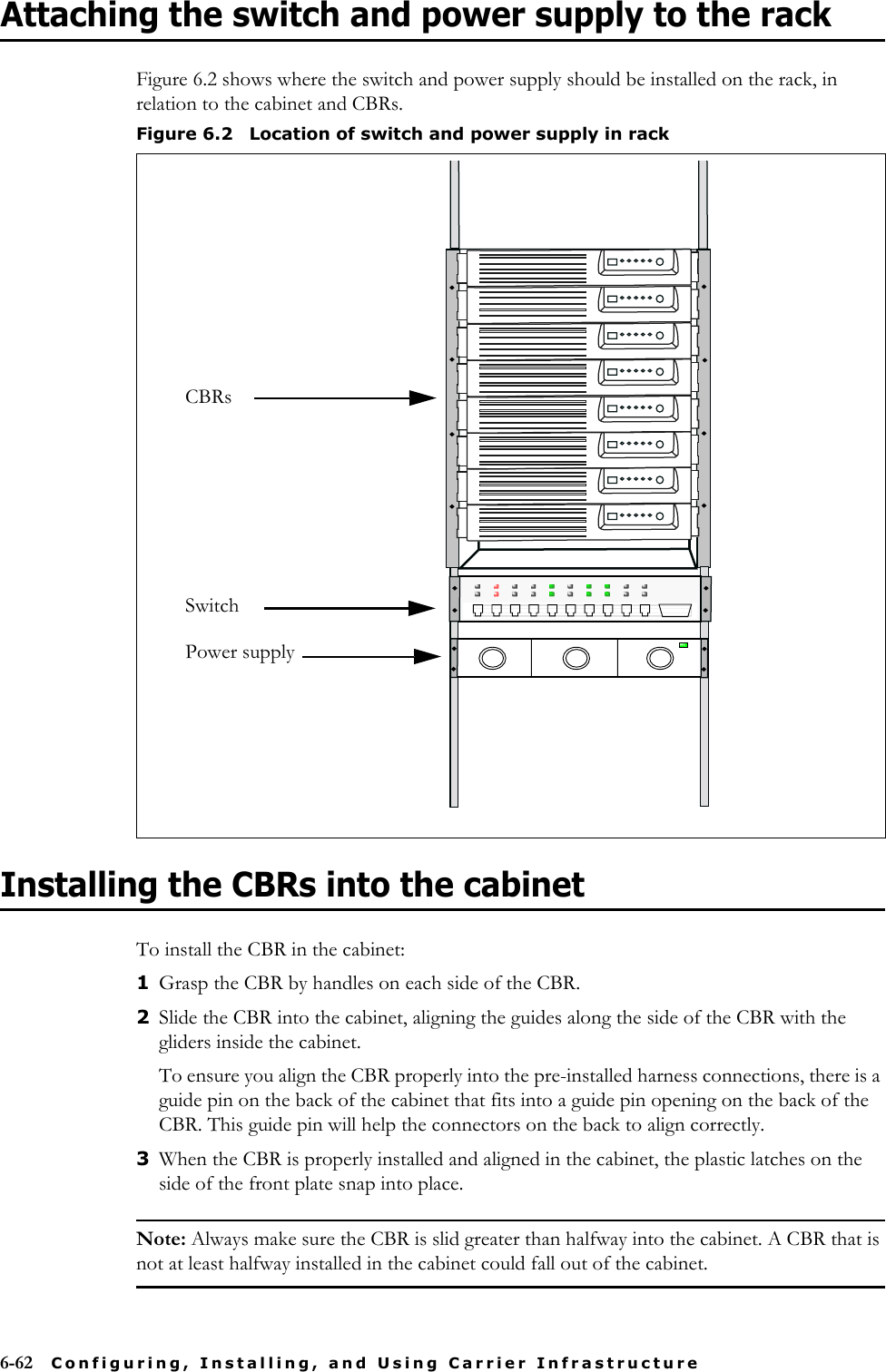
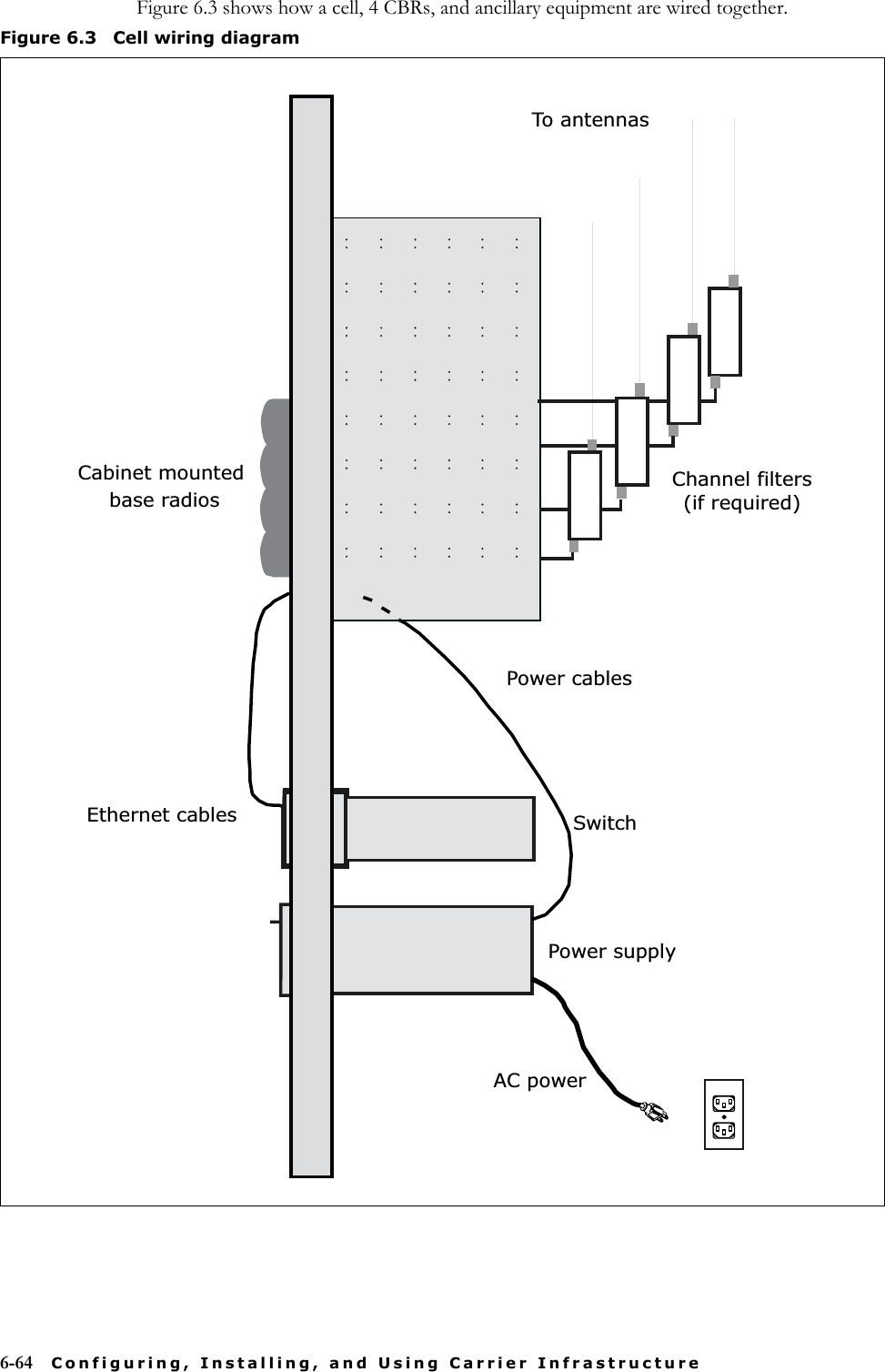
![xvTypographical conventions this guide usesTable iii describes the typographical conventions that this guide uses.Configuring and monitoring the ISP networkIntended for use by an ISP. Provides an overview of the Expedience system, its components, and its network architecture. This guide describes how to install and configure the ISP’s provisioning server. It describes how to define service level agreements (SLAs) and how SLAs are enforced by the NetEnforcer device.Expedience Broadband Wireless Access ModemIntended for use by your subscribers, this guide describes how to install a RSU (that is, an indoor CPE) at a subscriber site. Your subscribers can completely install the RSU.The guide explains, in detail, how to connect the RSU to a computer or to a network device. It explains system pre-requisites, and provides troubleshooting information. This guide is available in electronic (pdf) format, on the CD-ROM that accompanies the LinkMonitor software.Installing the RSU Intended for use by your subscribers, this guide describes how to quickly install a RSU directly to a computer. Expedience NLOS Outdoor Broadband Wireless Access ModemIntended for use by a professional installer, this guide describes how to install an outdoor CPE. Table ii Additional documentationGuide DescriptionTable iii Typographical conventionsConvention MeaningBold face If you are using a graphical user interface (GUI), bold face indicates a button, menu option, icon, and so on, that you manipulate directly.If you are using a command line interface, bold face indicates commands and keywords.Bold face can also indicate information that you must enter.Italic face Arguments for which you supply values are in italic face.Courier (mono-spaced) fontA command you type in, exactly as it appears, at a command line.[ ... ] Arguments that appear inside square brackets [ ], are optional.Also, when the guide shows a system prompt, the default system prompt appears inside square brackets.{..} | {..} Required keywords are grouped in braces and separated by vertical bars.Note Notes contain helpful suggestions for the reader.<...> Non-printing characters, such as passwords, appear in angle brackets.Caution Cautions contain information about which the reader must exercise care.Warning Warnings contain information about how readers might do something resulting in harm to themselves or in damage to equipment or data.](https://usermanual.wiki/Nokia-Solutions-and-Networks/RBTS2500/User-Guide-415130-Page-15.png)