Nokia Solutions and Networks T4KJ1 LTE 700 MHz Public Safety Base Station Transceiver User Manual Exhibit 8 Users Manual
Nokia Solutions and Networks LTE 700 MHz Public Safety Base Station Transceiver Exhibit 8 Users Manual
Contents
- 1. Exhibit 8 Users Manual
- 2. Exhibit 8 Users Manual (print)
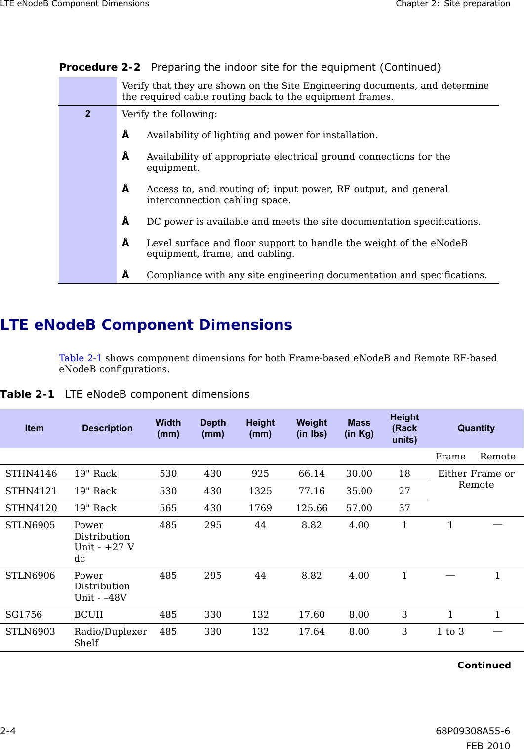
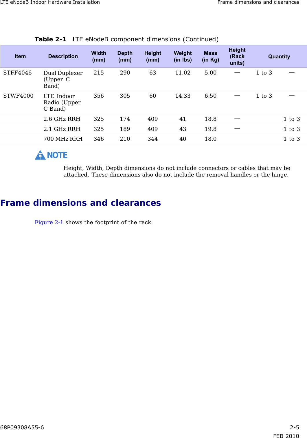
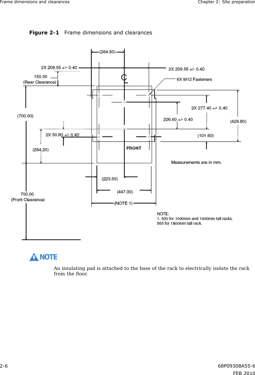
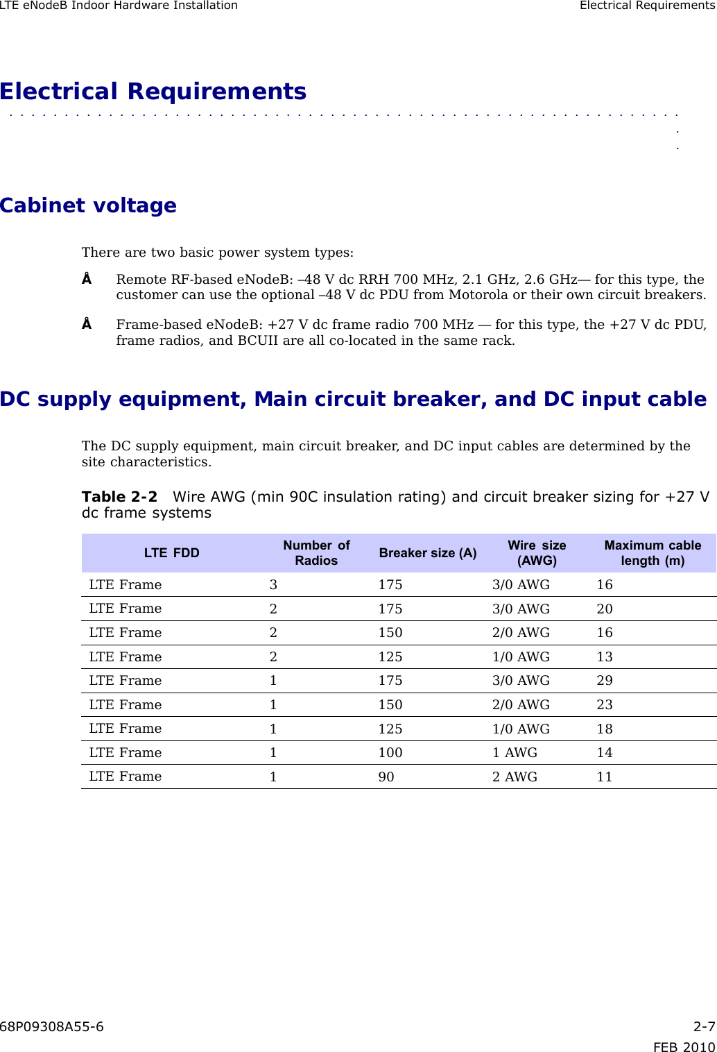
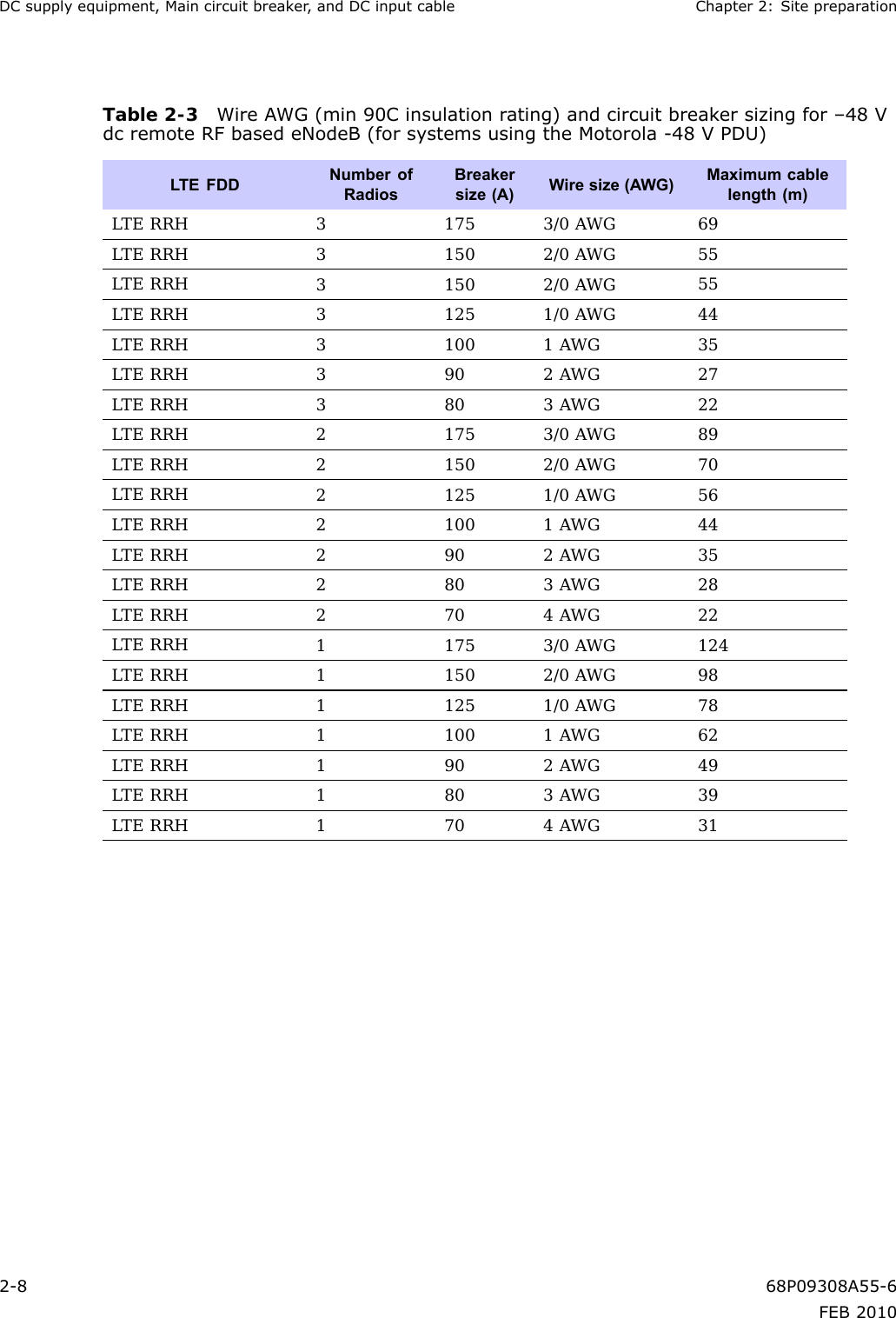
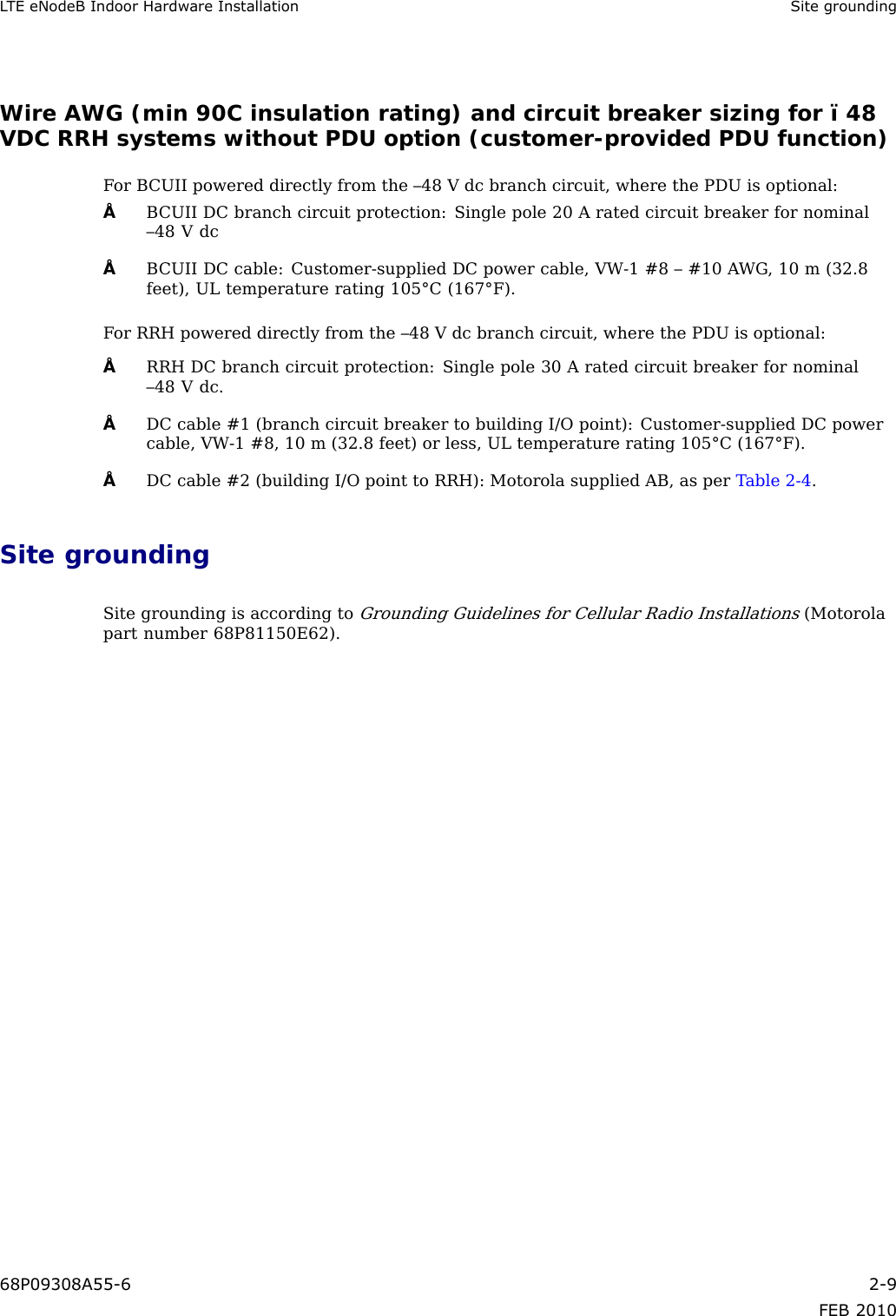
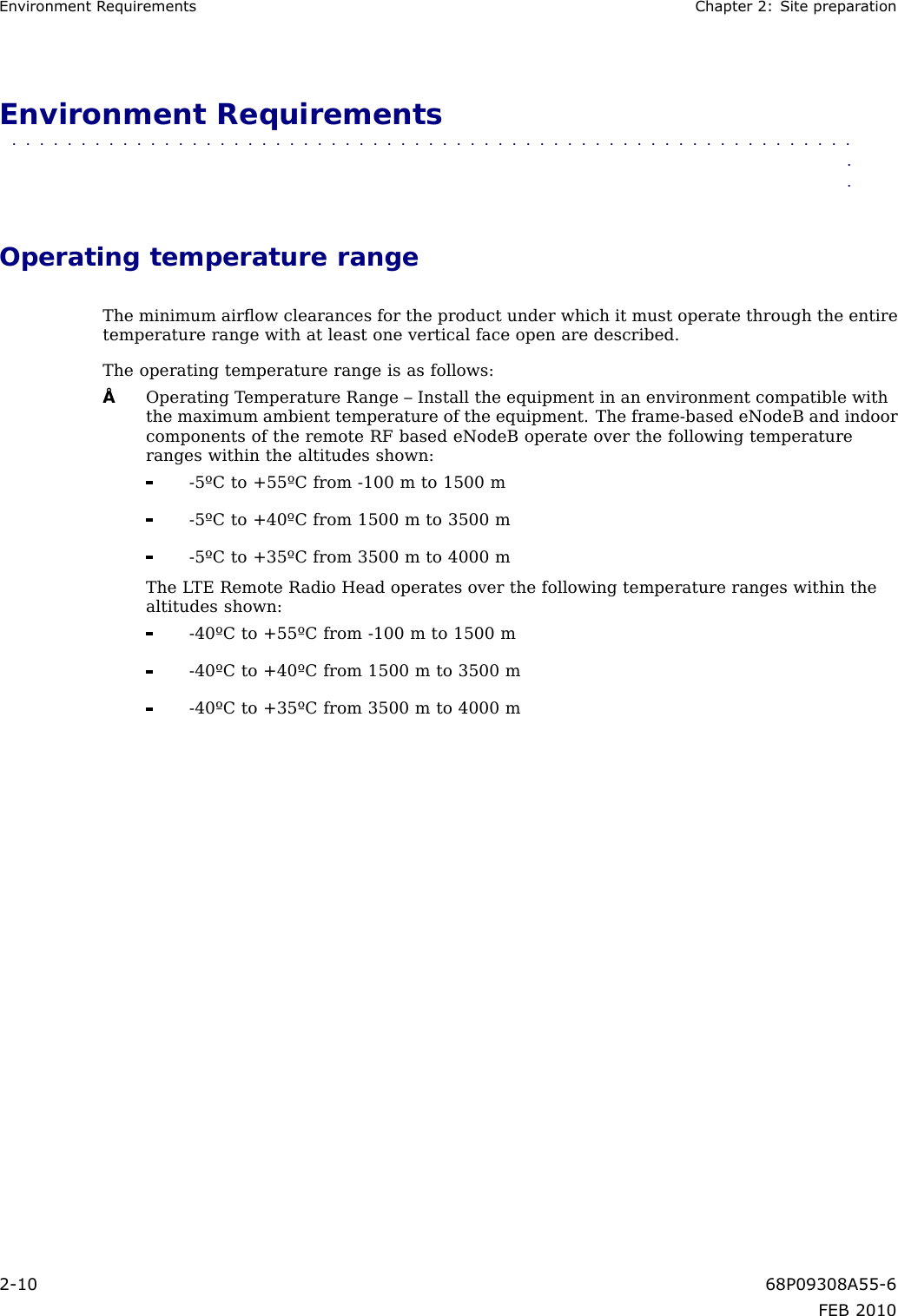
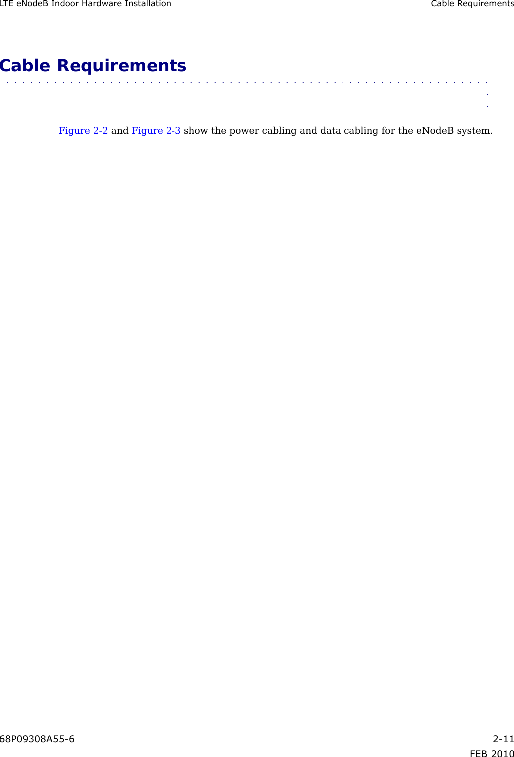
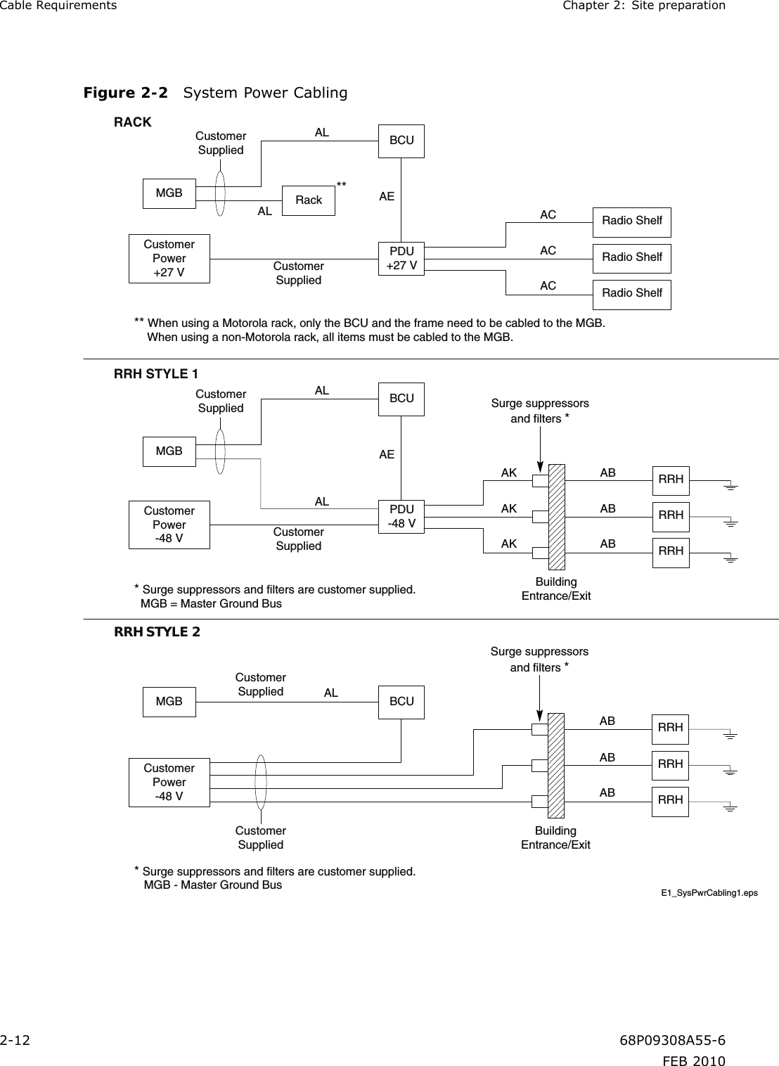
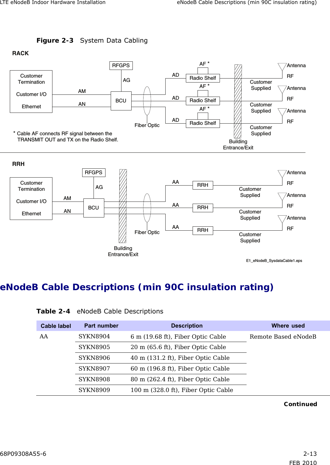
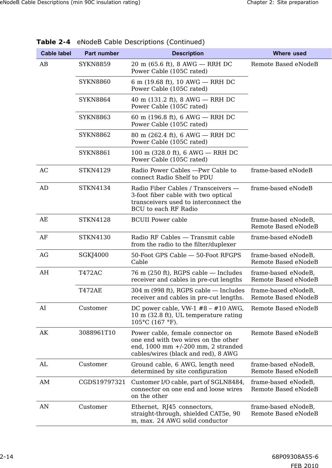
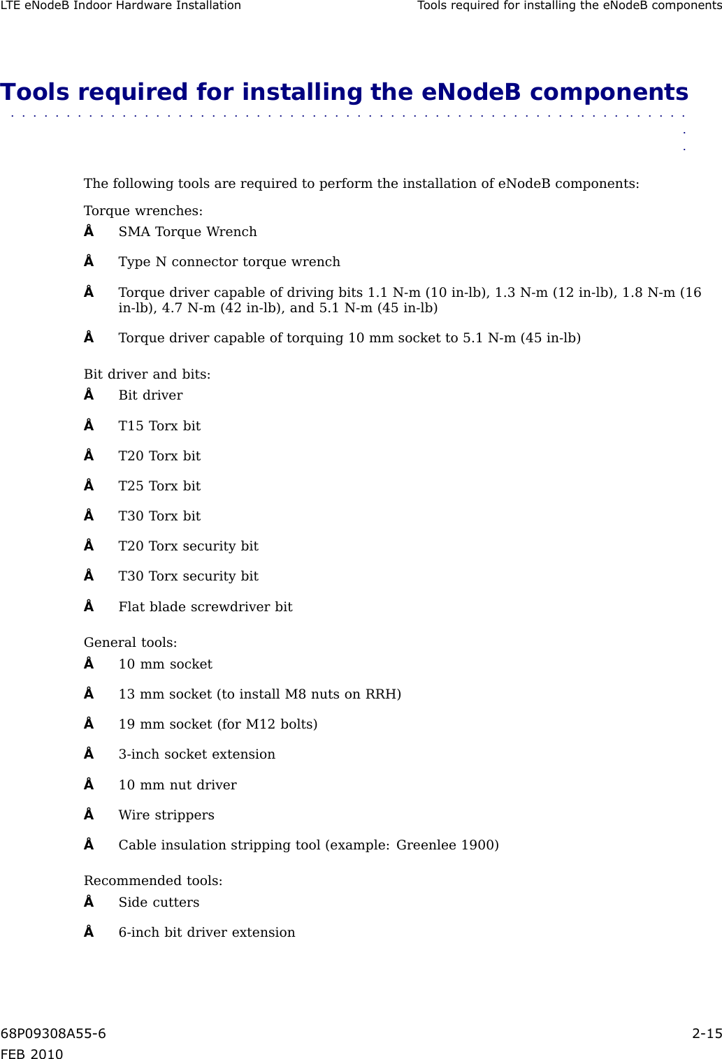
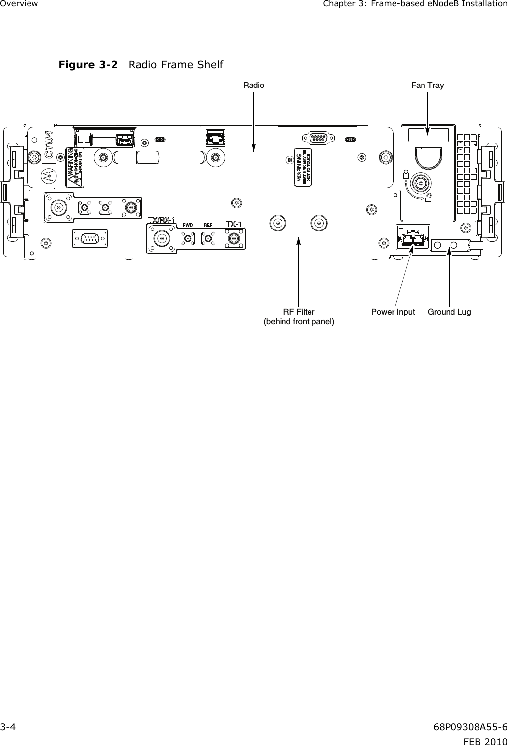
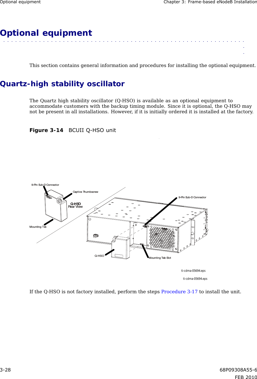
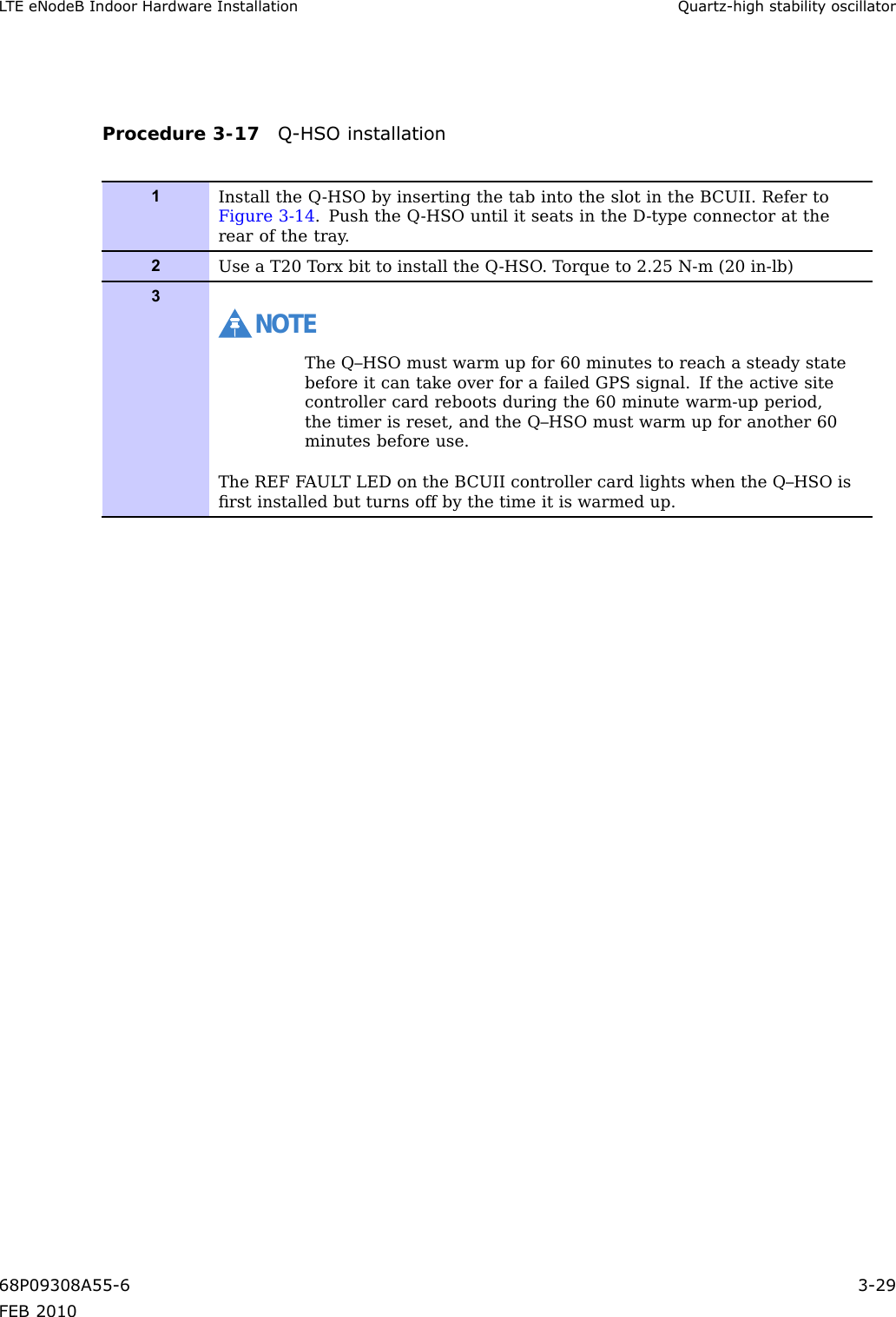
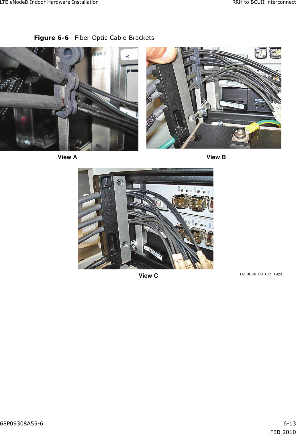
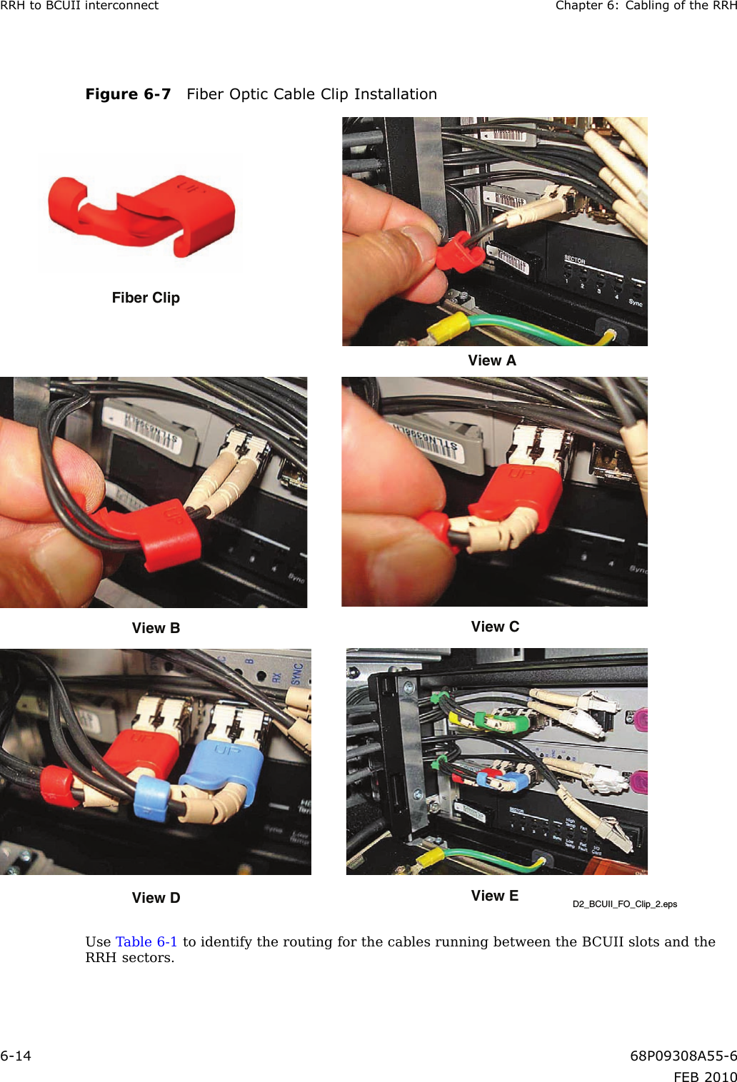
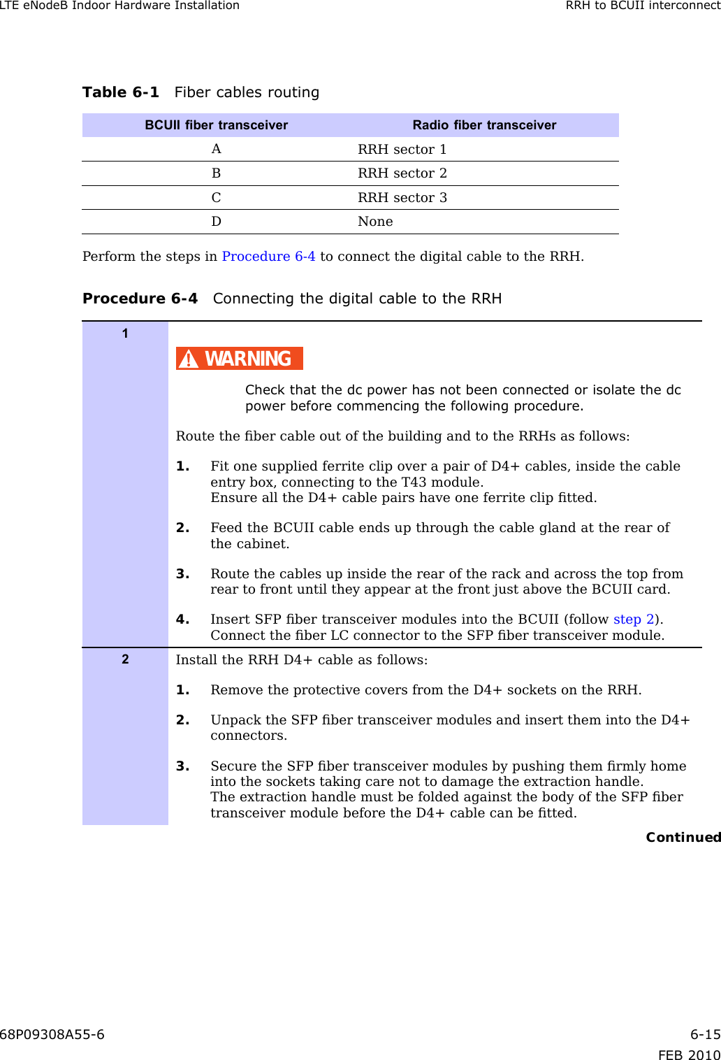
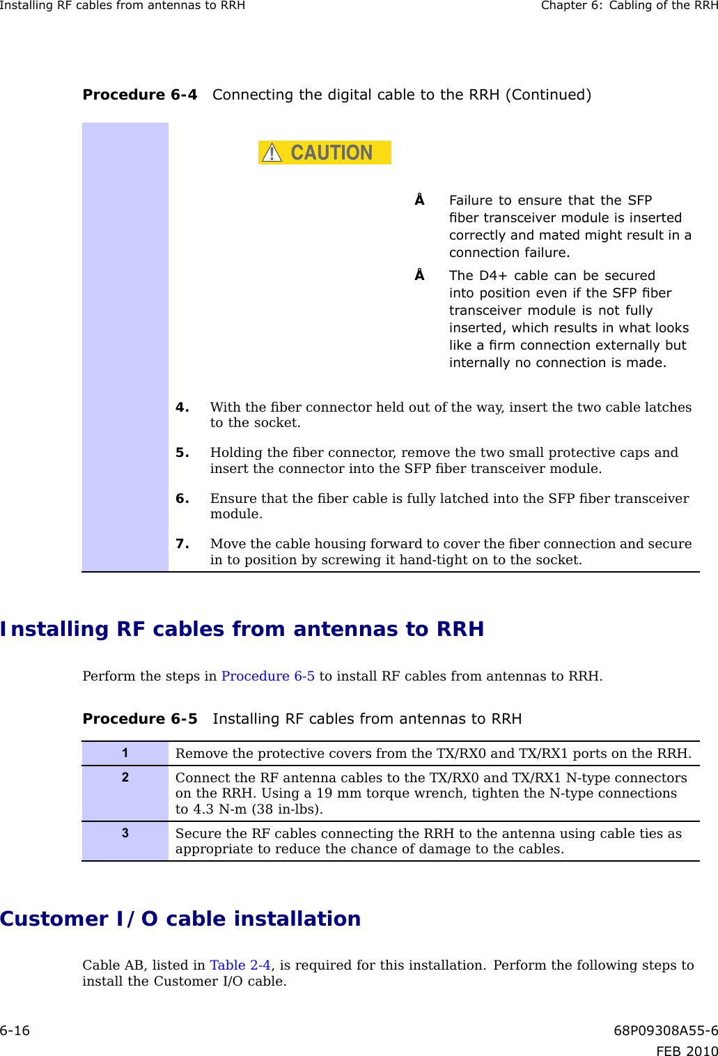
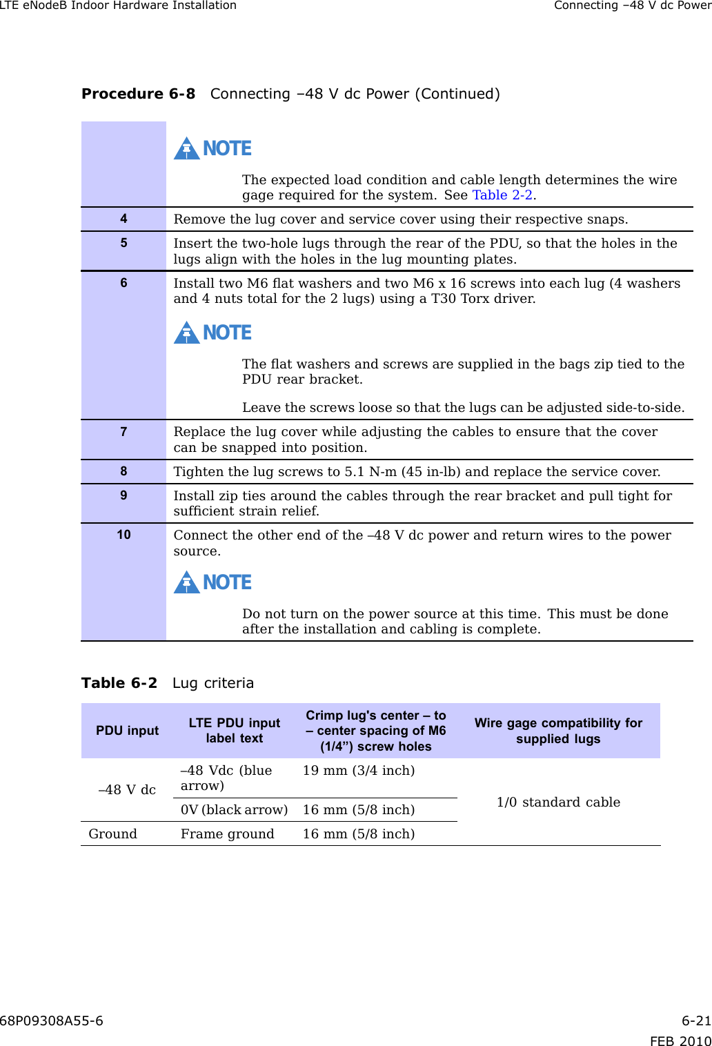
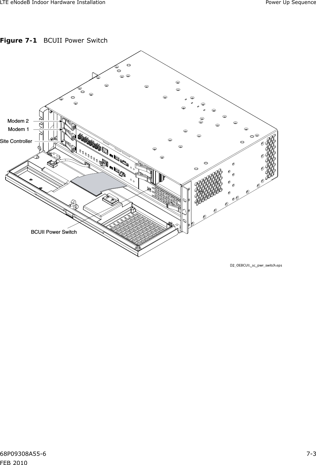
Exhibit 8 Users Manual