Nokia Solutions and Networks T5BP1 SC4812-MF 1X @ 800MHz CDMA BTS User Manual 1X SC4812T BTS Optimization ATP Release 2 16 3 x
Nokia Solutions and Networks SC4812-MF 1X @ 800MHz CDMA BTS 1X SC4812T BTS Optimization ATP Release 2 16 3 x
UserManual.wiki
>
Nokia Solutions and Networks
>
T5BP1 User Manual
Exhibit 8
Navigation menu
Upload a User Manual
Namespaces
Wiki Guide
HTML
PDF
Info
Views
User Manual
Discussion / Help
Navigation
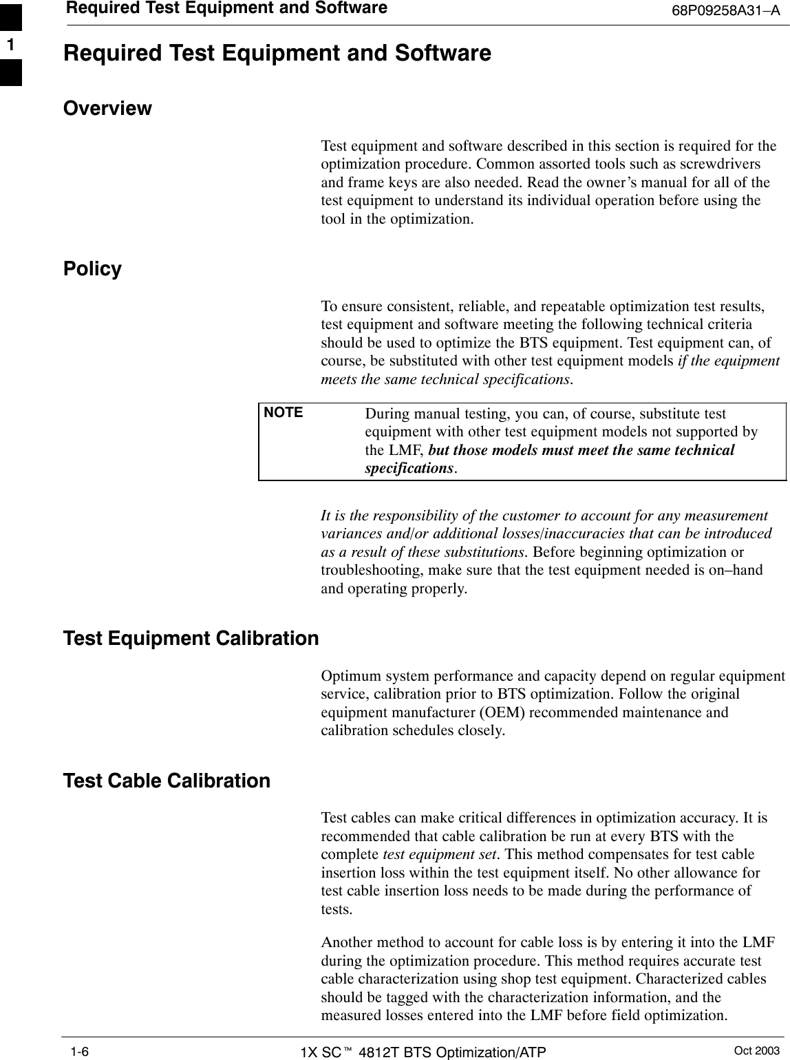
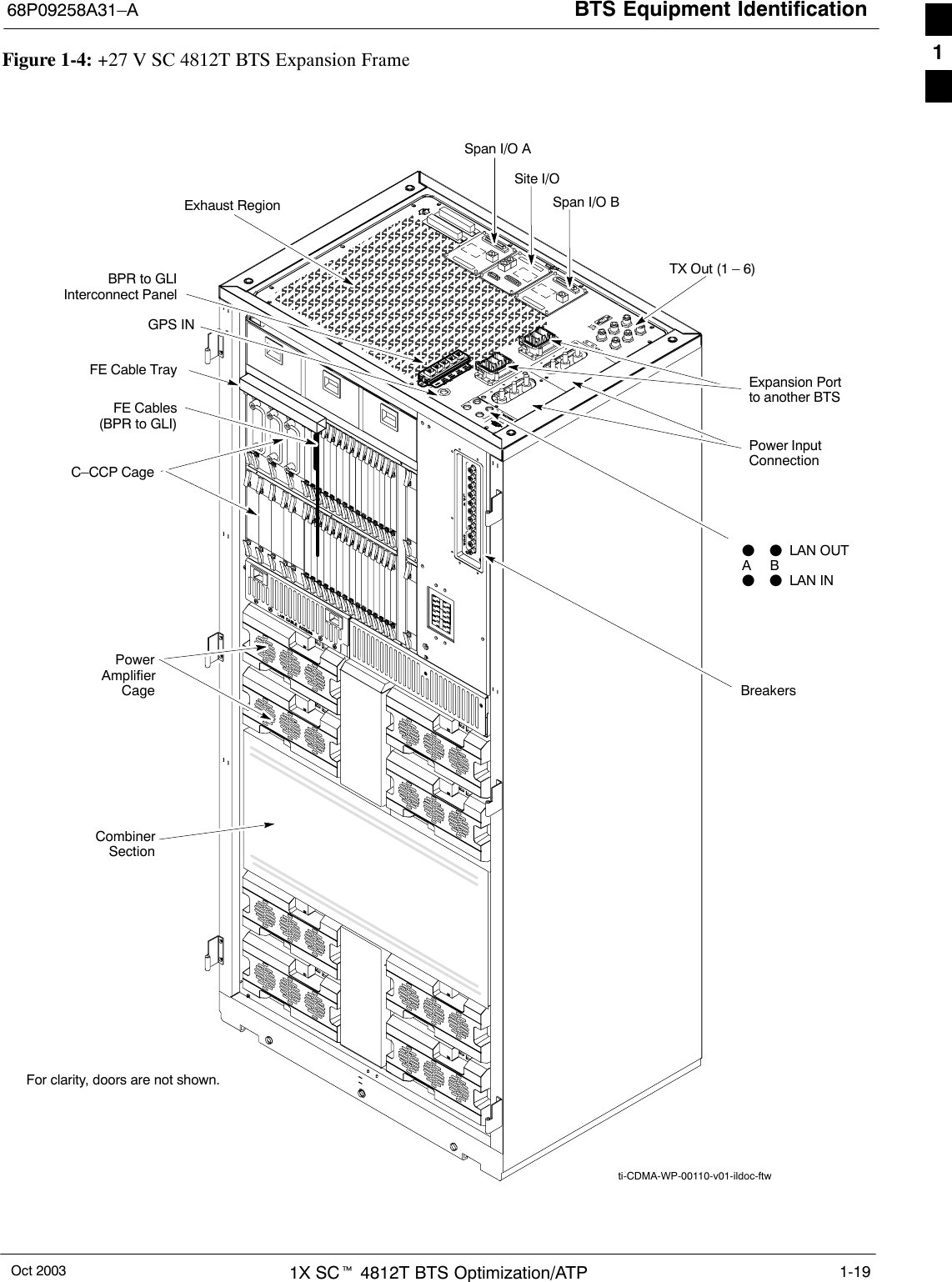
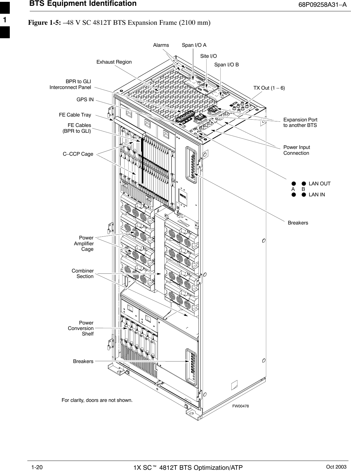
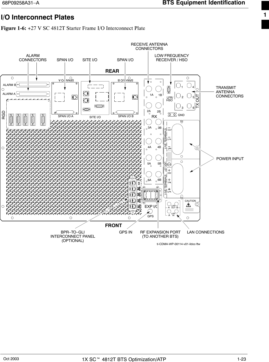
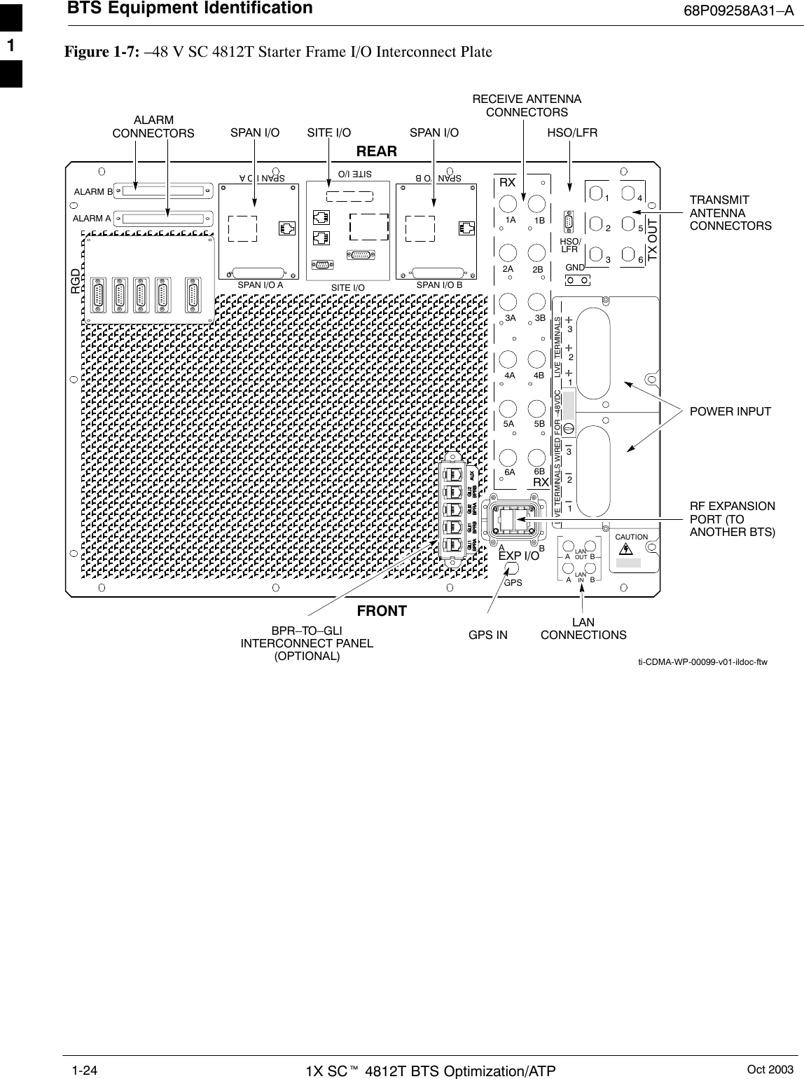
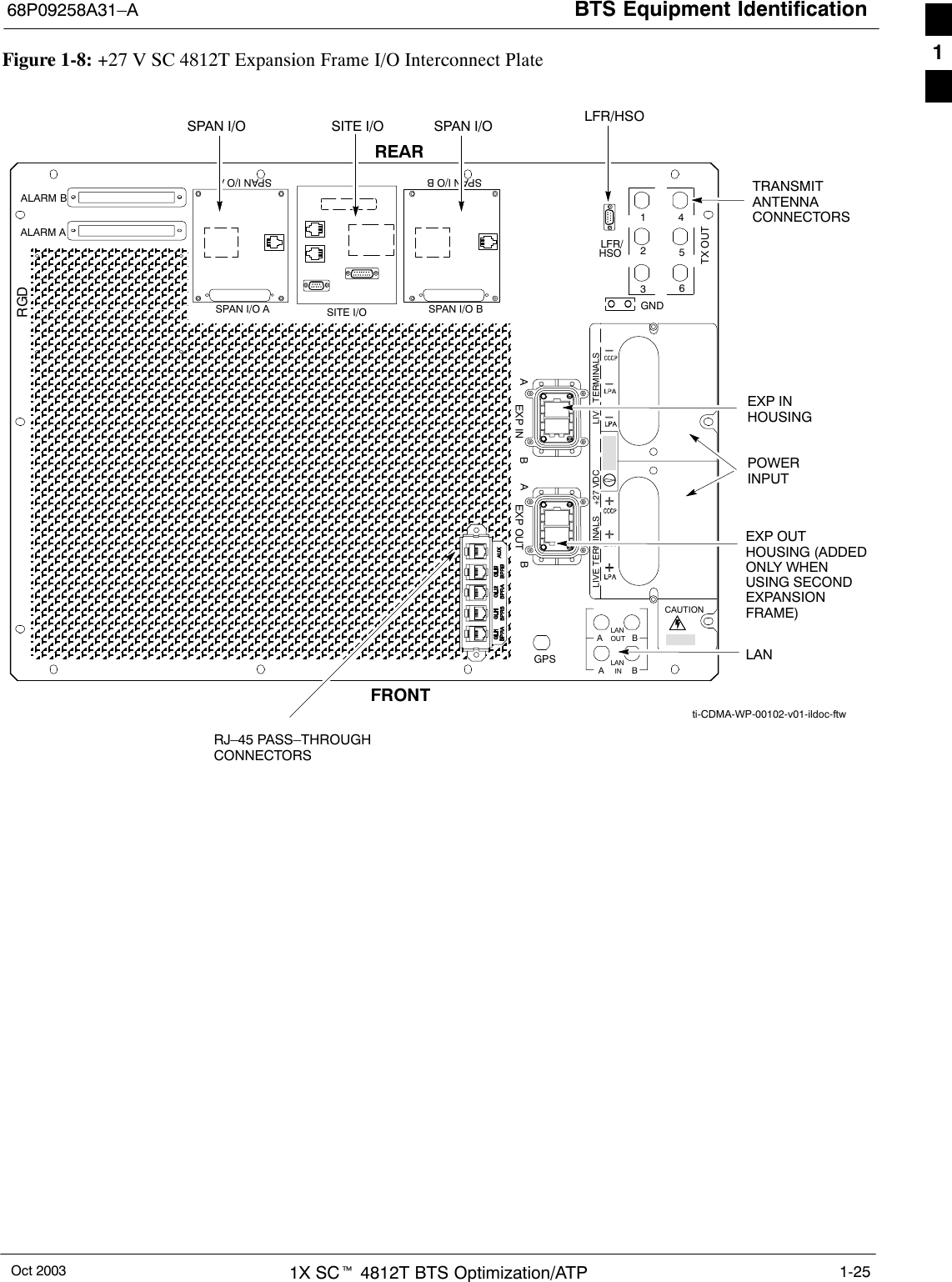
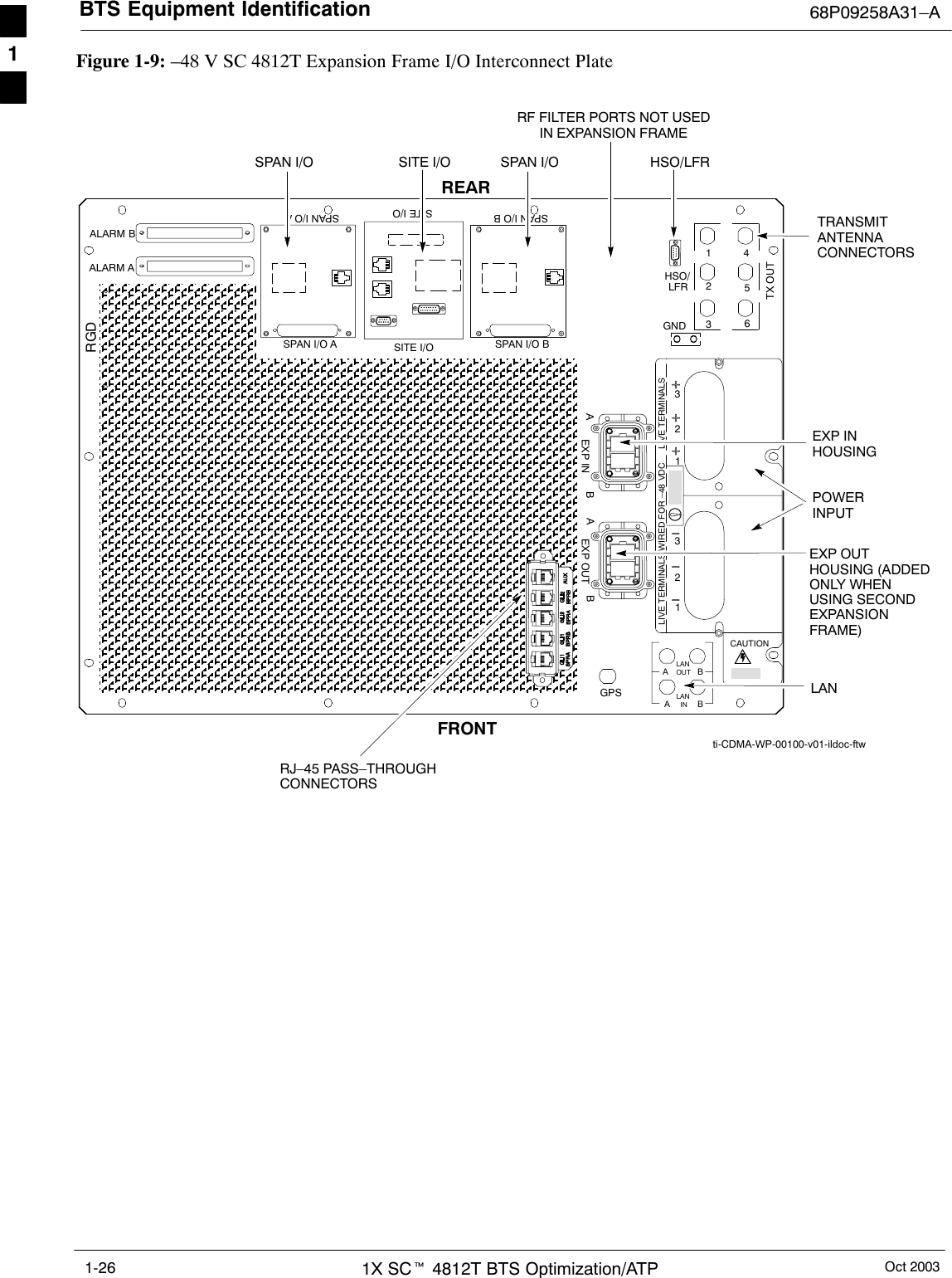
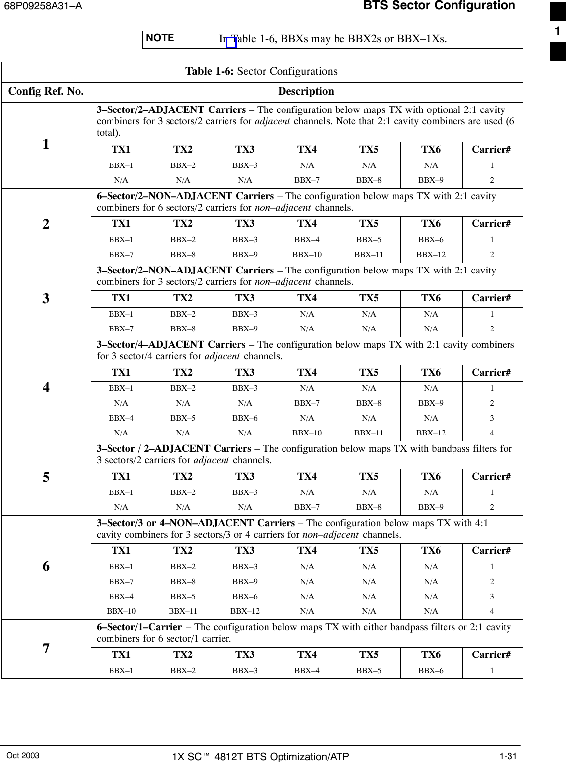
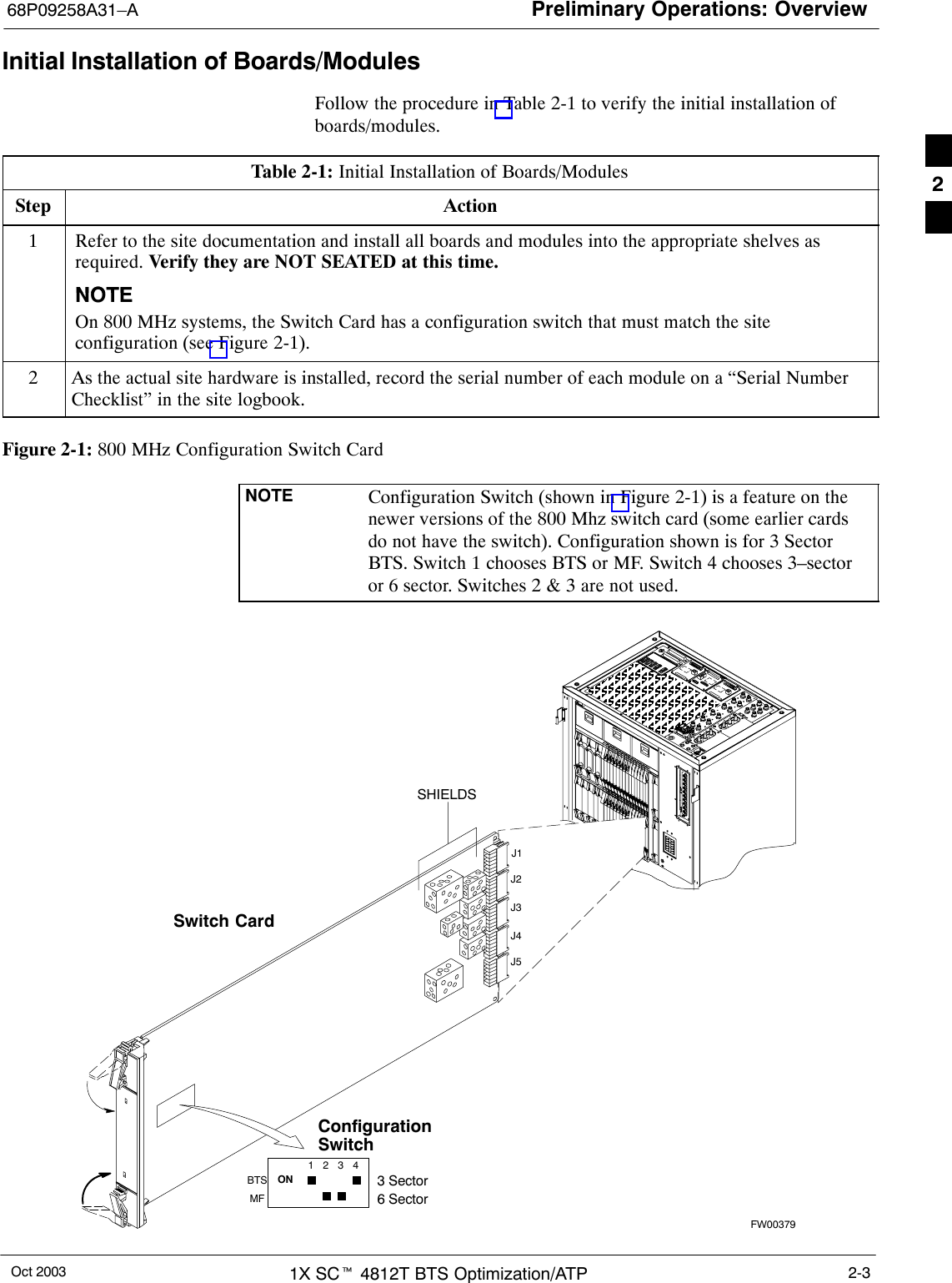
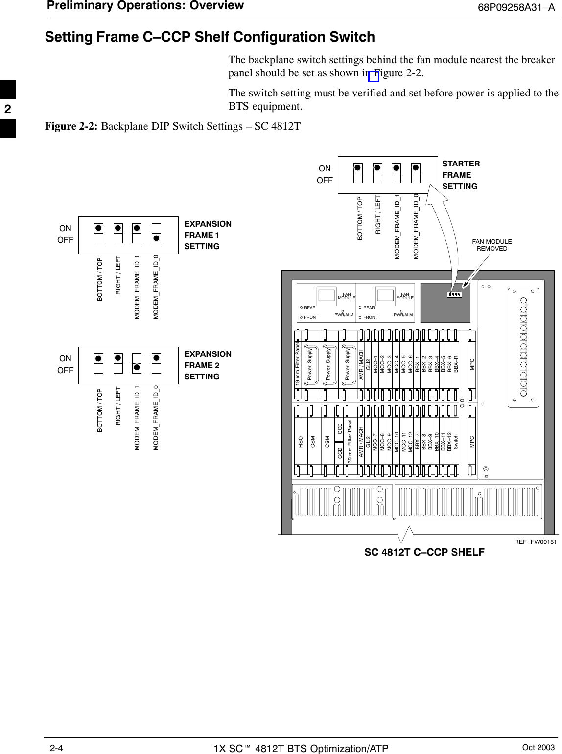
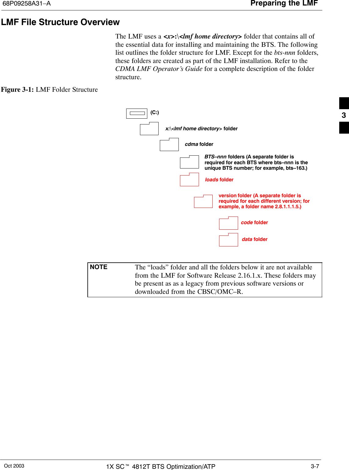
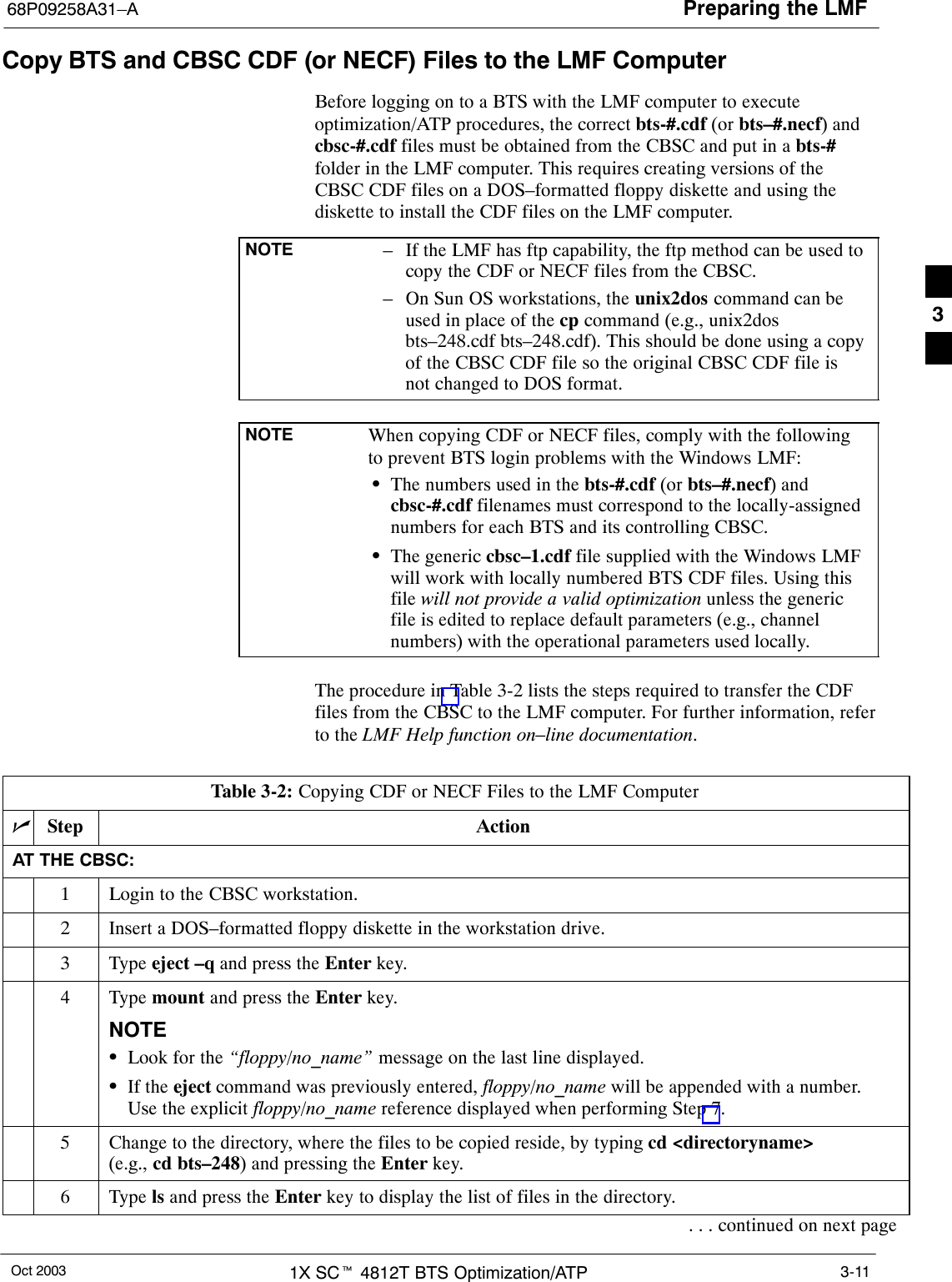
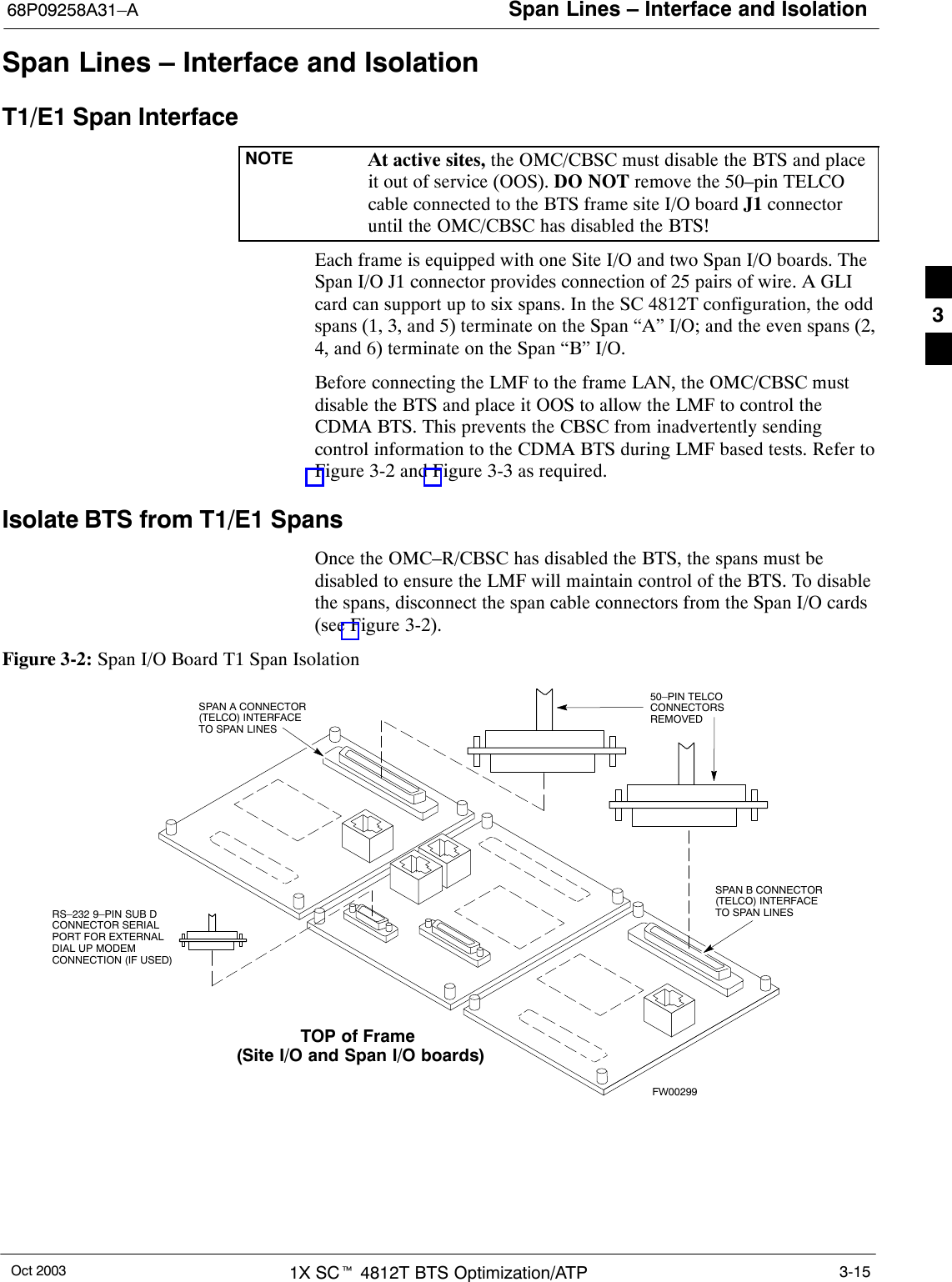
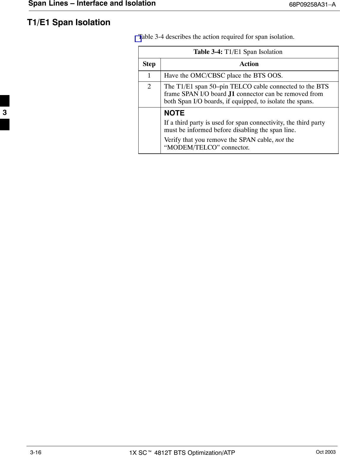
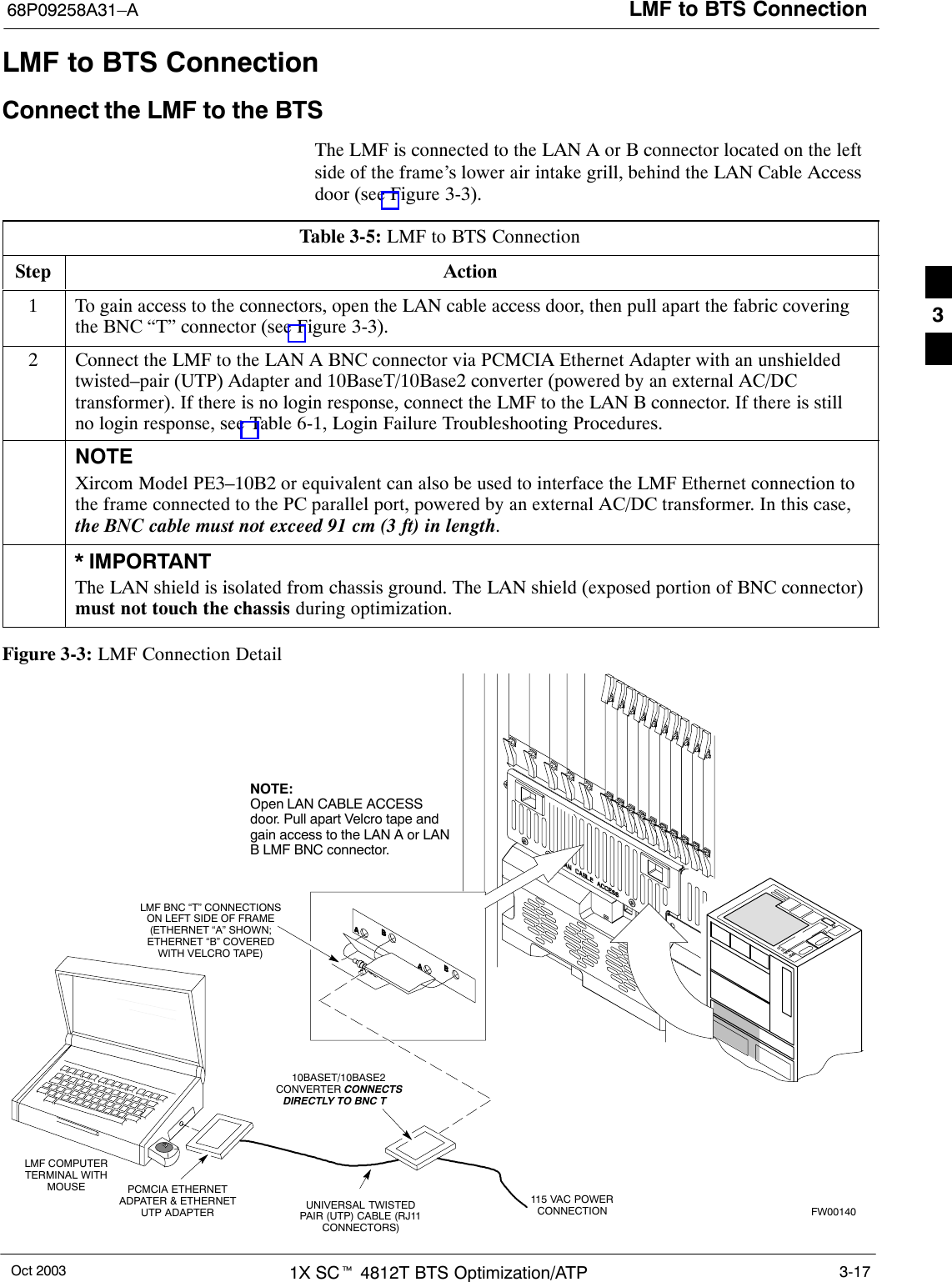
![Required Test Equipment and Software 68P09258A31–AOct 20031X SCt 4812T BTS Optimization/ATP1-10GPIB CablesSHewlett Packard 10833A or equivalent; 1 to 2 meters (3 to 6 feet) longused to interconnect test equipment and LMF terminal.Timing Reference CablesSTwo BNC-male to BNC-male RG316 cables; 3.05 m (10 ft.) long.Used to connect the communications analyzer to the front timingreference of the CSM cards in the BTS frame.Digital MultimeterSFluke Model 8062A with Y8134 test lead kit or equivalent; used forprecision dc and ac measurements, requiring 4–1/2 digits.Directional CouplerSNarda Model 30661 30 dB (Motorola part no. 58D09732W01)1900 MHz coupler terminated with two Narda Model 375BN–Mloads, or equivalent.SNarda Model 30445 30 dB (Motorola Part No. 58D09643T01 )800 MHz coupler terminated with two Narda Model 375BN–M loads,or equivalent.RF AttenuatorS20 dB fixed attenuator, 20 W (Narda 768–20); used with 1.7/1.9 GHztest cable calibrations or during general troubleshooting procedures.RF Terminations/LoadsSAt least three 100–Watt (or larger) non–radiating RFterminations/loads.Miscellaneous RF Adapters, Loads, etcSAs required to interface test cables and BTS equipment and forvarious test set ups. Should include at least two 50 Ohm loads (typeN) for calibration and one RF short, two N–Type Female–to–FemaleAdapters.LAN CableSBNC–to BNC 50 ohm coaxial cable [.91 m (3 ft) maximum] with anF–to–F adapter, used to connect the 10BaseT–to–coaxial adapter tothe BTS LAN connector.High–impedance Conductive Wrist StrapSMotorola Model 42–80385A59; used to prevent damage fromElectrostatic Discharge (ESD) when handling or working withmodules.1](https://usermanual.wiki/Nokia-Solutions-and-Networks/T5BP1/User-Guide-463994-Page-38.png)