Nokia Solutions and Networks T5CG1 SC300 1X Microcell @ 800 MHz User Manual 3of 3
Nokia Solutions and Networks SC300 1X Microcell @ 800 MHz Users Manual 3of 3
Contents
- 1. Users Manual 1 of 3
- 2. Users Manual 2 of 3
- 3. Users Manual 3of 3
Users Manual 3of 3

JAN 2002 SCt300 1X BTS Hardware Installation, ATP, and FRU Procedures
DRAFT
Chapter 7: Optimization and Optional Acceptance Test Procedures (ATP)
Table of Contents
ATP Overview 7-1. . . . . . . . . . . . . . . . . . . . . . . . . . . . . . . . . . . . . . . . . . . . . . . . . . .
Overview 7-1. . . . . . . . . . . . . . . . . . . . . . . . . . . . . . . . . . . . . . . . . . . . . . . .
BTS Preparation 7-2. . . . . . . . . . . . . . . . . . . . . . . . . . . . . . . . . . . . . . . . . . . . . . . . .
Overview 7-2. . . . . . . . . . . . . . . . . . . . . . . . . . . . . . . . . . . . . . . . . . . . . . . .
Required Tools and Equipment 7-2. . . . . . . . . . . . . . . . . . . . . . . . . . . . . . .
Procedure to Remove the Solar Cover 7-2. . . . . . . . . . . . . . . . . . . . . . . . . .
BTS Power Up 7-2. . . . . . . . . . . . . . . . . . . . . . . . . . . . . . . . . . . . . . . . . . . .
Procedure to Remove Diagnostic Access Cover 7-4. . . . . . . . . . . . . . . . . .
Connect LMF to BTS 7-6. . . . . . . . . . . . . . . . . . . . . . . . . . . . . . . . . . . . . . . . . . . . .
Overview 7-6. . . . . . . . . . . . . . . . . . . . . . . . . . . . . . . . . . . . . . . . . . . . . . . .
LMF to BTS Connection 7-6. . . . . . . . . . . . . . . . . . . . . . . . . . . . . . . . . . . .
Procedure to Connect LMF to BTS via Serial Port Connection 7-6. . . . . .
Procedure to Connect LMF to BTS via Ethernet Connection 7-7. . . . . . . .
Connect Test Equipment to BTS 7-10. . . . . . . . . . . . . . . . . . . . . . . . . . . . . . . . . . . .
Overview 7-10. . . . . . . . . . . . . . . . . . . . . . . . . . . . . . . . . . . . . . . . . . . . . . . .
Procedure to Connect Advantest R3465 to BTS 7-11. . . . . . . . . . . . . . . . .
Procedure to Connect Advantest R3267 to BTS 7-13. . . . . . . . . . . . . . . . . .
Procedure to Connect the Motorola CyberTest, HP 8935, and
HP 8921 to BTS 7-15. . . . . . . . . . . . . . . . . . . . . . . . . . . . . . . . . . . . . . . . . . .
Procedure to Connect the Agilent E4406A/E4432B to BTS 7-16. . . . . . . . .
Connect Test Set and Power Meter to LMF 7-18. . . . . . . . . . . . . . . . . . . . . . . . . . . .
Procedure to Connect the Communication Test Set and
Power Meter to the LMF 7-18. . . . . . . . . . . . . . . . . . . . . . . . . . . . . . . . . . . .
RS232 Cable Configuration 7-19. . . . . . . . . . . . . . . . . . . . . . . . . . . . . . . . . .
BTS Configuration 7-20. . . . . . . . . . . . . . . . . . . . . . . . . . . . . . . . . . . . . . . . . . . . . . .
Objective 7-20. . . . . . . . . . . . . . . . . . . . . . . . . . . . . . . . . . . . . . . . . . . . . . . .
Procedure to Create a Named HyperTerminal Connection for MMI
Communication 7-20. . . . . . . . . . . . . . . . . . . . . . . . . . . . . . . . . . . . . . . . . . .
Procedure to Establish an MMI Communication Session 7-22. . . . . . . . . . .
Procedure to Set IP Address 7-23. . . . . . . . . . . . . . . . . . . . . . . . . . . . . . . . .
Procedure to Simulate an LMF Session 7-24. . . . . . . . . . . . . . . . . . . . . . . .
Updating Default Channel Setting to Customer Operating Channel 7-25. . .
Synchronization Background 7-26. . . . . . . . . . . . . . . . . . . . . . . . . . . . . . . . .
Procedure to Verify and Change BTS Synchronization Mode 7-27. . . . . . .
Procedure to Verify DPLL Tracking (RGPS/HSO) 7-28. . . . . . . . . . . . . . . .
Procedure to Verify and Modify Default Location Coordinates 7-29. . . . . .
7

Table of Contents – continued
DRAFT
SCt300 1X BTS Hardware Installation, ATP, and FRU Procedures JAN 2002
Procedure to Set Frame ID for Multi–Unit Logical BTS Configuration 7-31
BTS Software 7-32. . . . . . . . . . . . . . . . . . . . . . . . . . . . . . . . . . . . . . . . . . . . . . . . . . .
Objective 7-32. . . . . . . . . . . . . . . . . . . . . . . . . . . . . . . . . . . . . . . . . . . . . . . .
Install the LMF Program and BTS Binaries 7-32. . . . . . . . . . . . . . . . . . . . .
Create a Site–Specific BTS Directory 7-32. . . . . . . . . . . . . . . . . . . . . . . . . .
Start the LMF and Login to the BTS 7-32. . . . . . . . . . . . . . . . . . . . . . . . . . .
Update BTS Specific CDF File Device Load Version 7-33. . . . . . . . . . . . .
Download/Enable MAWI 7-34. . . . . . . . . . . . . . . . . . . . . . . . . . . . . . . . . . .
Configuration Data File (CDF) 7-35. . . . . . . . . . . . . . . . . . . . . . . . . . . . . . .
System Status LED States 7-36. . . . . . . . . . . . . . . . . . . . . . . . . . . . . . . . . . .
Verify and Set Span Line Settings 7-37. . . . . . . . . . . . . . . . . . . . . . . . . . . . . . . . . . .
Objective 7-37. . . . . . . . . . . . . . . . . . . . . . . . . . . . . . . . . . . . . . . . . . . . . . . .
Span Line Settings 7-37. . . . . . . . . . . . . . . . . . . . . . . . . . . . . . . . . . . . . . . . .
Procedure to Verify and Set Span Line Settings 7-37. . . . . . . . . . . . . . . . . .
SPAN_CONFIG Parameters 7-39. . . . . . . . . . . . . . . . . . . . . . . . . . . . . . . . .
GPIB Addresses 7-40. . . . . . . . . . . . . . . . . . . . . . . . . . . . . . . . . . . . . . . . . . . . . . . . .
Introduction 7-40. . . . . . . . . . . . . . . . . . . . . . . . . . . . . . . . . . . . . . . . . . . . . .
Verify the Gigatronics 8541C Power Meter GPIB Address 7-40. . . . . . . . .
Verify and Set Motorola CyberTest GPIB Address 7-41. . . . . . . . . . . . . . . .
Verify and Set HP8935 Test Set GPIB Address 7-42. . . . . . . . . . . . . . . . . .
Verify and Set the HP8921A and HP83236A/B GPIB Addresses 7-43. . . .
Verify and Set Advantest R3465 GPIB Address 7-44. . . . . . . . . . . . . . . . . .
RS232 GPIB Interface Box 7-45. . . . . . . . . . . . . . . . . . . . . . . . . . . . . . . . . .
Verify and Set Advantest R3267 GPIB Address 7-45. . . . . . . . . . . . . . . . .
Verify and Set Advantest R3562 Signal Generator GPIB Address 7-47. . . .
Verify and Set Agilent E4406A Transmitter Tester GPIB Address 7-47. . . .
Verify and Set Agilent E4432B Signal Generator GPIB Address 7-49. . . . .
Test Equipment Calibration 7-51. . . . . . . . . . . . . . . . . . . . . . . . . . . . . . . . . . . . . . . .
Background 7-51. . . . . . . . . . . . . . . . . . . . . . . . . . . . . . . . . . . . . . . . . . . . . .
Procedure to Calibrate Test Equipment 7-52. . . . . . . . . . . . . . . . . . . . . . . . .
Calibration Without the LMF 7-52. . . . . . . . . . . . . . . . . . . . . . . . . . . . . . . .
Procedure to Calibrate R3465 Test Set 7-53. . . . . . . . . . . . . . . . . . . . . . . . .
Procedure to Calibrate R3267 Test Set 7-53. . . . . . . . . . . . . . . . . . . . . . . . .
Procedure to Calibrate Agilent E4406A 7-54. . . . . . . . . . . . . . . . . . . . . . . .
Procedure to Setup Advantest R3465 Test Equipment 7-55. . . . . . . . . . . . .
Procedure to Setup Advantest R3267 Test Equipment 7-56. . . . . . . . . . . . .
Test Equipment Selection 7-57. . . . . . . . . . . . . . . . . . . . . . . . . . . . . . . . . . . . . . . . . .
Objective 7-57. . . . . . . . . . . . . . . . . . . . . . . . . . . . . . . . . . . . . . . . . . . . . . . .
Prerequisites 7-57. . . . . . . . . . . . . . . . . . . . . . . . . . . . . . . . . . . . . . . . . . . . . .
Procedure to Select Test Equipment 7-57. . . . . . . . . . . . . . . . . . . . . . . . . . .
Selecting Test Equipment Automatically or Manually 7-58. . . . . . . . . . . . .
Procedure to Manually Select Test Equipment in a
Serial Connection Tab 7-58. . . . . . . . . . . . . . . . . . . . . . . . . . . . . . . . . . . . . .
Procedure to Automatically Select Test Equipment in a
Serial Connection Tab 7-59. . . . . . . . . . . . . . . . . . . . . . . . . . . . . . . . . . . . . .
Power Meter Calibration 7-60. . . . . . . . . . . . . . . . . . . . . . . . . . . . . . . . . . . . . . . . . . .
7

Table of Contents – continued
JAN 2002 SCt300 1X BTS Hardware Installation, ATP, and FRU Procedures
DRAFT
Objective 7-60. . . . . . . . . . . . . . . . . . . . . . . . . . . . . . . . . . . . . . . . . . . . . . . .
Prerequisites 7-60. . . . . . . . . . . . . . . . . . . . . . . . . . . . . . . . . . . . . . . . . . . . . .
Procedure to Calibrate the Power Meter 7-60. . . . . . . . . . . . . . . . . . . . . . . .
Test Cable Calibration 7-61. . . . . . . . . . . . . . . . . . . . . . . . . . . . . . . . . . . . . . . . . . . .
Background 7-61. . . . . . . . . . . . . . . . . . . . . . . . . . . . . . . . . . . . . . . . . . . . . .
Purpose of Cable Calibration 7-61. . . . . . . . . . . . . . . . . . . . . . . . . . . . . . . . .
Procedure to do an Automated Cable Calibration 7-62. . . . . . . . . . . . . . . . .
Create CAL File 7-65. . . . . . . . . . . . . . . . . . . . . . . . . . . . . . . . . . . . . . . . . . . . . . . . .
Objective 7-65. . . . . . . . . . . . . . . . . . . . . . . . . . . . . . . . . . . . . . . . . . . . . . . .
Background 7-65. . . . . . . . . . . . . . . . . . . . . . . . . . . . . . . . . . . . . . . . . . . . . .
Procedure to Create a CAL File 7-66. . . . . . . . . . . . . . . . . . . . . . . . . . . . . . .
Acceptance Tests 7-67. . . . . . . . . . . . . . . . . . . . . . . . . . . . . . . . . . . . . . . . . . . . . . . . .
Overview 7-67. . . . . . . . . . . . . . . . . . . . . . . . . . . . . . . . . . . . . . . . . . . . . . . .
TX Test Objective 7-67. . . . . . . . . . . . . . . . . . . . . . . . . . . . . . . . . . . . . . . . .
TX Tests 7-67. . . . . . . . . . . . . . . . . . . . . . . . . . . . . . . . . . . . . . . . . . . . . . . . .
RX Test Objective 7-68. . . . . . . . . . . . . . . . . . . . . . . . . . . . . . . . . . . . . . . . .
RX Tests 7-68. . . . . . . . . . . . . . . . . . . . . . . . . . . . . . . . . . . . . . . . . . . . . . . . .
Subscriber Unit (SU) Test and Setup 7-69. . . . . . . . . . . . . . . . . . . . . . . . . . . . . . . . .
Objective 7-69. . . . . . . . . . . . . . . . . . . . . . . . . . . . . . . . . . . . . . . . . . . . . . . .
Background 7-69. . . . . . . . . . . . . . . . . . . . . . . . . . . . . . . . . . . . . . . . . . . . . .
Procedure to Test and Verify SU 7-69. . . . . . . . . . . . . . . . . . . . . . . . . . . . . .
Procedure to Program SU NAM Parameters 7-71. . . . . . . . . . . . . . . . . . . . .
CDMA Operating Frequency Programming Information – North American
Cellular Bands 7-73. . . . . . . . . . . . . . . . . . . . . . . . . . . . . . . . . . . . . . . . . . . . . . . . . .
Objective 7-73. . . . . . . . . . . . . . . . . . . . . . . . . . . . . . . . . . . . . . . . . . . . . . . .
1900 MHz PCS Channels 7-73. . . . . . . . . . . . . . . . . . . . . . . . . . . . . . . . . . .
Calculating 1900 MHz Center Frequencies 7-74. . . . . . . . . . . . . . . . . . . . . .
800 MHz CDMA Channels 7-76. . . . . . . . . . . . . . . . . . . . . . . . . . . . . . . . . .
Calculating 800 MHz Center Frequencies 7-76. . . . . . . . . . . . . . . . . . . . . . .
TX Acceptance Tests 7-78. . . . . . . . . . . . . . . . . . . . . . . . . . . . . . . . . . . . . . . . . . . . .
Objective 7-78. . . . . . . . . . . . . . . . . . . . . . . . . . . . . . . . . . . . . . . . . . . . . . . .
Prerequisites 7-78. . . . . . . . . . . . . . . . . . . . . . . . . . . . . . . . . . . . . . . . . . . . . .
Procedure to Run TX ATP Test 7-78. . . . . . . . . . . . . . . . . . . . . . . . . . . . . . .
Procedure to Run TX Tests Using Backup Synchronization
(Sites Equipped With GPS) 7-78. . . . . . . . . . . . . . . . . . . . . . . . . . . . . . . . . .
RX Acceptance Tests 7-84. . . . . . . . . . . . . . . . . . . . . . . . . . . . . . . . . . . . . . . . . . . . .
Objective 7-84. . . . . . . . . . . . . . . . . . . . . . . . . . . . . . . . . . . . . . . . . . . . . . . .
Prerequisites 7-84. . . . . . . . . . . . . . . . . . . . . . . . . . . . . . . . . . . . . . . . . . . . . .
Procedure to Run RX ATP Test 7-84. . . . . . . . . . . . . . . . . . . . . . . . . . . . . . .
Generate an ATP Report 7-88. . . . . . . . . . . . . . . . . . . . . . . . . . . . . . . . . . . . . . . . . . .
Background 7-88. . . . . . . . . . . . . . . . . . . . . . . . . . . . . . . . . . . . . . . . . . . . . .
ATP Report 7-88. . . . . . . . . . . . . . . . . . . . . . . . . . . . . . . . . . . . . . . . . . . . . .
Procedure to Run ATP Report 7-88. . . . . . . . . . . . . . . . . . . . . . . . . . . . . . . .
Copy LMF CAL File to CBSC 7-89. . . . . . . . . . . . . . . . . . . . . . . . . . . . . . . . . . . . .
Objective 7-89. . . . . . . . . . . . . . . . . . . . . . . . . . . . . . . . . . . . . . . . . . . . . . . .
7

Table of Contents – continued
DRAFT
SCt300 1X BTS Hardware Installation, ATP, and FRU Procedures JAN 2002
Background 7-89. . . . . . . . . . . . . . . . . . . . . . . . . . . . . . . . . . . . . . . . . . . . . .
Procedure to Copy CAL Files from LMF to a Diskette 7-89. . . . . . . . . . . .
Procedure to Copy CAL Files from Diskette to the CBSC 7-90. . . . . . . . . .
Prepare to Leave the Site 7-91. . . . . . . . . . . . . . . . . . . . . . . . . . . . . . . . . . . . . . . . . .
Remove External Test Equipment 7-91. . . . . . . . . . . . . . . . . . . . . . . . . . . . .
Reset and Initialize Site Remotely 7-91. . . . . . . . . . . . . . . . . . . . . . . . . . . . .
Bring BTS into Service with the CDMA LMF 7-91. . . . . . . . . . . . . . . . . . .
Terminate LMF Session/Remove Terminal 7-92. . . . . . . . . . . . . . . . . . . . . .
Replace Diagnostic Access Cover 7-93. . . . . . . . . . . . . . . . . . . . . . . . . . . . .
Replace Solar Cover 7-93. . . . . . . . . . . . . . . . . . . . . . . . . . . . . . . . . . . . . . .
7

ATP Overview
JAN 2002 7-1
SCt300 1X BTS Hardware Installation, ATP, and FRU Procedures
DRAFT
Overview
The purpose of this procedure is to outline the optimization and ATP
after a BTS installation. Calibration of the BTS is performed in the
factory and is not required. The ATP is also performed in the factory
and is optional.
All the procedures in this chapter are to be performed with the BTS out
of service or under LMF control. If necessary, refer to the “Shut Down
and Restoring BTS Signaling” procedure in Chapter 7.
For a complete listing of the required tools and equipment, refer to the
“ATP Tools and Equipment” list in Chapter 1.
You must run the ATP with LMF Software Release
2.15.0.1.10 or higher.
IMPORTANT
*
7

BTS Preparation
DRAFT
SCt300 1X BTS Hardware Installation, ATP, and FRU Procedures JAN 2002
7-2
Overview
The purpose of this procedure is to prepare the BTS for the ATP. This
procedure consists of:
1. Solar Cover Removal
2. BTS Power Up
3. Diagnostic Access Cover Removal
Required Tools and Equipment
The following tools and materials are necessary to do this procedure:
STorque driver wrench, 1/4–in. hex female drive, 0–10 N–M
ST20 Torx tamper bit
Procedure to Remove the Solar
Cover
If you did not mount the solar cover during the unit installation, then this
procedure is not necessary.
Remove the four captive screws (two on each side) that hold the front
solar cover. Refer to Figure 7-1.
Figure 7-1: Front Solar Cover
FRONT COVER
CAPTIVE SCREWS
CAPTIVE SCREWS
BTS Power Up
Figure 7-2 shows the location of the AC power breakers inside the
optional Primary Surge Suppressor. The AC breakers must be closed
before you power up the MicroCell unit.
Figure 7-3 shows the location of the AC and DC Power breakers on the
unit. Push both the AC and DC breakers in to power up the unit.
7
BTS Preparation – continued
JAN 2002 7-3
SCt300 1X BTS Hardware Installation, ATP, and FRU Procedures
DRAFT
Figure 7-2: Location of AC Power Breakers Inside Primary Surge Suppressor
AC POWER BREAKER
CARRIER 1
AC POWER BREAKER
CARRIER 2
AC POWER BREAKER
CARRIER 3
AC POWER BREAKER
CARRIER 4
MAIN INPUT BREAKER
Figure 7-3: Location of AC and DC Power Breakers
AC POWER BREAKER
DC POWER BREAKER
7

BTS Preparation – continued
DRAFT
SCt300 1X BTS Hardware Installation, ATP, and FRU Procedures JAN 2002
7-4
Procedure to Remove
Diagnostic Access Cover
The screws are captivated. Do not attempt to remove them
from the cover.
NOTE
Table 7-1: Procedure for Removing Diagnostic Access Cover
Step Action
1Using a T20 Torx tamper bit, loosen the two tamper resistant M4 screws holding the cover. See
Figure 7-4.
2Gently tap the cover to loosen if required.
3Remove the cover and set inside a secure place.
NOTE
The 19 MHz and 2 SEC connectors should not be terminated with a 50 ohm terminator.
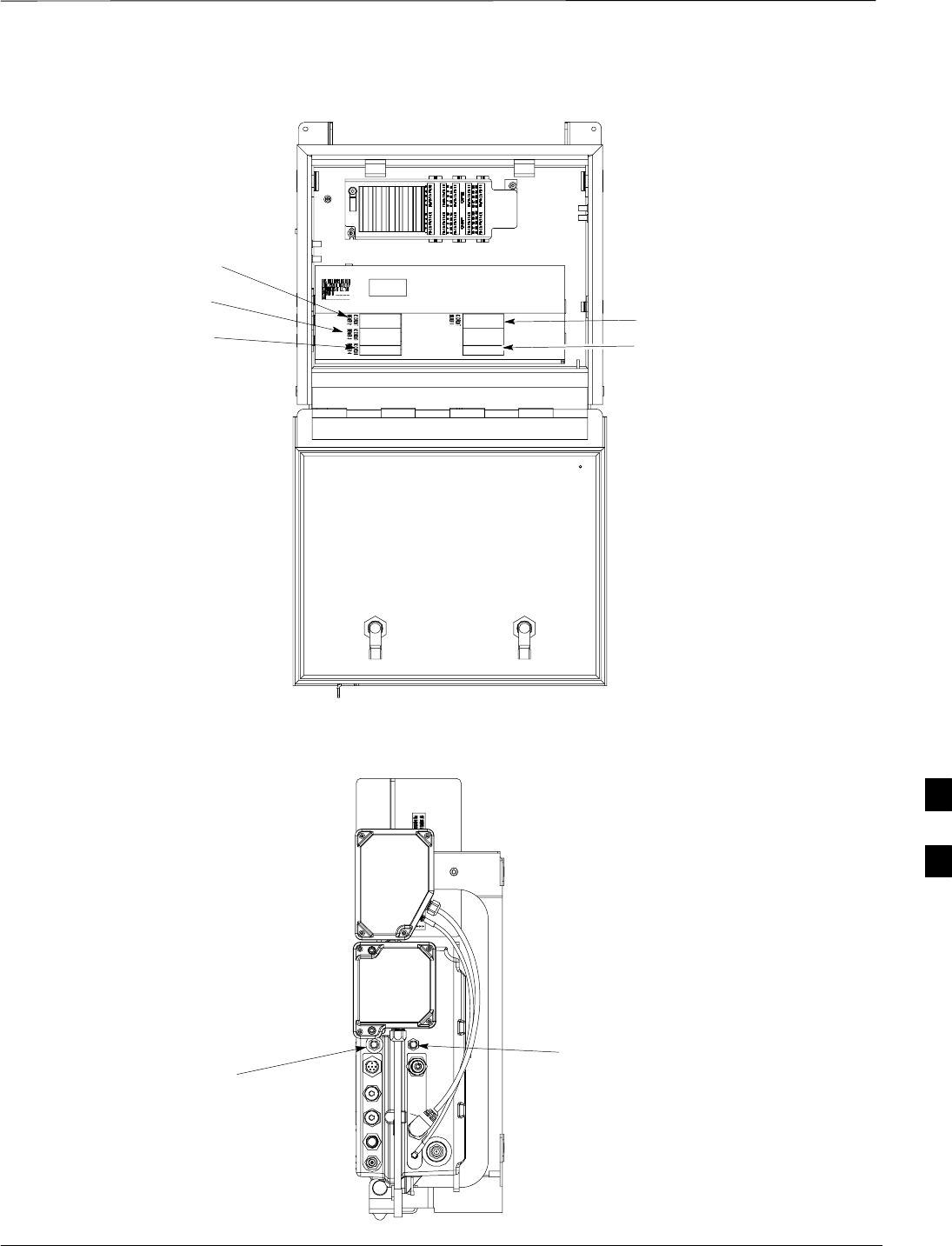
Figure 7-4: How To Remove The Diagnostic Access Cover
SCREWS IN DIAGNOSTIC
ACCESS COVER ARE CAPTIVE
7
BTS Preparation – continued
JAN 2002 7-5
SCt300 1X BTS Hardware Installation, ATP, and FRU Procedures
DRAFT
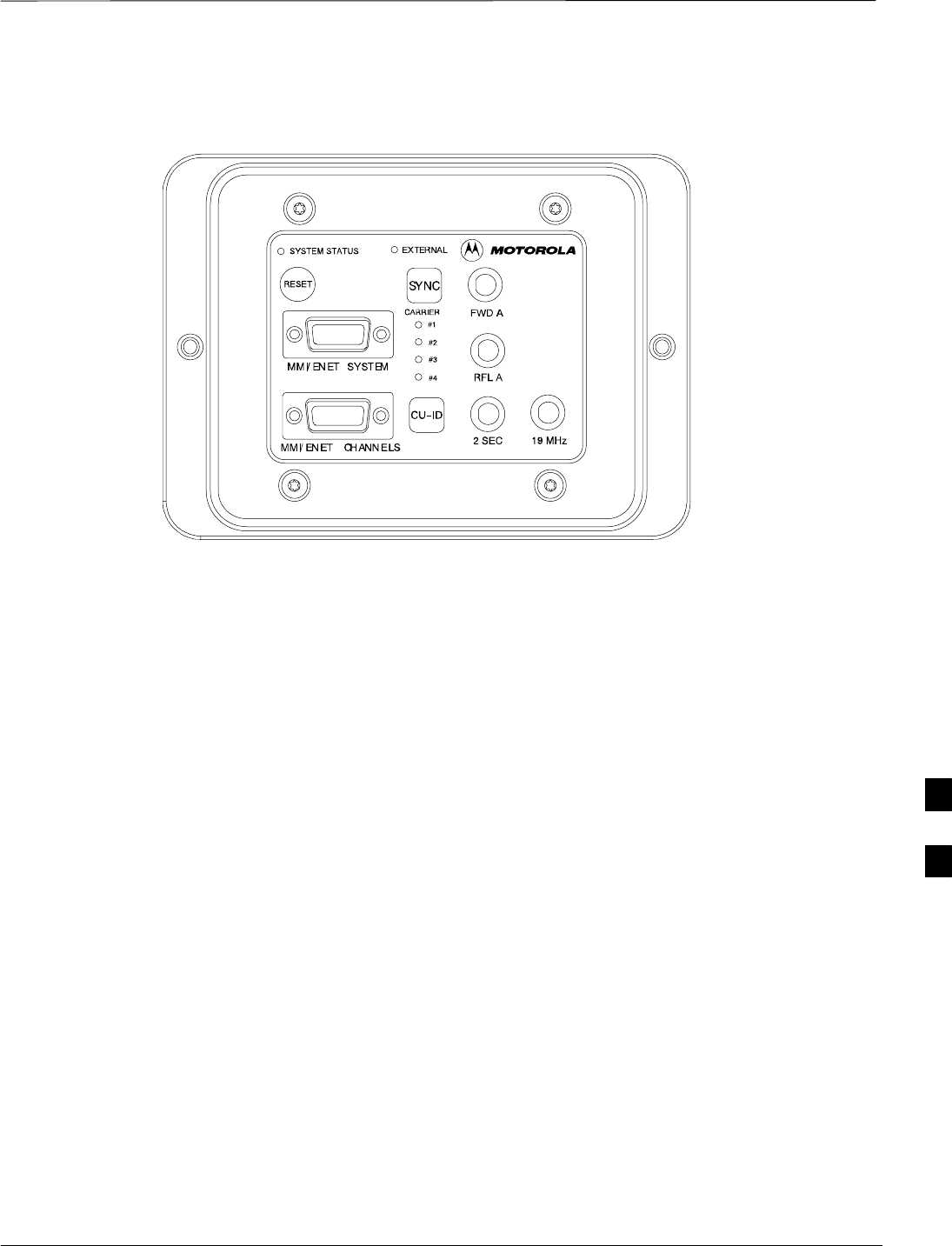
Figure 7-5: Detail Location of the Diagnostic Access Area
7
Connect LMF to BTS
DRAFT
SCt300 1X BTS Hardware Installation, ATP, and FRU Procedures JAN 2002
7-6
Overview
This procedure gives instructions to connect the LMF to the BTS.
LMF to BTS Connection
The LMF is connected to the MMI/LMF connector on the diagnostic
access area.
The LMF serial port, or PCMCIA (Personal Computer Memory Card
International Association) Serial Adapter provides the connection
between the LMF and the MMI/LMF connector located on the
diagnostic access area.
There are three different methods to connect the LMF to the BTS: serial
port to DB9, Ethernet via Ethernet hub, and Ethernet via crossover
connection.
Procedure to Connect LMF to
BTS via Serial Port Connection
Connect the LMF to the BTS. Refer to Figure 7-6, Figure 7-10, and
Table 7-2.
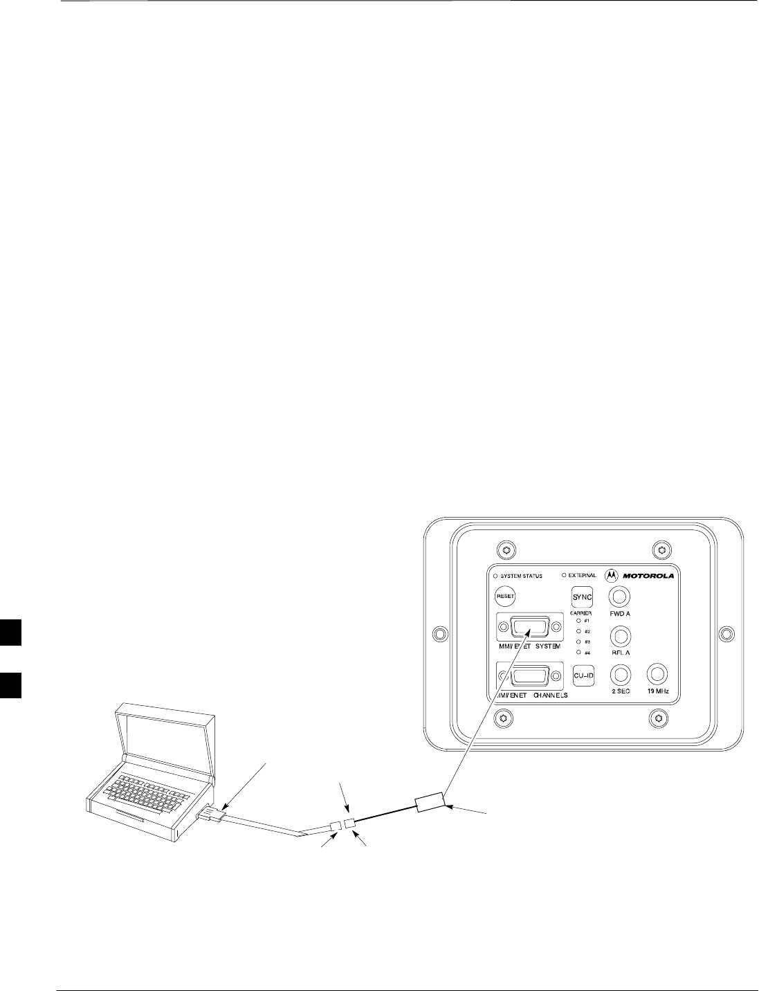
Figure 7-6: Serial to DB9 BTS to LMF connection
DB9 DB9
LMF
DB9 TO DB9 CABLE
CONNECT 15 TO 9–PIN MMI TO SERIAL
CONNECTOR TO MMI/ENET SYSTEM PORT
CONNECT TO
PCMCIA SERIAL I/O
OR SERIAL I/O PORT
7
Connect LMF to BTS – continued
JAN 2002 7-7
SCt300 1X BTS Hardware Installation, ATP, and FRU Procedures
DRAFT
Procedure to Connect LMF to
BTS via Ethernet Connection
You can connect the LMF to the BTS via an Ethernet connection.
Depending upon site configuration, you can use an Ethernet connection
with or without an Ethernet hub. For example, if your BTS is mounted
on a pole and there is no power connection available for the Ethernet
hub, then you can connect to the BTS via a RJ45 crossover cable or a
MMI to LAN crossover adapter. In either case, you must configure
either the RJ45 cable or the adapter to a crossover configuration.
Ethernet connection via Ethernet hub
To connect the LMF to the BTS via an Ethernet connection using an
Ethernet hub, refer to Figure 7-7, Figure 7-10, and Table 7-2.
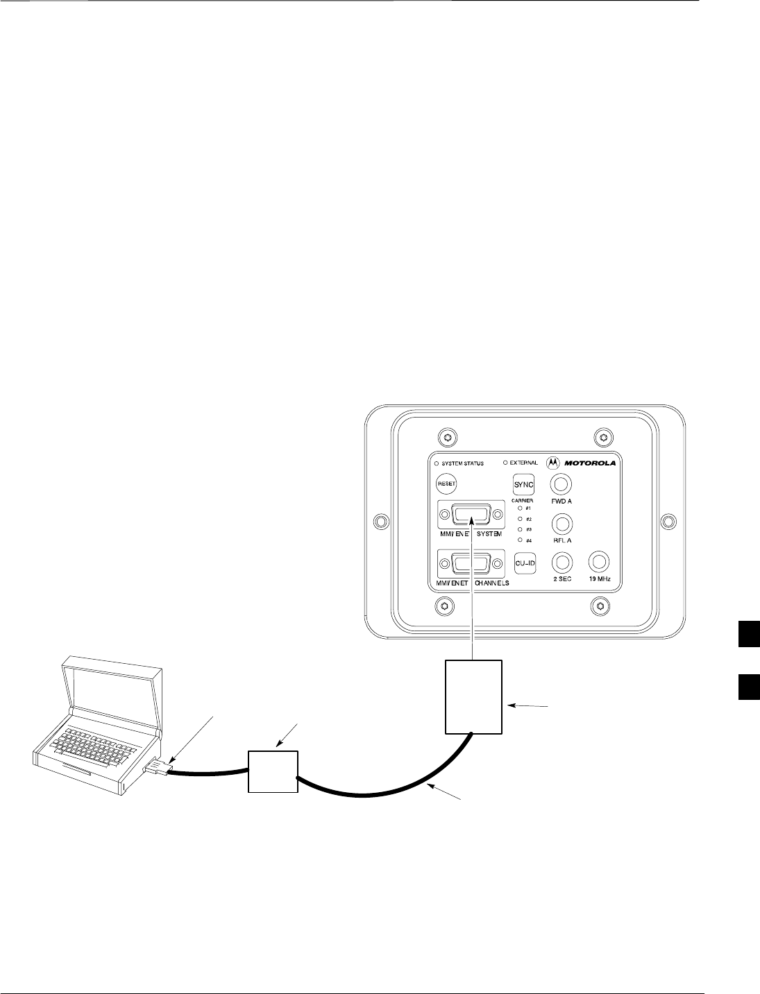
Figure 7-7: Ethernet BTS to LMF Connection Using an Ethernet Hub
LMF
4–PORT 10 BASE T
ETHERNET HUB
CONNECT PCMCIA
LAN CARD TO
ETHERNET HUB RJ45 ETHERNET TO
15–PIN MMI TO LAN
ADAPTER
RJ45 ETHERNET CABLE
Ethernet connection via crossover cable
To connect the LMF to the BTS via an Ethernet connection using a
crossover cable or adapter, you must configure the RJ45 cable or the
MMI to LAN adapter as a crossover. Refer to Figure 7-8 for information
on how to configure the cable or adapter. Refer to Figure 7-9,
Figure 7-10, and Table 7-2 to connect the LMF to the BTS.
7
Connect LMF to BTS – continued
DRAFT
SCt300 1X BTS Hardware Installation, ATP, and FRU Procedures JAN 2002
7-8
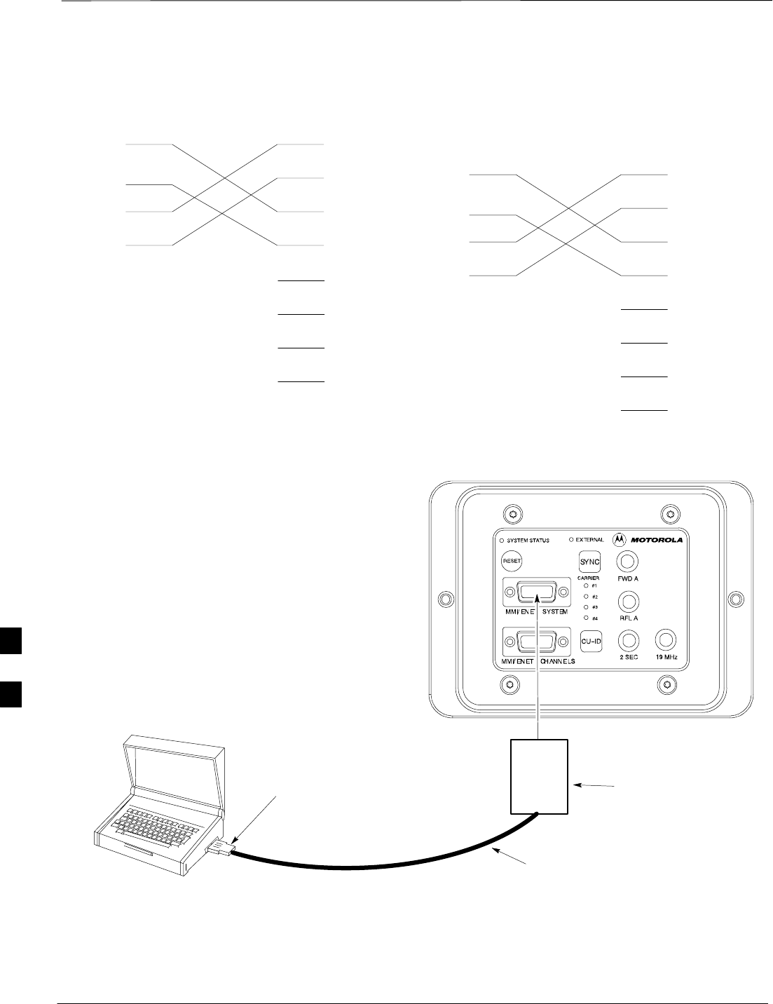
Figure 7-8: Ethernet Crossover Cable and Adapter Wiring
RJ45 ETHERNET CABLE CROSSOVER CONFIGURATION
1
2
3
6
1
2
3
6
TX+
TX–
RX+
RX–
MMI/LAN ADAPTER CROSSOVER CONFIGURATION
4
5
15
12
1
2
3
6
TX+
TX–
RX+
RX–
4
5
7
8
BLUE
ORANGE
BLACK
YELLOW
RED
GREEN
BROWN
GRAY
15–PIN D–SUB RJ–45
RED
GREEN
BROWN
GRAY
4
5
7
8
YELLOW
BLACK
ORANGE
BLUE
Figure 7-9: Ethernet BTS to LMF Connection Using Crossover Cable or Adapter
LMF
CONNECT PCMCIA
LAN CARD TO
ETHERNET HUB RJ45 ETHERNET TO
15–PIN MMI TO LAN
ADAPTER
(SEE NOTE)
RJ45 ETHERNET CABLE
(SEE NOTE)
NOTE: YOU MUST CONFIGURE EITHER THE RJ45
CABLE OR THE MMI TO LAN ADAPTER AS A
CROSSOVER TO CONNECT THE LMF TO THE BTS IN
THIS FASHION.
7

Connect LMF to BTS – continued
JAN 2002 7-9
SCt300 1X BTS Hardware Installation, ATP, and FRU Procedures
DRAFT
MMI/LMF serial connector information
Refer to Figure 7-10 and Table 7-2 for information for the 15–pin
MMI/LMF connector.
Figure 7-10: 15–Pin MMI/LMF Serial Connector
11 12 13 14 15
678910
12345
Table 7-2: 15–Pin MMI/LMF Serial Cable Information
Pin# Abbreviation Description
1RTS Request to Send
2 TXD Transmit Data
3 RXD Receive Data
4 TX+ Ethernet Transmit +
5 TX–Ethernet Transmit –
6 CTS Clear to Send
7 CTS Clear to Send
8 CTS Clear to Send
9–Open
10 RI Ring Indicator
11 RI Ring Indicator
12 RX+ Ethernet Receive +
13 CTS Clear to Send
14 GND Ground
15 RX–Ethernet Receive –
7

Connect Test Equipment to BTS
DRAFT
SCt300 1X BTS Hardware Installation, ATP, and FRU Procedures JAN 2002
7-10
Overview
The following test equipment setup applies to the BTS Acceptance Test
Procedure (ATP).
The SCt300 BTS supports the following test sets for IS95 A/B testing:
1. Advantest R3465 with R3561 Signal Generator.
2. Motorola CyberTest
3. HP 8921A (for 800 MHz testing only)
4. Aglient 8935 Series E6380A (formally HP8935)
The 1X SCt300 BTS supports the following test sets for CDMA2000
1X testing:
1. Advantest R3267 with R3562 Signal Generator
2. Agilent E4406A with E4432B Signal Generator
If you are not going to perform the ATP, then proceed to
the “Creating a Named HyperTerminal Connection for
MMI Communication” procedure in this chapter.
NOTE
Equipment warm-up
Warm-up BTS equipment site for a minimum of 60
minutes prior to the BTS ATP. This assures BTS site
stability and contributes to test accuracy.
(Time spent running initial power–up, hardware/firmware
audit, and BTS download counts as warm–up time).
IMPORTANT
*
Warm-up test equipment for a minimum of 60 minutes
prior to their use in the BTS ATP. This assures maximum
equipment measurement accuracy and consistency during
testing.
IMPORTANT
*
All test equipment is controlled by the LMF via a Serial Cable/GPIB
bus. The LMF expects each piece of test equipment to have a factory-set
GPIB address. If there is a communications problem between the LMF
and any piece of test equipment, you should verify that the GPIB
addresses have been set correctly.
7

Connect Test Equipment to BTS – continued
JAN 2002 7-11
SCt300 1X BTS Hardware Installation, ATP, and FRU Procedures
DRAFT
In the following procedure and illustrations, typical DIP
switch positions and/or configurations are shown. If
required, refer to the test equipment OEM user manuals for
additional information.
NOTE
Procedure to Connect
Advantest R3465 to BTS
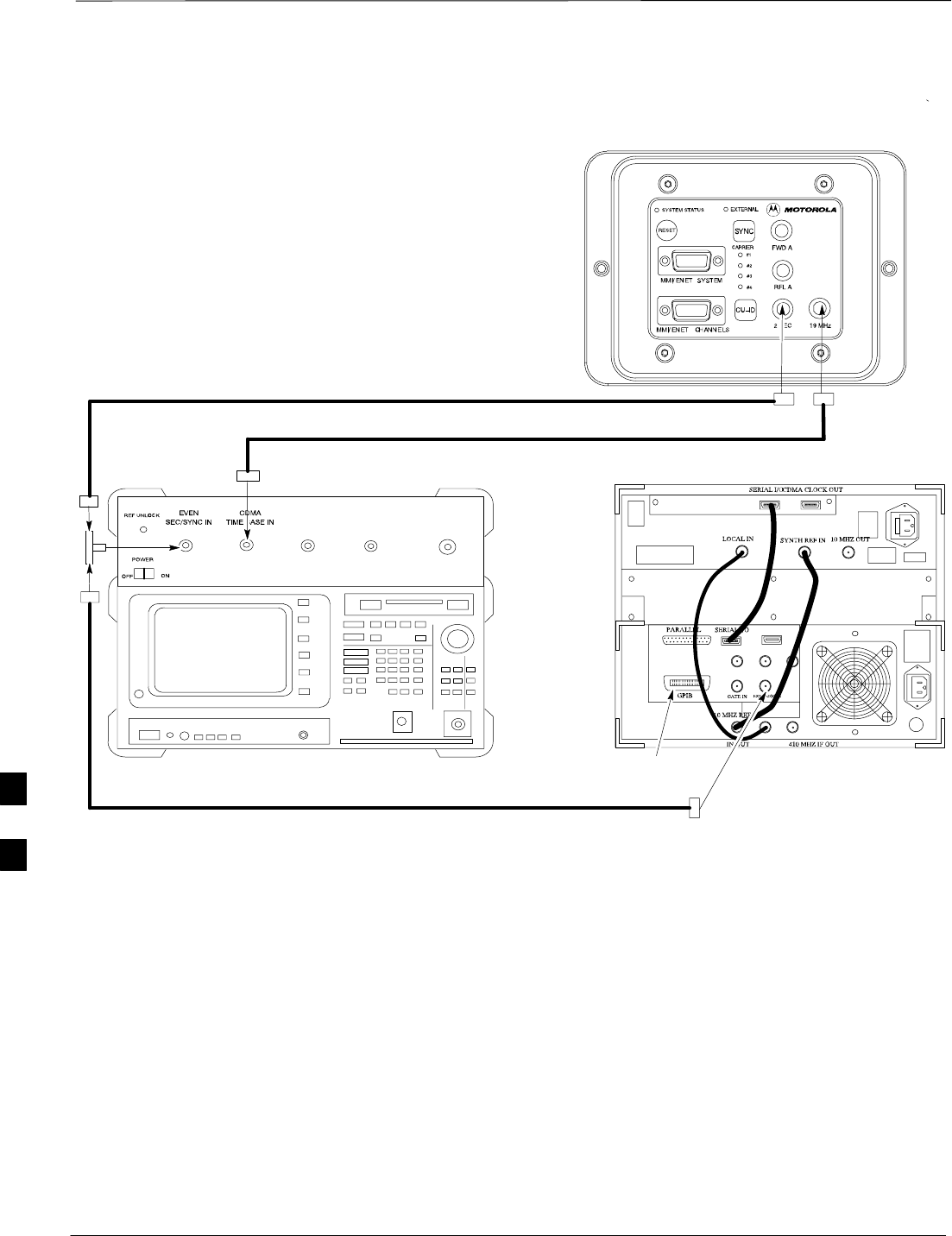
Follow the procedure in Table 7-3 to connect the Advantest R3465 to the
BTS. Refer to Figure 7-11.
Table 7-3: Connecting Advantest R3465 to the BTS
Step Action
1Connect an SMA/BNC coax cable between the following points:
–BNC on the Advantest CDMA TIMEBASE IN port.
–SMA on the 19 MHz port on the diagnostic access area of the BTS.
2Connect an SMA/BNC cable between the following points:
–BNC to one end of the BNC “T.”
–SMA on the 2 Sec port on the diagnostic access area of the BTS.
3Connect a BNC/BNC cable between the following points:
–BNC to one end of the BNC “T.”
–BNC to the EXT TRIG port on the rear panel of the Advantest R3465.
4Connect the BNC “T” to the EVEN SEC/SYNC IN port of the Advantest R356IL.
5Verify the R3561 and R3465 rear panel connections are in place (These are common connections and
should already be installed):
–Serial cable between 3465A rear panel SERIAL I/O port and R3561 SERIAL I/O port.
–SMA cable between 3465A rear panel 1ST LO OUT port and R3561 LOCAL IN port.
7
Connect Test Equipment to BTS – continued
DRAFT
SCt300 1X BTS Hardware Installation, ATP, and FRU Procedures JAN 2002
7-12
Advantest R3465
front panel Advantest R3465
rear panel
BNC
“T”
CONNECTIONS DEPICTED BY HEAVY BOLD LINES ARE
STATIONARY AND SHOULD REMAIN INSTALLED DURING
TEST EQUIPMENT TRANSPORT FROM SITE TO SITE.
19.6608 MHZ REFERENCE
2 SECOND REFERENCE
GPIB
CONNECTOR
FROM EVEN
SEC/SYNC IN
Figure 7-11: Communications Test Set Timing Signal Detail (Advantest R3465)
BTS DIAGNOSTIC ACCESS AREA
7

Connect Test Equipment to BTS – continued
JAN 2002 7-13
SCt300 1X BTS Hardware Installation, ATP, and FRU Procedures
DRAFT
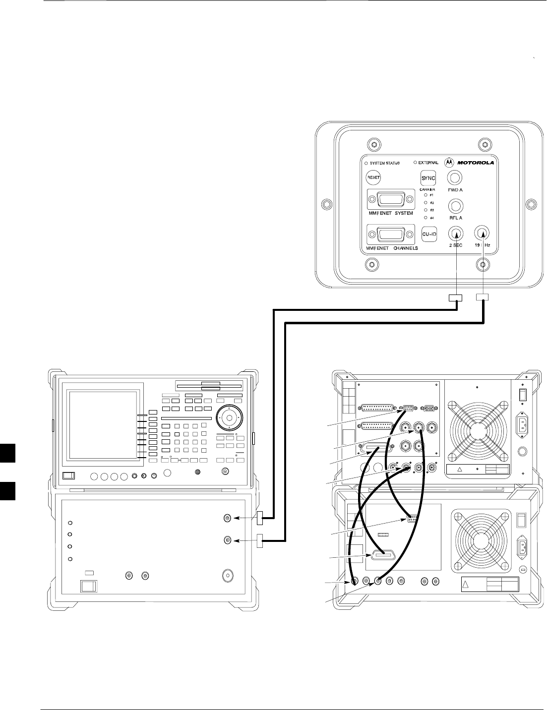
Procedure to Connect
Advantest R3267 to BTS
Use the procedures in Table 7-4 to connect the Advantest R3267 to the
BTS. Refer to Figure 7-12.
The Advantest R3267 test set is used for 1X system
testing.
NOTE
Table 7-4: Procedure to Connect Advantest R3267 to the BTS
Step Action
1Connect an SMA/BNC coax cable between the following points:
–BNC on the MOD TIMEBASE IN port on the front panel of the Advantest R3562 Test
Source.
–SMA on the 19 MHz port on the diagnostic access area of the BTS.
2Connect an SMA/BNC cable between the following points:
–SMA on the 2 Sec port on the diagnostic access area of the BTS.
–BNC to the EXT TRIG IN port on the front panel of the Advantest R3562 Test Source.
3Verify the R3267 and R3562 rear panel connections are in place (These are common connections
and should already be installed):
–Serial cable between R3267 rear panel SERIAL I/O port and R3562 rear panel SERIAL I/O
port.
–SMA cable between R3267 rear panel 10MHZ REF OUT port and R3562 rear panel
SYNTHE REF IN port.
–SMA cable between R3267 rear panel EXT TRIG port and R3562 rear panel CLOCK OUT
1 port.
–Parallel cable between R3267 rear panel GPIB port and R3562 GPIB port. 7
Connect Test Equipment to BTS – continued
DRAFT
SCt300 1X BTS Hardware Installation, ATP, and FRU Procedures JAN 2002
7-14
ADVANTEST R3267 FRONT PANEL ADVANTEST R3267 REAR PANEL
CONNECTIONS DEPICTED BY HEAVY BOLD
LINES ARE STATIONARY AND SHOULD REMAIN
INSTALLED DURING TEST EQUIPMENT
TRANSPORT FROM SITE TO SITE.
19.6608 MHZ REFERENCE
2 SECOND REFERENCE
Figure 7-12: R3267 Communications Test Set Timing Signal Detail
BTS DIAGNOSTIC ACCESS AREA
ADVANTEST R3267 SPECTRUM ANALYZER 100Hz –
8GHz
ADVANTEST R3562 RECEIVER TEST SOURCE
!
!
ADVANTEST R3562 TEST SOURCE
FRONT PANEL
ADVANTEST R3562 TEST SOURCE
REAR PANEL
EXT TRIG IN
MOD TIME BASE IN
SYNTHE
REF IN
10 MHZ
RF OUT
SERIAL I/O
SERIAL I/O
EXT TRIG
CLOCK
OUT 1
GPIB
GPIB
7
Connect Test Equipment to BTS – continued
JAN 2002 7-15
SCt300 1X BTS Hardware Installation, ATP, and FRU Procedures
DRAFT
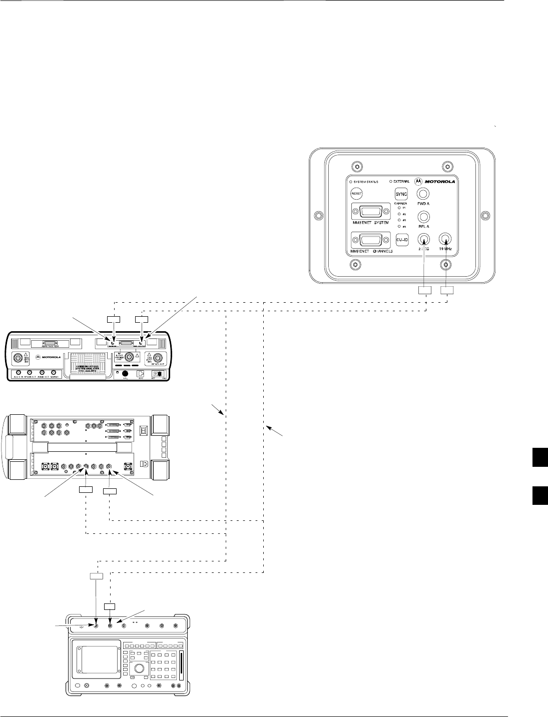
Procedure to Connect the
Motorola CyberTest, HP 8935,
and HP 8921 to BTS
CONNECTIONS DEPICTED BY DOTTED LINES ARE
STATIONARY AND SHOULD REMAIN INSTALLED DURING
TEST EQUIPMENT TRANSPORT FROM SITE TO SITE.
19.6608 MHZ REFERENCE
2 SECOND REFERENCE
Figure 7-13: Communications Test Set Timing Signal Detail (CyberTest, HP 8935, and HP 8921)
BTS DIAGNOSTIC ACCESS AREA
MOTOROLA CYBERTEST
AGILENT 8935 SERIES E6380A
(FORMALLY HP 8935)
HP 8921
COMMUNICATIONS TEST SET
FREQ MONITOR 19.6608
MHZ CLOCK REFERENCE
FROM DIAGNOSTIC
ACCESS AREA
FREQ MONITOR 19.6608 MHZ CLOCK
REFERENCE FROM DIAGNOSTIC
ACCESS AREA
FREQ MONITOR 19.6608 MHZ CLOCK
REFERENCE FROM DIAGNOSTIC
ACCESS AREA
SYNC MONITOR EVEN SEC TICK
PULSE REFERENCE FROM
DIAGNOSTIC ACCESS AREA
SYNC MONITOR EVEN
SEC TICK PULSE
REFERENCE FROM
DIAGNOSTIC ACCESS
AREA
SYNC MONITOR
EVEN SEC TICK
PULSE REFERENCE
FROM DIAGNOSTIC
ACCESS AREA
7

Connect Test Equipment to BTS – continued
DRAFT
SCt300 1X BTS Hardware Installation, ATP, and FRU Procedures JAN 2002
7-16
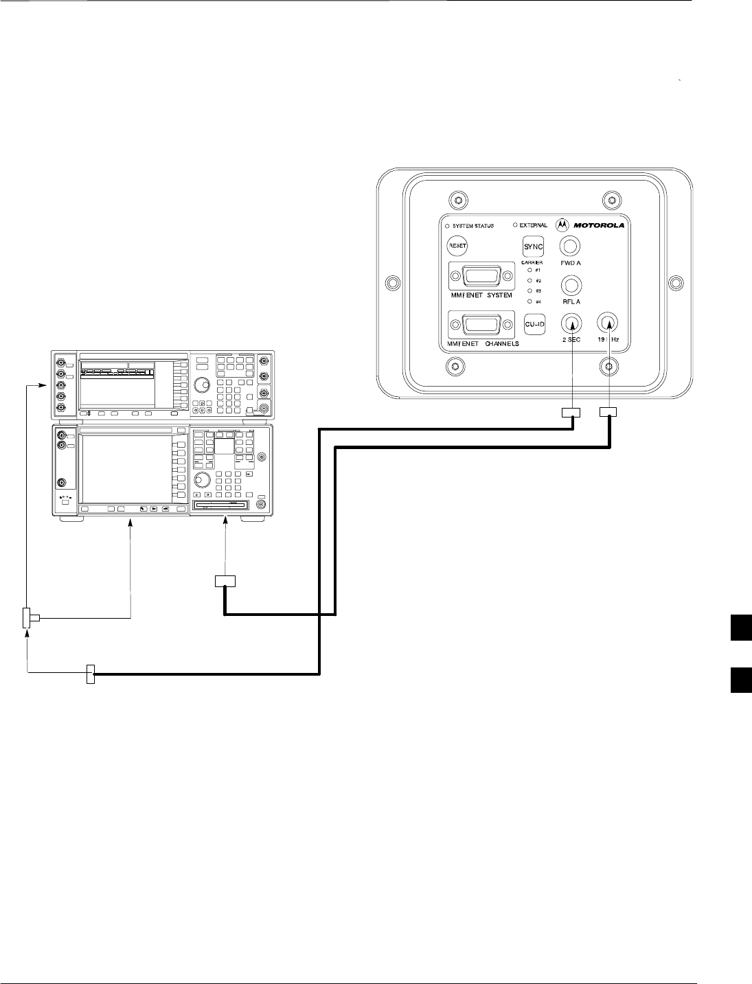
Procedure to Connect the
Agilent E4406A/E4432B to BTS
Agilent E4406A/E4432B test equipment interconnection
To provide proper operation during testing when both units are required,
the 10 MHz reference signal from the E4406A transmitter test set must
be provided to the E4432B signal generator. Connect a BNC (M)–BNC
(M) cable from the E4406A 10 MHz OUT (SWITCHED) connector to
the E4432B 10MHz IN connector as shown in Figure 7-14.
Figure 7-14: Agilent 10 MHz Reference Connections
E4406A
10 MHz OUT
(SWITCHED)
E4432B
10 MHz IN
TO GPIB BOX
7
Connect Test Equipment to BTS – continued
JAN 2002 7-17
SCt300 1X BTS Hardware Installation, ATP, and FRU Procedures
DRAFT
CONNECTIONS DEPICTED BY HEAVY BOLD
LINES ARE STATIONARY AND SHOULD REMAIN
INSTALLED DURING TEST EQUIPMENT
TRANSPORT FROM SITE TO SITE.
19.6608 MHZ REFERENCE
2 SECOND REFERENCE
Figure 7-15: Agilent E4406A/E4432B Communications Test Set Timing Signal Detail
BTS DIAGNOSTIC ACCESS AREA
Agilent E4432B (Top) and E4406A (Bottom)
FREQ MONITOR
19.6608 MHZ CLOCK
REFERENCE FROM
CSM BOARD
SYNC MONITOR
EVEN SEC TICK
PULSE REFERENCE
FROM CSM BOARD
BNC
“T”
TO TRIGGER IN
ON REAR OF
TRANSMITTER
TESTER
TO PATTERN TRIG IN
ON REAR OF SIGNAL
GENERATOR
TO EXT REF IN
ON REAR OF
TRANSMITTER
TESTER
NOTE:
10 MHZ IN ON REAR OF SIGNAL GENERATOR IS CONNECTED TO
10 MHZ OUT (SWITCHED) ON REAR OF TRANSMITTER TESTER
(FIGURE 7-14).
7
Connect Test Set and Power Meter to LMF
DRAFT
SCt300 1X BTS Hardware Installation, ATP, and FRU Procedures JAN 2002
7-18
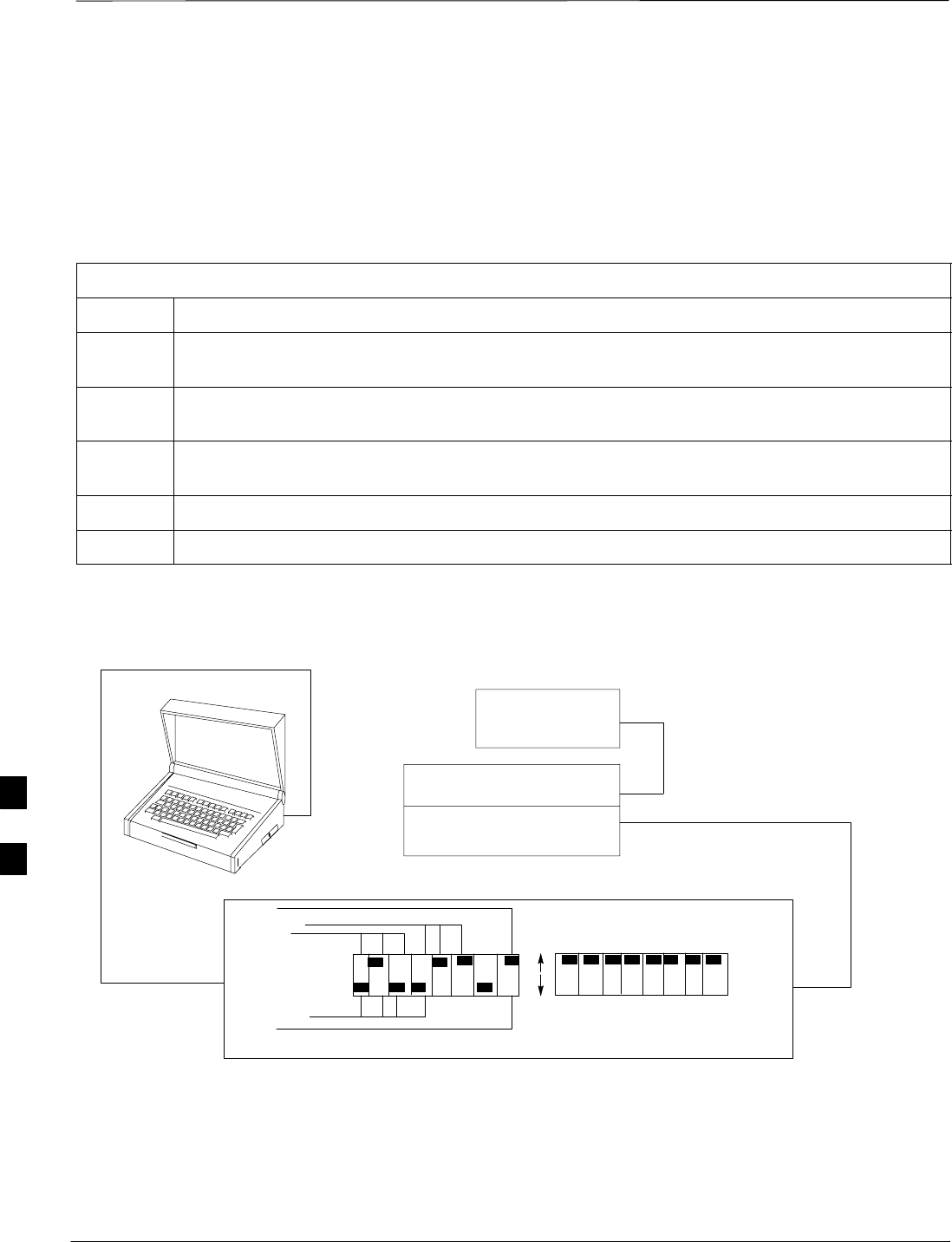
Procedure to Connect the
Communication Test Set and
Power Meter to the LMF
Use the following procedure in Table 7-5 to connect the communication
test set to the power meter and to the LMF. Refer to Figure 7-16.
Table 7-5: Procedure to Connect the Communication Test Set and Power Meter to the LMF
Step Action
1Connect the RS232–IEEE488 converter serial cable between the COM1 port of the LMF and the
RS232 port of the RS232–IEEE488 converter.
2Connect a GPIB cable between the RS232–IEEE488 converter and the GPIB port on the
communication test set.
3Connect a GPIB cable between the GPIB port on the communication test set and the GPIB port of
the power meter.
4Set the DIP switches on the RS232–IEEE488 converter as shown in Figure 7-16.
5Power on the communication test set, power meter and RS232–IEEE488 converter.
Figure 7-16: LMF to Test Equipment Connection
LMF
OFF
ON
S MODE
DATA FORMAT
BAUD RATE
GPIB ADDRESS
G MODE
RS232–IEEE488 CONVERTER
GIGATRONICS
POWER METER
SIGNAL GENERATOR
(IF EQUIPPED)
COMMUNICATION TEST SET
GPIB CABLE(S) TO GPIB
CONNECTOR ON TEST
EQUIPMENT
RS–232 CABLE
TO COMM1 PORT ON CDMA
LMF NOTEBOOK
7

Connect Test Set and Power Meter to LMF – continued
JAN 2002 7-19
SCt300 1X BTS Hardware Installation, ATP, and FRU Procedures
DRAFT
RS232 Cable Configuration
One National Instruments GPIB–232–CT with Motorola
CGDSEDN04X RS232 serial cable or equivalent is used to interface the
LMF to the test equipment.
A Standard RS–232 cable can be used with the following modifications:
SPin 8 (CTS) does not have to be jumpered/shorted to the others as it is
a driver output. The DTR is already a driver output signal. The other
pins are to receivers. Short pins 7, 1, 4, 6 on each cable end:
Figure 7-17 shows the cable configuration for the RS232–IEEE488
converter serial cable.
9–pin D (female) 9–pin D (female)
GND 5 5 GND
RX 3
3 RXTX 2
2 TX
RTS 7 7 RTS
RSD/DCD 1 1 RSD/DCD
DTR 4 4 DTR
DSR 6 6 DSR
Figure 7-17: RS232–IEEE488 Converter Serial Cable Configuration
CTS 8 8 CTS
ON BOTH CONNECTORS SHORT
PINS 7 AND 8;
SHORT PINS 1, 4 AND 6
7

BTS Configuration
DRAFT
SCt300 1X BTS Hardware Installation, ATP, and FRU Procedures JAN 2002
7-20
Objective
The objective of this procedure is to configure the BTS and establish
communication sessions between the LMF and BTS. This procedure
consists of:
1. Creating a named hyperterminal connection for MMI
communication
2. Establishing an MMI communication session
3. Verify and set IP address
4. Programming customer operating channel
5. Verifying BTS synchronization mode
6. Verifying DPLL tracking
7. Setting frame_id
Procedure to Create a Named
HyperTerminal Connection for
MMI Communication
Confirming or changing the configuration data of certain BTS Field
Replaceable Units (FRU) requires establishing an MMI communication
session between the CDMA LMF computer and the FRU. Using features
of the Windows operating system, the connection properties for an MMI
session can be saved on the CDMA LMF computer as a named Windows
HyperTerminal connection. This eliminates the need for setting up
connection parameters each time an MMI session is required to support
optimization.
Once the named connection is saved, a shortcut for it can be created on
the Windows desktop. Double–clicking the shortcut icon will start the
connection without the need to negotiate multiple menu levels.
Follow the procedures in Table 7-6 to establish a named HyperTerminal
connection and create a Windows desktop shortcut for it.
Table 7-6: Procedure to Create a Named HyperTerminal Connection for MMI Communication
Step Action
1From the Windows Start menu, select:
Programs > Accessories
2 Select Communications, double click the Hyperterminal folder, and then double click on the
Hypertrm.exe icon in the window which opens.
NOTE
SIf a Location Information Window appears, enter the required information, then click on the
Close button. (This is required the first time, even if a modem is not to be used.)
SIf a You need to install a modem..... message appears, click on NO.
. . . continued on next page
7

BTS Configuration – continued
JAN 2002 7-21
SCt300 1X BTS Hardware Installation, ATP, and FRU Procedures
DRAFT
Table 7-6: Procedure to Create a Named HyperTerminal Connection for MMI Communication
Step Action
3When the Connection Description box opens:
–Type a name for the connection being defined (e.g., MMI Session) in the Name: window,
–Highlight any icon preferred for the named connection in the Icon: chooser window, and
–Click OK.
NOTE
For CDMA LMF computer configurations where COM1 is used by another interface such as test
equipment and a physical port is available for COM2, select COM2 in the following step to prevent
conflicts.
4From the Connect using: pick list in the Connect To box displayed, select Direct to Com 1 or
Direct to Com 2 for the RS–232 connection port, and click OK.
5In the Port Settings tab of the COM# Properties window displayed, configure the RS–232 port
settings as follows:
SBits per second: 9600
SData bits: 8
SParity: None
SStop bits: 1
SFlow control: None
6 Click OK.
7Save the defined connection by selecting:
File > Save
8Close the HyperTerminal window by selecting:
File > Exit
9Click the Yes button to disconnect when prompted.
10 If the Hyperterminal folder window is still open, proceed to step 12.
11 Select Communications and double click the Hyperterminal folder.
12 Highlight the newly–created connection icon by clicking on it.
13 Right click and drag the highlighted connection icon to the Windows desktop and release the right
mouse button.
14 From the popup menu which appears, select Create Shortcut(s) Here.
15 If desired, reposition the shortcut icon for the new connection by dragging it to another location on the
Windows desktop.
16 Close the Hyperterminal folder window by selecting:
File > Close
7

BTS Configuration – continued
DRAFT
SCt300 1X BTS Hardware Installation, ATP, and FRU Procedures JAN 2002
7-22
Procedure to Establish an MMI
Communication Session
For those procedures which require MMI communication between the
CDMA LMF and the BTS, follow the procedures in Table 7-7 to initiate
the communication session.
If an LMF session is in progress, logout of the LMF prior
to establishing an MMI communication session. Refer to
steps 1 and 2 of the “Remove LMF” procedure in
Table 7-54.
NOTE
Table 7-7: Procedure to Establish an MMI Communication Session
Step Action
1Connect the CDMA LMF computer to the BTS. Refer to the “Connecting the LMF to the BTS”
procedure in this chapter.
2Start the named HyperTerminal connection for MMI sessions by double clicking on its Windows
desktop shortcut.
3NOTE
If a Windows desktop shortcut was not created for the MMI connection, access the connection from
the Windows Start menu by selecting:
Programs > Accessories > Hyperterminal > HyperTerminal > <Named HyperTerminal
Connection (e.g., MMI Session)>
Once the connection window opens, establish MMI communication with the BTS FRU by pressing
the CDMA LMF computer Enter key until the prompt identified in the applicable procedure is
obtained.
Every command is entered at the SC300> prompt unless otherwise specified.
7

BTS Configuration – continued
JAN 2002 7-23
SCt300 1X BTS Hardware Installation, ATP, and FRU Procedures
DRAFT
Procedure to Set IP Address
You must set an IP address on the unit before you can begin an LMF
Ethernet (LAN) session. Follow the instructions in Table 7-8 to set the
IP address.
Table 7-8: Procedure to Set IP Address
Step Action
1Enter the following command to check the ethernet IP address:
sc300>ether getip
Observe the following typical response (if the IP address was not set):
COMMAND ACCEPTED: ether getip
Current IP ADDRESS: 0.0.0.0
2Enter the following command to check the ethernet gateway address:
sc300>ether getgw
Observe the following typical response (if the IP address was not set):
COMMAND ACCEPTED: ether getgw
GW address: 0.0.0.0
3Enter the following command to check the ethernet netmask value:
sc300>ether getnm
Observe the following typical response (if the IP address was not set):
COMMAND ACCEPTED: ether getnm
NETMASK: 0.0.0.0
4If the IP address is set, then you are finished with this procedure. If you must set the IP address,
then proceed with steps 5 through 7.
NOTE
The default LMF IP address is 128.0.0.2.
5Enter the following command to set the IP address:
sc300>ether setip 128.0.0.2
The system will display the following output:
COMMAND ACCEPTED: ether setip 128.0.0.2
THESE ARE THE BYTES READ IN: 128.0.0.2
SETTING IP: 128.0.0.2
Completed flashing of IP address
CONFIRM NEW IP: 128.0.0.2
SETTING Ethernet Address: 8:0:80:0:0:2
Completed flashing of Ether address
CONFIRM NEW Ethernet Address: 8:0:80:0:0:2
New parameters will take affect after next reset.
. . . continued on next page
7

BTS Configuration – continued
DRAFT
SCt300 1X BTS Hardware Installation, ATP, and FRU Procedures JAN 2002
7-24
Table 7-8: Procedure to Set IP Address
Step Action
6Enter the following command at the sc300> prompt:
sc300>ether setgw 128.0.0.2
The system will display the following output:
COMMAND ACCEPTED: ether setgw 128.0.0.2
”128” ”0” ”0” ”2”
THESE ARE THE BYTES READ IN: 128.0.0.2
SETTING GW: 128.0.0.2
Completed flashing of Gateway address
CONFIRM NEW GW: 128.0.0.2
New parameters will take affect after next reset.
7Enter the following command at the sc300> prompt:
sc300>ether setnm 255.255.255.255
The system will display the following output:
COMMAND ACCEPTED: ether setnm 255.255.255.255
”255” ”255” ”255” ”255”
THESE ARE THE BYTES READ IN: 255.255.255.255
SETTING NETMASK: 255.255.255.255
Completed flashing of SubnetMask address
CONFIRM NEW NETMASK: 255.255.255.255
New parameters will take affect after next reset.
8Repeat steps 1 through 3 to verify your entries.
9If your entries are correct, then press the red RESET button on the diagnostic access area to reset
the unit.
Procedure to Simulate an LMF
Session
You must start a simulated LMF session when you enter MMI
commands. Enter the following command at the MMI prompt to
simulate an LMF link:
sndtype 0xa178
You should enter this command at the beginning of every simulated
MMI Communication Session.
7

BTS Configuration – continued
JAN 2002 7-25
SCt300 1X BTS Hardware Installation, ATP, and FRU Procedures
DRAFT
Updating Default Channel
Setting to Customer Operating
Channel
A non–volatile database containing the default channel and default
power level of the site must be programmed. The default channel is the
customer operating channel for this site. The default power level must
be set to –50 dBm which will be overwritten by the MM/OMCR when
the site comes on–line.
It is imperative that the customer frequency be programmed into this
database. Failure to do so may result in the RF interference to other
RF–emitting devices in the local area whenever the site is powered up.
Table 7-9: Procedure to Update Default Channel Setting to Customer Operating Channel
Step Action
1Connect the LMF computer terminal to the MMI/LMF connector. Refer to Figure 7-6.
2If you have not already done so, logout of the BTS and exit the LMF. Wait 10 seconds before
proceeding.
3Establish an MMI connection session with the BTS. Refer to Table 7-7.
4Simulate an LMF connection by issuing the sndtype 0xa178 command.
5Verify that the BTS is in OOS_RAM status by issuing the status command.
6Enter the op_param –w –50 chan# command. The command parameters are as follows:
–winstructs the BTS to write the values into non–volatile memory.
–50 defaults the power to –50dBm
chan# the customer operating channel (refer to Table 7-43 for 1.9 GHz systems and
Table 7-44 for 800 MHz systems).
If the command is successful, the following response will display:
PASSED: TRX EEPROM updated for power level = –50 (dBm) and channel =
chan#
7If no additional MMI sessions are required at this time, exit the MMI session and HyperTerminal
connection by selecting File>Exit.
If you are continuing the MMI session, proceed to Table 7-10.
7

BTS Configuration – continued
DRAFT
SCt300 1X BTS Hardware Installation, ATP, and FRU Procedures JAN 2002
7-26
Synchronization Background
GPS
GPS is typically used as the primary timing reference for CDMA BTSs.
In applications where RGPS is used, the BTS is said to be synchronous
with CDMA system time. The RGPS provides a 1 Pulse Per Second
timing reference and Time Of Day information to allow the BTS to
synchronize to CDMA system time.
HSO
A High Stability Oscillator (HSO) within the BTS provides a backup
timing reference in the event of a GPS outage. Using only the HSO, the
BTS can maintain CDMA system time for up to 24 hours. The BTS can
also use the HSO as the primary timing reference (non–synchronous
operation). However, synchronization to CDMA system time is not
possible. The HSO provides a 1 Pulse Per Second timing reference to
allow the BTS to remain synchronized to CDMA system time in the
event of a GPS outage (synchronous operation) or to provide a stable
frequency reference (non–synchronous operation).
The HSO must be installed with GPS tracking for at least
24 hours before the HSO can provide 24 hours of backup
for CDMA system time synchronization.
NOTE
BTS
The BTS uses a Digital Phase Locked Loop (DPLL) to track the RGPS
and/or HSO and generate a 19.6608 MHz CDMA timing reference. This
timing reference, in conjunction with Time Of Day information provided
by the RGPS, allows the BTS to synchronize to CDMA system time. A
2 Second reference is also generated by the BTS to allow alignment of
Pilot offsets for the BTS and external test equipment. Both the 19.6608
MHz (19 MHz) and 2 Second (2 Sec) references are available via SMA
connectors located in the Diagnostic Access Area.
In order for the DPLL to begin the RGPS tracking process, the RGPS
must be tracking GPS satellites. In order for the DPLL to begin the
HSO tracking process, the BTS must be powered up (warmed) for at
least 15 minutes.
The DPLL status is defined as being in one of five states: Init, Warm,
A1, A2 and TK.
SThe Init state is the starting state of the DPLL.
SThe Warm state is the condition during the 15 minute BTS warm up
time.
SThe A1 and A2 states are acquisition states when the DPLL is
adjusting the 19.6608 MHz frequency based on the available reference
7

BTS Configuration – continued
JAN 2002 7-27
SCt300 1X BTS Hardware Installation, ATP, and FRU Procedures
DRAFT
sources (RGPS or HSO). Under normal operating conditions, the
acquisition states last about 5 minutes.
SThe TK state is the DPLL tracking state and is entered at the end of
the acquisition states. The TK state is required for performing ATP.
Procedure to Verify and
Change BTS Synchronization
Mode
The Sync button in the Diagnostic Access Area is used to toggle the
RGPS or HSO as the primary timing reference for the BTS. If the
External indicator in the Diagnostic Access Area is illuminated, the BTS
expects an RGPS to be present for use as the primary timing reference.
If the External indicator is not illuminated, the BTS will use the internal
HSO as the primary timing reference.
Use the procedure in Table 7-10 to verify and, if necessary change the
BTS Sync mode.
Table 7-10: Procedure to Verify and Change BTS Sync Mode
Step Action
1If an MMI session was established, proceed to step 7. If no MMI session is running, proceed to
step 2.
2Connect the MMI/LMF.
3Open an MMI Communication session.
4Simulate an LMF connection by issuing the sndtype 0xa178 command.
5Verify that the BTS is in OOS_RAM status by issuing the status command.
6Enter the sndtype 0x4003 command to change the state to OOS_RAM.
7Observe the condition of the External indicator.
8No further action is required if the BTS is in the desired Sync mode. Continue with Step 9 if the
Sync mode needs to be altered.
9Push the Sync button to change the BTS Sync mode.
10 Reset the BTS using the Reset button in the Diagnostic Access Area.
11 If no additional MMI sessions are required at this time, exit the MMI session and HyperTerminal
connection by selecting File>Exit.
If you are continuing the MMI session, proceed to Table 7-11.
7

BTS Configuration – continued
DRAFT
SCt300 1X BTS Hardware Installation, ATP, and FRU Procedures JAN 2002
7-28
Procedure to Verify DPLL
Tracking (RGPS/HSO)
The DPLL within the BTS must be tracking either RGPS or HSO in
order to perform ATP. Use the procedure in Table 7-11 to verify DPLL
tracking.
Table 7-11: Procedure to Verify DPLL Tracking
Step Action
1If an MMI session was established, proceed to step 6. If no MMI session is running, proceed to
step 2.
2Connect the MMI/LMF.
3Open an MMI Communication session.
4Simulate an LMF connection by issuing the sndtype 0xa178 command.
5Verify that the BTS is in OOS_RAM status by issuing the status command.
6If an RGPS is not present, go to Step 9.
7Enter the gps_status command to display the current state of the RGPS. Observe the following
typical response:
gps_status
GPS Receiver Identification:
Current GPS Time :8 03 1999 23:01:12
Current GPS Receiver Status :8
Number of Satellites Currently visible :11
Number of Satellites Currently received :5
Number of Satellites Currently tracked :5
GPS Receiver Type :UT
Current GPS Task State :GPS_TRACK
Current Dilution of Precision (HDOP (2D)/antenna ok [0x01]): 0
Chan: 0, SVID: 9, Mode: 8, RSSI: 44, Status: 0xaa
Chan: 1, SVID: 4, Mode: 8, RSSI: 46, Status: 0xaa
Chan: 2, SVID: 10, Mode: 8, RSSI: 44, Status: 0xaa
Chan: 3, SVID: 6, Mode: 8, RSSI: 41, Status: 0xaa
Chan: 4, SVID: 7, Mode: 8, RSSI: 43, Status: 0xaa
Chan: 5, SVID: 24, Mode: 8, RSSI: 47, Status: 0xaa
Chan: 6, SVID: 30, Mode: 8, RSSI: 45, Status: 0xaa
Chan: 7, SVID: 5, Mode: 8, RSSI: 48, Status: 0xaa
Current Longitude: –350250952
Current Latitude: 118244730
Current Height: 24019
8The RGPS must have a Current GPS Task State of GPS_TRACK to proceed.
NOTE
GPS tracking times vary depending on location and installation.
. . . continued on next page
7

BTS Configuration – continued
JAN 2002 7-29
SCt300 1X BTS Hardware Installation, ATP, and FRU Procedures
DRAFT
Table 7-11: Procedure to Verify DPLL Tracking
Step Action
9Issue the dpll_status command to display the current state of the DPLL. Observe the following
typical response:
Current source set to: GPS reference
DPLL control task state: DPLL track.
DPLL status (not valid if using even sec src):
c:0000 off: –8639450,6736579,7204904 TK
(Note: This must say TK. A1 and A2 states will have preceded it)
Mode cntr: 120
ip: 9, iq: 4
aip1: 9, aiq1: 4
aip2: 6, aiq2: –2
tip: 3, tiq: –9
integrator: 4096
10 Verify that the DPLL is “tracking” either the RGPS or HSO. The DPLL must have a Current
source set to of GPS reference or HSO reference. The DPLL must also have a
DPLL control task state of DPLL track.
11 If no additional MMI sessions are required at this time, exit the MMI session and HyperTerminal
connection by selecting File>Exit.
If you are continuing the MMI session, proceed to Table 7-12.
Procedure to Verify and Modify
Default Location Coordinates
The BTS supplies the RGPS with default startup coordinates (latitude
and longitude) in order to assist the RGPS in tracking satellites. The
default startup coordinates can be modified and saved into non–volatile
memory to speed the tracking of satellites.
Use the procedure in Table 7-12 to verify and, if necessary, modify the
default startup coordinates. The procedure in Table 7-12 is only
applicable to sites equipped with an RGPS.
Table 7-12: Procedure to Verify Default Startup Coordinates
Step Action
1If an MMI session was established, proceed to step 6. If no MMI session is running, proceed to
step 2.
2Connect the LMF/MMI.
3Open an MMI Communication session.
4Simulate an LMF connection by issuing the sndtype 0xa178 command.
5Verify that the BTS is in OOS_RAM status by issuing the status command.
. . . continued on next page
7

BTS Configuration – continued
DRAFT
SCt300 1X BTS Hardware Installation, ATP, and FRU Procedures JAN 2002
7-30
Table 7-12: Procedure to Verify Default Startup Coordinates
Step Action
6Issue the dpll_status command to display the current state of the DPLL. Verify that the DPLL
has a ”Current source set to” of GPS reference and a ”DPLL control task state” of DPLL
track. The DPLL must be tracking GPS in order to complete this procedure.
7* IMPORTANT
The values for longitude and latitude in response to the gps_status command are given in units
of milli–arcseconds. Be careful to record the values accurately including any leading negative (–)
signs. The value of Current Height is given in units of centimeters.
Enter the gps_status command.
8Record the values displayed for Current Longitude, Current Latitude and
Current Height.
9* IMPORTANT
The gps_config command displays the default startup coordinates for the BTS. Note that
latitude is displayed first, followed by longitude. This is in reverse order compared to
the response of the gps_status command. The values for latitude and longitude are given in
units of milli–arcseconds. The value of Current Height is given in units of centimeters.
Enter the gps_config command to display the default startup coordinates for the BTS. Observe
the following typical response:
GPS Configuration data:
latitude: 151679715 msec
longitude: –316791269 msec
height: 19740 centi
–
meters
height
:
19740
c
enti
–
meters
height_type: 0
cable_delay: 0 nsec
accuracy: 0
If the default startup coordinates need to be modified, the gps_config command can be issued
with additional parameters. Using the Current Longitude, Current Latitude and
Current Height values recorded in step 8, issue the following command:
gps_config <latitude> <longitude> <height> 0 0 0
Be careful to input the latitude and longitude in the proper order along with any leading negative
(–) signs.
The GPS Height Type Configuration should be set to “0.”
10 Issue the gps_config to verify that the coordinates are set.
11 Reset the BTS to save the new coordinates.
12 Repeat the steps in Table 7-11 to verify the DPLL status prior to performing ATP.
13 If no additional MMI sessions are required at this time, exit the MMI session and HyperTerminal
connection by selecting File>Exit.
7

BTS Configuration – continued
JAN 2002 7-31
SCt300 1X BTS Hardware Installation, ATP, and FRU Procedures
DRAFT
Procedure to Set Frame ID for
Multi–Unit Logical BTS
Configuration
Do the following procedure in Table 7-13 to setup the hardware for a
multi–unit logical BTS configuration.
Table 7-13: Procedure to Set Frame ID for Multi–Unit Logical BTS Configuration
Step Action
1Establish an MMI session with the BTS. Refer to Table 7-7.
2Enter the following command at the SC300> prompt to set the frame ID to “1” on the first frame:
frame_id 1
You can also set the frame_id to 1 by pressing the CU–ID button on the diagnostic access area to
the “CARRIER #1” state.
3Enter the following command at the SC300> prompt to set the frame ID to “2” on the second
frame:
frame_id 2
You can also set the frame_id to 2 by pressing the CU–ID button on the diagnostic access area to
the “CARRIER #2” state.
4If you have three or more units, enter the following command at the SC300> prompt to set the
frame ID to “3” on the third frame:
frame_id 3
You can also set the frame_id to 3 by pressing the CU–ID button on the diagnostic access area to
the “CARRIER #3” state.
5If you have four units, enter the following command at the SC300> prompt to set the frame ID to
“4” on the second frame:
frame_id 4
You can also set the frame_id to 4 by pressing the CU–ID button on the diagnostic access area to
the “CARRIER #4” state.
6Press the SYNC button on the diagnostic access area on all of the units to switch them to the
“EXTERNAL” mode.
7If the frame_id of unit #1 is already set to “1” prior to the setup of the BTS, then you do not need
to reset it.
If the frame_id is not “1,” then you must press the RESET button on the diagnostic access area to
reset unit #1.
8Press the RESET buttons on the diagnostic access areas of units #2, #3 (if equipped), and #4 (if
equipped).
7

BTS Software
DRAFT
SCt300 1X BTS Hardware Installation, ATP, and FRU Procedures JAN 2002
7-32
Objective
This objective of this procedure is to:
1. Install the LMF program.
2. Create a site specific BTS directory.
3. Start the LMF.
4. Login to the BTS
5. Update the BTS–specific CDF file.
6. Download and enable the MAWI
Install the LMF Program and
BTS Binaries
Install the LMF and BTS binaries on the PC to be used if they are not already
installed. Refer to the CDMA LMF Operator’s Guide, 68P64114A78 for
the installation procedure.
Create a Site–Specific BTS
Directory
Follow the steps in Table 7-14 to create a bts–bts# directory, to which
the bts–bts#.cdf, cbsc–1.cdf, and ATP report files will
reside.
Table 7-14: Procedure to Create Site–Specific BTS Directory
Step Action
1Use MS Windows Explorer to create a bts–# folder under the wlmf\cdma folder (where # is
the BTS number).
2Get the bts–#.cdf file and cbsc–#.cdf file from the CBSC and put a copy of the files in the
wlmf\cdma\bts–# folder. Refer to the LMF help screens or the CDMA LMF Operator’s Guide,
68P64114A21 for the copy file procedure.
Start the LMF and Login to the
BTS
Use the following procedure in Table 7-15 to start the LMF and login to
the BTS.
Prerequisites
1. A bts–# folder with a correct CDF and CBSC file exists.
2. The LMF notebook is correctly set up and connected to the BTS.
Refer to Figure 7-6.
The Refresh button can be used to update the Available
Base Stations pick list to include any new bts–#
folders added/created after the LMF was started. To logout
of the BTS, click on Select>Logout. A confirm logout
pop–up message will appear.
NOTE
7

BTS Software – continued
JAN 2002 7-33
SCt300 1X BTS Hardware Installation, ATP, and FRU Procedures
DRAFT
Table 7-15: Procedure to Start the LMF and Login to the BTS
Step Action
1Click on the LMF desktop icon. The LMF window should appear.
2Click on the Login tab if it is not already displayed.
3 Double–click on CDMA in the Available Base Stations pick list if the list of available BTSs is
not displayed.
4Click on the desired BTS.
5Is all of the information in the Serial Login tab and Equipage Information box list correct?
–If YES, go to step 7.
–If NO, go to step 6.
6Click on the Serial Login tab if it is not in the forefront. Select the correct Comm Port (normally
COM2) and select the desired Baud Rate (normally 9600 for tests and 38400 for downloads).
NOTE
This step is not necessary if you are using the Ethernet LAN connection from the LMF to the BTS.
7Click on the Login button. The system will display a graphic of the SC300 BTS.
Update BTS Specific CDF File
Device Load Version
Follow the steps in Table 7-16 to update the existing BTS specific CDF
file NextLoad parameter to reflect the current device load version to be
downloaded.
The NextLoad version parameter in the CDF file for a BTS can be
updated to one of the existing version numbers in the
wlmf>cdma>loads folder. When code is downloaded the code file
used is determined by the NextLoad parameter in the CDF file. If a
version number folder that has the same number as the NextLoad
parameter is not found when the download code function is used the
LMF will not automatically select the code and data files to be
downloaded.
Device load version in the CDF file does not have to match
the current version loaded at the OMCR/CBSC.
NOTE
Table 7-16: Procedure to Update BTS–Specific CDF File Device Load Version
Step Action
1Click on the Tools menu item.
2Select the Update NextLoad item.
. . . continued on next page
7

BTS Software – continued
DRAFT
SCt300 1X BTS Hardware Installation, ATP, and FRU Procedures JAN 2002
7-34
Table 7-16: Procedure to Update BTS–Specific CDF File Device Load Version
Step Action
3 Select CDMA.
4Select the BTS number from the list of available base stations.
5Select the radio button next to the desired version number.
6Click on the Save button. A pop–up message will appear indicating that “This action may
take a few seconds.” Click on the OK button.
7A pop–up message will appear indicating that the NextLoad file has been updated.
NOTENOTE
At this point, a backup copy of the original CDF is created with a _bak extension, (e.g.,
bts–812.cdf_bak ).
8Click on the OK button to dismiss the pop–up message.
Download/Enable MAWI
The objective of this procedure is to download and enable the BTS.
The BTS software platform is based on the Motorola Advanced
Wideband Interface (MAWI). The term MAWI is used to refer to the
MicroCell from the LMF’s point of view.
The BTS is shipped from the factory with all the software
downloaded. Use the load procedure only when new
software is loaded.
NOTE
Follow the steps outlined in Table 7-17 to download the code and data to
enable the MAWI.
Before the download/enable process, use the status function and verify
the MAWI responds with status information. Use this information to get
the current code loaded in MAWI.
Table 7-17: Procedure to Download/Enable MAWI
Step Action
1If the ATP is going to be run, the MAWI has to have the same code load as the LMF CDF or the site
specific information cannot be loaded to MAWI (PN offset, etc.) for ATP to complete.
2If downloading code, insure the LMF is logged into the BTS at 38400 Baud Rate for timely
download (20 minutes vs 2+ hours).
3Click on the MAWI and select Device>Download>Code Manual.
A status report is displayed that confirms the change in device status. Click OK to close status
window.
. . . continued on next page
7

BTS Software – continued
JAN 2002 7-35
SCt300 1X BTS Hardware Installation, ATP, and FRU Procedures
DRAFT
Table 7-17: Procedure to Download/Enable MAWI
Step Action
4Click on the MAWI and select Device>Download>Code Data. A status report is displayed that
confirms the change in device status. Click OK to close status window.
5Click on the MAWI and select Device>Enable to enable the MAWI. The MAWI changes to green
(INS–ACT test mode).
NOTENOTE
The LMF may fail this step. After you enable the MAWI, verify that the LED on the SC300 changes
to a solid green, then click on the STOP radio button to halt the ENABLE command. Run the
STATUS MAWI command and the display will change to the INS_ACT (green) state.
Configuration Data File (CDF)
The Configuration Data File (CDF) includes the CDMA channel element
allocation plan. This plan indicates how each CDMA carrier is
configured, and how the paging, sync, traffic, and access channel
elements (and associated gain values) are assigned.
The CDF file also contains a table for the Effective Rated Power (ERP)
for each transmit antenna. Motorola System Engineering specifies the
ERP of a transmit antenna based on site geography, antenna placement,
and government regulations. Working from this ERP requirement, the
antenna gain, (dependent on the units of measurement specified) and
antenna feed line loss can be combined to determine the required power
at the BTS TX output.
Refer to the CDMA LMF Operators Guide; 68P64114A78
for additional information on the layout of the LMF
directory structure (including cdf file locations and
formats).
NOTE
Site equipage verification
If you have not already done so, use an editor to view the CDF, and
review the site documentation. Verify the site engineering equipage data
in the CDF to the actual site hardware.
If the current LMF or BTS binaries need to be installed on
the LMF PC, or for more information on viewing CDF
files, refer to the CDMA LMF Operators Guide;
68P64114A78.
NOTE
7

BTS Software – continued
DRAFT
SCt300 1X BTS Hardware Installation, ATP, and FRU Procedures JAN 2002
7-36
System Status LED States
Table 7-18 lists all of the possible system status LED states.
Table 7-18: System Status LED States
System Status LED Status Indication
Steady Green INS_ACT# or INS_SBY$, no alarms
Slow Flashing Red/Green
(0.2s Red, 1.4s Green) INS_ACT or INS_SBY w/alarms(s)
Fast Flashing Green/Off
(0.2s Green, 0.2s Off) OOS_RAM! with no alarms
Fast Flashing Red/Green
(0.2s Red, 0.2s Green) OOS_RAM with alarms(s)
Slow Flashing Green/Off
(0.2s Green, 1.4s Off) OOS_ROM@ with no alarms
Slow Flashing Green/Red
(0.2s Green, 1.4s Red) OOS_ROM with alarm(s)
Steady Red Critical hardware failure
Fast Flashing Red/Off
(0.25s Red/0.25s Off)%
NOTE
The MAWI has powered up in boot code because
the ROM code is either corrupt or not present.
This condition may indicate a MAWI hardware
failure.
#1: RAM test failure
#2: FLASH 1 (512K) manufacture/device ID mismatch
#3: FLASH 2 (512K) manufacture/device ID mismatch
#4: FLASH 3 (512K) manufacture/device ID mismatch
#5: Modem present but untrained
#6: Unknown interrupt event
#7: Reset by hardware watchdog timeout
#8: Reset by software watchdog timeout
#9: Reset by double bus fault
#10: Reset by loss of clock
#11: Reset by RESET instruction
#12: Reset by soft reset pin
Off No DC Power applied to module
!OOS_RAM refers to a MAWI that is loaded but not enabled
@OOS_ROM refers to a MAWI that is not loaded.
#INS_ACT refers to a MAWI that is in service and active.
$INS_SBY refers to a MAWI that is in service but on standby.
%The number of flashes equals the alarm #, with a three–second pause between flashes.
7

Verify and Set Span Line Settings
JAN 2002 7-37
SCt300 1X BTS Hardware Installation, ATP, and FRU Procedures
DRAFT
Objective
The following procedure is to verify and configure the BTS Span line
interface for T–1 or E–1 configurations.
Span Line Settings
The following are the span line settings for the BTS span line interface.
SSpan A: Primary span
SSpan B: Downstream span used for daisy–chaining.
Procedure to Verify and Set
Span Line Settings
Use the procedure in Table 7-19 to verify and set (if necessary) the span
line settings.
Both spans A and B must be set to either T–1 or E–1. The
spans must match the parameters of the CBSC.
IMPORTANT
*
Table 7-19: Procedure to Verify and Set Span Line Settings
Step Action
1If you have not already done so, connect the LMF computer terminal to the MMI/LMF connector.
Refer to Table 7-7.
2Open an MMI communications session. Refer to Table 7-6.
3Enter the following command at the SC300> prompt to verify the current span settings:
span_config a
The system will display the following output:
Span A data:
Span type: 5 – T1_2 (B8ZS, DS1 AT&T ESF 4 to 1 packing, 64K link)
Link Speed: 64K
Span EQ: 0 – T1_6 (T1, J1:longhaul, same as choice 10)
LAPD slot: 0
4Enter the following command at the SC300> prompt to verify the current span settings:
span_config b
The system will display the following output:
Span B data:
Span type: 1 – E1_2 (HDB3)
Link Speed: 64K
Span EQ: 16 – E1 (Long haul: 120 Ohm)
LAPD slot: 1
. . . continued on next page
7

Verify and Set Span Line Settings – continued
DRAFT
SCt300 1X BTS Hardware Installation, ATP, and FRU Procedures JAN 2002
7-38
Table 7-19: Procedure to Verify and Set Span Line Settings
Step Action
5If the span line settings are not the same for spans A and B, then enter the SPAN_CONFIG
command for span A. Refer to the SPAN_CONFIG parameters in Table 7-20.
SC300>span_config <span> <span type> <link speed> <span
equalization> <LAPD channel>
The SPAN_CONFIG parameters shown below are an example and may not be applicable to your
configuration.
SC300>span_config a 5 64 0 0
The system will return to the SC300> prompt:
6Enter the SPAN_CONFIG command for span B. Use the same parameters that you used in step
5. Refer to the SPAN_CONFIG parameters in Table 7-20.
SC300>span_config <span> <span type> <link speed> <span
equalization> <LAPD channel>
The SPAN_CONFIG parameters shown below are an example and may not be applicable to your
configuration.
SC300>span_config b 5 64 0 0
The system will return to the SC300> prompt:
7Enter the following command at the SC300> prompt to verify the changes to the span A settings:
SC300>span_config a
The system will display the following typical output.
Span A data:
Span type: 5 – T1_2 (B8ZS, DS1 AT&T ESF 4 to 1 packing, 64K link)
Link Speed: 64K
Span EQ: 0 – T1_6 (T1, J1:longhaul, same as choice 10)
LAPD slot: 0
8Enter the following command at the SC300> prompt to verify the changes to the span B settings:
SC300>span_config b
The system will display the following typical output.
Span B data:
Span type: 5 – T1_2 (B8ZS, DS1 AT&T ESF 4 to 1 packing, 64K link)
Link Speed: 64K
Span EQ: 0 – T1_6 (T1, J1:longhaul, same as choice 10)
LAPD slot: 0
7

Verify and Set Span Line Settings – continued
JAN 2002 7-39
SCt300 1X BTS Hardware Installation, ATP, and FRU Procedures
DRAFT
SPAN_CONFIG Parameters
The following parameters in Table 7-20 are for the SPAN_CONFIG
command.
Table 7-20: SPAN_CONFIG Command Parameters
Parameter Values
<span> A or B
<span type> 0 = E1_1 (HDB3, CRC–4)
1 = E1_2 (HDB3)
2 = E1_3 (HDB3, CRC–4, TS16)
3 = E1_4 (HDB3, TS16)
4 = T1_1 (AMI, DS1 AT&T D4, Ext ZCS, 3 to 1 packing, Group 0 unusable)
5 = T1_2 (B8ZS, DS1 AT&T ESF 4 to 1 packing, 64K link)
6 = J1_1 (B8ZS, J1 AT&T ESF, Japan CRC6, 4 to 1 packing)
7 = J1_2 (B8ZS, J1 AT&T ESF, US CRC6, 4 to 1 packing)
8 = T1_3 (AMI, DS1vAT&T D4, Int ZCS, 3 to 1 packing, Group 0 unusable)
<link speed> 56 or 64
<span
equalization>
0 = T1_6 (T1,J1: long haul, same as choice 10)
1 = T1_4 (T1,J1:393–524 feet)
2 = T1_2 (T1,J1:131–262 feet)
3 = E1_75 (E1:120 Ohm / 75 Ohm coax)
4 = T1_1 (T1,J1:0–131 feet)
5 = T1_5 (T1,J1:524–655 feet)
6 = T1_3 (T1,J1:262–393 feet)
7 = E1_120 (E1:120 Ohm)
8 = T1 (T1,J1: long haul pulse 0 dB, gain 36 dB)
9 = T1 (T1,J1: long haul pulse –7.5 dB, gain 36 dB)
10 = T1 (T1,J1: long haul pulse –15 dB, gain 36 dB)
11 = T1 (T1,J1: long haul pulse –22 dB, gain 36 dB)
12 = T1 (T1,J1: long haul pulse 0 dB, gain 26 dB)
13 = T1 (T1,J1: long haul pulse –7.5 dB, gain 26 dB)
14 = T1 (T1,J1: long haul pulse –15 dB, gain 26 dB)
15 = T1 (T1,J1: long haul pulse –22 dB, gain 26 dB)
16 = E1 (Long haul: 120 Ohm)
17 = E1 (Long haul: 120 Ohm / 75 Ohm coax)
<LAPD
channel>
0–31
7

GPIB Addresses
DRAFT
SCt300 1X BTS Hardware Installation, ATP, and FRU Procedures JAN 2002
7-40
Introduction
Use the following procedures to verify and/or change the GPIB
addresses of the applicable test equipment.
GPIB addresses can range from 1 through 30. The LMF will accept any
address in that range, but the numbers in the GPIB address boxes must
match the addresses of the test equipment. Motorola recommends that
you use 1 for a CDMA signal generator, 13 for a power meter, and 18 for
a CDMA analyzer.
The following procedures assume that the test equipment is
set up and ready for testing.
NOTE
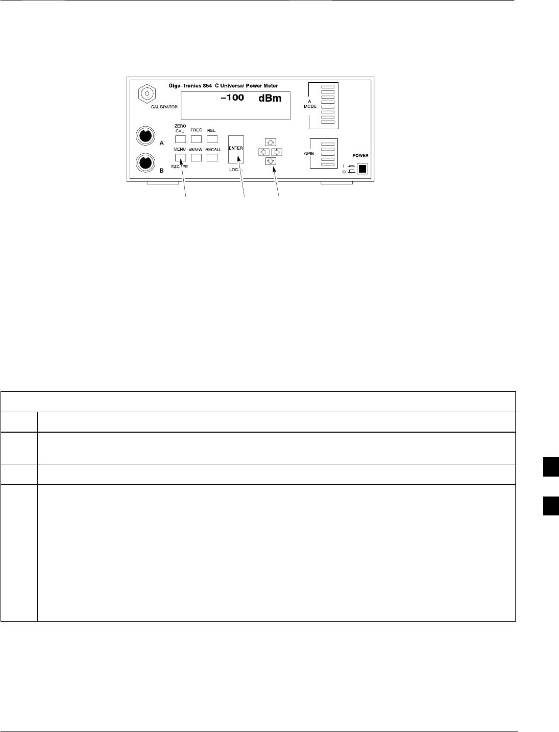
Verify the Gigatronics 8541C
Power Meter GPIB Address
Follow the steps in Table 7-21 to verify and, if necessary, change the
Gigatronics 8541C power meter GPIB address.
Table 7-21: Verify and/or Change Gigatronics 8541C Power Meter GPIB Address
Step Action
1! CAUTION
Do not connect/disconnect the power meter sensor cable with AC power applied to the meter.
Disconnection could result in destruction of the sensing element or miscalibration.
Press MENU (refer to Figure 7-18).
2Use the b arrow key to select CONFIG MENU and press ENTER.
3Use the b arrow key to select GPIB and press ENTER.
The system displays the current Mode and GPIB Address.
4If the Mode is not set to 8541C, perform the following to change it:
–Use the a ' arrow keys as required to select MODE.
–Use the by arrow keys as required to set MODE to 8541C.
5If the GPIB address is not set to 13, perform the following to change it:
–Use the ' arrow key to select ADDRESS.
–Use the by arrow keys as required to set the GPIB address to 13.
6 Press ENTER to return to normal operation.
7
GPIB Addresses – continued
JAN 2002 7-41
SCt300 1X BTS Hardware Installation, ATP, and FRU Procedures
DRAFT
MENU ENTER ARROW
KEYS
1
Figure 7-18: Gigatronics 8541C Power Meter Detail
Verify and Set Motorola
CyberTest GPIB Address
Follow the steps in Table 7-22 to verify and, if necessary, change the
GPIB address on the Motorola CyberTest. Changing the GPIB address
requires the following items:
SMotorola CyberTest communications analyzer.
SComputer running Windows 3.1/Windows 95.
SMotorola CyberTAME software program “TAME”.
SParallel printer port cable (shipped with CyberTest).
Table 7-22: Verify and/or Change Motorola CyberTest GPIB Address
Step Action
1On the LMF desktop, locate the CyberTAME icon. Double click on the icon to run the CyberTAME
application.
2In the CyberTAME window taskbar, under Special, select IEEE.488.2.
3CyberTAME software will query the CyberTest Analyzer for its current GPIB address. It will then
open the IEEE 488.2 dialog box. If the current GPIB address is not 18, perform the following steps to
change it:
–Use the up or down increment arrows, or double–click in the field and type the number.
–Click on the OK button. The system will write and save the new address to the CyberTest via the
parallel port.
NOTE
Repeat steps 2 and 3 to verify that the address was set. The new address should now appear in the
IEEE 488.2 dialog box Address field.
7
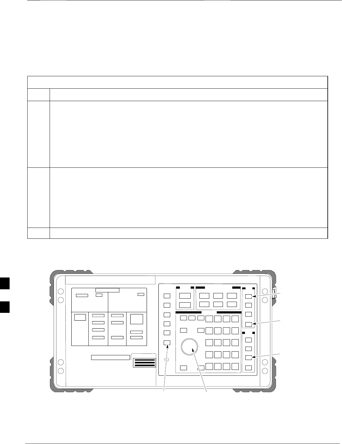
GPIB Addresses – continued
DRAFT
SCt300 1X BTS Hardware Installation, ATP, and FRU Procedures JAN 2002
7-42
Verify and Set HP8935 Test Set
GPIB Address
Follow the procedure in Table 7-23 to verify and, if necessary, change
the HP8935 GPIB address.
Table 7-23: Verify and/or Change HP8935 GPIB Address
Step Action
1* IMPORTANT
The HP I/O configuration MUST be set to Talk & Listen, or NO device on the GPIB bus will be
accessible (if necessary, consult test equipment OEM documentation for additional information).
To verify that the GPIB addresses are set correctly, press Shift and LOCAL on the HP8935 (refer
to Figure 7-19). The current HP–IB address will display at the top of the screen.
NOTE
HP–IB is the same as GPIB.
2If the current GPIB address is not set to 18, perform the following steps to change it:
–Press Shift and Inst Config.
–Turn the Cursor Control knob to move the cursor to the HP–IB Adrs field.
–Press the Cursor Control knob to select the field.
–Turn the Cursor Control knob as required to change the address to 18.
–Press the Cursor Control knob to set the address.
3 Press Preset to return to normal operation.
Figure 7-19: HP8935 Test Set
FW00885
Preset
Cursor Control
Shift
Inst Config
Local
7
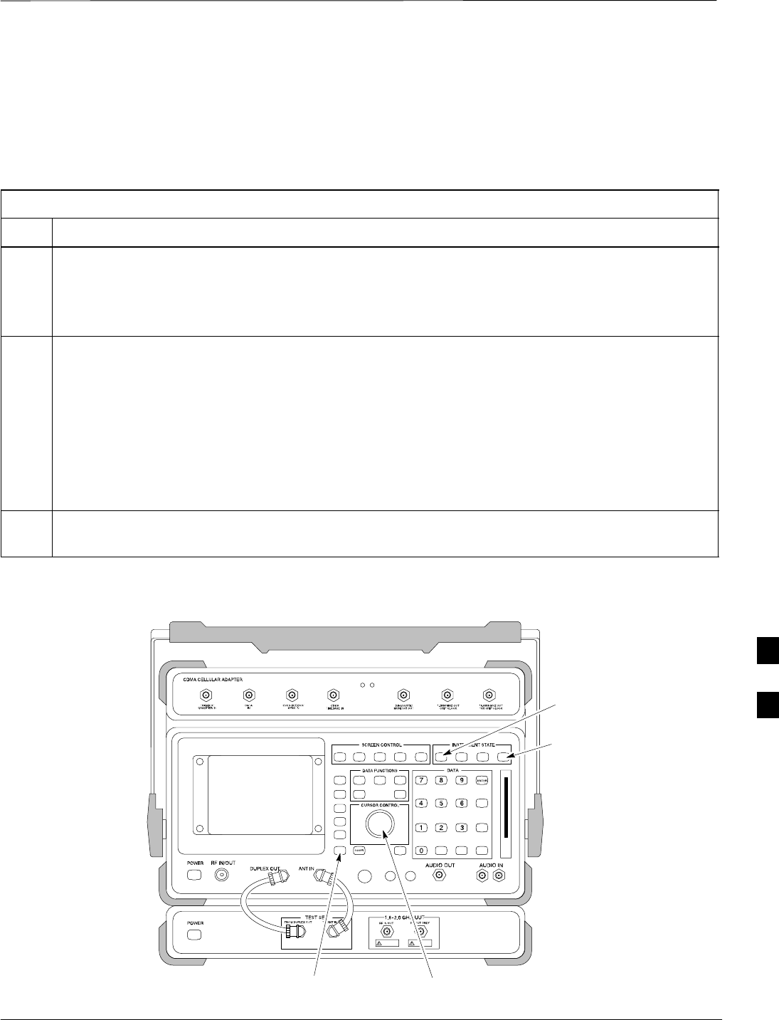
GPIB Addresses – continued
JAN 2002 7-43
SCt300 1X BTS Hardware Installation, ATP, and FRU Procedures
DRAFT
Verify and Set the HP8921A
and HP83236A/B GPIB
Addresses
Follow the procedure in Table 7-24 to verify and, if necessary, change
the HP8921A/HP83236A GPIB addresses.
Table 7-24: Verify and/or Change HP8921A and HP83236A GPIB Addresses
Step Action
1To verify that the GPIB addresses are set correctly, press Shift and LOCAL on the HP8921A (refer to
Figure 7-20). The current HP–IB address is displayed at the top of the screen.
NOTE
HP–IB is the same as GPIB.
2If the current HP–IB address is not set to 18, perform the following to change it:
–Turn the Cursor Control knob to move the cursor to More and press the knob to select the field.
–Turn the Cursor Control knob to move the cursor to I/O Config and press the knob to select the
field.
–Turn the Cursor Control knob to move the cursor to Adrs and press the knob to select the field.
–Turn the Cursor Control knob to change the HP–IB address to 18 and press the knob to set the
address.
–Press Shift and Preset to return to normal operation.
3To set the HP83236A (or B) PCS Interface GPIB address=19, set the dip switches as follows:
–A1=1, A2=1, A3=0, A4=0, A5=1, HP–IB/Ser = 1
Preset
Cursor Control
Shift
Local
Figure 7-20: HP8921A and HP83236A/B
7
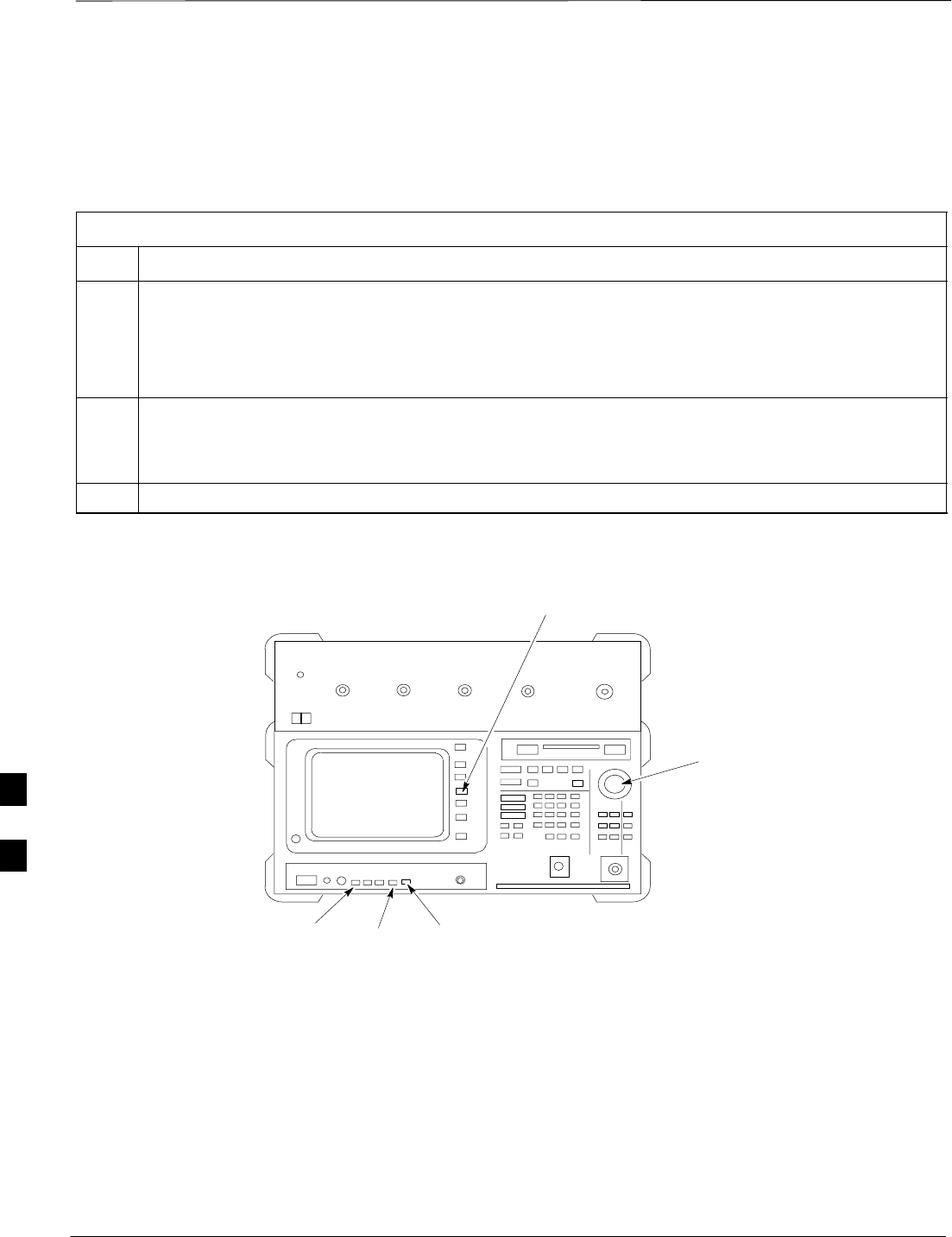
GPIB Addresses – continued
DRAFT
SCt300 1X BTS Hardware Installation, ATP, and FRU Procedures JAN 2002
7-44
Verify and Set Advantest R3465
GPIB Address
Table 7-25 describes the steps to verify and, if necessary, change the
GPIB address for the Advantest R3465.
Table 7-25: Verify and/or Change Advantest R3465 GPIB Address
Step Action
1Perform the following procedure to verify that the GPIB address is set correctly:
–Press SHIFT then PRESET (see Figure 7-21).
–Press LCL.
–Press the GPIB and Others CRT menu key to view the current address.
2If the current GPIB address is not set to 18, perform the following to change it:
–Turn the vernier knob as required to select 18.
–Press the vernier knob to set the address.
3To return to normal operation, press Shift and Preset.
Figure 7-21: R3465 Communications Test Set
BNC
“T”
REF UNLOCK EVEN
SEC/SYNC IN CDMA
TIME BASE IN
POWER
OFF ON
REF FW00337
LCL Shift Preset
GPIB and others
Vernier
Knob
7
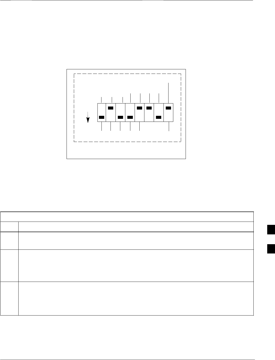
GPIB Addresses – continued
JAN 2002 7-45
SCt300 1X BTS Hardware Installation, ATP, and FRU Procedures
DRAFT
RS232 GPIB Interface Box
Ensure that the RS232 GPIB interface box dip switches are set as shown
in Figure 7-22.
RS232–GPIB
INTERFACE BOX
S MODE
DATA FORMAT
BAUD RATE
GPIB ADRS
ON
DIP SWITCH SETTINGS
G MODE
Figure 7-22: RS232 GPIB Interface Box
Verify and Set Advantest R3267
GPIB Address
Perform the procedure in Table 7-26 and refer to Figure 7-23 to verify
and, if necessary, change the Advantest R3267 spectrum analyzer GPIB
address.
Table 7-26: Verify and Change Advantest R3267 GPIB Address
Step Action
1If the REMOTE LED is lighted, press the LCL key.
–The LED extinguishes.
2Press the CONFIG key.
–The CONFIG softkey labels will appear in the softkey label display area of the instrument
display.
–The current GPIB address will be displayed below the GPIB Address softkey label.
3If the current GPIP address is not set to 18, perform the following to change it:
3a Press the GPIB Address softkey.
–A GPIB Address entry window will open in the instrument display showing the current GPIB
address.
. . . continued on next page
7
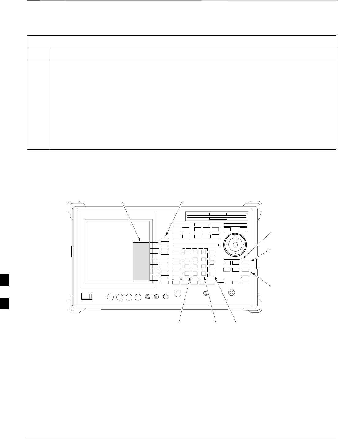
GPIB Addresses – continued
DRAFT
SCt300 1X BTS Hardware Installation, ATP, and FRU Procedures JAN 2002
7-46
Table 7-26: Verify and Change Advantest R3267 GPIB Address
Step Action
3b Enter 18 on the keypad in the ENTRY section of the instrument front panel.
–Characters typed on the keypad will replace the address displayed in the GPIB Address entry
window.
NOTE
To correct an entry, press the BS (backspace) key at the lower right of the keypad to delete one
character at a time.
3c Press the ENTR key to the lower right of the keypad to enter the address.
–The GPIB Address entry window closes.
–The new address is displayed in the bottom portion of the GPIB Address softkey label.
Figure 7-23: Setting Advantest R3267 GPIB Address
onREMOTE
LED
LCL Key
CONFIG
Key
Softkey Label
Display Area Softkey
Buttons
Keypad BS
Key ENTR
Key
7
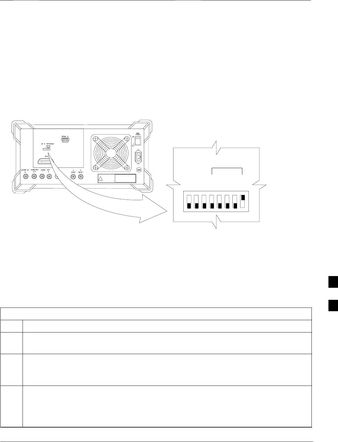
GPIB Addresses – continued
JAN 2002 7-47
SCt300 1X BTS Hardware Installation, ATP, and FRU Procedures
DRAFT
Verify and Set Advantest R3562
Signal Generator GPIB
Address
Set the GP–IP ADDRESS switch on the rear of the Advantest R3562
signal generator to address 1 as shown in Figure 7-24.
Figure 7-24: Advantest R3562 GPIB Address Switch Setting
123 45678
54321
GP–IP ADDRESS
1
0
GPIB Address set to “1”
Verify and Set Agilent E4406A
Transmitter Tester GPIB
Address
Follow the procedure in Table 7-27 and refer to Figure 7-25 to verify
and, if necessary, change the Agilent E4406A GPIB address.
Table 7-27: Verify and Change Agilent E4406A GPIB Address
Step Action
1In the SYSTEM section of the instrument front panel, press the System key.
The softkey labels displayed on the right side of the instrument screen will change.
2Press the Config I/O softkey button to the right of the instrument screen.
–The softkey labels will change.
–The current instrument GPIB address will display below the GPIB Address softkey label.
3If the current GPIB address is not set to 18, perform the following to change it:
3a Press the GPIB Address softkey button.
In the on–screen Active Function Area, GPIB Address will be displayed followed by the current
GPIB address.
. . . continued on next page
7
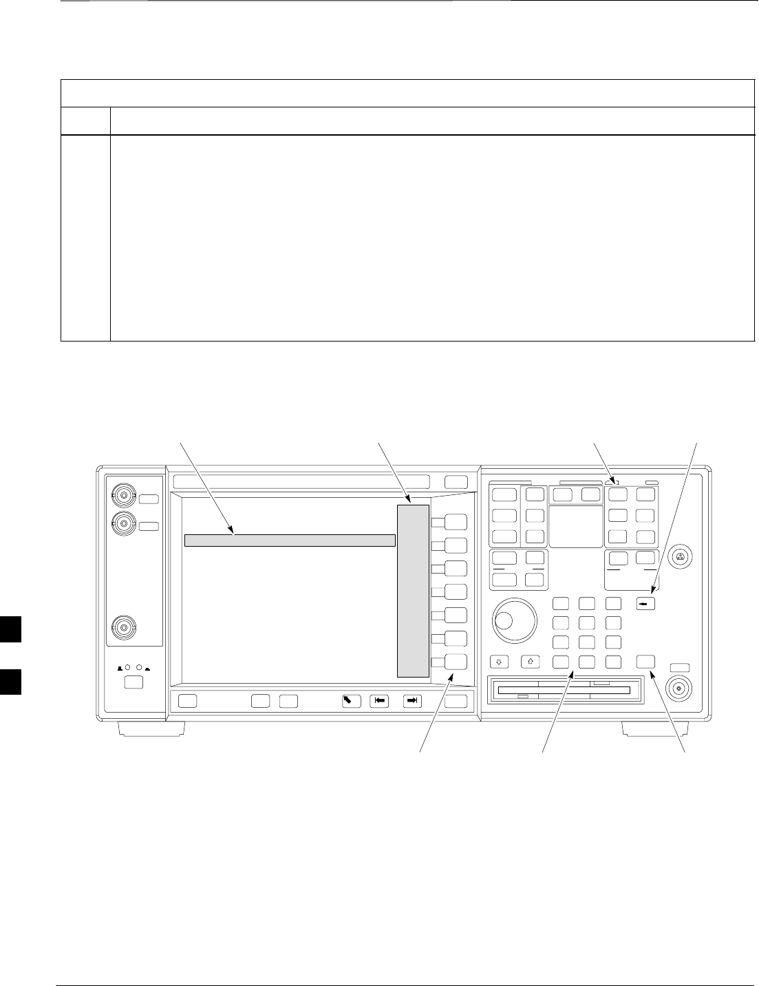
GPIB Addresses – continued
DRAFT
SCt300 1X BTS Hardware Installation, ATP, and FRU Procedures JAN 2002
7-48
Table 7-27: Verify and Change Agilent E4406A GPIB Address
Step Action
3b On the front panel Data Entry keypad, enter the communications system analyzer GPIB address of 18.
–The GPIB Address label will change to Enter.
–Digits entered with the keypad will replace the current GPIB address in the display.
NOTE
To correct an entry, press the Bk Sp key at the upper right of the keypad to delete one character at a
time.
3c Press the Enter softkey button or the keypad Enter key to set the new GPIB address.
–The Config I/O softkey labels will re–appear.
–The new GPIB address will display under the GPIB Address softkey label.
Figure 7-25: Setting Agilent E4406A GPIB Address
System
Key Bk Sp
Key
Enter
Key
Data Entry
Keypad
Softkey
Buttons
Softkey Label
Display Area
Active Function
Area
7

GPIB Addresses – continued
JAN 2002 7-49
SCt300 1X BTS Hardware Installation, ATP, and FRU Procedures
DRAFT
Verify and Set Agilent E4432B
Signal Generator GPIB
Address
Refer to Figure 7-26 and follow the procedure in Table 7-28 to verify
and, if necessary, change the Agilent E4432B GPIB address.
Table 7-28: Verify and Change Agilent E4432B GPIB Address
Step Action
1In the MENUS section of the instrument front panel, press the Utility key.
–The softkey labels displayed on the right side of the instrument screen will change.
2Press the GPIB/RS232 softkey button to the right of the instrument screen.
–The softkey labels will change.
–The current instrument GPIB address will be display below the GPIB Address softkey label.
3If the current GPIB address is not set to 1, perform the following to change it:
3a Press the GPIB Address softkey button.
–The GPIB Address label and current GPIB address will change to boldface.
–In the on–screen Active Entry Area, Address: and the current GPIB address will display.
3b On the front panel Numeric keypad, enter the signal generator GPIB address of 1.
–The GPIB Address label will change to Enter.
–Digits entered with the keypad will replace the current GPIB address in the Active Entry display.
NOTE
To correct an entry, press the backspace key at the lower right of the keypad to delete one character at
a time.
3c Press the Enter softkey button to set the new GPIB address.
–The new GPIB address will be display under the GPIB Address softkey label.
7
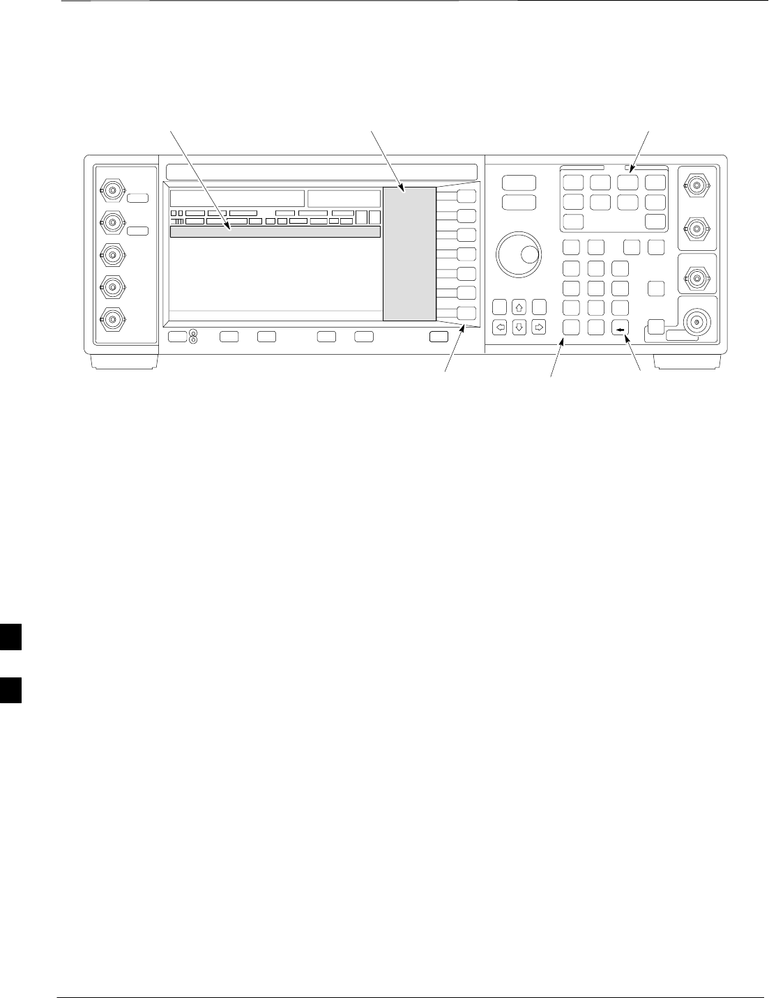
GPIB Addresses – continued
DRAFT
SCt300 1X BTS Hardware Installation, ATP, and FRU Procedures JAN 2002
7-50
Figure 7-26: Setting Agilent E4432B GPIB Address
Numeric
Keypad
Softkey
Buttons
Softkey Label
Display Area
Active Entry
Area
Backspace
Key
Utility
Key
7

Test Equipment Calibration
JAN 2002 7-51
SCt300 1X BTS Hardware Installation, ATP, and FRU Procedures
DRAFT
Background
To prevent damage to the test equipment, all Microcell
transmit (TX) tests must be made using the 30 dB
attenuator.
CAUTION
Proper test equipment calibration ensures that the test equipment and
associated test cables do not introduce measurement errors, and that
measurements are correct.
If the test set being used to interface with the BTS has been
calibrated and maintained as a set, this procedure does not
need to be performed. (Test Set includes LMF terminal,
communications test set, additional test equipment,
associated test cables, and adapters.)
NOTE
This procedure must be performed prior to beginning the optimization.
Verify all test equipment (including all associated test cables and
adapters actually used to interface all test equipment and the BTS) has
been calibrated and maintained as a set.
If any piece of test equipment, test cable, or RF adapter,
that makes up the calibrated test equipment set, has been
replaced, re-calibration must be performed. Failure to do so
can introduce measurement errors, resulting in incorrect
measurements and degradation to system performance.
CAUTION
Calibration of the communications test set (or equivalent
test equipment) must be performed at the site before
calibrating the overall test set. Calibrate the test equipment
after it has been allowed to warm–up and stabilize for a
minimum of 60 minutes.
IMPORTANT
*
These procedures access the LMF automated calibration routine used to
determine the path losses of the supported communications analyzer,
power meter, associated test cables, and (if used) antenna switch that
make up the overall calibrated test set. After calibration, the gain/loss
offset values are stored in a test measurement offset file on the LMF.
7

Test Equipment Calibration – continued
DRAFT
SCt300 1X BTS Hardware Installation, ATP, and FRU Procedures JAN 2002
7-52
Procedure to Calibrate Test
Equipment
The calibrate test equipment function zeros the power measurement level
of the test equipment item that is to be used for TX calibration and audit.
If both a power meter and an analyzer are connected, only the power
meter is zeroed.
Use the Calibrate Test Equipment menu item from the Util menu to
calibrate test equipment. The test equipment must be selected before
calibration can begin. Follow the procedure in Table 7-29 to calibrate the
test equipment.
Prerequisites
Ensure the following prerequisites have been met before proceeding:
STest equipment to be calibrated has been connected correctly for tests
that are to be run.
STest equipment has been selected.
Table 7-29: Procedure to Calibrate Test Equipment
Step Action
1From the Util menu, select Calibrate Test Equipment.
A Directions window is displayed.
2Follow the directions provided.
3Click on Continue to close the Directions window.
A status report window is displayed.
4Click on OK to close the status report window.
Calibration Without the LMF
Several test equipment items used in the optimization process require
pre–calibration actions or calibration verification which are not
supported by the LMF. Procedures to perform these activities for the
applicable test equipment items are covered in this section.
7

Test Equipment Calibration – continued
JAN 2002 7-53
SCt300 1X BTS Hardware Installation, ATP, and FRU Procedures
DRAFT
Procedure to Calibrate R3465
Test Set
Follow the steps inTable 7-30 to configure and calibrate the R3465
communication test set.
Table 7-30: Procedure to Calibrate R3465
Step Action
1* IMPORTANT
–Perform this calibration only after the analyzer has warmed–up and stabilized for a minimum
of 60 minutes. Test equipment warm–up may vary depending on operating environment or
initial temperature of unit upon turn–on. Consult test equipment OEM documentation for
additional information as required.
Connect the male BNC to male N cable between the CAL OUT connector and the INPUT 50 W
connector.
2 Select CW.
3Push the SHIFT and CAL pushbuttons.
4 Select Cal All in CRT menu.
Internal calibration should complete in about 6 minutes.
Procedure to Calibrate R3267
Test Set
Follow the steps in Table 7-31 to configure and calibrate the R3267
communication test set.
Table 7-31: Procedure to Calibrate R3267
Step Action
1* IMPORTANT
–Perform this calibration only after the analyzer has warmed–up and stabilized for a minimum
of 60 minutes. Test equipment warm–up may vary depending on operating environment or
initial temperature of unit upon turn–on. Consult test equipment OEM documentation for
additional information as required.
Connect the male BNC to male N cable between the CAL OUT connector and the INPUT 50 W
connector.
2 Select CW.
3Push the SHIFT and CAL pushbuttons.
4 Select Cal All in CRT menu.
Internal calibration should complete in about 6 minutes.
7
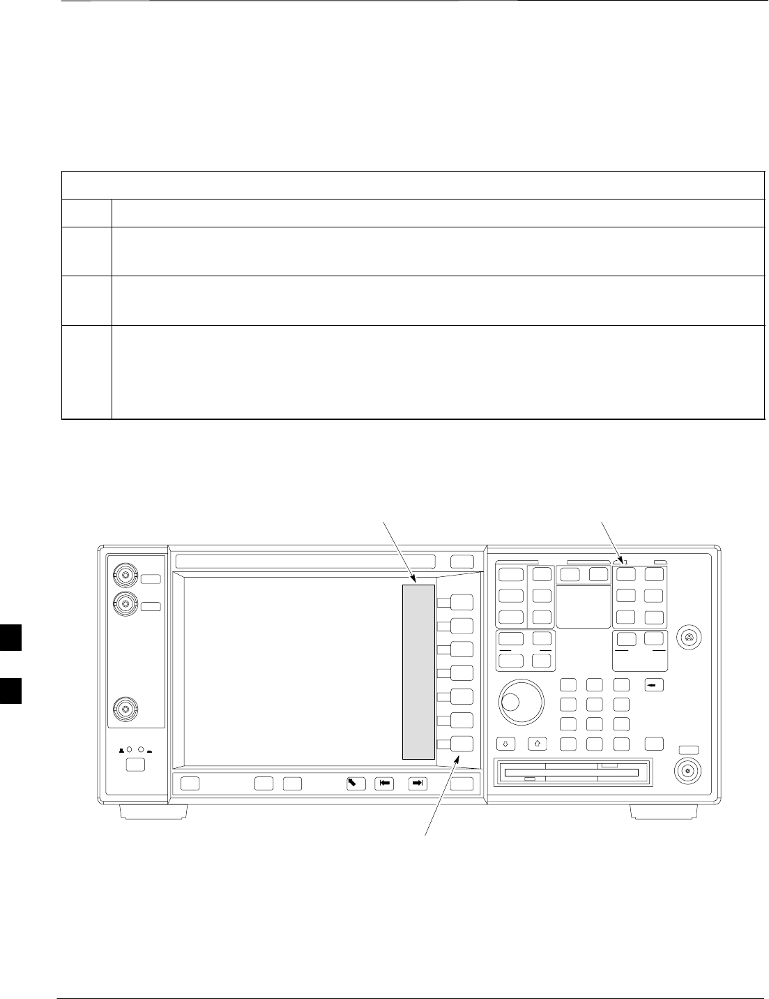
Test Equipment Calibration – continued
DRAFT
SCt300 1X BTS Hardware Installation, ATP, and FRU Procedures JAN 2002
7-54
Procedure to Calibrate Agilent
E4406A
Refer to Figure 7-27 and follow the procedure in Table 7-32 to perform
the Agilent E4406A self–alignment (calibration).
Table 7-32: Perform Agilent E4406A Self–alignment (Calibration)
Step Action
1In the SYSTEM section of the instrument front panel, press the System key.
–The softkey labels displayed on the right side of the instrument screen will change.
2Press the Alignments softkey button to the right of the instrument screen.
–The softkey labels will change.
3Press the Align All Now softkey button.
–All other instrument functions will be suspended during the alignment.
–The display will change to show progress and results of the alignments performed.
–The alignment will take less than one minute.
Figure 7-27: Performing Agilent E4406A Self–alignment (Calibration)
System
Key
Softkey
Buttons
Softkey Label
Display Area
7
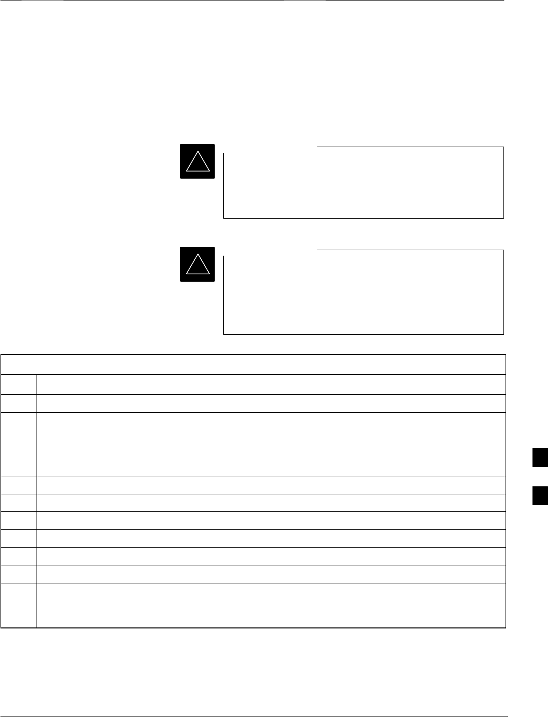
Test Equipment Calibration – continued
JAN 2002 7-55
SCt300 1X BTS Hardware Installation, ATP, and FRU Procedures
DRAFT
Procedure to Setup Advantest
R3465 Test Equipment
Follow the steps outlined in Table 7-33 (for Advantest R3465) or
Table 7-34 (for Advantest R3267) to set up test equipment prior to
performing ATP tests.
LMF based measurements factor in cable and attenuator
loss between the BTS and test equipment. No additional
attenuation can be inserted as the additional losses would
not be factored in.
IMPORTANT
*
If you are logged in to the BTS, you must log out prior to
loading the special JCDMA software on a PCMCIA RAM
card and inserting it in the Advantest R3465 PCMCIA slot.
This must be done before using the Advantest R3465 test
set for JCDMA tests.
IMPORTANT
*
Table 7-33: Procedure to Setup Advantest R3465 Test Equipment
Step Action
1If you have not already done so, interface the CDMA LMF computer to the BTS and login to the BTS.
2Perform the following steps for the manual test procedure for Automated TX verification.
Set up the communication test set by inserting the Automatic TX test PCMCIA card into the
Advantest PCMCIA card reader slot A. (software version=97.10.07 rev 0001 or later).
Perform the following steps to access and use the Advantest Automatic TX test screen:
3Press the Remote LCL button (located below the CRT).
4Press the Loader ON button (located below the CRT).
5Press the LOAD CRT menu button.
6Use the DISPLAY CONTROL knob to select CDMA_BSR.BAS and then press the knob.
7Press the RUN CRT menu button after the LOAD pop–up disappears.
8Wait for *Idle Free space to appear at the bottom of the CRT.
9Refer to Figure 7-34 to set up test equipment.
Verify that the coaxial cable from the appropriate TX connector on the BTS is connected to the test
equipment RF input port via the in line 30 dB high power attenuator for MicroCell BTSs.
7

Test Equipment Calibration – continued
DRAFT
SCt300 1X BTS Hardware Installation, ATP, and FRU Procedures JAN 2002
7-56
Procedure to Setup Advantest
R3267 Test Equipment
Table 7-34: Procedure to Setup Advantest R3267 Test Equipment
Step Action
1If you have not already done so, interface the CDMA LMF computer to the BTS and login to the BTS.
2Perform the following steps for the manual test procedure for Automated TX verification.
Set up the communication test set by inserting the Automatic TX test PCMCIA card into the
Advantest PCMCIA card reader slot A. (software revision 0.0.0.4 or later).
Perform the following steps to access and use the Advantest Automatic TX test screen:
3Press the Remote LCL button (located below the CRT).
4Press the Loader ON button (located below the CRT).
5 Select LOAD on the CRT screen (button #6).
6Use the DISPLAY CONTROL knob to select the REMOTE.BAS file, then press the knob.
7 Select RUN on the CRT screen (button #1).
8Wait for *Idle Free space to appear at the bottom of the CRT.
9Refer to Figure 7-34 to set up test equipment.
Verify that the coaxial cable from the appropriate TX connector on the BTS is connected to the test
equipment RF input port via the in line 30 dB high power attenuator for MicroCell BTSs.
7

Test Equipment Selection
JAN 2002 7-57
SCt300 1X BTS Hardware Installation, ATP, and FRU Procedures
DRAFT
Objective
The objective of this procedure is to select the test equipment used for
BTS testing. The LMF must select the test equipment before it is used
for BTS testing.
Prerequisites
The following are prerequisites for test equipment selection:
1. Test equipment to be used has been connected as shown in
Figure 7-16.
2. Power for the test equipment and GPIB box has been turned on.
3. LMF has been started (do not have to be logged in to the BTS).
Procedure to Select Test
Equipment
Follow the steps in Table 7-35 for test equipment selection
The test equipment can also be selected via a manual or
automatic connection. Refer to the CDMA LMF
Operator’s Guide, 68P64114A78 for the procedures.
NOTE
Table 7-35: Procedure to Select Test Equipment
Step Action
1 Select Tools>Options from the menu. A LMF Options window appears.
2Select the correct COM port from the Comm Port pick list (normally COM1).
3Click on the Auto–Detection button if it is not enabled.
4If the GPIB addresses are not displayed, enter the GPIB addresses in the box labeled GPIB
addresses to search.
NOTE
When both a power meter and a communication test set are selected, the first item listed in the
GPIB addresses to search box will be used for RF power measurements, e.g., TX calibration and
audit. The address for a power meter is 13 and the address for a communications test set is 18.
The numbers 13 and 18 must be included in the GPIB address to search box so the power meter
(13) will be used for TX calibration and audit.
5Click on the Apply button. The button will darken until the selection has been committed. A
check mark will appear in the Manual Configuration section for detected test equipment items.
6Click on the Dismiss button to close the LMF Options window.
7

Test Equipment Selection – continued
DRAFT
SCt300 1X BTS Hardware Installation, ATP, and FRU Procedures JAN 2002
7-58
Selecting Test Equipment
Automatically or Manually
Use LMF Options from the Tools>Options menu list to select test
equipment automatically (using the autodetect feature) or manually.
A Serial Connection and a Network Connection tab are provided for
test equipment selection. The Serial Connection tab is used when the
test equipment items are connected directly to the LMF computer via a
GPIB box (normal setup). The Network Connection tab is used when
the test equipment is to be connected remotely via a network connection.
Procedure to Manually Select
Test Equipment in a Serial
Connection Tab
Test equipment can be manually specified before, or after, the test
equipment is connected. The LMF does not check to see if the test
equipment is actually detected for manual specification. Follow the
procedure in Table 7-36 to select test equipment manually.
Table 7-36: Procedure to Manually Select Test Equipment in a Serial Connection Tab
Step Action
1 Select Tools>Options. The LMF Options window appears.
2Click on the Serial Connection tab (if not in the forefront).
3Select the correct serial port in the COMM Port pick list (normally COM1).
4Click on the Manual Specification button (if not enabled).
5Click on the check box corresponding to the test item(s) to be used.
6Type the GPIB address in the corresponding GPIB address box (the default address is “1”).
Recommended Addresses
1 = R3562 Test Source
13 = Power Meter
18 = CDMA Analyzer
7Click on Apply (the button darkens until the selection has been committed).
NOTE
With manual selection, the LMF does not detect the test equipment to see if it is connected and
communicating with the LMF.
8Click on Dismiss to close the test equipment window.
7

Test Equipment Selection – continued
JAN 2002 7-59
SCt300 1X BTS Hardware Installation, ATP, and FRU Procedures
DRAFT
Procedure to Automatically
Select Test Equipment in a
Serial Connection Tab When using the auto-detection feature to select test equipment, the LMF
examines which test equipment items are actually communicating with
the LMF. Follow the procedure in Table 7-37 to use the auto-detect
feature.
Table 7-37: Procedure to Select Test Equipment Using Auto-Detect
Step Action
1 Select Tools>Options. The LMF Options window appears.
2Click on the Serial Connection tab (if not in the forefront).
3Select the correct serial port in the COMM Port pick list (normally COM1).
4Click on Auto–Detection (if not enabled).
5Type in the GPIB addresses in the box labeled GPIB addresses to search (the default address is
“1”).
NOTE
When both a power meter and analyzer are selected, the first item listed in the GPIB addresses to
search box is used for RF power measurements (i.e., TX calibration). The address for a the test
source is 1; the address for the power meter is normally 13; and the address for a CDMA analyzer
is normally 18. If 1, 13,18 are included in the GPIB addresses to search box, the power meter
(13) is used for RF power measurements. If the test equipment items are manually selected, the
CDMA analyzer is used only if a power meter is not selected.
6Click on Apply.
NOTE
The button darkens until the selection has been committed. A check mark appears in the Manual
Configuration section for detected test equipment items.
7 Click Dismiss to close the LMF Options window. 7

Power Meter Calibration
DRAFT
SCt300 1X BTS Hardware Installation, ATP, and FRU Procedures JAN 2002
7-60
Objective
This procedure calibrates the power meter that will be used for cable
calibration and BTS testing.
Prerequisites
The following are prerequisites for power meter calibration:
1. The power meter is connected. Refer to Figure 7-16 in the “Test
Equipment Selection” procedure.
2. Test equipment has been selected.
Procedure to Calibrate the
Power Meter
Follow the steps in Table 7-38 to calibrate the power meter.
Table 7-38: Procedure to Calibrate the Power Meter
Step Action
1Click on Util>Calibrate Test Equipment. A cable connection direction pop–up is displayed.
2Follow the directions provided.
3Click on the OK button to close the status results window.
7
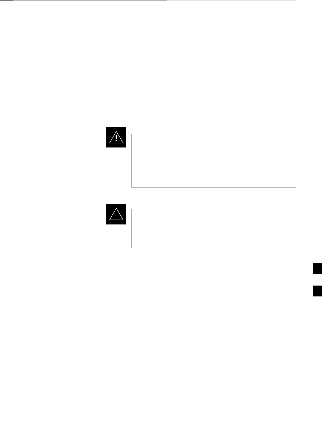
Test Cable Calibration
JAN 2002 7-61
SCt300 1X BTS Hardware Installation, ATP, and FRU Procedures
DRAFT
Background
Proper test equipment setup ensures that all measurements are correct,
and that test equipment and associated test cables do not introduce
measurement errors. Motorola recommends repeating cable calibration
prior to testing at each BTS site.
If not already done so, this procedure needs to be performed prior to
beginning the ATP. Verify that all test equipment (including all
associated test cables and adapters actually used to interface all test
equipment and the BTS together) has been calibrated.
In the event that any piece of test equipment, test cable, or
RF adaptor is replaced that makes up the calibrated test
equipment set, re–calibration should be performed. Failure
to do so can introduce measurement errors, resulting in
incorrect measurements or degradation to system
performance.
CAUTION
Calibration of the communications test set (or equivalent
test equipment) must be performed at the site before
calibrating the overall test set after it has been allowed to
warm–up and stabilize for a minimum of 60 minutes.
IMPORTANT
*
Purpose of Cable Calibration
This procedure accesses the LMF automated calibration routine used to
determine the path losses of the supported communications analyzer,
power meter, associated test cables, and (if used) RF Network making up
the overall calibrated test set. After calibration, the gain/loss offset
values are stored in a test measurement offset file on the LMF.
If you have obtained the test cable insertion loss values previously, you
can manually enter them using the Util>Edit>CableLoss>TX or RX
menu.
Do not use the manual method if you plan to run/have already run the
cable calibration procedure.
7

Test Cable Calibration – continued
DRAFT
SCt300 1X BTS Hardware Installation, ATP, and FRU Procedures JAN 2002
7-62
Procedure to do an Automated
Cable Calibration
This procedure calibrates the cables that will be used for BTS testing.
Follow the steps in Table 7-39 to calibrate the test cables. Refer to
Figure 7-28.
Prerequisites
1. Test equipment has been connected as shown in Figure 7-16.
2. Power for the test equipment and GPIB box has been turned on.
3. LMF has been started and BTS has been logged into.
4. Inspect and verify the TX and RX antenna cabling for your BTS.
Refer to the applicable “Antenna Cabling” procedure in chapter 6.
Table 7-39: Automated Cable Calibration
Step Action
1Click on the Util>Cable Calibration menu item.
2Select one of the following options in the Cable Calibration menu: TX and RX CABLE
CAL, TX CABLE CAL, or RX CABLE CAL.
NOTENOTE
Normally, the option TX and RX CABLE CAL is used so both the TX and RX cable
configurations are calibrated. Use the TX CABLE CAL and RX CABLE CAL options only if
one of the cable configurations needs to be calibrated.
3Enter a channel value into the Channel box. The channel value is the channel that the BTS is
being calibrated on, e.g., 170.
4Click the OK button. A Directions pop–up is displayed for each step of the cable calibration.
5Follow the directions displayed for each step. A status report window is displayed with the
results of the cable calibration.
6Click on OK to close the status report window.
7
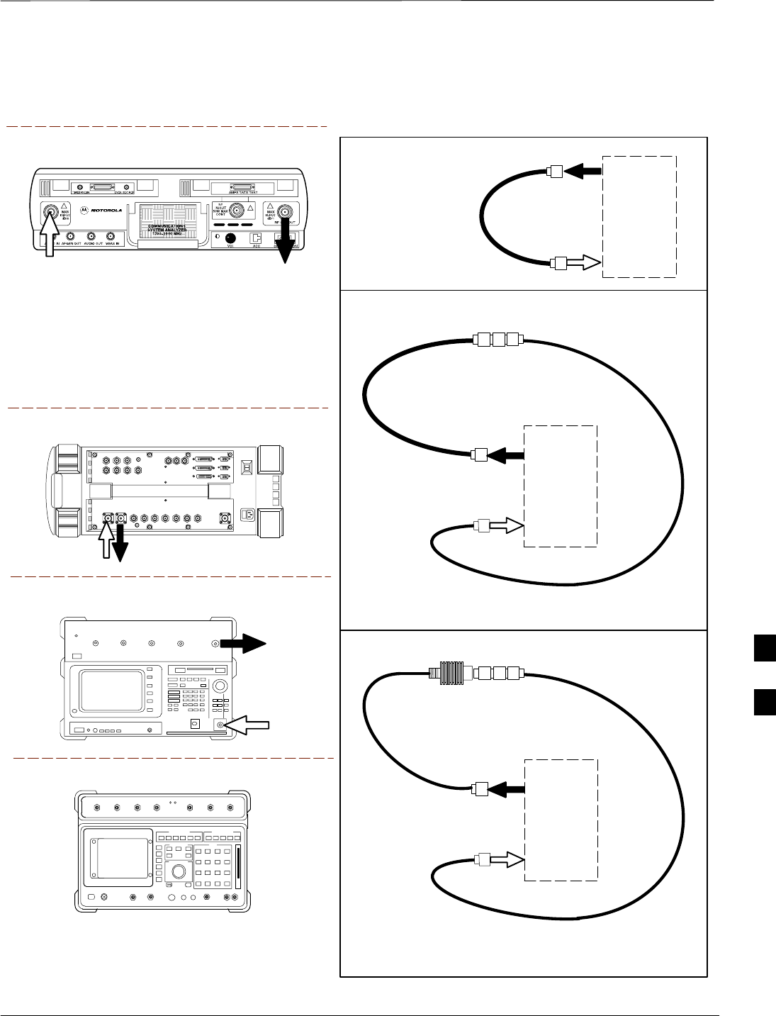
Test Cable Calibration – continued
JAN 2002 7-63
SCt300 1X BTS Hardware Installation, ATP, and FRU Procedures
DRAFT
Figure 7-28: Cable Calibration Test Setup (Motorola CyberTest, HP 8935, HP 8921, and Advantest R3465)
Motorola CyberTest
Hewlett–Packard Model HP 8935
Advantest Model R3465
DUPLEX
OUT
RF OUT
50–OHM
INPUT
50–OHM
RF GEN OUTANT IN
ANT
IN
SUPPORTED TEST SETS
TEST
SET
A. SHORT CABLE CAL
SHORT
CABLE
B. RX TEST SETUP
C. TX TEST SETUP
CALIBRATION SET UP
Note: The Directional Coupler is not used with the
Cybertest Test Set. The TX cable is connected
directly to the Cybertest Test Set.
A 10dB attenuator must be used with the short test
cable for cable calibration with the CyberTest Test
Set. The 10dB attenuator is used only for the cable
calibration procedure, not with the test cables for
TX calibration and ATP tests.
TEST
SET
RX
CABLE
SHORT
CABLE
FW00089
Note: For 800 MHZ only. The HP8921A cannot
be used to calibrate cables for PCS frequencies.
Hewlett–Packard Model HP 8921A
N–N FEMALE
ADAPTER
TEST
SET
TX
CABLE
SHORT
CABLE
N–N FEMALE
ADAPTER
30 DB 10W RF
ATTENUATOR
7
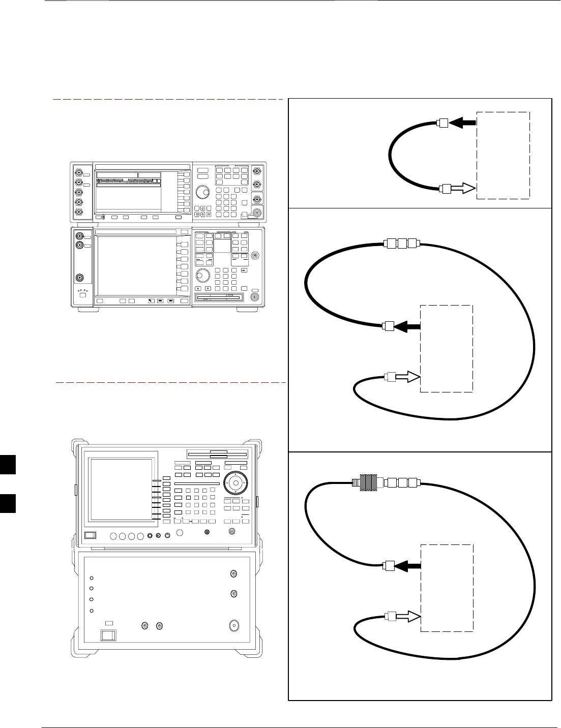
Test Cable Calibration – continued
DRAFT
SCt300 1X BTS Hardware Installation, ATP, and FRU Procedures JAN 2002
7-64
Figure 7-29: Cable Calibration Test Setup (Advantest R3267 and Agilent E4406A)
SUPPORTED TEST SETS
TEST
SET
A. SHORT CABLE CAL
SHORT
CABLE
B. RX TEST SETUP
C. TX TEST SETUP
CALIBRATION SET UP
TEST
SET
RX
CABLE
SHORT
CABLE
N–N FEMALE
ADAPTER
TEST
SET
TX
CABLE
SHORT
CABLE
N–N FEMALE
ADAPTER
30 DB 10W RF
ATTENUATOR
Agilent E4406A with E4432B
Signal Generator
ADVANTEST R3267 SPECTRUM ANALYZER
100Hz – 8GHz
ADVANTEST R3562 RECEIVER TEST SOURCE
Advantest Model R3267 with
R3562 Signal Generator
7

Create CAL File
JAN 2002 7-65
SCt300 1X BTS Hardware Installation, ATP, and FRU Procedures
DRAFT
Objective
Use this procedure to create a CAL file for the Calibration audit. You
must do this procedure before the RF path audit.
Background
The Create CAL File function gets the BLO data from the MAWI and
creates/updates the CAL file for the BTS. If a CAL file does not exist, a
new one is created. If a CAL file already exists, it is updated. The BTS
is calibrated at the factory and normally does not require calibration after
installation, so you must use the Create CAL File function to create a
CAL file since TX calibration is not performed.
The Create CAL File function only applies to selected
(highlighted) MAWIs.
NOTE
The CBSC does not require a calibration file for operation
of an SC300 BTS.
NOTE
The user is not encouraged to edit the CAL file as this
action can cause interface problems between the BTS and
the LMF. To manually edit the CAL file, you must first
logout of the BTS. If you manually edit the CAL file and
then use the Create CAL File function, the edited
information is lost.
NOTE
Prerequisites
The following must be done before you run this test:
SThe MAWI has the correct code load and data load.
SThe MAWI is INS.
SThe LMF is logged on to the BTS.
7

Create CAL File – continued
DRAFT
SCt300 1X BTS Hardware Installation, ATP, and FRU Procedures JAN 2002
7-66
Procedure to Create a CAL File
Use the following procedure in Table 7-40 to create a CAL file.
Table 7-40: Procedure to Create a CAL File
Step Action
1Log on to the BTS if you have not already done so.
2Select the MAWI.
3Click on the Device menu.
4Click on the Create Cal File menu item.
The status report window displays the results of the action.
5 Click OK.
The bts–#.cal is located in the wlmf\cdma\bts–#
folder (where # is the number of the BTS).
NOTE
7

Acceptance Tests
JAN 2002 7-67
SCt300 1X BTS Hardware Installation, ATP, and FRU Procedures
DRAFT
Overview
This chapter describes the various TX and RX acceptance tests.
TX Test Objective
The following tests will verify the TX antenna path. Output power
control will also be verified. All tests will be performed using the power
meter and communication test set. Measurements will be via the
Antenna B connectors.
You must remove the antenna cables before you perform
the ATP.
NOTE
The BTS is keyed up to generate a CDMA carrier at 31 dBm.
TX Tests
The following TX tests will be performed to verify the CDMA Forward
Link.
Near band & in band spurious emissions and occupied
bandwidth
You will verify that the transmitted CDMA carrier waveform generated
meets the Spurious Emissions specification (transmit spectral mask and
Occupied Bandwidth as defined in IS95A/B) with respect to either a
pre–determined test pattern or test pattern generated by using assigned
cdf file values.
–+/– 750 kHz from center frequency to +/– 1980 kHz from center
frequency – at least –45 dBc
–+/– 1980 kHz from center frequency and out – at least –60 dBc
–all near band and out of band spurious emissions are verified to be
less than or equal to –60 dBc relative to reference power (measured
previously as total power).
Waveform quality (Rho) and pilot time tolerance (offset)
You will verify that the transmitted Pilot channel waveform quality (rho)
exceeds the minimum specified value in ARIB STD T53. Rho
represents the correlation between actual and perfect CDMA modulation
spectrum. 1.0000 represents 100% (or perfect correlation).
–Waveform quality (Rho) should be > 0.912 (–0.4 dB).
The Pilot Time Tolerance (Offset) is the difference between the CDMA
analyzer measurement interval (based on the BTS system time reference)
and the incoming block of transmitted data from the BTS (Pilot only,
Walsh code 0).
–Pilot Time Tolerance (Offset) should be < 10 uS. (< 3 uS typical).
7

Acceptance Tests – continued
DRAFT
SCt300 1X BTS Hardware Installation, ATP, and FRU Procedures JAN 2002
7-68
CDMA carrier frequency verification
You will verify the frequency of the transmitted CDMA carrier signal to
be within 0.05 ppm.
Code domain power noise, pilot power, and total power
You will verify that the code domain noise floor of all unused Walsh
codes within the CDMA spectrum measures < –27 dB (with respect to
total power). Pilot power will be verified to measure –7.04 dB +/–0.5
dB (with respect to standard test patterns). Total power will be verified
to measure +2/–4 dB (with respect to CDF specific file parameters).
BTS frequency accuracy
BTS frequency accuracy can be verified manually during normal
operation by monitoring the 19.6608 MHz reference (19 MHz) from the
Diagnostic Access Area. A frequency counter with an accuracy of +/–
0.005 ppm can be used to check the BTS frequency accuracy.
RX Test Objective
The following test will verify the RX antenna path(s).
All tests will be performed using the communication test set.
Measurements will be via the Antenna A and Antenna B connectors.
RX Tests
The following RX test will be performed to verify the CDMA Reverse
Link.
BTS RX sensitivity/frame erasure rate
The default test verifies the BTS sensitivity on all Traffic Channel
elements (fullrate at 1% FER) at an RF input level of –117 dBm on the
RX antenna path.
There are no pass/fail criteria associated with FER readings
taken at level below –117 dBm; other than to verify that
the FER measurement reflects changes in RX input signal
level.
NOTE
7

Subscriber Unit (SU) Test and Setup
JAN 2002 7-69
SCt300 1X BTS Hardware Installation, ATP, and FRU Procedures
DRAFT
Objective
The following procedure is to test and verify the operation of the
Subscriber Unit (SU). This procedure also contains instructions to
program the NAM parameters into the SU prior to operation.
Background
The integral Subscriber Unit (SU) provides a controlled method of
terminating calls within the local BTS for diagnostic purposes. The
SU’s RF is connected to the forward port of the antenna directional
couplers via distribution components to provide a hard–wired path. The
SU performs a system–level test call with audio loopback functionality.
Control of the SU is only available remotely via the dial up modem (or
locally via the MMI). The OMCR–based SALT script is not supported.
The Subscriber Unit Distribution (SUD) is the board that provides RF
splitting and attenuation for the subscriber unit RF signal. The SUD is
an internal module.
Procedure to Test and Verify
SU
Follow the instructions in Table 7-41 to test and verify the operation of
the SU.
Table 7-41: Procedure to Test and Verify the Subscriber Unit
Step Action
1Connect the LMF computer to the MMI/LMF connector. Refer to Figure 7-6.
2If you have not already done so, logout of the BTS and exit the LMF. Wait 10 seconds before
proceeding.
3Establish an MMI communications session with the BTS. Refer to NO TAG.
4Enter the sndtype 0xa178 command to simulate an LMF session.
5Make sure the unit has booted into the OOS_RAM state.
6Enter the following command at the sc300’x–1> prompt to enable SU response printing in the
MMI session:
printf on
. . . continued on next page
7

Subscriber Unit (SU) Test and Setup – continued
DRAFT
SCt300 1X BTS Hardware Installation, ATP, and FRU Procedures JAN 2002
7-70
Table 7-41: Procedure to Test and Verify the Subscriber Unit
Step Action
7Enter the following command at the sc300’x–1> prompt to view the ESN number of the SU
and the CAMPS version:
su version
The system will display the following output. Note that the ESN numbers will be different, but
everything else will remain as shown below.
sc300’x–1>su version
COMMAND ACCEPTED: su version
***************su version***************
Model :+GMM: C401M
GMIinfo :+GMI: SANYO Electric Co., Ltd.
GMRinfo :+GMR: 1.310
GOI_id :+GOI:
GSN_id :+GSN: 1869FE88
GCAP_format :+GCAP: +CIS707, +MS, +ES, +FCLASS
ESN: 0x1869FE88
8Press ENTER once to return to the sc300’x–1> prompt. Proceed to the “Subscriber Unit
Programming” procedure in Table 7-42.
7

Subscriber Unit (SU) Test and Setup – continued
JAN 2002 7-71
SCt300 1X BTS Hardware Installation, ATP, and FRU Procedures
DRAFT
Procedure to Program SU NAM
Parameters
Follow the instructions in Table 7-42 to program the SU NAM
parameters.
Table 7-42: Procedure to Program the SU NAM Parameters
Step Action
1Enter the following command at the sc300’x–1> prompt to turn the power to the SU on:
su power on
2Enter the following command at the sc300’x–1> prompt to view the NAM parameters stored
in the SU:
su nam show
The system will display the following typical output:
sc300’x–1>su nam show
COMMAND ACCEPTED: su nam show
SU NAM CONFIG
–––––––––––––––––––––––
Phone Number 8476324677
Station Class Mark 34
Access Overload Code 0
Si d 8
Security Code 48
Lock Code 123
Slot Cycle Index 2
System Id 1
Network Id 65535
IMSI 11 & 12 11
IMSI MCC 111
CDMA Pri Channel A 76
CDMA Pri Channel B 76
CDMA Sec Channel A 872
CDMA Sec Channel B 872
NOTE
The NAM values shown above are for example only. You must enter site–specific NAM
parameter values into the following commands.
3Enter the following command at the sc300’x–1> prompt to program the Mobile Phone
Number:
su nam min <phone number>
4Enter the following command at the sc300’x–1> prompt to program the Access Overload
Code:
su nam aoc <access overload code>
5Enter the following command at the sc300’x–1> prompt to program the Slot Cycle Index:
su nam si <slot cycle index>
. . . continued on next page
7

Subscriber Unit (SU) Test and Setup – continued
DRAFT
SCt300 1X BTS Hardware Installation, ATP, and FRU Procedures JAN 2002
7-72
Table 7-42: Procedure to Program the SU NAM Parameters
Step Action
6Enter the following command at the sc300’x–1> prompt to program the System ID:
su nam sid <system ID>
7Enter the following command at the sc300’x–1> prompt to program the Mobile Country Code
(MCC) and IMSI 11&12 (MNC) code:
su nam imsi <mcc & IMSI>
For example, if the MCC code is “11” and the MNC code is “23,” you would enter:
su nam imsi 1123
8Enter the following command at the sc300’x–1> prompt to view the changes to the NAM
table:
su nam show
9Enter the following command at the sc300’x–1> prompt to download the NAM information
into the mobile:
su nam update
Downloading the NAM parameters into the Mobile may take a few minutes.
7

CDMA Operating Frequency Programming Information – North American
Cellular Bands
JAN 2002 7-73
SCt300 1X BTS Hardware Installation, ATP, and FRU Procedures
DRAFT
Objective
The following tables show each of the valid operating channels for North
American PCS Bands and their corresponding transmit and receive
frequencies.
1900 MHz PCS Channels
Figure 7-30 shows the valid channels for the North American PCS
1900 MHz frequency spectrum.
FREQ (MHz)
RX TX
275
1175
CHANNEL
1863.75
925
1851.2525
1871.25425
675 1883.75
1896.25
1908.75
1943.75
1931.25
1951.25
1963.75
1976.25
1988.75
A
D
B
E
F
C
FW00463
Figure 7-30: North America PCS Frequency Spectrum (CDMA Allocation)
7

CDMA Operating Frequency Programming Information – North American
Cellular Bands – continued
DRAFT
SCt300 1X BTS Hardware Installation, ATP, and FRU Procedures JAN 2002
7-74
Calculating 1900 MHz Center
Frequencies
Table 7-43 shows selected 1900 MHz CDMA candidate operating
channels, listed in both decimal and hexadecimal, and the corresponding
transmit, and receive frequencies. Center frequencies (in MHz) for
channels not shown in the table may be calculated as follows:
STX = 1930 + 0.05 * Channel#
Example: Channel 262
TX = 1930 + 0.05*262 = 1943.10 MHz
SRX = TX – 80
Example: Channel 262
RX = 1943.10 – 80 = 1863.10 MHz
Actual frequencies used depend on customer CDMA system frequency
plan.
Each CDMA channel requires a 1.77 MHz frequency segment. The
actual CDMA carrier is 1.23 MHz wide, with a 0.27 MHz guard band on
both sides of the carrier.
Minimum frequency separation required between any CDMA carrier and
the nearest NAMPS/AMPS carrier is 900 kHz (center-to-center).
Table 7-43: 1900 MHz TX and RX Frequency vs. Channel
Channel Number
Decimal Hex Transmit Frequency (MHz)
Center Frequency Receive Frequency (MHz)
Center Frequency
25 0019 1931.25 1851.25
50 0032 1932.50 1852.50
75 004B 1933.75 1853.75
100 0064 1935.00 1855.00
125 007D 1936.25 1856.25
150 0096 1937.50 1857.50
175 00AF 1938.75 1858.75
200 00C8 1940.00 1860.00
225 00E1 1941.25 1861.25
250 00FA 1942.50 1862.50
275 0113 1943.75 1863.75
300 012C 1945.00 1865.00
325 0145 1946.25 1866.25
350 015E 1947.50 1867.50
375 0177 1948.75 1868.75
400 0190 1950.00 1870.00
425 01A9 1951.25 1871.25
450 01C2 1952.50 1872.50
475 01DB 1953.75 1873.75
500 01F4 1955.00 1875.00
525 020D 1956.25 1876.25
550 0226 1957.50 1877.50
575 023F 1958.75 1878.75
. . . continued on next page
7

CDMA Operating Frequency Programming Information – North American
Cellular Bands – continued
JAN 2002 7-75
SCt300 1X BTS Hardware Installation, ATP, and FRU Procedures
DRAFT
Table 7-43: 1900 MHz TX and RX Frequency vs. Channel
Channel Number
Decimal Hex Receive Frequency (MHz)
Center Frequency
Transmit Frequency (MHz)
Center Frequency
600 0258 1960.00 1880.00
625 0271 1961.25 1881.25
650 028A 1962.50 1882.50
675 02A3 1963.75 1883.75
700 02BC 1965.00 1885.00
725 02D5 1966.25 1886.25
750 02EE 1967.50 1887.50
775 0307 1968.75 1888.75
800 0320 1970.00 1890.00
825 0339 1971.25 1891.25
850 0352 1972.50 1892.50
875 036B 1973.75 1893.75
900 0384 1975.00 1895.00
925 039D 1976.25 1896.25
950 03B6 1977.50 1897.50
975 03CF 1978.75 1898.75
1000 03E8 1980.00 1900.00
1025 0401 1981.25 1901.25
1050 041A 1982.50 1902.50
1075 0433 1983.75 1903.75
1100 044C 1985.00 1905.00
1125 0465 1986.25 1906.25
1150 047E 1987.50 1807.50
1175 0497 1988.75 1908.75
7
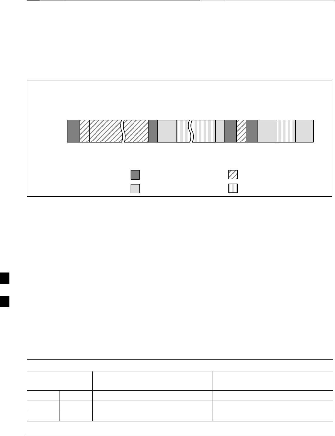
CDMA Operating Frequency Programming Information – North American
Cellular Bands – continued
DRAFT
SCt300 1X BTS Hardware Installation, ATP, and FRU Procedures JAN 2002
7-76
800 MHz CDMA Channels
Figure 7-31 shows the valid channels for the North American cellular
telephone frequency spectrum.
Figure 7-31: North American Cellular Telephone System Frequency Spectrum (CDMA Allocation).
RX FREQ
(MHz)
991
1023
1
333
334
666
667
716
717
799
CHANNEL
OVERALL NON–WIRELINE (A) BANDS
OVERALL WIRELINE (B) BANDS
824.040
825.000
825.030
834.990
835.020
844.980
845.010
846.480
846.510
848.970
869.040
870.000
870.030
879.990
880.020
889.980
890.010
891.480
891.510
893.970
TX FREQ
(MHz)
1013
694
689
311
356
644
739
777
CDMA NON–WIRELINE (A) BAND
CDMA WIRELINE (B) BAND
FW00402
Calculating 800 MHz Center
Frequencies
Table 7-44 shows selected 800 MHz CDMA candidate operating
channels, listed in both decimal and hexadecimal, and the corresponding
transmit, and receive frequencies. Center frequencies (in MHz) for
channels not shown in the table may be calculated as follows:
SChannels 1–777
TX = 870 + 0.03 * Channel#
Example: Channel 262
TX = 870 + 0.03*262 = 877.86 MHz
SChannels 1013–1023
TX = 870 + 0.03 * (Channel# – 1023)
Example: Channel 1015
TX = 870 +0.03 *(1015 – 1023) = 869.76 MHz
SRX = TX – 45 MHz
Example: Channel 262
RX = 877.86 –45 = 832.86 MHz
Table 7-44: 800 MHz TX and RX Frequency vs. Channel
Channel Number
Decimal Hex Transmit Frequency (MHz)
Center Frequency Receive Frequency (MHz)
Center Frequency
1 0001 870.0300 825.0300
25 0019 870.7500 825.7500
50 0032 871.5000 826.5000
. . . continued on next page
7

CDMA Operating Frequency Programming Information – North American
Cellular Bands – continued
JAN 2002 7-77
SCt300 1X BTS Hardware Installation, ATP, and FRU Procedures
DRAFT
Table 7-44: 800 MHz TX and RX Frequency vs. Channel
Channel Number
Decimal Hex Receive Frequency (MHz)
Center Frequency
Transmit Frequency (MHz)
Center Frequency
75 004B 872.2500 827.2500
100 0064 873.0000 828.0000
125 007D 873.7500 828.7500
150 0096 874.5000 829.5000
175 00AF 875.2500 830.2500
200 00C8 876.0000 831.0000
225 00E1 876.7500 831.7500
250 00FA 877.5000 832.5000
275 0113 878.2500 833.2500
300 012C 879.0000 834.0000
325 0145 879.7500 834.7500
350 015E 880.5000 835.5000
375 0177 881.2500 836.2500
400 0190 882.0000 837.0000
425 01A9 882.7500 837.7500
450 01C2 883.5000 838.5000
475 01DB 884.2500 839.2500
500 01F4 885.0000 840.0000
525 020D 885.7500 840.7500
550 0226 886.5000 841.5000
575 023F 887.2500 842.2500
600 0258 888.0000 843.0000
625 0271 888.7500 843.7500
650 028A 889.5000 844.5000
675 02A3 890.2500 845.2500
700 02BC 891.0000 846.0000
725 02D5 891.7500 846.7500
750 02EE 892.5000 847.5000
775 0307 893.2500 848.2500
NOTE
Channel numbers 778 through 1012 are not used.
1013 03F5 869.7000 824.7000
1023 03FF 870.0000 825.0000
7

TX Acceptance Tests
DRAFT
SCt300 1X BTS Hardware Installation, ATP, and FRU Procedures JAN 2002
7-78
Objective
Refer to Table 7-45 to perform a TX ATP test. This procedure assumes
that the site specific CDF file is in the wlmf\cdma\bts–# folder.
The ALL TX list performs the following ATP tests:
1. TX Mask
2. Rho
3. Pilot Time Offset
4. Code Domain Power
Prerequisites
You must successfully complete all the procedures outlined in previous
chapters before you attempt to run an ATP.
Procedure to Run TX ATP Test
Table 7-45: Procedure to Run TX ATP Test
Step Action
1Set up test equipment for TX tests per Figure 7-32 or Figure 7-33.
2Perform the following to run TX Acceptance Tests:
–Select the MAWI.
–Click on the Tests menu
–Select ALL TX.
* IMPORTANT
The DPLL must be tracking either GPS or HSO.
Procedure to Run TX Tests
Using Backup Synchronization
(Sites Equipped With GPS)
Follow the steps in Table 7-46 to perform the TX test using backup
synchronization.
Table 7-46: Procedure to Run TX Test Using Backup Synchronization
Step Action
1If logged into the BTS with the LMF, disable the MAWI and logout. Enter the sndtype 0x4003
command to change the state to OOS_RAM.
2Open an MMI Communication session.
3Enter the status command to verify that the BTS is in OOS_RAM status.
4Enter the sndtype 0xa178 command to simulate an LMF connection.
. . . continued on next page
7

TX Acceptance Tests – continued
JAN 2002 7-79
SCt300 1X BTS Hardware Installation, ATP, and FRU Procedures
DRAFT
Table 7-46: Procedure to Run TX Test Using Backup Synchronization
Step Action
5At the MMI prompt, enter dpll_info and verify that GPS and HSO are good reference sources.
Observe the following typical response.
current dpll task state info:
dpll task state: DPLL_LOCKED
global cdma time: enabled
local cdma time: disabled
Reference Ref_Status Ref_select Even_select(DPLL’s Ref source)
GPS TRUE TRUE TRUE
HSO TRUE FALSE FALSE
FREERUN FALSE FALSE FALSE
2SEC FALSE FALSE FALSE
The Ref_Status for the GPS and HSO must be TRUE. The Ref_select must be TRUE and
FALSE for the GPS and HSO, respectively.
6Verify that the HSO takes over for the GPS by simulating a failure of the GPS through software.
Enter the gps_rx_debug nosats on command at the MMI prompt to simulate the GPS losing
all tracked satellites. Observe the following typical response.
FM: #2716 Ticks=00140aab pc=08137df4 nid=30003004 org=6
info=09e200270000 file=gps_misc.c line=3904
send gps no sats SET –seeing no tracked sats.
7 Enter dpll_info at the MMI prompt to verify that the BTS is now using the HSO as the primary
reference source. The Ref_select must be FALSE and TRUE for the GPS and HSO,
respectively.
8Enter the dpll_status command to display the current state of the DPLL. Observe the following
typical response.
Current source set to: HSO reference
DPLL control task state: DPLL track
DPLL status (not valid if using even sec src):
c:6CD6 off: –9697314,25154,8669797 TK
Mode cntr: 60
ip: 3, iq: –9
aip1: 9, aiq1: 4
aip2: 6, aiq2: –2
tip: 3, tiq: –9
integrator: –2511864
9Verify that the DPLL is “tracking” the HSO. The Current source set to field should
read HSO reference. The DPLL control task state field should read DPLL
track.
10 Exit the MMI communication session and login to the BTS with the LMF.
11 Select Tests>TX>Pilot Time Offset to verify that the BTS passes using the HSO as the backup
synchronization source.
12 Logout of the BTS.
. . . continued on next page
7

TX Acceptance Tests – continued
DRAFT
SCt300 1X BTS Hardware Installation, ATP, and FRU Procedures JAN 2002
7-80
Table 7-46: Procedure to Run TX Test Using Backup Synchronization
Step Action
13 If logged into the BTS with the LMF, then logout.
14 Open an MMI Communication session.
15 Enter the status command to verify that the BTS is in OOS_RAM status.
16 Enter the sndtype 0xa178 command to simulate an LMF connection.
17 Enter the gps_rx_debug nosats off command at the MMI prompt to disable the simulation of
the GPS losing tracked satellites.
NOTENOTE
The gps_rx_debug command simulates the “No Satellites Tracked” condition. In reality, the
receiver is tracking satellites. However, the software is masking that information. Be sure to turn
off the “No Satellites” condition after completing this test.
18 Follow the procedure in Table 7-11 (Synchronization Verification) to make sure the BTS is
tracking the RGPS.
7
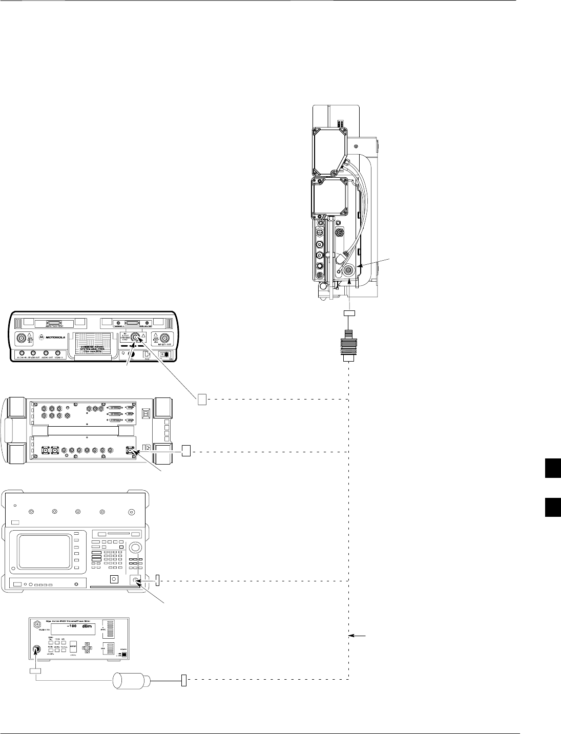
TX Acceptance Tests – continued
JAN 2002 7-81
SCt300 1X BTS Hardware Installation, ATP, and FRU Procedures
DRAFT
Figure 7-32: TX ATP Setup (CyberTest, HP 8935 and Advantest R3465)
COMMUNICATIONS TEST SET
MICROCELL
UNIT
ANTENNA B
30DB IN-LINE
ATTENUATOR
TRANSMIT RF
TEST CABLE
POWER SENSOR
NOTE: THE DOTTED LINES REPRESENT THAT
EITHER TX RF TEST CABLE CONNECTS TO
BOTH COMMUNICATIONS TEST SET AND
POWER METER
MOTOROLA CYBERTEST
AGILENT 8935 SERIES E6380A
(FORMERLY HP 8935)
ADVANTEST MODEL R3465
RF IN/OUT
RF IN/OUT
INPUT
50–OHM
POWER METER: GIGATRONICS
8541C OR HP 437B
7
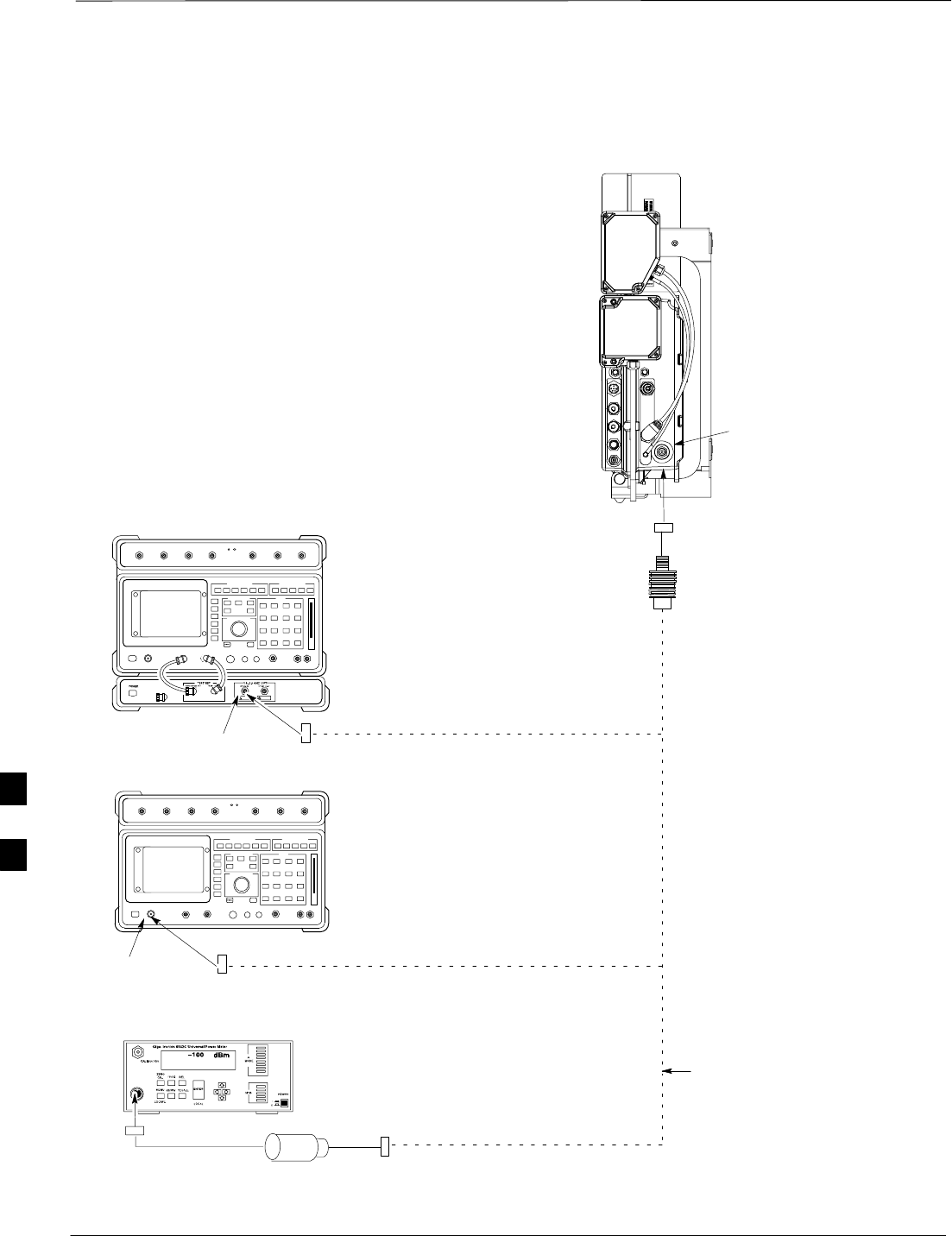
TX Acceptance Tests – continued
DRAFT
SCt300 1X BTS Hardware Installation, ATP, and FRU Procedures JAN 2002
7-82
Figure 7-33: TX ATP Setup (HP 8921A)
COMMUNICATIONS TEST SET
MICROCELL
UNIT
ANTENNA B
POWER METER: GIGATRONICS
8541C OR HP 437B
30DB IN-LINE
ATTENUATOR
TRANSMIT RF
TEST CABLE
POWER SENSOR
NOTE: THE DOTTED LINES REPRESENT THAT
EITHER TX RF TEST CABLE CONNECTS TO
BOTH COMMUNICATIONS TEST SET AND
POWER METER
HEWLETT–PACKARD MODEL HP 8921A W/PCS
INTERFACE (FOR 1700 AND 1900 MHz)
RF
IN/OUT
HEWLETT–PACKARD MODEL HP
8921A (FOR 800 MHz)
RF
IN/OUT
7
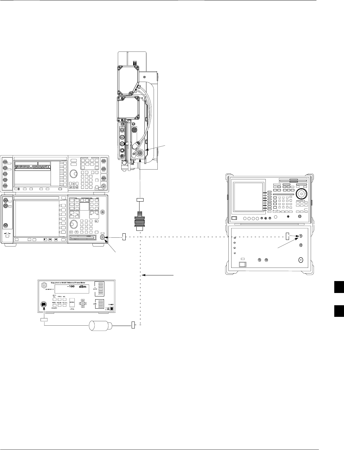
TX Acceptance Tests – continued
JAN 2002 7-83
SCt300 1X BTS Hardware Installation, ATP, and FRU Procedures
DRAFT
Figure 7-34: TX ATP Setup (Advantest R3267 and Agilent E4406A)
ANTENNA B
POWER METER
30DB IN-LINE ATTENUATOR
TRANSMIT RF
TEST CABLE
POWER SENSOR
NOTE: THE DOTTED LINES REPRESENT THAT
EITHER TX RF TEST CABLE CONNECTS TO
BOTH COMMUNICATIONS TEST SET AND
POWER METER
ADVANTEST R3267 SPECTRUM
ANALYZER 100Hz – 8GHz
ADVANTEST R3562 RECEIVER TEST
SOURCE
ADVANTEST R3267 (TOP)
AND R3562 (BOTTOM)
RF INPUT INPUT 50 OHM
AGILENT E4432B (TOP)
AND E4406A (BOTTOM)
7

RX Acceptance Tests
DRAFT
SCt300 1X BTS Hardware Installation, ATP, and FRU Procedures JAN 2002
7-84
Objective
This procedure assumes that the site specific CDF file is in the
wlmf\cdma\bts–# folder.
Prerequisites
You must successfully complete all the procedures outlined in previous
chapters before you attempt to run an ATP.
Procedure to Run RX ATP Test
Refer to Table 7-47 to perform an RX ATP test. This procedure assumes
that the site specific CDF file is in the wlmf\cdma\bts–# folder.
Table 7-47: Procedure to Run RX ATP Test
Step Action
1Set up test equipment per Figure 7-35, Figure 7-36, or Figure 7-37.
2Terminate diversity RX antenna inputs on the unit.
3Enter the following commands to run the RX Acceptance Tests.
–Select the MAWI.
–Select Tests>ALL RX.
NOTE
The LMF refers to the antennas as Main and Diversity. The Main is Antenna B and the Diversity
is Antenna A.
NOTE
Select Both in the RX Branch pick list if a diversity antenna is used.
7
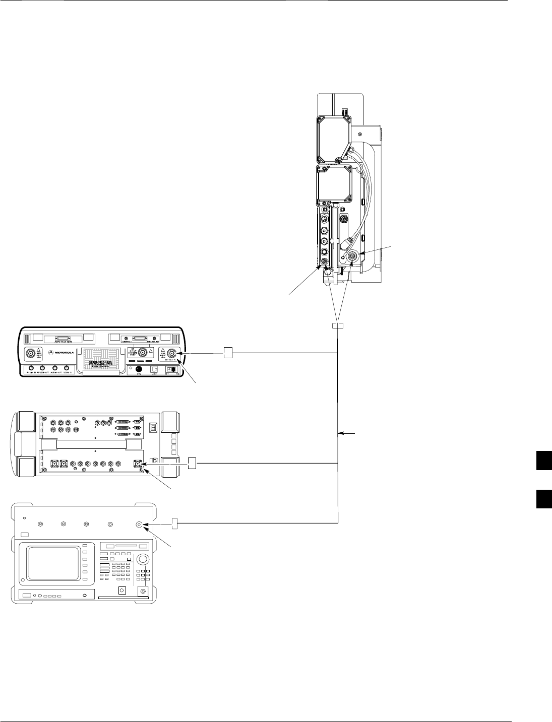
RX Acceptance Tests – continued
JAN 2002 7-85
SCt300 1X BTS Hardware Installation, ATP, and FRU Procedures
DRAFT
Figure 7-35: RX ATP Setup (CyberTest, HP 8935, and Advantest R3465)
COMMUNICATIONS TEST SET
MICROCELL
UNIT
ANTENNA B
(MAIN)
RECEIVE RF
TEST CABLE
MOTOROLA CYBERTEST
ADVANTEST MODEL R3465
RF GEN OUT
RF IN/OUT
RF OUT
ANTENNA A
(DIVERSITY)
AGILENT 8935 SERIES E6380A
(FORMERLY HP 8935)
7
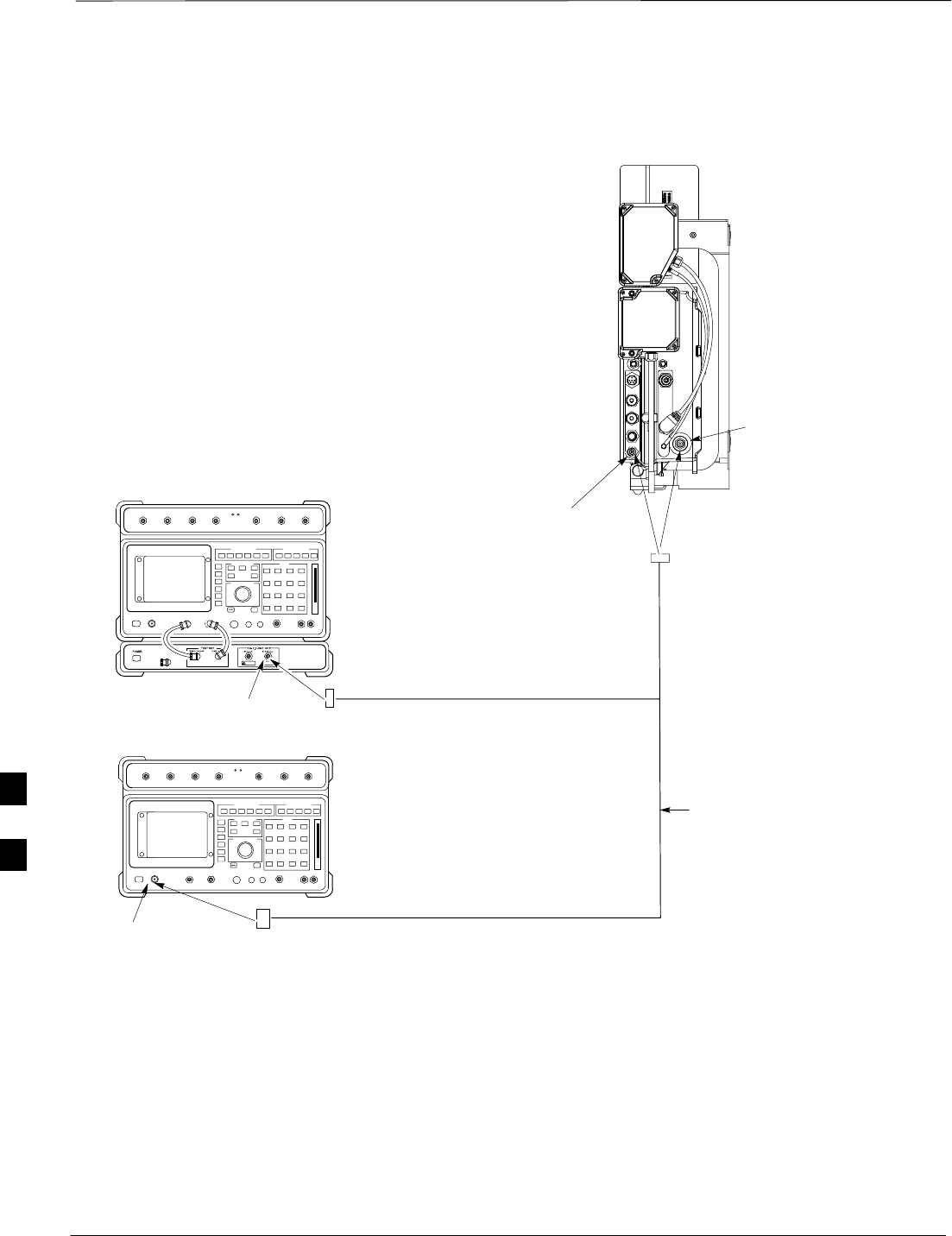
RX Acceptance Tests – continued
DRAFT
SCt300 1X BTS Hardware Installation, ATP, and FRU Procedures JAN 2002
7-86
Figure 7-36: RX ATP Setup (HP 8921A)
COMMUNICATIONS TEST SET
MICROCELL
UNIT
ANTENNA B
(MAIN)
RECEIVE RF
TEST CABLE
ANTENNA A
(DIVERSITY)
RF OUT ONLY
RF IN/OUT
HEWLETT–PACKARD MODEL HP 8921A W/PCS
INTERFACE (FOR 1700 AND 1900 MHz)
HEWLETT–PACKARD MODEL HP
8921A (FOR 800 MHz)
7
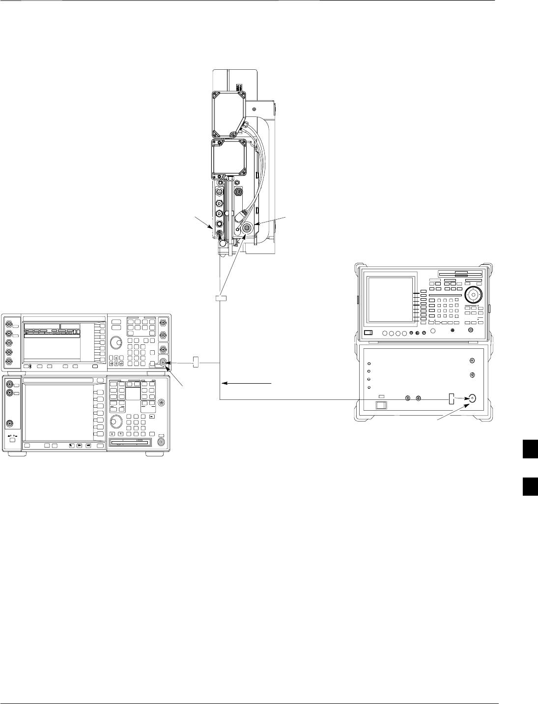
RX Acceptance Tests – continued
JAN 2002 7-87
SCt300 1X BTS Hardware Installation, ATP, and FRU Procedures
DRAFT
Figure 7-37: RX ATP Setup (Advantest R3267 and Agilent E4406A)
ANTENNA B
(MAIN)
RECEIVE RF
TEST CABLE
ADVANTEST R3267 SPECTRUM
ANALYZER 100Hz – 8GHz
ADVANTEST R3562 RECEIVER TEST
SOURCE
ADVANTEST R3267 (TOP)
AND R3562 (BOTTOM)
RF
OUTPUT
RF OUT
AGILENT E4432B (TOP)
AND E4406A (BOTTOM)
ANTENNA A
(DIVERSITY)
7

Generate an ATP Report
DRAFT
SCt300 1X BTS Hardware Installation, ATP, and FRU Procedures JAN 2002
7-88
Background
Each time an ATP test is run, an ATP report is updated to include the
results of the most recent ATP tests if the Save Results button is used
to close the status report window. The ATP report will not be updated if
the status reports window is closed with use of the Dismiss button.
ATP Report
A separate report is created for each BTS and includes the following for
each test:
STest name
SPASS or FAIL
SDescription information (if applicable)
SMAWI number
SChannel number
SCarrier number
SSector number
SUpper test limit
SLower test limit
STest result
STime stamp
SDetails/Warning information (if applicable)
Procedure to Run ATP Report
Follow the procedures in Table 7-48 to view and create a printable file
for the ATP report of a BTS.
Table 7-48: Procedure to Generate an ATP Report
Step Action
1Click on the Login tab if it is not in the forefront.
2Select the desired BTS from the Available Base Stations pick list.
3Click on the Report button.
4Start the report if desired by clicking on a column heading.
5Click on the Dismiss button if you do not want to create a printable file copy.
6To create a printable file, select the desired file type in the picklist and then click on the Save
button.
Refer to the LMF help screens, or the CDMA LMF
Operator’s Guide, 68P64114A21, for information on how
to print an ATP report.
NOTE
7

Copy LMF CAL File to CBSC
JAN 2002 7-89
SCt300 1X BTS Hardware Installation, ATP, and FRU Procedures
DRAFT
Objective
The following procedure is to copy the LMF CAL file to the CBSC after
performing an ATP.
Background
After you perform the ATP you must move a copy of the CAL file for
the BTS from the LMF to the CBSC. This is normally done by putting a
copy of the CAL file on a floppy disk and then using the floppy disk to
move the CAL file to the CBSC.
Prerequisites
SA DOS formatted 1.44 MB 3 1/2–in. floppy disk is necessary to do
this procedure.
SThe ATP and Audit procedures have successfully been performed.
SThe Create CAL File procedure was performed.
SYou logged out of the BTS.
Procedure to Copy CAL Files
from LMF to a Diskette
Follow the procedure in Table 7-49 to copy CAL files from an LMF
computer to a 3.5 diskette.
Table 7-49: Procedure to Copy CAL Files from LMF to a Diskette
Step Action
1Insert a diskette into your Windows A: drive.
NOTE
If your diskette has not been formatted, format it using Windows. The diskette must be DOS
formatted before copying any files. Consult your Windows/DOS documentation or online help on
how to format diskettes.
2Click on the bold Start button to launch the Windows Explorer program from your
Programs menu list.
3Click on your C: drive
4Double click on the wlmf folder.
5 Double–click on the CDMA folder
6Double click on the bts–# folder for the file you want to copy.
7Drag the file (for example, BTS–#.cal, BTS–#.txt, BTS–#.htm, BTS–#.xls) to the
3–1/2–in. floppy (A:) icon on the top left of the screen and release the mouse button.
8Repeat step 6 and 7 until you have copied each file desired and close the Windows Explorer
program by selecting Close from the File menu option.
7

Copy LMF CAL File to CBSC – continued
DRAFT
SCt300 1X BTS Hardware Installation, ATP, and FRU Procedures JAN 2002
7-90
Procedure to Copy CAL Files
from Diskette to the CBSC
Follow the procedures in Table 7-50 to copy CAL file from a diskette to
the CBSC.
Table 7-50: Procedure to Copy CAL Files from Diskette to the CBSC
Step Action
1Log in to the CBSC on the OMC–R Unix workstation using your account name and password.
2Place your diskette containing calibration file(s) in the workstation diskette drive.
3Type in eject –q and press the Enter key.
4Type in mount and press the Enter key.
NOTE
SCheck to see that the message floppy/no_name is displayed on the last line.
SIf the eject command was previously entered, floppy/no_name will be appended with a
number. Use the explicit floppy/no_name reference displayed.
5Type in cd /floppy/no_name and press the Enter key.
6Type in ls –lia and press the Enter key. Verify that the bts–#.cal file is on the diskette.
7Type in cd and press the Enter key.
8Type in pwd and press the Enter key. Verify you are in your home directory (/home/<name>).
9 With Solaris versions of Unix, create a Unix–formatted version of the bts–#.cal file in your home
directory by entering the following command:
dos2unix /floppy/no_name/bts–#.cal bts–#.cal and press the Enter key
(where # is BTS number).
NOTE
Other versions of Unix do not support the dos2unix command. In these cases, use the Unix cp
(copy) command. The copied files will contain DOS line feed characters which must be edited out
with a Unix text editor.
10 Type in ls –l *.cal and press the Enter key. Verify the cal files have been copied.
11 Type in eject and press the Enter key.
12 Remove the diskette from the workstation.
7

Prepare to Leave the Site
JAN 2002 7-91
SCt300 1X BTS Hardware Installation, ATP, and FRU Procedures
DRAFT
Remove External Test
Equipment Perform the procedure in Table 7-51 to disconnect the test equipment
and prepare the BTS for active service.
Table 7-51: Remove External Test Equipment
Step Action
1Disconnect all test equipment from the antenna connectors on the BTS.
2Reconnect and visually inspect all antenna feed lines on the BTS.
3Disconnect all test equipment from the diagnostic access area.
Reset and Initialize Site
Remotely
The BTS should not be left with data and code loaded from the CDMA
LMF. The configuration data and code loads used for normal operation
could be different from those stored in the CDMA LMF files. By
resetting the BTS, the required data and code can be loaded from the
CBSC when spans are again active.
To reset the BTS and have the OMCR/CBSC bring up the site remotely,
perform the procedure in Table 7-52.
Table 7-52: Reset BTS and Remote Site Initialization
Step Action
1Terminate the CDMA LMF session by following the procedures in Table 7-54.
2Use the AC and DC power breakers to cycle BTS power off and on.
3Notify the OMCR/CBSC to take control of the site and download code and data to the BTS.
4Verify the CBSC can communicate with the MAWI.
Bring BTS into Service with the
CDMA LMF
Whenever possible, have the OMCR/CBSC enable the
BTS.
IMPORTANT
*
If code and/or data could not be loaded remotely from the
OMCR/CBSC, follow the steps outlined in Table 7-53 as required to
bring the BTS from the OOS to INS mode.
7

Prepare to Leave the Site – continued
DRAFT
SCt300 1X BTS Hardware Installation, ATP, and FRU Procedures JAN 2002
7-92
Table 7-53: Procedure to Bring BTS into Service
Step Action
1On the CDMA LMF, select the MAWI.
2Click on Device from the menu bar.
3Click on Enable from the Device menu. A status report window is displayed.
4 Click Cancel to close the transceiver parameters window, if applicable.
5 Click OK to close the status report window.
The selected devices that successfully change to INS change color to green.
Terminate LMF
Session/Remove Terminal
Perform the procedure in Table 7-54 to terminate the LMF session and
remove the CDMA LMF computer.
Table 7-54: Procedure to Remove LMF
Step Action
! CAUTION
Do not power down the CDMA LMF terminal without performing the procedure below.
Corrupted/lost data files may result.
1Log out of all BTS sessions and exit CDMA LMF by clicking on the File selection in the menu bar
and selecting Exit from the File menu list.
2 Click Yes in the Confirm Logout pop–up message which appears.
3In the Windows Task Bar, click Start and select Shutdown.
4 Click Yes when the Shut Down Windows message appears.
5Wait for the system to shut down and the screen to go blank.
6Disconnect the CDMA LMF terminal serial cable from the BTS.
7Disconnect the CDMA LMF terminal serial port, the RS–232–IEEE488 converter and the GPIB
cables as required for equipment transport.
7

Prepare to Leave the Site – continued
JAN 2002 7-93
SCt300 1X BTS Hardware Installation, ATP, and FRU Procedures
DRAFT
Replace Diagnostic Access
Cover
Use a T20 Torx tamper bit to tighten the two tamper–resistant M4
screws holding the cover. Torque to 10 in–lb. Refer to Figure 7-38.
Figure 7-38: How To Replace The Diagnostic Access Cover
SCREWS IN DIAGNOSTIC
ACCESS COVER ARE CAPTIVE
Replace Solar Cover
Replace the solar cover. Refer to the “Powering on Unit and Mounting
the Solar Cover” procedure in Chapter 5.
7

Prepare to Leave the Site – continued
DRAFT
SCt300 1X BTS Hardware Installation, ATP, and FRU Procedures JAN 2002
7-94
Notes
7

JAN 2002 SCt300 1X BTS Hardware Installation, ATP, and FRU Procedures
DRAFT
Chapter 8: Field Replaceable Unit (FRU) Procedures
Table of Contents
Field Replaceable Unit (FRU) Overview 8-1. . . . . . . . . . . . . . . . . . . . . . . . . . . . . .
Overview 8-1. . . . . . . . . . . . . . . . . . . . . . . . . . . . . . . . . . . . . . . . . . . . . . . .
List of FRUs 8-1. . . . . . . . . . . . . . . . . . . . . . . . . . . . . . . . . . . . . . . . . . . . .
Shut Down & Restoring BTS Signaling 8-3. . . . . . . . . . . . . . . . . . . . . . . . . . . . . . .
Objective 8-3. . . . . . . . . . . . . . . . . . . . . . . . . . . . . . . . . . . . . . . . . . . . . . . .
Accessing the OMCR CLI window 8-3. . . . . . . . . . . . . . . . . . . . . . . . . . . .
Shut Down Signaling Functions 8-3. . . . . . . . . . . . . . . . . . . . . . . . . . . . . .
Restore Signaling Operations 8-10. . . . . . . . . . . . . . . . . . . . . . . . . . . . . . . .
Site I/O Junction Box Replacement Procedure 8-14. . . . . . . . . . . . . . . . . . . . . . . . .
Objective 8-14. . . . . . . . . . . . . . . . . . . . . . . . . . . . . . . . . . . . . . . . . . . . . . . .
System Impact/Considerations 8-14. . . . . . . . . . . . . . . . . . . . . . . . . . . . . . .
Required Tools and Materials 8-14. . . . . . . . . . . . . . . . . . . . . . . . . . . . . . . .
Procedure to Replace Site I/O Junction Box 8-14. . . . . . . . . . . . . . . . . . . . .
Site I/O Junction Box Location Diagram 8-16. . . . . . . . . . . . . . . . . . . . . . .
Short Duration Battery Replacement Procedures 8-17. . . . . . . . . . . . . . . . . . . . . . . .
Objective 8-17. . . . . . . . . . . . . . . . . . . . . . . . . . . . . . . . . . . . . . . . . . . . . . . .
Required Tools and Materials 8-17. . . . . . . . . . . . . . . . . . . . . . . . . . . . . . . .
Procedure to Replace Short Duration Battery 8-17. . . . . . . . . . . . . . . . . . . .
Remote GPS Replacement Procedure 8-19. . . . . . . . . . . . . . . . . . . . . . . . . . . . . . . . .
Objective 8-19. . . . . . . . . . . . . . . . . . . . . . . . . . . . . . . . . . . . . . . . . . . . . . . .
Required Tools and Materials 8-19. . . . . . . . . . . . . . . . . . . . . . . . . . . . . . . .
Procedure to Replace Remote GPS 8-19. . . . . . . . . . . . . . . . . . . . . . . . . . . .
Full Unit Replacement Procedures 8-21. . . . . . . . . . . . . . . . . . . . . . . . . . . . . . . . . . .
Objective 8-21. . . . . . . . . . . . . . . . . . . . . . . . . . . . . . . . . . . . . . . . . . . . . . . .
System Impact/Considerations 8-21. . . . . . . . . . . . . . . . . . . . . . . . . . . . . . .
Required Tools and Materials 8-21. . . . . . . . . . . . . . . . . . . . . . . . . . . . . . . .
Procedure to Replace Failed Unit 8-21. . . . . . . . . . . . . . . . . . . . . . . . . . . . .
8

Table of Contents – continued
DRAFT
SCt300 1X BTS Hardware Installation, ATP, and FRU Procedures JAN 2002
Notes
8
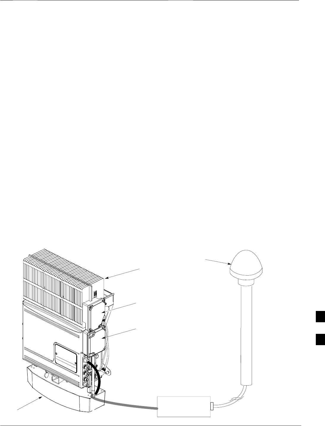
Field Replaceable Unit (FRU) Overview
JAN 2002 8-1
SCt300 1X BTS Hardware Installation, ATP, and FRU Procedures
DRAFT
Overview
The purpose of this chapter is to provide the Field Replaceable Unit
(FRU) replacement procedures for the unit. Figure 8-1, Figure 8-2 and
Figure 8-3 show the FRUs associated with the unit.
List of FRUs
The following is a list of FRUs for the unit:
1. Site I/O Junction Box with Primary Surge Suppressor – Kit T450AE
2. Site I/O Junction Box without Primary Surge Suppressor – Kit
T450AA
3. RGPS Head – Kit T472AP
4. Short Duration Battery – Kit T348AE
5. Primary Surge Suppressor – Kit T449AA
6. AC Installation Box – Kit T449AB
MicroCell units
1. A Band BTS with HSO – Kit SG1478AA
2. A Band BTS without HSO – Kit SG1479AA
3. B Band BTS with HSO – Kit SG1486AA
4. B Band BTS without HSO – Kit SG1487AA
5. Solar Cover – Kit T451AA
6. Fin Cover – Kit T389AB
Figure 8-1: FRU Items
UNIT
SHORT DURATION BATTERY
SITE I/O INTERFACE
RGPS HEAD
SITE I/O
JUNCTION
BOX
SUBSCRIBER
UNIT
8
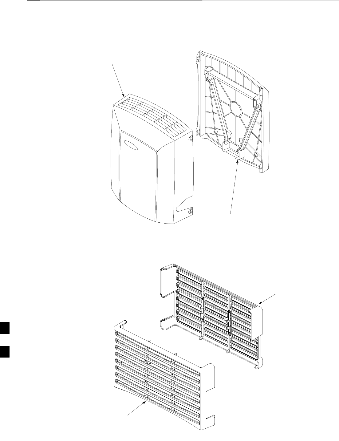
Field Replaceable Unit (FRU) Overview – continued
DRAFT
SCt300 1X BTS Hardware Installation, ATP, and FRU Procedures JAN 2002
8-2
Figure 8-2: Front and Back Solar Covers for MicroCell
FRONT COVER
BACK COVER
Figure 8-3: Front and Back Fin Covers
BACK COVER
FRONT COVER
8
Shut Down & Restoring BTS Signaling
JAN 2002 8-3
SCt300 1X BTS Hardware Installation, ATP, and FRU Procedures
DRAFT
Objective
The FRU procedures require the shut down of BTS signalling functions.
Accessing the OMCR CLI
window
The commands to manipulate the BTS in the following replacement
procedure must be entered via UNO or OMCR (Operations and
Maintenance Center – Radio).
Should there be any issues which affect CLI operations or
the UNO/OMCR, this replacement procedure cannot be
performed.
IMPORTANT
*
Accessing the OMCR CLI window
The commands used in the following replacement procedure in Table 8-1
are entered at the OMCR.
Table 8-1: Procedure to Login and Access Alarm Window
Step Action
1Login by entering the user name.
2Enter the password at the system prompt.
3Open an Alarm Manager window and an OMCR CLI window from the pull down menu using the
mouse button.
4Verify that the filter display is set to ALL. This is so that any alarms which may be encountered
while installing the hardware can be observed and rectified.
Shut Down Signaling Functions
Table 8-2 contains steps for shutting down the signaling functions for the
sector/site.
The BTS acts like a single sector and all sector commands
operate on the BTS carrier.
NOTE
8

Shut Down & Restore BTS Signaling – continued
DRAFT
SCt300 1X BTS Hardware Installation, ATP, and FRU Procedures JAN 2002
8-4
The EDIT SECTOR REDIRECT or REDIRECT2
command does NOT affect calls in progress and will NOT
move these calls to another sector/carrier. The command
only prevents future calls from being originated on the
targeted sector/carrier. If active call processing is still
taking place in the target sector/carrier, it is advisable to
wait for any active calls to terminate prior to disabling the
sector.
IMPORTANT
*
Table 8-2: Procedure to Shut Down Signaling Functions
Step Action
1Open a CLI window. Refer to Table 8-1.
2* IMPORTANT
Record the values shown in the following system display response. These values will be used to
answer the prompts for the EDIT SECTOR REDIRECT command when restoring signaling
operations at the end of the replacement procedure.
View the status of the sector signaling redirect parameters for all carriers equipped for the sector
by entering the following command at the prompt:
000000 bt # t#
omc–000000>display sector–<bts#>–<sector#> redirect
Observe the following typical system display response (this example shows initial standard
values):
Access Overload Class Redirect Flags ROTATE
CARRIER ID RETURN 0 0 0 0 0 0 0 0 0 0 1 1 1 1 1 1 TIMER RECORD EXP IGNORE SYS
(bts–sector–carrier) IF FAIL 0 1 2 3 4 5 6 7 8 9 0 1 2 3 4 5 (SEC) TYPE SID CDMA ORDERING
–––––––––––––––––––– ––––––– – – – – – – – – – – – – – – – – ––––– –––– ––– –––– –––––––
CARRIER–1–1–1 N N N N N N N N N N N N N N N N N 4 1 0 N CUSTOM
. . . continued on next page
8

Shut Down & Restore BTS Signaling – continued
JAN 2002 8-5
SCt300 1X BTS Hardware Installation, ATP, and FRU Procedures
DRAFT
Table 8-2: Procedure to Shut Down Signaling Functions
Step Action
3NOTE
This step edits the redirect parameters so that the Global Service Redirect Message broadcast on
the paging channel redirects all subscribers away from the sector with the failed equipment and
onto a different system.
Enter the following command at the prompt:
omc–000000>edit sector–<bts#>–<sector#> redirect !
The system will prompt you to enter each command parameter value one at a time. Answer the
prompts in the following order:
<accolc0> enter Y, <accolc1> enter Y, ... <accolc15> enter Y
All Access Overload Classes must be set to Y (yes) to ensure that all subscribers are redirected.
<returniffail> , enter N
Must be set to no to ensure that subscribers do not return if redirect is unsuccessful.
<recordtype> , enter 1 or 2
A value of 2 will invoke REDIRECT2 which is used to redirect subscribers to a CDMA channel
at a neighbor site. A value of 1 redirects subscribers to an 800 MHz analog site. This example
uses 2.
<expe tedsid>
<
expe
c
tedsid
> , enter 13
Use the Area ID the subscriber units should expect to find on the system they are being redirected
to. This example uses 13.
<ignorecdma> , enter Y
<sysordering> , enter custom
The system acquisition ordering value tells the mobiles the order to use when attempting to obtain
service on the different analog systems. The valid values are: custom – use custom system
selection (default selection); aonly – try the A system only; bonly – use the B system only;
afirst – try the A system first. If unsuccessful, enter bfirst to try the B system first. If
unsuccessful, enter aorb to try the A or B. If unsuccessful, enter custom to try the alternative
system.
<rotatetimer> , enter 4
Call processing continuously rotates, circular right–shifts, the Y/N values of Access Overload
Class Redirect Flags 0 to 9. Values are shifted one flag at the end of the timer period; then timer
re–starts. Valid values are 0–255; 4 is default.
The system will display the command that will be sent. Verify the command syntax.
omc–000000>Accept [yes/no]?
Enter Y to accept the command.
. . . continued on next page
8

Shut Down & Restore BTS Signaling – continued
DRAFT
SCt300 1X BTS Hardware Installation, ATP, and FRU Procedures JAN 2002
8-6
Table 8-2: Procedure to Shut Down Signaling Functions
Step Action
4View the status of the sector signaling redirect parameters to verify that the sector is ready for
maintenance.
omc–000000>display sector–<bts#>–<sector#> redirect
Ensure that the values in the system display response match the values input in step 3 (see
example below).
Access Overload Class Redirect Flags ROTATE
CARRIER ID RETURN 0 0 0 0 0 0 0 0 0 0 1 1 1 1 1 1 TIMER RECORD EXP IGNORE SYS
(bts–sector–carrier) IF FAIL 0 1 2 3 4 5 6 7 8 9 0 1 2 3 4 5 (SEC) TYPE SID CDMA ORDERING
–––––––––––––––––––– ––––––– – – – – – – – – – – – – – – – – ––––– –––– –––– ––– ––––––––
CARRIER–1–1–1 N Y Y Y Y Y Y Y Y Y Y Y Y Y Y Y Y 4 4 13 Y CUSTOM
5If you entered 2 for <recordtype> in step 3, go to step 6.
If you entered 1 for <recordtype> in step 3, go to step 9.
6* IMPORTANT
Record the values shown in the following system display response. These values will be used to
answer the prompts for the EDIT SECTOR REDIRECT2 command when restoring signaling
operations at the end of the replacement procedure.
View the status of the BTS signaling redirect parameters for all carriers equipped for the BTS.
Enter the following command at the prompt:
omc–000000>display sector–<bts#>–<sector#> redirect2
omc 000000>
display sector–
<bts#> <sector#>
redirect2
Ensure that the values in the system display response match the values input in step 3.
Observe the following typical system output:
Access Overload Class Redirect Flags
CARRIER ID EXP BAND 123456 789101112131415
(bts–sector–carrier) NID CLASS
–––––––––––––––––––– –––– ––––– –––––––––––––––––––––––––––––––––––––––––––––––––––––––
CARRIER–1–1–1 65535 AMPS –––––– –––––––––
. . . continued on next page
8

Shut Down & Restore BTS Signaling – continued
JAN 2002 8-7
SCt300 1X BTS Hardware Installation, ATP, and FRU Procedures
DRAFT
Table 8-2: Procedure to Shut Down Signaling Functions
Step Action
7NOTE
This step edits the REDIRECT2 parameters so that the Global Service Redirect Message
broadcast on the paging channel redirects all subscribers away from the BTS with the failed
equipment and onto a CDMA channel at a neighbor site.
Enter the following command at the prompt:
omc–000000>edit sector–<bts#>redirect2!
The system prompts you to enter each command parameter value one at a time. Answer the
prompts in the following order:
expecting an integer number (from 0 to 65535)
<EXPNID= ?>
Use the Network ID the subscriber units should expect to find on the system they are being
redirected to. This example uses 555.
redirected to. This example uses 555.
expecting an integer number (from 0 to 2047)
<CHAN1=?>, <CHAN2=?>...<CHAN15=?>
A list of CDMA channels for neighbor sites that the subscriber units can use for redirection. This
example uses 200, 350, 400, 725, 75, 175, 100, 575, and 950.
expecting an enumerated value:
CDMA1900 CDMA800 CDMA900 JAPANCDMA
<BANDCLASS=?>
Use CDMA1900 for 1.9 GHz systems and CDMA800 for 800 MHz systems. This example uses
CDMA1900.
The system displays the command to be sent. Verify the command syntax.
omc–000000>Accept [yes/no]?
Enter Y to accept the command or N to go back and enter the correct value(s).
8View the status of the BTS signalling REDIRECT2 parameters to verify that the BTS is ready for
maintenance.
omc–000000>display sector–<bts#> redirect2
Make sure that the values in the system display response match the values input in step 7 (see
example below):
Access Overload Class Redirect Flags ROTATE
CARRIER ID RETURN 0 0 0 0 0 0 0 0 0 0 1 1 1 1 1 1 TIMER RECORD EXP IGNORE SYS
(bts–sector–carrier) IF FAIL 0 1 2 3 4 5 6 7 8 9 0 1 2 3 4 5 (SEC) TYPE SID CDMA ORDERING
–––––––––––––––––––– ––––––– – – – – – – – – – – – – – – – – ––––– –––– –––– ––– ––––––––
CARRIER–1–1–1 N Y Y Y Y Y Y Y Y Y Y Y Y Y Y Y Y 4 4 13 Y CUSTOM
. . . continued on next page
8

Shut Down & Restore BTS Signaling – continued
DRAFT
SCt300 1X BTS Hardware Installation, ATP, and FRU Procedures JAN 2002
8-8
Table 8-2: Procedure to Shut Down Signaling Functions
Step Action
9View the existing congestion control parameters for all carriers equipped for the sector by entering
the following command at the prompt:
omc–000000>display sector–<bts#>–<sector#> congestconf
Observe the following typical system display response:
CARRIER NEWCALL REG AGG
(bts#–sector#–carrier#) SET ALARMFLAG ALARMFLAG ALARMFLAG ANALOGREDIRECT GLOBALREDIRECT
––––––––––––––––––––––– ––– ––––––––– –––––––––– –––––––––– –––––––––––––– ––––––––––––––
300–1–4 1 ENABLE ENABLE ENABLE DISABLE DISABLE
10 NOTE
In this step, you will change the value of the Global Service Redirection Flag
(GLOBALREDIRECT) in the congestion control parameters so that the Global Service Redirect
Message is broadcast on the sector paging channel.
Enter the following command at the prompt:
omc–000000>edit sector–<bts#>–<sector#> congestconf !
The system will prompt you to enter each control parameter value one at a time. Skip through the
prompts until you get to the following:
<
g
lobalredirect> , enter enable
<globalredire
c
t>
, enter enable
(This will force the Global Service Redirect Message to be broadcast on the sector paging
channel.)
The system will display the values of the control parameters. Verify that only the
globalredirect value changed.
omc–000000>Accept [yes/no]?
Enter Y to accept the change.
Now the Global Service Redirection Message is sent over the sector paging channels. All
subscribers are redirected away from the sector and onto a different system. This effectively shuts
down the sector.
11 Display the status of the MAWI at the BTS by entering the following command at the prompt:
omc–000000>display bts–<bts#> status
Observe the following typical system response for the entry of: DISPLAY BTS – 300 STATUS
DEVSYNC
Config Calibration Calibration ISO RELATED
DEVICE CBSC STATUS Data Data Sync STATE
–––––––––––––––––– –––– –––––– –––– –––– ––––––– ––––––––––––
BTS–300 1 INS n/a n/a UNLOCKED UNLOCKED
BTSSPAN–300–1 1 INS n/a n/a n/a n/a
BTSLINK–300–1 1 INS n/a n/a n/a n/a
LPA–300–1 1 OOS_PARENT n/a n/a n/a n/a
MDM–300–1 1 PRECUT n/a n/a n/a n/a
MAWI–300–1 1 INS GOOD GOOD GOOD KEYED
. . . continued on next page
8

Shut Down & Restore BTS Signaling – continued
JAN 2002 8-9
SCt300 1X BTS Hardware Installation, ATP, and FRU Procedures
DRAFT
Table 8-2: Procedure to Shut Down Signaling Functions
Step Action
12 Display the status of the MAWI at the BTS to verify the status of the MAWI (which CEs are
INS_IDLE or INS_BUSY) by entering the following command at the prompt:
omc–000000>status mawi–<bts#>–<mawi#> add
Observe the following typical system response:
MAWI–300–1 00–05–24 15:10:31 omcr5 MM–5 M000109.00046 045519/479457
INFO:42 ”Mawi Status Response”
TELSTATE=INS_ACTIVE PROCEDURE=NONE
PHYSTATE=INS_ACTIVE HDWR_TYPE=MAWI
DEVICE_ASSUMED=NONE CLOCK_SRC=REMOTE_GPS
LATITUDE=”+032:50:41.502”LONGITUDE=”–097:17:38.645”
ALTITUDE=”+0019865”NUM_SATELLITES=”8”
CF MMCONF MMSTATE MMSECTOR PHYCONF PHYSTATE PHYREASON PHYSECTOR
–– –––––– –––––––– –––––––– ––––––– –––––––– ––––––––– –––––––––
0 PCH_ACH INS_BUSY 1 PCH_ACH INS_BUSY NONE 1
1 SCH INS_BUSY 1 SCH INS_BUSY NONE 1
2 TCH INS_IDLE FLOAT TCH INS_IDLE NONE FLOAT
3 TCH INS_IDLE FLOAT TCH INS_IDLE NONE FLOAT
4 TCH INS_IDLE FLOAT TCH INS_IDLE NONE FLOAT
5 TCH INS_IDLE FLOAT TCH INS_IDLE NONE FLOAT
6 TCH INS_IDLE FLOAT TCH INS_IDLE NONE FLOAT
7 TCH INS_IDLE FLOAT TCH INS_IDLE NONE FLOAT
8 TCH INS_IDLE FLOAT TCH INS_IDLE NONE FLOAT
9 TCH INS_IDLE FLOAT TCH INS_IDLE NONE FLOAT
10 TCH INS_IDLE FLOAT TCH INS_IDLE NONE FLOAT
11 TCH INS_IDLE FLOAT TCH INS_IDLE NONE FLOAT
12 TCH INS_IDLE FLOAT TCH INS_IDLE NONE FLOAT
13 TCH INS_IDLE FLOAT TCH INS_IDLE NONE FLOAT
14 TCH INS_IDLE FLOAT TCH INS_IDLE NONE FLOAT
15 TCH INS_IDLE FLOAT TCH INS_IDLE NONE FLOAT
13 Disable the MAWI in the INS–IDLE or the INS–BUSY state (predetermine number of active calls
remaining to be terminated prematurely) by entering the following command at the prompt:
omc–000000>disable mawi–<bts#>–<mawi#> unc
14 Disable the BTS where the replacement procedure will be performed by entering the following
command at the prompt:
omc–000000>disable bts–<bts#> unc 8

Shut Down & Restore BTS Signaling – continued
DRAFT
SCt300 1X BTS Hardware Installation, ATP, and FRU Procedures JAN 2002
8-10
Restore Signaling Operations
Follow the steps in Table 8-3 to restore signaling operations to the site.
Table 8-3: Procedure to Restore Signaling Operations
Step Action
1Open a CLI window. Refer to Table 8-1.
2Enable the BTS by entering the following command at the prompt:
omc–000000>enable bts–<bts#> unc
3Enable the MAWI by entering the following command at the prompt:
omc–000000>enable mawi–<bts#> unc
4View the status of the sector signaling redirect parameters for all carriers equipped for the sector
by entering the following command at the prompt:
omc–000000>display sector–<bts#>–<sector#> redirect
Observe that the values in the system display response should match the values input in step 3 of
the shut down signaling functions table.
Access Overload Class Redirect Flags ROTATE
CARRIER ID RETURN 0 0 0 0 0 0 0 0 0 0 1 1 1 1 1 1 TIMER RECORD EXP IGNORE SYS
(bts–sector–carrier) IF FAIL 0 1 2 3 4 5 6 7 8 9 0 1 2 3 4 5 (SEC) TYPE SID CDMA ORDERING
–––––––––––––––––––– ––––––– – – – – – – – – – – – – – – – – ––––– –––– ––– –––– ––––––––
CARRIER–1–1–1 N Y Y Y Y Y Y Y Y Y Y Y Y Y Y Y Y 4 4 13 Y CUSTOM
. . . continued on next page
8

Shut Down & Restore BTS Signaling – continued
JAN 2002 8-11
SCt300 1X BTS Hardware Installation, ATP, and FRU Procedures
DRAFT
Table 8-3: Procedure to Restore Signaling Operations
Step Action
5* IMPORTANT
In this step, use the values recorded in step 2 of the shut down signaling functions table to answer
the prompts for the EDIT SECTOR REDIRECT command; except for record type enter 2.
NOTE
This step shows the entry of initial standard values which is consistent with the original example;
except record type must be 2. Your entries may be different.
Restore the values of all redirect parameters by entering the following command at the prompt:
omc–000000>edit sector–<bts#>–<sector#> redirect !
The system will prompt you to enter each command parameter one at a time. Answer the prompts
in the following order (Note that the following specified values are consistent with the original
example. Yours may be different):
<accolc0> Enter N, <accolc1> Enter N, ... <accolc15> enter N
<returniffail> , enter N
<recordtype> , enter 2
<expe tedsid>
<expecte
d
s
id
> , enter 0
<ignorecdma> , enter N
<sysordering> , enter custom
<rotatetimer> , enter 4
The system will display the command that will be sent. Verify the command syntax.
omc–000000>Accept [yes/no]?
Enter Y to accept the command.
6View the status of the sector signaling redirect parameters to verify that the sector is ready for
maintenance.
omc–000000>display sector–<bts#>–<sector#> redirect
Ensure that the values in the system display response match the values input by the operator in
step 5 (see example below).
Access Overload Class Redirect Flags ROTATE
CARRIER ID RETURN 0 0 0 0 0 0 0 0 0 0 1 1 1 1 1 1 TIMER RECORD EXP IGNORE SYS
(bts–sector–carrier) IF FAIL 0 1 2 3 4 5 6 7 8 9 0 1 2 3 4 5 (SEC) TYPE SID CDMA ORDERING
–––––––––––––––––––– ––––––– – – – – – – – – – – – – – – – – ––––– –––– ––– –––– ––––––––
CARRIER–1–1–1 N N N N N N N N N N N N N N N N N 4 2 0 N CUSTOM
. . . continued on next page
8

Shut Down & Restore BTS Signaling – continued
DRAFT
SCt300 1X BTS Hardware Installation, ATP, and FRU Procedures JAN 2002
8-12
Table 8-3: Procedure to Restore Signaling Operations
Step Action
7View the congestion control parameters for all carriers equipped for the sector by entering the
following command at the prompt:
omc–000000>display sector–<bts#>–<sector#> congestconf
Observe the following typical system display response:
CARRIER NEWCALL REG AGG
(bts#–sector#–carrier#) SET ALARMFLAG ALARMFLAG ALARMFLAG ANALOGREDIRECT GLOBALREDIRECT
––––––––––––––––––––––– ––– ––––––––– ––––––––– ––––––––– –––––––––––––– ––––––––––––––
300–1–4 1 ENABLE ENABLE ENABLE DISABLE ENABLE
8NOTE
In this step, you will change the value of the Global Service Redirection Flag
(GLOBALREDIRECT) in the congestion control parameters so that the Global Service Redirect
Message is only broadcast on the sector paging channel when there is traffic congestion in the
sector.
Enter the following command at the prompt:
omc–000000>edit sector–<bts#>–<sector#> congestconf !
The system will prompt you to enter each control parameter value one at a time. Skip through the
prompts until you get to the following:
<globalredirect> , enter disable
(This will revert the Global Service Redirect Message to congestion control.)
The system will display the values of the control parameters. Verify that only the
GLOBALREDIRECT value changed.
omc–000000>Accept [yes/no]?
Enter Y to accept the change.
Now the Global Service Redirection Message will only be sent over the sector paging channels
when there is traffic congestion in the sector.
9Display the status of the MAWI at the BTS by entering the following command at the prompt:
omc–000000>display bts–<bts#> status
Observe the following typical system response:
DEVSYNC
Config Calibration Calibration ISO RELATED
DEVICE CBSC STATUS Data Data Sync STATE
–––––––––––––––––– –––– –––––– –––– –––– ––––––– ––––––––––––
BTS–300 1 INS n/a n/a UNLOCKED UNLOCKED
BTSSPAN–300–1 1 INS n/a n/a n/a n/a
BTSLINK–300–1 1 INS n/a n/a n/a n/a
LPA–300–1 1 OOS_PARENT n/a n/a n/a n/a
MDM–300–1 1 PRECUT n/a n/a n/a n/a
MAWI–300–1 1 INS GOOD GOOD GOOD KEYED
. . . continued on next page
8

Shut Down & Restore BTS Signaling – continued
JAN 2002 8-13
SCt300 1X BTS Hardware Installation, ATP, and FRU Procedures
DRAFT
Table 8-3: Procedure to Restore Signaling Operations
Step Action
10 Display the status of the MAWI in the BTS by entering the following command at the prompt:
omc–000000>status mawi–<bts#>–<mawi#> add
Observe the following typical system response for entry of: STATUS MAWI – 300 –1 ADD
MAWI–300–1 00–05–24 15:10:31 omcr5 MM–5 M000109.00046 045519/479457
INFO:42 ”Mawi Status Response”
TELSTATE=INS_ACTIVE PROCEDURE=NONE
PHYSTATE=INS_ACTIVE HDWR_TYPE=MAWI
DEVICE_ASSUMED=NONE CLOCK_SRC=REMOTE_GPS
LATITUDE=”+032:50:41.502”LONGITUDE=”–097:17:38.645”
ALTITUDE=”+0019865”NUM_SATELLITES=”8”
CF MMCONF MMSTATE MMSECTOR PHYCONF PHYSTATE PHYREASON PHYSECTOR
–– –––––– –––––––– –––––––– ––––––– –––––––– ––––––––– –––––––––
0 PCH_ACH INS_BUSY 1 PCH_ACH INS_BUSY NONE 1
1 SCH INS_BUSY 1 SCH INS_BUSY NONE 1
2 TCH INS_IDLE FLOAT TCH INS_IDLE NONE FLOAT
3 TCH INS_IDLE FLOAT TCH INS_IDLE NONE FLOAT
4 TCH INS_IDLE FLOAT TCH INS_IDLE NONE FLOAT
5 TCH INS_IDLE FLOAT TCH INS_IDLE NONE FLOAT
6 TCH INS_IDLE FLOAT TCH INS_IDLE NONE FLOAT
7 TCH INS_IDLE FLOAT TCH INS_IDLE NONE FLOAT
8 TCH INS_IDLE FLOAT TCH INS_IDLE NONE FLOAT
9 TCH INS_IDLE FLOAT TCH INS_IDLE NONE FLOAT
10 TCH INS_IDLE FLOAT TCH INS_IDLE NONE FLOAT
11 TCH INS_IDLE FLOAT TCH INS_IDLE NONE FLOAT
12 TCH INS_IDLE FLOAT TCH INS_IDLE NONE FLOAT
13 TCH INS_IDLE FLOAT TCH INS_IDLE NONE FLOAT
14 TCH INS_IDLE FLOAT TCH INS_IDLE NONE FLOAT
15 TCH INS_IDLE FLOAT TCH INS_IDLE NONE FLOAT
8

Site I/O Junction Box Replacement Procedure
DRAFT
SCt300 1X BTS Hardware Installation, ATP, and FRU Procedures JAN 2002
8-14
Objective
The objective of this procedure is to replace the Site I/O junction box.
System Impact/Considerations
The removal of the failed Site I/O junction box will require system
downtime. The BTS cannot report alarms without the Site I/O junction
box. The other system level alarms are too numerous and outside the
scope of this document.
Required Tools and Materials
The following tools are required to remove the solar cover and install the
new Site I/O junction box.
Tools
STorque driver wrench, 1/4–in. hex female drive, 0–10 N–M
ST20 Torx tamper bit
ST30 Torx tamper bit
Replacement units
One Site I/O junction box is required – Kit T396AA
Procedure to Replace Site I/O
Junction Box
Before you begin
Before you begin, enter the following information into the following
replacement list table.
Table 8-4: Item Number Replacement List
Item Number
BTS number
Failed Site I/O Junction Box
number
8

Site I/O Junction Box Replacement Procedure – continued
JAN 2002 8-15
SCt300 1X BTS Hardware Installation, ATP, and FRU Procedures
DRAFT
Remove the failed site I/O junction box
Follow the steps in Table 8-5 to remove the failed Site I/O junction box.
Table 8-5: Remove the Failed Site I/O Junction Box
Step Action
1Place the BTS out of service using the “Shut Down Signaling Functions” procedure shown in
Table 8-2.
2Using a T20 Torx tamper bit, remove the Solar Cover if one is present and locate the failed Site
I/O junction box.
3If DC power is being supplied to the unit or if the battery backup is present, open (pull) the DC
power breaker. The white collar on the breaker is visible when the breaker is opened.
4If AC power is being supplied to the unit, open (pull) the AC power breaker. The white collar on
the breaker is visible when the breaker is open.
5Disconnect the unit ground cable from the Site I/O junction box.
6Using a T30 Torx tamper bit, remove the two tamper resistant captive screws to disconnect the
Site I/O junction box from the unit. See Figure 8-4.
7If your BTS is equipped with the customer–supplied Site I/O interface, then proceed to step 8. If
your BTS is equipped with the optional Primary Surge Suppressor, then proceed to step 9.
8Disconnect the Site I/O cable from the Deutsche connector on the Site I/O cable. Location of Site
I/O interface is site– dependent.
9Disconnect the Site I/O cable from the Primary Surge Suppressor.
Install the replacement Site I/O junction box
Follow the steps in Table 8-6 to install the replacement Site I/O junction
box.
Table 8-6: Install the Replacement Site I/O Junction Box
Step Action
1Reconnect the Site I/O cable according to the “Site I/O, Span Line, RGPS and Modem Cabling”
procedure in Chapter 4.
2Install the replacement Site I/O junction box according to the “Mounting the Site I/O Junction
Box to the Unit” procedure in Chapter 5.
3Attach the ground cable from the mounting bracket to the Site I/O junction box.
4If AC power is being supplied to the unit, close (push) the AC power breaker. The white collar on
the breaker is not visible when the breaker is closed.
5If DC power is being supplied to the unit or if battery backup is present, close (push) the DC
power breaker. The white collar on the breaker is not visible when the breaker is closed.
6Install the Solar Cover if one is present according to the “Mounting Solar Cover and Powering on
Unit” procedure in Chapter 5.
7Place the BTS back in service using the “Restore Signaling Operations” procedure in Table 8-3.
8

Site I/O Junction Box Replacement Procedure – continued
DRAFT
SCt300 1X BTS Hardware Installation, ATP, and FRU Procedures JAN 2002
8-16
Site I/O Junction Box Location
Diagram
Figure 8-4: Site I/O Junction Box Replacement
REMOVE TWO M6
CAPTIVE SCREWS
SITE I/O
JUNCTION BOX
DISCONNECT SITE I/O
CABLE FROM SITE I/O
INTERFACE
DISCONNECT GROUND
NOTE: SU REMOVED FOR CLARITY
8

Short Duration Battery Replacement Procedures
JAN 2002 8-17
SCt300 1X BTS Hardware Installation, ATP, and FRU Procedures
DRAFT
Objective
The objective of this procedure is to replace the short duration battery.
Required Tools and Materials
The following tools are required to remove the solar cover and install the
new battery.
Tools
Attaching the battery to the unit requires:
ST20 Torx tamper bit, 1/4–in. hex
ST30 Torx tamper bit, 1/4–in. hex
STorque driver wrench, 1/4–in. hex female drive, 0–10 N–M
STwo (2) Screws M6x19 (Motorola Part Number 0387541C03)
Replacement units
One Battery – Kit T392AA is necessary for this procedure.
Procedure to Replace Short
Duration Battery
Before you begin
Before you begin, enter the following information into the following
replacement list table.
Table 8-7: Item Number Replacement List
Item Number
BTS number
Failed Battery number
Remove the failed battery
Follow the steps in Table 8-8 to remove the failed battery. Refer to
NO TAG.
The short duration battery is designed to be replaced with
the DC breaker closed (pushed). If the DC breaker is
opened (pulled) during this procedure, the BTS must be
taken off–line and restarted to ensure proper battery fault
management.
NOTE
Table 8-8: Procedure to Remove the Failed Short Duration Battery
Step Action
1Turn the DC Power Breaker off.
2Use a T20 Torx tamper bit to remove the Solar Cover (if one is present) and locate the battery.
. . . continued on next page
8

Short Duration Battery Replacement Procedure – continued
DRAFT
SCt300 1X BTS Hardware Installation, ATP, and FRU Procedures JAN 2002
8-18
Table 8-8: Procedure to Remove the Failed Short Duration Battery
Step Action
3Turn the connector on the short duration battery cable counterclockwise to disconnect the cable
from the unit. See NO TAG. An alarm will be generated.
4Using a T30 Torx tamper bit remove the two screws that are holding the battery to the unit. See
NO TAG.
Install the replacement battery
Follow the steps in Table 8-8 to install the replacement short duration
battery. Refer to NO TAG.
Table 8-9: Procedure to Install the Replacement Short Duration Battery
Step Action
1Install the replacement battery according to the “Attaching the Battery to the Unit” installation
procedure in Chapter 5.
2 Re–connect the short–duration battery cable to DC input connector. See Figure 8-5. The alarm
will clear.
3 Re–install the Solar Cover if one is present.
8

Short Duration Battery Replacement Procedure – continued
JAN 2002 8-19
SCt300 1X BTS Hardware Installation, ATP, and FRU Procedures
DRAFT
Figure 8-5: Short Duration Battery Replacement
REMOVE TWO SCREWS HOLDING
BATTERY TO THE UNIT
CABLE IS PART OF
THE BATTERY
ASSEMBLY
TURN
COUNTERCLOCKWISE
TO REMOVE CABLE
DC POWER BREAKER
AC POWER BREAKER
8

Remote GPS Replacement Procedure
DRAFT
SCt300 1X BTS Hardware Installation, ATP, and FRU Procedures JAN 2002
8-20
Objective
The objective of this procedure is to replace the RGPS head.
Required Tools and Materials
Replacement units
One RGPS head with cable attached (Motorola Kit T472AP) is required
to do this procedure.
Procedure to Replace Remote
GPS
Before you begin
Before you begin, enter the following information into the following
replacement list table.
Table 8-10: Item Number Replacement List
Item Number
BTS number
Failed RGPS head number
Remove the failed RGPS head
Follow the steps in Table 8-11 to remove the failed RGPS head. Refer to
Figure 8-6.
Table 8-11: Procedure to Remove the Failed RGPS Head
Step Action
1NOTE
To prevent twisting of cables, do not unscrew or screw the RGPS head while holding the
pipe/conduit.
Loosen the pipe/conduit mounting hardware until the pipe/conduit is free to be unscrewed from
the RGPS head.
2Grasp the RGPS head with one hand and the pipe/conduit with the other hand.
Unscrew the pipe/conduit from the head and separate the head from the pipe/conduit.
Grasp the cable just below the head and pull about 16 inches of cable out of the pipe/conduit until
the mating cable connectors are exposed.
3Separate the mating cable connectors to disconnect the RGPS head from the RGPS cable.
8
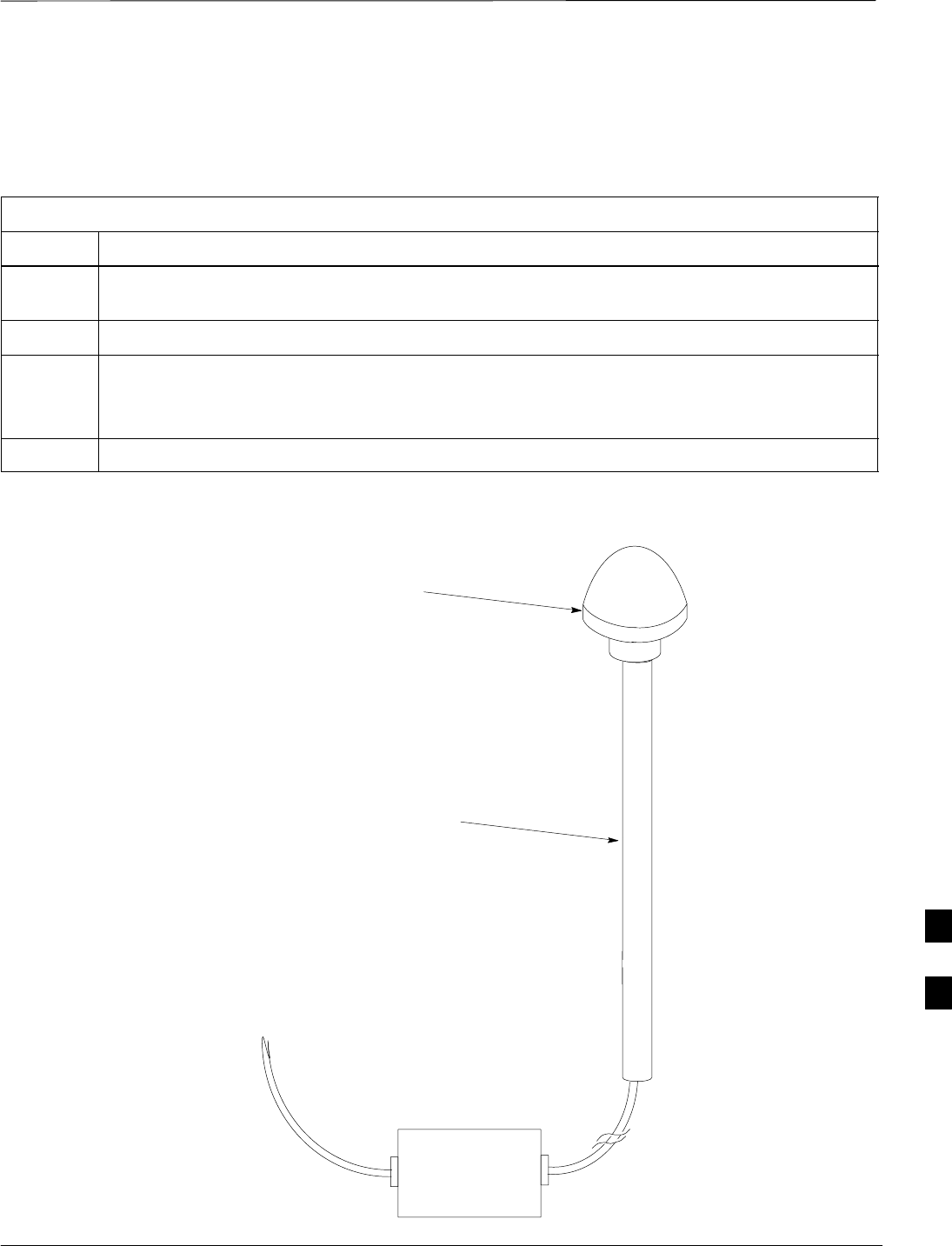
Remote GPS Replacement Procedures – continued
JAN 2002 8-21
SCt300 1X BTS Hardware Installation, ATP, and FRU Procedures
DRAFT
Install the replacement RGPS head
Follow the steps in Table 8-12 to install the replacement RGPS head.
Refer to Figure 8-6.
Table 8-12: Procedure to Install the Replacement RGPS Head
Step Action
1Connect the cable connector of the replacement RGPS head to the RGPS cable connector. Secure
the connection by tightening the spinning connector flange.
2Feed the cable slack into the RGPS head end of the mounting pipe/conduit.
3Grasp the RGPS head with one hand and the pipe/conduit with the other hand.
Be careful not to cross–thread the fitting on the RGPS head, screw the pipe/conduit into the head.
Hand tighten only!
4Tighten the pipe/conduit mounting hardware until the pipe/conduit is securely mounted.
Figure 8-6: RGPS Head Replacement
SITE I/O INTERFACE
UNSCREW PIPE, PULL CABLE THROUGH AND
DISCONNECT CABLE CONNECTOR
CABLE CONNECTOR LOCATED
INSIDE PIPE
8

Full Unit Replacement Procedures
DRAFT
SCt300 1X BTS Hardware Installation, ATP, and FRU Procedures JAN 2002
8-22
Objective
The objective of this procedure is to replace a Microcell unit. See
NO TAG.
System Impact/Considerations
The removal of the failed unit will require system downtime.
Required Tools and Materials
The following tools and materials are required to do this procedure:
Tools
The following tools are required to do this procedure:
STorque driver wrench, 1/4–in. hex female drive, 0–10 N–M
ST20 TORX Tamper Bit, 1/4–in. hex
ST30 TORX Tamper Bit, 1/4–in. hex
S13 mm torque wrench set to 5.0 N–M
S5/16 breakaway torque wrench 9–in. lb.
S13/16 breakaway torque wrench 38–in. lb
SKey for lock (optional)
SHandles for unit (optional)
Replacement units
One Microcell unit is required to do this procedure.
Procedure to Replace Failed
Unit
Before you begin
Before you begin, enter the following information into the following
replacement list table.
Table 8-13: Item Number Replacement List
Item Description
BTS Number
Failed Unit Number
Remove the failed unit
Follow the steps in Table 8-14 to remove the failed unit.
Table 8-14: Procedure to Remove the Failed Unit
Step Action
1Place the BTS out of service. Refer to the “Shut Down Signaling Functions” procedure in
Table 8-2.
2If necessary, use a T20 TORX Tamper bit to remove the Solar Cover.
. . . continued on next page
8

Full Unit Replacement Procedures – continued
JAN 2002 8-23
SCt300 1X BTS Hardware Installation, ATP, and FRU Procedures
DRAFT
Table 8-14: Procedure to Remove the Failed Unit
Step Action
3If DC power is being supplied to the unit or if battery backup is present, open (pull) the DC power
breaker. The white collar on the breaker is visible when the breaker is opened.
4If AC power is being supplied to the unit, open (pull) the AC power breaker. The white collar on
the breaker is visible when the breaker is opened.
5Turn the power off at the main power source (AC and/or DC).
6Use a T30 TORX tamper bit to remove the two tamper–resistant screws that hold the site I/O
junction box (or site I/O cap) to the BTS. Refer to Figure 8-4 in the “Site I/O Junction Box
Replacement” procedure.
7Disconnect the AC input cable from the unit. Refer to NO TAG.
8Disconnect the DC input cable from the unit. Refer to NO TAG.
9Disconnect the antenna cable(s) from the unit. Refer to NO TAG.
10 Disconnect the MIB cables from the unit (if equipped). Refer to NO TAG.
11 Disconnect the SU cables from the unit (if equipped). Refer to NO TAG.
12 Remove the two mounting screws that hold the short duration battery (if present) to the unit.
Refer to Table 8-8 in the “Short Duration Battery Replacement Procedures” procedure and
NO TAG.
13 Attach the installation handles to the unit. Refer to the “Attaching Installation Handles to the
Unit” procedure in Chapter 6.
14 Use a T30 Tamper bit to remove the two screws that hold the unit to the mounting bracket.
15 Remove the pin or lock (if equipped) from the unit.
16 Remove the unit from the mounting bracket.
8

Full Unit Replacement Procedures – continued
DRAFT
SCt300 1X BTS Hardware Installation, ATP, and FRU Procedures JAN 2002
8-24
Install the replacement unit
Follow the steps in Table 8-15 to install the replacement unit.
Table 8-15: Procedure to Install the New Unit
Step Action
1Attach the installation handles to the replacement unit. Refer to the “Attaching Installation
Handles to Unit” procedure in Chapter 6.
2Mount the replacement unit to the bracket. Refer to the “Attaching Unit to the Mounting
Bracket” procedure in Chapter 6.
3Once the replacement unit has been secured to the mounting bracket, remove the installation
handles (reverse the installation order of the “Attaching Installation Handles to the Unit”
procedure in Chapter 6).
4Attach the site I/O junction box or site I/O cap to the unit. Refer to the “Attaching the Site I/O
Junction Box to the Unit” procedure in Chapter 6 and Figure 8-4.
5Attach the short duration battery (if present) to the unit. Refer to Table 8-9 in the “Short Duration
Battery Replacement Procedure” and NO TAG.
6Connect the AC input cable. Refer to the “AC Power Cabling” procedure in Chapter 6.
7Connect the DC input cable. Refer to the “DC Power Cabling” procedure in Chapter 6.
8Connect the antenna cable(s). Refer to the “Antenna Cabling” procedure in Chapter 6.
9Connect the MIB cables (if equipped). Refer to the “MIB Cabling” procedure in Chapter 6.
10 Connect the SU cables (if equipped). Refer to the “SU Cabling” procedure in Chapter 6.
11 Turn power on at the main power source (AC and/or DC).
12 If AC power is being supplied to the unit, close (push) the AC power breaker. The white collar on
the breaker is not visible when the breaker is closed.
13 If DC power is being supplied to the unit or if battery backup is present, close (push) the DC
power breaker. The white collar is not visible when the breaker is closed.
14 Perform the ATP, if necessary. Refer to the ATP procedures in Chapter 7.
15 Install the Solar Covers (if necessary).
16 Place the BTS back in service using the “Restore Signaling Operations” procedure in Table 8-3.
8
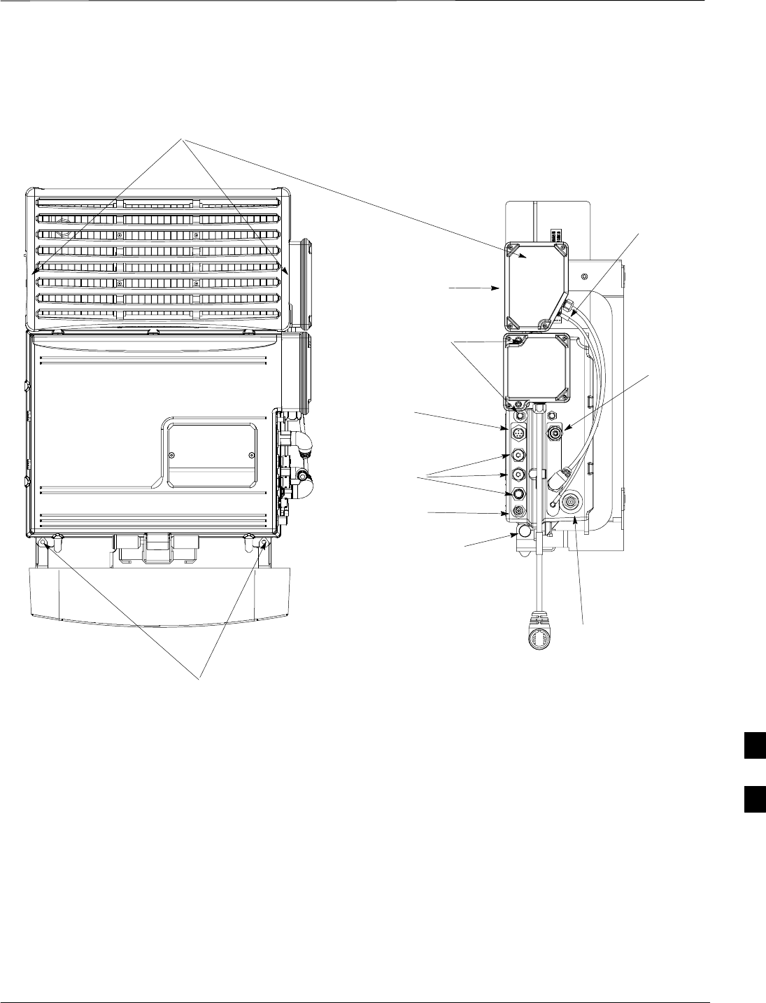
Full Unit Replacement Procedures – continued
JAN 2002 8-25
SCt300 1X BTS Hardware Installation, ATP, and FRU Procedures
DRAFT
REMOVE SCREWS USED TO
HOLD UNIT ON BRACKET
REMOVE SCREWS TO
REMOVE SITE I/O
JUNCTION BOX OR SITE
I/O CAP (IF EQUIPPED)
REMOVE DC INPUT CABLE
REMOVE SCREWS TO REMOVE SHORT DURATION BATTERY
REMOVE ANTENNA B
Figure 8-7: Unit Replacement
REMOVE SU CABLE
(IF EQUIPPED)
REMOVE MIB
CABLES (OPTIONAL)
REMOVE
ANTENNA A
CABLE
REMOVE
LOCK
NOTE: REMOVE THE SITE I/O JUNCTION BOX (OR SITE I/O CAP), SUBSCRIBER UNIT, AND
BATTERY FROM THE FAILED UNIT AND RE–MOUNT THEM ON THE REPLACEMENT UNIT
REMOVE AC
INPUT POWER
CABLE
REMOVE SCREWS TO
REMOVE SUBSCRIBER
UNIT (IF EQUIPPED)
8

Full Unit Replacement Procedures – continued
DRAFT
SCt300 1X BTS Hardware Installation, ATP, and FRU Procedures JAN 2002
8-26
Notes
8

JAN 2002 SCt300 1X BTS Hardware Installation, ATP, and FRU Procedures
DRAFT
Appendix A: Outdoor Grounding Guidelines Overview
Appendix Content
Outdoor Grounding Guidelines Summary A-1. . . . . . . . . . . . . . . . . . . . . . . . . . . . .
Background A-1. . . . . . . . . . . . . . . . . . . . . . . . . . . . . . . . . . . . . . . . . . . . . .
Chassis Isolation A-1. . . . . . . . . . . . . . . . . . . . . . . . . . . . . . . . . . . . . . . . . .
Master Ground Plate A-1. . . . . . . . . . . . . . . . . . . . . . . . . . . . . . . . . . . . . . .
Main AC Power A-1. . . . . . . . . . . . . . . . . . . . . . . . . . . . . . . . . . . . . . . . . . .
Antenna A-1. . . . . . . . . . . . . . . . . . . . . . . . . . . . . . . . . . . . . . . . . . . . . . . . .
Chassis A-2. . . . . . . . . . . . . . . . . . . . . . . . . . . . . . . . . . . . . . . . . . . . . . . . . .
T1 Span Lines A-2. . . . . . . . . . . . . . . . . . . . . . . . . . . . . . . . . . . . . . . . . . . .
Modem A-2. . . . . . . . . . . . . . . . . . . . . . . . . . . . . . . . . . . . . . . . . . . . . . . . . .
Customer I/O A-2. . . . . . . . . . . . . . . . . . . . . . . . . . . . . . . . . . . . . . . . . . . . .
A

Table of Contents – continued
DRAFT
SCt300 1X BTS Hardware Installation, ATP, and FRU Procedures JAN 2002
Notes
A

Outdoor Grounding Guidelines Summary
JAN 2002 A-1
SCt300 1X BTS Hardware Installation, ATP, and FRU Procedures
DRAFT
Background
This is a summary of the outdoor grounding guidelines. Outdoor
installations should be based on this summary and site specific
documentation. Motorola publication 68P81150E62 should also be
followed to ground an antenna tower.
This guideline assumes that auxiliary equipment is co–located at the
installation site. All of the equipment referenced may not be present at
every site.
Because outdoor MicroCell installations will involve a variety of
methods, this information is not meant to represent actual physical
layout. It is meant to act as an aid to understanding an effective ground
system.
Chassis Isolation
Regardless of the type of installation (wall, frame, pole), the grounding
plan must have a single point ground to prevent surge/transient currents
from passing through the BTS and auxiliary equipment. The BTS
includes insulation hardware to insure that the chassis will be grounded
by the intended ground path and not through the mounting structure
(frame, pole, or wall).
Master Ground Plate
The Master Ground Plate (MGP) is the key to the outdoor grounding
scheme. The MGP is the single grounding point for all BTS input and
output and provides a uniform ground potential through out the site.
Although the MGP may be implemented differently at each installation,
it must be a plate that is big enough to attach to all the lightning arrestors
and have a ground stud.
The MGP ground stud is the only connection to earth ground for the
BTS hardware.
Main AC Power
The AC power input is single–phase and connects to the BTS by a three
conductor cable. The cable is insulated and connects to the BTS on one
end and the AC source on the other end. The AC power source should
be ground referenced to the MGP at a point closest to the access point.
The line and neutral conductors must be protected by lightning arrestors.
The lightning arrestors connect to the MGP at the same point as the AC
ground reference.
If an external circuit breaker or an uninterruptible power supply are used,
install them between the AC power lightning arrestor and the BTS.
Antenna
Coaxial cables are used to connect to the antenna(s). The ground
conductor (shield) of the coaxial cable must be ground referenced to the
A

Outdoor Grounding Guidelines Summary – continued
DRAFT
SCt300 1X BTS Hardware Installation, ATP, and FRU Procedures JAN 2002
A-2
MGP at the antenna access point. The signal (center) conductor must be
protected by a lightning arrestor. The lightning arrestor connects to the
MGP at the same point as the ground conductor (shield) of the antenna
cable.
Chassis
The ground stud of the BTS chassis connects to the MGP.
T1 Span Lines
The BTS can connect to two T1 span lines. For many applications the
T1 cable is derived from an optical fiber interconnect. For cases where
the optical interconnect is non–metallic, no special grounding is needed.
If the optical fiber is encased in a metallic sheath, the sheath must be
grounded to the MGP. If the span lines are metallic, the conductors must
be protected by lightning arrestors which connect to the MGP at a point
closest to the demarcation point.
Modem
A single tip and ring pair is used for a dial–up modem connection. The
tip and ring pair must be protected by a lightning arrestor which
connects to the MGP at a point closest to the demarcation point.
Customer I/O
The BTS provides eight customer defined inputs. These connections are
internal to the cell site and do not require special grounding unless they
originate from an area not protected by the MGP.
Example: Signal light in tower configuration
A

JAN 2002 SCt300 1X BTS Hardware Installation, ATP, and FRU Procedures
DRAFT
Appendix B: Alarm List
Appendix Content
Release 15 Alarm List B-1. . . . . . . . . . . . . . . . . . . . . . . . . . . . . . . . . . . . . . . . . . . .
Objective B-1. . . . . . . . . . . . . . . . . . . . . . . . . . . . . . . . . . . . . . . . . . . . . . . .
List of Alarms B-1. . . . . . . . . . . . . . . . . . . . . . . . . . . . . . . . . . . . . . . . . . . .
B

Table of Contents – continued
DRAFT
SCt300 1X BTS Hardware Installation, ATP, and FRU Procedures JAN 2002
Notes
B

Release 15 Alarm List
JAN 2002 B-1
SCt300 1X BTS Hardware Installation, ATP, and FRU Procedures
DRAFT
Objective
Table B-1 lists all the alarms which can be generated by an SCt300
BTS. Additional Data field values are not shown. The list of alarms is
based on R15 SCt300 functionality.
List of Alarms
Table B-1: List of Alarms (Software Release 15)
Alarm
#Alarm Name Alarm Description
400 Traffic Channel
Element Failure This trouble notification indicates the availability of a single channel
element or a set of channel elements. It is generated whenever the BTS
detects an alarm condition on a DSP, its internal path connection, or its
associated span. It is never displayed or latched in the MM and it is only
used to update the MM’s call processing resource list. This trouble
notification contains the address of the channel card along with the list of
affected channel elements.
1200 BTS LAN Connection
Error This alarm causes the MM to take the BTS out of service. The MM
converts the alarm ID from 1200 to 12–60 (MAWI out of service).
Call Overload Alarms
1950 BTS Overload: New
Calls Threshold 1
Reached
A capacity overload alarm indicates that the new calls capacity ceiling
was reached and mobile restrictions associated with the alarm will be in
effect for the call setups. This alarm is cleared when the overload
condition is no longer in effect. The reporting mechanism is disabled by
default for all overload alarms in this category and can be changed via the
Recent Change command EDIT CARRIER/SECTOR/BTS
CONGESTCONF at the OMCR. Supplemental data represents the state
of the system after the alarm actions have taken place.
1951 BTS Overload: New
Calls Threshold 2
Reached
A capacity overload alarm indicates that the new calls capacity ceiling
was reached and mobile restrictions associated with the alarm will be in
effect for the call setups. This alarm is cleared when the overload
condition is no longer in effect. The reporting mechanism is disabled by
default for all overload alarms in this category and can be changed via the
Recent Change command EDIT CARRIER/SECTOR/BTS
CONGESTCONF at the OMCR. Supplemental data represents the state
of the system after the alarm actions have taken place.
1952 BTS Overload: New
Calls Threshold 3
Reached
A capacity overload alarm indicates that the new calls capacity ceiling
was reached and mobile restrictions associated with the alarm will be in
effect for the call setups. This alarm is cleared when the overload
condition is no longer in effect. The reporting mechanism is disabled by
default for all overload alarms in this category and can be changed via the
Recent Change command EDIT CARRIER/SECTOR/BTS
CONGESTCONF at the OMCR. Supplemental data represents the state
of the system after the alarm actions have taken place.
B

Release 15 Alarm List – continued
DRAFT
SCt300 1X BTS Hardware Installation, ATP, and FRU Procedures JAN 2002
B-2
Table B-1: List of Alarms (Software Release 15)
Alarm
#Alarm DescriptionAlarm Name
1953 BTS Overload:
Registration Threshold
1 Reached
A capacity overload alarm indicates that the new calls capacity ceiling
was reached and mobile restrictions associated with the alarm will be in
effect for the call setups. This alarm is cleared when the overload
condition is no longer in effect. The reporting mechanism is disabled by
default for all overload alarms in this category and can be changed via the
Recent Change command EDIT CARRIER/SECTOR/BTS
CONGESTCONF at the OMCR. Supplemental data represents the state
of the system after the alarm actions have taken place.
1954 BTS Overload:
Registration Threshold
2 Reached
A capacity overload alarm indicates that the new calls capacity ceiling
was reached and mobile restrictions associated with the alarm will be in
effect for the call setups. This alarm is cleared when the overload
condition is no longer in effect. The reporting mechanism is disabled by
default for all overload alarms in this category and can be changed via the
Recent Change command EDIT CARRIER/SECTOR/BTS
CONGESTCONF at the OMCR. Supplemental data represents the state
of the system after the alarm actions have taken place.
1955 BTS Overload:
Registration Threshold
3 Reached
A capacity overload alarm indicates that the new calls capacity ceiling
was reached and mobile restrictions associated with the alarm will be in
effect for the call setups. This alarm is cleared when the overload
condition is no longer in effect. The reporting mechanism is disabled by
default for all overload alarms in this category and can be changed via the
Recent Change command EDIT CARRIER/SECTOR/BTS
CONGESTCONF at the OMCR. Supplemental data represents the state
of the system after the alarm actions have taken place.
1956 BTS Overload:
Aggregate Access
Threshold 1 Reached
A capacity overload alarm indicates that the new calls capacity ceiling
was reached and mobile restrictions associated with the alarm will be in
effect for the call setups. This alarm is cleared when the overload
condition is no longer in effect. The reporting mechanism is disabled by
default for all overload alarms in this category and can be changed via the
Recent Change command EDIT CARRIER/SECTOR/BTS
CONGESTCONF at the OMCR. Supplemental data represents the state
of the system after the alarm actions have taken place.
1957 BTS Overload:
Aggregate Access
Threshold 2 Reached
A capacity overload alarm indicates that the new calls capacity ceiling
was reached and mobile restrictions associated with the alarm will be in
effect for the call setups. This alarm is cleared when the overload
condition is no longer in effect. The reporting mechanism is disabled by
default for all overload alarms in this category and can be changed via the
Recent Change command EDIT CARRIER/SECTOR/BTS
CONGESTCONF at the OMCR. Supplemental data represents the state
of the system after the alarm actions have taken place.
B

Release 15 Alarm List – continued
JAN 2002 B-3
SCt300 1X BTS Hardware Installation, ATP, and FRU Procedures
DRAFT
Table B-1: List of Alarms (Software Release 15)
Alarm
#Alarm DescriptionAlarm Name
1958 BTS Overload:
Aggregate Access
Threshold 3 Reached
A capacity overload alarm indicates that the aggregate of both call setups
and registration capacity ceiling was reached and mobile restrictions
associated with the alarm will be in effect for the mobile originations and
registrations. This alarm is cleared when the overload condition is no
longer in effect. The reporting mechanism is disabled by default for all
overload alarms in this category and can be changed via Recent Change
command EDIT CARRIER/SECTOR/BTS CONGESTCONF at
OMCR. Supplemental data represents the state of the system after the
alarm actions have taken place.
1959 Global Service
Redirection Threshold
Reached: New Calls
This alarm indicates that all mobiles in the affected access class will be
redirected to an overlaid analog system or to another CDMA system until
the rate drops below the threshold level for new calls. This alarm is
cleared when the overload condition is no longer in effect. The default is
set to DISABLED for all overload alarms in this category and can be
changed via the Recent Change command EDIT CARRIER/SECTOR/
BTS CONGESTCONF at the OMCR. Supplemental data represents the
state of the system after the alarm actions have taken place.
1960 Global Service
Redirection Threshold
Reached: Registrations
This alarm indicates that all mobiles in the affected access class will be
redirected to an overlaid analog system or to another CDMA system until
the rate drops below the threshold level for new calls. This alarm is
cleared when the overload condition is no longer in effect. The default is
set to DISABLED for all overload alarms in this category and can be
changed via the Recent Change command EDIT CARRIER/SECTOR/
BTS CONGESTCONF at the OMCR. Supplemental data represents the
state of the system after the alarm actions have taken place.
1961 Global Service
Redirection Threshold
Reached: Aggregate
This alarm indicates that all mobiles in the affected access class will be
redirected to an overlaid analog system or to another CDMA system until
the rate drops below the threshold level for new calls. This alarm is
cleared when the overload condition is no longer in effect. The default is
set to DISABLED for all overload alarms in this category and can be
changed via the Recent Change command EDIT CARRIER/SECTOR/
BTS CONGESTCONF at the OMCR. Supplemental data represents the
state of the system after the alarm actions have taken place.
LPAC Alarms
3901 LPAC: High Power
Over Limit Alarm –
Unit A
The output detector on the unit monitors the output power. An alarm
generates when the output power surpasses a preset threshold. At this
point, the PA is outputting more power than it can sustain, and damage
will result if the PA continues to operate. A typical scenario that would
cause a high power over limit alarm would be when power into the PA is
more than it can safely sustain. This would cause an input overload,
which is detected by the output detector, and the BTS would
automatically reduce its output power. The BTS will remain in service
after this alarm. Some calls may be dropped.
B

Release 15 Alarm List – continued
DRAFT
SCt300 1X BTS Hardware Installation, ATP, and FRU Procedures JAN 2002
B-4
Table B-1: List of Alarms (Software Release 15)
Alarm
#Alarm DescriptionAlarm Name
3921 LPAC: Very High
Temperature Alarm –
Unit A
This alarm is generated when the temperature on the PA unit exceeds the
threshold value for very high temperatures. This is either an equipment
alarm suggesting a hardware failure, or an alarm indicating environmental
extremes. To avoid equipment damage, the PA will automatically shut
down. This will also cause the BTS to reboot.
3931 LPAC: High
Temperature Alarm –
Unit A
This alarm is generated when the temperature on the PA unit exceeds the
threshold value for very high temperature. This is either an equipment
alarm suggesting a hardware failure, or an alarm indicating environmental
extremes. The BTS will reboot automatically to avoid equipment
damage.
3941 LPAC: VSWR Alarm
– Unit A This alarm indicates a VSWR alarm was detected on the PA unit. This is
an equipment alarm, suggesting a hardware failure of the antenna system,
which is external to the PA.
This alarm is considered capacity–limiting because the BTS will reboot
automatically.
3961 LPAC: IM Loop Not
Converged Alarm –
Unit A
This alarm is generated when the convergence loop on the PA unit is
unable to cancel the distortion components created by the PA such that the
PA meets proper specifications. This alarm is detected by monitoring and
measuring IM products. An alarm will generate if the readings fall below
a preset threshold. The BTS will reboot automatically.
3980 LPAC Combination
Alarm, Complete
Sector Failure
This alarm is generated when the LPAC reports at least one of the
following alarms:
SVery High Temperature Alarm,
SIM Loop Not Converged Alarm,
SVSWR Alarm
A combination alarm indicates a complete BTS reboot. Therefore, the
sector has lost power and is no longer transmitting. Calls will neither
originate to the failed sector, nor will existing calls hand off.
RF Related Alarms
9141 Forward Power Very
High Alarm: Sector 1 This alarm is generated whenever the P out of N forward gain samples
(where N and P may be configured) exceed a configurable forward gain
threshold. Two alarm levels can be specified: a very high (first level) and
a high (second level). The order of alarming by increasing severity is
normal condition, then high (second level), followed by very high (first
level). A forward power very high alarm clear is generated whenever P
out of N forward gain samples fall below the forward threshold minus a
forward gain Delta.
B

Release 15 Alarm List – continued
JAN 2002 B-5
SCt300 1X BTS Hardware Installation, ATP, and FRU Procedures
DRAFT
Table B-1: List of Alarms (Software Release 15)
Alarm
#Alarm DescriptionAlarm Name
9151 Reverse Noise Rise
Very High Alarm:
Sector 1
This alarm is generated whenever a reverse noise rise measurement
(rolling average over a configurable number of samples) exceeds a reverse
noise rise threshold. Two alarm levels can be specified: a very high (first
level) and a high (second level). The order of alarming by increasing
severity is normal condition, then high (second level), followed by very
high (first level). A Reverse Noise Rise Very High Alarm clear is
generated whenever the reverse noise rise measurement recedes below the
reverse noise rise threshold minus a Delta.
9161 Forward Power High
Alarm: Sector 1 This alarm is generated whenever the P out of N forward gain samples
(where N and P may be configured) exceed a configurable forward gain
threshold. Two alarm levels can be specified: a very high (first level) and
a high (second level). The order of alarms listed by increasing severity is:
normal condition, high (second level), and very high (first level). A
Forward Power High Alarm Clear is generated whenever P out of N
forward gain samples fall below the forward threshold minus a forward
gain Delta.
9171 Reverse Noise Rise
High Alarm: Sector 1 This alarm is generated whenever a reverse noise rise measurement
(rolling average over a configurable number of samples) exceeds a reverse
noise rise threshold. Two alarm levels can be specified: a very high (first
level) and a high (second level). The order of alarms listed by increasing
severity are: normal condition, high (second level), and very high (first
level). A Reverse Noise Rise High Alarm Clear is generated whenever
the reverse noise rise measurement recedes below the reverse noise rise
threshold minus a delta.
9210 Forward Power
Limiting Alarm When the Forward Power Limiting alarm is activated, the BTS controller
will instruct the CDMA transceiver to limit the forward power at or below
the current peak power level (or at a fixed power level) or to reduce the
forward gain by a fixed amount. A Forward Power Limiting Alarm is
generated whenever the forward power exceeds the user definable fixed
power threshold (fixed limit mode), or the forward gain measurement
exceeds the forward gain limiting threshold (self–calibrating limit mode).
A Forward Power Limiting Alarm Clear is generated whenever the
forward power falls below the power limit threshold minus a clear event
delta (fixed limit mode) or the forward gain measurement falls below the
forward gain limiting threshold minus a forward gain limiting delta
(self–calibrating limit mode).
9211 Forward Power
Limiting Alarm –
Recovery Attempts
Exceeded
This alarm is generated when the system has tried to recover the LPA
over–driven condition for the user–configurable maximum number of
times and the over–driven condition still exist. This alarm is only
applicable for the self–calibrating limit mode.
Synchronization Alarms
10030 Lost Phase Lock This alarm is generated when the active BTS DPLL loses phase lock and
re–enters acquisition mode. If the BTS does not regain phase lock, or
repeatedly gains and loses phase lock, the problem is most likely a
hardware problem in the unit.
B

Release 15 Alarm List – continued
DRAFT
SCt300 1X BTS Hardware Installation, ATP, and FRU Procedures JAN 2002
B-6
Table B-1: List of Alarms (Software Release 15)
Alarm
#Alarm DescriptionAlarm Name
10040 GPS Reference Source
Failure This alarm is generated when the BTS detects a failure (missing clock
pulses or associated device not ready) of its GPS reference source. The
additional alarm data will include information about the reference source
priority. The reference source priority is the priority of the GPS reference
source in relation to the other available reference sources.
This alarm will report when local conditions prevent proper GPS
reception or when the GPS system is taken down for configuration. If the
GPS reference source does not recover or repeatedly fails, a problem may
exist in the GPS receiver hardware. This alarm is only reported after the
GPS is lost for more than 30 seconds. The loss of GPS for shorter periods
of time is not considered unusual, especially if the antenna placement is
less than optimum. Short losses of GPS will have no impact on the
performance of the BTS.
10060 GPS Message Failure This alarm is generated when the BTS receives a message from the GPS
receiver that cannot be processed. The additional info will indicate if the
message problem was due to an unknown type, checksum failure, format
failure, incomplete message (timeout during message reception) or remote
GPS cable delay compensation failure. This alarm is provided to allow
additional status to be tracked.
10091 HSO Reference Source
Failure This alarm is generated when the BTS detects a failure (missing clock
pulses) of its High Stability Oscillator (HSO) reference source. The
additional alarm data will include information about the reference source
priority. The reference source priority is the priority of the Rubidium
reference source in relation to the other available reference sources.
If the Rubidium reference source does not recover or repeatedly fails, a
problem may exist in the Rubidium Reference Source hardware.
10100 No Reference Source
Available This alarm is generated when the BTS detects a failure of all of its
available reference sources.
10110 Reference Source
Switch This alarm is generated when the BTS switches to an alternate reference
source. The additional alarm data will identify the alternate reference
source type (GPS, HSO, HSO2 – if sync daisy chain is used or freerun).
A reference source switch occurs when a reference source fails and an
alternate reference source is available. The reference source switch is
seamless and does not cause degradation in system performance
10111 Reference Source
Unreliable This alarm is generated when the reporting device expires a given time
period during which its reference source is known to provide a reliable
clock for the maintenance of CDMA system time. Once the alarm is
generated, it is possible that the reporting device is running with a clock
that has drifted from CDMA system time. If so, the reporting device will
continue to support call originations and maintenance, but cannot
guarantee hand–off capability. The additional data will identify the
reference source the device is currently using as a timing reference.
B

Release 15 Alarm List – continued
JAN 2002 B-7
SCt300 1X BTS Hardware Installation, ATP, and FRU Procedures
DRAFT
Table B-1: List of Alarms (Software Release 15)
Alarm
#Alarm DescriptionAlarm Name
HW Specific Alarms
1701–
1708 BTS Relay #n –
Contact Alarm This alarm is active when a BTS input relay has opened or closed. The
relay number “n” will be 1–8. This is an equipment alarm and suggests a
possible hardware failure or operator–defined condition.
1800 BTS Controller
Disabled Device This alarm is active when the BTS Controller has detected a faulty device
and is requesting that the device be disabled. The device is not
responding to an update or has been implicated by a series of alarms.
12040 TRX Failure This alarm is generated when a BTS detects a failure in its TRX. The
additional data specifies the TRX failure. If the BTS is not a master
device, the BTS will de–key its TRX and Ram Boot itself. If the BTS is
a master device and it is in service, the master BTS shall de–key its
troubled TRX and stay in service. Since there is a one–to–one relation
between a BTS and its TRX, this will result in the sector going out of
service.
12050 TRX Warning This alarm is generated when a BTS detects a high temperature in its
TRX. The additional data indicates the specific problem. The BTS will
not de–key the TRX as a result of this alarm.
12060 Cabinet Temperature This alarm is generated when a BTS detects a temperature threshold
violation or a problem with the temperature sensing mechanism. The
reason code indicates the exact error.
12071
–
12072
RXDC Failure Unit
A/B This alarm is generated when a BTS detects a failure in a particular
RXDC unit. This is reported thru the RX and indicates a diversity
problem within the site.
CE Alarms
12100
–
12131
Channel Element
Failure #n This alarm is generated when a BTS detects an unrecoverable error for a
particular channel element (CE). The additional data indicates the specific
error. The CE will be disabled automatically.
NOTE
SC340 device has 16 channel elements, thus it does not detect and
generate alarms 12116–12131.
12200
–
12231
Channel Element
Recovered #n This alarm is generated when a BTS detects a recoverable error for a
particular Channel Element (CE). The additional data indicates the
specific error. The CE has been recovered automatically. While in
recovery mode, all active calls at the CE could be lost.
NOTE
SC340 device has 16 channel elements, thus it does not detect and
generate alarms 12216–12231.
B

Release 15 Alarm List – continued
DRAFT
SCt300 1X BTS Hardware Installation, ATP, and FRU Procedures JAN 2002
B-8
Table B-1: List of Alarms (Software Release 15)
Alarm
#Alarm DescriptionAlarm Name
12300
–
12331
Channel Element TSI
Mapping Failure #n This alarm is generated when a BTS detects a problem internally
allocating a SRCHAN to a particular channel element (CE). The
additional data indicates the specific error. The CE is unusable for call
processing.
NOTE
The SC340 device has 16 channel elements, thus it does not detect and
generate alarms 12316–12331.
Span Alarms
18001/
18002 SPAN Degraded –
Remote Fault Daily
Threshold Exceeded
(source)/(sink)
This alarm indicates that the count of remote faults exceeded the alarm
threshold (default threshold = 16) within a 24–hour period. This alarm is
caused by the transmit span line path fading in and out. This alarm
condition will have an insignificant impact on system performance and
call quality. This alarm may provide an early warning of a more serious
condition.
This alarm will be sent by one of the two devices at the end of the span.
In some cases, a second alarm will be sent by the device at the other end
of the span. One alarm will have “(source)” to indicate that it came
from the source end point, and the other will have “(sink)” to indicate
that it came from the sink end point.
18004/
18005 SPAN Degraded –
Remote Fault Hourly
Threshold Exceeded
(source)/(sink)
This alarm indicates that the count of remote alarms exceeded the alarm
threshold (default threshold = 20) within a 1–hour period. This alarm is
caused by the transmit span line path fading in and out. This alarm
condition may have a minor impact on system performance and call
quality. This alarm may provide an early warning of a more serious
condition. This alarm will be sent by one of the two devices at the end of
the span. In some cases, a second alarm will be sent by the device at the
other end of the span. One alarm will have “(source)” to indicate that
it came from the source end point, and the other will have “(sink)” to
indicate that it came from the sink end point.
18007/
18008 SPAN Degraded –
Remote Fault Critical
Threshold Exceeded
(source)/(sink)
This alarm indicates that the count of remote faults exceeded the alarm
threshold (default threshold = 511) within a 24–hour period. This alarm is
caused by the transmit span line path fading in and out. This alarm
indicates that system performance and call quality is seriously degraded.
This alarm will be sent by one of the two devices at the end of the span.
In some cases, a second alarm will be sent by the device at the other end
of the span. One alarm will have “(source)” to indicate that it came
from the source end point, and the other will have “(sink)” to indicate
that it came from the sink end point.
B

Release 15 Alarm List – continued
JAN 2002 B-9
SCt300 1X BTS Hardware Installation, ATP, and FRU Procedures
DRAFT
Table B-1: List of Alarms (Software Release 15)
Alarm
#Alarm DescriptionAlarm Name
18010/
18011 SPAN Out–of–Service
– Continuous Remote
Faults (source)/(sink)
This alarm indicates that the span is out–of–service due to continuous
remote faults being received for more than 0.5 seconds. This alarm
indicates that the transmit span line signal was lost at the remote end, or
the transmit framing words were corrupted at the remote end. This alarm
will be sent by one of the two devices at the end of the span. In some
cases, a second alarm will be sent by the device at the other end of the
span. One alarm will have “(source)” to indicate that it came from the
source end point, and the other will have “(sink)” to indicate that it
came from the sink end point.
18013/
18014 SPAN Degraded –
Frame Slip Daily
Threshold Exceeded
(source)/(sink)
This alarm indicates that the number of frame slips exceeded the alarm
threshold (default threshold = 4) within a 24–hour period. This alarm is
caused by the master unit in the BTS not being synchronized with the
inbound span line. This alarm condition will have an insignificant impact
on system performance and call quality. This alarm may provide an early
warning of a more serious condition. This alarm will be sent by one of
the two devices at the end of the span.
In some cases, a second alarm will be sent by the device at the other end
of the span. One alarm will have “(source)” to indicate that it came
from the source end point, and the other will have “(sink)” to indicate
that it came from the sink end point.
18016/
18017 SPAN Degraded –
Frame Slip Hourly
Threshold Exceeded
(source)/(sink)
This alarm indicates that the number of frame slips exceeded the alarm
threshold (default threshold = 10) within a 1–hour period. This alarm is
caused by the BTS unit not being synchronized with the inbound span
line. This alarm condition may have a minor impact on system
performance and call quality. This alarm may provide an early warning of
a more serious condition. This alarm will be sent by one of the two
devices at the end of the span.
In some cases, a second alarm will be sent by the device at the other end
of the span. One alarm will have “(source)” to indicate that it came
from the source end point, and the other will have “(sink)” to indicate
that it came from the sink end point.
18019/
18020 SPAN Degraded –
Frame Slip Critical
Threshold Exceeded
(source)/(sink)
This alarm indicates that the number of frame slips exceeded the alarm
threshold (default threshold = 255) within a 24–hour period. This alarm
is caused by the BTS unit not being synchronized with the inbound span
line. This alarm indicates that system performance and call quality is
seriously degraded. This alarm will be sent by one of the two devices at
the end of the span.
In some cases, a second alarm will be sent by the device at the other end
of the span. One alarm will have “(source)” to indicate that it came
from the source end point, and the other will have “(sink)” to indicate
that it came from the sink end point.
B

Release 15 Alarm List – continued
DRAFT
SCt300 1X BTS Hardware Installation, ATP, and FRU Procedures JAN 2002
B-10
Table B-1: List of Alarms (Software Release 15)
Alarm
#Alarm DescriptionAlarm Name
18031/
18032 SPAN Out–of–Service
– Continuous Framed
AIS Faults
(source)/(sink)
This alarm indicates that the span is out–of–service due to continuous
Framed Alarm Indication Signal (AIS) faults being received for more than
2.5 seconds. This alarm indicates that the receive span signal was lost,
the receive framing words were corrupted, or an incompatible remote span
interface was detected by the network. This alarm will be sent by one of
the two devices at the end of the span.
In some cases, a second alarm will be sent by the device at the other end
of the span. One alarm will have “(source)” to indicate that it came
from the source end point, and the other will have “(sink)” to indicate
that it came from the sink end point.
18034/
18035 SPAN Degraded –
Unframed AIS Daily
Threshold Exceeded
(source)/(sink)
This alarm indicates that the number of Unframed Alarm Indication
Signal (AIS) alarms exceeded the alarm threshold (default threshold = 16)
within a 24–hour period. This alarm is caused by the receive span fading
in and out. This alarm condition will have an insignificant impact on
system performance and call quality. This alarm may provide an early
warning of a more serious condition. This alarm will be sent by one of the
two devices at the end of the span.
In some cases, a second alarm will be sent by the device at the other end
of the span. One alarm will have “(source)” to indicate that it came
from the source end point, and the other will have “(sink)” to indicate
that it came from the sink end point.
18037/
18038 SPAN Degraded –
Unframed AIS Hourly
Threshold Exceeded
(source)/(sink)
This alarm indicates that the number of Unframed Alarm Indication
Signal (AIS) alarms exceeded the alarm threshold (default threshold = 20)
within a 1–hour period. This alarm is caused by the receive span fading
in and out. This alarm condition may have a minor impact on system
performance and call quality. This alarm may provide an early warning of
a more serious condition. This alarm will be sent by one of the two
devices at the end of the span.
In some cases, a second alarm will be sent by the device at the other end
of the span. One alarm will have “(source)” to indicate that it came
from the source end point, and the other will have “(sink)” to indicate
that it came from the sink end point.
18040/
18041 SPAN Degraded –
Unframed AIS Critical
Threshold Exceeded
(source)/(sink)
This alarm indicates that the number of Unframed Alarm Indication
Signal (AIS) alarms exceeded the alarm threshold (default threshold =
511) within a 24–hour period. This alarm indicates that system
performance and call quality is seriously degraded. This alarm will be
sent by one of the two devices at the end of the span.
In some cases, a second alarm will be sent by the device at the other end
of the span. One alarm will have “(source)” to indicate that it came
from the source end point, and the other will have “(sink)” to indicate
that it came from the sink end point.
B

Release 15 Alarm List – continued
JAN 2002 B-11
SCt300 1X BTS Hardware Installation, ATP, and FRU Procedures
DRAFT
Table B-1: List of Alarms (Software Release 15)
Alarm
#Alarm DescriptionAlarm Name
18043/
18044 SPAN Out–of–Service
– Continuous
Unframed AIS Faults
(source)/(sink)
This alarm indicates that the span is out–of–service due to continuous
Unframed Alarm Indication Signal (AIS) faults being received for more
than 2.5 seconds. This alarm indicates that the receive span signal was
lost, the receive framing words were corrupted, or an incompatible remote
span interface was detected by the network. This alarm will be sent by
one of the two devices at the end of the span.
In some cases, a second alarm will be sent by the device at the other end
of the span. One alarm will have “(source)” to indicate that it came
from the source end point, and the other will have “(sink)” to indicate
that it came from the sink end point.
18046/
18047 SPAN Degraded –
REC Fault Daily
Threshold Exceeded
(source)/(sink)
This alarm indicates that the number of Receive Error Condition (REC)
alarms exceeded the alarm threshold (default threshold = 16) within a
24–hour period. This alarm condition will have an insignificant impact
on system performance and call quality. This alarm may provide an early
warning of a more serious condition. This alarm will be sent by one of
the two devices at the end of the span.
In some cases, a second alarm will be sent by the device at the other end
of the span. One alarm will have “(source)” to indicate that it came
from the source end point, and the other will have “(sink)” to indicate
that it came from the sink end point.
18049/
18050 SPAN Degraded –
REC Fault Hourly
Threshold Exceeded
(source)/(sink)
This alarm indicates that the number of Receive Error Condition (REC)
alarms exceeded the alarm threshold (default threshold = 20) within a
1–hour period. This alarm condition may have a minor impact on system
performance and call quality. This alarm may provide an early warning of
a more serious condition. This alarm will be sent by one of the two
devices at the end of the span.
In some cases, a second alarm will be sent by the device at the other end
of the span. One alarm will have “(source)” to indicate that it came
from the source end point, and the other will have “(sink)” to indicate
that it came from the sink end point.
18052/
18053 SPAN Degraded –
REC Fault Critical
Threshold Exceeded
(source)/(sink)
This alarm indicates that the number of Receive Error Condition (REC)
alarms exceeded the alarm threshold (default threshold = 511) within a
24–hour period. This alarm indicates that system performance and call
quality is seriously degraded. This alarm will be sent by one of the two
devices at the end of the span.
In some cases, a second alarm will be sent by the device at the other end
of the span. One alarm will have “(source)” to indicate that it came
from the source end point, and the other will have “(sink)” to indicate
that it came from the sink end point.
B

Release 15 Alarm List – continued
DRAFT
SCt300 1X BTS Hardware Installation, ATP, and FRU Procedures JAN 2002
B-12
Table B-1: List of Alarms (Software Release 15)
Alarm
#Alarm DescriptionAlarm Name
18055/
18056 SPAN Out–of–Service
– Continuous REC
Faults (source)/(sink)
This alarm indicates that the span is out–of–service due to continuous
Receive Error Condition (REC) faults being received for more than 2.5
seconds. This alarm indicates that the receive span signal was lost, the
receive framing words were corrupted, or an incompatible remote span
interface was detected by the network. This alarm will be sent by one of
the two devices at the end of the span.
In some cases, a second alarm will be sent by the device at the other end
of the span. One alarm will have “(source)” to indicate that it came
from the source end point, and the other will have “(sink)” to indicate
that it came from the sink end point.
18058/
18059 SPAN Degraded –
RED Fault Daily
Threshold Exceeded
(source)/(sink)
This alarm indicates that the number of RED faults exceeded the alarm
threshold (default threshold = 16) within a 24–hour period. A RED
Alarm Event is generated when there is a Loss of Signal, Loss of Frame
Alignment or the Bit Error Rate <= 10E–3. This alarm is caused by the
receive span fading in and out. This alarm condition will have an
insignificant impact on system performance and call quality. This alarm
may provide an early warning of a more serious condition. This alarm
will be sent by one of the two devices at the end of the span.
In some cases, a second alarm will be sent by the device at the other end
of the span. One alarm will have “(source)” to indicate that it came
from the source end point, and the other will have “(sink)” to indicate
that it came from the sink end point.
18061/
18062 SPAN Degraded –
RED Fault Hourly
Threshold Exceeded
(source)/(sink)
This alarm indicates that the number of RED alarms exceeded the alarm
threshold (default threshold = 20) within a 1–hour period. A RED Alarm
Event is generated when there is a Loss of Signal, Loss of Frame
Alignment or the Bit Error Rate <= 10E–3. This alarm condition may
have an minor impact on system performance and call quality. This alarm
may provide an early warning of a more serious condition. This alarm
will be sent by one of the two devices at the end of the span.
In some cases, a second alarm will be sent by the device at the other end
of the span. One alarm will have “(source)” to indicate that it came
from the source end point, and the other will have “(sink)” to indicate
that it came from the sink end point.
18064/
18065 SPAN Degraded –
RED Fault Critical
Threshold Exceeded
(source)/(sink)
This alarm indicates that the number of RED alarms exceeded the alarm
threshold (default threshold = 511) within a 24–hour period. A RED
Alarm Event is generated when there is a Loss of Signal, Loss of Frame
Alignment or the Bit Error Rate <= 10E–3. This alarm indicates that
system performance and call quality is seriously degraded. This alarm
will be sent by one of the two devices at the end of the span.
In some cases, a second alarm will be sent by the device at the other end
of the span. One alarm will have “(source)” to indicate that it came
from the source end point, and the other will have “(sink)” to indicate
that it came from the sink end point.
B

Release 15 Alarm List – continued
JAN 2002 B-13
SCt300 1X BTS Hardware Installation, ATP, and FRU Procedures
DRAFT
Table B-1: List of Alarms (Software Release 15)
Alarm
#Alarm DescriptionAlarm Name
18067/
18068 SPAN Out–of–Service
– Continuous RED
Faults (source)/(sink)
This alarm indicates that the span is out–of–service due to continuous
RED faults being received for more than 2.5 seconds. A RED Alarm
Event is generated when there is a Loss of Signal, Loss of Frame
Alignment or the Bit Error Rate >= 10E–3. This alarm indicates that the
receive span signal was lost, the receive framing words were corrupted, or
an incompatible remote span interface was detected by the network. This
alarm will be sent by one of the two devices at the end of the span.
In some cases, a second alarm will be sent by the device at the other end
of the span. One alarm will have “(source)” to indicate that it came
from the source end point, and the other will have “(sink)” to indicate
that it came from the sink end point.
18070/
18071 SPAN Degraded –
Sync Loss Daily
Threshold Exceeded
(source)/(sink)
The alarm indicates that the count of synch loss alarms has exceeded the
alarm threshold (default threshold = 16) within a 24 hour period. This
alarm condition will have an insignificant impact on system performance
and call quality. This alarm may provide an early warning of a more
serious condition. This alarm will be sent by one of the two devices at the
end of the span.
In some cases, a second alarm will be sent by the device at the other end
of the span. One alarm will have “(source)” to indicate that it came
from the source end point, and the other will have “(sink)” to indicate
that it came from the sink end point.
18073/
18074 SPAN Degraded –
Sync Loss Hourly
Threshold Exceeded
(source)/(sink)
The alarm indicates that the count of synch loss alarms has exceeded the
alarm threshold (default threshold = 20) within a 1 hour period. This
alarm condition may have an minor impact on system performance and
call quality. This alarm may provide an early warning of a more serious
condition. This alarm will be sent by one of the two devices at the end of
the span.
In some cases, a second alarm will be sent by the device at the other end
of the span. One alarm will have “(source)” to indicate that it came
from the source end point, and the other will have “(sink)” to indicate
that it came from the sink end point.
18076/
18077 SPAN Degraded –
Sync Loss Critical
Threshold Exceeded
(source)/(sink)
The alarm indicates that the count of synch loss alarms has exceeded the
alarm threshold (default threshold = 511) within a 24 hour period. This
alarm indicates that system performance and call quality is seriously
degraded. This alarm will be sent by one of the two devices at the end of
the span.
In some cases, a second alarm will be sent by the device at the other end
of the span. One alarm will have “(source)” to indicate that it came
from the source end point, and the other will have “(sink)” to indicate
that it came from the sink end point.
B

Release 15 Alarm List – continued
DRAFT
SCt300 1X BTS Hardware Installation, ATP, and FRU Procedures JAN 2002
B-14
Table B-1: List of Alarms (Software Release 15)
Alarm
#Alarm DescriptionAlarm Name
18079/
18080 SPAN Degraded –
BER Daily Threshold
Exceeded
(source)/(sink)
This error indicates that the Bit Error Rate (BER) has risen above the
alarm threshold (default threshold = 10E–6). This alarm condition will
have an insignificant impact on system performance and call quality. This
alarm may provide an early warning of a more serious condition. This
alarm will be sent by one of the two devices at the end of the span.
In some cases, a second alarm will be sent by the device at the other end
of the span. One alarm will have “(source)” to indicate that it came
from the source end point, and the other will have “(sink)” to indicate
that it came from the sink end point.
18082/
18083 SPAN Degraded –
BER Hourly Threshold
Exceeded
(source)/(sink)
This error indicates that the Bit Error Rate (BER) has risen above the
alarm threshold (default threshold = 10E–4). This alarm condition may
have an minor impact on system performance and call quality. This alarm
may provide an early warning of a more serious condition. This alarm
will be sent by one of the two devices at the end of the span.
In some cases, a second alarm will be sent by the device at the other end
of the span. One alarm will have “(source)” to indicate that it came
from the source end point, and the other will have “(sink)” to indicate
that it came from the sink end point.
18085/
18086 SPAN Degraded –
BER Critical
Threshold Exceeded
(source)/(sink)
This error indicates that the Bit Error Rate (BER) has risen above the
alarm threshold (default threshold = 10E–3). This alarm indicates that
system performance and call quality is seriously degraded. This alarm
will be sent by one of the two devices at the end of the span.
In some cases, a second alarm will be sent by the device at the other end
of the span. One alarm will have “(source)” to indicate that it came
from the source end point, and the other will have “(sink)” to indicate
that it came from the sink end point.
18090 Span Type Mismatch This error indicates that the span type configuration downloaded from the
OMC–R is not the same as the type programmed into the BTSs in the
modem cage where the span terminates. The span is operational while the
alarm is present but may prevent a span from returning to service if a BTS
fails or goes out of service for any reason.
18091/
18092 SPAN Out–of–Service
– Continuous Sync
Loss (source)/(sink)
This alarm indicates that the span is out–of–service due to continuous
sync loss faults being detected. This alarm indicates that the receive span
signal was lost, the receive framing words were corrupted, or an
in–compatible remote span interface was detected by the network. This
alarm will be sent by one of the two devices at the end of the span.
In some cases, a second alarm will be sent by the device at the other end
of the span. One alarm will have “(source)” to indicate that it came
from the source end point, and the other will have “(sink)” to indicate
that it came from the sink end point.
B