Nokia Solutions and Networks T6BM1 SC4812ET 1.9 GHz CDMA BTS User Manual IHET6BM1
Nokia Solutions and Networks SC4812ET 1.9 GHz CDMA BTS IHET6BM1
UserManual.wiki
>
Nokia Solutions and Networks
>
T6BM1 User Manual
IHET6BM1 User Manual
Navigation menu
Upload a User Manual
Namespaces
Wiki Guide
HTML
PDF
Info
Views
User Manual
Discussion / Help
Navigation

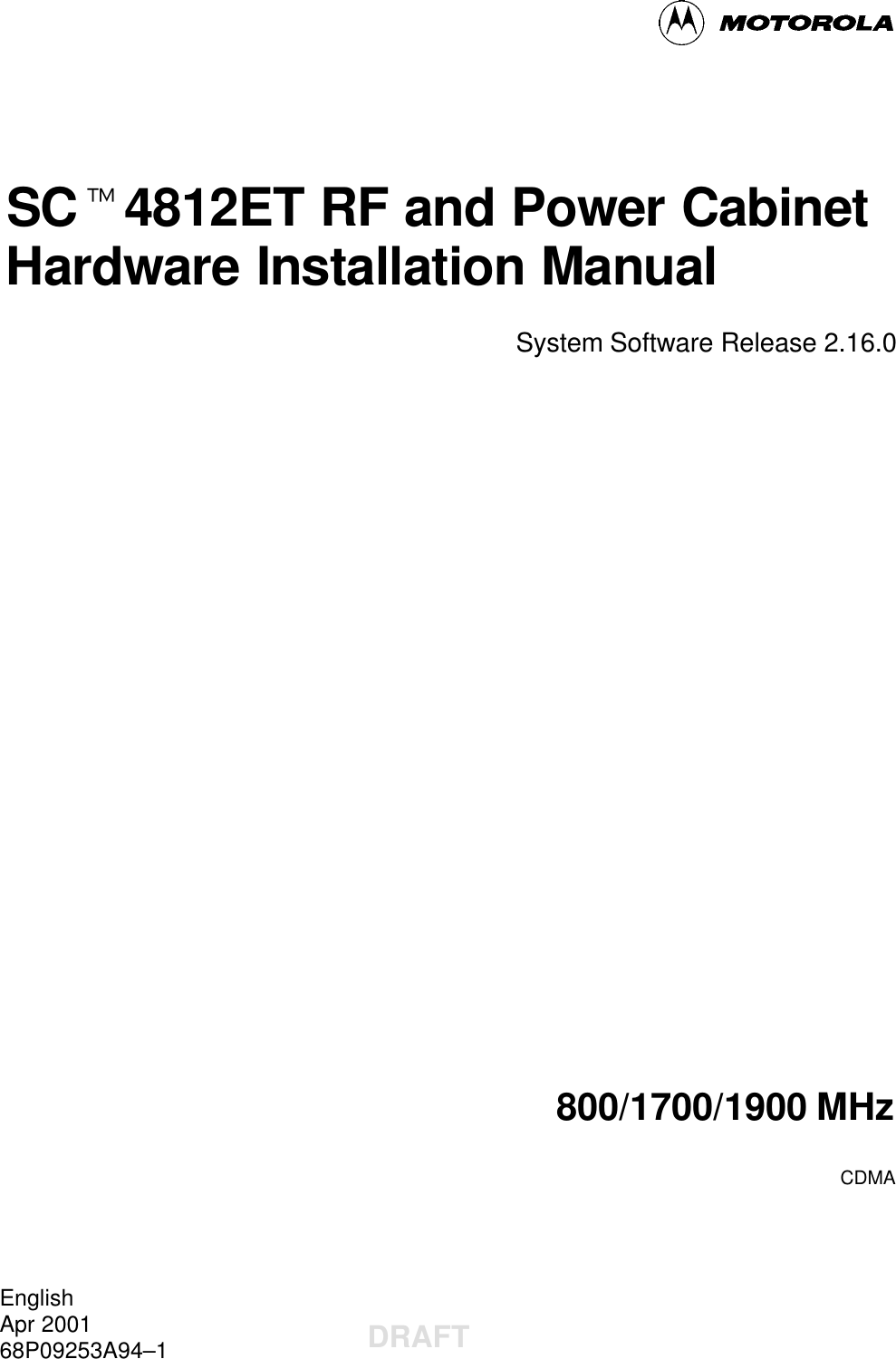
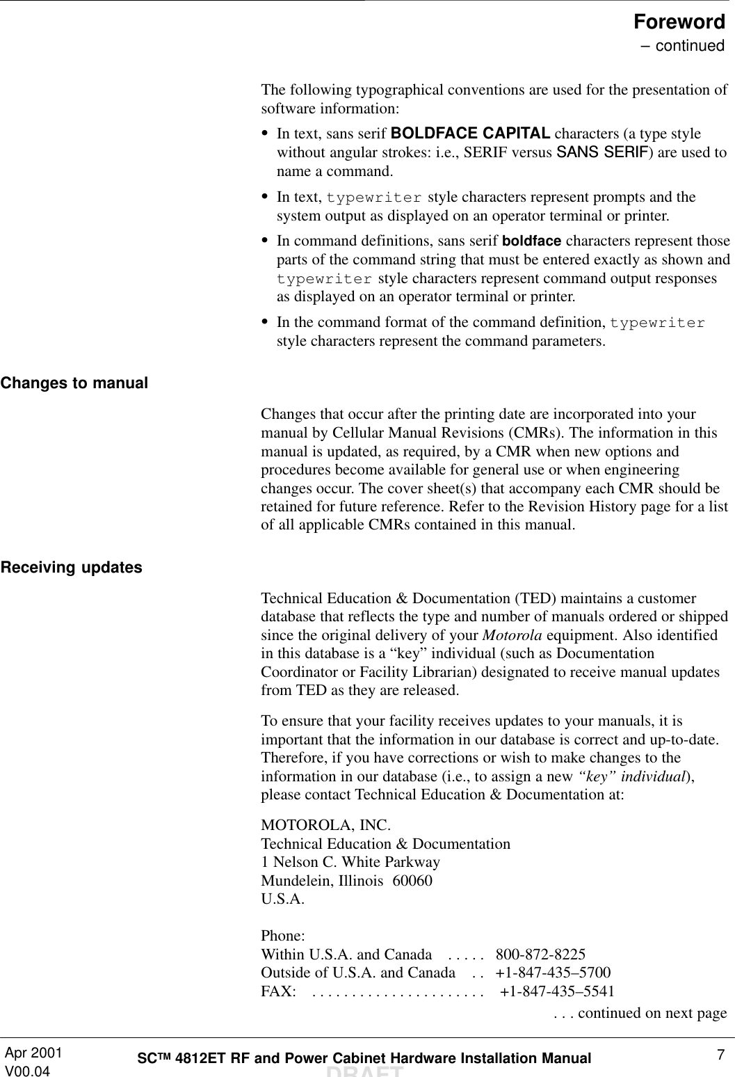
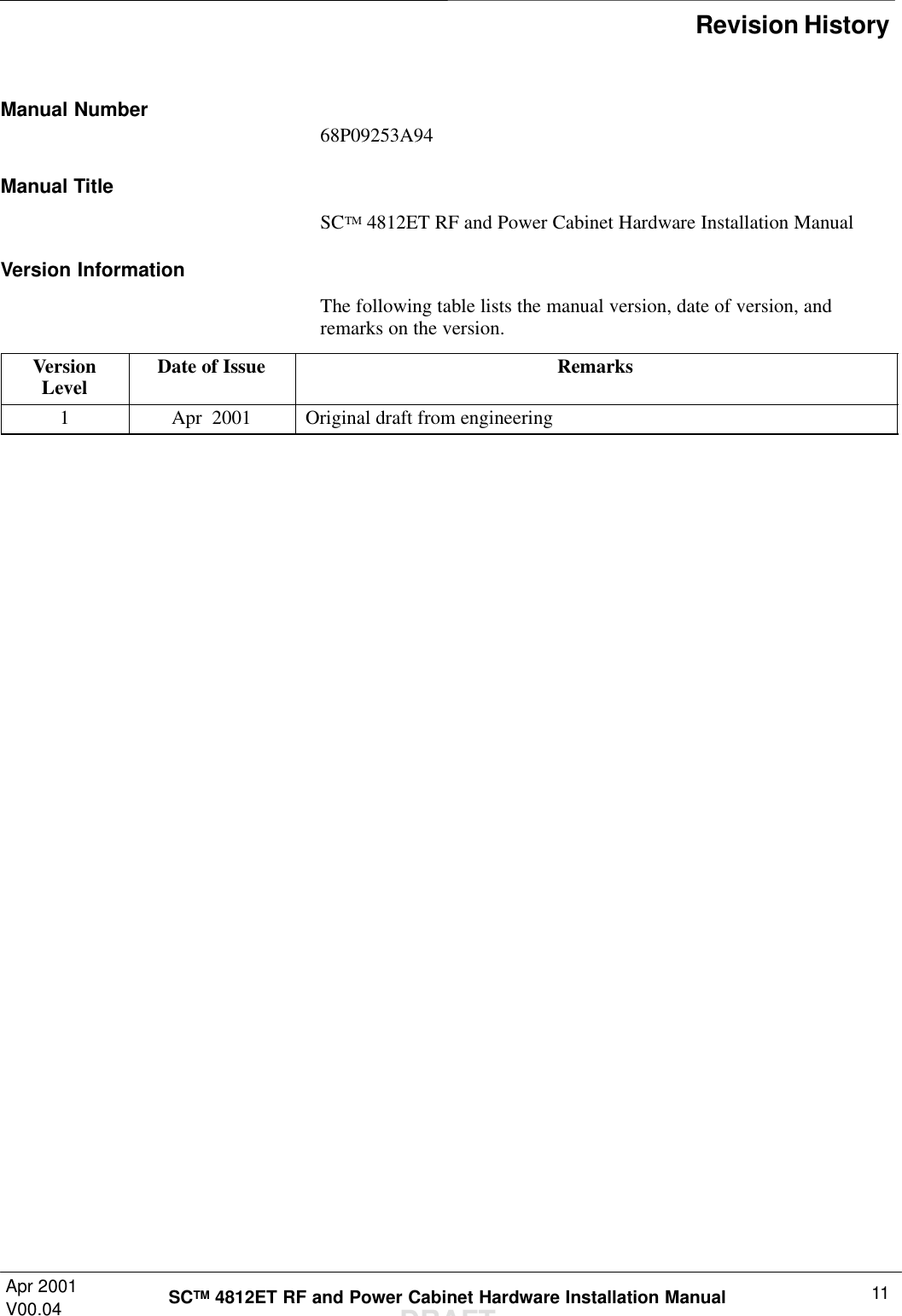
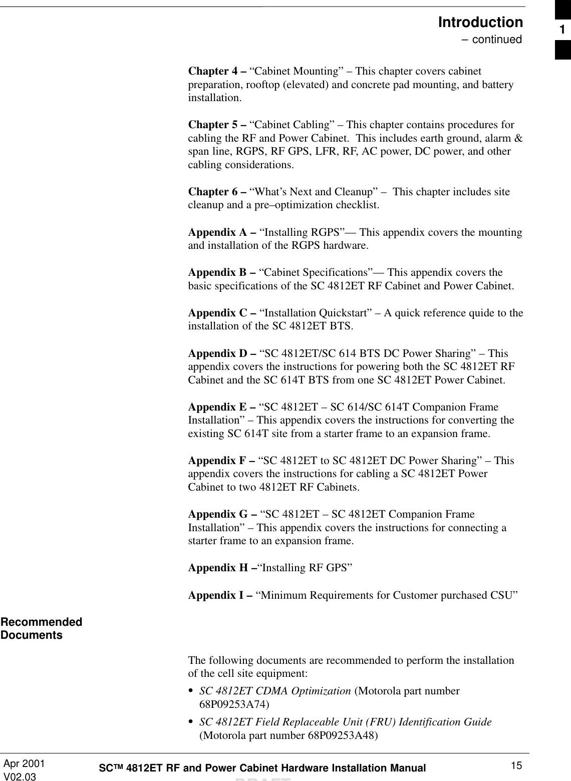
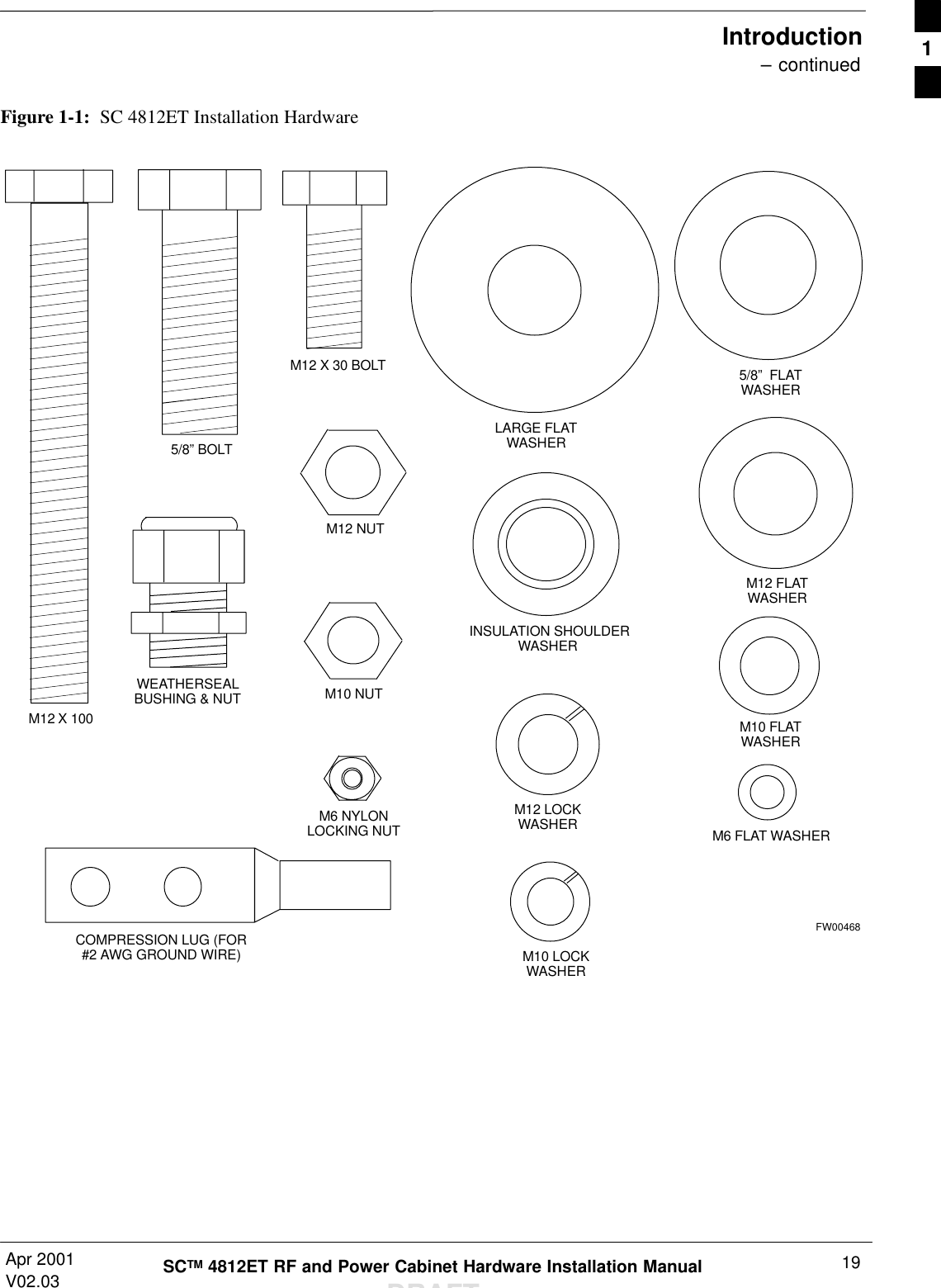
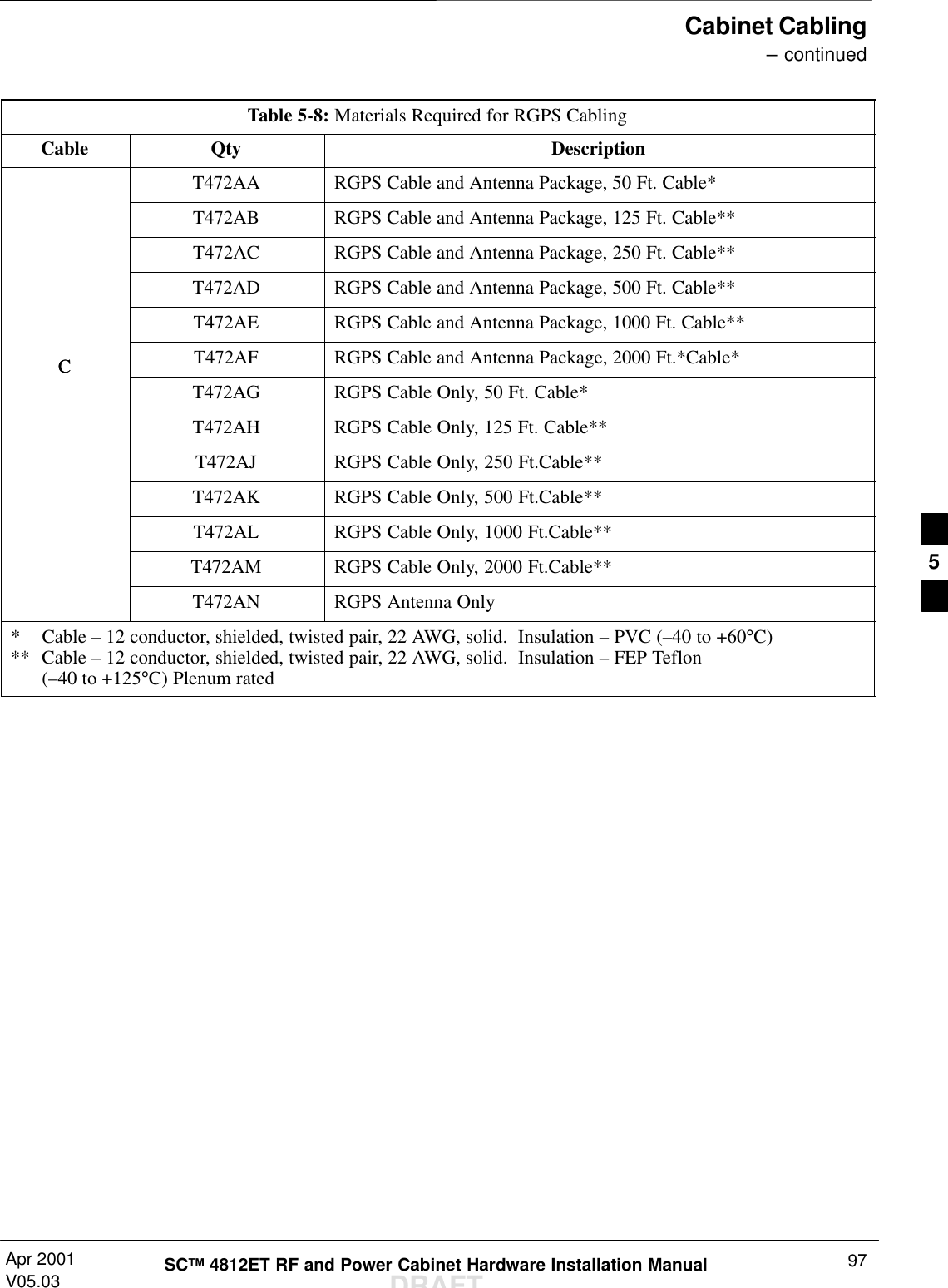
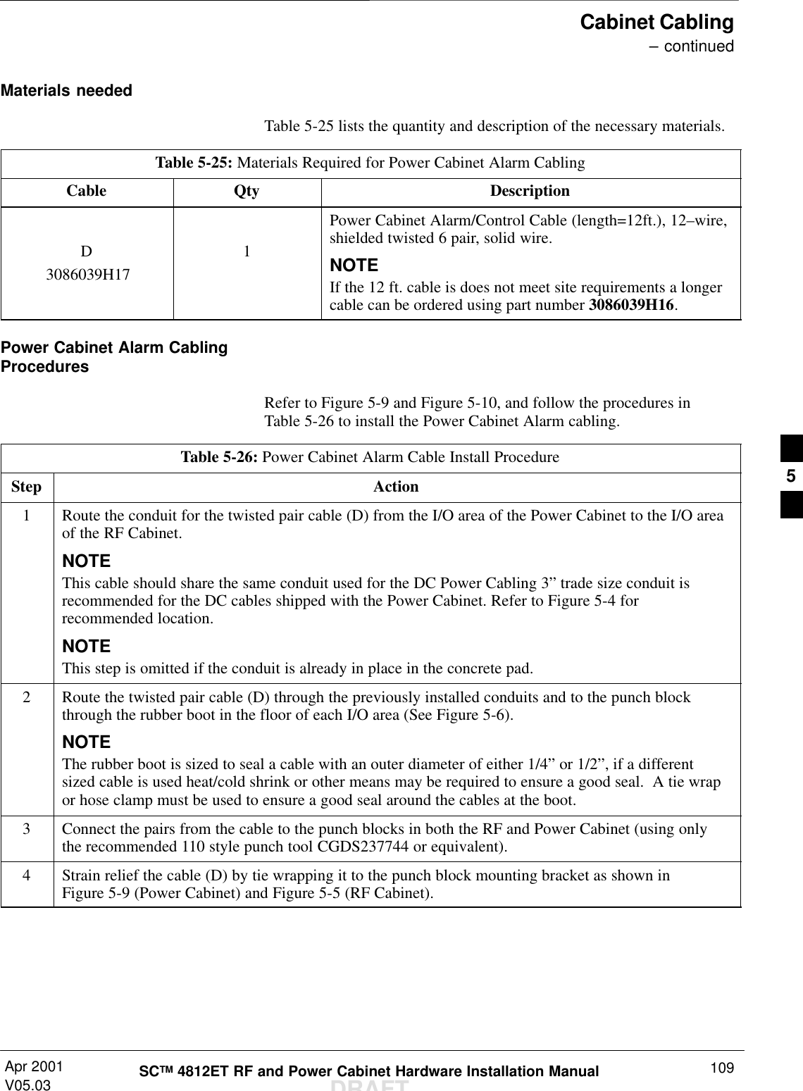
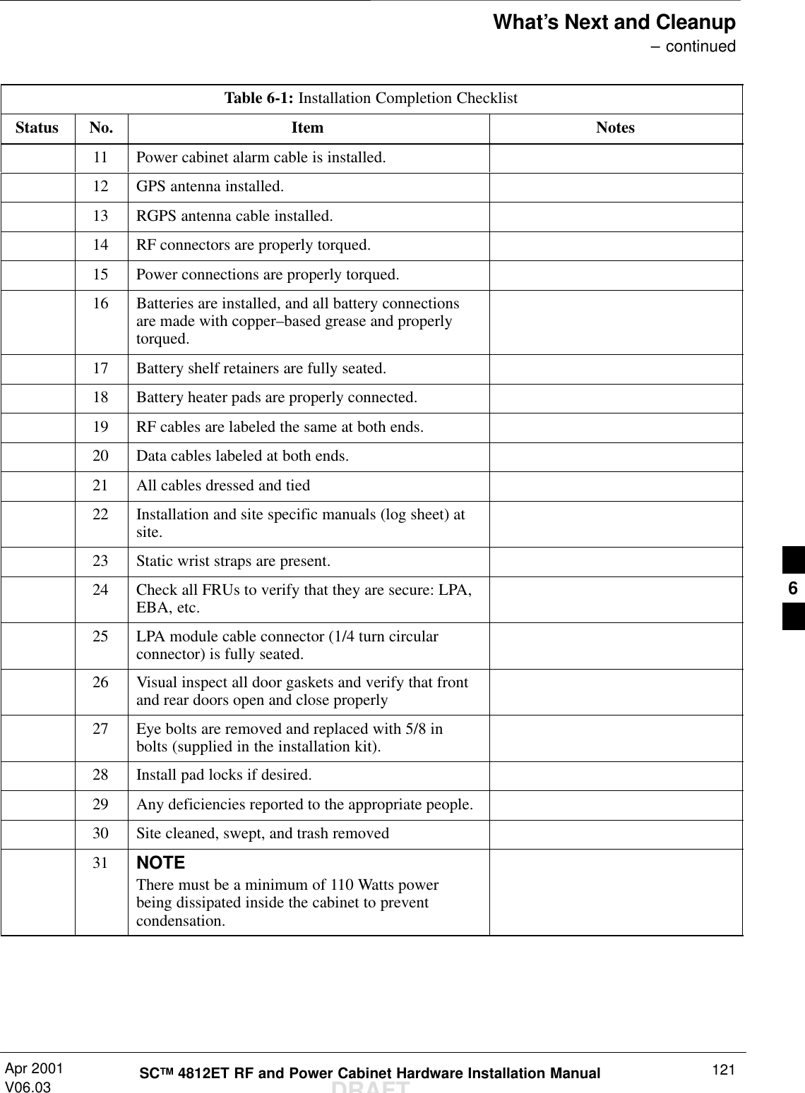
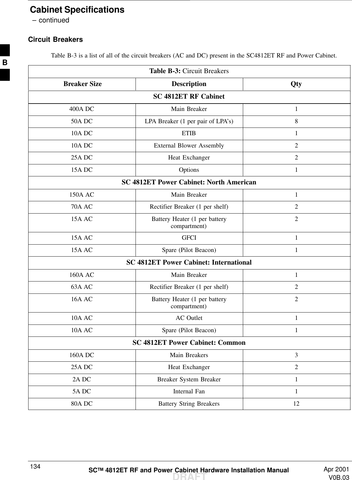
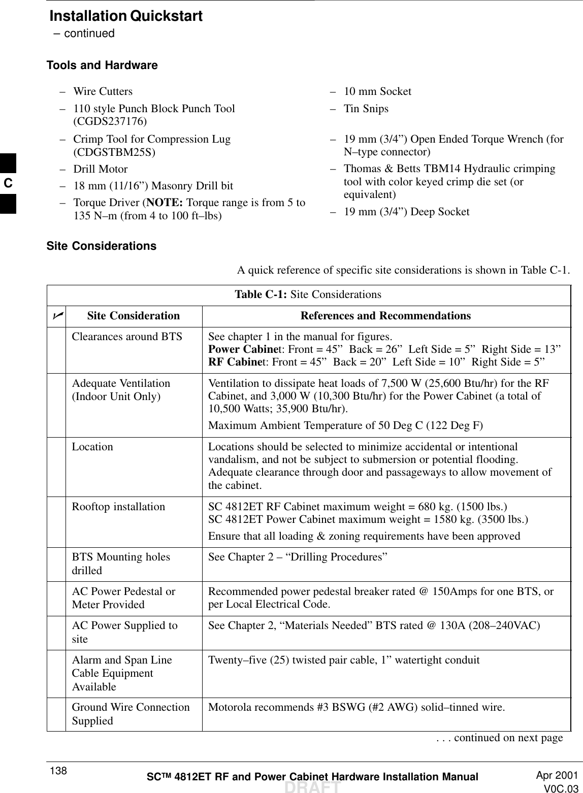
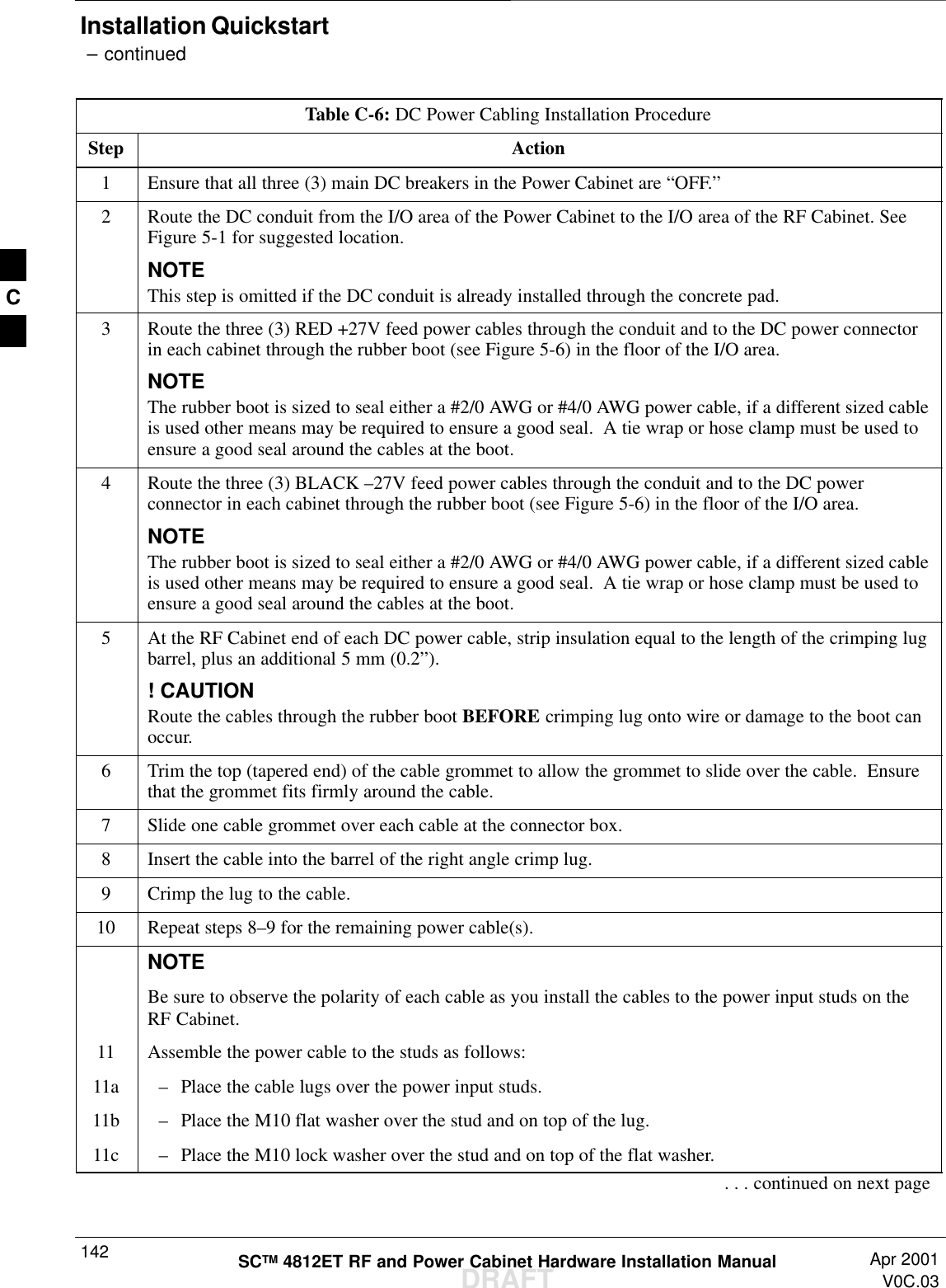
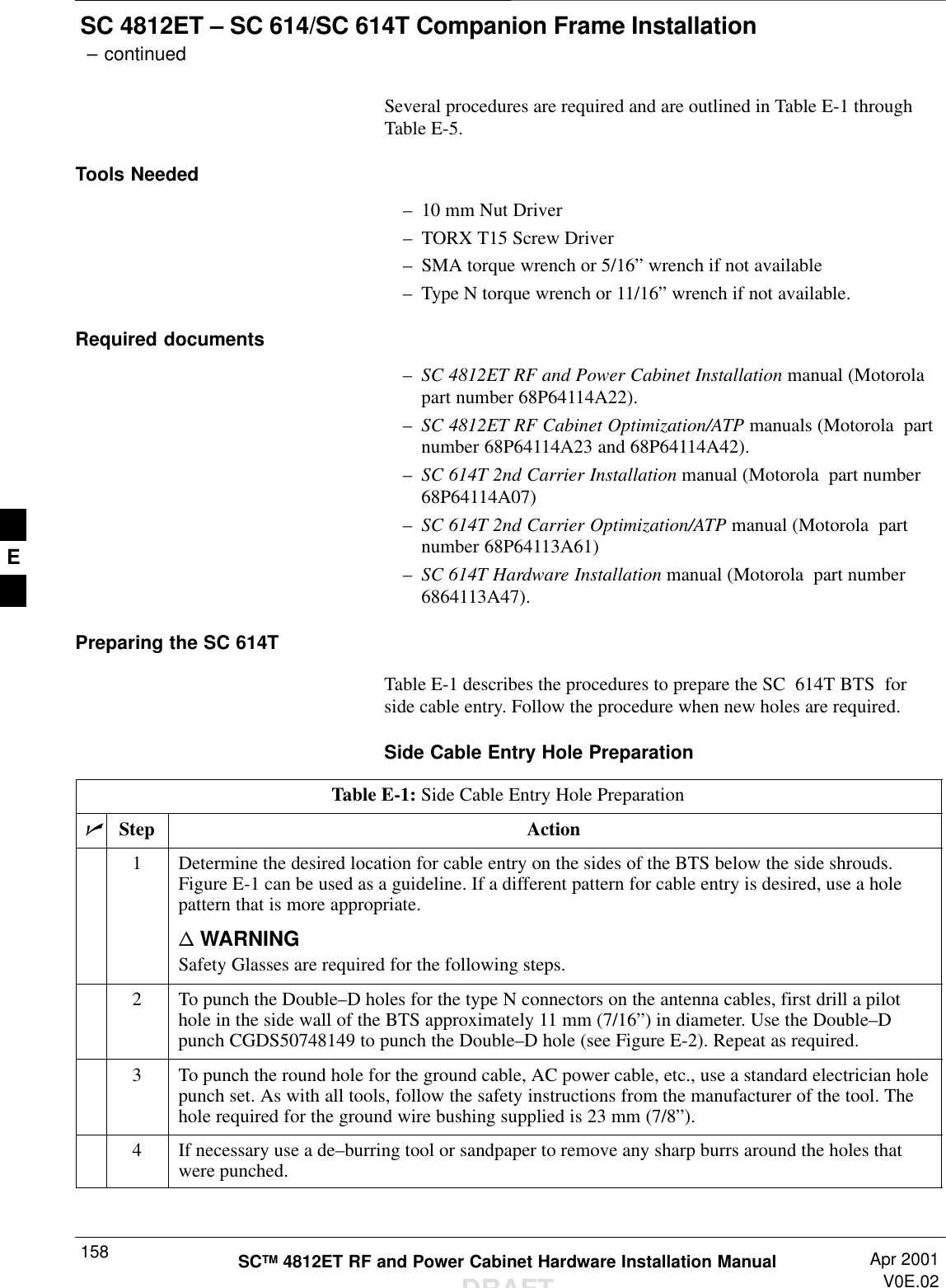
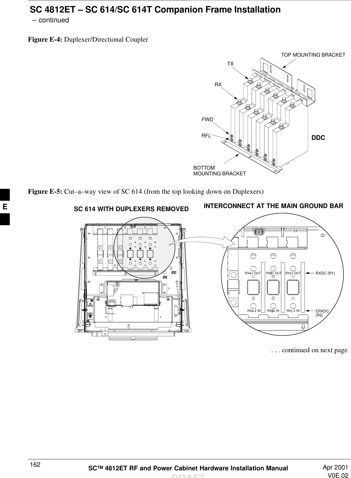
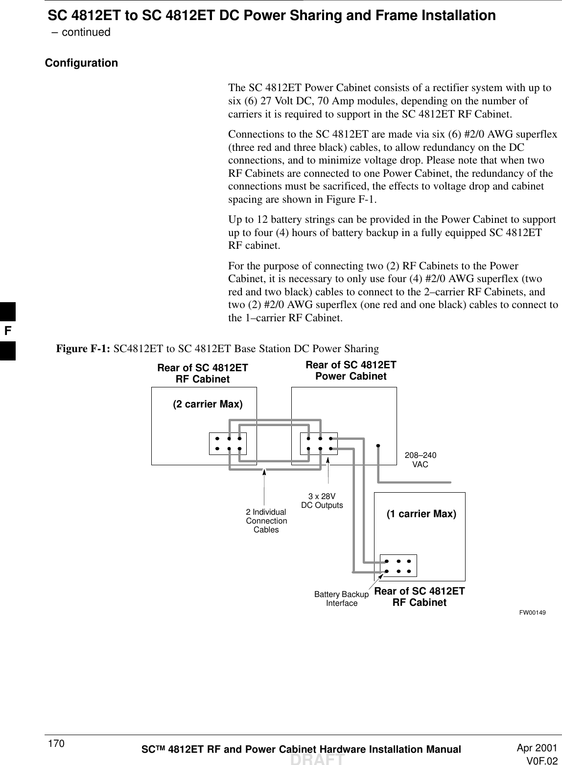
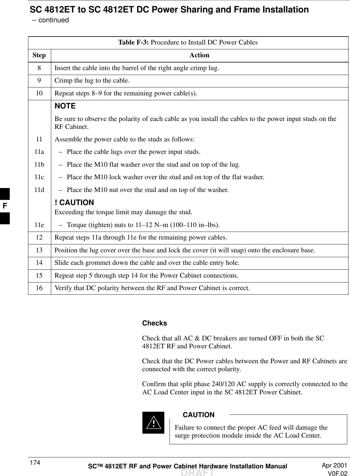
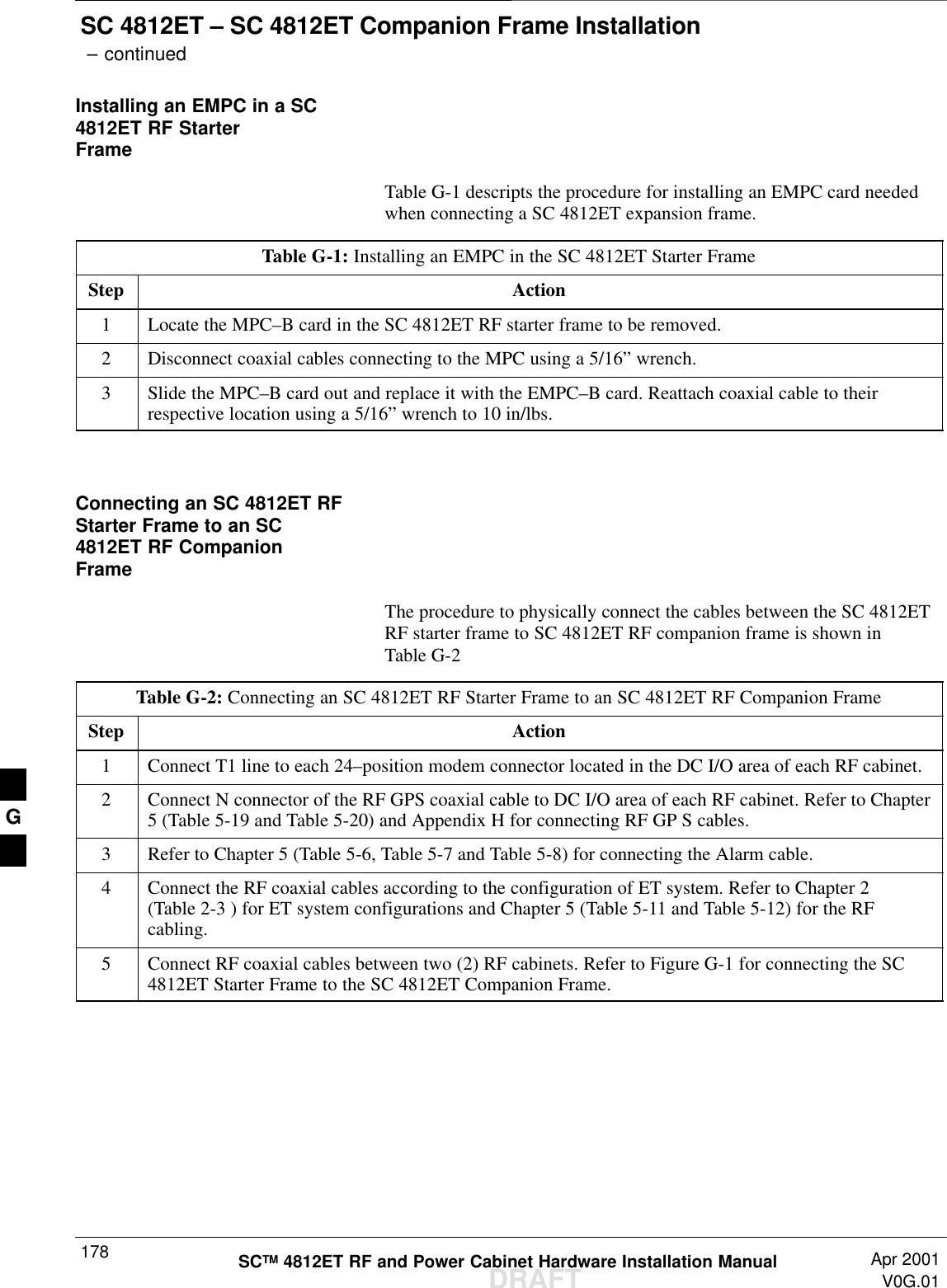
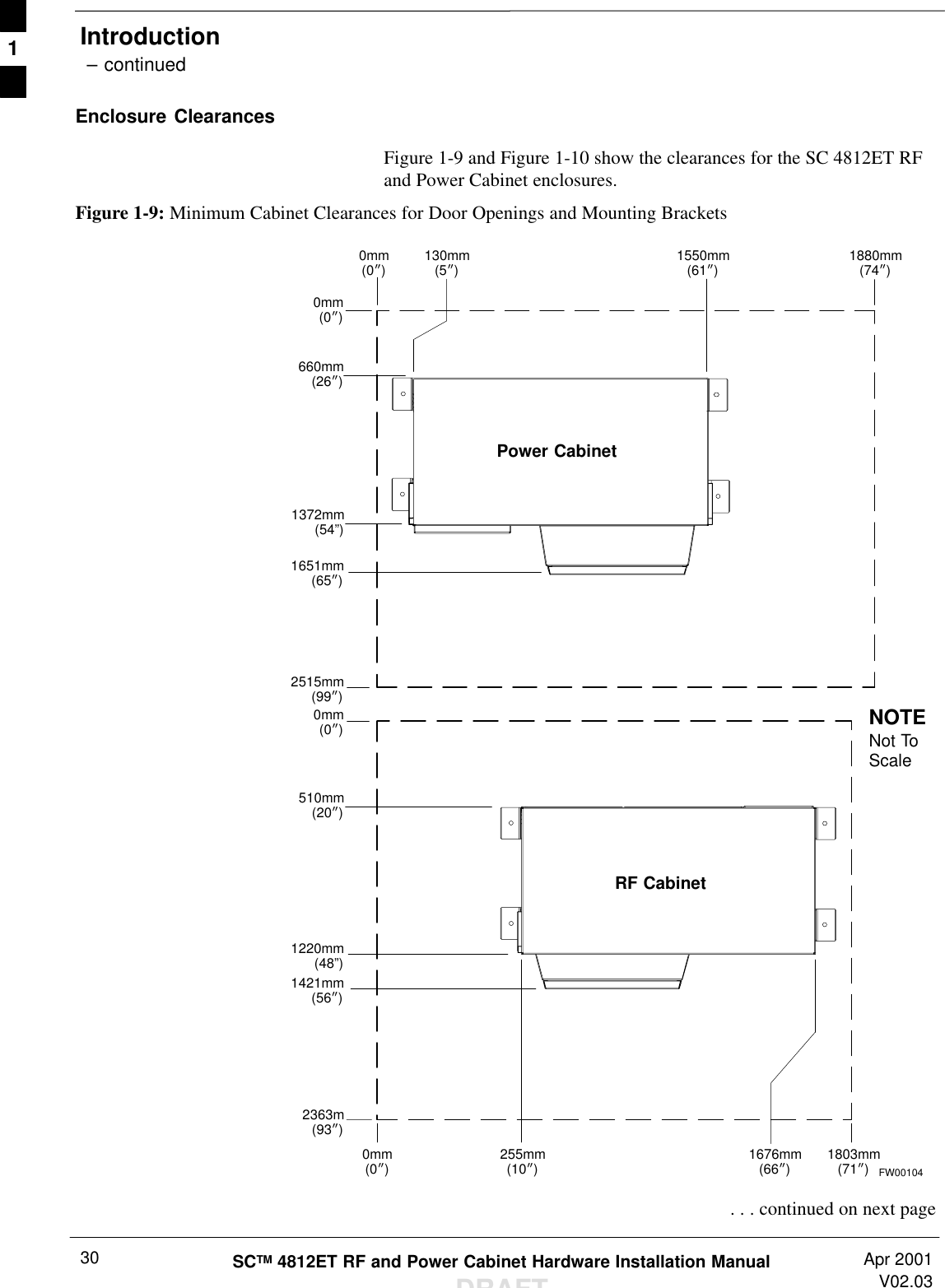
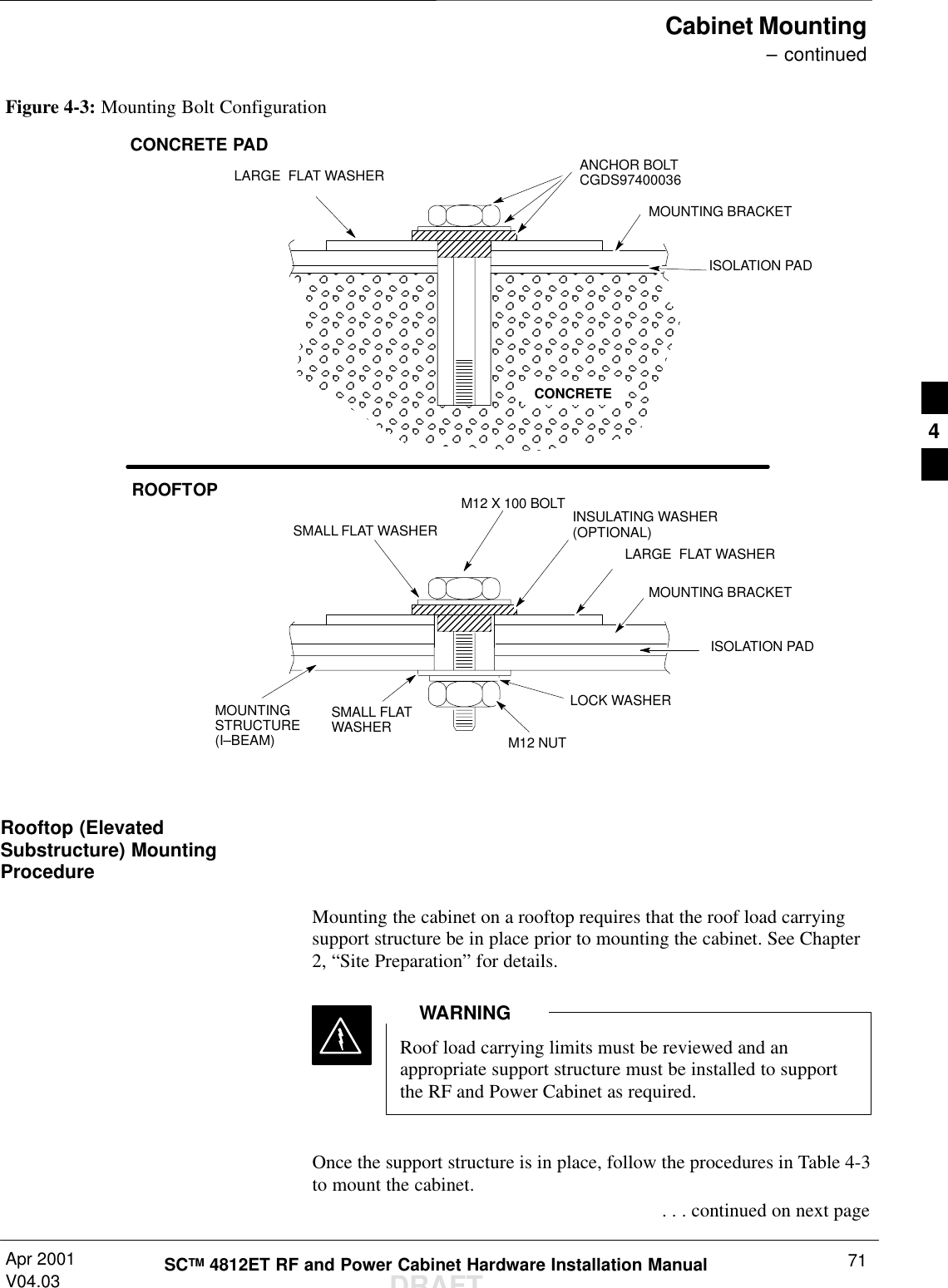
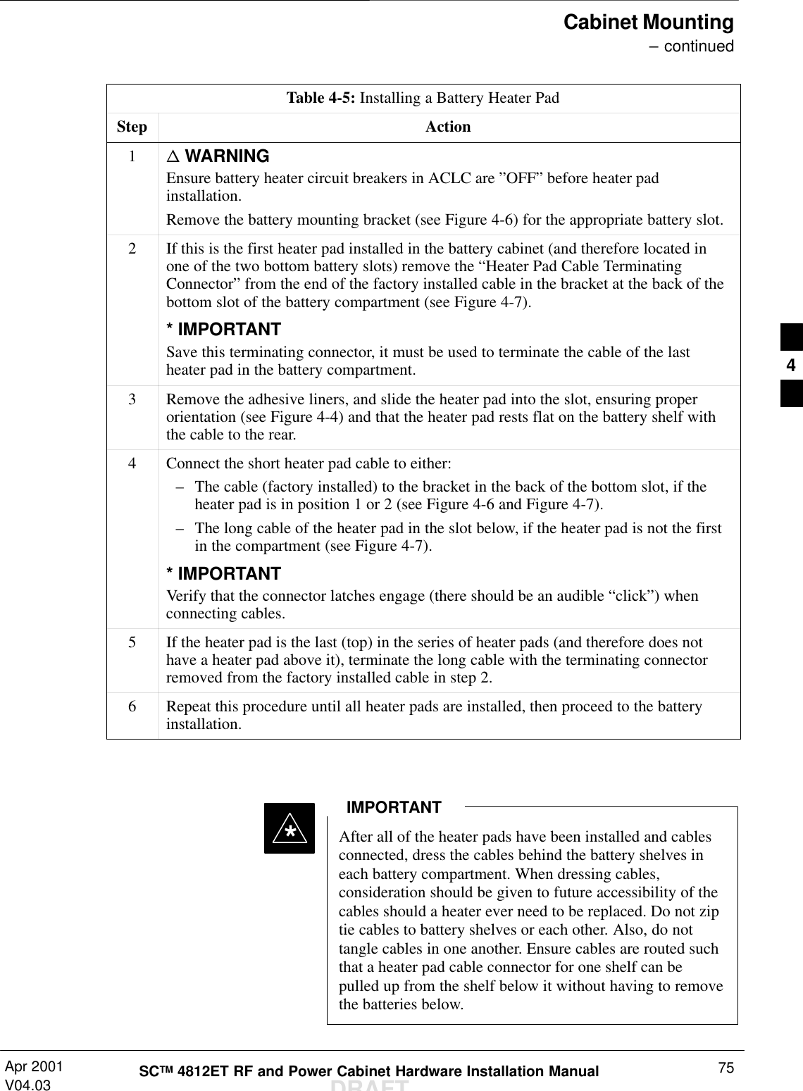
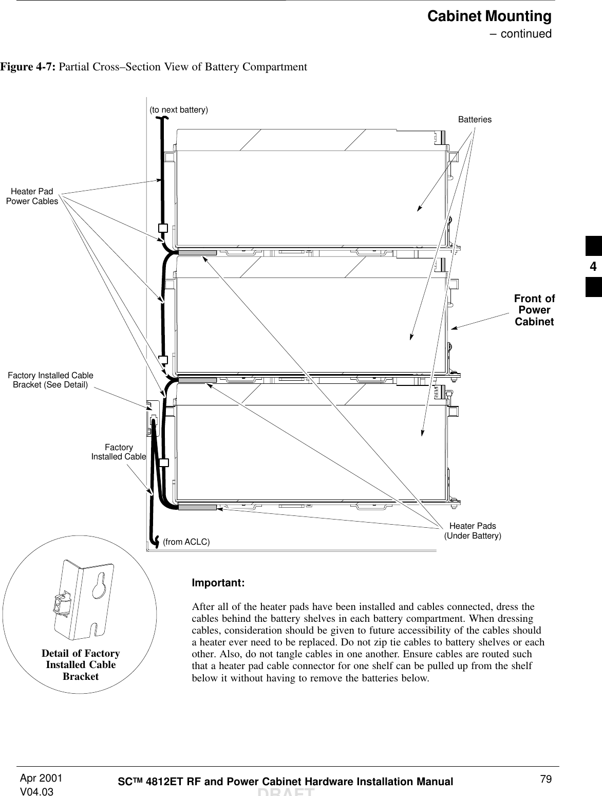
![Introduction – continuedSCTM 4812ET RF and Power Cabinet Hardware Installation ManualDRAFTApr 2001V02.0320Recommended ToolsTable 1-3 lists tools recommended for installing RF and Power Cabinets.Table 1-3: Recommended ToolsItem Tool Description1Tin Snips2Wire Brush3Knife or Scissors410 mm Nut Driver519 mm (3/4”) Open ended Torque Wrench (for N–typeconnector)6110 Style Punch Block Termination Tool7Thomas & Betts TBM14 Hydraulic crimping tool with colorkeyed crimp die set (or equivalent)8Drill Motor918 mm (11/16”) Masonry Drill Bit10 Ratchet Handle with 19 mm (3/4”) Socket (Deep Socket orRatchet Extension required).11 Torque Driver (Torque Range: 5–135 N–m [4–100 ft–lbs])with 19 mm (3/4”) and 10 mm Socket12 Torque wrench for SMA’s Mountz Inc. MTBN2 (Part number020314) with 5/16” open end head (Part number 020402).13 Copper–based Conductive Grease (Berndy “Penetrox” orequivalent). 1](https://usermanual.wiki/Nokia-Solutions-and-Networks/T6BM1/User-Guide-162010-Page-20.png)
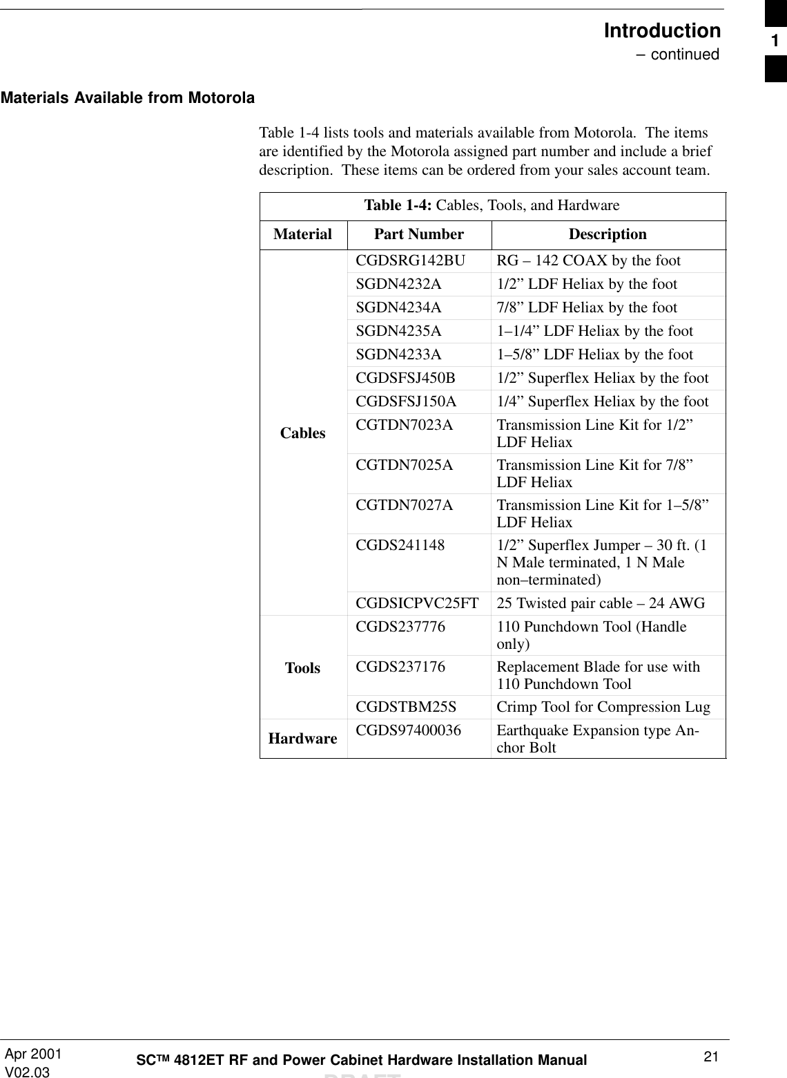
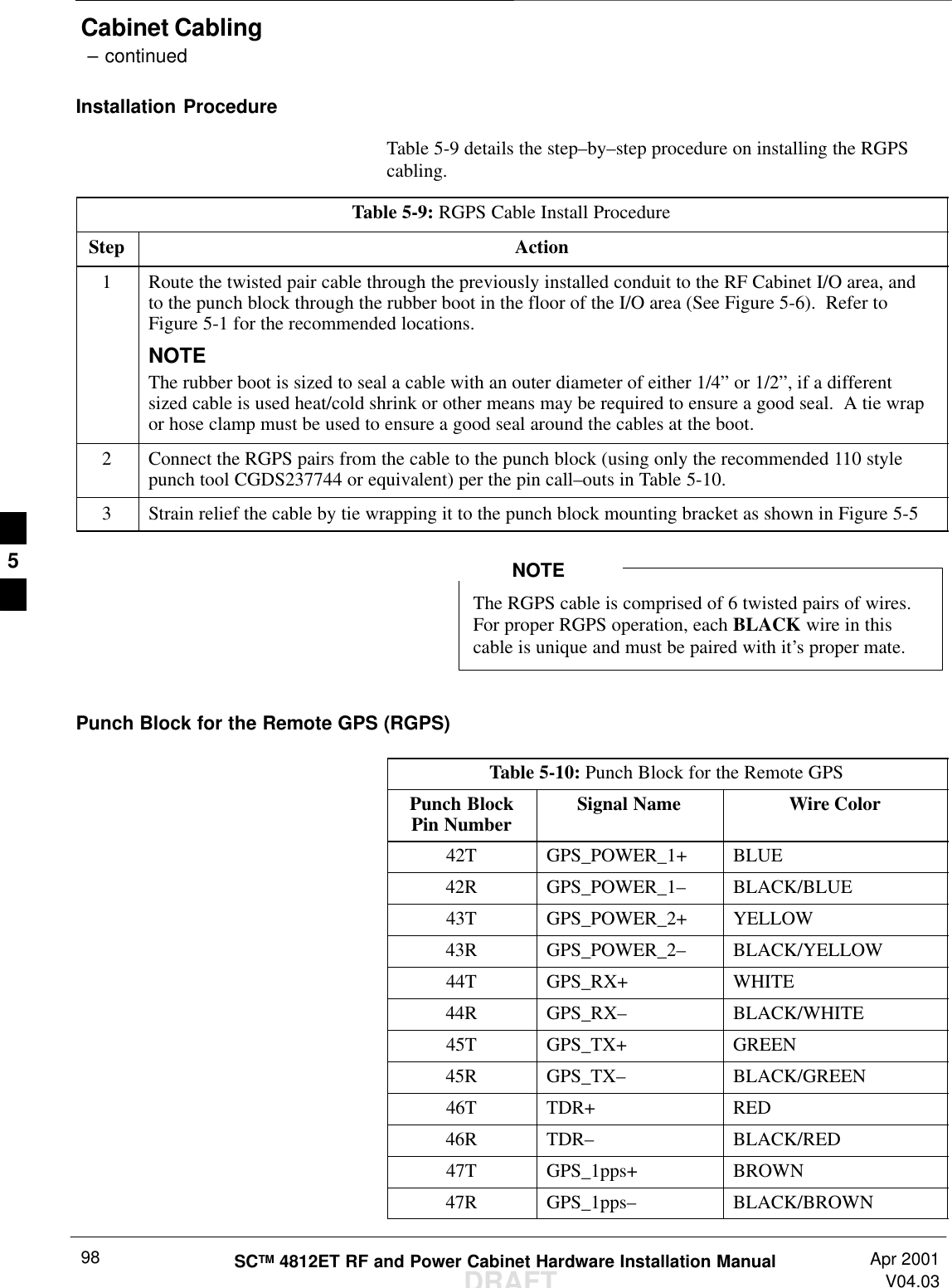
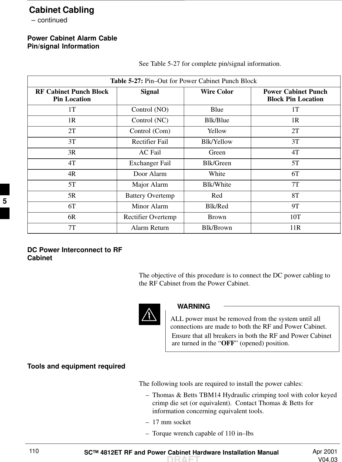
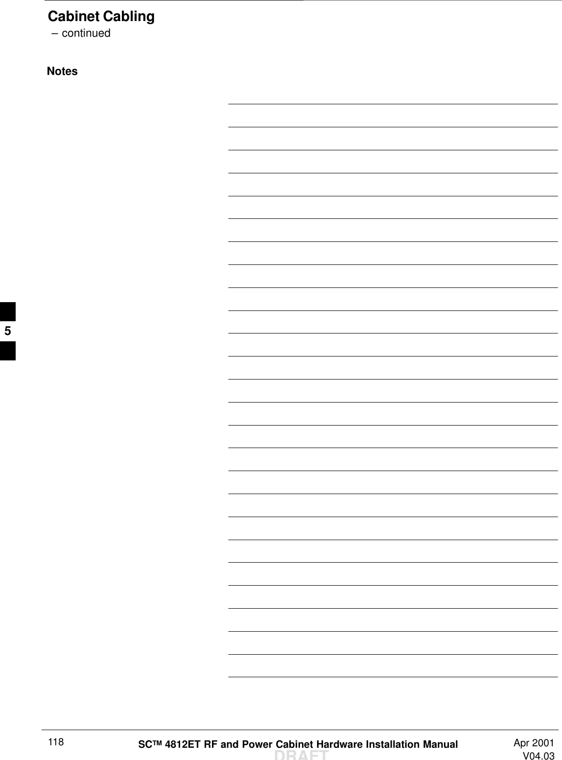
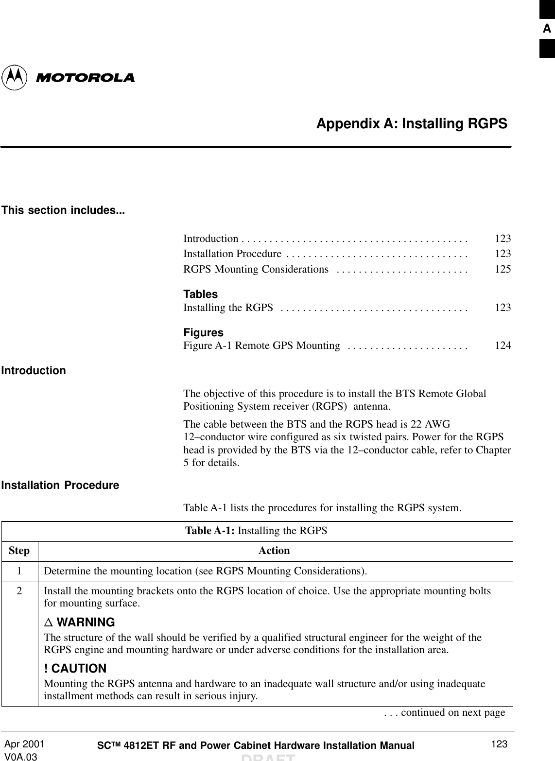
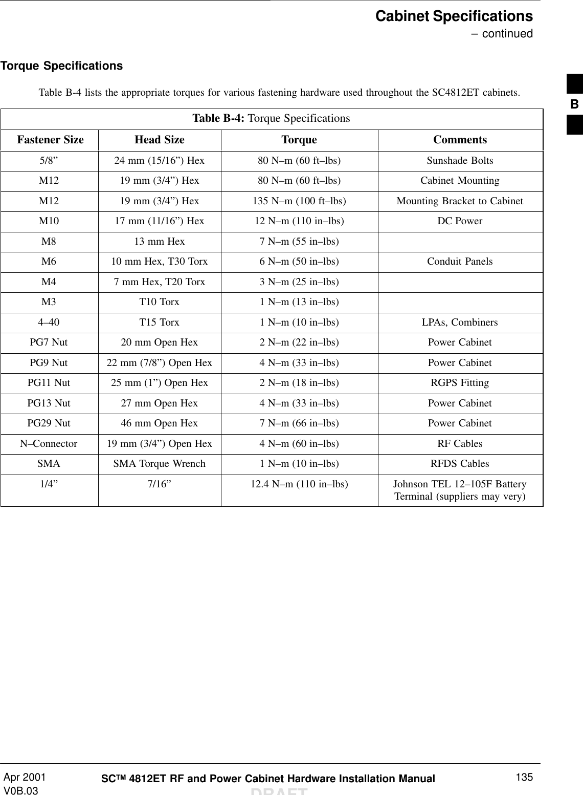
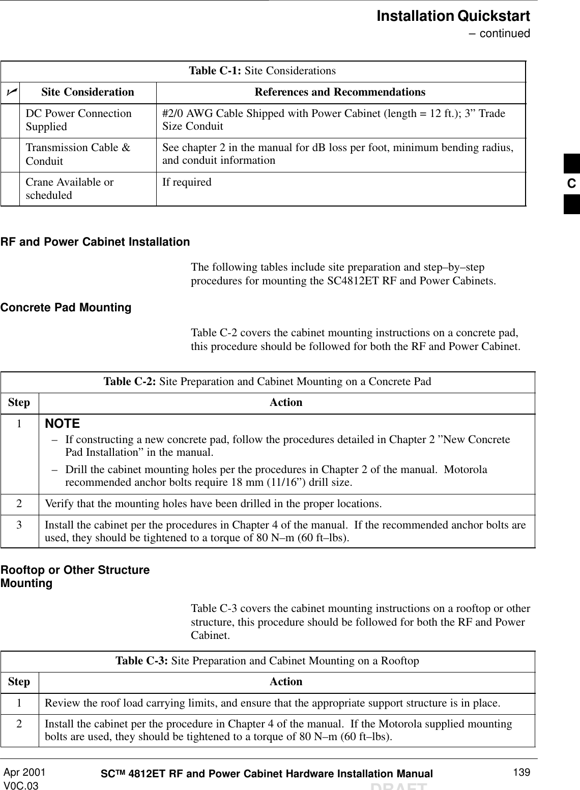
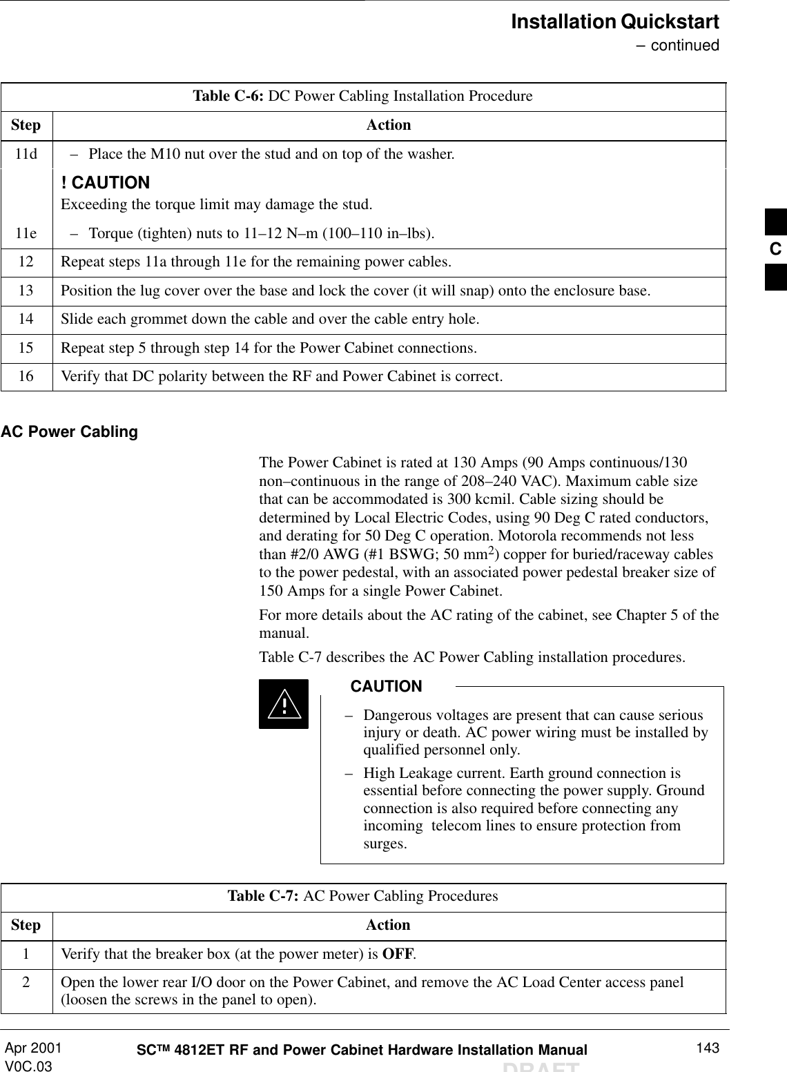
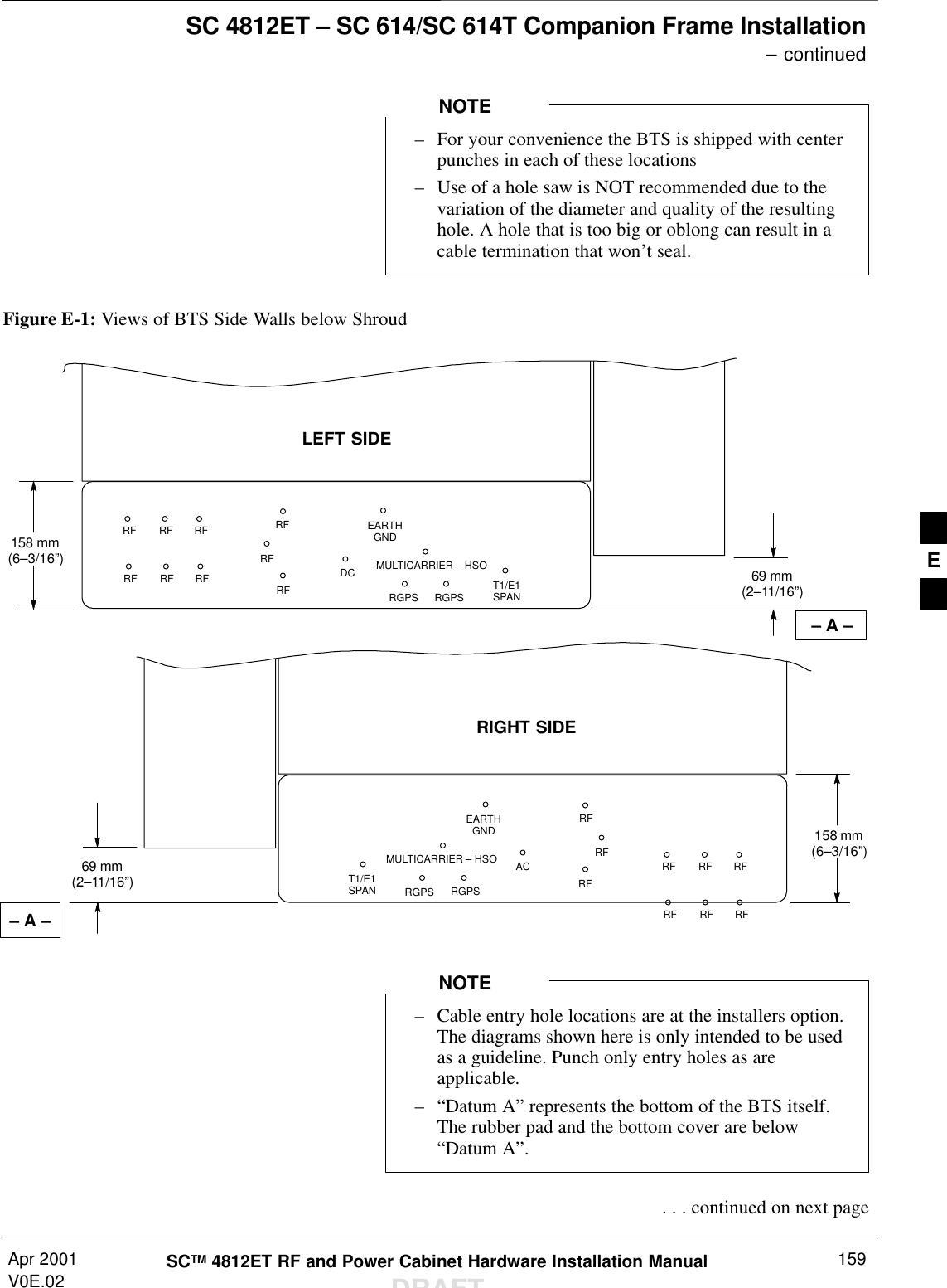
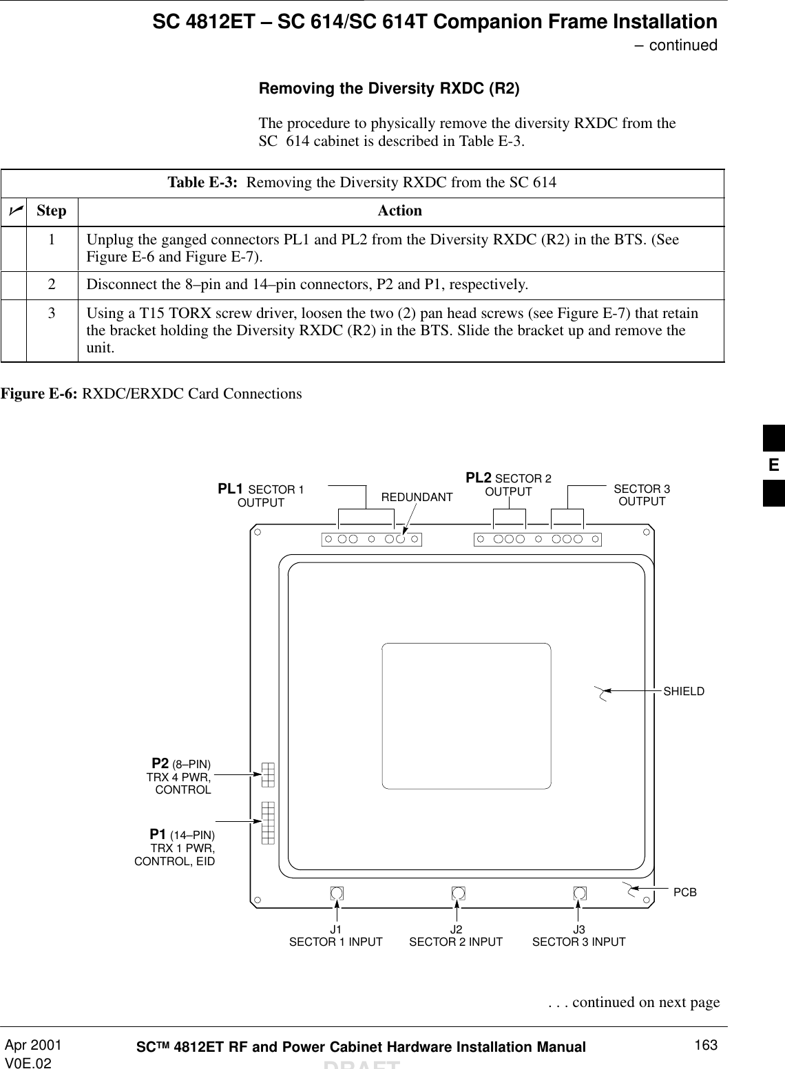
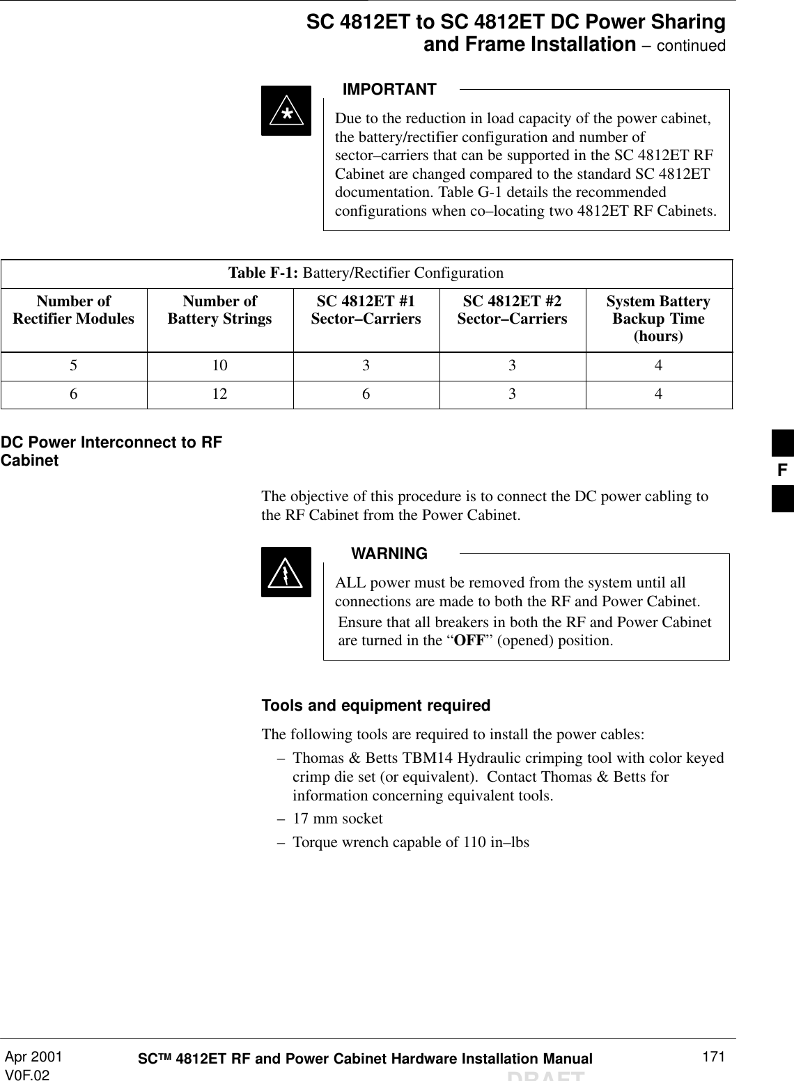
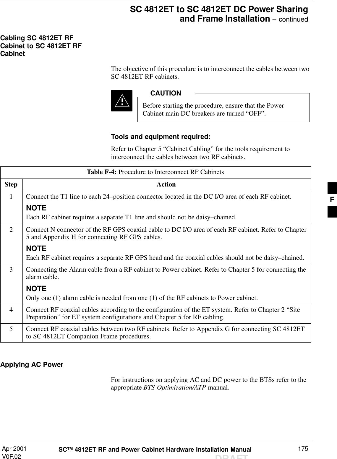
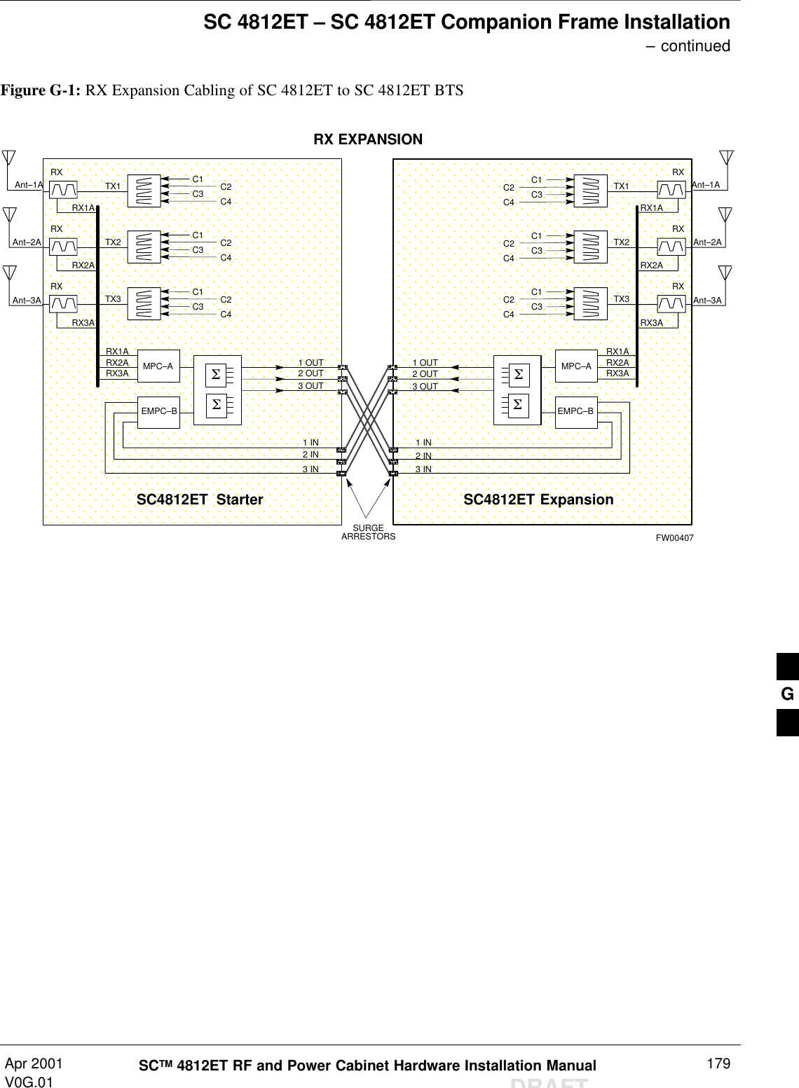
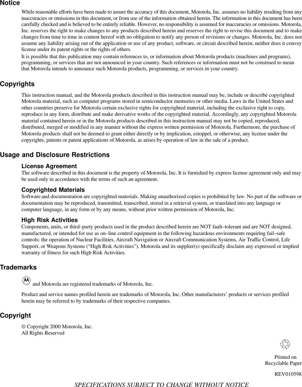
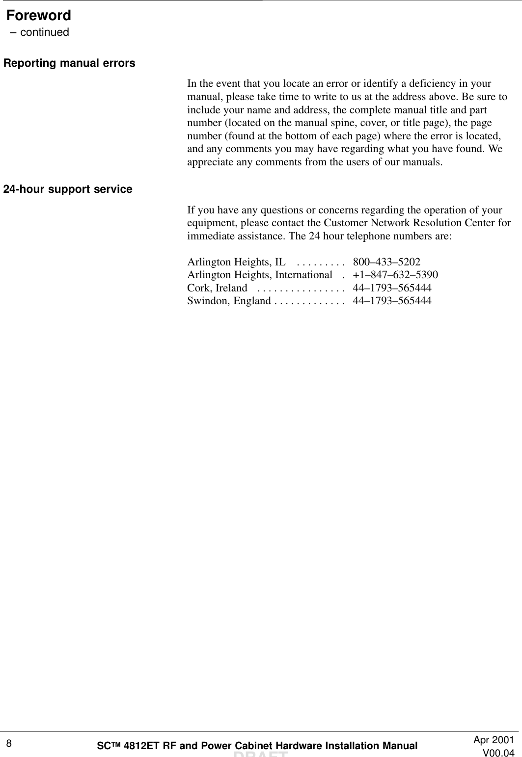
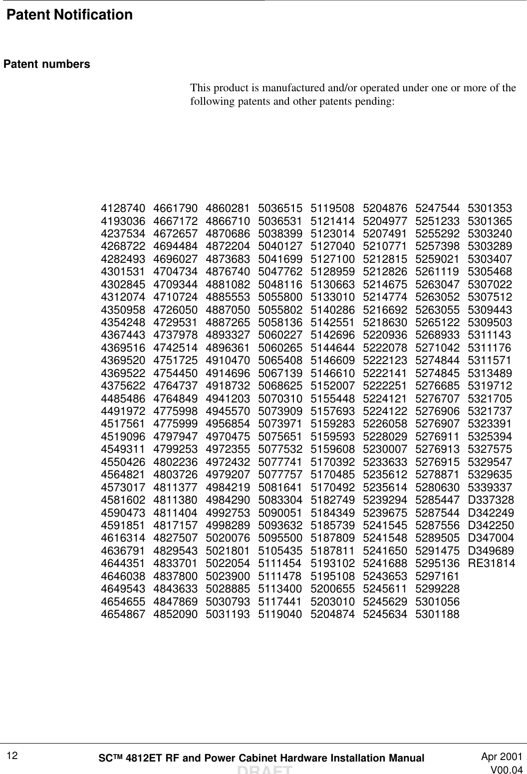
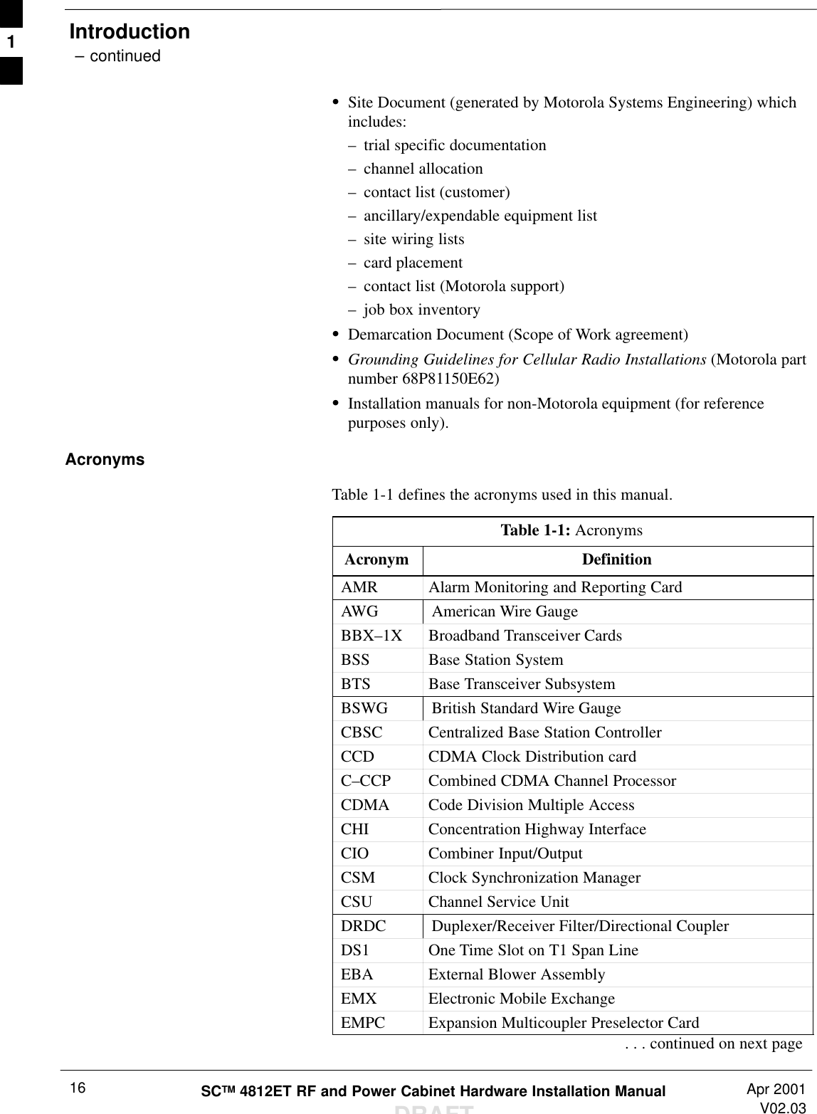
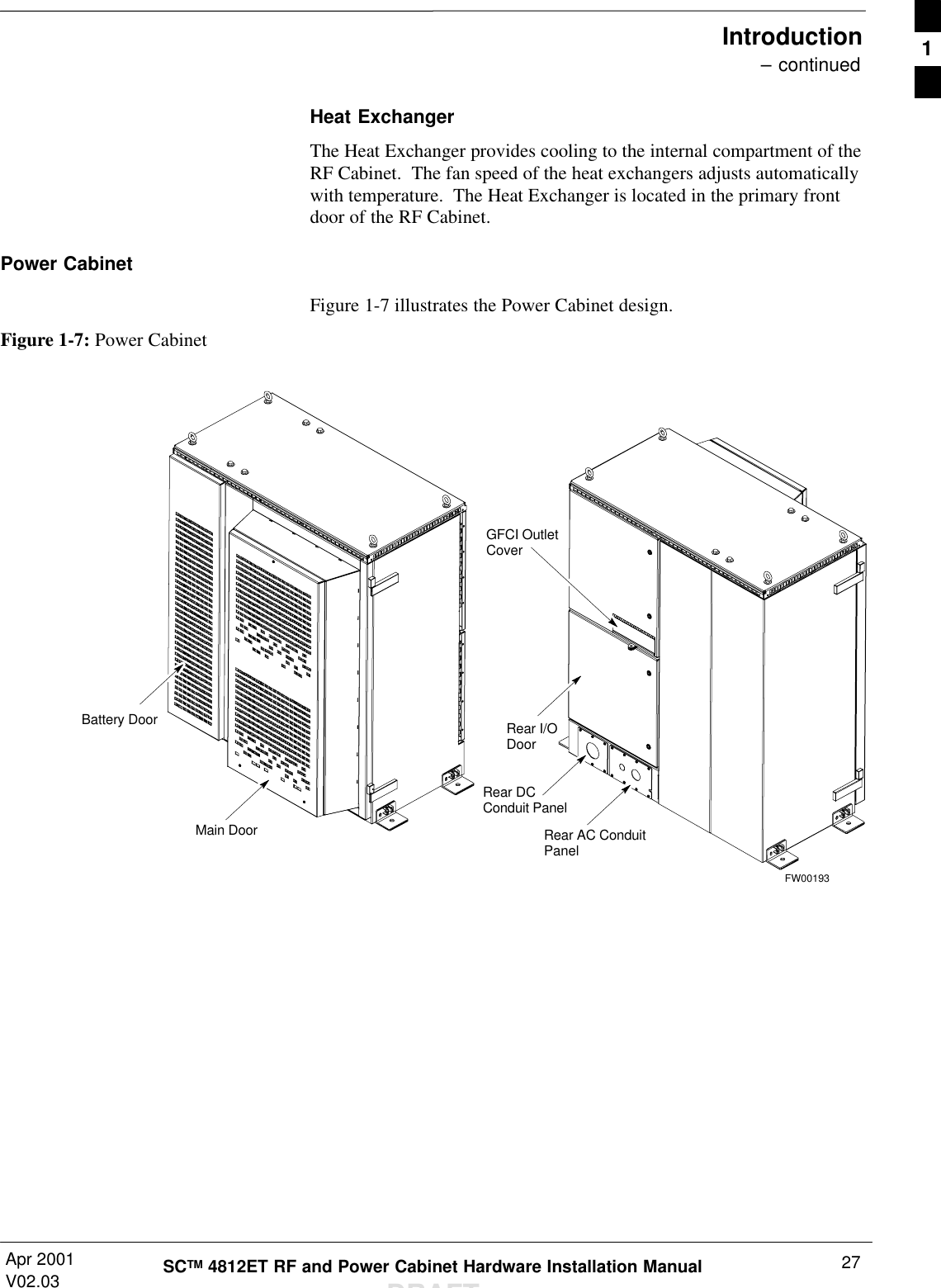
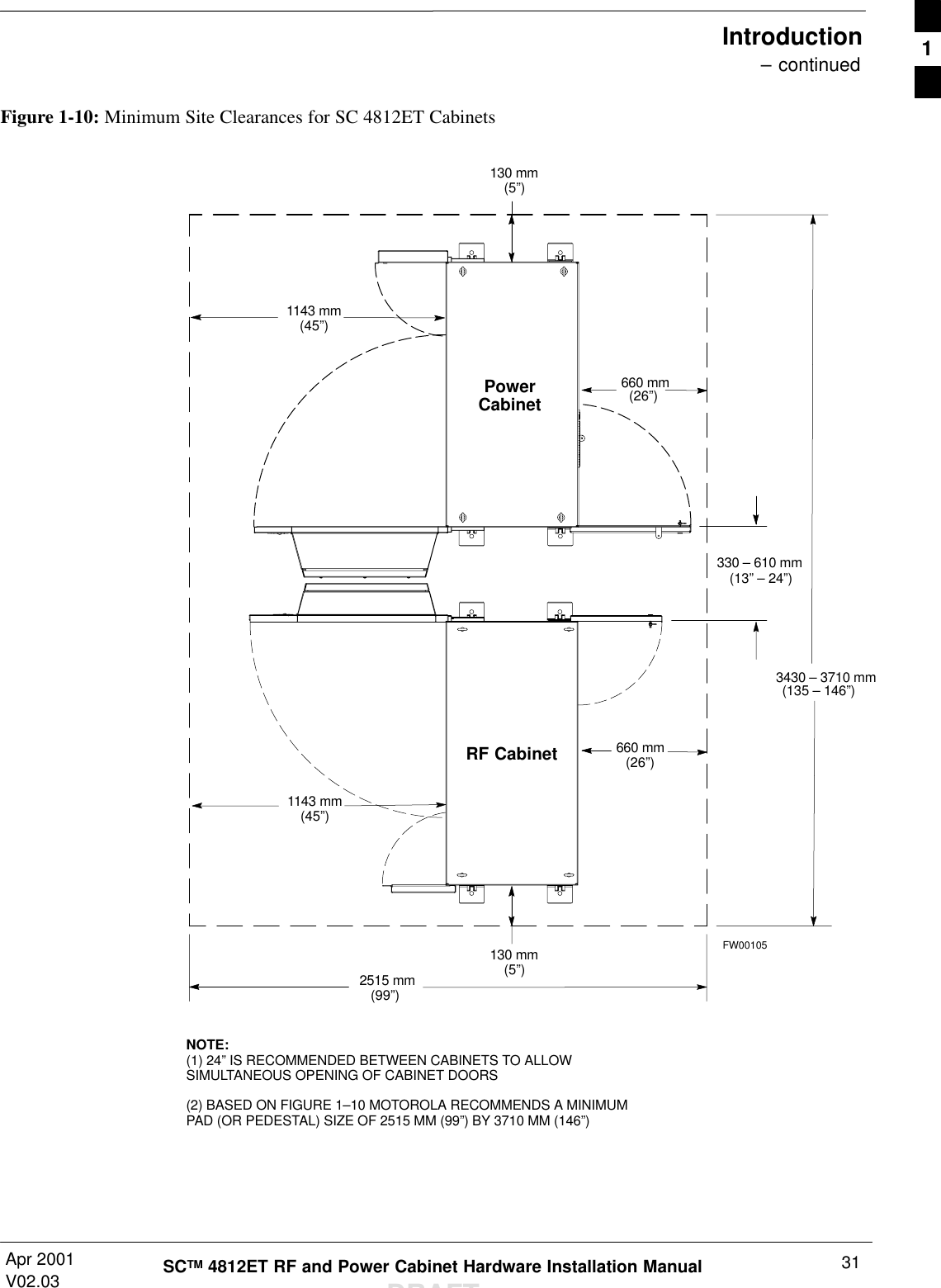
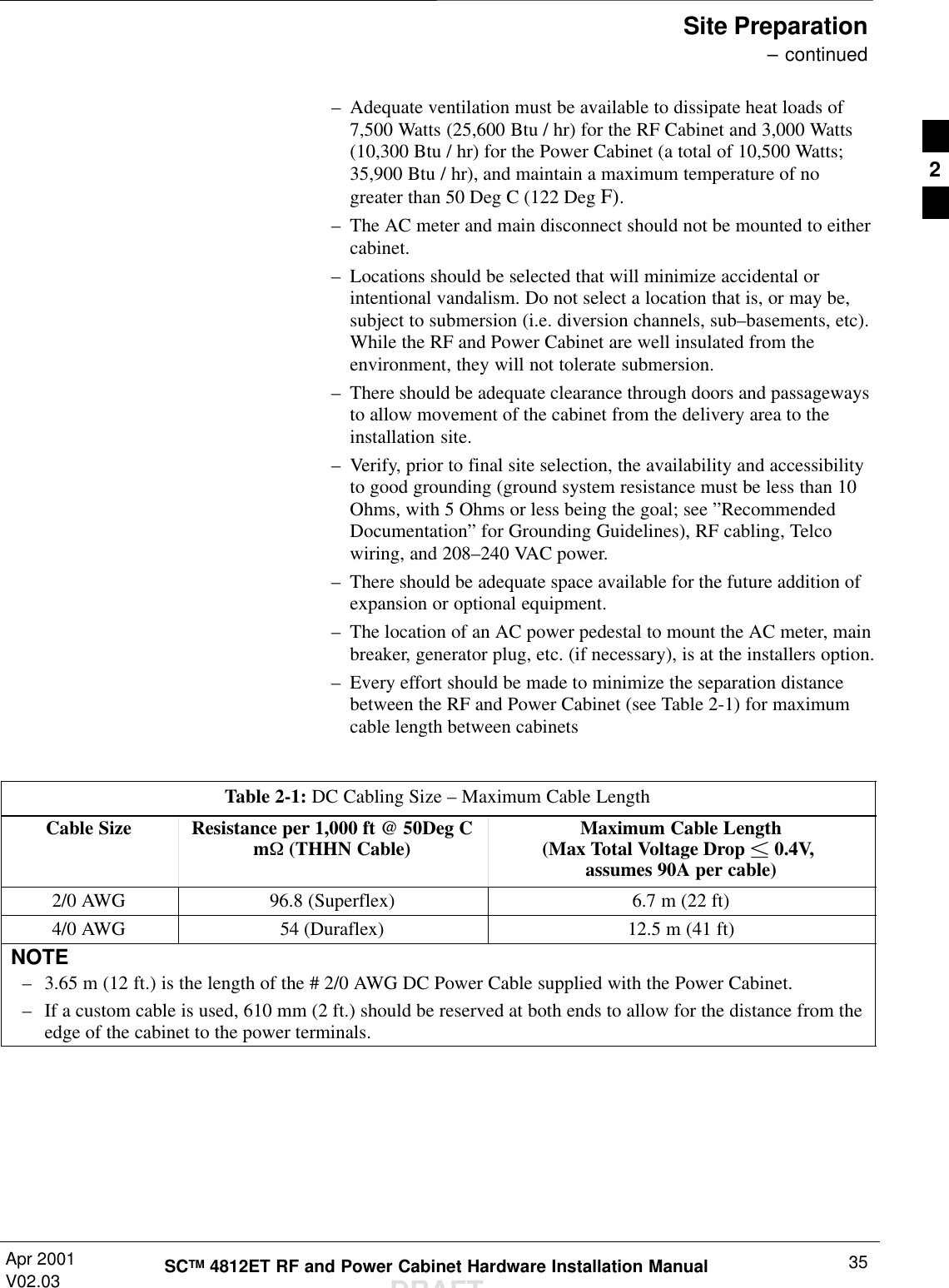
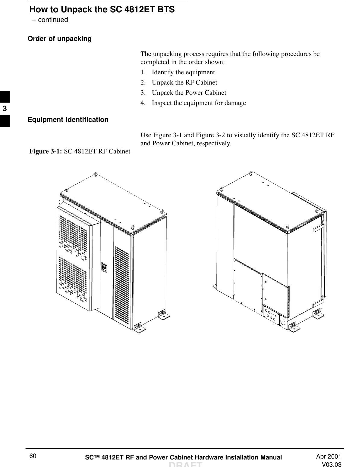
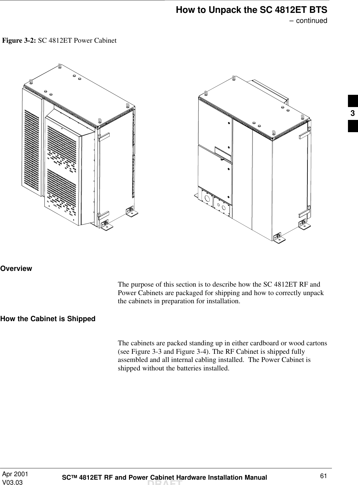
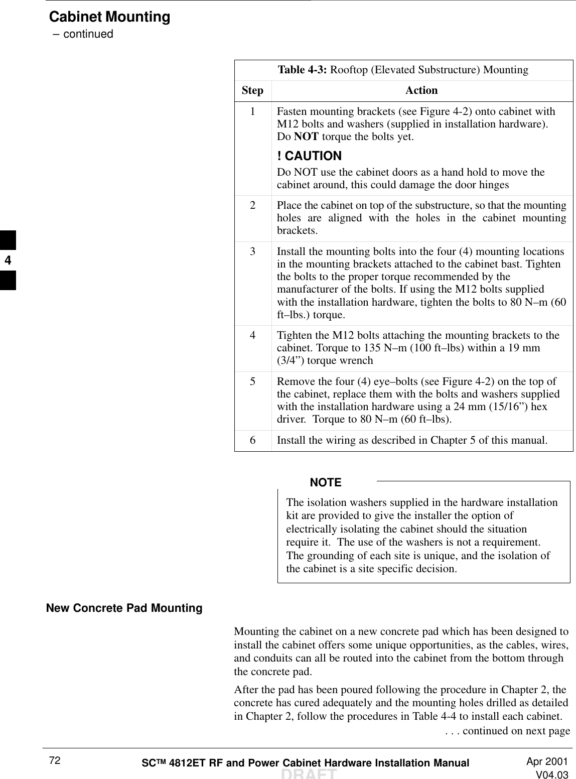
![Introduction – continuedSCTM 4812ET RF and Power Cabinet Hardware Installation ManualDRAFTApr 2001V02.0322OverviewThe major components which make up the Motorola SC 4812ET RFCabinet (see Figure 1-2) and Power Cabinet (see Figure 1-7) system areillustrated in this section.A service tent [reference: Pelsue Cabinet Mounted ServiceTent; Pelsue (800–525–8460) P/N CM564866M] must bein place prior to opening the main doors of the SC 4812ETRF or Power Cabinet during times of inclement weather(rain, snow, sleet, or hail). This will prevent moisture frombeing drawn into the electronics by internal fans anddamaging the equipment.A service tent [reference: Pelsue Cabinet Mounted ServiceTent; Pelsue (800–525–8460) P/N CM564866M] with aheater is required to service the SC 4812ET RF Cabinetwhen temperatures are below –10 degrees C (14 degreesF). Temperatures inside the tent should be above 0 degreesC (32 degrees F) prior to opening the main cabinet door.This will prevent a rapid temperature change to theelectronics which could result in site outage.CAUTIONFigure 1-2: SC 4812ET RF CabinetMain DoorLPA Door(Can only be opened after Main Door is open)RF I/OArea Cover PlateRear I/O DoorRear DC Conduit PanelRear Conduit PanelFW001891](https://usermanual.wiki/Nokia-Solutions-and-Networks/T6BM1/User-Guide-162010-Page-22.png)
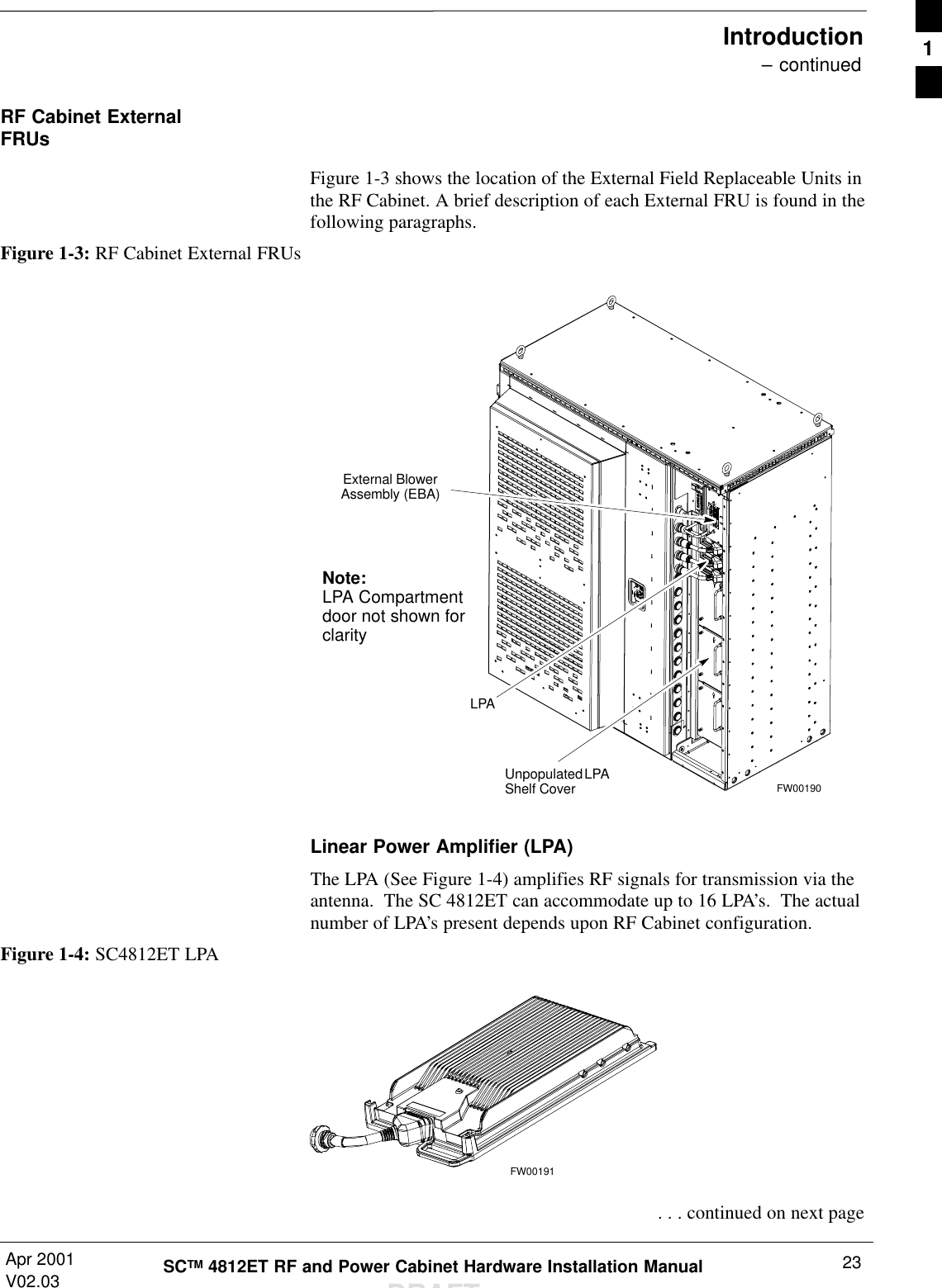
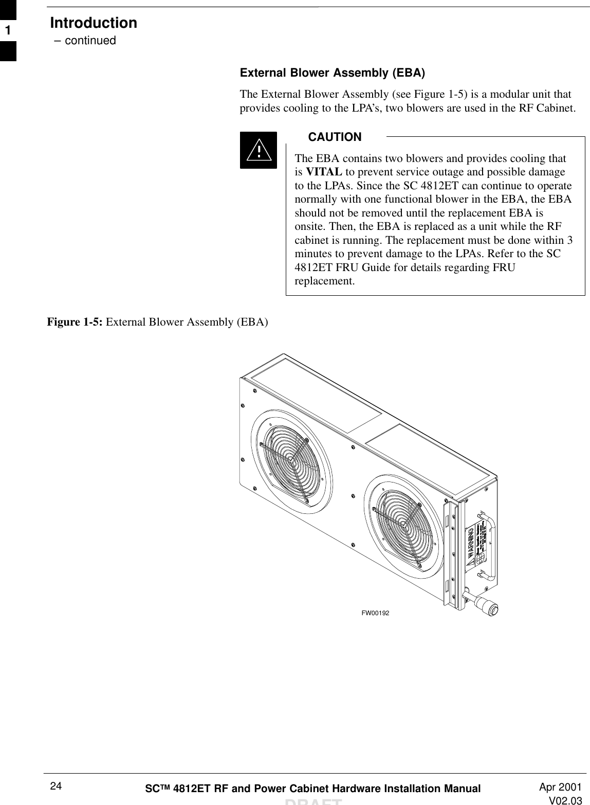
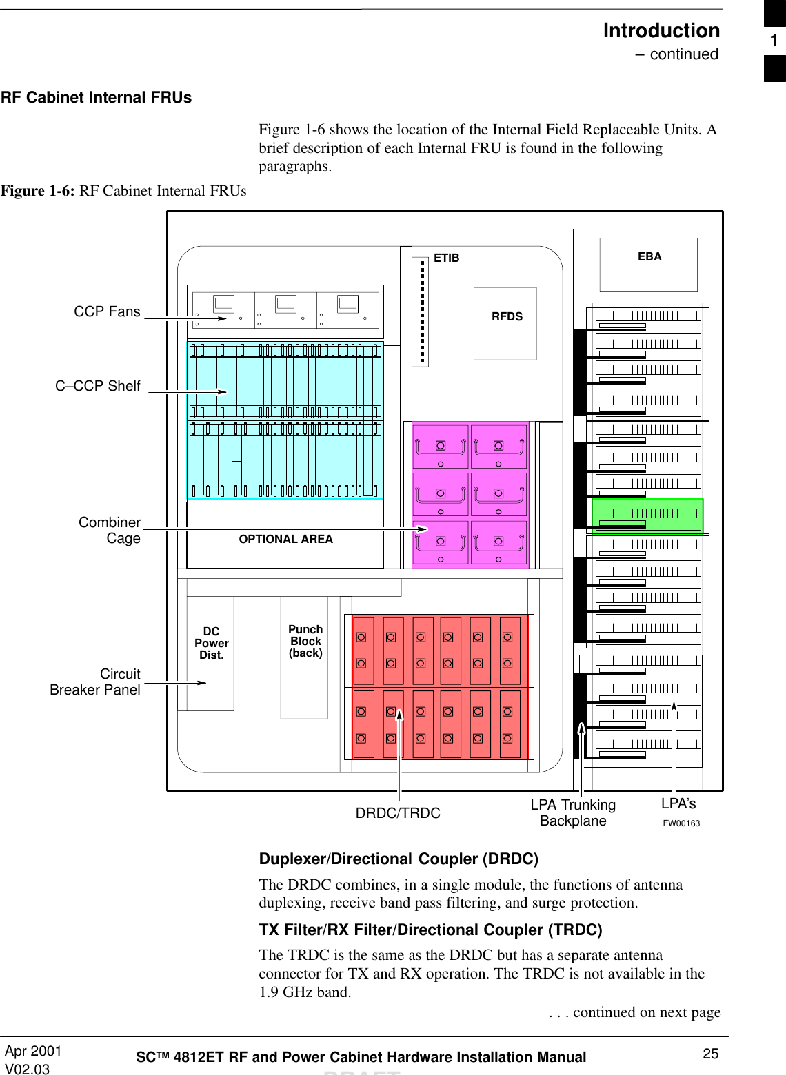
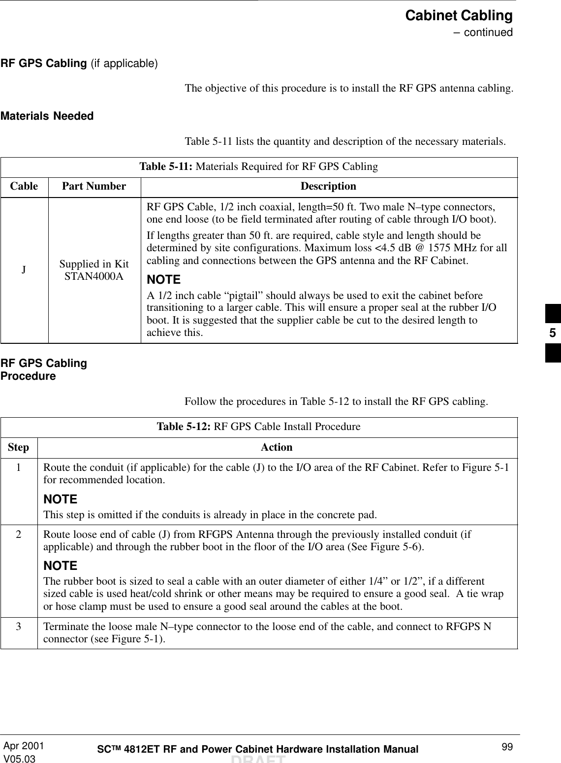
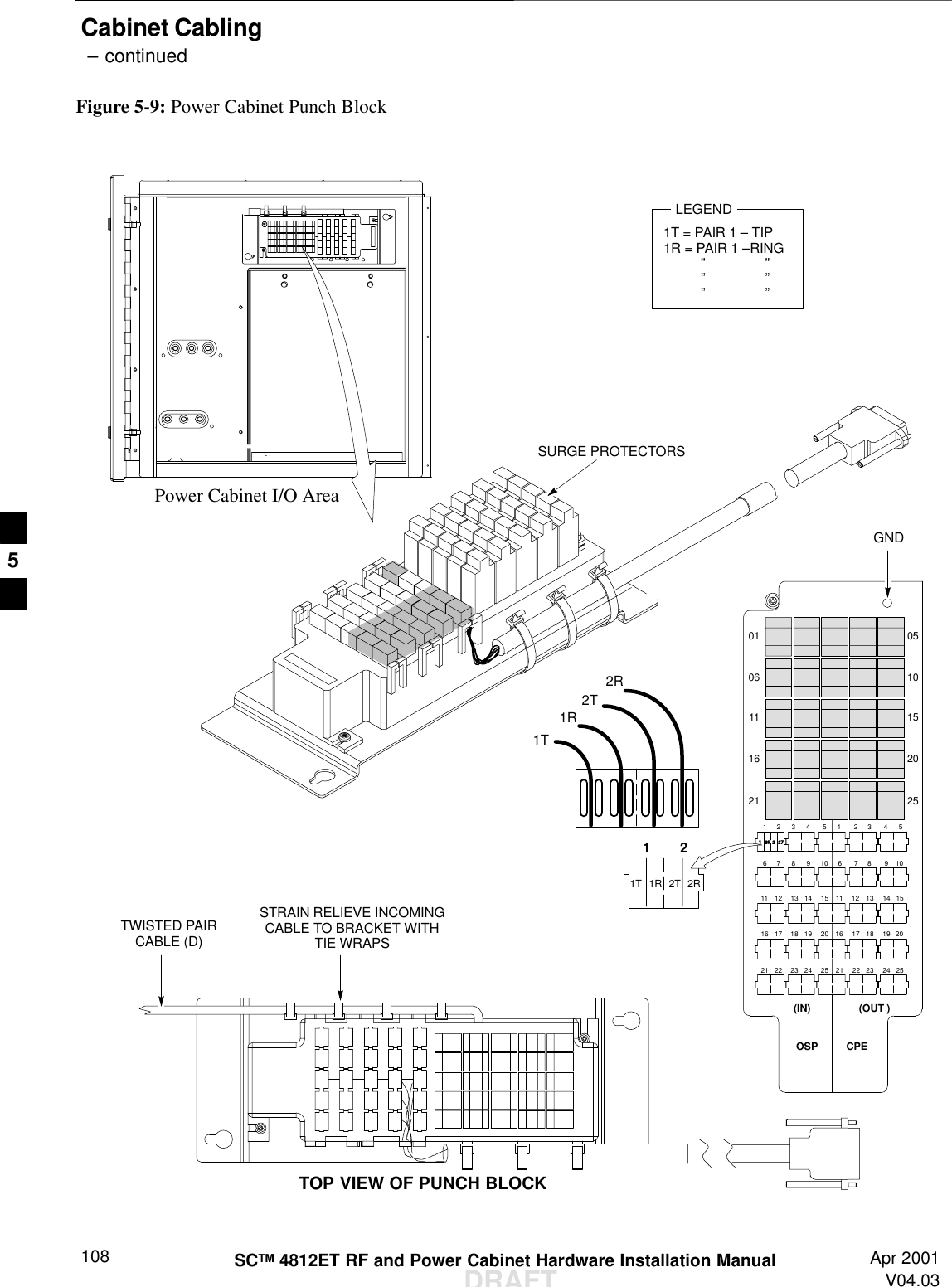
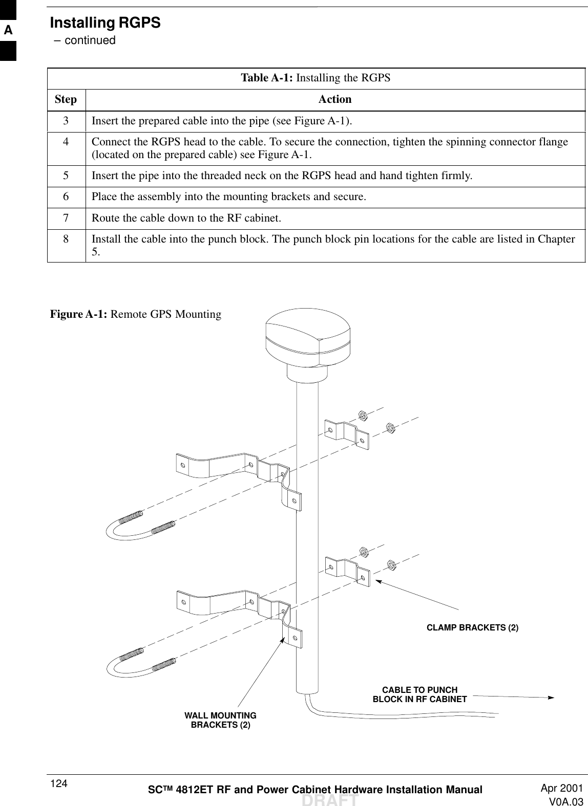
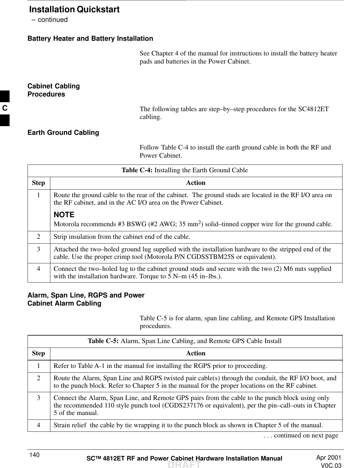
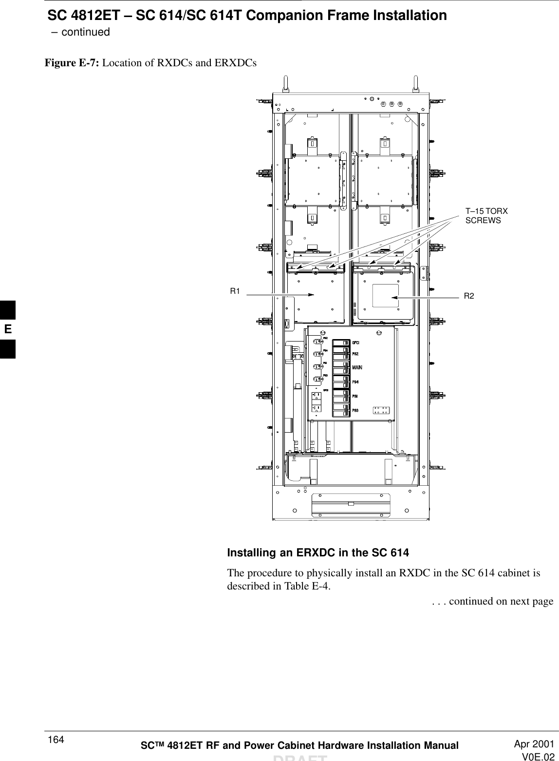
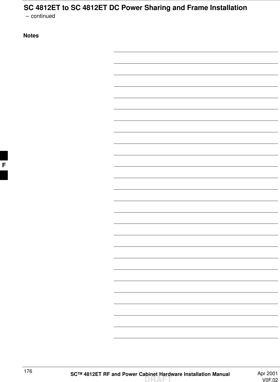
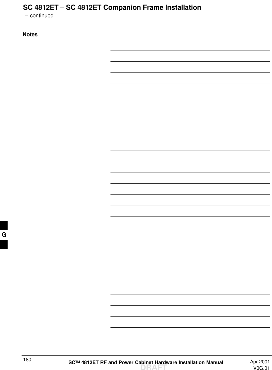
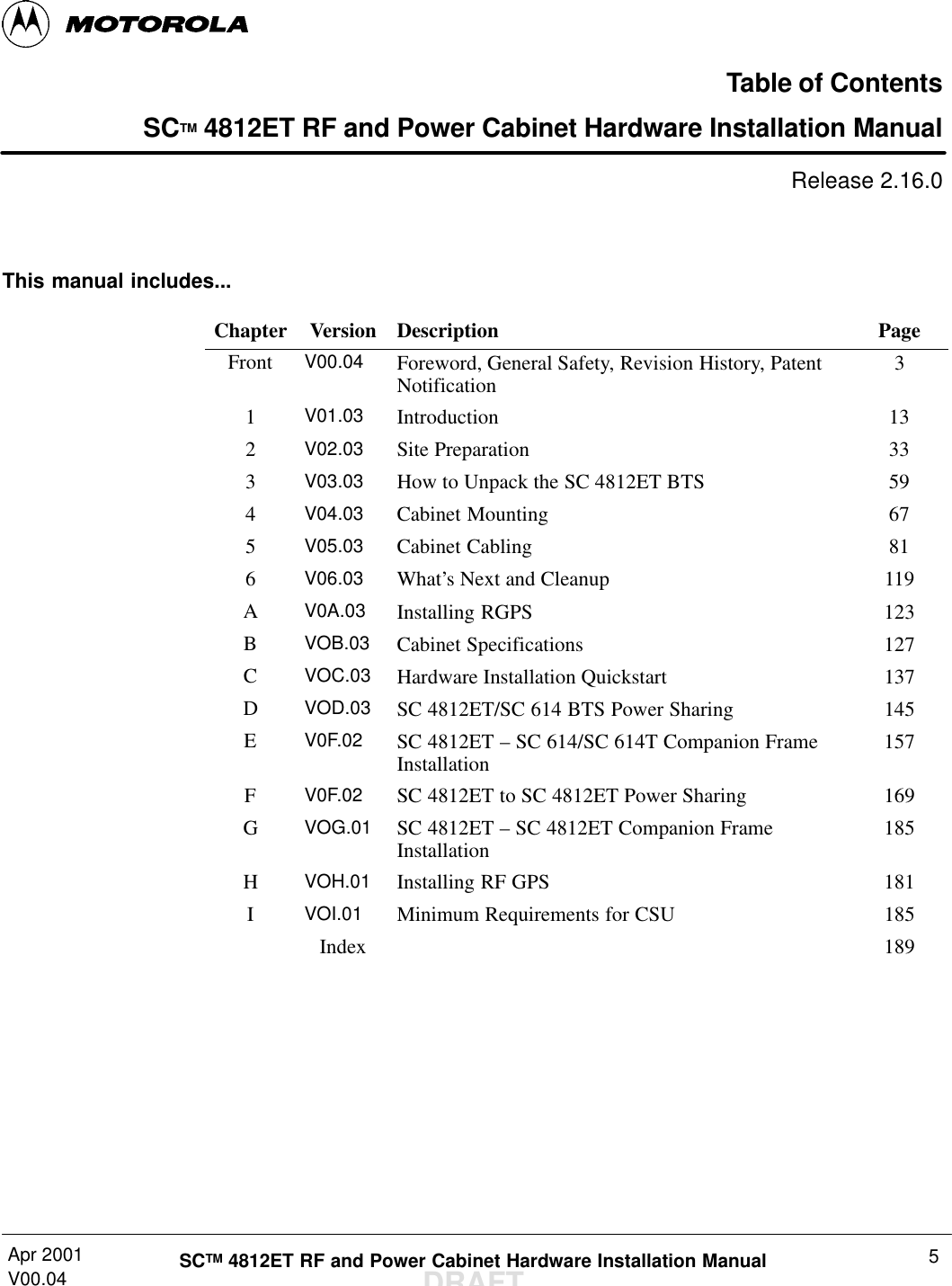
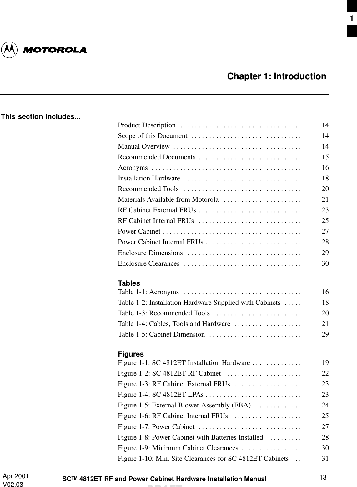
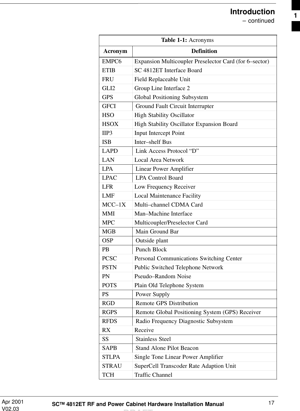
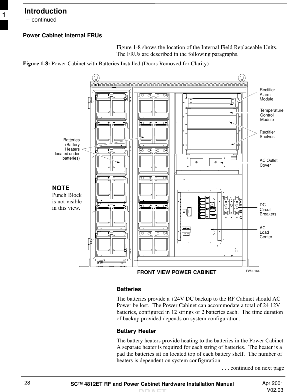
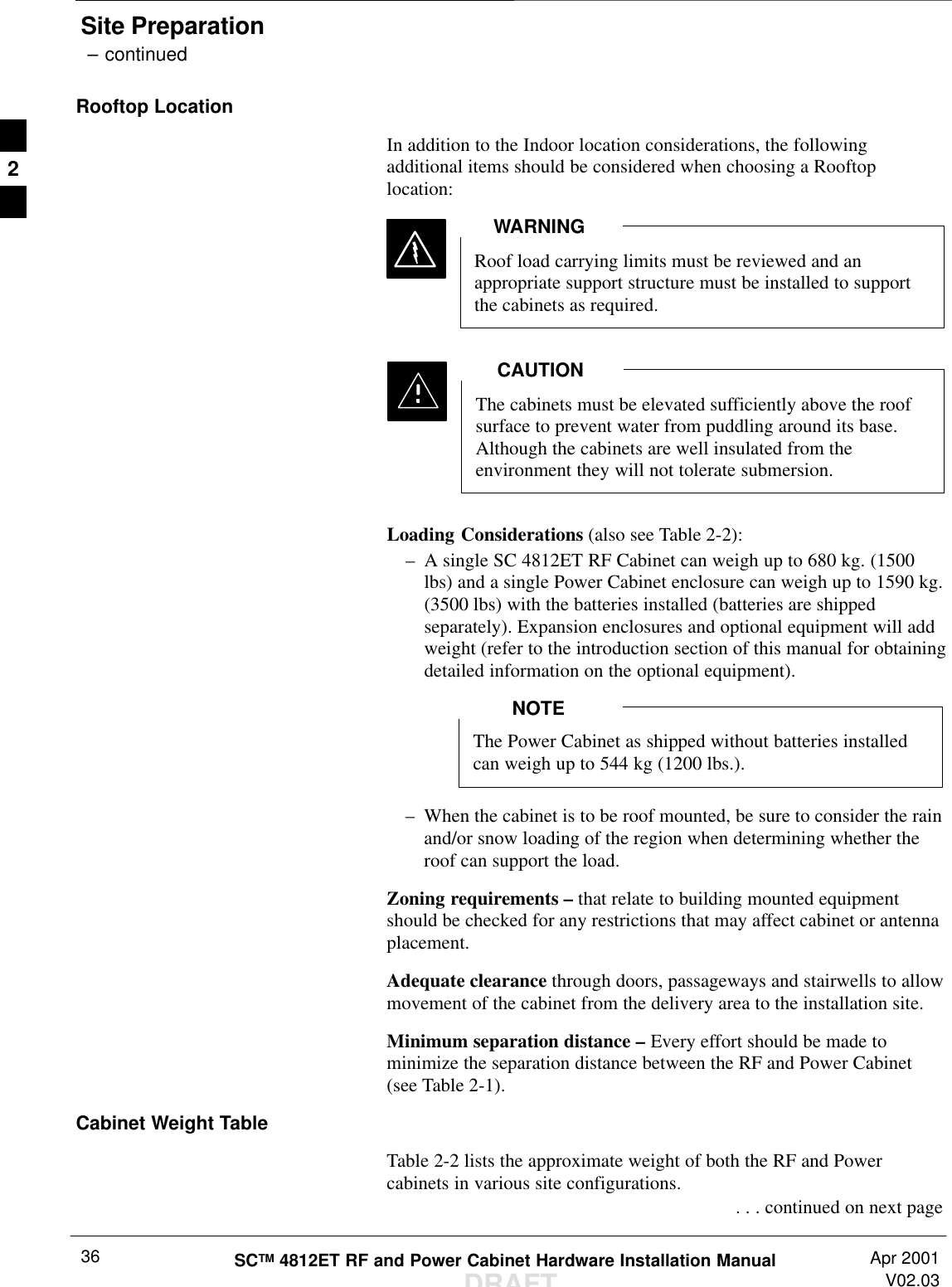
![Introduction – continuedSCTM 4812ET RF and Power Cabinet Hardware Installation ManualDRAFTApr 2001V02.0326Combiner Cage (2:1, 4:1, or Band pass Filter)The Combiner Cage holds the transmit band pass filters, 2:1 combiners,or 4:1 combiners, depending on system configuration.Combined CDMA Channel Processor (C–CCP) ShelfThe C–CCP shelf contains the following:SHigh Stability Oscillator (HSO)/LFR (Optional) cardSClock Synchronization Manager (CSM) on 2 cards (one with GPSreceiver if ordered).SCDMA Clock Distribution (CCD) cards (2)SPower Supply cards (2 minimum, 3 maximum)SMulticoupler Preselector Cards (MPC) (2)SAlarm Monitoring and Reporting (AMR) cards (2)SMulti Channel CDMA [MCC–1X (8E or 24), MCC–1X (8E/24)]cards (up to 12)SBroadband Transceiver (BBX–1X) cards (up to 13)SCombined Input/Output (CIO) (1)SGroup Line Interface (GLI2) cards (2)SBBX2 Switch card (1)SModem (optional)SFiller PanelsSFan Module (3)Punch BlockThe Punch Block is the interface point of the RF Cabinet between theT1/E1 span lines, the Customer I/O, alarms, multi–cabinet timing(RGPS and RHSO), and Pilot Beacon control (optional).Span I/O BoardThe Span I/O Board provides the interface for the span lines from theCSU to the C–CCP backplane.RF Diagnostic Subsystem (RFDS)The RFDS provides the capability for remotely monitoring the status ofthe SC 4812ET RF Transmit and Receive paths.SC 4812ET Interface Board (ETIB) & LPA Control Brd (LPAC)The ETIB is an interconnect board showing status LEDs for the RFCabinet, as well as providing secondary surge protection. The LPACboard provides the interface for the LPA connection.SC 4812ET Trunking BackplaneThe Trunking Backplane contains a complex passive RF network thatallows RF signals to share the resources of a bank of four LPAs. It alsoprovides DC Power and digital interconnect.1](https://usermanual.wiki/Nokia-Solutions-and-Networks/T6BM1/User-Guide-162010-Page-26.png)
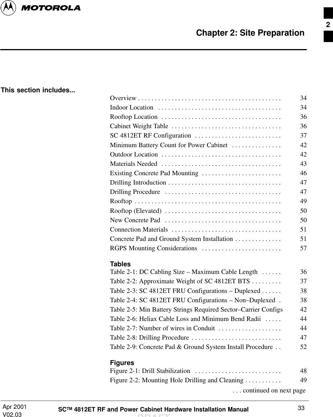
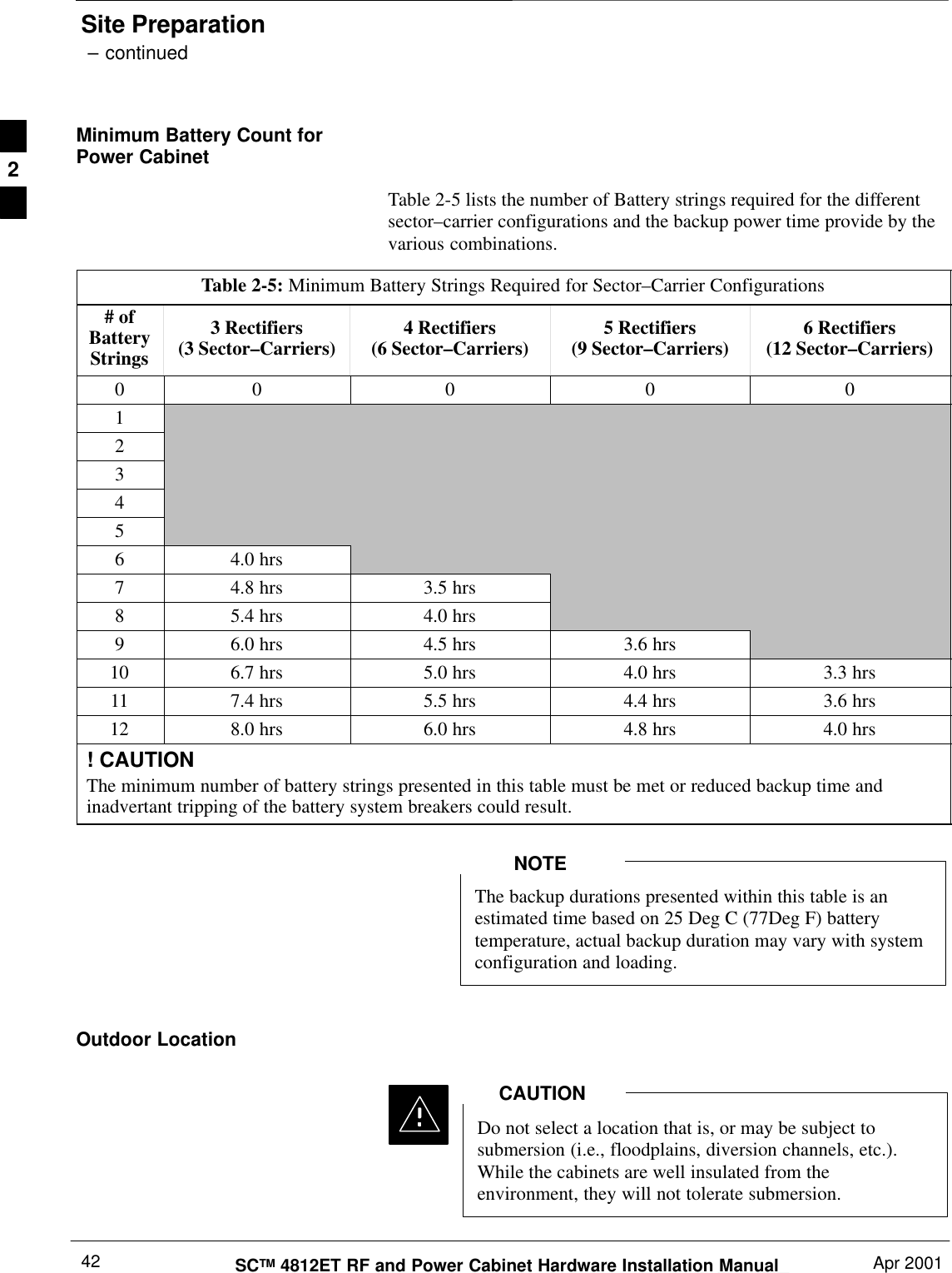
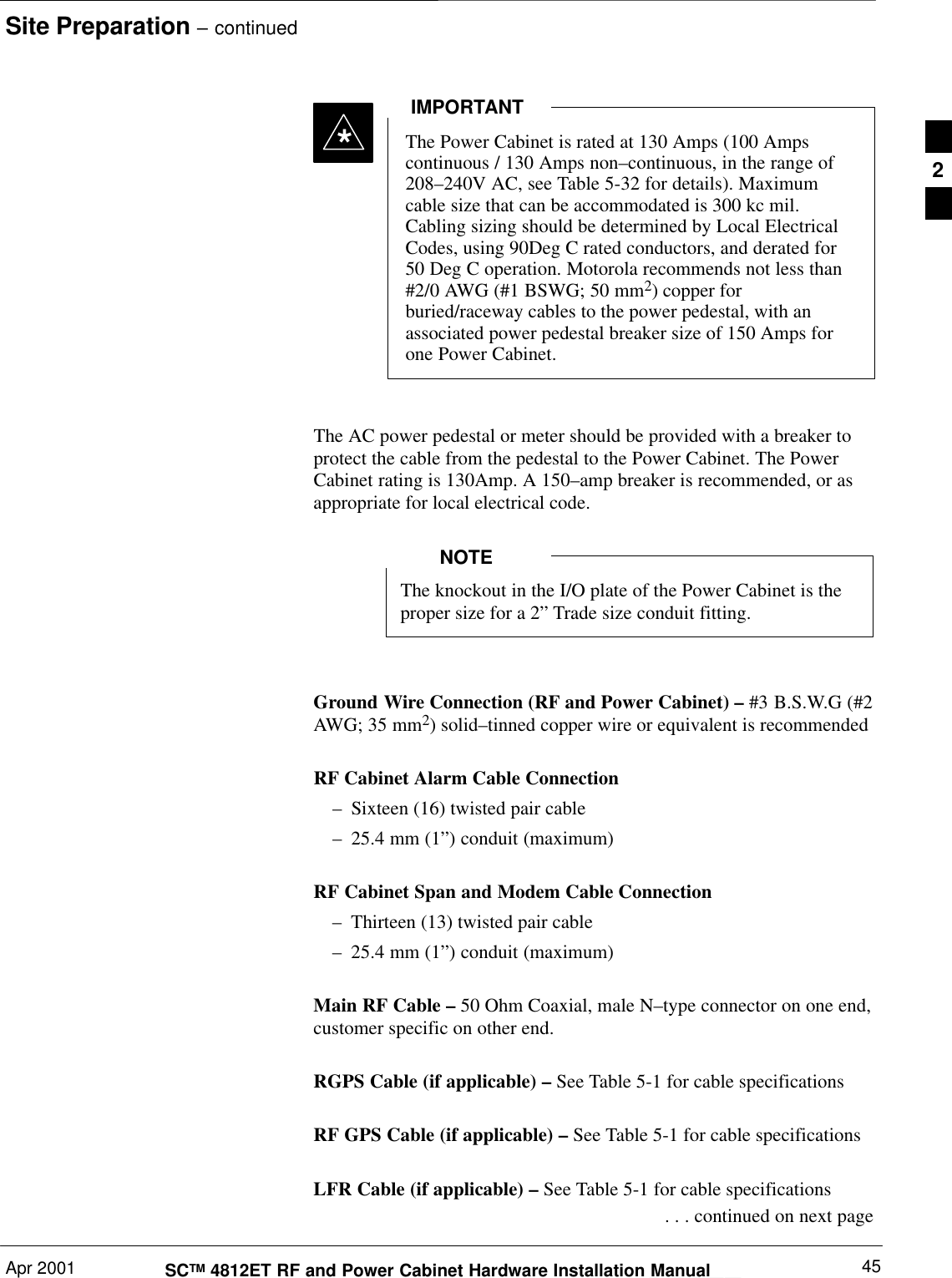
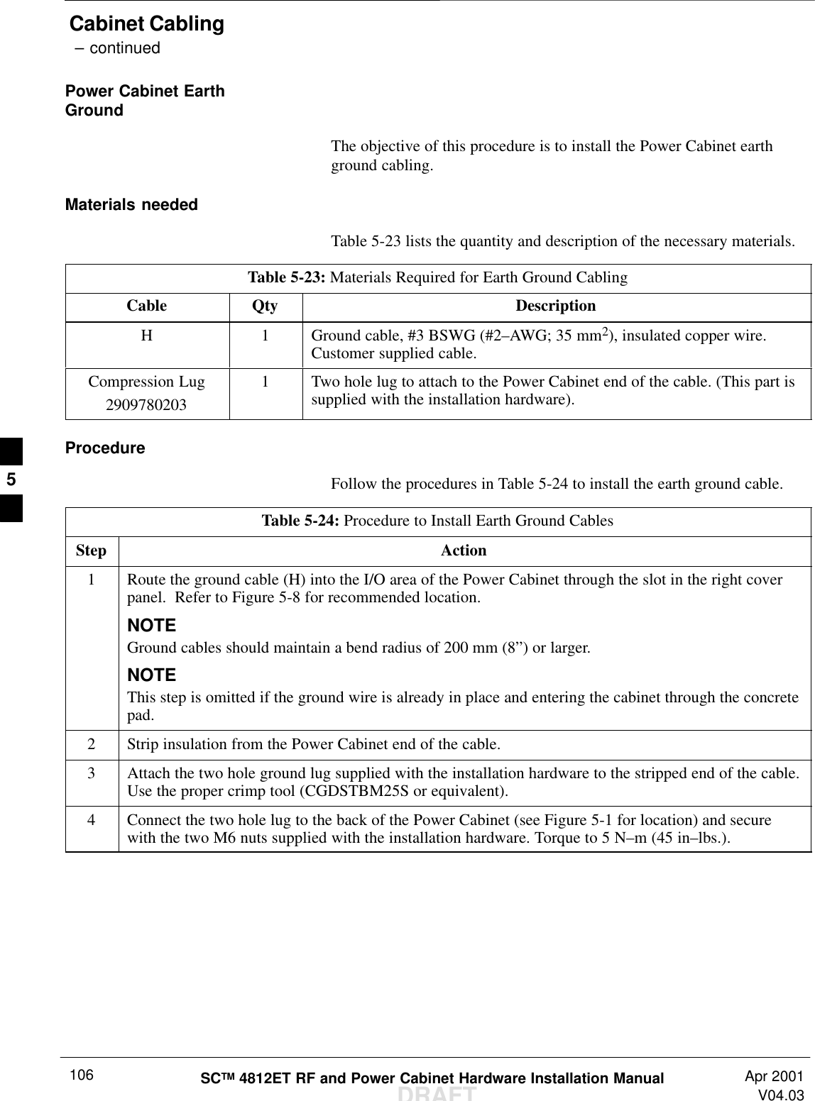
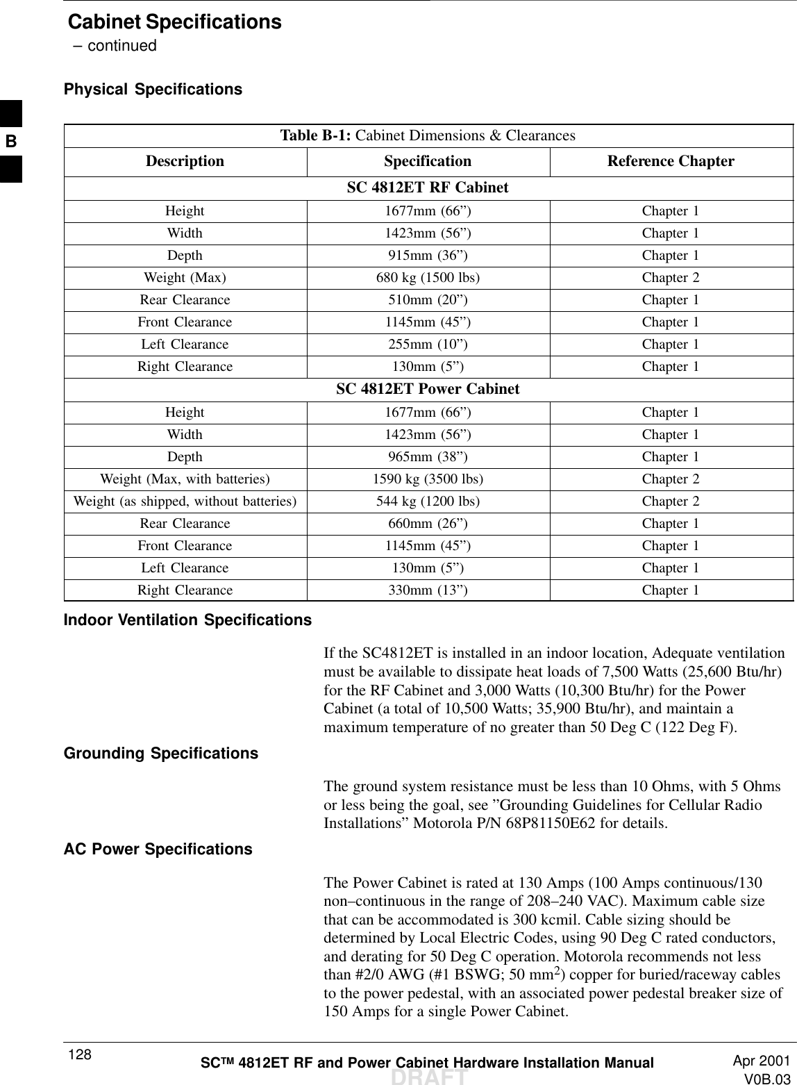
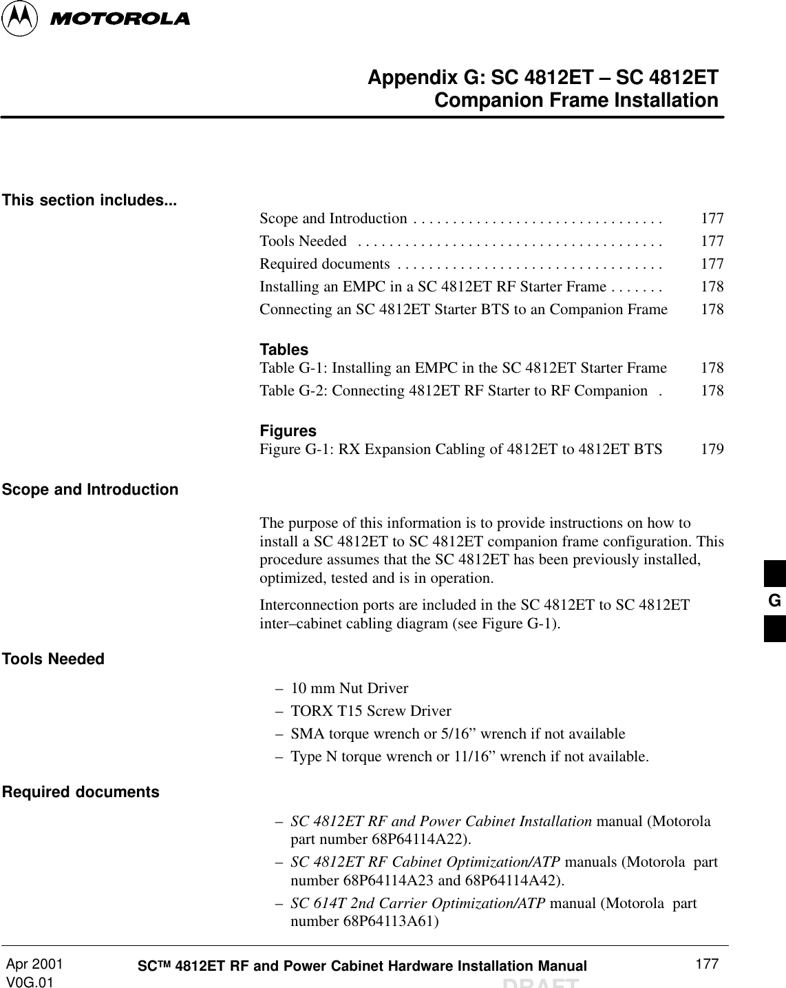
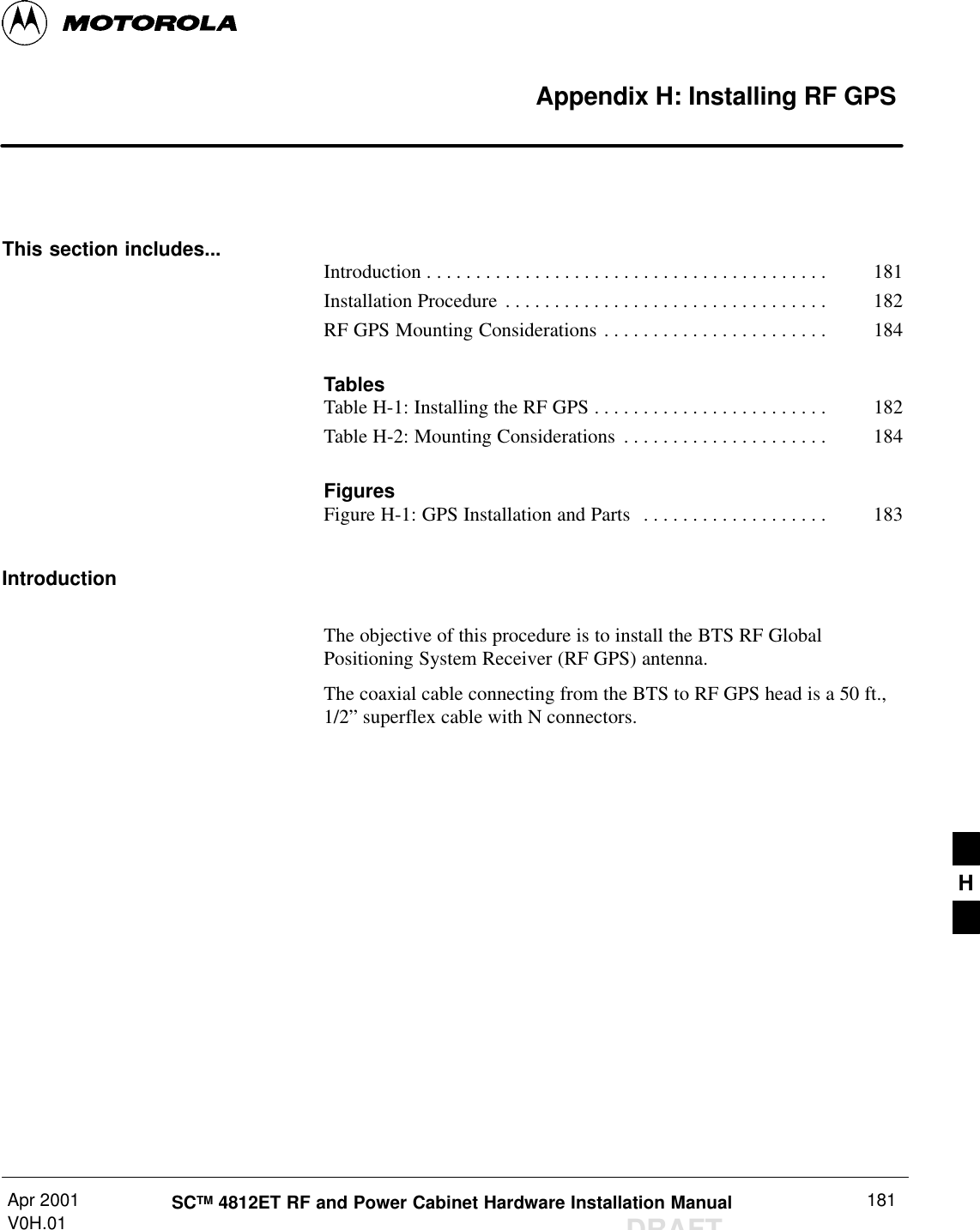
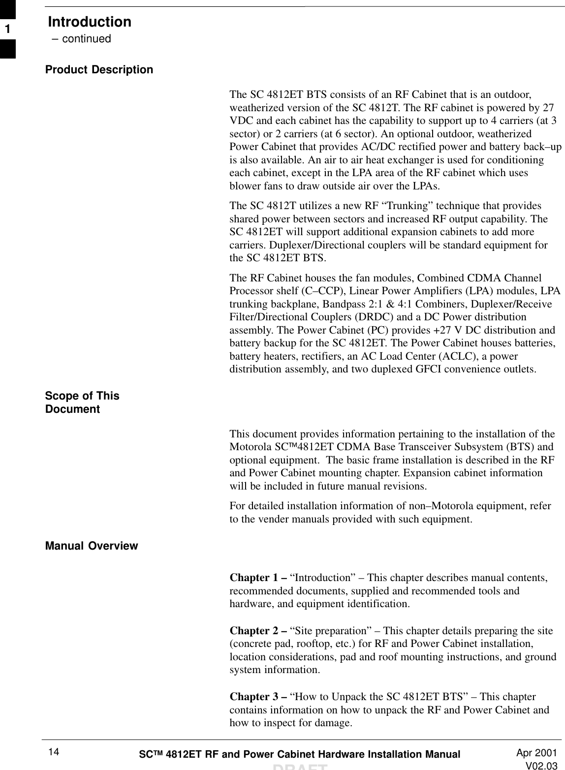
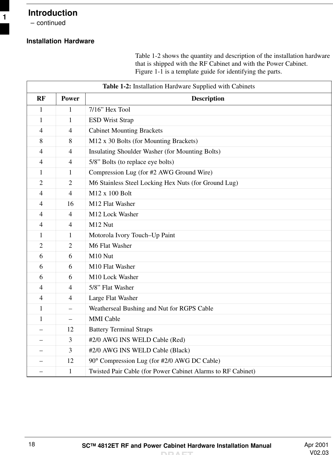
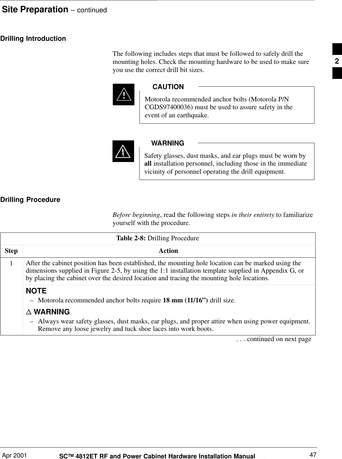
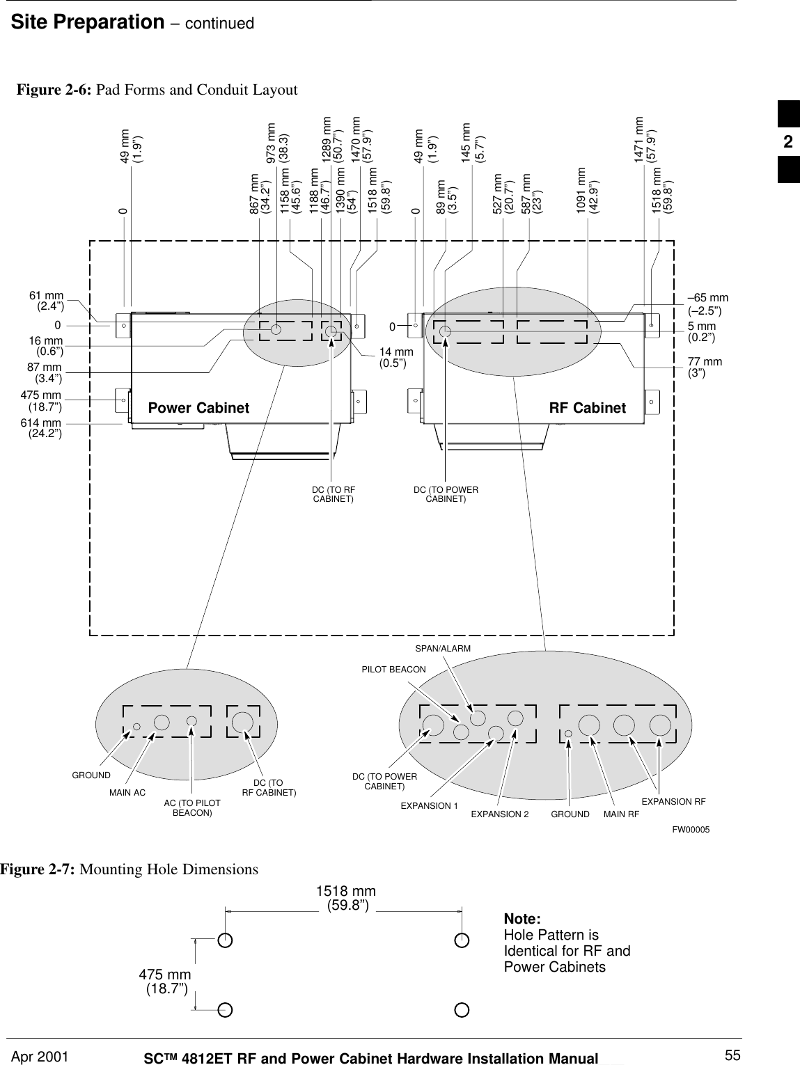
![Site Preparation – continuedDRAFTSCTM 4812ET RF and Power Cabinet Hardware Installation Manual Apr 200146Power Cabinet Alarm Cable – A Twelve (12) wire, Six (6) twisted paircable [Cable supplied with the Power Cabinet is 4.5 m (15 ft) in length].Custom cable lengths are available from Storm Products(214–637–1381); 9215 Premier Row, Dallas, TX. 75247.Part number “070197–6SA” for Non–Plenum rated cable.NOTEDC Power Interconnect–#1 BSWG (#2/0 AWG; 50 mm2) insulated weld wire or equivalentis recommended (supplied with the Power Cabinet)–51 mm (3”) conduitThe DC Power Cabling and the Power Cabinet AlarmCable can be run in the same 3” Conduit from the RFCabinet to the Power Cabinet.NOTEExisting Concrete PadMountingThe mounting surface must be flat. Door closure problemsmay occur if the BTS is not installed on a flat surface.CAUTIONFor an installation where the cabinet will mount flush to an existingconcrete floor, all of the connections to the cabinet will be made throughthe rear I/O area of the cabinet. For this reason, the cabinet must be setin place and bolted down prior to running any conduits or wiring.Conduit/wire routing will be discussed in Chapter 5.Lightning protection is provided with the cabinet. A good earth ground(ground system resistance must be less than 10 Ohms, with 5 Ohms orless being the goal), is required for the lightning protection equipment toperform properly. Refer to Motorola’s guidelines (Motorola Publication68P81150E62) for details on the design of a grounding system. Conformto local electrical construction standards for conduit materials and sizing.2](https://usermanual.wiki/Nokia-Solutions-and-Networks/T6BM1/User-Guide-162010-Page-46.png)
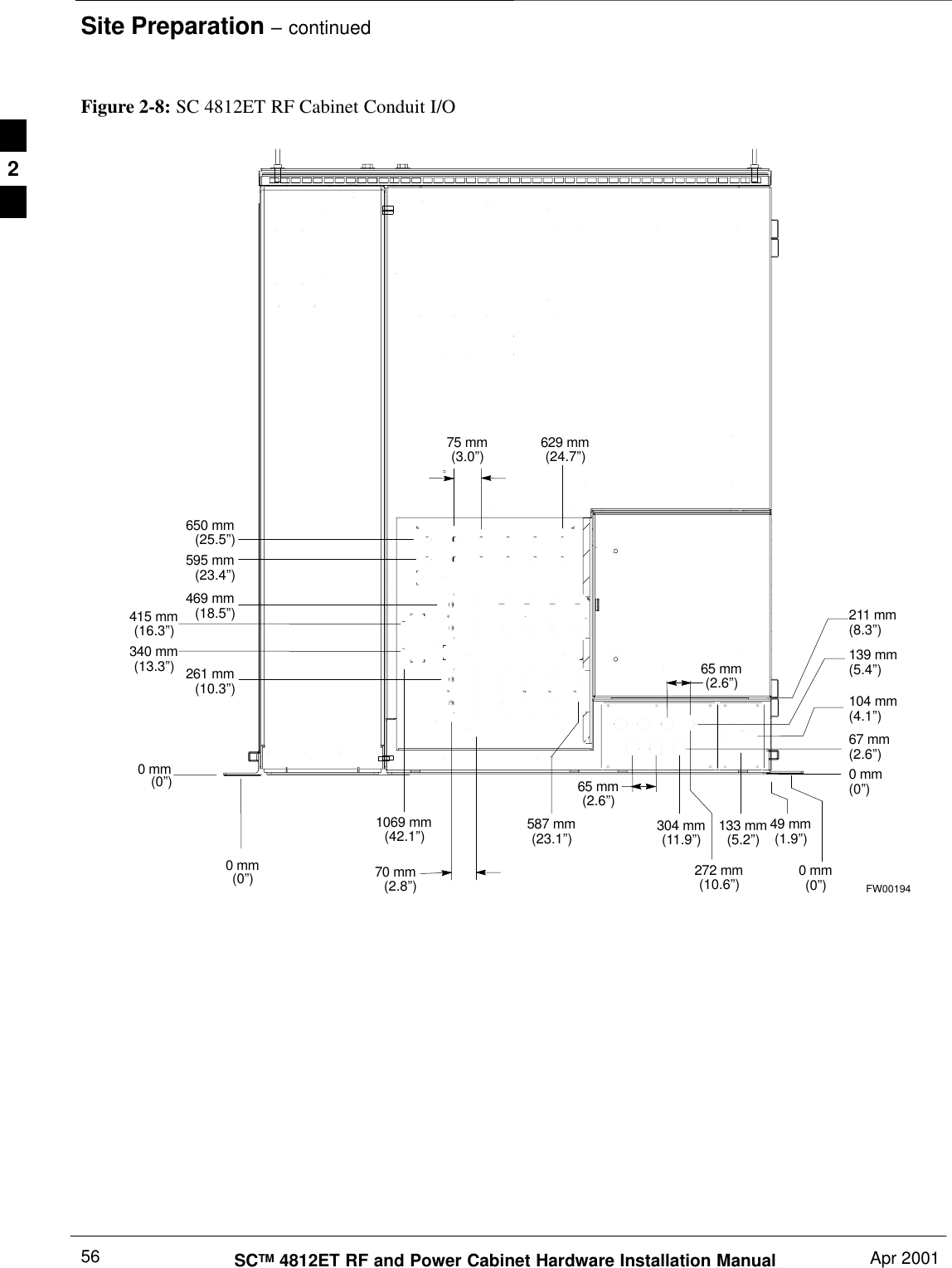
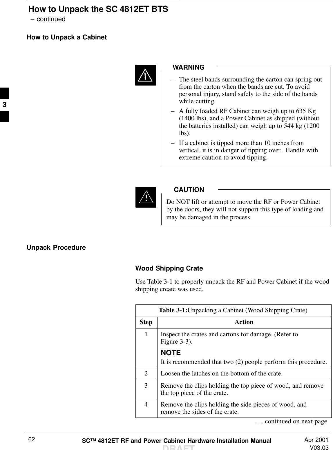
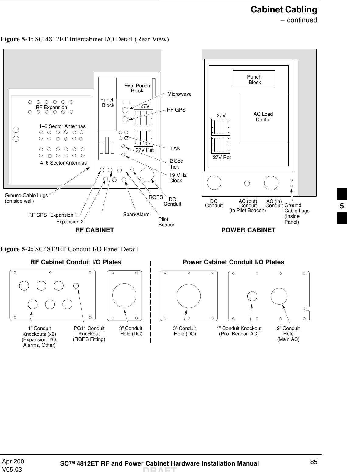
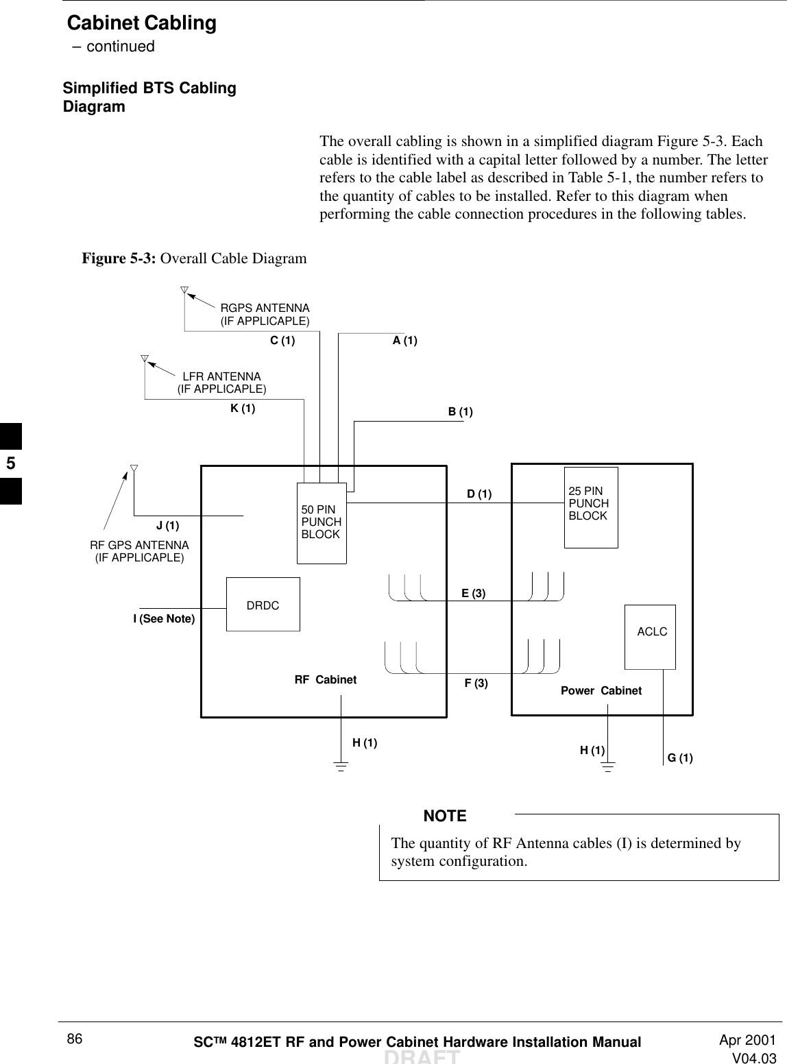
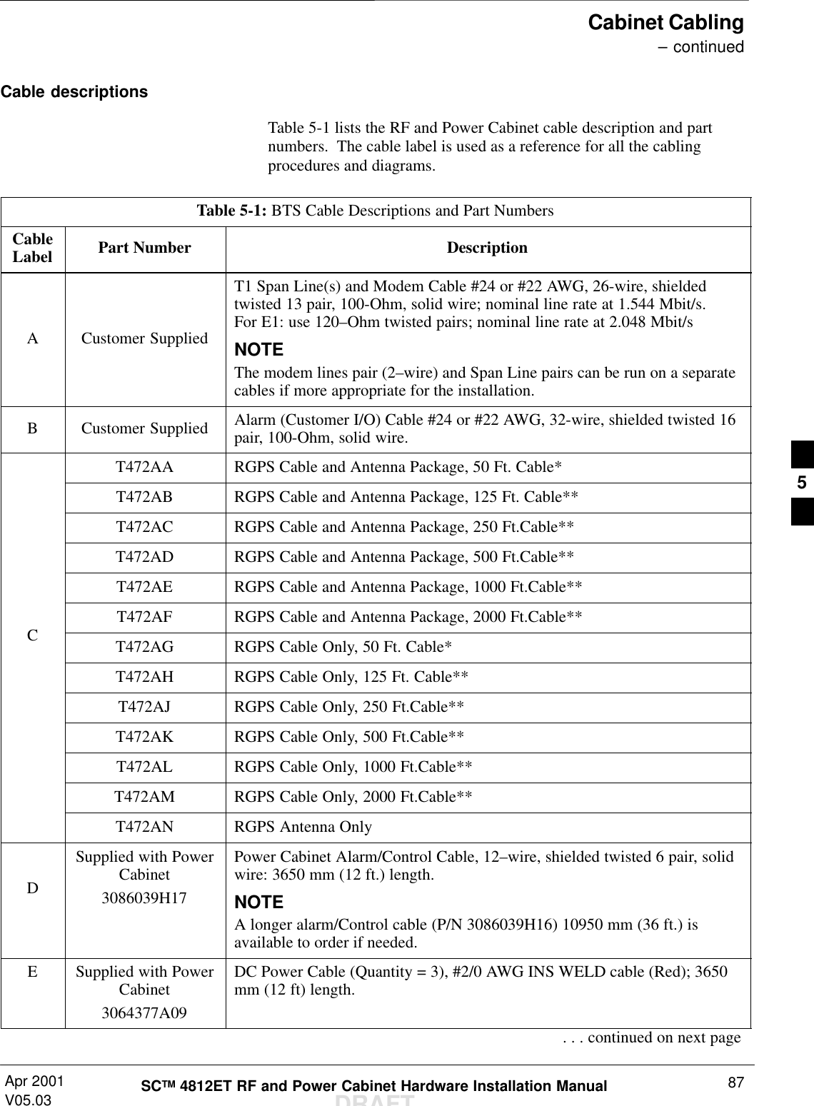
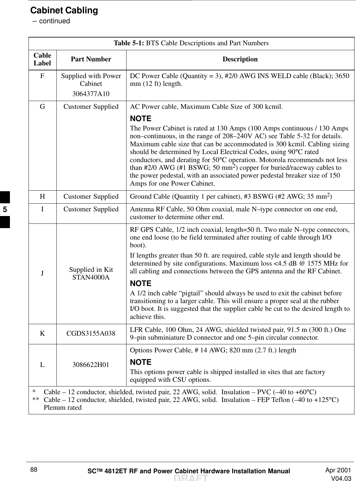
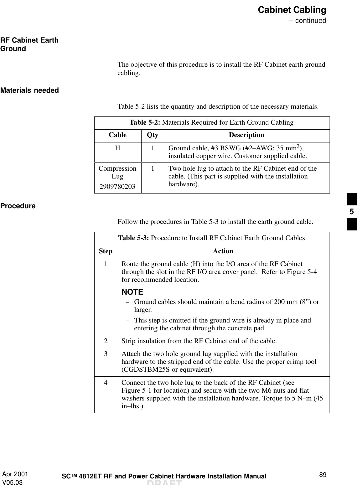
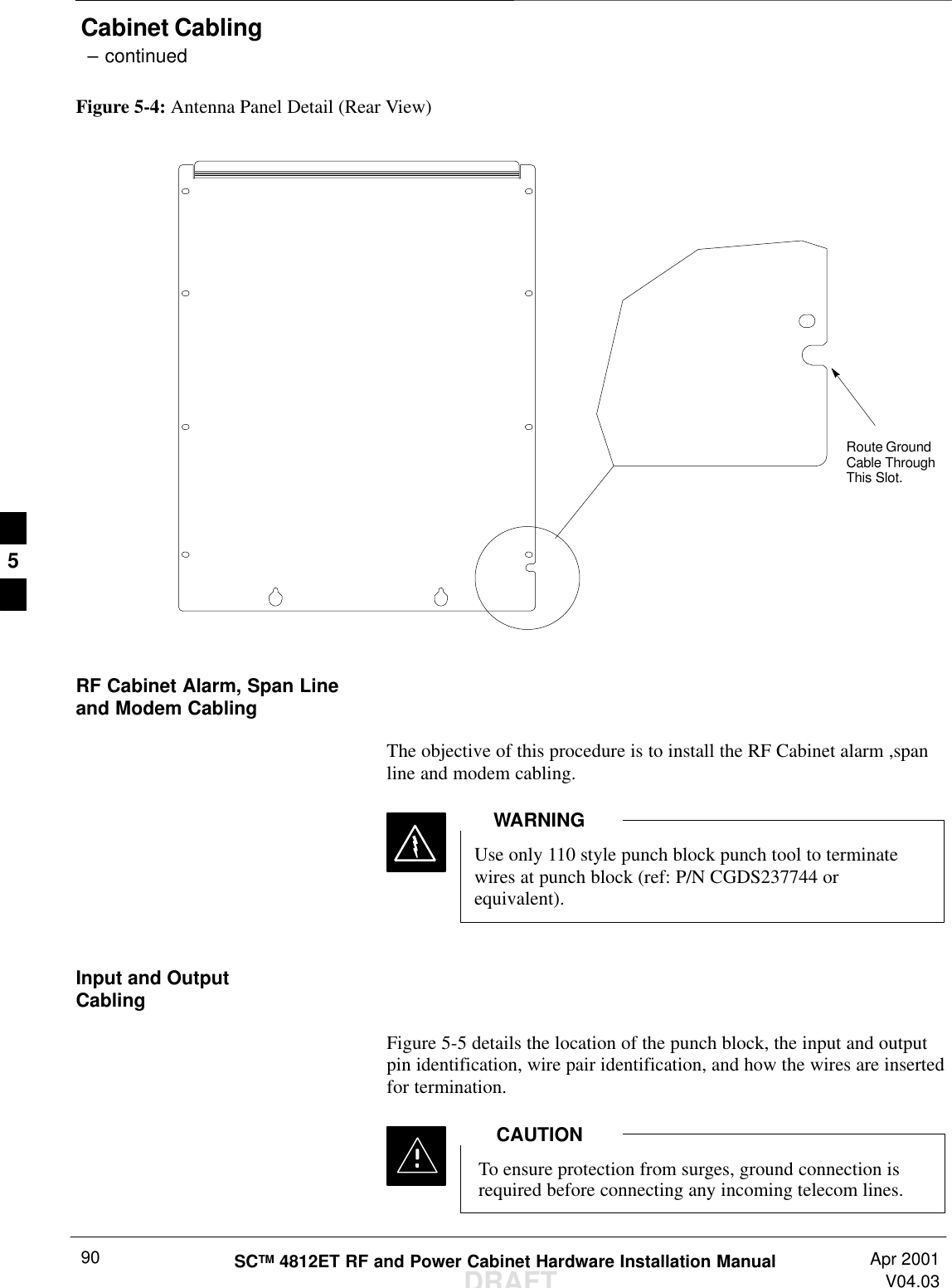
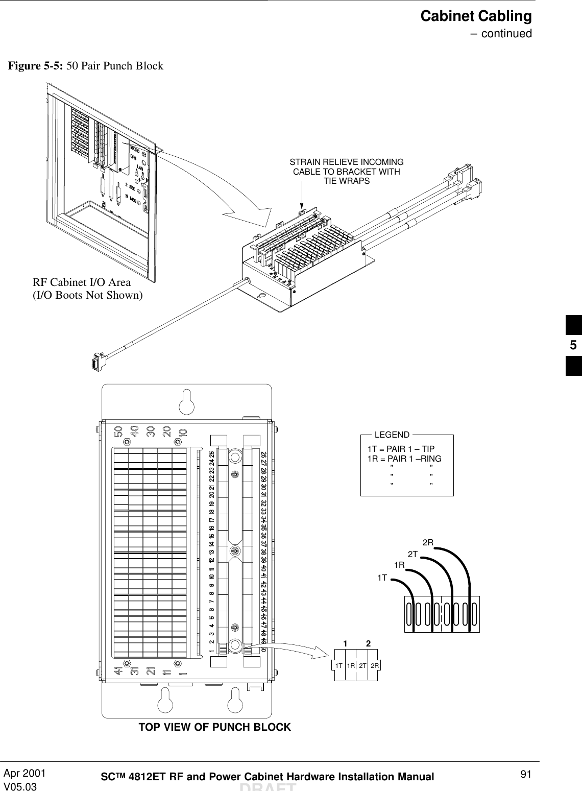
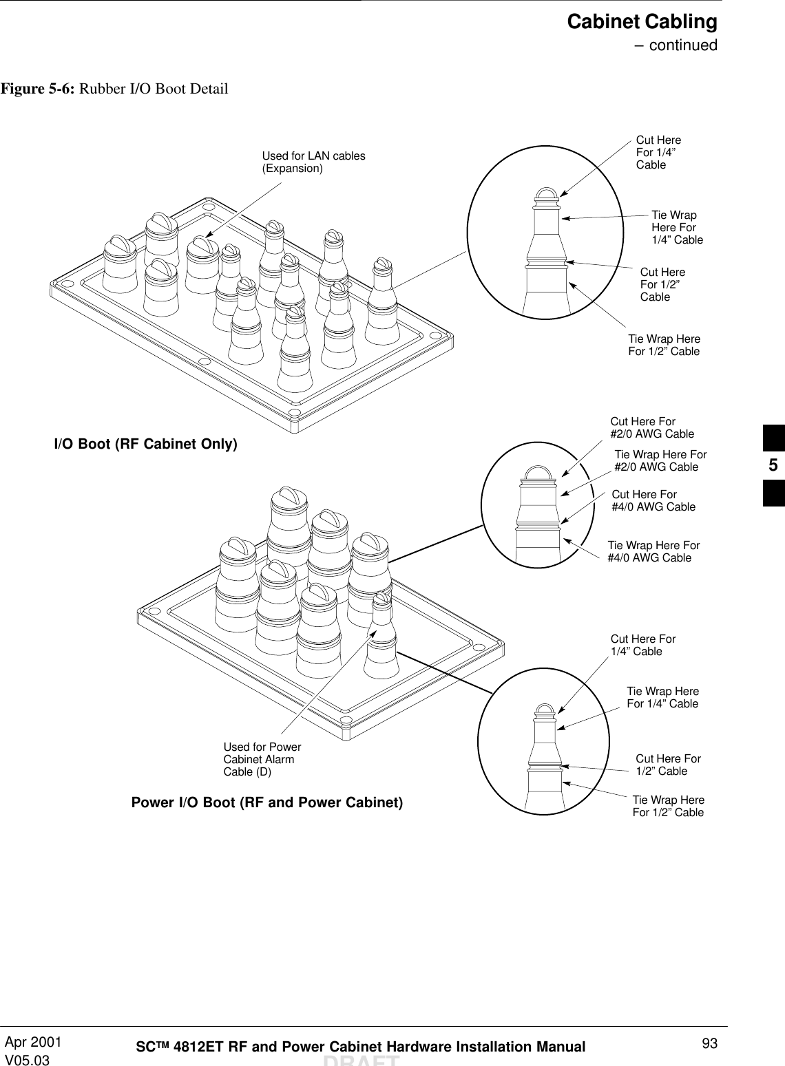
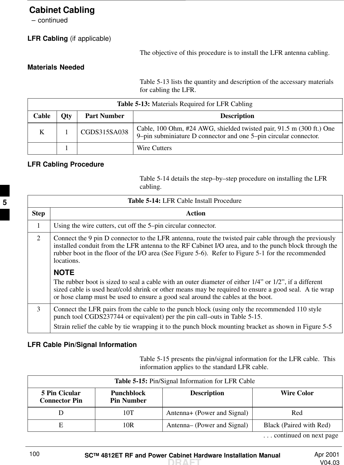
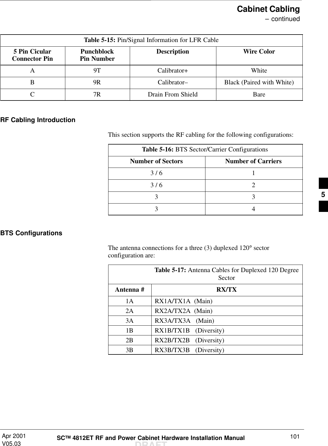
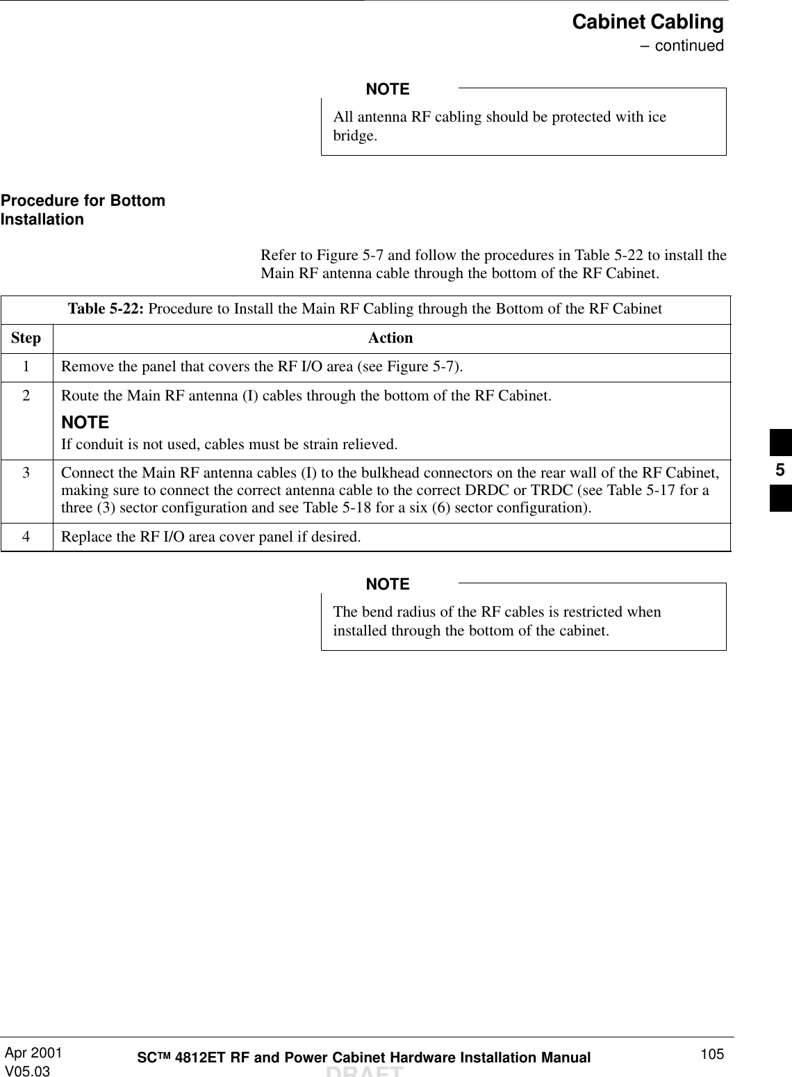
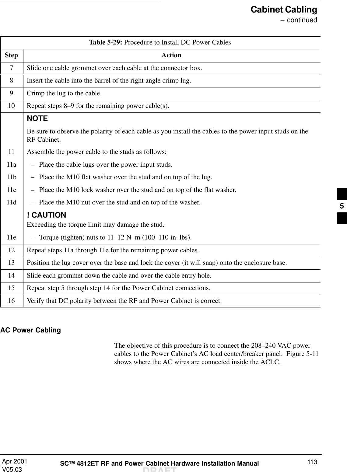
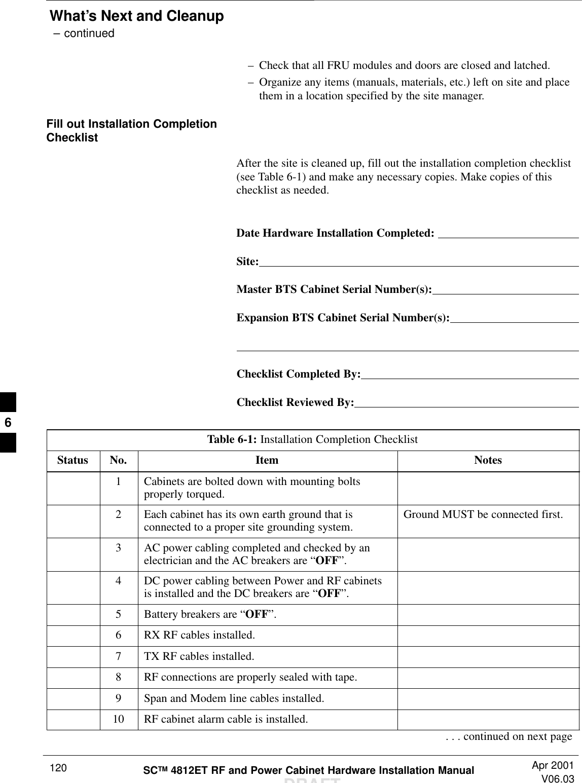
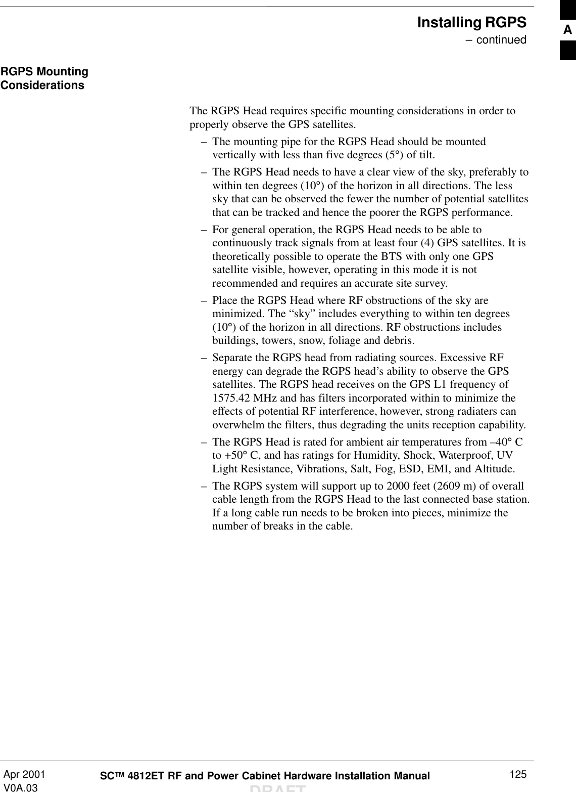
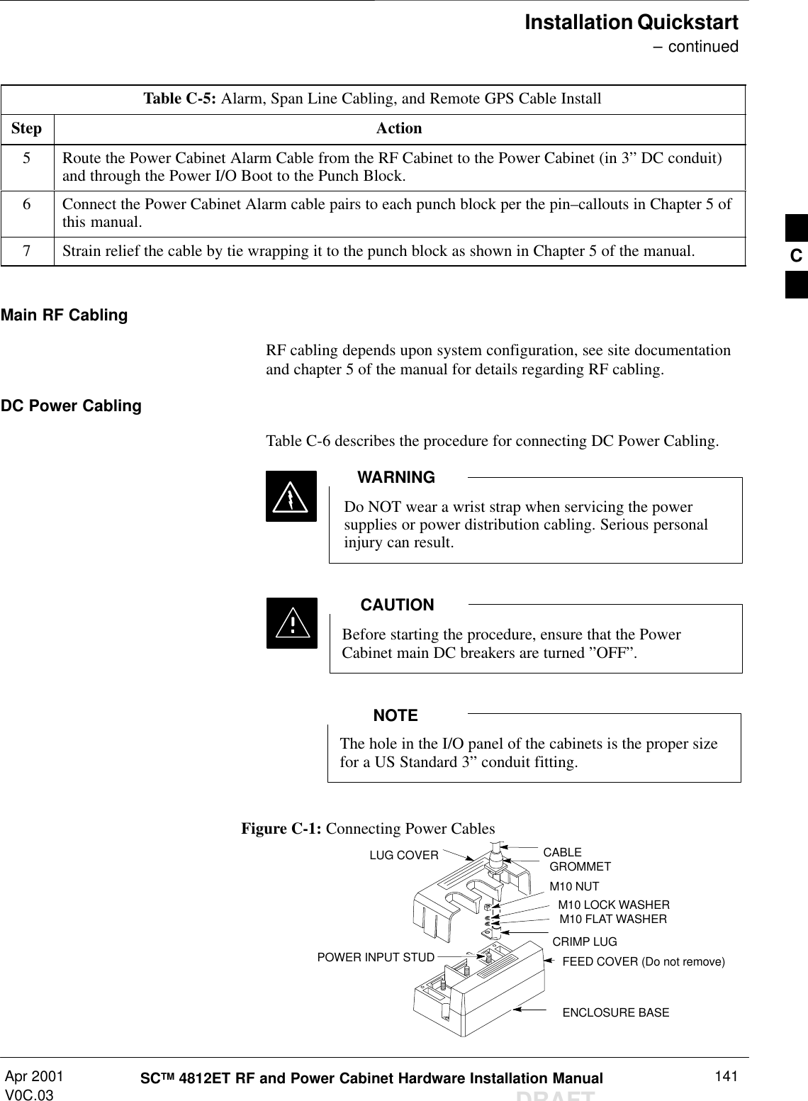
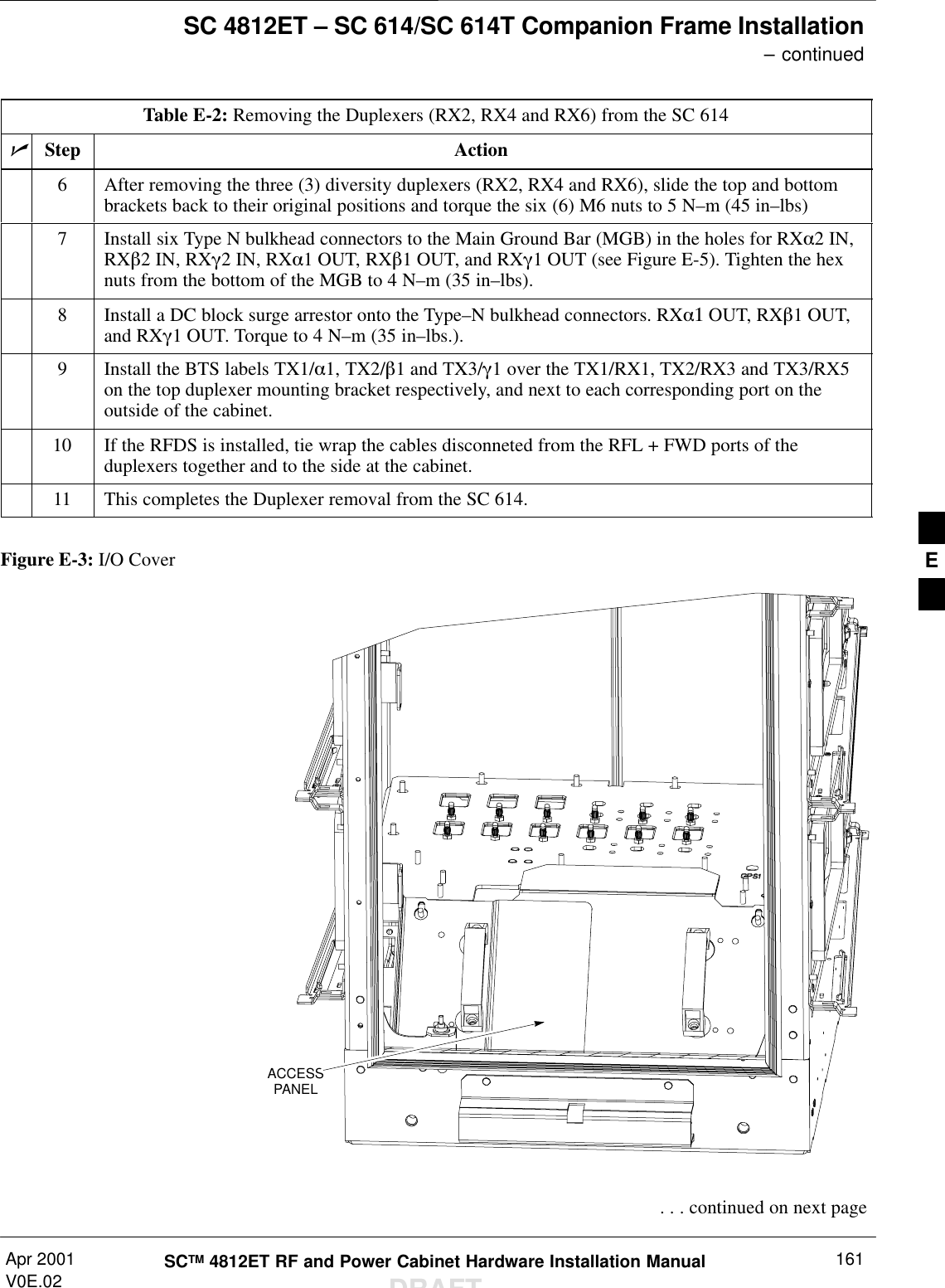
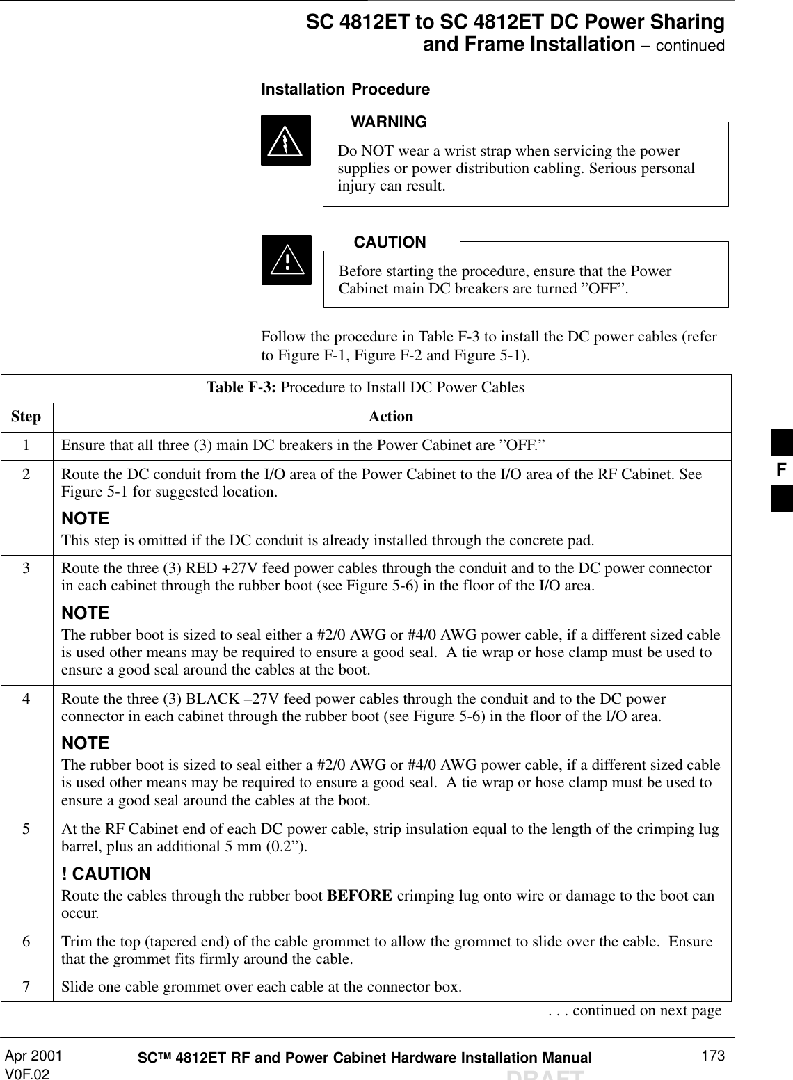
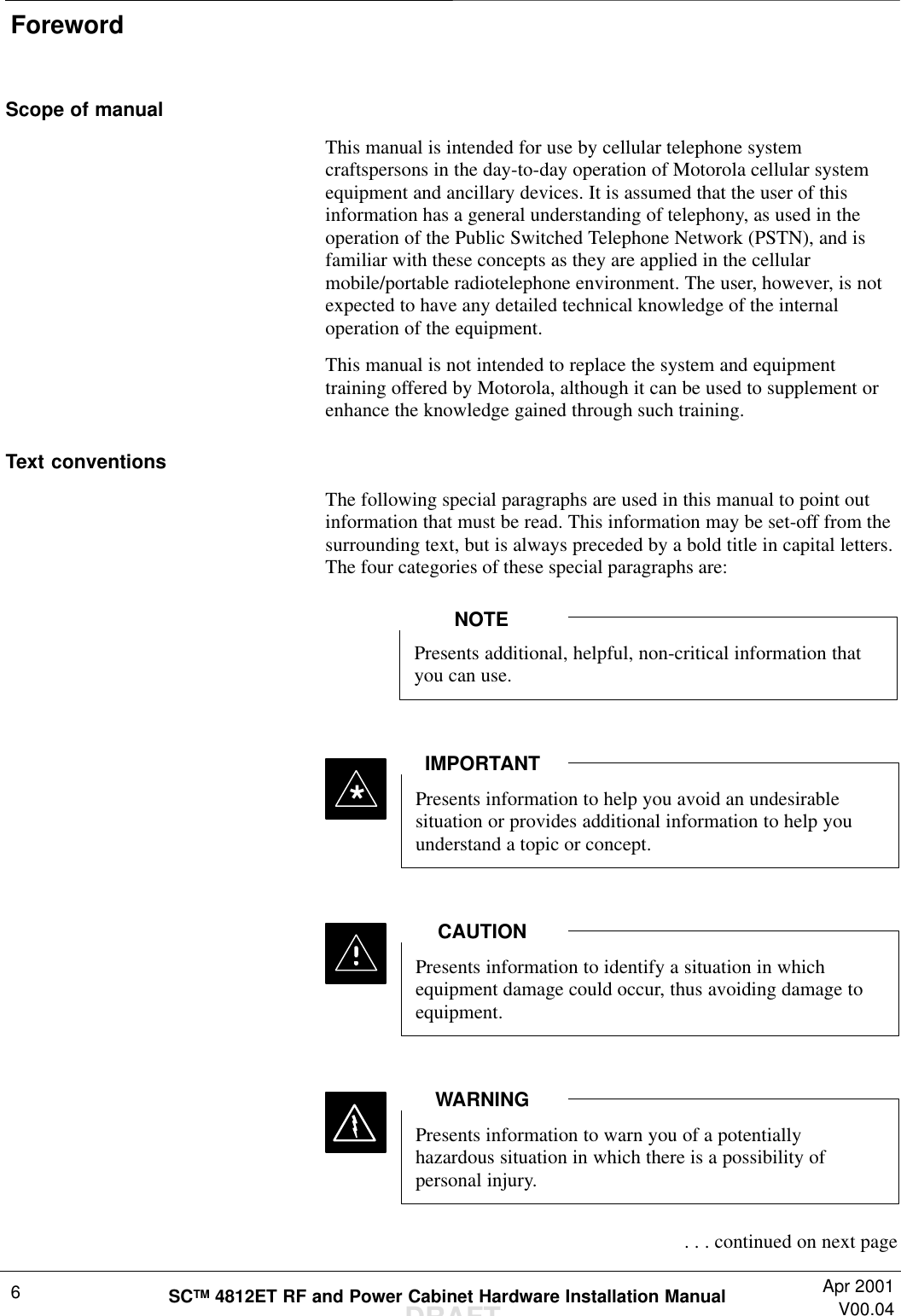
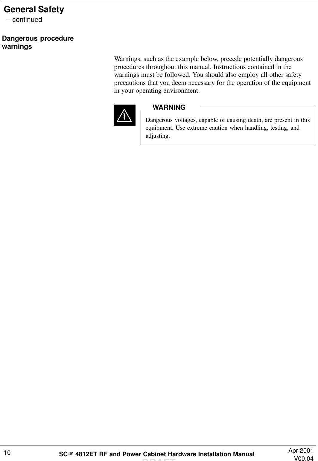
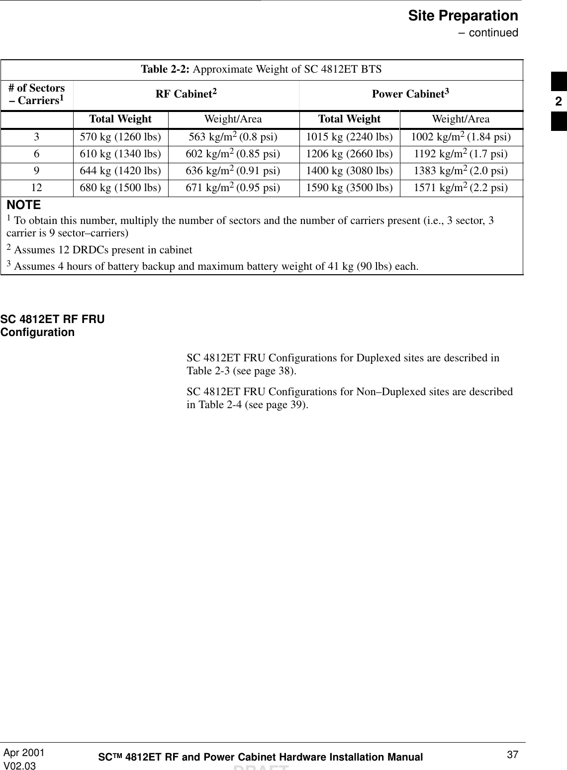
![Cabinet Cabling – continuedDRAFTSCTM 4812ET RF and Power Cabinet Hardware Installation Manual Apr 2001V04.0384–A service tent [reference: Pelsue Cabinet MountedService Tent; Pelsue (800–525–8460) P/NCM564866M] must be in place prior to opening themain doors of the SC4812ET RF or Power Cabinetduring times of inclement weather (rain, snow, sleet,or hail). This will prevent moisture from being drawninto the electronics by internal fans and damaging theequipment.–A service tent [reference: Pelsue Cabinet MountedService Tent; Pelsue (800–525–8460) P/NCM564866M] with a heater is required to service theSC4812ET RF Cabinet when temperatures are below–10 Deg C (14 Deg F). Temperatures inside the tentshould be above 0 Deg (32 Deg F) prior to openingthe main cabinet door. This will prevent a rapidtemperature change to the electronics that could resultin a site outage.WARNINGCabling Installation OrderMotorola recommends the RF and Power Cabinet inter-cabinet cablingbe installed in the order shown:1. RF Cabinet Cabling1. Earth Ground2. Alarm, Span Line and Modem3. RGPS cabling (if applicable) 4. RF GPS cabling (if applicable)5. LFR Cabling (if applicable) 6. Main RF (RX/TX) path cabling2. Power Cabinet Cabling1. Earth Ground2. Battery Cabling3. Alarm Interconnect Cabling to RF Cabinet4. DC Interconnect Cabling to RF Cabinet5. AC Power CablingCabinet I/O AreaThe cabinet I/O area is used as a common point of connection for theinter–cabinet cabling. See Figure 5-1 for an overview of the I/O area forthe SC 4812ET RF and Power Cabinet.5](https://usermanual.wiki/Nokia-Solutions-and-Networks/T6BM1/User-Guide-162010-Page-84.png)