Nokia Solutions and Networks T6HG1 CDMA Base Station User Manual Exhibit 8a
Nokia Solutions and Networks CDMA Base Station Exhibit 8a
UserManual.wiki
>
Nokia Solutions and Networks
>
T6HG1 User Manual
>
Exhibit 8a
Contents
1.
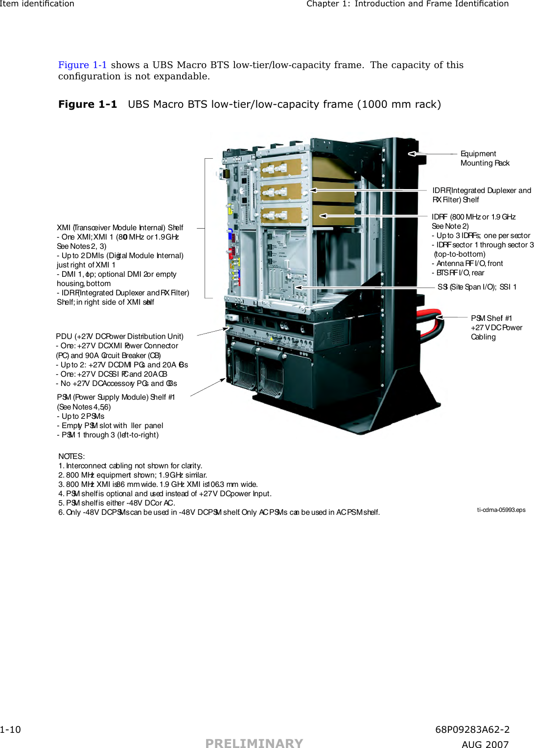
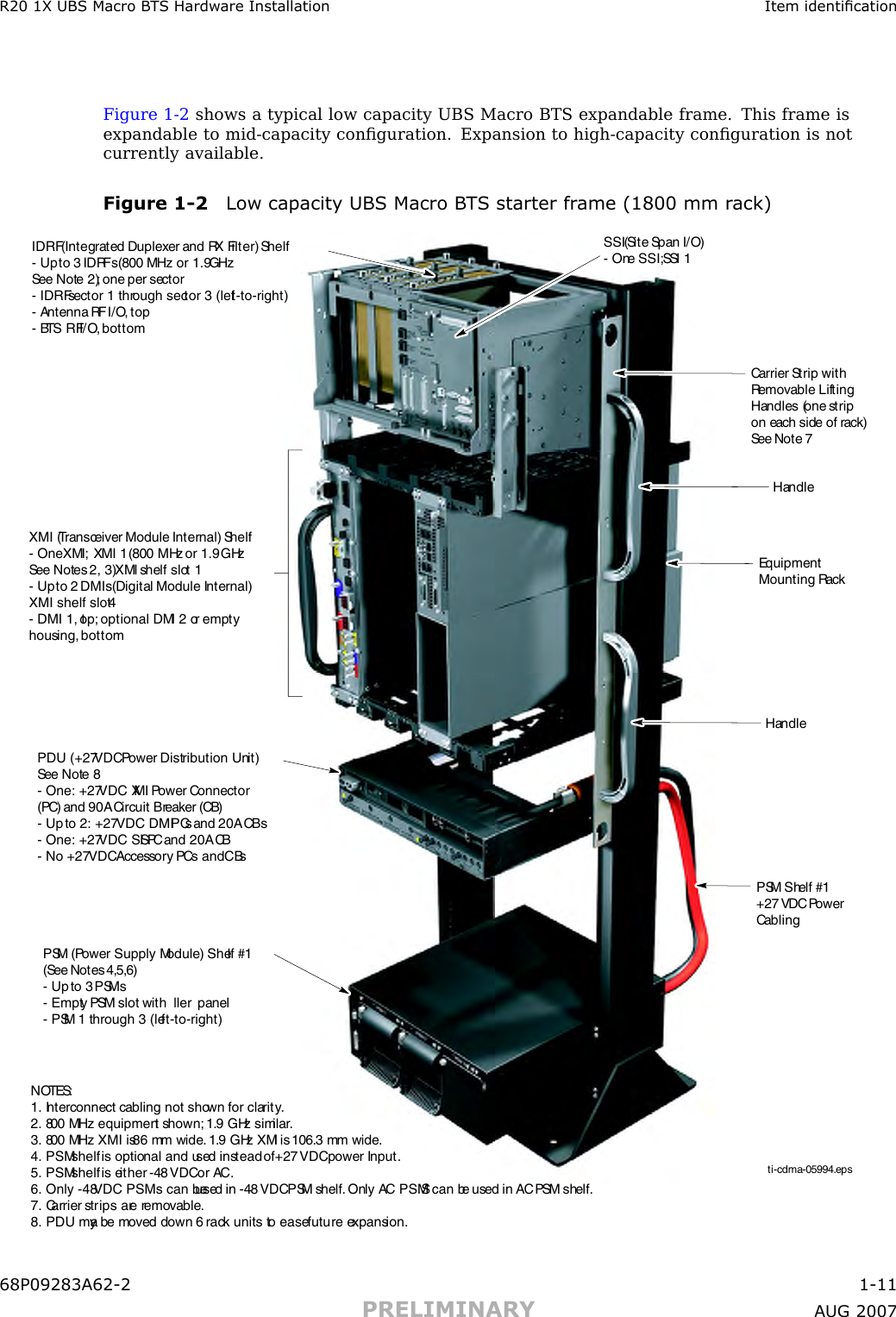
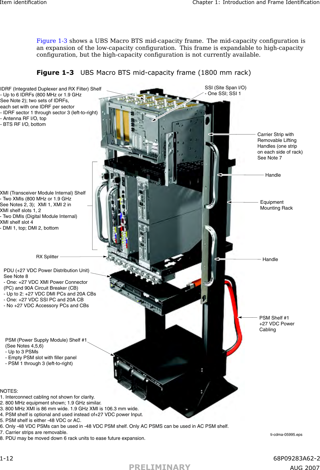
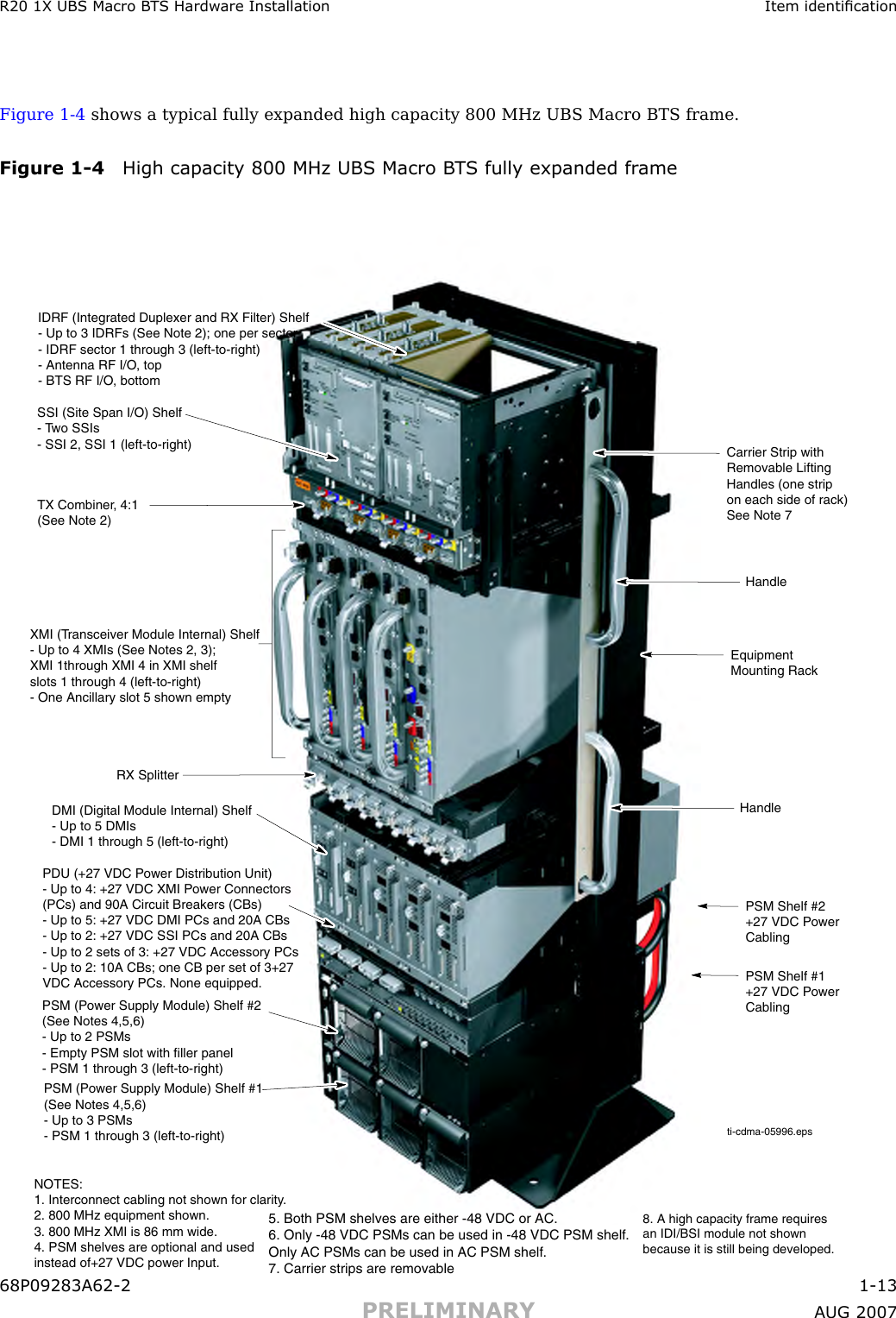
Exhibit 8a
2.
Exhibit 8b
Exhibit 8a
Navigation menu
Upload a User Manual
Namespaces
Wiki Guide
HTML
PDF
Info
Views
User Manual
Discussion / Help
Navigation