Nokia Solutions and Networks T6ZD1 SC1900 Fixed Wireless Terminal User Manual
Nokia Solutions and Networks SC1900 Fixed Wireless Terminal
UserManual.wiki
>
Nokia Solutions and Networks
>
T6ZD1 User Manual
>
Users Manual
Contents
1.
Users Manual
2.
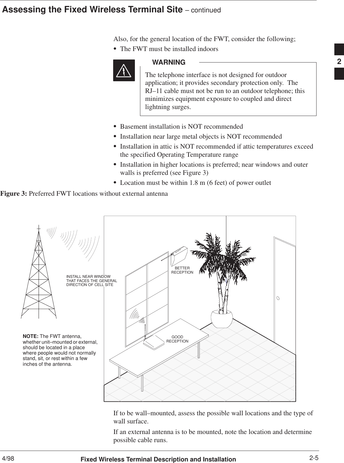
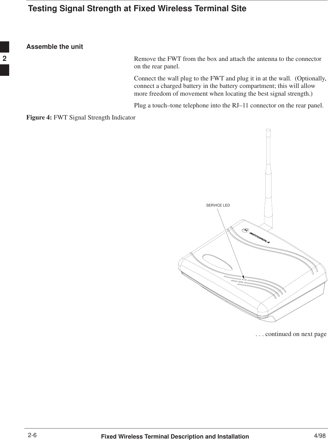
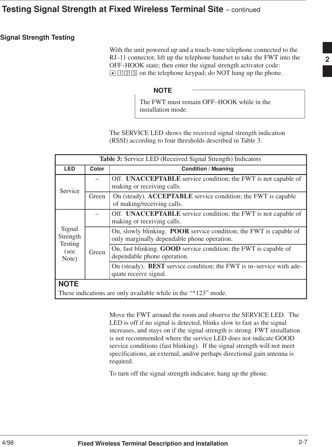
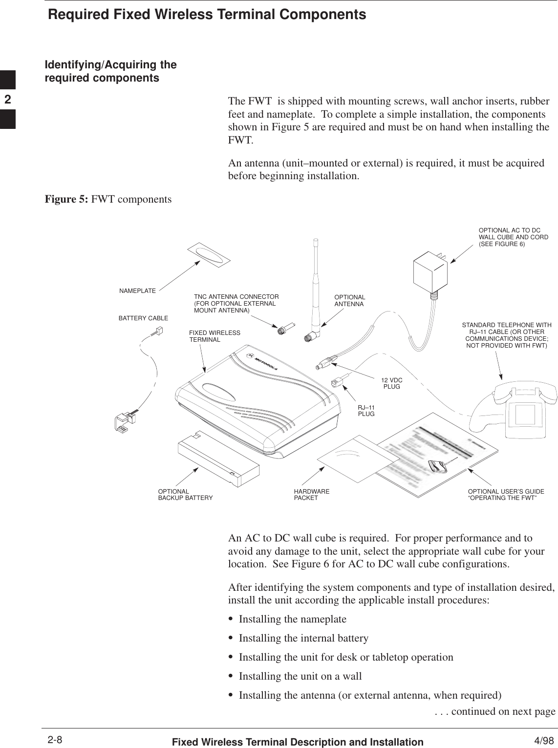
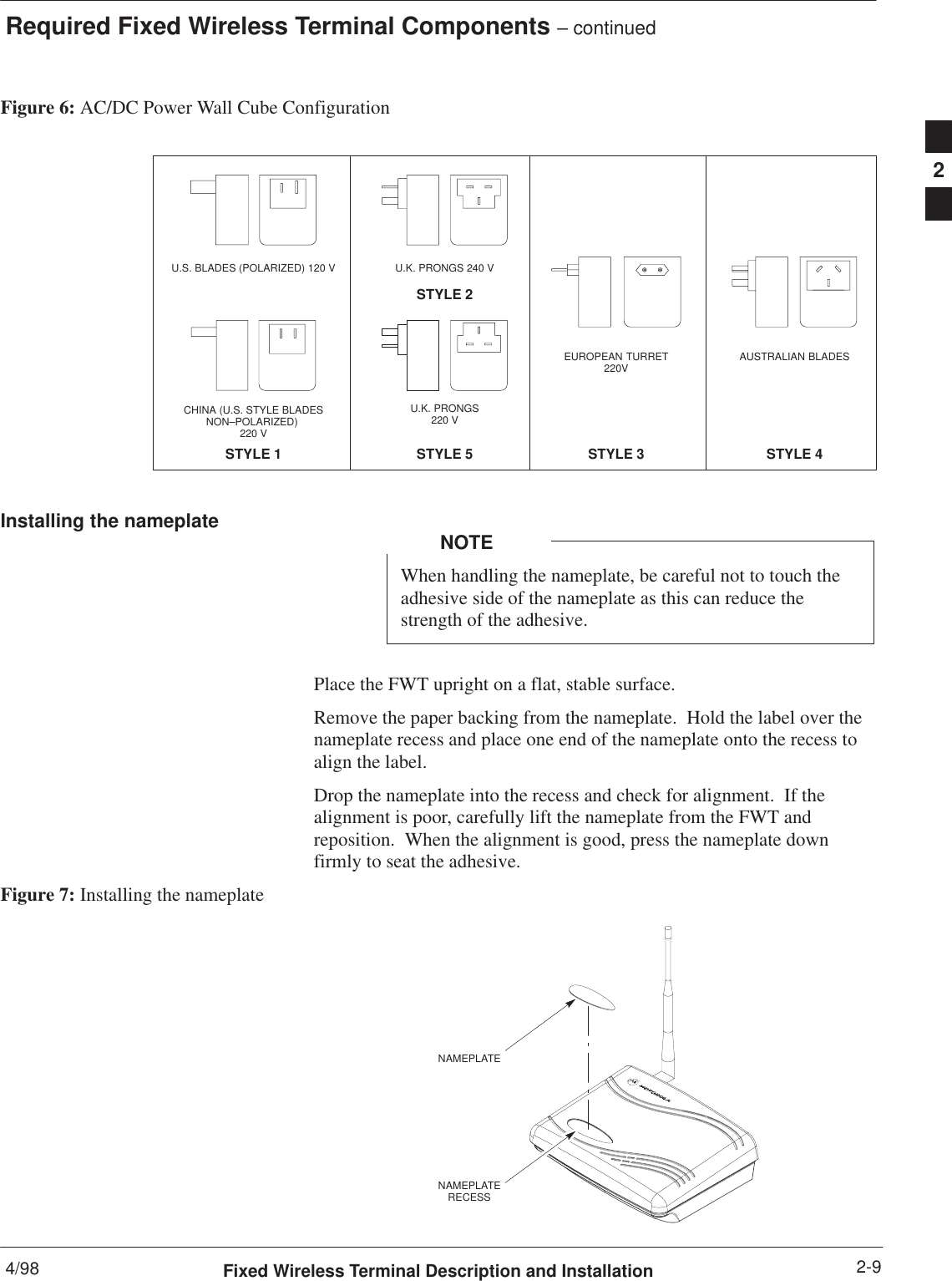
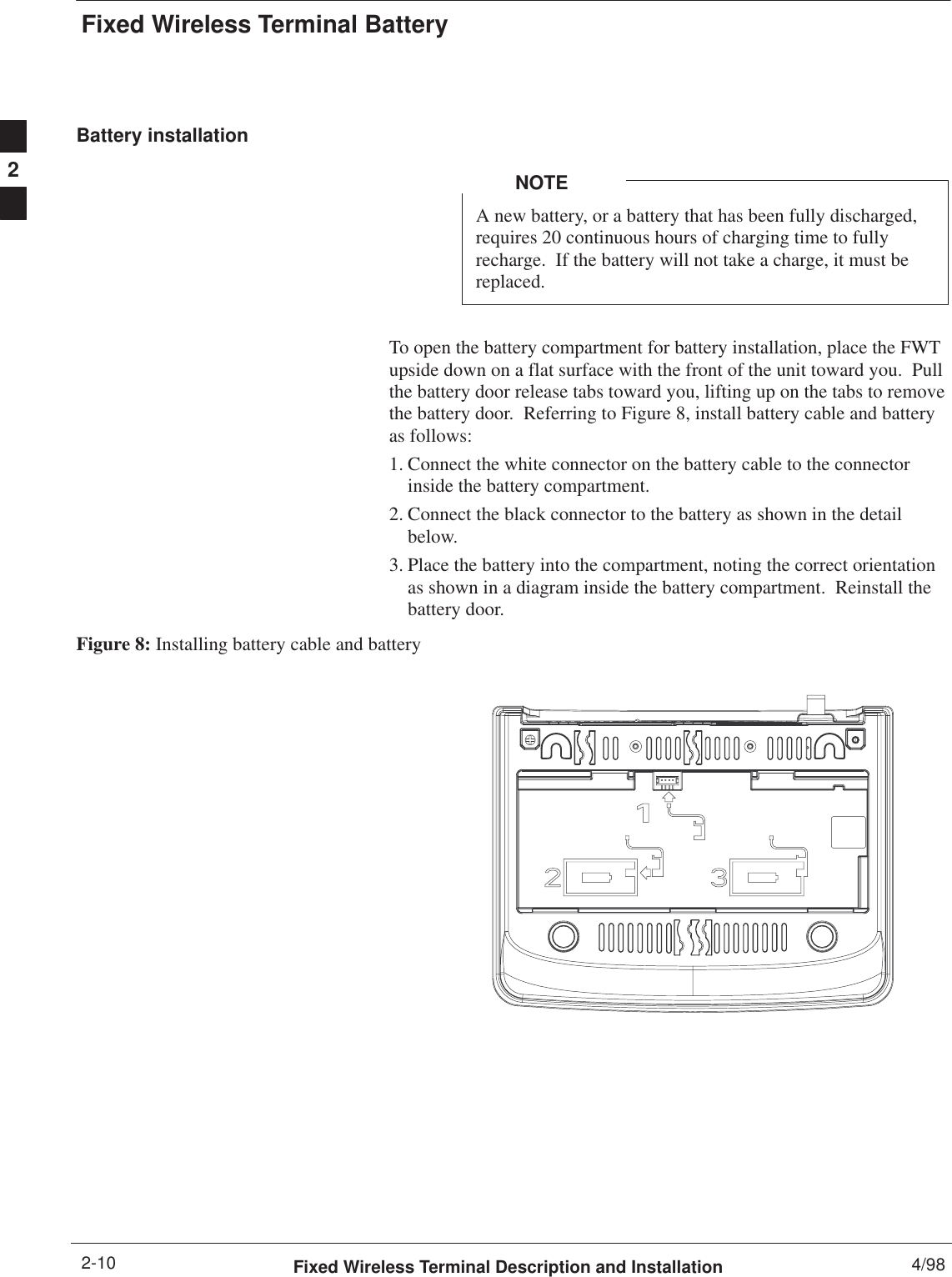
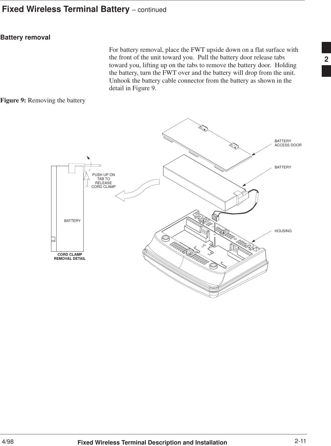
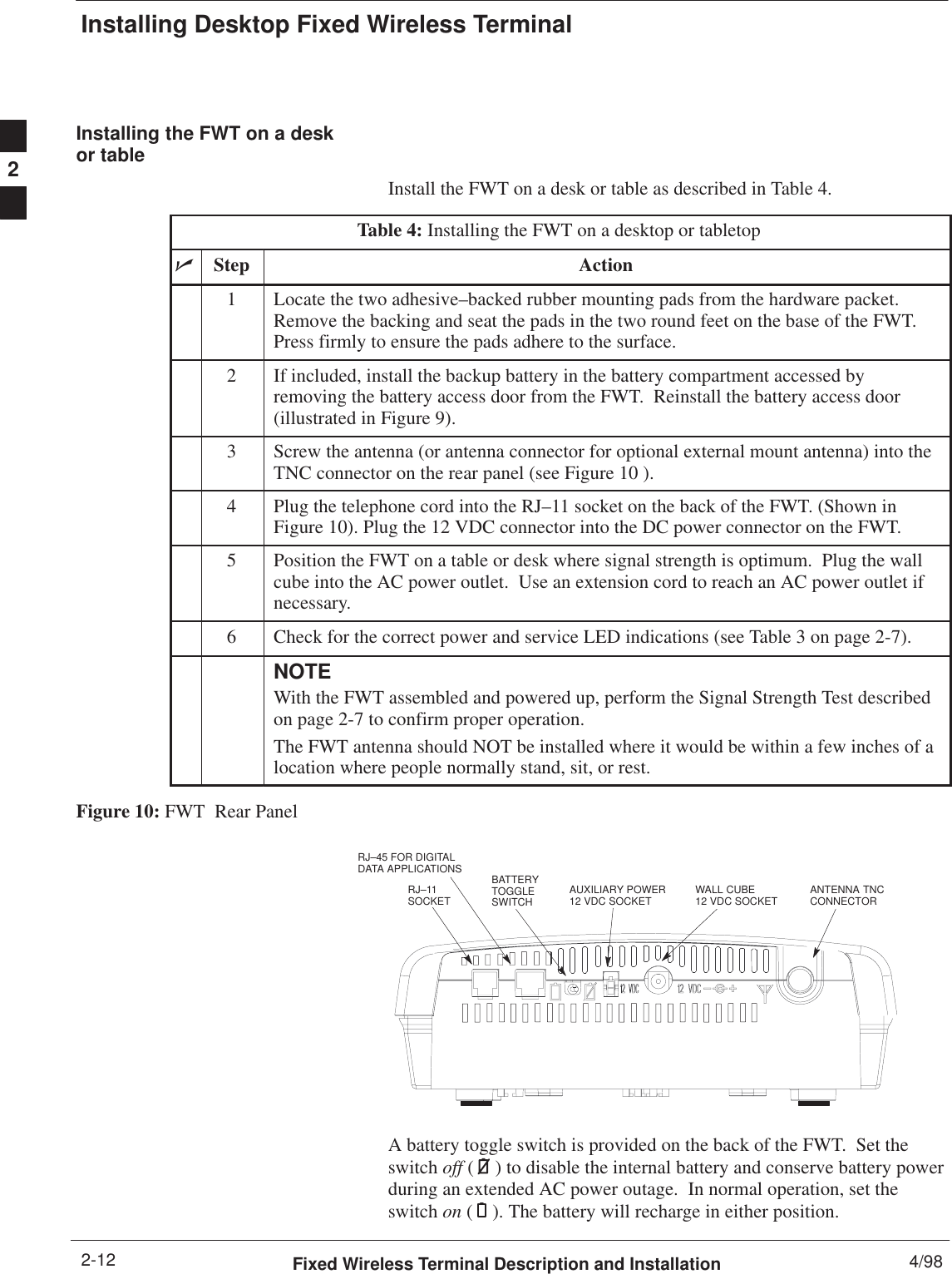
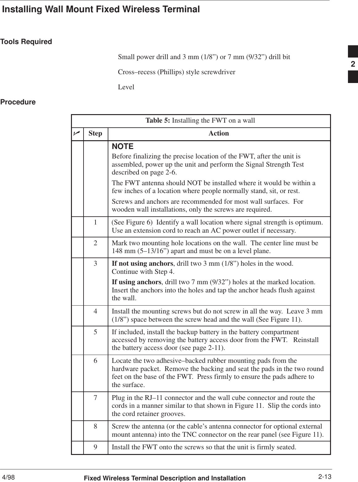
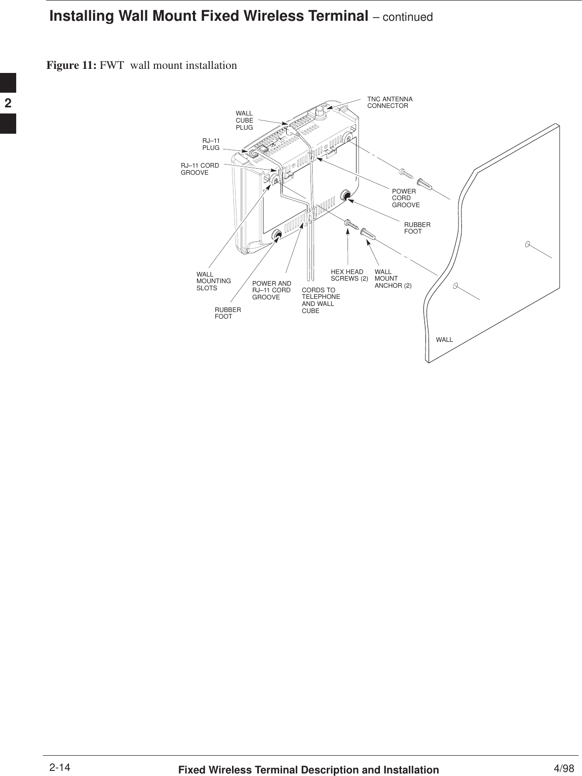
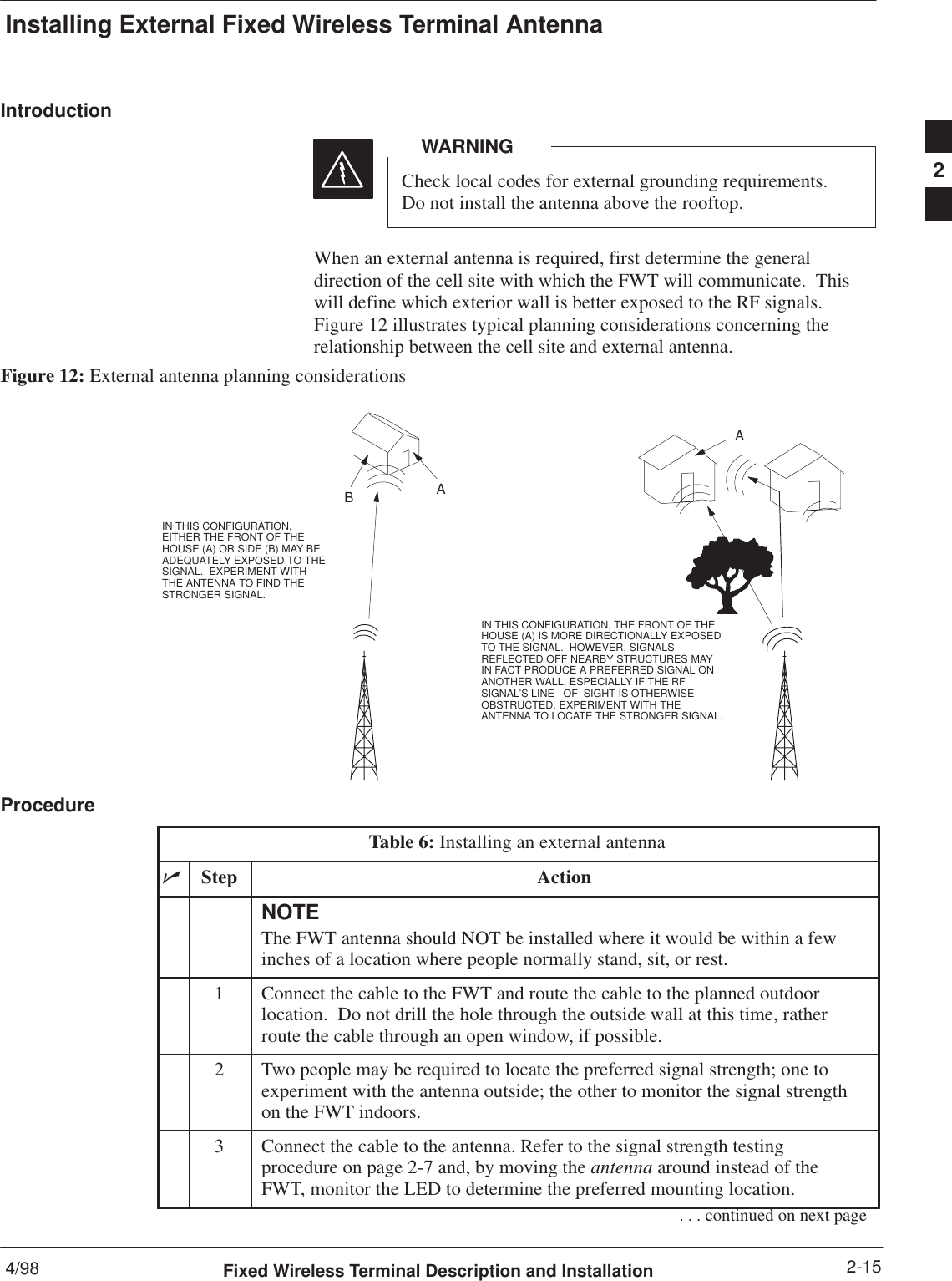
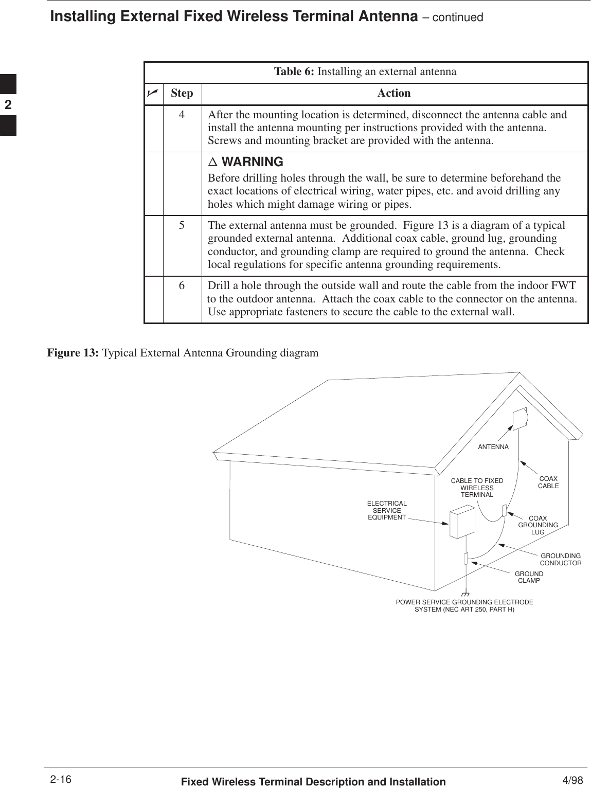
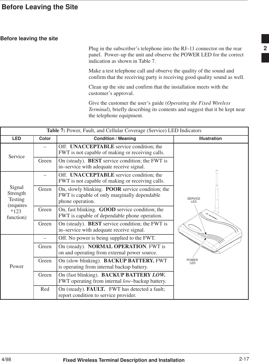
Fixed Wireless Terminal Description and Installation Manual
Users Manual
Navigation menu
Upload a User Manual
Namespaces
Wiki Guide
HTML
PDF
Info
Views
User Manual
Discussion / Help
Navigation