Nokia 12 Gsm Module Remote I O Users Manual Name
12 GSM MODULE REMOTE IO to the manual e2d65584-fead-47d2-85af-0919154f8159
2015-01-21
: Nokia Nokia-12-Gsm-Module-Remote-I-O-Users-Manual-349597 nokia-12-gsm-module-remote-i-o-users-manual-349597 nokia pdf
Open the PDF directly: View PDF ![]() .
.
Page Count: 53

Copyright © 2002-2004 Nokia. All rights reserved. Issue 2.0 9231722
NOKIA 12 GSM MODULE
REMOTE I/O CONTROL GUIDE

Contents
ACRONYMS AND TERMS ......................................................................................................1
1. ABOUT THIS DOCUMENT ................................................................................................2
2. INTRODUCTION ................................................................................................................3
2.1 GENERAL..................................................................................................................... 3
2.2 REMOTE I/O CONTROL ..............................................................................................3
3. SECURITY.......................................................................................................................... 5
4. GETTING STARTED .......................................................................................................... 7
4.1 SETTING UP THE CONFIGURATOR ENVIRONMENT ..............................................7
4.2 CONNECTING A DEVICE OR A MACHINE ................................................................ 8
4.3 MANDATORY SETTINGS............................................................................................8
4.4 READING AND WRITING PARAMETERS ..................................................................9
4.5 DEFINING THE MESSAGE IDENTIFIER..................................................................... 9
4.6 SETTING THE SMS CENTRE ADDRESS ................................................................. 11
5. OPTIONAL CONFIGURATIONS ...................................................................................... 13
5.1 DISABLING ACKNOWLEDGEMENTS....................................................................... 13
5.2 SECURITY SETTINGS...............................................................................................15
5.2.1 Authorised numbers............................................................................................. 15
5.3 ALIASING ...................................................................................................................17
5.4 INPUT SETTINGS ...................................................................................................... 19
5.5 DEFAULT OUTPUT VALUE SETTING ......................................................................20
6. INPUT/OUTPUT PIN DESCRIPTIONS ............................................................................ 22
7. SUPPORTED CHARACTERS.......................................................................................... 25
8. COMMAND SYNTAX ....................................................................................................... 26
9. REMOTE I/O CONTROL SMS COMMANDS................................................................... 27
9.1 COMMANDS ..............................................................................................................27
9.2 STATUS MESSAGES ................................................................................................28
9.3 DETAILED COMMAND INFORMATION AND RESPONSES .................................... 29
9.3.1 Changing the Password....................................................................................... 29
9.3.2 Reading Inputs.....................................................................................................30
9.3.3 Subscribing to Input Alarms.................................................................................32

9.3.4 Reading Outputs..................................................................................................34
9.3.5 Writing Outputs ....................................................................................................35
9.3.6 Inverting Outputs .................................................................................................37
9.3.7 Output Pulses ......................................................................................................38
9.3.8 Cancelling Output Pulses ....................................................................................40
9.3.9 Location information ............................................................................................43
10. SAFETY INFORMATION.................................................................................................. 46
10.1 NETWORK SUPPORT ...............................................................................................46
10.2 ANTENNA................................................................................................................... 47
10.3 MEDICAL DEVICES ................................................................................................... 47
10.4 VEHICLES .................................................................................................................. 47
10.5 POTENTIALLY EXPLOSIVE ENVIRONMENTS ........................................................48
10.6 CARE AND MAINTENANCE ...................................................................................... 48

Legal Notice
Copyright © 2002-2004 Nokia. All rights reserved.
Reproduction, transfer, distribution or storage of part or all of the contents in this document in any form without the
prior written permission of Nokia is prohibited.
Nokia and Nokia Connecting People are registered trademarks of Nokia Corporation. <Java and all Java-based
marks are trademarks or registered trademarks of Sun Microsystems, Inc.> Other product and company names
mentioned herein may be trademarks or trade names of their respective owners.
Nokia operates a policy of continuous development. Nokia reserves the right to make changes and improvements
to any of the products described in this document without prior notice.
Under no circumstances shall Nokia be responsible for any loss of data or income or any special, incidental,
consequential or indirect damages howsoever caused.
The contents of this document are provided "as is". Except as required by applicable law, no warranties of any
kind, either express or implied, including, but not limited to, the implied warranties of merchantability and fitness
for a particular purpose, are made in relation to the accuracy, reliability or contents of this document. Nokia
reserves the right to revise this document or withdraw it at any time without prior notice.

ACRONYMS AND TERMS
Acronym/term Description
ASCII American Standard Code for Information
Interchange
AT Attention
CORBA Common Object Request Broker Architecture
CSD Circuit Switched Data
GPRS General Packet Radio Service
GPS Global Positioning System
GSM Global System for Mobile Communications
I/O Input/Output
M2M Machine-to-Machine, Mobile-to-Machine,
Machine-to-Mobile
NITZ Network Indication and Time zone
SMS Short Message Service
SW Software
1/49

1. ABOUT THIS DOCUMENT
This document describes how the Nokia 12 GSM module can be used in
Remote I/O control mode. The methods for controlling a module in this
operation mode are described, as well as how to increase security.
Before using the product, it is important to read the safety instructions and
notifications at the end of this document, see chapter 10.
For more information about the Nokia 12, other Nokia M2M products, and
application development for M2M, please visit Forum Nokia and M2M links at
http://www.forum.nokia.com or http://www.americas.forum.nokia.com.
2/49

2. INTRODUCTION
2.1 GENERAL
The Nokia 12 GSM Module provides wireless connectivity and remote
management possibilities for machine-to-machine (M2M) applications and other
wireless solutions. The Nokia 12 GSM Module has two variants:
• RX-2 is dual band EGSM900/GSM1800 product
• RX-9 dual band GSM850/GSM1900 product.
The Nokia 12 GSM Module supports EGPRS, GPRS, HSCSD (not supported in
RX-9), CSD, and SMS.
Simple I/O applications can be easily implemented using the Nokia 12 GSM
Module in the Remote I/O control, which offers message personalising, secure
messaging, and timing functionality for SMS controlled I/O applications.
Additional intelligence for I/O applications can easily be implemented with Java.
Java technology enables upgrading the application software, IMlet, also
remotely.
The Nokia 12 GSM Module enables also location service in the Remote I/O
control. Location coordinates can be easily queried by SMS.
The Remote I/O control is explained in this document.
Note: Some services described or mentioned in this document, such as GPRS, are
network dependent. Please contact your network service provider for details.
2.2 REMOTE I/O CONTROL
In the Remote I/O control the Nokia 12 GSM Module is controlled with, for
example, a compatible mobile phone. Control messages are sent as text
messages from the mobile phone to the Nokia 12 GSM Module. Based on the
information in the text message, the Nokia 12 GSM Module in turn controls a
device or machine attached to it through the M2M system connector.
Table 1. Functions in the Remote I/O control
Function Details
Control a device Switch devices on or off
Switch devices on or off for a period of time
3/49
Monitor a device Find out if a device is already on or off
Receive alarm messages if a device has been switched on or off
Receive alarm messages if a specified alarm limit has been crossed
Personalize Define your own device commands (aliases)
Disable acknowledgements for device commands
Select the frequency of alarm messages (alarm once/continuously)
Identify the calling party and give permissions for device control
Position Get position information through the Nokia 12 GSM Module when connected to a
GPS device
The Nokia 12 GSM Module processes the control message it receives, and
sends the response as a text message back to the originator. Received and
recognised control messages are not stored in the Nokia 12 GSM Module
memory. If a text message is not recognised as a control message, it is stored
on the SIM card or Nokia 12 GSM Module memory as a normal text message.
Before you can send control messages to the Nokia 12 GSM Module in order to
control or monitor the device attached to it, you must configure the Nokia 12
GSM Module. Use the Nokia 12 Configurator software, which can be
downloaded at http://www.forum.nokia.com or
http://www.americas.forum.Nokia.com. Some configurations are also possible
with control messages; others require that Configurator is used.
Note: To use Configurator, you need the Nokia 12 GSM Module and a test board.
The Nokia 12 GSM Module is connected to a compatible PC and Configurator with
the test board. A power supply, data cable, antenna adapter, antenna, and SIM
card are also needed. All these items are included in the Nokia 12 GSM Module
test board sales package.
Attach the device to be controlled or monitored with control messages to the
general-purpose inputs and outputs of the M2M system connector of the Nokia
12 GSM Module. There are 11 inputs of which the first three (1-3) are analog
and the rest (4-11) are digital. The Nokia 12 GSM Module has also 9 digital
output pins on the M2M system connector. If the information available from the
device is continuous, select one of the three analog input pins. If the information
is on/off information, use the inputs 4-11. The nine outputs can be used in
digital mode only (set something on/off).
4/49

3. SECURITY
There are different levels of access control for the Remote I/O control: message
identifier, password, and authorised numbers. Also the aliases defined for
commands increase security.
You must use a message identifier, which means that you must name the Nokia
12 GSM Module to be able to use the Remote I/O control. Each control
message begins with an identifier, which enables the Nokia 12 GSM Module
recognise it as a Remote I/O control message. Enter the identifier with the
Nokia 12 Configurator software when using the Nokia 12 GSM Module for the
first time (see chapter 4.5). Only users who know the correct message identifier
can control and monitor the device attached to the Nokia 12 GSM Module. The
message identifier is case sensitive.
You can use a password to further secure the communication between the
mobile phone and the Nokia 12 GSM Module. You must enter the password
when sending a control message to the Nokia 12 GSM Module. Set the
password with Configurator or with a control message (see chapter 5.2). Only
users who know the correct password can control and monitor the device
attached to the Nokia 12 GSM Module. The password is case sensitive.
You can also determine a closed user group of up to 16 authorised phone
numbers. The Nokia 12 GSM Module only accepts control messages from
these phone numbers. Specify the numbers with Configurator. The first number
on the authorised phone number list is in bold and it identifies the main user of
the Nokia 12 GSM Module. The main user is notified of any unauthorised
control attempts.
You can use user-defined commands (aliases) instead of the default
commands of the Nokia 12 GSM Module (see chapter 5.3). If an alias has been
defined, the default command can no longer be used and is not accepted as
part of a control message. While default commands are generally known, an
alias is only known by the one who defined it. Only users who know the correct
alias can control and monitor the device attached to the Nokia 12 GSM Module.
Note: The message identifier and password are case sensitive, whereas
commands and aliases are not.
5/49

6/49

4. GETTING STARTED
4.1 SETTING UP THE CONFIGURATOR ENVIRONMENT
To use Configurator, the following tools are needed:
• Nokia 12 GSM Module (RX-2 or RX-9)
• Nokia 12 test board
• Power supply ACW-6
• Data cable AXS-3
• Antenna adapter cable
• Antenna
• SIM card
All items listed above, except the SIM card, are included in Test board sales
package. Configurator can be used with a SIM card inserted to the test board
SIM card holder. To use Configurator:
1. Mount the Nokia 12 GSM Module on the 60-pin connector of the test board.
2. Insert the SIM card into the test board SIM card holder.
3. Connect the antenna to the Nokia 12 GSM Module with the antenna adapter
cable.
4. Connect the data cable AXS-3 to a compatible PC and to the test board. Use
the D9 connector port 2 in the test board. To enable the connection, select
the M2M system protocol in the preferences dialog (File -> Preferences) as
the communication type.
5. Turn the switch on the test board in the following way:
6. Connect the power supply ACW-6 to the test board and to an AC wall outlet.
Note: The connection settings in the preferences dialog must be correct.
For more information on the Nokia 12 test board, refer to the Nokia 12 Test
Board Specification.
7/49

When you have completed the above steps, Configurator automatically
establishes a connection between the PC and the Nokia 12 GSM Module when
Configurator is started.
4.2 CONNECTING A DEVICE OR A MACHINE
Connect the device to be controlled with the Remote I/O control to the Nokia 12
GSM Module through the M2M system interface. The general-purpose inputs
and outputs of the M2M system connector that are described in Chapter 6 are
connected to the device.
More information about how to connect a device electrically to the Nokia 12
GSM Module and about the recommended connector types is provided in Nokia
12 GSM Module HW Integration Manual.
4.3 MANDATORY SETTINGS
To use the Remote I/O control of the Nokia 12 GSM Module, you have to
configure these settings:
• Message identifier
• SMS centre address
• You can also configure the following optional settings (described in Chapter
5):
• Disabling acknowledgements
• Security settings
• Input settings
• Defining aliases for text messages
• Initial output value settings
• GPS port settings
Use Nokia 12 Configurator to configure the settings of the Nokia 12 GSM
Module. Download Configurator at http://www.forum.nokia.com or
http://www.americas.forum.nokia.com. You can also use a control message
(short message) for the optional settings.
The following sections describe the process of getting started with the Remote
I/O control.
Note: To use Configurator, you need the Nokia 12 GSM Module and a test board.
The Nokia 12 GSM Module is connected to a compatible PC and Configurator with
the test board. A power supply, data cable, antenna adapter, antenna, and SIM
card are also needed. All these items are included in the Nokia 12 GSM Module
test board sales package.
8/49
4.4 READING AND WRITING PARAMETERS
To read parameter values from the Nokia 12 GSM Module and write parameter
values to it, use Configurator. Each Configurator dialog has “Read parameters”
and “Write parameters” button for this purpose. Data is transferred between
Configurator and the Nokia 12 GSM Module only after you have clicked either
of these buttons.
Note: To apply the configured settings, click either the Read parameters or Write
parameters button.
Some of the settings require that you reset the Nokia 12 GSM Module before
they take effect. Either click the Reset button on the test board or remove and
plug in the power cord on the test board. You can also use Configurator to reset
the Nokia 12 GSM Module (File -> Reboot Module).
Note: The Nokia 12 GSM Module should be reset after you have configured all
parameter values.
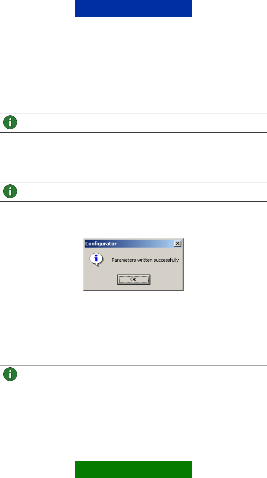
After a parameter value has been successfully configured to the Nokia 12 GSM
Module, the dialog in Figure 1 appears.
Figure 1. Dialog for successful parameter configuration
4.5 DEFINING THE MESSAGE IDENTIFIER
The message identifier is a mandatory setting that must be configured in order
to use the Remote I/O control. Figure 2 shows a dialog (User Control Mode ->
Settings -> Initialize) where you can set the identifier in Configurator. To define
the message identifier, press Change. See Figure 2.
Note: Press the Write parameters button to activate the new identifier.
After you have set the message identifier, more parameters become available.
If a message identifier has been previously defined to the Nokia 12 GSM
Module, press the Read parameters button to enable the additional parameters.
9/49
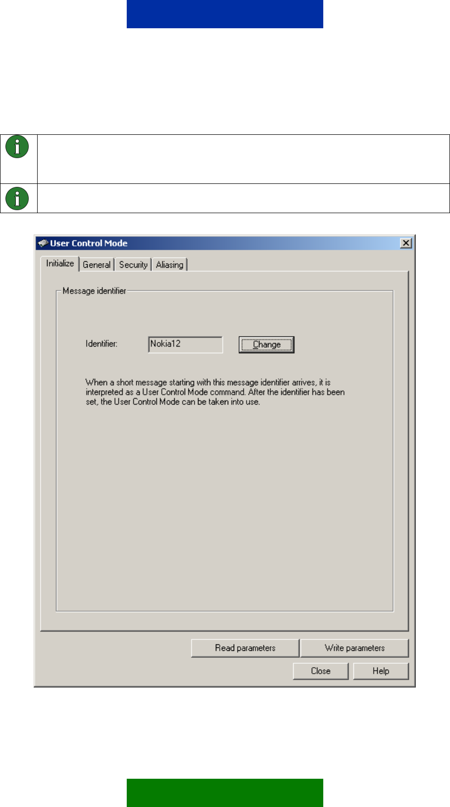
Characters accepted for the message identifier are defined in Chapter 7, except
the space characters.
Note: You cannot use the Remote I/O control if there is no message identifier
defined. In this case, all received short messages will be handled as normal
messages and the inputs/outputs cannot be controlled in the Remote I/O control.
Note: The message identifier is 1-8 characters long and case sensitive.
Figure 2. User Control Mode dialog
10/49
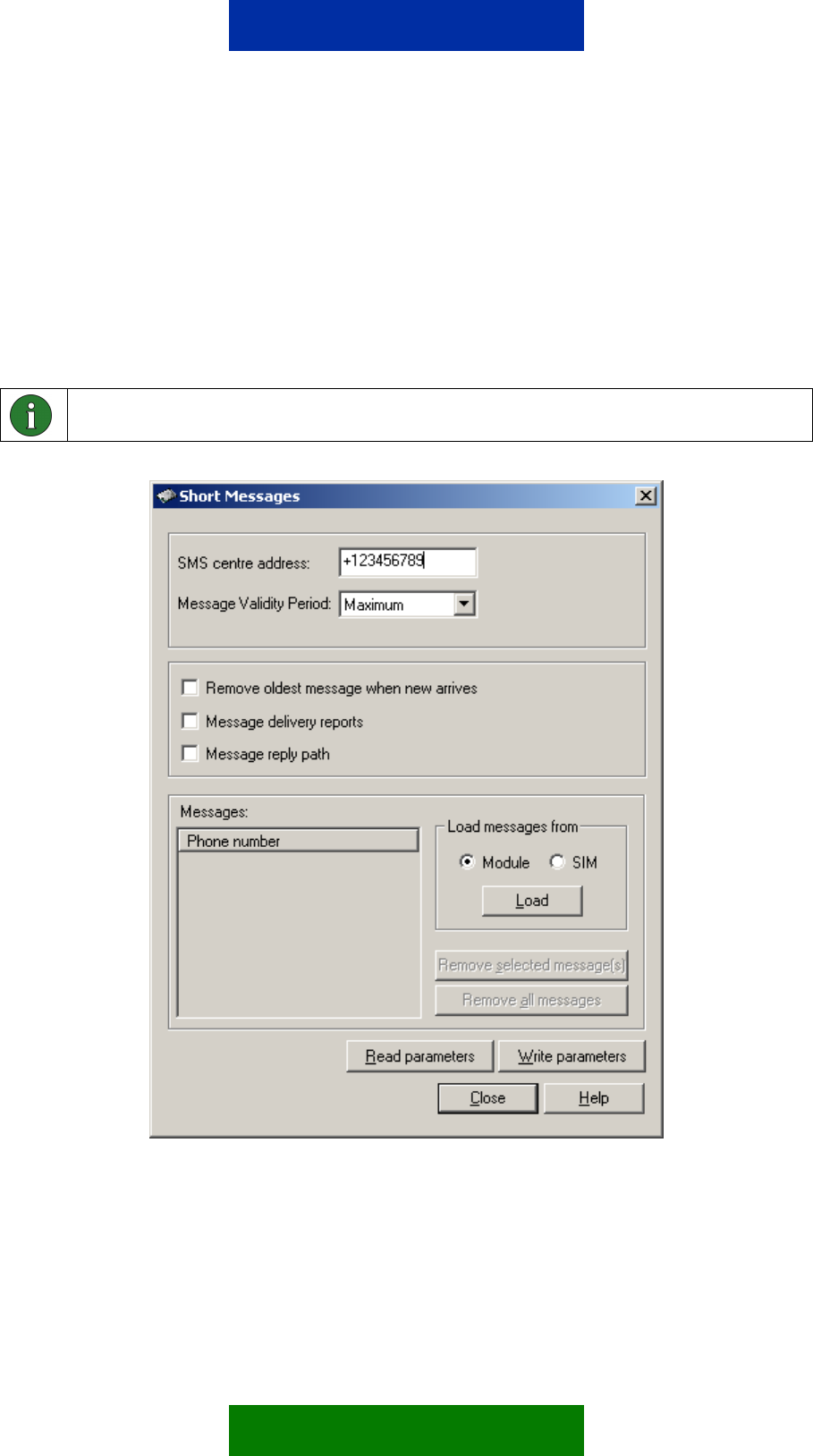
4.6 SETTING THE SMS CENTRE ADDRESS
A dialog for setting the SMS centre address with the Nokia 12 Configurator
(GSM Settings -> Advanced -> Short Messages) is shown in Figure 3.
To check whether the SMS centre address is available on the network service
provider SIM card, press the Read parameters button shown in Figure 3. If the
SMS centre address is not available, specify it in the Short Messages dialog in
order to be able to use the Remote I/O control.
Note: Contact your network service provider for the SMS centre address.
Figure 3. Short Messages dialog
Short messages can be stored in the SIM card or the Nokia 12 GSM Module
memory. If both of these short message storages are full, new messages
cannot reach the Nokia 12 GSM Module. If the “Remove oldest message”
option is selected in the short message dialog, the oldest message will be
removed from the SIM card memory when a new message arrives, if both the
11/49

SIM card and the Nokia 12 GSM Module memory are full. It is recommended to
select the option “Remove oldest message when new arrives” for the Remote
I/O control, because then the control messages have a better chance of
reaching their destination and fulfilling their purpose.
12/49

5. OPTIONAL CONFIGURATIONS
5.1 DISABLING ACKNOWLEDGEMENTS
The Nokia 12 GSM Module acknowledges whether or not a text message has
successfully commanded a device. The Nokia 12 GSM Module sends a
response as a text message back to the phone number that sent the control
message. It is also possible to disable this feature to decrease the amount of
communication with the device, for example.
Figure 4 displays a dialog (User Control Mode -> Settings -> General) for
configuring acknowledgement messages.
13/49
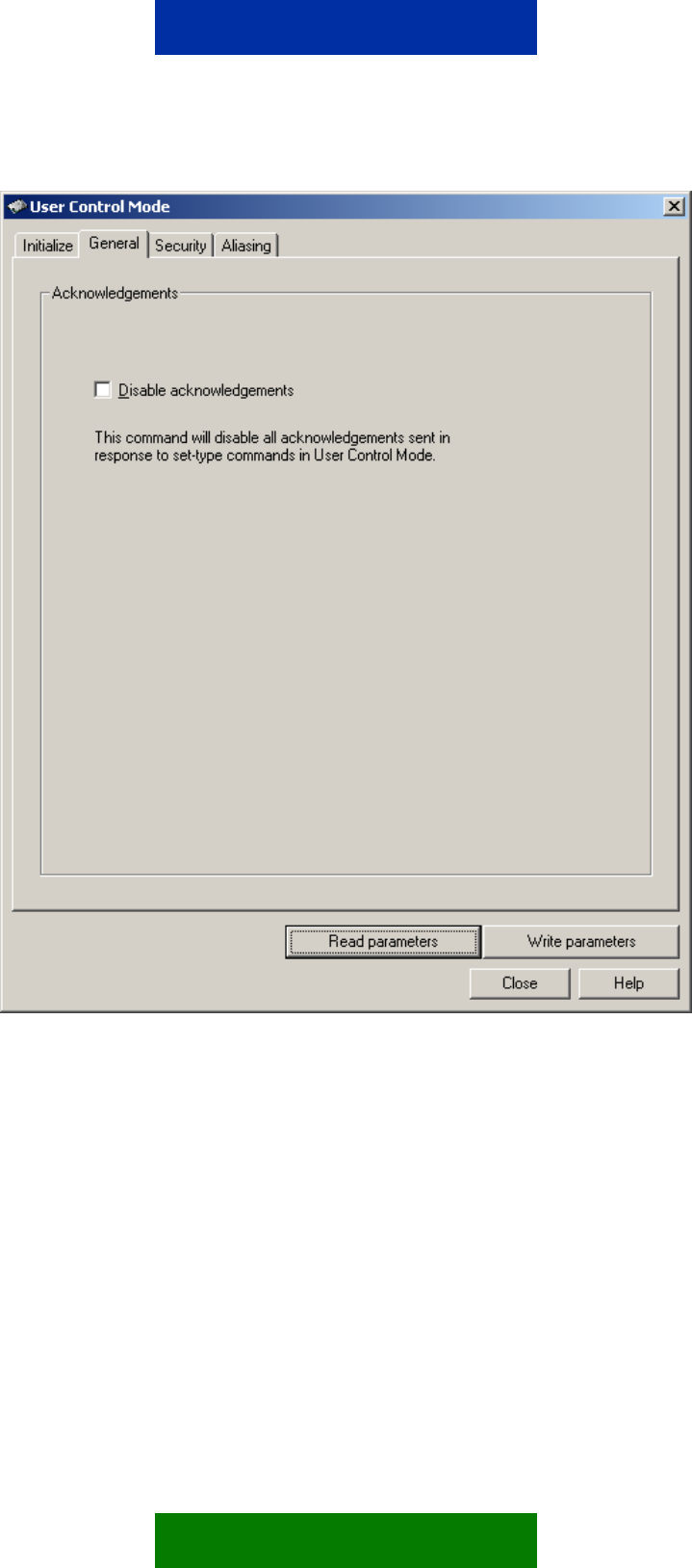
Figure 4. General settings
If you select the Disable acknowledgements option, only response messages to
acknowledgement messages are disabled. The following will not be disabled:
• Status messages; responses to input state or value queries
• Indication messages, for example, responses to timed commands (see
Chapter 9.3.7)
• Alarm messages; responses to alarm subscriptions (see Chapters 5.4 and
9.3.3)
• Error messages that are sent, for example, in response to a control
message with the correct message identifier and password, but with the
wrong command
14/49

• Response messages to password change messages (see Chapter 9.3.1)
• Response messages to pulse cancel messages (see Chapter 9.3.8)
5.2 SECURITY SETTINGS
Figure 5 shows a dialog (User Control Mode -> Settings -> Security) where
security settings can be configured with Nokia 12 Configurator.
5.2.1 Authorised numbers
Authorised number selection limits the access to specific phone numbers only
in the Remote I/O control. Only control messages originating from an
authorised number are allowed to control the Nokia 12 GSM Module and the
device attached to it.
It is possible to define up to 16 authorised numbers. The first number on the
authorised phone number list is in bold (see Figure 5) and is the phone number
of the main user. The main user will be notified of any unauthorised control
attempts.
The following message will be sent to the main user if there is an unauthorised
control attempt:
Unauthorized Number:
Number: X
Command: Y
X is the phone number of the originator of the control message, and Y is the
command that was attempted. If the length of a command or alias is too long to
be shown in one message (more than 160 characters), it will be sent as several
messages.
The phone numbers in the authorised number list may contain digits 0-9 and
the “+” character (ASCII range 0x30-0x39 and 0x2B), for example,
+1234567890, for a maximum length of 32 characters.
Note: The phone numbers in the authorised number list should be defined in
international format with a plus sign, country codes, etc. Note that the Nokia 12
GSM Module needs to receive and identify the number to recognise it as
authorised. Contact your network service provider for details.
15/49
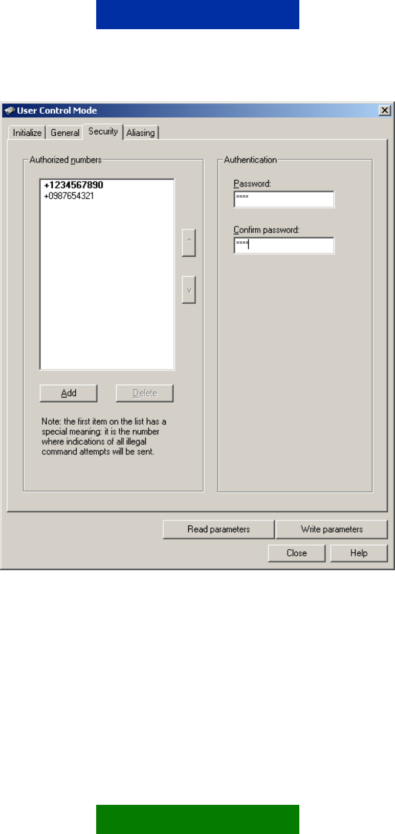
Figure 5. Security settings
Authentication
A user-specified password can further secure the communication between a
mobile handset and the Nokia 12 GSM Module. The password must be entered
when a control message is sent to the Nokia 12 GSM Module. When this
feature has been set on, but the password is missing or incorrect, the message
received is discarded. Activate or change the password with Configurator or
with a control message (see Chapter 9.3.1).
16/49

The length of the password is 1- 8 characters, and it is case sensitive. It
accepts characters defined in Chapter 7, except space characters. The
password is case sensitive.
Note: If the password is changed, an indication message is only sent to the phone
number that requested the change.
5.3 ALIASING
Figure 6 shows a dialog (User Control Mode -> Settings -> Aliasing) where
aliases can be defined for commands with the Nokia 12 Configurator.
17/49
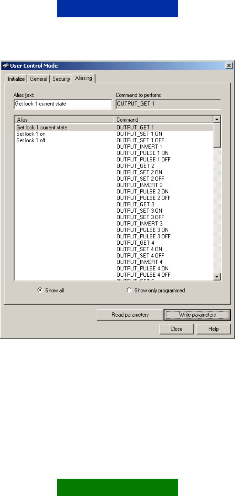
Figure 6. Setting aliases for device commands
In the Aliasing dialog, you can replace the predefined commands with user-
specified commands (aliases). The defined alias replaces the initial command
or previous alias configured for the command. If an alias has been configured,
the original command is no longer accepted. Defining an empty alias for a
command can restore the original command. Duplicate aliases are not allowed.
Aliases can also be defined for status messages sent in response to status
queries. Thus, an alias can be defined for a command for controlling the device,
querying the status of the device (see chapter 9.1), and for the message
received in response to the query (see chapter 9.2).
18/49
Characters accepted in aliases are defined in chapter 7.
Note: If an alias is defined, the default command will be disabled. There can be
only one effective command or alias for each function at a time. An alias must not
be equal to a default command.
Empty aliases cannot be used. If an empty alias is set, the default command will
remain effective.
Note: The alias string must be unique and the maximum length is 24 characters.
Neither commands nor aliases are case sensitive. However, the message identifier
and password are.
5.4 INPUT SETTINGS
Figure 7 shows a dialog (File -> Module Configuration -> Input Settings) where
you can configure analog input settings with Configurator.
The Nokia 12 GSM Module has separate digital and analog inputs. You can set
high and low limits to the analog input pins. The pin can be in the normal or
alarm mode. If the information is continuous, use inputs 1-3.
The input sampling interval indicates the period for which the Nokia 12 GSM
Module polls the input state. The sampling interval value ranges from 1 to 60
seconds.
For control messages querying input states or values, see Chapter 9.3.2.
You can subscribe to text message alarms as response messages. This is
done using control messages described in Chapter 9.3.3.
As a default, the alarm message is sent once to the number where the alarm
was subscribed. Alternatively, the alarm can be sent continuously. In this case,
alarm messages are sent when alarm conditions are met, until the alarm
subscription is cancelled (see Chapter 9.3.3). To configure the alarm sequence,
select “Continuously” or “Once” in the Input Settings dialog.
In analog input, or if device data is continuous, an alarm can be set to be
triggered when a limit is crossed. Configurator requires the high and low limits
as millivolts (0 … 2800 mV) and the sampling interval as seconds (1-60 s).
Control messages for subscribing an alarm or alarms are described in chapter
9.3.3.
Note: It is mandatory to set input high and low limit values in the analog mode.
Note: The number to which alarm messages are sent can only be defined by
subscribing to an alarm. After the subscription, the alarm will be sent as a response
to the number where the alarm was subscribed. Thus, the number cannot be
defined with Configurator.
19/49
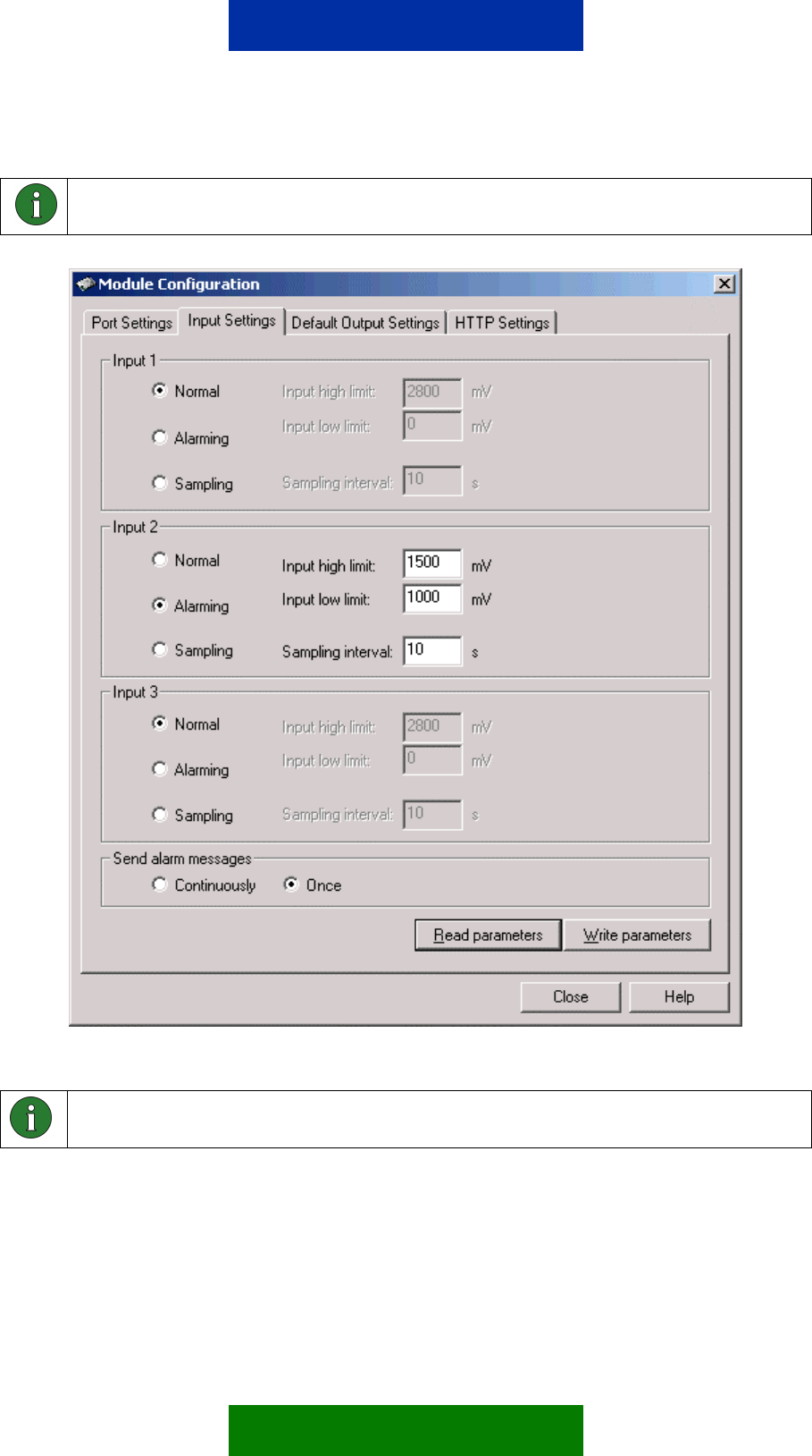
Note: In digital input, an alarm can be triggered when the state of the digital input
changes. See chapter 9.3.3 for more information.
Figure 7. Input settings
Note: In Figure 7 the Input 1 and 3 cannot be used for alarming because they are
configured as Normal.
5.5 DEFAULT OUTPUT VALUE SETTING
Set the initial state of each output pin and the device being controlled with
Configurator (File -> Module Configuration -> Default Output Values). The
20/49

values set here will take effect the next time the Nokia 12 GSM Module is
powered up.
Check the box in the Default Output Settings window to set the output to 1. If
you leave the box empty, the output is 0.
Note: The number of available digital outputs depends on the port configurations.
21/49


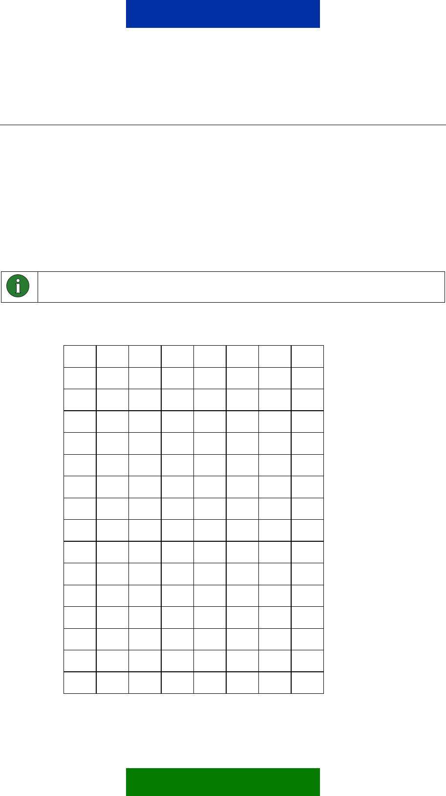
Table 2. PIN descriptions
Name Analog/Digital R/W Pin Number (*)
Input 1 Analog Read 36
Input 2 Analog Read 20
Input 3 Analog Read 19
Input 4 Digital Read 54
Input 5 Digital Read 35
Input 6 Digital Read 34
Input 7 Digital Read 56
Input 8 Digital Read 43
Input 9 Digital Read 59
Input 10 Digital Read 55
Input 11 Digital Read 46
Output 1 Digital Read/Write 53
Output 2 Digital Read/Write 30
Output 3 Digital Read/Write 31
Output 4 Digital Read/Write 32
Output 5 Digital Read/Write 33
Output 6 Digital Read/Write 57
Output 7 Digital Read/Write 58
Output 8 Digital Read/Write 42
Output 9 Digital Read/Write 44
(*) Pin number on M2M System Connector
For more information on the electrical characteristics of the M2M system
connector, see Nokia 12 GSM Module Hardware Integration Manual.
Note: Depending on the Nokia 12 GSM Module configuration, some pins are used
as serial ports (TxD, RxD, CTS and so on). GPS support can be configured to
some pins. See Figure 8.
23/49
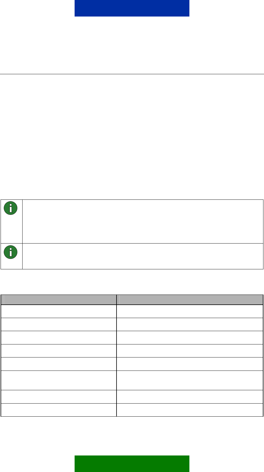
7. SUPPORTED CHARACTERS
The characters listed in Table 4 are supported for:
• Message identifier
• Password
• Aliasing
The list is derived from the Default Alphabet table of a GSM technical
specification (see Digital cellular telecommunications system (Phase 2+);
Alphabets and language-specific information (GSM 03.38)). CR, LF and Escape
characters are not supported.
Note: You cannot use a space in the message identifier or password. However,
you can use it in aliases defined for commands.
Table 3. Characters supported by Configurator for Remote I/O control
@ ∆ SP 0 ¡ P ¿ p
£ _ ! 1 A Q a q
$ Φ " 2 B R b r
¥ Γ # 3 C S c s
è Λ ¤ 4 D T d t
é Ω % 5 E U e u
ù Π & 6 F V f v
ì Ψ ' 7 G W g w
ò Σ ( 8 H X h x
Ç Θ ) 9 I Y i y
SP Ξ * : J Z j z
Ø SP + ; K Ä k ä
ø Æ , < L Ö l ö
SP æ - = M Ñ m ñ
Å ß . > N Ü n ü
å É / ? O § o à
25/49

8. COMMAND SYNTAX
The command syntax of control messages varies according to the activated
options. There may also be spaces in aliases defined for commands as seen in
the example below. However, only one space character is accepted between
words. The message identifier and password are case sensitive.
Note: A control message always begins with a message identifier. Otherwise the
message is not interpreted as a Remote I/O control message, and is stored in the
SIM card or the Nokia 12 GSM Module memory.
Control message without a password:
<message identifier> <command / alias>
term123 Output_Set All On
Control message without a password with an alias defined:
<message identifier> <command / alias> <parameter>
term123 Output_Pulse All On 1h30m
Control message with a password:
<message identifier> <password> <command / alias>
term123 password Output_Set All On
Control message with a password with an alias defined:
<message identifier> <password> <command / alias>
<parameter>
term123 password Output_Pulse All On 1h30m
26/49
9. REMOTE I/O CONTROL SMS COMMANDS
The following chapter describes the commands and status messages available
in the Remote I/O control. Status messages are sent in response to device
status queries. You can define an alias for each of the commands and status
messages described here with Configurator.
The first part of the chapter lists commands that are sent to the Remote I/O
control as part of a control message; the second part provides a list of status
messages for which an alias can be defined.
9.1 COMMANDS
The Nokia 12 GSM Module supports the SMS commands listed in Table 4.
These commands are for controlling or monitoring purposes (to query the state
of a device attached to the Nokia 12 GSM Module). An alias can be defined for
each of the commands.
Note: If an alias is defined, the default command will be disabled. There can be
only one effective command or alias for each function at a time. An alias must not
be equal to a default command.
Empty aliases cannot be used. If an empty alias is set, the default command will
remain effective.
Note: The alias string must be unique and the maximum length is 24 characters.
Neither commands nor aliases are case sensitive. However, the message identifier
and password are.
Table 4. List of commands.
Command Description
OUTPUT_GET x Return a state of output x, x = pin number 1-9
OUTPUT_SET x ON Set output x ON, x = pin number 1-9
OUTPUT_SET x OFF Set output x OFF, x = pin number 1-9
OUTPUT_INVERT x Inverts output x, x = pin number 1-9
OUTPUT_PULSE x ON * Output x pulse ON *, x = pin number 1-9
OUTPUT_PULSE x OFF
* Output x pulse OFF *, x = pin number 1-9
OUTPUT_GET ALL Return a state of all outputs
OUTPUT_SET ALL ON Set all outputs ON
27/49

OUTPUT_SET ALL OFF Set all outputs OFF
OUTPUT_INVERT ALL Inverts all outputs
OUTPUT PULSE ALL ON
* All outputs pulse ON *
OUTPUT_PULSE ALL
OFF *
All outputs pulse OFF *
INPUT_GET x Return a voltage of input x, x = pin number 1-11
INPUT_GET ALL Return states of all inputs
INPUT_GET_CHANGE x Subscribe a voltage limit alarm of input x, x = pin number 1-
11
INPUT_GET_CHANGE
ALL Subscribe a input state change of all inputs
INPUT CHANGE CANCEL
x Cancel input x subscription, x = pin number 1-11
INPUT CHANGE CANCEL
ALL Cancel all input subscriptions
CHANGE_PWORD Change password
OUTPUT PULSE CANCEL
x Cancel output x pulse, x = pin number 1-9
OUTPUT PULSE CANCEL
ALL Cancel all outputs
LOCATION_GET Get location information **
* The duration of the pulse will be added to the control message after the corresponding command. The format is the
following:
Output_Pulse 1 On <days>d<hours>h<minutes>m<seconds>s
for example Output_Pulse 1 On 5m30s
For more information about pulse commands, see Chapter 9.3.7.
** The location support needs external GPS device to be connected to the Nokia 12 GSM Module. The Nokia 12
GSM Module supports NMEA-0183 protocol.
9.2 STATUS MESSAGES
The Nokia 12 GSM Module supports the status messages listed in
Table 5. You can define an alias for each of them. The messages will be sent
as responses to device query control messages according to the current
command and device state.
28/49
Note: If an alias is defined, the default command will be disabled. There can be
only one effective command or alias for each function at a time. An alias must not
be equal to a default command.
Empty aliases cannot be used. If an empty alias is set, the default command will
remain effective.
Note: The alias string must be unique and the maximum length is 24 characters.
Neither commands nor aliases are case sensitive. However, the message identifier
and password are.
Table 5. List of response messages
Response Message Description
OUTPUT x: ON Alias for output x on state, x = pin number 1-9
OUTPUT x: OFF Alias for output x off state, x = pin number 1-9
INPUT x: * Alias for input x voltage *, x = pin number 1-3
INPUT x: ON Alias for input x on state, x = pin number 4-11
INPUT x: OFF Alias for input x off state, x = pin number 4-11
* The value of the sampled voltage will be added to the end of the response. The value of the sampled voltage is
between 0 – 2800 mV, for example:
INPUT 1: 10mV
9.3 DETAILED COMMAND INFORMATION AND RESPONSES
All example commands in this chapter use the “term123” identifier string, and
the password property is set off in all of the subsequent chapters.
Note: If a command or the alias defined for it is not identified, but the identifier and
the optional password are correct, the Nokia 12 GSM Module will send an error
message as a response to the command originator, for example:
Control message: term123 passWORD ResetAll
Response: ERROR (Unknown Command)
9.3.1 Changing the Password
Use the Change_Pword command to control the password. Note that all
example commands in this chapter use the “term123” identifier string (see
Table 6).
29/49
Table 6. Commands for the password control.
Command Type Command Comments
Changing Password term123 passWORD
Change_PWord wordPASS
OK Response:
CHANGE_PWORD wordPASS: OK
Fail Response:
CHANGE_PWORD: FAILED
The example
changes the
password from
‘passWORD’ to
‘wordPASS’
Activating Password
Property
term123 Change_PWord
wordPASS
OK Response:
CHANGE_PWORD wordPASS: OK
Fail Response:
CHANGE_PWORD: FAILED
The example
changes an empty
password to
‘wordPASS’
Deactivating
Password Property
term123 wordPASS
Change_PWord
OK Response:
CHANGE_PWORD: OK
Fail Response:
CHANGE_PWORD: FAILED
The example
changes the
password from
‘wordPASS’ to an
empty password
Note: An indication of a password change is only sent to the phone number where
the change was requested.
9.3.2 Reading Inputs
Use the Input_Get X commands for reading inputs, that is the state or value of
a device. Note that all example control messages in this chapter use the
“term123” identifier string and the password property is set off (see Table 7)
A response depends on the pin. There are three analog inputs (1-3) and nine
digital inputs (4-11) in the Nokia 12 GSM Module M2M system interface. You
can also specify an alias for the response (see chapter 9.2).
30/49

Table 7. The Input_Get X commands
Command Type Command Comments
Input_Get All term123 Input_Get All
Response:
INPUT_GET ALL: OK
INPUT1: Y
INPUT2: Y
INPUT3: Y
INPUT4: Y
INPUT5: Y
INPUT6: Y
INPUT7: Y
INPUT8: Y
INPUT9: Y
INPUT10: Y
INPUT11: Y
The Y varies according to the input pin state and it can be:
xxxx mV if the input analog (pins 1-3), xxxx = value
between 0-2800
ON or OFF if the input is digital (pins 4 -11)
The command
reads all inputs
and the response
returns the value
and state
Input_Get X term123 Input_Get X
Response:
INPUT_GET X: OK
INPUT X: Y
The X refers to input pin number,
X=1,2,3,4,5,6,7,8,9,10,11.
The Y varies according to the input pin state and it can be:
xxxx mV if the input is analog (pins 1-3), xxxx = value
between 0-2800
ON or OFF if the input is digital (pins 4-11)
The command
reads input pin X
and the response
returns the value
or state of it
according to
queried input pin
31/49

9.3.3 Subscribing to Input Alarms
To subscribe to input state changes, that is, alarms, use the
Input_Get_Change X commands. All example control messages in this
chapter use the “term123” identifier string and the password property is set off
(see Table 9).
When you subscribe to this service, and an input state changes, you will
receive an alarm message. You can also subscribe to alarms on a continuous
basis, so that each time the state changes, you receive an alarm message until
you cancel the subscription with the Input_Change_Cancel command.
You can subscribe to alarms for all input state changes at once, or to each input
separately. Note that an input must be configured properly in order to get the
alarms. For more information about alarm configurations, see Chapter 5.4.
There are two ways to configure an analog input to operate with alarm sending
(see Chapter 5.4 for configurations):
• Alarming + Input High Limit + Input Low Limit + Sampling Interval
• Once/Continuously
An alarm from the analog pin is sent if the value is equal to or higher than the
high limit, or equal to or lower than the low limit. Define the frequency of the
state of the input polling in the sampling interval box (see Figure 7).
An alarm from the digital pin is sent if the digital pin state is changed and the
input state change is subscribed to that pin by the Input_Get_Change X
command.
Important: The latest subscription overrides any previous alarm subscription. The
alarm will only be sent as a response to the latest subscription; the originator of the
previous subscription will not be notified.
32/49

Table 8. Input_Get_Change commands for alarm functionality
Command Type Command Comments
Input_Get_Change All Term123 Input Get Change
All
Response:
INPUT_GET_CHANGE ALL:
INPUT 1: Y
INPUT 2: Y
INPUT 3: Y
INPUT 4: Y
INPUT 5: Y
INPUT 6: Y
INPUT 7: Y
INPUT 8: Y
INPUT 9: Y
INPUT 10: Y
INPUT 11: Y
The Y refers to success state and it can be:
OK or CHECK CONFIG
Alarm message, when input state has changed,
contains the following information:
INPUT 1: Y
INPUT 2: Y
INPUT 3: Y
INPUT 4: Y
INPUT 5: Y
INPUT 6: Y
INPUT 7: Y
INPUT 8: Y
INPUT 9: Y
INPUT 10: Y
The command
subscribes alarms for
all inputs at once
33/49

INPUT 11: Y
The Y varies according to the input pin state and it can
be:
xxxx mV if the input is in analog mode (pins 1-3)
(xxxx=value between 0-2800)
ON or OFF if the input is in digital mode (pins 4-11)
Input_Get_Change X
term123 Input Get Change
X
Response:
INPUT_GET_CHANGE Z:
INPUT X: Y
The X refers to input pin number,
X=1,2,3,4,5,6,7,8,9,10,11.
The Y refers to success state and it can be:
OK or CHECK CONFIG
Event data, when input state has changed, contains the
following information:
INPUT X: Y
The X refers to input pin number,
X=1,2,3,4,5,6,7,8,9,10,11.
The Y varies according to the input pin state and it can
be:
ON or OFF if the input is digital (4-11)
xxxx mV if the input is analog (1-3) (xxxx=value
between 0-2800)
The command
subscribes an alarm
for input pin X and the
response returns the
state of it according to
input pin configuration
Input_Change_Cancel
term123
Input_Change_Cancel X
OK Response:
INPUT_CHANGE_CANCEL X:
OK
The X refers to input pin number,
X=1,2,3,4,5,6,7,8,9,10,11,all.
The command
cancels an alarm
subscription for input
pin X
9.3.4 Reading Outputs
Use the Output_Get X commands for reading digital output states. Note that all
example control messages in this chapter use the “term123” identifier string and
the password property is set off (see Table 9).
34/49

Table 9. Output_Get X commands
Command Type Command Comments
Output_Get All term123 Output_Get All
Response:
OUTPUT_GET ALL: OK
OUTPUT 1: Y
OUTPUT 2: Y
OUTPUT 3: Y
OUTPUT 4: Y
OUTPUT 5: Y
OUTPUT 6: Y
OUTPUT 7: Y
OUTPUT 8: Y
OUTPUT 9: Y
The Y refers to either ON or OFF
The command reads all
outputs and the response
returns the state of them
Output_Get X
term123 Output_Get X
Response:
OUTPUT_GET X: OK
OUTPUT X: Y
The X refers to output pin number, X=1,2,3,4,5,6,7,8,9.
The Y refers to either ON or OFF
The command reads
output pin X and the
response returns the
state of it
9.3.5 Writing Outputs
Use the Output_Set X commands to set digital output states. Note that all
example control messages in this chapter use the “term123” identifier string and
the password property is set off (see Table 10).
35/49

Table 10. Output_Set X commands
Command Type Command Comments
Output_Set X On
term123 Output_Set X On
Response:
OUTPUT_SET Z ON: OK
OUTPUT Z: ON
The X refers to output pin number, X=1,2,3,4,5,6,7,8,9.
The command sets
output pin X to ON state
and the response returns
the state of it
Output_Set X Off
term123 Output_Set X Off
Response:
OUTPUT_SET X OFF: OK
OUTPUT X: OFF
The X refers to output pin number, X=1,2,3,4,5,6,7,8,9.
The command sets output
pin X to OFF state and the
response returns the state
of it
Output_Set All On term123 Output_Set All
On
Response:
OUTPUT_SET ALL ON: OK
OUTPUT 1: ON
OUTPUT 2: ON
OUTPUT 3: ON
OUTPUT 4: ON
OUTPUT 5: ON
OUTPUT 6: ON
OUTPUT 7: ON
OUTPUT 8: ON
OUTPUT 9: ON
The command sets all
outputs to ON state and
the response returns the
state of all outputs
Output_Set All Off term123 Output_Set All
Off
Response:
OUTPUT_SET ALL OFF: OK
OUTPUT 1: OFF
OUTPUT 2: OFF
The command sets
all outputs to OFF
state and the
response returns the
state of all outputs
36/49

OUTPUT 3: OFF
OUTPUT 4: OFF
OUTPUT 5: OFF
OUTPUT 6: OFF
OUTPUT 7: OFF
OUTPUT 8: OFF
OUTPUT 9: OFF
9.3.6 Inverting Outputs
Use the Output_Invert X commands to invert digital output states. The
state of an output can be changed without knowing its previous state. Note that
all example control messages in this chapter use the “term123” identifier string
and the password property is set off (see Table 11).
Table 11. Output_Invert X commands
Command Type Command Comments
Output_Invert X
term123 Output_Invert X
Response:
OUTPUT_INVERT X: OK
OUTPUT X: Y
The X refers to output pin number, X=1,2,3,4,5,6,7,8,9.
The Y refers to either ON or OFF
The command inverts
output pin X to
opposite state.
Output_Invert All
term123 Output_Invert
All
Response:
OUTPUT_INVERT ALL: OK
OUTPUT 1: X
OUTPUT 2: X
OUTPUT 3: X
OUTPUT 4: X
OUTPUT 5: X
OUTPUT 6: X
The command inverts
all output pins to
opposite state.
37/49
OUTPUT 7: X
OUTPUT 8: X
OUTPUT 9: X
The X refers to either ON or OFF
9.3.7 Output Pulses
Use the Output_Pulse X Y commands to set digital output states to
requested state for a specified time. Note that all example control messages in
this chapter use the “term123” identifier string and the password property is
set off (see Table 12).
While the pulse is active, the pin state remains as requested and is locked. You
can cancel the pulse with the Output_Pulse_Cancel command described in
Chapter 9.3.8. After the requested time has passed, the output state is returned
to the opposite value of that requested. The final state of the output is
independent of the initial state of the output.
The behavior of the output pins when the Output_pulse X command is used
is depicted in Figure 9.
d)
c)
b)
a)
Case Initial
state
Control message to be sent
a) ON term123 Output_pulse 1 ON 5s
b) ON term123 Output_pulse 1 OFF 5s
c) OFF term123 Output_pulse 1 ON 5s
d) OFF term123 Output_pulse 1 OFF 5s
0 s 5 s Time
Figure 9. Output pulses in different initial stages and for different
commands
38/49

Table 12. Output_Pulse X commands
Command Type Command Comments
Output_Pulse X On
term123 Output_Pulse X
On <time>
Response:
OUTPUT_PULSE X ON
<time>: OK
Response, when pulse time expires:
OUTPUT X: Y
The X refers to output pin number, X=
1,2,3,4,5,6,7,8,9,all.
The Y refers to either ON or OFF.
Response, if another pulse command has already been
issued:
OUTPUT_PULSE X ON
<time>:
OUTPUT X LOCKED
Fail response, if invalid <time> value:
ERROR( Unknown Command )
Fail response, if NITZ network service is not supported
and <time> value was more than 23 hours 59 minutes
and 59 seconds:
OUTPUT_PULSE ON <time>:
ERROR( Network Time
Missing )
The command sets to
output pin X on for a
requested time interval,
that is, pulse
Output_Pulse X Off
term123 Output_Pulse X
Off <time>
Response:
OUTPUT_PULSE X OFF
<time>: OK
Response, when pulse time expires:
OUTPUT X:Y
Response, if another pulse command has already been
issued:
OUTPUT_PULSE X OFF
<time>:
OUTPUT X LOCKED
Fail response, if invalid <time> value:
The command sets to
output pin X off for a
requested time interval,
that is, pulse
39/49

ERROR( Unknown Command )
Fail response, if NITZ network service is not supported
and <time> value was more than 23 hours 59 minutes
and 59 seconds:
OUTPUT PULSE OFF <time>:
ERROR( Network Time
Missing )
The X refers to output pin number,
X=1,2,3,4,5,6,7,8,9,all.
The Y refers to either ON or OFF
Command syntax for <time> parameter:
<days>d<hours>h<minutes>m<seconds>s
for example, Output_Pulse 1 On 5m30s
Value ranges for <time> parameter:
<time> If Network Indication and Time Zone (NITZ) network service is
supported, the range is from 1 second to 7 days.
If NITZ network service is not supported, the range is from 1 second to 23
hours 59 minutes and 59 seconds.
<days> If NITZ network service is supported, the range is from 1 … 7
days.
<hours> 1…23
<minutes> 1…59
<seconds> 1…59
Value examples for valid <time>:
7d, 6d23h59m59s, 45m, 59s, 4h25s, 30m45s, etc.
Value examples for invalid <time>:
7d1s Maximum time (7 days) exceeded
3m3m There cannot be two unit fields of the same
100s Maximum second and minute value is 59. Use 1m40s instead
24h Maximum hour value is 23. Use 1d instead of 24h
9.3.8 Cancelling Output Pulses
It is possible to cancel pulses before the <time> parameter defined in the pulse
control message has passed. This is done with the “Output_Pulse_Cancel
40/49
X” command. Note that all example control messages in this chapter use the
“term123” identifier string and the password property is set off (see Table 13).
The command cancels the timing of the pulse operation and informs the original
pulse originator about it. The state of the cancelled output remains the same, as
was set with Output_Pulse X command. Thus, it is the timing of the pulse
that is cancelled, not the pulse itself.
Table 13. Output_Pulse_Cancel X commands
Command Type Command Comments
Output_Pulse_Cancel X
term123
Output_Pulse_Cancel X
Response:
OUTPUT_PULSE_CANCEL X:
OK
Indication to original pulse originator:
OUTPUT X PULSE
CANCELLED
The X refers to output pin number,
X=1,2,3,4,5,6,7,8,9,all.
The command cancels
the pulse of output pin X
Note: When canceling a pulse, the state of the output does not revert to the same
as it was before the Output_Pulse X command. The Output_Pulse_Cancel
X command cancels the timing on the pulse, not the pulse itself, as can be seen in
Figure 10 (the pulse without cancelling can be seen dashed in the figure).
d)
c)
b)
a)
0 s 3 s 5 s Time
41/49

Case Initial
state
Control message Control message sent when 3s
passed
a) ON Term123 Output_pulse 1 ON 5s
b) ON Term123 Output_pulse 1 OFF 5s
c) OFF Term123 Output_pulse 1 ON 5s
d) OFF Term123 Output_pulse 1 OFF 5s
Term123 Output_Pulse_Cancel 1
Figure 10. Effects of cancelling an output pulse in different initial stages
and for different commands
42/49
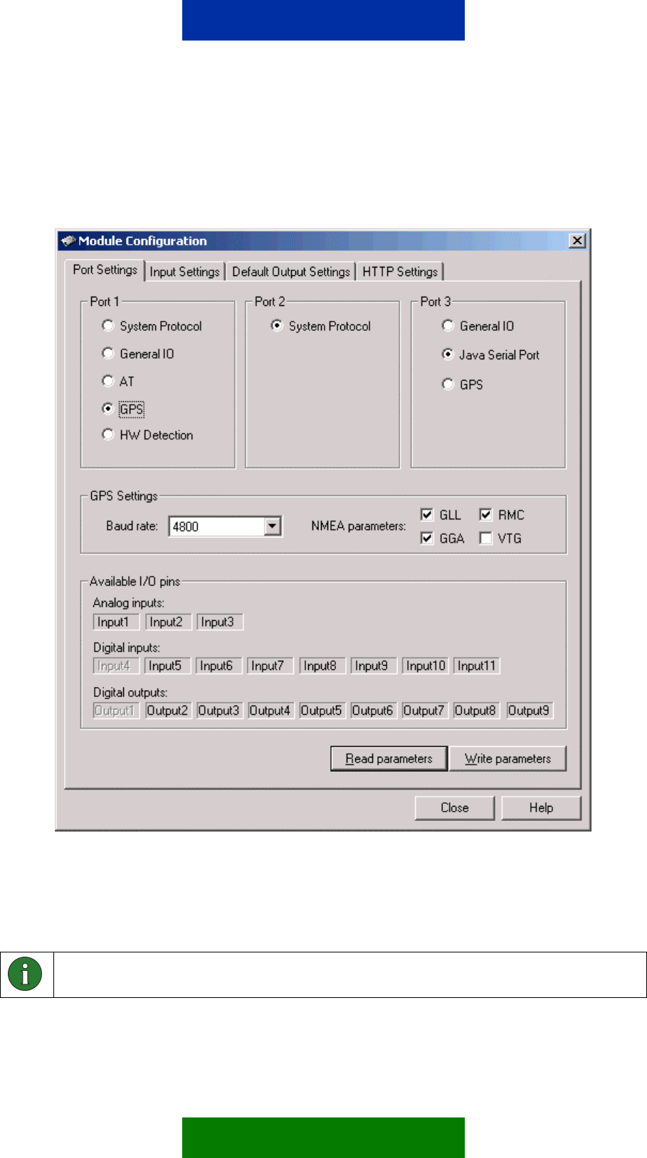
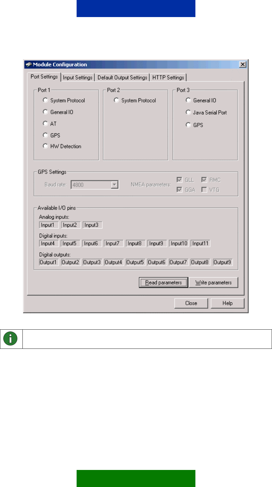
9.3.9 Location information
Figure 11. GPS support configured to serial port 1
You can query location information from the Nokia 12 GSM Module if an
external GPS device is connected to either the serial port 1 or 3. The serial port
used has to be configured with Nokia 12 Configurator, see Figure 11.
Note: If you have selected serial port 3 for GPS support, Java cannot use the serial
port.
43/49

Note: You cannot connect a GPS device to serial port 2. It is always in the M2M
system protocol use.
Note: You can connect only one GPS device to the Nokia 12 GSM Module
(PORT1 or PORT3).
To use GPS support, configure the GPS settings (baud rate and used NMEA
parameters). See your GPS device manual for information about parameters
used.
Query the location information with the Location_get command. Note that all
example control messages in this chapter use the “term123” identifier string and
the password property is set off (see Table 14).
Response parameters of Location_get command are:
• AA Latitude, degrees [0 – 90]
• BBBBBBBBB Latitude, minutes [0 – 59.999999]
• C Latitude, type [N or S]
• DDD Longitude, degrees [0 – 180]
• EEEEEEEEE Longitude, minutes [0 – 59.999999]
• F Longitude, type [E or W]
• GGGG Angle (geological) [0 – 359,9]
• HHHH Speed in knots [0 – 999,9]
• II Number of visible satellites [0 – 99]
• JJJJJJJJ Altitude [-99999.9 - +99999.9]
• K Altitude unit [M]
• LL UTC Time hours [00 – 23]
• MM UTC Time minuts [00 – 59]
• NNNN UTC Time seconds [00 – 59.99]
• OO UTC Date day [01 – 31]
• PP UTC Date month [01 – 12]
• QQQQ UTC Date year [0000 - 9999]
44/49

Table 14. Location_get
Command Type Command Comments
Location_get
term123 Location_get
Response:
LOCATION:
LATITUDE: AA, BBBBBBBBB,
C
LONGITUDE: DDD,
EEEEEEEEE, F
SPEED: GGGG, HHHH
SATELLITES: II
ALTITUDE: JJJJJJJJ, K
TIME: LL, MM, NNNN
DATE: OO, PP, QQQQ
Example response:
LOCATION:
LATITUDE:
66,12.2907,N
LONGITUDE:
025,30.7094,E
SPEED:173.3,21.7
SATELLITES: 04
ALTITUDE:
-0022,M
TIME:13,36,15.44
DATE:15,09,2003
Response is packed to
one reply message.
45/49

10. SAFETY INFORMATION
Read these simple guidelines as they contain important safety information.
Breaking the rules may be dangerous or illegal and may also invalidate the
service terms that may apply to this device. Read the complete documentation
for further information.
The device should only be installed to places where it does not cause
interference or danger. Do not use or install where the use of wireless phones
is prohibited.
Do not install or use in hospitals, airports or planes, potentially explosive
atmospheres. Obey all signs and regulations concerning the use of wireless
phones.
Obey all laws, regulations and safety standards when using this device.
All wireless devices are susceptible to interference, which could affect
performance.
Only qualified personnel may install or repair this device.
To protect the power supply cables and meet the fire safety requirements, it is
recommended that the electrical circuits are supplied with a power regulator.
The power regulator should be placed as close to the terminals of the power
supply as possible.
Do not connect to incompatible products or components.
The device and antenna may be damaged if either come into contact with
ground potentials other than the one in your applications.
10.1 NETWORK SUPPORT
The wireless device described in this guide is approved for use on the EGSM
900/GSM 1800 network (RX-2) or on the GSM 850/GSM 1900 network (RX-9).
Contact your service provider for more information about networks.
This device requires a separate SIM card reader. Always switch off the device
before handling the SIM cards. Design your application to enable easy access
to the SIM card reader. Keep all miniature SIM cards out of the reach of small
children. For availability and information on using SIM card services, contact
your SIM card vendor. This may be the service provider, network operator, or
other vendor.
To use the device you must have service from a wireless service provider.
Many of the features in this device depend on features in the wireless network
to function. These Network Services may not be available on all networks or
you may have to make specific arrangements with your service provider before
46/49

you can utilize Network Services. Your service provider may need to give you
additional instructions for their use and explain what charges will apply. Some
networks may have limitations that affect how you can use Network Services.
This device operates using radio signals, wireless networks, landline networks,
and user-programmed functions. Because of this, connections in all conditions
cannot be guaranteed. You should never rely solely on any wireless device for
essential communications.
10.2 ANTENNA
This device requires a separate antenna. If the antenna is to be mounted
outside, consider the risk of lightning. Follow the instructions provided by the
antenna manufacturer. Never connect more than one device to a single
antenna. The device can be damaged by radio frequency energy from the
transmitter of another module.
Like any mobile station, the antenna of the device emits radio frequency
energy. To avoid EMI (electromagnetic interference), you must determine
whether the application itself, or equipment in the application’s proximity, need
further protection against radio emission and the disturbances it might cause.
In any event, you should contact your local antenna manufacturer for additional
information concerning antenna types, cables, connectors, antenna placement,
and the surrounding area. You should also determine whether the antenna
needs to be grounded or not. Your local antenna manufacturer might be able to
design a special antenna suitable for the application.
In order to comply with RF exposure guidelines, install the external antenna so
that a minimum distance of 20 cm (8 inches) can be maintained between the
external antenna and all persons, with external antenna gain not exceeding 3
dBi. Note that you may be required to provide SAR measurement test report
and declaration.
10.3 MEDICAL DEVICES
Operation of any radio transmitting equipment, including this device, may
interfere with the functionality of inadequately protected medical devices.
Hospitals or health care facilities may be using equipment that could be
sensitive to external RF energy.
10.4 VEHICLES
RF signals may affect improperly installed or inadequately shielded electronic
systems in motor vehicles such as electronic fuel injection systems, electronic
antiskid (antilock) braking systems, electronic speed control systems, air bag
47/49

systems. For more information, check with the manufacturer or it’s
representative of your vehicle or any equipment that has been added.
Only qualified personnel should service the device, or install the device in a
vehicle. Faulty installation or service may be dangerous and may invalidate any
warranty that may apply to the device. Check regularly that all wireless device
equipment in your vehicle is mounted and operating properly. Do not store or
carry flammable liquids, gases, or explosive materials in the same compartment
as the device, its parts, or enhancements. For vehicles equipped with an air
bag, remember that air bags inflate with great force. Do not place objects,
including installed or portable wireless equipment in the area over the air bag or
in the air bag deployment area. If in-vehicle wireless equipment is improperly
installed and the air bag inflates, serious injury could result.
10.5 POTENTIALLY EXPLOSIVE ENVIRONMENTS
Do not use the device when in any area with a potentially explosive atmosphere
and obey all signs and instructions. Potentially explosive atmospheres include
areas where you would normally be advised to turn off your vehicle engine.
Sparks in such areas could cause an explosion or fire resulting in bodily injury
or even death. Observe restrictions on the use of radio equipment in fuel
depots, storage, and distribution areas, chemical plants or where blasting
operations are in progress. Areas with a potentially explosive atmosphere are
often but not always clearly marked. They include below deck on boats,
chemical transfer or storage facilities, vehicles using liquefied petroleum gas
(such as propane or butane), and areas where the air contains chemicals or
particles such as grain, dust or metal powders.
10.6 CARE AND MAINTENANCE
Your device is a product of superior design and craftsmanship and should be
treated with care. The suggestions below will help you protect your warranty
coverage.
• Keep the device dry. Precipitation, humidity and all types of liquids or
moisture can contain minerals that will corrode electronic circuits.
• Do not use or install the device in dusty, dirty areas. Its moving parts and
electronic components can be damaged.
• Do not store the device in hot areas. High temperatures can shorten the life
of electronic devices and warp or melt certain plastics.
• Do not store the device in cold areas. When the device returns to its normal
temperature, moisture can form inside the device and damage electronic
circuit boards.
• Do not attempt to open the device.
48/49

49/49
• Do not drop, knock, or shake the device. Rough handling can break internal
circuit boards and fine mechanics.
• Do not use harsh chemicals, cleaning solvents, or strong detergents to
clean the device.
• Do not paint the device.
• Use only with properly authorized antennas. Unauthorised antennas,
modifications, or attachments could damage the device and may violate
regulations governing radio devices.
If the device is not working properly, take it to the nearest authorized service
facility for service.
