Nokian Tyres PLC RSPW-01T Tyre Pressure Monitoring Device User Manual text
Nokian Tyres plc Tyre Pressure Monitoring Device text
UserManual.wiki
>
Nokian Tyres PLC
>
RSPW-01T User Manual
>
user manual text
Contents
1.
user manual text
2.
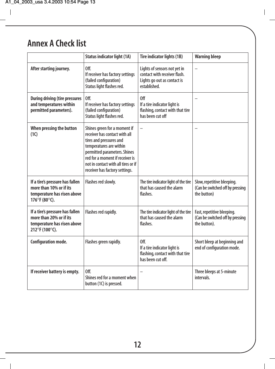
User manual figures
user manual text
Navigation menu
Upload a User Manual
Namespaces
Wiki Guide
HTML
PDF
Info
Views
User Manual
Discussion / Help
Navigation