Nonin Medical BT4000 Puls oximeter display containing Bluetooth User Manual Bluetooth English
Nonin Medical, Inc. Puls oximeter display containing Bluetooth Bluetooth English
UserManual.wiki
>
Nonin Medical
>
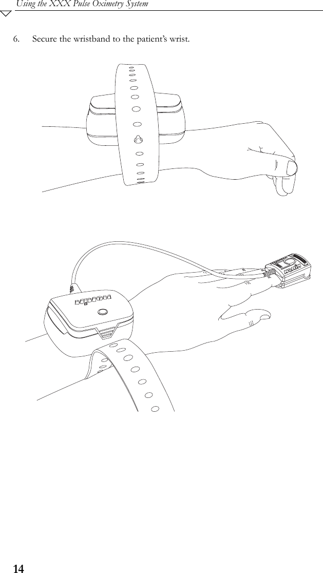
BT4000 User Manual
Users Manual
Navigation menu
Upload a User Manual
Namespaces
Wiki Guide
HTML
PDF
Info
Views
User Manual
Discussion / Help
Navigation