Nordic ID NUR05W RFID Module User Manual
Nordic ID Oy RFID Module
user manual
Nordic ID
International Headquarters
Myllyojankatu 2 A, 24100 Salo, Finland
NUR-05W IMPLEMENTATION GUIDE

2 (23)
2011-06-29
NUR-05W Implementation Guide v0.7
CONFIDENTIAL
Table of contents
1
GENERAL DESCRIPTION................................................................................................................................... 3
1.1
Block diagram .................................................................................................................................... 3
1.2
Key features....................................................................................................................................... 3
1.3
Typical application schematics .......................................................................................................... 3
2
ELECTRICAL CHARACTERISTICS ........................................................................................................................ 5
2.1
Absolute maximum ratings ................................................................................................................ 5
2.2
DC characteristics.............................................................................................................................. 5
2.3
RF characteristics .............................................................................................................................. 5
2.4
Performance characteristics .............................................................................................................. 5
3
PIN ASSIGNMENTS ......................................................................................................................................... 7
3.1
Pin designation .................................................................................................................................. 7
3.2
Pin mapping ....................................................................................................................................... 7
3.3
Signal description............................................................................................................................... 9
4
DESIGN CONSIDERATIONS............................................................................................................................. 11
4.1
RF output and antenna recuirement ................................................................................................ 11
4.2
Power supply ................................................................................................................................... 11
4.3
USB device port ............................................................................................................................... 12
5
RF PARAMETERS .......................................................................................................................................... 13
5.1
Output power ................................................................................................................................... 13
5.2
Receiver sensitivity .......................................................................................................................... 13
5.3
Modulation ....................................................................................................................................... 13
5.4
Link frequency.................................................................................................................................. 13
5.5
RX coding (miller coding)................................................................................................................. 14
5.6
Q-value ............................................................................................................................................ 14
6
DIMENSIONS................................................................................................................................................ 15
6.1
Mechanical dimensions ................................................................................................................... 15
7
REGULATORY AGENCIES INFORMATION......................................................................................................... 17
7.1
7.1 European Union and EFTA countries........................................................................................ 17
7.1.1
User’s Guide Requirements................................................................................................... 17
7.1.2
Labeling Requirements ......................................................................................................... 20
7.1.3
Approved Antennas.............................................................................................................. 20
7.2
7.2 FCC............................................................................................................................................ 20
7.2.1
User’s Guide Requirements................................................................................................... 21
7.2.2
Labeling Requirements ......................................................................................................... 22
7.2.3
Approved Antennas.............................................................................................................. 22
7.3
Industry Canada............................................................................................................................... 22
7.3.1
Labeling Requirements ......................................................................................................... 23
7.3.2
Approved Antennas.............................................................................................................. 23
3 (23)
2011-06-29
NUR-05W Implementation Guide v0.7
CONFIDENTIAL
1 GENERAL DESCRIPTION
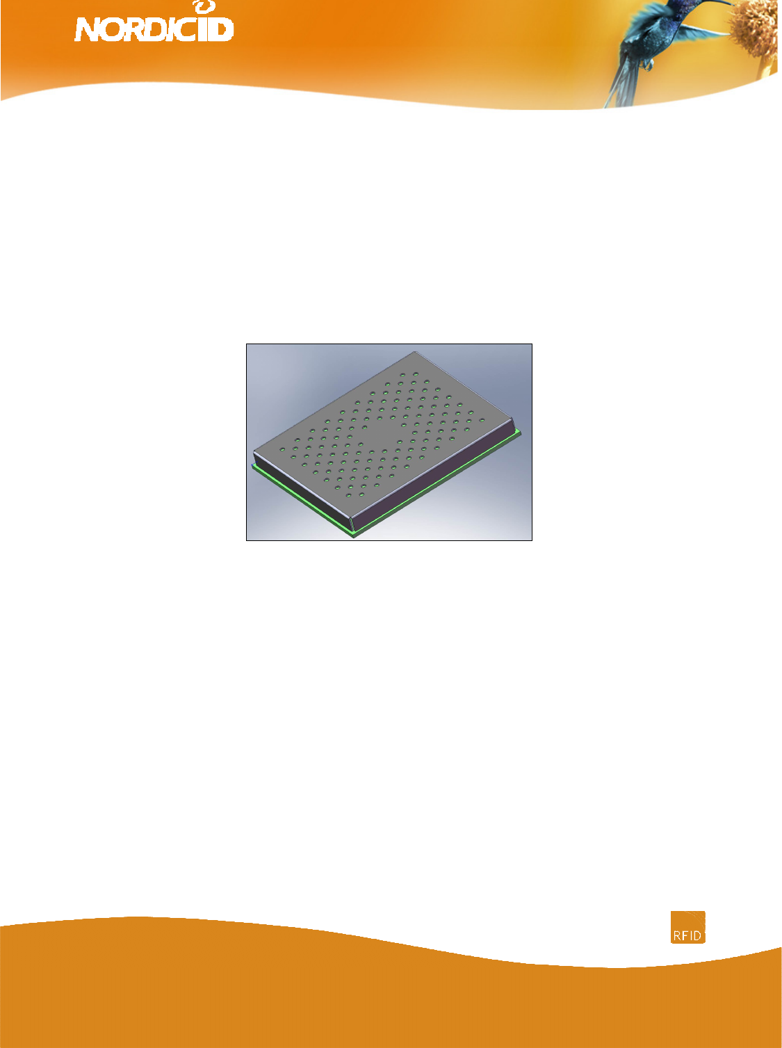
NUR-05W is a compact UHF RFID reader / writer module. It is compatible with ISO18000-6C (EPC
C1G2) standard. Module fulfills ETSI, FCC and IC radio regulations. It is also compatible with DRM
(dense reader mode) requirements. Maximum output power is +27dBm and it can be adjusted via SW
by steps of 1dB. Maximum receiver sensitivity is -86dBm.
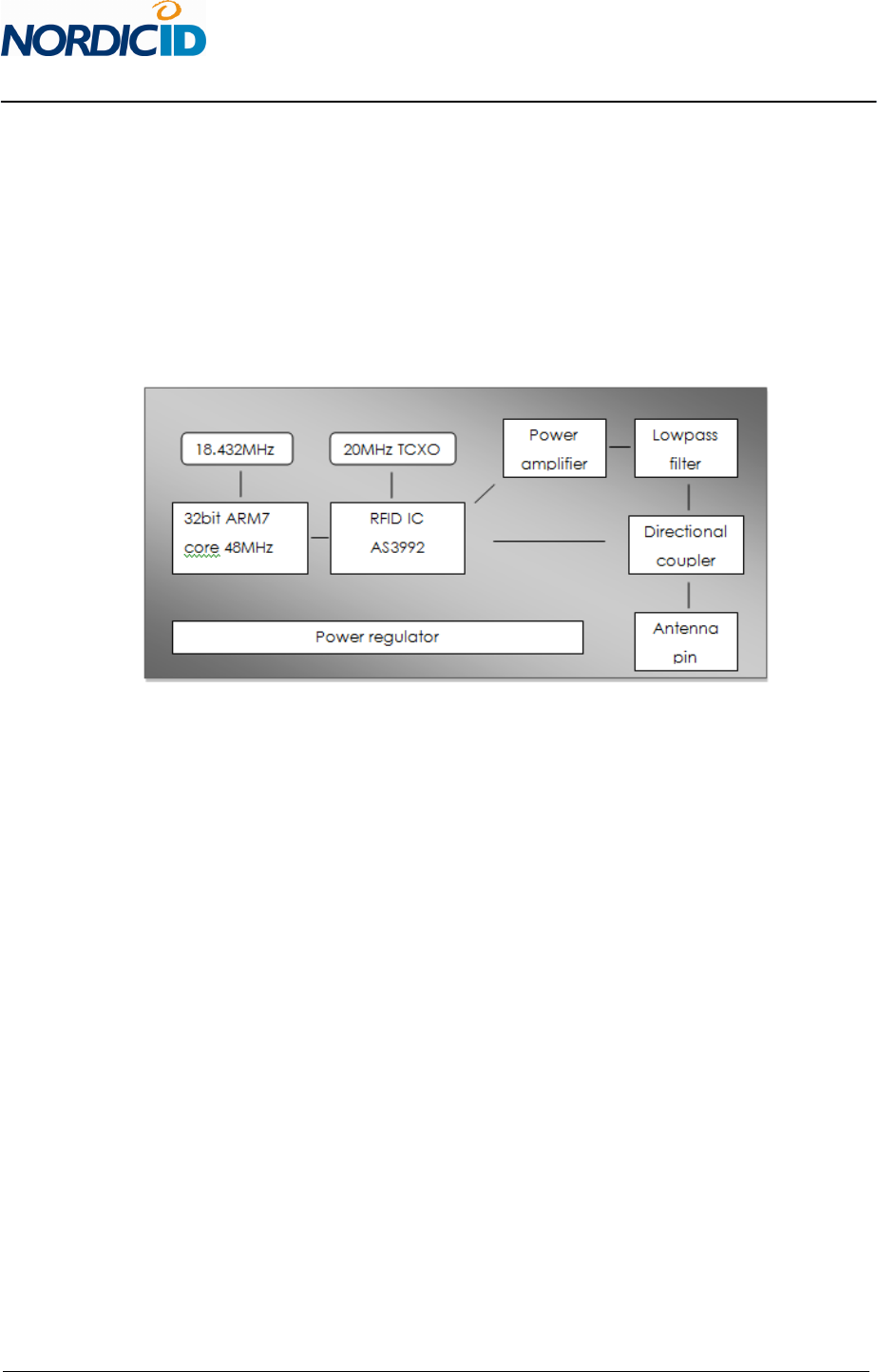
1.1 Block diagram
1.2 Key features
• Small footprint and SMT compatible
• ISO 18000-6C (EPC C1G2) full protocol support
• Low power consumption
• DRM compatible
• High performance with +27dBm output power (adjustable by 1dB steps)
• ETSI, FCC and IC compatible
• Selectable parameters, coding, link frequency and modulation
• UART and USB 2.0 communication
• 5 programmable GPIO
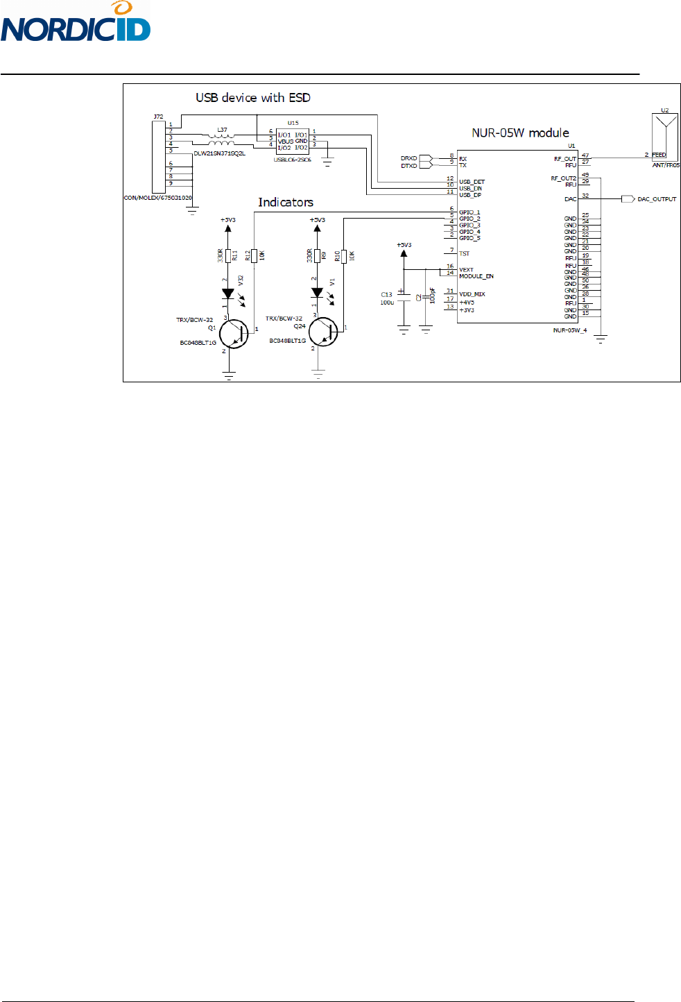
1.3 Typical application schematics
Typical application schematic including mini USB connector with ESD protection circuitry, 2 LED
indicators, NUR-05W module and antenna.
Typical schematic.
4 (23)
2011-06-29
NUR-05W Implementation Guide v0.7
CONFIDENTIAL
5 (23)
2011-06-29
NUR-05W Implementation Guide v0.7
CONFIDENTIAL
2 ELECTRICAL CHARACTERISTICS
2.1 Absolute maximum ratings
Violating these values may cause damage to module. Also correct operation is not guaranteed if
operating outside these values.
Absolute maximum ratings Value
Operation temperature -20°C to +55°C
Storage temperature -30°C to +85°C
Supply voltage +6.0V
Other inputs +5.5V
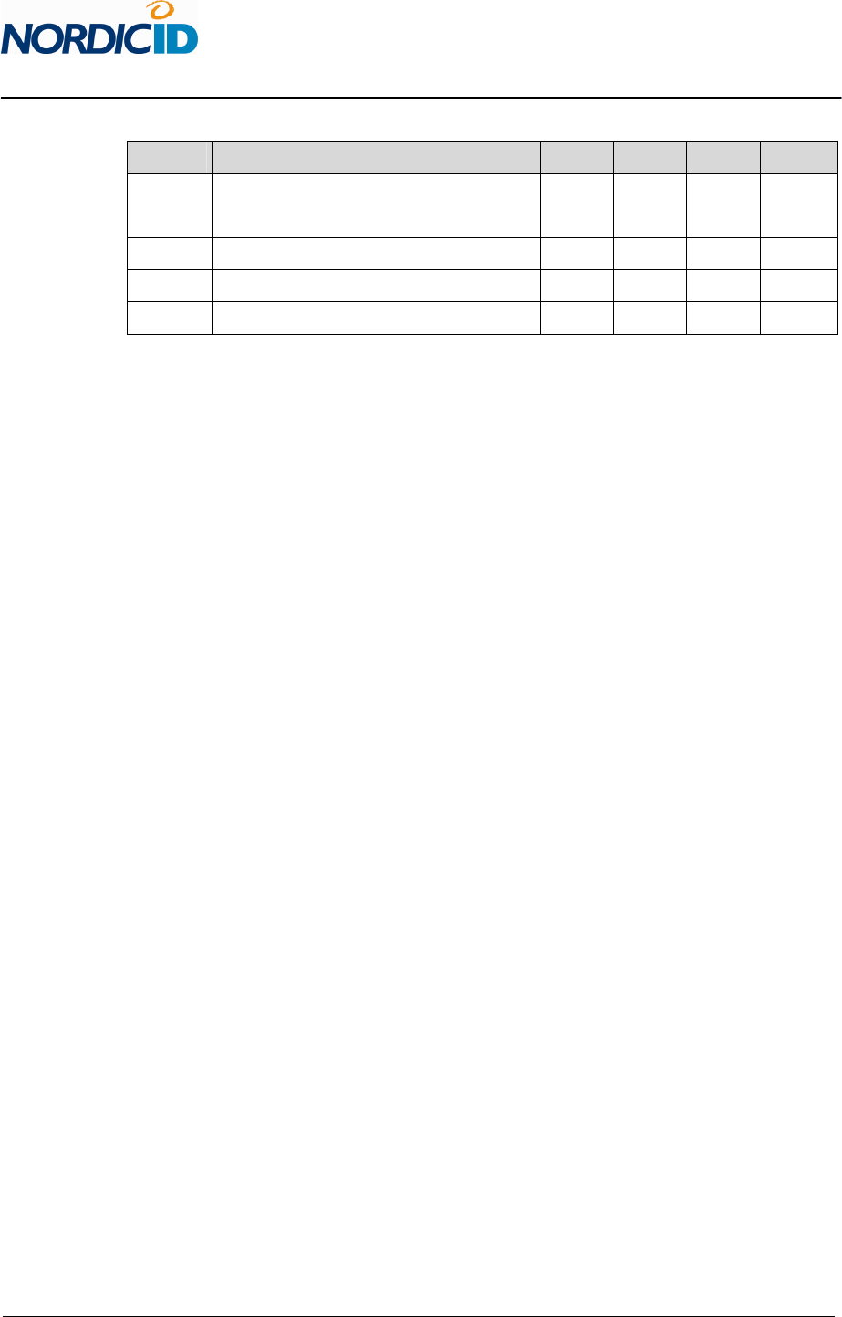
2.2 DC characteristics
Typical values (VEXT = 5.3V @ +25°C)
Symbol Parameter Min Typ Max Units
V
ext
Supply voltage 5.0 5.3 5.5 V
I
ext
Supply current - - 500 mA
I
med
GPIO 1,2,3,4 source / sink current - - 8 mA
I
high
GPIO 5 source / sink current - - 16 mA
V
low
GPIO input low-level voltage - - 0.8 V
V
high
GPIO input high-level voltage 2.0 - - V
V
en
Module enable voltage 1.2 - Supply V
2.3 RF characteristics
Typical values (VEXT = 5.3V @ +25°C)
Symbol Parameter Min Typ Max Units
S
ens
Receiver sensitivity -46 - -86 dBm
S
adj
Sensitivity adjust step - 10 - dB
P
out
Output power 8 - 27 dBm
P
adj
Power adjust step - 1 - dB
S
11
VSWR requirement - - 1,5:1 @50Ω
2.4 Performance characteristics
6 (23)
2011-06-29
NUR-05W Implementation Guide v0.7
CONFIDENTIAL
Typical values (VEXT = 5.3V @ +25°C)
Symbol Parameter Min Typ Max Units
R
dist
Typical reading distance with 2.15dBi dipole
antenna - 5 - m
R
rate
Typical reading rate - 150 - tags/s
O
temp
Operation temperature -20 - +55 °C
H
rel
Relative humidity 10 - 95 %
7 (23)
2011-06-29
NUR-05W Implementation Guide v0.7
CONFIDENTIAL
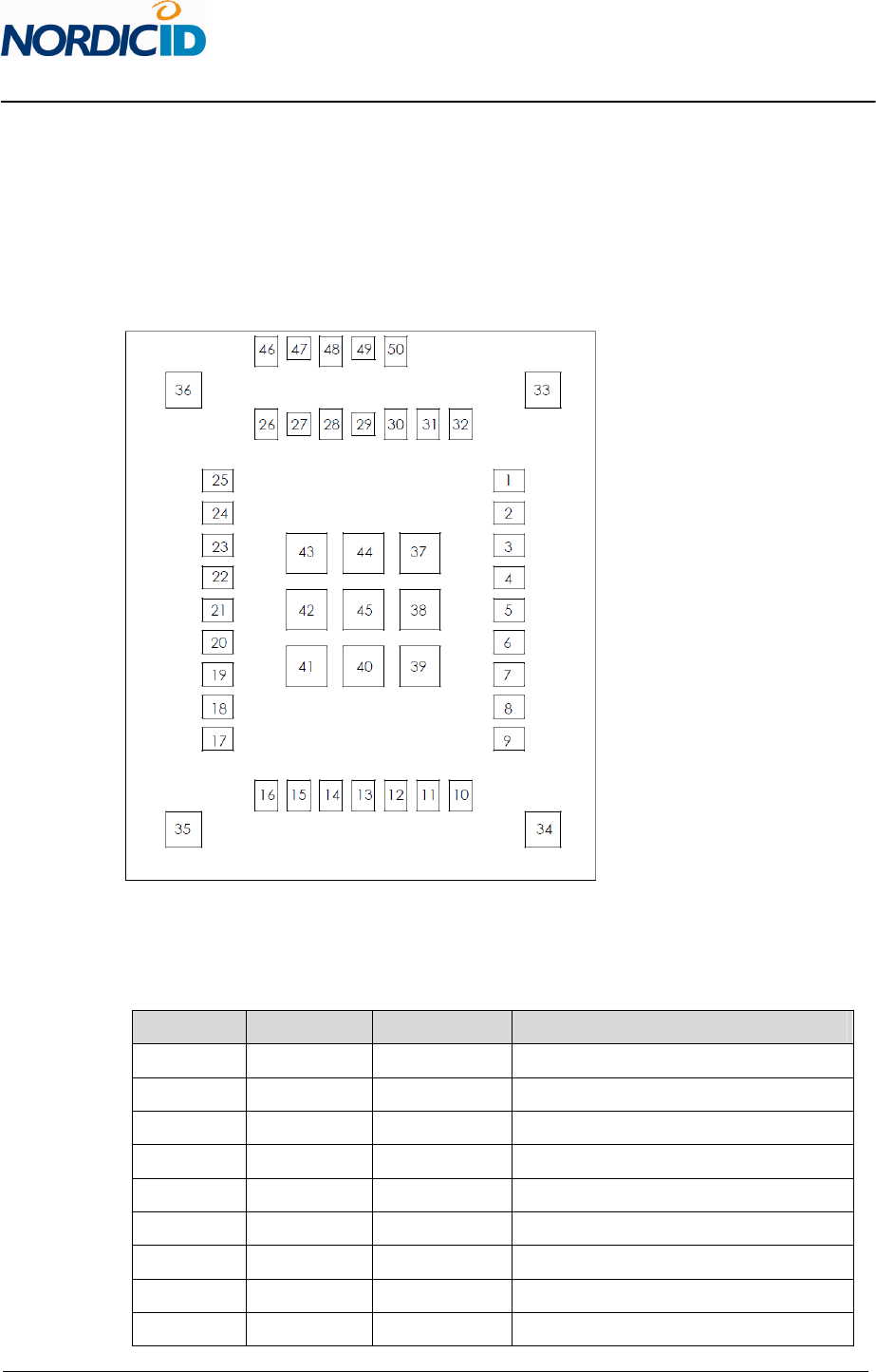
3 PIN ASSIGNMENTS
3.1 Pin designation
Through top view.
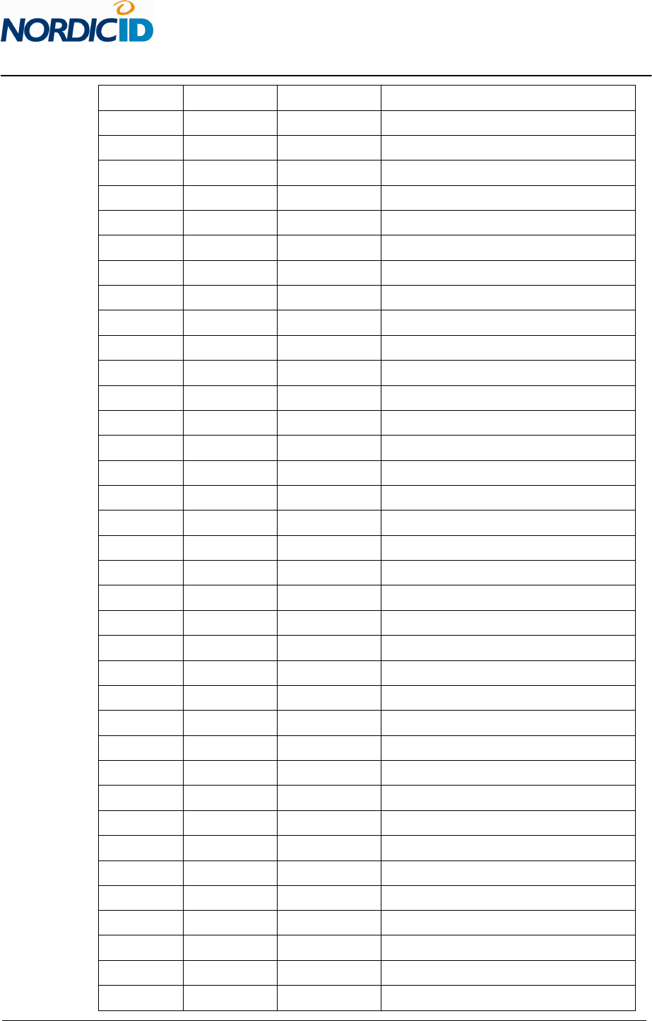
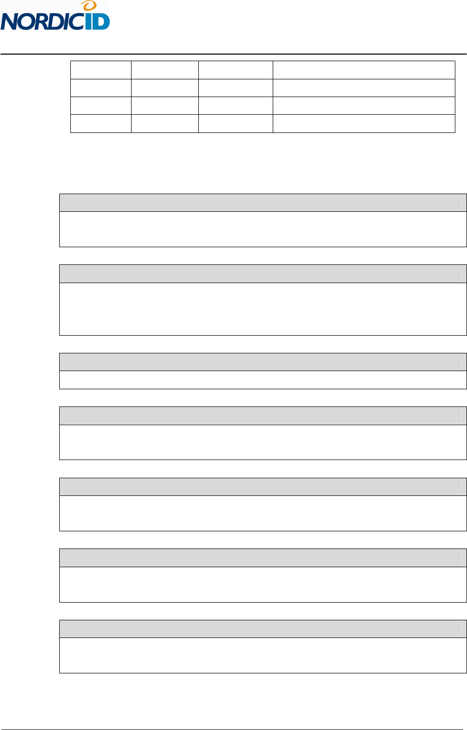
3.2 Pin mapping
Pin number Signal name Pin type Description
1 RFU Bidirectional RFU, DNU (do not use)
2 GPIO_5 Bidirectional 3.3V GPIO (5V tolerant)
3 GPIO_4 Bidirectional 3.3V GPIO (5V tolerant)
4 GPIO_3 Bidirectional 3.3V GPIO (5V tolerant)
5 GPIO_2 Bidirectional 3.3V GPIO (5V tolerant)
6 GPIO_1 Bidirectional 3.3V GPIO (5V tolerant)
7 TST Input Should not be connected
8 RX Input Data from Host to Module
9 TX Output Data from module to Host
8 (23)
2011-06-29
NUR-05W Implementation Guide v0.7
CONFIDENTIAL
10 USB_DN Bidirectional USB – (device port)
11 USB_DP Bidirectional USB + (device port)
12 USB_DET Input Used only for USB detection
13 +3V3 Supply output NC or bypass capacitor to GND
14 MODULE_EN Input Driving high will enable the module
15 GND Supply input Ground
16 VEXT Supply input Module power supply
17 +4V5 Supply output NC or bypass capacitor to GND
18 RFU Bidirectional RFU, DNU (do not use)
19 RFU Bidirectional RFU, DNU (do not use)
20 GND Supply input Ground
21 GND Supply input Ground
22 GND Supply input Ground
23 GND Supply input Ground
24 GND Supply input Ground
25 GND Supply input Ground
26 GND Supply input Ground
27 RFU Bidirectional RFU, DNU (do not use)
28 GND Supply input Ground
29 RFU Bidirectional RFU, DNU (do not use)
30 GND Supply input Ground
31 VDD_MIX Supply output NC or bypass capacitor to GND
32 RFU Output RFU, DNU (do not use)
33 GND Supply input Ground
34 GND Supply input Ground
35 GND Supply input Ground
36 GND Supply input Ground
37 GND Supply input Ground
38 GND Supply input Ground
39 GND Supply input Ground
40 GND Supply input Ground
41 GND Supply input Ground
42 GND Supply input Ground
43 GND Supply input Ground
44 GND Supply input Ground
45 GND Supply input Ground
46 GND Supply input Ground
9 (23)
2011-06-29
NUR-05W Implementation Guide v0.7
CONFIDENTIAL
47 RF_OUT Bidirectional 50Ω RF output/input
48 GND Supply input Ground
49 RFU Bidirectional RFU, DNU (do not use)
50 GND Supply input Ground
3.3 Signal description
Signal name: GND Pin number(s): 15, 20-26, 28, 30, 33-46, 48, 50
These pins are used for grounding and to improve thermal performance. They should be connected to
Host board GND net.
Signal name: GPIO_X Pin number(s): 2-6
These pins are used as general purpose IO. They can be configured via SW API as input or output
ports. IO voltage level is 3.3V. GPIO_1, GPIO_2, GPIO_3 and GPIO_4 have current capability of 8mA
and GPIO_5 has 16mA.
Signal name: TST Pin number(s): 7
Pin is used for production testing purposes only. Should not be connected.
Signal name: RX Pin number(s): 8
Pin is used for module UART input signal. Logic level is 3.3V. If UART is used for communication pin
should be connected to Host MCU serial TX port.
Signal name: TX Pin number(s): 9
Pin is used for module UART output signal. Logic level is 3.3V. If UART is used for communication pin
should be connected to Host MCU serial RX port.
Signal name: USB_DN Pin number(s): 10
Pin is used as USB_D- device port. It is advised to use external ESD protection component if connected
to user accessible USB connector.
Signal name: USB_DP Pin number(s): 11
Pin is used as USB_D+ device port. It is advised to use external ESD protection component if connected
to user accessible USB connector.
10 (23)
2011-06-29
NUR-05W Implementation Guide v0.7
CONFIDENTIAL
Signal name: USB_DET Pin number(s): 12
This pin is used only for USB connection detection. It is advised to use external ESD
protection component if connected to user accessible USB connector. Current is not drawn
from this input pin.
Signal name: +3V3 Pin number(s): 13
Pin is connected to internal regulator output. Pin is used for production testing and it can be left
unconnected. Also bypass capacitor to GND can be used on this pin to improve noise filtering. Value
for capacitor is 10-100pF.
Signal name: MODULE_EN Pin number(s): 14
Driving this pin to high will enable the NUR-05W module. It is internally connected to onboard voltage
regulators enable input. Trigger level is 1.2V. Module will wake up in 50ms. If external power switch is
used to toggle ON and OFF, this pin can be connected directly to VEXT.
Signal name: VEXT Pin number(s): 16
This pin is used for power supply input for NUR-05W module. It is recommended to use 100µF (low
ESR) and 100pF capacitor near the VEXT input pin to maintain stable operating voltage for module.
Signal name: +4V5 Pin number(s): 17
Pin is connected to internal regulator output. Pin is used for production testing and it can be left
unconnected. Also bypass capacitor to GND can be used on this pin to improve noise filtering. Value
for capacitor is 10-100pF.
Signal name: RFU Pin number(s): 1, 18, 19, 27, 29, 32, 49
These pins are reserved for future use. Do not connect these pins.
Signal name: VDD_MIX Pin number(s): 31
Pin is connected to internal regulator output. Pin is used for production testing and it can be left
unconnected. Also bypass capacitor to GND can be used on this pin to improve noise filtering. Value
for capacitor is 10-100pF.
Signal name: RF_OUT Pin number(s): 47
50Ω impedance RF output / input pin. Trace to this pin should be also matched to 50 Ω. See more
details from design considerations section.
11 (23)
2011-06-29
NUR-05W Implementation Guide v0.7
CONFIDENTIAL
4 DESIGN CONSIDERATIONS
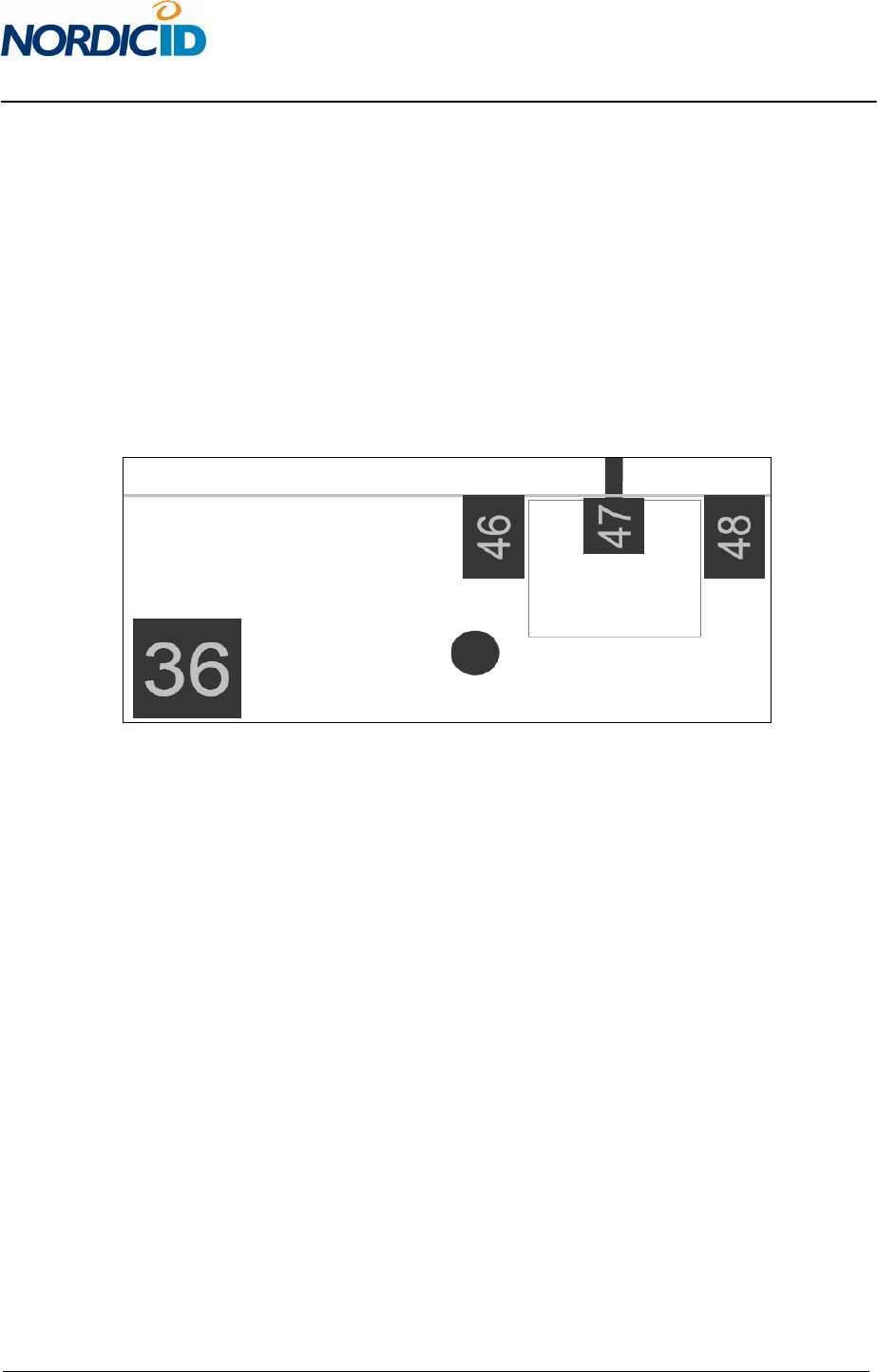
4.1 RF output and antenna recuirement
RF output impedance is 50Ω so it is important to keep the trace leaving from RF_OUT pin in that same
impedance level to avoid reflections and mismatch of RF signal. It is recommended to do copper pour
keep out area to Host board top layer according to picture below. Other layers can be filled with
copper.
Recommended host board copper keep out area.
Antenna is one of the most important elements in UHF RFID system. For the reader / writer module
point of view it is very important that used antenna has low VSWR value. VSWR should be better than
1.5:1 @ 50Ω to avoid decrement in sensitivity performance of the receiver. If reflected power duo to
poor matching of antenna is high enough will that power eventually block the input mixers. With
nominal sensitivity settings NUR-05W module can handle about +15dBm power level coming
backwards to RF_OUT pin without decrement in performance.
4.2 Power supply
NUR-05W has internal linear regulators to get better power supply noise rejection. Still it is important
to provide low noise and stable supply power to NUR-05W module. Voltage ripple should be kept
under 50mVpp. It is recommended to add minimum of 200µF low ESR and 100pF capacitors next to
VEXT pin.
+3V3, +4V5 and VCC_MIX are internal regulator outputs and they can be left open or connected to
GND via 10-100pF bypass capacitors to get better noise rejection. Mainly these pins are used for
testing purposes at production.
12 (23)
2011-06-29
NUR-05W Implementation Guide v0.7
CONFIDENTIAL
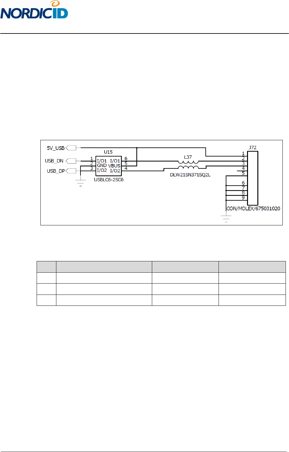
4.3 USB device port
USB_DP, USB_DN and USB_DET pins are used to provide 2.0 compliant USB device port. It must be
remembered that only one communication method can be used to communicate with NUR-05W
module at the time. Connecting USB will automatically prevent communication via serial port. It is
advised to use external ESD protection component if connected to user accessible USB connector.
Below is the reference schematics used in NUR-05W EVB board.
NUR-05W EVB schematics for mini USB connector with ESD protection.
Used components.
Ref Description Manufacturer Part code
U15 ESD protection ST Microelectronics USBLC6-2SC6
L37 Common mode choke Murata DLW21SN371SQ2L
J72 Mini USB connector Molex 67503-1020

13 (23)
2011-06-29
NUR-05W Implementation Guide v0.7
CONFIDENTIAL
5 RF PARAMETERS
5.1 Output power
Maximum output power is +27dBm (500mW). Power can be adjusted by 1dB steps. There is 19 steps
so minimum output value is 8dBm what equals 6mW power. When using high output power it must
be remembered that then antennas VSWR comes even more important. Because high output power
combined with antenna with poor VSWR means that lot of power is reflected back to receiver.
5.2 Receiver sensitivity
Maximum sensitivity of receiver is -86dBm. Receiver can handle +15dBm power coming backwards to
RF_OUT pin.
5.3 Modulation
It is possible to use ASK (amplitude shift keying) or PR-ASK (phase reversed amplitude shift keying)
modulation. Tags that are compliant with ISO18000-6C (EPC C1G2) must support both of these
modulations. PR-ASK has lower transmission data rate and because of that it has narrower output
spectrum. That’s why it is recommended to be used when operating in DRM mode. In other hand
some older tag IC might work better with ASK modulation, because it is easier to tag to demodulate
ASK modulated transmission. By default the modulation is set to PR-ASK.
5.4 Link frequency
Link frequency affects to frequency offset of tags replay in order to readers carrier wave. For example
when used link frequency is 256 kHz, tag will replay at frequency of reader transmission frequency ±
256 kHz. Selectable parameters are 160, 256 and 320 kHz. Tags that are compliant with ISO18000-6C
(EPC C1G2) must support all these parameters. Link frequency also affects tag to reader data rate
which is calculated by formula below:
Tag to reader data rate = (Link frequency / Miller coding)
By default link frequency is set 256 kHz. Default settings must be used when operating in DRM mode.

14 (23)
2011-06-29
NUR-05W Implementation Guide v0.7
CONFIDENTIAL
5.5 RX coding (miller coding)
Like stated above miller coding scheme affects also tag to reader data rate. In practice miller coding
affects the number of clock cycles that tag uses to modulate one symbol. So when using higher Miller
coding scheme tag to reader data rate will be slower but at the same time it is more robust to
interferences. Also tags response spectrum is more concentrated around the link frequency when
using high miller scheme. This allows receiver to use narrower channel filters. Selectable values are 2,
4 and 8. When operating on DRM mode values 4 or 8 should be used. By default Miller 4 is used.
5.6 Q-value
Q-value defines the amount of open response slots that tags can use per one inventory round.
Number of slots can be calculated by formula 2
Q
. It is advised to use twice as much slots compared to
amount of tags that you have in your readers reading field simultaneously. Selectable values are 0 –
15 and value 0 means automatic Q-value adjustment. By default Q-value is set to 0.
15 (23)
2011-06-29
NUR-05W Implementation Guide v0.7
CONFIDENTIAL
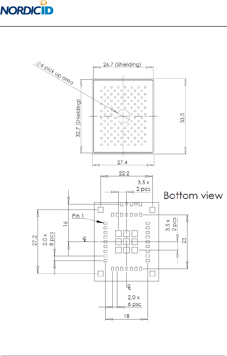
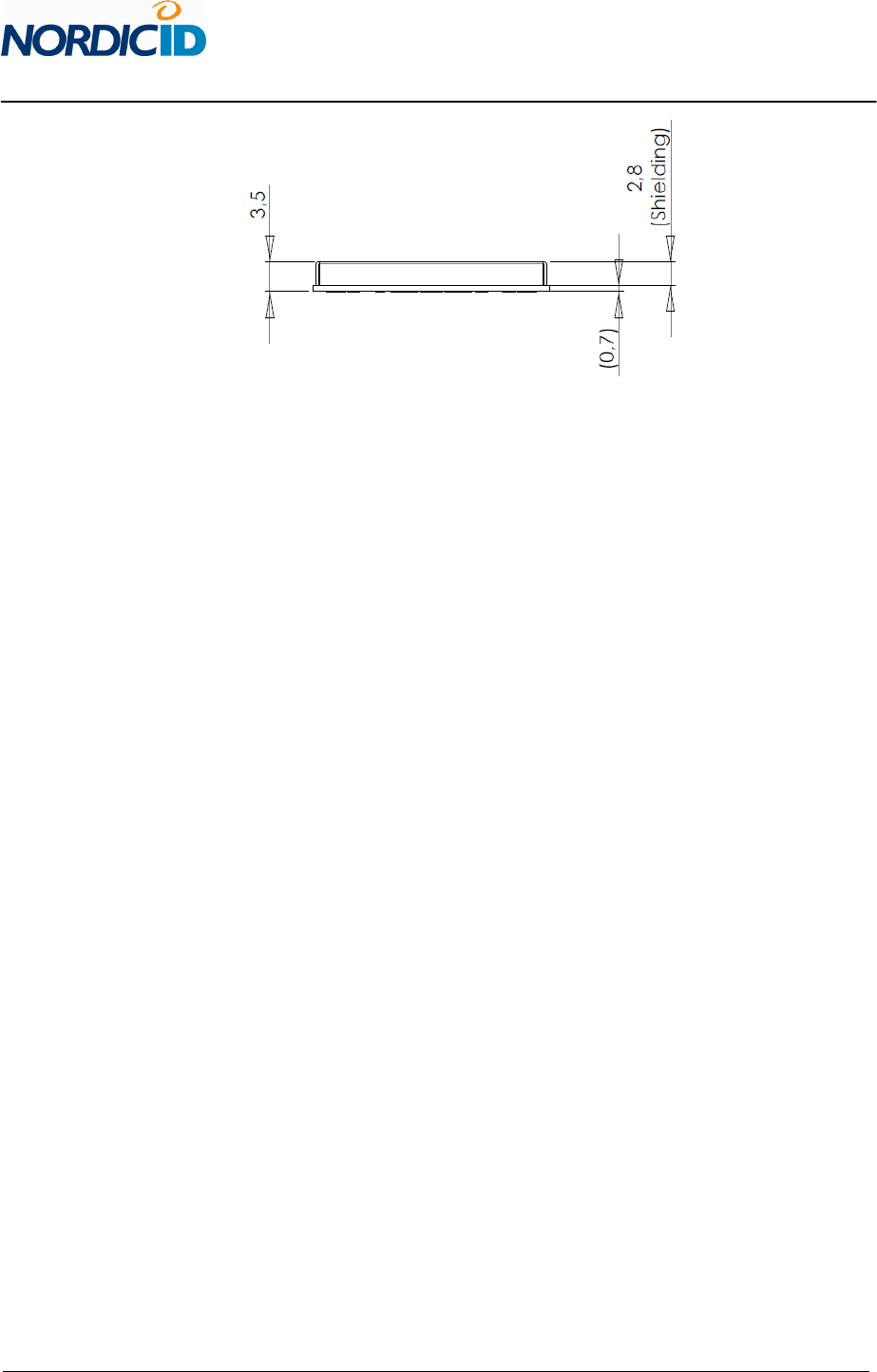
6 DIMENSIONS
6.1 Mechanical dimensions
16 (23)
2011-06-29
NUR-05W Implementation Guide v0.7
CONFIDENTIAL

17 (23)
2011-06-29
NUR-05W Implementation Guide v0.7
CONFIDENTIAL
7 REGULATORY AGENCIES INFORMATION
When OEM prefers to leverage Nordic ID’s grants and certifications of the NUR-05W UHF RFID
module, the host device documentation shall include regulatory compliance information on the NUR-
05W module. Corresponding to the applicable regulatory agencies the following sections outline
regulatory compliance information needed in the user documentation and external labels for the host
devices into which the NUR-05W is integrated.
When leveraging Nordic ID’s grants and certifications, antenna shall be taken into account in view of
the fact that the NUR-05W module has met the essential regulatory requirements with the antennas
listed in the context of particular regulatory compliance information (Approved Antennas). Using the
antenna that is an approved one, OEM integrator may demonstrate with less effort that the device
with the integrated NUR-05W module is in compliance with the requirements.
7.1 7.1 European Union and EFTA countries
7.1.1 User’s Guide Requirements
This apparatus is in compliance with the essential requirements of the R&TTE Directive 1999/5/EC. In
order to prove presumption of conformity with the essential requirements of the R&TTE Directive
1999/5/EC the following requirements and test methods have been applied to the apparatus:
• article 3.2: ETSI EN 302 208 v1.3.1
Radio spectrum matters for Radio Frequency Identification (RFID) equipment operating in the
band 865 MHz to 868 MHz with power levels up to 2W
• article 3.1b: ETSI EN 301 489-1 v1.9.1
Common ElectroMagnetic Compatibility (EMC) requirements
• article 3.1b: ETSI EN 301 489-3 v1.4.1
Specific ElectroMagnetic Compatibility (EMC) conditions for Short-Range Devices (SRD)
operating on frequencies between 9 kHz and 40 GHz
• article 3.1a: EN 60950-1:2005
General requirements for Safety of Information Technology Equipment
This apparatus is in compliance with EU Directive 2003/95/EC, Reduction of Hazardous Substances
(RoHS).
Česky
[Czech]

18 (23)
2011-06-29
NUR-05W Implementation Guide v0.7
CONFIDENTIAL
[name of manufacture] tímto prohlašuje, že tento [type of apparatus] je ve shodě sezákladními
požadavky a dalšími příslušnými ustanoveními směrnice1999/5/ES.
Dansk
[Danish]
Undertegnede [name of manufacture] erklærer herved, at følgende udstyr [type of apparatus]
overholder de væsentlige krav og øvrige relevante krav i direktiv 1999/5/EF.
Deutsch
[German]
Hiermit erklärt [name of manufacture], dass sich das Gerät [type of apparatus] in Übereinstimmung
mit den grundlegenden Anforderungen und den übrigen einschlägigen Bestimmungen der Richtlinie
1999/5/EG befindet.
Eesti
[Estonian]
Käesolevaga kinnitab [name of manufacture] seadme [type of apparatus] vastavust direktiivi
1999/5/EÜ põhinõuetele ja nimetatud direktiivist tulenevatele teistele asjakohastele sätetele.
English
Hereby, [name of manufacture], declares that this [type of apparatus] is in compliance with the
essential requirements and other relevant provisions of Directive 1999/5/EC.
Español
[Spanish]
Por medio de la presente [name of manufacture] declara que el [type of apparatus] cumple con los
requisitos esenciales y cualesquiera otras disposiciones aplicables o exigibles de la Directiva
1999/5/CE.
Ελληνική
[Greek]
ΜΕ ΤΗΝ ΠΑΡΟΥΣΑ [name of manufacture] ΔΗΛΩΝΕΙ ΟΤΙ [type of apparatus] ΣΥΜΜΟΡΦΩΝΕΤΑΙ ΠΡΟΣ
ΤΙΣ ΟΥΣΙΩΔΕΙΣ ΑΠΑΙΤΗΣΕΙΣ ΚΑΙ ΤΙΣ ΛΟΙΠΕΣ ΣΧΕΤΙΚΕΣ ΔΙΑΤΑΞΕΙΣ ΤΗΣ ΟΔΗΓΙΑΣ 1999/5/ΕΚ.
Français
[French]
Par la présente [name of manufacture] déclare que l'appareil [type of apparatus] est conforme aux
exigences essentielles et aux autres dispositions pertinentes de
la directive 1999/5/CE.
Italiano
[Italian]
Con la presente [name of manufacture] dichiara che questo [type of apparatus] è conforme ai requisiti
essenziali ed alle altre disposizioni pertinenti stabilite dalla direttiva 1999/5/CE.
Latviski
[Latvian]

19 (23)
2011-06-29
NUR-05W Implementation Guide v0.7
CONFIDENTIAL
Ar šo [name of manufacture] deklarē, ka [type of apparatus] atbilst Direktīvas 1999/5/EK būtiskajām
prasībām un citiem ar to saistītajiem noteikumiem.
Lietuvių
[Lithuanian]
Šiuo [name of manufacture] deklaruoja, kad šis [type of apparatus] atitinka esminius reikalavimus ir
kitas 1999/5/EB Direktyvos nuostatas.
Nederlands
[Dutch]
Hierbij verklaart [name of manufacture] dat het toestel [type of apparatus] in overeenstemming is
met de essentiële eisen en de andere relevante bepalingen van richtlijn 1999/5/EG.
Malti
[Maltese]
Hawnhekk, [name of manufacture], jiddikjara li dan [type of apparatus] jikkonforma mal-ħtiġijiet
essenzjali u ma provvedimenti oħrajn relevanti li hemm fid-Dirrettiva 1999/5/EC.
Magyar
[Hungarian]
Alulírott, [name of manufacture] nyilatkozom, hogy a [type of apparatus] megfelel a vonatkozó
alapvetõ követelményeknek és az 1999/5/EC irányelv egyéb elõírásainak.
Polski
[Polish]
Niniejszym [name of manufacture] oświadcza, że [type of apparatus] jest zgodny z zasadniczymi
wymogami oraz pozostałymi stosownymi postanowieniami Dyrektywy 1999/5/EC.
Português
[Portuguese]
[name of manufacture] declara que este [type of apparatus] está conforme com os requisitos
essenciais e outras disposições da Directiva 1999/5/CE.
Slovensko
[Slovenian]
[name of manufacture] izjavlja, da je ta [type of apparatus] v skladu z bistvenimi zahtevami in ostalimi
relevantnimi določili direktive 1999/5/ES.
Slovensky
[Slovak]
[name of manufacture] týmto vyhlasuje, že [type of apparatus] spĺňa základné požiadavky a všetky
príslušné ustanovenia Smernice 1999/5/ES.
Suomi
[Finnish]

20 (23)
2011-06-29
NUR-05W Implementation Guide v0.7
CONFIDENTIAL
[name of manufacture] vakuuttaa täten että [type of apparatus] tyyppinen laite on direktiivin
1999/5/EY oleellisten vaatimusten ja sitä koskevien direktiivin muiden ehtojen mukainen.
Svenska
[Swedish]
Härmed intygar [name of manufacture] att denna [type of apparatus] står i överensstämmelse med de
väsentliga egenskapskrav och övriga relevanta bestämmelser som framgår av direktiv 1999/5/EG.
7.1.2 Labeling Requirements
The 'CE' marking must be in a visible area on the OEM product.
7.1.3 Approved Antennas
Manufacturer: Poynting
Antenna Description: RFID patch antenna
Manufacturer Part Number: PATCH-A0025
Gain: 7 dBi
7.2 7.2 FCC
This equipment has been tested and found to comply with the limits for a Class B digital device,
pursuant to Part 15 of the FCC Rules. These limits are designed to provide reasonable protection
against harmful interference in a residential installation. This equipment generates uses and can
radiate radio frequency energy and, if not installed and used in accordance with the instructions, may
cause harmful interference to radio communications. However, there is no guarantee that
interference will not occur in a particular installation. If this equipment does cause harmful
interference to radio or television reception, which can be determined by turning the equipment off
and on, the user is encouraged to try to correct the interference by one of the following measures:
• Reorient or relocate the receiving antenna.
• Increase the separation between the equipment and receiver.
• Connect the equipment into an outlet on a circuit different from that to which the receiver is
connected.
• Consult the dealer or an experienced radio/TV technician for help.
This device complies with Part 15 of the FCC Rules. Operation is subject to the following two
conditions: (1) This device may not cause harmful interference, and (2) this device must accept any
interference received, including interference that may cause undesired operation.
FCC Caution: Any changes or modifications not expressly approved by the party responsible for
compliance could void the user's authority to operate this equipment.

21 (23)
2011-06-29
NUR-05W Implementation Guide v0.7
CONFIDENTIAL
This NUR-05W transmitter module is authorized to be used in other devices only by OEM
Integrators under the following conditions:
1. The antenna(s) must be installed such that a minimum separation distance of 20cm is
maintained between the radiator (antenna) & user’s/nearby people’s body at all times.
2. The transmitter module must not be co-located with any other antenna or transmitter.
When the conditions above are met, typically no further transmitter testing is required. However, the
OEM integrator is still responsible for testing their end-product for any additional compliance
requirements required with this module installed (for example, digital device emissions, PC peripheral
requirements, etc.).
The antenna used with the NUR-05W transmitter module can have a gain of 8 dBi at the maximum.
Higher gain antennas may be used if cable loss compensates the exceeded antenna gain. For example
2dB antenna cable loss reduces EIRP so that 10dBi antenna may be used.
Note
In the event that these conditions can’t be met (for certain configurations or co-location with
another transmitter), then the FCC authorization is no longer considered valid and the FCC ID
can’t be used on the final product. In these circumstances, the OEM integrator will be
responsible for reevaluating the end product (including the transmitter) and obtaining a
separate FCC authorization.
The OEM integrator has to be aware not to provide information to the end user regarding how to
install or remove this RF module in the user manual of the end product.
For the User’s Guide the required FCC statements outlined in the User’s Guide Requirements section
must be in a prominent location.
7.2.1 User’s Guide Requirements
“To comply with FCC’s RF radiation exposure requirements, the antenna(s) used for this transmitter
must be installed such that a minimum separation distance of 20cm is maintained between the
radiator (antenna) & user’s/nearby people’s body at all times and must not be co-located or operating
in conjunction with any other antenna or transmitter.”
“This device complies with Part 15 of the FCC Rules”
“Any changes or modifications to the transmitting module not expressly approved by
Nordic ID Oy could void the user’s authority to operate this equipment”

22 (23)
2011-06-29
NUR-05W Implementation Guide v0.7
CONFIDENTIAL
7.2.2 Labeling Requirements
The end product must be labeled in a visible area as follows:
“Contains Transmitter Module FCC ID: SCCNUR05W”
or
“Contains FCC ID: SCCNUR05W”
7.2.3 Approved Antennas
Option 1:
Manufacturer: HUBER-SHUNER
Antenna Description: RFID Reader Antenna; Polarization: linear
vertical; Frequency range: 902-928MHz
Manufacturer Part Number: SPA-915/70/8/0/V
Gain: 8 dBi
Option 2:
Manufacturer: Nordic ID
Antenna Description: RFID Reader Antenna; Linear polarization: dipole;
Frequency range: 902-928MHz
Manufacturer Product Name: Nordic ID Merlin UHF RFID
Gain: 2 dBi
Option 3:
Manufacturer: Nordic ID
Antenna Description: RFID Reader Antenna; Cross polarization: dipole;
Frequency range: 902-928MHz
Manufacturer Product Name: Nordic ID Merlin Cross Dipole UHF RFID
Gain: 5 dBi
7.3 Industry Canada
Demonstrating the compliance is subject to the following two conditions: (1) this device may not
cause interference, and (2) this device must accept any interference, including interference that may
cause undesired operation of the device.
Under Industry Canada regulations, this radio transmitter may only operate using an antenna of a
type and maximum (or lesser) gain approved for the transmitter by Industry Canada. To reduce
potential radio interference to other users, the antenna type and its gain should be so chosen that
the equivalent isotropically radiated power (e.i.r.p.) is not more than that necessary for successful
communication.

23 (23)
2011-06-29
NUR-05W Implementation Guide v0.7
CONFIDENTIAL
To leverage the Nordic ID’s IC grant, the device with the integrated NUR-05W module shall be met the
following conditions:
1. The antenna used with the NUR-05W module must be installed so that the distance of the
antenna from all persons can be maintained at least 20 cm in every situation.
2. The antenna(s) used with the NUR-05W module must not be collocated in conjunction with any
other antenna or transmitter that is capable of transmitting at the same time.
When the conditions above are met, typically no transmitter testing is required, although the OEM
integrator shall demonstrate that the end-product is in compliance with the other regulatory
requirements.
There is no user’s documentation requirements other than that the required FCC statements outlined
in the FCC section are in a prominent place in the user’s guide.
7.3.1 Labeling Requirements
The end product must be labeled in a visible area as follows:
“Contains IC: 5137A-NUR05W”
7.3.2 Approved Antennas
This radio transmitter 5137A-NUR05W has been approved by Industry Canada to operate with the
antenna types listed below with the maximum permissible gain and required antenna impedance for
each antenna type indicated. Antenna types not included in this list, having a gain greater than the
maximum gain indicated for that type, are strictly prohibited for use with this device.
Manufacturer: HUBER-SHUNER
Antenna Description: RFID Reader Antenna; Polarization: linear
vertical; Frequency range: 902-928MHz
Manufacturer Part Number: SPA-915/70/8/0/V
Gain: 8 dBi
Impedance: 50Ω