Nordic ID NUR21W UHF RFID Radio Module NUR2-1W User Manual
Nordic ID Oy UHF RFID Radio Module NUR2-1W
UserManual.wiki
>
Nordic ID
>
NUR21W User Manual
User Manual
Navigation menu
Upload a User Manual
Namespaces
Wiki Guide
HTML
PDF
Info
Views
User Manual
Discussion / Help
Navigation
![18 2017-09-07 NUR2-1W HW Implementation Guide v1.0 If you want to use custom frequencies or hop tables you need to feed parameter described below. Table 11. Custom hop table parameters. Parameter Value Description Frequency entry 840 000 – 960 000 [kHz] Defines the center frequency of the first transmit channel. Channel count 1 - 100 Defines the number of transmit channels Channel spacing 25 * n [kHz] Defines the frequency between transmit channels. Channel time minimum 100 ms Defines the time that reading is ON at the same channel Wait time maximum 1000 ms Defines the time that transmitter is silent between frequency hops Tari 1=12.5us 2=25us Defines the Tari value LF 160 000, 256 000 or 320 000 Defines the maximum link frequency that is used](https://usermanual.wiki/Nordic-ID/NUR21W/User-Guide-3551282-Page-18.png)
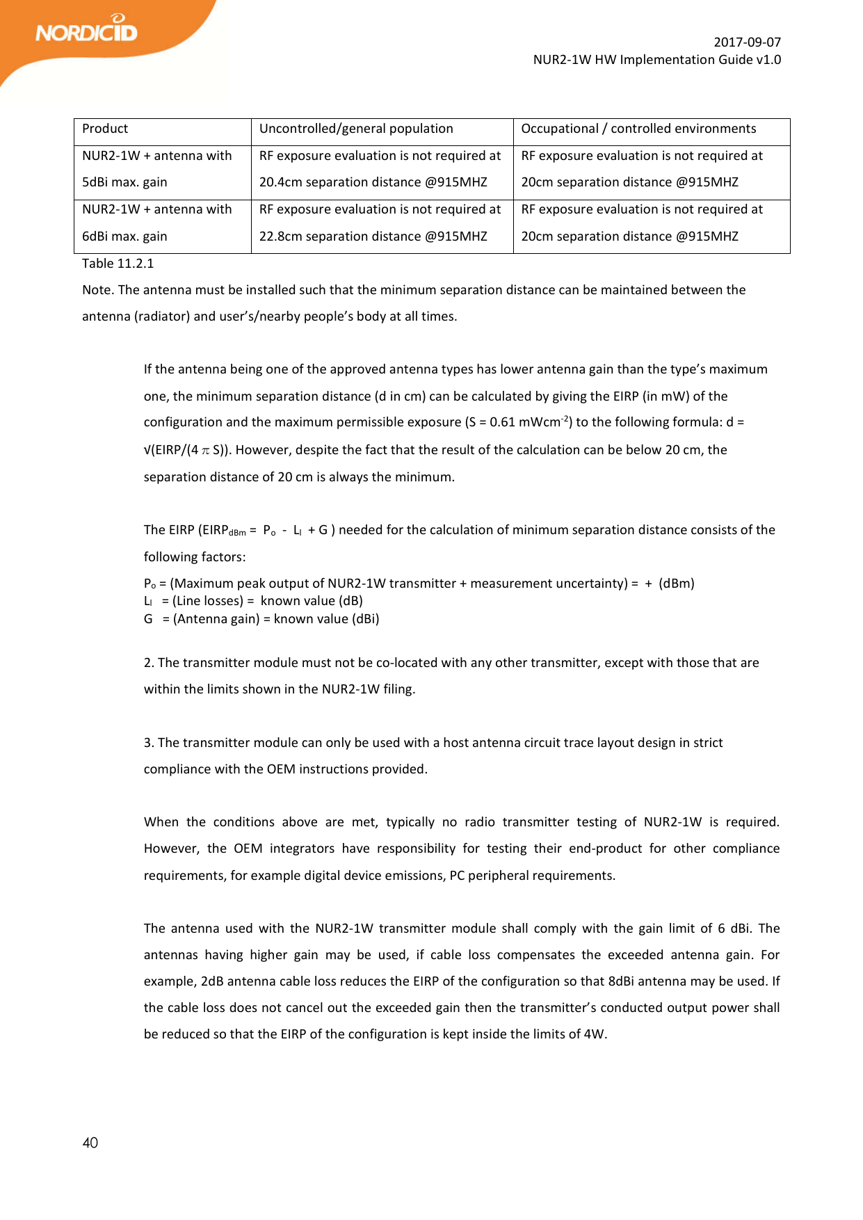
![36 2017-09-07 NUR2-1W HW Implementation Guide v1.0 EN 62311: 2008 - Human exposure limits This apparatus is in compliance with EU Directive 2011/65/EU, Reduction of Hazardous Substances (RoHS). Česky [Czech] [Nordic ID] tímto prohlašuje, že tento [RFID Radio module NUR2-1W] je ve shodě sezákladními požadavky a dalšími příslušnými ustanoveními směrnice 2014/53/ES. Dansk [Danish] Undertegnede [Nordic ID] erklærer herved, at følgende udstyr [RFID Radio module NUR2-1W] overholder de væsentlige krav og øvrige relevante krav i direktiv 2014/53/EF. Deutsch [German] Hiermit erklärt [Nordic ID], dass sich das Gerät [RFID Radio module NUR2-1W] in Übereinstimmung mit den grundlegenden Anforderungen und den übrigen einschlägigen Bestimmungen der Richtlinie 2014/53/EG befindet. Eesti [Estonian] Käesolevaga kinnitab [Nordic ID] seadme [RFID Radio module NUR2-1W] vastavust direktiivi 2014/53/EÜ põhinõuetele ja nimetatud direktiivist tulenevatele teistele asjakohastele sätetele. English Hereby, [Nordic ID], declares that this [RFID Radio module NUR2-1W] is in compliance with the essential requirements and other relevant provisions of Directive 2014/53/EU. Español [Spanish] Por medio de la presente [Nordic ID] declara que el [RFID Radio module NUR2-1W] cumple con los requisitos esenciales y cualesquiera otras disposiciones aplicables o exigibles de la Directiva 2014/53/EU. Ελληνική [Greek] ΜΕ ΤΗΝ ΠΑΡΟΥΣΑ [Nordic ID] ΔΗΛΩΝΕΙ ΟΤΙ [RFID Radio module NUR2-1W] ΣΥΜΜΟΡΦΩΝΕΤΑΙ ΠΡΟΣ ΤΙΣ ΟΥΣΙΩΔΕΙΣ ΑΠΑΙΤΗΣΕΙΣ ΚΑΙ ΤΙΣ ΛΟΙΠΕΣ ΣΧΕΤΙΚΕΣ ΔΙΑΤΑΞΕΙΣ ΤΗΣ ΟΔΗΓΙΑΣ 2014/53/ΕΚ.](https://usermanual.wiki/Nordic-ID/NUR21W/User-Guide-3551282-Page-36.png)
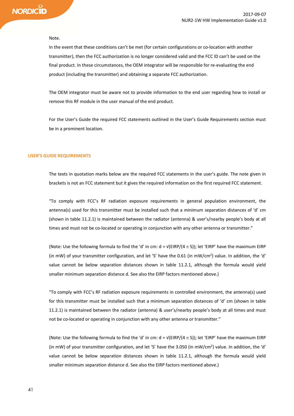
![37 2017-09-07 NUR2-1W HW Implementation Guide v1.0 Français [French] Par la présente [Nordic ID] déclare que l'appareil [RFID Radio module NUR2-1W] est conforme aux exigences essentielles et aux autres dispositions pertinentes de la directive 2014/53/EU. Italiano [Italian] Con la presente [Nordic ID] dichiara che questo [RFID Radio module NUR2-1W] è conforme ai requisiti essenziali ed alle altre disposizioni pertinenti stabilite dalla direttiva 2014/53/EU. Latviski [Latvian] Ar šo [Nordic ID] deklarē, ka [RFID Radio module NUR2-1W] atbilst Direktīvas 2014/53/EK būtiskajām prasībām un citiem ar to saistītajiem noteikumiem. Lietuvių [Lithuanian] Šiuo [Nordic ID] deklaruoja, kad šis [RFID Radio module NUR2-1W] atitinka esminius reikalavimus ir kitas 2014/53/EB Direktyvos nuostatas. Nederlands [Dutch] Hierbij verklaart [Nordic ID] dat het toestel [RFID Radio module NUR2-1W] in overeenstemming is met de essentiële eisen en de andere relevante bepalingen van richtlijn 2014/53/EG. Malti [Maltese] Hawnhekk, [Nordic ID], jiddikjara li dan [RFID Radio module NUR2-1W] jikkonforma mal-ħtiġijiet essenzjali u ma provvedimenti oħrajn relevanti li hemm fid-Dirrettiva 2014/53/EU. Magyar [Hungarian] Alulírott, [Nordic ID] nyilatkozom, hogy a [RFID Radio module NUR2-1W] megfelel a vonatkozó alapvetõ követelményeknek és az 2014/53/EU irányelv egyéb elõírásainak. Polski [Polish] Niniejszym [Nordic ID] oświadcza, że [RFID Radio module NUR2-1W] jest zgodny z zasadniczymi wymogami oraz pozostałymi stosownymi postanowieniami Dyrektywy 2014/53/EU.](https://usermanual.wiki/Nordic-ID/NUR21W/User-Guide-3551282-Page-37.png)
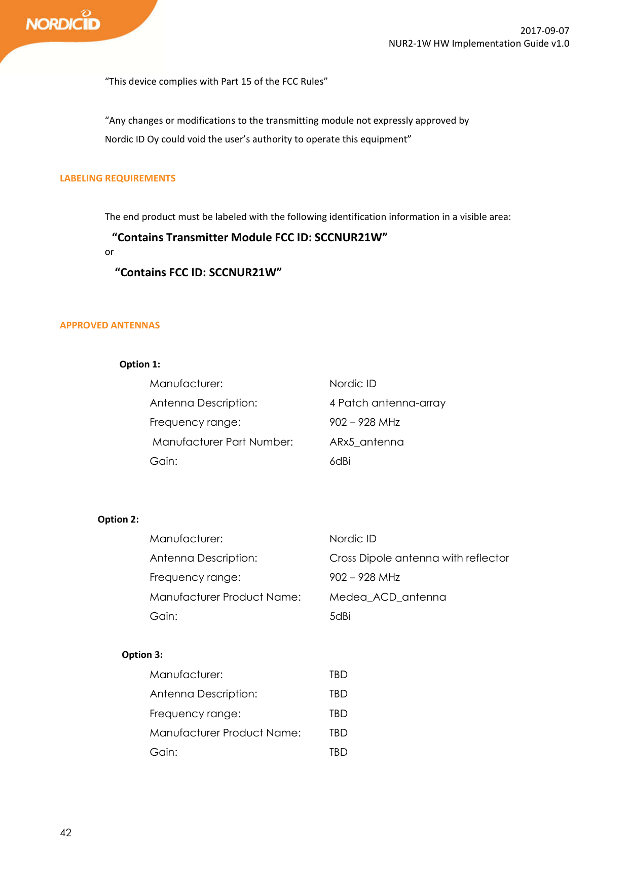
![38 2017-09-07 NUR2-1W HW Implementation Guide v1.0 Português [Portuguese] [Nordic ID] declara que este [RFID Radio module NUR2-1W] está conforme com os requisitos essenciais e outras disposições da Directiva 2014/53/EU. Slovensko [Slovenian] [Nordic ID] izjavlja, da je ta [RFID Radio module NUR2-1W] v skladu z bistvenimi zahtevami in ostalimi relevantnimi določili direktive 2014/53/ES. Slovensky [Slovak] [Nordic ID] týmto vyhlasuje, že [RFID Radio module NUR2-1W] spĺňa základné požiadavky a všetky príslušné ustanovenia Smernice 2014/53/ES. Suomi [Finnish] [Nordic ID] vakuuttaa täten että [RFID Radio module NUR2-1W] tyyppinen laite on direktiivin 2014/53/EY oleellisten vaatimusten ja sitä koskevien direktiivin muiden ehtojen mukainen. Svenska [Swedish] Härmed intygar [Nordic ID] att denna [RFID Radio module NUR2-1W] står i överensstämmelse med de väsentliga egenskapskrav och övriga relevanta bestämmelser som framgår av direktiv 2014/53/EG. LABELING REQUIREMENTS The 'CE' marking must be in a visible area on the OEM product. APPROVED ANTENNAS Maximum allowed ERP power is 33dBm. NUR2-1W has maximum output power of 30dBm. Meaning that 5dBi is the maximum allowed antenna gain without cable losses. Formula how to calculate maximum allowed antenna gain: 30 dBm – 2.15 (dipole gain) + [antenna gain dBi] – [cable attenuation dB] < 33dBm Beamwidth restrictions: For transmissions ≤500 mW e.r.p. there shall be no restriction on beam width.](https://usermanual.wiki/Nordic-ID/NUR21W/User-Guide-3551282-Page-38.png)